Alarm com orporated 143200T5V4 Wireless Transceiver that operates in the amateur band 902-928 MHz User Manual User Guide Rev 1

Alarm.com Incorporated Wireless Transceiver that operates in the amateur band 902-928 MHz User Guide Rev 1

Contents

User Guide Rev. 1

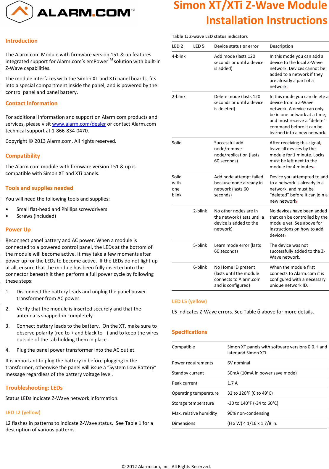
Simon XT/XTi Z-Wave Module Installation Instructions  © 2012 Alarm.com, Inc.  All Rights Reserved. Introduction  The Alarm.com Module with firmware version 151 & up features integrated support for Alarm.com’s emPowerTM solution with built-in Z-Wave capabilities.   The module interfaces with the Simon XT and XTi panel boards, fits into a special compartment inside the panel, and is powered by the control panel and panel battery. Contact Information  For additional information and support on Alarm.com products and services, please visit www.alarm.com/dealer or contact Alarm.com technical support at 1-866-834-0470. Copyright © 2013 Alarm.com. All rights reserved.  Compatibility The Alarm.com module with firmware version 151 & up is compatible with Simon XT and XTi panels.   Tools and supplies needed You will need the following tools and supplies: •  Small flat-head and Phillips screwdrivers •  Screws (included) Power Up Reconnect panel battery and AC power. When a module is connected to a powered control panel, the LEDs at the bottom of the module will become active. It may take a few moments after power up for the LEDs to become active.  If the LEDs do not light up at all, ensure that the module has been fully inserted into the connector beneath it then perform a full power cycle by following these steps: 1.  Disconnect the battery leads and unplug the panel power transformer from AC power. 2.  Verify that the module is inserted securely and that the antenna is snapped-in completely. 3.  Connect battery leads to the battery.  On the XT, make sure to observe polarity (red to + and black to –) and to keep the wires outside of the tab holding them in place.  4.  Plug the panel power transformer into the AC outlet. It is important to plug the battery in before plugging in the transformer, otherwise the panel will issue a “System Low Battery” message regardless of the battery voltage level.  Troubleshooting: LEDs Status LEDs indicate Z-Wave network information. LED L2 (yellow) L2 flashes in patterns to indicate Z-Wave status.  See Table 1 for a description of various patterns.  Table 1: Z-wave LED status indicators LED 2  LED 5  Device status or error  Description 4-blink    Add mode (lasts 120 seconds or until a device is added) In this mode you can add a device to the local Z-Wave network. Devices cannot be added to a network if they are already a part of a network. 2-blink    Delete mode (lasts 120 seconds or until a device is deleted) In this mode you can delete a device from a Z-Wave network. A device can only be in one network at a time, and must receive a “delete” command before it can be learned into a new network. Solid    Successful add node/remove node/replication (lasts 60 seconds) After receiving this signal, leave all devices by the module for 1 minute. Locks must be left next to the module for 4 minutes. Solid with one blink   Add node attempt failed because node already in network (lasts 60 seconds) Device you attempted to add to a network is already in a network, and must be “deleted” before it can join a new network.   2-blink  No other nodes are in the network (lasts until a device is added to the network) No devices have been added that can be controlled by the module yet. See above for instructions on how to add devices.   5-blink  Learn mode error (lasts 60 seconds) The device was not successfully added to the Z-Wave network.    6-blink  No Home ID present (lasts until the module connects to Alarm.com and is configured) When the module first connects to Alarm.com it is configured with a necessary unique network ID. LED L5 (yellow) L5 indicates Z-Wave errors. See Table 5 above for more details.     Specifications  Compatible  Simon XT panels with software versions 0.0.H and later and Simon XTi. Power requirements  6V nominal Standby current  30mA (10mA in power save mode) Peak current  1.7 A Operating temperature  32 to 120°F (0 to 49°C) Storage temperature  -30 to 140°F (-34 to 60°C) Max. relative humidity  90% non-condensing Dimensions  (H x W) 4 1/16 x 1 7/8 in.
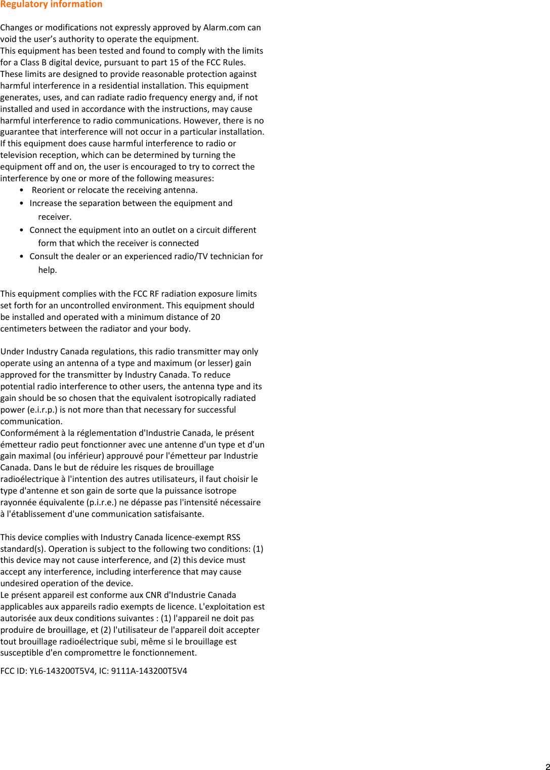
  2 Regulatory information  Changes or modifications not expressly approved by Alarm.com can void the user’s authority to operate the equipment. This equipment has been tested and found to comply with the limits for a Class B digital device, pursuant to part 15 of the FCC Rules. These limits are designed to provide reasonable protection against harmful interference in a residential installation. This equipment generates, uses, and can radiate radio frequency energy and, if not installed and used in accordance with the instructions, may cause harmful interference to radio communications. However, there is no guarantee that interference will not occur in a particular installation. If this equipment does cause harmful interference to radio or television reception, which can be determined by turning the equipment off and on, the user is encouraged to try to correct the interference by one or more of the following measures: •  Reorient or relocate the receiving antenna. • Increase the separation between the equipment and receiver. • Connect the equipment into an outlet on a circuit different form that which the receiver is connected • Consult the dealer or an experienced radio/TV technician for help. This equipment complies with the FCC RF radiation exposure limits set forth for an uncontrolled environment. This equipment should be installed and operated with a minimum distance of 20 centimeters between the radiator and your body.  Under Industry Canada regulations, this radio transmitter may only operate using an antenna of a type and maximum (or lesser) gain approved for the transmitter by Industry Canada. To reduce potential radio interference to other users, the antenna type and its gain should be so chosen that the equivalent isotropically radiated power (e.i.r.p.) is not more than that necessary for successful communication. Conformément à la réglementation d'Industrie Canada, le présent émetteur radio peut fonctionner avec une antenne d'un type et d'un gain maximal (ou inférieur) approuvé pour l'émetteur par Industrie Canada. Dans le but de réduire les risques de brouillage radioélectrique à l'intention des autres utilisateurs, il faut choisir le type d'antenne et son gain de sorte que la puissance isotrope rayonnée équivalente (p.i.r.e.) ne dépasse pas l'intensité nécessaire à l'établissement d'une communication satisfaisante.  This device complies with Industry Canada licence-exempt RSS standard(s). Operation is subject to the following two conditions: (1) this device may not cause interference, and (2) this device must accept any interference, including interference that may cause undesired operation of the device. Le présent appareil est conforme aux CNR d'Industrie Canada applicables aux appareils radio exempts de licence. L'exploitation est autorisée aux deux conditions suivantes : (1) l'appareil ne doit pas produire de brouillage, et (2) l'utilisateur de l'appareil doit accepter tout brouillage radioélectrique subi, même si le brouillage est susceptible d'en compromettre le fonctionnement. FCC ID: YL6-143200T5V4, IC: 9111A-143200T5V4

Navigation menu