Alarm com orporated 143IS15V4 Wireless transceiver that operates in the amature band 902-928 MHz User Manual UsersGuide
Alarm.com Incorporated Wireless transceiver that operates in the amature band 902-928 MHz UsersGuide
User Manual

Alarm.com © 2000 - 2011
- 1 -
Setup Instructions for GE
Simon XT with Alarm.com
Module and PIR Camera
These are the installation instructions for the
Alarm.com PIR Camera Daughterboard. This will
allow the Alarm.com GSM module report PIR
detection and image captures.
Intended Use
Use this product only for the purpose it was designed
for; refer to the data sheet and user documentation.
Compliance
Operation is subject to the following two conditions:
(1) This device may not cause interference
(2) This device must accept any interference,
including interference that may cause undesired
operation of the device
Changes or modifications not expressly approved by
Alarm.com can void the user’s authority to operate
the equipment.
This equipment has been tested and found to comply
with the limits for a Class B digital device, pursuant
to part 15 of the FCC Rules. These limits are designed
to provide reasonable protection against harmful
interference in a residential installation. This
equipment generates, uses, and can radiate radio
frequency energy and, if not installed and used in
accordance with the instructions, may cause harmful
interference to radio communications. However, there
is no guarantee that interference will not occur in a
particular installation. If this equipment does cause
harmful interference to radio or television reception,
which can be determined by turning the equipment
off and on, the user is encouraged to try to correct
the interference by one or more of the following
measures:
-Reorient or relocate the receiving antenna.
-Increase the separation between the equipment
and receiver.
-Connect the equipment into an outlet on a circuit
different form that which the receiver is connected
-Consult the dealer or an experienced radio/TV
technician for help.
Installation
Remove the backing from the tape on the backside
of the Alarm.com daughterboard. Carefully align
the connector on the daughterboard with the
connector on the Alarm.com GSM module and push
gently until snapped into place and the
daughterboard is firmly attached.
Troubleshooting: LEDs
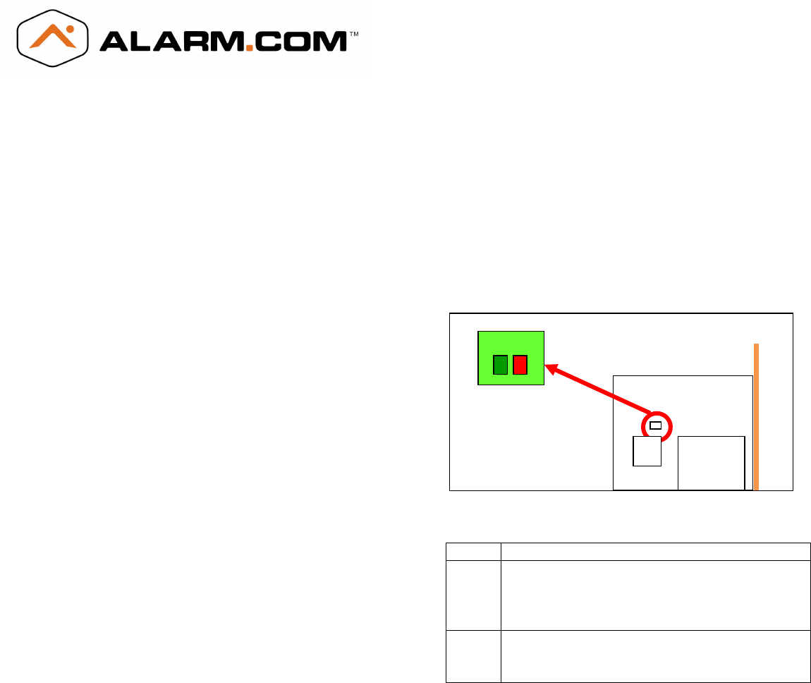
There are two status LEDs on the daughterboard
that indicate network and communication status.
Figure 1 shows the location of the LEDs on the
Alarm.com daughterboard.
Figure 1
Table 1 describes the LED functions.
LED Function
Z1 Network LED. This will be steady if the
network is active and communicating.
This LED will flash in a given interval to
indicate specific error conditions.
Z2 Node Communication. This will notify the
user of any nodes that have changed
(i.e. added, deleted, etc).
Table 1
Adding PIR Camera
Using a GE Simon XT 1.3 panel (or higher), enter
System Programming Menu and then Interactive
Services. From there, enter Image Sensor Setup
and then choose Image Sensor Learn Mode. Once
the display shows, “Plug In or Reset ISC Now,”
take the PIR Camera and plug in the batteries or
AC power. The camera will auto detect the
network and add itself to the panel. The display on
the panel will show what sensor the PIR Camera
was added as.
Z2 Z1
Alarm.com © 2000 - 2011
- 2 -
Deleting PIR Cameras
Please consult the GE Simon XT installation manual
for deleting sensors from the security panel.
Troubleshooting
• The LEDs or button are not responding. Power
down the Alarm.com GSM Module. Verify that
Alarm.com daughterboard connector is securely
connected to the Alarm.com GSM module.
• The network LED (Z1) does not turn on
immediately after initial power up. You may need
to wait a few minutes after power up
for the unit to create the network.
• PIR Cameras are not being added or deleted from
the network. The GE Simon XT panel display will
show any errors related to the PIR Cameras. Also,
check that the network LED (Z1) is solid