Alcatel Canada 31T07A01A22B Alcatel 7390 LMDS Broadband Wireless System - 31GHz User Manual 3cc12425aaaaTQbja01
Alcatel Canada Inc Alcatel 7390 LMDS Broadband Wireless System - 31GHz 3cc12425aaaaTQbja01
Terminal Station User Manaul 1 of 2

3CC12425AAAA TQ BJA Ed. 01
Alcatel 7390
Alcatel 7390Alcatel 7390
Alcatel 7390
Multiservice broadband wireless
access solution
Terminal Station - release 2.2b
(Ex 9900)
(Ex 9900)(Ex 9900)
(Ex 9900)
Cross - Polarized version
User Manual

2/70 Issue 01 - April 2001 - Draft 03 3CC12425AAAA TQ BJA 01
4
Status Draft
Change Note
Short Title A7390 Terminal Station – release 2.2b
All rights reserved. Passing on and copying of this
document, use and communication of its contents not
permitted without written authorization from Alcatel.

3CC12425AAAA TQ BJA 01 Issue 01 - April 2001 - Draft 03 3/70
4
Customer Service Support:
a Team tuned to your needs for your entire satisfaction
Congratulations on having bought your equipment from Alcatel.
We hope that it will give you full satisfaction.
For any additional information or if you have any questions concerning this equipment, please contact
the Technical Assistance Center, (TAC) dedicated to your support whose coordinates have been
given to you by the Alcatel Contract Manager or:
http://www.cid.alcatel.com/support .
You must specify the hardware and software configurations of each item concerned when getting in
touch.
This service, available on subscription, is free for the duration of the initial waranty period.

4/70 Issue 01 - April 2001 - Draft 03 3CC12425AAAA TQ BJA 01
4
PAGE INTENTIONALLY LEFT BLANK

3CC12425AAAA TQ BJA 01 Issue 01 - April 2001 - Draft 03 5/70
6
Table of contents
1 – Foreword . . . . . . . . . . . . . . . . . . . . . . . . . . . . . . . . . . . . . . . . . . . . . . . . . . . . . . . . . . . . . . . . . . 7
1.1 – Structure of the manual . . . . . . . . . . . . . . . . . . . . . . . . . . . . . . . . . . . . . . . . . . . . . . . . . . . 7
1.2 – Using the manual. . . . . . . . . . . . . . . . . . . . . . . . . . . . . . . . . . . . . . . . . . . . . . . . . . . . . . . . 7
1.3 – Safety instructions . . . . . . . . . . . . . . . . . . . . . . . . . . . . . . . . . . . . . . . . . . . . . . . . . . . . . . . 8
1.3.1 – General rules . . . . . . . . . . . . . . . . . . . . . . . . . . . . . . . . . . . . . . . . . . . . . . . . . . . . . 8
2 – Equipment overview . . . . . . . . . . . . . . . . . . . . . . . . . . . . . . . . . . . . . . . . . . . . . . . . . . . . . . . . . 15
2.1 – Overview of the A7390 system . . . . . . . . . . . . . . . . . . . . . . . . . . . . . . . . . . . . . . . . . . . . . 15
2.2 – Composition of the A7390 system . . . . . . . . . . . . . . . . . . . . . . . . . . . . . . . . . . . . . . . . . . . 16
2.3 – A7390 System specifications. . . . . . . . . . . . . . . . . . . . . . . . . . . . . . . . . . . . . . . . . . . . . . . 17
2.3.1 – Frequency bands used . . . . . . . . . . . . . . . . . . . . . . . . . . . . . . . . . . . . . . . . . . . . . 17
2.3.2 – Radio transmission specifications (typical values) . . . . . . . . . . . . . . . . . . . . . . . . 17
2.3.3 – Capacity. . . . . . . . . . . . . . . . . . . . . . . . . . . . . . . . . . . . . . . . . . . . . . . . . . . . . . . . .18
2.4 – Description of the Terminal Station (7390TS) . . . . . . . . . . . . . . . . . . . . . . . . . . . . . . . . . . 20
2.5 – Examples of configuration of the Terminal Station (7390TS) . . . . . . . . . . . . . . . . . . . . . . 21
2.5.1 – Mono "NT" . . . . . . . . . . . . . . . . . . . . . . . . . . . . . . . . . . . . . . . . . . . . . . . . . . . . . . 21
2.5.2 – Multi "NT" with passive splitter (2 NT) . . . . . . . . . . . . . . . . . . . . . . . . . . . . . . . . . . 21
2.6 – Technical specifications of the Terminal Station (7390TS) . . . . . . . . . . . . . . . . . . . . . . . . 22
2.6.1 – X-Pol RT/NT specifications . . . . . . . . . . . . . . . . . . . . . . . . . . . . . . . . . . . . . . . . . . 22
2.6.2 – NT Specifications. . . . . . . . . . . . . . . . . . . . . . . . . . . . . . . . . . . . . . . . . . . . . . . . . . 22
2.7 – Equipment power consumption . . . . . . . . . . . . . . . . . . . . . . . . . . . . . . . . . . . . . . . . . . . . . 23
3 – Installation of the X-Pol RT’s A7390 Terminal Station . . . . . . . . . . . . . . . . . . . . . . . . . . . . . 25
3.1 – Equipment delivery . . . . . . . . . . . . . . . . . . . . . . . . . . . . . . . . . . . . . . . . . . . . . . . . . . . . . . 25
3.1.1 – Unpacking . . . . . . . . . . . . . . . . . . . . . . . . . . . . . . . . . . . . . . . . . . . . . . . . . . . . . . . 25
3.2 – Installing an X-Pol RT . . . . . . . . . . . . . . . . . . . . . . . . . . . . . . . . . . . . . . . . . . . . . . . . . . . . 25
3.3 – To install the X-Pol RT on a pole . . . . . . . . . . . . . . . . . . . . . . . . . . . . . . . . . . . . . . . . . . . . 27
3.4 – To ground the X-Pol RT. . . . . . . . . . . . . . . . . . . . . . . . . . . . . . . . . . . . . . . . . . . . . . . . . . .29
3.5 – Installation of the Terminal Station X-Pol RT unit with a non integrated antenna . . . . . . . 29
3.6 – Installation of the X-Pol RT/NT link . . . . . . . . . . . . . . . . . . . . . . . . . . . . . . . . . . . . . . . . . . 29
3.7 – Installation of the Terminal Station 7390NT (Indoor Unit) . . . . . . . . . . . . . . . . . . . . . . . . . 31
3.7.1 – Installation of the 7390NT unit on a desktop . . . . . . . . . . . . . . . . . . . . . . . . . . . . . 32
3.7.2 – Installation of the NT unit on a 19" rack. . . . . . . . . . . . . . . . . . . . . . . . . . . . . . . . . 32
3.7.3 – Earthing the NT units. . . . . . . . . . . . . . . . . . . . . . . . . . . . . . . . . . . . . . . . . . . . . . . 33
4 – Commissioning the 7390 Terminal Station . . . . . . . . . . . . . . . . . . . . . . . . . . . . . . . . . . . . . . 35
4.1 – Commissioning the X-Pol RT. . . . . . . . . . . . . . . . . . . . . . . . . . . . . . . . . . . . . . . . . . . . . . . 35
4.1.1 – X-Pol RT adjustment . . . . . . . . . . . . . . . . . . . . . . . . . . . . . . . . . . . . . . . . . . . . . . . 35
4.2 – Commissioning the NT . . . . . . . . . . . . . . . . . . . . . . . . . . . . . . . . . . . . . . . . . . . . . . . . . . .39
4.3 – Client terminal connections . . . . . . . . . . . . . . . . . . . . . . . . . . . . . . . . . . . . . . . . . . . . . . . .42
4.3.1 – Ethernet connector . . . . . . . . . . . . . . . . . . . . . . . . . . . . . . . . . . . . . . . . . . . . . . . . 42
4.3.2 – G703 connector (120 ohm E1 and 100 ohm T1 standards) . . . . . . . . . . . . . . . . . 42
4.3.3 – X21 connector . . . . . . . . . . . . . . . . . . . . . . . . . . . . . . . . . . . . . . . . . . . . . . . . . . . . 43
4.3.4 – 48V connector (HE 15) . . . . . . . . . . . . . . . . . . . . . . . . . . . . . . . . . . . . . . . . . . . . . 43
4.3.5 – Client terminal connections . . . . . . . . . . . . . . . . . . . . . . . . . . . . . . . . . . . . . . . . . . 43
4.3.6 – Ethernet connector . . . . . . . . . . . . . . . . . . . . . . . . . . . . . . . . . . . . . . . . . . . . . . . . 44
4.3.7 – G703 connector (120 ohm E1 and 100 ohm T1 standards) . . . . . . . . . . . . . . . . . 44
4.4 – Initiating services . . . . . . . . . . . . . . . . . . . . . . . . . . . . . . . . . . . . . . . . . . . . . . . . . . . . . . . . 44
4.5 – Filling in the installation sheet . . . . . . . . . . . . . . . . . . . . . . . . . . . . . . . . . . . . . . . . . . . . . . 44
4.5.1 – 7390 X-Pol RT installation sheet . . . . . . . . . . . . . . . . . . . . . . . . . . . . . . . . . . . . . . 45

6/70 Issue 01 - April 2001 - Draft 03 3CC12425AAAA TQ BJA 01
6
4.5.2 – NT installation sheet . . . . . . . . . . . . . . . . . . . . . . . . . . . . . . . . . . . . . . . . . . . . . . . 45
4.5.3 – X-Pol RT/NT wiring sheet . . . . . . . . . . . . . . . . . . . . . . . . . . . . . . . . . . . . . . . . . . . 45
5 – Operation and maintenance. . . . . . . . . . . . . . . . . . . . . . . . . . . . . . . . . . . . . . . . . . . . . . . . . . . 47
5.1 – 7390 system supervision . . . . . . . . . . . . . . . . . . . . . . . . . . . . . . . . . . . . . . . . . . . . . . . . . .47
5.2 – Preventive maintenance . . . . . . . . . . . . . . . . . . . . . . . . . . . . . . . . . . . . . . . . . . . . . . . . . .47
5.3 – Corrective maintenance. . . . . . . . . . . . . . . . . . . . . . . . . . . . . . . . . . . . . . . . . . . . . . . . . . .47
5.4 – Changing a faulty NT unit . . . . . . . . . . . . . . . . . . . . . . . . . . . . . . . . . . . . . . . . . . . . . . . . .47
5.5 – Changing a faulty X-Pol RT unit . . . . . . . . . . . . . . . . . . . . . . . . . . . . . . . . . . . . . . . . . . . . 48
6 – Changes of configuration . . . . . . . . . . . . . . . . . . . . . . . . . . . . . . . . . . . . . . . . . . . . . . . . . . . . 49
6.1 – Declaration, deletion, reset of an NT . . . . . . . . . . . . . . . . . . . . . . . . . . . . . . . . . . . . . . . . . 49
6.2 – Implementation of client services. . . . . . . . . . . . . . . . . . . . . . . . . . . . . . . . . . . . . . . . . . . . 50
6.3 – Changing an X-Pol RT. . . . . . . . . . . . . . . . . . . . . . . . . . . . . . . . . . . . . . . . . . . . . . . . . . . .50
6.4 – Adding an additional NT to a TS site . . . . . . . . . . . . . . . . . . . . . . . . . . . . . . . . . . . . . . . . . 51
6.4.1 – Case of a pre-wired installation . . . . . . . . . . . . . . . . . . . . . . . . . . . . . . . . . . . . . . . 51
6.4.2 – Case of a non-pre-wired installation . . . . . . . . . . . . . . . . . . . . . . . . . . . . . . . . . . . 51
6.5 – To asign an NT to an alternate BS . . . . . . . . . . . . . . . . . . . . . . . . . . . . . . . . . . . . . . . . . . 51
Appendix 1 – 7390 TS installation sheet. . . . . . . . . . . . . . . . . . . . . . . . . . . . . . . . . . . . . . . . . . . . 53
A.1.1 – 7390 X-Pol RT INSTALLATION SHEET . . . . . . . . . . . . . . . . . . . . . . . . . . . . . . . . . . . . 53
A.1.2 – 7390 NT INSTALLATION SHEET . . . . . . . . . . . . . . . . . . . . . . . . . . . . . . . . . . . . . . . . . 55
A.1.3 – 7390 X-Pol RT / NT CABLING SHEET . . . . . . . . . . . . . . . . . . . . . . . . . . . . . . . . . . . . . 56
A.1.4 – LIST OF CHECKPOINTS FOR TS COMMISSIONING . . . . . . . . . . . . . . . . . . . . . . . . . 57
Appendix 2 – Climatic areas world map . . . . . . . . . . . . . . . . . . . . . . . . . . . . . . . . . . . . . . . . . . . . 59
Appendix 3 – Mounting coaxial connectors. . . . . . . . . . . . . . . . . . . . . . . . . . . . . . . . . . . . . . . . . 61
A.3.1 – Installing Stirling connectors. . . . . . . . . . . . . . . . . . . . . . . . . . . . . . . . . . . . . . . . . . . . . . 63
A.3.1.1 – To install a Stirling connector . . . . . . . . . . . . . . . . . . . . . . . . . . . . . . . . . . . . . . 63
Appendix 4 – Correspondence between commercial codes and industrial
codes relating to the TS . . . . . . . . . . . . . . . . . . . . . . . . . . . . . . . . . . . . . . . . . . . . . 67
Appendix 5 – List of abbreviations . . . . . . . . . . . . . . . . . . . . . . . . . . . . . . . . . . . . . . . . . . . . . . . . 69

3CC12425AAAA TQ BJA 01 Issue 01 - April 2001 - Draft 03 7/70
14
1 – Foreword
1.1 – Structure of the manual
This manual is for users with a sound knowledge of how to operate and install point-multipoint
microwave systems and how to use a PC-based craft terminal running the WindowsTM operating
system. With it, you should quickly be able to operate the equipment. It is not intended to replace the
training services that we can provide for your particular needs.
The manual is divided into six sections followed by appendixes:
– Foreword
– Equipment overview
– Installation of the X-Pol RT’s 7390 Terminal Station
– Commissioning the 7390 Terminal Station
– Operation and maintenance
– Changes of configuration
– Appendixes
1.2 – Using the manual
With this manual, you should be able to commission and operate the described equipment to a basic
level.
You should always read this manual in conjunction with the attached "Update" document (if provided) so
that you are aware of the latest equipment upgrades.
Manual updates
This edition of the manual describes hardware and software releases of the following revision indexes
and above:
Hardware revision: 01
In cases where an equipment upgrade affects the content of the manual, the relevant modification should
be inserted in the "Update" document, with the same reference number, but with code type VE (instead
of TQ).
When the number or extent of the changes justifies it, they should be incorporated in the body of the
manual and the manual's revision index should be incremented. Revision bars will show the differences
from the previous version.
Note: MS-DOS, MICROSOFT and WINDOWS are registered trademarks of Microsoft Corporation.

8/70 Issue 01 - April 2001 - Draft 03 3CC12425AAAA TQ BJA 01
14
1.3 – Safety instructions
1.3.1 – General rules
The following general safety precautions must be observed by the installer and the operator.
ALCATEL assumes no liability for the customer's failure to comply with these requirements.
•Ground the equipment: for Safety Class 1 equipment, always connect the earth conductor of
the power cable to an appropriate earthing device.
• DO NOT operate the product in an explosive atmosphere or in presence of flammable
gases or fumes.
•For protection against fire: replace the line fuse(s) only with fuse(s) of the same voltage and
current rating and type.
•Dangerous voltages: users must not remove equipment covers or shields. The installation
and maintenance procedures described in this manual are for use by service-trained personnel
only.
•Protection against short circuits: the mains equipment should ensure protection against
short circuits according to the current domestic standards (residual current differential protec-
tion recommended).
• Observe the standards in force for all activities carried out on the roofs.
• For any on-site intervention, observe the precautions against lightning.
• DO NOT operate equipment which may be damaged: its protection level could be affec-
ted.
• Whenever it is possible that the safety protection features built into this equipment have been
impaired, ISOLATE FROM THE POWER SUPPLY and do not use the equipment until safe
operation can be verified by service-trained personnel. If necessary, return the equipment to
Alcatel After Sales for service and repair.
• DO NOT OPEN THE EQUIPMENT.
• Return the product to Alcatel Customer Service for servicing and repair.
•Recommendation to installers and maintenance operators: before carrying out any ope-
rations, check the equipotential bonding of the earthing devices to which our measurement
equipment and instruments are connected. If necessary, during installation, ensure the equi-
potential bonding by electrical connection of these devices.
Local regulations
All BS and CPE installations must adhere to all local, national and civil electrical/safety regulations of the
area where they are installed.
Wireless safety compliance in the United States of America
It is the responsibility of the wireless licence holder to ensure that the requirements of OET Bulletin 65
are met in the USA.
Wireless safety compliance in Canada
It is the responsibility of the wireless licence holder to ensure that the requirements of Safety Code 6 are
met in Canada.

3CC12425AAAA TQ BJA 01 Issue 01 - April 2001 - Draft 03 9/70
14
Placement of transmitting equipment
To prevent exposure to non-ionizing radiation, the X-Pol RT should always be mounted at a minimum of
3 m (10 ft) above ground level or roof-top level. An X-Pol RT that is mounted on a wall should be mounted
at least 3 m (10 ft) away from any point of exposure such as windows, balconies or doors.
X-Pol RT service and repair safety precautions
Only authorized personnel should service X-Pol RT units.
Equipment interconnection points
All card faceplate connectors are SELV.
Connect SELV circuits on this equipment only to other circuits that comply with the requirements of SELV
circuits as defined in EN60950.
Restriction of unauthorized access
Only authorized personnel should have access to the equipment. Install the equipment in a restricted-
access location or similar environment, and post appropriate warning signs to indicate safety concerns.
Failure to prevent unauthorized user access will invalidate any approvals given to this equipment.
Regulatory symbols
The following sections show examples of regulatory approval symbols generally used. They may be
used on product markings such as approval labels. These symbols are described in IEC417.
Power on
Power off
Danger - Never touch the X-Pol RT antennas while they are in operation. Do not stand in
front of X-Pol RT antennas, and never pass closer than 1 m (3 ft) in front of an operating or
X-Pol RT.
Power to X-Pol RTs must be disconnected prior to installation or servicing.
Service and repair preparation activities should be made as close as possible to the base of
an elevated X-Pol RT, as the risk of exposure to non-ionizing radiation increases as you
move further from the base toward the area that is serviced by the transmitter.
This symbol indicates the on position of the main on/off switch.
This symbol indicates the off (O) position of the main on/off switch.

10/70 Issue 01 - April 2001 - Draft 03 3CC12425AAAA TQ BJA 01
14
Protective grounding terminal
These symbols indicate a terminal that must be connected to earth ground prior to making any
other connections to the equipment.
Dangerous voltage
This symbol indicates the presence of uninsulated “dangerous voltage” within the product's enclo-
sure that could cause electric shock. Labels bearing this symbol are installed on the outside of the
product enclosure.
Instructions
This symbol indicates the existence of important operating and maintenance (servicing) instruc-
tions in the product documentation.
Elevated non-ionizing radiation levels
This symbol identifies equipment that emits elevated levels of non-ionizing radiation. Do not ap-
proach equipment that is marked with this symbol unless power to the device is disconnected.
Labels bearing this symbol are installed on the outside casing of transmitter devices.
Supply wire protective earth
Protective earth
Dangerous voltage symbol
Important instructions symbol
Elevated non-ionizing radiation levels symbol

3CC12425AAAA TQ BJA 01 Issue 01 - April 2001 - Draft 03 11/70
14
International EMC compliance
The EMC compliance of these products relies on the user following the installation processes correctly.
Failure to follow the correct installation processes may result in non-compliance to the EMC standards
against which these products have been assessed.
Appropriate shielded cables must be used to connect NT to telecommunications equipment.
NT EMC compliance
This Class B digital apparatus complies with Canadian ICES-003.
Cet appareil numérique de la classe B est conforme à la norme NMB-003 du Canada.
DBS card EMC compliance
This Class A digital apparatus complies with Canadian ICES-003.
Cet appareil numérique de la classe A est conforme à la norme NMB-003 du Canada.
Industry Canada regulations
The Industry Canada (formerly known as the Department of Communications) label identifies certified
equipment. This certification means that the equipment meets certain telecommunications network
protective, operational and safety requirements as prescribed in the Terminal Equipment Technical
Requirements document(s). Industry Canada does not guarantee that the equipment will operate to the
user's satisfaction.
Before installing this equipment, users should ensure that it is permissible to be connected to the
facilities of the local telecommunications company. The equipment must also be installed using an
acceptable method of connection. The customer should be aware that compliance with the above
conditions may not prevent degradation of service in some situations.
Repairs to certified equipment should be coordinated by a representative designated by the supplier.
Any repairs or alterations made by the user to this equipment, or any equipment malfunctions, may give
the telecommunications company cause to request the user to disconnect the equipment.
For their own protection, users should ensure that the electrical ground connections of the power utility,
telephone lines and internal metallic water pipe system, if present, are connected together. This
precaution may be particularly important in rural areas.
The Ringer Equivalence Number (formerly known as Load Number) assigned to each terminal device
provides an indication of the maximum number of terminals allowed to be connected to a telephone
interface. The termination on an interface may consist of any combination of devices subject only to the
requirement that the sum of the Ringer Equivalence Numbers of all the devices does not exceed five (5).
The Ringer Equivalence Number regulations do not apply to the NT.
Safety approval for dc systems
The dc source for the Alcatel Broadband Wireless system must meet the requirements of a SELV source
in accordance with CSA C22.2 No. 950. These systems are intended for use with a SELV secondary
source that is electrically isolated from the ac source, and that is reliably connected to ground.
Caution - Users should not attempt to make electrical ground connections, but should
contact the appropriate electrical inspection authority or electrician.

12/70 Issue 01 - April 2001 - Draft 03 3CC12425AAAA TQ BJA 01
14
United States Federal Communications Commission regulations
This equipment has been approved to the Federal Communications Commission Part 68 Rules as not
being harmful to the telephone network when connected directly to telephone lines. Customers must,
upon request from the telephone company, provide the following information:
– FCC Registration Numbers
– USOC: RJ48C
– FIC: 04DU9-BN/DN/1KN/1SN
– SOC: 6.0Y
The FCC identification number can be found on the product label located on the product chassis.
The REN determines the number of devices that users can connect to their telephone line and still have
the assurance that these devices will ring properly when their number is called. In most, but not all areas,
the sum of the RENs for all devices should not exceed five (5.0). To determine the maximum number of
devices users can connect to their line, as specified by the REN, users must contact the local telephone
company and request the information on the maximum REN for their calling area.
If the user equipment causes harm to the telephone network, the telephone company may temporarily
discontinue service to the line. If possible and practical, the company will notify the user in advance. If
not, the company will notify the user as soon as possible. Included in the notification, the users will be
advised of their right to file a complaint with the FCC.
The telephone company may make changes to its facilities, equipment, operations and procedures that
could affect the operation of user’s equipment. Before these changes are made, the telephone company
will provide advance notice that service will be interrupted.
FCC regulations prohibit the connection of customer-provided equipment to coin service (central office
implemented systems). Connection to party lines is subject to tariffs; contact the state public utility
commission, public service commission or corporation commission for information. In the event that
repairs are needed to this equipment, contact:
Alcatel Inc.
810 Commerce Park Drive,
Ogdensburg, NY 13669
1-315-393-9981
This equipment has been tested and found to comply with the limits for a Class A digital device, pursuant
to Part 15 of the FCC Rules. These limits are designed to provide reasonable protection against harmful
interference in a commercial environment. This equipment generates, uses and can radiate radio
frequency energy and if not installed and used in accordance with the instruction manual, may cause
harmful interference to radio communications. Operation of this equipment in a residential area is likely
to cause harmful interference, in which case, the user will be required to correct the interference at their
own expense.

3CC12425AAAA TQ BJA 01 Issue 01 - April 2001 - Draft 03 13/70
14
Food and Drug Administration
This product complies with 21 CFR 1040.10 and 1040.11 regulations, which govern the safe use of
lasers. Only qualified service personnel, thoroughly familiar with laser radiation hazards, should install
or remove the fiber optic cables used in this system. Information regarding the safe use of lasers can be
found in ANSI Z 136.1: Safe Use of Lasers and ANSI Z 136.2: Safe Use of Lasers in Optical Fiber
Communications Systems. These documents and other instructional material can be obtained from:
Laser Institute of America
12424 Research Parkway, Suite 125
Orlando, FL 32826-3274
CSA NRTL
This equipment is certified by the Canadian Standards Association as meeting the requirements of
UL1950, Safety of Information Technology Equipment (or UL1459, Safety of Telephone Equipment).
CSA is listed by the American Federal Occupational Safety and Health Administration as equivalent to
Underwriters Laboratories and other American safety testing laboratories under the Nationally
Recognized Testing Laboratories program.
Safety precautions for installing TNV devices
Danger 1 - Never install telephone wiring during a lightning storm. Use caution when
installing or modifying telephone lines.
Danger 2 - Never touch uninsulated telephone wires or terminals unless the telephone line
has been disconnected at the telephone network interface. Never install telephone jacks in
wet locations, unless the jack is specifically designed for wet locations.
Caution - Always disconnect the NT from the telephone system when installing or removing
covers from connected equipment.

14/70 Issue 01 - April 2001 - Draft 03 3CC12425AAAA TQ BJA 01
14
PAGE INTENTIONALLY LEFT BLANK
3CC12425AAAA TQ BJA 01 Issue 01 - April 2001 - Draft 03 15/70
24
2 – Equipment overview
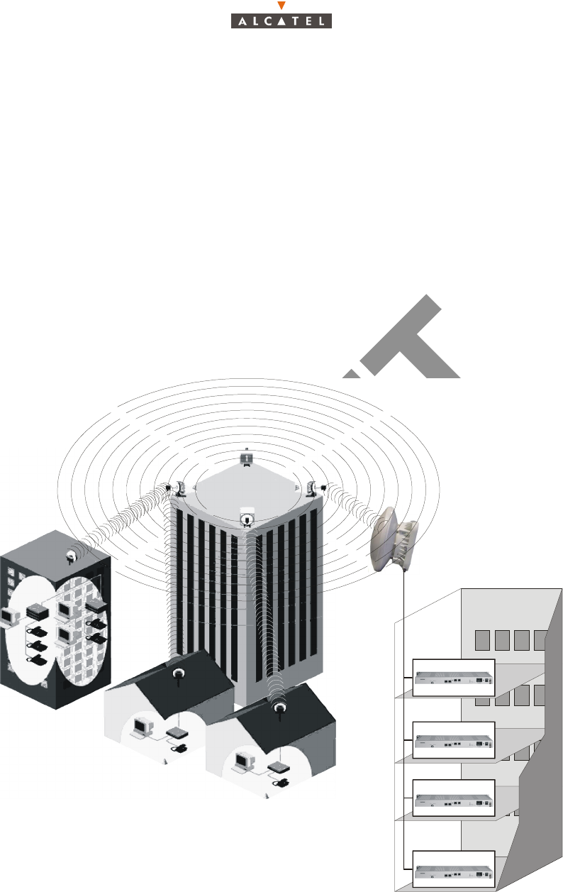
2.1 – Overview of the A7390 system
The Alcatel 7390 is a multi-service broadband wireless local loop system designed to provide telecom
services to small and medium-sized enterprises.
Broad band WLL (Wireless Local Loop) system, Alcatel 7390 allows operators to offer rapid provision -
to a large number of client sites - of a comprehensive range of telephone and data transmission
services.
For cellular phone network operators, Alcatel 7390 offers the possibility of linking base stations to
base station controllers. This makes Alcatel 7390 an economical transmission solution, for the
implementation or extension of high traffic density areas coverage.
For mixed network operators (fixed and mobile), Alcatel 7390 enables to connect, with the same
system, fixed professional end user as well as base stations of cellular telephony.
Figure 1 – 7390 System - Local point - multipoint service distribution -
SME
Independant profession
Independant profession
Compagny D
Compagny A
Compagny B
Compagny C
16/70 Issue 01 - April 2001 - Draft 03 3CC12425AAAA TQ BJA 01
24
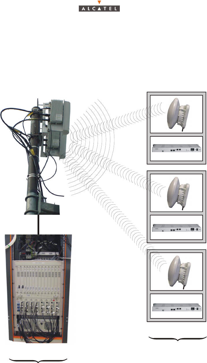
2.2 – Composition of the A7390 system
An A7390 network cell consists of the following:
–a common base station designated 7390BS;
and several terminal stations distributed across the user sites, and designated 7390TS.
Figure 2 – Base Station and Terminal Stations
"Digital Base Station" DBS
"Terminal Stations"
Cross-polarized Radio Base Station
7390BS
nx7390TS
"X-Pol RBS"

3CC12425AAAA TQ BJA 01 Issue 01 - April 2001 - Draft 03 17/70
24
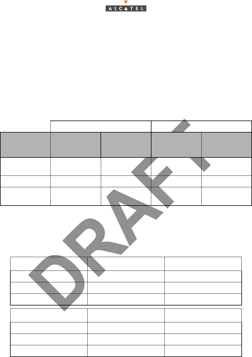
2.3 – A7390 System specifications
2.3.1 – Frequency bands used
2.3.2 – Radio transmission specifications (typical values)
The following table gives the main characteristics of the A7390 wireless system.
A downstream (BS to TS) carrier is combined with up four upstream (TS to BS) carriers.
Cross-polarized radio Down-link Up-link
LMCS/AB 27 850 28 350 27 350 27 650
LMCS/F 25 600 25 850 25 350 25 600
LMCS/C 27 100 27 350 26 850 27 100
LMDS/A 27 500 28 350 31.075 31 225
LMDS/B 31 225 31 300 31 000 31 075
38/700/1 39 700 40 000 39 000 39 300
Downstream
Channel bandwidth 14 MHz 28 MHz
Occupied bandwidth 13.63 MHz 27.25 MHz
Roll-off factor 35% 35%
Modulation QPSK QPSK
Gross bit rate 20.19 Mbit/s 40.37 Mbit/s
Inner Code Convol. 7/8 (k=7) Convol.7/8 (k=7)
Interleaving depth 12 depth 12
Outer Code Reed-Solomon (204,188,8) Reed-Solomon (204,188,8)
Bit rate before coding 16.19 Mbit/s 32.38 Mbit/s
Radio 25 GHz 28 GHz 31 GHz 39 GHz 25 GHz 28 GHz 31 GHz 39 GHz
X-Pol RBS output power
(antenna port) 17 dBm 17 dBm 17 dBm 17 dBm 17 dBm 17 dBm 17 dBm 17 dBm
Transmit antenna gain 21 dB 21 dB 21 dB 21 dB 21 dB 21 dB 21 dB 21 dB
Receive antenna gain
(with radome) 36 dB 34.5 dB 35 dB 34.5 dB 36 dB 34.5 dB 35 dB 34.5 dB
18/70 Issue 01 - April 2001 - Draft 03 3CC12425AAAA TQ BJA 01
24
2.3.3 – Capacity
The system capacity depends on the traffic mix between data services (transported on ATM cells) and
leased lines or telephony services (transported on TDM circuits)
It also depends on the channeling and the number of upstream channels.
Figures are given in the following tables for three mix examples : minimum, medium and maximum
circuit capacity but any intermediate mix is possible.
28 / 7 MHz channeling:
Upstream
Channel bandwidth 3.5 MHz 7 MHz
Occupied bandwidth 3.36 MHz 6.72 MHz
Roll-off factor 25% 25%
Modulation D-QPSK D-QPSK
Gross bit rate 5.38 Mbit/s 10.75 Mbit/s
Outer Code Reed-Solomon (63,53,5) Reed-Solomon (63,53,5)
Bit rate before coding 4.19 Mbit/s 8.38 Mbit/s
Radio 25 GHz 28 GHz 25 GHz 28 GHz
TS output power (antenna port) 14 dBm 14 dBm 14 dBm 14 dBm
Transmit antenna gain 35 dB 34.5 dB 35 dB 34.5 dB
Receive antenna gain (with radome) 15 dB 15 dB 15 dB 15 dB
Downlink: 28 MHz Trafic MIX: circuit capacity
Uplink: 1 x 7 MHz Minimum Medium Maximum
Nb of circuits: 64 kbit/s 0 60 120
ATM uplink capacity (cells/s) 18.823 9.412 0
ATM downlink capacity
(cells/s) 75.512 66.530 57.399
Downlink : 28 MHz Trafic MIX: circuit capacity
Uplink : 2 x 7 MHz Minimum Medium Maximum
Nb of circuits: 64 kbit/s 0 120 240
ATM uplink capacity (cells/s) 37.647 18.823 0
ATM downlink capacity
(cells/s) 75.512 57.548 39.286

3CC12425AAAA TQ BJA 01 Issue 01 - April 2001 - Draft 03 19/70
24
14/3.5 MHz channeling:
Downlink : 28 MHz Trafic MIX: circuit capacity
Uplink : 3 x 7 MHz Minimum Medium Maximum
Nb of circuits: 64 kbit/s 0 180 360
ATM uplink capacity (cells/s) 56.471 28.235 0
ATM downlink capacity
(cells/s) 75.512 48.566 21.173
Downlink : 28 MHz Trafic MIX: circuit capacity
Uplink : 4 x 7 MHz Minimum Medium Maximum
Nb of circuits: 64 kbit/s 0 240 480
ATM uplink capacity (cells/s) 75.294 37.647 0
ATM downlink capacity
(cells/s) 75.512 39.585 3.084
Downlink: 14 MHz Trafic MIX: circuit capacity
Uplink: 1 x 3.5 MHz Minimum Medium Maximum
Nb of circuits: 64 kbit/s 0 30 60
ATM uplink capacity (cells/s) 9.412 4.706 0
ATM downlink capacity
(cells/s) 38.047 33.519 28.990
Downlink : 14 MHz Trafic MIX: circuit capacity
Uplink : 2 x 3.5 MHz Minimum Medium Maximum
Nb of circuits: 64 kbit/s 0 60 120
ATM uplink capacity (cells/s) 18.824 9.412 0
ATM downlink capacity
(cells/s) 38.047 28.990 19.934
Downlink : 14 MHz Trafic MIX: circuit capacity
Uplink : 3 x 3.5 MHz Minimum Medium Maximum
Nb of circuits: 64 kbit/s 0 90 180
ATM uplink capacity (cells/s) 28.235 14.118 0
ATM downlink capacity
(cells/s)
38.047 24.462 10.877
20/70 Issue 01 - April 2001 - Draft 03 3CC12425AAAA TQ BJA 01
24
2.4 – Description of the Terminal Station (7390TS)
The A7390 system Terminal Station (7390TS) consists of the following main elements:
– an external transceiver "X-Pol RT";
– one or two indoor units for user connection (NT);
– IF coaxial cable linking the X-Pol RT and NT (NT/X-Pol RT link);
– one lightning arrester installed on the NT/X-Pol RT link cable;
– one IGAU installed on the NT/X-Pol RT link cable before the splitter module;
– depending on the configurations, on splitter module.
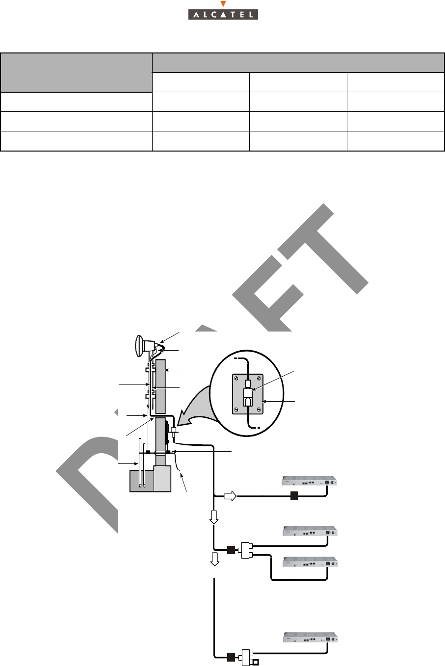
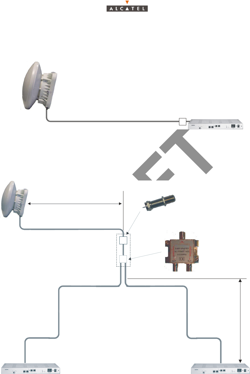
The figure below shows the three typical Terminal Station Installation types: Single NT, Dual NT, and
Single NT pre-wired for an additional NT.
Figure 3 – Terminal Station Installation example
Downlink : 14 MHz Trafic MIX: circuit capacity
Uplink : 4 x 3.5 MHz Minimum Medium Maximum
Nb of circuits: 64 kbit/s 0 120 240
ATM uplink capacity (cells/s) 37.647 18.824 0
ATM downlink capacity (cells/s) 38.047 19.934 1.821
OR
OR
X-Pol RT
X-Pol RT ground wire
«F» connector
Exterior
wall
IF cable Mounting
pole
Mounting pole
ground wire
Weatherproof
caulk
Ground
rod(s)
IGAU
Power utility
entrance
ground
wire
Lightning arrester
with mounting bracket
Copper plate
connected to
the power
utility ground
Mechanically bonded
ground connection
Single NT configuration
Dual NT configuration
NT 1
NT 2
2:1
Combiner/
Splitter
Single NT configuration Pre-wired
for the addition of a seconde NT
NT 1
75 Ohm Termination Load
IGAU
IGAU
3CC12425AAAA TQ BJA 01 Issue 01 - April 2001 - Draft 03 21/70
24
2.5 – Examples of configuration of the Terminal Station (7390TS)
2.5.1 – Mono "NT"
2.5.2 – Multi "NT" with passive splitter (2 NT)
Figure 4 – Example of assembly with passive splitters
65 meters 5916
X-Pol RT NT
IGAU
45 meters Filotex
or
FILOTEX or 5916
(See Appendix 3)
X-Pol RT
splitter
NT1 NT2
IGAU
35 meters 5916
22 meters Filotex
or
2 meters
A
B
A + B = 24 m or 37 m max.
22/70 Issue 01 - April 2001 - Draft 03 3CC12425AAAA TQ BJA 01
24
The single NT configuration is composed of a single X-Pol RT and a single NT. The dual NT configuration
is composed of a single X-Pol RT and two NTs linked to the X-Pol RT via a splitter module. The single
NT configuration pre-wired for and additional NT is identical to the Dual NT configuration, except that the
second NT and associated cable is replaced by a 75 ohm termination load. This configuration is
recommended wherever a second NT may be required in the future, as it allows the installation of the
additional NT without removing the first NT from service.
2.6 – Technical specifications of the Terminal Station (7390TS)
2.6.1 – X-Pol RT/NT specifications
2.6.2 – NT Specifications
There are six types of NT units:
–NT unit:
X-Pol RT NT
Designation
Description
with antenna
30 cm
Observations Description Observations
Dimensions
HxLxP
230 x 230 (mm)
x 80 (mm) —1U x 19"
x 240 (mm)
cf. diagram
in § 3 Installation
Weight 3 kg — 3 kg —
Operating air
temperature – 40°C to + 46°C — – 5°C to + 55°C —
9900 NCA 001 9900 NCD 001 9900 NCE 001
2 x E1 (2 x G703) — 2 x T1 ANSI
2 x Eth 10bT 2 x Eth 10bT 2 x Eth 10bT
85 — 264V a (47 - 63 Hz) 85 — 264V a (47 - 63 Hz) 85 — 264V a (47 - 63 Hz)
9900 NCA 002 9900 NGA 001 9900 NGA 004
1 x E1 2 x E1 (G703) 2 x E1 (2 x G703) LEMO
2 x Eth 10bT 2 x Eth 10bT 2 x Eth 10bT
85 — 264V a (47 - 63 Hz) 85 — 264V a (47 - 63 Hz) 85 — 264V a (47 - 63 Hz)

3CC12425AAAA TQ BJA 01 Issue 01 - April 2001 - Draft 03 23/70
24
– NT Lite unit:
2.7 – Equipment power consumption
The typical power consumption of the X-Pol RT is 22.5 W.
The maximal power consumption of an NT is 71 VA.
9900 NCF 001 9900 NCG 001
1 x E1 1 x T1
1 x Eth 10bT 1 x Eth 10bT
85 — 264V a (47 - 63 Hz) 85 — 264V a (47 - 63 Hz)

24/70 Issue 01 - April 2001 - Draft 03 3CC12425AAAA TQ BJA 01
24
PAGE INTENTIONALLY LEFT BLANK
3CC12425AAAA TQ BJA 01 Issue 01 - April 2001 - Draft 03 25/70
34
3 – Installation of the X-Pol RT’s A7390 Terminal Sta-
tion
3.1 – Equipment delivery
When you receive the equipment in its packaging:
– Check the condition of the packaging.
– If damaged, notify ALCATEL without delay.
3.1.1 – Unpacking
Considerations
You are recommended to:
– unpack the equipment according to the instructions on the packaging, and to the instructions given
below.
– take an inventory and identify any missing items. If the delivery does not match the delivery advice
note, notify ALCATEL within 48 hours of receipt of the equipment.
3.2 – Installing an X-Pol RT
There are two types of X-Pol RTs: side-mount and rear-mount. Both X-Pol RTs have the same part
number, and are shipped according to availability.
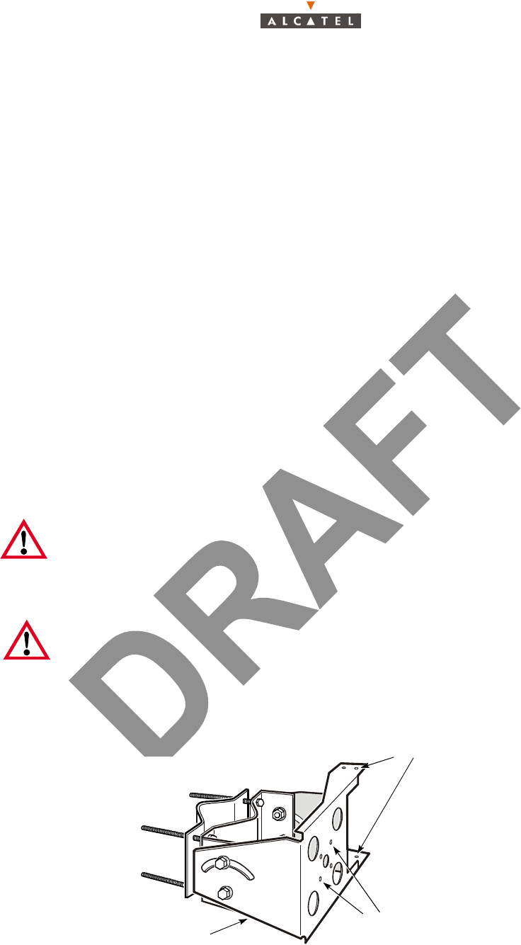
Side-mount and rear-mount X-Pol RTs use the same X-Pol RT mounting bracket, shown in Figure 5 –
X-Pol RT mounting bracket. As indicated in the figure, the rear-mount and side-mount X-Pol RTs mount
to the bracket in two separate locations.
Figure 5 – X-Pol RT mounting bracket
Note 1: X-Pol RTs must be installed and serviced by trained personnel who are experienced
in the local, national, international civil electrical and safety regulations of the area where
the equipment is being installed.
Some areas require that only licensed individuals may install and service equipment.
Consult appropriate local authorities prior to installation.
Note 2: If more than one X-Pol RT is installed at the same customer site, the X-Pol RTs
must be installed at least 1 m (3.28 ft) apart (horizontal or vertical), to avoid blocking line-of-
sight access to the BS.
Mounting holes for
Mounting holes for
rear-mount antenna
Mounting bracket
side-mount antenna
26/70 Issue 01 - April 2001 - Draft 03 3CC12425AAAA TQ BJA 01
34
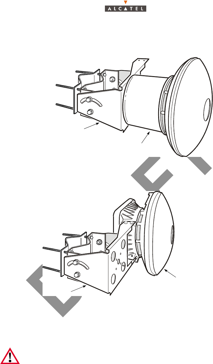
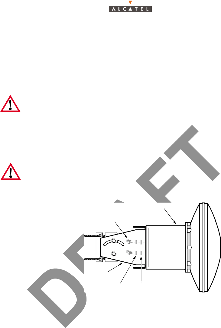
Figure 6 – Front-mount X-Pol RT (attached) and Figure 7 – Side-mount X-Pol RT (attached) show the
appearance of both X-Pol RTs when attached to a mounting bracket.
Figure 6 – Front-mount X-Pol RT (attached)
Figure 7 – Side-mount X-Pol RT (attached)
The X-Pol RT mounting bracket connects to standard steel mounting pipe with an outer diameter in the
range of 11.5 cm to 7.3 cm (4 1/2 in. to 2 1/2 in.).
Warning: The required inner diameter of a mounting pole must be determined by
professional engineering staff, taking into consideration the torsional and vibrational
forces caused by the wind loading on the pole and on the equipment mounted on the pole,
as well as the distribution of these forces on the supported and unsupported parts of the
pole.
Rear-mount X-Pol RT
Mounting bracket
Side-mount X-Pol RT
Mounting bracket
3CC12425AAAA TQ BJA 01 Issue 01 - April 2001 - Draft 03 27/70
34
3.3 – To install the X-Pol RT on a pole
For each X-Pol RT:
1. Rotate the X-Pol RT until the polarization arrow on the back of the X-Pol RT radome indicates the
correct polarization, and position the X-Pol RT against the appropriate bracket mounting holes.
The polarization arrow must point sideways for horizontal Tx polarization, and up or down for vertical
Tx polarization.
2. Attach the X-Pol RT to the mounting bracket using the four supplied bolts, lock washers and flat
washers. Tighten each bolt to 8.8 Nm (6 ft-lb) torque.
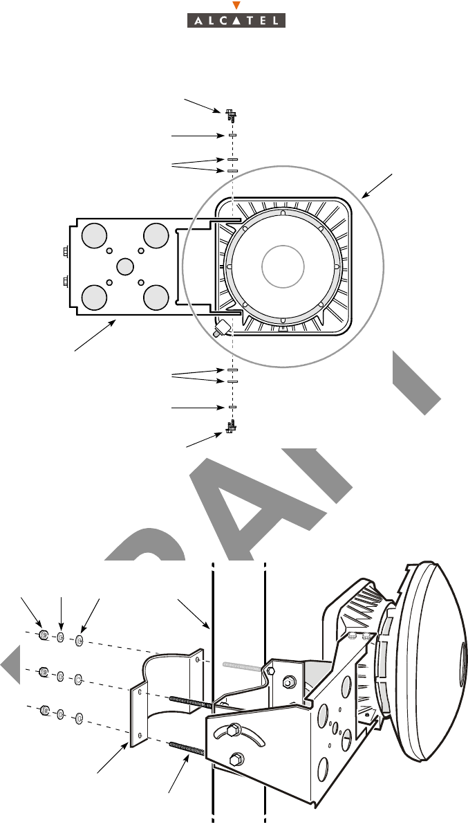
Figure 8 – Rear-mount X-Pol RT bolts shows the bolt locations for the rear-mount X-Pol RT, and
Figure 9 – Side-mount X-Pol RT bolts shows the bolt locations for the side-mount X-Pol RT.
Figure 8 – Rear-mount X-Pol RT bolts
Always align the X-Pol RT such that a drain hole is at the bottom of the antenna.
Note: The side-mount X-Pol RT requires two flat washers on each bolt that attaches it to
the mounting bracket, in addition to the lock washer. The back-mount X-Pol RT requires
only a single lock washer and a single flat washer on each bolt.
Rear-mount X-Pol RT
Mounting bolts (4)
Side of mounting bracket
Lock washer Flat washer
28/70 Issue 01 - April 2001 - Draft 03 3CC12425AAAA TQ BJA 01
34
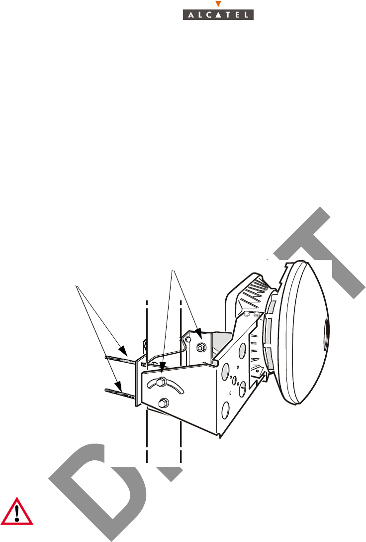
Figure 9 – Side-mount X-Pol RT bolts
3. Position the mounting bracket against the pole, and fasten the backing plate using the backing plate
nuts and bolts shown in Figure 10 – Securing the backing plate. Tighten the four backing plate nuts
to 4.1 Nm (36 in.-lb).
Figure 10 – Securing the backing plate
4. Install the provided plugs in the drain holes on the side and top of the X-Pol RT antenna housing.
Ensure that the drain hole located at the bottom of the X-Pol RT antenna housing is clear of
obstructions.
Side-mount X-Pol RT
Mounting bolts
Lock washer
Flat washers
Front of mounting
bracket
Mounting bolts
Lock washer
Flat washers
Nut
Lock
washer Flat
washers
Pole
Backing plate
Bolts
(two per side)

3CC12425AAAA TQ BJA 01 Issue 01 - April 2001 - Draft 03 29/70
34
3.4 – To ground the X-Pol RT
The following parts and supplies are required:
– an adequate length of ground conductor
– an M6 ring lug
– a 1.0 thread pitch, 10 mm M6 bolt
– dielectric paste
1. Measure a length of ground conductor sufficient to run from the X-Pol RBS Tx or X-Pol RBS Rx to
the nearest suitable ground point. The required diameter, metal type and physical type of the ground
conductor may vary according to local regulations. Consult local electrical authorities for information.
2. Connect an uninsulated M6 ring lug connector securely to one end of the ground conductor using a
suitable mechanical connection method.
3. Apply an appropriately rated dielectric paste liberally to both sides of the ring lug.
4. Connect the ring lug to the X-Pol RT case with the M6 X-Pol RT ground bolt, located on the side
(side-mount X-Pol RT) or back (rear-mount X-Pol RT) of the X-Pol RT case. Tighten the bolt to
10.8 Nm ± 2.7 Nm (8 ft-lb ± 2 ft-lb) of torque.
5. Connect the remaining end of the ground conductor to a suitable lightning discharge ground, using
a mechanical connection method that is approved by local electrical authorities.
3.5 – Installation of the Terminal Station X-Pol RT unit with a non
integrated antenna
3.6 – Installation of the X-Pol RT/NT link
Procedures
– The electrical connection between the X-Pol RT unit and the NT unit of the Terminal Station is
made using a type FILOTEX or 5916 75 ohm coaxial cable equipped with "F" connectors on each
end.
– If the X-Pol RT unit is connected to two NTs, use one splitter.
– The length of the cable used must be recorded. Refer to the numbers printed on the cable at one
meter intervals to determine the length of cable installed (subtract the number printed on one end
of the cable from the number printed on the other end of the cable).
– Secure the coaxial cable every meter with a cable tie. Use collars fitted to the support used for the
path.
Figure 11 – Coaxial cable
75Ω "F" connector To X-Pol RT unit
"F" connector To NT unit

30/70 Issue 01 - April 2001 - Draft 03 3CC12425AAAA TQ BJA 01
34
– Physical cable characteristics are:
• diameter = 7.5 mm,
• maximum installed cable length = 65 meters or 35 meters cable 5916 or
45 meters or 22 meters cable FILOTEX,
• minimal bend radius = 40 mm,
• minimal bend radius = 100 mm for a "drip loop".
Steps
1. Install the 75 ohm connector between the X-Pol RT unit and the NT unit.
Note: In the event of the use of splitters, use the number of cables required by the configuration.
Note: Make a drip loop where the cable enters the building, respecting the cable's bending radius
(100 mm minimum), in order to prevent water infiltration.
2. Record the length of the cable installed in the 7390 X-Pol RT cabling sheet. This information will be
entered into the database when the equipment is commissioned using the configuration software.
Note: The accuracy required by the configuration software is ± 1.5 m.
3. At the X-Pol RT, install a type "F" 75 ohm coaxial connector (designed for outdoor use) on the cable.
Refer to the manufacturer’s Assembly manual and use the specific tools as recommended for
installing the connector. One of the main causes of installation problems is the faulty installation of
connectors.
AVOID LONG CABLE RUNS PARALLEL TO CABLES THAT COULD CAUSE
INTERFERENCE (E.G. AC POWER OR GSM/DCS BASE STATION CABLES)
ALWAYS USE A "F" CONNECTOR WITH A CENTER PIN NOT EXCEEDING 0.042 INCH.
DIAMETER ANY OTHER CONNECTOR IS USED, THE X-Pol RT COULD BE DAMAGED
IMPORTANT NOTE: NEVER HANDLE THE X-Pol RT UNIT BY ITS ANTENNA. ALWAYS
HANDLE THE UNIT BY THE BODY OF THE RADIO OR THE SUPPORT ARM
IMPERATIVE : PROTECT THE "F" CONNECTOR CONNECTION WITH
A PRE-PASTED THERMOSHRINKABLE SLEEVE
3CC12425AAAA TQ BJA 01 Issue 01 - April 2001 - Draft 03 31/70
34
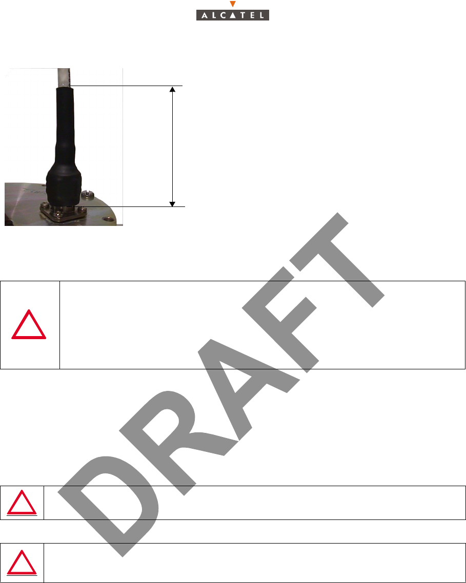
Figure 12 – Connecting the "F" connector with the thermoshrinkable sleeve
4. Attach the cable to the X-Pol RT unit using a cable tie.
Note: Do no overtighten the cable tie on the cable; this could cause deformation of the dielectric and
subsequent loss of performance.
5. Run the cable to the NT unit and equip it with a type "F" 75 ohm coaxial connector, supplied with the
equipment.
3.7 – Installation of the Terminal Station 7390NT (Indoor Unit)
Considerations
– The NT units are designed for indoor installation only.
– The NT should be positioned in accordance with the needs of the user and the technical cons-
traints (e.g., minimum distances to be respected, topology of the connections, accessibility of the
X-Pol RT/NT link, power supply).
– Always place the NT in a dry, dust-free environment, away from any major source of heat
(-5°C < T < +55°C).
IF THE COAXIAL CABLE IS INSTALLED IN SUCH A WAY THAT THE CABLE "F"
CONNECTOR IS UNDER EXCESSIVE TENSION, ANTENNA MISALIGMENT OR
CABLE DAMAGE AT THE CONNECTOR CAN OCCUR. HOWEVER, AN
EXCESSIVELY SLACK CABLE CAN CAUSE THE SAME PROBLEMS UNDER THE
EFFECT TO THE WIND. ALWAYS INSTALL THE CABLE IN SUCH A WAY THAT
THE CONNECTOR IS NOT UNDER EXCESSIVE TENSION, AND THAT THE CABLE
CANNOT MOVE OR VIBRATE DUE TO WIND FORCES.
A SPACE OF 1U (in the event of rack mounting) OR APPROXIMATELY 50 mm
MUST BE LEFT FREE ABOVE THE TERMINAL STATION NT
NEVER PLACE DOCUMENTATION OR ANY OTHER OBJECTS ABOVE THE NT
UNIT ON THE VENTILATION HOLES. THIS MAY CAUSE DAMAGE DUE TO
OVERHEATING
70
Thermoshrink a pre-pasted sleeve on the
connector/terminal/cable assembly 70 mm
along. (80 mm minimum long before thermoshrink).
The sleeve end should stop at the terminal base.
32/70 Issue 01 - April 2001 - Draft 03 3CC12425AAAA TQ BJA 01
34
– Always place the NCAxxx NT unit near a rated power source: 85 – 264 VAC , 47 – 63 Hz with
ground connection.
Note: Use grounded power connections only. Avoid the use of extension cables.
– The NT to sector connection must be done last, during commissioning (see Chapter 4 – Com-
missioning the 7390 Terminal Station ), TS installation, included all other connections, being com-
pleted.
– Do not install the NT too close to the ground (keep at a distance from dust and floor cleaning pro-
ducts).
– Do not install on premises containing corrosive materials.
3.7.1 – Installation of the 7390NT unit on a desktop
Steps
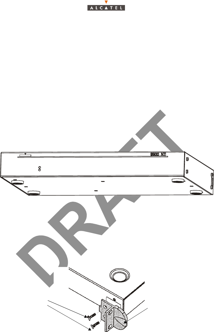
1. After unpacking the unit, fit it with its four feet, clipping them on to the bottom of the unit.
2. Connect the NT unit to the Terminal Station X-Pol RT ("F" connector).
Figure 13 – Mounting the feet
3.7.2 – Installation of the NT unit on a 19" rack
Steps
1. Fit the handles on the NT unit (see Figure 14 – Fitting the NT unit handles).
2. Install the unit in the 19" (or other type) rack (screw fittings not included, depending on the
manufacturer).
3. Connect the NT to the X-Pol RT ("F" connector).
Figure 14 – Fitting the NT unit handles
M3x6 countersunk
fixing screws Rack adapter
3CC12425AAAA TQ BJA 01 Issue 01 - April 2001 - Draft 03 33/70
34
3.7.3 – Earthing the NT units
Considerations
– NT casing must be connected to the main earth with a cable 16 mm2 minimal cross-section whose
length must not exceed 2.40 m. The grounding terminal is on the right of the NT unit (connections
side) and is in the form of a tapped hole (see Figure 15 – Earthing the (NCAxxx) NT unit).
– The earth connection should be made as directly as possible between the unit and the general
earthing system of the side (bar, rod, plate, etc.).
– The NCAxxx NT units are grounded through the 85 – 264Va main connector; for the NGAxxx
units, only one earthing point is necessary, after the earthing of all the NT units.
Steps
1. Crimp a lug (ref.: 16-6 CT) on to the earthing cable (16 mm2 cross-section).
2. Screw the cable lug into the terminal designed for this purpose. Use an M6 screw.
Figure 15 – Earthing the (NCAxxx) NT unit
Figure 16 – Earthing the (NCFxxx) NT Lite unit
General earthing lug

34/70 Issue 01 - April 2001 - Draft 03 3CC12425AAAA TQ BJA 01
34
PAGE INTENTIONALLY LEFT BLANK

3CC12425AAAA TQ BJA 01 Issue 01 - April 2001 - Draft 03 35/70
46
4 – Commissioning the 7390 Terminal Station
4.1 – Commissioning the X-Pol RT
4.1.1 – X-Pol RT adjustment
4.1.1.1 – Overview
This chapter describes how to align an X-Pol RT by adjusting the azimuth, elevation and vertical angle
of an X-Pol RT. The procedure requires a minimum distance of 100 m (328 ft) between the BS and the
X-Pol RT.
The procedure also requires clear weather conditions and a clear line-of-sight between the BS and the
X-Pol RT. There must not be any obstacles in the clear line-of-sight within the following distances:
– within 4 m (13 ft) for a TS site up to 6 km (3.8 mi) away,
– within 7 m (23 ft) for a TS site between 6 and 10 km (3.8 to 6.2 mi) away.
Lists the equipment needed to align the X-Pol RT.
The following information is required before the X-Pol RT is aligned.
– approximate distance and elevation/depression angle (with respect to the horizontal) between the
TS site being installed and the BS,
– expected upstream and downstream operating frequencies assigned to the NT,
Note: Alcatel Broadband Wireless equipment should only be installed by qualified individuals
who are trained and certified for the type of installation task assigned to them.
Equipment Purpose Recommended
supplier
Spectrum analyzer Measures signal strength Anritsu Site Master
S332B or equivalent
Bias-T (75Ω) Provides connectors for dc supply voltage to
X-Pol RT, and for protect spectrum analyzer
Pulsar BT-G1-411F75
or equivalent
50/75Ω coaxial mat-
ching pad (5.7 dB loss)
Provides impedance match for spectrum analy-
zer (50 Ω connector: SMA(F)), 75 Ω connector:
F(F))
Inmet Model 9088-50/
75 or equivalent
RF test cable, 1 m (3 ft)
in length, minimum
Connects Bias-T to spectrum analyzer through
the 50/75 Ω matching pad
Two cable lengths needed:
– Bias-T to pad: requires an F(M) connec-
tor at each end
– pad to analyzer: requires SMA(M) and
spectrum analyzer connectors
Same as IF cable or
equivalent
Coaxial jumper cable,
any length
Connects NT to Bias-T, providing dc supply
voltage to X-Pol RT Requires an F(M) connec-
tor at each end
Same as IF cable or
equivalent
36/70 Issue 01 - April 2001 - Draft 03 3CC12425AAAA TQ BJA 01
46
– Rx polarization of the TS antenna,
– desired power level of the downstream signal at the NT F connector (labeled IF In/Out and 35 VDC
Out) (see § 4.2 – Commissioning the NT - Table: Malfunctions to the installation),
– Additionally, the insertion loss value of the test equipment (such as cables, couplers and adapters)
must be measured and recorded for this procedure.
4.1.1.2 – Aligning the X-Pol RT
An X-Pol RT must be aligned with respect to the BS X-Pol RBS Tx and X-Pol RBS RX antennas in order
to receive a reliable signal. Figure 17 – X-Pol RT adjustment bolts shows the bolts used to adjust the
azimuth, elevation and vertical angle of an X-Pol RT in relation to the BS.
To align the X-Pol RT to the BS signal, adjust the X-Pol RT mounting hardware to find a position that
provides the desired signal power level. Acceptable power levels are based on RF planning and analysis
that should be done before an X-Pol RT is installed. Typical signal strengths for various cell radii are
given in Table: Malfunctions to the installation.
Figure 17 – X-Pol RT adjustment bolts
1. Ensure that the NT is switched off.
2. Ensure that the terminal station (TS) has been mounted according to the Radio Network Plan for the
pole height (where applicable), in order to aim the TS at the desired sector of the desired base station
(BS).
3. Determine and record the distance between the TS and the desired Base Station.
Note: All 5916 cable connectors must be tightened to 3.4 Nm (30 in.-lb) of torque, using a
torque wrench equivalent to tool part number 10.168360 (5/8 in. torque wrench) available
from CableTel.
All RG-6/U and RG-59/U cable connectors must be tightened to 3.4 Nm (30 in.-lb) of torque,
using a torque wrench equivalent to tool part number TW-307 (7/8 in. torque wrench)
available from PPC.
Pole elevation
and azimuth bolts
Vertical angle
bolts
3CC12425AAAA TQ BJA 01 Issue 01 - April 2001 - Draft 03 37/70
46
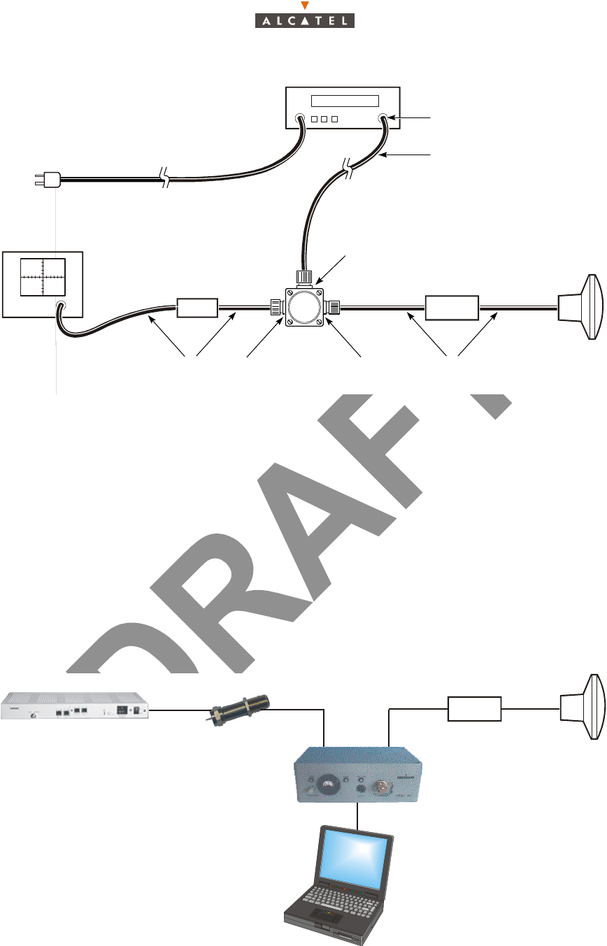
Figure 18 – Test setup for X-Pol RT alignment
4. Using the A7390 Release 2.2b Cable Installation Methods document, determine and record the
IGAU transition radius (ITR).
5. Determine and record the IGAU type from the A7390 Release 2.2b Cable Installation Methods
document based on the actual BS-TS distance relative to the ITR.
6. Using the A7390 Release 2.2b Cable Installation Methods document, determine and record the
required IGAU value (for both upstream and downstream values in the case of the assymetrical
IGAU).
7. Using the A7390 Release 2.2b Antenna Systems Installation Methods document, determine and
record the antenna misalignment transition radius (AMTR).
8. From the A7390 Release 2.2b Antenna Systems Installation Methods document, determine and
record whether antenna misalignment is required based on the actual BS-TS distance relative to the
AMTR and where applicable, record the level of misalignment (normally 15 dB in order to line up with
the side band).
Figure 19 – Antenna misalignment with E-RIT tool
DC IN
RF RF
DC
NT
IF In/Out and
35 VDC Out
Coaxial jumper
cable
X-Pol RT
Lightning
arrester
DC IN
50/75Ω
matching pad
To ac power
Spectrum analyzer
RF test
cable RF
Bias-T
Rf and DC X-Pol RT IF
cable
NT
X-Pol RT
Lightning arrester
IGAU
E-RIT tool
PC

38/70 Issue 01 - April 2001 - Draft 03 3CC12425AAAA TQ BJA 01
46
Figure 20 – Cell radius distances
9. If antenna misalignment is not required as per «8» above, connect the test equipment as shown in
Figure 19 – Antenna misalignment with E-RIT tool (with Enhanced RIT tool) while inserting the
appropriate IGAU type value as recorded in «5» and «6» above. If antenna misalignment is required,
proceed directly to «19».
10. Ensure that the base station is transmitting a signal in the desired sector.
11. Adjust the bolts identified in Figure 15 until the X-Pol RT mounting hardware is sufficiently snug to
hold the unit on the mast, but is loose enough to allow easy rotation of the unit by hand.
12. Switch the NT on.
13. Roughly align the X-Pol RT based on the Radio Network plan.
14. Using the Enhanced RIT tool, fine align the X-Pol RT antenna to maximum field strength and record
the Enhanced RIT tool level and LED status.
15. Determine the calculated maximum received signal level (RSL) using the signal level calculator. In
comparing the measured RSL to the calculated RSL, both values should be roughly the same.
16. Tighten the pole elevation and azimuth bolts to 4.07 Nm (36 in-lb) torque, and the vertical angle bolts
to 10.85 Nm (8 ft-lb) torque.
17. Verify the level measurement using the Enhanced RIT tool to ensure that the X-Pol RT is still aligned
to provide the maximum level. If this level has changed, repeat the maximum alignment procedure.
18. Switch the NT off, disconnect the test equipment and reconnect the IF cable to the NT. Switch the
NT on.
19. If antenna misalignment is possibly required as per «8» above, connect the test equipment as shown
in figure 16 (with spectrum analyzer) while inserting the appropriate IGAU type and value as
recorded in «5» and «6» above.
20. Ensure that the base station is transmitting a signal in the desired sector.
21. Adjust the bolts identified in figure 15 until the X-Pol RT mounting hardware is sufficiently snug to
hold the unit on the mast, but is loose enough to allow easy rotation of the unit by hand.
22. Switch the NT on.
23. Roughly align the TS based on the Radio Network plan.
24. Determine the calculated maximum received signal level (RSL) using the signal level calculator.
25. Determine whether the desired sector configuration is a vertical X-Pol RBS Tx/X-Pol RBS Rx
configuration or a horizontal1 X-Pol RBS Tx/X-Pol RBS Rx configuration.
26. If horizontal, proceed to «32».
Maximum cell radius
Transition radius
100 m (328 ft)
BS antenna
BS cell

3CC12425AAAA TQ BJA 01 Issue 01 - April 2001 - Draft 03 39/70
46
27. If vertical, fine align the X-Pol RT antenna to maximum field strength using the spectrum analyzer
and record the level. If this recorded level is already 15 dB below the calculated RSL, natural
misalignment due to the elevation relationship between the BS and TS has occurred and no further
misalignment is necessary. Proceed to «29».
28. If the measured RSL is not 15 dB below the calculated RSL, misalign the X-Pol RT antenna upwards
in the vertical plane until the RSL is 15 dB below the calculated RSL and record the value.
29. Tighten the pole elevation and azimuth bolts to 4.1 Nm (36 in-lb) torque, and the vertical angle bolts
to 10.85 Nm (8 ft-lb) torque.
30. Verify the level measurement using the spectrum analyzer to ensure that the X-Pol RT is still aligned
to the desired level in «28». If this level has changed, repeat «27-29».
31. Switch the NT off, disconnect the test equipment and reconnect the IF cable to the NT. Switch the
NT on.
32. In the case where the desired sector’s X-Pol RBS Tx/X-Pol RBS Rx pair is horizontally separated by
∼ 10 meters worst case, in order for an equivalent amount of CPE antenna gain to be seen by both
the X-Pol RBS Tx and the X-Pol RBS Rx, the CPE should be aligned to the mid point between the
X-Pol RBS Tx and X-Pol RBS Rx. This task can be performed visually within a few hundred meters
where the worst case at 100 m would yield ∼ 16 dB of CPE misalignment to both the X-Pol RBS Tx
and X-Pol RBS Rx respectively. In this case, no elevation misalignment is necessary. As we
approach the AMTR (distance depends on rain region), visual alignment to the mid-point of the X-
Pol RBS Tx and X-Pol RBS Rx becomes more difficult but is not as critical whereby if the CPE were
aligned to the X-Pol RBS Tx instead of the mid-point, the X-Pol RBS Tx would only have ∼ 1 dB
stronger relative antenna impact to the X-Pol RBS Rx, which is acceptable.
33. Record this azimuthal mid-point RSL. If this recorded level is already 15 dB below the calculated
RSL, natural misalignment due to the mid-point TS antenna pattern roll-off and/or the elevation
relationship between the BS and TS has occurred and no further misalignment is necessary.
Proceed to «35».
34. If the measured RSL is not 15 dB below the calculated RSL, misalign the X-Pol RT antenna upwards
in the vertical plane until the RSL is 15 dB below the calculated RSL and record the value.
35. Tighten the pole elevation and azimuth bolts to 4.1 Nm (36 in-lb) torque, and the vertical angle bolts
to 10.85 Nm (8 ft-lb) torque.
36. Verify the level measurement using the spectrum analyzer to ensure that the X-Pol RT is still aligned
to the desired level in «34». If this level has changed, repeat «33-35».
37. Switch the NT off, disconnect the test equipment and reconnect the IF cable to the NT. Switch the
NT on.
4.2 – Commissioning the NT
Note: To carry out the following phases of the Terminal Station commissioning, the link Base Station
must be operational and its antenna correctly orientated.
Considerations
– Before commissioning the NT unit, complete the X-Pol RT unit adjustment procedures.
– No adjustment is required for commissioning the NT.
– To check the voltage at the mains connector terminals, use a measuring instrument (voltmeter).
1. Please note that Alcatel recommends the use of a vertical X-Pol RBS Tx/X-Pol RBS Rx configu-
ration wherever possible.

40/70 Issue 01 - April 2001 - Draft 03 3CC12425AAAA TQ BJA 01
46
– For the mains connection, use only the connection cable supplied with the equipment.
– Never use an extension cable for connecting the NT unit to the power source.
Stages (Figure 21 – The NT unit (85 – 264 V 47 – 63 Hz) )
1. Connect the X-Pol RT/NT connection cable.
2. To ground the NT unit in this way, carry out the procedures described in Chapter 3 – Installation of
the X-Pol RT’s A7390 Terminal Station. Use the lug and screw hardware supplied with the
equipment, ref. 7.
3. Check that the mains socket to which the NT is to be connected supplies voltage compliant with the
equipment characteristics and that it is fitted with an earth.
4. (ref. 5)
• For NCAxxx: connect the NT connection cable to the NT connector and then to the mains.
• For NGAxxx: connect the 48V cable to the HE15-3 connector, then to the 48V arrival.
5. Power-up the NT unit using the On/Off switch (ref. 6); the green "Power on" LED (ref. 3) lights up.
The red "Alarm" LED (ref. 4) lights up (searching for the carrier frequency) then flashes at different
rates according to the current phase:
•slow flashing: automatic scanning over the frequencies,
•fast flashing: frame recovery (authentication by the serial number) once the frequency is
found.
Malfunctions to the installation:
The A7390 is a reliable and easy-to-install system. By following the procedures described in the
documentation, no problems should occur. However, if these procedures have been poorly applied, here
is a list of the possible problems that may arise.
Manifestation of
the problem Possible causes Solution
The red NT LED is
flashing slowly.
1 Errored NT declaration.
2 Poor connector contact.
3 Cable damaged or
severed.
4 Alignment problem.
5 Incorrect X-Pol RT set-
tings.
6 X-Pol RT breakdown.
7 NT breakdown.
1 Check NT declaration.
2 Check connectors. Secure loo-sely cabled
connectors.
3 Check installation wiring. Change damaged
cables.
4 and 5 Reconfigure and check antenna alignn-
ment.
6 Replace X-Pol RT.
The red NT LED is
flashing quickly.
1 Bad transmission.
2 Incorrect NT settings.
1 Delete and recreate the managed NT using
the 7390LT.
Check the allocation of the correct NT serial
number.
2 and 3 Reconfigure and check antenna alignn-
ment.
4 Replace X-Pol RT.
The red NT LED
rest lit uninterrup-
ted
1 Check the NT supply
voltage
2 NT breakdown.
Try a swith off/switch on, and if the LED remains
red, replace NT.
a
3CC12425AAAA TQ BJA 01 Issue 01 - April 2001 - Draft 03 41/70
46
6. Wait for this automatical initialization time of the NT. As soon as the red LED (ref. 4) goes out, the
system can be managed by the BS (calibration of the radio link (output, frequency, time) has been
performed).
Note: The maximum initialization time is in the order of 5 minutes (otherwise see § 5.4 – Changing a
faulty NT unit).
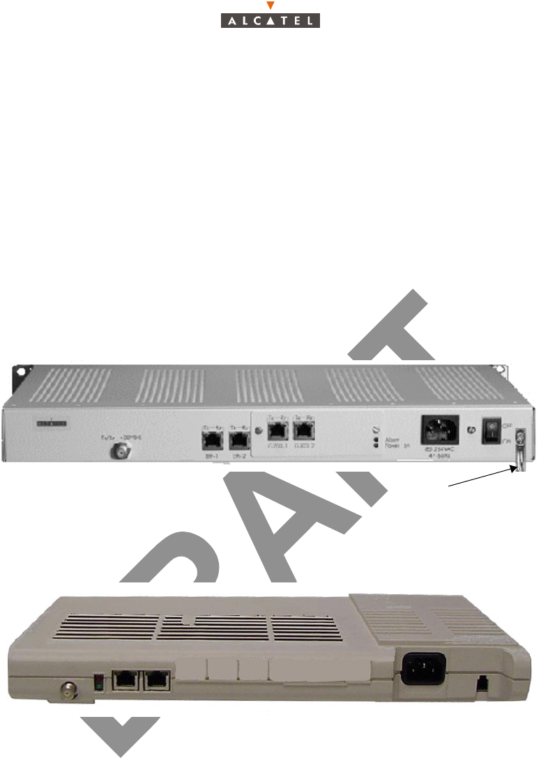
Client terminals are connected to the ref. 2 connectors (see § Figure 22 – The metallic NT unit (48 Vcc)).
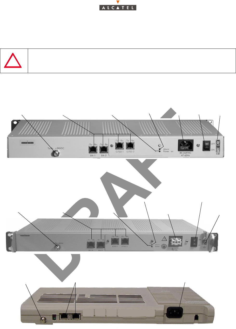
Figure 21 – The NT unit (85 – 264 V 47 – 63 Hz)
Figure 22 – The metallic NT unit (48 Vcc)
Figure 23 – The NT Lite unit (85 – 264 V 47 – 63 Hz)
NEVER DISCONNECT THE NT/X-Pol RT LINK UNLESS REQUIRED FOR MAINTENANCE OR
INSTALLATION PURPOSES. SUCH INTERVENTION MUST BE CARRIED OUT IN
ACCORDANCE WITH THE PROCEDURE INDICATED IN CHAPTER 5
NT/X-Pol RT
1
Terminal connexion
2
Mains
5
Ground
7
ON/OFF
Power on LED
3
Ready on LED
46
Link
NT/X-Pol RT Link
1
Terminal connexion
2
DC Input socket
5
Ground
7
ON/OFF
6
Power on LED
3
Ready on LED
4
NT/X-Pol RT Link
1
Mains
3
Terminal connexion
2
a
a
42/70 Issue 01 - April 2001 - Draft 03 3CC12425AAAA TQ BJA 01
46
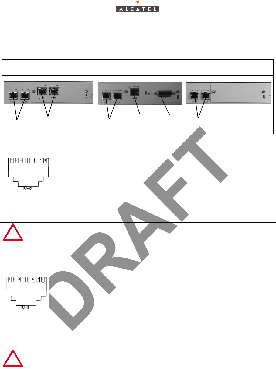
4.3 – Client terminal connections
There are eight types of NT units:
4.3.1 – Ethernet connector
Pin 1: Tx_diff_plusPin 5: Not connected
Pin 2: Tx_diff_MoinsPin 6: Rx_diff_Moins
Pin 3: Rx_diff_plusPin 7: Not connected
Pin 4: Not connectedPin 8: Not connected
Figure 24 – Affectation of Ethernet access points at NT back
4.3.2 – G703 connector (120 ohm E1 and 100 ohm T1 standards)
Pin 1: Rx_Ring Pin 5: Tx_Tip
Pin 2: Rx_Tip Pin 6: Not connected or
Pin 3: Not connected equipment ground
or equipment ground Pin 7: Not connected
Pin 4: Tx_Ring Pin 8: Not connected Pin 4: Tx_Ring
Figure 25 – Affectation of G703 access points at NT back
9900 NCA 001, 9900 NGA 001
and 9900 NCE 001 9900 NCA 002 9900 NCD 001
SHIELDED CABLES MANDATORY
SHIELDED CABLES MANDATORY
2 x Eth 10bT
2x G703:
E1 for NCA001 and NGA001
T1 for NCE001
G703
2 x Eth 10bT
X21 2 x Eth 10bT
Front view
socket
Front view
socket
3CC12425AAAA TQ BJA 01 Issue 01 - April 2001 - Draft 03 43/70
46
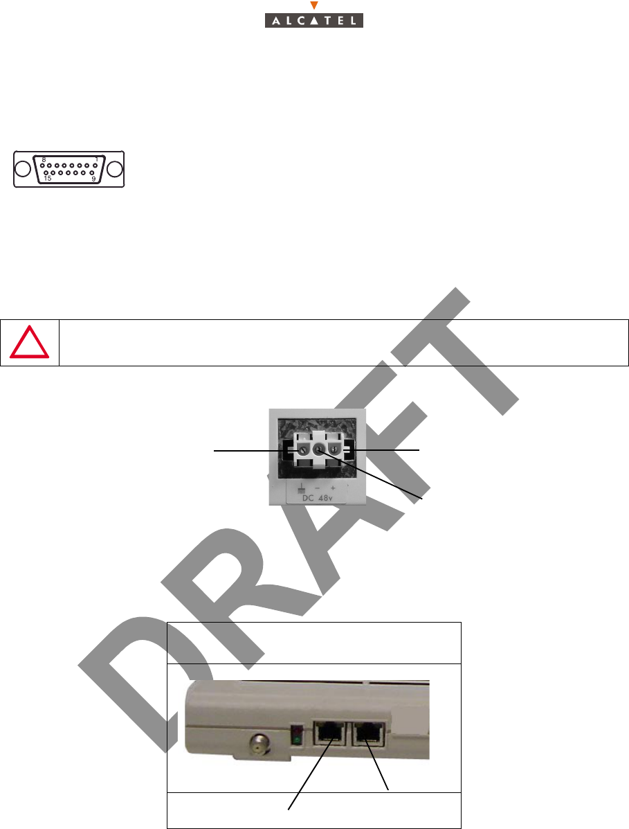
4.3.3 – X21 connector
If the distance between DCE (NT) and DTE is too long, according to V11 norms, you can exchange pin
6 and pin 13 in order to get a phase inversion.
Pin 1: Screen Pin 6: S_neg Pin 11: R_pos
Pin 2: T_neg Pin 7: B_neg Pin 12: I_pos
Pin 3: C_neg Pin 8: Ground Pin 13: S_pos
Pin 4: R_neg Pin 9: T_pos Pin 14: B_pos
Pin 5: I_neg Pin 10: C_pos Pin 15: Not connected
Figure 26 – Affectation of X21 connector access points
4.3.4 – 48V connector (HE 15)
Figure 27 – Affectation of 48V points
4.3.5 – Client terminal connections
There are four types of NT units:
SHIELDED CABLES MANDATORY
9900 NCF 001
9900 NCG 001
1 x Eth 10 bt
1 x Eth 10 bt
1 x E1 (G703)
1 x T1 (G703)
female
connector
Ground 0V / +48V
-48V / 0V
44/70 Issue 01 - April 2001 - Draft 03 3CC12425AAAA TQ BJA 01
46
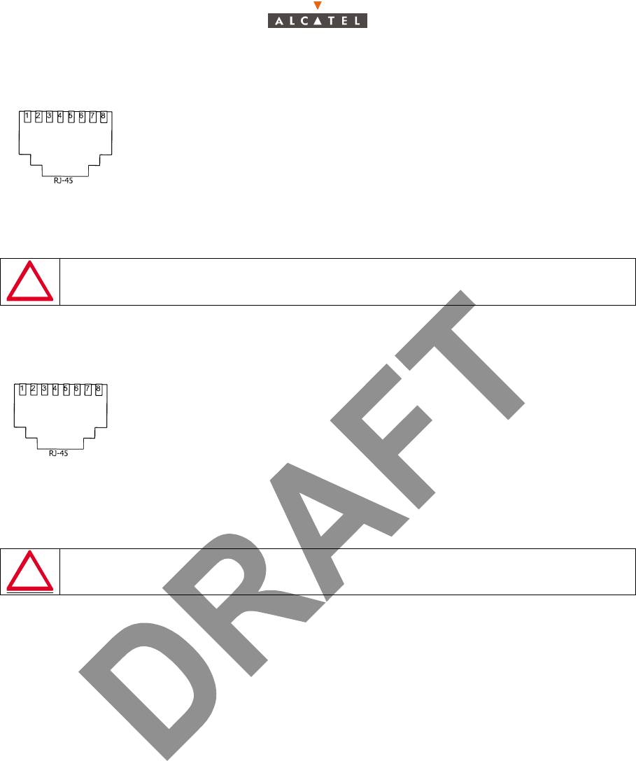
4.3.6 – Ethernet connector
Pin 1: Tx_diff_plusPin 5: Not connected
Pin 2: Tx_diff_MoinsPin 6: Rx_diff_Moins
Pin 3: Rx_diff_plusPin 7: Not connected
Pin 4: Not connectedPin 8: Not connected
Figure 28 – Affectation of Ethernet access points at NT back
4.3.7 – G703 connector (120 ohm E1 and 100 ohm T1 standards)
Pin 1: Rx_Ring Pin 5: Tx_Tip
Pin 2: Rx_Tip Pin 6: Not connected or
Pin 3: Not connected equipment ground
or equipment ground Pin 7: Not connected
Pin 4: Tx_Ring Pin 8: Not connected Pin 4: Tx_Ring
Figure 29 – Affectation of G703 access points at NT back
4.4 – Initiating services
Once X-Pol RT and NT are installed and in operational status, service initiation requires a further step:
the Base Station operator must activate the cross-connections (see User Manual 3CC12426 Axxx Base
Station § Client Services and § 6.2 – Implementation of client services of the present document).
4.5 – Filling in the installation sheet
The installation sheet (Appendix 1 – 7390 TS installation sheet) is initially issued by Radio Planning. It
contains all the data needed by the installer for successful programming of the X-Pol RT.
The installer must complete this sheet by supplying the requested information, in particular the serial
numbers of the installed equipment, then submit it to the supervisor. The information in the sheet
ensures the traceability of the customer installation equipment, to facilitate subsequent interventions.
The sheet should be signed by the client and the installer. It allows with the customer, the effective
commissionings to be validated.
The sheet consists of three parts:
– 7390 X-Pol RT installation sheet,
– 7390 NT installation sheet
SHIELDED CABLES MANDATORY
SHIELDED CABLES MANDATORY
Front view
socket
Front view
socket

3CC12425AAAA TQ BJA 01 Issue 01 - April 2001 - Draft 03 45/70
46
– 7390 X-Pol RT/NT connections sheet.
4.5.1 – 7390 X-Pol RT installation sheet
This part contains all the information necessary for the configuration. The installer must have this
information to configure the radio part.
For each parameter to be entered according to the Radio Planning, the installer must if appropriate
indicate the real input value if this differs from the value on the sheet. He must also provide the following
information: site and operator co-ordinates.
4.5.2 – NT installation sheet
This sheet is to be completed for each NT in the installation, by filling in the requested information.
4.5.3 – X-Pol RT/NT wiring sheet
The installer must fill in, in this part, all the information relating to the wiring and to the equipment used
for carrying out the assembly.
In addition, a wiring diagram is to be drawn up.

46/70 Issue 01 - April 2001 - Draft 03 3CC12425AAAA TQ BJA 01
46
PAGE INTENTIONALLY LEFT BLANK

3CC12425AAAA TQ BJA 01 Issue 01 - April 2001 - Draft 03 49/70
52
6 – Changes of configuration
During the life-cycle of an Alcatel A7390 LMDS network, both physical and software configuration
changes will likely occur for reasons of both network growth and maintenance.
These changes may involve either changes of configuration using the 7390LT software, or changes to
the physical equipment (X-Pol RT or NT).
The possible changes using the 7390LT software only are:
– declaration/removal/reset of an NT terminal (cf. § 6.1 – Declaration, deletion, reset of an NT),
– implementation of client services (cf. § 6.2 – Implementation of client services).
The possible changes with physical intervention are:
– addition/removal of an NT unit (cf. § 6.1 – Declaration, deletion, reset of an NT),
– changing an NT unit (cf. § 5.4 – Changing a faulty NT unit),
– changing an X-Pol RT unit (cf. § 6.3 – Changing an X-Pol RT),
– addition of an NT to a cluster (cf. § 6.4 – Adding an additional NT to a TS site),
– affectation of an NT unit to another BS (cf. § 6.5 – To asign an NT to an alternate BS).
6.1 – Declaration, deletion, reset of an NT
To add a new NT:
– update the "Installation information" sheet required for station installation (refer to Appendix 1 –
7390 TS installation sheet),
– carry out installation (refer to Chapter 3 – Installation of the X-Pol RT’s A7390 Terminal Station)
and commissioning (refer to Chapter 4 – Commissioning the 7390 Terminal Station) of the NT,
– to declare the new NT terminal, execute the commands indicated in section Declaring a new NT
of the Base Station User Manual (3CC 12426 Axxx).
To delete a NT from the network:
– update the "Installation information" sheet required for station installation (refer to Appendix 1 –
7390 TS installation sheet),
– execute the commands indicated in section NT deletion of the Base Station User Manual (3CC
12426 Axxx),
– turn off power to unit using ON/OFF switch (reference 6 of Figure 21 – The NT unit (85 – 264 V
47 – 63 Hz) ).
To reset a NT :
– execute the commands indicated in section NT reset of the Base Station User Manual (3CC
12426 Axxx)
– if necessary, update the "Installation information" sheet (refer to Appendix 1 – 7390 TS installation
sheet).
The supervisor must be informed of any configuration changes
a

50/70 Issue 01 - April 2001 - Draft 03 3CC12425AAAA TQ BJA 01
52
To replace a NT:
– update the "Installation information" sheet required for station installation (refer to Appendix 1 –
7390 TS installation sheet),
– carry out installation (refer to Chapter 3 – Installation of the X-Pol RT’s A7390 Terminal Station)
and commissioning (refer to Chapter 4 – Commissioning the 7390 Terminal Station) of the NT,
– perform the NT replace operation that changes serial number from old NT to new NT, and then
execute the commands indicated in section NT replace of the Base Station User Manual (3CC
12426 Axxx).
6.2 – Implementation of client services
To implement client services:
– execute the commands indicated in section Client services of the Base Station User Manual (3CC
12426 Axxx),
Note: The system benefits from E1 or IP links. For each case, use the specific procedure.
– if necessary, update the "Installation information" sheet (refer to Appendix 1 – 7390 TS installation
sheet).
6.3 – Changing an X-Pol RT
When replacing and X-Pol RT (as required by a change to the operating frequency band, or for
repair, it is necessary to reinitialise the radio part configuration and in case of an integrated antenna to
carry out antenna alignment (tracking).
To change the X-Pol RT:
– turn off the power to the NT,
– disconnect the mains cable,
– disconnect the X-Pol RT/NT link cable,
– carry out installation of the X-Pol RT unit and tracking of the Terminal Station antenna (for this,
refer to Chapter 3 – Installation of the X-Pol RT’s A7390 Terminal Station).
– restart the Terminal Station. For this, refer to Chapter 4 – Commissioning the 7390 Terminal Sta-
tion.
– reconfigure the system according to the procedures in Chapter 4 – Commissioning the 7390 Ter-
minal Station.
For system initialization and retrofit, refer to section NT Supervision of the Base Station User Manual
(3CC 12426 Axxx).

3CC12425AAAA TQ BJA 01 Issue 01 - April 2001 - Draft 03 51/70
52
6.4 – Adding an additional NT to a TS site
When a Terminal Station is installed, and an additional NT is expected to be required in the future, the
cabling on the site can be pre-wired with a splitter. One port of the splitter is connected to an NT, and a
75 ohm termination load is connected to the other port. By removing the termination load and connecting
an additional NT in its place, an additional NT can be added without interrupting traffic on the original NT.
If a Terminal Station is not pre-wired to accept an additional NT, cables must be disconnected, cable
lengths adjusted, and a splitter added. The original NT is unable to pass traffic during the installation of
an additional NT.
6.4.1 – Case of a pre-wired installation
In the case of a pre-wired installation, the cables are already pulled, the distribution frames and splitter
are already in place and there is a 75 ohm termination load on the spare splitter port.
To add an NT to a pre-wired TS site (see § 2.5 – Examples of configuration of the Terminal Station
(7390TS)):
– remove the 75 ohm termination load,
– connect the NT in place of the 75 ohm termination load,
– follow the procedure for adding an NT described in § 6.1 – Declaration, deletion, reset of an NT.
Note: There is no service interruption and, furthermore, it is not necessary to reconfigure the radio
parameters of the X-Pol RT.
6.4.2 – Case of a non-pre-wired installation
In a non-pre-wired installation,
– turn off the power to the existing NT
– install and connect the splitter and distribution frames, and adjust the cable lengths if required.
– follow the procedure for adding an NT described in § 6.1 – Declaration, deletion, reset of an NT,
– reconfigure the X-Pol RT radio parameters.
Note: You are recommended, with a view to possible future Multi-NT use, to wire as for Multi-NT on
first installation. This means that it will not be necessary to reset the X-Pol RT, so avoiding the
interruption of services.
6.5 – To asign an NT to an alternate BS
To assign a Terminal Station to on alternate Base Station:
– delete the NT in the BS with the 7390LT software (cf. § 6.1 – Declaration, deletion, reset of an NT),
– declare the NT in the new BS with the 7390LT software,
– turn off the power to the NT unit,
– allign the Terminal Station X-Pol RT to the new Base Station. Refer to Chapter 3 – Installation of
the X-Pol RT’s A7390 Terminal Station for information.

52/70 Issue 01 - April 2001 - Draft 03 3CC12425AAAA TQ BJA 01
52
– restart the Terminal Station.Refer to Chapter 4 – Commissioning the 7390 Terminal Station for
information.
– reconfigure the system according to the procedures in Chapter 4 – Commissioning the 7390 Ter-
minal Station.
For system initialization and retrofit, refer to section NT supervision in the Base Station User Manual
(3CC 12426 Axxx).
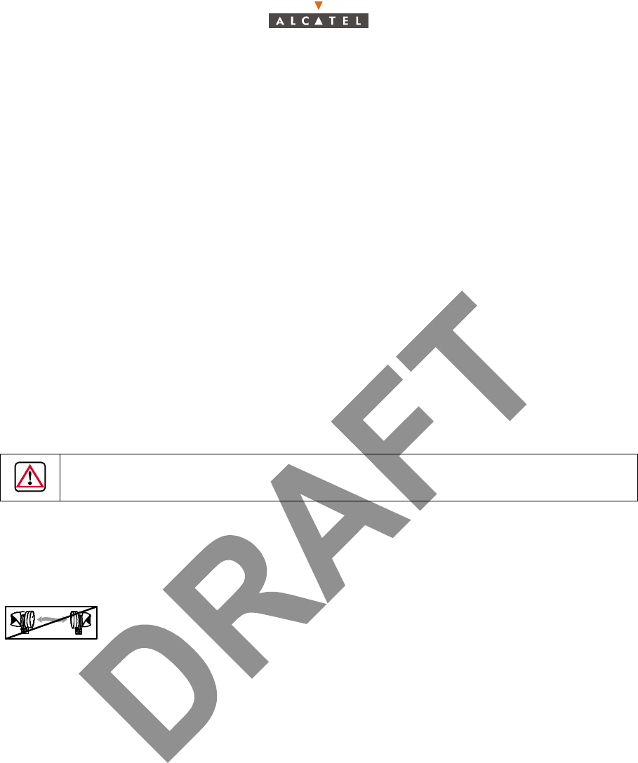
3CC12425AAAA TQ BJA 01 Issue 01 - April 2001 - Draft 03 47/70
48
5 – Operation and maintenance
5.1 – 7390 system supervision
The system operator receives the alarms sent by the network equipment. With the aid of the the 7390LT
software applications, the operator can view and analyze the alarms and trigger the appropriate
operations (see specific procedures below).
On detection of a fault, the operator analyzes alarms and starts the suitable maintenance actions.
5.2 – Preventive maintenance
This maintenance is carried out, either during a corrective maintenance inspection, or during a periodic
inspection, on all station equipment. It consists in inspecting the units and their interconnections
(connectors, cables, sockets, etc.) and ensuring that the environment of the Indoor Units (NTs and RTs)
complies with installation requirements (see § 3 – Installation of the X-Pol RT’s A7390 Terminal Station).
It is essential to check connectors and splitters state with earthing.
In case of doubt, the suspect parts should be checked, taking all precautions to avoid interrupting link
data transmission.
5.3 – Corrective maintenance
Corrective maintenance is carried out with the use of the programs of the 7390LT software.
To use the alarms refer to section "Alarms" of the Base Station User Manual 3CC 12426 Axxx.
5.4 – Changing a faulty NT unit
Make sure that the network manager has deleted the NT to be replaced beforehand and declared the
new one, using the 7390LT software (see the Base Station User Manual 3CC 12426 Axxx).
Stages
1. Turn off NT unit power.
2. Disconnect the mains cable connecting the NT unit to the power source.
3. Disconnect all cables connected to the NT unit to be changed.
4. Change NT unit after checking that the characteristics coincide (number of inputs, impedance, etc.).
5. Reconnect NT unit cables.
6. Connect the NT power cable to the mains supply.
7. Power up NT unit.
8. Wait for "Power on" LED to light up.
9. Wait for flashing of "Alarm" LED. The NT unit is in operation once the LED is extinguished.
10. Make NT replace operation in the 7390LT software application (see section NT replace of the Base
Station User Manual 3CC 12426 Axxx)
DO NOT OPEN THE EQUIPMENT UNDER ANY CIRCUMSTANCE

48/70 Issue 01 - April 2001 - Draft 03 3CC12425AAAA TQ BJA 01
48
11. Check the absence of alarms in the 7390LT software application (see section Alarms of the Base
Station User Manual 3CC 12426 Axxx).
12. Update the station installation sheet (Appendix 1 – 7390 TS installation sheet).
5.5 – Changing a faulty X-Pol RT unit
Stages
1. Turn off the NT power supply.
2. Disconnect the mains cable connecting the NT unit to the power source.
3. Disconnect the X-Pol RT/NT connection cable.
4. Change X-Pol RT after checking on the label that mnemonics are identicals to the previous one.
5. Install again the X-Pol RT and carry out antenna alignment. For this, refer to § 3 – Installation of the
X-Pol RT’s A7390 Terminal Station and § 4 – Commissioning the 7390 Terminal Station.
6. Reconnect the X-Pol RT/NT connection cable.
7. Connect the NT to the mains supply.
8. Power up the NT.
9. Wait between 2 and 5 minutes. Reconfiguration is automatic.
10. Check the absence of alarms in the 7390LT software application (see section "Alarms" of the Base
Station User Manual 3CC 12426 Axxx).
11. Update the station installation sheet (Appendix 1 – 7390 TS installation sheet).

3CC12425AAAA TQ BJA 01 Issue 01 - April 2001 - Draft 03 53/70
58
Appendix 1 – 7390 TS installation sheet
A.1.1 – 7390 X-Pol RT INSTALLATION SHEET
General information
Radio planning parameters
Name ................................................................... Operator
Address No ............................................................
Street .......................................................
Bld ..... Stair .............
Floor ....................................................
Town ................. Country .................
Installation parameters
to be entered (Radio
planning instructions)
Installation
parameters entered
(OK or new values)
Site identification
Name of the corresponding Base Station
Sector number (1, 2, 3, 4, etc.)
Distance between BS and TS
Altitude difference
Climatic zone (A, B, etc.)
Availability
X-Pol RBS antenna type (dBi)
X-Pol RBS antenna tilt
X-Pol RBS power out
X-Pol RT antenna type (dBi)
Polarization
Frequency band (GHz)
Frequency down link
Frequency up link
Bandwidth
Duplex deviation (MHz)
Sub-band (A,.B, etc.)

54/70 Issue 01 - April 2001 - Draft 03 3CC12425AAAA TQ BJA 01
58
7390 RT INSTALLATION SHEET (continuation)
Designation
Version
Part number
ICS
Serial number
Reception level (dBm)
Installation type (rooftop, tower, mast)
Mecanical support References
Radio installation height / ground
Obstacle (type, distance,...)
Installer: Costumer:
Date:
Name:
Visa:

3CC12425AAAA TQ BJA 01 Issue 01 - April 2001 - Draft 03 55/70
58
A.1.2 – 7390 NT INSTALLATION SHEET
Name ................................................................... Operator
Address No
..................................................................
Street .......................................................
Bld ..... Stair .............
Floor .......................................................
Town ................ Country .................
Designation NT
Type
Reference
ICS
Serial number
Downloaded application
Version
Position, location of the equipment
Installation type (Rack, wall-mounting, table)
Mother board (Ref. + ICS + Serial number)
ACCEPTANCE
Green LED lighting: (OK or NO OK)
Red LED off: (OK or NO OK)
Installer: Costumer:
Date:
Name:
Visa:
56/70 Issue 01 - April 2001 - Draft 03 3CC12425AAAA TQ BJA 01
58
A.1.3 – 7390 X-Pol RT / NT CABLING SHEET
Diagram marks
Type of cable
Length between RT and the
first element
Splitter references
Splitter serial numbers
75 ohm load references
Connecting diagram
Installer: Costumer:
Date:
Name:
Visa:

3CC12425AAAA TQ BJA 01 Issue 01 - April 2001 - Draft 03 57/70
58
A.1.4 – LIST OF CHECKPOINTS FOR TS COMMISSIONING
CHECK SAFETY RULE
– Equipment grounding OK NOK
– Differential protection OK NOK
– Fire protection OK NOK
CHECK RT INSTALLATION
– No pollutants or possible flow on the X-Pol RT OK NOK
– No possible trespassing in the X-Pol RT antenna field OK NOK
– Direct view between X-Pol RT antenna and base station antenna OK NOK
– Use of a torque wrench for the X-Pol RT assembly OK NOK
– Support stiffness and absence of vibrations OK NOK
– Same polarization as for base station antenna OK NOK
CHECK CABLES BETWEEN X-Pol RT and NT
–F 75Ω connectors X-Pol RT side OK NOK
– Watertightness by thermoshrinkable pre-pasted sleeve X-Pol RT side OK NOK
– No cable strain OK NOK
– Observe minimum bend radius OK NOK
CHECK NT INSTALLATION
– Min Max temperature of the premises hosting the NT (-5º to + 55ºC) OK NOK
– Ventilation clearance above the NT OK NOK
– Check the NT grounding OK NOK
– Check that all client access cables are shielded cables OK NOK
– Diagram compliant with multi-NT connection OK NOK

58/70 Issue 01 - April 2001 - Draft 03 3CC12425AAAA TQ BJA 01
58
PAGE INTENTIONALLY LEFT BLANK