Alcatel Canada 31T28A04A22A Alcatel 7390 LMDS Broadband Wireless System - 31GHz User Manual 3cc12426aaaaTQbja01

Alcatel Canada Inc Alcatel 7390 LMDS Broadband Wireless System - 31GHz 3cc12426aaaaTQbja01

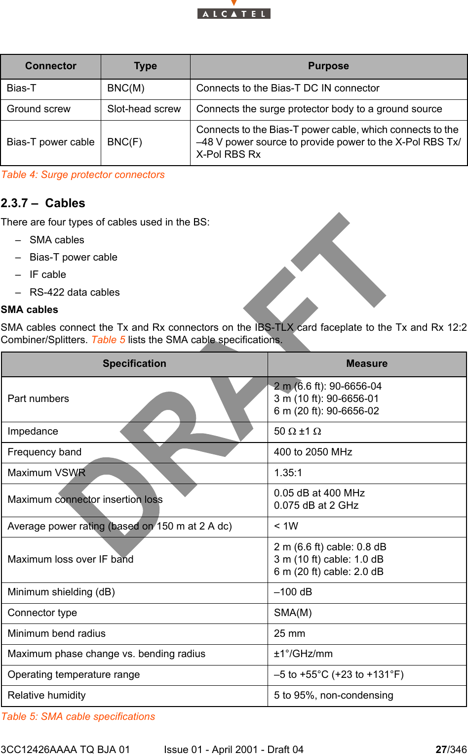
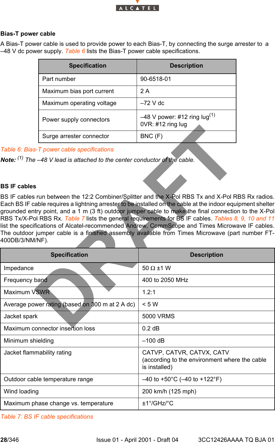
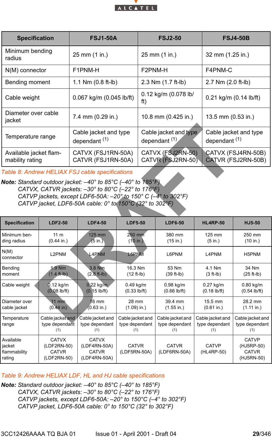
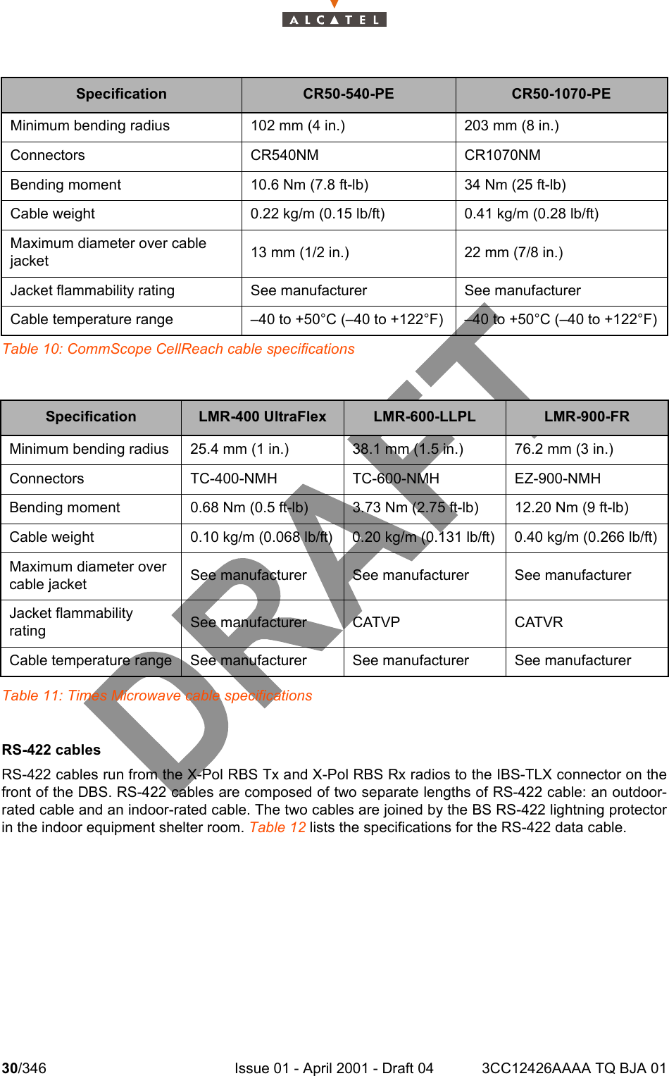
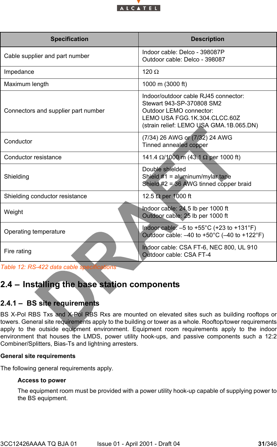
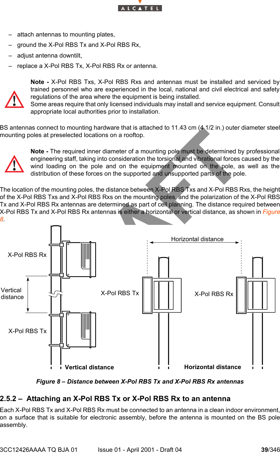
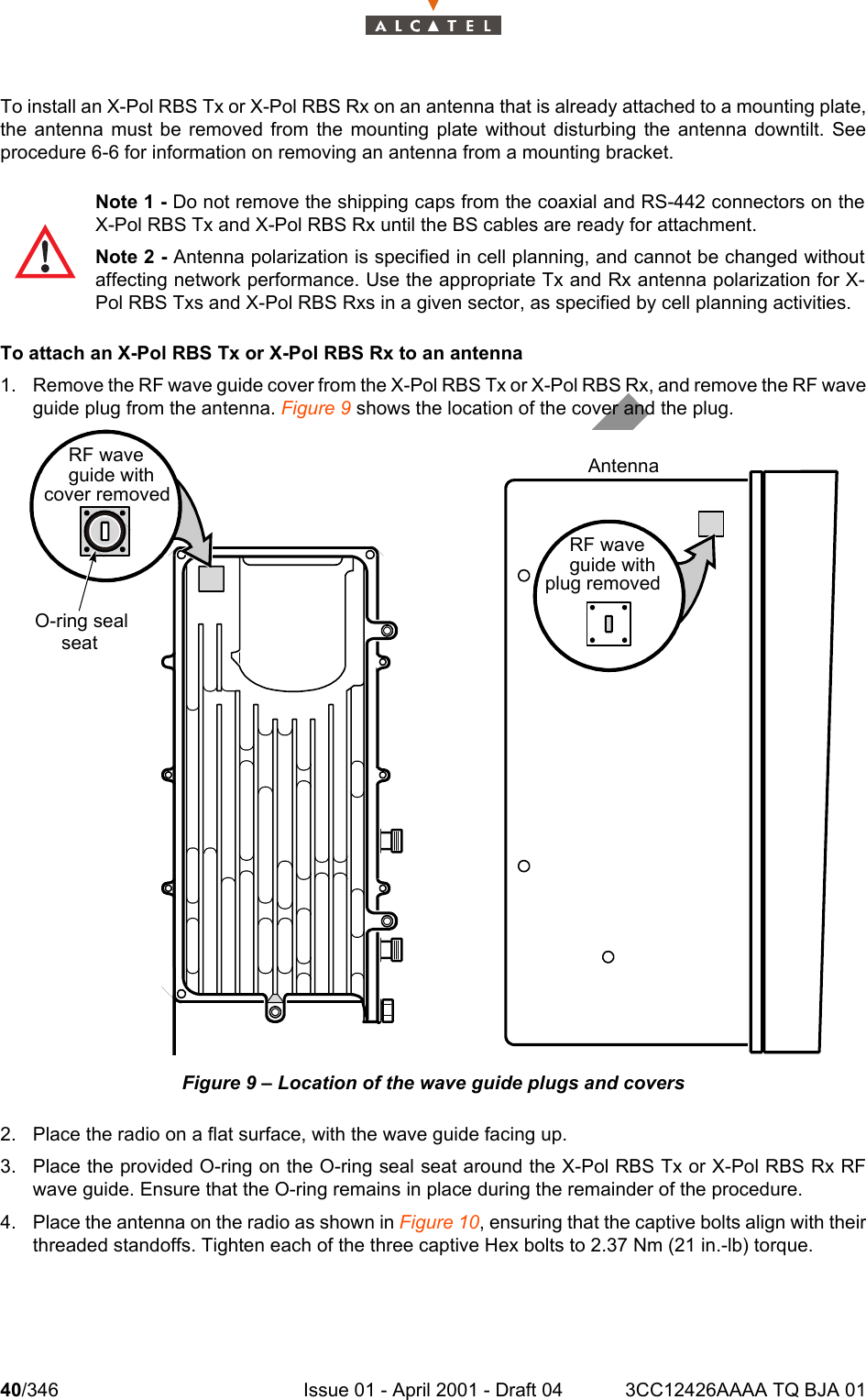
Base Station User Manual 1 0f 14

3CC12426AAAA TQ BJA Ed. 01AAAAllllccccaaaatttteeeellll    7777333399990000Multiservice broadband wireless access solutionBase Station - release 2.2b((((EEEExxxx    9999999900000000))))X - Polarized versionUser Manual
2/346 Issue 01 - April 2001 - Draft 04 3CC12426AAAA TQ BJA 014Status DraftChange NoteShort Title A7390 Base Station – release 2.2bAll rights reserved. Passing on and copying of thisdocument, use and communication of its contents notpermitted without written authorization from Alcatel.
3CC12426AAAA TQ BJA 01 Issue 01 - April 2001 - Draft 04 3/3464Customer Service Support:a Team tuned to your needs for your entire satisfactionCongratulations on having bought your equipment from Alcatel.We hope that it will give you full satisfaction.For any additional information or if you have any questions concerning this equipment, please contactthe Technical Assistance Center, (TAC) dedicated to your support whose coordinates have beengiven to you by the Alcatel Contract Manager or:http://www.cid.alcatel.com/support .You must specify the hardware and software configurations of each item concerned when getting intouch.This service, available on subscription, is free for the duration of the initial waranty period.
4/346 Issue 01 - April 2001 - Draft 04 3CC12426AAAA TQ BJA 014PAGE INTENTIONALLY LEFT BLANK
3CC12426AAAA TQ BJA 01 Issue 01 - April 2001 - Draft 04 5/34610Table of contents1 –  Foreword . . . . . . . . . . . . . . . . . . . . . . . . . . . . . . . . . . . . . . . . . . . . . . . . . . . . . . . . . . . . . . . . . . 111.1 –  Structure of the manual . . . . . . . . . . . . . . . . . . . . . . . . . . . . . . . . . . . . . . . . . . . . . . . . . . . 111.2 –  Using the manual. . . . . . . . . . . . . . . . . . . . . . . . . . . . . . . . . . . . . . . . . . . . . . . . . . . . . . . . 111.3 –  Safety instructions . . . . . . . . . . . . . . . . . . . . . . . . . . . . . . . . . . . . . . . . . . . . . . . . . . . . . . . 121.3.1 –  General rules . . . . . . . . . . . . . . . . . . . . . . . . . . . . . . . . . . . . . . . . . . . . . . . . . . . . . 122 –  Equipment overview . . . . . . . . . . . . . . . . . . . . . . . . . . . . . . . . . . . . . . . . . . . . . . . . . . . . . . . . . 192.1 –  Overview of the A7390 system  . . . . . . . . . . . . . . . . . . . . . . . . . . . . . . . . . . . . . . . . . . . . . 192.2 –  Composition of the A7390 system . . . . . . . . . . . . . . . . . . . . . . . . . . . . . . . . . . . . . . . . . . . 202.3 –  A7390 system specifications . . . . . . . . . . . . . . . . . . . . . . . . . . . . . . . . . . . . . . . . . . . . . . . 212.3.1 –  Frequency bands used  . . . . . . . . . . . . . . . . . . . . . . . . . . . . . . . . . . . . . . . . . . . . . 212.3.2 –  Radio transmission specifications (typical values)  . . . . . . . . . . . . . . . . . . . . . . . . 212.3.3 –  Capacity. . . . . . . . . . . . . . . . . . . . . . . . . . . . . . . . . . . . . . . . . . . . . . . . . . . . . . . . .222.3.4 –  X-Pol RBS Tx and X-Pol RBS Rx . . . . . . . . . . . . . . . . . . . . . . . . . . . . . . . . . . . . . 242.3.5 –  Bias-T  . . . . . . . . . . . . . . . . . . . . . . . . . . . . . . . . . . . . . . . . . . . . . . . . . . . . . . . . . . 252.3.6 –  Surge protectors . . . . . . . . . . . . . . . . . . . . . . . . . . . . . . . . . . . . . . . . . . . . . . . . . . 262.3.7 –  Cables . . . . . . . . . . . . . . . . . . . . . . . . . . . . . . . . . . . . . . . . . . . . . . . . . . . . . . . . . .272.4 –  Installing the base station components . . . . . . . . . . . . . . . . . . . . . . . . . . . . . . . . . . . . . . . 312.4.1 –  BS site requirements . . . . . . . . . . . . . . . . . . . . . . . . . . . . . . . . . . . . . . . . . . . . . . . 312.4.2 –  BS installation overview. . . . . . . . . . . . . . . . . . . . . . . . . . . . . . . . . . . . . . . . . . . . . 332.4.3 –  Equipment and cable connection for non-redundant and redundantX-Pol RBS Tx/X-Pol RBS Rx configurations . . . . . . . . . . . . . . . . . . . . . . . . . . . . . 362.4.4 –  BS installation tasks  . . . . . . . . . . . . . . . . . . . . . . . . . . . . . . . . . . . . . . . . . . . . . . . 382.5 –  Installing BS X-Pol RBS Txs, X-Pol RBS Rxs and antennas. . . . . . . . . . . . . . . . . . . . . . . 382.5.1 –  Overview . . . . . . . . . . . . . . . . . . . . . . . . . . . . . . . . . . . . . . . . . . . . . . . . . . . . . . . .382.5.2 –  Attaching an X-Pol RBS Tx or X-Pol RBS Rx to an antenna. . . . . . . . . . . . . . . . . 392.5.3 –  Attaching a mounting plate and antenna to a pole  . . . . . . . . . . . . . . . . . . . . . . . . 422.5.4 –  Replacing an X-Pol RBS Tx, X-Pol RBS Rx or antenna . . . . . . . . . . . . . . . . . . . . 482.6 –  Installing Bias-Ts and surge protectors . . . . . . . . . . . . . . . . . . . . . . . . . . . . . . . . . . . . . . . 492.6.1 –  Replacing the gas discharge tube in a surge protector . . . . . . . . . . . . . . . . . . . . . 512.7 –  Installing Type N lightning arresters  . . . . . . . . . . . . . . . . . . . . . . . . . . . . . . . . . . . . . . . . . 522.8 –  BS cables connections  . . . . . . . . . . . . . . . . . . . . . . . . . . . . . . . . . . . . . . . . . . . . . . . . . . .552.8.1 –  Selecting BS IF cables  . . . . . . . . . . . . . . . . . . . . . . . . . . . . . . . . . . . . . . . . . . . . . 592.8.2 –  Marking IF cables for identification  . . . . . . . . . . . . . . . . . . . . . . . . . . . . . . . . . . . . 612.8.3 –  Cable strain relief. . . . . . . . . . . . . . . . . . . . . . . . . . . . . . . . . . . . . . . . . . . . . . . . . . 642.8.4 –  Connecting BS IF cables . . . . . . . . . . . . . . . . . . . . . . . . . . . . . . . . . . . . . . . . . . . . 652.8.5 –  Connecting the RS-422 data cables . . . . . . . . . . . . . . . . . . . . . . . . . . . . . . . . . . . 682.8.6 –  Connecting SMA cables  . . . . . . . . . . . . . . . . . . . . . . . . . . . . . . . . . . . . . . . . . . . . 702.8.7 –  Connecting the Bias-T power cable. . . . . . . . . . . . . . . . . . . . . . . . . . . . . . . . . . . . 712.8.8 –  Installing an RJ45 connector on an RS-422 cable  . . . . . . . . . . . . . . . . . . . . . . . . 722.8.9 –  Installing a LEMO connector on an RS-422 cable. . . . . . . . . . . . . . . . . . . . . . . . . 772.9 –  Installing an L4PNM Heliax connector. . . . . . . . . . . . . . . . . . . . . . . . . . . . . . . . . . . . . . . . 832.9.1 –  Overview . . . . . . . . . . . . . . . . . . . . . . . . . . . . . . . . . . . . . . . . . . . . . . . . . . . . . . . .832.9.2 –  To add a solder-connect L4PNM connector  . . . . . . . . . . . . . . . . . . . . . . . . . . . . . 832.9.3 –  To add a ring-flare L4PNM connector . . . . . . . . . . . . . . . . . . . . . . . . . . . . . . . . . . 892.10–  BT system loss calibration  . . . . . . . . . . . . . . . . . . . . . . . . . . . . . . . . . . . . . . . . . . . . . . . .952.10.1–  Overview. . . . . . . . . . . . . . . . . . . . . . . . . . . . . . . . . . . . . . . . . . . . . . . . . . . . . . . .952.10.2–  To calibrating the upstream and downstream cable runs . . . . . . . . . . . . . . . . . . . 962.11–  Simplified description of the Base Station (7390BS)  . . . . . . . . . . . . . . . . . . . . . . . . . . . . 982.12–  Technical specifications of the Base Station (7390BS)  . . . . . . . . . . . . . . . . . . . . . . . . . . 992.12.1–  X-Pol RBS specifications . . . . . . . . . . . . . . . . . . . . . . . . . . . . . . . . . . . . . . . . . . . 99
6/346 Issue 01 - April 2001 - Draft 04 3CC12426AAAA TQ BJA 01102.12.2–  DBS specifications . . . . . . . . . . . . . . . . . . . . . . . . . . . . . . . . . . . . . . . . . . . . . . . . 1002.12.3–  Common characteristics of the X-Pol RBS and DBS . . . . . . . . . . . . . . . . . . . . . . 1032.13–  Equipment power consumption  . . . . . . . . . . . . . . . . . . . . . . . . . . . . . . . . . . . . . . . . . . . . 1042.13.1–  X-Pol RBS. . . . . . . . . . . . . . . . . . . . . . . . . . . . . . . . . . . . . . . . . . . . . . . . . . . . . . . 1042.13.2–  DBS  . . . . . . . . . . . . . . . . . . . . . . . . . . . . . . . . . . . . . . . . . . . . . . . . . . . . . . . . . . . 1043 –  Installation of the Base Station . . . . . . . . . . . . . . . . . . . . . . . . . . . . . . . . . . . . . . . . . . . . . . . . 1053.1 –  Equipment delivery  . . . . . . . . . . . . . . . . . . . . . . . . . . . . . . . . . . . . . . . . . . . . . . . . . . . . . . 1053.1.1 –  Labels on the equipment and the packaging. . . . . . . . . . . . . . . . . . . . . . . . . . . . . 1053.2 –  Installing the equipment. . . . . . . . . . . . . . . . . . . . . . . . . . . . . . . . . . . . . . . . . . . . . . . . . . . 1083.2.1 –  Information required for installation . . . . . . . . . . . . . . . . . . . . . . . . . . . . . . . . . . . . 1083.2.2 –  Precautions . . . . . . . . . . . . . . . . . . . . . . . . . . . . . . . . . . . . . . . . . . . . . . . . . . . . . . 1083.2.3 –  Tools required . . . . . . . . . . . . . . . . . . . . . . . . . . . . . . . . . . . . . . . . . . . . . . . . . . . . 1093.3 –  Installation of outdoor equipment. . . . . . . . . . . . . . . . . . . . . . . . . . . . . . . . . . . . . . . . . . . . 1093.3.1 –  Spatial separation for Base Station Antennas. . . . . . . . . . . . . . . . . . . . . . . . . . . . 1103.4 –  Base Station equipment installation. . . . . . . . . . . . . . . . . . . . . . . . . . . . . . . . . . . . . . . . . . 1113.4.1 –  Mechanical installation  . . . . . . . . . . . . . . . . . . . . . . . . . . . . . . . . . . . . . . . . . . . . . 1123.4.2 –  Electrical connection . . . . . . . . . . . . . . . . . . . . . . . . . . . . . . . . . . . . . . . . . . . . . . . 1133.4.3 –  Customer access connections (circuits interfaces) . . . . . . . . . . . . . . . . . . . . . . . . 1153.4.4 –  Client access connections (ATM network interface) . . . . . . . . . . . . . . . . . . . . . . . 1233.4.5 –  Place of the board into the rack. . . . . . . . . . . . . . . . . . . . . . . . . . . . . . . . . . . . . . . 1263.4.6 –  End of the installation  . . . . . . . . . . . . . . . . . . . . . . . . . . . . . . . . . . . . . . . . . . . . . . 1274 –  7390LT software overview . . . . . . . . . . . . . . . . . . . . . . . . . . . . . . . . . . . . . . . . . . . . . . . . . . . . 1294.1 –  General information . . . . . . . . . . . . . . . . . . . . . . . . . . . . . . . . . . . . . . . . . . . . . . . . . . . . . . 1294.1.1 –  Functionalities . . . . . . . . . . . . . . . . . . . . . . . . . . . . . . . . . . . . . . . . . . . . . . . . . . . . 1294.1.2 –  Principles of the Man-Machine Interface (MMI) of the 7390LT . . . . . . . . . . . . . . . 1294.1.3 –  Rearrangement of active windows  . . . . . . . . . . . . . . . . . . . . . . . . . . . . . . . . . . . . 1314.1.4 –  Printing  . . . . . . . . . . . . . . . . . . . . . . . . . . . . . . . . . . . . . . . . . . . . . . . . . . . . . . . . . 1324.2 –  Running and quitting the software . . . . . . . . . . . . . . . . . . . . . . . . . . . . . . . . . . . . . . . . . . . 1334.2.1 –  Installation of the 7390 LT software. . . . . . . . . . . . . . . . . . . . . . . . . . . . . . . . . . . . 1334.2.2 –  Accessing and running 7390 LT  . . . . . . . . . . . . . . . . . . . . . . . . . . . . . . . . . . . . . . 1334.2.3 –  Quitting the 7390 LT  . . . . . . . . . . . . . . . . . . . . . . . . . . . . . . . . . . . . . . . . . . . . . . . 1344.3 –  Connection and Disconnection  . . . . . . . . . . . . . . . . . . . . . . . . . . . . . . . . . . . . . . . . . . . . . 1354.3.1 –  NE Connection  . . . . . . . . . . . . . . . . . . . . . . . . . . . . . . . . . . . . . . . . . . . . . . . . . . . 1354.3.2 –  Disconnecting the NE assembly . . . . . . . . . . . . . . . . . . . . . . . . . . . . . . . . . . . . . . 1384.4 –  Supervision Principles . . . . . . . . . . . . . . . . . . . . . . . . . . . . . . . . . . . . . . . . . . . . . . . . . . . . 1394.4.1 –  Data retrieval . . . . . . . . . . . . . . . . . . . . . . . . . . . . . . . . . . . . . . . . . . . . . . . . . . . . . 1394.4.2 –  Local access requests . . . . . . . . . . . . . . . . . . . . . . . . . . . . . . . . . . . . . . . . . . . . . . 1394.4.3 –  Administrative statuses . . . . . . . . . . . . . . . . . . . . . . . . . . . . . . . . . . . . . . . . . . . . . 1394.5 –  Base Station Supervision. . . . . . . . . . . . . . . . . . . . . . . . . . . . . . . . . . . . . . . . . . . . . . . . . .1404.5.1 –  Base Station Supervision  . . . . . . . . . . . . . . . . . . . . . . . . . . . . . . . . . . . . . . . . . . . 1414.5.2 –  General parameters. . . . . . . . . . . . . . . . . . . . . . . . . . . . . . . . . . . . . . . . . . . . . . . . 1424.5.3 –  DBS . . . . . . . . . . . . . . . . . . . . . . . . . . . . . . . . . . . . . . . . . . . . . . . . . . . . . . . . . . . . 1434.5.4 –  Clock synchronization parameters  . . . . . . . . . . . . . . . . . . . . . . . . . . . . . . . . . . . . 1504.5.5 –  Sending time to the Agent . . . . . . . . . . . . . . . . . . . . . . . . . . . . . . . . . . . . . . . . . . . 1514.5.6 –  Memory initalization. . . . . . . . . . . . . . . . . . . . . . . . . . . . . . . . . . . . . . . . . . . . . . . . 1514.5.7 –  X-Pol RBS . . . . . . . . . . . . . . . . . . . . . . . . . . . . . . . . . . . . . . . . . . . . . . . . . . . . . . . 1524.5.8 –  Redundancy Radio capability  . . . . . . . . . . . . . . . . . . . . . . . . . . . . . . . . . . . . . . . . 1554.6 –  NT Supervision  . . . . . . . . . . . . . . . . . . . . . . . . . . . . . . . . . . . . . . . . . . . . . . . . . . . . . . . . . 1574.6.1 –  NT Supervision . . . . . . . . . . . . . . . . . . . . . . . . . . . . . . . . . . . . . . . . . . . . . . . . . . . 1584.6.2 –  Declaring a new NT . . . . . . . . . . . . . . . . . . . . . . . . . . . . . . . . . . . . . . . . . . . . . . . . 1594.6.3 –  NT Details . . . . . . . . . . . . . . . . . . . . . . . . . . . . . . . . . . . . . . . . . . . . . . . . . . . . . . .160
3CC12426AAAA TQ BJA 01 Issue 01 - April 2001 - Draft 04 7/346104.6.4 –  NT deletion  . . . . . . . . . . . . . . . . . . . . . . . . . . . . . . . . . . . . . . . . . . . . . . . . . . . . . . 1624.6.5 –  NT reset. . . . . . . . . . . . . . . . . . . . . . . . . . . . . . . . . . . . . . . . . . . . . . . . . . . . . . . . .1624.6.6 –  NT substitution. . . . . . . . . . . . . . . . . . . . . . . . . . . . . . . . . . . . . . . . . . . . . . . . . . . . 1634.7 –  Radio supervision and parameters  . . . . . . . . . . . . . . . . . . . . . . . . . . . . . . . . . . . . . . . . . . 1644.7.1 –  Radio configuration . . . . . . . . . . . . . . . . . . . . . . . . . . . . . . . . . . . . . . . . . . . . . . . . 1644.7.2 –  Dynamic Traffic Configuration . . . . . . . . . . . . . . . . . . . . . . . . . . . . . . . . . . . . . . . . 1664.7.3 –  On-demand Service management. . . . . . . . . . . . . . . . . . . . . . . . . . . . . . . . . . . . . 1674.7.4 –  Bandwidth allocation . . . . . . . . . . . . . . . . . . . . . . . . . . . . . . . . . . . . . . . . . . . . . . . 1694.8 –  NE management . . . . . . . . . . . . . . . . . . . . . . . . . . . . . . . . . . . . . . . . . . . . . . . . . . . . . . . . 1734.8.1 –  NE Supervision . . . . . . . . . . . . . . . . . . . . . . . . . . . . . . . . . . . . . . . . . . . . . . . . . . . 1734.8.2 –  Events log . . . . . . . . . . . . . . . . . . . . . . . . . . . . . . . . . . . . . . . . . . . . . . . . . . . . . . .1744.8.3 –  Historical Event log . . . . . . . . . . . . . . . . . . . . . . . . . . . . . . . . . . . . . . . . . . . . . . . . 1754.8.4 –  Event log legend . . . . . . . . . . . . . . . . . . . . . . . . . . . . . . . . . . . . . . . . . . . . . . . . . . 1784.9 –  Interface parameters . . . . . . . . . . . . . . . . . . . . . . . . . . . . . . . . . . . . . . . . . . . . . . . . . . . . . 1794.9.1 –  ATM . . . . . . . . . . . . . . . . . . . . . . . . . . . . . . . . . . . . . . . . . . . . . . . . . . . . . . . . . . . . 1794.9.2 –  IP addresses . . . . . . . . . . . . . . . . . . . . . . . . . . . . . . . . . . . . . . . . . . . . . . . . . . . . . 1804.9.3 –  Network addresses . . . . . . . . . . . . . . . . . . . . . . . . . . . . . . . . . . . . . . . . . . . . . . . . 1814.10–  Environment and equipment incident management . . . . . . . . . . . . . . . . . . . . . . . . . . . . . 1824.10.1–  Alarms. . . . . . . . . . . . . . . . . . . . . . . . . . . . . . . . . . . . . . . . . . . . . . . . . . . . . . . . . . 1824.10.2–  Alarms correspondence tables (ASAP)  . . . . . . . . . . . . . . . . . . . . . . . . . . . . . . . . 1844.10.3–  Alarms and remotes . . . . . . . . . . . . . . . . . . . . . . . . . . . . . . . . . . . . . . . . . . . . . . . 1874.11–  Performance . . . . . . . . . . . . . . . . . . . . . . . . . . . . . . . . . . . . . . . . . . . . . . . . . . . . . . . . . . . 1894.11.1–  Radio Performance. . . . . . . . . . . . . . . . . . . . . . . . . . . . . . . . . . . . . . . . . . . . . . . . 1894.12–  Client services: leased lines . . . . . . . . . . . . . . . . . . . . . . . . . . . . . . . . . . . . . . . . . . . . . . .1944.12.1–  Leased lines E1  . . . . . . . . . . . . . . . . . . . . . . . . . . . . . . . . . . . . . . . . . . . . . . . . . . 1944.12.2–  Leased lines X21  . . . . . . . . . . . . . . . . . . . . . . . . . . . . . . . . . . . . . . . . . . . . . . . . . 1994.12.3–  Leased lines T1  . . . . . . . . . . . . . . . . . . . . . . . . . . . . . . . . . . . . . . . . . . . . . . . . . . 2024.12.4–  Leased lines ISDN  . . . . . . . . . . . . . . . . . . . . . . . . . . . . . . . . . . . . . . . . . . . . . . . . 2064.12.5–  Principles of management common to all types of leased lines . . . . . . . . . . . . . . 2094.12.6–  Circuit emulation (CES)  . . . . . . . . . . . . . . . . . . . . . . . . . . . . . . . . . . . . . . . . . . . . 2114.13–  Client services: IP links. . . . . . . . . . . . . . . . . . . . . . . . . . . . . . . . . . . . . . . . . . . . . . . . . . . 2134.13.1–  Creation procedure of an IP link . . . . . . . . . . . . . . . . . . . . . . . . . . . . . . . . . . . . . . 2134.13.2–  Access to the IP link management . . . . . . . . . . . . . . . . . . . . . . . . . . . . . . . . . . . . 2134.14–  Utilities  . . . . . . . . . . . . . . . . . . . . . . . . . . . . . . . . . . . . . . . . . . . . . . . . . . . . . . . . . . . . . . . 2214.14.1–  NFS server . . . . . . . . . . . . . . . . . . . . . . . . . . . . . . . . . . . . . . . . . . . . . . . . . . . . . . 2214.14.2–  Backup / Restore  . . . . . . . . . . . . . . . . . . . . . . . . . . . . . . . . . . . . . . . . . . . . . . . . . 2214.14.3–  Downloading . . . . . . . . . . . . . . . . . . . . . . . . . . . . . . . . . . . . . . . . . . . . . . . . . . . . . 2254.14.4–  SNTP server configuration . . . . . . . . . . . . . . . . . . . . . . . . . . . . . . . . . . . . . . . . . . 2345 –  Commissioning the Base Station (7390BS) . . . . . . . . . . . . . . . . . . . . . . . . . . . . . . . . . . . . . . 2355.1 –  Initialisation and configuration of parameters  . . . . . . . . . . . . . . . . . . . . . . . . . . . . . . . . . . 2355.1.1 –  Equipment required . . . . . . . . . . . . . . . . . . . . . . . . . . . . . . . . . . . . . . . . . . . . . . . . 2365.1.2 –  Powering up X-Pol RBS and DBS equipment in site configuration . . . . . . . . . . . . 2375.2 –  Checking and validating parameters . . . . . . . . . . . . . . . . . . . . . . . . . . . . . . . . . . . . . . . . . 2426 –  Operation and maintenance. . . . . . . . . . . . . . . . . . . . . . . . . . . . . . . . . . . . . . . . . . . . . . . . . . . 2436.1 –  Network supervision  . . . . . . . . . . . . . . . . . . . . . . . . . . . . . . . . . . . . . . . . . . . . . . . . . . . . . 2436.2 –  Operation . . . . . . . . . . . . . . . . . . . . . . . . . . . . . . . . . . . . . . . . . . . . . . . . . . . . . . . . . . . . . . 2436.2.1 –  Time setting . . . . . . . . . . . . . . . . . . . . . . . . . . . . . . . . . . . . . . . . . . . . . . . . . . . . . . 2446.2.2 –  Configuration of frequencies and transmit power  . . . . . . . . . . . . . . . . . . . . . . . . . 2446.2.3 –  Configuration of the cable attenuation dB . . . . . . . . . . . . . . . . . . . . . . . . . . . . . . . 2456.2.4 –  Activation of upstream . . . . . . . . . . . . . . . . . . . . . . . . . . . . . . . . . . . . . . . . . . . . . . 2456.2.5 –  Validation of upstream for IP data traffic . . . . . . . . . . . . . . . . . . . . . . . . . . . . . . . . 246
8/346 Issue 01 - April 2001 - Draft 04 3CC12426AAAA TQ BJA 01106.2.6 –  On-demand Service  Management . . . . . . . . . . . . . . . . . . . . . . . . . . . . . . . . . . . . 2466.2.7 –   Configuration of IP addresses  . . . . . . . . . . . . . . . . . . . . . . . . . . . . . . . . . . . . . . . 2476.2.8 –  Configuration of the  NFS Server  . . . . . . . . . . . . . . . . . . . . . . . . . . . . . . . . . . . . . 2486.2.9 –  Configuration of ATM interface . . . . . . . . . . . . . . . . . . . . . . . . . . . . . . . . . . . . . . . 2496.2.10–  Configuration of TNT board for circuit emulation  . . . . . . . . . . . . . . . . . . . . . . . . . 2496.2.11–  Creation of ASAP table for NT . . . . . . . . . . . . . . . . . . . . . . . . . . . . . . . . . . . . . . . 2506.2.12–  Suppression of ASAP table for NT . . . . . . . . . . . . . . . . . . . . . . . . . . . . . . . . . . . . 2506.2.13–  Change of alarm severity profile. . . . . . . . . . . . . . . . . . . . . . . . . . . . . . . . . . . . . . 2516.2.14–  Service creation leased lines, IP, CES, ISDN. . . . . . . . . . . . . . . . . . . . . . . . . . . . 2516.2.15–  Service suppression leased lines, IP, CES, ISDN  . . . . . . . . . . . . . . . . . . . . . . . . 2586.2.16–  Start radio performance for NT . . . . . . . . . . . . . . . . . . . . . . . . . . . . . . . . . . . . . . . 2616.2.17–  Stop radio performance for NT . . . . . . . . . . . . . . . . . . . . . . . . . . . . . . . . . . . . . . . 2616.2.18–  Start radio performance for Radio Link. . . . . . . . . . . . . . . . . . . . . . . . . . . . . . . . . 2626.2.19–  Stop radio performance for Radio Link . . . . . . . . . . . . . . . . . . . . . . . . . . . . . . . . . 2626.2.20–  Stop NE Supervision. . . . . . . . . . . . . . . . . . . . . . . . . . . . . . . . . . . . . . . . . . . . . . . 2626.2.21–  Start NE Supervision  . . . . . . . . . . . . . . . . . . . . . . . . . . . . . . . . . . . . . . . . . . . . . . 2636.2.22–  Stop NT Supervision. . . . . . . . . . . . . . . . . . . . . . . . . . . . . . . . . . . . . . . . . . . . . . . 2636.2.23–  Start NT Supervision. . . . . . . . . . . . . . . . . . . . . . . . . . . . . . . . . . . . . . . . . . . . . . . 2636.2.24–  Stop BS Supervision. . . . . . . . . . . . . . . . . . . . . . . . . . . . . . . . . . . . . . . . . . . . . . . 2646.2.25–  Start BS Supervision. . . . . . . . . . . . . . . . . . . . . . . . . . . . . . . . . . . . . . . . . . . . . . . 2646.2.26–  Backup . . . . . . . . . . . . . . . . . . . . . . . . . . . . . . . . . . . . . . . . . . . . . . . . . . . . . . . . .2646.2.27–  Restore . . . . . . . . . . . . . . . . . . . . . . . . . . . . . . . . . . . . . . . . . . . . . . . . . . . . . . . . .2666.3 –  Preventive maintenance  . . . . . . . . . . . . . . . . . . . . . . . . . . . . . . . . . . . . . . . . . . . . . . . . . .2676.4 –  Corrective maintenance. . . . . . . . . . . . . . . . . . . . . . . . . . . . . . . . . . . . . . . . . . . . . . . . . . .2676.4.1 –  Alarms processing . . . . . . . . . . . . . . . . . . . . . . . . . . . . . . . . . . . . . . . . . . . . . . . . . 2676.4.2 –  Definition of 7390NE alarms . . . . . . . . . . . . . . . . . . . . . . . . . . . . . . . . . . . . . . . . . 2686.5 –  Replacing a DBS board . . . . . . . . . . . . . . . . . . . . . . . . . . . . . . . . . . . . . . . . . . . . . . . . . . .2746.5.1 –  Boards other than the ANT . . . . . . . . . . . . . . . . . . . . . . . . . . . . . . . . . . . . . . . . . . 2746.5.2 –  Replacement of an ANT board . . . . . . . . . . . . . . . . . . . . . . . . . . . . . . . . . . . . . . . 2756.5.3 –  Replacement of ventilation module . . . . . . . . . . . . . . . . . . . . . . . . . . . . . . . . . . . . 2766.5.4 –  Replacement of a fuse. . . . . . . . . . . . . . . . . . . . . . . . . . . . . . . . . . . . . . . . . . . . . . 2766.6 –  Replacement of the X-Pol RBS . . . . . . . . . . . . . . . . . . . . . . . . . . . . . . . . . . . . . . . . . . . . . 2776.7 –  Replacement of a NT. . . . . . . . . . . . . . . . . . . . . . . . . . . . . . . . . . . . . . . . . . . . . . . . . . . . . 2776.8 –  Malfunctions. . . . . . . . . . . . . . . . . . . . . . . . . . . . . . . . . . . . . . . . . . . . . . . . . . . . . . . . . . . . 2786.8.1 –  Malfunctions on installation . . . . . . . . . . . . . . . . . . . . . . . . . . . . . . . . . . . . . . . . . . 2786.8.2 –  In-service system malfunctions . . . . . . . . . . . . . . . . . . . . . . . . . . . . . . . . . . . . . . . 2786.8.3 –  Management malfunctions  . . . . . . . . . . . . . . . . . . . . . . . . . . . . . . . . . . . . . . . . . . 2787 –  Changes of configuration  . . . . . . . . . . . . . . . . . . . . . . . . . . . . . . . . . . . . . . . . . . . . . . . . . . . . 2797.1 –  Interventions required by system evolution . . . . . . . . . . . . . . . . . . . . . . . . . . . . . . . . . . . . 2797.2 –  Recommendations. . . . . . . . . . . . . . . . . . . . . . . . . . . . . . . . . . . . . . . . . . . . . . . . . . . . . . . 2807.3 –  Remote interventions using software. . . . . . . . . . . . . . . . . . . . . . . . . . . . . . . . . . . . . . . . . 2807.3.1 –  Alarm filtering for NT . . . . . . . . . . . . . . . . . . . . . . . . . . . . . . . . . . . . . . . . . . . . . . . 2807.3.2 –  Alarm filtering for BS . . . . . . . . . . . . . . . . . . . . . . . . . . . . . . . . . . . . . . . . . . . . . . . 2807.3.3 –  Modification of service parameters . . . . . . . . . . . . . . . . . . . . . . . . . . . . . . . . . . . . 2827.3.4 –  Change of power level (X-Pol RBS)  . . . . . . . . . . . . . . . . . . . . . . . . . . . . . . . . . . . 2837.3.5 –  Changing the IP address of the equipment . . . . . . . . . . . . . . . . . . . . . . . . . . . . . . 2847.3.6 –  Change of channelling. . . . . . . . . . . . . . . . . . . . . . . . . . . . . . . . . . . . . . . . . . . . . . 2847.3.7 –  Inhibition of Dynamic traffic on upstream  . . . . . . . . . . . . . . . . . . . . . . . . . . . . . . . 2857.3.8 –  Desactivation of upstream . . . . . . . . . . . . . . . . . . . . . . . . . . . . . . . . . . . . . . . . . . . 2877.3.9 –  Inhibition of automatic time setting  . . . . . . . . . . . . . . . . . . . . . . . . . . . . . . . . . . . . 2877.3.10–  Modification of CES parameter of a TNT board . . . . . . . . . . . . . . . . . . . . . . . . . . 2877.3.11–  Change of frequency in the same sub-band. . . . . . . . . . . . . . . . . . . . . . . . . . . . . 2887.3.12–  Upgrading the equipment . . . . . . . . . . . . . . . . . . . . . . . . . . . . . . . . . . . . . . . . . . . 290
3CC12426AAAA TQ BJA 01 Issue 01 - April 2001 - Draft 04 9/346107.3.13–  First 7390NE software update  . . . . . . . . . . . . . . . . . . . . . . . . . . . . . . . . . . . . . . . 2957.4 –  On-site interventions . . . . . . . . . . . . . . . . . . . . . . . . . . . . . . . . . . . . . . . . . . . . . . . . . . . . . 2957.4.1 –  Change of frequency in a different sub-band or band . . . . . . . . . . . . . . . . . . . . . . 2957.4.2 –  Addition of a radio sector. . . . . . . . . . . . . . . . . . . . . . . . . . . . . . . . . . . . . . . . . . . . 2967.4.3 –  Network interface. . . . . . . . . . . . . . . . . . . . . . . . . . . . . . . . . . . . . . . . . . . . . . . . . . 2977.4.4 –  Updating the 7390LT software  . . . . . . . . . . . . . . . . . . . . . . . . . . . . . . . . . . . . . . . 2987.4.5 –  Setting ANT board redundancy . . . . . . . . . . . . . . . . . . . . . . . . . . . . . . . . . . . . . . . 2987.4.6 –  Radio sector redundancy corresponding to the addition of AMD/IBS and backup X-Pol RBS boards  . . . . . . . . . . . . . . . . . . . . . . . . . . . . . . . . . . . . . . . . . . . . . . . . . . . . . . . . . . . . 3007.5 –  Sub-band distribution plan . . . . . . . . . . . . . . . . . . . . . . . . . . . . . . . . . . . . . . . . . . . . . . . . .301Appendix 1 –  Installation sheet . . . . . . . . . . . . . . . . . . . . . . . . . . . . . . . . . . . . . . . . . . . . . . . . . . . 303A.1.1 –  7390DBS  . . . . . . . . . . . . . . . . . . . . . . . . . . . . . . . . . . . . . . . . . . . . . . . . . . . . . . . . . . . . 303A.1.2 –  7390 X-Pol RBS . . . . . . . . . . . . . . . . . . . . . . . . . . . . . . . . . . . . . . . . . . . . . . . . . . . . . . . 305A.1.3 –  Check point list for BS commissioning . . . . . . . . . . . . . . . . . . . . . . . . . . . . . . . . . . . . . . 307Appendix 2 –  Installation of 7390LT software  . . . . . . . . . . . . . . . . . . . . . . . . . . . . . . . . . . . . . . . 309A.2.1 –  Requirements . . . . . . . . . . . . . . . . . . . . . . . . . . . . . . . . . . . . . . . . . . . . . . . . . . . . . . . . . 309A.2.2 –  Installation Procedure. . . . . . . . . . . . . . . . . . . . . . . . . . . . . . . . . . . . . . . . . . . . . . . . . . . 309A.2.3 –  License the .OCX files . . . . . . . . . . . . . . . . . . . . . . . . . . . . . . . . . . . . . . . . . . . . . . . . . . 315A.2.4 –  Craft.ini configuration . . . . . . . . . . . . . . . . . . . . . . . . . . . . . . . . . . . . . . . . . . . . . . . . . . . 316A.2.5 –   Running 7390LT . . . . . . . . . . . . . . . . . . . . . . . . . . . . . . . . . . . . . . . . . . . . . . . . . . . . . . 316A.2.6 –  NFS Server installation. . . . . . . . . . . . . . . . . . . . . . . . . . . . . . . . . . . . . . . . . . . . . . . . . . 316A.2.6.1 –  NFS server product references  . . . . . . . . . . . . . . . . . . . . . . . . . . . . . . . . . . . . 316A.2.6.2 –  Installation of NFS server . . . . . . . . . . . . . . . . . . . . . . . . . . . . . . . . . . . . . . . . . 316A.2.6.3 –  Configuring the NFS server . . . . . . . . . . . . . . . . . . . . . . . . . . . . . . . . . . . . . . . 319A.2.7 –  Installation of Software Packages  . . . . . . . . . . . . . . . . . . . . . . . . . . . . . . . . . . . . . . . . . 320A.2.8 –  FTP Server configuration . . . . . . . . . . . . . . . . . . . . . . . . . . . . . . . . . . . . . . . . . . . . . . . .321A.2.9 –  How to remove the 7390LT  . . . . . . . . . . . . . . . . . . . . . . . . . . . . . . . . . . . . . . . . . . . . . . 322A.2.10 –  SNTP Service Control  . . . . . . . . . . . . . . . . . . . . . . . . . . . . . . . . . . . . . . . . . . . . . . . . .323A.2.10.1 –  SNTP Configuration . . . . . . . . . . . . . . . . . . . . . . . . . . . . . . . . . . . . . . . . . . . . 323Appendix 3 –  Installation of MIB migration tool. . . . . . . . . . . . . . . . . . . . . . . . . . . . . . . . . . . . . . 325A.3.1 –  Requirements . . . . . . . . . . . . . . . . . . . . . . . . . . . . . . . . . . . . . . . . . . . . . . . . . . . . . . . . . 325A.3.2 –  If Python is already installed. . . . . . . . . . . . . . . . . . . . . . . . . . . . . . . . . . . . . . . . . . . . . . 325A.3.3 –  Python installation procedure . . . . . . . . . . . . . . . . . . . . . . . . . . . . . . . . . . . . . . . . . . . . . 325A.3.4 –  LT configuration file modification  . . . . . . . . . . . . . . . . . . . . . . . . . . . . . . . . . . . . . . . . . . 331Appendix 4 –  Mounting coaxial connector. . . . . . . . . . . . . . . . . . . . . . . . . . . . . . . . . . . . . . . . . . 333Appendix 5 –  Correspondence between commercial codes and industrialcodes relating to the BS. . . . . . . . . . . . . . . . . . . . . . . . . . . . . . . . . . . . . . . . . . . . . 337Appendix 6 –  Error messages and corrective actions  . . . . . . . . . . . . . . . . . . . . . . . . . . . . . . . . 339A.6.1 –  Error messages for 7390LT software . . . . . . . . . . . . . . . . . . . . . . . . . . . . . . . . . . . . . . . 339A.6.2 –  NT management error messages. . . . . . . . . . . . . . . . . . . . . . . . . . . . . . . . . . . . . . . . . . 339A.6.3 –  Error messages for communication between BS and 7390LT . . . . . . . . . . . . . . . . . . . . 340A.6.4 –  Error message linked with client services. . . . . . . . . . . . . . . . . . . . . . . . . . . . . . . . . . . . 340A.6.4.1 –  Error messages linked with E1 leased lines. . . . . . . . . . . . . . . . . . . . . . . . . . . 340A.6.4.2 –  Error messages linked with IP "cross-connection" . . . . . . . . . . . . . . . . . . . . . . 341A.6.4.3 –  Error messages linked with circuit emulation . . . . . . . . . . . . . . . . . . . . . . . . . . 341A.6.5 –  Download error messages . . . . . . . . . . . . . . . . . . . . . . . . . . . . . . . . . . . . . . . . . . . . . . . 342
10/346 Issue 01 - April 2001 - Draft 04 3CC12426AAAA TQ BJA 0110A.6.6 –  Error message at backup / restore . . . . . . . . . . . . . . . . . . . . . . . . . . . . . . . . . . . . . . . . . 342A.6.7 –  Error messages for radio management . . . . . . . . . . . . . . . . . . . . . . . . . . . . . . . . . . . . . 342A.6.7.1 –  Error messages linked to the radio configuration. . . . . . . . . . . . . . . . . . . . . . . 342A.6.7.2 –  Radio Resources Manager (RRM). . . . . . . . . . . . . . . . . . . . . . . . . . . . . . . . . . 342A.6.8 –  ASAP error messages . . . . . . . . . . . . . . . . . . . . . . . . . . . . . . . . . . . . . . . . . . . . . . . . . .343A.6.9 –  Miscellaneous error messages. . . . . . . . . . . . . . . . . . . . . . . . . . . . . . . . . . . . . . . . . . . . 343Appendix 7 –  List of abbreviations . . . . . . . . . . . . . . . . . . . . . . . . . . . . . . . . . . . . . . . . . . . . . . . . 345PAGE INTENTIONALLY LEFT BLANK
3CC12426AAAA TQ BJA 01 Issue 01 - April 2001 - Draft 04 11/346181 – Foreword1.1 – Structure of the manualThis manual is for users with a sound knowledge of how to operate and install point-multipointmicrowave systems and how to use a PC-based craft terminal running the Windows operatingsystem.With it, you should quickly be able to operate the equipment. It is not intended to replace the trainingservices that we can provide for your particular needs.The manual is divided into seven sections followed by appendixes:– Foreword– Equipment overview– Installation of the Base Station– 7390LT Software overview– Commissioning the Base Station (7390BS)– Operation and maintenance– Changes of configuration– Appendixes1.2 – Using the manualWith this manual, you should be able to commission and operate the described equipment to a basiclevel.You should always read this manual in conjunction with the attached "Update" document (if provided)so that you are aware of the latest equipment upgrades.Manual updatesThis edition of the manual describes hardware and software releases whose revision indexes are greaterthan or equal to those given below:Hardware revision: 01In cases where an equipment upgrade affects the content of the manual, the relevant modification shouldbe inserted in the "Update" document, with the same reference number, but with code type VE (insteadof TQ).When the number or extent of the changes justifies it, they should be incorporated in the body of themanual and the manual's revision index should be incremented. Revision bars will show the differencesfrom the previous version.Note: MS-DOS, MICROSOFT and WINDOWS are registered trademarks of Microsoft Corporation.
12/346 Issue 01 - April 2001 - Draft 04 3CC12426AAAA TQ BJA 01181.3 – Safety instructions1.3.1 – General rulesThe following general safety precautions must be observed by the installer and the operator.ALCATEL assumes no liability for the customer's failure to comply with these requirements.•Ground the equipment: for Safety Class 1 equipment, always connect the earth conductor ofthe power cable to an appropriate earthing device.• DO NOT operate the product in an explosive atmosphere or in presence of flammablegases or fumes.•For protection against fire: replace the line fuse(s) only with fuse(s) of the same voltage andcurrent rating and type.•Dangerous voltages: users must not remove equipment covers or shields. The installationand maintenance procedures described in this manual are for use by service-trained personnelonly.•Protection against short circuits: the mains equipment should ensure protection againstshort circuits according to the current domestic standards (residual current differential protec-tion recommended).• Observe the standards in force for all activities carried out on the roofs.• For any on-site intervention, observe the precautions against lightning.• DO NOT operate equipment which may be damaged: its protection level could be affec-ted.• Whenever it is possible that the safety protection features built into this equipment have beenimpaired, ISOLATE FROM THE POWER SUPPLY and do not use the equipment until safeoperation can be verified by service-trained personnel. If necessary, return the equipment toAlcatel After Sales for service and repair.• DO NOT OPEN THE EQUIPMENT.• Return the product to Alcatel Customer Service for servicing and repair.•Recommendation to installers and maintenance operators: before carrying out any ope-rations, check the equipotential bonding of the earthing devices to which our measurementequipment and instruments are connected. If necessary, during installation, ensure the equi-potential bonding by electrical connection of these devices.Local regulationsAll BS and CPE installations must adhere to all local, national and civil electrical/safety regulations of thearea where they are installed.Wireless safety compliance in the United States of America It is the responsibility of the wireless licence holder to ensure that the requirements of OET Bulletin 65are met in the USA.Wireless safety compliance in CanadaIt is the responsibility of the wireless licence holder to ensure that the requirements of Safety Code 6 aremet in Canada.
3CC12426AAAA TQ BJA 01 Issue 01 - April 2001 - Draft 04 13/34618Placement of transmitting equipmentTo prevent exposure to non-ionizing radiation, the X-Pol RT should always be mounted at a minimum of3m (10 ft) above ground level or roof-top level. An X-Pol RT that is mounted on a wall should be mountedat least 3m (10 ft) away from any point of exposure such as windows, balconies or doors.X-Pol RT service and repair safety precautionsOnly authorized personnel should service X-Pol RT units.Equipment interconnection pointsAll card faceplate connectors are SELV.Connect SELV circuits on this equipment only to other circuits that comply with the requirements of SELVcircuits as defined in EN60950.Restriction of unauthorized accessOnly authorized personnel should have access to the equipment. Install the equipment in a restricted-access location or similar environment, and post appropriate warning signs to indicate safety concerns.Failure to prevent unauthorized user access will invalidate any approvals given to this equipment.Regulatory symbolsThe following sections show examples of regulatory approval symbols generally used. They may beused on product markings such as approval labels. These symbols are described in IEC417.Power onPower offDanger - Never touch the X-Pol RT antennas while they are in operation. Do not stand infront of X-Pol RT antennas, and never pass closer than 1m (3 ft) in front of an operating orX-Pol RT.Power to X-Pol RTs must be disconnected prior to installation or servicing.Service and repair preparation activities should be made as close as possible to the base ofan elevated X-Pol RT, as the risk of exposure to non-ionizing radiation increases as youmove further from the base toward the area that is serviced by the transmitter.This symbol indicates the on position of the main on/off switch.This symbol indicates the off (O) position of the main on/off switch.
14/346 Issue 01 - April 2001 - Draft 04 3CC12426AAAA TQ BJA 0118Protective grounding terminalThese symbols indicate a terminal that must be connected to earth ground prior to making anyother connections to the equipment. Dangerous voltageThis symbol indicates the presence of uninsulated “dangerous voltage” within the product's enclo-sure that could cause electric shock. Labels bearing this symbol are installed on the outside of theproduct enclosure.InstructionsThis symbol indicates the existence of important operating and maintenance (servicing) instruc-tions in the product documentation.Elevated non-ionizing radiation levelsThis symbol identifies equipment that emits elevated levels of non-ionizing radiation. Do not ap-proach equipment that is marked with this symbol unless power to the device is disconnected. Labels bearing this symbol are installed on the outside casing of transmitter devices.Supply wire protective earthProtective earthDangerous voltage symbolImportant instructions symbolElevated non-ionizing radiation levels symbol
3CC12426AAAA TQ BJA 01 Issue 01 - April 2001 - Draft 04 15/34618International EMC complianceThe EMC compliance of these products relies on the user following the installation processes correctly. Failure to follow the correct installation processes may result in non-compliance to the EMC standardsagainst which these products have been assessed.Appropriate shielded cables must be used to connect NT to telecommunications equipment.NT EMC complianceThis Class B digital apparatus complies with Canadian ICES-003. Cet appareil numérique de la classe B est conforme à la norme NMB-003 du Canada.DBS card EMC complianceThis Class A digital apparatus complies with Canadian ICES-003. Cet appareil numérique de la classe A est conforme à la norme NMB-003 du Canada.Industry Canada regulationsThe Industry Canada (formerly known as the Department of Communications) label identifies certifiedequipment. This certification means that the equipment meets certain telecommunications networkprotective, operational and safety requirements as prescribed in the Terminal Equipment TechnicalRequirements document(s). Industry Canada does not guarantee that the equipment will operate to theuser's satisfaction.Before installing this equipment, users should ensure that it is permissible to be connected to thefacilities of the local telecommunications company. The equipment must also be installed using anacceptable method of connection. The customer should be aware that compliance with the aboveconditions may not prevent degradation of service in some situations. Repairs to certified equipment should be coordinated by a representative designated by the supplier.Any repairs or alterations made by the user to this equipment, or any equipment malfunctions, may givethe telecommunications company cause to request the user to disconnect the equipment.For their own protection, users should ensure that the electrical ground connections of the power utility,telephone lines and internal metallic water pipe system, if present, are connected together. Thisprecaution may be particularly important in rural areas.The Ringer Equivalence Number (formerly known as Load Number) assigned to each terminal deviceprovides an indication of the maximum number of terminals allowed to be connected to a telephoneinterface. The termination on an interface may consist of any combination of devices subject only to therequirement that the sum of the Ringer Equivalence Numbers of all the devices does not exceed five (5).The Ringer Equivalence Number regulations do not apply to the MainStreet NIUs.Safety approval for dc systemsThe dc source for the Alcatel Broadband Wireless system must meet the requirements of a SELV sourcein accordance with CSA C22.2 No. 950. These systems are intended for use with a SELV secondarysource that is electrically isolated from the ac source, and that is reliably connected to ground.Caution - Users should not attempt to make electrical ground connections, but shouldcontact the appropriate electrical inspection authority or electrician.
16/346 Issue 01 - April 2001 - Draft 04 3CC12426AAAA TQ BJA 0118United States Federal Communications Commission regulationsThis equipment has been approved to the Federal Communications Commission Part 68 Rules as notbeing harmful to the telephone network when connected directly to telephone lines. Customers must,upon request from the telephone company, provide the following information:– FCC Registration Numbers– USOC: RJ48C– FIC: 04DU9-BN/DN/1KN/1SN– SOC: 6.0YThe FCC identification number can be found on the product label located on the product chassis.The REN determines the number of devices that users can connect to their telephone line and still havethe assurance that these devices will ring properly when their number is called. In most, but not all areas,the sum of the RENs for all devices should not exceed five (5.0). To determine the maximum number ofdevices users can connect to their line, as specified by the REN, users must contact the local telephonecompany and request the information on the maximum REN for their calling area.If the user equipment causes harm to the telephone network, the telephone company may temporarilydiscontinue service to the line. If possible and practical, the company will notify the user in advance. Ifnot, the company will notify the user as soon as possible. Included in the notification, the users will beadvised of their right to file a complaint with the FCC.The telephone company may make changes to its facilities, equipment, operations and procedures thatcould affect the operation of user’s equipment. Before these changes are made, the telephone companywill provide advance notice that service will be interrupted.FCC regulations prohibit the connection of customer-provided equipment to coin service (central officeimplemented systems). Connection to party lines is subject to tariffs; contact the state public utilitycommission, public service commission or corporation commission for information. In the event thatrepairs are needed to this equipment, contact:Alcatel Inc.810 Commerce Park Drive, Ogdensburg, NY 136691-315-393-9981This equipment has been tested and found to comply with the limits for a Class A digital device, pursuantto Part 15 of the FCC Rules. These limits are designed to provide reasonable protection against harmfulinterference in a commercial environment. This equipment generates, uses and can radiate radiofrequency energy and if not installed and used in accordance with the instruction manual, may causeharmful interference to radio communications. Operation of this equipment in a residential area is likelyto cause harmful interference, in which case, the user will be required to correct the interference at theirown expense.
3CC12426AAAA TQ BJA 01 Issue 01 - April 2001 - Draft 04 17/34618Food and Drug Administration This product complies with 21 CFR 1040.10 and 1040.11 regulations, which govern the safe use oflasers. Only qualified service personnel, thoroughly familiar with laser radiation hazards, should installor remove the fiber optic cables used in this system. Information regarding the safe use of lasers can befound in ANSI Z 136.1: Safe Use of Lasers and ANSI Z 136.2: Safe Use of Lasers in Optical FiberCommunications Systems. These documents and other instructional material can be obtained from:Laser Institute of America12424 Research Parkway, Suite 125Orlando, FL   32826-3274 CSA NRTLThis equipment is certified by the Canadian Standards Association as meeting the requirements ofUL1950, Safety of Information Technology Equipment (or UL1459, Safety of Telephone Equipment).CSA is listed by the American Federal Occupational Safety and Health Administration as equivalent toUnderwriters Laboratories and other American safety testing laboratories under the NationallyRecognized Testing Laboratories program.Safety precautions for installing TNV devicesDanger 1 - Never install telephone wiring during a lightning storm. Use caution wheninstalling or modifying telephone lines. Danger 2 - Never touch uninsulated telephone wires or terminals unless the telephone linehas been disconnected at the telephone network interface. Never install telephone jacks inwet locations, unless the jack is specifically designed for wet locations.Caution - Always disconnect the MainStreet NT from the telephone system when installingor removing covers from connected equipment.
18/346 Issue 01 - April 2001 - Draft 04 3CC12426AAAA TQ BJA 0118PAGE INTENTIONALLY LEFT BLANK
3CC12426AAAA TQ BJA 01 Issue 01 - April 2001 - Draft 04 19/3461042 – Equipment overview2.1 – Overview of the A7390 systemThe Alcatel 7390 is a multi-service broadband wireless local loop system designed to provide telecomservices to small and medium-sized enterprises.Broad band WLL (Wireless Local Loop) system, Alcatel 7390 allows operators to offer rapid provision -to a large number of client sites - of a comprehensive range of telephone and data transmissionservices.For cellular phone network operators, Alcatel 7390 offers the possibility of linking base stations tobase station controllers. This makes Alcatel 7390 an economical transmission solution, for theimplementation or extension of high traffic density areas coverage.For  mixed network operators (fixed and mobile), Alcatel 7390 enables to connect, with the samesystem, fixed professional end user as well as base stations of cellular telephony.Figure 1 – A7390 System - Local point - multipoint service distribution -SMEIndependant professionIndependant professionCompagny DCompagny ACompagny BCompagny C
20/346 Issue 01 - April 2001 - Draft 04 3CC12426AAAA TQ BJA 011042.2 – Composition of the A7390 systemAn A7390 network cell consists of the following:–a common base station designated 7390BS;– and several terminal stations distributed across the user sites, and designated 7390TS.Figure 2 – Base Station and Terminal Stations"Digital Base Station" DBS"Terminal Stations"Cross-polarized Radio Base Station7390BSnx7390TS"X-Pol RBS"
3CC12426AAAA TQ BJA 01 Issue 01 - April 2001 - Draft 04 21/3461042.3 – A7390 system specifications2.3.1 – Frequency bands used2.3.2 – Radio transmission specifications (typical values)The following table gives the main characteristics of the A7390 wireless system.A downstream (BS to TS) carrier is combined with up four upstream (TS to BS) carriers.Cross-polarized radio Down-link Up-linkLMCS/AB 27 850 ¾ 28 350 27 350 ¾ 27 650LMCS/F 25 600 ¾ 25 850 25 350 ¾ 25 600LMCS/C 27 100 ¾ 27 350 26 850 ¾ 27 100LMDS/A 27 500 ¾ 28 350 31.075 ¾ 31 225LMDS/B 31 225 ¾ 31 300 31 000 ¾ 31 07538/700/1 39 700 ¾ 40 000 39 000 ¾ 39 300    DownstreamChannel bandwidth 14 MHz 28 MHzOccupied bandwidth 13.63 MHz 27.25 MHzRoll-off factor 35% 35%Modulation QPSK QPSKGross bit rate 20.19 Mbit/s 40.37 Mbit/sInner Code Convol. 7/8 (k=7) Convol.7/8 (k=7)Interleaving depth 12 depth 12Outer Code Reed-Solomon (204,188,8) Reed-Solomon (204,188,8)Bit rate before coding 16.19 Mbit/s 32.38 Mbit/sRadio 25 GHz 28 GHz 31 GHz 39 GHz 25 GHz 28 GHz 31 GHz 39 GHzX-Pol RBS output power (antenna port) 17 dBm 17 dBm 17 dBm 17 dBm 17 dBm 17 dBm 17 dBm 17 dBmTransmit antenna gain 21 dB 21 dB 21 dB 21 dB 21 dB 21 dB 21 dB 21 dBReceive antenna gain (with radome) 36 dB 34.5 dB 35 dB 34.5 dB 36 dB 34.5 dB 35 dB 34.5 dB
22/346 Issue 01 - April 2001 - Draft 04 3CC12426AAAA TQ BJA 011042.3.3 – CapacityThe system capacity depends on the traffic mix between data services (transported on ATM cells) andleased lines or telephony services (transported on TDM circuits).It also depends on the channeling and the number of upstream channels.Figures are given in the following tables for three mix examples: minimum, medium and maximumcircuit capacity but any intermediate mix is possible.28 / 7 MHz channeling:UpstreamChannel bandwidth 3.5 MHz 7 MHzOccupied bandwidth 3.36 MHz 6.72 MHzRoll-off factor 25% 25%Modulation D-QPSK D-QPSKGross bit rate 5.38 Mbit/s 10.75 Mbit/sOuter Code Reed-Solomon (63,53,5) Reed-Solomon (63,53,5)Bit rate before coding 4.19 Mbit/s 8.38 Mbit/sRadio 25 GHz 28 GHz 25 GHz 28 GHzTS output power (antenna port) 14 dBm 14 dBm 14 dBm 14 dBmTransmit antenna gain 35 dB 34.5 dB 35 dB 34.5 dBReceive antenna gain (with radome) 15 dB 15 dB 15 dB 15 dBDownlink: 28 MHz Trafic MIX: circuit capacityUplink: 1 x 7 MHz Minimum Medium MaximumNb of circuits: 64 kbit/s 0 60 120ATM uplink capacity (cells/s) 18.823 9.412 0ATM downlink capacity (cells/s) 75.512 66.530 57.399Downlink : 28 MHz Trafic MIX: circuit capacityUplink : 2 x 7 MHz Minimum Medium MaximumNb of circuits: 64 kbit/s 0 120 240ATM uplink capacity (cells/s) 37.647 18.823 0ATM downlink capacity (cells/s) 75.512 57.548 39.286
3CC12426AAAA TQ BJA 01 Issue 01 - April 2001 - Draft 04 23/34610414/3.5 MHz channeling:Downlink: 28 MHz Trafic MIX: circuit capacityUplink: 3 x 7 MHz Minimum Medium MaximumNb of circuits: 64 kbit/s 0 180 360ATM uplink capacity (cells/s) 56.471 28.235 0ATM downlink capacity (cells/s) 75.512 48.566 21.173Downlink: 28 MHz Trafic MIX: circuit capacityUplink: 4 x 7 MHz Minimum Medium MaximumNb of circuits: 64 kbit/s 0 240 480ATM uplink capacity (cells/s) 75.294 37.647 0ATM downlink capacity (cells/s) 75.512 39.585 3.084Downlink: 14 MHz Trafic MIX: circuit capacityUplink: 1 x 3.5 MHz Minimum Medium MaximumNb of circuits: 64 kbit/s 0 30 60ATM uplink capacity (cells/s) 9.412 4.706 0ATM downlink capacity (cells/s) 38.047 33.519 28.990Downlink: 14 MHz Trafic MIX: circuit capacityUplink: 2 x 3.5 MHz Minimum Medium MaximumNb of circuits: 64 kbit/s 0 60 120ATM uplink capacity (cells/s) 18.824 9.412 0ATM downlink capacity (cells/s) 38.047 28.990 19.934Downlink: 14 MHz Trafic MIX: circuit capacityUplink: 3 x 3.5 MHz Minimum Medium MaximumNb of circuits: 64 kbit/s 0 90 180ATM uplink capacity (cells/s) 28.235 14.118 0ATM downlink capacity (cells/s) 38.047 24.462 10.877
24/346 Issue 01 - April 2001 - Draft 04 3CC12426AAAA TQ BJA 011042.3.4 – X-Pol RBS Tx and X-Pol RBS RxThe X-Pol RBS Tx is a transmitter radio that connects to an antenna. The X-Pol RBS Tx receives an IFchannel from each of one or more IBS-TLX cards, upconverts the IF signal to RF, and sends the RFsignal to the transmit antenna.The X-Pol RBS Rx is a receiver radio that connects to an antenna. The X-Pol RBS Rx receives an RFsignal from one or more NIUs through the connected antenna, downconverts the RF signal to IF, andsends the IF signal to the IBS-TLX card.Figure 3 shows the X-Pol RBS Tx and X-Pol RBS Rx connected to antennas.Figure 3 – X-Pol RBS Tx, X-Pol RBS Rx and antennasX-Pol RBS Txs and X-Pol RBS Rxs are supplied with mounting hardware that is used to install theequipment on mounting poles. Table 1 lists the environmental requirements for an X-Pol RBS Tx or X-Pol RBS Rx. These specifications are met by using mounting brackets provided by Alcatel; however, themounting brackets must be attached to mounting poles that are designed and fastened to a building ortower in such a way that these requirements are met.Downlink: 14 MHz Trafic MIX: circuit capacityUplink: 4 x 3.5 MHz Minimum Medium MaximumNb of circuits: 64 kbit/s 0 120 240ATM uplink capacity (cells/s) 37.647 18.824 0ATM downlink capacity (cells/s) 38.047 19.934 1.821X-Pol RBS Tx X-Pol RBS RxRS-422 dataLEMO connectorIF and -48Vconnector100 MHz referencecable connectorAntennasRS-422 dataLEMO connectorIF and -48Vconnector100 MHz referencecable connectorTx LED
3CC12426AAAA TQ BJA 01 Issue 01 - April 2001 - Draft 04 25/346104Table 1: X-Pol RBS Tx and X-Pol RBS Rx environmental requirementsConnectorsTable 2 describes the X-Pol RBS Tx and X-Pol RBS Rx connectors.Table 2: X-Pol RBS Tx and X-Pol RBS Rx connectorsNote: (1)  This port has a dc blocking capacitor that protects the X-Pol RBS Tx/X-Pol RBS Rx fromdamage if –48 V dc is accidentally applied.2.3.5 – Bias-TThe Bias-T mounts directly onto the 12:2 Combiner/Splitter and provides –48 V to the X-Pol RBS Tx andX-Pol RBS Rx at the BS site. Figure 4 shows the Bias-T. Table 3 describes the connectors on the Bias-T.Specification RequirementOperatingAmbient temperature –40 to +50×C (–40 to +122°F)Humidity 0 to 100% condensingWind loading 0 to 180 km/h (112 mph)Vibration 1 g random, at 5 to 2000 HzPhysical shock (three axis) 11 ms half-sine pulses at 0 to 10 gAltitude 4572 m (15 000 ft)Seismic NEBs, California zone 4Elevation positioning relative to prescribed downtilt < 0.1°Azimuthal positioning relative to the prescribed bearing line < 1.0°Allowable elevation rotation motion < 0.25°Allowable azimuthal rotation motion < 0.5°SurvivalWind loading 0 to 217 km/h (135 mph)Connector Type PurposeRS-422 Data RS-422 LEMO Connects to the IBS-TLX via an RS-422 cableIF and –48V N(F) coaxial Connects to Tx IF coaxial cable (X-Pol RBS Tx)Connects to Rx IF coaxial cable (X-Pol RBS Rx)100 MHz REF(1) N(F) coaxial Connects to a synchronization reference cable that syn-chronizes the X-Pol RBS Tx with the X-Pol RBS RxWarning - The RS-422 Data connector must be protected by a dust cap or tape if the X-PolRBS Tx/X-Pol RBS Rx is installed before its cables are attached. The RS-422 Dataconnector is waterproof only when it is mated with the RS-422 data cable connector.
26/346 Issue 01 - April 2001 - Draft 04 3CC12426AAAA TQ BJA 01104Figure 4 – Bias-TTable 3: Bias-T connectors2.3.6 – Surge protectorsSurge protectors protect the system power supply from damaging power surges that may occur duringa lightning strike to the outdoor equipment or IF cables. Surge protectors connect directly to each Bias-T via a BNC connector, and contain a gas discharge tube that must be replaced regularly. Figure 5shows a surge protector. Table 4 lists the connectors.Figure 5 – Surge protectorConnector Type PurposeDC OUT N(F) Connects to the X-Pol RBS Tx or X-Pol RBS Rx to provide both –48 V and RF signal connectionDC IN BNC(F) Connects to the Bias-T power cable via an intermediate surge protector to provide a –48 V power inputRF IN N(M) Connects to the Primary radio or Redundant radio connector on the 12:2 Combiner/SplitterDC OUTDC INRF INTo  Bi a s- T Ground screw To Bias-Tpower cable
3CC12426AAAA TQ BJA 01 Issue 01 - April 2001 - Draft 04 27/346104Table 4: Surge protector connectors2.3.7 – CablesThere are four types of cables used in the BS:–SMA cables– Bias-T power cable– IF cable– RS-422 data cablesSMA cablesSMA cables connect the Tx and Rx connectors on the IBS-TLX card faceplate to the Tx and Rx 12:2Combiner/Splitters. Table 5 lists the SMA cable specifications.Table 5: SMA cable specificationsConnector Type PurposeBias-T BNC(M) Connects to the Bias-T DC IN connectorGround screw Slot-head screw Connects the surge protector body to a ground sourceBias-T power cable BNC(F)Connects to the Bias-T power cable, which connects to the –48 V power source to provide power to the X-Pol RBS Tx/X-Pol RBS RxSpecification MeasurePart numbers2 m (6.6 ft): 90-6656-043 m (10 ft): 90-6656-016 m (20 ft): 90-6656-02Impedance 50 W ±1 WFrequency band 400 to 2050 MHzMaximum VSWR 1.35:1Maximum connector insertion loss 0.05 dB at 400 MHz0.075 dB at 2 GHzAverage power rating (based on 150 m at 2 A dc) < 1WMaximum loss over IF band2 m (6.6 ft) cable: 0.8 dB3 m (10 ft) cable: 1.0 dB6 m (20 ft) cable: 2.0 dBMinimum shielding (dB) –100 dBConnector type SMA(M)Minimum bend radius 25 mmMaximum phase change vs. bending radius ±1°/GHz/mmOperating temperature range –5 to +55°C (+23 to +131°F)Relative humidity 5 to 95%, non-condensing
28/346 Issue 01 - April 2001 - Draft 04 3CC12426AAAA TQ BJA 01104Bias-T power cableA Bias-T power cable is used to provide power to each Bias-T, by connecting the surge arrester to a–48 V dc power supply. Table 6 lists the Bias-T power cable specifications.Table 6: Bias-T power cable specificationsNote: (1) The –48 V lead is attached to the center conductor of the cable.BS IF cablesBS IF cables run between the 12:2 Combiner/Splitter and the X-Pol RBS Tx and X-Pol RBS Rx radios.Each BS IF cable requires a lightning arrester to be installed on the cable at the indoor equipment sheltergrounded entry point, and a 1 m (3 ft) outdoor jumper cable to make the final connection to the X-PolRBS Tx/X-Pol RBS Rx. Table 7 lists the general requirements for BS IF cables. Tables 8, 9, 10 and 11list the specifications of Alcatel-recommended Andrew, CommScope and Times Microwave IF cables.The outdoor jumper cable is a finished assembly available from Times Microwave (part number FT-400DB/3/NM/NF).Table 7: BS IF cable specificationsSpecification DescriptionPart number 90-6518-01Maximum bias port current 2 AMaximum operating voltage –72 V dcPower supply connectors –48 V power: #12 ring lug(1)0VR: #12 ring lugSurge arrester connector BNC (F)Specification DescriptionImpedance 50 W ±1 WFrequency band 400 to 2050 MHzMaximum VSWR 1.2:1Average power rating (based on 300 m at 2 A dc) < 5 WJacket spark 5000 VRMSMaximum connector insertion loss 0.2 dBMinimum shielding –100 dBJacket flammability rating CATVP, CATVR, CATVX, CATV(according to the environment where the cable is installed)Outdoor cable temperature range –40 to +50°C (–40 to +122°F)Wind loading 200 km/h (125 mph)Maximum phase change vs. temperature ±1°/GHz/°C
3CC12426AAAA TQ BJA 01 Issue 01 - April 2001 - Draft 04 29/346104Table 8: Andrew HELIAX FSJ cable specificationsNote: Standard outdoor jacket: –40° to 85°C (–40° to 185°F)CATVX, CATVR jackets: –30° to 80°C (–22° to 176°F)CATVP jackets, except LDF6-50A: –20° to 150° C (–4° to 302°F)CATVP jacket, LDF6-50A cable: 0° to 150°C (32° to 302°F)Table 9: Andrew HELIAX LDF, HL and HJ cable specificationsNote: Standard outdoor jacket: –40° to 85°C (–40° to 185°F)CATVX, CATVR jackets: –30° to 80°C (–22° to 176°F)CATVP jackets, except LDF6-50A: –20° to 150°C (–4° to 302°F)CATVP jacket, LDF6-50A cable: 0° to 150°C (32° to 302°F)Specification FSJ1-50A FSJ2-50 FSJ4-50BMinimum bending radius 25 mm (1 in.) 25 mm (1 in.) 32 mm (1.25 in.)N(M) connector F1PNM-H F2PNM-H F4PNM-CBending moment 1.1 Nm (0.8 ft-lb) 2.3 Nm (1.7 ft-lb) 2.7 Nm (2.0 ft-lb)Cable weight 0.067 kg/m (0.045 lb/ft) 0.12 kg/m (0.078 lb/ft) 0.21 kg/m (0.14 lb/ft)Diameter over cable jacket 7.4 mm (0.29 in.) 10.8 mm (0.425 in.) 13.5 mm (0.53 in.)Temperature range Cable jacket and type dependant (1)Cable jacket and type dependant (1)Cable jacket and type dependant (1)Available jacket flam-mability ratingCATVX (FSJ1RN-50A)CATVR (FSJ1RN-50A)CATVX (FSJ2RN-50)CATVR (FSJ2RN-50)CATVX (FSJ4RN-50B)CATVR (FSJ2RN-50B)Specification LDF2-50 LDF4-50 LDF5-50 LDF6-50 HL4RP-50 HJ5-50Minimum ben-ding radius11 m(0.44 in.)125 mm(5 in.)250 mm(10 in.)380 mm(15 in.)125 mm(5 in.)250 mm(10 in.)N(M)connector L2PNM L4PNM L5PNM L6PNM L4PNM H5PNMBending moment1.9 Nm(1.4 ft-lb)3.8 Nm(2.8 ft-lb)16.3 Nm(12 ft-lb)53 Nm(39 ft-lb)4.1 Nm(3 ft-lb)34 Nm(25 ft-lb)Cable weight 0.12 kg/m(0.08 lb/ft)0.22 kg/m(0.15 lb/ft)0.49 kg/m(0.33 lb/ft)0.98 kg/m(0.66 lb/ft)0.27 kg/m(0.18 lb/ft)0.80 kg/m(0.54 lb/ft)Diameter over cable jacket11 mm(0.44 in)16 mm(0.63 in.)28 mm(1.09) in.)39.4 mm(1.55 in.)15.5 mm(0.61 in.)28.2 mm(1.11 in.)Temperature rangeCable jacket and type dependant (1)Cable jacket and type dependant (1)Cable jacket and type dependant (1)Cable jacket and type dependant (1)Cable jacket and type dependant (1)Cable jacket and type dependant (1)Availablejacketflammability ratingCATVX (LDF2RN-50)CATVR (LDF2RN-50)CATVX (LDF4RN-50A)CATVR (LDF4RN-50A)CATVR (LDF5RN-50A)CATVR (LDF6RN-50A)CATVP(HL4RP-50)CATVP(HJ5RP-50)CATVR (HJ5RN-50)
30/346 Issue 01 - April 2001 - Draft 04 3CC12426AAAA TQ BJA 01104Table 10: CommScope CellReach cable specificationsTable 11: Times Microwave cable specificationsRS-422 cablesRS-422 cables run from the X-Pol RBS Tx and X-Pol RBS Rx radios to the IBS-TLX connector on thefront of the DBS. RS-422 cables are composed of two separate lengths of RS-422 cable: an outdoor-rated cable and an indoor-rated cable. The two cables are joined by the BS RS-422 lightning protectorin the indoor equipment shelter room. Table 12 lists the specifications for the RS-422 data cable.Specification CR50-540-PE CR50-1070-PEMinimum bending radius 102 mm (4 in.) 203 mm (8 in.)Connectors CR540NM CR1070NMBending moment 10.6 Nm (7.8 ft-lb) 34 Nm (25 ft-lb)Cable weight 0.22 kg/m (0.15 lb/ft) 0.41 kg/m (0.28 lb/ft)Maximum diameter over cablejacket 13 mm (1/2 in.) 22 mm (7/8 in.)Jacket flammability rating See manufacturer See manufacturerCable temperature range –40 to +50°C (–40 to +122°F) –40 to +50°C (–40 to +122°F)Specification LMR-400 UltraFlex LMR-600-LLPL LMR-900-FRMinimum bending radius 25.4 mm (1 in.) 38.1 mm (1.5 in.) 76.2 mm (3 in.)Connectors TC-400-NMH TC-600-NMH EZ-900-NMHBending moment 0.68 Nm (0.5 ft-lb) 3.73 Nm (2.75 ft-lb) 12.20 Nm (9 ft-lb)Cable weight 0.10 kg/m (0.068 lb/ft) 0.20 kg/m (0.131 lb/ft) 0.40 kg/m (0.266 lb/ft)Maximum diameter over cable jacket See manufacturer See manufacturer See manufacturerJacket flammability rating See manufacturer CATVP CATVRCable temperature range See manufacturer See manufacturer See manufacturer
3CC12426AAAA TQ BJA 01 Issue 01 - April 2001 - Draft 04 31/346104Table 12: RS-422 data cable specifications2.4 – Installing the base station components2.4.1 – BS site requirementsBS X-Pol RBS Txs and X-Pol RBS Rxs are mounted on elevated sites such as building rooftops ortowers. General site requirements apply to the building or tower as a whole. Rooftop/tower requirementsapply to the outside equipment environment. Equipment room requirements apply to the indoorenvironment that houses the LMDS, power utility hook-ups, and passive components such a 12:2Combiner/Splitters, Bias-Ts and lightning arresters.General site requirementsThe following general requirements apply.Access to powerThe equipment room must be provided with a power utility hook-up capable of supplying power tothe BS equipment.Specification DescriptionCable supplier and part number Indoor cable: Delco - 398087POutdoor cable: Delco - 398087Impedance 120 WMaximum length 1000 m (3000 ft)Connectors and supplier part numberIndoor/outdoor cable RJ45 connector:Stewart 943-SP-370808 SM2Outdoor LEMO connector:LEMO USA FGG.1K.304.CLCC.60Z(strain relief: LEMO USA GMA.1B.065.DN)Conductor (7/34) 26 AWG or (7/32) 24 AWGTinned annealed copperConductor resistance 141.4 W/1000 m (43.1 W per 1000 ft)ShieldingDouble shieldedShield #1 = aluminum/mylar tapeShield #2 = 36 AWG tinned copper braidShielding conductor resistance 12.5 W per 1000 ftWeight Indoor cable: 24.5 lb per 1000 ftOutdoor cable: 25 lb per 1000 ftOperating temperature Indoor cable: –5 to +55°C (+23 to +131°F)Outdoor cable: –40 to +50°C (–40 to +122°F)Fire rating Indoor cable: CSA FT-6, NEC 800, UL 910Outdoor cable: CSA FT-4
32/346 Issue 01 - April 2001 - Draft 04 3CC12426AAAA TQ BJA 01104Access to building or towerAccess to the rooftop or tower and equipment room must be available day or night, 24 hours eachday for emergency repair or configuration.Arranging access with the appropriate partner (facility security personnel, or the building/towerowner or lease-holder) is the responsibility of the wireless equipment owner.Access to telecommunications servicesWhere access to telecommunications services or to back-bone network attachments are requiredby network design, permission to route fiber or cable to the equipment room must be arranged bythe wireless equipment owner.Rooftop/tower requirementsThe following rooftop/tower requirements apply.Rooftop/tower modificationDepending on international, national, territorial, regional or municipal regulations, rooftop/towerequipment may be affected by one or more of the following:• allowable maximum height of mounting poles allowed on the rooftop or tower,• color of exposed outdoor equipment and cable,• aircraft glide slope (as governed by ICAO/IATA standards),• equipment wind loading and structural impact of equipment added to a rooftop or tower.These issues must be considered, and resolved with appropriate national, territorial, regional ormunicipal authorities, as well as with the owner and lease-holder of the property.SafetyEquipment must be installed in such a way that installers and maintenance personnel are not atrisk. Elevated installations must have accessible places for the proper connection of safety straps,to prevent accidental injury due to falls.Equipment must be installed in such a way that public safety is not at risk due to falling equipmentor tools during installation and long term operation.Third-party equipmentRooftops may contain third-party equipment that interferes with the RF or line-of-sight require-ments of the system. If such conditions exist, this information must be provided to network designstaff for contingency planning or alternate site selection.Rooftop or tower accessRooftop or tower access should be limited to authorized personnel only. All entry points to the roof-top or tower must be clearly marked with RF hazard signs.Equipment room requirementsThe following equipment room requirements apply.Proximity to the X-Pol RBS Tx and X-Pol RBS Rx radiosThe equipment room should be located in an area that is central to each sector pair of X-Pol RBSTxs and X-Pol RBS Rxs, to provide convenient cable access. The equipment room should be lo-cated as close to the rooftop level as possible, to reduce cable length requirements.Shelf space Each equipment rack requires 0.652 m2 (7.02 ft2), in accordance with Bellcore GR-63-CORE.This space requirement includes wiring and maintenance space.
3CC12426AAAA TQ BJA 01 Issue 01 - April 2001 - Draft 04 33/346104Power The MainStreetXpress 36170 shelf consumes a maximum of 1050 W of power. Each –48 V powersupply used to power an X-Pol RBS Tx or X-Pol RBS Rx radios consumes 50W of power.Electrical ground accessThe equipment room must provide access to a ground source that fulfils all international, national,territorial, regional and municipal regulations for absorbing energy discharge from lightning arres-ters.Temperature and environmental controlThe air temperature in the equipment room must be maintained in the range of –5 to +55°C (+23to +131°F). This may require installing an air conditioning system, and a back-up air venting sys-tem. Additionally, the equipment room must provide protection from precipitation, seeping waterand humidity.Cables must enter the equipment room through feed-through, weatherproof rubber cable portalscapable of handling the BS configuration and growth plans.Fire suppressionThe equipment room must be equipped with a chemical fire suppression system that complieswith all international, national, territorial, regional and municipal fire safety codes.Cable guidesCable guides and ladders should be used appropriately to route cable both inside and outside theequipment room.Controlled accessOnly authorized personnel should have access to the equipment room.2.4.2 – BS installation overviewCustomer-supplied equipmentCustomers installing a BS need to supply: – attenuators,– IF cable,– a grounded entry point,– ground wires and connectors,– weatherproof cable entry panel(s),– poles or towers for mounting X-Pol RBS Rxs and X-Pol RBS Txs,– miscellaneous supplies and connector tools (such as butyl electrical tape, cold-shrink tubing, ca-ble cutter, wire stripper and crimping tool),Note 1 - BS components and cables must be installed and serviced by trained personnel whoare experienced in the local, national and civil electrical and safety regulations of the areawhere the equipment is being installed.Some areas require that only licensed individuals may install and service equipment. Consultappropriate local authorities prior to installation.Note 2 - All IF cabling must meet local safety and building code requirements.
34/346 Issue 01 - April 2001 - Draft 04 3CC12426AAAA TQ BJA 01104– cable guides and ladders,– cable hangers and cable grounding kits,– antenna heaters (to prevent antenna icing).Grounded entry pointEach BS requires a grounded entry point in order to ground BS components and cables. Refer to localelectrical code requirements when choosing a grounded entry point for the BS.Lightning protectionBS site lightning protection requires:– installing lightning arresters on IF and RS-422 cables,– grounding X-Pol RBS Txs, X-Pol RBS Rxs and mounting poles,– grounding IF cables,– lightning rods.Lightning arrestersThe installation of both IF and RS-422 cable lightning arresters is strongly recommended. If light-ning arresters are not used, equipment is not covered by the warranty agreement.Lightning arresters should be installed as close to the rooftop IF cable entry point as possible. Li-ghtning arresters must be grounded according to international, national, territorial, regional andmunicipal safety codes.Lightning rodsEquipment that may be subject to lightning strikes must be protected by a lightning protection sys-tem that is installed in accordance with all applicable international, national, territorial and localregulations and practices.This may require the installation of lightning rods, a rooftop ground loop, and a main buildingground.X-Pol RBS Tx and X-Pol RBS RxThe X-Pol RBS Tx and X-Pol RBS Rx cases, mounting bracket and mounting pole must be groun-ded to the building power utility ground.IF cableIF cables must be grounded at the cable entry point, every 50 m (164 ft) between the cable entrypoint and the X-Pol RBS Tx or X-Pol RBS Rx, and at the base of a tower.Use a standard cable grounding kit available from the recommended cable manufacturer. IF cable installationIF cables provide a signal path for data, and power for the X-Pol RBS Tx and X-Pol RBS Rx. IF cablesshould be approved by Alcatel, and rated for the particular environment where they are installed (indoor,outdoor, riser or plenum).Cable run requirements for the inside and outside of the equipment room vary from site to site. Alcatelcurrently recommends only certain cable types, connectors and manufacturers. However, customerscan contact Alcatel to inquire about using alternate cable solutions if the currently approved cables donot suit a specific application. Because there are many factors associated with choosing a suitable IF cable, customers are advised byAlcatel of the manufacturers and part numbers recommended for these cable assemblies.
3CC12426AAAA TQ BJA 01 Issue 01 - April 2001 - Draft 04 35/346104WeatherproofingIF cable connectors and cable entry points must be weatherproofed. IF cable connectorsMoisture in IF cables causes an increase in VSWR that increases signal loss beyond the specifi-cations of the system. All IF cable connections should be weather-proofed using butyl tape, orcold-shrink kits available from the cable or connector manufacturer.RS-422 data cable LEMO connectorsThe RS-422 data cable LEMO connector is a waterproof connector when properly assembled. Ad-ditional weatherproofing is not required.X-Pol RBS Tx, X-Pol RBS Rx and antennasIf an X-Pol RBS TxX-Pol RBS Tx or X-Pol RBS Rx is removed from an antenna, care must betaken to ensure the O-ring that seals the RF channel between the X-Pol RBS Tx/X-Pol RBS Rxand antenna is correctly installed when the X-Pol RBS Tx/X-Pol RBS Rx is reconnected to an an-tenna.Cable entry pointIn order to keep moisture from entering the building, cable entry points should be weatherproofedusing a feed-through weatherproof rubber cable portal.Where a cable runs down a wall to enter a building, a drip-loop or bend in the cable is required toensure that rainwater does not follow the cable into the building. The drip-loop or bend causes rainwater to drip from the cable before it reaches the cable entry point.X-Pol RBS Tx and X-Pol RBS Rx installationThe X-Pol RBS Tx and X-Pol RBS Rx must be connected to antennas before being mounted on towers,masts, building rooftops or other appropriate fixtures. BS antennas connect to mounting hardware that is attached to 11.43 cm (4 1/2 in.) outer diameter steelmounting poles at preselected locations on a rooftop. Vertical and horizontal spacing between X-Pol RBS Txs and X-Pol RBS Rxs is provided by cell planningactivities, and must be adhered to.Power for each X-Pol RBS Tx and X-Pol RBS Rx is delivered by the IF cable. No additional powerdelivery is required for the radios. Caution - When installing IF cable, use the connectors and connector tools recommendedin Appendix A. Failure to do so could damage the connectors or result in poor signal quality.Note - The required inner diameter (wall thickness) of a mounting pole must be determinedby professional engineering staff, taking into consideration the torsional and vibrationalforces caused by the wind loading on the pole and on the equipment mounted on the pole,as well as the distribution of these forces on the supported and unsupported parts of the pole.
36/346 Issue 01 - April 2001 - Draft 04 3CC12426AAAA TQ BJA 011042.4.3 – Equipment and cable connection for non-redundant and redundantX-Pol RBS Tx/X-Pol RBS Rx configurationsFigure 6 shows a typical non-redundant X-Pol RBS Tx/X-Pol RBS Rx BS configuration. Figure 7 showsa redundant X-Pol RBS Tx/X-Pol RBS Rx BS configuration. Grounding, surge protection and powerconnection for non-redundant and redundant systems are similar. Attenuators, if required, are installedbetween the 12:2 Combiner/Splitter and the Bias-T. Table 13 lists the BS components and part numbers. Figure 6 – Non-redundant X-Pol RBS Tx/X-Pol RBS Rx BS components and cables    Bias-TSurgeprotectorTx 12:2Combiner/SplitterRx 12:2Combiner/SplitterBias-TSurgeprotectorIBS-TLXTxRxX-PolX-PolRBS TxRBS Rx- 48V- 48VBias-T power cableBias-T power cableLightningarresterLightningarresterRS-422LightningarresterRS-422LightningarresterExterior wallX-Pol RBS TxX-Pol RBS RxIF and -48VRS-422 dataSynchronizationreferenceIF and -48VRS-422 dataSynchronizationreference
3CC12426AAAA TQ BJA 01 Issue 01 - April 2001 - Draft 04 37/346104Figure 7 – Redundant X-Pol RBS Tx/X-Pol RBS Rx BS components and cablesIBS-TLX   2:12:12:1 =     Bias-TSurgeprotectorTx 12:2Combiner/SplitterIBSX-PolX-PolRBS TxRBS Rx- 48VBias-TLightningarresterRS-422LightningarresterExterior wallR-X-PolIF andRS-422Synchreferencepower cableRS-422Lightningarresterdata-48VRBS TxX-PolIF andRS-422Synchreferencedata-48VRBS TxTxRx Rx 12:2Combiner/SplitterBias-TSurgeprotectorLightningarrester- 48VBias-Tpower cable- 48VBias-Tpower cable- 48VBias-Tpower cableLightningarresterLightningarresterBias-TSurgeprotectorBias-TSurgeprotectorRS-422LightningarresterRS-422LightningarresterTo manager selected Tx IBS-TLX 2:1 Combiner/SplitterR-X-Pol RBS Tx = redundant X-Pol RBS Tx R-X-Pol RBS Rx = redundant X-Pol RBS Rx X-PolIF andRS-422Synchreferencedata-48VRBS RxR-X-PolIF andRS-422Synchreferencedata-48VRBS RxIBSX-PolX-PolRBS TxRBS RxTxTo manager selected Tx IBS-TLX Rx
38/346 Issue 01 - April 2001 - Draft 04 3CC12426AAAA TQ BJA 01104Table 13: BS equipment summary per sector2.4.4 – BS installation tasksThe following installation tasks apply to the installation of a BS.2.5 – Installing BS X-Pol RBS Txs, X-Pol RBS Rxs and antennas2.5.1 – OverviewThis chapter describes how to: – attach an X-Pol RBS Tx or X-Pol RBS Rx to an antenna,– attach antenna mounting plates to a pole,ItemNumber for non-redundant X-Pol RBS Tx/X-Pol RBS Rx systemNumber for redundantX-Pol RBS Tx/X-Pol RBS Rx systemPart number Commercial Code12:2 Combiner/Splitter 2 2 90-6659-012:1 Combiner/Splitter 0 2 90-6734-01Type N lightning arrester 2 4 90-6517-01X-Pol RBS Tx 1 2 See § 2.3X-Pol RBS Rx 1 2 See § 2.3Antennas 1122290-4563-xx(horizontal polarization)90-4564-xx(vertical polarization)RS-422 lightning arrester 2 4 90-6519-01Surge protector 2 4 90-6739-01Bias-T 2 4 90-6516-01Bias-T power cable 2 4 90-6518-01Task ChapterInstall the IBSAttach the X-Pol RBS Tx/X-Pol RBS Rx to an antennaAttach the antenna to the pole assembly, ground theX-Pol RBS Tx/X-Pol RBS Rx and adjust the downtiltConnect the surge protectors to the Bias-TsConnect the Bias-Ts to the 12:2 Combiner/SplitterMount the Type N lightning arrestersConnect the BS cablesCalibrate IF cable upstream and downstream losses
3CC12426AAAA TQ BJA 01 Issue 01 - April 2001 - Draft 04 39/346104– attach antennas to mounting plates,– ground the X-Pol RBS Tx and X-Pol RBS Rx,– adjust antenna downtilt,– replace a X-Pol RBS Tx, X-Pol RBS Rx or antenna.BS antennas connect to mounting hardware that is attached to 11.43 cm (4 1/2 in.) outer diameter steelmounting poles at preselected locations on a rooftop. The location of the mounting poles, the distance between X-Pol RBS Txs and X-Pol RBS Rxs, the heightof the X-Pol RBS Txs and X-Pol RBS Rxs on the mounting poles, and the polarization of the X-Pol RBSTx and X-Pol RBS Rx antennas are determined as part of cell planning. The distance required betweenX-Pol RBS Tx and X-Pol RBS Rx antennas is either a horizontal or vertical distance, as shown in Figure8.Figure 8 – Distance between X-Pol RBS Tx and X-Pol RBS Rx antennas2.5.2 – Attaching an X-Pol RBS Tx or X-Pol RBS Rx to an antennaEach X-Pol RBS Tx and X-Pol RBS Rx must be connected to an antenna in a clean indoor environment,on a surface that is suitable for electronic assembly, before the antenna is mounted on the BS poleassembly. Note - X-Pol RBS Txs, X-Pol RBS Rxs and antennas must be installed and serviced bytrained personnel who are experienced in the local, national and civil electrical and safetyregulations of the area where the equipment is being installed.Some areas require that only licensed individuals may install and service equipment. Consultappropriate local authorities prior to installation.Note - The required inner diameter of a mounting pole must be determined by professionalengineering staff, taking into consideration the torsional and vibrational forces caused by thewind loading on the pole and on the equipment mounted on the pole, as well as thedistribution of these forces on the supported and unsupported parts of the pole.X-Pol RBS TxX-Pol RBS TxX-Pol RBS RxX-Pol RBS RxHorizontal distanceHorizontal distanceVertical distanceVerticaldistance
40/346 Issue 01 - April 2001 - Draft 04 3CC12426AAAA TQ BJA 01104To install an X-Pol RBS Tx or X-Pol RBS Rx on an antenna that is already attached to a mounting plate,the antenna must be removed from the mounting plate without disturbing the antenna downtilt. Seeprocedure 6-6 for information on removing an antenna from a mounting bracket.To attach an X-Pol RBS Tx or X-Pol RBS Rx to an antenna1. Remove the RF wave guide cover from the X-Pol RBS Tx or X-Pol RBS Rx, and remove the RF waveguide plug from the antenna. Figure 9 shows the location of the cover and the plug.Figure 9 – Location of the wave guide plugs and covers2. Place the radio on a flat surface, with the wave guide facing up.3. Place the provided O-ring on the O-ring seal seat around the X-Pol RBS Tx or X-Pol RBS Rx RFwave guide. Ensure that the O-ring remains in place during the remainder of the procedure.4. Place the antenna on the radio as shown in Figure 10, ensuring that the captive bolts align with theirthreaded standoffs. Tighten each of the three captive Hex bolts to 2.37 Nm (21 in.-lb) torque.Note 1 - Do not remove the shipping caps from the coaxial and RS-442 connectors on theX-Pol RBS Tx and X-Pol RBS Rx until the BS cables are ready for attachment.Note 2 - Antenna polarization is specified in cell planning, and cannot be changed withoutaffecting network performance. Use the appropriate Tx and Rx antenna polarization for X-Pol RBS Txs and X-Pol RBS Rxs in a given sector, as specified by cell planning activities.RF waveguide with cover removedO-ring sealseatAntennaRF waveguide with plug removed

Navigation menu