Alcatel Canada 39T07A01B22B Alcatel 7390 LMDS Multiservice Broadband WIreless User Manual 3cc12425aaaaTQbja01

Alcatel Canada Inc Alcatel 7390 LMDS Multiservice Broadband WIreless 3cc12425aaaaTQbja01

Contents

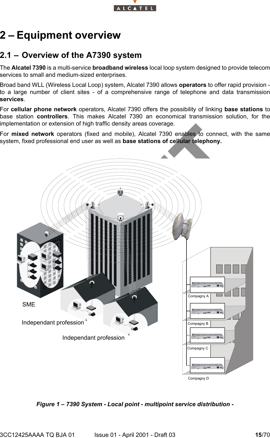
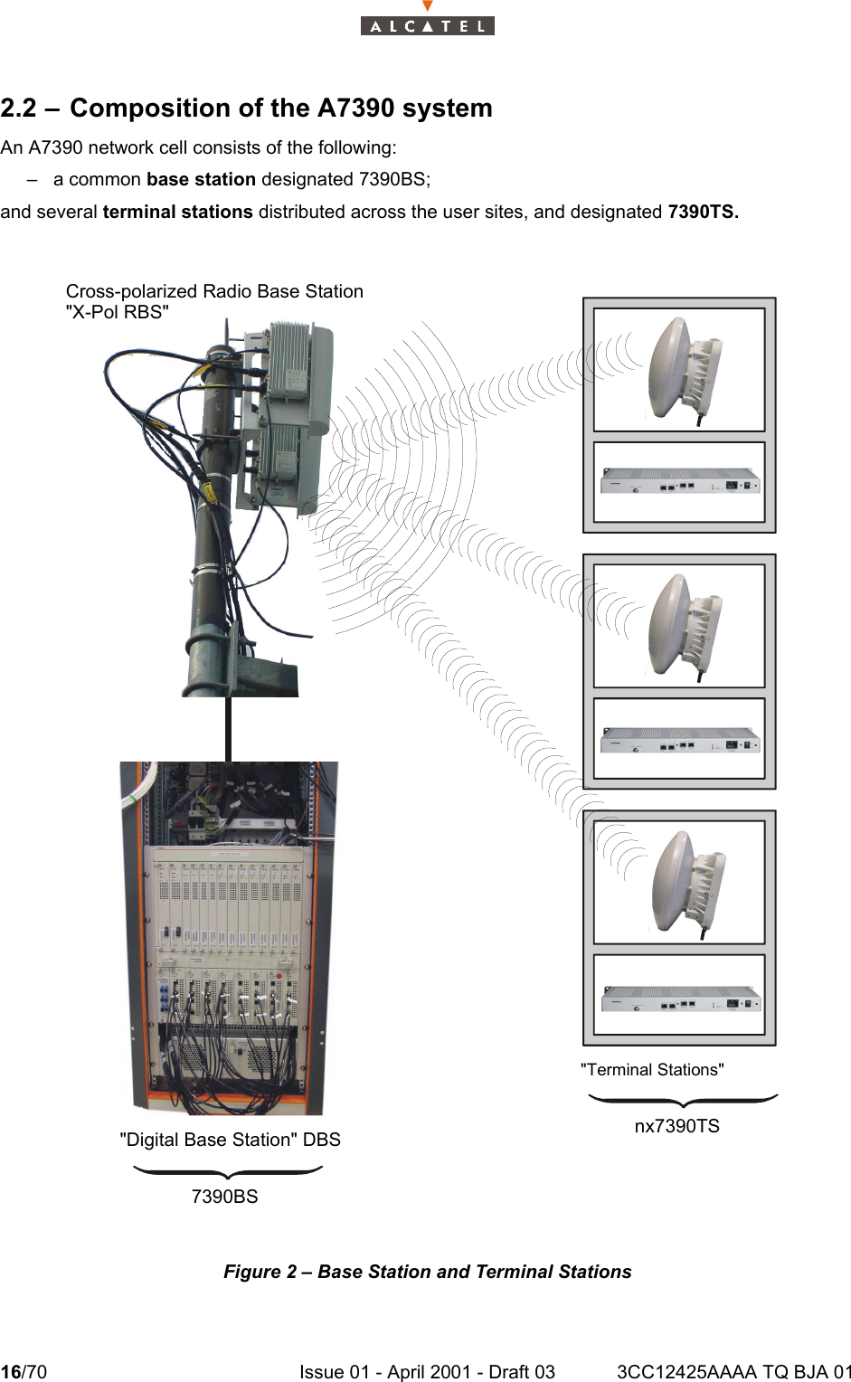
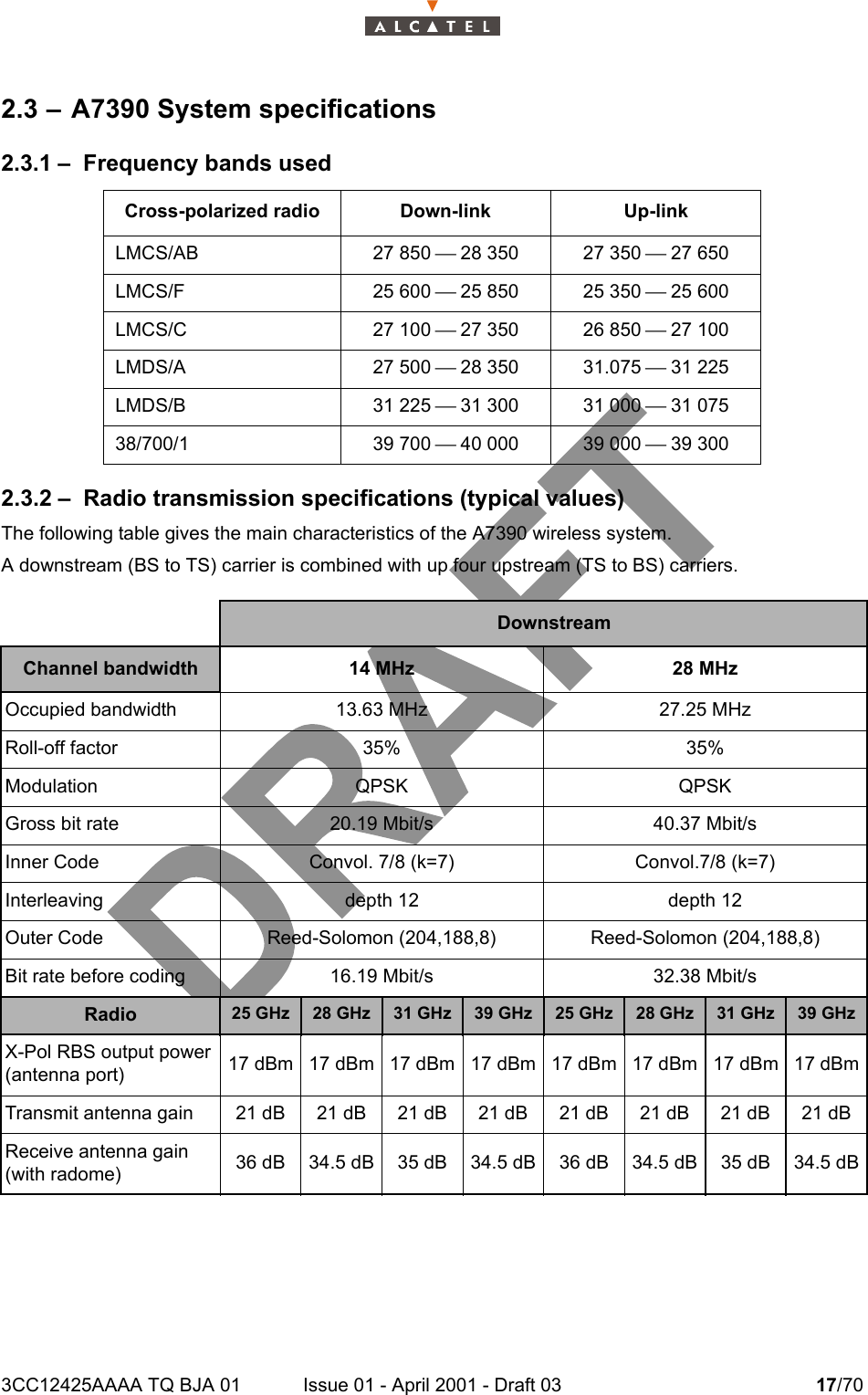
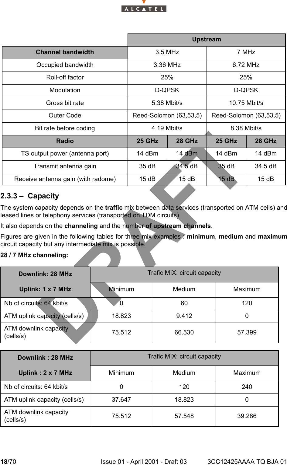
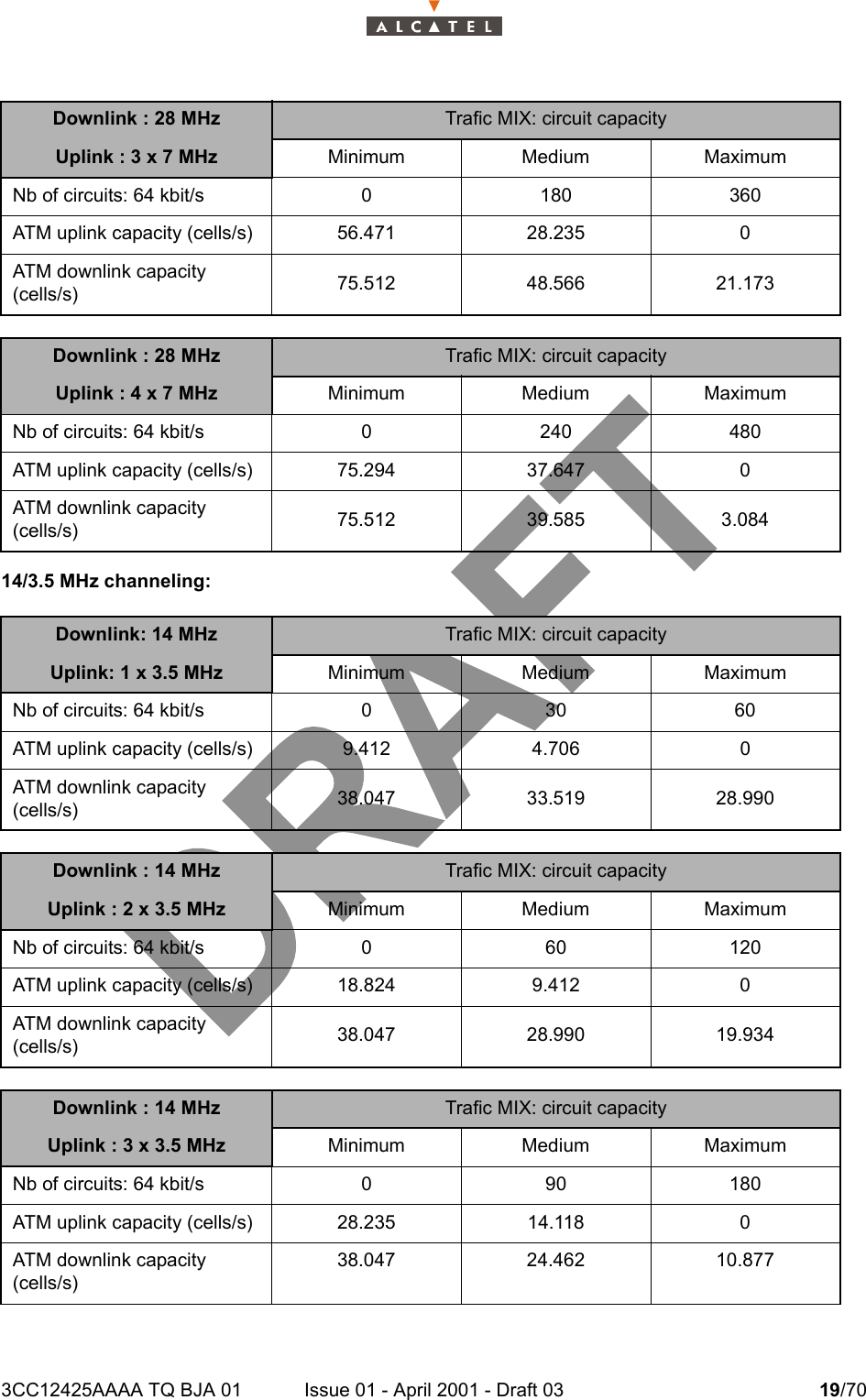
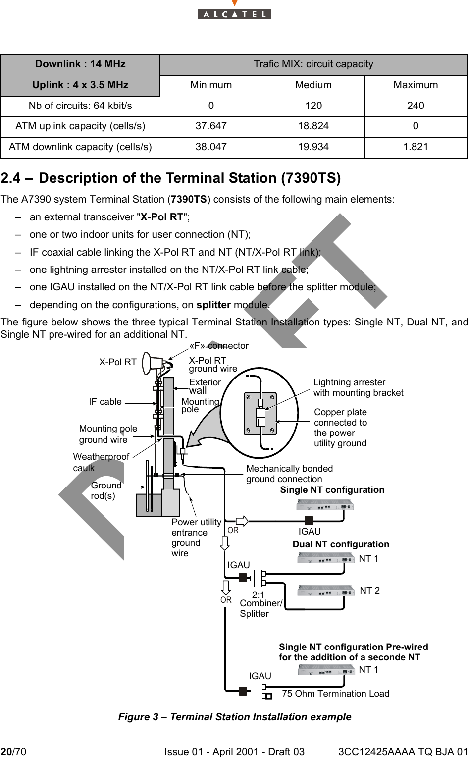
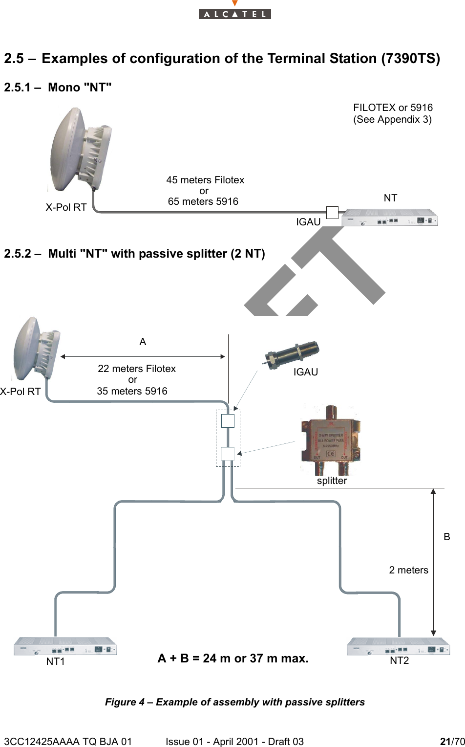
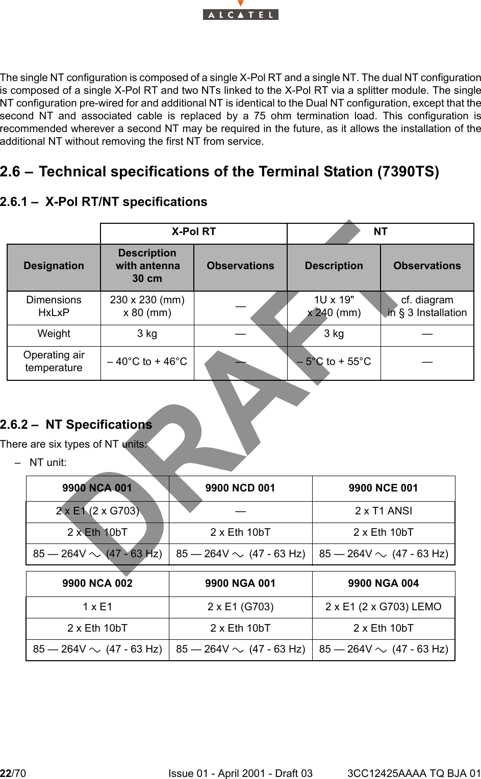
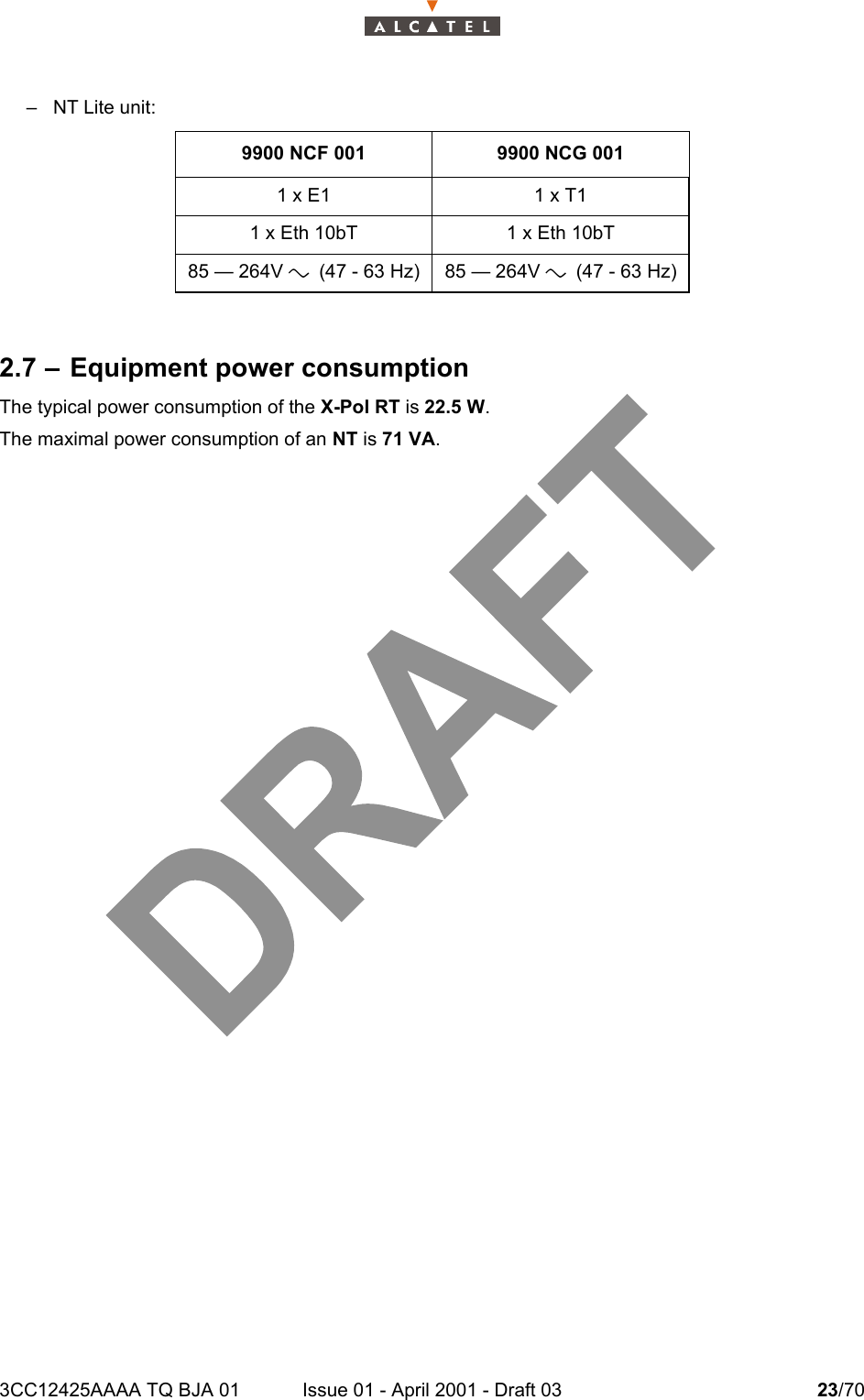
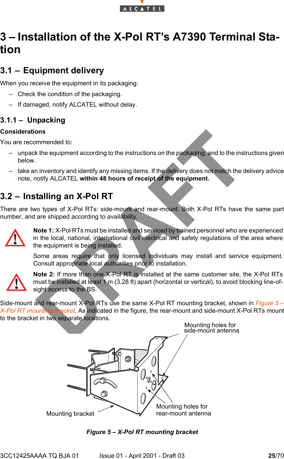
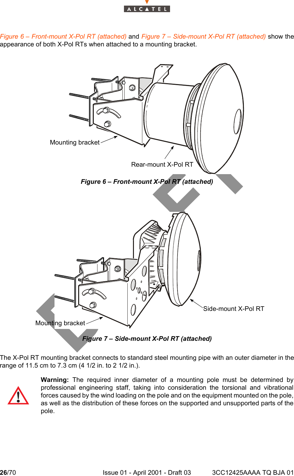
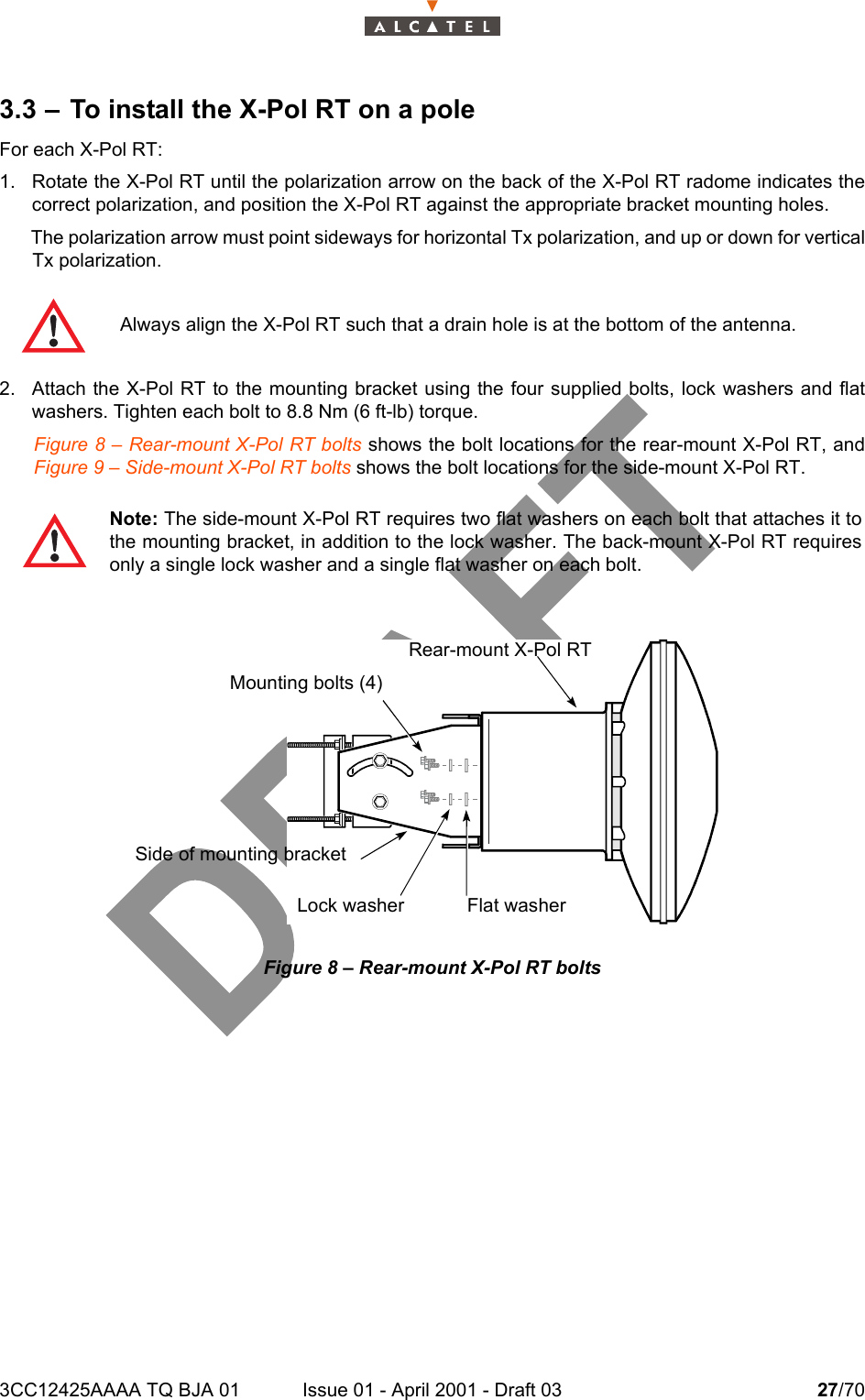
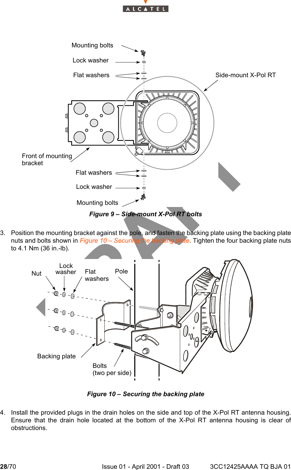
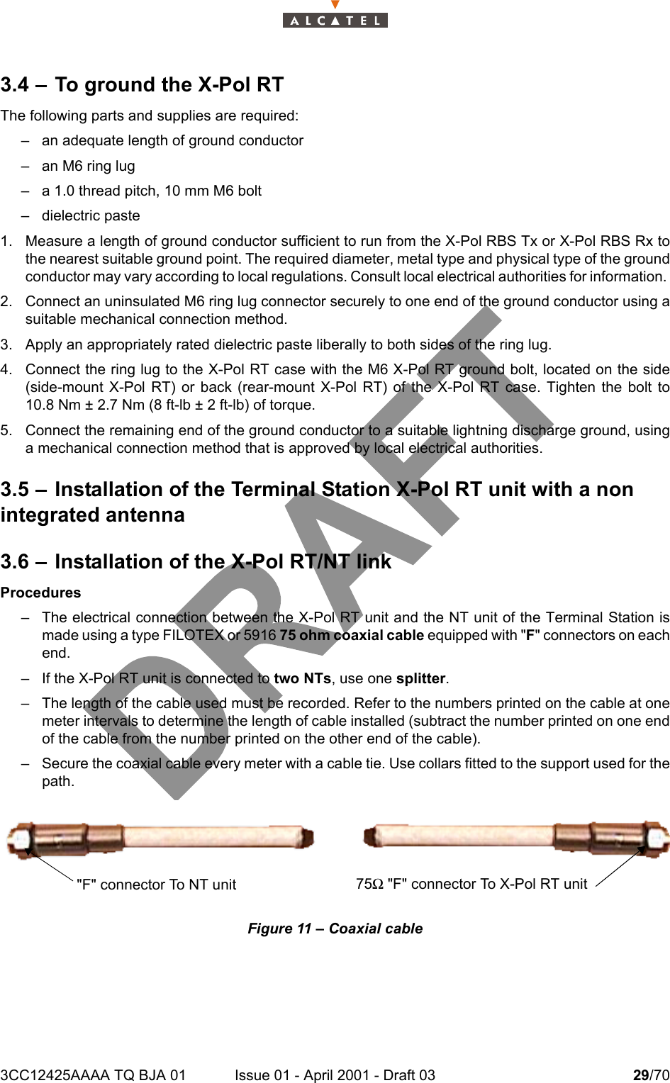
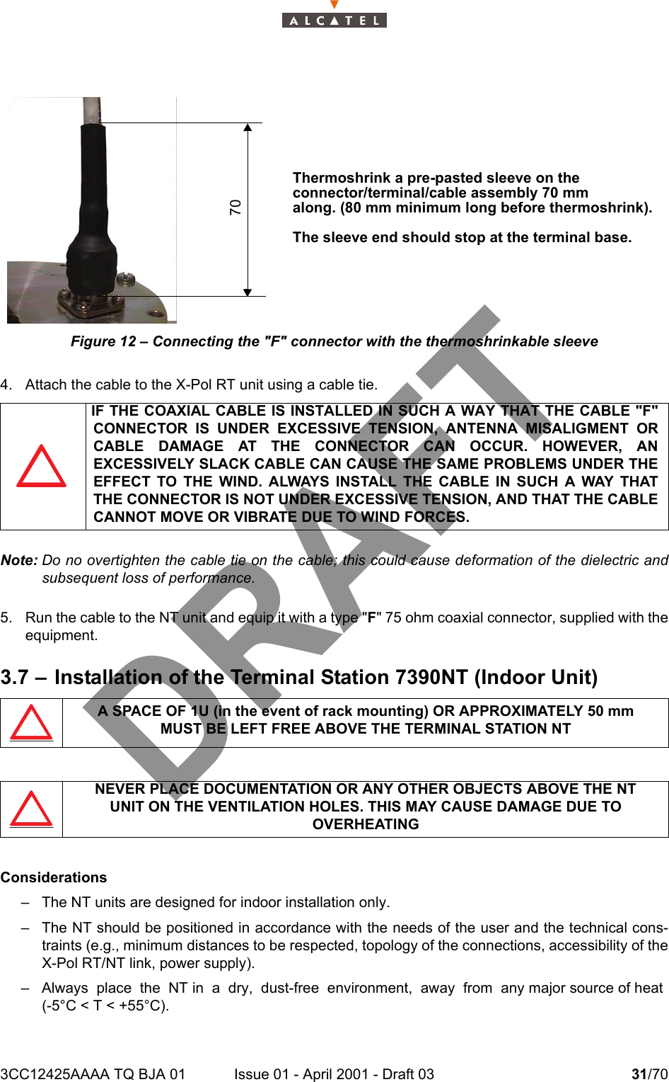
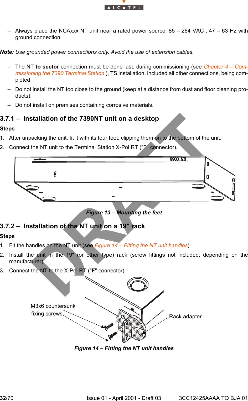
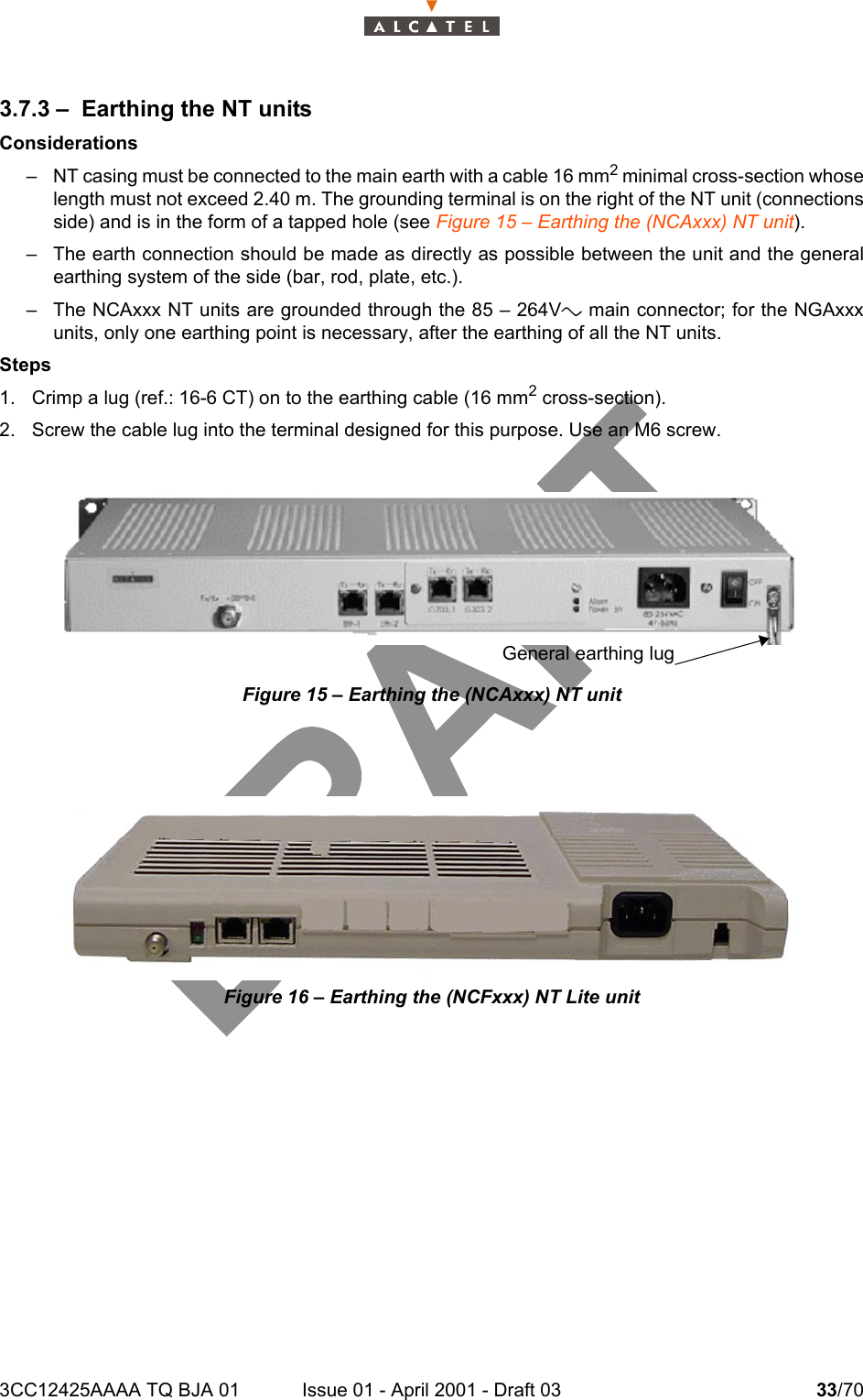
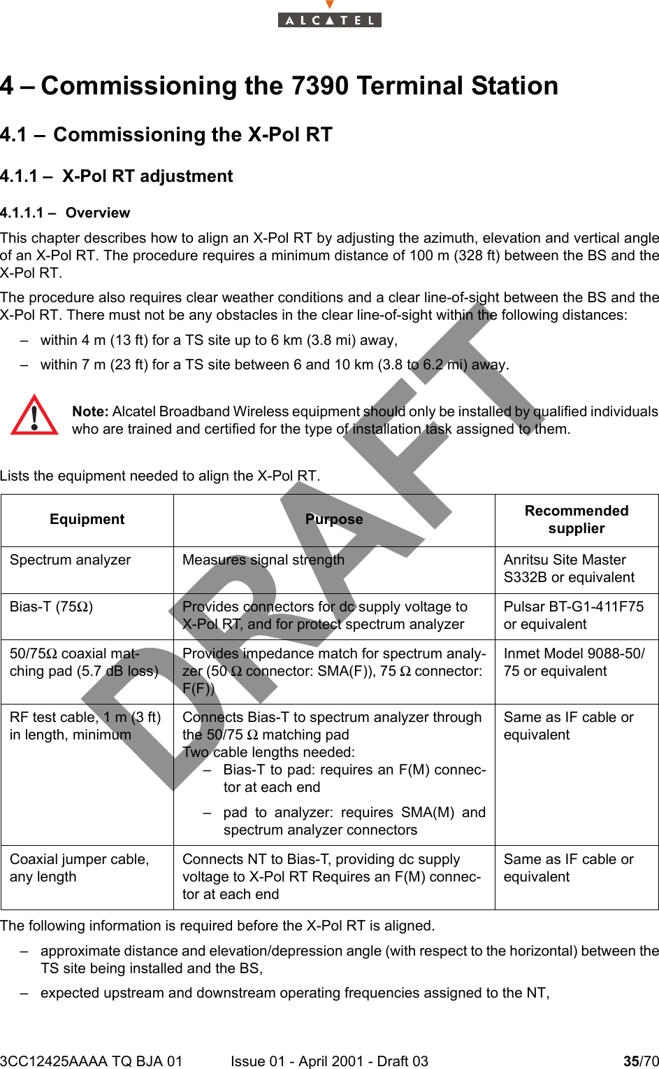
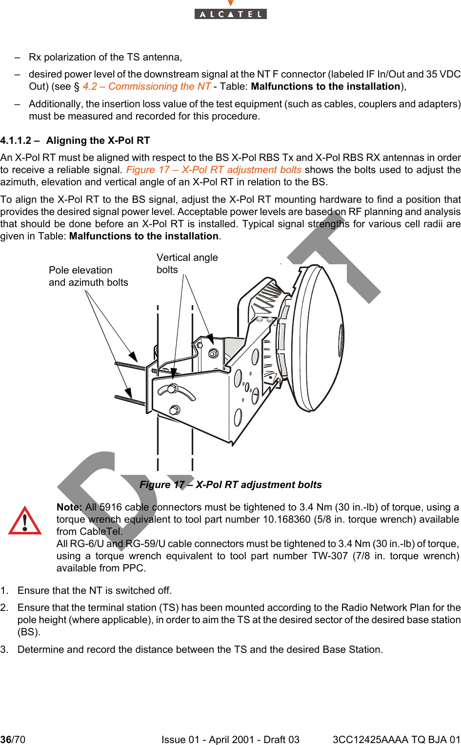
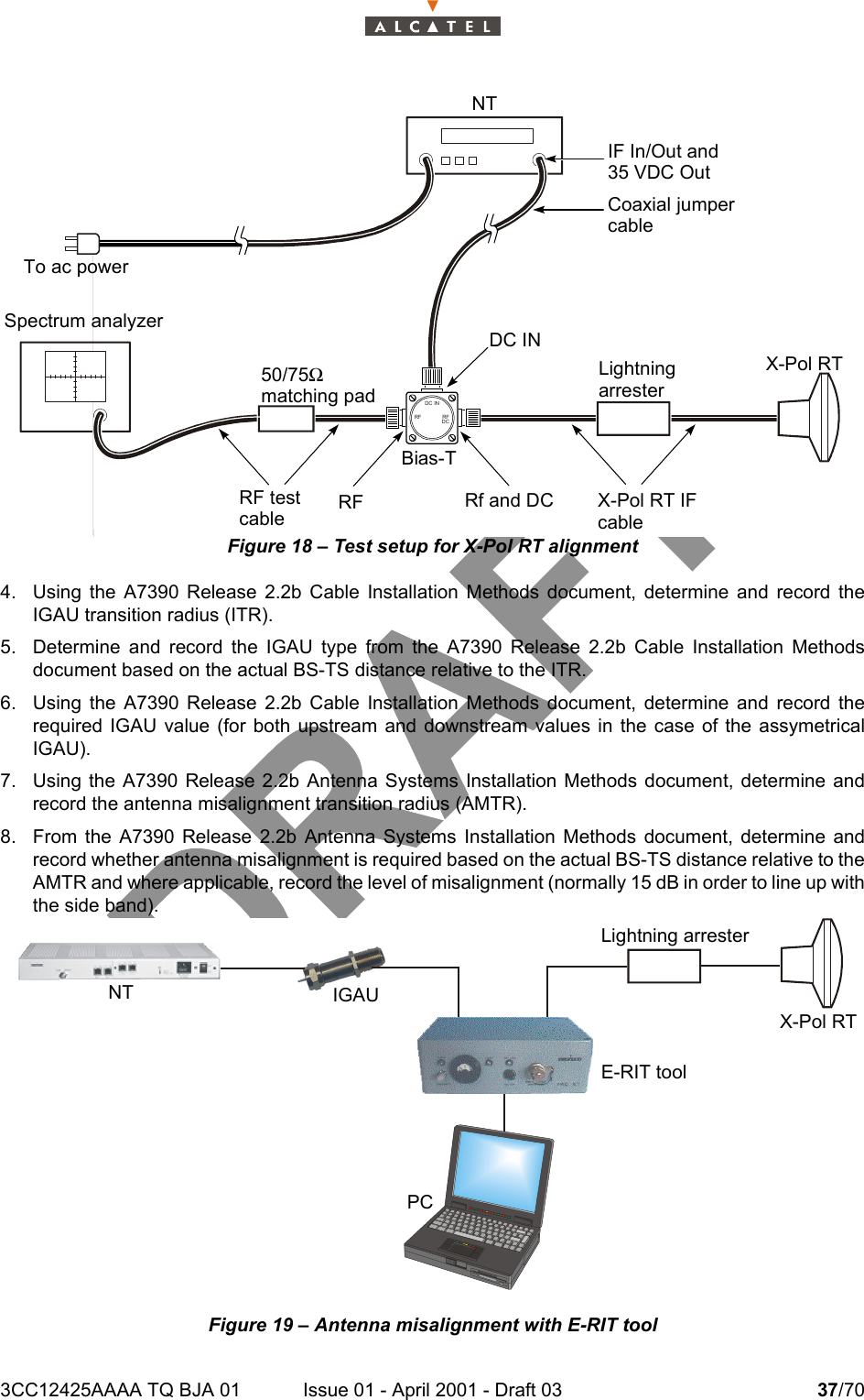
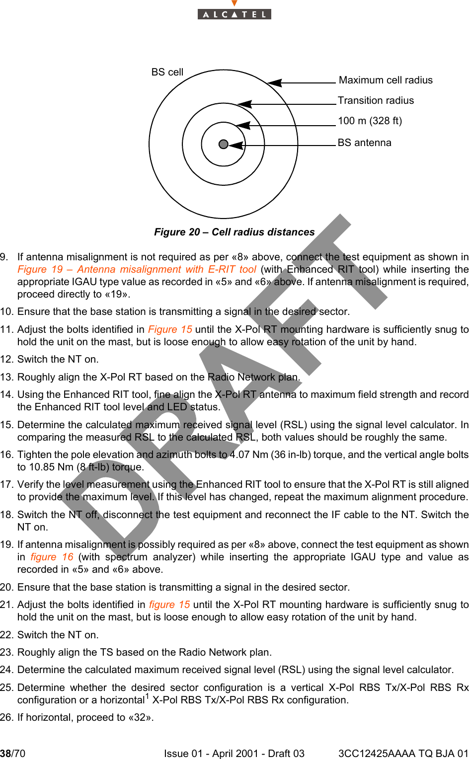
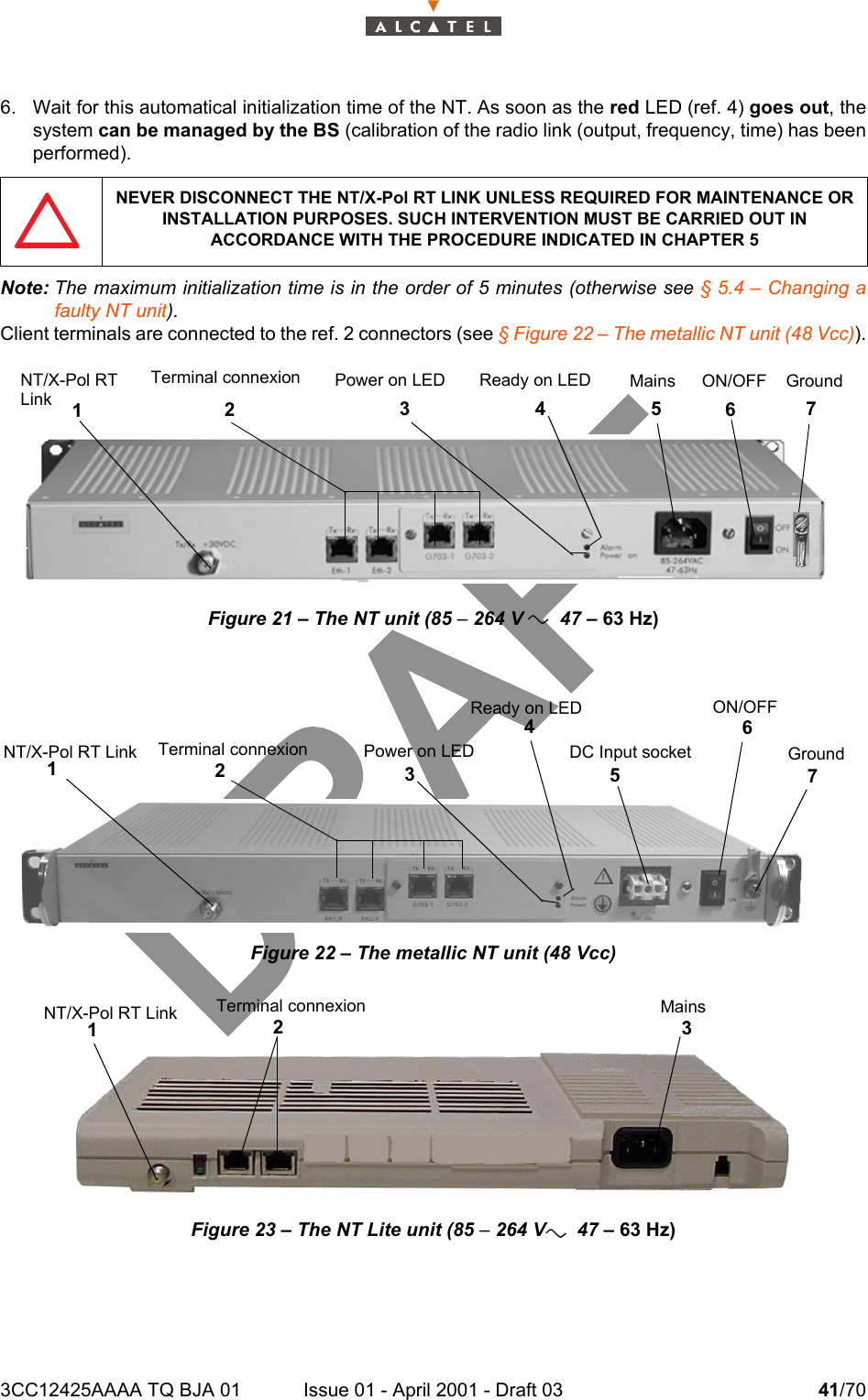
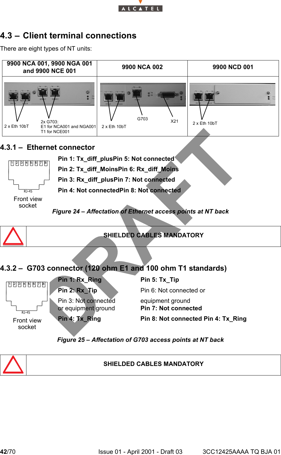
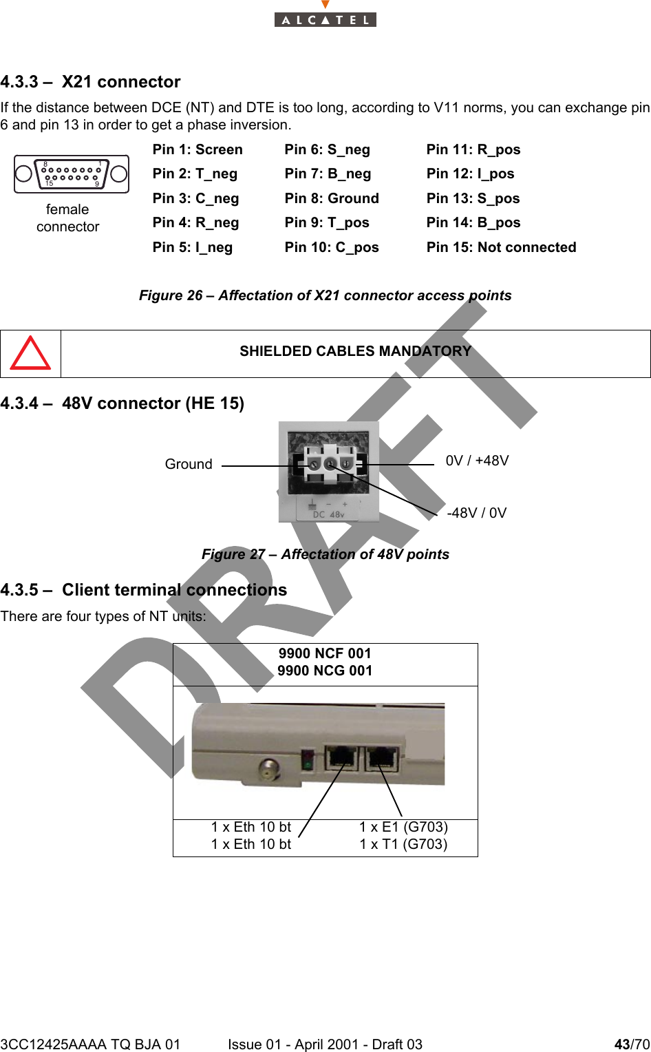
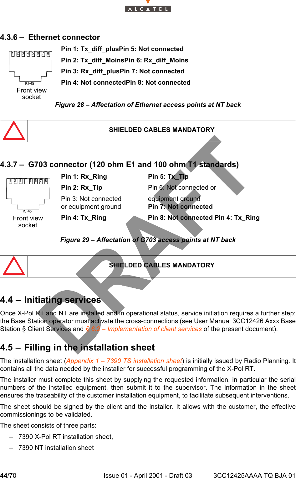
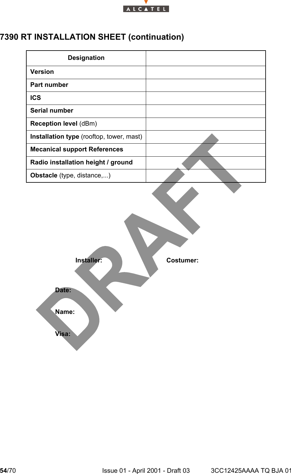
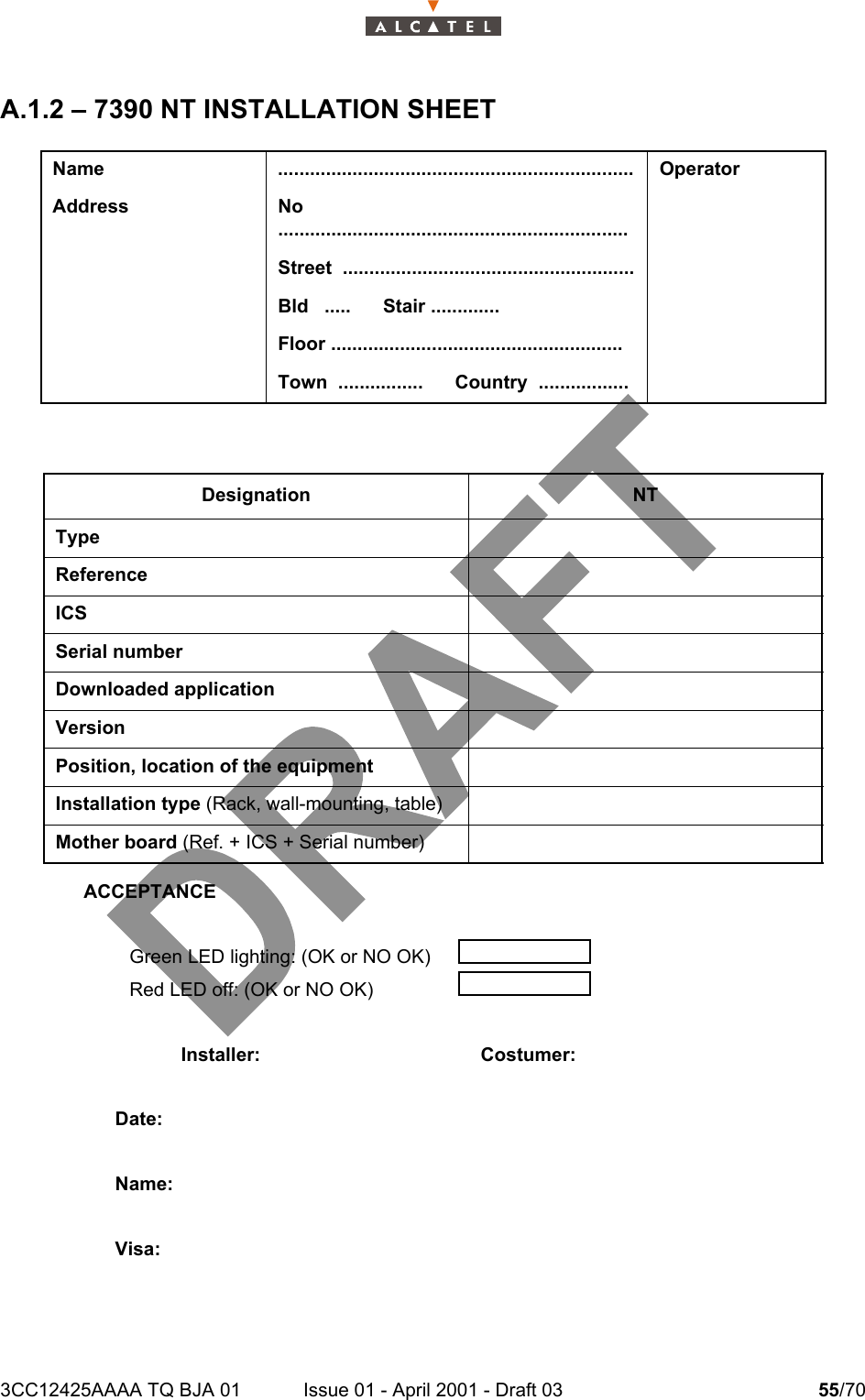
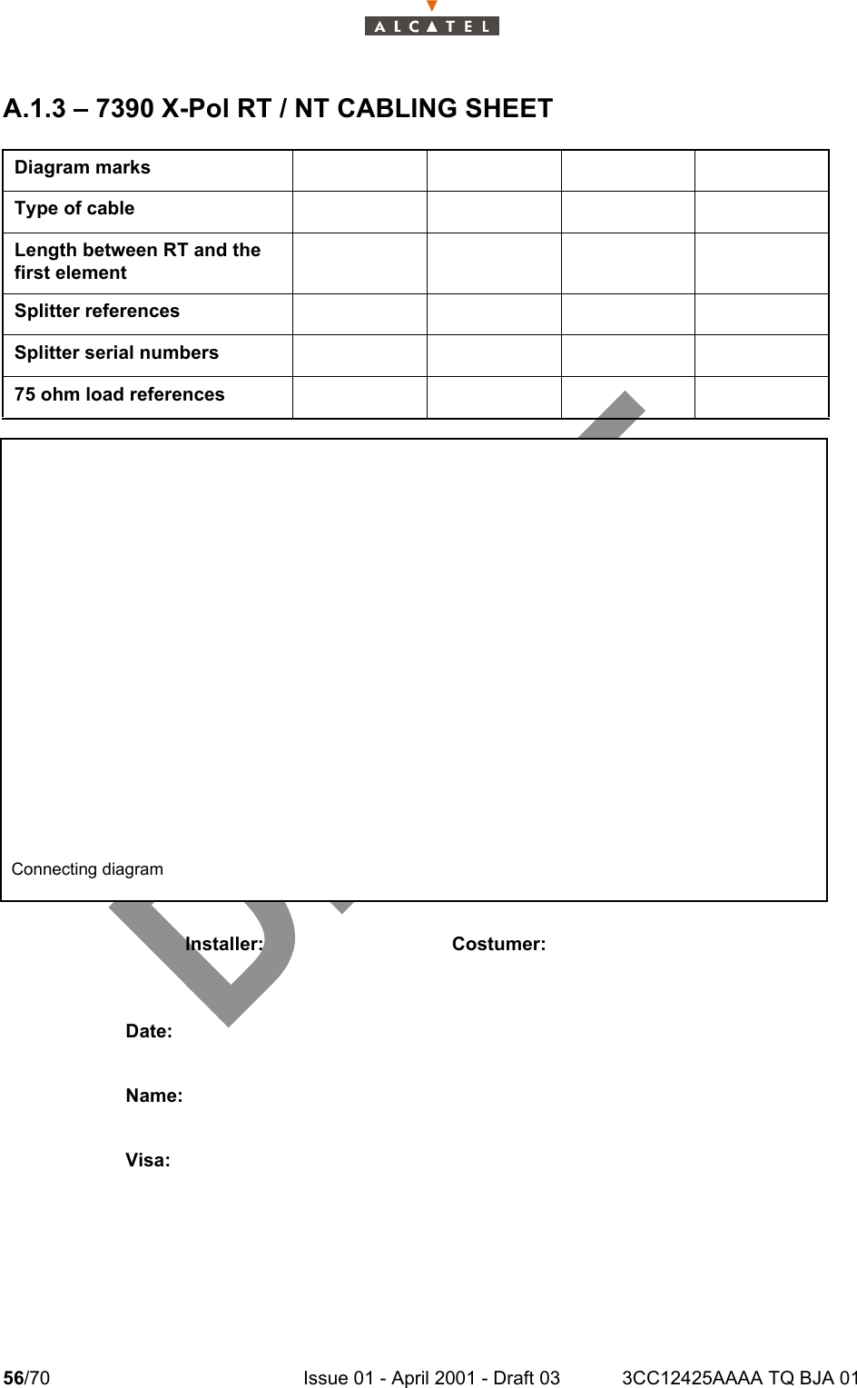
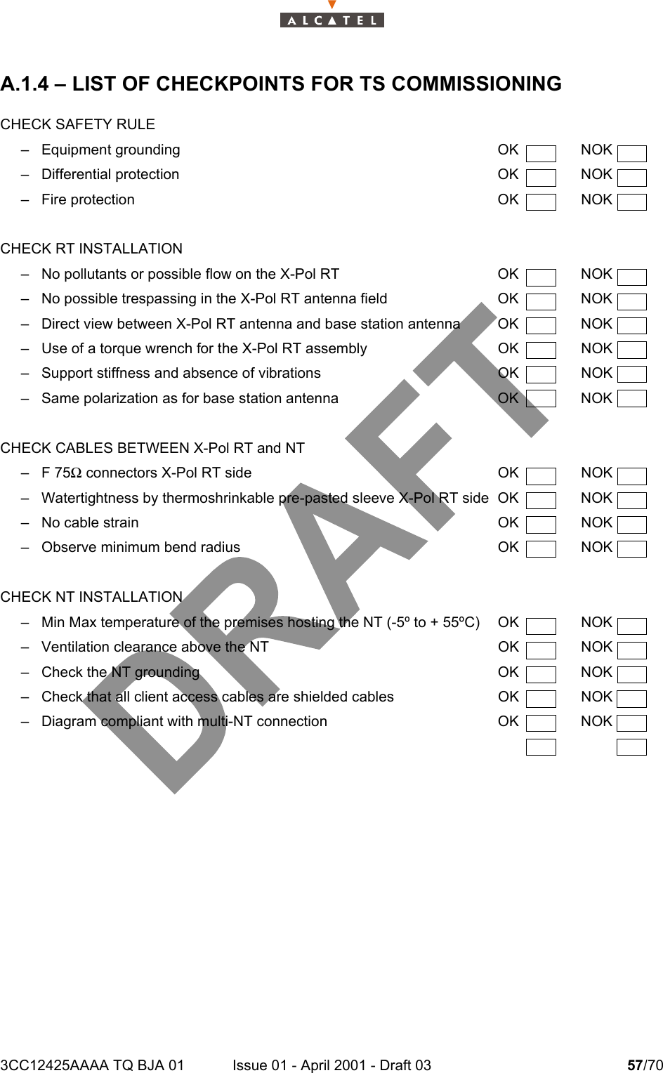
Terminal Station user manual 1 of 2

3CC12425AAAA TQ BJA Ed. 01Alcatel 7390Alcatel 7390Alcatel 7390Alcatel 7390Multiservice broadband wireless access solutionTerminal Station - release 2.2b(Ex 9900)(Ex 9900)(Ex 9900)(Ex 9900)Cross - Polarized versionUser Manual
2/70 Issue 01 - April 2001 - Draft 03 3CC12425AAAA TQ BJA 014Status DraftChange NoteShort Title A7390 Terminal Station – release 2.2bAll rights reserved. Passing on and copying of thisdocument, use and communication of its contents notpermitted without written authorization from Alcatel.
3CC12425AAAA TQ BJA 01 Issue 01 - April 2001 - Draft 03 3/704Customer Service Support:a Team tuned to your needs for your entire satisfactionCongratulations on having bought your equipment from Alcatel.We hope that it will give you full satisfaction.For any additional information or if you have any questions concerning this equipment, please contactthe Technical Assistance Center, (TAC) dedicated to your support whose coordinates have beengiven to you by the Alcatel Contract Manager or:http://www.cid.alcatel.com/support .You must specify the hardware and software configurations of each item concerned when getting intouch.This service, available on subscription, is free for the duration of the initial waranty period.
4/70 Issue 01 - April 2001 - Draft 03 3CC12425AAAA TQ BJA 014PAGE INTENTIONALLY LEFT BLANK
3CC12425AAAA TQ BJA 01 Issue 01 - April 2001 - Draft 03 5/706Table of contents1 –  Foreword . . . . . . . . . . . . . . . . . . . . . . . . . . . . . . . . . . . . . . . . . . . . . . . . . . . . . . . . . . . . . . . . . . 71.1 –  Structure of the manual . . . . . . . . . . . . . . . . . . . . . . . . . . . . . . . . . . . . . . . . . . . . . . . . . . . 71.2 –  Using the manual. . . . . . . . . . . . . . . . . . . . . . . . . . . . . . . . . . . . . . . . . . . . . . . . . . . . . . . . 71.3 –  Safety instructions . . . . . . . . . . . . . . . . . . . . . . . . . . . . . . . . . . . . . . . . . . . . . . . . . . . . . . . 81.3.1 –  General rules . . . . . . . . . . . . . . . . . . . . . . . . . . . . . . . . . . . . . . . . . . . . . . . . . . . . . 82 –  Equipment overview . . . . . . . . . . . . . . . . . . . . . . . . . . . . . . . . . . . . . . . . . . . . . . . . . . . . . . . . . 152.1 –  Overview of the A7390 system  . . . . . . . . . . . . . . . . . . . . . . . . . . . . . . . . . . . . . . . . . . . . . 152.2 –  Composition of the A7390 system . . . . . . . . . . . . . . . . . . . . . . . . . . . . . . . . . . . . . . . . . . . 162.3 –  A7390 System specifications. . . . . . . . . . . . . . . . . . . . . . . . . . . . . . . . . . . . . . . . . . . . . . . 172.3.1 –  Frequency bands used  . . . . . . . . . . . . . . . . . . . . . . . . . . . . . . . . . . . . . . . . . . . . . 172.3.2 –  Radio transmission specifications (typical values)  . . . . . . . . . . . . . . . . . . . . . . . . 172.3.3 –  Capacity. . . . . . . . . . . . . . . . . . . . . . . . . . . . . . . . . . . . . . . . . . . . . . . . . . . . . . . . .182.4 –  Description of the Terminal Station (7390TS) . . . . . . . . . . . . . . . . . . . . . . . . . . . . . . . . . . 202.5 –  Examples of configuration of the Terminal Station (7390TS)  . . . . . . . . . . . . . . . . . . . . . . 212.5.1 –  Mono "NT"   . . . . . . . . . . . . . . . . . . . . . . . . . . . . . . . . . . . . . . . . . . . . . . . . . . . . . . 212.5.2 –  Multi "NT" with passive splitter (2 NT) . . . . . . . . . . . . . . . . . . . . . . . . . . . . . . . . . . 212.6 –  Technical specifications of the Terminal Station (7390TS) . . . . . . . . . . . . . . . . . . . . . . . . 222.6.1 –  X-Pol RT/NT specifications . . . . . . . . . . . . . . . . . . . . . . . . . . . . . . . . . . . . . . . . . . 222.6.2 –  NT Specifications. . . . . . . . . . . . . . . . . . . . . . . . . . . . . . . . . . . . . . . . . . . . . . . . . . 222.7 –  Equipment power consumption . . . . . . . . . . . . . . . . . . . . . . . . . . . . . . . . . . . . . . . . . . . . . 233 –  Installation of the X-Pol RT’s A7390 Terminal Station  . . . . . . . . . . . . . . . . . . . . . . . . . . . . . 253.1 –  Equipment delivery  . . . . . . . . . . . . . . . . . . . . . . . . . . . . . . . . . . . . . . . . . . . . . . . . . . . . . . 253.1.1 –  Unpacking . . . . . . . . . . . . . . . . . . . . . . . . . . . . . . . . . . . . . . . . . . . . . . . . . . . . . . . 253.2 –  Installing an X-Pol RT  . . . . . . . . . . . . . . . . . . . . . . . . . . . . . . . . . . . . . . . . . . . . . . . . . . . . 253.3 –  To install the X-Pol RT on a pole . . . . . . . . . . . . . . . . . . . . . . . . . . . . . . . . . . . . . . . . . . . . 273.4 –  To ground the X-Pol RT. . . . . . . . . . . . . . . . . . . . . . . . . . . . . . . . . . . . . . . . . . . . . . . . . . .293.5 –  Installation of the Terminal Station X-Pol RT unit with a non integrated antenna . . . . . . . 293.6 –  Installation of the X-Pol RT/NT link . . . . . . . . . . . . . . . . . . . . . . . . . . . . . . . . . . . . . . . . . . 293.7 –  Installation of the Terminal Station 7390NT (Indoor Unit) . . . . . . . . . . . . . . . . . . . . . . . . . 313.7.1 –  Installation of the 7390NT unit on a desktop . . . . . . . . . . . . . . . . . . . . . . . . . . . . . 323.7.2 –  Installation of the NT unit on a 19" rack. . . . . . . . . . . . . . . . . . . . . . . . . . . . . . . . . 323.7.3 –  Earthing the NT units. . . . . . . . . . . . . . . . . . . . . . . . . . . . . . . . . . . . . . . . . . . . . . . 334 –  Commissioning the 7390 Terminal Station  . . . . . . . . . . . . . . . . . . . . . . . . . . . . . . . . . . . . . . 354.1 –  Commissioning the X-Pol RT. . . . . . . . . . . . . . . . . . . . . . . . . . . . . . . . . . . . . . . . . . . . . . . 354.1.1 –  X-Pol RT adjustment . . . . . . . . . . . . . . . . . . . . . . . . . . . . . . . . . . . . . . . . . . . . . . . 354.2 –  Commissioning the NT  . . . . . . . . . . . . . . . . . . . . . . . . . . . . . . . . . . . . . . . . . . . . . . . . . . .394.3 –  Client terminal connections . . . . . . . . . . . . . . . . . . . . . . . . . . . . . . . . . . . . . . . . . . . . . . . .424.3.1 –  Ethernet connector  . . . . . . . . . . . . . . . . . . . . . . . . . . . . . . . . . . . . . . . . . . . . . . . . 424.3.2 –  G703 connector (120 ohm E1 and 100 ohm T1 standards)  . . . . . . . . . . . . . . . . . 424.3.3 –  X21 connector . . . . . . . . . . . . . . . . . . . . . . . . . . . . . . . . . . . . . . . . . . . . . . . . . . . . 434.3.4 –  48V connector (HE 15)  . . . . . . . . . . . . . . . . . . . . . . . . . . . . . . . . . . . . . . . . . . . . . 434.3.5 –  Client terminal connections . . . . . . . . . . . . . . . . . . . . . . . . . . . . . . . . . . . . . . . . . . 434.3.6 –  Ethernet connector  . . . . . . . . . . . . . . . . . . . . . . . . . . . . . . . . . . . . . . . . . . . . . . . . 444.3.7 –  G703 connector (120 ohm E1 and 100 ohm T1 standards)  . . . . . . . . . . . . . . . . . 444.4 –  Initiating services . . . . . . . . . . . . . . . . . . . . . . . . . . . . . . . . . . . . . . . . . . . . . . . . . . . . . . . . 444.5 –  Filling in the installation sheet . . . . . . . . . . . . . . . . . . . . . . . . . . . . . . . . . . . . . . . . . . . . . . 444.5.1 –  7390 X-Pol RT installation sheet . . . . . . . . . . . . . . . . . . . . . . . . . . . . . . . . . . . . . . 45
6/70 Issue 01 - April 2001 - Draft 03 3CC12425AAAA TQ BJA 0164.5.2 –  NT installation sheet  . . . . . . . . . . . . . . . . . . . . . . . . . . . . . . . . . . . . . . . . . . . . . . . 454.5.3 –  X-Pol RT/NT wiring sheet  . . . . . . . . . . . . . . . . . . . . . . . . . . . . . . . . . . . . . . . . . . . 455 –  Operation and maintenance. . . . . . . . . . . . . . . . . . . . . . . . . . . . . . . . . . . . . . . . . . . . . . . . . . . 475.1 –  7390 system supervision . . . . . . . . . . . . . . . . . . . . . . . . . . . . . . . . . . . . . . . . . . . . . . . . . .475.2 –  Preventive maintenance  . . . . . . . . . . . . . . . . . . . . . . . . . . . . . . . . . . . . . . . . . . . . . . . . . .475.3 –  Corrective maintenance. . . . . . . . . . . . . . . . . . . . . . . . . . . . . . . . . . . . . . . . . . . . . . . . . . .475.4 –  Changing a faulty NT unit  . . . . . . . . . . . . . . . . . . . . . . . . . . . . . . . . . . . . . . . . . . . . . . . . .475.5 –  Changing a faulty X-Pol RT unit  . . . . . . . . . . . . . . . . . . . . . . . . . . . . . . . . . . . . . . . . . . . . 486 –  Changes of configuration  . . . . . . . . . . . . . . . . . . . . . . . . . . . . . . . . . . . . . . . . . . . . . . . . . . . . 496.1 –  Declaration, deletion, reset of an NT . . . . . . . . . . . . . . . . . . . . . . . . . . . . . . . . . . . . . . . . . 496.2 –  Implementation of client services. . . . . . . . . . . . . . . . . . . . . . . . . . . . . . . . . . . . . . . . . . . . 506.3 –  Changing an X-Pol RT. . . . . . . . . . . . . . . . . . . . . . . . . . . . . . . . . . . . . . . . . . . . . . . . . . . .506.4 –  Adding an additional NT to a TS site . . . . . . . . . . . . . . . . . . . . . . . . . . . . . . . . . . . . . . . . . 516.4.1 –  Case of a pre-wired installation . . . . . . . . . . . . . . . . . . . . . . . . . . . . . . . . . . . . . . . 516.4.2 –  Case of a non-pre-wired installation  . . . . . . . . . . . . . . . . . . . . . . . . . . . . . . . . . . . 516.5 –  To asign an NT to an alternate BS  . . . . . . . . . . . . . . . . . . . . . . . . . . . . . . . . . . . . . . . . . . 51Appendix 1 –  7390 TS installation sheet. . . . . . . . . . . . . . . . . . . . . . . . . . . . . . . . . . . . . . . . . . . . 53A.1.1 –  7390 X-Pol RT INSTALLATION SHEET  . . . . . . . . . . . . . . . . . . . . . . . . . . . . . . . . . . . . 53A.1.2 –  7390 NT INSTALLATION SHEET  . . . . . . . . . . . . . . . . . . . . . . . . . . . . . . . . . . . . . . . . . 55A.1.3 –  7390 X-Pol RT / NT CABLING SHEET  . . . . . . . . . . . . . . . . . . . . . . . . . . . . . . . . . . . . . 56A.1.4 –  LIST OF CHECKPOINTS FOR TS COMMISSIONING . . . . . . . . . . . . . . . . . . . . . . . . . 57Appendix 2 –  Climatic areas world map . . . . . . . . . . . . . . . . . . . . . . . . . . . . . . . . . . . . . . . . . . . . 59Appendix 3 –  Mounting coaxial connectors. . . . . . . . . . . . . . . . . . . . . . . . . . . . . . . . . . . . . . . . . 61A.3.1 –  Installing Stirling connectors. . . . . . . . . . . . . . . . . . . . . . . . . . . . . . . . . . . . . . . . . . . . . . 63A.3.1.1 –  To install a Stirling connector . . . . . . . . . . . . . . . . . . . . . . . . . . . . . . . . . . . . . . 63Appendix 4 –  Correspondence between commercial codes and industrialcodes relating to the TS  . . . . . . . . . . . . . . . . . . . . . . . . . . . . . . . . . . . . . . . . . . . . . 67Appendix 5 –  List of abbreviations . . . . . . . . . . . . . . . . . . . . . . . . . . . . . . . . . . . . . . . . . . . . . . . . 69
3CC12425AAAA TQ BJA 01 Issue 01 - April 2001 - Draft 03 7/70141 – Foreword1.1 – Structure of the manualThis manual is for users with a sound knowledge of how to operate and install point-multipointmicrowave systems and how to use a PC-based craft terminal running the WindowsTM operatingsystem. With it, you should quickly be able to operate the equipment. It is not intended to replace thetraining services that we can provide for your particular needs.The manual is divided into six sections followed by appendixes:– Foreword– Equipment overview– Installation of the X-Pol RT’s 7390 Terminal Station– Commissioning the 7390 Terminal Station– Operation and maintenance– Changes of configuration– Appendixes1.2 – Using the manualWith this manual, you should be able to commission and operate the described equipment to a basiclevel.You should always read this manual in conjunction with the attached "Update" document (if provided) sothat you are aware of the latest equipment upgrades.Manual updatesThis edition of the manual describes hardware and software releases of the following revision indexesand above:Hardware revision: 01In cases where an equipment upgrade affects the content of the manual, the relevant modification shouldbe inserted in the "Update" document, with the same reference number, but with code type VE (insteadof TQ).When the number or extent of the changes justifies it, they should be incorporated in the body of themanual and the manual's revision index should be incremented. Revision bars will show the differencesfrom the previous version.Note: MS-DOS, MICROSOFT and WINDOWS are registered trademarks of Microsoft Corporation.
8/70 Issue 01 - April 2001 - Draft 03 3CC12425AAAA TQ BJA 01141.3 – Safety instructions1.3.1 – General rulesThe following general safety precautions must be observed by the installer and the operator.ALCATEL assumes no liability for the customer's failure to comply with these requirements.•Ground the equipment: for Safety Class 1 equipment, always connect the earth conductor ofthe power cable to an appropriate earthing device.• DO NOT operate the product in an explosive atmosphere or in presence of flammablegases or fumes.•For protection against fire: replace the line fuse(s) only with fuse(s) of the same voltage andcurrent rating and type.•Dangerous voltages: users must not remove equipment covers or shields. The installationand maintenance procedures described in this manual are for use by service-trained personnelonly.•Protection against short circuits: the mains equipment should ensure protection againstshort circuits according to the current domestic standards (residual current differential protec-tion recommended).• Observe the standards in force for all activities carried out on the roofs.• For any on-site intervention, observe the precautions against lightning.• DO NOT operate equipment which may be damaged: its protection level could be affec-ted.• Whenever it is possible that the safety protection features built into this equipment have beenimpaired, ISOLATE FROM THE POWER SUPPLY and do not use the equipment until safeoperation can be verified by service-trained personnel. If necessary, return the equipment toAlcatel After Sales for service and repair.• DO NOT OPEN THE EQUIPMENT.• Return the product to Alcatel Customer Service for servicing and repair.•Recommendation to installers and maintenance operators: before carrying out any ope-rations, check the equipotential bonding of the earthing devices to which our measurementequipment and instruments are connected. If necessary, during installation, ensure the equi-potential bonding by electrical connection of these devices.Local regulationsAll BS and CPE installations must adhere to all local, national and civil electrical/safety regulations of thearea where they are installed.Wireless safety compliance in the United States of America It is the responsibility of the wireless licence holder to ensure that the requirements of OET Bulletin 65are met in the USA.Wireless safety compliance in CanadaIt is the responsibility of the wireless licence holder to ensure that the requirements of Safety Code 6 aremet in Canada.
3CC12425AAAA TQ BJA 01 Issue 01 - April 2001 - Draft 03 9/7014Placement of transmitting equipmentTo prevent exposure to non-ionizing radiation, the X-Pol RT should always be mounted at a minimum of3 m (10 ft) above ground level or roof-top level. An X-Pol RT that is mounted on a wall should be mountedat least 3 m (10 ft) away from any point of exposure such as windows, balconies or doors.X-Pol RT service and repair safety precautionsOnly authorized personnel should service X-Pol RT units.Equipment interconnection pointsAll card faceplate connectors are SELV.Connect SELV circuits on this equipment only to other circuits that comply with the requirements of SELVcircuits as defined in EN60950.Restriction of unauthorized accessOnly authorized personnel should have access to the equipment. Install the equipment in a restricted-access location or similar environment, and post appropriate warning signs to indicate safety concerns.Failure to prevent unauthorized user access will invalidate any approvals given to this equipment.Regulatory symbolsThe following sections show examples of regulatory approval symbols generally used. They may beused on product markings such as approval labels. These symbols are described in IEC417.Power onPower offDanger - Never touch the X-Pol RT antennas while they are in operation. Do not stand infront of X-Pol RT antennas, and never pass closer than 1 m (3 ft) in front of an operating orX-Pol RT.Power to X-Pol RTs must be disconnected prior to installation or servicing.Service and repair preparation activities should be made as close as possible to the base ofan elevated X-Pol RT, as the risk of exposure to non-ionizing radiation increases as youmove further from the base toward the area that is serviced by the transmitter.This symbol indicates the on position of the main on/off switch.This symbol indicates the off (O) position of the main on/off switch.
10/70 Issue 01 - April 2001 - Draft 03 3CC12425AAAA TQ BJA 0114Protective grounding terminalThese symbols indicate a terminal that must be connected to earth ground prior to making anyother connections to the equipment. Dangerous voltageThis symbol indicates the presence of uninsulated “dangerous voltage” within the product's enclo-sure that could cause electric shock. Labels bearing this symbol are installed on the outside of theproduct enclosure.InstructionsThis symbol indicates the existence of important operating and maintenance (servicing) instruc-tions in the product documentation.Elevated non-ionizing radiation levelsThis symbol identifies equipment that emits elevated levels of non-ionizing radiation. Do not ap-proach equipment that is marked with this symbol unless power to the device is disconnected. Labels bearing this symbol are installed on the outside casing of transmitter devices.Supply wire protective earthProtective earthDangerous voltage symbolImportant instructions symbolElevated non-ionizing radiation levels symbol
3CC12425AAAA TQ BJA 01 Issue 01 - April 2001 - Draft 03 11/7014International EMC complianceThe EMC compliance of these products relies on the user following the installation processes correctly. Failure to follow the correct installation processes may result in non-compliance to the EMC standardsagainst which these products have been assessed.Appropriate shielded cables must be used to connect NT to telecommunications equipment.NT EMC complianceThis Class B digital apparatus complies with Canadian ICES-003. Cet appareil numérique de la classe B est conforme à la norme NMB-003 du Canada.DBS card EMC complianceThis Class A digital apparatus complies with Canadian ICES-003. Cet appareil numérique de la classe A est conforme à la norme NMB-003 du Canada.Industry Canada regulationsThe Industry Canada (formerly known as the Department of Communications) label identifies certifiedequipment. This certification means that the equipment meets certain telecommunications networkprotective, operational and safety requirements as prescribed in the Terminal Equipment TechnicalRequirements document(s). Industry Canada does not guarantee that the equipment will operate to theuser's satisfaction.Before installing this equipment, users should ensure that it is permissible to be connected to thefacilities of the local telecommunications company. The equipment must also be installed using anacceptable method of connection. The customer should be aware that compliance with the aboveconditions may not prevent degradation of service in some situations. Repairs to certified equipment should be coordinated by a representative designated by the supplier.Any repairs or alterations made by the user to this equipment, or any equipment malfunctions, may givethe telecommunications company cause to request the user to disconnect the equipment.For their own protection, users should ensure that the electrical ground connections of the power utility,telephone lines and internal metallic water pipe system, if present, are connected together. Thisprecaution may be particularly important in rural areas.The Ringer Equivalence Number (formerly known as Load Number) assigned to each terminal deviceprovides an indication of the maximum number of terminals allowed to be connected to a telephoneinterface. The termination on an interface may consist of any combination of devices subject only to therequirement that the sum of the Ringer Equivalence Numbers of all the devices does not exceed five (5).The Ringer Equivalence Number regulations do not apply to the NT.Safety approval for dc systemsThe dc source for the Alcatel Broadband Wireless system must meet the requirements of a SELV sourcein accordance with CSA C22.2 No. 950. These systems are intended for use with a SELV secondarysource that is electrically isolated from the ac source, and that is reliably connected to ground.Caution - Users should not attempt to make electrical ground connections, but shouldcontact the appropriate electrical inspection authority or electrician.
12/70 Issue 01 - April 2001 - Draft 03 3CC12425AAAA TQ BJA 0114United States Federal Communications Commission regulationsThis equipment has been approved to the Federal Communications Commission Part 68 Rules as notbeing harmful to the telephone network when connected directly to telephone lines. Customers must,upon request from the telephone company, provide the following information:– FCC Registration Numbers– USOC: RJ48C– FIC: 04DU9-BN/DN/1KN/1SN– SOC: 6.0YThe FCC identification number can be found on the product label located on the product chassis.The REN determines the number of devices that users can connect to their telephone line and still havethe assurance that these devices will ring properly when their number is called. In most, but not all areas,the sum of the RENs for all devices should not exceed five (5.0). To determine the maximum number ofdevices users can connect to their line, as specified by the REN, users must contact the local telephonecompany and request the information on the maximum REN for their calling area.If the user equipment causes harm to the telephone network, the telephone company may temporarilydiscontinue service to the line. If possible and practical, the company will notify the user in advance. Ifnot, the company will notify the user as soon as possible. Included in the notification, the users will beadvised of their right to file a complaint with the FCC.The telephone company may make changes to its facilities, equipment, operations and procedures thatcould affect the operation of user’s equipment. Before these changes are made, the telephone companywill provide advance notice that service will be interrupted.FCC regulations prohibit the connection of customer-provided equipment to coin service (central officeimplemented systems). Connection to party lines is subject to tariffs; contact the state public utilitycommission, public service commission or corporation commission for information. In the event thatrepairs are needed to this equipment, contact:Alcatel Inc.810 Commerce Park Drive, Ogdensburg, NY 136691-315-393-9981This equipment has been tested and found to comply with the limits for a Class A digital device, pursuantto Part 15 of the FCC Rules. These limits are designed to provide reasonable protection against harmfulinterference in a commercial environment. This equipment generates, uses and can radiate radiofrequency energy and if not installed and used in accordance with the instruction manual, may causeharmful interference to radio communications. Operation of this equipment in a residential area is likelyto cause harmful interference, in which case, the user will be required to correct the interference at theirown expense.
3CC12425AAAA TQ BJA 01 Issue 01 - April 2001 - Draft 03 13/7014Food and Drug Administration This product complies with 21 CFR 1040.10 and 1040.11 regulations, which govern the safe use oflasers. Only qualified service personnel, thoroughly familiar with laser radiation hazards, should installor remove the fiber optic cables used in this system. Information regarding the safe use of lasers can befound in ANSI Z 136.1: Safe Use of Lasers and ANSI Z 136.2: Safe Use of Lasers in Optical FiberCommunications Systems. These documents and other instructional material can be obtained from:Laser Institute of America12424 Research Parkway, Suite 125Orlando, FL   32826-3274 CSA NRTLThis equipment is certified by the Canadian Standards Association as meeting the requirements ofUL1950, Safety of Information Technology Equipment (or UL1459, Safety of Telephone Equipment).CSA is listed by the American Federal Occupational Safety and Health Administration as equivalent toUnderwriters Laboratories and other American safety testing laboratories under the NationallyRecognized Testing Laboratories program.Safety precautions for installing TNV devicesDanger 1 - Never install telephone wiring during a lightning storm. Use caution wheninstalling or modifying telephone lines. Danger 2 - Never touch uninsulated telephone wires or terminals unless the telephone linehas been disconnected at the telephone network interface. Never install telephone jacks inwet locations, unless the jack is specifically designed for wet locations.Caution - Always disconnect the NT from the telephone system when installing or removingcovers from connected equipment.
14/70 Issue 01 - April 2001 - Draft 03 3CC12425AAAA TQ BJA 0114PAGE INTENTIONALLY LEFT BLANK
3CC12425AAAA TQ BJA 01 Issue 01 - April 2001 - Draft 03 15/70242 – Equipment overview2.1 – Overview of the A7390 systemThe Alcatel 7390 is a multi-service broadband wireless local loop system designed to provide telecomservices to small and medium-sized enterprises.Broad band WLL (Wireless Local Loop) system, Alcatel 7390 allows operators to offer rapid provision -to a large number of client sites - of a comprehensive range of telephone and data transmissionservices.For cellular phone network operators, Alcatel 7390 offers the possibility of linking base stations tobase station controllers. This makes Alcatel 7390 an economical transmission solution, for theimplementation or extension of high traffic density areas coverage.For  mixed network operators (fixed and mobile), Alcatel 7390 enables to connect, with the samesystem, fixed professional end user as well as base stations of cellular telephony.Figure 1 – 7390 System - Local point - multipoint service distribution -SMEIndependant professionIndependant professionCompagny DCompagny ACompagny BCompagny C
16/70 Issue 01 - April 2001 - Draft 03 3CC12425AAAA TQ BJA 01242.2 – Composition of the A7390 systemAn A7390 network cell consists of the following:–a common base station designated 7390BS;and several terminal stations distributed across the user sites, and designated 7390TS.Figure 2 – Base Station and Terminal Stations"Digital Base Station" DBS"Terminal Stations"Cross-polarized Radio Base Station7390BSnx7390TS"X-Pol RBS"
3CC12425AAAA TQ BJA 01 Issue 01 - April 2001 - Draft 03 17/70242.3 – A7390 System specifications2.3.1 – Frequency bands used2.3.2 – Radio transmission specifications (typical values)The following table gives the main characteristics of the A7390 wireless system.A downstream (BS to TS) carrier is combined with up four upstream (TS to BS) carriers.Cross-polarized radio Down-link Up-linkLMCS/AB 27 850  28 350 27 350  27 650LMCS/F 25 600  25 850 25 350  25 600LMCS/C 27 100  27 350 26 850  27 100LMDS/A 27 500  28 350 31.075  31 225LMDS/B 31 225  31 300 31 000  31 07538/700/1 39 700  40 000 39 000  39 300    DownstreamChannel bandwidth 14 MHz 28 MHzOccupied bandwidth 13.63 MHz 27.25 MHzRoll-off factor 35% 35%Modulation QPSK QPSKGross bit rate 20.19 Mbit/s 40.37 Mbit/sInner Code Convol. 7/8 (k=7) Convol.7/8 (k=7)Interleaving depth 12 depth 12Outer Code Reed-Solomon (204,188,8) Reed-Solomon (204,188,8)Bit rate before coding 16.19 Mbit/s 32.38 Mbit/sRadio 25 GHz 28 GHz 31 GHz 39 GHz 25 GHz 28 GHz 31 GHz 39 GHzX-Pol RBS output power (antenna port) 17 dBm 17 dBm 17 dBm 17 dBm 17 dBm 17 dBm 17 dBm 17 dBmTransmit antenna gain 21 dB 21 dB 21 dB 21 dB 21 dB 21 dB 21 dB 21 dBReceive antenna gain (with radome) 36 dB 34.5 dB 35 dB 34.5 dB 36 dB 34.5 dB 35 dB 34.5 dB
18/70 Issue 01 - April 2001 - Draft 03 3CC12425AAAA TQ BJA 01242.3.3 – CapacityThe system capacity depends on the traffic mix between data services (transported on ATM cells) andleased lines or telephony services (transported on TDM circuits)It also depends on the channeling and the number of upstream channels.Figures are given in the following tables for three mix examples : minimum, medium and maximumcircuit capacity but any intermediate mix is possible.28 / 7 MHz channeling:UpstreamChannel bandwidth 3.5 MHz 7 MHzOccupied bandwidth 3.36 MHz 6.72 MHzRoll-off factor 25% 25%Modulation D-QPSK D-QPSKGross bit rate 5.38 Mbit/s 10.75 Mbit/sOuter Code Reed-Solomon (63,53,5) Reed-Solomon (63,53,5)Bit rate before coding 4.19 Mbit/s 8.38 Mbit/sRadio 25 GHz 28 GHz 25 GHz 28 GHzTS output power (antenna port) 14 dBm 14 dBm 14 dBm 14 dBmTransmit antenna gain 35 dB 34.5 dB 35 dB 34.5 dBReceive antenna gain (with radome) 15 dB 15 dB 15 dB 15 dBDownlink: 28 MHz Trafic MIX: circuit capacityUplink: 1 x 7 MHz Minimum Medium MaximumNb of circuits: 64 kbit/s 0 60 120ATM uplink capacity (cells/s) 18.823 9.412 0ATM downlink capacity (cells/s) 75.512 66.530 57.399Downlink : 28 MHz Trafic MIX: circuit capacityUplink : 2 x 7 MHz Minimum Medium MaximumNb of circuits: 64 kbit/s 0 120 240ATM uplink capacity (cells/s) 37.647 18.823 0ATM downlink capacity (cells/s) 75.512 57.548 39.286
3CC12425AAAA TQ BJA 01 Issue 01 - April 2001 - Draft 03 19/702414/3.5 MHz channeling:Downlink : 28 MHz Trafic MIX: circuit capacityUplink : 3 x 7 MHz Minimum Medium MaximumNb of circuits: 64 kbit/s 0 180 360ATM uplink capacity (cells/s) 56.471 28.235 0ATM downlink capacity (cells/s) 75.512 48.566 21.173Downlink : 28 MHz Trafic MIX: circuit capacityUplink : 4 x 7 MHz Minimum Medium MaximumNb of circuits: 64 kbit/s 0 240 480ATM uplink capacity (cells/s) 75.294 37.647 0ATM downlink capacity (cells/s) 75.512 39.585 3.084Downlink: 14 MHz Trafic MIX: circuit capacityUplink: 1 x 3.5 MHz Minimum Medium MaximumNb of circuits: 64 kbit/s 0 30 60ATM uplink capacity (cells/s) 9.412 4.706 0ATM downlink capacity (cells/s) 38.047 33.519 28.990Downlink : 14 MHz Trafic MIX: circuit capacityUplink : 2 x 3.5 MHz Minimum Medium MaximumNb of circuits: 64 kbit/s 0 60 120ATM uplink capacity (cells/s) 18.824 9.412 0ATM downlink capacity (cells/s) 38.047 28.990 19.934Downlink : 14 MHz Trafic MIX: circuit capacityUplink : 3 x 3.5 MHz Minimum Medium MaximumNb of circuits: 64 kbit/s 0 90 180ATM uplink capacity (cells/s) 28.235 14.118 0ATM downlink capacity (cells/s)38.047 24.462 10.877
20/70 Issue 01 - April 2001 - Draft 03 3CC12425AAAA TQ BJA 01242.4 – Description of the Terminal Station (7390TS)The A7390 system Terminal Station (7390TS) consists of the following main elements:– an external transceiver "X-Pol RT";– one or two indoor units for user connection (NT);– IF coaxial cable linking the X-Pol RT and NT (NT/X-Pol RT link);– one lightning arrester installed on the NT/X-Pol RT link cable;– one IGAU installed on the NT/X-Pol RT link cable before the splitter module;– depending on the configurations, on splitter module.The figure below shows the three typical Terminal Station Installation types: Single NT, Dual NT, andSingle NT pre-wired for an additional NT.Figure 3 – Terminal Station Installation exampleDownlink : 14 MHz Trafic MIX: circuit capacityUplink : 4 x 3.5 MHz Minimum Medium MaximumNb of circuits: 64 kbit/s 0 120 240ATM uplink capacity (cells/s) 37.647 18.824 0ATM downlink capacity (cells/s) 38.047 19.934 1.821ORORX-Pol RTX-Pol RT ground wire«F» connectorExteriorwallIF cable MountingpoleMounting poleground wireWeatherproofcaulkGroundrod(s)IGAUPower utilityentrancegroundwireLightning arresterwith mounting bracketCopper plateconnected tothe powerutility groundMechanically bondedground connectionSingle NT configurationDual NT configurationNT 1NT 22:1Combiner/SplitterSingle NT configuration Pre-wiredfor the addition of a seconde NTNT 175 Ohm Termination LoadIGAUIGAU
3CC12425AAAA TQ BJA 01 Issue 01 - April 2001 - Draft 03 21/70242.5 – Examples of configuration of the Terminal Station (7390TS)2.5.1 – Mono "NT" 2.5.2 – Multi "NT" with passive splitter (2 NT)Figure 4 – Example of assembly with passive splitters65 meters 5916X-Pol RT  NTIGAU45 meters FilotexorFILOTEX or 5916(See Appendix 3)X-Pol RTsplitter NT1 NT2IGAU35 meters 591622 meters Filotexor2 metersABA + B = 24 m or 37 m max.
22/70 Issue 01 - April 2001 - Draft 03 3CC12425AAAA TQ BJA 0124The single NT configuration is composed of a single X-Pol RT and a single NT. The dual NT configurationis composed of a single X-Pol RT and two NTs linked to the X-Pol RT via a splitter module. The singleNT configuration pre-wired for and additional NT is identical to the Dual NT configuration, except that thesecond NT and associated cable is replaced by a 75 ohm termination load. This configuration isrecommended wherever a second NT may be required in the future, as it allows the installation of theadditional NT without removing the first NT from service.2.6 – Technical specifications of the Terminal Station (7390TS)2.6.1 – X-Pol RT/NT specifications2.6.2 – NT SpecificationsThere are six types of NT units:–NT unit:X-Pol RT NTDesignationDescription with antenna   30 cmObservations Description ObservationsDimensionsHxLxP230 x 230 (mm)x 80 (mm) —1U x 19"x 240 (mm)cf. diagramin § 3 InstallationWeight 3 kg — 3 kg —Operating airtemperature – 40°C to + 46°C — – 5°C to + 55°C —9900 NCA 001 9900 NCD 001 9900 NCE 0012 x E1 (2 x G703) — 2 x T1 ANSI2 x Eth 10bT 2 x Eth 10bT 2 x Eth 10bT85 — 264V a (47 - 63 Hz) 85 — 264V a (47 - 63 Hz) 85 — 264V a (47 - 63 Hz)9900 NCA 002 9900 NGA 001 9900 NGA 0041 x E1 2 x E1 (G703) 2 x E1 (2 x G703) LEMO2 x Eth 10bT 2 x Eth 10bT 2 x Eth 10bT85 — 264V a (47 - 63 Hz) 85 — 264V a (47 - 63 Hz) 85 — 264V a (47 - 63 Hz)
3CC12425AAAA TQ BJA 01 Issue 01 - April 2001 - Draft 03 23/7024– NT Lite unit:2.7 – Equipment power consumptionThe typical power consumption of the X-Pol RT is 22.5 W.The maximal power consumption of an NT is 71 VA.9900 NCF 001 9900 NCG 0011 x E1 1 x T11 x Eth 10bT 1 x Eth 10bT85 — 264V a (47 - 63 Hz) 85 — 264V a (47 - 63 Hz)
24/70 Issue 01 - April 2001 - Draft 03 3CC12425AAAA TQ BJA 0124PAGE INTENTIONALLY LEFT BLANK
3CC12425AAAA TQ BJA 01 Issue 01 - April 2001 - Draft 03 25/70343 – Installation of the X-Pol RT’s A7390 Terminal Sta-tion3.1 – Equipment deliveryWhen you receive the equipment in its packaging:– Check the condition of the packaging.– If damaged, notify ALCATEL without delay.3.1.1 – UnpackingConsiderationsYou are recommended to:– unpack the equipment according to the instructions on the packaging, and to the instructions givenbelow.– take an inventory and identify any missing items. If the delivery does not match the delivery advicenote, notify ALCATEL within 48 hours of receipt of the equipment.3.2 – Installing an X-Pol RTThere are two types of X-Pol RTs: side-mount and rear-mount. Both X-Pol RTs have the same partnumber, and are shipped according to availability.Side-mount and rear-mount X-Pol RTs use the same X-Pol RT mounting bracket, shown in Figure 5 –X-Pol RT mounting bracket. As indicated in the figure, the rear-mount and side-mount X-Pol RTs mountto the bracket in two separate locations.Figure 5 – X-Pol RT mounting bracketNote 1: X-Pol RTs must be installed and serviced by trained personnel who are experiencedin the local, national, international civil electrical and safety regulations of the area wherethe equipment is being installed.Some areas require that only licensed individuals may install and service equipment.Consult appropriate local authorities prior to installation.Note 2: If more than one X-Pol RT is installed at the same customer site, the X-Pol RTsmust be installed at least 1 m (3.28 ft) apart (horizontal or vertical), to avoid blocking line-of-sight access to the BS.Mounting holes forMounting holes forrear-mount antennaMounting bracketside-mount antenna
26/70 Issue 01 - April 2001 - Draft 03 3CC12425AAAA TQ BJA 0134Figure 6 – Front-mount X-Pol RT (attached) and Figure 7 – Side-mount X-Pol RT (attached) show theappearance of both X-Pol RTs when attached to a mounting bracket.Figure 6 – Front-mount X-Pol RT (attached)Figure 7 – Side-mount X-Pol RT (attached)The X-Pol RT mounting bracket connects to standard steel mounting pipe with an outer diameter in therange of 11.5 cm to 7.3 cm (4 1/2 in. to 2 1/2 in.).Warning:  The required inner diameter of a mounting pole must be determined byprofessional engineering staff, taking into consideration the torsional and vibrationalforces caused by the wind loading on the pole and on the equipment mounted on the pole,as well as the distribution of these forces on the supported and unsupported parts of thepole.Rear-mount X-Pol RTMounting bracketSide-mount X-Pol RTMounting bracket
3CC12425AAAA TQ BJA 01 Issue 01 - April 2001 - Draft 03 27/70343.3 – To install the X-Pol RT on a poleFor each X-Pol RT:1. Rotate the X-Pol RT until the polarization arrow on the back of the X-Pol RT radome indicates thecorrect polarization, and position the X-Pol RT against the appropriate bracket mounting holes.The polarization arrow must point sideways for horizontal Tx polarization, and up or down for verticalTx polarization.2. Attach the X-Pol RT to the mounting bracket using the four supplied bolts, lock washers and flatwashers. Tighten each bolt to 8.8 Nm (6 ft-lb) torque. Figure 8 – Rear-mount X-Pol RT bolts shows the bolt locations for the rear-mount X-Pol RT, andFigure 9 – Side-mount X-Pol RT bolts shows the bolt locations for the side-mount X-Pol RT. Figure 8 – Rear-mount X-Pol RT boltsAlways align the X-Pol RT such that a drain hole is at the bottom of the antenna.Note: The side-mount X-Pol RT requires two flat washers on each bolt that attaches it tothe mounting bracket, in addition to the lock washer. The back-mount X-Pol RT requiresonly a single lock washer and a single flat washer on each bolt.Rear-mount X-Pol RTMounting bolts (4)Side of mounting bracketLock washer Flat washer
28/70 Issue 01 - April 2001 - Draft 03 3CC12425AAAA TQ BJA 0134Figure 9 – Side-mount X-Pol RT bolts3. Position the mounting bracket against the pole, and fasten the backing plate using the backing platenuts and bolts shown in Figure 10 – Securing the backing plate. Tighten the four backing plate nutsto 4.1 Nm (36 in.-lb).Figure 10 – Securing the backing plate4. Install the provided plugs in the drain holes on the side and top of the X-Pol RT antenna housing.Ensure that the drain hole located at the bottom of the X-Pol RT antenna housing is clear ofobstructions.Side-mount X-Pol RTMounting boltsLock washerFlat washersFront of mountingbracketMounting boltsLock washerFlat washersNutLockwasher FlatwashersPoleBacking plateBolts(two per side)
3CC12425AAAA TQ BJA 01 Issue 01 - April 2001 - Draft 03 29/70343.4 – To ground the X-Pol RTThe following parts and supplies are required:– an adequate length of ground conductor– an M6 ring lug– a 1.0 thread pitch, 10 mm M6 bolt– dielectric paste1. Measure a length of ground conductor sufficient to run from the X-Pol RBS Tx or X-Pol RBS Rx tothe nearest suitable ground point. The required diameter, metal type and physical type of the groundconductor may vary according to local regulations. Consult local electrical authorities for information. 2. Connect an uninsulated M6 ring lug connector securely to one end of the ground conductor using asuitable mechanical connection method.3. Apply an appropriately rated dielectric paste liberally to both sides of the ring lug.4. Connect the ring lug to the X-Pol RT case with the M6 X-Pol RT ground bolt, located on the side(side-mount X-Pol RT) or back (rear-mount X-Pol RT) of the X-Pol RT case. Tighten the bolt to10.8 Nm ± 2.7 Nm (8 ft-lb ± 2 ft-lb) of torque. 5. Connect the remaining end of the ground conductor to a suitable lightning discharge ground, usinga mechanical connection method that is approved by local electrical authorities. 3.5 – Installation of the Terminal Station X-Pol RT unit with a non integrated antenna3.6 – Installation of the X-Pol RT/NT linkProcedures– The electrical connection between the X-Pol RT unit and the NT unit of the Terminal Station ismade using a type FILOTEX or 5916 75 ohm coaxial cable equipped with "F" connectors on eachend.– If the X-Pol RT unit is connected to two NTs, use one splitter.– The length of the cable used must be recorded. Refer to the numbers printed on the cable at onemeter intervals to determine the length of cable installed (subtract the number printed on one endof the cable from the number printed on the other end of the cable).– Secure the coaxial cable every meter with a cable tie. Use collars fitted to the support used for thepath.Figure 11 – Coaxial cable75Ω "F" connector To X-Pol RT unit"F" connector To NT unit
30/70 Issue 01 - April 2001 - Draft 03 3CC12425AAAA TQ BJA 0134– Physical cable characteristics are:• diameter = 7.5 mm,• maximum installed cable length  = 65 meters or 35 meters cable 5916 or45 meters or 22 meters cable FILOTEX,• minimal bend radius = 40 mm,• minimal bend radius = 100 mm for a "drip loop".Steps1. Install the 75 ohm connector between the X-Pol RT unit and the NT unit.Note: In the event of the use of splitters, use the number of cables required by the configuration.Note: Make a drip loop where the cable enters the building, respecting the cable's bending radius(100 mm minimum), in order to prevent water infiltration.2. Record the length of the cable installed in the 7390 X-Pol RT cabling sheet. This information will beentered into the database when the equipment is commissioned using the configuration software.Note:  The accuracy required by the configuration software is ± 1.5 m.3. At the X-Pol RT, install a type "F" 75 ohm coaxial connector (designed for outdoor use) on the cable.Refer to the manufacturer’s Assembly manual and use the specific tools as recommended forinstalling the connector. One of the main causes of installation problems is the faulty installation ofconnectors.AVOID LONG CABLE RUNS PARALLEL TO CABLES THAT COULD CAUSE INTERFERENCE (E.G. AC POWER OR GSM/DCS BASE STATION CABLES)ALWAYS USE A "F" CONNECTOR WITH A CENTER PIN NOT EXCEEDING 0.042 INCH. DIAMETER ANY OTHER CONNECTOR IS USED, THE X-Pol RT COULD BE DAMAGEDIMPORTANT NOTE: NEVER HANDLE THE X-Pol RT UNIT BY ITS ANTENNA. ALWAYS HANDLE THE UNIT BY THE BODY OF THE RADIO OR THE SUPPORT ARMIMPERATIVE : PROTECT THE "F" CONNECTOR CONNECTION WITHA PRE-PASTED THERMOSHRINKABLE SLEEVE
3CC12425AAAA TQ BJA 01 Issue 01 - April 2001 - Draft 03 31/7034Figure 12 – Connecting the "F" connector with the thermoshrinkable sleeve4. Attach the cable to the X-Pol RT unit using a cable tie.Note: Do no overtighten the cable tie on the cable; this could cause deformation of the dielectric andsubsequent loss of performance.5. Run the cable to the NT unit and equip it with a type "F" 75 ohm coaxial connector, supplied with theequipment.3.7 – Installation of the Terminal Station 7390NT (Indoor Unit)Considerations– The NT units are designed for indoor installation only.– The NT should be positioned in accordance with the needs of the user and the technical cons-traints (e.g., minimum distances to be respected, topology of the connections, accessibility of theX-Pol RT/NT link, power supply).– Always  place  the  NT in  a  dry,  dust-free  environment,  away  from  any major source of heat(-5°C < T < +55°C).IF THE COAXIAL CABLE IS INSTALLED IN SUCH A WAY THAT THE CABLE "F"CONNECTOR IS UNDER EXCESSIVE TENSION, ANTENNA MISALIGMENT ORCABLE DAMAGE AT THE CONNECTOR CAN OCCUR. HOWEVER, ANEXCESSIVELY SLACK CABLE CAN CAUSE THE SAME PROBLEMS UNDER THEEFFECT TO THE WIND. ALWAYS INSTALL THE CABLE IN SUCH A WAY THATTHE CONNECTOR IS NOT UNDER EXCESSIVE TENSION, AND THAT THE CABLECANNOT MOVE OR VIBRATE DUE TO WIND FORCES.A SPACE OF 1U (in the event of rack mounting) OR APPROXIMATELY 50 mmMUST BE LEFT FREE ABOVE THE TERMINAL STATION NTNEVER PLACE DOCUMENTATION OR ANY OTHER OBJECTS ABOVE THE NTUNIT ON THE VENTILATION HOLES. THIS MAY CAUSE DAMAGE DUE TO OVERHEATING70Thermoshrink a pre-pasted sleeve on theconnector/terminal/cable assembly 70 mmalong. (80 mm minimum long before thermoshrink).The sleeve end should stop at the terminal base.
32/70 Issue 01 - April 2001 - Draft 03 3CC12425AAAA TQ BJA 0134– Always place the NCAxxx NT unit near a rated power source: 85 – 264 VAC , 47 – 63 Hz withground connection.Note: Use grounded power connections only. Avoid the use of extension cables.– The NT to sector connection must be done last, during commissioning (see Chapter 4 – Com-missioning the 7390 Terminal Station ), TS installation, included all other connections, being com-pleted.– Do not install the NT too close to the ground (keep at a distance from dust and floor cleaning pro-ducts).– Do not install on premises containing corrosive materials.3.7.1 – Installation of the 7390NT unit on a desktopSteps1. After unpacking the unit, fit it with its four feet, clipping them on to the bottom of the unit.2. Connect the NT unit to the Terminal Station X-Pol RT ("F" connector).Figure 13 – Mounting the feet3.7.2 – Installation of the NT unit on a 19" rackSteps1. Fit the handles on the NT unit (see Figure 14 – Fitting the NT unit handles).2. Install the unit in the 19" (or other type) rack (screw fittings not included, depending on themanufacturer).3. Connect the NT to the X-Pol RT ("F" connector).Figure 14 – Fitting the NT unit handlesM3x6 countersunkfixing screws Rack adapter
3CC12425AAAA TQ BJA 01 Issue 01 - April 2001 - Draft 03 33/70343.7.3 – Earthing the NT unitsConsiderations– NT casing must be connected to the main earth with a cable 16 mm2 minimal cross-section whoselength must not exceed 2.40 m. The grounding terminal is on the right of the NT unit (connectionsside) and is in the form of a tapped hole (see Figure 15 – Earthing the (NCAxxx) NT unit).– The earth connection should be made as directly as possible between the unit and the generalearthing system of the side (bar, rod, plate, etc.).– The NCAxxx NT units are grounded through the 85 – 264Va main connector; for the NGAxxxunits, only one earthing point is necessary, after the earthing of all the NT units.Steps1. Crimp a lug (ref.: 16-6 CT) on to the earthing cable (16 mm2 cross-section).2. Screw the cable lug into the terminal designed for this purpose. Use an M6 screw.Figure 15 – Earthing the (NCAxxx) NT unitFigure 16 – Earthing the (NCFxxx) NT Lite unitGeneral earthing lug
34/70 Issue 01 - April 2001 - Draft 03 3CC12425AAAA TQ BJA 0134PAGE INTENTIONALLY LEFT BLANK
3CC12425AAAA TQ BJA 01 Issue 01 - April 2001 - Draft 03 35/70464 – Commissioning the 7390 Terminal Station4.1 – Commissioning the X-Pol RT4.1.1 – X-Pol RT adjustment4.1.1.1 – OverviewThis chapter describes how to align an X-Pol RT by adjusting the azimuth, elevation and vertical angleof an X-Pol RT. The procedure requires a minimum distance of 100 m (328 ft) between the BS and theX-Pol RT.The procedure also requires clear weather conditions and a clear line-of-sight between the BS and theX-Pol RT. There must not be any obstacles in the clear line-of-sight within the following distances:– within 4 m (13 ft) for a TS site up to 6 km (3.8 mi) away,– within 7 m (23 ft) for a TS site between 6 and 10 km (3.8 to 6.2 mi) away.Lists the equipment needed to align the X-Pol RT.The following information is required before the X-Pol RT is aligned.– approximate distance and elevation/depression angle (with respect to the horizontal) between theTS site being installed and the BS,– expected upstream and downstream operating frequencies assigned to the NT,Note: Alcatel Broadband Wireless equipment should only be installed by qualified individualswho are trained and certified for the type of installation task assigned to them.Equipment Purpose Recommended supplierSpectrum analyzer Measures signal strength Anritsu Site Master S332B or equivalentBias-T (75Ω) Provides connectors for dc supply voltage toX-Pol RT, and for protect spectrum analyzerPulsar BT-G1-411F75 or equivalent50/75Ω coaxial mat-ching pad (5.7 dB loss)Provides impedance match for spectrum analy-zer (50 Ω connector: SMA(F)), 75 Ω connector: F(F))Inmet Model 9088-50/75 or equivalentRF test cable, 1 m (3 ft) in length, minimumConnects Bias-T to spectrum analyzer through the 50/75 Ω matching padTwo cable lengths needed:– Bias-T to pad: requires an F(M) connec-tor at each end– pad to analyzer: requires SMA(M) andspectrum analyzer connectorsSame as IF cable or equivalentCoaxial jumper cable, any lengthConnects NT to Bias-T, providing dc supply voltage to X-Pol RT Requires an F(M) connec-tor at each endSame as IF cable or equivalent
36/70 Issue 01 - April 2001 - Draft 03 3CC12425AAAA TQ BJA 0146– Rx polarization of the TS antenna,– desired power level of the downstream signal at the NT F connector (labeled IF In/Out and 35 VDCOut) (see § 4.2 – Commissioning the NT - Table: Malfunctions to the installation),– Additionally, the insertion loss value of the test equipment (such as cables, couplers and adapters)must be measured and recorded for this procedure.4.1.1.2 – Aligning the X-Pol RTAn X-Pol RT must be aligned with respect to the BS X-Pol RBS Tx and X-Pol RBS RX antennas in orderto receive a reliable signal. Figure 17 – X-Pol RT adjustment bolts shows the bolts used to adjust theazimuth, elevation and vertical angle of an X-Pol RT in relation to the BS.To align the X-Pol RT to the BS signal, adjust the X-Pol RT mounting hardware to find a position thatprovides the desired signal power level. Acceptable power levels are based on RF planning and analysisthat should be done before an X-Pol RT is installed. Typical signal strengths for various cell radii aregiven in Table: Malfunctions to the installation. Figure 17 – X-Pol RT adjustment bolts1. Ensure that the NT is switched off.2. Ensure that the terminal station (TS) has been mounted according to the Radio Network Plan for thepole height (where applicable), in order to aim the TS at the desired sector of the desired base station(BS).3. Determine and record the distance between the TS and the desired Base Station.Note: All 5916 cable connectors must be tightened to 3.4 Nm (30 in.-lb) of torque, using atorque wrench equivalent to tool part number 10.168360 (5/8 in. torque wrench) availablefrom CableTel.All RG-6/U and RG-59/U cable connectors must be tightened to 3.4 Nm (30 in.-lb) of torque,using a torque wrench equivalent to tool part number TW-307 (7/8 in. torque wrench)available from PPC.Pole elevation and azimuth boltsVertical angle bolts
3CC12425AAAA TQ BJA 01 Issue 01 - April 2001 - Draft 03 37/7046Figure 18 – Test setup for X-Pol RT alignment4. Using the A7390 Release 2.2b Cable Installation Methods document, determine and record theIGAU transition radius (ITR).5. Determine and record the IGAU type from the A7390 Release 2.2b Cable Installation Methodsdocument based on the actual BS-TS distance relative to the ITR.6. Using the A7390 Release 2.2b Cable Installation Methods document, determine and record therequired IGAU value (for both upstream and downstream values in the case of the assymetricalIGAU).7. Using the A7390 Release 2.2b Antenna Systems Installation Methods document, determine andrecord the antenna misalignment transition radius (AMTR).8. From the A7390 Release 2.2b Antenna Systems Installation Methods document, determine andrecord whether antenna misalignment is required based on the actual BS-TS distance relative to theAMTR and where applicable, record the level of misalignment (normally 15 dB in order to line up withthe side band).Figure 19 – Antenna misalignment with E-RIT toolDC INRF RF DCNTIF In/Out and35 VDC OutCoaxial jumpercableX-Pol RTLightningarresterDC IN50/75Ωmatching padTo ac powerSpectrum analyzerRF testcable RFBias-TRf and DC X-Pol RT IFcableNTX-Pol RTLightning arresterIGAUE-RIT toolPC
38/70 Issue 01 - April 2001 - Draft 03 3CC12425AAAA TQ BJA 0146Figure 20 – Cell radius distances9. If antenna misalignment is not required as per «8» above, connect the test equipment as shown inFigure 19 – Antenna misalignment with E-RIT tool (with Enhanced RIT tool) while inserting theappropriate IGAU type value as recorded in «5» and «6» above. If antenna misalignment is required,proceed directly to «19».10. Ensure that the base station is transmitting a signal in the desired sector.11. Adjust the bolts identified in Figure 15 until the X-Pol RT mounting hardware is sufficiently snug tohold the unit on the mast, but is loose enough to allow easy rotation of the unit by hand.12. Switch the NT on.13. Roughly align the X-Pol RT based on the Radio Network plan.14. Using the Enhanced RIT tool, fine align the X-Pol RT antenna to maximum field strength and recordthe Enhanced RIT tool level and LED status.15. Determine the calculated maximum received signal level (RSL) using the signal level calculator. Incomparing the measured RSL to the calculated RSL, both values should be roughly the same.16. Tighten the pole elevation and azimuth bolts to 4.07 Nm (36 in-lb) torque, and the vertical angle boltsto 10.85 Nm (8 ft-lb) torque.17. Verify the level measurement using the Enhanced RIT tool to ensure that the X-Pol RT is still alignedto provide the maximum level. If this level has changed, repeat the maximum alignment procedure.18. Switch the NT off, disconnect the test equipment and reconnect the IF cable to the NT. Switch theNT on.19. If antenna misalignment is possibly required as per «8» above, connect the test equipment as shownin figure 16 (with spectrum analyzer) while inserting the appropriate IGAU type and value asrecorded in «5» and «6» above.20. Ensure that the base station is transmitting a signal in the desired sector.21. Adjust the bolts identified in figure 15 until the X-Pol RT mounting hardware is sufficiently snug tohold the unit on the mast, but is loose enough to allow easy rotation of the unit by hand.22. Switch the NT on.23. Roughly align the TS based on the Radio Network plan.24. Determine the calculated maximum received signal level (RSL) using the signal level calculator.25. Determine whether the desired sector configuration is a vertical X-Pol RBS Tx/X-Pol RBS Rxconfiguration or a horizontal1 X-Pol RBS Tx/X-Pol RBS Rx configuration.26. If horizontal, proceed to «32».Maximum cell radiusTransition radius100 m (328 ft)BS antennaBS cell
3CC12425AAAA TQ BJA 01 Issue 01 - April 2001 - Draft 03 39/704627. If vertical, fine align the X-Pol RT antenna to maximum field strength using the spectrum analyzerand record the level. If this recorded level is already 15 dB below the calculated RSL, naturalmisalignment due to the elevation relationship between the BS and TS has occurred and no furthermisalignment is necessary. Proceed to «29».28. If the measured RSL is not 15 dB below the calculated RSL, misalign the X-Pol RT antenna upwardsin the vertical plane until the RSL is 15 dB below the calculated RSL and record the value.29. Tighten the pole elevation and azimuth bolts to 4.1 Nm (36 in-lb) torque, and the vertical angle boltsto 10.85 Nm (8 ft-lb) torque.30. Verify the level measurement using the spectrum analyzer to ensure that the X-Pol RT is still alignedto the desired level in «28». If this level has changed, repeat «27-29».31. Switch the NT off, disconnect the test equipment and reconnect the IF cable to the NT. Switch theNT on.32. In the case where the desired sector’s X-Pol RBS Tx/X-Pol RBS Rx pair is horizontally separated by∼ 10 meters worst case, in order for an equivalent amount of CPE antenna gain to be seen by boththe X-Pol RBS Tx and the X-Pol RBS Rx, the CPE should be aligned to the mid point between theX-Pol RBS Tx and X-Pol RBS Rx. This task can be performed visually within a few hundred meterswhere the worst case at 100 m would yield ∼ 16 dB of CPE misalignment to both the X-Pol RBS Txand X-Pol RBS Rx respectively. In this case, no elevation misalignment is necessary. As weapproach the AMTR (distance depends on rain region), visual alignment to the mid-point of the X-Pol RBS Tx and X-Pol RBS Rx becomes more difficult but is not as critical whereby if the CPE werealigned to the X-Pol RBS Tx instead of the mid-point, the X-Pol RBS Tx would only have ∼ 1 dBstronger relative antenna impact to the X-Pol RBS Rx, which is acceptable.33. Record this azimuthal mid-point RSL. If this recorded level is already 15 dB below the calculatedRSL, natural misalignment due to the mid-point TS antenna pattern roll-off and/or the elevationrelationship between the BS and TS has occurred and no further misalignment is necessary.Proceed to «35».34. If the measured RSL is not 15 dB below the calculated RSL, misalign the X-Pol RT antenna upwardsin the vertical plane until the RSL is 15 dB below the calculated RSL and record the value.35. Tighten the pole elevation and azimuth bolts to 4.1 Nm (36 in-lb) torque, and the vertical angle boltsto 10.85 Nm (8 ft-lb) torque.36. Verify the level measurement using the spectrum analyzer to ensure that the X-Pol RT is still alignedto the desired level in «34». If this level has changed, repeat «33-35».37. Switch the NT off, disconnect the test equipment and reconnect the IF cable to the NT. Switch theNT on.4.2 – Commissioning the NTNote: To carry out the following phases of the Terminal Station commissioning, the link Base Stationmust be operational and its antenna correctly orientated.Considerations– Before commissioning the NT unit, complete the X-Pol RT unit adjustment procedures.– No adjustment is required for commissioning the NT.– To check the voltage at the mains connector terminals, use a measuring instrument (voltmeter).1. Please note that Alcatel recommends the use of a vertical X-Pol RBS Tx/X-Pol RBS Rx configu-ration wherever possible.
40/70 Issue 01 - April 2001 - Draft 03 3CC12425AAAA TQ BJA 0146– For the mains connection, use only the connection cable supplied with the equipment.– Never use an extension cable for connecting the NT unit to the power source.Stages (Figure 21 – The NT unit (85 – 264 V 47 – 63 Hz)       )1. Connect the X-Pol RT/NT connection cable.2. To ground the NT unit in this way, carry out the procedures described in Chapter 3 – Installation ofthe X-Pol RT’s A7390 Terminal  Station. Use the lug and screw hardware supplied with theequipment, ref. 7.3. Check that the mains socket to which the NT is to be connected supplies voltage compliant with theequipment characteristics and that it is fitted with an earth.4. (ref. 5)• For NCAxxx: connect the NT connection cable to the NT connector and then to the mains.• For NGAxxx: connect the 48V cable to the HE15-3 connector, then to the 48V arrival.5. Power-up the NT unit using the On/Off switch (ref. 6); the green "Power on" LED (ref. 3) lights up.The red "Alarm" LED (ref. 4) lights up (searching for the carrier frequency) then flashes at differentrates according to the current phase:•slow flashing: automatic scanning over the frequencies,•fast flashing: frame recovery (authentication by the serial number) once the frequency isfound.Malfunctions to the installation:The A7390 is a reliable and easy-to-install system. By following the procedures described in thedocumentation, no problems should occur. However, if these procedures have been poorly applied, hereis a list of the possible problems that may arise.Manifestation of the problem Possible causes SolutionThe red NT LED is flashing slowly.1 Errored NT declaration.2 Poor connector contact.3 Cable damaged or   severed.4 Alignment problem.5 Incorrect X-Pol RT set-tings.6 X-Pol RT breakdown.7 NT breakdown.1 Check NT declaration.2 Check connectors. Secure loo-sely cabled connectors.3 Check installation wiring. Change damaged cables.4 and 5 Reconfigure and check antenna alignn-ment.6 Replace X-Pol RT.The red NT LED is flashing quickly.1 Bad transmission.2 Incorrect NT settings.1 Delete and recreate the managed NT using the 7390LT.Check the allocation of the correct NT serial number.2 and 3 Reconfigure and check antenna alignn-ment.4 Replace X-Pol RT.The red NT LED rest lit uninterrup-ted1 Check the NT supply   voltage2 NT breakdown.Try a swith off/switch on, and if the LED remains red, replace NT.a
3CC12425AAAA TQ BJA 01 Issue 01 - April 2001 - Draft 03 41/70466. Wait for this automatical initialization time of the NT. As soon as the red LED (ref. 4) goes out, thesystem can be managed by the BS (calibration of the radio link (output, frequency, time) has beenperformed).Note: The maximum initialization time is in the order of 5 minutes (otherwise see § 5.4 – Changing afaulty NT unit).Client terminals are connected to the ref. 2 connectors (see § Figure 22 – The metallic NT unit (48 Vcc)).Figure 21 – The NT unit (85 – 264 V       47 – 63 Hz)   Figure 22 – The metallic NT unit (48 Vcc)Figure 23 – The NT Lite unit (85 – 264 V      47 – 63 Hz)NEVER DISCONNECT THE NT/X-Pol RT LINK UNLESS REQUIRED FOR MAINTENANCE OR INSTALLATION PURPOSES. SUCH INTERVENTION MUST BE CARRIED OUT IN ACCORDANCE WITH THE PROCEDURE INDICATED IN CHAPTER 5NT/X-Pol RT1Terminal connexion2Mains5Ground7ON/OFFPower on LED3Ready on LED46LinkNT/X-Pol RT Link1Terminal connexion2DC Input socket5Ground7ON/OFF6Power on LED3Ready on LED4NT/X-Pol RT Link1Mains3Terminal connexion2aa
42/70 Issue 01 - April 2001 - Draft 03 3CC12425AAAA TQ BJA 01464.3 – Client terminal connectionsThere are eight types of NT units:4.3.1 – Ethernet connectorPin 1: Tx_diff_plusPin 5: Not connectedPin 2: Tx_diff_MoinsPin 6: Rx_diff_MoinsPin 3: Rx_diff_plusPin 7: Not connectedPin 4: Not connectedPin 8: Not connectedFigure 24 – Affectation of Ethernet access points at NT back4.3.2 – G703 connector (120 ohm E1 and 100 ohm T1 standards)Pin 1: Rx_Ring Pin 5: Tx_TipPin 2: Rx_Tip Pin 6: Not connected or Pin 3: Not connected equipment groundor equipment ground Pin 7: Not connectedPin 4: Tx_Ring Pin 8: Not connected Pin 4: Tx_RingFigure 25 – Affectation of G703 access points at NT back9900 NCA 001, 9900 NGA 001and 9900 NCE 001 9900 NCA 002 9900 NCD 001SHIELDED CABLES MANDATORYSHIELDED CABLES MANDATORY2 x Eth 10bT2x G703:E1 for NCA001 and NGA001T1 for NCE001G7032 x Eth 10bTX21 2 x Eth 10bTFront viewsocketFront viewsocket
3CC12425AAAA TQ BJA 01 Issue 01 - April 2001 - Draft 03 43/70464.3.3 – X21 connectorIf the distance between DCE (NT) and DTE is too long, according to V11 norms, you can exchange pin6 and pin 13 in order to get a phase inversion.Pin 1: Screen Pin 6: S_neg Pin 11: R_posPin 2: T_neg Pin 7: B_neg Pin 12: I_posPin 3: C_neg Pin 8: Ground Pin 13: S_posPin 4: R_neg Pin 9: T_pos Pin 14: B_posPin 5: I_neg Pin 10: C_pos Pin 15: Not connectedFigure 26 – Affectation of X21 connector access points4.3.4 – 48V connector (HE 15)Figure 27 – Affectation of 48V points4.3.5 – Client terminal connectionsThere are four types of NT units: SHIELDED CABLES MANDATORY9900 NCF 0019900 NCG 0011 x Eth 10 bt1 x Eth 10 bt1 x E1 (G703)1 x T1 (G703)femaleconnectorGround  0V / +48V-48V / 0V
44/70 Issue 01 - April 2001 - Draft 03 3CC12425AAAA TQ BJA 01464.3.6 – Ethernet connectorPin 1: Tx_diff_plusPin 5: Not connectedPin 2: Tx_diff_MoinsPin 6: Rx_diff_MoinsPin 3: Rx_diff_plusPin 7: Not connectedPin 4: Not connectedPin 8: Not connectedFigure 28 – Affectation of Ethernet access points at NT back4.3.7 – G703 connector (120 ohm E1 and 100 ohm T1 standards)Pin 1: Rx_Ring Pin 5: Tx_TipPin 2: Rx_Tip Pin 6: Not connected or Pin 3: Not connected equipment groundor equipment ground Pin 7: Not connectedPin 4: Tx_Ring Pin 8: Not connected Pin 4: Tx_RingFigure 29 – Affectation of G703 access points at NT back4.4 – Initiating servicesOnce X-Pol RT and NT are installed and in operational status, service initiation requires a further step:the Base Station operator must activate the cross-connections (see User Manual 3CC12426 Axxx BaseStation § Client Services and § 6.2 – Implementation of client services of the present document).4.5 – Filling in the installation sheetThe installation sheet (Appendix 1 – 7390 TS installation sheet) is initially issued by Radio Planning. Itcontains all the data needed by the installer for successful programming of the X-Pol RT.The installer must complete this sheet by supplying the requested information, in particular the serialnumbers of the installed equipment, then submit it to the supervisor. The information in the sheetensures the traceability of the customer installation equipment, to facilitate subsequent interventions.The sheet should be signed by the client and the installer. It allows with the customer, the effectivecommissionings to be validated.The sheet consists of three parts:– 7390 X-Pol RT installation sheet,– 7390 NT installation sheetSHIELDED CABLES MANDATORYSHIELDED CABLES MANDATORYFront viewsocketFront viewsocket
3CC12425AAAA TQ BJA 01 Issue 01 - April 2001 - Draft 03 45/7046– 7390 X-Pol RT/NT connections sheet.4.5.1 – 7390 X-Pol RT installation sheetThis part contains all the information necessary for the configuration. The installer must have thisinformation to configure the radio part.For each parameter to be entered according to the Radio Planning, the installer must if appropriateindicate the real input value if this differs from the value on the sheet. He must also provide the followinginformation: site and operator co-ordinates.4.5.2 – NT installation sheetThis sheet is to be completed for each NT in the installation, by filling in the requested information.4.5.3 – X-Pol RT/NT wiring sheetThe installer must fill in, in this part, all the information relating to the wiring and to the equipment usedfor carrying out the assembly.In addition, a wiring diagram is to be drawn up.
46/70 Issue 01 - April 2001 - Draft 03 3CC12425AAAA TQ BJA 0146PAGE INTENTIONALLY LEFT BLANK
3CC12425AAAA TQ BJA 01 Issue 01 - April 2001 - Draft 03 49/70526 – Changes of configurationDuring the life-cycle of an Alcatel A7390 LMDS network, both physical and software configurationchanges will likely occur for reasons of both network growth and maintenance.These changes may involve either changes of configuration using the 7390LT software, or changes tothe physical equipment (X-Pol RT or NT).The possible changes using the 7390LT software only are:– declaration/removal/reset of an NT terminal (cf. § 6.1 – Declaration, deletion, reset of an NT),– implementation of client services (cf. § 6.2 – Implementation of client services).The possible changes with physical intervention are:– addition/removal of an NT unit (cf. § 6.1 – Declaration, deletion, reset of an NT),– changing an NT unit (cf. § 5.4 – Changing a faulty NT unit),– changing an X-Pol RT unit (cf. § 6.3 – Changing an X-Pol RT),– addition of an NT to a cluster (cf. § 6.4 – Adding an additional NT to a TS site),– affectation of an NT unit to another BS (cf. § 6.5 – To asign an NT to an alternate BS).6.1 – Declaration, deletion, reset of an NTTo add a new NT:– update the "Installation information" sheet required for station installation (refer to Appendix 1 –7390 TS installation sheet),– carry out installation (refer to Chapter 3 – Installation of the X-Pol RT’s A7390 Terminal  Station)and commissioning (refer to Chapter 4 – Commissioning the 7390 Terminal Station) of the NT,– to declare the new NT terminal, execute the commands indicated in section Declaring a new NTof the Base Station User Manual (3CC 12426 Axxx).To delete a NT from the network:– update the "Installation information" sheet required for station installation (refer to Appendix 1 –7390 TS installation sheet),– execute the commands indicated in section NT deletion of the Base Station User Manual (3CC12426 Axxx),– turn off power to unit using ON/OFF switch (reference 6 of Figure 21 – The NT unit (85 – 264 V47 – 63 Hz)       ).To reset a NT :– execute the commands indicated in section NT reset of the Base Station User Manual (3CC12426 Axxx)– if necessary, update the "Installation information" sheet (refer to Appendix 1 – 7390 TS installationsheet).The supervisor must be informed of any configuration changesa
50/70 Issue 01 - April 2001 - Draft 03 3CC12425AAAA TQ BJA 0152To replace a NT:– update the "Installation information" sheet required for station installation (refer to Appendix 1 –7390 TS installation sheet),– carry out installation (refer to Chapter 3 – Installation of the X-Pol RT’s A7390 Terminal  Station)and commissioning (refer to Chapter 4 – Commissioning the 7390 Terminal Station) of the NT,– perform the NT replace operation that changes serial number from old NT to new NT, and thenexecute the commands indicated in section NT replace of the Base Station User Manual (3CC12426 Axxx).6.2 – Implementation of client servicesTo implement client services:– execute the commands indicated in section Client services of the Base Station User Manual (3CC12426 Axxx),Note: The system benefits from E1 or IP links. For each case, use the specific procedure.– if necessary, update the "Installation information" sheet (refer to Appendix 1 – 7390 TS installationsheet).6.3 – Changing an X-Pol RTWhen replacing and X-Pol RT (as required by a change to the operating frequency band, or forrepair, it is necessary to reinitialise the radio part configuration and in case of an integrated antenna tocarry out antenna alignment (tracking).To change the X-Pol RT:– turn off the power to the NT,– disconnect the mains cable,– disconnect the X-Pol RT/NT link cable,– carry out installation of the X-Pol RT unit and tracking of the Terminal Station antenna (for this,refer to Chapter 3 – Installation of the X-Pol RT’s A7390 Terminal  Station).– restart the Terminal Station. For this, refer to Chapter 4 – Commissioning the 7390 Terminal Sta-tion.– reconfigure the system according to the procedures in Chapter 4 – Commissioning the 7390 Ter-minal Station.For system initialization and retrofit, refer to section NT Supervision of the Base Station User Manual(3CC 12426 Axxx).
3CC12425AAAA TQ BJA 01 Issue 01 - April 2001 - Draft 03 51/70526.4 – Adding an additional NT to a TS siteWhen a Terminal Station is installed, and an additional NT is expected to be required in the future, thecabling on the site can be pre-wired with a splitter. One port of the splitter is connected to an NT, and a75 ohm termination load is connected to the other port. By removing the termination load and connectingan additional NT in its place, an additional NT can be added without interrupting traffic on the original NT.If a Terminal Station is not pre-wired to accept an additional NT, cables must be disconnected, cablelengths adjusted, and a splitter added. The original NT is unable to pass traffic during the installation ofan additional NT.6.4.1 – Case of a pre-wired installationIn the case of a pre-wired installation, the cables are already pulled, the distribution frames and splitterare already in place and there is a 75 ohm termination load on the spare splitter port.To add an NT to a pre-wired TS site (see § 2.5 – Examples of configuration of the Terminal Station(7390TS)):– remove the 75 ohm termination load,– connect the NT in place of the 75 ohm termination load,– follow the procedure for adding an NT described in § 6.1 – Declaration, deletion, reset of an NT.Note: There is no service interruption and, furthermore, it is not necessary to reconfigure the radioparameters of the X-Pol RT.6.4.2 – Case of a non-pre-wired installationIn a non-pre-wired installation,– turn off the power to the existing NT– install and connect the splitter and distribution frames, and adjust the cable lengths if required.– follow the procedure for adding an NT described in § 6.1 – Declaration, deletion, reset of an NT,– reconfigure the X-Pol RT radio parameters.Note: You are recommended, with a view to possible future Multi-NT use, to wire as for Multi-NT onfirst installation. This means that it will not be necessary to reset the X-Pol RT, so avoiding theinterruption of services.6.5 – To asign an NT to an alternate BSTo assign a Terminal Station to on alternate Base Station:– delete the NT in the BS with the 7390LT software (cf. § 6.1 – Declaration, deletion, reset of an NT),– declare the NT in the new BS with the 7390LT software,– turn off the power to the NT unit,– allign the Terminal Station X-Pol RT to the new Base Station. Refer to Chapter 3 – Installation ofthe X-Pol RT’s A7390 Terminal  Station for information.
52/70 Issue 01 - April 2001 - Draft 03 3CC12425AAAA TQ BJA 0152– restart the Terminal Station.Refer to Chapter 4 – Commissioning the 7390 Terminal Station forinformation.– reconfigure the system according to the procedures in Chapter 4 – Commissioning the 7390 Ter-minal Station.For system initialization and retrofit, refer to section NT supervision in the Base Station User Manual(3CC 12426 Axxx).
3CC12425AAAA TQ BJA 01 Issue 01 - April 2001 - Draft 03 47/70485 – Operation and maintenance5.1 – 7390 system supervisionThe system operator receives the alarms sent by the network equipment. With the aid of the the 7390LTsoftware applications, the operator can view and analyze the alarms and trigger the appropriateoperations (see specific procedures below).On detection of a fault, the operator analyzes alarms and starts the suitable maintenance actions.5.2 – Preventive maintenanceThis maintenance is carried out, either during a corrective maintenance inspection, or during a periodicinspection, on all station equipment. It consists in inspecting the units and their interconnections(connectors, cables, sockets, etc.) and ensuring that the environment of the Indoor Units (NTs and RTs)complies with installation requirements (see § 3 – Installation of the X-Pol RT’s A7390 Terminal  Station).It is essential to check connectors and splitters state with earthing.In case of doubt, the suspect parts should be checked, taking all precautions to avoid interrupting linkdata transmission.5.3 – Corrective maintenanceCorrective maintenance is carried out with the use of the programs of the 7390LT software.To use the alarms refer to section "Alarms" of the Base Station User Manual 3CC 12426 Axxx.5.4 – Changing a faulty NT unitMake sure that the network manager has deleted the NT to be replaced beforehand and declared thenew one, using the 7390LT software (see the Base Station User Manual 3CC 12426 Axxx).Stages1. Turn off NT unit power.2. Disconnect the mains cable connecting the NT unit to the power source.3. Disconnect all cables connected to the NT unit to be changed.4. Change NT unit after checking that the characteristics coincide (number of inputs, impedance, etc.).5. Reconnect NT unit cables.6. Connect the NT power cable to the mains supply.7. Power up NT unit.8. Wait for "Power on" LED to light up.9. Wait for flashing of "Alarm" LED. The NT unit is in operation once the LED is extinguished.10. Make NT replace operation in the 7390LT software application (see section NT replace of the BaseStation User Manual 3CC 12426 Axxx)DO NOT OPEN THE EQUIPMENT UNDER ANY CIRCUMSTANCE
48/70 Issue 01 - April 2001 - Draft 03 3CC12425AAAA TQ BJA 014811. Check the absence of alarms in the 7390LT software application (see section Alarms of the BaseStation User Manual 3CC 12426 Axxx).12. Update the station installation sheet (Appendix 1 – 7390 TS installation sheet).5.5 – Changing a faulty X-Pol RT unitStages1. Turn off the NT power supply.2. Disconnect the mains cable connecting the NT unit to the power source.3. Disconnect the X-Pol RT/NT connection cable.4. Change X-Pol RT after checking on the label that mnemonics are identicals to the previous one.5. Install again the X-Pol RT and carry out antenna alignment. For this, refer to § 3 – Installation of theX-Pol RT’s A7390 Terminal  Station and § 4 – Commissioning the 7390 Terminal Station.6. Reconnect the X-Pol RT/NT connection cable.7. Connect the NT to the mains supply.8. Power up the NT.9. Wait between 2 and 5 minutes. Reconfiguration is automatic.10. Check the absence of alarms in the 7390LT software application (see section "Alarms" of the BaseStation User Manual 3CC 12426 Axxx).11. Update the station installation sheet (Appendix 1 – 7390 TS installation sheet).
3CC12425AAAA TQ BJA 01 Issue 01 - April 2001 - Draft 03 53/7058Appendix 1 – 7390 TS installation sheetA.1.1 – 7390 X-Pol RT INSTALLATION SHEETGeneral informationRadio planning parametersName ................................................................... OperatorAddress No  ............................................................Street  .......................................................Bld   .....      Stair .............Floor ....................................................Town  .................      Country  .................Installation parameters to be entered (Radio planning instructions)Installation parameters entered(OK or new values)Site identificationName of the corresponding Base StationSector number (1, 2, 3, 4, etc.)Distance between BS and TSAltitude differenceClimatic zone (A, B, etc.)AvailabilityX-Pol RBS antenna type (dBi)X-Pol RBS antenna tiltX-Pol RBS power outX-Pol RT antenna type (dBi)Polarization Frequency band (GHz)Frequency down linkFrequency up linkBandwidthDuplex deviation (MHz)Sub-band (A,.B, etc.)
54/70 Issue 01 - April 2001 - Draft 03 3CC12425AAAA TQ BJA 01587390 RT INSTALLATION SHEET (continuation)DesignationVersionPart numberICSSerial numberReception level (dBm)Installation type (rooftop, tower, mast)Mecanical support ReferencesRadio installation height / groundObstacle (type, distance,...)Installer: Costumer:Date:Name:Visa:
3CC12425AAAA TQ BJA 01 Issue 01 - April 2001 - Draft 03 55/7058A.1.2 – 7390 NT INSTALLATION SHEETName ................................................................... OperatorAddress No  ..................................................................Street  .......................................................Bld   .....      Stair .............Floor .......................................................Town  ................      Country  .................Designation NTTypeReferenceICSSerial numberDownloaded applicationVersionPosition, location of the equipmentInstallation type (Rack, wall-mounting, table)Mother board (Ref. + ICS + Serial number)ACCEPTANCEGreen LED lighting: (OK or NO OK)Red LED off: (OK or NO OK)Installer: Costumer:Date:Name:Visa:
56/70 Issue 01 - April 2001 - Draft 03 3CC12425AAAA TQ BJA 0158A.1.3 – 7390 X-Pol RT / NT CABLING SHEETDiagram marksType of cableLength between RT and the first elementSplitter referencesSplitter serial numbers75 ohm load referencesConnecting diagramInstaller: Costumer:Date:Name:Visa:
3CC12425AAAA TQ BJA 01 Issue 01 - April 2001 - Draft 03 57/7058A.1.4 – LIST OF CHECKPOINTS FOR TS COMMISSIONINGCHECK SAFETY RULE– Equipment grounding OK NOK– Differential protection OK NOK– Fire protection OK NOKCHECK RT INSTALLATION– No pollutants or possible flow on the X-Pol RT  OK  NOK– No possible trespassing in the X-Pol RT antenna field OK NOK– Direct view between X-Pol RT antenna and base station antenna OK NOK– Use of a torque wrench for the X-Pol RT assembly OK NOK– Support stiffness and absence of vibrations OK NOK– Same polarization as for base station antenna OK  NOKCHECK CABLES BETWEEN X-Pol RT and NT–F 75Ω connectors X-Pol RT side OK NOK– Watertightness by thermoshrinkable pre-pasted sleeve X-Pol RT side OK NOK– No cable strain OK NOK– Observe minimum bend radius OK NOKCHECK NT INSTALLATION– Min Max temperature of the premises hosting the NT (-5º to + 55ºC) OK NOK– Ventilation clearance above the NT OK NOK– Check the NT grounding OK NOK– Check that all client access cables are shielded cables OK NOK– Diagram compliant with multi-NT connection OK NOK
58/70 Issue 01 - April 2001 - Draft 03 3CC12425AAAA TQ BJA 0158PAGE INTENTIONALLY LEFT BLANK

Navigation menu