Alcatel Lucent 7750 Sr Os Users Manual RouterGuide
7750 SR OS to the manual 4c0e1f44-e9bd-4355-b079-2ad126734d0b
2015-02-02
: Alcatel-Lucent Alcatel-Lucent-7750-Sr-Os-Users-Manual-413993 alcatel-lucent-7750-sr-os-users-manual-413993 alcatel-lucent pdf
Open the PDF directly: View PDF ![]() .
.
Page Count: 482 [warning: Documents this large are best viewed by clicking the View PDF Link!]
- 7750 SR OS Router Configuration Guide
- Table of Contents
- List of Tables
- List of Figures
- Preface
- IP Router Configuration
- Configuring IP Router Parameters
- Router Configuration Process Overview
- Router Configuration Process Overview
- Router Configuration Process Overview
- Configuration Notes
- Configuring an IP Router with CLI
- Router Configuration Overview
- CLI Command Structure
- List of Commands
- Basic Configuration
- Common Configuration Tasks
- Service Management Tasks
- IP Router Command Reference
- Configuration Commands
- Generic Commands
- Router Global Commands
- Router Interface Commands
- interface
- address
- allow-directed-broadcasts
- arp-timeout
- bfd
- cflowd
- local-proxy-arp
- loopback
- mac
- ntp-broadcast
- port
- proxy-arp-policy
- qos
- remote-proxy-arp
- secondary
- static-arp
- tos-marking-state
- unnumbered
- egress
- ingress
- filter
- icmp
- mask-reply
- redirects
- ttl-expired
- unreachables
- ipv6
- address (ipv6)
- icmp6
- packet-too-big
- param-problem
- redirects
- time-exceeded
- unreachables
- local-proxy-nd
- proxy-nd-policy
- neighbor
- Router Advertisement Commands
- Show Commands
- Clear Commands
- Debug Commands
- VRRP
- VRRP Overview
- VRRP Components
- Virtual Router
- IP Address Owner
- Primary and Secondary IP Addresses
- Virtual Router Master
- Virtual Router Backup
- Owner and Non-Owner VRRP
- Configurable Parameters
- Virtual Router ID (VRID)
- Priority
- IP Addresses
- Message Interval and Master Inheritance
- Skew Time
- Master Down Interval
- Preempt Mode
- VRRP Message Authentication
- Authentication Data
- Virtual MAC Address
- VRRP Advertisement Message IP Address List Verification
- Inherit Master VRRP Router’s Advertisement Interval Timer
- Policies
- VRRP Priority Control Policies
- VRRP Non-Owner Accessibility
- VRRP Configuration Process Overview
- Configuration Notes
- Configuring VRRP with CLI
- VRRP Configuration Overview
- VRRP CLI Command Structure
- List of Commands
- Basic VRRP Configurations
- Common Configuration Tasks
- Configuring VRRP Policy Components
- VRRP Configuration Management Tasks
- VRRP Command Reference
- Configuration Commands
- Show Commands
- Clear Commands
- Filter Policies
- Filter Policy Configuration Overview
- Creating Redirect Policies
- Configuration Notes
- Configuring Filter Policies with CLI
- Filter CLI Command Structure
- List of Commands
- Basic Configuration
- Common Configuration Tasks
- Filter Management Tasks
- Filter Command Reference
- Configuration Commands
- Show Commands
- Clear Commands
- Monitor Commands
- Cflowd
- Cflowd Overview
- Cflowd Configuration Process Overview
- Cflowd Configuration Components
- Configuration Notes
- Configuring Cflowd with CLI
- Cflowd Configuration Overview
- Cflowd CLI Command Structure
- Basic Cflowd Configuration
- Common Configuration Tasks
- Cflowd Configuration Management Tasks
- Cflowd Command Reference
- Cflowd Configuration Commands
- Show Commands
- Clear Commands
- Standards and Protocol Support
- Index

7750 SR OS
Router Configuration Guide
Software Version: 7750 SR OS 5.0
February 2007
Document Part Number: 93-0073-03-01
*93-0073-03-01*

This document is protected by copyright. Except as specifically permitted herein, no portion of the provided information can be
reproduced in any form, or by any means, without prior written permission from Alcatel-Lucent.

7750 SR OS Router Configuration Guide Page 3
Table of Contents
Getting Started
Alcatel-Lucent 7750 SR-Series Router Configuration
Process. . . . . . . . . . . . . . . . . . . . . . . . . . . . . . . . . . . . . . . . . . . . . . . . . . . . . . . . . . . . . . . . . . . . . . . . . . . .17
IP Router Configuration
Configuring IP Router Parameters . . . . . . . . . . . . . . . . . . . . . . . . . . . . . . . . . . . . . . . . . . . . . . . . . . . . . . .20
Interfaces. . . . . . . . . . . . . . . . . . . . . . . . . . . . . . . . . . . . . . . . . . . . . . . . . . . . . . . . . . . . . . . . . . . . . . . .20
Network Interface . . . . . . . . . . . . . . . . . . . . . . . . . . . . . . . . . . . . . . . . . . . . . . . . . . . . . . . . . . . . . . .20
System Interface . . . . . . . . . . . . . . . . . . . . . . . . . . . . . . . . . . . . . . . . . . . . . . . . . . . . . . . . . . . . . . .21
IP Addresses . . . . . . . . . . . . . . . . . . . . . . . . . . . . . . . . . . . . . . . . . . . . . . . . . . . . . . . . . . . . . . . . . . . . .22
Creating an IP Address Range. . . . . . . . . . . . . . . . . . . . . . . . . . . . . . . . . . . . . . . . . . . . . . . . . . . . .22
Router ID . . . . . . . . . . . . . . . . . . . . . . . . . . . . . . . . . . . . . . . . . . . . . . . . . . . . . . . . . . . . . . . . . . . . . . .22
Autonomous Systems (AS) . . . . . . . . . . . . . . . . . . . . . . . . . . . . . . . . . . . . . . . . . . . . . . . . . . . . . . . . . .23
Confederations . . . . . . . . . . . . . . . . . . . . . . . . . . . . . . . . . . . . . . . . . . . . . . . . . . . . . . . . . . . . . . . . . . .24
Proxy ARP . . . . . . . . . . . . . . . . . . . . . . . . . . . . . . . . . . . . . . . . . . . . . . . . . . . . . . . . . . . . . . . . . . . . . . .26
Internet Protocol Versions . . . . . . . . . . . . . . . . . . . . . . . . . . . . . . . . . . . . . . . . . . . . . . . . . . . . . . . . . . .27
IPv6 Applications . . . . . . . . . . . . . . . . . . . . . . . . . . . . . . . . . . . . . . . . . . . . . . . . . . . . . . . . . . . . . . .29
IPv6 Provider Edge Router over MPLS (6PE) . . . . . . . . . . . . . . . . . . . . . . . . . . . . . . . . . . . . . . . . .31
Bidirectional Forwarding Detection . . . . . . . . . . . . . . . . . . . . . . . . . . . . . . . . . . . . . . . . . . . . . . . . . . . .33
BFD Control Packet . . . . . . . . . . . . . . . . . . . . . . . . . . . . . . . . . . . . . . . . . . . . . . . . . . . . . . . . . . . . .33
Control Packet Format . . . . . . . . . . . . . . . . . . . . . . . . . . . . . . . . . . . . . . . . . . . . . . . . . . . . . . . . . . .34
Router Configuration Process Overview. . . . . . . . . . . . . . . . . . . . . . . . . . . . . . . . . . . . . . . . . . . . . . . . . . .36
Router Configuration Process Overview. . . . . . . . . . . . . . . . . . . . . . . . . . . . . . . . . . . . . . . . . . . . . . . . . . .37
Router Configuration Process Overview. . . . . . . . . . . . . . . . . . . . . . . . . . . . . . . . . . . . . . . . . . . . . . . . . . .38
Configuration Notes . . . . . . . . . . . . . . . . . . . . . . . . . . . . . . . . . . . . . . . . . . . . . . . . . . . . . . . . . . . . . . . . . .39
Reference Sources . . . . . . . . . . . . . . . . . . . . . . . . . . . . . . . . . . . . . . . . . . . . . . . . . . . . . . . . . . . . . . . .39
Configuring an IP Router with CLI . . . . . . . . . . . . . . . . . . . . . . . . . . . . . . . . . . . . . . . . . . . . . . . . . . . . . . .41
Router Configuration Overview. . . . . . . . . . . . . . . . . . . . . . . . . . . . . . . . . . . . . . . . . . . . . . . . . . . . . . . . . .42
System Interface . . . . . . . . . . . . . . . . . . . . . . . . . . . . . . . . . . . . . . . . . . . . . . . . . . . . . . . . . . . . . . .42
Network Interface . . . . . . . . . . . . . . . . . . . . . . . . . . . . . . . . . . . . . . . . . . . . . . . . . . . . . . . . . . . . . . .42
CLI Command Structure . . . . . . . . . . . . . . . . . . . . . . . . . . . . . . . . . . . . . . . . . . . . . . . . . . . . . . . . . . . . . . .43
List of Commands. . . . . . . . . . . . . . . . . . . . . . . . . . . . . . . . . . . . . . . . . . . . . . . . . . . . . . . . . . . . . . . . . . . .44
Basic Configuration. . . . . . . . . . . . . . . . . . . . . . . . . . . . . . . . . . . . . . . . . . . . . . . . . . . . . . . . . . . . . . . . . . .48
Common Configuration Tasks . . . . . . . . . . . . . . . . . . . . . . . . . . . . . . . . . . . . . . . . . . . . . . . . . . . . . . . . . .49
Configuring a System Name . . . . . . . . . . . . . . . . . . . . . . . . . . . . . . . . . . . . . . . . . . . . . . . . . . . . . . . . .49
Configuring Interfaces . . . . . . . . . . . . . . . . . . . . . . . . . . . . . . . . . . . . . . . . . . . . . . . . . . . . . . . . . . . . . .51
Configuring a System Interface . . . . . . . . . . . . . . . . . . . . . . . . . . . . . . . . . . . . . . . . . . . . . . . . . . . .51
Configuring a Network Interface. . . . . . . . . . . . . . . . . . . . . . . . . . . . . . . . . . . . . . . . . . . . . . . . . . . .51
Configuring IPv6 Parameters . . . . . . . . . . . . . . . . . . . . . . . . . . . . . . . . . . . . . . . . . . . . . . . . . . . . . .53
Configuring IPv6 Over IPv4 Parameters . . . . . . . . . . . . . . . . . . . . . . . . . . . . . . . . . . . . . . . . . . . . .55
Tunnel Ingress Node . . . . . . . . . . . . . . . . . . . . . . . . . . . . . . . . . . . . . . . . . . . . . . . . . . . . . . . . . . . .55
Tunnel Egress Node. . . . . . . . . . . . . . . . . . . . . . . . . . . . . . . . . . . . . . . . . . . . . . . . . . . . . . . . . . . . .61
Router Advertisement. . . . . . . . . . . . . . . . . . . . . . . . . . . . . . . . . . . . . . . . . . . . . . . . . . . . . . . . . . . .66
Configuring Proxy ARP . . . . . . . . . . . . . . . . . . . . . . . . . . . . . . . . . . . . . . . . . . . . . . . . . . . . . . . . . .68
Creating an IP Address Range. . . . . . . . . . . . . . . . . . . . . . . . . . . . . . . . . . . . . . . . . . . . . . . . . . . . .71
Deriving the Router ID . . . . . . . . . . . . . . . . . . . . . . . . . . . . . . . . . . . . . . . . . . . . . . . . . . . . . . . . . . . . . .72
Configuring a Confederation . . . . . . . . . . . . . . . . . . . . . . . . . . . . . . . . . . . . . . . . . . . . . . . . . . . . . . . . .73
Page 4 7750 SR OS QoS Configuration Guide
Table of Contents
Configuring an Autonomous System . . . . . . . . . . . . . . . . . . . . . . . . . . . . . . . . . . . . . . . . . . . . . . . . . . .75
Service Management Tasks . . . . . . . . . . . . . . . . . . . . . . . . . . . . . . . . . . . . . . . . . . . . . . . . . . . . . . . . . . . .76
Changing the System Name . . . . . . . . . . . . . . . . . . . . . . . . . . . . . . . . . . . . . . . . . . . . . . . . . . . . . . . . .76
Modifying Interface Parameters. . . . . . . . . . . . . . . . . . . . . . . . . . . . . . . . . . . . . . . . . . . . . . . . . . . . . . .77
Deleting a Logical IP Interface. . . . . . . . . . . . . . . . . . . . . . . . . . . . . . . . . . . . . . . . . . . . . . . . . . . . . . . .78
IP Router Command Reference . . . . . . . . . . . . . . . . . . . . . . . . . . . . . . . . . . . . . . . . . . . . . . . . . . . . . . . . .79
Configuration Commands . . . . . . . . . . . . . . . . . . . . . . . . . . . . . . . . . . . . . . . . . . . . . . . . . . . . . . . . . . .85
Generic Commands . . . . . . . . . . . . . . . . . . . . . . . . . . . . . . . . . . . . . . . . . . . . . . . . . . . . . . . . . . . . .85
Router Global Commands . . . . . . . . . . . . . . . . . . . . . . . . . . . . . . . . . . . . . . . . . . . . . . . . . . . . . . . .86
Router Interface Commands . . . . . . . . . . . . . . . . . . . . . . . . . . . . . . . . . . . . . . . . . . . . . . . . . . . . . .95
Router Advertisement Commands . . . . . . . . . . . . . . . . . . . . . . . . . . . . . . . . . . . . . . . . . . . . . . . . .116
Show Commands . . . . . . . . . . . . . . . . . . . . . . . . . . . . . . . . . . . . . . . . . . . . . . . . . . . . . . . . . . . . . . . .123
Clear Commands. . . . . . . . . . . . . . . . . . . . . . . . . . . . . . . . . . . . . . . . . . . . . . . . . . . . . . . . . . . . . . . . .160
Debug Commands. . . . . . . . . . . . . . . . . . . . . . . . . . . . . . . . . . . . . . . . . . . . . . . . . . . . . . . . . . . . . . . .164
VRRP
VRRP Overview . . . . . . . . . . . . . . . . . . . . . . . . . . . . . . . . . . . . . . . . . . . . . . . . . . . . . . . . . . . . . . . . . . . .170
VRRP Components . . . . . . . . . . . . . . . . . . . . . . . . . . . . . . . . . . . . . . . . . . . . . . . . . . . . . . . . . . . . . . . . .171
Virtual Router. . . . . . . . . . . . . . . . . . . . . . . . . . . . . . . . . . . . . . . . . . . . . . . . . . . . . . . . . . . . . . . . . . . .171
IP Address Owner . . . . . . . . . . . . . . . . . . . . . . . . . . . . . . . . . . . . . . . . . . . . . . . . . . . . . . . . . . . . . . . .171
Primary and Secondary IP Addresses. . . . . . . . . . . . . . . . . . . . . . . . . . . . . . . . . . . . . . . . . . . . . . . . .172
Virtual Router Master. . . . . . . . . . . . . . . . . . . . . . . . . . . . . . . . . . . . . . . . . . . . . . . . . . . . . . . . . . . . . .172
Virtual Router Backup . . . . . . . . . . . . . . . . . . . . . . . . . . . . . . . . . . . . . . . . . . . . . . . . . . . . . . . . . . . . .173
Owner and Non-Owner VRRP. . . . . . . . . . . . . . . . . . . . . . . . . . . . . . . . . . . . . . . . . . . . . . . . . . . . . . .173
Configurable Parameters. . . . . . . . . . . . . . . . . . . . . . . . . . . . . . . . . . . . . . . . . . . . . . . . . . . . . . . . . . .174
Virtual Router ID (VRID). . . . . . . . . . . . . . . . . . . . . . . . . . . . . . . . . . . . . . . . . . . . . . . . . . . . . . . . .174
Priority . . . . . . . . . . . . . . . . . . . . . . . . . . . . . . . . . . . . . . . . . . . . . . . . . . . . . . . . . . . . . . . . . . . . . .174
IP Addresses . . . . . . . . . . . . . . . . . . . . . . . . . . . . . . . . . . . . . . . . . . . . . . . . . . . . . . . . . . . . . . . . .175
Message Interval and Master Inheritance . . . . . . . . . . . . . . . . . . . . . . . . . . . . . . . . . . . . . . . . . . .176
Skew Time . . . . . . . . . . . . . . . . . . . . . . . . . . . . . . . . . . . . . . . . . . . . . . . . . . . . . . . . . . . . . . . . . . .176
Master Down Interval . . . . . . . . . . . . . . . . . . . . . . . . . . . . . . . . . . . . . . . . . . . . . . . . . . . . . . . . . . .177
Preempt Mode . . . . . . . . . . . . . . . . . . . . . . . . . . . . . . . . . . . . . . . . . . . . . . . . . . . . . . . . . . . . . . . .177
VRRP Message Authentication . . . . . . . . . . . . . . . . . . . . . . . . . . . . . . . . . . . . . . . . . . . . . . . . . . .178
Authentication Data . . . . . . . . . . . . . . . . . . . . . . . . . . . . . . . . . . . . . . . . . . . . . . . . . . . . . . . . . . . .180
Virtual MAC Address . . . . . . . . . . . . . . . . . . . . . . . . . . . . . . . . . . . . . . . . . . . . . . . . . . . . . . . . . . .180
VRRP Advertisement Message IP Address List Verification . . . . . . . . . . . . . . . . . . . . . . . . . . . . .180
Inherit Master VRRP Router’s Advertisement Interval Timer . . . . . . . . . . . . . . . . . . . . . . . . . . . . .181
Policies . . . . . . . . . . . . . . . . . . . . . . . . . . . . . . . . . . . . . . . . . . . . . . . . . . . . . . . . . . . . . . . . . . . . . .181
VRRP Priority Control Policies . . . . . . . . . . . . . . . . . . . . . . . . . . . . . . . . . . . . . . . . . . . . . . . . . . . . . . . . .182
VRRP Virtual Router Policy Constraints . . . . . . . . . . . . . . . . . . . . . . . . . . . . . . . . . . . . . . . . . . . . . . .182
VRRP Virtual Router Instance Base Priority . . . . . . . . . . . . . . . . . . . . . . . . . . . . . . . . . . . . . . . . . . . .182
VRRP Priority Control Policy Delta In-Use Priority Limit . . . . . . . . . . . . . . . . . . . . . . . . . . . . . . . . . . .183
VRRP Priority Control Policy Priority Events . . . . . . . . . . . . . . . . . . . . . . . . . . . . . . . . . . . . . . . . . . . .183
Priority Event Hold-Set Timers . . . . . . . . . . . . . . . . . . . . . . . . . . . . . . . . . . . . . . . . . . . . . . . . . . . .184
Port Down Priority Event . . . . . . . . . . . . . . . . . . . . . . . . . . . . . . . . . . . . . . . . . . . . . . . . . . . . . . . .184
LAG Degrade Priority Event . . . . . . . . . . . . . . . . . . . . . . . . . . . . . . . . . . . . . . . . . . . . . . . . . . . . . .184
Host Unreachable Priority Event . . . . . . . . . . . . . . . . . . . . . . . . . . . . . . . . . . . . . . . . . . . . . . . . . .187
Route Unknown Priority Event . . . . . . . . . . . . . . . . . . . . . . . . . . . . . . . . . . . . . . . . . . . . . . . . . . . .187
VRRP Non-Owner Accessibility . . . . . . . . . . . . . . . . . . . . . . . . . . . . . . . . . . . . . . . . . . . . . . . . . . . . . . . .188
Non-Owner Access Ping Reply . . . . . . . . . . . . . . . . . . . . . . . . . . . . . . . . . . . . . . . . . . . . . . . . . . . . . .188
7750 SR OS QoS Configuration Guide Page 5
Table of Contents
Non-Owner Access Telnet. . . . . . . . . . . . . . . . . . . . . . . . . . . . . . . . . . . . . . . . . . . . . . . . . . . . . . . . . .188
Non-Owner Access SSH . . . . . . . . . . . . . . . . . . . . . . . . . . . . . . . . . . . . . . . . . . . . . . . . . . . . . . . . . . .189
VRRP Configuration Process Overview . . . . . . . . . . . . . . . . . . . . . . . . . . . . . . . . . . . . . . . . . . . . . . . . . .190
VRRP Configuration Components. . . . . . . . . . . . . . . . . . . . . . . . . . . . . . . . . . . . . . . . . . . . . . . . . . . .191
Configuration Notes . . . . . . . . . . . . . . . . . . . . . . . . . . . . . . . . . . . . . . . . . . . . . . . . . . . . . . . . . . . . . . . . .194
General . . . . . . . . . . . . . . . . . . . . . . . . . . . . . . . . . . . . . . . . . . . . . . . . . . . . . . . . . . . . . . . . . . . . . . . .194
Reference Sources . . . . . . . . . . . . . . . . . . . . . . . . . . . . . . . . . . . . . . . . . . . . . . . . . . . . . . . . . . . . . . .194
Configuring VRRP with CLI . . . . . . . . . . . . . . . . . . . . . . . . . . . . . . . . . . . . . . . . . . . . . . . . . . . . . . . . . . .195
VRRP Configuration Overview . . . . . . . . . . . . . . . . . . . . . . . . . . . . . . . . . . . . . . . . . . . . . . . . . . . . . . . . .196
Preconfiguration Requirements. . . . . . . . . . . . . . . . . . . . . . . . . . . . . . . . . . . . . . . . . . . . . . . . . . . . . .196
VRRP CLI Command Structure . . . . . . . . . . . . . . . . . . . . . . . . . . . . . . . . . . . . . . . . . . . . . . . . . . . . . . . .197
List of Commands. . . . . . . . . . . . . . . . . . . . . . . . . . . . . . . . . . . . . . . . . . . . . . . . . . . . . . . . . . . . . . . . . . .199
Basic VRRP Configurations . . . . . . . . . . . . . . . . . . . . . . . . . . . . . . . . . . . . . . . . . . . . . . . . . . . . . . . . . . .204
VRRP Policy . . . . . . . . . . . . . . . . . . . . . . . . . . . . . . . . . . . . . . . . . . . . . . . . . . . . . . . . . . . . . . . . . . . .204
VRRP IES Service Parameters . . . . . . . . . . . . . . . . . . . . . . . . . . . . . . . . . . . . . . . . . . . . . . . . . . . . . .205
VRRP Router Interface Parameters . . . . . . . . . . . . . . . . . . . . . . . . . . . . . . . . . . . . . . . . . . . . . . . . . .206
Common Configuration Tasks . . . . . . . . . . . . . . . . . . . . . . . . . . . . . . . . . . . . . . . . . . . . . . . . . . . . . . . . .207
Creating Interface Parameters . . . . . . . . . . . . . . . . . . . . . . . . . . . . . . . . . . . . . . . . . . . . . . . . . . . . . .208
Configuring VRRP Policy Components . . . . . . . . . . . . . . . . . . . . . . . . . . . . . . . . . . . . . . . . . . . . . . . . . .209
Configuring IES or VPRN Service VRRP Parameters. . . . . . . . . . . . . . . . . . . . . . . . . . . . . . . . . . . . .211
Non-Owner IES or VPRN VRRP Example. . . . . . . . . . . . . . . . . . . . . . . . . . . . . . . . . . . . . . . . . . .212
Owner IES or VPRN VRRP . . . . . . . . . . . . . . . . . . . . . . . . . . . . . . . . . . . . . . . . . . . . . . . . . . . . . .214
Configuring Router Interface VRRP Parameters. . . . . . . . . . . . . . . . . . . . . . . . . . . . . . . . . . . . . . . . .215
Router Interface VRRP Non-Owner . . . . . . . . . . . . . . . . . . . . . . . . . . . . . . . . . . . . . . . . . . . . . . .216
Router Interface VRRP Owner . . . . . . . . . . . . . . . . . . . . . . . . . . . . . . . . . . . . . . . . . . . . . . . . . . .218
VRRP Configuration Management Tasks. . . . . . . . . . . . . . . . . . . . . . . . . . . . . . . . . . . . . . . . . . . . . . . . .219
Modifying a VRRP Policy. . . . . . . . . . . . . . . . . . . . . . . . . . . . . . . . . . . . . . . . . . . . . . . . . . . . . . . . . . .219
Deleting a VRRP Policy . . . . . . . . . . . . . . . . . . . . . . . . . . . . . . . . . . . . . . . . . . . . . . . . . . . . . . . . .220
Modifying Service and Interface VRRP Parameters . . . . . . . . . . . . . . . . . . . . . . . . . . . . . . . . . . . . . .221
Modifying Non-Owner Parameters . . . . . . . . . . . . . . . . . . . . . . . . . . . . . . . . . . . . . . . . . . . . . . . . .221
Modifying Owner Parameters. . . . . . . . . . . . . . . . . . . . . . . . . . . . . . . . . . . . . . . . . . . . . . . . . . . . .221
Deleting VRRP on an Interface or Service. . . . . . . . . . . . . . . . . . . . . . . . . . . . . . . . . . . . . . . . . . .221
VRRP Command Reference. . . . . . . . . . . . . . . . . . . . . . . . . . . . . . . . . . . . . . . . . . . . . . . . . . . . . . . . . . .223
Configuration Commands . . . . . . . . . . . . . . . . . . . . . . . . . . . . . . . . . . . . . . . . . . . . . . . . . . . . . . . . . .227
Interface Configuration Commands . . . . . . . . . . . . . . . . . . . . . . . . . . . . . . . . . . . . . . . . . . . . . . . .227
Priority Policy Commands . . . . . . . . . . . . . . . . . . . . . . . . . . . . . . . . . . . . . . . . . . . . . . . . . . . . . . .242
Priority Policy Event Commands . . . . . . . . . . . . . . . . . . . . . . . . . . . . . . . . . . . . . . . . . . . . . . . . . .245
Priority Policy Port Down Event Commands . . . . . . . . . . . . . . . . . . . . . . . . . . . . . . . . . . . . . . . . .248
Priority Policy LAG Events Commands . . . . . . . . . . . . . . . . . . . . . . . . . . . . . . . . . . . . . . . . . . . . .250
Priority Policy Host Unreachable Event Commands . . . . . . . . . . . . . . . . . . . . . . . . . . . . . . . . . . .253
Priority Policy Route Unknown Event Commands . . . . . . . . . . . . . . . . . . . . . . . . . . . . . . . . . . . . .257
Show Commands . . . . . . . . . . . . . . . . . . . . . . . . . . . . . . . . . . . . . . . . . . . . . . . . . . . . . . . . . . . . . . . .261
Clear Commands. . . . . . . . . . . . . . . . . . . . . . . . . . . . . . . . . . . . . . . . . . . . . . . . . . . . . . . . . . . . . . . . .274
Filter Policies
Filter Policy Configuration Overview. . . . . . . . . . . . . . . . . . . . . . . . . . . . . . . . . . . . . . . . . . . . . . . . . . . . .276
Service and Network Port-based Filtering . . . . . . . . . . . . . . . . . . . . . . . . . . . . . . . . . . . . . . . . . . . . . .276
Filter Policy Entities . . . . . . . . . . . . . . . . . . . . . . . . . . . . . . . . . . . . . . . . . . . . . . . . . . . . . . . . . . . . . . .277
Applying Filter Policies . . . . . . . . . . . . . . . . . . . . . . . . . . . . . . . . . . . . . . . . . . . . . . . . . . . . . . . . . .277
Redirect Policies . . . . . . . . . . . . . . . . . . . . . . . . . . . . . . . . . . . . . . . . . . . . . . . . . . . . . . . . . . . . . . . . .278
Page 6 7750 SR OS QoS Configuration Guide
Table of Contents
Web Redirection (Captive Portal). . . . . . . . . . . . . . . . . . . . . . . . . . . . . . . . . . . . . . . . . . . . . . . . . .280
Creating Redirect Policies . . . . . . . . . . . . . . . . . . . . . . . . . . . . . . . . . . . . . . . . . . . . . . . . . . . . . . . . . . . .282
Policy Components . . . . . . . . . . . . . . . . . . . . . . . . . . . . . . . . . . . . . . . . . . . . . . . . . . . . . . . . . . . . . . .284
Packet Matching Criteria . . . . . . . . . . . . . . . . . . . . . . . . . . . . . . . . . . . . . . . . . . . . . . . . . . . . . . . .286
Ordering Filter Entries . . . . . . . . . . . . . . . . . . . . . . . . . . . . . . . . . . . . . . . . . . . . . . . . . . . . . . . . . .291
Applying Filters. . . . . . . . . . . . . . . . . . . . . . . . . . . . . . . . . . . . . . . . . . . . . . . . . . . . . . . . . . . . . . . .293
Configuration Notes . . . . . . . . . . . . . . . . . . . . . . . . . . . . . . . . . . . . . . . . . . . . . . . . . . . . . . . . . . . . . . . . .294
MAC Filters . . . . . . . . . . . . . . . . . . . . . . . . . . . . . . . . . . . . . . . . . . . . . . . . . . . . . . . . . . . . . . . . . . . . .294
IP Filters . . . . . . . . . . . . . . . . . . . . . . . . . . . . . . . . . . . . . . . . . . . . . . . . . . . . . . . . . . . . . . . . . . . . . . .295
IPv6 Filters. . . . . . . . . . . . . . . . . . . . . . . . . . . . . . . . . . . . . . . . . . . . . . . . . . . . . . . . . . . . . . . . . . . . . .295
Log Filter . . . . . . . . . . . . . . . . . . . . . . . . . . . . . . . . . . . . . . . . . . . . . . . . . . . . . . . . . . . . . . . . . . . . . . .295
Reference Sources . . . . . . . . . . . . . . . . . . . . . . . . . . . . . . . . . . . . . . . . . . . . . . . . . . . . . . . . . . . . . . .297
Configuring Filter Policies with CLI . . . . . . . . . . . . . . . . . . . . . . . . . . . . . . . . . . . . . . . . . . . . . . . . . . . . . .299
Filter CLI Command Structure . . . . . . . . . . . . . . . . . . . . . . . . . . . . . . . . . . . . . . . . . . . . . . . . . . . . . . . . .300
List of Commands. . . . . . . . . . . . . . . . . . . . . . . . . . . . . . . . . . . . . . . . . . . . . . . . . . . . . . . . . . . . . . . . . . .302
Basic Configuration. . . . . . . . . . . . . . . . . . . . . . . . . . . . . . . . . . . . . . . . . . . . . . . . . . . . . . . . . . . . . . . . . .308
Common Configuration Tasks . . . . . . . . . . . . . . . . . . . . . . . . . . . . . . . . . . . . . . . . . . . . . . . . . . . . . . . . .309
Creating an IP Filter Policy . . . . . . . . . . . . . . . . . . . . . . . . . . . . . . . . . . . . . . . . . . . . . . . . . . . . . . . . .310
IP Filter Policy . . . . . . . . . . . . . . . . . . . . . . . . . . . . . . . . . . . . . . . . . . . . . . . . . . . . . . . . . . . . . . . .310
IP Filter Entry . . . . . . . . . . . . . . . . . . . . . . . . . . . . . . . . . . . . . . . . . . . . . . . . . . . . . . . . . . . . . . . . .312
IP Entry Matching Criteria . . . . . . . . . . . . . . . . . . . . . . . . . . . . . . . . . . . . . . . . . . . . . . . . . . . . . . .316
Creating an IPv6 Filter Policy . . . . . . . . . . . . . . . . . . . . . . . . . . . . . . . . . . . . . . . . . . . . . . . . . . . . . . .317
IPv6 Filter Policy. . . . . . . . . . . . . . . . . . . . . . . . . . . . . . . . . . . . . . . . . . . . . . . . . . . . . . . . . . . . . . .317
IPv6 Filter Entry . . . . . . . . . . . . . . . . . . . . . . . . . . . . . . . . . . . . . . . . . . . . . . . . . . . . . . . . . . . . . . .318
Creating a MAC Filter Policy . . . . . . . . . . . . . . . . . . . . . . . . . . . . . . . . . . . . . . . . . . . . . . . . . . . . . . . .320
MAC Filter Policy . . . . . . . . . . . . . . . . . . . . . . . . . . . . . . . . . . . . . . . . . . . . . . . . . . . . . . . . . . . . . .320
MAC Filter Entry . . . . . . . . . . . . . . . . . . . . . . . . . . . . . . . . . . . . . . . . . . . . . . . . . . . . . . . . . . . . . . .321
MAC Entry Matching Criteria . . . . . . . . . . . . . . . . . . . . . . . . . . . . . . . . . . . . . . . . . . . . . . . . . . . . .322
Creating Filter Log Policies . . . . . . . . . . . . . . . . . . . . . . . . . . . . . . . . . . . . . . . . . . . . . . . . . . . . . . . . .323
Applying Filter Policies . . . . . . . . . . . . . . . . . . . . . . . . . . . . . . . . . . . . . . . . . . . . . . . . . . . . . . . . . . . .324
Apply IP and MAC Filter Policies . . . . . . . . . . . . . . . . . . . . . . . . . . . . . . . . . . . . . . . . . . . . . . . . . .324
Apply an IPv6 Filter Policy to an IES SAP . . . . . . . . . . . . . . . . . . . . . . . . . . . . . . . . . . . . . . . . . . .326
Apply Filter Policies to Network Port . . . . . . . . . . . . . . . . . . . . . . . . . . . . . . . . . . . . . . . . . . . . . . . . .327
Apply an IP Interface . . . . . . . . . . . . . . . . . . . . . . . . . . . . . . . . . . . . . . . . . . . . . . . . . . . . . . . . . . .327
Apply an IPv6 Interface . . . . . . . . . . . . . . . . . . . . . . . . . . . . . . . . . . . . . . . . . . . . . . . . . . . . . . . . .328
Creating a Redirect Policy . . . . . . . . . . . . . . . . . . . . . . . . . . . . . . . . . . . . . . . . . . . . . . . . . . . . . . . . . .329
Configuring Policy-Based Forwarding for Deep Packet Inspection in VPLS . . . . . . . . . . . . . . . . . . . .332
Filter Management Tasks . . . . . . . . . . . . . . . . . . . . . . . . . . . . . . . . . . . . . . . . . . . . . . . . . . . . . . . . . . . . .336
Renumbering Filter Policy Entries . . . . . . . . . . . . . . . . . . . . . . . . . . . . . . . . . . . . . . . . . . . . . . . . . . . .336
Modifying an IP Filter Policy . . . . . . . . . . . . . . . . . . . . . . . . . . . . . . . . . . . . . . . . . . . . . . . . . . . . . . . .338
Modifying an IPv6 Filter Policy . . . . . . . . . . . . . . . . . . . . . . . . . . . . . . . . . . . . . . . . . . . . . . . . . . . . . .340
Modifying a MAC Filter Policy . . . . . . . . . . . . . . . . . . . . . . . . . . . . . . . . . . . . . . . . . . . . . . . . . . . . . . .341
Deleting a Filter Policy. . . . . . . . . . . . . . . . . . . . . . . . . . . . . . . . . . . . . . . . . . . . . . . . . . . . . . . . . . . . .342
From an Ingress SAP . . . . . . . . . . . . . . . . . . . . . . . . . . . . . . . . . . . . . . . . . . . . . . . . . . . . . . . . . . .342
From an Egress SAP . . . . . . . . . . . . . . . . . . . . . . . . . . . . . . . . . . . . . . . . . . . . . . . . . . . . . . . . . . .342
From a Network Interface. . . . . . . . . . . . . . . . . . . . . . . . . . . . . . . . . . . . . . . . . . . . . . . . . . . . . . . .343
From the Filter Configuration . . . . . . . . . . . . . . . . . . . . . . . . . . . . . . . . . . . . . . . . . . . . . . . . . . . . .346
Modifying a Redirect Policy . . . . . . . . . . . . . . . . . . . . . . . . . . . . . . . . . . . . . . . . . . . . . . . . . . . . . . . . .347
Deleting a Redirect Policy . . . . . . . . . . . . . . . . . . . . . . . . . . . . . . . . . . . . . . . . . . . . . . . . . . . . . . . . . .348
Copying Filter Policies . . . . . . . . . . . . . . . . . . . . . . . . . . . . . . . . . . . . . . . . . . . . . . . . . . . . . . . . . . . . .349
Filter Command Reference. . . . . . . . . . . . . . . . . . . . . . . . . . . . . . . . . . . . . . . . . . . . . . . . . . . . . . . . . . . .351
7750 SR OS QoS Configuration Guide Page 7
Table of Contents
Configuration Commands . . . . . . . . . . . . . . . . . . . . . . . . . . . . . . . . . . . . . . . . . . . . . . . . . . . . . . . . . .357
Generic Commands . . . . . . . . . . . . . . . . . . . . . . . . . . . . . . . . . . . . . . . . . . . . . . . . . . . . . . . . . . . .357
Global Filter Commands. . . . . . . . . . . . . . . . . . . . . . . . . . . . . . . . . . . . . . . . . . . . . . . . . . . . . . . . .358
Filter Log Destination Commands . . . . . . . . . . . . . . . . . . . . . . . . . . . . . . . . . . . . . . . . . . . . . . . . .360
Filter Policy Commands . . . . . . . . . . . . . . . . . . . . . . . . . . . . . . . . . . . . . . . . . . . . . . . . . . . . . . . . .363
General Filter Entry Commands. . . . . . . . . . . . . . . . . . . . . . . . . . . . . . . . . . . . . . . . . . . . . . . . . . .364
IP Filter Entry Commands . . . . . . . . . . . . . . . . . . . . . . . . . . . . . . . . . . . . . . . . . . . . . . . . . . . . . . .366
MAC Filter Entry Commands . . . . . . . . . . . . . . . . . . . . . . . . . . . . . . . . . . . . . . . . . . . . . . . . . . . . .372
IP Filter Match Criteria . . . . . . . . . . . . . . . . . . . . . . . . . . . . . . . . . . . . . . . . . . . . . . . . . . . . . . . . . .375
MAC Filter Match Criteria . . . . . . . . . . . . . . . . . . . . . . . . . . . . . . . . . . . . . . . . . . . . . . . . . . . . . . . .383
Policy and Entry Maintenance Commands . . . . . . . . . . . . . . . . . . . . . . . . . . . . . . . . . . . . . . . . . .388
Redirect Policy Commands . . . . . . . . . . . . . . . . . . . . . . . . . . . . . . . . . . . . . . . . . . . . . . . . . . . . . .390
Show Commands . . . . . . . . . . . . . . . . . . . . . . . . . . . . . . . . . . . . . . . . . . . . . . . . . . . . . . . . . . . . . . . .395
Clear Commands. . . . . . . . . . . . . . . . . . . . . . . . . . . . . . . . . . . . . . . . . . . . . . . . . . . . . . . . . . . . . . . . .425
Monitor Commands . . . . . . . . . . . . . . . . . . . . . . . . . . . . . . . . . . . . . . . . . . . . . . . . . . . . . . . . . . . . . . .427
Cflowd
Cflowd Overview. . . . . . . . . . . . . . . . . . . . . . . . . . . . . . . . . . . . . . . . . . . . . . . . . . . . . . . . . . . . . . . . . . . .430
Operation. . . . . . . . . . . . . . . . . . . . . . . . . . . . . . . . . . . . . . . . . . . . . . . . . . . . . . . . . . . . . . . . . . . . . . .431
Cflowd Filter Matching . . . . . . . . . . . . . . . . . . . . . . . . . . . . . . . . . . . . . . . . . . . . . . . . . . . . . . . . . . . . .432
Cflowd Configuration Process Overview . . . . . . . . . . . . . . . . . . . . . . . . . . . . . . . . . . . . . . . . . . . . . . . . .434
Cflowd Configuration Components . . . . . . . . . . . . . . . . . . . . . . . . . . . . . . . . . . . . . . . . . . . . . . . . . . . . . .435
Configuration Notes . . . . . . . . . . . . . . . . . . . . . . . . . . . . . . . . . . . . . . . . . . . . . . . . . . . . . . . . . . . . . . . . .437
Reference Sources . . . . . . . . . . . . . . . . . . . . . . . . . . . . . . . . . . . . . . . . . . . . . . . . . . . . . . . . . . . . . . .438
Configuring Cflowd with CLI . . . . . . . . . . . . . . . . . . . . . . . . . . . . . . . . . . . . . . . . . . . . . . . . . . . . . . . . . . .439
Cflowd Configuration Overview . . . . . . . . . . . . . . . . . . . . . . . . . . . . . . . . . . . . . . . . . . . . . . . . . . . . . . . .440
Traffic Sampling. . . . . . . . . . . . . . . . . . . . . . . . . . . . . . . . . . . . . . . . . . . . . . . . . . . . . . . . . . . . . . . . . .440
Collectors . . . . . . . . . . . . . . . . . . . . . . . . . . . . . . . . . . . . . . . . . . . . . . . . . . . . . . . . . . . . . . . . . . . . . .441
Aggregation . . . . . . . . . . . . . . . . . . . . . . . . . . . . . . . . . . . . . . . . . . . . . . . . . . . . . . . . . . . . . . . . . .441
Cflowd CLI Command Structure . . . . . . . . . . . . . . . . . . . . . . . . . . . . . . . . . . . . . . . . . . . . . . . . . . . . . . . .443
List of Commands . . . . . . . . . . . . . . . . . . . . . . . . . . . . . . . . . . . . . . . . . . . . . . . . . . . . . . . . . . . . . . . .444
Basic Cflowd Configuration. . . . . . . . . . . . . . . . . . . . . . . . . . . . . . . . . . . . . . . . . . . . . . . . . . . . . . . . . . . .446
Common Configuration Tasks . . . . . . . . . . . . . . . . . . . . . . . . . . . . . . . . . . . . . . . . . . . . . . . . . . . . . . . . .447
Global Cflowd Components. . . . . . . . . . . . . . . . . . . . . . . . . . . . . . . . . . . . . . . . . . . . . . . . . . . . . . . . .447
Collector Components . . . . . . . . . . . . . . . . . . . . . . . . . . . . . . . . . . . . . . . . . . . . . . . . . . . . . . . . . . . . .447
Configuring Cflowd . . . . . . . . . . . . . . . . . . . . . . . . . . . . . . . . . . . . . . . . . . . . . . . . . . . . . . . . . . . . . . .448
Enabling Cflowd. . . . . . . . . . . . . . . . . . . . . . . . . . . . . . . . . . . . . . . . . . . . . . . . . . . . . . . . . . . . . . . . . .449
Configuring Global Cflowd Parameters . . . . . . . . . . . . . . . . . . . . . . . . . . . . . . . . . . . . . . . . . . . . . . . .450
Configuring Cflowd Collectors . . . . . . . . . . . . . . . . . . . . . . . . . . . . . . . . . . . . . . . . . . . . . . . . . . . . . . .451
Enabling Cflowd on Interfaces and Filters. . . . . . . . . . . . . . . . . . . . . . . . . . . . . . . . . . . . . . . . . . . . . .453
Dependencies . . . . . . . . . . . . . . . . . . . . . . . . . . . . . . . . . . . . . . . . . . . . . . . . . . . . . . . . . . . . . . . .453
Specifying Cflowd Options on an IP Interface . . . . . . . . . . . . . . . . . . . . . . . . . . . . . . . . . . . . . . . . . . .455
Interface Configurations . . . . . . . . . . . . . . . . . . . . . . . . . . . . . . . . . . . . . . . . . . . . . . . . . . . . . . . . .455
Service Interfaces. . . . . . . . . . . . . . . . . . . . . . . . . . . . . . . . . . . . . . . . . . . . . . . . . . . . . . . . . . . . . .456
Specifying Sampling Options in Filter Entries . . . . . . . . . . . . . . . . . . . . . . . . . . . . . . . . . . . . . . . . . . .457
Filter Configurations . . . . . . . . . . . . . . . . . . . . . . . . . . . . . . . . . . . . . . . . . . . . . . . . . . . . . . . . . . . .457
Cflowd Configuration Management Tasks . . . . . . . . . . . . . . . . . . . . . . . . . . . . . . . . . . . . . . . . . . . . . . . .458
Modifying Global Cflowd Components . . . . . . . . . . . . . . . . . . . . . . . . . . . . . . . . . . . . . . . . . . . . . . . .459
Modifying Cflowd Collector Parameters . . . . . . . . . . . . . . . . . . . . . . . . . . . . . . . . . . . . . . . . . . . . . . .460
Cflowd Command Reference . . . . . . . . . . . . . . . . . . . . . . . . . . . . . . . . . . . . . . . . . . . . . . . . . . . . . . . . . .463
Page 8 7750 SR OS QoS Configuration Guide
Table of Contents
Cflowd Configuration Commands . . . . . . . . . . . . . . . . . . . . . . . . . . . . . . . . . . . . . . . . . . . . . . . . . . . .465
Global Commands . . . . . . . . . . . . . . . . . . . . . . . . . . . . . . . . . . . . . . . . . . . . . . . . . . . . . . . . . . . . .465
Show Commands . . . . . . . . . . . . . . . . . . . . . . . . . . . . . . . . . . . . . . . . . . . . . . . . . . . . . . . . . . . . . . . .471
Clear Commands. . . . . . . . . . . . . . . . . . . . . . . . . . . . . . . . . . . . . . . . . . . . . . . . . . . . . . . . . . . . . . . . .476
Standards and Protocol Support . . . . . . . . . . . . . . . . . . . . . . . . . . . . . . . . . . . . . . . . . . . . . . . . . . . . .477
Index. . . . . . . . . . . . . . . . . . . . . . . . . . . . . . . . . . . . . . . . . . . . . . . . . . . . . . . . . . . . . . . . . . . . . . . . . . . . . . .481

7750 SR OS Router Configuration Guide Page 9
List of Tables
Getting Started
Table 1: Configuration Process . . . . . . . . . . . . . . . . . . . . . . . . . . . . . . . . . . . . . . . . . . . . . . . . . . . . . . . .17
IP Router Configuration
Table 2: IPv6 Header Field Descriptions. . . . . . . . . . . . . . . . . . . . . . . . . . . . . . . . . . . . . . . . . . . . . . . . . .28
Table 3: BFD Control Packet Field Descriptions. . . . . . . . . . . . . . . . . . . . . . . . . . . . . . . . . . . . . . . . . . . .34
Table 4: CLI Commands to Configure Basic IP Router Parameters . . . . . . . . . . . . . . . . . . . . . . . . . . . . .44
Table 5: Default Route Preferences . . . . . . . . . . . . . . . . . . . . . . . . . . . . . . . . . . . . . . . . . . . . . . . . . . . . .93
VRRP
Table 6: LAG Events . . . . . . . . . . . . . . . . . . . . . . . . . . . . . . . . . . . . . . . . . . . . . . . . . . . . . . . . . . . . . . . .185
Table 7: CLI Commands to Configure a VRRP Policy . . . . . . . . . . . . . . . . . . . . . . . . . . . . . . . . . . . . . .199
Table 8: CLI Commands to Configure IES or VPRN Service VRRP Parameters . . . . . . . . . . . . . . . . . .201
Table 9: Show VRRP Global-Statistics Output . . . . . . . . . . . . . . . . . . . . . . . . . . . . . . . . . . . . . . . . . . . .261
Table 10: Show VRRP Instance Output . . . . . . . . . . . . . . . . . . . . . . . . . . . . . . . . . . . . . . . . . . . . . . . . . .262
Table 11: Show VRRP Policy Output . . . . . . . . . . . . . . . . . . . . . . . . . . . . . . . . . . . . . . . . . . . . . . . . . . . .266
Table 12: Show VRRP Policy Event Output . . . . . . . . . . . . . . . . . . . . . . . . . . . . . . . . . . . . . . . . . . . . . . .269
Table 13: Show VRRP Policy Output . . . . . . . . . . . . . . . . . . . . . . . . . . . . . . . . . . . . . . . . . . . . . . . . . . . .273
Filter Policies
Table 14: Applying Filter Policies . . . . . . . . . . . . . . . . . . . . . . . . . . . . . . . . . . . . . . . . . . . . . . . . . . . . . . .277
Table 15: DSCP Name to DSCP Value Table . . . . . . . . . . . . . . . . . . . . . . . . . . . . . . . . . . . . . . . . . . . . .288
Table 16: IP Option Values . . . . . . . . . . . . . . . . . . . . . . . . . . . . . . . . . . . . . . . . . . . . . . . . . . . . . . . . . . . .290
Table 17: MAC Match Criteria Exclusivity Rules. . . . . . . . . . . . . . . . . . . . . . . . . . . . . . . . . . . . . . . . . . . .294
Table 18: CLI Commands to Configure Filter Policies Parameters. . . . . . . . . . . . . . . . . . . . . . . . . . . . . .302
Table 19: Applying Filter Policies . . . . . . . . . . . . . . . . . . . . . . . . . . . . . . . . . . . . . . . . . . . . . . . . . . . . . . .324
Cflowd
Table 20: CLI Commands to Configure Cflowd Parameters . . . . . . . . . . . . . . . . . . . . . . . . . . . . . . . . . . .444
Table 21: Cflowd Configuration Dependencies. . . . . . . . . . . . . . . . . . . . . . . . . . . . . . . . . . . . . . . . . . . . .454
Table 22: Show Cflowd Collector Output Fields . . . . . . . . . . . . . . . . . . . . . . . . . . . . . . . . . . . . . . . . . . . .471
Table 23: Show Cflowd Collector Detailed Output Fields . . . . . . . . . . . . . . . . . . . . . . . . . . . . . . . . . . . . .472
Table 24: Show Cflowd Status Output Fields . . . . . . . . . . . . . . . . . . . . . . . . . . . . . . . . . . . . . . . . . . . . . .475
Page 10 7750 SR OS Router Configuration Guide
List of Tables

7750 SR OS Router Configuration Guide Page 11
LIST OF FIGURES
IP Router Configuration
Figure 1: Confederation Configuration . . . . . . . . . . . . . . . . . . . . . . . . . . . . . . . . . . . . . . . . . . . . . . . . . . .25
Figure 2: IPv6 Header Format . . . . . . . . . . . . . . . . . . . . . . . . . . . . . . . . . . . . . . . . . . . . . . . . . . . . . . . . . .27
Figure 3: IPv6 Internet Exchange . . . . . . . . . . . . . . . . . . . . . . . . . . . . . . . . . . . . . . . . . . . . . . . . . . . . . . .29
Figure 4: IPv6 Transit Services . . . . . . . . . . . . . . . . . . . . . . . . . . . . . . . . . . . . . . . . . . . . . . . . . . . . . . . . .29
Figure 5: IPv6 Services to Enterprise Customers and Home Users . . . . . . . . . . . . . . . . . . . . . . . . . . . . .30
Figure 6: IPv6 over IPv4 Relay Services . . . . . . . . . . . . . . . . . . . . . . . . . . . . . . . . . . . . . . . . . . . . . . . . . .30
Figure 7: Example of a 6PE Topology within One AS . . . . . . . . . . . . . . . . . . . . . . . . . . . . . . . . . . . . . . . .31
Figure 8: Mandatory Frame Format . . . . . . . . . . . . . . . . . . . . . . . . . . . . . . . . . . . . . . . . . . . . . . . . . . . . .34
Figure 9: IP Router Configuration Flow . . . . . . . . . . . . . . . . . . . . . . . . . . . . . . . . . . . . . . . . . . . . . . . . . . .36
Figure 10: Router Configuration Components . . . . . . . . . . . . . . . . . . . . . . . . . . . . . . . . . . . . . . . . . . . . . . .37
Figure 11: CLI Configuration Context . . . . . . . . . . . . . . . . . . . . . . . . . . . . . . . . . . . . . . . . . . . . . . . . . . . . .43
Figure 12: CLI System Configuration Context . . . . . . . . . . . . . . . . . . . . . . . . . . . . . . . . . . . . . . . . . . . . . . .43
VRRP
Figure 13: VRRP Configuration . . . . . . . . . . . . . . . . . . . . . . . . . . . . . . . . . . . . . . . . . . . . . . . . . . . . . . . . .170
Figure 14: VRRP Configuration and Implementation Flow . . . . . . . . . . . . . . . . . . . . . . . . . . . . . . . . . . . .190
Figure 15: VRRP Policy Configuration Components . . . . . . . . . . . . . . . . . . . . . . . . . . . . . . . . . . . . . . . . .191
Figure 16: Interface VRRP Configuration Components . . . . . . . . . . . . . . . . . . . . . . . . . . . . . . . . . . . . . .192
Figure 17: IES VRRP Configuration Components . . . . . . . . . . . . . . . . . . . . . . . . . . . . . . . . . . . . . . . . . . .193
Figure 18: VRRP Command Structure . . . . . . . . . . . . . . . . . . . . . . . . . . . . . . . . . . . . . . . . . . . . . . . . . . .197
Filter Policies
Figure 19: Web Redirect Traffic Flow . . . . . . . . . . . . . . . . . . . . . . . . . . . . . . . . . . . . . . . . . . . . . . . . . . . .281
Figure 20: Filter Creation and Implementation Flow . . . . . . . . . . . . . . . . . . . . . . . . . . . . . . . . . . . . . . . . .282
Figure 21: Filter Creation and Implementation Flow . . . . . . . . . . . . . . . . . . . . . . . . . . . . . . . . . . . . . . . . .283
Figure 22: Redirect Policy Components . . . . . . . . . . . . . . . . . . . . . . . . . . . . . . . . . . . . . . . . . . . . . . . . . .284
Figure 23: Filter Policy Components . . . . . . . . . . . . . . . . . . . . . . . . . . . . . . . . . . . . . . . . . . . . . . . . . . . . .285
Figure 24: Filtering Process Example . . . . . . . . . . . . . . . . . . . . . . . . . . . . . . . . . . . . . . . . . . . . . . . . . . . .292
Figure 25: Filter Command Structure . . . . . . . . . . . . . . . . . . . . . . . . . . . . . . . . . . . . . . . . . . . . . . . . . . . .300
Figure 26: Redirect Policy Command Structure . . . . . . . . . . . . . . . . . . . . . . . . . . . . . . . . . . . . . . . . . . . .301
Figure 27: Applying an IP Filter to an Ingress Interface . . . . . . . . . . . . . . . . . . . . . . . . . . . . . . . . . . . . . .308
Figure 28: Policy-Based Forwarding for Deep Packet Inspection . . . . . . . . . . . . . . . . . . . . . . . . . . . . . . .332
Cflowd
Figure 29: Basic Cflowd Steps . . . . . . . . . . . . . . . . . . . . . . . . . . . . . . . . . . . . . . . . . . . . . . . . . . . . . . . . .431
Figure 30: V5 and V8 Flow Processing . . . . . . . . . . . . . . . . . . . . . . . . . . . . . . . . . . . . . . . . . . . . . . . . . . .433
Figure 31: Cflowd Configuration and Implementation Flow . . . . . . . . . . . . . . . . . . . . . . . . . . . . . . . . . . . .434
Figure 32: Cflowd Configuration Components . . . . . . . . . . . . . . . . . . . . . . . . . . . . . . . . . . . . . . . . . . . . .435
Figure 33: Router Interface Cflowd Configuration Components . . . . . . . . . . . . . . . . . . . . . . . . . . . . . . . .436
Figure 34: IP Filter Cflowd Configuration Components . . . . . . . . . . . . . . . . . . . . . . . . . . . . . . . . . . . . . . .436
Figure 35: Cflowd Command Structure . . . . . . . . . . . . . . . . . . . . . . . . . . . . . . . . . . . . . . . . . . . . . . . . . . .443
Page 12 7750 SR OS Router Configuration Guide
List of Figures

7750 SR OS Router Configuration Guide Page 13
Preface
About This Guide
This guide describes logical IP routing interfaces, virtual routers, IP and MAC-based filtering, and
cflowd support provided by the 7750 SR OS and presents configuration and implementation
examples.
This document is organized into functional chapters and provides concepts and descriptions of the
implementation flow, as well as Command Line Interface (CLI) syntax and command usage.
Audience
This manual is intended for network administrators who are responsible for configuring the 7750
SR-Series routers. It is assumed that the network administrators have an understanding of
networking principles and configurations. Protocols, standards, and services described in this
manual include the following:
• IP router configuration
• Virtual routers
• IP and MAC-based filters
•Cflowd
Preface
Page 14 7750 SR OS Router Configuration Guide
List of Technical Publications
The 7750 SR documentation set is composed of the following books:
• 7750 SR OS Basic System Configuration Guide
This guide describes basic system configurations and operations.
• 7750 SR OS System Management Guide
This guide describes system security and access configurations as well as event logging
and accounting logs.
• 7750 SR OS Interface Configuration Guide
This guide describes card, Media Dependent Adapter (MDA), and port provisioning.
• 7750 SR OS Router Configuration Guide
This guide describes logical IP routing interfaces and associated attributes such as an IP
address, port, link aggregation group (LAG) as well as IP and MAC-based filtering,
VRRP, and Cflowd.
• 7750 SR OS Routing Protocols Guide
This guide provides an overview of routing concepts and provides configuration examples
for RIP, OSPF, IS-IS, Multicast, BGP, and route policies.
• 7750 SR OS MPLS Guide
This guide describes how to configure Multiprotocol Label Switching (MPLS) and Label
Distribution Protocol (LDP).
• 7750 SR OS Services Guide
This guide describes how to configure service parameters such as service distribution
points (SDPs), customer information, user services, service mirroring and Operations,
Administration and Management (OAM) tools.
• 7750 SR OS Triple Play Guide
This guide describes Triple Play services and support provided by the 7750 SR and
presents examples to configure and implement various protocols and services.
• 7750 SR Quality of Service Guide
This guide describes how to configure Quality of Service (QoS) policy management.
Preface
7750 SR OS Router Configuration Guide Page 15
Technical Support
If you purchased a service agreement for your 7750 SR-Series router and related products from a
distributor or authorized reseller, contact the technical support staff for that distributor or reseller
for assistance. If you purchased an Alcatel-Lucent service agreement, contact your welcome center
at:
Web: http://www1.alcatel-lucent.com/comps/pages/carrier_support.jhtml
Preface
Page 16 7750 SR OS Router Configuration Guide

7750 SR OS Router Configuration Guide Page 17
Getting Started
In This Chapter
This chapter provides process flow information to configure routing entities, virtual routers, IP and
MAC filters, and Cflowd.
Alcatel-Lucent 7750 SR-Series Router Configuration
Process
Table 1 lists the tasks necessary to configure logical IP routing interfaces, virtual routers, IP and
MAC-based filtering, and Cflowd.
This guide is presented in an overall logical configuration flow. Each section describes a software
area and provides CLI syntax and command usage to configure parameters for a functional area.
Table 1: Configuration Process
Area Task Chapter
Router
configuration Configure router parameters, including router
interface and addresses, router ID, autonomous
systems, and confederations.
IP Router Configuration on page
19
Protocol
configuration VRRP VRRP on page 169
IP and MAC filters Filter Policies on page 275
Cflowd Cflowd on page 429
Reference List of IEEE, IETF, and other proprietary entities. Standards and Protocol Support on
page 715
Getting Started
Page 18 7750 SR OS Router Configuration Guide

7750 SR OS Router Configuration Guide Page 19
IP Router Configuration
In This Chapter
This chapter provides information about commands required to configure basic router parameters.
Topics in this chapter include:
•Configuring IP Router Parameters on page 20
→Interfaces on page 20
→Router ID on page 22
→Autonomous Systems (AS) on page 23
→Confederations on page 24
→Proxy ARP on page 26
→Internet Protocol Versions on page 27
•Router Configuration Process Overview on page 36
•Configuration Notes on page 39

Configuring IP Router Parameters
Page 20 7750 SR OS Router Configuration Guide
Configuring IP Router Parameters
In order to provision services on a 7750 SR-Series router, logical IP routing interfaces must be
configured to associate attributes such as an IP address, port or the system with the IP interface.
A special type of IP interface is the system interface. A system interface must have an IP address
with a 32-bit subnet mask. The system interface is used as the router identifier by higher-level
protocols such as OSPF and BGP, unless overwritten by an explicit router ID.
The following router features can be configured:
•Interfaces
•IP Addresses
•Router ID
•Autonomous Systems (AS)
•Confederations
• DHCP Relay
•Internet Protocol Versions
Interfaces
7750 SR-Series routers use different types of interfaces for various functions. Interfaces must be
configured with parameters such as the interface type (network and system) and address. A port is
not associated with a system interface. An interface can be associated with the system (loopback
address).
Network Interface
A network interface (a logical IP routing interface) can be configured on one of the following
entities:
• A physical or logical port
• A SONET/SDH channel
IP Router Configuration
7750 SR OS Router Configuration Guide Page 21
System Interface
The system interface is associated with the network entity (such as a specific router or switch), not
a specific interface. The system interface is also referred to as the loopback address. The system
interface is associated during the configuration of the following entities:
• The termination point of service tunnels
• The hops when configuring MPLS paths and LSPs
• The addresses on a target router for BGP and LDP peering
The system interface is used to preserve connectivity (when routing reconvergence is possible)
when an interface fails or is removed. The system interface is used as the router identifier. A
system interface must have an IP address with a 32-bit subnet mask.

Configuring IP Router Parameters
Page 22 7750 SR OS Router Configuration Guide
IP Addresses
Creating an IP Address Range
An IP address range can be reserved for exclusive use for services by defining the
config>router>service-prefix command. When the service is configured, the IP address
must be in the range specified as a service prefix. If no service prefix command is configured, then
no limitation exists.
Addresses in the range of a service prefix can be allocated to a network port unless the exclusive
parameter is used. Then, the address range is exclusively reserved for services.
When defining a range that is a superset of a previously defined service prefix, the subset will be
replaced with the superset definition. For example, if a service prefix exists for 10.10.10.0/24, and
a new service prefix is configured as 10.10.0.0/16, then the old address (10.10.10.0/24) will be
replaced with the new address (10.10.0.0/16).
When defining a range that is a subset of a previously defined service prefix, the subset will
replace the existing superset, providing addresses used by services are not affected; for example, if
a service prefix exists for 10.10.0.0/16, and a new service prefix is configured as 10.10.10.0/24,
then the 10.10.0.0/16 entry will be removed, provided that no services are configured that use
10.10.x.x addresses other than 10.10.10.x.
Router ID
The router ID, a 32-bit number, uniquely identifies the router within an autonomous system (AS)
(see Autonomous Systems (AS) on page 23). In protocols such as OSPF, routing information is
exchanged between areas, groups of networks that share routing information. It can be set to be the
same as the loopback address. The router ID is used by both OSPF and BGP routing protocols in
the routing table manager instance.
There are several ways to obtain the router ID. On each 7750 SR-Series router, the router ID can be
derived in the following ways.
• Define the value in the config>router router-id context. The value becomes the
router ID.
• Configure the system interface with an IP address in the config>router>interface
ip-int-name context. If the router ID is not manually configured in the
config>router router-id context, then the system interface acts as the router ID.
• If neither the system interface or router ID are implicitly specified, then the router ID is
inherited from the last four bytes of the MAC address.
• The router can be derived on the protocol level; for example, BGP.
IP Router Configuration
7750 SR OS Router Configuration Guide Page 23
Autonomous Systems (AS)
Networks can be grouped into areas. An area is a collection of network segments within an AS that
have been administratively assigned to the same group. An area’s topology is concealed from the
rest of the AS, which results in a significant reduction in routing traffic.
Routing in the AS takes place on two levels, depending on whether the source and destination of a
packet reside in the same area (intra-area routing) or different areas (inter-area routing). In intra-
area routing, the packet is routed solely on information obtained within the area; no routing
information obtained from outside the area can be used. This protects intra-area routing from the
injection of bad routing information.
Routers that belong to more than one area are called area border routers. All routers in an AS do
not have an identical topological database. An area border router has a separate topological
database for each area it is connected to. Two routers, which are not area border routers, belonging
to the same area, have identical area topological databases.
Autonomous systems share routing information, such as routes to each destination and information
about the route or AS path, with other ASs using BGP. Routing tables contain lists of next hops,
reachable addresses, and associated path cost metrics to each router. BGP uses the information and
path attributes to compile a network topology.
Configuring IP Router Parameters
Page 24 7750 SR OS Router Configuration Guide
Confederations
Configuring confederations is optional and should only be implemented to reduce the IBGP mesh
inside an AS. An AS can be logically divided into smaller groupings called sub-confederations and
then assigned a confederation ID (similar to an autonomous system number). Each sub-
confederation has fully meshed IBGP and connections to other ASs outside of the confederation.
The sub-confederations have EBGP-type peers to other sub-confederations within the
confederation. They exchange routing information as if they were using IBGP. Parameter values
such as next hop, metric, and local preference settings are preserved. The confederation appears
and behaves like a single AS.
Confederations have the following characteristics.
• A large AS can be sub-divided into sub-confederations.
• Routing within each sub-confederation is accomplished via IBGP.
• EBGP is used to communicate between sub-confederations.
• BGP speakers within a sub-confederation must be fully meshed.
• Each sub-confederation (member) of the confederation has a different AS number. The AS
numbers used are typically in the private AS range of 64512 — 65535.
To migrate from a non-confederation configuration to a confederation configuration requires a
major topology change and configuration modifications on each participating router. Setting BGP
policies to select an optimal path through a confederation requires other BGP modifications.
IP Router Configuration
7750 SR OS Router Configuration Guide Page 25
There are no default confederations. Router confederations must be explicitly created. Figure 1
depicts a confederation configuration example.
Figure 1: Confederation Configuration
SRSG005
Confederation Member 1
Confederation Member 2
ALA-D
ALA-B ALA-C
ALA-A
AS 100
AS 200
Confederation Member 3
ALA-G
ALA-E ALA-F
AS 300
AS 400
Confederation 2002
ALA-H
AS 500
Configuring IP Router Parameters
Page 26 7750 SR OS Router Configuration Guide
Proxy ARP
Proxy ARP is the technique in which a router answers ARP requests intended for another node.
The router appears to be present on the same network as the “real” node that is the target of the
ARP and takes responsibility for routing packets to the “real” destination. Proxy ARP can help
nodes on a subnet reach remote subnets without configuring routing or a default gateway.
Typical routers only support proxy ARP for directly attached networks; the 7750 SR-Series is
targeted to support proxy ARP for all known networks in the routing instance where the virtual
interface proxy ARP is configured.
In order to support DSLAM and other edge like environments, 7750 SR-Series proxy ARP
supports policies that allow the provider to configure prefix lists that determine for which target
networks proxy ARP will be attempted and prefix lists that determine for which source hosts proxy
ARP will be attempted.
In addition, the 7750 SR OS proxy ARP implementation will support the ability to respond for
other hosts within the local subnet domain. This is needed in environments such as DSL where
multiple hosts are in the same subnet but can not reach each other directly.
Static ARP is used when a 7750 SR OS needs to know about a device on an interface that cannot or
does not respond to ARP requests. Thus, the 7750 SR OS configuration can state that if it has a
packet that has a certain IP address to send it to the corresponding ARP address. Use proxy ARP so
the 7750 SR responds to ARP requests on behalf of another device.
IP Router Configuration
7750 SR OS Router Configuration Guide Page 27
Internet Protocol Versions
The 7750 SR OS implements IP routing functionality, providing support for IP version 4 (IPv4)
and IP version 6 (IPv6). IP version 6 (IPv6) (RFC 1883, Internet Protocol, Version 6 (IPv6)) is a
newer version of the Internet Protocol designed as a successor to IP version 4 (IPv4) (RFC-791,
Internet Protocol). The changes from IPv4 to IPv6 effect the following categories:
• Expanded addressing capabilities — IPv6 increases the IP address size from 32 bits (IPv4)
to 128 bits, to support more levels of addressing hierarchy, a much greater number of
addressable nodes, and simpler auto-configuration of addresses. The scalability of
multicast routing is improved by adding a scope field to multicast addresses. Also, a new
type of address called an anycast address is defined that is used to send a packet to any one
of a group of nodes.
• Header format simplification — Some IPv4 header fields have been dropped or made
optional to reduce the common-case processing cost of packet handling and to limit the
bandwidth cost of the IPv6 header.
• Improved support for extensions and options — Changes in the way IP header options are
encoded allows for more efficient forwarding, less stringent limits on the length of
options, and greater flexibility for introducing new options in the future.
• Flow labeling capability — The capability to enable the labeling of packets belonging to
particular traffic flows for which the sender requests special handling, such as non-default
quality of service or “real-time” service was added in IPv6.
• Authentication and privacy capabilities — Extensions to support authentication, data
integrity, and (optional) data confidentiality are specified for IPv6.
+-+-+-+-+-+-+-+-+-+-+-+-+-+-+-+-+-+-+-+-+-+-+-+-+-+-+-+-+-+-+-+-+
|Version| Prio. | Flow Label |
+-+-+-+-+-+-+-+-+-+-+-+-+-+-+-+-+-+-+-+-+-+-+-+-+-+-+-+-+-+-+-+-+
| Payload Length | Next Header | Hop Limit |
+-+-+-+-+-+-+-+-+-+-+-+-+-+-+-+-+-+-+-+-+-+-+-+-+-+-+-+-+-+-+-+-+
| |
+ +
| |
+ Source Address +
| |
+ +
| |
+-+-+-+-+-+-+-+-+-+-+-+-+-+-+-+-+-+-+-+-+-+-+-+-+-+-+-+-+-+-+-+-+
| |
+ +
| |
+ Destination Address +
| |
+ +
| |
+-+-+-+-+-+-+-+-+-+-+-+-+-+-+-+-+-+-+-+-+-+-+-+-+-+-+-+-+-+-+-+-+
Figure 2: IPv6 Header Format

Configuring IP Router Parameters
Page 28 7750 SR OS Router Configuration Guide
Table 2: IPv6 Header Field Descriptions
Field Description
Version 4-bit Internet Protocol version number = 6.
Prio. 4-bit priority value.
Flow Label 24-bit flow label.
Payload Length 16-bit unsigned integer. The length of payload, for example, the rest of the packet
following the IPv6 header, in octets. If the value is zero, the payload length is
carried in a jumbo payload hop-by-hop option.
Next Header 8-bit selector. Identifies the type of header immediately following the IPv6 header.
This field uses the same values as the IPv4 protocol field.
Hop Limit 8-bit unsigned integer. Decremented by 1 by each node that forwards the packet.
The packet is discarded if the hop limit is decremented to zero.
Source Address 128-bit address of the originator of the packet.
Destination Address 128-bit address of the intended recipient of the packet (possibly not the ultimate
recipient if a routing header is present).
IP Router Configuration
7750 SR OS Router Configuration Guide Page 29
IPv6 Applications
Examples of the IPv6 applications supported by the 7750 SR OS include:
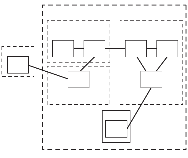
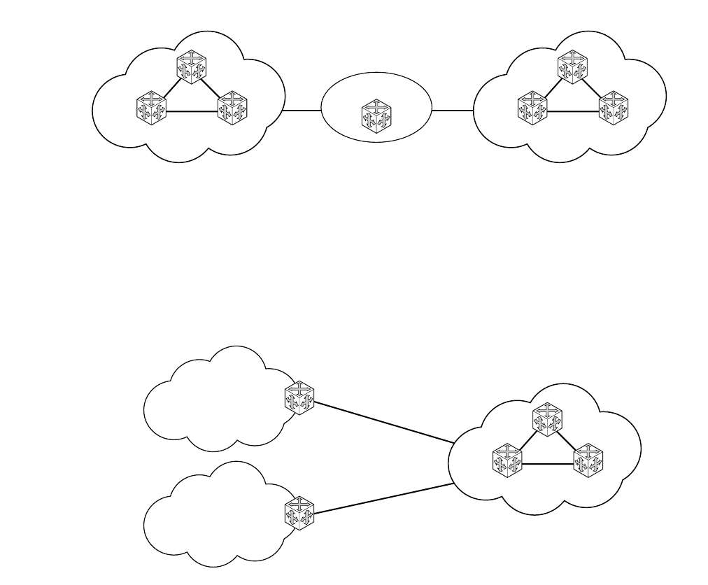
• IPv6 Internet exchange peering — Figure 3 shows an IPv6 Internet exchange where
multiple ISPs peer over native IPv6.
Figure 3: IPv6 Internet Exchange
• IPv6 transit services — Figure 4 shows IPv6 transit provided by an ISP.
Figure 4: IPv6 Transit Services
IPIPE_007
ISP A
IPv6 IX
Peering
ISP B
IPIPE_008
Customer 1
2001:0410:0001:/48
ISP
2001:0410::/32
Customer 2
2001:0410:0002:/4
Configuring IP Router Parameters
Page 30 7750 SR OS Router Configuration Guide
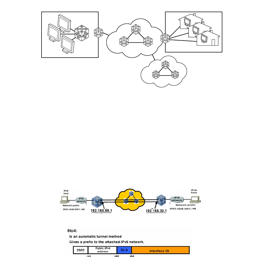
• IPv6 services to enterprise customers and home users — Figure 5 shows IPv6 connectivity
to enterprise and home broadband users.
Figure 5: IPv6 Services to Enterprise Customers and Home Users
• IPv6 over IPv4 relay services — IPv6 over IPv4 tunnels are one of many IPv6 transition
methods to support IPv6 in an environment where not only IPv4 exists but native IPv6
networks depend on IPv4 for greater IPv6 connectivity. 7750 SR OS supports dynamic
IPv6 over IPv4 tunneling. The ipv4 source and destination address are taken from
configuration, the source address is the ipv4 system address and the ipv4 destination is the
next hop from the configured 6over4 tunnel.
IPv6 over IPv4 is an automatic tunnel method that gives a prefix to the attached IPv6
network. Figure 6 shows IPv6 over IPv4 tunneling to transition from IPv4 to IPv6.
Figure 6: IPv6 over IPv4 Relay Services
IPIPE_009
IPv6 Core
Enterprise
IPv6 Broadband Users
DSL, Cable
FTTH
ISP
IPv4 Cloud
6t o4 6t o4
IP Router Configuration
7750 SR OS Router Configuration Guide Page 31
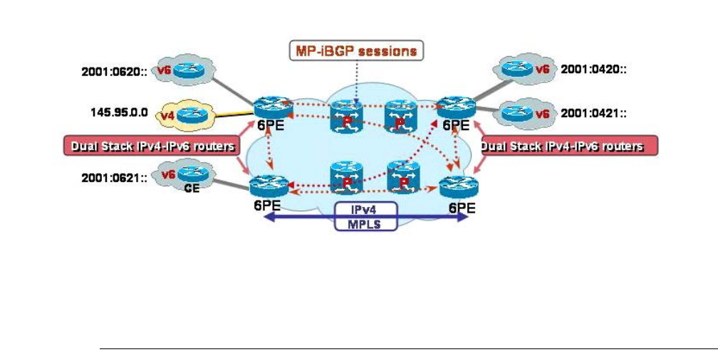
IPv6 Provider Edge Router over MPLS (6PE)
6PE allows IPv6 domains to communicate with each other over an IPv4 MPLS core network. This
architecture requires no backbone infrastructure upgrades and no reconfiguration of core routers,
because forwarding is purely based on MPLS labels. 6PE is a cost effective solution for IPv6
deployment.
Figure 7: Example of a 6PE Topology within One AS
6PE Control Plane Support
The 6PE MP-BGP routers support:
• IPv4/IPv6 dual-stack
• MP-BGP can be used between 6PE routers to exchange IPv6 reachability information.
→The 6PE routers exchange IPv6 prefixes over MP-BGP sessions running over IPv4
transport. The MP-BGP AFI used is IPv6 (value 2).
→An IPv4 address of the 6PE router is encoded as an IPv4-mapped IPv6 address in the
BGP next-hop field of the IPv6 NLRI. By default, the IPv4 address that is used for
peering is used. It is configurable through the route policies.
→The 6PE router binds MPLS labels to the IPv6 prefixes it advertises. The SAFI used in
MP-BGP is the SAFI (value 4) label. The 7750 SR-Series router uses the IPv6 Explicit
Null (value 2) label for all the IPv6 prefixes that it advertises and can accept an
arbitrary label from its peers.

Configuring IP Router Parameters
Page 32 7750 SR OS Router Configuration Guide
• LDP is used to create the MPLS full mesh between the 6PE routers and the IPv4 addresses
that are embedded in the next-hop field are reachable by LDP LSPs. The ingress 6PE
router uses the LDP LSPs to reach remote 6PE routers.
6PE Data Plane Support
The ingress 6PE router can push two MPLS labels to send the packets to the egress 6PE router. The
top label is an LDP label used to reach the egress 6PE router. The bottom label is advertised in MP-
BGP by the remote 6PE router. Typically, the IPv6 explicit null (value 2) label is used but an
arbitrary value can be used when the remote 6PE router is from a vendor other than Alcatel-
Lucent.
The egress 6PE router pops the top LDP tunnel label. It sees the IPv6 explicit null label, which
indicates an IPv6 packet is encapsulated. It also pops the IPv6 explicit null label and performs an
IPv6 route lookup to find out the next hop for the IPv6 packet.

IP Router Configuration
7750 SR OS Router Configuration Guide Page 33
Bidirectional Forwarding Detection
Bidirectional Forwarding Detection (BFD) is a light-weight, low-overhead, short-duration
detection of failures in the path between two systems. If a system stops receiving BFD messages
for a long enough period (based on configuration) it is assumed that a failure along the path has
occurred and the associated protocol or service is notified of the failure.
BFD can provide a mechanism used for liveness detection over any media, at any protocol layer,
with a wide range of detection times and overhead, to avoid a proliferation of different methods.
There are two modes of operation for BFD:
• Asynchronous mode — Uses periodic BFD control messages to test the path between
systems.
• Demand mode — Does not send periodic messages. BFD control messages are only sent
when either system feels it needs to again verify connectivity, in which case, it transmits a
short sequence of BFD messages and then stops.
A path is only declared operational when two-way communications has been established between
both systems.
A separate BFD session is created for each communications path and data protocol in use between
two systems.
In addition to the two operational modes, there is also an echo function defined within draft-ietf-
bfd-base-04.txt, Bidirectional Forwarding Detection, that allows either of the two systems to send
a sequence of BFD echo packets to the other system, which loops them back within that system’s
forwarding plane. If a number of these echo packets are lost then the BFD session is declared
down.
BFD Control Packet
The base BFD specification does not specify the encapsulation type to be used for sending BFD
control packets. Instead it is left to the implementers to use the appropriate encapsulation type for
the medium and network. The encapsulation for BFD over IPv4 and IPv6 networks is specified in
draft-ietf-bfd-v4v6-1hop-04.txt, BFD for IPv4 and IPv6 (Single Hop). This specification requires
that BFD control packets be sent over UDP with a destination port number of 3784 and the source
port number must be within the range 49152 to 65535.
In addition, the TTL of all transmitted BFD packets must have an IP TTL of 255. All BFD packets
received must have an IP TTL of 255 if authentication is not enabled. If authentication is enabled,
the IP TTL should be 255 but can still be processed if it is not (assuming the packet passes the
enabled authentication mechanism).

Configuring IP Router Parameters
Page 34 7750 SR OS Router Configuration Guide
If multiple BFD sessions exist between two nodes, the BFD discriminator is used to de-multiplex
the BFD control packet to the appropriate BFD session.
Control Packet Format
The BFD control packet has 2 sections, a mandatory section and an optional authentication section.
0 1 2 3
0 1 2 3 4 5 6 7 8 9 0 1 2 3 4 5 6 7 8 9 0 1 2 3 4 5 6 7 8 9 0 1
+-+-+-+-+-+-+-+-+-+-+-+-+-+-+-+-+-+-+-+-+-+-+-+-+-+-+-+-+-+-+-+-+
|Vers | Diag |Sta|P|F|C|A|D|R| Detect Mult | Length |
+-+-+-+-+-+-+-+-+-+-+-+-+-+-+-+-+-+-+-+-+-+-+-+-+-+-+-+-+-+-+-+-+
| My Discriminator |
+-+-+-+-+-+-+-+-+-+-+-+-+-+-+-+-+-+-+-+-+-+-+-+-+-+-+-+-+-+-+-+-+
| Your Discriminator |
+-+-+-+-+-+-+-+-+-+-+-+-+-+-+-+-+-+-+-+-+-+-+-+-+-+-+-+-+-+-+-+-+
| Desired Min TX Interval |
+-+-+-+-+-+-+-+-+-+-+-+-+-+-+-+-+-+-+-+-+-+-+-+-+-+-+-+-+-+-+-+-+
| Required Min RX Interval |
+-+-+-+-+-+-+-+-+-+-+-+-+-+-+-+-+-+-+-+-+-+-+-+-+-+-+-+-+-+-+-+-+
| Required Min Echo RX Interval |
+-+-+-+-+-+-+-+-+-+-+-+-+-+-+-+-+-+-+-+-+-+-+-+-+-+-+-+-+-+-+-+-+
Figure 8: Mandatory Frame Format
Table 3: BFD Control Packet Field Descriptions
Field Description
Vers The version number of the protocol. The initial protocol version is 0.
Diag A diagnostic code specifying the local system’s reason for the last transition of the
session from Up to some other state.
Possible values are:
0-No diagnostic
1-Control detection time expired
2-Echo function failed
3-Neighbor signaled session down
4-Forwarding plane reset
5-Path down
6-Concatenated path down
7-Administratively down
H Bit The “I Hear You” bit. This bit is set to 0 if the transmitting system either is not
receiving BFD packets from the remote system, or is in the process of tearing down
the BFD session for some reason. Otherwise, during normal operation, it is set to 1.

IP Router Configuration
7750 SR OS Router Configuration Guide Page 35
D Bit The “demand mode” bit. If set, the transmitting system wishes to operate in demand
mode.
P Bit The poll bit. If set, the transmitting system is requesting verification of
connectivity, or of a parameter change.
F Bit The final bit. If set, the transmitting system is responding to a received BFD control
packet that had the poll (P) bit set.
Rsvd Reserved bits. These bits must be zero on transmit and ignored on receipt.
Detect Mult Detect time multiplier. The negotiated transmit interval, multiplied by this value,
provides the detection time for the transmitting system in asynchronous mode.
Like the IGP hello protocol mechanisms, this is analogous to the hello-multiplier in
IS-IS, which can be used to determine the hold-timer.
(hello-interval) x (hello-multiplier) = hold-timer. If a hello is not received within
the hold-timer, a failure has occurred.
Similarly in BFD: (transmit interval) x (detect multiplier) = detect-timer. If a BFD
control packet is not received from the remote system within detect-timer, a failure
has occurred.
Length Length of the BFD control packet, in bytes.
My Discriminator A unique, nonzero discriminator value generated by the transmitting system, used
to demultiplex multiple BFD sessions between the same pair of systems.
Your Discriminator The discriminator received from the corresponding remote system. This field
reflects back the received value of my discriminator, or is zero if that value is
unknown.
Desired Min TX Interval This is the minimum interval, in microseconds, that the local system would like to
use when transmitting BFD control packets.
Required Min RX
Interval This is the minimum interval, in microseconds, between received BFD control
packets that this system is capable of supporting.
Required Min Echo RX
Interval This is the minimum interval, in microseconds, between received BFD echo
packets that this system is capable of supporting. If this value is zero, the
transmitting system does not support the receipt of BFD echo packets.
Table 3: BFD Control Packet Field Descriptions (Continued)
Field Description
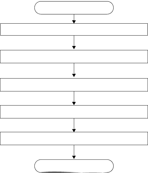
Router Configuration Process Overview
Page 36 7750 SR OS Router Configuration Guide
Router Configuration Process Overview
Figure 9 displays the process to configure basic router parameters.
Figure 9: IP Router Configuration Flow
ENABLE
START
SET THE SYSTEM NAME
CONFIGURE SYSTEM IP ADDRESS
CONFIGURE CONFEDERATIONS (optional)
CONFIGURE ROUTER ID (optional)
AUTONOMOUS SYSTEMS (optional)
IP Router Configuration
7750 SR OS Router Configuration Guide Page 37
Router Configuration Process Overview
Figure 9 displays the process to configure basic router parameters.
Figure 10: Router Configuration Components
ROUTER
ROUTER ID (optional)
INTERFACE
AUTONOMOUS SYSTEM (optional)
CONFEDERATION (optional)
IPV6
ADDRESS
NEIGHBOR
ADDRESS
Router Configuration Process Overview
Page 38 7750 SR OS Router Configuration Guide
Router Configuration Process Overview
Figure 10 displays the process to configure basic router parameters.
• Interface — A logical IP routing interface. Once created, attributes like an IP address, port,
link aggregation group or the system can be associated with the IP interface.
• Address — The address associates the device’s system name with the IP system address.
An IP address must be assigned to each IP interface.
• System interface — This command creates an association between the logical IP interface
and the system (loopback) address. The system interface address is the circuitless address
(loopback) and is used by default as the router ID for protocols such as OSPF and BGP.
• Router ID — (Optional) The router ID specifies the router's IP address.
• Autonomous system — (Optional) An autonomous system (AS) is a collection of
networks that are subdivided into smaller, more manageable areas.
• Confederation — (Optional) Creates confederation autonomous systems within an AS to
reduce the number of IBGP sessions required within an AS.

IP Router Configuration
7750 SR OS Router Configuration Guide Page 39
Configuration Notes
The following information describes router configuration caveats.
• A system interface and associated IP address should be specified.
• Boot options file (BOF) parameters must be configured prior to configuring router
parameters.
• Confederations can be configured before protocol connections (such as BGP) and peering
parameters are configured.
• IPv6 interface parameters can only be configured on systems provisioned with the iom2-
20g and 400g SFM2 card types.
• In order to configure IPv6 interface parameters, the chassis mode must be set to c in the
config>system>chassis-mode context. Use the force keyword to upgrade to c mode with
cards provisioned as iom-20g or iom-20g-b.
• An iom2-20g and a SFM2 card are required to enable the IPv6 CPM filter and per-peer
queuing functionality.
Reference Sources
For information on supported IETF drafts and standards, as well as standard and proprietary
MIBS, refer to Standards and Protocol Support on page 477.
Configuration Notes
Page 40 7750 SR OS Router Configuration Guide
IP Router Configuration
7750 SR OS Router Configuration Guide Page 41
Configuring an IP Router with CLI
This section provides information to configure an IP router.
Topics in this section include:
•Router Configuration Overview on page 42
•CLI Command Structure on page 43
•List of Commands on page 44
•Basic Configuration on page 48
•Common Configuration Tasks on page 49
→Configuring a System Name on page 49
→Configuring Interfaces on page 51
•Configuring a System Interface on page 51
•Configuring a Network Interface on page 51
•Configuring IPv6 Parameters on page 53
•Router Advertisement on page 66
→Configuring Proxy ARP on page 68
→Deriving the Router ID on page 72
→Configuring a Confederation on page 73
→Configuring an Autonomous System on page 75
•Service Management Tasks on page 76
→Changing the System Name on page 76
→Modifying Interface Parameters on page 77
→Deleting a Logical IP Interface on page 78

Router Configuration Overview
Page 42 7750 SR OS Router Configuration Guide
Router Configuration Overview
In a 7750 SR, an interface is a logical named entity. An interface is created by specifying an
interface name under the configure>router context. This is the global router configuration
context where objects like static routes are defined. An IP interface name can be up to 32
alphanumeric characters long, must start with a letter, and is case-sensitive; for example, the
interface name “1.1.1.1” is not allowed, but “int-1.1.1.1” is allowed.
To create an interface on an Alcatel-Lucent 7750 SR-Series router, the basic configuration tasks
that must be performed are:
• Assign a name to the interface
• Associate an IP address with the interface
• Associate the interface with a network interface or the system interface
• Configure appropriate routing protocols
A system interface and network interface should be configured.
System Interface
The system interface is associated with the network entity (such as a specific 7750 SR-Series), not
a specific interface. The system interface is also referred to as the loopback address. The system
interface is associated during the configuration of the following entities:
• The termination point of service tunnels
• The hops when configuring MPLS paths and LSPs
• The addresses on a target router for BGP andLDP peering.
The system interface is used to preserve connectivity (when routing reconvergence is possible)
when an interface fails or is removed. The system interface is used as the router identifier. A
system interface must have an IP address with a 32-bit subnet mask.
Network Interface
A network interface can be configured on one of the following entities:
• A physical or logical port
• A SONET/SDH channel
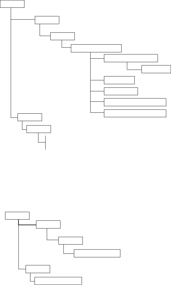
IP Router Configuration
7750 SR OS Router Configuration Guide Page 43
CLI Command Structure
Figure 11 displays the CLI command structure to configure router parameters. The commands are
located under the config>router context.
Figure 11: CLI Configuration Context
Figure 12 displays the brief CLI command structure to configure the system name. The commands
are located under the config>system context. See the 7750 SR OS System Configuration Guide
for command syntax and descriptions.
Figure 12: CLI System Configuration Context
ROOT
show
router
CONFIG
ROUTER
INTERFACE
arp
interface
route-table
AUTONOMOUS SYSTEM
CONFEDERATION
ROUTER ID
SYSTEM INTERFACE
ADDRESS
PORT
CONFIG
show
system information
SYSTEM
name system-name
ROOT

List of Commands
Page 44 7750 SR OS Router Configuration Guide
List of Commands
Table 4 lists all the configuration commands to configure a 7750 SR-Series router, indicating the
configuration level at which each command is implemented with a short command description.
Refer to each specific chapter for specific routing protocol information and command syntax to
configure protocols such as OSPF and BGP.
The command list is organized in the following task-oriented manner:
•Configure the system name
•Configure the router ID
•Configure router parameters
•Configure a network interface
•Configure the system interface
•Configure IPv6 parameters on an interface
•Configure router advertisement parameters
•Configure interface ICMP
Table 4: CLI Commands to Configure Basic IP Router Parameters
Command Description Page
Configure the system name
config>system 49
name The system name for the device. Only one system name can be configured.
Configure the router ID
config>router 72
router-id Configures the router ID for the router instance. When configuring a new
router ID, protocols will not automatically be restarted with the ID. The
next time a protocol is initialized, the new router ID is used. This may lead
to an interim period of time where different protocols use different router
IDs
89
Configure router parameters
config>router 49
aggregate Creates an aggregate route. Aggregate routes group a number of routes
with common prefixes into a single entry in the routing table, thereby
reducing the number of routes that need to be advertised by this router and
the routing tables of downstream routers.
86

IP Router Configuration
7750 SR OS Router Configuration Guide Page 45
autonomous-system Assigns an autonomous system (AS) number to the router. 87
confederation Creates a confederation within an AS. 87
ecmp Enables ECMP and configures the number of routes for path sharing. 88
ignore-icmp-
redirect
Drops or accepts ICMP redirects received on the management interface. 89
mc-maximum-routes Specifies the maximum number of multicast routes that can be held within
a VPN routing/forwarding (VRF) context. 89
service-prefix Creates an IP address range reserved for IES and certain VPLS services.
The purpose of reserving IP addresses using service-prefix is to provide a
mechanism to reserve one or more address ranges for services.
90
static-route Creates static route entries for both the network and access routes. 91
triggered-policy Triggers route policy re-evaluation. 91
Configure a network interface
config>router>interface 51
address Assigns an IP address, subnet and broadcast address format to an IP
interface. Only one IP address is associated with an IP interface. 96
allow-directed-
broadcasts
Enables the forwarding of directed broadcasts out of the IP interface. 98
arp-timeout Configures the minimum time in seconds that an address resolution
protocol (ARP) entry learned on the IP interface will be stored in the ARP
table.
98
bfd Specifies the bi-directional forwarding detection (BFD) parameters for the
associated IP interface 98
cflowd Enables the collection of traffic flow samples through a router for analysis. 99
local-proxy-arp Enables local proxy ARP on the interface. 99
loopback Configures the interface as a loopback interface. 100
mac Assigns a specific MAC address to an IP interface. 100
ntp-broadcast Enables receiving of SNTP broadcasts on the IP interface. 100
port Creates an association with an IP interface and a physical port. 100
proxy-arp-policy Specifies an existing policy-statement to analyze match and action criteria
that controls the flow of routing information to and from a given protocol,
set of protocols, or a particular neighbor.
101
qos Associates a network Quality of Service (QoS) policy with an IP interface. 102
remote-proxy-arp Enables remote proxy ARP on the interface. 102
secondary Assigns a secondary IP address, IP subnet/broadcast address format to the
interface. 103
Table 4: CLI Commands to Configure Basic IP Router Parameters (Continued)
Command Description Page

List of Commands
Page 46 7750 SR OS Router Configuration Guide
static-arp Configures a static ARP entry associating an IP address with a MAC
address for the core router instance. 104
tos-marking-state Specifies the TOS marking state. 104
unnumbered Sets an IP interface as an unnumbered interface and the IP address to be
used for the interface. 105
Configure the system interface
config>router>interface 51
address Assigns an IP address, IP subnet and broadcast address format to an IP
interface. Only one IP address can be associated with an IP interface. 96
secondary Assigns a secondary IP address, IP subnet/broadcast address format to the
interface. 103
Configure IPv6 parameters on an interface
config>router>interface>ipv6 53
address Assigns an IPv6 address to the interface. Multiple addresses (up to 8) are
allowed per interface. 112
egress Specifies egress network filter policies for IPv6 on the interface. 107
ingress Specifies ingress network filter policies for IPv6 on the interface. 107
filter Specifies the IPv6 filter policy to be associated with the interface. IPv6
filter policies must be configured in the config>filter>ipv6-filter context
before it can be specified in the router interface context.
107
icmp6 Enables the context to configure ICMPv6 parameters for the interface. 112
packet-too-big Configures the rate for ICMPv6 packet-too-big messages. 112
param-problem Configures the rate for ICMPv6 param-problem messages. 113
redirects Configures the rate for ICMPv6 redirect messages. 113
time-exceeded Configures the rate for ICMPv6 time-exceeded messages. 114
unreachables Configures the rate for ICMPv6 unreachable messages. 114
neighbor Configures an IPv6-to-MAC address mapping on the interface. 115
Configure router advertisement parameters
config>router>router-advertisement 66
interface Configures router advertisement properties on a specific interface. The
interface must already exist in the config>router>interface context. 116
current-hop-limit Configures the current-hop-limit in the router advertisement messages. It
informs the nodes on the subnet about the hop-limit when originating IPv6
packets.
116
Table 4: CLI Commands to Configure Basic IP Router Parameters (Continued)
Command Description Page

IP Router Configuration
7750 SR OS Router Configuration Guide Page 47
managed-
configuration
Sets the managed address configuration flag. This flag indicates that
DHCPv6 is available for address configuration in addition to any address
autoconfigured using stateless address autoconfiguration.
116
max-advertisement-
interval
Configures the maximum interval between sending router advertisement
messages. 117
min-advertisement-
interval
Configures the minimum interval between sending ICMPv6 neighbor
discovery router advertisement messages. 117
mtu Configures the MTU for the nodes to use to send packets on the link. 117
other-stateful-
configuration
Sets the “Other configuration” flag. This flag indicates that DHCPv6lite is
available for autoconfiguration of other (non-address) information such as
DNS-related information or information on other servers in the network.
118
prefix Configures an IPv6 prefix in the router advertisement messages. 118
autonomous Specifies whether the prefix can be used for stateless address
autoconfiguration. 118
on-link Specifies whether the prefix can be used for onlink determination. 119
preferred-lifetime Configures the length of time that the prefix remains preferred. 119
valid-lifetime Configures the length of time that the prefix is valid. 119
reachable-time Configures how long this router should be considered reachable by other
nodes on the link after receiving a reachability confirmation. 119
retransmit-time Configures the retransmission frequency of neighbor solicitation
messages. 120
router-lifetime Sets the router lifetime. 120
no shutdown Enables router advertisement on an interface. 120
Configure interface ICMP
config>router>interface
icmp Configures ICMP parameters on a network IP interface. 109
mask-reply Enables responses to ICMP mask requests on the router interface. 109
redirects Enables and configures the rate for ICMP redirect messages issued on the
router interface. 109
ttl-expired Configures the rate that ICMP TTL expired messages are issued by the
interface. 110
unreachables Enables and configures the rate for ICMP host and network destination
unreachable messages issued on the router interface. 110
Table 4: CLI Commands to Configure Basic IP Router Parameters (Continued)
Command Description Page
Basic Configuration
Page 48 7750 SR OS Router Configuration Guide
Basic Configuration
NOTE: Refer to each specific chapter for specific routing protocol information and command
syntax to configure protocols such as OSPF and BGP.
The most basic router configuration must have the following:
• System name
• System address
The following example displays a router configuration:
A:ALA-A> config# info
. . .
#------------------------------------------
# Router Configuration
#------------------------------------------
router
interface "system"
address 10.10.10.103/32
exit
interface "to-104"
address 10.0.0.103/24
port 1/1/1
exit
exit
autonomous-system 100
confederation 1000 members 100 200 300
router-id 10.10.10.103
. . .
exit
isis
exit
. . .
#------------------------------------------
A:ALA-A> config#

IP Router Configuration
7750 SR OS Router Configuration Guide Page 49
Common Configuration Tasks
The following sections describe basic system tasks.
•Configuring a System Name on page 49
•Configuring Interfaces on page 51
→Configuring a System Interface on page 51
→Configuring a Network Interface on page 51
→Configuring IPv6 Parameters on page 53
→Router Advertisement on page 66
•Configuring Proxy ARP on page 68
•Creating an IP Address Range on page 71
•Deriving the Router ID on page 72
•Configuring a Confederation on page 73
•Configuring an Autonomous System on page 75
Configuring a System Name
Use the system command to configure a name for the device. The name is used in the prompt
string. Only one system name can be configured. If multiple system names are configured, the last
one configured will overwrite the previous entry.
If special characters are included in the system name string, such as spaces, #, or ?, the entire string
must be enclosed in double quotes.
Use the following CLI syntax to configure the system name:
CLI Syntax: config# system
name system-name
Example:config# system
config>system# name ALA-A
ALA-A>config>system# exit all
ALA-A#
Common Configuration Tasks
Page 50 7750 SR OS Router Configuration Guide
The following example displays the system name output.
A#ALA-A>config>system# info
#------------------------------------------
# System Configuration
#------------------------------------------
name "ALA-A"
location "Mt.View, CA, NE corner of FERG 1 Building"
coordinates "37.390, -122.05500 degrees lat."
snmp
exit
. . .
exit
----------------------------------------------
A#ALA-A>config>system#

IP Router Configuration
7750 SR OS Router Configuration Guide Page 51
Configuring Interfaces
The following command sequences create a system and a logical IP interface. The system interface
assigns an IP address to the interface, and then associates the IP interface with a physical port. The
logical interface can associate attributes like an IP address or port.
Note that the system interface cannot be deleted.
Configuring a System Interface
To configure a system interface:
CLI Syntax: config>router
interface ip-int-name
address ip-addr{/mask-length|mask} [broadcast {all-
ones|host-ones}]
secondary {[ip-addr/mask|ip-addr][netmask]} [broadcast
{all-ones|host-ones}] [igp-inhibit]
Example:config>router# interface system
config>router>if# address 10.10.10.104/32
config>router>if# exit
Configuring a Network Interface
To configure a network interface:
CLI Syntax: config>router
interface ip-int-name
address ip-addr{/mask-length | mask} [broadcast {all-
ones | host-ones}]
cflowd {acl | interface}
egress
filter ip ip-filter-id
filter ipv6 ipv6-filter-id
ingress
filter ip ip-filter-id
filter ipv6 ipv6-filter-id
port [port-id | ccag-group]
Example:config>router> interface “to-ALA-2”
config>router>if# address 10.10.24.4/24
config>router>if# port 8/1/1
config>router>if# egress
Common Configuration Tasks
Page 52 7750 SR OS Router Configuration Guide
config>router>if>egress# filter ip 10
config>router>if>egress# exit
config>router>if# cflowd acl
config>router>if# exit
The following displays the IP configuration output showing the interface information.
A:ALA-A>config>router# info
#------------------------------------------
# IP Configuration
#------------------------------------------
interface "system"
address 10.10.0.4/32
exit
interface "to-ALA-2"
address 10.10.24.4/24
port 8/1/1
egress
filter ip 10
exit
exit
...
#------------------------------------------
A:ALA-A>config>router#

IP Router Configuration
7750 SR OS Router Configuration Guide Page 53
Configuring IPv6 Parameters
To configure IPv6 parameters, you must first:
• The chassis mode must be set to c in the config>system>chassis-mode context. Use the
force keyword to upgrade to c mode with cards provisioned as iom-20g or iom-20g-b.
The following displays the interface configuration showing the IPv6 default configuration when
IPv6 is enabled on the interface.
A:ALA-49>config>router>if>ipv6# info detail
----------------------------------------------
port 1/2/37
ipv6
packet-too-big 100 10
param-problem 100 10
redirects 100 10
time-exceeded 100 10
unreachables 100 10
exit
----------------------------------------------
A:ALA-49>config>router>if>ipv6# exit all
Use the following CLI syntax to configure IPv6 parameters on a router interface.
CLI Syntax: config>router# interface interface-name
port port-name
ipv6
address {ipv6-address/prefix-length} [eui-64]
icmp6
packet-too-big [number seconds]
param-problem [number seconds]
redirects [number seconds]
time-exceeded [number seconds]
unreachables [number seconds]
neighbor ipv6-address mac-address?
Common Configuration Tasks
Page 54 7750 SR OS Router Configuration Guide
The following example displays IPv6 interface configuration command usage. These commands
are configured in the config>router context.
Example: config>router# interface gemini_5_21
config>router>if# address 10.11.10.1/24
config>router>if# port 1/2/37
config>router>if# ipv6
config>router>if>ipv6# address 10::1/24
config>router>if>ipv6# exit
config>router>if# no shutdown
The following displays the configuration output showing the interface information.
A:ALA-49>config>router>if# info
----------------------------------------------
address 10.11.10.1/24
port 1/2/37
ipv6
address 10::1/24
exit
----------------------------------------------
A:ALA-49>config>router>if#

IP Router Configuration
7750 SR OS Router Configuration Guide Page 55
Configuring IPv6 Over IPv4 Parameters
This section provides several examples of the features that must be configured in order to
implement IPv6 over IPv4 relay services.
•Tunnel Ingress Node on page 55
→Learning the Tunnel Endpoint IPv4 System Address on page 57
→Configuring an IPv4 BGP Peer on page 58
→An Example of a IPv6 Over IPv4 Tunnel Configuration on page 59
•Tunnel Egress Node on page 61
→Learning the Tunnel Endpoint IPv4 System Address on page 62
→Configuring an IPv4 BGP Peer on page 63
→An Example of a IPv6 Over IPv4 Tunnel Configuration on page 64
Tunnel Ingress Node
This configuration shows how the interface through which the IPv6 over IPv4 traffic leaves the
node. This must be configured on a network interface.
CLI Syntax: config>router
static-route ::C8C8:C802/128 indirect 200.200.200.2
interface ip-int-name
address {ip-address/mask>|ip-address netmask} [broadcast
all-ones|host-ones]
port port-name
Example:config>router# interface ip-1.1.1.1
config>router>if# address 1.1.1.1/30
config>router>if# port 1/1/1
config>router>if# exit
config>router#
The following displays the configuration output showing the interface information.
A:ALA-49>configure>router# info
----------------------------------------------
...
interface "ip-1.1.1.1"
address 1.1.1.1/30
port 1/1/1
exit
...
----------------------------------------------
A:ALA-49>configure>router#
Common Configuration Tasks
Page 56 7750 SR OS Router Configuration Guide
Both the IPv4 and IPv6 system addresses must to configured
CLI Syntax: config>router
interface ip-int-name
address {ip-address/mask>|ip-address netmask} [broad-
cast all-ones|host-ones]
ipv6
address ipv6-address/prefix-length [eui-64]
Example:config>router# interface system
config>router>if# address 200.200.200.1/32
config>router>if# ipv6
config>router>if>ipv6# interface “ip-1.1.1.1”
config>router>if>ipv6# exit
The following displays the configuration output showing the interface information.
A:ALA-49>configure>router# info
----------------------------------------------
...
interface "system"
address 200.200.200.1/32
ipv6
address 3FFE::C8C8:C801/128
exit
exit
...
----------------------------------------------
A:ALA-49>configure>router#
IP Router Configuration
7750 SR OS Router Configuration Guide Page 57
Learning the Tunnel Endpoint IPv4 System Address
This configuration displays the OSPF configuration to learn the IPv4 system address of the tunnel
endpoint.
CLI Syntax: config>router
ospf
area area-id
interface ip-int-name
Example:config>router# ospf
config>router>ospf# interface system
config>router>ospf>if# exit
config>router>ospf# interface ip-1.1.1.1
config>router>ospf>if# exit
The following displays the configuration showing the OSPF output.
A:ALA-49>configure>router# info
----------------------------------------------
...
ospf
area 0.0.0.0
interface "system"
exit
interface "ip-1.1.1.1"
exit
exit
exit
----------------------------------------------
A:ALA-49>configure>router#
Common Configuration Tasks
Page 58 7750 SR OS Router Configuration Guide
Configuring an IPv4 BGP Peer
This configuration display the commands to configure an IPv4 BGP peer with (IPv4 and) IPv6
protocol families.
CLI Syntax: config>router
bgp
export policy-name [policy-name...(upto 5 max)]
router-id ip-address
group name
family [ipv4] [vpn-ipv4] [ipv6] [mcast-ipv4]
type {internal|external}
neighbor ip-address
local-as as-number [private]
peer-as as-number
Example:config>router# bgp
config>router>bgp# export ospf3
config>router>bgp# router-id 200.200.200.1
config>router>bgp# group "main"
config>router>bgp>group# family ipv4 ipv6
config>router>bgp>group# type internal
config>router>bgp>group# neighbor 200.200.200.2
config>router>bgp>group>neighbor# local-as 1
config>router>bgp>group>neighbor# peer-as 1
config>router>bgp>group>neighbor# exit
config>router>bgp>group# exit
config>router>bgp# exit
The following displays the configuration showing the BGP output.
A:ALA-49>configure>router# info
----------------------------------------------
...
bgp
export "ospf3"
router-id 200.200.200.1
group "main"
family ipv4 ipv6
type internal
neighbor 200.200.200.2
local-as 1
peer-as 1
exit
exit
exit
...
----------------------------------------------
A:ALA-49>configure>router#
IP Router Configuration
7750 SR OS Router Configuration Guide Page 59
An Example of a IPv6 Over IPv4 Tunnel Configuration
The IPv6 address is the next-hop as it is received through BGP. The IPv4 address is the system
address of the tunnel's endpoint static-route ::C8C8:C802/128 indirect 200.200.200.2.
This configuration displays an example to configure a policy to export IPv6 routes into BGP.
CLI Syntax: config>router
bgp
export policy-name [policy-name...(upto 5 max)]
router-id ip-address
group name
family [ipv4] [vpn-ipv4] [ipv6] [mcast-ipv4]
type {internal|external}
neighbor ip-address
local-as as-number [private]
peer-as as-number
Example:config>router# policy-options
config>router>policy-options# begin
config>router>policy-options# policy-statement ospf3
config>router>policy-options>policy-statement#
config>router>policy-options>policy-statement# description "Plcy
Stmnt For 'From ospf3 To bgp'"
config>router>policy-options>policy-statement# entry 10
config>router>policy-options>policy-statement>entry# description
"Entry protocol ospf3 To bgp"
config>router>policy-options>policy-statement>entry# from
config>router>policy-options>policy-statement>entry>from# protocol
ospf3
config>router>policy-options>policy-statement>entry>from# exit
config>router>policy-options>policy-statement>entry# action accept
config>router>policy-options>policy-statement>entry>action# exit
config>router>policy-options>policy-statement>entry# to
config>router>policy-options>policy-statement>entry>to# protocol bgp
config>router>policy-options>policy-statement>entry>to# exit
config>router>policy-options>policy-statement>entry# exit
config>router>policy-options>policy-statement# exit
config>router>policy-options# exit
config>router#
The following displays the configuration showing the policy output.
A:ALA-49>configure>router# info
----------------------------------------------
...
policy-options
policy-statement "ospf3"
description "Plcy Stmnt For 'From ospf3 To bgp'"
entry 10
description "Entry From Protocol ospf3 To bgp"
from
Common Configuration Tasks
Page 60 7750 SR OS Router Configuration Guide
protocol ospf3
exit
to
protocol bgp
exit
action accept
exit
exit
exit
exit
...
----------------------------------------------
A:ALA-49>configure>router#
IP Router Configuration
7750 SR OS Router Configuration Guide Page 61
Tunnel Egress Node
This configuration shows how the interface through which the IPv6 over IPv4 traffic leaves the
node. It must be configured on a network interface. Both the IPv4 and IPv6 system addresses must
be configured.
CLI Syntax: config>router
configure router static-route ::C8C8:C801/128 indirect
200.200.200.1
interface ip-int-name
address {ip-address/mask>|ip-address netmask} [broad-
cast all-ones|host-ones]
ipv6
address ipv6-address/prefix-length [eui-64]
port port-name
Example:config>router# interface ip-1.1.1.2
config>router>if# address 1.1.1.2/30
config>router>if# port 1/1/1
config>router>if# exit
config>router#
config>router# interface system
config>router>if# address 200.200.200.2/32
config>router>if# ipv6
config>router>if>ipv6# address 3FFE::C8C8:C802/128
config>router>if>ipv6# exit
config>router>if# exit
config>router#
The following displays the configuration showing the interface information.
A:ALA-49>configure>router# info
----------------------------------------------
...
interface "ip-1.1.1.2"
address 1.1.1.2/30
port 1/1/1
exit
interface "system"
address 200.200.200.2/32
ipv6
address 3FFE::C8C8:C802/128
exit
exit
----------------------------------------------
Common Configuration Tasks
Page 62 7750 SR OS Router Configuration Guide
Learning the Tunnel Endpoint IPv4 System Address
This configuration displays the OSPF configuration to learn the IPv4 system address of the tunnel
endpoint.
CLI Syntax: config>router
ospf
area area-id
interface ip-int-name
Example:config>router# ospf
config>router>ospf# interface system
config>router>ospf>if# exit
config>router>ospf# interface ip-1.1.1.2
config>router>ospf>if# exit
config>router>ospf# exit
The following displays the configuration showing the OSPF output.
A:ALA-49>configure>router# info
----------------------------------------------
...
ospf
area 0.0.0.0
interface "system"
exit
interface "ip-1.1.1.2"
exit
exit
exit
----------------------------------------------
A:ALA-49>configure>router#
IP Router Configuration
7750 SR OS Router Configuration Guide Page 63
Configuring an IPv4 BGP Peer
This configuration display the commands to configure an IPv4 BGP peer with (IPv4 and) IPv6
protocol families.
CLI Syntax: config>router
bgp
export policy-name [policy-name...(upto 5 max)]
router-id ip-address
group name
family [ipv4] [vpn-ipv4] [ipv6] [mcast-ipv4]
type {internal|external}
neighbor ip-address
local-as as-number [private]
peer-as as-number
Example:config>router# bgp
config>router>bgp# export ospf3
config>router>bgp# router-id 200.200.200.2
config>router>bgp# group "main"
config>router>bgp>group# family ipv4 ipv6
config>router>bgp>group# type internal
config>router>bgp>group# neighbor 200.200.200.1
config>router>bgp>group>neighbor# local-as 1
config>router>bgp>group>neighbor# peer-as 1
config>router>bgp>group>neighbor# exit
config>router>bgp>group# exit
config>router>bgp# exit
The following displays the configuration showing the BGP output.
A:ALA-49>configure>router# info
----------------------------------------------
...
bgp
export "ospf3"
router-id 200.200.200.2
group "main"
family ipv4 ipv6
type internal
neighbor 200.200.200.1
local-as 1
peer-as 1
exit
exit
exit
...
----------------------------------------------
A:ALA-49>configure>router#
Common Configuration Tasks
Page 64 7750 SR OS Router Configuration Guide
An Example of a IPv6 Over IPv4 Tunnel Configuration
The IPv6 address is the next-hop as it is received through BGP. The IPv4 address is the system
address of the tunnel's endpoint static-route ::C8C8:C802/128 indirect 200.200.200.2
This configuration displays an example to configure a policy to export IPv6 routes into BGP.
CLI Syntax: config>router
bgp
export policy-name [policy-name...(upto 5 max)]
router-id ip-address
group name
family [ipv4] [vpn-ipv4] [ipv6] [mcast-ipv4]
type {internal|external}
neighbor ip-address
local-as as-number [private]
peer-as as-number
Example:config>router# policy-options
config>router>policy-options# begin
config>router>policy-options# policy-statement ospf3
config>router>policy-options>policy-statement#
config>router>policy-options>policy-statement# description "Plcy
Stmnt For 'From ospf3 To bgp'"
config>router>policy-options>policy-statement# entry 10
config>router>policy-options>policy-statement>entry# description
"Entry protocol ospf3 To bgp"
config>router>policy-options>policy-statement>entry# from
config>router>policy-options>policy-statement>entry>from# protocol
ospf3
config>router>policy-options>policy-statement>entry>from# exit
config>router>policy-options>policy-statement>entry# action accept
config>router>policy-options>policy-statement>entry>action# exit
config>router>policy-options>policy-statement>entry# to
config>router>policy-options>policy-statement>entry>to# protocol bgp
config>router>policy-options>policy-statement>entry>to# exit
config>router>policy-options>policy-statement>entry# exit
config>router>policy-options>policy-statement# exit
config>router>policy-options# exit
config>router#
The following displays the configuration showing the policy output.
A:ALA-49>configure>router# info
----------------------------------------------
...
policy-options
policy-statement "ospf3"
description "Plcy Stmnt For 'From ospf3 To bgp'"
entry 10
description "Entry From Protocol ospf3 To bgp"
from
IP Router Configuration
7750 SR OS Router Configuration Guide Page 65
protocol ospf3
exit
to
protocol bgp
exit
action accept
exit
exit
exit
exit
----------------------------------------------
A:ALA-49>configure>router#
Common Configuration Tasks
Page 66 7750 SR OS Router Configuration Guide
Router Advertisement
To configure the router to originate router advertisement messages, the router-advertisement
command must be enabled. All other router advertisement configuration parameters are optional.
Router advertisement on all IPv6-enabled interfaces will be enabled.
Use the following CLI syntax to enable router advertisement and configure router advertisement
parameters:
CLI Syntax: config>router# router-advertisement
interface ip-int-name
current-hop-limit number
managed-configuration
max-advertisement-interval seconds
min-advertisement-interval seconds
mtu mtu-bytes
other-stateful-configuration
prefix ipv6-prefix/prefix-length
autonomous
on-link
preferred-lifetime {seconds | infinite}
valid-lifetime {seconds | infinite}
reachable-time milli-seconds
retransmit-time milli-seconds
router-lifetime seconds
no shutdown
IP Router Configuration
7750 SR OS Router Configuration Guide Page 67
The following example displays router advertisement command usage. These commands are
configured in the config>router context.
Example: config>router# router-advertisement
config>router>router-advert# interface gemini_5_21
config>router>router-advert>if>prefix> autonomous
config>router>router-advert>if>prefix> on-link
config>router>router-advert>if>prefix> preferred-
lifetime 604800
config>router>router-advert>if>prefix> valid-
lifetime 2592000
config>router>router-advert>if# reachable-time 50000
config>router>router-advert>if# retransmit-time 10000
config>router>router-advert>if# no shutdown
config>router>router-advert>if# exit
*A:tahi>config>router>router-advert>if>prefix# info detail
----------------------------------------------
interface
autonomous
on-link
preferred-lifetime 604800
valid-lifetime 2592000
reachable-time 50000
retransmit-time 10000
no shutdown
----------------------------------------------
*A:tahi>config>router>router-advert>if>prefix#
Common Configuration Tasks
Page 68 7750 SR OS Router Configuration Guide
Configuring Proxy ARP
To configure proxy ARP, you can configure:
• A prefix list in the config>router>policy-options>prefix-list context.
• A route policy statement in the config>router>policy-options>policy-
statement context and apply the specified prefix list.
→In the policy statement entry>to context, specify the host source address(es) for
which ARP requests can or cannot be forwarded to non-local networks, depending on
the specified action.
→In the policy statement entry>from context, specify network prefixes that ARP
requests will or will not be forwarded to depending on the action if a match is found.
For more information about route policies, refer to Route Policies on page 597.
• Apply the policy statement to the proxy-arp configuration in the
config>router>interface context.
CLI Syntax: config>router# policy-options
begin
commit
prefix-list name
prefix ip-prefix/mask [exact|longer|through
length|prefix-length-range length1-length2]
The following example displays prefix list configuration command usage. These commands are
configured in the config>router context.
Example:config>router>policy-options# begin
config>router>policy-options# prefix-list prefixlist1
config>router>policy-options>prefix-list# prefix 10.20.30.0/24
through 32
config>router>policy-options>prefix-list# exit
config>router>policy-options# prefix-list prefixlist2
config>router>policy-options>prefix-list# prefix 10.10.10.0/24
through 32
config>router>policy-options>prefix-list# exit
config>router>policy-options# commit
IP Router Configuration
7750 SR OS Router Configuration Guide Page 69
Use the following CLI syntax to configure the policy statement specified in the proxy-arp-
policy policy-statement command.
CLI Syntax: config>router# policy-options
begin
commit
policy-statement name
default-action {accept|next-entry|next-policy|reject}
entry entry-id
action {accept|next-entry|next-policy|reject}
to
prefix-list name [name...(upto 5 max)]
from
prefix-list name [name...(upto 5 max)]
Example:config>router>policy-options# begin
config>router>policy-options# policy-statement "ProxyARPpolicy"
config>..>policy-statement# default-action accept
config>..>policy-statement>default-action# exit
config>..>policy-statement# entry 10
config>..>policy-statement>entry# from
config>..>policy-statement>entry>from# prefix-list prefixlist1
config>..>policy-statement>entry>from# exit
config>..>policy-statement>entry# to
config>..>policy-statement>entry>to# prefix-list prefixlist1
config>..>policy-statement>entry>to# exit
config>..>policy-statement>entry# action reject
config>..>policy-statement>entry# exit
config>..>policy-statement# exit
config>router>policy-options#
The following output displays the prefix list and policy statement configurations:
A:ALA-49>config>router>policy-options# info
----------------------------------------------
prefix-list "prefixlist1"
prefix 10.20.30.0/24 through 32
exit
prefix-list "prefixlist2"
prefix 10.10.10.0/24 through 32
exit
...
policy-statement "ProxyARPpolicy"
entry 10
from
prefix-list "prefixlist1"
exit
to
prefix-list "prefixlist2"
exit
action reject
exit
default-action accept
Common Configuration Tasks
Page 70 7750 SR OS Router Configuration Guide
exit
exit
...
----------------------------------------------
A:ALA-49>config>router>policy-options#
Use the following CLI to configure proxy ARP:
CLI Syntax: config>router>interface interface-name
local-proxy-arp
proxy-arp-policy policy-name [policy-name...(upto 5 max)]
remote-proxy-arp
Example:config>router# interface “testARP”
config>router>if# address 128.251.10.59/24
config>router>if# local-proxy-arp
config>router>if# proxy-arp
config>router>if>proxy-arp# policy-statement "ProxyARPpolicy"
config>router>if>proxy-arp# exit
config>router>if# exit
A:ALA-49>config>router>if# info
----------------------------------------------
address 128.251.10.59/24
local-proxy-arp
proxy-arp
policy-statement "ProxyARPpolicy"
exit
----------------------------------------------
A:ALA-49>config>router>if#
IP Router Configuration
7750 SR OS Router Configuration Guide Page 71
Creating an IP Address Range
An IP address range can be reserved for exclusive use for services by defining the
config>router>service-prefix command. When the service is configured, the IP address
must be in the range specified as a service prefix. If no service prefix command is configured, then
no limitation exists.
The no service-prefix ip-prefix/mask command removes all address reservations. A
service prefix cannot be removed while one or more services use address(es) in the range to be
removed.
CLI Syntax: config>router
service-prefix ip-prefix/mask [exclusive]
Example:config>router# service-prefix
Common Configuration Tasks
Page 72 7750 SR OS Router Configuration Guide
Deriving the Router ID
The router ID defaults to the address specified in the system interface command. If the system
interface is not configured with an IP address, then the router ID inherits the last four bytes of the
MAC address. The router ID can also be manually configured in the config>router router-
id context. On the BGP protocol level, a BGP router ID can be defined in the
config>router>bgp router-id context and is only used within BGP.
Note that if a new router ID is configured, protocols are not automatically restarted with the new
router ID. The next time a protocol is initialized the new router ID is used. An interim period of
time can occur when different protocols use different router IDs. To force the new router ID, issue
the shutdown and no shutdown commands for each protocol that uses the router ID, or restart
the entire router.
Use the following CLI syntax to configure the router ID:
CLI Syntax: config>router
router-id router-id
interface ip-int-name
address {ip-address/mask|ip-address netmask} [broad-
cast all-ones|host-ones]
The following example displays the router ID command usage:
Example:config>router# router-id 10.10.0.4
config>router# exit
Example:config>router# interface “system”
config>router>if# address 10.10.0.4/32
config>router>if# exit
The following example displays the router ID configuration:
A:ALA-4>config>router# info
#------------------------------------------
# IP Configuration
#------------------------------------------
interface "system"
address 10.10.0.4/32
exit
. . .
router-id 10.10.0.4
#------------------------------------------
A:ALA-4>config>router#
IP Router Configuration
7750 SR OS Router Configuration Guide Page 73
Configuring a Confederation
Configuring a confederation is optional. The AS and confederation topology design should be
carefully planned. Autonomous system (AS), confederation, and BGP connection and peering
parameters must be explicitly created on each participating SR. Identify AS numbers,
confederation numbers, and members participating in the confederation.
Refer to the BGP section for CLI syntax and command descriptions.
Use the following CLI syntax to configure a confederation:
CLI Syntax: config>router
confederation confed-as-num members member-as-num
The following example displays the commands to configure the confederation topology diagram
displayed in Figure 1 on page 25.
Example:ALA-B>config>router# autonomous-system 200
ALA-B>config>router# confederation 2002 members 200 300 400
ALA-B>config>router# exit
ALA-C>config>router# autonomous-system 200
ALA-C>config>router# confederation 2002 members 200 300 400
ALA-C>config>router# exit
ALA-D>config>router# autonomous-system 400
ALA-D>config>router# confederation 2002 members 200 300 400
ALA-D>config>router# exit
ALA-E>config>router# autonomous-system 300
ALA-E>config>router# confederation 2002 members 200 300 400
ALA-E>config>router# exit
ALA-F>config>router# autonomous-system 300
ALA-F>config>router# confederation 2002 members 200 300 400
ALA-F>config>router# exit
ALA-G>config>router# autonomous-system 300
ALA-G>config>router# confederation 2002 members 200 300 400
ALA-G>config>router# exit
Common Configuration Tasks
Page 74 7750 SR OS Router Configuration Guide
NOTES:
• Confederations can be preconfigured prior to configuring BGP connections and peering.
• Each confederation can have up to 15 members.
The following example displays the confederation output.
A:ALA-B>config>router# info
#------------------------------------------
# IP Configuration
#------------------------------------------
interface "system"
address 10.10.10.103/32
exit
interface "to-104"
shutdown
address 10.0.0.103/24
port 1/1/1
exit
autonomous-system 100
confederation 2002 members 200 300 400
router-id 10.10.10.103
#------------------------------------------
A:ALA-B>config>router#
IP Router Configuration
7750 SR OS Router Configuration Guide Page 75
Configuring an Autonomous System
Configuring an autonomous system is optional. Use the following CLI syntax to configure an
autonomous system:
CLI Syntax: config>router
autonomous-system as-number
The following example displays the autonomous system configuration command usage:
Example: config>router# autonomous-system 100
config>router#
The following example displays the autonomous system configuration:
A;ALA-A>config>router# info
#------------------------------------------
# IP Configuration
#------------------------------------------
interface "system"
address 10.10.10.103/32
exit
interface "to-104"
address 10.0.0.103/24
port 1/1/1
exit
exit
autonomous-system 100
router-id 10.10.10.103
#------------------------------------------
A:ALA-A>config>router#

Service Management Tasks
Page 76 7750 SR OS Router Configuration Guide
Service Management Tasks
This section discusses the following service management tasks:
•Changing the System Name on page 76
•Modifying Interface Parameters on page 77
•Deleting a Logical IP Interface on page 78
Changing the System Name
The system command sets the name of the device and is used in the prompt string. Only one
system name can be configured. If multiple system names are configured, the last one configured
will overwrite the previous entry.
Use the following CLI syntax to change the system name:
CLI Syntax: config# system
name system-name
The following example displays the command usage to change the system name:
Example:A:ALA-A>config>system# name TGIF
A:TGIF>config>system#
The following example displays the system name change:
A:ALA-A>config>system# name TGIF
A:TGIF>config>system# info
#------------------------------------------
# System Configuration
#------------------------------------------
name "TGIF"
location "Mt.View, CA, NE corner of FERG 1 Building"
coordinates "37.390, -122.05500 degrees lat."
synchronize
snmp
exit
security
snmp
community "private" rwa version both
exit
exit
. . .
----------------------------------------------
A:TGIF>config>system#
IP Router Configuration
7750 SR OS Router Configuration Guide Page 77
Modifying Interface Parameters
Starting at the config>router level, navigate down to the router interface context.
To modify an IP address, perform the following steps:
Example:A:ALA-A>config>router# interface “to-sr1”
A:ALA-A>config>router>if# shutdown
A:ALA-A>config>router>if# no address
A:ALA-A>config>router>if# address 10.0.0.25/24
A:ALA-A>config>router>if# no shutdown
To modify a port, perform the following steps:
Example:A:ALA-A>config>router# interface “to-sr1”
A:ALA-A>config>router>if# shutdown
A:ALA-A>config>router>if# no port
A:ALA-A>config>router>if# port 1/1/2
A:ALA-A>config>router>if# no shutdown
The following example displays the interface configuration:
A:ALA-A>config>router# info
#------------------------------------------
# IP Configuration
#------------------------------------------
interface "system"
address 10.0.0.103/32
exit
interface "to-sr1"
address 10.0.0.25/24
port 1/1/2
exit
router-id 10.10.0.3
#------------------------------------------
A:ALA-A>config>router#
Service Management Tasks
Page 78 7750 SR OS Router Configuration Guide
Deleting a Logical IP Interface
The no form of the interface command typically removes the entry, but all entity associations
must be shut down and/or deleted before an interface can be deleted.
1. Before an IP interface can be deleted, it must first be administratively disabled with the
shutdown command.
2. After the interface has been shut down, it can then be deleted with the no interface
command.
CLI Syntax: config>router
no interface ip-int-name
Example:config>router# interface test-interface
config>router>if# shutdown
config>router>if# exit
config>router# no interface test-interface
config>router#

IP Router Configuration
7750 SR OS Router Configuration Guide Page 79
IP Router Command Reference
Command Hierarchies
Configuration Commands
•Router Commands
•Router Interface Commands
•Router Interface IPv6 Commands
•Router Advertisement Commands
•Show Commands
•Clear Commands
•Debug Commands
Router Commands
config
—router [router-name]
—aggregate ip-prefix/mask [summary-only] [as-set] [aggregator as-number:ip-address]
—no aggregate ip-prefix/mask
—autonomous-system as-number
—no autonomous-system
—confederation confed-as-num members as-number [as-number...(up to 15 max)]
—no confederation [confed-as-num members as-number....(up to 15 max)]
—ecmp max-ecmp-routes
—no ecmp
—[no] ignore-icmp-redirect
—mc-maximum-routes number [log-only] [threshold threshold]
—no mc-maximum-routes
—router-id ip-address
—no router-id
—service-prefix {ip-prefix/mask | ip-prefix netmask}[exclusive]
—no
service-prefix ip-prefix/mask | ip-prefix netmask}
—[no] static-route {ip-prefix/prefix-length | ip-prefix netmask} [preference preference] [met-
ric metric] [tag tag] [enable | disable] next-hop ip-int-name|ip-address [mcast-ipv4]
—[no] static-route {ip-prefix/prefix-length | ip-prefix netmask} [preference preference] [met-
ric metric] [tag tag] [enable | disable] indirect ip-address [ldp [disallow-igp]]
—[no] static-route {ip-prefix/prefix-length | ip-prefix netmask} [preference preference] [met-
ric metric] [tag tag] [enable | disable] black-hole [mcast-ipv4]
—[no] triggered-policy
IP Router Command Reference
Page 80 7750 SR OS Router Configuration Guide
Router Interface Commands
config
—router [router-name]
—[no] interface ip-int-name
—address {ip-address/mask | ip-address netmask} [broadcast {all-ones | host-
ones}]
—no address
—[no] allow-directed-broadcasts
—arp-timeout seconds
—no arp-timeout
—bfd transmit-interval [receive receive-interval] [multiplier multiplier]
—no bfd
—cflowd {acl | interface}
—no cflowd
—description description-string
—no description
—egress
—filter ip ip-filter-id
—filter ipv6 ipv6-filter-id
—no filter [ip ip-filter-id] [ipv6 ipv6-filter-id]
—icmp —[no] mask-reply
—redirects [number seconds]
—no redirects
—ttl-expired [number seconds]
—no ttl-expired
—unreachables [number seconds]
—no unreachables
—ingress
—filter ip ip-filter-id
—filter ipv6 ipv6-filter-id
—no filter
—no filter [ip ip-filter-id] [ipv6 ipv6-filter-id]
—[no] local-proxy-arp
—[no] loopback
—mac ieee-mac-addr
—no mac
—[no] ntp-broadcast
—port port-name
—no port
—[no] proxy-arp-policy
—qos network-policy-id
—no qos
—[no] remote-proxy-arp
—secondary {[ip-addr/mask | ip-addr][netmask]} [broadcast {all-ones | host-
ones}] [igp-inhibit]
—no secondary [ip-addr/mask | ip-addr][netmask ]
—[no] static-arp
—static-arp ip-addr ieee-mac-addr
—no static-arp ip-addr
—[no] shutdown
—tos-marking-state {trusted | untrusted}
—no tos-marking-state
—unnumbered [ip-addr | ip-int-name]
—no unnumbered
IP Router Configuration
7750 SR OS Router Configuration Guide Page 81
For router interface VRRP commands, see “VRRP Command Reference” on page 223.
Router Interface IPv6 Commands
config
—router [router-name]
—[no] interface ip-int-name
—[no] ipv6
—address (ipv6) ipv6-address/prefix-length [eui-64]
—no address (ipv6) ipv6-address/prefix-length
—icmp6
—packet-too-big [number seconds]
—no packet-too-big
—param-problem [number seconds]
—no param-problem
—redirects [number seconds]
—no redirects
—time-exceeded [number seconds]
—no time-exceeded
—unreachables [number seconds]
—no unreachables
—[no] local-proxy-nd
—neighbor ipv6-address [mac-address]
—no neighbor ipv6-address
—proxy-nd-policy policy-name [ policy-name...(up to 5 max)]
—no proxy-nd-policy
Router Advertisement Commands
config
— router
—[no] router-advertisement
—[no] interface ip-int-name
—current-hop-limit number
—no current-hop-limit
—[no] managed-configuration
—max-advertisement-interval seconds
—no max-advertisement-interval
—min-advertisement-interval seconds
—no min-advertisement-interval
—mtu mtu-bytes
—no mtu
—[no] other-stateful-configuration
—prefix [ipv6-prefix/prefix-length]
—no prefix
—[no] autonomous
—[no] on-link
—preferred-lifetime {seconds | infinite}
—no preferred-lifetime
—valid-lifetime {seconds | infinite}
—no valid-lifetime
—reachable-time milli-seconds
—no reachable-time
—retransmit-time milli-seconds
IP Router Configuration
7750 SR OS Router Configuration Guide Page 83
Show Commands
show —router router-instance
—aggregate [family] [active]
—arp [ ip-int-name | ip-address/mask | mac ieee-mac-address | summary]
[local|dynamic|static|managed]
—authentication
—statistics
—statistics interface [ip-int-name|ip-address]
—statistics policy name
—bfd —interface
—session [src ip-address [dst ip-address] | [detail]]
—dhcp —statistics [ip-int-name | ip-address]
—summary
—dhcp6
—statistics [ip-int-name | ip-address]
—summary
—ecmp
—fib slot-number [family] [ip-prefix/prefix-length] [longer]
—icmp6
—interface [interface-name]
—interface [{[ip-address | ip-int-name] [detail]} | [summary] | [exclude-services]
—interface family [detail]
—neighbor [ip-address | ip-int-name | mac ieee-mac-address | summary]
—policy [name | damping | prefix-list name | as-path name | community name | admin]
—route-table [family] [ip-prefix[/prefix-length] [longer | exact]] | [protocol protocol-name] |
[summary]
—rtr-advertisement [interface interface-name] [prefix ipv6-prefix[/prefix-length] [conflicts]
—service-prefix
—static-arp [ip-address | ip-int-name | mac ieee-mac-addr]
—static-route [family] [[ip-prefix[/mask]] | [preference preference] | [next-hop ip-address]|
[tag tag]
—status
—tunnel-table [ip-address[/mask]] | [protocol protocol | sdp sdp-id] [summary]
—neighbor [interface-name]
IP Router Command Reference
Page 84 7750 SR OS Router Configuration Guide
Clear Commands
clear — router
—arp {all | ip-addr | interface {ip-int-name | ip-addr}}
—bfd —session src-ip ip-address dst-ip ip-address
—session all
—statistics src-ip ip-address dst-ip ip-address
—statistics all
—dhcp —statistics [ip-int-name | ip-address]
—dhcp6
—statistics [ip-int-name | ip-address]
—forwarding-table [slot-number]
—icmp-redirect-route {all | ip-address}
—icmp6 all
—icmp6 global
—icmp6 interface interface-name
—interface [ip-int-name | ip-addr] [icmp]
—neighbor {all | ip-address}
—neighbor [interface ip-int-name | ip-address]
—router-advertisement all
—router-advertisement [interface interface-name]
—forwarding-table [slot-number]
—interface [ip-int-name | ip-addr] [icmp]
Debug Commands
debug
—trace
—destination trace-destination
— enable
—[no] trace-point [module module-name] [type event-type] [class event-class] [task task-
name] [function function-name]
— router router-instance
—ip —[no] arp
—icmp
—no icmp
—icmp6 [ip-int-name]
—no icmp6
—[no] interface [ip-int-name | ip-address]
—[no] neighbor
—packet [ip-int-name | ip-address] [headers] [protocol-id]
—no packet [ip-int-name | ip-address]
—route-table [ip-prefix/prefix-length] [longer]
—no route-table
—mtrace
—[no] misc
—[no] packet [query | request | response]
—

IP Router Configuration
7750 SR OS Router Configuration Guide Page 85
Configuration Commands
Generic Commands
shutdown
Syntax [no] shutdown
Context config>router>interface ip-int-name
Description The shutdown command administratively disables the entity. When disabled, an entity does not
change, reset, or remove any configuration settings or statistics. Many entities must be explicitly
enabled using the no shutdown command.
The shutdown command administratively disables an entity. The operational state of the entity is
disabled as well as the operational state of any entities contained within. Many objects must be shut
down before they may be deleted.
Unlike other commands and parameters where the default state is not indicated in the configuration
file, shutdown and no shutdown are always indicated in system generated configuration files.
The no form of the command puts an entity into the administratively enabled state.
Default no shutdown
description
Syntax description description-string
no description
Context config>router>if
config>router>if>dhcp
config>router>if>vrrp
Description This command creates a text description stored in the configuration file for a configuration context.
The no form of the command removes the description string from the context.
Default No description is associated with the configuration context.
Parameters description-string — The description character string. Allowed values are any string up to 80
characters long composed of printable, 7-bit ASCII characters. If the string contains special
characters (#, $, spaces, etc.), the entire string must be enclosed within double quotes.

Configuration Commands
Page 86 7750 SR OS Router Configuration Guide
Router Global Commands
router
Syntax router router-name
Context config
Description This command enables the context to configure router parameters, interfaces, route policies, and
protocols.
Parameters router-name — Specify the router-name.
Values router-name: Base, management
Default Base
aggregate
Syntax aggregate ip-prefix/ip-prefix-length [summary-only] [as-set] [aggregator as-number:ip-
address]
no aggregate ip-prefix/mask
Context config>router
Description This command creates an aggregate route.
Use this command to group a number of routes with common prefixes into a single entry in the
routing table. This reduces the number of routes that need to be advertised by this router and reduces
the number of routes in the routing tables of downstream routers.
Both the original components and the aggregated route (source protocol aggregate) are offered to the
Routing Table Manager (RTM). Subsequent policies can be configured to assign protocol-specific
characteristics (BGP, IS-IS or OSPF) such as the route type, or OSPF tag, to aggregate routes.
Multiple entries with the same prefix but a different mask can be configured; for example, routes are
aggregated to the longest mask. If one aggregate is configured as 10.0./16 and another as 10.0.0./24,
then route 10.0.128/17 would be aggregated into 10.0/16, and route 10.0.0.128/25 would be
aggregated into 10.0.0/24. If multiple entries are made with the same prefix and the same mask, the
previous entry is overwritten.
The no form of the command removes the aggregate.
Default No aggregate routes are defined.
Parameters ip-prefix — The destination address of the aggregate route in dotted decimal notation.
Values ipv4-prefix a.b.c.d (host bits must be 0)
ipv4-prefix-length 0 — 32
ipv6-prefix x:x:x:x:x:x:x:x (eight 16-bit pieces)
x:x:x:x:x:x:d.d.d.d
x: [0 — FFFF]H
IP Router Configuration
7750 SR OS Router Configuration Guide Page 87
d: [0 — 255]D
ipv6-prefix-length 0 — 128
Values mask
The mask associated with the network address expressed as a mask length.
Values 0 — 32
summary-only — This optional parameter suppresses advertisement of more specific component
routes for the aggregate.
To remove the summary-only option, enter the same aggregate command without the
summary-only parameter.
as-set — This optional parameter is only applicable to BGP and creates an aggregate where the path
advertised for this route will be an AS_SET consisting of all elements contained in all paths that
are being summarized.
Use this feature carefully. Aggregating several paths can result in the constant withdrawal and
insertion of AS-PATHs as associated component routes of the aggregate that are experiencing
changes.
aggregator as-number:ip-address — This optional parameter specifies the BGP aggregator path
attribute to the aggregate route. When configuring the aggregator, a two-octet AS number used to
form the aggregate route must be entered, followed by the IP address of the BGP system that
created the aggregate route.
autonomous-system
Syntax autonomous-system as-number
no autonomous-system
Context config>router
Description This command configures the autonomous system (AS) number for the router. A router can only
belong to one AS. An AS number is a globally unique number with an AS. This number is used to
exchange exterior routing information with neighboring ASs and as an identifier of the AS itself.
If the AS number is changed on a router with an active BGP instance, the new AS number is not used
until the BGP instance is restarted either by administratively disabling/enabling (shutdown/
no shutdown) the BGP instance or rebooting the system with the new configuration.
Default No autonomous system number is defined.
Parameters as-number — The autonomous system number expressed as a decimal integer.
Values 1 - 65535
confederation
Configuration Commands
Page 88 7750 SR OS Router Configuration Guide
Syntax confederation confed-as-num members as-number [as-number...up to 15 max]
no confederation [confed-as-num members as-number...up to 15 max]
Context config>router
Description This command creates confederation autonomous systems within an AS.
This technique is used to reduce the number of IBGP sessions required within an AS. Route
reflection is another technique that is commonly deployed to reduce the number of IBGP sessions.
The no form of the command deletes the specified member AS from the confederation.
When no members are specified in the no statement, the entire list is removed and confederation is
disabled.
When the last member of the list is removed, confederation is disabled.
Default no confederation - no confederations are defined.
Parameters confed-as-num — The confederation AS number expressed as a decimal integer.
Values 1 - 65535
members member-as-num — The AS number(s) of members that are part of the confederation,
expressed as a decimal integer. Up to 15 members per confed-as-num can be configured.
Values 1 - 65535
ecmp
Syntax ecmp max-ecmp-routes
no ecmp
Context config>router
Description This command enables ECMP and configures the number of routes for path sharing; for example, the
value 2 means two equal cost routes will be used for cost sharing.
ECMP can only be used for routes learned with the same preference and same protocol. See the
discussion on preferences in the static-route command.
When more ECMP routes are available at the best preference than configured in max-ecmp-routes,
then the lowest next-hop IP address algorithm is used to select the number of routes configured in
max-ecmp-routes.
The no form of the command disables ECMP path sharing. If ECMP is disabled and multiple routes
are available at the best preference and equal cost, then the route with the lowest next-hop IP address
is used.
Default no ecmp
Parameters max-ecmp-routes — The maximum number of equal cost routes allowed on this routing table
instance, expressed as a decimal integer. Setting ECMP max-ecmp-routes to 1 yields the same
result as entering no ecmp.
Values 0 — 16
IP Router Configuration
7750 SR OS Router Configuration Guide Page 89
ignore-icmp-redirect
Syntax [no] ignore-icmp-redirect
Context config>router
Description This command drops or accepts ICMP redirects received on the management interface.
mc-maximum-routes
Syntax mc-maximum-routes number [log-only] [threshold threshold]
no mc-maximum-routes
Context config>router
Description This command specifies the maximum number of multicast routes that can be held within a VPN
routing/forwarding (VRF) context. When this limit is reached, a log and SNMP trap are sent. If the
log-only parameter is not specified and the maximum-routes value is set below the existing number
of routes in a VRF, then no new joins will be processed.
The no form of the command disables the limit of multicast routes within a VRF context. Issue the no
form of the command only when the VPRN instance is shutdown.
Default no mc-maximum-routes
Parameters number — Specifies the maximum number of routes to be held in a VRF context.
Values 1 — 2147483647
log-only — Specifies that if the maximum limit is reached, only log the event. log-only does not
disable the learning of new routes.
threshold threshold — The percentage at which a warning log message and SNMP trap should be
sent.
Values 0 — 100
Default 10
router-id
Syntax router-id ip-address
[no] router-id
Context config>router
Description This command configures the router ID for the router instance.
The router ID is used by both OSPF and BGP routing protocols in this instance of the routing table
manager. IS-IS uses the router ID value as its system ID.
When configuring a new router ID, protocols are not automatically restarted with the new router ID.
The next time a protocol is initialized, the new router ID is used. This can result in an interim period
of time when different protocols use different router IDs.
Configuration Commands
Page 90 7750 SR OS Router Configuration Guide
To force the new router ID to be used, issue the shutdown and no shutdown commands for each
protocol that uses the router ID, or restart the entire router.
The no form of the command to reverts to the default value.
Default The system uses the system interface address (which is also the loopback address).
If a system interface address is not configured, use the last 32 bits of the chassis MAC address.
Parameters router-id — The 32 bit router ID expressed in dotted decimal notation or as a decimal value.
service-prefix
Syntax service-prefix ip-prefix/mask | ip-prefix netmask [exclusive]
no service-prefix ip-prefix/mask | ip-prefix netmask
Context config>router
Description This command creates an IP address range reserved for IES or VPLS services.
The purpose of reserving IP addresses using service-prefix is to provide a mechanism to reserve one
or more address ranges for services.
When services are defined, the address must be in the range specified as a service prefix. If a service
prefix is defined, then IP addresses assigned for services must be within one of the ranges defined in
the service-prefix command. If the service-prefix command is not configured, then no limitations
exist.
Addresses in the range of a service prefix can be allocated to a network port unless the exclusive
parameter is used. Then, the address range is exclusively reserved for services.
When a range that is a superset of a previously defined service prefix is defined, the subset is
replaced with the superset definition; for example, if a service prefix exists for 10.10.10.0/24, and a
service prefix is configured as 10.10.0.0/16, then 10.10.10.0/24 is replaced by the new 10.10.0.0/16
configuration.
When a range that is a subset of a previously defined service prefix is defined, the subset replaces the
existing superset, providing addresses used by services are not affected; for example, if a service
prefix exists for 10.10.0.0/16, and a service prefix is configured as 10.10.10.0/24, then the 10.10.0.0/
16 entry is removed as long as no services are configured that use 10.10.x.x addresses other than
10.10.10.x.
The no form of the command removes all address reservations. A service prefix cannot be removed
while one or more service uses an address or addresses in the range.
Default no service-prefix - no IP addresses are reserved for services.
Parameters ip-prefix/mask — The IP address prefix to include in the service prefix allocation in dotted decimal
notation.
Values ipv4-prefix: a.b.c.d (host bits must be 0)
ipv4-prefix-length: 0 — 32
ipv6-prefix: x:x:x:x:x:x:x:x (eight 16-bit pieces)
x:x:x:x:x:x:d.d.d.d
x: [0 — FFFF]H
IP Router Configuration
7750 SR OS Router Configuration Guide Page 91
d: [0 — 255]D
ipv6-prefix-length: 0 — 128
Values exclusive
When this option is specified, the addresses configured are exclusively used for services and
cannot be assigned to network ports.
triggered-policy
Syntax triggered-policy
no triggered-policy
Context config>router
Description This command triggers route policy re-evaluation.
By default, when a change is made to a policy in the config router policy options context and then
committed, the change is effective immediately. There may be circumstances when the changes
should or must be delayed; for example, if a policy change is implemented that would affect every
BGP peer on a 7750 SR router, the consequences could be dramatic. It would be more effective to
control changes on a peer-by-peer basis.
If the triggered-policy command is enabled, and a given peer is established, and you want the peer to
remain up, in order for a change to a route policy to take effect, a clear command with the soft or soft
inbound option must be used; for example, clear router bgp neighbor x.x.x.x soft. This keeps the
peer up, and the change made to a route policy is applied only to that peer or group of peers.
static-route
Syntax [no] static-route {ip-prefix/prefix-length | ip-prefix netmask} [preference preference]
[metric metric] [tag tag] [enable | disable] next-hop ip-int-name|ip-address [mcast-ipv4]
[no] static-route {ip-prefix/prefix-length | ip-prefix netmask} [preference preference]
[metric metric] [tag tag] [enable | disable] indirect ip-address [ldp [disallow-igp]]
[no] static-route {ip-prefix/prefix-length | ip-prefix netmask} [preference preference]
[metric metric] [tag tag] [enable | disable] black-hole [mcast-ipv4]
Context config>router
Description This command creates static route entries for both the network and access routes.
When configuring a static route, either next-hop, indirect or black-hole must be configured.
The no form of the command deletes the static route entry. If a static route needs to be removed when
multiple static routes exist to the same destination, then as many parameters to uniquely identify the
static route must be entered.
Default No static routes are defined.
Parameters ip-prefix/prefix-length — The destination address of the static route.
Values ipv4-prefix a.b.c.d (host bits must be 0)
ipv4-prefix-length 0 — 32
ipv6-prefix x:x:x:x:x:x:x:x (eight 16-bit pieces)
Configuration Commands
Page 92 7750 SR OS Router Configuration Guide
x:x:x:x:x:x:d.d.d.d
x [0 — FFFF]H
d [0 — 255]D
ipv6-prefix-length 0 — 128
ip-address — The IP address of the IP interface. The ip-addr portion of the address command
specifies the IP host address that will be used by the IP interface within the subnet. This address
must be unique within the subnet and specified in dotted decimal notation.
Values ipv4-address a.b.c.d (host bits must be 0)
ipv6-address x:x:x:x:x:x:x:x[-interface]
x:x:x:x:x:x:d.d.d.d[-interface]
x: [0..FFFF]H
d: [0..255]D
interface: 32 characters maximum, mandatory for link local
addresses
netmask — The subnet mask in dotted decimal notation.
Values 0.0.0.0 — 255.255.255.255 (network bits all 1 and host bits all 0)
preference preference — The preference of this static route versus the routes from different sources
such as BGP or OSPF, expressed as a decimal integer. When modifing the preference of an
existing static route, the metric will not be changed unless specified.
Different protocols should not be configured with the same preference. If this occurs, the
tiebreaker is according to the default preference table defined in Table 5 on page 93.
If multiple routes are learned with an identical preference using the same protocol, the lowest-
cost route is used. If multiple routes are learned with an identical preference using the same
protocol, and the costs (metrics) are equal, then the route to use is determined by the
configuration of the ecmp command.
metric metric — The cost metric for the static route, expressed as a decimal integer. This value is
used when importing the static route into other protocols such as OSPF. When the metric is
configured as 0 then the metric configured in OSPF, default-import-metric, applies. When
modifying the metric of an existing static route, the preference will not change unless specified.
This value is also used to determine which static route to install in the forwarding table:
• If there are multiple static routes with the same preference but unequal metrics then the
lower cost (metric) route will be installed.
• If there are multiple static routes with equal preferences and metrics then ECMP rules
apply.
• If there are multiple routes with unequal preferences then the lower preference route
will be installed.
Default 1
Values 0 — 65535
next-hop [ip-address | ip-int-name] — Specifies the directly connected next hop IP address used to
reach the destination. If the next hop is over an unnumbered interface, the ip-int-name of the
unnumbered interface (on this node) can be configured.

IP Router Configuration
7750 SR OS Router Configuration Guide Page 93
The next-hop keyword and the indirect or black-hole keywords are mutually exclusive. If an
identical command is entered (with the exception of either the indirect or black-hole
parameters), then this static route will be replaced with the newly entered command, and unless
specified, the respective defaults for preference and metric will be applied.
The ip-address configured here can be either on the network side or the access side on this node.
This address must be associated with a network directly connected to a network configured on
this node.
Values ip-int-name 32 chars max
ipv4-address a.b.c.d
ipv6-address x:x:x:x:x:x:x:x[-interface]
x:x:x:x:x:x:d.d.d.d[-interface]
x: [0..FFFF]H
d: [0..255]D
interface: 32 characters maximum, mandatory for link local
addresses
indirect ip-address — Specifies that the route is indirect and specifies the next hop IP address used to
reach the destination.
The configured ip-addr is not directly connected to a network configured on this node. The
destination can be reachable via multiple paths. The static route remains valid as long as the
address configured as the indirect address remains a valid entry in the routing table. Indirect
static routes cannot use an ip-prefix/mask to another indirect static route.
The indirect keyword and the next-hop or black-hole keywords are mutually exclusive. If an
identical command is entered (with the exception of either the next-hop or black-hole
parameters), then this static route will be replaced with the newly entered command and unless
specified the respective defaults for preference and metric will be applied.
The ip-addr configured can be either on the network or the access side and is normally at least
one hop away from this node.
black-hole — Specifies the route is a black hole route. If the destination address on a packet matches
this static route, it will be silently discarded.
The black-hole keyword and the next-hop or indirect keywords are mutually exclusive. If an
identical command is entered (with the exception of either the next-hop or indirect parameters),
then this static route will be replaced with the newly entered command, and unless specified, the
respective defaults for preference and metric will be applied.
LDP disallow-igp — This value is valid only for indirect static routes. If set and if none of the
defined tunneling mechanisms (RSVP-TE, LDP or IP) qualify as a next-hop, the normal IGP
next-hop to the indirect next-hop address will not be used. If not set then the IGP next-hop to the
indirect next-hop address can be used as the next-hop of the last resort.
tag — Adds a 32-bit integer tag to the static route. The tag is used in route policies to control
distribution of the route into other protocols.
Table 5: Default Route Preferences
Route Type Preference Configurable
Direct attached 0 No
Configuration Commands
Page 94 7750 SR OS Router Configuration Guide
Default 5
Values 1 — 255
enable — Static routes can be administratively enabled or disabled. Use the enable parameter to re-
enable a disabled static route. In order to enable a static route, it must be uniquely identified by
the IP address, mask, and any other parameter that is required to identify the exact static route.
The administrative state is maintained in the configuration file.
Default enable
disable — Static routes can be administratively enabled or disabled. Use the disable parameter to
disable a static route while maintaining the static route in the configuration. In order to enable a
static route, it must be uniquely identified by the IP address, mask, and any other parameter that
is required to identify the exact static route.
The administrative state is maintained in the configuration file.
Default enable
bfd-enable — Associates the state of the static route to a BFD session between the local system and
the configured nexthop. This keyword cannot be configured if the nexthop is indirect or
blackhole keywords are specified.
mcast-ipv4 — Specifies peers that are IPv4 multicast capable.
Static-route 5 Yes
OSPF Internal routes 10 Yes
IS-IS level 1 internal 15 Yes
IS-IS level 2 internal 18 Yes
OSPF External 150 Yes
IS-IS level 1 external 160 Yes
IS-IS level 2 external 165 Yes
BGP 170 Yes
Table 5: Default Route Preferences
Route Type Preference Configurable

IP Router Configuration
7750 SR OS Router Configuration Guide Page 95
Router Interface Commands
interface
Syntax [no] interface ip-int-name
Context config>router
Description This command creates a logical IP routing interface. Once created, attributes like IP address, port, or
system can be associated with the IP interface.
Interface names are case-sensitive and must be unique within the group of IP interfaces defined for
config router interface and config service ies interface. Interface names must not be in the dotted
decimal notation of an IP address.; for example, the name “1.1.1.1” is not allowed, but “int-1.1.1.1” is
allowed. Show commands for router interfaces use either the interface names or the IP addresses.
Ambiguity can exist if an IP address is used as an IP address and an interface name. Duplicate
interface names can exist in different router instances, although this is not recommended because it is
confusing.
When a new name is entered, a new logical router interface is created. When an existing interface
name is entered, the user enters the router interface context for editing and configuration.
Although not a keyword, the ip-int-name “system” is associated with the network entity (such as a
specific 7750 SR), not a specific interface. The system interface is also referred to as the loopback
address.
The no form of the command removes the IP interface and all the associated configurations. The
interface must be administratively shut down before issuing the no interface command.
Default No interfaces or names are defined within the system.
Parameters ip-int-name — The name of the IP interface. Interface names must be unique within the group of
defined IP interfaces for config router interface and config service ies interface commands. An
interface name cannot be in the form of an IP address. If the string contains special characters (#,
$, spaces, etc.), the entire string must be enclosed within double quotes.
Values 1 to 32 alphanumeric characters.
If the ip-int-name already exists, the context is changed to maintain that IP interface. If ip-int-
name already exists within another service ID or is an IP interface defined within the config
router commands, an error will occur and the context will not be changed to that IP interface. If
ip-int-name does not exist, the interface is created and the context is changed to that interface for
further command processing.
Configuration Commands
Page 96 7750 SR OS Router Configuration Guide
address
Syntax address {ip-address/mask | ip-address netmask} [broadcast {all-ones | host-ones}]
no address
Context config>router>interface ip-int-name
Description This command assigns an IP address, IP subnet, and broadcast address format to an IP interface. Only
one IP address can be associated with an IP interface.
An IP address must be assigned to each IP interface. An IP address and a mask combine to create a
local IP prefix. The defined IP prefix must be unique within the context of the routing instance. It
cannot overlap with other existing IP prefixes defined as local subnets on other IP interfaces in the
same routing context within the router.
The local subnet that the address command defines must not be part of the services address space
within the routing context by use of the config router service-prefix command. Once a portion of
the address space is allocated as a service prefix, that portion is not available to IP interfaces for
network core connectivity.
The IP address for the interface can be entered in either CIDR (Classless Inter-Domain Routing) or
traditional dotted decimal notation. Show commands display CIDR notation and are stored in
configuration files.
By default, no IP address or subnet association exists on an IP interface until it is explicitly created.
The no form of the command removes the IP address assignment from the IP interface. Interface-
specific configurations for IGP protocols like OSPF are also removed. The no form of this command
can only be performed when the IP interface is administratively shut down. Shutting down the IP
interface will operationally stop any protocol interfaces or MPLS LSPs that explicitly reference that
IP address. When a new IP address is defined, the IP interface can be administratively enabled (no
shutdown), which reinitializes the protocol interfaces and MPLS LSPs associated with that IP
interface.
To change an IP address, perform the following steps:
1. Shut down the router interface.
2. Assign the new IP address.
3. Reconfigure the interface-specific parameters for IGP protocols such as OSPF.
4. Enable the router interface.
If a new address is entered while another address is still active, the new address will be rejected.
Default No IP address is assigned to the IP interface.
Parameters ip-address — The IP address of the IP interface. The ip-addr portion of the address command
specifies the IP host address that will be used by the IP interface within the subnet. This address
must be unique within the subnet and specified in dotted decimal notation.
Values 1.0.0.0 – 223.255.255.255
/ — The forward slash is a parameter delimiter that separates the ip-addr portion of the IP address
from the mask that defines the scope of the local subnet. No spaces are allowed between the ip-
IP Router Configuration
7750 SR OS Router Configuration Guide Page 97
addr, the “/” and the mask-length parameter. If a forward slash does not immediately follow the
ip-addr, a dotted decimal mask must follow the prefix.
mask-length — The subnet mask length when the IP prefix is specified in CIDR notation. When the
IP prefix is specified in CIDR notation, a forward slash (/) separates the ip-addr from the mask-
length parameter. The mask length parameter indicates the number of bits used for the network
portion of the IP address; the remainder of the IP address is used to determine the host portion of
the IP address. Allowed values are integers in the range 1— 32. Note that a mask length of 32 is
reserved for system IP addresses.
Values 1 — 32
mask — The subnet mask in dotted decimal notation. When the IP prefix is not specified in CIDR
notation, a space separates the ip-addr from a traditional dotted decimal mask. The mask
parameter indicates the complete mask that will be used in a logical ‘AND’ function to derive the
local subnet of the IP address. Note that a mask of 255.255.255.255 is reserved for system IP
addresses.
Values 128.0.0.0 – 255.255.255.255
netmask — The subnet mask in dotted decimal notation.
Values 0.0.0.0 — 255.255.255.255 (network bits all 1 and host bits all 0)
broadcast {all-ones | host-ones} — The optional broadcast parameter overrides the default
broadcast address used by the IP interface when sourcing IP broadcasts on the IP interface. If no
broadcast format is specified for the IP address, the default value is host-ones, which indictates a
subnet broadcast address. Use this parameter to change the broadcast address to all-ones or
revert back to a broadcast address of host-ones.
The all-ones keyword following the broadcast parameter specifies that the broadcast address
used by the IP interface for this IP address will be 255.255.255.255, also known as the local
broadcast.
The host-ones keyword following the broadcast parameter specifies that the broadcast address
used by the IP interface for this IP address will be the subnet broadcast address. This is an IP
address that corresponds to the local subnet described by the ip-addr and the mask-length or
mask with all the host bits set to binary 1. This is the default broadcast address used by an IP
interface.
The broadcast parameter within the address command does not have a negate feature, which is
usually used to revert a parameter to the default value. To change the broadcast type to host-
ones after being changed to all-ones, the address command must be executed with the
broadcast parameter defined.
The broadcast format on an IP interface can be specified when the IP address is assigned or
changed.
This parameter does not affect the type of broadcasts that can be received by the IP interface. A
host sending either the local broadcast (all-ones) or the valid subnet broadcast address (host-
ones) will be received by the IP interface.
Default host-ones
Values all-ones, host-ones
Configuration Commands
Page 98 7750 SR OS Router Configuration Guide
allow-directed-broadcasts
Syntax [no] allow-directed-broadcasts
Context config>router>interface ip-int-name
Description This command enables the forwarding of directed broadcasts out of the IP interface.
A directed broadcast is a packet received on a local router interface destined for the subnet broadcast
address of another IP interface. The allow-directed-broadcasts command on an IP interface enables
or disables the transmission of packets destined to the subnet broadcast address of the egress IP
interface.
When enabled, a frame destined to the local subnet on this IP interface is sent as a subnet broadcast
out this interface. NOTE: Allowing directed broadcasts is a well-known mechanism used for denial-
of-service attacks.
By default, directed broadcasts are not allowed and are discarded at this egress IP interface.
The no form of the command disables directed broadcasts forwarding out of the IP interface.
Default no allow-directed-broadcasts - directed broadcasts are dropped.
arp-timeout
Syntax arp-timeout seconds
no arp-timeout
Context config>router>interface ip-int-name
Description This command configures the minimum time, in seconds, an ARP entry learned on the IP interface is
stored in the ARP table. ARP entries are automatically refreshed when an ARP request or gratuitous
ARP is seen from an IP host. Otherwise, the ARP entry is aged from the ARP table. If the arp-
timeout value is set to 0 seconds, ARP aging is disabled.
The no form of the command reverts to the default value.
Default 14400 seconds (4 hours)
Parameters seconds — The minimum number of seconds a learned ARP entry is stored in the ARP table,
expressed as a decimal integer. A value of 0 specifies that the timer is inoperative and learned
ARP entries will not be aged.
Values 0 — 65535
bfd
Syntax bfd transmit-interval [receive receive-interval] [multiplier multiplier]
no bfd
Context config>router> interface
Description This command specifies the bi-directional forwarding detection (BFD) parameters for the associated
IP interface. If no parameters are defined the default value are used.
IP Router Configuration
7750 SR OS Router Configuration Guide Page 99
The multiplier specifies the number of consecutive BFD messages that must be missed from the peer
before the BFD session state is changed to down and the upper level protocols (OSPF, IS-IS or PIM)
is notified of the fault.
The no form of the command removes BFD from the router interface regardless of the IGP.
Default no bfd
Parameters transmit-interval — Sets the transmit interval, in milliseconds, for the BFD session.
Values 100 — 100000
Default 100
receive receive-interval — Sets the receive interval, in milliseconds, for the BFD session.
Values 100 — 100000
Default 100
multiplier multiplier — Set the multiplier for the BFD session.
Values 3 — 20
Default 3
cflowd
Syntax cflowd {acl | interface}
no cflowd
Context config>router>interface ip-int-name
Description This command enables cflowd to collect traffic flow samples through a router for analysis.
cdflowd is used for network planning and traffic engineering, capacity planning, security, and
application, as well as user profiling, performance monitoring, and SLA measurement. When cflowd
is enabled at the interface level, all packets forwarded by the interface are subjected to analysis
according to the cflowd configuration.
Default no cflowd
Parameters ACL — cflowd policy associated with a filter.
interface — cflowd policy associated with an IP interface.
local-proxy-arp
Syntax [no] local-proxy-arp
Context config>router>interface ip-int-name
Description This command enables local proxy ARP on the interface.
Default no local-proxy-arp
Configuration Commands
Page 100 7750 SR OS Router Configuration Guide
loopback
Syntax [no] loopback
Context config>router>interface ip-int-name
Description This command configures the interface as a loopback interface.
Default Not enabled
mac
Syntax mac ieee-mac-addr
no mac
Context config>router>interface ip-int-name
Description This command assigns a specific MAC address to an IP interface.
Only one MAC address can be assigned to an IP interface. When multiple mac commands are
entered, the last command overwrites the previous command.
A default MAC address for the interface is assigned by the system
The no form of the command returns the MAC address of the IP interface to the default value.
Default IP interface has a system-assigned MAC address.
Parameters ieee-mac-addr — Specifies the 48-bit MAC address for the IP interface in the form aa:bb:cc:dd:ee:ff
or aa-bb-cc-dd-ee-ff, where aa, bb, cc, dd, ee and ff are hexadecimal numbers. Allowed values
are any non-broadcast, non-multicast MAC and non-IEEE reserved MAC addresses.
ntp-broadcast
Syntax [no] ntp-broadcast
Context config>router>interface ip-int-name
Description This command enables SNTP broadcasts received on the IP interface.
This parameter is only valid when the SNTP broadcast-client global parameter is configured.
The no form of the command disables SNTP broadcast received on the IP interface.
Default no ntp-broadcast - receipt of SNTP broadcasts is disabled.
port
IP Router Configuration
7750 SR OS Router Configuration Guide Page 101
Syntax port port-name
no port
Context config>router>interface ip-int-name
Description This command creates an association with a logical IP interface and a physical port.
An interface can also be associated with the system (loopback address).
The command returns an error if the interface is already associated with another port or the system. In
this case, the association must be deleted before the command is re-attempted.
The no form of the command deletes the association with the port. The no form of this command can
only be performed when the interface is administratively down.
Default No port is associated with the IP interface.
Parameters port-id — The physical port identifier to associate with the IP interface.
Values port-name: port-id[:encap-val]
port-id slot/mda/port[.channel]
encap-val 0 for null
0 — 4094 for dot1q
aps-id aps-group-id[.channel]
aps keyword
group-id 1 — 64
bundle-type-slot/mda.bundle-num
bundle keyword
type ima, ppp
bundle-num 1 — 128
ccag-id ccag-id. path-id[cc-type]
ccag keyword
id 1 — 8
path-id a, b
cc-type .sap-net, .net-sap
lag-id lag-id
lag keyword
id 1 — 200
The port-id can be in one of the following forms:
Ethernet Interfaces
If the card in the slot has MDAs, port-id is in the slot_number/MDA_number/port_number
format; for example, 1/1/3 specifies port 3 of the MDA installed in MDA slot 1on the card
installed in chassis slot 1.
SONET/SDH interfaces
When the port-id represents a POS interface, the port-id must include the channel-id. The POS
interface must be configured as a network port.
proxy-arp-policy
Configuration Commands
Page 102 7750 SR OS Router Configuration Guide
Syntax [no] proxy-arp-policy policy-name [policy-name...(up to 5 max)]
Context config>router>interface ip-int-name
Description This command enables and configure proxy ARP on the interface and specifies an existing policy-
statement to analyze match and action criteria that controls the flow of routing information to and
from a given protocol, set of protocols, or a particular neighbor. The policy-name is configured in the
config>router>policy-options context.
Use proxy ARP so the 7750 SR responds to ARP requests on behalf of another device. Static ARP is
used when a 7750 SR needs to know about a device on an interface that cannot or does not respond to
ARP requests. Thus, the 7750 SR OS configuration can state that if it has a packet that has a certain
IP address to send it to the corresponding ARP address.
Default no proxy-arp-policy
Parameters policy-name — The export route policy name. Allowed values are any string up to 32 characters long
composed of printable, 7-bit ASCII characters. If the string contains special characters (#, $,
spaces, etc.), the entire string must be enclosed within double quotes. The specified policy
name(s) must already be defined.
qos
Syntax qos network-policy-id
no qos
Context config>router>interface ip-int-name
Description This command associates a network Quality of Service (QoS) policy with an IP interface.
Only one network QoS policy can be associated with an IP interface at one time. Attempts to
associate a second QoS policy return an error.
Packets are marked using QoS policies on edge devices. Invoking a QoS policy on a network port
allows for the packets that match the policy criteria to be remarked.
The no form of the command removes the QoS policy association from the SAP or IP interface, and
the QoS policy reverts to the default.
Default qos 1 - IP interface associated with network QoS policy 1
Parameters network-policy-id — The network policy ID to associate with the IP interface. The policy ID must
already exist.
Values 1 — 65535
remote-proxy-arp
Context config>router>interface ip-int-name
Description This command enables remote proxy ARP on the interface.
Default no remote-proxy-arp
IP Router Configuration
7750 SR OS Router Configuration Guide Page 103
secondary
Syntax secondary {[ip-address/mask | ip-address netmask]} [broadcast {all-ones | host-ones}]
[igp-inhibit]
no secondary ip-addr
Context config>router>interface ip-int-name
Description Use this command to assign up to 16 secondary IP addresses to the interface. Each address can be
configured in an IP address, IP subnet or broadcast address format.
ip-address — The IP address of the IP interface. The ip-address portion of the address command
specifies the IP host address that will be used by the IP interface within the subnet. This address
must be unique within the subnet and specified in dotted decimal notation.
Values 1.0.0.0 — 223.255.255.255
/ — The forward slash is a parameter delimiter that separates the ip-address portion of the IP address
from the mask that defines the scope of the local subnet. No spaces are allowed between the ip-
addr, the “/” and the mask-length parameter. If a forward slash does not immediately follow the
ip-addr, a dotted decimal mask must follow the prefix.
mask-length — The subnet mask length when the IP prefix is specified in CIDR notation. When the
IP prefix is specified in CIDR notation, a forward slash (/) separates the ip-address from the
mask-length parameter. The mask length parameter indicates the number of bits used for the
network portion of the IP address; the remainder of the IP address is used to determine the host
portion of the IP address. Allowed values are integers in the range 1— 32. Note that a mask
length of 32 is reserved for system IP addresses.
Values 1 — 32
mask — The subnet mask in dotted decimal notation. When the IP prefix is not specified in CIDR
notation, a space separates the ip-addr from a traditional dotted decimal mask. The mask
parameter indicates the complete mask that will be used in a logical ‘AND’ function to derive the
local subnet of the IP address. Note that a mask of 255.255.255.255 is reserved for system IP
addresses.
Values 128.0.0.0 — 255.255.255.255
broadcast {all-ones | host-ones} — The optional broadcast parameter overrides the default
broadcast address used by the IP interface when sourcing IP broadcasts on the IP interface. If no
broadcast format is specified for the IP address, the default value is host-ones, which indicates a
subnet broadcast address. Use this parameter to change the broadcast address to all-ones or
revert back to a broadcast address of host-ones.
The all-ones keyword following the broadcast parameter specifies that the broadcast address
used by the IP interface for this IP address will be 255.255.255.255, also known as the local
broadcast.
The host-ones keyword following the broadcast parameter specifies that the broadcast address
used by the IP interface for this IP address will be the subnet broadcast address. This is an IP
address that corresponds to the local subnet described by the ip-addr and the mask-length or
Configuration Commands
Page 104 7750 SR OS Router Configuration Guide
mask with all the host bits set to binary 1. This is the default broadcast address used by an IP
interface.
The broadcast parameter within the address command does not have a negate feature, which is
usually used to revert a parameter to the default value. To change the broadcast type to host-
ones after being changed to all-ones, the address command must be executed with the
broadcast parameter defined.
The broadcast format on an IP interface can be specified when the IP address is assigned or
changed.
This parameter does not affect the type of broadcasts that can be received by the IP interface. A
host sending either the local broadcast (all-ones) or the valid subnet broadcast address (host-
ones) will be received by the IP interface.
igp-inhibit — The secondary IP address should not be recognized as a local interface by the running
IGP.
static-arp
Syntax static-arp ip-addr ieee-mac-addr
no static-arp ip-addr
Context config>router>interface
Description This command configures a static Address Resolution Protocol (ARP) entry associating an IP address
with a MAC address for the core router instance. This static ARP appears in the core routing ARP
table. A static ARP can only be configured if it exists on the network attached to the IP interface.
If an entry for a particular IP address already exists and a new MAC address is configured for the IP
address, the existing MAC address is replaced by the new MAC address.
The number of static-arp entries that can be configured on a single node is limited to 1000.
Static ARP is used when a 7750 SR needs to know about a device on an interface that cannot or does
not respond to ARP requests. Thus, the 7750 SR OS configuration can state that if it has a packet that
has a certain IP address to send it to the corresponding ARP address. Use proxy ARP so the 7750 SR
responds to ARP requests on behalf of another device.
The no form of the command removes a static ARP entry.
Default No static ARPs are defined.
Parameters ip-addr — Specifies the IP address for the static ARP in IP address dotted decimal notation.
ieee-mac-addr — Specifies the 48-bit MAC address for the static ARP in the form aa:bb:cc:dd:ee:ff
or aa-bb-cc-dd-ee-ff, where aa, bb, cc, dd, ee and ff are hexadecimal numbers. Allowed values
are any non-broadcast, non-multicast MAC and non-IEEE reserved MAC addresses.
tos-marking-state
IP Router Configuration
7750 SR OS Router Configuration Guide Page 105
Syntax tos-marking-state {trusted | untrusted}
no tos-marking-state
Context config>router>interface
Description This command is used on a network IP interface to alter the default trusted state to a non-trusted state.
When unset or reverted to the trusted default, the ToS field will not be remarked by egress network IP
interfaces unless the egress network IP interface has the remark-trusted state set, in which case the
egress network interface treats all IES and network IP interface as untrusted.
When the ingress network IP interface is set to untrusted, all egress network IP interfaces will remark
IP packets received on the network interface according to the egress marking definitions on each
network interface. The egress network remarking rules also apply to the ToS field of IP packets
routed using IGP shortcuts (tunneled to a remote next-hop). However, the tunnel QoS markings are
always derived from the egress network QoS definitions.
Egress marking and remarking is based on the internal forwarding class and profile state of the packet
once it reaches the egress interface. The forwarding class is derived from ingress classification
functions. The profile of a packet is either derived from ingress classification or ingress policing.
The default marking state for network IP interfaces is trusted. This is equivalent to declaring no tos-
marking-state on the network IP interface. When undefined or set to tos-marking-state trusted, the
trusted state of the interface will not be displayed when using show config or show info unless the
detail parameter is given. The save config command will not store the default tos-marking-state
trusted state for network IP interfaces unless the detail parameter is also specified.
The no tos-marking-state command is used to restore the trusted state to a network IP interface. This
is equivalent to executing the tos-marking-state trusted command.
Default trusted
Parameters trusted — The default prevents the ToS field to not be remarked by egress network IP interfaces
unless the egress network IP interface has the remark-trusted state set
untrusted — Specifies that all egress network IP interfaces will remark IP packets received on the
network interface according to the egress marking definitions on each network interface
unnumbered
Syntax unnumbered [ip-address | ip-int-name]
no unnumbered
Context config>router>interface ip-int-name
Description This command sets an IP interface as an unnumbered interface and specifies the IP address to be used
for the interface.
To conserve IP addresses, unnumbered interfaces can be configured. The address used when
generating packets on this interface is the ip-addr parameter configured.
An error message will be generated if an unnumbered interface is configured, and an IP address
already exists on this interface.
The no form of the command removes the IP address from the interface, effectively removing the
unnumbered property. The interface must be shutdown before no unnumbered is issued to delete the
IP address from the interface, or an error message will be generated.
Configuration Commands
Page 106 7750 SR OS Router Configuration Guide
Parameters ip-addr | ip-int-name — Optional. The IP address or IP interface name to associate with the
unnumbered IP interface in dotted decimal notation. The configured IP address must exist on this
node. It is recommended to use the system IP address as it is not associated with a particular
interface and is therefore always reachable. The system IP address is the default if no ip-addr or
ip-int-name is configured.
Default no unumbered

IP Router Configuration
7750 SR OS Router Configuration Guide Page 107
Router Interface Filter Commands
egress
Syntax egress
Context config>router>interface ip-int-name
Description This command enables access to the context to configure egress network filter policies for the IP
interface.
If an egress filter is not defined, no filtering is performed.
ingress
Syntax ingress
Context config>router>interface ip-int-name
Description This command enables access to the context to configure ingress network filter policies for the IP
interface.
If an ingress filter is not defined, no filtering is performed.
filter
Syntax filter ip ip-filter-id
filter ipv6 ipv6-filter-id
no filter [ip ip-filter-ip] [ipv6 ipv6-filter-id]
Context config>router>if>ingress
config>router>if>egress
Description This command associates an IP filter policy with an IP interface.
Filter policies control packet forwarding and dropping based on IP match criteria.
The ip-filter-id must have been pre-configured before this filter command is executed. If the filter ID
does not exist, an error occurs.
Only one filter ID can be specified.
The no form of the command removes the filter policy association with the IP interface.
Default No filter is specified.
Parameters ip ip-filter-id — The filter name acts as the ID for the IP filter policy expressed as a decimal integer.
The filter policy must already exist within the config>filter>ip context.
Values 1 — 16384
Configuration Commands
Page 108 7750 SR OS Router Configuration Guide
ipv6 ipv6-filter-id — The filter name acts as the ID for the IPv6 filter policy expressed as a decimal
integer. The filter policy must already exist within the config>filter>ipv6 context.
Values 1— 65535

IP Router Configuration
7750 SR OS Router Configuration Guide Page 109
Router Interface ICMP Commands
icmp
Syntax icmp
Context config>router>interface ip-int-name
Description This command enables access to the context to configure Internet Control Message Protocol (ICMP)
parameters on a network IP interface. ICMP is a message control and error reporting protocol that
also provides information relevant to IP packet processing.
mask-reply
Syntax [no] mask-reply
Context config>router>if>icmp
Description This command enables responses to ICMP mask requests on the router interface.
If a local node sends an ICMP mask request to the router interface, the mask-reply command
configures the router interface to reply to the request.
The no form of the command disables replies to ICMP mask requests on the router interface.
Default mask-reply — replies to ICMP mask requests.
redirects
Syntax redirects [number seconds]
no redirects
Context config>router>if>icmp
Description This command enables and configures the rate for ICMP redirect messages issued on the router
interface.
When routes are not optimal on this router, and another router on the same subnetwork has a better
route, the router can issue an ICMP redirect to alert the sending node that a better route is available.
The redirects command enables the generation of ICMP redirects on the router interface. The rate at
which ICMP redirects are issued can be controlled with the optional number and time parameters by
indicating the maximum number of redirect messages that can be issued on the interface for a given
time interval.
By default, generation of ICMP redirect messages is enabled at a maximum rate of 100 per 10 second
time interval.
The no form of the command disables the generation of ICMP redirects on the router interface.
Default redirects 100 10 — maximum of 100 redirect messages in 10 seconds
Configuration Commands
Page 110 7750 SR OS Router Configuration Guide
Parameters number — The maximum number of ICMP redirect messages to send, expressed as a decimal integer.
This parameter must be specified with the time parameter.
Values 10 — 1000
seconds — The time frame, in seconds, used to limit the number of ICMP redirect messages that can
be issued,expressed as a decimal integer.
Values 1 — 60
ttl-expired
Syntax ttl-expired [number seconds]
no ttl-expired
Context config>router>if>icmp
Description This command configures the rate that Internet Control Message Protocol (ICMP) Time To Live
(TTL) expired messages are issued by the IP interface.
By default, generation of ICMP TTL expired messages is enabled at a maximum rate of 100 per 10
second time interval.
The no form of the command disables the generation of TTL expired messages.
Default ttl-expired 100 10 — maximum of 100 TTL expired message in 10 seconds
Parameters number — The maximum number of ICMP TTL expired messages to send, expressed as a decimal
integer. The seconds parameter must also be specified.
Values 10 — 1000
seconds — The time frame, in seconds, used to limit the number of ICMP TTL expired messages that
can be issued, expressed as a decimal integer.
Values 1 — 60
unreachables
Syntax unreachables [number seconds]
no unreachables
Context config>router>if>icmp
Description This command enables and configures the rate for ICMP host and network destination unreachable
messages issued on the router interface.
The unreachables command enables the generation of ICMP destination unreachables on the router
interface. The rate at which ICMP unreachables is issued can be controlled with the optional number
and seconds parameters by indicating the maximum number of destination unreachable messages that
can be issued on the interface for a given time interval.
By default, generation of ICMP destination unreachables messages is enabled at a maximum rate of
100 per 10 second time interval.
IP Router Configuration
7750 SR OS Router Configuration Guide Page 111
The no form of the command disables the generation of ICMP destination unreachables on the router
interface.
Default unreachables 100 10 — maximum of 100 unreachable messages in 10 seconds
Parameters number — The maximum number of ICMP unreachable messages to send, expressed as a decimal
integer. The seconds parameter must also be specified.
Values 10 — 1000
seconds — The time frame, in seconds, used to limit the number of ICMP unreachable messages that
can be issued, expressed as a decimal integer.
Values 1 — 60

Configuration Commands
Page 112 7750 SR OS Router Configuration Guide
Router Interface IPv6 Commands
ipv6
Syntax [no] ipv6
Context config>router>interface
Description This command configures IPv6 for a router interface.
The no form of the command disables IPv6 on the interface.
Default not enabled
address (ipv6)
Syntax address {ipv6-address/prefix-length} [eui-64]
no address {ipv6-address/prefix-length}
Context config>router>if>ipv6
Description This command assigns an IPv6 address to the interface.
Default none
Parameters ipv6-address/prefix-length — Specify the IPv6 address on the interface.
Values ipv6-address/prefix: ipv6-address x:x:x:x:x:x:x:x (eight 16-bit pieces)
x:x:x:x:x:x:d.d.d.d
x [0 — FFFF]H
d [0 — 255]D
prefix-length 1 — 128
eui-64 — When the eui-64 keyword is specified, a complete IPv6 address from the supplied prefix
and 64-bit interface identifier is formed. The 64-bit interface identifier is derived from MAC
address on Ethernet interfaces. For interfaces without a MAC address, for example POS
interfaces, the Base MAC address of the chassis should be used.
icmp6
Syntax icmp6
Context config>router>if>ipv6
Description This command enables the context to configure ICMPv6 parameters for the interface.
packet-too-big
IP Router Configuration
7750 SR OS Router Configuration Guide Page 113
Syntax packet-too-big [number seconds]
no packet-too-big
Context config>router>if>ipv6>icmp6
Description This command configures the rate for ICMPv6 packet-too-big messages.
Parameters number — Limits the number of packet-too-big messages issued per the time frame specifed in the
seconds parameter.
Values 10 — 1000
seconds — Determines the time frame, in seconds, that is used to limit the number of packet-too-big
messages issued per time frame.
Values 1 — 60
param-problem
Syntax param-problem [number seconds]
no param-problem
Context config>router>if>ipv6>icmp6
Description This command configures the rate for ICMPv6 param-problem messages.
Parameters number — Limits the number of param-problem messages issued per the time frame specifed in the
seconds parameter.
Values 10 — 1000
seconds — Determines the time frame, in seconds, that is used to limit the number of param-problem
messages issued per time frame.
Values 1 — 60
redirects
Syntax redirects [number seconds]
no redirects
Context config>router>if>ipv6>icmp6
Description This command configures the rate for ICMPv6 redirect messages. When configured, ICMPv6
redirects are generated when routes are not optimal on the router and another router on the same
subnetwork has a better route to alert that node that a better route is available.
The no form of the command disables ICMPv6 redirects.
Default 100 10 (when IPv6 is enabled on the interface)
Parameters number — Limits the number of redirects issued per the time frame specifed in seconds parameter.
Values 10 — 1000
Configuration Commands
Page 114 7750 SR OS Router Configuration Guide
seconds — Determines the time frame, in seconds, that is used to limit the number of redirects issued
per time frame.
Values 1 — 60
time-exceeded
Syntax time-exceeded [number seconds]
no time-exceeded
Context config>router>if>ipv6>icmp6
Description This command configures rate for ICMPv6 time-exceeded messages.
Parameters number — Limits the number of time-exceeded messages issued per the time frame specifed in
seconds parameter.
Values 10 — 1000
seconds — Determines the time frame, in seconds, that is used to limit the number of time-exceeded
messages issued per time frame.
Values 1 — 60
unreachables
Syntax unreachables [number seconds]
no unreachables
Context config>router>if>ipv6>icmp6
Description This command configures the rate for ICMPv6 unreachable messages. When enabled, ICMPv6 host
and network unreachable messages are generated by this interface.
The no form of the command disables the generation of ICMPv6 host and network unreachable
messages by this interface.
Default 100 10 (when IPv6 is enabled on the interface)
Parameters number — Determines the number destination unreachable ICMPv6 messages to issue in the time
frame specified in seconds parameter.
Values 10 — 1000
seconds — Sets the time frame, in seconds, to limit the number of destination unreachable ICMPv6
messages issued per time frame.
Values 1 — 60
local-proxy-nd
IP Router Configuration
7750 SR OS Router Configuration Guide Page 115
Syntax [no] local-proxy-nd
Context config>router>if>ipv6
Description This command enables local proxy neighbor discovery on the interface.
The no form of the command disables local proxy neighbor discovery.
proxy-nd-policy
Syntax proxy-nd-policy policy-name [policy-name...(up to 5 max)]
no proxy-nd-policy
Context config>router>if>ipv6
Description This command configure a proxy neighbor discovery policy for the interface.
Parameters policy-name — The neighbor discovery policy name. Allowed values are any string up to 32
characters long composed of printable, 7-bit ASCII characters. If the string contains special
characters (#, $, spaces, etc.), the entire string must be enclosed within double quotes. The
specified policy name(s) must already be defined.
neighbor
Syntax neighbor [ipv6-address] [mac-address]
no neighbor [ipv6-address]
Context config>router>if>ipv6
Description This command configures an IPv6-to-MAC address mapping on the interface. Use this command if a
directly attached IPv6 node does not support ICMPv6 neighbor discovery, or for some reason, a static
address must be used. This command can only be used on Ethernet media.
The ipv6-address must be on the subnet that was configured from the IPv6 address command or a
link-local address.
Parameters ipv6-address — The IPv6 address assigned to a router interface.
Values ipv6-address: x:x:x:x:x:x:x:x (eight 16-bit pieces)
x:x:x:x:x:x:d.d.d.d
x: [0 — FFFF]H
d: [0 — 255]D
mac-address — Specifies the MAC address for the neighbor in the form of xx:xx:xx:xx:xx:xx or xx-
xx-xx-xx-xx-xx.

Configuration Commands
Page 116 7750 SR OS Router Configuration Guide
Router Advertisement Commands
router-advertisement
Syntax [no] router-advertisement
Context config>router
Description This command configures router advertisement properties. By default, it is disabled for all IPv6
enabled interfaces.
The no form of the command disables all IPv6 interface. However, the no interface interface-name
command disables a specific interface.
Default disabled
interface
Syntax [no] interface ip-int-name
Context config>router>router-advertisement
Description This command configures router advertisement properties on a specific interface. The interface must
already exist in the config>router>interface context.
Default No interfaces are configured by default.
Parameters ip-int-name — Specify the interface name. If the string contains special characters (#, $, spaces, etc.),
the entire string must be enclosed within double quotes.
current-hop-limit
Syntax current-hop-limit number
no current-hop-limit
Context config>router>router-advert>if
Description This command configures the current-hop-limit in the router advertisement messages. It informs the
nodes on the subnet about the hop-limit when originating IPv6 packets.
Default 64
Parameters number — Specifies the hop limit.
Values 0 — 255. A value of zero means there is an unspecified number of hops.
managed-configuration
IP Router Configuration
7750 SR OS Router Configuration Guide Page 117
Syntax [no] managed-configuration
Context config>router>router-advert>if
Description This command sets the managed address configuration flag. This flag indicates that DHCPv6 is
available for address configuration in addition to any address autoconfigured using stateless address
autoconfiguration. See RFC 3315, Dynamic Host Configuration Protocol (DHCP) for IPv6.
Default no managed-configuration
max-advertisement-interval
Syntax [no] max-advertisement-interval seconds
Context config>router>router-advert>if
Description This command configures the maximum interval between sending router advertisement messages.
Default 600
Parameters seconds — Specifies the maximum interval in seconds between sending router advertisement
messages.
Values 4 — 1800
min-advertisement-interval
Syntax [no] min-advertisement-interval seconds
Context config>router>router-advert>if
Description This command configures the minimum interval between sending ICMPv6 neighbor discovery router
advertisement messages.
Default 200
Parameters seconds — Specify the minimum interval in seconds between sending ICMPv6 neighbor discovery
router advertisement messages.
Values 3 — 1350
mtu
Syntax [no] mtu mtu-bytes
Context config>router>router-advert>if
Description This command configures the MTU for the nodes to use to send packets on the link.
Default no mtu — the MTU option is not sent in the router advertisement messages.
Configuration Commands
Page 118 7750 SR OS Router Configuration Guide
Parameters mtu-bytes — Specify the MTU for the nodes to use to send packets on the link.
Values 1280 — 9212
other-stateful-configuration
Syntax [no] other-stateful-configuration
Description This command sets the "Other configuration" flag. This flag indicates that DHCPv6lite is available
for autoconfiguration of other (non-address) information such as DNS-related information or
information on other servers in the network. See RFC 3736, Stateless Dynamic Host Configuration
Protocol (DHCP) for IPv6.
Default no other-stateful-configuration
prefix
Syntax [no] prefix [ipv6-prefix/prefix-length]
Context config>router>router-advert>if
Description This command configures an IPv6 prefix in the router advertisement messages. To support multiple
IPv6 prefixes, use multiple prefix statements. No prefix is advertised until explicitly configured using
prefix statements.
Default none
Parameters ip-prefix — The IP prefix for prefix list entry in dotted decimal notation.
Values ipv4-prefix a.b.c.d (host bits must be 0)
ipv4-prefix-length 0 — 32
ipv6-prefix x:x:x:x:x:x:x:x (eight 16-bit pieces)
x:x:x:x:x:x:d.d.d.d
x: [0 — FFFF]H
d: [0 — 255]D
ipv6-prefix-length 0 — 128
prefix-length — Specifies a route must match the most significant bits and have a prefix length.
Values 1 — 128
autonomous
Syntax [no] autonomous
Context config>router>router-advert>if>prefix
Description This command specifies whether the prefix can be used for stateless address autoconfiguration.
Default enabled
IP Router Configuration
7750 SR OS Router Configuration Guide Page 119
on-link
Syntax [no] on-link
Context config>router>router-advert>if>prefix
Description This command specifies whether the prefix can be used for onlink determination.
Default enabled
preferred-lifetime
Syntax [no] preferred-lifetime {seconds | infinite}
Context config>router>router-advert>if
Description This command configures the remaining length of time in seconds that this prefix will continue to be
preferred, such as, time until deprecation.
The address generated from a deprecated prefix should not be used as a source address in new
communications, but packets received on such an interface are processed as expected.
Default 604800
Parameters seconds — Specifies the remaining length of time in seconds that this prefix will continue to be
preferred.
infinite — Specifies that the prefix will always be preferred. A value of 4,294,967,295 represents
infinity.
valid-lifetime
Syntax valid-lifetime {seconds | infinite}
Description This command specifies the length of time in seconds that the prefix is valid for the purpose of on-
link determination. A value of all one bits (0xffffffff) represents infinity.
The address generated from an invalidated prefix should not appear as the destination or source
address of a packet.
Default 2592000
Parameters seconds — Specifies the remaining length of time in seconds that this prefix will continue to be valid.
infinite — Specifies that the prefix will always be valid. A value of 4,294,967,295 represents infinity.
reachable-time
Configuration Commands
Page 120 7750 SR OS Router Configuration Guide
Syntax reachable-time milli-seconds
no reachable-time
Context config>router>router-advert>if
Description This command configures how long this router should be considered reachable by other nodes on the
link after receiving a reachability confirmation.
Default no reachable-time
Parameters milli-seconds — Specifies the length of time the router should be considered reachable.
Values 0 — 3600000
retransmit-time
Syntax retransmit-timer milli-seconds
no retransmit-timer
Context config>router>router-advert>if
Description This command configures the retransmission frequency of neighbor solicitation messages.
Default no retransmit-time
Parameters milli-seconds — Specifies how often the retransmission should occur.
Values 0 — 1800000
router-lifetime
Syntax router-lifetime seconds
no router-lifetime
Context config>router>router-advert>if
Description This command sets the router lifetime.
Default 1800
Parameters seconds — The length of time, in seconds, (relative to the time the packet is sent) that the prefix is
valid for route determination.
Values 0, 4 — 9000 seconds. 0 means that the router is not a default router on this link.
shutdown
Syntax [no] shutdown
Context config>router>router-advert>if
Description This command enables or disables router advertisement on an interface.
IP Router Configuration
7750 SR OS Router Configuration Guide Page 121
Default no shutdown
Configuration Commands
Page 122 7750 SR OS Router Configuration Guide
IP Router Configuration
7750 SR OS Router Configuration Guide Page 123
Show Commands
aggregate
Syntax aggregate [family][active]
Context show>router
Description This command displays aggregate routes.
Parameters family — Specifies to display IPv4 or IPv6 aggregate routes.
Values ipv4, ipv6
active — When the active keyword is specified, inactive aggregates are filtered out.
arp
Syntax arp [ip-int-name | ip-address/mask | mac ieee-mac-address | summary] [local | dynamic |
static | managed]
Context show>router
Description This command displays the router ARP table sorted by IP address.
If no command line options are specified, all ARP entries are displayed.
Parameters ip-address/mask — Only displays ARP entries associated with the specified IP address and mask.
ip-int-name — Only displays ARP entries associated with the specified IP interface name.
mac ieee-mac-addr — Only displays ARP entries associated with the specified MAC address.
summary — Displays an abbreviate list of ARP entries.
[local | dynamic | static | managed] — Only displays ARP information associated with the specified
keyword.
Output ARP Table Output — The following table describes the ARP table output fields:
Label Description
IP Address The IP address of the ARP entry.
MAC Address The MAC address of the ARP entry.
Expiry The age of the ARP entry.

Show Commands
Page 124 7750 SR OS Router Configuration Guide
Sample Output
A:ALA-A# show router ARP
===============================================================================
ARP Table
===============================================================================
IP Address MAC Address Expiry Type Interface
-------------------------------------------------------------------------------
10.10.0.3 04:5d:ff:00:00:00 00:00:00 Oth system
10.10.13.1 04:5b:01:01:00:02 03:53:09 Dyn to-ser1
10.10.13.3 04:5d:01:01:00:02 00:00:00 Oth to-ser1
10.10.34.3 04:5d:01:01:00:01 00:00:00 Oth to-ser4
10.10.34.4 04:5e:01:01:00:01 01:08:00 Sta to-ser4
10.10.35.3 04:5d:01:01:00:03 00:00:00 Oth to-ser5
10.10.35.5 04:5f:01:01:00:03 02:47:07 Dyn to-ser5
192.168.2.93 00:03:47:97:68:7d 00:00:00 Oth management
192.168.5.204 00:01:03:c0:f6:5a 00:19:59 Dyn management
-------------------------------------------------------------------------------
No. of ARP Entries: 9
===============================================================================
A:ALA-A#
A:ALA-A# show router ARP 10.10.0.3
===============================================================================
ARP Table
===============================================================================
IP Address MAC Address Expiry Type Interface
-------------------------------------------------------------------------------
10.10.0.3 04:5d:ff:00:00:00 00:00:00 Oth system
===============================================================================
A:ALA-A#
A:ALA-A# show router ARP to-ser1
===============================================================================
ARP Table
===============================================================================
IP Address MAC Address Expiry Type Interface
-------------------------------------------------------------------------------
10.10.13.1 04:5b:01:01:00:02 03:53:09 Dyn to-ser1
===============================================================================
A:ALA-A#
Type Dyn — The ARP entry is a dynamic ARP entry.
Inv — The ARP entry is an inactive static ARP entry (invalid).
Oth — The ARP entry is a local or system ARP entry.
Sta — The ARP entry is an active static ARP entry.
Interface The IP interface name associated with the ARP entry.
No. of ARP Entries The number of ARP entries displayed in the list.
Label Description (Continued)
IP Router Configuration
7750 SR OS Router Configuration Guide Page 125
authentication
Syntax authentication
Context show>router>authentication
Description This command enables the command to display authentication statistics.
statistics
Syntax statistics
statistics interface [ip-int-name | ip-address]
statistics policy name
Context show>router>authentication
Description This command displays interface or policy authentication statistics.
Parameters interface [ip-int-name | ip-address] — Specifies an existing interface name or IP address.
Values ip-int-name: 32 chars max
ip-address: a.b.c.d
policy name — Specifies an existing policy name.
Output Authentication Statistics Output — The following table describes the show authentication
statistics output fields:
Sample Output
A:SR-3>show>router>auth# statistics
===================================================================
Authentication Global Statistics
===================================================================
Client Packets Authenticate Fail : 0
Client Packets Authenticate Ok : 12
===================================================================
A:SR-3>
Label Description
Client Packets
Authenticate Fail
The number of packets that failed authentication.
Client Packets
Authenticate Ok
The number of packets that were authenticated.

Show Commands
Page 126 7750 SR OS Router Configuration Guide
bfd
Syntax bfd
Context show>router
Description This command enables the context to display bi-directional forwarding detection (BFD) information.
interface
Syntax interface
Context show>router>bfd
Description This command displays interface information.
Output BFD interface Output — The following table describes the show BFD interface output fields:
Sample Output
B:CORE2# show router bfd interface
===============================================================================
BFD Interface
===============================================================================
Interface name Tx Interval Rx Interval Multiplier
-------------------------------------------------------------------------------
net10_1_2 100 100 3
net11_1_2 100 100 3
net12_1_2 100 100 3
net13_1_2 100 100 3
net14_1_2 100 100 3
net15_1_2 100 100 3
net16_1_2 100 100 3
net17_1_2 100 100 3
net18_1_2 100 100 3
net19_1_2 100 100 3
net1_1_2 100 100 3
net1_2_3 100 100 3
net20_1_2 100 100 3
net21_1_2 100 100 3
net22_1_2 100 100 3
net23_1_2 100 100 3
net24_1_2 100 100 3
Label Description
TX Interval Displays the interval, in milliseconds, between the transmitted BFD mes-
sages to maintain the session
RX Interval Displays the expected interval, in milliseconds, between the received BFD
messages to maintain the session
Multiplier Displays the integer used by BFD to declare when the neighbor is down.

IP Router Configuration
7750 SR OS Router Configuration Guide Page 127
net25_1_2 100 100 3
net2_1_2 100 100 3
net3_1_2 100 100 3
net4_1_2 100 100 3
net5_1_2 100 100 3
net6_1_2 100 100 3
net7_1_2 100 100 3
net8_1_2 100 100 3
net9_1_2 100 100 3
-------------------------------------------------------------------------------
No. of BFD Interfaces: 26
===============================================================================
session
Syntax session [src ip-address [dst ip-address] | detail]
Context show>router>bfd
Description This command displays session information.
Parameters ip-address — Only displays the interface information associated with the specified IP address.
Values ipv4-address a.b.c.d (host bits must be 0)
Output BFD Session Output — The following table describes the show BFD session output fields:
Sample Output
B:CORE2# show router bfd session
===============================================================================
BFD Session
===============================================================================
Interface State Tx Intvl Rx Intvl Mult
Label Description
State Displays the administrative state for this BFD session.
Protocol Displays the active protocol.
Tx Intvl Displays the interval, in milliseconds, between the transmitted BFD mes-
sages to maintain the session
Tx Pkts Displays the number of transmitted BFD packets.
Rx Intvl Displays the expected interval, in milliseconds, between the received BFD
messages to maintain the session
Rx Pkts Displays the number of received packets.
Mult Displays the integer used by BFD to declare when the neighbor is down.
Show Commands
Page 128 7750 SR OS Router Configuration Guide
Remote Address Protocol Tx Pkts Rx Pkts
-------------------------------------------------------------------------------
net1_1_2 Up (3) 100 100 3
12.1.2.1 ospf2 isis 5029 5029
net1_2_3 Up (3) 100 100 3
12.2.3.2 ospf2 isis 156367 156365
-------------------------------------------------------------------------------
No. of BFD sessions: 2
===============================================================================
dhcp
Syntax dhcp
Context show>router
Description This command enables the context to display DHCP related information.
dhcp6
Syntax dhcp6
Context show>router
Description This command enables the context to display DHCP6 related information.
statistics
Syntax statistics [ip-int-name | ip-address]
Context show>router>dhcp
show>router>dhcp6
Description This command displays statistics for DHCP relay and DHCP snooping.
If no IP address or interface name is specified, then all configured interfaces are displayed.
If an IP address or interface name is specified, then only data regarding the specified interface is
displayed.
Parameters ip-int-name | ip-address — Displays statistics for the specified IP interface.
Output Show DHCP Statistics Output — The following table describes the output fields for DHCP.
statistics.

IP Router Configuration
7750 SR OS Router Configuration Guide Page 129
Sample Output
A:ALA-1# show router dhcp statistics
==========================================================================
DHCP6 statistics (Router: Base)
==========================================================================
Msg-type Rx Tx Dropped
--------------------------------------------------------------------------
1 SOLICIT 0 0 0
2 ADVERTISE 0 0 0
3 REQUEST 0 0 0
4 CONFIRM 0 0 0
5 RENEW 0 0 0
6 REBIND 0 0 0
7 REPLY 0 0 0
8 RELEASE 0 0 0
9 DECLINE 0 0 0
10 RECONFIGURE 0 0 0
11 INFO_REQUEST 0 0 0
12 RELAY_FORW 0 0 0
13 RELAY_REPLY 0 0 0
Label Description
Received Packets The number of packets received from the DHCP clients.
Transmitted Pack-
ets
The number of packets transmitted to the DHCP clients.
Received Mal-
formed Packets
The number of malformed packets received from the DHCP clients.
Received
Untrusted Packets
The number of untrusted packets received from the DHCP clients.
Client Packets
Discarded
The number of packets received from the DHCP clients that were
discarded.
Client Packets
Relayed
The number of packets received from the DHCP clients that were
forwarded.
Client Packets
Snooped
The number of packets received from the DHCP clients that were
snooped.
Server Packets
Discarded
The number of packets received from the DHCP server that were
discarded.
Server Packets
Relayed
The number of packets received from the DHCP server that were
forwarded.
Server Packets
Snooped
The number of packets received from the DHCP server that were
snooped.
Show Commands
Page 130 7750 SR OS Router Configuration Guide
--------------------------------------------------------------------------
Dhcp6 Drop Reason Counters :
--------------------------------------------------------------------------
1 Dhcp6 oper state is not Up on src itf 0
2 Dhcp6 oper state is not Up on dst itf 0
3 Relay Reply Msg on Client Itf 0
4 Hop Count Limit reached 0
5 Missing Relay Msg option, or illegal msg type 0
6 Unable to determine destinatinon client Itf 0
7 Out of Memory 0
8 No global Pfx on Client Itf 0
9 Unable to determine src Ip Addr 0
10 No route to server 0
11 Subscr. Mgmt. Update failed 0
12 Received Relay Forw Message 0
13 Packet too small to contain valid dhcp6 msg 0
14 Server cannot respond to this message 0
15 No Server Id option in msg from server 0
16 Missing or illegal Client Id option in client msg 0
17 Server Id option in client msg 0
18 Server DUID in client msg does not match our own 0
19 Client sent message to unicast while not allowed 0
20 Client sent message with illegal src Ip address 0
21 Client message type not supported in pfx delegation 0
22 Nbr of addrs or pfxs exceeds allowed max (128) in msg 0
23 Unable to resolve client's mac address 0
24 The Client was assigned an illegal address 0
25 Illegal msg encoding 0
==========================================================================
A:ALA-1#
summary
Syntax summary
Context show>router>dhcp
Description Display the status of the DHCP Relay and DHCP Snooping functions on each interface.
Output Show DHCP Summary Output — The following table describes the output fields for DHCP
summary.
Label Description
Interface Name Name of the router interface.
Info Option Indicates whether Option 82 processing is enabled on the interface.

IP Router Configuration
7750 SR OS Router Configuration Guide Page 131
Sample Output
A:ALA-1# show router dhcp summary
===============================================================================
DHCP6 Summary (Router: Base)
===============================================================================
Interface Name Nbr Used/Max Relay Admin Oper Relay
SapId Resol. Used/Max Server Admin Oper Server
-------------------------------------------------------------------------------
interfaceServiceDefault No 0/0 Up NoServerCo*
sap:6/2/12:1 0/8000 Up Up
interfaceServiceIxia No 0/0 Down Down
sap:6/2/1 0/8000 Down Down
interfaceServiceNonDefault No 0/0 Up NoServerCo*
sap:6/2/12:2 0/8000 Down Down
ip-61.4.113.4 Yes 575/8000 Up Up
sap:6/1/1:1 580/8000 Up Up
=============================================================================
A:ALA-1#
ecmp
Syntax ecmp
Context show>router
Description This command displays the ECMP settings for the router.
Output ECMP Settings Output — The following table describes the output fields for the router ECMP
settings.
Auto Filter Indicates whether IP Auto Filter is enabled on the interface.
Snoop Indicates whether Auto ARP table population is enabled on the
interface.
Interfaces Indicates tot total number of router interfaces on the 7750 SR.
Label Description
Instance The router instance number.
Router Name The name of the router instance.
ECMP False — ECMP is disabled for the instance.
True — ECMP is enabled for the instance.
Configured-ECMP-
Routes
The number of ECMP routes configured for path sharing.
Show Commands
Page 132 7750 SR OS Router Configuration Guide
Sample Output
A:ALA-A# show router ecmp
===============================================================================
Router ECMP
===============================================================================
Instance Router Name ECMP Configured-ECMP-Routes
-------------------------------------------------------------------------------
1 Base True 8
===============================================================================
A:ALA-A#
fib
Syntax fib slot-number [family] [ip-prefix/prefix-length] [longer] [secondary]
Context show>router
Description Displays the active FIB entries for a specific IOM.
Parameters slot-number — Displays routes only matching the specified chassis slot number.
Default all IOMs
Values 1 - 10
family — Displays the router IP interface table to display.
Values ipv4 — Displays only those peers that have the IPv4 family enabled.
ipv6 — Displays the peers that are IPv6-capable.
ip-prefix/prefix-length — Displays FIB entries only matching the specified ip-prefix and length.
Values ipv4-prefix: a.b.c.d (host bits must be 0)
ipv4-prefix-length:[ 0 — 32
ipv6-prefix: x:x:x:x:x:x:x:x (eight 16-bit pieces)
x:x:x:x:x:x:d.d.d.d
x: [0 — FFFF]H
d: [0 — 255]D
ipv6-prefix-length: 0 — 128
longer — Displays FIB entries matching the ip-prefix/mask and routes with longer masks.
secondary — Displays secondary VRF ID information.
icmp6
Syntax icmp6
Context show>router
Description This command displays Internet Control Message Protocol Version 6 (ICMPv6) statistics. ICMP
generates error messages (for example, ICMP destination unreachable messages) to report errors during
processing and other diagnostic functions. ICMPv6 packets can be used in the neighbor discovery
protocol and path MTU discovery.

IP Router Configuration
7750 SR OS Router Configuration Guide Page 133
Output icmp6 Output — The following table describes the show router icmp6 output fields:
Sample Output
A:SR-3>show>router>auth# show router icmp6
===============================================================================
Global ICMPv6 Stats
===============================================================================
Received
Total : 14 Errors : 0
Destination Unreachable : 5 Redirects : 5
Time Exceeded : 0 Pkt Too Big : 0
Echo Request : 0 Echo Reply : 0
Router Solicits : 0 Router Advertisements : 4
Neighbor Solicits : 0 Neighbor Advertisements : 0
-------------------------------------------------------------------------------
Sent
Total : 10 Errors : 0
Destination Unreachable : 0 Redirects : 0
Time Exceeded : 0 Pkt Too Big : 0
Echo Request : 0 Echo Reply : 0
Router Solicits : 0 Router Advertisements : 0
Neighbor Solicits : 5 Neighbor Advertisements : 5
===============================================================================
A:SR-3>show>router>auth#
Label Description
Total The total number of all messages.
Destination
Unreachable
The number of message that did not reach the destination.
Time Exceeded The number of messages that exceeded the time threshold.
Echo Request The number of echo requests.
Router Solicits The number of times the local router was solicited.
Neighbor Solicits The number of times the neighbor router was solicited.
Errors The number of error messages.
Redirects The number of packet redirects.
Pkt too big The number of packets that exceed appropriate size.
Echo Reply The number of echo replies.
Router Advertise-
ments
The number of times the router advertised its location.
Neighbor Adver-
tisements
The number of times the neighbor router advertised its location.

Show Commands
Page 134 7750 SR OS Router Configuration Guide
interface
Syntax interface [interface-name]
Context show>router>icmpv6
Description This command displays interface ICMPv6 statistics.
Parameters interface-name — Only displays entries associated with the specified IP interface name.
Output icmp6 interface Output — The following table describes the show router icmp6 interface output
fields:
Sample Output
B:CORE2# show router icmp6 interface net1_1_2
===============================================================================
Interface ICMPv6 Stats
===============================================================================
===============================================================================
Interface "net1_1_2"
-------------------------------------------------------------------------------
Received
Total : 41 Errors : 0
Destination Unreachable : 0 Redirects : 0
Time Exceeded : 0 Pkt Too Big : 0
Label Description
Total The total number of all messages.
Destination
Unreachable
The number of message that did not reach the destination.
Time Exceeded The number of messages that exceeded the time threshold.
Echo Request The number of echo requests.
Router Solicits The number of times the local router was solicited.
Neighbor Solicits The number of times the neighbor router was solicited.
Errors The number of error messages.
Redirects The number of packet redirects.
Pkt too big The number of packets that exceed appropriate size.
Echo Reply The number of echo replies.
Router Advertise-
ments
The number of times the router advertised its location.
Neighbor Adver-
tisements
The number of times the neighbor router advertised its location.

IP Router Configuration
7750 SR OS Router Configuration Guide Page 135
Echo Request : 0 Echo Reply : 0
Router Solicits : 0 Router Advertisements : 0
Neighbor Solicits : 20 Neighbor Advertisements : 21
-------------------------------------------------------------------------------
Sent
Total : 47 Errors : 0
Destination Unreachable : 0 Redirects : 0
Time Exceeded : 0 Pkt Too Big : 0
Echo Request : 0 Echo Reply : 0
Router Solicits : 0 Router Advertisements : 0
Neighbor Solicits : 27 Neighbor Advertisements : 20
===============================================================================
B:CORE2#
interface
Syntax interface [{[ip-address | ip-int-name] [detail]} | [summary] | [exclude-services]
interface family [detail]]
Context show>router
Description This command displays the router IP interface table sorted by interface index.
Parameters ip-address — Only displays the interface information associated with the specified IP address.
Values ipv4-address a.b.c.d (host bits must be 0)
ipv6-address x:x:x:x:x:x:x:x (eight 16-bit pieces)
x:x:x:x:x:x:d.d.d.d
x: [0 — FFFF]H
d: [0 — 255]D
ip-int-name — Only displays the interface information associated with the specified IP interface name.
detail — Displays detailed IP interface information.
summary — Displays summary IP interface information for the router.
exclude-services — Displays IP interface information, excluding IP interfaces configured for customer
services. Only core network IP interfaces are displayed.
family — Displays the router IP interface family to display.
Values ipv4 — Displays only those peers that have the IPv4 family enabled.
ipv6 — Displays the peers that are IPv6-capable.
Output Standard IP Interface Output — The following table describes the standard output fields for an IP
interface.
Label Description
Interface-Name The IP interface name.

Show Commands
Page 136 7750 SR OS Router Configuration Guide
Sample Output
A:ALA-A# show router interface
===============================================================================
Interface Table (Router: Base)
===============================================================================
Interface-Name Adm(v4/v6) Opr(v4/v6) Mode Port/SapId
IP-Address PfxState
-------------------------------------------------------------------------------
ip-100.0.0.2 Up/Up Up/Up Network lag-1
100.0.0.2/10 n/a
3FFE:1::2/64 PREFERRED
FE80::200:FF:FE00:4/64 PREFERRED
ip-100.128.0.2 Up/Up Up/Up Network lag-2
100.128.0.2/10 n/a
3FFE:2::2/64 PREFERRED
FE80::200:FF:FE00:4/64 PREFERRED
ip-11.2.4.4 Up/Up Down/Down Network 3/1/1
11.2.4.4/24 n/a
15::2/120
ip-11.4.101.4 Up/Up Up/Up Network 5/2/1
11.4.101.4/24 n/a
3FFE::B04:6504/120 PREFERRED
FE80::200:FF:FE00:4/64 PREFERRED
ip-11.4.113.4 Up/Up Up/Up Network 6/1/1
11.4.113.4/24 n/a
3FFE::B04:7104/120 PREFERRED
FE80::200:FF:FE00:4/64 PREFERRED
ip-11.4.114.4 Up/Up Up/Up Network 6/1/2
11.4.114.4/24 n/a
3FFE::B04:7204/120 PREFERRED
Type n/a — No IP address has been assigned to the IP interface, so the IP
address type is not applicable.
Pri — The IP address for the IP interface is the Primary address on the
IP interface.
Sec — The IP address for the IP interface is a secondary address on the
IP interface.
IP-Address The IP address and subnet mask length of the IP interface.
n/a — Indicates no IP address has been assigned to the IP interface.
Adm Down — The IP interface is administratively disabled.
Up — The IP interface is administratively enabled.
Opr Down — The IP interface is operationally disabled.
Up — The IP interface is operationally disabled.
Mode Network — The IP interface is a network/core IP interface.
Service — The IP interface is a service IP interface.
Label Description (Continued)
IP Router Configuration
7750 SR OS Router Configuration Guide Page 137
FE80::200:FF:FE00:4/64 PREFERRED
ip-12.2.4.4 Up/Up Down/Down Network 3/1/2
12.2.4.4/24 n/a
3FFE::C02:404/120
ip-13.2.4.4 Up/Up Down/Down Network 3/1/3
13.2.4.4/24 n/a
3FFE::D02:404/120
ip-14.2.4.4 Up/Up Down/Down Network 3/1/4
14.2.4.4/24 n/a
3FFE::E02:404/120
ip-15.2.4.4 Up/Up Down/Down Network 3/1/5
15.2.4.4/24 n/a
3FFE::F02:404/120
ip-21.2.4.4 Up/Up Up/Up Network 6/2/11
21.2.4.4/24 n/a
3FFE::1502:404/120 PREFERRED
FE80::200:FF:FE00:4/64 PREFERRED
ip-22.2.4.4 Up/Up Up/Up Network 6/2/12
22.2.4.4/24 n/a
3FFE::1602:404/120 PREFERRED
FE80::200:FF:FE00:4/64 PREFERRED
ip-23.2.4.4 Up/Up Up/Up Network 6/2/13
23.2.4.4/24 n/a
3FFE::1702:404/120 PREFERRED
FE80::200:FF:FE00:4/64 PREFERRED
ip-24.2.4.4 Up/Up Up/Up Network 6/2/14
24.2.4.4/24 n/a
3FFE::1802:404/120 PREFERRED
FE80::200:FF:FE00:4/64 PREFERRED
system Up/Up Up/Up Network system
200.200.200.4/32 n/a
3FFE::C8C8:C804/128 PREFERRED
-------------------------------------------------------------------------------
Interfaces : 15
===============================================================================
A:ALA-A#
A:ALA-A# show router interface 10.10.0.3/32
===============================================================================
Interface Table
===============================================================================
Interface-Name Type IP-Address Adm Opr Mode
-------------------------------------------------------------------------------
system Pri 10.10.0.3/32 Up Up Network
===============================================================================
A:ALA-A#
A:ALA-A# show router interface to-ser1
===============================================================================
Interface Table
===============================================================================
Interface-Name Type IP-Address Adm Opr Mode
-------------------------------------------------------------------------------
to-ser1 Pri 10.10.13.3/24 Up Up Network
===============================================================================
A:ALA-A#
A:ALA-A# show router interface exclude-services

Show Commands
Page 138 7750 SR OS Router Configuration Guide
===============================================================================
Interface Table
===============================================================================
Interface-Name Type IP-Address Adm Opr Mode
-------------------------------------------------------------------------------
system Pri 10.10.0.3/32 Up Up Network
to-ser1 Pri 10.10.13.3/24 Up Up Network
to-ser4 Pri 10.10.34.3/24 Up Up Network
to-ser5 Pri 10.10.35.3/24 Up Up Network
to-ser6 n/a n/a Up Down Network
management Pri 192.168.2.93/20 Up Up Network
===============================================================================
A:ALA-A#
Detailed IP Interface Output — The following table describes the detailed output fields for an IP
interface.
Label Description
If Name The IP interface name.
Admin State Down — The IP interface is administratively disabled.
Up — The IP interface is administratively enabled.
Oper State Down — The IP interface is operationally disabled.
Up — The IP interface is operationally enabled.
IP Addr/mask The IP address and subnet mask length of the IP interface.
Not Assigned — Indicates no IP address has been assigned to the IP
interface.
IPV6 Addr The IPv6 address of the interface.
If Index The interface index of the IP router interface.
Virt If Index The virtual interface index of the IP router interface.
Last Oper Change The last change in operational status.
Global If Index The global interface index of the IP router interface.
Sap ID The SAP identifier.
TOS Marker The TOS byte value in the logged packet.
If Type Network — The IP interface is a network/core IP interface.
Service — The IP interface is a service IP interface.
SNTP B.cast Displays if the broadcast-client global parameter is configured
IES ID The IES identifier.
QoS Policy The QoS policy ID associated with the IP interface.

IP Router Configuration
7750 SR OS Router Configuration Guide Page 139
A:ALA# show router interface ip-11.2.4.4 detail
===============================================================================
Interface Table (Router: Base)
===============================================================================
-------------------------------------------------------------------------------
Interface
-------------------------------------------------------------------------------
If Name : dut-1
Admin State : Up Oper (v4/v6) : Down/Down
Protocols : None
IPv6 Addr : 3FFE:501:FFFF:100:200:FF:FE00:101/64 INACCESSIBLE
IPv6 Addr : FE80::200:FF:FE00:101/64 INACCESSIBLE
-------------------------------------------------------------------------------
Details
-------------------------------------------------------------------------------
If Index : 2 Virt. If Index : 2
Last Oper Chg: 02/13/2007 01:00:29 Global If Index : 127
SAP Id : 1/1/1
MAC Address The MAC address of the IP interface.
Arp Timeout The ARP timeout for the interface, in seconds, which is the time an ARP
entry is maintained in the ARP cache without being refreshed.
IP MTU The IP Maximum Transmission Unit (MTU) for the IP interface.
ICMP Mask Reply False — The IP interface will not reply to a received ICMP mask
request.
True — The IP interface will reply to a received ICMP mask request.
Arp Populate Displays if ARP is enabled or disabled.
Host Conn Verify Host connectivity verification.
Cflowd Specifies the type of Cflowd analysis that is applied to the interface.
acl — ACL Cflowd analysis is applied to the interface.
interface — Interface cflowd analysis is applied to the interface.
none — No Cflowd analysis is applied to the interface.
redirects Specifies the maximum number of ICMP redirect messages the IP inter-
face will issue in a given period of time in seconds.
Disabled — Indicates the IP interface will not generate ICMP redirect
messages.
Unreachables Specifies the maximum number of ICMP destination unreachable mes-
sages the IP interface will issue in a given period of time in seconds.
Disabled — Indicates the IP interface will not generate ICMP destina-
tion unreachable messages.
TTL Expired The maximum number (Number) of ICMP TTL expired messages the IP
interface will issue in a given period of time in seconds.
Disabled — Indicates the IP interface will not generate ICMP TTL
expired messages.
Label Description (Continued)
Show Commands
Page 140 7750 SR OS Router Configuration Guide
TOS Marking : Untrusted If Type : IES
SNTP B.Cast : False IES ID : 1
MAC Address : 00:00:00:00:01:01 Arp Timeout : 14400
IP MTU : 1500 ICMP Mask Reply : True
Arp Populate : Disabled Host Conn Verify : Disabled
Cflowd : None
Proxy ARP Details
Rem Proxy ARP: Disabled Local Proxy ARP : Disabled
Policies : none
Proxy Neighbor Discovery Details
Local Pxy ND : Disabled
Policies : none
DHCP Details
Admin State : Down Lease Populate : 0
Gi-Addr : Not configured Gi-Addr as Src Ip: Disabled
Action : Keep Trusted : Disabled
DHCP Proxy Details
Admin State : Down
Lease Time : N/A
Emul. Server : Not configured
Subscriber Authentication Details
Auth Policy : None
DHCP6 Relay Details
Admin State : Down Lease Populate : 0
Oper State : Down Nbr Resolution : Disabled
If-Id Option : None Remote Id : Disabled
Src Addr : Not configured
DHCP6 Server Details
Admin State : Down Max. Lease States: 8000
ICMP Details
Redirects : Number - 100 Time (seconds) - 10
Unreachables : Number - 100 Time (seconds) - 10
TTL Expired : Number - 100 Time (seconds) - 10
===============================================================================
A:ALA#
Summary IP Interface Output — The following table describes the summary output fields for the
router IP interfaces..
Label Description
Instance The router instance number.
Router Name The name of the router instance.
Interfaces The number of IP interfaces in the router instance.

IP Router Configuration
7750 SR OS Router Configuration Guide Page 141
Sample Output
A:ALA-A# show router interface summary
===============================================================================
Router Summary (Interfaces)
===============================================================================
Instance Router Name Interfaces Admin-Up Oper-Up
-------------------------------------------------------------------------------
1 Base 7 7 5
===============================================================================
A:ALA-A#
neighbor
Syntax neighbor [interface-name | ipv6-address | ipv6-address]
Context show>router
Description This command displays information about the IPv6 neighbor cache.
Parameters interface-name — Specify the IP interface name.
ipv6-address — Specify the address of the IPv6 interface address.
ipv6-address — Specify the address of the IPv6 interface address.
Output Neighbor Output — The following table describes neighbor output fields.
Admin-Up The number of administratively enabled IP interfaces in the router
instance.
Oper-Up The number of operationally enabled IP interfaces in the router instance.
Label Description (Continued)
Label Description
IPv6 Address Displays the name of the IPv6 interface.
IPv6 Address Displays the name of the IPv6 interface.
MAC Address Specifies the link-layer address.
Exp Displays the number of seconds until the entry expires.
Type Displays the type of IPv6 interface.
Interface Displays the interface name.
Rtr Specifies whether a neighbor is a router.
Mtu Displays the MTU size.
Show Commands
Page 142 7750 SR OS Router Configuration Guide
Sample Output
B:CORE2# show router neighbor
===============================================================================
Neighbor Table (Router: Base)
===============================================================================
IPv6 Address Interface
IPv6 Address Interface
MAC Address State Expiry Type RTR
-------------------------------------------------------------------------------
FE80::203:FAFF:FE78:5C88 net1_1_2
00:16:4d:50:17:a3 STALE 03h52m08s Dynamic Yes
FE80::203:FAFF:FE81:6888 net1_2_3
00:03:fa:1a:79:22 STALE 03h29m28s Dynamic Yes
-------------------------------------------------------------------------------
No. of Neighbor Entries: 2
===============================================================================
B:CORE2#
policy
Syntax policy [name | damping | prefix-list name | as-path name | community name | admin]
Context show>router
Description This command displays policy-related information.
Parameters name — Specify an existing policy-statement name.
damping — Specify damping to display route damping profiles.
prefix-list name — Specify a prefix list name to display the route policy entries.
as-path name — Specify the route policy AS path name to display route policy entries.
community name — Specify a route policy community name to display information about a particular
community member.
admin — Specify the admin keyword to display the entities configured in the config>router>policy-
options context.
Output Policy Output — The following table describes policy output fields.
Sample Output
B:CORE2# show router policy
===============================================================================
Route Policies
Label Description
Policy The policy name.
Description Displays the description of the policy.
IP Router Configuration
7750 SR OS Router Configuration Guide Page 143
===============================================================================
Policy Description
-------------------------------------------------------------------------------
fromStatic
-------------------------------------------------------------------------------
Policies : 1
===============================================================================
B:CORE2#
route-table
Syntax route-table [family] [ip-prefix[/prefix-length] [longer | exact] ] | [protocol protocol-name] |
[summary]
Context show>router
Description This command displays the active routes in the routing table.
If no command line arguments are specified, all routes are displayed, sorted by prefix.
Parameters family — Specify the type of routing information to be distributed by this peer group.
Values ipv4 — Displays only those BGP peers that have the IPv4 family enabled and not
those capable of exchanging IP-VPN routes.
ipv6 — Displays the BGP peers that are IPv6 capable.
mcast-ipv4 — Displays the BGP peers that are IPv4 multicast capable.
ip-prefix[/prefix-length] — Displays routes only matching the specified ip-address and length.
Values ipv4-prefix: a.b.c.d (host bits must be set to 0)
ipv4-prefix-length: 0 — 32
ipv6 ipv6-prefix[/pref*: x:x:x:x:x:x:x:x (eight 16-bit pieces)
x:x:x:x:x:x:d.d.d.d
x: [0 — FFFF]H
d: [0 — 255]D
prefix-length: 1 — 128ipv6
longer — Displays routes matching the ip-prefix/mask and routes with longer masks.
exact — Displays the exact route matching the ip-prefix/mask masks.
protocol protocol-name — Displays routes learned from the specified protocol.
Values bgp, bgp-vpn, isis, local, ospf, rip, static, aggregate, ospf3
summary — Displays a route table summary information.
Output Standard Route Table Output — The following table describes the standard output fields for the
route table.
Label Description
Dest Address The route destination address and mask.
Next Hop The next hop IP address for the route destination.

Show Commands
Page 144 7750 SR OS Router Configuration Guide
Sample Output
A:ALA# show router route-table
===============================================================================
Route Table (Router: Base)
===============================================================================
Dest Prefix Type Proto
Age Pref
Next Hop[Interface Name] Metric
-------------------------------------------------------------------------------
11.2.103.0/24 Remote OSPF
00h59m02s 10
21.2.4.2 2
11.2.103.0/24 Remote OSPF
00h59m02s 10
22.2.4.2 2
11.2.103.0/24 Remote OSPF
00h59m02s 10
23.2.4.2 2
11.2.103.0/24 Remote OSPF
00h59m02s 10
24.2.4.2 2
11.2.103.0/24 Remote OSPF
00h59m02s 10
100.0.0.1 2
11.2.103.0/24 Remote OSPF
00h59m02s 10
100.128.0.1 2
11.4.101.0/24 Local Local 02h14m29s 0
...
-------------------------------------------------------------------------------
A:ALA#
B:ALA-B# show router route-table 100.10.0.0 exact
===============================================================================
Route Table (Router: Base)
===============================================================================
Dest Address Next Hop Type Proto Age Metric Pref
-------------------------------------------------------------------------------
100.10.0.0/16 Black Hole Remote Static 00h03m17s 1 5
-------------------------------------------------------------------------------
No. of Routes: 1
Type Local — The route is a local route.
Remote — The route is a remote route.
Protocol The protocol through which the route was learned.
Age The route age in seconds for the route.
Metric The route metric value for the route.
Pref The route preference value for the route.
No. of Routes The number of routes displayed in the list.
Label Description (Continued)
IP Router Configuration
7750 SR OS Router Configuration Guide Page 145
===============================================================================
B:ALA-B#
A:ALA-A# show router route-table 10.10.0.4
===============================================================================
Route Table
===============================================================================
Dest Address Next Hop Type Protocol Age Metric Pref
-------------------------------------------------------------------------------
10.10.0.4/32 10.10.34.4 Remote OSPF 3523 1001 10
-------------------------------------------------------------------------------
A:ALA-A#
A:ALA-A# show router route-table 10.10.0.4/32 longer
===============================================================================
Route Table
===============================================================================
Dest Address Next Hop Type Protocol Age Metric Pref
-------------------------------------------------------------------------------
10.10.0.4/32 10.10.34.4 Remote OSPF 3523 1001 10
-------------------------------------------------------------------------------
No. of Routes: 1
===============================================================================
+ : indicates that the route matches on a longer prefix
A:ALA-A#
A:ALA-A# show router route-table protocol ospf
===============================================================================
Route Table
===============================================================================
Dest Address Next Hop Type Protocol Age Metric Pref
-------------------------------------------------------------------------------
10.10.0.1/32 10.10.13.1 Remote OSPF 65844 1001 10
10.10.0.2/32 10.10.13.1 Remote OSPF 65844 2001 10
10.10.0.4/32 10.10.34.4 Remote OSPF 3523 1001 10
10.10.0.5/32 10.10.35.5 Remote OSPF 1084022 1001 10
10.10.12.0/24 10.10.13.1 Remote OSPF 65844 2000 10
10.10.15.0/24 10.10.13.1 Remote OSPF 58836 2000 10
10.10.24.0/24 10.10.34.4 Remote OSPF 3523 2000 10
10.10.25.0/24 10.10.35.5 Remote OSPF 399059 2000 10
10.10.45.0/24 10.10.34.4 Remote OSPF 3523 2000 10
-------------------------------------------------------------------------------
A:ALA-A#
Summary Route Table Output — Summary output for the route table displays the number of
active routes and the number of routes learned by the router by protocol. Total active and available
routes are also displayed.
Sample Output
A:ALA-A# show router route-table summary
===============================================================================
Route Table Summary
===============================================================================
Active Available

Show Commands
Page 146 7750 SR OS Router Configuration Guide
-------------------------------------------------------------------------------
Static 1 1
Direct 6 6
BGP 0 0
OSPF 9 9
ISIS 0 0
RIP 0 0
Aggregate 0 0
-------------------------------------------------------------------------------
Total 15 15
===============================================================================
A:ALA-A#
rtr-advertisement
Syntax rtr-advertisement [interface interface-name] [prefix ipv6-prefix[/prefix-length]]
rtr-advertisement [conflicts]
Context show>router
Description This command displays router advertisement inormation.
If no command line arguments are specified, all routes are displayed, sorted by prefix.
Parameters interface-name — Maximum 32 characters.
ipv6-prefix[/prefix-length] — Displays routes only matching the specified ip-address and length.
Values ipv6 ipv6-prefix[/pref*: x:x:x:x:x:x:x:x (eight 16-bit pieces)
x:x:x:x:x:x:d.d.d.d
x: [0 — FFFF]H
d: [0 — 255]D
prefix-length: 1 — 128
Output Router-Advertisement Table Output — The following table describes the output fields for router-
advertisement.
Label Description
Rtr Advertisement
Tx/Last Sent
The number of router advertisements sent and time since they were sent.
Nbr Solicitation
Tx
The number of neighbor solicitations sent and time since they were sent.
Nbr Advertisement
Tx
The number of neighbor advertisements sent and time since they were
sent.
Rtr Advertisement
Rx
The number of router advertisements received and time since they were
received.
Nbr Advertisement
Rx
The number of neighbor advertisements received and time since they were
received.

IP Router Configuration
7750 SR OS Router Configuration Guide Page 147
Sample Output
A:Dut-A# show router rtr-advertisement
=======================================================================
Router Advertisement
=======================================================================
-------------------------------------------------------------------------------
Interface: interfaceNetworkNonDefault
-------------------------------------------------------------------------------
Rtr Advertisement Tx : 8 Last Sent : 00h01m28s
Nbr Solicitation Tx : 83 Last Sent : 00h00m17s
Nbr Advertisement Tx : 74 Last Sent : 00h00m25s
Rtr Advertisement Rx : 8 Rtr Solicitation Rx : 0
Nbr Advertisement Rx : 83 Nbr Solicitation Rx : 74
-------------------------------------------------------------------------------
Max Advert Interval : 601 Min Advert Interval : 201
Managed Config : TRUE Other Config : TRUE
Reachable Time : 00h00m00s400ms Router Lifetime : 00h30m01s
Retransmit Time : 00h00m00s400ms Hop Limit : 63
Link MTU : 1500
Prefix: 211::/120
Autonomous Flag : FALSE On-link flag : FALSE
Max Advert Inter-
val
The maximum interval between sending router advertisement messages.
Managed Config True — Indicates that DHCPv6 has been configured.
False — Indicates that DHCPv6 is not available for address configura-
tion.
Reachable Time The time, in milliseconds, that a node assumes a neighbor is reachable
after receiving a reachability confirmation.
Retransmit Time The time, in milliseconds, between retransmitted neighbor solicitation
messages.
Link MTU The MTU number the nodes use for sending packets on the link.
Rtr Solicitation
Rx
The number of router solicitations received and time since they were
received.
Nbr Solicitation
Rx
The number of neighbor solicitations received and time since they were
received.
Min Advert Inter-
val
The minimum interval between sending ICMPv6 neighbor discovery
router advertisement messages.
Other Config True — Indicates there are other stateful configurations.
False — Indicates there are no other stateful configurations.
Router Lifetime Displays the router lifetime in seconds.
Hop Limit Displays the current hop limit.
Label Description (Continued)
Show Commands
Page 148 7750 SR OS Router Configuration Guide
Preferred Lifetime : 07d00h00m Valid Lifetime : 30d00h00m
Prefix: 231::/120
Autonomous Flag : FALSE On-link flag : FALSE
Preferred Lifetime : 49710d06h Valid Lifetime : 49710d06h
Prefix: 241::/120
Autonomous Flag : TRUE On-link flag : TRUE
Preferred Lifetime : 00h00m00s Valid Lifetime : 00h00m00s
Prefix: 251::/120
Autonomous Flag : TRUE On-link flag : TRUE
Preferred Lifetime : 07d00h00m Valid Lifetime : 30d00h00m
-------------------------------------------------------------------------------
Advertisement from: FE80::200:FF:FE00:2
Managed Config : FALSE Other Config : FALSE
Reachable Time : 00h00m00s0ms Router Lifetime : 00h30m00s
Retransmit Time : 00h00m00s0ms Hop Limit : 64
Link MTU : 0
-------------------------------------------------------------------------------
Interface: interfaceServiceNonDefault
-------------------------------------------------------------------------------
Rtr Advertisement Tx : 8 Last Sent : 00h06m41s
Nbr Solicitation Tx : 166 Last Sent : 00h00m04s
Nbr Advertisement Tx : 143 Last Sent : 00h00m05s
Rtr Advertisement Rx : 8 Rtr Solicitation Rx : 0
Nbr Advertisement Rx : 166 Nbr Solicitation Rx : 143
-------------------------------------------------------------------------------
Max Advert Interval : 601 Min Advert Interval : 201
Managed Config : TRUE Other Config : TRUE
Reachable Time : 00h00m00s400ms Router Lifetime : 00h30m01s
Retransmit Time : 00h00m00s400ms Hop Limit : 63
Link MTU : 1500
Prefix: 23::/120
Autonomous Flag : FALSE On-link flag : FALSE
Preferred Lifetime : infinite Valid Lifetime : infinite
Prefix: 24::/120
Autonomous Flag : TRUE On-link flag : TRUE
Preferred Lifetime : 00h00m00s Valid Lifetime : 00h00m00s
Prefix: 25::/120
Autonomous Flag : TRUE On-link flag : TRUE
Preferred Lifetime : 07d00h00m Valid Lifetime : 30d00h00m
-------------------------------------------------------------------------------
Advertisement from: FE80::200:FF:FE00:2
Managed Config : FALSE Other Config : FALSE
Reachable Time : 00h00m00s0ms Router Lifetime : 00h30m00s
Retransmit Time : 00h00m00s0ms Hop Limit : 64
Link MTU : 0
Prefix: 2::/120
Autonomous Flag : TRUE On-link flag : TRUE
Preferred Lifetime : 07d00h00m Valid Lifetime : 30d00h00m
Prefix: 23::/120
Autonomous Flag : TRUE On-link flag : TRUE
Preferred Lifetime : 07d00h00m Valid Lifetime : 30d00h00m
Prefix: 24::/119

IP Router Configuration
7750 SR OS Router Configuration Guide Page 149
Autonomous Flag : TRUE On-link flag : TRUE
Preferred Lifetime : 07d00h00m Valid Lifetime : 30d00h00m
Prefix: 25::/120
Autonomous Flag : TRUE On-link flag : TRUE
Preferred Lifetime : 07d00h00m Valid Lifetime : infinite
Prefix: 231::/120
Autonomous Flag : TRUE On-link flag : TRUE
Preferred Lifetime : 07d00h00m Valid Lifetime : 30d00h00m
-------------------------------------------------------------------------------
...
A:Dut-A#
Output Router-Advertisement Conflicts Output — The following table describes the output fields for
router- advertisement conflicts.
Sample Output
A:Dut-A# show>router# rtr-advertisement conflicts
===============================================================================
Router Advertisement
===============================================================================
Interface: interfaceNetworkNonDefault
-------------------------------------------------------------------------------
Advertisement from: FE80::200:FF:FE00:2
Managed Config : FALSE [TRUE]
Other Config : FALSE [TRUE]
Reachable Time : 00h00m00s0ms [00h00m00s400ms]
Router Lifetime : 00h30m00s [00h30m01s]
Retransmit Time : 00h00m00s0ms [00h00m00s400ms]
Hop Limit : 64 [63]
Link MTU : 0 [1500]
Prefix not present in neighbor router advertisement
Prefix: 211::/120
Autonomous Flag : FALSE On-link flag : FALSE
Preferred Lifetime : 07d00h00m Valid Lifetime : 30d00h00m
Prefix not present in neighbor router advertisement
Label Description
Advertisement
from
The address of the advertising router.
Reachable Time The time, in milliseconds, that a node assumes a neighbor is reachable
after receiving a reachability confirmation.
Router Lifetime Displays the router lifetime in seconds.
Retransmit Time The time, in milliseconds, between retransmitted neighbor solicitation
messages.
Hop Limit Displays the current hop limit
Link MTU The MTU number the nodes use for sending packets on the link.
Show Commands
Page 150 7750 SR OS Router Configuration Guide
Prefix: 231::/120
Autonomous Flag : FALSE On-link flag : FALSE
Preferred Lifetime : 49710d06h Valid Lifetime : 49710d06h
Prefix not present in neighbor router advertisement
Prefix: 241::/120
Autonomous Flag : TRUE On-link flag : TRUE
Preferred Lifetime : 00h00m00s Valid Lifetime : 00h00m00s
Prefix not present in neighbor router advertisement
Prefix: 251::/120
Autonomous Flag : TRUE On-link flag : TRUE
Preferred Lifetime : 07d00h00m Valid Lifetime : 30d00h00m
-------------------------------------------------------------------------------
Interface: interfaceServiceNonDefault
-------------------------------------------------------------------------------
Advertisement from: FE80::200:FF:FE00:2
Managed Config : FALSE [TRUE]
Other Config : FALSE [TRUE]
Reachable Time : 00h00m00s0ms [00h00m00s400ms]
Router Lifetime : 00h30m00s [00h30m01s]
Retransmit Time : 00h00m00s0ms [00h00m00s400ms]
Hop Limit : 64 [63]
Link MTU : 0 [1500]
Prefix not present in own router advertisement
Prefix: 2::/120
Autonomous Flag : TRUE On-link flag : TRUE
Preferred Lifetime : 07d00h00m Valid Lifetime : 30d00h00m
Prefix: 23::/120
Autonomous Flag : TRUE [FALSE]
On-link flag : TRUE [FALSE]
Preferred Lifetime: 07d00h00m [infinite]
Valid Lifetime : 30d00h00m [infinite]
Prefix not present in own router advertisement
Prefix: 24::/119
Autonomous Flag : TRUE On-link flag : TRUE
Preferred Lifetime : 07d00h00m Valid Lifetime : 30d00h00m
Prefix not present in neighbor router advertisement
Prefix: 24::/120
Autonomous Flag : TRUE On-link flag : TRUE
Preferred Lifetime : 00h00m00s Valid Lifetime : 00h00m00s
Prefix: 25::/120
Valid Lifetime : infinite [30d00h00m]
Prefix not present in own router advertisement
Prefix: 231::/120
Autonomous Flag : TRUE On-link flag : TRUE
Preferred Lifetime : 07d00h00m Valid Lifetime : 30d00h00m
-------------------------------------------------------------------------------
===============================================================================
A:Dut-A#

IP Router Configuration
7750 SR OS Router Configuration Guide Page 151
static-arp
Syntax static-arp [ip-addr | ip-int-name | mac ieee-mac-addr]
Context show>router
Description This command displays the router static ARP table sorted by IP address.
If no options are present, all ARP entries are displayed.
Parameters ip-addr — Only displays static ARP entries associated with the specified IP address.
ip-int-name — Only displays static ARP entries associated with the specified IP interface name.
mac ieee-mac-addr — Only displays static ARP entries associated with the specified MAC address.
Output Static ARP Table Output — The following table describes the output fields for the ARP table.
Sample Output
A:ALA-A# show router static-arp
===============================================================================
ARP Table
===============================================================================
IP Address MAC Address Age Type Interface
-------------------------------------------------------------------------------
10.200.0.253 00:00:5a:40:00:01 00:00:00 Sta to-ser1
12.200.1.1 00:00:5a:01:00:33 00:00:00 Inv to-ser1a
-------------------------------------------------------------------------------
No. of ARP Entries: 1
===============================================================================
A:ALA-A#
A:ALA-A# show router static-arp 12.200.1.1
===============================================================================
ARP Table
===============================================================================
IP Address MAC Address Age Type Interface
-------------------------------------------------------------------------------
12.200.1.1 00:00:5a:01:00:33 00:00:00 Inv to-ser1
Label Description
IP Address The IP address of the static ARP entry.
MAC Address The MAC address of the static ARP entry.
Age The age of the ARP entry. Static ARPs always have 00:00:00 for the age.
Type Inv — The ARP entry is an inactive static ARP entry (invalid).
Sta — The ARP entry is an active static ARP entry.
Interface The IP interface name associated with the ARP entry.
No. of ARP Entries The number of ARP entries displayed in the list.
Show Commands
Page 152 7750 SR OS Router Configuration Guide
===============================================================================
A:ALA-A#
A:ALA-A# show router static-arp to-ser1
===============================================================================
ARP Table
===============================================================================
IP Address MAC Address Age Type Interface
-------------------------------------------------------------------------------
10.200.0.253 00:00:5a:40:00:01 00:00:00 Sta to-ser1
===============================================================================
A:ALA-A#
A:ALA-A# show router static-arp mac 00:00:5a:40:00:01
===============================================================================
ARP Table
===============================================================================
IP Address MAC Address Age Type Interface
-------------------------------------------------------------------------------
10.200.0.253
00:00:5a:40:00:01 00:00:00 Sta to-ser1
===============================================================================
A:ALA-A#
static-route
Syntax static-route [family] [[ip-prefix [/mask]] | [preference preference] | [next-hop ip-address] |
tag tag]
Context show>router
Description This command displays the static entries in the routing table.
If no options are present, all static routes are displayed sorted by prefix.
Parameters family — Specify the type of routing information to be distributed by this peer group.
Values ipv4 — Displays only those BGP peers that have the IPv4 family enabled and not
those capable of exchanging IP-VPN routes.
ipv6 — Displays the BGP peers that are IPv6 capable.
mcast-ipv4 — Displays the BGP peers that are IPv4 multicast capable.
ip-prefix[/mask] — Displays static routes only matching the specified ip-prefix and optional mask.
Values ipv4-prefix: a.b.c.d (host bits must be 0)
ipv4-prefix-length: 0 — 32
ipv6-prefix: x:x:x:x:x:x:x:x (eight 16-bit pieces)
x:x:x:x:x:x:d.d.d.d
x: [0 — FFFF]H
d: [0 — 255]D
ipv6-prefix-length: 0 — 128
preference preference — Only displays static routes with the specified route preference.
Values 0 — 65535

IP Router Configuration
7750 SR OS Router Configuration Guide Page 153
next-hop ip-address — Only displays static routes with the specified next hop IP address.
Values ipv4-address: a.b.c.d (host bits must be 0)
ipv6-address: x:x:x:x:x:x:x:x (eight 16-bit pieces)
x:x:x:x:x:x:d.d.d.d
x: [0 — FFFF]H
d: [0 — 255]D
tag tag — Displays the tag used to add a 32-bit integer tag to the static route. The tag is used in route
policies to control distribution of the route into other protocols.
Values 1 — 4294967295
Output Static Route Output — The following table describes the output fields for the static route table.
Sample Output
A:ALA-A# show router static-route
===============================================================================
Route Table
===============================================================================
IP Addr/mask Pref Metric Type Nexthop Interface Active
-------------------------------------------------------------------------------
192.168.250.0/24 5 1 ID 10.200.10.1 to-ser1 Y
Label Description
IP Addr/mask The static route destination address and mask.
Pref The route preference value for the static route.
Metric The route metric value for the static route.
Type BH — The static route is a black hole route. The Nexthop for this type of
route is black-hole.
ID — The static route is an indirect route, where the nexthop for this
type of route is the non-directly connected next hop.
NH — The route is a static route with a directly connected next hop. The
Nexthop for this type of route is either the next hop IP address or an
egress IP interface name.
Next Hop The next hop for the static route destination.
Protocol The protocol through which the route was learned.
Interface The egress IP interface name for the static route.
n/a — indicates there is no current egress interface because the static
route is inactive or a black hole route.
Active N — The static route is inactive; for example, the static route is disabled
or the next hop IP interface is down.
Y — The static route is active.
No. of Routes The number of routes displayed in the list.
Show Commands
Page 154 7750 SR OS Router Configuration Guide
192.168.252.0/24 5 1 NH 10.10.0.254 n/a N
192.168.253.0/24 5 1 NH to-ser1 n/a N
192.168.253.0/24 5 1 NH 10.10.0.254 n/a N
192.168.254.0/24 4 1 BH black-hole n/a Y
===============================================================================
A:ALA-A#
A:ALA-A# show router static-route 192.168.250.0/24
===============================================================================
Route Table
===============================================================================
IP Addr/mask Pref Metric Type Nexthop Interface Active
-------------------------------------------------------------------------------
192.168.250.0/24 5 1 ID 10.200.10.1 to-ser1 Y
===============================================================================
A:ALA-A#
A:ALA-A# show router static-route preference 4
===============================================================================
Route Table
===============================================================================
IP Addr/mask Pref Metric Type Nexthop Interface Active
-------------------------------------------------------------------------------
192.168.254.0/24 4 1 BH black-hole n/a Y
===============================================================================
A:ALA-A#
A:ALA-A# show router static-route next-hop 10.10.0.254
===============================================================================
Route Table
===============================================================================
IP Addr/mask Pref Metric Type Nexthop Interface Active
-------------------------------------------------------------------------------
192.168.253.0/24 5 1 NH 10.10.0.254 n/a N
===============================================================================
A:ALA-A#
service-prefix
Syntax service-prefix
Description This command displays the address ranges reserved by this node for services sorted by prefix.
Output Service Prefix Output — The following table describes the output fields for service prefix
information.
Label Description
IP Prefix The IP prefix of the range of addresses included in the range for ser-
vices.
Mask The subnet mask length associated with the IP prefix.

IP Router Configuration
7750 SR OS Router Configuration Guide Page 155
Sample Output
A:ALA-A# show router service-prefix
=================================================
Address Ranges reserved for Services
=================================================
IP Prefix Mask Exclusive
-------------------------------------------------
172.16.1.0 24 true
172.16.2.0 24 false
=================================================
A:ALA-A#
status
Syntax status
Context show>router
Description This command displays the router status.
Output Router Status Output — The following table describes the output fields for router status
information.
Exclusive false — Addresses in the range are not exclusively for use for ser-
vice IP addresses.
true — Addresses in the range are exclusively for use for service IP
addresses and cannot be assigned to network IP interfaces.
Label Description (Continued)
Label Description
Router The administrative and operational states for the router.
OSPF The administrative and operational states for the OSPF protocol.
RIP The administrative and operational states for the RIP protocol.
ISIS The administrative and operational states for the IS-IS protocol.
MPLS The administrative and operational states for the MPLS protocol.
RSVP The administrative and operational states for the RSVP protocol.
LDP The administrative and operational states for the LDP protocol.
BGP The administrative and operational states for the BGP protocol.
Max Routes The maximum number of routes configured for the system.
Total Routes The total number of routes in the route table.
Show Commands
Page 156 7750 SR OS Router Configuration Guide
Sample Output
Note that there are multiple instances of OSPF. OSPF-0 is persistent. OSPF-1 through OSPF-31 are
present when that particular OSPF instance is configured.
*A:Performance# show router status
================================================================
Router Status (Router: Base)
================================================================
Admin State Oper State
----------------------------------------------------------------
Router Up Up
OSPFv2-0 Up Up
RIP Up Up
ISIS Up Up
MPLS Not configured Not configured
RSVP Not configured Not configured
LDP Not configured Not configured
BGP Up Up
IGMP Not configured Not configured
PIM Not configured Not configured
OSPFv3 Not configured Not configured
MSDP Not configured Not configured
Max Routes No Limit
Total IPv4 Routes 244285
Total IPv6 Routes 0
Max Multicast Routes No Limit
Total Multicast Routes PIM not configured
ECMP Max Routes 1
Triggered Policies No
================================================================
*A:Performance#
*A:Performance# configure router ospf [1..31] shutdown
*A:Performance# show router status
================================================================
Router Status (Router: Base)
================================================================
Admin State Oper State
----------------------------------------------------------------
Router Up Up
OSPFv2-0 Up Up
OSPFv2-1 Down Down
OSPFv2-2 Down Down
OSPFv2-3 Down Down
OSPFv2-4 Down Down
OSPFv2-5 Down Down
OSPFv2-6 Down Down
OSPFv2-7 Down Down
OSPFv2-8 Down Down
ECMP Max Routes The number of ECMP routes configured for path sharing.
Triggered Policies No — Triggered route policy re-evaluation is disabled.
Yes — Triggered route policy re-evaluation is enabled.
Label Description (Continued)
IP Router Configuration
7750 SR OS Router Configuration Guide Page 157
OSPFv2-9 Down Down
OSPFv2-10 Down Down
OSPFv2-11 Down Down
OSPFv2-12 Down Down
OSPFv2-13 Down Down
OSPFv2-14 Down Down
OSPFv2-15 Down Down
OSPFv2-16 Down Down
OSPFv2-17 Down Down
OSPFv2-18 Down Down
OSPFv2-19 Down Down
OSPFv2-20 Down Down
OSPFv2-21 Down Down
OSPFv2-22 Down Down
OSPFv2-23 Down Down
OSPFv2-24 Down Down
OSPFv2-25 Down Down
OSPFv2-26 Down Down
OSPFv2-27 Down Down
OSPFv2-28 Down Down
OSPFv2-29 Down Down
OSPFv2-30 Down Down
OSPFv2-31 Down Down
RIP Up Up
ISIS Up Up
MPLS Not configured Not configured
RSVP Not configured Not configured
LDP Not configured Not configured
BGP Up Up
IGMP Not configured Not configured
PIM Not configured Not configured
OSPFv3 Not configured Not configured
MSDP Not configured Not configured
OSPFv3 Not configured Not configured
MSDP Not configured Not configured
Max Routes No Limit
Total IPv4 Routes 244277
Total IPv6 Routes 0
Max Multicast Routes No Limit
Total Multicast Routes PIM not configured
ECMP Max Routes 1
Triggered Policies No
================================================================
*A:Performance#

Show Commands
Page 158 7750 SR OS Router Configuration Guide
tunnel-table
Syntax tunnel-table [ip-address[/mask]] [protocol protocol | sdp sdp-id] [summary]
Context show>router
Description This command displays tunnel table information.
Note that auto-bind GRE tunnels are not displayed in show command output. GRE tunnels are not the
same as SDP tunnels that use the GRE encapsulation type. When the auto-bind command is used when
configuring a VPRN service, it means the MP-BGP NH resolution is refering to the core routing
instance for IP reachability. For a VPRN service this object specifies the lookup to be used by the
routing instance if no SDP to the destination exists.
Parameters [ip-address[/mask]] — Displays the specified tunnel table’s destination IP address and mask.
protocol protocol — Dislays LDP protocol information.
sdp sdp-id — Displays information pertaining to the specified SDP.
summary — Displays summary tunnel table information.
Output Tunnel Table Output — The following table describes tunnel table output fields.
Sample Output
A:ALA-A>config>service# show router tunnel-table
===============================================================================
Tunnel Table
===============================================================================
DestinationOwner Encap Tunnel Id Pref Nexthop Metric
-------------------------------------------------------------------------------
10.0.0.1/32 sdp GRE 10 5
10.0.0.1 0
10.0.0.1/32 sdp GRE 21 5 10.0.0.1 0
10.0.0.1/32 sdp GRE 31 5 10.0.0.1 0
10.0.0.1/32 sdp GRE 41 5 10.0.0.1 0
===============================================================================
A:ALA-A>config>service#
Label Description
Destination The route’s destination address and mask.
Owner Specifies the tunnel owner.
Encap Specifies the tunnel’s encapsulation type.
Tunnel ID Specifies the tunnel (SDP) identifier.
Pref Specifies the route preference for routes learned from the configured
peer(s).
Nexthop The next hop for the route’s destination.
Metric The route metric value for the route.
IP Router Configuration
7750 SR OS Router Configuration Guide Page 159
A:ALA-A>config>service# show router tunnel-table summary
===============================================================================
Tunnel Table Summary (Router: Base)
===============================================================================
Active Available
-------------------------------------------------------------------------------
LDP 1 1
SDP 1 1
===============================================================================
A:ALA-A>config>service#

Clear Commands
Page 160 7750 SR OS Router Configuration Guide
Clear Commands
arp
Syntax arp {all | ip-addr | interface {ip-int-name | ip-addr}}
Context clear>router
Description This command clears all or specific ARP entries.
The scope of ARP cache entries cleared depends on the command line option(s) specified.
Parameters all — Clears all ARP cache entries.
ip-addr — Clears the ARP cache entry for the specified IP address.
interface ip-int-name — Clears all ARP cache entries for the IP interface with the specified name.
interface ip-addr — Clears all ARP cache entries for the specified IP interface with the specified IP
address.
bfd
Syntax bfd
Context clear>router
Description This command enables the context to clear bi-directional forwarding (BFD) sessions and statistics.
session
Syntax session src-ip ip-address dst-ip ip-address
session all
Context clear>router>bfd
Description This command clears BFD sessions.
Parameters src-ip ip-address — Specifies the address of the local endpoint of this BFD session.
dst-ip ip-address — Specifies the address of the remote endpoint of this BFD session.
all — Clears all BFD sessions.
IP Router Configuration
7750 SR OS Router Configuration Guide Page 161
statistics
Syntax statistics src-ip ip-address dst-ip ip-address
statistics all
Context clear>router>bfd
Description This command clears BFD statistics.
Parameters src-ip ip-address — Specifies the address of the local endpoint of this BFD session.
dst-ip ip-address — Specifies the address of the remote endpoint of this BFD session.
all — Clears statistics for all BFD sessions.
dhcp
Syntax dhcp
Context clear>router
Description This command enables the context to clear DHCP related information.
dhcp6
Syntax dhcp6
Context clear>router
Description This command enables the context to clear DHCP6 related information.
forwarding-table
Syntax forwarding-table [slot-number]
Context clear>router
Description This command clears entries in the forwarding table (maintained by the IOMs).
If the slot number is not specified, the command forces the route table to be recalculated.
Parameters slot-number — Clears the specified IOM slot.
Default all IOMs
Values 1 - 10
Clear Commands
Page 162 7750 SR OS Router Configuration Guide
icmp-redirect-route
Syntax icmp-redirect-route {all | ip-address}
Context clear>router
Description This command deletes routes created as a result of ICMP redirects received on the management
interface.
Parameters all — Clears all routes.
ip-address — Clears the routes associated with the specified IP address.
icmp6
Syntax icmp6 all
icmp6 global
icmp6 interface interface-name
Context clear>router
Description This command clears ICMP statistics.
Parameters all — Clears all statistics.
global — Clears global statistics.
interface-name — Clears ICMP6 statistics for the specified interface.
interface
Syntax interface [ip-int-name | ip-addr] [icmp]
Context clear>router
Description This command clears IP interface statistics.
If no IP interface is specified either by IP interface name or IP address, the command will perform the
clear operation on all IP interfaces.
Parameters ip-int-name | ip-addr — The IP interface name or IP interface address.
Default all IP interfaces
icmp — Specifies to reset the ICMP statistics for the IP interface(s) used for ICMP rate limiting.
IP Router Configuration
7750 SR OS Router Configuration Guide Page 163
statistics
Syntax statistics [ip-address | ip-int-name]
Context clear>router>dhcp
clear>router>dhcp6
Description This command clear statistics for DHCP and DHCP6 relay and snooping statistics.
If no IP address or interface name is specified, then statistics are cleared for all configured interfaces.
If an IP address or interface name is specified, then only data regarding the specified interface is
cleared.
Parameters ip-address | ip-int-name — Displays statistics for the specified IP interface.
neighbor
Syntax neighbor {all | ip-address}
neighbor [interface ip-int-name | ip-address]
Context clear>router
Description This command clears IPv6 neighbor information.
Parameters all — Clears IPv6 neighbors.
ip-int-name — Clears the specified neighbor interface information.
Values 32 characters maximum
ip-address — Clears the specified IPv6 neighbors.
Values ipv6-address: x:x:x:x:x:x:x:x (eight 16-bit pieces)
x:x:x:x:x:x:d.d.d.d
x: [0 — FFFF]H
d: [0 — 255]D
router-advertisement
Syntax router-advertisement all
router-advertisement [interface interface-name]
Context clear>router
Description This command clears all router advertisement counters.
Parameters all — Clears all router advertisement counters for all interfaces.
interface interface-name — Clear router advertisement counters for the specified interface.

Debug Commands
Page 164 7750 SR OS Router Configuration Guide
Debug Commands
destination
Syntax destination trace-destination
Context debug>trace
Description This command specifies the destination to send trace messages.
Parameters trace-destination — The destination to send trace messages.
Values stdout, console, logger, |memory
enable
Syntax [no] enable
Context debug>trace
Description This command enables the trace.
The no form of the command disables the trace.
trace-point
Syntax [no] trace-point [module module-name] [type event-type] [class event-class] [task task-
name] [function function-name]
Context debug>trace
Description This command adds trace points.
The no form of the command removes the trace points.
router
Syntax router router-instance
Context debug
Description This command configures debugging for a router instance.
Parameters router-instance — Specify the router name or service ID.
Values router-name: Base, management
service-id: 1 — 2147483647
Default Base
IP Router Configuration
7750 SR OS Router Configuration Guide Page 165
ip
Syntax ip
Context debug>router
Description This command configures debugging for IP.
arp
Syntax arp
Context debug>router>ip
Description This command configures route table debugging.
icmp
Syntax [no] icmp
Context debug>router>ip
Description This command enables ICMP debugging.
icmp6
Syntax icmp6 [ip-int-name]
no icmp6
Context debug>router>ip
Description This command enables ICMP6 debugging.
interface
Syntax [no] interface [ip-int-name | ip-address | ipv6-address]
Context debug>router>ip
Description This command displays the router IP interface table sorted by interface index.
Parameters ip-address — Only displays the interface information associated with the specified IP address.
Values ipv4-address a.b.c.d (host bits must be 0)
ipv6-address x:x:x:x:x:x:x:x (eight 16-bit pieces)
Debug Commands
Page 166 7750 SR OS Router Configuration Guide
x:x:x:x:x:x:d.d.d.d
x: [0 — FFFF]H
d: [0 — 255]D
ip-int-name — Only displays the interface information associated with the specified IP interface name.
Values 32 characters maximum
packet
Syntax packet [ip-int-name | ip-address] [headers] [protocol-id]
no packet [ip-int-name | ip-address]
Context debug>router>ip
Description This command enables debugging for IP packets.
Parameters ip-int-name — Only displays the interface information associated with the specified IP interface name.
Values 32 characters maximum
ip-address — Only displays the interface information associated with the specified IP address.
headers — Only displays information associated with the packet header.
protocol-id — Specifies the decimal value representing the IP protocol to debug. Well known protocol
numbers include ICMP(1), TCP(6), UDP(17). The no form the command removes the protocol
from the criteria.
Values 0 — 255 (values can be expressed in decimal, hexidecimal, or binary)
keywords: none, crtp, crudp, egp, eigrp, encap, ether-ip, gre, icmp, idrp, igmp, igp,
ip, ipv6, ipv6-frag, ipv6-icmp, ipv6-no-nxt, ipv6-opts, ipv6-route, isis, iso-ip, l2tp,
ospf-igp, pim, pnni, ptp, rdp, rsvp, stp, tcp, udp, vrrp
* — udp/tcp wildcard
route-table
Syntax route-table [ip-prefix/prefix-length]
route-table ip-prefix/prefix-length longer
no route-table
Context debug>router>ip
Description This command configures route table debugging.
Parameters ip-prefix — The IP prefix for prefix list entry in dotted decimal notation.
Values ipv4-prefix a.b.c.d (host bits must be 0)
ipv4-prefix-length 0 — 32
ipv6-prefix x:x:x:x:x:x:x:x (eight 16-bit pieces)
x:x:x:x:x:x:d.d.d.d
x: [0 — FFFF]H
IP Router Configuration
7750 SR OS Router Configuration Guide Page 167
d: [0 — 255]D
ipv6-prefix-length 0 — 128
longer — Specifies the prefix list entry matches any route that matches the specified ip-prefix and pre-
fix mask length values greater than the specified mask.
mtrace
Syntax [no] mtrace
Context debug>router
Description This command configures debugging for mtrace.
misc
Syntax [no] misc
Context debug>router>mtrace
Description This command enables debugging for mtrace miscellaneous.
packet
Syntax [no] packet [query | request | response]
Context debug>router>mtrace
Description This command enables debugging for mtrace packets.
Debug Commands
Page 168 7750 SR OS Router Configuration Guide

7750 SR OS Router Configuration Guide Page 169
VRRP
In This Chapter
This chapter provides information about configuring Virtual Router Redundancy Protocol (VRRP)
parameters. Topics in this chapter include:
•VRRP Overview on page 170
→Virtual Router on page 171
→IP Address Owner on page 171
→Primary and Secondary IP Addresses on page 172
→Virtual Router Master on page 172
→Virtual Router Backup on page 173
→Owner and Non-Owner VRRP on page 173
→Configurable Parameters on page 174
•VRRP Priority Control Policies on page 182
→VRRP Virtual Router Policy Constraints on page 182
→VRRP Virtual Router Instance Base Priority on page 182
→VRRP Priority Control Policy Delta In-Use Priority Limit on page 183
→VRRP Priority Control Policy Priority Events on page 183
•VRRP Non-Owner Accessibility on page 188
→Non-Owner Access Ping Reply on page 188
→Non-Owner Access Telnet on page 188
→Non-Owner Access SSH on page 189
→VRRP Advertisement Message IP Address List Verification on page 180
•VRRP Configuration Process Overview on page 190
→VRRP Configuration Components on page 191
•Configuration Notes on page 194
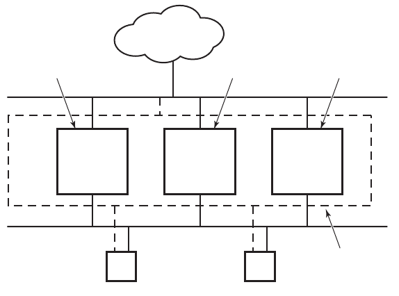
VRRP Overview
Page 170 7750 SR OS Router Configuration Guide
VRRP Overview
The Virtual Router Redundancy Protocol (VRRP) is defined in the IETF RFC 2338, Virtual Router
Redundancy Protocol, and further described in draft-ietf-vrrp-spec-v2-06.txt. VRRP describes a
method of implementing a redundant IP interface shared between two or more routers on a
common LAN segment, allowing a group of routers to function as one virtual router. When this IP
interface is specified as a default gateway on hosts directly attached to this LAN, the routers
sharing the IP interface prevent a single point of failure by limiting access to this gateway address.
VRRP can be implemented on IES service interfaces and on core network IP interfaces.
If the master virtual router fails, the backup router configured with the highest acceptable priority
becomes the master virtual router. The new master router assumes the normal packet forwarding
for the local hosts.
Figure 13 displays an example of a VRRP configuration.
Figure 13: VRRP Configuration
OSRG006
Non-Owner
ALA-3
vrld 100
Priority 150
Owner
ALA-2
vrld 100
Non-Owner
ALA-1
vrld 100
Priority 200
Internet
Backup Master Backup
Virtual
Router ID
(VRID)

VRRP
7750 SR OS Router Configuration Guide Page 171
VRRP Components
VRRP consists of the following components:
•Virtual Router on page 171
•IP Address Owner on page 171
•Primary and Secondary IP Addresses on page 172
•Virtual Router Master on page 172
•Virtual Router Backup on page 173
•Owner and Non-Owner VRRP on page 173
Virtual Router
A virtual router is a logical entity managed by VRRP that acts as a default router for hosts on a
shared LAN. It consists of a Virtual Router Identifier (VRID) and a set of associated IP addresses
(or address) across a common LAN. A VRRP router can backup one or more virtual routers.
The purpose of supporting multiple IP addresses within a single virtual router is for multi-netting.
This is a common mechanism that allows multiple local subnet attachment on a single routing
interface. Up to four virtual routers are possible on a single Alcatel-Lucent IP interface. The virtual
routers must be in the same subnet. Each virtual router has its own VRID, state machine and
messaging instance.
IP Address Owner
VRRP can be configured in either an owner or non-owner mode. The owner is the VRRP router
whose virtual router IP address is the same as the real interface IP address. This is the router that
responds to packets addressed to one of the IP addresses for ICMP pings, TCP connections, etc.
All other virtual router instances participating in this message domain must have the same VRID
configured and cannot be configured as owner.
7750 SR OS allows the virtual routers to be configured as non-owners of the IP address. VRRP on
a 7750 SR router can be configured to allow non-owners to respond to ICMP echo requests when
they become the virtual router master for the virtual router. Telnet and other connection-oriented
protocols can also be configured for non-owner master response. However, the individual
application conversations (connections) will not survive a VRRP failover. A non-owner VRRP
router operating as a backup will not respond to any packets addressed to any of the virtual router
IP addresses.

VRRP Components
Page 172 7750 SR OS Router Configuration Guide
Primary and Secondary IP Addresses
A primary address is an IP address selected from the set of real interface address. VRRP
advertisements are always sent using the primary IP address as the source of the IP packet.
A 7750 SR IP interface must always have a primary IP address assigned for VRRP to be active on
the interface. 7750 SR OS supports both primary and secondary IP addresses (multi-netting) on the
IP interface. The virtual router’s VRID primary IP address is always the primary address on the IP
interface. VRRP uses the primary IP address as the IP address placed in the source IP address field
of the IP header for all VRRP messages sent on that interface.
Virtual Router Master
The VRRP router which controls the IP address(es) associated with a virtual router is called the
master. The master is responsible for forwarding packets sent to the VRRP IP addresses. An
election process provides dynamic failover of the forwarding responsibility if the master becomes
unavailable. This allows any of the virtual router IP addresses on the LAN to be used as the default
first hop router by end hosts. This enables a higher availability default path without requiring
configuration of dynamic routing or router discovery protocols on every end host.
If the master is unavailable, each backup virtual router for the VRID compare the configured
priority values to determine the master role. In case of a tie, the virtual router with the highest
primary IP address becomes master.
The preempt parameter can be set to false to prevent a backup virtual router with a better
priority value from becoming master when an existing non-owner virtual router is the current
master. This is determined on a first-come, first-served basis.
While master, a virtual router routes and originates all IP packets into the LAN using the physical
MAC address for the IP interface as the Layer 2 source MAC address, not the VRID MAC address.
ARP packets also use the parent IP interface MAC address as the Layer 2 source MAC address
while inserting the virtual router MAC address in the appropriate hardware address field. VRRP
messages are the only packets transmitted using the virtual router MAC address as the Layer 2
source MAC.

VRRP
7750 SR OS Router Configuration Guide Page 173
Virtual Router Backup
A new virtual router master is selected from the set of VRRP routers available to assume
forwarding responsibility for a virtual router should the current master fail.
Owner and Non-Owner VRRP
The owner controls the IP address of the virtual router and is responsible for forwarding packets
sent to this IP address. The owner assumes the role of the master virtual router. Only one virtual
router in the domain can be configured as owner. All other virtual router instances participating in
this message domain must have the same VRID configured.
The most important parameter to be defined on a non-owner virtual router instance is the priority.
The priority defines a virtual router’s selection order in the master election process. The priority
value and the preempt mode determine the virtual router with the highest priority to become the
master virtual router.
The base priority is used to derive the in-use priority of the virtual router instance as modified by
any optional VRRP priority control policy. VRRP priority control policies can be used to either
override or adjust the base priority value depending on events or conditions within the chassis.
For information about non-owner access parameters, refer to VRRP Non-Owner Accessibility on
page 188.

VRRP Components
Page 174 7750 SR OS Router Configuration Guide
Configurable Parameters
In addition to backup IP addresses, to facilitate configuration of a virtual router on 7750 SR
routers, the following parameters can be defined in owner configurations:
•Virtual Router ID (VRID) on page 174
•Message Interval and Master Inheritance on page 176
•VRRP Message Authentication on page 178
•Authentication Data on page 180
•Virtual MAC Address on page 180
The following parameters can be defined in non-owner configurations:
•Virtual Router ID (VRID) on page 174
•Priority on page 174
•Message Interval and Master Inheritance on page 176
•Master Down Interval on page 177
•Preempt Mode on page 177
•VRRP Message Authentication on page 178
•Authentication Data on page 180
•Virtual MAC Address on page 180
•Inherit Master VRRP Router’s Advertisement Interval Timer on page 181
•Policies on page 181
Virtual Router ID (VRID)
The VRID must be configured with the same value on each virtual router associated with the
redundant IP address (IP addresses). It is placed in all VRRP advertisement messages sent by each
virtual router.
Priority
The priority value affects the interaction between this VRID and the same VRID of other virtual
routers participating on the same LAN. A higher priority value defines a greater priority in
becoming the virtual router master for the VRID. The priority value can only be configured when
the defined IP address on the IP interface is different than the virtual router IP address (non-owner
mode).

VRRP
7750 SR OS Router Configuration Guide Page 175
When the IP address on the IP interface matches the virtual router IP address (owner mode), the
priority value is fixed at 255, the highest value possible. This virtual router member is considered
the owner of the virtual router IP address. There can only be one owner of the virtual router IP
address for all virtual router members.
The priority value 0 is reserved for VRRP advertisement message purposes. It is used to tell other
virtual routers in the same VRID that this virtual router is no longer acting as master, triggering a
new election process. When this happens, each backup virtual router sets its master down timer
equal to the skew time value. This shortens the time until one of the backup virtual routers
becomes master.
The current master virtual router must transmit a VRRP advertisement message immediately upon
receipt of a VRRP message with priority set to 0. This prevents another backup from becoming
master for a short period of time.
Non-owner virtual routers may be configured with a priority of 254 through 1. The default value is
100. Multiple non-owners can share the same priority value. When multiple non-owner backup
virtual routers are tied (transmit VRRP advertisement messages simultaneously) in the election
process, both become master simultaneously, the one with the best priority will win the election. If
the priority value in the message is equal to the master’s local priority value, then the primary IP
address of the local master and the message is evaluated as the tie breaker. The higher IP address
becomes master. (The primary IP address is the source IP address of the VRRP advertisement
message.)
The priority is also used to determine when to preempt the existing master. If the preempt mode
value is true, VRRP advertisement messages from inferior (lower priority) masters are discarded,
causing the master down timer to expire and the transition to master state.
The priority value also dictates the skew time added to the master timeout period.
IP Addresses
Each virtual router participating in the same VRID should be defined with the same set of IP
addresses. These are the IP addresses being used by hosts on the LAN as gateway addresses. Since
multi-netting supports 16 IP addresses on the IP interface, up to 16 addresses may be assigned to a
specific a virtual router instance.

VRRP Components
Page 176 7750 SR OS Router Configuration Guide
Message Interval and Master Inheritance
Each virtual router is configured with a message interval per VRID within which it participates.
This parameter must be the same for every virtual router on the VRID.
The default advertisement interval is 1 second and can be configured between 1 and 255 seconds in
1 second increments.
As stated in RFC 2338, the advertisement interval field in every received VRRP advertisement
message must match the locally configured advertisement interval. If a mismatch occurs, the
incoming message is discarded without further processing. An optional inherit parameter specifies
that the current master’s advertisement interval setting should operationally override the locally
configured advertisement interval setting. If the current master changes, the new master setting is
used. If the local virtual router becomes master, the locally configured advertisement interval is
enforced.
If a VRRP advertisement message is received with an advertisement interval set to a value
different than the local value and the inherit parameter is disabled, the message is discarded
without processing.
The master virtual router on a VRID uses the advertisement interval to load the advertisement
timer, specifying when to send the next VRRP advertisement message. Each backup virtual router
on a VRID uses the advertisement interval (with the configured local priority) to derive the master
down timer value.
Skew Time
The skew time is used to add a sub-second time period to the master down interval. This is not a
configurable parameter. It is derived from the current local priority of the virtual router’s VRID. To
calculate the skew time, the virtual router evaluates the following formula:
Skew Time = ((256 - priority) / 256) seconds
The higher priority value, the smaller the skew time will be. This means that virtual routers with a
lower priority will transition to master slower than virtual routers with higher priorities.

VRRP
7750 SR OS Router Configuration Guide Page 177
Master Down Interval
The master down interval is a calculated value used to load the master down timer. When the
master down timer expires, the virtual router enters the master state. To calculate the master down
interval, the virtual router evaluates the following formula:
Master Down Interval = ((3 x Operational Advertisement Interval) + Skew Time) seconds)
The operational advertisement interval is dependent upon the state of the inherit parameter. When
the inherit parameter is enabled, the operational advertisement interval is derived from the current
master’s advertisement interval field in the VRRP advertisement message. When inherit is
disabled, the operational advertisement interval must be equal to the locally configured
advertisement interval.
The master down timer is only operational when the local virtual router is operating in backup
mode.
Preempt Mode
Preempt mode is a true or false configured value which controls whether a specific backup virtual
router preempts a lower priority master. The IP address owner will always become master when
available. Preempt mode cannot be set to false on the owner virtual router. The default value for
preempt mode is true.
When preempt mode is true, the advertised priority from the incoming VRRP advertisement
message from the current master is compared to the local configured priority. If the local priority is
higher, the received VRRP advertisement message is discarded. This will result in the eventual
expiration of the master down timer causing a transition to the master state. If the received priority
is equal to the local priority, the message is not discarded and the current master will not be
discarded. Note that when in the backup state, the received primary IP address is not part of the
decision to preempt and is not used as a tie breaker when the received and local priorities are equal.
When preempt is enabled, the virtual router instance overrides any non-owner master with an in-
use message priority value less than the virtual router instance in-use priority value. If preempt is
disabled, the virtual router only becomes master if the master down timer expires before a VRRP
advertisement message is received from another virtual router.

VRRP Components
Page 178 7750 SR OS Router Configuration Guide
VRRP Message Authentication
The authentication type parameter defines the type of authentication used by the virtual router in
VRRP advertisement message authentication. The current master uses the configured
authentication type to indicate any egress message manipulation that must be performed in
conjunction with any supporting authentication parameters before transmitting a VRRP
advertisement message. The configured authentication type value is transmitted in the message
authentication type field with the appropriate authentication data field filled in. Backup routers use
the authentication type message field value in interpreting the contained authentication data field
within received VRRP advertisement messages.
VRRP supports three message authentication methods which provide varying degrees of security.
The supported authentication types are:
0 – No Authentication
1 – Simple Text Password
2 – IP Authentication Header
Authentication Type 0 – No Authentication
The use of type 0 indicates that VRRP advertisement messages are not authenticated (provides no
authentication). The master transmitting VRRP advertisement messages will transmit the value 0
in the egress messages authentication type field and the authentication data field. Backup virtual
routers receiving VRRP advertisement messages with the authentication type field equal to 0 will
ignore the authentication data field in the message.
All compliant VRRP advertisement messages are accepted. The following fields within the
received VRRP advertisement message are checked for compliance (the VRRP specification may
require additional checks).
• IP header checks specific to VRRP
→IP header destination IP address – Must be 224.0.0.18
→IP header TTL field – Must be equal to 255, the packet must not have traversed any IP
routed hops
→IP header protocol field – must be 112 (decimal)

VRRP
7750 SR OS Router Configuration Guide Page 179
• VRRP message checks
→Version field – Must be set to the value 2
→Type field – Must be set to the value of 1 (advertisement)
→Virtual router ID field – Must match one of the configured VRID on the ingress IP
interface (All other fields are dependent on matching the virtual router ID field to one
of the interfaces configured VRID parameters)
→Priority field – Must be equal to or greater than the VRID in-use priority or be equal to
0 (Note, equal to the VRID in-use priority and 0 requires further processing regarding
master/backup and senders IP address to determine validity of the message)
→Authentication type field – Must be equal to 0
→Advertisement interval field – Must be equal to the VRID configured advertisement
interval
→Checksum field – Must be valid
→Authentication data fields – Must be ignored.
VRRP messages not meeting the criteria are silently dropped.
Authentication Type 1 – Simple Text Password
The use of type 1 indicates that VRRP advertisement messages are authenticated with a clear
(simple) text password. All virtual routers participating in the virtual router instance must be
configured with the same 8 octet password. Transmitting virtual routers place a value of 1 in the
VRRP advertisement message authentication type field and put the configured simple text
password into the message authentication data field. Receiving virtual routers compare the
message authentication data field with the local configured simple text password based on the
message authentication type field value of 1.
The same checks are performed for type 0 with the following exceptions (the VRRP specification
may require additional checks):
• VRRP message checks
→Authentication type field – Must be equal to 1
→Authentication data fields – Must be equal to the VRID configured simple text
password
Any VRRP message not meeting the type 0 verification checks with the exceptions above are
silently discarded.

VRRP Components
Page 180 7750 SR OS Router Configuration Guide
Authentication Failure
Any received VRRP advertisement message that fails authentication must be silently discarded
with an invalid authentication counter incremented for the ingress virtual router instance.
Authentication Data
This feature is different than the VRRP advertisement message field with the same name. This is
any required authentication information that is pertinent to the configured authentication type. The
type of authentication data used for each authentication type is as follows:
Authentication Type Authentication Data
0 None, authentication is not performed
1 Simple text password consisting of 8 octets
Virtual MAC Address
The MAC address can be used instead of an IP address in ARP responses when the virtual router
instance is master. The MAC address configuration must be the same for all virtual routers
participating as a virtual router or indeterminate connectivity by the attached IP hosts will result.
All VRRP advertisement messages are transmitted with ieee-mac-addr as the source MAC.
The command can be configured in both non-owner and owner VRRP contexts.
VRRP Advertisement Message IP Address List Verification
VRRP advertisement messages contain an IP address count field that indicates the number of IP
addresses listed in the sequential IP address fields at the end of the message. The 7750 SR OS
implementation always logs mismatching events. The decision on where and whether to forward
the generated messages depends on the configuration of the event manager.
To facilitate the sending of mismatch log messages, each virtual router instance keeps the
mismatch state associated with each source IP address in the VRRP master table. Whenever the
state changes, a mismatch log message is generated indicating the source IP address within the
message, the mismatch or match event and the time of the event.
With secondary IP address support, multiple IP addresses may be found in the list and it should
match the IP address on the virtual router instance. Owner and non-owner virtual router instances

VRRP
7750 SR OS Router Configuration Guide Page 181
have the supported IP addresses explicitly defined, making mismatched supported IP address
within the interconnected virtual router instances a provisioning issue.
Inherit Master VRRP Router’s Advertisement Interval Timer
The virtual router instance can inherit the master VRRP router’s advertisement interval timer
which is used by backup routers to calculate the master down timer.
The inheritance is only configurable in the non-owner nodal context. It is used to allow the current
virtual router instance master to dictate the master down timer for all backup virtual routers.
Policies
Policies can be configured to control VRRP priority with the virtual router instance. VRRP priority
control policies can be used to override or adjust the base priority value depending on events or
conditions within the chassis.
The policy can be associated with more than one virtual router instance. The priority events within
the policy override or diminish the base priority dynamically affecting the in-use priority. As
priority events clear in the policy, the in-use priority can eventually be restored to the base priority
value.
Policies can only be configured in the non-owner VRRP context. For non-owner virtual router
instances, if policies are not configured, then the base priority is used as the in-use priority.

VRRP Priority Control Policies
Page 182 7750 SR OS Router Configuration Guide
VRRP Priority Control Policies
This implementation of VRRP supports control policies to manipulate virtual router participation
in the VRRP master election process and master self-deprecation. The local priority value for the
virtual router instance is used to control the election process and master state.
VRRP Virtual Router Policy Constraints
Priority control policies can only be applied to non-owner VRRP virtual router instances. Owner
VRRP virtual routers cannot be controlled by a priority control policy because they are required to
have a priority value of 255 that cannot be diminished. Only one VRRP priority control policy can
be applied to a non-owner virtual router instance.
Multiple VRRP virtual router instances may be associated with the same IP interface, allowing
multiple priority control policies to be associated with the IP interface.
An applied VRRP priority control policy only affects the in-use priority on the virtual router
instance when the preempt mode has been enabled. A virtual router instance with preempt mode
disabled will always use the base priority as the in-use priority, ignoring any configured priority
control policy.
VRRP Virtual Router Instance Base Priority
Non-owner virtual router instances must have a base priority value between 1 and 254. The value 0
is reserved for master termination. The value 255 is reserved for owners. The default base priority
for non-owner virtual router instances is the value 100.
The base priority is the starting priority for the VRRP instance. The actual in-use priority for the
VRRP instance is derived from the base priority and an optional VRRP priority control policy.

VRRP
7750 SR OS Router Configuration Guide Page 183
VRRP Priority Control Policy Delta In-Use Priority Limit
A VRRP priority control policy enforces an overall minimum value that the policy can inflict on
the VRRP virtual router instance base priority. This value provides a lower limit to the delta
priority events manipulation of the base priority.
A delta priority event is a conditional event defined in the priority control policy that subtracts a
given amount from the current, in-use priority for all VRRP virtual router instances to which the
policy is applied. Multiple delta priority events can apply simultaneously, creating a dynamic
priority value. The base priority for the instance, less the sum of the delta values derives the actual
priority value in-use.
An explicit priority event is a conditional event defined in the priority control policy that explicitly
defines the in-use priority for the virtual router instance. The explicitly defined values are not
affected by the delta in-use priority limit. When multiple explicit priority events happen
simultaneously, the lowest value is used for the in-use priority. The configured base priority is not
a factor in explicit priority overrides of the in-use priority.
The allowed range of the Delta In-Use Priority Limit is 1 to 254. The default is 1, which prevents
the delta priority events from operationally disabling the virtual router instance.
VRRP Priority Control Policy Priority Events
The main function of a VRRP priority control policy is to define conditions or events that impact
the system’s ability to communicate with outside hosts or portions of the network. When one or
multiple of these events are true, the base priority on the virtual router instance is either
overwritten with an explicit value, or a sum of delta priorities is subtracted from the base priority.
The result is the in-use priority for the virtual router instance. Any priority event may be
configured as an explicit event or a delta event.
Explicit events override all delta events. When multiple explicit events occur, the event with the
lowest priority value is assigned to the in-use priority. As events clear, the in-use priority is
reevaluated accordingly and adjusted dynamically.
Delta priority events also have priority values. When no explicit events have occurred within the
policy, the sum of the occurring delta events priorities is subtracted from the base priority of each
virtual router instance. If the result is lower than the delta in-use priority limit, the delta in-use
priority limit is used as the in-use priority for the virtual router instance. Otherwise, the in-use
priority is set to the base priority less the sum of the delta events.

VRRP Priority Control Policies
Page 184 7750 SR OS Router Configuration Guide
Each event generates a VRRP priority event message indicating the policy-id, the event type, the
priority type (delta or explicit) and the event priority value. Another log message is generated
when the event is no longer true, indicating that it has been cleared.
Priority Event Hold-Set Timers
Hold-set timers are used to dampen the effect of a flapping event. A flapping event is where the
event continually transitions between clear and set. The hold-set value is loaded into a hold set
timer that prevents a set event from transitioning to the cleared state until it expires.
Each time an event transitions between cleared and set, the timer is loaded and begins to count
down to zero. If the timer reaches zero, the event will be allowed to enter the cleared state once
more. Entering the cleared state is always dependent on the object controlling the event
conforming to the requirements defined in the event itself. It is possible, on some event types, to
have a further set action reload the hold set timer. This extends the amount of time that must expire
before entering the cleared state.
For an example of a hold-set timer setting, refer to LAG Degrade Priority Event on page 184.
Port Down Priority Event
The port down priority event is tied to either a physical port or a SONET/SDH channel. The port or
channel operational state is evaluated to determine a port down priority event or event clear.
When the port or channel operational state is up, the port down priority event is considered false or
cleared. When the port or channel operational state is down, the port down priority event is
considered true or set.
LAG Degrade Priority Event
The LAG degrade priority event is tied to an existing Link Aggregation Group (LAG). The LAG
degrade priority event is conditional to percentage of available port bandwidth on the LAG.
Multiple bandwidth percentage thresholds may be defined, each with its own priority value.
If the LAG transitions from one threshold to the next, the previous threshold priority value is
subtracted from the total delta sum while the new threshold priority value is added to the sum. The
new sum is then subtracted from the base priority and compared to the delta in-use priority limit to
derive the new in-use priority on the virtual router instance.

VRRP
7750 SR OS Router Configuration Guide Page 185
The following example illustrates a LAG priority event and it’s interaction with the hold set timer
in changing the in-use priority.
The following state and timer settings are used for the LAG events displayed in Table 6:
• User-defined thresholds: 2 ports down 4 ports down 6 ports down
• LAG configured ports: 8 ports
• Hold set timer (hold-set): 5 seconds
Table 6: LAG Events
Time LAG Port State Parameter State Comments
0 All ports down Event State Set - 8 ports down
Event Threshold 6 ports down
Hold Set Timer 5 seconds Set to hold-set parameter
1 One port up Event State Set - 8 ports down Cannot change until Hold Set Timer expires
Event Threshold 6 ports down
Hold Set Timer 5 seconds Event does not affect timer
2 All ports up Event State Set - 8 ports down Still waiting for Hold Set Timer expires
Event Threshold 6 ports down
Hold Set Timer 3 seconds
5 All ports up Event State Cleared - All ports up
Event Threshold None Event cleared
Hold Set Timer Expired
100 Five ports down Event State Set - 5 ports down
Event Threshold 4 ports down
Hold Set Timer Expired Set to hold-set parameter
102 Three ports down Event State Set - 5 ports down
Event Threshold 4 ports down
Hold Set Timer 3 seconds
103 All ports up Event State Set - 5 ports down
Event Threshold 4 ports down
Hold Set Timer 2 second

VRRP Priority Control Policies
Page 186 7750 SR OS Router Configuration Guide
104 Two ports down Event State Set - 5 ports down
Event Threshold 4 ports down
Hold Set Timer 1 second Current threshold is 5, so 2 down has no
effect
105 Two ports down Event State Set - 2 ports down
Event Threshold 2 ports down
Hold Set Timer Expired
200 Four ports down Event State Set - 2 ports down
Event Threshold 4 ports down
Hold Set Timer 5 seconds Set to hold-set parameter
202 Seven ports down Event State Set - 7 ports down Changed due to increase
Event Threshold 6 ports down
Hold Set Timer 5 seconds Set to hold-set due to threshold increase
206 All ports up Event State Set - 7 ports down
Event Threshold 6 ports down
Hold Set Timer 1 second
207 All ports up Event State Cleared - All ports up
Event Threshold None Event cleared
Hold Set Timer Expired
Table 6: LAG Events (Continued)
Time LAG Port State Parameter State Comments

VRRP
7750 SR OS Router Configuration Guide Page 187
Host Unreachable Priority Event
The host unreachable priority event creates a continuous ping task that is used to test connectivity
to a remote host. The path to the remote host and the remote host itself must be capable and
configured to accept ICMP echo request and replies for the ping to be successful.
The ping task is controlled by interval and size parameters that define how often the ICMP request
messages are transmitted and the size of each message. A historical missing reply parameter
defines when the ping destination is considered unreachable.
When the host is unreachable, the host unreachable priority event is considered true or set. When
the host is reachable, the host unreachable priority event is considered false or cleared.
Route Unknown Priority Event
The route unknown priority event defines a task that monitors the existence of a given route prefix
in the system’s routing table.
The route monitoring task can be constrained by a condition that allows a prefix that is less
specific than the defined prefix to be considered as a match. The source protocol can be defined to
indicate the protocol the installed route must be populated from. To further define match criteria
when multiple instances of the route prefix exist, an optional next hop parameter can be defined.
When a route prefix exists within the active route table that matches the defined match criteria, the
route unknown priority event is considered false or cleared. When a route prefix does not exist
within the active route table matching the defined criteria, the route unknown priority event is
considered true or set.

VRRP Non-Owner Accessibility
Page 188 7750 SR OS Router Configuration Guide
VRRP Non-Owner Accessibility
Although RFC 2338 and draft-ietf-vrrp-spec-v2-06.txt states that only VRRP owners can respond
to ping and other management-oriented protocols directed to the VRID IP addresses, 7750 SR OS
allows an override of this restraint on a per VRRP virtual router instance basis.
Non-Owner Access Ping Reply
When non-owner access ping reply is enabled on a virtual router instance, ICMP echo request
messages destined to the non-owner virtual router instance IP addresses are not discarded at the IP
interface when operating in master mode. ICMP echo request messages are always discarded in
backup mode.
When non-owner access ping reply is disabled on a virtual router instance, ICMP echo request
messages destined to the non-owner virtual router instance IP addresses are silently discarded in
both the master and backup modes.
Non-Owner Access Telnet
When non-owner access Telnet is enabled on a virtual router instance, authorized Telnet sessions
may be established that are destined to the virtual router instance IP addresses when operating in
master mode. Telnet sessions are always discarded at the IP interface when destined to a virtual
router IP address operating in backup mode. Enabling non-owner access Telnet does not guarantee
Telnet access, proper management and security features must be enabled to allow Telnet on this
interface and possibly from the given source IP address.
When non-owner access Telnet is disabled on a virtual router instance, Telnet sessions destined to
the non-owner virtual router instance IP addresses are silently discarded in both master and backup
modes.
VRRP
7750 SR OS Router Configuration Guide Page 189
Non-Owner Access SSH
When non-owner access SSH is enabled on a virtual router instance, authorized SSH sessions may
be established that are destined to the virtual router instance IP addresses when operating in master
mode. SSH sessions are always discarded at the IP interface when destined to a virtual router IP
address operating in backup mode. Enabling non-owner access SSH does not guarantee SSH
access, proper management and security features must be enabled to allow SSH on this interface
and possibly from the given source IP address.
When non-owner access SSH is disabled on a virtual router instance, SSH sessions destined to the
non-owner virtual router instance IP addresses are silently discarded in both master and backup
modes.
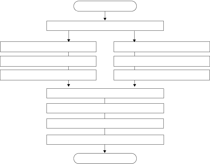
VRRP Configuration Process Overview
Page 190 7750 SR OS Router Configuration Guide
VRRP Configuration Process Overview
Figure 14 displays the process to provision VRRP parameters.
Figure 14: VRRP Configuration and Implementation Flow
TURN UP
START
CONFIGURE VRRP PRIORITY CONTROL POLICIES (optional)
CONFIGURE IES SERVICE CONFIGURE ROUTER INTERFACE
CONFIGURE INTERFACE CONFIGURE INTERFACE
SPECIFY ADDRESS, SECONDARY ADDRESS(ES) SPECIFY ADDRESS, SECONDARY ADDRESS(ES)
APPLY VRRP PRIORITY CONTROL POLICIES (optional)
SPECIFY BACKUP IP ADDRESS(ES)
CONFIGURE VRRP OWNER/NON-OWNER INSTANCE
CONFIGURE VRRP PARAMETERS
VRRP
7750 SR OS Router Configuration Guide Page 191
VRRP Configuration Components
Figure 15 displays the major components to configure a VRRP priority control policy.
Figure 15: VRRP Policy Configuration Components
• Policy — A VRRP priority control policy can be used to modify the VRRP in-use priority
based on priority control events such as port-down, lag-port-down, host-
unreachable, and route-unknown parameters.
• Priority event — The context to configure VRRP priority control events used to define
criteria for modifying the VRRP in-use priority.
•Port down
— Configure a port down priority control event that monitors the operational
state of a given port or SONET/SDH channel. When a port or channel enters an
operational down state, the event is considered set. When the port or channel enters an
operational up state, the event is considered cleared.
• LAG port down — Configures a Link Aggregation Group (LAG) priority control event
that monitors the operational state of the links in the LAG. The event monitors the
operational state of each port in the specified LAG. When one or more of the ports enter
the operational down state, the event is considered set. When all the ports enter an
operational up state, the event is considered clear.
• Host unreachable — Configures a host unreachable priority control event to monitor the
ability to receive ICMP echo reply packets from a given IP host address. A host
unreachable priority event creates a continuous ICMP echo request (ping) probe to the
specified IP address. During ping failure, the event is considered to be set. During ping
success, the event is considered to be cleared.
• Route unknown — Configures a route unknown priority control event that monitors the
existence of a specific active IP route prefix within the routing table. Route unknown
defines a link between the VRRP priority control policy and the Route Table Manager
(RTM). The RTM registers the specified route prefix as monitored by the policy. If any
change (add, delete, new next hop) occurs relative to the prefix, the policy is notified and
takes proper action according to the priority event definition.
Figure 16 displays the major components to configure a network interface VRRP instance.
VRRP
POLICY
PRIORITY-EVENT
PORT-DOWN
LAG-PORT-DOWN
HOST-UNREACHABLE
ROUTE-UNKNOWN
VRRP Configuration Process Overview
Page 192 7750 SR OS Router Configuration Guide
Figure 16: Interface VRRP Configuration Components
• Interface — A logical IP routing interface.
• Address — Assigns the primary IP address for the interface. A primary IP address must be
assigned to each IP interface.
• Secondary — Assigns a secondary IP address, IP subnet/broadcast address format to the
interface.
• VRRP — The context to configure a VRRP virtual router instance. A virtual router is
defined by its VRID and a set of IP addresses.
• Owner — When the owner keyword is specified, the virtual router instance owns the
backed up IP addresses. Only one router in the message domain can be the owner.
•Non-owner
— VRRP instances are created as non-owners unless the owner keyword is
specified. Non-owners are all the other virtual router instances participating in the message
domain that have the same VRID configured.
• Backup — Non-owner virtual router instances create a routable IP interface address that is
operationally dependent on the virtual router instance mode (master or backup). The
backup command in owner virtual router instances does not create a routable IP interface
address; it defines the already existing parental IP interface IP addresses that are advertised
by the virtual router instance.
For owner virtual router instances, backup defines the list of IP addresses that will be
advertised within VRRP Advertisement messages. This indicates to backup virtual routers
receiving the messages what IP addresses the master is representing.
• Policy — (optional) Assigns an existing VRRP priority control policy association with the
virtual router instance.
ROUTER
INTERFACE
ADDRESS
SECONDARY
VRRP
OWNER (optional)
NON-OWNER (default)
BACKUP
BACKUP
POLICY (optional)
POLICY (optional)
VRRP
7750 SR OS Router Configuration Guide Page 193
Figure 17 displays the major components to configure a VRRP instance in an IES service.
Figure 17: IES VRRP Configuration Components
• IES — The context to creates or modify an IES service.
• Interface — A logical IP routing interface.
• Address — Assigns the primary IP address for the interface. A primary IP address must be
assigned to each IP interface.
• Secondary — Assigns a secondary IP address, IP subnet/broadcast address format to the
interface.
• VRRP — The context to configure a VRRP virtual router instance. A virtual router is
defined by its VRID and a set of IP addresses.
• Owner — When the owner keyword is specified, the virtual router instance owns the
backed up IP addresses. Only one router in the message domain can be the owner.
•Non-owner
— VRRP instances are created as non-owners unless the owner keyword is
specified. Non-owners are all the other virtual router instances participating in the
message domain that have the same VRID configured.
• Backup — Non-owner virtual router instances create a routable IP interface address that is
operationally dependent on the virtual router instance mode (master or backup). The
backup command in owner virtual router instances does not create a routable IP interface
address; it defines the already existing parental IP interface IP addresses that are
advertised by the virtual router instance.
For owner virtual router instances, backup defines the list of IP addresses that will be
advertised within VRRP Advertisement messages. This indicates to backup virtual routers
receiving the messages what IP addresses the master is representing.
• Policy — (optional) Assigns an existing VRRP priority control policy association with the
virtual router instance.
SERVICE
INTERFACE
ADDRESS
VRRP vrid
OWNER
NON-OWNER
BACKUP
BACKUP
POLICY (optional)
POLICY (optional)
IES
SECONDARY

Configuration Notes
Page 194 7750 SR OS Router Configuration Guide
Configuration Notes
This section describes VRRP configuration caveats.
General
• Creating and applying VRRP policies are optional.
• Backup command:
→You can configure up to 16 backup IP addresses in the non-owner mode. The backup
IP address(es) must be on the same subnet. The backup addresses explicitly define
which IP addresses are in the VRRP advertisement message IP address list.
→In the owner mode, the backup IP address must be identical to one of the interface’s IP
addresses. The backup address explicitly defines which IP addresses are in the VRRP
advertisement message IP address list.
Reference Sources
For information on supported IETF drafts and standards, as well as standard and proprietary MIBS,
refer to Standards and Protocol Support on page 715.
VRRP
7750 SR OS Router Configuration Guide Page 195
Configuring VRRP with CLI
This section provides information to configure VRRP using the command line interface.
Topics in this section include:
•VRRP Configuration Overview on page 196
•VRRP CLI Command Structure on page 197
•List of Commands on page 199
•Basic VRRP Configurations on page 204
•Common Configuration Tasks on page 207
•Configuring VRRP Policy Components on page 209
•VRRP Configuration Management Tasks on page 219
•Modifying a VRRP Policy on page 219
•Deleting a VRRP Policy on page 220
→Modifying Service and Interface VRRP Parameters on page 221
•Modifying Non-Owner Parameters on page 221
•Modifying Owner Parameters on page 221
•Deleting VRRP on an Interface or Service on page 221

VRRP Configuration Overview
Page 196 7750 SR OS Router Configuration Guide
VRRP Configuration Overview
Configuring VRRP policies and configuring VRRP instances on IES or VPRN interfaces and
router interfaces is optional. The basic owner and non-owner VRRP configurations on an IES or
router interface must specify the backup ip-address parameter.
VRRP helps eliminate the single point of failure in a routed environment by using virtual router IP
address shared between two or more routers connecting the common domain. VRRP provides
dynamic fail over of the forwarding responsibility if the master becomes unavailable.
The VRRP implementation allows one master per IP subnet. All other VRRP instances in the same
domain must be in backup mode.
Preconfiguration Requirements
VRRP policies:
• VRRP policies must be configured before they can be applied to an interface or IES or
VPRN VRRP instance. VRRP policies are configured in the config>vrrp context.
Configuring VRRP on an IES or VPRN service interface:
• The service customer account must be created prior to configuring an IES or VPRN VRRP
instance.
• The interface address must be specified in the both the owner and non-owner IES or
VPRN or router interface instances.
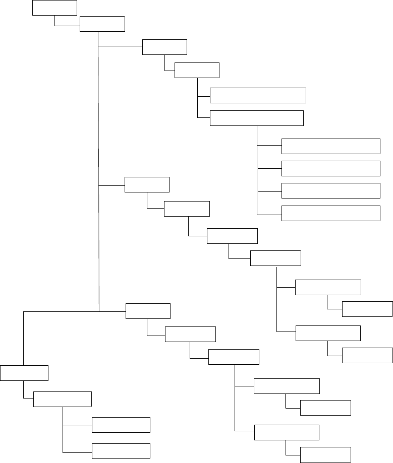
VRRP
7750 SR OS Router Configuration Guide Page 197
VRRP CLI Command Structure
The 7750 SR OS VRRP command structure is displayed in Figure 18. VRRP policy
commands are located under the config>vrrp context.
VRRP service configuration commands are located under the config>service>ies>
interface context. VRRP interface configuration commands are located under the
config>router>interface context.
VRRP show commands are located under the show>vrrp context.
Figure 18: VRRP Command Structure
ROOT
CONFIG
SHOW
VRRP
SERVICE
IES/VPRN
INTERFACE
VRRP
HOST UNREACHABLE
LAG PORT DOWN
PORT DOWN
ROUTE UNKNOWN
VRRP
DELTA-IN-USE LIMIT
PRIORITY EVENT
ROUTER
OWNER
NON-OWNER
BACKUP
BACKUP
INTERFACE
VRRP
OWNER
NON-OWNER
BACKUP
BACKUP
INSTANCE
POLICY
POLICY

VRRP CLI Command Structure
Page 198 7750 SR OS Router Configuration Guide
ROOT
CONFIG
SHOW
VRRP
SERVICE
IES/VPRN
INTERFACE
VRRP
HOST UNREACHABLE
LAG PORT DOWN
PORT DOWN
ROUTE UNKNOWN
VRRP
DELTA-IN-USE LIMIT
PRIORITY EVENT
ROUTER
OWNER
NON-OWNER
BACKUP
BACKUP
INTERFACE
VRRP
OWNER
NON-OWNER
BACKUP
BACKUP
INSTANCE
POLICY
POLICY

VRRP
7750 SR OS Router Configuration Guide Page 199
List of Commands
Table 7 lists the commands to configure VRRP policy parameters, indicating the configuration
level at which each command is implemented with a short command description.
Table 8 lists the commands to configure VRRP parameters on an interface and in an IES or
VPRN service, indicating the configuration level at which each command is implemented with
a short command description. Refer to the IES chapter of the 7750 SR OS Services Guide for
information about IES command syntax and usage.
The VRRP command list is organized in the following task-oriented manner:
•Configure a VRRP policy
•Configure VRRP policy priority events
•Configure IES or VPRN VRRP owner parameters
•Configure IES or VPRN VRRP non-owner parameters
Table 7: CLI Commands to Configure a VRRP Policy
Command Description Page
Configure a VRRP policy
config>vrrp>policy
description Text string describing the policy. 243
delta-in-use-limit Sets a lower limit on the virtual router in-use priority that can be derived
from the delta priority control events. 242
Configure VRRP policy priority events
config>vrrp>policy>priority-event
port-down Creates a port down priority control event that monitors the operational
state of a given port or SONET/SDH channel. 248
hold-set Configures the amount of time before the set state for a VRRP priority
control event can transition to the cleared state to dampen flapping
events.
245
priority Configures the effect the set event has on the virtual router instance in-
use priority. 246
lag-port-down Creates context for configuring Link Aggregation Group (LAG) priority
control event that monitors the operational state of the links in the LAG. 250

List of Commands
Page 200 7750 SR OS Router Configuration Guide
hold-set Configures the amount of time before the set state for a VRRP priority
control event transitions to the cleared state to dampen flapping events. 245
number-down Creates a context for configuring an event set threshold within a lag-port-
down priority control event. 251
priority Configures the effect the set event has on the virtual router instance in-
use priority. 246
host-unreachable Creates a context for configuring a host unreachable priority control
event to monitor the ability to receive ICMP echo reply packets from a
given IP host address.
253
hold-set Configures the amount of time before the set state for a VRRP priority
control event can transition to the cleared state to dampen flapping
events.
245
interval Configures the number of seconds between host unreachable priority
event ICMP echo request messages directed to the host IP address. 255
timeout Configures the time allowed for receiving an ICMP echo reply message
in response to a transmitted ICMP echo request message for the host
unreachable priority control event.
255
drop-count Configures the number of consecutive ICMP echo request message sends
that must fail before the host unreachable priority control event is set. 253
priority Configures the effect the set event has on the virtual router instance in-
use priority. 246
route-unknown Creates a context for configuring a route unknown priority control event
that monitors the existence of a specific active IP route prefix within the
routing table.
259
hold-set Configures the amount of time before the set state for a VRRP priority
control event can transition to the cleared state to dampen flapping
events.
245
less-specific Allows a CIDR shortest match hit on a route prefix that contains the IP
route prefix associated with the route unknown priority event. 257
next-hop Adds one of potentially multiple allowed next hop IP addresses when
matching the IP route prefix for a route unknown priority control event. 257
protocol bgp
protocol ospf
protocol isis
protocol rip
protocol static
Adds one or multiple allowable route sources such as BGP, OSPF, IS-IS,
and RIP, when matching the route unknown IP route prefix for a route
unknown priority control event.
258
priority Configures the effect the set event has on the virtual router instance in-
use priority. 246
Table 7: CLI Commands to Configure a VRRP Policy (Continued)
Command Description Page

VRRP
7750 SR OS Router Configuration Guide Page 201
Table 8: CLI Commands to Configure IES or VPRN Service VRRP Parameters
Command Description Page
VRRP IES service and network interface parameters are configured in the following contexts:
config>service>ies>interface>vrrp 211
config>service>vprn>interface>vrrp 211
config>router>interface>vrrp 215
Configure IES or VPRN VRRP owner parameters
config>service>ies>interface>vrrp virtual-router-id owner
config>service>vprn>interface>vrrp virtual-router-id owner
interface Creates a logical IP routing interface for IES services. Once created,
attributes like an IP address and service access point (SAP) can be
associated with the IP interface.
address Assigns the primary IP address, IP subnet, and broadcast address
format to an IES IP router interface.
secondary Assigns a secondary IP address, IP subnet/broadcast address format
to the interface.
no shutdown Enables the interface and address instance.
vrrp virtual-router-id
owner
Creates context for configuring VRRP virtual router instance and can
specify which virtual router instance owns the backed up IP
addresses. A virtual router is defined by its virtual router identifier
(VRID) and a set of IP addresses.
When the optional owner keyword is used the virtual router instance
owns the backed up IP addresses. All other virtual router instances
participating in this message domain must have the same vrid
configured and cannot be configured as owner. Once created, the
owner keyword is optional when entering the vrid for configuration
purposes.
240
authentication-type Configures the VRRP authentication:
• VRRP Type 0 authentication provides no authentication. All
compliant VRRP advertisement messages are accepted.
• VRRP Type 1 authentication provides a simple password check on
incoming VRRP advertisement messages.
• VRRP Type 2 authentication provides an MD5 IP header
authentication check on incoming VRRP advertisement messages.
228
authentication-key Sets/clears the simple text authentication key used for generating
master VRRP advertisement messages and validating received VRRP
advertisements.
227

List of Commands
Page 202 7750 SR OS Router Configuration Guide
backup ip-address Assigns virtual router IP addresses associated with the parental IP
interface IP addresses.
Owner instances do not create a routable IP interface address; it
defines the existing parental IP interface IP addresses that will be
advertised by the virtual router instance.
229
mac Sets an explicit MAC address to be used by the virtual router instance
overriding the VRRP default derived from the VRID. 232
message-interval Configures the administrative advertisement message timer used by
the master virtual router instance to send VRRP advertisement
messages and to derive the master down timer as backup.
234
Configure IES or VPRN VRRP non-owner parameters
config>service>ies>interface>vrrp virtual-router-id
config>service>vprn>interface>vrrp virtual-router-id
interface Creates a logical IP routing interface for IES services. Once created,
attributes like an IP address and service access point (SAP) can be
associated with the IP interface.
address Assigns an IP address, IP subnet, and broadcast address format to an
IES IP router interface. Only one IP address can be associated with an
IP interface.
no shutdown Enables the interface and address instance.
vrrp vrid Creates context for configuring VRRP virtual router instance
participating in the message domain. The virtual router must have the
same vrid configured as the other routers participating in the message
domain.
240
authentication-type Configures the VRRP authentication:
• VRRP Type 0 authentication provides no authentication. All
compliant VRRP advertisement messages are accepted.
• VRRP Type 1 authentication provides a simple password check on
incoming VRRP advertisement messages.
• VRRP Type 2 authentication provides an MD5 IP header
authentication check on incoming VRRP advertisement messages.
228
authentication-key Sets/clears the simple text authentication key used for generating
master VRRP advertisement messages and validating received VRRP
advertisements.
227
Table 8: CLI Commands to Configure IES or VPRN Service VRRP Parameters (Continued)
Command Description Page

VRRP
7750 SR OS Router Configuration Guide Page 203
backup ip-address Assigns virtual router IP addresses associated with the parental IP
interface IP addresses.
Non-owner instances create a routable IP interface address that is
operationally dependent on the virtual router instance mode (master
or backup).
229
init-delay Configures a VRRP initialization delay timer. 232
mac Sets an explicit MAC address to be used by the virtual router instance
overriding the VRRP default derived from the VRID. 232
message-interval Configures the administrative advertisement message timer used by
the master virtual router instance to send VRRP advertisement
messages and to derive the master down timer as backup.
234
priority Configures the base router priority for the virtual router instance used
in the master election process. 236
policy Adds a VRRP priority control policy association with the virtual
router instance. 235
preempt Enables overriding an existing VRRP master if the virtual router’s in-
use priority is higher than the current master. 235
ping-reply Enables the non-owner master to reply to ICMP echo requests
directed at the virtual router instances IP addresses. 237
telnet-reply Enables the non-owner master to reply to TCP port 23 Telnet
requests directed at the virtual router instances IP addresses. 239
ssh-reply Enables the non-owner master to reply to SSH requests directed at
the virtual router instances IP addresses. 238
no shutdown Administratively enables the VRRP instance. 237
Table 8: CLI Commands to Configure IES or VPRN Service VRRP Parameters (Continued)
Command Description Page

Basic VRRP Configurations
Page 204 7750 SR OS Router Configuration Guide
Basic VRRP Configurations
Configure VRRP parameters in the following contexts:
•VRRP Policy on page 204
•VRRP IES Service Parameters on page 205
•VRRP Router Interface Parameters on page 206
VRRP Policy
Configuring and applying VRRP policies are optional. There are no default VRRP policies.
Each policy must be explicitly defined.
A VRRP policy configuration must include the following:
• Policy ID
• Define at least one of the following priority events:
→Port down
→LAG port down
→Host unreachable
→Route unknown
The following example displays a sample configuration of a VRRP policy.
A:SR2>config>vrrp>policy# info
----------------------------------------------
delta-in-use-limit 50
priority-event
port-down 4/1/2
hold-set 43200
priority 100 delta
exit
port-down 4/1/3
priority 200 explicit
exit
lag-port-down 1
number-down 3
priority 50 explicit
exit
exit
host-unreachable 10.10.24.4
drop-count 25
exit
route-unknown 10.10.0.0/32
priority 50 delta
protocol bgp

VRRP
7750 SR OS Router Configuration Guide Page 205
exit
exit
----------------------------------------------
A:SR2>config>vrrp>policy#
VRRP IES Service Parameters
VRRP parameters are configured within an IES service with two contexts, owner or non-
owner. The status is specified when the VRRP configuration is created. When configured as
owner, the virtual router instance owns the backup IP addresses. All other virtual router
instances participating in this message domain must have the same vrid configured and
cannot be configured as owner.
Up to 4 virtual routers IDs (vrid) can be configured on an IES service interface. Each virtual
router instance can manage up to 16 backup IP addresses, including up to 16 secondary IP
addresses. If there are multiple subnets configured on an Ethernet interface, you can configure
VRRP on each subnet.
VRRP parameters configured within an IES service must include the following:
•VRID
• Backup IP address(es)
The following example displays a sample configuration of a IES service owner and non-owner
VRRP configurations.
A:SR2>config>service>ies# info
----------------------------------------------
interface "tuesday" create
address 10.10.36.2/24
vrrp 19 owner
backup 10.10.36.2
authentication-type password
authentication-key "testabc"
exit
exit
interface "testing" create
address 10.10.10.16/24
vrrp 12
backup 10.10.10.15
backup 10.10.10.17
policy 1
authentication-type password
authentication-key "testabc"
exit
exit
no shutdown
----------------------------------------------
A:SR2>config>service>ies#
Basic VRRP Configurations
Page 206 7750 SR OS Router Configuration Guide
VRRP Router Interface Parameters
VRRP parameters are configured on a router interface with two contexts, owner or non-owner.
The status is specified when the VRRP configuration is created. When configured as owner,
the virtual router instance owns the backed up IP addresses. All other virtual router instances
participating in this message domain must have the same vrid configured and cannot be
configured as owner.
Up to 4 virtual routers IDs (vrid) can be configured on a router interface. Each virtual router
instance can manage up to 16 backup IP addresses, including up to 16 secondary IP addresses.
If there are multiple subnets configured on an Ethernet interface, you can configure VRRP on
each subnet.
VRRP parameters configured on a router interface must include the following:
•VRID
• Backup IP address(es)
The following example displays a sample configuration of a router interface owner and non-
owner VRRP configurations.
A:SR4>config>router# info
#------------------------------------------
echo "IP Configuration "
#------------------------------------------
interface "system"
address 10.10.0.4/32
exit
interface "ethel"
address 10.10.14.1/24
secondary 10.10.16.1/24
secondary 10.10.17.1/24
secondary 10.10.18.1/24
exit
interface "fatfreddie"
address 10.10.10.23/24
vrrp 1 owner
backup 10.10.10.23
authentication-type password
authentication-key "testabc"
exit
exit
#------------------------------------------
A:SR4>config>router#
VRRP
7750 SR OS Router Configuration Guide Page 207
Common Configuration Tasks
This section provides a brief overview of the tasks that must be performed to configure VRRP
and provides the CLI commands.
VRRP parameters are defined under a service interface or a router interface context. An IP
address must be assigned to each IP interface. Only one IP address can be associated with an
IP interface but several secondary IP addresses also be associated.
Owner and non-owner configurations must include the following parameters:
• All participating routers in a VRRP instance must be configured with the same vrid.
• All participating non-owner routers can specify up to 16 backup IP addresses (IP
addresses the master is representing). The owner configuration must include one back
IP address.
Other owner and non-owner configurations include the following optional commands:
•authentication-type
•authentication-key
•mac
•message-interval
In addition to the common parameters, the following non-owner commands can be configured:
•master-int-inherit
•priority
•policy
•ping-reply
•preempt
•telnet-reply
•ssh-reply
•[no] shutdown
Common Configuration Tasks
Page 208 7750 SR OS Router Configuration Guide
Creating Interface Parameters
You can configure up to 4 virtual routers IDs on an IP interface. Each virtual router instance
can manage up to 16 backup IP addresses, including up to 16 secondary IP addresses. If you
have multiple subnets configured on an Ethernet interface, you can configure VRRP on each
subnet.
To configure an interface:
CLI Syntax: config>router
interface ip-int-name
address ip-addr{/mask-length|mask} [broadcast {all-
ones|host-ones}]
secondary {[ip-addr/mask|ip-addr][netmask]}
[broadcast {all-ones|host-ones}][igp-inhibit]
Example:config>router> interface “ethel”
config>router>if$ address 10.10.14.1/24
config>router>if# secondary 10.10.16.1/24
config>router>if# secondary 10.10.17.1/24
config>router>if# secondary 10.10.18.1/24
config>router>if# exit
The following example displays the IP interface configuration:
A:SR1>config>router# info
#------------------------------------------
echo "IP Configuration "
#------------------------------------------
interface "system"
address 10.10.0.1/32
exit
interface "fred"
address 123.123.123.123/24
exit
interface "ethel"
address 10.10.14.1/24
secondary 10.10.16.1/24
secondary 10.10.17.1/24
secondary 10.10.18.1/24
exit
router-id 10.10.0.1
#------------------------------------------
A:SR1>config>router#
VRRP
7750 SR OS Router Configuration Guide Page 209
Configuring VRRP Policy Components
Use the CLI syntax displayed below to configure a VRRP policy:
CLI Syntax: config>vrrp
policy policy-id [context service-id]
description string
delta-in-use-limit in-use-priority-limit
priority-event
port-down port-id[.channel-id]
hold-set seconds
priority priority-level [{delta|explicit}]
lag-port-down lag-id
hold-set seconds
number-down number-of-lag-ports-down
priority priority-level [{delta|explicit}]
host-unreachable ip-addr
hold-set seconds
interval seconds
timeout seconds
drop-count consecutive-failures
priority priority-level [{delta|explicit}]
route-unknown prefix/mask-length
hold-set seconds
less-specific [allow-default]
next-hop ip-address
protocol bgp
protocol ospf
protocol isis
protocol rip
protocol static
priority priority-level [{delta|explicit}]
The following output displays an example of a VRRP policy specifying parameter values that
are assumed in the event that a specific port is down:
Example: SR1>config>vrrp#
config>vrrp# policy 1
config>vrrp>policy$ delta-in-use-limit 50
config>vrrp>policy# priority-event
config>vrrp>policy>priority-event# port-down 1/1/2
config>vrrp>policy>priority-event>port-down$ hold-set 43200
config>vrrp>policy>priority-event>port-down# priority 100 delta
Configuring VRRP Policy Components
Page 210 7750 SR OS Router Configuration Guide
The following displays the VRRP policy configuration:
A:SR1>config>vrrp# info
----------------------------------------------
policy 1
delta-in-use-limit 50
priority-event
port-down 1/1/2
hold-set 43200
priority 100 delta
exit
route-unknown 0.0.0.0/0
protocol isis
exit
exit
exit
----------------------------------------------
A:SR1>config>vrrp#

VRRP
7750 SR OS Router Configuration Guide Page 211
Configuring IES or VPRN Service VRRP Parameters
VRRP parameters can be configured on an interface in an IES or VPRN service to provide
virtual default router support which allows traffic to be routed without relying on a single
router in case of failure.
VRRP can be configured the following ways:
•Non-Owner IES or VPRN VRRP Example on page 212
•Owner IES or VPRN VRRP on page 214
Use the following CLI syntax to configure IES or VPRN service owner and non-owner VRRP
parameters:
CLI Syntax: config>service# ies service-id [customer customer-id ]
config>service# vprn service-id [customer customer-id ]in-
terface ip-int-name
address ip-addr/mask-length [broadcast {all-ones|host-
ones}]
no shutdown
vrrp vrid
authentication-type {password}
authentication-key [authentication-key | hash-key]
[hash|hash2]
backup ip-addr
init-delay seconds
mac ieee-mac-address
master-int-inherit
priority base-priority
policy vrrp-policy-id [context service-id]
preempt
message-interval seconds
ping-reply
telnet-reply
ssh-reply
shutdown
vrrp vrid owner
authentication-type {password}
authentication-key [authentication-key | hash-key]
[hash|hash2]
backup ip-addr
init-delay seconds
mac ieee-mac-address
message-interval seconds
Configuring VRRP Policy Components
Page 212 7750 SR OS Router Configuration Guide
Non-Owner IES or VPRN VRRP Example
Use the CLI syntax displayed below to configure IES or VPRN service non-owner VRRP
parameters:
CLI Syntax: config>service# ies service-id [{customer customer-id }]
config>service# vprn service-id [customer customer-id ]in-
terface ip-int-name
address ip-addr/mask-length [broadcast {all ones|host-
ones}]
no shutdown
vrrp vrid
authentication-type {password}
authentication-key [authentication-key | hash-key]
[hash |hash2]
backup ip-addr
init-delay seconds
mac ieee-mac-address
master-int-inherit
priority base-priority
policy volicy-id [context service-id]
preempt
message-interval seconds
ping-reply
telnet-reply
ssh-reply
no shutdown
The following output displays an example an IES non-owner VRRP configuration:
Example: config>service>ies>if# vrrp 1
config>service>ies>if>vrrp$ backup 10.10.0.4/32
config>service>ies>if>vrrp# authentication-type password
config>service>ies>if>vrrp# authentication-key 18
config>service>ies>if>vrrp# priority 254
config>service>ies>if>vrrp# policy 1
config>service>ies>if>vrrp# no ssh-reply
config>service>ies>if>vrrp# no telnet-reply
config>service>ies>if>vrrp# no shutdown
VRRP
7750 SR OS Router Configuration Guide Page 213
The following example displays the basic non-owner VRRP configuration:
A:SR2>config>service>ies# info
----------------------------------------------
interface "mertz" create
address 10.10.65.4/24
backup 10.10.0.4/32
vrrp 1
priority 254
policy 1
authentication-type password
authentication-key "18"
exit
exit
no shutdown
----------------------------------------------
A:SR2>config>service>ies#
Configuring VRRP Policy Components
Page 214 7750 SR OS Router Configuration Guide
Owner IES or VPRN VRRP
Use the CLI syntax displayed below to configure IES or VPRN service owner VRRP
parameters:
CLI Syntax: config>service# ies service-id [{customer customer-id }]
config>service# vprn service-id [customer customer-id ]
interface ip-int-name
address ip-addr/mask-length [broadcast {all-ones|host-
ones}]
no shutdown
vrrp vrid owner
authentication-type {password}
authentication-key [authentication-key | hash-key]
[hash|hash2]
backup ip-addr
init-delay seconds
mac ieee-mac-address
message-interval seconds
The following output displays an example of an owner IES VRRP configuration:
Example: config>service>ies# interface tuesday create
config>service>ies>if# address 10.10.36.2/24
config>service>ies>if# vrrp 2 owner
config>service>ies>if>vrrp# backup 10.10.36.2
config>service>ies>if>vrrp# authentication-type password
config>service>ies>if>vrrp# authentication-key testabc
The following example displays the owner VRRP configuration:
A:SR2>config>service>ies# info
----------------------------------------------
interface "tuesday" create
address 10.10.36.2/24
vrrp 19 owner
backup 10.10.36.2
authentication-type password
authentication-key "testabc"
exit
exit
#------------------------------------------
A:SR2>config>service>ies#
VRRP
7750 SR OS Router Configuration Guide Page 215
Configuring Router Interface VRRP Parameters
VRRP parameters can be configured on an interface in an interface to provide virtual default
router support which allows traffic to be routed without relying on a single router in case of
failure.
VRRP can be configured the following ways:
•Router Interface VRRP Non-Owner on page 216
Use the CLI syntax displayed below to configure owner and non-owner router interface VRRP
parameters:
CLI Syntax: config>router
interface ip-int-name
address ip-addr/mask-length
no shutdown
vrrp vrid
authentication-type {password}
authentication-key [authentication-key | hash-key]
[hash|hash2]
backup ip-addr
init-delay seconds
mac ieee-mac-address
priority base-priority
policy vrrp-policy-id
message-interval seconds
ping-reply
telnet-reply
ssh-reply
no shutdown
vrrp vrid owner
authentication-type {password}
authentication-key [authentication-key | hash-key]
[hash|hash2]
backup ip-addr
init-delay seconds
mac ieee-mac-address
message-interval seconds
Configuring VRRP Policy Components
Page 216 7750 SR OS Router Configuration Guide
Router Interface VRRP Non-Owner
Use the CLI syntax displayed below to configure non-owner router interface VRRP
parameters:
CLI Syntax: config>router
interface ip-int-name
address ip-addr/mask-length
no shutdown
vrrp vrid
authentication-type {password}
authentication-key [authentication-key | hash-key]
[hash|hash2]
backup ip-addr
init-delay seconds
mac ieee-mac-address
priority base-priority
policy vrrp-policy-id
message-interval seconds
ping-reply
telnet-reply
ssh-reply
no shutdown
The following example displays router interface non-owner VRRP configuration command
usage:
Example: config>router# interface "lucy"
config>router>if# address 10.20.30.40/24
config>router>if# secondary 10.10.50.1/24
config>router>if# secondary 10.10.60.1/24
config>router>if# secondary 10.10.70.1/24
config>router>if# no shutdown
config>router>if# vrrp 1
config>router>if>vrrp# backup 10.10.50.2
config>router>if>vrrp# backup 10.10.60.2
config>router>if>vrrp# backup 10.10.70.2
config>router>if>vrrp# backup 10.20.30.41
config>router>if>vrrp# ping-reply
config>router>if>vrrp# telnet-reply
config>router>if>vrrp# authentication-type password
config>router>if>vrrp# authentication-key testabc
config>router>if>vrrp# no shutdown
VRRP
7750 SR OS Router Configuration Guide Page 217
The following example displays the non-owner interface VRRP configuration:
A:SR2>config># info
#------------------------------------------
interface "lucy"
address 10.20.30.40/24
secondary 10.10.50.1/24
secondary 10.10.60.1/24
secondary 10.10.70.1/24
vrrp 1
backup 10.10.50.2
backup 10.10.60.2
backup 10.10.70.2
backup 10.20.30.41
ping-reply
telnet-reply
authentication-type password
authentication-key "testabc"
exit
exit
#------------------------------------------
A:SR2>config>#
Configuring VRRP Policy Components
Page 218 7750 SR OS Router Configuration Guide
Router Interface VRRP Owner
Use the CLI syntax displayed below to configure owner router interface VRRP parameters:
CLI Syntax: config>router
interface ip-int-name
address ip-addr/mask-length
no shutdown
vrrp vrid owner
authentication-type {password}
authentication-key [authentication-key | hash-key]
[hash | hash2]
backup ip-addr
init-delay seconds
mac ieee-mac-address
message-interval seconds
The following example displays router interface owner VRRP configuration command usage:
Example: config>router# interface "vrrpowner"
config>router>if# address 10.10.10.23/24
config>router>if# vrrp 1 owner
config>router>if>vrrp# backup 10.10.10.23
config>router>if>vrrp# authentication-type password
config>router>if>vrrp# authentication-key "testabc"
config>router>if>vrrp# exit
The following example displays the router interface owner VRRP configuration:
A:SR2>config>router# info
#------------------------------------------
interface "vrrpowner"
address 10.10.10.23/24
vrrp 1 owner
backup 10.10.10.23
authentication-type password
authentication-key "testabc"
exit
exit
#------------------------------------------
A:SR2>config>router#

VRRP
7750 SR OS Router Configuration Guide Page 219
VRRP Configuration Management Tasks
This section discusses the following VRRP configuration management tasks:
•Modifying a VRRP Policy on page 219
•Deleting a VRRP Policy on page 220
•Modifying Service and Interface VRRP Parameters on page 221
→Modifying Non-Owner Parameters on page 221
→Modifying Owner Parameters on page 221
→Deleting VRRP on an Interface or Service on page 221
Modifying a VRRP Policy
To access a specific VRRP policy, you must specify the policy ID. To display a list of VRRP
policies, use the show vrrp policy command.
Example: config>vrrp#
config>vrrp# policy 1
config>vrrp>policy# priority-event
config>vrrp>policy>priority-event# port-down 1/1/3
config>vrrp>policy>priority-event>port-down$ priority 200
explicit
config>vrrp>policy>priority-event>port-down# exit
config>vrrp>policy>priority-event# host-unreachable
10.10.24.4
config>vrrp>policy>priority-event>host-unreachable$ drop-
count 25
The following example displays the modified VRRP policy configuration:
A:SR2>config>vrrp>policy# info
----------------------------------------------
delta-in-use-limit 50
priority-event
port-down 1/1/2
hold-set 43200
priority 100 delta
exit
port-down 1/1/3
priority 200 explicit
exit
host-unreachable 10.10.24.4
drop-count 25
exit
exit
----------------------------------------------
A:SR2>config>vrrp>policy#
VRRP Configuration Management Tasks
Page 220 7750 SR OS Router Configuration Guide
Deleting a VRRP Policy
Policies are only applied to non-owner VRRP instances. A VRRP policy cannot be deleted if it
is applied to an interface or to an IES service. Each instance in which the policy is applied
must be deleted.
The following example displays the command usage to remove a policy from an IES service
and then deleting the policy from the configuration:
Example: config>service# ies 10
config>service>ies# interface “test”
config>service>ies>if# vrrp 1
config>service>ies>if>vrrp# no policy
config>service>ies>if>vrrp# exit all
config>vrrp# no policy 1
config>vrrp# exit all
The Applied column in the following example displays whether or not the VRRP policies are
applied to an entity.
A:SR2#
===============================================================================
VRRP Policies
===============================================================================
Policy Current Current Current Delta Applied
Id Priority & Effect Explicit Delta Sum Limit
-------------------------------------------------------------------------------
1 200 Explicit 200 100 50 Yes
15 254 None None 1 No
32 100 None None 1 No
===============================================================================
A:SR2#

VRRP
7750 SR OS Router Configuration Guide Page 221
Modifying Service and Interface VRRP Parameters
Modifying Non-Owner Parameters
Once a VRRP instance is created as non-owner, it cannot be modified to the owner state. The
vrid must be deleted and then recreated with the owner keyword to invoke IP address
ownership.
Modifying Owner Parameters
Once a VRRP instance is created as owner, it cannot be modified to the non-owner state. The
vrid must be deleted and then recreated without the owner keyword to remove IP address
ownership.
Entering the owner keyword is optional when entering the vrid for modification purposes.
Deleting VRRP on an Interface or Service
The vrid does not need to be shutdown to remove the virtual router instance from an interface
or service.
Example: config>router#interface
config>router# interface lucy
config>router>if# shutdown
config>router>if# exit
config>router# no interface lucy
config>router#
The following example displays the command usage to delete a VRRP instance from an
interface or IES service:
Example: config>service#ies 10
config>service>ies# interface “test”
config>service>ies>if# vrrp 1
config>service>ies>if>vrrp# shutdown
config>service>ies>if>vrrp# exit
config>service>ies>if# no vrrp 1
config>service>ies>if# exit all
VRRP Configuration Management Tasks
Page 222 7750 SR OS Router Configuration Guide

VRRP
7750 SR OS Router Configuration Guide Page 223
VRRP Command Reference
Command Hierarchies
Configuration Commands
•VRRP Network Interface Commands on page 223
•VRRP Priority Control Event Policy Commands on page 225
•Show Commands on page 226
• Clear Commands on page 226
VRRP Network Interface Commands
config
— router
—[no] interface interface-name
—address {ip-address/mask | ip-address netmask} [broadcast all-ones | host-ones]
—no address
—[no] allow-directed-broadcasts
—arp-timeout seconds
—no arp-timeout
—description description-string
—no description
—secondary {ip-address/mask | ip-address netmask} [broadcast all-ones | host-
ones] [igp-inhibit]
—no secondary {ip-address/mask | ip-address netmask}
—[no] shutdown
— static-arp ip-address ieee-address
—[no] static-arp ip-address
—tos-marking-state {trusted | untrusted}
—no tos-marking-state
—unnumbered [ip-int-name | ip-address]
—no unnumbered
—vrrp virtual-router-id [owner]
—no vrrp virtual-router-id
—authentication-key [authentication-key | hash-key] [hash | hash2]
—no authentication-key
—authentication-type {password}
—no authentication-type
—[no] backup ip-address
—init-delay seconds
—no init-delay
—mac mac-address
—no mac
—[no] master-int-inherit
—message-interval {[seconds] [milliseconds milliseconds]}
—no message-interval
—[no] ping-reply
—policy vrrp-policy-id
—no policy
VRRP
7750 SR OS Router Configuration Guide Page 225
VRRP Priority Control Event Policy Commands
config
—vrrp—[no] policy policy-id [context service-id]
—delta-in-use-limit limit
—no delta-in-use-limit
—description description string
—no description
—[no] priority-event
—[no] host-unreachable ip-addr
—drop-count consecutive-failures
—no drop-count
—hold-clear seconds
—no hold-clear
—hold-set seconds
—no hold-set
—interval seconds
—no interval
—priority priority-level [{delta | explicit}]
—no priority
—timeout seconds
—no timeout
—[no] lag-port-down lag-id
—hold-clear seconds
—no hold-clear
—hold-set seconds
—no
hold-set
—[no] number-down number-of-lag-ports-down
—priority priority-level [delta | explicit]
—no priority
—[no] port-down port-id
—hold-clear seconds
—no hold-clear
—hold-set seconds
—no hold-set
—priority priority-level [delta | explicit]
—no priority
—[no] route-unknown ip-prefix/mask
—hold-clear seconds
—no hold-clear
—hold-set seconds
—no hold-set
—less-specific [allow-default]
—no less-specific
—[no] next-hop ip-address
—priority priority-level [delta | explicit]
—no priority
—protocol protocol
—no protocol[protocol]
—[no] protocol bgp
—[no] protocol ospf
—[no] protocol isis
—[no] protocol rip
—[no] protocol static
VRRP Command Reference
Page 226 7750 SR OS Router Configuration Guide
Show Commands
show —router
—vrrp—instance [interface interface-name [vrid virtual-router-id]]
—statistics
Clear Commands
clear — router
—vrrp—instance interface-name [vrid virtual-router-id]
—statistics [interface interface-name [vrid virtual-router-id]]

VRRP
7750 SR OS Router Configuration Guide Page 227
Configuration Commands
Interface Configuration Commands
authentication-key
Syntax authentication-key [authentication-key | hash-key] [hash | hash2]
no authentication-key
Context config>router>if>vrrp
Description This command sets the simple text authentication key used to generate master VRRP advertisement
messages and validates VRRP advertisements.
If simple text password authentication is not required, the authenticaton-key command is not
required.
The command is configurable in both non-owner and owner vrrp nodal contexts.
The key parameter identifies the simple text password to be used when VRRP Authentication Type 1
is enabled on the virtual router instance. Type 1 uses an eight octet long string that is inserted into all
transmitted VRRP advertisement messages and is compared against all received VRRP advertisement
messages. The authentication data fields are used to transmit the key.
The key string is case sensitive and is left justified in the VRRP advertisement message authentication
data fields. The first field contains the first four characters with the first octet (starting with IETF RFC
bit position 0) containing the first character. The second field similarly holds the fifth through eighth
characters. Any unspecified portion of the authentication data field is padded with a 0 value in the
corresponding octet.
If the command is re-executed with a different password key defined, the new key is used
immediately.
The authentication-key command can be executed at anytime, altering the simple text password
used when the authentication-type password authentication method is specified for the virtual
router instance. The authentication-type password command does not have to be executed before
defining the authentication-key command.
To change the current in-use password key on multiple virtual router instances:
1. Identify the current master.
2. Shutdown the virtual router instance on all backups.
3. Execute the authentication-key command on the master to change the password key.
4. Execute the authentication-key command and no shutdown command on each backup.
The no form of the command reverts to the default value.
Default no authentication-key - The authentication key value is the null string.
Configuration Commands
Page 228 7750 SR OS Router Configuration Guide
Parameters authentication-key — The authentication key. Allowed values are any string up to 8 characters long
composed of printable, 7-bit ASCII characters. If the string contains special characters (#, $,
spaces, etc.), the entire string must be enclosed within double quotes.
hash-key — The hash key. The key can be any combination of ASCII characters up to 22 (hash-key1)
or 121 (hash-key2) characters in length (encrypted). If spaces are used in the string, enclose the
entire string in quotation marks (“ ”).
This is useful when a user must configure the parameter, but for security purposes, the actual
unencrypted key value is not provided.
hash — Specifies the key is entered in an encrypted form. If the hash parameter is not used, the key
is assumed to be in a non-encrypted, clear text form. For security, all keys are stored in encrypted
form in the configuration file with the hash parameter specified.
hash2 — Specifies the key is entered in a more complex encrypted form. If the hash2 parameter is
not used, the less encrypted hash form is assumed.
authentication-type
Syntax authentication-type {password}
no authentication
Context config>router>if>vrrp
Description This command configures the VRRP authentication Type 0 (no authentication), Type 1 (simple
password), or Type 2 (MD5) for the virtual router.
If authentication is not required, the authenticaton-type command must not be executed. If the
command is re-executed with a different authentication type defined, the new type is used.
If the no authentication-type command is executed, authentication is removed and no authentication
is performed. The authentication-type command can be executed at anytime, altering the
authentication method used by the virtual router instance.
The command is configurable in both non-owner and owner vrrp nodal contexts.
The VRRP specification supports three message authentication methods that provide varying degrees
of security: Type 0, Type 1 and Type 2.
VRRP Type 0 authentication provides no authentication. All compliant VRRP advertisement
messages are accepted.
VRRP Type 1 authentication provides a simple password check on incoming VRRP advertisement
messages.
VRRP Type 2 authentication provides an MD5 IP header authentication check on incoming VRRP
advertisement messages.
For all VRRP authentication types, VRRP messages not meeting the verification checks are
discarded.
The no form of the command removes authentication from the virtual router instance. All VRRP
advertisement messages sent will have the authentication type field set to 0 and the authentication
data fields will contain 0 in all octets. VRRP advertisement messages received with authentication
type fields containing a value other than 0 will be discarded.
Default no authentication - VRRP Type 0 (no authentication) is used .
VRRP
7750 SR OS Router Configuration Guide Page 229
Parameters password — Specifies VRRP Authentication Type 1 is used.
Type 1 requires the definition of an eight octet long string. All transmitted VRRP advertisement
messages must have the authentication type field set to 1 and the authentication data fields must
contain the authentication-key password.
All received VRRP advertisement messages must contain a value of 1 in the authentication type
field and the authentication data fields must match the defined authentication-key. All other
received messages are discarded.
backup
Syntax [no] backup ip-address
Context config>router>if>vrrp
Description This command associates router IP addresses with the parental IP interface IP addresses.
The backup command has two distinct functions when used in an owner or a non-owner context of
the virtual router instance.
Non-owner virtual router instances actually create a routable IP interface address that is operationally
dependent on the virtual router instance mode (master or backup). The backup command in owner
virtual router instances does not create a routable IP interface address; it simply defines the existing
parental IP interface IP addresses that are advertised by the virtual router instance.
For owner virtual router instances, the backup command defines the IP addresses that are advertised
within VRRP advertisement messages. This communicates the IP addresses that the master is
representing to backup virtual routers receiving the messages. It is possible (as an RFC sanctioned
option) for recipients to discard any advertisement that has an IP address list that does not match the
list of addresses it would advertise. Advertising a correct list is important. The specified ip-addr must
be equal to one of the existing parental IP interface IP addresses (primary or secondary) or the
backup command will fail. Multiple owner virtual router instances on the same parental IP interface
may backup the same IP address.
For non-owner virtual router instances, the backup command actually creates an IP interface IP
address used for routing IP packets and communicating with the system when the access commands
are defined (ping-reply, telnet-reply, and ssh-reply). The specified ip-addr must be an IP address
that is within one of the parental IP interface local subnets created with the address or secondary
commands. If a local subnet does not exist that includes the specified ip-addr or if ip-addr is the same
IP address as the parental IP interface IP address, the backup command will fail.
The new interface IP address created with the backup command assumes the mask and parameters of
the corresponding parent IP interface IP address. The ip-addr is only active when the virtual router
instance is operating in the master state. When not operating as master, the virtual router instance acts
as if it is operationally down. It will not respond to ARP requests to ip-addr, nor will it route packets
received with its vrid derived source MAC address. A non-master virtual router instance always
silently discards packets destined to ip-addr. A single virtual router instance may only have a single
virtual router IP address from a given parental local subnet. Multiple virtual router instances can
define a virtual router IP address from the same local subnet as long as each is a different IP address.
Up to sixteen backup ip-addr commands can be executed within the same virtual router instance.
Executing backup multiple times with the same ip-addr results in no operation performed and no
Configuration Commands
Page 230 7750 SR OS Router Configuration Guide
error generated. At least one successful backup ip-addr command must be executed before the
virtual router instance can enter the operational state.
When operating as (non-owner) master, the default functionality associated with ip-addr is ARP
response to ARP requests to ip-addr, routing of packets destined to the virtual router instance source
MAC address and silently discarding packets destined to ip-addr. Enabling the non-owner-access
parameters selectively allows ping, Telnet and SSH connectivity to ip-addr when the virtual router
instance is operating as master.
The no form of the command removes the specified virtual router IP address from the virtual router
instance. For non-owner virtual router instances, this causes all routing and local access associated
with the ip-addr to cease. For owner virtual router instances, the no backup command only removes
ip-addr from the list of advertised IP addresses. If the last ip-addr is removed from the virtual router
instance, the virtual router instance will enter the operationally down state
Special Cases Assigning the Virtual Router ID IP Address — Once the vrid is created on the parent IP
interface, IP addresses need to be assigned to the virtual router instance. If the vrid was created with
the keyword owner, the virtual router instance IP addresses must have one or more of the parent IP
interface defined IP addresses (primary and secondary). For non-owner virtual router instances, the
virtual router IP addresses each must be within one of the parental IP interface IP address defined
local subnets. For both owner and non-owner virtual router instances, the virtual router IP addresses
must be explicitly defined using the backup ip-addr command.
Virtual Router Instance IP Address Assignment Conditions — The RFC does not specify
that the assigned IP addresses to the virtual router instance must be in the same subnet as the parent
IP interface primary IP address or secondary IP addresses. The only requirement is that all virtual
routers participating in the same virtual router instance have the same virtual router IP addresses
assigned. To avoid confusion, the assigned virtual router IP addresses must be in a local subnet of one
of the parent IP interfaces IP addresses. For owner virtual router instances the assigned virtual router
IP address must be the same as one of the parental IP interface primary or secondary IP addresses.
The following rules apply when adding, changing, or removing parental and virtual router IP
addresses:
Owner Virtual Router IP Address Parental Association — When an IP address is assigned
to an owner virtual router instance, it must be associated with one of the parental IP interface-
assigned IP addresses. The virtual router IP address must be equal to the primary or one of the
secondary IP addresses within the parental IP interface.
VRRP
7750 SR OS Router Configuration Guide Page 231
Example - Owner Virtual Router Instance
Non-Owner Virtual Router IP Address Parental Association — When an IP address is
assigned to a non-owner virtual router instance, it must be associated with one of the parental IP
interface assigned IP addresses. The virtual router IP address must be a valid IP address within one of
the parental IP interfaces local subnet. Local subnets are created by the primary or secondary IP
addresses in conjunction with the IP addresses mask. If the defined virtual router IP address is equal
to the associated subnet’s broadcast address, it is invalid. Virtual router IP addresses for non-owner
virtual router instances that are equal to a parental IP interface IP address are also invalid.
The same virtual router IP address may not be assigned to two separate virtual router instances. If the
virtual router IP address already exists on another virtual router instance, the virtual router IP address
assignment will fail.
Example - Non-Owner Virtual Router Instance
Virtual Router IP Address Assignment without Parent IP Address — When assigning an
IP address to a virtual router instance, an associated IP address (see Owner Virtual Router IP
Address Parental Association and Non-Owner Virtual Router IP Address Parental Association)
on the parental IP interface must already exist. If an associated IP address on the parental IP interface
is not configured, the virtual router IP address assignment fails.
Parent IP addresses: 10.10.10.10/24
11.11.11.11/24
Virtual router IP addresses: 10.10.10.11 Invalid (not equal to parent IP address)
10.10.10.10 Associated (same as parent IP
address 10.10.10.10)
10.10.11.11 Invalid (not equal to parent IP address)
11.11.11.254 Invalid (not equal to parent IP address)
11.11.11.255 Invalid (not equal to parent IP address)
Parent IP addresses: 10.10.10.10/24
11.11.11.11/24
Virtual router IP addresses: 10.10.10.11 Associated with 10.10.10.10 (in sub-
net)
10.10.10.10 Invalid (same as parent IP address)
10.10.11.11 Invalid (outside of all Parent IP sub-
nets)
11.11.11.254 Associated with 11.11.11.11 (in sub-
net)
11.11.11.255 Invalid (broadcast address of
11.11.11.11/24)
Configuration Commands
Page 232 7750 SR OS Router Configuration Guide
Parent Primary IP Address Changed — When a virtual router IP address is set and the
associated parent IP interface IP address is changed, the new parent IP interface IP address is
evaluated to ensure it meets the association rules defined in Owner Virtual Router IP Address
Parental Association or Non-Owner Virtual Router IP Address Parental Association. If the
association check fails, the parental IP address change is not allowed. If the parental IP address
change fails, the previously configured IP address definition remains in effect.
Only the primary parent IP address can be changed. Secondary addresses must be removed before the
new IP address can be added. Parent Primary or Secondary IP Address Removal explains IP
address removal conditions.
Parent Primary or Secondary IP Address Removal — When a virtual router IP address is
successfully set, but removing the associated parent IP interface IP address is attempted and fails. All
virtual router IP addresses associated with the parental IP interface IP address must be deleted prior
to removing the parental IP address. This includes virtual router IP address associations from
multiple virtual router instances on the IP interface.
Default no backup - No virtual router IP address is assigned.
Parameters ip-address — The virtual router IP address expressed in dotted decimal notation. The IP virtual router
IP address must be in the same subnet of the parental IP interface IP address or equal to one of
the primary or secondary IP addresses for owner virtual router instances.
Values 1.0.0.1 - 223.255.255.254
init-delay
Syntax init-delay seconds
no init-delay
Context config>router>if>vrrp
Description This command configures a VRRP initialization delay timer.
Parameters seconds — Specifies the initialization delay timer for VRRP, in seconds.
Values 1 — 65535
mac
Syntax mac mac-addr
no mac
Context config>router>if>vrrp
Description This command sets an explicit MAC address used by the virtual router instance overriding the VRRP
default derived from the VRID.
Changing the default MAC address is useful when an existing HSRP or other non-VRRP default
MAC is in use by the IP hosts using the virtual router IP address. Many hosts do not monitor
unessential ARPs and continue to use the cached non-VRRP MAC address after the virtual router
becomes master of the host’s gateway address.
VRRP
7750 SR OS Router Configuration Guide Page 233
The mac command sets the MAC address used in ARP responses when the virtual router instance is
master. Routing of IP packets with ieee-mac-addr as the destination MAC is also enabled. The mac
setting must be the same for all virtual routers participating as a virtual router or indeterminate
connectivity by the attached IP hosts will result. All VRRP advertisement messages are transmitted
with ieee-mac-addr as the source MAC.
The command can be configured in both non-owner and owner vrrp nodal contexts.
The mac command can be executed at any time and takes effect immediately. When the virtual router
MAC on a master virtual router instance changes, a gratuitous ARP is immediately sent with a VRRP
advertisement message. If the virtual router instance is disabled or operating as backup, the gratuitous
ARP and VRRP advertisement message is not sent.
The no form of the command restores the default VRRP MAC address to the virtual router instance.
Default no mac - The virtual router instance uses the default VRRP MAC address derived from the
VRID.
Parameters mac-addr — The 48-bit MAC address for the virtual router instance in the form aa:bb:cc:dd:ee:ff or
aa-bb-cc-dd-ee-ff where aa, bb, cc, dd, ee and ff are hexadecimal numbers. Allowed values are
any non-broadcast, non-multicast MAC, and non-IEEE reserved MAC addresses.
master-int-inherit
Syntax [no] master-int-inherit
Context config>router>if>vrrp
Description This command enables the virtual router instance to inherit the master VRRP router’s advertisement
interval timer which is used by backup routers to calculate the master down timer.
The master-int-inherit command is only available in the non-owner nodal context and is used to
allow the current virtual router instance master to dictate the master down timer for all backup virtual
routers. The master-int-inherit command has no effect when the virtual router instance is operating
as master.
If master-int-inherit is not enabled, the locally configured message-interval must match the
master’s VRRP advertisement message advertisement interval field value or the message is
discarded.
The no form of the command restores the default operating condition which requires the locally
configured message-interval to match the received VRRP advertisement message advertisement
interval field value.
Default no master-int-inherit - The virtual router instance does not inherit the master VRRP router’s
advertisement interval timer and uses the locally configured message interval.
Configuration Commands
Page 234 7750 SR OS Router Configuration Guide
message-interval
Syntax message-interval {[seconds] [milliseconds milliseconds]}
no message-interval
Context config>router>if>vrrp
Description This command configures the administrative advertisement message timer used by the master virtual
router instance to send VRRP advertisement messages and to derive the master down timer as
backup.
For an owner virtual router instance, the administrative advertisement timer directly sets the
operational advertisement timer and indirectly sets the master down timer for the virtual router
instance.
Non-owner virtual router instances usage of the message-interval setting is dependent on the state of
the virtual router (master or backup) and the state of the master-int-inherit parameter.
• When a non-owner is operating as master for the virtual router, the configured message-interval
is used as the operational advertisement timer similar to an owner virtual router instance. The
master-int-inherit command has no effect when operating as master.
• When a non-owner is in the backup state with master-int-inherit disabled, the configured mes-
sage-interval value is used to match the incoming VRRP advertisement message advertisement
interval field. If the locally configured message interval does not match the advertisement inter-
val field, the VRRP advertisement is discarded.
• When a non-owner is in the backup state with master-int-inherit enabled, the configured mes-
sage-interval is ignored. The master down timer is indirectly derived from the incoming VRRP
advertisement message advertisement interval field value.
The in-use value of the message interval is used to derive the master down timer to be used when the
virtual router is operating in backup mode based on the following formula:
(3x (in-use message interval) + (((256 - (in-use priority)) / 256) x ((256 - (in-use priority)) / 256)
The (in-use priority / 256) portion of the equation is the skew-time used to slow down virtual routers
with relatively low priority values when competing in the master election process.
The command is available in both non-owner and owner vrrp nodal contexts.
By default, a message-interval of 1 second is used.
The no form of the command reverts to the default value.
Default 1 - advertisement timer set to 1 second
Parameters seconds — The number of seconds that will transpire before the advertisement timer expires
expressed as a decimal integer.
Values 1 — 255
milliseconds milliseconds — Specifies the time interval, in milliseconds, between sending
advertisement messages.
Values 100 — 900
VRRP
7750 SR OS Router Configuration Guide Page 235
policy
Syntax policy vrrp-policy-id
no policy
Context config>router>if>vrrp
Description This command adds a VRRP priority control policy association with the virtual router instance.
To further augment the virtual router instance base priority, VRRP priority control policies can be
used to override or adjust the base priority value depending on events or conditions within the chassis.
The policy can be associated with more than one virtual router instance. The priority events within the
policy either override or diminish the base priority set with the priority command dynamically
affecting the in-use priority. As priority events clear in the policy, the in-use priority can eventually be
restored to the base priority value.
The policy command is only available in the non-owner vrrp nodal context. The priority of owner
virtual router instances is permanently set to 255 and cannot be changed by VRRP priority control
policies. For non-owner virtual router instances, if the policy command is not executed, the base
priority is used as the in-use priority.
The no form of the command removes existing VRRP priority control policy associations from the
virtual router instance. All associations must be removed prior to deleting the policy from the system.
Default no policy - No VRRP priority control policy is associated with the virtual router instance.
Parameters vrrp-policy-id — The policy ID of the VRRP priority control expressed as a decimal integer. The
vrrp-policy-id must already exist for the command to function.
Values 1 — 9999
preempt
Syntax [no] preempt
Context config>router>if>vrrp
Description This command enables the overriding of an existing VRRP master if the virtual router’s in-use
priority is higher than the current master.
The priority of the non-owner virtual router instance, the preempt mode allows the best available
virtual router to force itself as the master over other available virtual routers.
When preempt is enabled, the virtual router instance overrides any non-owner master with an in-use
message priority value less than the virtual router instance in-use priority value. If preempt is
disabled, the virtual router only becomes master if the master down timer expires before a VRRP
advertisement message is received from another virtual router.
Enabling preempt mode improves the effectiveness of the base priority and the VRRP priority
control policy mechanisms on the virtual router instance. If the virtual router cannot preempt an
existing non-owner master, the affect of the dynamic changing of the in-use priority is diminished.
The preempt command is only available in the non-owner vrrp nodal context. The owner may not be
preempted because the priority of non-owners can never be higher than the owner. The owner always
preempts all other virtual routers when it is available.
Configuration Commands
Page 236 7750 SR OS Router Configuration Guide
Non-owner virtual router instances only preempt when preempt is set and the current master has an
in-use message priority value less than the virtual router instances in-use priority.
A master non-owner virtual router only allows itself to be preempted when the incoming VRRP
advertisement message priority field value is one of the following:
• Greater than the virtual router in-use priority value.
• Equal to the in-use priority value and the source IP address (primary IP address) is greater than
the virtual router instance primary IP address.
By default, preempt mode is enabled on the virtual router instance.
The no form of the command disables preempt mode and prevents the non-owner virtual router
instance from preempting another, less desirable virtual router.
Default preempt - The preempt mode enabled on the virtual router instance where it will preempt a
VRRP master with a lower priority.
priority
Syntax priority base-priority
no priority
Context config>router>if>vrrp
Description This command configures the base router priority for the virtual router instance used in the master
election process.
The priority is the most important parameter set on a non-owner virtual router instance. The priority
defines a virtual router’s selection order in the master election process. Together, the priority value
and the preempt mode allow the virtual router with the best priority to become the master virtual
router.
The base-priority is used to derive the in-use priority of the virtual router instance as modified by any
optional VRRP priority control policy. VRRP priority control policies can be used to either override
or adjust the base priority value depending on events or conditions within the chassis.
The priority command is only available in the non-owner vrrp nodal context. The priority of owner
virtual router instances is permanently set to 255 and cannot be changed.
For non-owner virtual router instances, the default base priority value is 100.
The no form of the command reverts to the default value.
Default 100 - virtual router base priority set to 100
Parameters base-priority — The base priority used by the virtual router instance expressed as a decimal integer.
If no VRRP priority control policy is defined, the base-priority is the in-use priority for the
virtual router instance.
Values 1 — 254
VRRP
7750 SR OS Router Configuration Guide Page 237
ping-reply
Syntax [no] ping-reply
Context config>router>if>vrrp
Description This command enables the non-owner master to reply to ICMP echo requests directed at the vritual
router instances IP addresses.
Non-owner virtual router instances are limited by the VRRP specifications to responding to ARP
requests destined to the virtual router IP addresses and routing IP packets not addressed to the virtual
router IP addresses. Many network administrators find this limitation frustrating when
troubleshooting VRRP connectivity issues.
7750 SR OS allows this access limitation to be selectively lifted for certain applications. Ping, Telnet
and SSH can be individually enabled or disabled on a per-virtual-router-instance basis.
The ping-reply command enables the non-owner master to reply to ICMP echo requests directed at
the virtual router instances IP addresses. The Ping request can be received on any routed interface.
Ping must not have been disabled at the management security level (either on the parental IP interface
or based on the Ping source host address).
When ping-reply is not enabled, ICMP echo requests to non-owner master virtual IP addresses are
silently discarded.
Non-owner backup virtual routers never respond to ICMP echo requests regardless of the ping-reply
setting.
The ping-reply command is only available in non-owner vrrp nodal context.
By default, ICMP echo requests to the virtual router instance IP addresses are silently discarded.
The no form of the command configures discarding all ICMP echo request messages destined to the
non-owner virtual router instance IP addresses.
Default no ping-reply - ICMP echo requests to the virtual router instance IP addresses are discarded.
shutdown
Syntax [no] shutdown
Context config>router>if>vrrp
Description This command administratively disables an entity. When disabled, an entity does not change, reset, or
remove any configuration settings or statistics.
The operational state of the entity is disabled as well as the operational state of any entities contained
within. Many objects must be shut down before they may be deleted.
The no form of this command administratively enables an entity.
Special Cases Non-Owner Virtual Router — Non-owner virtual router instances can be administratively
shutdown. This allows the termination of VRRP participation in the virtual router and stops all
routing and other access capabilities with regards to the virtual router IP addresses. Shutting down the
virtual router instance provides a mechanism to maintain the virtual routers without causing false
backup/master state changes.
Configuration Commands
Page 238 7750 SR OS Router Configuration Guide
If the shutdown command is executed, no VRRP advertisement messages are generated and all
received VRRP advertisement messages are silently discarded with no processing.
By default, virtual router instances are created in the no shutdown state.
Whenever the administrative state of a virtual router instance transitions, a log message is generated.
Whenever the operational state of a virtual router instance transitions, a log message is generated.
Owner Virtual Router — An owner virtual router context does not have a shutdown command.
To administratively disable an owner virtual router instance, use the shutdown command within the
parent IP interface node which administratively downs the IP interface.
ssh-reply
Syntax [no] ssh-reply
Context config>router>if>vrrp
Description This command enables the non-owner master to reply to SSH requests directed at the virtual router
instance IP addresses.
Non-owner virtual router instances are limited by the VRRP specifications to responding to ARP
requests destined to the virtual router IP addresses and routing IP packets not addressed to the virtual
router IP addresses.
This limitation can be disregarded for certain applications. Ping, Telnet and SSH can be individually
enabled or disabled on a per-virtual-router-instance basis.
The ssh-reply command enables the non-owner master to reply to SSH requests directed at the
virtual router instances IP addresses. The SSH request can be received on any routed interface. SSH
must not have been disabled at the management security level (either on the parental IP interface or
based on the SSH source host address). Proper login and CLI command authentication is still
enforced.
When ssh-reply is not enabled, SSH requests to non-owner master virtual IP addresses are silently
discarded.
Non-owner backup virtual routers never respond to SSH requests regardless of the ssh-reply setting.
The ssh-reply command is only available in non-owner vrrp nodal context.
By default, SSH requests to the virtual router instance IP addresses are silently discarded.
The no form of the command discards all SSH request messages destined to the non-owner virtual
router instance IP addresses.
Default no ssh-reply - SSH requests to the virtual router instance IP addresses are discarded.
VRRP
7750 SR OS Router Configuration Guide Page 239
standby-forwarding
Syntax [no] standby-forwarding
Context config>router>if>vrrp
Description This command specifies whether this VRRP instance allows forwarding packets to a standby router.
When disabled, a standby router should not forward traffic sent to virtual router's MAC address.
However, the standby router should forward traffic sent to the standby router’s real MAC address.
When enabled, a standby router should forward all traffic.
telnet-reply
Syntax [no] telnet-reply
Context config>router>if>vrrp
Description This command enables the non-owner master to reply to TCP port 23 Telnet requests directed at the
virtual router instances’ IP addresses.
Non-owner virtual router instances are limited by the VRRP specifications to responding to ARP
requests destined to the virtual router IP addresses and routing IP packets not addressed to the virtual
router IP addresses. Many network administrators find this limitation frustrating when
troubleshooting VRRP connectivity issues.
This limitation can be disregarded for certain applications. Ping, SSH and Telnet can each be
individually enabled or disabled on a per-virtual-router-instance basis.
The telnet-reply command enables the non-owner master to reply to Telnet requests directed at the
virtual router instances’ IP addresses. The Telnet request can be received on any routed interface.
Telnet must not have been disabled at the management security level (either on the parental IP
interface or based on the Telnet source host address). Proper login and CLI command authentication
is still enforced.
When telnet-reply is not enabled, Telnet requests to non-owner master virtual IP addresses are
silently discarded.
Non-owner backup virtual routers never respond to Telnet requests regardless of the telnet-reply
setting.
The telnet-reply command is only available in non-owner vrrp nodal context.
By default, Telnet requests to the virtual router instance IP addresses will be silently discarded.
The no form of the command configures discarding all Telnet request messages destined to the non-
owner virtual router instance IP addresses.
Default no telnet-reply - Telnet requests to the virtual router instance IP addresses are discarded.
Configuration Commands
Page 240 7750 SR OS Router Configuration Guide
traceroute-reply
Syntax [no] traceroute-reply
Context config>router>if>vrrp
Description This command is valid only if the VRRP virtual router instance associated with this entry is a non-
owner.
When this command is enabled, a non-owner master can reply to traceroute requests directed to the
virtual router instance IP addresses.
A non-owner backup virtual router never responds to such traceroute requests regardless of the trace-
route-reply status.
Default no traceroute-reply
vrrp
Syntax vrrp vrid [owner]
no vrrp vrid
Context config>router>interface ip-int-name
Description This command creates the context to configure a VRRP virtual router instance. A virtual router is
defined by its virtual router identifier (VRID) and a set of IP addresses.
The optional owner keyword indicates that the owner controls the IP address of the virtual router and
is responsible for forwarding packets sent to this IP address. The owner assumes the role of the
master virtual router.
All other virtual router instances participating in this message domain must have the same vrid
configured and cannot be configured as owner. Once created, the owner keyword is optional when
entering the vrid for configuration purposes.
A vrid is internally associated with the IP interface. This allows the vrid to be used on multiple IP
interfaces while representing different virtual router instances.
Up to four vrrp vrid nodes can be defined on an IP interface. Any or all may be defined as owner.
The nodal context of vrrp is used to define the configuration parameters for the vrid.
The no form of the command removes the specified vrid from the IP interface. This terminates VRRP
participation and deletes all references to the vrid in conjunction with the IP interface. The vrid does
not need to be shutdown to remove the virtual router instance.
Special Cases Virtual Router Instance Owner IP Address Conditions — It is possible for the virtual router
instance owner to be created prior to assigning the parent IP interface primary or secondary IP
addresses. When this is the case, the virtual router instance is not associated with an IP address. The
operational state of the virtual router instance is down. Once the virtual router instance is created, an
advertise exclude list may be created, listing parent IP interface IP addresses that will not be
advertised in VRRP advertisement messages. The advertise exclude list allows the advertised IP
address list to be a subset of the parent IP addresses. This provides a method where non-owner virtual
routers backing up the owner may be configured with a subset of virtual router IP addresses and
while enabling IP address list match verification.
VRRP
7750 SR OS Router Configuration Guide Page 241
VRRP Owner Command Exclusions — By specifying the VRRP vrid as owner, The following
commands are no longer available:
•vrrp mismatch-discard — Owner virtual router instances do not accept VRRP advertisement
messages; IP address mismatches are not checked or logged.
•vrrp priority — The virtual router instance owner is hard-coded with a priority value of 255
and cannot be changed.
•vrrp master-int-inherit — Owner virtual router instances do not accept VRRP advertisement
messages; the advertisement interval field is not evaluated and cannot be inherited.
•ping-reply, telnet-reply and ssh-reply — The owner virtual router instance always allows Ping,
Telnet and SSH if the management and security parameters are configured to accept them on the
parent IP interface.
•vrrp shutdown — The owner virtual router instance cannot be shutdown in the vrrp node. If
this was allowed, VRRP messages would not be sent, but the parent IP interface address would
continue to respond to ARPs and forward IP packets. Another virtual router instance may detect
the missing master due to the termination of VRRP advertisement messages and become master.
This would cause two routers responding to ARP requests for the same IP addresses. To shut-
down the owner virtual router instance, use the shutdown command in the parent IP interface
context. This will prevent VRRP participation, IP ARP reply and IP forwarding. To continue par-
ent IP interface ARP reply and forwarding without VRRP participation, remove the vrrp vrid
instance.
Default no vrrp - No VRRP virtual router instance is associated with the IP interface.
Parameters vrid — The virtual router ID for the IP interface expressed as a decimal integer.
Values 1 — 255
owner — Identifies this virtual router instance as owning the virtual router IP addresses. If the owner
keyword is not specified at the time of vrid creation, the vrrp backup commands must be
specified to define the virtual router IP addresses. The owner keyword is not required when
entering the vrid for editing purposes. Once created as owner, a vrid on an IP interface cannot
have the owner parameter removed. The vrid must be deleted and than recreated without the
owner keyword to remove ownership.

Configuration Commands
Page 242 7750 SR OS Router Configuration Guide
Priority Policy Commands
delta-in-use-limit
Syntax delta-in-use-limit in-use-priority-limit
no delta-in-use-limit
Context config>vrrp>policy vrrp-policy-id
Description This command sets a lower limit on the virtual router in-use priority that can be derived from the
delta priority control events.
Each vrrp-priority-id places limits on the delta priority control events to define the in-use priority of
the virtual router instance. Setting this limit prevents the sum of the delta priority events from
lowering the in-use priority value of the associated virtual router instances below the configured
value.
The limit has no effect on explicit priority control events. Explicit priority control events are
controlled by setting the in-use priority to any value between 1 and 254.
Only non-owner virtual router instances can be associated with VRRP priority control policies and
their priority control events.
Once the total sum of all delta events is calculated and subtracted from the base priority of the virtual
router instance, the result is compared to the delta-in-use-limit value. If the result is less than the
limit, the delta-in-use-limit value is used as the virtual router in-use priority value. If an explicit
priority control event overrides the delta priority control events, the delta-in-use-limit has no effect.
Setting the limit to a higher value than the default of 1 limits the effect of the delta priority control
events on the virtual router instance base priority value. This allows for multiple priority control
events while minimizing the overall effect on the in-use priority.
Changing the in-use-priority-limit causes an immediate re-evaluation of the in-use priority values for
all virtual router instances associated with this vrrp-policy-id based on the current sum of all active
delta control policy events.
The no form of the command reverts to the default value.
Default 1 - The lower limit of 1 for the in-use priority, as modified, by delta priorty control events.
Parameters in-use-priority-limit — The lower limit of the in-use priority base, as modified by priority control
policies. The in-use-priority-limit has the same range as the non-owner virtual router instance
base-priority parameter. If the result of the total delta priority control events minus the virtual
router instances base-priority, is less than the in-use-priority-limit, the in-use-priority-limit value
is used as the virtual router instances in-use priority value.
Setting the in-use-priority-limit to a value equal to or larger than the virtual router instance base-
priority prevents the delta priority control events from having any effect on the virtual router
instance in-use priority value.
Values 1 — 254
VRRP
7750 SR OS Router Configuration Guide Page 243
description
Syntax description string
no description
Context config>vrrp>policy vrrp-policy-id
Description This command creates a text description stored in the configuration file for a configuration context.
The description command associates a text string with a configuration context to help identify the
content in the configuration file.
The no form of the command removes the string from the configuration.
Default No text description is associated with this configuration. The string must be entered.
Parameters string — The description character string. Allowed values are any string up to 80 characters long
composed of printable, 7-bit ASCII characters. If the string contains special characters (#, $,
spaces, etc.), the entire string must be enclosed within double quotes.
policy
Syntax policy policy-id [context service-id]
no policy policy-id
Context config>vrrp
Description This command creates the context to configure a VRRP priority control policy which is used to
control the VRRP in-use priority based on priority control events. It is a parental node for the various
VRRP priority control policy commands that define the policy parameters and priority event
conditions.
The virtual router instance priority command defines the initial or base value to be used by non-
owner virtual routers. This value can be modified by assigning a VRRP priority control policy to the
virtual router instance. The VRRP priority control policy can override or diminish the base priority
setting to establish the actual in-use priority of the virtual router instance.
The policy policy-id command must be created first, before it can be associated with a virtual router
instance.
Because VRRP priority control policies define conditions and events that must be maintained, they
can be resource intensive. The number of policies is limited to 1000.
The policy-id do not have to be consecutive integers. The range of available policy identifiers is from
1 to 9999.
The no form of the command deletes the specific policy-id from the system.
The policy-id must be removed first from all virtual router instances before the no policy command
can be issued. If the policy-id is associated with a virtual router instance, the command will fail.
Default no policy - No VRRP priority control policies are defined.
Configuration Commands
Page 244 7750 SR OS Router Configuration Guide
Parameters vrrp-policy-id — The VRRP priority control ID expressed as a decimal integer that uniquely
identifies this policy from any other VRRP priority control policy defined on the system. Up to
1000 policies can be defined.
Values 1 — 9999
context service-id — Specifies the service ID to which this policy applies. A value of zero (0) means
that this policy does not apply to a service but applies to the base router instance.
Values 1 — 2147483647
priority-event
Syntax [no] priority-event
Context config>vrrp>policy vrrp-priority-id
Description This command creates the context to configure VRRP priority control events used to define criteria to
modify the VRRP in-use priority.
A priority control event specifies an object to monitor and the effect on the in-use priority level for an
associated virtual router instance.
Up to 32 priority control events can be configured within the priority-event node.
The no form of the command clears any configured priority events.

VRRP
7750 SR OS Router Configuration Guide Page 245
Priority Policy Event Commands
hold-clear
Syntax hold-clear seconds
no hold-clear
Context config>vrrp>policy vrrp-policy-id>priority-event>port-down
config>vrrp>policy vrrp-policy-id>priority-event>lag-port-down
config>vrrp>policy vrrp-policy-id>priority-event>route-unknown
Description This command configures the hold clear time for the event. The seconds parameter specifies the hold-
clear time, the amount of time in seconds by which the effect of a cleared event on the associated
virtual router instance is delayed.
The hold-clear time is used to prevent black hole conditions when a virtual router instance advertises
itself as a master before other conditions associated with the cleared event have had a chance to enter
a forwarding state.
Default no hold-clear
Parameters seconds — Specifies the amount of time in seconds by which the effect of a cleared event on the
associated virtual router instance is delayed.
Values 0 — 86400
hold-set
Syntax hold-set seconds
no hold-set
Context config>vrrp>policy vrrp-policy-id>priority-event>host-unreachable
config>vrrp>policy vrrp-policy-id>priority-event>lag-port-down
config>vrrp>policy vrrp-policy-id>priority-event>port-down
config>vrrp>policy vrrp-policy-id>priority-event>route-unknown
Description This command specifies the amount of time that must pass before the set state for a VRRP priority
control event event can transition to the cleared state to dampen flapping events. A flapping event
continually transitions between clear and set.
The hold-set command is used to dampen the effect of a flapping event. The hold-set value is loaded
into a hold set timer that prevents a set event from transitioning to the cleared state until it expires.
Each time an event transitions between cleared and set, the timer is loaded and begins a countdown to
zero. When the timer reaches zero, the event is allowed to enter the cleared state. Entering the cleared
state is dependent on the object controlling the event, conforming to the requirements defined in the
event itself. It is possible, on some event types, to have another set action reload the hold-set timer.
This extends the amount of time that must expire before entering the cleared state.
Once the hold set timer expires and the event meets the cleared state requirements or is set to a lower
threshold, the current set effect on the virtual router instances in-use priority can be removed. As with
Configuration Commands
Page 246 7750 SR OS Router Configuration Guide
lag-port-down events, this may be a decrease in the set effect if the clearing amounts to a lower set
threshold.
The hold-set command can be executed at anytime. If the hold-set timer value is configured larger
than the new seconds setting, the timer is loaded with the new hold-set value.
The no form of the command reverts the default value.
Default 0 - The hold-set timer is disabled so event transitions are processed immediately.
Parameters seconds — The number of seconds that the hold set timer waits after an event enters a set state or
enters a higher threshold set state, depending on the event type.
The value of 0 disables the hold set timer, preventing any delay in processing lower set
thresholds or cleared events.
Values 0 — 86400
priority
Syntax priority priority-level [{delta | explicit}]
no priority
Context config>vrrp>policy vrrp-policy-id>priority-event>host-unreachable ip-addr
config>vrrp>policy vrrp-policy-id>priority-event>lag-port-down lag-id>number-
down number-of-lag-ports-down
config>vrrp>policy vrrp-policy-id>priority-event>port-down port-id[.channel-id]
config>vrrp>policy vrrp-policy-id>priority-event>route-unknown prefix/mask-length
Description This command controls the effect the set event has on the virtual router instance in-use priority.
When the event is set, the priority-level is either subtracted from the base priority of each virtual
router instance or it defines the explicit in-use priority value of the virtual router instance depending
on whether the delta or explicit keywords are specified.
Multiple set events in the same policy have interaction constraints:
• If any set events have an explicit priority value, all the delta priority values are ignored.
• The set event with the lowest explicit priority value defines the in-use priority that are used by
all virtual router instances associated with the policy.
• If no set events have an explicit priority value, all the set events delta priority values are added
and subtracted from the base priority value defined on each virtual router instance associated
with the policy.
• If the delta priorities sum exceeds the delta-in-use-limit parameter, then the delta-in-use-limit
parameter is used as the value subtracted from the base priority value defined on each virtual
router instance associated with the policy.
If the priority command is not configured on the priority event, the priority-value defaults to 0 and
the qualifier keyword defaults to delta, thus, there is no impact on the in-use priority.
The no form of the command reverts to the default values.
Default 0 delta - The set event will subtract 0 from the base priority (no effect).
VRRP
7750 SR OS Router Configuration Guide Page 247
Parameters priority-level — The priority level adjustment value expressed as a decimal integer.
Values 0 — 254
delta | explicit — Configures what effect the priority-level will have on the base priority value.
When delta is specified, the priority-level value is subtracted from the associated virtual router
instance’s base priority when the event is set and no explicit events are set. The sum of the
priority event priority-level values on all set delta priority events are subtracted from the virtual
router base priority to derive the virtual router instance in-use priority value. If the delta priority
event is cleared, the priority-level is no longer used in the in-use priority calculation.
When explicit is specified, the priority-level value is used to override the base priority of the
virtual router instance if the priority event is set and no other explicit priority event is set with a
lower priority-level. The set explicit priority value with the lowest priority-level determines the
actual in-use protocol value for all virtual router instances associated with the policy.
Default delta
Values delta, explicit

Configuration Commands
Page 248 7750 SR OS Router Configuration Guide
Priority Policy Port Down Event Commands
port-down
Syntax [no] port-down port-id
Context config>vrrp>policy>priority-event
Description This command configures a port down priority control event that monitors the operational state of a
port or SONET/SDH channel. When the port or channel enters the operational down state, the event
is considered set. When the port or channel enters the operational up state, the event is considered
cleared.
Multiple unique port-down event nodes can be configured within the priority-event context up to
the overall limit of 32 events. Up to 32 events can be defined in any combination of types.
The port-down command can reference an arbitrary port or channel. The port or channel does not
need to be pre-provisioned or populated within the system. The operational state of the port-down
event will indicate:
• Set – non-provisioned
• Set – not populated
• Set – down
• Cleared – up
When the port or channel is provisioned, populated, or enters the operationally up or down state, the
event operational state is updated appropriately.
When the event enters the operationally down, non-provisioned, or non-populated state, the event is
considered to be set. When an event transitions from clear to set, the set is processed immediately and
must be reflected in the associated virtual router instances in-use priority value. As the event
transitions from cleared to set, a hold set timer is loaded with the value configured by the events
hold-set command. This timer prevents the event from clearing until it expires, damping the effect of
event flapping. If the event clears and becomes set again before the hold set timer expires, the timer is
reset to the hold-set value, extending the time before another clear can take effect.
When the event enters the operationally up state, the event is considered to be cleared. Once the
events hold-set expires, the effects of the events priority value are immediately removed from the
in-use priority of all associated virtual router instances.
The actual effect on the virtual router instance in-use priority value depends on the defined event
priority and its delta or explicit nature.
The no form of the command deletes the specific port or channel monitoring event. The event may be
removed at anytime. When the event is removed, the in-use priority of all associated virtual router
instances will be re-evaluated. The events hold-set timer has no effect on the removal procedure.
Default no port-down - No port down priority control events are defined.
Parameters port-id — The port ID of the port monitored by the VRRP priority control event.
The port-id can only be monitored by a single event in this policy. The port can be monitored by
multiple VRRP priority control policies. A port and a specific channel on the port are considered
VRRP
7750 SR OS Router Configuration Guide Page 249
to be separate entities. A port and a channel on the port can be monitored by separate events in
the same policy.
Values port-id slot/mda/port[.channel]
aps-id aps-group-id[.channel]
aps keyword
group-id 1 — 64
bundle-type-slot/mda.<bundle-num>
bundle keyword
type ima, ppp
bundle-num 1 —128
ccag-id ccag-id. path-id[cc-type]
ccag keyword
id 1 — 8
path-id a, b
cc-type .sap-net, .net-sap
Values .channel
The POS channel on the port monitored by the VRRP priority control event. The port-
id.channel-id can only be monitored by a single event in this policy. The channel can be
monitored by multiple VRRP priority control policies. A port and a specific channel on the port
are considered to be separate entities. A port and a channel on the port can be monitored by
separate events in the same policy.
If the port is provisioned, but the channel does not exist or the port has not been populated, the
appropriate event operational state is Set – non-populated.
If the port is not provisioned, the event operational state is Set – non-provisioned.
If the POS interface is configured as a clear-channel, the channel-id is 1 and the channel
bandwidth is the full bandwidth of the port.

Configuration Commands
Page 250 7750 SR OS Router Configuration Guide
Priority Policy LAG Events Commands
lag-port-down
Syntax [no] lag-port-down lag-id
Context config>vrrp>policy vrrp-policy-id>priority-event
Description This command creates the context to configure Link Aggregation Group (LAG) priority control
events that monitor the operational state of the links in the LAG.
The lag-port-down command configures a priority control event. The event monitors the operational
state of each port in the specified LAG. When one or more of the ports enter the operational down
state, the event is considered to be set. When all the ports enter the operational up state, the event is
considered to be clear. As ports enter the operational up state, any previous set threshold that
represents more down ports is considered cleared, while the event is considered to be set.
Multiple unique lag-port-down event nodes can be configured within the priority-event node up to
the maximum of 32 events.
The lag-port-down command can reference an arbitrary LAG. The lag-id does have to already exist
within the system. The operational state of the lag-port-down event will indicate:
• Set – non-existent
• Set – one port down
• Set – two ports down
• Set – three ports down
• Set – four ports down
• Set – five ports down
• Set – six ports down
• Set – seven ports down
• Set – eight ports down
• Cleared – all ports up
When the lag-id is created, or a port in lag-id becomes operationally up or down, the event
operational state must be updated appropriately.
When one or more of the LAG composite ports enters the operationally down state or the lag-id is
deleted or does not exist, the event is considered to be set. When an event transitions from clear to
set, the set is processed immediately and must be reflected in the associated virtual router instances
in-use priority value. As the event transitions from clear to set, a hold set timer is loaded with the
value configured by the events hold-set command. This timer prevents the event from clearing until
it expires, damping the effect of event flapping. If the event clears and becomes set again before the
hold set timer expires, the timer is reset to the hold-set value, extending the time before another clear
can take effect.
The lag-port-down event is considered to have a tiered event set state. While the priority impact per
number of ports down is totally configurable, as more ports go down, the effect on the associated
virtual router instances in-use priority is expected to increase (lowering the priority). When each
VRRP
7750 SR OS Router Configuration Guide Page 251
configured threshold is crossed, any higher thresholds are considered further event sets and are
processed immediately with the hold set timer reset to the configured value of the hold-set command.
As the thresholds are crossed in the opposite direction (fewer ports down then previously), the
priority effect of the event is not processed until the hold set timer expires. If the number of ports
down threshold again increases before the hold set timer expires, the timer is only reset to the hold-
set value if the number of ports down is equal to or greater than the threshold that set the timer.
The event contains number-down nodes that define the priority delta or explicit value to be used
based on the number of LAG composite ports that are in the operationally down state. These nodes
represent the event set thresholds. Not all port down thresholds must be configured. As the number of
down ports increase, the number-down ports-down node that expresses a value equal to or less than
the number of down ports describes the delta or explicit priority value to be applied.
The no form of the command deletes the specific LAG monitoring event. The event can be removed
at anytime. When the event is removed, the in-use priority of all associated virtual router instances
must be reevaluated. The events hold-set timer has no effect on the removal procedure.
Default no lag-port-down - No LAG priority control events are created.
Parameters lag-id — The LAG ID that the specific event is to monitor expressed as a decimal integer. The lag-id
can only be monitored by a single event in this policy. The LAG may be monitored by multiple
VRRP priority control policies. A port within the LAG and the LAG ID itself are considered to
be separate entities. A composite port may be monitored with the port-down event while the lag-
id the port is in is monitored by a lag-port-down event in the same policy.
Values 1 — 200
number-down
Syntax [no] number-down number-of-lag-ports-down
Context config>vrrp>policy vrrp-policy-id>priority-event>lag-port-down lag-id
Description This command creates a context to configure an event set threshold within a lag-port-down priority
control event.
The number-down command defines a sub-node within the lag-port-down event and is uniquely
identified with the number-of-lag-ports-down parameter. Each number-down node within the same
lag-port-down event node must have a unique number-of-lag-ports-down value. Each number-
down node has its own priority command that takes effect whenever that node represents the current
threshold.
The total number of sub-nodes (uniquely identified by the number-of-lag-ports-down parameter)
allowed in a single lag-port-down event is equal to the total number of possible physical ports
allowed in a LAG.
A number-down node is not required for each possible number of ports that could be down. The
active threshold is always the closest lower threshold. When the number of ports down equals a given
threshold, that is the active threshold.
The no form of the command deletes the event set threshold. The threshold may be removed at any
time. If the removed threshold is the current active threshold, the event set thresholds must be re-
evaluated after removal.
Default no number-down - No threshold for the LAG priority event is created.
Configuration Commands
Page 252 7750 SR OS Router Configuration Guide
Parameters number-of-lag-ports-down — The number of LAG ports down to create a set event threshold. This is
the active threshold when the number of down ports in the LAG equals or exceeds number-of-
lag-ports-down, but does not equal or exceed the next highest configured number-of-lag-ports-
down.
Values 1 — 8

VRRP
7750 SR OS Router Configuration Guide Page 253
Priority Policy Host Unreachable Event Commands
drop-count
Syntax drop-count consecutive-failures
no drop-count
Context config>vrrp vrrp-policy-id>priority-event>host-unreachable ip-addr
Description This command configures the number of consecutively sent ICMP echo request messages that must
fail before the host unreachable priority control event is set.
The drop-count command is used to define the number of consecutive message send attempts that
must fail for the host-unreachable priority event to enter the set state. Each unsuccessful attempt
increments the event’s consecutive message drop counter. With each successful attempt, the event’s
consecutive message drop counter resets to zero.
If the event’s consecutive message drop counter reaches the drop-count value, the host-unreachable
priority event enters the set state.
The event’s hold-set value defines how long the event must stay in the set state even when a
successful message attempt clears the consecutive drop counter. The event is not cleared until the
consecutive drop counter is less than the drop-count value and the hold-set timer has a value of zero
(expired).
The no form of the command reverts to the default value.
Default 3 — 3 consecutive ICMP echo request failures are required before the host unreachable priority
control event is set.
Parameters consecutive-failures — The number of ICMP echo request message attempts that must fail for the
event to enter the set state. It also defines the threshold so a lower consecutive number of failures
can clear the event state.
Values 1 — 60
host-unreachable
Syntax [no] host-unreachable ip-addr
Context config>vrrp vrrp-policy-id>priority-event
Description This command creates the context to configure a host unreachable priority control event to monitor
the ability to receive ICMP echo reply packets from an IP host address.
A host unreachable priority event creates a continuous ICMP echo request (ping) probe to the
specified ip-addr. If a ping fails, the event is considered to be set. If a ping is successful, the event is
considered to be cleared.
Multiple unique (different ip-addr) host-unreachable event nodes can be configured within the
priority-event node to a maximum of 32 events.

Configuration Commands
Page 254 7750 SR OS Router Configuration Guide
The host-unreachable command can reference any valid local or remote IP address. The ability to
ARP a local IP address or find a remote IP address within a route prefix in the route table is
considered part of the monitoring procedure. The host-unreachable priority event operational state
tracks ARP or route table entries dynamically appearing and disappearing from the system. The
operational state of the host-unreachable event can be one of the following:
Unlike other priority event types, the host-unreachable priority event monitors a repetitive task. A
historical evaluation is performed on the success rate of receiving ICMP echo reply messages. The
operational state takes its cleared and set orientation from the historical success rate. The
informational portion of the operational state is derived from the last attempt’s result. It is possible
for the previous attempt to fail while the operational state is still cleared due to an insufficient number
of failures to cause it to become set. It is also possible for the state to be set while the previous
attempt was successful.
When an event transitions from clear to set, the set is processed immediately and must be reflected in
the associated virtual router instances in-use priority value. As the event transitions from clear to set,
a hold set timer is loaded with the value configured by the events hold-set command. This timer
prevents the event from clearing until it expires, damping the effect of event flapping. If the event
clears and becomes set again before the hold set timer expires, the timer is reset to the hold-set value,
extending the time before another clear can take effect.
The hold-set timer be expired and the historical success rate must be met prior to the event
operational state becoming cleared.
Host Unreachable
Operational State Description
Set – no ARP No ARP address found for ip-addr for drop-count consecutive
attempts. Only applies when IP address is considered local.
Set – no route No route exists for ip-addr for drop-count consecutive attempts. Only
when IP address is considered remote.
Set – host unreachable ICMP host unreachable message received for drop-count consecutive
attempts.
Set – no reply ICMP echo request timed out for drop-count consecutive attempts.
Set – reply received Last ICMP echo request attempt received an echo reply but historically
not able to clear the event.
Cleared – no ARP No ARP address found for ip-addr - not enough failed attempts to set
the event.
Cleared – no route No route exists for ip-addr - not enough failed attempts to set the event.
Cleared – host
unreachable ICMP host unreachable message received - not enough failed attempts
to set the event.
Cleared – no reply ICMP echo request timed out - not enough failed attempts to set the
event.
Cleared – reply
received Event is cleared - last ICMP echo request received an echo reply.
VRRP
7750 SR OS Router Configuration Guide Page 255
The no form of the command deletes the specific IP host monitoring event. The event may be deleted
at anytime. When the event is deleted, the in-use priority of all associated virtual router instances
must be reevaluated. The event’s hold-set timer has no effect on the removal procedure.
Default no host-unreachable - No host unreachable priority events are created.
Parameters ip-addr — The IP address of the host for which the specific event will monitor connectivity. The ip-
addr can only be monitored by a single event in this policy. The IP address can be monitored by
multiple VRRP priority control policies. The IP address can be used in one or multiple ping
requests. Each VRRP priority control host-unreachable and ping destined to the same ip-addr is
uniquely identified on a per message basis. Each session originates a unique identifier value for
the ICMP echo request messages it generates. This allows received ICMP echo reply messages to
be directed to the appropriate sending application.
Values 1.0.0.0 — 223.255.255.255
interval
Syntax interval seconds
no interval
Context config>vrrp vrrp-policy-id>priority-event>host-unreachable ip-addr
Description This command configures the number of seconds between host unreachable priority event ICMP echo
request messages directed to the host IP address.
The no form of the command reverts to the default value.
Default 1 — 1 second between ICMP echo request messages to the target host.
Parameters seconds — The number of seconds between the ICMP echo request messages sent to the host IP
address for the host unreachable priority event.
Values 1 — 60
timeout
Syntax timeout seconds
no timeout
Context config>vrrp vrrp-policy-id>priority-event>host-unreachable ip-addr
Description This command defines the time, in seconds, that must pass before considering the far-end IP host
unresponsive to an outstanding ICMP echo request message.
The timeout value is not directly related to the configured interval parameter. The timeout value
may be larger, equal, or smaller, relative to the interval value.
If the timeout value is larger than the interval value, multiple ICMP echo request messages may be
outstanding. Every ICMP echo request message transmitted to the far end host is tracked individually
according to the message identifier and sequence number.
Configuration Commands
Page 256 7750 SR OS Router Configuration Guide
With each consecutive attempt to send an ICMP echo request message, the timeout timer is loaded
with the timeout value. The timer decrements until:
• An internal error occurs preventing message sending (request unsuccessful).
• An internal error occurs preventing message reply receiving (request unsuccessful).
• A required route table entry does not exist to reach the IP address (request unsuccessful).
• A required ARP entry does not exist and ARP request timed out (request unsuccessful).
• A valid reply is received (request successful).
Note that it is possible for a required ARP request to succeed or timeout after the message timeout
timer expires. In this case, the message request is unsuccessful.
If an ICMP echo reply message is not received prior to the timeout period for a given ICMP echo
request, that request is considered to be dropped and increments the consecutive message drop
counter for the priority event.
If an ICMP echo reply message with the same sequence number as an outstanding ICMP echo
request message is received prior to that message timing out, the request is considered successful.
The consecutive message drop counter is cleared and the request message no longer is outstanding.
If an ICMP Echo Reply message with a sequence number equal to an ICMP echo request sequence
number that had previously timed out is received, that reply is silently discarded while incrementing
the priority event reply discard counter.
The no form of the command reverts to the default value.
Default 1 — 1 second timeout to receive an ICMP echo reply in response to an ICMP echo request.
Parameters seconds — The number of seconds before an ICMP echo request message is timed out. Once a
message is timed out, a reply with the same identifier and sequence number is discarded.
Values 1 — 60

VRRP
7750 SR OS Router Configuration Guide Page 257
Priority Policy Route Unknown Event Commands
less-specific
Syntax [no] less-specific [allow-default]
Context config>vrrp>policy vrrp-policy-id>priority-event>route-unknown prefix/mask-length
Description This command allows a CIDR shortest match hit on a route prefix that contains the IP route prefix
associated with the route unknown priority event.
The less-specific command modifies the search parameters for the IP route prefix specified in the
route-unknown priority event. Specifying less-specific allows a CIDR shortest match hit on a route
prefix that contains the IP route prefix.
The less-specific command eases the RTM lookup criteria when searching for the prefix/mask-length.
When the route-unknown priority event sends the prefix to the RTM (as if it was a destination
lookup), the result route table prefix (if a result is found) is checked to see if it is an exact match or a
less specific match. The less-specific command enables a less specific route table prefix to match the
configured prefix. When less-specific is not specified, a less specific route table prefix fails to match
the configured prefix. The allow-default optional parameter extends the less-specific match to
include the default route (0.0.0.0).
The no form of the command prevents RTM lookup results that are less specific than the route prefix
from matching.
Default no less-specific — The route unknown priority events requires an exact prefix/mask match.
Parameters allow-default — When the allow-default parameter is specified with the less-specific command, an
RTM return of 0.0.0.0 matches the IP prefix. If less-specific is entered without the allow-default
parameter, a return of 0.0.0.0 will not match the IP prefix. To disable allow-default, but continue
to allow less-specific match operation, only enter the less-specific command (without the allow-
default parameter).
next-hop
Syntax [no] next-hop ip-address
Context config>vrrp>policy vrrp-policy-id>priority-event>route-unknown prefix/mask-length
Description This command adds an allowed next hop IP address to match the IP route prefix for a route-unknown
priority control event.
If the next-hop IP address does not match one of the defined ip-addr, the match is considered
unsuccessful and the route-unknown event transitions to the set state.
The next-hop command is optional. If no next-hop ip-addr commands are configured, the
comparison between the RTM prefix return and the route-unknown IP route prefix are not included
in the next hop information.
Configuration Commands
Page 258 7750 SR OS Router Configuration Guide
When more than one next hop IP addresses are eligible for matching, a next-hop command must be
executed for each IP address. Defining the same IP address multiple times has no effect after the first
instance.
The no form of the command removes the ip-addr from the list of acceptable next hops when looking
up the route-unknown prefix. If this ip-addr is the last next hop defined on the route-unknown
event, the returned next hop information is ignored when testing the match criteria. If the ip-addr
does not exist, the no next-hop command returns a warning error, but continues to execute if part of
an exec script.
Default no next-hop — No next hop IP address for the route unknown priority control event is defined.
Parameters ip-address — The IP address for an acceptable next hop IP address for a returned route prefix from
the RTM when looking up the route-unknown route prefix.
Values 1.0.0.0 — 223.255.255.255
protocol
Syntax protocol {bgp | ospf | is-is | rip | static}
no protocol
Context config>vrrp>policy vrrp-policy-id>priority-event>route-unknown prefix/mask-length
Description This command adds one or more route sources to match the route unknown IP route prefix for a route
unknown priority control event.
If the route source does not match one of the defined protocols, the match is considered unsuccessful
and the route-unknown event transitions to the set state.
The protocol command is optional. If the protocol command is not executed, the comparison
between the RTM prefix return and the route-unknown IP route prefix will not include the source of
the prefix. The protocol command cannot be executed without at least one associated route source
parameter. All parameters are reset each time the protocol command is executed and only the
explicitly defined protocols are allowed to match.
The no form of the command removes protocol route source as a match criteria for returned RTM
route prefixes.
To remove specific existing route source match criteria, execute the protocol command and include
only the specific route source criteria. Any unspecified route source criteria is removed.
Default no protocol — No route source for the route unknown priority event is defined.
Parameters bgp — This parameter defines BGP as an eligible route source for a returned route prefix from the
RTM when looking up the route-unknown route prefix. The bgp parameter is not exclusive
from the other available protocol parameters. If protocol is executed without the bgp parameter,
a returned route prefix with a source of BGP will not be considered a match and will cause the
event to enter the set state.
ospf — This parameter defines OSPF as an eligible route source for a returned route prefix from the
RTM when looking up the route-unknown route prefix. The ospf parameter is not exclusive
from the other available protocol parameters. If protocol is executed without the ospf
parameter, a returned route prefix with a source of OSPF will not be considered a match and will
cause the event to enter the set state.

VRRP
7750 SR OS Router Configuration Guide Page 259
is-is — This parameter defines IS-IS as an eligible route source for a returned route prefix from the
RTM when looking up the route-unknown route prefix. The is-is parameter is not exclusive
from the other available protocol parameters. If protocol is executed without the is-is parameter,
a returned route prefix with a source of IS-IS will not be considered a match and will cause the
event to enter the set state.
rip — This parameter defines RIP as an eligible route source for a returned route prefix from the
RTM when looking up the route-unknown route prefix. The rip parameter is not exclusive from
the other available protocol parameters. If protocol is executed without the rip parameter, a
returned route prefix with a source of RIP will not be considered a match and will cause the event
to enter the set state.
static — This parameter defines a static route as an eligible route source for a returned route prefix
from the RTM when looking up the route-unknown route prefix. The static parameter is not
exclusive from the other available protocol parameters. If protocol is executed without the static
parameter, a returned route prefix with a source of static route will not be considered a match and
will cause the event to enter the set state.
route-unknown
Syntax [no] route-unknown prefix/mask-length
Context config>vrrp>policy vrrp-policy-id>priority-event
Description This command creates a context to configure a route unknown priority control event that monitors the
existence of a specific active IP route prefix within the routing table.
The route-unknown command configures a priority control event that defines a link between the
VRRP priority control policy and the Route Table Manager (RTM). The RTM registers the specified
route prefix as monitored by the policy. If any change (add, delete, new next hop) occurs relative to
the prefix, the policy is notified and takes proper action according to the priority event definition. If
the route prefix exists and is active in the routing table according to the conditions defined, the event
is in the cleared state. If the route prefix is removed, becomes inactive or fails to meet the event
criteria, the event is in the set state.
The command creates a route-unknown node identified by prefix/mask-length and containing event
control commands.
Multiple unique (different prefix/mask-length) route-unknown event nodes can be configured within
the priority-event node up to the maximum limit of 32 events.
The route-unknown command can reference any valid IP addres mask-length pair. The IP address
and associated mask length define a unique IP router prefix. The dynamic monitoring of the route
prefix results in one of the following event operational states:
route-unknown
Operational State Description
Set – non-existent The route does not exist in the route table.
Set – inactive The route exists in the route table but is not being used.
Configuration Commands
Page 260 7750 SR OS Router Configuration Guide
An existing route prefix in the RTM must be active (used by the IP forwarding engine) to clear the
event operational state. It may be less specific (the defined prefix may be contained in a larger prefix
according to Classless Inter-Domain Routing (CIDR) techniques) if the event has the less-specific
statement defined. The less specific route that incorporates the router prefix may be the default route
(0.0.0.0) if the less-specific allow-default statement is defined. The matching prefix may be required
to have a specific next hop IP address if defined by the event next-hop command. Finally, the source
of the RTM prefix may be required to be one of the dynamic routing protocols or be statically defined
if defined by the event protocol command. If an RTM prefix is not found that matches all the above
criteria (if defined in the event control commands), the event is considered to be set. If a matching
prefix is found in the RTM, the event is considered to be cleared.
When an event transitions from clear to set, the set is processed immediately and must be reflected in
the associated virtual router instances in-use priority value. As the event transitions from clear to set,
a hold set timer is loaded with the value configured by the events hold-set command. This timer
prevents the event from clearing until it expires, damping the effect of event flapping. If the event
clears and becomes set again before the hold set timer expires, the timer is reset to the hold-set value,
extending the time before another clear can take effect.
The no form of the command is used to remove the specific prefix/mask-length monitoring event.
The event can be removed at anytime. When the event is removed, the in-use priority of all associated
virtual router instances must be reevaluated. The events hold-set timer has no effect on the removal
procedure.
Default no route-unknown — No route unknown priority control events are defined for the priority
control event policy.
Parameters prefix — The IP prefix address to be monitored by the route unknown priority control event in dotted
decimal notation.
Values 0.0.0.0 — 255.255.255.255
mask-length — The subnet mask length expressed as a decimal integer associated with the IP prefix
defining the route prefix to be monitored by the route unknown priority control event.
Values 0 — 32
Set – wrong next hop The route exists in the route table but does not meet the next-hop
requirements.
Set – wrong protocol The route exists in the route table but does not meet the protocol
requirements.
Set – less specific
found The route exists in the route table but does is not an exact match and
does not meet any less-specific requirements.
Set – default best
match The route exists in the route table as the default route but the default
route is not allowed for route matching.
Cleared – less specific
found A less specific route exists in the route table and meets all criteria
including the less-specific requirements.
Cleared – found The route exists in the route table manager and meets all criteria.
route-unknown
Operational State Description
VRRP
7750 SR OS Router Configuration Guide Page 261
Show Commands
global-statistics
Syntax global-statistics
Context show>vrrp
Description This command displays global VRRP statistics.
Output VRRP Global Statistics Output — The following table describes the global statistics command
output fields for VRRP.
Output Sample Output
A:ALA-A# show vrrp global-statistics
===============================================================================
VRRP Global Statistics
===============================================================================
VR Id Errors : 13 Version Errors : 0
Checksum Errors : 0
===============================================================================
A:ALA-A#
instance
Syntax instance [interface ip-int-name [vrid vrid]]
Context show>vrrp
Description This command displays information for VRRP instances.
If no command line options are specified, summary information for all VRRP instances displays.
Parameters interface ip-int-name — Displays detailed information for the VRRP instances on the specified IP
interface including status and statistics.
Default Summary information for all VRRP instances.
Table 9: Show VRRP Global-Statistics Output
Label Description
VR ID Errors The number of errors the Virtual Router Identifier (VR ID) has
reported.
Version Errors The number of version errors detected in VRRP messages.
Checksum Errors The number of checksum errors detected in VRRP messages.

Show Commands
Page 262 7750 SR OS Router Configuration Guide
vrid vrid — Displays detailed information for the specified VRRP instance on the IP interface.
Default All VRIDs for the IP interface.
Values 1 — 255
Output VRRP Instance Output — The following table describes the instance command output fields for
VRRP.
Table 10: Show VRRP Instance Output
Label Description
Interface name The name of the IP interface.
VR ID The virtual router ID for the IP interface
Own
Owner
Yes — Specifies that the virtual router instance as owning the
virtual router IP addresses.
No — Indicates that the virtual router instance is operating as a
non-owner.
Adm Up — Indicates that the administrative state of the VRRP
instance is up.
Down — Indicates that the administrative state of the VRRP
instance is down.
Opr Up — Indicates that the operational state of the VRRP instance
is up.
Down — Indicates that the operational state of the VRRP
instance is down.
State When owner, backup defines the IP addresses that are
advertised within VRRP advertisement messages.
When non-owner, backup actually creates an IP interface IP
address used for routing IP packets and communicating with the
system when the access commands are defined (ping-reply, tel-
net-reply, and ssh-reply).
Pol Id The value that uniquely identifies a Priority Control Policy.
Base Priority The base-priority value used to derive the in-use priority of the
virtual router instance as modified by any optional VRRP
priority control policy.
InUse Priority The current in-use priority associated with the VRRP virtual
router instance.
Msg Int The administrative advertisement message timer used by the
master virtual router instance to send VRRP advertisement mes-
sages and to derive the master down timer as backup.

VRRP
7750 SR OS Router Configuration Guide Page 263
Inh Int Yes — When the VRRP instance is a non-owner and is operat-
ing as a backup and the master-int-inherit command is enabled,
the master down timer is indirectly derived from the value in the
advertisement interval field of the VRRP message received from
the current master.
No — When the VRRP instance is operating as a backup and
the master-int-inherit command is not enabled, the configured
advertisement interval is matched against the value in the adver-
tisement interval field of the VRRP message received from the
current master. If the two values do not match then the VRRP
advertisement is discarded.
If the VRRP instance is operating as a master, this value has no
effect.
Backup Addr The backup virtual router IP address.
VRRP State Specifies whether the VRRP instance is operating in a master or
backup state.
Policy ID The VRRP priority control policy associated with the VRRP vir-
tual router instance.
A value of 0 indicates that no control policy policy is associated
with the virtual router instance.
Preempt Mode Yes — The preempt mode is enabled on the virtual router
instance where it will preempt a VRRP master with a lower pri-
ority.
No — The preempt mode is disabled and prevents the non-
owner virtual router instance from preempting another, less
desirable virtual router.
Ping Reply Yes — A non-owner master is enabled to reply to ICMP Echo
requests directed to the virtual router instance IP addresses.
Ping Reply is valid only if the VRRP virtual router instance
associated with this entry is a non-owner.
A non-owner backup virtual router never responds to such ICMP
echo requests irrespective if Ping Reply is enabled.
No — ICMP echo requests to the virtual router instance IP
addresses are discarded.
Telnet Reply Yes — Non-owner masters can to reply to TCP port 23 Telnet
requests directed at the vritual router instances IP addresses.
No — Telnet requests to the virtual router instance IP addresses
are discarded.
Table 10: Show VRRP Instance Output
Label Description

Show Commands
Page 264 7750 SR OS Router Configuration Guide
Output Sample Output
A:ALA-A# show vrrp instance
===============================================================================
VRRP Instances
===============================================================================
Interface Name VR Own Adm Opr State Pol Base InUse Msg Inh
Id Id Pri Pri Int Int
-------------------------------------------------------------------------------
d2hub 1 No Up Up Backup n/a 100 100 1 No
Backup Addr: 10.10.11.5
===============================================================================
SSH Reply Yes — Non-owner masters can to reply to SSH requests
directed at the virtual router instances IP addresses.
No — All SSH request messages destined to the non-owner
virtual router instance IP addresses are discarded.
Primary IP of Master The IP address of the VRRP master.
Primary IP The IP address of the VRRP owner.
Up Time The date and time when the operational state of the event last
changed.
Virt MAC Addr The virtual MAC address used in ARP responses when the
VRRP virtual router instance is operating as a master.
Auth Type Specifies the VRRP authentication Type 0 (no authentication),
Type 1 (simple password), or Type 2 (MD5) for the virtual
router.
Addr List Mismatch Specifies whether a trap was generated when the IP address list
received in the advertisement messages received from the cur-
rent master did not match the configured IP address list.
This is an edge triggered notification. A second trap will not be
generated for a packet from the same master until this event has
been cleared.
Master Priority The priority of the virtual router instance which is the current
master.
Master Since The date and time when operational state of the virtual router
changed to master.
For a backup virtual router, this value specifies the date and time
when it received the first VRRP advertisement message from the
virtual router which is the current master.
Table 10: Show VRRP Instance Output
Label Description
VRRP
7750 SR OS Router Configuration Guide Page 265
A:ALA-A#
A:ALA-A# show vrrp instance d2hub
===============================================================================
VRRP Instances for interface "d2hub"
===============================================================================
-------------------------------------------------------------------------------
VRID 1
-------------------------------------------------------------------------------
Owner : No VRRP State : Backup
Primary IP of Master: 10.10.2.1 (Other)
Primary IP : 10.10.2.1
VRRP Backup Addr : 10.10.2.3
Admin State : Up Oper State : Up
Up Time : 12/13/2005 23:18:51 Virt MAC Addr : 00:00:5e:00:01:01
Auth Type : None
Config Mesg Intvl : 1 In-Use Mesg Intvl : 1
Master Inherit Intvl: No
Base Priority : 100 In-Use Priority : 100
Policy ID : n/a Preempt Mode : Yes
Ping Reply : No Telnet Reply : No
SSH Reply : No
-------------------------------------------------------------------------------
Master Information
-------------------------------------------------------------------------------
Primary IP of Master: 10.10.11.3 (Other)
Addr List Mismatch : No Master Priority : 100
Master Since : 12/13/2005 23:18:52
Master Down Interval: 3.609 sec (Expires in 3.550 sec)
-------------------------------------------------------------------------------
Masters Seen (Last 32)
-------------------------------------------------------------------------------
Primary IP of Master Last Seen Addr List Mismatch Msg Count
-------------------------------------------------------------------------------
10.10.11.3 12/14/2005 00:46:48 No 5225
-------------------------------------------------------------------------------
Statistics
-------------------------------------------------------------------------------
Become Master : 0 Master Changes : 0
Adv Sent : 0 Adv Received : 5225
Pri Zero Pkts Sent : 0 Pri Zero Pkts Rcvd: 0
Preempt Events : 0 Preempted Events : 0
Mesg Intvl Discards : 0 Mesg Intvl Errors : 0
Addr List Discards : 0 Addr List Errors : 0
Auth Type Mismatch : 0 Auth Failures : 0
Invalid Auth Type : 0 Invalid Pkt Type : 0
IP TTL Errors : 0 Pkt Length Errors : 0
Total Discards : 0
===============================================================================
A:ALA-A#

Show Commands
Page 266 7750 SR OS Router Configuration Guide
policy
Syntax policy [vrrp-policy-id [event event-type specific-qualifier]]
Context show>vrrp
Description This command displays VRRP priority control policy information.
If no command line options are specified, a summary of the VRRP priority control event policies dis-
plays.
Parameters vrrp-policy-id — Displays information on the specified priority control policy ID.
Default All VRRP policies IDs
Values 1 — 9999
event event-type specific-qualifier — Displays information on the specified VRRP priority control
event within the policy ID.
Default All event types and qualifiers
Values port-down port-id
lag-port-down lag-id
host-unreachable host-ip-addr
route-unknown route-prefix/mask
Output VRRP Policy Output — The following table describes the VRRP policy command output fields.
Table 11: Show VRRP Policy Output
Label Description
Policy Id The VRRP priority control policy associated with the VRRP vir-
tual router instance.
A value of 0 indicates that no control policy policy is associated
with the virtual router instance.
Current Priority & Effects
Current Explicit When multiple explicitly defined events associated with the pri-
ority control policy happen simultaneously, the lowest value of
all the current explicit priorities will be used as the in-use prior-
ity for the virtual router.
Current Delta Sum The sum of the priorities of all the delta events when multiple
delta events associated with the priority control policy happen
simultaneously. This sum is subtracted from the base priority of
the virtual router to give the in-use priority.

VRRP
7750 SR OS Router Configuration Guide Page 267
Delta Limit The delta-in-use-limit for a VRRP policy. Once the total sum of
all delta events has been calculated and subtracted from the
base-priority of the virtual router, the result is compared to the
delta-in-use-limit value. If the result is less than this value, the
delta-in-use-limit value is used as the virtual router in-use prior-
ity value. If an explicit priority control event overrides the delta
priority control events, the delta-in-use-limit has no effect.
If the delta-in-use-limit is 0, the sum of the delta priority control
events to reduce the virtual router's in-use-priority to 0 can pre-
vent it from becoming or staying master.
Applied The number of virtual router instances to which the policy has
been applied. The policy cannot be deleted unless this value is 0.
Description A text string which describes the VRRP policy.
Current Priority The configured delta-in-use-limit priority for a VRRP priority
control policy or the configured delta or explicit priority for a
priority control event.
Event Type & ID A delta priority event is a conditional event defined in a priority
control policy that subtracts a given amount from the base prior-
ity to give the current in-use priority for the VRRP virtual router
instances to which the policy is applied.
An explicit priority event is a conditional event defined in a pri-
ority control policy that explicitly defines the in-use priority for
the VRRP virtual router instances to which the policy is applied.
Explicit events override all delta Events. When multiple explicit
events occur simultaneously, the event with the lowest priority
value defines the in-use priority.
Event Oper State The operational state of the event.
Hold Set Remaining The amount of time that must pass before the set state for a
VRRP priority control event can transition to the cleared state to
dampen flapping events.
Table 11: Show VRRP Policy Output (Continued)
Label Description

Show Commands
Page 268 7750 SR OS Router Configuration Guide
Output Sample Output
A:ALA-A# show vrrp policy
===============================================================================
VRRP Policies
===============================================================================
Policy Current Current Current Delta Applied
Id Priority & Effect Explicit Delta Sum Limit
-------------------------------------------------------------------------------
1 None None None 1 Yes
2 None None None 1 No
===============================================================================
A:ALA-A#
A:ALA-A# show vrrp policy 1
===============================================================================
VRRP Policy 1
===============================================================================
Description : 10.10.200.253 reachability
Current Priority: None Applied : No
Current Explicit: None Current Delta Sum : None
Delta Limit : 1
-------------------------------------------------------------------------------
Applied To VR Opr Base In-use Master Is
Interface Name Id Pri Pri Pri Master
-------------------------------------------------------------------------------
None
Priority & Effect Delta — The priority-level value is subtracted from the asso-
ciated virtual router instance’s base priority when the event is set
and no explicit events are set. The sum of the priority event
priority-level values on all set delta priority events are subtracted
from the virtual router base priority to derive the virtual router
instance in-use priority value.
If the delta priority event is cleared, the priority-level is no
longer used in the in-use priority calculation.
Explicit — The priority-level value is used to override the
base priority of the virtual router instance if the priority event is
set and no other explicit priority event is set with a lower
priority-level.
The set explicit priority value with the lowest priority-level
determines the actual in-use protocol value for all virtual router
instances associated with the policy.
In Use Specifies whether or not the event is currently affecting the in-
use priority of some virtual router.
Table 11: Show VRRP Policy Output (Continued)
Label Description

VRRP
7750 SR OS Router Configuration Guide Page 269
-------------------------------------------------------------------------------
Priority Control Events
-------------------------------------------------------------------------------
Event Type & ID Event Oper State Hold Set Priority In
Remaining &Effect Use
-------------------------------------------------------------------------------
Host Unreach 10.10.200.252 n/a Expired 20 Del No
Host Unreach 10.10.200.253 n/a Expired 10 Del No
Route Unknown 10.10.100.0/24 n/a Expired 1 Exp No
===============================================================================
A:ALA-A#
Output VRRP Policy Event Output — The following table describes a specific event VRRP policy
command output fields.
Table 12: Show VRRP Policy Event Output
Label Description
Description A text string which describes the VRRP policy.
Policy Id The VRRP priority control policy associated with the VRRP vir-
tual router instance.
A value of 0 indicates that no control policy is associated with
the virtual router instance.
Current Priority The base router priority for the virtual router instance used in the
master election process.
Current Explicit When multiple explicitly defined events associated with the pri-
ority control policy happen simultaneously, the lowest value of
all the current explicit priorities will be used as the in-use prior-
ity for the virtual router.
Applied The number of virtual router instances to which the policy has
been applied. The policy cannot be deleted unless this value is 0.
Current Delta Sum The sum of the priorities of all the delta events when multiple
delta events associated with the priority control policy happen
simultaneously. This sum is subtracted from the base priority of
the virtual router to give the in-use priority.
Delta Limit The delta-in-use-limit for a VRRP policy. Once the total sum of
all delta events has been calculated and subtracted from the
base-priority of the virtual router, the result is compared to the
delta-in-use-limit value. If the result is less than this value, the
delta-in-use-limit value is used as the virtual router in-use prior-
ity value. If an explicit priority control event overrides the delta
priority control events, the delta-in-use-limit has no effect.
If the delta-in-use-limit is 0, the sum of the delta priority control
events to reduce the virtual router's in-use-priority to 0 can pre-
vent it from becoming or staying master.

Show Commands
Page 270 7750 SR OS Router Configuration Guide
Applied to Interface
Name
The interface name the VRRP policy is applied to.
VR ID The virtual router ID for the IP interface
Opr Up — Indicates that the operational state of the VRRP instance
is up.
Down — Indicates that the operational state of the VRRP
instance is down.
Base Pri The base priority used by the virtual router instance.
InUse Priority The current in-use priority associated with the VRRP virtual
router instance.
Master Priority The priority of the virtual router instance which is the current
master.
Priority The base priority used by the virtual router instance.
Priority Effect Delta — A delta priority event is a conditional event defined
in a priority control policy that subtracts a given amount from
the base priority to give the current in-use priority for the VRRP
virtual router instances to which the policy is applied.
Explicit — A conditional event defined in a priority control
policy that explicitly defines the in-use priority for the VRRP
virtual router instances to which the policy is applied.
Explicit events override all delta events. When multiple explicit
events occur simultaneously, the event with the lowest priority
value defines the in-use priority.
Current Priority The configured delta-in-use-limit priority for a VRRP priority
control policy or the configured delta or explicit priority for a
priority control event.
Event Oper State The operational state of the event.
Hold Set Remaining The amount of time that must pass before the set state for a
VRRP priority control event can transition to the cleared state to
dampen flapping events.
Priority The base priority used by the virtual router instance.
Table 12: Show VRRP Policy Event Output (Continued)
Label Description

VRRP
7750 SR OS Router Configuration Guide Page 271
Sample Output
A:ALA-A#show vrrp policy event port-down
===============================================================================
VRRP Policy 1, Event Port Down 1/1/1
===============================================================================
Description :
Current Priority: None Applied : Yes
Current Explicit: None Current Delta Sum : None
Delta Limit : 1
-------------------------------------------------------------------------------
Applied To VR Opr Base In-use Master Is
Interface Name Id Pri Pri Pri Master
-------------------------------------------------------------------------------
ies301backup 1 Down 100 100 0 No
Priority Effect Delta — The priority-level value is subtracted from the asso-
ciated virtual router instance’s base priority when the event is set
and no explicit events are set. The sum of the priority event
priority-level values on all set delta priority events are subtracted
from the virtual router base priority to derive the virtual router
instance in-use priority value.
If the delta priority event is cleared, the priority-level is no
longer used in the in-use priority calculation.
Explicit — The priority-level value is used to override the
base priority of the virtual router instance if the priority event is
set and no other explicit priority event is set with a lower
priority-level.
The set explicit priority value with the lowest priority-level
determines the actual in-use protocol value for all virtual router
instances associated with the policy.
Hold Set Config The configured number of seconds that the hold set timer waits
after an event enters a set state or enters a higher threshold set
state, depending on the event type.
Value In Use Yes — The event is currently affecting the in-use priority of
some virtual router.
No — The event is not affecting the in-use priority of some vir-
tual router.
# trans to Set The number of times the event has transitioned to one of the 'set'
states.
Last Transition The time and date when the operational state of the event last
changed.
Table 12: Show VRRP Policy Event Output (Continued)
Label Description
Show Commands
Page 272 7750 SR OS Router Configuration Guide
-------------------------------------------------------------------------------
Priority Control Event Port Down 1/1/1
-------------------------------------------------------------------------------
Priority : 30 Priority Effect : Delta
Hold Set Config : 0 sec Hold Set Remaining: Expired
Value In Use : No Current State : Cleared
# trans to Set : 6 Previous State : Set-down
Last Transition : 04/12/2005 04:54:35
===============================================================================
A:ALA-A#
A:ALA-A# show vrrp policy event host-unreachable
===============================================================================
VRRP Policy 1, Event Host Unreachable 10.10.200.252
===============================================================================
Description : 10.10.200.253 reachability
Current Priority: None Applied : No
Current Explicit: None Current Delta Sum : None
Delta Limit : 1
-------------------------------------------------------------------------------
Applied To VR Opr Base In-use Master Is
Interface Name Id Pri Pri Pri Master
-------------------------------------------------------------------------------
None
-------------------------------------------------------------------------------
Priority Control Event Host Unreachable 10.10.200.252
-------------------------------------------------------------------------------
Priority : 20 Priority Effect : Delta
Interval : 1 sec Timeout : 1 sec
Drop Count : 3
Hold Set Config : 0 sec Hold Set Remaining: Expired
Value In Use : No Current State : n/a
# trans to Set : 0 Previous State : n/a
Last Transition : 12/13/2005 23:10:24
===============================================================================
A:ALA-A#
A:ALA-A# show vrrp policy event route-unknown
===============================================================================
VRRP Policy 1, Event Route Unknown 10.10.100.0/24
===============================================================================
Description : 10.10.200.253 reachability
Current Priority: None Applied : No
Current Explicit: None Current Delta Sum : None
Delta Limit : 1
-------------------------------------------------------------------------------
Applied To VR Opr Base In-use Master Is
Interface Name Id Pri Pri Pri Master
-------------------------------------------------------------------------------
None
-------------------------------------------------------------------------------
Priority Control Event Route Unknown 10.10.100.0/24
-------------------------------------------------------------------------------
Priority : 1 Priority Effect : Explicit
Less Specific : No Default Allowed : No
Next Hop(s) : None
VRRP
7750 SR OS Router Configuration Guide Page 273
Protocol(s) : None
Hold Set Config : 0 sec Hold Set Remaining: Expired
Value In Use : No Current State : n/a
# trans to Set : 0 Previous State : n/a
Last Transition : 12/13/2005 23:10:24
===============================================================================
A:ALA-A#
statistics
Syntax statistics
Context show>router>vrrp
Description This command displays statistics for VRRP instance.
Output VRRP Policy Output — The following table describes the VRRP policy command output fields.
Sample Output
A:ALA-48# show router vrrp statistics
===============================================================================
VRRP Global Statistics
===============================================================================
VR Id Errors : 0 Version Errors : 0
Checksum Errors : 0
===============================================================================
A:ALA-48#
Table 13: Show VRRP Policy Output
Label Description
VR Id Errors Displays the number of virtual router ID errors.
Version Errors Displays the number of version errors.
Checksum Errors Displays the number of checksum errors.

Clear Commands
Page 274 7750 SR OS Router Configuration Guide
Clear Commands
instance
Syntax interface ip-int-name [vrid vrid]
Context clear>vrrp
Description This command resets VRRP protocol instances on an IP interface.
Parameters ip-int-name — The IP interface to reset the VRRP protocol instances.
vrid vrid — Resets the VRRP protocol instance for the specified VRID on the IP interface.
Default All VRIDs on the IP interface.
Values 1 — 255
statistics
Syntax statistics {interface [ip-int-name [vrid vrid]] | policy [vrrp-policy-id]}
Context clear>vrrp
Description This command clears statistics for VRRP instances on an IP interface or VRRP priority control poli-
cies.
Parameters interface ip-int-name — Clears the VRRP statistics for all VRRP instances on the specified IP inter-
face.
vrid vrid — Clears the VRRP statistics for the specified VRRP instance on the IP interface.
Default All VRRP instances on the IP interface.
Values 1 — 255
policy [vrrp-policy-id] — Clears VRRP statistics for all or the specified VRRP priority control pol-
icy.
Default All VRRP policies.
Values 1 — 9999

7750 SR OS Router Configuration Guide Page 275
Filter Policies
In This Chapter
This chapter provides information about filter policies and management.
Topics in this chapter include:
•Filter Policy Configuration Overview on page 276
→Service and Network Port-based Filtering on page 276
→Filter Policy Entities on page 277
→Redirect Policies on page 278
•Creating Redirect Policies on page 282
→Policy Components on page 284
•Configuration Notes on page 294

Filter Policy Configuration Overview
Page 276 7750 SR OS Router Configuration Guide
Filter Policy Configuration Overview
Filter policies, also referred to as Access Control Lists (ACLs), are templates applied to services or
network ports to control network traffic into (ingress) or out of (egress) a service access port (SAP)
or network port based on IP, IPv6, and MAC matching criteria. Filters are applied to services to
look at packets entering or leaving a SAP or network interface. Filters can be used on several
interfaces. The same filter can be applied to ingress traffic, egress traffic, or both. Ingress filters
affect only inbound traffic destined for the routing complex, and egress filters affect only outbound
traffic sent from the routing complex.
Configuring an entity with a filter policy is optional. If an entity such as a service or network port
is not configured with filter policies, then all traffic is allowed on the ingress and egress interfaces.
By default, there are no filters associated with services or interfaces. They must be explicitly
created and associated. When you create a new filter, default values are provided although you
must specify a unique filter ID value to each new filter policy as well as each new filter entry and
associated actions. The filter entries specify the filter matching criteria.
Only one ingress IP or MAC filter policy and one egress IP or MAC filter policy can be applied to
a L2 SAP. Only one ingress IP filter policy and one egress IP filter policy can be applied to a L3
SAP or network interface. Only one ingress IPv6 filter policy and one egress IPv6 filter policy can
be applied to a L3 SAP or network interface but this can be in combination with an IP filter policy.
Network filter policies control the forwarding and dropping of packets based on IP or MAC match
criteria. Note that non-IP packets are not hitting the IP filter policy, so the default action in the filter
policy will not apply to these packets.
Service and Network Port-based Filtering
IP, IPv6, and MAC filter policies specify either a forward or a drop action for packets based on
information specified in the match criteria. You can create up to 2047 IP, 2047 IPv6, and 2047
MAC filter policies per node although your network can handle up to 65535 policies including
policies pushed out globally or to specific nodes. Within each filter policy, you can create up to
16384 entries.
Filter entry matching criteria can be as general or specific as you require, but all conditions in the
entry must be met in order for the packet to be considered a match and the specified entry action
performed. The process stops when the first complete match is found and executes the action
defined in the entry, either to drop or forward packets that match the criteria.
Filter Policies
7750 SR OS Router Configuration Guide Page 277
Filter Policy Entities
A filter policy compares the match criteria specified within a filter entry to packets coming
through the system, in the order the entries are numbered in the policy. When a packet matches all
the parameters specified in the entry, the system takes the specified action to either drop or forward
the packet. If a packet does not match the entry parameters, the packet continues through the filter
process and is compared to the next filter entry, and so on. If the packet does not match any of the
entries, then system executes the default action specified in the filter policy. Each filter policy is
assigned a unique filter ID. Each filter policy is defined with:
•Scope
• Default action
• Description
• At least one filter entry
Each filter entry contains:
• Match criteria
• An action
Applying Filter Policies
Filter policies can be associated with the following entities:
Table 14: Applying Filter Policies
IP Filter MAC Filter IPv6 Filter
Security CPM filter N/A Security CPM filter
CRON TOD-suite CRON TOD-suite CRON TOD-suite
Router interface N/A Router interface
Egress multicast group Egress multicast group Egress multicast group
VLL SAP, spoke SDP VLL SAP, spoke SDP VLL SAP, spoke SDP
IES interface SAP,
subscriber-interface N/A IES interface SAP,
subscriber-interface
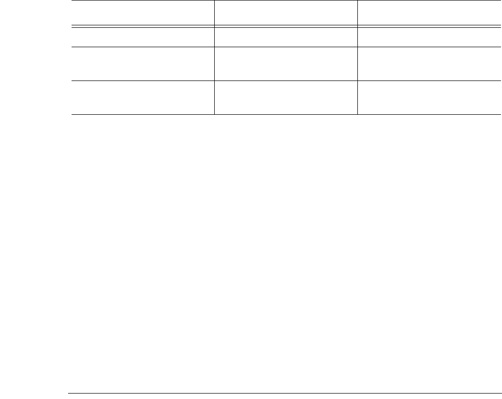
Filter Policy Configuration Overview
Page 278 7750 SR OS Router Configuration Guide
Filter policies can be applied to specific service types:
• Epipe — Both MAC and IP filters are supported on an Epipe SAP and spoke SDPs.
• VPLS — Both MAC and IP filters are supported on a VPLS SAP.
• IES — Only IP and IPv6 filters are supported on an IES IP interface and spoke SDPs
• VPLS — Both MAC and IP filters are supported on an VPLS SAP and mesh and spoke
SDPs.
• VPRN — Only IP filters are supported on VPRN interface SAPS and spoke SDPs.
Filter policies are applied to the following service entities:
• SAP ingress — IP and MAC filter policies applied on the SAP ingress define the Service
Level Agreement (SLA) enforcement of service packets as they ingress a SAP according
to the filter policy match criteria.
• SAP egress — Filter policies applied on SAP egress define the Service Level Agreement
(SLA) enforcement for service packets as they egress on the SAP according to the filter
policy match criteria.
• Network ingress — IP filter policies are applied to network ingress IP interfaces.
• Network egress — IP filter policies are applied to network egress IP interfaces.
Redirect Policies
Redirect policies define one or more cache server destinations and provides a method to determine
which destination is used. Redirection policies are used to identify cache servers (or other
redirection target destinations) and define health check test methods used to validate the ability for
the destination to receive redirected traffic. This destination monitoring greatly diminishes the
likelihood of a destination receiving packets it cannot process.
Redirection identifies packets to be redirected and specifies the method to reach the web cache
server. Packets are identified by IP filter entries. The redirection action is accomplished and
supported with Policy Based Routing. Only IP routed frames can be redirected. Bridged IP packets
that match the entry criteria will not be redirected.
Ipipe SAP, spoke SDP N/A N/A
VPLS mesh SDP, spoke SDP,
SAP VPLS mesh SDP, spoke SDP,
SAP VPLS mesh SDP, spoke SDP,
SAP
VPRN interface SAP, spoke
SDP, subscriber-interface N/A Subscriber-interface
Table 14: Applying Filter Policies
IP Filter MAC Filter IPv6 Filter
Filter Policies
7750 SR OS Router Configuration Guide Page 279
Redirection policies can contain multiple destinations. Each destination is assigned an initial or
base priority describing its relative importance within the policy. The destination with the highest
priority value is selected.
There are no default redirect policies. Each redirect policy must be explicitly configured and
specified in an IP filter entry.
To facilitate redirection based on a redirection policy, an IP filter must be created and applied to
the appropriate ingress or egress IP interfaces where redirection is required. The entry criteria for
the filter entry must specify a redirect policy to enable the appropriate IP packets to be redirected
from the normal IP routing next hop. If packets do not meet any of the defined match criteria, then
those packets are routed normally through the destination-based routing process.
The redirection policy is referenced within the action context for an IP filter entry, binding the
filter entry to the policy and the IP destinations managed by the policy. The policy specifies the
destination IP address where the packets matching the filter entry will be redirected. When the
policy determines the destination for packets matching the filter, the action on the filter entry is
similar to provisioning that destination IP address as an indirect next hop Policy Based Route
(PBR) action.

Filter Policy Configuration Overview
Page 280 7750 SR OS Router Configuration Guide
Web Redirection (Captive Portal)
The 7xx0 Series introduces a new type of redirection policy. Redirection policies were designed
for testing purposes. The new redirection policy can now block a customer’s request from an
intended recipient and force the customer to connect to the service’s portal server. 255 unique
entries with http-redirect are allowed.
Traffic Flow
The following example provides a brief scenario of a customer connection with web redirection.
1. The customer gets an IP address using DHCP (if the customer is trying to set a static IP he
will be blocked by the anti-spoofing filter).
2. The customer tries to connect to a website.
3. The router intercepts the HTTP GET request and blocks it from the network
4. The router then sends the customer a HTTP 302 (service temporarily unavailable/moved).
The target URL should then include the customer’s IP and MAC addresses as part of the por-
tal’s URL.
5. The customer’s web browser will then close the original connection and open a new connec-
tion to the web portal.
6. The web portal updates the ACL (directly or through SSC) to remove the redirection policy.
7. The customer connects to the original site.
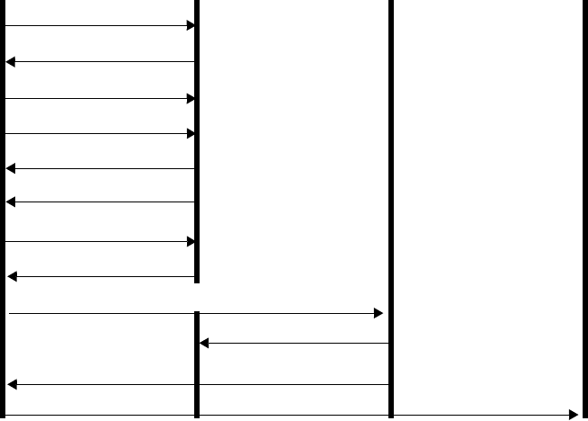
Filter Policies
7750 SR OS Router Configuration Guide Page 281
Figure 19: Web Redirect Traffic Flow
Starred entries (*) are items the router performs masquerading as the destination, regardless of the
destination IP address or type of service.
Information needed by the filter that may be sent to the portal:
• Customer’s IP address
• Customer’s MAC address
• Original requested URL
•Customer’s SAP
• Customer’s subscriber identification string
Note that the subscriber identification string is available only when used with subscriber
management. Refer to the subscriber management section of the 7750 SR OS Triple Play Guide
and the 7750 SR OS Router Configuration Guide
Since most web sites are accessed using the domain name the router allows either DNS queries or
responds to DNS with the portal’s IP address.
CUSTOMER’S COMPUTER SR/ESS PORTAL WEBSITE ORIGINAL WEBSITE
X>HTTP TCP SYN
X>HTTP TCP SYN ACK*
X>HTTP TCP ACK
HTTP GET
HTTP>X TCP ACK*
HTTP 302 (moved)*
X>HTTP TCP FIN ACK
HTTP>X TCP FIN ACK*
UPDATE POLICY
REDIRECT TO ORIGINAL WEBSITE
NORMAL HTTP WITH ORGINAL WEBSITE
NORMAL HTTP WITH PORTAL
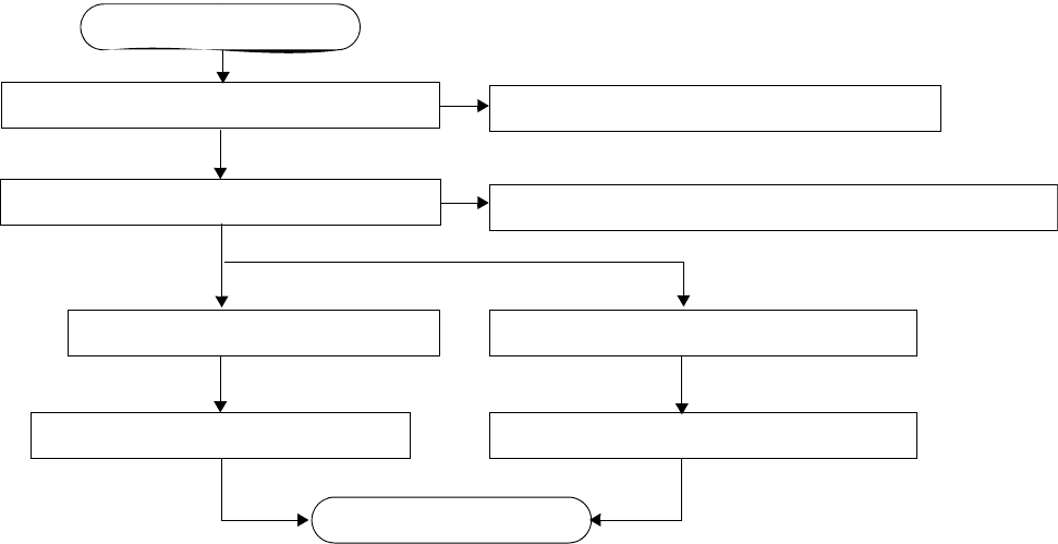
Creating Redirect Policies
Page 282 7750 SR OS Router Configuration Guide
Creating Redirect Policies
Figure 20 displays the process to create redirect policies and apply them to a service SAP or router
interface.
Figure 20: Filter Creation and Implementation Flow
CREATE A REDIRECT POLICY
CREATE IP FILTER
SPECIFY DESTINATION, PRIORITY, TEST TYPES
SPECIFY REDIRECT POLICY IN ENTRY’S FORWARDING ACTION
TURN UP
CREATE SERVICE
ASSOCIATE FILTER ID TO SAP
START
ASSOCIATE FILTER ID TO ROUTER INTERFACE
ASSOCIATE INTERFACE TO ROUTER ENTITIES
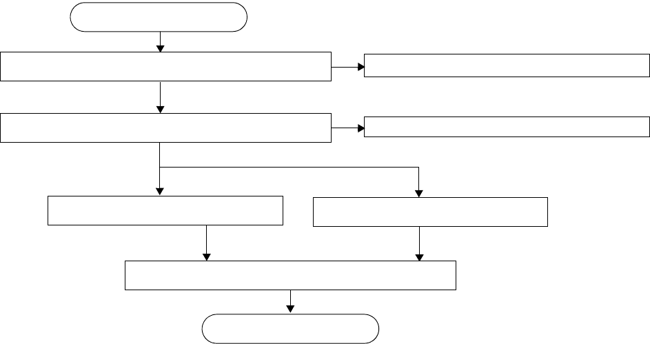
Filter Policies
7750 SR OS Router Configuration Guide Page 283
Figure 20 displays the process to create filter policies and apply them to a service or network port.
Figure 21: Filter Creation and Implementation Flow
CREATE AN IP OR MAC FILTER (FILTER ID)
CREATE FILTER ENTRIES (ENTRY ID)
SPECIFY SCOPE, DEFAULT ACTION, DESCRIPTION
SPECIFY ACTION, PACKET MATCHING CRITERIA
TURN UP
CREATE SERVICE
ASSOCIATE FILTER ID
START
SELECT NETWORK PORT
Creating Redirect Policies
Page 284 7750 SR OS Router Configuration Guide
Policy Components
Figure 22 displays the major components of a redirect policy.
Figure 22: Redirect Policy Components
• Redirect policy — This is the value which identifies the filter.
• Destination — An IP address that serves as a cache server destination.
• Priority — The value assigned to the initial or base priority to describe its relative
importance within the policy. The destination with the highest priority will be used.
• Ping test — Performs connectivity ping tests to validate the ability for the destination to
receive redirected traffic.
• SNMP test — Performs
• URL test — Performs
REDIRECT POLICY NAME:
DESTINATION
PRIORITY
PING-TEST
DROP-COUNT
INTERVAL
TIMEOUT
DROP-COUNT
INTERVAL
TIMEOUT
SNMP-TEST
OID
RETURN-VALUE
URL-TEST
DROP-COUNT
INTERVAL
TIMEOUT
RETURN-CODE
URL
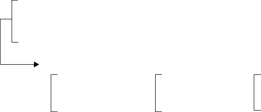
Filter Policies
7750 SR OS Router Configuration Guide Page 285
Figure 23 displays the major components of a filter policy.
Figure 23: Filter Policy Components
• Filter (mandatory) — This is the value which identifies the filter.
• Description (optional) — The description provides a brief overview of the filter’s features.
• Scope (mandatory) — A filter policy must be defined as having either an exclusive scope
for one-time use, or a template scope which enables its use with multiple SAPs and
interfaces.
• Default action (mandatory) — The default action specifies the action to be applied to
packets when no action is specified in the IP or MAC filter entries or when the packets do
not match the specified criteria.
• Entry ID (one or more) — Each entry represents a collection of filter match criteria.
Packet matching begins the comparison process with the criteria specified in the lowest
entry ID.
Entries identify attributes which define matching conditions and actions. All criteria in the
entry must match the specified action to be taken. Each entry consists of the following
components:
→Entry ID (mandatory) — This value determines the order amongst all entry IDs,
within a specific filter ID, in which the matching criteria specified in the collection is
compared. Packets are compared to entry IDs in an ascending order.
→Description (optional) — The description should provide a brief overview of the entry
ID criteria.
→Action (mandatory) — An action parameter must be specified for the entry to be
active. Any filter entry without an action parameter specified will be considered
incomplete and be inactive.
→Packet matching criteria — You can input and select criteria to create a specific
template through which packets are compared and either forwarded or dropped,
depending on the action specified. See Packet Matching Criteria on page 286.
FILTER ID:
DESCRIPTION
SCOPE
DEFAULT ACTION
ENTRY ID <N>:
DESCRIPTION
ACTION
MATCHING CRITERIA
ENTRY ID <N+>:ENTRY ID <N+>:
DESCRIPTION
ACTION
MATCHING CRITERIA
DESCRIPTION
ACTION
MATCHING CRITERIA
Creating Redirect Policies
Page 286 7750 SR OS Router Configuration Guide
Packet Matching Criteria
Up to 65535 IP and 65535 MAC filter IDs (unique filter policies) can be defined. A maximum of
16384 filter entries can be defined in one filter at the same time. Each filter ID can contain up to
65535 filter entries. A maximum of 16384 filter entries can be defined in 1 filter at the same time.
As few or as many match parameters can be specified as required, but all conditions must be met in
order for the packet to be considered a match and the specified action performed. The process stops
when the first complete match is found and then executes the action defined in the entry, either to
drop or forward packets that match the criteria.
IP filter policies match criteria that associate traffic with an ingress or egress SAP. Matching
criteria to drop or forward IP traffic include:
• Source IP address and mask
Source IP address and mask values can be entered as search criteria. The IP Version 4
addressing scheme consists of 32 bits expressed in dotted decimal notation (X.X.X.X).
Address ranges are configured by specifying mask values, the 32-bit combination used to
describe the address portion which refers to the subnet and which portion refers to the host.
The mask length is expressed as an integer (range 1 to 32).
The IP Version 6 (IPv6) addressing scheme consists of 128 bits expressed in compressed
representation of IPv6 addresses (rfc 1924).
• Destination IP address and mask — Destination IP address and mask values can be entered
as search criteria.
• Protocol — Entering a protocol (such as TCP, UDP, etc.) allows the filter to search for the
protocol specified in this field.
• Protocol — For IPv6: entering a next header allows the filter to match the first next header
following the IPv6 header.
• Source port/range — Entering the source port number or port range allows the filter to
search for matching TCP or UDP port and range values.
• Destination port/range — Entering the destination port number or port range allows the
filter to search for matching TCP or UDP values.
• DSCP marking — Entering a DSCP marking enables the filter to search for the DSCP
marking specified in this field. See Table 15.
• ICMP code — Entering an ICMP code allows the filter to search for matching ICMP code
in the ICMP header.
• ICMP type — Entering an ICMP type allows the filter to search for matching ICMP types
in the ICMP header.
• Fragmentation — IPv4 only: Enable fragmentation matching. A match occurs if packets
have either the MF (more fragment) bit set or have the Fragment Offset field of the IP
header set to a non-zero value.
Filter Policies
7750 SR OS Router Configuration Guide Page 287
• Option value — Entering an option value enables the first filter to search for a specific IP
option. See Table 16.
• TCP-ACK/SYN flags - Entering a TCP-SYN/TCP-ACK flag allows the filter to search for
the TCP flags specified in these fields.
MAC filter policies match criteria that associate traffic with an ingress or egress SAP. Matching
criteria to drop or forward MAC traffic include:
• Source MAC address and mask
Entering the source MAC address range allows the filter to search for matching a source
MAC address and/or range. Enter the source MAC address and mask in the form of
xx:xx:xx:xx:xx:xx or xx-xx-xx-xx-xx-xx; for example, 00:dc:98:1d:00:00.
• Destination MAC address and mask
Entering the destination MAC address range allows the filter to search for matching a
destination MAC address and/or range. Enter the destination MAC address and mask in
the form of xx:xx:xx:xx:xx:xx or xx-xx-xx-xx-xx-xx; for example, 02:dc:98:1d:00:01.
• Dot1p and mask
Entering an IEEE 802.1p value or range allows the filter to search for matching 802.1p
frame. The Dot1p and mask accepts decimal, hex, or binary in the range of 0 to 7.
• Ethertype
Entering an Ethernet type II Ethertype value to be used as a filter match criterion. The
Ethernet type field is a two-byte field used to identify the protocol carried by the Ethernet
frame. The Ethertype accepts decimal, hex, or binary in the range of 1536 to 65535.
• IEEE 802.2 LLC SSAP
Specifying an Ethernet 802.2 LLC DSAP value allows the filter to match a source access
point on the network node designated in the source field of a packet. The SSAP and mask
accepts decimal, hex, and binary in the range of 0 to 255.
• IEEE 802.2 LLC DSAP
Specifying an Ethernet 802.2 LLC DSAP value allows the filter to match a destination
access point on the network node designated in the destination field of a packet. The
DSAP and mask accepts decimal, hex, and binary in the range of 0 to 255.
• IEEE 802.3 LLC SNAP PID
Specifying an Ethernet IEEE 802.3 LLC SNAP PID allows the filter to match the two-byte
protocol ID that follows the three-byte OUI field. The DSAP and mask accepts decimal
and hex in the range of 0 to 65535.

Creating Redirect Policies
Page 288 7750 SR OS Router Configuration Guide
DSCP Values
Table 15: DSCP Name to DSCP Value Table
DSCP Name Decimal
DSCP Value Hexadecimal
DSCP Value Binary
DSCP Value
default 0 *
cp1 1
cp2 2
cp3 3
cp4 4
cp5 5
cp6 6
cp7 7 *
cs1 8
cp9 9
af10 10 *
af11 11 *
af12 12 *
cp13 13
cp14 14
cp15 15
cs2 16 *
cp17 17
af21 18 *
cp19 19
af22 20 *
cp21 21
af23 22 *
cp23 23
cs3 24 *
cp25 25
af31 26 *
cp27 27
af32 28 *
cp29 29
af33 30 *

Filter Policies
7750 SR OS Router Configuration Guide Page 289
cp21 31
cs4 32 *
cp33 33
af41 34 *
cp35 35
af42 36 *
cp37 37
af43 38 *
cp39 39
cs5 40 *
cp41 41
cp42 42
cp43 43
cp44 44
cp45 45
ef 46 *
cp47 47
nc1 48 * (cs6)
cp49 49
cp50 50
cp51 51
cp52 52
cp53 53
cp54 54
cp55 55
cp56 56
cp57 57
nc2 58 * (cs7)
cp60 60
cp61 61
cp62 62
Table 15: DSCP Name to DSCP Value Table (Continued)
DSCP Name Decimal
DSCP Value Hexadecimal
DSCP Value Binary
DSCP Value

Creating Redirect Policies
Page 290 7750 SR OS Router Configuration Guide
IP Option Values
Table 16: IP Option Values
Copy Class Number Value Name Description
0 0 0 0 EOOL End of options list
0011NOPNo operation
0 0 7 7 RR Record route
0 0 10 10 ZSU Experimental measurement
0 0 11 11 MTUP MTU probe
0 0 12 12 MTUR MTU reply
0 0 15 15 ENCODE
0 2 4 68 TS Time stamp
0 2 18 82 TR Traceroute
1 0 2 130 SEC Security
1 0 3 131 LSR Loose source router
1 0 5 133 E-SEC Extended security
1 0 6 134 CIPSO Commercial security
1 0 8 136 SID Stream id
1 0 9 137 SSR Strict source route
1 0 14 142 VISA Experimental Access Control [Estrin]
1 0 16 144 IMITD IMI Traffic Descriptor
1 0 17 145 EIP Extended Internet Protocol
1 0 19 147 ADDEXT Address Extension
1 0 20 148 RTRALT Router alert
1 0 21 149 SDB Selective directed broadcast
1 0 22 150 NSAPA NSAP addresses
1 0 23 151 DPS Dynamic packet state
1 0 24 152 UMP Upstream multicast packet
1 2 13 205 FINN Experimental flow control
Filter Policies
7750 SR OS Router Configuration Guide Page 291
Ordering Filter Entries
When entries are created, they should be arranged sequentially from the most explicit entry to the
least explicit. Filter matching ceases when a packet matches an entry. The entry action is
performed on the packet, either drop or forward. To be considered a match, the packet must meet
all the conditions defined in the entry.
Packets are compared to entries in a filter policy in an ascending entry ID order. To reorder entries
in a filter policy, edit the entry ID value; for example, to reposition entry ID 6 to a more explicit
location, change the entry ID 6 value to entry ID 2.
When a filter consists of a single entry, the filter executes actions as follows:
• If a packet matches all the entry criteria, the entry’s specified action is performed (drop or
forward).
• If a packet does not match all of the entry criteria, the policy’s default action is performed.
If a filter policy contains two or more entries, packets are compared in ascending entry ID order (1,
2, 3 or 10, 20, 30, etc.):
• Packets are compared with the criteria in the first entry ID.
• If a packet matches all the properties defined in the entry, the entry’s specified action is
executed.
• If a packet does not completely match, the packet continues to the next entry, and then
subsequent entries.
• If a packet does not completely match any subsequent entries, then the default action is
performed.

Creating Redirect Policies
Page 292 7750 SR OS Router Configuration Guide
Figure 24 displays an example of several packets forwarded upon matching the filter criteria and
several packets traversing through the filter entries and then dropped.
Figure 24: Filtering Process Example
INGRESSING PACKETS:
#1: SA: 10.10.10.103, DA: 10.10.10.104
#2: SA: 10.10.10.103, DA: 10.10.10.105
#3: SA: 10.10.10.103, DA: 10.10.10.106
Source Address: 10.10.10.103
Destination Address: 10.10.10.106
FILTER ENTRY ID: 30
Action: Forward
Source Address: 10.10.10.103
Destination Address: 10.10.10.104
SEARCH CRITERIA:
Source Address: 10.10.10.103
Destination Address: 10.10.10.104
FILTER ENTRY ID: 10
Action: Forward
Source Address: 10.10.10.103
Destination Address: 10.10.10.105
FILTER ENTRY ID: 20
Action: Forward
REMAINING PACKETS ARE DROPPED PER THE DEFAULT ACTION (DROP)
FORWARD PACKETS WITH MATCHING SA AND DA
FORWARD PACKETS WITH MATCHING SA AND DA
FORWARD PACKETS WITH MATCHING SA AND DA
Y
N
N
N
Y
Y
SA: 10.10.10.103, DA: 10.10.10.104
INGRESS PACKETS:
SA: 10.10.10.103, DA: 10.10.10.105
SA: 10.10.10.103, DA: 10.10.10.106
(SA: 10.10.10.103, DA: 10.10.10.104)
(SA: 10.10.10.103, DA: 10.10.10.105)
(SA: 10.10.10.103, DA: 10.10.10.106)
SA: 10.10.10.103, DA: 10.10.10.107
SA: 10.10.10.103, DA: 10.10.10.108
SA: 10.10.10.103, DA: 10.10.10.107
SA: 10.10.10.103, DA: 10.10.10.108
DEFAULT ACTION: DROP
FILTER ID: 5
FILTER ENTIES: 10 (ACTION: FORWARD)
20 (ACTION: FORWARD)
30 (ACTION: FORWARD)
SA: 10.10.10.192, DA: 10.10.10.16
SA: 10.10.10.155, DA: 10.10.10.21
SA: 10.10.10.192, DA: 10.10.10.16
SA: 10.10.10.155, DA: 10.10.10.21

Filter Policies
7750 SR OS Router Configuration Guide Page 293
Applying Filters
After filters are created, they can be applied to the following entities:
•Applying a Filter to a SAP on page 293
•Applying a Filter to a Network Port on page 293
Applying a Filter to a SAP
During the SAP creation process, ingress and egress filters are selected from a list of qualifying IP
and MAC filters. When ingress filters are applied to a SAP, packets received at the SAP are
checked against the matching criteria in the filter entries. If the packet completely matches all
criteria in an entry, the checking stops and an entry action is preformed. If permitted, the traffic is
forwarded according to the specification of the action. If the packets do not match, the default filter
action is applied. If permitted, the traffic is forwarded. If the packets do not match, the default
filter action is applied.
When egress filters are applied to a SAP, packets received at the egress SAP are checked against
the matching criteria in the filter entries. If the packet completely matches all criteria in an entry,
the checking stops. If permitted, the traffic is transmitted. If denied, the traffic is dropped. If the
packets do not match, the default filter action is applied.
Filters can be added or changed to an existing SAP configuration by modifying the SAP
parameters. Filter policies are not operational until they are applied to a SAP and the service
enabled.
Applying a Filter to a Network Port
You can apply an IP filter to a network port. Packets received on the interface are checked against
the matching criteria in the filter entries. If the packet completely matches all criteria in an entry,
the checking stops. If permitted, the traffic is forwarded. If the packets do not match, they are
discarded.

Configuration Notes
Page 294 7750 SR OS Router Configuration Guide
Configuration Notes
The following information describes filter implementation caveats:
• Creating a filter policy is optional.
• Associating a service with a filter policy is optional.
• When a filter policy is configured, it must be defined as having either an exclusive scope
for one-time use, or a template scope meaning that the filter can be applied to multiple
SAPs.
• A specific filter must be explicitly associated with a specific service in order for packets to
be matched.
• Each filter policy must consist of at least one filter entry. Each entry represents a collection
of filter match criteria. When packets enter the ingress or egress ports, packets are
compared to the criteria specified within the entry or entries.
• When you configure a large (complex) filter, it take may a few seconds to load the filter
policy configuration and be instantiated.
• The action keyword must be entered for the entry to be active. Any filter entry without the
action keyword will be considered incomplete and be inactive.
MAC Filters
• If a MAC filter policy is created with an entry and entry action specified but the packet
matching criteria is not defined, then all packets processed through this filter policy entry
will pass and take the action specified. There are no default parameters defined for
matching criteria.
• MAC filters cannot be applied to network interfaces, routable VPLS or IES services.
• Some of the MAC match criteria fields are exclusive to each other, based on the type of
Ethernet frame. Use the following table to determine the exclusivity of fields.
Table 17: MAC Match Criteria Exclusivity Rules
Frame Format Etype LLC – Header
(ssap & dsap) SNAP-OUI SNAP- PID
Ethernet – II Yes No No No
802.3 No Yes No No
802.3 – snap No No a
a. When snap header is present, this is always set to AA-AA.
Yes Yes

Filter Policies
7750 SR OS Router Configuration Guide Page 295
IP Filters
• Define filter entry packet matching criteria — If a filter policy is created with an entry and
entry action specified but the packet matching criteria is not defined, then all packets
processed through this filter policy entry will pass and take the action specified. There are
no default parameters defined for matching criteria.
• Action — An action parameter must be specified for the entry to be active. Any filter entry
without an action parameter specified will be considered incomplete and be inactive.
• When you configure a filter policy which is intended for filter-based mirroring, you must
specify that the scope is exclusive.
IPv6 Filters
• Define filter entry packet matching criteria — If a filter policy is created with an entry and
entry action specified but the packet matching criteria is not defined, then all packets
processed through this filter policy entry will pass and take the action specified. There are
no default parameters defined for matching criteria.
• Action — An action parameter must be specified for the entry to be active. Any filter entry
without an action parameter specified will be considered incomplete and be inactive.
Log Filter
• Summarization logging is the collection and summarization of log messages for 1 specific
log-id within a period of time.
• Filter log can be applied to different ACL filters or CPM HW filters.
• The implementation of the feature applies to filter logs with destination syslog.
• In case of VPLS scenario both L2 & L3 are applicable.
→L2: Src Mac or optionally Dest MAC
→ - L3: Src IPv6 or optionally Dest IPv6 for L3 filters.
• The summarization interval is 100 seconds.
• Upon activation of a summary, a mini-table with src/dst-address and count is created for
each type (ip/ipv6/mac).
• Every received log packet (due to filter hit) is examined for source or destination address.
If the logpacket (src/dst-address) matches a src/dst address entry in the mini-table (thus a
packet receive previously), the summary counter of the matching address is incremented.
• If source or destination address of the Log messages does not match an entry already
present in the table, the src/dst-address is stored in a free entry in the minitable.
Configuration Notes
Page 296 7750 SR OS Router Configuration Guide
• In case the mini-table has no more free entries, only Total counter is incremented.
• At expiry of the summarization interval, the mini-table for each type is flushed to the
syslog destination.
Configuration Notes
Page 298 7750 SR OS Router Configuration Guide
Filter Policies
7750 SR OS Router Configuration Guide Page 299
Configuring Filter Policies with CLI
This section provides information to configure filter policies using the command line interface.
Topics in this section include:
•Filter CLI Command Structure on page 300
•List of Commands on page 302
•Basic Configuration on page 308
•Common Configuration Tasks on page 309
→Creating an IP Filter Policy on page 310
→Creating an IPv6 Filter Policy on page 317
→Creating a MAC Filter Policy on page 320
→Creating Filter Log Policies on page 323
→Applying Filter Policies on page 324
→Apply Filter Policies to Network Port on page 327
→Creating a Redirect Policy on page 329
→Configuring Policy-Based Forwarding for Deep Packet Inspection in VPLS on page
332
•Filter Management Tasks on page 336
→Renumbering Filter Policy Entries on page 336
→Modifying an IP Filter Policy on page 338
→Deleting a Filter Policy on page 342
→Deleting a Filter Policy on page 342
→Copying Filter Policies on page 349
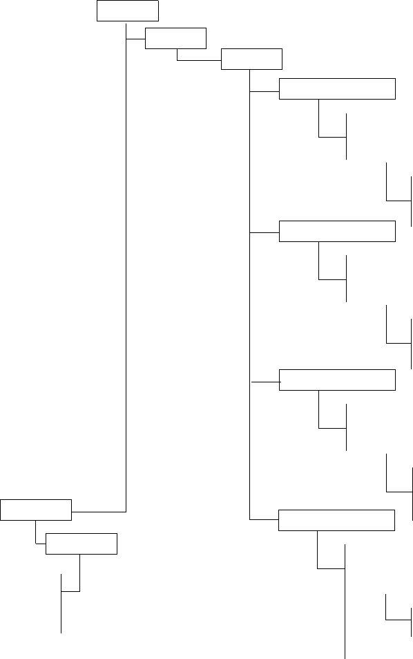
Filter CLI Command Structure
Page 300 7750 SR OS Router Configuration Guide
Filter CLI Command Structure
Figure 25 displays the 7750 SR OS filter command structure. The filter configuration commands
are located under the config>filter context and the show commands are under show>filter
ip and show>filter mac.
Figure 25: Filter Command Structure
ROOT
FILTER
default-action
description
IP-FILTER name
entry entry-id
description
action
CONFIG
match
default-action
description
MAC-FILTER name
entry entry-id
FILTER
anti-spoof
SHOW
log log-id
description
action
match
log log-id
default-action
description
IPv6-FILTER name
entry entry-id
description
action
match
log log-id
IP
IPV6
log
mac
default-action
destination
LOG log-id
summary
summary-crit dst-addr
summary-crit src-addr
wrap-around
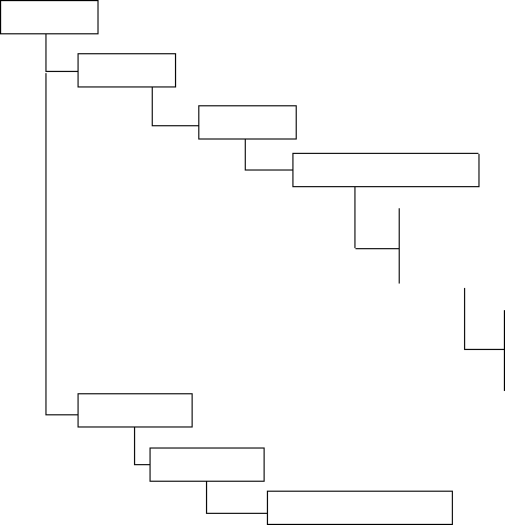
Filter Policies
7750 SR OS Router Configuration Guide Page 301
Figure 26 displays the 7750 SR OS filter redirect policy command structure. The redirect policy
configuration commands are located under the config>filter context and the show commands
are under show>filter>redirect-policy context.
Figure 26: Redirect Policy Command Structure
ROOT
FILTER
default-action
description
REDIRECT-POLICY
entry entry-id
description
action
CONFIG
match
FILTER
SHOW
log log-id
REDIRECT-POLICY

List of Commands
Page 302 7750 SR OS Router Configuration Guide
List of Commands
Table 18 lists all the filter configuration commands indicating the configuration level at which
each command is implemented with a short command description. The filter policy command list
is organized in the following task-oriented manner:
•Configure an IP filter policy
→Configure an IP filter policy entry
→Configure IP filter entry matching criteria
•Configure an IPv6 filter policy
→Configure an IPv6 filter policy entry
→Configure an IPv6 filter entry matching criteria
•Configure a MAC filter policy entry
→Configure MAC filter entry matching criteria
•Configure a redirect policy
Table 18: CLI Commands to Configure Filter Policies Parameters
Command Description Page
Configure an IP filter policy
config>filter
ip-filter Creates an IP filter policy. 358
default-action The default action specifies the action to be applied to packets when the
packets do not match the specified criteria in any of the IP filter entries of
the filter.
363
description A text string describing the filter policy. 357
renum Renumbers existing filter entries to properly sequence filter entries. 388
scope Configures the filter policy scope as exclusive or template. An exclusive
policy can only be applied to a single entity (SAP or network port). A
template policy can be applied to multiple SAPs or network ports.
363
Configure an IP filter policy entry
config>filter>ip-filter
entry Creates a filter entry and identifies a group of match criteria and the
corresponding action. 364
action Creates the drop or forward action associated with the match criteria. If
not specified, the filter policy entry is not taken into account. 366
description A text string describing the entry. 357

Filter Policies
7750 SR OS Router Configuration Guide Page 303
filter-sample Specifies that traffic matching the associated IP filter entry is sampled if
the IP interface is set to cflowd ip-filter mode. 368
interface-disable-
sample
Specifies that traffic matching the associated IP filter entry is not sampled
if the IP interface is set to cflowd ip-filter mode. 369
Configure IP filter entry matching criteria
config>filter>ip-filter>entry
match Enables the context to configure match criteria for the filter entry. 369
dscp Configures a DiffServ Code Point (DSCP) name to be used for IP filter
matching. 375
dst-ip Configures a destination IP address range to be used for IP filter matching. 375
dst-port Configures a destination TCP or UDP port number or port range for IP
filter matching. 376
fragment Configures fragmented or non-fragmented IP packets as an IP filter
matching. 377
icmp-code Configures matching on ICMP code field in the ICMP header of an IP
packet for IP filter matching. 377
icmp-type Configures matching on ICMP type field in the ICMP header of an IP
packet for IP filter matching. 377
ip-option Configures matching packets with a specific IP option or a range of IP
options in the first option of the IP header as for IP filter matching. 378
multiple-option Configures matching packets that contain one or more than one option
fields in the IP header for IP filter matching. 379
option-present Configures matching packets that contain the option field or have an
option field of zero in the IP header for IP filter matching. 379
src-ip Configures a source IP address range to be used for IP filter matching. 379
src-port Configures a source TCP or UDP port number or port range for IP filter
matching. 380
tcp-syn Configures matching on the SYN bit being set or reset in the control bits
of the TCP header of an IP packet for IP filter matching. 381
tcp-ack Configures matching on the ACK bit being set or reset in the control bits
of the TCP header of an IP packet for IP filter matching. 381
Table 18: CLI Commands to Configure Filter Policies Parameters (Continued)
Command Description Page

List of Commands
Page 304 7750 SR OS Router Configuration Guide
Configure an IPv6 filter policy
config>filter
ipv6-filter Creates an IPv6 filter policy. 358
default-action The default action specifies the action to be applied to packets when the
packets do not match the specified criteria in any of the IPv6 filter entries
of the filter.
363
description A text string describing the IPv6 filter policy. 357
renum Renumbers existing filter entries to properly sequence filter entries. 388
scope Configures the IPv6 filter policy scope as exclusive or template. An
exclusive policy can only be applied to a single entity (such as a SAP or
network port). A template policy can be applied to multiple SAPs or
network ports.
363
Configure an IPv6 filter policy entry
config>filter>ipv6-filter
entry Creates an IPv6 filter entry and identifies a group of match criteria and the
corresponding action. 364
action Creates the drop or forward action associated with the match criteria. If
not specified, the filter policy entry is not taken into account. 368
description A text string describing the entry. 357
log log-id Creates a context for configuring destinations for event streams to direct
events, alarms/traps and debug information to their respective
destinations.
360
Configure an IPv6 filter entry matching criteria
config>filter>ipv6-filter>entry
match Creates context for entering/editing match criteria for the filter entry. 371
dscp Configures a DiffServ Code Point (DSCP) name to be used as an IP filter
match criterion. 375
dst-ip Configures a destination IP address range to be used as an IP filter match
criterion. 375
dst-port Configures a destination TCP or UDP port number or port range for an IP
filter match criterion. 376
icmp-code Configures matching on ICMP code field in the ICMP header of an IP
packet as an IP filter match criterion. 377
Table 18: CLI Commands to Configure Filter Policies Parameters (Continued)
Command Description Page

Filter Policies
7750 SR OS Router Configuration Guide Page 305
icmp-type Configures matching on ICMP type field in the ICMP header of an IP
packet as an IP filter match criterion. 377
src-ip Configures a source IP address range to be used as an IP filter match
criterion. 380
src-port Configures a source TCP or UDP port number or port range for an IP filter
match criterion. 380
tcp-ack Configures matching on the ACK bit being set or reset in the control bits
of the TCP header of an IP packet as an IP filter match criterion. 381
tcp-syn Configures matching on the SYN bit being set or reset in the control bits
of the TCP header of an IP packet as an IP filter match criterion. 381
Configure a MAC filter policy
config>filter>mac-filter
mac-filter Creates a MAC filter policy. 358
scope Configures the filter policy scope as exclusive or template. An exclusive
policy can only be applied to a single entity (SAP or network port). A
template policy can be applied to multiple SAPs or network ports.
363
description A text string describing the filter policy. 357
default-action The default action specifies the action to be applied to packets when the
packets do not match the specified criteria in any of the any filter entries of
the filter.
363
renum Renumbers existing filter entries to properly sequence filter entries. 388
Configure a MAC filter policy entry
config>filter>mac-filter
entry Creates a filter entry and identifies a group of match criteria and the
corresponding action. 364
description A text string describing the entry. 357
action Creates the drop or forward action associated with the match criteria. If
not specified, the filter policy entry is not taken into account. 366
Configure MAC filter entry matching criteria
config>filter>mac-filter entry
match Creates context for entering/editing match criteria for the filter entry. 369
src-mac Configures a source MAC address or range to be used as a MAC filter
match criterion. 386
dst-mac Configures a destination MAC address or range to be used as a MAC filter
match criterion. 384
Table 18: CLI Commands to Configure Filter Policies Parameters (Continued)
Command Description Page

List of Commands
Page 306 7750 SR OS Router Configuration Guide
dot1p Configures an IEEE 802.1p value or range to be used as a MAC filter
match criterion. 383
etype Configures an Ethernet type II Ethertype value to be used as a MAC filter
match criterion. 385
dsap Configures an Ethernet 802.2 LLC DSAP value or range for a MAC filter
match criterion. 383
ssap Configures an Ethernet 802.2 LLC SSAP value or range for a MAC filter
match criterion. 387
snap-pid Configures an IEEE 802.3 LLC SNAP Ethernet Frame PID value to be
used as a MAC filter match criterion. 386
snap-oui Configures an IEEE 802.3 LLC SNAP Ethernet Frame OUI zero or non-
zero value to be used as a MAC filter match criterion. 385
Configure a redirect policy
config>filter
redirect-policy Enables the context to redirect policies. 359
description Creates a text description stored in the configuration file for a
configuration context. 357
destination Specifies a cache server destination (an IP address) to redirect packets
matching IP filter entry criteria. 390
ping-test The context to configure connectivity ping tests to validate the ability of
the destination to receive redirected traffic. 390
drop-count Specifies the number of consecutive ping test failures before declaring the
destination down. 390
interval The frequency at which the ping test, SNMP test, or URL test is executed. 391
timeout Specifies the amount of time in seconds that is allowed for receiving a
response from the far-end host. 391
priority The destination’s priority describes its relative importance within the
policy. If more than one destination is specified, the destination with the
highest priority value is selected.
391
snmp-test The context to configure SNMP test parameters. 392
oid The OID of the object to be fetched from the destination. 392
return-value Specifies the criterion to adjust the priority based on the test result. 392
url-test The context to enable URL test parameters. 393
url Specifies the URL to be probed by the URL test. 394
Table 18: CLI Commands to Configure Filter Policies Parameters (Continued)
Command Description Page

Filter Policies
7750 SR OS Router Configuration Guide Page 307
configure a filter log policy
config>filter
log Enables the context to create a filter log policy. 360
destination memory Specifies the destination for filter log entries be sent to memory.
destination syslog Specifies the destination for filter log entries be sent to an existing syslog.
summary Enables the context to configure log summarization. 361
summary-crit dst-
addr
Specifies that received log packets are summarized based on the
destination IP or MAC 361
summary-crit src-
addr
Specifies that received log packets are summarized based on the source IP
or MAC address. 361
wrap-around Configures a memory filter log to log until full or to store the most recent
log entries (circular buffer). 362
Table 18: CLI Commands to Configure Filter Policies Parameters (Continued)
Command Description Page
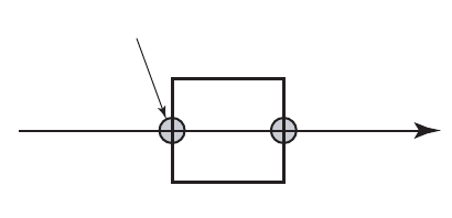
Basic Configuration
Page 308 7750 SR OS Router Configuration Guide
Basic Configuration
The most basic IP, IPv6, and MAC filter policies must have the following:
• A filter ID
• Template scope, either exclusive or template
• Default action, either drop or forward
• At least one filter entry
→Specified action, either drop or forward
→Specified matching criteria
The following example displays a sample configuration of an IP filter policy. The configuration
blocks all incoming TCP session except Telnet and allows all outgoing TCP sessions from IP net
10.67.132.0/24. Figure 27 depicts the interface to apply the filter.
A:ALA-1>config>filter# info
----------------------------------------------
ip-filter 3 create
entry 10 create
match protocol 6
dst-port eq 23
src-ip 10.67.132.0/24
exit
action forward
exit
entry 20 create
match protocol 6
tcp-syn true
tcp-ack false
exit
action drop
exit
exit
----------------------------------------------
A:ALA-1>config>filter#
Figure 27: Applying an IP Filter to an Ingress Interface
ALA-1
Ingress
Filter
TCP Connection
OSRG007
Filter Policies
7750 SR OS Router Configuration Guide Page 309
Common Configuration Tasks
This section provides a brief overview of the tasks that must be performed for both IP and MAC
filter configurations and provides the CLI commands.
To configure a filter policy, perform the following tasks:
•Creating an IP Filter Policy on page 310
•Creating an IPv6 Filter Policy on page 317
•Creating a MAC Filter Policy on page 320
•Creating Filter Log Policies on page 323
•Applying Filter Policies on page 324
•Apply Filter Policies to Network Port on page 327

Common Configuration Tasks
Page 310 7750 SR OS Router Configuration Guide
Creating an IP Filter Policy
Configuring and applying filter policies is optional. Each filter policy must have the following:
• The filter type specified (IP)
• A filter policy ID
• A default action, either drop or forward.
• Template scope specified, either exclusive or template
• At least one filter entry with matching criteria specified
IP Filter Policy
Use the following CLI syntax to create an IP filter policy template:
CLI Syntax: config>filter# ip-filter filter-id
description description-string
scope {exclusive|template}
default-action {drop|forward}
The following displays the command usage to create a filter policy:
Example:config>filter# ip-filter 12 create
config>filter# description "IP-filter"
config>filter# scope template
The following example displays the exclusive filter policy configuration:
A:ALA-7>config>filter# info
----------------------------------------------
...
ip-filter 12 create
description "IP-filter"
scope template
exit
...
----------------------------------------------
A:ALA-7>config>filter#
Use the following CLI syntax to create an exclusive IP filter policy:
CLI Syntax: config>filter# ip-filter filter-id
description description-string
scope {exclusive|template}
default-action {drop|forward}
Filter Policies
7750 SR OS Router Configuration Guide Page 311
The following displays the command usage to create an exclusive IP filter policy:
Example:config>filter# ip-filter 11 create
config>filter# description "filter-main"
config>filter# scope exclusive
The following example displays the exclusive filter policy configuration:
A:ALA-7>config>filter# info
----------------------------------------------
...
ip-filter 11 create
description "filter-main"
scope exclusive
exit
...
----------------------------------------------
A:ALA-7>config>filter#
Common Configuration Tasks
Page 312 7750 SR OS Router Configuration Guide
IP Filter Entry
Within a filter policy, configure filter entries which contain criteria against which ingress, egress,
or network traffic is matched. The action specified in the entry determine how the packets are
handled, either dropped or forwarded.
• Enter a filter entry ID. The system does not dynamically assign a value.
• Assign an action, either drop or forward.
• Specify matching criteria.
Use the following CLI syntax to create an IP filter entry:
CLI Syntax: config>filter# ip-filter filter-id
entry entry-id [time-range time-range-name]
description description-string
The following displays the configuration command usage to create an IP filter entry:
Example:config>filter# ip-filter 11
config>filter>ip-filter# entry 10 create
config>filter>ip-filter>entry$ description “no-91”
config>filter>ip-filter>entry# exit
The following example displays the IP filter entry configuration.
A:ALA-7>config>filter>ip-filter# info
----------------------------------------------
description "filter-main"
scope exclusive
entry 10 create
description "no-91"
match
exit
exit
----------------------------------------------
A:ALA-7>config>filter>ip-filter#
Filter Policies
7750 SR OS Router Configuration Guide Page 313
Configuring the HTTP-Redirect Option
If http-redirect is specified as an action, a corresponding forward entry must be specified before
the redirect. For example:
CLI Syntax: config>filter# ip-filter filter-id
entry entry-id [time-range time-range-name]
action [drop]
action forward [next-hop {ip-address |indirect ip-address
|interface ip-int-name}]
action forward [redirect-policy policy-name]
action forward [sap sap-id|sdp sdp-id]
action http-redirect url
Note that http-redirect is not supported on 7750 SR-1 or 7450 ESS-1 models.
The following displays the configuration command usage to configure http-redirect:
Example:config>filter>ip-filter# entry 20 create
config>filter>ip-filter>entry$ match protocol tcp
config>filter>ip-filter>entry>match$ dst-ip 100.0.0.2/32
config>filter>ip-filter>entry>match$ dst-port eq 80
config>filter>ip-filter>entry>match$ exit
config>filter>ip-filter# entry 30 create
config>filter>ip-filter>entry# match protocol tcp
config>filter>ip-filter>entry>match# dst-port eq 80
config>filter>ip-filter>entry>match# exit
config>filter>ip-filter>entry# action http-redirect
"http://100.0.0.2/login.cgi?mac=$MAC$sap=
$SAP&ip=$IP&orig_url=$URL"
config>filter>ip-filter>entry# exit
The following example displays the http-redirect configuration:
A:ALA-48>config>filter>ip-filter# info
----------------------------------------------
description "filter-main"
scope exclusive
entry 10 create
description "no-91"
match
dst-ip 10.10.10.91/24
src-ip 10.10.0.100/24
exit
no action
exit
entry 20 create
match protocol tcp
dst-ip 100.0.0.2/32
dst-port eq 80
exit
action forward
Common Configuration Tasks
Page 314 7750 SR OS Router Configuration Guide
exit
entry 30 create
match protocol tcp
dst-ip 10.10.10.91/24
dst-port eq 80
exit
action http-redirect "http://100.0.0.2/login.cgi?mac=$MAC$sap=$S
AP&ip=$IP&orig_url=$URL"
exit
----------------------------------------------
A:ALA-48>config>filter>ip-filter#
Filter Policies
7750 SR OS Router Configuration Guide Page 315
Filter Sampling
Within a filter entry, you can specify that traffic matching the associated IP filter entry is sampled.
if the IP interface is set to cflowd ip-filter mode. Enabling filter-sample enables the cflowd tool.
Use the following CLI syntax to enable filter sampling:
CLI Syntax: config>filter# ip-filter filter-id
entry entry-id time-range time-range-name
filter-sample
interface-disable-sample
The following displays the configuration command usage to enable filter sampling in an existing
filter configuration:
Example: config>filter# ip-filter 11
config>filter>ip-filter# entry 10
config>filter>ip-filter>entry# filter-sample
config>filter>ip-filter>entry# interface-disable-sample
config>filter>ip-filter>entry# exit
The following example displays the IP filter entry configuration.
A:ALA-7>config>filter>ip-filter# info
----------------------------------------------
description "filter-main"
scope exclusive
entry 10 create
description "no-91"
filter-sample
interface-disable-sample
match
exit
action forward redirect-policy redirect1
exit
----------------------------------------------
A:ALA-7>config>filter>ip-filter#
Common Configuration Tasks
Page 316 7750 SR OS Router Configuration Guide
IP Entry Matching Criteria
Use the following CLI syntax to configure IP filter matching criteria:
CLI Syntax: config>filter>ip-filter>entry#
match
dscp dscp-name
dst-ip {ip-address/mask|ip-address netmask}
dst-port {{lt|gt|eq} dst-port-number} | {range start end}
fragment {true|false}
icmp-code icmp-code
icmp-type icmp-type
ip-option ip-option-value [ip-option-mask]
multiple-option {true|false}
option-present {true|false}
src-ip {ip-address/mask|ip-address netmask}
src-port {{lt|gt|eq} dst-port-number} | {range start end}
tcp-ack {true|false}
tcp-syn {true|false}
The following displays the command usage to configure IP filter matching criteria:
Example:config>filter>ip-filter>entry# match
config>filter>ip-filter>entry>match# src-ip 10.10.10.103/24
config>filter>ip-filter>entry>match# dst-ip 10.10.10.91/24
config>filter>ip-filter>entry>match# exit
The following displays a matching configuration.
A:ALA-7>config>filter>ip-filter# info
----------------------------------------------
description "filter-main"
scope exclusive
entry 10 create
description "no-91"
filter-sample
interface-disable-sample
match
dst-ip 10.10.10.91/24
src-ip 10.10.10.103/24
exit
action forward redirect-policy redirect1
exit
----------------------------------------------
A:ALA-7>config>filter>ip-filter#

Filter Policies
7750 SR OS Router Configuration Guide Page 317
Creating an IPv6 Filter Policy
Configuring and applying IPv6 filter policies is optional. Each filter policy must have the
following:
• The IPv6 filter type specified
• An IPv6 filter policy ID
• A default action, either drop or forward.
• Template scope specified, either exclusive or template
• At least one filter entry with matching criteria specified
IPv6 Filter Policy
Use the following CLI syntax to create an IPv6 filter policy:
CLI Syntax: config>filter
ipv6-filter ipv6-filter-id create
default-action {drop|forward}
description description-string
scope {exclusive|template}
The following displays the command usage to create a filter policy:
Example:config>filter# ipv6-filter 11 create
config>filter>ipv6-filter$ description "New IPv6 filter info"
config>filter>ipv6-filter$ scope exclusive
The following example displays the IPv6 filter policy configuration:
A:ALA-49>config>filter>ipv6-filter# info
----------------------------------------------
description "New IPv6 filter info"
scope exclusive
exit
----------------------------------------------
A:ALA-49>config>filter>ipv6-filter# tree detail
Common Configuration Tasks
Page 318 7750 SR OS Router Configuration Guide
IPv6 Filter Entry
Within an IPv6 filter policy, configure filter entries which contain criteria against which ingress,
egress, or network traffic is matched. The action specified in the entry determine how the packets
are handled, either dropped or forwarded.
• Enter an IPv6 filter entry ID. The system does not dynamically assign a value.
• Assign an action, either drop or forward.
• Specify matching criteria.
Use the following CLI syntax to create an IPv6 filter entry:
CLI Syntax: config>filter# ipv6-filter ipv6-filter-id
entry entry-id time-range time-range-name
action [drop|forward]
description description-string
log log-id
match [next-header next-header]
dscp dscp-name
dst-ip ipv6-address/prefix-length
dst-port {lt|gt|eq} dst-port-number
dst-port range start end
icmp-code icmp-code
icmp-type icmp-type
src-ip ipv6-address/prefix-length
src-port {lt|gt|eq} src-port-number
src-port range start end
tcp-ack {true|false}
tcp-syn {true|false}
The following displays the configuration command usage to create an IPv6 filter entry:
Example:config>filter# ipv6-filter 11
config>filter>ipv6-filter# entry 1 create
config>filter>ipv6-filter>entry# match
config>filter>ipv6-filter>entry>match# dst-ip 11::12/128
config>filter>ipv6-filter>entry>match# src-ip 13::14/128
config>filter>ipv6-filter>entry>match$ exit
config>filter>ipv6-filter>entry# action drop
config>filter>ipv6-filter>entry# exit
Filter Policies
7750 SR OS Router Configuration Guide Page 319
The following example displays the IPv6 filter entry configuration.
A:ALA-49>config>filter>ipv6-filter# info
----------------------------------------------
description "New IPv6 filter info"
scope exclusive
entry 1 create
match
dst-ip 11::12/128
src-ip 13::14/128
exit
action drop
exit
----------------------------------------------
A:ALA-49>config>filter>ipv6-filter#

Common Configuration Tasks
Page 320 7750 SR OS Router Configuration Guide
Creating a MAC Filter Policy
Configuring and applying filter policies is optional. Each filter policy must have the following:
• The filter type specified (MAC).
• A filter policy ID.
• A default action, either drop or forward.
• Template scope, either exclusive or template.
• At least one filter entry.
• Matching criteria specified.
MAC Filter Policy
Use the following CLI syntax to create a MAC filter policy:
CLI Syntax: config>filter# mac-filter filter-id
description description-string
scope {exclusive | template}
default-action {drop | forward}
The following displays the command usage to create a filter policy:
Example:config>filter# mac-filter 90 create
config>filter>mac-filter$ description "filter-west"
config>filter>mac-filter# scope exclusive
config>filter>mac-filter# default-action drop
config>filter>mac-filter#
The following example displays the MAC filter policy configuration:
A:ALA-7>config>filter# info
----------------------------------------------
...
mac-filter 90 create
description "filter-west"
scope exclusive
exit
----------------------------------------------
A:ALA-7>config>filter#
Filter Policies
7750 SR OS Router Configuration Guide Page 321
MAC Filter Entry
Within a filter policy, configure filter entries which contain criteria against which ingress, egress,
or network traffic is matched. The action specified in the entry determine how the packets are
handled, either dropped or forwarded.
• Enter a filter entry ID. The system does not dynamically assign a value.
• Assign an action, either drop or forward.
• Specify matching criteria.
Use the following CLI syntax to create an MAC filter entry:
CLI Syntax: config>filter# mac-filter filter-id
entry entry-id [time-range time-range-name]
description description-string
action [drop]
action forward [sap sap-id|sdp sdp-id]
action http-redirect url
The following displays the configuration command usage:
Example:config>filter# mac-filter 90
config>filter>mac-filter# entry 1
config>filter>mac-filter>entry#
config>filter>mac-filter>entry# description "allow-104"
config>filter>mac-filter>entry# action drop
A:sim1>config>filter# info
----------------------------------------------
mac-filter 90 create
entry 1 create
description "allow-104"
match
exit
action drop
exit
exit
----------------------------------------------
A:sim1>config>filter#
Common Configuration Tasks
Page 322 7750 SR OS Router Configuration Guide
MAC Entry Matching Criteria
Use the following CLI syntax to configure MAC filter matching criteria:
CLI Syntax: config>filter>mac-filter># entry entry-id
match [frame-type {802dot3|802dot2-llc|802dot2-
snap|ethernet_II}]
dot1p dot1p-value [dot1p-mask]
dsap dsap-value [dsap-mask]
dst-mac ieee-address [ieee-address-mask]
etype 0x0600..0xffff
snap-oui {zero|non-zero}
snap-pid snap-pid
src-mac ieee-address [ieee-address-mask]
ssap ssap-value [ssap-mask]
The following displays the command usage to configure IP filter matching criteria:
Example:config>filter>ip-filter>entry# match
config>filter>mac-filter>entry>match# src-mac 00:dc:98:1d:00:00
config>filter>mac-filter>entry>match# dst-mac 02:dc:98:1d:00:01
config>filter>ip-filter>entry>match# exit
The following displays the filter matching configuration.
A;ALA-7>config>filter# info
----------------------------------------------
description "filter-west"
scope exclusive
entry 1 create
description "allow-104"
match
src-mac 00:dc:98:1d:00:00 ff:ff:ff:ff:ff:ff
dst-mac 02:dc:98:1d:00:01 ff:ff:ff:ff:ff:ff
exit
action drop
exit
----------------------------------------------
A:ALA-7>config>filter#
Filter Policies
7750 SR OS Router Configuration Guide Page 323
Creating Filter Log Policies
Use the following CLI syntax to configure filter log policy:
CLI Syntax: config>filter>log log-id
description description-string
destination memory num-entries
destination syslog syslog-id
no shutdown
summary
no shutdown
summary-crit dst-addr
summary-crit src-addr
wrap-around
The following displays the command usage to configure a filter log policy.
Example:config>filter# log 101 create
config>filter>log# description "Test filter log"
config>filter>log# destination memory 1000
config>filter>log# wraparound
config>filter>log# no shutdown
The following displays the filter matching configuration.
A:ALA-48>config>filter>log# info detail
---------------------------------------------
description "Test filter log."
destination memory 1000
wrap-around
no shutdown
---------------------------------------------
A:ALA-48>config>filter>log#
Common Configuration Tasks
Page 324 7750 SR OS Router Configuration Guide
Applying Filter Policies
Filter policies can be associated with the following entities:
Apply IP and MAC Filter Policies
The following example shows an example of applying an IP and a MAC filter policy to an Epipe
service:
CLI Syntax: config>service# epipe service-id
sap sap-id
egress
filter {ip ip-filter-id | mac-filter-id}
ingress
filter {ip ip-filter-id | mac-filter-id}
spoke-sdp sdp-id:vc-id [vc-type {ether|vlan}]
egress
filter {ip ip-filter-id | mac-filter-id}
ingress
filter {ip ip-filter-id | mac-filter-id}
The following displays the command usage to assign IP filters to a service SAP and spoke SDP:
Example:config# service epipe 103
config>service>epipe# sap 1/1/1.1.1
config>service>epipe>sap# ingress
config>service>epipe>sap>ingress# filter ip 10
config>service>epipe>sap>ingress# exit
config>service>epipe>sap# egress
config>service>epipe>sap>egress# filter mac 92
config>service>epipe>sap>egress# exit
config>service>epipe>sap# exit
Table 19: Applying Filter Policies
IP Filter MAC Filter IPv6 Filter
Epipe SAP, spoke SDP Epipe SAP, spoke SDP N/A
Fpipe SAP, spoke SDP N/A N/A
IES interface SAP N/A IES interface SAP
Ipipe SAP, spoke SDP N/A N/A
VPLS mesh SDP, spoke SDP,
SAP VPLS mesh SDP, spoke SDP,
SAP N/A
VPRN interface SAP, spoke
SDP N/A N/A
Filter Policies
7750 SR OS Router Configuration Guide Page 325
config>service>epipe# spoke-sdp 8:8 create
config>service>epipe>spoke-sdp$ egress
config>service>epipe>spoke-sdp>egress$ filter mac 91
config>service>epipe>spoke-sdp>egress$ exit
config>service>epipe>spoke-sdp# ingress
config>service>epipe>spoke-sdp>ingress# filter ip 10
config>service>epipe>spoke-sdp>ingress# exit
config>service>epipe>spoke-sdp# exit
The following output displays the IP and MAC filters assigned to the ingress and egress SAP and
spoke SDP:
A:ALA-48>config>service>epipe# info
----------------------------------------------
sap 1/1/1.1.1 create
ingress
filter ip 10
exit
egress
filter mac 92
exit
exit
spoke-sdp 8:8 create
ingress
filter ip 10
exit
egress
filter mac 91
exit
exit
no shutdown
----------------------------------------------
A:ALA-48>config>service>epipe#
Common Configuration Tasks
Page 326 7750 SR OS Router Configuration Guide
Apply an IPv6 Filter Policy to an IES SAP
Use the following CLI syntax to apply an IPv6 filter policy to an ingress or egress SAP:
CLI Syntax: config>service# ies service-id
interface interface-name
sap sap-id
ingress
filter ipv6 ipv6-filter-id
egress
filter ipv6 ipv6-filter-id
The following displays the command usage to assign IPv6 filters to an IES service interface:
Example:config>service# ies 104
config>service# ies 104
config>service>ies# interface "testA"
config>service>ies>if# sap 2/1/3:0
config>service>ies>if>sap# ingress
config>service>ies>if>sap>ingress# filter ipv6 100
config>service>ies>if>sap>ingress# exit
config>service>ies>if>sap# egress
config>service>ies>if>sap>egress# filter ipv6 100
config>service>ies>if>sap>egress# exit
config>service>ies>if>sap# exit
config>service>ies>if#
The following output displays the IPv6 filters assigned to an IES service interface:
A:ALA-48>config>service>ies# info
----------------------------------------------
interface "testA" create
address 192.22.1.1/24
sap 2/1/3:0 create
exit
ipv6
ingress
filter ipv6 100
egress
filter ipv6 100
exit
exit
...
----------------------------------------------
A:ALA-48>config>service>ies#

Filter Policies
7750 SR OS Router Configuration Guide Page 327
Apply Filter Policies to Network Port
IP filter policies can be applied to network IP interfaces. MAC filters cannot be applied to network
IP interfaces or to routable IES services. IPv6 filter policies can be applied to network IP interfaces
in the IPv6 context within the interface configuration.
Filter policies must be created prior to the service creation.
Apply an IP Interface
CLI Syntax: config>router# interface ip-int-name
ingress
filter ip-filter-id
Example:config>router# interface to-104
config>router>if# ingress
config>router>if>ingress# filter ip 10
config>router>if# exit
config>router>if# egress
config>router>if>egress# filter ip 10
config>router>if# exit
A:ALA-48>config>router# info
#------------------------------------------
# IP Configuration
#------------------------------------------
...
interface "to-104"
address 10.0.0.103/24
port 1/1/1
ingress
filter ip 10
exit
egress
filter ip 10
exit
exit
...
#------------------------------------------
A:ALA-48>config>router#
Common Configuration Tasks
Page 328 7750 SR OS Router Configuration Guide
Apply an IPv6 Interface
Use the following CLI syntax to apply an IPv6 filter policy to a network IP interface:
CLI Syntax: config>router# interface ip-int-name
egress
filter ipv6 ipv6-filter-id
ingress
filter ipv6 ipv6-filter-id
Example:config>router# interface ipv6-test
config>router>if# ingress filter ipv6 1
config>router>if# egress filter ipv6 1
config>router>if# ingress filter ip 2
config>router>if# egress filter ip 2
A:config>router>if# info
----------------------------------------------
port 1/1/1
ipv6
address 3FFE::101:101/120
exit
ingress
filter ip 2
filter ipv6 1
exit
egress
filter ip 2
filter ipv6 1
exit
----------------------------------------------
A:config>router>if#

Filter Policies
7750 SR OS Router Configuration Guide Page 329
Creating a Redirect Policy
Configuring and applying redirect policies is optional. Each redirect policy must have the
following:
• A destination IP address
• A priority (default is 100)
• At least one of the following tests must be enabled:
→Ping test
→SNMP test
→URL test
Use the following CLI syntax to create a redirect policy:
CLI Syntax: config>filter# redirect-policy redirect-policy-name
description description-string
destination ip-address
description description-string
ping-test
drop-count consecutive-failures [hold-down seconds]
interval seconds
timeout seconds
priority priority
[no] shutdown
snmp-test test-name
drop-count consecutive-failures [hold-down seconds]
interval seconds
oid oid-string community community-string
return-value return-value type return-type [disable|
lower-priority priority|raise-priority priority]
timeout seconds
url-test test-name
drop-count consecutive-failures [hold-down seconds]
interval seconds
return-code return-code-1 [ return-code-2] [disable |
lower-priority priority | raise-priority priority]
timeout seconds
url url-string [http-version version-string]
[no] shutdown
Common Configuration Tasks
Page 330 7750 SR OS Router Configuration Guide
The following displays the command usage to create a redirect policy:
Example:config>filter# redirect-policy redirect1
config>filter>redirect-policy# destination 10.10.10.104
config>filter>redirect-policy>dest# description "SNMP_to_104"
config>filter>redirect-policy>dest# priority 105
config>filter>redirect-policy>dest# snmp-test "SNMP-1"
config>filter>redirect-policy>dest>snmp-test$ drop-count 30
hold-down 120
config>filter>redirect-policy>dest>snmp-test# interval 30
config>filter>redirect-policy>dest>snmp-test# no shutdown
config>filter>redirect-policy>dest>snmp-test# exit
config>filter>redirect-policy>dest# exit
config>filter>redirect-policy# destination 10.10.10.105
config>filter>redirect-policy>dest# priority 95
config>filter>redirect-policy>dest# ping-test
config>filter>redirect-policy>dest>ping-test$ timeout 30
config>filter>redirect-policy>dest>ping-test# drop-count 5
config>filter>redirect-policy>dest>ping-test# no shutdown
config>filter>redirect-policy>dest>ping-test# exit
config>filter>redirect-policy>dest# no shutdown
config>filter>redirect-policy# destination 10.10.10.106 creat
config>filter>redirect-policy>dest$ priority 90
config>filter>redirect-policy>dest$ url-test "URL_to_106"
config>filter>redirect-policy>dest>url-test# url
http://aww.alcatel.com/ipd
config>filter>redirect-policy>dest>url-test# interval 60
config>filter>redirect-policy>dest>url-test# return-code 2323 4567
raise-priority 96
config>filter>redirect-policy>dest>url-test# no shutdown
config>filter>redirect-policy>dest>url-test# exit
config>filter>redirect-policy>dest# exit
config>filter>redirect-policy#
The following example displays the policy configuration:
A:ALA-7>config>filter# info
----------------------------------------------
redirect-policy "redirect1" create
destination 10.10.10.104 create
description "SNMP_to_104"
priority 105
snmp-test "SNMP-1"
interval 30
drop-count 30 hold-down 120
exit
no shutdown
exit
destination 10.10.10.105 create
priority 95
ping-test
timeout 30
drop-count 5
Filter Policies
7750 SR OS Router Configuration Guide Page 331
exit
no shutdown
exit
destination 10.10.10.106 create
priority 90
url-test "URL_to_106"
url "http://aww.alcatel.com/ipd/"
interval 60
return-code 2323 4567 raise-priority 96
exit
no shutdown
exit
...
----------------------------------------------
A:ALA-7>config>filter#
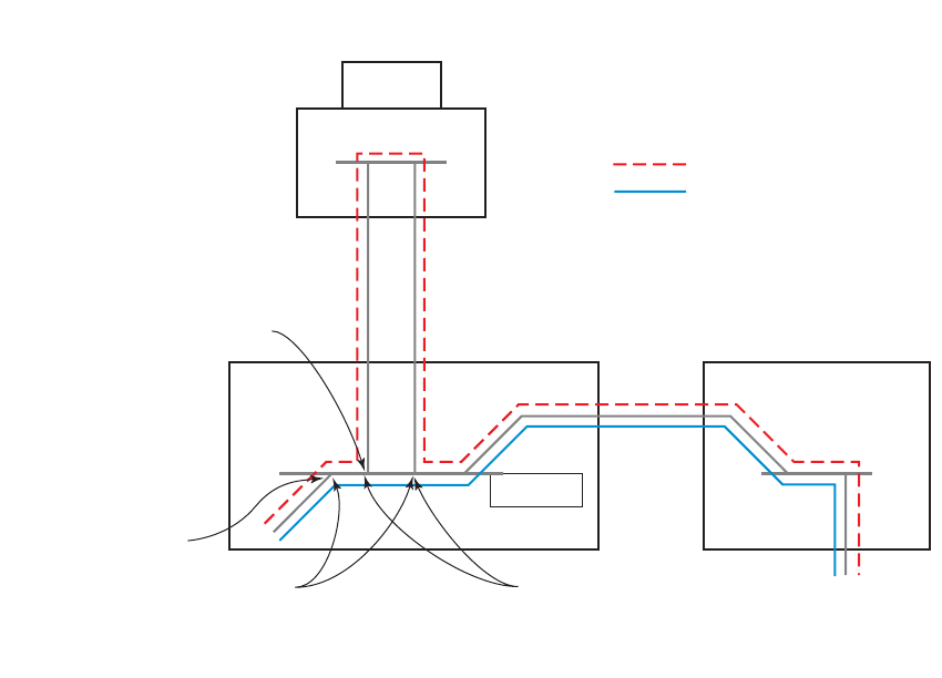
Common Configuration Tasks
Page 332 7750 SR OS Router Configuration Guide
Configuring Policy-Based Forwarding for Deep Packet Inspection
in VPLS
The purpose policy-based forwarding is to capture traffic from a customer and perform a deep
packet inspection (DPI) and forward traffic, if allowed, by the DPI.
In the following example, the split horizon groups are used to prevent flooding of traffic. Traffic
from customers enter at SAP 1/1/5:5. Due to the mac-filter 100 that is applied on ingress, all traffic
with dot1p 07 marking will be forwarded to SAP 1/1/22:1, which is the DPI.
DPI performs packet inspection/modification and either drops the traffic or forwards the traffic
back into the box through SAP 1/1/21:1. Traffic will then be sent to spoke-sdp 3:5.
SAP 1/1/23:5 is configured to see if the VPLS service is flooding all the traffic. If flooding is
performed by the router then traffic would also be sent to SAP 1/1/23:5 (which it should not).
Figure 28 shows an example to configure policy-based forwarding for deep packet inspection on a
VPLS service. For information about configuring services, refer to the 7750 SR OS Services
Guide.
Figure 28: Policy-Based Forwarding for Deep Packet Inspection
OSSG125
DPI Box
Residential Split
IngressPBF Filter
on Incoming Traffic
Split Horizon SAPs Disable Learning
VPLS 10
Normal Stream
PBF Diverted Stream
Filter Policies
7750 SR OS Router Configuration Guide Page 333
Configuring the VPLS service:
Example:config>service# vpls 10 customer 1 create
config>service>vpls$ service-mtu 1400
config>service>vpls$ split-horizon-group "dpi" residential-group create
config>service>vpls>split-horizon-group$ exit
config>service>vpls# split-horizon-group split create
config>service>vpls>split-horizon-group# exit
config>service>vpls# sap 1/1/21:1 split-horizon-group split create
config>service>vpls>sap$ disable-learning
config>service>vpls>sap$ static-mac 00:00:00:31:11:01 create
config>service>vpls>sap$ exit
config>service>vpls# sap 1/1/22:1 split-horizon-group "dpi" create
config>service>vpls>sap$ disable-learning
config>service>vpls>sap$ static-mac 00:00:00:31:12:01 create
config>service>vpls>sap$ exit
config>service>vpls# sap 1/1/23:5 create
config>service>vpls>sap$ static-mac 00:00:00:31:13:05 create
config>service>vpls>sap$ exit
config>service>vpls# no shutdown
The following example displays the service configuration:
*A:ALA-48>config>service# info
----------------------------------------------
...
vpls 10 customer 1 create
service-mtu 1400
split-horizon-group "dpi" residential-group create
exit
split-horizon-group "split" create
exit
stp
shutdown
exit
sap 1/1/21:1 split-horizon-group "split" create
disable-learning
static-mac 00:00:00:31:11:01 create
exit
sap 1/1/22:1 split-horizon-group "dpi" create
disable-learning
static-mac 00:00:00:31:12:01 create
exit
sap 1/1/23:5 create
static-mac 00:00:00:31:13:05 create
exit
no shutdown
exit
...
----------------------------------------------
*A:ALA-48>config>service#
Common Configuration Tasks
Page 334 7750 SR OS Router Configuration Guide
Configuring the MAC filter policy:
Example:config>filter# mac-filter 100 create
config>filter>mac-filter$ default-action forward
config>filter>mac-filter$ entry 10 create
config>filter>mac-filter>entry$ match
config>filter>mac-filter>entry>match$ dot1p 07
config>filter>mac-filter>entry>match$ exit
config>filter>mac-filter>entry# log 101
config>filter>mac-filter>entry# action forward sap 1/1/22:1
config>filter>mac-filter>entry# exit
config>filter>mac-filter# exit
The following example displays the MAC filter configuration:
*A:ALA-48>config>filter# info
----------------------------------------------
...
mac-filter 100 create
default-action forward
entry 10 create
match
dot1p 7 7
exit
log 101
action forward sap 1/1/22:1
exit
exit
...
----------------------------------------------
*A:ALA-48>config>filter#
Filter Policies
7750 SR OS Router Configuration Guide Page 335
Adding the MAC filter to the VPLS service:
Example:config>service# config>service# vpls 10
config>service>vpls# sap 1/1/5:5 split-horizon-group "split" create
config>service>vpls>sap$ ingress
config>service>vpls>sap>ingress$ filter mac 100
config>service>vpls>sap>ingress$ exit
config>service>vpls>sap# static-mac 00:00:00:31:15:05 create
config>service>vpls>sap# exit
config>service>vpls# spoke-sdp 3:5 create
config>service>vpls>spoke-sdp$ exit
config>service>vpls# no shutdown
The following example displays the service configuration:
*A:ALA-48>config>service# info
----------------------------------------------
...
vpls 10 customer 1 create
service-mtu 1400
split-horizon-group "dpi" residential-group create
exit
split-horizon-group "split" create
exit
stp
shutdown
exit
sap 1/1/5:5 split-horizon-group "split" create
ingress
filter mac 100
exit
static-mac 00:00:00:31:15:05 create
exit
sap 1/1/21:1 split-horizon-group "split" create
disable-learning
static-mac 00:00:00:31:11:01 create
exit
sap 1/1/22:1 split-horizon-group "dpi" create
disable-learning
static-mac 00:00:00:31:12:01 create
exit
sap 1/1/23:5 create
static-mac 00:00:00:31:13:05 create
exit
spoke-sdp 3:5 create
exit
no shutdown
exit
....
----------------------------------------------
*A:ALA-48>config>service#

Filter Management Tasks
Page 336 7750 SR OS Router Configuration Guide
Filter Management Tasks
This section discusses the following filter policy management tasks:
•Renumbering Filter Policy Entries on page 336
•Modifying an IP Filter Policy on page 338
•Modifying a MAC Filter Policy on page 341
•Deleting a Filter Policy on page 342
•Modifying an IP Filter Policy on page 338
•Modifying an IPv6 Filter Policy on page 340
•Modifying a MAC Filter Policy on page 341
•Copying Filter Policies on page 349
Renumbering Filter Policy Entries
The 7750 SR OS exits the matching process when the first match is found and then executes the
actions in accordance with the specified action. Because the ordering of entries is important, the
numbering sequence can be rearranged. Entries should be numbered from the most explicit to the
least explicit.
Use the following CLI syntax to renumber existing MAC or IP filter entries to re-sequence filter
entries:
CLI Syntax: config>filter
ip-filter filter-id
renum old-entry-number new-entry-number
mac-filter filter-id
renum old-entry-number new-entry-number
Example:config>filter>ip-filter# renum 10 15
config>filter>ip-filter# renum 20 10
config>filter>ip-filter# renum 40 1
Filter Policies
7750 SR OS Router Configuration Guide Page 337
The following displays the original filter entry order on the left side and the reordered filter entries
on the right side:
A:ALA-7>config>filter# info
----------------------------------------------
...
ip-filter 11 create
description "filter-main"
scope exclusive
entry 10 create
description "no-91"
filter-sample
interface-disable-sample
match
dst-ip 10.10.10.91/24
src-ip 10.10.10.103/24
exit
action forward redirect-policy redirect1
exit
entry 20 create
match
dst-ip 10.10.10.91/24
src-ip 10.10.0.100/24
exit
action drop
exit
entry 30 create
match
dst-ip 10.10.10.91/24
src-ip 10.10.0.200/24
exit
action forward
exit
entry 40 create
match
dst-ip 10.10.10.91/24
src-ip 10.10.10.106/24
exit
action drop
exit
exit
...
----------------------------------------------
A:ALA-7>config>filter#
A:ALA-7>config>filter# info
----------------------------------------------
...
ip-filter 11 create
description "filter-main"
scope exclusive
entry 1 create
match
dst-ip 10.10.10.91/24
src-ip 10.10.10.106/24
exit
action drop
exit
entry 10 create
match
dst-ip 10.10.10.91/24
src-ip 10.10.0.100/24
exit
action drop
exit
entry 15 create
description "no-91"
filter-sample
interface-disable-sample
match
dst-ip 10.10.10.91/24
src-ip 10.10.10.103/24
exit
action forward redirect-policy
redirect1
exit
entry 30 create
match
dst-ip 10.10.10.91/24
src-ip 10.10.0.200/24
exit
action forward
exit
exit
...
----------------------------------------------
A:ALA-7>config>filter#
Filter Management Tasks
Page 338 7750 SR OS Router Configuration Guide
Modifying an IP Filter Policy
To access a specific IP filter, you must specify the filter ID. Use the no form of the command to
remove the command parameters or return the parameter to the default setting.
Example:config>filter>ip-filter# description "New IP filter info"
config>filter>ip-filter# entry 2 create
config>filter>ip-filter>entry$ description "new entry"
config>filter>ip-filter>entry# action drop
config>filter>ip-filter>entry# match dst-ip 10.10.10.104/32
config>filter>ip-filter>entry# exit
config>filter>ip-filter#
The following output displays the modified IP filter output:
A:ALA-7>config>filter# info
----------------------------------------------
..
ip-filter 11 create
description "New IP filter info"
scope exclusive
entry 1 create
match
dst-ip 10.10.10.91/24
src-ip 10.10.10.106/24
exit
action drop
exit
entry 2 create
description "new entry"
match
dst-ip 10.10.10.104/32
exit
action drop
exit
entry 10 create
match
dst-ip 10.10.10.91/24
src-ip 10.10.0.100/24
exit
action drop
exit
entry 15 create
description "no-91"
match
dst-ip 10.10.10.91/24
src-ip 10.10.10.103/24
exit
action forward
exit
entry 30 create
match
dst-ip 10.10.10.91/24
src-ip 10.10.0.200/24
exit
action forward
exit
Filter Policies
7750 SR OS Router Configuration Guide Page 339
exit
..
----------------------------------------------
A:ALA-7>config>filter#
Filter Management Tasks
Page 340 7750 SR OS Router Configuration Guide
Modifying an IPv6 Filter Policy
To access a specific IPv6 filter, you must specify the filter ID. Use the no form of the command to
remove the command parameters or return the parameter to the default setting.
Example:config>filter# ipv6-filter 11
config>filter>ipv6-filter# description "IPv6 filter for Customer
1"
config>filter>ipv6-filter# scope exclusive
config>filter>ipv6-filter# entry 1
config>filter>ipv6-filter>entry# description "Fwds matching
packets"
config>filter>ipv6-filter>entry# action forward
config>filter>ipv6-filter>entry# exit
The following output displays the modified IPv6 filter output:
A:ALA-49>config>filter>ipv6-filter# info
----------------------------------------------
description "IPv6 filter for Customer 1"
scope exclusive
entry 1 create
description "Fwds matching packets"
match
dst-ip 11::12/128
src-ip 13::14/128
exit
action forward
exit
----------------------------------------------
A:ALA-49>config>filter>ipv6-filter#
Filter Policies
7750 SR OS Router Configuration Guide Page 341
Modifying a MAC Filter Policy
To access a specific MAC filter, you must specify the filter ID. Use the no form of the command
to remove the command parameters or return the parameter to the default setting.
Example: config>filter# mac-filter 90
config>filter>mac-filter# description "New filter info"
config>filter>mac-filter# entry 1
config>filter>mac-filter>entry# description "New entry info"
config>filter>mac-filter>entry# action forward
config>filter>mac-filter>entry# exit
config>filter>mac-filter# entry 2 create
config>filter>mac-filter>entry$ action drop
config>filter>mac-filter>entry# match
config>filter>mac-filter>entry>match# dot1p 7 7
The following output displays the modified MAC filter output:
A:ALA-7>config>filter# info
----------------------------------------------
...
mac-filter 90 create
description "New filter info"
scope exclusive
entry 1 create
description "New entry info"
match
src-mac 00:dc:98:1d:00:00 ff:ff:ff:ff:ff:ff
dst-mac 02:dc:98:1d:00:01 ff:ff:ff:ff:ff:ff
exit
action forward
exit
entry 2 create
match
dot1p 7 7
exit
action drop
exit
exit
...
----------------------------------------------
A:ALA-7>config>filter#

Filter Management Tasks
Page 342 7750 SR OS Router Configuration Guide
Deleting a Filter Policy
Before you can delete a filter, you must remove the filter association from the applied ingress and
egress SAPs and network interfaces.
•From an Ingress SAP on page 342
•From an Egress SAP on page 342
•From a Network Interface on page 343
•From the Filter Configuration on page 346
From an Ingress SAP
To remove a filter from an ingress SAP, enter the following CLI commands:
CLI Syntax: config>service# [epipe|ies|vpls] service-id
sap port-id[:encap-val]
ingress
no filter
Example:config>service# epipe 5
config>service>epipe# sap 1/1/2:3
config>service>epipe>sap# ingress
config>service>epipe>sap>ingress# no filter
From an Egress SAP
To remove a filter from an egress SAP, enter the following CLI commands:
CLI Syntax: config>service# [epipe|ies|vpls] service-id
sap port-id[:encap-val]
egress
no filter
Example:config>service# epipe 5
config>service>epipe# sap 1/1/2:3
config>service>epipe>sap# egress
config>service>epipe>sap>ingress# no filter
Filter Policies
7750 SR OS Router Configuration Guide Page 343
From a Network Interface
To delete a filter from a network interface, enter the following CLI commands:
CLI Syntax: config>router# interface ip-int-name
ingress
no filter
Example:config>router# interface 11
config>router>if# shutdown
config>filter>if# exit
config>filter# no interface 11
IP and IPv6 filters can be assigned and deleted together or separately. To delete both IP and IPv6
filter associations, consider the following examples:
A:ALA-49>config>router>if# info
----------------------------------------------
port 1/1/1
ipv6
address 3FFE::101:101/120
exit
ingress
filter ip 2
filter ipv6 1
exit
egress
filter ip 2
filter ipv6 1
exit
----------------------------------------------
A:ALA-49>config>router>if#
CLI Syntax: config>router>if#
config>router>if# ingress no filter
A:ALA-49>config>router>if# info
----------------------------------------------
port 1/1/1
ipv6
address 3FFE::101:101/120
exit
egress
filter ip 2
filter ipv6 1
exit
----------------------------------------------
A:ALA-49>config>router>if#
Filter Management Tasks
Page 344 7750 SR OS Router Configuration Guide
CLI Syntax: config>router>if# egress no filter ip 2
A:ALA-49>config>router>if# info
----------------------------------------------
port 1/1/1
ipv6
address 3FFE::101:101/120
exit
egress
filter ipv6 1
exit
----------------------------------------------
A:ALA-49>config>router>if#
CLI Syntax: config>router>if# ingress filter ip 2
config>router>if# ingress filter ipv6 1
A:ALA-49>config>router>if# info
----------------------------------------------
port 1/1/1
ipv6
address 3FFE::101:101/120
exit
ingress
filter ip 2
filter ipv6 1
exit
egress
filter ipv6 1
exit
----------------------------------------------
A:ALA-49>config>router>if#
CLI Syntax: config>router>if# ingress no filter ipv6 1
A:ALA-49>config>router>if# info
----------------------------------------------
port 1/1/1
ipv6
address 3FFE::101:101/120
exit
ingress
filter ip 2
exit
egress
filter ipv6 1
exit
----------------------------------------------
A:ALA-49>config>router>if#
Filter Policies
7750 SR OS Router Configuration Guide Page 345
CLI Syntax: config>router>if# ingress no filter
A:ALA-49>config>router>if#
----------------------------------------------
port 1/1/1
ipv6
address 3FFE::101:101/120
exit
egress
filter ipv6 1
exit
----------------------------------------------
A:ALA-49>config>router>if#
CLI Syntax: config>router>if# egress no filter
A:ALA-49>config>router>if#
----------------------------------------------
port 1/1/1
ipv6
address 3FFE::101:101/120
exit
----------------------------------------------
A:ALA-49>config>router>if#
Filter Management Tasks
Page 346 7750 SR OS Router Configuration Guide
From the Filter Configuration
After you have removed the filter from the SAP, use the following CLI syntax to delete the filter.
CLI Syntax: config>filter# no ip-filter filter-id
CLI Syntax: config>filter# no mac-filter filter-id
CLI Syntax: config>filter# no ipv6-filter filter-id
Example:config>filter# no ip-filter 11
config>filter# no mac-filter 13
config>filter# no ipv6-filter 100
Filter Policies
7750 SR OS Router Configuration Guide Page 347
Modifying a Redirect Policy
To access a specific redirect policy, you must specify the policy name. Use the no form of the
command to remove the command parameters or return the parameter to the default setting.
Example: config>filter# redirect-policy redirect1
config>filter>redirect-policy# description "New redirect info"
config>filter>redirect-policy# destination 10.10.10.106
config>filter>redirect-policy>dest# no url-test "URL_to_106"
config>filter>redirect-policy>dest# url-test "URL_to_Proxy"
config>filter>redirect-policy>dest>url-test$ url http://
www.alcatel.com
config>filter>redirect-policy>dest>url-test# interval 10
config>filter>redirect-policy>dest>url-test# timeout 10
config>filter>redirect-policy>dest>url-test# return-code 1
4294967295 raise-priority 255
A:ALA-7>config>filter# info
----------------------------------------------
...
redirect-policy "redirect1" create
description "New redirect info"
destination 10.10.10.104 create
description "SNMP_to_104"
priority 105
snmp-test "SNMP-1"
interval 30
drop-count 30 hold-down 120
exit
no shutdown
exit
destination 10.10.10.105 create
priority 95
ping-test
timeout 30
drop-count 5
exit
no shutdown
exit
destination 10.10.10.106 create
priority 90
url-test "URL_to_Proxy"
url "http://www.alcatel.com"
interval 10
timeout 10
return-code 1 4294967295 raise-priority 255
exit
no shutdown
exit
no shutdown
exit
...
----------------------------------------------
A:ALA-7>config>filter#
Filter Management Tasks
Page 348 7750 SR OS Router Configuration Guide
Deleting a Redirect Policy
Before you can delete a redirect policy from the filter configuration, you must remove the policy
association from the IP filter.
The following example shows the command usage to replace the configured redirect policy
(redirect1) with a different redirect policy (redirect2) and then removing the redirect1 policy
from the filter configuration.
Example:config>filter>ip-filter 11
config>filter>ip-filter# entry 1
config>filter>ip-filter>entry# action forward redirect-policy
redirect2
config>filter>ip-filter>entry# exit
config>filter>ip-filter# exit
config>filter# no redirect-policy redirect1
A:ALA-7>config>filter>ip-filter# info
----------------------------------------------
description "This is new"
scope exclusive
entry 1 create
filter-sample
interface-disable-sample
match
dst-ip 10.10.10.91/24
src-ip 10.10.10.106/24
exit
action forward redirect-policy redirect2
exit
entry 2 create
description "new entry"
...
----------------------------------------------
A:ALA-7>config>filter>ip-filter#
Filter Policies
7750 SR OS Router Configuration Guide Page 349
Copying Filter Policies
When changes are made to an existing filter policy, they are applied immediately to all services
where the policy is applied. If numerous changes are required, the policy can be copied so you can
edit the “work in progress” version without affecting the filtering process. When the changes are
completed, you can overwrite the work in progress version with the original version.
New filter policies can also be created by copying an existing policy and renaming the new filter.
CLI Syntax: config>filter# copy filter-type src-filter-id [src-entry src-
entry-id] to dst-filter-id [dst-entry dst-entry-id] [over-
write]
The following displays the command usage to copy an existing IP filter (11) to create a new filter
policy (12).
Example:config>filter# copy ip-filter 11 to 12
A:ALA-7>config>filter# info
----------------------------------------------
...
ip-filter 11 create
description "This is new"
scope exclusive
entry 1 create
match
dst-ip 10.10.10.91/24
src-ip 10.10.10.106/24
exit
action drop
exit
entry 2 create
...
ip-filter 12 create
description "This is new"
scope exclusive
entry 1 create
match
dst-ip 10.10.10.91/24
src-ip 10.10.10.106/24
exit
action drop
exit
entry 2 create
...
----------------------------------------------
A:ALA-7>config>filter#
Filter Management Tasks
Page 350 7750 SR OS Router Configuration Guide

Filter Policies
7750 SR OS Router Configuration Guide Page 351
Filter Command Reference
Command Hierarchies
•Log Commands on page 351
•IP Filter Policy Commands on page 351
•IPv6 Filter Policy Commands on page 353
•MAC Filter Policy Commands on page 353
•Redirect Policy Configuration Commands on page 355
•Generic Filter Commands on page 356
•Show Commands on page 356
•Clear Commands on page 356
•Monitor Commands on page 356
Configuration Commands
Log Commands
config
—filter
—log log-id [create]
—no log log-id
—description description-string
—no description
—destination memory num-entries | syslog syslog-id
—destination syslog syslog-id
—no destination
—[no] shutdown
—summary
—[no] shutdown
—summary-crit dst-addr
—summary-crit src-addr
—no summary-crit
—[no] wrap-around
IP Filter Policy Commands
—ip-filter filter-id [create]
—no ip-filter filter-id
—description description-string
—no description
—default-action {drop | forward}
—renum old-entry-id new-entry-id
—scope {exclusive | template}
—no scope
—entry entry-id [time-range time-range-name] [create]
—no entry entry-id
Filter Command Reference
Page 352 7750 SR OS Router Configuration Guide
—action [drop]
—action forward [next-hop {ip-address | indirect ip-address | interface
ip-int-name}]
—action forward [redirect-policy policy-name]
—action forward [sap sap-id | sdp sdp-id]
—action http-redirect url
—no action
—description description-string
—no description
—[no] filter-sample
—[no] interface-disable-sample
—log log-id
—no log
—match [protocol protocol-id]
—no match
—dscp dscp-name
—no dscp
—dst-ip {ip-address/mask | ip-address netmask}
—no dst-ip
—dst-port {lt | gt | eq} dst-port-number
—dst-port range start end
—no dst-port
—fragment {true | false}
—no fragment
—icmp-code icmp-code
—no icmp-code
—icmp-type icmp-type
—no icmp-type
—ip-option ip-option-value [ip-option-mask]
—no ip-option
—multiple-option {true | false}
—no multiple-option
—option-present {true | false}
—no option-present
—src-ip{ip-address/mask | ip-address netmask}
—no src-ip
—src-port {{lt | gt | eq} src-port-number
—src-port range start end}
—no src-port
—tcp-ack {true | false}
—no tcp-ack
—tcp-syn {true | false}
—no tcp-syn
Filter Policies
7750 SR OS Router Configuration Guide Page 353
IPv6 Filter Policy Commands
config
—filter
—ipv6-filter ipv6-filter-id [create]
—default-action {drop | forward}
—description description-string
—no description
—entry entry-id [time-range time-range-name]
—no entry entry-id
—action {drop | forward}
—no action
—description description-string
—no description
—log log-id
—no log
—match [next-header next-header]
—no match
—dscp dscp-name
—no dscp
—dst-ip [ipv6-address/prefix-length]
—no dst-ip
—dst-port {lt | gt | eq} dst-port-number
—dst-port range start end
—no
dst-port
—icmp-code icmp-code
—no icmp-code
—icmp-type icmp-type
—no icmp-type
—src-ip{ipv6-address/prefix-length}
—no src-ip
—src-port {lt | gt | eq} src-port-number
—src-port range start end}
—no src-port
—tcp-ack {true | false}
—no tcp-ack
—tcp-syn {true | false}
—no tcp-syn
—renum old-entry-id new-entry-id
—scope {exclusive | template}
—no scope
—MAC filter commands
MAC Filter Policy Commands
config
—filter
—mac-filter filter-id [create]
—no mac-filter filter-id
—description description-string
—no description
Filter Command Reference
Page 354 7750 SR OS Router Configuration Guide
—default-action {drop | forward}
—renum old-entry-id new-entry-id
—scope {exclusive | template}
—no scope
—entry entry-id [time-range time-range-name]
—no entry entry-id [create]
—description description-string
—no description
—action [drop]
—action forward [sap sap-id |sdp sdp-id]
—action http-redirect url
—no action
—log log-id
—no log
—match [frame-type {802dot3 | 802dot2-llc | 802dot2-snap |
ethernet_II}]
—no match
—dot1p dot1p-value [dot1p-mask]
—no dot1p
—dsap dsap-value [dsap-mask]
—no dsap
—dst-mac ieee-address [ieee-address-mask]
—no dst-mac
—etype 0x0600..0xffff
—no etype
—snap-oui {zero | non-zero}
—no snap-oui
—snap-pid snap-pid
—no snap-pid
—ssap ssap-value [ssap-mask]
—no ssap
—src-mac ieee-address [ieee-address-mask]
—no src-mac
Filter Policies
7750 SR OS Router Configuration Guide Page 355
Redirect Policy Configuration Commands
—Redirect policy commands —redirect-policy redirect-policy-name [create]
—no redirect-policy redirect-policy-name
—description description-string
—no description
—[no] shutdown
—destination ip-address [create]
—no destination ip-address
—description description-string
—no description
—priority [priority]
—no priority
—[no] shutdown
—[no] ping-test
—drop-count consecutive-failures [hold-down seconds]
—no drop-count
—interval seconds
—no interval
—timeout seconds
—no timeout
—snmp-test test-name [create]
—no snmp-test test-name
—drop-count consecutive-failures [hold-down seconds]
—no drop-count
—interval seconds
—no interval
—oid oid-string community community-string
—no oid
—return-value return-value type return-type [disable | lower-
priority priority | raise-priority priority]
—no return-value return-value type return-type
—timeout seconds
—no timeout
— url-test test-name [create]
—no url-test test-name
—drop-count consecutive-failures [hold-down seconds]
—no drop-count
—interval seconds
—no interval
—return-code return-code-1 [return-code-2] [disable | lower-
priority priority | raise-priority priority]
—no return-code return-code-1 [return-code-2]
—timeout seconds
—no timeout
—url url-string [http-version version-string]
—no url
Filter Command Reference
Page 356 7750 SR OS Router Configuration Guide
Generic Filter Commands
config
—filter
—copy ip-filter | ipv6-filter | mac-filter src-filter-id [src-entry src-entry-id] to dst-filter-id
[dst-entry dst-entry-id] [overwrite]
Show Commands
show —filter
—anti-spoof [sap-id]
—download-failed
—ip [ip-filter-id [entry entry-id] [association | counters | subscriber]
—ipv6 [ipv6-filter-id [entry entry-id] [association | counters]]
—log [bindings]
—log log-id [match string]
—mac {mac-filter-id [entry entry-id] [association | counters]}
—redirect-policy {redirect-policy-name [dest ip-address] [association]}
Clear Commands
clear —filter
—ip filter-id [entry entry-id] [ingress | egress]
—ipv6 filter-id [entry entry-id] [ingress | egress]
—log log-id
—mac filter-id [entry entry-id] [ingress | egress]
Monitor Commands
monitor
—filter ip ip-filter-id entry entry-id [interval seconds] [repeat repeat] [absolute | rate]
—filter (ipv6) ipv6 ipv6-filter-id entry entry-id [interval seconds] [repeat repeat] [absolute | rate]
—filter mac mac-filter-id entry entry-id [interval seconds] [repeat repeat] [absolute | rate]

Filter Policies
7750 SR OS Router Configuration Guide Page 357
Configuration Commands
Generic Commands
description
Syntax description string
no description
Context config>filter>ip-filter
config>filter>ip-filter>entry
config>filter>ipv6-filter
config>filter>log
config>filter>mac-filter
config>filter>mac-filter>entry
config>filter>redirect-policy
config>filter>redirect-policy>destination
Description This command creates a text description stored in the configuration file for a configuration context.
The description command associates a text string with a configuration context to help identify the
context in the configuration file.
The no form of the command removes any description string from the context.
Default No description associated with the configuration context.
Parameters string — The description character string. Allowed values are any string up to 80 characters long
composed of printable, 7-bit ASCII characters. If the string contains special characters (#, $,
spaces, etc.), the entire string must be enclosed within double quotes.

Page 358 7750 SR OS Router Configuration Guide
Global Filter Commands
ip-filter
Syntax [no] ip-filter filter-id [create]
Context config>filter
Description This command creates a configuration context for an IP filter policy.
IP-filter policies specify either a forward or a drop action for packets based on the specified match
criteria.
The IP filter policy, sometimes referred to as an access control list (ACL), is a template that can be
applied to multiple services or multiple network ports as long as the scope of the policy is template.
Any changes made to the existing policy, using any of the sub-commands, will be applied
immediately to all services where this policy is applied. For this reason, when many changes are
required on an ip-filter policy, it is recommended that the policy be copied to a work area. That work-
in-progress policy can be modified until complete and then written over the original filter policy. Use
the config filter copy command to maintain policies in this manner.
The no form of the command deletes the IP filter policy. A filter policy cannot be deleted until it is
removed from all SAPs or network ports where it is applied.
Parameters filter-id — Specifies the IP filter policy ID number.
Values 1 — 16384
create — Keyword required when first creating the configuration context. Once the context is
created, one can navigate into the context without the create keyword.
ipv6-filter
Syntax [no] ipv6-filter ipv6-filter-id [create]
Context config>filter
Description This command creates a configuration context for an IPv6 filter policy.
Parameters ipv6-filter-id — specifies the IPv6 filter policy ID number.
Values 1 — 16384
create — Keyword required when first creating the configuration context. Once the context is
created, one can navigate into the context without the create keyword.
mac-filter
Syntax [no] mac-filter filter-id [create]
Filter Policies
7750 SR OS Router Configuration Guide Page 359
Context config>filter
Description This command enables the context for a MAC filter policy.
The mac-filter policy specifies either a forward or a drop action for packets based on the specified
match criteria.
The mac-filter policy, sometimes referred to as an access control list, is a template that can be applied
to multiple services as long as the scope of the policy is template.
Note it is not possible to apply a MAC filter policy to a network port or an IES service.
Any changes made to the existing policy, using any of the sub-commands, will be applied
immediately to all services where this policy is applied. For this reason, when many changes are
required on a mac-filter policy, it is recommended that the policy be copied to a work area. That
work-in-progress policy can be modified until complete and then written over the original filter
policy. Use the config filter copy command to maintain policies in this manner.
The no form of the command deletes the mac-filter policy. A filter policy cannot be deleted until it is
removed from all SAP where it is applied.
Parameters filter-id — The MAC Filter Policy ID number.
Values 1 — 16384
create — Keyword required when first creating the configuration context. Once the context is
created, one can navigate into the context without the create keyword.
redirect-policy
Syntax [no] redirect-policy redirect-policy-name
Context config>filter
Description This command configures redirect policies.
The no form of the command removes the redirect policy from the filter configuration only if the
policy is not referenced in an IP filter and the IP filter is not in use (applied to a service or network
interface).
Default none
Parameters redirect-policy-name — Specifies the redirect policy name. Allowed values are any string up to 32
characters long composed of printable, 7-bit ASCII characters. If the string contains special
characters (#, $, spaces, etc.), the entire string must be enclosed within double quotes. There is no
limit to the number of redirect policies that can be configured.

Page 360 7750 SR OS Router Configuration Guide
Filter Log Destination Commands
destination
Syntax destination memory num-entries
destination syslog syslog-id
no destination
Context config>filter>log
Description This command configures the destination for filter log entries for the filter log ID.
Filter logs can be sent to either memory (memory) or to an existing Syslog server definition (server).
If the filter log destination is memory, the maximum number of entries in the log must be specified.
The no form of the command deletes the filter log association.
Default no destination - no destination specified for the filter log ID
Parameters memory num-entries — Specifies the destination of the filter log ID is a memory log. The num-
entries value is the maximum number of entries in the filter log expressed as a decimal integer.
Values 10 — 50000
syslog syslog-id — Specifies the destination of the filter log ID is a Syslog server. The syslog-id
parameter is the number of the Syslog server definition.
Values 1 — 10
log
Syntax log log-id [create]
no log
Context config>filter
Description This command enables the context to create a filter log policy.
The no form of the command deletes the filter log ID. The log cannot be deleted if there are filter
entries configured to write to the log. All filter entry logging associations need to be removed before
the log can be deleted.
Special Cases Filter log 101 — Filter log 101 is the default log and is automatically created by the system. Filter
log 101 is always a memory filter log and cannot be changed to a Syslog filter log. The log size
defaults to 1000 entries. The number of entries and wrap-around behavior can be edited.
Default log 101 — no filter log destinations defined
Parameters log-id — The filter log ID destination expressed as a decimal integer.
Values 101 — 199
Filter Policies
7750 SR OS Router Configuration Guide Page 361
shutdown
Syntax [no] shutdown
Context config>filter>log
config>filter>log>summary
config>filter>redirect-policy
config>filter>redirect-policy>destination
Administratively enables/disabled (AdminUp/AdminDown) an entity. Downing an entity does not
change, reset or remove any configuration settings or statistics. Many objects must be shutdown
before they may be deleted.
The shutdown command administratively downs an entity. Administratively downing an entity
changes the operational state of the entity to down and the operational state of any entities contained
within the administratively down entity.
Unlike other commands and parameters where the default state will not be indicated in the
configuration file, shutdown and no shutdown are always indicated in system generated
configuration files.
The no form of the command puts an entity into the administratively enabled state.
Default no shutdown
summary
Syntax summary
Context config>filter>log
Description This command enables the context to configure log summarization. These settings will only be taken
into account when syslog is the log destination. Note that summary settings will only be taken into
account in case the log destination is syslog.
Parameters none
summary-crit
Syntax summary-crit dst-addr
summary-crit src-addr
no summary-crit
Context config>filter>log>summary
Description This command defines the the key of the index of the minitable. If key information is changed while
summary is in no shutdown, the filter summary minitable is flushed and recreated with different key
information. Log packets received during the reconfiguration time will be handled as if summary was
not active.
The no form of the command reverts to the default parameter.
Default dst-addr
Page 362 7750 SR OS Router Configuration Guide
Parameters dst-addr — Specifies that received log packets are summarized based on the destination IP, IPv6 or
MAC address.
src-addr — Specifies that received log packets are summarized based on the source IP, IPv6 or MAC
address.
wrap-around
Syntax [no] wrap-around
Context config>filter>log
Description This command configures a memory filter log to log until full or to store the most recent log entries
(circular buffer).
Specifying wrap-around configures the memory filter log to store the most recent filter log entries
(circular buffer). When the log is full, the oldest filter log entries are overwritten with new entries.
The no form of the command configures the memory filter log to accept filter log entries until full.
When the memory filter log is full, filter logging for the log filter ID ceases.
Default wrap-around - the filter log store the most recent filter log entries

Filter Policies
7750 SR OS Router Configuration Guide Page 363
Filter Policy Commands
default-action
Syntax default-action {drop | forward}
Context config>filter>ip-filter
config>filter>ipv6-filter
config>filter>mac-filter
Description This command specifies the action to be applied to packets when the packets do not match the
specified criteria in all of the IP filter entries of the filter.
When multiple default-action commands are entered, the last command will overwrite the previous
command.
Default drop
Parameters drop — Specifies all packets will be dropped unless there is a specific filter entry which causes the
packet to be forwarded.
forward — Specifies all packets will be forwarded unless there is a specific filter entry which causes
the packet to be dropped.
scope
Syntax scope {exclusive | template}
no scope
Context config>filter>ip-filter
config>filter>ipv6-filter
config>filter>mac-filter
Description This command configures the filter policy scope as exclusive or template. If the scope of the policy is
template and is applied to one or more services or network interfaces, the scope cannot be changed.
The no form of the command sets the scope of the policy to the default of template.
Default scope template — a filter is created as a filter policy template
Parameters exclusive — When the scope of a policy is defined as exclusive, the policy can only be applied to a
single entity (SAP or network port). Attempting to assign the policy to a second entity will result
in an error message. If the policy is removed from the entity, it will become available for
assignment to another entity.
template — When the scope of a policy is defined as template, the policy can be applied to multiple
SAPs or network ports.

Page 364 7750 SR OS Router Configuration Guide
General Filter Entry Commands
entry
Syntax entry entry-id [time-range time-range-name]
no entry entry-id
Context config>filter>ip-filter
config>filter>ipv6-filter
config>filter>mac-filter
Description This command creates or edits an IP, IPv6, or MAC filter entry. Multiple entries can be created using
unique entry-id numbers within the filter. The 7750 SR OS implementation exits the filter on the first
match found and executes the actions in accordance with the accompanying action command. For
this reason, entries must be sequenced correctly from most to least explicit.
An entry may not have any match criteria defined (in which case, everything matches) but must have
at least the keyword action for it to be considered complete. Entries without the action keyword will
be considered incomplete and hence will be rendered inactive.
The no form of the command removes the specified entry from the IP or MAC filter. Entries removed
from the IP or MAC filter are immediately removed from all services or network ports where that
filter is applied.
Default none
Parameters entry-id — An entry-id uniquely identifies a match criteria and the corresponding action. It is
recommended that multiple entries be given entry-ids in staggered increments. This allows users
to insert a new entry in an existing policy without requiring renumbering of all the existing
entries.
Values 1 — 65535
time-range time-range-name — Specifies the time range name to be associated with this filter entry
up to 32 characters in length. The time-range name must already exist in the config>cron
context.
create — Keyword required when first creating the configuration context. Once the context is
created, one can navigate into the context without the create keyword.
log
Syntax log log-id
no log
Context config>filter>ip-filter>entry
config>filter>ipv6-filter>entry
config>filter>mac-filter>entry
Description This command creates the context to enable filter logging for a filter entry and specifies the
destination filter log ID.
Filter Policies
7750 SR OS Router Configuration Guide Page 365
The filter log ID must exist before a filter entry can be enabled to use the filter log ID.
The no form of the command disables logging for the filter entry.
Default no log — no destination filter log ID specified
Parameters log-id — The filter log ID destination expressed as a decimal integer.
Values 101 — 199

Page 366 7750 SR OS Router Configuration Guide
IP Filter Entry Commands
action
Syntax action [drop]
action forward [next-hop {ip-address | indirect ip-address | interface ip-int-name}]
action forward [redirect-policy policy-name]
action forward [sap sap-id | sdp sdp-id]
action http-redirect url
no action
Context config>filter>ip-filter>entry
Description This command specifies to match packets with a specific IP option or a range of IP options in the first
option of the IP header as an IP filter match criterion. The action keyword must be entered and a
keyword specified in order for the entry to be active.
Note that action forward next-hop cannot be applied to multicast traffic.
Multiple action statements entered will overwrite previous actions parameters when defined.
The no form of the command removes the specified action statement. The filter entry is considered
incomplete and hence rendered inactive without the action keyword.
Default No action is specified, thus rendering the entry inactive.
Parameters drop — Specifies packets matching the entry criteria will be dropped.
forward — Specifies packets matching the entry criteria will be forwarded.
If neither drop nor forward is specified, the filter action is No-Op and the filter entry is inactive.
next-hop ip-address — The IP address of the direct next-hop to which to forward matching packets
in dotted decimal notation.
indirect ip-address — The IP address of the indirect next-hop to which to forward matching packets
in dotted decimal notation. The direct next-hop IP address and egress IP interface are determined
by a route table lookup.
interface ip-int-name — The name of the egress IP interface where matching packets will be
forwarded from. This parameter is only valid for unnumbered point-to-point interfaces. If the
string contains special characters (#, $, spaces, etc.), the entire string must be enclosed within
double quotes.
redirect policy-name — Specifies the redirect policy configured in the config>filter>redirect-
policy context.
sap sap-id — Specifies the physical port identifier portion of the SAP definition. Only Ethernet
SAPs are supported (including q-in-q, BCP, bridged Ethernet in Frame Relay or ATM).
Values sap-id:null[port-id | bundle-id | lag-id | aps-id]
dot1q [port-id | bundle-id | lag-id | aps-id]:qtag1
qinq [port-id | bundle-id | lag-id]:qtag1.qtag2
atm [port-id | bundle-id][:vpi/vci | vpi | vpi1.vpi2]
Filter Policies
7750 SR OS Router Configuration Guide Page 367
frame [port-id | bundle-id]:dlci
cisco-hdlc slot/mda/port.channel
ima-grp bundle-id[:vpi/vci | vpi | vpi1.vpi2]
port-id slot/mda/port[.channel]
aps-id aps-group-id[.channel]
aps keyword
group-id 1 — 16
bundle-type-slot/mda.bundle-num
bundle keyword
type ima, ppp
bundle-num 1 — 128
ccag-id ccag-id.path-id[cc-type]:cc-id
ccag keyword
id 1 — 8
path-id a, b
cc-type .sap-net, .net-sap]
cc-id 0 — 4094
lag-id lag-id
lag keyword
id 1 — 200
qtag1 0 — 4094
qtag2 *, 0 — 4094
vpi NNI 0 — 4095
UNI 0 — 255
vci 1, 2, 5 — 65535
dlci 16 — 1022
port-id — Specifies the physical port ID in the slot/mda/port format.
If the card in the slot has Media Dependent Adapters (MDAs) installed, the port-id must be in the
slot_number/MDA_number/port_number format. For example 1/1/3 specifies the port 3 on
MDA 1 in slot 1.
The port-id must reference a valid port type. When the port-id parameter represents SONET/
SDH and TDM channels, the port ID must include the channel ID. A period “.” separates the
physical port from the channel-id. The port must be configured as an access port.
If the SONET/SDH port is configured as clear-channel then only the port is specified.
bundle-id — Specifies the multilink bundle to be associated with this IP interface. The bundle key-
word must be entered at the beginning of the parameter.
The command syntax must be configured as follows:
bundle-id: bundle-type-slot-id/mda-slot.bundle-num
bundle-id value range: 1 — 128
For example:
ALA-12>config# port bundle-ima-5/1.1
ALA-12>config>port# multilink-bundle
ima — Specifies Inverse Multiplexing over ATM. An IMA group is a collection of physical links
bundled together and assigned to an ATM port.
Page 368 7750 SR OS Router Configuration Guide
qtag1, qtag2 — Specifies the encapsulation value used to identify the SAP on the port or sub-port. If
this parameter is not specificially defined, the default value is 0.
Values qtag1: 0 — 4094
qtag2 : * | 0 — 4094
sdp-id — The SDP identifier.
Values 1 — 17407
vc-id — The virtual circuit identifier. This value is used to validate the VC ID portion of each mesh
SDP binding defined in the service. The default value of this object is equal to the service ID.
Values 1 — 4294967295
http-redirect url — Specifies the HTTP web address that will be sent to the user’s browser. Note
that http-redirect is not supported on 7750 SR-1 or 7450 ESS-1 models.
Values 255 characters maximum
action
Syntax action {drop | forward}
no action
Context config>filter>ipv6-filter>entry
Description This command specifies the action to take for packets that match this filter entry. The action keyword
must be entered and a keyword specified in order for the entry to be active.
Multiple action statements entered will overwrite previous actions parameters when defined.
The no form of the command removes the specified action statement. The filter entry is considered
incomplete and hence rendered inactive without the action keyword.
Default drop
Parameters [drop | forward] — Specifies the action to take on packets matching the entry criteria.
drop specifies packets matching the entry criteria will be dropped.
forward specifies packets matching the entry criteria will be forwarded.
filter-sample
Syntax [no] filter-sample
Context config>filter>ip-filter>entry
Description Specifies that traffic matching the associated IP filter entry is sampled if the IP interface is set to
cflowd acl.
If the cflowd is either not enabled or set to cflowd interface mode, this command is ignored.
The no form removes this command for the system configuration, disallowing the sampling of
packets if the ingress interface is in cflowd acl mode.
Filter Policies
7750 SR OS Router Configuration Guide Page 369
Default no filter-sample
interface-disable-sample
Syntax [no] interface-disable-sample
Context config>filter>ip-filter>entry
Description Specifies that traffic matching the associated IP filter entry is not sampled if the IP interface is set to
cflowd interface mode.
If the cflowd is either not enabled or set to cflowd acl mode, this command is ignored.
The no form of this command enables sampling.
Default no interface-disable-sample
match
Syntax match [protocol protocol-id]
no match
Context config>filter>ip-filter>entry
Description This command enables the context to enter match criteria for the filter entry. When the match criteria
have been satisfied the action associated with the match criteria is executed.
If more than one match criteria (within one match statement) are configured then all criteria must be
satisfied (AND function) before the action associated with the match is executed.
A match context may consist of multiple match criteria, but multiple match statements cannot be
entered per entry.
The no form of the command removes the match criteria for the entry-id.
Parameters protocol — The protocol keyword configures an IP protocol to be used as an IP filter match
criterion. The protocol type such as TCP or UDP is identified by its respective protocol number.
protocol-id — Configures the decimal value representing the IP protocol to be used as an IP filter
match criterion. Well known protocol numbers include ICMP(1), TCP(6), UDP(17). The no form
the command removes the protocol from the match criteria.
Values 0 — 255 (values can be expressed in decimal, hexidecimal, or binary - DHB)
keywords: none, crtp, crudp, egp, eigrp, encap, ether-ip, gre, icmp, idrp, igmp,
igp, ip, ipv6, ipv6-frag, ipv6-icmp, ipv6-no-nxt, ipv6-opts, ipv6-route, isis, iso-ip,
l2tp, ospf-igp, pim, pnni, ptp, rdp, rsvp, stp, tcp, udp, vrrp
* — udp/tcp wildcard
Protocol Protocol ID Description
icmp 1 Internet Control Message

Page 370 7750 SR OS Router Configuration Guide
igmp 2 Internet Group Management
ip 4 IP in IP (encapsulation)
tcp 6 Transmission Control
egp 8 Exterior Gateway Protocol
igp 9 any private interior gateway (used by Cisco for their IGRP)
udp 17 User Datagram
rdp 27 Reliable Data Protocol
ipv6 41 Ipv6
ipv6-route 43 Routing Header for IPv6
ipv6-frag 44 Fragment Header for IPv6
idrp 45 Inter-Domain Routing Protocol
rsvp 46 Reservation Protocol
gre 47 General Routing Encapsulation
ipv6-icmp 58 ICMP for IPv6
ipv6-no-nxt 59 No Next Header for IPv6
ipv6-opts 60 Destination Options for IPv6
iso-ip 80 ISO Internet Protocol
eigrp 88 EIGRP
ospf-igp 89 OSPFIGP
ether-ip 97 Ethernet-within-IP Encapsulation
encap 98 Encapsulation Header
pnni 102 PNNI over IP
pim 103 Protocol Independent Multicast
vrrp 112 Virtual Router Redundancy Protocol
l2tp 115 Layer Two Tunneling Protocol
stp 118 Schedule Transfer Protocol
ptp 123 Performance Transparency Protocol
isis 124 ISIS over IPv4
crtp 126 Combat Radio Transport Protocol
Protocol Protocol ID Description
Filter Policies
7750 SR OS Router Configuration Guide Page 371
match
Syntax match [next-header next-header]
no match
Context config>filter>ipv6-filter>entry
Description This command enables the context to enter match criteria for the filter entry. When the match criteria
have been satisfied the action associated with the match criteria is executed.
If more than one match criteria (within one match statement) are configured then all criteria must be
satisfied (AND function) before the action associated with the match is executed.
A match context may consist of multiple match criteria, but multiple match statements cannot be
entered per entry.
The no form of the command removes the match criteria for the entry-id.
Parameters next-header — Specifies the IPv6 next header to match. Note that this parameter is analogous to the
protocol parameter used in IP-Filter match criteria.
Values [0 — 42 | 45 — 49 | 52 — 59 | 61— 255] — protocol numbers accepted in decimal,
hexidecimal, or binary - DHB
keywords: none, crtp, crudp, egp, eigrp, encap, ether-ip, gre, icmp, idrp, igmp, igp,
ip, ipv6, ipv6-icmp, ipv6-no-nxt, isis, iso-ip, l2tp, ospf-igp, pim, pnni, ptp, rdp,
rsvp, stp, tcp, udp, vrrp
* — udp/tcp wildcard
crudp 127 Combat Radio User Datagram
Protocol Protocol ID Description

Page 372 7750 SR OS Router Configuration Guide
MAC Filter Entry Commands
action
Syntax action [drop]
action forward [sap sap-id |sdp sdp-id]
action http-redirect url
no action
Context config>filter>mac-filter>entry
Description This command configures no action, drop or forward for a MAC filter entry. The action keyword
must be entered for the entry to be active. Any filter entry without the action keyword will be
considered incomplete and will be inactive.
If neither drop nor forward is specified, this is considered a No-Op filter entry used to explicitly set a
filter entry inactive without modifying match criteria or removing the entry itself.
Multiple action statements entered will overwrite previous actions parameters when defined. To
remove a parameter, use the no form of the action command with the specified parameter.
The no form of the command removes the specified action statement. The filter entry is considered
incomplete and hence rendered inactive without the action keyword.
Default No action is specified, thus rendering the entry inactive.
Parameters drop — Specifies packets matching the entry criteria will be dropped.
forward — Specifies packets matching the entry criteria will be forwarded. Only Ethernet SAPs are
supported (including q-in-q, BCP, bridged Ethernet in Frame Relay or ATM).
If neither drop nor forward is specified, the filter action is no-op and the filter entry is inactive.
sap sap-id — Specifies the physical port identifier portion of the SAP definition.
Values sap-id: null [port-id | bundle-id | lag-id | aps-id]
dot1q [port-id | bundle-id | lag-id | aps-id]:qtag1
qinq [port-id | bundle-id | lag-id]:qtag1.qtag2
atm [port-id | bundle-id][:vpi/vci | vpi | vpi1.vpi2]
frame [port-id | bundle-id]:dlci
cisco-hdlc slot/mda/port.channel
ima-grp bundle-id[:vpi/vci | vpi | vpi1.vpi2]
port-id slot/mda/port[.channel]
aps-id aps-group-id[.channel]
aps keyword
group-id 1 — 64
bundle-type-slot/mda.bundle-num
bundle keyword
type ima, ppp
bundle-num 1 — 128
ccag-id ccag-id.path-id[cc-type]:cc-id
ccag keyword
Filter Policies
7750 SR OS Router Configuration Guide Page 373
id 1 — 8
path-id a, b
cc-type .sap-net, .net-sap]
cc-id 0 — 4094
lag-id lag-id
lag keyword
id 1 — 200
qtag1 0 — 4094
qtag2 *, 0 — 4094
vpi NNI 0 — 4095
UNI 0 — 255
vci 1, 2, 5 — 65535
dlci 16 — 1022
port-id — Specifies the physical port ID in the slot/mda/port format.
If the card in the slot has Media Dependent Adapters (MDAs) installed, the port-id must be in the
slot_number/MDA_number/port_number format. For example 1/1/3 specifies the port 3 on
MDA 1 in slot 1.
The port-id must reference a valid port type. When the port-id parameter represents SONET/
SDH and TDM channels, the port ID must include the channel ID. A period “.” separates the
physical port from the channel-id. The port must be configured as an access port.
If the SONET/SDH port is configured as clear-channel then only the port is specified.
bundle-id — Specifies the multilink bundle to be associated with this IP interface. The bundle key-
word must be entered at the beginning of the parameter.
The command syntax must be configured as follows:
bundle-id: bundle-type-slot-id/mda-slot.bundle-num
bundle-id value range: 1 — 128
For example:
ALA-12>config# port bundle-ima-5/1.1
ALA-12>config>port# multilink-bundle
ima — Specifies Inverse Multiplexing over ATM. An IMA group is a collection of physical links
bundled together and assigned to an ATM port.
qtag1, qtag2 — Specifies the encapsulation value used to identify the SAP on the port or sub-port. If
this parameter is not specificially defined, the default value is 0.
Values qtag1: 0 — 4094
qtag2 : * | 0 — 4094
sdp-id — The SDP identifier.
Values 1 — 17407
vc-id — The virtual circuit identifier. This value is used to validate the VC ID portion of each mesh
SDP binding defined in the service. The default value of this object is equal to the service ID.
Values 1 — 4294967295
Page 374 7750 SR OS Router Configuration Guide
http-redirect url — Specifies the HTTP web address that will be sent to the user’s browser.
Values 255 characters maximum
match
Syntax match [frame-type 802dot3 | 802dot2-llc | 802dot2-snap | ethernet_II]
no match
Context config>filter>mac-filter>entry
Description This command creates the context for entering/editing match criteria for the filter entry and specifies
an Ethernet frame type for the entry. When the match criteria have been satisfied the action associated
with the match criteria is executed.
If more than one match criteria (within one match statement) are configured then all criteria must be
satisfied (AND function) before the action associated with the match will be executed.
A match context may consist of multiple match criteria, but multiple match statements cannot be
entered per entry.
The no form of the command removes the match criteria for the entry-id.
Parameters frame-type keyword — The frame-type keyword configures an Ethernet frame type to be used for
the MAC filter match criteria.
Default 802dot3
Values 802dot3, 802dot2-llc, 802dot2-snap, ethernet_II
802dot3 — Specifies the frame type is Ethernet IEEE 802.3.
802dot2-llc — Specifies the frame type is Ethernet IEEE 802.2 LLC.
802dot2-snap — Specifies the frame type is Ethernet IEEE 802.2 SNAP.
ethernet_II — Specifies the frame type is Ethernet Type II.

Filter Policies
7750 SR OS Router Configuration Guide Page 375
IP Filter Match Criteria
dscp
Syntax dscp dscp-name
no dscp
Context config>filter>ip-filter>entry>match
config>filter>ipv6-filter>entry>match
Description This command configures a DiffServ Code Point (DSCP) name to be used as an IP filter match
criterion.
The no form of the command removes the DSCP match criterion.
Default no dscp — no dscp match criterion
Parameters dscp-name — Configure a dscp name that has been previously mapped to a value using the dscp-
name command. The DiffServ code point may only be specified by its name.
Values be, cp1, cp2, cp3, cp4, cp5, cp6, cp7, cs1, cp9, af11, cp11, af12, cp13, af13, cp15,
cs2, cp17, af21, cp19, af22, cp21, af23, cp23
dst-ip
Syntax dst-ip {ip-address[/mask]} [netmask]
no dst-ip
Context config>filter>ip-filter>entry>match
Description This command configures a destination IP address range to be used as an IP filter match criterion.
To match on the destination IP address, specify the address and its associated mask, e.g. 10.1.0.0/16.
The conventional notation of 10.1.0.0 255.255.0.0 may also be used.
The no form of the command removes the destination IP address match criterion.
Default No destination IP match criterion
Parameters ip-prefix — The IP prefix for the IP match criterion in dotted decimal notation.
Values 0.0.0.0 — 255.255.255.255
mask — The subnet mask length expressed as a decimal integer.
Values 0 — 32
netmask — Any mask epressed in dotted quad notation.
Values 0.0.0.0 — 255.255.255.255
dst-ip
Page 376 7750 SR OS Router Configuration Guide
Syntax dst-ip [ipv6-address/prefix-length]
no dst-ip
Context config>filter>ipv6-filter>entry>match
Description This command matches a destination IPv6 address.
To match on the destination IPv6 address, specify the address and prefix length, for example, 11::12/
128.
The no form of the command removes the destination IP address match criterion.
Default No destination IP match criterion
Parameters ipv6-prefix — The IPv6 prefix for the IP match criterion in dotted decimal notation.
Values ipv6-address x:x:x:x:x:x:x:x (eight 16-bit pieces)
x:x:x:x:x:x::d.d.d.d
x: [0..FFFF]H
d: [0..255]D
prefix-length — The IPv6 prefix length for the ipv6-address expressed as a decimal integer.
Values 1 — 128
dst-port
Syntax dst-port {lt | gt | eq} dst-port-number
dst-port range start end
no dst-port
Context config>filter>ip-filter>entry>match
config>filter>ipv6-filter>entry>match
Description This command configures a destination TCP or UDP port number or port range for an IP filter match
criterion.
The no form of the command removes the destination port match criterion.
Default no dst-port — No dst-port match criterion
Parameters lt | gt | eq — Specifies the operator to use relative to dst-port-number for specifying the port number
match criteria.
lt specifies all port numbers less than dst-port-number match.
gt specifies all port numbers greater than dst-port-number match.
eq specifies that dst-port-number must be an exact match.
dst-port-number — The destination port number to be used as a match criteria expressed as a decimal
integer.
Values 1 — 65535
range start end — Specifies an inclusive range of port numbers to be used as a match criteria. The
destination port numbers start-port and end-port are expressed as decimal integers.
Values 1 — 65535
Filter Policies
7750 SR OS Router Configuration Guide Page 377
fragment
Syntax fragment {true | false}
no fragment
Context config>filter>ip-filter>entry>match
Description Configures fragmented or non-fragmented IP packets as an IP filter match criterion.
The no form of the command removes the match criterion.
Default false
Parameters true — Configures a match on all fragmented IP packets. A match will occur for all packets that have
either the MF (more fragment) bit set OR have the Fragment Offset field of the IP header set to a
non-zero value.
false — Configures a match on all non-fragmented IP packets. Non-fragmented IP packets are
packets that have the MF bit set to zero and have the Fragment Offset field also set to zero.
icmp-code
Syntax icmp-code icmp-code
no icmp-code
Context config>filter>ip-filter>entry>match
config>filter>ipv6-filter>entry>match
Description Configures matching on ICMP code field in the ICMP header of an IP or IPv6 packet as a filter match
criterion.
This option is only meaningful if the protocol match criteria specifies ICMP (1).
The no form of the command removes the criterion from the match entry.
Default no icmp-code — the no match criterion for the ICMP code
Parameters icmp-code — The ICMP code values that must be present to match.
Values 0 — 255
icmp-type
Syntax icmp-type icmp-type
no icmp-type
Context config>filter>ip-filter>entry>match
config>filter>ipv6-filter>entry>match
Description This command configures matching on the ICMP type field in the ICMP header of an IP or IPv6
packet as a filter match criterion.
This option is only meaningful if the protocol match criteria specifies ICMP (1).

Page 378 7750 SR OS Router Configuration Guide
The no form of the command removes the criterion from the match entry.
Default no icmp-type — no match criterion for the ICMP type
Parameters icmp-type — The ICMP type values that must be present to match.
Values 0 — 255
ip-option
Syntax ip-option ip-option-value ip-option-mask
no ip-option
Context config>filter>ip-filter>entry>match
Description This command configures matching packets with a specific IP option or a range of IP options in the
first option of the IP header as an IP filter match criterion.
The option-type octet contains 3 fields:
1 bit copied flag (copy options in all fragments)
2 bits option class
5 bits option number
The no form of the command removes the match criterion.
Default No IP option match criterion
Parameters ip-option-value — Enter the 8 bit option-type as a decimal integer. The mask is applied as an AND to
the option byte, the result is compared with the option-value.
The decimal value entered for the match should be a combined value of the eight bit option type
field and not just the option number. Thus to match on IP packets that contain the Router Alert
option (option number = 20), enter the option type of 148 (10010100).
Values 0 — 255
ip-option-mask — This is optional and may be used when specifying a range of option numbers to
use as the match criteria.
This 8 bit mask can be configured using the following formats:
Default 255 (decimal) (exact match)
Values 1 — 255 (decimal)
Format Style Format Syntax Example
Decimal DDD 20
Hexadecimal 0xHH 0x14
Binary 0bBBBBBBBB 0b0010100
Filter Policies
7750 SR OS Router Configuration Guide Page 379
multiple-option
Syntax multiple-option {true | false}
no multiple-option
Context config>filter>ip-filter>entry>match
Description This command configures matching packets that contain one or more than one option fields in the IP
header as an IP filter match criterion.
The no form of the command removes the checking of the number of option fields in the IP header as
a match criterion.
Default no multiple-option — No checking for the number of option fields in the IP header
Parameters true — Specifies matching on IP packets that contain more than one option field in the header.
false — Specifies matching on IP packets that do not contain multiple option fields present in the
header.
option-present
Syntax option-present {true | false}
no option-present
Context config>filter>ip-filter>entry>match
Description This command configures matching packets that contain the option field or have an option field of
zero in the IP header as an IP filter match criterion.
The no form of the command removes the checking of the option field in the IP header as a match
criterion.
Parameters true — Specifies matching on all IP packets that contain the option field in the header. A match will
occur for all packets that have the option field present. An option field of zero is considered as no
option present.
false — Specifies matching on IP packets that do not have any option field present in the IP header
(an option field of zero). An option field of zero is considered as no option present.
src-ip
Syntax src-ip {ip-address[/mask]} [netmask]
no src-ip
Context config>filter>ip-filter>entry>match
Description This command configures a source IP address range to be used as an IP filter match criterion.
To match on the source IP address, specify the address and its associated mask, e.g. 10.1.0.0/16. The
conventional notation of 10.1.0.0 255.255.0.0 may also be used.
The no form of the command removes the source IP address match criterion.
Page 380 7750 SR OS Router Configuration Guide
Default no src-ip — no source IP match criterion
Parameters ip-address — The IP prefix for the IP match criterion in dotted decimal notation.
Values 0.0.0.0 — 255.255.255.255
mask — The subnet mask length expressed as a decimal integer.
Values 0 — 32
netmask — Any mask epressed in dotted quad notation.
Values 0.0.0.0 — 255.255.255.255
src-ip
Syntax src-ip [ipv6-address/prefix-length]
no src-ip
Context config>filter>ipv6-filter>entry>match
Description This command configures a source IPv6 address range to be used as an IP filter match criterion.
The no form of the command removes the source IPv6 address match criterion.
Default no src-ip - no source IP match criterion
Parameters ipv6-address — The IP prefix for the IP match criterion in dotted decimal notation.
Values x:x:x:x:x:x:x:x (eight 16-bit pieces)
x:x:x:x:x:x:d.d.d.d
x [0..FFFF]H
d [0 — 255]D
prefix-length — The IPv6 mask value for the IPv6 filter entry.
Values 1 — 28
src-port
Syntax src-port {lt | gt | eq} src-port-number
src-port range start end
no src-port
Context config>filter>ip-filter>entry>match
config>filter>ipv6-filter>entry>match
Description This command configures a source TCP or UDP port number or port range for an IP filter match
criterion.
The no form of the command removes the source port match criterion.
Default No src-port match criterion
Filter Policies
7750 SR OS Router Configuration Guide Page 381
Parameters lt | gt | eq — Specifies the operator to use relative to src-port-number for specifying the port number
match criteria.
lt specifies all port numbers less than src-port-number match.
gt specifies all port numbers greater than src-port-number match.
eq specifies that src-port-number must be an exact match.
src-port-number — The source port number to be used as a match criteria expressed as a decimal
integer.
Values 1 — 65535
range start end — Specifies an inclusive range of port numbers to be used as a match criteria. The
source port numbers start-port and end-port are expressed as decimal integers.
Values 1 — 65535
tcp-ack
Syntax tcp-ack {true | false}
no tcp-ack
Context config>filter>ip-filter>entry>match
config>filter>ipv6-filter>entry>match
Description This command configures matching on the ACK bit being set or reset in the control bits of the TCP
header of an IP packet as an IP filter match criterion.
The no form of the command removes the criterion from the match entry.
Default No match criterion for the ACK bit
Parameters true — Specifies matching on IP packets that have the ACK bit set in the control bits of the TCP
header of an IP packet.
false — Specifies matching on IP packets that do not have the ACK bit set in the control bits of the
TCP header of the IP packet.
tcp-syn
Syntax tcp-syn {true | false}
no tcp-syn
Context config>filter>ip-filter>entry>match
config>filter>ipv6-filter>entry>match
Description This command configures matching on the SYN bit being set or reset in the control bits of the TCP
header of an IP packet as an IP filter match criterion.
The SYN bit is normally set when the source of the packet wants to initiate a TCP session with the
specified destination IP address.
The no form of the command removes the criterion from the match entry.
Page 382 7750 SR OS Router Configuration Guide
Default No match criterion for the SYN bit
Description no tcp-syn
Use the no form of this command to remove this as a criterion from the match entry.
Default none
Parameters true — Specifies matching on IP packets that have the SYN bit set in the control bits of the TCP
header.
false — Specifies matching on IP packets that do not have the SYN bit set in the control bits of the
TCP header.

Filter Policies
7750 SR OS Router Configuration Guide Page 383
MAC Filter Match Criteria
dot1p
Syntax dot1p p-value [mask]
no dot1p
Context config>filter>mac-filter>entry
Description Configures an IEEE 802.1p value or range to be used as a MAC filter match criterion.
When a frame is missing the 802.1p bits, specifying an dot1p match criterion will fail for the frame
and result in a non-match for the MAC filter entry.
The no form of the command removes the criterion from the match entry.
Special Cases SAP Egress — Egress dot1p value matching will only match if the customer payload contains the
802.1p bits; for example, if a packet ingresses on a null encapsulated SAP and the customer
packet is IEEE 802.1Q or 802.1p tagged, the 802.1p bits will be present for a match evaluation.
On the other hand, if a customer tagged frame is received on a dot1p encapsulated SAP, the tag
will be stripped on ingress and there will be no 802.1p bits for a MAC filter match evaluation; in
this case, any filter entry with a dot1p match criterion specified will fail.
Default none
Parameters p-value — The IEEE 802.1p value in decimal.
Values 0 — 7
mask — This 3-bit mask can be configured using the following formats:
To select a range from 4 up to 7 specify p-value of 4 and a mask of 0b100 for value and mask.
Default 7 (decimal)
Values 1 — 7 (decimal)
dsap
Syntax dsap dsap-value [mask]
no dsap
Context config>filter>mac-filter>entry
Format Style Format Syntax Example
Decimal D4
Hexadecimal 0xH 0x4
Binary 0bBBB 0b100

Page 384 7750 SR OS Router Configuration Guide
Description Configures an Ethernet 802.2 LLC DSAP value or range for a MAC filter match criterion.
This is a one-byte field that is part of the 802.2 LLC header of the IEEE 802.3 Ethernet Frame.
The snap-pid field, etype field, ssap and dsap fields are mutually exclusive and may not be part of the
same match criteria. “MAC Match Criteria Exclusivity Rules” on page 294 describes fields that are
exclusive based on the frame format.
Use the no form of the command to remove the dsap value as the match criterion.
Default None
Parameters dsap-value — The 8-bit dsap match criteria value in hexadecimal.
Values 0x00 — 0xFF (hex)
mask — This is optional and may be used when specifying a range of dsap values to use as the match
criteria.
This 8 bit mask can be configured using the following formats:
Default FF (hex) (exact match)
Values 0x00 — 0xFF
dst-mac
Syntax dst-mac ieee-address [mask]
no dst-mac
Context config>filter>mac-filter>entry
Description Configures a destination MAC address or range to be used as a MAC filter match criterion.
The no form of the command removes the destination mac address as the match criterion.
Default none
Parameters ieee-address — The MAC address to be used as a match criterion.
Values HH:HH:HH:HH:HH:HH or HH-HH-HH-HH-HH-HH where H is a hexadecimal
digit
mask — A 48-bit mask to match a range of MAC address values.
Format Style Format Syntax Example
Decimal DDD 240
Hexadecimal 0xHH 0xF0
Binary 0bBBBBBBBB 0b11110000

Filter Policies
7750 SR OS Router Configuration Guide Page 385
This 48-bit mask can be configured using the following formats:
To configure so that all packets with a source MAC OUI value of 00-03-FA are subject to a
match condition then the entry should be specified as: 0003FA000000 0x0FFFFF000000
Default 0xFFFFFFFFFFFF (exact match)
Values 0x00000000000000 — 0xFFFFFFFFFFFF
etype
Syntax etype ethernet-type
no etype
Context config>filter>mac-filter>entry
Description Configures an Ethernet type II Ethertype value to be used as a MAC filter match criterion.
The Ethernet type field is a two-byte field used to identify the protocol carried by the Ethernet frame.
For example, 0800 is used to identify the IPv4 packets.
The Ethernet type field is used by the Ethernet version-II frames. IEEE 802.3 Ethernet frames do not
use the type field. For IEEE 802.3 frames, use the dsap, ssap or snap-pid fields as match criteria.
The snap-pid field, etype field, ssap and dsap fields are mutually exclusive and may not be part of the
same match criteria. “MAC Match Criteria Exclusivity Rules” on page 294 describes fields that are
exclusive based on the frame format.
The no form of the command removes the previously entered etype field as the match criteria.
Default none
Parameters ethernet-type — The Ethernet type II frame Ethertype value to be used as a match criterion expressed
in hexadecimal.
Values 0x0600 — 0xFFFF
snap-oui
Syntax snap-oui [zero | non-zero]
no snap-oui
Context config>filter>mac-filter>entry
Description Configures an IEEE 802.3 LLC SNAP Ethernet Frame OUI zero or non-zero value to be used as a
MAC filter match criterion.
Format Style Format Syntax Example
Decimal DDDDDDDDDDDDDD 281474959933440
Hexadecimal 0xHHHHHHHHHHHH 0xFFFFFF000000
Binary 0bBBBBBBB...B 0b11110000...B
Page 386 7750 SR OS Router Configuration Guide
The no form of the command removes the criterion from the match criteria.
Default none
Parameters zero — Specifies to match packets with the three-byte OUI field in the SNAP-ID set to zero.
non-zero — Specifies to match packets with the three-byte OUI field in the SNAP-ID not set to zero.
snap-pid
Syntax snap-pid pid-value
no snap-pid
Context config>filter>mac-filter>entry
Description Configures an IEEE 802.3 LLC SNAP Ethernet Frame PID value to be used as a MAC filter match
criterion.
This is a two-byte protocol id that is part of the IEEE 802.3 LLC SNAP Ethernet Frame that follows
the three-byte OUI field.
The snap-pid field, etype field, ssap and dsap fields are mutually exclusive and may not be part of the
same match criteria. “MAC Match Criteria Exclusivity Rules” on page 294 describes fields that are
exclusive based on the frame format.
Note: The snap-pid match criterion is independent of the OUI field within the SNAP header. Two
packets with different three-byte OUI fields but the same PID field will both match the same filter
entry based on a snap-pid match criteria.
The no form of the command removes the snap-pid value as the match criteria.
Default none
Parameters pid-value — The two-byte snap-pid value to be used as a match criterion in hexadecimal.
Values 0x0000 — 0xFFFF
src-mac
Syntax src-mac ieee-address [ieee-address-mask]
no src-mac
Context config>filter>mac-filter>entry
Description Configures a source MAC address or range to be used as a MAC filter match criterion.
The no form of the command removes the source mac as the match criteria.
Default none
Parameters ieee-address — Enter the 48-bit IEEE mac address to be used as a match criterion.
Values HH:HH:HH:HH:HH:HH or HH-HH-HH-HH-HH-HH where H is a hexadecimal
digit

Filter Policies
7750 SR OS Router Configuration Guide Page 387
ieee-address-mask — This 48-bit mask can be configured using:
To configure so that all packets with a source MAC OUI value of 00-03-FA are subject to a
match condition then the entry should be specified as: 003FA000000 0xFFFFFF000000
Default 0xFFFFFFFFFFFF (exact match)
Values 0x00000000000000 — 0xFFFFFFFFFFFF
ssap
Syntax ssap ssap-value [ssap-mask]
no ssap
Context config>filter>mac-filter>entry
Description Configures an Ethernet 802.2 LLC SSAP value or range for a MAC filter match criterion.
This is a one-byte field that is part of the 802.2 LLC header of the IEEE 802.3 Ethernet Frame.
The snap-pid field, etype field, ssap and dsap fields are mutually exclusive and may not be part of the
same match criteria. “MAC Match Criteria Exclusivity Rules” on page 294 describes fields that are
exclusive based on the frame format.
The no form of the command removes the ssap match criterion.
Default none
Parameters ssap-value — The 8-bit ssap match criteria value in hex.
Values 0x00 — 0xFF
ssap-mask — This is optional and may be used when specifying a range of ssap values to use as the
match criteria.
This 8 bit mask can be configured using the following formats:
Default none
Values 0x00 — 0xFF
Format Style Format Syntax Example
Decimal DDDDDDDDDDDDDD 281474959933440
Hexadecimal 0xHHHHHHHHHHHH 0x0FFFFF000000
Binary 0bBBBBBBB...B 0b11110000...B
Format Style Format Syntax Example
Decimal DDD 240
Hexadecimal 0xHH 0xF0
Binary 0bBBBBBBBB 0b11110000

Page 388 7750 SR OS Router Configuration Guide
Policy and Entry Maintenance Commands
copy
Syntax copy {ip-filter | ipv6-filter | mac-filter} source-filter-id dest-filter-id dest-filter-id [overwrite]
Context config>filter
Description Copies existing filter list entries for a specific filter ID to another filter ID.
The copy command is a configuration level maintenance tool used to create new filters using existing
filters. It also allows bulk modifications to an existing policy with the use of the overwrite keyword.
If overwrite is not specified, an error will occur if the destination policy ID exists.
Parameters ip-filter — This keyword indicates that the source-filter-id and the dest-filter-id are IP filter IDs.
ipv6-filter — This keyword indicates that the source-filter-id and the dest-filter-id are IPv6 filter
IDs.
mac-filter — This keyword indicates that the source-filter-id and the dest-filter-id are MAC filter
IDs.
source-filter-id — The source-filter-id identifies the source filter policy from which the copy
command will attempt to copy. The filter policy must exist within the context of the preceding
keyword (ip-filter, ipv6-filter or mac-filter).
dest-filter-id — The dest-filter-id identifies the destination filter policy to which the copy command
will attempt to copy. If the overwrite keyword does not follow, the filter policy ID cannot
already exist within the system for the filter type the copy command is issued for. If the
overwrite keyword is present, the destination policy ID may or may not exist.
overwrite — The overwrite keyword specifies that the destination filter ID may exist. If it does,
everything in the existing destination filter ID will be completely overwritten with the contents
of the source filter ID. If the destination filter ID exists, either overwrite must be specified or an
error message will be returned. If overwrite is specified, the function of copying from source to
destination occurs in a ‘break before make’ manner and therefore should be handled with care.
renum
Syntax renum old-entry-id new-entry-id
Context config>filter>ip-filter
config>filter>ipv6-filter
config>filter>mac-filter
Description This command renumbers existing MAC or IP filter entries to properly sequence filter entries.
This may be required in some cases since the OS exits when the first match is found and executes the
actions according to the accompanying action command. This requires that entries be sequenced
correctly from most to least explicit.
Filter Policies
7750 SR OS Router Configuration Guide Page 389
Parameters old-entry-id — Enter the entry number of an existing entry.
Values 1 — 65535
new-entry-id — Enter the new entry-number to be assigned to the old entry.
Values 1 — 65535

Page 390 7750 SR OS Router Configuration Guide
Redirect Policy Commands
destination
Syntax [no] destination ip-address
Context config>filter>redirect-policy
Description This command defines a cache server destination in a redirect policy. More than one destination can
be configured. Whether a destination IP address will receive redirected packets depends on the
effective priority value after evaluation.
Default none
Parameters ip-address — Specifies the IP address to send the redirected traffic.
ping-test
Syntax [no] ping-test
Context config>filter>destination>ping-test
config>filter>destination>snmp-test
Description This command configures parameters to perform connectivity ping tests to validate the ability for the
destination to receive redirected traffic.
Default none
drop-count
Syntax drop-count consecutive-failures [hold-down seconds]
no drop-count
Context config>filter>destination>ping-test
config>filter>destination>snmp-test
config>filter>destination>url-test
Description This command specifies the number of consecutive requests that must fail for the destination to be
declared unreachable.
Default drop-count 3 hold-down 0
Parameters consecutive-failures — Specifies the number of consecutive ping test failures before declaring the
destination down.
Values 1 — 60
Filter Policies
7750 SR OS Router Configuration Guide Page 391
hold-down seconds — The amount of time, in seconds, that the system should be held down if any
of the test has marked it unreachable.
Values 0 — 86400
interval
Syntax interval seconds
no interval
Context config>filter>destination>ping-test
config>filter>destination>snmp-test
config>filter>destination>url-test
Description This command specifies the amount of time, in seconds, between consecutive requests sent to the far
end host.
Default 1
Parameters seconds — Specifies the amount of time, in seconds, between consecutive requests sent to the far end
host.
Values 1 — 60
timeout
Syntax timeout seconds
no timeout
Context config>filter>destination>snmp-test
config>filter>destination>url-test
Description Specifies the amount of time, in seconds, that is allowed for receiving a response from the far-end
host. If a reply is not received within this time the far-end host is considered unresponsive.
Default 1
Parameters seconds — Specifies the amount of time, in seconds, that is allowed for receiving a response from the
far end host.
Values 1 — 60
priority
Syntax priority priority
no priority
Context config>filter>destination
Page 392 7750 SR OS Router Configuration Guide
Description Redirect policies can contain multiple destinations. Each destination is assigned an initial or base
priority which describes its relative importance within the policy. If more than one destination is
specified, the destination with the highest effective priority value is selected.
Default 100
Parameters priority — The priority, expressed as a decimal integer, used to weigh the destination’s relative
importance within the policy.
Values 1 — 255
snmp-test
Syntax snmp-test test-name
Context config>filter>redirect-policy>destination
Description This command enables the context to configure SNMP test parameters.
Default none
Parameters test-name — specifies the name of the SNMP test. Allowed values are any string up to 32 characters
long composed of printable, 7-bit ASCII characters. If the string contains special characters (#, $,
spaces, etc.), the entire string must be enclosed within double quotes.
oid
Syntax oid oid-string community community-string
Context config>filter>redirect-policy>destination>snmp-test
Description This command specifies the OID of the object to be fetched from the destination.
Default none
Parameters oid-string — Specifies the object identifier (OID) in the OID field.
community community-string — The SNMP v2 community string or the SNMP v3 context name
used to conduct this SNMP test.
return-value
Syntax return-value return-value type return-type [disable | lower-priority priority | raise-priority
priority]
Context config>filter>redirect-policy>destination>snmp-test
Description This command specifies the criterion to adjust the priority based on the test result. Multiple criteria
can be specified with the condition that they are not conflicting or overlap. If the returned value is
Filter Policies
7750 SR OS Router Configuration Guide Page 393
within the specified range, the priority can be disabled, lowered or raised.
Default none
Parameters return-value — Specifies the SNMP value against which the test result is matched.
Values A maximum of 256 characters
return-type — Specifies the SNMP object type against which the test result is matched.
Values integer, unsigned, string, ip-address, counter, time-ticks, opaque
disable — The keyword that specifies that the destination may not be used for the amount of time
specified in the hold-time command when the test result matches the criterion.
lower-priority priority — Specifies the amount to lower the priority of the destination.
Values 1 — 255
raise-priority priority — Specifies the amount to raise the priority of the destination.
Values 1 — 255
url-test
Syntax url-test test-name
Context config>filter>redirect-policy>destination
Description The context to enable URL test parameters. IP filters can be used to selectively cache some web sites.
Default none
Parameters test-name — The name of the URL test. Allowed values are any string up to 32 characters long
composed of printable, 7-bit ASCII characters. If the string contains special characters (#, $,
spaces, etc.), the entire string must be enclosed within double quotes.
return-code
Syntax return-code return-code-1 [return-code-2] [disable | lower-priority priority | raise-priority
priority]
no return-code return-code-1 [return-code-2]
Context config>filter>redirect-policy>destination>url-test
Description Return codes are returned when the URL test is performed. Values for the specified range are the
return codes which can be given back to the system as a result of the test been performed.
For example, error code 401 for HTTP is “page not found.” If, while performing this test, the URL is
not reachable, you can lower the priority by 10 points so that other means of reaching this destination
are prioritized higher than the older one.
Default none
Page 394 7750 SR OS Router Configuration Guide
Parameters return-code-1, return-code-2 — Specifies a range of return codes. When the URL test return-code
falls within the specified range, the corresponding action is performed.
Values return-code-1: 1 — 4294967294
return-code-2: 2 — 4294967295
disable — Specifies that the destination may not be used for the amount of time specified in the
hold-time command when the return code falls within the specified range.
lower-priority priority — Specifies the amount to lower the priority of the destination when the
return code falls within the specified range.
raise-priority priority — Specifies the amount to raise the priority of the destination when the return
code falls within the specified range.
url
Syntax url url-string [http-version version-string]
Context config>filter>redirect-policy>destination>url-test
Description This command specifies the URL to be probed by the URL test.
Default none
Parameters url-string — Specify a URL up to 255 characters in length.
http-version version-string — Specifies the HTTP version, 80 characters in length.

Filter Policies
7750 SR OS Router Configuration Guide Page 395
Show Commands
anti-spoof
Syntax anti-spoof [sap-id]
Context show>filter
Description Displays anti-spoofing filter information.
Parameters sap-id — When the sap-id is specified, it specifies the physical port identifier portion of the SAP
definition. If not specified, all anti-spoof filters in the system are displayed.
The sap-id can be configured in one of the following formats:
port-id — Specifies the physical port ID in the slot/mda/port format.
If the card in the slot has Media Dependent Adapters (MDAs) installed, the port-id must be in the
slot_number/MDA_number/port_number format. For example 6/2/3 specifies the port 3 on
MDA 2 in slot 6.
The port-id must reference a valid port type. When the port-id parameter represents SONET/
SDH and TDM channels, the port ID must include the channel ID. A period “.” separates the
physical port from the channel-id. The port must be configured as an access port.
If the SONET/SDH port is configured as clear-channel then only the port is specified.
Type Syntax Example
null [port-id | bundle-id | lag-id | aps-id]port-id: 6/2/3
bundle-id: bundle-5/1.1
lag-id: lag-100
aps-id: aps-1
dot1q [port-id | bundle-id | lag-id ]:qtag1 port-id:qtag1: 6/2/3:100
lag-id: lag-100
bundle-id:qtag1:bundle-5/1.1:100
aps-id: aps-1
qinq [port-id | bundle-id | lag-
id]:qtag1.qtag2
port-id:qtag1.qtag2: 6/2/3:100.10
lag-id: lag-100
bundle-id:qtag1.qtag2: bundle-5/1.1:100.10
atm [port-id | aps-id][:vpi/vci|vpi|vpi1.vpi2]port-id: 9/1/1:100/100
frame-
relay [port-id | aps-id]:dlci port-id: 9/1/1:100
cisco-hdlc slot/mda/port.channel 2/2/3.1
port-id slot/mda/port[.channel]6/2/3.1
Show Commands
Page 396 7750 SR OS Router Configuration Guide
Values null [port-id | bundle-id | lag-id | aps-id]
dot1q [port-id | bundle-id | lag-id | aps-id]:qtag1
qinq [port-id | bundle-id | lag-id]:qtag1.qtag2
atm [port-id | aps-id][:vpi/vci|vpi|vpi1.vpi2]
frame [port-id | aps-id]:dlci
cisco-hdlc slot/mda/port.channel
ima-grp [bundle-id[:vpi/vci|vpi|vpi1.vpi2]
port-id slot/mda/port[.channel]
aps-id aps-group-id[.channel]
aps keyword
group-id 1 — 64
bundle-type-slot/mda<bundle-num
bundle keyword
type ima, ppp
bundle-num 1 — 128
ccag-id - ccag-id.path-id[cc-type]:cc-id
ccag keyword
id 1 — 8
path-id a, b
cc-type .sap-net, .net-sap
cc-id 0 — 4094
lag-id lag-id
lag keyword
id 1 — 200
qtag1 0 — 4094
qtag2 *, 0 — 4094
vpi 0 — 4095 (NNI)
0 — 255 (UNI)
vci 1, 2, 5 — 65535
dlci 16 — 1022
bundle-id — Specifies the multilink bundle to be associated with this IP interface. The bundle key-
word must be entered at the beginning of the parameter.
The command syntax must be configured as follows:
bundle-id: bundle-type-slot-id/mda-slot.bundle-num
bundle-id value range: 1 — 128
For example:
ALA-12>config# port bundle-ima-5/1.1
ALA-12>config>port# multilink-bundle
ima — Specifies Inverse Multiplexing over ATM. An IMA group is a collection of physical links
bundled together and assigned to an ATM port.
qtag1, qtag2 — Specifies the encapsulation value used to identify the SAP on the port or sub-port. If
this parameter is not specificially defined, the default value is 0.
Values qtag1: 0 — 4094
qtag2 : * | 0 — 4094

Filter Policies
7750 SR OS Router Configuration Guide Page 397
The values depends on the encapsulation type configured for the interface. The following table
describes the allowed values for the port and encapsulation types..
Output Anti-spoofing Output — The following table describes the output for the command.
Sample Output
A:ALA-48# show filter anti-spoof
==================================================================
Anti Spoofing Table
==================================================================
SapId IP Address Mac Address
------------------------------------------------------------------
==================================================================
A:ALA-48# show filter anti-spoof
Port Type Encap-Type Allowed Values Comments
Ethernet Null 0 The SAP is identified by the port.
Ethernet Dot1q 0 — 4094 The SAP is identified by the 802.1Q tag on the port.
Note that a 0 qtag1 value also accepts untagged packets
on the dot1q port.
Ethernet QinQ qtag1: 0 — 4094
qtag2: 0 — 4094 The SAP is identified by two 802.1Q tags on the port.
Note that a 0 qtag1 value also accepts untagged packets
on the dot1q port.
SONET/SDH IPCP - The SAP is identified by the channel. No BCP is
deployed and all traffic is IP.
SONET/SDH
TDM BCP-Null 0 The SAP is identified with a single service on the
channel. Tags are assumed to be part of the customer
packet and not a service delimiter.
SONET/SDH
TDM BCP-Dot1q 0 — 4094 The SAP is identified by the 802.1Q tag on the channel.
SONET/SDH
TDM Frame Relay 16 — 991 The SAP is identified by the data link connection
identifier (DLCI).
SONET/SDH
ATM ATM vpi (NNI) 0 — 4095
vpi (UNI) 0 — 255
vci 1, 2, 5 — 65535
The SAP is identified by the PVC identifier (vpi/vci).
Label Description
SapID Displays the physical port identifier.
IP Address Displays the IP address.
Mac Address Displays the MAC address.
Show Commands
Page 398 7750 SR OS Router Configuration Guide
download-failed
Syntax download-failed
Context show>filter
Description This command shows all filter entries for which the download has failed.
Output download-failed Output — The following table describes the filter download-failed output.
Sample Output
A:ALA-48# show filter download-failed
============================================
Filter entries for which download failed
============================================
Filter-type Filter-Id Filter-Entry
--------------------------------------------
ip 1 10
============================================
A:ALA-48#
ip
Syntax ip [ip-filter-id] [entry entry-id] [association | counters]
Context show>filter
Description Displays IP filter information.
Parameters ip-filter-id — Displays detailed information for the specified filter ID and its filter entries.
Values 1 — 65535
entry entry-id — Displays information on the specified filter entry ID for the specified filter ID only.
Values 1 — 9999
associations — Appends information as to where the filter policy ID is applied to the detailed filter
policy ID output.
counters — Displays counter information for the specified filter ID.
Label Description
Filter-type Displays the filter type.
Filter-ID Displays the ID of the filter.
Filter-Entry Displays the entry number of the filter.

Filter Policies
7750 SR OS Router Configuration Guide Page 399
Output Show Filter (no filter-id specified) — The following table describes the command output for the
command when no filter ID is specified.
Sample Output
A:ALA-49# show filter ip
===============================================================================
IP Filters
===============================================================================
Filter-Id Scope Applied Description
-------------------------------------------------------------------------------
1 Template Yes
3 Template Yes
6 Template Yes
10 Template No
11 Template No
-------------------------------------------------------------------------------
Num IP filters: 5
===============================================================================
A:ALA-49#
Output Show Filter (with filter-id specified) — The following table describes the command output for
the command when a filter ID is specified.
Label Description
Filter Id The IP filter ID
Scope Template — The filter policy is of type template.
Exclusive — The filter policy is of type exclusive.
Applied No — The filter policy ID has not been applied.
Yes — The filter policy ID is applied.
Description The IP filter policy description.
Label Description
Filter Id The IP filter policy ID.
Scope Template — The filter policy is of type template.
Exclusive — The filter policy is of type exclusive.
Entries The number of entries configured in this filter ID.
Description The IP filter policy description.
Applied No — The filter policy ID has not been applied.
Yes — The filter policy ID is applied.

Show Commands
Page 400 7750 SR OS Router Configuration Guide
Def. Action Forward — The default action for the filter ID for packets that do not
match the filter entries is to forward.
Drop — The default action for the filter ID for packets that do not
match the filter entries is to drop.
Filter Match
Criteria
IP — Indicates the filter is an IP filter policy.
Entry The filter ID filter entry ID. If the filter entry ID indicates the entry is
(Inactive), then the filter entry is incomplete as no action has been
specified.
Log Id The filter log ID.
Src. IP The source IPv6 address and prefix length match criterion.
Dest. IP The destination IPv6 address and prefix length match criterion
Next-header The next header ID for the match criteria. Undefined indicates no
next-header specified.
ICMP Type The ICMP type match criterion. Undefined indicates no ICMP type
specified.
Fragment Off — Configures a match on all non-fragmented IP packets.
On — Configures a match on all fragmented IP packets.
Sampling Off — Specifies that traffic sampling is disabled.
On — Specifies that traffic matching the associated IP filter entry is
sampled.
IP-Option Specifies matching packets with a specific IP option or a range of IP
options in the IP header for IP filter match criteria.
TCP-syn Off — Specifies that the SYN bit is disabled.
On — Specifies that the SYN bit is set.
Match action Default — The filter does not have an explicit forward or drop
match action specified. If the filter entry ID indicates the entry is (Inac-
tive), then the filter entry is incomplete as no action has been specified.
Drop — Drop packets matching the filter entry.
Forward — The explicit action to perform is forwarding of the
packet.
Forward - indirect: ip-addr
Forward - interface: ip-int-name
Forward - next-hop: ip-addr
Label Description (Continued)

Filter Policies
7750 SR OS Router Configuration Guide Page 401
Sample Output
A:ALA-49>config>filter# show filter ip 3
===============================================================================
IP Filter
===============================================================================
Filter Id : 3 Applied : Yes
Scope : Template Def. Action : Drop
Entries : 1
-------------------------------------------------------------------------------
Filter Match Criteria : IP
-------------------------------------------------------------------------------
Entry : 10
Log Id : n/a
Src. IP : 10.1.1.1/24 Src. Port : None
Dest. IP : 0.0.0.0/0 Dest. Port : None
Protocol : 2 Dscp : Undefined
ICMP Type : Undefined ICMP Code : Undefined
TCP-syn : Off TCP-ack : Off
Match action : Drop
Ing. Matches : 0 Egr. Matches : 0
===============================================================================
A:ALA-49>config>filter#
Ing. Matches The number of ingress filter matches/hits for the filter entry.
Src. Port The source TCP or UDP port number or port range.
Dest. Port The destination TCP or UDP port number or port range.
Dscp The DiffServ Code Point (DSCP) name.
ICMP Code The ICMP code field in the ICMP header of an IP packet.
Option-present Off — Specifies not to search for packets that contain the option field
or have an option field of zero.
On — Matches packets that contain the option field or have an option
field of zero be used as IP filter match criteria.
Int. Sampling Off — Interface traffic sampling is disabled.
On — Interface traffic sampling is enabled.
Multiple Option Off — The option fields are not checked.
On — Packets containing one or more option fields in the IP header
will be used as IP filter match criteria.
TCP-ack Off — No matching of the ACK bit.
On — Matches the ACK bit being set or reset in the control bits of the
TCP header of an IP packet.
Egr. Matches The number of egress filter matches/hits for the filter entry.
Label Description (Continued)

Show Commands
Page 402 7750 SR OS Router Configuration Guide
Output Show Filter (with time-range specified) — If a time-range is specified for a filter entry, it is
displayed.
A:ALA-49# show filter ip 10
===============================================================================
IP Filter
===============================================================================
Filter Id : 10 Applied : No
Scope : Template Def. Action : Drop
Entries : 2
-------------------------------------------------------------------------------
Filter Match Criteria : IP
-------------------------------------------------------------------------------
Entry : 1010
time-range : day Cur. Status : Inactive
Log Id : n/a
Src. IP : 0.0.0.0/0 Src. Port : None
Dest. IP : 10.10.100.1/24 Dest. Port : None
Protocol : Undefined Dscp : Undefined
ICMP Type : Undefined ICMP Code : Undefined
Fragment : Off Option-present : Off
Sampling : Off Int. Sampling : On
IP-Option : 0/0 Multiple Option: Off
TCP-syn : Off TCP-ack : Off
Match action : Forward
Next Hop : 138.203.228.28
Ing. Matches : 0 Egr. Matches : 0
Entry : 1020
time-range : night Cur. Status : Active
Log Id : n/a
Src. IP : 0.0.0.0/0 Src. Port : None
Dest. IP : 10.10.1.1/16 Dest. Port : None
Protocol : Undefined Dscp : Undefined
ICMP Type : Undefined ICMP Code : Undefined
Fragment : Off Option-present : Off
Sampling : Off Int. Sampling : On
IP-Option : 0/0 Multiple Option: Off
TCP-syn : Off TCP-ack : Off
Match action : Forward
Next Hop : 172.22.184.101
Ing. Matches : 0 Egr. Matches : 0
===============================================================================
A:ALA-49#
Output Show Filter Assocations — The following table describes the fields that display when the
associations keyword is specified.
Label Description
Filter Id The IP filter policy ID.
Scope Template — The filter policy is of type Template.
Exclusive — The filter policy is of type Exclusive.
Entries The number of entries configured in this filter ID.

Filter Policies
7750 SR OS Router Configuration Guide Page 403
Applied No — The filter policy ID has not been applied.
Yes — The filter policy ID is applied.
Def. Action Forward — The default action for the filter ID for packets that do not
match the filter entries is to forward.
Drop — The default action for the filter ID for packets that do not
match the filter entries is to drop.
Service Id The service ID on which the filter policy ID is applied.
SAP The Service Access Point on which the filter policy ID is applied.
(Ingress) The filter policy ID is applied as an ingress filter policy on the inter-
face.
(Egress) The filter policy ID is applied as an egress filter policy on the interface.
Type The type of service of the Service ID.
Entry The filter ID filter entry ID. If the filter entry ID indicates the entry is
(Inactive), then the filter entry is incomplete as no action has been
specified.
Log Id The filter log ID.
Src. IP The source IP address and mask match criterion. 0.0.0.0/0 indicates
no criterion specified for the filter entry.
Dest. IP The destination IP address and mask match criterion. 0.0.0.0/0 indi-
cates no criterion specified for the filter entry.
Protocol The protocol ID for the match criteria. Undefined indicates no proto-
col specified.
ICMP Type The ICMP type match criterion. Undefined indicates no ICMP type
specified.
Fragment Off — Configures a match on all non-fragmented IP packets.
On — Configures a match on all fragmented IP packets.
Sampling Off — Specifies that traffic sampling is disabled.
On — Specifies that traffic matching the associated IP filter entry is
sampled.
IP-Option Specifies matching packets with a specific IP option or a range of IP
options in the IP header for IP filter match criteria.
TCP-syn Off — Specifies that the SYN bit is disabled.
On — Specifies that the SYN bit is set.
Label Description (Continued)

Show Commands
Page 404 7750 SR OS Router Configuration Guide
Sample Output
A:ALA-49# show filter ip 1 associations
===============================================================================
IP Filter
===============================================================================
Match action Default — The filter does not have an explicit forward or drop
match action specified. If the filter entry ID indicates the entry is
(Inactive), then the filter entry is incomplete as no action has been
specified.
Drop — Drop packets matching the filter entry.
Forward — The explicit action to perform is forwarding of the
packet. If the action is Forward, then if configured the nexthop infor-
mation should be displayed, including Nexthop: <IP address>, Indi-
rect: <IP address> or Interface: <IP interface name>.
Forward - indirect: ip-addr
Forward - interface: ip-int-name
Forward - next-hop: ip-addr
Ing. Matches The number of ingress filter matches/hits for the filter entry.
Src. Port The source TCP or UDP port number or port range.
Dest. Port The destination TCP or UDP port number or port range.
Dscp The DiffServ Code Point (DSCP) name.
ICMP Code The ICMP code field in the ICMP header of an IP packet.
Option-present Off — Specifies not to search for packets that contain the option field
or have an option field of zero.
On — Matches packets that contain the option field or have an option
field of zero be used as IP filter match criteria.
Int. Sampling Off — Interface traffic sampling is disabled.
On — Interface traffic sampling is enabled.
Multiple Option Off — The option fields are not checked.
On — Packets containing one or more option fields in the IP header
will be used as IP filter match criteria.
TCP-ack Off — No matching of the ACK bit.
On — Matches the ACK bit being set or reset in the control bits of the
TCP header of an IP packet.
Egr. Matches The number of egress filter matches/hits for the filter entry.
Label Description (Continued)

Filter Policies
7750 SR OS Router Configuration Guide Page 405
Filter Id : 1 Applied : Yes
Scope : Template Def. Action : Drop
Entries : 1
-------------------------------------------------------------------------------
Filter Association : IP
-------------------------------------------------------------------------------
Service Id : 1001 Type : VPLS
- SAP 1/1/1:1001 (Ingress)
Service Id : 2000 Type : IES
- SAP 1/1/1:2000 (Ingress)
===============================================================================
Filter Match Criteria : IP
-------------------------------------------------------------------------------
Entry : 10
Log Id : n/a
Src. IP : 10.1.1.1/24 Src. Port : None
Dest. IP : 0.0.0.0/0 Dest. Port : None
Protocol : 2 Dscp : Undefined
ICMP Type : Undefined ICMP Code : Undefined
Fragment : Off Option-present : Off
Sampling : Off Int. Sampling : On
IP-Option : 0/0 Multiple Option: Off
TCP-syn : Off TCP-ack : Off
Match action : Drop
Ing. Matches : 0 Egr. Matches : 0
===============================================================================
A:ALA-49#
Output Show Filter Associations (with TOD-suite specified) — If a filter is referred to in a TOD
Suite assignment, it is displayed in the show filter associations command output:
A:ALA-49# show filter ip 160 associations
===============================================================================
IP Filter
===============================================================================
Filter Id : 160 Applied : No
Scope : Template Def. Action : Drop
Entries : 0
-------------------------------------------------------------------------------
Filter Association : IP
-------------------------------------------------------------------------------
Tod-suite "english_suite"
- ingress, time-range "day" (priority 5)
===============================================================================
A:ALA-49#
Output Show Filter Counters — The following table describes the output fields when the counters
keyword is specified..
Label Description
IP Filter
Filter Id
The IP filter policy ID.
Scope Template — The filter policy is of type Template.
Exclusive — The filter policy is of type Exclusive.

Show Commands
Page 406 7750 SR OS Router Configuration Guide
Sample Output
A:ALA-49# show filter ip 3 counters
===============================================================================
IP Filter : 100
===============================================================================
Filter Id : 3 Applied : Yes
Scope : Template Def. Action : Forward
Description : Not Available
-------------------------------------------------------------------------------
Filter Match Criteria : IP
-------------------------------------------------------------------------------
Entry : 10
Ing. Matches: 749 Egr. Matches : 235
Entry : 200
Ing. Matches: 0 Egr. Matches : 1155
===============================================================================
A:ALA-49#
ipv6
Syntax ipv6 {ipv6-filter-id [entry entry-id] [association | counters]}
Context show>filter
Description Displays IPv6 filter information.
Parameters ipv6-filter-id — Displays detailed information for the specified IPv6 filter ID and filter entries.
Values 1 — 65535
Applied No — The filter policy ID has not been applied.
Yes — The filter policy ID is applied.
Def. Action Forward — The default action for the filter ID for packets that do not
match the filter entries is to forward.
Drop — The default action for the filter ID for packets that do not
match the filter entries is to drop.
Filter Match
Criteria
IP — Indicates the filter is an IP filter policy.
Entry The filter ID filter entry ID. If the filter entry ID indicates the entry is
(Inactive), then the filter entry is incomplete as no action has been
specified.
Ing. Matches The number of ingress filter matches/hits for the filter entry.
Egr. Matches The number of egress filter matches/hits for the filter entry.
Label Description (Continued)

Filter Policies
7750 SR OS Router Configuration Guide Page 407
entry entry-id — Displays information on the specified IPv6 filter entry ID for the specified filter ID.
Values 1 — 9999
associations — Appends information as to where the IPv6 filter policy ID is applied to the detailed
filter policy ID output.
counters — Displays counter information for the specified IPv6 filter ID.
Output Show Filter (no filter-id specified) — The following table describes the command output for the
command when no filter ID is specified.
Sample Output
A:ALA-48# show filter ipv6
===============================================================================
IP Filters
===============================================================================
Filter-Id Scope Applied Description
-------------------------------------------------------------------------------
100 Template Yes test
200 Exclusive Yes
-------------------------------------------------------------------------------
Num IPv6 filters: 2
===============================================================================
A:ALA-48#
Output Show Filter (with filter-id specified) — The following table describes the command output for
the command when a filter ID is specified.
Label Description
Filter Id The IP filter ID
Scope Template — The filter policy is of type template.
Exclusive — The filter policy is of type exclusive.
Applied No — The filter policy ID has not been applied.
Yes — The filter policy ID is applied.
Description The IP filter policy description.
Label Description
Filter Id The IP filter policy ID.
Scope Template — The filter policy is of type template.
Exclusive — The filter policy is of type exclusive.
Entries The number of entries configured in this filter ID.
Description The IP filter policy description.

Show Commands
Page 408 7750 SR OS Router Configuration Guide
Applied No — The filter policy ID has not been applied.
Yes — The filter policy ID is applied.
Def. Action Forward — The default action for the filter ID for packets that do not
match the filter entries is to forward.
Drop — The default action for the filter ID for packets that do not
match the filter entries is to drop.
Filter Match
Criteria
IP — Indicates the filter is an IP filter policy.
Entry The filter ID filter entry ID. If the filter entry ID indicates the entry is
(Inactive), then the filter entry is incomplete as no action has been
specified.
Log Id The filter log ID.
Src. IP The source IP address and mask match criterion. 0.0.0.0/0 indicates
no criterion specified for the filter entry.
Dest. IP The destination IP address and mask match criterion. 0.0.0.0/0 indi-
cates no criterion specified for the filter entry.
Protocol The protocol ID for the match criteria. Undefined indicates no proto-
col specified.
ICMP Type The ICMP type match criterion. Undefined indicates no ICMP type
specified.
Fragment Off — Configures a match on all non-fragmented IP packets.
On — Configures a match on all fragmented IP packets.
Sampling Off — Specifies that traffic sampling is disabled.
On — Specifies that traffic matching the associated IP filter entry is
sampled.
IP-Option Specifies matching packets with a specific IP option or a range of IP
options in the IP header for IP filter match criteria.
TCP-syn Off — Specifies that the SYN bit is disabled.
On — Specifies that the SYN bit is set.
Label Description (Continued)

Filter Policies
7750 SR OS Router Configuration Guide Page 409
Sample Output
A:ALA-48# show filter ipv6 100
===============================================================================
Match action Default — The filter does not have an explicit forward or drop
match action specified. If the filter entry ID indicates the entry is
(Inactive), then the filter entry is incomplete as no action has been
specified.
Drop — Drop packets matching the filter entry.
Forward — The explicit action to perform is forwarding of the
packet. If the action is Forward, then if configured the nexthop infor-
mation should be displayed, including Nexthop: <IP address>, Indi-
rect: <IP address> or Interface: <IP interface name>.
Forward - indirect: ip-addr
Forward - interface: ip-int-name
Forward - next-hop: ip-addr
Ing. Matches The number of ingress filter matches/hits for the filter entry.
Src. Port The source TCP or UDP port number or port range.
Dest. Port The destination TCP or UDP port number or port range.
Dscp The DiffServ Code Point (DSCP) name.
ICMP Code The ICMP code field in the ICMP header of an IP packet.
Option-present Off — Specifies not to search for packets that contain the option field
or have an option field of zero.
On — Matches packets that contain the option field or have an option
field of zero be used as IP filter match criteria.
Int. Sampling Off — Interface traffic sampling is disabled.
On — Interface traffic sampling is enabled.
Multiple Option Off — The option fields are not checked.
On — Packets containing one or more option fields in the IP header
will be used as IP filter match criteria.
TCP-ack Off — No matching of the ACK bit.
On — Matches the ACK bit being set or reset in the control bits of the
TCP header of an IP packet.
Egr. Matches The number of egress filter matches/hits for the filter entry.
Label Description (Continued)

Show Commands
Page 410 7750 SR OS Router Configuration Guide
IPv6 Filter
===============================================================================
Filter Id : 100 Applied : Yes
Scope : Template Def. Action : Forward
Entries : 1
Description : test
-------------------------------------------------------------------------------
Filter Match Criteria : IPv6
-------------------------------------------------------------------------------
Entry : 10
Log Id : 101
Src. IP : ::/0 Src. Port : None
Dest. IP : ::/0 Dest. Port : None
Next Header : Undefined Dscp : Undefined
ICMP Type : Undefined ICMP Code : Undefined
TCP-syn : Off TCP-ack : Off
Match action : Drop
Ing. Matches : 0 Egr. Matches : 0
===============================================================================
A:ALA-48#
Output Show Filter Assocations — The following table describes the fields that display when the
associations keyword is specified.
Label Description
Filter Id The IPv6 filter policy ID.
Scope Template — The filter policy is of type Template.
Exclusive — The filter policy is of type Exclusive.
Entries The number of entries configured in this filter ID.
Applied No — The filter policy ID has not been applied.
Yes — The filter policy ID is applied.
Def. Action Forward — The default action for the filter ID for packets that do not
match the filter entries is to forward.
Drop — The default action for the filter ID for packets that do not
match the filter entries is to drop.
Service Id The service ID on which the filter policy ID is applied.
SAP The Service Access Point on which the filter policy ID is applied.
(Ingress) The filter policy ID is applied as an ingress filter policy on the inter-
face.
(Egress) The filter policy ID is applied as an egress filter policy on the interface.
Type The type of service of the service ID.

Filter Policies
7750 SR OS Router Configuration Guide Page 411
Entry The filter ID filter entry ID. If the filter entry ID indicates the entry is
(Inactive), then the filter entry is incomplete as no action has been
specified.
Log Id The filter log ID.
Src. IP The source IP address and mask match criterion. 0.0.0.0/0 indicates
no criterion specified for the filter entry.
Dest. IP The destination IP address and mask match criterion. 0.0.0.0/0 indi-
cates no criterion specified for the filter entry.
Protocol The protocol ID for the match criteria. Undefined indicates no proto-
col specified.
ICMP Type The ICMP type match criterion. Undefined indicates no ICMP type
specified.
Fragment Off — Configures a match on all non-fragmented IP packets.
On — Configures a match on all fragmented IP packets.
Sampling Off — Specifies that traffic sampling is disabled.
On — Specifies that traffic matching the associated IP filter entry is
sampled.
IP-Option Specifies matching packets with a specific IP option or a range of IP
options in the IP header for IP filter match criteria.
TCP-syn Off — Specifies that the SYN bit is disabled.
On — Specifies that the SYN bit is set.
Match action Default — The filter does not have an explicit forward or drop
match action specified. If the filter entry ID indicates the entry is
(Inactive), then the filter entry is incomplete as no action has been
specified.
Drop — Drop packets matching the filter entry.
Forward — The explicit action to perform is forwarding of the
packet. If the action is Forward, then if configured the nexthop infor-
mation should be displayed, including Nexthop: <IP address>, Indi-
rect: <IP address> or Interface: <IP interface name>.
Forward - indirect: ip-addr
Forward - interface: ip-int-name
Forward - next-hop: ip-addr
Ing. Matches The number of ingress filter matches/hits for the filter entry.
Src. Port The source TCP or UDP port number or port range.
Label Description (Continued)

Show Commands
Page 412 7750 SR OS Router Configuration Guide
Sample Output
A:ALA-48# show filter ipv6 1 associations
===============================================================================
IPv6 Filter
===============================================================================
Filter Id : 1 Applied : Yes
Scope : Template Def. Action : Drop
Entries : 1
-------------------------------------------------------------------------------
Filter Association : IPv6
-------------------------------------------------------------------------------
Service Id : 2000 Type : IES
- SAP 1/1/1:2000 (Ingress)
===============================================================================
Filter Match Criteria : IPv6
-------------------------------------------------------------------------------
Entry : 10
Log Id : 101
Src. IP : ::/0 Src. Port : None
Dest. IP : ::/0 Dest. Port : None
Next Header : Undefined Dscp : Undefined
ICMP Type : Undefined ICMP Code : Undefined
TCP-syn : Off TCP-ack : Off
Match action : Drop
Ing. Matches : 0 Egr. Matches : 0
===============================================================================
Dest. Port The destination TCP or UDP port number or port range.
Dscp The DiffServ Code Point (DSCP) name.
ICMP Code The ICMP code field in the ICMP header of an IP packet.
Option-present Off — Specifies not to search for packets that contain the option field
or have an option field of zero.
On — Matches packets that contain the option field or have an option
field of zero be used as IP filter match criteria.
Int. Sampling Off — Interface traffic sampling is disabled.
On — Interface traffic sampling is enabled.
Multiple Option Off — The option fields are not checked.
On — Packets containing one or more option fields in the IP header
will be used as IP filter match criteria.
TCP-ack Off — No matching of the ACK bit.
On — Matches the ACK bit being set or reset in the control bits of the
TCP header of an IP packet.
Egr. Matches The number of egress filter matches/hits for the filter entry.
Label Description (Continued)

Filter Policies
7750 SR OS Router Configuration Guide Page 413
A:ALA-48#
Output Show Filter Counters — The following table describes the output fields when the counters
keyword is specified..
Sample Output
A:ALA-48# show filter ipv6 100 counters
===============================================================================
IPv6 Filter
===============================================================================
Filter Id : 100 Applied : Yes
Scope : Template Def. Action : Forward
Entries : 1
Description : test
-------------------------------------------------------------------------------
Filter Match Criteria : IPv6
-------------------------------------------------------------------------------
Entry : 10
Ing. Matches : 0 Egr. Matches : 0
===============================================================================
A:ALA-48#
Label Description
IP Filter
Filter Id
The IP filter policy ID.
Scope Template — The filter policy is of type template.
Exclusive — The filter policy is of type exclusive.
Applied No — The filter policy ID has not been applied.
Yes — The filter policy ID is applied.
Def. Action Forward — The default action for the filter ID for packets that do not
match the filter entries is to forward.
Drop — The default action for the filter ID for packets that do not
match the filter entries is to drop.
Filter Match
Criteria
IP — Indicates the filter is an IP filter policy.
Entry The filter ID filter entry ID. If the filter entry ID indicates the entry is
(Inactive), then the filter entry is incomplete as no action has been
specified.
Ing. Matches The number of ingress filter matches/hits for the filter entry.
Egr. Matches The number of egress filter matches/hits for the filter entry.

Show Commands
Page 414 7750 SR OS Router Configuration Guide
log
Syntax log log-id [match string] [bindings]
Context show>filter
Description Displays the contents of a memory-based or a file-based filter log.
If the optional keyword match and string parameter are given, the command displays the given filter
log from the first occurence of the given string.
Parameters log-id — The filter log ID destination expressed as a decimal integer.
Values 101 — 199
match string — Specifies to start displaying the filter log entries from the first occurence of string.
bindings — Displays the number of filter logs currently instantiated.
Output Log Message Formatting — Each filter log entry contains the following information in case
summary log feature is not active (as appropriate):
Label Description
yyyy/mm/dd
hh:mm:ss
The date and timestamp for the log filter entry where yyyy is the year,
mm is the month, dd is the day, hh is the hour, mm is the minute and ss
is the second.
Filter The filter ID and the entry ID which generated the filter log entry in the
form Filter_ID:Entry_ID.
Desc The description of the filter entry ID which generated the filter log
entry.
Interface The IP interface on which the filter ID and entry ID was associated
which generated the filter log entry.
Action The action of the filter entry on the logged packet.
Src MAC The source MAC address of the logged packet.
Dst MAC The destination MAC of the logged packet.
EtherType The Ethernet Type of the logged Ethernet Type II packet.
Src IP The source IP address of the logged packet. The source port will be
displayed after the IP address as appropriate separated with a colon.
Dst IP The destination IP address of the logged packet. The source port will
be displayed after the IP address as appropriate separated with a colon.
Flags
(IP flags)
M — The More Fragments IP flag is set in the logged packet.
DF — The Do Not Fragment IP flag is set in the logged packet.
TOS The TOS byte value in the logged packet.

Filter Policies
7750 SR OS Router Configuration Guide Page 415
If the packet being logged does not have a source or destination MAC address (i.e., POS) then the
MAC information output line is omitted from the log entry.
In case log summary is active, the filter log mini-tables contain the following information:
Protocol The IP protocol of the logged packet (TCP, UDP, ICMP or a protocol
number in hex).
Flags
(TCP flags) URG — Urgent bit set.
ACK — Acknowledgement bit set.
RST — Reset bit set.
SYN — Synchronize bit set.
FIN — Finish bit set.
HEX If an IP protocol does not have a supported decode, the first 32 bytes
following the IP header are printed in a hex dump.
Log entries for Non-IP packets include the Ethernet frame information
and a hex dump of the first 40 bytes of the frame after the Ethernet
header.
Total Log
Instances
(Allowed)
Specifies the maximum allowed instances of filter logs allowed on the
system.
Total Log
Instances (In Use)
Specifies the instances of filter logs presently existing on the system.
Total Log Bindings Specifies the count of the filter log bindings presently existing on the
system.
Type The type of service of the Service ID.
Filter ID Uniquely identifies an IP filter as configured on the system.
Entry ID The identifier which uniquely identifies an entry in a filter table.
Log Specifies an entry in the filter log table.
Instantiated Specifies if the filter log for this filter entry has or has not been instan-
tiated.
Label Description
Summary Log LogID Log ID.
Crit1 Summary criterion that is used as index into the mini-tables of the Log.
TotCnt The description of the filter entry ID which generated the filter log
entry.
Label Description (Continued)

Show Commands
Page 416 7750 SR OS Router Configuration Guide
Sample Filter Log Output
2005/11/24 16:23:09 Filter: 100:100 Desc: Entry-100
Interface: to-ser1 Action: Forward
Src MAC: 04-5b-01-01-00-02 Dst MAC: 04-5d-01-01-00-02 EtherType: 0800
Src IP: 10.10.0.1:646 Dst IP: 10.10.0.4:49509 Flags: TOS: c0
Protocol: TCP Flags: ACK
2005/11/24 16:23:10 Filter: 100:100 Desc: Entry-100
Interface: to-ser1 Action: Forward
Src MAC: 04-5b-01-01-00-02 Dst MAC: 04-5d-01-01-00-02 EtherType: 0800
Src IP: 10.10.0.1:646 Dst IP: 10.10.0.3:646 Flags: TOS: c0
Protocol: UDP
2005/11/24 16:23:12 Filter: 100:100 Desc: Entry-100
Interface: to-ser1 Action: Forward
Src MAC: 04-5b-01-01-00-02 Dst MAC: 01-00-5e-00-00-05 EtherType: 0800
Src IP: 10.10.13.1 Dst IP: 224.0.0.5 Flags: TOS: c0
Protocol: 89
Hex: 02 01 00 30 0a 0a 00 01 00 00 00 00 ba 90 00 00
00 00 00 00 00 00 00 00 ff ff ff 00 00 03 02 01
ALA-A>config# show filter log bindings
===============================================================================
Filter Log Bindings
===============================================================================
Total Log Instances (Allowed) : 2046
Total Log Instances (In Use) : 0
Total Log Bindings : 0
-------------------------------------------------------------------------------
Type FilterId EntryId Log Instantiated
-------------------------------------------------------------------------------
No Instances found
===============================================================================
ALA-A>config#
Note: A summary log will be printed only in case TotCnt is different from 0. Only the address types
with at least 1 entry in the minitable will be printed.
A:ALA-A>config# show filter log 190
===============================================================================
Summary Log[190] Crit1: SrcAddr TotCnt: 723 ArpCnt: 83
ArpCnt Total Number messages logged for this log ID ArpCnt Number of arp
messages logged.
Mac/IP/IPv6 Address type indication of the key in the mini-table.
count The number of messages logged with the specified Mac/IP/IPv6 src/
dst-address.
address The 'Crit1' 'Mac/IP/IPv6' address for which 'count' messages where
received.
Label Description (Continued)

Filter Policies
7750 SR OS Router Configuration Guide Page 417
Mac 8 06-06-06-06-06-06
Mac 8 06-06-06-06-06-05
Mac 8 06-06-06-06-06-04
Mac 8 06-06-06-06-06-03
Mac 8 06-06-06-06-06-02
Ip 16 6.6.6.1
Ip 16 6.6.6.2
Ip 16 6.6.6.3
Ip 16 6.6.6.4
Ip 8 6.6.6.5
Ipv6 8 3FE:1616:1616:1616:1616:1616::
Ipv6 8 3FE:1616:1616:1616:1616:1616:FFFF:FFFF
Ipv6 8 3FE:1616:1616:1616:1616:1616:FFFF:FFFE
Ipv6 8 3FE:1616:1616:1616:1616:1616:FFFF:FFFD
Ipv6 8 3FE:1616:1616:1616:1616:1616:FFFF:FFFC
===============================================================================
A:ALA-A
mac
Syntax mac [mac-filter-id [associations | counters] [entry entry-id]]
Context show>filter
Description Displays MAC filter information.
Parameters mac-filter-id — Displays detailed information for the specified filter ID and its filter entries.
Values 1— 65535
associations — Appends information as to where the filter policy ID is applied to the detailed filter
policy ID output.
counters — Displays counter information for the specified filter ID.
entry entry-id — Displays information on the specified filter entry ID for the specified filter ID only.
Values 1 — 9999
Output No Parameters Specified — When no parameters are specified, a brief listing of IP filters is
produced. The following table describes the command output for the command.
Label Description
Filter Id The IP filter ID
Scope Template — The filter policy is of type Template.
Exclusiv — The filter policy is of type Exclusive.
Applied No — The filter policy ID has not been applied.
Yes — The filter policy ID is applied.
Description The MAC filter policy description.

Show Commands
Page 418 7750 SR OS Router Configuration Guide
Sample Output
===============================================================================
Mac Filters
===============================================================================
Filter-Id Scope Applied Description
-------------------------------------------------------------------------------
100 Template No
200 Exclusiv No Forward SERVER sourced packets
===============================================================================
Filter ID Specified — When the filter ID is specified, detailed filter information for the filter ID
and its entries is produced. The following table describes the command output for the command.
Label Description
MAC Filter
Filter Id
The MAC filter policy ID.
Scope Template — The filter policy is of type Template.
Exclusiv — The filter policy is of type Exclusive.
Description The IP filter policy description.
Applied No — The filter policy ID has not been applied.
Yes — The filter policy ID is applied.
Def. Action Forward — The default action for the filter ID for packets that do not
match the filter entries is to forward.
Drop — The default action for the filter ID for packets that do not
match the filter entries is to drop.
Filter Match
Criteria
MAC — Indicates the filter is an MAC filter policy.
Entry The filter ID filter entry ID. If the filter entry ID indicates the entry is
(Inactive), then the filter entry is incomplete as no action has been
specified.
Description The filter entry description.
FrameType Ethernet — The entry ID match frame type is Ethernet IEEE 802.3.
802.2LLC — The entry ID match frame type is Ethernet IEEE 802.2
LLC.
802.2SNAP — The entry ID match frame type is Ethernet IEEE 802.2
SNAP.
Ethernet II — The entry ID match frame type is Ethernet Type II.
Src MAC The source MAC address and mask match criterion. When both the
MAC address and mask are all zeroes, no criterion specified for the fil-
ter entry.

Filter Policies
7750 SR OS Router Configuration Guide Page 419
Sample Detailed Output
===============================================================================
Mac Filter : 200
===============================================================================
Filter Id : 200 Applied : No
Scope : Exclusive D. Action : Drop
Description : Forward SERVER sourced packets
-------------------------------------------------------------------------------
Filter Match Criteria : Mac
-------------------------------------------------------------------------------
Entry : 200 FrameType : 802.2SNAP
Description : Not Available
Src Mac : 00:00:5a:00:00:00 ff:ff:ff:00:00:00
Dest Mac : 00:00:00:00:00:00 00:00:00:00:00:00
Dot1p : Undefined Ethertype : 802.2SNAP
Dest MAC The destination MAC address and mask match criterion. When both
the MAC address and mask are all zeroes, no criterion specified for the
filter entry.
Dot1p The IEEE 802.1p value for the match criteria. Undefined indicates no
value is specified.
Ethertype The Ethertype value match criterion.
DSAP The DSAP value match criterion. Undefined indicates no value spec-
ified.
SSAP The SSAP value match criterion. Undefined indicates no value speci-
fied.
Snap-pid The Ethernet SNAP PID value match criterion. Undefined indicates
no value specified.
Esnap-oui-zero Non-Zero — Filter entry matches a non-zero value for the Ethernet
SNAP OUI.
Zero — Filter entry matches a zero value for the Ethernet SNAP OUI.
Undefined — No Ethernet SNAP OUI value specified.
Match action Default — The filter does not have an explicit forward or drop
match action specified. If the filter entry ID indicates the entry is
(Inactive), then the filter entry is incomplete as no action has been
specified.
Drop — Packets matching the filter entry criteria will be dropped.
Forward — Packets matching the filter entry criteria will be for-
warded.
Ing. Matches The number of ingress filter matches/hits for the filter entry.
Egr. Matches The number of egress filter matches/hits for the filter entry.
Label Description (Continued)

Show Commands
Page 420 7750 SR OS Router Configuration Guide
DSAP : Undefined SSAP : Undefined
Snap-pid : Undefined ESnap-oui-zero : Undefined
Match action: Forward
Ing. Matches: 0 Egr. Matches : 0
Entry : 300 (Inactive) FrameType : Ethernet
Description : Not Available
Src Mac : 00:00:00:00:00:00 00:00:00:00:00:00
Dest Mac : 00:00:00:00:00:00 00:00:00:00:00:00
Dot1p : Undefined Ethertype : Ethernet
DSAP : Undefined SSAP : Undefined
Snap-pid : Undefined ESnap-oui-zero : Undefined
Match action: Default
Ing. Matches: 0 Egr. Matches : 0
===============================================================================
Filter Assocations — The associations for a filter ID will be displayed if the associations
keyword is specified. The assocation information is appended to the filter information. The
following table describes the fields in the appended associations output.
Sample Output
A:ALA-49# show filter mac 3 associations
===============================================================================
Mac Filter
===============================================================================
Filter Id : 3 Applied : Yes
Scope : Template Def. Action : Drop
Entries : 1
-------------------------------------------------------------------------------
Filter Association : Mac
-------------------------------------------------------------------------------
Service Id : 1001 Type : VPLS
- SAP 1/1/1:1001 (Egress)
===============================================================================
A:ALA-49#
Label Description
Filter Associa-
tion
Mac — The filter associations displayed are for a MAC filter policy
ID.
Service Id The service ID on which the filter policy ID is applied.
SAP The Service Access Point on which the filter policy ID is applied.
Type The type of service of the Service ID.
(Ingress) The filter policy ID is applied as an ingress filter policy on the inter-
face.
(Egress) The filter policy ID is applied as an egress filter policy on the interface.

Filter Policies
7750 SR OS Router Configuration Guide Page 421
Filter Entry Counters Output — When the counters keyword is specified, the filter entry output
displays the filter matches/hit information. The following table describes the command output for the
command.
Sample Output
===============================================================================
Mac Filter : 200
===============================================================================
Filter Id : 200 Applied : Yes
Scope : Exclusive D. Action : Drop
Description : Forward SERVER sourced packets
-------------------------------------------------------------------------------
Filter Match Criteria : Mac
-------------------------------------------------------------------------------
Label Description
Mac Filter
Filter Id
The MAC filter policy ID.
Scope Template — The filter policy is of type Template.
Exclusive — The filter policy is of type Exclusive.
Description The MAC filter policy description.
Applied No — The filter policy ID has not been applied.
Yes — The filter policy ID is applied.
Def. Action Forward — The default action for the filter ID for packets that do not
match the filter entries is to forward.
Drop — The default action for the filter ID for packets that do not
match the filter entries is to drop.
Filter Match
Criteria
Mac — Indicates the filter is an MAC filter policy.
Entry The filter ID filter entry ID. If the filter entry ID indicates the entry is
(Inactive), then the filter entry is incomplete as no action has been
specified.
FrameType Ethernet — The entry ID match frame type is Ethernet IEEE 802.3.
802.2LLC — The entry ID match frame type is Ethernet IEEE 802.2
LLC.
802.2SNAP — The entry ID match frame type is Ethernet IEEE 802.2
SNAP.
Ethernet II — The entry ID match frame type is Ethernet Type II.
Ing. Matches The number of ingress filter matches/hits for the filter entry.
Egr. Matches The number of egress filter matches/hits for the filter entry.

Show Commands
Page 422 7750 SR OS Router Configuration Guide
Entry : 200 FrameType : 802.2SNAP
Ing. Matches: 0 Egr. Matches : 0
Entry : 300 (Inactive) FrameType : Ethernet
Ing. Matches: 0 Egr. Matches : 0
===============================================================================
redirect-policy
Syntax redirect-policy {redirect-policy-name [dest ip-address] [association]}
Context show>filter
Description Displays redirect filter information.
Parameters redirect-policy-name — Displays information for the specified redirect policy.
dest ip-address — Directs the router to use a specified IP address for communication.
association — Appends association information.
Output Redirect Policy Output — The following table describes the fields in the redirect policy
command output.
Label Description
Redirect Policy Specifies a specific redirect policy.
Applied Specifies whether the redirect policy is applied to a filter policy entry.
Description Displays the user-provided description for this redirect policy.
Active Destina-
tion
ip address — Specifies the IP address of the active destination.
none — Indicates that there is currently no active destination.
Destination Specifies the destination IP address.
Oper Priority Specifies the operational value of the priority for this destination. The
highest operational priority across multiple destinations is used as the
preferred destination.
Admin Priority Specifies the configured base priority for the destination.
Admin State Specifies the configured state of the destination.
Out of Service — Tests for this destination will not be conducted.
Oper State Specifies the operational state of the destination.
Ping Test Specifies the name of the ping test.
Timeout Specifies the amount of time in seconds that is allowed for receiving a
response from the far-end host. If a reply is not received within this
time the far-end host is considered unresponsive.

Filter Policies
7750 SR OS Router Configuration Guide Page 423
Sample Output
A:ALA-A>config>filter# show filter redirect-policy
===============================================================================
Redirect Policies
===============================================================================
Redirect Policy Applied Description
-------------------------------------------------------------------------------
wccp Yes
redirect1 Yes New redirect info
redirect2 Yes Test test test test
===============================================================================
ALA-A>config>filter#
ALA-A>config>filter# show filter redirect-policy redirect1
===============================================================================
Redirect Policy
===============================================================================
Redirect Policy: redirect1 Applied : Yes
Description : New redirect info
Active Dest : 10.10.10.104
-------------------------------------------------------------------------------
Destination : 10.10.10.104
-------------------------------------------------------------------------------
Description : SNMP_to_104
Admin Priority : 105 Oper Priority: 105
Admin State : Up Oper State : Up
SNMP Test : SNMP-1
Interval : 30 Timeout : 1
Drop Count : 30
Hold Down : 120 Hold Remain : 0
Last Action at : None Taken
-------------------------------------------------------------------------------
Interval Specifies the amount of time in seconds between consecutive requests
sent to the far end host.
Drop Count Specifies the number of consecutive requests that must fail for the des-
tination to declared unreachable.
Hold Down Specifies the amount of time in seconds that the system should be held
down if any of the test has marked it unreachable.
Hold Remain Specifies the amount of time in seconds that the system will remain in
a hold down state before being used again.
Last Action at Displays a time stamp of when this test received a response for a probe
that was sent out.
SNMP Test Specifies the name of the SNMP test.
URL Test Specifies the name of the URL test.
Label Description (Continued)
Show Commands
Page 424 7750 SR OS Router Configuration Guide
Destination : 10.10.10.105
-------------------------------------------------------------------------------
Description : another test
Admin Priority : 95 Oper Priority: 105
Admin State : Up Oper State : Down
Ping Test
Interval : 1 Timeout : 30
Drop Count : 5
Hold Down : 0 Hold Remain : 0
Last Action at : 03/19/2005 00:46:55 Action Taken : Disable
-------------------------------------------------------------------------------
Destination : 10.10.10.106
-------------------------------------------------------------------------------
Description : (Not Specified)
Admin Priority : 90 Oper Priority: 90
Admin State : Up Oper State : Down
URL Test : URL_to_Proxy
Interval : 10 Timeout : 10
Drop Count : 3
Hold Down : 0 Hold Remain : 0
Last Action at : 03/19/2005 05:04:15 Action Taken : Disable
Priority Change: 0 Return Code : 0
===============================================================================
A:ALA-A>config>filter#
A:ALA-A>show filter redirect-policy redirect1 dest 10.10.10.106
===============================================================================
Redirect Policy
===============================================================================
Redirect Policy: redirect1 Applied : Yes
Description : New redirect info
Active Dest : 10.10.10.104
-------------------------------------------------------------------------------
Destination : 10.10.10.106
-------------------------------------------------------------------------------
Description : (Not Specified)
Admin Priority : 90 Oper Priority: 90
Admin State : Up Oper State : Down
URL Test : URL_to_Proxy
Interval : 10 Timeout : 10
Drop Count : 3
Hold Down : 0 Hold Remain : 0
Last Action at : 03/19/2005 05:04:15 Action Taken : Disable
Priority Change: 0 Return Code : 0
===============================================================================
ALA-A#

Filter Policies
7750 SR OS Router Configuration Guide Page 425
Clear Commands
ip
Syntax ip ip-filter-id [entry entry-id] [ingress | egress]
Context clear>filter
Description Clears the counters associated with the IP filter policy.
By default, all counters associated with the filter policy entries are reset. The scope of which counters
are cleared can be narrowed using the command line parameters.
Default clears all counters associated with the IP filter policy entries.
Parameters ip-filter-id — The IP filter policy ID.
Values 1 — 65535
entry-id — Specifies that only the counters associated with the specified filter policy entry will be
cleared.
Values 1 — 65535
ingress — Specifies to only clear the ingress counters.
egress — Specifies to only clear the egress counters.
ipv6
Syntax ipv6 ip-filter-id [entry entry-id] [ingress | egress]
Context clear>filter
Description Clears the counters associated with the IPv6 filter policy.
By default, all counters associated with the filter policy entries are reset. The scope of which counters
are cleared can be narrowed using the command line parameters.
Default Clears all counters associated with the IPv6 filter policy entries.
Parameters ip-filter-id — The IP filter policy ID.
Values 1 — 65535
entry-id — Specifies that only the counters associated with the specified filter policy entry will be
cleared.
Values 1 — 65535
ingress — Specifies to only clear the ingress counters.
egress — Specifies to only clear the egress counters.
Clear Commands
Page 426 7750 SR OS Router Configuration Guide
log
Syntax log log-id
Context clear
Description Clears the contents of a memory or file based filter log.
This command has no effect on a syslog based filter log.
Parameters log-id — The filter log ID destination expressed as a decimal integer.
Values 101 — 199
mac
Syntax mac mac-filter-id [entry entry-id] [ingress | egress]
Context clear>filter
Clears the counters associated with the MAC filter policy.
By default, all counters associated with the filter policy entries are reset. The scope of which counters
are cleared can be narrowed using the command line parameters.
Default Clears all counters associated with the MAC filter policy entries
Parameters mac-filter-id — The MAC filter policy ID.
Values 1 — 65535
entry-id — Specifies that only the counters associated with the specified filter policy entry will be
cleared.
Values 1 — 65535
ingress — Specifies to only clear the ingress counters.
egress — Specifies to only clear the egress counters.

Filter Policies
7750 SR OS Router Configuration Guide Page 427
Monitor Commands
filter
Syntax filter ip ip-filter-id entry entry-id [interval seconds] [repeat repeat] [absolute | rate]
Context monitor
Description This command monitors the counters associated with the IP filter policy.
Parameters ip-filter-id — The IP filter policy ID.
Values 1 — 65535
entry-id — Specifies that only the counters associated with the specified filter policy entry will be
monitored.
Values 1 — 65535
interval — Configures the interval for each display in seconds.
Default 5 seconds
Values 3 — 60
repeat repeat — Configures how many times the command is repeated.
Default 10
Values 1 — 999
absolute — When the absolute keyword is specified, the raw statistics are displayed, without pro-
cessing. No calculations are performed on the delta or rate statistics.
rate — When the rate keyword is specified, the rate-per-second for each statistic is displayed instead
of the delta.
filter (ipv6)
Syntax filter ipv6 ipv6-filter-id entry entry-id [interval seconds] [repeat repeat] [absolute | rate]
Context monitor
Description This command monitors the counters associated with the IPv6 filter policy.
Parameters ipv6-filter-id — The IP filter policy ID.
Values 1 — 65535
entry-id — Specifies that only the counters associated with the specified filter policy entry will be
moniitored.
Values 1 — 65535
interval — Configures the interval for each display in seconds.
Monitor Commands
Page 428 7750 SR OS Router Configuration Guide
Default 5 seconds
Values 3 — 60
repeat repeat — Configures how many times the command is repeated.
Default 10
Values 1 — 999
absolute — When the absolute keyword is specified, the raw statistics are displayed, without pro-
cessing. No calculations are performed on the delta or rate statistics.
rate — When the rate keyword is specified, the rate-per-second for each statistic is displayed instead
of the delta.
filter
Syntax filter mac mac-filter-id entry entry-id [interval seconds] [repeat repeat] [absolute | rate]
Context monitor
Description This command monitors the counters associated with the MAC filter policy.
Parameters mac-filter-id — The MAC filter policy ID.
Values 1 — 65535
entry-id — Specifies that only the counters associated with the specified filter policy entry will be
cleared.
Values 1 — 65535
interval — Configures the interval for each display in seconds.
Default 5 seconds
Values 3 — 60
repeat repeat — Configures how many times the command is repeated.
Default 10
Values 1 — 999
absolute — When the absolute keyword is specified, the raw statistics are displayed, without pro-
cessing. No calculations are performed on the delta or rate statistics.
rate — When the rate keyword is specified, the rate-per-second for each statistic is displayed instead
of the delta.

7750 SR OS Router Configuration Guide Page 429
Cflowd
In This Chapter
This chapter provides information to configure Cflowd.
Topics in this chapter include:
•Cflowd Overview on page 430
→Operation on page 431
→Cflowd Filter Matching on page 432
•Cflowd Configuration Process Overview on page 434
•Cflowd Configuration Components on page 435
•Configuration Notes on page 437
Cflowd Overview
Page 430 7750 SR OS Router Configuration Guide
Cflowd Overview
Cflowd is a tool used to sample IP traffic data flows through a router. Cflowd enables traffic
sampling and analysis by ISPs and network engineers to support capacity planning, trends analysis,
and characterization of workloads in a network service provider environment.
Cflowd is also useful for Web host tracking, accounting, network planning and analysis, network
monitoring, developing user profiles, data warehousing and mining, as well as security-related
investigations. Collected information can be viewed several ways such as in port, AS, or network
matrices, and pure flow structures. The amount of data stored depends on the cflowd
configurations.
Cflowd maintains a list of data flows through a router. A flow is a uni-directional traffic stream
defined by several characteristics such as source and destination IP addresses, source and
destination ports, inbound interface, IP protocol and TOS bits.
When a router receives a packet for which it currently does not have a flow entry, a flow structure
is initialized to maintain state information regarding that flow, such as the number of bytes
exchanged, IP addresses, port numbers, AS numbers, etc. Each subsequent packet matching the
same parameters of the flow contribute to the byte and packet count of the flow until the flow is
terminated and exported to a collector for storage.
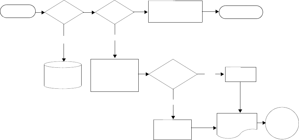
Cflowd
7750 SR OS Router Configuration Guide Page 431
Operation
Figure 29 depicts the basic operation of the cflowd feature. This sample flow is only used to
describe the basic steps that are performed. It is not intended to specify implementation.
Figure 29: Basic Cflowd Steps
1. As a packet ingresses a port, a decision is made to forward or drop the packet.
2. If the packet is forwarded, it is then decided if the packet should be sampled for
cflowd.
3. If a new flow is found, a new entry is added to the cache. If the flow already exists in
the cache, the flow statistics are updated.
4. If a new flow is detected and the maximum number of entries are already in the flow
cache, the earliest expiry entry is removed. The earliest expiry entry/flow is the next
flow that will expire due to the active or inactive timer expiration.
5. If a flow has been inactive for a period of time equal to or greater than the inactive
timer (default 15 sec.), then, depending on the format, if V5, the entry is removed from
the flow cache, or, if V8, further processing occurs.
6. If a flow has bee active for a period of time equal to or greater than the active timer
(default 30 min.), then depending on the format, if V5, the entry is removed from the
flow cache, or, if V8, further processing occurs.
copy of header sent to cflowd
HEADER
INFORMATION
PROCESSED
AND FLOW CACHE
UPDATED
INGRESS PORT FORWARD/
DROP ? SAMPLE? FINISH FORWARDING
PROCESS AND SEND
TO EGRESS PORT EGRESS PORT
drop
BIT BUCKET
NEW OR
EXISTING
FLOW
?
existing flow
new
flow ADD ENTRY
FLOW CACHE EXPORT
TO
COLLECTOR
UPDATE
ENTRY

Cflowd Overview
Page 432 7750 SR OS Router Configuration Guide
When a flow is exported from the cache, the collected data is sent to an external collector which
maintains an accumulation of historical data flows that network operators can use to analyze traffic
patterns.
Data is exported in one of two formats:
• Version 5 (V5) — V5 generates an export record for each individual flow captured.
• Version 8 (V8) — V8 aggregates multiple individual flows into an aggregate flow.
There are several different aggregate flow types including:
•AS matrix
• Destination prefix matrix
• Source prefix matrix
• Prefix matrix
• Protocol/port matrix.
V8 is an aggregated export format. As individual flows are aged out of the active flow cache, the
data is added to the aggregate flow cache for each configured aggregate type. Each of these
aggregate flows are also aged in a manner similar to the method the active flow cache entries are
aged. When an individual aggregate flow is aged out, it is sent to the external collector in the V8
record format.
Cflowd Filter Matching
In the filter-matching process, normally, every packet is matched against filter (access list) criteria
to determine acceptability. With cflowd, only the first packet of a flow is checked. If the first
packet is forwarded, an entry is added to the cflowd cache. Subsequent packets in the same flow
are then forwarded without needing to be matched against the complete set of filters. Specific
performance varies depending on the number and complexity of the filters.
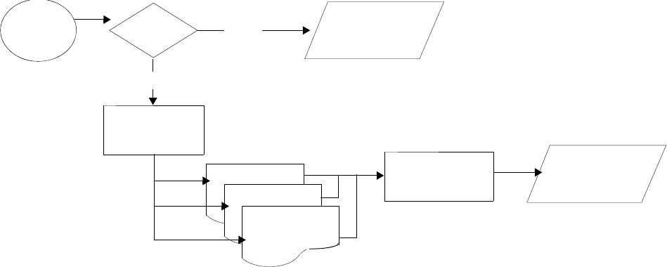
Cflowd
7750 SR OS Router Configuration Guide Page 433
Figure 30 depicts V5 and V8 flow processing.
Figure 30: V5 and V8 Flow Processing
1. As flows are exported from the active flow cache, the export format must be determined, either
V5 or V8.
2. If the export format is V5, no further processing is performed and the flow data is
accumulated to be sent to the external collector.
3. If the export format is V8, then the flow entry is added to one or more of the config-
ured aggregation matrices. Cflowd only records and sends flows that match the speci-
fied criteria.
As the entries within the aggregate matrices are aged out, they are accumulated to be sent
to the external flow collector in V8 format.
The sample rate and cache size are configurable values. The cache size default is 64K flow entries.
If a flow is not updated in the time configured (the default is 15 seconds) that flow is aged out of
the cache and accumulated to be exported to the collector (that is, a server collecting cflowd data).
A flow terminates when one of the following conditions is met:
• When the inactive timeout period expires. A flow is considered terminated when no
packets are seen for the flow for N seconds.
• When an active timeout expires. A flow terminates according to the time duration
regardless of whether or not there are packets coming in for the flow.
• When the cflowd cache is cleared.
• When other measures are met that apply to aggressively age flows as the cache becomes
too full (i.e., overflow percent).
DATA AGED
FROM ACTIVE
FLOW CACHE
V5 OR V8
FORMAT
V8
V5
FORMAT AND
SEND V5 RECORD
TO EXTERNAL
COLLECTOR
ADD ENTRY
V8 AGGREGATE
FLOW CACHE
V8 AGGREGATE
FLOW CACHE
V8 AGGREGATE
FLOW CACHE
AGE AGGREGATE
FLOWS
FORMAT AND
SEND V8 RECORD
TO EXTERNAL
COLLECTOR
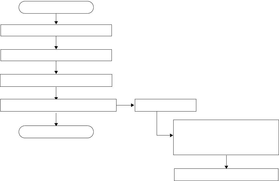
Cflowd Configuration Process Overview
Page 434 7750 SR OS Router Configuration Guide
Cflowd Configuration Process Overview
Figure 31 displays the process to configure Cflowd parameters.
Figure 31: Cflowd Configuration and Implementation Flow
TURN UP
START
CONFIGURE COLLECTOR(S)
SPECIFY ROUTER INTERFACE FOR COLLECTION ACL OR INTERFACE
ENABLE IP FILTER ENTRY FILTER SAMPLING
FOR CFLOWD INTERFACE MODE:
ENABLE INTERFACE-DISABLE-SAMPLE
APPLY FILTER TO INTERFACE
ENABLE CFLOWD
FOR CFLOWD ACL MODE:
IN AN IP-FILTER ENTRY:
CONFIGURE CFLOWD PARAMETERS
Cflowd
7750 SR OS Router Configuration Guide Page 435
Cflowd Configuration Components
Figure 32 displays the major components to configure Cflowd parameters.
Figure 32: Cflowd Configuration Components
• Active timeout — Specifies the time, in minutes, before an active flow is removed from
the active cache.
• Inactive timeout — Specifies the time, in seconds, that must elapse without a packet
matching a flow in order for the flow to be considered inactive and removed from the
active cache.
• Cache size — Specifies the maximum number of active flows to maintain in the flow
cache table. When the actual number of flows approaches the maximum cache size,
cflowd ages several flows with an accelerated timeout to ensure flow entry space is always
available.
• Overflow — Specifies the percentage of the flow cache entries removed when the
maximum number of entries is exceeded.
• Rate — Specifies the rate (N) at which traffic is sampled.
• Collector — Defines a flow data collector for cflowd data using an IP address and a port
number as identifiers. A maximum of 5 collectors can be configured.
• Aggregation — Components of this command specify the types of data to be aggregated.
• Autonomous system type — Specifies whether the autonomous system (AS) information
included in the flow data is based on the originating AS or peer AS.
CFLOWD
ACTIVE-TIMEOUT
CACHE-SIZE
INACTIVE-TIMEOUT
OVERFLOW
RATE
COLLECTOR
AGGREGATION
AUTONOMOUS-SYSTEM-TYPE
CONFIG
Cflowd Configuration Components
Page 436 7750 SR OS Router Configuration Guide
Figure 33 displays the components to specify router interface cflowd parameters.
Figure 33: Router Interface Cflowd Configuration Components
• Interface — A specific logical IP routing interface in which cflowd parameters can be
configured.
• Cflowd ACL — Cflowd can collect traffic flow samples according to filter parameters for
analysis.
• Cflowd interface — Cflowd can collect traffic flow samples according to interface
parameters for analysis.
Figure 34 displays the components to specify cflowd filter parameters.
Figure 34: IP Filter Cflowd Configuration Components
• IP filter — Specifies either a forward or a drop action for packets based on the specified
match criteria.
• Entry — Specifies a unique IP filter entry. Cflowd can be implemented and enabled on one
or more IP filter entries.
• Filter sample — Specifies that traffic matching the associated IP filter entry is sampled if
the IP interface is set to cflowd acl.
• Interface disable sample — Specifies that traffic matching the associated IP filter entry is
not sampled if the IP interface is set to cflowd interface mode.
CONFIG
ROUTER
INTERFACE
CFLOWD ACL
CFLOWD INTERFACE
CONFIG
FILTER
IP-FILTER
ENTRY
FILTER SAMPLE
INTERFACE DISABLE SAMPLE
Cflowd
7750 SR OS Router Configuration Guide Page 437
Configuration Notes
This section describes cflowd caveats.
• Cflowd is enabled globally.
• At least one collector must be configured and enabled.
• A cflowd option must be specified and enabled on a router interface.
• Sampling can only be enabled on either:
→An IP filter which is applied to a port or service.
→An interface on a port or service.
Cflowd
7750 SR OS Router Configuration Guide Page 439
Configuring Cflowd with CLI
This section provides information to configure cflowd using the command line interface.
Topics in this section include:
•Cflowd Configuration Overview on page 440
→Traffic Sampling on page 440
→Collectors on page 441
→Aggregation on page 441
•Basic Cflowd Configuration on page 446
•Common Configuration Tasks on page 447
→Enabling Cflowd on page 449
→Configuring Global Cflowd Parameters on page 450
→Configuring Cflowd Collectors on page 451
→Dependencies on page 453
→Enabling Cflowd on Interfaces and Filters on page 453
→Specifying Cflowd Options on an IP Interface on page 455
→Specifying Sampling Options in Filter Entries on page 457
•Cflowd Configuration Management Tasks on page 458
→Modifying Global Cflowd Components on page 459
→Modifying Cflowd Collector Parameters on page 460

Page 440 7750 SR OS Router Configuration Guide
Cflowd Configuration Overview
The 7750 SR OS implementation of cflowd supports the option to analyze traffic flow. The imple-
mentation also supports the use of traffic/access list (ACL) filters to limit the type of traffic that is
analyzed. Traffic blocked (dropped) by ACL filters is not sent to cflowd for analysis.
Traffic Sampling
Traffic sampling does not examine all packets received by a router. Command parameters allow
the rate at which traffic is sampled and sent for flow analysis to be modified. The default sampling
rate is every 1000th packet. Excessive sampling over an extended period of time, for example,
more than every 1000th packet, can burden router processing resources.
The following data is maintained for each individual flow in the active flow cache:
• Source IP address
• Destinations IP address
• Source port
• Destination port
• Input interface
• Output interface
• IP protocol
•TCP flags
• First timestamp (of the first packet in the flow)
• Last timestamp
• Source AS number (taken from BGP)
• Destination AS number (taken from BGP)

Cflowd
7750 SR OS Router Configuration Guide Page 441
Within the active flow cache, the following characteristics are used to identify an individual flow:
• Ingress interface
• Source IP address
• Destination IP address
• Source transport port number
• Destination transport port number
• IP protocol type
• IP TOS byte
The 7750 SR OS implementation allows you to enable cflowd either at the interface level or as an
action to a filter. By enabling cflowd at the interface level, all packets forwarded by the interface
are subject to cflowd analysis. By setting cflowd as an action in a filter, only packets matching the
specified filter are subject to cflowd analysis. This provides the network operator greater flexibility
in the types of flows that are captured.
Collectors
A collector defines the data flow for exporting sampled data from the cache. A maximum of 5
collectors can be configured. Each collector is identified by a unique IP address and UDP port
value. The parameters within a collector configuration can be modified or the defaults retained.
The autonomous-system-type command defines whether the autonomous system information
to be included in the flow data is based on the originating AS or external peer AS of the flow.
Aggregation
V8 aggregation allows for flow data to be aggregated into larger, less granular flows. Use
aggregation commands to specify the type of data to be collected. Only flows that match the
specified criteria are sent.
The following aggregation schemes are supported:
• AS matrix — Flows are aggregated based on source and destination AS and ingress and
egress interface.
• Protocol-port — Flows are aggregated based on the IP protocol, source port number, and
destination port number.
• Source prefix — Flows are aggregated based on source prefix and mask, source AS, and
ingress interface.
• Destination prefix — Flows are aggregated based on destination prefix and mask,
destination AS, and egress interface.
Page 442 7750 SR OS Router Configuration Guide
• Source-destination prefix — Flows are aggregated based on source prefix and mask,
destination prefix and mask, source and destination AS, ingress interface and egress
interface.
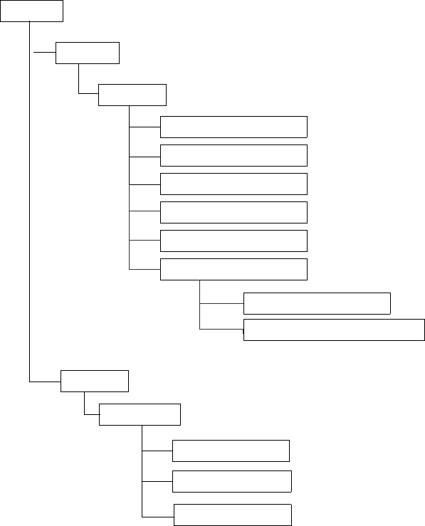
Cflowd
7750 SR OS Router Configuration Guide Page 443
Cflowd CLI Command Structure
The 7750 SR OS cflowd command structure is displayed in Figure 35. Cflowd configuration
commands are located under the config>cflowd context and the show commands are under
show>cflowd.
Figure 35: Cflowd Command Structure
CFLOWD
CONFIG
SHOW
CFLOWD
ACTIVE-TIMEOUT
CACHE-SIZE
COLLECTOR
ROOT
COLLECTOR
INTERFACE
STATUS
INACTIVE-TIMEOUT
OVERFLOW
RATE
AGGREGATION
AUTONOMOUS-SYSTEM-TYPE

Page 444 7750 SR OS Router Configuration Guide
List of Commands
Table 20 lists all the cflowd configuration commands indicating the configuration level at which
each command is implemented with a short command description. The cflowd command list is
organized in the following task-oriented manner:
•Configure cflowd parameters
•Configure collection parameters
Table 20: CLI Commands to Configure Cflowd Parameters
Command Description Page
Configure cflowd parameters
config> router>cflowd#
active-timeout Configures maximum amount of time before an active flow will be
removed from the active cache. 465
cache-size Specifies the maximum number of active flows to maintain in the
flow cache table. 466
inactive-timeout Specifies the amount of time, in seconds, that must elapse without a
packet matching a flow in order for the flow to be considered
inactive and removed from the active cache.
469
overflow Specifies the percentage of the flow cache entries removed when
the maximum number of entries is exceeded. 470
rate Specifies the rate (N) at which traffic is sampled. A packet is
sampled every N packets. 470
no shutdown Administratively enables cflowd. 469
Configure collection parameters
config> router>cflowd>collector#
collector Defines a flow data collector for cflowd data using an IP address
and a port number as identifiers. A maximum of 5 collectors can be
configured.
466
aggregation Configures the type of aggregation scheme(s). 466
as-matrix Specifies that the aggregation data should be based on autonomous
system (AS) information. 467
destination-prefix Specifies that the aggregation data is based on destination prefix
information. 467

Cflowd
7750 SR OS Router Configuration Guide Page 445
protocol-port Specifies that flows be aggregated based on the IP protocol, source
port number, and destination port number. 467
raw Configures raw flow data to be sent in version 5. 467
source-destination-
prefix
Configures cflowd aggregation based on source and destination
prefixes. 468
source-prefix Configures cflowd aggregation based on source prefix information. 468
autonomous-system-type Defines whether the autonomous system (AS) information included
in the flow data is based on the originating AS or peer AS. 468
description Creates a text description stored in the configuration file for a
configuration context. 468
no shutdown Administratively enables the cflowd collector. 469
Table 20: CLI Commands to Configure Cflowd Parameters (Continued)
Command Description Page
Page 446 7750 SR OS Router Configuration Guide
Basic Cflowd Configuration
This section provides information to configure cflowd and configuration examples of common
configuration tasks. In order to sample traffic, the minimal cflowd parameters that need to be
configured are:
• Cflowd must be enabled.
• At least one collector must be configured and enabled.
• Sampling must be enabled on either:
→An IP filter entry and applied to a service or an port.
→An interface applied to a port.
The following example displays a cflowd configuration.
ALA-1>config>cflowd# info detail
----------------------------------------------
active-timeout 30
cache-size 65536
inactive-timeout 15
overflow 1
rate 1000
collector 10.10.10.103:5
no aggregation
autonomous-system-type origin
no description
no shutdown
exit
no shutdown
----------------------------------------------
ALA-1>config>cflowd#

Cflowd
7750 SR OS Router Configuration Guide Page 447
Common Configuration Tasks
This section provides a brief overview of the tasks that must be performed to configure cflowd and
provides the CLI commands. In order to begin traffic flow sampling, cflowd must be enabled and
at least one collector must be configured.
Global Cflowd Components
The components common (global) to all instances of cflowd include the following parameters:
• Active timeout
• Inactive timeout
•Cache size
• Overflow
•Rate
Collector Components
Components that are common to all collector configurations include the following parameters:
• Aggregation
• Autonomous-system-type
• Description

Page 448 7750 SR OS Router Configuration Guide
Configuring Cflowd
Use the CLI syntax displayed below to perform the following tasks:
•Enabling Cflowd on page 449
•Configuring Global Cflowd Parameters on page 450
•Configuring Cflowd Collectors on page 451
•Enabling Cflowd on Interfaces and Filters on page 453
CLI Syntax: config>cflowd#
active-timeout minutes
cache-size num-entries
inactive-timeout seconds
overflow percent
rate sample-rate
collector ip-address[:port]
aggregation
as-matrix
destination-prefix
protocol-port
raw
source-destination-prefix
source-prefix
autonomous-system-type [origin | peer]
description description-string
no shutdown
no shutdown
Cflowd
7750 SR OS Router Configuration Guide Page 449
Enabling Cflowd
Cflowd is disabled by default. You must enter the no shutdown command to administratively
enable traffic sampling.
Use the following CLI syntax to enable cflowd:
CLI Syntax: config# cflowd
no shutdown
The following example displays the default values when cflowd is initially enabled. No collectors
or collector options are configured.
ALA-1>config# info detail
...
#------------------------------------------
echo "Cflowd Configuration"
#------------------------------------------
cflowd
active-timeout 30
cache-size 65536
inactive-timeout 15
overflow 1
rate 1000
no shutdown
exit
#------------------------------------------
ALA-1>config#
Page 450 7750 SR OS Router Configuration Guide
Configuring Global Cflowd Parameters
The following cflowd parameters apply to all instances where cflowd (traffic sampling) is enabled.
Use the following CLI commands to configure cflowd parameters:
CLI Syntax: config>cflowd#
active-timeout minutes
cache-size num-entries
inactive-timeout seconds
overflow percent
rate sample-rate
no shutdown
The following example displays cflowd configuration command usage:
Example: config>cflowd# active-timeout 20
config>cflowd# inactive-timeout 10
config>cflowd# overflow 10
config>cflowd# rate 100
The following example displays the common cflowd component configuration:
ALA-1>config>cflowd# info
#------------------------------------------
active-timeout 20
inactive-timeout 10
overflow 10
rate 100
#------------------------------------------
ALA-1>config>cflowd#
Cflowd
7750 SR OS Router Configuration Guide Page 451
Configuring Cflowd Collectors
To configure cflowd collector parameters, enter the following commands:
CLI Syntax: config>cflowd#
collector ip-address[:port]
aggregation
as-matrix
destination-prefix
protocol-port
raw
source-destination-prefix
source-prefix
autonomous-system-type [origin | peer]
description description-string
no shutdown
The following example displays collector and aggregation configuration command usage:
Example: config>cflowd# collector 10.10.10.1:2000
config>cflowd>collector$ autonomous-system-type peer
config>cflowd>collector# aggregation
config>cflowd>coll>agg# as-matrix
config>cflowd>coll>agg# raw
config>cflowd>coll>agg# description “AS info collector”
config>cflowd>coll>agg# exit
config>cflowd# collector 10.10.10.1:2000
config>cflowd>collector$ no shutdown
config>cflowd>collector# description "Neighbor collector"
config>cflowd>collector# aggregation
config>cflowd>coll>agg# protocol-port
config>cflowd>coll>agg# source-destination-prefix
config>cflowd>collector# no shutdown
config>cflowd>coll>agg# exit
Page 452 7750 SR OS Router Configuration Guide
The following example displays the basic cflowd configuration:
ALA-1>config>cflowd# info
-----------------------------------------
active-timeout 20
inactive-timeout 10
overflow 10
rate 100
collector 10.10.10.1:2000
aggregation
as-matrix
raw
exit
description "AS info collector"
exit
collector 10.10.10.2:5000
aggregation
protocol-port
source-destination-prefix
exit
autonomous-system-type peer
description "Neighbor collector"
exit
-----------------------------------------
ALA-1>config>cflowd#

Cflowd
7750 SR OS Router Configuration Guide Page 453
Enabling Cflowd on Interfaces and Filters
This section discusses the following cflowd configuration management tasks:
•Dependencies on page 453
•Specifying Cflowd Options on an IP Interface on page 455
→Interface Configurations on page 455
→Service Interfaces on page 456
•Specifying Sampling Options in Filter Entries on page 457
→Interface Configurations on page 455
Dependencies
In order for cflowd to be operational, the following requirements must be met:
• Cflowd must be enabled on a global level. If cflowd is disabled, any traffic sampling
instances are also disabled.
• At least one collector must be configured and enabled in order for traffic sampling to occur
on an enabled entity.
• If a specific collector UDP port is not identified then, by default, flows are sent to port
2055.
Cflowd can also be dependent on the following entity configurations:
•Interface Configurations on page 455
•Service Interfaces on page 456
•Filter Configurations on page 457
Depending on the combination of interface and filter entry configurations determine if and when
flow sampling occurs. Table 21 displays the expected results when specific features are enabled
and disabled.

Page 454 7750 SR OS Router Configuration Guide
Table 21: Cflowd Configuration Dependencies
Interface Setting router>interface
cflowd [acl | interface]
Setting
Command
ip-filter entry Expected Results
IP-filter mode ACL filter-sampled Traffic matching is sampled at
specified rate.
IP-filter mode ACL no filter-sampled No traffic is sampled on this
interface.
Interface mode or
cflowd not enabled on
interface
interface filter-sampled Command is ignored. No sampling
occurs.
IP-filter mode or
cflowd not enabled on
interface
ACL interface-
disable-sample
Command is ignored. No sampling
occurs.
Interface mode interface interface-
disable-sample
Traffic matching this IP filter entry
is not sampled.

Cflowd
7750 SR OS Router Configuration Guide Page 455
Specifying Cflowd Options on an IP Interface
When cflowd is enabled on an interface, all packets forwarded by the interface are subject to
analysis according to the global cflowd configuration and sorted according to the collector
configuration(s).
Refer to Table 21, Cflowd Configuration Dependencies, on page 454 for configuration
combinations.
To enable for filter traffic sampling, the following requirements must be met:
1. Cflowd must be enabled globally.
2. At least one cflowd collector must be configured and enabled.
3. On the IP interface being used, the interface>cflowd acl option must be selected.
(See Interface Configurations on page 455.) For configuration information, refer to the IP
Router Configuration Overview sections of the 7750 SR OS Router Configuration Guide.
4. On the IP filter being used, the entry>filter-sample option must be explicitly
enabled. The default is no filter-sample. (See Filter Configurations on page 457.)
5. The filter must be applied to a service or a port. The service or port must be enabled and
operational.
Interface Configurations
CLI Syntax: config>router>if#
cflowd {acl|interface}
no cflowd
Depending on the option selected, either acl or interface, cflowd extracts traffic flow samples
from an IP filter or an interface for analysis. All packets forwarded by the interface are analyzed
according to the cflowd configuration.
The acl option must be selected in order to enable traffic sampling on an IP filter. Cflowd
(filter-sample) must be enabled in at least one IP filter entry.
The interface option must be selected in order to enable traffic sampling on an interface. If
cflowd is not enabled (no cflowd) then traffic sampling will not occur on the interface.
Page 456 7750 SR OS Router Configuration Guide
Service Interfaces
CLI Syntax: config>service>vpls service-id# interface ip-int-name
cflowd {acl|interface}
When enabled on a service interface, cflowd collects routed traffic flow samples through a router
for analysis. Cflowd is supported on IES and VPRN services interfaces only. Layer 2 traffic is
excluded. All packets forwarded by the interface are analyzed according to the cflowd
configuration. On the interface level, cflowd can be associated with a filter (ACL) or an IP
interface.

Cflowd
7750 SR OS Router Configuration Guide Page 457
Specifying Sampling Options in Filter Entries
Packets are matched against filter entries to determine acceptability. With cflowd, only the first
packet of a flow is compared. If the first packet matches the filter criteria, then an entry is added to
the cflowd cache. Subsequent packets in the same flow are also sampled based on the cache entry.
Since a filter can be applied to more than one interface (when configured with a scope
template), the interface-disable-sample option is intended to enable or disable traffic
sampling on an interface-by-interface basis. The command can be enabled or disabled as needed
instead creating numerous filter versions.
When the cflowd interface option is configured in the config>router> interface
context, the following requirements must be met in order to enable traffic sampling on the specific
interface:
1. Cflowd must be enabled.
2. At least one cflowd collector must be configured and enabled.
3. The interface>cflowd interface option must be selected. For configuration
information, refer to the Filter Policy Overview sections of the 7750 SR OS Router
Configuration Guide.
4. The config>filter>ip-filter>entry>interface-disable-sample option
must be enabled (the default, no interface-disable-sample, must be explicitly
modified to interface-disable-sample).
5. The filter must be applied to a service or a port.
Filter Configurations
CLI Syntax: config>filter>ip-filter>entry#
[no] filter-sample
[no] interface-disable-sample
When a filter policy is applied to a service or port, sampling can be configured so that traffic
matching the associated IP filter entry is sampled when the IP interface is set to cflowd ACL mode
and the filter-sample command is enabled. If cflowd is either not enabled (no filter-
sample) or set to the cflowd interface mode, then sampling does not occur.
When the interface-disable-sample command is enabled, then traffic matching the
associated IP filter entry is not sampled if the IP interface is set to cflowd ACL mode.

Page 458 7750 SR OS Router Configuration Guide
Cflowd Configuration Management Tasks
This section discusses the following cflowd configuration management tasks:
•Modifying Global Cflowd Components on page 459
•Modifying Cflowd Collector Parameters on page 460
Use the following CLI syntax to modify cflowd parameters.
CLI Syntax: config>cflowd
active-timeout minutes
no active-timeout
cache-size num-entries
no cache-size
[no] collector ip-addr[:port]
[no] aggregation
[no] as-matrix
[no] destination-prefix
[no] protocol-port
[no] raw
[no] source-destination-prefix
[no] source-prefix
autonomous-system-type {origin | peer}
no autonomous-system-type
description description-string
no description
[no] shutdown
inactive-timeout seconds
no inactive-timeout
overflow percent
no overflow
rate sample-rate
no rate
[no] shutdown
Cflowd
7750 SR OS Router Configuration Guide Page 459
Modifying Global Cflowd Components
Cflowd parameter modifications apply to all instances where cflowd or traffic sampling is enabled.
Changes are applied immediately.
Use the following cflowd commands to modify global cflowd parameters:
CLI Syntax: config>cflowd#
active-timeout minutes
[no] active-timeout
cache-size num-entries
[no] cache-size
inactive-timeout seconds
[no] inactive-timeout
overflow percent
[no] overflow
rate sample-rate
[no] rate
[no] shutdown
The following example displays the cflowd command usage to modify configuration parameters:
Example: config>cflowd# active-timeout 60
config>cflowd# no inactive-timeout
config>cflowd# overflow 2
config>cflowd# rate 10
The following example displays the common cflowd component configuration:
ALA-1>config>cflowd# info
#------------------------------------------
active-timeout 60
overflow 2
rate 10
#------------------------------------------
ALA-1>config>cflowd#
Page 460 7750 SR OS Router Configuration Guide
Modifying Cflowd Collector Parameters
Use the following commands to modify cflowd collector and aggregation parameters:
CLI Syntax: config>cflowd#
[no] collector ip-address[:port]
[no] aggregation
[no] as-matrix
[no] destination-prefix
[no] protocol-port
[no] raw
[no] source-destination-prefix
[no] source-prefix
autonomous-system-type [origin | peer]
no autonomous-system-type
description description-string
no description
[no] shutdown
The following example displays collector and aggregation configuration command usage:
Example: config>cflowd# collector 10.10.10.1:2000
config>cflowd>collector# no aggregation
config>cflowd>collector# exit
config>cflowd# 10.10.10.1:2000
config>cflowd>collector$ no shutdown
config>cflowd>collector# aggregation
config>cflowd>coll>agg# no protocol-port
config>cflowd>coll>agg# no source-destination-prefix
config>cflowd>coll>agg# raw
config>cflowd>coll>agg# source-prefix
config>cflowd>coll>agg# exit
config>cflowd>collector# no autonomous-system-type
config>cflowd>collector# description "Test collector"
config>cflowd>collector# exit
Cflowd
7750 SR OS Router Configuration Guide Page 461
The following example displays the basic cflowd modifications:
ALA-1>config>cflowd# info
-----------------------------------------
active-timeout 60
overflow 2
rate 10
collector 10.10.10.1:2000
description "AS info collector"
exit
collector 10.10.10.2:5000
aggregation
source-prefix
raw
exit
description "Test collector"
exit
-----------------------------------------
ALA-1>config>cflowd#
Page 462 7750 SR OS Router Configuration Guide

Cflowd
7750 SR OS Router Configuration Guide Page 463
Cflowd Command Reference
Command Hierarchies
Configuration Commands
config
—[no] cflowd
—active-timeout minutes
—no active-timeout
—cache-size num-entries
—no cache-size
—[no] collector ip-address[:port]
—[no] aggregation
—[no] as-matrix
—[no] destination-prefix
—[no] protocol-port
—[no] raw
—[no] source-destination-prefix
—[no] source-prefix
—autonomous-system-type {origin | peer}
—no autonomous-system-type
—description description-string
—no description
—[no] shutdown
—inactive-timeout seconds
—no inactive-timeout
—overflow percent
—no overflow
—rate sample-rate
—no rate
—[no] shutdown
Show Commands
show — cflowd
— collector [ip-address[:port]] [detail]
— interface [ip-int-name | ip-address]
— status
Clear Commands
clear —cflowd
Cflowd Command Reference
Page 464 7750 SR OS Router Configuration Guide

Cflowd
7750 SR OS Router Configuration Guide Page 465
Cflowd Configuration Commands
Global Commands
cflowd
Syntax [no] cflowd
Context config>cflowd
Description This command creates the context to configure cflowd. The interface can be set to either sample all
packets (interface mode) or sample only packets matching an IP filter with an action of filter-sample.
The no form of this command disables cflowd.
Default no cflowd
active-timeout
Syntax active-timeout minutes
no active-timeout
Context config>cflowd
Description This command configures the maximum amount of time before an active flow is aged out of the
active cache. If an individual flow is active for this amount of time, the flow is aged out and a new
flow created.
Note: Existing flows do not inherit the new active-timeout value if this parameter is changed while
cflowd is active. The active-timeout value for a flow is set when the flow is first created in the active
cache table and does not change dynamically.
The no form of this command resets the inactive timeout back to the default value.
Default 30
Parameters minutes — The value expressed in minutes before an active flow is exported.
Values 1 — 600
Cflowd Configuration Commands
Page 466 7750 SR OS Router Configuration Guide
cache-size
Syntax cache-size num-entries
no cache-size
Context config>cflowd
Description This command specifies the maximum number of active flows to maintain in the flow cache table.
The no form of this command resets the number of active entries back to the default value.
Default 65536 (64K)
Parameters num-entries — The number of entries maintained in the cflowd cache.
Values 1000 — 131072
collector
Syntax [no] collector ip-addr[:port]
Context config>cflowd
Description This command defines a flow data collector for cflowd data. The IP address of the flow collector
must be specified. The UDP port number is an optional parameter. If it is not set, the default of 2055
is used. A maximum of 5 collectors can be configured.
The no form of this command removes the flow collector definition from the config and stops the
export of data to the collector. The collector needs to be shutdown to be deleted.
Default none
Parameters ip-addr — The IP address of the flow data collector in dotted decimal notation.
:port — The UDP port of flow data collector.
Default 2055
Values 0 — 65535
aggregation
Syntax [no] aggregation
Context config>cflowd>collector
Description This command configures the type of aggregation scheme to be exported.
Specifies the type of data to be aggregated and to the collector.
To configure aggregation, you must decide which type of aggregation scheme to configure:
autonomous system, destination prefix, protocol port, raw, source destination, or source prefix.
The no form of this command removes all aggregation types from the collector configuration.
Default no aggregation
Cflowd
7750 SR OS Router Configuration Guide Page 467
as-matrix
Syntax [no] as-matrix
Context config>cflowd>collector>aggregation
Description This command specifies that the aggregation data should be based on autonomous system (AS)
information. An AS matrix contains packet and byte counters for traffic from either source-
destination autonomous systems or last-peer to next-peer autonomous systems.
The no form of this command removes this type of aggregation from the collector configuration.
Default no as-matrix
destination-prefix
Syntax [no] destination-prefix
Context config>cflowd>collector>aggregation
Description This command specifies that the aggregation data is based on destination prefix information.
The no form removes this type of aggregation from the collector configuration.
Default none
protocol-port
Syntax [no] protocol-port
Context config>cflowd>collector>aggregation
Description This command specifies that flows be aggregated based on the IP protocol, source port number, and
destination port number.
The no form of this command removes this type of aggregation from the collector configuration.
Default none
raw
Syntax [no] raw
Context config>cflowd>collector>aggregation
Description This command configures raw (unaggregated) flow data to be sent in Version 5.
The no form of this command removes this type of aggregation from the collector configuration.
Default none
Cflowd Configuration Commands
Page 468 7750 SR OS Router Configuration Guide
source-destination-prefix
Syntax [no] source-destination-prefix
Context config>cflowd>collector>aggregation
Description This command configures cflowd aggregation based on source and destination prefixes.
The no form of this command removes this type of aggregation from the collector configuration.
Default none
source-prefix
Syntax [no] source-prefix
Context config>cflowd>collector>aggregation
Description This command configures cflowd aggregation based on source prefix information.
The no form of this command removes this type of aggregation from the collector configuration.
Default none
autonomous-system-type
Syntax autonomous-system-type {origin | peer}
no autonomous-system-type
Context config>cflowd>collector
Description This command defines whether the autonomous system (AS) information included in the flow data is
based on the originating AS or external peer AS of the routes.
The no form of this command resets the AS type to the default value.
Default autonomous-system-type origin
Parameters origin — Specifies that the AS information included in the flow data is based on the originating AS.
peer — Specifies that the AS information included in the flow data is based on the peer AS.
description
Syntax description description-string
no description
Context config>cflowd>collector
Description This command creates a text description stored in the configuration file for a configuration context.
The no form of this command removes the description string from the context.
Cflowd
7750 SR OS Router Configuration Guide Page 469
Default No description is associated with the configuration context.
Parameters description-string — The description character string. Allowed values are any string up to 80 charac-
ters long composed of printable, 7-bit ASCII characters. If the string contains special characters
(#, $, spaces, etc.), the entire string must be enclosed within double quotes.
shutdown
Syntax [no] shutdown
Context config>cflowd
config>cflowd>collector
Description This command administratively disables an entity. When disabled, an entity does not change, reset, or
remove any configuration settings or statistics.
The operational state of the entity is disabled as well as the operational state of any entities contained
within. Many objects must be shut down before they may be deleted.
The no form of this command administratively enables an entity.
Unlike other commands and parameters where the default state is not indicated in the configuration
file. The shutdown and no shutdown states are always indicated in system generated configuration
files.
inactive-timeout
Syntax inactive-timeout seconds
no inactive-timeout
Context config>cflowd
Description This command specifies the amount of time, in seconds, that must elapse without a packet matching a
flow in order for the flow to be considered inactive.
The no form of this command resets the inactive timeout back to the default of 15 seconds.
Note: Existing flows will not inherit the new inactive-timeout value if this parameter is changed
while cflowd is active. The inactive-timeout value for a flow is set when the flow is first created in the
active cache table and does not change dynamically.
Default 15
Parameters seconds — Specifies the amount of time, in seconds, that must elapse without a packet matching a
flow in order for the flow to be considered inactive.
Values 10 — 600
Cflowd Configuration Commands
Page 470 7750 SR OS Router Configuration Guide
overflow
Syntax overflow percent
no overflow
Context config>cflowd
Description This command specifies the percentage of the flow cache entries removed when the maximum
number of entries is exceeded. The entries removed are the entries that have not been updated for the
longest amount of time.
The no form of this command resets the number of entries cleared from the flow cache on overflow
to the default value.
Default 1 %
Parameters percent — Specifies the percentage of the flow cache entries removed when the maximum number of
entries is exceeded.
Values 1 — 50 percent
rate
Syntax rate sample-rate
no rate
Context config>cflowd
Description This command specifies the rate (N) at which traffic is sampled and sent for flow analysis. A packet
is sampled every N packets; for example, when sample-rate is configured as 1, then all packets are
sent to the cache. When sample-rate is configured as 100, then every 100th packet is sent to the
cache.
The no form of this command resets the sample rate to the default value.
Default 1000
Parameters sample-rate — Specifies the rate at which traffic is sampled.
Values 1 — 1000
Cflowd
7750 SR OS Router Configuration Guide Page 471
Show Commands
collector
Syntax collector [ip-addr[:port]] [detail]
Context show>cflowd
Description This command displays administrative and operational status of data collector configuration.
Parameters ip-addr — Display only information about the specified collector IP address.
Default all collectors
:port — Display only information the collector on the specified UDP port.
Default all UDP ports
Values 0 — 65535
detail — Displays details about either all collectors or the specified collector.
Output cflowd Collector Output — The following table describes the show cflowd collector output
fields:
Table 22: Show Cflowd Collector Output Fields
Label Description
Host Address The IP address of a remote Cflowd collector host to receive the
exported Cflowd data.
Port The UDP port number on the remote Cflowd collector host to
receive the exported Cflowd data.
AS Type The style of AS reporting used in the exported flow data.
origin — Reflects the endpoints of the AS path which the flow
is following.
peer — Reflects the AS of the previous and next hops for the
flow.
Admin The desired administrative state for this Cflowd remote collector
host.
Oper The current operational status of this Cflowd remote collector host.
Recs Sent The number of Cflowd records that have been transmitted to this
remote collector host.
Collectors The total number of collectors using this IP address.

Show Commands
Page 472 7750 SR OS Router Configuration Guide
Sample Output
ALA-1# show cflowd collector 10.10.10.103:5
=========================================================================
Cflowd Collectors
=========================================================================
Host Address Port AS Type Admin Oper Recs Sent
-------------------------------------------------------------------------
10.10.10.103 5 origin up down 0
-------------------------------------------------------------------------
Collectors : 1
=========================================================================
ALA-1#
Table 23: Show Cflowd Collector Detailed Output Fields
Label Description
Host Address The IP address of a remote Cflowd collector host to receive the
exported Cflowd data.
Port The UDP port number on the remote Cflowd collector host to receive
the exported Cflowd data.
Description A user-provided descriptive string for this Cflowd remote collector
host.
AS Type The style of AS reporting used in the exported flow data.
origin — Reflects the endpoints of the AS path which the flow is fol-
lowing.
peer — Reflects the AS of the previous and next hops for the flow.
Admin State The desired administrative state for this Cflowd remote collector host.
Oper State The current operational status of this Cflowd remote collector host.
Records Sent The number of Cflowd records that have been transmitted to this remote
collector host.
Last Changed The time when this row entry was last changed.
Last Pkt Sent The time when the last Cflowd packet was sent to this remote collector
host.

Cflowd
7750 SR OS Router Configuration Guide Page 473
ALA-1# show cflowd collector 10.10.10.103:5 detail
===============================================================
Cflowd Collectors
===============================================================
Address : 10.10.10.103
Port : 5
Description : Not Available
AS Type : origin
Admin State : up
Oper State : down
Records Sent : 0
Last Changed : 03/25/2005 02:44:02
Last Pkt Sent : No Pkts sent
Aggregation : None
===============================================================
ALA-1#
interface
Syntax interface [ip-addr | ip-int-name]
Context show>cflowd
Description Displays the administrative and operational status of the interfaces with cflowd enabled.
Parameters ip-addr — Display only information for the IP interface with the specified IP address.
Default all interfaces with cflowd enabled
ip-int-name — Display only information for the IP interface with the specified name.
Default all interfaces with cflowd enabled
Aggregation The bit mask which specifies the aggregation scheme(s) used to aggre-
gate multiple individual flows into an aggregated flow for export to this
remote host collector.
none — No data will be exported for this remote collector host.
raw — Flow data is exported without aggregation in version 5 format.
All other aggregation types use version 8 format to export the flow data
to this remote host collector.
Collectors The total number of collectors using this IP address.
Table 23: Show Cflowd Collector Detailed Output Fields (Continued)
Label Description

Show Commands
Page 474 7750 SR OS Router Configuration Guide
Output cflowd Interface Output — The following table describes the show cflowd interface output
fields.
Sample Output
B:sr-002# show cflowd interface
===============================================================================
Cflowd Interfaces
===============================================================================
Interface IP Address Mode Admin Oper
-------------------------------------------------------------------------------
To_Sr1 1.10.1.2/24 Interface Up Up
To_C2 1.12.1.2/24 Interface Up Up
To_Cisco_7600 1.13.1.2/24 Interface Up Up
To_E 1.11.1.2/24 Interface Up Up
To_G2 150.153.1.1/24 Interface Up Up
To_Sr1_Sonet 150.140.1.2/24 Interface Up Down
Main 120.1.1.1/24 Filter Down Down
New 120.2.1.1/24 Filter Up Up
-------------------------------------------------------------------------------
Interfaces : 8
===============================================================================
B:sr12-002#
status
Syntax status
Context show>cflowd
Description This command displays basic information regarding the administrative and operational status of
cflowd.
Output cflowd Status Output — The following table describes the show cflowd status output fields:
Label Description
Interface Displays the physical port identifier.
IP Address Displays the IP address.
Mode Displays the mode.
Admin Displays the administrative state of the interface.
Oper Displays the operational state of the interface.

Cflowd
7750 SR OS Router Configuration Guide Page 475
Sample Output
ALA-1>show>cflowd# status
====================================================
Cflowd Status
====================================================
Cflowd Admin Status : Enabled
Cflowd Oper Status : Disabled
Active Timeout : 30 minutes
Inactive Timeout : 15 seconds
Cache Size : 65536 entries
Overflow : 1%
Sample Rate : 1000
Active Flows : 0
Total Pkts Rcvd : 0
Total Pkts Dropped : 0
Aggregation Info : None
====================================================
ALA-1>show>cflowd# status
Table 24: Show Cflowd Status Output Fields
Label Description
Cflowd Admin Sta-
tus
The desired administrative state for this Cflowd remote collector host.
Cflowd Oper Status The current operational status of this Cflowd remote collector host.
Active Timeout The maximum amount of time, in minutes, before an active flow will be
exported. If an individual flow is active for this amount of time, the
flow is exported and a new flow is created.
Cache Size The maximum number of active flows to be maintained in the flow
cache table.
Overflow The percentage number of flows to be flushed when the flow cache size
has been exceeded.
Sample Rate The rate at which traffic is sampled and forwarded for Cflowd analysis.
one (1) — All packets are analyzed.
1000 (default) — Every 1000th packet is analyzed.
Active Flows The current number of active flows being collected.
Total Pkts Rcvd The rate at which traffic is sampled and forwarded for Cflowd analysis.
Total Pkts Dropped The total number of packets dropped.
Aggregation Info:
Type The type of data to be aggregated and to the collector.
Status enabled — Specifies that the aggregation type is enabled.
disabled — Specifies that the aggregation type is disabled.

Clear Commands
Page 476 7750 SR OS Router Configuration Guide
Clear Commands
cflowd
Syntax cflowd
Context clear
Description Clears the active and aggregation flow caches which are sending flow data to the configured collec-
tors. This action will trigger all the flows to be exported to the collector(s). The caches restart flow
data collection from a fresh state. This command also clears collector statistics, such as, Pkts Sent and
Flows Sent.

Standards and Protocols Page 715
Standards and Protocol Support
Standards Compliance
IEEE 802.1d Bridging
IEEE 802.1p/Q VLAN Tagging
IEEE 802.1s Multiple Spanning Tree
IEEE 802.1w Rapid Spanning Tree Protocol
IEEE 802.1x Port Based Network Access Control
IEEE 802.3 10BaseT
IEEE 802.3ad Link Aggregation
IEEE 802.3ae 10Gbps Ethernet
IEEE 802.3u 100BaseTX
IEEE 802.3x Flow Control
IEEE 802.3z 1000BaseSX/LX
Protocol Support
OSPF
RFC 1765 OSPF Database Overflow
RFC 2328 OSPF Version 2
RFC 2370 Opaque LSA Support
RFC 3101 OSPF NSSA Option
RFC 3137 OSPF Stub Router Advertisement
RFC 3630 Traffic Engineering (TE) Extensions to OSPF
Version 2
BGP
RFC 1397 BGP Default Route Advertisement
RFC 1965 Confederations for BGP
RFC 1997 BGP Communities Attribute
RFC 2385 Protection of BGP Sessions via MD5
RFC 2439 BGP Route Flap Dampening
RFC 2547bis BGP/MPLS VPNs
RFC 2796 BGP Route Reflection: Alternative to Ful-mesh
IBGP (previously RFC 1966)
draft-ietf-idr-rfc2796bis-02.txt.
RFC 2858 Multi-protocol Extensions for BGP
draft-ietf-idr-rfc2858bis-09.txt.
RFC 2918 Route Refresh Capability for BGP-4
RFC 3065 Confederations for BGP
draft-ietf-idr-rfc3065bis-05.txt.
RFC 3392 Capabilities Advertisement
RFC 4271 BGP-4 (previously RFC 1771)
RFC 4360 BGP Extended Communities Attribute
IS-IS
RFC 1142 OSI IS-IS Intra-domain Routing Protocol (ISO
10589)
RFC 1195 Use of OSI IS-IS for routing in TCP/IP & dual
environments
RFC 2763 Dynamic Hostname Exchange for IS-IS
RFC 2966 Domain-wide Prefix Distribution with Two-Level
IS-IS
RFC 2973 IS-IS Mesh Groups
RFC 3373 Three-Way Handshake for Intermediate System to
Intermediate System (IS-IS) Point-to-Point Adjacencies
RFC 3567 Interfmediate System to Intermediate System (IS-
IS) Cryptographic Authentication
RFC 3719 Recommendations for Interoperable Networks
using IS-IS
RFC 3784 Intermediate System to Intermediate System (IS-IS)
Extensions for Traffic Engineering (TE)
RFC 3787 Recommendations for Interoperable IP Networks
draft-ietf-isis-igp-p2p-over-lan-05.txt
LDP
RFC 3036 LDP Specification
RFC 3037 LDP Applicability
IPv6
RFC 1981 Path MTU Discovery for IPv6
RFC 2460 Internet Protocol, Version 6 (IPv6) Specification
RFC 2461 Neighbor Discovery for IPv6
RFC 2462 IPv6 Stateless Address Auto configuration
RFC 2463 Internet Control Message Protocol (ICMPv6) for
the Internet Protocol Version 6 Specification
Standards and Protocols
Page 716 Standards and Protocols
RFC 4644 Transmission of IPv6
Packets over Ethernet Networks
RFC 2529 Transmission of IPv6 over
IPv4 Domains without Explicit
Tunnels
RFC 2545 Use of BGP-4 Multi-
protocol Extension for IPv6
Inter-Domain Routing
RFC 2740 OSPF for IPv6
RFC 3587 IPv6 Global Unicast
Address Format
RFC 4007 IPv6 Scoped Address Archi-
tecture
RFC 4193 Unique Local IPv6 Unicast
Addresses
RFC 4291 IPv6 Addressing Architec-
ture
draft-ietf-ipv6-over-ppp-v2-02
draft-ietf-isis-ipv6-05
draft-ietf-isis-wg-multi-topology-xx.txt
Multicast
RFC 1112 Host Extensions for IP
Multicasting (Snooping)
RFC 2236 Internet Group Management
Protocol, (Snooping)
RFC 3376 Internet Group Management
Protocol, Version 3 (Snooping)
RFC 2362 Protocol Independent
Multicast-Sparse Mode (PIM-
SM)
RFC 3618 Multicast Source Discovery
Protocol (MSDP)
RFC 3446 Anycast Rendevous Point
(RP) mechanism using Protocol
Independent Multicast (PIM)
and Multicast Source Discovery
Protocol (MSDP)
Draft-ietf-pim-anycast-rp-03
draft-ietf-pim-sm-v2-new-11.txt
draft-ietf-mboned-msdp-mib-01.txt
MPLS
RFC 2702 Requirements for Traffic
Engineering over MPLS
RFC 3031 MPLS Architecture
RFC 3032 MPLS Label Stack
Encoding
RFC 4379 LSP Ping
RIP
RFC 1058 RIP Version 1
RFC 2082 RIP-2 MD5 Authentication
RFC 2453 RIP Version 2
RSVP-TE
RFC 2430 A Provider Architecture for
DiffServ & TE
RFC 3209 Extensions to RSVP for LSP
Tunnels
RFC 4090 Fast reroute Extensions to
RSVP-TE for LSP Tunnels
DIFFERENTIATED SERVICES
RFC 2474 Definition of the DS Field in
the IPv4 and IPv6 Headers
RFC 2597 Assured Forwarding PHB
Group
RFC 2598 An Expedited Forwarding
PHB
RFC 3140 Per-Hop Behavior
Identification Codes
TCP/IP
RFC 768 UDP
RFC 1350 The TFTP Protocol (Rev. 2)
RFC 791 IP
RFC 792 ICMP
RFC 793 TCP
RFC 826 ARP
RFC 854 Telnet
RFC 951 BootP
RFC 1519 CIDR
RFC 1542 Clarifications and
Extensions for the Bootstrap
Protocol
RFC 1812 Requirements for IPv4
Routers
RFC 2401 Security Architecture for the
Internet Protocol
draft-ietf-bfd-mib-00.txtBidirectional
Forwarding Detection Management
Information Base
draft-ietf-bfd-base-02.txtBidirectional
Forwarding Detection
draft-ietf-bfd-v4v6-1hop-02.txtBFD for
IPv4 and IPv6 (Single Hop)
VRRP
RFC 2787 Definitions of Managed
Objects for the Virtual Router
Redundancy Protocol
RFC 3768 Virtual Router Redundancy
Protocol
PPP
RFC 1332 PPP IPCP
RFC 1377 PPP OSINLCP
RFC 1638/2878PPP BCP
RFC 1661 PPP
RFC 1662 PPP in HDLC-like Framing
RFC 1989 PPP Link Quality
Monitoring
RFC 2615 PPP over SONET/SDH
RFC 1990 The PPP Multilink Protocol
(MP)
ATM
RFC 1626 Default IP MTU for use
over ATM AAL5, May 1994
RFC 2514 Definitions of Textual
Conventions and
OBJECT_IDENTITIES for
ATM Management, February
1999
RFC 2515 Definition of Managed
Objects for ATM Management,
February 1999
RFC 2684 Multiprotocol Encapsulation
over ATM Adaptation Layer 5,
September 1999
af-tm-0121.000 Traffic Management
Specification Version 4.1, March 1999
ITU-T Recommendation I.610 - B-ISDN
Operation and Maintenance Principles
and Functions version 11/95
ITU-T Recommendation I.432.1 - B-
ISDN user-network interface - Physical
layer specification: General
characteristics
GR-1248-CORE - Generic Requirements
for Operations of ATM Network
Elements (NEs). Issue 3 June 1996
GR-1113-CORE - Bellcore,
Asynchronous Transfer Mode (ATM)
and ATM Adaptation Layer (AAL)
Protocols Generic Requirements, Issue
1, July 1994
AF-ILMi-0065.000 Integrated Local
Management Interface (ILMI) Version
4.0
AF-TM-0150.00 Addendum to Traffic
Management v4.0 optional minimum
desired cell rate indication for UBR
DHCP
RFC 2131 Dynamic Host
Configuration Protocol
RFC 3046 DHCP Relay Agent
Information Option (Option 82)
RFC 1534 Interoperation between
DHCP and BOOTP
Standards and Protocols
Standards and Protocols Page 717
VPLS
draft-ietf-l2vpn-vpls-ldp-08.txtVirtual
Private LAN Services Using LDP
PSEUDO-WIRE
RFC 3985 Pseudo Wire Emulation
Edge-to-Edge (PWE3)
RFC 4385 Pseudo Wire Emulation
Edge-to-Edge (PWE3) Control
Word for Use over an MPLS
PSN
RFC 3916 Requirements for Pseudo-
Wire Emulation Edge-to-Edge
(PWE3)
draft-ietf-pwe3-atm-encap-10.txt
draft-ietf-pwe3-cell-transport-04.txt
draft-ietf-pwe3-ethernet-encap-11.txt
draft-ietf-pwe3-frame-relay-07.txt
draft-ietf-pwe3-control-protocol-17.txt
draft-ietf-l2vpn-vpws-iw-oam-00.txt
draft-ietf-pwe3-vccv-07.txt
draft-ietf-pwe3-oam-msg-map-04-txt
draft-ietf-l2vpn-arp-mediation-04.txt
draft-ietf-pwe3-iana-allocation-15.txt
draft-hart-pwe3-segmented-pw-vccv-
01.txt
SONET/SDH
GR-253-CORE SONET Transport
Systems: Common Generic Criteria.
Issue 3, September 2000
ITU-G.841 Telecommunication
Standardization Section of ITU,
Types and Characteristics of
SDH Networks Protection
Architecture, issued in October
1998 and as augmented by
Corrigendum1 issued in July
2002
GR-253-CORE - SONET Transport
Systems: Common Generic
Criteria. Issue 3, September
2000
RADIUS
RFC 2865 Remote Authentication Dial
In User Service
RFC 2866 RADIUS Accounting
SSH
draft-ietf-secsh-architecture.txtSSH
Protocol Architecture
draft-ietf-secsh-userauth.txt SSH
Authentication Protocol
draft-ietf-secsh-transport.txt SSH
Transport Layer Protocol
draft-ietf-secsh-connection.txt SSH
Connection Protocol
draft-ietf-secsh- newmodes.txt
SSH Transport Layer Encryption
Modes
TACACS+
draft-grant-tacacs-02.txt
NETWORK MANAGEMENT
ITU-T X.721: Information technology-
OSI-Structure of Management
Information
ITU-T X.734: Information technology-
OSI-Systems Management: Event
Report Management Function
M.3100/3120 Equipment and
Connection Models
TMF 509/613 Network Connectivity
Model
RFC 1157 SNMPv1
RFC 1657 BGP4-MIB
RFC 1724 RIPv2-MIB
RFC 1850 OSPF-MIB
RFC 1907 SNMPv2-MIB
RFC 2011 IP-MIB
RFC 2012 TCP-MIB
RFC 2013 UDP-MIB
RFC 2096 IP-FORWARD-MIB
RFC 2138 RADIUS
RFC 2206 RSVP-MIB
RFC 2452 IPv6 Management
Information Base for the
Transmission Control Protocol
RFC 2454 IPv6 Management
Information Base for the User
Datagram Protocol
RFC 2465 Management Information
Base for IPv6: Textual
Conventions and General Group
RFC 2558 SONET-MIB
RFC 2571 SNMP-FRAMEWORK-
MIB
RFC 2572 SNMP-MPD-MIB
RFC 2573 SNMP-TARGET-&-
NOTIFICATION-MIB
RFC 2574 SNMP-USER-BASED-SM-
MIB
RFC 2575 SNMP-VIEW-BASED-
ACM-MIB
RFC 2576 SNMP-COMMUNITY-MIB
RFC 2665 EtherLike-MIB
RFC 2819 RMON-MIB
RFC 2863 IF-MIB
RFC 2864 INVERTED-STACK-MIB
RFC 2987 VRRP-MIB
RFC 3014 NOTIFICATION-LOG-
MIB
RFC 3273 HCRMON-MIB
draft-ietf-disman-alarm-mib-04.txt
draft-ietf-ospf-mib-update-04.txt
draft-ietf-mpls-lsr-mib-06.txt
draft-ietf-mpls-te-mib-04.txt
draft-ietf-mpls-ldp-mib-07.txt
draft-ietf-isis-wg-mib-05.txt
IANA-IFType-MIB
IEEE8023-LAG-MIB
Proprietary MIBs
TIMETRA-APS-MIB.mib
TIMETRA-ATM-MIB.mib
TIMETRA-BGP-MIB.mib
TIMETRA-CAPABILITY-7750-
V4v0.mib
TIMETRA-CFLOWD-MIB.mib
TIMETRA-CHASSIS-MIB.mib
TIMETRA-CLEAR-MIB.mib
TIMETRA-FILTER-MIB.mib
TIMETRA-GLOBAL-MIB.mib
TIMETRA-IGMP-MIB.mib
TIMETRA-ISIS-MIB.mib
TIMETRA-LAG-MIB.mib
TIMETRA-LDP-MIB.mib
TIMETRA-LOG-MIB.mib
TIMETRA-MIRROR-MIB.mib
TIMETRA-MPLS-MIB.mib
TIMETRA-NG-BGP-MIB.mib
TIMETRA-OAM-TEST-MIB.mib
TIMETRA-OSPF-MIB.mib
TIMETRA-OSPF-V3-MIB.mib
TIMETRA-PIM-MIB.mib
TIMETRA-PORT-MIB.mib
TIMETRA-PPP-MIB.mib
TIMETRA-QOS-MIB.mib
TIMETRA-RIP-MIB.mib
TIMETRA-ROUTE-POLICY-MIB.mib
TIMETRA-RSVP-MIB.mib
TIMETRA-SECURITY-MIB.mib
TIMETRA-SERV-MIB.mib
TIMETRA-SUBSCRIBER-MGMT-
MIB.mib
TIMETRA-SYSTEM-MIB.mib
TIMETRA-TC-MIB.mib
TIMETRA-VRRP-MIB.mib
Standards and Protocols
Page 718 Standards and Protocols
TIMETRA-VRTR-MIB.mib
7750 SR OS Router Configuration Guide Page 481
Index
C
Cflowd
overview 430
collectors 430
filter matching 432
operation 431
V5 and V8 flow processing 433
configuring
basic 446
collectors 441, 451
enabling 449
global parameters 450
interfaces and filters 453
IP interfaces 455
overview 440
sampling options 457
traffic sampling 440
management tasks 458
command reference 463
F
Filters
overview 276
applying filter
to network ports 293
to SAP 293
entities 278
entries 277
filter entry ordering 291
filter types
IP 276, 286
IPv6 276
MAC 276, 287, 294
matching criteria
DSCP values 288
IP 286
IP option values 290
MAC 287
packets 286
policies 277
policy entries 277
port-based filtering 276
redirect policies 278
scope 285, 294
services 278
configuring
basic 308
IP filter policy 310, 317
MAC filter policy 320
redirect policy 329
applying
to network ports 327
management tasks 336
I
IP Router
overview 20
autonomous systems 23
confederations 24
interfaces 20
network 20
system 21
IP addresses 22
address range 22
Router ID 22
configuring
autonomous systems 75
basic 48
command reference 79
confederations 73
interfaces 51
IP address range 71
network interface 42
overview 42
router ID 72
service management tasks 76
system interface 42
system name 49
S
Standards & Protocols
proprietary MIBS 479
protocols 477
standards compliance 477
Index
Page 482 7750 SR OS Router Configuration Guide
V
VRRP
overview 170
components 171
IP address owner 171
IP addresses 172
owner and non-owner 173
virtual router 171
virtual router backup 173
virtual router master 172
VRID 174
configuring
basic 204
command reference 223
IES parameters 211
non-owner 212
owner 214
management tasks 219
overview 196
router interface 208, 215
non-owner 216
owner 218
VRRP policy parameters 209
