Alcatel USA 0101 Spread Spectrum Wireless ADSL Router User Manual Manual
Alcatel USA Marketing, Inc. Spread Spectrum Wireless ADSL Router Manual
Manual

3EC 17766 AAAA TCZZA Ed. 01
SPEED TOUCH
WIRELESS
User Manual

3EC 17766 AAAA TCZZA Ed. 01
2/ 362
Status Released
Change Note BD F aa -PreRL
Short Title CD-UG STWire R1.0
All rights reserved. Passing on and copying of this
document, use and communication of its contents
not permitted without written authorization from Alcatel.

Contents
3EC 17766 AAAA TCZZA Ed. 01 3/ 362
Contents
1 Speed Touch Wireless Quick Guide 13...................................
1.1 Get Acquainted with your Speed Touch Wireless 14...................
1.2 Speed Touch Wireless Installation 16................................
1.2.1 What you Need 17......................................
1.2.2 STWireless Connections 18...............................
1.2.3 Check your Service Provider's Offering 21..................
1.2.4 Select an STWireless Packet Service 22.....................
1.2.5 Configure your STWireless (If Necessary) 23.................
1.2.6 Surf the Internet 24......................................
1.2.7 Detailed STWireless Information 25........................
2 Wiring Guide - ADSL, Power and Console 29............................
2.1 Locating Ports 30.................................................
2.2 Connecting the ADSL Port 31.......................................
2.3 Connecting the Power Adapter 32...................................
2.4 Connecting the Serial Port (Optional) 33.............................
3 Wiring Guide - Network Connections 35................................
3.1 Connecting Wireless LAN 36.......................................
3.2 LAN Cables 39...................................................
3.3 Connecting Wired Ethernet (Optionally) 40...........................
3.3.1 The Ethernet Port on your STWireless 41....................
3.3.2 Wired Single PC Connection 42...........................
3.3.3 Wired Ethernet LAN 43..................................
3.4 Wired Ethernet vs. WLAN Connectivity 44............................
4 Data Services - Packet Services 47......................................
4.1 Supported Packet Services 48.......................................
4.2 Packet Services at a Glance 49.....................................
4.3 Internet & Corporate Intranet Access vs. LANĆtoĆLAN Interconnection 52..
4.4 Direct Networking vs. DialĆup Networking 53.........................
4.5 ADSL Modem vs. ADSL Gateway 55.................................
4.5.1 ADSL Modem Model 56..................................
4.5.2 ADSL Gateway Model 57.................................
5 Data Services - Transparent Bridging 59................................
5.1 Preparatory Steps 60..............................................
5.2 Using Bridging 62................................................
5.3 Bridging Configuration 63.........................................
5.3.1 Bridging Phonebook Entries 64............................

Contents
3EC 17766 AAAA TCZZA Ed. 01
4/ 362
5.3.2 Bridging Entries 65......................................
5.4 Advanced Bridging Concepts 69....................................
5.4.1 STWireless Bridge Operation 70...........................
5.4.2 STWireless 'Bridge Data' Web Page 73.....................
6 Data Services - MAC Encapsulated Routing 75...........................
6.1 Preparatory Steps 76..............................................
6.2 Using MER 77....................................................
6.3 MER Configuration 78.............................................
6.3.1 MER Phonebook Entries 79...............................
6.3.2 MER Entries 80..........................................
6.4 Advanced MER Concepts 86........................................
7 Data Services - PPPoAĆtoĆPPTP Relaying 89..............................
7.1 Preparatory Steps 90..............................................
7.2 Configuring and Using a PPTP Connection 92........................
7.2.1 Preparing your PC for PPPoA/PPTP 93......................
7.2.2 Using PPTP towards your STWireless 94....................
7.3 Example : MS Windows 98 DialĆUp Networking 95....................
7.3.1 Create a New DialĆUp Networking Icon 96.................
7.3.2 Create a Shortcut on your Desktop (Optional) 99............
7.3.3 Open a PPPoA/PPTP DialĆUp Session 100....................
7.3.4 Close a PPPoA/PPTP DialĆUp Session in Use 102..............
7.4 PPPoA/PPTP Configuration 103......................................
7.4.1 PPPoA/PPTP Phonebook Entries 104.........................
7.4.2 PPPoA/PPTP Active Connections 105.........................
7.5 Customizing PPPoA/PPTP Connections 108............................
7.5.1 PPPoA/PPTP Phonebook Entries 109.........................
7.5.2 Single Destination 110....................................
7.5.3 Multiple Destinations 111..................................
7.5.4 Restrictions on Using Specific Virtual Channels 115............
7.5.5 PPTP Profiles 116.........................................
7.6 Advanced PPPoA/PPTP Concepts 117.................................
7.6.1 PointĆtoĆPoint Tunneling 118...............................
7.6.2 Local Tunneling 119......................................
7.6.3 PPPoAĆtoĆPPTP Relaying (PPPoA/PPTP) 120....................
7.6.4 Simultaneous PPPoA/PPTP Sessions 121......................
8 Data Services - PPP & IP Routing 123.....................................
8.1 Preparatory Steps 124..............................................
8.2 Using PPP & IP Routing 125.........................................
8.3 PPP Configuration 127..............................................
8.3.1 PPP Phonebook Entries 128................................
8.3.2 PPP Entries 129..........................................

Contents
3EC 17766 AAAA TCZZA Ed. 01 5/ 362
8.4 PPP Entry Configuration 133.........................................
8.4.1 The PPP Configuration Web Page 134.......................
8.4.2 Link Related Configuration 135.............................
8.4.3 Security Related Configurations 136.........................
8.4.4 IP Routing Related Configurations 137.......................
8.4.5 Connection Related Configuration 141......................
8.4.6 NAPT and PPP & IP Routing 144............................
8.4.7 NAPT and STWireless Transparency 145.....................
9 Data Services - Classical IP & IP Routing 149..............................
9.1 Preparatory Steps 150..............................................
9.2 CIP Configuration for a LIS 151......................................
9.2.1 General CIP Configuration Procedure 152...................
9.2.2 Retrieving LIS Parameters 153..............................
9.2.3 Implicit Assignment Mechanism 154........................
9.2.4 Explicit Assignment Mechanism 155.........................
9.2.5 Configuring the STWireless for CIP 156......................
9.2.6 Adding Appropriate Routes to the Routing Tables 157..........
9.2.7 Example Configuration 159................................
9.3 Using CIP & IP Routing 161.........................................
9.4 CIP Configuration 162..............................................
9.4.1 CIP Phonebook Entries 163................................
9.4.2 CIP Entries 164..........................................
9.5 Advanced CIP Configurations 170....................................
9.5.1 Configuring Multiple CIP PVCs 171.........................
9.5.2 Creating Multiple CIP Members. 173........................
10 Networking Services - ATM 177..........................................
10.1 The ATM Packet Switching Technology 178.............................
10.1.1 ATM Parameters 179......................................
10.1.2 ATM and the STWireless 180...............................
10.1.3 ATM and Interfaces 181...................................
10.2 The Speed Touch Wireless Phonebook 182............................
10.2.1 The STWireless 'Phonebook' Web Page 183..................
10.2.2 Using the Phonebook 187.................................
10.2.3 AutoPVC and the Phonebook 190...........................
11 Networking Services - IP 193............................................
11.1 General IP Information 194.........................................
11.1.1 IP Addresses and Subnet Masks 195........................
11.1.2 Private vs. Public Addresses 197............................
11.1.3 Choosing an IP Address 199...............................
11.1.4 Dynamic IP Address Configuration: DHCP 201...............
11.2 Packet Services and IP Addressing 202................................
11.2.1 Transparent Bridging and IP Addresses 203.................

Contents
3EC 17766 AAAA TCZZA Ed. 01
6/ 362
11.2.2 MER and IP Addresses 205................................
11.2.3 PPPoAĆtoĆPPTP Relaying and IP Addresses 206................
11.2.4 PPP & IP Routing and IP Addresses 207......................
11.3 Speed Touch Wireless and IP Addressing 208..........................
11.3.1 STWireless IP Address Types 209............................
11.3.2 Static IP Address Configuration 211.........................
11.3.3 Dynamic IP Address Configuration: DHCP 214...............
11.3.4 Configuring the STWireless DHCP Server 218................
11.4 IP Routing 222.....................................................
11.4.1 The STWireless IP Router 223..............................
11.4.2 Configuring the STWireless IP Routing Table 225..............
12 Networking Services - DNS 229..........................................
12.1 Speed Touch Wireless DNS Resolving 230.............................
12.2 Configuring the Speed Touch Wireless DNS Server 233.................
13 Networking Services - Firewalling 235...................................
13.1 Operation of the Firewall 236.......................................
13.2 Firewall Model 237................................................
13.3 Firewall Actions 239................................................
13.4 Firewall Criteria 240...............................................
13.5 Firewalling and NAPT 242..........................................
13.6 Firewall Configuration 243..........................................
13.7 Firewall Configuration Examples 244.................................
14 Wireless LAN Services - WLAN Configuration 249........................
15 Maintenance - Software Upgrade 255....................................
15.1 Upload Software from a PC 256.....................................
15.2 Software Download 261............................................
16 Maintenance - Speed Touch Wireless Security 263........................
17 Maintenance - Lost Speed Touch Wireless 267............................
17.1 PingĆofĆLife 268...................................................
17.2 Speed Touch Wireless Reset 271.....................................
17.2.1 BrowseĆtoĆDefaults 272...................................
17.2.2 PingĆtoĆDefaults 273......................................
17.2.3 SwitchĆtoĆDefaults 274....................................
18 Maintenance - Speed Touch Wireless Web Interface 275..................
18.1 Web Interface Preconditions 276.....................................
18.1.1 Disabling Proxy Servers 277................................
18.1.2 Disabling Proxying for Local IP Addresses 278................
18.2 Browsing to the Web Pages 279......................................

Contents
3EC 17766 AAAA TCZZA Ed. 01 7/ 362
18.3 Web Page Structure 281............................................
19 Maintenance - Speed Touch Wireless Command Line Interface 285........
19.1 CLI via the Web Pages 286..........................................
19.2 Native CLI Access 289..............................................
19.2.1 CLI through a Telnet Session 290...........................
19.2.2 CLI via Serial Access 294..................................
19.2.3 CLI Command Basics 295.................................
Abbreviations 299............................................................
AppendixA Troubleshooting 301.........................................
AppendixB ADSL Connectivity 303.......................................
AppendixC Microsoft DialĆUp Networking 311............................
AppendixD STWireless Layout and Behaviour 331.........................
AppendixE STWireless Original Settings 335..............................
AppendixF Hardware Reference 345.....................................
AppendixG Wall Fixing Assembly 353....................................
AppendixH Safety and Agency Regulatory Notices 355....................

Contents
3EC 17766 AAAA TCZZA Ed. 01
8/ 362

9/ 362
3EC 17766 AAAA TCZZA Ed. 01
Welcome to the Speed Touch Wireless
Welcome to the Alcatel Speed TouchWireless Asymmetric Digital Subscriber
Line (ADSL) router.
With the Alcatel Speed TouchWireless ADSL router, surfing the Internet, downloading
files and interconnecting computer networks become a whole new experience.
With download speeds up to 8 Mega bits per seconds (Mbps) the Speed Touch
Wireless is around 200 times faster than present day modems. This superior Alcatel ADSL
technology outperforms all similar products on the market.
Your Speed TouchWireless provides the brandĆnew Wireless LAN (WLAN) technology.
With Speed TouchWireless's WLAN solution, users can access other members of your
(W)LAN, and surf the Internet, without using any wire to connect.
Users are not bound to a fixed location in the building anymore, and enlarging the
network can happen without the need of expensive wiring installation.
Next to the ADSL router part, for the management of your wired and/or Wireless Ethernet
environment, your Speed TouchWireless features also a complete toolbox for excellent
Local Area Network (LAN) performance. Among others the most important are a DNS
server, a DHCP server, IP Routing. On top, a programmable firewall allows you to shield
your local network from the Wide Area Network (WAN) and to protect your resources from
intruders.

Safety instructions
Trademark
s
Terminolog
y
Service Provider
10 / 362 3EC 17766 AAAA TCZZA Ed. 01
Prior to connecting the Speed TouchWireless , read the Safety
Instructions in appendix H.
The following words and symbols mark special messages
throughout this document:
WARNING: indicates that failure to follow the directions could
cause bodily harm or loss of life.
CAUTION: indicates that failure to follow the directions could
result in damage to equipment or loss of information.
The following trademarks are used in this document:
"Speed Touchis a trademark of the Alcatel Company
"Netscapeand Netscape Navigatorare registered
trademarks of Netscape Communications Corporation
"Windowsand Internet Explorerare trademarks of
Microsoft Corporation
"Appleand MACOS are registered trademarks of Apple
Computer Inc.
"UNIXis a registered trademark of UNIX System
Laboratories, Inc.
"Ethernetis a trademark of Xerox Corporation.
For readability, the Speed TouchWireless will be referred to as
STWireless further in this User Manual.
For readability, Service Provider (SP) will refer to all instances,
responsible for your ADSL connections, i.e. ADSL Service
Provider (ASP), Internet Service Provider (ISP), Corporate, etc.
CAUTION
WARNING

PC, workstation
,
terminal, ...
LAN, network, WLAN
Disclaime
r
User Manual updates
11 / 362
3EC 17766 AAAA TCZZA Ed. 01
For readability, PC will refer to all involved computer devices,
which are able to interact with the STWireless, i.e. (portable)
Personal Computer (PC), workstation, (remote) terminal, etc.
For the STWireless there is no difference between wired Ethernet
connectivity and Wireless LAN (WLAN) connectivity. Therefore,
both will be referred to as (W)LAN.
All examples throughout this document refer to :
"Net 10" IP addresses for local network configurations
"VPI 0, or VPI 8 to identify the Virtual Path (VP) on the ADSL
line.
However, your SP might prefer other values.
Due to the continuous evolution of the Alcatel ADSL technology,
existing products are often upgraded. Alcatel documentation
changes accordingly.
For more information on the newest technological breakdowns
and documents, please consult our Alcatel web site at:
http://www.alcatel.com
http://www.alcateldsl.com

12 / 362 3EC 17766 AAAA TCZZA Ed. 01

Aim of this Quick Guide
In this chapte
r
1 Speed Touch Wireless Quick Guide
13 / 362
3EC 17766 AAAA TCZZA Ed. 01
1 Speed Touch Wireless Quick Guide
Use this chapter to quickly connect your STWireless to the
Internet.
Topic See
Get Acquainted with your STWireless 1.1
STWireless Installation 1.2

Delivery chec
k
Damaged or missing
items
Other materials
1 Speed Touch Wireless Quick Guide
14 / 362 3EC 17766 AAAA TCZZA Ed. 01
1.1 Get Acquainted with your Speed Touch Wireless
Check your STWireless package for the following items:
"The Speed TouchWireless
"1 Power supply adapter with 2m (6.56ft.) connecting cable
"2m Ethernet/ATMF straightĆthrough cable (RJ45/RJ45)
"2m ADSL cable (RJ11/RJ11, RJ14/RJ14)
"1 Wall mounting assembly
"1 Velcro sticker for the wall mounting assembly
"2 Screws and 2 wall plug for the wall mounting assembly
"This User Manual, either in hard copy format, or on CDĆrom.
In the event of damaged or missing items, contact your local
product dealer for further instructions.
Your STWireless shipping carton may also include release notes,
safety and conformity declarations, and other materials.

Your STWireless
POTS vs. ISDN
Wall mounting the
STWireles
s
1 Speed Touch Wireless Quick Guide
15 / 362
3EC 17766 AAAA TCZZA Ed. 01
Your STWireless ADSL router is presented in a slim line box:
For a detailed information and a LED description, refer to
Appendix D.
Ensure you have the correct STWireless:
"APOTSSTWireless, connecting to an analog POTS line
"An ISDN STWireless, connecting to a digital ISDN line.
See the marking label to identify your STWireless.
To avoid damage to your equipment, use only the appropriate
STWireless.
Part of the packaging is a wall mounting assembly with
accompanying screws and wall plugs.
For instructions to prepare the STWireless and wall mounting
assembly for use, refer to appendix G.

Aim of this section
In this section
1 Speed Touch Wireless Quick Guide
16 / 362 3EC 17766 AAAA TCZZA Ed. 01
1.2 Speed Touch Wireless Installation
Execute the steps in this section and in noĆtime you are on the
Internet.
Topic See
What you Need 1.2.1
STWireless Connections 1.2.2
Check your SP's Service Offerings 1.2.3
Select an STWireless Packet Service 1.2.4
Configure your STWireless (If Necessary) 1.2.5
Surf the Internet 1.2.6
Detailed STWireless Information 1.2.7

ADSL and telephone
servic
e
Wireless LAN
Ethernet por
t
Accessing the
STWireles
s
1 Speed Touch Wireless Quick Guide
17 / 362
3EC 17766 AAAA TCZZA Ed. 01
1.2.1 What you Need
ADSL service must be enabled on your telephone line.
You need a central splitter, or distributed filters for decoupling
ADSL, and telephone signals.
For more information, refer to Appendix B.
For wireless LAN connectivity:
"The (portable) PCs, intended to be connected via the
STWireless need a WLAN networking adapter (WLANĆNIC).
Each WLAN client adapter must be:
"Compliant to 802.11b Direct Sequencing Spread
Spectrum (DSSS)
"WECA WiĆFi certified to ensure smooth interoperability.
To use the 10BaseĆT Ethernet port you need at least:
"One PC with an Ethernet 10BaseĆT PCĆNetwork Interface
Card (NIC) installed.
"For local networking, a 10BaseĆT hub (if needed), and the
necessary connection cables.
For local configuration via HTTP/HTML, you need:
"A TCP/IP protocol suite
"A Web browser.
For native Command Line Interface (CLI) you need:
"A serial cable
"An ASCII terminal (VT100), or a PC with ASCII terminal
emulation.

You must connec
t
ADSL port (Line)
Power port (DC)
Turn on you
r
STWireles
s
1 Speed Touch Wireless Quick Guide
18 / 362 3EC 17766 AAAA TCZZA Ed. 01
1.2.2 STWireless Connections
"The ADSL Port (Line)
"The Power Port (DC).
After performing these steps you can turn on your STWireless.
Proceed then with connecting:
"Your WLAN clients
"Optionally the Ethernet Port (10BaseĆT)
Use the included ADSL cable to wire the STWireless's Line port to
your ADSL wall outlet.
Refer to section 2.2 for more information.
Only use the included power adapter to source your STWireless.
The STWireless should be operated only from the type of power
source, indicated on its marking label.
Refer to section 2.3 for more information.
If you are not sure of the regional power conditions, check the
adapter's specifications in section F.3, and your local power
company.
Use the power switch on the STWireless back panel to turn on
your STWireless.
Refer to section D.3 for more information.

Connecting WLAN
client
s
Optionally Etherne
t
port (10BaseĆT)
Note
1 Speed Touch Wireless Quick Guide
19 / 362
3EC 17766 AAAA TCZZA Ed. 01
"Preconditions:
Make sure your STWireless is turned on and finished its
Power On Self Test (POST).
The (portable) PCs, intended to be connected to the
STWireless, must have a WLAN adapter readily installed,
and must be configured as DHCP client.
"Joining the STWireless WLAN network
As soon as the WLAN adapter detected the presence of the
STWireless WLAN network, you must push the 'WLAN' button
on the STWireless's back panel to allow the WLAN adapter
to join the STWireless WLAN network.
Repeat this procedure for each (portable) PC you want to join
the STWireless WLAN network.
Refer to section 3.1 for more information.
Next to the WLAN clients, a 10BaseĆT Ethernet port on the back
panel of the STWireless allows wired Ehternet connectivity.
Use the included LAN cable to wire your PC's Ethernet port to
STWireless's Ethernet interface.
Refer to section 3.3 for more information.
There is no difference between wired Ethernet and WLAN
connections for the STWireless, i.e. all network configurations are
equally valid for both.
Therefore, both are referred to as (W)LAN.
Refer to section 3.3 for more information.
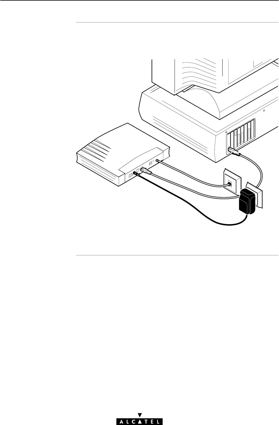
Check your wiring
1 Speed Touch Wireless Quick Guide
20 / 362 3EC 17766 AAAA TCZZA Ed. 01
After you finished wiring the STWireless, the result should
resemble the following figure:
Note: WLAN client PCs are not shown in the above figure.

Service offering
Default STWireless
VPI/VCI settings
1 Speed Touch Wireless Quick Guide
21 / 362
3EC 17766 AAAA TCZZA Ed. 01
1.2.3 Check your Service Provider's Offering
The SP provides at least the following information:
"The Virtual Channel Identifier, that is, the VPI/VCI value of the
VC to use on the ADSL line
"The Connection Service supported on this VC
Example: VPI/VCI = 0/35; Connection Service = PPPoE
Your STWireless supports multiple simultaneous VCs on the ADSL
line. If your SP exploits this capability, he will provide this
information per VC.
The VPI/VCI value of the default configured VCs are listed in
Appendix E.
In the event that the provided VPI/VCI differ with the STWireless
defaults, you can change VC settings via the STWireless web
pages.
See section 10.2 for more information.

Connection service
Selection criteria
1 Speed Touch Wireless Quick Guide
22 / 362 3EC 17766 AAAA TCZZA Ed. 01
1.2.4 Select an STWireless Packet Service
As soon as you know the Connection Service on a VC, you can
attach a Packet Service to it.
Following combinations are possible:
Connection Service Packet Service
ETHoA (RFC1483 Bridging) IEEE 802.1D Transparent Bridging
(gg)
MAC Encapsulated Routing
PPPoE (implies RFC1483 Bridging) IEEE 802.1D Transparent Bridging (*)
PPPoA (RFC2364 PPPoA) PPPoAĆtoĆPPTP Relaying
()
PPP & IP Routing
PPPĆtoĆDHCP Spoofing
CIP (RFC1483 Routing/RFC1577) CIP & IP Routing
(*) A PPPoE Client application must also be installed on your PC.
Criteria to prefer one Packet Service over the other for a given
Connection Service are enumerated below.
"ETHernet over ATM (ETHoA)
If your application relies on protocols other then TCP/IP, e.g.
IPX/SPX, or PPPoE to name a few, select the bridge.
Select MER if multiple users want to share the Internet
connection.
"PPP over ATM (PPPoA)
If your application relies on protocols other then TCP/IP, e.g.
IPX/SPX, or NETBEUI, or if you want to avoid NAPT, select the
PPPoAĆtoĆPPTP Relay.
If PPTP Tunneling is not supported by your PC's OS, and if you
want to avoid NAPT, select PPPĆtoĆDHCP Spoofing.
For all other cases use PPP & IP Routing. This allows you to
share the IP address obtained via PPP by the users on your
(W)LAN.
"Classical IP (CIP)
In some special circumstances, advanced user can use the CIP
& IP routing Packet Service.

STWireless access
STWireles
s
Configuration
1 Speed Touch Wireless Quick Guide
23 / 362
3EC 17766 AAAA TCZZA Ed. 01
1.2.5 Configure your STWireless (If Necessary)
In most cases your STWireless provides instant Internet
connectivity as it features well chosen defaults
In the exceptional cases, additional, or advanced configurations
are desired, the STWireless offers various access methods:
"Its web pages (See chapter 18)
"A Telnet CLI session (See subsection 19.2.1)
"A Serial CLI session (See section 19.2.2).
Configure the STWireless via its web pages.
All packet services, the STWireless 's local networking tools, i.e.
DHCP server, DNS server and IP router, and system setup tools,
have their own web page.
Context related Help web pages provide detailed information.
For profound configurations the Command Line Interface (CLI) is
provided.

Finishing setup
Access Type
s
AlwaysĆon access
DialĆup access
1 Speed Touch Wireless Quick Guide
24 / 362 3EC 17766 AAAA TCZZA Ed. 01
1.2.6 Surf the Internet
After wiring (and optionally configuring) your STWireless, you are
ready to surf the Internet.
Depending on the used packet service(s), you can have:
"AlwaysĆOn Access
"DialĆUp Access.
With Bridging, MER and CIP, no connection procedure is needed.
Make sure your STWireless is turned on, open your PC's web
browser and you are online, i.e. you are AlwaysĆon connected.
Note: Although no connection procedure is needed, in some
cases the SP expects authentication before granting complete
access to the remote side's resources.
The STWireless features also the traditional DialĆin connectivity.
Now you can manually make a connection to the remote side,
either via the STWireless's web pages, in the case of PPP & IP
Routing, or via Operating System (OS) dependent DialĆin
applications, e.g. Microsoft's DialĆUp Networking, or a PPPoE
session client application.
Note: During the connectioning procedure you will have to
authenticate yourself, via a User Name and Password.

The STWireless is more
than just" an ADS
L
router
1 Speed Touch Wireless Quick Guide
25 / 362
3EC 17766 AAAA TCZZA Ed. 01
1.2.7 Detailed STWireless Information
Use the following parts (marked grey) of this manual to explore
STWireless's advanced features:
Speed TouchWireless Quick Guide 1
Speed TouchWireless Wiring Guide
ADSL, Power and Console 2
Network Connections 3
Speed TouchWireless Data Services
Packet Services 4
Transparent Bridging 5
MAC Encapsulated Routing 6
PPPĆtoĆPPTP Relaying 7
PPP & IP Routing 8
Classical IP & IP Routing 9
Speed TouchWireless Networking Services
ATM 10
IP 11
DNS 12
Firewalling 13
Speed TouchWireless Wireless LAN Services
WLAN Configuration 14
Speed TouchWireless Maintenance
Software Upgrade 15
Speed TouchWireless Security 16
Lost Speed TouchWireless 17
Speed TouchWireless Web Interface 18
Speed TouchWireless CLI 19
Speed TouchWireless Appendices

1 Speed Touch Wireless Quick Guide
26 / 362 3EC 17766 AAAA TCZZA Ed. 01

27 / 362
3EC 17766 AAAA TCZZA Ed. 01
Speed TouchWireless
Wiring Guide

28 / 362 3EC 17766 AAAA TCZZA Ed. 01

In this chapte
r
2 Wiring Guide - ADSL, Power and Console
29 / 362
3EC 17766 AAAA TCZZA Ed. 01
2 Wiring Guide - ADSL, Power and Console
Topic See
Locating Ports 2.1
Connecting the ADSL Port 2.2
Connecting the Power Adapter 2.3
Connecting the Serial Port (Optional) 2.4

Port description
2 Wiring Guide - ADSL, Power and Console
30 / 362 3EC 17766 AAAA TCZZA Ed. 01
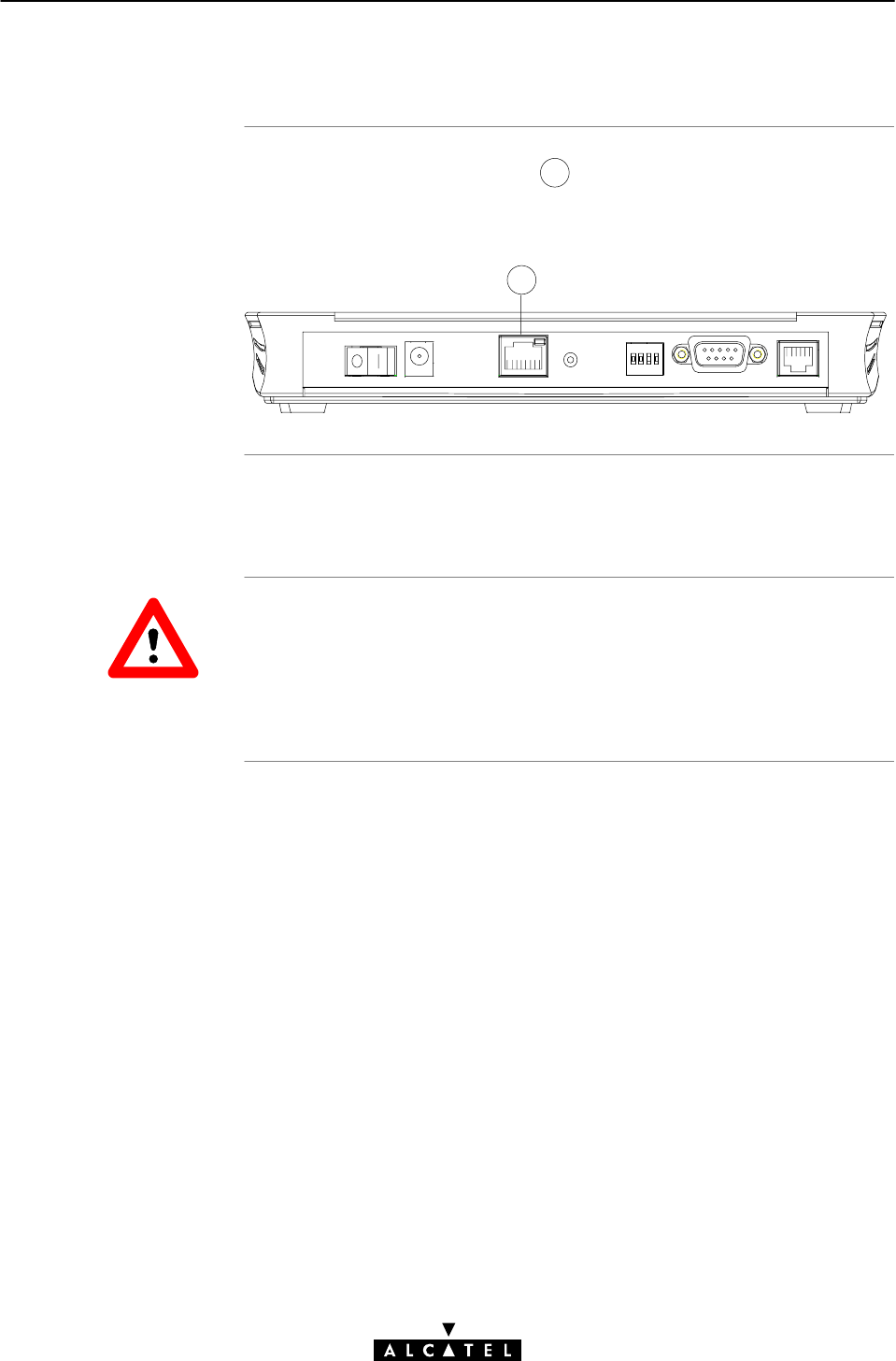
2.1 Locating Ports
43
5
Following ports are used:
"3:ADSL line port, marked LINE"
"4:Power socket, market DC"
"5:Serial port, marked Console".
Important information
Preconditions prior to
connecting
Procedure
2 Wiring Guide - ADSL, Power and Console
31 / 362
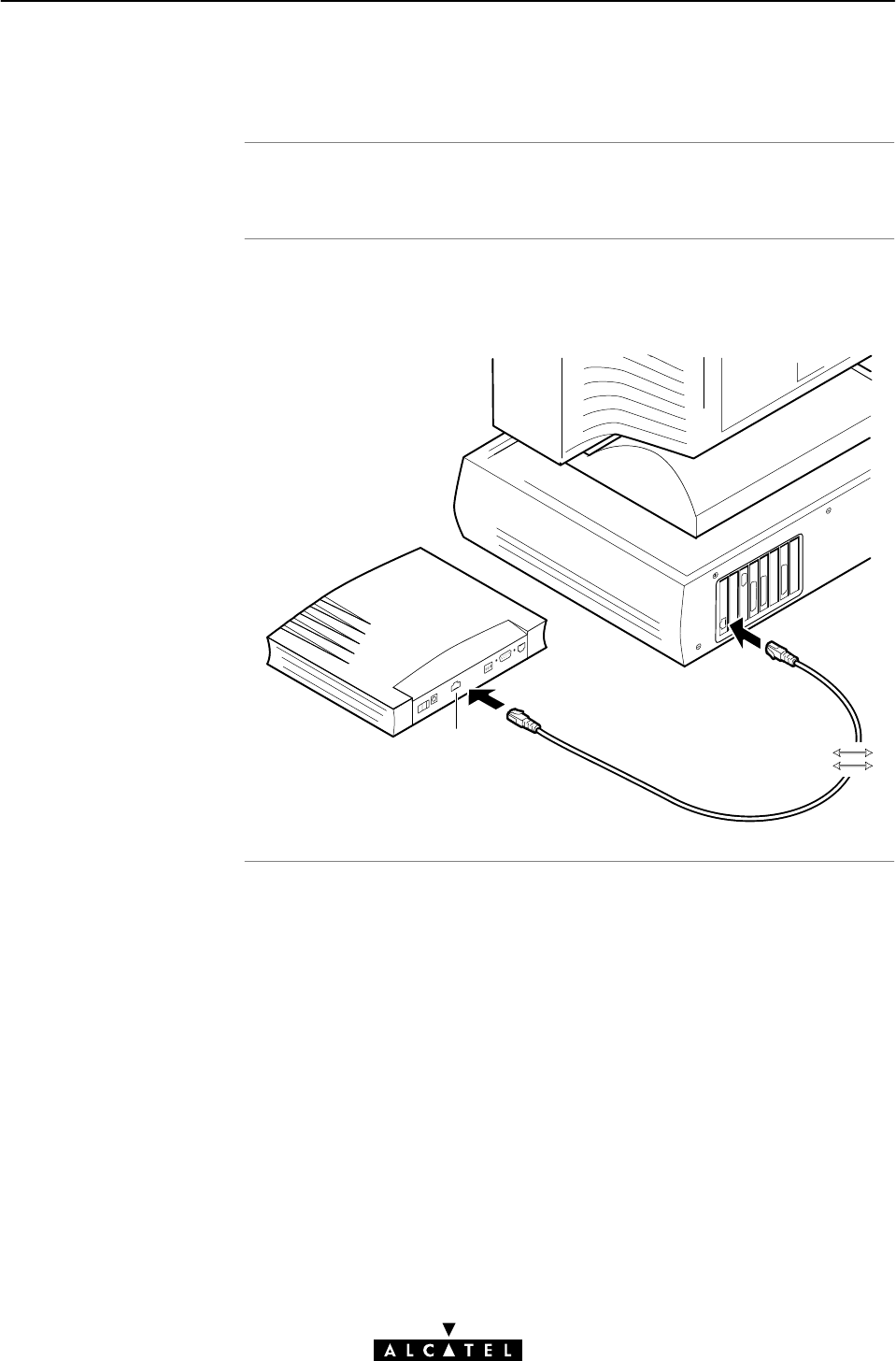
3EC 17766 AAAA TCZZA Ed. 01
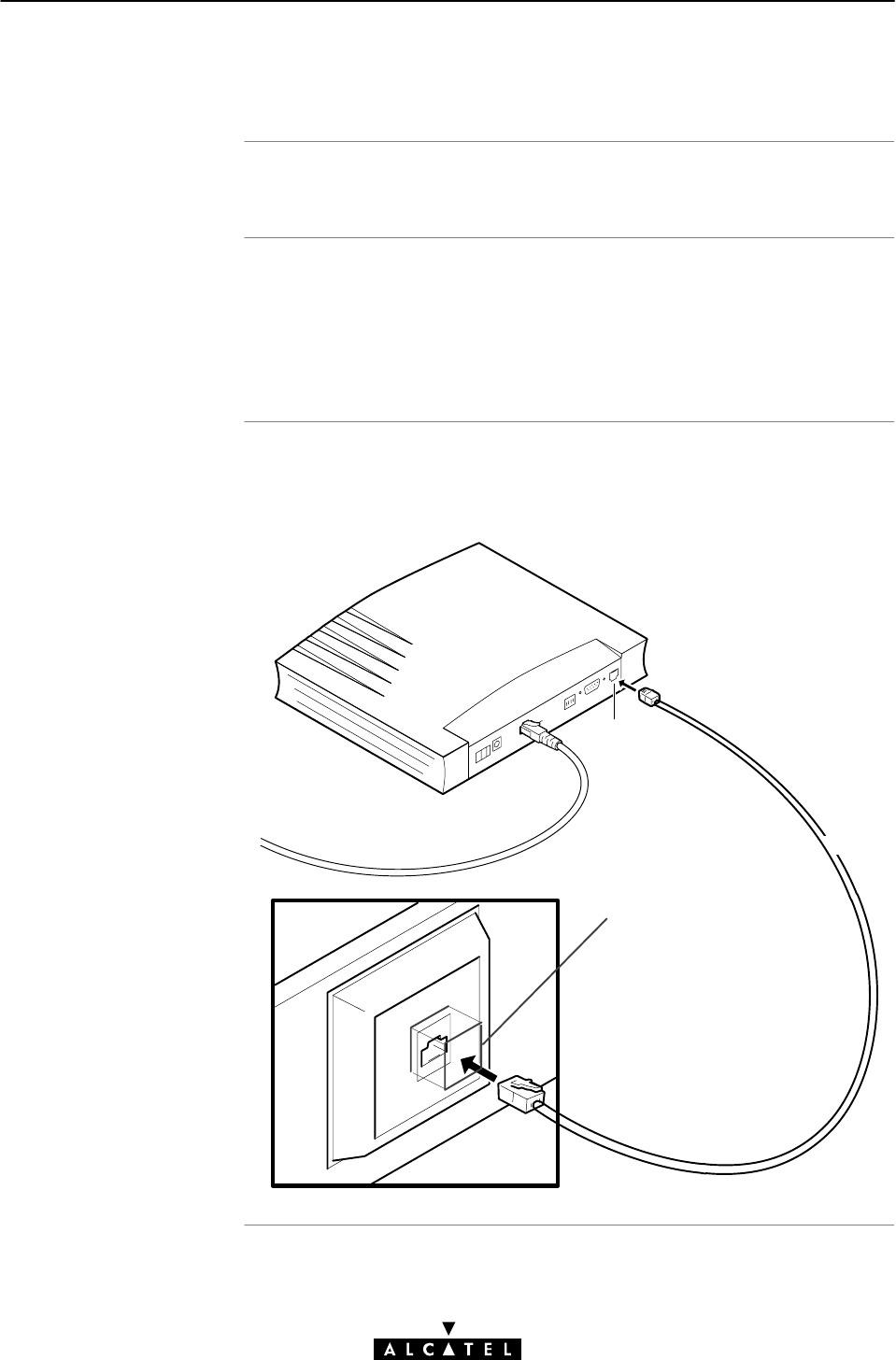
2.2 Connecting the ADSL Port
Read appendix B before you connect the STWireless.
Acentral splitter,ordistributed filters for decoupling ADSL and
POTS, or ISDN signals must be installed. Crossover adapters
might be required.
See appendix B for more information.
Proceed as indicated in the following figure to connect the
STWireless to the ADSL line, using the included black ADSL
cable:
Line
Crossover adapter / microfilter
(if needed)
ADSL Cable
Introduction
Power adapter types
Procedure
2 Wiring Guide - ADSL, Power and Console
32 / 362 3EC 17766 AAAA TCZZA Ed. 01
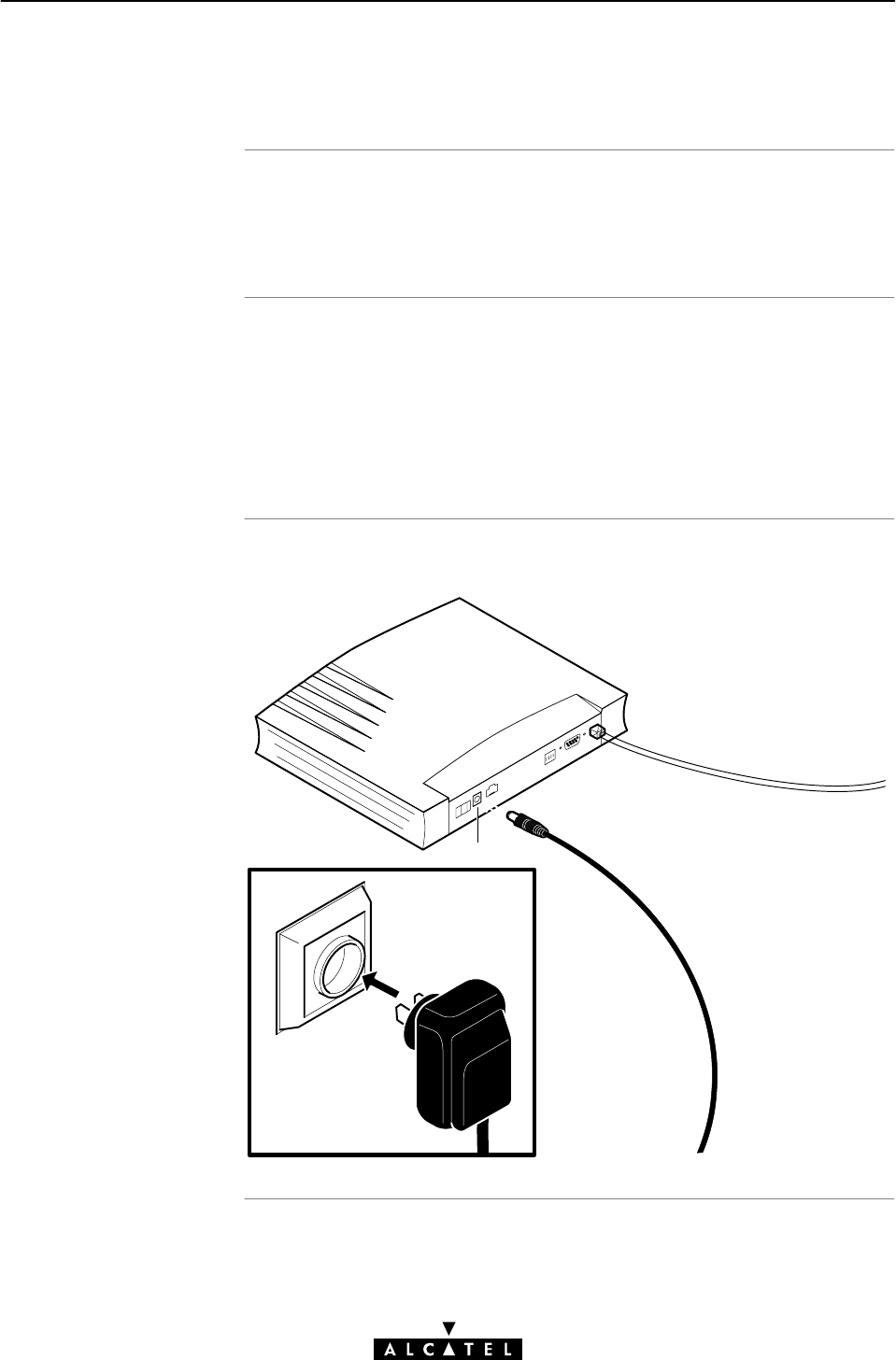
2.3 Connecting the Power Adapter
The STWireless is delivered with a modular external power
adapter converting the AC mains to 9VDC/1A unregulated output
voltage.
Check if the power adapter included in the STWireless package
is compatible with your local electrical power specifications.
See section F.3 for connector layout and output specifications.
If you are insure of the specifications of your local mains power,
contact your local product dealer for more information.
Proceed as follows to connect the power supply adapter :
DC

Serial access
Requirements for using
the serial access
Procedure
2 Wiring Guide - ADSL, Power and Console
33 / 362
3EC 17766 AAAA TCZZA Ed. 01
2.4 Connecting the Serial Port (Optional)
Like most routers, the STWireless carries a serial port on its rear
panel, featuring access from a remote host via a modem
connection, or local access from a terminal.
For access via the serial port, you must have the following:
"A serial cable
"An ASCII terminal (VT100), or a workstation/PC with ASCII
terminal emulation, or emulation application, for local
configuration via the CLI,
or
"A (voiceband) modem, for allowing remote configuration of
the STWireless via the CLI.
Proceed as follows to connect the STWireless serial port:
Step Action
1 Determine the serial port on the rear panel of your
STWireless.
2 Connect the serial cable to the STWireless serial port.
3Connect the other end of the serial cable to the serial
interface of the (emulated) ASCII terminal, or modem.

2 Wiring Guide - ADSL, Power and Console
34 / 362 3EC 17766 AAAA TCZZA Ed. 01

In this chapte
r
3 Wiring Guide - Network Connections
35 / 362
3EC 17766 AAAA TCZZA Ed. 01
3 Wiring Guide - Network Connections
Topic See
Connecting Wireless LAN 3.1
LAN Cables 3.2
Connecting Wired Ethernet (Optional) 3.3
Wired Ethernet vs. WLAN Connectivity 3.4

Introduction
In this section
WLAN basics
3 Wiring Guide - Network Connections
36 / 362 3EC 17766 AAAA TCZZA Ed. 01
3.1 Connecting Wireless LAN
Next to the single Ethernet port, enabling wired LAN connectivity,
the STWireless contains a Wireless LAN (WLAN) hub.
This WLAN hub allows wireless connection of several devices to
the public network, e.g. the Internet. The same technology enables
these devices to communicate with each other in a locally mobile
fashion, without the need of a wired LAN environment.
"Wireless LAN Basics
"Wireless LAN Requirements
"Connecting WLAN Clients
"Configuration of your WLAN Environment.
The WLAN's 'radio' link is a shared medium. A wireless access
point like the STWireless, can be seen as a hub between the
wireless clients. As no physical connection exists between the
STWireless and these clients, you must name your STWireless's
WLAN environment. This is done by the so called Service Set
ID (SSID). Your WLAN clients must be part of this SSID
environment in order to be able to communicate with other clients
of this wireless network - including the STWireless.
In most cases, the WLAN client will automatically recognize the
presence of WLAN networks, and their SSID. It is up to the WLAN
hub's policy whether the client is accepted to join the WLAN
network, or not. This is particularly interesting in case several
independent WLAN hubs (e.g. two STWirelesss of different
workgroups") are coĆlocated.
The IEEE802.11b standard for WLANs allows for several WLAN
systems to be coĆlocated, without sharing the bandwidth. Several
channels are available for use which are associated to a slightly
different frequency in the allowed range. The STWireless
supports operation on all allowed channels.

WLAN clien
t
requirements
Connecting WLAN
client
s
3 Wiring Guide - Network Connections
37 / 362
3EC 17766 AAAA TCZZA Ed. 01
Only WLAN client adapters compliant to IEEE802.11b DSSS, will
be able to communicate with the STWireless, and hence, with
other members of the STWireless WLAN environment.
It is advisable that the WLAN client adapter is WECA WiĆFi
certified to ensure smooth interoperability.
Before you start connecting the WLAN clients, make sure your
STWireless is powered on and finished its POST.
Proceed as follows:
Step Action
1 Install the WLAN Client adapter (WLANĆNIC, or WLAN
PCMCIA card) in your (portable) PC, according the
WLAN client adapter's user manual.
3 For initial connectivity it is recommended to configure
your (portable) PC as DHCP client.
2 In most cases the WLAN client adapter cards
automatically detect the presence of WLAN networks
(that is why the STWireless must be powered up first).
The STWireless WLAN's initial SSID is configured as
'Alcatel_STW'. In case your WLAN adapter does not
find this network, you may configure it manually, or
perform a rescan of the radio environment.
3 Let your WLAN adapter try to join the STWireless's
WLAN.
4 Use a pencil to push the Wireless LAN Authentication
button, marked WLAN" on the rear panel of your
STWireless.This allows the STWireless to authenticate
the WLAN client.
Note: In fact this step allows your WLAN to be secure:
without the physical authentication, i.e. pushing the
WLAN Authentication button, while your WLAN client
tries to join your WLAN, no connectivity will be enabled
between the WLAN client and the STWireless WLAN.

Resul
t
Configuration of you
r
WLAN environmen
t
3 Wiring Guide - Network Connections
38 / 362 3EC 17766 AAAA TCZZA Ed. 01
After performing the last step of the procedure, you should be
able to contact the STWireless, e.g. pinging 10.0.0.138, or open
the STWireless web pages. See chapter 18 for more information.
As soon you have connectivity with the STWireless you are able to
configure the STWireless WLAN parameters via the web pages.
You can configure the following parameters:
"SSID
You can change the default SSID 'Alcatel_STW' into another
value. This can be useful in case another STWireless is
located nearby. It will avoid a WLAN client from his wireless
network to connect by accident to yours.
"Channel
You can change the default channel number to another value.
If you know another wireless equipment runs nearby yours,
e.g. another STWireless WLAN environment, you can avoid
sharing the channel bandwidth by changing the channel in
use.
Note: After the SSID, and/or channel number has been changed
inside the STWireless, the contact may be lost and the WLAN
clients might be reconfigured, and reĆauthenticated to use the
same SSID, and/or channel number.
See chapter 14 for more information on STWireless's Wireless
configuration.

Included LAN cable
Using LAN cables
LAN cable types vs.
port types
Devices and their ports
3 Wiring Guide - Network Connections
39 / 362
3EC 17766 AAAA TCZZA Ed. 01
3.2 LAN Cables
In your STWireless package, a full wired straightĆthrough
RJ45/RJ45 cable, further referred to as LAN cable, is included.
You can use LAN cables other than the one provided in the box,
e.g. crossover LAN cables, etc. However, make sure that these
have the correct layout.
See section F.4 for more information on how to identify
straightĆthrough, and crossover LAN cables.
Determine the LAN cable type from the following table:
Port Type Interconnection Type of LAN cable Symbol
MDIĆX to MDI StraightĆthrough
MDIĆX to MDIĆX
MDI to MDI
Crossover
The STWireless's Ethernet port is of type MDIĆX.
A PC's Ethernet port is always of type MDI.
An Ethernet hub's port is always of type MDIĆX.

In this section
3 Wiring Guide - Network Connections
40 / 362 3EC 17766 AAAA TCZZA Ed. 01
3.3 Connecting Wired Ethernet (Optionally)
Topic See
The Ethernet Port on your STWireless 3.3.1
Wired Single PC Connection 3.3.2
Wired Ethernet LAN 3.3.2
Ethernet interface
Ethernet on your PC
3 Wiring Guide - Network Connections
41 / 362
3EC 17766 AAAA TCZZA Ed. 01
3.3.1 The Ethernet Port on your STWireless
The STWireless Ethernet port 1is a 10BaseĆT Half Duplex
Ethernet interface of type MDIĆX, connecting to either a single PC,
or a workgroup hub.
1
Your PC may have a builtĆin Ethernet port. If not, firstly install an
Ethernet PCĆNIC.
10BaseĆT Half Duplex Interfacing
Make sure the 10BaseĆT port(s) of your PC(s) are configured for
either Auto Negotiation or Half Duplex.
Never configure the 10BaseĆT Ports for FullĆDuplex !
CAUTION
Single PC configuration
Procedure
3 Wiring Guide - Network Connections
42 / 362 3EC 17766 AAAA TCZZA Ed. 01
3.3.2 Wired Single PC Connection
In this configuration the STWireless is connected to a single PC.
Proceed as indicated in the following figure to connect your
STWireless to a single PC:
10 BaseĆT
MDIĆX
MDI
Procedure
MDI vs. MDIĆX hub
ports and the
STWireles
s
3 Wiring Guide - Network Connections
43 / 362
3EC 17766 AAAA TCZZA Ed. 01
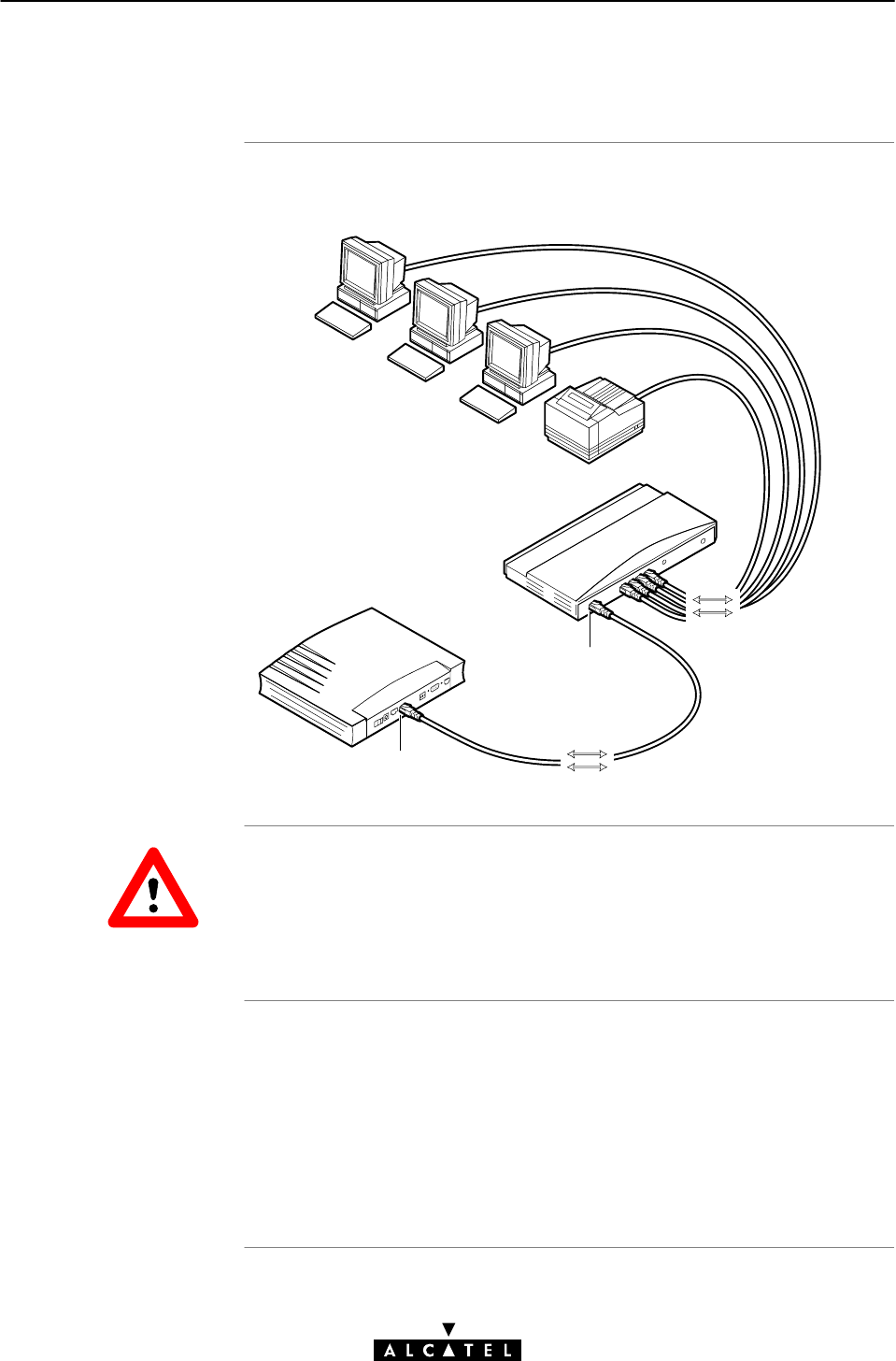
3.3.3 Wired Ethernet LAN
Proceed as indicated in the following figure to make the
connections for a wired LAN:
Hub
10BaseĆT
MDI
MDIĆX
MDI
MDI
MDI
MDI
Cascading Repeating Hubs
Because of the limitations of Repeating Ethernet V2.0/IEEE802.3
hubs, the maximum number of repeating hubs cascaded in your
LAN is four. This restriction does not apply to switching hubs.
In the above figure example the MDI uplink, also referred to as
cascade", port on the hub connects the STWireless. Therefore,
the included straightĆthrough LAN cable can be used.
Note: This port can also be a switchable MDI/MDIĆX port.
You can also use one of the MDIĆX ports of your hub. Then a
crossover LAN cable must be used.
CAUTION

Wireless vs. Wired
LAN
s
STWireless networ
k
configuration
s
STWireless ADS
L
configuration
s
STWireles
s
configuration example
s
3 Wiring Guide - Network Connections
44 / 362 3EC 17766 AAAA TCZZA Ed. 01
3.4 Wired Ethernet vs. WLAN Connectivity
The STWireless makes no difference between wired Ethernet and
WLAN clients. All connected PCs, whether these are connected via
the STWireless Ethernet port, or connected via joining the WLAN
SSID, share the same (sub)network. All are equally valid.
The STWireless allows local network management via:
"An IP router (See section 11.4)
"A DHCP server (See subsection 11.1.4)
"NAPT abilities (See subsection 8.4.6)
"A DNS server for local name resolving and DNS proxying
(See chapter 12)
"A Firewall (See chapter 13)
All STWireless configurations for these management tools, are
equally valid for both wired Ethernet clients, and WLAN clients,
upon configuration.
All STWireless configurations for ADSL connectivity, are equally
valid for both wired Ethernet clients, as for WLAN clients, upon
configuration.
This User Manual contains numerous examples and exemplary
figures.
For clarity, all network connections, i.e. both wired Ethernet and
WLAN client connections, are visualized as if all were wired.

45 / 362
3EC 17766 AAAA TCZZA Ed. 01
Speed TouchWireless
Data Services

46 / 362 3EC 17766 AAAA TCZZA Ed. 01

Introduction
In this chapte
r
4 Data Services - Packet Services
47 / 362
3EC 17766 AAAA TCZZA Ed. 01
4 Data Services - Packet Services
This chapter is about selecting the appropriate packet service for
your application.
Topic See
Supported Packet Services 4.1
Packet Services at a Glance 4.2
Internet & Corporate Access vs. LANĆtoĆLAN
Interconnection
4.3
Direct Networking vs. DialĆUp Networking 4.4
ADSL Modem vs. ADSL Gateway 4.5

What is a packe
t
service ?
The STWireless offers
five types of packe
t
service
s
Networking protocols
Examples in this
manual
4 Data Services - Packet Services
48 / 362 3EC 17766 AAAA TCZZA Ed. 01
4.1 Supported Packet Services
Apacket service can be defined as:
The actions that need to be performed on every data packet in
order to filter or forward packets to the next device in the
communication chain."
"IEEE 802.1D Transparent Bridging
"MAC Encapsulated Routing
"PPPoAĆtoĆPPTP Relaying
"PPP & IP Routing
"Classical IP & IP Routing.
All examples in this manual, use the Transmission Control
Protocol (TCP)/Internet Protocol (IP) suite because it is widely
available (See chapter 11 for more information).
However, the STWireless ADSL router is a true multiprotocol
device, as it is able to manage most other forms of protocols.
Only typical solutions are presented in this manual.
However, this does not prevent you from experimenting with
various configurations and settings.
An optimal solution may be discovered through experimentation.
You can also try a combination of the presented solutions.

In this section
IEEE 802.1D
Transparent Bridging
MAC Encapsulated
Routing
PPPoAĆtoĆPPT
P
Relaying
4 Data Services - Packet Services
49 / 362
3EC 17766 AAAA TCZZA Ed. 01
4.2 Packet Services at a Glance
"IEEE 802.1D Transparent Bridging
"MAC Encapsulated Routing
"PPPoAĆtoĆPPTP Relaying
"PPP & IP Routing
"CIP & IP Routing
"Selection Criteria
"Simultaneous Use of Packet Services
"Resumé.
The STWireless IEEE802.1D Transparent Bridging packet service
offers complete protocol transparency and has inherent
configuration simplicity. Yet it provides excellent forwarding
performance.
Next to the Bridge, the STWireless contains an IP router.
The STWireless RFC1483 MAC Encapsulated Routing (MER)
packet service relies on standard IP Routing for its packet
forwarding on the (W)LAN side. However, to the remote access
router on the WAN side, the STWireless presents itself as a
IEEE802.1D Bridge.
That way the remote side can be fooled, i.e. via Network Address
& Port Translation (NAPT), the single public IP address, assigned to
the MAC entity, i.e. the Bridge", can be shared by multiple users
on the local (W)LAN.
In contrast to Transparent Bridging, and MAC Encapsulated
Routing, which both provide an "AlwaysĆOn" type of connection,
PPPoAĆtoĆPPTP Relaying (PPPoA/PPTP), supports a session concept.
An important advantage of PPPoAĆtoĆPPTP Relaying is that it avoids
the complexity of a network router, yet to a certain extent, provides
identical features.

PPP & IP Routing
CIP & IP Routing
Selection criteria
Simultaneous use o
f
packet services
4 Data Services - Packet Services
50 / 362 3EC 17766 AAAA TCZZA Ed. 01
PointĆtoĆPoint Protocol (PPP) combined with IP routing is the
technology of choice to create a small IP based homeĆ(W)LAN.
Similar to PPPoA/PPTP, it provides a session concept. Additionally,
IP routing combined with NAPT allows to multiplex users into a
single VC.
The STWireless IP router can also be combined with Classical IP
(CIP).
Classical IP is a mature technique for creating classical IP networks
on top of ATM technology. It is widely supported by most, if not all
remote access routers.
Although not the original aim of Classical IP, it is mostly used for
connecting routers over wide area pointĆtoĆpoint links.
The criteria below can help you to select the most appropriate
packet service for your application:
"The configuration required by your SP
"The application protocol you wish to use (within the
boundaries of the remote end)
"The session aspect: an AlwaysĆon" connection or a
connection that is established when needed, i.e. DialĆup"
"Connectivity to a single, or simultaneously to multiple remote
network(s)
"Security features such as identification, authentication and
encryption
"ADSL modem vs. ADSL gateway router model.
All packet services can be active at the same time without any
restriction. The STWireless can manage any combination of the
five packet services simultaneously up to a maximum number of
12 configured virtual connections.
Note: For Transparent Bridging, the maximum number of
configured Bridging ports is four.

Resum
é
4 Data Services - Packet Services
51 / 362
3EC 17766 AAAA TCZZA Ed. 01
All STWireless's packet services can be summarized in the
following table:
Port Packet Service Protocol Chapter
10BaseĆT
Eh
IEEE 802.1D Bridging Multiprotocol 5
Ethernet MAC Encapsulated Routing TCP/IP 6
PPPoAĆtoĆPPTP Relaying TCP/IP, IPX/SPX,
NETBEUI
7
PPP & IP Routing TCP/IP 8
CIP & IP Routing TCP/IP 9

Exemplary applications
using ADS
L
Internet & corporate
acces
s
LANĆtoĆLAN
interconnection
Selecting the packe
t
servic
e
4 Data Services - Packet Services
52 / 362 3EC 17766 AAAA TCZZA Ed. 01
4.3 Internet & Corporate Intranet Access vs.
LANĆtoĆLAN Interconnection
This manual highlights the two most prominent ADSL applications:
"High speed Internet access, or corporate Intranet access
"Private Wide Area Network (WAN) /Local Area Network (LAN)
interconnection
Although the objective (Internet vs. Intranet access) is different, the
networking model/configuration is almost identical.
Traditionally, the user must open a session by dialing into a
remote access server. Prior to accessing the resources, this remote
server will ask for the user's credentials.
The most appropriate STWireless configurations are:
"PPPoAĆtoĆPPTP Relaying (See chapter 7)
"PPP & IP Routing (See chapter 8).
Multiple PCs on a (W)LAN are interconnected via public, or private
wide area ADSL/ATM networks to devices on remote LANs.
In the LANĆtoĆLAN scenario, users are less concerned about a
session concept. Their networking experience should be as if they
are part of a large and widely dispersed LAN.
The most appropriate STWireless configurations are:
"IEEE 802.1D Transparent Bridging (See chapter 5)
"MAC Encapsulated Routing (See chapter 6)
"Classical IP & IP Routing (See chapter 9).
In the case of Internet, or corporate access, your SP will usually
determine which networking model to use. In the LANĆtoĆLAN
scenario you determine the endĆtoĆend setĆup yourself.
Independent of your application, the protocols supported at both
ends of the connection must be mirror images of each other for
successful communication.

In this section
What is direc
t
networking ?
Comparison with LAN
networking
What is dialĆup
networking ?
STWireless vs.
networking
4 Data Services - Packet Services
53 / 362
3EC 17766 AAAA TCZZA Ed. 01
4.4 Direct Networking vs. DialĆup Networking
"What is Direct Networking
"Comparison with LAN Networking
"What is DialĆUp Networking
"STWireless & Networking
"Ethernet Port(s) & Networking.
Direct networking refers to how the network connection is
experienced by the user. The connection is continuously active,
thus no actions need be performed.
Powering on the local PCs and the STWireless is enough to
enable the user to interact with the network, once the initial
configuration is done.
Direct networking is what is typically experienced on a LAN. Initial
configuration of all networking nodes in the endĆtoĆend network is
still required, but this is performed only once, i.e. when the service
is enabled.
In this mode, there is no initial connectivity. You must explicitly
request a connection by dialing up to the remote access server.
The remote side will require you to identify and authenticate
yourself.
The STWireless supports both direct networking, and dialĆup
networking solutions, independently whether you are using the
Ethernet port.

Ethernet port(s)
&
networking
4 Data Services - Packet Services
54 / 362 3EC 17766 AAAA TCZZA Ed. 01
Following scenarios are available:
"Direct and continuous connectivity is accomplished via
the IEEE 802.1D transparent databridge, in the STWireless.
See chapter 5 for more information.
"MER provides continuous connectivity
See chapter 6 for more information.
"PPPoAĆtoĆPPTP Relaying dialĆup networking relies on the
standard PPP protocol family and local tunneling, using the
industry PPTP protocol.
See chapter 7 for more information.
"PPP & IP Routing provides dialĆup networking.
See chapter 8 for more information.
"CIP & IP Routing provides continuous connectivity.
See chapter 9 for more information.

Introduction
Note
In this section
4 Data Services - Packet Services
55 / 362
3EC 17766 AAAA TCZZA Ed. 01
4.5 ADSL Modem vs. ADSL Gateway
In the configuration where multiple PCs reside on a common LAN,
they must share a gateway for specific services. The most
important service is ADSL for accessing the outside world.
The STWireless can be used as a fast ADSL modem, leaving the
gateway tasks to another (W)LAN member.
However, the STWireless is able to act as an ADSL gateway router
itself. The latter is often called home or residential gateway.
The boundaries between the ADSL modem model and the ADSL
gateway function are not as clearly defined as explained in this
section. They are portrayed that way to focus the attention on both
models.
Topic See
ADSL Modem Model 4.5.1
ADSL Gateway Model 4.5.2
ADSL modem model
Role of the STWireless
Packet services and
STWireless ADS
L
modem model
4 Data Services - Packet Services
56 / 362 3EC 17766 AAAA TCZZA Ed. 01
4.5.1 ADSL Modem Model
The STWireless in this role, provides connectivity to either a single
PC: or to a dedicated home gateway:
Single PC
Bit pipe
ADSL Line
Or to a dedicated home gateway:
Bit pipe
ADSL Line
Ć Routing
Ć NAPT
Ć Firewalling
Ć Name Resolving
Home Gateway
performing:
Ć DHCP
The desired functionality of the STWireless ADSL router in this
model, is maximum transparency. Packets arriving on inbound
ports must be forwarded transparently to outbound ports. All
intelligent decisions will be made in either the single PC, or the
home gateway.
In fact, this functionality has been offered by voiceband modems
for a long time, but then with an important speed limit.
The IEEE 802.1D transparent databridge, the PPPoAĆtoĆPPTP relay
and the PPPĆtoĆDHCP Proxy - all bound to the Ethernet port and
the ATM switching capabilities of the ATMF25.6 port -, adhere
best to this model.
ADSL gateway model
Role of the STWireless
Packet services and
STWireless ADS
L
gateway model
4 Data Services - Packet Services
57 / 362
3EC 17766 AAAA TCZZA Ed. 01
4.5.2 ADSL Gateway Model
The gateway to access the outside world can be a dedicated PC as
shown in subsection 4.5.1.
However, the STWireless itself is designed to act as a cost
effective ADSL gateway.
STWireless ADSL Router
acting as Home Gateway:
Ć Routing
Ć NAPT
Ć Firewalling
Ć Name Resolving
ADSL Line
Ć DHCP
To perform the gateway tasks itself, the STWireless has, in
addition to the ADSL modem part:
"An IP router (See section 11.4)
"A DHCP server (See subsection 11.1.4)
"NAPT abilities (See subsection 8.4.6)
"A DNS server for local name resolving and DNS proxying
(See chapter 12)
"A Firewall (See chapter 13)
MER, PPP & IP Routing and CIP & IP Routing are ideally suited for
the ADSL gateway model.

4 Data Services - Packet Services
58 / 362 3EC 17766 AAAA TCZZA Ed. 01

Introduction
In this chapte
r
5 Data Services - Transparent Bridging
59 / 362
3EC 17766 AAAA TCZZA Ed. 01
5 Data Services - Transparent Bridging
The STWireless IEEE802.1D Transparent Bridging packet service
offers complete protocol transparency and has inherent
configuration simplicity. Yet it provides excellent forwarding
performance.
Topic See
Preparatory Steps 5.1
Using Bridging 5.2
Bridging Configuration 5.3
Advanced Bridging Concepts 5.4

Features
What you should kno
w
in advance
STWireles
s
PC(s
)
5 Data Services - Transparent Bridging
60 / 362 3EC 17766 AAAA TCZZA Ed. 01
5.1 Preparatory Steps
IEEE 802.1D Transparent Bridging:
"Is platform and OS independent
"Is simple to configure and easy to use
"Is a true multiprotocol device
"In the Alcatel implementation, has no performance limitations
"Has no theoretical constraints on the number of attached
users
(There is a practical limit to achieve a reasonable
performance, e.g. 16 PCs)
"Features concurrent access to multiple remote destinations
"Supports up to four concurrent Bridge ports.
"The VPI/VCI value of the VC(s) to use on the ADSL line
"ETHoA connection service must be supported on this VC
"Whether IP configuration is static, or dynamic (DHCP)
The STWireless comes with four preconfigured Bridging/MER
phonebook entries, i.e. Br1 ... Br4.
If the SP(s) impose settings which differ from the STWireless
defaults, perform the necessary adjustments via the STWireless
web pages.
See section 5.3 for more information.
The STWireless's Transparent Bridging packet service does not
impose specific requirements to your PC's networking protocol
layers. However, ensure that the applied protocols are properly
installed and configured on your PC.

TCP/I
P
5 Data Services - Transparent Bridging
61 / 362
3EC 17766 AAAA TCZZA Ed. 01
For TCP/IP, your SP will assign you either static IP parameters (per
PC), or will instruct you to enable DHCP on your PC(s).
Transparent Bridging and DHCP
If the SP requires you to use DHCP on your local PC(s), you must
disable the STWireless DHCP server.
This is to avoid conflicts between two DHCP servers, i.e. the
STWireless DHCP server and a remote DHCP server, being active
at the same time.
See subsection 11.3.3 for more information.
CAUTION
Using Bridging
AlwaysĆon and
credential
s
Configuration exampl
e
5 Data Services - Transparent Bridging
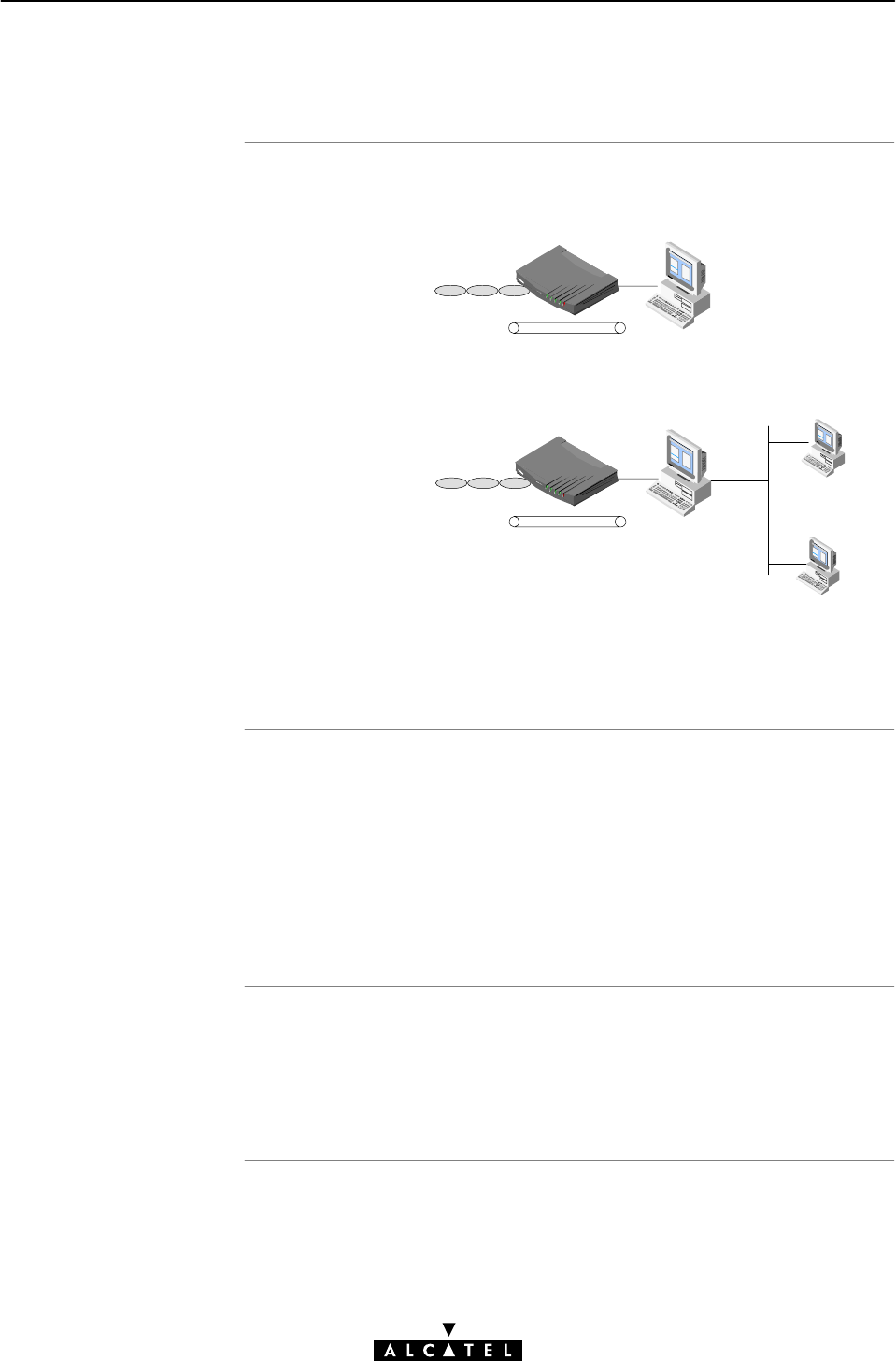
62 / 362 3EC 17766 AAAA TCZZA Ed. 01
5.2 Using Bridging
From this point on, using Transparent Bridging is rather
straightĆforward. Turn on both your STWireless and PC, start your
Web browser and you are on the Internet.
This form of remote network access is sometimes referred to as
AlwaysĆon". No connection procedure must be performed prior to
connectivity. However, the remote organization might present you
with a welcome screen asking for a user name and password
prior to granting access to secured servers or the Internet.
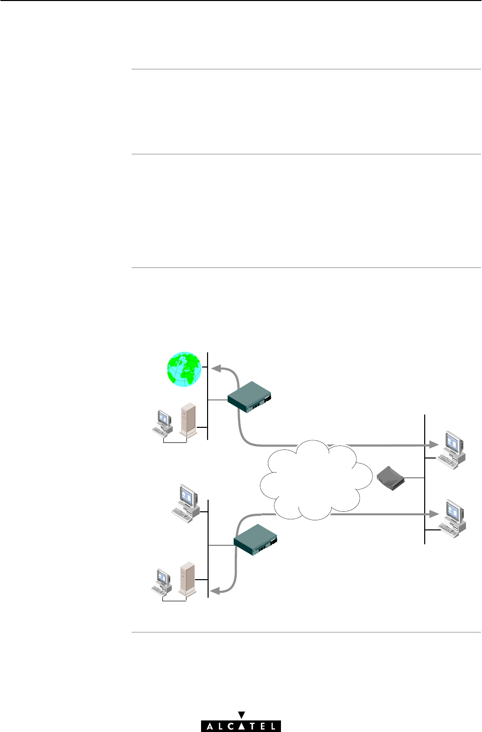
In the following figure an example configuration is given:
"One PC is connected to an ISP
"Another PC is connected to a remote LAN.
Internet access via
VC 8/35
Internet
ISP
Access Point
Remote LAN
Access Point
LANĆtoĆLAN
interconnection via
VC 8/36 Static IP address
e.g. :172.16.0.2
Server
Server
IP address
obtained via
DHCP
ATM
Network

Introduction
In this section
5 Data Services - Transparent Bridging
63 / 362
3EC 17766 AAAA TCZZA Ed. 01
5.3 Bridging Configuration
The STWireless allows local configurations via the STWireless
web pages.
This section describes the configuration of Bridging entries, and
the use of the 'Bridging' web page.
Topic See
Bridging Phonebook Entries 5.3.1
Bridging Entries 5.3.2
Bridging phoneboo
k
entries
Adding/deleting
phonebook entries
5 Data Services - Transparent Bridging
64 / 362 3EC 17766 AAAA TCZZA Ed. 01
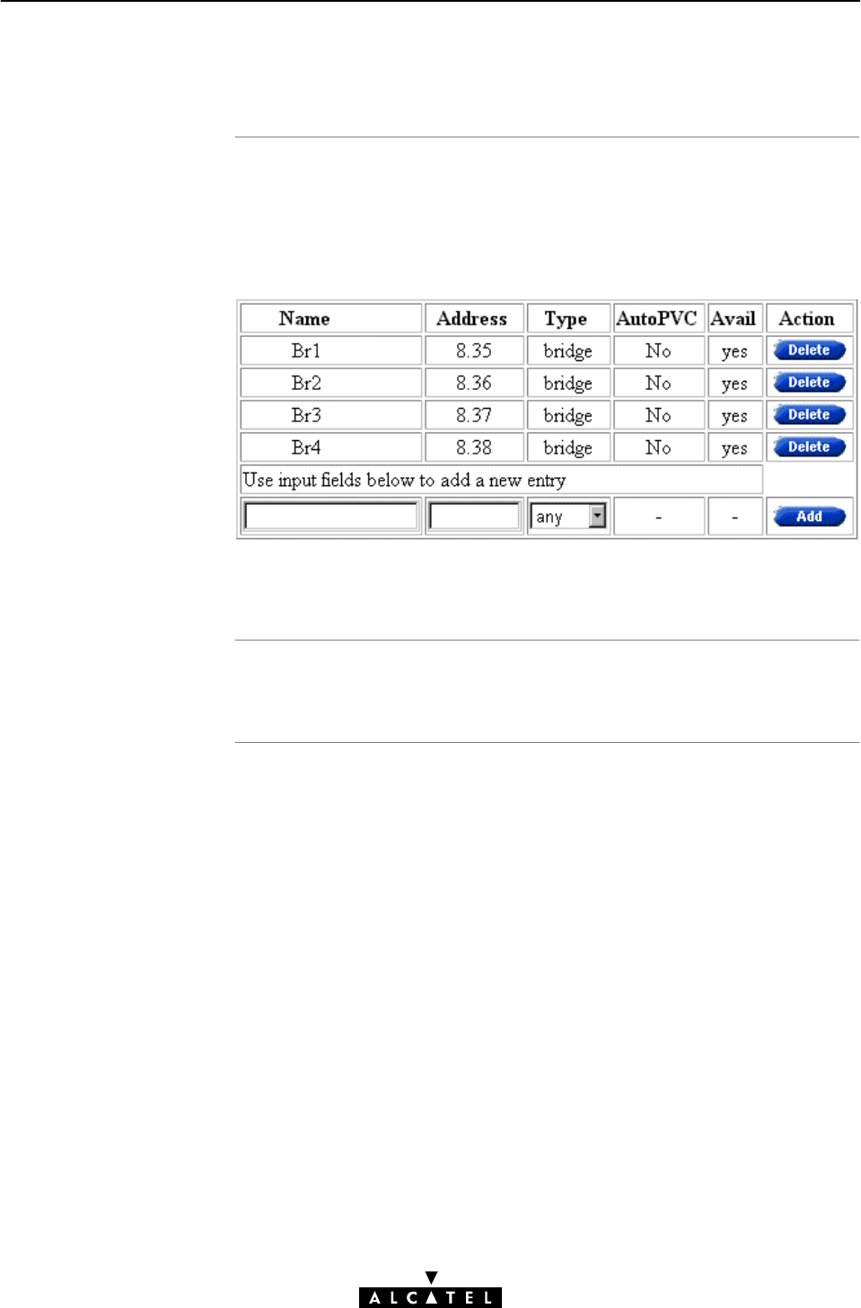
5.3.1 Bridging Phonebook Entries
Central to the STWireless VC pool management, is the
'Phonebook' web page.
The STWireless in its default state features the following
Bridging/MER related phonebook entries:
Note: Both Bridging and MER share the same type of phonebook
entries, i.e. bridge.
See section 10.2 for more information.
In this subsection
The STWireless
'Bridging' web page
5 Data Services - Transparent Bridging
65 / 362
3EC 17766 AAAA TCZZA Ed. 01
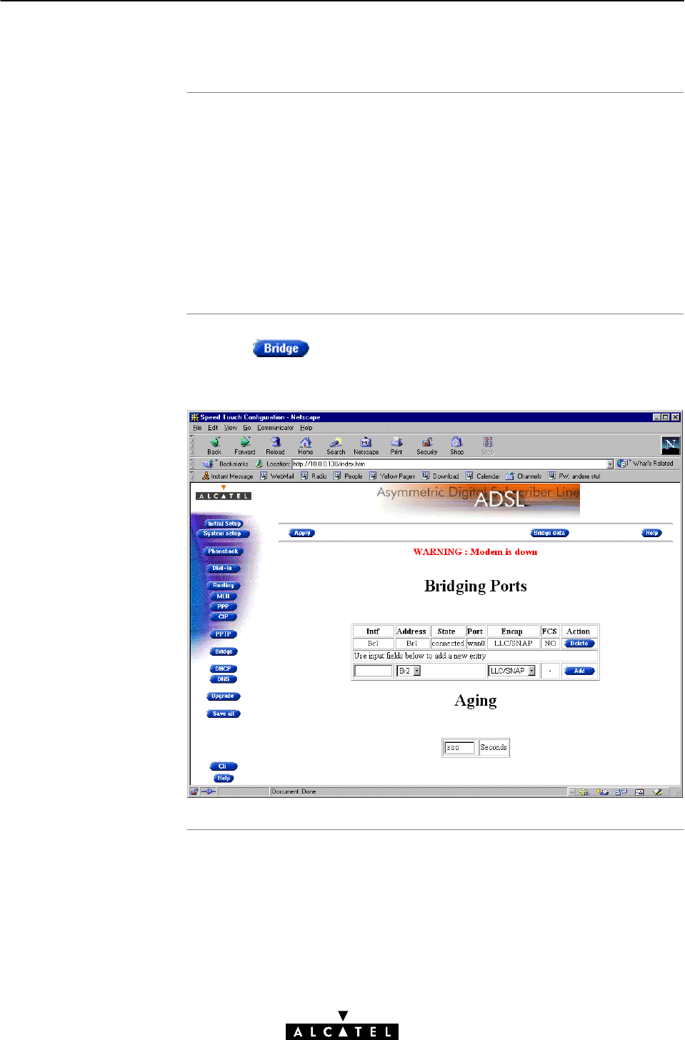
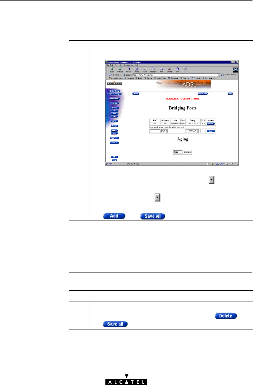
5.3.2 Bridging Entries
"The STWireless 'Bridging' Web Page
"The 'Bridging Ports' Table
"'Bridging Ports' Table Components
"The 'Aging' Box
"Adding Bridging Entries
"Deleting Bridging Entries.
Clicking in the left pane of the STWireless web pages,
pops up the 'Bridging' web page (See section 18.2 for more
information):

The 'Bridging Ports'
tabl
e
'Bridging Ports' table
component
s
5 Data Services - Transparent Bridging
66 / 362 3EC 17766 AAAA TCZZA Ed. 01
The following figure shows the 'Bridging Ports' table in its default
state:
The following fields are shown:
Field Description
Intf Allows you to choose an interface name for the Bridge
interface.
Note: In most cases, the interface name will be the same as
the phonebook entry name.
Destination Indicates available Phonebook entries for Bridging.
Note: Specific free MER/Bridging phonebook Entries are
shown, as well as free 'any type' phonebook entries
State Indicates the state of the individual (W)LAN port. It can take
following values:
Value Description
connected
idle The Bridge port only submits
information to the filtering database.
It does not participate in the relaying
of frames.
The Bridge interface is attached to
the Bridge port.
In most cases this also implies that
the Bridge port is connected and
forwarding.
Port Indicates the name of the Bridge port on the WAN side:
wan0, wan1, wan2, etc. by default.
The 'Aging' bo
x
5 Data Services - Transparent Bridging
67 / 362
3EC 17766 AAAA TCZZA Ed. 01
Field Description
Encap Refers to the encapsulation, and decapsulation of Ethernet,
or IEEE 802.3 frames in/from AAL5/ATM. The STWireless is
compliant with RFC 1483 Multiprotocol Encapsulation over
ATM Adaptation Layer 5" and supports both the LLC/SNAP
method and the VCĆMUX method for Bridged Ethernet
V2.0/IEEE 802.3 PDUs.
By default the encapsulation method is set to LLC/SNAP.
FCS Is part of the RFC 1483 encapsulation method and indicates
whether the last four bytes of the Medium Access
Control (MAC) frames (mostly referred to as Ethernet or IEEE
802.3 frames) will be preserved or not.
For all Bridge ports, the FCS is set to NO by default. However,
via the CLI, you can set the FCS to YES. See chapter 19 for
more information.
Action Contains one of the two following action buttons:
Button Action
Delete an existing entry from the list.
Add an entry to the list.
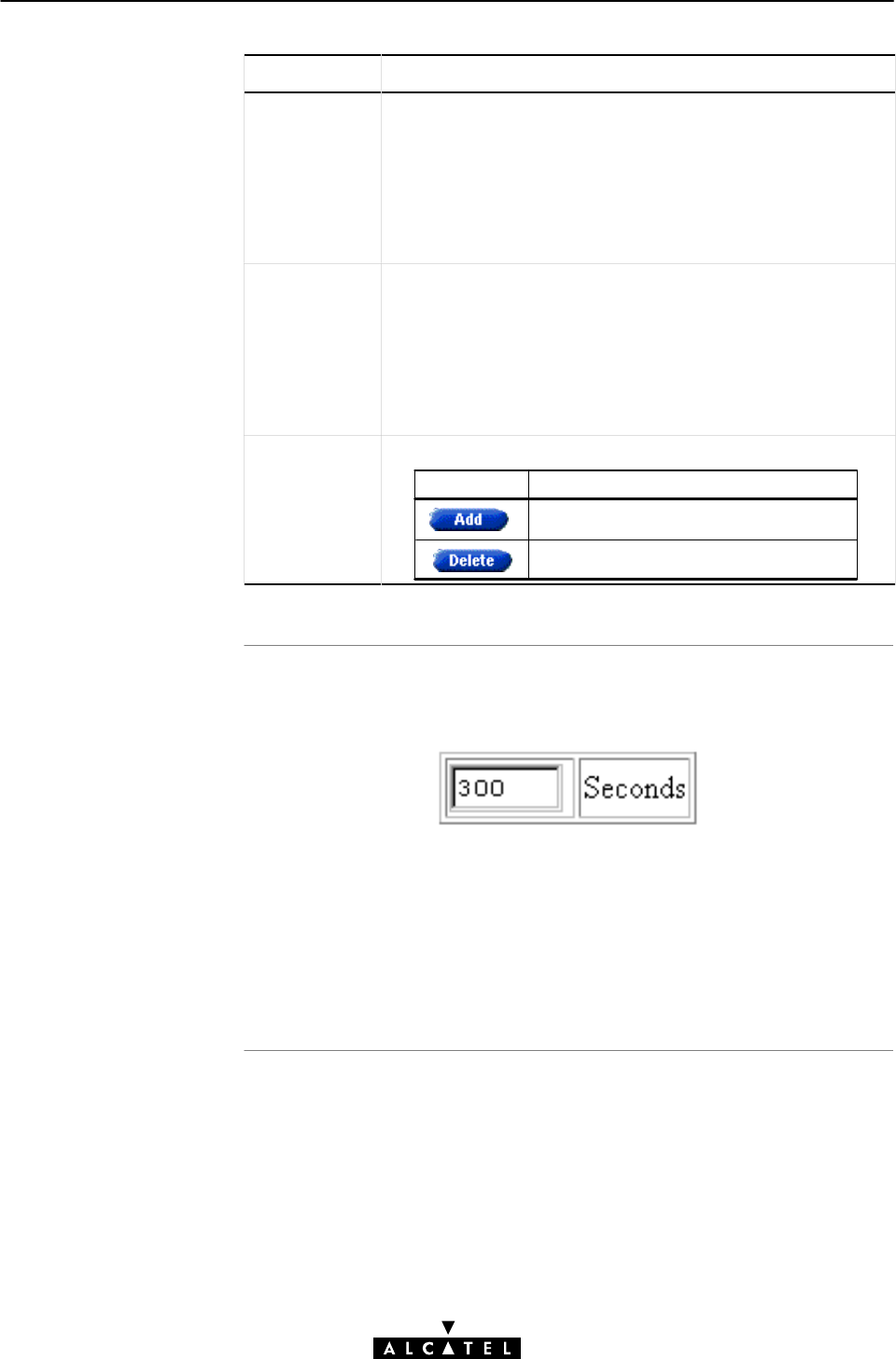
The following figure shows the 'Aging' box of the 'Bridging' web
page:
This box contains the aging timer of the bridge internal database.
If the aging time of a MAC entry has expired, this entry will be
removed from the database.
Only in exceptional cases the default value of 300 seconds (5
minutes) needs to be modified. The allowed range is from 10
seconds to 12 days (IEEE 802.1D Bridging standard).
Adding Bridging
entries
Note
Deleting Bridging
entries
5 Data Services - Transparent Bridging
68 / 362 3EC 17766 AAAA TCZZA Ed. 01
Proceed as follows:
Step Action and Description
1Browse to the 'Bridging' web page.
The bottom row of the table allows addition of a new entry.
2In the 'Destination' column of the bottom row, click and select
the Bridging entry you want to add to the table.
3In the 'Encap' column, click and select the encapsulation
method for the connection, i.e. LLC/SNAP, or VCĆMUX.
4Click and to finish the procedure.
The maximum number of remote Bridging ports supported is 4.
However, if no multiple connectivity is required, leave the
configuration as is, to conserve ADSL upstream bandwidth.
Proceed as follows:
Step Action and Description
1Browse to the 'Bridging' web page.
2Select the Bridging entry you want to delete, and click
and to finish the procedure.
Bridging
Simplified bridge
architectur
e
In this section
5 Data Services - Transparent Bridging
69 / 362
3EC 17766 AAAA TCZZA Ed. 01
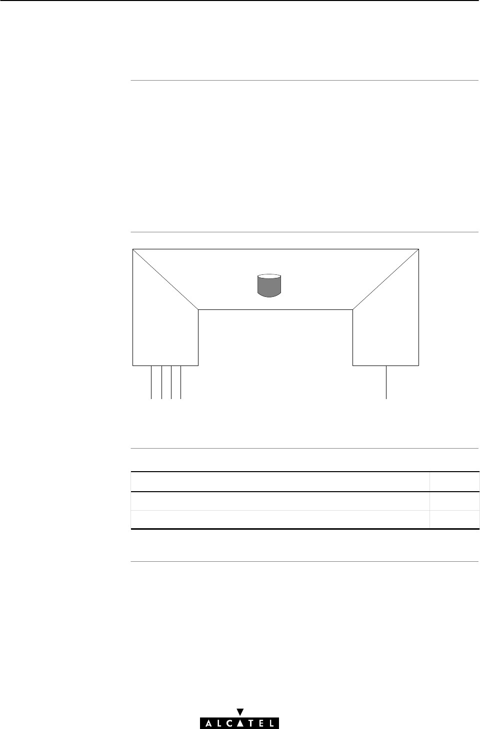
5.4 Advanced Bridging Concepts
Bridging is a LAN technology that transparently relays Ethernet
frames between Bridging ports.
Depending on the destination MAC addresses of Ethernet frames,
the bridge makes decisions whether to forward or discard frames.
Central to the operation of a databridge is its filtering database.
All forwarding and filtering actions are based on information in
this database.
MAC RELAY ENTITY
ADSL/ATM (Wireless)
ETHERNET
(W)LAN PORT
Filtering Database
REMOTE
PORTS
Virtual Channels
Topic See
STWireless Bridge Operation 5.4.1
STWireless 'Bridge Data' Web Page 5.4.2

Introduction to bridge
operation
In this subsection
5 Data Services - Transparent Bridging
70 / 362 3EC 17766 AAAA TCZZA Ed. 01
5.4.1 STWireless Bridge Operation
This section describes how the STWireless bridge operates. All of
these operations have an impact on the entries in the filtering
database of the bridge.
One of the characteristics of a databridge is the number of
supported Bridge ports. A Bridge port is the logical equivalent of
an interface. By default the STWireless supports one local port,
i.e. the Ethernet port, and four remote ports. The remote ports are
mapped to virtual ATM channels on the ADSL line.
"Learning
"Aging
"Learning and Aging
"Flooding
"Forwarding
"Filtering
"Isolation
"Multiprotocol Bridging
"Number of Supported Devices.

Learning
Aging
Learning and Aging
Flooding
5 Data Services - Transparent Bridging
71 / 362
3EC 17766 AAAA TCZZA Ed. 01
If the bridge is turned on, the filtering database is empty. Over
time it is filled with entries via the learning mechanism.
Ethernet frames arriving on any port are inspected for their source
MAC address and put into the filtering database together with the
port ID the frames arrived on.
Through this knowledge, it is able to keep traffic submitted to your
local printer from crossing the bridge. Yet it allows frames
belonging to sessions with remote machines to pass over the ADSL
line.
Entries are aged, i.e. removed from the filtering database, after a
certain time has elapsed (Aging time).
The learning and aging process make the bridge Plug & Play. Both
keep the filtering database upĆtoĆdate with the current network
configuration.
Example: Suppose a PCĆNIC is replaced, the old MAC address is
aged (and will be consequently discarded), while a new MAC
address will be learned.
If an Ethernet frame arrives, the destination MAC address is
searched for in the filtering database. If the destination MAC
address is not found (implying it is not yet learned), it is forwarded
to all ports in the forwarding state, except the one the frame
arrived on.
Note: Broadcast and multicast MAC addresses are always
flooded.

Forwarding
Filtering
Isolation
Multi Protocol Bridging
Number of supported
device
s
5 Data Services - Transparent Bridging
72 / 362 3EC 17766 AAAA TCZZA Ed. 01
If an Ethernet frame arrives with a destination MAC address that is
found in the filtering database (implying it is already learned), it is
forwarded to the port that is associated with that entry.
In contrast to flooding, forwarding is more selective.
If the destination MAC address is found on the same port as the
frame arrived on, it is filtered, i.e. silently discarded.
Indeed, it makes little sense to forward the frame on this port as
the destination is directly connected to the source.
The Alcatel Multiport bridge in the STWireless provides isolation
between remote ports.
i.e. Frames (including broadcasts) arriving via ADSL/ATM ports will
never be forwarded/flooded to another ADSL/ATM port.
Bridging actions are performed on MAC frames. The contents of
the MAC frame is not of importance to the bridge.
Consequently it makes no difference whether your PCs or
workstations use TCP/IP, Appletalk, IPX/SPX or any other protocol
suite.
However, some operators might embed restrictions into the
bridge. In this way only traffic that passes through the bridge filter
will be allowed on the ADSL line.
Via the dynamic learning and aging mechanism of the bridge, the
number of PCs that can be connected to either the local, or virtual
ports is theoretically unlimited.
Practically, the filtering database can hold as many as 256 entries
simultaneously.
Introduction
The 'Bridge Data' web
pag
e
Available 'Bridge Data'
table
s
5 Data Services - Transparent Bridging
73 / 362
3EC 17766 AAAA TCZZA Ed. 01
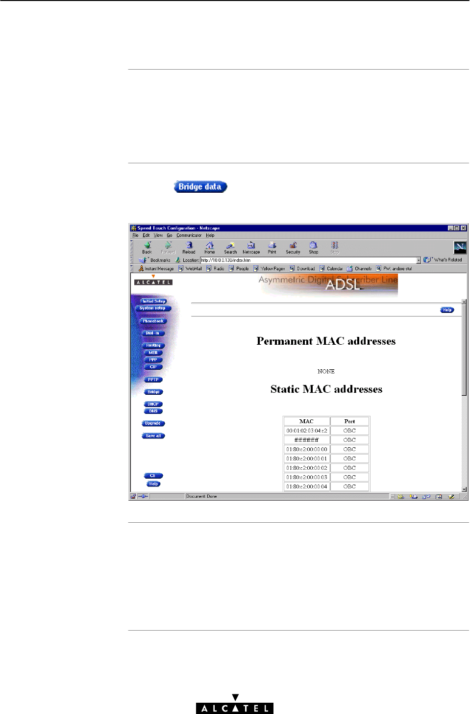
5.4.2 STWireless 'Bridge Data' Web Page
Transparent Bridging relies completely on its filtering database for
managing the traffic, passing through the bridge. This filtering
database is accessible via the STWireless 'Bridging' web page,
and allows you to overview all MACĆlayer entries.
Clicking on the 'Bridging' web page pops up the
'Bridge Data' web page:
The filtering database's MAC addresses are spread over 3 tables:
"The 'permanent MAC addresses' table
"The 'static MAC addresses' table
"The 'dynamic MAC addresses' table.

Permanent MAC
addresse
s
Static MAC addresses
Dynamic MAC
addresse
s
5 Data Services - Transparent Bridging
74 / 362 3EC 17766 AAAA TCZZA Ed. 01
These are the MAC addresses that must always be resident inside
the bridge, as stipulated in the IEEE802.1D standard:
"The STWireless's own MAC address:
e.g. 00-80-9F-01-02-03
"The Broadcast MAC address:
FF-FF-FF-FF-FF-FF
"The bridge group MAC address:
01-80-C2-00-00-00
"The 16 reserved MAC addresses of IEEE802.1D:
From 01-80-C2-00-00-01
up to 01-80-C2-00-00-0F
"The all LANs bridge management group MAC address:
01-80-C2-00-00-10
This table list the MAC addresses you have added to the filtering
database via the CLI. These MAC addresses, dedicated to a
particular port, will never be aged by the bridge.
In principle, no static MAC addresses are to be configured.
This table lists all the MAC addresses that are currently learned by
the STWireless bridge.
While the learning process adds MAC addresses received on any
of its ports, the aging process will swap them out of the table
when their aging timer expired.

Introduction
In this chapte
r
6 Data Services - MAC Encapsulated Routing
75 / 362
3EC 17766 AAAA TCZZA Ed. 01
6 Data Services - MAC Encapsulated Routing
Via the STWireless MAC Encapsulated Routing packet service you
can connect to an ADSL line supporting the ETHernet over ATM
(ETHoA) connection service. In contrast to bridging though, packet
filtering and forwarding is performed by the IP router of the
STWireless and consequently inherits all the features that come
with IP.
In the following, MAC Encapsulated Routing will be referred to as
MER.
Note: MAC is the standardized term for Ethernet.
Topic See
Preparatory Steps 6.1
Using MER 6.2
MER Configuration 6.3
Advanced MER Concepts 6.4

Features
What you should kno
w
in advance
STWireles
s
PC(s
)
6 Data Services - MAC Encapsulated Routing
76 / 362 3EC 17766 AAAA TCZZA Ed. 01
6.1 Preparatory Steps
MAC Encapsulated Routing:
"Is instantly replaceable with an IEEE Transparent Bridge
"Provides AlwaysĆon type of connections and is
autoĆconfigurable if DHCP is enabled
"If used in combination with NAPT, allows multiple users to
share a single IP address
"When Firewalling is turned on, your local network is shielded
for threats from the Internet.
"Supports up to 12 concurrent virtual channels assigned to
MER.
"The VPI/VCI value of the VC(s) to use on the ADSL line
"ETHoA connection service must be supported on this VC
"Whether IP configuration is static, or dynamic (DHCP)
The STWireless comes with four preconfigured MER/Bridging
phonebook entries, i.e. Br1 ... Br4.
If the SP(s) impose settings which differ from the STWireless
defaults, perform the necessary adjustments via the STWireless
web pages.
See section 6.3 for more information.
For MER it is assumed that communication between the
STWireless and your PC(s) is performed via the Internet protocol.
You can:
"Enable the STWireless's DHCP server to enable dynamic IP
configuration of your (W)LAN
"Configure all (W)LAN's IP settings statically.
Using Bridging
AlwaysĆon and
credential
s
MER endĆtoĆend
architectur
e
6 Data Services - MAC Encapsulated Routing
77 / 362
3EC 17766 AAAA TCZZA Ed. 01
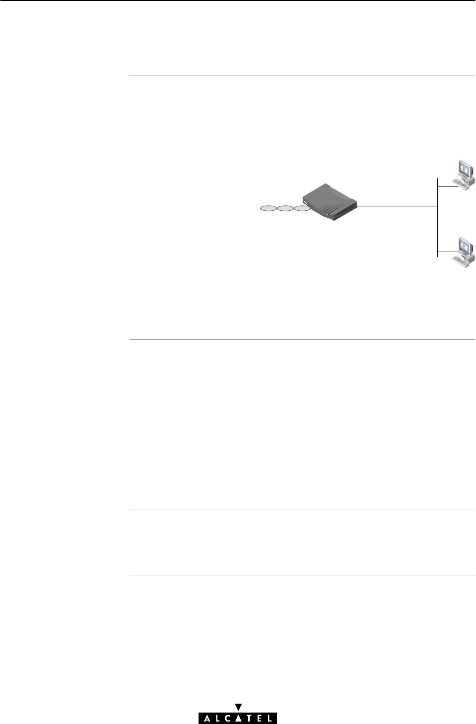
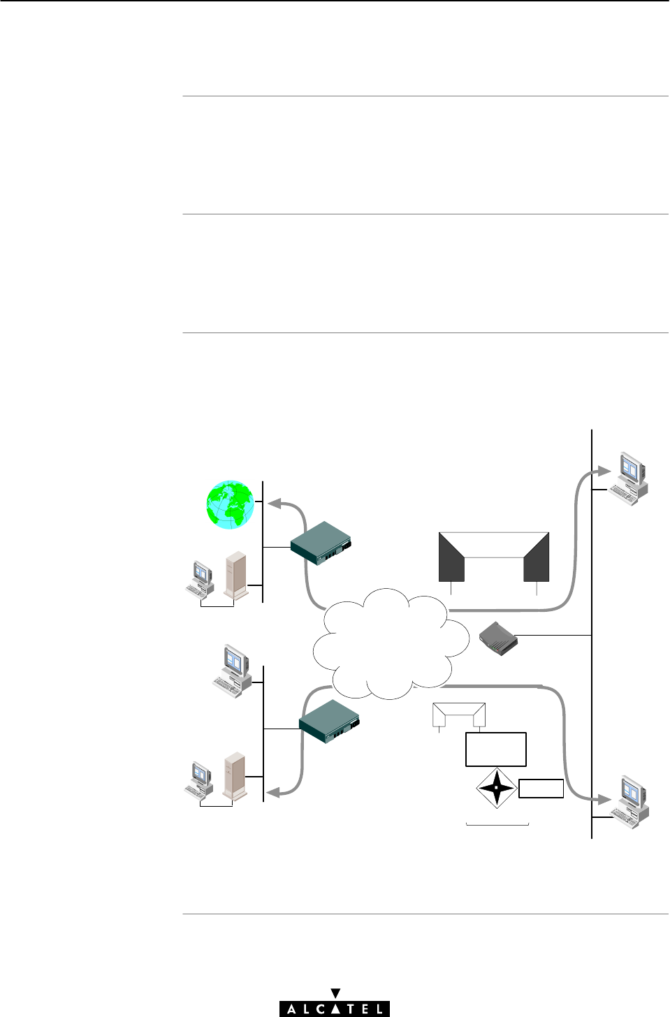
6.2 Using MER
From this point on, using MER is rather straightĆforward. Turn on
both your STWireless and PCs, and your connected to the remote
access router.
As MER presents itself as a Bridge, the connection behaves as for
the Transparent Bridging packet service. No connection procedure
must be performed prior to connectivity.
In the following figure an example configuration of a Transparent
Bridging connection, and a MER connection is given:
Internet
ISP
Access Point
Remote LAN
Access Point
Server
Server
PC 1 connected via the STWireĆ
less's Transparent Bridge
ATM
Network
Bridge
MAC Frames
IP Routing
Ethernet
MER
Interface
NAPT
Virtual Bridging
PC 2 connected via the STWireĆ
less's IP Router and MER InterĆ
face

Introduction
In this section
6 Data Services - MAC Encapsulated Routing
78 / 362 3EC 17766 AAAA TCZZA Ed. 01
6.3 MER Configuration
The STWireless allows local configurations via the STWireless
web pages.
This section describes the configuration of MER entries, and the
use of the 'MER' web page.
Topic See
MER Phonebook Entries 6.3.1
MER Entries 6.3.2

MER phoneboo
k
entries
Adding/deleting
phonebook entries
6 Data Services - MAC Encapsulated Routing
79 / 362
3EC 17766 AAAA TCZZA Ed. 01
6.3.1 MER Phonebook Entries
Central to the STWireless VC pool management, is the
'Phonebook' web page.
The STWireless in its default state features the following MER
related phonebook entries:
Note: Both MER and Bridging share the same type of phonebook
entries, i.e. bridge.
See section 10.2 for more information.
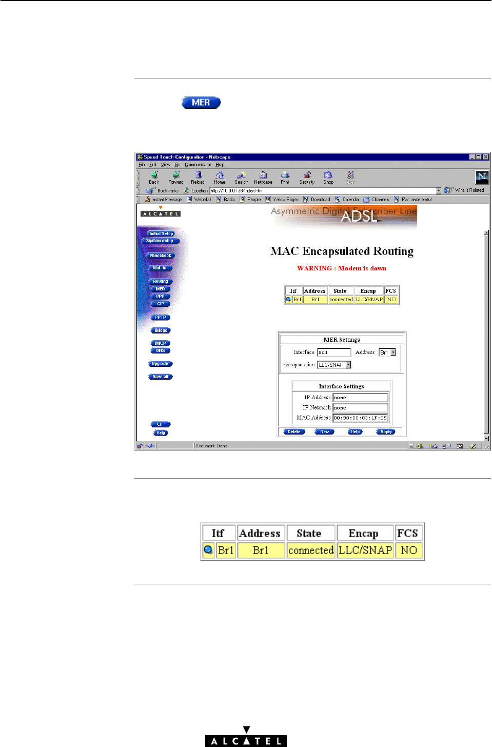
The STWireless 'MER'
web page
The 'MER Connections'
tabl
e
6 Data Services - MAC Encapsulated Routing
80 / 362 3EC 17766 AAAA TCZZA Ed. 01
6.3.2 MER Entries
Clicking in the left pane of the STWireless web pages,
pops up the 'MER' web page (See section 18.2 for more
information):
The following figure shows the 'MER Connections' table:

'MER Connections'
table components
6 Data Services - MAC Encapsulated Routing
81 / 362
3EC 17766 AAAA TCZZA Ed. 01
The following fields are shown:
Field Description
Click the button next to the MER connection you want to
configure.
Selected MER connections are indicated by a yellow bar, and
a button which is lit.
Itf Indicates the interface name.
Note: In most cases, the interface name will be the same as
the phonebook entry name.
Address Indicates the name you have chosen for the MER phonebook
entry.
Note: Specific free MER phonebook entries are shown, as
well as free 'any type' phonebook entries
State Indicates the state of the MER connection. It can take
following values:
Value Description
Idle
Retry The MER interface tries to setup a
WAN connection.
Connected WAN connectivity is achieved on this
MER interface.
The MER interface has no WAN
connection at this time.
Encap Refers to the encapsulation, and decapsulation of Ethernet,
or IEEE 802.3 frames in/from AAL5/ATM. The STWireless is
compliant with RFC 1483 Multiprotocol Encapsulation over
ATM Adaptation Layer 5" and supports both the LLC/SNAP
method and the VCĆMUX method for Bridged Ethernet
V2.0/IEEE 802.3 PDUs.
By default the encapsulation method is set to LLC/SNAP.
FCS Is part of the RFC 1483 encapsulation method and indicates
whether the last four bytes of the MAC frames (mostly
referred to as Ethernet or IEEE 802.3 frames) will be
preserved or not.
For all MER connections, the FCS is set to NO by default.
However, via the CLI, you can set the FCS to YES. See
chapter 19 for more information.
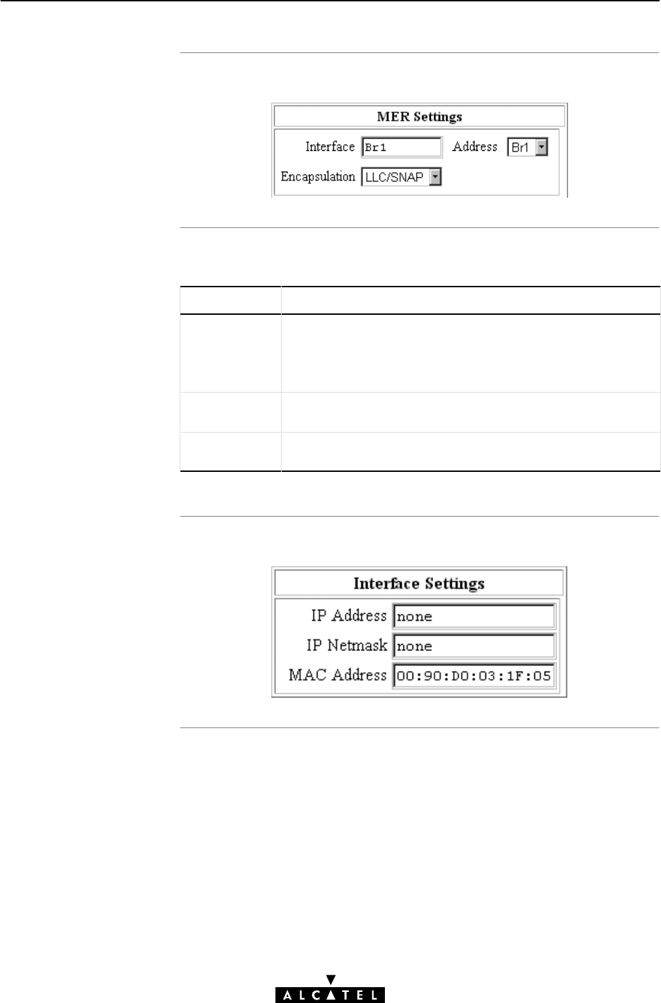
The 'MER Settings'
tabl
e
'MER Settings' table
component
s
The 'MER Interface
Settings' table
6 Data Services - MAC Encapsulated Routing
82 / 362 3EC 17766 AAAA TCZZA Ed. 01
The following figure shows the 'MER Settings' table:
The following fields are shown:
Field Description
Interface Allows to enter an interface name for the MER connection.
Note: You don't have to fill in a name for the MER interface.
The name applied will be the same as the phonebook entry
name.
Address Indicates free MER phonebook entries, as well as free 'any
type' phonebook entries.
Encapsulation Allows to select the encapsulation method, i.e. LLC/SNAP
(default), or VCĆMUX.
The following figure shows the 'MER Interface Settings' table:

'MER Interface
Settings' table
component
s
'MER Configuration'
Button
s
6 Data Services - MAC Encapsulated Routing
83 / 362
3EC 17766 AAAA TCZZA Ed. 01
The following fields are shown:
Field Description
IP Address Allows to enter a static IP address for the MER connection.
Note: In case no IP address is entered, the MER connection
will receive an IP address from the remote access server.
IP Netmask Allows to enter an associated IP netmask for the static IP
address.
Note: In case no IP address is entered in the IP address field,
or no IP netmask is entered, the default associated netmask
will be used.
MAC Address Allows to enter a MAC address for the MER connection. This
MAC address, visible for the remote access server, overrules
the STWireless MAC address.
Note: In case no MAC address is entered, the source MAC
address of the bridged frames is the STWireless MAC
address.
The following buttons are available:
Field Description
Deletes the selected MER connection.
If you create a new MER connection, this button allows to
clear all configurational fields for the connection, i.e. returns
them to their default settings.
Creates a new MER connection, in addition to (an) existing
MER connection(s).
Adds the configured MER connection to the 'MAC
Encapsulated Routing' table, i.e. activates" the MER
connection.
Applies changes you made to an existing MER connection.
connection.
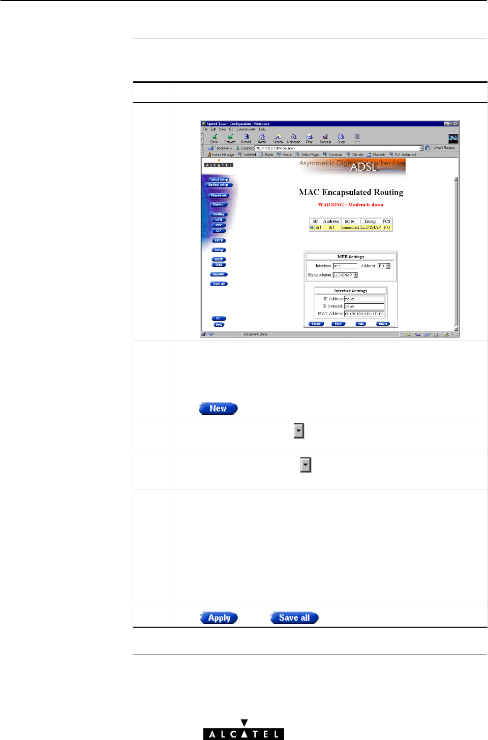
Adding MER entries
6 Data Services - MAC Encapsulated Routing
84 / 362 3EC 17766 AAAA TCZZA Ed. 01
Proceed as follows:
Step Action and Description
1Browse to the 'MER' web page.
2If the 'MAC Encapsulated Routing' table is empty, i.e. you are
creating the first MER connection, proceed with step 3.
If you want to add a MER connection in addition to existing MER
connections (see 'MAC Encapsulated Routing' table),
click
3In the 'Address' field, click and select the (free) phonebook
entry for your MER connection.
4In the 'Encap' column, click and select the encapsulation
method for the connection, i.e. LLC/SNAP, or VCĆMUX.
5Optionally, enter the appropriate configuration in one, or more of
the following fields:
•the 'Interface' field
•the 'IP Address' field
•the 'IP Netmask' field
•the 'MAC Address' field.
Note: See topics 'MER Settings table' and MER Interface Settings
table' in this subsection for more information.
6Click and to finish the procedure.
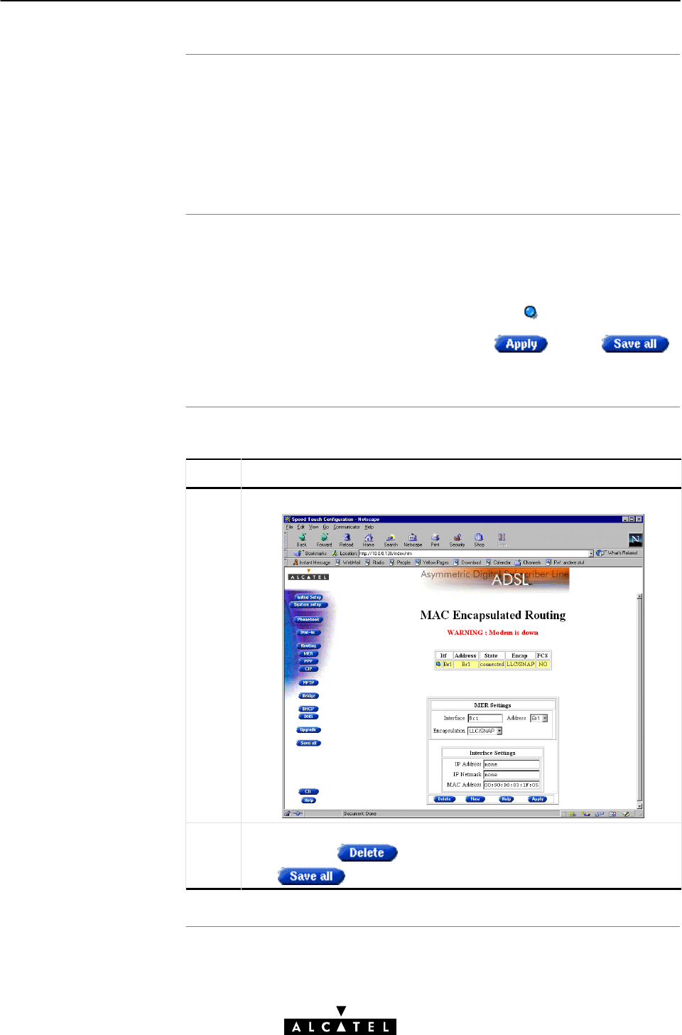
Maximum number o
f
MER connections
Reconfiguring an
existing ME
R
connection
Deleting Bridging
entries
6 Data Services - MAC Encapsulated Routing
85 / 362
3EC 17766 AAAA TCZZA Ed. 01
The STWireless can manage up to 12 MER connections
simultaneously. This can be achieved by deleting all other packet
service entries.
Note: Check with your ASP, or corporate whether multiple
endĆtoĆend connectivity is enabled.
Click the selection button of a MER interface.
The settings shown in the 'MER Settings' and 'MER Interface
Settings' table apply to the MER connection which is marked with a
yellow bar and a selection button which is lit ( ).
Make the changes to the fields, and click . Click
to make the changes persistent.
Proceed as follows:
Step Action and Description
1 Browse to the 'Bridging' web page.
2Click the selection button of the MER connection you want to deĆ
lete, and click
Click to finish the procedure.

In this subsection
MAC Encapsulated
Routing
MER Operation: from
(W)LAN to STWireless's
IP route
r
6 Data Services - MAC Encapsulated Routing
86 / 362 3EC 17766 AAAA TCZZA Ed. 01
6.4 Advanced MER Concepts
"MAC Encapsulated Routing
"MER operation: From (W)LAN to STWireless's IP router
"MER operation: From IP Router to MER
"MER operation: From MER to WAN
"Configuration and Operation Example.
MAC Encapsulated Routing allows IP packets to be carried as
bridged frames. The RFC1483 link protocol with MER is a
multiprotocol encapsulation method over ATM. While the true
IEEE802.1D Transparent Bridge is a hardware component of the
STWireless, for MER, the encapsulation method is implemented
by software.
In the PCs, IP packets are encapsulated in MAC frames, according
their destination:
"For local networking, the destination MAC address is the one
of the destination device, e.g. another PC
"For nonĆlocal traffic, the destination MAC address is that of
the STWireless
"In both cases, the source MAC address, is the MAC address of
the source device, e.g. your PC.
All MAC frames arrive via the Ethernet segment in the
STWireless. It decapsulates the MAC frames and routes the IP
packets, according their destination.
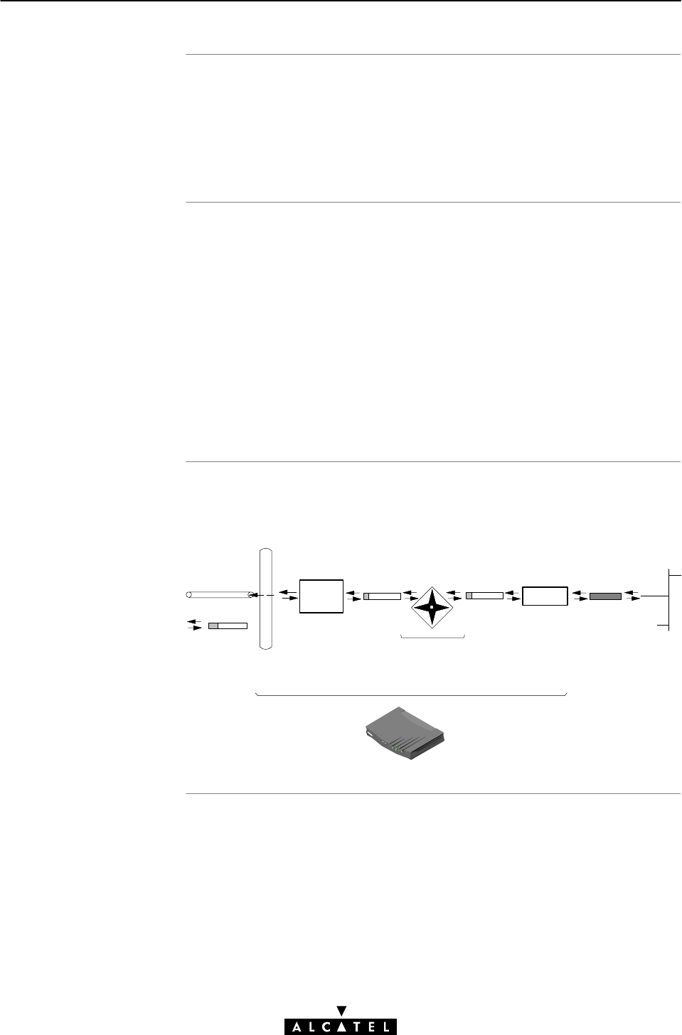
MER Operation: from
STWireless's IP route
r
to ME
R
MER Operation: from
MER to WAN
Configuration and
operation exampl
e
6 Data Services - MAC Encapsulated Routing
87 / 362
3EC 17766 AAAA TCZZA Ed. 01
IP packets destinated for MER, can be subjected to NAPT, prior to
end up in the appropriate MER interface
NAPT allows local (W)LAN PCs to share the single static, or
dynamically obtained public IP address for the MER connection.
The IP packets, ending up in the MER interface are encapsulated
in MAC frames:
"The source MAC address is now the STWireless MAC
address, or the MAC address, configured on the 'MER' web
page
"The destination MAC address is obtained via ARP.
Finally these MAC frames are processed to the WAN, over the
ADSL line by the STWireless, as if it were an IEEE802.1D
compliant bridge, sending MAC, i.e. bridged frames.
The figure below provides an overview of the STWireless
rearĆtoĆfront end MER operation:
Virtual Channel
VPI/VCI:8/83
IP Routing
IP Packet Ethernet MAC
Frame
MER
Interface IP Packet
MAC
Frame NAPT

6 Data Services - MAC Encapsulated Routing
88 / 362 3EC 17766 AAAA TCZZA Ed. 01

Introduction
Topic
s
7 Data Services - PPPoAĆtoĆPPTP Relaying
89 / 362
3EC 17766 AAAA TCZZA Ed. 01
7 Data Services - PPPoAĆtoĆPPTP Relaying
The STWireless PPPoAĆtoĆPPTP Relaying packet service relays PPP
frames, arriving via local IP tunnels to a previously selected VC,
and vice versa.
The PPP protocol that originates, or terminates in the locally
attached PCs, offers a session concept, and provides security via
identification, authentication and encryption.
A major advantage of PPPoAĆtoĆPPTP Relaying is that it avoids the
complexity of an IP router, yet to a certain extent, provides
identical features.
Topic See
Preparatory Steps 7.1
Configuring and Using a PPTP Connection 7.2
Example : MS Windows 98 DialĆUp Networking 7.3
PPPoA/PPTP Configuration 7.4
Customizing PPPoA/PPTP Connections 7.5
Advanced PPPoA/PPTP Concepts 7.6

Features
What you should kno
w
in advance
STWireles
s
7 Data Services - PPPoAĆtoĆPPTP Relaying
90 / 362 3EC 17766 AAAA TCZZA Ed. 01
7.1 Preparatory Steps
PPPoAĆtoĆPPTP Relaying:
"Provides standard DialĆup" PPP behavior
"Supports security via identification, authentication and
encryption
"Has multiprotocol support depending on the PPTP
implementation, e.g. for MS Windows: TCP/IP, IPX/SPX and
NETBEUI
"Offers complete TCP/IP protocol transparency; no NAPT is
required
"Supports concurrent access to multiple remote destinations
(depending on provisioning).
"Supports up to 12 concurrent virtual channels assigned to
PPPoA/PPTP.
"The VPI/VCI value of the VC(s) to use on the ADSL line
"PPPoA connection service must be supported on this VC
"User name and password for your user account.
Note: If connectivity to multiple remote organizations is required,
you need additional sets of these parameters.
The STWireless comes with five preconfigured free PPP
phonebook entries, i.e. Relay_PPP1 ... Relay_PPP4, and PPP3.
If the SP(s) impose PPPoA/PPTP settings which differ from the
STWireless defaults, perform the necessary adjustments via the
STWireless web pages.
See section 7.4 for more information.

PC(s
)
TCP/I
P
7 Data Services - PPPoAĆtoĆPPTP Relaying
91 / 362
3EC 17766 AAAA TCZZA Ed. 01
Your PC must support PPP and PointĆtoĆPoint Tunnelling
Protocol (PPTP).
e.g. All Microsoft Windows platforms support PPP and PPTP.
Before you can establish PPTP tunnels, you must configure:
"An IP address in each PC which initiates a PPTP tunnel
"An IP address in your STWireless which terminates the PPTP
tunnel(s)
To configure an IP address, or enable DHCP in your PC(s), see
Appendix NO TAG.
To configure an IP address, or enable DHCP in your STWireless,
see section 11.3.

Introduction
In this section
7 Data Services - PPPoAĆtoĆPPTP Relaying
92 / 362 3EC 17766 AAAA TCZZA Ed. 01
7.2 Configuring and Using a PPTP Connection
Before you can open a PPTP tunnel towards the STWireless, firstly
you must initially configure a PPTP dialĆup connection on your PC.
Once this PPTP dialĆup connection is configured, you can use it to
open a PPPoA/PPTP connection to the remote side of the ADSL
line.
Because the configuration and use of such a connection follows
similar patterns for all popular OSs, this section will describe the
procedures in global.
In section 7.3 an example is provided how to create and use a
PPTP DialĆUp icon in MS Windows 98.
Refer to appendix C for more information on other OSs.
Topic See
Preparing your PC for PPPoA/PPTP 7.2.1
Using PPTP towards your STWireless 7.2.2

Creating a PPTP
connection icon
PPPoA/PPT
P
parameter
s
7 Data Services - PPPoAĆtoĆPPTP Relaying
93 / 362
3EC 17766 AAAA TCZZA Ed. 01
7.2.1 Preparing your PC for PPPoA/PPTP
Most, if not all OSs provide a GUI guided procedure for the initial
creation of a PPTP connection icon.
The result of such creation is in most cases an icon, or entry in a
folder, or a table, called 'RAS', 'DialĆUp Networking', 'PPTP', 'Call
sessions', etc.
During the initial configuration of your PPTP connection icon, you
must provide the following parameters:
"A name for the PPTP connection icon
"The VPN server's IP address, or DNS hostname, i.e. the
STWireless's IP address, or DNS hostname
Optionally, you can complete this entry with
"The VC's phonebook name to use for this connection
"A PPTP profile name

Opening a session
Credential
s
7 Data Services - PPPoAĆtoĆPPTP Relaying
94 / 362 3EC 17766 AAAA TCZZA Ed. 01
7.2.2 Using PPTP towards your STWireless
Depending on your OS, you can open a session by either doubleĆ
clicking the PPTP connection icon, or selecting it from a RAS table
and clicking 'DialĆUp', or 'Connect'.
Before you can actually browse the Internet, or contact the remote
side's resources, you must supply the following credentials:
"A username
"An associated password
Note: Most, if not all OSs allow the credentials to be saved.

In this section
7 Data Services - PPPoAĆtoĆPPTP Relaying
95 / 362
3EC 17766 AAAA TCZZA Ed. 01
7.3 Example : MS Windows 98 DialĆUp Networking
The following overview summarizes the necessary steps to setup a
Microsoft Windows 98 PC for the use of PPPoAĆtoĆPPTP Relaying:
Step Action See
1 Configure a Private IP address on your PC
2 Create a new DialĆUp Networking icon 7.3.1
3 Adapt DialĆUp Networking Properties C.1
4 Create a shortcut on your desktop (optional) 7.3.2
5 Open a PPPoA/PPTP DialĆUp Session 7.3.3
6 Surf the Internet.
7 Close a PPPoA/PPTP DialĆUp Session in Use 7.3.4
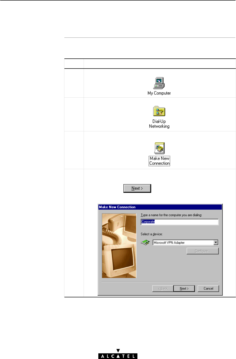
Procedure
7 Data Services - PPPoAĆtoĆPPTP Relaying
96 / 362 3EC 17766 AAAA TCZZA Ed. 01
7.3.1 Create a New DialĆUp Networking Icon
Proceed as follows:
Step Action and Description
1DoubleĆclick the 'My Computer' icon on your desktop.
2DoubleĆclick the 'DialĆUp Networking' icon.
3DoubleĆclick the 'Make New Connection' icon to activate the 'Make
New Connection' wizard.
4If you use the DialĆUp Networking application for the first time, the
'Welcome to DialĆUp Networking' window appears.
In that case, click
The 'Make New Connection' window pops up:
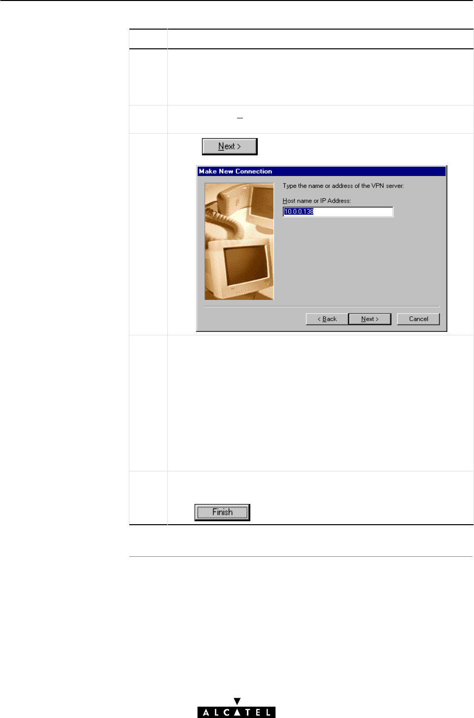
7 Data Services - PPPoAĆtoĆPPTP Relaying
97 / 362
3EC 17766 AAAA TCZZA Ed. 01
Step Action and Description
5In the first input field of the 'Make New Connection' window, type a
name, or alias of the organization you are connecting to.
Note: This name will appear below the DialĆUp icon at the end of
this procedure.
6In the 'Select a device' listbox of the Make New Connection' window,
you must select the 'Microsoft VPN Adapter' for PPTP tunneling.
7Click to pop up the VPN server window:
8Enter the DNS hostname or IP address of the Virtual Private NetĆ
work (VPN) server.
Note: VPN server" is another word for PPTP server, which is in this
case your STWireless.
The default IP address for the STWireless is 10.0.0.138.
Its default hostname is SpeedTouch".
Optionally, you can add the phonebook name to specify which VC is
to be used for the connection. Optionally this phonebook name can
be followed by a PPTP profile. See section 7.5 for more information.
9
Click to finish the procedure.
A window pops up confirming that you have successfully installed a
new DialĆUp connection.
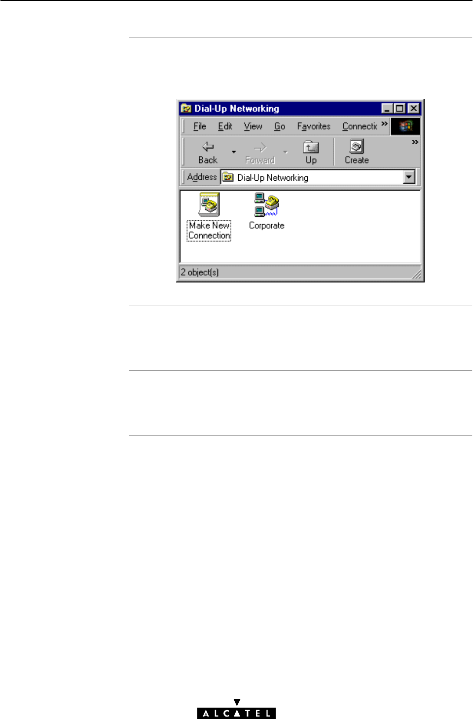
Resul
t
Creating multiple
DialĆUp icons fo
r
multiple destinations
Specific VC and PPTP
Profiles
7 Data Services - PPPoAĆtoĆPPTP Relaying
98 / 362 3EC 17766 AAAA TCZZA Ed. 01
A new icon with the name of the connection that you have just
created, will be added to your 'DialĆUp Networking' folder:
Per destination you can create a unique icon. To do so, repeat the
steps, starting with 3 of the previous procedure.
Using a specific PPP phonebook entry and/or PPTP profile is
described in section 7.5.
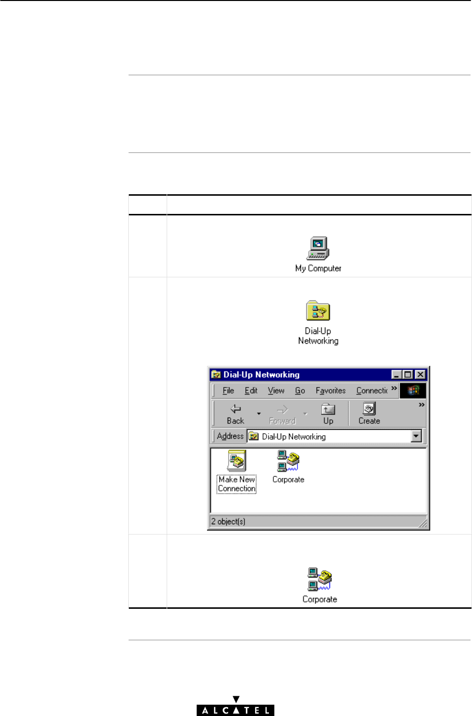
Introduction
Shortcut procedure
7 Data Services - PPPoAĆtoĆPPTP Relaying
99 / 362
3EC 17766 AAAA TCZZA Ed. 01
7.3.2 Create a Shortcut on your Desktop (Optional)
To work comfortably with the DialĆUp connection(s) you created,
Windows 98 offers you the possibility to place a shortcut of the
connection icon on your desktop.
Proceed as follows:
Step Action and Description
1DoubleĆclick the 'My Computer' icon on your desktop.
2DoubleĆclick the 'DialĆUp Networking' icon.
The 'DialĆUp Networking window pops up.
3Select the appropriate DialĆUp connection icon (in the example
'Corporate') and drag it to your desktop to create a copy of the
icon.
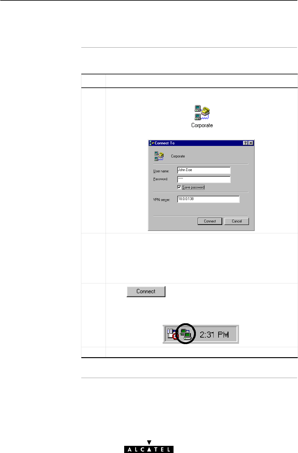
Procedure
7 Data Services - PPPoAĆtoĆPPTP Relaying
100 / 362 3EC 17766 AAAA TCZZA Ed. 01
7.3.3 Open a PPPoA/PPTP DialĆUp Session
Proceed as follows:
Step Action and Description
1DoubleĆclick the appropriate PPPoA/PPTP DialĆUp icon in the 'DialĆ
Up Networking' folder, or doubleĆclick its shortcut on your desktop.
The 'Connect To' window pops up
2Fill in your user name and password, according your user account at
the ISP, or corporate.
Note: If you want the current DialĆUp connection application to reĆ
member your credentials for future use, tick the 'Save Password' box
(n). Make sure though, that you have logged into Windows 98
when you boot your PC.
3Click
The 'Connecting To Corporate' window appears shortly before being
minimized in the system tray.
4Start your application now, e.g. a Web browser.
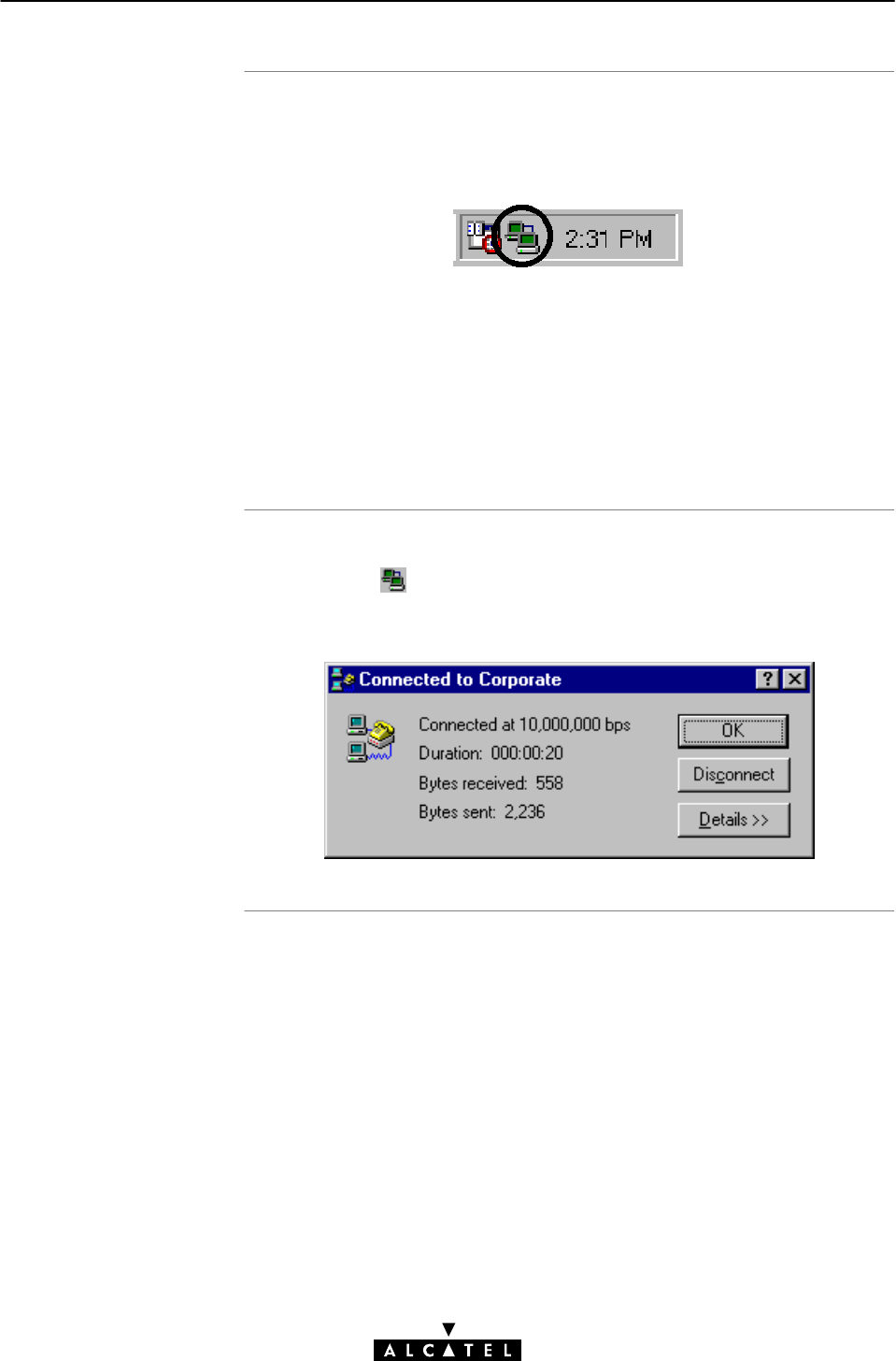
While you are
connected
The 'Connected To'
windo
w
7 Data Services - PPPoAĆtoĆPPTP Relaying
101 / 362
3EC 17766 AAAA TCZZA Ed. 01
Once the PPPoA/PPTP DialĆUp connection is established, you can
find the MSDUN icon showing two PCs connected to each other in
the system tray:
The MSDUN icon symbolizes activity on the PPPoA/PPTP
connection by flashing PC(s):
"A flashing Front" PC symbolizes upstream (TX) link activity
(from your local PC towards the remote device).
"A flashing Behind" PC symbolizes downstream (RX) link
activity (from the remote device towards your PC).
You can check the status of the connection by doubleĆclicking the
MSDUN icon in the system tray.
A'Connected To' window will pop up, showing the status of the
connection:
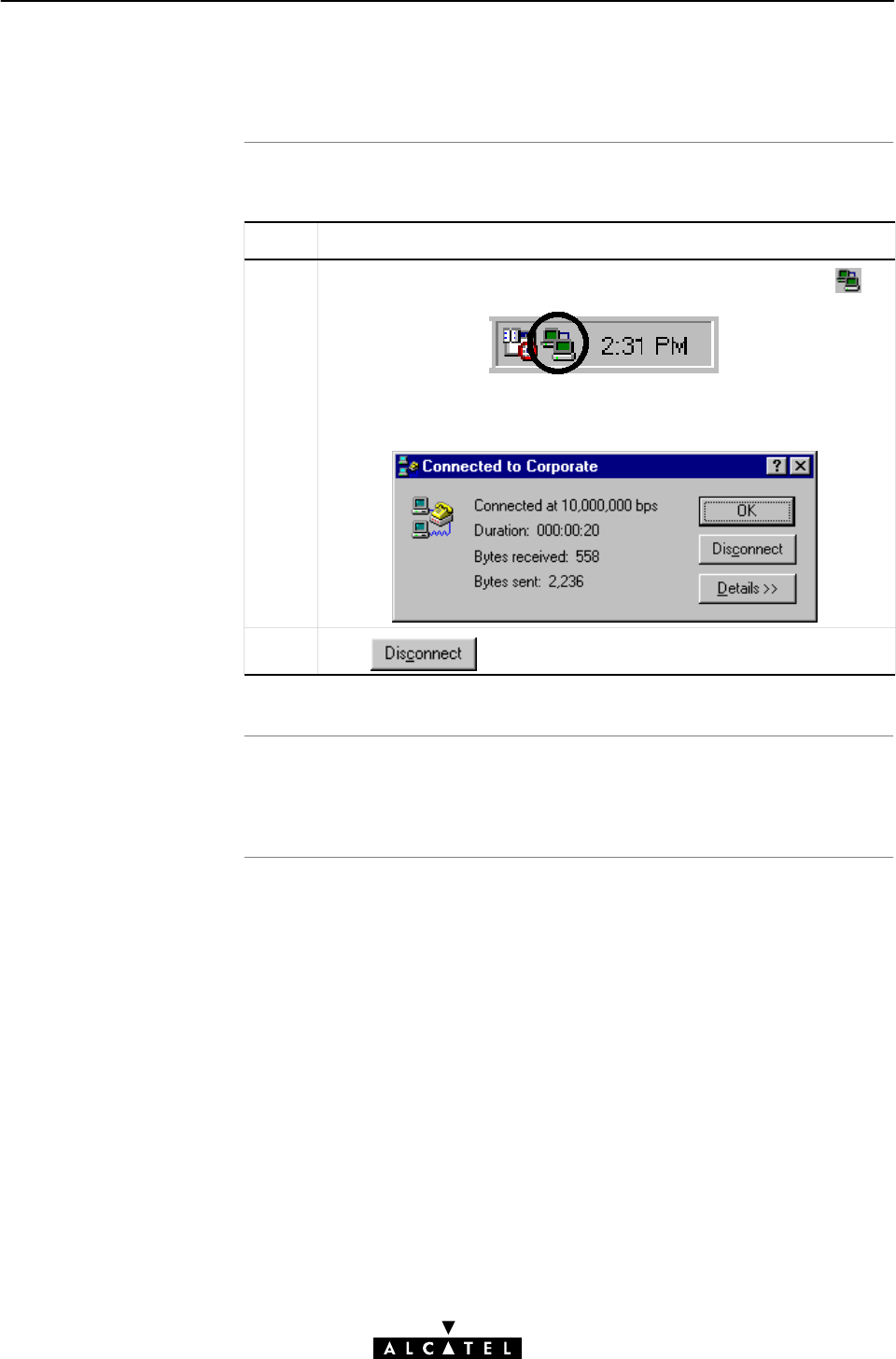
Procedure
Resul
t
7 Data Services - PPPoAĆtoĆPPTP Relaying
102 / 362 3EC 17766 AAAA TCZZA Ed. 01
7.3.4 Close a PPPoA/PPTP DialĆUp Session in Use
Proceed as follows:
Step Action and Description
1If the DialĆUp connection is minimized, click the MSDUN icon
in the system tray:
The 'Connected To' window pops up.
2Click to close the PPPoA/PPTP session.
The PPPoA/PPTP DialĆUp connection will no longer exists. The
PPPoA/PPTP connection is idle, e.g. for other hosts.

Introduction
In this section
7 Data Services - PPPoAĆtoĆPPTP Relaying
103 / 362
3EC 17766 AAAA TCZZA Ed. 01
7.4 PPPoA/PPTP Configuration
The STWireless allows local configuration via the STWireless
web pages.
This section describes the configuration of PPPoA/PPTP entries, and
how to use the 'PPTP' web page.
Topic See
PPPoA/PPTP Phonebook Entries 7.4.1
PPPoA/PPTP Active Connections 7.4.2
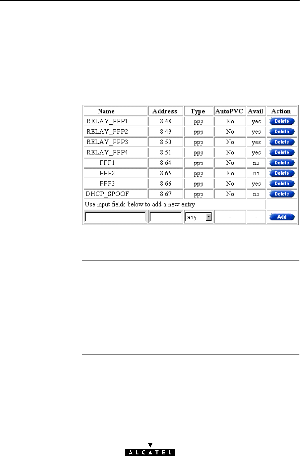
PPTP phoneboo
k
entries
PPTP and PPP
phonebook entries
Adding/deleting
phonebook entries
7 Data Services - PPPoAĆtoĆPPTP Relaying
104 / 362 3EC 17766 AAAA TCZZA Ed. 01
7.4.1 PPPoA/PPTP Phonebook Entries
Basic to the STWireless VC pool management, is the 'Phonebook'
web page.
The STWireless in its default state features the following PPP
related phonebook entries:
Note: Both PPPoA/PPTP and PPP & IP Routing share the same type
of phonebook entries, i.e. ppp.
As you notice, four phonebook entries exist, named Relay_PPP,
which are free, and specifically suitable for PPPoA/PPTP, and four
other phonebook entries, named PPP, and DHCP_SPOOF. Only
use the latter in exceptional cases for PPPoA/PPTP service.
See section 10.2 for more information.
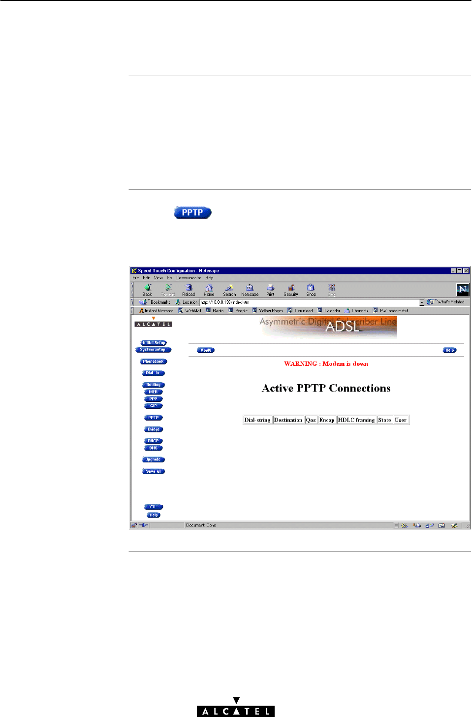
In this subsection
The STWireless 'PPTP'
web page
7 Data Services - PPPoAĆtoĆPPTP Relaying
105 / 362
3EC 17766 AAAA TCZZA Ed. 01
7.4.2 PPPoA/PPTP Active Connections
"The STWireless 'PPTP' Web Page
"The 'Active PPTP Connections' Table
"'Active PPTP Connections' Table Components
"Configuring PPTP Profiles
Clicking in the left pane of the STWireless web pages,
pops up the 'PPTP' web page (See section 18.2 for more
information):
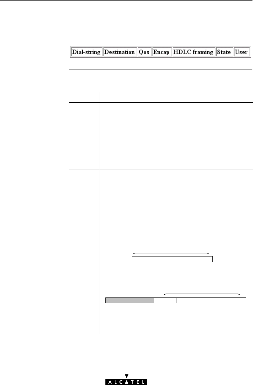
The 'Active PPTP
Connections' table
'Active PPTP
Connections' table
component
s
7 Data Services - PPPoAĆtoĆPPTP Relaying
106 / 362 3EC 17766 AAAA TCZZA Ed. 01
The following figure shows the 'Active PPTP Connections' table:
The following fields are shown:
Field Description
DialĆstring Indicates the name you have chosen for the PPTP connection.
Note: In your DialĆUp application you are able to specify which
PPTP connection is to be used by adding the appropriate
DialĆstring, indicated here.
Destination Indicates the PPTP phonebook entry name, active for this
connection.
Qos Indicates the Quality of Service (QoS) applicable for the
PPPoA/PPTP connection. In most cases the QoS column will
indicate default. Via CLI a specific QoS can be configured.
Encap Refers to the encapsulation, and decapsulation of PPP frames
in/from AAL5/ATM. The STWireless is compliant with RFC 2364
PPP over AAL5" and supports both the LLC/NLPID method and
the VCĆMUX method. By default the encapsulation method for
PPP frames is VCĆMUX.
The encapsulation method for a PPPoA/PPTP connection can be
configured via the CLI, see section 7.5 for more information.
HDLC
Framing
The PPP frames arriving via a PPTP tunnel, and the PPP frames
encapsulated on ATM connections, differ in format.
The PPP format on AAL5 follows RFC 1661 PointĆtoĆPoint
Protocol (PPP)":
P_ID Information Padding
PPP Frame
Address Control P_ID Information Padding
(FF) (03)
PPP Frame
The latter format has two additional bytes in front of the frame
(FFĆ03) inherited from another encapsulation i.e., RFC 1662
PPP in HDLCĆlike framing".
Whereas the PPP format within a tunnel follows PointĆtoĆPoint
Tunneling Protocol (PPTP)":

Configuring PPTP
profiles
7 Data Services - PPPoAĆtoĆPPTP Relaying
107 / 362
3EC 17766 AAAA TCZZA Ed. 01
Field Description
HDLC
Framing
(continued)
Value Description
Never
Always The STWireless will make sure that
FFĆ03 is always in front of a PPP frame
encapsulated on an AAL5/ATM
connection. Although not supported by
RFC2364, some equipment may rely
on this format.
Keep The STWireless will not change the
PPP frame arriving via a tunnel.
The STWireless will make sure that
FFĆ03 will never be found in front of a
PPP frame encapsulated on a
AAL5/ATM connection, independent of
the actual format of the PPP frame in
the tunnel. This setting is default, and
follows RFC2364.
Note: This configuration possibility applies only to the upstream
direction ! In the downstream direction, the STWireless will
always make sure that FFĆ03 is in front of the frame prior to put
it in a PPTP tunnel.
In order to cope with these PPP frame differences, the
STWireless adapts to the different formats on a 'per
connection' base.
Additionally, the STWireless offers the following PPP/AAL5
format configuration options via the CLI if interoperability
problems should arise (See section 7.5 for more information):
State Indicates the connection state of the active PPTP connection. It
can take following values:
Value Description
Resolving
In Use A user opened a session on this PPTP
entry.
The PPTP entry is setting up the
connection.
Retry The PPTP entry did not succeed in
connecting to the remote side, and is
retrying.
User Indicates the IP address of the host, i.e. PC, using this PPTP
connection
PPTP profiles can be configured via the CLI.
See section 7.5 for more information.

Introduction
In this section
7 Data Services - PPPoAĆtoĆPPTP Relaying
108 / 362 3EC 17766 AAAA TCZZA Ed. 01
7.5 Customizing PPPoA/PPTP Connections
In this section the advanced configuration and use of PPPoA/PPTP
connections is described.
Firstly, this section deals with some concepts on the customization
of PPPoA/PPTP connections.
Topic See
PPTP Phonebook Entries 7.5.1
Single Destination 7.5.2
Multiple Destinations 7.5.3
Restrictions of Using Specific Virtual Channels 7.5.4
PPTP Profiles 7.5.4

Introduction
Customizing
PPPoA/PPTP entries
Using added
phonebook entries
PPPoA/PPTP session
scenario
s
7 Data Services - PPPoAĆtoĆPPTP Relaying
109 / 362
3EC 17766 AAAA TCZZA Ed. 01
7.5.1 PPPoA/PPTP Phonebook Entries
To establish a PPPoA/PPTP session, all you need to do is opening a
PPTP tunnel.
However, this does only apply in the case only a single destination
is reachable via one, or more VCs.
With the STWireless, it is possible to open multiple simultaneous
sessions, or even simultaneously open sessions to multiple
destinations.
Via the STWireless 'Phonebook' web page, you are able to add
PPP phonebook entries in addition to the defaults.
You can give them names of your choice (in the name field). See
section 7.4 for more information.
The name you gave the PPTP phonebook entries in the
STWireless's phonebook can be used to specify which
PPPoA/PPTP VC is to be issued by a particular PPTP connection
icon.
The PPPoA/PPTP entries can be used in several ways:
"(All) directed to a single destination
"Directed to specific destinations.
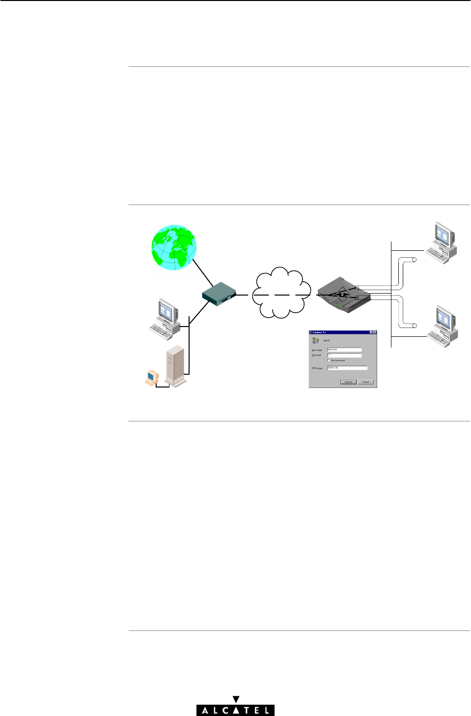
Single destination
PPPoA/PPTP sessions
Single destination
architectur
e
Two scenarios
7 Data Services - PPPoAĆtoĆPPTP Relaying
110 / 362 3EC 17766 AAAA TCZZA Ed. 01
7.5.2 Single Destination
If the 'VPN Server' field of the PPTP DialĆUp application is left
unchanged, i.e. only the IP address of the STWireless (or its host
name) is visible, the STWireless automatically chooses a free PPP
phonebook entry from the Phonebook.
This is the most easy scenario and works best if all (one, or more)
PPPoA/PPTP related PPP VCs are attached to the same remote
destination.
Local PPTP
Tunnels
Corporate HQ
Remote
Access Point
INTERNET
ATM VC
PPP RELAY
Two scenarios are possible:
"Single PPP VC to a single destination
In this scenario, the SP supplied one PPP VC for connectivity. It
is most applicable when a single PC is connected to the
STWireless.
"Multiple PPP VCs to single destination
In this scenario, the SP supplied multiple PPP VCs, all direct to
the same destination. This implies that several PCs can
connect to this destination at the same time (as long there is
an idle channel left). Therefore, this is most applicable with a
STWireless connected to a (W)LAN.
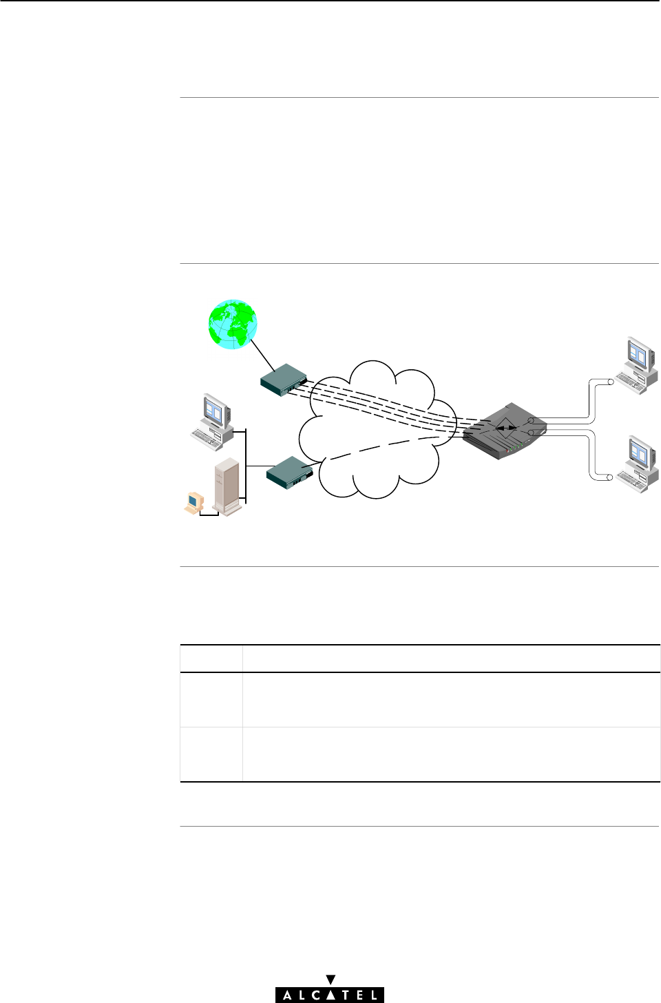
Multiple destination
PPPoA/PPTP sessions
Multiple destination
architectur
e
Procedure to specify a
VC for a PPTP
connection icon
7 Data Services - PPPoAĆtoĆPPTP Relaying
111 / 362
3EC 17766 AAAA TCZZA Ed. 01
7.5.3 Multiple Destinations
Multiple SPs might be connected to your STWireless, e.g., your
private ISP and your corporate.
In this case, the STWireless's PPP VCs can be split over both
locations. For example, 6 PPP VCs could be provisioned to your
ISP, while 6 other PPP VCs are used for connecting to your
corporate.
Corporate HQ
Remote LAN
INTERNET
PPPoA RELAY
Local PPTP
Tunnels
Other Virtual
Channels
Specific Virtual Channel
Proceed as follows to specify which VC (i.e. Phonebook entry) is to
be used by a DialĆUp connection:
Step Action
1 Add, if needed, a PPP phonebook entry to the STWireless's
phonebook with the appropriate VPI/VCI values for the specific
destination.
2 When creating a new PPTP tunnel configuration, add this PPP VC
phonebook name next to the IP address, or DNS name of the VPN
server (i.e. the STWireless).
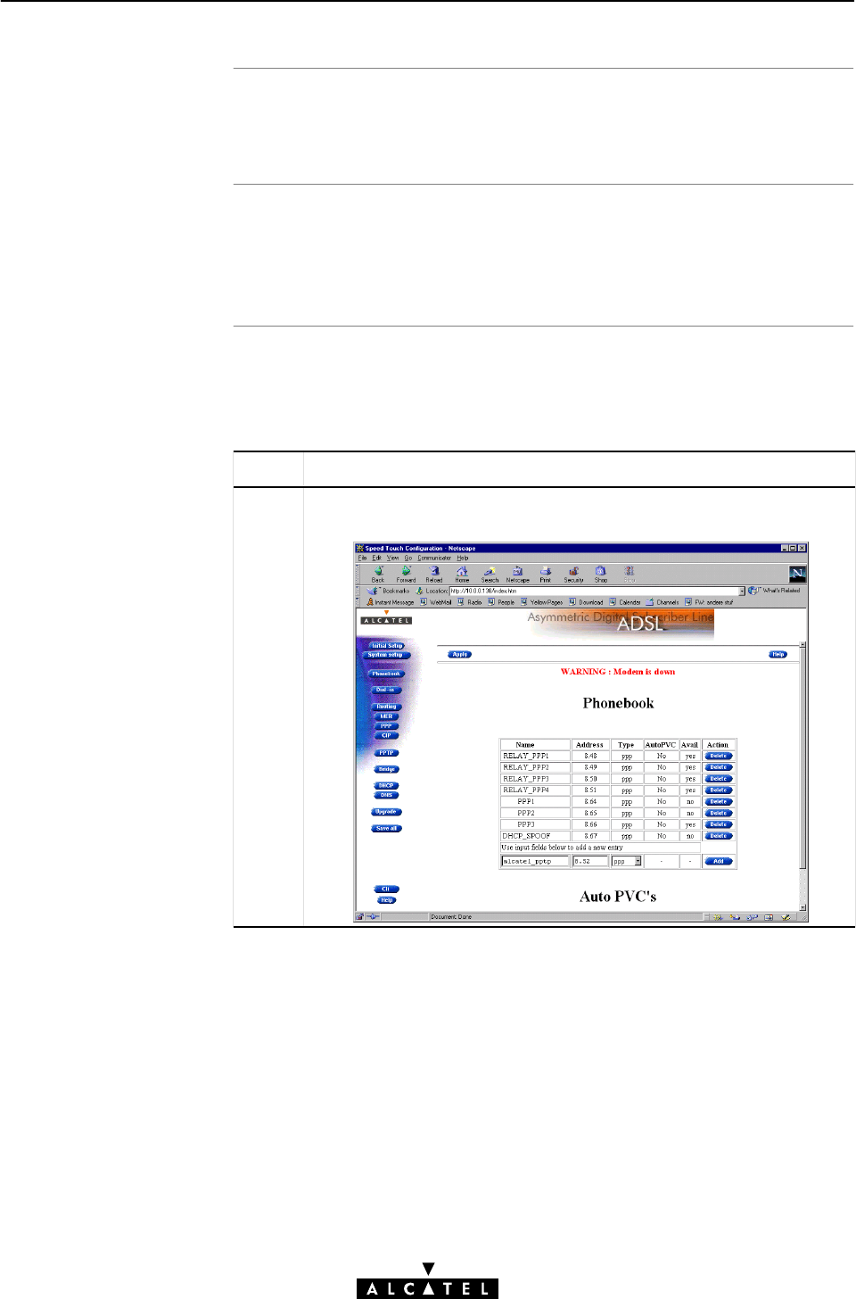
Resul
t
Note
Example for Windows
9
x
7 Data Services - PPPoAĆtoĆPPTP Relaying
112 / 362 3EC 17766 AAAA TCZZA Ed. 01
If you open this PPPoA/PPTP session, it will use the PPP Phonebook
entry, specified in the VPN server field.
You must check with your ISP and your corporate LAN
administrator to verify which crossĆconnections exist between the
PPP VCs and the locations.
Proceed as follows to create an MS Windows 9x DialĆUp
Networking icon to the corporate 'Alcatel', which has to use the
VC, named 'Alcatel_pptp':
Step Action and Description
1 Configure a PPP phonebook entry, named 'Alcatel_pptp', in the
Phonebook as described in subsection 7.4.1.
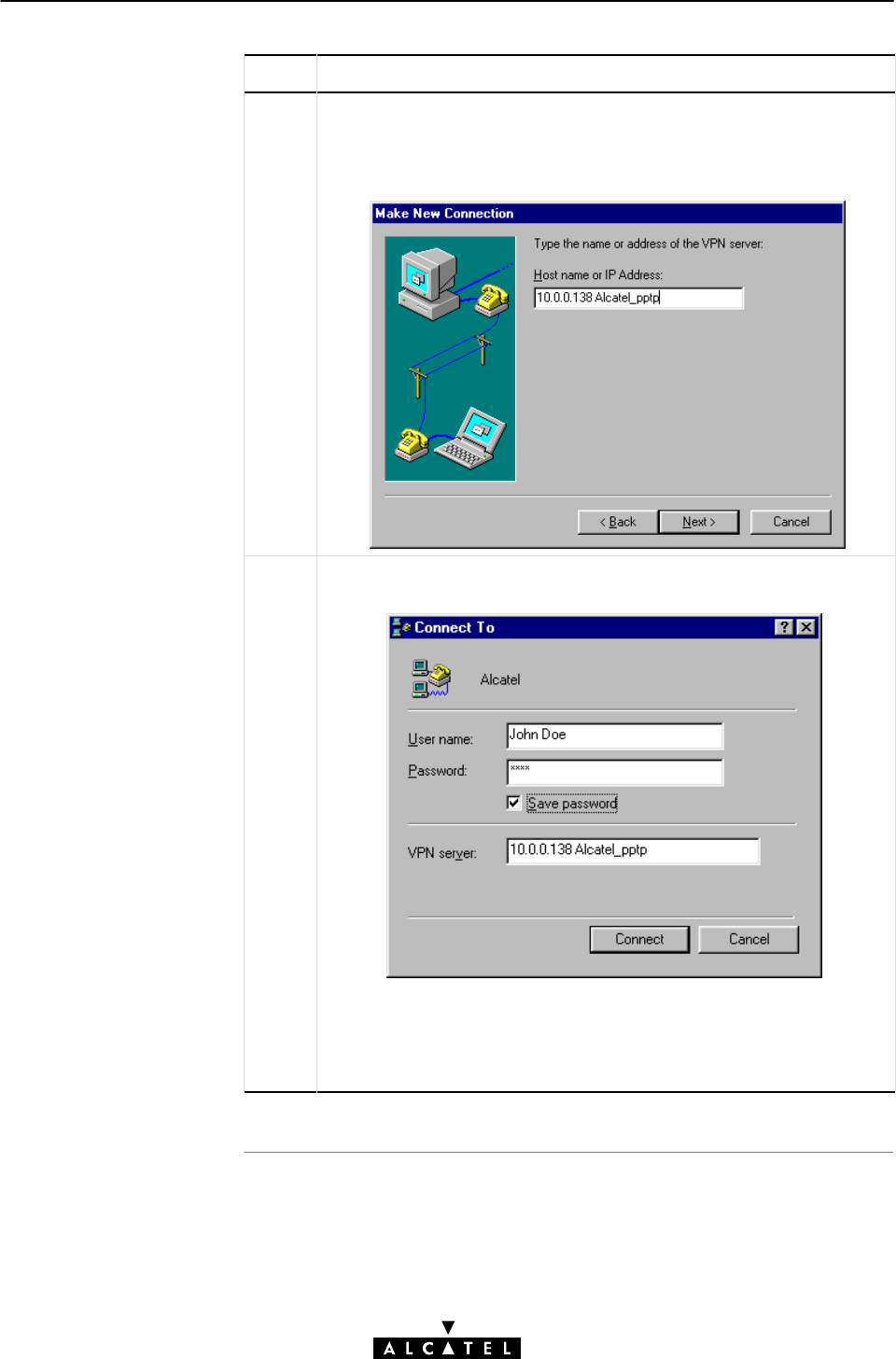
7 Data Services - PPPoAĆtoĆPPTP Relaying
113 / 362
3EC 17766 AAAA TCZZA Ed. 01
Step Action and Description
2Create a DialĆUp Networking icon, named 'Alcatel', according to
section 7.3.1.
In step 9 of the procedure (See section 7.3.1), you not only specify
the VPN server, i.e. the STWireless, but also the VC 'Alcatel_pptp':
3DoubleĆclick the 'Alcatel' icon to open the PPPoA/PPTP session. The
following DialĆUp window pops up:
As you can see in the 'VPN Server' field, the VC, i.e. alcatel_pptp, to
be used is specified by its name. Consequently, this PPPoA/PPTP
session will always use this VC for establishing a connection to the
corporate 'Alcatel'.
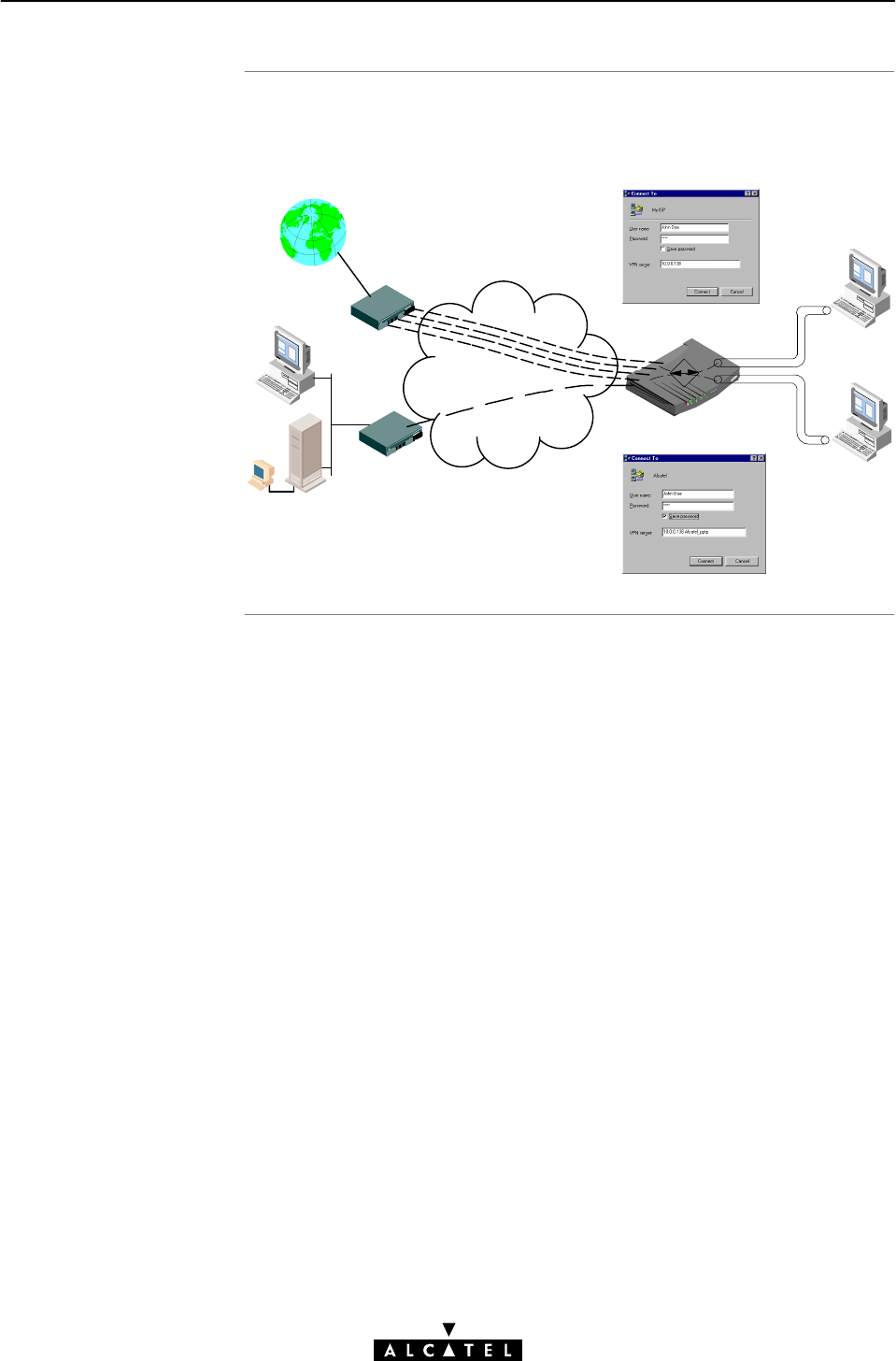
Example Resul
t
7 Data Services - PPPoAĆtoĆPPTP Relaying
114 / 362 3EC 17766 AAAA TCZZA Ed. 01
The following figure shows an example of both single and multiple
PPPoA/PPTP connections established simultaneously.
Alcatel
Remote LAN
My ISP
INTERNET
PPP RELAY
Local PPTP
Tunnels
ATM Channels
Other Virtual
Channels
'Alcatel_pptp'

Similar phoneboo
k
name
s
Positive use of simila
r
name
s
Case of no entr
y
matche
s
7 Data Services - PPPoAĆtoĆPPTP Relaying
115 / 362
3EC 17766 AAAA TCZZA Ed. 01
7.5.4 Restrictions on Using Specific Virtual Channels
The STWireless will look for a match between the string, specified
next to the VPN server's DNS hostname or IP address (in the
previous example the string 'Alcatel_pptp').
If however, several PPPoA/PPTP entries exist, with names starting
with the same string, e.g. Alcatel_pptp1, Alcatel_pptp2, etc., it can
not be determined which of these will be used to establish the
connection.
This can be used in a positive way however: if a selection of
PPPoA/PPTP VCs may be used by a particular PPPoA/PPTP session,
you just have to give them names with a stringmatch in the
beginning, e.g. 'Alcatel_pptpX' ,where X is a number.
In case no match is found in the STWireless phonebook, or if the
specified VC is already used, the DialĆUp application will use the
first available idle PPPoA/PPTP VC found in the 'PPTP connections'
table.
Consequently, again it can not be determined which PPPoA/PPTP
VC will be used to establish the connection.

Introduction
PPTP profile selections
Creating a PPTP Profile
7 Data Services - PPPoAĆtoĆPPTP Relaying
116 / 362 3EC 17766 AAAA TCZZA Ed. 01
7.5.5 PPTP Profiles
In most cases, the STWireless's PPP phonebook entries are ideally
suited to make PPPoA/PPTP connections over the ADSL line.
However, in case the remote access server demands specific
configurations for PPPoA/PPTP, you can easily configure a PPTP
profile via the CLI.
By default a 'default' profile exists, applicable for all PPP
phonebook entries. This default profile inhibits the following
settings:
"Encapsulation method : VCĆMUX
"HDLC framing : never
"QoS : default.
A PPTP Profile can only be created and configured via the CLI. See
chapter 19 for more information on the CLI.

Introduction
Topic
s
7 Data Services - PPPoAĆtoĆPPTP Relaying
117 / 362
3EC 17766 AAAA TCZZA Ed. 01
7.6 Advanced PPPoA/PPTP Concepts
This section describes some advanced concepts of the
STWireless's PPPoAĆtoĆPPTP Relaying packet service.
Topic See
PointĆtoĆPoint Tunneling 7.6.1
Local Tunneling 7.6.2
PPPoAĆtoĆPPTP Relaying (PPPoA/PPTP) 7.6.3
Simultaneous PPPoA/PPTP Sessions 7.6.4

What is Tunneling
Tunneling applied to
the STWireless
Result of PPTP
tunneling
Supported (W)LAN
Protocols
7 Data Services - PPPoAĆtoĆPPTP Relaying
118 / 362 3EC 17766 AAAA TCZZA Ed. 01
7.6.1 PointĆtoĆPoint Tunneling
Tunneling is a technique that allows to transport certain protocols
over a network, which is not designed for that purpose.
Example: IPX Packets can be wrapped in IP, ready to be routed
over an IP network.
At the destination, the IPX packets are decapsulated and made
available in their original format again.
Tunneling applied to the STWireless implies that:
"Tunnels have a local scope.
Indeed, tunnels are established between two peers on the
local IP network: local PCs initiate tunnels, the STWireless
terminates these tunnels.
"IP tunnels are established and released for the duration of a
session.
"The protocol carried inside the tunnels is PPP. However,
various protocols can be carried inside the PPP frames.
The net result of PPTP tunneling is that PPP frames can cross
the local Ethernet segment between the STWireless and the client
computer and vice versa.
This would otherwise not be possible as PPP is designed to run on
pointĆtoĆpoint connections, e.g. DialĆUp connections, whereas
Ethernet is a shared medium.
Within PPP, all kinds of protocols can be transported.
The PPP/PPTP client, however, is the limiting factor. Some OSs only
allow specific protocols to be transported within PPP tunnels (e.g.
TCP/IP, IPX/SPX, or NETBEUI in case of Window 9x).
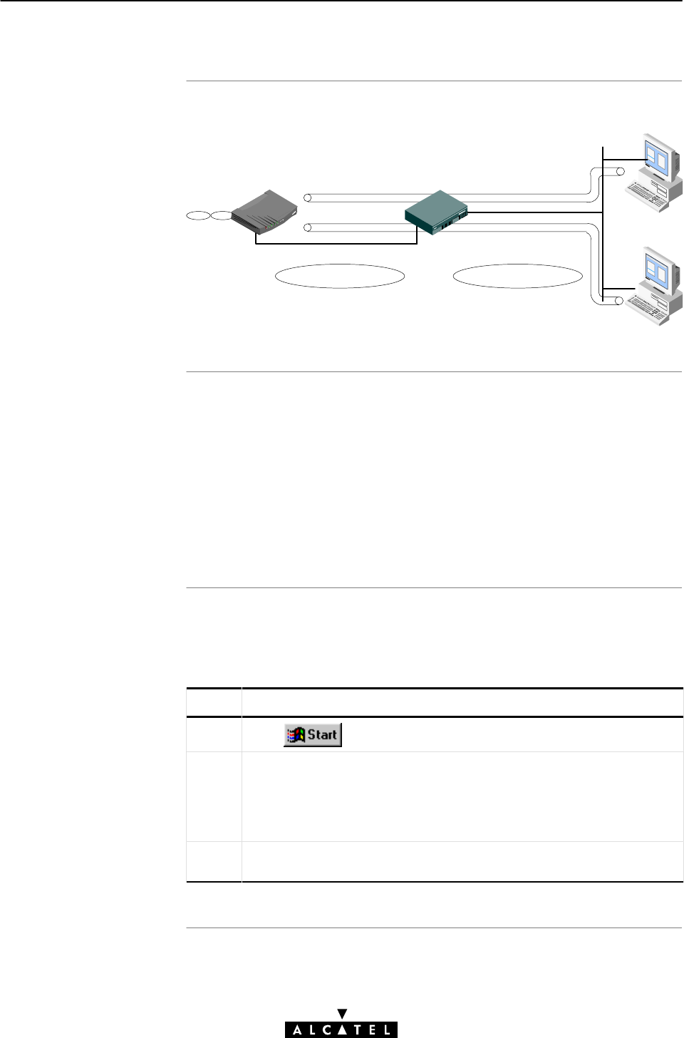
Tunneling from behind
an IP route
r
STWireles
s
PC
s
7 Data Services - PPPoAĆtoĆPPTP Relaying
119 / 362
3EC 17766 AAAA TCZZA Ed. 01
7.6.2 Local Tunneling
The STWireless allows local tunneling from behind an IP router:
IP Network 10 IP Network 172.16
10.0.0.138 10.0.0.1
172.16.0.1
172.16.0.3
172.16.0.2
Ethernet (W)LA
N
IP Router Local PPTP tunnels
This requires settings in both STWireless and PCs.
You must add a default route for the STWireless via the 'Routing'
web page (See subsection 11.4.2 for more information).
In the example of the above figure, the route to be added, has the
following parameters:
"Destination: 0.0.0.0/0
"Source: Any
"Gateway: 10.0.0.1
For each PC, you must add a route to its internal routing table.
This route must point to the STWireless. Proceed as follows for a
Windows OS:
Step Action and Description
1Click , select 'Programs', and 'MSĆDOS' prompt.
2 At the DOS prompt, enter:
route add <Destination IPaddress>
<Gateway IPaddress>
In the example of the previous figure, the command would be:
route add 10.0.0.138 172.16.0.1
3 To verify IP connectivity, you can ping the STWireless. If it responds,
setting up PPTP tunnels is possible.
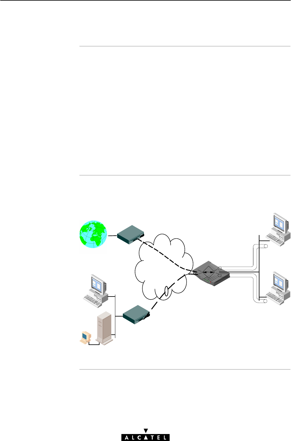
What is PPPoAĆtoĆPPT
P
Relaying
PPPoA/PPTP overvie
w
architectur
e
7 Data Services - PPPoAĆtoĆPPTP Relaying
120 / 362 3EC 17766 AAAA TCZZA Ed. 01
7.6.3 PPPoAĆtoĆPPTP Relaying (PPPoA/PPTP)
By opening a PPPoA/PPTP session, PPTP tunnels are established
between the STWireless and the PCs on your (W)LAN.
These PPTP tunnels trigger the Relaying utility of the STWireless:it
chooses a free VC from the pool of available free PPP phonebook
entries and relays all PPP frames, sourced by the PPTP tunnel from
the tunnel to the VC, and vice versa.
At the remote end of the VC, i.e. ADSL line, the remote access
server extracts the PPP frames, reconstructs the encapsulated IP
packets and forwards them to their destination, e.g. the Internet.
At the end of a PPPoA/PPTP session, the PPTP tunnel is destroyed.
This triggers the STWireless's Relay utility to release the VC.
The figure below provides an overview of the endĆtoĆend
architecture.
Local PPTP
Tunnels
Ethernet
(W)LAN
Corporate Access Point
Remote LAN
ISP Access Point
INTERNET
Bundled ATM VCs
PPP RELAY
ATM Network

Upper limit o
f
simultaneou
s
PPPoA/PPTP sessions
STWireless and
simultaneou
s
connection
s
7 Data Services - PPPoAĆtoĆPPTP Relaying
121 / 362
3EC 17766 AAAA TCZZA Ed. 01
7.6.4 Simultaneous PPPoA/PPTP Sessions
PPTP tunneling does not influence your local communication; you
can add as many hosts as your local network supports.
However, there is an upper limit to the number of simultaneous
outbound connections. Unlike Bridging, or MER, a PPPoA/PPTP
related VC cannot be shared by multiple users. A user establishing
a tunnel requires at least one PPPoA/PPTP related VC.
Therefore, any user on the local network can only initiate tunnels
as long as there are idle PPPoA/PPTP VCs, i.e. idle PPTP
phonebook entries.
By disabling all other packet service entries in the STWireless
Phonebook, the STWireless is capable of managing up to 12
simultaneous PPPoA/PPTP VCs.
If all PPPoA/PPTP VCs are in use, and a user tries to setĆup a new
tunnel, the STWireless will refuse the request and an error
message will appear on the screen.

7 Data Services - PPPoAĆtoĆPPTP Relaying
122 / 362 3EC 17766 AAAA TCZZA Ed. 01

Introduction
In this chapte
r
8 Data Services - PPP & IP Routing
123 / 362
3EC 17766 AAAA TCZZA Ed. 01
8 Data Services - PPP & IP Routing
The STWireless features the PPP & IP Routing packet service.
Via the PPP protocol an authenticated session is established with
your SP.
IP packets, arriving over the PPP connection, are forwarded by the
IP router to PCs on your (W)LAN.
Optionally, Network Address & Port Translation (NAPT) can be
enabled to isolate your local network from the Internet, or to share
a single IP address.
Topic See
Preparatory Steps 8.1
Using PPP & IP Routing 8.2
PPP Configuration 8.3
PPP Entry Configuration 8.4

Features
What you should kno
w
in advance
STWireles
s
PC(s
)
8 Data Services - PPP & IP Routing
124 / 362 3EC 17766 AAAA TCZZA Ed. 01
8.1 Preparatory Steps
PPP & IP Routing:
"Has an authenticated session concept: it supports
identification, authentication and autoconfiguration.
"Requires no session client on the PC(s), avoiding special
installation procedures
"Combined with NAPT, allows multiple users to share a single
IP address simultaneously on a single VC
"Supports up to 12 concurrent virtual channels for PPP.
"The VPI/VCI value of the VC(s) to use on the ADSL line
"PPPoA connection service must be supported on this VC
"User name and password for your user account.
Note: If connectivity to multiple remote organizations is required,
you need additional sets of these parameters.
The STWireless comes with eight phonebook entries available for
PPP & IP Routing, of which three are preconfigured for immediate
use.
If the SP(s) impose settings which differ from the STWireless
defaults, perform the necessary adjustments via the STWireless
web pages.
See sections 8.3 and 8.4 for more information.
In order to use the PPP & IP Routing mode of the STWireless, the
OS on your PC(s) must support the TCP/IP suite.
See chapter 11 for more information on IP.
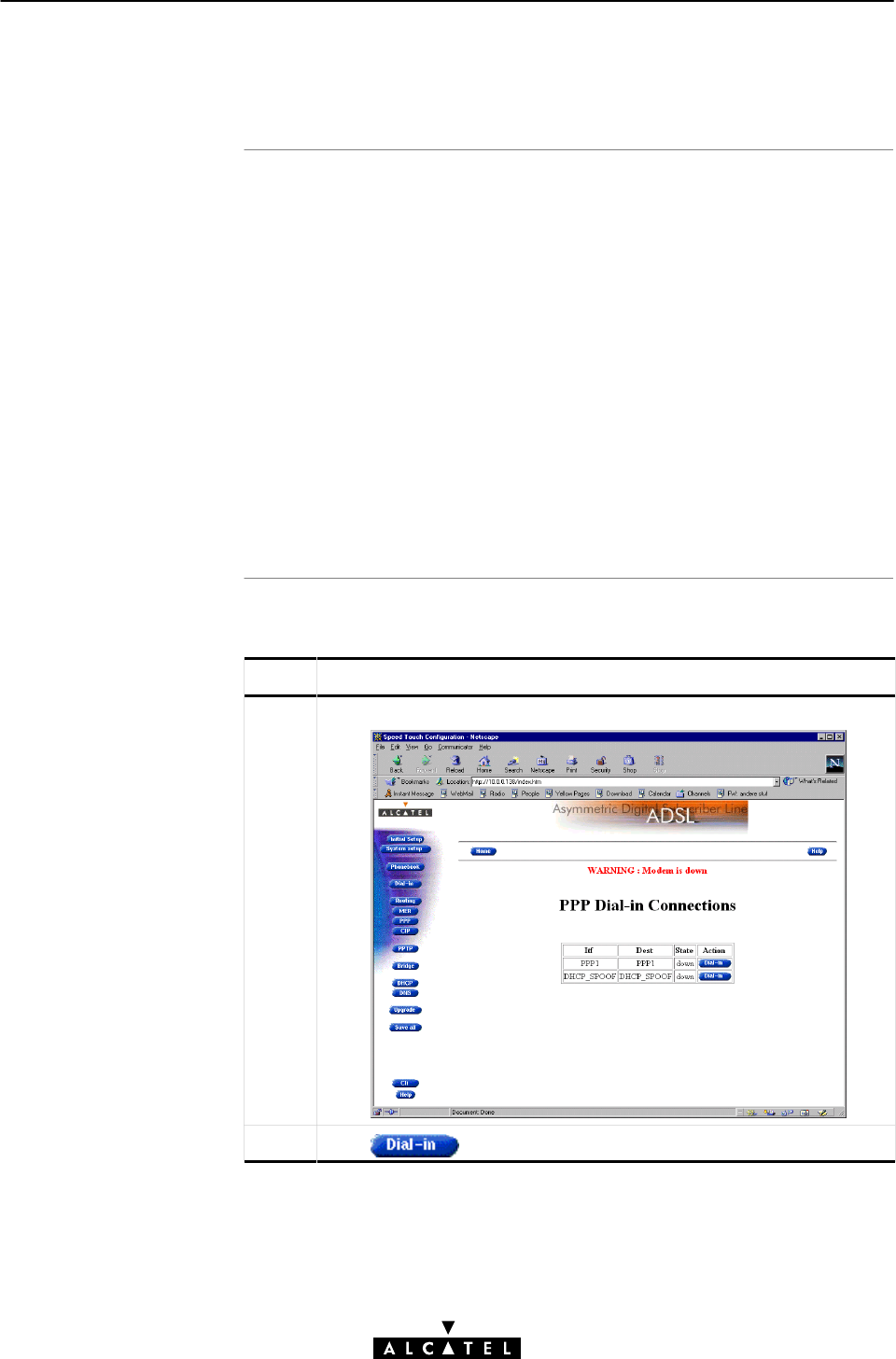
AlwaysĆon, DialĆin and
DialĆonĆDemand PPP
session
s
Opening dialĆin PPP
session
s
8 Data Services - PPP & IP Routing
125 / 362
3EC 17766 AAAA TCZZA Ed. 01
8.2 Using PPP & IP Routing
Three methods exist to open a PPP:
"DialĆin
The PPP session is opened manually
"AlwaysĆon
After the STWireless is powered and finished its POST
successfully, the STWireless automatically tries to open the
PPP session
"DialĆonĆdemand
The PPP session is opened automatically, triggered by the
arrival of packets at a/the STWireless Ethernet port, destined
for a PPP connection.
Proceed as follows (See section 18.2 for more information):
Step Action and Description
1Browse to the 'DialĆin' web page:
2Click next to a PPP entry in the list.
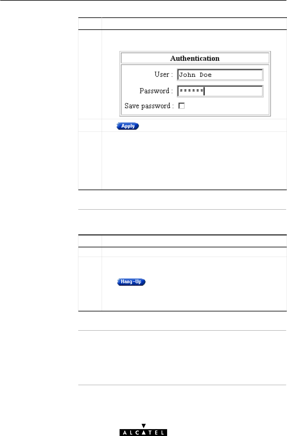
Closing dialĆin PPP
session
s
Saving credentials
8 Data Services - PPP & IP Routing
126 / 362 3EC 17766 AAAA TCZZA Ed. 01
Step Action and Description
3 If applicable the 'Authentication' web page pops up:
Enter user name and password in the appropriate fields.
4Click .
5After identification and authentication, the 'PPP connections' web
page reappears.
While the STWireless tries to open the session, trying will appear
in the 'State' field. Once the session is active, the field displays up.
From then, you are online, and you can start your application, or
browse the Internet.
Note: AlwaysĆon" PPP connections will not appear in this table.
Proceed as follows:
Step Action and Description
1Browse to the 'DialĆin' web page.
2Click next to the PPP entry you want to close the session
for.
The session state of the PPP entry will change to down, i.e. it
becomes idle.
Active PPP sessions are indicated via up in the 'State' field.
If you want the STWireless to remember your credentials, check
'Save password' (n)inthe'Authentication' web page.
See subsection 8.4.4 for more information.

Introduction
In this section
8 Data Services - PPP & IP Routing
127 / 362
3EC 17766 AAAA TCZZA Ed. 01
8.3 PPP Configuration
The STWireless allows local configurations via its web pages.
This section describes the enabling of PPP entries, and the use of
the 'PPP' web page.
Prior to be able to use the PPP entry, you must configure the PPP
entry. This is described in section 8.4.
Topic See
PPP Phonebook Entries 8.3.1
PPP Entries 8.3.2
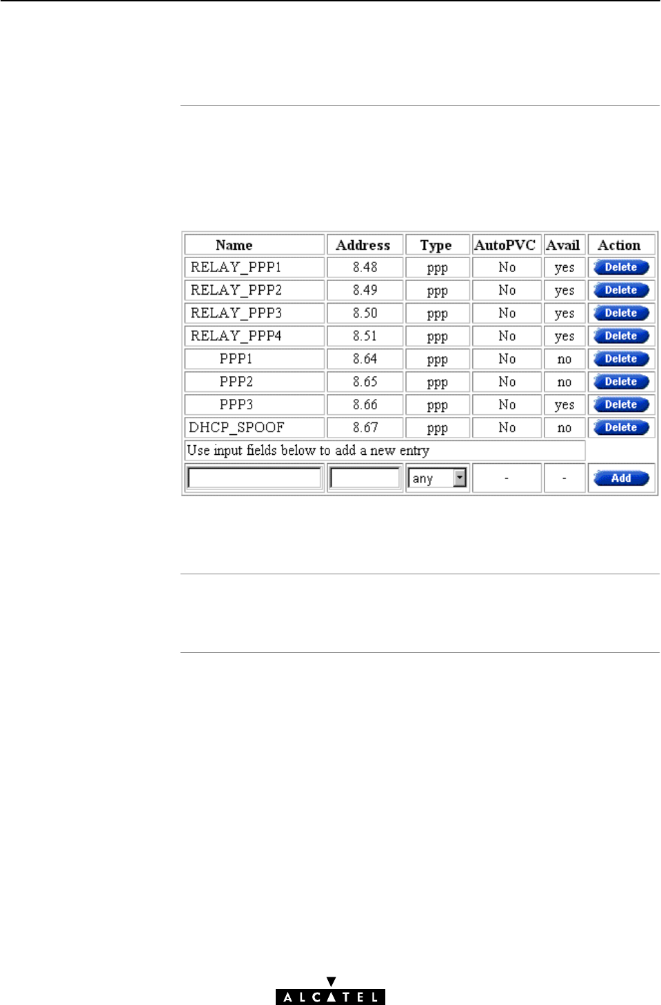
PPP phonebook entries
Adding/deleting
phonebook entries
8 Data Services - PPP & IP Routing
128 / 362 3EC 17766 AAAA TCZZA Ed. 01
8.3.1 PPP Phonebook Entries
Central to the STWireless VC pool management, is the
'Phonebook' web page.
The STWireless in its default configuration features the following
PPP related phonebook entries:
Note: Both PPP & IP Routing and PPPoA/PPTP share the same type
of phonebook entries, i.e. ppp.
See section 10.2 for more information.
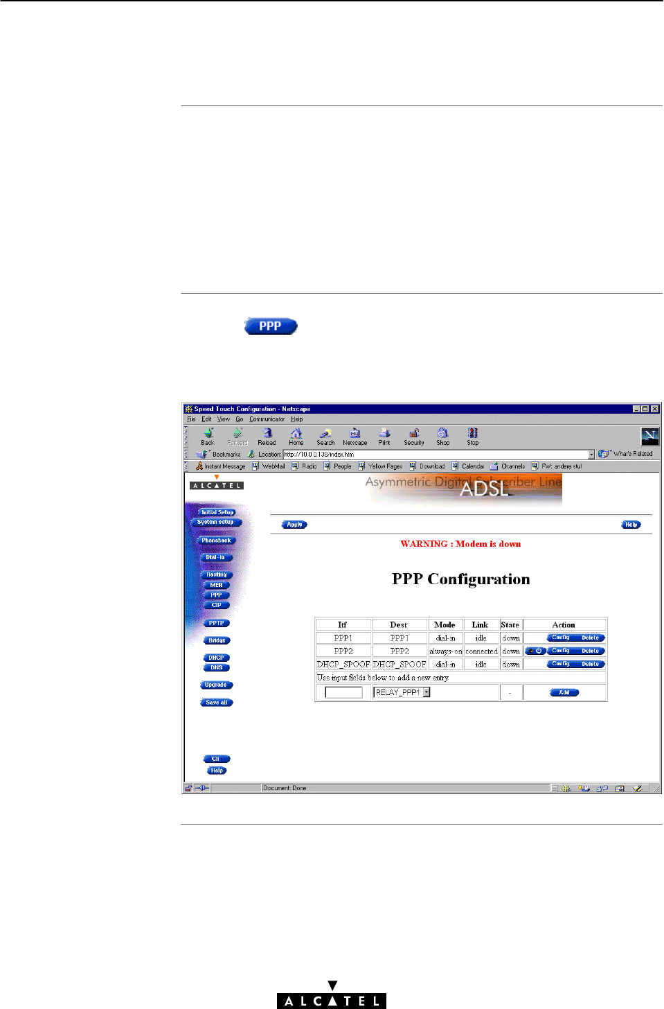
In this subsection
The 'PPP' web page
8 Data Services - PPP & IP Routing
129 / 362
3EC 17766 AAAA TCZZA Ed. 01
8.3.2 PPP Entries
"The 'PPP' Web Page
"The 'PPP Configuration' Table
"'PPP Configuration' Table Components
"Adding PPP Entries
"Deleting PPP Entries.
Clicking in the left pane of the STWireless web pages,
pops up the 'PPP' web page (See section 18.2 for more
information):
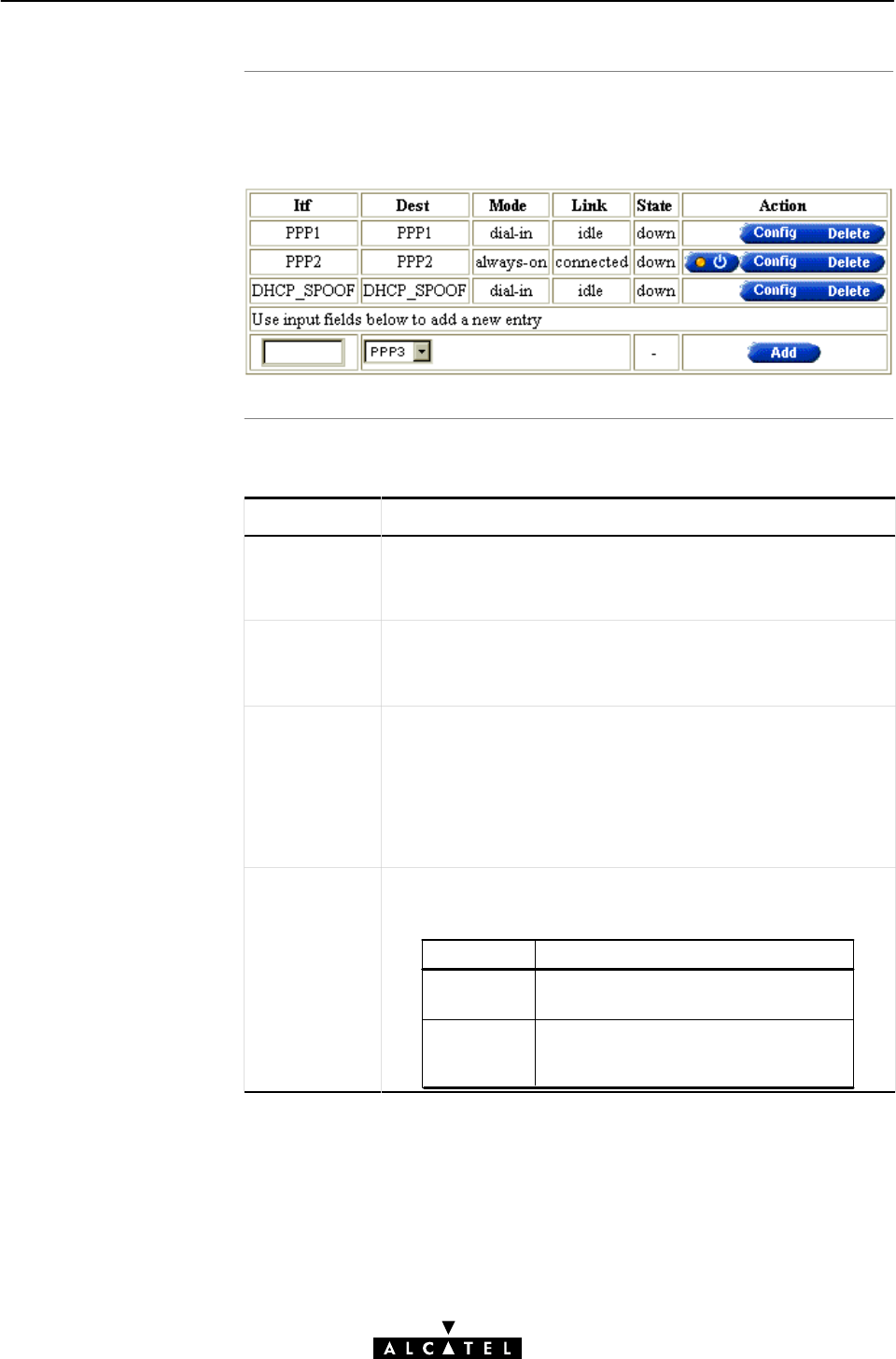
The 'PPP configuration'
tabl
e
'PPP Configuration'
table components
8 Data Services - PPP & IP Routing
130 / 362 3EC 17766 AAAA TCZZA Ed. 01
The following figure shows the 'PPP Configuration' table of the
'PPP' web page:
The following fields are shown:
Field Description
Itf Allows you to choose an interface name for the PPP interface.
Note: In most cases, the interface name will be the same as
the phonebook entry name.
Dest Indicates available phonebook entries for PPP.
Note: Specific free PPPoA/PPTP phonebook entries are
shown, as well as free 'any type' phonebook entries
Mode Indicates whether the PPP connection is:
•An AlwaysĆon" connection
•A DialĆin" connection
•A DialĆonĆDemand" connection.
See section 8.4.5 for more information.
Link Indicates the link state of the PPP entry.
It can take following values:
Value Description
idle
Connected The PPP entry is active, i.e. it tries to
setup a PPP connection, or PPP
connectivity is achieved.
The PPP entry is not activated, i.e. it
does not setup a PPP connection.
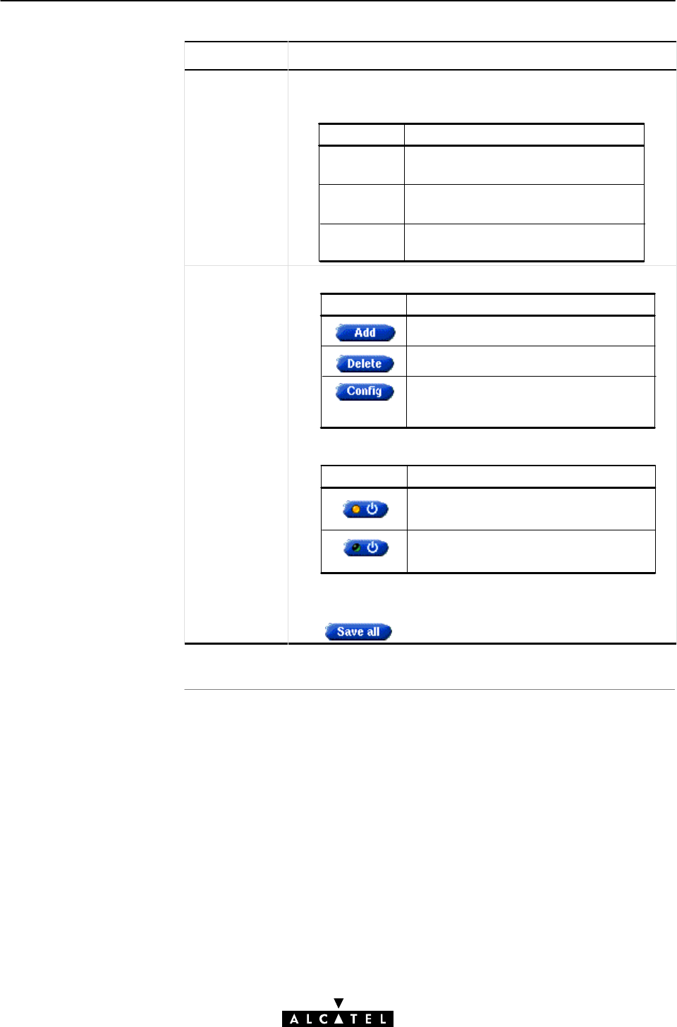
8 Data Services - PPP & IP Routing
131 / 362
3EC 17766 AAAA TCZZA Ed. 01
Field Description
State Indicates the active state of the PPP session.
It can take following values:
Value Description
Up
Down The PPP session is closed, the PPP
connection is idle.
Trying The PPP session is trying to reach the
active state.
The PPP session is opened and
active.
Action This field contains the three following action buttons:
Button Action
Delete an existing entry from the list.
Add a PPP entry to the list.
Configure the PPP entry.
See subsection 8.4 for more.
For alwaysĆon PPP entries, also an on/off button is included:
Clicking the button activates/deactivates the alwaysĆon PPP
connection.
Click to make the on/off change permanent
Button Action
The alwaysĆon PPP connection is
disabled, i.e. not active.
The alwaysĆon PPP connection is
enabled, i.e. activated.
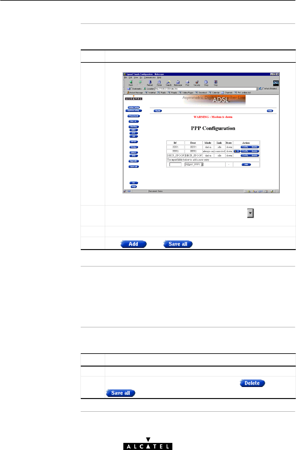
Adding PPP entries
Resul
t
Deleting PPP entries
8 Data Services - PPP & IP Routing
132 / 362 3EC 17766 AAAA TCZZA Ed. 01
Proceed as follows:
Step Action and Description
1Browse to the 'PPP' web page:
The bottom row of the table allows addition of a new entry.
2In the 'Destination' column of the bottom row, click and select
the PPP entry you want to add to the table.
3Optionally, enter a name for the PPP interface in the 'Itf' column.
4Click and to finish the procedure.
The PPP entry is added to the 'PPP Configuration' table. Prior to be
able to open a PPP session on this PPP entry, you MUST configure
the PPP entry.
See section 8.4 for more information.
Proceed as follows:
Step Action and Description
1Browse to the 'PPP' web page.
2Select the PPP connection you want to delete, click and
to finish the procedure.

Introduction
In this section
Interaction with the
STWireless IP route
r
8 Data Services - PPP & IP Routing
133 / 362
3EC 17766 AAAA TCZZA Ed. 01
8.4 PPP Entry Configuration
After enabling the PPP entry in the 'PPP Configurations' table, you
must configure the PPP connection.
Configuration of PPP entries must be done per PPP entry.
This section describes the various PPP entry configurations the
offers for assuring endĆtoĆend connectivity.
Topic Section
The PPP Configuration Web Page 8.4.1
Link Related Configuration 8.4.1
Security Related Configuration 8.4.3
IP Routing Related Configuration 8.4.4
Connection Related Configuration 8.4.5
NAPT and PPP & IP Routing 8.4.6
NAPT and STWireless Transparency 8.4.7
Most of the configurations described in this section, influence the
IP router in the STWireless.
See section 11.4, and subsection 11.2.4 for more information on
IP routing aspects.
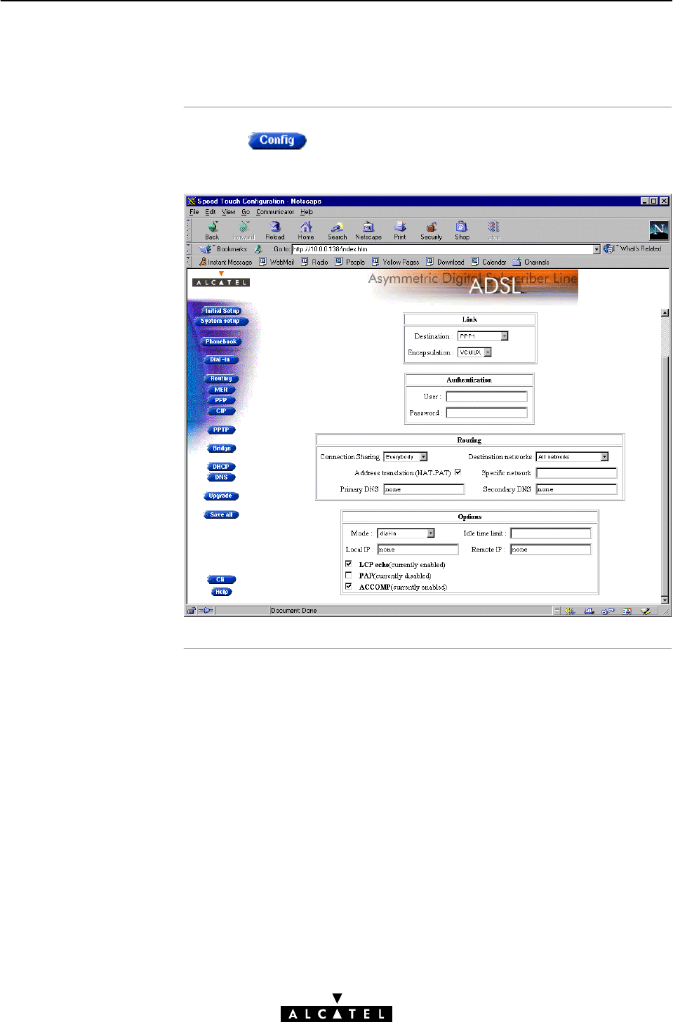
PPP configuration web
pag
e
8 Data Services - PPP & IP Routing
134 / 362 3EC 17766 AAAA TCZZA Ed. 01
8.4.1 The PPP Configuration Web Page
Clicking next to a PPP connection you want to configure,
pops up the particular 'PPP Configuration' web page:
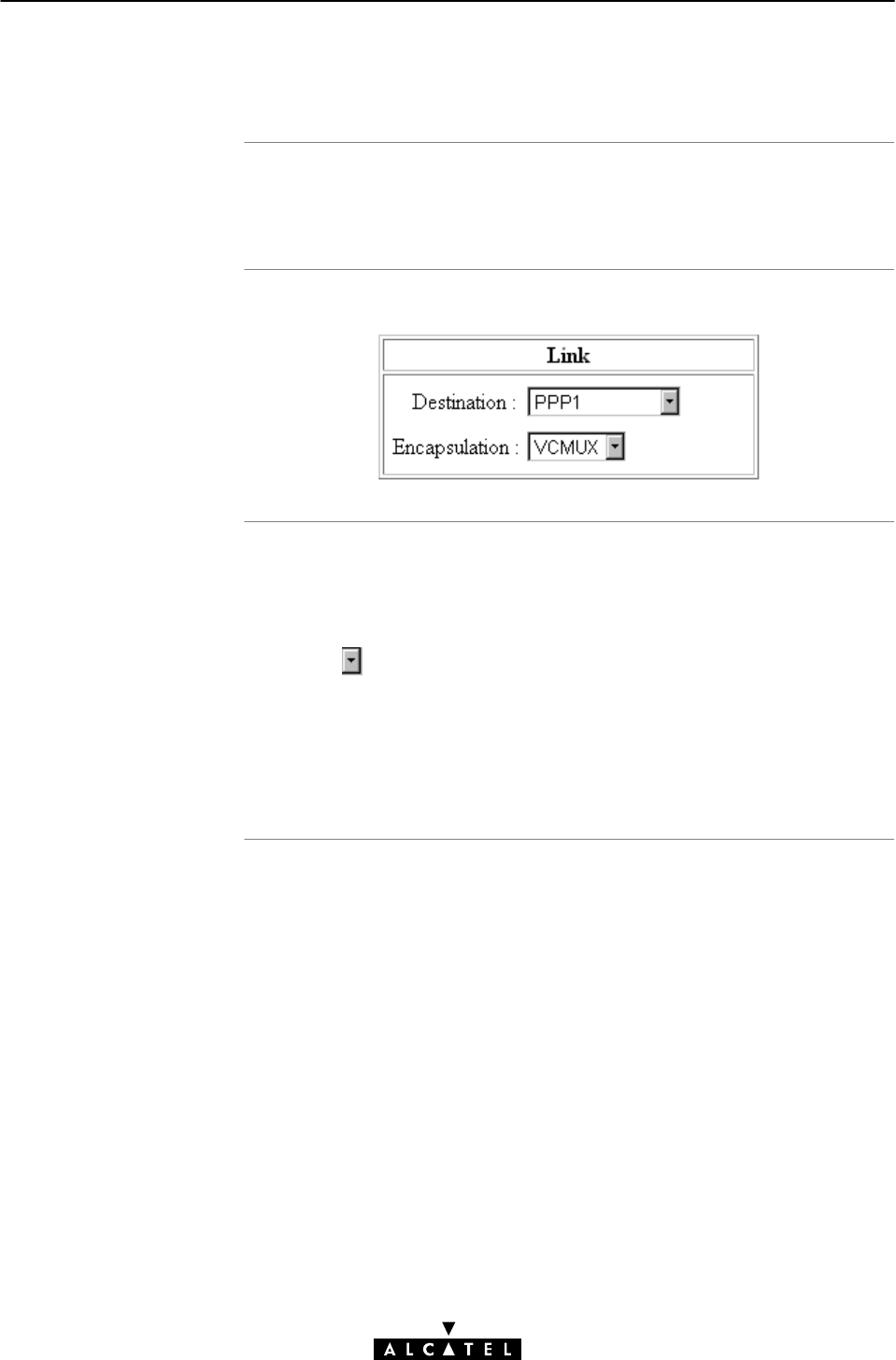
Introduction
'Link' bo
x
Destination networks
8 Data Services - PPP & IP Routing
135 / 362
3EC 17766 AAAA TCZZA Ed. 01
8.4.2 Link Related Configuration
The following options allow to configure the link related aspects of
your PPP connection.
Following figure shows the 'Link' box:
The 'Link' box contains the following fields:
"Destination
Displays the PPP phonebook entry for the PPP connection.
Click to select another free PPP phonebook entry for the
PPP connection.
"Encapsulation
Allows you to select the encapsulation method for the PPP
connection, i.e. VCĆMUX (default), or LLC/NLPID.
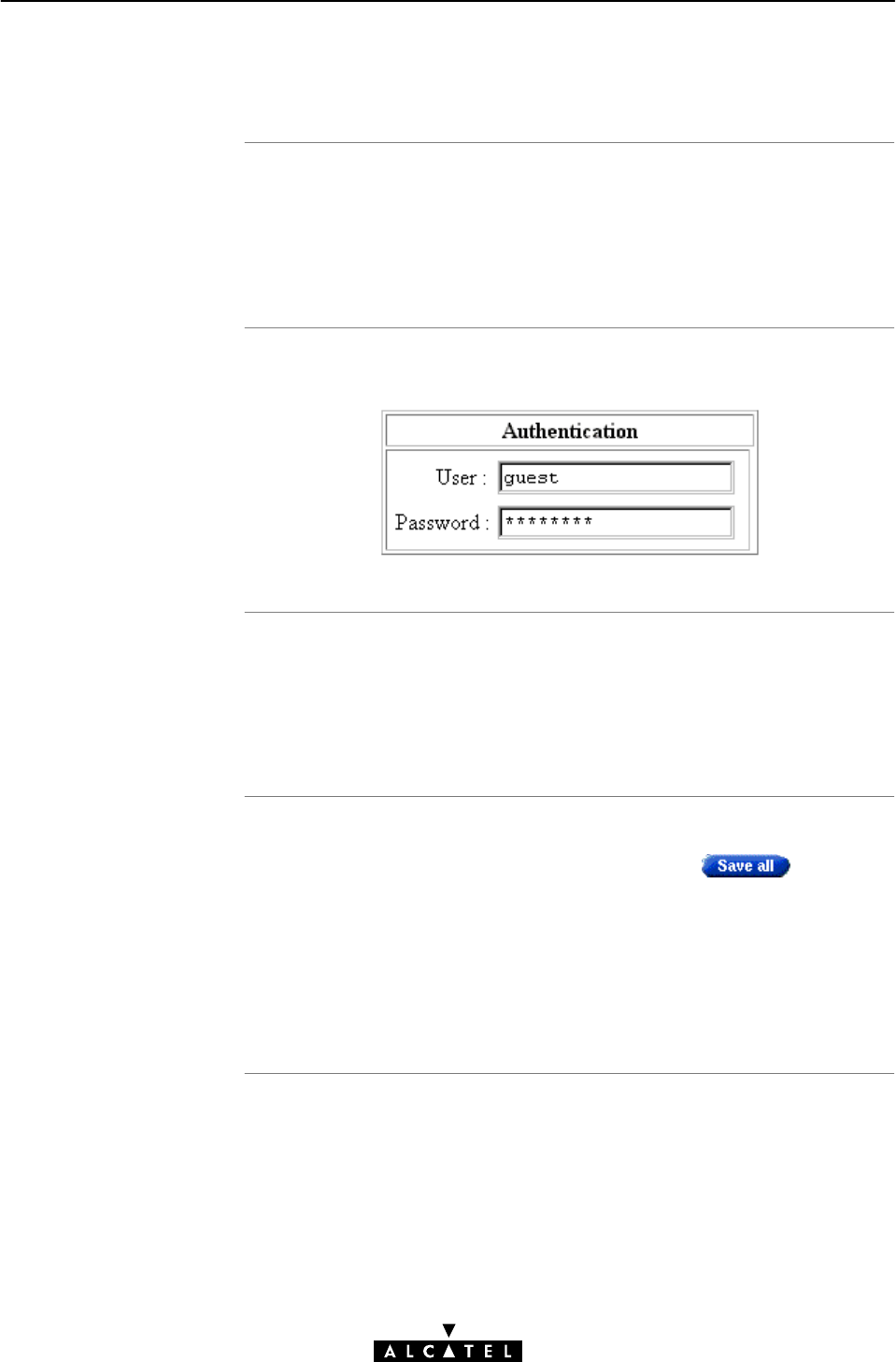
Introduction
'Authentication' bo
x
Guest" credentials
Memorizing
Credential
s
8 Data Services - PPP & IP Routing
136 / 362 3EC 17766 AAAA TCZZA Ed. 01
8.4.3 Security Related Configurations
In most cases you will have a user account, with user name and
password, at the SP.
Via the 'Authentication' box in the 'PPP Configuration' web page,
you can fill out your credentials for permanent storage.
Following figure shows the 'Authentication' box:
As default, the user account guest" is assumed (Both user name
and password are 'guest').
If your SP has a guest account, you are able to open a session
without having an actual subscription.
The STWireless is able to memorize user name, and password
per PPP connection; just fill out both, and click .
The next time you establish this PPP connection, the information is
retrieved from permanent storage.
Note: Leaving the entries free, forces you to identify and
authenticate yourself each time the session is opened.

Introduction
Advanced routing
In this subsection
'Routing' bo
x
8 Data Services - PPP & IP Routing
137 / 362
3EC 17766 AAAA TCZZA Ed. 01
8.4.4 IP Routing Related Configurations
If a PPP session is opened successfully (either manually by the user,
triggered by (W)LAN traffic, or automatic at boot time), routes are
automatically added to the STWireless's routing table.
The settings in the PPP 'IP Routing' box, are reflected in the routing
table.
For advanced users, the STWireless allows manual configuration
of permanent routes to dedicated destinations.
See section 11.4 for more information on the STWireless's IP
router.
Moreover, routes can be configured via the CLI, which will only be
added to the IP route table upon establishing the PPP connection.
See chapter 19 for more information on the CLI.
"'Routing' box
"Connection Sharing
"Connection Sharing Subnet Values
"'My net only' Configuration
"Destination Networks
"Destination Networks Subnet Values
"Primary and Secondary DNS Server.
The following figure shows the 'Routing' input box:

Connection sharing
Connection sharing
subnet values
8 Data Services - PPP & IP Routing
138 / 362 3EC 17766 AAAA TCZZA Ed. 01
The 'Connection Sharing' field allows you to configure which
(W)LAN members, besides the PC that opened the PPP session,
can use the PPP connection.
Three options are available:
"Only Me
Only frames of the PC that opened the PPP session will be
routed via this PPP connection.
Suppose you opened a PPP session to your corporate and
other (W)LAN members are surfing the Internet.
Via this option you can prevent them from using the PPP
connection to your corporate as their gateway to the Internet.
"Everybody
All PC(s) on the local (W)LAN can forward frames over this
PPP connection. This option is the exact opposite to 'Only me'.
If you open a PPP session to the Internet, other (W)LAN
members can share the PPP connection. In this way they are
not required to open a session themselves.
"My net only
Only PC(s) having the same network, and subnet number as
the PC that opened the outbound PPP session, can use the PPP
connection.
The following table lists the used netmasks, related to the three
possible options:
Connection Sharing value Related Source Subnet Mask Notation
Only Me 255.255.255.255 /32
Everybody 0.0.0.0 /0
My net Only 255.255.255.0 (default)
This value depends on the subĆ
net mask in use.
/*

'My net Only'
configuration
Destination networks
8 Data Services - PPP & IP Routing
139 / 362
3EC 17766 AAAA TCZZA Ed. 01
In case you want to privilege access via a particular PPP
connection for specific PCs, proceed as follows::
Step Action
1 Configure the PCs, to which you want to privilege outbound access
via this PPP connection, in a particular subnet of your local (W)LAN.
Note: Don't forget to make the STWireless also a member of this
workgroup.
2 Configure the 'Connection Sharing' box of the particular PPP
connection for 'My net only'.
3 It is sufficient now to open the PPP session of this PPP connection
from one PC of this subnet.
Note: As a result, only the members of that particular subnet can
share this PPP connection.
The 'Destination networks' field allows you to configure which
destination can be reached over the particular PPP connection.
Four options are available:
"All networks
The STWireless can potentially route frames to all
destinations over this PPP connection. The PPP connection acts
as if it was a default gateway.
"Remote net only
A PPP connection configured for 'Remote net only', only
forwards frames that is destined to this specific network. All
other frames are blocked.
"Remote host only
Only those frames with a destination IP address which
matches exactly with this entry in the STWireless routing table
are forwarded over this PPP connection. In fact, only
communication with the single remote host is possible.
"Specific network defined below
If all previous cases do not fulfill your requirements, 'Specific
network' might help you out: you can specify which
destination(s) are reachable over this PPP connection. Only if
the destination IP address of a packet matches with this entry,
the packet is forwarded over this PPP connection.

Destination networks
subnet values
Primary and secondar
y
DNS serve
r
8 Data Services - PPP & IP Routing
140 / 362 3EC 17766 AAAA TCZZA Ed. 01
The following table lists the used netmasks, related to the four
possible options:
Connection Sharing value Related Source Subnet Mask Notation
All Networks 0.0.0.0 /0
Remote net only 255.255.255.0 /0
Remote host only 255.255.255.255 /32
Specific network
defined below
255.255.255.0.0 (default)
This value is depending on the
destination Subnet Mask.
/*
These fields allow - optionally - to enter the IP address(es) of the
primary, and optionally the secondary, DNS server(s). If you supply
these IP addresses, the STWireless will negotiate these addresses
with the remote side of the PPP connection. If these fields are left
blank, the remote side will supply the IP addresses of the primary
and secondary DNS servers.
See chapter 12 for more information on DNS.
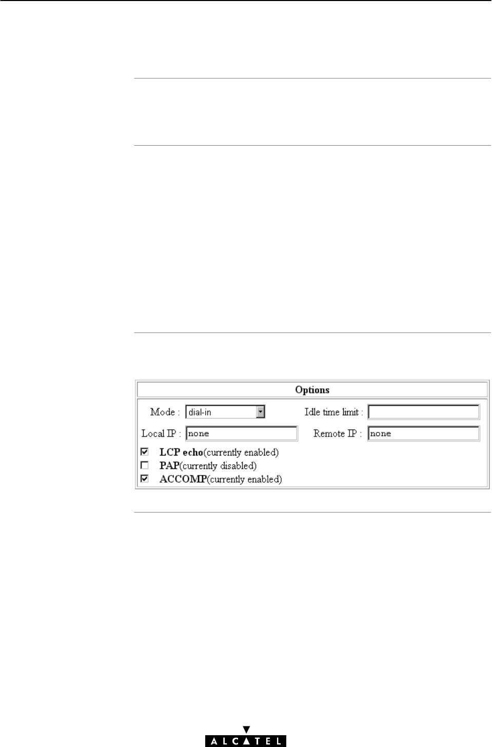
Introduction
In this subsection
'Options' bo
x
8 Data Services - PPP & IP Routing
141 / 362
3EC 17766 AAAA TCZZA Ed. 01
8.4.5 Connection Related Configuration
The following paragraphs explain which options that are used by
a PPP entry when it opens a PPP session.
"'Options' box
"Mode: Triggering of a PPP Session
"Idle Time Limit
"Local and/or Remote IP: STWireless PPP Client/Server
Behavior
"LCP Echo (n) Requests
"PAP (n): Authentication Protocols
"ACCOMP (n): PPP Framing
Following figure shows the 'Options' input box:

Mode: triggering o
f
PPP session
Idle time limi
t
8 Data Services - PPP & IP Routing
142 / 362 3EC 17766 AAAA TCZZA Ed. 01
The 'Mode' field allows you to configure how a PPP session is
opened.
Three options are available:
"DialĆin
The PPP session is opened manually by clicking next
to the PPP connection in the 'DialĆin' web page.
"AlwaysĆon
After the STWireless is powered and finished its POST
successfully, the STWireless automatically tries to open a PPP
session for the PPP connection.
"DialĆonĆdemand
The PPP session is opened automatically for a limited period
of time. The opening of the session is triggered by the arrival
of packets at a/the STWireless Ethernet port, to be sent over
the PPP connection.
Note: By default one PPP connection is configured as 'DialĆin' (i.e.
PPP1), and another as 'AlwaysĆon' (i.e. PPP2).
In case you configured a PPP connection for 'DialĆonĆdemand',
the 'Idle Time Limit' box allows you to specify the time after which
an opened, but unused PPP session is closed.
If left free, the idle limit time is infinite (i.e. the PPP session will
never be closed).

Local and/or remote
IP: STWireless PPP
server/client behavio
r
LCP echo (n) requests
PAP (n): used
authentication protocol
ACCOMP (n): used
PPP framing
8 Data Services - PPP & IP Routing
143 / 362
3EC 17766 AAAA TCZZA Ed. 01
During the opening of a PPP session, IP addresses are negotiated
between the two PPP peers for the PPP connection. The Local IP',
and 'Remote IP' fields influence this negotiation.
Typically at the client side, the 'Local IP', and 'Remote IP' boxes are
left empty. This forces the client to ask the remote server for
addresses.
In case you want to set up the STWireless as PPP server, suitable
values for your network configuration must be supplied:
"Setting a local IP address
Forces the remote PPP client (if it allows to) to accept this IP
address as the STWireless PPP session IP address.
"Setting a remote IP address
Forces the remote client (if it allows to) to accept this IP
address as its PPP session IP address.
If a PPP session is up, it can issue Link Control Protocol (LCP) echo
requests at regular intervals and expects LCP echo replies in
return.
This checkbox allows to turn on/off LCP echo request/replies by
respectively setting (n), or clearing the flag.
By default LCP echo is on (i.e. flagged n), allowing the local PPP
peer to detect communication errors, resulting in closing of the
PPP session.
The default PPP authentication protocol is Challenge Handshake
Authentication Protocol (CHAP).
Setting the PAP flag (n) will use Password Authentication
Protocol (PAP) instead.
Address and Control field COMPression (ACCOMP), sometimes
abbreviated as ACCM, is by default enabled, i.e. flagged (n).
This option flag should not be cleared, except in special
circumstances, i.e. where the remote PPP server expects to see
HDLC like framing (FF03 imposed to the PPP packet).

NAP
T
NAPT and supported
protocol
s
Configuration of NAP
T
NAT/PAT and
STWireles
s
transparenc
y
8 Data Services - PPP & IP Routing
144 / 362 3EC 17766 AAAA TCZZA Ed. 01
8.4.6 NAPT and PPP & IP Routing
Network Address Translation (NAT) is a technique that allows you
to shield or decouple an internal (Private) IP address from the
(negotiated) external (Public) IP address.
In addition, via Port Translation (PT), this single external Public IP
address is mapped onto multiple internal ports on the (W)LAN,
thus allowing multiple users to share this external IP address
simultaneously.
The amalgam of address & port allocation is often referred to as
NAPT.
All supported protocols that are NAPT insensitive, pass
transparently through NAPT.
In addition, the STWireless supports also the following protocols
as NAPT insensitive:
"All generic TCP/UDP protocols, e.g. HTTP (Hyper Text Transfer
Protocol)
"Internet Control Message Protocol (ICMP)
"File Transfer Protocol (FTP)
"Internet Relay Chat (IRC)
"Real Audio
"Real Time Stream Protocol (RTSP).
You can enable/disable NAPT via the 'PPP Configuration' web
page per PPP entry.
In the 'Routing' box (See subsection 8.4.4) it is possible to
set/unset the NAT flag (n).
Advanced NAPT can be configured via the CLI. See chapter 19 for
more information.
The NAPT feature comes at the expense of the STWireless
transparency. For consequences and solutions, see subsection
8.4.7.

NAPT and STWireless
transparenc
y
In this subsection
Consequences of NAP
T
on layers
8 Data Services - PPP & IP Routing
145 / 362
3EC 17766 AAAA TCZZA Ed. 01
8.4.7 NAPT and STWireless Transparency
As described in subsection 8.4.6, the STWireless can perform
NAPT to decouple your local IP addresses from the public IP
address negotiated during a PPP session.
However, this feature comes at the expense of the STWireless
transparency. This because a number of protocols that are layered
on top of either TCP/IP, or UDP/IP do not adhere to the ISO/OSI
reference model.
Note: The ISO Open Systems Interconnection (OSI) reference
model promotes the layered implementation of communications
protocol stacks. Layers from protocol stacks implemented
according to this model can be changed without affecting the
upper or lower layers.
"Consequences of NAPT on Layers
"STWireless Solutions
"ATMFĆ25
"Via the PPPoAĆtoĆPPTP Relay
"PPPĆtoĆDHCP Spoofing.
An important consequence is that changing IP addresses, or
TCP/UDP ports via NAPT affects the other layers as well.
Due to these changes, applications that are the ultimate
consumers of the protocols cannot decode the information
correctly anymore.

STWireless solutions
Via the PPPĆtoĆPPT
P
Rela
y
Resul
t
8 Data Services - PPP & IP Routing
146 / 362 3EC 17766 AAAA TCZZA Ed. 01
The STWireless offers some solutions to cope with this situation.
Basically these solutions boil down in transporting Public IP
addresses transparently through the STWireless towards a device
where a more advanced NAT, and/or PAT can be performed.
Some solutions are described in the following paragraphs:
"Via the PPPĆtoĆPPTP Relay
"PPPĆtoĆDHCP Spoofing.
You might consider the following setup below (which can be used
only for wired LANs:
Step Action
1 Install a second Ethernet PCĆNIC, next to the existing Ethernet
PCĆNIC, in a PC.
2 Install an OS on this PC that has routing capabilities, e.g. Windows
NT, UNIX, Linux, etc.
3 Install on this PC a NAT/PAT package that supports all TCP/IP
protocols.
Now this PC can act as some 'home gateway'.
4 Connect an Ethernet port of the STWireless to one of two PC's
Ethernet PCĆNIC.
5 Connect your local LAN to the second Ethernet PCĆNIC.
By setting up a PPTP tunnel from the 'home gateway', the Public IP
address is transported transparently through the STWireless to
end up in the 'home gateway', where more complex NAT, and/or
PAT operations can be performed.

PPPĆtoĆDHCP Spoofing
Resul
t
8 Data Services - PPP & IP Routing
147 / 362
3EC 17766 AAAA TCZZA Ed. 01
A second technique is to use the PPPĆtoĆDHCP Spoofing feature of
the STWireless. The network configuration is practically identical
to the one described above, for wired LANs applicable only:
Step Action
1 Install two Ethernet PCĆNICs in a PC.
2 Install an OS on this PC that has routing capabilities, e.g. Windows
NT, UNIX, Linux, etc.
3 Install on this PC a NAT/PAT package that supports all TCP/IP
protocols.
Now this PC can act as some 'home gateway'.
4 Connect (one of) the Ethernet interface(s) of the STWireless to the
PC's Ethernet PCĆNIC port.
5 Connect your local LAN to the other Ethernet PCĆNIC.
6 Configure the PC (acting as 'home gateway') as DHCP client.
7 Configure the STWireless as DHCP server.
8 DHCP in the STWireless must be configured for DHCP Spoofing.
See subsection 11.3.4 for more information.
9 At least one PPP connection must begin with the mnemonic "DHCP"
in its phonebook name, e.g. DHCP_Spoof.
As soon as a DHCP request from the home gateway hits
the STWireless, a PPPĆtoĆDHCP Spoofing connection is triggered.
The IP parameters that are negotiated with the remote peer, are
carried up to the home gateway via a DHCP reply message.

8 Data Services - PPP & IP Routing
148 / 362 3EC 17766 AAAA TCZZA Ed. 01

Introduction
In this chapte
r
9 Data Services - Classical IP & IP Routing
149 / 362
3EC 17766 AAAA TCZZA Ed. 01
9 Data Services - Classical IP & IP Routing
Classical IP is a popular term for RFC1577: Classical IP and ARP
over ATM . This RFC describes how a classical IP network can be
created with ATM technology.
"Classical" refers to the way IP operates in legacy (W)LANs. i.e. IP
communication between nodes within the same IP subnet is made
possible by the shared nature of popular (W)LAN media (e.g.
Ethernet) and their inherent broadcast capabilities.
For communication between IP subnets, routers do intervene.
In the following, Classical IP will be referred to as CIP.
Topic Section
Preparatory Steps 9.1
CIP Configuration for a LIS 9.2
Using CIP & IP Routing 9.3
CIP Configuration 9.4
Advanced CIP Configurations 9.5

Features
What you should kno
w
in advance
STWireles
s
PC(s
)
9 Data Services - Classical IP & IP Routing
150 / 362 3EC 17766 AAAA TCZZA Ed. 01
9.1 Preparatory Steps
Classical IP:
"Next to PPPoA, is a second standardized method for creating
IP networks on top of ATM technology
"Is traditionally well supported by ATM access routers at the
remote end of the connection
"Similar to Bridging, provides "always on" type of connections
"Supports up to 12 concurrent virtual channels assigned to CIP.
"The VPI/VCI value of the VC(s) to use on the ADSL line
"CIP connection service must be supported on this VC
"The remote access device must issue and respond to
InATMARP messages.
Note: If connectivity to multiple remote organizations is required,
you need additional sets of these parameters.
The STWireless comes with four preconfigured CIP entries.
If the SP(s) impose CIP settings which differ from the STWireless
defaults, perform the necessary adjustments via the STWireless
web pages.
See section 9.4 for more information.
In CIP mode, the STWireless exchanges IP packets with
computers on your local network. As a consequence all that is
required on your local PC(s) is "standard" TCP/IP.
Prior to configuring CIP, you must establish IP connectivity with the
STWireless. The easiest method is to configure your PCs as DHCP
clients. By default the STWireless acts as DHCP server and leases
IP addresses to local PCs during startup.
See subsection 11.1.4 for more information.

Introduction
In this section
9 Data Services - Classical IP & IP Routing
151 / 362
3EC 17766 AAAA TCZZA Ed. 01
9.2 CIP Configuration for a LIS
In this section the basic procedure to enable connectivity in a
Logical IP Subnet (LIS) via the ADSL line is described.
Topic See
General CIP Configuration Procedure 9.2.1
Retrieving LIS Parameters 9.2.2
Implicit Assignment Mechanism 9.2.3
Explicit Assignment Mechanism 9.2.4
Configuring the STWireless for CIP 9.2.5
Adding Appropriate Routes to the Routing Tables. 9.2.6
Example of a CIP LIS Configuration 9.2.7

Decision procedure
9 Data Services - Classical IP & IP Routing
152 / 362 3EC 17766 AAAA TCZZA Ed. 01
9.2.1 General CIP Configuration Procedure
Due to the many decisions that must be made in order to be able
to configure the STWireless to be an active member of a LIS, the
procedure to be followed is best retrieved from the following
decision table:
Step Decision and/or Action See
1
Answer Action and Description
Ye s
No You can create the LIS with IP parameters of
your choice. See topic 'Creating a New LIS' of
subsection 9.2.2.
In case you create a new LIS, you must create
the LIS at both end of the ADSL connection, i.e.
at the local, and on the remote side.
You must retrieve the LIS IP parameters to
which your local configuration must adhere
to. See topic 'Configuration for an Existing LIS'
of subsection 9.2.2.
Are you configuring the STWireless for an existing LIS ? 9.2.2
2 Retrieve the appropriate LIS parameters, and check on
which VCs (identifiable by their VPI/VCI values) your service
provider enabled the CIP packet service.
9.2.2
3 If needed, create a CIP phonebook entry, i.e. a CIP PVC, in
the 'Phonebook' web page.
9.4
4Is the remote access router a RFC1577 compliant device,
e.g. another STWireless?
Answer Action and Description
Ye s
No The remote access router will not respond to
'InATMARP' requests submitted by the
STWireless, thus the CIP PVC must be explicitly
assigned to the CIP member.
The remote access router will respond to
'InATMARP' requests, thus the CIP PVC can be
implicitly assigned to the CIP member.
See
9.2.3
9.2.4
5 If needed, create a CIP member in the 'CIP Interfaces' table
of the 'CIP' web page.
9.4
6 Add appropriate IP routes to the STWireless via the 'IP
route' table on the 'Routing' web page.
9.2.6
7 Add appropriate IP routes in you PC(s). 9.2.6

LIS
LIS parameters
Configuration for an
existing LIS
Creating a new LIS
9 Data Services - Classical IP & IP Routing
153 / 362
3EC 17766 AAAA TCZZA Ed. 01
9.2.2 Retrieving LIS Parameters
The LIS is an important CIP concept. It is a group of IP machines
configured as members of the same IP subnet. In other words:
they share the same IP network and subnetwork numbers.
In most cases this LIS will be a corporate (W)LAN/WAN
environment, which is interconnected via the ADSL/ATM network.
In order to be able to properly configure your STWireless for
sharing the same logical IP subnet, you must know the following
LIS parameters:
"The IP network number
"The IP subnetwork number
"The remote access router's RFC1577 compliancy state
"The remote access router IP address, in the case it is not
RFC1577 compliant.
Of course, in case you know the IP address of one member of the
LIS, and the associated netmask, you also have enough
information.
For an existing LIS, you must configure the STWireless CIP
settings, according to the existing LIS parameters.
If the default CIP member's IP parameters, and the CIP
connection's remote IP address, configured in the STWireless,
match with these parameters, nothing needs to be configured.
However, make sure that the CIP member's local IP address is not
ambiguous within the LIS.
In the case of creating a new LIS, you are recommended to use
the default CIP configurations of the STWireless. In case the
remote access router is also a STWireless, best results are
assured.
Note: Both ends of the LIS must be properly configured for
connectivity, inclusive the routing tables.

Implicit assignmen
t
Implicit assignmen
t
exampl
e
Note
9 Data Services - Classical IP & IP Routing
154 / 362 3EC 17766 AAAA TCZZA Ed. 01
9.2.3 Implicit Assignment Mechanism
If the remote side is RFC1577 compliant, e.g. another
STWireless, your local STWireless is able to retrieve the remote
IP address of the CIP PVC, by issuing an InATMARP request on that
PVC.
That way, you must not specify an IP address for the CIP PVCs you
add to the 'CIP Connections' table, it will be implicitly assigned
when connecting to the LIS.
The sequence below describes an example of an implicit
assignment mechanism:
Phase Decision and Description
1 Suppose you added a CIPPVC without supplying an IP address (e.g.
CIPPVC2).
2 The STWireless will automatically issue an InATMARP request on
this PVC.
3 Is the remote side is RFC1577 compliant ?
Ye s No
4 It responds with an InATMARP
reply, containing its IP address.
The CIP's remote IP address in the
'CIP Connections' table is
completed.
"Unresolved" will show up in the
'Remote IP Address' field.
Consequently the CIPPVC cannot
be assigned and IP connectivity
will not exist with the remote
hi
5 Does the remote address share a
LIS with a local CIP member ?
machine.
Ye s No
6 the CIPPVC is
assigned to this
member.
Connectivity is
assured.
"Unresolved"
will show up.
No connectivity
exists.
The grey shaded area of the table indicates the sequence of a
correct RFC1577 compliant LIS interconnection.
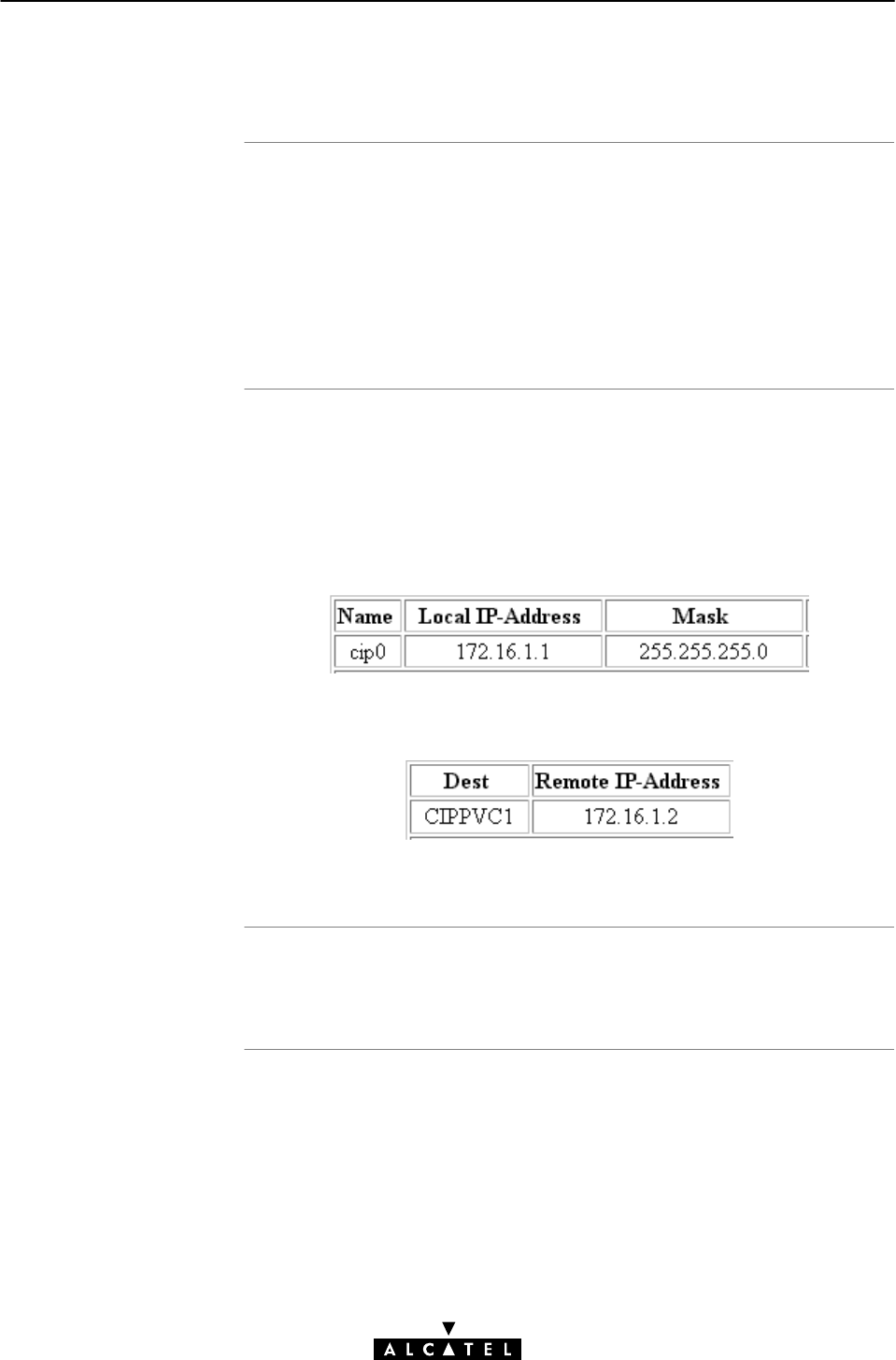
Explicit assignmen
t
Explicit assignmen
t
exampl
e
Note
9 Data Services - Classical IP & IP Routing
155 / 362
3EC 17766 AAAA TCZZA Ed. 01
9.2.4 Explicit Assignment Mechanism
In the case of a remote access server which is not RFC1577
compliant, it will not respond to InATMARP requests.
As a consequence, the STWireless can not retrieve the remote IP
address to assign the CIP PVC to the CIP member.
Therefore you must explicit assign a remote IP address to the CIP
PVC.
The default configuration of the STWireless is an example of the
explicit assignment of a CIP PVC to a CIP member:
In the 'CIP Interfaces' table, the CIP member is configured as
follows:
In the 'CIP Connections' table, the remote IP address is statically
configured:
Consequently, CIPPVC1 is explicitly assigned to cip0.
Both local and remote IP addresses must fall within the same IP
network and IP subnetwork, according the LIS parameters.

Introduction
Configuration of the
STWireles
s
'Phonebook' web page
Configuration of the
STWireless 'CIP' web
pag
e
9 Data Services - Classical IP & IP Routing
156 / 362 3EC 17766 AAAA TCZZA Ed. 01
9.2.5 Configuring the STWireless for CIP
After retrieving the LIS parameters, you must configure the
STWireless, according to these parameters.
This section describes in short the global procedure for
configuring your STWireless 'Phonebook',and'CIP' web page.
By default the STWireless is configured for a CIP VC as used in
the example of section 9.2.7. If this VC is appropriate to your,
and/or the ADSL provider's needs, nothing has to be configured
in the STWireless phonebook.
If this VC does not match the requirements, three other CIP
phonebook entries are available to add.
However, in the case none of the entries match, you must add a
CIP phonebook entry yourself.
Adding CIP phonebook entries is described in subsection 9.4.1.
The default CIP phonebook entry mentioned above is by default
configured for a LIS according to the example of section 9.2.7. If
this LIS configuration meets your requirements, nothing needs to
be configured, and your STWireless is ready for use.
However, if additional configuration is needed, you can configure
CIP members yourself.
The assignment of your CIP PVC to the CIP member can be done
implicit, or explicit, according the RFC1577 compliancy of the
remote access router.
Configuration of the STWireless 'CIP' web page is fully described
in subsection 9.4.2.

Introduction to routing
Configuring the
STWireless for LIS
connectivity, basic
9 Data Services - Classical IP & IP Routing
157 / 362
3EC 17766 AAAA TCZZA Ed. 01
9.2.6 Adding Appropriate Routes to the Routing Tables
IP routing is a very important aspect for a LIS configuration.
This subsection describes how you can ensure endĆtoĆend
connectivity for a CIP environment.
"Configuring the STWireless for LIS Connectivity, Basic
"Configuring the STWireless for LIS Connectivity, Advanced
"Configuring your (W)LAN PCs for EndĆtoĆEnd Connectivity
"Routing Table Configuration.
Generally, for proper CIP routing, an IP route pointing to the
remote access router must exist in your STWireless's IP routing
table.
If the remote access router is RFC1577 compliant, no routes for
LIS connectivity need to be configured by yourself for the
STWireless's IP router. This because it automatically adds two
necessary routes as soon you configure the CIP member, i.e. two
default gateways, thus any (0.0.0.0/0) as source address, and
with:
"The LIS's local CIP member's IP address, i.e. the STWireless's
CIP interface address as destination
and
"The LIS's IP subnetwork (based on the CIP member's IP
parameters) as destination.
As the RFC1577 compliant remote access router, falls within the
same LIS as the STWireless CIP member, it is also a member of
the second route's destination IP subnetwork.
If the remote access router is not RFC1577 compliant, you must
add this default route (with the known remote IP address) yourself.

Configuring the
STWireless for LIS
connectivity, advanced
Configuration you
r
(W)LAN PCs fo
r
endĆtoĆend
connectivit
y
Routing table
configuration
9 Data Services - Classical IP & IP Routing
158 / 362 3EC 17766 AAAA TCZZA Ed. 01
The possibility exists to add routes yourself, e.g. to be more
specific in the source IP address pool.
The default added routes have any as source address, meaning
that all local hosts can use this gateway to connect to the LIS via
the CIP interface.
However, you might want to embed restrictions in LIS access by
creating a subnet in your (W)LAN, e.g. 10.0.1.x, and privilege
access to the LIS - and its beyond (W)LAN - to this subnet by
adding a route, pointing to the remote access router (implicit, or
explicit), but with source IP address pool 10.0.1.0/24.
Of course, then the default IP routes, configured by default, must
be deleted.
In order to have endĆtoĆend connectivity from your PCs to the
remote side of the CIP connection and beyond, you must add
routes having the STWireless Ethernet interface IP address as
gateway.
By specifying 0.0.0.0/0 as destination, and the STWireless local
Ethernet IP address as gateway, the STWireless is configured as
the default gateway for all connection requests.
However, you can specify a destination IP address pool; e.g. if the
remote LAN's IP subnetwork is 192.6.11.x, you can add routes in
your PC's routing table with destination 192.6.11.0/32, and the
STWireless as gateway.
Configuring routes for the STWireless is described in subsection
11.4.2.
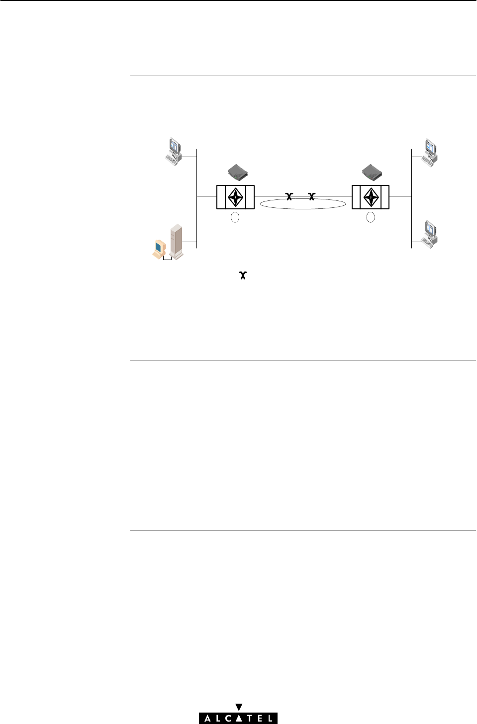
Configuration figure
Local premisses
configuration
9 Data Services - Classical IP & IP Routing
159 / 362
3EC 17766 AAAA TCZZA Ed. 01
9.2.7 Example Configuration
The configuration of a Classical IP LIS is illustrated with the
following example:
ETH
ATM
ATM
ETH
Symbolizes an VP/VC cross-connect
10.0.0.2
255.0.0.0
10.0.0.138<-0.0.0.0
10.0.0.1
255.0.0.0
10.0.0.138<-0.0.0.0
10.0.0.138
255.0.0.0
172.16.1.2
255.255.255.0
192.168.0.1
255.0.0.0
192.168.0.2
255.255.255.0
0.0.0.0.->192.168.0.1
8/80 8/80
172.16.1.2<-0.0.0.0
172.16.1.1
255.255.255.0
10.0.0.0->172.16.1.1
LIS 172.16.1.x
Subnet 10.1
Local Servers
12
In the drawing above a LIS, 172.16.1.x, represented by the
ellipse, runs between the STWireless (1) and the remote access
router (2).
At the local premisses an IP network, 10.x.x.x, is created.
An IP address is configured on the Ethernet port (10.0.0.138).
On the ADSL side of the STWireless (1) one CIP member is by
default enabled. This CIP member is configured with IP address
172.16.1.1 and is part of the LIS 172.16.1.x.
One VC in the STWireless (1) phonebook (CIPPVC1), is explicitly
assigned to this CIP member. This VC(8/80) is crossĆconnected to
the remote destination.

Remote premisses
configuration
Routing configuration
Note
9 Data Services - Classical IP & IP Routing
160 / 362 3EC 17766 AAAA TCZZA Ed. 01
At the remote ADSL side, the CIP LIS is terminated by the remote
access router (2) and IP packets are forwarded to local servers, or
the Internet and vice versa.
Here, the CIP member is configured with IP address 172.16.1.2
and is part of the same LIS 172.16.1.x.
Additionally, a VC, with the same VPI/VCI values 8/80, is assigned
to this CIP member (e.g. implicit assignment, because STWireless
(1) is RFC1577 compliant).
The routing engine must be configured with routes to the final
destinations.
For the given example, the configuration is as follows:
"STWireless (1) has its default route pointing to the remote
access router (2)
The local PCs of IP network 10.0.0.x have default gateways
pointing to STWireless (1)
"The remote access router (2) has a route for Net10"
(10.0.0.0) pointing to STWireless (1)
The remote IP network 192.168.0.x has a default gateway
pointing to access router (2).
You will notice that the example relies exclusively on Private IP
addresses. Depending the application though, other IP addresses
in combination with NAPT (configurable via the CLI) can be used.
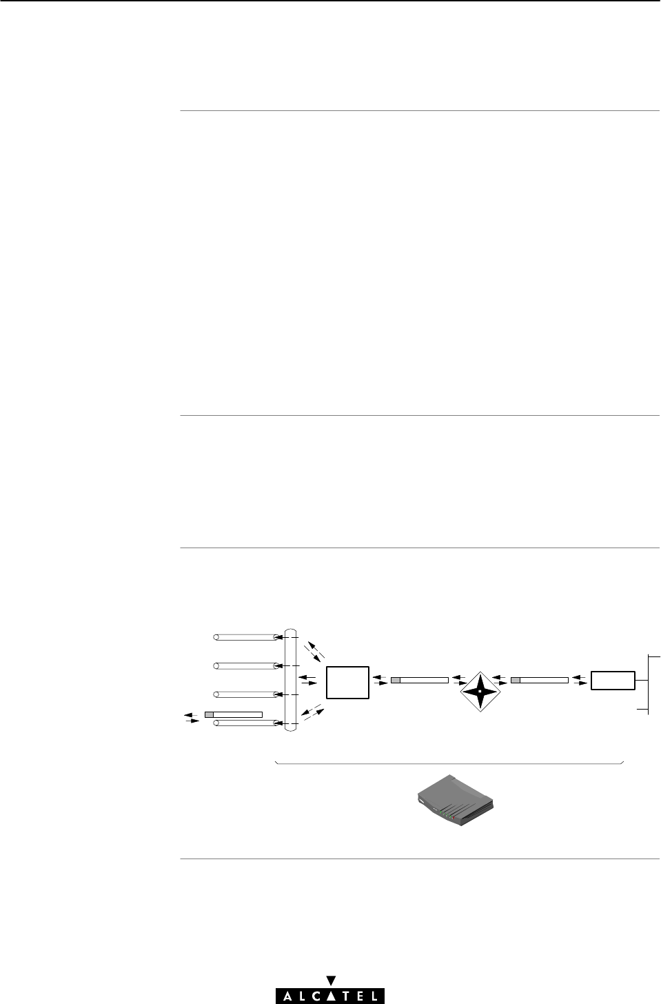
CIP operation
Classical IP and
STWireles
s
Configuration and
operation exampl
e
9 Data Services - Classical IP & IP Routing
161 / 362
3EC 17766 AAAA TCZZA Ed. 01
9.3 Using CIP & IP Routing
Similar to classical LAN networking, IP Routing and CIP adhere to
the "alwaysĆon" concept. That is, no special actions (e.g. dialing)
must be undertaken prior to IP connectivity.
IP packets sourced by local PCs, arrive via the Ethernet segment in
the STWireless. The latter makes routing decisions based on the
destination IP address of the packet. If the packet ends up in the
CIP member, it will on its turn determine to which VC it has to
output the packet.
You can check IP connectivity from any PC on the local Ethernet
segment. Therefor, ping the IP address at the far end of the virtual
connection; e.g. for the example of subsection 9.2.7, this would
be 172.16.1.2, or thus ping 172.16.1.2.
The IP router in the STWireless forwards packets between the
Ethernet port and the Classical IP entity sitting on top of the
ADSL/ATM port. In turn, the CIP entity determines which VC it has
to output the packet to, prior to ATM encapsulation.
The figure below provides an overview of the STWireless
rearĆtoĆfront end Classical IP operation:
Virtual Channels
VPI/VCI:8/80
VPI/VCI:8/81
VPI/VCI:8/82
VPI/VCI:8/83
Virtual Channel Resolving,
ATM encapsulation
IP Routing
IP Packet Ethernet
CIP
Member

Introduction
In this section
9 Data Services - Classical IP & IP Routing
162 / 362 3EC 17766 AAAA TCZZA Ed. 01
9.4 CIP Configuration
The STWireless allows local configuration via the STWireless
web pages.
This section describes the configuration of CIP entries, and how to
use the 'CIP' web page.
Topic See
CIP Phonebook Entries 9.4.1
CIP Entries 9.4.2
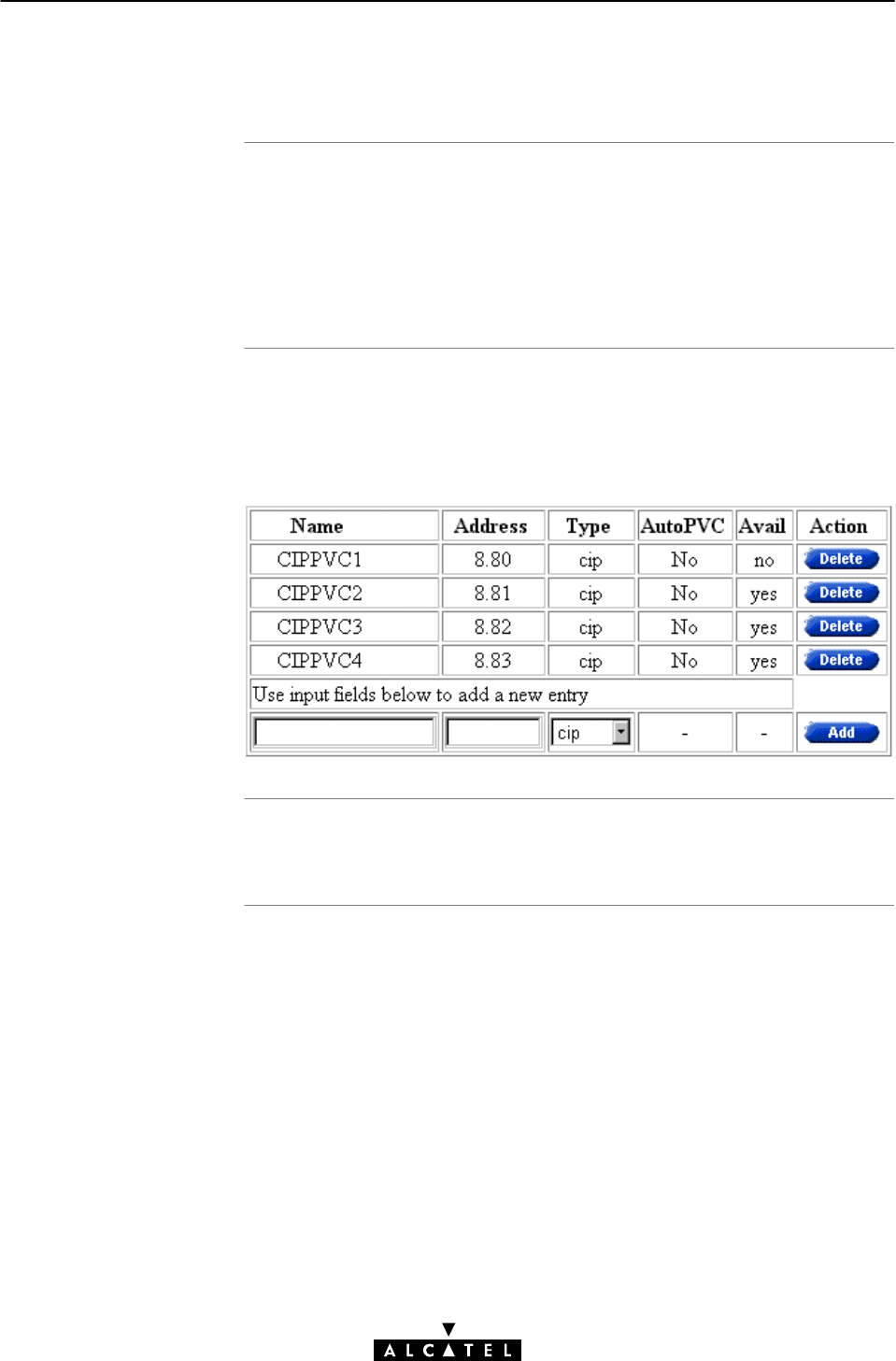
In this subsection
CIP phonebook entries
Adding/deleting
phonebook entries
9 Data Services - Classical IP & IP Routing
163 / 362
3EC 17766 AAAA TCZZA Ed. 01
9.4.1 CIP Phonebook Entries
"CIP Phonebook Entries
"Adding CIP Phonebook Entries
"Deleting CIP Phonebook Entries.
See subsection 10.2.2 for more information.
Basic to the STWireless VC pool management, is the 'Phonebook'
web page.
The STWireless in its default state features the following CIP
related phonebook entries:
See section 10.2 for more information.
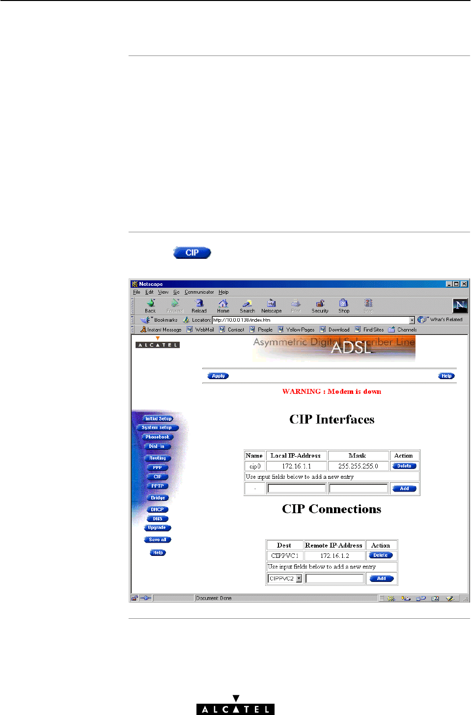
In this subsection
The STWireless 'CIP'
web page
9 Data Services - Classical IP & IP Routing
164 / 362 3EC 17766 AAAA TCZZA Ed. 01
9.4.2 CIP Entries
"The STWireless 'CIP' Web Page
"The 'CIP Interfaces' Table
"'CIP Interfaces' Table Components
"The 'CIP connections' Table
"'CIP Connections' Table Components
"Adding CIP members
"Assigning CIP PVCs to CIP members
"Deleting CIP Entries.
Clicking in the left pane of the STWireless web pages,
pops up the 'CIP' web page:
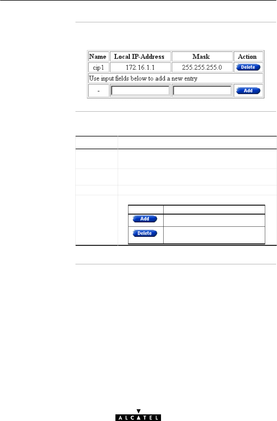
The 'CIP Interfaces'
tabl
e
'CIP Interfaces' table
component
s
9 Data Services - Classical IP & IP Routing
165 / 362
3EC 17766 AAAA TCZZA Ed. 01
The following figure shows the 'CIP Interfaces' table:
The following fields are shown:
Field Description
Name Indicates the CIP member name.
All CIP members are named as cipX, where Xis a number.
Local IP
Address
Indicates the IP address of the local ADSL side of the LIS, i.e.
the IP address of your CIP interface.
Mask Indicates the netmask/subnetmask of the local IP address.
Action This field contains one of the two following action buttons:
Button Action
Delete an existing member from the
list.
Add a CIP member to the list.
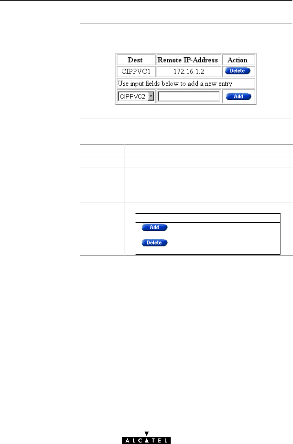
The 'CIP Connections'
tabl
e
'CIP Connections' table
component
s
9 Data Services - Classical IP & IP Routing
166 / 362 3EC 17766 AAAA TCZZA Ed. 01
The following figure shows the 'CIP Connections' table:
The following fields are shown:
Field Description
Dest Indicates the CIP VC phonebook name.
Remote IP
Address
Indicates the remote IP address of the remote ADSL side of
the LIS, i.e. the IP address of the remote CIP interface.
Note: In case the VC is not crossĆconnected, or implicit
assignment was not successful, this field shows Unresolved".
Action This field contains one of the two following action buttons:
Button Action
Delete an existing connection from the
list.
Add a CIP connection to the list.
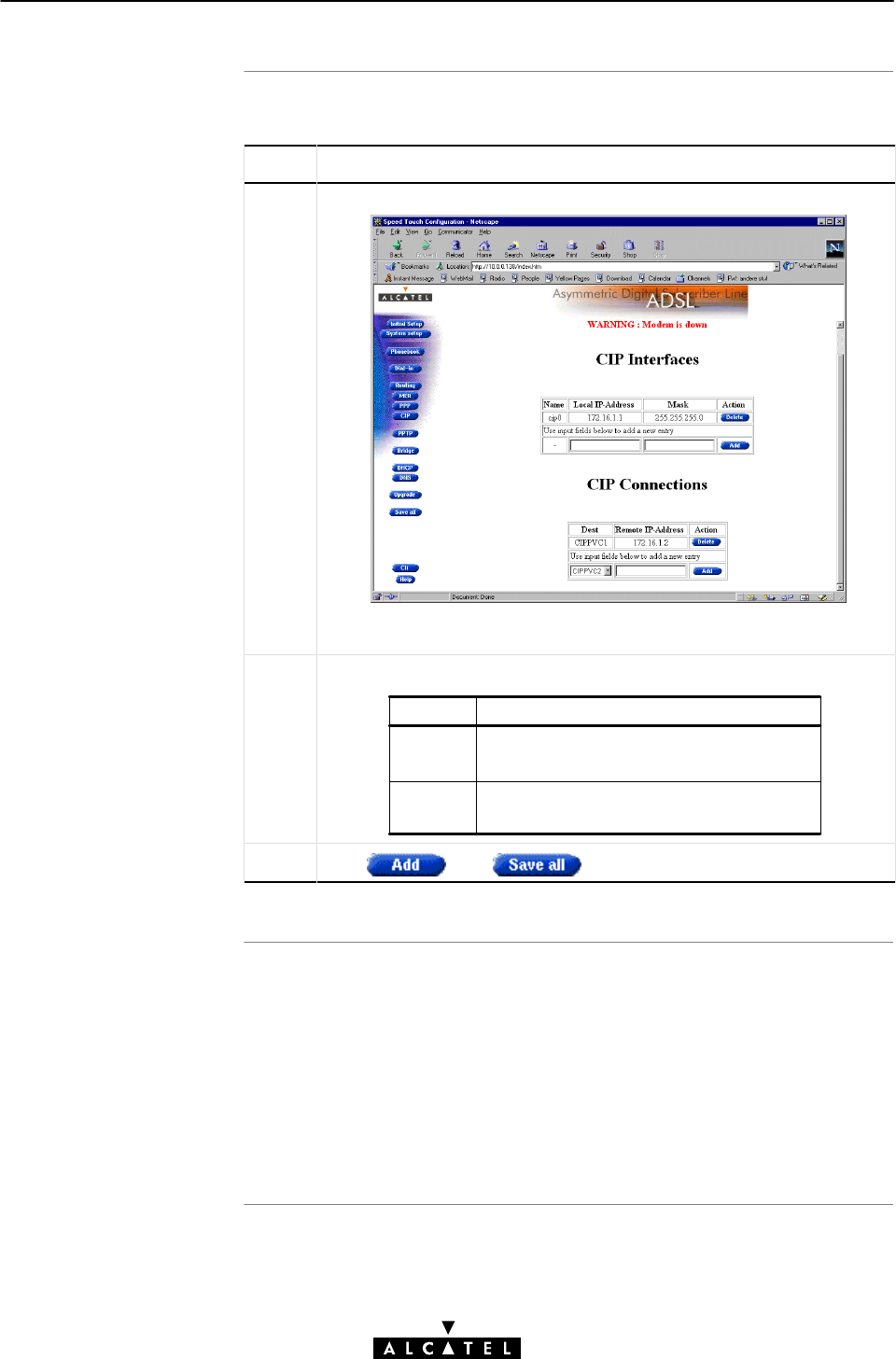
Adding CIP members
Resul
t
9 Data Services - Classical IP & IP Routing
167 / 362
3EC 17766 AAAA TCZZA Ed. 01
Proceed as follows:
Step Action and Description
1 Browse to the 'CIP' web page:
The bottom row of the 'CIP Interfaces' table allows addition of a new
CIP member.
2Fill in the following CIP member parameters:
Value Description
Local IP
Address
Mask The associated netmask/subnetmask for
that local IP address.
The IP address at the CIP member at your
local side of the LIS.
3Click and to finish the procedure.
A CIP member of the LIS is created at your STWireless's CIP
interface side of the LIS. The local IP address is added to the 'IP
Address' table.
Two default routes are added to the 'IP Route' table, both pointing
to the STWireless as gateway, but the first with the CIP member
itself as destination, and the second with the LIS subnetwork IP
address pool as destination.
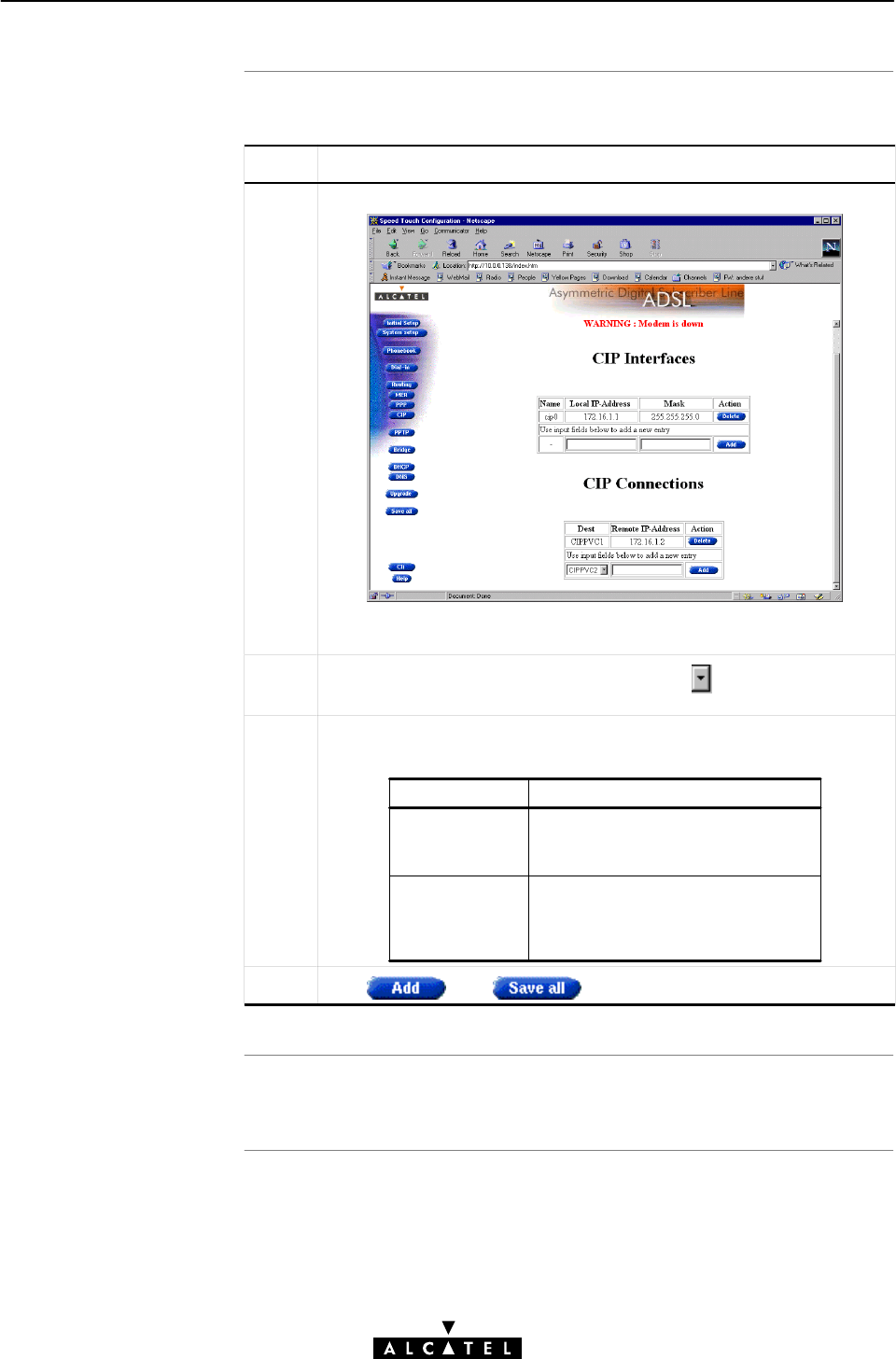
Assigning CIP PVCs to
CIP members
Resul
t
9 Data Services - Classical IP & IP Routing
168 / 362 3EC 17766 AAAA TCZZA Ed. 01
Proceed as follows:
Step Action and Description
1 Browse to the 'CIP' web page:
The bottom row of the 'CIP Connections' table allows addition of a
new CIP connection.
2In the 'Dest' column of the bottom row, click and select the CIP
PVC you want to assign.
3Depending the RFC1577 compliancy of the remote access router,
the following must be filled in, in the 'Remote IP address' column:
Compliancy Remote IP Address
YES
NO You must fill in the exact IP address
of the remote access router; the
PVC is explicitly assigned to the
CIP member.
You don't have to fill in anything; the
InATMARP reply will implicitly
assign the PVC to the CIP member.
3Click and to finish the procedure.
A CIP PVC is assigned, and added in the 'CIP Connections' table.

Deleting CIP entries
9 Data Services - Classical IP & IP Routing
169 / 362
3EC 17766 AAAA TCZZA Ed. 01
Proceed as follows:
Step Action and Description
1Browse to the 'CIP' web page.
2Select the CIP connection, and/or CIP member you want to
delete, and click
3Click to store the changes in permanent memory.

Introduction
In this section
9 Data Services - Classical IP & IP Routing
170 / 362 3EC 17766 AAAA TCZZA Ed. 01
9.5 Advanced CIP Configurations
The example of subsection 9.2.7 showed a configuration with a
single VC, used for ADSL connectivity within one LIS.
In this section the use of multiple VCs to connect to a LIS, and the
connectivity to multiple LISs is described.
Topic See
Configuring multiple CIP PVCs 9.5.1
Creating multiple CIP members 9.5.2
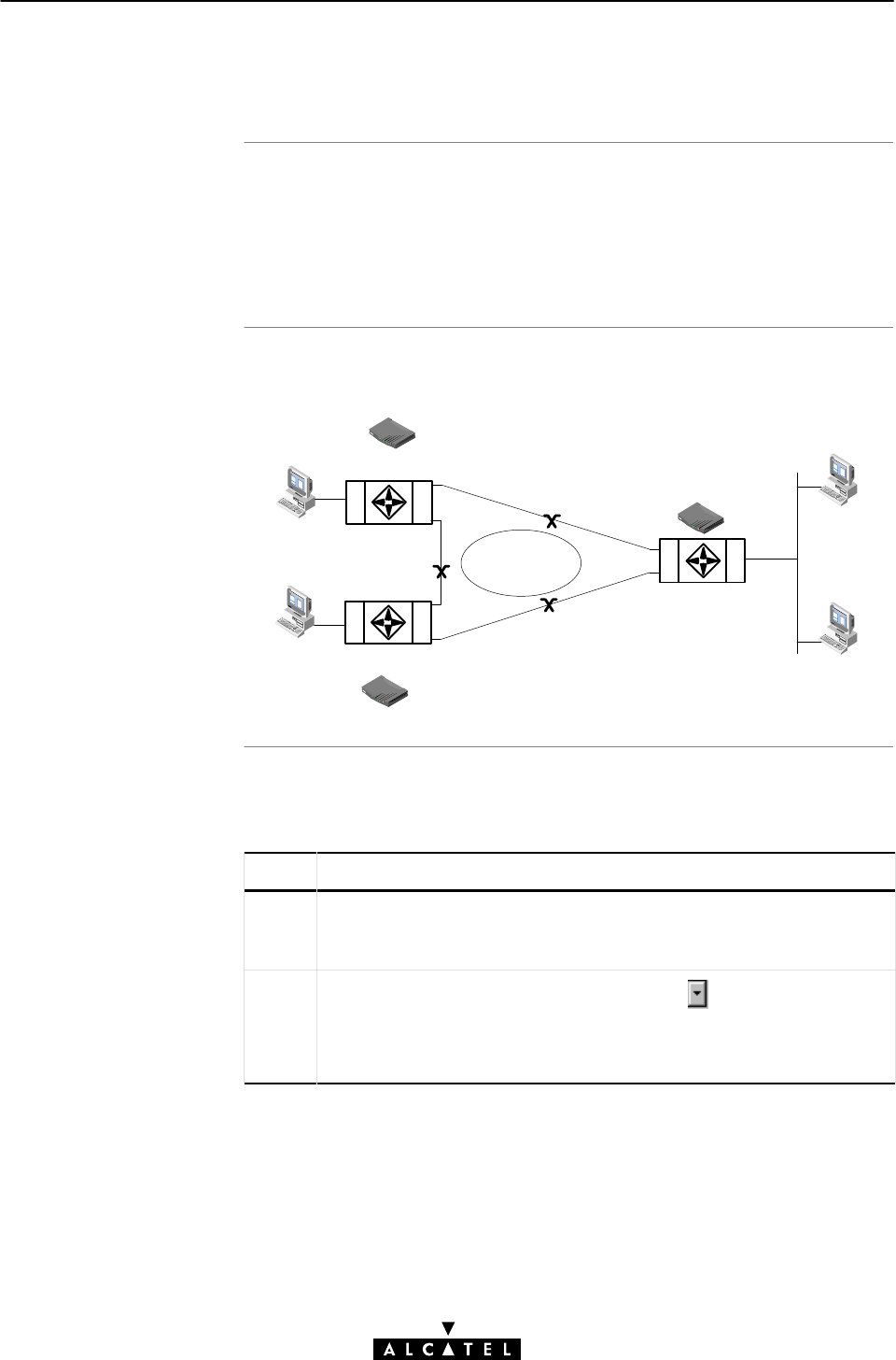
Multiple VCs for one
LIS
Exampl
e
Procedure
9 Data Services - Classical IP & IP Routing
171 / 362
3EC 17766 AAAA TCZZA Ed. 01
9.5.1 Configuring Multiple CIP PVCs
Multiple VCs can be assigned, either explicit or implicit, to CIP
members in the 'CIP Connections' table.
By doing so, local PCs can simultaneously access multiple ADSL
nodes of one LIS.
The following figure shows an example of such a configuration:
PVC1
172.16.0.3
10.1.0.1
10.1.0.2
ETH
ATM
172.16.0.1 10.1.0.138
ETH
ATM
LIS 172.16.x.x
ETH
ATM
PVC2
172.16.0.210.1.0.138
10.3.0.138
10.1.0.1
10.3.0.1
(VPI/VCI: 8/80)
8/81
PVC3
8/80
8/81
8/80
8/81
(VPI/VCI: 8/81)
8/80
(VPI/VCI: 8/81)
Proceed as follows to assign multiple CIP PVCs to one CIP
member:
Step Action and Description
1 Browse to the 'CIP' web page.
The bottom row of the 'CIP Connections' table allows addition of a
new CIP connection.
2In the 'Dest' column of the bottom row, click and select the CIP
PVC you want to assign.
E.g., you can select the preconfigured CIPPVC2, 3, or 4 if these are
supported for the CIP packet service by the ADSL provider.

Resul
t
Note
9 Data Services - Classical IP & IP Routing
172 / 362 3EC 17766 AAAA TCZZA Ed. 01
Step Action and Description
3Depending the RFC1577 compliancy of the remote access router, the
following must be filled in, in the 'Remote IP address' column of the
CIP PVC:
Compliancy Remote IP Address
YES
NO You must fill in the exact IP
address of the remote access
router; the PVC is explicitly
assigned to the CIP member
You don't have to fill in anything;
the InATMARP reply will implicitly
assign the PVC to the CIP
member.
4Click
5 Repeat steps 2, 3 and 4 until all provided crossĆconnects are added
to the 'CIP Connections' table.
6Click to store the changes in permanent memory.
The CIP PVCs you have added, appear in the 'CIP Connections'
table.
However, check whether the remote IP addresses get resolved on
these new CIPPVCs.
If yes, check IP connectivity with the remote device via a ping utility
on one of the local PCs.
As your SP is responsible for the crossĆconnects, check whether he
supports this advanced configuration.
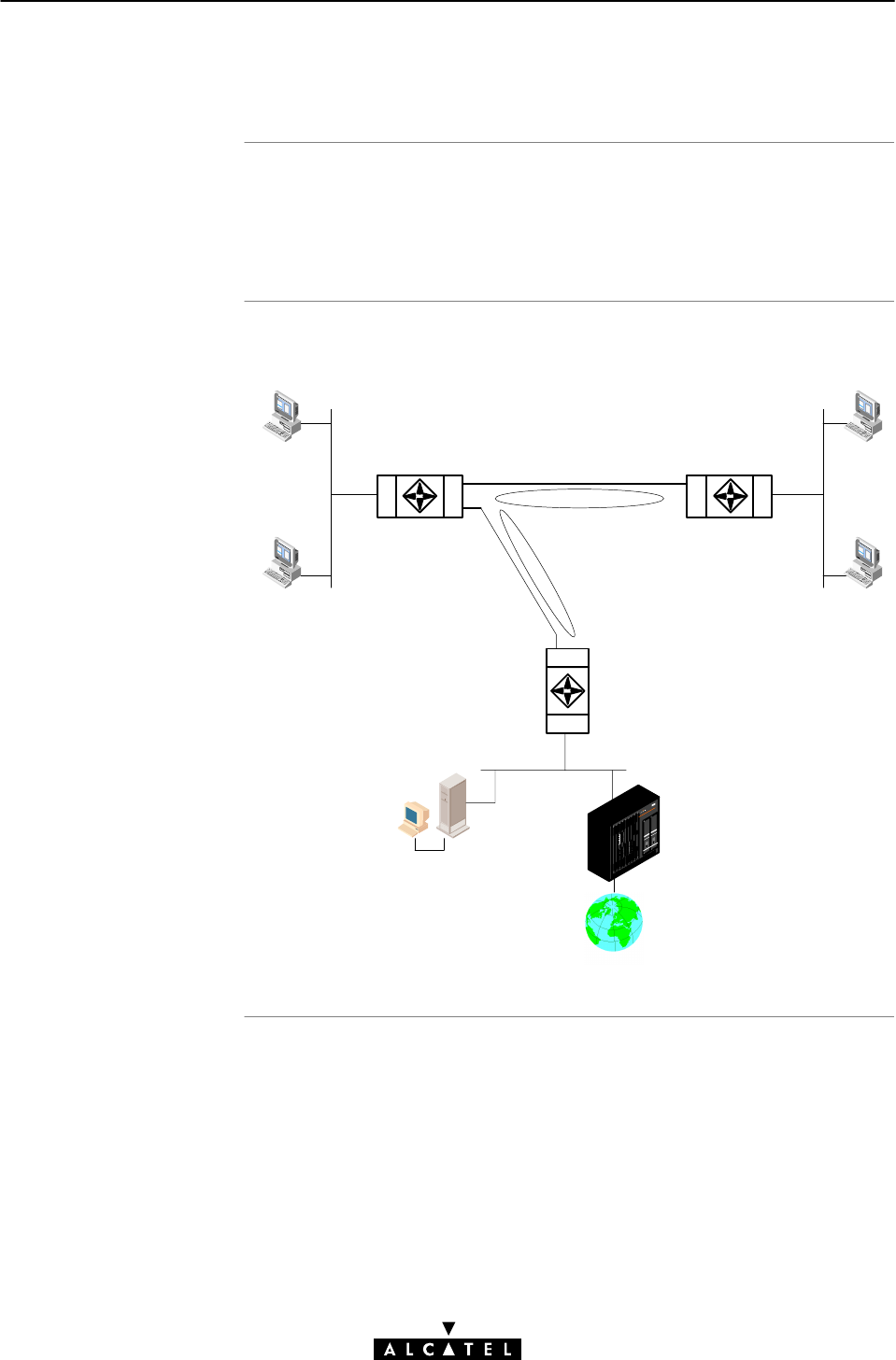
Multiple VCs fo
r
multiple LISs
Exampl
e
9 Data Services - Classical IP & IP Routing
173 / 362
3EC 17766 AAAA TCZZA Ed. 01
9.5.2 Creating Multiple CIP Members.
You can create multiple CIP members, and consequently the
STWireless can be part of multiple LISs.
By doing so, your PC(s) can connect to multiple LISs.
The following figure shows an example of such a configuration:
ETH
ATM
ETH
ATM
ETH
ATM
10.2.0.1
10.2.0.2
10.2.0.138
172.16.0.2
(VPI/VCI:8/80)PVC1
LIS:172.16.x.x
LIS:192.168.0.x
PVC2
192.168.0.2
192.168.0.110.1.0.138
10.1.0.2
10.1.0.1
Internet
Gateway
INTERNET
Local Servers
8/80
8/81
172.16.0.1
(VPI/VCI:8/81)
8/80
8/81
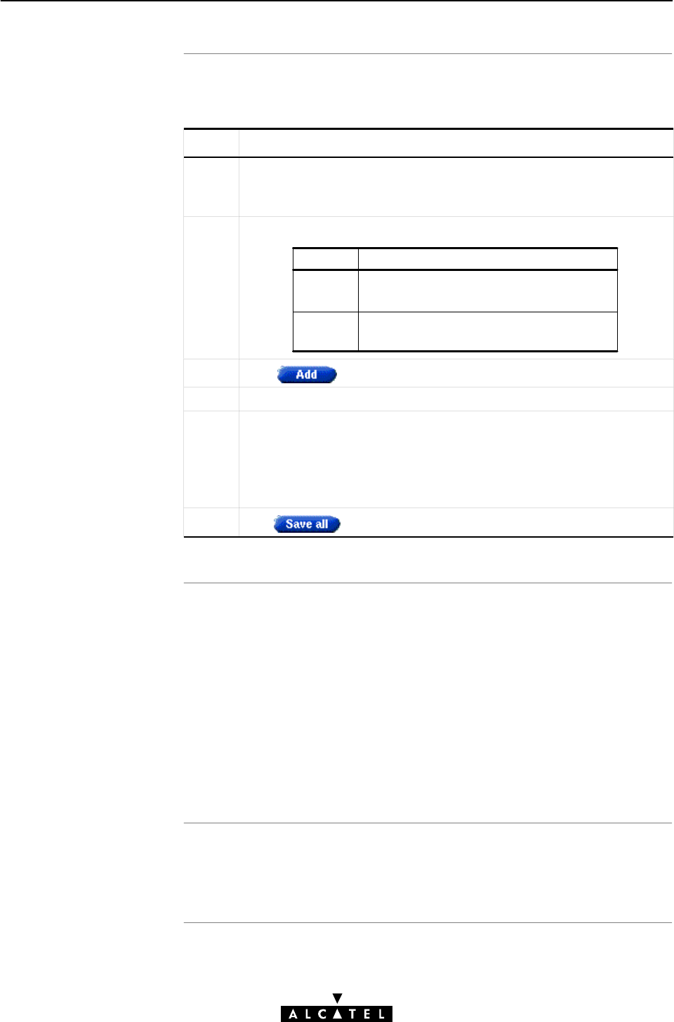
Adding CIP members
Resul
t
Note
9 Data Services - Classical IP & IP Routing
174 / 362 3EC 17766 AAAA TCZZA Ed. 01
Proceed as follows to add multiple CIP members to the 'CIP
Interfaces' table:
Step Action and Description
1 Browse to the 'CIP' web page.
The bottom row of the 'CIP Interfaces' table allows addition of a new
CIP member.
2Fill in the following CIP interface parameters:
Value Description
Local IP
Address
Mask The associated netmask/subnetmask for
that local IP address.
The IP address at the additional CIP
member.
3Click
4 Repeat steps 2 and 3 for each LIS you want to connect to.
5 For each additional CIP member, at least one CIP PVC must be
assigned. This can be done implicit, or explicit (according each
remote side's RFC1577 compliancy).
See the procedure in subsection 9.5.1 for adding CIP PVCs to the
'CIP Connections' table.
6Click to store the changes in permanent memory.
The CIP members you created, appear in the 'CIP Interfaces'
table.
The CIP PVCs, you have added appear in the 'CIP Connections'
table.
However, check whether the remote IP addresses get resolved on
these new CIP members and their associated CIP PVCs.
If yes, check IP connectivity with the LISs via a ping utility on one of
the local PCs.
As your SP is responsible for the crossĆconnects, check whether he
supports this advanced configuration.

175 / 362
3EC 17766 AAAA TCZZA Ed. 01
Speed TouchWireless
Networking Services

176 / 362 3EC 17766 AAAA TCZZA Ed. 01

Introduction
In this chapte
r
10 Networking Services - ATM
177 / 362
3EC 17766 AAAA TCZZA Ed. 01
10 Networking Services - ATM
All data arriving at and departing from your STWireless via the
ADSL line is carried in ATM cells.
In this way, ATM is the fundamental communication language"
for the STWireless towards the remote devices.
Topic See
The ATM Packet Switching Technology 10.1
The STWireless Phonebook 10.2

ATM Switching
In this section
10 Networking Services - ATM
178 / 362 3EC 17766 AAAA TCZZA Ed. 01
10.1 The ATM Packet Switching Technology
ATM is a connectionĆoriented packet switching technology using
fixedĆsize packets, called cells.
These cells consist of a header and a payload and are switched
through a public or private ATM network depending on the
contents of the header.
EndĆtoĆend connections are formed by crossĆconnecting individual
ATM segments in ATM switches.
Topic See
ATM Parameters 10.1.1
ATM and the STWireless 10.1.2
ATM and Interfaces 10.1.3

Virtual channels
VCs and the STWireless
Channel identifiers
10 Networking Services - ATM
179 / 362
3EC 17766 AAAA TCZZA Ed. 01
10.1.1 ATM Parameters
ATM uses VCs to create individual communication links between
network nodes. ATM uses two types of VCs:
"Permanent Virtual Channels (PVCs) are static connections
between network nodes that are configured statically.
The nodes of the connection operate as if they are connected
with a dedicated physical line.
"Switched Virtual Channels (SVCs) are similar to voice
telephone network connections. These are temporary
connections between any two end points on the network and
are configured via signaling. A Switched VC (SVC) is created
dynamically for each session and released when the
information exchange is complete.
Currently all STWireless ATM connections are static, i.e. of type
PVC.
Each ATM cell carries two labels called VPI and VCI as part of its
header.
An ATM channel, commonly referred to as virtual channel, is fully
identified by these two labels. Therefore, multiple ATM channels
can reside on your ADSL line.
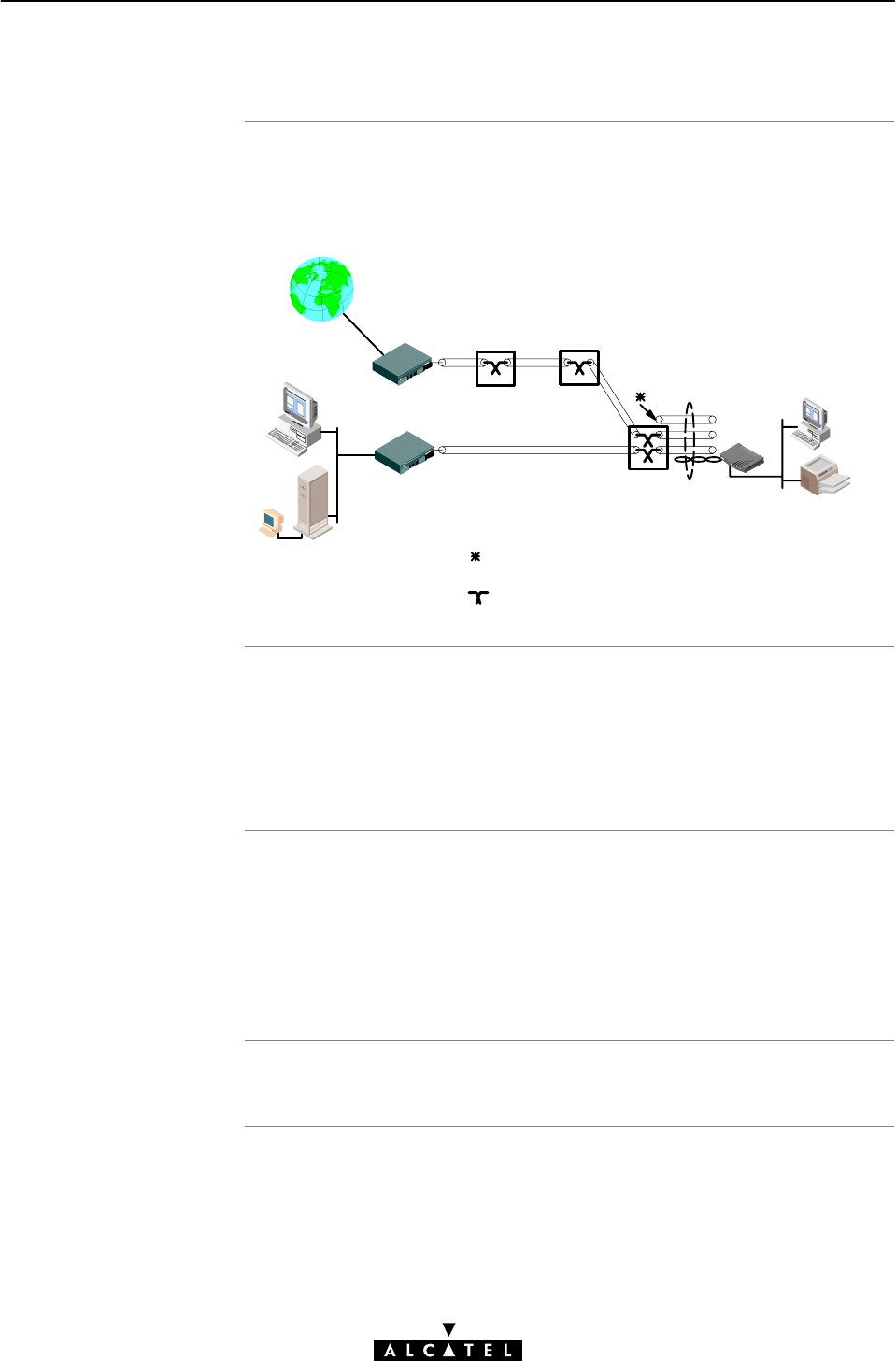
EndĆtoĆend ATM
connectivit
y
STWireless vs. remote
destination
ATM provision
STWireless defaul
t
PVC
s
10 Networking Services - ATM
180 / 362 3EC 17766 AAAA TCZZA Ed. 01
10.1.2 ATM and the STWireless
The following figure provides an overview of the endĆtoĆend
architecture of the ATM connectivity; from your STWireless to the
remote access devices.
Corporate Access Point
Internet
ISP Access Point ATM CrossĆconnect
ATM CrossĆconnect
ADSL Line
Multiple ATM
virtual channels
Ethernet
This channel is not crossĆconnected
Symbolizes a cross connection.
Hence no endĆtoĆend connectivity!
Remote LAN
Practically speaking, a number of VCs to one, or multiple remote
destination(s) can start from/are terminated at the STWireless.
By default, a number of channels are terminated in the
STWireless.
EndĆtoĆend ATM connectivity is the responsibility of local
operators. There might be regional differences in the type and
number of ATM channels that are crossĆconnected.
If problems are encountered, check with your local operator for
more information.
See Appendix E for the specific default VPI/VCI values.

ATM traffic handling
Ethernet por
t
10 Networking Services - ATM
181 / 362
3EC 17766 AAAA TCZZA Ed. 01
10.1.3 ATM and Interfaces
ATM traffic, arriving at the STWireless, is switched to the Ethernet
port, and WLAN hub.
Inside ATM VCs any protocol can be transported. However, at both
endpoints - that is where the ATM channels are terminated -, the
same protocol must be supported. If not, there will be no
endĆtoĆend connectivity.
This port terminates a number of ATM connections and extracts
frames from arriving cells and encapsulates frames in departing
cells.
Only frames recognized/supported by the STWireless on
a particular ATM connection are extracted, or encapsulated.
Currently the supported encapsulations are:
"For Bridged connections:
RFC 1483, Ethernet V2.0/IEEE 802.3 bridged PDUs for both
the LLC/SNAP method and VCĆMUX method
"For MER connections:
RFC 1483, Ethernet V2.0/IEEE 802.3 bridged PDUs for both
the LLC/SNAP method and VCĆMUX method
"For PPPoA/PPTP connections:
RFC 2364, PPP PDUs for both the LLC/NLPID method and
VCĆMUX method
"For Routed PPP connections:
RFC 2364, PPP PDUs for both the LLC/NLPID method and
VCĆMUX method
"For Routed CIP connections:
RFC 1483 LLC/SNAP method for Routed PDUs.

Introduction
In this section
10 Networking Services - ATM
182 / 362 3EC 17766 AAAA TCZZA Ed. 01
10.2 The Speed Touch Wireless Phonebook
The STWireless phonebook is like any ordinary phonebook:
A repository for names and numbers".
However, in contrast to a standard phonebook, it contains
additional connectivity information.
Basic to the STWireless ADSL router operation are ATM VCs. The
STWireless phonebook is the management tool for all possible
ATM VC connections.
This chapter describes how to use the STWireless phonebook,
and consequently how to manage this VC pool.
Topic See
The 'Phonebook' Web Page 10.2.1
Using the Phonebook 10.2.2
AutoPVC and the Phonebook 10.2.3
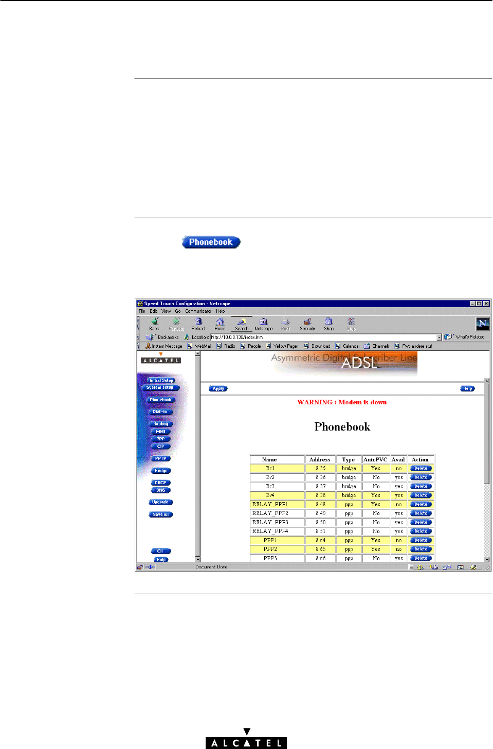
In this subsection
The STWireless
'Phonebook' web page
10 Networking Services - ATM
183 / 362
3EC 17766 AAAA TCZZA Ed. 01
10.2.1 The STWireless 'Phonebook' Web Page
"The STWireless 'Phonebook' Web Page
"The 'Phonebook' Table
"'Phonebook' Table Components
"Phonebook Defaults
"The 'AutoPVC' Table.
Clicking in the left pane of the STWireless web
pages, pops up the 'Phonebook' web page (See section 18.2 for
more information):
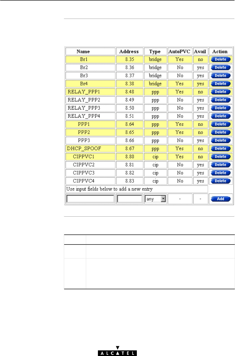
The 'Phonebook' table
'Phonebook' table
component
s
10 Networking Services - ATM
184 / 362 3EC 17766 AAAA TCZZA Ed. 01
The following figure shows an example of the 'Phonebook' table of
the 'Phonebook' web page:
The following fields are shown:
Field Description
Name Indicates the name, or alias of the virtual connection phonebook
entry. Any name can be given to an entry.
Address Indicates the VPI, and VCI value of the ATM VC, terminated on the
ADSL port, for the phonebook entry.
The allowed VPI range: from 0 up to 15.
The allowed VCI range: from 32 up to 511.
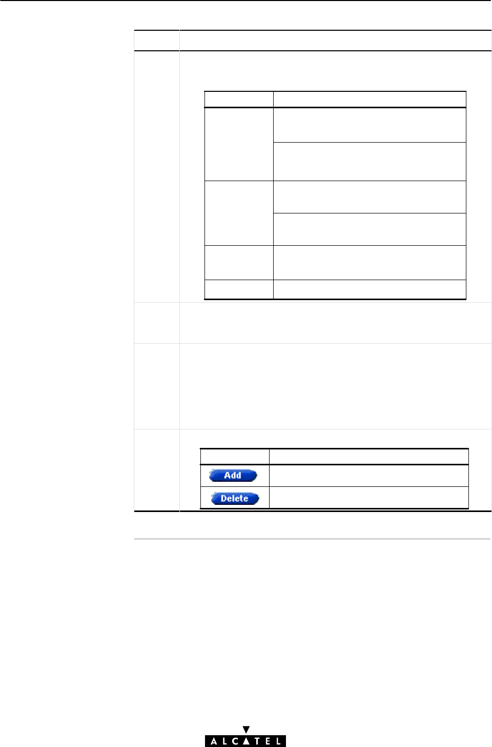
10 Networking Services - ATM
185 / 362
3EC 17766 AAAA TCZZA Ed. 01
Field Description
Type Represents the sort of packet services that are supported on the
ATM VC.
It can take the following values:
Value Packet Service
bridge
ppp PPPoAĆtoĆPPTP Relaying
See chapter 7 for more information.
IP Routing & PPP.
See chapter 8 for more information.
IP Routing & CIP.
See chapter 9 for more information.
IEEE802.1D Transparent Bridging
See chapter 5 for more information.
MAC encapsulated Routing
See chapter 6 for more information.
cip
any Any kind of packet service is allowed.
Avail Indicates the availability of the VC phonebook entry. An entry is
available if it is not configured in any packet service web page, or
not in temporary use by a packet service.
Auto
PVC
Indicates whether the entry is listed in the 'AutoPVC'list (yes), or not
(no).
If the ATM VC related to the phonebook entry is listed in the
'AutoPVC' list, the phonebook entry row is highlighted by a yellow
bar.
See subsection 10.2.3 for more information.
Action Contains one of the two following action buttons:
Button Action
Delete a phonebook entry from the list.
Add a phonebook entry to the list.
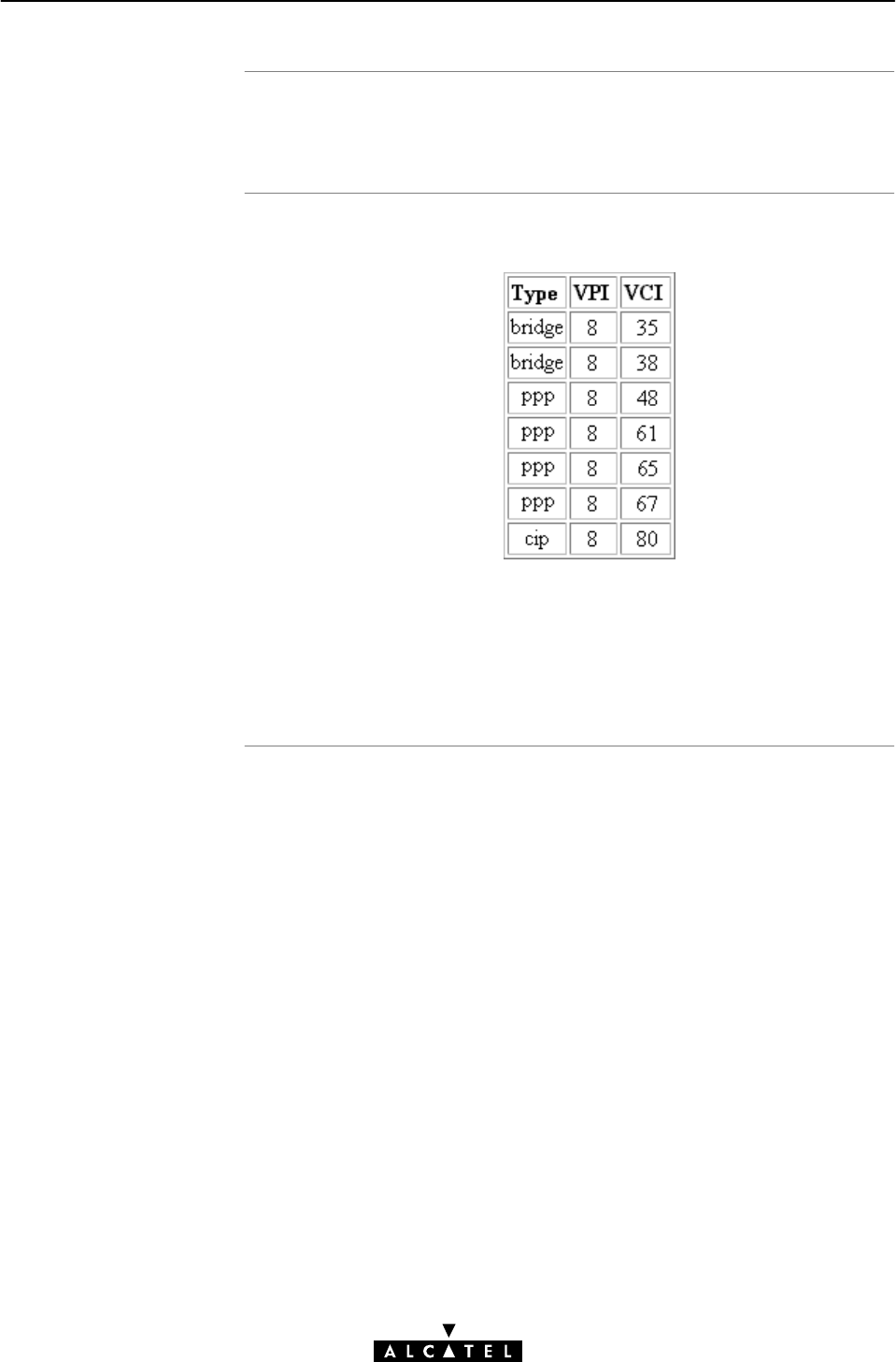
Phonebook Defaults
The 'AutoPVC' table
10 Networking Services - ATM
186 / 362 3EC 17766 AAAA TCZZA Ed. 01
The phonebook entries, configured by default, are listed in
appendix E.
The following figure shows an example of the 'AutoPVC' table:
Any PVC, identified by its VPI/VCI, communicated via AutoPVC, is
added to the 'AutoPVC' table. If AutoPVC is not supported at the
remote side, the 'AutoPVC' table stays empty.
See subsection 10.2.3 for more information.

Introduction
In this subsection
Restrictions for adding
phonebook entries
10 Networking Services - ATM
187 / 362
3EC 17766 AAAA TCZZA Ed. 01
10.2.2 Using the Phonebook
The main function of the STWireless phonebook is to present an
instant overview of all possible entries and their status.
Another important function is that it helps you to navigate through
the various STWireless VC connection possibilities.
"Restrictions for Adding Phonebook Entries
"Adding Phonebook Entries
"Deleting Phonebook Entries.
Although you are free to give any name to a phonebook entry, a
few restrictions apply:
"You may not provide an entry with a name which already is
supplied in the 'Phonebook' table.
"Phonebook entries, which are intended to be used for the
PPPoAĆtoĆPPTP Relaying packet service may not start with a
capital 'P', or a capital 'T'.
"In case you want to use the STWireless PPPĆtoĆDHCP
Spoofing feature, the name of the PPP entry you intend to use
with this feature, must start with 'DHCP', e.g. DHCP_Spoof1,
DHCP_2, etc.
Each entry in the STWireless phonebook must have a unique VC,
i.e. a unique VPI/VCI combination. Adding a phonebook entry
with a VPI/VCI, which is already used in the 'Phonebook' table,
will result in an error message.
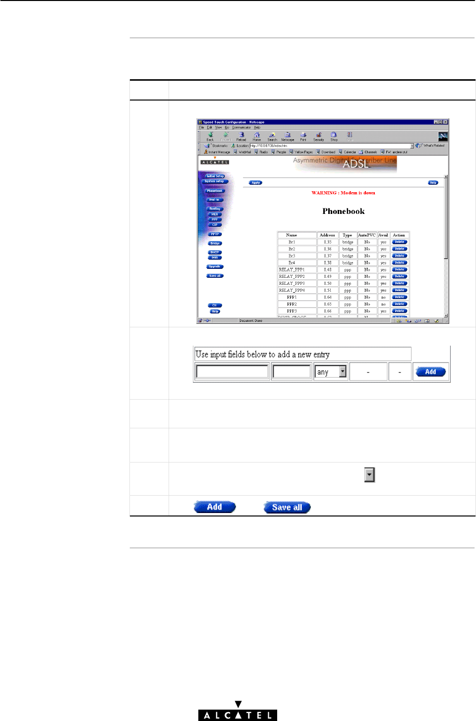
Adding phoneboo
k
entries
10 Networking Services - ATM
188 / 362 3EC 17766 AAAA TCZZA Ed. 01
Proceed as follows:
Step Action and Description
1Browse to the 'Phonebook' web page:
2Scroll to the bottom row of the 'Phonebook' table:
The bottom row of the table allows addition of a new entry.
3In the 'Name' column of the bottom row, enter a name of your
choice for identifying the phonebook entry.
4In the 'Address'column, enter the VC's VPI.VCI values.
In most cases these values are provided by your SP.
5In the 'Type' column of the bottom row, click and select the
packet service of your choice, or choose any.
6Click and to finish the procedure.
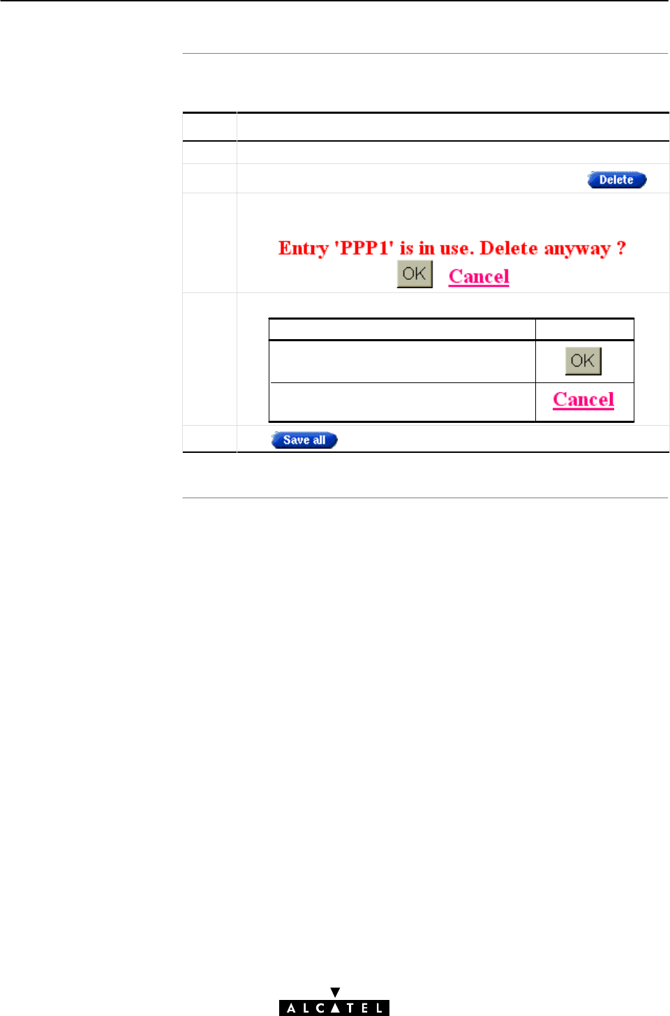
Deleting phoneboo
k
entries
10 Networking Services - ATM
189 / 362
3EC 17766 AAAA TCZZA Ed. 01
Proceed as follows:
Step Action and Description
1Browse to the 'Phonebook' web page.
2Select the phonebook entry you want to delete, and click
3If the phonebook is currently in use, i.e. is connected, or
configured, you are asked to confirm the deletion of the entry:
4Make the following selection:
If ... Then click ...
You are sure that the phonebook entry
may be deleted ...
The phonebook entry, which is in use,
may not be deleted ...
4Click to store the changes in permanent memory.

AutoPV
C
Operation of AutoPVC
Criterion 1
Criterion 2
10 Networking Services - ATM
190 / 362 3EC 17766 AAAA TCZZA Ed. 01
10.2.3 AutoPVC and the Phonebook
The default VCs, can be remotely modified via the AutoPVC
feature of the STWireless.
AutoPVC operates only in conjunction with the Alcatel DSLAM and
STWireless, and offers the functionality that user VCs that are to
be terminated on the Ethernet port, can be notified by the
STWireless.
Basically the following steps are executed:
1. The ADSL operator configures VCs on the DSLAM
2. Via AutoPVC the VPI/VCI values are communicated to the
STWireless
3. AutoPVC messages are subsequently processed by the
STWireless, according to the two criteria listed below.
Any PVC, or VPI/VCI communicated via AutoPVC is added to the
AutoPVC list on the 'Phonebook' web page.
If AutoPVC is not supported, this list is empty.
An AutoPVC VPI value in the range from 0 up to 15 will be
notified in the AutoPVC list.
If the VPI/VCI value is used in the Phonebook, this phonebook
entry will be highlighted by a yellow bar.
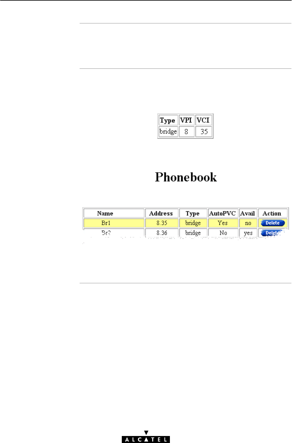
Example 1
Example 2
10 Networking Services - ATM
191 / 362
3EC 17766 AAAA TCZZA Ed. 01
If the ADSL provider configures Virtual Path (VP) 5 on the DSLAM,
then the STWireless crossĆconnects VPI 5 on the ADSL line to VPI
5 on the Ethernet port, and WLAN hub
Suppose the ADSL provider configures one of the STWireless's
default terminated VCs, e.g. 8/35, on the DSLAM.
VPI/VCI 8/35 will end up in the 'AutoPVC' list:
As this VC matches with the Bridging entry Br1, this phonebook
entry will be highlighted in the 'Phonebook' table:
In this way the user can distinguish the activated VC from dummy
phonebook entries.

10 Networking Services - ATM
192 / 362 3EC 17766 AAAA TCZZA Ed. 01

Introduction
Aim of this chapte
r
In this chapte
r
11 Networking Services - IP
193 / 362
3EC 17766 AAAA TCZZA Ed. 01
11 Networking Services - IP
For Internet access, and home networking, TCP/IP plays a crucial
role. Due to the flexibility and the multitude of TCP/IP features,
numerous configurations are possible.
This chapter highlights some general IP parameters and some
possible IP configurations for the below purposes:
"Internet access via your SP
"Private LANĆtoĆLAN interconnections over the ADSL/ATM
network
"Local IP connectivity towards other PCs on your (W)LAN.
Topic See
General IP Information 11.1
Packet Services and IP Addresses 11.2
STWireless and IP Addressing 11.3
IP Routing 11.4

In this section
11 Networking Services - IP
194 / 362 3EC 17766 AAAA TCZZA Ed. 01
11.1 General IP Information
Topic See
IP Addresses and Subnet Masks 11.1.1
Private vs. Public IP Addresses 11.1.2
Choosing an IP Address 11.1.3
Dynamic IP Address Configuration: DHCP 11.1.4

What is an IP address
Network part, subne
t
part and host par
t
Example: network and
subnetwork parts
11 Networking Services - IP
195 / 362
3EC 17766 AAAA TCZZA Ed. 01
11.1.1 IP Addresses and Subnet Masks
An IP address is a 32Ćbit number that uniquely identifies
a computer (i.e. an networking interface) on your network or the
Internet.
This number is commonly represented in dotted quad" format.
Each octet (8 bits) is represented as a decimal number.
Dots are used as octet separators (e.g. 10.0.0.138).
Historically, an IP address consists of two parts: a network part
and a host part.
The network part identifies the network on which a PC resides. The
host part identifies a particular PC on a given network.
The dividing line between the network part and the host part can
be derived from the netmask or subnet mask.
The 1 bits in the Subnet Mask represent the contiguous leading
bits of the IP address that has network significance.
For example, an IP address is 172.16.0.2 and the subnet mask is
255.255.255.0.
The binary notation of the IP address equals:
10101100.00010000.00000000.00000010
The dotted quad notation of the subnet mask equals:
11111111.11111111.11111111.00000000
Since all the 1Ćbits of the subnet mask have network significance,
the network part of the IP address would be:
10101100.00010000.00000000.00000010
AND 11111111.11111111.11111111.00000000
10101100.00010000.00000000
or 172. 16. 0.
The subnet part is the remaining part 00000010
or 2.

IP address networ
k
classe
s
Prefix notation for IP
addresse
s
Example: prefi
x
notation
IP address notation
and the STWireless
11 Networking Services - IP
196 / 362 3EC 17766 AAAA TCZZA Ed. 01
By splitting up the IP address in a network part and a subnetwork
part, it is possible to divide IP addresses in four classes (In fact
five).
These classes are differentiated by the initial bits of an IP address:
Class Range from ... up to ... Network Part Bits
A 0.0.0.0 ... 127.255.255.255 8
B128.0.0.0 ... 191.255.255.255 16
C192.0.0.0 ... 223.255.255.255 24
D224.0.0.0 ... 239.255.255.255 32
A more up to date representation of subnet masks does not refer
to a subnet mask, but to a prefix length.
The prefix number equals the number of ones in the subnet mask.
For example, the subnet mask 255.255.255.0 could also be
written as the prefix /24.
For example:
"IP address 10.0.0.138
"netmask 255.255.255.0
With the prefix method this will be written as :
"prefix IP address 10.0.0.138/24
In the routing table of the STWireless this notation will be used.

Introduction
Private IP addresses
Using private
addresse
s
Private PC(s) accessing
public services
11 Networking Services - IP
197 / 362
3EC 17766 AAAA TCZZA Ed. 01
11.1.2 Private vs. Public Addresses
Private PC(s) do not require access to PC(s) in other enterprises, or
to the Internet. Therefore it is sufficient for the PC to have an IP
address that is unique within the enterprise but may be ambiguous
between enterprises and on the Internet.
On the other hand there is also a need for InternetĆwide" unique
IP addresses to allow web servers to be constantly online.
The first set of addresses are called Private IP addresses; the
second set Public IP addresses.
In the examples throughout this document Private IP addresses are
used for local IP configurations.
Private IP addresses are defined in RFC1918 Address Allocation
for Private Internets". This RFC is categorized as "Best Current
Practice".
In principle if an IP address is assigned to a PC and the connectivity
is limited to intraĆenterprise communication only, the IP address can
be assumed to be privately held.
The limitation however is that communication between enterprises
and connection to the Internet itself via those private IP addressed
PCs is not possible, and even not allowed.
Via mediating gateways (e.g. the STWireless) private PC(s) can
still have access to external services, e.g. the Internet.

Private IP address
classe
s
Public IP addresses
Using Public IP
addresse
s
11 Networking Services - IP
198 / 362 3EC 17766 AAAA TCZZA Ed. 01
IANA (the Internet Assigned Number Authority), defined blocks of
IP addresses for private purposes:
Class
Type
From To Number of Network
Numbers
A 10.0.0.0 10.255.255.255 1
B 172.16.0.0 172.16.255.255 16 (Contiguous)
C 192.168.0.0 192.168.255.255 256 (Contiguous)
A Public IP address is an officially assigned IP address by an
Internet Registry and is guaranteed to be worldwide unique.
As a consequence the PC to which the address is assigned, has
worldwide Internet connectivity.
Public IP addresses are used by PC(s) that need global
connectivity, outside the enterprise, and/or with the Internet;
therefore these PC(s) require public IP addresses to be globally
unique.
You may not assign Public IP addresses yourself. If you need a
Public IP address or block of IP addresses, contact your Internet
Service Provider (ISP).
The ISP must in turn contact its upstream registry, or his
appropriate regional registry, e.g.: the American Registry for
Internet Numbers (ARIN) (http://www.arin.net).

Introduction
Use of public IP
addresse
s
Use of private IP
addresse
s
Simultaneous use o
f
public & private IP
addresse
s
11 Networking Services - IP
199 / 362
3EC 17766 AAAA TCZZA Ed. 01
11.1.3 Choosing an IP Address
Regardless of your application, IP addresses must always be
configured at both ends of the connection.
Prior to configuring an IP address, you must choose a suitable
one. In this subsection a few criteria are listed that may influence
your choice.
Public IP addresses are required when accessing the Internet. Each
PC on the Internet must have a unique IP address. If not, IP
packets cannot be routed.
For endĆtoĆend IP communication your ISP or LAN administrator
will supply you with a Public IP address.
Private IP addresses are to be used for local IP communication.
E.g. configuring the STWireless, or dumping files to your local
printer.
For this purpose it is best to choose addresses from the private
ranges.
Further, all examples will be given with 10.x.x.x private addresses,
sometimes referred to as Net10" IP addresses.
In most networking scenario's, Private and Public IP addresses will
be in use simultaneously, e.g.:
"PPPoAĆtoĆPPTP Relaying
In this configuration, one IP layer is carried into another.
Otherwise stated: on your local (home) (W)LAN the Public IP
layer is carried inside a Private IP layer (a so called IP Tunnel).
"PPP & IP Routing
In this scenario the Public IP layer will be terminated in the
STWireless and translated into a Private IP layer via the NAPT
translation feature of the STWireless.

Local vs. endĆtoĆend
Dynamic vs. static IP
configuration
11 Networking Services - IP
200 / 362 3EC 17766 AAAA TCZZA Ed. 01
In the various configurations, multiple IP addresses are in use at
the same time, however their scope will differ. The Public IP
addresses will run endĆtoĆend, Private IP addresses will remain
local.
Both Public and Private IP addresses can either be statically
configured, or can be distributed dynamically via DHCP.
See section 11.1.4 for more information.
Again, for endĆtoĆend IP communication, your ISP or (W)LAN
administrator will decide on the method. For local configuration
you can choose the method yourself.

DHC
P
Use of DHCP
Operation of DHCP
DHCP and STWireless
11 Networking Services - IP
201 / 362
3EC 17766 AAAA TCZZA Ed. 01
11.1.4 Dynamic IP Address Configuration: DHCP
DHCP is short for Dynamic Host Configuration Protocol and is part
of the TCP/IP protocol suite. It provides a framework for passing
configuration information to PC(s) on a TCP/IP network.
The intention is for individual PC(s) to extract their IP parameters
from a central server, rather then configuring them manually.
A PC supporting DHCP, will receive the following IP parameters via
DHCP:
"Its own IP address and subnet mask
"The IP address of the default gateway
"The IP addresses of the primary and secondary DNS servers.
DHCP operates in client/server mode: a PC in its booting stage
acts as a DHCP client and emits broadcast DHCP requests. These
are intercepted by a DHCP server (on the same network) which
responds with DHCP replies.
These DHCP replies contains, among other information, the IP
address for the DHCP client.
Mostly this IP address is given for a limited period of time. This
allows automatic reuse of an address that is no longer needed by
the PC to which it was assigned.
The task of being DHCP server can also be performed by the
STWireless.
STWireless DHCP server configuration is possible via the 'DHCP'
web page. See section 11.3.3 for more information.

Introduction
In this section
11 Networking Services - IP
202 / 362 3EC 17766 AAAA TCZZA Ed. 01
11.2 Packet Services and IP Addressing
In this section the interaction between IP addresses and packet
services is described.
Apart from Bridging, all packet services require the TCP/IP suite,
and even the Bridging packet service will in most cases be used in
combination with IP addressing.
Topic See
Transparent Bridging and IP Addresses 11.2.1
MER and IP Addresses 11.2.2
PPPoAĆtoĆPPTP Relaying and IP Addresses 11.2.3
PPP & IP Routing and IP Addresses 11.2.4
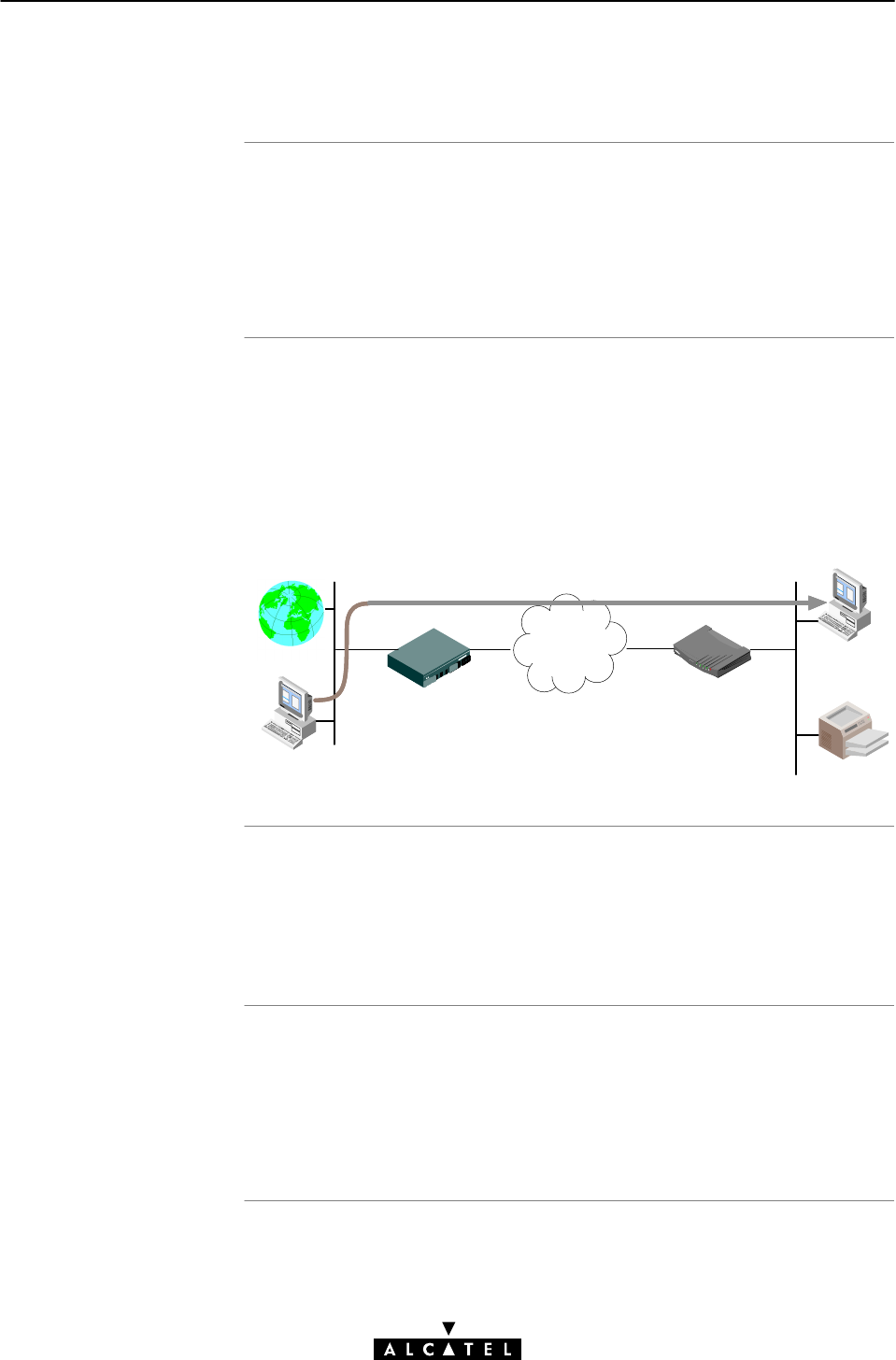
IP vs. Bridging
Typical Bridging Setup
Using TCP/IP and
Bridging
Local IP communication
11 Networking Services - IP
203 / 362
3EC 17766 AAAA TCZZA Ed. 01
11.2.1 Transparent Bridging and IP Addresses
Basically, Bridging does not require any IP address at all: neither
in your PC(s), nor in your STWireless.
However, in case of Internet access or private IP networking, your
PC(s) must be configured for TCP/IP.
In most cases, your SP will require you to use DHCP for your PC.
In this case the DHCP server is at the remote side of the ADSL
connection. Therefore, also your STWireless's DHCP server must
be disabled.
As you can see in the following figure, this typical configuration
setup, illustrates the transparency of the Bridging packet service:
STWireless
Internet
Access Point
ATM
Network DHCP Client
IP Address
DHCP Server
ATM
Network
Your SP may:
"Provide you with an IP address
"Require you to use DHCP.
Alternatively, a second but Private IP address can be manually
configured for local IP communication. It depends on your OS
whether it supports this combination.
e.g. Microsoft supports Logical Multihoming via Registry keys.

11 Networking Services - IP
204 / 362 3EC 17766 AAAA TCZZA Ed. 01
Bridging & DHCP Service
The STWireless DHCP server is by default enabled (via Auto
DHCP).
In case you use your STWireless in Bridging mode and your ISP
requires you to enable DHCP in your PC(s), you must disable the
DHCP server inside the STWireless to avoid conflicts between two
DHCP servers being active at the same time.
Setting the DHCP modes of your STWireless is described in
section 11.3.3.
CAUTION

MER and IP addresses
STWireless IP
addresse
s
PC IP address
configuration
Default gateway fo
r
the PCs
MER & IP routing
11 Networking Services - IP
205 / 362
3EC 17766 AAAA TCZZA Ed. 01
11.2.2 MER and IP Addresses
Local IP addresses must be configured prior to use IP routing.
As the STWireless has a preconfigured Net10" address
(10.0.0.138), you can configure IP addresses like 10.0.0.1,
10.0.0.2, ... in your PCs, or use the STWireless DHCP server.
In case another IP address is required, you can set STWireless's
IP address via the STWireless web pages, or via a PingĆofĆLife.
See sections 11.3 and 17.1 for more information.
The PC IP address can be configured statically (no DHCP), or
dynamically (STWireless as DHCP server).
See subsection 11.3.3 for more information.
In addition, configure the STWireless's IP address as default
gateway in your PCs.
At the ADSL side of the STWireless IP router, MER will receive an
IP address from the remote access server. However, you can also
configure an IP address for the MER connection on the 'MER' web
page. In this case, the STWireless negotiates the acceptance of
the IP address with the remote side.
Via NAPT, both Private and Public IP addresses can coexist in the
router.

IP vs. PPPoA/PPT
P
Private IP addresses
Public IP addresses
Simultaneous use o
f
public & private IP
PPP IP address
negotiation
11 Networking Services - IP
206 / 362 3EC 17766 AAAA TCZZA Ed. 01
11.2.3 PPPoAĆtoĆPPTP Relaying and IP Addresses
Prior to using PPTP, local IP addresses must be configured. The use
of these IP addresses is limited to the local network.
Consequently you are free to choose any IP address as long as it is
compatible with your local network and is unique in that same
network.
As the STWireless has a preconfigured Net10" address
(10.0.0.138), you should configure IP addresses like 10.0.0.1,
10.0.0.2, ... on your PCs.
Note: IP addresses can be configured automatically via
STWireless's DHCP server. See section 11.3.3, for more
information.
For PPPoA/PPTP, a second set of (Public) IP addresses having
endĆtoĆend scope, will automatically be negotiated via the PPP
protocol inside your PC(s).
Both Public and Private IP addresses are active simultaneously
because of PPTP tunneling. In fact two nested" IP layers exist:
the Public IP layer which is carried within the Private IP layer on the
local (W)LAN.
By default the PPTP tunnel application automatically negotiates the
Public IP address.
In case your SP instructs you to use a static IP address for
PPPoA/PPTP, you can supply a static IP address:

IP routing and IP
addresse
s
STWireless IP
addresse
s
PC IP address
configuration
Default gateway fo
r
the PCs
PPP & IP routing
PPP IP address
negotiation
NAP
T
11 Networking Services - IP
207 / 362
3EC 17766 AAAA TCZZA Ed. 01
11.2.4 PPP & IP Routing and IP Addresses
Local IP addresses must be configured prior to use IP routing.
As the STWireless has a preconfigured Net10" address
(10.0.0.138), you can configure IP addresses like 10.0.0.1,
10.0.0.2, ... in your PCs, or use the STWireless DHCP server.
In case another IP address is required, you can set STWireless's
IP address via the STWireless web pages, or via a PingĆofĆLife.
See sections 11.3 and 17.1 for more information.
The PC IP address can be configured statically (no DHCP), or
dynamically (STWireless as DHCP server).
In addition, configure the STWireless's IP address as default
gateway in your PCs.
At the ADSL side of the STWireless IP router, PPP automatically
negotiates an IP address with its remote PPP peer. Via NAPT, both
Private and Public IP addresses can coexist in the router.
You can configure the PPP local IP address of the STWireless.In
special circumstances, you can configure a remote IP address for
the PPP connection.
See subsection 8.4.5 for more information.
NAPT is enabled by default on PPP connections. In case your
(W)LAN uses Public IP addresses, NAPT is not required.
See subsection 8.4.6 for more information.

Introduction
In this section
11 Networking Services - IP
208 / 362 3EC 17766 AAAA TCZZA Ed. 01
11.3 Speed Touch Wireless and IP Addressing
Like any other member of a (W)LAN, the STWireless must be
locally identified by an IP address to be able to communicate with
other local (W)LAN devices.
This section deals with the IP address configuration of the
STWireless for local communication only.
Topic See
STWireless IP Address Types 11.3.1
Static IP Address Configuration 11.3.2
Dynamic IP Address Configuration 11.2.4
Configuring the STWireless DHCP Server 11.2.4
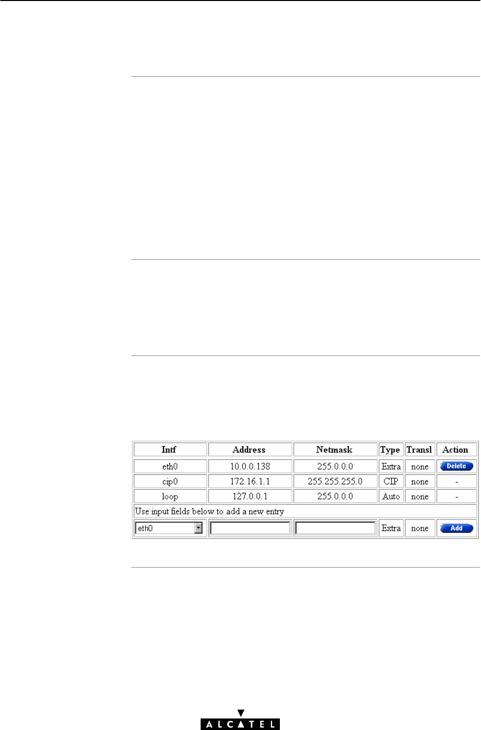
Assigning IP addresses
to the STWireless
STWireless and
multiple IP addresses
'IP address' table
11 Networking Services - IP
209 / 362
3EC 17766 AAAA TCZZA Ed. 01
11.3.1 STWireless IP Address Types
IP addresses can be assigned to the STWireless in several ways.
Summarized, following IP address types exist:
"The default IP address: 10.0.0.138
"IP addresses assigned via the 'Initial Setup' web page
"IP addresses assigned via a 'PingĆofĆLife
"IP addresses assigned via the 'Routing' web page.
Moreover, IP addresses can be configured, and/or negotiated
during connection sessions (e.g. MER, and PPP & IP Routing).
As the STWireless IP layer supports logical multiĆhoming (one
interface supporting multiple IP addresses), the statically
configured IP address(es) and dynamically required IP address(es)
can be active at the same time.
If you browse to the 'Routing' web page (See section 18.2 for
more information), you can find the 'IP address' table. This table
summarizes all IP addresses configured on any of the STWireless
interfaces:

'IP address' table
component
s
11 Networking Services - IP
210 / 362 3EC 17766 AAAA TCZZA Ed. 01
The following fields are shown:
Field Description
Intf Indicates the interface (Intf) to which the IP parameter set was
assigned to.
It can take several values depending on the packet services
that are active. The Ethernet (eth0) and the Loopback (loop)
are always present.
Address Shows the IP address of the interface.
Netmask If available, it shows the Netmask of the interface.
Type Indicates the origin of the IP parameters.
It can take following values:
Value Description
Auto
User Implies that an additional IP parameter set
was added through the 'Initial Setup' web
page.
Extra Implies that an additional IP parameter set
was added through the 'Routing' web page.
The default IP address 10.0.0.138 is also of
this type.
Temp Implies that this (additional) IP parameter set
was added via a PingĆofĆLife.
Implies that the parameters were acquired
automatically through DHCP, or are typical
standard IP addresses (e.g. 'loop').
Transl This field indicates the translation performed.
It can take following values:
Value Description
None
NAT NAPT is performed on this address.
No address translation is performed on this
address.
Action Contains one of the two following action buttons:
Button Action
Delete an IP address from the list.
Add an IP address to the list.
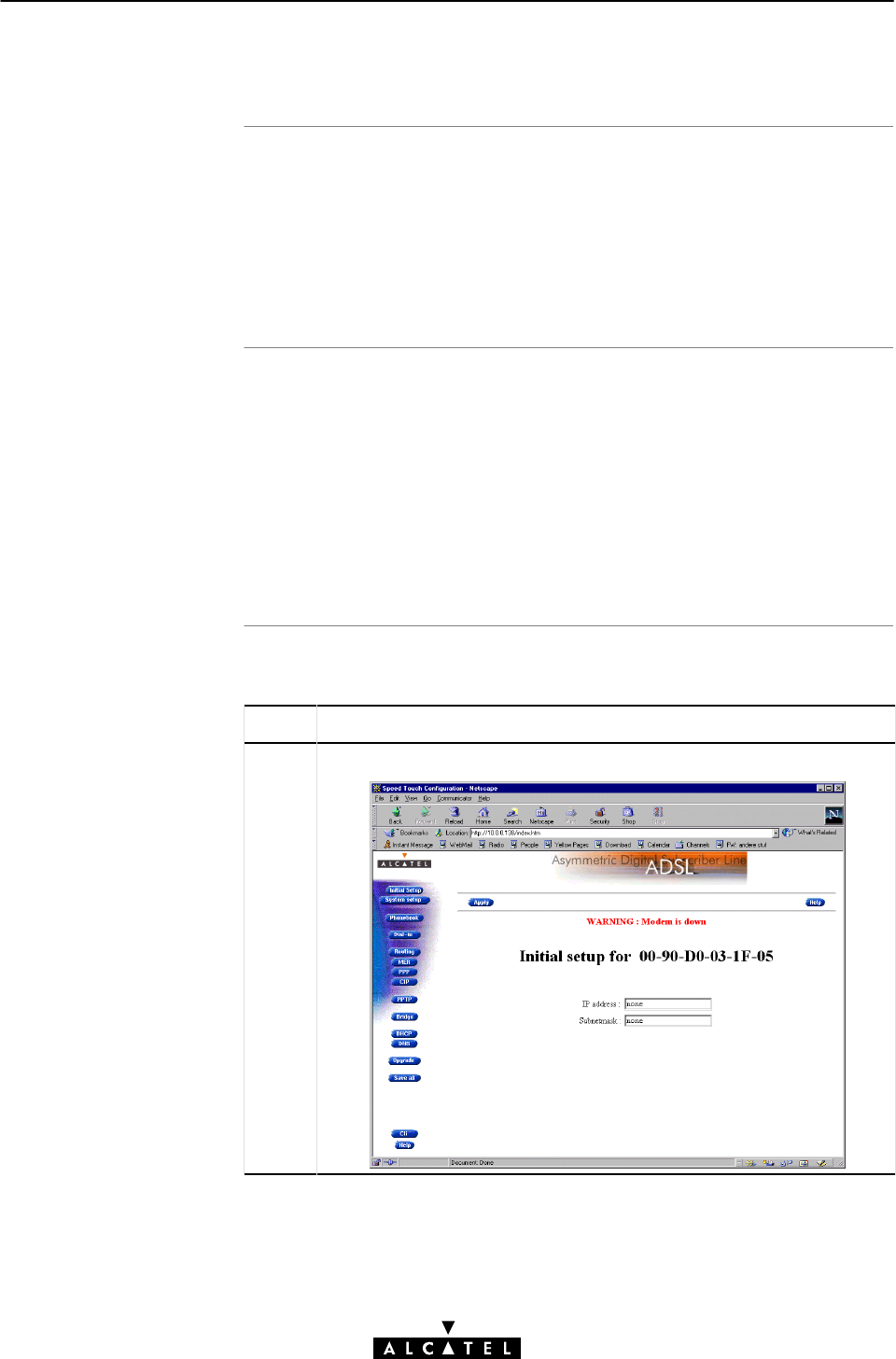
Default STWireless IP
addres
s
In this subsection
Setting an IP address
via the 'Initial Setup'
web page
11 Networking Services - IP
211 / 362
3EC 17766 AAAA TCZZA Ed. 01
11.3.2 Static IP Address Configuration
The STWireless comes with a preconfigured Net10" IP address,
i.e. 10.0.0.138.
In case you add the STWireless to an existing (W)LAN, it could be
that you must configure a User Defined" IP address, other than
the Net 10" address, appropriate for the (W)LAN's IP settings.
"Setting an IP Address via the 'Initial Setup' Web Page
"Setting an IP Address via the 'Routing' Web Page
"STWireless Associated Netmasks
"Sample Configuration: Single PC
"Sample Configuration: Small Workgroup.
See section 18.2 for more information.
Proceed as follows:
Step Action and Description
1Browse to the 'Initial Setup' web page:

Setting an IP address
via the 'Routing' web
pag
e
STWireless associated
netmask
s
11 Networking Services - IP
212 / 362 3EC 17766 AAAA TCZZA Ed. 01
Step Action and Description
2In the 'IP Address' field you can configure a user defined IP address
for the STWireless.
This IP address will show up as User " in the STWireless 'IP
address' table (See section 11.3.1).
3In the 'Subnetmask' field you must configure an appropriate
netmask for applying subnetting in your (W)LAN.
4Click . As a result, the new IP settings are applied.
5To verify connectivity, point your Web browser to the new IP address.
Make sure though that your PC shares the same subnetwork.
6Click to store the IP settings to permanent storage.
Proceed as follows to configure an Extra" IP address:
Step Action and Description
1Browse to the 'Routing' web page.
2In the 'IP address' table, you can configure an extra IP address,
using the table's bottom row.
Fill in the bottom row as follows:
•Intf: Eth0"
•IP address: the IP address for the STWireless.
•Netmask: the appropriate netmask.
3Click . As a result, the new IP settings are applied.
4To verify connectivity, point your browser to the new address. Make
sure though that your PC shares the same subnetwork.
Click to store the IP settings to permanent storage.
(Private) IP Address Class Associated
Netmask
Example IP
Address
A (1.x.x.x to 126.x.x.x) 255.0.0.0 10.x.x.x
B (128.0.x.x to 191.255.x.x) 255.255.0.0 172.16.x.x
C (192.0.0.x to 223.255.255.x) 255.255.255.0 192.168.x.x
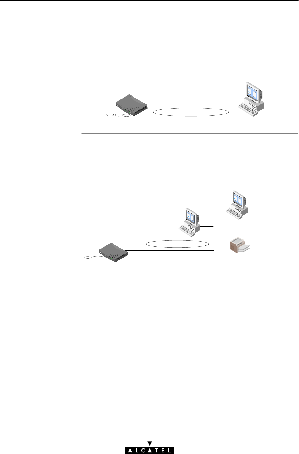
Sample configuration:
single PC
Sample configuration:
small workgroup
11 Networking Services - IP
213 / 362
3EC 17766 AAAA TCZZA Ed. 01
In the below figure, a simple configuration is given: One PC is
attached to the STWireless:
IP Network 10
IP address : 10.0.0.138
(Sub)netmask : 255.255.0.0
Default Gateway : none
IP address : 10.0.0.1
(Sub)netmask : 255.255.0.0
Default Gateway : none
You can setup a local workgroup around the STWireless as
shown in the figure below:
IP Network 172.16
IP address : 172.16.0.4
(Sub)netmask : 255.255.0.0
Default Gateway : none
IP address : 172.16.0.3
(Sub)netmask : 255.255.0.0
Default Gateway : 172.16.0.4
IP address : 172.16.0.1
(Sub)netmask : 255.255.0.0
Default Gateway : 172.16.0.4
IP address : 172.16.0.2
(Sub)netmask : 255.255.0.0
Default Gateway : 172.16.0.4
Note: Notice that the default gateways in the PCs point to the
STWireless.

STWireless DHCP
client/server setting
Default STWireless
DHCP configuration
In this subsection
11 Networking Services - IP
214 / 362 3EC 17766 AAAA TCZZA Ed. 01
11.3.3 Dynamic IP Address Configuration: DHCP
Depending on the size and complexity of your network, a few
DHCP configurations can be envisaged:
(W)LAN
Type
DHCP
Mode
Argumentation
Simple No All few members of the small (W)LAN have static IP
addresses, including the STWireless.
Medium
sized
Server For small home (W)LANs it might be worthwhile to
configure all of your (W)LAN devices as DHCP clients,
and the STWireless as the DHCP server.
In this configuration each time a computer starts, it
will obtain its IP configuration from the STWireless.
Advanced Client For advanced networks, the role of DHCP server
might be performed by an IP node other than the
STWireless on the local (W)LAN.
Typically such functions are attributed to home
gateways: computers having better networking
capabilities than the other PC(s) on the home (W)LAN.
All local PCs remain configured as DHCP clients,
including the STWireless.
For the STWireless, the DHCP server is by default enabled, i.e.
set for 'Auto DHCP'.
"The STWireless 'DHCP' Web Page
"Configuring the STWireless for (W)LANs without DHCP
Server
"Configuring the STWireless as DHCP Server
"Configuring the STWireless as DHCP Client
"Configuring the STWireless Auto DHCP
"Dynamic IP Addressing.
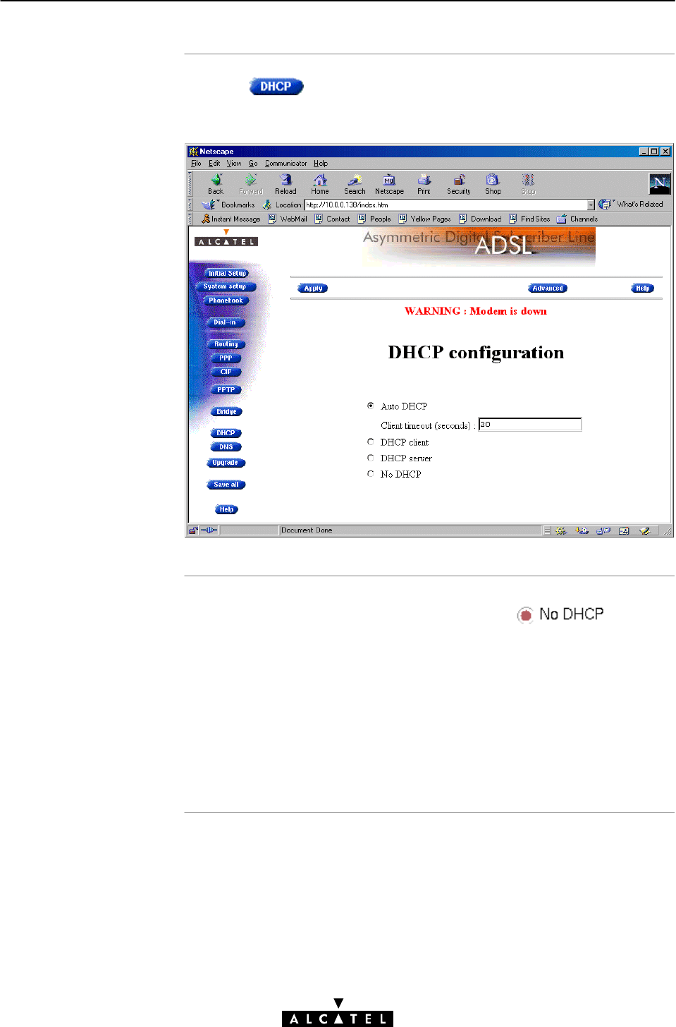
The STWireless 'DHCP'
web page
Configuring the
STWireless for a
(W)LAN without DHCP
11 Networking Services - IP
215 / 362
3EC 17766 AAAA TCZZA Ed. 01
Clicking in the left pane of the STWireless web pages,
pops up the 'DHCP'web page:
To setup the STWireless without DHCP, tick on the
'DHCP' web page.
In this configuration, it is assumed that all members, the
STWireless included, have static IP addresses.
See subsection 11.3.2 for static IP addressing of the STWireless.
Note: This configuration might be required in case you use the
Transparent Bridging packet service.
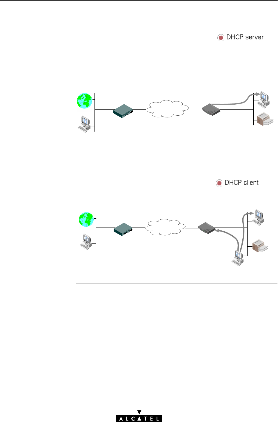
Configuring the
STWireless as DHCP
serve
r
Configuring the
STWireless as DHCP
clien
t
11 Networking Services - IP
216 / 362 3EC 17766 AAAA TCZZA Ed. 01
To setup the STWireless as DHCP server, tick on
the 'DHCP' web page.
Via the 'DHCP Server Configuration' web page, you can configure
the STWireless DHCP server settings. See subsection 11.3.4 for
more information.
IP Address
STWireless DHCP
Server
Internet
Access Point
ATM
Network
Note: This setting might cause side effects with Bridging. See
section 11.2.1 for more information.
To setup the STWireless as DHCP client, tick on
the 'DHCP' web page.
IP Address
Internet
Access Point
ATM
Network DHCP Client
IP Address
DHCP Server
STWireless

Configuring the
STWireless for Auto
DHC
P
Automatic IP
addressin
g
11 Networking Services - IP
217 / 362
3EC 17766 AAAA TCZZA Ed. 01
One of the STWireless features is that it can automatically revert
from DHCP client to DHCP server.
At boot time the STWireless probes the (W)LAN for a specified
time limit ('Client timeout') to check wether another DHCP server is
available on the network. If so, it will act as a DHCP client. If no
response is received within the specified time, the STWireless
becomes a DHCP server.
To allow the STWireless to act as Auto DHCP client/server, tick
on the 'DHCP' web page.
Additionally, you can configure the 'Client timeout' in seconds.
Via the 'DHCP server configuration' web page, you can configure
the STWireless DHCP server settings. See subsection 11.3.4 for
more information.
OSs supporting 'Automatic IP Addressing', might initially not
establish IP connectivity with the STWireless. This is because the IP
address they assimilated is not within the STWireless 'Auto DHCP'
server range.
To prevent this problem, please power on your (W)LAN
devices after the STWireless has come online.
Indeed, when the STWireless is in 'Auto DHCP', it will first
operate as a DHCP client. After the client timeout exceeded, it
switches to DHCP server mode, but this might be to late as some
clients will already selected an automatic IP address.
Dynamic IP addressing is a feature allowing DHCP clients to
assign themselves an IP address.
This happens when there is no DHCP server on the network, or
when the server is temporarily down. After automatic assignment,
the DHCP client will issue DHCP requests at regular instances.
If the DHCP server is back online, the client will now lease an IP
address from the server, after discarding its temporary automatic
IP address.
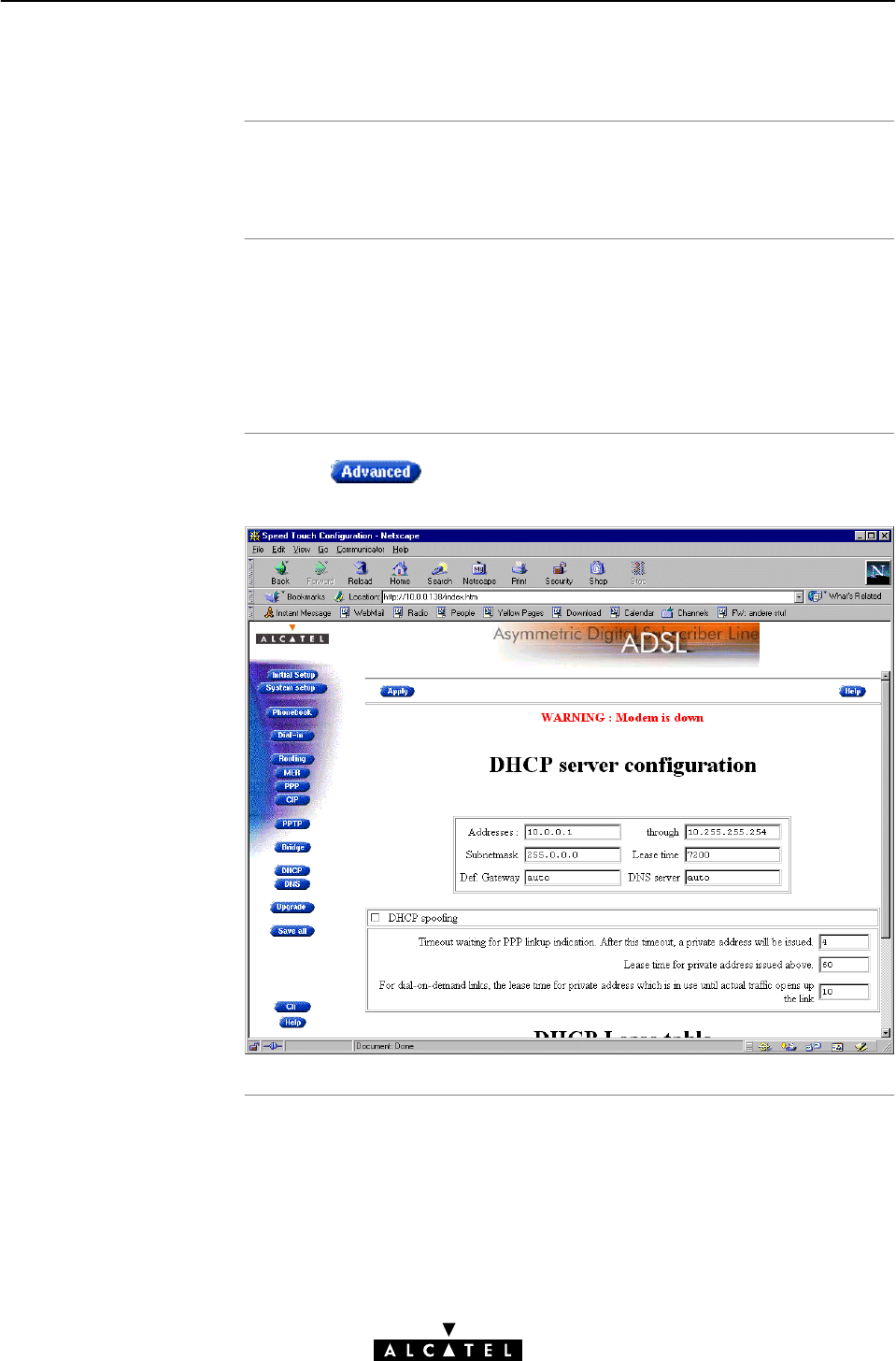
Introduction
In this subsection
The 'DHCP serve
r
configuration' web
pag
e
11 Networking Services - IP
218 / 362 3EC 17766 AAAA TCZZA Ed. 01
11.3.4 Configuring the STWireless DHCP Server
If the STWireless is configured for 'Auto DHCP' or 'DHCP server',
additional configuration must be done.
"The 'DHCP server configuration' Web Page
"DHCP Server IP Addressing Box
"DHCP Spoofing Box
"DHCP Lease Table.
Clicking on the 'DHCP' web page, pops up the 'DHCP
server configuration' web page:

DHCP server IP
addressing bo
x
DHCP server IP
addressing box options
11 Networking Services - IP
219 / 362
3EC 17766 AAAA TCZZA Ed. 01
This box allows to specify the STWireless DHCP server features:
You can configure following parameters:
Field This configures ... Default
Addresses
through ...
The range of addresses the DHCP server can
choose an IP address from for lease.
Net10"
Subnet Mask The subnetting applied to the local network,
scoped by the DHCP server.
no
subnetting
Lease Time The time (Lease Time) IP addresses can be
assigned to a device by DHCP.
7200
seconds
Default
Gateway
The IP address of the default gateway. 'auto' (*)
DNS Server The IP address of the DNS server. 'auto' (**)
(*) Setting 'auto' in the 'Def. Gateway' field means, that there will
be referred to the 'Routing' web page.
(**) Setting 'auto' in the 'DNS server' field means, that there will be
referred to the 'DNS' web page.

DHCP spoofing bo
x
DHCP spoofing bo
x
option
s
11 Networking Services - IP
220 / 362 3EC 17766 AAAA TCZZA Ed. 01
This box allows you to set the DHCP spoofing parameters for
PPPĆtoĆDHCP spoofing connections.
See section 8.4.7 for more information on PPPĆtoĆDHCP spoofing.
You can configure following parameters:
Field This configures ... Default
Timeout The time limit the STWireless is waiting
for a negotiated PPP connection session IP
address. After timeout a Private PPP
connection session IP address will be
issued.
4 seconds
Lease Time The time (Lease Time) the Private PPP
connection session IP address, issued after
timeout, can be assigned to the
STWireless.
60 seconds
DialĆonĆDemand
Lease Time
The lease time for the Private PPP
dialĆonĆdemand IP address which is in use
until actual traffic opens up the link.
10 seconds
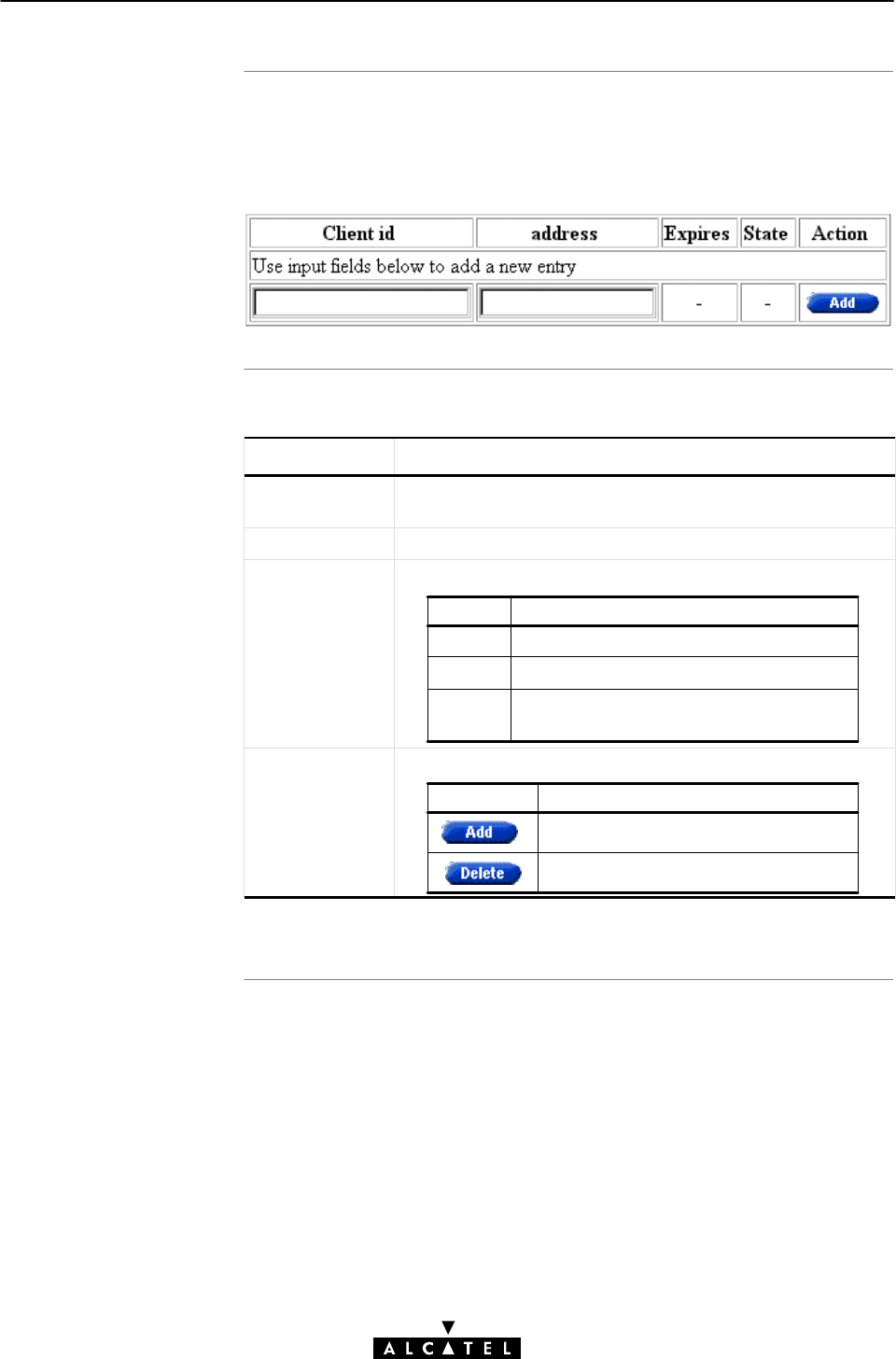
DHCP lease table
DHCP lease table
option
s
11 Networking Services - IP
221 / 362
3EC 17766 AAAA TCZZA Ed. 01
This table allows you to manually assign IP addresses to devices,
identified by there MAC address, with the possibility to let this
lease expire after some specified time.
You can configure following parameters:
Field Description
Client ID Configures the MAC address of the device the STWireless
leases to.
Address Configures the lease IP address for the device.
State Indicates if the lease is:
Value Description
on
off Device is unreachable.
expired Timeout time limit has expired for the
lease.
Device is up, running and using the lease.
Action Contains one of the two following action buttons:
Button Action
Delete an existing lease.
Manually add a lease to the list.

Introduction
In this section
11 Networking Services - IP
222 / 362 3EC 17766 AAAA TCZZA Ed. 01
11.4 IP Routing
Next to the ADSL router part, the STWireless supports also
standard IP routing via its IP router.
This section aims to familiarize you with the STWireless IP router
abilities.
Topic See
The STWireless IP router 11.4.1
Configuring the STWireless IP Routing Table 11.4.2

Introduction
Features
Configuring an IP
routing table
11 Networking Services - IP
223 / 362
3EC 17766 AAAA TCZZA Ed. 01
11.4.1 The STWireless IP Router
Because the STWireless can act as an IP router, it has the ability
to access machines in other networks than its own. This can
be achieved by adding specific routes to its IP routing table.
This subsection provides some general information on the
STWirelessIP router functionality.
IP routing:
"Is a standard and a wellĆknown principle, mainly due to the
widespread Internet use
"Has broad application support, as it is implemented in most,
if not all Operating Systems (Windows, Unix, MAC OS, ...).
The routes in an ordinary routing table or Forwarding Information
Base (FIB) include, among others, destination IP addresses, subnet
masks and gateways.
When an IP packet arrives at the router, the router examines
the destination IP address. The router looks up the most specific
match in the routing table for that destination address. Finding the
most specific match equals finding the longest subnet mask for
that IP address.
For example, the subnet mask 255.255.255.0 is more specific
than 255.255.0.0 because the network part in the first case is
longer (and thus more specific) than the network part in the
second case.
Once the most specific match is found, the router forwards the IP
packet to the gateway associated with that match.

Simplified example o
f
a traditional IP routing
tabl
e
The STWireless IP
routing table
Example of the
STWireless extended IP
routing table
11 Networking Services - IP
224 / 362 3EC 17766 AAAA TCZZA Ed. 01
The following table is an example of an IP routing table:
Route Destination Subnet Mask Gateway
30.0.0.2 255.255.255.255 30.0.0.10
10.0.0.0 255.255.255.0 10.0.0.138
0.0.0.0 0.0.0.0 20.0.0.10
Depending on the configuration made, the STWireless may use
an extended routing table.
In addition to the data contained in an ordinary routing table, it
contains information about the source IP address and the source
subnet mask.
The lookup principle may also be extended: not only the
combination of destination IP address and subnet mask is looked
up, but also the combination of source IP address and subnet
mask.
The extended IP routing table gives extra functionality to the
STWireless and is explained in subsection 11.4.2.
The following table is an example of the STWireless extended IP
routing table:
Dest. IP
Address
Dest. Subnet
Mask
Source IP
Address
Source Subnet
Mask
Gateway
30.0.0.2 255.255.255.255 10.0.0.2 255.255.255.255 30.0.0.10
10.0.0.0 255.255.255.0 10.0.0.0 255.255.255.0 10.0.0.138
0.0.0.0 0.0.0.0 10.0.0.0 255.255.255.0 20.0.0.10
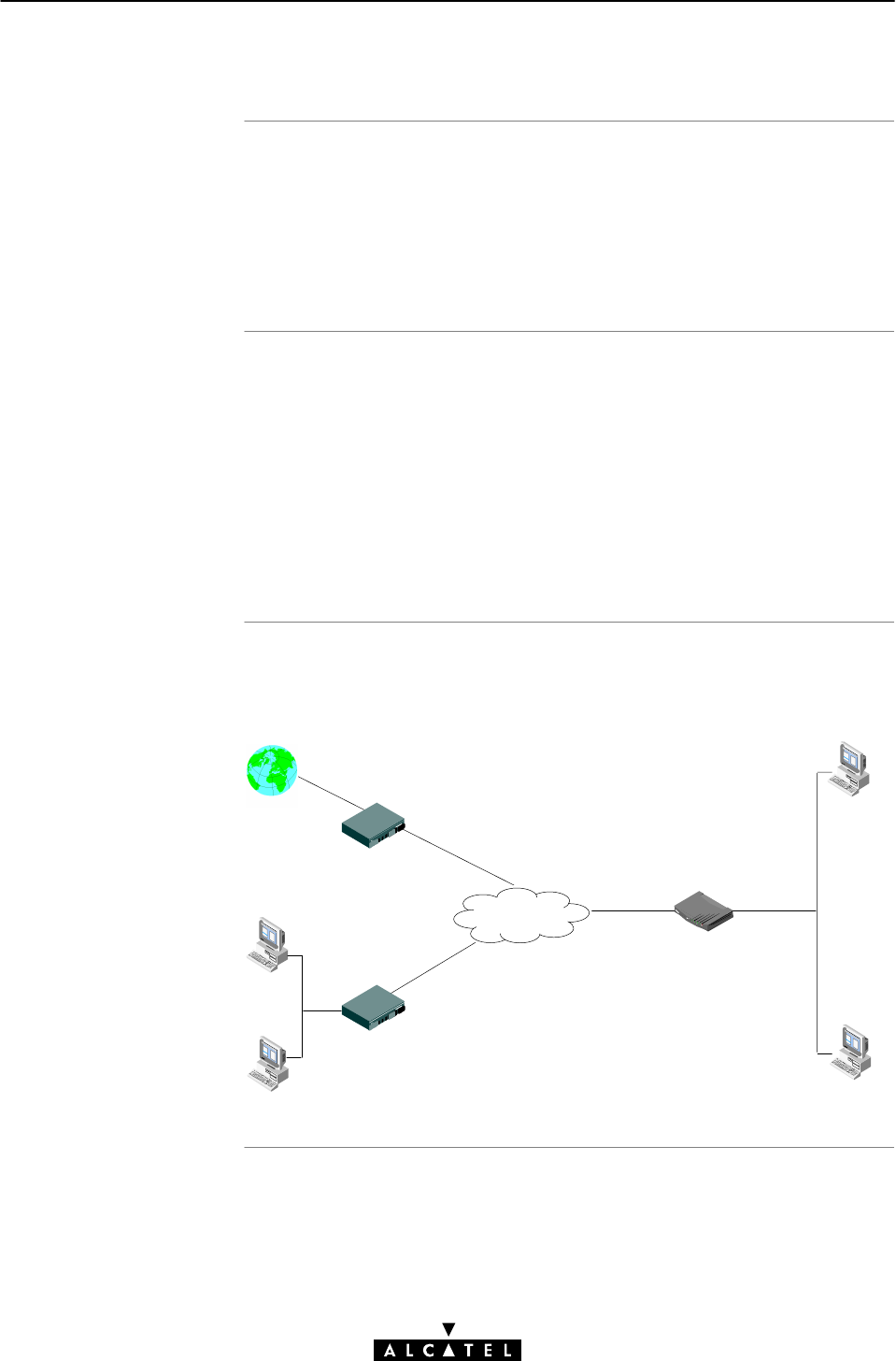
Introduction
In this subsection
General ATM/ADS
L
endĆtoĆend IP
architectur
e
11 Networking Services - IP
225 / 362
3EC 17766 AAAA TCZZA Ed. 01
11.4.2 Configuring the STWireless IP Routing Table
The main function of the IP router in the STWireless, is to route IP
packets from the local network to the remote networks over
the ATM/ADSL connections and vice versa.
In this subsection, configuration of the STWireless IP routing table
is described.
"General ATM/ADSL EndĆtoĆEnd IP Architecture
"ATM/ADSL IP Routing
"STWireless PowerĆon IP Routing Table Configuration
"IP Route Table
"Adding Specific Routes to the 'IP Route' Table
"Criteria for a Valid IP Route.
The figure below provides an overview of the general endĆtoĆend
IP architecture:
Internet
20.0.0.1
ISP
10.0.0.1
10.0.0.10
30.0.0.1
30.0.0.3
30.0.0.2
10.0.0.2
STWireless
Corporate
ATM
Network

ATM/ADSL IP routing
STWireless powerĆon
IP routing table
configuration
11 Networking Services - IP
226 / 362 3EC 17766 AAAA TCZZA Ed. 01
Routing to ATM/ADSL connections actually means:
"Routing between the local (W)LAN and Classical Logical IP
subnets and vice/versa
"Routing between the local (W)LAN and PPP connections and
vice/versa.
Basically the IP router only cares about IP addresses, i.e. the
'Destination IP address' of any packet received on any of its
interfaces (PPP, CIP or Ethernet) is looked up in the IP routing table.
The lookup process will determine the best route that may lead to
the final destination of the packet. Consequently it will forward
the packet to the interface that may reach this destination.
When the STWireless is powered, routes are automatically
configured in the routing table, e.g.:
"As soon as the Ethernet interface is up and running, a route
(being the IP address of the Ethernet interface) is added
"If a CIP member is created and configured with an IP address,
this IP address will show up in the table
"The IP address negotiated between the remote peer and a
PPP connection (configured for AlwaysĆOn) will also be
automatically added to the routing table.
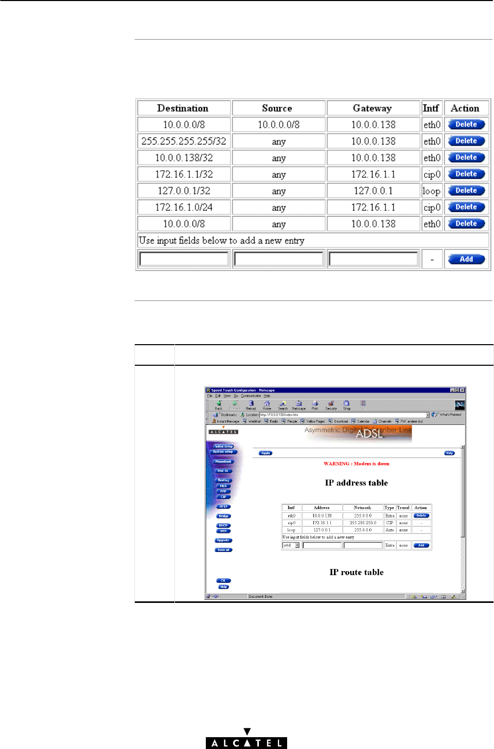
'IP route' table
Adding specific routes
to the 'IP route' table
11 Networking Services - IP
227 / 362
3EC 17766 AAAA TCZZA Ed. 01
If you browse to the 'Routing' web page (See section 18.2 for
more information), you can find the 'IP route' table:
Proceed as follows:
Step Action and Description
1Browse to the 'Routing' web page:

Criteria for a valid IP
route
11 Networking Services - IP
228 / 362 3EC 17766 AAAA TCZZA Ed. 01
Step Action and Description
2In the 'IP route' table, you can configure an IP route, using the
table's bottom row.
Fill in the following IP route parameters:
Value Description
Destination
Source The IP prefix of the source device (pool).
Specifying any, indicates that all traffic,
coming from the Ethernet interface, is
sent over this route
Gateway The IP address of the gateway.
The IP prefix of the destination, or
nextĆhop" device.
Note: See section 11.1.1 for more information on the prefix
notation.
3Click
4Click to store the changes in permanent memory.
The criteria for an IP route to be valid are that:
"The destination and source entries must yield correct prefixes
"The gateway must be directly connected.

Introduction
In this chapte
r
12 Networking Services - DNS
229 / 362
3EC 17766 AAAA TCZZA Ed. 01
12 Networking Services - DNS
IP addresses are fundamental to the operation of the Internet.
They not only uniquely identify Internet nodes but also allow IP
routers to forward datagrams to their destinations.
IP addresses, being 32Ćbit numbers, are ideally suited for
computers but are far from usable to humans.
Therefore, the Domain Name System,orDNS, was designed: a
distributed database, held by a hierarchical system of servers, that
is used by TCP/IP applications to map between hostnames and IP
addresses.
This chapter describes STWireless's DNS abilities.
Topic See
STWireless DNS Resolving 12.1
Configuring your STWireless DNS Server 12.2

Introduction
Local DNS resolving
Example of local DNS
resolving
Result of local DNS
resolving
12 Networking Services - DNS
230 / 362 3EC 17766 AAAA TCZZA Ed. 01
12.1 Speed Touch Wireless DNS Resolving
The STWireless features a DNS server for the locally attached
PCs, and as DNS relay for nonĆlocal DNS hostnames.
The same mechanism for resolving computer names to IP
addresses when browsing the Internet, applies to your local
network. Instead of using the IP addresses for a local IP node e.g.
10.0.0.138 for the STWireless, you can give your nodes names
and let a local DNS server, e.g. the STWireless itself, do the
resolving.
In the following example, a (W)LAN is built around the
STWireless.
In this scenario, it is assumed that the STWireless acts as DHCP
server, and as DNS server for the local network.
During startĆup, a first PC launches a DHCP request on the
(W)LAN.
One of the fields in the DHCP request contains the computer
name e.g. YourPC.
The STWireless reacts by intercepting this request and returns
a DHCP reply containing:
"The IP address for his computer, e.g. 10.0.0.1
"The local domain name, e.g. lan (default)
"The IP address of the local DNS server, e.g. 10.0.0.138 being
the STWireless (default).
A second PC, named MyPC, is powered on and is configured via
a DHCP reply as below:
"The IP address for his computer, e.g. 10.0.0.2
"The local domain name, i.e. lan
"The IP address of the local DNS server, i.e. 10.0.0.138
In the example scenario, it is now possible to ping both PCs,
MyPC, and YourPC, by referring to their computer names instead
of their IP addresses.

12 Networking Services - DNS
231 / 362
3EC 17766 AAAA TCZZA Ed. 01

Local DNS resolving
mechanis
m
NonĆlocal DNS
resolving
12 Networking Services - DNS
232 / 362 3EC 17766 AAAA TCZZA Ed. 01
The mechanism as follows:
Phase Description
1 Apply a ping YourPC on MyPC.
2 Via this command, MyPC launches a DNS request,
basically asking:
What is the IP address of YourPC.lan ?
3 As the STWireless is the DNS server, it will respond with
the appropriate IP address, being 10.0.0.1.
4 The ping utility in MyPC will now submit the ping to
10.0.0.1 which may eventually reply.
The STWireless resolves names within the local domain, i.e. lan
(default STWireless setting) as described above.
However, all other domain names, e.g. Alcatel.com, cannot be
resolved by the STWireless, and are forwarded over the
appropriate link on the ADSL line.
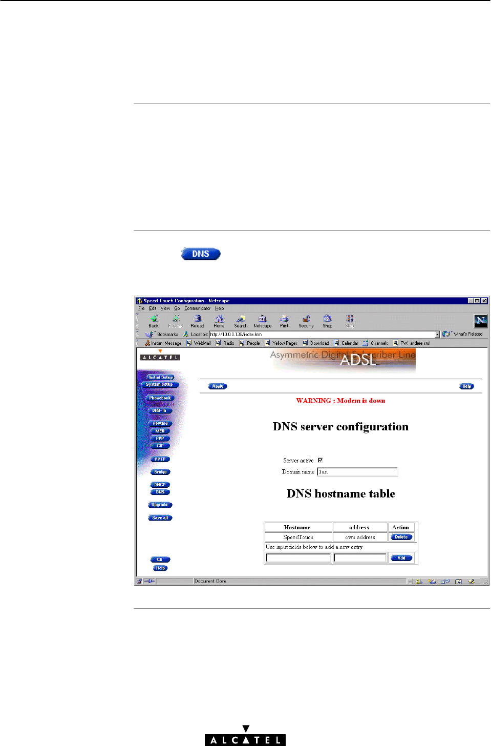
In this subsection
The STWireless 'DNS'
web page
12 Networking Services - DNS
233 / 362
3EC 17766 AAAA TCZZA Ed. 01
12.2 Configuring the Speed Touch Wireless DNS
Server
The example of section 12.1, refers to a new (W)LAN, using the
default STWireless configuration, thus as well as Auto DHCP
server, as DNS server.
In case the STWireless is added to a existing (W)LAN,
configuration of the STWireless DNS server might be necessary
to meet the existing (W)LAN conditions.
Clicking in the left pane of the STWireless web pages,
pops up the 'DNS'web page:
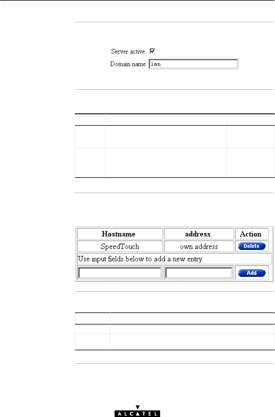
DNS server field
DNS server field
component
s
DNS hostname table
DNS hostname table
component
s
12 Networking Services - DNS
234 / 362 3EC 17766 AAAA TCZZA Ed. 01
This field allows configuration of the STWireless DNS server:
You can configure the following parameters:
Field Description Default
Server
active
This check box enables (n), or disables the
STWireless DNS server.
n,STWireless
DNS server
active.
Domain
Name
Specifies the domain name of your (W)LAN.
This name is communicated by the DNS server
to the local PCs, and is subsequently used by
the PCs to complete a DNS request.
lan
This table allows you to manually configure DNS hostnames to
hosts, identified by their IP address:
You can configure the following parameters:
Field Description
Hostname A DNS hostname of your choice for the PC.
Address The IP address of the PC to which you assign the DNS
hostname.

Introduction
In this chapte
r
13 Networking Services - Firewalling
235 / 362
3EC 17766 AAAA TCZZA Ed. 01
13 Networking Services - Firewalling
A Firewall is a security gateway that controls access between a
private (W)LAN domain, often referred to as Intranet, and the
public Internet.
It secures the entry points to the network, in such a way that access
is only allowed to authorized traffic. Therefore, to effectively
control the flow of data, firewall protection should be placed at
each point where the network connects to the WAN, or the
Internet.
This chapter aims to familiarize you with the operation of the
STWireless's programmable Firewall.
Topic See
Operation of the Firewall 13.1
Firewall Model 13.2
Firewall Actions 13.3
Firewall Criteria 13.4
Firewall and NAPT 13.5
Firewall Configuration 13.6
Firewall Configuration Examples 13.7

What is the STWireless
Firewall
How the STWireless
Firewall works
13 Networking Services - Firewalling
236 / 362 3EC 17766 AAAA TCZZA Ed. 01
13.1 Operation of the Firewall
The STWireless Firewall is a set of related programs that protects
the resources of your local network from users from other
networks.
Basically, a firewall examines each network packet to determine
whether to forward it toward its destination. Firewalls work in most
cases closely together with a proxy server that makes network
requests on behalf of your local network users.
For the STWireless Firewall the STWireless acts as well as
network gateway and proxy server to contact the outside world via
the ADSL line
The STWireless Firewall is in fact a packet filter: inside and
outside nodes are visible to each other at the IP level, but the
firewall filters out, i.e. blocks the passage of certain packets,
based on their header.
Packets are intercepted at certain Packet Interception Point (PIP),
called hooks, in the STWireless IP router. At this points, they are
matched against a chain, which comprises rules (at least one).
These rules determine the type of control implemented on the
packets.
Incoming and outgoing traffic is validated by comparing certain
values in the packets with configured Firewall parameters. The
parameters in a rule can be divided according to the protocol to
which they belong: a first group validates traffic on the interface
level, a second group on IP level, a third group filters on TCP, UDP,
and ICMP level.

STWireless Firewall
Model
STWireless Firewall
module
s
13 Networking Services - Firewalling
237 / 362
3EC 17766 AAAA TCZZA Ed. 01
13.2 Firewall Model
The following figure shows a model of the STWireless Firewall:
(1) (2)
(3)
Sink Source
Input Output
Forward
Router
Module
Forward
Module
NAPT
Module
The following modules can be identified (See Firewall model):
"Router Module : This module, which has nothing to do with
the STWireless IP router, is responsible for the traffic within"
the STWireless Firewall, i.e. it routes the packets towards the
Sink PIP or Forward PIP.
"Forward Module : This module is responsible for forwarding
the packets toward the output.
"NAPT Module : This module is responsible for the translation
of IP addresses, in case firewalling is used with NAPT.

STWireless Firewall
hook
s
STWireless Firewall
stream
s
13 Networking Services - Firewalling
238 / 362 3EC 17766 AAAA TCZZA Ed. 01
The following hooks, or PIPs can be determined (See Firewall
model):
"Input : The point of all incoming traffic
At this point it can be determined whether the packet is
allowed to reach the STWireless IP router, or the local host.
"Sink : The point of all traffic destined to the STWireless IP
router
At this point it can be determined whether the packet is
allowed to address the local host.
"Forward : The point of all traffic to be forwarded by the
STWireless
At this point it can be determined whether the packet is
allowed to be handled, i.e. routed, by the STWireless IP
router.
"Source : The point of all traffic sourced by the STWireless IP
router
At this point it can be determined whether the packet is
allowed to leave the local host.
"Output : The point of all outgoing traffic
At this point it can be determined whether the packet is
allowed to leave the STWireless IP router, or local host.
The following streams (See Firewall model) can run through the
PIPs:
"(1) Input -> Sink : The flow of packets exclusively destined
to the STWireless.
"(2) Source-> Output : The flow of packets sourced
exclusively by the STWireless itself
"(3) Input -> Forward -> Output : The flow of packets
sourced by the WAN, forwarded towards the local network, or
vice versa.

STWireless Firewall
action
s
13 Networking Services - Firewalling
239 / 362
3EC 17766 AAAA TCZZA Ed. 01
13.3 Firewall Actions
Once a packet is intercepted in a hook, and a rule is found to be
applicable, one of the following actions can be performed on the
packet:
"Accept
The packet will be submitted to the next processing stage,
without further action.
"Deny
The packet will not be submitted to the next processing stage.
A message will be sent to the sender that the packet could not
be delivered, e.g. with an ICMP host unreachable" error
message.
"Drop
The packet will not be submitted to the next processing stage,
without any further action.
"Count
Each packet passing through is counted, without any further
action.

STWireless Firewall
criteria
Interface related
criteria
IP related criteria
TCP related criteria
13 Networking Services - Firewalling
240 / 362 3EC 17766 AAAA TCZZA Ed. 01
13.4 Firewall Criteria
At every hook (PIP) a separate access list, called chain, containing
an ordered list of rules will operate on each processed packet,
resulting in a specific treatment of this packet (See topic
'STWireless Firewall Actions').
A rule is able to operate on the following packet criteria:
"Interface related
"IP related
"TCP related
"UDP related
"ICMP related.
"Source interface
"Source interface group
"Destination interface
"Destination interface group.
"Source IP address
"Source IP netmask
"Destination IP address
"Destination IP netmask
"Type of service
"Protocol (TCP, UDP, or ICMP).
"Source Port number
"Source Port number range
"Destination Port number
"Destination Port number range
"Synchronization flag
"Urgent flag

UDP related criteria
ICMP related criteria
13 Networking Services - Firewalling
241 / 362
3EC 17766 AAAA TCZZA Ed. 01
"Source Port number
"Source Port number range
"Destination Port number
"Destination Port number range
"Type
"code number
"Code number range.

What is NAP
T
STWireless Firewall
and NAP
T
13 Networking Services - Firewalling
242 / 362 3EC 17766 AAAA TCZZA Ed. 01
13.5 Firewalling and NAPT
NAT (Network Address Translation), is the translation of an IP
address used within one network to another IP address, known
within another network.
NAPT (Network Address and Port Translation) uses a combination
of IP addressing and port number mapping to create unique
combinations. That way, the STWireless can determine which
packet, sourced by the WAN, is destined to which device on your
local (W)LAN, and vice versa, without revealing the internal device
information towards the remote side.
The position of the Input, NAPT, Forward and Output logical
processing modules in the overall STWireless Firewall model is
relative to the traffic direction. In contrast, the STWireless's WAN
and (W)LAN interfaces are physical" interfaces; their position is
not relative to the traffic direction.
The NAPT module is situated between the Forward and Output
hook (See STWireless Firewall model). Since the traffic direction
will determine input, and output, the NAPT module can always be
positioned between the Forward and Output module.
If you set rules on a hook, you should know if the packets that
pass through that hook contain IP addresses that are
NAPTĆtranslated or not.
If rules are set on the Output hook and NAPT is active, the IP
packets that pass that hook will contain translated IP addresses. If
you want to avoid certain traffic, by setting rules that filter on
certain (ranges of) IP addresses, you should be aware of the
location where the rule will be verified, since, depending on the
hook, another IP address will be seen by the Firewall.
As a conclusion: if NAPT is activated, the IP address that identifies
a local device, will be different depending on the direction of the
traffic.

Configuring the
STWireless Firewall
Default STWireless
Firewall configuration
13 Networking Services - Firewalling
243 / 362
3EC 17766 AAAA TCZZA Ed. 01
13.6 Firewall Configuration
In order to create a Firewall, suitable for your needs, you can
create a chain on every hook at the STWireless. In each chain
rules can be applied with configurable parameters. Rules can also
refer to a previously defined access list, thus allowing nested
access lists, or chains.
You can configure the STWireless firewall only via the CLI.
See chapter 19 for more information.
The STWireless Firewall is enabled by default with following
behavior:
Packets migrating
"from WAN to WAN are dropped
"from STWireless to WAN are dropped, except Port 53 (DNS)
"from STWireless to (W)LAN are allowed
"from (W)LAN to STWireless are allowed
"from (W)LAN to WAN are allowed
"from WAN to (W)LAN are allowed
"from a remote LAN to local (W)LAN are allowed
"from local (W)LAN to a remote LAN are allowed.
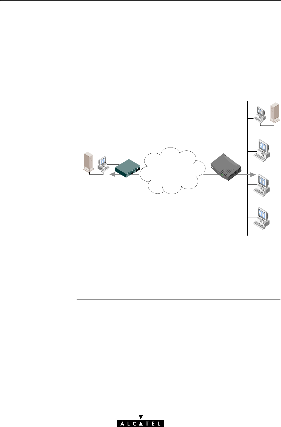
Example setup
13 Networking Services - Firewalling
244 / 362 3EC 17766 AAAA TCZZA Ed. 01
13.7 Firewall Configuration Examples
In the following two simple examples are provided to show the
working and configuration of the STWireless Firewall.
Both are based on a small (W)LAN, consisting of the STWireless
and a small number of PCs, all configured with dynamic 'Net10'
IP addresses, leased by the STWireless's DHCP server:
Remote LAN
Access Point
Telnet Server
Server
ATM
Network
Speed Touch Pro
with Firewall
IP address:
200.20.20.1
Local (W)LAN
IP address
range:
10.0.0.0/8
In both examples the STWireless Firewall must block all services,
except an outgoing Telnet service towards one specified remote
Telnet server, with IP address 200.20.20.1.

Example 1: Firewall
configuration withou
t
NAP
T
13 Networking Services - Firewalling
245 / 362
3EC 17766 AAAA TCZZA Ed. 01
NAPT is not applied on your local (W)LAN for this ADSL
connection. This means that the IP addresses are not hidden for
the remote side of the connection.
In the following table, the rules to apply are summarized:
Flow Source Dest. Prot. Source
port
Dest.
port
ACK
=1
Action
Out 10.0.0.0/8 200.20.20.1 TCP 1024Ć
65535
23 - accept
In 200.20.20.1 10.0.0.0/8 TCP 23 1024Ć
65535
Yes accept
Any External 10.0.0.0/8 Any Any Any - drop
For the STWireless Firewall, this will result in the following CLI
configuration:
1. A chain must be created, e.g. 'Telnet':
firewall chain create chain=Telnet
2. Following rules must be created for that chain:
DFor the outgoing Telnet service packets:
firewall rule create chain=Telnet src=10.0.0.0/8
dst=200.20.20.1 srcintfgrp=lan prot=tcp
srcport=1024 srcportend=65535 dstport=23
action=accept
DFor incoming Telnet service reply packets:
firewall rule create chain=Telnet src=200.20.20.1
dst=10.0.0.0/8 srcintfgrp=wan prot=tcp srcport=23
dstport=1024 dstportend=65535 ack=yes
action=accept
DFor blocking all other services:
firewall rule create chain=Telnet action=drop
3. The chain 'Telnet' must be assigned to the input hook:
firewall assign hook=input chain=Telnet

Example 2: Firewall
configuration with
NAP
T
More information
13 Networking Services - Firewalling
246 / 362 3EC 17766 AAAA TCZZA Ed. 01
NAPT is applied for this ADSL connection; all outgoing 'Net10' IP
addressed packets are translated into the 192.6.11.10 IP
address. So the complete local LAN is presented towards the
remote side as the single IP address 192.6.11.10.
In the following table, the rules to apply are summarized:
Flow Source Dest. Prot. Source
port
Dest.
port
ACK
=1
Action
Out 10.0.0.0/8 200.20.20.1 TCP 1024Ć
65535
23 - accept
In 200.20.20.1 192.6.11.10 TCP 23 1024Ć
65535
Yes accept
Any External Internal Any Any Any - drop
For the STWireless Firewall, this will result in the following CLI
configuration:
1. A chain must be created, e.g. 'Telnet':
firewall chain create chain=Telnet
2. Following rules must be created for that chain:
DFor the outgoing Telnet service packets:
firewall rule create chain=Telnet src=10.0.0.0/8
dst=200.20.20.1 srcintfgrp=lan prot=tcp
srcport=1024 srcportend=65535 dstport=23
action=accept
DFor incoming Telnet service reply packets:
firewall rule create chain=Telnet src=200.20.20.1
dst=192.6.11.10 srcintfgrp=wan prot=tcp srcport=23
dstport=1024 dstportend=65535 ack=yes
action=accept
DFor blocking all other services:
firewall rule create chain=Telnet action=drop
3. The chain 'Telnet' must be assigned to the input hook:
firewall assign hook=input chain=Telnet
See chapter 19 for more information on STWireless's Firewall CLI
configuration.

247 / 362
3EC 17766 AAAA TCZZA Ed. 01
Speed TouchWireless
Wireless LAN Services

248 / 362 3EC 17766 AAAA TCZZA Ed. 01

Introduction
In this chapte
r
14 Wireless LAN Services - WLAN Configuration
249 / 362
3EC 17766 AAAA TCZZA Ed. 01
14 Wireless LAN Services - WLAN Configuration
After having initial WLAN connectivity, you can configure your
STWireless WLAN parameters. Additional configuration of your
WLAN environment settings might be required in case, e.g.
another STWireless, with identical WLAN configuration, is located
nearby.
"The STWireless 'Wireless' Web Page
"The 'SSID' Field
"'Channel' Field
"Connectivity after Configuration
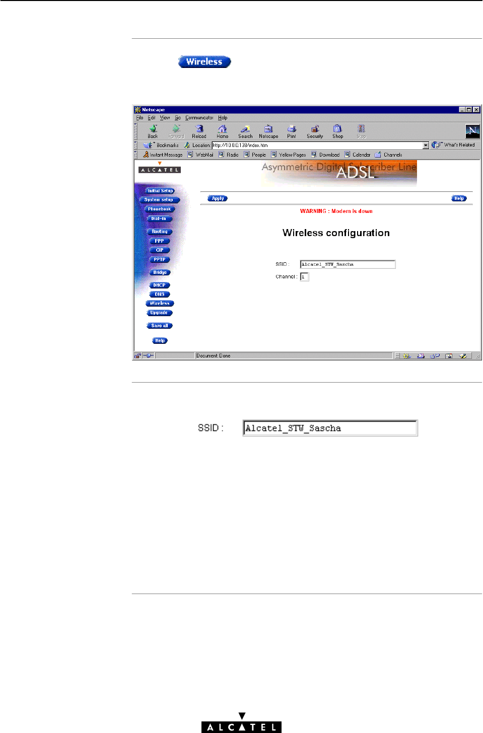
The STWireless
'Wireless' web page
The 'SSID' field
14 Wireless LAN Services - WLAN Configuration
250 / 362 3EC 17766 AAAA TCZZA Ed. 01
Clicking in the left pane of the STWireless web pages,
pops up the 'Wireless' web page (See chapter 18 for more
information):
The following figure shows the 'SSID' field:
The Service Set ID (SSID) allows you to uniquely identify your
STWireless WLAN in the radio environment. This can be useful in
case multiple WLAN environments are present nearby your
location.
Changing the default SSID 'Alcatel_STW' into another value can
be useful in case another STWireless is located nearby. It will
avoid a WLAN client from his wireless network to connect by
accident to yours.

The 'Channel' field
14 Wireless LAN Services - WLAN Configuration
251 / 362
3EC 17766 AAAA TCZZA Ed. 01
The following figure shows the 'Channel' field:
The channel number identifies the frequency on which your WLAN
connectivity is enabled in the WLAN environment.
Changing the default channel number to another value can be
useful in case you know another wireless equipment runs nearby
yours, e.g. another STWireless WLAN environment. This way you
can avoid sharing the channel bandwidth with other WLANs by
selecting different channel numbers for concurrent WLANs.
You may not freely choose any channel number. The channel
number range is from 1 up to 14 (included).
Moreover, restrictions apply depending on the country where the
STWireless is used:
"US:1,6,or11
"Europe (except France): 1, 7, or 13
"France: 14.
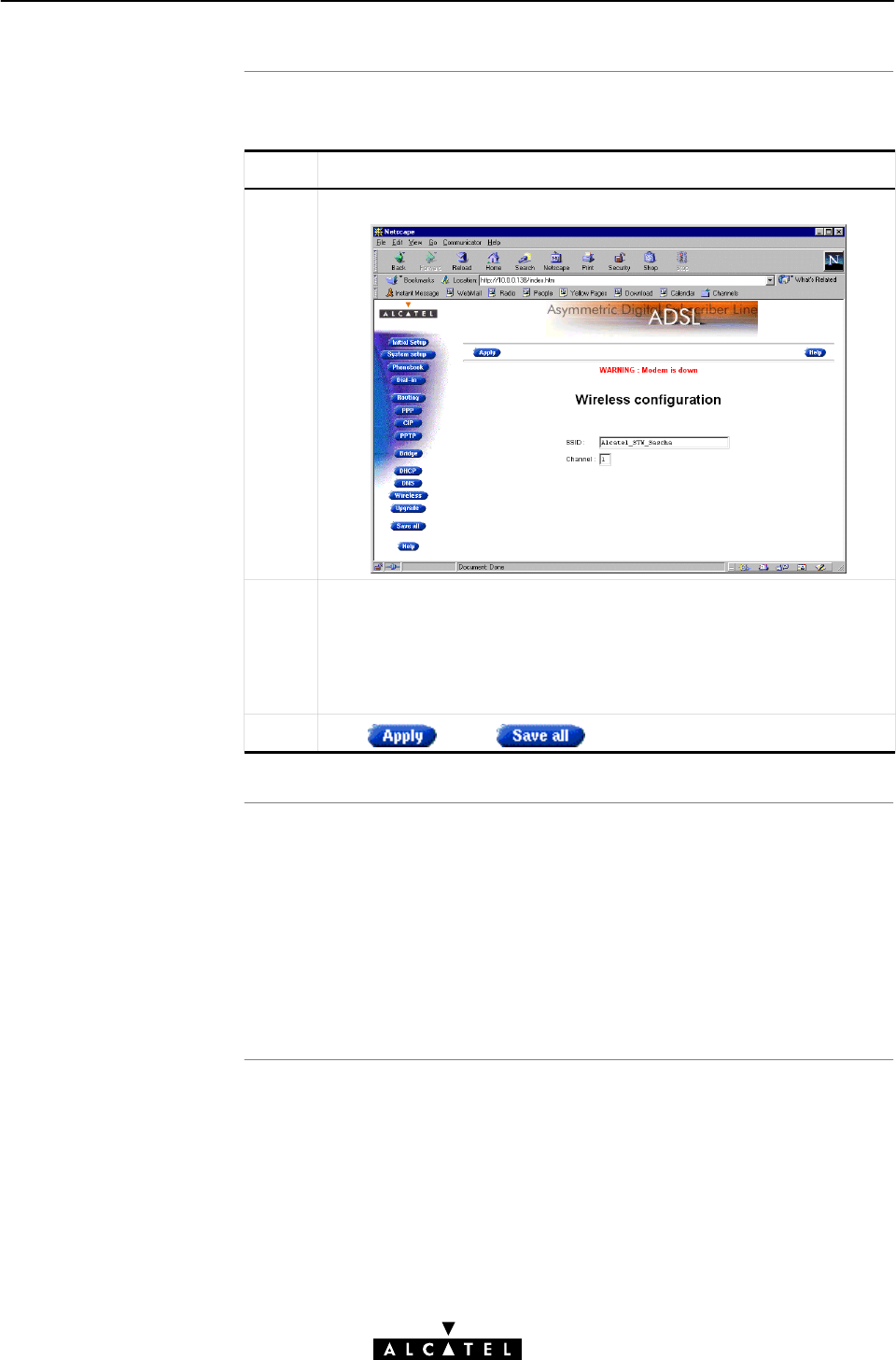
Configuring Wireless
parameter
s
WLAN connectivit
y
after configuration
14 Wireless LAN Services - WLAN Configuration
252 / 362 3EC 17766 AAAA TCZZA Ed. 01
Proceed as follows:
Step Action and Description
1Browse to the 'Wireless Configuration' web page.
2Enter the appropriate configuration in the following fields:
•the 'SSID' name of your WLAN
•the 'channel' number for your WLAN connectivity
Note: See the corresponding topics in this chapter for more
information.
3Click and to finish the procedure.
After the SSID, and/or channel number has been changed inside
the STWireless, the contact is lost.
All your WLAN clients must be reconfigured, and/or
reĆauthenticated to use the same new SSID, and/or new channel
number as the STWireless.
See section 3.1 for more information.

253 / 362
3EC 17766 AAAA TCZZA Ed. 01
Speed TouchWireless
Maintenance

254 / 362 3EC 17766 AAAA TCZZA Ed. 01

Software Upgrade
In this chapte
r
15 Maintenance - Software Upgrade
255 / 362
3EC 17766 AAAA TCZZA Ed. 01
15 Maintenance - Software Upgrade
The STWireless supports two software upgrade possibilities:
"A new version of the software can be downloaded via
the ADSL line to your STWireless.
"You can upload new STWireless software yourself from a PC
on your local LAN.
Both features, presented in this chapter, are simultaneously
supported. However the final result depends on the ADSL
provider's policy.
Topic See
Upload Software from a PC 15.1
Software Download 15.2
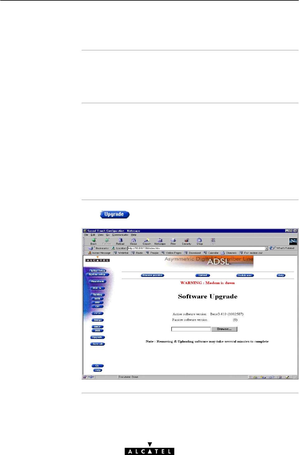
Introduction
In this section
The 'Software
Upgrade' web page
15 Maintenance - Software Upgrade
256 / 362 3EC 17766 AAAA TCZZA Ed. 01
15.1 Upload Software from a PC
Alcatel ADSL products continue to evolve.
By upgrading software, the STWireless is able to follow this
evolution.
"The 'Software Upgrade' Web Page
"'Upgrade' Web Page Components
"'Upgrade' Web Page Buttons
"Upgrade Preconditions
"Uploading Upgrade Software
"Activating Upgrade Software.
Click to pop up the 'Upgrade' web page:
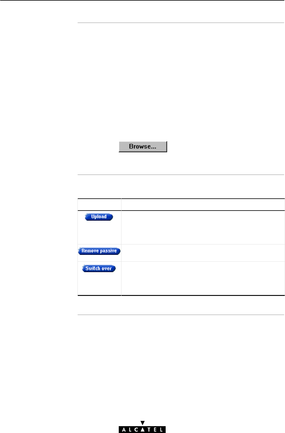
'Upgrade' web page
component
s
'Upgrade' web page
component
s
15 Maintenance - Software Upgrade
257 / 362
3EC 17766 AAAA TCZZA Ed. 01
The following fields are shown:
"'Active software version'
Indicates the software version that the STWireless is currently
using.
"'Passive software version'
Indicates the software version resident in the STWireless, but
not used. This could be a newer version which is yet to be
switched to active, but also a dormant older version.
"Software path field
Allows you to specify the path to the STWireless upgrade
software package to be uploaded.
Clicking allows you to browse to the location
of the upgrade software.
The following buttons are available:
Button Functionality
To start the upload process.
The software package indicated by the Software path will be
transferred to the STWireless to become the passive
software version.
To remove the passive software version from the STWireless
memory.
To switch active and passive software versions after a sucĆ
cessful upload.
Your STWireless will reboot and come online again with the
new version.
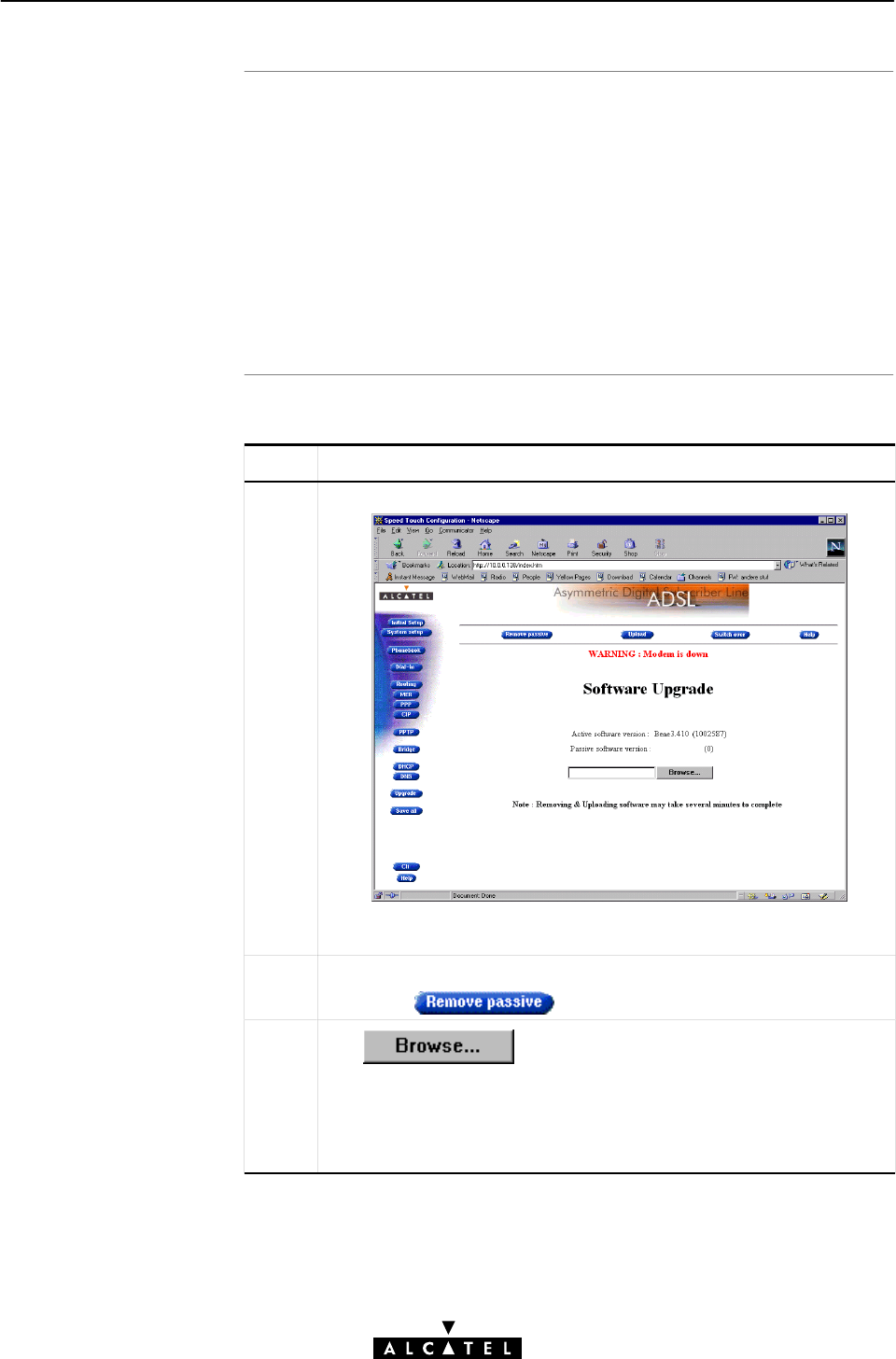
Upgrade Precondition
s
Uploading software
15 Maintenance - Software Upgrade
258 / 362 3EC 17766 AAAA TCZZA Ed. 01
A valid STWireless software package must reside either on your
harddisk, on a floppy disk, or CDĆrom.
For new software upgrade packages, please contact your SP, or
check the Alcatel web sites at:
http://www.alcatel.com
http://www.alcateldsl.com
Proceed as follows:
Step Action and Description
1Browse to the 'Software Upgrade' web page
In the 'Active software version' field the software package that is
running is labeled.
2Check whether the 'Passive software version' field is empty.
If not, click
3Click next to the Software path input field to
locate the upgrade software package
Note: If the path is known, you can immediately enter it in the
Software path input field and skip step 4 in this procedure.
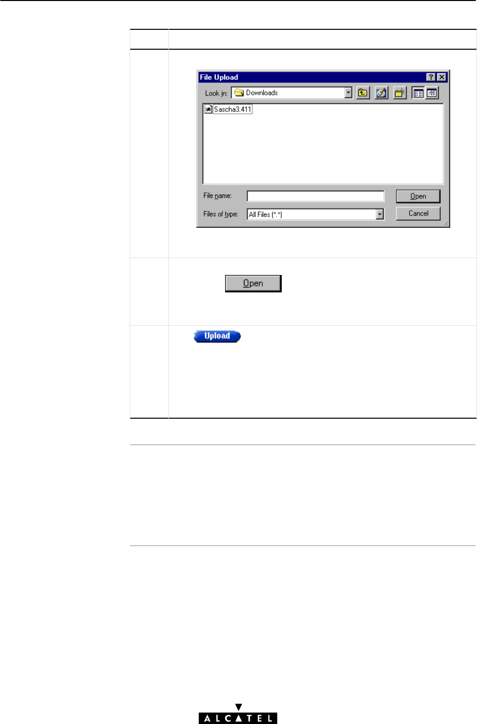
Upload Resul
t
15 Maintenance - Software Upgrade
259 / 362
3EC 17766 AAAA TCZZA Ed. 01
Step Action and Description
4The 'File Upload' window pops up:
This window allows you to browse to the location of the upgrade
software package on either your harddisk, floppy, or CDĆrom.
5Click on the appropriate upgrade software package name to select
it, and click
As a result, the upgrade software location will be inserted in the
Software path field.
6Click to start the upload.
As a result the upgrade software package name will appear in the
'Passive software version' field.
Note: In case you did not remove the passive version, prior to
uploading new software, the upload will be unsuccessful and an
error message will appear.
After a successful upload, two software versions are stored on the
STWireless:
"The running, active version
"The dormant, passive version.

Activating upgrade
softwar
e
Resul
t
15 Maintenance - Software Upgrade
260 / 362 3EC 17766 AAAA TCZZA Ed. 01
Proceed as follows to switch passive upgrade and active running
software versions:
Step Action and Description
1If needed, browse to the 'Upgrade' web page.
Note: Make sure a passive software version is labeled in the
'Passive software version' field.
If not, firstly upload a upgrade software package as described in the
previous procedure.
2Click to start the switching of the two versions.
After switching the versions, the STWireless reboots:
After reboot your STWireless will come online with the new
version.
In the 'Upgrade' web page you will notice that active and passive
versions (prior to the upgrade) have trade places.

Introduction
Software Download
Resul
t
15 Maintenance - Software Upgrade
261 / 362
3EC 17766 AAAA TCZZA Ed. 01
15.2 Software Download
The STWireless supports a second software upgrade possibility: a
new version of the software can be downloaded from the ADSL
network to your STWireless.
This can be done via the STWireless dedicated control VCs.
This feature is controlled by the SP.
At some point in time he might decide to upgrade the software in
your STWireless.
Software download will happen almost unnoticed, while you are
connected to the ADSL line.
The removal of a possible dormant software version, the
download itself, and the switching of both versions is performed
automatically.
ADSL service can be interrupted for a short period due to a reboot
of the STWireless.
You will notice a change in the software version if you browse to
the STWireless 'Software Upgrade' web page.

15 Maintenance - Software Upgrade
262 / 362 3EC 17766 AAAA TCZZA Ed. 01

In this chapte
r
Note
16 Maintenance - Speed Touch Wireless Security
263 / 362
3EC 17766 AAAA TCZZA Ed. 01
16 Maintenance - Speed Touch Wireless Security
Your STWireless is a highly advanced product, operating according
the many configurations set via the STWireless Web interface, or via
the CLI.
In this way, STWireless operation is vulnerable to misconfiguration
by other users.
Therefore, the STWireless can be secured from such users by a
system password to restrict access to the Web interface, or the CLI.
This chapter describes how to set such a system password.
Never use an obvious system password to protect the STWireless,
as your name, birth date, or phone number.
Forgetting the System Password
In case you forgot the system password, you are no longer able to
access the web interface, or the CLI, and you will be no longer able
to (re)configure the STWireless settings.
Therefore, write your system password down and keep it on a save
place.
Otherwise, a SwitchĆtoĆDefaults, must be performed, restoring all
original settings of the STWireless.
CAUTION
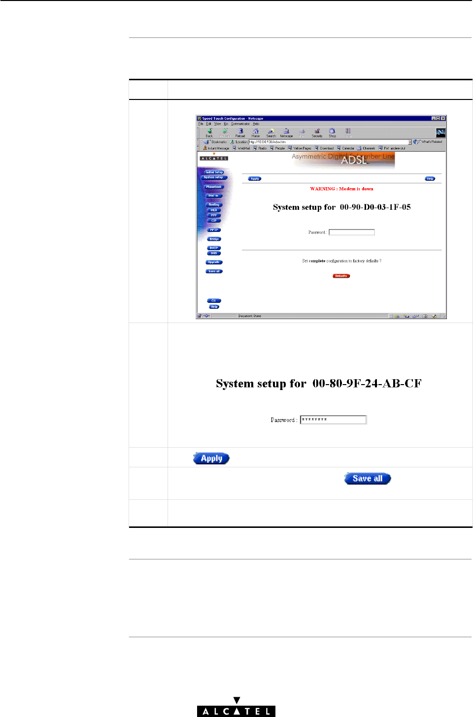
Setting a system
password
Resul
t
16 Maintenance - Speed Touch Wireless Security
264 / 362 3EC 17766 AAAA TCZZA Ed. 01
Proceed as follows:
Step Action and Description
1Browse to the 'System' web page.
2In the 'Password' field, fill in a password.
Note: Asterisks will appear instead of the password. The number of
asterisks is at random:
3Click in the header frame.
4To make your password permanent, click in the menu
frame.
5Authenticate yourself, using the system password, you just
configured.
Every time you want to access the STWireless web pages, or (Telnet)
CLI, you must authenticate yourself, using the system password you
configured.
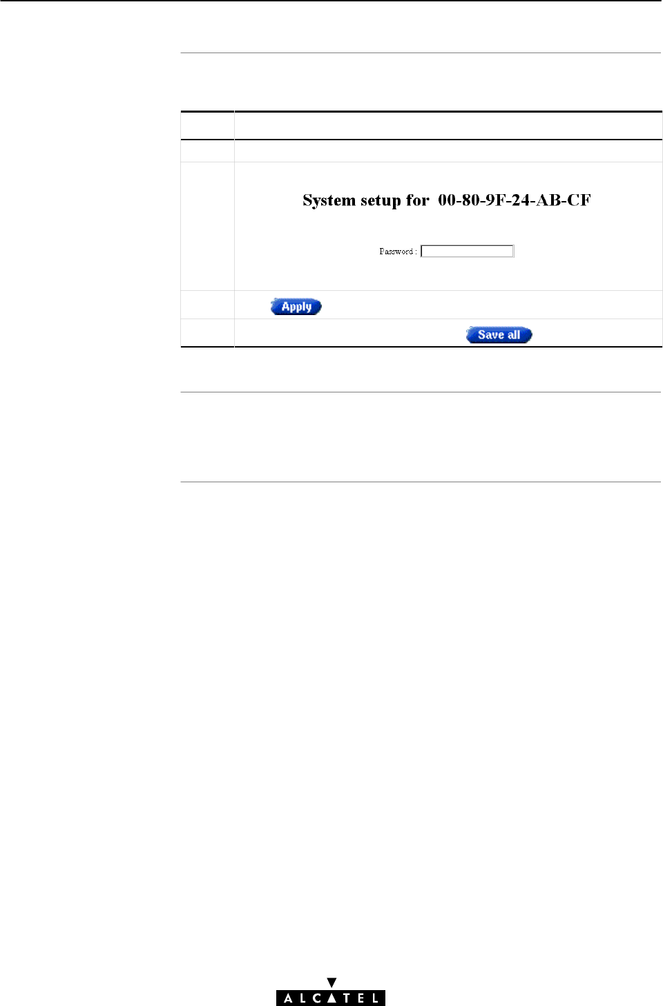
Clearing a system
password
Resul
t
16 Maintenance - Speed Touch Wireless Security
265 / 362
3EC 17766 AAAA TCZZA Ed. 01
Proceed as follows to set a system password for your STWireless:
Step Action and Description
1Browse to the 'System' web page.
2In the 'Password' field, delete the asterisks
3Click in the header frame.
4To make the deletion permanent, click in the menu frame.
No authentication is required anymore to access the STWireless web
pages, or the (Telnet) CLI.

16 Maintenance - Speed Touch Wireless Security
266 / 362 3EC 17766 AAAA TCZZA Ed. 01

Introduction
In this chapte
r
17 Maintenance - Lost Speed Touch Wireless
267 / 362
3EC 17766 AAAA TCZZA Ed. 01
17 Maintenance - Lost Speed Touch Wireless
Non accessibility to your STWireless may occur if wrongly
configured, simply by forgetting its IP address, or forgetting the
system password.
Due to the flexible nature of the STWireless, you may end up in a
situation where restoring all of the original defaults is the only
solution.
The STWireless has tools to cope with these situations.
Topic See
PingĆofĆLife17.1
STWireless Reset 17.2

Introduction
General procedure
Note
The PingĆofĆLife
procedur
e
17 Maintenance - Lost Speed Touch Wireless
268 / 362 3EC 17766 AAAA TCZZA Ed. 01
17.1 PingĆofĆLife
The STWireless offers a unique method to supply an IP address to
the STWireless.
This method, the PingĆofĆLife,allows to provide the STWireless
with an IP address, without affecting other configurational settings.
The principle is fairly simple: a special ping packet will deliver an
IP address to your STWireless.
Generally the procedure is as follows:
Step Action
1 PreĆconfigure the intended IP address and a special MAC group
address in the ARP cache of one of your PCs.
2 Power cycle the STWireless, and allow the POST to end (this
takes about 30 seconds).
3Ping this same IP address within 60 seconds after the STWireless
ended its POST.
If everything goes well, the STWireless has assimilated this IP
address.
4 Save the new IP setting via the STWireless web pages.
Most TCP/IP packages support the
ARP
and
PING
command. The
PingĆofĆLife can be executed from any PC on your local network.
Proceed as follows:
Step Action and Description
1 Turn off the STWireless.
2Open an DOS window (Windows OS), or a terminal window
(UNIX, Linux) on a PC.
3 In the DOS window, or terminal window, execute: arp –a
This command allows you to overview the current entries in the
ARP cache.

PingĆofĆLifewith
multiple PCĆNICs
17 Maintenance - Lost Speed Touch Wireless
269 / 362
3EC 17766 AAAA TCZZA Ed. 01
Step Action and Description
4 Add a static entry to the ARP cache, according to following syntax:
arp –s <STWireless IP address> 01–90–D0–80–01–01
or
arp –s <STWireless IP address> 01:90:D0:80:01:01
<STWireless IP address> is a placeholder for the IP address
to be assigned to the STWireless.
5 Verify if this step was successful. Execute: arp –a a second time.
In the entries list, your arp –s command entry should be added.
6 Turn on the STWireless and allow the POST to end.
7 Ping the IP address you just entered in the ARP cache within 60
seconds:
ping <STWireless IP address>
8 If successful, the STWireless has configured this IP address and
will reply to the ping.
8You may clear the entry in the ARP cache by issuing the following
command:
arp –d <STWireless IP address>
Note: Leaving the entry in the ARP cache does not harm the
general operation.
10 Browse to the STWireless web pages, and click to
make the new IP address permanent.
If your PC is equipped with multiple PCĆNICs, or WLAN adapters,
make sure that the procedure is applied to the one which joined
the STWireless. WLAN environment.
In the following syntax, <Interface IP address> identifies the
particular PCĆNIC:
arp –<a,s,d> <STWireless IP address> –N <interface IP
address>
IP Addresses and Subnet Masks
Make sure that the intended STWireless IP address and your PC
share the same IP (sub)network.
If not, the ping will be submitted with the MAC address of the
default router instead of the special MAC group address.
CAUTION
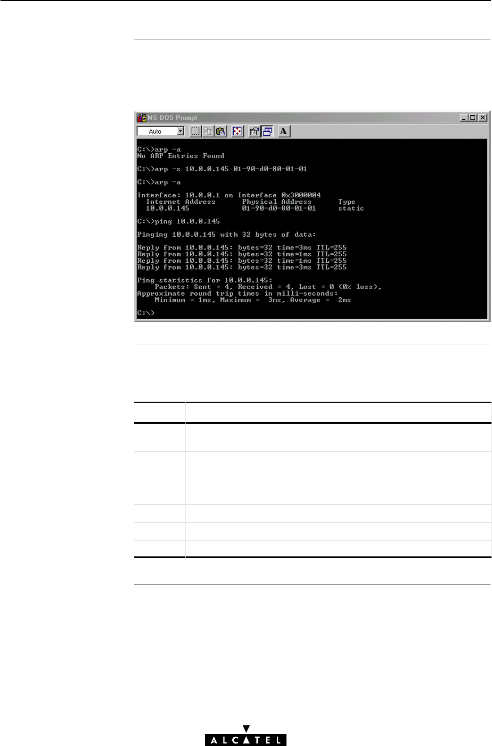
Example DOS bo
x
The 'Ping Ćt' command
17 Maintenance - Lost Speed Touch Wireless
270 / 362 3EC 17766 AAAA TCZZA Ed. 01
In the following figure all the steps are shown as an example of
setting STWireless's IP address to 10.0.0.145 from a PC with an
MS Windows OS:
You can avoid waiting 30 and then 60 seconds by proceeding as
follows:
Step Action and Description
1..5 Follow the PingĆofĆLifeprocedure as described, from step 1 up to
step 5.
6 Initiate a continuous pinging, by executing
ping –t <STWireless IP address>
7 Turn on the STWireless.
8 After the POST, the STWireless will reply to the ping.
9 Terminate the continuous ping by pressing CTRLĆC.
10 Save the IP address via the STWireless web pages.

Overview of the
ToĆDefaults methods
In this section
17 Maintenance - Lost Speed Touch Wireless
271 / 362
3EC 17766 AAAA TCZZA Ed. 01
17.2 Speed Touch Wireless Reset
To restore STWireless's original settings, three methods are
provided:
"Two local software methods:
DBrowseĆtoĆDefaults
Which sets all parameters to original defaults, but keeps
the system password and IP address.
DPingĆtoĆDefaults
Which sets all parameters to original defaults, including
the system password and IP address.
"One hardware method:
DSwitchĆtoĆDefaults.
Which sets all parameters to original defaults, including
the system password and IP address.
Restoring Original Settings
Be careful when using ToĆDefaults procedures as these destroy
changes you previously made to the STWireless internal settings.
A reset to defaults via a PingĆtoĆDefaults, or via a
SwitchĆtoĆDefaults, also implies the STWireless's IP address is
reset to 10.0.0.138. As a consequence, IP connectivity with the
STWireless could be lost. In that case you must execute a
PingĆofĆLife.
Topic See
BrowseĆtoĆDefaults 17.2.1
PingĆtoĆDefaults17.2.2
SwitchĆtoĆDefaults 17.2.3
CAUTION
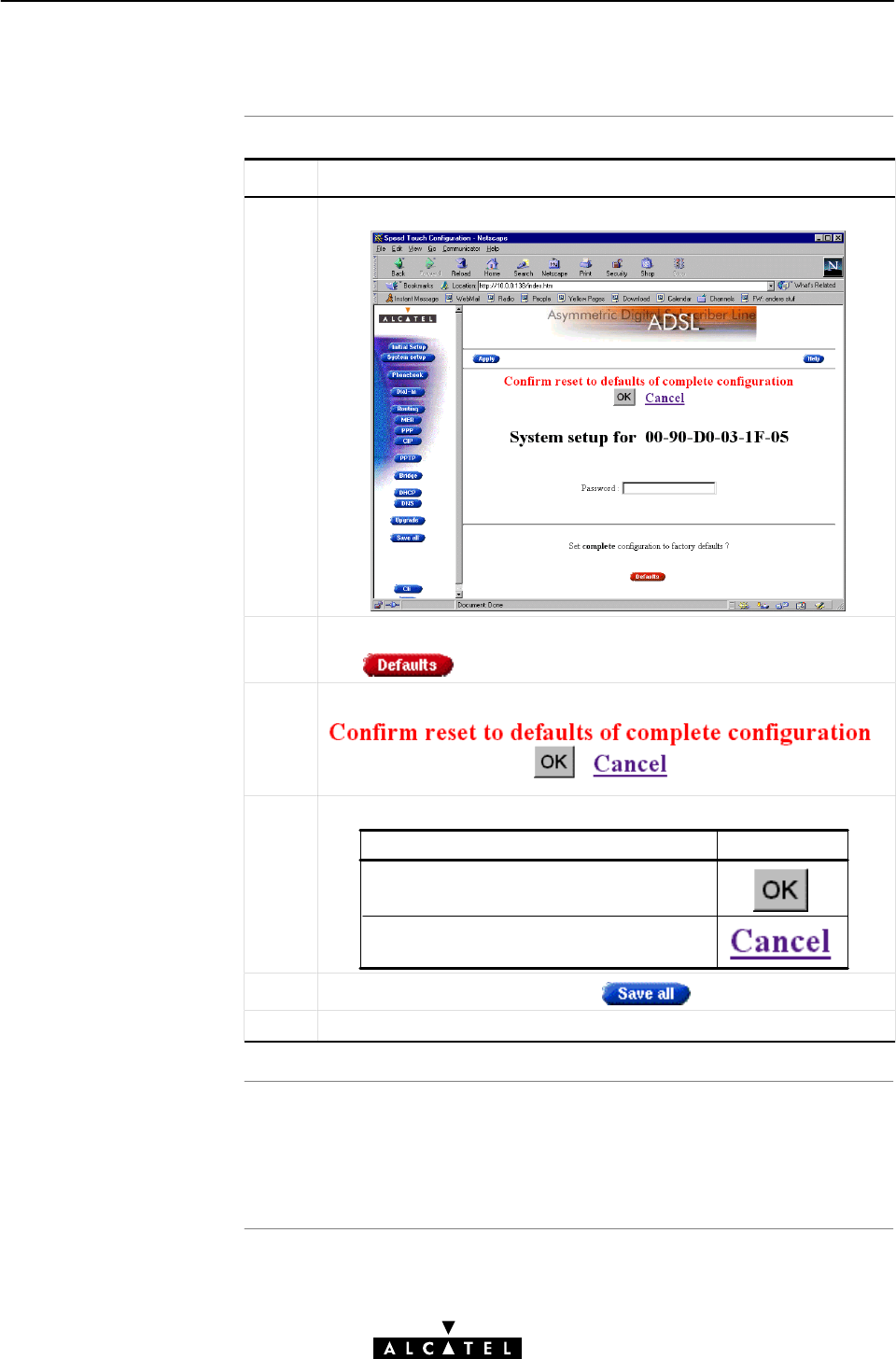
Procedure
BrowseĆtoĆDefault
s
result
17 Maintenance - Lost Speed Touch Wireless
272 / 362 3EC 17766 AAAA TCZZA Ed. 01
17.2.1 BrowseĆtoĆDefaults
Step Action and Description
1Browse to the 'System' web page.
2If you are sure to reset the STWireless to its original defaults,
click
3The STWireless will ask to confirm the reset:
4Make the following selection:
If ... Then click ...
You are sure that you want to reset the
STWireless completely ...
You do not want to continue with the reset
to original defaults ...
4To make the reset permanent, click in the menu frame.
5Press the reload button of your Web browser.
After reset, all original configurations of the STWireless are
restored, except the STWireless system password, and Ethernet IP
address(es).

Introduction
Procedure
Note
17 Maintenance - Lost Speed Touch Wireless
273 / 362
3EC 17766 AAAA TCZZA Ed. 01
17.2.2 PingĆtoĆDefaults
A second software method to reset all settings to the original
defaults is the PingĆtoĆDefaults.
The technique is identical to that used for the PingĆofĆLife, except
that another MAC address is used, i.e. 01–90–D0–80–01–FF.
Proceed as follows:
Step Action and Description
1 Turn off the STWireless.
2Open an MSDOS command prompt window (Windows OS), or a
terminal window (UNIX, Linux).
3 Add a static entry to the ARP cache, according to following syntax:
arp –s <IP address> 01-90-D0-80-01-FF
This <IP address> can be any address within your subnet as
long as it is not used by any other member of your local network.
4 Verify if this step was successful. Execute arp –a
In the entries list, your arp –s command entry should be added.
5 Turn on the STWireless and allow the POST to end.
6 Ping the IP address <IP address> you just entered in the ARP
cache: ping <IP address>
7You must clear the entry in the ARP cache by issuing the following
command:
arp –d <IP address>
8 If needed, reconfigure the STWireless's IP address.
The IP address <IP address> used to perform a PingĆtoĆDefaults
is not assimilated by your STWireless. The STWireless will restart
with the original defaults, including the default IP address
10.0.0.38.
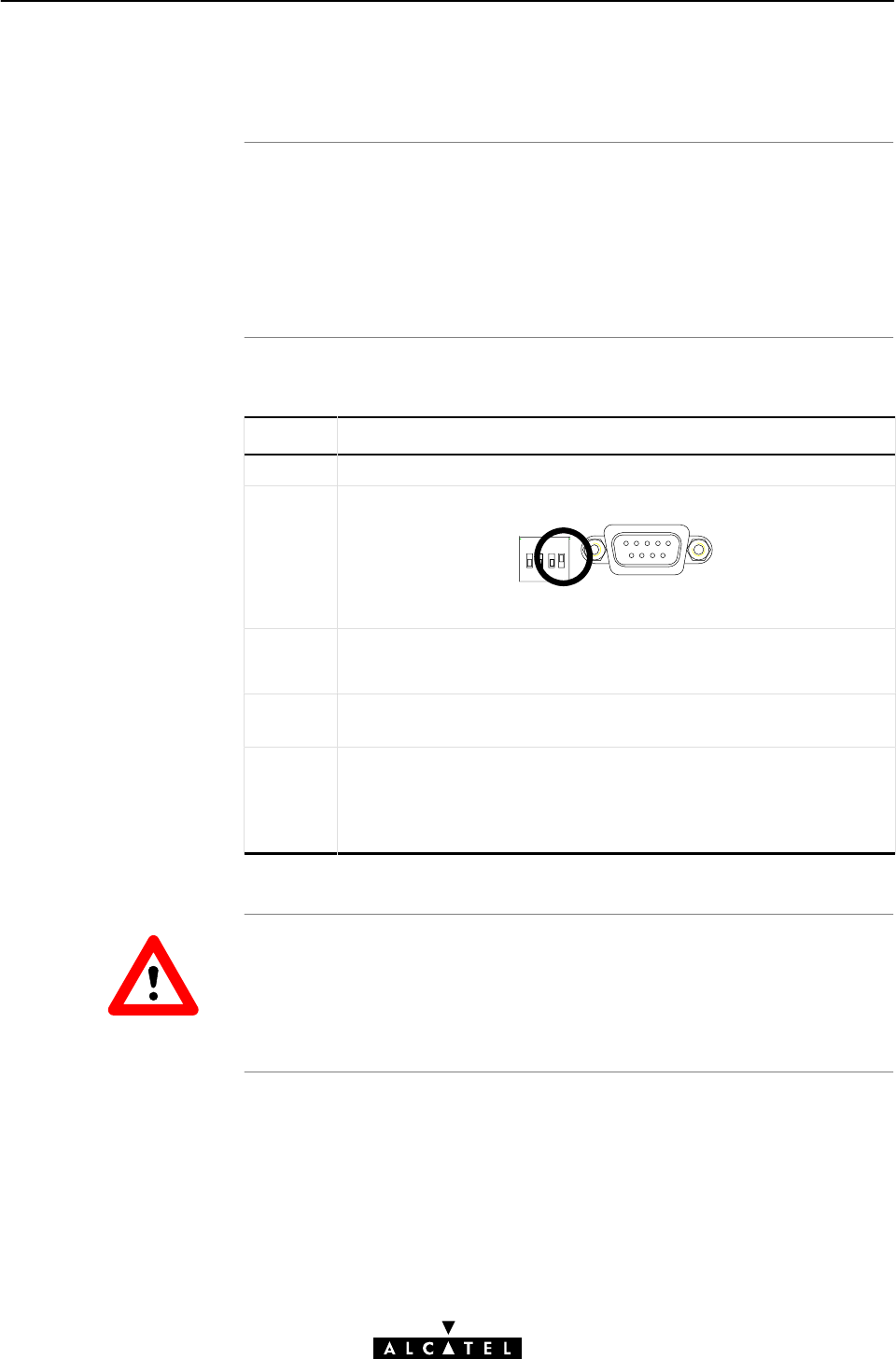
Introduction
Procedure
17 Maintenance - Lost Speed Touch Wireless
274 / 362 3EC 17766 AAAA TCZZA Ed. 01
17.2.3 SwitchĆtoĆDefaults
At the back of the STWireless there is a a set of DIP switches
labeled "Config".
Via these switches a hardware reset of the STWireless, the
SwitchĆtoĆDefaults, is possible.
Proceed as follows:
Step Action and Description
1 Make sure your STWireless is turned on.
2 Put DIP switch number 4 in the UP position:
Config Console
You will notice that the PWR/Alarm LED flashes amber.
3 Power cycle the STWireless and wait to allow the POST to end.
The STWireless will come online with manufacturing defaults.
4 Reset the DIP switch in its original position. If not, the 'PWR/Alarm'
LED will flash amber as a warning.
5 After a reset to original defaults a reconfiguration of STWireless's
IP address might be necessary.
This because the reset to defaults also resets your STWireless's IP
address to its default value 10.0.0.138.
DIP Switch Position
Leaving the DIP switch in the UP position, will cause unintended
reset to manufacturing defaults !
CAUTION

Introduction
The STWireless web
interfac
e
In this chapte
r
18 Maintenance - Speed Touch Wireless Web Interface
275 / 362
3EC 17766 AAAA TCZZA Ed. 01
18 Maintenance - Speed Touch Wireless Web
Interface
The STWireless comes with integrated local configuration
capabilities.
Two methods exist:
"Configuration via a Web Browser
"Configuration through a Command Line Interface (CLI).
The local configuration via the STWireless web interface, is based
on the HyperText Transfer Protocol (HTTP) server/Web browser
concept.
It allows configuration of your STWireless via a Web browser
through HyperText Markup Language (HTML) web pages from any
local PC attached to the Ethernet interface(s).
Topic See
Web Interface Preconditions 18.1
Browsing to the Web Pages 18.2
Web Page Structure 18.3

Precondition
s
Note
In this section
18 Maintenance - Speed Touch Wireless Web Interface
276 / 362 3EC 17766 AAAA TCZZA Ed. 01
18.1 Web Interface Preconditions
When your PC is connected to a Proxy server for accessing the
Internet, you must change your Web browser preferences,
because the STWireless is a local device and its IP address cannot
be resolved by the Proxy server.
Therefore, prior to access the STWireless web pages, make sure
that, either:
"Your Web browser is not using a Proxy server
"The STWireless IP address is not submitted to the Proxy
server.
The procedures described, are methods for:
"Netscape Navigator, version 2.0 or above
"Microsoft Internet Explorer, version 2.2 or above.
This section covers the following topics:
Topic See
Disabling Proxy Servers 18.1.1
Disabling Proxying for Local IP Addresses 18.1.2

Introduction
Disabling Proxy servers
for Netscape Navigato
r
Disabling Proxy servers
for Internet Explore
r
Web browser versions
18 Maintenance - Speed Touch Wireless Web Interface
277 / 362
3EC 17766 AAAA TCZZA Ed. 01
18.1.1 Disabling Proxy Servers
This subsection describes how to disable Proxy servers for your
Web browser.
As a consequence of this action, connectivity through the Proxy
server to the Internet is lost.
Therefore, after configuring your STWireless, do not forget to
reset your Web browser to its original settings !
1. Select 'Edit' from the toolbar
2. Select 'Preferences'
3. In the 'Category' box select Advanced, Proxies
4. Click the option button 'Direct Connection to the Internet'.
1. RightĆclick the 'Internet' icon
2. From the popĆup menu select 'Properties'
3. Clear the 'Use Proxy Server' check box.
Since several versions of these Web browsers exist, the proxy
settings might be located in other menus than the ones described
above. Consult the documentation of your Web browser for more
information on proxy settings.

Introduction
Disabling Proxying fo
r
Netscape Navigato
r
Disabling Proxying fo
r
Internet Explore
r
Web browser versions
18 Maintenance - Speed Touch Wireless Web Interface
278 / 362 3EC 17766 AAAA TCZZA Ed. 01
18.1.2 Disabling Proxying for Local IP Addresses
This subsection describes how to avoid that IP addresses, you can
connect to directly, as for the STWireless, are passed over to the
Proxy server.
However, this option can only be used if the Proxy servers are
manually configured, i.e. are not automatically configured, or if
the Proxy servers are known by name, and port.
1. Select 'Edit' from the toolbar
2. Select 'Preferences'
3. In the 'Category' box select Advanced, Proxies
4. Under 'Manual Proxies', click the view button
5. In the Exceptions box, add the IP address of your STWireless,
or the IP subnetwork address pool.
1. Select 'Tools'from the toolbar
2. From the popĆup menu select 'Internet Options'
3. In the 'Internet Options' window, select the 'Connections' tab
4. Click the 'LAN Settings...' button
5. In the 'Proxy Server' box, check the 'Bypass Proxy servers for
local addresses' box, and click 'Advanced'
6. In the 'Exceptions' settings, add the STWireless IP address.
Since several versions of these Web browsers exist, the proxy
settings might be located in other menus than the ones described
above. Consult the documentation of your Web browser for more
information on proxy settings.
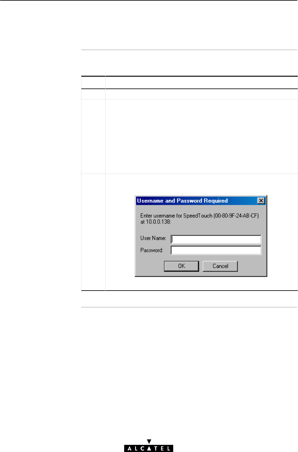
Procedure
18 Maintenance - Speed Touch Wireless Web Interface
279 / 362
3EC 17766 AAAA TCZZA Ed. 01
18.2 Browsing to the Web Pages
Proceed as follows:
Step Action and Description
1Start the Web browser on your PC or workstation.
2Contact the STWireless by entering either:
"The STWireless IP address
or
"The STWireless DNS hostname.
Note: The default IP address is 10.0.0.138
The default DNS hostname is SpeedTouch.
3If a system password was set (See chapter 16 for more information),
an authentication window will pop up:
Enter the system password in the 'Password' field and press Enter.
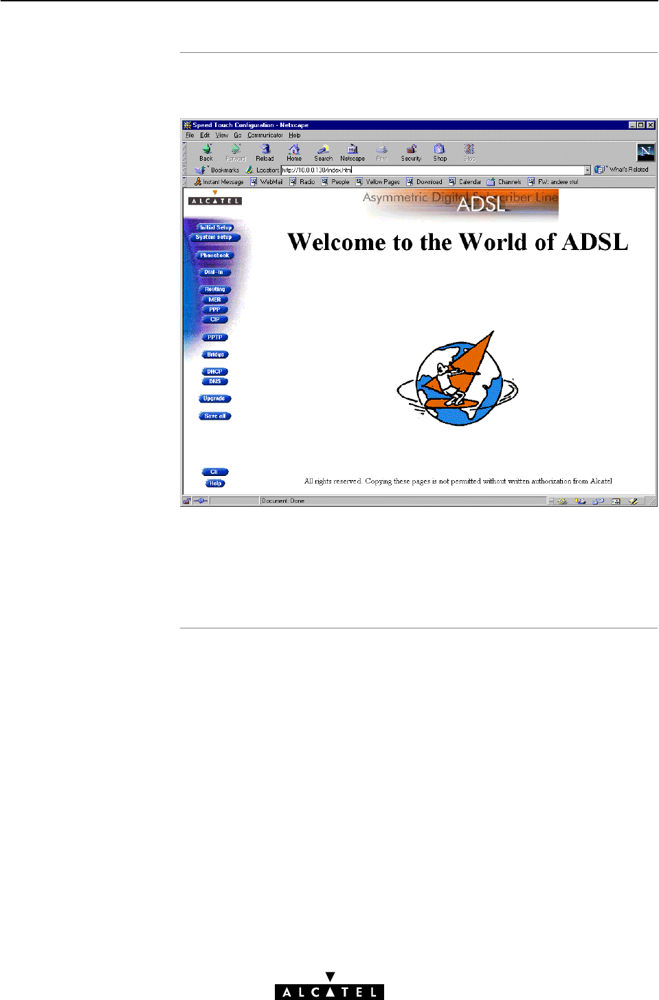
Resul
t
18 Maintenance - Speed Touch Wireless Web Interface
280 / 362 3EC 17766 AAAA TCZZA Ed. 01
As a result the 'Welcome to the World of ADSL' web page pops up:
From now on the STWireless acts as a Web server sending HTML
pages/forms at your request. You can fill out these pages/forms
and submit them to the STWireless. The latter scans the pages
and makes configurations accordingly.
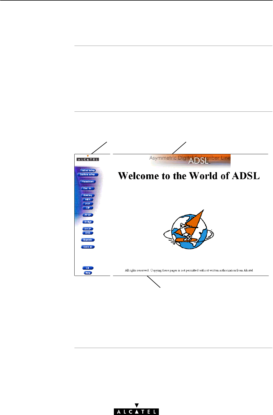
In this section
STWireless web page
frame
s
18 Maintenance - Speed Touch Wireless Web Interface
281 / 362
3EC 17766 AAAA TCZZA Ed. 01
18.3 Web Page Structure
"STWireless Web Page Frames
"Header Frame Components
"Menu Frame Components
"Body Frame Components.
All web pages can be divided into three sections:
Menu frame Header
f
rame
Body frame
Each web page contains:
"A horizontal bar, referred to as Menu frame hereafter
"A vertical pane, referred to as Header frame hereafter
"The user field, referred to as Body frame hereafter.
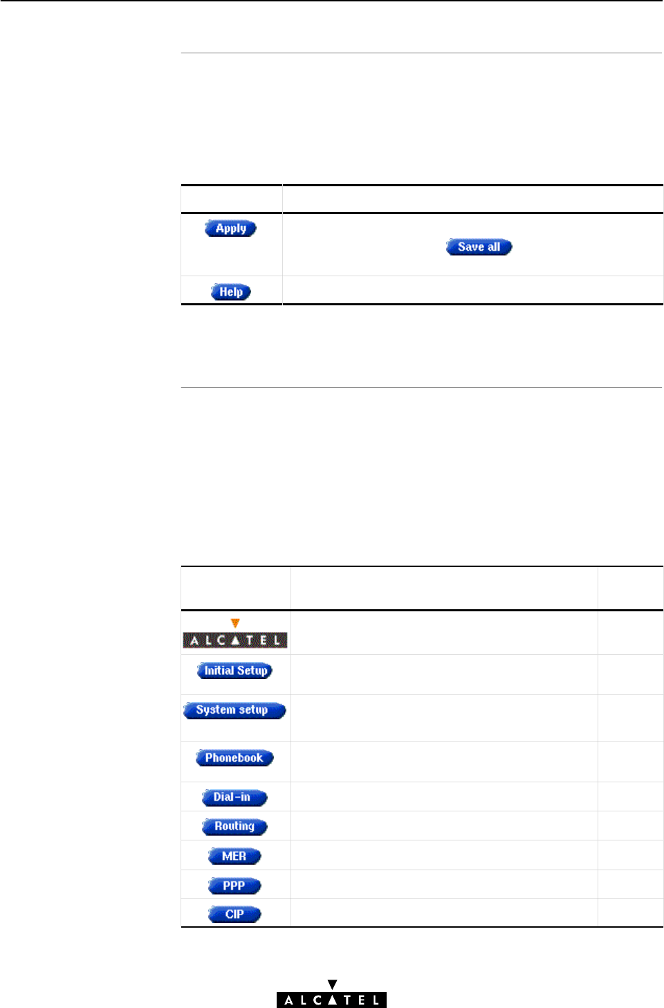
Header frame
component
s
Menu frame
component
s
18 Maintenance - Speed Touch Wireless Web Interface
282 / 362 3EC 17766 AAAA TCZZA Ed. 01
The header frame is present in all of the STWireless web pages.
Under the generic ADSL banner it contains on most pages also
subject related command buttons.
Two command buttons are always available:
Button Functionality
To let the changes you made, take effect.
However, you must still click to store the changes
to permanent memory.
To pop up the STWireless online help pages.
Subject related command buttons are only visible in the
appropriate web page you have selected.
The Menu frame is generic for all STWireless's web pages.
Each menu button represents a STWireless configuration web
page, yielding all configurational possibilities related to menu
subject.
The following buttons are available:
Click this
button ...
To ... See
Return to the 'Welcome to the World of ADSL' web
page.
18.2
Configure user defined STWireless IP parameĆ
ters.
11.3.2
Set a System password
Perform a BrowseĆtoĆDefaults.
16
17.2.1
Overview the record of all possible, and existing
ATM connection information.
10.2
DialĆin to WAN via the PPP packet service. 8.2
Configure the STWireless IP router. 11.4.1
Configure the MER packet service. 6.3
Configure the PPP packet service. 8.3
Configure the CIP packet service. 9.4

18 Maintenance - Speed Touch Wireless Web Interface
283 / 362
3EC 17766 AAAA TCZZA Ed. 01
Click this
button ...
SeeTo ...
Overview active PPTP connections. 7.4
Configure the Bridging packet service.
View Bridging MAC layer data.
5.3
5.4.2
Configure the STWireless DHCP server/client. 11.3.3
Configure the STWireless DNS server/client. 12.2
Configure the STWireless WLAN parameters. 14
Upgrade STWireless software. 15
Save all changes made to persistent memory.
Open the 'CLI' web pages to allow detailed
configuration of the STWireless.
19.1
PopuptheSTWireless online help pages.

18 Maintenance - Speed Touch Wireless Web Interface
284 / 362 3EC 17766 AAAA TCZZA Ed. 01

Introduction
In this chapte
r
19 Maintenance - Speed Touch Wireless Command Line Interface
285 / 362
3EC 17766 AAAA TCZZA Ed. 01
19 Maintenance - Speed Touch Wireless
Command Line Interface
For advanced configurations, with full control over all the
STWireless functions, the STWireless exhibits a low level
interface, i.e. the Command Line Interface (CLI).
As the CLI has far more configurational possibilities than the
regular STWireless web pages, it is intended for experienced
users only.
The CLI is accessible via:
"The STWireless web pages
"A Telnet session via Ethernet IP connectivity
"The serial 'Console' port.
Topic See
CLI via the Web Pages 19.1
Native CLI Access 19.2
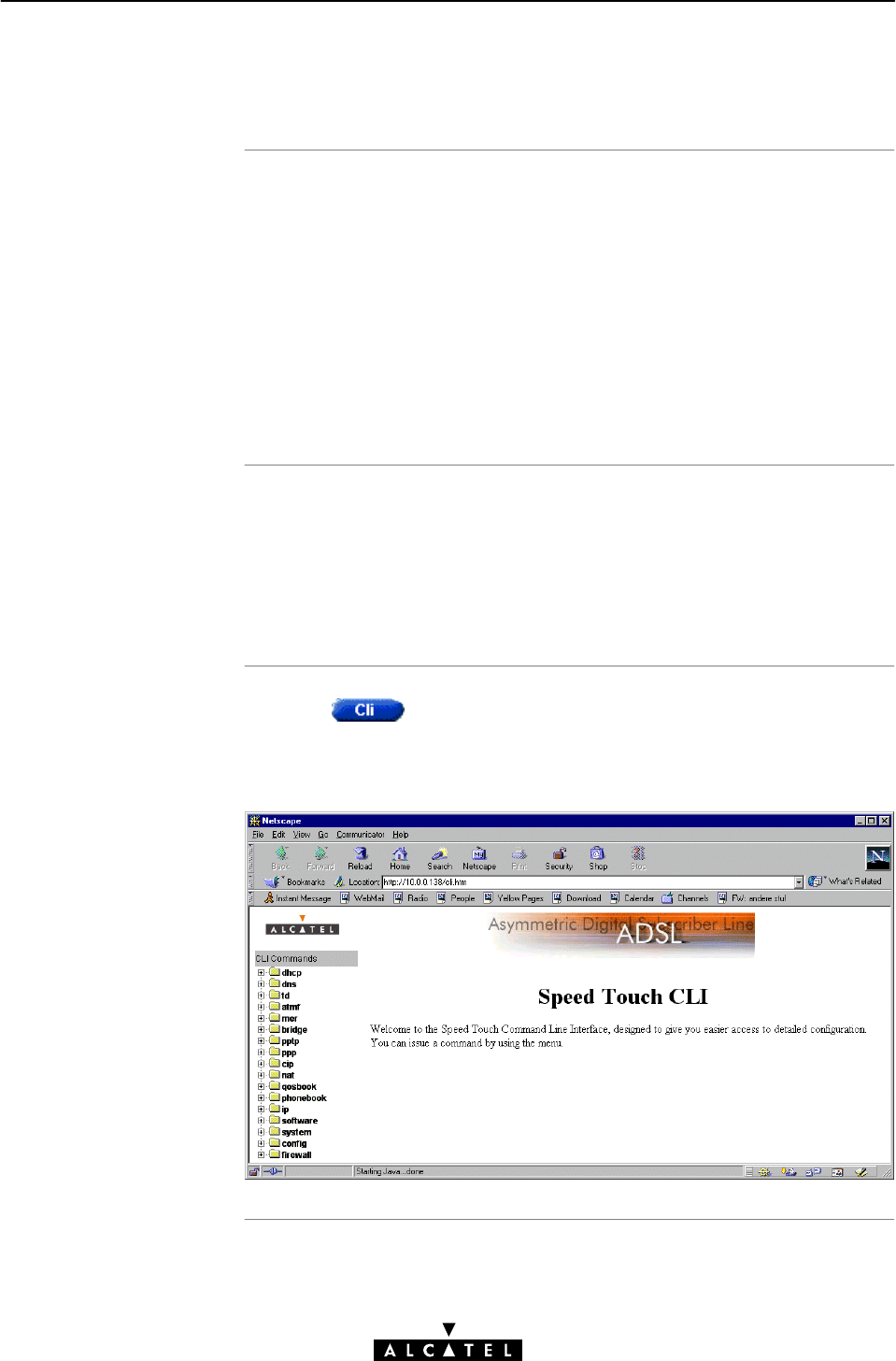
In this section
CLI web page
requirements
The STWireless 'CLI'
web page
19 Maintenance - Speed Touch Wireless Command Line Interface
286 / 362 3EC 17766 AAAA TCZZA Ed. 01
19.1 CLI via the Web Pages
"CLI Web Page Requirements
"The STWireless 'CLI' Web Page
"CLI Commands Basics
"Example: Command Group Description
"Executing Commands
"Example: Command Execution
"Detailed CLI Commands Description
To be able to access the 'CLI' web page, you need the following:
"Microsoft's Internet Explorer 4.0, or better
"Netscape's Communicator 4.06, or better.
Both web browsers must support JavaScript.
Clicking in the left pane of the STWireless web pages,
pops up the 'CLI' web page (See section 18.2 for more
information):
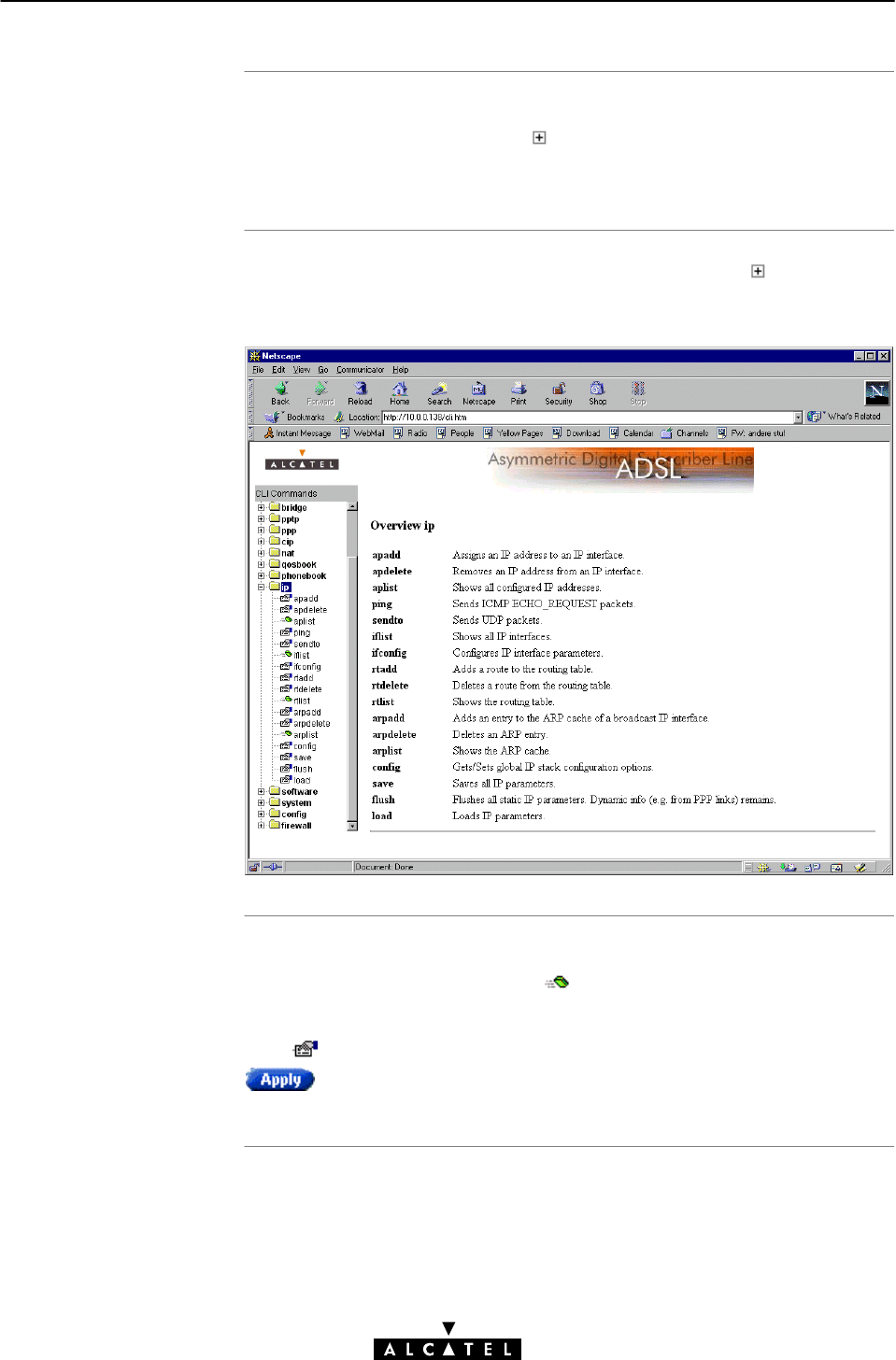
CLI commands basics
Example: command
group description
Executing commands
19 Maintenance - Speed Touch Wireless Command Line Interface
287 / 362
3EC 17766 AAAA TCZZA Ed. 01
All CLI groups and commands are placed in a menu. You can
open a group by clicking the mark next to a group name, or
clicking the group name.
The following example shows the output if you click next to the
'ip' group name:
Clicking on a command name will execute it. Commands without
parameters are indicated with , and are executed immediately.
Commands which require additional parameters are indicated
with . After you configured all parameters, you must click
to execute the command.
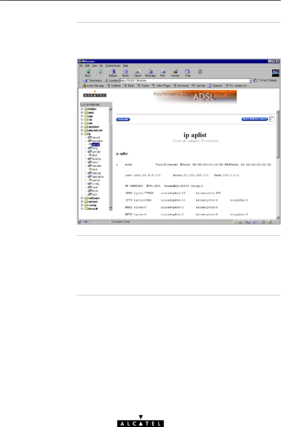
Example: command
execution
CLI Reference Manual
19 Maintenance - Speed Touch Wireless Command Line Interface
288 / 362 3EC 17766 AAAA TCZZA Ed. 01
Clicking 'aplist' in the 'ip' command group generates the
following immediate output:
A CLI Reference manual with detailed CLI configuration
description of all the commands can be found at:
http://www.alcatel.com
http://www.alcateldsl.com

Introduction
In this chapte
r
19 Maintenance - Speed Touch Wireless Command Line Interface
289 / 362
3EC 17766 AAAA TCZZA Ed. 01
19.2 Native CLI Access
Next to the CLI access via the STWireless web pages, you can use
native access via the serial port, or via a basic Telnet session.
This allows configuration via a character based CLI. As a
consequence, the use of a web browser, or even any graphical, or
operational environment is avoided.
Topic See
CLI through a Telnet Session 19.2.1
CLI via Serial Access 19.2.2
CLI Commands Basics 19.2.3

Introduction
Note
In this section
Telnet features
Telnet requirements
19 Maintenance - Speed Touch Wireless Command Line Interface
290 / 362 3EC 17766 AAAA TCZZA Ed. 01
19.2.1 CLI through a Telnet Session
Via a PC, or terminal connected via the STWireless WLAN
environment, or connected to the Ethernet interface of the
STWireless you can execute CLI commands.
However, you must gain access to the STWireless first, by
opening a TCP/IP Telnet session.
The examples throughout this section all refer to Microsoft
Windows OSs. However, all the concepts remain equally valid for
other OSs.
"Telnet Features
"Telnet Requirements
"Opening a Telnet Session to your STWireless
"Closing a Telnet Session.
Telnet is:
"A fairly general, biĆdirectional, eightĆbit byteĆoriented
communication facility
"A standard method of interfacing terminal devices to each
other.
Prior to using Telnet, you need:
"A connected, and configured STWireless, with known IP
address, or DNS hostname, and, if applicable, the system
password
"A PC, or terminal connected to the (W)LAN
Note: (W)LAN is referred to as a network containing at least
one PC, or terminal, and your STWireless.
"A TCP/IP suite installed on this PC, or terminal
"A Telnet session application installed on this PC, or terminal.
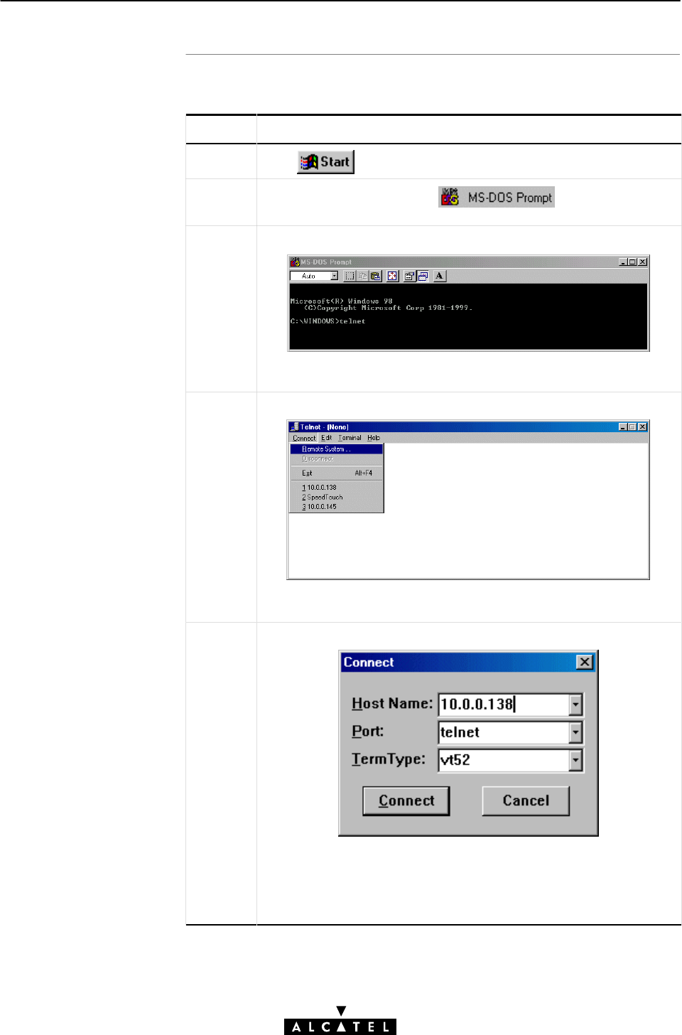
Opening a Telnet
session to you
r
STWireles
s
19 Maintenance - Speed Touch Wireless Command Line Interface
291 / 362
3EC 17766 AAAA TCZZA Ed. 01
Proceed as follows:
Step Action and Description
1Click from the system tray on your desktop.
2Select 'Programs' and click to open a DOS
window.
3The DOS window pops up:
At the DOS prompt, enter: telnet.
4The 'Telnet' window pops up:
In the toolbar, you select 'Connect', and click 'Remote System...'.
5The 'Connect' window pops up:
In the Host Name' field, enter the STWireless IP address, or its
DNS hostname.
Note: The default IP address is 10.0.0.138
The default DNS hostname is SpeedTouch.
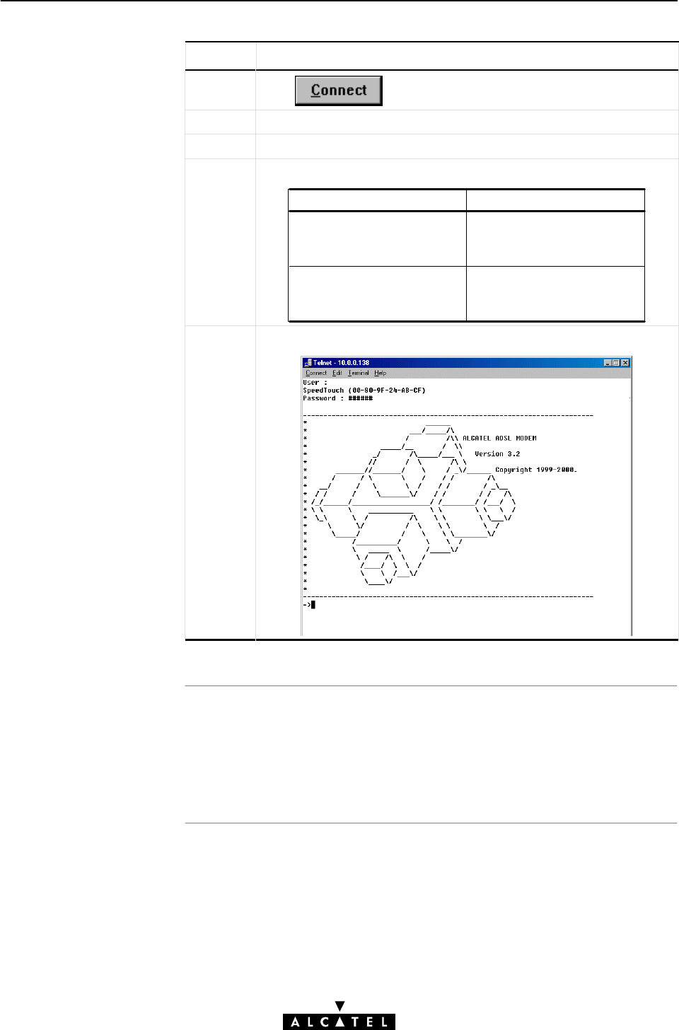
Resul
t
19 Maintenance - Speed Touch Wireless Command Line Interface
292 / 362 3EC 17766 AAAA TCZZA Ed. 01
Step Action and Description
6Click
7 The STWireless will prompt you with User:
8 Press 'Enter'.
9 The following step depends on the following:
If ... Then ...
A system password was set
before
You must supply the
password, prior to gaining
CLI access.
No system password was
set
No passwords must be
supplied, and you have
immediate CLI access.
10 The STWireless CLI banner will appear:
At this point you reached the CLI prompt, preceded by the
opening CLI banner:
=>
CLI commands can be executed now.

Closing a Telnet
Session
Note
19 Maintenance - Speed Touch Wireless Command Line Interface
293 / 362
3EC 17766 AAAA TCZZA Ed. 01
CLI access to your STWireless is released, either via timeout, or
by holding down the 'Ctrl' tab and pressing ']'.
To quit the Telnet application, enter quit, or hold down the 'Ctrl'
tab and press 'C'.
You can perform a quick release from the CLI to your OS's
prompt, by holding down the 'Ctrl' tab and pressing 'C' at the CLI
prompt.

Advantages of the CLI
via serial access
Serial access
requirements
Serial connection
setting
s
Accessing the CLI
19 Maintenance - Speed Touch Wireless Command Line Interface
294 / 362 3EC 17766 AAAA TCZZA Ed. 01
19.2.2 CLI via Serial Access
The CLI via serial access:
"Provides CLI command connectivity to the STWireless,
without the need of a TCP/IP configuration
"Allows remote STWireless configuration via an intermediate
POTS modem, or ISDN modem/router.
For serial access, you need:
"A serial cable.
"An ASCII terminal (VT100), or a PC with ASCII terminal
emulation, for local configuration
or
"A POTS, or ISDN modem/router for remote configuration
Setup the serial interface of your ASCII terminal, or PC for:
"9600 BAUD
"8 databits
"no parity, 1 stopbit.
As soon the connection is made, your terminal is ready for the CLI.
Just press 'Enter' to pop up the CLI banner, possibly after
supplying the STWireless system password.

Introduction
General CLI
information
CLI help
Navigating through CLI
levels
19 Maintenance - Speed Touch Wireless Command Line Interface
295 / 362
3EC 17766 AAAA TCZZA Ed. 01
19.2.3 CLI Command Basics
Although it is not the aim of this subsection to give a complete
overview of all possible configurational STWireless items, this
subsection describes some of the generalities of the native CLI
environment.
Once you accessed your STWireless, you will get the CLI prompt:
=>.
From this point you can start entering your commands.
The CLI access is structured in what is called levels".
The => prompt indicates that you are in the root" level of CLI.
Typing help at the root prompt shows you the available
command groups:
=>help
Following commands are available :
help : Displays this help information
? : Displays this help information
exit : Exits group selection.
.. : Exits group selection.
Following command groups are available :
dhcp dns td atmf mer
bridge pptp ppp cip nat
qosbook phonebook ip software system
config firewall
=>
Entering the name of a command group, accesses you to this
specific level.
For example , entering =>config followed by pressing 'Enter',
brings you to the 'config' level.
This is indicated by its own prompt: [config]=>

Command group help
Command help
Command execution
CLI Reference Manual
19 Maintenance - Speed Touch Wireless Command Line Interface
296 / 362 3EC 17766 AAAA TCZZA Ed. 01
Typing help at the command group level prompt shows you the
available commands.
For example , entering help at the 'config' level generates the
following output:
[config]=>help
Following command groups are available :
save : Saves complete configuration.
erase : Removes all saved data.
load : Loads saved or factory default configuration.
flush : Flushes complete configuration.
reset : Flush & restore factory default configuration.
[config]=>
Typing help followed by a command generates shows you a
description of the command, and a parameter syntax, if
applicable:
For example , entering help reset in the 'config' level
generates the following output:
[config]=>help reset
[keep_ip = <{no|yes}>]
Reset IP settings or not. Resetting IP can break
current telnet/http session !
[config]=>
Typing the command executes the command. In most cases you
must also provide related parameters.
The consequences of a command execution have immediate
effect. However, only after executing the save command, the new
settings are stored in persistent memory.
A CLI Reference manual with detailed CLI configuration
description of all the commands can be found at:
http://www.alcatel.com
http://www.alcateldsl.com

297 / 362
3EC 17766 AAAA TCZZA Ed. 01
Speed TouchWireless
Appendices

298 / 362 3EC 17766 AAAA TCZZA Ed. 01

Abbreviations
299 / 362
3EC 17766 AAAA TCZZA Ed. 01
Abbreviations
ACCOMP Address and Control field COMPression
ADSL Asymmetric Digital Subscriber Line
ARIN American Registry for Internet Numbers
ASP ADSL Service Provider
CHAP Challenge Handshake Authentication Protocol
CIP Classical IP
CLI Command Line Interface
DSSS Direct Sequencing Spread Spectrum
DTE Data Terminal Equipment
ETHoA ETHernet over ATM
FIB Forwarding Information Base
FTP File Transfer Protocol
GUI Graphical User Interface
HTML HyperText Markup Language
HTTP HyperText Transfer Protocol
ICMP Internet Control Message Protocol
IP Internet Protocol
IRC Internet Relay Chat
ISDN Integrated Services Digital Network
ISP Internet Service Provider
LAN Local Area Network
LCP Link Control Protocol
LIS Logical IP Subnet
MAC Medium Access Control
Mbps Mega bits per seconds
MER MAC Encapsulated Routing
NAPT Network Address & Port Translation
NIC Network Interface Card
NID Network Interface Device
OS Operating System
OSI Open Systems Interconnection

Abbreviations
300 / 362 3EC 17766 AAAA TCZZA Ed. 01
PAP Password Authentication Protocol
PC Personal Computer
PIP Packet Interception Point
POST Power On Self Test
POTS Plain Old Telephone Service
PPP PointĆtoĆPoint Protocol
PPPoA PPP over ATM
PPTP PointĆtoĆPoint Tunnelling Protocol
PT Port Translation
QoS Quality of Service
RAS Remote Access Services
REN Ringer Equivalence Number
ROW Rest Of the World
RTSP Real Time Stream Protocol
SP Service Provider
SSID Service Set ID
SVC Switched VC
TCP Transmission Control Protocol
URL Uniform Resource Locator
VP Virtual Path
VPN Virtual Private Network
WAN Wide Area Network
WLAN Wireless LAN

Introduction
Configuration
problem
s
AppendixA Troubleshooting
301 / 362
3EC 17766 AAAA TCZZA Ed. 01
AppendixA Troubleshooting
This appendix provides information on how to identify and correct
some common problems you may encounter when using, and
configuring the STWireless.
If the following troubleshooting tips have not resolved the problem,
contact the company from which you purchased the STWireless for
assistance.
In case you encounter ADSL connectivity problems due to
misconfiguration, you might consider a reset to original defaults as
described in chapter 17.
However, be aware that a reset to original defaults destroys all
configurational changes you made to the STWireless internal
settings.

Trouble solving table
AppendixA Troubleshooting
302 / 362 3EC 17766 AAAA TCZZA Ed. 01
The following table provides possible solutions to some problems:
Problem Solution
STWireless does not work.
(none off the LEDs lights up)
Make sure the STWireless is
plugged into an electrical
outlet.
Make sure the power switch on
the STWireless modem is
turned on.
No Ethernet connectivity. Make sure the cable(s) are
securely connected to the
10BaseĆT port.
Make sure you are using the
correct cable type for your
Ethernet equipment.
No Wireless connectivity. Make sure your WLAN adapter
is compliant to the STWireless
WLAN standards.
Make sure both STWireless
and WLAN adapter are
configured for the same
regulatory area.
Telnet session from a Windows
PC is not possible.
The STWireless system
password is longer than 8
characters.
Change the STWireless system
password.
Poor STWireless ADSL
performance.
Make sure the STWireless is
installed as instructed in this
user manual.
Windows Error 730.
(Windows98/98SE)
TCP/IP is not installed on your
PC. Install the TCP/IP protocol
suite on this PC.

Introduction
In this appendi
x
AppendixB ADSL Connectivity
303 / 362
3EC 17766 AAAA TCZZA Ed. 01
AppendixB ADSL Connectivity
ADSL is stateĆofĆtheĆart technology, used for unlocking the
potential bandwidth of the widely available public telephone
network.
Topic See
ADSL Exposed B.1
Preconditions B.2
Splitter and Filters B.3
Central Splitter B.4
Distributed Filters B.5
ADSL Line Pinning B.6
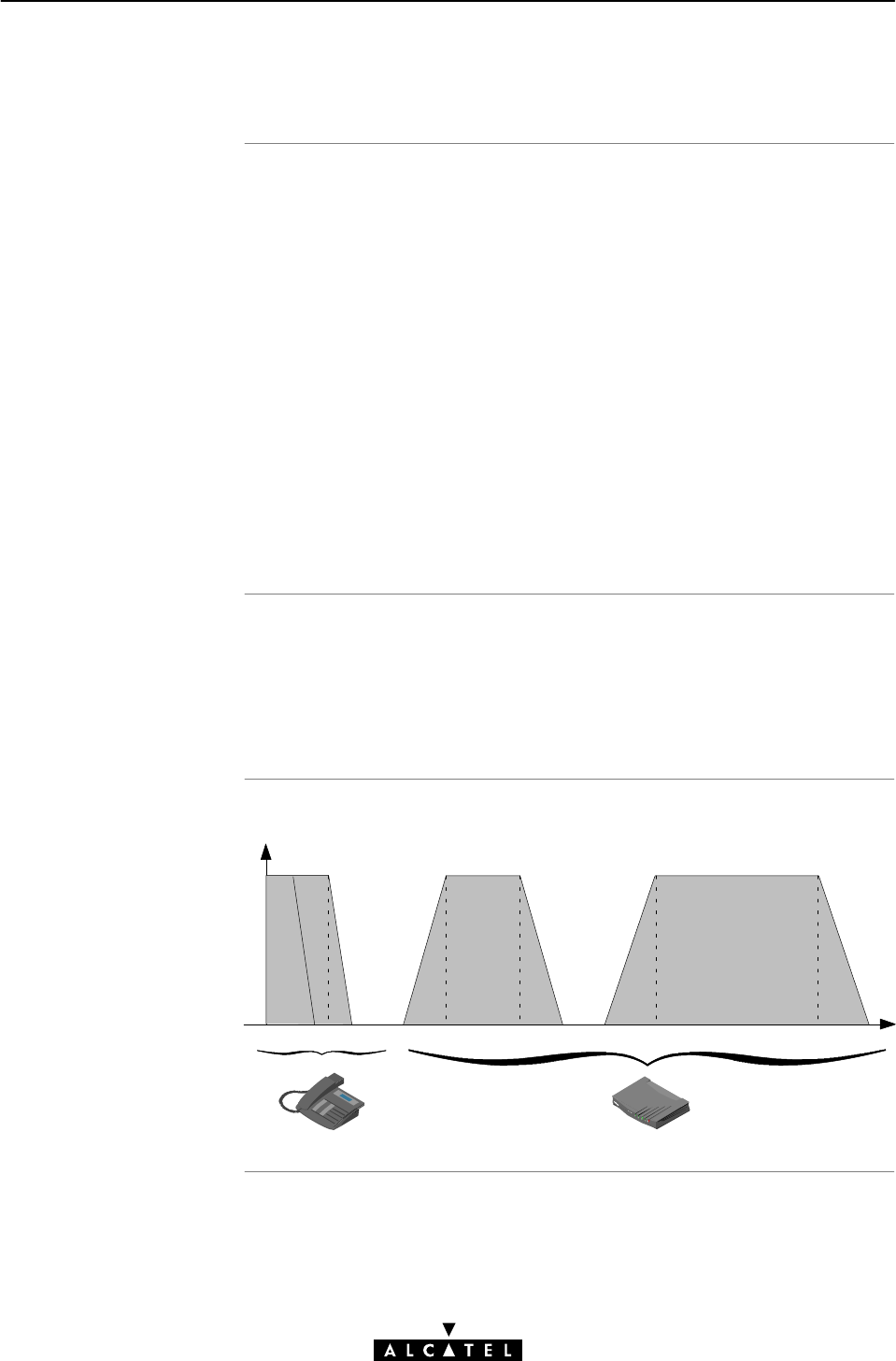
ADS
L
ADSL vs. POTS
Frequency spectrum
AppendixB ADSL Connectivity
304 / 362 3EC 17766 AAAA TCZZA Ed. 01
B.1 ADSL Exposed
ADSL is short for Asymmetric Digital Subscriber Line. This
somewhat cryptic name is best explained in straightforward terms:
"Line: ADSL uses the ordinary existing copper line, known as
local loop", running between your local premises and the
telephone central office.
"Subscriber: That's you, the end user. Because this is what
service providers or operators call their customers.
"Digital: ADSL is a digital transmission technology. To a certain
extend, digital information is not affected by impairments on
the telephone line, thus achieving a higher reliability.
"Asymmetric: ADSL can transmit data much faster from the
Internet towards the end user than vice versa.
As Plain Old Telephone Service (POTS) or Integrated Services
Digital Network (ISDN), and ADSL occupy distinct frequency
spectra, ADSL service can coexist with these conventional
telephone services.
ADSL
UPSTREAM
ADSL
DOWNSTREAM
POTS
ISDN

Before you start using
ADSL service
Requirements to use
ADSL service
STWireless and
telephone service
POTS, or ISDN vs.
telephone equipmen
t
AppendixB ADSL Connectivity
305 / 362
3EC 17766 AAAA TCZZA Ed. 01
B.2 Preconditions
Prior to using the STWireless, you MUST contact your SP. The SP
will inform you whether the ADSL service is already enabled. If
not, the SP will advice you on how to proceed.
Your SP must provide you with:
"A telephone line (POTS, or ISDN) which supports ADSL service
"Guidelines for inĆhouse cabling
"A splitter or filters to decouple conventional phone signals and
ADSL signals.
Two variants of the STWireless models exist: a POTS variant, and
an ISDN variant.
To identify your variant, see the marking label on your
STWireless.
In all cases you must use the appropriate equipment according
your local telephone service, this to avoid damage to your
equipment and the telephone line.
In case your local telephone line is POTS, only use:
"APOTSSTWireless variant
"A POTS/ADSL splitter, or POTS/ADSL filters.
In case your local telephone service is ISDN, only use:
"A ISDN STWireless variant
"A ISDN/ADSL splitter, or ISDN/ADSL filters.

Mutual POTS/ADSL, o
r
ISDN/ADSL interference
Consequences o
f
interference
Solutions to avoid this
interference
Inside the STWireless
Home installation
In the following
section
s
AppendixB ADSL Connectivity
306 / 362 3EC 17766 AAAA TCZZA Ed. 01
B.3 Splitters and Filters
Next to existing POTS, or ISDN signals, ADSL signals are added to
the wires in central telephony offices.
Although POTS, or ISDN and ADSL occupy distinct channels, they
might influence one another.
In devices such as phones, modems, answering machines and fax
machines (collectively referred to as telephony devices) ADSL
signals can cause audible noise.
Telephony devices can in turn interfere with ADSL signals, causing
deterioration in data throughput.
To avoid this mutual interference, an electronic central splitter, or
distributed filters need to be installed.
Inside the STWireless, dedicated filters remove the POTS, or ISDN
signals. Consequently, only the ADSL signals remain to be
processed by the STWireless ADSL router.
As a variety of configurations are deployed, ask your ADSL
provider for advice. He will usually prefer one solution rather than
another.
Topic See
Central Splitter B.4
Distributed Filters B.5
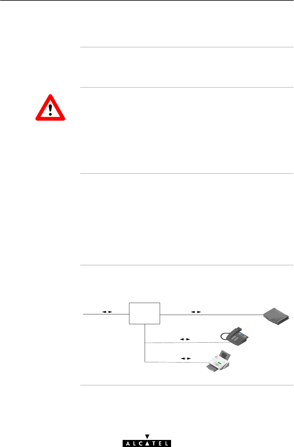
Introduction
In this section
General configuration
AppendixB ADSL Connectivity
307 / 362
3EC 17766 AAAA TCZZA Ed. 01
B.4 Central Splitter
In this section some configuration features of the central splitter
are described.
In all cases contact your ADSL service provider about splitter
installation.
Public telephone lines carry voltages that can cause electric
shock.
You may only install splitters yourself if the splitter model clearly
stipulates that selfĆinstallation is allowed. All other splitters may
only be installed by qualified service personnel.
"General Configuration
"Splitter Installation and InĆHouse Cabling
"InĆHouse ADSL Service
"Splitter Locations
"The Network Interface Device (NID)
"Indoor Splitter Installation.
In the below configuration the public telephone line terminates
into a central splitter.
POTS/ISDN + ADSL
POTS/ISDN ONLY
Central
Splitter
POTS/ISDN ONLY
POTS/ISDN + ADSL
WARNING

Splitter installation
and inĆhouse cabling
InĆhouse ADSL service
Splitter Locations
The NID
Indoor splitte
r
installation
AppendixB ADSL Connectivity
308 / 362 3EC 17766 AAAA TCZZA Ed. 01
The central splitter is installed as follows:
"The POTS/ADSL, or ISDN/ADSL line is connected to the
splitter input
"One output, containing POTS, or ISDN signals only, is
connected to the existing inĆhouse POTS, or ISDN network for
your ordinary telephone service
"The other output, containing POTS/ADSL, or ISDN/ADSL, is
either connected to:
DA dedicated spare wire pair in the existing telephone
cable to connect to the STWireless
DA newly installed cable to connect to the STWireless if no
spare wire pair is available.
Note: Ensure that the installed cables are of sufficient quality.
Depending upon the existing wiring and sockets, ADSL should
now be present from all of your telephony wall sockets. When
using a new dedicated cable, ADSL service is only present from
the wall sockets attached to this cable.
The central splitter can be either external, or internal to your
home.
An outdoor splitter is installed by the SP in what is often referred to
as Network Interface Device, or NID.
The NID is mostly an outdoor enclosure terminating and securing
the public telephone cable. For the telephone operator it is the
demarcation point between the public and private section of your
line.
Depending on splitter type and your SP's instructions, you are
allowed to install the indoor splitter yourself. For more
information, check the manual, supplied with the indoor splitter.
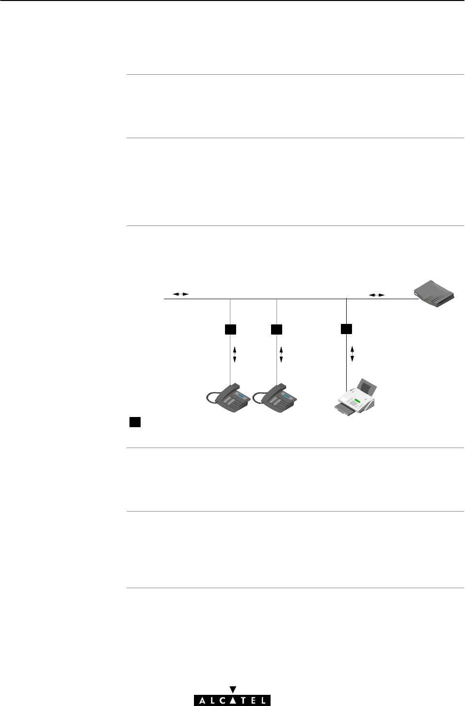
Introduction
In this section
General configuration
InĆhouse ADSL service
Filter installation
AppendixB ADSL Connectivity
309 / 362
3EC 17766 AAAA TCZZA Ed. 01
B.5 Distributed Filters
In this section some configuration features of distributed filters are
described.
"General Configuration
"InĆhouse ADSL Service
"Filter Installation.
In this configuration, the combined POTS/ADSL, or ISDN/ADSL
signals are distributed over the complete inĆhouse wiring.
POTS/ISDN + ADSL POTS/ISDN + ADSL
= one distributed filter
POTS/
ISDN
ONLY
POTS/
ISDN
ONLY
POTS/
ISDN
ONLY
You can connect your STWireless to any wall outlet supporting
POTS/ADSL, or ISDN/ADSL service.
For optimum ADSL performance, and for telephony device
protection from the ADSL signals, you must insert filters in front of
any connected telephony device inside your house.

Introduction
STWireless ADS
L
connector pinning, and
included ADSL cable
Splitter/filter ADS
L
connector pinning
Crossover adapters
AppendixB ADSL Connectivity
310 / 362 3EC 17766 AAAA TCZZA Ed. 01
B.6 ADSL Line Pinning
This section provides information on the possible ADSL pinning
terminations.
Depending on the model variant you purchased, ADSL is
terminated on pins 2/5, or 3/4 of the ADSL port (See section F.2).
To identify your model variant, see the marking label on your
STWireless.
The included ADSL cable is a full wired RJ11/RJ11 cable.
In case a central splitter is installed, ADSL signals are present on
pins 2 and 5 of the ADSL enabled wall socket.
POTS, or ISDN telephone service is terminated on pins 3 and 4 of
the wall socket.
In case distributed filters are used, both ADSL and POTS, or ISDN,
service is present on pins 3 and 4 of the wall sockets.
Depending on how ADSL and POTS, or ISDN are distributed over
your inĆhouse wiring, and depending on your STWireless model
variant, crossover adapters might be required.

In this appendi
x
AppendixC Microsoft DialĆUp Networking
311 / 362
3EC 17766 AAAA TCZZA Ed. 01
AppendixC Microsoft DialĆUp Networking
Topic See
Adapting DialĆUp Networking Properties C.1
Upgrade Procedure for MS Windows 95 C.2
Configuring PPTP Tunneling for Windows NT C.3 ...
C.6
Using PPTP Tunneling for Windows NT C.7
Platform Limitations for Microsoft DialĆUp Networking C.8
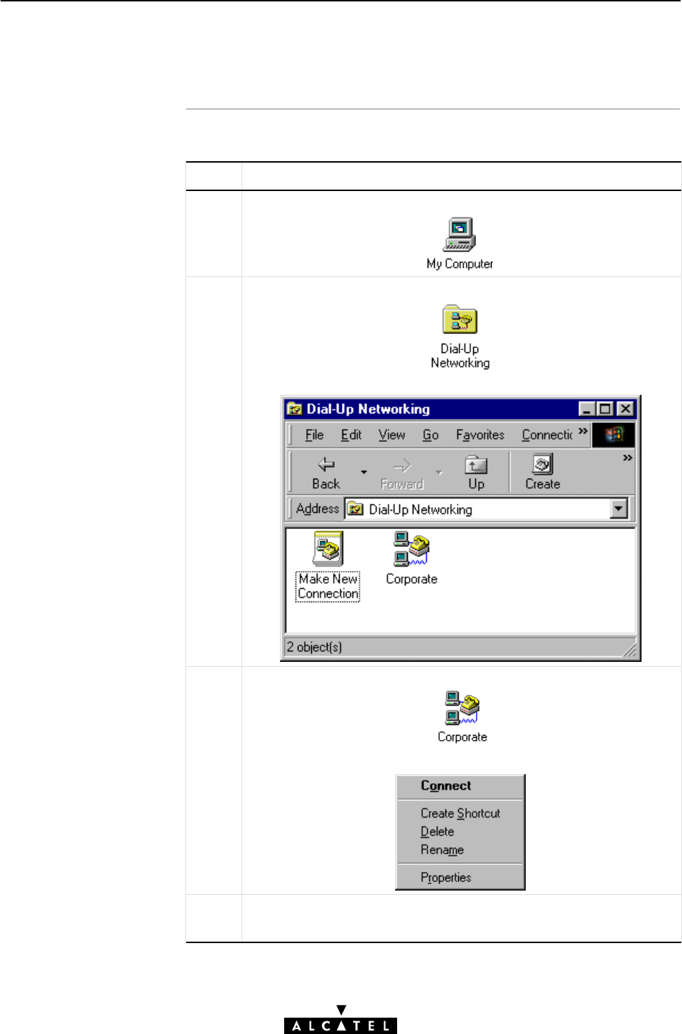
DialĆUp connection
properties procedure
AppendixC Microsoft DialĆUp Networking
312 / 362 3EC 17766 AAAA TCZZA Ed. 01
C.1 Adapting DialĆUp Networking Properties
Proceed as follows:
Step Action and Description
1DoubleĆclick the 'My Computer' icon on your desktop.
2DoubleĆclick the 'DialĆUp Networking' icon.
The 'DialĆUp Networking window pops up.
3RightĆclick the DialĆUp connection icon 'Corporate' created via the
previous procedure.
As a result, a selection box pops down:
4In the selection box, select 'Properties'.
The 'Corporate' window appears.
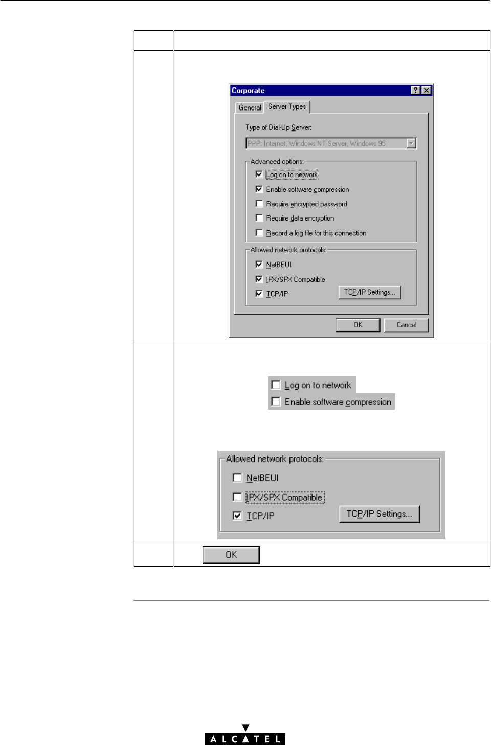
AppendixC Microsoft DialĆUp Networking
313 / 362
3EC 17766 AAAA TCZZA Ed. 01
Step Action and Description
5In the 'Corporate' window you select the 'Server Types' tab to pop up
the following window:
6Ensure that 'Log on to the network' and 'Enable software compresĆ
sion' boxes are blank, i.e. not flagged:
In the 'Allowed network protocols' ensure that only 'TCP/IP' is seĆ
lected, i.e. flagged (n):
7Click to finish the procedure.

Introduction
PC/workstation
requirements
Download
requirements
Prior to installing the
upgrad
e
To enable Windows95
VPN server suppor
t
AppendixC Microsoft DialĆUp Networking
314 / 362 3EC 17766 AAAA TCZZA Ed. 01
C.2 Upgrade Procedure for MS Windows 95
This section explains how to download and install the Windows
DialĆUp Networking 1.3 Performance and Security Upgrade for
Windows 95" needed for the STWireless's PPPoAĆtoĆPPTP
Relaying packet service.
The Windows 95 PC(s)/workstation(s) must meet the following
minimum requirements :
"PentiumĆclass processor 90MHz or higher
"16MB of memory.
For downloading the Windows DialĆUp Networking 1.3
Performance and Security Upgrade for Windows 95" one PC needs
to have Internet access via a voiceband modem.
If you have installed Windows 95 from a CDĆrom, you will need to
have the Windows 95 CDĆrom ready prior to start the installation
process.
You must:
"Download the DialĆUp Networking Upgrade
"Install the DialĆUp Networking Upgrade
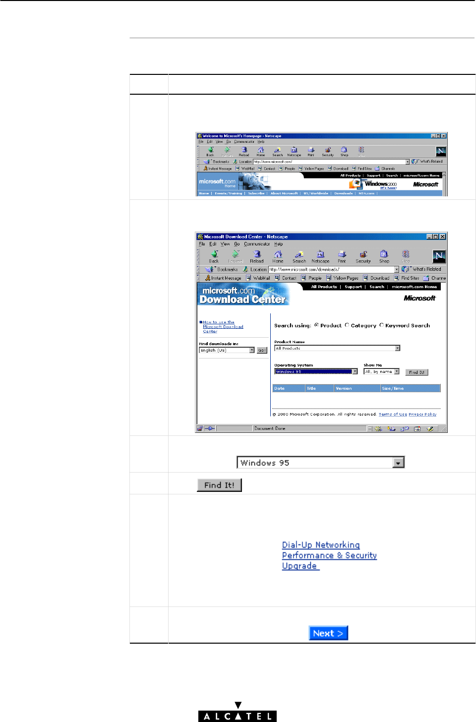
Download the DialĆUp
Networking Upgrade
AppendixC Microsoft DialĆUp Networking
315 / 362
3EC 17766 AAAA TCZZA Ed. 01
Proceed as follows:
Step Action and Description
1 Browse to the Microsoft website at l'http://www.microsoft.com' by
entering this address in the Uniform Resource Locator (URL) field of
your Web browser:
2Click the 'Downloads' button in the Microsoft homepage's taskbar.
You will be guided to Microsoft's 'Download Center'.
3In the 'Download Center' web page, select Windows 95 as OS:
4Click
5 On the resulting web page all available downloads for Windows 95
are listed. In the list, look for the 'DialĆUp Networking Performance &
Security Upgrade' and click it.
Note: You can also use Microsoft's Search Tool to locate the
Upgrade file. Therefor, search on 'MSDUN13.EXE'.
6 A 'Read me first' web page pops up, informing how the download
will progress. to proceed, click
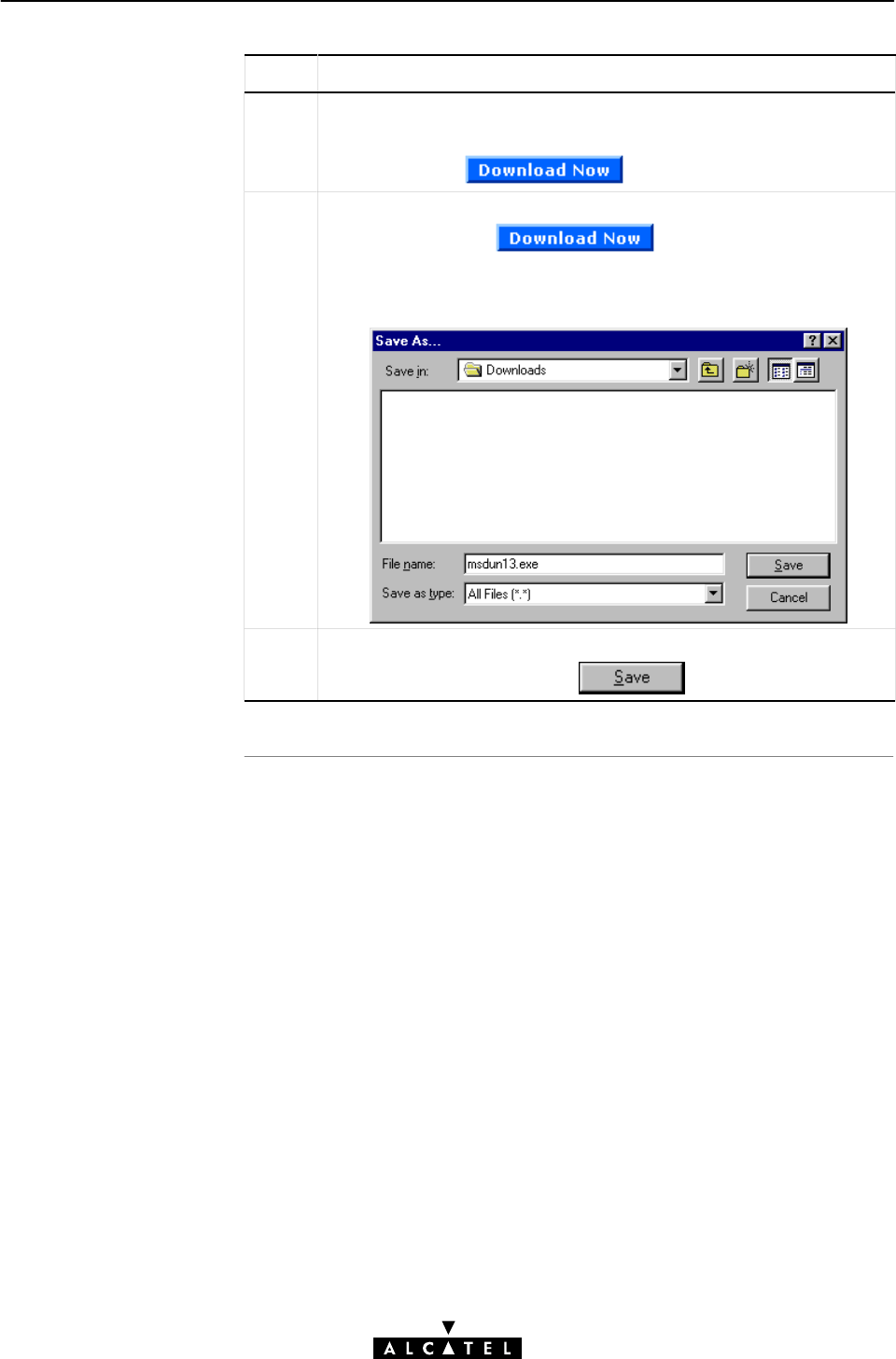
AppendixC Microsoft DialĆUp Networking
316 / 362 3EC 17766 AAAA TCZZA Ed. 01
Step Action and Description
7 In the following web page, select the DialĆUp Networking
Graphical User Interface (GUI) language.
To proceed, click
8 The next web page allows you to choose the nearest download site.
Select one, and click
A'Save As...' window pops up, asking you to specify a location for
the MSDUN13.exe file to be downloaded.
9 Specify a location for the storage.
To execute the download, click
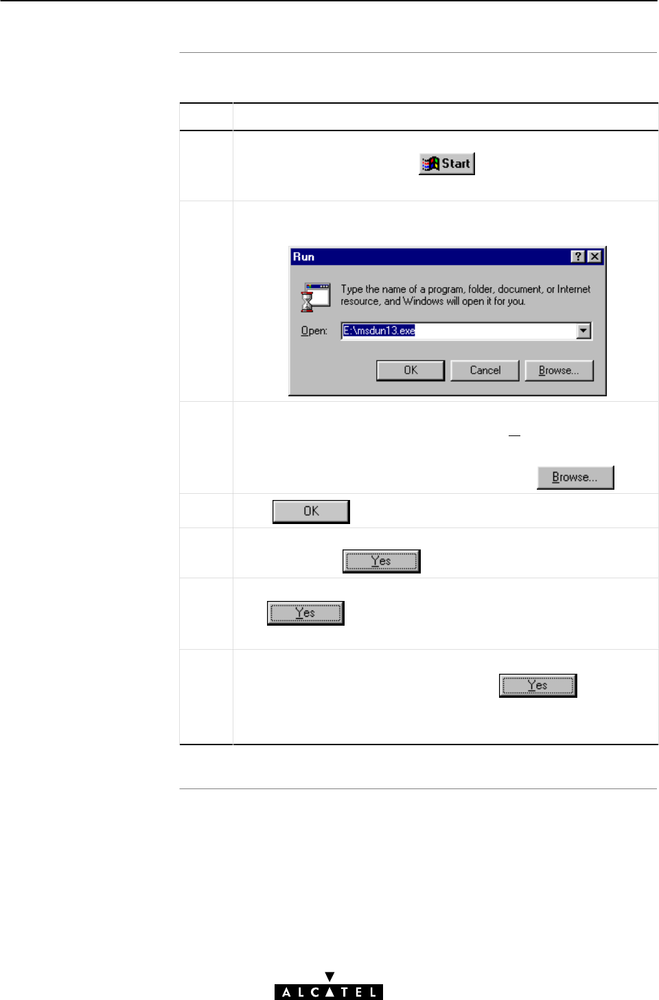
Installing the DialĆUp
Networking Upgrade
AppendixC Microsoft DialĆUp Networking
317 / 362
3EC 17766 AAAA TCZZA Ed. 01
Proceed as follows:
Step Action and Description
1Click 'Start' from the system tray on your desktop:
Note: All other applications must be closed.
2 Select 'Run' from the menu list.
As a result the 'Run' window pops up:
3 Specify the path (the one that you specified during the download
procedure) for the MSDUN13.EXE file in the 'Open' box of the 'Run'
window.
Note: You can also browse to the file, by clicking
4Click
5 The system will ask if you want to start the MSDUN13
installation. Click to proceed.
6An 'EndĆUser License Agreement' window pops up. To accept,
click
As a result the installation starts.
7During the installation, setup will ask you twice to restart
your computer. To proceed each time, click
Upon restart, the installer will rebuild your driver twice: once for
DialĆUpĆNetworking and once to enable Virtual Private Networking.

In this section
AppendixC Microsoft DialĆUp Networking
318 / 362 3EC 17766 AAAA TCZZA Ed. 01
C.3 Configuring PPTP Tunneling for Windows NT
The following overview summarizes the procedures to setup your
Windows NT PC for the use of PPTP DialĆUp connections over
standard telephone lines and Virtual Private Network connections
over IP networks such as the Internet:
Step Action See
1 Make sure that Microsoft Service Pack 3 has been installed
on your PC(s).
2 Configure a Private IP address on your PC NO TAG
3 Install the PPTP Tunneling network protocol C.4
4 Configure RAS for PPTP Tunneling C.5
5 Create PPTP DialĆup phonebook entries C.6
Microsoft Service Pack 3 Installation
Make sure that 'Microsoft Service Pack 3' has been installed on
your PC before you start creating tunnel sessions.
CAUTION
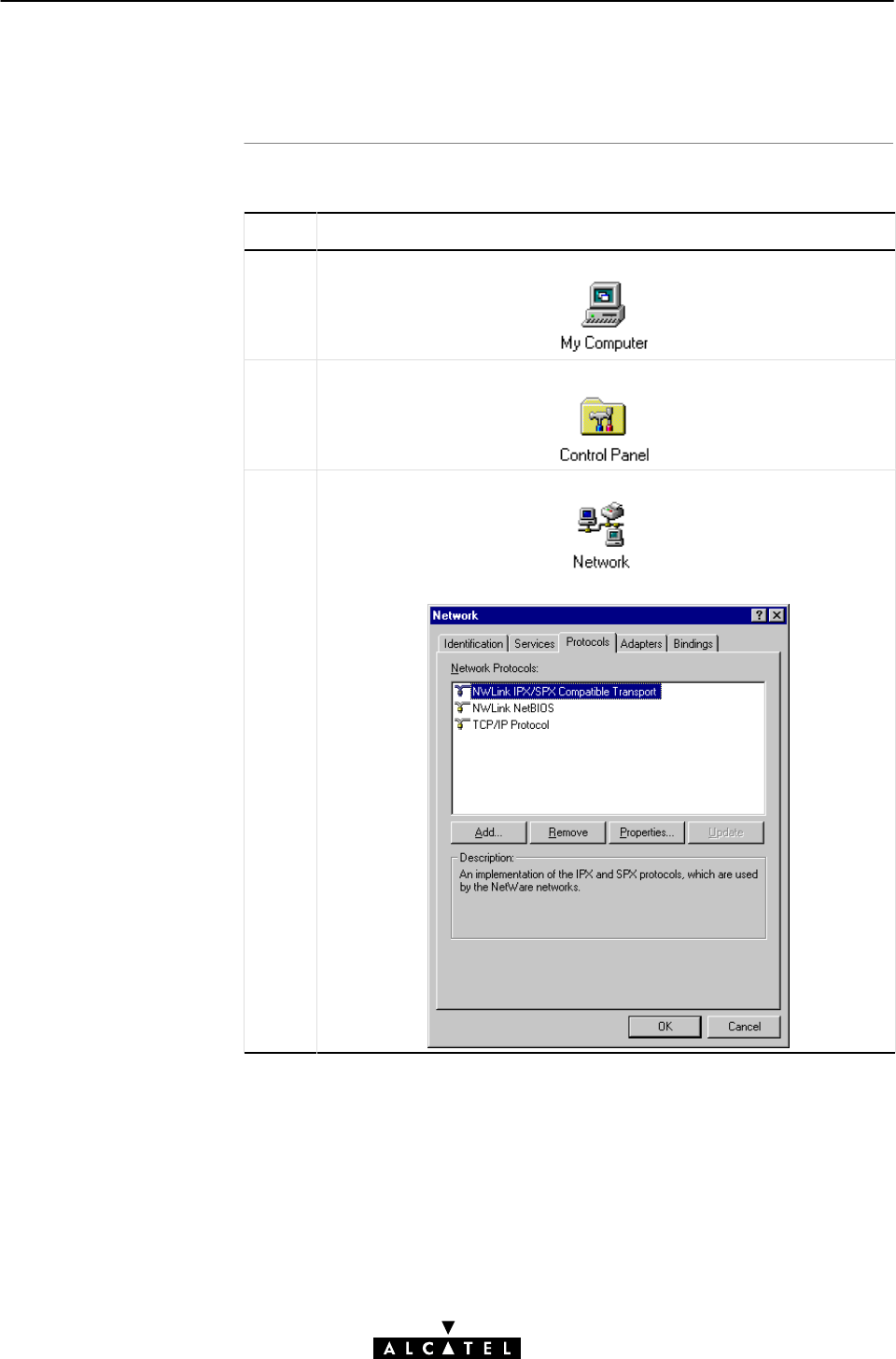
Procedure
AppendixC Microsoft DialĆUp Networking
319 / 362
3EC 17766 AAAA TCZZA Ed. 01
C.4 Installing the PPTP Tunneling Network Protocol (WinNT)
Proceed as follows:
Step Action and Description
1DoubleĆclick the 'My Computer' icon on your desktop.
2DoubleĆclick the 'Control Panel' icon.
3In the 'Control Panel' folder, doubleĆclick the 'Network' icon.
As a result the 'Network' window pops up.
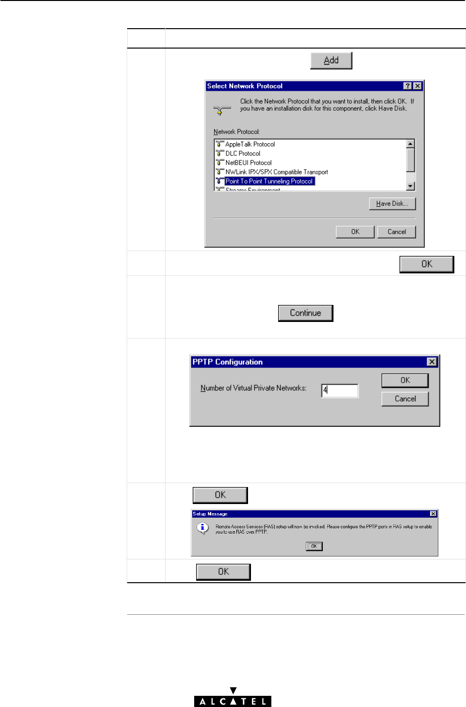
AppendixC Microsoft DialĆUp Networking
320 / 362 3EC 17766 AAAA TCZZA Ed. 01
Step Action and Description
4Select the 'Protocol' tab and click to pop up the 'Select
Network Protocol' window:
5Select the 'PointĆtoĆPoint Tunneling Protocol', and click
6Setup now needs to copy some Windows NT files and prompts you
for the proper path to the installation files.
Specify the path and click
The installation will load all necessary PPTP files.
7The 'PPTP Configuration' box pops up.
This box presents you with a key question : how many VPNs do
you want to enable for access to the Remote Access Services (RAS)
server.
Type the number of VPNs you want in the VPN field.
8Click to pop up the 'System Message' box:
9Click to continue.
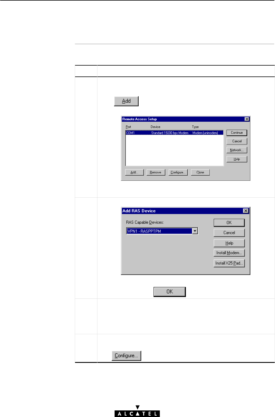
Procedure
AppendixC Microsoft DialĆUp Networking
321 / 362
3EC 17766 AAAA TCZZA Ed. 01
C.5 Configuring RAS for PPTP Tunneling (WinNT)
Proceed as follows:
Step Action and Description
1 After the 'Installing the PPTP Tunneling Network Protocol' procedure,
the 'Remote Access Setup' window pops up.
In the example window, one (voiceband) modem is shown, which
already was configured for RAS.
Click to add new created VPN ports to the RAS
configuration.
2 The 'Add RAS Device' window pops up.
You must add each port individually. To do so, doubleĆclick on the
correct port and click
3The 'Remote Access Setup' window reappears, now with the VPN
port added to the device list.
Repeat steps 1 and 2 until all VPN ports are listed in the 'Remote
Access Setup' window.
4At this point the ports are configured by default for dialĆin only. To
change this, select a port in the 'Remote Access Setup' window and
click
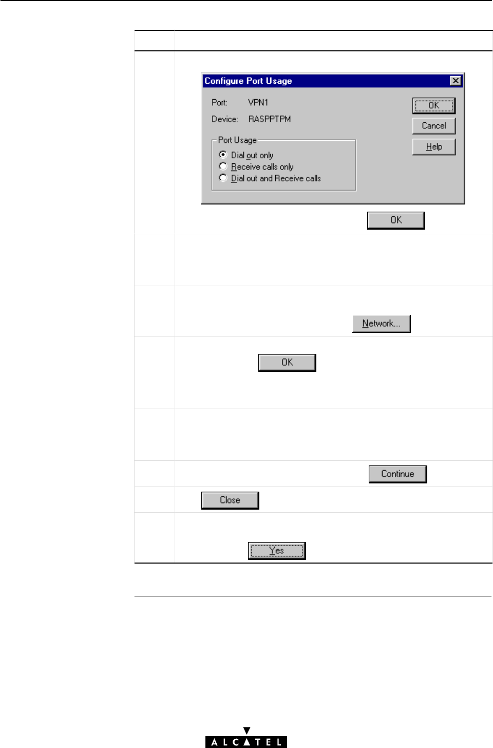
AppendixC Microsoft DialĆUp Networking
322 / 362 3EC 17766 AAAA TCZZA Ed. 01
Step Action and Description
5 The 'Configure Port Usage' window pops up.
Select the 'DialĆout only' option and click
6The 'Remote Access Setup' window returns.
Repeat steps 4 and 5 until all VPN ports are configured for dialĆout
only.
7In addition, you can also define which tunneled protocols you will
allow through the VPNs.
To do so, highlight each port and click
8 Enable, or disable the protocols in the 'Network Configuration'
window and click
Note: You can enable or disable IP, IPX or NETBEUI sessions for
each port.
9The 'Remote Access Setup' window returns.
Repeat steps 7 and 8 until the network configuration for each VPN
port is configured.
10 In the 'Remote Access Setup' window, click
11 Click
12 The RAS application will inform you it needs to be restarted in order
for the changes to take effect.
To restart, click
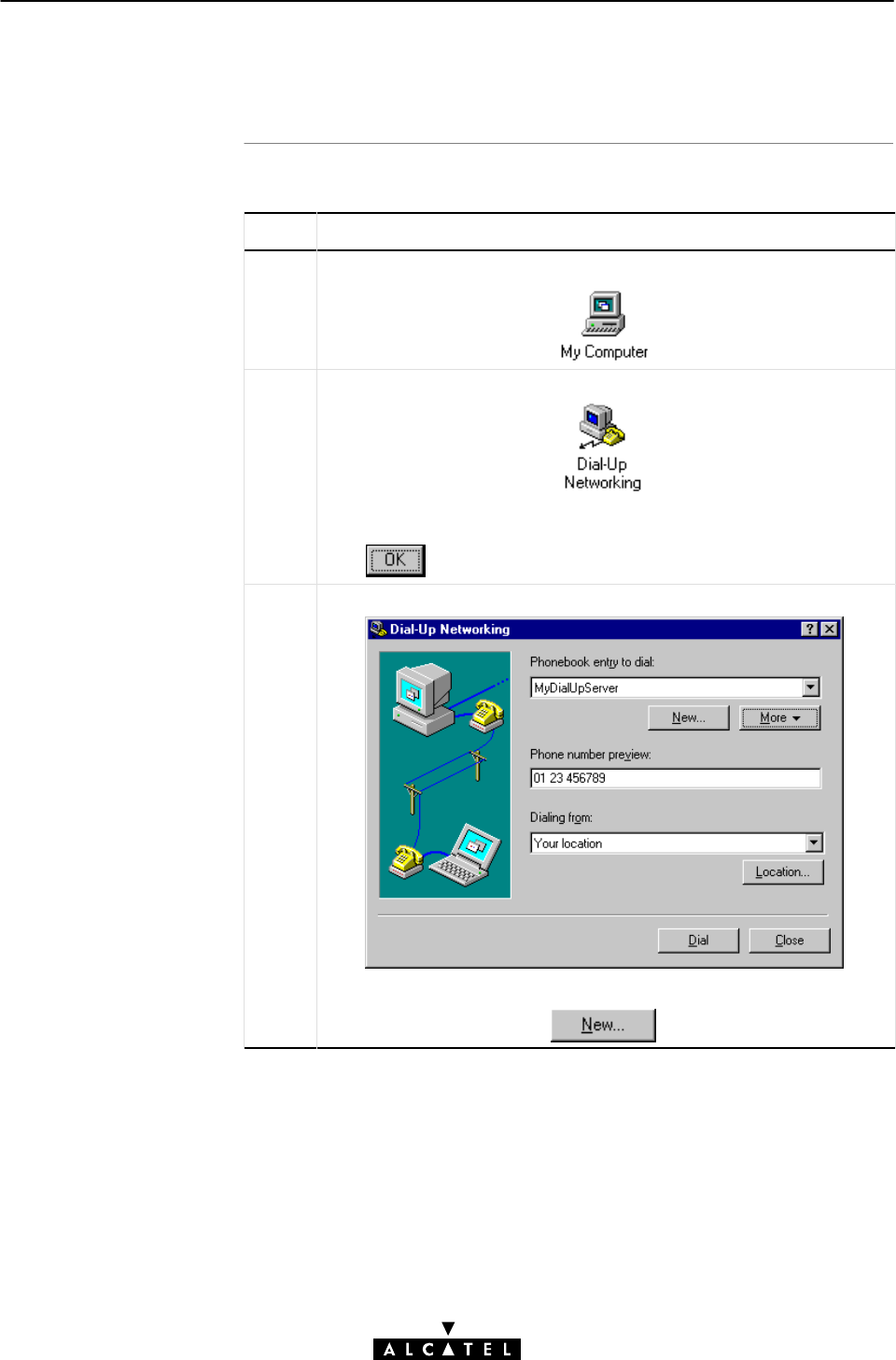
Procedure
AppendixC Microsoft DialĆUp Networking
323 / 362
3EC 17766 AAAA TCZZA Ed. 01
C.6 Creating PPTP DialĆUp phonebook Entries (WinNT)
Proceed as follows:
Step Action and Description
1DoubleĆclick the 'My Computer' icon on your desktop.
2DoubleĆclick the 'DialĆUp Networking' icon.
Note: If the DialĆUp phonebook was empty, a window appears to
inform you that no entries exist in the phonebook.
Click to continue with step 4.
3The 'DialĆUp Networking' window pops up.
The 'Phonebook entry to dial' box lists all existing entries. To add a
new phonebook entry, click
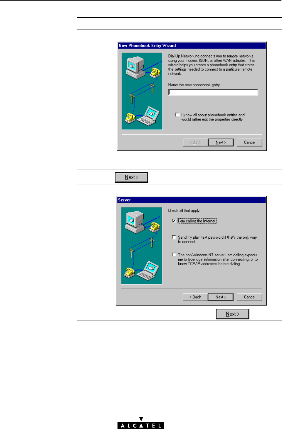
AppendixC Microsoft DialĆUp Networking
324 / 362 3EC 17766 AAAA TCZZA Ed. 01
Step Action and Description
4The 'New Phonebook Entry Wizard' window pops up.
Enter a name for the entry you are creating; the entry will be saved
in the phonebook under this name.
5Click
6 The 'Server' window pops up.
Activate all the options that apply, and click
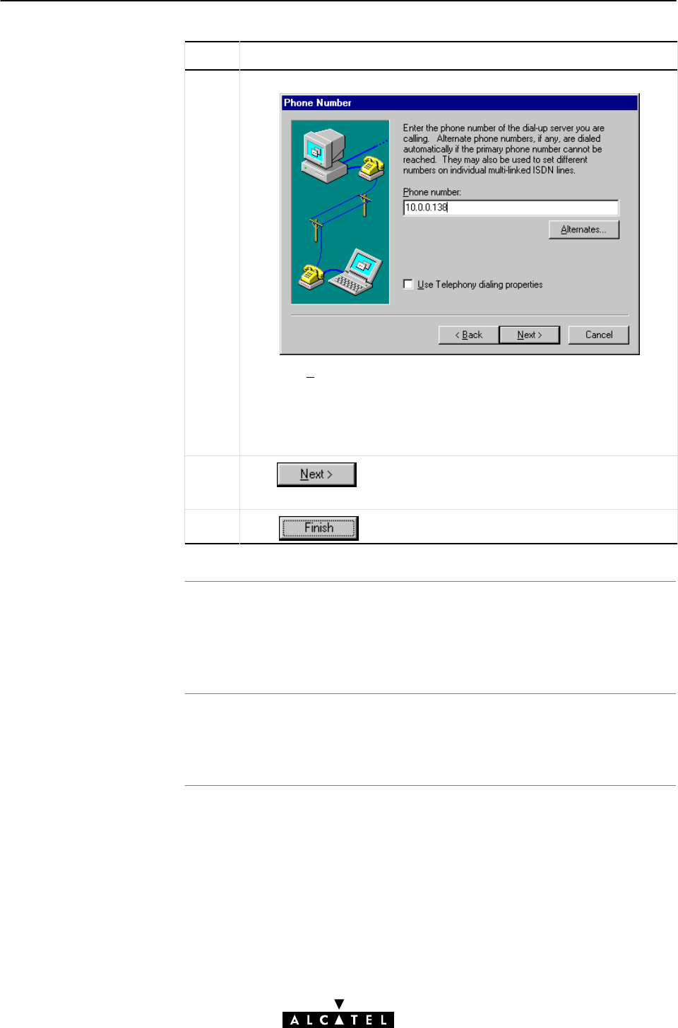
Creating multiple PPTP
DialĆup phoneboo
k
entries
Specific VC and PPTP
Profile
AppendixC Microsoft DialĆUp Networking
325 / 362
3EC 17766 AAAA TCZZA Ed. 01
Step Action and Description
7 The 'Phone Number' window pops up.
Enter the 'Phone number', i.e. the IP address, or DNS hostname, of
the STWireless.
Optionally, you can add the phonebook name to specify which VC is
to be used for the connection. Optionally this phonebook name can
be followed by a PPTP profile. See section 7.5 for more information.
8Click to proceed. A window pops up, announcing the
successful creation of a new tunnel.
9Click to finish the procedure.
Per destination you can create a unique PPTP DialĆup phonebook
entry. To do so, repeat the steps, starting with 3 of the previous
procedure.
Using a specific PPTP phonebook entry and/or PPTP profile is
described in section 7.5.
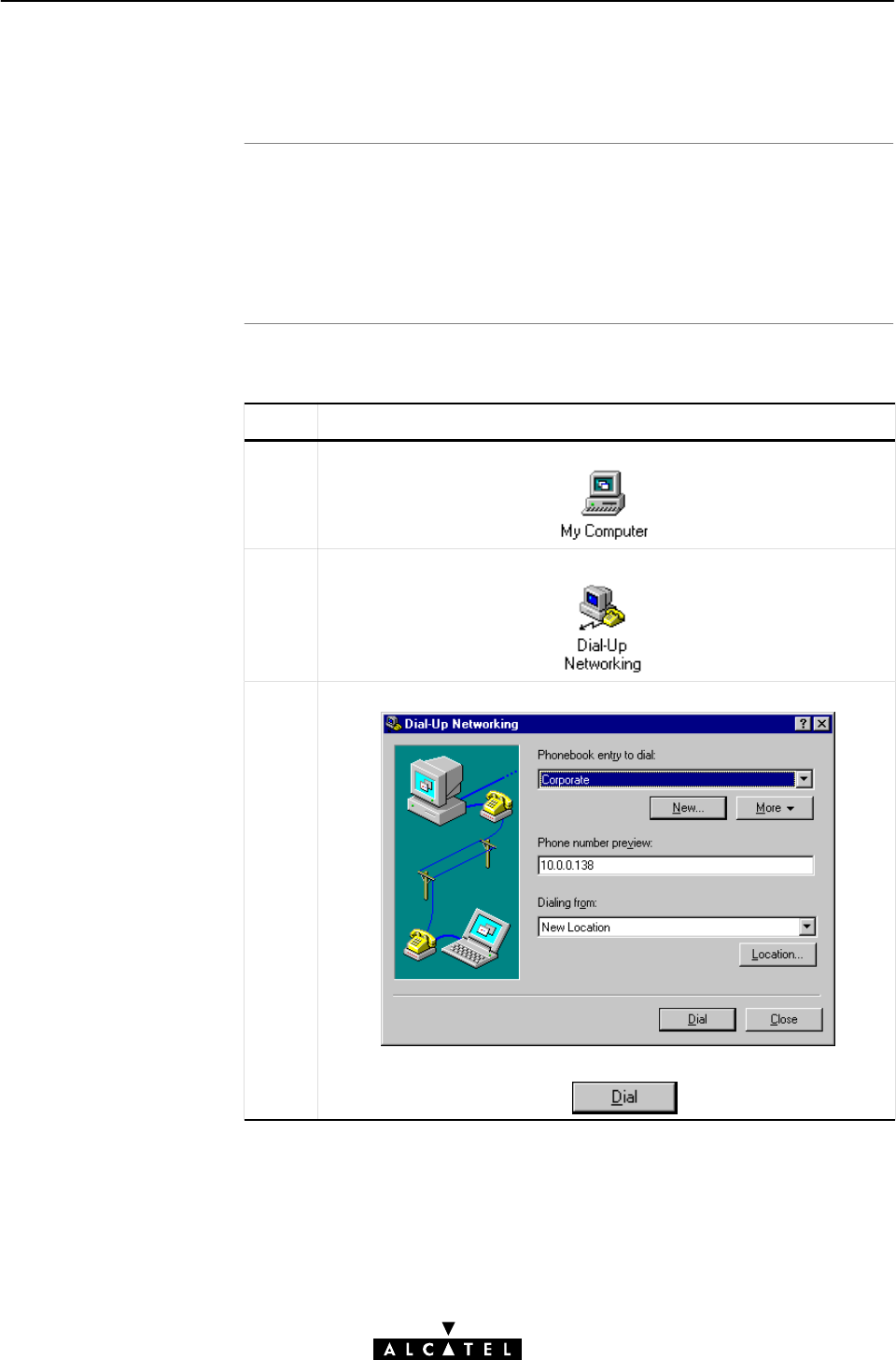
In this section
Opening a PPTP Tunnel
session
AppendixC Microsoft DialĆUp Networking
326 / 362 3EC 17766 AAAA TCZZA Ed. 01
C.7 Using PPTP Tunneling for Windows NT
"Opening a PPTP Tunnel Session
"NT DialĆUp Networking in Detail
"Closing a PPTP Tunnel Session.
Proceed as follows:
Step Action and Description
1DoubleĆclick the 'My Computer' icon on your desktop.
2DoubleĆclick the 'DialĆUp Networking' icon.
3The 'DialĆUp Networking' window pops up.
Select the appropriate entry (e.g. 'Corporate')inthe'Phonebook
entry to dial' listbox, and click
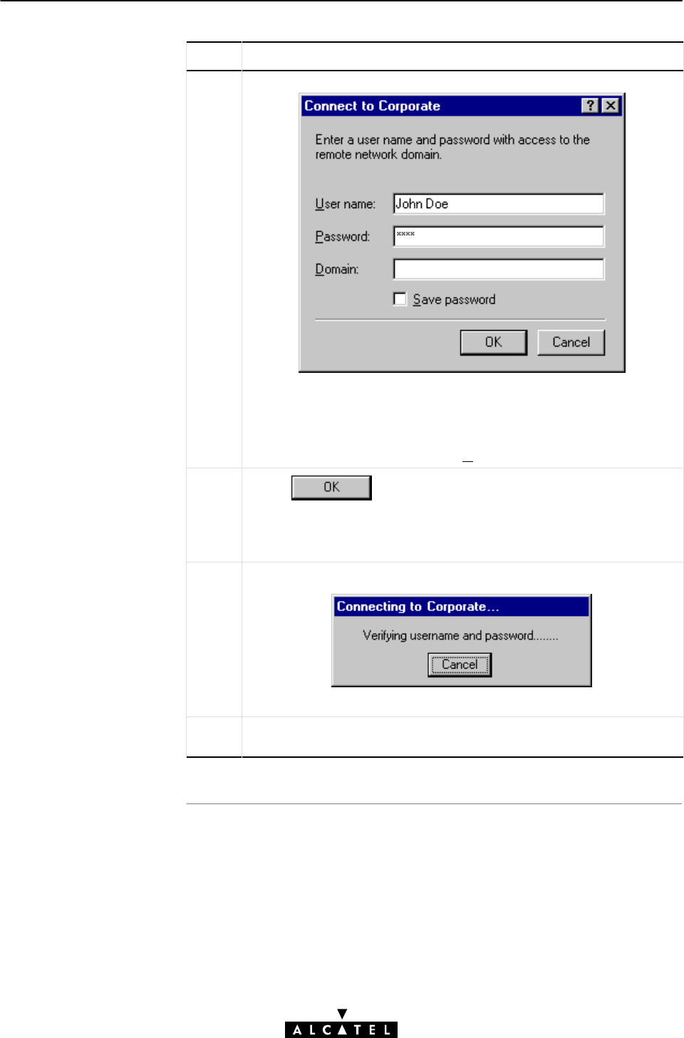
AppendixC Microsoft DialĆUp Networking
327 / 362
3EC 17766 AAAA TCZZA Ed. 01
Step Action and Description
4The 'Connect To' window pops up.
Enter your user name and password for the VPN server.
Enter the optional information in the 'Domain' box. This is only
required by some Microsoft NT VPN servers.
Note: To save your password, tick 'Save password'(n).
5Click
Note: Steps 4 and 5 need only be executed the first time the tunnel
is set up. After the tunnel is set up, the 'Connecting to' window will
directly appear on your desktop.
6The 'Connecting To' window pops up.
This window informs you of the status of the connection process.
Result Once the connection is established, an MSDUN icon representing
the DialĆUp connection appears on your system tray.
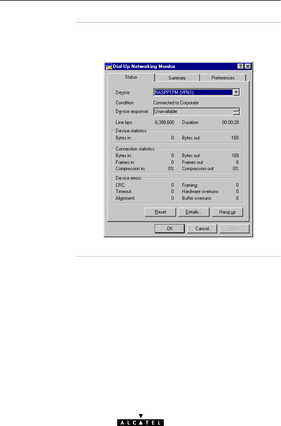
NT DialĆUp Networking
in detail
AppendixC Microsoft DialĆUp Networking
328 / 362 3EC 17766 AAAA TCZZA Ed. 01
During your session, you can view the connection status by clicking
the DialĆUp icon in the system tray. The following window will pop
up:
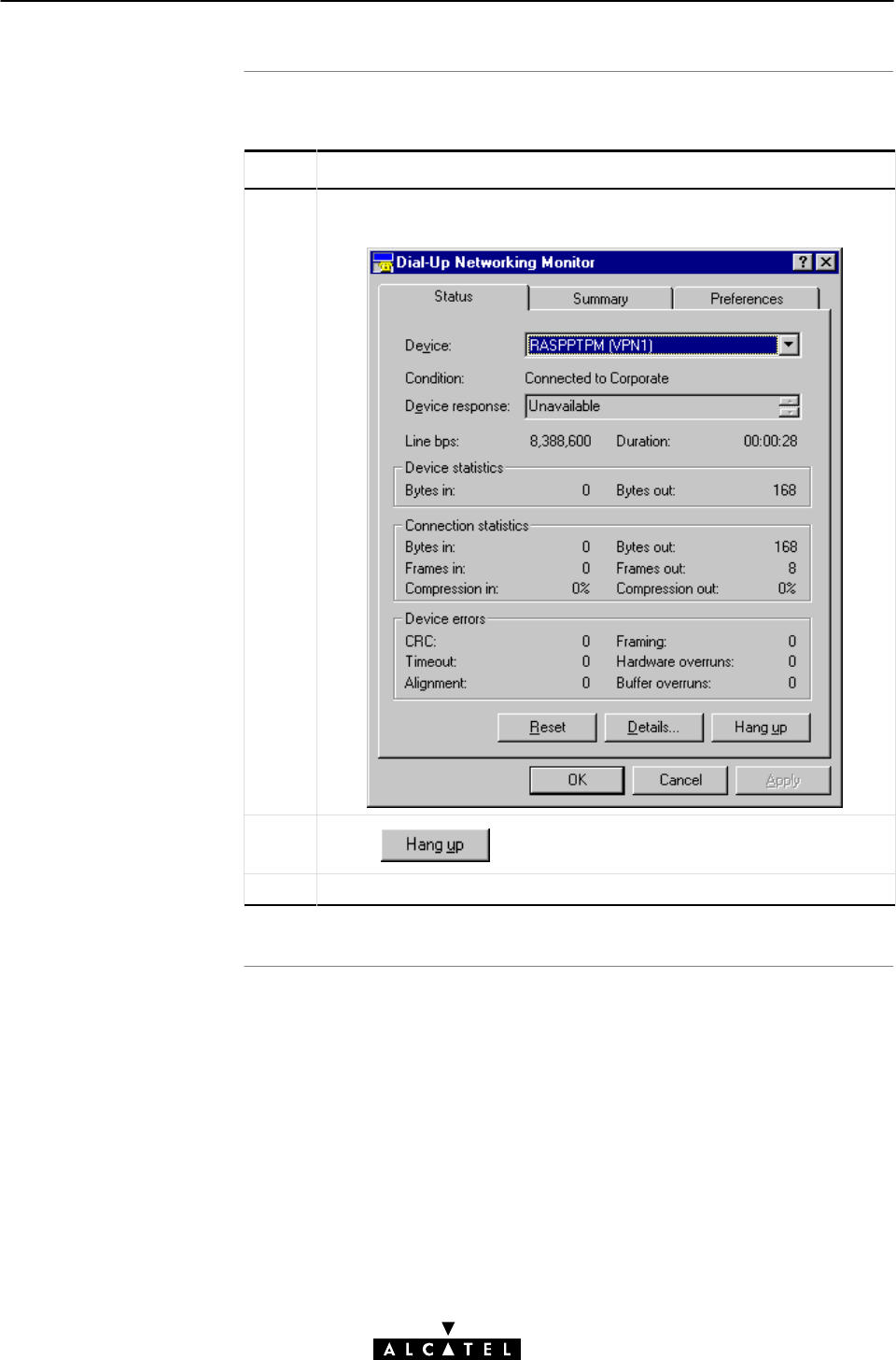
Closing a PPTP Tunnel
session
AppendixC Microsoft DialĆUp Networking
329 / 362
3EC 17766 AAAA TCZZA Ed. 01
Proceed as follows:
Step Action and Description
1Click the appropriate connection icon on your system tray to pop up
the 'DialĆUp Networking Monitor' window:
2Click
Result The connection to your SP no longer exists.

Windows 95/98
Windows N
T
AppendixC Microsoft DialĆUp Networking
330 / 362 3EC 17766 AAAA TCZZA Ed. 01
C.8 Platform Limitations of Windows DialĆUp Networking
Three limitations exist when using the Windows 9x OS:
"One Tunnel
Windows 9x only allows you to set up one tunnel at a time.
This implies that you cannot connect to both your ISP and your
corporate simultaneously from one PC.
"Tunneling within a Tunnel
Tunneling within a tunnel is not possible with Windows 9x,
due to its single tunnel limitation.
"Local Connectivity is Lost
After you set up a tunnel, communication with local LAN
devices may be lost. This is because Windows 9x adds a new
default gateway to its routing table. This new default gateway
points to the tunnel. As TCP/IP is designed to use only one
default gateway, connectivity through the original gateway will
be lost.
As soon as the tunnel is terminated, connectivity through the
original default gateway is again possible.
You can circumvent this problem by manually adding routes to
local destinations in the routing table (See section 11.4).
Windows NT does not share the first two limitations with Windows
9x:
"Multiple Tunnels
You can set up multiple tunnels; consequently you can connect
to multiple remote destinations simultaneously.
"Tunneling within a Tunnel
A tunnel within another tunnel is also possible, assuring better
endĆtoĆend security.

Introduction
In this appendi
x
AppendixD STWireless Layout and Behaviour
331 / 362
3EC 17766 AAAA TCZZA Ed. 01
AppendixD STWireless Layout and Behaviour
This appendix describes how your STWireless looks like,
describes its LEDs description, and describes its startĆup behaviour.
Topic See
Front Panel Layout and LED Description D.1
Rear Panel Layout D.2
Power On/Off Behaviour D.3

Front panel layou
t
Five front panel LEDs
AppendixD STWireless Layout and Behaviour
332 / 362 3EC 17766 AAAA TCZZA Ed. 01
D.1 Front Panel Layout and LED Description
The STWireless features the following front panel:
The STWireless is equipped with 5 LEDs on its front panel,
indicating the state of the device:
Indicator Description
Name Color State
LAN Green Flashing Data is flowing from/to the
Ethernet port, and/or WLAN hub.
Off No activity on both Ethernet
interface and WLAN hub.
Line TX Green Flashing ATM cells are being sent over the
ADSL line.
Off No transmission activity.
Line RX Green Flashing ATM cells are being received via
the ADSL line.
Off No reception activity.
Line Sync Green Flashing During initialization of the ADSL
line.
On ADSL line synchronization
achieved.
PWR/Alarm Green On Power on, normal operation.
Red Flashing Power on, POST(*) pending.
On Power on, POST(*) failed.
(*) Power On Self Test (POST)

Dual port model
Ethernet port LED
Indication of lin
k
integrit
y
Indication of lin
k
activit
y
AppendixD STWireless Layout and Behaviour
333 / 362
3EC 17766 AAAA TCZZA Ed. 01
D.2 Rear Panel Layout
The STWireless features the following rear panel:
Power
Switch
Power
Socket Ethernet Port
Serial
Port
Line
Port
WLAN
Authentication
Button
Dip
Switches
The Ethernet port on the rear panel has a LED:
Link Integrity(Activity) Led
10Base T/MDI-X
If the STWireless and other LAN device(s) are properly connected
and powered on, the particular green LED lights up.
A flashing green LAN LED on the fron panel, indicates reception
of data (RX) via the Ethernet port, and/or WLAN hub.

Turning on/off the
STWireles
s
POST phases
Checking link integrit
y
AppendixD STWireless Layout and Behaviour
334 / 362 3EC 17766 AAAA TCZZA Ed. 01
D.3 Power On/Off Behaviour
You can turn the STWireless on (I), or off (O) with the power
switch.
As soon your STWireless is turned on, you can check the
PWR/Alarm" LED (See section D.1) to see how the POST
progresses.
Phase PWR/Alarm" LED Indication Description
1 Flashing red POST pending
2 Solid red POST failed
Solid green Normal operation
Your STWireless is ready for service.
If the LAN device, directly connected to the STWireless Ethernet
port is powered on, the link integrity/activity LED lights up green.

Introduction
In this chapte
r
AppendixE STWireless Original Settings
335 / 362
3EC 17766 AAAA TCZZA Ed. 01
AppendixE STWireless Original Settings
This chapter lists all of the STWireless original settings.
These settings apply at the time the STWireless leaves the factory
and after a reset to original defaults.
Topic See
General Settings E.1
Wireless LAN Settings E.2
IEEE802.1D Transparent Bridging Defaults E.3
MAC Encapsulated Routing Defaults E.4
PPPoAĆtoĆPPTP Relaying Defaults E.5
PPP Defaults E.6
CIP Defaults E.7
Global VPI/VCI Defaults E.8

STWireless IP address
STWireless DNS name
STWireless domain
nam
e
STWireless DNS serve
r
STWireless DHCP
serve
r
STWireless Firewall
AppendixE STWireless Original Settings
336 / 362 3EC 17766 AAAA TCZZA Ed. 01
E.1 General settings
10.0.0.138
SpeedTouch
lan
Active
AutoDHCP
On (default settings)

STWireless WLAN SSID
STWireless WLAN
channel numbe
r
AppendixE STWireless Original Settings
337 / 362
3EC 17766 AAAA TCZZA Ed. 01
E.2 Wireless LAN Settings
STW_Alcatel
6

Phonebook entries
ATM encapsulation
Aging Time
AppendixE STWireless Original Settings
338 / 362 3EC 17766 AAAA TCZZA Ed. 01
E.3 IEEE802.1D Transparent Bridging Defaults
Name VPI VCI State
Br1 8 35 Free
Br2 8 36 Free
Br3 8 37 Free
Br4 8 38 Free
RFC1483 LLC/SNAP for Bridged PDUs (FCS not preserved)
5 minutes (300 seconds)

Phonebook entries
ATM encapsulation
AppendixE STWireless Original Settings
339 / 362
3EC 17766 AAAA TCZZA Ed. 01
E.4 MAC Encapsulated Routing Defaults
Name VPI VCI State
Br1 8 35 Free
Br2 8 36 Free
Br3 8 37 Free
Br4 8 38 Free
RFC1483 LLC/SNAP for Bridged PDUs

Phonebook entries
ATM encapsulation
AppendixE STWireless Original Settings
340 / 362 3EC 17766 AAAA TCZZA Ed. 01
E.5 PPPoAĆToĆPPTP Relaying Defaults
Name VPI VCI State
RELAY_PPP1 8 48 Free
RELAY_PPP2 8 49 Free
RELAY_PPP3 8 50 Free
RELAY_PPP4 8 51 Free
PPP1 8 64 Configured
(PPP & IP routing)
PPP2 8 65 Configured
(PPP & IP routing)
PPP3 8 66 Free
RFC2364 VCĆMUX for PPP PDUs

Phonebook entries
ATM encapsulation
PPP configuration
,
authentication
AppendixE STWireless Original Settings
341 / 362
3EC 17766 AAAA TCZZA Ed. 01
E.6 PPP Defaults
Name VPI VCI State
RELAY_PPP1 8 48 Free
RELAY_PPP2 8 49 Free
RELAY_PPP3 8 50 Free
RELAY_PPP4 8 51 Free
PPP1 8 64 Configured
(PPP & IP routing)
PPP2 8 65 Configured
(PPP & IP routing)
PPP3 8 66 Free
DHCP_SPOOF 8 67 Configured
(PPP to DHCP Spoofing)
RFC2364 VCĆMUX of PPP PDUs
Name User Password
PPP1 guest guest
PPP2 guest guest
DHCP_SPOOF guest guest

PPP configuration
,
routing
PPP configuration
,
option
s
AppendixE STWireless Original Settings
342 / 362 3EC 17766 AAAA TCZZA Ed. 01
Name Connection Sharing NAPT
PPP1 Everybody n
PPP2 Everybody n
DHCP_SPOOF Only me
Name Mode LCP echo ACCOMP
PPP1 DialĆin n n
PPP2 AlwaysĆon n n
DHCP_SPOOF DialĆin n n

Phonebook entries
ATM encapsulation
CIP configuration
AppendixE STWireless Original Settings
343 / 362
3EC 17766 AAAA TCZZA Ed. 01
E.7 CIP Defaults
Name VPI VCI State
CIPPVC1 8 80 Configured
CIPPVC2 8 81 Free
CIPPVC3 8 82 Free
CIPPVC4 8 83 Free
RFC1577-RFC1483 LLC/SNAP for Routed nonĆISO PDUs
Enabled CIP member cip0
CIP member IP address 172.16.1.1 (255.255.255.0)
VC explicitly assigned CIPPVC1
VC's IP address 172.16.1.2
NAPT disabled

Ethernet/WLAN
AppendixE STWireless Original Settings
344 / 362 3EC 17766 AAAA TCZZA Ed. 01
E.8 Global Default VPI/VCI Values
VPI VCI Service channel
8 35 IEEE802.1D Transparent Bridging
8 36
pgg
MAC Encapsulated Routing
8 37
pg
8 38
8 48 PPPoAĆtoĆPPTP Relaying
8 49
yg
PPP
8 50
8 51
8 64
8 65
8 66
8 67
8 80 CIP
8 81
8 82
8 83
15 16 SNMP/ASAM agent communication channel for the
Alcatel ASAM
15 64 Software download channel

Introduction
In this appendi
x
AppendixF Hardware Reference
345 / 362
3EC 17766 AAAA TCZZA Ed. 01
AppendixF Hardware Reference
This appendix provides physical specifications and connector pin
assignments for the STWireless.
Topic See
Specifications F. 1
Connector Pin Assignments F. 2
Power Supply Adapter F. 3
LAN Cables Layout F. 4

Physical specifications
Operating environmen
t
Power requirements
Hardware platform
ADSL route
r
specification
s
AppendixF Hardware Reference
346 / 362 3EC 17766 AAAA TCZZA Ed. 01
F.1 Specifications
210mm W x 185mm D x 35mm H
Temperature: 5ºC to 40ºC (40F to 105F)
Humidity: 20% to 80%
AC voltage: 100 to 120 VAC, 220 to 240 VAC
Frequency: 50/60 Hz
Power consumption: 8Wmax
LAN interfaces: 1 10BaseĆT MDIĆX Ethernet port
Wireless LAN hub
WAN interface: ADSL line (RJ11) port
Serial interface: RS232
Up to 8Mbps downstream
Up to 1Mbps upstream
ADSL standard compliancy:
"ITU G.DMT (Full rate G.992.1 Annex A)
"ITU G.LITE (Lite rate G.992.2)
"Full rate ANSI T1.413 Issue2
"ITU Automode

Wireless LAN
specification
s
AppendixF Hardware Reference
347 / 362
3EC 17766 AAAA TCZZA Ed. 01
"11Mbps IEEE802.11b High Rate specification compliant
WLAN
"Wireless Ethernet Compatibility Alliance (WECA): WiĆFi
Interoperability compliancy certificated
"Dynamic rate switching: 11, 5.5, 2, 1 Mbit/s
"Coverage: 60m (200ft.) typically indoors
"Antenna diversity support for maximum operating range and
throughput
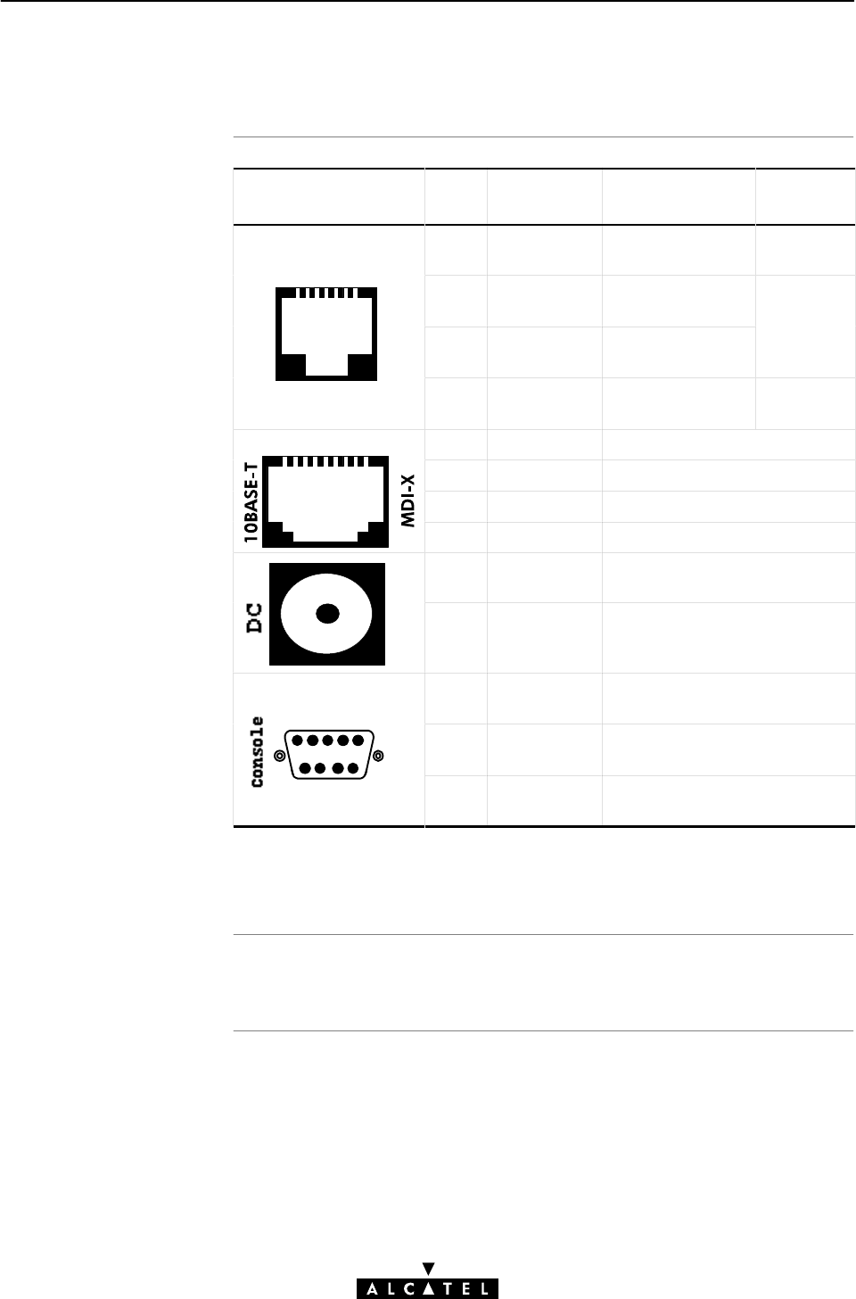
STWireless por
t
description
Free connector pins
AppendixF Hardware Reference
348 / 362 3EC 17766 AAAA TCZZA Ed. 01
F.2 Connector Pin Assignments
Port Pin
No.
Signal
Name
Function Model
Reference
123456
2 Wire A Subscriber line
wire A
2/5 model
123456
RJ 11/RJ 14
E
3 Wire A Subscriber line
wire A
3/4 model
Front view
LINE
4 Wire B Subscriber line
wire B
5 Wire B Subscriber line
wire B
2/5 model
12345678 1 RX+ Receive data from DTE* (+)
RJ 45 2 RX- Receive data from DTE* (-)
RJ
45
Front view 3 TX+ Transmit data to DTE* (+)
Front
view
6 TX- Transmit data to DTE* (-)
Inner +9VDC Power supply connection (+)
Outer GND Power supply connection
(ground)
12345
2 RD
[RS232Ć9]
Received data
12345
3 SD
[RS232Ć9]
Transmitted data
6789 5 DCD
[RS232Ć9]
Signal common
Note: (*) Data Terminal Equipment (DTE)
Connector pins not mentioned are not connected.

Power adapter use
Power adapter models
Output specifications
AppendixF Hardware Reference
349 / 362
3EC 17766 AAAA TCZZA Ed. 01
F.3 Power Supply Adapter
The STWireless is equipped with one of the following pluggable
power supply adapters listed in the table.
Due to the special characteristics of the output class II AC adaptor,
use only the AULT Incorporated types, or equivalents, listed in
the table.
Model
Reference
AC/DC Plugtype AULTInc. Model
(or equivalent)
US model 120V/9V North America wall
plug
P48-091000-Axxxx
UK/Sing model 230V/9V UK wall plug F48-091000-Axxxx
ROW* model 230V/9V Euro wall plug D48-091000-Axxxx
Australia model 240V/9V Australia wall plug E48-091000-Axxxx
Korea Model 220V/9V Korea wall plug Q48-091000-Axxxx
Note: (*) Rest Of the World (ROW)
The supplied adapter has the following output specifications:
"9VDC/1A unregulated output voltage
"Maximum 860 mVeff ripple voltage
"Maximum 1A output current
"Limited power source (according to IEC/EN 60950,
subĆclause 2.11 and UL1950).
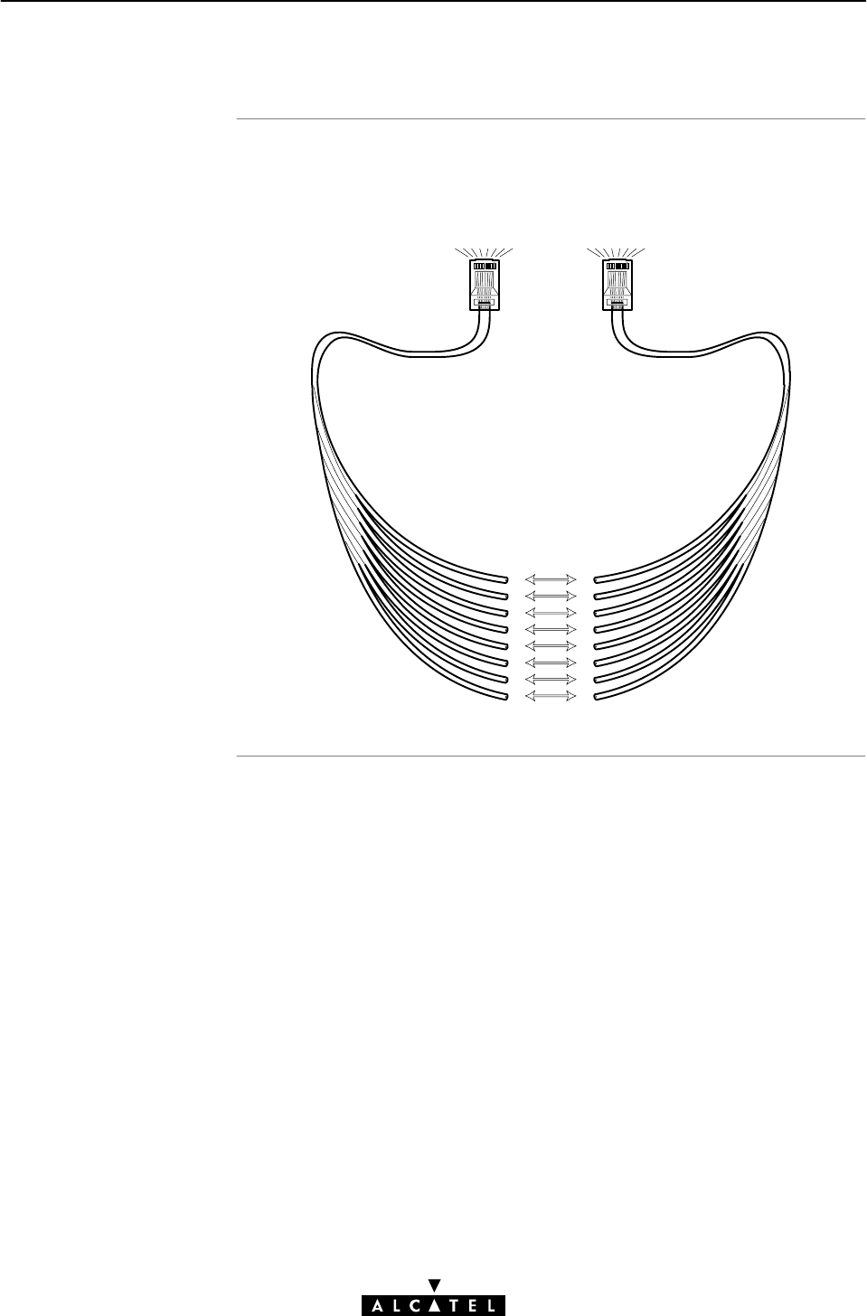
StraightĆthrough LAN
cabl
e
AppendixF Hardware Reference
350 / 362 3EC 17766 AAAA TCZZA Ed. 01
F.4 LAN Cables Layout
StraightĆthrough LAN cables with the following layout are
applicable for interconnecting Ethernet ports:
12345678
1
2
3
4
5
6
7
8
1
2
3
4
5
6
7
8
12345678

Crossover LAN cable
AppendixF Hardware Reference
351 / 362
3EC 17766 AAAA TCZZA Ed. 01
Crossover LAN cables with the following layout are applicable for
interconnecting Ethernet ports:
12345678 12345678
1
2
3
4
5
6
7
8
1
2
3
4
5
6
7
8

AppendixF Hardware Reference
352 / 362 3EC 17766 AAAA TCZZA Ed. 01
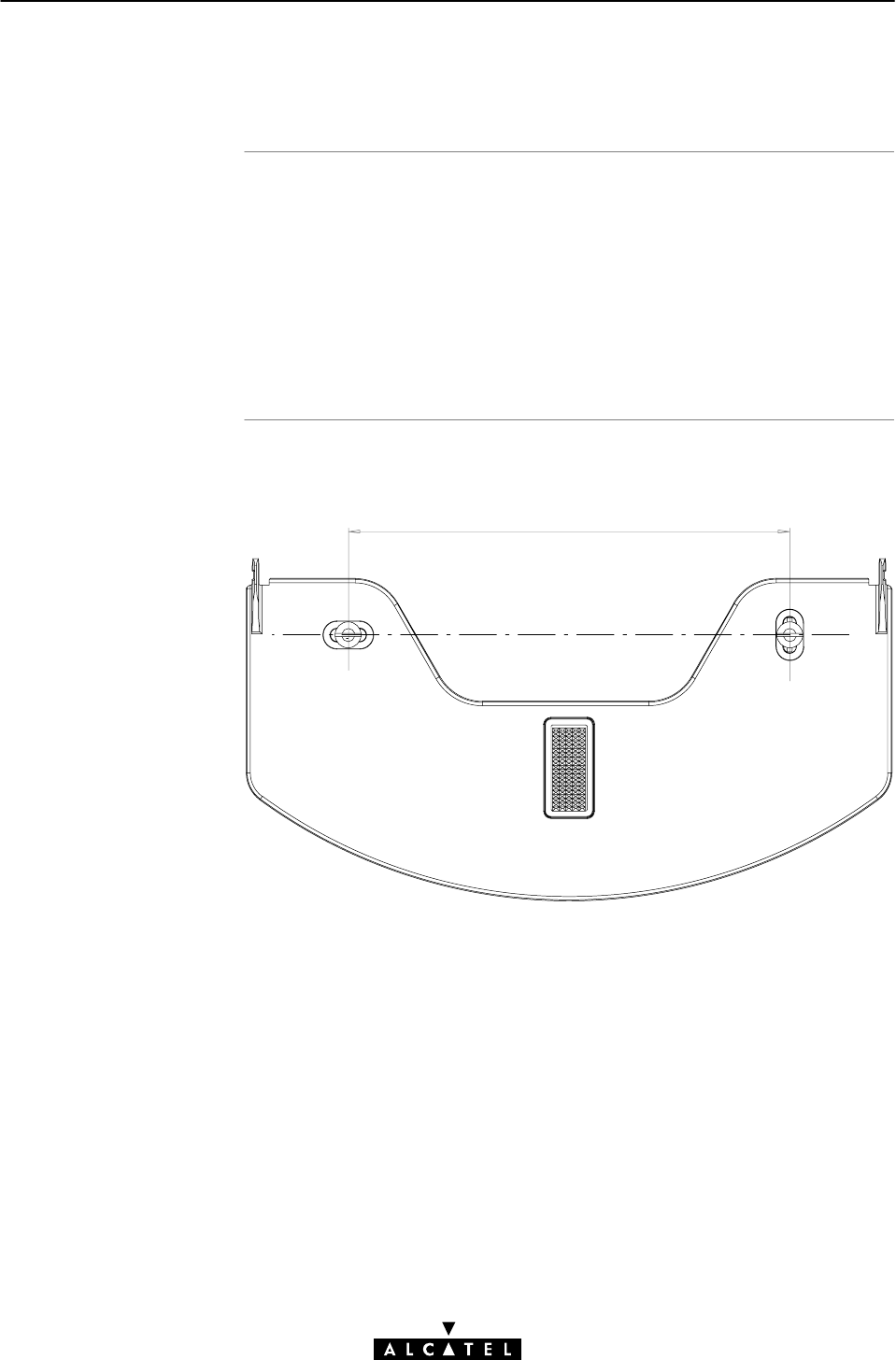
Introduction
Preparing your wall
fixing assembl
y
AppendixG Wall Fixing Assembly
353 / 362
3EC 17766 AAAA TCZZA Ed. 01
AppendixG Wall Fixing Assembly
This appendix describes how to wall mount your STWireless, with
the wall fixing assembly delivered in the package.
Before you start, check for the following items:
"The wall fixing assembly
"2 screws and 2 wall plugs
"1 Velcro sticker
1. Mark two hole positions horizontal at 134 mm (5.36 inches)
distance:
134
2. Drill the marked holes with a 6mm (0.24 inches) diameter
drill bit to a minimum depth of 35mm (1.38 inches).
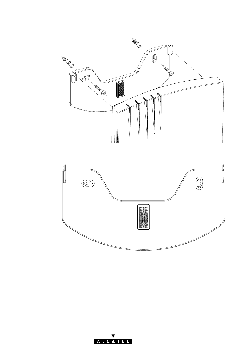
AppendixG Wall Fixing Assembly
354 / 362 3EC 17766 AAAA TCZZA Ed. 01
3. Insert the wall plugs in the drilled holes, position the wall
fixing assembly over the holes, insert the screws in the wall
plugs and tighten them firmly:
4. Place the Velcro sticker on the wall fixing assembly in the
outlined area:
5. Position the STWireless over the two hooks and pull the box
down until its firmly positioned, and sticking to the Velcro.

Aim of this appendi
x
Reading all instructions
In this appendi
x
AppendixH Safety and Agency Regulatory Notices
355 / 362
3EC 17766 AAAA TCZZA Ed. 01
AppendixH Safety and Agency Regulatory Notices
This appendix provides basic Safety Information on Alcatel's
Speed Touchproduct.
Prior to using the Speed Touchproduct, read this appendix
carefully.
Follow all warnings and instructions marked on the product.
This chapter covers the following topics:
Topic See
Safety Instructions H.1
European Declaration of Conformity H.2
Radio Frequency Interference Statement H.3
Canadian Class B Notice H.4
STORE THESE INSTRUCTIONS CAREFULLY

Climatic conditions
Cleaning
Water and moisture
Power supply adapte
r
Power sources
AppendixH Safety and Agency Regulatory Notices
356 / 362 3EC 17766 AAAA TCZZA Ed. 01
H.1 Safety Instructions
The Speed Touchproduct equipment is intended for:
"InĆhouse stationary desktop use; the maximum ambient
temperature may not exceed 40ºC (104ºF).
"It must not be mounted in a location exposed to direct or
excessive solar and/or heat radiation.
"It must not be exposed to heat trap conditions and must not
be subjected to water or condensation.
"It must be installed in a Pollution Degree 2 environment.
Unplug this product from the wall outlet before cleaning. Do not
use liquid cleaners or aerosol cleaners. Use a damp cloth for
cleaning.
Do not use this product near water, for example, near a bathtub,
wash bowl, kitchen sink, laundry tub, in a wet basement or near a
swimming pool.
The Speed Touchproduct comes with a portable power supply
adapter.
Due to the special characteristics of the output of the
class II AC adaptor, only use the models or equivalent listed in
the power adapter table in Appendix F.
The powering of this product must adhere to the power
specifications indicated on the marking labels. If you are insure of
the type of power supply to your home, consult your product
dealer or local power company.
The mains socket outlet must be close to the equipment and easily
accessible.
The Speed Touchproduct equipment is not intended to be
connected to an ITĆtype power system.

Power cord protection
Overloading
Servicing
Damage requiring
servic
e
AppendixH Safety and Agency Regulatory Notices
357 / 362
3EC 17766 AAAA TCZZA Ed. 01
Do not allow anything to rest on the power cord. Do not locate
this product where the cord will be subject to persons walking on
it.
Do not overload wall (mains) outlets and extension cords as this
increases the risk of fire or electric shock.
To reduce the risk of electric shock, do not disassemble this
product. None of its internal parts are userĆreplaceable; therefore,
there is no reason to access the interior. Opening or removing
covers may expose you to dangerous voltages. Incorrect
reassembly could cause electric shock if the appliance is
subsequently used.
If service or repair work is required, take it to a qualified service
dealer.
Unplug this product from the wall outlet and refer servicing to
qualified service personnel under the following conditions:
"When the power supply cord or plug is damaged or frayed.
"If liquid has been spilled into the product.
"If the product has been exposed to rain or water.
"If the product does not operate normally.
"If the product has been dropped or damaged in any way.
"If the product exhibits a distinct change in performance.
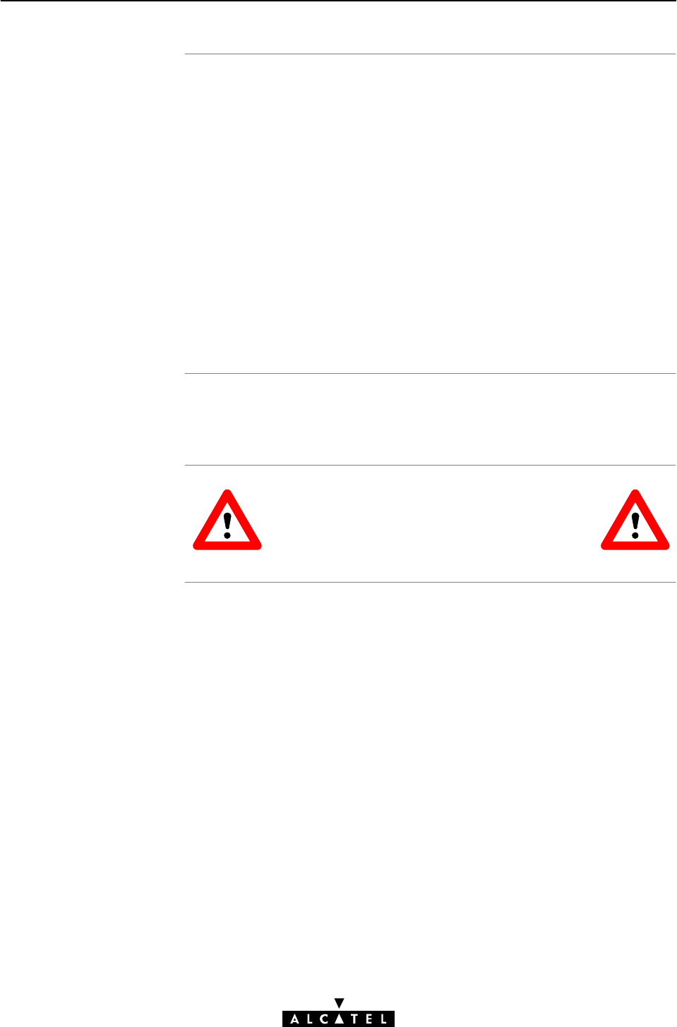
Modem/Telephone use
Modification
s
AppendixH Safety and Agency Regulatory Notices
358 / 362 3EC 17766 AAAA TCZZA Ed. 01
Avoid using a modem/telephone (other than a cordless type)
during an electric storm. There is a slight risk of electric shock
caused by lightning.
Do not use the telephone to report a gas leak in the vicinity of the
leak.
If telephone service is required on the same line, a central splitter,
or distributed filter(s) must be installed for optimal ADSL
performance.
Depending on your ADSL configuration and type of splitter/filters,
installation must be carried out by qualified service personnel.
Consult your telephone service company or ADSL service provider
for instructions.
Changes or modifications not expressly approved by Alcatel could
invalidate the users authority to operate this equipment.
STORE THESE INSTRUCTIONS CAREFULLY

EC Declaration o
f
Conformit
y
AppendixH Safety and Agency Regulatory Notices
359 / 362
3EC 17766 AAAA TCZZA Ed. 01
H.2 European Community Declaration of Conformity
Products with the marking comply with both EMC and Low
Voltage Directives issued by the Commission of the European
Community.
A copy of the European Community Declaration of Conformity is
provided in your Speed Touchproduct shipping box.

AppendixH Safety and Agency Regulatory Notices
360 / 362 3EC 17766 AAAA TCZZA Ed. 01
H.3 Radio Frequency Interference Statement
This device has been tested and found to comply with the limits for a Class B digital device,
pursuant to Part 15 of the FCC Rules. These limits are designed to provide reasonable protection
against such interferenve in a residential installation. This equipment generates, uses and can
radiate radio frequency energy. If not installed and used in accordance with the instructions, it may
cause harmful interference to radio communications. However, there is no guarantee that
interference will not occur in a particular installation. If this equipment does cause harmful
interference to radio or television reception, which can be determined by turning the equipment ON
and OFF, the user is encouraged to try correct the interference by one or more of the following
measures:
"Reorient or relocate the receiving antenna
"Increase the separation between the equipment and receiver
"Connect the equipment into an outlet on a circuit different from that to which the receiver is
connected
"Consult the dealer or an experienced radio/television technician for help.
This equipment complies with Part 68 of the FCC Rules. On the back of this equipment is a label
that contains, among other information, the FCC certification number (FCC ID) and Ringer
Equivalence Number (REN) for this equipment. If requested, this information must be provided to
the telephone company.
An FCC compliant telephone cord and modular plug is provided with this equipment. This
equipment is designed to be connected to the telephone network or premises wiring using a
compatible modular jack that is Part 68 compliant (See Appendix F: Hardware Reference) for
details.
The Ringer Equivalence Number (REN) is used to determine the quantity of devices that may be
connected to the telephone line. Excessive RENs on the telephone line may result in the devices not
ringing in response to an incoming call. Typically, the sum of RENs should not exceed five (5.0). To
be certain of the number of devices that may be connected to a line (as determined by the total
RENs) contact the local telephone company.
If this equipment causes harm to the telephone network, the telephone company will notify you in
advance that temporary discontinuance of service may be required. But if advance notice is not
practical, the telephone company will notify the customer as soon as possible. Also you will be
advised of your right to file a compliant with the FCC if you believe it is necessary.
The telephone company may make changes to its facilities, equipment, operations or procedures
that could affect the operation of the equipment. If this happens the telephone company will provide
advance notice so you can make the necessary modifications to maintain uninterrupted service.
If the equipment is causing harm to the telephone network, the telephone company may request
that you disconnect the equipment until the problem is resolved. Connection to party lines is subject
to state tariffs (contact the state public utility commission, public service commission or corporation
commission for information).
No repairs can be performed by the customer, if you experience trouble with this equipment
for repair or warranty information, please contact: (919) 850-1231 for locations in North
America.

AppendixH Safety and Agency Regulatory Notices
361 / 362
3EC 17766 AAAA TCZZA Ed. 01
H.4 Canadian DOC Class B Notice
Notification of Canadian RF Interference Statements
This digital apparatus does not exceed the Class B limits for radio noise emissions from digital
apparatus as set out in the radio interference regulations of the Canadian Department of
Communication.
Le présent appareil numérique n'émet pas de bruits radioélectriques dépassant les limites applicable
aux appareils numérique de classe B prescrites dans le règlement sur le brouillage radioélectrique
édicté par le Ministère des Communications du Canada.

AppendixH Safety and Agency Regulatory Notices
362 / 362 3EC 17766 AAAA TCZZA Ed. 01