Alcatel USA 8000-2U Digital Transmission System Transmitter User Manual 701210
Alcatel USA Marketing, Inc. Digital Transmission System Transmitter 701210
Contents
- 1. User Guide Warnings
- 2. User Guide Part 1
- 3. User Guide Part 2
- 4. USer guide warnings
User Guide Warnings

2-5
Issue 1 3EM20188AAAA
June 2006 Applications Section
2 APPLICATIONS
2.1 INTRODUCTION
The MDR-8000 family of microwave radios is specifically designed to satisfy the evolving
needs of public, private, government, and international networks. Each DS1/E1 radio offers the
flexibility of 2, 4, 8, 12, 16 DS1s or E1s to meet the need for low capacity domestic or inter-
national systems. Each DS3 radio offers up to three DS3s with equal number of wayside DS1s to
meet domestic high capacity system requirements. Each OC3/STM-1 radio offers one or three
STS1s with equal number of wayside DS1s or E1s to meet domestic or international
Synchronous Optical Network (SONET) system requirements. The MDR-8000E Ethernet radio
p
rovides transport for IP/packet data in licensed and unlicensed frequency bands. The radio
supports 10baseT, 100baseT, and 1000baseT interface rates with auto-negotiation and can be
configured to transport low and high capacity data at RF frequencies in the 2, 4, 5, 6, 7/ 8, and
10/11 GHz bands.
The number of channels transmitted and the RF channel bandwidth depend on the capacity keys
installed in the transmitter and receiver modules. The modulation formats are 32 or 128 TCM
(DS1/E1), 64 QAM (DS3), and 128 TCM (OC3/STM-1). Growth in DS1/E1 system capacity can
be performed in service and requires only exchanging capacity keys. Growth from DS1/ E1 to
DS3 system capacity is an out-of-service procedure and requires exchanging modules and
capacity keys. Changing to OC3/STM-1 system capacity is performed out-of-service and
requires exchanging modules, and capacity keys.
All radios are available in 1:0 non-standby (NS) and 1:1 hot-standby (HS) and frequency diver-
sity (FD). The HS version allows for troubleshooting and module replacement, on an in-service
basis. Space diversity can be added to any of the three basic configurations. In addition to the
three basic configurations, the OC3/STM-1 radio is available with a 0:2 dual channel (no pro-
tection) equipment configuration and the protected OC3/STM-1 radio is also available in a 2 X
4-fiber or 4-fiber cable configuration.
2.2 TYPICAL USERS
Because of unique flexibility in both frequency and capacity, the MDR-8000/i/s can be used for a
variety of voice, data, and video applications, for many types of users, some of which are listed
as follows:
• Personal Communication Systems (PCS)
• Cellular Operators
• Common Carriers
• Alternate Access and Competitive Access Providers (CAP)
• Private Networks
• Educational Institutions
• State, Local, and Federal Government Systems
• International Users.
2.3 UNLICENSED RADIO
The MDR-8X05U/8X02U (unlicensed) radio provides fast deployment of service with
microwave radio No license and small antennas (no FCC requirements) allow immediate turnup.
After the license is received, the unlicensed radio can be easily converted to the lower 6 GHz
licensed band.
2-6
Issue 1 Applications Section
June 2006 3EM20188AAAA
Refer to drawing 3DH031770001BJZZA in Volume 2 for configurations and equipping options.
The MDR-8X05U radio operates in the 5725-5850 and 2400-2483.5 Information, Scientific, and
Medical (ISM) band in accordance with FCC Part 15.247 of the FCC rules. Any changes or
modifications not expressly approved by the manufacturer could void the user’s authority to
operate the equipment. This unlicensed radio, although operating in the same band as a spread
spectrum radio, operates using narrower bandwidths than spread spectrum. Advantages,
disadvantages, and antenna recommendations for the unlicensed radio follow:
2.3.1 Advantages
• Fast installation and turnup
• 2, 4, 8, 16 DS1, DS3, and OC3/STM-1 capacities
• Field convertible to lower 6 GHz licensed band
• Field expandable to higher capacities.
• Common network management with licensed radios.
• Common spares and training with licensed radios
2.3.2 Disadvantages
• No interference protection
• Operating restrictions
• 5.725 to 5.850 GHz band/2.4 to 2.4835 GHz
• Performance could deteriorate due to interference as the frequency band becomes
congested.
2.3.3 Antenna Recommendations
• Frequency – 5.8 GHz/2.4 GHz
• Size and Type – 2, 4, 6, 8, or 10 foot parabolic; 1 or 2 foot flat panel.
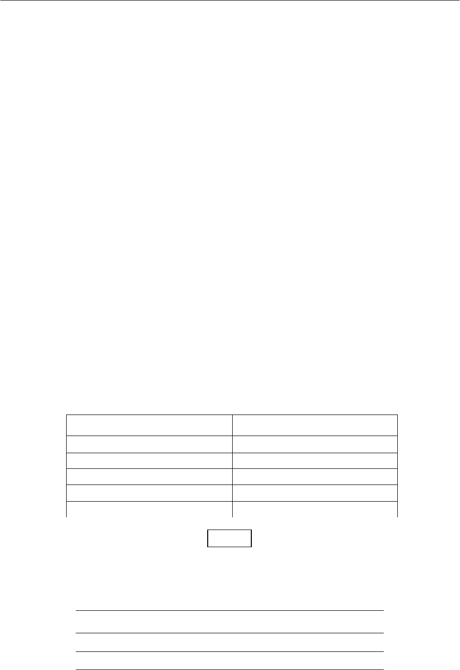
• Gain and Beamwidth
(
3 dB
)
5.8 GHz 2.4 GHz
2 ft parabolic – 29 dB/6
û
2 ft parabolic – 20 dB/13.8
û
4 ft parabolic – 35 dB/3
û
4 ft parabolic – 27 dB/6.9
û
6 ft parabolic – 38 dB/2
û
6 ft parabolic – 30.5 dB/4.6
û
8 ft parabolic – 41 dB/1.5
û
8 ft parabolic – 33.3 dB/3.5
û
10 ft parabolic – 42.5 dB/1.2
û
10 ft parabolic – 35.2 dB/2.8
û
Note
When using a 1 ft flat panel antenna with a 1 watt (+30 dBm) output power,
the antenna must be located in an area that does not allow the general pop-
ulation access to within 5 feet of the antenna.
5.8 GHz 2.4 GHz
1 ft flat panel – 23 dB/9
û
1 ft flat panel – 18 dB/30
û
2 ft flat panel – 28 dB/3.5
û