Alcatel USA 8502-4 Digital Modulated Radio User Manual 00 Book I 6 fullTOC
Alcatel USA Marketing, Inc. Digital Modulated Radio 00 Book I 6 fullTOC
Contents
- 1. MDR8000 Users Manual
- 2. Complete Users Manual
- 3. Complete Users Manual Cont
- 4. Complete users manual
- 5. Complete users manual Cont
Complete users manual Cont

MDR-8000
/i/s
/u
Alcatel Part Number 3EM15726AA
3400 West Plano Parkway
Plano, Texas 75075-5813 U.S.A.
Part 2 of 2
Issue 2, June, 2004
Microwave Digital Radios
Users Manual

4-1
4
INITIAL TURNUP
4.1
SECTION INTRODUCTION
This section describes the procedures required to turn up the MDR-8000 Microwave
Digital Radios after installation.
This provisioning part of the section describes provisioning options available with the
MDR-8000 software application. Provisioning allows for the definition, editing, and storing
of specific functions. The MDR-8000 provides the ability to provision equipment and facili-
ties through a series of Windows™-based screens and messages. The Provisioning menu
lists equipment and functions which may be provisioned. You should use only those provi-
sioning screens that are applicable to your radio. Refer to the Users Guide section and
applicable DS1/E1, DS3, or OC3 Initial Turnup section on the attached CD for more infor-
mation.
4.2
RECOMMENDED SEQUENCE
Perform the following initial turnup procedures in sequence:
1
Install software on PC.
Software installed at the factory before delivery should not be overwrit-
ten by downloading to the radio controller at initial turnup. Refer to
Maintenance section on the attached CD for procedure to upgrade exist-
ing software.
2
Establish communication between radio and USI computer.
Saving provisioning on disk provides a reference for any future provi-
sioning changes.
3
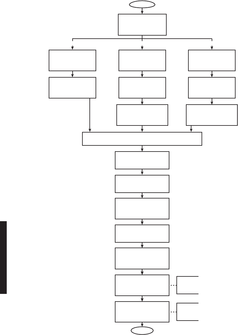
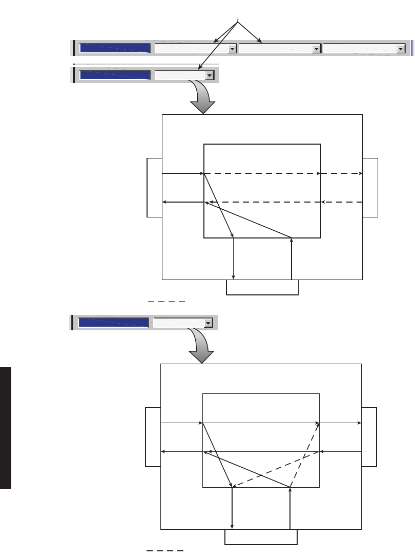
Provision radio. See Figure 4-1.
The radio has been properly aligned and tested at the factory before shipment eliminating
the need for testing after initial turn-up. The only time testing and/or adjustment is
required is after a maintenance action such as removal and replacement procedure and/or
constant alarms requiring corrective maintenance action. The completed maintenance
action procedure(s) will reference any required test procedure(s).
Note
Note
4-2
Figure 4-1 Provisioning Sequence
FIG 4-5
DS3 RADIO
CONFIG
PROVISIONING
FIG 4-2
DS1/E1, DS3, OC3 RADIO
CONFIG
PROVISIONING
FIG 4-6
DS3
FACILITIES
PROVISIONING
FIG 4-3
DS1/E1 RADIO
CONFIG
PROVISIONING
FIG 4-4
DS1/E1
FACILITIES
PROVISIONING
FIG 4-8
OC3 RADIO
CONFIG
PROVISIONING
FIG 4-9
OC3
FACILITIES
PROVISIONING
FIG 4-10
OC3 RADIO
WAYSIDE DS1 FACILITIES
PROVISIONING
FIG 4-7
DS3 RADIO
WAYSIDE DS1 FACILITIES
PROVISIONING
FIG 4-11
DS1/E1, DS3, OC3 RADIO SERVICE CHANNEL PROVISIONING
FIG 4-12
DS1/E1, DS3, OC3 RADIO
AUDIO PROVISIONING
FIG 4-13
DS1/E1, DS3, OC3 RADIO
MCS-11 PROVISIONING
FIG 4-14
DS1/E1, DS3, OC3 RADIO
MCS TRANSPORT/PPP
TRANSPORT PROVISIONING
FIG 4-17
DS1/E1, DS3, OC3 RADIO
CONTROL NAMES
PROVISIONING
START
OPTIONAL
ENTRY
LMW-9038-sm
05/07/04
FIG 4-16
DS1/E1, DS3, OC3 RADIO
ELMC REMOTE TIME-OUT
CONSTANT PROVISIONING
FIG 4-18
DS1/E1, DS3, OC3 RADIO
STATION ALARM NAMES
PROVISIONING
END
OPTIONAL
ENTRY
FIG 4-15
DS1/E1, DS3, OC3 RADIO
ELMC PROVISIONING
DS1/E1 DS3 OC3
4-3
4.3
PROVISIONING RADIO
Screen shown is for DS1 Radio. DS3 and OC3 radio configuration pro-
visioning is similar. Changes to provisioning do not have to be made in
any particular order.
Open radio provisioning screens. On main screen, double click on tower icon. Status and
alarm screen displays. Click on Provisioning. Check current provisioning and change as
required.
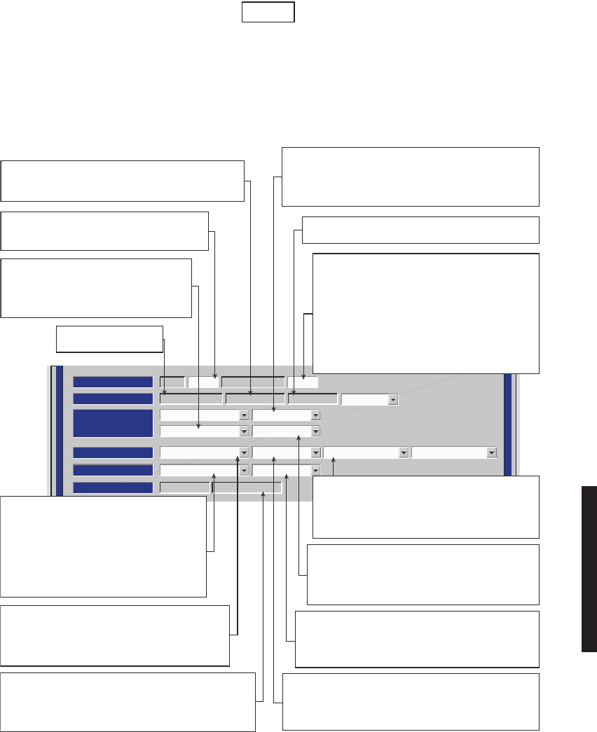
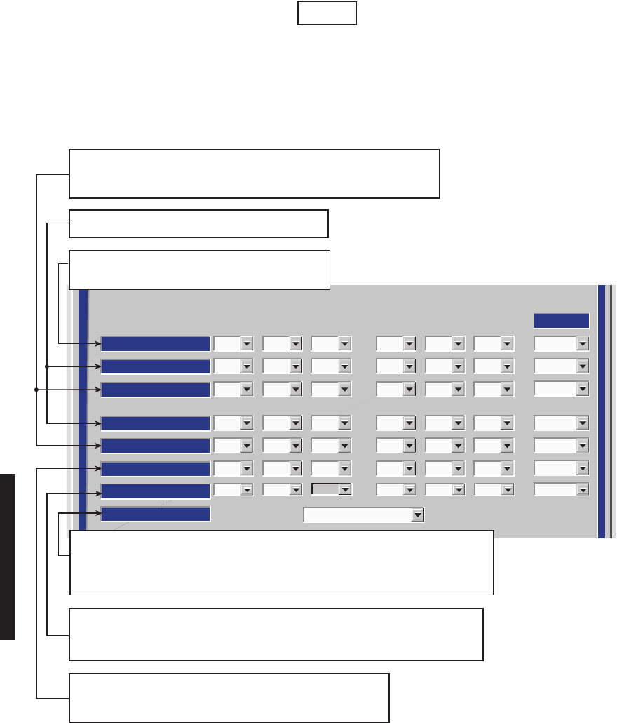
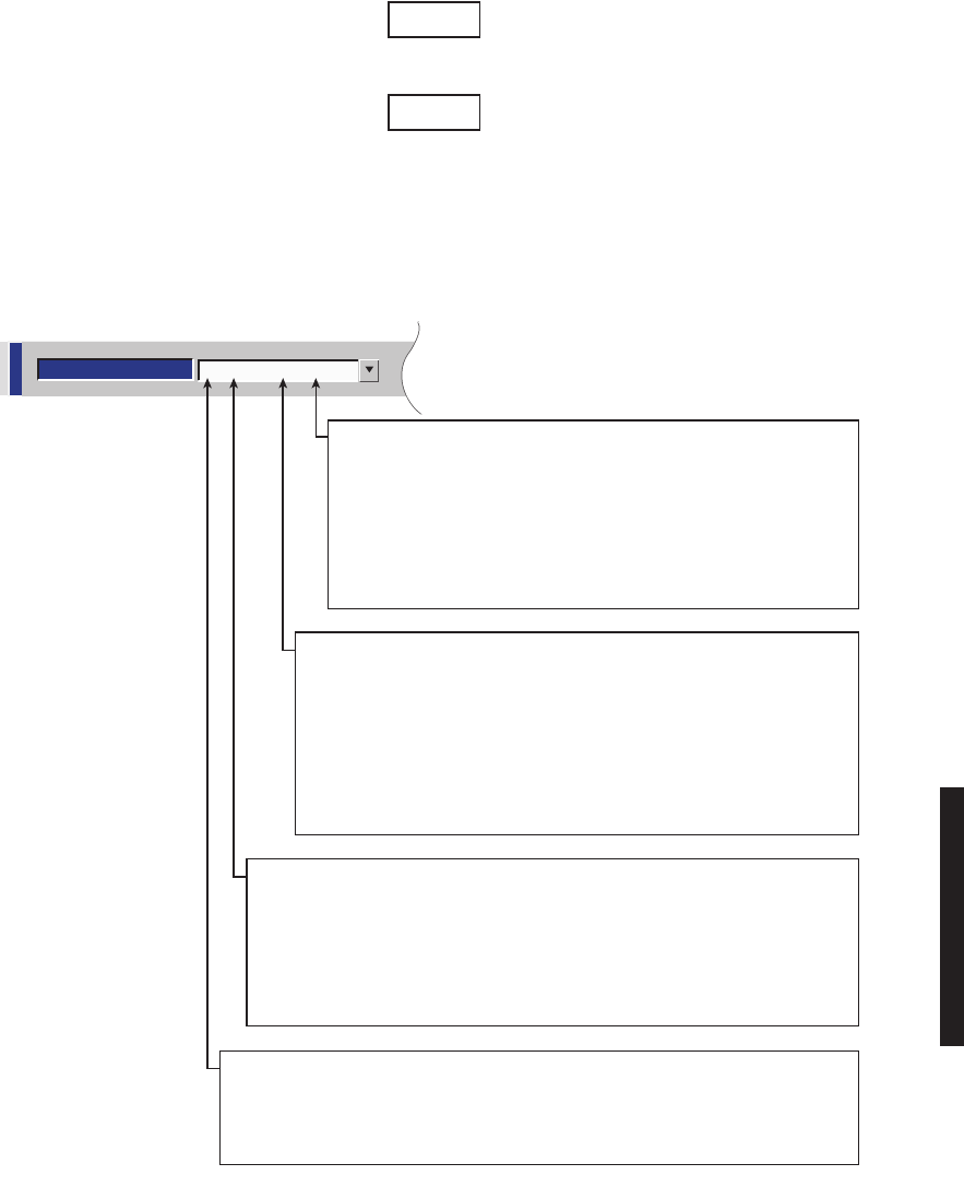
Figure 4-2 DS1/E1, DS3, OC3 Radio Configuration Provisioning (Sheet 1 of 4)
Note
ATPC Enabled A&B PA Present
RADIO CONFIG:
HS Tx/HS Rx TERMINAL
6-8 GHz
SYSTEM ALARM
Visual/Audible Relays ON/NO Station Alarm 13-16 RSL Alarm Enable
RSL-Sw Enable Eye BER Disable
RCV SWITCHING:
RADIO TYPE:
MDR-8000 DS1 16 LINES 128 TCM
OPTIONS:
Stat/Prov/WaySideOption Key:
SYSTEM ID:
TEST1 Disable
RADIO LINK ID:ELMC:
SELECT DISABLE OR DOUBLE CLICK TO ENABLE
(00 DISPLAYS). ENTER 2-DIGIT NUMBER
BETWEEN 00 AND 99 AS IDENTIFICATION FOR
RADIO RCV/XMT PAIR.
USE FOR FREQUENCY COORDINATION IN
CONGESTED AREAS THAT HAVE NEARBY
TRANSMITTERS AT SAME FREQUENCY WITH
SAME MODULATION. ID MUST BE SAME AT BOTH
ENDS OF HOP. IF RCV ID DOES NOT MATCH ID
RECEIVED FROM FAR-END XMTR, A USI ALARM
AND RACK ALARM ARE GENERATED.
DISPLAYS NUMBER OF LINES AVAILABLE AS
DETERMINED BY CAPACITY KEY. CHANGING NUMBER
OF LINES REQUIRES CHANGING CAPACITY KEY.
SELECT APPROXIMATE ERROR RATE AT WHICH EYE
CLOSURE ALARM ACTIVATES AND SWITCHING OCCURS:
EYE BER=1X10⁻⁵, 1X10⁻⁶, 1X10⁻⁷, 1X10⁻⁸ OR SELECT
Eye BER Disable TO ACTIVATE ALARMS AT APPROXIMATELY
1X10⁻⁶ WITHOUT RECEIVERS SWITCHING.
SELECT A&B PA Present IF SHELF IS EQUIPPED
WITH A&B PAs, A OR B PA ONLY IF SHELF IS EQUIP-
PED WITH ONLY ONE PA, OR NO PA IF SHELF IS NOT
EQUIPPED WITH PA. UNEQUIPPED PA ALARMS ARE
DISABLED.
SELECT Major/Minor TO TRIGGER MAJOR ALARM
ON ANY ALARM ON
ON-LINE SIDE AND MINOR ALARM
ON
ANY ALARM ON OFF-LINE SIDE. SELECT
Visual/
Audible TO TRIGGER RACK ALARM ON ANY ALARM
ON ON-LINE SIDE.
DISPLAYS ELMC OPTION KEY TYPE INSTALLED ON CON-
TROLLER. STAT (STATUS)/PROV (REMOTE PROVISIONING)/
WAYSIDE (WITH WAYSIDE DS1 MONITORING). NOT PRO-
VISIONABLE. CHANGING DISPLAY REQUIRES CHANGING
OPTION KEY.
SELECT TERMINAL, REPEATER, RING TERMINAL OR
RING REPEATER FROM DROP DOWN LIST. SELECT
REPEATER IF TRAFFIC AND SERVICE CHANNEL (FOUR
RAILS OF X/Y DATA) ARE BEING TRANSPORTED
BETWEEN
J314 OF BOTH SHELVES.
ENABLE OR DISABLE AUTOMATIC POWER
CONTROL (ATPC) FUNCTION. SELECT
ATPC Disable, ATPC Enabled, OR ATPC
with Timeout FROM DROP DOWN LIST.
SEE SHEET 2 0F 3 FOR DETAILS.
DISPLAYS MODULATION SCHEME.
NOT PROVISIONABLE
DISPLAYS RADIO TYPE
NOT PROVISIONABLE
BACKSPACE TO DELETE CURRENT ADDRESS
AND ENTER 5-DIGIT REMOTE RACK ADDRESS.
SEE FIGURE 6-11 FOR DETAILS.
SELECT RSL-Sw Enable TO ENABLE
AUTOMATIC RECEIVER SWITCHING BASED ON
RSL. WHEN ENABLED, RECEIVER SWITCHES IF:
1. ON-LINE RCV RSL IS BELOW RCV
AGC THRESHOLD, AND
2. OFF-LINE RCV RSL IS ABOVE RCV
AGC THRESHOLD.
SELECT RSL-Sw Disable TO DISABLE
AUTOMATIC RECEIVER SWITCHING.
LMW-7084
Sheet 1 of 2
02/04/03
SELECT Station Alarm 13-16 TO ENABLE STATION
ALARM 13-16 INPUTS TO RELAY INTFC. WHEN
EXTERNAL TBOS IS WIRED TO RADIO, SELECT
TBOS Display 1-8 TO ENABLE TBOS DRIVERS ON
CONTROLLER AND SELECT A TBOS DISPLAY (1-8)
TO VIEW.
SELECT Relays ON/NO (NORMALLY OPEN-HIGH
IMPEDANCE) OR Relays ON/NC (NORMALLY CLOSED-
GROUND) ON ALARM FOR ALARM/STATUS OUTPUTS OR
Relays OFF. REFER TO RELAY INTERFACE IN THEORY
SECTION FOR DETAILS.
4-4
Screen shown is for DS1 Radio. DS3 and OC3 radio configuration pro-
visioning is similar. Changes to provisioning do not have to be made in
any particular order.
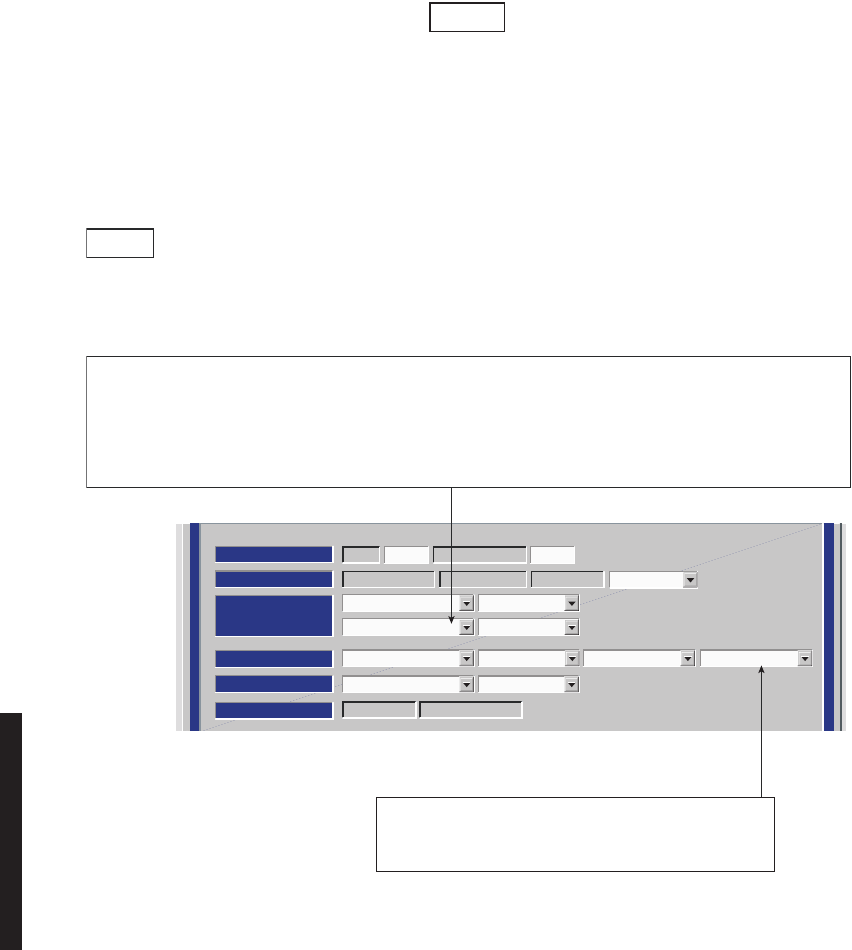
Figure 4-2 DS1/E1, DS3, OC3 Radio Configuration Provisioning (Sheet 2 of 4)
Note
ATPC Enabled A&B PA Present
RADIO CONFIG:
HS Tx/HS Rx TERMINAL
6-8 GHz
SYSTEM ALARM
Visual/Audible RELAYS ON/NO Station Alarm 13-16 RSL Alarm Enable
Disable AGC BER Disable
RCV SWITCHING:
RADIO TYPE:
MDR-8000 DS1 16 LINES 128 TCM
OPTIONS:
Stat/Prov/WaySideOption Key:
SYSTEM ID:
TEST1 Disable
RADIO LINK ID:ELMC:
LMW-7085
Sheet 2 of 2
06/04/02
SELECT ATPC OR ATPC T/O ENABLE AUTOMATIC XMT POWER CONTROL (ATPC) FUNCTION. WHEN PROVISIONED
ATPC OR ATPC T/0, ONE RCVR OUT-OF-LOCK CAUSES HIGH POWER ATPC FOR 10 SECONDS EVERY ONE MINUTE.
IF BOTH RCVRS ARE OUT-OF-LOCK, ATPC GOES TO HIGH POWER AND STAYS AT HIGH POWER UNTIL ONE RCVR
(REVERTS TO ONE RCVR OUT-OF-LOCK MODE) OR BOTH RCVRS LOCK. WHEN PROVISIONED ATPC T/O (TIMEOUT),
IF CMD PATH IS LOST, ATPC GOES TO HIGH POWER FOR FIVE MINUTES THEN GOES TO LOW POWER. THEN, EVERY
HOUR, ATPC GOES HIGH FOR 10 SECONDS AND THEN GOES TO LOW POWER. THIS CONTINUES UNTIL THE CMD
PATH IS RESTORED. SELECT DISABLE TO DISABLE ATPC FUNCTION.
NOTES
1. ATPC T/O IS A CMD PATH FUNCTION PERFORMED AT XMTR.
2. ATPC TRACKS RCVR WITH HIGHEST LEVEL.
3. LOW POWER ATPC IS 10dB DOWN FROM HIGH POWER.
SELECT RSL Alarm Enable TO ENABLE ALARM ON USI
ALARM AND STATUS SCREEN WHEN RSL DROPS
BELOW THRESHOLD. SELECT RSL Alarm Disable TO
INHIBIT ALARM.
4-5
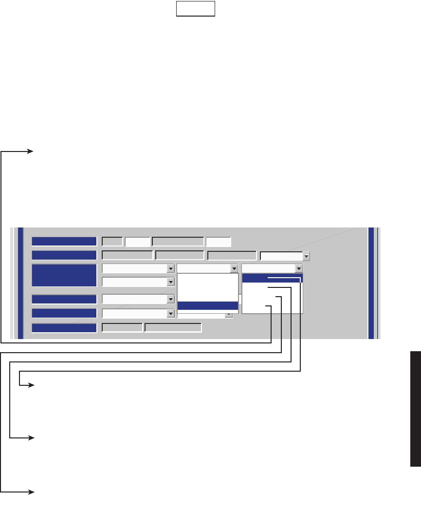
Figure 4-2 DS1/E1, DS3, OC3 Radio Configuration Provisioning (Sheet 3 of 4)
ATPC Enabled A&B PA Present
RADIO CONFIG:
HS Tx/HS Rx TERMINAL
SYSTEM ALARM
Visual/Audible RELAYS ON/NO Station Alarm 13-16
RSL-SW Enable Eye BER Disable
RCV SWITCHING:
RADIO TYPE:
MDR-8000 DS1 16 LINES
OPTIONS:
Stat/Prov/WaySideOption Key:
SYSTEM ID:
TEST1 Disable
RADIO LINK ID:ELMC:
LMW-9088
09/08/03
6-8 GHz
128 TCM
Ring Repeater Normal
Terminal
Repeater
Ring Terminal
Ring Repeater
Normal
Master
Primary
Secondary
SELECT RING REPEATER MASTER AT ANY ONE RADIO IN THE RING, TO ENABLE THE
CONFIGURATION THAT IS USED TO BREAK THE LOOP OF A SYNCHRONOUS RING. IN THIS
CONFIGURATION, THE RF SERVICE CHANNEL AND REPEATER SYNC ARE DISABLED (NORMALLY
ENABLED), PREVENTING THE RING FROM CLOSING ON ITSELF. WHEN A RING FAILURE OCCURS,
THE MASTER RECEIVES A RING FAIL MESSAGE FROM THE FAILED RADIO AND RESPONDS BY
ENABLING THE RF SERVICE CHANNEL AND REPEATER SYNC TO CONNECT THE SERVICE
CHANNELS. THE FAILURE IS WHAT NOW BREAKS THE SERVICE CHANNEL LOOP, PREVENTING
THE RING FROM CLOSING ON ITSELF.
SELECT RING REPEATER NORMAL AT ALL RADIOS IN THE RING, EXCEPT THE ONE
PROVISIONED MASTER. THIS ENABLES THE CONFIGURATION THAT ENABLES RF SERVICE
CHANNEL AND REPEATER SYNC, ALLOWING SERVICE CHANNEL DATA TO PASS THROUGH
THE RF AND REPEATER PORTS. WHEN A FAILURE IS DETECTED ON THE RF OR REPEATER
PORT, THE ASSOCIATED RADIO SENDS A RING FAIL MESSAGE TO THE MASTER.
SELECT RING REPEATER PRIMARY WHEN THE RADIO IS IN THE MIDDLE OF A SUBTENDING
RING AND IS THE PRIMARY SERVICE CHANNEL CONNECTION POINT TO ANOTHER RING. IN
THIS CONFIGURATION, THE RF SERVICE CHANNEL AND REPEATER SYNC ARE ENABLED,
ALLOWING SERVICE CHANNEL DATA TO PASS THROUGH THE RF AND REPEATER PORTS.
WHEN A FAILURE OCCURS, THE RF SERVICE CHANNEL AND REPEATER SYNC ARE DISABLED.
SELECT RING REPEATER SECONDARY WHEN THE RADIO IS IN THE MIDDLE OF A
SUBTENDING RING AND IS THE SECONDARY SERVICE CHANNEL CONNECTION POINT TO
ANOTHER RING. IN THIS CONFIGURATION, THE RF SERVICE CHANNEL AND REPEATER
SYNC ARE DISABLED. WHEN A FAILURE OCCURS, THE RF SERVICE CHANNEL IS ENABLED.
MASTER RING CONFIGURATIONS – Master rings are networks that consist entirely of a loop of
synchronous repeaters. All nodes in the same ring direction use the same clock timing. Timing may be
different for each direction. All service channel data is passed synchronously around the ring. The
status of the ring is monitored using messages in the ELMC channel.
SUBTENDING RING CONFIGURATIONS – Subtending rings are networks that connect asynchronously
to another ring at two locations (called primary and secondary connection points). The networks consist
of a string of synchronous repeaters. All nodes in the same direction use the same clock timing. Timing
may be different for each direction. All service channel data is passed synchronously within the
subtending ring section and asynchronously to the main ring. Asynchronous connection must use LMC1
for the ELMC connection. Messages are sent on LMC1 by the subtending ring primary and secondary
nodes to monitor for continuity of the synchronous connection.
Note
4-6
Figure 4-2 DS1/E1, DS3, OC3 Radio Configuration Provisioning (Sheet 4 of 4)
ATPC Enabled A&B PA Present
RADIO CONFIG:
HS Tx HS Rx Ring Repeater Normal
SYSTEM ALARM
Visual/Audible RELAYS ON/NO Station Alarm 13-16 RSL Alarm Enable
Degrade Enable
Disable AGC BER Disable
RCV SWITCHING:
RADIO TYPE:
MDR-8000 OC3 OC-3 128 QAM
OPTIONS:
Stat/Prov/WaySideOption Key:
SYSTEM ID:
TEST1 Disable
RADIO LINK ID:ELMC:
LMW-9089
09/08/03
Terminal
Repeater
Ring Terminal
Ring Repeater
Normal
Master
Primary
Secondary
RING TERMINAL MASTER – NOT USED
SELECT RING TERMINAL NORMAL AT FIRST RADIO IN AN INCOMPLETE RING, WHEN BUILDING
OUT A NEW RING. THIS PREVENTS HAVING TO GO BACK AND REPROVISION EACH RADIO WHEN
THE RING IS COMPLETE. AS EACH NEW HOP IS ADDED, PROVISION THE RADIOS ON EACH END
AS RING TERMINAL NORMAL AND PROVISION ALL RADIOS IN BETWEEN AS RING REPEATER
NORMAL. IN THE RING TERMINAL NORMAL CONFIGURATION, THE REPEATER CABLE IS NOT
INSTALLED. SYNC ALARMS ARE INHIBITED. THE RF SERVICE CHANNEL IS ENABLED, ALLOWING
SERVICE CHANNEL DATA TO PASS THROUGH THE RF PORT. WHEN THE RING IS COMPLETE,
PROVISION ONE RADIO RING REPEATER MASTER AND ALL OTHER RADIOS AS RING REPEATER
NORMAL.
SELECT RING TERMINAL NORMAL AT RADIOS AT ENDS OF STUBS OFF SUBTENDING RINGS.
SELECT RING TERMINAL PRIMARY WHEN THE RADIO IS THE PRIMARY CONNECTION POINT
TO THE MAIN RING. IN THIS CONFIGURATION, THE REPEATER CABLE IS NOT INSTALLED.
SYNC ALARMS ARE INHIBITED. THE RF SERVICE CHANNEL IS ENABLED, ALLOWING SERVICE
CHANNEL DATA TO PASS THROUGH THE RF PORT. THE RF SERVICE CHANNEL IS DISABLED
WHEN A FAILURE OCCURS.
SELECT RING
TERMINAL
SECONDARY WHEN THE RADIO IS THE SECOND CONNECTION
POINT TO THE MAIN RING. IN THIS CONFIGURATION, THE REPEATER CABLE IS NOT
INSTALLED. SYNC ALARMS ARE INHIBITED. THE RF SERVICE CHANNEL IS DISABLED. THE
RF SERVICE CHANNEL IS ENABLED WHEN A FAILURE OCCURS ALLOWING SERVICE
CHANNEL DATA TO PASS THROUGH THE RF PORT.
4-7
Figure 4-3 DS1/E1 Radio Configuration Provisioning
AT PC Enabled A&B PA Present
RADIO CONFIG:
HS Tx/HS Rx TERMINAL
SYSTEM ALARM
Visual/Audible RELAYS ON/NO Station Alarm 13-16 RSL Alarm Enable
Disable AGC BER Disable
RCV SWITCHING:
RADIO TYPE:
MDR-8000 DS1 16 LINES 128 TCM 6-8 GHz
OPTIONS:
Stat/Prov/WaySideOption Key:
SYSTEM ID:
TEST1 Disable
RADIO LINK ID:ELMC:
LMW-7100-SM
09/16/02
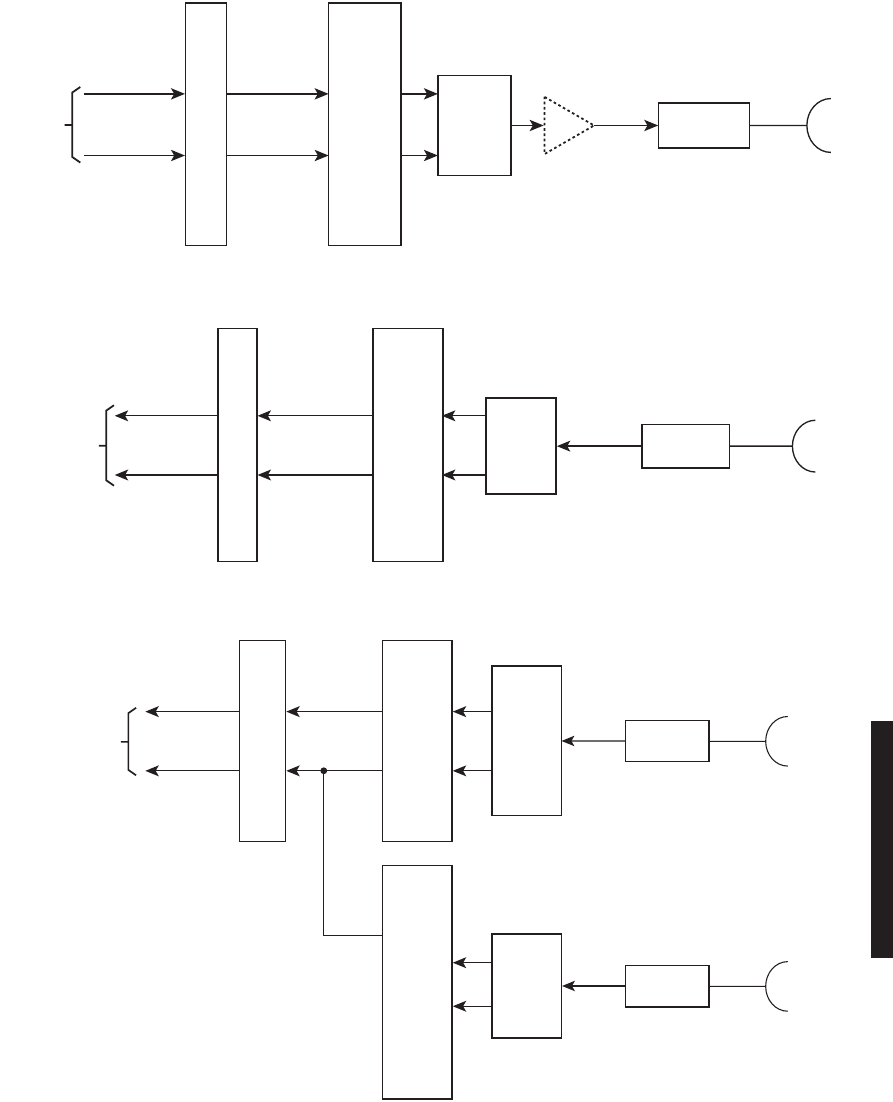
SELECT ONE:
* NS Tx/NS Rx
NS Tx/HS Rx
* NS Tx/SD Rx
* HS Tx/HS Rx
* HS Tx/SD Rx
FD TxA/Rx A
FD TxA/Rx B
NS = NON-STANDBY
HS = HOT-STANDBY
SD = SPACE DIVERSITY
FQ = FREQUENCY DIVERSITY
* ALTHOUGH THERE ARE A TOTAL
OF 7 CONFIGURATIONS, ONLY 4
EXAMPLES ARE ILLUSTRATED.
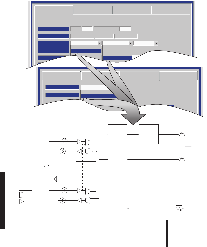
4-8
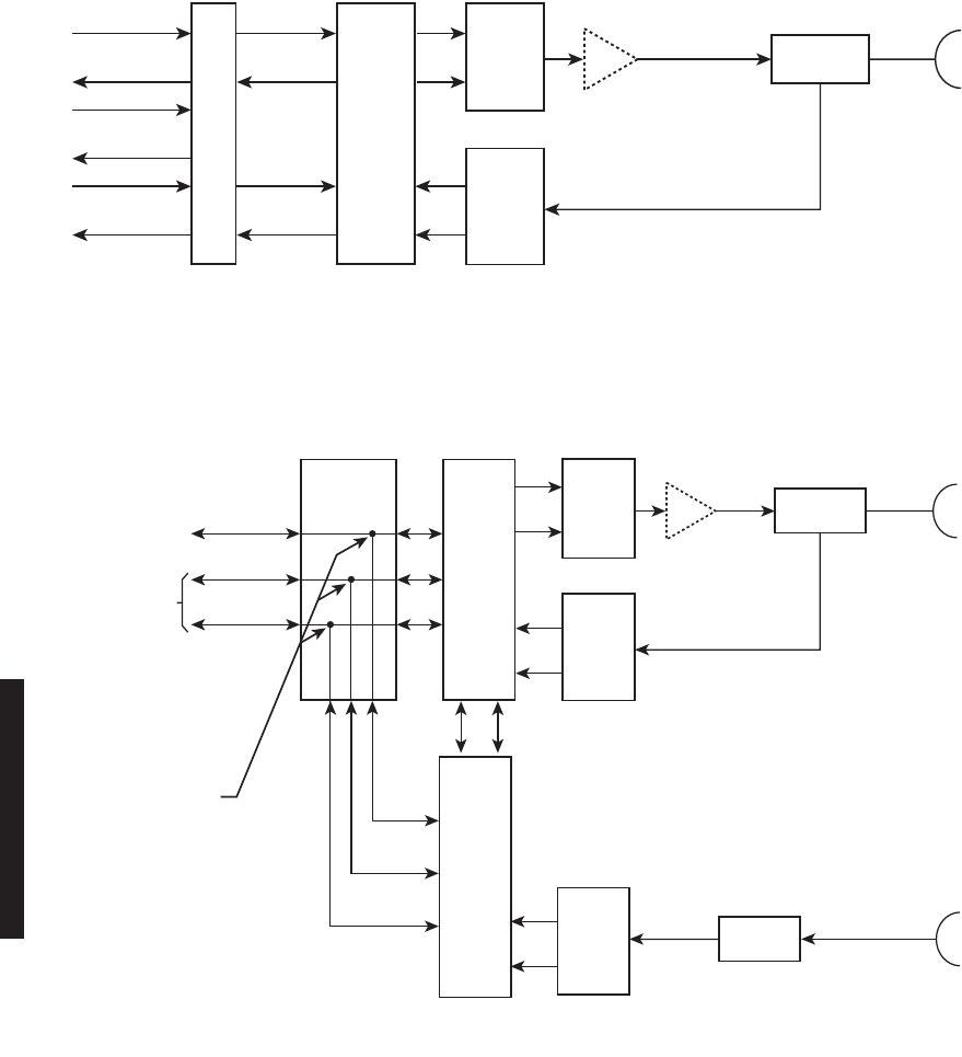
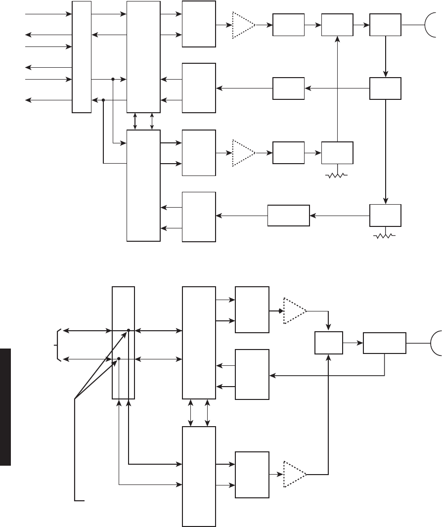
DS1/E1 PROVISIONING EXAMPLE 1: NS Tx/NS Rx
DS1/E1 PROVISIONING EXAMPLE 2: NS Tx/SD Rx
LBO
RPTR
CH
RF
IN/OUT
I
Q
RX
RS
RF
RF
DS1/E1
1-16
RPTR
CH
DS1/E1
1-16
XMTR
ADIPLEXER
RCVR
A
I/O
INTER-
FACE
A
PA
(OPTIONAL)
LMW-5051-SM
09/16/02
LBO
RPTR
CH
RF
IN/OUT
I
Q
RX
RS
RX
RS
RF
RF
DS1/E1
1-16
RPTR
CH
DS1/E1
1-16
XMTR
A
DIPLEXER
XMT
SW
RCVR
A
I/O
INTER-
FACE
A
RCV
FILTER
RCVR
B
I/O
INTER-
FACE
B
PA
(OPTIONAL)
RF
LMW-5050-sm
07/24/01
RF
IN
FROM
SECOND
ANTENNA
4-9
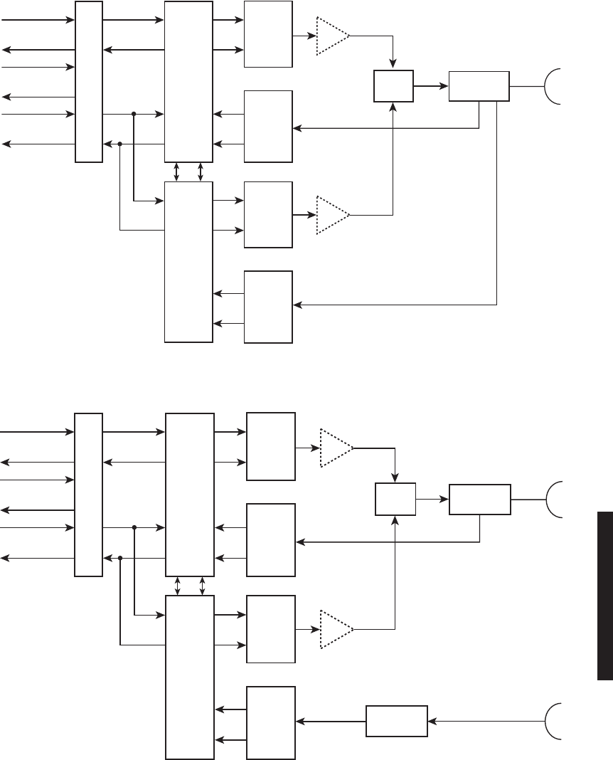
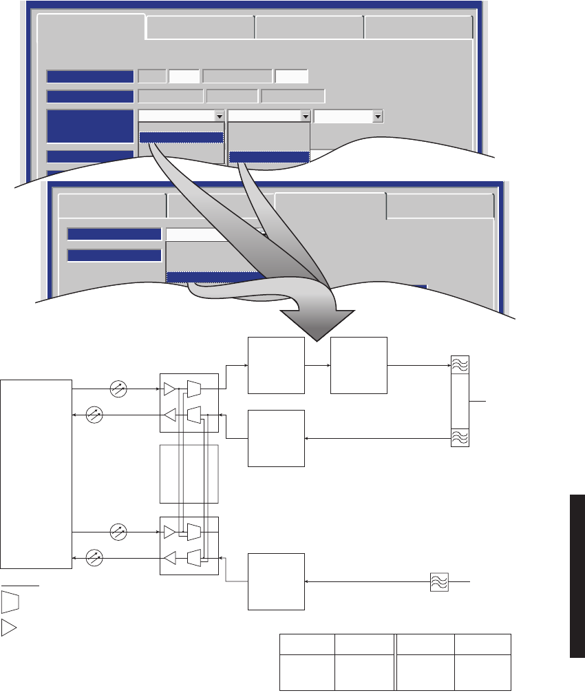
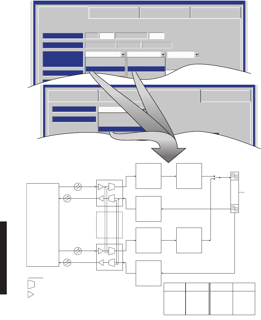
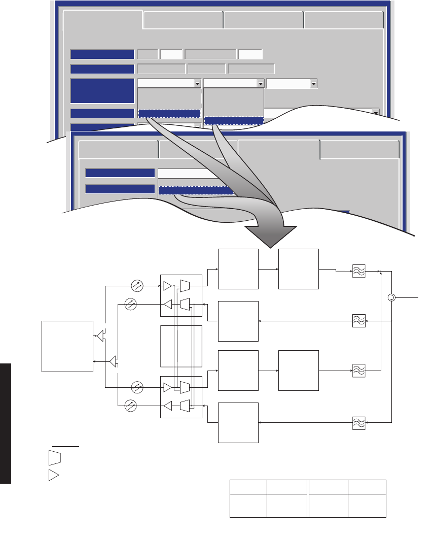
DS1/E1 PROVISIONING EXAMPLE 3: HS Tx/HS Rx
DS1/E1 PROVISIONING EXAMPLE 4: HS Tx/SD Rx
LBO
RPTR
CH
RF
IN/OUT
I
Q
RX
RS
I
Q
RX
RS
RF
RF
RF
DS1/E1
1-16
RPTR
CH
DS1/E1
1-16
XMTR
A
DIPLEXER
XMT
SW
RCVR
A
I/O
INTER-
FACE
A
XMTR
B
RCVR
B
I/O
INTER-
FACE
B
PA
(OPTIONAL)
(OPTIONAL)
RF
LMW-5049-sm
07/24/01
PA
MX DX
LBO
RPTR
CH
RF
IN/OUT
I
Q
RX
RS
I
Q
RX
RS
RF
RF
DS1/E1
1-16
RPTR
CH
DS1/E1
1-16
XMTR
A
DIPLEXER
XMT
SW
RCVR
A
I/O
INTER-
FACE
A
XMTR
B
RCV
FILTER
RCVR
B
I/O
INTER-
FACE
B
PA
(OPTIONAL)
(OPTIONAL)
RF
RF
LMW-5048-SM
09/16/02
PA
RF
IN
FROM
SECOND
ANTENNA
MX DX
4-10
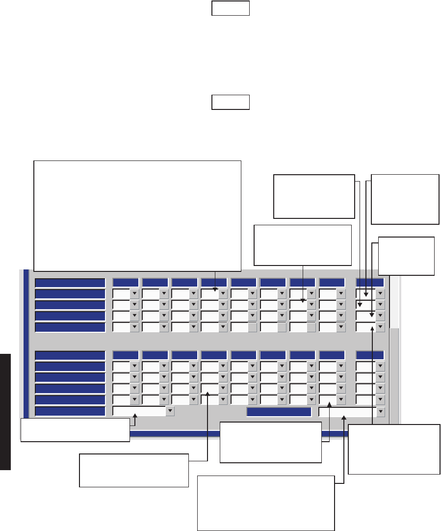
Figure 4-4 DS1/E1 Facilities Provisioning
LMW-3020-sm
12/16/03
DS1 LINE LENGTH
LINES
INSERT CHANNEL
DROP CHANNEL
LINE CODING
31 2 4
ON
ON
AMI
ON
ON
AMI
OFF
OFF
AMI
OFF
OFF
AMI
75 6
OFF
OFF
AMI
OFF
OFF
AMI
OFF
OFF
AMI
8
OFF
OFF
AMI
Select All
AIS INHIBIT
OFF OFF OFF OFF OFF OFF OFF OFF
LINE
INSERT CHANNEL
DROP CHANNEL
LINE CODING
119 10 12
OFF
OFF
AMI
OFF
OFF
AMI
OFF
OFF
AMI
OFF
OFF
AMI
1513 14
OFF
OFF
AMI
OFF
OFF
AMI
OFF
OFF
AMI
16
OFF
OFF
AMI
Select All
AIS INHIBIT
OFF OFF OFF OFF OFF OFF OFF OFF
AIS SIGNAL
ALL ONES
0-150
SELECT ALL 1s OR ALL 0s AIS
DATA FORMAT FOR ALL LINES. SELECT ON OR OFF. WHEN
SET TO ON,
AIS INSERTION
IS INHIBITED ON SELECTED
DS1/E1.
SELECT AMI OR B8ZS CODING
FOR EACH DS1 LINE. E1 LINE
CODING IS ALWAYS HDB3.
FOR EACH LINE, SELECT
ON TO DROP LINE OR OFF
TO DISABLE LINE AND
ALARMS.
SELECT ON TO DROP
ALL LINES OR OFF TO
DISABLE ALL LINES
AND ALARMS.
SELECTING ON INSERTS LOCAL DATA AND TURNS ON
ALARM REPORTING. SELECTING NM (NOT MONITORED),
DEFAULT SETTING, INSERTS LOCAL AIS DATA BUT TURNS
OFF ALARM REPORTING. SELECTING
OFF
TURNS OFF LOCAL
DATA INSERT AND TURNS OFF ALARM REPORTING.
SELECT
ON
FOR ALL LINES IN USE AT A TERMINAL OR DROP-
AND-INSERT REPEATER. SELECT NM FOR ALL LINES NOT
USED AT A TERMINAL AND DROP-AND-INSERT REPEATER.
SELECT OFF FOR ALL LINES AT A NON-STANDBY THROUGH
REPEATER, OR SELECT
OFF
FOR LINES 1 THROUGH 4 AND
NM FOR LINES 5 THROUGH 16 AT A PROTECTED REPEATER.
SELECT
ON
TO
INSERT ALL
LINES OR
OFF
TO
DISABLE ALL LINES
AND ALARMS.
SELECT
ON
TO INHIBIT AIS
INSERTION ON ALL LINES.
SELECT
OFF
TO ENABLE
AIS INSERTION ON ALL
LINES.
SELECT AMI
OR B8ZS
CODING FOR
ALL DSI LINES
FOR ALL DS1 LINES, SELECT RANGE
THAT MATCHES ACTUAL DISTANCE
TO CROSS-CONNECT 0-150 (TEO OFF),
150-330 (TEO ON), 330-480 (TEO OFF)
OR
480-660 (TEO ON)
FT. FOR E1, NO DIS-
TANCE
IS DISPLAYED.
Note
The term "LINE" is used to describe an input/output signal at DS1/E1 rate (1.544 MB/S 2.043 MB/S). The
term "CHANNEL" is used to describe a multiplexed signal, at a higher rate than DS1/E1. The inserted
channel is output of multiplexer circuit. The dropped channel is input to demultiplexer circuit. The multiplexer
and demultiplexer circuits are located on I/O interface module.
Note
If installation at both ends of a hop are complete except for connecting to customer inputs/outputs and it is
desirable to have an alarm-free system, alarm reporting on the incomplete connections can be disabled
temporarily through provisioning. You can communicate over the hop even if you do not have the radio connected
to customer DS1 inputs; however, you will alarm unless you select OFF to disable INSERT CHANNEL (located on the
USI DS1 Facilities screen) for all equipped lines. Disabling the DS1 insert function disables both the lines and
alarm reporting for the lines. After all customer connections are complete, alarm reporting can be restored to
normal. To restore alarm reporting to normal, set INSERT CHANNEL on DS1 Facilities screen to ON.
4-11
Figure 4-5 DS3 Radio Configuration Provisioning
ATPC Enabled A&B PA Present
RADIO CONFIG:
HS Tx/HS Rx TERMINAL
SYSTEM ALARM
Visual/Audible RELAYS ON/NO Station Alarm 13-16
Degrade Enable
RSL Alarm Enable
Disable AGC BER Disable
RCV SWITCHING:
RADIO TYPE:
MDR-8000 DS3 3 LINES 64 QAM
OPTIONS:
Stat/Prov/WaySideOption Key:
SYSTEM ID:
TEST1 Disable
RADIO LINK ID:ELMC:
LMW-7101-SM
09/16/02
SELECT ONE:
* NS Tx/NS Rx
NS Tx/HS Rx
* NS Tx/SD Rx
* HS Tx/HS Rx
* HS Tx/SD Rx
* FREQ DIV
* HS Tx/NS Rx
* SIMPLEX NS Tx
SIMPLEX HS Tx
* SIMPLEX NS Rx
* SIMPLEX HS/SD Rx
NS = NON-STANDBY
HS = HOT-STANDBY
SD = SPACE DIVERSITY
FQ = FREQUENCY DIVERSITY
SELECT Degrade Enable TO ACTIVATE APPROXIMATE ERROR RATE
AT WHICH BER Deg Alm ALARM ACTIVATES AND SWITCHING OCCURS:
1X10⁻⁵, 1X10⁻⁶, 1X10⁻⁸, ON DS3 FACILITIES PROVISIONING SCREEN.
SELECT Degrade Disable TO ACTIVATE BER Deg Alm AT SELECTED
ERROR RATE WITHOUT RCVRS SWITCHING.
* Although there are a total of 11
configurations available, only 9
examples are illustrated.
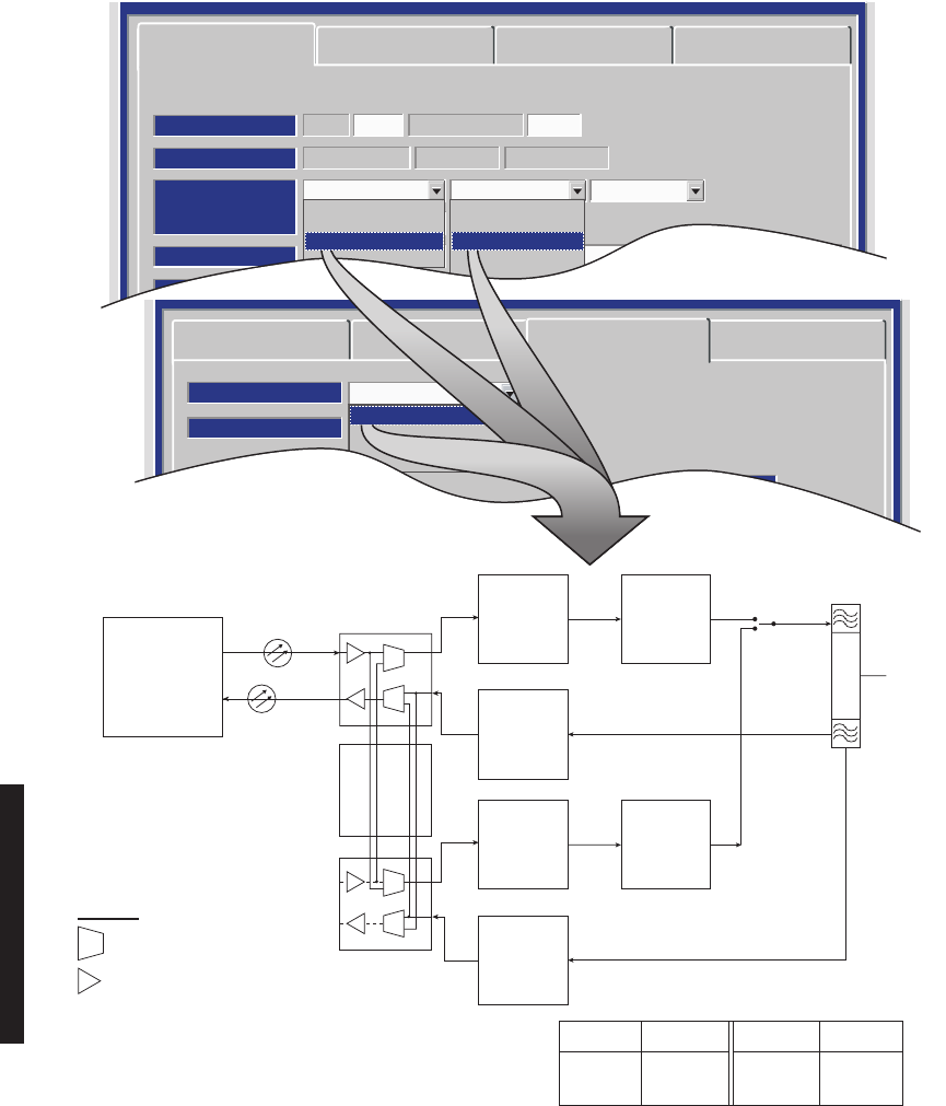
4-12
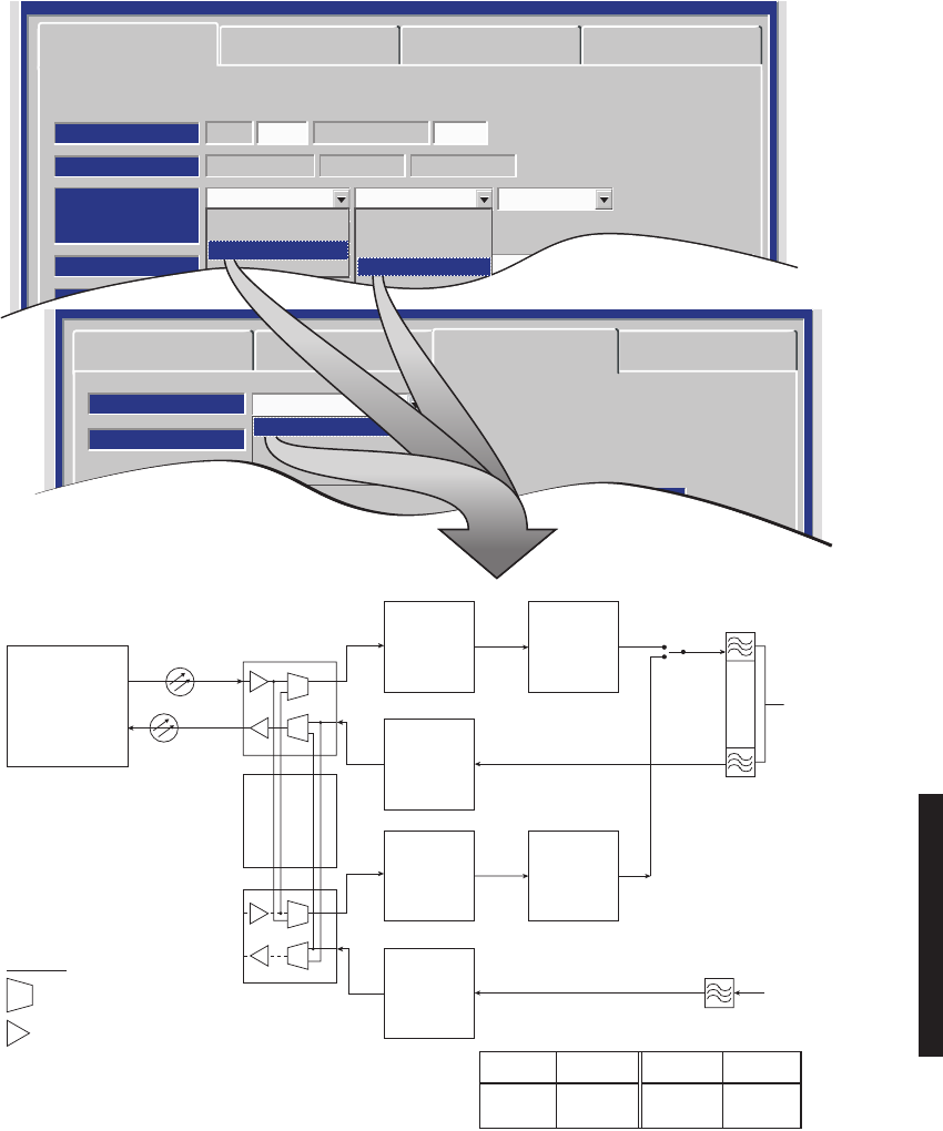
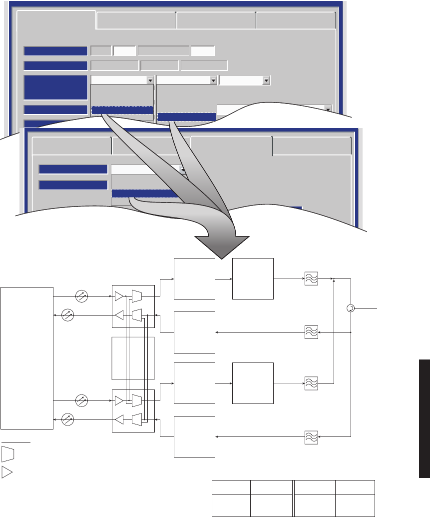
DS3 PROVISIONING EXAMPLE 1: NS Tx/NS Rx
DS3 PROVISIONING EXAMPLE 2: NS Tx/SD Rx
RPTR
CH
LBO
DS3
1 OR 3
WAYSIDE DS1
1 OR 3
I/O
INTFC
XMTR DIPLEXERPA
I
Q
I
Q
(OPTIONAL)
RF
IN/OUT
RCVR
LMW-3124-sm
05/17/03
LBO I
RF
RF
Q
I
Q
I
SC SYNC
Q
I/O
INTFC
A
I/O
INTFC
B
XMTR
ADIPLEXER
RCV
FILTER
PA
(OPTIONAL)
RF
IN/OUT
RF
IN
FROM
DIVERSITY
ANTENNA
RCVR
A
RCVR
B
LMW-3125-sm
05/17/03
SC/SYNC2ND MDR-8000
SHELF (RPTR)
SPLITTER (XMT)
COMBINER (RCV)
X-CONN (TERM)
OR
2ND MDR-8000
SHELF (RPTR)
WAYSIDE DS1
DS3
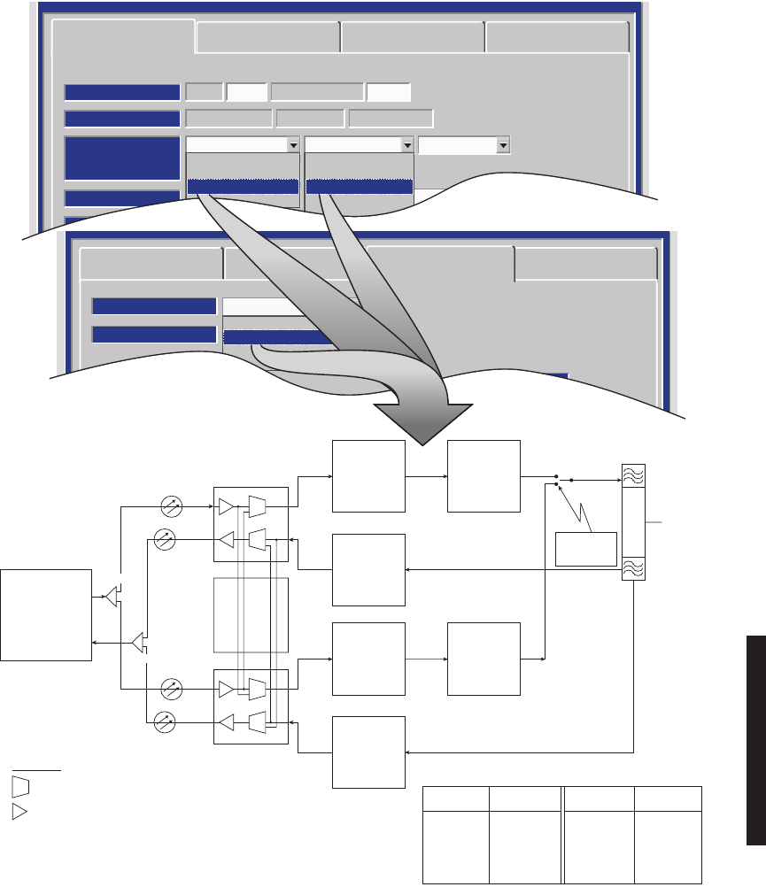
4-13
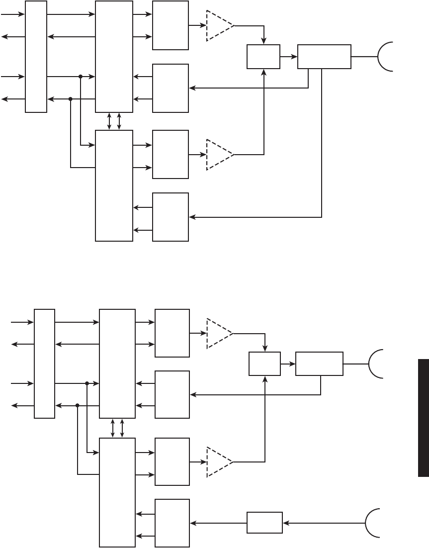
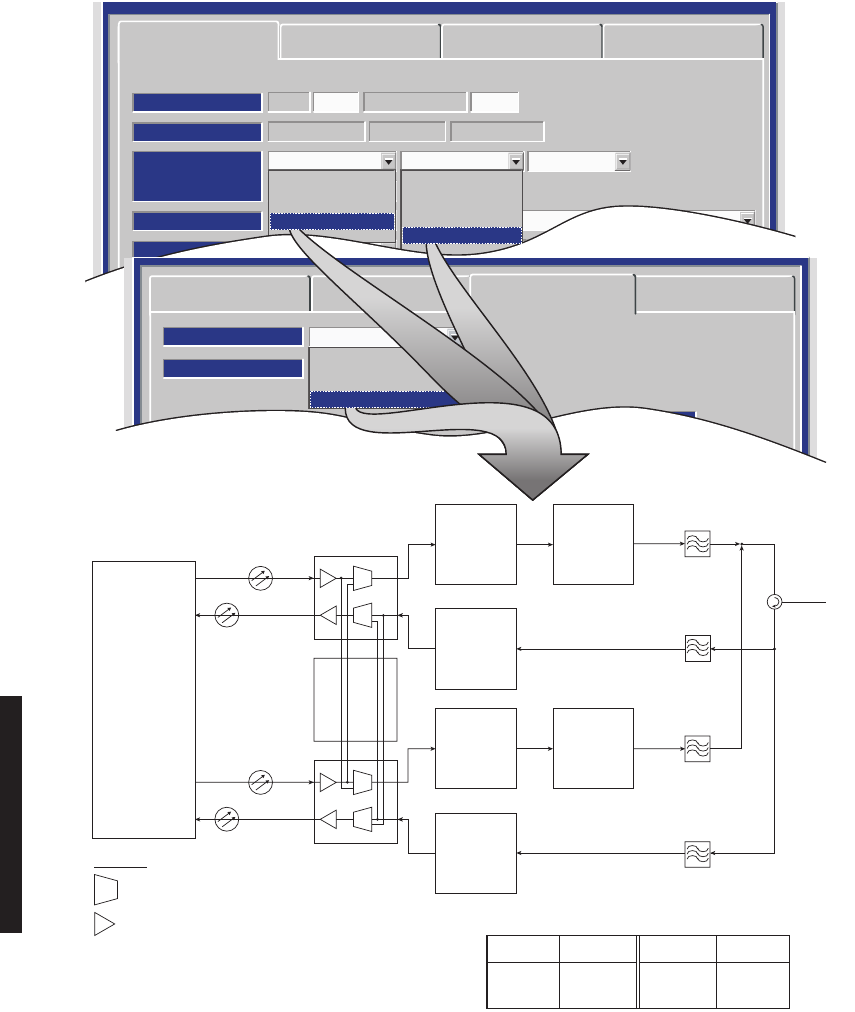
DS3 PROVISIONING EXAMPLE 3: HS Tx/HS Rx
DS3 PROVISIONING EXAMPLE 4: HS Tx/SD Rx
LBO
I
Q
I
Q
I
Q
I/O
INTFC
A
I/O
INTFC
B
XMTR
A
I
Q
XMTR
B
DIPLEXER
PA
XMT
SW
(OPTIONAL)
PA
(OPTIONAL)
RF
IN/OUT
RCVR
A
RCVR
B
LMW-3126-sm
05/17/03
RPTR
CH
DS3
1 OR 3
WAYSIDE DS1
1 OR 3
SYNCSC
LBO
I
Q
I
Q
I
Q
I/O
INTFC
A
I/O
INTFC
B
XMTR
A
I
Q
XMTR
B
DIPLEXER
PA
XMT
SW
(OPTIONAL)
PA
(OPTIONAL)
RF
IN/OUT
RCVR
A
RCVR
B
LMW-3127-sm
05/17/03
RPTR
CH
DS3
1 OR 3
WAYSIDE DS1
1 OR 3
RCV
FILTER
RF
IN
FROM
SECOND
ANTENNA
SYNCSC
4-14
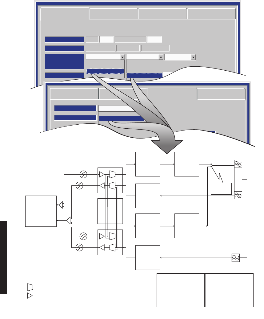
DS3 PROVISIONING EXAMPLE 5: FREQ DIV
DS3 PROVISIONING EXAMPLE 6: HS Tx/NS Rx
LBO
I
Q
I
Q
I
Q
I/O
INTFC
A
I/O
INTFC
B
XMTR
A
I
Q
XMTR
B
PA XMT
FILTER
XMT
FILTER
RCV
FILTER
CIRCU-
LATOR
CIRCU-
LATOR
CIRCU-
LATOR
CIRCU-
LATOR
CIRCU-
LATOR
(OPTIONAL)
PA
(OPTIONAL)
RF
IN/OUT
RCVR
A
RCVR
B
LMW-3128-sm
05/17/03
RPTR
CH
DS3
1 OR 3
WAYSIDE DS1
1 OR 3
RCV
FILTER
SYNCSC
I
Q
I
Q
SC SYNC
I/O
INTFC
A
LBO
I/O
INTFC
B
XMTR
A
I
RF
RF
RF
RF
QXMTR
B
DIPLEXER
PA
XMT
SW
(OPTIONAL)
PA
(OPTIONAL)
RF
IN/OUT
RCVR
A
LMW-5061-sm
08/02/01
3
DS3
TO/FROM
X-CONN
3
WAYSIDE
DS1
SPLITTER (XMT)
COMBINER (RCV)
3
DS3
3
WAYSIDE
DS1
4-15
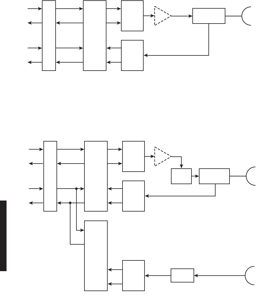
DS3 PROVISIONING EXAMPLE 7: SIMPLEX NS Tx
DS3 PROVISIONING EXAMPLE 8: SIMPLEX NS Rx
DS3 PROVISIONING EXAMPLE 9: SIMPLEX HS/SD Rx
LBO
1 OR 3
DS3
1 OR 3
WAYSIDE
DS1
1 OR 3
DS3
1 OR 3
WAYSIDE
DS1
I/O
INTFC XMTR FILTERPA
I
Q
RF
(OPTIONAL)
RF
IN/OUT
LMW-5058-sm
05/17/03
FROM
X-CONN
LBO
1 OR 3
DS3
1 OR 3
WAYSIDE
DS1
1 OR 3
DS3
1 OR 3
WAYSIDE
DS1
I/O
INTFC RCVR FILTER
I
Q
RF
RF
IN/OUT
LMW-5057-sm
05/17/03
TO
X-CONN
LBO
I
Q
I
Q
I/O
INTFC
A
I/O
INTFC
B
RCVR
A
RCVR
B
LMW-5059-sm
07/09/03
1 OR 3
DS3
1 OR 3
DS3
1 OR 3
WAYSIDE
DS1
1 OR 3
WAYSIDE
DS1
TO
X-CONN
RF
RF FILTER
FILTER
RF IN
RF IN
MAIN
ANT
DIVERSITY
ANT
4-16
Figure 4-6 DS3 Facilities Provisioning
BIT ERROR RATE
DS3 DEGRADE=10E-5
INPUT LINE BRIDGE
Select All
NA
TX/RX INTERFACE A
123 123
TX/RX INTERFACE B
DS3 LINES
XMT ALARM DISABLE
OFF
XMT VMR DISABLE
ON
NA
OFF
ON
OFF
OFF
ON
OFF
OFF
ON
OFF
OFF
ON
OFF
OFF
ON
RCV ALARM DISABLE
OFF
RCV VMR DISABLE
OFF
AIS SIGNAL DISABLE
OFF
OFF
OFF
OFF
OFF
OFF
OFF
OFF
OFF
OFF
OFF
OFF
OFF
OFF
OFF
OFF
AIS SIGNAL TIMING
10/350 10/350
10/350 10/350 10/350 10/350
10/350
SELECT ON TO BRIDGE DS3 LINE 1 ONTO SELECTED
LINE(S) 2 AND/OR 3 TO PREVENT ALARMS ON UNUSED
LINE(S). SELECT OFF TO DISABLE FUNCTION.
SELECT ON TO DISABLE AIS (BLUE SIGNAL) INSERTION ON LINE
WHEN LOSS OF UPSTREAM DS3 FRAME IS DETECTED. SELECT OFF
TO INSERT AIS (BLUE SIGNAL) WHEN RADIO OR DS3 FRAME LOSS
IS DETECTED.
SELECT ON TO DISABLE VIOLATION MONITORING AND REMOVAL (VMR) ON
LINE DUE TO LOSS OF UPSTREAM DS3 FRAME. DS3 PARITY ERRORS ARE NOT
REMOVED AND ARE PASSED ON TO NEXT SECTION. SELECT OFF TO ENABLE
VMR AND REMOVE DS3 PARITY ERRORS.
SELECT OFF TO REPORT ALL ALARMS. SELECT ON TO
DISABLE ALARMS FOR LINE.
LMW-9039-sm
06/03/03
SELECT 10/350 TO INSERT AIS (BLUE SIGNAL) WHEN DS3 FRAME LOSS IS DETECTED
FOR AT LEAST 10ms AND REMOVE AIS WHEN FRAME LOSS HAS CLEARED FOR 350ms.
SELECT 3/3 TO INSERT AIS WITHIN 3ms OF DS3 FRAME LOSS DETECTION AND REMOVAL
WITHIN 3ms AFTER FRAME LOSS CLEARS.
WHEN Degrade Enable IS SELECTED ON RADO CONFIGURATION PROVISIONING SCREEN,
SELECT APPROXIMATE ERROR RATE AT WHICH BER Deg Alm ALARM ACTIVATES AND RCVR
SWITCHING OCCURS: 10E-5 (1X10⁻⁵), 10E-6 (1X10⁻⁶), 10E-7 (1X10⁻⁷), OR 10E-8 (1X10⁻⁸).
WHEN Degrade Disable IS SELECTED, SELECT ERROR RATE AT WHICH BER Deg Alm
ACTIVATES WITHOUT RCVRS SWITCHING.
Note
I
f installation at both ends of a hop are complete except for connecting to customer inputs/outputs and it is
desirable to have an alarm-free system, alarm reporting on the incomplete connections can be disabled
temporarily through provisioning. You can communicate over the hop even if you do not have the radio
connected to customer DS3 and wayside DS1 inputs; however, you will alarm. On the DS3 Facilities screen,
set XMT ALARM DISABLE and RCV ALARM DISABLE to ON to disable DS3 alarm reporting on the wayside DS1
F
acilities screen, set ALARM Lockout to ON to disable alarm reporting for all equipped wayside DS1 lines.
A
fter all customer connections are complete, alarm reporting can be restored to normal.
4-17
Figure 4-7 DS3 Radio Wayside DS1 Facilities Provisioning
ALARM LOCK OUT
Select All
OFF
DS1 CARD A
123 123
DS1 CARD B
DS1 LINES
DS1 LINE CODING
AMI
AIS INHIBIT
OFF
AIS INSERT
1
OFF
AMI
OFF
1
OFF
AMI
OFF
1
OFF
AMI
OFF
1
OFF
AMI
OFF
1
OFF
AMI
OFF
1
SELECT ON TO DISABLE ALARM REPORTING FOR WAYSIDE DS1 LINE.
SELECT OFF TO REPORT ALL ALARMS FOR THAT LINE.
SELECT AMI OR B8ZS CODING FOR WAYSIDE DS1 LINE.
LMW-3133C-sm
01/29/01
SELECT 1 (ALL ONES) OR 0 (ALL ZEROES) FOR ALARM INDICATION SIGNAL (AIS) LINE CODE.
SELECT ON TO DISABLE AIS INSERTION ON WAYSIDE DS1 LINE WHEN LOSS OF UPSTREAM
DS1 FRAME IS DETECTED. SELECT OFF TO INSERT AIS WHEN DS1 FRAME LOSS IS DETECTED.
4-18
Figure 4-8 OC3 Radio Configuration Provisioning
LMW-7033-sm
05/17/03
SYSTEM ID:
RADIO TYPE:
RADIO CONFIG:
SYSTEM ALARM
RCV SWITCHING:
OPTIONS:
ELMC: TEST 1 RADIO LINK ID: Disable
MDR-8000 OC3 OC3-3 128 TCM
HS Tx HS Rx TERMINAL
ATPC Enabled A&B PA Present
Visual/Audible RELAYS ON/NO Station Alarm 13-16 RSL Alarm Enable
Disable AGC BER Disable
Option Key: Stat/Prov/WaySide
SELECT ONE ON EACH
None
NS Tx
HS Tx
FD Tx
None
NS Rx
HS Rx
SD Rx
FD Rx
SELECT
FIBER
CONFIGURATION
++
2 Fiber
2 Fiber Switched
4 Fiber
4Fiber Switched
FIBER
CONFIGURATION
IS SELECTED ON
OC3 FACILITIES
PROVISIONING
SCREEN (FIG 7-6).
*
Although there are a total of 34 configurations
available, only 13 examples are illustrated.
Resulting Configurations
(Provisioning Examples 7-1 thru 7-13)
None/ NS Rx/2 Fiber
None/HS Rx/2 Fiber
None/HS Rx/2 Fiber SW
None/HS Rx/4 Fiber SW
None/SD Rx/2 Fiber
None/SD Rx/2 Fiber SW
None/SD Rx/4 Fiber SW
None/FD Rx/2 Fiber
None/FD Rx/2 Fiber SW
None/FD Rx/4 Fiber
NS Tx/None/2 Fiber
* NS Tx/NS Rx/2 Fiber
NS Tx/HS Rx/2 Fiber
NS Tx/HS Rx/2 Fiber SW
NS Tx/HS Rx/4 Fiber SW
* NS Tx/SD Rx/2 Fiber
* NS Tx/SD Rx/2 Fiber SW
*
HS Tx/SD Rx/2 Fiber
*
HS Tx/SD Rx/2 Fiber SW
HS Tx/SD Rx/4 Fiber SW
FD Tx/None/2 Fiber
FD Tx/None/2 Fiber SW
FD Tx/None/4 Fiber
FD Tx/None/4 Fiber SW
*
FD Tx/FD Rx/2 Fiber
*
FD Tx/FD Rx/2 Fiber SW
*
FD Tx/FD Rx/4 Fiber
*
FD Tx/FD Rx/4 Fiber SW
* NS Tx/SD Rx/4 Fiber SW
HS Tx/None/2 Fiber
HS Tx/None/2 Fiber SW
* HS Tx/Hs Rx/2 Fiber
* HS Tx/HS Rx/2 Fiber SW
* HS Tx/HS Rx/4 Fiber SW
NS = NON-STANDBY
HS = HOT-STANDBY
SD = SPACE DIVERSITY
SW = SWITCHED
TO
=
4-19
Figure 4-9 OC3 Facilities Provisioning
Radio Configuration
Fiber Configuration
Select All
Section OH Insertion
BER Alarm Threshold
BER Switch Threshold
1X10⁻⁶
1X10⁻⁶
4 Fiber Switched
Frame & B1
1X10⁻⁶
1X10⁻⁶
1X10⁻⁶
1X10⁻⁶
1X10⁻⁶
1X10⁻⁶
Alarm Disable
OFF OFF OFF OFF
Service Channel OC3 Facilities WaySide DS1 Facilities
AB
TRANSMITTER (IN)
AB
RECEIVER (OUT)
Tuesday, June 3, 2003 5:20:04 AM USI Version R1.04 MDR-8000 OC3 Controller Version R1.4
Alcatel User Interface – [Provisioning]
File View Setup Options
F6
Performance
Alarm Status
F4
Analog Monitor Station Alarm
F7
Provisioning
F9
User Control
F8F5
Prov. Save
F3
ELMC Address:
ELMC Description:
R101
OC3 6 GHz Top
LOCAL OC3 PROVISIONING
Communicating***
SELECT ERROR RATE (1X10⁻⁵, 1x10⁻⁶, 1x10⁻⁷, OR
1x10⁻⁸) AT WHICH RCVR BER ALARM ACTIVATES
OR SELECT DISABLE TO DISABLE ALARM.
SELECT OFF, TO ENABLE OC3 ALARMS. SELECT
ON TO DISABLE ALARMS.
SELECT ERROR RATE (1x10⁻⁵, 1x10⁻⁶,
1x10⁻⁷, OR 1x10⁻⁸) WHICH CAUSES
OC3 OUTPUT TO BE SWITCHED OR
SELECT DISABLE TO DISABLE OC3
OUTPUT SWITCHING.
SELECT ERROR RATE (1x10⁻⁵,
1x10⁻⁶, 1x10⁻⁷, OR 1x10⁻⁸)
WHICH CAUSES OC3 INPUT
TO BE SWITCHED OR SELECT
DISABLE TO DISABLE OC3 INPUT
SWITCHING.
SELECT ERROR RATE (1x10⁻⁵,
1x10⁻⁶, 1x10⁻⁷, OR 1x10⁻⁸) AT WHICH
XMTR BER ALARM ACTIVATES OR
SELECT DISABLE TO DISABLE
ALARM.
LMW-4026-sm
06/03/03
SELECT None TO DISABLE SECTION OVERHEAD (OH) DATA INSERT FUNC-
TION IN APPLICATIONS WHERE FRAME AND PARITY INSERT IS PERFORMED
EXTERNALLY. SELECT Frame TO INSERT SECTION OVERHEAD DATA. SELECT
Frame & B1 TO INSERT SECTION OVERHEAD DATA AND PARITY BIT.
Note
If installation at both ends of a hop are complete except for connecting to customer inputs/outputs and it is
desirable to have an alarm-free system, alarm reporting on the incomplete connections can be disabled
temporarily through provisioning. You can communicate over the hop even if you do not have the radio
connected to customer OC3 and wayside DS1 inputs; however, you will alarm. On the OC3 Facilities screen,
set Alarm Disable TRANSMITTER (IN) A and/or B and RECEIVER (OUT) A and/or B to ON to disable OC3 alarm
reporting for all equipped wayside DS1 lines. After all customer connections are complete, alarm reporting
can be restored to normal.
4-20
OC3 PROVISIONING EXAMPLE 1: NS Tx/NS Rx/2 Fiber
MDR-8000 OC3 128 TCMOC3-3
RADIO TYPE:
ELMC: 203R2 RADIO LINK ID: Disable
SYSTEM ID:
RADIO CONFIG:
NS Tx NS Rx Repeater
ATPC Enabled
A&B PA Present
Option Key:
Stat/Prov/WaySide
OPTIONS:
SYSTEM ALARM:
Major/Minor
RELAYS ON/NO
TBOS Display 1 RSL Alarm Disable
BER=1x10⁻⁶
RCV SWITCHING:
Disable AGC
Radio Configuration Service Channel OC3 Facilities
WaySide DS1 Facilities
Tuessday, March 7, 2000 1:27:15 PM USI Version R1.00 MDR-8000 OC3 Controller Version R1.00
None
NS Tx
HS Tx
FD Tx
None
NS Rx
HS Rx
SD Rx
FD Rx
Radio Configuration
Fiber Configuration
Select All
Section OH Insertion
BER Alarm Threshold
BER Switch Threshold
1X10⁻⁶
Disable
2 Fiber
Frame & B1
1X10⁻⁸
1X10⁻⁸
1X10⁻⁸
1X10⁻⁷
1X10⁻⁸
1X10⁻⁸
Service Channel OC3 Facilities WaySide DS1 Facilities
A
TRANSMITTER
AB
RECEIVER
Tuesday, January 22, 2002 2:03:38 PM USI Version R1.00 MDR-8000 OC3 Controller Version R1.0
2 Fiber
2 Fiber Switched
4 Fiber
4 Fiber Switched
CUSTOMER
2 FIBER
A
TRANS-
MITTER
A
POWER
AMPLIFIER
(OPTIONAL)
LMW-6023-sm
06/27/02
ANTENNA
PORT
DIPLEXER
FILTER
RT-1
RR-1
A
RECEIVER
A OC3
I/O INTERFACE
OR-1
OT-1
LEGEND
NS RxNS Tx
2 Fiber
= SWITCH
= LASER
OR = OPTICAL RCV
OT = OPTICAL XMT
RR = RADIO RCV
RT = RADIO XMT
4-21
OC3 PROVISIONING EXAMPLE 2: NS Tx/SD Rx/2 Fiber
MDR-8000 OC3 128 TCMOC3-3
RADIO TYPE:
ELMC: 203R2 RADIO LINK ID: Disable
SYSTEM ID:
RADIO CONFIG:
NS Tx SD Rx Repeater
ATPC Enabled
A&B PA Present
Option Key:
Stat/Prov/WaySide
OPTIONS:
SYSTEM ALARM:
Major/Minor
RELAYS ON/NO
TBOS Display 1 RSL Alarm Disable
BER=1x10⁻⁶
RCV SWITCHING:
Disable AGC
Radio Configuration Service Channel OC3 Facilities
WaySide DS1 Facilities
Tuessday, March 7, 2000 1:27:15 PM USI Version R1.00 MDR-8000 OC3 Controller Version R1.00
None
NS Tx
HS Tx
FD Tx
None
NS Rx
HS Rx
SD Rx
FD Rx
Radio Configuration
Fiber Configuration
Select All
Section OH Insertion
BER Alarm Threshold
BER Switch Threshold
1X10⁻⁶
Disable
2 Fiber
Frame & B1
1X10⁻⁸
1X10⁻⁸
1X10⁻⁸
1X10⁻⁷
1X10⁻⁸
1X10⁻⁸
Service Channel OC3 Facilities WaySide DS1 Facilities
AB
TRANSMITTER
AB
RECEIVER
Tuesday, January 22, 2002 2:03:38 PM USI Version R1.00 MDR-8000 OC3 Controller Version R1.0
2 Fiber
2 Fiber Switched
4 Fiber
4 Fiber Switched
CUSTOMER
2 FIBER
A
TRANS-
MITTER
A
POWER
AMPLIFIER
(OPTIONAL)
LMW-6024-SM
06/27/02
MAIN
ANTENNA
PORT
DIPLEXER
FILTER
RCV
FILTER DIVERSITY
ANTENNA
PORT
RT-1
RR-1
A
RECEIVER
B
RECEIVER
A OC3
I/O INTERFACE
OR-1
OT-1
RR-2
OR-2
OT-2
B OC3
I/O INTERFACE
AUXILIARY
INTERFACE
OC3 IN
OR-1
XMTR
ALLOWABLE COMBINATIONS
RT-1
RCVR
RR-1
OC3 OUT
OT-1
RR-2 OT-1
LEGEND
= SWITCH
= LASER
OR = OPTICAL RCV
OT = OPTICAL XMT
RR = RADIO RCV
RT = RADIO XMT
NS Tx
None
NS Rx
HS Rx
SD Rx
2 Fiber
4-22
OC3 PROVISIONING EXAMPLE 3: NS Tx/SD Rx/2 Fiber Switched
MDR-8000 OC3 128 TCMOC3-3
RADIO TYPE:
ELMC: 203R2 RADIO LINK ID: Disable
SYSTEM ID:
RADIO CONFIG:
NS Tx SD Rx Repeater
ATPC Enabled
A&B PA Present
Option Key:
Stat/Prov/WaySide
OPTIONS:
SYSTEM ALARM:
Major/Minor
RELAYS ON/NO
TBOS Display 1 RSL Alarm Disable
BER=1x10⁻⁶
RCV SWITCHING:
Disable AGC
Radio Configuration Service Channel OC3 Facilities
WaySide DS1 Facilities
Tuessday, March 7, 2000 1:27:15 PM USI Version R1.00 MDR-8000 OC3 Controller Version R1.00
None
NS Tx
HS Tx
FD Tx
None
NS Rx
HS Rx
SD Rx
FD Rx
Radio Configuration
Fiber Configuration
Select All
Section OH Insertion
BER Alarm Threshold
BER Switch Threshold
1X10⁻⁶
Disable
2 Fiber Switched
Frame & B1
1X10⁻⁸
1X10⁻⁸
1X10⁻⁸
1X10⁻⁷
1X10⁻⁸
1X10⁻⁸
Service Channel OC3 Facilities WaySide DS1 Facilities
AB
TRANSMITTER
AB
RECEIVER
Tuesday, January 22, 2002 2:03:38 PM USI Version R1.00 MDR-8000 OC3 Controller Version R1.0
2 Fiber
2 Fiber Switched
4 Fiber
4 Fiber Switched
A
TRANS-
MITTER
A
POWER
AMPLIFIER
(OPTIONAL)
LMW-6027
06/27/02
MAIN
ANTENNA
PORT
RCV
FILTER DIVERSITY
ANTENNA
PORT
RT-1
1 OR 2
RR-1
RR-2
A
RECEIVER
B
RECEIVER
A OC3
I/O INTERFACE
B OC3
I/O INTERFACE
OR-1
OT-1
CUSTOMER
2 FIBER
AUXILIARY
INTERFACE
OR-2
OT-2
OC3 IN XMTR
ALLOWABLE COMBINATIONS
RCVR OC3 OUT
OR-1 RT-1 RR-1 OT-1
OR-2 RT-1 RR-2 OT-1
RR-2 OT-2
RR-1 OT-2
DIPLEXER
FILTER
LEGEND
= SWITCH
= LASER
OR = OPTICAL RCV
OT = OPTICAL XMT
RR = RADIO RCV
RT = RADIO XMT
NS Tx
None
NS Rx
HS Rx
SD Rx
2 Fiber
SPLITTER
COMBINER
4-23
OC3 PROVISIONING EXAMPLE 4: NS Tx/SD Rx/4 Fiber Switched
MDR-8000 OC3 128 TCMOC3-3
RADIO TYPE:
ELMC: 203R2 RADIO LINK ID: Disable
SYSTEM ID:
RADIO CONFIG:
HS Tx SD Rx Repeater
ATPC Enabled
A&B PA Present
Option Key:
Stat/Prov/WaySide
OPTIONS:
SYSTEM ALARM:
Major/Minor
RELAYS ON/NO
TBOS Display 1 RSL Alarm Disable
BER=1x10⁻⁶
RCV SWITCHING:
Disable AGC
Radio Configuration Service Channel OC3 Facilities
WaySide DS1 Facilities
Tuessday, March 7, 2000 1:27:15 PM USI Version R1.00 MDR-8000 OC3 Controller Version R1.00
None
NS Tx
HS Tx
FD Tx
None
NS Rx
HS Rx
SD Rx
FD Rx
Radio Configuration
Fiber Configuration
Select All
Section OH Insertion
BER Alarm Threshold
BER Switch Threshold
1X10⁻⁶
Disable
4 Fiber Switched
Frame & B1
1X10⁻⁸
1X10⁻⁸
1X10⁻⁸
1X10⁻⁷
1X10⁻⁸
1X10⁻⁸
Service Channel OC3 Facilities WaySide DS1 Facilities
AB
TRANSMITTER
AB
RECEIVER
Tuesday, January 22, 2002 2:03:38 PM USI Version R1.00 MDR-8000 OC3 Controller Version R1.0
2 Fiber
2 Fiber Switched
4 Fiber
4 Fiber Switched
CUSTOMER
4 FIBER
A
TRANS-
MITTER
A
POWER
AMPLIFIER
(OPTIONAL)
MAIN
ANTENNA
PORT
RT-1
DIPLEXER
FILTER
RR-1
A
RECEIVER
A OC3
I/O INTERFACE
OR-1
OT-1
AUXILIARY
INTERFACE
RR-2
B
RECEIVER
B OC3
I/O INTERFACE
OR-2
OT-2
LEGEND
= SWITCH
= LASER
OR = OPTICAL RCV
OT = OPTICAL XMT
RR = RADIO RCV
RT = RADIO XMT
RCV
FILTER DIVERSITY
ANTENNA
PORT
OC3 IN XMTR
ALLOWABLE COMBINATIONS
RCVR OC3 OUT
OR-1 RT-1
RT-1
RR-1 OT-1, OT-2
OR-2 RR-2 OT-1, OT-2
NS Tx
LMW-6031-sm
06/27/02
SD Rx
4-24
OC3 PROVISIONING EXAMPLE 5: HS Tx/HS Rx/2 Fiber
MDR-8000 OC3 128 TCMOC3-3
RADIO TYPE:
ELMC: 203R2 RADIO LINK ID: Disable
SYSTEM ID:
RADIO CONFIG:
HS Tx HS Rx Repeater
ATPC Enabled
A&B PA Present
Option Key:
Stat/Prov/WaySide
OPTIONS:
SYSTEM ALARM:
Major/Minor
RELAYS ON/NO
TBOS Display 1 RSL Alarm Disable
BER=1x10⁻⁶
RCV SWITCHING:
Disable AGC
Radio Configuration Service Channel OC3 Facilities
WaySide DS1 Facilities
Tuessday, March 7, 2000 1:27:15 PM USI Version R1.00 MDR-8000 OC3 Controller Version R1.00
None
NS Tx
HS Tx
FD Tx
None
NS Rx
HS Rx
SD Rx
FD Rx
Radio Configuration
Fiber Configuration
Select All
Section OH Insertion
BER Alarm Threshold
BER Switch Threshold
1X10⁻⁶
Disable
2 Fiber
Frame & B1
1X10⁻⁸
1X10⁻⁸
1X10⁻⁸
1X10⁻⁷
1X10⁻⁸
1X10⁻⁸
Service Channel OC3 Facilities WaySide DS1 Facilities
AB
TRANSMITTER
AB
RECEIVER
Tuesday, January 22, 2002 2:03:38 PM USI Version R1.00 MDR-8000 OC3 Controller Version R1.0
2 Fiber
2 Fiber Switched
4 Fiber
4 Fiber Switched
LMW-6028-sm
06/27/02
OC3 IN XMTR
ALLOWABLE COMBINATIONS
RCVR OC3 OUT
OR-1 RT-1 RR-1 OT-1
OR-1 RT-2 RR-2 OT-1
A
TRANS-
MITTER
A
POWER
AMPLIFIER
(OPTIONAL)
ANTENNA
PORT
RT-1
RF
RELAY
DIPLEXER
FILTER
RR-1
A
RECEIVER
A OC3
I/O INTERFACE
AUXILIARY
INTERFACE
B
TRANS-
MITTER
B
POWER
AMPLIFIER
(OPTIONAL)
RT-2
RR-2 9 dB DOWN FROM RR1
B OC3
I/O INTERFACE
LEGEND
= SWITCH
= LASER
OR = OPTICAL RCV
OT = OPTICAL XMT
RR = RADIO RCV
RT = RADIO XMT
CUSTOMER
2 FIBER
OR-1
OT-1
B
RECEIVER
NS Tx
None
NS Rx
2 Fiber
HS Tx HS Rx
4-25
OC3 PROVISIONING EXAMPLE 6: HS Tx/HS Rx/2 Fiber Switched
MDR-8000 OC3 128 TCMOC3-3
RADIO TYPE:
ELMC: 203R2 RADIO LINK ID: Disable
SYSTEM ID:
RADIO CONFIG:
HS Tx HS Rx Repeater
ATPC Enabled
A&B PA Present
Option Key:
Stat/Prov/WaySide
OPTIONS:
SYSTEM ALARM:
Major/Minor
RELAYS ON/NO
TBOS Display 1 RSL Alarm Disable
BER=1x10⁻⁶
RCV SWITCHING:
Disable AGC
Radio Configuration Service Channel OC3 Facilities
WaySide DS1 Facilities
Tuessday, March 7, 2000 1:27:15 PM USI Version R1.00 MDR-8000 OC3 Controller Version R1.00
None
NS Tx
HS Tx
FD Tx
None
NS Rx
HS Rx
SD Rx
FD Rx
Radio Configuration
Fiber Configuration
Select All
Section OH Insertion
BER Alarm Threshold
BER Switch Threshold
1X10⁻⁶
Disable
2 Fiber Switched
Frame & B1
1X10⁻⁸
1X10⁻⁸
1X10⁻⁸
1X10⁻⁷
1X10⁻⁸
1X10⁻⁸
Service Channel OC3 Facilities WaySide DS1 Facilities
AB
TRANSMITTER
AB
RECEIVER
Tuesday, January 22, 2002 2:03:38 PM USI Version R1.00 MDR-8000 OC3 Controller Version R1.0
2 Fiber
2 Fiber Switched
4 Fiber
4 Fiber Switched
OC3 IN XMTR
ALLOWABLE COMBINATIONS
RCVR OC3 OUT
OR-1 RT-1 RR-1 OT-1
OR-1 RT-2 RR-2 OT-1
OR-2 RT-2 RR-2 OT-2
OR-2 RT-1 RR-1 OT-2
CUSTOMER
2 FIBER
A
TRANS-
MITTER
A
POWER
AMPLIFIER
(OPTIONAL)
ANTENNA
PORT
RT-1
RF
RELAY
DIPLEXER
FILTER
RR-1
A
RECEIVER
A OC3
I/O INTERFACE
OR-1
OT-1
AUXILIARY
INTERFACE
SPLITTER
COMBINER
B
TRANS-
MITTER
B
POWER
AMPLIFIER
(OPTIONAL) RT-2
RR-2
9 dB DOWN FROM RR1
B
RECEIVER
B OC3
I/O INTERFACE
OR-2
OT-2
OFF-LINE
XMTR IS
TERMINATED
LEGEND
= SWITCH
= LASER
OR = OPTICAL RCV
OT = OPTICAL XMT
RR = RADIO RCV
RT = RADIO XMT
HS Tx HS Rx
2 Fiber Switched
LMW-6025-SM
06/27/02
4-26
OC3 PROVISIONING EXAMPLE 7: HS Tx/HS Rx/4 Fiber Switched
MDR-8000 OC3 128 TCMOC3-3
RADIO TYPE:
ELMC: 203R2 RADIO LINK ID: Disable
SYSTEM ID:
RADIO CONFIG:
HS Tx HS Rx Repeater
ATPC Enabled
A&B PA Present
Option Key:
Stat/Prov/WaySide
OPTIONS:
SYSTEM ALARM:
Major/Minor
RELAYS ON/NO
TBOS Display 1 RSL Alarm Disable
BER=1x10⁻⁶
RCV SWITCHING:
Disable AGC
Radio Configuration Service Channel OC3 Facilities
WaySide DS1 Facilities
Tuessday, March 7, 2000 1:27:15 PM USI Version R1.00 MDR-8000 OC3 Controller Version R1.00
None
NS Tx
HS Tx
FD Tx
None
NS Rx
HS Rx
SD Rx
FD Rx
Radio Configuration
Fiber Configuration
Select All
Section OH Insertion
BER Alarm Threshold
BER Switch Threshold
1X10⁻⁶
Disable
4 Fiber Switched
Frame & B1
1X10⁻⁸
1X10⁻⁸
1X10⁻⁸
1X10⁻⁷
1X10⁻⁸
1X10⁻⁸
Service Channel OC3 Facilities WaySide DS1 Facilities
AB
TRANSMITTER
AB
RECEIVER
Tuesday, January 22, 2002 2:03:38 PM USI Version R1.00 MDR-8000 OC3 Controller Version R1.0
2 Fiber
2 Fiber Switched
4 Fiber
4 Fiber Switched
CUSTOMER
4 FIBER
A
TRANS-
MITTER
A
POWER
AMPLIFIER
(OPTIONAL)
ANTENNA
PORT
RT-1
RF
RELAY
DIPLEXER
FILTER
RR-1
A
RECEIVER
A OC3
I/O INTERFACE
OR-1
OT-1
AUXILIARY
INTERFACE
B
TRANS-
MITTER
B
POWER
AMPLIFIER
(OPTIONAL)
RT-2
RR-2 9 dB DOWN FROM RR1
B
RECEIVER
B OC3
I/O INTERFACE
OR-2
OT-2
LEGEND
= SWITCH
= LASER
OR = OPTICAL RCV
OT = OPTICAL XMT
RR = RADIO RCV
RT = RADIO XMT
OC3 IN XMTR
ALLOWABLE COMBINATIONS
RCVR OC3 OUT
OR-1 RT-1 RR-1 OT-1
OR-1 RT-2 RR-2 OT-1
OR-2 RT-2 RR-2 OT-2
OR-2 RT-1 RR-1 OT-2
HS Tx HS Rx
LMW-6030-sm
06/29/02
4 Fiber Switched
4-27
OC3 PROVISIONING EXAMPLE 8: HS Tx/SD Rx/2 Fiber
MDR-8000 OC3 128 TCMOC3-3
RADIO TYPE:
ELMC: 203R2 RADIO LINK ID: Disable
SYSTEM ID:
RADIO CONFIG:
HS Tx SD Rx Repeater
ATPC Enabled
A&B PA Present
Option Key:
Stat/Prov/WaySide
OPTIONS:
SYSTEM ALARM:
Major/Minor
RELAYS ON/NO
TBOS Display 1 RSL Alarm Disable
BER=1x10⁻⁶
RCV SWITCHING:
Disable AGC
Radio Configuration Service Channel OC3 Facilities
WaySide DS1 Facilities
Tuessday, March 7, 2000 1:27:15 PM USI Version R1.00 MDR-8000 OC3 Controller Version R1.00
None
NS Tx
HS Tx
FD Tx
None
NS Rx
HS Rx
SD Rx
Radio Configuration
Fiber Configuration
Select All
Section OH Insertion
BER Alarm Threshold
BER Switch Threshold
1X10⁻⁶
Disable
2 Fiber
Frame & B1
1X10⁻⁸
1X10⁻⁸
1X10⁻⁸
1X10⁻⁷
1X10⁻⁸
1X10⁻⁸
Service Channel OC3 Facilities WaySide DS1 Facilities
AB
TRANSMITTER
AB
RECEIVER
Tuesday, January 22, 2002 2:03:38 PM USI Version R1.00 MDR-8000 OC3 Controller Version R1.0
2 Fiber
2 Fiber Switched
4 Fiber
4 Fiber Switched
LMW-6029-sm
06/27/02
OC3 IN XMTR
ALLOWABLE COMBINATIONS
RCVR OC3 OUT
OR-1 RT-1 RR-1 OT-1
OR-1 RT-2 RR-2 OT-1
A
TRANS-
MITTER
A
POWER
AMPLIFIER
(OPTIONAL)
MAIN
ANTENNA
PORT
RT-1
RF
RELAY
DIPLEXER
FILTER
RR-1
A
RECEIVER
A OC3
I/O INTERFACE
AUXILIARY
INTERFACE
B
TRANS-
MITTER
B
POWER
AMPLIFIER
(OPTIONAL)
RT-2
RR-2
B OC3
I/O INTERFACE
LEGEND
= SWITCH
= LASER
OR = OPTICAL RCV
OT = OPTICAL XMT
RR = RADIO RCV
RT = RADIO XMT
CUSTOMER
2 FIBER
OR-1
OT-1
B
RECEIVER
DIVERSITY
ANTENNA
PORT
RCV
FILTER
SD Rx
NS Tx
2 Fiber
HS Tx
4-28
OC3 PROVISIONING EXAMPLE 9: HS Tx/SD Rx/2 Fiber Switched
MDR-8000 OC3 128 TCMOC3-3
RADIO TYPE:
ELMC: 203R2 RADIO LINK ID: Disable
SYSTEM ID:
RADIO CONFIG:
HS Tx SD Rx Repeater
ATPC Enabled
A&B PA Present
Option Key:
Stat/Prov/WaySide
OPTIONS:
SYSTEM ALARM:
Major/Minor
RELAYS ON/NO
TBOS Display 1 RSL Alarm Disable
BER=1x10⁻⁶
RCV SWITCHING:
Disable AGC
Radio Configuration Service Channel OC3 Facilities
WaySide DS1 Facilities
Tuessday, March 7, 2000 1:27:15 PM USI Version R1.00 MDR-8000 OC3 Controller Version R1.00
FD Tx
Radio Configuration
Fiber Configuration
Select All
Section OH Insertion
BER Alarm Threshold
BER Switch Threshold
1X10⁻⁶
Disable
2 Fiber Switched
Frame & B1
1X10⁻⁸
1X10⁻⁸
1X10⁻⁸
1X10⁻⁷
1X10⁻⁸
1X10⁻⁸
Service Channel OC3 Facilities WaySide DS1 Facilities
AB
TRANSMITTER
AB
RECEIVER
Tuesday, January 22, 2002 2:03:38 PM USI Version R1.00 MDR-8000 OC3 Controller Version R1.0
2 Fiber
2 Fiber Switched
4 Fiber
4 Fiber Switched
LMW-6026-sm
07/01/04
OC3 IN XMTR
ALLOWABLE COMBINATIONS
RCVR OC3 OUT
OR-1 RT-1 RR-1 OT-1
OR-1 RT-2 RR-1 OT-2
RR-2 OT-2
RR-2 OT-1
OR-2 RT-2
OR-2 RT-1
CUSTOMER
2 FIBER
A
TRANS-
MITTER
F1
A
POWER
AMPLIFIER
(OPTIONAL)
MAIN
ANTENNA
PORT
RT-1
RF
RELAY
DIPLEXER
FILTER
RCV
FILTER
RR-1
A
RECEIVER
F3
A OC3
I/O INTERFACE
OR-1
OT-1
AUXILIARY
INTERFACE
SPLITTER
COMBINER
DIVERSITY
ANTENNA
PORT
B
TRANS-
MITTER
F2
B
POWER
AMPLIFIER
(OPTIONAL)
RT-2
RR-2
B
RECEIVER
F4
B OC3
I/O INTERFACE
OR-2
OT-2
OFF-LINE
XMTR IS
TERMINATED
2 Fiber Switched
NS Tx
None
NS Rx
HS Rx
SD Rx
LEGEND
= SWITCH
= LASER
OR = OPTICAL RCV
OT = OPTICAL XMT
RR = RADIO RCV
RT = RADIO XMT
None
NS Tx
HS Tx
4-29
OC3 PROVISIONING EXAMPLE 10: FD Tx/FD Rx/2 Fiber
MDR-8000 OC3 128 TCMOC3-3
RADIO TYPE:
ELMC: 203R2 RADIO LINK ID: Disable
SYSTEM ID:
RADIO CONFIG:
HS Tx HS Rx Repeater
ATPC Enabled
A&B PA Present
Option Key:
Stat/Prov/WaySide
OPTIONS:
SYSTEM ALARM:
Major/Minor
RELAYS ON/NO
TBOS Display 1 RSL Alarm Disable
BER=1x10⁻⁶
RCV SWITCHING:
Disable AGC
Radio Configuration Service Channel OC3 Facilities
WaySide DS1 Facilities
Tuessday, March 7, 2000 1:27:15 PM USI Version R1.00 MDR-8000 OC3 Controller Version R1.00
Radio Configuration
Fiber Configuration
Select All
Section OH Insertion
BER Alarm Threshold
BER Switch Threshold
1X10⁻⁶
Disable
4 Fiber Switched
Frame & B1
1X10⁻⁸
1X10⁻⁸
1X10⁻⁸
1X10⁻⁷
1X10⁻⁸
1X10⁻⁸
Service Channel OC3 Facilities WaySide DS1 Facilities
AB
TRANSMITTER
AB
RECEIVER
Tuesday, January 22, 2002 2:03:38 PM USI Version R1.00
2 Fiber
2 Fiber Switched
4 Fiber
XMT
FILTER
F1
CIRCULATOR
ANTENNA
PORT
XMT
FILTER
F2
RCV
FILTER
F4
RCV
FILTER
F3
CUSTOMER
2 FIBER
A
TRANS-
MITTER
F1
A
POWER
AMPLIFIER
(OPTIONAL)
RT-1
RR-1
A
RECEIVER
F3
A OC3
I/O INTERFACE
OR-1
OT-1
AUXILIARY
INTERFACE
B
TRANS-
MITTER
F2
B
POWER
AMPLIFIER
(OPTIONAL)
RT-2
RR-2
B
RECEIVER
F4
B OC3
I/O INTERFACE
LEGEND
= SWITCH
= LASER
OR = OPTICAL RCV
OT = OPTICAL XMT
RR = RADIO RCV
RT = RADIO XMT
OC3 IN XMTR
ALLOWABLE COMBINATIONS
RCVR OC3 OUT
OR-1 RT-1, 2 RR-1 OT-1
RR-2 OT-1
HS Tx HS Rx
LMW-7023-sm
06/29/02
4 Fiber Switched
None
NS Tx
HS Tx
FD Tx
None
NS Rx
HS Rx
SD Rx
FD Rx
4-30
OC3 PROVISIONING EXAMPLE 11: FD Tx/FD Rx/2 Fiber Switched
MDR-8000 OC3 128 TCMOC3-3
RADIO TYPE:
ELMC: 203R2 RADIO LINK ID: Disable
SYSTEM ID:
RADIO CONFIG:
HS Tx SD Rx Repeater
ATPC Enabled
A&B PA Present
Option Key:
Stat/Prov/WaySide
OPTIONS:
SYSTEM ALARM:
Major/Minor
RELAYS ON/NO
TBOS Display 1 RSL Alarm Disable
BER=1x10⁻⁶
RCV SWITCHING:
Disable AGC
Radio Configuration Service Channel OC3 Facilities
WaySide DS1 Facilities
Tuessday, March 7, 2000 1:27:15 PM USI Version R1.00 MDR-8000 OC3 Controller Version R1.00
Radio Configuration
Fiber Configuration
Select All
Section OH Insertion
BER Alarm Threshold
BER Switch Threshold
1X10⁻⁶
Disable
2 Fiber Switched
Frame & B1
1X10⁻⁸
1X10⁻⁸
1X10⁻⁸
1X10⁻⁷
1X10⁻⁸
1X10⁻⁸
Service Channel OC3 Facilities WaySide DS1 Facilities
AB
TRANSMITTER
AB
RECEIVER
Tuesday, January 22, 2002 2:03:38 PM USI Version R1.00 MDR-8000 OC3 Controller Version R1.0
2 Fiber
2 Fiber Switched
4 Fiber
4 Fiber Switched
LMW-7024-sm
07/01/04
OC3 IN XMTR
ALLOWABLE COMBINATIONS
RCVR OC3 OUT
OR-1 RT-1, 2 RR-1 OT-1, 2
RR-2 OT-1, 2
OR-2 RT-1, 2
CIRCULATOR
ANTENNA
PORT
CUSTOMER
2 FIBER
A
TRANS-
MITTER
F1
A
POWER
AMPLIFIER
(OPTIONAL)
RT-1
XMT
FILTER
F2
XMT
FILTER
F1
RCV
FILTER
F3
RR-1
A
RECEIVER
F3
A OC3
I/O INTERFACE
OR-1
OT-1
AUXILIARY
INTERFACE
SPLITTER
COMBINER
B
TRANS-
MITTER
F2
B
POWER
AMPLIFIER
(OPTIONAL)
RT-2
RR-2
B
RECEIVER
F4
B OC3
I/O INTERFACE
OR-2
OT-2
RCV
FILTER
F4
LEGEND
= SWITCH
= LASER
OR = OPTICAL RCV
OT = OPTICAL XMT
RR = RADIO RCV
RT = RADIO XMT
NS Rx
2 Fiber Switched
NS Tx
None
NS Tx
HS Tx
FD Tx
None
NS Rx
HS Rx
SD Rx
FD Rx
4-31
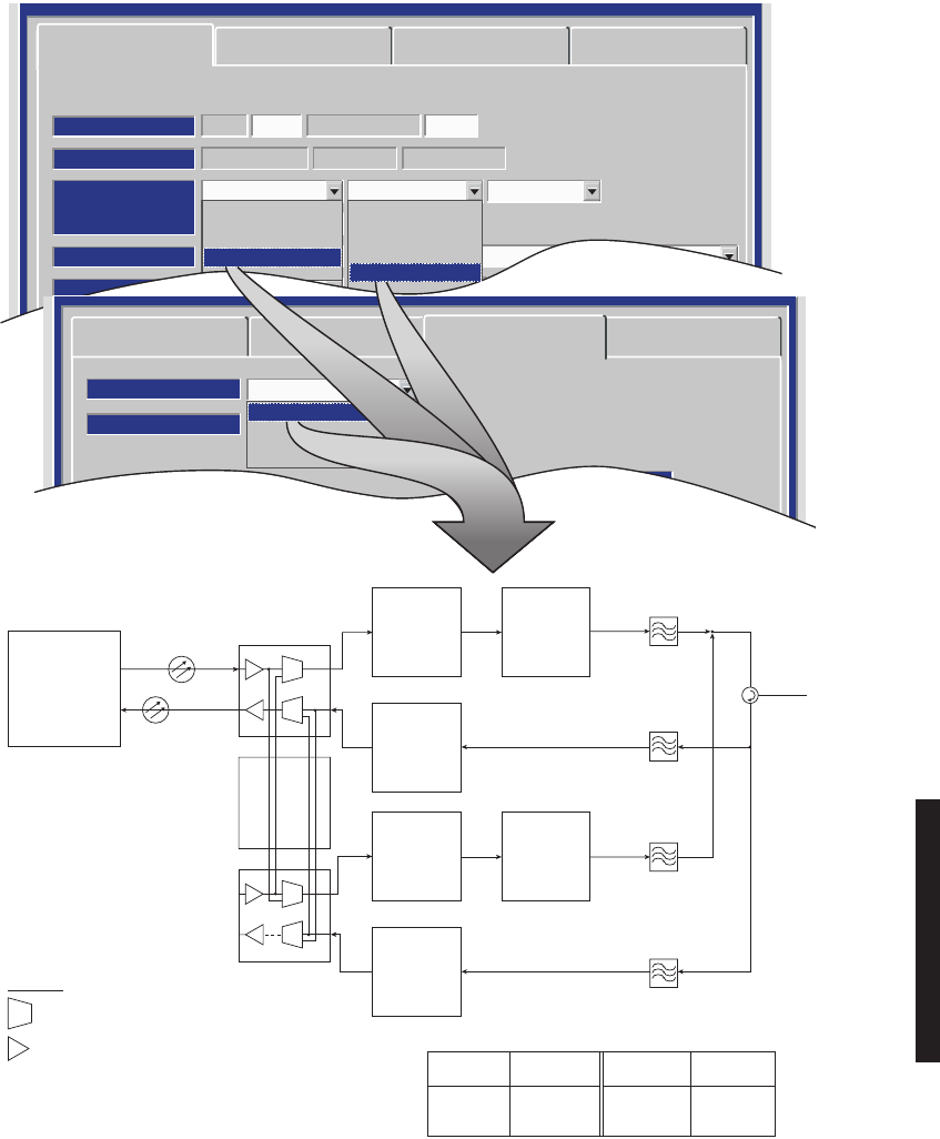
OC3 PROVISIONING EXAMPLE 12: FD Tx/FD Rx/4 Fiber
MDR-8000 OC3 128 TCMOC3-3
RADIO TYPE:
ELMC: 203R2 RADIO LINK ID: Disable
SYSTEM ID:
RADIO CONFIG:
HS Tx HS Rx Repeater
ATPC Enabled
A&B PA Present
Option Key:
Stat/Prov/WaySide
OPTIONS:
SYSTEM ALARM:
Major/Minor
RELAYS ON/NO
TBOS Display 1 RSL Alarm Disable
BER=1x10⁻⁶
RCV SWITCHING:
Disable AGC
Radio Configuration Service Channel OC3 Facilities
WaySide DS1 Facilities
Tuessday, March 7, 2000 1:27:15 PM USI Version R1.00 MDR-8000 OC3 Controller Version R1.00
Radio Configuration
Fiber Configuration
Select All
Section OH Insertion
BER Alarm Threshold
BER Switch Threshold
1X10⁻⁶
Disable
4 Fiber Switched
Frame & B1
1X10⁻⁸
1X10⁻⁸
1X10⁻⁸
1X10⁻⁷
1X10⁻⁸
1X10⁻⁸
Service Channel OC3 Facilities WaySide DS1 Facilities
AB
TRANSMITTER
AB
RECEIVER
Tuesday, January 22, 2002 2:03:38 PM USI Version R1.00
2 Fiber
2 Fiber Switched
4 Fiber
4 Fiber Switched
CUSTOMER
4 FIBER
A
TRANS-
MITTER
F1
A
POWER
AMPLIFIER
(OPTIONAL)
RT-1
RR-1
A
RECEIVER
F3
A OC3
I/O INTERFACE
OR-1
OT-1
AUXILIARY
INTERFACE
B
TRANS-
MITTER
F2
B
POWER
AMPLIFIER
(OPTIONAL)
RT-2
RR-2
B
RECEIVER
F4
B OC3
I/O INTERFACE
OR-2
OT-2
LEGEND
= SWITCH
= LASER
OR = OPTICAL RCV
OT = OPTICAL XMT
RR = RADIO RCV
RT = RADIO XMT
OC3 IN XMTR
ALLOWABLE COMBINATIONS
RCVR OC3 OUT
OR-1 RT-1, 2 RR-1 OT-1, 2
OR-2 RT-1, 2 RR-2 OT-1, 2
XMT
FILTER
F1
CIRCULATOR
ANTENNA
PORT
XMT
FILTER
F2
RCV
FILTER
F4
RCV
FILTER
F3
HS Tx HS Rx
LMW-7021-sm
06/29/02
None
NS Tx
HS Tx
FD Tx
None
NS Rx
HS Rx
SD Rx
FD Rx
4-32
OC3 PROVISIONING EXAMPLE 13: FD Tx/FD Rx/4 Fiber Switched
MDR-8000 OC3 128 TCMOC3-3
RADIO TYPE:
ELMC: 203R2 RADIO LINK ID: Disable
SYSTEM ID:
RADIO CONFIG:
HS Tx HS Rx Repeater
ATPC Enabled
A&B PA Present
Option Key:
Stat/Prov/WaySide
OPTIONS:
SYSTEM ALARM:
Major/Minor
RELAYS ON/NO
TBOS Display 1 RSL Alarm Disable
BER=1x10⁻⁶
RCV SWITCHING:
Disable AGC
Radio Configuration Service Channel OC3 Facilities
WaySide DS1 Facilities
Tuessday, March 7, 2000 1:27:15 PM USI Version R1.00 MDR-8000 OC3 Controller Version R1.00
Radio Configuration
Fiber Configuration
Select All
Section OH Insertion
BER Alarm Threshold
BER Switch Threshold
1X10⁻⁶
Disable
4 Fiber Switched
Frame & B1
1X10⁻⁸
1X10⁻⁸
1X10⁻⁸
1X10⁻⁷
1X10⁻⁸
1X10⁻⁸
Service Channel OC3 Facilities WaySide DS1 Facilities
AB
TRANSMITTER
AB
RECEIVER
Tuesday, January 22, 2002 2:03:38 PM USI Version R1.00
2 Fiber
2 Fiber Switched
4 Fiber
XMT
FILTER
F1
CIRCULATOR
ANTENNA
PORT
XMT
FILTER
F2
RCV
FILTER
F4
RCV
FILTER
F3
CUSTOMER
4 FIBER
A
TRANS-
MITTER
F1
A
POWER
AMPLIFIER
(OPTIONAL)
RT-1
RR-1
A
RECEIVER
F3
A OC3
I/O INTERFACE
OR-1
OT-1
AUXILIARY
INTERFACE
B
TRANS-
MITTER
F2
B
POWER
AMPLIFIER
(OPTIONAL)
RT-2
RR-2
B
RECEIVER
F4
B OC3
I/O INTERFACE
OR-2
OT-2
LEGEND
= SWITCH
= LASER
OR = OPTICAL RCV
OT = OPTICAL XMT
RR = RADIO RCV
RT = RADIO XMT
OC3 IN XMTR
ALLOWABLE COMBINATIONS
RCVR OC3 OUT
OR-1 RT-1, 2 RR-1 OT-1, 2
OR-2 RT-1, 2 RR-2 OT-1, 2
HS Tx HS Rx
LMW-7022-sm
06/29/02
4 Fiber Switched
None
NS Tx
HS Tx
FD Tx
None
NS Rx
HS Rx
SD Rx
FD Rx
4-33
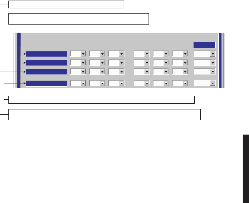
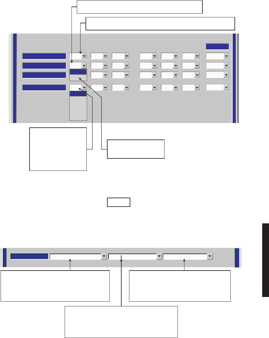
Figure 4-10 OC3 Radio Wayside DS1 Facilities Provisioning
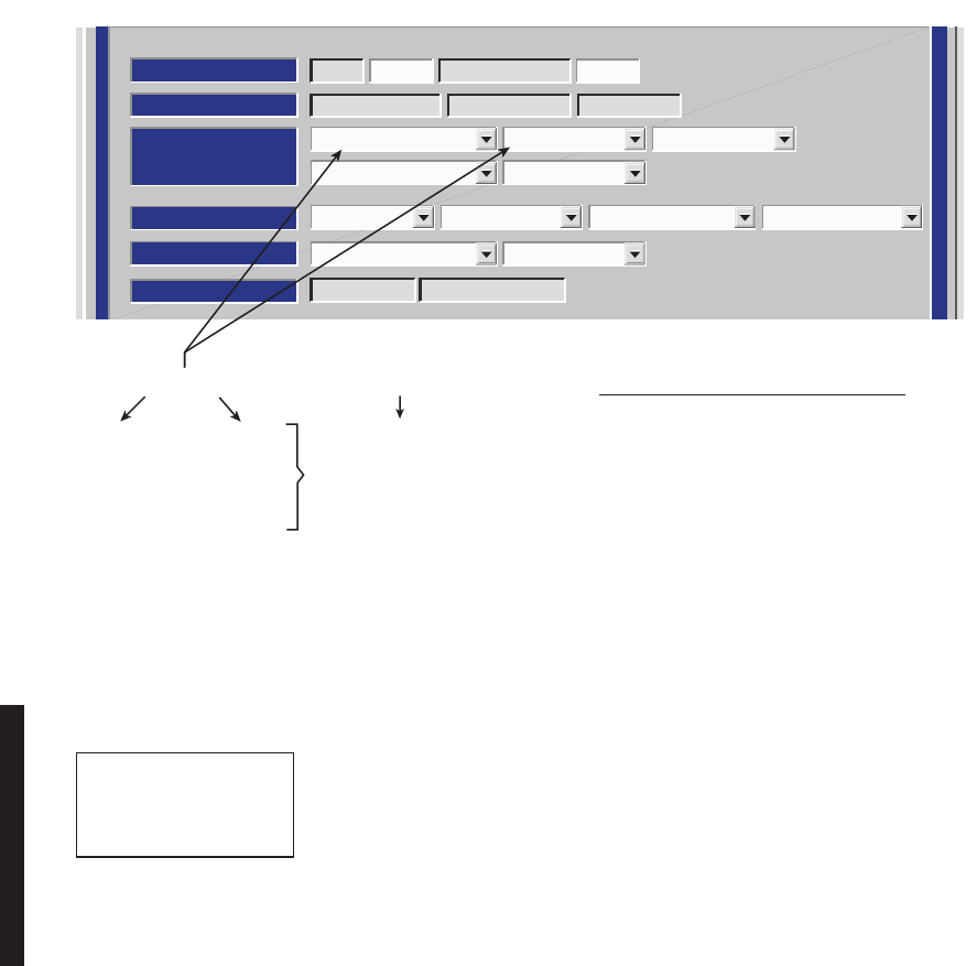
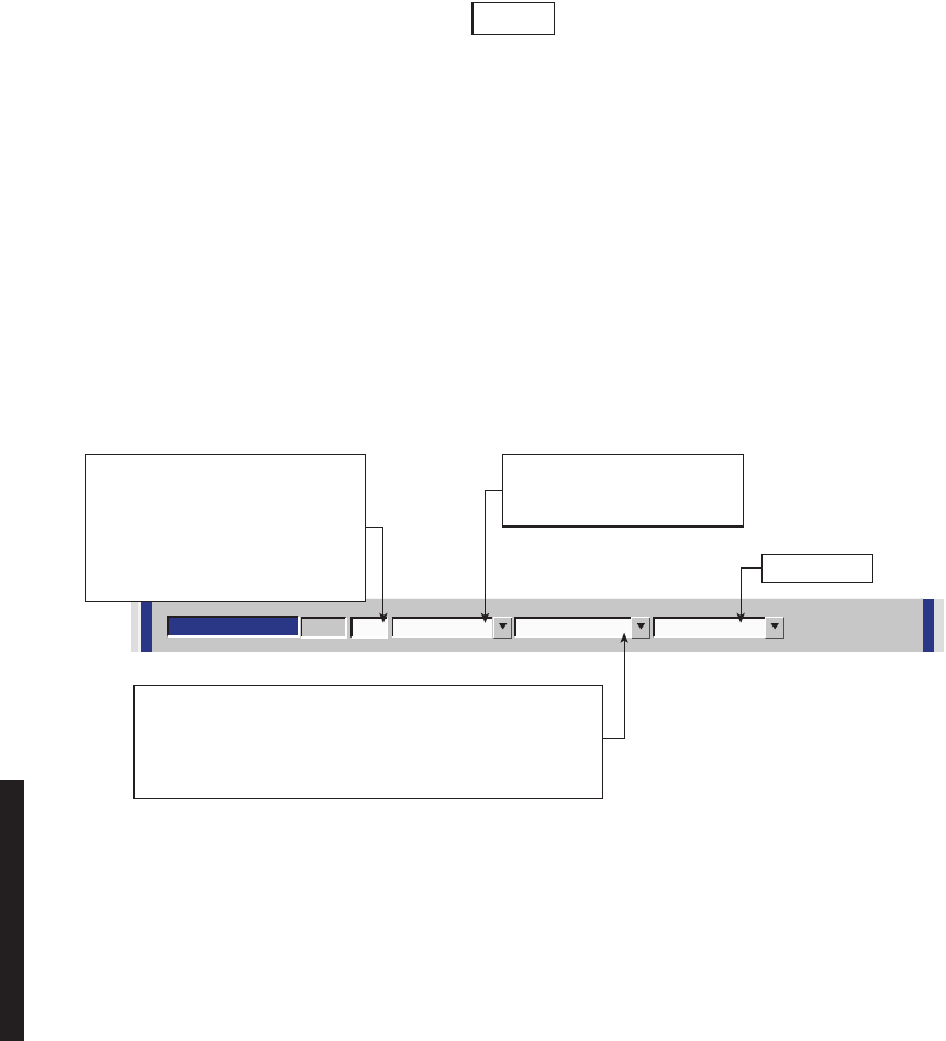
Figure 4-11 DS1/E1, DS3, OC3 Radio Service Channel Provisioning (Sheet 1 of 2)
ALARM DISABLE
ALARM DISABLE
Select All
OFF
123 123
DS1 LINES
FRAME FORMAT
FRAME FORMAT
ESF
LINE CODING
LINE CODING
OFF
LINE LENGTH
LINE LENGTH
0-133
OFF
ESF
OFF
0-33
OFF
ESF
OFF
0-33
OFF
ESF
OFF
0-33
OFF
ESF
OFF
0-33
OFF
ESF
OFF
0-33
ESF
SF
0-133
133-266
133-266
133-266
133-266
SELECT ON TO DISABLE ALARM REPORTING FOR WAYSIDE DS1 LINE.
SELECT OFF TO REPORT ALL ALARMS FOR LINE.
SELECT SUPERFRAME (SF) OR EXTENDED SUPERFRAME
(ESF) TO MATCH FRAMING ON WAYSIDE DS1 INPUT.
MDR-1018
05/05/04
SELECT DISTANCE IN FT.
TO CROSSCONNECT:
0-133
133-266
266-399
399-533
533-655
SELECT AMI OR B8ZS
CODING FOR WAYSIDE
DS1 LINE.
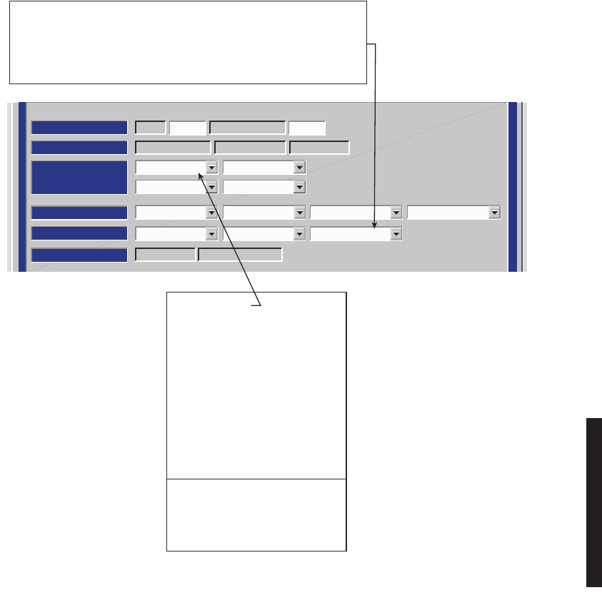
SERVICE CHANNEL: 2:AUDIO-2 -16/+7 Norm 3:MCS1:AUDIO-1 -16/+7 Norm
LMW-3017B-sm
06/04/03
SELECT AUDIO–1 0/0 Norm, AUDIO–1 0/0 O/H,
AUDIO–1 –16/+7 Norm, AUDIO–1 –16/+7 O/H,
AUDIO–2 0/0 Norm, AUDIO–2 0/0 O/H,
AUDIO 2 –16/+7 Norm, AUDIO–2 –16/+7 O/H, MCS
OR RS232-1 FROM THE DROP DOWN LIST.
SELECT AUDIO–1 0/0 Norm, AUDIO–1 0/0 O/H,
AUDIO–1 –16/+7 Norm, AUDIO–1 –16/+7 O/H,
AUDIO–2 0/0 Norm, AUDIO–2 0/0 O/H,
AUDIO 2 –16/+7 Norm, AUDIO–2 –16/+7 O/H,
OR MCS FROM THE DROP DOWN LIST.
SELECT AUDIO–1 0/0 Norm, AUDIO–1 0/0 O/H,
AUDIO–1 –16/+7 Norm, AUDIO–1 –16/+7 O/H,
AUDIO–2 0/0 Norm, AUDIO–2 0/0 O/H,
AUDIO 2 –16/+7 Norm, AUDIO–2 –16/+7 O/H, MCS
OR RS232–2 FROM THE DROP DOWN LIST.
There are five connectors on the backplane to interface the three service channels. Connectors
on backplane interface three functions: Audio, RS-232, and MCS. Each service channel is
provisioned for a specific function. Audio and MCS can be put on any open service channel.
RS-232-1 data can be put on Service Channel 1 and RS-232-2 data can be put on Service
Channel 2. RS-232 data cannot be put on Service Channel 3.
Note
4-34
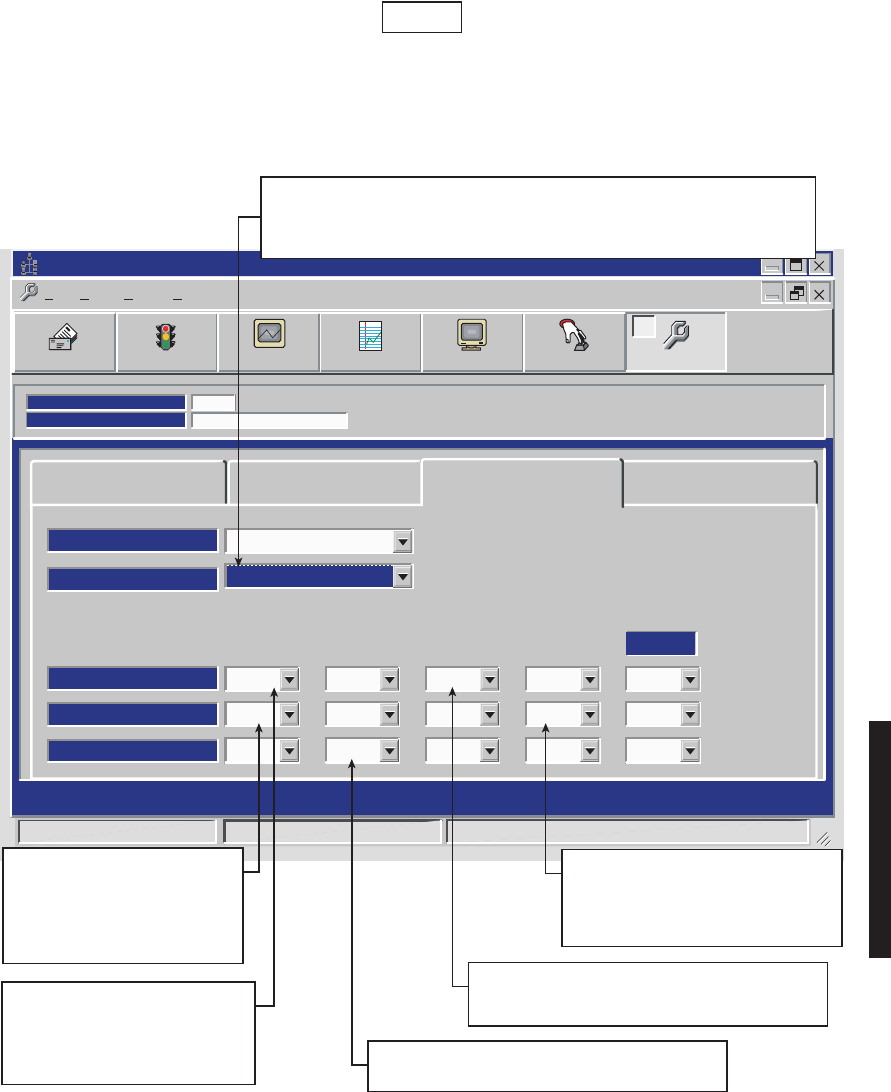
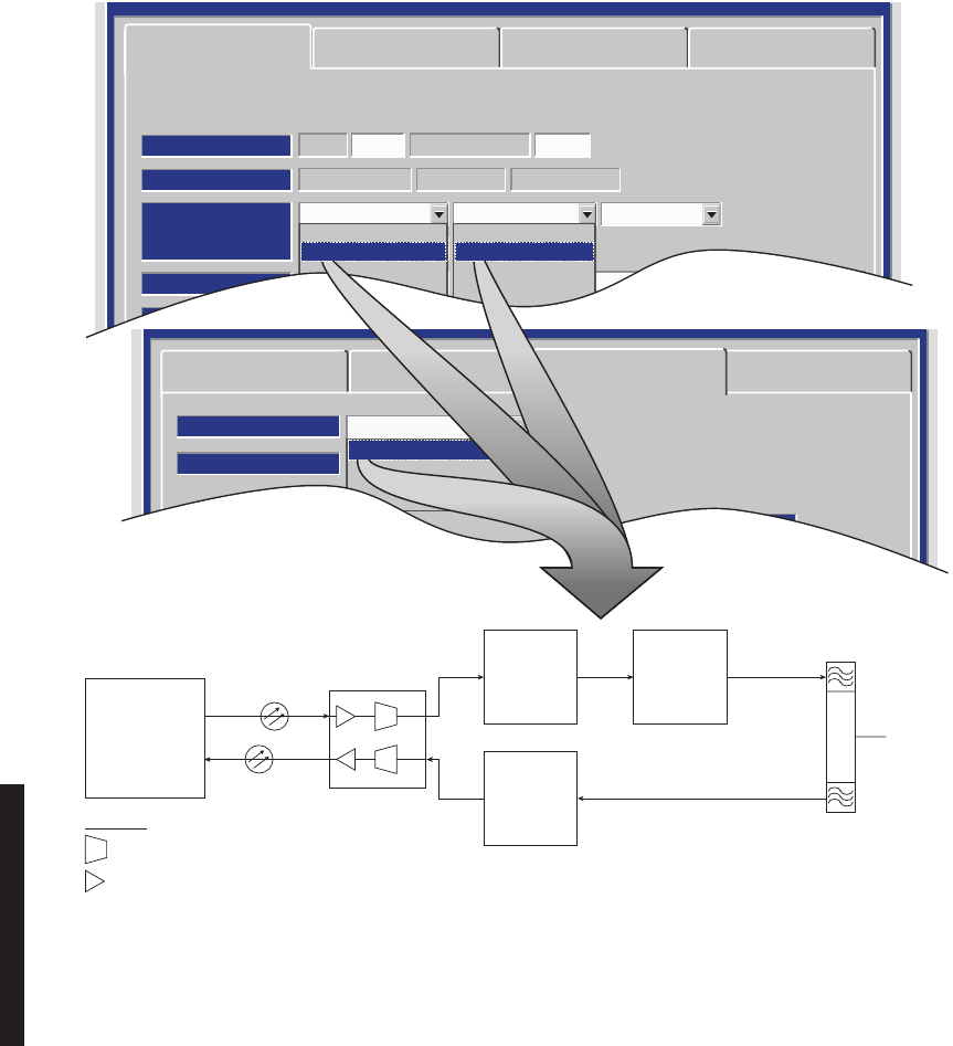
Figure 4-11 DS1/E1, DS3, OC3 Radio Service Channel Provisioning (Sheet 2 of 2)
J312
J343 J314
RCV SC
DATA E
XMT SC
DATA W
INSERT
W
AE-37( ) CONTROLLER
SELECT FOR TERMINAL
(ONE DIRECTION)
TO/FROM
A
I/O INTFC
RS-232 RXD1
DATA PATH NOT USED
RS-232 TXD1
DROP
E
SC MULDEM
1:RS232-ISERVICE CHANNEL: 2:RS232-2 3: MCS
Bridge OffRS-232
ONE MUST BE SELECTED
FOR FUNCTION TO DISPLAY.
J312
J343
LMW-9007-SM
03/13/03
J314
THRU
THRU
RCV SC
DATA E
XMT SC
DATA W
DROP
EINSERT
E
INSERT
WDROP
W
AE-37( ) CONTROLLER
SC MULDEM
SELECT FOR REPEATER
(TWO DIRECTIONS)
TO/FROM
A
I/O INTFC
RS-232 RXD1
BRIDGED PATHS
RS-232 TXD1
XMT SC
DATA E
RCV SC
DATA W
RS-232 Bridge On
4-35
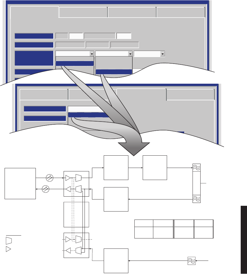
Figure 4-12 DS1/E1, DS3, OC3 Radio Audio Provisioning (Sheet 1 of 2)
SERVICE CHANNEL:
1:AUDIO-1 0/0 Norm
LMW-9041-sm
09/15/03
NORM – MODE OF OPERATION SELECTED IS NORMAL. IN THIS MODE
THE RADIO REQUIRES AN OFF HOOK SIGNAL FROM THE EXTERNAL
AUDIO EQUIPMENT. THIS MEANS THAT THE AUDIO EQUIPMENT USED
TO CONNECT TO THE RADIO MUST HAVE E AND M-LEAD SIGNALING
CAPABILITY (MOST AUDIO EQUIPMENT DOES HAVE THIS CAPABILITY).
IF THE EXTERNAL AUDIO EQUIPMENT DOES NOT HAVE E AND M-
LEAD SIGNALING CAPABILITY, SELECT O/H AND A CONSTANT OFF-
HOOK SIGNAL WILL BE PROVIDED AUTOMATICALLY BY THE RADIO
CONTROLLER SOFTWARE.
0/0 – RADIO REQUIRES 0 dBm AUDIO INPUT SIGNAL AT CONNECTOR J316.
THE RECEIVED AUDIO SIGNALS ARE NOT AMPLIFIED. THE RADIO
OUTPUTS 0 dBm ON AUDIO 1 CONNECTOR J316. THIS SELECTION IS
NORMALLY SUFFICIENT IF THE RADIO AND EXTERNAL AUDIO
EQUIPMENT ARE LOCATED IN THE SAME SHELTER, ROOM AND EVEN
BUILDING. LONGER DISTANCES (SUCH AS BETWEEN BUILDINGS) MAY
REQUIRE AMPLIFICATION ON THE OUTPUT SIGNAL. IN THIS CASE,
SELECT -16/+7 WHERE THE RADIO INPUT REQUIRED IS -16 dBm AND THE
RADIO AMPLIFIES RECEIVED AUDIO SIGNALS TO PROVIDE A +7 dBm
OUTPUT AT AUDIO 1 CONNECTOR J316.
AUDIO 1 OR AUDIO 2 – AUDIO CHANNEL TO BE INSERTED INTO SERVICE
CHANNEL 1 IS 1 OR 2. IF AUDIO CHANNEL 1 IS ALREADY IN USE, SELECT AUDIO
2. ALL ORDERWIRE IS PARTY-LINE. IF YOU WANT TO BE ABLE TO RING A
PARTICULAR SITE YOU MUST USE DTMF ON AUDIO 1. DTMF ALLOWS YOU TO
RING A DIALED SITE BUT ANYONE CAN PICK UP THE 4-WIRE TELEPHONE
AND/OR 2-WIRE HANDSET AND LISTEN TO THE CONVERSATION AND TALK.
WHATEVER IS SELECTED FOR SERVICE CHANNEL 1, IT MUST BE THE SAME
END-TO-END.
1:, 2: OR 3: – THE 64 kb/s SERVICE CHANNEL TO BE INSERTED INTO RADIO
OVERHEAD IS 1. IF SERVICE CHANNEL 1 IS ALREADY IN USE, SELECT SERVICE
CHANNEL 2 (2:) OR SERVICE CHANNEL 3 (3:) FOR THE AUDIO CHANNEL. WHATEVER
IS SELECTED FOR SERVICE CHANNEL 1, 2, OR 3, IT MUST BE THE SAME END-TO-
END.
Audio provisioning is required only if 4-wire audio equipment (external equipment not
part of the radio) is supplied and the external audio equipment is connected to audio
port 1 J316 or audio port 2 J317 on the radio backplane. These provisionable 4-wire
audio functions should not be confused with the 2-wire audio handset. The handset is
fully operational after it is connected to the TEL jack on the radio controller module,
provided the radio is provisioned Audio 1.
The most common audio provisioning is: 1:, 2:, or 3: AUDIO 1 0/0 Norm.
Note
The 2-wire handset is transported over Audio 1 only.
Note
4-36
DTMF allows you to dialup and ring other sites using the 2-wire hand-
set. Only the ringing is detected. Communication over the handset is
party-line. DTMF addressing is a local function not a network func-
tion, therefore if one or more radios are assigned the same DTMF
address, they will all ring when that address is dialed.
To be able to use the DTMF function:
1. Audio 1 must be selected for 2-wire handset operation.
2. DTMF must be turned ON on the Audio provisioning screen.
3. 2-wire handset must be connected to TEL jack on controller module.
4. Radios must be provisioned with DTMF address.
Figure 4-12 DS1/E1, DS3, OC3 Radio Audio Provisioning (Sheet 2 of 2)
Note
AUDIO:
Auto Squelch OnAll Call Ringer OffE-Lead-24Vdc
DTMF: OFF
LMW-3120B-SM
03/29/03
SELECT E-Lead-24Vdc OR
E-Lead GND TO BE APPLIED TO
SERVICE CHANNEL E-LEAD.
NOT USED
DOUBLE CLICK TO ENABLE
(000 DISPLAYS). ENTER 3-DIGIT
STATION CALL NUMBER. OPERATOR
CAN DIAL THIS NUMBER AND RING/
COMMUNICATE WITH THE STATION
VIA ORDERWIRE. SELECT OFF TO
DISABLE DTMF.
WHEN All Call Ringer On IS SELECTED, ALL TELEPHONES
RING WHEN CALL IS INITIATED. WHEN All Call Ringer Off IS
SELECTED, TELE
PHONE ASSOCIATED WITH RADIO WILL NOT
RING.
USEFUL IN SITUATIONS WHERE MULTIPLE RADIOS
ARE CONNECTED AT ONE SITE.
4-37
Figure 4-13 DS1/E1, DS3, OC3 Radio MCS-11 Provisioning
MCS-11: J309 Termination OnMCS RSS Off
J308 Input Clock J310 Modem
MCS: A1B
SELECT MCS RSS ON TO ALLOW CONTROLLER TO
RESPOND WHEN REMOTE STATION SCANNER (RSS) IS
POLLED. IF THIS OPTION IS TURNED OFF, CONTROLLER
DOES NOT RESPOND WHEN RSS IS POLLED. REMOTE
STATION SCANNER OPERATION IS AVAILABLE ONLY IF
MCS IS SELECTED IN ONE OF THE SERVICE CHANNELS.
LMW-4025-sm
09/17/02
SELECT MCS 11 J309 Termination On TO ENABLE
RESISTIVE TERMINATION AT THE END OF AN
MCS-11 "DAISY CHAIN". SELECT MCS 11 J309
Termination Off FOR STAND-ALONE APPLICATIONS
OR WHEN MDR-8000 IS JUST A LINK IN A DAISY-CHAIN.
MCS ADDRESS–ALLOWS USER TO ENTER AN
MCS ADDRESS IF MCS-11 HAS BEEN SELECTED IN
ONE OF THE SERVICE CHANNELS. THE FOLLOWING
LIST PROVIDES A VALID ADDRESS FOR EACH STATION:
ALPHA NUMERIC ALPHA
A 1 A
THROUGH THROUGH THROUGH
H 16 F
SELECT J308 Input Clock TO SYNC PORT
TO INPUT CLOCK FROM EXTERNAL SOURCE.
(RCV CLK, XMT CLK AND OUTPUT CLK ARE
DISABLED).
SELECT J308 Output Clock TO SEND A 64 KBS
CLOCK TO EXTERNAL EQUIPMENT. (RCV CLK,
XMT CLK, AND OUTPUT CLK ARE ENABLED).
SELECT MCS-11 J310 Master/Junction TO ENABLE
XMT, RCV,
AND OUTPUT CLOCKS. SELECT
MCS-11 J310 Modem TO DISABLE XMT AND RCV
CLOCKS. ALL CLOCKS TO BE PROVIDED BY
EXTERNAL MODEM.
4-38
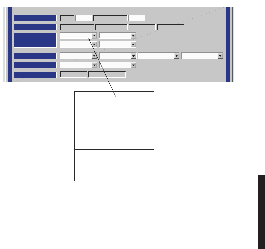
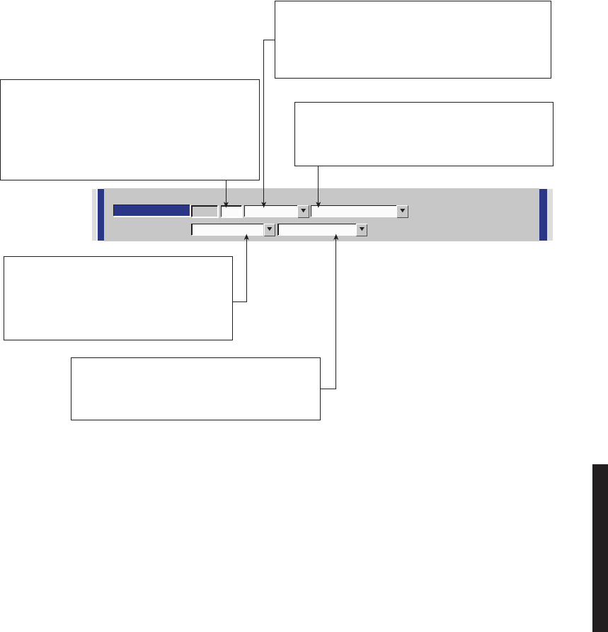
Figure 4-14 MCS Transport/PPP Transport Provisioning
MCS: A1AMCS 11: J309 Termination Off J310 Master/JunctionMCS RSS On
J308 Output Clock RF/Rptr
MCS Transport PPP Transport
None
RF
Rptr
RF/Rptr
None
None
RF
Rptr
RF/Rptr
LMW-7234A
02/08/04
Note
MCS-11 is enabled/disabled using the service channel 1-3 selections.
MCS-11 must be enabled for MCS-11/PPP transport operation.
Note
Currently the only valid transport combinations (for
terminal or repeater) are:
Note
For MCS-11 to operate properly, all radio controllers in
a system interconnected by RF or RPTR must have the
same MCS transport and PPP transport provisioning.
Currently the only valid transport combinations (for
terminal or repeater) are:
SELECT PORTS ON
I/O INTFC MODULE.
SERVICE CHANNEL IS
INSERTED/DROPPED.
MCS-11 DATA MCS-11 AND
IP DATA
MCS TRANSPORT PPP TRANSPORT REMARKS
RF/RPTR NONE TMN INTFC MODULE IS NOT INSTALLED.
COMPATIBLE WITH OLDER (PRE-TMN) SOFTWARE.
RECOMMENDED FOR SYSTEM UPGRADES ONLY.
RF/RPTR RF/RPTR MUST BE CHOSEN IF TMN INTERFACE MODULE IS
INSTALLED. RECOMMENDED FOR ALL NEW SYSTEMS.
4-39
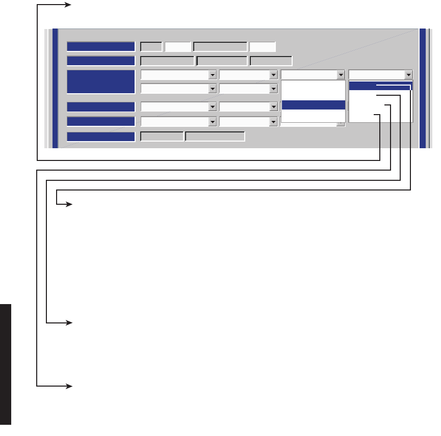
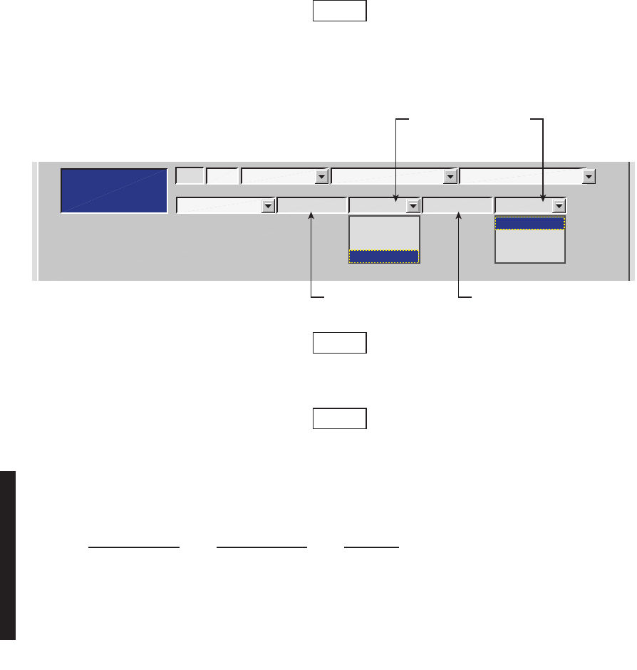
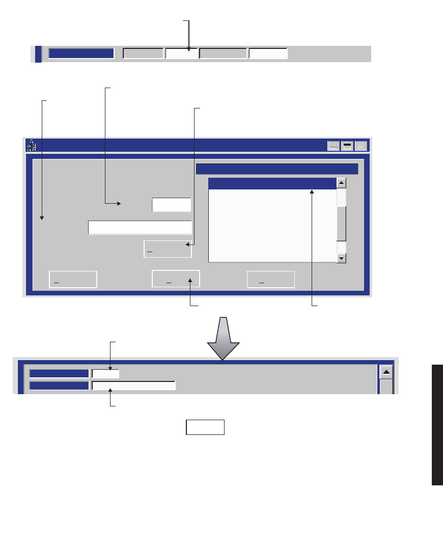
Figure 4-15 DS1/E1, DS3, OC3 Radio ELMC Provisioning
Setup ELMC Address -- MDR-8000
Extended Link Monitor Channel (Elmc) Address
J7914
DURANGO
Description:
ELMC:
Save Cancel
Delete Elmc
Add Elmc=>
J7914 -- DURANGO
5. TYPE IN 5-CHARACTER
ADDRESS. MUST MATCH
ADDRESS IN STEP 1
EXACTLY.
6. TYPE IN
DESCRIPTION
(IF DESIRED).
7. CLICK HERE
TO ENTER NEW
ADDRESS AND
DESCRIPTION
8. CLICK HERE
TO SAVE.
PROVISION ANY ONE OR ALL RADIOS AT A SITE, LOCALLY, USING FOLLOWING PROCEDURE:
LOCAL PROVISIONING
Communicating
ELMC Address:
Description:
DURANGO
J7914
2. BACKSPACE TO DELETE
CURRENT ELMC ADDRESS
(IF ANY).
3. ENTER 5-CHARACTER
ELMC ADDRESS.
4. OPEN ELMC ADDRESS
SETUP SCREEN.
LMW-1019-sm
08/08/02
SYSTEM ID:
ELMC
J7914
RADIO LINK ID: Disable
1. SINGLE CLICK TO
PLACE CURSOR
HERE.
DISPLAYS
ENTERED ADDRESS
DISPLAYS ENTERED
DESCRIPTION (IF ANY)
DISPLAYS
ENTERED ADDRESS
Note
E
ach network element controller with ELMC must first be locally provisioned with a unique ELMC
or remote address. The ELMC address is not related to MCS-11. Any name can be entered as long as
the name is a 5-character, alphanumeric word. The address is case sensitive. Space, dash, slash,
asterisk, and underscored characters are not allowed. If small numbers are used as addresses, then it
is necessary to fill higher order digits with zeros. For example, if the address is the value 1, then the
address must be entered as 00001. No address, or the same address used on multiple network
e
lements, prevents ELMC access to that/those network elements. The remote address can only be pro-
visioned and changed locally. Service-affecting functions, including operation mode, radio
configuration, and remote address, cannot be provisioned or changed remotely.
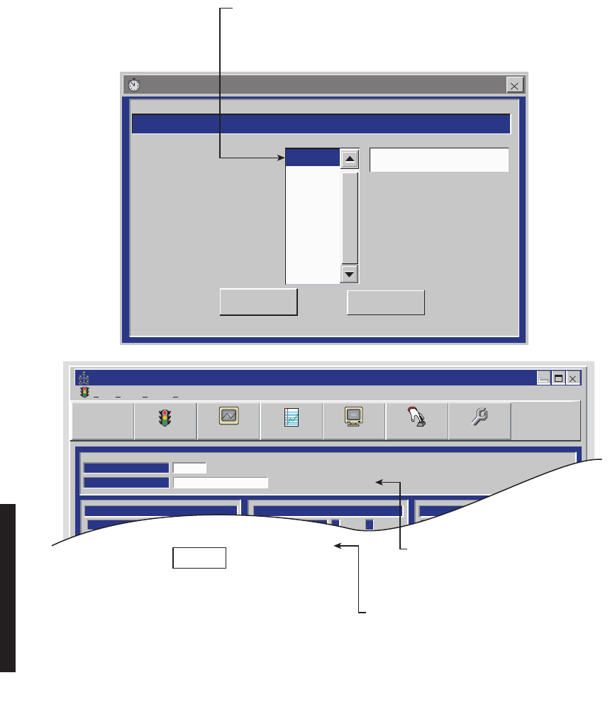
4-40
Figure 4-16 DS1/E1, DS3, OC3 Radio ELMC Remote Time-Out Constant Provisioning
Remote Time-Out Constants -- MDR-8000
Select a value in the following list to change the current remote timeout
OK Cancel
3 secs
4 secs
5 secs
6 secs
7 secs
8 secs
9 secs
10 secs
Current time-out is 3 secs
Alcatel User Interface - [Alarm Status -- MDR-8000 OC3]
File View Setup Options
REMOTE STATUS ALARM
Retrieving Provisioning
ELMC Address [F8]:
ELMC Description:
DURANGO
J7914
A B
TRANSMIT
TRANSMITTER
STATUS
A B
RECEIVER
A B
COMMON
RECEIVER
STATUS
I/O
PWR
STATUS
F6
Performance
Alarm Status Analog Monitor
F5
Station Alarm
F7
Provisioning
F9
Acknowledge
F3
User Control
F8
✓
F4
LMW-4024A-SM
08/08/02
SELECT TIME LOCALLY FOR ELMC RESPONSE TO A REQUEST
FOR STATUS BEFORE TRYING AGAIN. SELECT SHORTER TIME
(5 SECS) FOR SHORTER SYSTEMS (10 HOPS OR LESS).
SELECT LONGER TIME (10 SECS) FOR SYSTEMS WITH 10 HOPS
OR MORE.
MESSAGE DISPLAYED FOR LENGTH
OF TIME SELECTED DURING TIME LOCAL
RADIO IS ATTEMPTING TO COMMUNICATE
WITH REMOTE ADDRESS VIA ELMC.
MESSAGE DISPLAYED FOR LENGTH
OF TIME SELECTED IF THERE IS NO
RESPONSE TO REQUEST FOR STATUS/
CONTROL/PROVISIONING.
No Report
Note
If the time-out value selected is too short, there
may not be enough time for the remote
controller to respond before the requesting
controller times out, resulting in a constant No
Report. ELMC response time delay is a function
of controller circuitry and is not linear. Always
start with longer time-out, then reduce time to
an acceptable value.
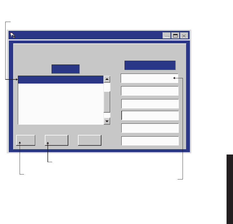
4-41
Figure 4-17 DS1/E1, DS3, OC3 Radio Control Names Provisioning
LMW-1021-SM
02/04/03
2. SELECT RADIO
NOTE: DEFAULT CONTROL NAMES ARE USER CONTROL 1-6
User Control Names Setup -- MDR-8000
RACK1 -- DURANGO
RACK2 -- DURANGO
RACK3 -- RED MTH PASS
RACK4 -- SILVERTON
APPLY
OK CANCEL
GEN START
TWR LIGHT OVRD
User Control #3
User Control #4
User Control #5
User Control #6
ELMC List CONTROL NAMES
3. SELECT CONTROL POINT
4. BACKSPACE TO DELETE
AND TYPE IN NEW CONTROL
NAME
CLICK HERE TO CANCEL
TRANSACTIONS
BEFORE SAVE
CLICK HERE
TO SAVE
1. OPEN USER CONTROL NAMES SETUP SCREEN
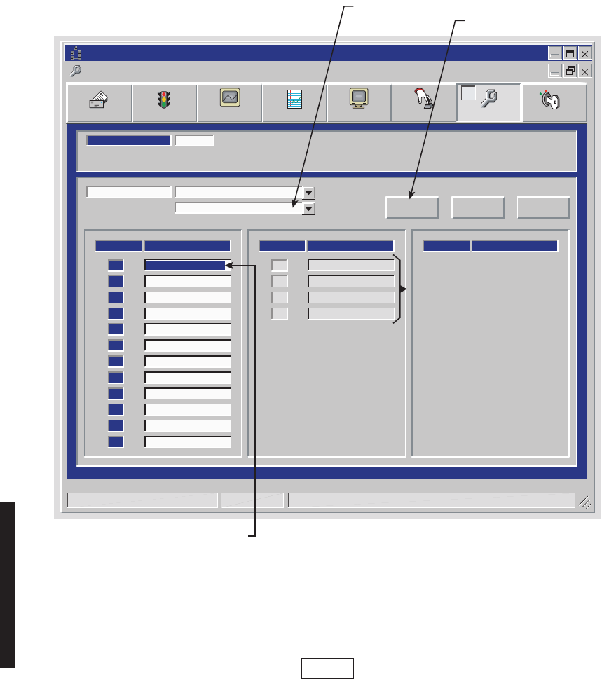
4-42
Figure 4-18 DS1/E1, DS3, OC3 Radio Alarm Names Provisioning
DS3 screen is shown. DS1/E1 and OC3 alarm names provisioning is
similar.
Alcatel User Interface – [Provisioning MDR-8000 OC3]
File View Setup Options
User Control
F8
F6
Performance
Alarm Status
F4
Station Alarm
F7 F9
Prov. Save
F3 F5
Analog Monitor Password
F11
LOCAL DS3 PROVISIONING
Communicating***
ELMC ADDRESS:
ELMC ADDRESS:
S302
LMW-5068-sm
03/29/03
ALARM #
ALARM NAMES
[1]
STATION ALARM #2
[2]
STATION ALARM #3
[3]
STATION ALARM #4
[4]
STATION ALARM #5
[5]
STATION ALARM #6
[6]
STATION ALARM #7
[7]
STATION ALARM #8
[8]
STATION ALARM #9
[9]
STATION ALARM #10
[10]
STATION ALARM #11
[11]
STATION ALARM #12
[12]
ALARM #
ALARM NAMES
STATION ALARM #13
[13]
STATION ALARM #14
[14]
STATION ALARM #15
[15]
STATION ALARM #16
[16]
ALARM #
ALARM NAMES
DS301 -- MDR-8000 DS3
DS301 -- MDR-8000 DS3 OK Cancel Apply
STATION ALARM #1
Monday, August 6, 2001 2:11:32 PM MDR-8000 DS3 Controller Version R1.03
2. SELECT ALARM
3. BACKSPACE TO DELETE
AND TYPE IN NEW ALARM
NAME
1. SELECT RADIO
CLICK HERE TO SAVE
AVAILABLE IF RADIO IS
PROVISIONED STATION ALARM
13-16 FOR SYSTEM ALARM ON
RADIO CONFIGURATION
PROVISIONING SCREEN.
HIDDEN IF RADIO IS
PROVISIONED TBOS DISPLAY
1-8.
Note

5-1
5
MAINTENANCE
5.1
GENERAL
This section contains information and procedures to aid in restoring the equipment to its
proper operating condition after it has been determined that a problem exists.
The following warnings and cautions apply while operating, performance testing, trouble-
shooting, or repairing the MDR-8000 series radios.
Short circuits in low-voltage, low-impedance dc circuits can cause
severe arcing that may result in burns or eye injury. Remove rings,
watches, and other metal jewelry while working with primary cir-
cuits. Exercise caution to avoid shorting power input terminals.
XMTR and RCVR crystals are soldered and tuned in an oscillator
assembly board at the factory. Crystals are not replaceable compo-
nents.
Units with the electrostatic-sensitive (ESS) symbol contain ESS
devices. Store these units in an antistatic container when not in use,
and anyone handling a unit should observe antistatic precautions.
Refer to the Special Precautions pages in the front of the instruction
book for detailed handling information.
DANGER
Possibility of
Injury
to Personnel
CAUTION
Possibility of
Service
Interruption
CAUTION
Possibility of
Service
Interruption

5-2
RF flex coaxial cable requires special consideration. The electrical
characteristics of the coax can be affected if it is accidentally twisted
or bent. Provide mechanical support to prevent any weight or strain to
the coax and connector when connecting or disconnecting equipment.
Loosen the connectors at both ends of a coax section if one end must be
moved even slightly. SMA connectors should be secured in place finger-
tight, and then gently tightened using a torque wrench with a 5/16 in.
head set for 7 to 9 inch-pounds. The connectors should not be left fin-
gertight.
Ensure that all antennas are properly aligned and waveguide is in good physi-
cal condition.
Before performing procedures that might in any way affect transmission, it is
recommended that the person performing the procedure understand the FCC
Rules and Regulations pertaining to the equipment and be properly authorized
to operate the equipment.
5.2
MAINTENANCE PHILOSOPHY
This section provides information and procedures for equipment maintenance down to the
module level. Module repair is not covered in this manual. A replacement procedure for the
crystal oscillator subboard on the transmitter and receiver modules is provided to enable
future use of the local oscillator at a different frequency in another application or at
another location. Use the drawings in the appendix and those in the station drawing pack-
age to support the procedures in this section
The use of maintenance procedures in this section may result from failure of a
periodic check, an alarm indication, or unacceptable performance. These problems should
normally be resolved as shown in the maintenance philosophy flow chart (Figure 5-1).
CAUTION
Possibility of
Service
Interruption
Note
Note
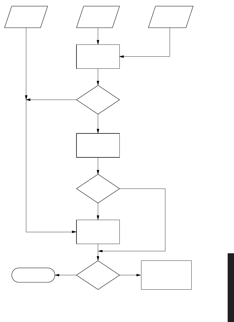
5-3
Figure 5-1 Maintenance Philosophy Flow Chart
PERIODIC
CHECK
FAILURE*
ALARM
PERFORM
TROUBLE
ANALYSIS
CAUSE
OF
ALARM
REFER TO
MODULE
REPLACEMENT
TABLE
MODULE
ADJUSTMENT
REQUIRED
PERFORM
PROBLEM
RESOLVED
PERFORM ADDITIONAL
TROUBLESHOOTING
USING THEORY AND
DIAGRAMS SECTION
AS REQUIRED TO
RESOLVE PROBLEM
INDICATION
CHECKS AND
ADJUSTMENTS
REQUIRED*
MODULE
REPLACEMENT
REQUIRED
NO
YES
YES NO
MAINTENANCE
COMPLETE
MW300–0843–2
*IF APPLICABLE
APPLICABLE
CHECKS AND
ADJUSTMENTS*
PERFORMANCE
DOES NOT MEET
ESTABLISHED
STANDARDS
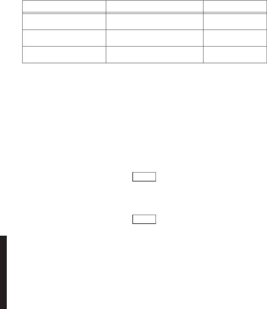
5-4
5.3
SPECIAL TOOLS
Refer to Table 5-1 for special tools required for maintenance. Similar tools can be substi-
tuted for those recommended; however, before substitution, check the minimum parameters.
5.4
PERSONAL COMPUTER (PC)
The PC is an on-line maintenance and troubleshooting tool. See Figure 5-2. Connect the
RS-232 interface cable between USI connector on controller and the PC.
5.5
ALARM MONITORING AND INSPECTION
Perform the following checks whenever a station is entered:
1
Verify that no alarms are lighted; only the green status indicators should be
lighted.
2
Momentarily press LAMP TEST switch. Verify all indicators light.
Keeping records of errors and alarm history can be an aid to system trouble-
shooting.
The local status alarms screen displays the alarms of the radio to which the
USI is connected, either physically or addressed via the ELMC.
3
Using the USI computer, check local alarms on the Local Status Alarms
screen.
Table 5-1 Special Tools Required
TOOL ESSENTIAL CHARACTERISTICS USED ON
Torque Limiting Screwdriver
Briggs-Weaver PN 8370-01880 #2 Phillips, 19 in-lb DS1/E1, DS3, OC3
#2 Phillips Bit Extension
Briggs-Weaver PN 8528-27370 (for use with torque limiting screw-
driver) DS1/E1, DS3, OC3
Torque Wrench,
Utica Model CHA5 w/OP-102 5/16 in., 7-to-9 in-lb, sensing type DS1/E1, DS3, OC3
Note
Note
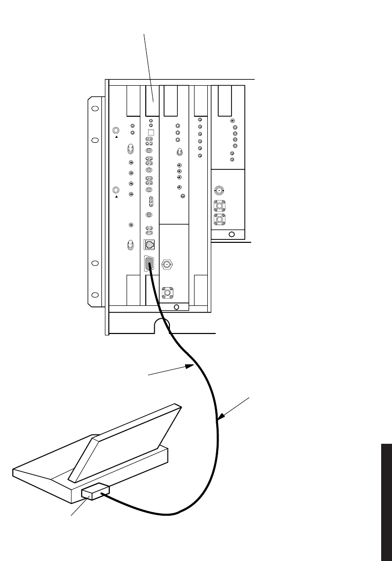
5-5
Figure 5-2 USI Computer to Controller Interconnection
MW211–0066–1
101598
AE–37( )
CNTLR
C1
RS–232C PORT
RS–232C
INTERFACE CABLE
USI
TERMINAL
TO CONNECTOR J301
(CONNECTS TO
AE–37 CONTROLLER)
MDR–8000
SHELF

5-6
5.6
RECOMMENDED PERIODIC CHECKS
Perform local oscillator frequency verification, receive local oscillator frequency verifica-
tion, and transmitter output check 1 year after initial setting and at 5-year intervals
thereafter to correct possible drift caused by aging.
5.7
TROUBLESHOOTING
The digital radio system is equipped with alarm circuitry and automatic switching (in hot-
standby, frequency diversity, and space diversity configurations) to provide protection
against loss of traffic. This automatic switching, coupled with adaptive equalization of mul-
tipath distortion, provides protection against equipment outage and propagation varia-
tions. Because of the finite life of electronic equipment, failures occur.
5.7.1
Test Procedures
All referenced test and check procedures are in Appendix E on attached CD.
5.7.2
Linear/Ring Radio Troubleshooting
Troubleshoot linear and ring radio systems using alarm troubleshooting Figure 5-3
through Figure 5-14. Ring troubleshooting is further explained in the Maintenance section
on the attached CD. After isolating the fault to the most probable cause, replace modules
or repair as directed. The Module Replacement Matrix identifies the alignment procedures
to be performed after a module has been replaced.
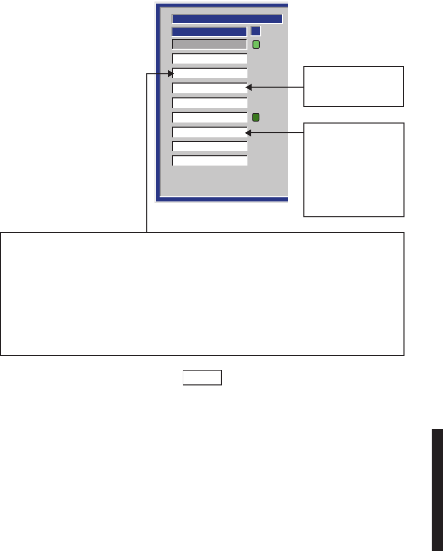
5-7
Figure 5-3 Troubleshooting DS1/E1 Radio XMT Alarms (Sheet 1 of 2)
TRANSMITTER
XMT OnLine
STATUS
A
XMT Provisioning
Common Loss
PA Temperature
PA Power
Transmit Power
ATPC High Power
ATPC Timeout
Sync Loss
LMW-1027-sm
(Page 1 of 2)
05/17/03
SILENT FAILURE (NO ALARM ACTIVATED) AT TRANSMITTER. THE COMMON LOSS ALARM, GENERATED BY
THE AE-37Y CONTROLLER, TRIGGERS WHEN BOTH A SIDE AND B SIDE DOWNSTREAM RECEIVERS HAVE A
RADIO FRAME LOSS OR CHANNEL FAILURE. IN A HOT-STANDBY HOP, LOSS OF BOTH RECEIVERS INITIATES
A REQUEST
TO SWITCH TO STANDBY TRANSMITTER, EVEN THOUGH NO TRANSMIT ALARMS ARE PRESENT.
IF THE PATH IS NOMINAL, THE TRANSMITTER SWITCHES IN 5 SECONDS. IF
THE PATH IS IN A FADE (APC IS IN
ACTIVE RANGE), THE TRANSMITTER SWITCHES IN 30 SECONDS. IF THE DOWNSTREAM ALARMS CLEAR
WITHIN 5 SECONDS, A CLA IS INITIATED ON THE OFF-LINE SIDE TO INDICATE A SILENT TRANSMIT FAILURE.
IF
ALARMS STILL EXIST, THE TRANSMITTER CONTINUES TO SWITCH EVERY 30
SECONDS. THIS PROCESS
CONTINUES UNTIL THE RECEIVE ALARMS CLEAR, BUT NO
CLA IS ACTIVATED.
PA TEMPERATURE LIMITS
EXCEEDED. CHECK
MOUNTING SCREWS.
ATPC HAS BEEN ACTIVE
FOR 5 MINUTES WITHOUT
RETURNING TO NORMAL
(DROPS BACK TO LOW
POWER ONLY IF ATPC
HAS BEEN ENABLED WITH
TIMEOUT).
In order to clear a CLA, it must be acknowledged locally
(at radio indicating alarm) using front panel control on
controller module.
Note
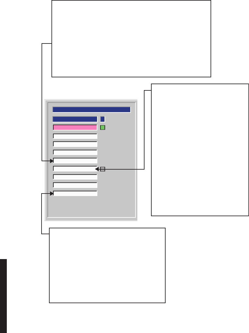
5-8
Figure 5-3 Troubleshooting DS1/E1 Radio XMT Alarms (Sheet 2 of 2)
LMW-1027
(Page 2 of 2)
10/27/99
TRANSMITTER
A
STATUS
Transmit Power
ATPC High Power
ATPC Timeout
Sync Loss
PA Temperature
PA Power
XMT On Line
XMT Provisioning
Common Loss
LOSS OF XMT SIGNAL DETECTED AT OUTPUT OF PA. IF ANY OTHER
ALARMS ARE RED, GO TO 1. IF NOT GO TO 2.
1. IF OFF NORMAL ALARM IS LIT, CHECK 10.5 V SWITCH
ON POWER SUPPLY IS ON. IF NOT REMOVE/REPLACE PA MODULE.
2. MEASURE RF LEVEL AT RF MON CONNECTOR ON
XMTR MODULE. IF LEVEL IS LOW, GO TO 3. IF NOT, GO TO 4.
3. MEASURE FREQUENCY AT XTAL MON CONNECTOR ON XMTR
MODULE. IF FREQUENCY IS CORRECT, REMOVE/REPLACE XMTR
MODULE. IF NOT REMOVE/REPLACE XTAL OSCILLATOR SUBBOARD.
4. REMOVE/REPLACE I/O INTERFACE MODULE.
LOSS OF XMT SIGNAL DETECTED AT
OUTPUT OF XMTR. IF I/O COMMON
ALARM AND XMT SYNC LOSS ALARM ARE
RED, GO TO 1. IF NOT GO TO 2.
1. REMOVE/REPLACE I/O INTERFACE
MODULE.
2. MEASURE RF LEVEL AT RF MON
CONNECTOR
ON XMTR MODULE. IF LEVEL IS LOW,
GO TO 3. IF NOT, GO TO 4.
3. MEASURE FREQUENCY AT XTAL MON
CONNECTOR ON XMTR MODULE. IF
FREQUENCY IS CORRECT,
REMOVE/REPLACE XMTR MODULE.
IF NOT, REMOVE/REPLACE XTAL
OSCILLATOR SUBBOARD.
4. REMOVE/REPLACE I/O INTERFACE
MODULE.
IN PROTECTED SYSTEMS, INDICATES FAILURE IN
SYNCHRONIZATION BETWEEN I/O INTERFACE
MODULES. IF I/O INTERFACE MODULE IN-SERVICE
IS NOT ACTIVE ON ALARMED SIDE, FAILURE IS
BETWEEN A
AND B I/O INTERFACE MODULES. IF
I/O INTERFACE MODULE IN-SERVICE IS ACTIVE,
FAILURE IS BETWEEN REPEATER RACKS OF
SYNCHRONOUS REPEATER.
1. REPLACE A-SIDE I/O INTERFACE MODULE.
2. REPLACE B-SIDE I/O INTERFACE MODULE.
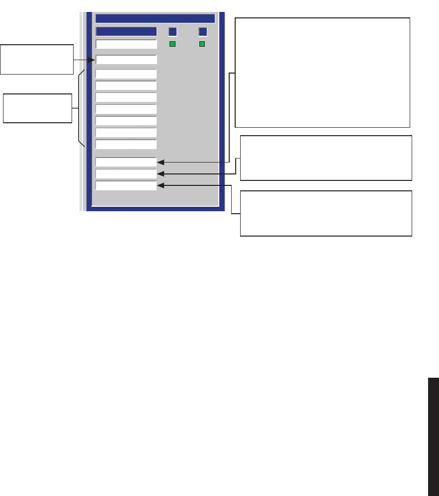
5-9
Figure 5-4 Troubleshooting DS3 Radio XMT Alarms
A B
TRANSMITTER
Common Loss
XMT On Line
XMT Provisioning
PA Temperature
PA Power
Transmit Power
ATPC High Power
ATPC Timeout
SYNC Loss
DS3 Frame Loss
DS3 Degraded
DS3 AIS Detect
STATUS
LMW-3131-sm
06/27/02
SEE DS1/E1
XMT ALARMS,
FIG 5-3
SEE
DS1/E1 XMT ALARMS
XMT PROV, FIG 5-3
DS3 I/O INTFC CANNOT RECOVER FRAMING FROM
INCOMING DS3 SIGNAL OR THERE IS NO INPUT
SIGNAL. IS DS3 AIS Detect ALARM ON?
YES, TROUBLESHOOT UPSTREAM
RADIOS AND EXTERNAL MUX
EQUIPMENT.
NO, CHECK INPUT SIGNAL. IF INPUT SIGNAL
IS OK, REPLACE DS3 I/O INTFC.
IF NOT, TROUBLESHOOT EXTERNAL
MUX EQUIPMENT.
DS3 INPUT TO DS3 I/O INTFC HAS EXCEEDED
PROVISIONED BER THRESHOLD (HIGH ERROR
CONDITION).
TROUBLESHOOT EXTERNAL MUX EQUIPMENT.
AIS (BLUE SIGNAL), INSERTED AT MUX (EXTERNAL
TO THE RADIO) HAS BEEN DETECTED ON XMT
INPUT TO DS3 I/O INTFC.
TROUBLESHOOT EXTERNAL MUX EQUIPMENT.

5-10
Figure 5-5 Troubleshooting OC3 Radio XMT Alarm
A B
TRANSMITTER
Transmitter Fault
Transmitter On Line
RF Common Loss
PA Temperatore
PA RF Power
Transmitter RF Power
ATPC High Power
ATPC Timeout
OC3 Input Online
OC3 LOS
OC3 LOF
OC3 AIS-L Detect
OC3 Degrade
STATUS
Monday, April 09, 2001 1:58:29 PM
LMW-5034-sm
05/17/03
SEE DS1/E1
XMT ALARMS,
FIG. 5-3
SUMMARY ALARM
FOR XMTR
OC3 I/O INTFC CANNOT RECOVER FRAMING
FROM INCOMING OC3 SIGNAL OR THERE IS
NO OPTICAL INPUT SIGNAL.
IS OC3 AIS-L Detect ALARM ON?
YES, TROUBLESHOOT UPSTREAM
RADIOS AND EXTERNAL MUX
EQUIPMENT.
NO, CHECK OPTICAL INPUT SIGNAL.
IF OPTICAL INPUT SIGNAL IS OK,
REPLACE OC3 I/O INTFC.
IF NOT, TROUBLESHOOT
EXTERNAL MUX EQUIPMENT.
AIS (BLUE SIGNAL), INSERTED AT MUX
(EXTERNAL TO THE RADIO) HAS BEEN
DETECTED ON OC3 INPUT TO OC3 I/O
INTFC.
TROUBLESHOOT EXTERNAL MUX
EQUIPMENT.
OC3 INPUT TO OC3 I/O INTFC HAS
EXCEEDED PROVISIONED BER
THRESHOLD (HIGH ERROR CONDITION).
TROUBLESHOOT EXTERNAL MUX
EQUIPMENT.
TRIGGERS WHEN BOTH A AND B RCVRS
HAVE LOF. THIS INITIATES A REQUEST TO SWITCH
XMTRS AT FAREND. WHEN RSL IS MORE POSITIVE
THAN - 50 DBM, FAREND XMTR SWITCHES IN 5 SE-
CONDS AND THEN SWITCHES EVERY 30 SECONDS
UNTIL ALARM CLEARS. AFTER XMTR SWITCHES 10
TIMES, THE I/O INTERFACE MODULE SWITCHES.
THIS SEQUENCE OF EVENTS CONTINUES UNTIL
ALARM CLEARS. TROUBLESHOOT FAREND XMTRS.
In order to clear a CLA, it must be
acknowledged locally (at radio
indicating alarm) using front panel
control on controller module.
Note
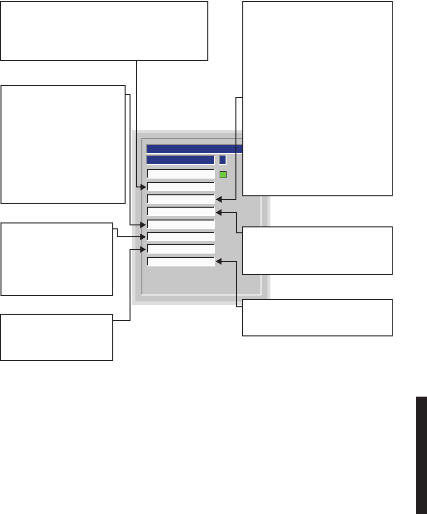
5-11
Figure 5-6 Troubleshooting DS1/E1 Radio RCV Alarms
ASTATUS
RCV On Line
RCV Provisioning
Channel Fail
Radio Frame Loss
Eye Closure
RSL Status
Path Distortion
Radio Dade
RECEIVER
LMW-1028
09/14/02
COMMUNICATION FAILURE BETWEEN CONTROLLER AND
RCVR. MAY BE CAUSED BY MISMATCH BETWEEN
CAPACITY KEYS. IF BOTH A AND B SIDES ARE ALARMED,
REMOVE/REPLACE CONTROLLER. IF ONLY ONE SIDE IS
ALARMED, CHECK RCVR CAPACITY KEY ON FAILED SIDE.
DEGRADED SIGNAL. NORMALLY
THRESHOLD IS PROVISIONED TO
PRECEDE CHANNEL FAIL ALARM.
NORMALLY ON IF CHANNEL FAIL
AND RADIO FRAME ARE ALARMED.
VERIFY RSL ON ANALOG MONITOR
SCREEN. IF RSL IS OK,
REMOVE/REPLACE RCVR. IF NOT:
1. CHECK FOR PATH FADING.
2. CHECK UPSTREAM XMTR.
HIGH LEVEL OF DISTORTION IN
TDE DUE TO EXCESSIVE
MULTIPATH ACTIVITY. CHECK
PATH FOR INTERFERENCE.
LOSS OF SIGNAL LOCK IN RCVR.
MAY BE DUE TO LOSS OF RCV SIGNAL
OR LO OFF FREQUENCY
1. VERIFY RSL ON ANALOG MONITOR
SCREEN. IF RSL IS OK, GO TO 2.
IF NOT GO TO 3.
2. VERIFY RCVR XTAL FREQUENCY. IF
FREQUENCY IS CORRECT,
REMOVE/REPAIR RCVR. IF NOT,
REMOVE/REPLACE XTAL OSC
SUBBOARD
3. ON ANALOG MONITOR SCREEN VERIFY
RECEIVE LO VOLTAGE IS -3.0 ±0.5V dc.
IF VOLTAGE IS CORRECT CHECK
UPSTREAM XMTR. IF NOT,
REMOVE/REPLACE XTAL OSC
SUBBOARD.
LOSS OF RADIO FRAME IN I/O INTERFACE.
IF A AND B ARE ALARMED, REPLACE I/O
INTERFACE. IF NOT, REPLACE ON LINE
XMTR.
OUT OF DADE RANGE. APPLICABLE TO
HOT-STANDBY RADIO. CHECK CABLE
LENGTHS.
LOW RSL ON ALARMED RCVR.
ALARM ONLY FUNCTIONS IF
AGC SWITCHING THRESHOLD
IS PROVISIONED ACTIVE.
1. CHECK FOR PATH FADING.
2. CHECK UPSTREAM XMTR.

5-12
Figure 5-7 Troubleshooting DS3 Radio RCV Alarms
A B
RECEIVER
RCV On Line
RCV Provisioning
Channel Fail
Radio Frame Loss
Eye Closure
RSL Status
Path Distortion
DS3 Frame Loss
DS3 Degraded
DS3 AIS Detect
DS3 AIS Insert
STATUS
I/O INTERFACE CANNOT RECOVER FRAMING
FROM SIGNAL FROM RCVR MODULE.
1. IS DS3 AIS Detect ALARM ON?
YES, CHECK FOR UPSTREAM XMTR
DS3 AIS Detect ALARM. IF XMTR DS3
AIS Detect ALARM IS ON, TROUBLESHOOT
EXTERNAL MUX EQUIPMENT AT XMT END.
IF NOT, TROUBLESHOOT UPSTREAM
XMTR.
NO, GO TO 2.
2. IS DS3 AIS Ins ALARM ON?
YES, CHECK FOR UPSTREAM XMTR
ALARMS. IF ANY XMTR ALARM IS ON,
TROUBLESHOOT UPSTREAM XMTR.
NO, GO TO 3.
3. IS RADIO HOT-STBY?
YES
A. ARE A
AND B ALARMED?
YES, TROUBLESHOOT XMTR
NO, GO TO B
B. REMOVE/REPLACE RCVR MODULE.
C. REMOVE/REPLACE ALARMED DS3 I/O
INTFC.
SIGNAL FROM RCVR MODULE (INPUT TO DS3
I/O INTFC) HAS EXCEEDED PROVISIONED BER
THRESHOLD (TYPICAL FADE CONDITION).
IS DS3 Frame Alarm ALSO ON?
YES, TROUBLESHOOT DS3 Frame Alarm.
NO, AND NO-FADE CONDITION CONFIRMED
1. REPLACE RCVR MODULE.
2. REPLACE ALARMED DS3 I/O INTFC
MODULE.
AIS (BLUE SIGNAL), INSERTED AT MUX
(EXTERNAL
TO THE RADIO) HAS BEEN DETECTED BY DS3 I/O
INTFC RCV CIRCUITS.
TROUBLESHOOT EXTERNAL MUX EQUIPMENT
(FAULT IS NOT IN RADIO).
LOS HAS BEEN DETECTED AT RCV INPUT OF DS3
I/O INTFC AND AIS (BLUE SIGNAL) IS BEING
INSERTED.
CHECK FOR LOS AT XMTR END OF HOP. IF NOT,
1. CHECK FOR UPSTREAM XMTR ALARMS.
ANY XMTR ALARMS?
YES, TROUBLESHOOT XMTR.
NO, GO TO 2.
2. REPLACE RCVR MODULE ON ALARMED SIDE.
3. REPLACE ALARMED DS3 I/O INTFC MODULE.
SEE DS1/E1
RCV ALARMS, FIG 5-5
SEE DS1/E1 RCV ALARMS
RCV PROV, FIG 5-5
LMW-3132
07/17/02
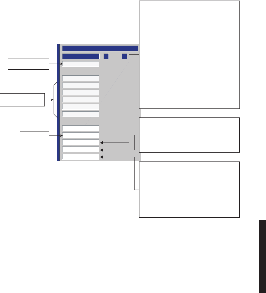
5-13
Figure 5-8 Troubleshooting OC3 Radio RCV Alarms
A B
RECEIVER
Receiver Fault
Receiver On Line
Channel Fail
Eye Closure
Low RSL
Path Distortion
Radio Frame Loss
OC3 Output Online
OC3 Common Loss
OC3 LOF
OC3 AIS-L Detect
OC3 Degrade
STATUS
I/O CONDITIONER CANNOT RECOVER FRAMING
FROM SIGNAL FROM RCVR MODULE.
1. IS OC3 AIS-L Detect ALARM ON?
YES, CHECK FOR UPSTREAM XMTR
OC3 AIS-L Detect ALARM. IF XMTR OC3
AIS Detect ALARM IS ON, TROUBLESHOOT
EXTERNAL MUX EQUIPMENT AT XMT END.
IF NOT, TROUBLESHOOT UPSTREAM XMTR.
NO, GO TO 2.
2. IS RADIO HOT-STBY?
YES
A. ARE A
AND B ALARMED?
YES, TROUBLESHOOT XMTR
NO, GO TO B
B. REMOVE/REPLACE RCVR MODULE.
C. REMOVE/REPLACE ALARMED OC3 I/O INTFC.
SUMMARY ALARM
FOR RCVR.
SEE DS1/E1 RCV
ALARMS, FIGURE 5-5
FUTURE USE
LMW-5035-SM
06/27/02
SIGNAL FROM RCVR MODULE (INPUT TO OC3
I/O INTFC) HAS EXCEEDED PROVISIONED BER
THRESHOLD (TYPICAL FADE CONDITION).
IS OC3 LOF ALSO ON?
YES, TROUBLESHOOT OC3 LOF.
NO, AND NO-FADE CONDITION CONFIRMED
1. REPLACE RCVR MODULE.
2. REPLACE ALARMED OC3 I/O INTFC MODULE.
AIS (BLUE SIGNAL), INSERTED AT MUX (EXTERNAL
TO THE RADIO) HAS BEEN DETECTED BY OC3 I/O
INTFC RCV CIRCUITS.
TROUBLESHOOT EXTERNAL MUX EQUIPMENT
(FAULT IS NOT IN RADIO).
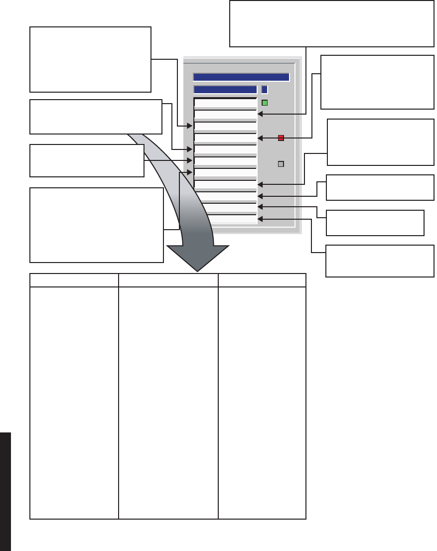
5-14
Figure 5-9 Troubleshooting DS1/E1 Radio Common Alarms
ASTATUS
I/O On Line
DS1 Provisioning
Power Regulator
Command Path
Off Normal
Controller
Inventory
Prov. Mismatch
DS1 PROV
Radio ID
Ring Broke
Previous Section
COMMON
LMW-1029
09/14/02
FAILURE OF RCVR IN PREVIOUS
SECTION OF SYNCHRONOUS
REPEATER CONFIGURATION.
RADIO IDs AT EACH END OF HOP
MUST BE THE SAME.
EQUIPMENT MALFUNCTION
WITHIN RING
CLICK HERE, DROP DOWN LIST
DISPLAYS ONE OR MORE MESSAGES.
TROUBLESHOOT AS FOLLOWS.
CONTROLLER MODULE FAILURE.
1. RESEAT CONTROLLER.
2. REPLACE CONTROLLER.
MODULE IS PRESENT, BUT CANNOT
COMMUNICATE WITH CONTROLLER ON
I
2
C BUS.
1. REMOVE AND REPLACE MODULE
INDICATING READ FAIL ON
INVENTORY SCREEN.
2. REMOVE AND REPLACE CONTROLLER.
LOSS OF COMMUNICATION
BETWEEN CONTROLLER AND
FAREND CONTROLLER.
1. VERIFY RCVR OPERATION.
2. REPLACE CONTROLLER.
COMMUNICATION FAILURE BETWEEN CONTROLLER AND ONE
OR MORE DS1/E1 INTERFACE ASICS ON I/O INTERFACE MODULE.
1. IF A
AND B ALARMS ARE ACTIVE, REPLACE CONTROLLER.
2. REPLACE I/O INTERFACE.
CONTROLLER PROVISIONING
DOES NOT
MATCH MODULE
PROVISIONING. REPROVISION TO
MEET SYSTEM REQUIREMENTS.
MESSAGE MEANING ACTION
A/B SIDE LIO SPI FAIL LOST COMMUNICATION REMOVE/REPLACE
BETWEEN CONTROLLER 1) I/O INTERFACE
AND I/O INTERFACE 2) CONTROLLER
A/B SIDE RCV SPI FAIL LOST COMMUNICATION REMOVE/REPLACE
BETWEEN CONTROLLER 1) RCVR
AND I/O INTERFACE/RCVR 2) I/O INTERFACE
3) CONTROLLER
A/B SIDE DS1 SPI FAIL LOST COMMUNICATION REMOVE/REPLACE
BETWEEN CONTROLLER 1) I/O INTERFACE
AND I/O INTERFACE 2) CONTROLLER
FAN ALARM FAN OR FAN CONTROL REMOVE/REPLACE
MODULE FAILED FAN/FAN ASSEMBLY
LIO/DS1 LOOPBACK ON FUNCTION ENABLED ON DISABLE FUNCTION
A/B HIGH/LOW POWER LOCK
CONTROL SCREEN ON CONTROL SCREEN
A/B TX/RX/OR I/O OVERRIDE
FUNCTION ENABLED ON DISABLE FUNCTION
CONTROL SCREEN OR FRONT
ON CONTROL SCREEN
PANEL ON CONTROLLER OR CONTROLLER
FRONT PANEL
EEPROM PROV DOES NOT PROVISIONING ON PROVISION TO MATCH
MATCH MODULE PROV CONTROLLER DOES NOT PROPER SYSTEM
MATCH PROVISIONING REQUIREMENTS
SCREEN
VOLTAGE REGULATION FAILURE
OR EXCESSIVE LOAD.
1. CYCLE POWER
2. CHECK FUSE
3. CHECK OUTPUT POWER
4. REPLACE POWER SUPPLY
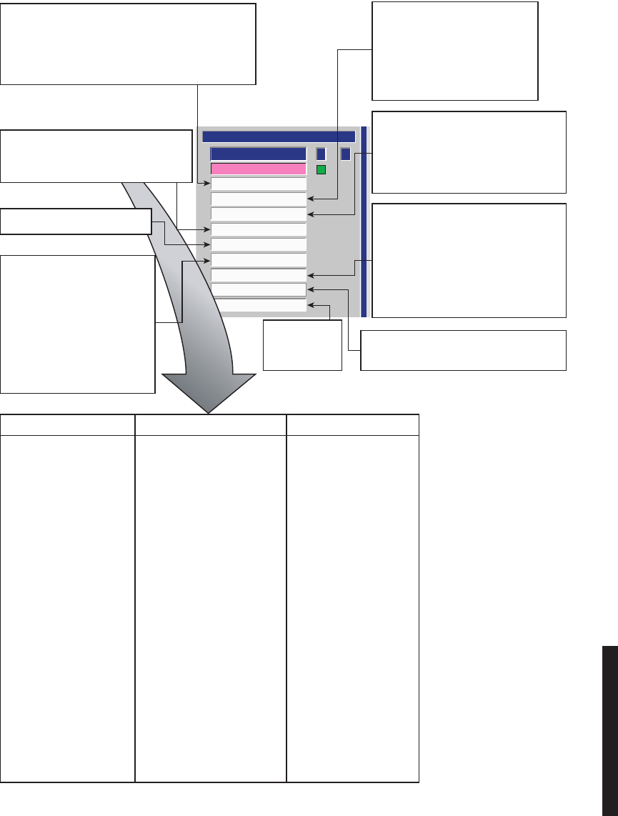
5-15
Figure 5-10 Troubleshooting DS3 Radio Common Alarms
Ring Broke
Radio ID
DS1 Provisioning
Power Regulator
Command Path
Off Normal
Controller
Inventory
Prov. Mismatch
I/O On Line
A B
COMMON
STATUS
LMW-1029B
02/27/02
MODULE IS PRESENT, BUT
CANNOT COMMUNICATE WITH
CONTROLLER ON I
2
C BUS.
1. REMOVE AND REPLACE
MODULE
INDICATING READ FAIL ON
INVENTORY SCREEN.
2. REMOVE AND REPLACE
CONTROLLER.
MESSAGE MEANING ACTION
A/B SIDE LIO SPI FAIL LOST COMMUNICATION REMOVE/REPLACE
BETWEEN CONTROLLER 1) I/O INTERFACE
AND I/O INTERFACE 2) CONTROLLER
A/B SIDE RCV SPI FAIL LOST COMMUNICATION REMOVE/REPLACE
BETWEEN CONTROLLER 1) RCVR
AND I/O INTERFACE/RCVR 2) I/O INTERFACE
3) CONTROLLER
A/B SIDE DS1 SPI FAIL LOST COMMUNICATION REMOVE/REPLACE
BETWEEN CONTROLLER 1) I/O INTERFACE
AND I/O INTERFACE 2) CONTROLLER
FAN ALARM FAN OR FAN CONTROL REMOVE/REPLACE
MODULE FAILED FAN/FAN ASSEMBLY
DS3 LOOPBACK ON FUNCTION ENABLED ON DISABLE FUNCTION
A/B HIGH/LOW POWER LOCK CONTROL SCREEN ON CONTROL SCREEN
A/B TX/RX/OR I/O OVERRIDE FUNCTION ENABLED ON DISABLE FUNCTION
CONTROL SCREEN OR FRONT ON CONTROL SCREEN
PANEL ON CONTROLLER OR CONTROLLER
FRONT PANEL
EEPROM PROV DOES NOT PROVISIONING ON PROVISION TO MATCH
MATCH MODULE PROV CONTROLLER DOES NOT PROPER SYSTEM
MATCH PROVISIONING REQUIREMENTS
SCREEN
MISMATCH BETWEEN PROVISIONING DATA WRITTEN
TO I/O INTERFACE BY CONTROLLER AND THEN READ
BY CONTROLLER.
1. REPROVISION AND SAVE.
2. REPLACE I/O INTERFACE MODULE.
VOLTAGE REGULATION FAILURE
OR EXCESSIVE LOAD.
1. CYCLE POWER
2. CHECK FUSE
3. CHECK OUTPUT POWER
4. REPLACE POWER SUPPLY
LOSS OF COMMUNICATION BETWEEN
CONTROLLER AND FAREND
CONTROLLER.
1. VERIFY RCVR OPERATION.
2. REPLACE CONTROLLER.
CONTROLLER PROVISIONING DOES NOT
MATCH MODULE PROVISIONING.
REPROVISION TO MEET SYSTEM
REQUIREMENTS.
1. IF A AND B I/O INTERFACE ALARMS
ARE ACTIVE, REPLACE CONTROLLER.
2. REPLACE I/O INTERFACE.
MISMATCH BETWEEN LOCAL PROVISIONED
RADIO ID AND FAR END RADIO ID.
EQUIPMENT
MALFUNCTION
WITHIN RING
CLICK HERE, DROP DOWN LIST
DISPLAYS ONE OR MORE MESSAGES.
TROUBLESHOOT AS FOLLOWS.
CONTROLLER MODULE RESET.
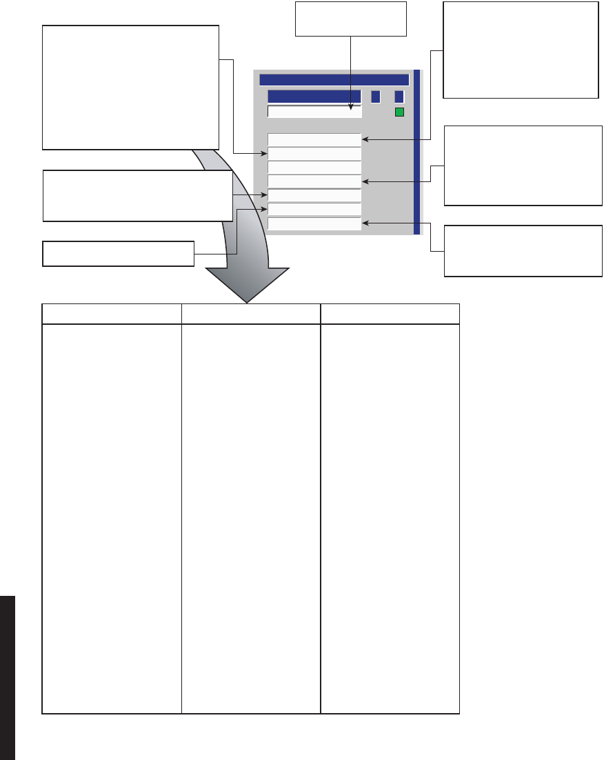
5-16
Figure 5-11 Troubleshooting OC3 Radio Common Alarms
Off Normal
Controller
Repeater
Power Supply
Inventory
Command Path
I/O Interface Fault
A B
COMMON
STATUS
LMW-5033-SM
06/28/02
LOSS OF COMMUNICATION
BETWEEN CONTROLLER AND
FAREND CONTROLLER.
1. VERIFY RCVR OPERATION.
2. REPLACE CONTROLLER.
LOSS OF SIGNAL AT RPTR PORT.
1. CHECK RPTR CABLE
2. REPLACE I/O INTERFACE
MESSAGE MEANING ACTION
OVERRIDE SWITCH ACTIVE OVRD CONTROL ON DISABLE OVERRIDE
CONTROLLER MODULE IS
ACTIVATED.
PA POWER SUPPLY ALARM PA ON/OFF SWITCH ON SET PA ON/OFF SWITCH
POWER SUPPLY IS TO OFF
SET TO ON.
CONTROLLER/POWER SUPPLY PROVISIONING DATA STORED
PROVISION MISMATCH IN MEMORY ON CONTROLLER
DOES NOT MATCH
PROVISIONING DATA
STORED IN MEMORY ON
THE A-SIDE POWER SUPPLY.
CAN'T PROVISION A POWER CAN NOT DOWNLOAD REMOVE/REPLACE
SUPPLY PROVISIONING DATA 1) A-SIDE POWER SUPPLY
FROM CONTROLLER 2) CONTROLLER
TO A-SIDE POWER SUPPLY.
A&B TX CAP-KEY CAPACITY KEY ON A-SIDE VERIFY CAPACITY KEY
MISMATCH XMTR HAS DIFFERENT REQUIREMENTS.
PAST NUMBER THAN REPLACE A/B SIDE
CAPACITY KEY ON CAPACITY KEY AS
B-SIDE XMTR. REQUIRED.
ATPC LOCKED HIGH OR ATPC LOCK FUNCTION ON USI DISABLE ATPC OR
LOW CONTROL SCREEN IS UNLOCK ATPC LOCK
ENABLED. FUNCTION ON CONTROL
SCREEN.
FAN ALARM FAN OR FAN CONTROL REMOVE/REPLACE
MODULE FAILED. FAN/FAN ASSEMBLY
SUMMARY ALARM
FOR I/O INTERFACE
VOLTAGE REGULATION FAILURE
OR EXCESSIVE LOAD.
1. CYCLE POWER
2. CHECK FUSE
3. CHECK OUTPUT POWER
4. REPLACE POWER SUPPLY
CLICK HERE, DROP DOWN LIST
DISPLAYS ONE OR MORE MESSAGES.
TROUBLESHOOT AS FOLLOWS.
MODULE IS PRESENT, BUT CANNOT
COMMUNICATE WITH CONTROLLER
ON I
2
C BUS.
1. REMOVE AND REPLACE MODULE
INDICATING READ FAIL ON
INVENTORY SCREEN.
2. REMOVE AND REPLACE
CONTROLLER.
CONTROLLER MODULE RESET.
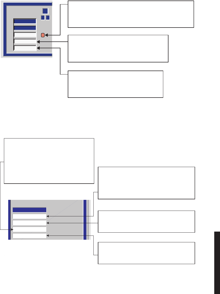
5-17
Figure 5-12 Troubleshooting DS1/E1 Radio Alarms
Figure 5-13 Troubleshooting DS3 Radio Wayside DS1 Alarms
A B
1
DS1 LINE #
SIDES
TX SIG
TX ALM
RX ALM
LMW-1030-SM
10/27/99
LOSS OF INPUT SIGNAL TO I/O INTERFACE, INABILITY TO RECOVER
CLOCK ON ALARMED LINE, OR BIPOLAR VIOLATION DETECTION
1. CHECK PRESENCE AND QUALITY OF DS1/E1 INPUT TO RADIO.
2. REPLACE I/O INTERFACE MODULE.
TRANSMIT HARDWARE FAILURE OR BUFFER SPILLS
ON ALARMED LINE.
1. VERIFY QUALITY OF TX INPUT DATA.
2. REPLACE I/O INTERFACE MODULE.
LOSS OF RECEIVE CLOCK, BUFFER SPILLS, OR
ALARM INSERTION SIGNAL ON THE ALARMED LINE.
MAY ALSO BE CAUSED BY DS1 DRIVER FAILURE.
REPLACE I/O INTERFACE MODULE.
DS1 Inuput Loss
DS1 XMT ALARM
DS1 AIS INSERT
DS1 RCV ALARM
DS1 ALARMS
LMW-3134
06/27/02
LOSS OF INPUT SIGNAL TO I/O INTERFACE, INABILITY
TO RECOVER CLOCK ON ALARMED LINE, OR BIPOLAR
VIOLATION DETECTION.
1. CHECK PRESENCE AND QUALITY OF DS1/E1 INPUT
TO RADIO.
2. REPLACE I/O INTERFACE MODULE.
TRANSMIT HARDWARE FAILURE OR BUFFER SPILLS
ON ALARMED LINE.
1. VERIFY QUALITY OF TX INPUT DATA.
2. REPLACE I/O INTERFACE MODULE.
LOSS OF RECEIVE CLOCK, BUFFER SPILLS, OR
ALARM INSERTION SIGNAL ON THE ALARMED LINE.
MAY ALSO BE CAUSED BY DS1 DRIVER FAILURE.
REPLACE I/O INTERFACE MODULE.
LOS HAS BEEN DETECTED AT RCV INPUT OF I/O
CONDITIONER AND AIS (ALL ONES OR ZEROS) IS
BEING INSERTED.
CHECK FOR LOS AT XMT END OF HOP. IF NOT,
1. CHECK FOR UPSTREAM XMTR ALARMS.
ANY XMTR ALARMS?
YES, TROUBLESHOOT XMTR.
NO, GO TO 2.
2. REPLACE ALARMED DS3 I/O INTFC.
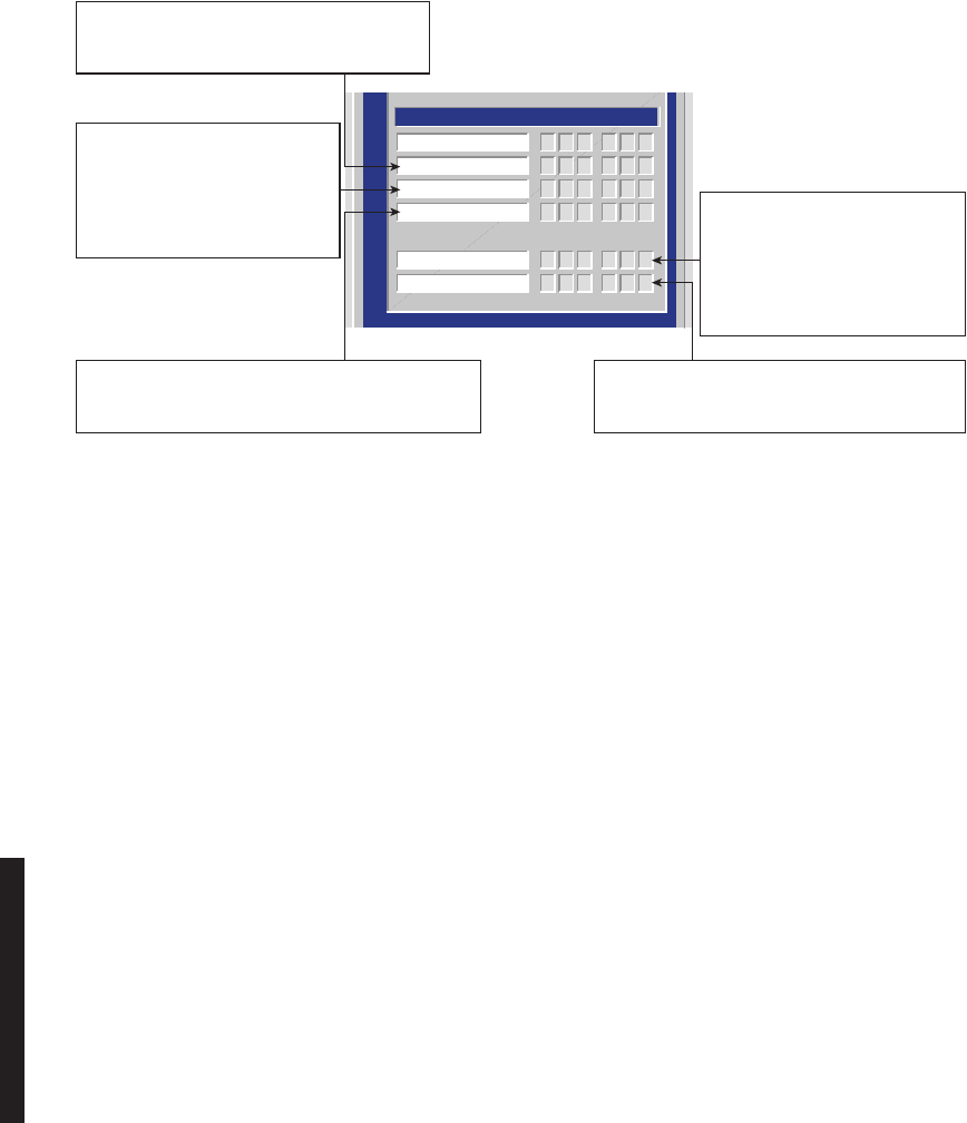
5-18
Figure 5-14 Troubleshooting OC3 Radio Wayside DS1 Alarms
5.7.3
Ring Radio Troubleshooting
The four ring status LEDS on the front panel of the controller module are useful in deter-
mining the status of the ring radios. The four LEDs are divided into two groups: Command
LEDs and Idle LEDs. Each group has an LED for the RF path and a LED for the repeater
link. The command LEDs use a flashing pattern to determine the status of the ring. The Idle
leds are used to determine if ring commands are being received on the corresponding port.
Refer to ring trouble shooting on the attached CD for details.
123
123
123
123
1 2 3
1 2 3
1 2 3
1 2 3
WAYSIDE DS1
Xmtr/Rcvr On Line
Xmtr LOS
Xmtr LOF
Xmtr AIS Detect
123
123
1 2 3
1 2 3
Rcvr LOF
Rcvr AIS Detect
LMW-5032
07/17/02
AIS DETECTED ON DS1 INPUT TO RADIO.
FAULT IS EXTERNAL TO RADIO.
CHECK EXTERNAL MUX SUPPLYING DS1/E1 TO RADIO.
AIS HAS BEEN DETECTED ON OUTPUT OF RADIO
RCVR. FAULT IS NOT IN THIS RADIO.
CHECK UPSTREAM XMTR/HOPS FOR ALARMS.
INABILITY TO RECOVER CLOCK
OR BIPOLAR VIOLATION DETECTED
ON DS1/E1 INPUT TO RADIO.
1. CHECK QUALITY OF DS1 INPUT
TO RADIO.
2. REPLACE I/O INTFC MODULE.
INABILITY TO RECOVER CLOCK OR
BIPOLAR VIOLATION DETECTED ON
OUTPUT OF RADIO RCVR.
1. CHECK XMTR END OF HOP FOR
ALARMS.
2. REPLACE ALARMED I/O INTFC
MODULE.
LOSS OF INPUT SIGNAL TO I/O INTFC.
1. CHECK PRESENCE OF DS1 INPUT TO RADIO.
2. REPLACE I/O INTFC MODULE.

5-19
5.8
MODULE REPLACEMENT
Modules screwed to heat sink must be screwed securely before
power is turned on.
Units with the electrostatic-sensitive (ESS) symbol contain ESS
devices. Store these units in an antistatic container when not in use,
and anyone handling a unit should observe antistatic precautions.
Damage to the unit may result if antistatic protection is not main-
tained. Refer to the Special Precautions pages in the front of the
instruction book for detailed handling information.
RF flex coaxial cable requires special consideration. The electrical
characteristics of the coax can be affected if it is accidentally twisted
or bent. Provide mechanical support to prevent any weight or strain
to the coax and connector when connecting or disconnecting equip-
ment. Loosen the connectors at both ends of a coax section if one
end must be moved even slightly. SMA connectors should be secured
fingertight, and then gently tightened using a torque wrench with a
5/16 in. head set for 7 to 9 inch-pounds. The connectors should not
be left fingertight.
XMTR Crystals should never be shipped as replacements without
being soldered and tuned up in an oscillator assembly board at the
factory.
WARNING
Possibility of
Damage
to Equipment
WARNING
Possibility of
Damage
to Equipment
WARNING
Possibility of
Damage
to Equipment
CAUTION
Possibility of
Service
Interruption

5-20
Modules may be removed or installed with shelf power applied. How-
ever, exercise reasonable care to prevent contacting adjacent modules.
If clearances are narrow, consider setting the power supply to OFF
while the module is being removed or replaced. (Before setting any
switch to OFF, verify that traffic has been protected.)
Before replacing any module, refer to Table 5-2 to determine the actions, other than phys-
ical replacement, required. If the module has any options (switches, subboards, etc.), refer
to the removed module so that the replacement module can be set up the same way.
Any module installed in the card cage, except those having front-panel cable connections,
can be removed by grasping the module handle(s) and pulling firmly outward. Modules
with front-panel interconnects can be removed in the same manner after disconnecting the
cable from the module being removed and moving the cable out of the way.
To install a module in the card cage, insert the module card connector edge into the appro-
priate card slot. Engage module handles in card cage and press on module handles until
they are latched and the card is fully seated. After installing a module with front-panel
interconnections, reconnect the cable(s) to the front-panel connector(s).
CAUTION
Possibility of
Service
Interruption

5-21
Table 5-2 Module Replacement Matrix
MODULE/UNIT REMOVAL/REPLACEMENT
PROCEDURE CHECKS/ADJUSTMENTS
PROCEDURE
AE-27AF Relay Interface No Special Procedure Required None Required
AE-37Y Controller Chart 2 None Required
CE-16BB Power Supply Chart 1 None Required
Fuse No Special Procedure Required.
Refer to Operations Section for
Location.
DX-35M DS1/E1 I/O Interface Chart 3 None Required
DX-35N DS3 I/O Interface Chart 3 Appendix E
DX-35P OC3 I/O Interface Chart 3 None Required
UD-35( ) Transmitter Chart 4 Appendix E
Crystal Oscillator Subboard Figure 5-17 The crystal oscillator subboard
and crystal part numbers define
this unit. The crystal is soldered
to the oscillator subboard and
factory tuned to the customers
requirements.
Capacity Key Figure 5-18
UD-36( ) Receiver Chart 5 Appendix E
Crystal Oscillator Subboard Figure 5-19 The crystal oscillator subboard
and crystal part numbers define
this unit. The crystal is soldered
to the oscillator subboard and
factory tuned to the customers
requirements.
Capacity Key Figure 5-20
UD-51( ) Power Amplifier Chart 6 Appendix E
LBO/AUX Interface Chart 7 in the Maintenance sec-
tion on the attached CD No Special Procedure Required
RF Switch Chart 8 in the Maintenance sec-
tion on the attached CD No Special Procedure Required
(1)
If ATPC is in use, it must be provisioned disabled or locked high before removing controller.
(2)
Appendix E is on attached CD.

5-22
5.9
CHANGING FREQUENCY
Crystals are soldered and tuned up in a crystal oscillator subboard at
the factory.
Changing frequencies requires changing the crystal on the crystal oscillator subboard in
the transmitter and receiver modules. Changing out the crystal requires tuning the crystal
oscillator subboard. Tuning the crystal oscillator subboard is a factory procedure.
An RF frequency change of ±2 MHz requires re-tuning the diplexer. Re-tuning the diplexer
is a factory procedure.
5.10
CLEANING
Do not use acid, alcohol, or brushes to clean modules because damage
to the silkscreen labeling and antistatic coating can result. Cleaning
should be confined to the removal of dust and dirt using a damp cloth.
Cleaning should normally be confined to the removal of dust and dirt using a soft bristled
(natural fiber) brush and a low velocity blower (such as a vacuum cleaner with a plastic
blower nozzle). Do not use acid or synthetic bristled brushes to clean modules that contain
electrostatic-sensitive components.
CAUTION
Possibility of
Service
Interruption
CAUTION
Possibility of
Service
Interruption
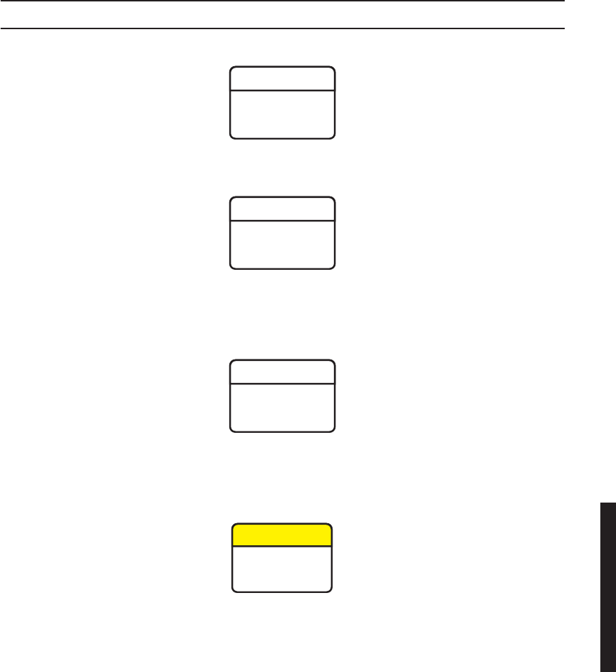
5-23
Chart 1 Power Supply Removal and Replacement
PURPOSE
Use this procedure to remove and replace CE-16BB Power Supply.
SPECIAL TOOLS REQUIRED
Torque Screwdriver
STEP PROCEDURE
Wear ground straps according to local office procedures.
Ensure the two mounting screws, accessible through the front panel,
are loosened before attempting to remove power supply from shelf
to prevent breaking handle.
Mounting surfaces on both power supply and heatsink must be
clean to ensure proper heat transfer. Mounting screws must be
torqued to 19 in. lbs.
This is an out-of-service procedure when on a nonstandby (unpro-
tected) system. On a hot-standby or frequency diversity system, switch
traffic on the channel under test to protect.
WARNING
Possibility of
Damage
to Equipment
WARNING
Possibility of
Damage
to Equipment
WARNING
Possibility of
Damage
to Equipment
CAUTION
Possibility of
Service
Interruption

5-24
STEP PROCEDURE, CONTINUED
1
Is radio protected (hot-standby or frequency diversity)?
If yes, go to step 2.
If no, go to step 3.
2
Use front panel
OVRD
controls on AE-37( ) Controller to switch and lock
on-line opposite side XMTR, RCVR, and I/O to opposite side from failed
power supply.
3
Do you want to remove or install power supply module?
If remove, go to step 4.
If install, go to step 7.
REMOVE:
4
On failed power supply, set
PA ON/OFF
switch to
OFF
.
5
On failed power supply, set
POWER ON/OFF
switch to
OFF
.
6
Perform removal steps shown on Figure 5-15.
INSTALL:
7
Perform installation steps shown on Figure 5-15.
8
Was XMTR, RCVR, and I/O switched (step 2)?
If yes, go to step 9.
If no, go to step 10.
9
On AE-37( ) Controller, toggle
OVRD
switch to disable override (unlocks
on-line XMTR, RCVR, and I/O and restores automatic switching
functions).
If radio is not equipped with power amplifiers and the PA ON/OFF switch on
the power supply is accidently turned on, the OFF NORM alarm on the power
supply and the Off Normal alarm on the USI Status Alarm screen will light.
The off normal message on the USI Status Alarm screen will be blank.
Note

5-25
STEP PROCEDURE, CONTINUED
10
Is radio equipped with optional PA?
If yes, go to step 11.
If no, go to step 16.
11
On power supply, set
PA ON/OFF
switch to
ON
.
DS3 and OC3 radios have provisioning data stored on both the controller and
A-side power supply. When provisioning is saved through downloading, the
provisioning data is stored on both modules. If the radio is non-standby and
the A-side power supply fails, the radio must be reprovisioned after the module
is replaced and the reprovisioned data downloaded and saved. If the radio is
hot-standby, the provisioning data stored on the controller is automatically
copied to the replacement A-side power supply when provisioning is saved.
12
is radio DS3/OC3 non-standby?
If yes, go to step 13.
If no, go to step 16.
13
Go to applicable DS3/OC3 initial turnup section and reprovision radio.
A mismatch between software revisions on the controller and the replacement
A-side power supply causes a flashing controller fail alarm when the spare
power supply is plugged in.
14
Observe Alarm LED on controller. Is controller alarm flashing (software/
firmware mismatch indicated)?
If yes, go to step 15.
If no, go to step 16.
15
Go to applicable DS3/OC3 initial turnup section and download and save
current provisioning.
16
STOP. This procedure is complete.
Note
Note
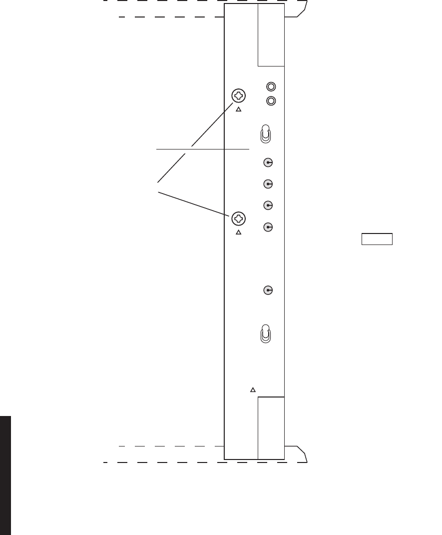
5-26
Figure 5-15 Power Supply Removal/Installation
P/O SHELF
REMOVE:
(REMOVE STEPS ARE PREFIXED
BY LETTER "R").
LMW-6092-SM
06/04/02
R1. SET PA POWER SWITCH TO OFF.
R2. SET POWER SWITCH TO OFF.
R3. LOOSEN MOUNTING SCREWS.
R4. UNLATCH TOP AND BOTTOM
INSERTION AND EXTRACTION HANDLES
AND REMOVE POWER SUPPLY
FROM SHELF.
INSTALL:
(INSTALL STEPS ARE
PREFIXED BY LETTER "I").
I1. VERIFY JOINING SURFACES
ON POWER SUPPLY AND
HEATSINK ARE CLEAN.
I2. INSERT POWER SUPPLY
IN SHELF AND LATCH TOP
AND BOTTOM INSERTION
AND EXTRACTION HANDLES.
I3. TIGHTEN SCREWS.
TORQUE SCREWS TO
19 IN. LBS.
I5. SET PA POWER SWITCH
TO ON (IF EQUIPPED).
I4. SET POWER SWITCH TO ON.
IF PA IS NOT EQUIPPED,
SETTING PA POWER
SWITCH TO ON WILL
TURN ON OFF NORM
ALARM.
NOTE
ALARM
P/O SHELF
OFF
NORM
ON 1
OFF 0
+10.5V
+12V
–5V
–12V
GND
TIGHTEN MOUNTING
SCREWS BEFORE
APPLYING POWER
2 PLACES
MARKED
POWER
CAUTION:
PA
ON
OFF
5-27
Chart 2 Controller Removal and Replacement
PURPOSE
Use this procedure to remove and replace AE-37Y Controller.
SPECIAL TOOLS REQUIRED
None
STEP PROCEDURE
Wear ground straps according to local office procedures.
This is an in service procedure, however protection switching is dis-
abled. If another failure occurs during the performance of the proce-
dure, service will be interrupted.
1
Do you want to remove or install controller module?
If remove, go to step 2.
If install, go to step 6.
REMOVE:
2
Is controller installed in an OC3 radio?
If yes, go to step 3.
If no, go to step 5.
3
On front panel of controller module, press and hold
ACO LT/OVRD
switch in
ACO LT
(lamp test) position until
TX, RX,
and
I/O ON LINE
LEDs on front of controller flash (approximately 5 seconds wait).
4
Release
ACO LT/OVRD
switch.
5
Remove controller module from shelf.
WARNING
Possibility of
Damage
to Equipment
CAUTION
Possibility of
Service
Interruption
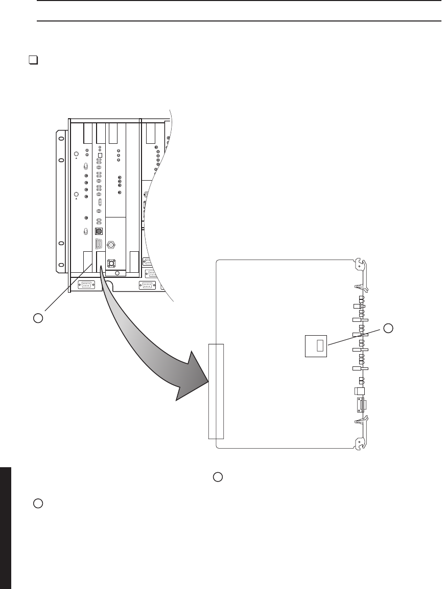
5-28
STEP PROCEDURE, CONTINUED
INSTALL:
6
See Figure 5-16 and follow step-by step procedure to install controller
module.
Figure 5-16 Controller Module Installation (Sheet 1 of 4)
LBO/OC3 AUX INTFC
1
REMOVE FAILED
CONTROLLER
2
REMOVE
ELMC
OPTION
KEY
(IF EQUIPPED)
LMW-5062-SM
06/04/02
3INSTALL REMOVED ELMC OPTION KEY FROM
STEP 2 ON REPLACEMENT CONTROLLER.
4INSTALL REPLACEMENT CONTROLLER IN SHELF.
J2
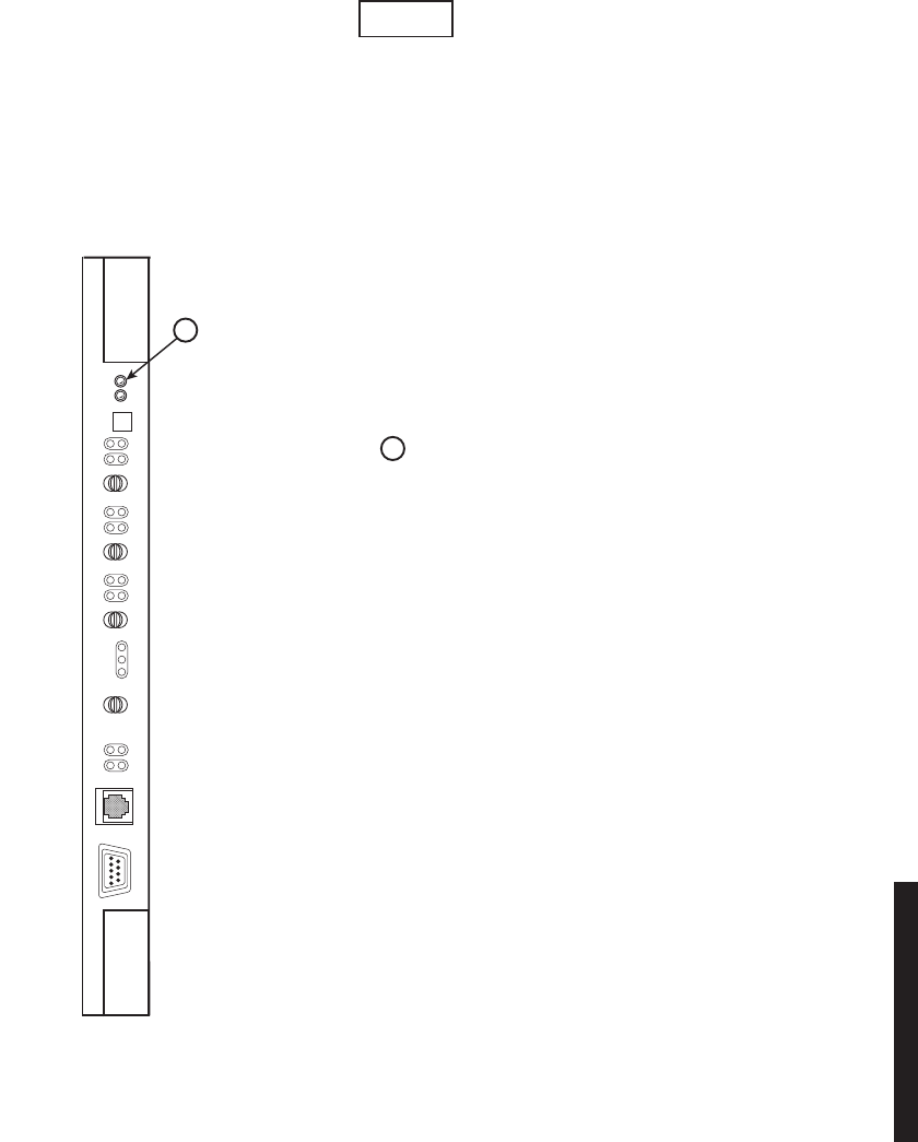
5-29
Figure 5-16 Controller Module Installation (Sheet 2 of 4)
VERIFY ALARM LED IS NOT FLASHING
AND REBOOT IS IN PROGRESS. (REBOOT
IS INDICATED BY ALL LEDS FLASHING
IN PROGRESSION.
5
IS CONTROLLER ALARM FLASHING?
YES, GO TO STEP .
NO, IS REBOOT IN PROGRESS?
YES, STOP. THIS PROCEDURE IS COMPLETE.
NO, REPLACEMENT CONTROLLER HAS FAILED.
6
LMW-5063
06/04/02
A
replacement controller that is loaded with the same firmware load as the controller
that is being replaced (i.e.: controller for DS3 radio is replacing a DS3 radio controller)
is automatically rebooted and provisioned to match the module it is replacing. If the
replacement controller is for a different type of radio (i.e.; controller for a DS3 radio is
being used to replace a controller in a DS1 or OC3 radio), the controller alarm will
f
lash when the replacement module is installed in the shelf. The flashing alarm
p
rompts the user that the wrong firmware is installed.
Note
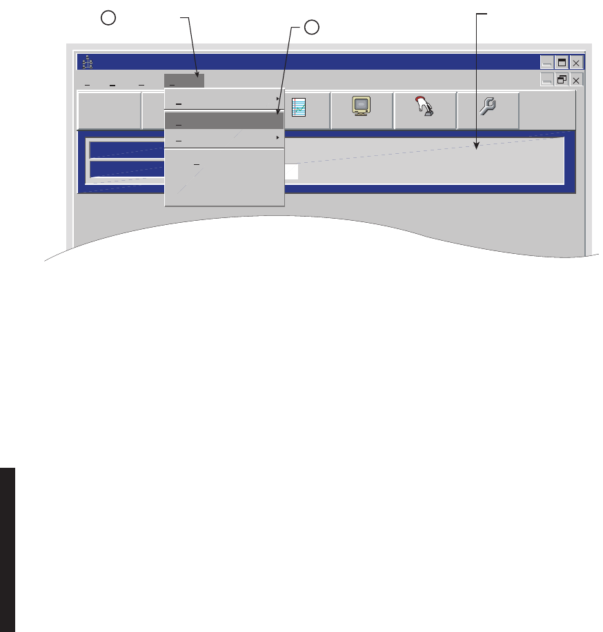
5-30
Figure 5-16 Controller Module Installation (Sheet 3 of 4)
Alcatel User Interface
ELMC Address
ELMC Descriptions
LOCAL MAIN
Communicating*** Prov. Hold
File View Setup Options
F6
Performance
Alarm Status
F4
Station Alarm
F7 F9
User Control
F8F5
Provisioning
Communication Options
Firmware Upgrade
Diagnostics
TDE Chip
Receive Provisioning
New Controller
PROVISIONING HOLD
MESSAGE DISPLAYS.
NOTE
PROVISIONING HOLD MESSAGE IS DISPLAYED
ON ALL SCREENS. THE MESSAGE IS REMOVED
WHEN PROVISIONING IS SAVED.
CLICK HERE
6CLICK HERE
7
LMW-5065-SM
08/10/01
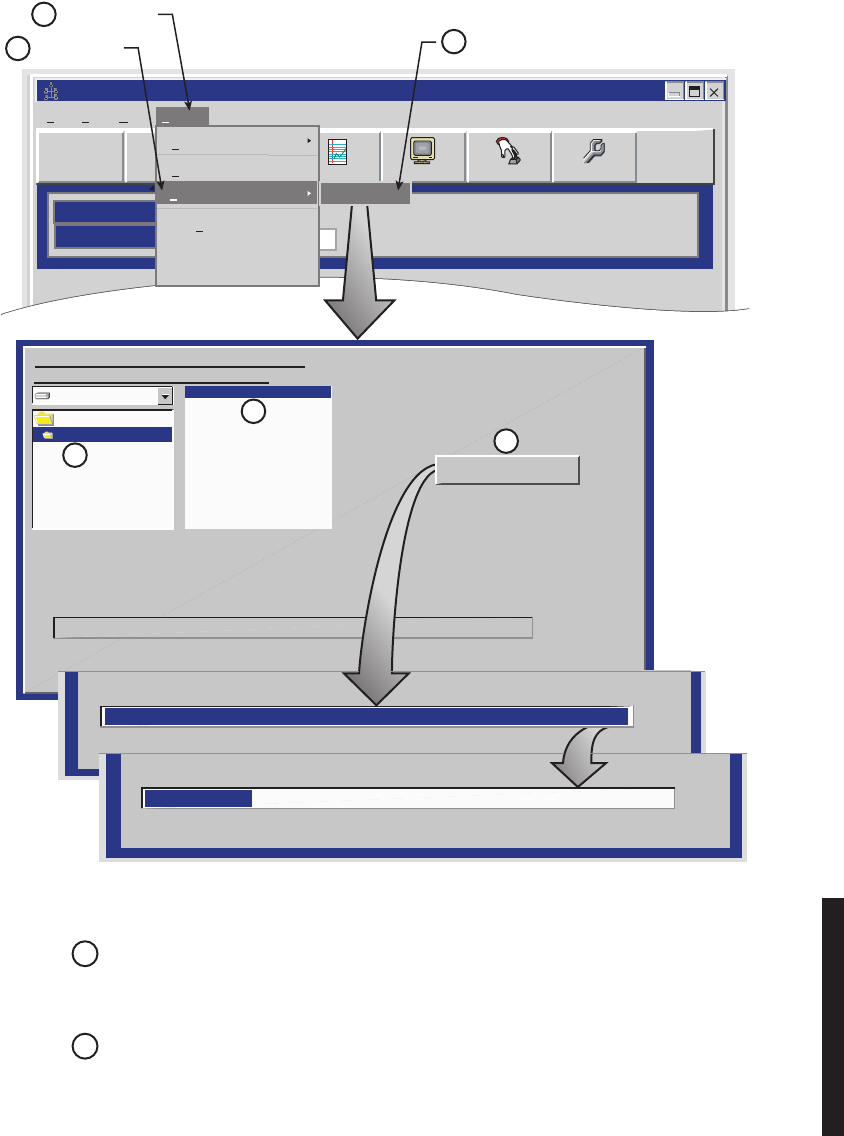
5-31
Figure 5-16 Controller Module Installation (Sheet 4 of 4)
Alcatel User Interface
ELMC Address
ELMC Descriptions
LOCAL MAIN
Communicating***
Prov. Hold
File View Setup Options
F6
Performance
Alarm Status
F4
Station Alarm
F7 F9
User Control
F8F5
Provisioning
Communication Options
Diagnostics
TDE Chip
Receive Provisioning
New Controller
CLICK HERE
8
CLICK HERE
10
9
Firmware Upgrade
CLICK HERE
c:
c:\
CSS00 38.DAT
The Current Select File Is:
c:\windnld\CSS00_38.DAT
windnld
Downloading at 38400 Baud
Verify Down Load
Please Select a Filename in the Following
Drive Directory before Downloading
CSS00 38.DAT
LMW-5064-SM
08/10/01
13
12
11
Start Down Load
CLICK
HERE
PROGRESS BAR DISPLAYS
% OF DATA LOADED
VERIFY PROGRESS BAR
DISPLAYS % OF DATA VERIFIED
0%
0%
100%
100%
CLICK ON
LATEST FILE
(HIGHEST NUMBER)
CLICK HERE
NOTE
AFTER AUTOMATICALLY REBOOTING, THE CONTROLLER WILL START
RUNNING, PROVISIONING PREVIOUSLY STORED IN THE CONTROLLER
WILL BE LEFT UNCHANGED BY THE DOWNLOAD PROGRAM.
15
14
GO TO THE INITIAL TURNUP SECTION AND CHECK PROVISIONING/REPROVISIONING AS REQUIRED.
NOTE
AFTER PROVISIONING IS SAVED, THE CONTROLLER WILL BOOT UP
WITHIN 20 SECONDS.
STOP. THIS PROCEDURE IS COMPLETE.
Download
5-32
Chart 3 I/O Interface Removal and Replacement
PURPOSE
Use this procedure to remove and replace DX-35( ) I/O Interface module.
SPECIAL TOOLS REQUIRED
None
STEP PROCEDURE
Wear ground straps according to local office procedures.
This is an out-of-service procedure when on a nonstandby (unpro-
tected) system. On a hot-standby or frequency diversity system, switch
traffic on the channel under test to protect.
1Is radio protected (hot-standby or frequency diversity)?
If yes, go to step 2.
If no, go to step 3.
2Use front panel OVRD controls on AE-37( ) Controller to lock on-line
XMTR, RCVR, and I/O (opposite side from failed I/O) on line.
3Do you want to remove or install I/O interface module?
If remove, go to step 4.
If install, go to step 9.
REMOVE:
4Is I/O interface module DX-35P OC3 I/O Interface?
If yes, go to step 7.
If no, go to step 8.
WARNING
Possibility of
Damage
to Equipment
CAUTION
Possibility of
Service
Interruption

5-33
STEP PROCEDURE, CONTINUED
5On front panel of controller module, press and hold ACO LT/OVRD
switch in ACO LT (lamp test) position until TX, RX, and I/O ON LINE
LEDs on front of controller flash (approximately 5 seconds wait).
6Release ACO LT/OVRD switch.
7Disconnect fiber optic cables.
8Remove I/O interface module from shelf.
INSTALL:
9Install I/O interface module in shelf.
10 Is I/O interface module DX-35P OC3 I/O Interface?
If yes, go to step 11.
If no, go to step 15.
11 Connect fiber optic cables.
12 Is I/O interface module DX-35N DS3 I/O Interface?
If yes, go to step 13.
If no, go to step 15.
13 Perform Radio DADE. Refer to Appendix E.
14 Perform DS3 Line DADE. Refer to Appendix E.
15 Was I/O locked on line (step 2).
If yes, go to step 16.
If no, go to step 17.
16 On AE-37( ) Controller, toggle OVRD switch to disable override (unlocks
on-line XMTR and restores automatic switching functions).
17 STOP. This procedure is complete.

5-34
Chart 4 XMTR Removal and Replacement
XMTR Crystals should never be shipped as replacements without
being soldered and tuned up in an oscillator assembly board at the
factory.
PURPOSE
Use this procedure to remove and replace UD-35( ) XMTR and/or:
1to replace a faulty crystal oscillator subboard
2to change out the crystal oscillator subboard to change frequency
3to move oscillator to a replacement XMTR
4to replace a faulty capacity key
5to change DS1/E1 or DS3 capacity
6to move capacity key to a replacement XMTR
SPECIAL TOOLS REQUIRED
None
STEP PROCEDURE
This is an out-of-service procedure when on a nonstandby (unpro-
tected) system. On a hot-standby or frequency diversity system,
switch traffic on the channel under test to protect.
CAUTION
Possibility of
Service
Interruption
WARNING
Possibility of
Damage
to Equipment
5-35
STEP PROCEDURE, CONTINUED
Wear ground straps according to local office procedures.
1Do you want to remove or install XMTR module?
If remove, go to step 2.
If install, go to step 8.
REMOVE:
2Is radio protected (hot-standby or frequency diversity)?
If yes, go to step 3.
If no, go to step 4.
3Use front panel OVRD controls on AE-37( ) Controller to lock on-line
XMTR (opposite side from failed XMTR) on line.
4On XMTR module, disconnect cable from RF OUT connector.
Removing XMTR module from card cage causes SYNC LOSS and I/O
PROV alarms.
5Remove XMTR module from card cage.
6On XMTR module being replaced, remove XMTR crystal oscillator
subboard. Retain for installation on replacement module.
7On XMTR module being replaced, remove XMTR capacity key. Retain for
installation on replacement module.
WARNING
Possibility of
Damage
to Equipment
CAUTION
Possibility of
Service
Interruption

5-36
STEP PROCEDURE, CONTINUED
INSTALL:
8On replacement XMTR module, install XMTR crystal oscillator subboard.
See Figure 5-17.
9
On replacement XMTR module, install XMTR capacity key. See Figure 5-18.
10 Install replacement XMTR module in card cage.
11 Perform XMT Crystal Oscillator Frequency Checks and Adjustment
procedure. Refer to Appendix E.
12 Is radio equipped with optional PA?
If no, Perform XMTR Output Level Checks and Adjustment (No PA)
procedure. Refer to Appendix E.
If yes, Perform PA Output Level Checks and Adjustment procedure.
Refer to Appendix E.
13 Perform XMTR Carrier Null Adjustment procedure. Refer to Appendix E.
14 Was XMTR locked on-line on step 3.
If yes, go to step 15.
If no, go to step 16.
15 On AE-37( ) Controller, toggle OVRD switch to disable override (unlocks
on-line XMTR and restores automatic switching functions).
16 STOP. This procedure is complete.
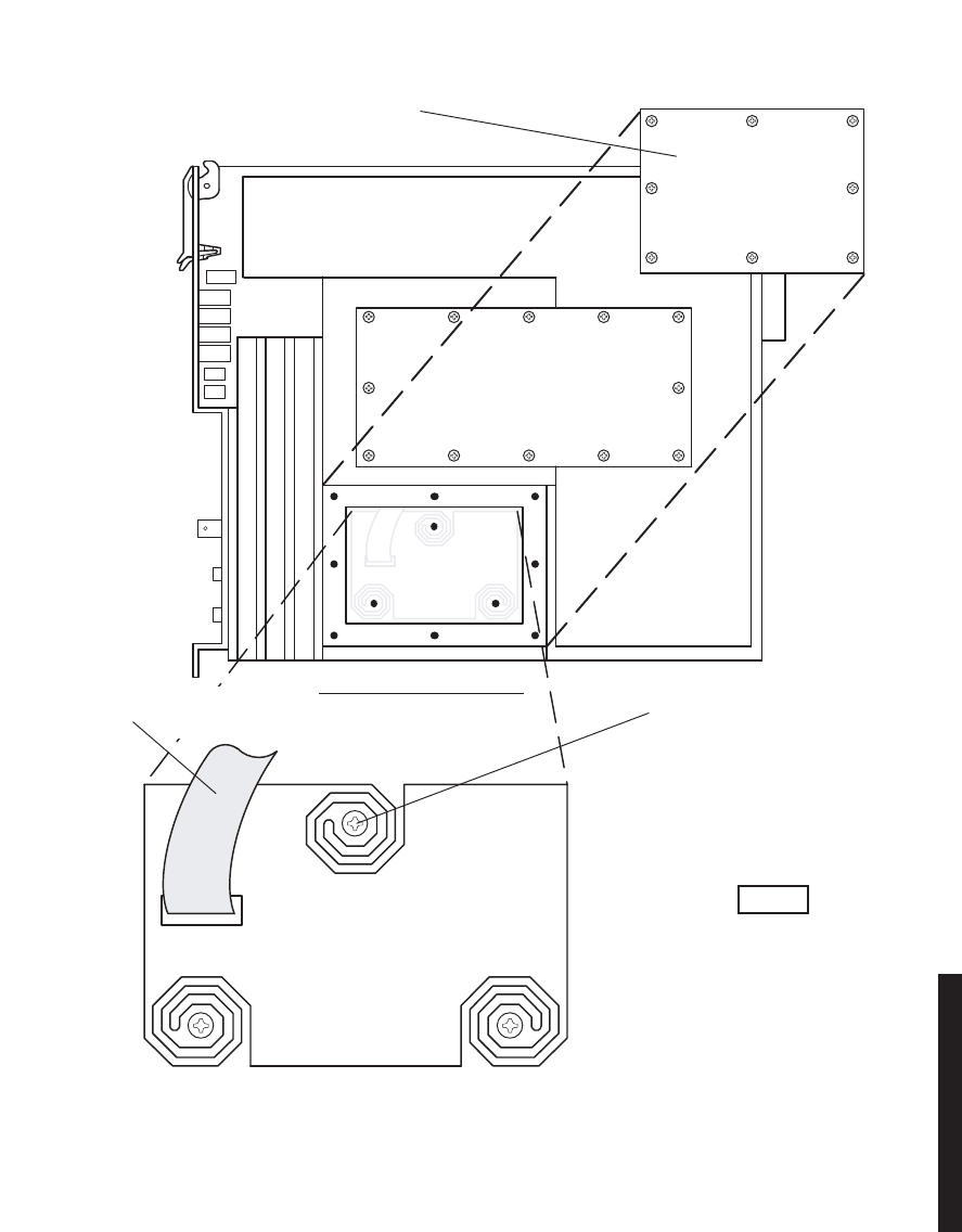
5-37
Figure 5-17 XMTR Crystal Oscillator Subboard Removal/Installation
CRYSTAL OSC
SUBBOARD
J8
XMTR-RIGHT SIDE VIEW
DISCONNECT RIBBON CABLER3.
FROM J8.
REMOVE 3 MOUNTINGR4. SCREWS, AND REMOVE
CRYSTAL OSC SUBBOARD.
INSTALL
(INSTALL STEPS ARE
PREFIXED BY LETTER “I”).
PLACE CRYSTAL OSC SUBBOARDI1.
INSTALL 3 MOUNTING SCREWS.I2.
CONNECT RIBBON CABLE TOI3. CONNECTOR J8.
INSTALL COVER WITH 8 SCREWS.I4.
INSTALL XMTR IN CARD CAGE.I5.
REMOVE TRANSMITTER FROM CARD CAGE.R1.
ARE PREFIXED
REMOVE:
(REMOVE STEPS
BY LETTER “R”).
REMOVE 8 SCREWS FROM CR YSTAL OSCR2. SUBBOARD COVER, AND REMOVE COVER.
MDR-1021
06/08/04
Ensure board edge does not make
contact with chassis wall.
Note
IN MOUNTING CAVITY
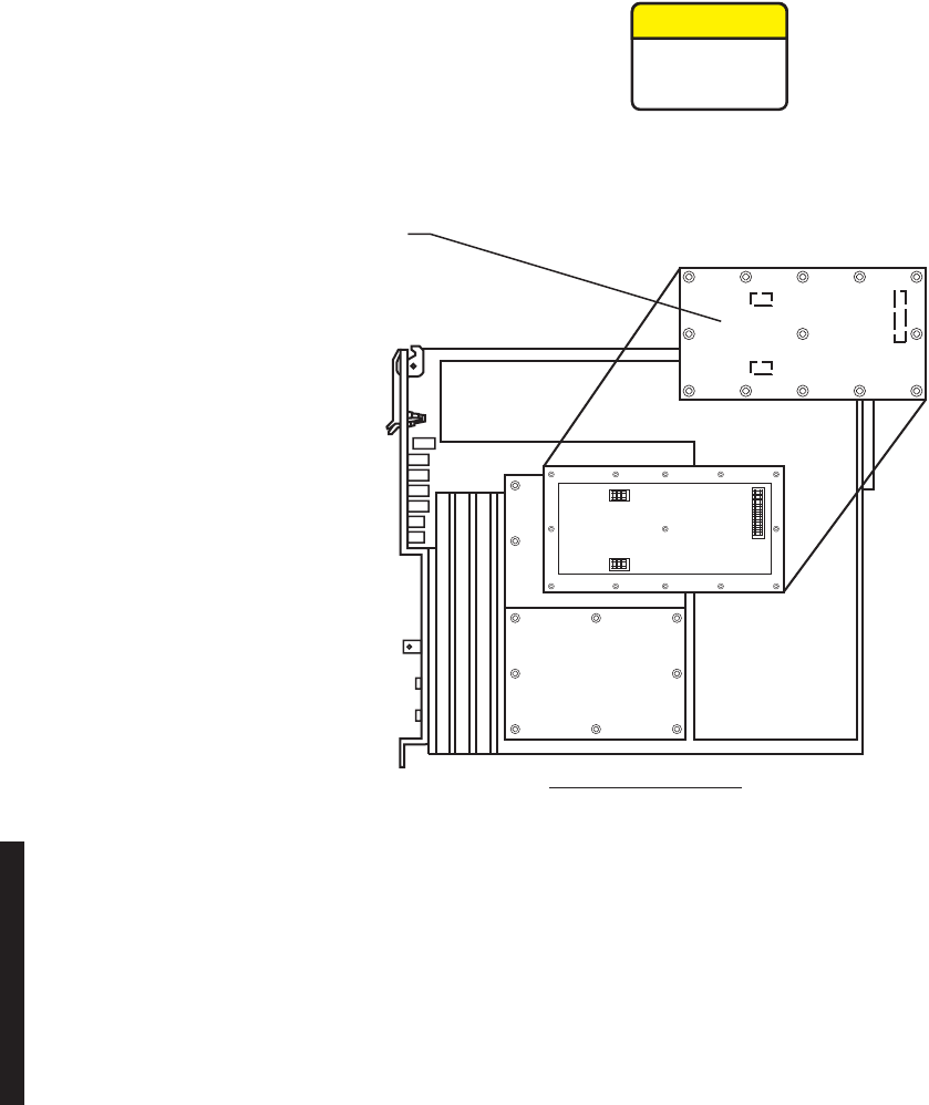
5-38
Figure 5-18 XMTR Capacity Key Removal/Installation
XMTR-RIGHT SIDE VIEW LMW-6016-SM
09/12/02
R1. REMOVE TRANSMITTER FROM
CARD CAGE.
R2. REMOVE 13 SCREWS FROM
CAPACITY KEY AND REMOVE
CAPACITY KEY.
REMOVE:
(REMOVE STEPS ARE PREFIXED
BY THE LETTER "R").
I1. INSTALL CAPACITY KEY
ON THREE CONNECTORS.
I2. INSTALL 13 SCREWS.
INSTALL:
(INSTALL STEPS ARE PREFIXED
BY THE LETTER "I").
This is an out-of-service procedure when on a
nonstandby (unprotected) system. On a hot-
standby or frequency diversity system, switch
traffic on the channel under test to protect.
CAUTION
Possibility of
Service
Interruption

5-39
Chart 5 RCVR Removal and Replacement
XMTR Crystals should never be shipped as replacements without
being soldered and tuned up in an oscillator assembly board at the
factory.
PURPOSE
Use this procedure to remove and replace UD-36( ) RCVR and/or:
1to replace a faulty crystal oscillator subboard
2to change out the crystal oscillator subboard to change frequency
3to move oscillator to a replacement RCVR
4to replace a faulty capacity key
5to change DS1/E1 or DS3 capacity
6to move capacity key to a replacement RCVR
SPECIAL TOOLS REQUIRED
None
STEP PROCEDURE
Exposure to energy radiated at microwave frequencies can
cause eye injury and eventual blindness. Do not operate the system
with a waveguide port unterminated.
CAUTION
Possibility of
Service
Interruption
DANGER
Possibility of
Injury
to Personnel
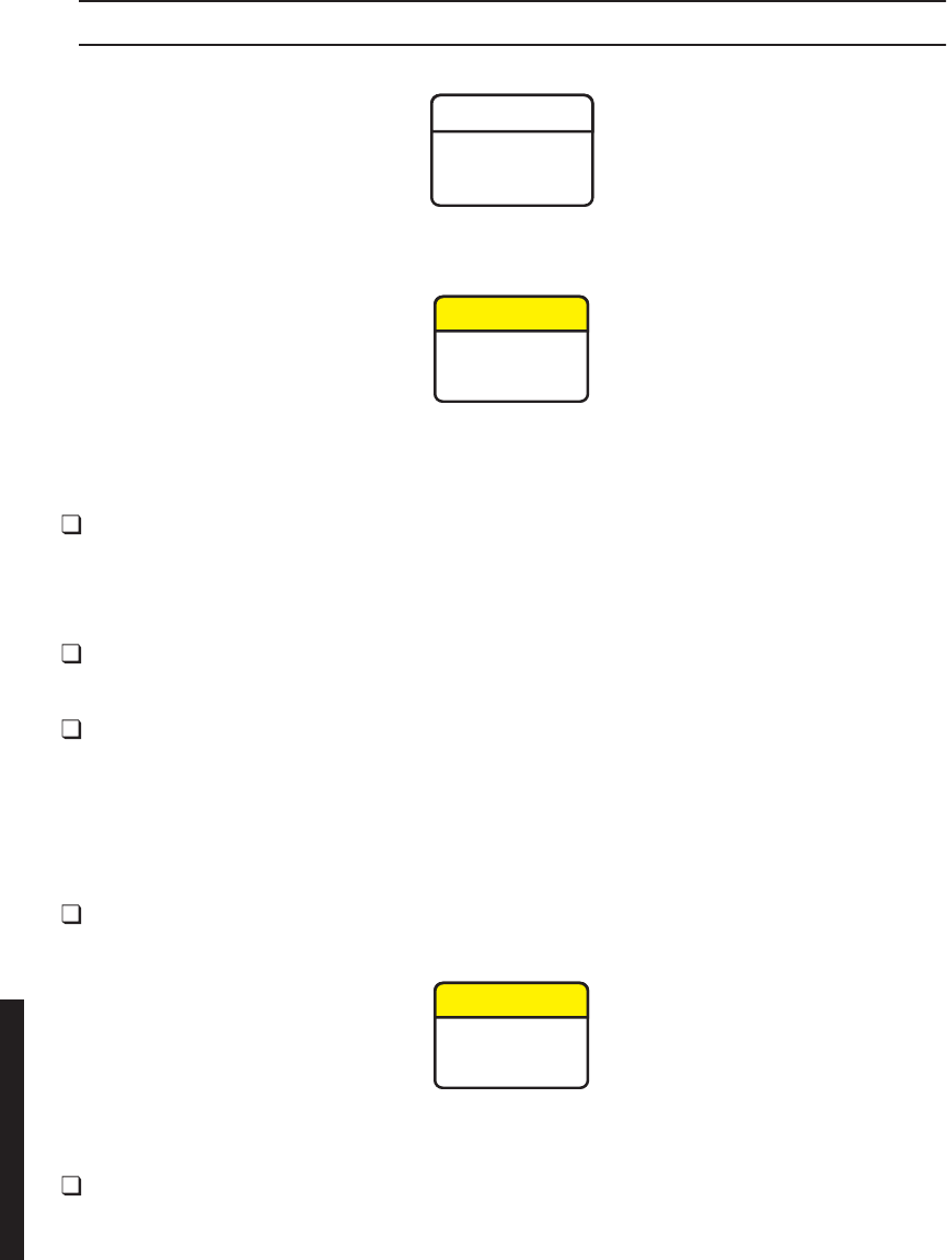
5-40
STEP PROCEDURE, CONTINUED
Wear ground straps according to local office procedures.
This is an out-of-service procedure when on a nonstandby (unpro-
tected) system. On a hot-standby, space diversity, or frequency diver-
sity system, switch traffic on the channel under test to protect.
1Is radio protected (hot-standby or frequency diversity)?
If yes, go to step 2.
If no, go to step 3.
2Use front panel OVRD controls on AE-37( ) Controller to switch and lock
opposite side RCVR (opposite side from failed RCVR) on line.
3Do you want to remove or install RCVR module?
If remove, go to step 4.
If install, go to step 8.
REMOVE:
4On RCVR module, disconnect cable from RF In connector.
Removing RCVR module from card cage causes CHANNEL FAIL, EYE
CLOSURE, RADIO FRM LOSS, and RCV PROV alarms.
5Remove RCVR module from card cage.
WARNING
Possibility of
Damage
to Equipment
CAUTION
Possibility of
Service
Interruption
CAUTION
Possibility of
Service
Interruption

5-41
STEP PROCEDURE, CONTINUED
6On RCVR module being replaced, remove RCVR crystal oscillator
subboard. See Figure 5-19. Retain for installation on replacement
module.
7On RCVR module being replaced, remove RCVR capacity key. See figure
2. Retain for installation on replacement module.
INSTALL:
8On replacement RCVR module, install RCVR crystal oscillator subboard.
See Figure 5-19.
9
On replacement RCVR module, install RCVR capacity key. See Figure 5-20.
10 Install replacement RCVR module in card cage.
11 Is RCVR equipped with front panel FREQ CONT?
If yes, go to step 12.
If no, go to step 13.
12 Perform RCV Crystal Oscillator Frequency Checks and Adjustment
procedure. Refer to Appendix E.
Optional performance checks, including RSL, BER and RCVR Threshold are
provided in Appendix E.
13 Was RCVR switched on step 2?
If yes, go to step 14.
If no, go to step 17.
14 On AE-37( ) Controller, toggle OVRD switch to disable override (unlocks
on-line RCVR and restores automatic switching functions).
15 Open Control screen.
16 On Control screen, under heading IN-SERVICE, highlight A RCVR On
Line or B RCVR On Line and select Yes on confirmation message to
force opposite side RCVR off line.
17 STOP. This procedure is complete.
Note
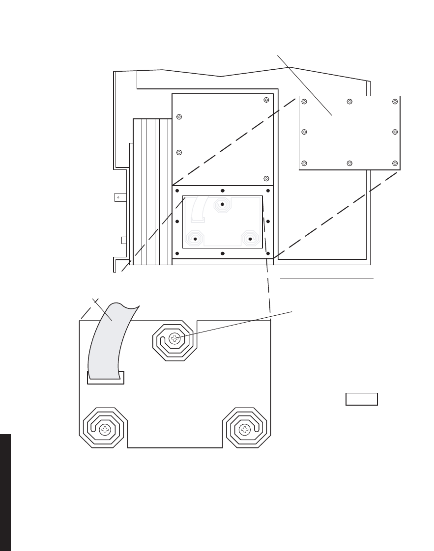
5-42
Figure 5-19 RCVR Crystal Oscillator Subboard Removal/Installation
CRYSTAL OSC
SUBBOARD
J8
REMOVE 3 MOUNTINGR4. SCREWS, AND REMOVE
CRYSTAL OSC SUBBOARD.
DISCONNECT RIBBON CABLER3. FROM J8.
REMOVE RECEIVER FROM CARD CAGE.R1.
REMOVE:
(REMOVE STEPS ARE PREFIXED
BY LETTER “R”).
REMOVE 8 SCREWS FROM CR YSTAL OSC SUBBOARD COVER, AND REMOVE COVER.R2.
INSTALL:
(INSTALL STEPS ARE
PREFIXED BY LETTER “I”).
PLACE CRYSTAL OSC SUBBOARDI1.
INSTALL 3 MOUNTING SCREWS.I2.
IN MOUNTING CAVITY.
CONNECT RIBBON CABLE TOI3. CONNECTOR J8.
INSTALL COVER WITH 8 SCREWS.I4.
INSTALL RECEIVER IN CARD CAGE.I5.
RCVR–RIGHT SIDE VIEW
MDR-1022
06/08/04
Ensure board edge does not make
contact with chassis wall.
Note
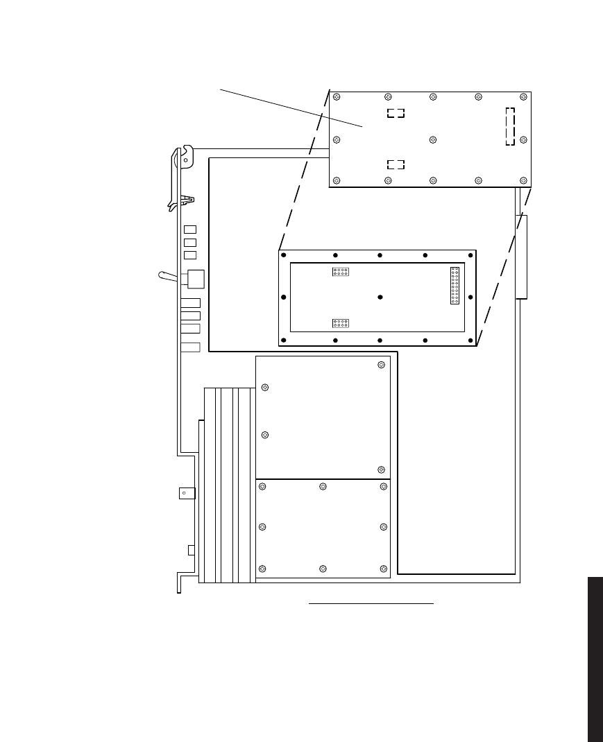
5-43
Figure 5-20 RCVR Capacity Key Removal/Installation
MW211–0069–1
101598
RCVR–RIGHT SIDE VIEW
REMOVE RCVR FROM CARD CAGE.R1.
REMOVE:
(REMOVE STEPS ARE PREFIXED
BY LETTER ‘R’).
INSTALL:
(INSTALL STEPS ARE
PREFIXED BY LETTER ‘I’).
REMOVE 13 SCREWS FROM CAPACITY KEYR2. AND REMOVE CAPACITY KEY.
INSTALL CAPACITY KEY ON THREE CONNECTORS.I1.
INSTALL 13 SCREWS.I2.
5-44
Chart 6 PA Removal and Replacement
PURPOSE
Use this procedure to remove and replace UD-51( ) PA.
SPECIAL TOOLS REQUIRED
None
STEP PROCEDURE
Exposure to energy radiated at microwave frequencies can cause
eye injury and eventual blindness. Do not operate the system with a
waveguide port unterminated.
Wear ground straps according to local office procedures.
This is an out-of-service procedure when on a nonstandby (unpro-
tected) system. On a hot-standby or frequency diversity system, switch
traffic on the channel under test to protect.
1Is radio protected (hot-standby or frequency diversity)?
If yes, go to step 2.
If no, go to step 3.
DANGER
Possibility of
Injury
to Personnel
WARNING
Possibility of
Damage
to Equipment
CAUTION
Possibility of
Service
Interruption

5-45
STEP PROCEDURE, CONTINUED
2Use front panel OVRD controls on AE-37( ) Controller to lock on-line
XMTR (opposite side from failed XMTR) on line.
3Do you want to remove or install PA module?
If remove, go to step 4.
If install, go to step 6.
REMOVE:
Check to ensure that the three mounting screws securing the PA to
the heatsink are loose before attempting to remove the PA to pre-
vent damage to the module.
4Remove PA from shelf. See Figure 5-21.
To prevent monitor point errors, use caution to ensure that the front
panel removed from the PA is replaced on that same PA. No two
monitor point levels labeled on PAs are the same. Erroneous output
levels can result from installing the wrong front panel and calibrat-
ing the PA to the level labeled on that front panel.
WARNING
Possibility of
Damage
to Equipment
WARNING
Possibility of
Damage
to Equipment

5-46 This page intentionally left blank.
STEP PROCEDURE, CONTINUED
INSTALL
The PA to heatsink mounting is critical. The three screws securing the
PA to the heat sink must be tightened to 19 in-lbs using a torque
wrench and not over/under-tightened. Improper mounting will
cause over-heating and alarm and shut off power to the PA. This will
result in loss of traffic on unprotected systems. On protected sys-
tems, a switch to the off-line PA will occur.
5Install PA in shelf. See Figure 5-21.
6Perform PA Checks and Adjustment procedure. Refer to Appendix E.
7Was XMTR locked on line (step 2).
If yes, go to step 8.
If no, go to step 9.
8On AE-37( ) Controller, toggle OVRD switch to disable override (unlocks
on-line XMTR and restores automatic switching functions).
9STOP. This procedure is complete.
WARNING
Possibility of
Damage
to Equipment
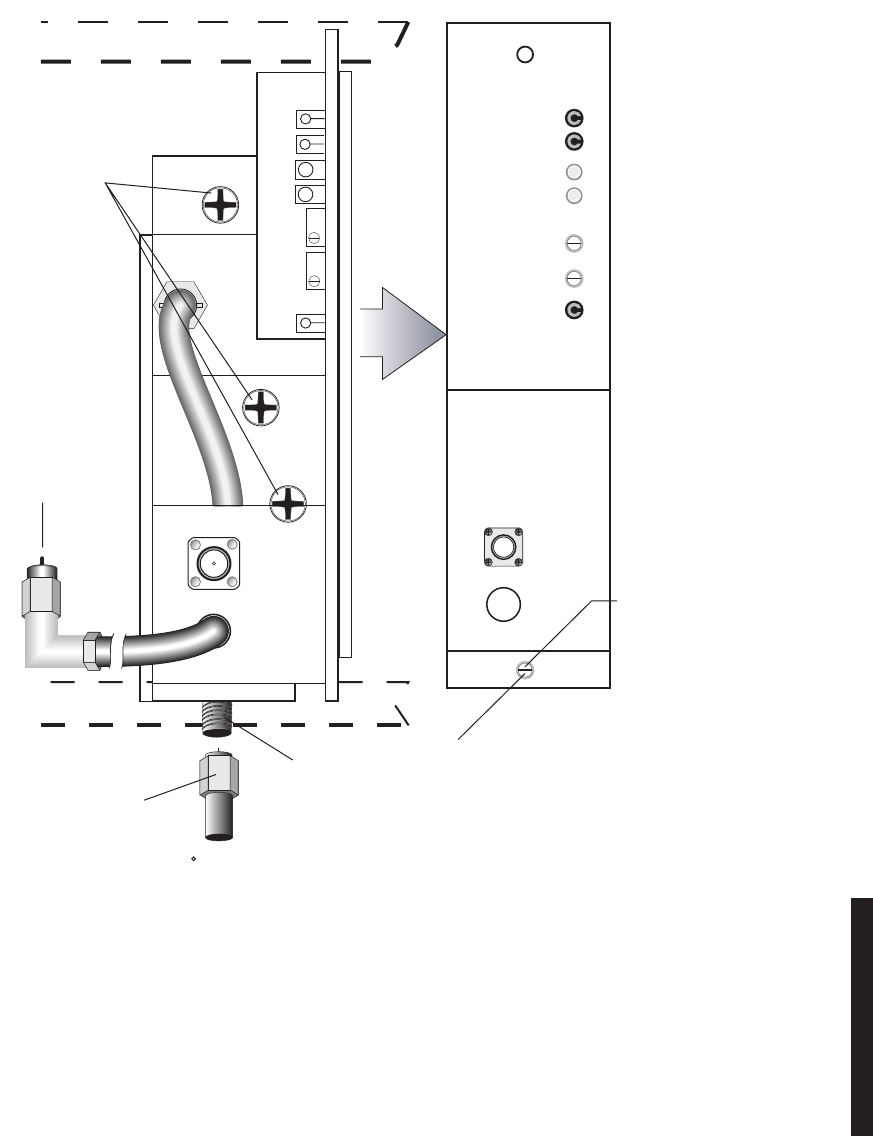
5-47
Figure 5-21 UD-51( ) Power Amplifier Removal and Replacement
DC MON
GND
10.5V DC
PWR ALM
TEMP ALM
DC MON ADJ
PWR ALM ADJ
POWER AMPLIFIER
RF
IN
RF
MON
LMW-7099-SM
04/29/03
FRONT PANEL
INSTALL:
(INSTALL STEPS
ARE PREFIXED BY
LETTER 'I').
I1. INSTALL REPLACE-
MENT PA IN SHELF
AND TIGHTEN
MOUNTING SCREWS
(TORQUE TO 19 IN. LBS).
I2 CONNECT
RF OUT CABLE.
I3. CONNECT
RF IN CABLE
TO XMTR RF OUT
CONNECTOR.
I4. REINSTALL PA FRONT
PANEL AND TIGHTEN
THUMBSCREWS
R2. LOOSEN THUMBSCREWS
AND REMOVE FRONT PANEL
R4. DISCONNECT
RF OUT CABLE.
RF OUT
P/O SHELF
P/O SHELF
REMOVE:
(REMOVE STEPS ARE
PREFIXED BY LETTER 'R').
R3. LOOSEN
MOUNTING
SCREWS AND
SLIDE PA TO-
WARD FRONT OF
CARD CAGE TO
ACCESS RF OUT
CONNECTOR
R5. TILT TOP OF PA
FORWARD APPROX 45
TO CLEAR RF OUT
CONNECTOR.
R6. REMOVE PA FROM
CARD CAGE.
R1. DISCONNECT
CABLE FROM
XMTR RF OUT
CONNECTOR.
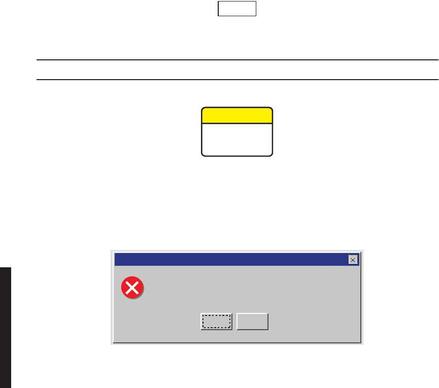
5-48
Chart 7 Changing System Software
PURPOSE
This procedure provides instructions to change previously loaded software to a newer
version. The procedure is written for DS3 but applies to DS1, DS3, and OC3 software and
radios.
TOOLS REQUIRED
PC
RS-232 interface cable PN 695-7848
GENERAL
The system operating software for the AE-37( ) Controller can be changed through the USI
port using the laptop computer. The system software in remotely located AE-37( )
Controllers can also be changed remotely using the ELMC function.
For DS1 controller loads R1.04 or earlier, refer to Issue 5 of the MDR-8000
instruction book.
STEP PROCEDURE
When upgrading system software, the load must be for the specific
radio type, e.g., DS1 for a DS1 radio, DS3 for a DS3 radio, and OC3 for
an OC3 radio. Use of incorrect software will result in a controller
alarm and a software types mismatch message on the computer screen
(see Figure 5-22). The mismatch message asks “Do you want to con-
tinue with the download?” Click Cancel and load the correct software.
Figure 5-22 Mismatch Message
Note
CAUTION
Possibility of
Service
Interruption
OK Cancel
MAY DISTURB TRAFFIC
Download file and controller software types mismatch.
Do you want to continue with the download?
LMW-7049
07/20/02
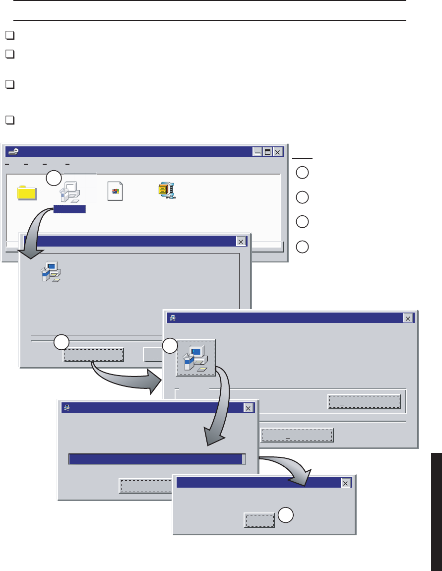
5-49
STEP PROCEDURE, CONTINUED
1Insert CD ROM disk into PC.
2On Windows desktop, double click on My Computer icon. My Computer
window displays.
3In My Computer window, click on CD ROM icon. Files window displays.
DOWNLOAD SOFTWARE TO PC
4See Figure 5-23. Follow directions to download software to PC.
Figure 5-23 Download Software to PC
File
020604_0736 (Z:)
EditFile View
Release
Docume...
Setup.lst win12_16.CAB
Help
1 object(s) selected 136KB
setup.exe
MDR-8000 DS3 USI Setup
Welcome to the MDR-8000 DS3 USI installation program.
Setup cannot install system files or update shared files if they are in use.
Before proceeding, we recommend that you close any applications you may
be running.
Exit SetupOK
MDR-8000 DS3 USI Setup
Begin the installation by clicking the button below.
c:\Winusi12\ Change Directory
Click this button to install MDR-8000 DS3 USI software to the specified
destination directory.
Exit Setup
Directory:
MDR-8000 DS3 USI Setup
MDR-8000 DS3 USI Setup was completed successfully.
OK
MDR-8000 DS3 USI Setup
Destination File:
Cancel
C:\Winusi12\win12_16.exe
99%
DOUBLE CLICK
(WILL LOAD FILES)
CLICK OK
(COPYING FILES)
CLICK ON SETUP ICON
(STARTS DOWNLOAD)
CLICK OK WHEN COMPLETED
STEP
1
2
4
3
4
3
2
1
LMW-7044-SM
07/16/02

5-50
STEP PROCEDURE, CONTINUED
DOWNLOAD SOFTWARE TO RADIO CONTROLLER
While the system software is being changed, all alarm monitoring and
protection switching functions are suspended. If the system software
change is interrupted before completion, the change is aborted and
operation under the previous software resumes.
5Connect RS-232 interface cable between USI port on controller and laptop
computer.
6Open Download screen (Start>Programs>WinUSI).
7Will download be to a local or remote radio?
If local, go to step 8.
If remote, go to step 9.
LOCAL DOWNLOAD CONTROLLER
8See Figure 5-24. Follow directions to install program on local controller.
REMOTE DOWNLOAD TO CONTROLLER
9Is the remote controller equipped with ELMC option key with
provisioning?
If yes, go to step 10.
If no, stop. Remote downloading requires that the ELMC option key
with provisioning be installed on controller module.
10 See Figure 5-25. Follow directions to install program on remote controller.
CAUTION
Possibility of
Service
Interruption
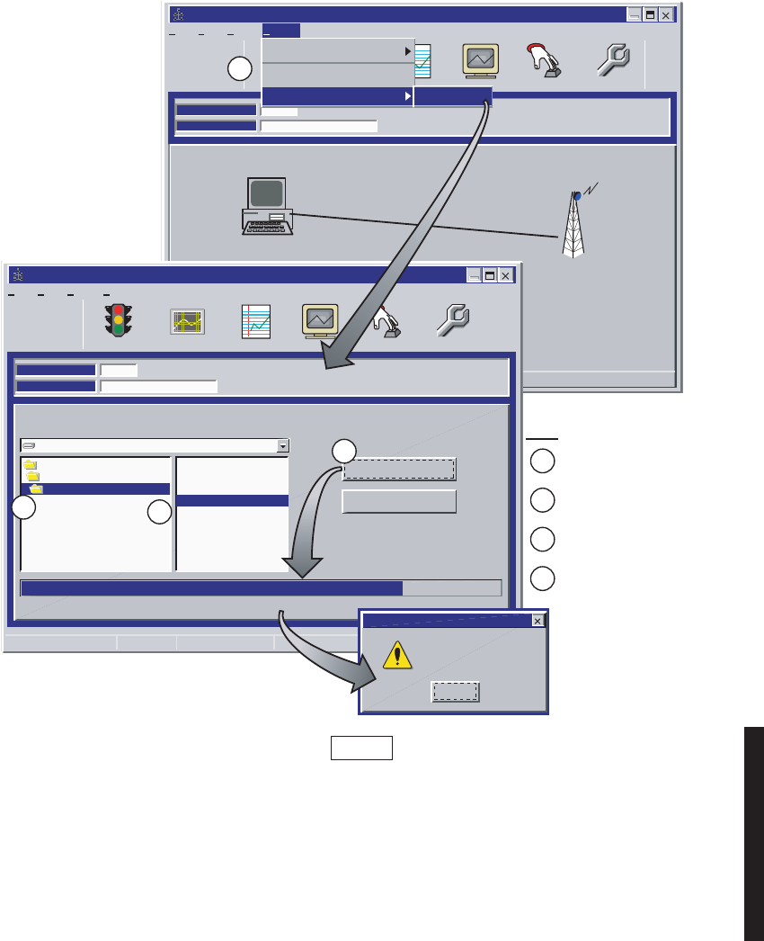
5-51
Figure 5-24 Download Software From PC to Local Radio Controller
File
Alcatel User Interface
ViewFile Setup
Station Alarm User ControlPerformanceAnalog Monitor
F7 F8
Provisioning
F9F6F6
LOCAL MAIN
ELMC Address:
Description: Rack-A - bottom radio
200R2
Options
F4
Alarm Status
Communicating***
200R2
COM 1
Tuesday, June 25, 2002 2:16:15 PM USI VersionR1.06 MDR-8000 3DS3 Controller Version R1.05
Communication Options
New Controller
Firmware Upgrade Download
File
Alcatel User Interface
ViewFile Setup
Station Alarm User ControlPerformanceAnalog Monitor
F7 F8
Provisioning
F9F6F6
LOCAL DOWNLOAD
C:\windnld\8000 DS3\css12_16.dat
Communicating at 38400 Baud
ELMC Address:
Description: Rack-A - bottom radio
200R2
c:
c:\
windnld
Start Download
Stop Download
Options
F4
Alarm Status
Communicating*
8000 DS3
css12_12.dat
css12_14.dat
css12_15.dat
css12_16.dat
Tuesday, June 25, 2002 2:16:15 PM USI VersionR1.06 MDR-8000 3DS3 Controller Version R1.05
Alcatel User System Interface
Download Successful!
OK
LMW-7045-SM
07/16/02
Click Options/Firmware
Upgrade/Download
Double click directory to
display all files
Click latest file
(highest number)
Click Start Down Load
STEP
4
After automatically re-booting, the controller will start running, provisioning
previously stored in the controller will be left unchanged by the download program.
Note
1
2
3
4
3
2
1
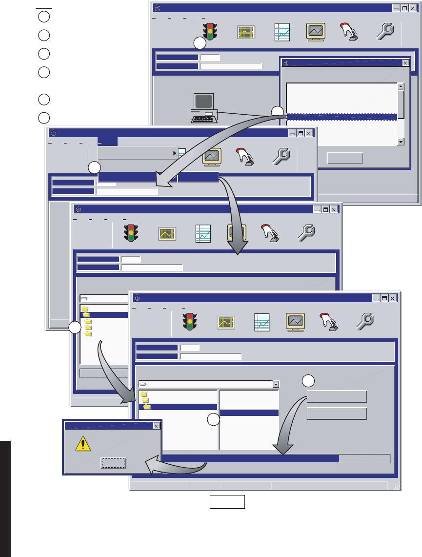
5-52
Figure 5-25 Download Software From PC to Remote Radio Controller
File
Alcatel User Interface
ViewFile Setup
Station Alarm User ControlPerformanceAnalog Monitor
F7 F8
Provisioning
F9F6F6
LOCAL MAIN
ELMC Address:
Description: Rack-A - bottom radio
200R2
Options
F4
Alarm Status
Communicating***
200R2
COM 1
Thursday June 27, 2002 2:16:15 PM USI VersionR1.06 MDR-8000 3DS3 Controller Version R1.05
Double Click on the Elmc to Select ADDRESS:
Exit
ELMC ADDRESS LIST
[LOCAL]
[FAREND]
<NEW>
200R1 -- Rack A - top radio
200R2 -- Rack A - bottom radio
201R1 -- Rack B - top radio
201R2 -- Rack B - bottom radio
202R1 -- Rack C - top radio
202R2 -- Rack C - bottom radio
203R1 -- Rack D - top radio
File
Alcatel User Interface
ViewFile Setup
Station Alarm User ControlPerformanceAnalog Monitor
F7 F8
Provisioning
F9F6F6
REMOTE MAIN
ELMC Address:
Description: Rack-B - top radio
201R2
Options
F4
Alarm Status
Communicating***
200R2
COM 1
Tuesday, June 25, 2002 2:16:15 PM USI VersionR1.06 MDR-8000 3DS3 Controller Version R1.05
Communication Options
New Controller
Firmware Upgrade Download
File
Alcatel User Interface
ViewFile Setup
Station Alarm User ControlPerformanceAnalog Monitor
F7 F8
Provisioning
F9F6F6
REMOTE DOWNLOAD
Please select a file from the Drive/Directory before Downloading
Communicating at 38400 Baud
ELMC Address:
Description: Rack-A - bottom radio
200R2
c:
c:\
windnld
Start Download
Details
Options
F4
Alarm Status
Communicating*
4000
8000 DS3
8000OC3
css11_12.dat
Tuesday, June 25, 2002 11:16:15 PM USI VersionR1.06 MDR-8000 3DS3 Controller Version R1.06
File
Alcatel User Interface
ViewFile Setup
Station Alarm User ControlPerformanceAnalog Monitor
F7 F8
Provisioning
F9F6F6
LOCAL DOWNLOAD
C:\windnld\8000 DS3\css12_16.dat
Communicating at 38400 Baud
ELMC Address:
Description: Rack-A - bottom radio
200R2
c:
c:\
windnld
Start Download
Stop Download
Options
F4
Alarm Status
Communicating*
8000 DS3
css12_12.dat
css12_14.dat
css12_15.dat
css12_16.dat
Tuesday, June 25, 2002 2:16:15 PM USI VersionR1.06 MDR-8000 3DS3 Controller Version R1.05
Alcatel User System Interface
Download Successful!
OK
DOUBLE CLICK TO OPEN
ELMC LIST
DOUBLE CLICK TO SELECT
REMOTE RADIO
SELECT OPTIONS/FIRMWARE
UPGRADE/DOWNLOAD
DOUBLE CLICK TO SELECT
DIRECTORY AND DISPLAY
ALL FILES
CLICK ON DIRECTORY AND
LATEST FILE (HIGHEST NUMBER)
CLICK TO DOWNLOAD
STEP
1
2
3
4
5
6
4
5
6
3
2
1
LMW-7046
07/16/02
Download
Start Download
After automatically re-booting, the controller will start running, provisioning previously stored in the
controller will be left unchanged by the download program.
Note
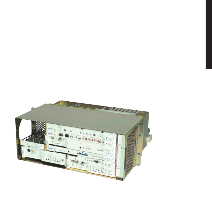
A-1
A
CommPak INDOOR SHELF
The MDR-8000 CommPak indoor shelf (Figure A-1) is a reduced-size package for
non-standby radio configurations. The CommPak indoor shelf operates the same as the
MDR-8000 hot-standby shelf configured as a non-standby radio using the same soft-
ware and equipped with the same modules with two exceptions: LBO and fan assembly.
Figure A-1 Typical MDR-8000 CommPak Indoor Shelf
This appendix describes the differences between the MDR-8000 hot-standby shelf
and the CommPak indoor shelf. Refer to the applicable sections in the Users Manual
for descriptions of functions common to both types of shelves. Refer to the instruction
book for details of functions not covered in the Users Manual.
A.1
COMPONENT LOCATIONS AND OPTIONS
See Figure A-2 for component locations and options.
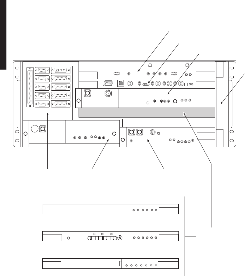
A-2
Figure A-2 Typical MDR-8000 CommPak Indoor Shelf Component Locations and Options (Sheet 1 of 3)
LMW-9080
08/29/03
SELECT I/O INTFC
MODULES
BY DATA RATE
CE-16BB PWR SUPPLY
AE-37Y CNTR
UD-36A( ) RCVR
FAN
ASSY
UD-35A( ) XMTRUD-51( ) PWR AMP
LBO/OC3
AUX INTFC
DX-35M
DS1/E1
I/O INTFC
ALM
ON
LINE
ALM
ON
LINE
SYNC
ALM
COM-
MON
LOSS
ALM
DX-35P
OC3
I/O INTFC
ALM
INSVC
OC3
IN
OC3
ALM
WYSD
ON
WYSD
ALM
OC3
OUT
DX-35N
DS3
I/O INTFC
5
6
7
8
9
0
1
2
3
4
XMT
AUX
SC
ALM
RCVR
ON
RAD
LOF
WYSD
DS1
WYSD
ALM
DS3
ALIGN
RAD DADE
1
2
3
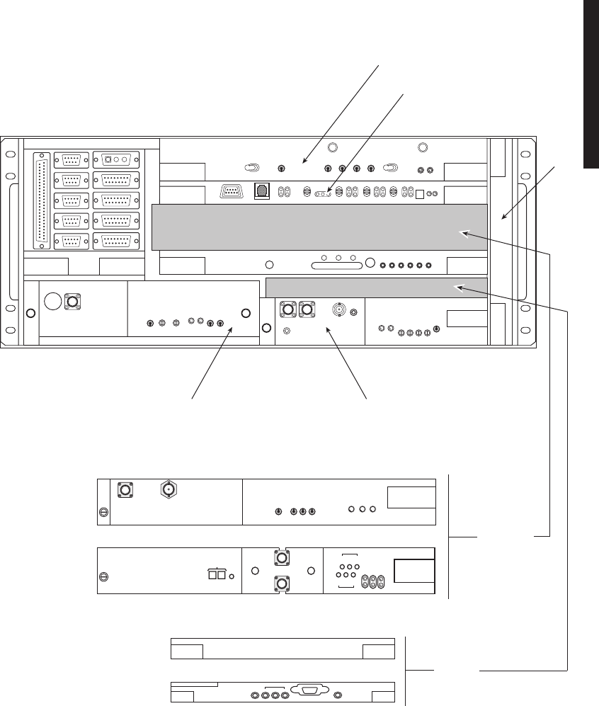
A-3
Figure A-2 Typical MDR-8000 CommPak Indoor Shelf Component Locations and Options (Sheet 2 of 3)
LMW-9079
08/29/03
CE-16BB PWR SUPPLY
AE-37Y CNTR
FAN
ASSY
UD-36( ) SINGLE RCVR
UD-36( ) DUAL RCVR
UD-35A( ) XMTRUD-51( ) PWR AMP
SELECT
RVCR BY
FUNCTION
CHANNEL ALM
MNDV
EYE CLOSURE
ON LINE
AFC
EYE
RSL
M
A
I
N
AFC
EYE
RSL
D
I
V
E
R
S
I
T
Y
GND
XTAL MN
XTAL DV
DUAL RECEIVER
RF IN
MN
RF IN
DV
CHAN ALM
EYE
CLOSURE
ON LINE
AFC MON
EYE MON
RSL MON
GND
RECEIVER
XTAL
MON
RF
IN
SELECT
ONE OR
NONE
AE-37AA TMN INTFC
ALM
1
2
3
PPP
C
R
A
F
T
E
T
H
E
R
N
E
T
AE-27AF RELAY INTFC
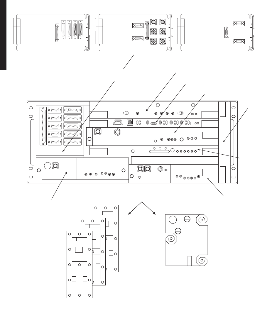
A-4
Figure A-2 Typical MDR-8000 CommPak Indoor Shelf Component Locations and Options (Sheet 3 of 3)
LMW-9078-SM
02/15/04
SELECT CAPACITY
KEY BY DATA RATE.
DS1/E1 LBO DS3 LBO OC3 AUX INTFC
SELECT XTAL
OSCILLATOR
SUBBOARD BY
CRYSTAL
FREQUENCY.
SELECT DS1/E1 CAPACITY KEY BY
CAPACITY AND MODULATION SCHEME
2, 4, 8, 12, 16 DS1/E1 AND 32 OR 128 TCM.
SELECT DS3 CAPACITY KEY BY
NUMBER OF LINES – 1, 2, OR 3 LINES.
SELECT OC3 CAPACITY KEY BY
NUMBER OF LINES – 1 OR 3 LINES.
DS1/E1
DS3
OC3
SELECT LBO/AUX INTFC
BY DATA RATE
CE-16BB PWR SUPPLY
AE-37Y CNTR
UD-36A( ) RCVR
FAN
ASSY
DX-35( )
I/O
INTFC
UD-35( ) XMTR
UD-51( ) PWR AMP
J202
J203
J201
J305
J306
J303
J304
J314
J401
J202
J201
J26
J24
J22 J25
J23
J21
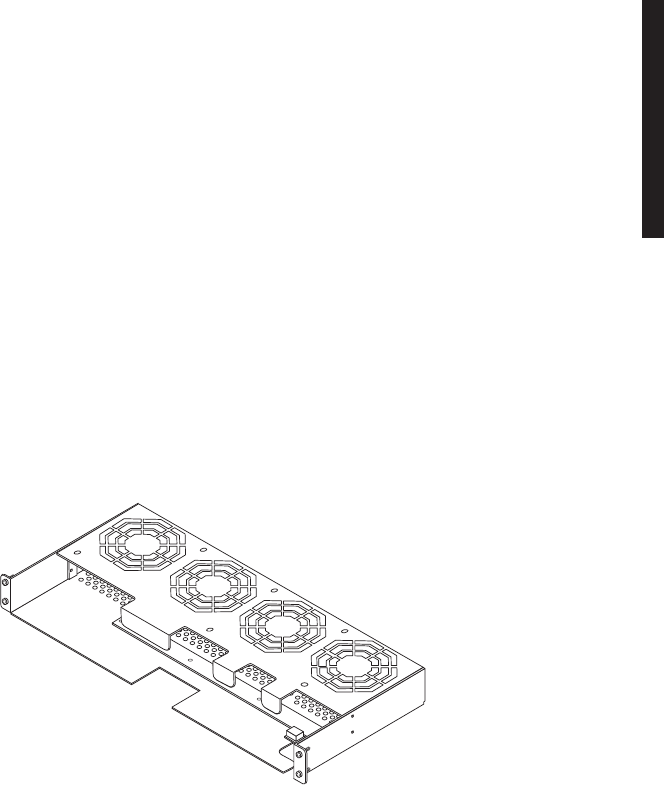
A-5
A.1.1
External Fan Assembly
See Figure A-3. The external fan assembly PN 3EM11901ABAA is required for cooling
the CommPak indoor unit equipped with high-power amplifiers, for specific frequency
bands, as follows:
The external fan assembly is wired to the CommPak indoor shelf internal fan assem-
bly PN 3EM14510AAAA via cable. The internal fan assembly passes +12 Vdc operat-
ing power to the external fan assembly, and the internal fan assembly passes 12C and
alarms from the external fan assembly.
The external fan assembly mounts to the rack rails directly below the heatsink on the
CommPak indoor shelf with four screws. The external fan assembly cools by blowing
air between the vanes on the heatsink. Fan revolutions are monitored and an alarm
occurs if any one or more fans loses rpm.
Figure A-3 External Fan Assembly
A.2
INTERCONNECT
This part of the section gives the location and describes strapping, power connections,
signal connections, status and alarm connections and service channel connections for
the CommPak indoor shelf.
A.2.1
Power Cable Assembly
See Figure A-4 for power cable assembly installation procedures. The MDR-8000 is
internally wired to accept 20.5 to 60 V dc input power with positive or negative ground.
To protect maintenance personnel from lightning strikes, the ground system must be
integrated by bonding station ground and dc battery return together. The dc power
connectors J1 and J2 are located on the rear of the back panel. Install power cables as
shown.
Radio Output Power
MDR-8505u +30 dBm
MDR-8506 +31 and +33 dBm
MDR-8510/8511 +29 dBm
MDR-1025
06/12/04

A-6
Short circuiting low-voltage, low-impedance dc circuits
can cause arcing that may result in burns or eye injury.
Remove rings, watches, and other metal jewelry while
working with primary circuits. Exercise caution to avoid
shorting input power terminals.
To protect maintenance personnel from antenna tower
lightning strikes, the ground system must be integrated by
bonding frame ground and dc battery return together.
Do not apply battery power until it is determined that A
and B battery cables with isolated returns and power
cables are wired correctly. With power applied, reverse
polarity on wiring (+batt wired to -batt pin on connector)
can cause power supply fuse to blow.
Grounding of pole, antenna, customer interfaces, and all entrances
to the building interior shall meet local electrical code and stan-
dard business practices.
Grounding of pole, antenna, customer interfaces, and all entrances
to the building interior shall meet local electrical code and stan-
dard business practices.
DANGER
Possibility of
Injury
to Personnel
DANGER
Possibility of
Injury
to Personnel
WARNING
Possibility of
Damage
to Equipment
Note
Note
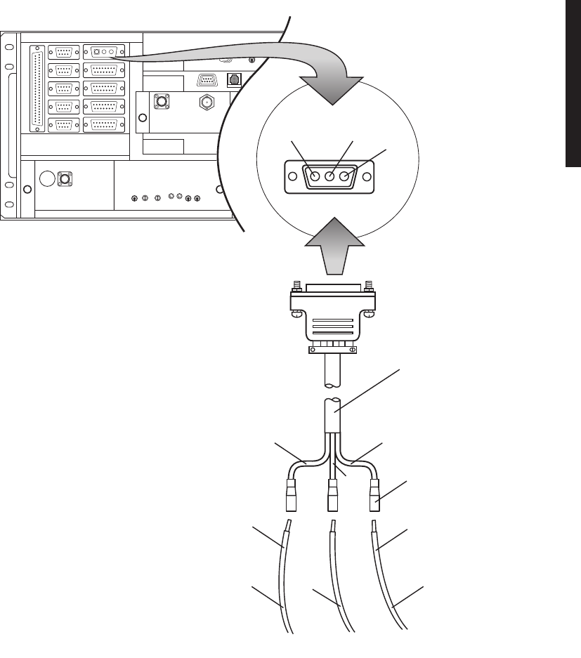
A-7
Figure A-4 Power Cable Assembly Installation
PIN 1
POS
PIN 2
GND
J1
PIN 3
NEG
PWR CABLE ASSEMBLY
PN695-7845-005
SLIDE-ON
LUG
RED
12 AWG
LMW-7224
01/22/04
CHASSIS
GND
– BATT
+ BATT
CONNECT + BATT WIRE
TO + RACK GND FOR
POS GND INSTALLATIONS CONNECT – BATT WIRE
TO – RACK GND FOR NEG
GND INSTALLATIONS
ORN
12 AWG
ORN
BLK
RED
BLK
12 AWG
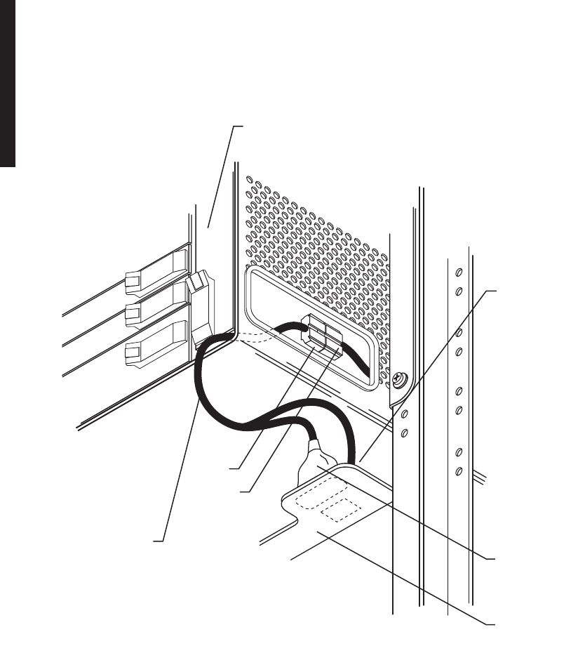
A-8
A.2.2
External Fan Assembly
See Figure A-5 for interconnect details.
Figure A-5 External Fan Assembly Interconnect Diagram (Sheet 1 of 2)
MDR-1027
06/16/04
INT. FAN CARD
P105
P302
J1
P1
FAN CABLE ASSY
PN 3EM15115ABAA
FAN ALM CARD
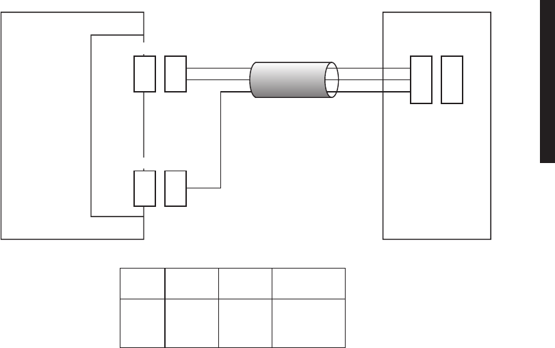
A-9
Figure A-5 External Fan Assembly Interconnect Diagram (Sheet 2 of 2)
A.2.3
SHELF/RACK ALARM CONNECTION
Each MDR-8000 rack equipped with the Power Distribution Unit (PDU) 695-6200-001/002
has a visual rack alarm indicator to report a shelf failure. In order to activate a rack alarm
visual indicator on the PDU, the shelf alarm output from each MDR-8000 shelf must be
hardwired to connector J1 on the PDU. The shelf alarm is provided on alarm connector
J305 pin 24 (major/visual alarm). A wire-wrap adapter (PN 695-4171-002) for connector
J305 is available. Insulated 22-gauge solid copper wire is recommended for connecting to
the wire-wrap adapter. To attach to J1 (2-pin connector) on the PDU, use 2-position socket
housing PN 372-0114-140 and socket contact PN 372-0114-390. See Figure A-6 for shelf-
to-rack alarm wiring.
Each MDR-8000 rack equipped with PDU 3EM13317AA has a blown fuse alarm visual
indicator and a Form C relay alarm output (J4, J5, and J6) for connection to customer
alarm equipment.
An optional Fuse and Shelf alarm plug-in assembly is available to provide shelf alarm
connections requiring Form C relays. The alarm inputs (major and minor) must be
hard wired to J3 on the PDU. The alarms are provided on alarm connector J305 pin 24
(major/visual alarm) and pin 50 (minor/audible alarm) of each shelf. A wire-wrap
adapter (PN 695-4171-002) for connector J305 is available. Insulated 22-gauge solid
copper wire is recommended for connecting to the wire-adapter and also to J3 on the
PDU. Alarm outputs are transmitted to customer equipment via Form C relay outputs
(J4, J5, J6, relays 1 through 8). This option also includes the blown fuse alarm indica-
tor and Form C relay alarm output (J4, J5, and J6 – relay 9). See Figure A-6 for typi-
cal shelf to PDU alarm wiring.
FAN
ALM
CARD
PN 3EM11901ABAA
FAN CARD
(ON CommPak
INDOOR SHELF)
PN 3EM14508ABAA
EXT
FAN
ASSY
+12 VDC
GND
9
1
P302 J302
9
1
FAN CABLE ASSY
PN 3EM15115ABAA
1
2
3
1
2
3
J1 P1
2
P105
2
FAN
ALM
MDR-1024
06/09/04
J105
FAN
ALM
1
2
3
J302
9
1
J305
2
WIRE
COLOR
RED
BLK
BLU
FAN CABLE ASSY PIN-OUT AND COLOR CODE
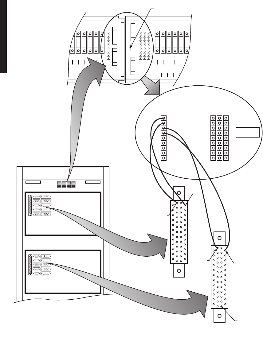
A-10
Figure A-6 Typical Shelf Alarm Wiring PDU (695-6200-001/002)
CommPak 1
CommPak 2
PDU
PIN 1
50
WIRE WRAP ADAPTER
WIRE WRAP
24
24
50
LMW-7225
01/22/04
6
E13
5
E14
4
E15
3
E16
2
E17
1
E18
E31 E32 E33 E34 E35 E36
FUSES
1
E7
2
E8
3
E9
4
E10
5
E11
6
E12
E25 E26 E27 E28 E29 E30
FUSES
RACK GND RACK GND
20 AMP
20 AMP
20 AMP
20 AMP
10 AMP
10 AMP
20 AMP
20 AMP
10 AMP
1 AMP1 AMP
1 AMP1 AMP
10 AMP
20 AMP
20 AMP
1
2
3
4
5
6
7
8
FUSE ALM
1
2
3
4
5
6
7
8
NC COM NO
J5
ALARM OUTPUTALARM INPUT
J4 J6
MAJOR 1
MINOR 1
MAJOR 2
MINOR 2
MAJOR 3
MINOR 3
MAJOR 4/AUX
MINOR 4/AUX
UNUSED
J3
CUSTOMER
OUTPUTS
FUSE ALARM INDICATOR
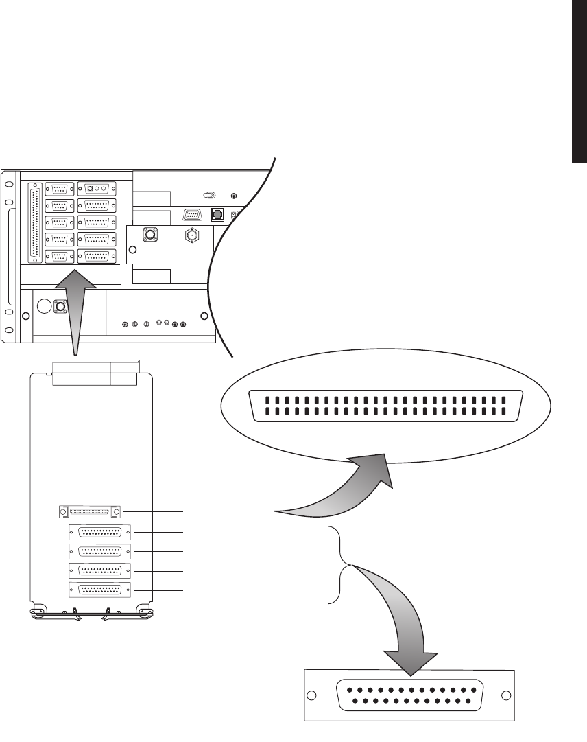
A-11
A.2.4
DS1 LBO Connections
A.2.4.1
DS1 Cable Connections
Recommended connectorized cable assembly – PN 695-7806-021 through -025 (22
AWG 12 pair shielded, jacketed cable with 25-pin D-type connector on one end). See
Figure A-7 for shelf connector location and pinout. Refer to Table A-1 for mating cable
wiring and color code.
Figure A-7 DS1 LBO Connector Location and Pinouts
J304 DS1/E1 LINES 9-16 IN
J314 REPEATER
J303 DS1/E1 LINES 1-8 IN
J306 DS1/E1 LINES 9-16 OUT
J305 DS1/E1 LINES 1-8 OUT
LMW-7223
01/21/04
J305
J306
J303
J304
J314
13 1
25 14
25
50
PIN 1
J314
26
FRONT VIEW

A-12
A.2.4.2
DS1 Repeater Cable Connections
The DS1 repeater cable carries clocks, DS1 data, and overhead for
two directions. If the 314 cable is not used, the embedded data in
the overhead must also be cabled individually. In this case, indi-
vidual cables must be run for MCS–11, audio, RS-232, and ELMC.
Recommended connectorized cable assembly – PN 695-7836-001/005 (25 pair shielded
cable with 50 pin Amp connectors) (SCSI). See Figure A-7 for shelf connector location
and pinout.
Use repeater cables for cabling repeater shelf 1 to repeater shelf 2
(eastbound/westbound data/clock)
Table A-1 DS1 IN J303 and DS1 OUT J304 Mating Cable
CONNECTOR PIN
NUMBER WIRE COLOR SIGNAL NAME CABLE PAIR
NUMBER
1 WHITE–BLUE CHAN 1 TIP 1
14 BLUE–WHITE CHAN 1 RING
2 WHITE–ORANGE CHAN 2 TIP 2
15 ORANGE–WHITE CHAN 2 RING
3 WHITE–GREEN CHAN 3 TIP 3
16 GREEN–WHITE CHAN 3 RING
4 WHITE–BROWN CHAN 4 TIP 4
17 BROWN–WHITE CHAN 4 RING
5 WHITE–SLATE CHAN 5 TIP 5
18 SLATE–WHITE CHAN 5 RING
6 RED–BLUE CHAN 6 TIP 6
19 BLUE–RED CHAN 6 RING
7 RED–ORANGE CHAN 7 TIP 7
20 ORANGE–RED CHAN 7 RING
8 RED–GREEN CHAN 8 TIP 8
21 GREEN–RED CHAN 8 RING
N/A RED–BROWN CUTBACK 9
N/A BROWN–RED CUTBACK
N/A RED–SLATE CUTBACK 10
N/A SLATE–RED CUTBACK
N/A BLACK–BLUE CUTBACK 11
N/A BLUE–BLACK CUTBACK
N/A BLACK–ORANGE CUTBACK 12
N/A ORANGE–BLACK CUTBACK
Note
Note
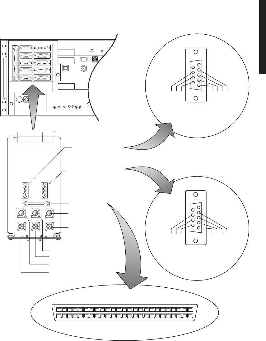
A-13
A.2.5
DS3 LBO CONNECTIONS
The DS3 LBO compensates for the distance to the cross-connect for DS3 and wayside
DS1 outputs. See Figure A-8 for connector locations.
Figure A-8 DS3 LBO Connector Location and Pinouts
J401
J202
J201
J26
J24
J22 J25
J23
J21
J201 WAYSIDE DS1 IN
J202 WAYSIDE DS1 OUT
J401 REPEATER
J6 LINE 3 DS3 IN
J5 LINE 3 DS3 OUT
J4 LINE 2 DS3 IN
J3 LINE 2 DS3 OUT
J2 LINE 1 DS3 IN
J1 LINE 1 DS3 OUT
TOP VIEW
J202
OUTPUT
51
96
LINE 2 OUT TIP
LINE 1 OUT TIP
GND
LINE 3 OUT TIP
LINE 3 OUT RING
LINE 2 OUT RING
LINE 1 OUT RING
25
50
PIN 1
J401
26
FRONT VIEW LMW-7221-SM
01/21/04
TOP VIEW
J201
INPUT
51
96
LINE 2 IN TIP
LINE 1 IN TIP
GND
LINE 3 IN TIP
LINE 3 IN RING
LINE 2 IN RING
LINE 1 IN RING

A-14
A.2.5.1
DS3 Cable Connections
Recommended connectorized cable assembly for all applications except repeaters,
PN 632-4429-096/180 (8/15 ft RG-59B/U coax cable with straight male BNC connector
on one end and right angle male BNC connector on other end). For repeater applica-
tions, recommend PN 632-4288-096/180 (8/15 ft RG-59B/U coax cable with straight
male BNC connector on each end). See Figure A-8 for locations.
A.2.5.2
Wayside DS1 Cable Connections
Recommended connectorized cable assembly – PN 695-4125-041 (26 AWG 5 pair
shielded, jacketed cable with 9-pin D-type connector on one end). See Figure A-8 for
shelf connector location and pinout. Refer to Table A-2 for mating cable wiring and
color code.
A.2.5.3
DS3 Repeater Cable Connections
The DS3 repeater cable carries clocks, data, and overhead for two
directions. It does not carry DS3 or wayside DS1 traffic. DS3 and
wayside DS1 cables must be run separately. If the 401 cable is not
used, the embedded data in the overhead must also be cabled indi-
vidually. In this case, individual cables must be run for MCS-11,
audio, RS-232, and ELMC.
Table A-2 DS1 LBO Wayside DS1 Connector Mating Cable – Wiring and Pinout
J201 (INPUTS) 202 (OUTPUTS)
FUNCTION END 1 WIRE COLOR WIRE COLOR END 2 FUNCTION
LINE 1 TIP IN 01 BLACK BLACK 01 LINE 1 TIP OUT
LINE 1 RING IN 06 RED RED 06 LINE 1 RING OUT
LINE 2 TIP IN 02 BLACK BLACK 02 LINE 2 TIP OUT
LINE 2 RING IN 07 WHITE WHITE 07 LINE 2 RING OUT
LINE 3 TIP IN 04 BLACK BLACK 04 LINE 3 TIP OUT
LINE 3 RING IN 08 GREEN GREEN 08 LINE 3 RING OUT
NOT USED 05 BLACK BLACK 05 NOT USED
NOT USED 09 BLUE BLUE 09 NOT USED
GND 03 BLACK GND 03 NOT USED
NOT USED 10 YELLOW YELLOW 10 NOT USED
Note

A-15
Recommended connectorized cable assembly – PN 695-7836-001/005 (25 pair shielded
cable with 50 pin Amp connectors) (SCSI). See Figure A-8 for shelf connector location
and pinout.
Use repeater cables for cabling repeater shelf 1 to repeater shelf 2
(eastbound/westbound data/clock)
A.2.6
Fiber Optic Cable Connections
This system normally operates as a Class I Laser Product
(no hazard), however during servicing operations, when
optical connectors are being connected, disconnected, or
handled without dust covers, it is possible to be exposed
to Class IIIB laser radiation which can cause eye damage.
Fiber optic connectors are delicate and can be damaged
easily by dirt or debris on the end of the connector. Keep
fiber optic connectors free of dust and debris by cleaning
the connector before and after use. Carefully clean the
fiber optic connector and cable ends with a cotton swab
dipped in alcohol or an alcohol wipe. Keep safety cap on
connectors when not in use.
The OC3 radio repeater cable carries DS1 clocks, data, and over-
head for two directions. OC3 fiber optic cables must be run sepa-
rately. If the repeater cable is not used, the embedded data in the
overhead must also be cabled individually. In this case, separate
cables must be run for MCS-11, audio, RS-232, and ELMC.
Note
DANGER
Possibility of
Injury
to Personnel
WARNING
Possibility of
Damage
to Equipment
Note
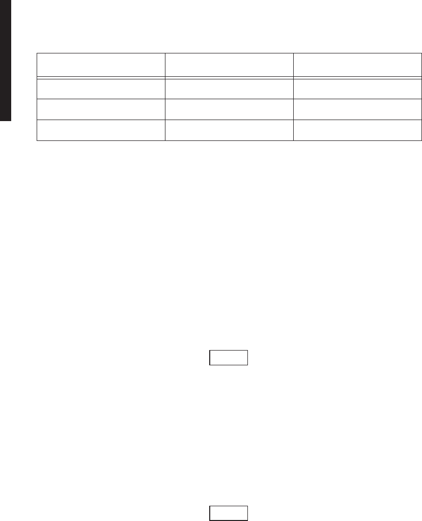
A-16
Refer to Table A-3 for recommended fiber optic jumpers.
A.2.7
OC3 AUX Interface Board Connections
A.2.7.1
Wayside DS1 Terminal
Recommended connectorized cable assembly – PN 695-4125-041 (26 AWG 5 pair
shielded, jacketed cable with 9-pin D-type connector on one end). See Figure A-9 for
location.
A.2.7.2
Wayside DS1 Repeater
Recommended connectorized cable assembly – PN 695-4125-051 (26 AWG 5 pair
shielded, jacketed cable with 9-pin D-type connector on each end). See Figure A-9 for
location.
A.2.7.3
OC3 Repeater Cable Connections
The OC3 radio repeater cable carries wayside clocks, data, and
overhead for two directions. It does not carry OC3 traffic. OC3 fiber
optic cables must be run separately. If the repeater cable is not
used, the embedded data in the overhead must also be cabled indi-
vidually. In this case, separate cables must be run for MCS-11,
audio, RS-232, and ELMC.
Recommended connectorized cable assembly – PN 695-4125-007/013 (26 AWG 5 pair
shielded, jacketed cable). See Figure A-9 for shelf connector location and pinout.
Use repeater cables for cabling repeater shelf 1 to repeater shelf 2
(eastbound/westbound data/clock).
Table A-3 Fiber Optic Jumpers
JUMPER TYPE PART NO. APPLICATION
FC to LC 3EM07651AA-AK TERMINAL
SC TO LC 3EM07646AA-AK TERMINAL
LC TO LC 3EM07641AA-AK REPEATER
Note
Note
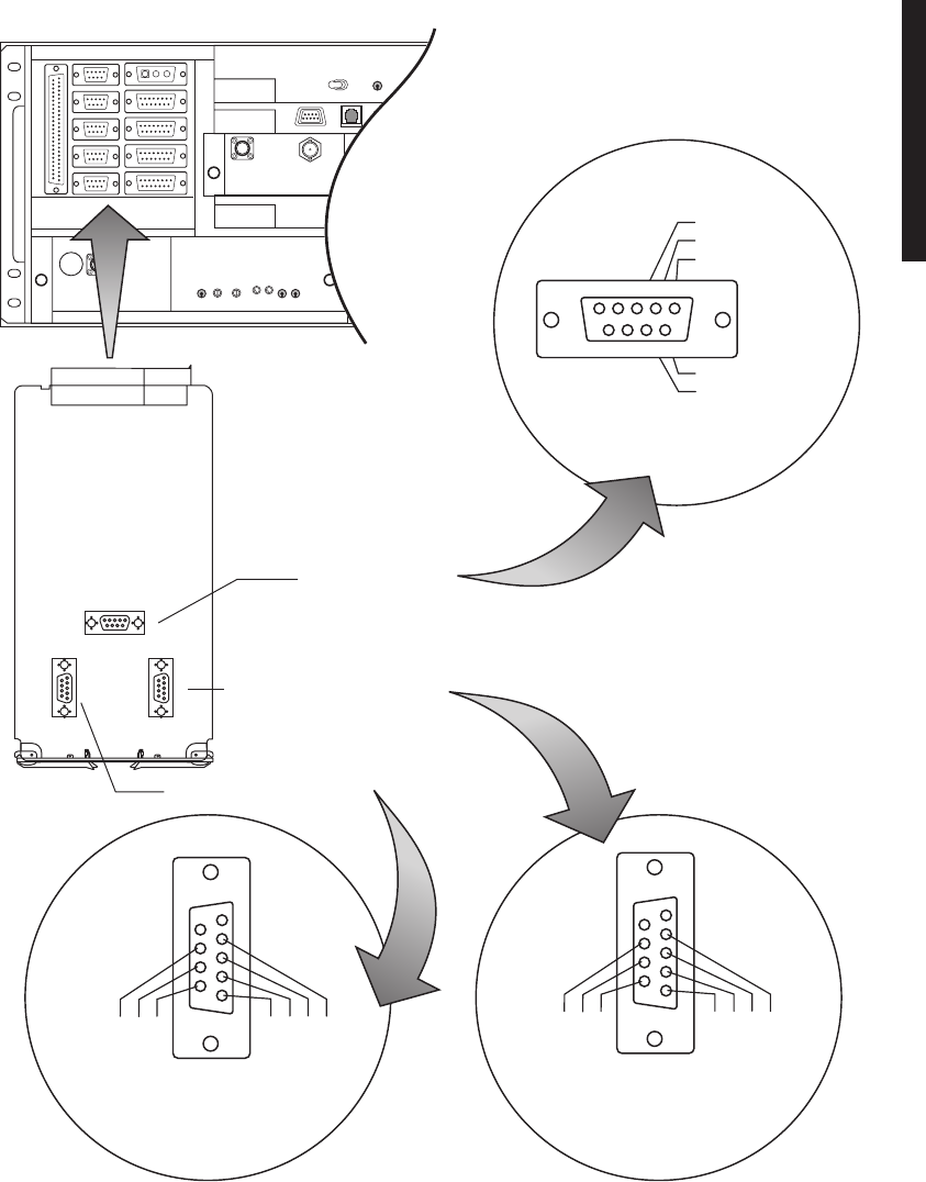
A-17
Figure A-9 OC3 AUX Interface Connector Location and Pinouts
J202
J203
J201
LMW-7222-SM
01/21/04
FRONT VIEW
51
96
LINE 2 OUT TIP
LINE 1 OUT TIP
GND
LINE 3 OUT TIP
LINE 3 OUT RING
LINE 2 OUT RING
LINE 1 OUT RING
J202
OUTPUT
FRONT VIEW
51
96
RPTR DS1 OUT TIP
RPTR DS1 IN TIP
GND
RPTR DS1 OUT RING
RPTR DS1 IN RING
J203
FRONT VIEW
J201
INPUT
51
96
LINE 2 IN TIP
LINE 1 IN TIP
GND
LINE 3 IN TIP
LINE 3 IN RING
LINE 2 IN RING
LINE 1 IN RING
J202 WAYSIDE DS1 OUT
J201 WAYSIDE DS1 IN
J203 REPEATER
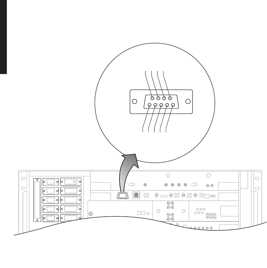
A-18
A.2.8
Controller Cable Connection (J301)
Recommended connectorized cable assembly – PN 695-7848-001 through 004 (24 AWG 6
pair shielded, jacketed cable with DEMM-9P connector on each end). See Figure A-10
for controller connector location and pinout.
Figure A-10 Controller USI Connector J301 Location and Pinout
A.2.9
Audio Cable Connections
Recommended cable – PN 424-0305-030 (26 AWG 5 pair shielded, jacketed cable with
9-pin D-type connector on each end). See Figure A-11 for pinout.
J315
J318
J316
J317
J312
J1
J307
J308
J309
J310
J301
J305
J312
J301
FRONT VIEW
USI
51
96
DTR
GND
TxD
RxD
DCD
RTS
DSR
CTS
RI
LMW-7214
01/21/04
J301
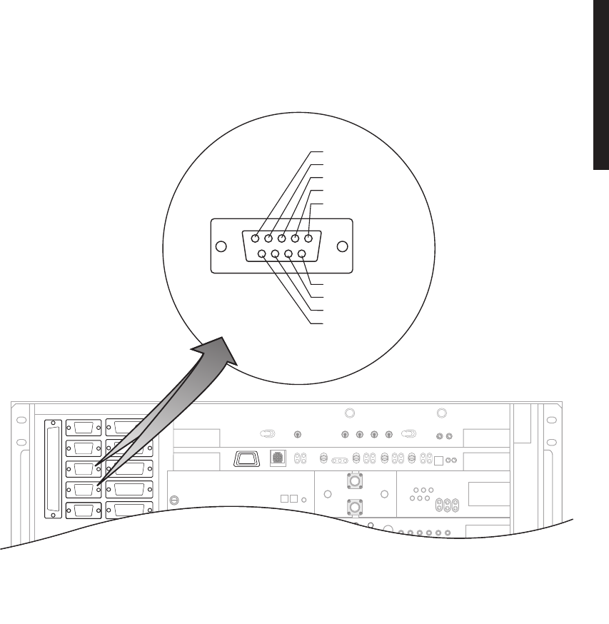
A-19
Figure A-11 Audio Connectors J316 and J317 Location and Pinout
A.2.10
RS-232 Cable Connections
Recommended connectorized cable assembly – PN 695-4125-021 through 025 (26 AWG 5
pair shielded, jacketed cable with 9-pin D-type connector on each end). See Figure A-12
for shelf connector locations and pinout.
J315
J318
J316
J317
J312
J1
J307
J308
J309
J310
J301
J305
J312
J316/J317
FRONT VIEW
51
96
M LEAD
AUDIO TIP IN
AUDIO TIP OUT
CALL DETECT
GND
CALL COMMON
AUDIO RING OUT
E LEAD
AUDIO RING IN
LMW-7215
01/21/04
J301
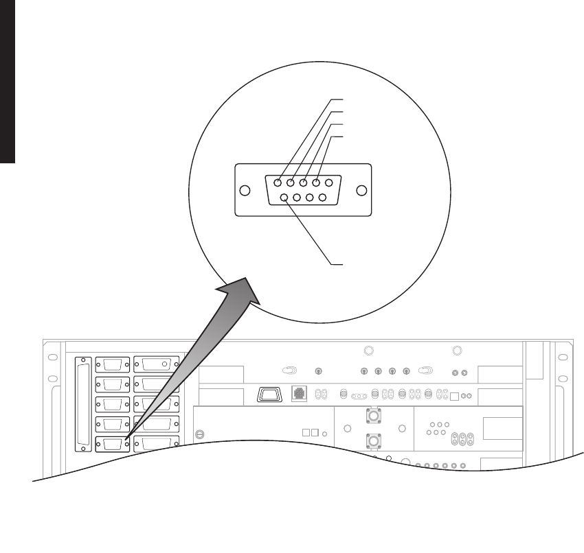
A-20
Figure A-12 RS-232 Connect J312 Location and Pinout
A.2.11
MCS-11 Cable Connections
When MCS is selected to be placed on one of the three service channels and then RSS
is enabled and properly addressed, applicable ports on the controller module are
enabled. This allows the user to interface external MCS-11 Monitor and Control Sys-
tem equipment at any or all four connectors on the backplane (J307, J308, J309, and
J310). Two connectors (J308 and J309) are synchronous, parallel, data ports and pro-
vide CLK outputs. Connectors J307 and J310 are asynchronous ports.
J315
J318
J316
J317
J312
J1
J307
J308
J309
J310
J301
J305
J312
J312
FRONT VIEW
51
96
RS232-1 OUT
RS232-1 IN
RS232-2 OUT
GND
RS232-2 IN
LMW-7216
01/21/04
J301
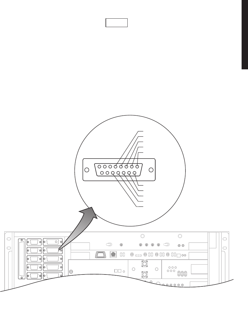
A-21
A.2.11.1
MCS-11 Master (J307) Cable Connection
If the radio is provisioned
Repeater
, port 2 on the controller, that
connects to J307, is disabled. At a repeater, you can use J310 in
lieu of J307 for connecting the TSM polling engine to the radio.
MCS-11 connector J307 is used to connect to a TSM (-2500, -3500, or -8000) polling
engine at a master terminal.
Recommended connectorized cable assembly – PN 695-4126-007/009/012 (26 AWG 8
pair shielded, jacketed cable). See Figure A-13 for shelf connector location and pinout.
Figure A-13 MCS-11 Connector J307 Location and Pinout
Note
J315
J318
J316
J317
J312
J1
J307
J308
J309
J310
J301
J305
J312
J307
FRONT VIEW
81
15 9
RCV DATA +
RCV CLK +
XMT CLK +
RTN CLK +
XMT DATA +
RTN CLK -
XMT DATA -
XMT CLK -
RCV DATA -
RCV CLK -
LMW-7218
01/21/04
J301
J307

A-22
A.2.11.2
MCS-11 Repeater-to-Spur Daisy Chain Connection (J308/J309)
MCS-11 must be provisioned
MCS-11 J310 Master/Junction
to
enable XMT, RCV, and OUTPUT clocks. If an external modem is
being used, provision MCS-11 for
MCS-11 J310 Modem
. This selec-
tion disables XMT, RCV,OUTPUT clocks and all MCS-11 clocks
must now be provided by the external modem.
MCS-11 connector J308/J309 is typically used to connect a repeater to a spur or multi-
ple spurs in a daisy chain system configuration. Either repeater shelf 1 or repeater
shelf 2 may feed the spur shelf. The first connection out of the repeater must be cross-
wired from J308 to J308. Then, every shelf from the spur must be wired 1:1, J309 to
J308, in a daisy-chain fashion.
CROSSWIRED CABLE ASSEMBLY – Recommended connectorized cable assembly –
PN 695-7837-001 through -005 (26 AWG 8 pair shielded, jacketed cable with 15-pin
D-type connector on each end). See Figure A-14 for shelf connector J308 location and
pinout. See Figure A-14 for shelf connector J309 location and pinout.
DAISY CHAIN CABLE ASSEMBLY – Recommended connectorized cable assembly –
PN 695-7837-021 through -025 (26 AWG 8 pair shielded, jacketed cable with 15-pin
D-type connector on each end, wired 1:1).
Note
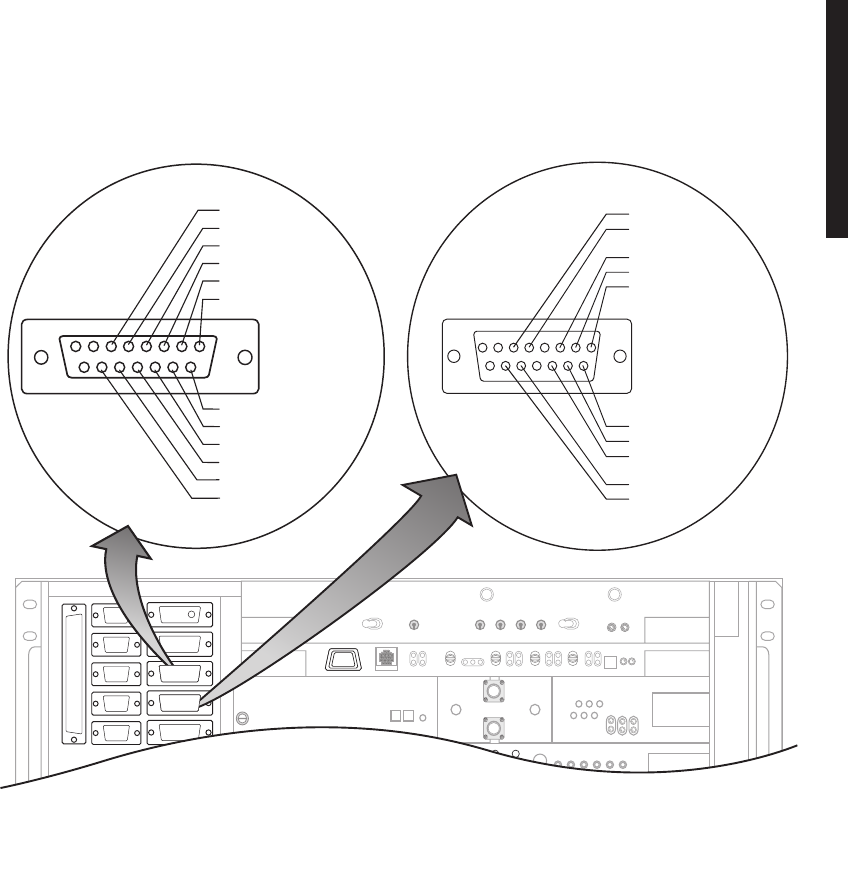
A-23
Figure A-14 MCS-11 Connector J308 and J309 Location and Pinout
J315
J318
J316
J317
J312
J1
J307
J308
J309
J310
J301
J305
J308
FRONT VIEW
1
9
RCV DATA +
RCV CLK +
XMT CLK +
CLK OUT +
XMT DATA +
OFF HOOK +
RTN CLK -
XMT DATA -
OFF HOOK -
XMT CLK -
RCV DATA -
RCV CLK -
8
15
J308J308
XMT DATA +
J309
FRONT VIEW
OFF HOOK +
XMT CLK +
RCV DATA +
RCV CLK +
RCV CLK –
RCV DATA –
XMT CLK –
XMT DATA –
OFF HOOK –
81
15 9
J309J309
J301
MDR-1010
04/08/04
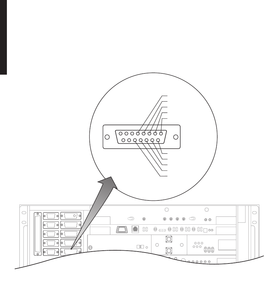
A-24
A.2.11.3
MCS-11 Spur Connection (J310)
MCS-11 connector J310 can be used to connect to a spur shelf and is the preferred con-
nection to the DMX-3003N MUX.
Recommended connectorized cable assembly – PN 695-4126-031 through -035
(26 AWG 8 pair shielded, jacketed cable with 15-pin D-type connector on each end).
See Figure A-15 for shelf connector J310 location and pinout.
Figure A-15 MCS-11 Connector J310 Location and Pinout
A.2.12
ELMC Cable Connections
The Extended Link Monitor Channel (ELMC) function allows provisioning, alarms,
status information, and control commands for the local radio and, with the exception
of wayside DS1, alarms, status information, control commands for addressable remote
radios as a standard feature. For wayside DS1 status, the ELMC option key (695-5647-
019 or -020) must be installed on the AE-37Y Controller. For remote provisioning and
downloading capability, the ELMC option key (695-5647-018 or 695-5647-020) must be
installed on the AE-37Y Controller.
J315
J318
J316
J317
J312
J1
J307
J308
J309
J310
J301
J305
J312
J310
FRONT VIEW
81
15 9
RCV DATA +
RCV CLK +
XMT CLK +
RTN CLK +
XMT DATA +
RTN CLK -
XMT DATA -
XMT CLK -
RCV DATA -
RCV CLK -
J301
J310
LMW-7220
01/21/04
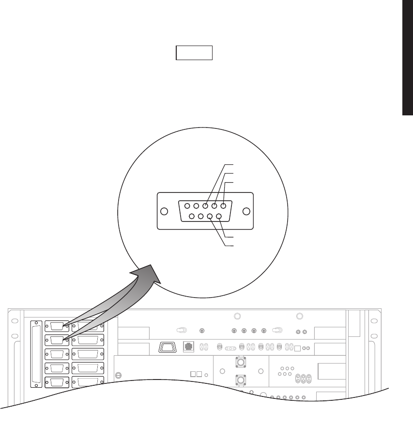
A-25
Recommended connectorized cable assembly – PN 695-4125-006/013 (26 AWG 5 pair
shielded, jacketed cable). See Figure A-16 for shelf connectors locations and pinout.
ELMC 1 connector J318 and ELMC 2 connector J315 are wired
in parallel. You can connect J315 to J315, J315 to J318, or J318
to J318.
Figure A-16 ELMC Connectors J315 and J318 Location and Pinout
A.2.13
Foreign Alarm Interface (J305)
Recommended connectorized cable assembly – PN 695-4121-001/003 (24 AWG 25 pair
cable). See Figure A-17 for shelf connector location and pinout.
or
Recommended wirewrap cable – PN 424-0429-020 (22 AWG 30-pair twisted cable) for
use with wirewrap adapter PN 695-4171-002.
Note
J315
J318
J316
J317
J312
J1
J307
J308
J309
J310
J301
J305
J312
J315/J318
FRONT VIEW
51
96
LMW-7217
01/21/04
XMT +
RCV +
GND
XMT -
RCV -
J301
J315
J318
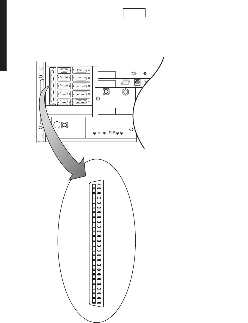
A-26
TBOS connections on J305 share pins with station alarms 13
through 16 and either TBOS or station alarms 13 through 16 is
selected (provisioned) on the USI Radio Configuration Provision-
ing screen.
Figure A-17 Alarm/Status/TBOS Connector J305 Location and Pinout
Note
LMW-7227-50pin
01/23/04
J305
25
50
PIN 1
26
FRONT VIEW
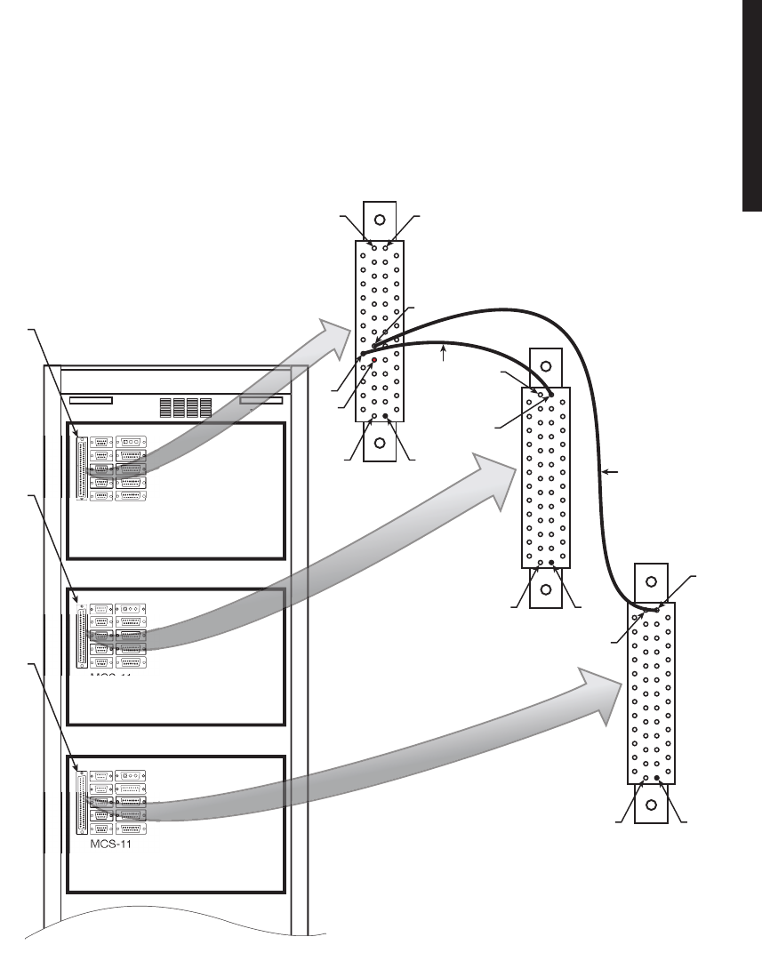
A-27
A.2.14
Station Alarm Wiring
See Figure A-18. Use wire wrap adapter PN 695-4171-002 to connect station alarm
inputs to the AE-27A Relay Interface module, via connector J305, in each rack. A typical
connection scenario is shown. The station/shelf alarm for MCS-11 address A1A (MCS-11
alarm point 1) is connected by software. The station alarms for MCS-11 address A1B
and A1C are assigned to MCS-11 Alarm points 2 and 3, respectively.
Figure A-18 Alarm and Status Relays/TBOS Interconnect
MCS-11
ADDRESS
A1A
CommPak 1
MCS-11
ADDRESS
A1B
CommPak 2
MCS-11
ADDRESS
A1C
CommPak 3
PDU
RACK ALM
PIN 25
RACK ALM
50
25
36
34*
35
50
50
25
26
26
26
PIN 1
PIN 1
PIN 1
#2
STATION
ALM
#3
STATION
ALM
#1
*STATION
ALM
(SEE NOTE)
LMW-7228
01/26/04
P
J305
J305
J305
NOTE
SOFTWARE AUTOMATICALLY CONNECTS
RACK ALM OUTPUT FROM CONTROLLER
J305-25 TO #1 STATION ALM INPUT J305-34.
WIRE WRAP ADAPTER
(PN 695-4171-002)

A-28
A.3
MAINTENANCE
This part of the appendix provides information and procedures that are different for
the hot-standby shelf and the CommPak indoor shelf.
A.3.1
Warnings and Cautions
All Warnings and Cautions outlined in the Maintenance section of the main book apply
while operating, performance testing, troubleshooting, or repairing the MDR-8000
series radio.
A.3.2
Troubleshooting
Refer to the Maintenance section in the main book.
A.3.3
Module Replacement
Before replacing any module refer to Table A-4 to determine the actions, other than
physical replacement, required. If the module has any options (switches, subboards, etc.),
refer to the removed module so that the replacement module can be set up the same way.
Table A-4 Module Replacement Matrix
MODULE/UNIT REMOVAL/REPLACEMENT
PROCEDURE CHECKS/ADJUSTMENTS
PROCEDURE
AE-27AF Relay Interface No Special Procedure Required None Required
AE-37Y Controller Chart 2 (Maintenance Section in
main book) None Required
CE-16BB Power Supply Chart 1 (Maintenance Section in
main book) None Required
Fuse No Special Procedure Required.
Refer to Operations Section in
main book for location.
DX-35M DS1/E1 I/O Interface Chart 3 (Maintenance Section in
main book) No Special Procedure Required
DX-35N DS3 I/O Interface Chart 3 (Maintenance Section in
main book) Chart 10 and 11 in Appendix E
on attached CD
UD-35( ) Transmitter Chart 4 (Maintenance Section in
main book) Applicable Charts 1 through 5
in Appendix E on attached CD
Crystal Oscillator Subboard Chart 4 (Maintenance Section in
main book)
Capacity Key Chart 5 (Maintenance Section in
main book)
UD-51( ) Power Amplifier Paragraph A.4.1 (This Section) Applicable Charts 6 through 8
in Appendix E on attached CD
DS1/E1 LBO Paragraph A.4.2 (This Section) No Special Procedure Required
DS3 LBO Paragraph A.4.3 (This Section) No Special Procedure Required
OC3 AUX Intfc Paragraph A.4.4 (This Section) No Special Procedure Required
(1)
If ATPC is in use, it must be provisioned disabled or locked high before removing controller.
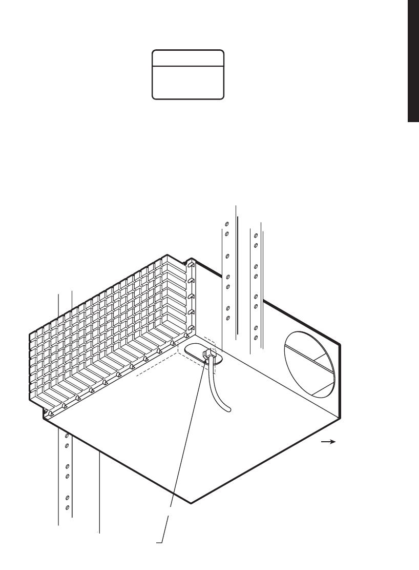
A-29
A.3.3.1
PA Module Removal and Replacement
Remove and replace the PA using the following procedure:
MDR-1001
03/08/04
1. USING OPEN-END 5/16 WRENCH
LOOSEN CABLE CONNECTOR ON
RF OUT
CONNECTOR ON PA.
FRONT
BOTTOM VIEW
B
efore starting removal procedure, loosen cable connected to
RF OUT
connector on
PA
.
S
emirigid coaxial cable requires special consideration. The electrical characteristics of the
semirigid coax can be affected if it is accidentally twisted or bent. Provide mechanical support to
p
revent any weight or strain to the coax and connector when connecting or disconnecting
e
quipment. Loosen the connectors at both ends of a semirigid coax section if one end must be
moved even slightly. SMA connectors should be secured in place fingertight, and then gently
tightened using a torque wrench with a 5/16 in. head set for 7 to 9 inch-pounds. The connectors
should not be left fingertight.
WARNING
Possibility of
Damage
to Equipment
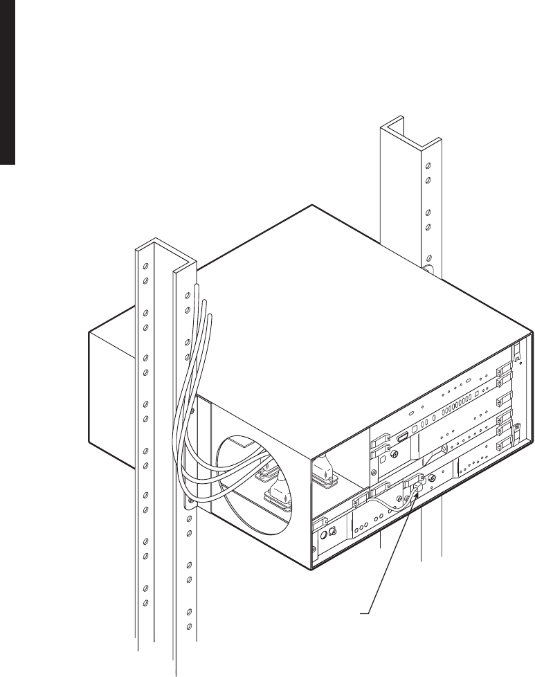
A-30
MDR-1004
03/08/04
2. DISCONNECT CABLE FROM
RF OUT
CONNECTOR ON
XMTR
.
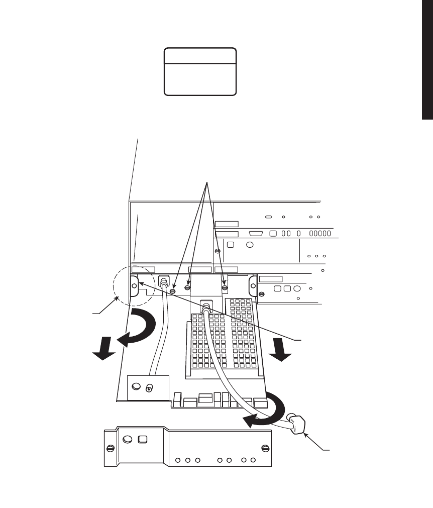
A-31
MDR-1002
03/08/04
6. ANGLE PA TO LEFT AND
PULL OUT ON RIGHT SIDE
OF PA UNTIL LEFT SIDE OF
CHASSIS COVER CLEARS
BRACKET.
5. PULL STRAIGHT OUT ON
PA UNTIL CHASSIS COVER
MEETS LEFT BRACKET ON
CARD CAGE.
LEFT
BRACKET
3. REMOVE PA FRONT PANEL AND
PLACE OUT OF THE WAY.
4. LOOSEN THREE CAPTIVE MOUNTING
SCREWS SECURING PA TO HEAT SINK.
2. DISCONNECT
CABLE FROM RF
OUT CONNECTOR
ON XMTR.
Check to ensure that the three mounting screws securing the PA to
the heatsink are loose before attempting to remove the PA to
prevent damage to the module.
WARNING
Possibility of
Damage
to Equipment
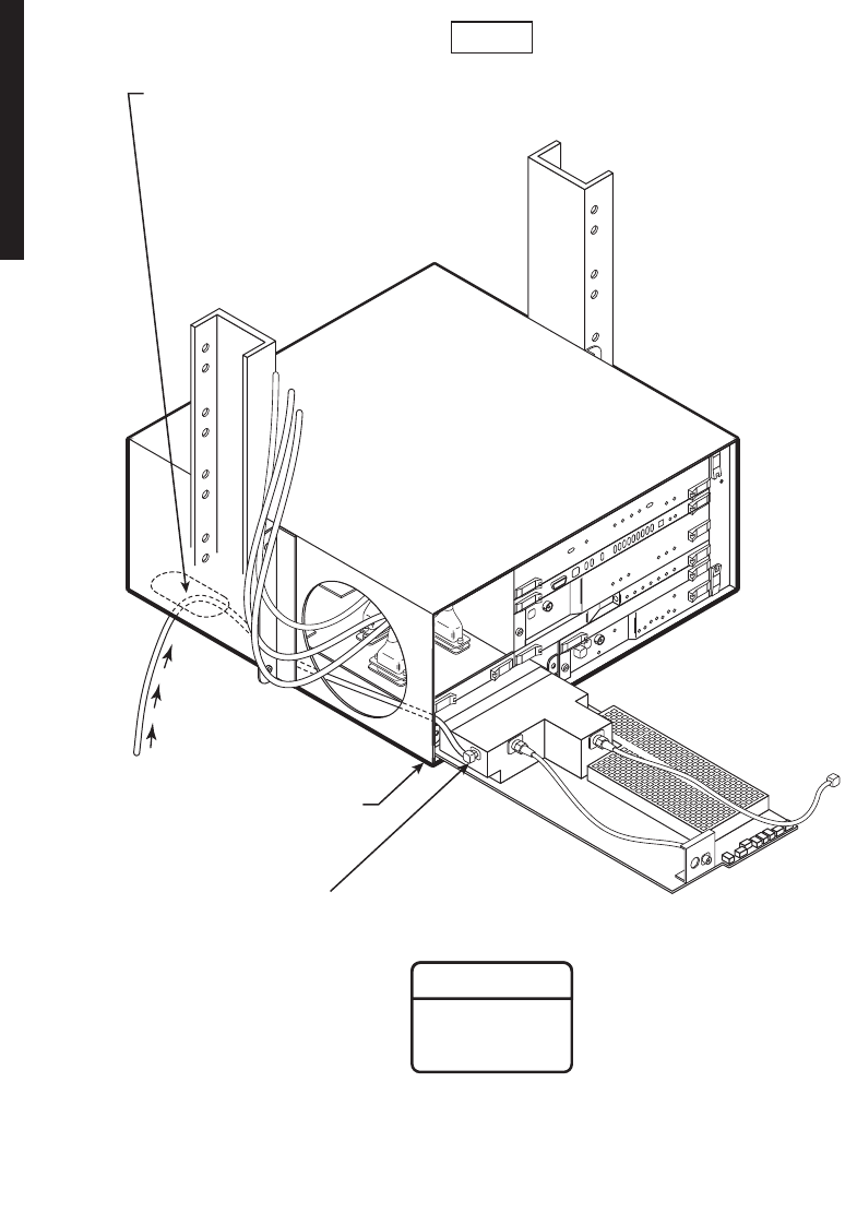
A-32
MDR-1003
03/08/04
7. STRAIGHTEN AND PULL
PA OUT UNTIL EDGE OF
PA IS RESTING ON EDGE
OF CARDCAGE.
To prevent monitor point errors, use caution to ensure that the front
panel removed from the PA is reinstalled on that same PA. No two
monitor levels labeled on PAs are the same. Erroneous output levels
can result from installing the wrong front panel and calibrating the
PA to the level labeled on that front panel.
WARNING
Possibility of
Damage
to Equipment
8. WHILE HOLDING PA, DISCONNECT PA RF OUT CABLE.
You must continually feed RF cable through bottom entrance hole in cardcage
as you pull out PA, being cautious to not damage or overbend cable.
Note
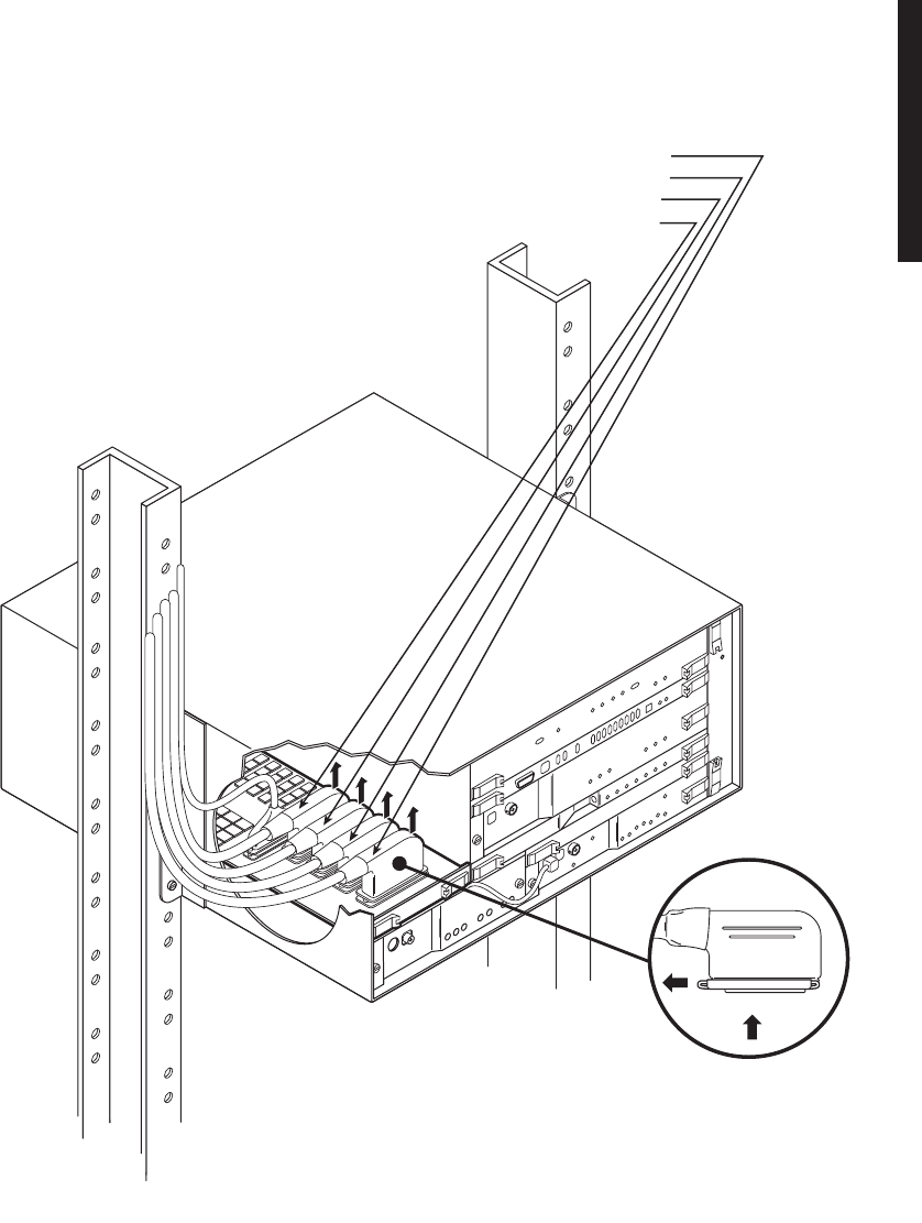
A-33
A.3.3.2
DS1/E1 LBO Module Removal and Replacement
Remove and replace the DS1/E1 LBO using the following procedure:
4. UNLOCK AND DISCONNECT CABLE FROM DS1/E1 LINES 9-16 IN CONNECTOR J304.
5. PULL CABLE THROUGH OPENING.
3. UNLOCK AND DISCONNECT CABLE FROM DS1/E1 LINES 1-8
IN CONNECTOR J303.
2. UNLOCK AND DISCONNECT CABLE FROM DS1/E1 LINES 9-16
OUT CONNECTOR J306.
1. UNLOCK AND DISCONNECT CABLE FROM DS1/E1 LINES 1-8 OUT CONNECTOR J305.
MDR-1005
03/09/04
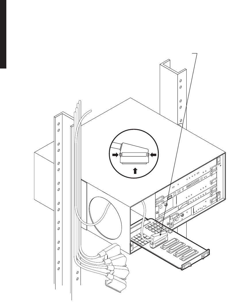
A-34
MDR-1006
03/08/04
6. USING HANDLES ON MODULE, UNLATCH DS1/E1 LBO AND PULL OUT OF CARDCAGE TO FULLY EXTENDED
POSITION WITH EDGE OF LBO RESTING ON EDGE OF CARDCAGE.
7. WHILE HOLDING LBO, UNLOCK AND DISCONNECT CABLE FROM RPTR CONNECTOR J314.
PRESSPRESS
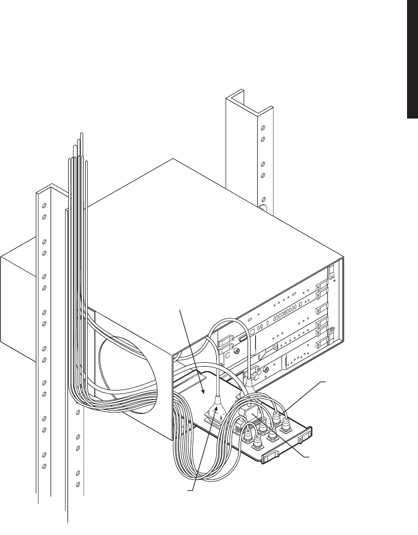
A-35
A.3.3.3
DS3 LBO Module Removal and Replacement
Remove and replace the DS3 LBO using the following procedure:
4. DISCONNECT WAYSIDE
DS1 CABLES.
MDR-1008
03/09/04
1. PULL DS3 LBO OUT OF CARDCAGE
UNTIL EDGE OF MODULE IS RESTING
ON EDGE OF CARDCAGE.
2. DISCONNECT
DS3 CABLES.
3. UNLOCK AND
DISCONNECT
RPTR CABLE.
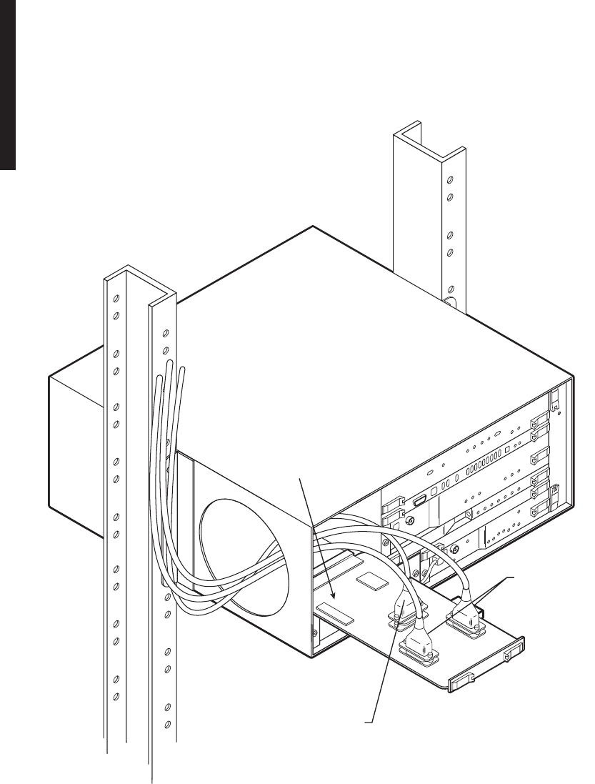
A-36
A.3.3.4
OC3 AUX Interface Board Removal and Replacement
Remove and replace the OC3 AUX interface board using the following procedure:
3. UNLOCK AND DISCONNECT
RPTR CABLE.
1. PULL OC3 AUX INTFC BOARD
OUT OF CARDCAGE UNTIL
EDGE OF MODULE IS RESTING
ON EDGE OF CARDCAGE.
2. DISCONNECT
WAYSIDE DS1
CABLES.
MDR-1007
03/09/04
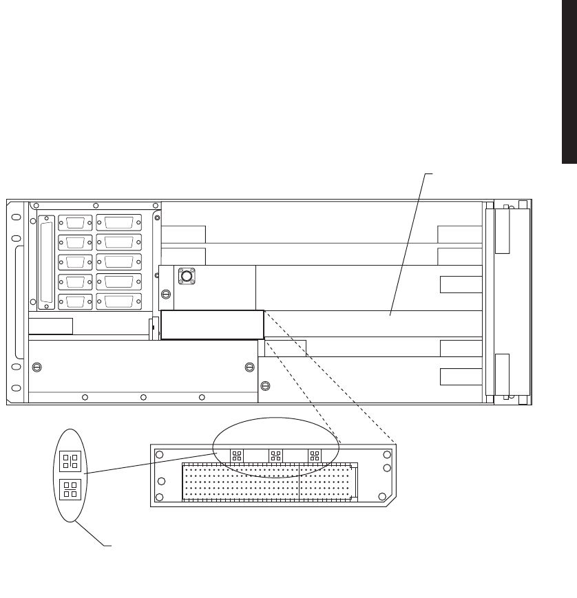
A-37
A.4
CAPACITY UPGRADE DS1 TO DS3 OR DS3 TO OC3
Upgrading a DS1 radio to DS3 or DS3 radio to OC3 requires changing straps on the
LBO adaptor, located behind the I/O interface module. Use the following procedure
before starting upgrade from DS3 to OC3.
A.5
CHANGING SYSTEM SOFTWARE
Refer to the Maintenance section in the main book.
J315 J1
POWER SUPPLY
CONTROLLER
RECEIVER
FAN UNIT
SSPA
LBO
TRANSMITTER
I/O INTFC
TMN / RELAY
J318 J307
J316
J315
J308
J317 J309
J312 J310
P1 P2 P3
DS3
DS1/OC3
1. REMOVE I/O
AND RCVR INTFC.
3. STRAP LBO
ADAPTER.
SHOWN IN DEFAULT POSITION FOR DS1/OC3
2. REPLACE I/O INTFC AND RCVR.
MDR-1015
06/15/04

A-38 This page intentionally left blank.