Alcatel USA 8702-4 Digital Modulated Radio User Manual 00 Book I 6 fullTOC

Alcatel USA Marketing, Inc. Digital Modulated Radio 00 Book I 6 fullTOC
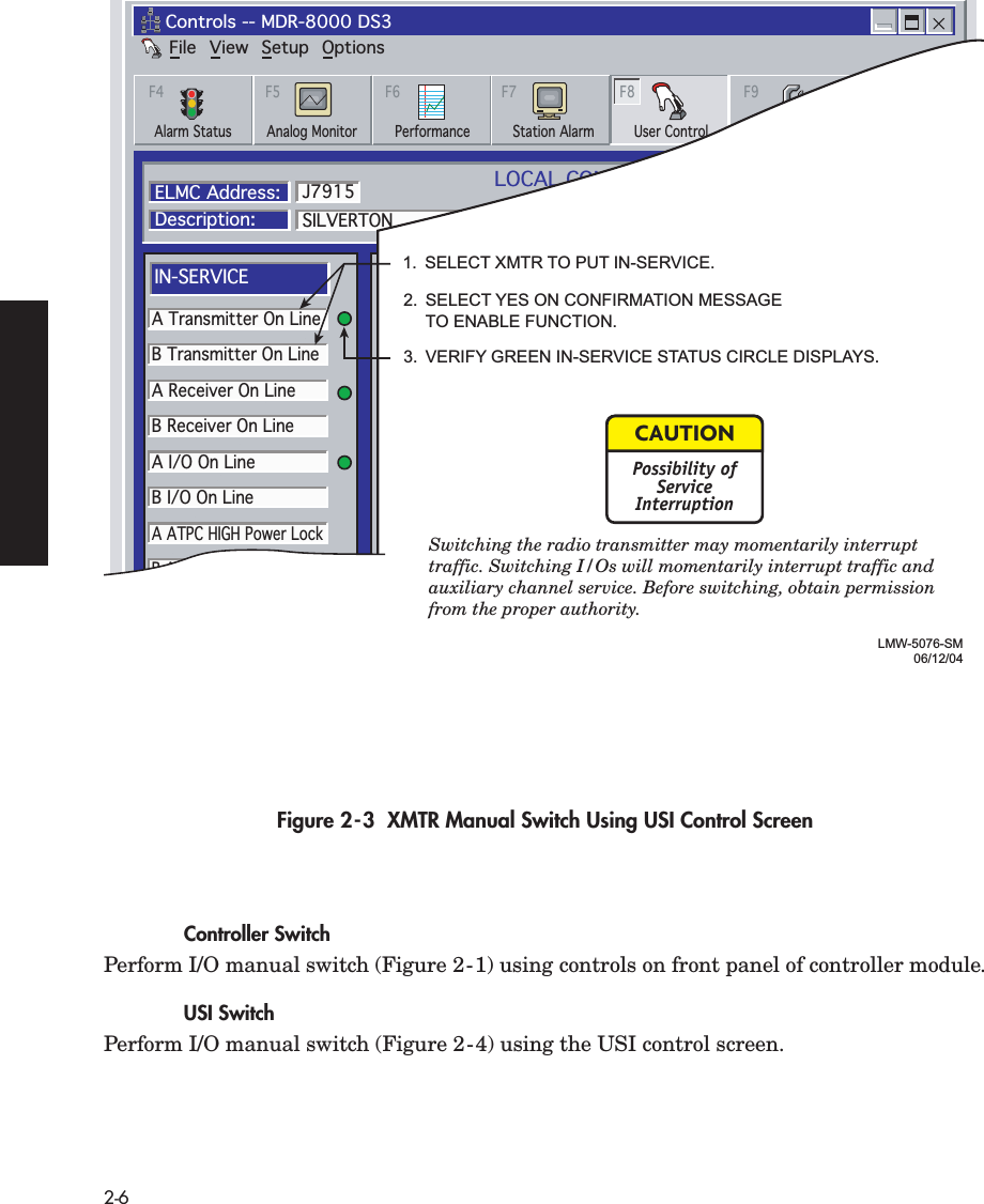
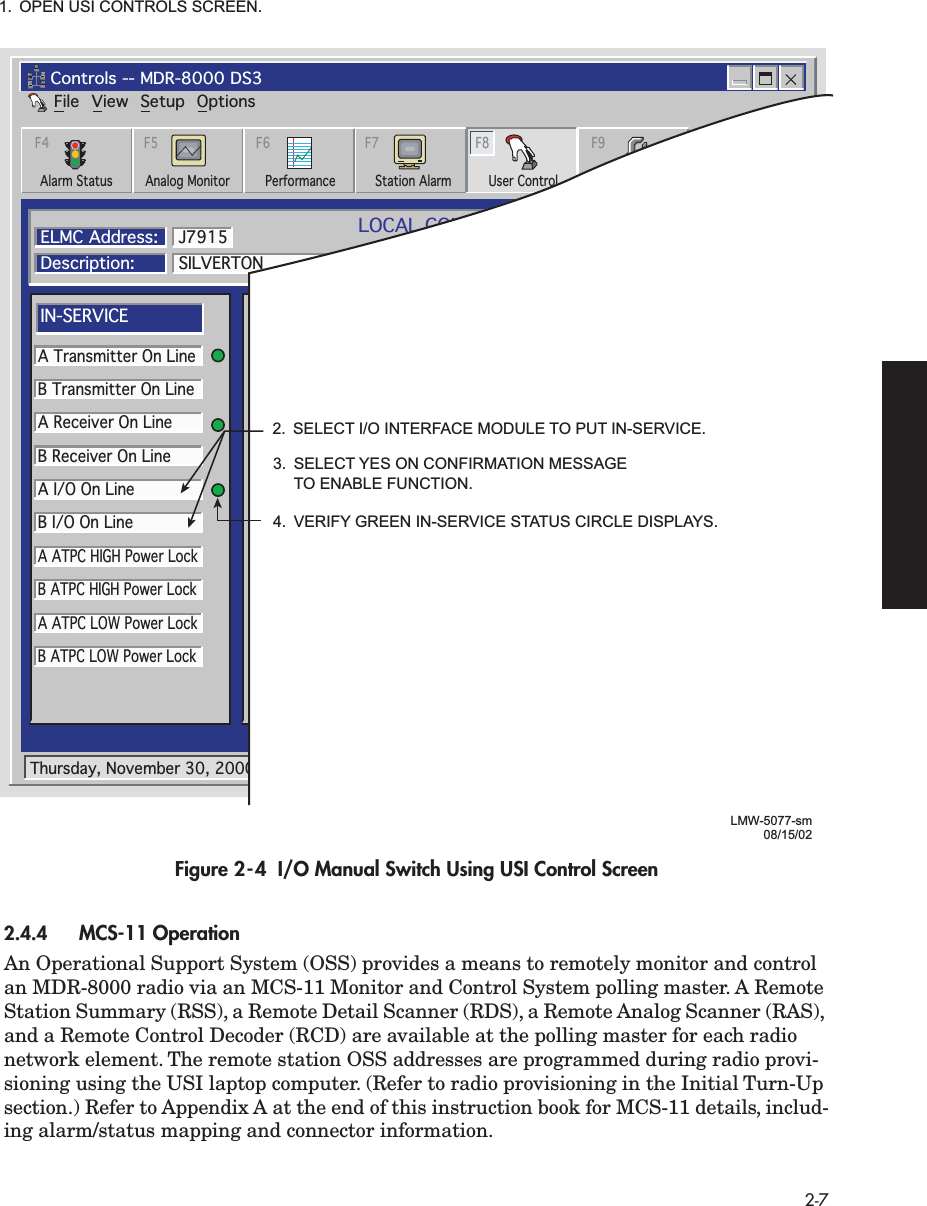
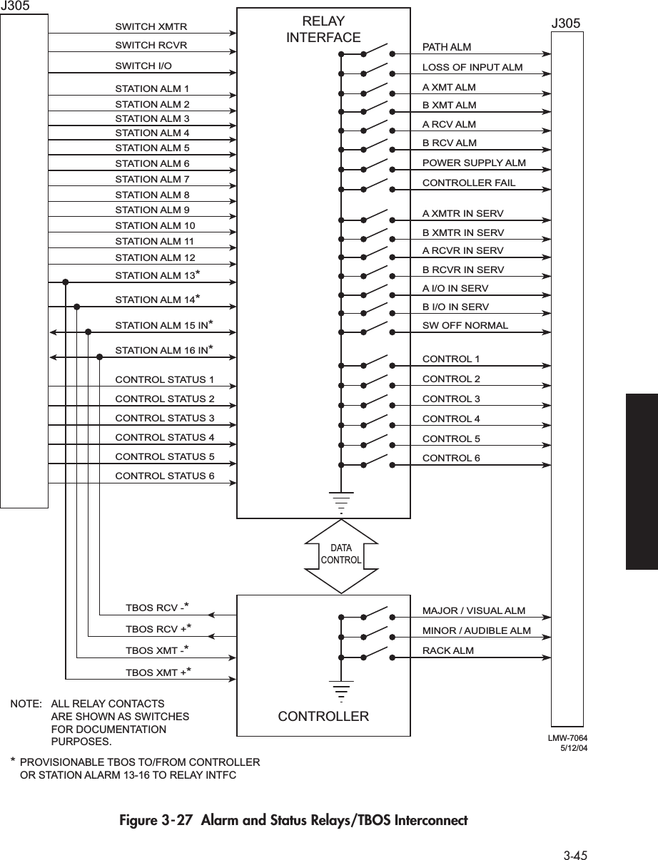
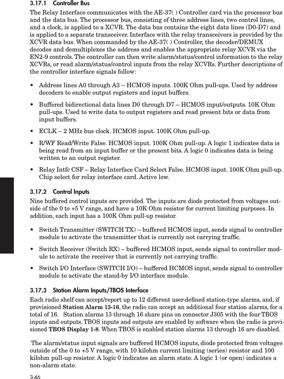
Complete Users Manual

MDR-8000/i/s/uAlcatel Part Number 3EM15726AA3400 West Plano ParkwayPlano, Texas 75075-5813 U.S.A.Part 1 of 2Issue 2, June, 2004Microwave Digital RadiosUsers Manual
 Table of Contents TOC-i Page Section 1 General 1.1 INTRODUCTION .............................................................................................1-11.2 CONTENT .......................................................................................................1-1 Section 2 Operation 2.1 GENERAL ........................................................................................................2-12.2 TURN-ON ........................................................................................................2-12.3 USER SYSTEM INTERFACE (USI) PROVISIONING FUNCTION/OPERATION ......2-22.4 OPERATING PROCEDURES ..............................................................................2-22.4.1 Radio Receiver Manual Switching .....................................................................2-22.4.2 Radio Transmitter Manual Switching .................................................................2-52.4.3 Radio I/O Interface Manual Switching ..............................................................2-52.4.4 MCS-11 Operation ..........................................................................................2-72.4.5 Lamp Tests .......................................................................................................2-82.4.6 Alarm Checks ..................................................................................................2-82.4.7 Orderwire Operation .......................................................................................2-82.4.8 Initiating Outgoing Orderwire Calls ..................................................................2-82.4.9 Answering Incoming Orderwire Calls ................................................................2-82.5 TURN-OFF PROCEDURE ...................................................................................2-92.6 EMERGENCY OPERATION ..............................................................................2-92.7 MODEM OPERATION ......................................................................................2-92.8 CONTROLS, INDICATORS, TEST POINTS, AND CONNECTORS .......................2-9 Section 3 Interconnect 3.1 SECTION INTRODUCTION ..............................................................................3-13.2 INSTALL POWER CABLE ASSEMBLIES ...............................................................3-1
 Page TOC-ii 3.3 PDU STRAPPING AND CONNECTIONS ........................................................... 3-33.4 SHELF/RACK ALARM CONNECTION .............................................................. 3-53.5 DS1 CONNECTIONS (J303 IN AND J304 OUT) .............................................. 3-83.6 DS1 REPEATER (J314 ON ONE SHELF TO J314 ON SECOND SHELF) ............ 3-103.7 DS3 LBO STRAPPING AND CONNECTIONS ................................................. 3-113.8 DS3 LBO DS3 BNC CONNECTIONS (J21 THROUGH J26) ............................. 3-123.9 DS3 LBO WAYSIDE DS1 CONNECTIONS (J201 IN AND J202 OUT) ............. 3-133.9.1 Wayside DS1 Terminal .................................................................................. 3-143.9.2 Wayside DS1 Repeater .................................................................................. 3-153.10 DS3 REPEATER (J401 ON ONE SHELF TO J401 ON SECOND SHELF) ............ 3-153.11 FIBER OPTIC CABLE CONNECTIONS ............................................................. 3-163.11.1 2 or 4 Fiber Management Panel ..................................................................... 3-173.11.2 2x4 Fiber Switched Management Panel .......................................................... 3-173.12 OC3 AUX INTERFACE BOARD WAYSIDE DS1 CONNECTIONS (J201 IN AND J202 OUT) .............................................................................. 3-203.12.1 Wayside DS1 Terminal .................................................................................. 3-203.12.2 Wayside DS1 Repeater .................................................................................. 3-203.13 OC3 REPEATER (J203 ON ONE SHELF TO J203 ON SECOND SHELF) ........... 3-213.14 USI/CONTROLLER CABLE CONNECTION TO LAPTOP (J301) ......................... 3-223.15 SERVICE CHANNEL ....................................................................................... 3-223.15.1 Handset Jack ................................................................................................. 3-233.15.2 Service Channels Provisioning Options ............................................................ 3-243.15.3 Audio 1, Audio 2 (J316, J317) ....................................................................... 3-243.15.4 RS-232-1, RS-232-2 (J312, J313) .................................................................... 3-273.15.5 MCS-11 Connections ..................................................................................... 3-283.15.6 ELMC (J315, J318) ........................................................................................ 3-373.16 FOREIGN ALARM INTERFACE (J305) ............................................................. 3-413.17 ALARM, STATUS, CONTROLS INTERCONNECT ............................................. 3-443.17.1 Controller Bus ................................................................................................ 3-463.17.2 Control Inputs ................................................................................................ 3-463.17.3 Station Alarm Inputs/TBOS Interface ............................................................... 3-46
 Page TOC-iii 3.17.4 Station Alarm Wiring .....................................................................................3-473.17.5 Relay Alarm/Status Outputs ............................................................................3-483.17.6 Relay Control Outputs ....................................................................................3-51 Section 4 Initial Turnup 4.1 SECTION INTRODUCTION ..............................................................................4-14.2 RECOMMENDED SEQUENCE .........................................................................4-14.3 PROVISIONING RADIO ...................................................................................4-3 Section 5 Maintenance 5.1 GENERAL ........................................................................................................5-15.2 MAINTENANCE PHILOSOPHY .........................................................................5-25.3 SPECIAL TOOLS ...............................................................................................5-45.4 PERSONAL COMPUTER (PC) ............................................................................5-45.5 ALARM MONITORING AND INSPECTION .......................................................5-45.6 RECOMMENDED PERIODIC CHECKS ...............................................................5-65.7 TROUBLESHOOTING .......................................................................................5-65.7.1 Test Procedures ................................................................................................5-65.7.2 Linear/Ring Radio Troubleshooting ...................................................................5-65.7.3 Ring Radio Troubleshooting ............................................................................5-185.8 MODULE REPLACEMENT ...............................................................................5-195.9 CHANGING FREQUENCY .............................................................................5-225.10 CLEANING ....................................................................................................5-22 Appendix A CommPak Indoor Shelf A.1 COMPONENT LOCATIONS AND OPTIONS ....................................................A-1A.1.1 External Fan Assembly ......................................................................................A-5A.2 INTERCONNECT .............................................................................................A-5A.2.1 Power Cable Assembly .....................................................................................A-5A.2.2 External Fan Assembly ......................................................................................A-8A.2.3 SHELF/RACK ALARM CONNECTION ..............................................................A-9
 Page TOC-iv A.2.4 DS1 LBO Connections ....................................................................................A-11A.2.5 DS3 LBO CONNECTIONS .............................................................................A-13A.2.6 Fiber Optic Cable Connections .......................................................................A-15A.2.7 OC3 AUX Interface Board Connections ...........................................................A-16A.2.8 Controller Cable Connection (J301) ................................................................A-18A.2.9 Audio Cable Connections ...............................................................................A-18A.2.10 RS-232 Cable Connections .............................................................................A-19A.2.11 MCS-11 Cable Connections ...........................................................................A-20A.2.12 ELMC Cable Connections ...............................................................................A-24A.2.13 Foreign Alarm Interface (J305) ........................................................................A-25A.2.14 Station Alarm Wiring .....................................................................................A-27A.3 MAINTENANCE ............................................................................................A-28A.3.1 Warnings and Cautions .................................................................................A-28A.3.2 Troubleshooting .............................................................................................A-28A.3.3 Module Replacement ......................................................................................A-28A.4CAPACITY UPGRADE DS1 TO DS3 OR DS3 TO OC3.....................................A-37A.5CHANGING SYSTEM SOFTWARE.................................................................A-37
 1-1 1 GENERAL  1.1 INTRODUCTION This MDR-8000 Users Manual contains information on the MDR-8000 Hot-Standby Shelf, MDR-8000 CommPak Indoor Shelf, and MDR-8000 CommPak Outdoor Unit as follows:MDR-8000 Hot-Standby Shelf – Section 1 through Section 5MDR-8000 CommPak Indoor Shelf – Appendix AMDR-8000 CommPak Outdoor Unit – Appendix B (to be supplied) The information in the Users Manual is a summary of the overall instruction book that is located on the attached CD. The summary information is provided to support initial turnup, day-to-day operation, and maintenance of the MDR-8000 equipment. 1.2 CONTENT Refer to Table 1-1. The  MDR-8000 Instruction Book  Section/Appendix column lists the parts of the  MDR-8000 Instruction Book , PN 3DH03220. A check mark under the Users Manual column or  the Instruction Book CD column indicates that this information is located in either the Users Manual, the Instruction Book, or both. Table 1-1   Information Location LocationSection/Appendix Users Manual MDR-8000 Instruction Book Glossary √ General √ Application √ Functional Description √ Physical Installation √ Interconnect √ √ Initial Turnup √ √ Operation √ √ Users Guide √ Maintenance √ √ Diagrams √ Rack Installation √ Alarm/Status/Control √ MCS-11 Reference Guide √ Modem Provisioning √ Maintenance Support Procedures √ CommPak Indoor Shelf √ √
 1-2 Figure 1-1  Typical MDR-8000 Hot-Standby Shelf Component Locations and Options  (Sheet 1 of 3)LBO/OC3 AUX INTFCSELECT LBO/OC3 AUX INTFCTO MATCH I/O INTFC(DATA RATE)CE–16BBPOWERSUPPLYA1CE–16BBPOWERSUPPLYB1UD–36A( )RCVRA2AE–37YCONTROLLERC1AE-27AATMN INTFCOR BLANK C3UD–35A( )XMTRA4UD–35A( )XMTRB4UD–51( )PWR AMPA5UD–36A( )RCVRB2UD–51( )PWR AMPB5I/O INTFCA3I/O INTFCB3LMW-7030-SM06/09/04ALMONLINEALMONLINESYNCALMCOM-MONLOSSALMDX-35MDS1/EISELECT A3 AND B3I/O INTFC MODULESBY DATA RATEDX-35NDS3XMTAUXSCALMRCVRONRADLOFWYSDDS1WYSDALMDS3ALIGNRAD DADE1235678901234DX-35POC3ALMINSVCOC3INOC3ALMWYSDONWYSDALMOC3OUTDS1/E1 LBODS3 LBOOC3 AUX INTFCAE–27AFRELAYINTFCC2
 1-3 ) Figure 1-1  Typical MDR-8000 Hot-Standby Shelf Component Locations and Options  (Sheet 2 of 3)LBO/OC3 AUX INTFCSELECT CAPACITY KEY BY DATA RATE.SELECT XTAL OSCILLATOR SUBBOARD BY CRYSTAL FREQUENCY.SELECT DS1/E1 CAPACITY KEY BY CAPACITY AND  MODULATION SCHEME 2, 4, 8, 12, 16 DS1/E1 AND 32 OR 128 TCM.SELECT DS3 CAPACITY KEY BY NUMBER OF LINES – 1, 2, OR 3 LINES.SELECT OC3 CAPACITY KEY BY NUMBER OF STS1 LINES – 1 OR 3 LINES.CE–16BBPOWERSUPPLYA1CE–16BBPOWERSUPPLYB1UD–36A( )RCVRA2AE–27AFRELAYINTFCC2AE–37YCONTROLLERC1UD–35A( )XMTRA4UD–35A( )XMTRB4UD–51( )PWR AMPA5UD–36A( )RCVRB2UD–51( )PWR AMPB5I/O INTFCA3I/O INTFCB3LMW-9051-SM02/15/04DS1/E1DS3OC3
 1-4 Figure 1-1  Typical MDR-8000 Hot-Standby Shelf Component Locations, and Options (Sheet 3 of 3 )RFSWITCHB-SIDEPOWERRF SWITCHXMTARCVANTBRCVISOLATORSHEATSINKA-SIDEPOWERLMW-7211-SM06/08/04DIPLEXERFILTERMOUNTINGBRACKETISOLATORDIPLEXERFILTERREAR VIEW(TYPICAL HOT-STANDBY 1:10 COUPLERSINGLE ANTENNA CONFIGURATION)Location of A and B RCV ports on diplexer filter varies, depending on RF frequency. For some frequencies, A and B ports reverse location.Note
 2-1 2 OPERATION 2.1 GENERAL This section contains turn-on, normal operation, turn-off, and emergency operating procedures plus a description of controls. indicators, test points, and connectors for the MDR-8000 Series Microwave Digital Radios. Before performing any procedures, operating personnel should becomefamiliar with the locations of power distribution units and circuitbreakers. If an equipment performance problem occurs during the fol-lowing procedures, refer to the Maintenance section. 2.2 TURN-ON The radio is designed to operate continuously without operator intervention. After initial installation and power turn-on, operating procedures are limited to periodic visual lamp checks, alarm checks, and answering or initiating orderwire service calls. Turn-on procedures are needed only if the system has been turned off due to a malfunction or during maintenance. Exposure to energy radiated at microwave frequencies cancause eye damage and eventual blindness. Do not operatethe system with either the transmit or the receive waveguideport unterminated. Do not look into the waveguide run or theantenna of an operating radio. Until all radios in the transmission link are interconnected, turned on,and operating properly, alarm conditions may exist. Perform the following procedure to turn on the MDR-8000 series radios: 1 On all power supply modules, set power ON/OFF switches to ON. 2 Verify that power distribution unit rack alarm indicator (if any) is not lighted. If indicator is lighted, troubleshoot as described in the Maintenance section. 3 Verify that no red indicators are lighted. If a red indicator is lit, troubleshoot as described in the Maintenance section. 4 Perform lamp test by momentarily holding OVRD-ACO/LT switch on control-ler to ACO/LT.   All indicator lamps/LEDs should light.NoteWARNINGPossibility ofDamageto EquipmentNote
 2-2 2.3 USER SYSTEM INTERFACE (USI) PROVISIONING FUNCTION/OPERATION The User System Interface (USI) software is used for maintenance and support of the radio including fault and status reporting. Refer to the Initial Turn-Up section for instruc-tions on loading and running the software. Refer to the User’s Guide section for descrip-tions and functions of the menus. Refer to the Software Release Notes before performing any operating,provisioning, or maintenance function on this equipment. The SoftwareRelease Notes may contain information affecting these functions that isnot contained in this instruction manual. 2.4 OPERATING PROCEDURES The USI computer is the main control for the radio. If instructions forsetting up the USI computer are needed, refer to Initial Turn-Up section. After installation and turn-on, operating procedures are limited to periodic alarm checks and, when necessary, answering or initiating orderwire calls. Automatic and manual switching are provided for equipment protection. Manual switching may be accomplished using the Control screen on the USI computer or the switches on the front panel of the con-troller module. The following paragraphs provide operating procedures for manual switchover of protected radio systems. 2.4.1 Radio Receiver Manual Switching  When used in conjunction with a RCVR manual switch, press theOVRD switch to lock the receiver on line regardless of alarms. Pressagain to unlock. Controller Switch Perform RCVR manual switch (Figure 2-1) using controls on front panel of controller module: USI Switch Perform RCVR manual switch (Figure 2-2) using the USI control screen.NoteNoteNote
 2-3 Figure 2-1  Manual Switch From Controller Front PanelALMOFFNORMSHLFALMALMONLINERXLABALMONLINETXLABALMRSPRSPONLINEI/OLAPOLLLCLRMTBACO/LTOVRDRF RPTRCMDIDLETELUSITOGGLE SWITCH LEFT TO SWITCH A XMTR, RCVR, OR I/O MODULE IN-SERVICE AND TOGGLE SWITCH RIGHT TO SWITCH  B XMTR, RCVR, OR I/O MODULE IN-SERVICE.LMW-5078-sm08/15/02OVERRIDE (OVRD) LOCKS XMTR, RCVR, OR I/O MODULE, SELECTED ABOVE IN-SERVICE, REGARDLESS OF ALARMS.TO ENABLE OVERRIDE:1.  PRESS AND HOLD TX A/B ON LINE,  RX A/B ON LINE, OR I/O A/B ON LINE  SWITCH.2.  TOGGLE ACO/LT OVRD SWITCH TO OVRD POSITION.3.  RELEASE A/B ON LINE SWITCH. TO DISABLE OVERRIDE: TOGGLE ACO/LT OVRD SWITCH TO OVRD  POSITION.NOTE
 2-4 Figure 2-2  RCVR Manual Switch Using USI Control ScreenFileControls -- MDR-8000 DS3View Setup OptionsAlarm Status Performance Station Alarm User Control ProvisioningAnalog MonitorF4 F5 F6 F7 F8 F9LOCAL CONTROLSCommunicating*ELMC Address:Description:SILVERTONA Transmitter On LineB Transmitter On LineA Receiver On LineB Receiver On LineA I/O On LineB I/O On LineA ATPC HIGH Power LockB ATPC HIGH Power LockA ATPC LOW Power LockB ATPC LOW Power LockJ7915IN-SERVICEA I/O LOOPBACKLine 1 loopbackLine 2 loopbackLine 3 loopbackB I/O LOOPBACKControl #1Control #2Control #3Control #4Control #5Control #6SYSTEM LOOP-BACKDS1 LINE LOOP-BACK RCV to XMTUSER CONTROLSThursday, November 30, 2000 1:44:19 PM USI Version R1.02 Controller Version R1.02LMW-5081-sm08/15/022.  SELECT RCVR TO PUT IN-SERVICE.1.  OPEN USI CONTROLS SCREEN.3.  SELECT YES ON CONFIRMATION MESSAGE  TO ENABLE FUNCTION.4.  VERIFY GREEN IN-SERVICE STATUS CIRCLE DISPLAYS.
 2-5 2.4.2 Radio Transmitter Manual Switching  Switching the radio transmitter may momentarily interrupttraffic. Before switching the transmitter, obtain permissionfrom the proper authority. When used in conjunction with a XMTR manual switch, press theOVRD switch to lock the XMTR on line regardless of alarms. Pressagain to unlock. Controller Switch Perform XMTR manual switch (Figure 2-1) using controls on front panel of controller module. USI Switch Perform XMTR manual switch (Figure 2-3) using the USI control screen. 2.4.3 Radio I/O Interface Manual Switching  Traffic and auxiliary channel service will be momentarilyinterrupted. Obtain proper authorization before making thisswitch. When used in conjunction with an I/O interface manual switch, pressthe OVRD switch to lock the I/O interface on line regardless of alarms.Press again to unlock.CAUTIONPossibility ofServiceInterruptionNoteCAUTIONPossibility ofServiceInterruptionNote
 2-6 Figure 2-3  XMTR Manual Switch Using USI Control Screen Controller Switch Perform I/O manual switch (Figure 2-1) using controls on front panel of controller module. USI Switch Perform I/O manual switch (Figure 2-4) using the USI control screen.FileControls -- MDR-8000 DS3View Setup OptionsAlarm Status Performance Station Alarm User Control ProvisioningAnalog MonitorF4 F5 F6 F7 F8 F9LOCAL CONTROLSCommunicating*ELMC Address:Description:SILVERTONA Transmitter On LineB Transmitter On LineA Receiver On LineB Receiver On LineA I/O On LineB I/O On LineA ATPC HIGH Power LockB ATPC HIGH Power LockA ATPC LOW Power LockB ATPC LOW Power LockJ7915IN-SERVICEA I/O LOOPBACKLine 1 loopbackLine 2 loopbackLine 3 loopbackB I/O LOOPBACKControl #1Control #2Control #3Control #4Control #5Control #6SYSTEM LOOP-BACKDS1 LINE LOOP-BACK RCV to XMTUSER CONTROLSThursday, November 30, 2000 1:44:19 PM USI Version R1.02 Controller Version R1.02LMW-5076-SM06/12/041.  SELECT XMTR TO PUT IN-SERVICE.2.  SELECT YES ON CONFIRMATION MESSAGE  TO ENABLE FUNCTION.3.  VERIFY GREEN IN-SERVICE STATUS CIRCLE DISPLAYS.Switching the radio transmitter may momentarily interrupt traffic. Switching I/Os will momentarily interrupt traffic and auxiliary channel service. Before switching, obtain permission from the proper authority. CAUTIONPossibility ofServiceInterruption
 2-7 Figure 2-4  I/O Manual Switch Using USI Control Screen 2.4.4 MCS-11 Operation  An Operational Support System (OSS) provides a means to remotely monitor and control an MDR-8000 radio via an MCS-11 Monitor and Control System polling master. A Remote Station Summary (RSS), a Remote Detail Scanner (RDS), a Remote Analog Scanner (RAS), and a Remote Control Decoder (RCD) are available at the polling master for each radio network element. The remote station OSS addresses are programmed during radio provi-sioning using the USI laptop computer. (Refer to radio provisioning in the Initial Turn-Up section.) Refer to Appendix A at the end of this instruction book for MCS-11 details, includ-ing alarm/status mapping and connector information.FileControls -- MDR-8000 DS3View Setup OptionsAlarm Status Performance Station Alarm User Control ProvisioningAnalog MonitorF4 F5 F6 F7 F8 F9LOCAL CONTROLSCommunicating*ELMC Address:Description:SILVERTONA Transmitter On LineB Transmitter On LineA Receiver On LineB Receiver On LineA I/O On LineB I/O On LineA ATPC HIGH Power LockB ATPC HIGH Power LockA ATPC LOW Power LockB ATPC LOW Power LockJ7915IN-SERVICEA I/O LOOPBACKLine 1 loopbackLine 2 loopbackLine 3 loopbackB I/O LOOPBACKControl #1Control #2Control #3Control #4Control #5Control #6SYSTEM LOOP-BACKDS1 LINE LOOP-BACK RCV to XMTUSER CONTROLSThursday, November 30, 2000 1:44:19 PM USI Version R1.02 Controller Version R1.02LMW-5077-sm08/15/022.  SELECT I/O INTERFACE MODULE TO PUT IN-SERVICE.1.  OPEN USI CONTROLS SCREEN.3.  SELECT YES ON CONFIRMATION MESSAGE  TO ENABLE FUNCTION.4.  VERIFY GREEN IN-SERVICE STATUS CIRCLE DISPLAYS.
 2-8 2.4.5 Lamp Tests Perform lamp tests by pressing and holding  ACO/LT OVRD  switch on controller front panel in  ACO/LT  position. All indicators on controller and indicators on all equipped modules should light. Release  ACO/LT OVRD  switch. 2.4.6 Alarm Checks The USI Alarm and Status screens provide alarms and status for the radio. Refer to description of alarms and status in the maintenance section. 2.4.7 Orderwire Operation These operating procedures describe use of the orderwire system to answer incoming calls and initiate outgoing calls. The DTMF function allows the user to ring the dialed station. 2.4.8 Initiating Outgoing Orderwire Calls 1 Connect telephone to J302 TEL jack on front panel of AE-37( ) Controller. 2 Dial the 3-digit DTMF extension on the telephone keypad to call specific party or press the * key on keypad to initiate CALL signaling to all stations. 2.4.9 Answering Incoming Orderwire Calls Call can be heard by all stations. 1 When the buzzer sounds, alerting the operator there is an incoming call, connect telephone to J302 TEL jack on front panel of AE-37( ) Controller and turn ON-HOOK/OFF-HOOK switch to OFF-Hook position. 2 To terminate call, turn ON-HOOK/OFF-HOOK switch to ON-Hook position. During the DTMF dialing process, if an incorrect number sequence hasbeen dialed, press # to reset DTMF digit accumulator to zero. A redialcan then be initiated.If 1.5 seconds elapse between dialed digits, the DTMF digit accumula-tor resets to zero, and a redial must be initiated.NoteNoteNote
 2-9 Caller can press # to clear all flashing CALL indicators at all DTMFsites equipped with the DTMF signaling option (a tone is transmitted). 2.5 TURN-OFF PROCEDURE The radio is designed for continuous operation. If power must be removed while perform-ing maintenance on a particular cabinet or shelf, power can be removed by turning off associated power supplies. Normally, the turn-off procedures are not used. System design allowsmaintenance of the rack without interrupting service. It is recom-mended that turn-off be performed only in an emergency. 2.6 EMERGENCY OPERATION If an emergency occurs, such as a short circuit or a fire, turn off all MDR-8000 Microwave Digital Radio power supplies as quickly as possible. 2.7 MODEM OPERATION Refer to the Modem Provisioning section for modem connection and setup procedures. 2.8 CONTROLS, INDICATORS, TEST POINTS, AND CONNECTORS Do not adjust controls unless instructed to do so in an installa-tion or maintenance procedure. Unauthorized adjustment ofcontrols illustrated and described in this section may interrupttraffic and/or degrade system performance. Controls, indicators, test points, and connectors used in normal operation or referenced in procedures are shown in Figure 2-5 through Figure 2-16. The figures are arranged in alphabetical order according to the type number.NoteNoteCAUTIONPossibility ofServiceInterruption
 2-10 Figure 2-5  AE-37AA TMN Interface Module Controls, Indicators, and Connectors (Sheet 1 of 2)ALM123PPPCRAFTETHERNETRED LED INDICATESMODULE FAULT ORREBOOT IN PROGRESS.9-PIN D-TYPE CONNECTOR FOR INTERFACE WITH COMPUTER.DUAL-COLOR LED (GREEN/YELLOW)LIGHTS GREEN TO INDICATE LINK IS ACTIVE. BLINKS GREEN WHEN RE-CEIVING DATA PACKETS ON PORT.LIGHTS YELLOW TO INDICATE PORT IS MISCONFIGURED. BLINKS YELLOW TO INDICATE COLLISIONS.DUAL-COLOR LED (GREEN/YELLOW)LIGHTS GREEN TO INDICATE LINK IS ACTIVE. BLINKS GREEN WHEN RE-CEIVING DATA PACKETS ON PORT.LIGHTS YELLOW WHEN RECEIVING IDLE SIGNAL (LINK IS NOT ESTABLISHED). BLINKS YELLOW WHEN LINK IS NOT ESTABLISHED, BUT PACKETS ARE BEING RECEIVED.LMW-8043-SM07/01/03
 2-11 Figure 2-5  AE-37AA TMN Interface Module Controls, Indicators, and Connectors (Sheet 2 of 2)J1J2J3J4DS1DS2DS3DS4DS5C3AC3BETH 1UPLINKETH 2ETH 3PPPETHERNET 1 RJ-45 CONNECTOR FOR UPLINK CONNECTION TO ETHERNET HUB, SWITCH OR ROUTERNOTE: LEDs ARE DESIGNATED DS1-DS5POINT-TO-POINT (PPP) RJ-45 CONNECTOR FOR CONNECTION TO OTHER RADIO TMN INTFC PPP PORTS. CAN SUPPORT BACKHAUL CONNEC-TION OVER CHANNEL BANK OR SYNCHRONOUS MODEM WITH APPROPRIATE CABLELMW-8047-SM06/19/03FLASHCARDPQ/ECRCSUBBOARDETHERNET 2 AND 3 RJ-45 CONNECTORS FOR NORMAL/BRIDGED CONNECTION TO OTHER SNMP PORTS OF OTHER NEs (RADIO, MUX, COMPUTERS)
 2-12 Figure 2-6  AE-37( ) Controller Controls, Indicators, and Connectors (Sheet 1 of 2)ALMOFFNORMSHLFALMALMONLINERXLABALMONLINETXLABALMRSPRSPONLINEI/OLAPOLLLCLRMTBACO/LTOVRDRF RPTRCMDIDLETELUSIYELLOW LED INDICATES ONE OR MORESOFTWARE OVERRIDES IN PROCESS OR ONE OR MORE SWITCHES ACTIVATED.MOMENTARY SWITCH SELECTS I/O INTFC A (PRESS LEFT AND RELEASE) OR I/O INTFC B (PRESS RIGHT AND RELEASE).MOMENTARY SWITCH SELECTS RCVR A (PRESS LEFT AND RELEASE) OR RCVR B (PRESS RIGHT AND RELEASE).MOMENTARY SWITCH SELECTS ALARM CUTOFF (ACO) AND LAMP TEST (LT) (PRESS LEFT AND RELEASE) OR OVERRIDE (OVRD) (PRESS RIGHT AND RELEASE). LT LIGHTS ALL LEDs ON SHELF MODULES. OVRD LATCHES STATE OFF THE A/B TX SW, A/B RX SW, AND A/B I/O SW AND OVERRIDES SOFTWARE CONTROL OF ONLINE ENABLE SIGNALS.GREEN LED FLASHING PATTERN INDICATES STATUS OF SERVICE CHANNEL OVER THE RF PATH IN A RING. SEE CHART FOR PATTERN.GREEN LED INDICATES LOSS OF SERVICE CHANNEL OVER RF PATH IN A RING.9-PIN, D-TYPE FEMALE CONNECTOR IS USI COMPUTER INTERFACE PORT.RED LED INDICATES XMTR A FAILED.GREEN LED INDICATES XMTR A IN SERVICE.GREEN LED INDICATES RCVR A IN SERVICE.RED LED INDICATES RCVR A FAILED.GREEN LED INDICATES I/O INTFC A IN SERVICE.RED LED INDICATES I/O INTFC A FAILED.MOMENTARY SWITCH SELECTS XMTR A (PRESS LEFT AND RELEASE) OR XMTR B (PRESS RIGHT AND RELEASE).FLASHING GREEN LED INDICATES ACTIVE POLLING.GREEN LED INDICATES I/O INTFC B IN SERVICE.FLASHING GREEN LED INDICATES DATA ACTIVITY IN RESPONSE TO LOCAL POLL.FLASHING GREEN LED INDICATES DATA ACTIVITY IN RESPONSE TO REMOTE POLL.GREEN LED INDICATES LOSS OF SERVICE CHANNEL OVER THE RPTR LINK IN A RING.GREEN LED FLASHING PATTERN INDICATES STATUS OF SERVICE CHANNEL OVER THE RPTR LINK IN A RING. SEE CHART FOR PATTERN.RED LED INDICATES CONTROLLER FAILED.FLASHING LED INDICATES INCORRECTFIRMWARE LOAD.RED LED INDICATES XMTR B FAILED.RED LED INDICATES ANY MODULE IN SHELFFAILED.GREEN LED INDICATES RCVR B IN SERVICE.RED LED INDICATES I/O INTFC B FAILED.RED LED INDICATES RCVR B FAILED.GREEN LED INDICATES XMTR B IN SERVICE.STANDARD 2-WIRE TELEPHONE JACK.LMW-3150-sm06/12/04
 2-13 Figure 2-6  AE-37( ) Controller Controls, Indicators, and Connectors (Sheet 2 of 2)C1 ELMC OPTION KEYEPLD PROGRAMMING CONNECTOR(FACTORY TEST PURPOSES ONLY)C1AJ2P1C1BC1CLMW-704707/18/02
 2-14 Table 2-1  DS1/E1 Ring Flashing Patterns CONTROLLER LOCATION CONTROLLER LEDRF CMD RPTR CMD RF IDLE RPTR IDLE Scenario 1. Ring Operating CorrectlyBoth Ring Terminals On-long Off-shortOn-long Off-shortOn OffAll Ring Repeaters On-long Off-shortOn-long Off-shortOff OffScenario 2. Failed Repeater- RF Path FailureBoth Ring Terminals On and Off SameOn-short Off-longOff OffAlarmed Ring Repeater Off On and Off SameOn OffAll Other Ring Repeaters Off OffScenario 3. Failed Repeater- RPTR Link FailureBoth Ring Terminals On and Off SameOn-short Off-longOff OffAlarmed Ring Repeater On and Off SameOff Off OnAll Other Ring Repeaters Off OffScenario 4. Failed Terminal- RPTR Link FailureAlarmed Ring Terminal On and Off SameNo Indication Off OnAssociated Ring Repeater On and Off SameNo Indication Off OnOther Ring Terminal On-short Off-longOn-short Off-longOff OffAll Other Ring Repeaters Depends on Location in RingOff OffNotes:On-long Off-short duration indicates all ring normal pattern received.On and Off Same duration indicates ring restore pattern received.On-short Off-long duration indicates ring fail pattern received.
 2-15 Table 2-2  DS3/OC3 Ring Flashing Patterns CONTROLLER LOCATION CONTROLLER LEDRF CMD RPTR CMD RF IDLE RPTR IDLE Scenario 1. Ring Operating CorrectlyRing Repeater – Master Radio On-long Off-short On-long Off-short On OffAll Ring Repeaters – Normal Radios On-long Off-short On-long Off-short Off OffScenario 2. Failed Repeater- RF Path FailureRing Repeater – Master Radio On-short Off-long On-short Off-long Off OffAlarmed Ring Repeater – Normal Radio Off On and Off Same On OffAll Other Ring Repeaters – Normal Radio Ring Fail or Ring Restore Ring Fail or Ring Restore Off OffScenario 3. Failed Repeater- RPTR Link FailureRing Repeater – Master On-short Off-long On-short Off-long Off OffAlarmed Ring Repeater – Normal Radio On and Off Same Off Off OnAll Other Ring Repeaters – Normal Radios Ring Fail or Ring Restore Ring Fail or Ring Restore Off OffScenario 4. Failed Master- RPTR Link FailureAlarmed Ring – Master Radio On-long Off-short Off Off OnAssociated Ring Repeater – Normal Radio On and Off Same Off Off OnAll Other Ring Repeaters – Normal Radios Ring Fail or Ring Restore Ring Fail or Ring Restore Off OffNotes:On-long Off-short duration indicates all ring normal pattern received.On and Off Same duration indicates ring restore pattern received.On-short Off-long duration indicates ring fail pattern received.
 2-16 Figure 2-7  CE-16BB Power Supply Controls, Indicators, Test Points, and Connectors (Sheet 1 of 2)ALARMRED LED INDICATES INTERNALFAILURE OR BLOWN FUSE.YELLOW LED INDICATES PA ON/OFFSWITCH IS SET TO OFF.FACTORY TEST POINTS FORPOWER SUPPLY VOLTAGES.2-POSITION TOGGLE SWITCH APPLIES POWER TO POWER SUPPLY(ON 1) OR REMOVES POWER (OFF 0).ON 1POWEROFF 0ONPAOFF+10.5V+12V-5V-12VGNDOFFNORMLMW-7048-sm06/12/042-POSITION TOGGLE SWITCH APPLIES POWER TO PA (IF EQUIPPED)(ON) OR REMOVES POWER (OFF).CAUTION:TIGHTEN MOUNTINGSCREWS BEFOREAPPLYING POWER2 PLACESMARKED
 2-17 Figure 2-7  CE-16BB Power Supply Controls, Indicators, Test Points, and Connectors (Sheet 2 of 2)SPARESSIDE VIEW OF POWER SUPPLYF1 F2AB15A FAST BLOPN 264-0928-130LMW-3160-sm08/15/02
 2-18 Figure 2-8  DX-35M DS1 I/O Interface Controls and IndicatorsRCVI/OALMONLINESYNCALMALMONLINECOMMONLOSSALMRED LED INDICATES LOSS OF SIGNAL, DETECTION OF BIPOLAR VIOLATION, OR FAILURE OF ACTIVE DS1/E1 LINE(S).RED LED INDICATES FRAME LOSS OR CHANNEL FAIL  ALM IN A AND B RCVR CIRCUITS. USUALLY INDICATES FAR-END XMTR ALM.RED LED INDICATES XMT SYNC FAILURE BETWEEN I/O INTERFACE MODULES.RED LED INDICATES LOSS OF RCV FRAME SYNC.GREEN LED INDICATES RCVR IN SERVICE.GREEN LED INDICATES I/O IN SERVICE.LMW-7051-sm08/15/02
 2-19 Figure 2-9  DX-35N DS3 I/O Interface Controls and IndicatorsXMTAUXSCALMRCVRONRADLOFWYSDDS1WYSDALMDS3ALIGNRAD DADEGREEN LED INDICATES AUXILIARY XMT CIRCUITS ARE ENABLED. ALLOWS TRANSFER OF DATA TO DS1/E1 INTFC CIRCUITS.RED LED INDICATES LOSS OF FRAME DETECTEDIN WAYSIDE DS1/E1 INTFC RCV CIRCUIT.10-POSITION ROTARY SWITCH ADJUSTS DELAY BETWEEN MAIN AND DIVERSITY RCV PATHS IN SPACE DIVERSITY CONFIGURATION.POTENTIOMETER ADJUSTS DADE BETWEEN A AND B SYNCPULSES FOR LINE 1 FORERRORLESS SWITCHING.DS3 ALIGN 3 TEST POINTDS3 ALIGN 2 TEST POINTDS3 ALIGN 1 TEST POINTRADIO DADE TEST POINTPOTENTIOMETER ADJUSTS DADE BETWEEN A AND B SYNCPULSES FOR LINE 2 FORERRORLESS SWITCHING.POTENTIOMETER ADJUSTS DADE BETWEEN A AND B SYNCPULSES FOR LINE 3 FORERRORLESS SWITCHING.CHASSIS GROUND TEST POINTGREEN LED INDICATES RCV CIRCUITS AREENABLED. ALLOWS TRANSFER OF DATA TO ENCODER/DECODER CIRCUITS.RED LED INDICATES SERVICE CHANNEL FRAMELOSS DETECTED IN RCV CIRCUITS.GREEN LED INDICATES WAYSIDE DS1/E1 INTFC CIRCUITS OUTPUT DRIVERS ARE ENABLED.RED LED INDICATES RADIO LOSS OF FRAME DETECTED IN RCV CIRCUITS.LMW-3137-sm06/12/041235678901234
 2-20 Figure 2-10  DX-35P OC3 I/O Interface Controls and IndicatorsRED LED INDICATES MODULE FAILURE.GREEN LED INDICATES XMT AND/OR RCV CIRCUITS ARE PASSING DATA.GREEN LED INDICATES OC3 DATA ON INPUT TO OPTICAL RCV/RADIO XMT CIRCUITS.YELLOW LED INDICATES OPTICAL RCV CIRCUIT FAILURE.GREEN LED INDICATES WAYSIDE DS1 IN SERVICE.YELLOW LED INDICATES WAYSIDE DS1 SIGNAL FAILURE.GREEN LED INDICATES OUTPUT LASER IS ON. ON 4-FIBER SYSTEMS, LASERS ON BOTH A AND B I/O INTERFACE ARE ALWAYS ON. ON 2-FIBER SYSTEMS, LASER ON A OR B IS ON.LMW-4011-sm08/15/02LC OPTICAL CONNECTORALMINSVCOC3INOC3ALMWYSDONWYSDALMOC3OUT
 2-21 Figure 2-11  UD-35( ) Transmitter Controls, Indicators, Test Points, and Connectors PWR MONXMT PWRALMON LINEI CARR NULLXMT LVLADJFREQ CONTQ CARR NULLTRANSMITTERRFOUTXTALMONRFMONMW211-0017-103/29/03ADJUSTS I–CHANNEL CARRIER SUPPRESSION.ADJUSTS Q–CHANNEL CARRIER SUPPRESSION.ADJUSTS RF OUTPUT POWER AT OUTPUT OF XMTR (AND PA, IF EQUIPPED).RED LED INDICATES XMTR POWER LOSS.MONITOR POINT TO MEASURE XMT OUTPUTSIGNAL LEVEL (SMA, FEMALE).RF OUTPUT CONNECTOR (SMA, FEMALE).GREEN LED INDICATES XMTR IN SERVICE.ADJUSTS FUNDAMENTAL FREQOF CRYSTAL OSCILLATOR.NULLS RF CARRIERMONITORS RFOUTPUTDETECTED DCMONITOR POINT TO MEASURE FUNDAMENTALCRYSTAL FREQ (MHz) (BNC, FEMALE).
 2-22 Figure 2-12  DS1/E1 UD-36( ) Receiver (Obsolete Version With Pedestal Switch) Controls, Indicators, Test Points, and Connectors RED LED INDICATES LOSS OF LOCKFROM RECEIVE SIGNAL.YELLOW LED INDICATES DEGRADEDRECEIVE SIGNAL.GREEN LED INDICATES RCVR INSERVICE.MONITOR POINT TO MEASURE DCCONTROL VOLTAGE USED TO CONTROL LO FREQ. SAME VOLTAGE IS DISPLAYED ON RX (AFC MON) FIELD ON ANALOG MONITOR SCREEN.MONITOR POINT TO MEASURE DCVOLTAGE INDICATING QUALITY OF RECEIVE BASEBAND SIGNALS. SAME VOLTAGE IS DISPLAYED ON RX (EYE MON) FIELD ON ANALOG MONITOR SCREEN.MONITOR POINT TO MEASURE DCVOLTAGE PROPORTIONAL TO RSL. SAME VOLTAGE IS DISPLAYED ON RX (RSL MON) FIELD ON ANALOG MONITOR SCREEN. MONITOR POINT TO MEASUREFUNDAMENTAL CRYSTAL FREQ (MHz)(BNC, FEMALE).RF INPUT CONNECTOR(SMA, FEMALE).CHAN ALMEYECLOSUREON LINEAFC MONEYE MONRSL MONGNDFREQCONTRECEIVERXTALMONRFINLMW-6089-sm08/15/022-POSITION TOGGLE SWITCH SETS AFC TO NORMAL (NORM) OR PEDESTAL (PED). NORM POSITION LOCKS RCVR TO FAR-END XMTR. RX (AFC MON) VOLTAGE DISPLAYED ON ANALOG MONITOR SCREEN TRACKS AFC VOLTAGE. PED POSITION DISABLES AFC AND LOCKS RCVR TO FIXED VOLTAGE (SETS RCV LO ON FREQ WITHOUT PHASE LOCK).ADJUSTS FREQ OF CRYSTAL OSCILLATOR. ONLY WITH AFC PED/NORM SWITCH IN PED POSITION.PEDAFCNORM
 2-23 Figure 2-13  UD-36( ) DS1/E1/DS3/OC3 Single Receiver Controls, Indicators, Test Points, and ConnectorsRED LED INDICATES LOSS OF LOCKFROM RECEIVE SIGNAL.YELLOW LED INDICATES DEGRADEDRECEIVE SIGNAL.GREEN LED INDICATES RCVR INSERVICE.MONITOR POINT TO MEASURE DC CON-TROL VOLTAGE USED TO CONTROL LO FREQ. SAME VOLTAGE IS DISPLAYED ON RX (AFC MON) FIELD ON ANALOG MONITOR SCREEN.MONITOR POINT TO MEASURE DC VOL-TAGE INDICATING QUALITY OF RECEIVE BASEBAND SIGNALS. SAME VOLTAGE IS DISPLAYED ON RX (EYE MON) FIELD ON ANALOG MONITOR SCREEN.MONITOR POINT TO MEASURE DC VOL-TAGE PROPORTIONAL TO RSL. SAME VOLTAGE IS DISPLAYED AS DBM ON RX (RSL 1) dBm FIELD ON ANALOG MONITOR SCREEN.MONITOR POINT TO MEASURE FREQ RCVR IS LOCKING ON (RCVR LOCKS ONXTAL FREQ OF ASSOCIATED UPSTREAMXMTR) (BNC, FEMALE).RF INPUT CONNECTOR(SMA, FEMALE).CHAN ALMEYECLOSUREON LINEAFC MONEYE MONRSL MONGNDRECEIVERXTALMONRFINLMW-3171-sm06/12/04
 2-24 Figure 2-14  UD 36( ) Dual Receiver Controls & Indicators, Test Points and ConnectorsCHANNEL ALMMNDVEYE CLOSUREON LINEAFCEYERSLMAINAFCEYERSLDIVERSITYGNDXTAL DVXTAL MNDUAL RECEIVERLMW-9033-sm06/12/04RF INDVRF INMNMONITOR POINT TO MEASURE DC CON-TROL VOLTAGE USED TO CONTROL MAIN LO FREQ. MONITOR POINT TO MEASURE DC VOLTAGE INDICATING QUALITY OF MAIN RECEIVE BASEBAND SIGNALS. SAME VOLTAGE IS DISPLAYED ON RX (EYE MON) (MN) FIELD ON ANALOG MONITOR SCREEN.MONITOR POINT TO MEASURE DC VOLTAGE PROPORTIONAL TO MAIN RSL. SAME VOL-TAGE IS CONVERTED TO dBm, AND dBm LEVEL IS DISPLAYED IN RX (RSL) (MN) FIELD ON ANALOG MONITOR SCREEN.RED LED INDICATES LOSS OF LOCK ON MAIN RECEIVE SIGNAL.GREEN LED INDICATES MAIN RCVR IN SERVICE.MAIN RF INPUT CABLE (SMA FEMALE)MONITOR POINT TO MEASURE MAIN FUNDAMENTAL CRYSTAL FREQ (MHz) (SMA FEMALE)YELLOW LED INDICATES DEGRADED MAIN RECEIVE SIGNAL.MONITOR POINT TO MEASURE DC CONTROL VOLTAGE USED TO CONTROL DIVERSITY LO FREQ. MONITOR POINT TO MEASURE DC VOLTAGE INDICATING QUALITY OF DIVERSITY RECEIVE BASEBAND SIGNALS. SAME VOLTAGE IS DIS-PLAYED ON RX (EYE MON) (DV) FIELDON ANALOG MONITOR SCREEN.MONITOR POINT TO MEASURE DC VOLTAGE PROPORTIONAL TO DIVERSITY RSL. SAME VOLTAGE IS CONVERTED TO dBm, AND dBm LEVEL IS DISPLAYED IN RX (RSL) (DV) FIELD ON ANALOG MONITOR SCREEN.RED LED INDICATES LOSS OF LOCK ON DIVERSITY RECEIVE SIGNAL.GREEN LED INDICATES DIVERSITY RCVR IN SERVICE.DIVERSITY RF INPUT CABLE (SMA FEMALE)MONITOR POINT TO MEASURE DIVERSITY FUNDAMENTAL CRYSTAL FREQ (MHz) (SMA FEMALE)TEST GROUNDPOINTFACTORY USECONNECTORYELLOW LED INDICATES DEGRADED DIVERSITY RECEIVE SIGNAL.
 2-25 Figure 2-15  UD-51( ) Power Amplifier Controls, Indicators, Test Points, and ConnectorsMW211-0038-1-sm04/29/03DC MONGND10.5V DCPWR ALMTEMP ALMDC MON ADJPWR ALM ADJPOWER AMPLIFIERRFINRFMONFACTORY ADJUST ONLYMONITOR POINT TO MEASURE DC VOLTAGE REPRESENTATIVE OF OUPUT POWER(0.1V DC PER DB OF RF OUTPUT SIGNAL FORNOMINAL POWER ONLY)RED LED INDICATES RF PWR IS ABOVE OR BE-LOW ALARM THRESHOLD SET BY PWR ALM ADJ.YELLOW LED INDICATES HIGH TEMP ON PA(MAY BE CAUSED BY IMPROPER MOUNTINGTO HEATSINK).ALLOWS USER TO ADJUST VOLTAGE AT DC MON TEST POINT (0.1V DC PER DB OF RF OUTPUT SIGNAL IS TYPICAL)MONITOR POINT TO MEASURE 10.5V DC INPUTMONITOR POINT TO MEASURE/CALIBRATE RF OUTPUT SIGNAL AT TOP OF STACK(SMA, FEMALE) (APPROX. 30 DB DOWN FROM RF OUTPUT)RF INPUT CABLE (SMA MALE)
 2-26 Figure 2-16  Handset Controls, Indicators, Test Points, and ConnectorsNOT USEDRNOT USEDON-HOOK/OFF-HOOKSWITCH - PUSH FROMLEFT TO RIGHT TOTALK AND LISTENBIS BUTTON - PRESSTO CALL LAST NUMBER DIALEDFV/DC SWITCHSET TO FV FORMDR-8000 APPLICATIONRJ11 CONNECTORRJ11 CONNECTOROFF-HOOK INDICATORREAR VIEWFRONT VIEWLMW-3006-sm8/15/02
 3-1 3 INTERCONNECT 3.1 SECTION INTRODUCTION This section gives the location and describes strapping, power connections, signal connec-tions, status and alarm connections, and service channel connections. For further details, refer to the complete instruction book on the attached CD ROM. 3.2 INSTALL POWER CABLE ASSEMBLIES See Figure 3-1 for power cable assembly installation procedures. The MDR-8000 is internally wired to accept 20.5 to 60 V dc input power with positive or negative ground. To protect main-tenance personnel from lightning strikes, the ground system must be integrated by bonding station ground and dc battery return together. The dc power connectors J1 and J2 are located on the rear of the back panel. Install power cables as shown. Short circuiting low-voltage, low-impedance dc circuits cancause arcing that may result in burns or eye injury. Removerings, watches, and other metal jewelry while working withprimary circuits. Exercise caution to avoid shorting inputpower terminals.To protect maintenance personnel from antenna tower light-ning strikes, the ground system must be integrated by bond-ing frame ground and dc battery return together.Do not apply battery power until it is determined that A andB battery cables with isolated returns and power cables arewired correctly. With power applied, reverse polarity on wir-ing (+batt wired to -batt pin on connector) can cause powersupply fuse to blow.DANGERPossibility ofInjuryto PersonnelDANGERPossibility ofInjuryto PersonnelWARNINGPossibility ofDamageto Equipment
 3-2 Grounding of pole, antenna, customer interfaces, and all entrances tothe building interior shall meet local electrical code and standard busi-ness practices.  Figure 3-1  Power Cable Assembly InstallationNotePIN 1POSPIN 2GNDJ1(J2 ON OPPOSITEEND OF SHELF)PWR CABLE ASSEMBLYPN 695-7845-005/009SLIDE-ONLUGRED12 AWGLMW-3103-sm03/25/03CHASSISGND– BATT+ BATTCONNECT + BATT WIRETO + RACK GND FORPOS GND INSTALLATIONS CONNECT – BATT WIRETO – RACK GND FOR NEG GND INSTALLATIONSPIN 3NEGORN12 AWGORNBLKREDBLK12 AWG1.  DETERMINE IF INSTALLATION     REQUIRES POS OR NEG GND.2.  INSTALL BATT, GND, AND JUMPER WIRES ON PWR CABLE ASSEMBLY.3.  CONNECT PWR CABLE ASSEMBLY   TO J1 (AND J2 IF HOT-STBY).4.  CONNECT RACK GND AND  CHASSIS GND.5. CONNECT BATT. REAR VIEW OF SHELF
 3-3 3.3 PDU STRAPPING AND CONNECTIONS   Figure 3-2  PDU (695-6200-001/002) Strapping and Connections (Sheet 1 of 2)–+ –+B BATTA BATTTOP VIEWSTRAP E7 TO E15 FOR POSITIVE INPUT VOLTAGE. STRAP E8 TO E15 FOR NEGATIVE INPUT VOLTAGE.STRAP J2D TO J2C TO J2BFOR 24V OPERATION.STRAP J2A TO J2B TO J2D FOR 48V OPERATION.JUMPER E2 TO E3 AND E5 TO E6 FOR POSITIVE RACK GND.JUMPER E1 TO E2 AND E4 TO E5 FOR NEGATIVE RACK GND.ALSO, MOVE CHASSIS GND TO AGREE WITH RACK GND POLARITY.SEE FIGURE 3-1, POWER CABLE ASSEMBLY INSTALLATION,AND APPLICATION DWG 3DH031770000 EJZZA.POWER DISTRIBUTION PANELFRONT VIEW – PANEL REMOVEDR3E72C2B2A2DE5E2E1 E3 E4 E6TB4TB3TB2TB1E15E8CIRCUIT BOARD LOCATED INSIDE POWER DISTRIBUTION PANEL FRONT VIEWNEG'A' BATTERY-24/-48POS'A' BATTERY+24/+48NEG'B' BATTERY-24/-48POS'B' BATTERY+24/+48BATTERY INPUTWIRE SIZE NO. 4 (MAX)LMW-7029-sm07/12/02 rev 03/25/03
 3-4 Figure 3-2  PDU (3EM13317AA) Strapping and Connections (Sheet 2 of 2)6E195E204E213E222E231E24FUSES1E12E23E34E45E56E6FUSESBATTERY BATTERY BATTERY BATTERYA+ A- B+ B-LMW-900104/22/03E42 E40 E41E37E39E381E72E23E3FUSES544E153E162E171E18FUSESJUMPER E39 TO E38 AND E42 TO E41 FOR POSITIVE RACK GND (AS SHOWN ABOVE).JUMPER E37 TO E38 AND E40 TO E41 FOR NEGATIVE RACK GND. FOR DETAILED WIRING INFORMATION, SEE APPLICATION DWG 3DH031770000 EJZZA.POWER DISTRIBUTION UNITISOMETRIC VIEW – CIRCUIT BOARDAND FRONT PANEL REMOVEDBATTERY INPUTWIRE SIZE NO. 4 (MAX)CIRCUIT BOARDLOCATED INSIDE PDU
 3-5 3.4 SHELF/RACK ALARM CONNECTION Each MDR-8000 rack equipped with the Power Distribution Unit (PDU) 695-6200-001/002 has a visual rack alarm indicator to report a shelf failure. In order to activate a rack alarm visual indicator on the PDU, the shelf alarm output from each MDR-8000 shelf must be hardwired to connector J1 on the PDU. The shelf alarm is provided on alarm connector J305 pin 24 (major/visual alarm). A wire-wrap adapter (PN 695-4171-002) for connector J305 is available. Insulated 22-gauge solid copper wire is recommended for connecting to the wire-wrap adapter. To attach to J1 (2-pin connector) on the PDU, use 2-position socket housing PN 372-0114-140 and socket contact PN 372-0114-390. See Figure 3-3, sheet 1, for shelf-to-rack alarm wiring.Each MDR-8000 rack equipped with PDU 3EM13317AA has a blown fuse alarm visual indicator and a Form C relay alarm output (J4, J5, and J6) for connection to customer alarm equipment. An optional Fuse and Shelf alarm plug-in assembly is available to provide shelf alarm connec-tions requiring Form C relays. The alarm inputs (major and minor) must be hard wired to J3 on the PDU. The alarms are provided on alarm connector J305 pin 24 (major/visual alarm) and pin 50 (minor/audible alarm) of each shelf. A wire-wrap adapter (PN 695-4171-002) for connec-tor J305 is available. Insulated 22-gauge solid copper wire is recommended for connecting to the wire-wrap adapter and also to J3 on the PDU. Alarm outputs are transmitted to customer equipment via Form C relay outputs (J4, J5, J6, relays 1 through 8). This option also includes the blown fuse alarm indicator and Form C relay alarm output (J4, J5, and J6 – relay 9). See Figure 3-3, sheet 2, for shelf to PDU alarm wiring.
 3-6   Figure 3-3  Shelf Alarm Wiring PDU (695-6200-001/002) (Sheet 1 of 2)E4E5E30E31E32E33J2CE8R1R2E7E15F4J2BJ2AJ2DE34MDR-8000   SHELFFAN ASSYHEAT DEFLECTORMDR-8000   SHELFFAN ASSYPDUJ305J305PIN 12424TO ATTACH USE:2 - POSITION SOCKET HOUSING: PN 372-0114-140AND SOCKET CONTACT: PN 372-0114-390WIRE WRAP ADAPTER(PN 695-4171-002)MAJOR / VISUAL ALMMAJOR / VISUAL ALMABAM CABLEPN 424-0429-030LMW-7070-sm07/24/02
 3-7 Figure 3-3  Shelf Alarm Wiring PDU (3EM13317AA) (Sheet 2 of 2)MDR-8000   SHELFFAN ASSYHEAT DEFLECTORMDR-8000   SHELFFAN ASSYPDUJ305J305PIN 1PIN 12450 WIRE WRAP ADAPTERWIRE WRAP2450LMW-8057-SM04/23/036E135E144E153E162E171E18E31 E32 E33 E34 E35 E36FUSES1E72E83E94E105E116E12E25 E26 E27 E28 E29 E30FUSESRACK GND RACK GND20 AMP20 AMP20 AMP20 AMP10 AMP10 AMP20 AMP20 AMP10 AMP1 AMP1 AMP1 AMP1 AMP10 AMP20 AMP20 AMP12345678FUSE ALM12345678NC COM NOJ5ALARM OUTPUTALARM INPUTJ4 J6MAJOR 1MINOR 1MAJOR 2MINOR 2MAJOR 3MINOR 3MAJOR 4/AUXMINOR 4/AUXUNUSEDJ3CUSTOMER OUTPUTSFUSE ALARM INDICATOR
 3-8 3.5 DS1 CONNECTIONS (J303 IN AND J304 OUT) Recommended connectorized cable assembly – PN 695-7806-001 through -005 (22 AWG 16 pair shielded, jacketed cable with 37-pin D-type connector on one end). See Figure 3-4 for shelf con-nector location and pinout. Refer to Table 3-1 for mating cable wiring and color code. Figure 3-4  DS1 Connectors Location and PinoutJ303/J304FRONT VIEWLBO371920LMW-903705/29/031
 3-9 Table 3-1  DS1 IN J303 and DS1 OUT J304 Pinout Assignments CONNECTOR PIN NUMBER WIRE COLOR SIGNAL NAME CABLE PAIR NUMBER 1 WHITE–BLUE CHAN 1 TIP 120 BLUE–WHITE CHAN 1 RING2 WHITE–ORANGE CHAN 2 TIP 221 ORANGE–WHITE CHAN 2 RING3 WHITE–GREEN CHAN 3 TIP 322 GREEN–WHITE CHAN 3 RING4 WHITE–BROWN CHAN 4 TIP 423 BROWN–WHITE CHAN 4 RING5 WHITE–SLATE CHAN 5 TIP 524 SLATE–WHITE CHAN 5 RING6 RED–BLUE CHAN 6 TIP 625 BLUE–RED CHAN 6 RING7 RED–ORANGE CHAN 7 TIP 726 ORANGE–RED CHAN 7 RING8 RED–GREEN CHAN 8 TIP 827 GREEN–RED CHAN 8 RING9 RED–BROWN CHAN 9 TIP 928 BROWN–RED CHAN 9 RING10 RED–SLATE CHAN 10 TIP 1029 SLATE–RED CHAN 10 RING11 BLACK–BLUE CHAN 11 TIP 1130 BLUE–BLACK CHAN 11 RING12 BLACK–ORANGE CHAN 12 TIP 1231 ORANGE–BLACK CHAN 12 RING13 BLACK–GREEN CHAN 13 TIP 1332 GREEN–BLACK CHAN 13 RING14 BLACK–BROWN CHAN 14 TIP 1433 BROWN–BLACK CHAN 14 RING15 BLACK–SLATE CHAN 15 TIP 1534 SLATE–BLACK CHAN 15 RING16 YELLOW–BLUE CHAN 16 TIP 1635 BLUE–YELLOW CHAN 16 RING
 3-10 3.6 DS1 REPEATER (J314 ON ONE SHELF TO J314 ON SECOND SHELF) The DS1 repeater cable carries clocks,  DS1 data, and overhead for twodirections. If the 314 cable is not used, the embedded data in the over-head must be cabled individually. In this case, individual cables mustbe run for MCS–11, audio, RS-232, and ELMC. Recommended connectorized cable assembly – PN 695-7836-001/005 (25 pair shielded cable with 50 pin Amp connectors) (SCSI).  See Figure 3-5 for shelf connector location and pinout.  Refer to the Interconnect Section on attached CD for mating cable wiring and color code. Use repeater cables for cabling repeater shelf 1 to repeater shelf 2 (east-bound/westbound data/clock) Figure 3-5  Connector J314 Location – DS1 LBONoteNoteLBOLMW-903805/29/032550PIN 1J31426FRONT VIEW
 3-11 3.7 DS3 LBO STRAPPING AND CONNECTIONS The DS3 LBO compensates for the distance to the cross-connect for DS3 and wayside DS1 outputs. See Figure 3-6 for strap locations. Refer to Table 3-2 for strapping requirements. Figure 3-6  DS3 LBO Strapping When using 734 or equivalent type DS3 cable, 450 feet is the maximumlength to the cross-connect. The maximum length with the LBOstrapped IN is 225 feet.  Table 3-2  DS3 LBO Strapping OUTPUTS DISTANCE TO CROSS-CONNECT STRAPPING DS3 0 to 225 ft InDS3 226 to 450 ft OutWayside DS1 0 to 330 ft InWayside DS1 331 to 660 ft OutLMW-3149B-sm07/27/02LBOOUTINLBOOUTINLBOOUTINLBOOUTININ/OUT STRAPPINGFORDS3 LINESIN/OUT STRAPPINGFORWAYSIDE DS1 LINESDS3 LINE 2DS3 LINE 1DS3 LINE 3WAYSIDE LINE 2WAYSIDE LINE 3WAYSIDE LINE 1Note
 3-12 3.8 DS3 LBO DS3 BNC CONNECTIONS (J21 THROUGH J26) BNC removal tool (PN 359-0092-010) is required for installing and removing BNC cables.Recommended connectorized cable assembly for all applications except repeaters, PN 632-4429-096/180 (8/15 ft RG-59B/U coax cable with straight male BNC connector on one end and right angle male BNC connector on other end). For repeater applications, recommend PN 632-4288-096/180 (8/15 ft RG-59B/U coax cable with straight male BNC connector on each end). See Figure 3-7 for locations. Refer to Table 3-3 for connections.   Figure 3-7  DS3 LBO DS3 Connectors LocationJ315J301J313J308 J309 J310 J312J318 J305 J316 J317 J302J307LMW-7065-sm07/23/02LINE 1 OUT – J21LINE 2 OUT – J23LINE 3 OUT – J25J22 – LINE 1 INJ24 – LINE 2 INJ26 – LINE 3 INFRONT VIEW
 3-13 3.9 DS3 LBO WAYSIDE DS1 CONNECTIONS (J201 IN AND J202 OUT) Wayside DS1 is an option in the MDR-8000 DS3 radios. This option provides 1 DS1 for each equipped DS3. To activate the wayside channels requires a small circuit board, called ELMC option key, that plugs onto the controller module. The protection of the wayside channels follows the protection scheme of the radio configuration. In other words, if the radio is hot-standby the wayside channels are hot-standby. The channels are point to point just as is the payload traffic. They are independent of the traffic and reside in the overhead channels. The advantage of the wayside DS1 is the ability to drop 1 to 3 DS1’s without hav-ing to add a 1:3 muldem to access the traffic. Refer to Table 3-4 for ELMC option key requirements for remote monitoring/controlling wayside DS1s. Table 3-3  DS3 LBO Connectors DS3 INPUTS DS3 OUTPUTSFUNCTION BNC CONNECTOR FUNCTION BNC CONNECTOR DS3 LINE 1 J22 DS3 LINE 1 J21DS3 LINE 2 J24 DS3 LINE 2 J23DS3 LINE 3 J26 DS3 LINE 3 J25 Table 3-4  Wayside DS1 Performance and Control PART NO. FUNCTION ELMC Option Key 695-5647-019 Required to enable WS DS1 lines for remote way-side DS1statusELMC Option Key 695-5647-020 Required to enable WS DS1 lines for remote way-side DS1status + remote provisioning and down-loading
 3-14 3.9.1 Wayside DS1 Terminal Recommended connectorized cable assembly – PN 695-4125-041 (26 AWG 5 pair shielded, jacketed cable with 9-pin D-type connector on one end). See Figure 3-8 for shelf connector location and pinout. Refer to Interconnect section on attached CD for mating cable wiring and color code. Figure 3-8  DS3 LBO Wayside DS1 Connectors Location and PinoutJ315J301J313J308 J309 J310 J312J318 J305 J316 J317 J302J307J201INPUTFRONT VIEW5196LINE 1 IN RINGLINE 2 IN RINGLINE 3 IN RINGGNDLINE 3 IN TIPLINE 1 IN TIPLINE 2 IN TIP5196J202OUTPUTFRONT VIEWGNDLINE 3 OUT TIPLINE 1 OUT TIPLINE 2 OUT TIPLINE 1 OUT RINGLINE 2 OUT RINGLINE 3 OUT RINGLMW-706907/23/02J301
 3-15 3.9.2 Wayside DS1 Repeater Recommended connectorized cable assembly – PN 695-4125-051 (26 AWG 5 pair shielded, jacketed cable with 9-pin D-type connector on each end). See Figure 3-9 for Wayside DS1 repeater interconnect. Figure 3-9  Wayside DS1 Repeater Interconnect 3.10 DS3 REPEATER (J401 ON ONE SHELF TO J401 ON SECOND SHELF) The DS3 repeater cable carries clocks, data, and overhead for twodirections. It does not carry DS3 or wayside DS1 traffic. DS3 and way-side DS1 cables must be run separately. If the 401 cable is not used, theembedded data in the overhead must be cabled individually. In thiscase, individual cables must be run for MCS-11, audio, RS-232, andELMC. Recommended connectorized cable assembly – PN 695-7836-001/005 (25 pair shielded cable with 50 pin Amp connectors) (SCSI). See Figure 3-10 for shelf connector location and pinout. Refer to Interconnect section on attached CD for mating cable wiring and color code. Use repeater cables for cabling repeater shelf 1 to repeater shelf 2 (east-bound/westbound data/clock)SHELF 1OUTPUTINPUTLMW-7071-sm7/24/02OUTPUTINPUTSHELF 2J201J202 J202J201NoteNote
 3-16   Figure 3-10  Connector J401 Location – DS3 LBO 3.11 FIBER OPTIC CABLE CONNECTIONS This system normally operates as a Class I Laser Product(no hazard), however during servicing operations, whenoptical connectors are being connected, disconnected, orhandled without dust covers, it is possible to be exposedto Class IIIB laser radiation which can cause eye damage.J315J301J313J308 J309 J310 J312J318 J305 J316 J317 J302J3072550PIN 1J40126LMW-7066-sm07/23/02J301FRONT VIEWDANGERPossibility ofInjuryto Personnel
 3-17 Fiber optic connectors are delicate and can be damagedeasily by dirt or debris on the end of the connector. Keepfiber optic connectors free of dust and debris by cleaningthe connector before and after use. Carefully clean the fiberoptic connector and cable ends with a cotton swab dippedin alcohol or an alcohol wipe. Keep safety cap on connec-tors when not in use. The Alcatel 2 or 4 fiber management panel (PN 3EM09257AB) and 2x4 fiber management panel (PN 3EM09257AA) connections are described. For other fiber management equip-ment, refer to the manufacturers instructions. See Figure 3-11 and Figure 3-12 for typi-cal connections. Refer to Table 3-5 for recommended fiber optic jumpers. 3.11.1 2 or 4 Fiber Management Panel The 2 or 4 fiber management panel provides a direct interface with customers 2 or 4 fiber equipment. The two fibers on a non-standby radio or four fibers on a hot-standby radio con-nect to the two or four fibers from the customers equipment. The 2 or 4 fiber configuration requires the duplex adapter panel to route the fiber to/from the I/O interface modules. One duplex adapter panel can accommodate two radio shelves. Customer fiber must have SC type connectors 3.11.2 2x4 Fiber Switched Management Panel The 2x4 fiber management panel interfaces the four fibers on a hot-standby shelf with cus-tomer’s 2-fiber equipment. The 2x4 fiber configuration requires combiner/splitter units to route the fiber to/from the I/O interface modules. One combiner/splitter unit per radio shelf is required. The 2x4-fiber management panel has cutouts for two combiner/splitter units and can accommodate two radio shelves. Table 3-5  Fiber Optic Jumpers JUMPER TYPE PART NO. APPLICATION FC to LC 3EM07651AA-AK TERMINALSC TO LC 3EM07646AA-AK TERMINALLC TO LC 3EM07641AA-AK REPEATERWARNINGPossibility ofDamageto Equipment
 3-18 Figure 3-11  2 or 4 Fiber Management PanelINOUTSHELF 1ASHELF 1BSHELF 2ASHELF 2BOR-1OT-1LMW-603807/22/02INPUTSOT-3 OUT OT-1 OUTOT-2 OUTOR-4 INOR-3 INOUTPUTSOR-2 INOR-1 INOR-2 INOR-3 INOR-4 INOT-2 OUT OT-4 OUTOT-1 OUTOT-4 OUT OT-3 OUTI/O INTFC MODULE SIDE VIEWOR-1 INVIEW OF CONNECTOR WITH FIBER OPTIC CABLES REMOVEDCONNECT OPTICAL RCV (OR) CABLE TO IN CONNECTOR CONNECT OPTICAL XMT (OT) CABLE TO OUT CONNECTORCUSTOMER INTFC SIDE VIEW
 3-19 Figure 3-12  2x4 Fiber Management PanelCOMCOM AABABOT-1 OT-2OUTPUT TOCUSTOMER2 FIBERINPUT FROMCUSTOMER2 FIBERCOMBINERFRONT VIEWTO RADIO I/OINTFC MODULESFROM RADIO I/OINTFC MODULESCOMCOMOR-1OR-1 OR-2SPLITTERINOUTVIEW OF CONNECTOR WITH FIBER OPTIC CABLES REMOVEDLMW-6037-sm07/22/02CONNECT OPTICAL RCV(OR) CABLE TO IN CONNECTOR CONNECT OPTICAL XMT(OT) CABLE TO OUT CONNECTOROT-1BAB
 3-20 3.12OC3 AUX INTERFACE BOARD WAYSIDE DS1 CONNECTIONS (J201 IN AND J202 OUT) Wayside DS1 is an option in the MDR-8000 OC3 radios that prevents having to add a SONET add/drop MUX to access payload traffic. This option provides 1 DS1 for each STS-1 within the OC3. Refer to Table 3-4 for ELMC option key requirements for remote monitor-ing/controlling wayside DS1.  3.12.1 Wayside DS1 Terminal Recommended connectorized cable assembly – PN 695-4125-041 (26 AWG 5 pair shielded, jacketed cable with 9-pin D-type connector on one end). See Figure 3-13 for location. Refer to Interconnect section on attached CD for pinout and color code. 3.12.2 Wayside DS1 Repeater Recommended connectorized cable assembly – PN 695-4125-051 (26 AWG 5 pair shielded, jacketed cable with 9-pin D-type connector on each end). See Figure 3-9 for Wayside DS1 repeater interconnect.  Figure 3-13  Wayside DS1 Connectors – OC3 AUX InterfaceJ315J301J313J308 J309 J310 J312J318 J305 J316 J317 J302J307J201INPUTFRONT VIEW5196GNDLINE 3 IN TIPLINE 2 IN TIPLINE 1 IN TIPLINE 1 IN RINGLINE 2 IN RINGLINE 3 IN RING5196LINE 3 OUT TIPJ202OUTPUTFRONT VIEWGNDLINE 1 OUT TIPLINE 2 OUT TIPLINE 1 OUT RINGLINE 2 OUT RINGLINE 3 OUT RINGLMW-7068-sm07/23/02J301
 3-21 3.13 OC3 REPEATER (J203 ON ONE SHELF TO J203 ON SECOND SHELF) The OC3 radio repeater cable carries clocks, data, and overhead for twodirections. It does not carry OC3 or Wayside DS1 traffic. OC3 fiberoptic cables and Wayside DS1 cables must be run separately. If therepeater cable is not used, the embedded data in the overhead must becabled individually. In this case, separate cables must be run for MCS-11, audio, RS-232, and ELMC. Recommended connectorized cable assembly – PN 695-4125-007/013 (26 AWG 5 pair shielded, jacketed cable). See Figure 3-14 for shelf connector location and pinout. Refer to Interconnect section on attached CD for mating cable wiring and color code. Use repeater cables for cabling repeater shelf 1 to repeater shelf 2 (east-bound/westbound data/clock)   Figure 3-14  Repeater Connector – OC3 AUX InterfaceNoteNoteJ315J301J313J308 J309 J310 J312J318 J305 J316 J317 J302J307J203FRONT VIEW5196GNDRPTR DS1 OUT TIPRPTR DS1 IN TIPRPTR DS1 OUT RINGRPTR DS1 IN RINGLMW-706707/23/02J301
 3-22 3.14 USI/CONTROLLER CABLE CONNECTION TO LAPTOP (J301) Recommended connectorized cable assembly – PN 695-7848-001 through 004 (24 AWG 6 pair shielded, jacketed cable with DEMM-9P connector on each end). See Figure 3-15 for controller connector location and pinout. Refer to attached CD for mating cable pinout and color code. Figure 3-15  Controller USI Connector Location and Pinout 3.15 SERVICE CHANNEL A service channel is defined as a non-revenue bearing channel provided as part of a trans-mission system for operation, maintenance, monitoring, and control of the system. The MDR-8000 provides a 256 kb/s auxiliary channel for servicing the radio. This is an over-head channel and is independent of the traffic channels. The 256 kb/s service channel con-tains four 64 kb/s service channels. Three of the four 64 kb/s channels (Service Channel 1, 2, and 3) can be provisioned on the USI for a specific use. Service channel 0 is dedicated to radio commands and ELMC. Service channel 0 is not provisionable. The four channels are multiplexed and shifted in and out of registers on the controller.J315J301J313J308 J309 J310 J312J318 J305 J316 J317 J302J307J301FRONT VIEWUSI5196DTRGNDTxDRxDDCDRTSDSRCTSRILMW-705902/04/03J301
 3-23 See Figure 3-16. There are eight connectors on the backplane to interface with three of the service channels. The connectors on the backplane interface three functions: audio, RS-232, and MCS-11. Each service channel is provisioned for a specific function. As shown by the vertical line connecting to the three functions on one side and the three service chan-nels (SC1, SC2, and SC3) on the opposite side, audio and MCS can be put on any open ser-vice channel. RS-232 data can be put on service channel 1 or 2 but cannot be put on service channel 3. This is shown by the dashed lines to the specific service channel. 3.15.1 Handset Jack The 2-wire port at the TEL connector on AE-37Y Controller accepts either the optional handset or a standard telephone. The 2-wire port is not provisionable. To use the handset, the radio must be provisioned for Audio 1. Figure 3-16  Service Channel Connections/ApplicationsJ316J317J307, J310(BRIDGED)J307, J310(BRIDGED)OVERHEADCHANNELSOVERHEADCHANNELSTSM–2500 TSM–2500SC1AUDIO1AUDIO2MCSJ315, J318(BRIDGED)ELMCJ315, J318(BRIDGED)ELMCSC0 SC0TELEPHONE(4-WIRE)HANDSET(2-WIRE)J312J313RS232–1RS232–2LAPTOPSC2SC3J316J317SC1AUDIO1AUDIO2MCSTELEPHONE(4-WIRE)J312J313RS232–1RS232–2LAPTOPSC2SC3RADIOCONTROLLERSCMULDEMRADIOCONTROLLERSCMULDEMTEL TELLMW-313804/21/04
 3-24 3.15.2 Service Channels Provisioning Options Service channels at both ends of a hop (and end-to-end in a link) mustbe provisioned the same. Service channel provisioning is interactive. When an option is selected for any service channel, that option is excluded from selections on the other applicable service channels. Provisioning options for Service Channels 1, 2, and 3 are listed:•Service Channel 1 (64 kb/s channel) – can be used to carry 4-wire audio, RS-232 data, or MCS-11 fault alarm information.•AUDIO 1 and 2 – Two audio provisioning options (AUDIO 1 and AUDIO 2) are pro-vided for Service Channel 1. Each audio channel is a 4-wire audio channel that pro-vides off-hook detection, level control, and E and M-lead signaling. AUDIO 1 also has DTMF decoding that allows a specific station to be dialed. External connection to AUDIO 1 is J316. External connection to AUDIO 2 is J317.•RS-232-1 – RS-232 Channel 1 is an RS-232 formatted data channel that can pro-vide interface to an external computer/modem. External connection to RS-232-1 is J312.•MCS-11 –  The MCS-11 channel is an RS-422 formatted data that provides an interface to an external MCS-11 Monitor and Control System or TSM system (used to control multiple MCS-11 systems). External connections to the MCS-11 include J307, J308, J309 and J310.•Service channel 2 (64 kb/s channel) – can be used to carry 4-wire audio, RS-232 data, or MCS-11 fault alarm information.•AUDIO-1 and -2 – Same as Service Channel 1•RS-232-2 – RS-232 Channel 2 is an RS-232 formatted data channel that can pro-vide interface to an external computer/modem. External connection to RS-232-2 is J313.•MCS-11 – Same as Service Channel 1•Service Channel 3 (64 kb/s channel) – can be used to carry 4-wire audio, or MCS-11 fault alarm information•AUDIO 1 and 2 – Same as Service Channel 1•MCS-11 – Same as Service Channel 1. 3.15.3 Audio 1, Audio 2 (J316, J317) The Audio 1 and 2 4-wire functions are provisionable. Refer to the Initial Turnup section for details. These audio functions should not be confused with the non-provisionable 2-wire handset.Note
 3-25 Audio 1 Audio 1 (J316) is a 4-wire function port on the backplane that provides off-hook detection, level control, E and M-lead signaling, DTMF, and 2-wire handset capabilities.  Audio 2 Audio 2 (J317) is a 4-wire function port on the backplane that provides off-hook detection, level control, and E and M-lead signaling. Audio 2 has no DTMF decoding capabilities. Recommended connectorized cable assembly – PN 695-4125-026 through 030 (26 AWG 5 pair shielded, jacketed cable with 9-pin D-type connector on each end). See Figure 3-17 for shelf connector locations and pinout. Refer to Table 3-6 for mating cable wiring and color code. orRecommended cable – PN 424-0305-030 (26 AWG 5 pair shielded, jacketed cable) for wire-wrapping to wirewrap adapter PN 3DH04178AB. See Figure 3-18 for pinout. Refer to Table 3-6 for mating cable wiring and color code.   Figure 3-17  Audio Connectors Location and PinoutJ315J301J313J308 J309J310J312J318 J305J316 J317J3025196CALL DETECTJ316/J317FRONT VIEWGNDAUDIO TIP OUTM LEADAUDIO TIP INE LEADAUDIO RING INAUDIO RING OUTCALL COMMONJ307 J312J308 J309J316 J317LMW-723802/23/04
 3-26   Figure 3-18  Audio Wirewrap Adapter PinoutTable 3-6  Audio Mating Cable Wiring and Color Codes FUNCTION END 1 WIRE COLOR PAIR WIRE COLOR END 2 FUNCTION AUDIO TIP IN 01 BLACK 1 BLACK 03 AUDIO TIP OUTAUDIO RING IN 06 RED 1 RED 08 AUDIO RING OUTAUDIO M LEAD 02 BLACK 2 BLACK 07 AUDIO E LEADAUDIO E LEAD 07 WHITE 2 WHITE 02 AUDIO M LEADAUDIO TIP OUT 03 BLACK 3 BLACK 01 AUDIO TIP INAUDIO RING OUT 08 GREEN 3 GREEN 06 AUDIO RING INCALL DETECT 04 BLACK 4 BLACK 04 NOT USEDCALL COMMON 09 BLUE 4 BLUE 09 NOT USEDGND 05 BLACK 5 BLACK 05 GNDNOT USED 10 YELLOW 5 YELLOW 10 NOT USEDJ315J301J313J308 J309 J310 J312J318 J305 J316 J317 J3025196J316P101P101P3161 AUDIO TIP IN  A16  AUDIO RING IN  A22  AUDIO M LEAD  A33 AUDIO TIP OUT  A48  AUDIO RING OUT  A57  AUDIO E LEAD  A64 CALL DETECT  A79 CALL COMMON  A85 GND  A9P102P3171 AUDIO TIP IN  A16  AUDIO RING IN  A22  AUDIO M LEAD  A33 AUDIO TIP OUT  A48  AUDIO RING OUT  A57  AUDIO E LEAD  A64 CALL DETECT  A79 CALL COMMON  A85 GND  A9P1025196J317P316 P317WIRE WRAP ADAPTERPN 3DH04178 ABWIRE WRAP ADAPTER PINS1919J316 J317LMW-705509/06/03
 3-27 3.15.4 RS-232-1, RS-232-2 (J312, J313) Recommended connectorized cable assembly – PN 695-4125-021 through 025 (26 AWG 5 pair shielded, jacketed cable with 9-pin D-type connector on each end). See Figure 3-19 for shelf connector locations and pinout. Refer to Table 3-7 for mating cable wiring and color code.  Figure 3-19  RS-232 Connectors Location and PinoutJ315J301J313J308 J309 J310 J312J318 J305 J316 J317 J302J312/J313FRONT VIEW5196GNDRS-232 INRS-232 OUTJ307 J312LMW-705607/23/02J308 J309J313
 3-28 3.15.5 MCS-11 Connections When MCS is selected to be placed on one of the three service channels and then RSS is enabled and properly addressed, applicable ports on the controller module are enabled. This allows the user to interface external MCS-11 Monitor and Control System equipment at any or all four connectors on the backplane (J307, J308, J309, and J310). Two connec-tors (J308 and J309) are synchronous, parallel, data ports and provide CLK outputs. Con-nectors J307 and J310 are asynchronous ports. For proper operation, MCS-11 must be provisioned using the following guidelines:a. MCS-11  must be selected as one of the service channels.b. MCS must be assigned a valid addressc. The  MCS RSS  must be set to  ON  for each radio with a unique RSS address. Refer to Appendix B on the attached CD for address details. At a site, typically only one RSS is turned on. Station scanners at all other radios at that site are normally jumpered to the RSS enabled radio to allow access to their detail scanners. If station scanners are prop-erly wired, detail scanners always respond, regardless of whether RSS is provisioned  ON  or  OFF . Table 3-7  RS-232 Mating Cable Wiring and Color Codes J312/J313 MDR-8000 J312/J313 J312/J313 MDR-8000FUNCTION END 1 WIRE COLOR PAIR WIRE COLOR END 2 FUNCTION NOT USED 01 BLACK 1 BLACK 01 NOT USEDNOT USED 06 RED 1 RED 06 NOT USED RS-232 OUT/RS-232-1 OUT* 02 BLACK 2 BLACK 03 RS-232 IN/RS-232-1 IN*NOT USED 07 WHITE 2 WHITE 08 NOT USEDRS-232 IN/RS-232-1 IN* 03 BLACK 3 BLACK 02 RS-232 OUT/ RS-232-1 OUT* NOT USED 08 GREEN 3 GREEN 07 NOT USED NOT USED/RS-232-2 OUT* 04 BLACK 4 BLACK 04 NOT USED /RS-232-2 OUT* NOT USED/RS-232-2 IN* 09 BLUE 4 BLUE 09 NOT USED/RS-232-2 IN*GND 05 BLACK 5 BLACK 05 GNDNOT USED 10 YELLOW 5 YELLOW 10 NOT USED*J312 on CommPak Radio
 3-29 MCS-11 must be provisioned  MCS-11 J310 Master/Junction  to enableXMT, RCV, and OUTPUT clocks. If an external modem is being used,provision MCS-11 for  MCS-11 J310 Modem .  This selection disablesXMT, RCV, and OUTPUT clocks and all MCS-11 clocks must now beprovided by the external modem. d. MCS-11 J310 Master/Junction  must be selected unless an external modem is con-nected to the radio. If an external modem is used it must provide all MCS-11 clocks and the radio must be provisioned  MCS-11 J310 Modem . When provisioned  J308 Input Clock ,  J308 and J309 RCV CLK andXMT CLK and J308 OUTPUT CLK are disabled. Select  J308 OutputClock  to send a 64 kb/s clock to external equipment (OUTPUT CLKJ308-4/12) and also enable RCV CLK and XMT CLK. e. MCS-11 J308 Output Clock  must be selected unless an external clock source is pro-vided that will supply all MCS-11 clocks. If an external clock source is used, the radio must be provisioned  MCS-11 J308 Input Clock . 3.15.5.1 MCS-11 (J307) If the radio is provisioned  Repeater , port 2 on the controller, that con-nects to J307, is disabled. At a repeater, you can use J310 in lieu ofJ307 for connecting the TSM polling engine to the radio. MCS-11 connector J307 is used to connect to a TSM (-2500, -3500, or -8000) polling engine at a master terminal.Recommended connectorized cable assembly – PN 695-4126-007/009/012 (26 AWG 8 pair shielded, jacketed cable). See Figure 3-20 for shelf connector location and pinout. Refer to Table 3-8 for mating cable pinout and color code. See Figure 3-21 for typical connection scheme. NoteNoteNote
 3-30   Figure 3-20  MCS-11 Master Connector Location and Pinout J315J301J313J308 J309 J310 J312J318 J305 J316 J317 J302XMT DATA +J307FRONT VIEWRTN CLK +XMT CLK +RCV DATA +RCV CLK +RCV CLK –RCV DATA –XMT CLK –RTN CLK –XMT DATA –8115 9J307 J312LMW-705207/23/02J310
 3-31 Table 3-8  MCS-11 Master Connector J307 Mating Cable Wiring and Color Codes J307 MDR-8000 POLLING ENGINEFUNCTION END 1 WIRE COLOR PAIR WIRE COLOR END 2 FUNCTION RCV CLK + 01 BLACK 1 BLACK 01 RCV CLK +RCV CLK- 09 RED 1 RED 09 RCV CLK-RCV DATA + 02 BLACK 2 BLACK 02 RCV DATA +RCV DATA - 10 WHITE 2 WHITE 10 RCV DATA -XMT CLK + 03 BLACK 3 BLACK 03 XMT CLK +XMT CLK - 11 GREEN 3 GREEN 11 XMT CLK -RETURN CLK + 04 BLACK 4 BLACK 04 RETURN CLK +RETURN CLK - 12 BLUE 4 BLUE 12 RETURN CLK -XMT DATA + 05 BLACK 5 BLACK 05 XMT DATA +XMT DATA - 13 YELLOW 5 YELLOW 13 XMT DATA -NOT USED 06 BLACK 6 BLACK 06 OFF HOOK +NOT USED 14 BROWN 6 BROWN 14 OFF HOOK -NOT USED 07 BLACK 7 BLACK 07 RCV DATANOT USED 15 ORANGE 7 ORANGE 15 SIG GNDNOT USED 08 RED 8 RED 08 DTRNOT USED 16 WHITE 8 WHITE 16 NOT USED
 3-32   Figure 3-21  Typical MCS-11 SystemB1TERM.DS307MDR-8000 MDR-8000B2RPTRDS308A10B3RPTRDS309REPEATER CABLE695-7836-001 THRU -005695-7837-001 THRU -005CROSSWIRE695-7801-001STRAIGHTCABLE695-7837-025STRAIGHTCABLE695-7837-025RPTRCABLE372-0546-020/050/070J309MDR-4000eMUXTERMA9MDR-4000eJ311J306TERMMDR-102306/08/04J308J307 J401 J401 J310B5TERMDS303MDR-8000J308J309B7TERMDS301MDR-8000J308J309MDR-8000B4TERM 4DS310MDR-8000DMX-3003NJ202J310J314E1AMDR-6000RPTRG7572E2AMDR-6000TERMP7572E4AMDR-6000TERMT7341E3AMDR-6000RPTRS7341J314MDR-8000B6TERMDS304MDR-8000B8TERMDS302LEGEND:XXXXYYYYZZZZMCS-11 ADDRESSCONFIGURATIONELMC ADDRESSDS3ZZ = RADIO CAPACITY  (DS3)AND SHELF NUMBER (DS301 - SHELF 1)  MDR-8000 J308/J309 PROVISIONING NOTES1.  PROVISION RPTR DS309 (FIRST  RADIO IN CHAIN) J308 OUTPUT CLOCK.2.  PROVISION ALL OTHER RADIOS IN  DAISY CHAIN (TERM DS303 AND TERM   DS301) J308 INPUT CLOCK.695-4126-007/009/012695-7837-021 THRU -025POLLING ENGINESITE C SITE DSITE ESITE FSITE GSITE HSITE BSITE A
 3-33 3.15.5.2 MCS-11 Repeater-to-Spur Daisy Chain Connection (J308/J309)MCS-11 must be provisioned MCS-11 J310 Master/Junction to enableXMT, RCV, and OUTPUT clocks. If an external modem is being used,provision MCS-11 for MCS-11 J310 Modem.  This selection disablesXMT, RCV,OUTPUT clocks and all MCS-11 clocks must now be pro-vided by the external modem.Multiple radios at a site can be provisioned and connected to operateusing a common XMT and RCV clock. In this scenario, one radio isprovisioned to supply the clocks. All other radios are provisioned tosync off the supplied clocks. Provision the radio supplying the clocksJ308 Output Clock. Provision all other radios at the site J308 InputClock.MCS-11 connector J308/J309 is typically used to connect a repeater to a spur or multiple spurs in a daisy chain system configuration. Either repeater shelf 1 or repeater shelf 2 may feed the spur shelf. The first connection out of the repeater must be crosswired from J308 to J308. Then, every shelf from the spur must be wired 1:1, J309 to J308, in a daisy-chain fashion.CROSSWIRED CABLE ASSEMBLY – Recommended connectorized cable assembly – PN 695-7837-001 through -005 (26 AWG 8 pair shielded, jacketed cable with 15-pin D-type connector on each end). See Figure 3-22 for shelf connector J308 location and pinout. See Figure 3-22 for shelf connector J309 location and pinout. Refer to Table 3-9 for J308 to J308 mating cable pinout and color code. See Figure 3-21 for typical connection scheme. DAISY CHAIN CABLE ASSEMBLY – Recommended connectorized cable assembly – PN 695-7837-021 through -025 (26 AWG 8 pair shielded, jacketed cable with 15-pin D-type connector on each end, wired 1:1.) Refer to Table 3-10 for J309 to J308 mating cable pinout and color code. See Figure 3-21 for typical connection scheme.NoteNote
3-34 Figure 3-22  MCS-11 Connector J308 and J309 Location and PinoutJ315J301J313J308 J310 J312J318 J305 J316 J317 J302XMT DATA +J308FRONT VIEWCLK OUT +OFF HOOK +XMT CLK +RCV DATA +RCV CLK +RCV CLK –RCV DATA –XMT CLK –CLK OUT –XMT DATA –OFF HOOK –8115 9XMT DATA +J309FRONT VIEWOFF HOOK +XMT CLK +RCV DATA +RCV CLK +RCV CLK –RCV DATA –XMT CLK –XMT DATA –OFF HOOK –8115 9J307 J312MDR-101204/12/04J309J308
3-35  Table 3-9  J308-to-J308 Mating Cable Wiring and PinoutJ308 MDR-8000 J308/J308 J308 MDR-8000FUNCTION END 1 WIRE COLOR PAIR WIRE COLOR END 2 FUNCTIONRCV CLK + 01 BLACK 1 BLACK 03 XMT CLK +RCV CLK- 09 RED RED 11 XMT CLK-RCV DATA + 02 BLACK 2 BLACK 05 XMT  DATA +RCV DATA - 10 WHITE WHITE 13 XMT  DATA -XMT CLK + 03 BLACK 3 BLACK 01 RCV  CLK +XMT CLK - 11 GREEN GREEN 09 RCV  CLK - CLK  OUT+ 04 BLACK 4 BLACK 04 NOT USEDCLK OUT - 12 BLUE BLUE 12 NOT USEDXMT DATA + 05 BLACK 5 BLACK 02 RCV  DATA +XMT DATA - 13 YELLOW YELLOW 10 RCV  DATA -OFF HOOK + 06 BLACK 6 BLACK 06 OFF HOOK +OFF HOOK - 14 BROWN BROWN 14 OFF HOOK -NOT USED 07 BLACK 7 BLACK 07 NOT USEDNOT USED 15 ORANGE ORANGE 15 NOT USEDNOT USED 08 RED 8 RED 08 NOT USEDNOT USED WHITE WHITE NOT USEDTable 3-10   J309-to-J308 Mating Cable Wiring and Pinout309 MDR-8000 J309/J308 J308 MDR-8000FUNCTION END 1 WIRE COLOR PAIR WIRE COLOR END 2 FUNCTIONRCV CLK + 01 BLACK 1 BLACK 01 RCV CLK +RCV CLK- 09 RED RED 09 RCV CLK-RCV DATA + 02 BLACK 2 BLACK 02 RCV DATA +RCV DATA - 10 WHITE WHITE 10 RCV DATA -XMT CLK + 03 BLACK 3 BLACK 03 XMT CLK +XMT CLK - 11 GREEN GREEN 11 XMT CLK - CLK  OUT+ 04 BLACK 4 BLACK 04 NOT USEDCLK OUT - 12 BLUE BLUE 12 NOT USEDXMT DATA + 05 BLACK 5 BLACK 05 XMT DATA +XMT DATA - 13 YELLOW YELLOW 13 XMT DATA -OFF HOOK + 06 BLACK 6 BLACK 06 OFF HOOK +OFF HOOK - 14 BROWN BROWN 14 OFF HOOK -NOT USED 07 BLACK 7 BLACK 07 NOT USEDNOT USED 08 ORANGE ORANGE 15 NOT USEDNOT USED 15 RED 8 RED 08 NOT USEDNOT USED 16 WHITE WHITE 16 NOT USED
3-363.15.5.3 MCS-11 Spur Connection (J310)MCS-11 connector J310 can be used to connect to a spur shelf and is the preferred connec-tion to the external DMX-3003N MUX. When connecting to a MDR-4000e or MDR-6000 radio use J310 on all of the radios for best results.Recommended connectorized cable assembly – PN 695-4126-031 through -035 (26 AWG 8 pair shielded, jacketed cable with 15-pin D-type connector on each end). See Figure 3-23 for shelf connector J310 location and pinout. Refer to Table 3-11 for mating cable wiring and color code. See Figure 3-21 for typical connection scheme.  Figure 3-23  MCS-11 Spur Connector J310 Location and Pinout J315J301J313J307J308 J309 J310 J312J318 J305 J316 J317 J302XMT DATA +J310FRONT VIEWRTN CLK +XMT CLK +RCV DATA +RCV CLK +RCV CLK –RCV DATA –XMT CLK –RTN CLK –XMT DATA –8115 9J307 J312LMW-707207/23/02J310
3-373.15.6 ELMC (J315, J318)As a standard feature, the Extended Link Monitor Channel (ELMC) function allows local provisioning, alarms, status information, and control commands for the local radio and, (with the exception of wayside DS1), alarms, status information, control for addressable remote radios. For wayside DS1 status, the ELMC option key (695-5647-019 or -020) must be installed on the AE-37Y Controller. For remote provisioning and downloading capabil-ity, the ELMC option key (695-5647-018 or 695-5647-020) must be installed on the AE-37Y Controller. Refer Table 3-12 for details.Recommended connectorized cable assembly – PN 695-4125-006/013 (26 AWG 5 pair shielded, jacketed cable). See Figure 3-24 for shelf connectors locations and pinout. Refer to Table 3-13 for mating cable wiring and color code. See Figure 3-25 for typical connec-tion scheme. Table 3-11  MCS-11 Spur Connector J310 Mating Cable Wiring and PinoutJ310 MDR-8000  J310/J310 J310 MDR-8000FUNCTION END 1 WIRE COLOR PAIR WIRE COLOR END 2 FUNCTIONRCV CLK + 01 BLACK 1 BLACK 04 RETURN CLK +RCV CLK- 09 RED 1 RED 12 RETURN CLK-RCV DATA + 02 BLACK 2 BLACK 05 XMT  DATA +RCV DATA - 10 WHITE 2 WHITE 13 XMT  DATA -XMT CLK + 03 BLACK 3 BLACK 03 XMT CLK +XMT CLK - 11 GREEN 3 GREEN 11 XMT CLK -RETURN CLK + 04 BLACK 4 BLACK 01 RCV CLK +RETURN CLK - 12 BLUE 4 BLUE 09 RCV CLK -XMT DATA + 05 BLACK 5 BLACK 02 RCV  DATA +XMT DATA - 13 YELLOW 5 YELLOW 10 RCV DATA -NOT USED 06 BLACK 6 BLACK 06 NOT USEDNOT USED 14 BROWN 6 BROWN 14 NOT USEDNOT USED 07 BLACK 7 BLACK 07 NOT USEDNOT USED 15 ORANGE 7 ORANGE 15 NOT USEDNOT USED 08 RED 8 RED 08 NOT USEDNOT USED 16 WHITE 8 WHITE 16 NOT USED
3-38ELMC 1 connector J318 and ELMC 2 connector J315 are wired in par-allel. You can connect J315 to J315, J315 to J318, or J318 to J318. Atypical connection scheme is shown.Table 3-12  ELMC Option KeysELMC Option Key 695-5647-018 Required for remote provisioning and downloading on DS1/E1 radios, and DS3 and OC3 radios with-out wayside DS1ELMC Option Key 695-5647-019 Required for status of DS3 and OC3 radios with wayside DS1 (no remote provisioning or download capability provided)ELMC Option Key 695-5647-020 Required for remote provisioning and downloading of DS3 and OC3 radios with wayside DS1 Table 3-13   ELMC Connector J315/J318 Mating Cable Wiring and PinoutJ315/J318 MDR-8000 J315/J318 MDR-8000FUNCTION END 1 WIRE COLOR PAIR WIRE COLOR END 2 FUNCTIONRCV+ 01 BLACK 1 BLACK 02 XMT+RCV- 06 RED RED 07 XMT-XMT+ 02 BLACK 2 BLACK 01 RCV+XMT- 07 WHITE WHITE 06 RCV-NOT USED BLACK 3 BLACK NOT USEDGND 03 GREEN GREEN 03 GNDNOT USED 04 BLACK 4 BLACK 05 NOT USEDNOT USED 08 BLUE BLUE 09 NOT USEDNOT USED 05 BLACK 5 BLACK 04 NOT USEDNOT USED 09 YELLOW YELLOW 08 NOT USEDNote
3-39Figure 3-24  ELMC Connectors Location and PinoutJ315J301J313J308 J309 J310 J312J318 J305 J316 J317 J302598764321J315/J318FRONT VIEWGNDXMT +RCV +XMT –RCV –J307 J312J308 J309J313J315 J318LMW-723702/23/04
3-40 Figure 3-25  Typical ELMC ConnectionsB1TERM.DS307MDR-8000REPEATER CABLE695-7836-001 THRU -005695-4125-006/013CROSSWIREA9MDR-4000EJ102TERMMDR-102606/12/04MDR-8000B2RPTRDS308J401B5TERMDS303MDR-8000J315J318B7TERMDS301MDR-8000J318B4TERM 4DS310MDR-8000E3AMDR-6000TERMS7341E4AMDR-6000RPTRT7341J309J314E2AMDR-6000RPTRT7572J314MDR-8000B6TERMDS304E1AMDR-6000TERMG7572J309695-4125-006/013CROSSWIRE695-4125-006/013CROSSWIRE695-4125-006/013CROSSWIREA10TERMMDR-4000EMDR-8000B8TERMDS302J318TERMDS106J318MDR-8000TERMDS105J318MDR-8000B3RPTRDS309J401MDR-8000J318PIGTAILCABLE695-4125-008REPEATERCABLE372-0456020/050/070NoteWhen connecting MDR-8000 radios with Windows USI to radios with DOS USI, check the DOS USI ELMC address for space, dash, slash,  asterisk,  or underscore. The Windows USI cannot recognize a space, dash, slash, asterisk, or underscore. Change the DOS ELMC address to a 5-character alphanumeric address without the prohibited characters.SITE ASITE BSITE C SITE GSITE HSITE ISITE DSITE ESITE F
3-413.16 FOREIGN ALARM INTERFACE (J305)Recommended connectorized cable assembly – PN 695-4121-001/003 (24 AWG 25 pair cable). See Figure 3-26 for shelf connector location and pinout. Refer to Table 3-13 for mating cable pinout and color code.orRecommended wirewrap cable – PN 424-0429-020 (22 AWG 30-pair twisted cable) for use with wirewrap adapter PN 695-4171-002. Refer to Table 3-14 for pinout.TBOS connections on J305 share pins with station alarms 13 through16 and either TBOS or station alarms 13 through 16 is selected (provi-sioned) on the USI Radio Configuration Provisioning screen.Figure 3-26  Alarm/Status/TBOS Connector J305 Location and PinoutNoteJ315J301J313J308 J309 J310 J312J318 J305 J316 J317 J302J30724 1J305FRONT VIEWWIRE WRAP ADAPTER2626504925J305LMW-706007/23/02
3-42Table 3-14   Alarm/Status Connector J305 Mating Cable Wiring and PinoutALM/STATUS/CONTROLPIN PR WIRE COLORREMARKSA XMT ALM OUT01 1 WHT/BLUALARM OUTPUT FROM RELAY INTFCNOT USED*26 BLU/WHTN/AA RCV ALM OUT02 2 WHT/ORNALARM OUTPUT FROM RELAY INTFCNOT USED*27 ORN/WHTN/ACONTROLLER FAIL ALM OUT03 3 WHT/GRNALARM OUTPUT FROM RELAY INTFCSWITCH I/O OUT28 GRN/WHTCONTROL OUTPUT FROM RELAY INTFCSWITCH XMTR OUT04 4 WHT/BRNCONTROL OUTPUT FROM RELAY INTFCSWITCH RCVR OUT29 BRN/WHTCONTROL OUTPUT FROM RELAY INTFCA XMT IN SVCE OUT05 5 WHT/SLTSTATUS OUTPUT FROM RELAY INTFCNOT USED*30 SLT/WHTN/AA RCV IN SVCE OUT06 6 RED/BLUSTATUS OUTPUT FROM RELAY INTFCNOT USED*31 BLU/REDN/AA I/O IN SVCE OUT07 7 RED/ORNSTATUS OUTPUT FROM RELAY INTFCNOT USED*32 ORN/REDN/APWR SUPPLY ALM OUT08 8 RED/GRNALARM OUTPUT FROM RELAY INTFCNOT USED*33 GRN/REDN/ASTATION ALM 9 IN09 9 RED/BRN RELAY INPUT FROM CUSTOMER EQUIPMENTSTATION ALM 1 IN34 BRN/REDRELAY INPUT FROM CUSTOMER EQUIPMENTSTATION ALM 10 IN10 10 RED/SLTRELAY INPUT FROM CUSTOMER EQUIPMENTSTATION ALM 2 IN35 SLT/REDRELAY INPUT FROM CUSTOMER EQUIPMENTSTATION ALM 11 IN11 11 BLK/BLURELAY INPUT FROM CUSTOMER EQUIPMENTSTATION ALM 3 IN36 BLU/BLKRELAY INPUT FROM CUSTOMER EQUIPMENTSTATION ALM 12 IN12 12 BLK/ORNRELAY INPUT FROM CUSTOMER EQUIPMENTSTATION ALM 4 IN37 ORN/BLKRELAY INPUT FROM CUSTOMER EQUIPMENTTBOS XMT- DATA IN OR STATION ALM 13 IN13 13 BLK/GRNSERIAL DATA INPUT TO RADIO CON-TROLLER OR INPUT FROM CUSTOMER EQUIPMENT TO RELAY INTFC CARD (PROVISIONABLE)STATION ALM 5 IN38 13 GRN/BLKINPUT FROM CUSTOMER EQUIPMENTTBOS XMT+ DATA IN OR STATION ALM 14 IN14 14 BLK/BRNSERIAL DATA INPUT TO RADIO CON-TROLLER OR INPUT FROM CUSTOMER EQUIPMENT TO RELAY INTFC CARD (PROVISIONABLE)STATION ALM 6 IN39 BRN/BLKINPUT FROM CUSTOMER EQUIPMENT
3-43TBOS RCV- DATA OUT OR STATION ALM 15 IN15 15 BLK/SLTSERIAL DATA INPUT TO RADIO CON-TROLLER OR INPUT FROM CUSTOMER EQUIPMENT TO RELAY INTFC CARD (PROVISIONABLE)STATION ALM 7 IN40 SLT/BLKINPUT FROM CUSTOMER EQUIPMENTTBOS RCV+ DATA OUT OR STATION ALM 16 IN16 16 YEL/BLUSERIAL DATA INPUT TO RADIO CON-TROLLER OR INPUT FROM CUSTOMER EQUIPMENT TO RELAY INTFC CARD (PROVISIONABLE)STATION ALM 8 IN41 BLU/YELINPUT FROM CUSTOMER EQUIPMENTCONTROL 1 OUT17 17 YEL/ORNOUTPUT TO CUSTOMER EQUIPMENTCONTROL STATUS 1 IN42 ORN/YELINPUT FROM CUSTOMER EQUIPMENT IN RESPONSE TO CONTROL 1 OUTPUTCONTROL 2 OUT18 18 YEL/GRNOUTPUT TO CUSTOMER EQUIPMENTCONTROL STATUS 2 IN43 GRN/YELINPUT FROM CUSTOMER EQUIPMENT IN RESPONSE TO CONTROL 2 OUTPUTCONTROL 3 OUT19 19 YEL/BRNOUTPUT TO CUSTOMER EQUIPMENTCONTROL STATUS 3 IN44 BRN/YELINPUT FROM CUSTOMER EQUIPMENT IN RESPONSE TO CONTROL 3 OUTPUTCONTROL 4 OUT20 20 YEL/SLTOUTPUT TO CUSTOMER EQUIPMENTCONTROL STATUS 4 IN45 SLTYELINPUT FROM CUSTOMER EQUIPMENT IN RESPONSE TO CONTROL 4 OUTPUTCONTROL 5 OUT21 21 VIO/BLUOUTPUT TO CUSTOMER EQUIPMENTCONTROL STATUS 5 IN46 BLU/VIOINPUT FROM CUSTOMER EQUIPMENT IN RESPONSE TO CONTROL 5 OUTPUTCONTROL 6 OUT22 22 VIO/ORNOUTPUT TO CUSTOMER EQUIPMENTCONTROL STATUS 6 IN47 ORN/VIOINPUT FROM CUSTOMER EQUIPMENT IN RESPONSE TO CONTROL 6 OUTPUTPATH ALM OUT23 23 VIO/GRNALARM OUTPUT FROM CONTROLLERLOSS OF INPUT OUT48 GRN/VIOALARM OUTPUT FROM CONTROLLERMAJOR ALM/VISUAL ALM OUT24 24 VIO/BRNALARM OUTPUT FROM CONTROLLER (PROVISIONABLE MAJOR/MINOR OR VISUAL/AUDIBLE ON USI SCREEN)RACK ALM RETURN49 VIO/BRNINPUT TO CONTROLLERRACK ALM OUT25 25 VIO/SLTOUTPUT FROM CONTROLLERMINOR ALM/AUDIBLE ALM OUT50 SLT/VIOALARM OUTPUT FROM CONTROLLER (PROVISIONABLE MAJOR/MINOR OR VISUAL/AUDIBLE ON USI SCREEN)*Wired but not usedTable 3-14   (Cont.) Alarm/Status Connector J305 Mating Cable Wiring and PinoutALM/STATUS/CONTROLPIN PR WIRE COLORREMARKS
3-443.17 ALARM, STATUS, CONTROLS INTERCONNECTSee Figure 3-27 for interconnect diagram. The AE-27( ) Relay Interface provides alarm, control and status inputs, and alarm, status and control relay outputs. All output relays can be disabled or provisioned normally open or normally closed as follows:Normally open (NO) – relays are normally de-energized and relay contacts are open. When activated, relays are energized. Relay contacts close, connecting the output to ground.Normally closed (NC) – relays are normally energized and relay contacts are closed and grounded. When activated, relays are de-energized. Relay contacts open, presenting an open (high impedance) to the output.Rack ALM Return, Pin 49 is a ground point for use with Rack ALM Out. It is a signal ground (low current) not used for battery voltage or high current ground.
3-45Figure 3-27  Alarm and Status Relays/TBOS InterconnectSWITCH XMTRPATH ALMJ305J305RELAYINTERFACECONTROLLERNOTE:  ALL RELAY CONTACTS   ARE SHOWN AS SWITCHES  FOR DOCUMENTATION   PURPOSES.* PROVISIONABLE TBOS TO/FROM CONTROLLER  OR STATION ALARM 13-16 TO RELAY INTFCLMW-70645/12/04SWITCH RCVRSWITCH I/OSTATION ALM 1STATION ALM 2STATION ALM 3STATION ALM 4STATION ALM 5STATION ALM 6CONTROL STATUS 1CONTROL STATUS 2CONTROL STATUS 3CONTROL STATUS 4CONTROL STATUS 5CONTROL STATUS 6TBOS RCV -*TBOS RCV +*TBOS XMT -*TBOS XMT +*STATION ALM 7STATION ALM 8STATION ALM 9STATION ALM 10STATION ALM 11STATION ALM 12STATION ALM 13*STATION ALM 14*STATION ALM 15 IN*STATION ALM 16 IN*LOSS OF INPUT ALMA XMT ALMB XMT ALMA RCV ALMB RCV ALMPOWER SUPPLY ALMCONTROLLER FAILA XMTR IN SERVB XMTR IN SERVA RCVR IN SERVB RCVR IN SERVA I/O IN SERVB I/O IN SERVSW OFF NORMALCONTROL 1CONTROL 2CONTROL 3CONTROL 4CONTROL 5CONTROL 6MAJOR / VISUAL ALMMINOR / AUDIBLE ALMRACK ALMDATACONTROL
3-463.17.1 Controller BusThe Relay Interface communicates with the AE-37( ) Controller card via the processor bus and the data bus. The processor bus, consisting of three address lines, two control lines, and a clock, is applied to a XCVR. The data bus contains the eight data lines (D0-D7) and is applied to a separate transceiver. Interface with the relay transceivers is provided by the XCVR data bus. When commanded by the AE-37( ) Controller, the decoder/DEMUX decodes and demultiplexes the address and enables the appropriate relay XCVR via the EN2-9 controls. The controller can then write alarm/status/control information to the relay XCVRs, or read alarm/status/control inputs from the relay XCVRs. Further descriptions of the controller interface signals follow:• Address lines A0 through A3 – HCMOS inputs. 100K Ohm pull-ups. Used by address decoders to enable output registers and input buffers.• Buffered bidirectional data lines D0 through D7 – HCMOS input/outputs. 10K Ohm pull-ups. Used to write data to output registers and read present bits or data from input buffers.• ECLK – 2 MHz bus clock. HCMOS input. 100K Ohm pull-up.• R/WF Read/Write False. HCMOS input. 100K Ohm pull-up. A logic 1 indicates data is being read from an input buffer or the present bits. A logic 0 indicates data is being written to an output register.•Relay Intfc CSF – Relay Interface Card Select False. HCMOS input. 100K Ohm pull-up. Chip select for relay interface card. Active low.3.17.2 Control InputsNine buffered control inputs are provided. The inputs are diode protected from voltages out-side of the 0 to +5 V range, and have a 10K Ohm resistor for current limiting purposes. In addition, each input has a 100K Ohm pull-up resistor.• Switch Transmitter (SWITCH TX) – buffered HCMOS input, sends signal to controller module to activate the transmitter that is currently not carrying traffic.• Switch Receiver (Switch RX) – buffered HCMOS input, sends signal to controller mod-ule to activate the receiver that is currently not carrying traffic.•Switch I/O Interface (SWITCH I/O) – buffered HCMOS input, sends signal to controller module to activate the stand-by I/O interface module.3.17.3 Station Alarm Inputs/TBOS InterfaceEach radio shelf can accept/report up to 12 different user-defined station-type alarms, and, if provisioned Station Alarm 13-16, the radio can accept an additional four station alarms, for a total of 16.   Station alarms 13 through 16 share pins on connector J305 with the four TBOS inputs and outputs. TBOS inputs and outputs are enabled by software when the radio is provi-sioned TBOS Display 1-8. When TBOS is enabled station alarms 13 through 16 are disabled. The alarm/status input signals are buffered HCMOS inputs, diode protected from voltages outside of the 0 to +5 V range, with 10 kilohm current limiting (series) resistor and 100 kilohm pull-up resistor. A logic 0 indicates an alarm state. A logic 1 (or open) indicates a non-alarm state.
3-473.17.4 Station Alarm WiringSee Figure 3-28. Use wire wrap adapter PN 695-4171-002 to connect station alarm inputs to the AE-27A Relay Interface module, via connector J305, in each rack. A typical connec-tion scenario is shown. The station/shelf alarm for MCS-11 address A1A (MCS-11 alarm point 1) is connected by software. The station alarms for MCS-11 address A1B and A1C are assigned to MCS-11 Alarm points 2 and 3, respectively.  Figure 3-28  Alarm and Status Relays/TBOS InterconnectMCS-11ADDRESSA1AMDR-8000   SHELFFAN ASSYHEAT DEFLECTORMCS-11ADDRESSA1BMDR-8000   SHELFFAN ASSYHEAT DEFLECTORMCS-11ADDRESSA1CMDR-8000   SHELFFAN ASSYPDUJ305J305NOTESOFTWARE AUTOMATICALLY CONNECTS RACK ALM OUTPUT FROM CONTROLLER J305-25 TO #1 STATION ALM INPUT J305-24.J30525RACK ALMPIN 126343635PIN 25 RACK ALMPIN 25RACK ALM4924#1 STATIONALMWIRE WRAP ADAPTER(PN 695-4171-002)#3STATIONALM#2 STAT I O NALM(SEE NOTE)LMW-800207/28/02
3-483.17.5 Relay Alarm/Status OutputsEight alarm relay outputs and seven status relay outputs provide relay closure to ground (provisioned NO) or open (provisioned NC) when activated. All relays default to open if card power is lost, except the Power Supply alarms, which default to ground. The maxi-mum contact rating for each relay is 0.5 A, 100 Vdc. The alarm/status relay outputs are:• Alarms:•Path Alarm– This summary alarm is activated by the following alarms:A/B Path DistortionA/B AGC Threshold• Loss of Input Alarm– This summary alarm is activated by the following alarms:Loss of DS3 input Loss of optical input (OC3)Loss of wayside DS1 input•A XMT – A-side transmitter failure. This summary alarm is activated by any of the following alarms on the A side:XMT SYNC AlarmRF Power AlarmCommon Loss AlarmATPC TimeoutMUX Input Loss Alarm•B XMT – B-side transmitter failure. This summary alarm is activated by any of the following alarms on the B side:XMT SYNC AlarmRF Power AlarmCommon Loss AlarmATPC TimeoutMUX Input Loss Alarm
3-49•A RCV – B-side receiver failure. This summary alarm is activated by any of the fol-lowing alarms on the A side:Channel AlarmRCV Frame LossEye ClosureRSL Alarm•B RCV – B-side receiver failure. This summary alarm is activated by any of the fol-lowing alarms on the B side:Channel AlarmRCV Frame LossEye ClosureRSL Alarm•PWR Supply Alarm – This summary alarm is activated by any A or B power supply failure.• Controller Fail – relay is activated if a card select has not been detected in the pre-vious approximately 200 msec. • Status:•A XMTR In Service – A-side transmitter module is on-line.•B XMTR In Service – B-side transmitter module is on-line.•A RCVR In Service – A-side receiver module is on-line.•B RCVR In Service – B-side receiver module is on-line.•A I/O In Service – A-side I/O interface module is on-line.•B I/O In Service – B-side I/O interface module is on-line.• Switch Off Normal – Click on OFF NORM LED on USI Status Alarm screen to view message. Indicates manual control enabled or one of following conditions exists:
3-50OFF NORMAL MESSAGE DISPLAYED ON USI STATUS ALARM SCREEN:A/B Side PA Off – PA ON/OFF switch on A or B power supply is set to OFF.     A/B Side LIO SPI Fail – XMT or RCV circuit failure on Low Capacity I/O ASIC in A or B DS1 I/O interface module.A/B Side RCV SPI Fail – Failure on the Serial Processor Interface bus causing loss of com-munication between the controller and RCV circuits on the I/O interface module.A/B Side DS1 SPI Fail – Failure on the Serial Processor Interface bus causing loss of com-munication between the controller and DS1 interface circuits on the I/O interface module.Fan Alarm – Failure of one or more cooling fans or failure of the fan control module on the fan assembly.I/O Loopback On – I/O LOOPBACK function is enabled on USI control screen.DS1 Line 1-3 Loopback On – DS1 LINE LOOPBACK RCV to XMT 1-3 function is enabled on USI control screen. A/B RCV Prov. ERROR UNIRCV – Failure in communication between processor on con-troller and UNIRCV ASIC on DS3 I/O interface module.A/B DS1 Prov. ERROR LEGHORN – Failure in communication between processor on con-troller and Leghorn ASIC on I/O interface module.A/B ATPC LOW POWER LOCK – A or B Automatic Transmit Power Control low power lock function is enabled on USI control screen on DS1, DS3, or OC3 radio. Lock prevents ATPC from going high.A/B ATPC HIGH POWER LOCK – A or B Automatic Transmit Power Control high power lock function is enabled on USI control screen on DS1, DS3, or OC3 radio. Lock prevents ATPC from going low.EEPROM PROV DOES NOT MATCH MODULE PROV – Stored provisioning in controller memory does not match provisioning stored in module memory.XMTR Capacity Key Mismatch – Part numbers of capacity keys on A and B XMTRs are different.
3-51RCVR Capacity Key Mismatch – Part numbers of capacity keys on A and B RCVRs are different.A/B Tx OVERRIDE – A or B XMTR has been switched and locked in-service using controls on the front panel of the controller module. Online XMTR will not switch out-of-service regardless of alarms.A/B Rx OVERRIDE – A or B RCVR has been switched and locked in-service using controls on the front panel of the controller module. Online RCVR will not switch out-of-service regardless of alarms.A/B I/O OVERRIDE – A or B I/O interface has been switched and locked in-service using controls on the front panel of the controller module. Online I/O interface will not switch out-of-service regardless of alarms.3.17.6 Relay Control OutputsControl outputs and control status inputs operate together to performcontrol functions. The control status inputs to the relay interface mustbe properly wired to the external equipment that is being controlled bythe associated control output in order to display the ON or OFF statuson the USI control screen. Without the control status inputs, the controlfunction on the USI screen will still turn on equipment/functions, butno status will be indicated and, once turned on, the equipment/func-tion cannot be turned off.Six relay control outputs (CTRL 1-6) provide relay closure to ground (provisioned NC) or open (provisioned NO) when activated. These relays default to open if card power is lost. The maximum contact rating for each relay is 0.5 A, 100 Vdc.Nine buffered status inputs (CTRL STATUS 1-6) from the equipment controlled by the CTRL 1-6 outputs, verifying the controlled function. The inputs are diode protected from voltages outside of the 0 to +5 V range, and have a 10K Ohm resistor for current limiting purposes. In addition, each input has a 100K Ohm pull-up resistor.Note
3-52 This page intentionally left blank.

Navigation menu