Alcatel USA 8702-4 MDR-8702-4 User Manual 408961
Alcatel USA Marketing, Inc. MDR-8702-4 408961
Contents
- 1. MDR8000 User Manual
- 2. MDR8000 Users Manual
- 3. Complete Users Manual
- 4. Complete Users Manual Cont
MDR8000 User Manual
EXHIBIT 6.
USER’S MANUAL
The MDR-8000 series Microwave Digital Radios (see Figure ) consists of:
• Solid-state, licensed, digital radios that provide transport for DS1 and E1 in 1.85, 2, 6,
7, 8, 10, and 11 GHz RF bands, DS3 in 2, 6, 7, 8, and 11 GHz RF bands, and OC3 in 6,
7, 8, and 11 GHz RF bands
• Solid-state, unlicensed digital radios that provide transport for DS1 and DS3 in the 5
GHz RF frequency band.
The following capacities and modulation schemes are available:
• MDR-8000 – 2, 4, 8, 12, or 16 North American Standard DS1 channels at either 32 or
128 TCM or 1, 2, or 3 North American Standard DS3 channels with 1, 2, or 3 wayside
DS1 channels at 64 QAM
• MDR-8000i – 2, 4, 8, 12, or 16 CCITT E1 channels at either 32 or 128 TCM
• MDR-8000s – OC3 (3 North American Standard STS1 channels with 3 wayside DS1
channels) or 1 STS1 channel with one wayside DS1 at 128 TCM
• MDR-8000u – 2, 4, 8, or 16 North American Standard DS1 channels at 32 TCM
or 1 North American Standard DS3 channel with 1 wayside DS1 channel at 64 QAM.
SHELF CONFIGURATIONS
The MDR-8000 is available in two shelf configurations: hot-standby and CommPak.
HOT STANDBY SHELF
The MDR-8000 hot-standby shelf is wired hot-standby and can be configured non-
standby, where only the A-side is populated, or hot-standby, where both the A- and the B-
sides are populated. The hot-standby shelf fits into a standard 19 in. (483 mm) rack and
occupies seven vertical rack increments. Up to four fully equipped hot-standby radios can
be mounted in a standard 7 ft. rack. The radio is front accessible and can be mounted
against a wall or back-to-back against other equipment.
COMMPAK RADIO
The MDR-8000 CommPak radio is available as a full indoor shelf or outdoor unit in a
cabinet.
COMMPAK INDOOR SHELF
The CommPak indoor shelf is wired and configured non-standby only. The indoor shelf
fits into a standard 19 in. (483 mm) rack and occupies four vertical rack increments (7
in.). The radio is front accessible and can be mounted against a wall or back-to-back
against other equipment.
COMMPAK OUTDOOR UNIT
The MDR-8000 outdoor unit consists of the CommPak indoor shelf mounted vertically in a
20 in. high x 7.5 in. wide x 12.5 in. deep enclosure.
STANDARD FEATURES
Standard features include:
• Frequency bands from 1.85 to 11 GHz
• Committee of European Post and Telegraph (CEPT)/Federal Communications
Commission (FCC) applications
• DS1, E1, DS3, and OC3 Traffic capacities
• International Telecommunications Union (ITU)/ETSI/FCC compliant
• Five configuration options
• Upstream management compatibility.
• User-friendly Personal Computer (PC) monitor and control
• Automatic Transmitter Power Control (ATPC)
• Adaptive Time Domain Equalization (TDE)
• Extended Link Monitor Channel (ELMC)
• MCS-11/Telemetry Byte Oriented Serial (TBOS) Alarm/Control Interface
• Two independent PCM audio channels
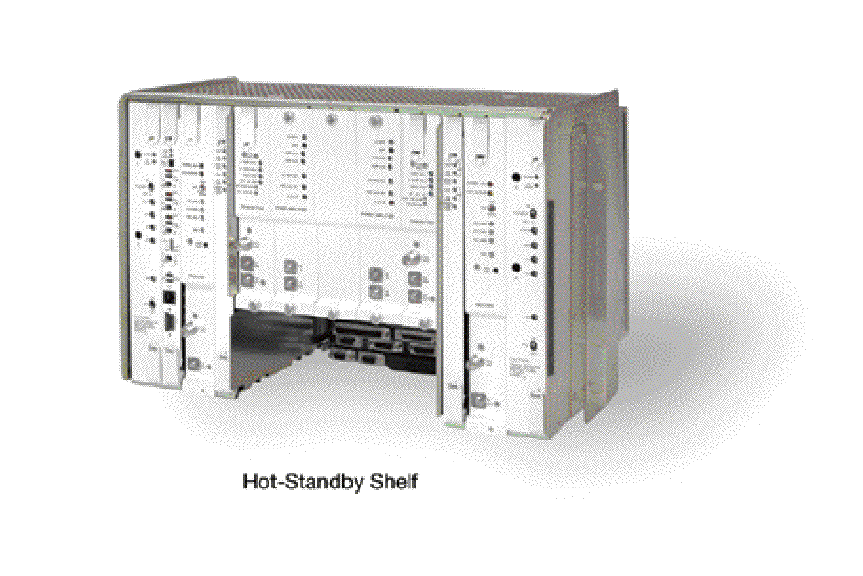
Figure 1 Typical MDR-8000 Series Microwave Digital Radio
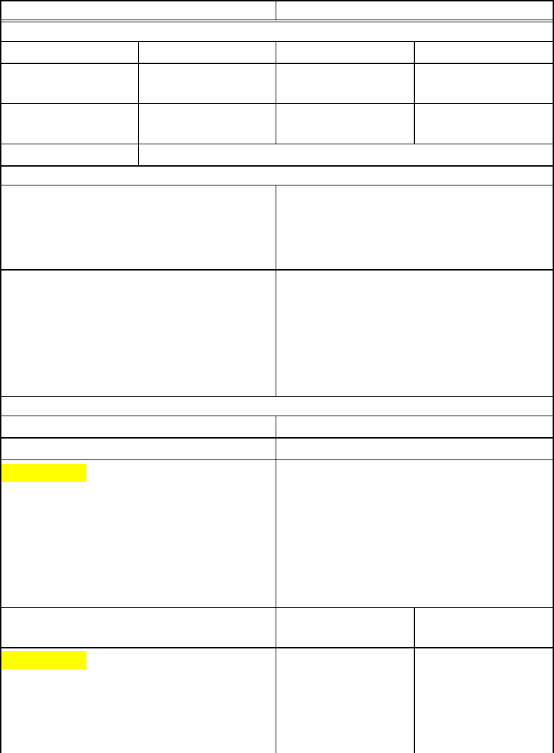
Table Physical, Environmental, and Electrical Characteristics
ITEM CHARACTERISTICS
PHYSICAL CHARACTERISTICS
Dimensions WIDTH DEPTH HEIGHT
Hot-Standby Shelf 483 mm (19 in.) 406.4 mm (16.25
in.)
311.15 mm (12.25
in.)
CommPak Indoor
Shelf
483 mm (19 in.) 406.4 mm (16.25
in.)
177.8 mm (7.0 in.)
Weight (Hot-Standby Terminal)38.6 kg (85 lbs)
ENVIRONMENTAL CHARACTERISTICS
Ambient Temperature
Spec Compliant
Operating Without Failure
Nonoperating
32° to 122°F (0° to 50°C)
- 4° to 158°F (- 20° to 70°C)
- 40° to 176°F (- 40° to 80°C)
Altitude
Operating
Nonoperating
Relative Humidity
Vibration and Shock
Duty Cycle
-350 to 16500 ft (-100 to 5000 m)
-350 to 40000 ft (-100 to 12000 m)
5 to 95 percent (without condensation)
Normal Storage and Handling
Continuous, unattended
COMMON ELECTRICAL CHARACTERISTICS
Primary Input Voltage ±20.5 to ±60.0 Vdc
RF CHANNEL FREQUENCY (MHZ)
MDR-8X02/i-X
MDR-8X05u-X
MDR-8X06/i/s-X
MDR-8X07/i/s-X
MDR-8X08/i/s-X
MDR-8X10/i/s-X
MDR-8X11/i/s-X
1850-2285
5725-5850
5850-7125
7125-7750
7700-8500
10440-10680
10700-11700
XMT OUTPUT POWER (DBM, NOMINAL) XMTR (NO PA) OPTIONAL PA
INSTALLED
MDR-8X02/i-X
MDR-8505u-X
MDR-8605u-X
MDR-8X06/i/s-X
MDR-8X07/i/s-X
+14
+15
+14
+14
+14
+30 or +33
+25 or +30
+23 or +29
+23 or +29 or +31
or +33

MDR-8X08/i/s-X
MDR-8X10/i/s-X
MDR-8X11/i/s-X
+14
+15
+15
+28 or +30
+28 or +30 or +32
+23 or +27 or +29
+23 or +27 or +29
Note: XMT Power Referenced at the SMA output of the diplexer filter or the
top of the stack for waveguide stacking configurations.
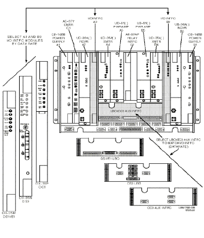
Figure 1. Typical MDR-8000 Hot-Standby Shelf Component