Alcatel USA 9558HC Microwave Packet Radio User Manual pi01
Alcatel USA Marketing, Inc. Microwave Packet Radio pi01
Contents
- 1. Users Manual
- 2. user manual
Users Manual

PRELIMINARY
Alcatel-Lucent 9500
MICROWAVE PACKET RADIO for ANSI | RELEASE 4.1.0
Indoor: MSS-8/MSS-4/MSS-1/MPT-HL
Outdoor: ODU300/MPT-HC/MPT-XP/9558HC
Product Information
3EM23952AL Edition 0.1
Alcatel-Lucent Proprietary
This document contains proprietary information of Alcatel-Lucent and is not to be disclosed
or used except in accordance with applicable agreements.
Copyright 2012 © Alcatel-Lucent. All rights reserved.
When printed by Alcatel-Lucent, this document is printed on recycled paper.
Alcatel-Lucent assumes no responsibility for the accuracy of the information presented, which is
subject to change without notice.
Alcatel, Lucent, Alcatel-Lucent and the Alcatel-Lucent logo are trademarks of Alcatel-Lucent. All
other trademarks are the property of their respective owners.
Copyright 2012 Alcatel-Lucent.
All rights reserved.
Disclaimers
Alcatel-Lucent products are intended for commercial uses. Without the appropriate network design
engineering, they must not be sold, licensed or otherwise distributed for use in any hazardous
environments requiring fail-safe performance, such as in the operation of nuclear facilities, aircraft
navigation or communication systems, air traffic control, direct life-support machines, or weapons
systems, in which the failure of products could lead directly to death, personal injury, or severe physical
or environmental damage. The customer hereby agrees that the use, sale, license or other distribution
of the products for any such application without the prior written consent of Alcatel-Lucent, shall be at
the customer's sole risk. The customer hereby agrees to defend and hold Alcatel-Lucent harmless from
any claims for loss, cost, damage, expense or liability that may arise out of or in connection with the
use, sale, license or other distribution of the products in such applications.
This document may contain information regarding the use and installation of non-Alcatel-Lucent
products. Please note that this information is provided as a courtesy to assist you. While Alcatel-Lucent
tries to ensure that this information accurately reflects information provided by the supplier, please refer
to the materials provided with any non-Alcatel-Lucent product and contact the supplier for
confirmation. Alcatel-Lucent assumes no responsibility or liability for incorrect or incomplete
information provided about non-Alcatel-Lucent products.
However, this does not constitute a representation or warranty. The warranties provided for
Alcatel-Lucent products, if any, are set forth in contractual documentation entered into by
Alcatel-Lucent and its customers.
This document was originally written in English. If there is any conflict or inconsistency between the
English version and any other version of a document, the English version shall prevail.

© Alcatel-Lucent 2012 - All Rights Reserved
Printed in U.S.A.
THIS PRODUCT COMPLIES WITH D.H.H.S. RADIATION PERFORMANCE STANDARDS 21
CFR, 1040.10, FOR A CLASS 1 LASER PRODUCT.
DANGER
Invisible laser radiation is present when the optic connector is open. AVOID DIRECT
EXPOSURE TO BEAM.
WARNING
This equipment has been tested and found to comply with the limits for a Class A digital device, pursuant
to Part 15 of the FCC Rules. These limits are designed to provide reasonable protection against harmful
interference when the equipment is operated in a commercial environment. This equipment generates,
uses, and can radiate radio frequency energy and, if not installed and used in accordance with the
instruction manual, may cause harmful interference to radio communications. Operation of this equipment
in a residential area is likely to cause harmful interference in which case users will be required to correct the
interference at their own expense.
NOTICE
This manual applies to 9500 MPR-A R4.1.0 software. Release notes describing revisions to this software
may impact operations described in this manual.
This transfer of commodities, technology, or software, if from the United States, is an export in accordance
with the U.S. Export Administration Regulations. Diversion contrary to U.S. law is prohibited. The export or
re-export (further transfer) of such commodities, technology, software or products made from such
technology is prohibited without proper authorization(s) from the U.S. Department of Commerce or other
appropriate U.S. government agency.
All rights reserved. No part of this manual may be reproduced, translated, stored in a retrieval system, or
transmitted or distributed by any means, electronic or mechanical, by photocopying, recording, or otherwise,
without the written permission of Alcatel-Lucent. Preparing derivative works or providing instruction based
on the material is prohibited unless agreed to in writing by Alcatel-Lucent.
The product specification and/or performance levels contained in this document are for information
purposes only and are subject to change without notice. They do not represent any obligation on the part of
Alcatel-Lucent. Such obligations will only be committed to in a written sales agreement signed by
Alcatel-Lucent.
DOCUMENTATION
Product documentation is available on Alcatel-Lucent’s OnLine Customer Support web site at
https://support.alcatel-lucent.com/portal/olcsHome.do.
To offer comments on this documentation, visit Alcatel-Lucent’s OnLine Customer Support web site at
https://support.alcatel-lucent.com/portal/olcsHome.do and select Contact us, Customer support, and then
OnLine Assistance or write to the following address.
Alcatel-Lucent
Attention: Doc Comment, M/S RND-1
3400 W. Plano Pkwy.
Plano, Texas 75075-0811 USA
3EM23952AL
Issue 0.1, November 2012
PRELIMINARY
© Alcatel-Lucent 2012 - All Rights Reserved i
ALCATEL-LUCENT PRACTICE
Standard
9500 MPR-A Product Information
Table of Contents
FCC part 15 subpart B
1. 9500 MPR-A unlicensed radio . . . . . . . . . . . . . . . . . . . . . . . . . . . . . . . . . . . . . . . . .1-1
FCC Class B compliance statement. . . . . . . . . . . . . . . . . . . . . . . . . . . . . . .1-1
FCC Class B requirements. . . . . . . . . . . . . . . . . . . . . . . . . . . . . . . . . . . . . .1-1
9500 MPR-A general system description
1. Introduction. . . . . . . . . . . . . . . . . . . . . . . . . . . . . . . . . . . . . . . . . . . . . . . . . . . . . . . .2-1
Purpose and function . . . . . . . . . . . . . . . . . . . . . . . . . . . . . . . . . . . . . . . . . .2-1
Innovative solutions . . . . . . . . . . . . . . . . . . . . . . . . . . . . . . . . . . . . . . . . . . .2-2
9500 MPR-A family overview . . . . . . . . . . . . . . . . . . . . . . . . . . . . . . . . . . . .2-5
Documentation . . . . . . . . . . . . . . . . . . . . . . . . . . . . . . . . . . . . . . . . . . . . . . .2-7
Standards . . . . . . . . . . . . . . . . . . . . . . . . . . . . . . . . . . . . . . . . . . . . . . . . . . .2-8
JF6-9558H and JF6-9558HC (unlicensed) radio . . . . . . . . . . . . . . . . . . . .2-11
2. System administration . . . . . . . . . . . . . . . . . . . . . . . . . . . . . . . . . . . . . . . . . . . . . .2-13
3. Features . . . . . . . . . . . . . . . . . . . . . . . . . . . . . . . . . . . . . . . . . . . . . . . . . . . . . . . . .2-15
4. Equipment layout . . . . . . . . . . . . . . . . . . . . . . . . . . . . . . . . . . . . . . . . . . . . . . . . . .2-23
Rack assemblies . . . . . . . . . . . . . . . . . . . . . . . . . . . . . . . . . . . . . . . . . . . .2-23
Constraints . . . . . . . . . . . . . . . . . . . . . . . . . . . . . . . . . . . . . . . . . . . . . . . . .2-27
Shelf assemblies . . . . . . . . . . . . . . . . . . . . . . . . . . . . . . . . . . . . . . . . . . . .2-28
5. Unit descriptions. . . . . . . . . . . . . . . . . . . . . . . . . . . . . . . . . . . . . . . . . . . . . . . . . . .2-33
6. Functional operation. . . . . . . . . . . . . . . . . . . . . . . . . . . . . . . . . . . . . . . . . . . . . . . .2-73
Microwave service switch (MSS) . . . . . . . . . . . . . . . . . . . . . . . . . . . . . . . .2-73
Radio . . . . . . . . . . . . . . . . . . . . . . . . . . . . . . . . . . . . . . . . . . . . . . . . . . . . .2-74
Ethernet . . . . . . . . . . . . . . . . . . . . . . . . . . . . . . . . . . . . . . . . . . . . . . . . . .2-125
Managed services and profiles. . . . . . . . . . . . . . . . . . . . . . . . . . . . . . . . .2-166
Cross-connections . . . . . . . . . . . . . . . . . . . . . . . . . . . . . . . . . . . . . . . . . .2-187
Database backup and restore . . . . . . . . . . . . . . . . . . . . . . . . . . . . . . . . .2-188
In-service upgrade . . . . . . . . . . . . . . . . . . . . . . . . . . . . . . . . . . . . . . . . . .2-188
LAG (link aggregation group) . . . . . . . . . . . . . . . . . . . . . . . . . . . . . . . . . .2-189
License key management. . . . . . . . . . . . . . . . . . . . . . . . . . . . . . . . . . . . .2-191
Loopback . . . . . . . . . . . . . . . . . . . . . . . . . . . . . . . . . . . . . . . . . . . . . . . . .2-194
Network Management . . . . . . . . . . . . . . . . . . . . . . . . . . . . . . . . . . . . . . .2-198
Performance monitoring . . . . . . . . . . . . . . . . . . . . . . . . . . . . . . . . . . . . . .2-199
Port segregation . . . . . . . . . . . . . . . . . . . . . . . . . . . . . . . . . . . . . . . . . . . .2-203
PRELIMINARY
3EM23952AL
Issue 0.1, November 2012
Table of Contents
ii
Remote inventory . . . . . . . . . . . . . . . . . . . . . . . . . . . . . . . . . . . . . . . . . . .2-208
Security. . . . . . . . . . . . . . . . . . . . . . . . . . . . . . . . . . . . . . . . . . . . . . . . . . .2-208
Stacking for EAS/MPT access cards . . . . . . . . . . . . . . . . . . . . . . . . . . . .2-210
Synchronization . . . . . . . . . . . . . . . . . . . . . . . . . . . . . . . . . . . . . . . . . . . .2-210
IP addressing . . . . . . . . . . . . . . . . . . . . . . . . . . . . . . . . . . . . . . . . . . . . . .2-257
Network provisioning . . . . . . . . . . . . . . . . . . . . . . . . . . . . . . . . . . . . . . . .2-267
TMN communication channels . . . . . . . . . . . . . . . . . . . . . . . . . . . . . . . . .2-282
Protection schemes . . . . . . . . . . . . . . . . . . . . . . . . . . . . . . . . . . . . . . . . .2-287
7. Engineering specifications . . . . . . . . . . . . . . . . . . . . . . . . . . . . . . . . . . . . . . . . . .2-299
Rack specifications. . . . . . . . . . . . . . . . . . . . . . . . . . . . . . . . . . . . . . . . . .2-299
Power specifications. . . . . . . . . . . . . . . . . . . . . . . . . . . . . . . . . . . . . . . . .2-299
Environmental specifications . . . . . . . . . . . . . . . . . . . . . . . . . . . . . . . . . .2-299
Component weights . . . . . . . . . . . . . . . . . . . . . . . . . . . . . . . . . . . . . . . . .2-299
Radio profiles . . . . . . . . . . . . . . . . . . . . . . . . . . . . . . . . . . . . . . . . . . . . . .2-299
Signal interface. . . . . . . . . . . . . . . . . . . . . . . . . . . . . . . . . . . . . . . . . . . . .2-302
Control interface . . . . . . . . . . . . . . . . . . . . . . . . . . . . . . . . . . . . . . . . . . . .2-304
Unit Data Sheets (UDSs)
UDS-100 9500 MPR-A unit data sheet cross-reference . . . . . . . . . . . . . . . . . . . . . . . . . . . . . . . .3-1
UDS-101 MSS-8 microwave service switch shelf . . . . . . . . . . . . . . . . . . . . . . . . . . . . . . . . . . . .3-15
UDS-102 MPT-HL microwave packet transport-long haul shelf . . . . . . . . . . . . . . . . . . . . . . . . .3-33
UDS-103 Core-E control and switching module . . . . . . . . . . . . . . . . . . . . . . . . . . . . . . . . . . . . .3-39
UDS-104 MOD300 radio interface. . . . . . . . . . . . . . . . . . . . . . . . . . . . . . . . . . . . . . . . . . . . . . . .3-43
UDS-105 P32E1DS1 DS1 PDH card. . . . . . . . . . . . . . . . . . . . . . . . . . . . . . . . . . . . . . . . . . . . . .3-47
UDS-106 P2E3DS3 DS3 PDH card. . . . . . . . . . . . . . . . . . . . . . . . . . . . . . . . . . . . . . . . . . . . . . .3-51
UDS-107 P8ETH ethernet access switch card . . . . . . . . . . . . . . . . . . . . . . . . . . . . . . . . . . . . . .3-55
UDS-108 ODU300 outdoor unit . . . . . . . . . . . . . . . . . . . . . . . . . . . . . . . . . . . . . . . . . . . . . . . . . .3-59
UDS-109 MPT-HL transceiver . . . . . . . . . . . . . . . . . . . . . . . . . . . . . . . . . . . . . . . . . . . . . . . . . . .3-69
UDS-110 Fan cards . . . . . . . . . . . . . . . . . . . . . . . . . . . . . . . . . . . . . . . . . . . . . . . . . . . . . . . . . . .3-77
UDS-111 GigE SFP . . . . . . . . . . . . . . . . . . . . . . . . . . . . . . . . . . . . . . . . . . . . . . . . . . . . . . . . . . .3-81
UDS-112 Power distribution unit (PDU). . . . . . . . . . . . . . . . . . . . . . . . . . . . . . . . . . . . . . . . . . . .3-85
3EM23952AL
Issue 0.1, November 2012
PRELIMINARY
Table of Contents iii
UDS-113 DS1 RJ-45 Patch Panel . . . . . . . . . . . . . . . . . . . . . . . . . . . . . . . . . . . . . . . . . . . . . . . .3-91
UDS-114 Type N adapter bracket . . . . . . . . . . . . . . . . . . . . . . . . . . . . . . . . . . . . . . . . . . . . . . . .3-93
UDS-115 DS1 d-connector patch panel. . . . . . . . . . . . . . . . . . . . . . . . . . . . . . . . . . . . . . . . . . . .3-95
UDS-116 3 dB hybrid splitter . . . . . . . . . . . . . . . . . . . . . . . . . . . . . . . . . . . . . . . . . . . . . . . . . . . .3-97
UDS-117 MSS-4 microwave service switch shelf . . . . . . . . . . . . . . . . . . . . . . . . . . . . . . . . . . . .3-99
UDS-118 MPTACC MPT access card . . . . . . . . . . . . . . . . . . . . . . . . . . . . . . . . . . . . . . . . . . . .3-111
UDS-119 MPT-HC/XP microwave packet transport-high capacity . . . . . . . . . . . . . . . . . . . . . .3-117
UDS-120 AUX auxiliary card . . . . . . . . . . . . . . . . . . . . . . . . . . . . . . . . . . . . . . . . . . . . . . . . . . .3-131
UDS-121 Power injector . . . . . . . . . . . . . . . . . . . . . . . . . . . . . . . . . . . . . . . . . . . . . . . . . . . . . .3-137
UDS-122 +24/-48 volt converter . . . . . . . . . . . . . . . . . . . . . . . . . . . . . . . . . . . . . . . . . . . . . . . .3-141
UDS-123 MPT power unit . . . . . . . . . . . . . . . . . . . . . . . . . . . . . . . . . . . . . . . . . . . . . . . . . . . . .3-145
UDS-124 MPT Extended Power Unit. . . . . . . . . . . . . . . . . . . . . . . . . . . . . . . . . . . . . . . . . . . . .3-157
UDS-125 SDHACC OC-3 SDH card . . . . . . . . . . . . . . . . . . . . . . . . . . . . . . . . . . . . . . . . . . . . .3-171
Appendix A: Glossary
. . . . . . . . . . . . . . . . . . . . . . . . . . . . . . . . . . . . . . . . . . . . . . . . . . . . . . . . . . .4-1
Appendix B: 9500 MPR-A RF band channel plans
9500 MPR-A channel plan . . . . . . . . . . . . . . . . . . . . . . . . . . . . . . . . . . . . . .4-1
PRELIMINARY
3EM23952AL
Issue 0.1, November 2012
Table of Contents
iv
3EM23952AL
Issue 0.1, November 2012
PRELIMINARY
List of Figures v
9500 MPR-A Product Information
List of Figures
Figure 1-1. Multiservice aggregation layer . . . . . . . . . . . . . . . . . . . . . . . . . . . . . . . . . . . . . . . . . . . .2-3
Figure 1-2. Service awareness. . . . . . . . . . . . . . . . . . . . . . . . . . . . . . . . . . . . . . . . . . . . . . . . . . . . .2-4
Figure 1-3. Packet node . . . . . . . . . . . . . . . . . . . . . . . . . . . . . . . . . . . . . . . . . . . . . . . . . . . . . . . . . .2-4
Figure 1-4. Service-driven packet adaptive modulation . . . . . . . . . . . . . . . . . . . . . . . . . . . . . . . . . .2-5
Figure 1-5. 9500 MPR-A family . . . . . . . . . . . . . . . . . . . . . . . . . . . . . . . . . . . . . . . . . . . . . . . . . . . .2-6
Figure 4-1. Standard equal flange aluminum rack assembly (PN 694-9000-006) . . . . . . . . . . . . .2-24
Figure 4-2. Unequal flange seismic rack assembly (PN 1AD014120046) . . . . . . . . . . . . . . . . . . .2-25
Figure 4-3. MSS-8 shelf, front view . . . . . . . . . . . . . . . . . . . . . . . . . . . . . . . . . . . . . . . . . . . . . . . .2-30
Figure 4-4. MSS-4 shelf, front view . . . . . . . . . . . . . . . . . . . . . . . . . . . . . . . . . . . . . . . . . . . . . . . .2-31
Figure 4-5. MPT-HL shelf, front view . . . . . . . . . . . . . . . . . . . . . . . . . . . . . . . . . . . . . . . . . . . . . . .2-31
Figure 6-1. Example of traffic 28MHz bandwidth and admission control . . . . . . . . . . . . . . . . . . . .2-78
Figure 6-2. Example of traffic 28MHz bandwidth and modulation downgraded to 16QAM . . . . . .2-78
Figure 6-3. Example of traffic 28MHz bandwidth and modulation downgraded to 4QAM . . . . . . .2-79
Figure 6-4. Fiber-microwave protection . . . . . . . . . . . . . . . . . . . . . . . . . . . . . . . . . . . . . . . . . . . . .2-80
Figure 6-5. Fiber-microwave protection - operation . . . . . . . . . . . . . . . . . . . . . . . . . . . . . . . . . . . .2-81
Figure 6-6. Fiber-microwave protection on tail links . . . . . . . . . . . . . . . . . . . . . . . . . . . . . . . . . . . .2-82
Figure 6-7. L1 LAG block diagram . . . . . . . . . . . . . . . . . . . . . . . . . . . . . . . . . . . . . . . . . . . . . . . . .2-85
Figure 6-8. Types of L1 LAG . . . . . . . . . . . . . . . . . . . . . . . . . . . . . . . . . . . . . . . . . . . . . . . . . . . . .2-87
Figure 6-9. Intra plug-in L1 link aggregation scenario . . . . . . . . . . . . . . . . . . . . . . . . . . . . . . . . . .2-87
Figure 6-10. Single P8ETH 1+0 intra plug-in L1 LAG configurations . . . . . . . . . . . . . . . . . . . . . . . .2-88
Figure 6-11. Dual P8ETH 1+0 intra plug-in L1 LAG configurations . . . . . . . . . . . . . . . . . . . . . . . . .2-88
Figure 6-12. Cross plug-in L1 link aggregation scenario . . . . . . . . . . . . . . . . . . . . . . . . . . . . . . . . .2-89
PRELIMINARY
3EM23952AL
Issue 0.1, November 2012
List of Figures
vi
Figure 6-13. 1+0 cross plug-in L1 LAG configurations . . . . . . . . . . . . . . . . . . . . . . . . . . . . . . . . . . .2-90
Figure 6-14. Protected 1+1 cross plug-in L1 link aggregation scenario . . . . . . . . . . . . . . . . . . . . . .2-91
Figure 6-15. Protected 2x(1+1) cross plug-in L1 LAG configurations. . . . . . . . . . . . . . . . . . . . . . . .2-92
Figure 6-16. Mix 1+0 and 1+1 protected cross plug-in L1 LAG configurations . . . . . . . . . . . . . . . .2-92
Figure 6-17. Protected 3x(1+1)/4x(1+1) cross plug-in L1 LAG configurations . . . . . . . . . . . . . . . . .2-93
Figure 6-18. Radio L2 LAG. . . . . . . . . . . . . . . . . . . . . . . . . . . . . . . . . . . . . . . . . . . . . . . . . . . . . . .2-105
Figure 6-19. Radio L2 LAG block diagram . . . . . . . . . . . . . . . . . . . . . . . . . . . . . . . . . . . . . . . . . . .2-106
Figure 6-20. Single 2+0 XPIC. . . . . . . . . . . . . . . . . . . . . . . . . . . . . . . . . . . . . . . . . . . . . . . . . . . . .2-110
Figure 6-21. Double 2x(1+1) HSB co-channel XPIC . . . . . . . . . . . . . . . . . . . . . . . . . . . . . . . . . . .2-111
Figure 6-22. Automatic remote TX mute . . . . . . . . . . . . . . . . . . . . . . . . . . . . . . . . . . . . . . . . . . . .2-113
Figure 6-23. Automatic remote TX mute complete loop. . . . . . . . . . . . . . . . . . . . . . . . . . . . . . . . .2-114
Figure 6-6. Branching box block diagram. . . . . . . . . . . . . . . . . . . . . . . . . . . . . . . . . . . . . . . . . . .2-117
Figure 6-7. Branching box band-pass detail. . . . . . . . . . . . . . . . . . . . . . . . . . . . . . . . . . . . . . . . .2-117
Figure 6-24. Frequency plan MPT-HL: 5.725 to 5.850 GHz unlicensed band
(FCC Part 15 and IC RSS-210) . . . . . . . . . . . . . . . . . . . . . . . . . . . . . . . . . . . . . . . . .2-124
Figure 6-25. Frequency plan 9558HC: 5.725 to 5.850 GHz unlicensed band
(FCC Part 15 and IC RSS-210) . . . . . . . . . . . . . . . . . . . . . . . . . . . . . . . . . . . . . . . . .2-125
Figure 6-26. QoS configuration . . . . . . . . . . . . . . . . . . . . . . . . . . . . . . . . . . . . . . . . . . . . . . . . . . .2-127
Figure 6-27. QoS in the Core-E unit. . . . . . . . . . . . . . . . . . . . . . . . . . . . . . . . . . . . . . . . . . . . . . . .2-136
Figure 6-28. QoS in the modem card . . . . . . . . . . . . . . . . . . . . . . . . . . . . . . . . . . . . . . . . . . . . . . .2-137
Figure 6-29. Per-VLAN Per-COS rate limiters with duplicate PCP values . . . . . . . . . . . . . . . . . . .2-144
Figure 6-30. Per-VLAN Per-CoS Rate Limiter and VLAN Rate Limiter with the same VLAN ID . .2-145
Figure 6-31. Per-VLAN Per-CoS Rate Limiter with VLAN ID = Any and a VLAN Rate Limiter . . .2-145
Figure 6-32. Input/output flow control block diagram . . . . . . . . . . . . . . . . . . . . . . . . . . . . . . . . . . .2-148
Figure 6-33. Ethernet ring protection, normal operation. . . . . . . . . . . . . . . . . . . . . . . . . . . . . . . . .2-158
3EM23952AL
Issue 0.1, November 2012
PRELIMINARY
List of Figures vii
Figure 6-34. Ethernet ring protection, single link failure . . . . . . . . . . . . . . . . . . . . . . . . . . . . . . . . .2-159
Figure 6-35. Two ERP instances, normal operation. . . . . . . . . . . . . . . . . . . . . . . . . . . . . . . . . . . .2-161
Figure 6-36. Two ERP instances, single link failure . . . . . . . . . . . . . . . . . . . . . . . . . . . . . . . . . . . .2-162
Figure 6-37. Ethernet L2 LAG block diagram. . . . . . . . . . . . . . . . . . . . . . . . . . . . . . . . . . . . . . . . .2-163
Figure 6-38. TDM2TDM flow diagram . . . . . . . . . . . . . . . . . . . . . . . . . . . . . . . . . . . . . . . . . . . . . .2-167
Figure 6-39. TDM2Eth flow diagram. . . . . . . . . . . . . . . . . . . . . . . . . . . . . . . . . . . . . . . . . . . . . . . .2-168
Figure 6-40. Eth to Eth flow diagram . . . . . . . . . . . . . . . . . . . . . . . . . . . . . . . . . . . . . . . . . . . . . . .2-168
Figure 6-41. Traffic profiles. . . . . . . . . . . . . . . . . . . . . . . . . . . . . . . . . . . . . . . . . . . . . . . . . . . . . . .2-169
Figure 6-42. Traffic profiles. . . . . . . . . . . . . . . . . . . . . . . . . . . . . . . . . . . . . . . . . . . . . . . . . . . . . . .2-170
Figure 6-43. TDM2TDM E1/DS1/DS3 traffic . . . . . . . . . . . . . . . . . . . . . . . . . . . . . . . . . . . . . . . . .2-171
Figure 6-44. TDM2Eth E1/DS1/DS3 traffic. . . . . . . . . . . . . . . . . . . . . . . . . . . . . . . . . . . . . . . . . . .2-172
Figure 6-45. SDH2SDH OC-3 traffic. . . . . . . . . . . . . . . . . . . . . . . . . . . . . . . . . . . . . . . . . . . . . . . .2-173
Figure 6-46. Eth2Eth DS1/DS3 traffic. . . . . . . . . . . . . . . . . . . . . . . . . . . . . . . . . . . . . . . . . . . . . . .2-174
Figure 6-47. MSS-8 shelf - front view. . . . . . . . . . . . . . . . . . . . . . . . . . . . . . . . . . . . . . . . . . . . . . .2-181
Figure 6-48. MSS-8 shelf, unprotected Core-E configuration. . . . . . . . . . . . . . . . . . . . . . . . . . . . .2-182
Figure 6-49. MSS-8 shelf, protected Core-E configuration. . . . . . . . . . . . . . . . . . . . . . . . . . . . . . .2-182
Figure 6-50. MSS-4 shelf - front view. . . . . . . . . . . . . . . . . . . . . . . . . . . . . . . . . . . . . . . . . . . . . . .2-183
Figure 6-51. MSS-4 shelf, unprotected Core-E configuration. . . . . . . . . . . . . . . . . . . . . . . . . . . . .2-184
Figure 6-52. MSS-4 shelf, protected Core-E configuration. . . . . . . . . . . . . . . . . . . . . . . . . . . . . . .2-184
Figure 6-53. Stacking configuration with 3 MSS-8, unprotected Core-E cards . . . . . . . . . . . . . . .2-185
Figure 6-54. Stacking configuration with 3 MSS-8, protected Core-E cards . . . . . . . . . . . . . . . . .2-186
Figure 6-55. Cross-connection . . . . . . . . . . . . . . . . . . . . . . . . . . . . . . . . . . . . . . . . . . . . . . . . . . . .2-187
Figure 6-56. Core and radio facing radio loopbacks. . . . . . . . . . . . . . . . . . . . . . . . . . . . . . . . . . . .2-195
Figure 6-57. Port segregation ODU300 . . . . . . . . . . . . . . . . . . . . . . . . . . . . . . . . . . . . . . . . . . . . .2-204
PRELIMINARY
3EM23952AL
Issue 0.1, November 2012
List of Figures
viii
Figure 6-58. Port segregation scenario: MPT access . . . . . . . . . . . . . . . . . . . . . . . . . . . . . . . . . .2-206
Figure 6-59. Port segregation scenario: MPT access . . . . . . . . . . . . . . . . . . . . . . . . . . . . . . . . . .2-207
Figure 6-60. Synchronization block diagram . . . . . . . . . . . . . . . . . . . . . . . . . . . . . . . . . . . . . . . . .2-212
Figure 6-61. Differential clock recovery . . . . . . . . . . . . . . . . . . . . . . . . . . . . . . . . . . . . . . . . . . . . .2-214
Figure 6-62. Adaptive clock recovery . . . . . . . . . . . . . . . . . . . . . . . . . . . . . . . . . . . . . . . . . . . . . . .2-215
Figure 6-63. Ring network with SSMs and port priorities normal situation . . . . . . . . . . . . . . . . . . .2-217
Figure 6-64. Ring network in restoration process - last node switched reference . . . . . . . . . . . . .2-218
Figure 6-65. Ring network in restoration process - final situation. . . . . . . . . . . . . . . . . . . . . . . . . .2-218
Figure 6-66. Synchronization connection in stacking configuration with core protection . . . . . . . .2-227
Figure 6-67. Protected split mount radio . . . . . . . . . . . . . . . . . . . . . . . . . . . . . . . . . . . . . . . . . . . .2-228
Figure 6-68. Protected full indoor mount radio . . . . . . . . . . . . . . . . . . . . . . . . . . . . . . . . . . . . . . . .2-229
Figure 6-69. Not protected split mount radio . . . . . . . . . . . . . . . . . . . . . . . . . . . . . . . . . . . . . . . . .2-229
Figure 6-70. Not protected full indoor mount radio . . . . . . . . . . . . . . . . . . . . . . . . . . . . . . . . . . . . .2-230
Figure 6-71. Core-E card block diagram . . . . . . . . . . . . . . . . . . . . . . . . . . . . . . . . . . . . . . . . . . . .2-231
Figure 6-72. Core-E Card front panel view. . . . . . . . . . . . . . . . . . . . . . . . . . . . . . . . . . . . . . . . . . .2-232
Figure 6-73. P32E1DS1 PDH card block diagram . . . . . . . . . . . . . . . . . . . . . . . . . . . . . . . . . . . . .2-233
Figure 6-74. P32E1DS1 PDH card front panel. . . . . . . . . . . . . . . . . . . . . . . . . . . . . . . . . . . . . . . .2-234
Figure 6-75. P2E3DS3 PDH card block diagram . . . . . . . . . . . . . . . . . . . . . . . . . . . . . . . . . . . . . .2-234
Figure 6-76. P2E3DS3 PDH card front panel. . . . . . . . . . . . . . . . . . . . . . . . . . . . . . . . . . . . . . . . .2-235
Figure 6-77. SDHACC SDH card block diagram . . . . . . . . . . . . . . . . . . . . . . . . . . . . . . . . . . . . . .2-236
Figure 6-78. SDHACC SDH card front panel . . . . . . . . . . . . . . . . . . . . . . . . . . . . . . . . . . . . . . . . .2-237
Figure 6-79. Modem radio interface card block diagram . . . . . . . . . . . . . . . . . . . . . . . . . . . . . . . .2-238
Figure 6-80. Modem unit . . . . . . . . . . . . . . . . . . . . . . . . . . . . . . . . . . . . . . . . . . . . . . . . . . . . . . . .2-240
Figure 6-81. MPT access unit (with PFoE) block diagram . . . . . . . . . . . . . . . . . . . . . . . . . . . . . . .2-241
3EM23952AL
Issue 0.1, November 2012
PRELIMINARY
List of Figures ix
Figure 6-82. MPT access unit (with PFoE). . . . . . . . . . . . . . . . . . . . . . . . . . . . . . . . . . . . . . . . . . .2-243
Figure 6-83. ODU300 and antenna, integrated mount configuration . . . . . . . . . . . . . . . . . . . . . . .2-245
Figure 6-84. ODU300 block diagram . . . . . . . . . . . . . . . . . . . . . . . . . . . . . . . . . . . . . . . . . . . . . . .2-246
Figure 6-85. MPT system . . . . . . . . . . . . . . . . . . . . . . . . . . . . . . . . . . . . . . . . . . . . . . . . . . . . . . . .2-249
Figure 6-86. 5.8 to 38 GHz MPT-HC/XP/9558HC housing . . . . . . . . . . . . . . . . . . . . . . . . . . . . . .2-250
Figure 6-87. MPT-HC/XP block diagram . . . . . . . . . . . . . . . . . . . . . . . . . . . . . . . . . . . . . . . . . . . .2-250
Figure 6-88. 7/8 GHz MPT-HC/XP architecture . . . . . . . . . . . . . . . . . . . . . . . . . . . . . . . . . . . . . . .2-255
Figure 6-89. 11 to 38 GHz MPT-HC architecture . . . . . . . . . . . . . . . . . . . . . . . . . . . . . . . . . . . . . .2-256
Figure 6-90. Typical interconnect/addressing method . . . . . . . . . . . . . . . . . . . . . . . . . . . . . . . . . .2-259
Figure 6-91. Typical interconnect/addressing method details continued . . . . . . . . . . . . . . . . . . . .2-260
Figure 6-92. Typical terminal addressing . . . . . . . . . . . . . . . . . . . . . . . . . . . . . . . . . . . . . . . . . . . .2-263
Figure 6-93. Typical terminal attached to external LAN . . . . . . . . . . . . . . . . . . . . . . . . . . . . . . . . .2-265
Figure 6-94. Back-to-back terminal and repeater configuration addressing. . . . . . . . . . . . . . . . . .2-266
Figure 6-95. Back-to-back terminal and repeater configuration addressing. . . . . . . . . . . . . . . . . .2-267
Figure 6-96. MSS-1: NETO logon window . . . . . . . . . . . . . . . . . . . . . . . . . . . . . . . . . . . . . . . . . . .2-268
Figure 6-97. MSS-1: ethernet interface provisioning . . . . . . . . . . . . . . . . . . . . . . . . . . . . . . . . . . .2-269
Figure 6-98. MSS-1: local configuration window . . . . . . . . . . . . . . . . . . . . . . . . . . . . . . . . . . . . . .2-269
Figure 6-99. MSS-1: IP static routing configuration window. . . . . . . . . . . . . . . . . . . . . . . . . . . . . .2-270
Figure 6-100. MSS-1: OSPF area configuration. . . . . . . . . . . . . . . . . . . . . . . . . . . . . . . . . . . . . . . .2-271
Figure 6-101. MSS-1: IP routing information window. . . . . . . . . . . . . . . . . . . . . . . . . . . . . . . . . . . .2-272
Figure 6-102. MSS-2: NETO logon window . . . . . . . . . . . . . . . . . . . . . . . . . . . . . . . . . . . . . . . . . . .2-273
Figure 6-103. MSS-2: TMN ethernet interface window . . . . . . . . . . . . . . . . . . . . . . . . . . . . . . . . . .2-273
Figure 6-104. MSS-2: local configuration window . . . . . . . . . . . . . . . . . . . . . . . . . . . . . . . . . . . . . .2-274
Figure 6-105. MSS-2: OSPF area configuration. . . . . . . . . . . . . . . . . . . . . . . . . . . . . . . . . . . . . . . .2-274
PRELIMINARY
3EM23952AL
Issue 0.1, November 2012
List of Figures
x
Figure 6-106. MSS-2: IP routing information window. . . . . . . . . . . . . . . . . . . . . . . . . . . . . . . . . . . .2-275
Figure 6-107. MSS-3: NETO logon window . . . . . . . . . . . . . . . . . . . . . . . . . . . . . . . . . . . . . . . . . . .2-276
Figure 6-108. MSS-3: TMN ethernet interface provisioning . . . . . . . . . . . . . . . . . . . . . . . . . . . . . . .2-276
Figure 6-109. MSS-3: local configuration window . . . . . . . . . . . . . . . . . . . . . . . . . . . . . . . . . . . . . .2-277
Figure 6-110. MSS-3: OSPF area configuration. . . . . . . . . . . . . . . . . . . . . . . . . . . . . . . . . . . . . . . .2-277
Figure 6-111. MSS-3: IP routing information window. . . . . . . . . . . . . . . . . . . . . . . . . . . . . . . . . . . .2-278
Figure 6-112. MSS-4: NETO logon window . . . . . . . . . . . . . . . . . . . . . . . . . . . . . . . . . . . . . . . . . . .2-279
Figure 6-113. MSS-4: TMN ethernet interface provisioning . . . . . . . . . . . . . . . . . . . . . . . . . . . . . . .2-279
Figure 6-114. MSS-4: local configuration window . . . . . . . . . . . . . . . . . . . . . . . . . . . . . . . . . . . . . .2-280
Figure 6-115. MSS-4: IP static routing configuration window. . . . . . . . . . . . . . . . . . . . . . . . . . . . . .2-280
Figure 6-116. MSS-4: OSPF area configuration. . . . . . . . . . . . . . . . . . . . . . . . . . . . . . . . . . . . . . . .2-281
Figure 6-117. MSS-4: IP routing information window. . . . . . . . . . . . . . . . . . . . . . . . . . . . . . . . . . . .2-282
Figure 6-118. NE TMN_RF port belongs to subnet 2. . . . . . . . . . . . . . . . . . . . . . . . . . . . . . . . . . . .2-284
Figure 6-119. NE TMN_RF port belongs to subnet 1. . . . . . . . . . . . . . . . . . . . . . . . . . . . . . . . . . . .2-285
Figure 6-120. NE TMN_RF port belongs to separate subnet 3 . . . . . . . . . . . . . . . . . . . . . . . . . . . .2-286
Figure 6-121. MOD300/ODU300 protection scheme block diagram . . . . . . . . . . . . . . . . . . . . . . . .2-288
Figure 6-122. MPT-HL protection scheme block diagram . . . . . . . . . . . . . . . . . . . . . . . . . . . . . . . .2-291
Figure 6-123. MPT-HC/XP protection schemes . . . . . . . . . . . . . . . . . . . . . . . . . . . . . . . . . . . . . . . .2-294
Figure 7-1. DS1 format template . . . . . . . . . . . . . . . . . . . . . . . . . . . . . . . . . . . . . . . . . . . . . . . . .2-324
Figure 7-2. DS1 input jitter accommodation . . . . . . . . . . . . . . . . . . . . . . . . . . . . . . . . . . . . . . . . .2-325
Figure 7-3. DS1 jitter transfer characteristics . . . . . . . . . . . . . . . . . . . . . . . . . . . . . . . . . . . . . . . .2-325
Figure 7-4. DS1 jitter measurement filter characteristics . . . . . . . . . . . . . . . . . . . . . . . . . . . . . . .2-326
Figure 7-5. Asynchronous DS3 format template . . . . . . . . . . . . . . . . . . . . . . . . . . . . . . . . . . . . .2-328
Figure 7-6. DS3 input jitter accommodation . . . . . . . . . . . . . . . . . . . . . . . . . . . . . . . . . . . . . . . . .2-329
3EM23952AL
Issue 0.1, November 2012
PRELIMINARY
List of Figures xi
Figure 7-7. DS3 jitter transfer characteristics . . . . . . . . . . . . . . . . . . . . . . . . . . . . . . . . . . . . . . . .2-329
Figure 7-8. DS3 jitter measurement filter characteristics . . . . . . . . . . . . . . . . . . . . . . . . . . . . . . .2-330
Figure 101-1. Microwave service switch (MSS-8) shelf . . . . . . . . . . . . . . . . . . . . . . . . . . . . . . . . . . .3-17
Figure 101-2. MSS-8 shelf dimensions . . . . . . . . . . . . . . . . . . . . . . . . . . . . . . . . . . . . . . . . . . . . . . .3-18
Figure 101-3. MSS-8 shelf slot definitions . . . . . . . . . . . . . . . . . . . . . . . . . . . . . . . . . . . . . . . . . . . . .3-19
Figure 101-4. MSS-8 shelf, unprotected Core-E configuration. . . . . . . . . . . . . . . . . . . . . . . . . . . . . .3-21
Figure 101-5. MSS-8 shelf, protected Core-E configuration. . . . . . . . . . . . . . . . . . . . . . . . . . . . . . . .3-22
Figure 101-6. MSS-8 stand-alone shelf, equipped with P32E1DS1 (DS1 Card) . . . . . . . . . . . . . . . .3-23
Figure 101-7. MSS-8 stand-alone shelf, equipped with P2E3DS3 (DS3 Card) . . . . . . . . . . . . . . . . .3-24
Figure 101-8. MSS-8 shelf, split mount, 1+0 drop and insert repeater configuration . . . . . . . . . . . . .3-25
Figure 101-9. MSS-8 shelf, split mount, 1+1 drop and insert repeater configuration . . . . . . . . . . . . .3-25
Figure 101-10.MSS-8 shelf, split mount MPT-HC/XP, 1+0 12-way nodal junction configuration . . . . 3-26
Figure 101-11.MSS-8 shelf, all indoor mount, 1+1 4-way junction configuration . . . . . . . . . . . . . . . .3-27
Figure 101-12.MSS-8 shelf, all indoor mount, 1+0 4-way junction configuration . . . . . . . . . . . . . . . .3-28
Figure 101-13.MSS-8 shelf, all indoor mount, 1+1 4-way junction configuration . . . . . . . . . . . . . . . .3-28
Figure 101-14.MSS-8 shelf, 1+0, 12 spoke hub configuration . . . . . . . . . . . . . . . . . . . . . . . . . . . . . .3-29
Figure 101-15.MSS-8 shelf, 1+0, 12 spoke hub configuration . . . . . . . . . . . . . . . . . . . . . . . . . . . . . .3-30
Figure 101-16.MSS-8 shelf block diagram . . . . . . . . . . . . . . . . . . . . . . . . . . . . . . . . . . . . . . . . . . . . .3-31
Figure 102-1. Microwave packet transport-long haul (MPT-HL) shelf . . . . . . . . . . . . . . . . . . . . . . . .3-34
Figure 102-2. MPT-HL shelf dimensions . . . . . . . . . . . . . . . . . . . . . . . . . . . . . . . . . . . . . . . . . . . . . .3-34
Figure 102-3. MPT-HL shelf w/diplexer dimensions - top view . . . . . . . . . . . . . . . . . . . . . . . . . . . . .3-35
Figure 102-4. MPT-HL shelf w/one waveguide bracket dimensions - top view . . . . . . . . . . . . . . . . .3-35
Figure 102-5. MPT-HL shelf w/two waveguide brackets dimensions - top view. . . . . . . . . . . . . . . . .3-36
Figure 103-1. Core-E front panel details . . . . . . . . . . . . . . . . . . . . . . . . . . . . . . . . . . . . . . . . . . . . . .3-41
PRELIMINARY
3EM23952AL
Issue 0.1, November 2012
List of Figures
xii
Figure 104-1. MOD300 card (MSS/MD300). . . . . . . . . . . . . . . . . . . . . . . . . . . . . . . . . . . . . . . . . . . .3-44
Figure 104-2. MOD300 card block diagram . . . . . . . . . . . . . . . . . . . . . . . . . . . . . . . . . . . . . . . . . . . .3-45
Figure 105-1. P32E1DS1 DS1 card (MSS/DS1) front panel view . . . . . . . . . . . . . . . . . . . . . . . . . . .3-48
Figure 105-2. P32E1DS1 DS1 block diagram . . . . . . . . . . . . . . . . . . . . . . . . . . . . . . . . . . . . . . . . . .3-49
Figure 106-1. P2E3DS3 DS3 card (MSS/DS3) front panel view . . . . . . . . . . . . . . . . . . . . . . . . . . . .3-52
Figure 106-2. P2E3DS3 DS3 block diagram . . . . . . . . . . . . . . . . . . . . . . . . . . . . . . . . . . . . . . . . . . .3-53
Figure 107-1. P8ETH card (MSS/P8ETH) . . . . . . . . . . . . . . . . . . . . . . . . . . . . . . . . . . . . . . . . . . . . .3-56
Figure 107-2. P8ETH block diagram . . . . . . . . . . . . . . . . . . . . . . . . . . . . . . . . . . . . . . . . . . . . . . . . .3-57
Figure 108-1. ODU300 and antenna, integrated mount configuration . . . . . . . . . . . . . . . . . . . . . . . .3-66
Figure 108-2. ODU300 and antenna, integrated mount with HSB coupler. . . . . . . . . . . . . . . . . . . . .3-66
Figure 109-1. MPT-HL transceiver . . . . . . . . . . . . . . . . . . . . . . . . . . . . . . . . . . . . . . . . . . . . . . . . . . .3-73
Figure 109-2. MPT-HL transceiver block diagram . . . . . . . . . . . . . . . . . . . . . . . . . . . . . . . . . . . . . . .3-75
Figure 110-1. Fan 2U card w/alarms (front view) . . . . . . . . . . . . . . . . . . . . . . . . . . . . . . . . . . . . . . . .3-78
Figure 111-1. Optical SFP module . . . . . . . . . . . . . . . . . . . . . . . . . . . . . . . . . . . . . . . . . . . . . . . . . . .3-83
Figure 111-2. Optical SFP module block diagram . . . . . . . . . . . . . . . . . . . . . . . . . . . . . . . . . . . . . . .3-84
Figure 112-1. Power distribution unit (PDU) isometric view . . . . . . . . . . . . . . . . . . . . . . . . . . . . . . . .3-86
Figure 112-2. Power distribution unit (PDU) front panel view. . . . . . . . . . . . . . . . . . . . . . . . . . . . . . .3-87
Figure 112-3. PDU indicator and connector locations . . . . . . . . . . . . . . . . . . . . . . . . . . . . . . . . . . . .3-87
Figure 113-1. DS1 RJ-45 patch panel (front view) . . . . . . . . . . . . . . . . . . . . . . . . . . . . . . . . . . . . . . .3-91
Figure 113-2. DS1 RJ-45 patch panel (rear view) . . . . . . . . . . . . . . . . . . . . . . . . . . . . . . . . . . . . . . .3-92
Figure 114-1. Type N adapter bracket (front view). . . . . . . . . . . . . . . . . . . . . . . . . . . . . . . . . . . . . . .3-93
Figure 114-2. Type N adapter bracket dimensions . . . . . . . . . . . . . . . . . . . . . . . . . . . . . . . . . . . . . .3-94
Figure 115-1. DS1 RJ-45 patch panel (front view) . . . . . . . . . . . . . . . . . . . . . . . . . . . . . . . . . . . . . . .3-95
Figure 115-2. DS1 RJ-45 patch panel (rear view) . . . . . . . . . . . . . . . . . . . . . . . . . . . . . . . . . . . . . . .3-96
3EM23952AL
Issue 0.1, November 2012
PRELIMINARY
List of Figures xiii
Figure 116-1. Hybrid splitter interconnect. . . . . . . . . . . . . . . . . . . . . . . . . . . . . . . . . . . . . . . . . . . . . .3-97
Figure 117-1. Microwave service switch (MSS-4) shelf . . . . . . . . . . . . . . . . . . . . . . . . . . . . . . . . . .3-101
Figure 117-2. MSS-4 shelf dimensions . . . . . . . . . . . . . . . . . . . . . . . . . . . . . . . . . . . . . . . . . . . . . .3-101
Figure 117-3. MSS-4 shelf slot definitions . . . . . . . . . . . . . . . . . . . . . . . . . . . . . . . . . . . . . . . . . . . .3-102
Figure 117-4. MSS-4 shelf, unprotected Core-E configuration. . . . . . . . . . . . . . . . . . . . . . . . . . . . .3-103
Figure 117-5. MSS-4 shelf, protected Core-E configuration. . . . . . . . . . . . . . . . . . . . . . . . . . . . . . .3-103
Figure 117-6. MSS-4 stand-alone shelf, equipped with P32E1DS1 (DS1 card) . . . . . . . . . . . . . . .3-104
Figure 117-7. MSS-4 stand-alone shelf, equipped with P2E3DS3 (DS3 card) . . . . . . . . . . . . . . . .3-104
Figure 117-8. MSS-4 shelf, split mount using MOD300, 1+0 drop and insert repeater
configuration. . . . . . . . . . . . . . . . . . . . . . . . . . . . . . . . . . . . . . . . . . . . . . . . . . . . . . . .3-105
Figure 117-9. MSS-4 shelf, split mount using MOD300, 1+1 terminal configuration . . . . . . . . . . . .3-105
Figure 117-10.MSS-4 shelf, split mount using MPTACC, 1+0 2-way junction configuration. . . . . . .3-106
Figure 117-11.MSS-4 shelf, split mount using MPTACC, 1+1 2-way junction configuration. . . . . . .3-106
Figure 117-12.MSS-4 shelf, split mount using MPTACC, 1+0 4-way junction configuration. . . . . . .3-107
Figure 117-13.MSS-4 shelf, all indoor mount, 1+0 4-way junction configuration . . . . . . . . . . . . . . .3-107
Figure 117-14.MSS-4 shelf, all indoor mount, 1+1 4-way junction configuration . . . . . . . . . . . . . . .3-108
Figure 117-15.MSS-4 shelf, 1+0, 12 spoke hub configuration . . . . . . . . . . . . . . . . . . . . . . . . . . . . .3-108
Figure 117-16.MSS-4 shelf block diagram . . . . . . . . . . . . . . . . . . . . . . . . . . . . . . . . . . . . . . . . . . . .3-109
Figure 118-1. MPTACC card (MSS/MPTACC). . . . . . . . . . . . . . . . . . . . . . . . . . . . . . . . . . . . . . . . .3-113
Figure 118-2. MPTACC card block diagram. . . . . . . . . . . . . . . . . . . . . . . . . . . . . . . . . . . . . . . . . . .3-115
Figure 119-1. Composition of MPT-HC/XP with external diplexer . . . . . . . . . . . . . . . . . . . . . . . . . .3-122
Figure 119-2. Branching box block diagram. . . . . . . . . . . . . . . . . . . . . . . . . . . . . . . . . . . . . . . . . . .3-123
Figure 119-3. Branching box band-pass detail. . . . . . . . . . . . . . . . . . . . . . . . . . . . . . . . . . . . . . . . .3-124
Figure 119-4. MPT-HC/XP TRANSCEIVER and BRANCHING boxes coupling surfaces . . . . . . . .3-125
Figure 119-5. MPT-HC/XP . . . . . . . . . . . . . . . . . . . . . . . . . . . . . . . . . . . . . . . . . . . . . . . . . . . . . . . .3-126
PRELIMINARY
3EM23952AL
Issue 0.1, November 2012
List of Figures
xiv
Figure 119-6. Views of MPT-HC with embedded diplexer (6, 11-38 GHz). . . . . . . . . . . . . . . . . . . .3-127
Figure 119-7. Views of MPT-HC/XP/9558HC with external diplexer (5.8 to 8 GHz) . . . . . . . . . . . .3-128
Figure 120-1. AUX card (MSS/AUX) . . . . . . . . . . . . . . . . . . . . . . . . . . . . . . . . . . . . . . . . . . . . . . . .3-132
Figure 120-2. Housekeeping alarm polarity . . . . . . . . . . . . . . . . . . . . . . . . . . . . . . . . . . . . . . . . . . .3-133
Figure 120-3. 64 Kb/s service channel DCE co-directional . . . . . . . . . . . . . . . . . . . . . . . . . . . . . . .3-135
Figure 121-1. Power injector box. . . . . . . . . . . . . . . . . . . . . . . . . . . . . . . . . . . . . . . . . . . . . . . . . . .3-138
Figure 121-2. Power injector box and bracket. . . . . . . . . . . . . . . . . . . . . . . . . . . . . . . . . . . . . . . . .3-138
Figure 121-3. Power injector card . . . . . . . . . . . . . . . . . . . . . . . . . . . . . . . . . . . . . . . . . . . . . . . . . .3-139
Figure 122-1. +24/-48 volt converter card . . . . . . . . . . . . . . . . . . . . . . . . . . . . . . . . . . . . . . . . . . . .3-142
Figure 123-1. MPT power unit front panel view . . . . . . . . . . . . . . . . . . . . . . . . . . . . . . . . . . . . . . . .3-146
Figure 123-2. MPT power unit upper view of box. . . . . . . . . . . . . . . . . . . . . . . . . . . . . . . . . . . . . . .3-147
Figure 123-3. MPT power unit upper view of board . . . . . . . . . . . . . . . . . . . . . . . . . . . . . . . . . . . . .3-148
Figure 123-4. MPT power unit block diagram. . . . . . . . . . . . . . . . . . . . . . . . . . . . . . . . . . . . . . . . . .3-150
Figure 123-5. MPT power unit mounting bracket . . . . . . . . . . . . . . . . . . . . . . . . . . . . . . . . . . . . . . .3-155
Figure 124-1. MPT Extended Power Unit Front Panel View . . . . . . . . . . . . . . . . . . . . . . . . . . . . . .3-159
Figure 124-2. MPT Extended Power Unit Upper View of Box . . . . . . . . . . . . . . . . . . . . . . . . . . . . .3-160
Figure 124-3. MPT Extended Power Unit Upper View of Board. . . . . . . . . . . . . . . . . . . . . . . . . . . .3-161
Figure 124-4. MPT Extended Power Unit Block Diagram . . . . . . . . . . . . . . . . . . . . . . . . . . . . . . . .3-163
Figure 124-5. MPT Extended Power Unit mounting bracket . . . . . . . . . . . . . . . . . . . . . . . . . . . . . .3-170
Figure 125-1. SDHACC OC-3 card (MSS/SDH (OC-3)) front panel view. . . . . . . . . . . . . . . . . . . . .3-172
3EM23952AL
Issue 0.1, November 2012
PRELIMINARY
List of Tables xv
9500 MPR-A Product Information
List of Tables
Table 4-A. Standard equipment rack specifications . . . . . . . . . . . . . . . . . . . . . . . . . . . . . . . . . . .2-26
Table 4-B. Seismic equipment rack specifications . . . . . . . . . . . . . . . . . . . . . . . . . . . . . . . . . . . .2-26
Table 4-C. Environmental condition specifications . . . . . . . . . . . . . . . . . . . . . . . . . . . . . . . . . . . .2-27
Table 5-A. MSS-4/8 shelf unit descriptions . . . . . . . . . . . . . . . . . . . . . . . . . . . . . . . . . . . . . . . . . .2-33
Table 5-B. ODU300 unit descriptions . . . . . . . . . . . . . . . . . . . . . . . . . . . . . . . . . . . . . . . . . . . . . .2-37
Table 5-C. MPT-HL shelf unit descriptions . . . . . . . . . . . . . . . . . . . . . . . . . . . . . . . . . . . . . . . . . .2-43
Table 5-D. MPT-HC/XP/9558HC unit descriptions . . . . . . . . . . . . . . . . . . . . . . . . . . . . . . . . . . . .2-51
Table 5-E. power, patch panels, and cable assemblies . . . . . . . . . . . . . . . . . . . . . . . . . . . . . . . .2-64
Table 5-F. Software, RTU capacity license, and documentation unit descriptions . . . . . . . . . . . .2-69
Table 6-A. Intra plug-in L1 LAG supported 1+0 configurations: single LAG group . . . . . . . . . . . .2-97
Table 6-B. Cross plug-in L1 LAG supported 1+0 configurations: single LAG group . . . . . . . . . . .2-97
Table 6-C. Cross plug-in L1 LAG supported 1+1 configurations: single L1 LAG group. . . . . . . . .2-98
Table 6-D. Cross plug-in L1 LAG supported 1+1 configurations: dual L1 LAG groups . . . . . . . . .2-99
Table 6-E. Tx Mute characteristics . . . . . . . . . . . . . . . . . . . . . . . . . . . . . . . . . . . . . . . . . . . . . . .2-109
Table 6-H. Lower 6 GHz 10 MHZ channel plan. . . . . . . . . . . . . . . . . . . . . . . . . . . . . . . . . . . . . .2-120
Table 6-I. Unlicensed radio . . . . . . . . . . . . . . . . . . . . . . . . . . . . . . . . . . . . . . . . . . . . . . . . . . . .2-121
Table 6-J. 5.8 GHz unlicensed antenna options . . . . . . . . . . . . . . . . . . . . . . . . . . . . . . . . . . . . .2-123
Table 6-A. Default 802.1p QoS classification criteria to internal forwarding class. . . . . . . . . . . .2-130
Table 6-B. Default DiffServ QoS classification criteria to internal forwarding class. . . . . . . . . . .2-131
Table 6-C. Default queue scheduling algorithm. . . . . . . . . . . . . . . . . . . . . . . . . . . . . . . . . . . . . .2-133
Table 6-K. Reserved multicast addresses. . . . . . . . . . . . . . . . . . . . . . . . . . . . . . . . . . . . . . . . . .2-149
Table 6-L. Configurations . . . . . . . . . . . . . . . . . . . . . . . . . . . . . . . . . . . . . . . . . . . . . . . . . . . . . .2-180
PRELIMINARY
3EM23952AL
Issue 0.1, November 2012
List of Tables
xvi
Table 6-M. Software upgrade paths to R4.0.0 . . . . . . . . . . . . . . . . . . . . . . . . . . . . . . . . . . . . . . .2-189
Table 6-N. SSM quality levels . . . . . . . . . . . . . . . . . . . . . . . . . . . . . . . . . . . . . . . . . . . . . . . . . . .2-219
Table 6-O. SSM quality levels . . . . . . . . . . . . . . . . . . . . . . . . . . . . . . . . . . . . . . . . . . . . . . . . . . .2-220
Table 6-P. Commonly used subnet masks and associated subnet sizes . . . . . . . . . . . . . . . . . .2-262
Table 7-A. Standard equipment rack specifications . . . . . . . . . . . . . . . . . . . . . . . . . . . . . . . . . .2-304
Table 7-B. Seismic equipment rack specifications . . . . . . . . . . . . . . . . . . . . . . . . . . . . . . . . . . .2-305
Table 7-C. Primary power interface specifications — MSS-8 shelf . . . . . . . . . . . . . . . . . . . . . . .2-305
Table 7-D. Primary power interface specifications — MSS-4 shelf . . . . . . . . . . . . . . . . . . . . . . .2-306
Table 7-E. Power consumption — MSS-4/8 shelf cards . . . . . . . . . . . . . . . . . . . . . . . . . . . . . . .2-308
Table 7-F. Primary power interface specifications — MPT-HL shelf. . . . . . . . . . . . . . . . . . . . . .2-308
Table 7-G. Environmental condition specifications . . . . . . . . . . . . . . . . . . . . . . . . . . . . . . . . . . .2-309
Table 7-H. 9500 MPR-A engineering data (component weight) . . . . . . . . . . . . . . . . . . . . . . . . .2-311
Table 7-I. Radio profiles: ODU300, static modulation . . . . . . . . . . . . . . . . . . . . . . . . . . . . . . . .2-311
Table 7-J. Radio profiles: ODU300, high gain static modulation. . . . . . . . . . . . . . . . . . . . . . . . .2-312
Table 7-K. Radio profiles: ODU300, adaptive modulation. . . . . . . . . . . . . . . . . . . . . . . . . . . . . .2-312
Table 7-L. Radio profiles: MPT-HC, static modulation . . . . . . . . . . . . . . . . . . . . . . . . . . . . . . . .2-314
Table 7-M. Radio profiles: MPT-HC, high gain static modulation. . . . . . . . . . . . . . . . . . . . . . . . .2-315
Table 7-N. Radio profiles: MPT-HC, XPIC, static modulation . . . . . . . . . . . . . . . . . . . . . . . . . . .2-316
Table 7-O. Radio profiles: MPT-HC, high gain, XPIC, static modulation . . . . . . . . . . . . . . . . . . .2-316
Table 7-P. Radio profiles: MPT-HC, adaptive modulation. . . . . . . . . . . . . . . . . . . . . . . . . . . . . .2-317
Table 7-Q. Radio profiles: MPT-HC, XPIC, adaptive modulation. . . . . . . . . . . . . . . . . . . . . . . . .2-318
Table 7-R. Radio profiles: MPT-XP, static modulation. . . . . . . . . . . . . . . . . . . . . . . . . . . . . . . . .2-319
Table 7-S. Radio profiles: MPT-XP, XPIC, static modulation . . . . . . . . . . . . . . . . . . . . . . . . . . .2-320
Table 7-T. Radio profiles: MPT-XP, adaptive modulation . . . . . . . . . . . . . . . . . . . . . . . . . . . . . .2-320
3EM23952AL
Issue 0.1, November 2012
PRELIMINARY
List of Tables xvii
Table 7-U. Radio profiles: MPT-XP, XPIC, adaptive modulation. . . . . . . . . . . . . . . . . . . . . . . . .2-321
Table 7-V. Radio profiles: MPT-HL, static modulation. . . . . . . . . . . . . . . . . . . . . . . . . . . . . . . . .2-321
Table 7-W. Radio profiles: MPT-HL, high gain, static modulation . . . . . . . . . . . . . . . . . . . . . . . .2-322
Table 7-X. Radio profiles: MPT-HL, adaptive modulation . . . . . . . . . . . . . . . . . . . . . . . . . . . . . .2-322
Table 7-Y. DS1 interface specifications. . . . . . . . . . . . . . . . . . . . . . . . . . . . . . . . . . . . . . . . . . . .2-323
Table 7-Z. DS3 interface specifications. . . . . . . . . . . . . . . . . . . . . . . . . . . . . . . . . . . . . . . . . . . .2-326
Table 101-A. MSS-8 shelf card complement. . . . . . . . . . . . . . . . . . . . . . . . . . . . . . . . . . . . . . . . . . .3-20
Table 102-A. MPT-HL shelf card complement. . . . . . . . . . . . . . . . . . . . . . . . . . . . . . . . . . . . . . . . . .3-37
Table 103-A. Core-E front panel indicator details . . . . . . . . . . . . . . . . . . . . . . . . . . . . . . . . . . . . . . .3-42
Table 103-B. Core-E front panel connector details . . . . . . . . . . . . . . . . . . . . . . . . . . . . . . . . . . . . . .3-42
Table 104-A. MOD300 front panel indicator details. . . . . . . . . . . . . . . . . . . . . . . . . . . . . . . . . . . . . .3-44
Table 104-B. MOD300 front panel connector details. . . . . . . . . . . . . . . . . . . . . . . . . . . . . . . . . . . . .3-44
Table 105-A. P32E1DS1 DS1 card front panel indicator details . . . . . . . . . . . . . . . . . . . . . . . . . . . .3-48
Table 105-B. P32E1DS1 DS1 card front panel connector details . . . . . . . . . . . . . . . . . . . . . . . . . . .3-48
Table 106-A. P2E3DS3 DS3 card front panel indicator details . . . . . . . . . . . . . . . . . . . . . . . . . . . . .3-52
Table 106-B. P2E3DS3 DS3 card front panel connector details . . . . . . . . . . . . . . . . . . . . . . . . . . . .3-52
Table 107-A. P8ETH front panel indicator details . . . . . . . . . . . . . . . . . . . . . . . . . . . . . . . . . . . . . . .3-56
Table 107-B. P8ETH front panel connector details . . . . . . . . . . . . . . . . . . . . . . . . . . . . . . . . . . . . . .3-56
Table 108-A. Core-E front panel connector details . . . . . . . . . . . . . . . . . . . . . . . . . . . . . . . . . . . . . .3-67
Table 108-C. RSSI table . . . . . . . . . . . . . . . . . . . . . . . . . . . . . . . . . . . . . . . . . . . . . . . . . . . . . . . . . .3-67
Table 108-D. ODU300 waveguide flange data . . . . . . . . . . . . . . . . . . . . . . . . . . . . . . . . . . . . . . . . .3-68
Table 109-A. MPT-HL static modulation profiles (standard gain) . . . . . . . . . . . . . . . . . . . . . . . . . . .3-70
Table 109-B. MPT-HL static modulation profiles (maximum system gain) . . . . . . . . . . . . . . . . . . . .3-71
Table 109-C. MPT-HL adaptive modulation profiles . . . . . . . . . . . . . . . . . . . . . . . . . . . . . . . . . . . . .3-71
PRELIMINARY
3EM23952AL
Issue 0.1, November 2012
List of Tables
xviii
Table 109-D. MPT-HL transceiver front panel indicator details . . . . . . . . . . . . . . . . . . . . . . . . . . . . .3-74
Table 109-E. MPT-HL transceiver front panel connector details . . . . . . . . . . . . . . . . . . . . . . . . . . . .3-74
Table 109-F. MPT-HL transceiver front panel control details . . . . . . . . . . . . . . . . . . . . . . . . . . . . . .3-75
Table 110-A. FAN 2U w/alarms front panel indicator details. . . . . . . . . . . . . . . . . . . . . . . . . . . . . . .3-79
Table 110-B. FAN 2U w/alarms front panel connector details. . . . . . . . . . . . . . . . . . . . . . . . . . . . . .3-79
Table 110-C. FAN 2U w/alarms front panel control details . . . . . . . . . . . . . . . . . . . . . . . . . . . . . . . .3-79
Table 110-D. Fan 2U card office alarm and control connector / cable detail. . . . . . . . . . . . . . . . . . .3-80
Table 111-A. SFP indicator details . . . . . . . . . . . . . . . . . . . . . . . . . . . . . . . . . . . . . . . . . . . . . . . . . .3-82
Table 111-B. SFP connector details . . . . . . . . . . . . . . . . . . . . . . . . . . . . . . . . . . . . . . . . . . . . . . . . .3-82
Table 112-A. PDU connector details . . . . . . . . . . . . . . . . . . . . . . . . . . . . . . . . . . . . . . . . . . . . . . . . .3-88
Table 113-A. P32E1DS1 DS1 card front panel connector details . . . . . . . . . . . . . . . . . . . . . . . . . . .3-92
Table 115-A. P32E1DS1 DS1 card front panel connector details . . . . . . . . . . . . . . . . . . . . . . . . . . .3-96
Table 116-A. Hybrid splitter connector detail. . . . . . . . . . . . . . . . . . . . . . . . . . . . . . . . . . . . . . . . . . .3-98
Table 117-A. MSS-4 shelf card complement. . . . . . . . . . . . . . . . . . . . . . . . . . . . . . . . . . . . . . . . . .3-102
Table 118-A. MPTACC front panel indicator details . . . . . . . . . . . . . . . . . . . . . . . . . . . . . . . . . . . .3-114
Table 118-B. MPTACC front panel connector details . . . . . . . . . . . . . . . . . . . . . . . . . . . . . . . . . . .3-114
Table 119-A. Branching box details. . . . . . . . . . . . . . . . . . . . . . . . . . . . . . . . . . . . . . . . . . . . . . . . .3-123
Table 119-B. MPT-HC with internal diplexer connector details . . . . . . . . . . . . . . . . . . . . . . . . . . . .3-126
Table 119-C. MPT-HC/XP: RF interface . . . . . . . . . . . . . . . . . . . . . . . . . . . . . . . . . . . . . . . . . . . . .3-126
Table 119-H. RSSI table . . . . . . . . . . . . . . . . . . . . . . . . . . . . . . . . . . . . . . . . . . . . . . . . . . . . . . . . .3-129
Table 120-A. AUX front panel indicator details . . . . . . . . . . . . . . . . . . . . . . . . . . . . . . . . . . . . . . . .3-132
Table 120-B. AUX front panel connector details . . . . . . . . . . . . . . . . . . . . . . . . . . . . . . . . . . . . . . .3-133
Table 121-A. Power injector box connector details . . . . . . . . . . . . . . . . . . . . . . . . . . . . . . . . . . . . .3-139
Table 121-B. Power injector card indicator connector details . . . . . . . . . . . . . . . . . . . . . . . . . . . . .3-139
3EM23952AL
Issue 0.1, November 2012
PRELIMINARY
List of Tables xix
Table 122-A. +24/-48 volt converter card indicator details . . . . . . . . . . . . . . . . . . . . . . . . . . . . . . .3-143
Table 122-B. +24/-48 volt converter card connector details . . . . . . . . . . . . . . . . . . . . . . . . . . . . . .3-143
Table 123-A. Operational environment requirements . . . . . . . . . . . . . . . . . . . . . . . . . . . . . . . . . . .3-149
Table 123-B. MPT power unit electrical characteristics of DC in interfaces . . . . . . . . . . . . . . . . . .3-150
Table 123-C. MPT power unit electrical characteristics of DC out interfaces . . . . . . . . . . . . . . . . .3-150
Table 123-D. MPT power unit electrical connections of DC in interfaces . . . . . . . . . . . . . . . . . . . .3-151
Table 123-F. MPT power unit electrical connections of housekeeping interfaces. . . . . . . . . . . . . .3-152
Table 123-E. MPT power unit electrical connections of DC out interfaces . . . . . . . . . . . . . . . . . . .3-152
Table 123-G. Main cases of alarms and LEDs by VDC MPT input battery . . . . . . . . . . . . . . . . . . .3-153
Table 123-H. VDC input battery operation ranges. . . . . . . . . . . . . . . . . . . . . . . . . . . . . . . . . . . . . .3-153
Table 123-J. DC output MPT (ODU) operation ranges. . . . . . . . . . . . . . . . . . . . . . . . . . . . . . . . . .3-154
Table 123-I. Main cases of alarms and LEDs by VDC MPT output (N connectors). . . . . . . . . . . .3-154
Table 123-K. Maximum allowed cable length for MPT Power Unit . . . . . . . . . . . . . . . . . . . . . . . . .3-155
Table 124-A. Operational environment requirements . . . . . . . . . . . . . . . . . . . . . . . . . . . . . . . . . . .3-162
Table 124-B. MPT Extended Power Unit Electrical Characteristics of DC In Interfaces . . . . . . . . .3-163
Table 124-C. MPT Extended Power Unit Electrical Characteristics of DC Out Interfaces. . . . . . . .3-164
Table 124-D. MPT Extended Power Unit Electrical Characteristics of dual-stacked RJ-45
connectors . . . . . . . . . . . . . . . . . . . . . . . . . . . . . . . . . . . . . . . . . . . . . . . . . . . . . . . . .3-164
Table 124-E. MPT Extended Power Unit Electrical Connections of housekeeping interface . . . . . 3-165
Table 124-F. MPT Extended Power Unit Interleaved Forward Clamp Topology Main Features. . .3-165
Table 124-G. MPT Extended Power Unit Electrical Connections of DC In Interfaces . . . . . . . . . . .3-166
Table 124-H. MPT Extended Power Unit Electrical Connections of DC Out Interfaces . . . . . . . . .3-166
Table 124-I. MPT Extended Power Unit Electrical Connections of top section of dual-stacked
RJ-45 connector. . . . . . . . . . . . . . . . . . . . . . . . . . . . . . . . . . . . . . . . . . . . . . . . . . . . .3-167
Table 124-J. MPT Extended Power Unit Electrical Connections of bottom section of
dual-stacked RJ-45 connector . . . . . . . . . . . . . . . . . . . . . . . . . . . . . . . . . . . . . . . . . .3-167
PRELIMINARY
3EM23952AL
Issue 0.1, November 2012
List of Tables
xx
Table 124-K. Main cases of alarms and LEDs by VDC MPT input battery . . . . . . . . . . . . . . . . . . .3-168
Table 124-L. VDC Input Battery Operation Ranges . . . . . . . . . . . . . . . . . . . . . . . . . . . . . . . . . . . .3-168
Table 124-M. Main cases of alarms and LEDs by VDC MPT output (N/RJ-45 connectors) . . . . . .3-168
Table 124-N. DC output MPT (ODU) Operation Ranges. . . . . . . . . . . . . . . . . . . . . . . . . . . . . . . . .3-169
Table 124-O. Maximum allowed cable length for MPT Extended Power Unit . . . . . . . . . . . . . . . . .3-169
Table 125-A. SDHACC OC-3 card front panel indicator details . . . . . . . . . . . . . . . . . . . . . . . . . . .3-172
Table 125-B. SDHACC OC-3 card front panel connector details . . . . . . . . . . . . . . . . . . . . . . . . . .3-172
Table 1-A. Unlicensed band: 65 MHz separation, channel plan . . . . . . . . . . . . . . . . . . . . . . . . . . .4-2
Table 1-B. Unlicensed band: 64 MHz separation, channel plan . . . . . . . . . . . . . . . . . . . . . . . . . . .4-2
Table 1-C. Lower 6 GHz: 252.04 MHz separation, 10/30 MHz channel plan . . . . . . . . . . . . . . . . .4-3
Table 1-D. Lower 6 GHz: 252.04 MHz separation, 30 MHz split C channel plan . . . . . . . . . . . . . .4-4
Table 1-E. Lower 6 GHz: 252.04 MHz separation, 30 MHz Split U channel plan . . . . . . . . . . . . . .4-4
Table 1-F. Lower 6 GHz: 252.04 MHz separation, 5 MHz channel plan . . . . . . . . . . . . . . . . . . . . .4-5
Table 1-G. Upper 6 GHz: 160/170 MHz separation, channel plan. . . . . . . . . . . . . . . . . . . . . . . . . .4-5
Table 1-H. Upper 6 GHz: 340 MHz separation, channel plan . . . . . . . . . . . . . . . . . . . . . . . . . . . . .4-7
Table 1-I. 7 GHz: 175 MHz separation, Canada Industry (Sub-Plan I) channel plan. . . . . . . . . . .4-8
Table 1-J. 7 GHz: 150 MHz separation, Canada Industry (Sub-Plan II) channel plan . . . . . . . . . .4-8
Table 1-K. 8 GHz: 300 MHz separation, Canada Industry channel plan . . . . . . . . . . . . . . . . . . . . .4-9
Table 1-L. 11 GHz: 490/500 MHz separation, channel plan . . . . . . . . . . . . . . . . . . . . . . . . . . . . .4-10
Table 1-M. 15 GHz: 475 MHz separation, Canada Industry channel plan. . . . . . . . . . . . . . . . . . .4-12
Table 1-N. 18 GHz: 1560 MHz separation, channel plan . . . . . . . . . . . . . . . . . . . . . . . . . . . . . . .4-14
Table 1-O. 23 GHz: 1200 MHz separation, channel plan . . . . . . . . . . . . . . . . . . . . . . . . . . . . . . .4-16

3EM23952AL
Issue 0.1, November 2012
PRELIMINARY
FCC part 15 subpart B 1-1
FCC part 15 subpart B
1. 9500 MPR-A unlicensed radio
1.1 The JF6-9558H/6933B-9500MPT (MPT-HL) unlicensed radio provides
fast deployment of service with microwave radio. No license and small
antennas (no FCC and Industry Canada requirements) allow immediate
turn-up. After the license is received, the unlicensed MPT-HL radio can be
easily converted to the lower 6 GHz licensed band.
1.2 The JF6-9558HC/6933B-9558HC (9558HC) unlicensed radio provides
fast deployment of service with microwave radio. No license and small
antennas (no FCC and Industry Canada requirements) allow immediate
turn-up. The 9558HC unlicensed radio can not be upgraded to licensed
operation.
1.3 The JF6-9558H/6933B-9500MPT and JF6-9558HC/6933B-9558HC
unlicensed radio operates in the 5725-5850 Information, Scientific, and
Medical (ISM) band in accordance with FCC Part 15.247 and IC RSS-210. This
unlicensed radio, although operating in the same band as a spread spectrum
radio, operates using narrower bandwidths than spread spectrum.
1.4 The 9558HC 5.8 Unlicensed band (JF6-9558HC/6933B-9558HC) is
currently being certified and is not available for quote, sale, or deployment.
FCC Class B compliance statement
1.5 The JF6-9558H/6933B-9500MPT and JF6-9558HC/6933B-9558HC
unlicensed radio have been tested and found to comply with the limits for a
Class B digital device, pursuant to Part 15 of the FCC Rules and IC RSS-210.
These limits are designed to provide reasonable protection against harmful
interference when the equipment is operated in a commercial environment.
This equipment generates, uses, and can radiate radio frequency energy and,
if not installed and used in accordance with the instruction manual, may cause
harmful interference to radio communications. Operation of this equipment in
a residential area is likely to cause harmful interference in which case the user
will be required to correct the interference at his own expense.

PRELIMINARY
3EM23952AL
Issue 0.1, November 2012
FCC part 15 subpart B
1-2
FCC Class B requirements
1.6 This device complies with part 15 of the FCC Rules and IC RSS-210.
Operation is subject to the following three conditions: (1) this device may not
cause harmful interference. (2) This device must accept any interference
received, including interference that may cause undesired operation. (3) This
device must be professionally installed.
1.7 Cet appareil radio est conforme à IC RSS-210. Son fonctionnement
respecte les trois conditions suivantes : 1) cette radio ne cause pas
d’interférences néfastes, 2) cette radio peut recevoir des interférences, ainsi
que des interférences qui peuvent causer des opérations non désirées, et 3)
cette radio doit être installée par des Professionnels.
CAUTION Possibility of service interruption. Changes or modifications not expressly
approved by Alcatel-Lucent could void the authority to operate the
JF6-9558H/6933B-9500MPT and JF6-9558HC/6933B-9558HC (unlicensed)
radio.
CAUTION Possibility of service interruption. Installation, Turn-Up, Maintenance, and
Operation Instruction supplied with the JF6-9558H/6933B-9500MPT and
JF6-9558HC/6933B-9558HC (unlicensed) radio require strict adherence for
continued part 15 of the FCC Rules and IC RSS-210 compliance.
Regulatory compliance warning: Physical changes or modifications to the
JF6-9558H/6933B-9500MPT and JF6-9558HC/6933B-9558HC (unlicensed)
radio are strictly prohibited.
3EM23952AL
Issue 0.1, November 2012
PRELIMINARY
9500 MPR-A general system description 2-1
9500 MPR-A general system description
1. Introduction
1.1 This General System Description applies to 9500 MPR-A software
R4.1.0 (hereafter called R4.1.0) and any subsequent or maintenance release to
this release. It describes system applications, floor space, and power
requirements. Signal input and output characteristics are also defined. This
manual can be used by system and operations staff who plan to operate, install,
commission, or maintain a 9500 MPR-A, and by any others who must be
familiar with the equipment.
1.2 Alcatel-Lucent 9500 MPR-A Microwave Packet radio (9500 MPR-A) is
a solution for smooth transformation of backhaul networks from TDM to IP.
1.3 The Alcatel-Lucent 9500 MPR-A efficiently transports multimedia
traffic since it handles packets natively, while still supporting legacy TDM
DS1/DS3/OC-3 traffic. It also provides the quality of service needed to satisfy
end-users. This solution improves packet aggregation, increases bandwidth
and optimizes Ethernet connectivity. With the Alcatel-Lucent 9500 MPR-A the
network can easily and efficiently absorb rapid growth in multimedia traffic,
because it handles packets natively by adapting the transmission of the
packets to the air conditions and the quality required by the different types of
services.
Purpose and function
1.4 The 9500 MPR-A is a microwave digital radio family that supports
both PDH and packet data (Ethernet) for migrating from TDM to IP. The
9500 MPR-A provides a generic, modular IP platform for multiple network
applications (including 2G/3G/HSDPA/WiMAX back hauling to Metro
Ethernet areas) to accommodate broadband services. The 9500 MPR-A radio
family supports low, medium, and high capacity applications using ANSI data
rates, frequencies, channel plans, and tributary interfaces.
•TDM/PDH Data Rates: DS1, DS3 and OC-3
•Ethernet Data Speeds: 10. 100, 1000 Mb/s
•RF Frequency Range: 6 to 38 GHz
PRELIMINARY
3EM23952AL
Issue 0.1, November 2012
9500 MPR-A general system description
2-2
Innovative solutions
1.5 The 9500 MPR-A innovative solutions:
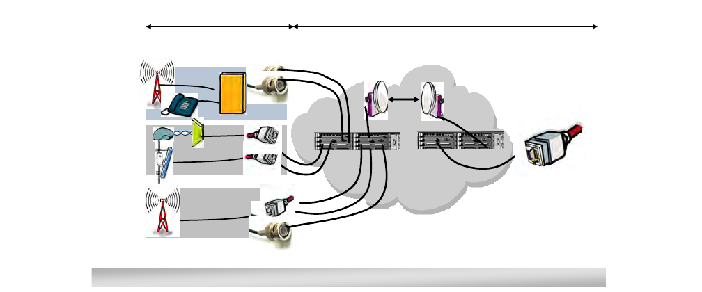
•Multiservice aggregation layer: the capacity to use Ethernet as a
common transmission layer to transport any kind of traffic,
independently by the type of interface. Ethernet becomes the
convergence layer.
•Service awareness: traffic handling and quality management,
queuing traffic according to the type of service assigned,
independently by the type of interface
•Packet node: no service aggregation limits with all traffic aggregated
in packets, in term of: capacity, type of service requirements and type
of interface
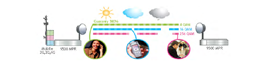
•Service-driven adaptive modulation: fully exploit the air
bandwidth in its entirety by changing modulation scheme according to
the propagation availability and allocate transport capacity,
discriminating traffic by different services, only possible in a packet-
based environment.
Multiservice aggregation layer
1.6 9500 MPR-A aggregates and carries over a COMMON PACKET
LAYER: TDM 2G, 3G, LTE, and IP/Ethernet. This allows sharing of common
packet transmission infrastructures, regardless of the nature of carried traffic.
1.7 Due to the nature of Ethernet, each service can be discriminated based
on several parameters like quality of service.
1.8 Mapping different access technologies over Ethernet is achieved by
standardized protocols like circuit emulation and pseudo-wire.
3EM23952AL
Issue 0.1, November 2012
PRELIMINARY
9500 MPR-A general system description 2-3
Service awareness
1.9 Service awareness means the ability to discriminate the different
traffic types carried over the converged Ethernet stream. The traffic flow can
be composed by DS1, DS3, OC-3, and/or IP/Eth, coming from different sources,
and therefore having different requirements.
1.10 For instance DS1 traffic from a 3G base stations can carry voice (high
priority, real time service) and data (lower priority and possibly non real time
with high variability load, such as internet browsing, music download or video
streaming).
1.11 Service awareness is what allows identifying the traffic types, and in
case of the non real time variable bit rate one, optimize the band with
overbooking of the radio scarce resource.
Figure 1-1. Multiservice aggregation layer
nxE1
Ethernet
ISAM,
WiMAX
2G Aggregated traffic
over Ethernet
Packet Backhaul network
Ethernet aggregation layer
Access network
Any TDM/Ethernet interfaces
nxE1
3G HSDPA
Voice on R99
9500 MPR
GSM
Single technology throughout the network: Ethernet as convergence layer

PRELIMINARY
3EM23952AL
Issue 0.1, November 2012
9500 MPR-A general system description
2-4
Packet node
1.12 9500 MPR-A offers a SINGLE PACKET MATRIX able to switch,
aggregate and handle any of the possible incoming traffic types with virtually
no capacity limits (up to 10 Gbps).
Figure 1-2. Service awareness
Figure 1-3. Packet node
Address new data services in the best way: packet natively
3EM23952AL
Issue 0.1, November 2012
PRELIMINARY
9500 MPR-A general system description 2-5
Service-driven adaptive modulation
1.13 Traffic with high priority will always have bandwidth available, like
voice (deterministic approach).
1.14 Broadband traffic is discriminated by QoS dynamically, with
modulation scheme changes driven by propagation conditions.
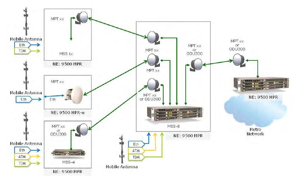
9500 MPR-A family overview
1.15 9500 MPR-A introduces new elements to the microwave packet family.
The most compact IDU solutions (MSS-1c) for DS1 and Ethernet hybrid
connectivity and a zero footprint solution (no IDU) addressing full out-door
applications. The new set of multipurpose Outdoor Units (ODU), the MPT-HC
and MPT-XP addresses any application in the microwave domain. Stand alone
and split mount applications depending on the network requirement and
layout. The MPT-HC/XP supports a variety of configurations to address the
different parts of the network in the most cost effective solution and also
includes millimeter wavelength.
Figure 1-4. Service-driven packet adaptive modulation
PRELIMINARY
3EM23952AL
Issue 0.1, November 2012
9500 MPR-A general system description
2-6
1.16 The Microwave Service Switch shelf (MSS-1c/4/8) provides baseband
processing and tributary interfaces as well as supervision.
1.17 The MOD300 radio card and ODU300 provides radio function from 6
GHz to 38 GHz.
1.18 The P8ETH Ethernet Access Switch card and Microwave Packet
Transport-Long Haul (MPT-HL) transceiver provides radio function from 6
GHz to 11 GHz.
1.19 The MPTACC MPT Access card and Microwave Packet
Transport-High Capacity (MPT-HC/XP) transceiver provides radio function
from 6 GHz to 38 GHz.
1.20 The MPT-HC/XP transceiver supports direct connection to the Core-E
electrical and optical Ethernet ports.
1.21 The MPT-HC/XP transceiver supports direct connection to the P8ETH
optical Ethernet ports.
Figure 1-5. 9500 MPR-A family
3EM23952AL
Issue 0.1, November 2012
PRELIMINARY
9500 MPR-A general system description 2-7
1.22 9500 MPR-A replaces the traditional terminal or single-link based
approach to networking with a nodal solution.
1.23 The MOD300 and ODU300 support up to six RF links for operation on
the same or different frequency bands. An ODU300 for each link is connected
to plug-in MOD300 card Radio Interface inside the MSS-4/8 shelf.
1.24 The MPTACC and MPT-HC/XP support up to twelve RF links for
operation on the same or different frequency bands. An MPT-HC/XP for each
link is connected to plug-in MPTACC card inside the MSS-4/8 shelf. Each
MPTACC supports up to two MPT-HC/XP Transceivers.
1.25 Four MPT-HL shelves support up to eight RF links for operation on
the same or different frequency bands. A Transceiver card in the MPT-HL shelf
for each link is connected to P8ETH Ethernet Access Switch card inside the
MSS-4/8 shelf.
1.26 A mixture of radio transceiver technologies supports up to a maximum
of eighteen radio interfaces.
1.27 Other plug-in cards provide line interface access and management.
Supports a mix of non-protected and protected or diversity operation for single
link, repeater, nodal or hub radio configurations.
1.28 System control and synchronization is provided by the Enhanced
Control and Switching Module (Core-E) card.
Documentation
1.29 For additional information, refer to the following related
documentation:
•9500 MPR-A Installation Practices manual (PN 3EM23953AL)
•9500 MPR-A Operation and Administration manual
(PN 3EM23954AL)
•9500 MPR-A Turn-Up manual (PN 3EM23955AL)
•9500 MPR-A Maintenance and Trouble Clearing manual
(PN 3EM23956AL)
•9500 MPR-A Engineering Support Documentation manual
(PN 3EM23957AL)
•9500 MPR MPT-GC User Manual (PN 3DB19025AA)
PRELIMINARY
3EM23952AL
Issue 0.1, November 2012
9500 MPR-A general system description
2-8
•9500 MPR MPR-e User Manual (PN 3DB19901EB)
•9500 MPR MSS-1c User Manual (PN 3DB19901DB)
Standards
1.30 The following is a partial list of the standards that have influenced
certain behavioral aspects of the 9500 MPR-A:
•21 CFR PART 1040.10 and 1040.11
•ANSI Z136.2
•ATIS 0600315
•Banned substances list
•CENELEC EN 61000-3-2
•CENELEC EN 61000-3-3
•CENELEC EN 61000-4-8
•CISPR/I/105/CDV-CISPR/I/29/CD-CISPR/I/106/CDV
•CISPR 16-1-1
•CISPR 16-1-2
•CISPR 16-1-4
•CISPR 16-2-1
•CISPR 16-2-3
•CISPR 16-2-4
•CISPR 16-4-2
•CISPR 22
•CSA-C22.2 No 60950
•EC RoHS Directive 2002/95/EU, compliance with
•EC WEEE Directive 2002/96/EU, compliance with
•EN 301 751
3EM23952AL
Issue 0.1, November 2012
PRELIMINARY
9500 MPR-A general system description 2-9
•EN 302 217-2-2
•EN 50 385
•EN 50 383
•ETSI and RTTE directive: health and safety
•ETSI and RTTE directive: electromagnetic compatibility
•ETSI and RTTE directive: ETSI standard
•ETSI and RTTE directive: EN 302 217
•ETSI standards: Transmitter requirements
•ETSI standards: Receiving requirements
•ETSI standards: Note
•ETSI EN 302 217-1 to 4
•ETSI EN 301 489
•ETSI EN 300 019
•ETSI EN 300 753
•ETSI EN 300 119
•ETSI EN 300 132-2
•ETSI EN 300 132-3
•ETSI EN 300253
•ETSI EN 300 386
•ETSI EN 55022
•EU Directive EuP Directive 92/42/EEC, Compliance with proposal
•FCC OET 65
•FCC Title 247, Part 15
•GR-63
•GR-78
•GR-487-CORE
PRELIMINARY
3EM23952AL
Issue 0.1, November 2012
9500 MPR-A general system description
2-10
•GR-1089-CORE
•GR-3108
•Human exposure
•IC RSS-210
•IEC 61000-4
•ICES 003
•ICNIRP
•IEC EN 60950-1
•IEC EN 50385
•IEC EN 60825-1/-2:2000
•IEC UL 60950-1
•IEC 60529
•IEEE Std 802.3
•IEEE Std 802.1D
•IEEE Std 802.1Q
•IEEE 1613
•IETF RFC 2474
•IETF RFC 2475
•IETF RFC 3550
•IETF RFC 0793
•IETF RFC 0791
•IETF RFC 1157
•IETF RFC 768
•IETF RFC 2616
•ITU-T G.664
•ITU-T G.703
3EM23952AL
Issue 0.1, November 2012
PRELIMINARY
9500 MPR-A general system description 2-11
•ITU-T G.704
•ITU-T G.706
•ITU-T G.775
•ITU-T G.823
•ITU-T G.8261
•ITU-T G.826
•ITU-T G.921
•ITU-T Recommendation K20
•ITU-T Recommendation K21
•ITU-T Recommendation K45
•ITU-T Recommendation K44
•MEF 8
•NAR EIA-310
•Safety (Canada)
•SR-332
•TR NWT 000499
•TR TSY 000191
JF6-9558H and JF6-9558HC (unlicensed) radio
1.31 The JF6-9558H/6933B-9500MPT (MPT-HL) and
JF6-9558HC/6933B-9558HC (MPT-HC) unlicensed radio provides fast
deployment of service with microwave radio. No license and small antennas (no
FCC and Industry Canada requirements) allow immediate turn-up. After the
license is received, the unlicensed radio can be easily converted to the lower 6
GHz licensed band.
1.32 The JF6-9558H/6933B-9500MPT and JF6-9558HC/6933B-9558HC
unlicensed radio operates in the 5725-5850 Information, Scientific, and
Medical (ISM) band in accordance with FCC Part 15.247 and IC RSS-210. This
unlicensed radio, although operating in the same band as a spread spectrum
radio, operates using narrower bandwidths than spread spectrum.
PRELIMINARY
3EM23952AL
Issue 0.1, November 2012
9500 MPR-A general system description
2-12
1.33 The MPT-HC 5.8 Unlicensed band (JF6-9558HC/6933B-9558HC) is
currently being certified and is not available for quote, sale, or deployment.
FCC class B compliance statement
1.34 The JF6-9558H/6933B-9500MPT and JF6-9558HC/6933B-9558HC
unlicensed radio have been tested and found to comply with the limits for a
Class B digital device, pursuant to Part 15 of the FCC Rules and IC RSS-210.
These limits are designed to provide reasonable protection against harmful
interference when the equipment is operated in a commercial environment.
This equipment generates, uses, and can radiate radio frequency energy and,
if not installed and used in accordance with the instruction manual, may cause
harmful interference to radio communications. Operation of this equipment in
a residential area is likely to cause harmful interference in which case the user
will be required to correct the interference at his own expense.
FCC class B requirements
1.35 This device complies with part 15 of the FCC Rules and IC RSS-210.
Operation is subject to the following three conditions: (1) this device may not
cause harmful interference. (2) This device must accept any interference
received, including interference that may cause undesired operation. (3) This
device must be professionally installed.
CAUTION Possibility of service interruption. Changes or modifications not expressly
approved by Alcatel-Lucent could void the authority to operate the
JJF6-9558H/6933B-9500MPT and JF6-9558HC/6933B-9558HC unlicensed radio.
CAUTION Possibility of service interruption. Installation, Turn-Up, Maintenance, and
Operation Instruction supplied with the JF6-9558H/6933B-9500MPT and
JF6-9558HC/6933B-9558HC unlicensed radio require strict adherence for
continued part 15 of the FCC Rules and IC RSS-210 compliance.
3EM23952AL
Issue 0.1, November 2012
PRELIMINARY
9500 MPR-A general system description 2-13
2. System administration
2.1 Three applications are available for 9500 MPR-A system
administration:
1. Craft Terminal (CT)
2. WebEML
3. MIB
2.2 The Craft Terminal and WebEML provide a Graphical User Interface
(GUI) to enable a user to view and perform system administration for all
Network Elements (NEs) in a network, including remote 9500 MPR-A systems.
The Craft Terminal and WebEML as an interface for performing provisioning,
monitoring, and alarm management for the 9500 MPR-A.
2.3 For more information on the The Craft Terminal and WebEML refer
to the 9500 MPR-A R4.1.0 Operation and Administration manual
(PN 3EM23954AL).
2.4 Network Management support using Alcatel-Lucent 1350 OMS,
1352 Compact, and 5620 SAM.
PRELIMINARY
3EM23952AL
Issue 0.1, November 2012
9500 MPR-A general system description
2-14
3EM23952AL
Issue 0.1, November 2012
PRELIMINARY
9500 MPR-A general system description 2-15
3. Features
3.1 The following lists the features of R4.1.0 of 9500 MPR-A. To
administer these features by the Craft Terminal and WebEML refer to the
9500 MPR-A Operation and Administration manual (PN 3EM23954AL).
Microwave service switch (MSS)
•MSS-8 shelf
•MSS-4 shelf
•MSS-1c shelf
Radio
•Radio configuration
– 1+0 and 1+1 Terminal
– 1+0 and 1+1 Drop and Insert Repeater
– 1+0 and 1+1 3-Way Junction
– 1+0 and 1+1 Nodal x-Way Junction
•Protection schemes
– 1+0 unprotected
– 1+1 Hot StandBy (HSB)
– 1+1 Space Diversity (SD)
– 1+1 Frequency Diversity (FD)
– 2x(1+0) XPIC
– 4x(1+0) XPIC
– 2x(1+1) XPIC
•Channel spacing
•Static Modulation
•Adaptive modulation
PRELIMINARY
3EM23952AL
Issue 0.1, November 2012
9500 MPR-A general system description
2-16
–Admission control
•Adaptive equalization
•Fiber-microwave protection
•Frequency agility
•Link identifier
•Loopback
–Core facing radio digital loopback
–Radio facing circuit loopback
–Core facing IF cable loopback
–Core facing RF loopback
•Performance monitoring
–Adaptive modulation PM
–Radio analog PM
–Radio ethernet PM
–Radio hop PM
–Radio link PM
–Radio QoS PM
–Radio RSL PM
•Power monitoring
•Radio direction label
•Radio L1 LAG
•Radio L2 LAG
•Transmit power control
–ATPC
–RTPC
•Tx mute
3EM23952AL
Issue 0.1, November 2012
PRELIMINARY
9500 MPR-A general system description 2-17
•XPIC
Radio transceivers
•MPT-GC
•MPT-HC/XP/9558HC
–MPR-e (standalone MPT-HC/XP)
–Unlicensed radio for MPT-HL and 9558HC
•MPT-HL
–Lower 6 GHz frequency plan
–Unlicensed radio for MPT-HL and 9558HC
•ODU300
Ethernet
•Ethernet traffic management
–802.1D
–802.1Q
•Frame type
–Ethernet v2
–802.3
–802.1Q
•Quality of service (QoS)
–QoS classification
–QoS priority value to internal forwarding class
–Internal forwarding class to queue mapping
–Queue scheduler algorithm
–Queue size
–QoS with jumbo frame
PRELIMINARY
3EM23952AL
Issue 0.1, November 2012
9500 MPR-A general system description
2-18
–QoS in the Core-E card
–QoS in the modem MOD300 card
–QoS in the MPT-HC/XP
–QoS in the MPT-HL
•Ethernet features provisioned by craft terminal
–C-VLAN translation
–Port based rate limiting
–Storm control (broadcast, multicast, and unknown unicast)
–VLAN based rate limiter
–Per-VLAN per-COS rate limiter
•Ethernet features configured by enhanced configuration file
–Access control list
–Out of range VLAN swap
–Per-flow policer
–Stacked VLAN (Q-in-Q) tagging
–VLAN remarking
–VLAN swap
–2xE1DS1 SFP Support
•Input/output flow control
•Reserved multicast addresses
•Traffic mode
•Ethernet synchronization messaging channel
•Ethernet connectivity fault management
•TACACS+
•Ethernet ring protection
•Jumbo frame
3EM23952AL
Issue 0.1, November 2012
PRELIMINARY
9500 MPR-A general system description 2-19
•Ethernet L2 LAG
•Performance monitoring
•Port segregation
•Synchronous ethernet
•VLAN IDs
Managed services and profiles
•TDM2TDM
•TDM2ETH
•SDH2SDH
•ETH2ETH
Traffic interfaces
•Core-E
–10/100/1000 Base-T ethernet interfaces
–GigE SFP ethernet interfaces
–MPT-HC/XP radio interface
–2xDS1 SFP
•DS1 PDH interface
•DS3 PDH interface
•OC-3 SDH interface
•Ethernet access switch
–10/100/1000Base-T ethernet interfaces
–GigE SFP ethernet interfaces
–MPT-HL radio interface
•MODEM 300 radio interface
•MPT access
PRELIMINARY
3EM23952AL
Issue 0.1, November 2012
9500 MPR-A general system description
2-20
Power
•Power injector box
•MPT power unit
•MPT Extended Power Unit
Configurations
•MSS-8 shelf configurations
•MSS-4 shelf configurations
•Stand alone MSS-4/MSS-8 shelf
•Stacking MSS-4/MSS-8 shelf configuration
Alarm management
•System Alarms
•Equipment Alarms
•Facility Alarms
•Alarm Monitor Tool
Cross-connections
•DS1/DS3 Cross-connections
•OC-3 Cross-connections
•Radio-radio cross-connections
•Ethernet cross-connections
Database backup and restore
External Communications
In-service upgrade
LAG (link aggregation group)
•L1/L2 link aggregation on radio ports (radio L1/L2 LAG)
3EM23952AL
Issue 0.1, November 2012
PRELIMINARY
9500 MPR-A general system description 2-21
•L2 Link aggregation on user ethernet ports (ethernet L2 LAG)
License key management
Loopback
•Core facing radio digital loopback
•Radio facing circuit loopback
•Core facing IF cable loopback
•Core facing RF loopback
•Line facing PDH (DS1/DS3) loopback
•Radio facing PDH (DS1/DS3) loopback
•Loopback time-out
Network Management
•Alcatel-Lucent 1350 OMS
•Alcatel-Lucent 1352 CM
•Alcatel-Lucent 1353 NM
•Alcatel-Lucent 5620 SAM
Performance monitoring
•Adaptive modulation PM
•Ethernet user port PM
•PDH PM (DS1)
•Radio analog PM
•Radio ethernet PM
•Radio hop PM
•Radio link PM
•Radio QoS PM
•Radio RSL PM
PRELIMINARY
3EM23952AL
Issue 0.1, November 2012
9500 MPR-A general system description
2-22
Port segregation
•TDM ports
•MPT access ports
•MPT-HC/XPs number for each MPT plug in
•ODU300
•ODU300 and MPTACC
•MPT-HC/XPs protected on different plug-ins
Remote inventory
Security
•User authentication
•User profile management
•SNMP operating mode (SNMPv3 support)
Stacking for EAS/MPT access cards
Synchronization
•Differential clock recovery
•Adaptive clock recovery
•Synchronization protection
•Quality level priority
•Hold-off and wait-to-restore
3EM23952AL
Issue 0.1, November 2012
PRELIMINARY
9500 MPR-A general system description 2-23
4. Equipment layout
4.1 The 9500 MPR-A contains cards that plug into shelf assemblies and
mechanical equipment housed in equipment racks. Power and signaling
connections are made through backplane connectors.
Rack assemblies
4.2 MSS-4/8/1c and MPT-HL shelf assemblies are mounted in either an
equal flange aluminum equipment rack or an unequal flange seismic rack. See
Figure 4-1 equal flange aluminum equipment rack. See Figure 4-2 for unequal
flange seismic rack. Each rack uses 1.75-inch Electronic Industries Association
(EIA) rack mounting increments. A 7 feet equal flange aluminum rack provides
46 EIA rack increments. A 7 feet unequal flange seismic rack provides 43 EIA
rack increments.
4.3 Seismic racks meet EIA specifications regarding earthquake
resistance.
4.4 Refer to table 4-A for standard equipment rack specifications. Refer to
table 4-B for seismic equipment rack specifications.
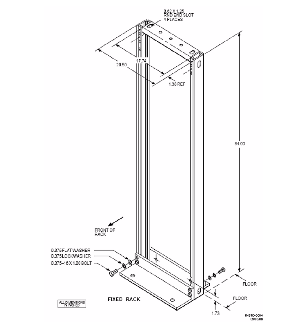
PRELIMINARY
3EM23952AL
Issue 0.1, November 2012
9500 MPR-A general system description
2-24
Figure 4-1. Standard equal flange aluminum rack assembly (PN 694-9000-006)
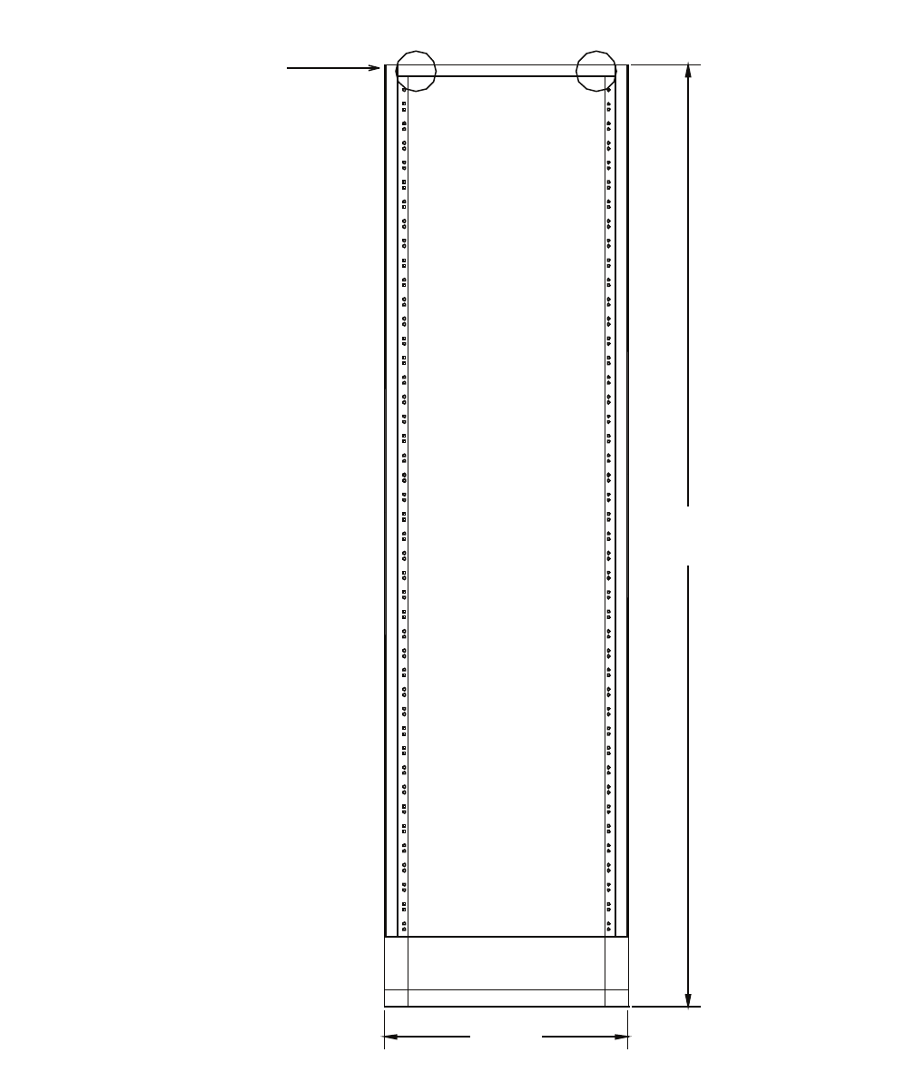
3EM23952AL
Issue 0.1, November 2012
PRELIMINARY
9500 MPR-A general system description 2-25
Figure 4-2. Unequal flange seismic rack assembly (PN 1AD014120046)
950-0207-1
022610
84.00
Standard
Height
See
Rack Grounding
Detail
(2 Places)
21.9375”

PRELIMINARY
3EM23952AL
Issue 0.1, November 2012
9500 MPR-A general system description
2-26
Table 4-A. Standard equipment rack specifications
ITEM CHARACTERISTICS
1. Description Equal-flange aluminum rack provides mounting space for shelves in
areas where zone 4 earthquake compliance is NOT required
2. Physical dimensions (bays)
Height
Width
Depth
MSS-8 Stand-Alone Shelf
MSS-4 Stand-Alone Shelf
MSS-1c Stand-Alone
Shelf
MPT-HL Shelf W/diplexer
MPT-HL Shelf W/One
Waveguide Bracket
MPT-HL Shelf W/Two
Waveguide Bracket
7 ft 0 in.
20.5 in.
12 in.
12 in.
12 in.
13.5 in.
17 in.
22.0 in.
Table 4-B. Seismic equipment rack specifications
ITEM CHARACTERISTICS
1. Description Unequal-flange seismic rack provides mounting space for shelves in
areas where zone 4 earthquake compliance is required
2. Physical dimensions (bays)
Height
Width
Depth
MSS-8 Stand-Alone Shelf
MSS-4 Stand-Alone Shelf
MSS-1c Stand-Alone
Shelf
MPT-HL Shelf W/diplexer
MPT-HL Shelf W/One
Waveguide Bracket
MPT-HL Shelf W/Two
Waveguide Bracket
7 ft 0 in.
22 in.
12 in.
12 in.
12 in.
13.5 in.
17 in.
22.0 in.

3EM23952AL
Issue 0.1, November 2012
PRELIMINARY
9500 MPR-A general system description 2-27
Constraints
4.5 Certain constraints must be considered when integrating the system
into a physical network environment. Each installation presents its own set of
considerations.
Environment
4.6 The MSS-8 shelf is designed for placement in a ‘partially controlled’
environment. Refer to table 4-C for environmental condition specifications.
Table 4-C. Environmental condition specifications
ITEM ASSEMBLY OPERATING NONOPERATING
1. Ambient temperature1MSS-4/8/1c -5 °C to +55 °C2
(41 °F to 131 °F)
-40 °C to 70 °C
(-40 °F to 158 °F)
MPT-HL -5 °C to +55 °C2
(41 °F to 131 °F)
-40 °C to 70 °C
(-40 °F to 158 °F)
MPT-HC,
MPT-XP,
ODU300,
Power
Injector
-40 °C to +65 °C
(-40 °F to 149 °F) -40 °C to 70 °C
(-40 °F to 158 °F)
2. Relative humidity MSS-4/8/1c,
Power
Injector
5 to 85%3
(without condensation)
0 to 95%
(without condensation)
MPT-HL 5 to 85%3
(without condensation)
0 to 95%
(without condensation)
ODU300, r 0 to 100%
3. Altitude4MSS-8,
MSS-4,
MPT-HC,
MPT-HL,
MPT-XP,
ODU300,
Power
Injector
-60 to 1800 m
(-197 to 5,905 ft) -60 to 4000 m
(-197 to 13,123 ft)
4. Cooling MSS-4/8/1c,
MPT-HL Forced air

PRELIMINARY
3EM23952AL
Issue 0.1, November 2012
9500 MPR-A general system description
2-28
Shelf assemblies
4.7 System shelf assemblies follow:
•MSS-8 shelf
•MSS-4 shelf
•MSS-1c shelf
•MPT-HL shelf
4.8 System OutDoor Unit (ODU) assemblies follow:
•ODU300
•MPT-HC
•MPT-XP
•MPT-GC
5. Vibration and shock MSS-8,
MSS-4,
MPT-HC,
MPT-HL,
MPT-XP,
ODU300,
Power
Injector
Earthquake requirements
6. Duty cycle MSS-8,
MSS-4,
MPT-HC,
MPT-HL,
MPT-XP,
ODU300,
Power
Injector
Continuous, unattended
[1] Room temperature is measured at a location 1.5 m (59 in.) above the floor and 400 mm (15.8 in.) in front of the
equipment.
[2] Short term operating ambient temperature is -5 °C to +55 °C (23 °F to 149 °F) for a period not to exceed 96
consecutive hours and a total of not more than 15 days in 1 year.
[3] Short term operating Relative humidity is 5 to 90% for a period not to exceed 96 consecutive hours and a
total of not more than 15 days in 1 year.
[4] At installation between 1800 m to 4000 m (5905 ft to 13,123 ft) above sea level, with an ambient aisle temper-
ature not to exceed of 30 °C (113 °F).
Table 4-C. Environmental condition specifications (cont.)
3EM23952AL
Issue 0.1, November 2012
PRELIMINARY
9500 MPR-A general system description 2-29
4.9 The following assemblies are also installed in rack assemblies:
•Power Distribution Unit (PDU)
•DS1 37 Pin D-Sub Patch Panel Assembly
•DS1 RJ45 Patch Panel Assembly
•DS3 BNC Patch Panel
•Type N Adapter Plate Assembly
MSS-8 shelf
4.10 The MSS-8 shelf mounts in a standard 19-inch rack. See figures 4-3.
4.11 Adapter brackets are available to mount MSS-8 shelf in standard
23-inch rack.
4.12 The MSS-8 shelf houses the following cards:
•Core-E—Enhanced Control and Switching Module - Core-E
•P32E1DS1 (DS1)—DS1 PDH card
•P2E3DS3 (DS3)—DS3 PDH card
•SDHACC (OC-3)—OC-3 SDH card
•P8ETH (EAS)—Ethernet Access Switch card
•MPTACC (RADIO)—MPT Access card
•MOD300 (RADIO)—Modem card
•AUX—Auxiliary card
•Power Injector
•Power Converter
•FAN—MSS Fan

PRELIMINARY
3EM23952AL
Issue 0.1, November 2012
9500 MPR-A general system description
2-30
MSS-4 shelf
4.13 The MSS-4 shelf mounts in a standard 19-inch rack. See figures 4-4.
4.14 Adapter brackets are available to mount MSS-4 shelf in standard
23-inch rack.
4.15 The MSS-4 shelf houses the following cards:
•Core-E—Enhanced Control and Switching Module
•P32E1DS1 (DS1)—DS1 PDH card
•P2E3DS3 (DS3)—DS3 PDH card
•SDHACC (OC-3)—OC-3 SDH card
•P8ETH (EAS)—Ethernet Access Switch card
•MOD300 (RADIO)—Modem card
•MPTACC (RADIO)—MPT Access card
Figure 4-3. MSS-8 shelf, front view
950-0003-3
092010
CSM-E
(Spare)
Transport Card Transport Card
Transport Card Transport Card
Transport Card
Transport Card
or
Auxiliary Card
CSM-E
(Main)
Fan
92
4
6
8
1
3
5
7
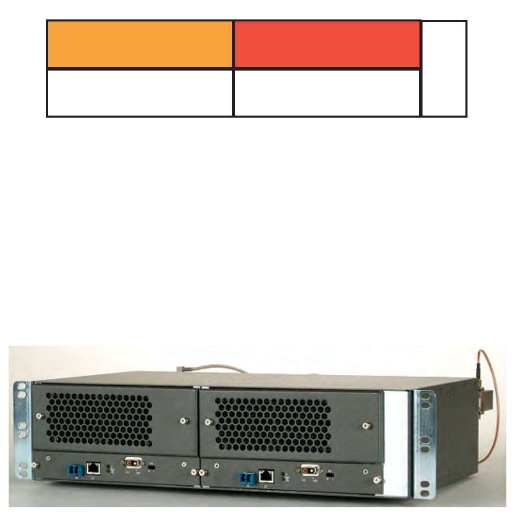
3EM23952AL
Issue 0.1, November 2012
PRELIMINARY
9500 MPR-A general system description 2-31
•AUX—Auxiliary card
•Power Injector
•FAN—MSS Fan
MPT-HL shelf
4.16 The MPT-HL shelf mounts in a standard 19-inch rack. See figures 4-5.
4.17 Adapter brackets are available to mount MPT-HL shelf in standard
23-inch rack.
4.18 The MPT-HL shelf houses the MPT-HL Transceiver card.
Figure 4-4. MSS-4 shelf, front view
Figure 4-5. MPT-HL shelf, front view
950-0025-1
091410
CSM-E
(Main)
Fan
52
4
1
3
CSM-E
(Spare)
Any Transport
Any Transport
or
Auxiliary Card
PRELIMINARY
3EM23952AL
Issue 0.1, November 2012
9500 MPR-A general system description
2-32
Miscellaneous assemblies
4.19 Other system assemblies include the following:
•Power Distribution Unit
•DS1 37 Pin D-Sub Patch Panel Assembly
•DS1 RJ45 Patch Panel Assembly
•DS3 BNC Patch Panel
•Type N Adapter Plate Assembly
•Power Injector Box
•MPT Power Unit

3EM23952AL
Issue 0.1, November 2012
PRELIMINARY
9500 MPR-A general system description 2-33
5. Unit descriptions
5.1 Refer to table 5-A for brief descriptions of MSS-4/8 shelf assemblies,
plug-in cards, and miscellaneous components.
5.2 Refer to table 5-B for brief descriptions of ODU300, antennas, couplers
and miscellaneous components.
5.3 Refer to table 5-C for brief descriptions of MPT-HL shelf assembly,
plug-in transceivers, and miscellaneous components.
5.4 Refer to table 5-D for brief descriptions of MPT-HC/XP, antennas,
couplers, and miscellaneous components.
5.5 Refer to table 5-E for brief descriptions of rack assemblies, Power
units, Patch Panels, cable assemblies, and miscellaneous components.
5.6 Refer to table 5-F for brief descriptions of software, RTU capacity
License, and documentation.
Table 5-A. MSS-4/8 shelf unit descriptions
UNIT DESCRIPTION
Microwave Switching Services Shelf
(MSS-8)
PN: 3DB18485AB
Qty: 1 per 9500 MPR-A node
The MSS-8 houses equipment that supports 10 Gb/s packet
switching, synchronization, protection switching,
provisioning, and alarm management. Up to 192 DS1 TDM
circuits, up to 12 DS3 TDM circuits, up to 12 OC-3 SDH
circuits, up to 16 10/100/1000BaseT Ethernet circuits, or 12
GigE SFP optical Ethernet circuits for customer data flows.
It is composed of a power panel, and a card cage.
Two Control and Switching Module (Core-E) slots support
either one Core-E card in unprotected configuration or two
Core-E cards in protected configuration.
Six transport slots support any mixture of unprotected and/or
1+1 EPS protected transport cards. Supported transport
types include: up to two P8ETH (Ethernet) cards, up to six
P32E1DS1 (DS1) cards, up to six P2E3DS3 (DS3), up to six
SDHACC (OC-3), up to six MPTACC (2xradio), up to six
MOD300 (radio) cards, and/or up to one AUX (Auxiliary)
cards.
One fan card is required for system cooling.

PRELIMINARY
3EM23952AL
Issue 0.1, November 2012
9500 MPR-A general system description
2-34
MSS-8 shelf Kits
PN: 3EM22715AB, 3EM22715AC
Qty: 1 per 9500 MPR-A node
MSS-8 shelf kits provide one MSS-8 shelf, power cables,
FAN card, and miscellaneous rack hardware.
PN: 3EM22715AB is MSS-8 shelf kit W/FAN Card
PN: 3EM22715AC is MSS-8 shelf kit W/Alarm FAN Card
Microwave Switching Services Shelf
(MSS-4)
PN: 3DB18219AB
Qty: 1 per 9500 MPR-A node
The MSS-4 houses equipment that supports 10 Gb/s packet
switching, synchronization, protection switching,
provisioning, and alarm management. Up to 64 DS1 TDM
circuits, up to 4 DS3 TDM circuits, up to 4 SDHACC (OC-3)
circuits, up to 16 10/100/1000BaseT Ethernet circuits, or 12
GigE SFP optical Ethernet circuits for customer data flows.
It is composed of a power panel, and a card cage.
Two Control and Switching Module (Core-E) slots support
either one Core-E card in unprotected configuration or two
Core-E cards in protected configuration.
Two transport slots support any mixture of unprotected or
1+1 EPS protected transport cards. Supported transport
types include: up to two P8ETH (Ethernet) cards, up to two
P32E1DS1 (DS1) cards, up to two P2E3DS3 (DS3), up to
two SDHACC (OC-3), up to two MPTACC (2xradio), up to
two MOD300 (radio) cards, and/or up to one AUX (Auxiliary)
cards.
One fan card is required for system cooling.
MSS-4 shelf Kit
PN: 3EM24463AA
Qty: 1 per 9500 MPR-A node
MSS-4 shelf kit provide one MSS-4 shelf, power cable, FAN
card, and miscellaneous rack hardware.
Enhanced Control and Switching Module
(Core-E)
PN: 3DB18326AC
Qty: 1 or 2 per MSS-8 Shelf
Enhanced Control and Switching Module (Core-E) performs
all supervisory functions for the 9500 MPR-A MSS-8 shelf
and switches Ethernet packets from peripheral ports to radio
ports. One Core-E card is required in unprotected
configuration. Two Core-E cards are required in protected
configuration.
Radio Interface Card (MOD300)
PN: 3DB18136AE
Qty: Up to 6 per MSS-8 Shelf, up to 2 per
MSS-4 Shelf
The MOD300 card converts Ethernet packet data and
modulates them into an IF signal which is then sent to the
ODU300. IF signal from the ODU300 is demodulated by the
MOD300 card and then converts them into Ethernet packet
data. The MSS-8 shelf supports up to six MOD300 cards, or
up to six unprotected radio channels, and/or up to three
protected radio channels. The MOD300 card supports only
static modulation schemes.
Table 5-A. MSS-4/8 shelf unit descriptions (cont.)
UNIT DESCRIPTION

3EM23952AL
Issue 0.1, November 2012
PRELIMINARY
9500 MPR-A general system description 2-35
Enhanced Radio Interface Card
(MOD300EN)
PN: 3DB18538AC
Qty: Up to 6 per MSS-8 Shelf, up to 2 per
MSS-4 Shelf
The MOD300EN card converts Ethernet packet data and
modulates them into an IF signal which is then sent to the
ODU300. IF signal from the ODU300 is demodulated by the
MOD300EN card and then converts them into Ethernet
packet data. The MSS-8 shelf supports up to six MOD300EN
cards, or up to six unprotected radio channels, and/or up to
three protected radio channels. The MOD300EN card
supports both static and adaptive modulation schemes.
8-Port Ethernet Access Switch (EAS)
(P8ETH)
PN: 3DB18206AC
Qty: Up to 2 per MSS-8 Shelf, up to 2 per
MSS-4 Shelf
The P8ETH card provides four 10/100/1000 10BaseT
Ethernet interfaces and four GigE optical Ethernet SFP
interfaces. The MSS-4/8 shelves support one protected pair
of P8ETH cards or two unprotected P8ETH cards. The
P8ETH GigE optical Ethernet SFP interfaces can be
configured to support MPT-HL transceivers. Each P8ETH
supports up to four MPT-HL transceiver based radio
channels or a mixture of eight unprotected or up to four
protected radio channels per MSS-4/8 shelves.
MPT Access card W/PFoE
(MPTACC)
PN: 3DB18634AB
Qty: Up to 6 per MSS-8 Shelf, up to 2 per
MSS-4 Shelf
The MPTACC card with PFoE provides 2 MPT-HC/XP
interfaces. The MSS-8 shelf supports up to six MPTACC
cards, or a mixture of up to twelve unprotected MPT-HC/XP
radio channels, or up to six protected MPT-HC/XP radio
channels. The MSS-4 shelf supports up to two MPTACC
cards, or a mixture of up to four unprotected MPT-HC/XP
radio channels, or up to two protected MPT-HC/XP radio
channels. The MPTACC card with PFoE supports Power
Feed over Ethernet solution to simplify inter connectivity
between the MSS-4/8 shelf and MPT-HC/XP.
32-Port DS1 PDH Transport card
(P32E1DS1)
PN: 3DB18126AE
Qty: Up to 6 per MSS-8 Shelf, up to 2 per
MSS-4 Shelf
The P32E1DS1 card provides 32 DS1 interfaces. The
MSS-8 shelf supports up to six P32E1DS1 cards, or a
mixture of up to one-hundred ninety-two unprotected DS1
interfaces, or up to ninety-six protected DS1 interfaces. The
MSS-4 shelf supports up to two P32E1DS1 cards, or a
mixture of up to sixty-four unprotected DS1 interfaces, or up
to thirty-two protected DS1 interfaces.
2-Port DS3 PDH Transport card
(P2E3DS3)
PN: 3DB18194AC
Qty: Up to 6 per MSS-8 Shelf, up to 2 per
MSS-4 Shelf
The P2E3DS3 card provides 2 DS3 interfaces. The MSS-8
shelf supports up to six P2E3DS3 cards, or a mixture of up
to twelve unprotected DS3 interfaces, or up to six protected
DS3 interfaces.
2-Port OC-3 SDH Transport card
(SDHACC)
PN: 3DB18735AA
Qty: Up to 6 per MSS-8 Shelf, up to 2 per
MSS-4 Shelf
The SDHACC card provides 2 OC-3 interfaces. The MSS-8
shelf supports up to six SDHACC cards, or a mixture of up to
twelve unprotected OC-3 interfaces, or up to six protected
OC-3 interfaces.
Table 5-A. MSS-4/8 shelf unit descriptions (cont.)
UNIT DESCRIPTION

PRELIMINARY
3EM23952AL
Issue 0.1, November 2012
9500 MPR-A general system description
2-36
Auxiliary Card (AUX)
PN: 3DB18236AB
Qty: Up to 1 per MSS-4/8 shelf
The AUX card provides thirteen housekeeping alarms, six
alarm inputs and seven alarm outputs. The MSS-4/8 shelves
support up to one AUX card per shelf.
+24/-48 Volt Converter1
PN: 3DB18764AA, 3DB18862AA,
3DB18863AA
QTY: 1 per MSS-8 Shelf
The +24/-48 Volt Converter converts +24 Vdc office battery
voltage to -48 Vdc for MSS-8 shelf +24 Vdc office
applications.
PN: 3DB18764AA is +24/-48 Volt converter (Spare)
PN: 3DB18862AA is 2 converters W/Chassis
PN: 3DB18863AA is 1 converter W/Chassis
Fan 2U Card, MSS-8 Shelf (FAN)
PN: 3DB18134BB
Qty: 1 per MSS-8 Shelf
Provides forced air flow for MSS-8 shelf cooling. One is
required per MSS-8 shelf.
Fan 2U Card W/Alarms, MSS-8 Shelf
(FAN)
PN: 3EM23911AA
Qty: 1 per MSS-8 Shelf
Provides forced air flow for MSS-8 shelf cooling. One is
required per MSS-8 shelf. Fan Card w/Alarms provides
summary, major, and minor alarm front panel LEDs and
alarm relay outputs.
Fan 1U Card, MSS-4 Shelf (FAN)
PN: 3DB18218AD
Qty: 1 per MSS-4 Shelf
Provides forced air flow for MSS-4 shelf cooling. One is
required per MSS-4 shelf.
MSS-4/8 Shelf Slot Cover
PN: 3DB18163AB
QTY: 1 per unequipped MSS-4/8 card slot
MSS-4/8 shelf slot cover is required for all unequipped slots
for EMI compliance and proper system cooling.
[1] For shelves equipped with the +24/-48 Volt Converter card, the FAN 2U Card W/Alarms is required.
Table 5-A. MSS-4/8 shelf unit descriptions (cont.)
UNIT DESCRIPTION

3EM23952AL
Issue 0.1, November 2012
PRELIMINARY
9500 MPR-A general system description 2-37
Table 5-B. ODU300 unit descriptions
UNIT DESCRIPTION
OutDoor Unit (ODU300)
ODU300 W/Lightning Surge Suppressor,
lower 6 GHz, 252.04 MHz Separation
PN: 3DB23215HA/3DB23215HF
Qty: 1 per Lower 6 GHz, 252.04 MHz
Separation Radio Channel
The ODU300 is a microprocessor controlled transceiver that
interfaces the MSS-8 shelf MOD300 card with the antenna.
Supports static and adaptive modulation schemes. Channel
frequency is software selectable within tuning range of the
ODU300. The ODU300 is frequency dependent. ODU300
includes built-in lightning surge suppressor.
PN: 3DB23215HA is ODU300, 5930 - 6020 MHz, HP, TX
Low
PN: 3DB23215HD is ODU300, 6182 - 6272 MHz, HP, TX
High
PN: 3DB23215HB is ODU300, 5989 - 6079 MHz, HP, TX
Low
PN: 3DB23215HE is ODU300, 6241 - 6331 MHz, HP, TX
High
PN: 3DB23215HC is ODU300, 6078 - 6168 MHz, HP, TX
Low
PN: 3DB23215HF is ODU300, 6330 - 6420 MHz, HP, TX
High
OutDoor Unit (ODU300)
ODU300 W/Lightning Surge Suppressor,
Upper 6 GHz, 160 MHz Separation
PN: 3DB23214HA/3DB23214HF
Qty: 1 per Upper 6 GHz, 160 MHz
Separation Radio Channel
The ODU300 is a microprocessor controlled transceiver that
interfaces the MSS-8 shelf MOD300 card with the antenna.
Supports static and adaptive modulation schemes. Channel
frequency is software selectable within tuning range of the
ODU300. The ODU300 is frequency dependent. ODU300
includes built-in lightning surge suppressor.
PN: 3DB23214HA is ODU300, 6540 - 6610 MHz, HP, TX
Low
PN: 3DB23214HB is ODU300, 6710 - 6780 MHz, HP, TX
High
PN: 3DB23214HC is ODU300, 6590 - 6660 MHz, HP, TX
Low
PN: 3DB23214HD is ODU300, 6760 - 6830 MHz, HP, TX
High
PN: 3DB23214HE is ODU300, 6640 - 6710 MHz, HP, TX
Low
PN: 3DB23214HF is ODU300, 6800 - 6870 MHz, HP, TX
High

PRELIMINARY
3EM23952AL
Issue 0.1, November 2012
9500 MPR-A general system description
2-38
OutDoor Unit (ODU300)
ODU300 W/Lightning Surge Suppressor,
Upper 6 GHz, 340 MHz Separation
PN: 3DB23216HA/3DB23216HF
Qty: 1 per Upper 6 GHz, 340 MHz
Separation Radio Channel
The ODU300 is a microprocessor controlled transceiver that
interfaces the MSS-8 shelf MOD300 card with the antenna.
Supports static and adaptive modulation schemes. Channel
frequency is software selectable within tuning range of the
ODU300. The ODU300 is frequency dependent. ODU300
includes built-in lightning surge suppressor.
PN: 3DB23216HA is ODU300, 6430 - 6590 MHz, HP, TX
Low
PN: 3DB23216HB is ODU300, 6770 - 6930 MHz, HP, TX
High
PN: 3DB23216HC is ODU300, 6515 - 6675 MHz, HP, TX
Low
PN: 3DB23216HD is ODU300, 6855 - 7015 MHz, HP, TX
High
PN: 3DB23216HE is ODU300, 6600 - 6760 MHz, HP, TX
Low
PN: 3DB23216HF is ODU300, 6940 - 7100 MHz, HP, TX
High
OutDoor Unit (ODU300)
ODU300 W/Lightning Surge Suppressor,
7 GHz, 175 MHz Separation
PN: 3DB23223HA/3DB23228HA,
Qty: 1 per 7 GHz, 175 MHz Separation
Radio Channel
The ODU300 is a microprocessor controlled transceiver that
interfaces the MSS-8 shelf MOD300 card with the antenna.
Supports static and adaptive modulation schemes. Channel
frequency is software selectable within tuning range of the
ODU300. The ODU300 is frequency dependent. ODU300
includes built-in lightning surge suppressor.
PN: 3DB23223HA is ODU300, 7124 - 7185 MHz, HP, TX
Low
PN: 3DB23224HA is ODU300, 7299 - 7360 MHz, HP, TX
High
PN: 3DB23225HA is ODU300, 7157.5 - 7217.5 MHz, HP, TX
Low
PN: 3DB23226HA is ODU300, 7332.5 - 7392.5 MHz, HP, TX
High
PN: 3DB23227HA is ODU300, 7190 - 7250 MHz, HP, TX
Low
PN: 3DB23228HA is ODU300, 7365 - 7425 MHz, HP, TX
High
Table 5-B. ODU300 unit descriptions (cont.)
UNIT DESCRIPTION

3EM23952AL
Issue 0.1, November 2012
PRELIMINARY
9500 MPR-A general system description 2-39
OutDoor Unit (ODU300)
ODU300 W/Lightning Surge Suppressor,
7 GHz, 150 MHz Separation
PN: 3DB23217HA/3DB23222HA
Qty: 1 per 7 GHz, 150 MHz Separation
Radio Channel
The ODU300 is a microprocessor controlled transceiver that
interfaces the MSS-8 shelf MOD300 card with the antenna.
Supports static and adaptive modulation schemes. Channel
frequency is software selectable within tuning range of the
ODU300. The ODU300 is frequency dependent. ODU300
includes built-in lightning surge suppressor.
PN: 3DB23217HA is ODU300, 7424 - 7485 MHz, HP, TX
Low
PN: 3DB23218HA is ODU300, 7574 - 7635 MHz, HP, TX
High
PN: 3DB23219HA is ODU300, 7470 - 7530 MHz, HP, TX
Low
PN: 3DB23220HA is ODU300, 7620 - 7680 MHz, HP, TX
High
PN: 3DB23221HA is ODU300, 7515 - 7575 MHz, HP, TX
Low
PN: 3DB23222HA is ODU300, 7665 - 7725 MHz, HP, TX
High
OutDoor Unit (ODU300)
ODU300 W/Lightning Surge Suppressor,
8 GHz, 300 MHz Separation
PN: 3DB23033HA/3DB23033HD
Qty: 1 per Upper 8 GHz, 300 MHz
Separation Radio Channel
The ODU300 is a microprocessor controlled transceiver that
interfaces the MSS-8 shelf MOD300 card with the antenna.
Supports static and adaptive modulation schemes. Channel
frequency is software selectable within tuning range of the
ODU300. The ODU300 is frequency dependent. ODU300
includes built-in lightning surge suppressor.
PN: 3DB23033HA is ODU300, 7722.5 - 7859 MHz, HP, TX
Low
PN: 3DB23033HC is ODU300, 8025 - 8171 MHz, HP, TX
High
PN: 3DB23033HB is ODU300, 7844 - 7981 MHz, HP, TX
Low
PN: 3DB23033HD is ODU300, 8145 - 8287 MHz, HP, TX
High
Table 5-B. ODU300 unit descriptions (cont.)
UNIT DESCRIPTION

PRELIMINARY
3EM23952AL
Issue 0.1, November 2012
9500 MPR-A general system description
2-40
OutDoor Unit (ODU300)
ODU300 W/Lightning Surge Suppressor,
11 GHz, 490-500 MHz Separation
PN: 3DB23035HA/3DB23035HH
Qty: 1 per 11 GHz, 490-500 MHz
Separation Radio Channel
The ODU300 is a microprocessor controlled transceiver that
interfaces the MSS-8 shelf MOD300 card with the antenna.
Supports static and adaptive modulation schemes. Channel
frequency is software selectable within tuning range of the
ODU300. The ODU300 is frequency dependent. ODU300
includes built-in lightning surge suppressor.
PN: 3DB23035HA is ODU300, 10675 - 10835 MHz, TX Low
PN: 3DB23035HE is ODU300, 11200 - 11345 MHz, TX High
PN: 3DB23035HB is ODU300, 10795 - 10955 MHz, TX Low
PN: 3DB23035HF is ODU300, 11310 - 11465 MHz, TX High
PN: 3DB23035HC is ODU300, 10915 - 11075 MHz, TX Low
PN: 3DB23035HG is ODU300, 11430 - 11585 MHz, TX High
PN: 3DB23035HD is ODU300, 11035 - 11200 MHz, TX Low
PN: 3DB23035HH is ODU300, 11550 - 11705 MHz, TX High
OutDoor Unit (ODU300)
ODU300 W/Lightning Surge Suppressor,
15 GHz, 475/490 MHz Separation
PN: 3DB23039HC, 3DB23039HD
Qty: 1 per 15 GHz, 475/490 MHz
Separation Radio Channel
The ODU300 is a microprocessor controlled transceiver that
interfaces the MSS-8 shelf MOD300 card with the antenna.
Supports static and adaptive modulation schemes. Channel
frequency is software selectable within tuning range of the
ODU300. The ODU300 is frequency dependent. ODU300
includes built-in lightning surge suppressor.
PN: 3DB23039HC is ODU300, 14500 - 14660 MHz, TX Low
PN: 3DB23039HD is ODU300, 14975 - 15135 MHz, TX Low
OutDoor Unit (ODU300)
ODU300 W/Lightning Surge Suppressor,
18 GHz, 1560 MHz Separation
PN: 3DB23062HC, 3DB23062HD
Qty: 1 per 18 GHz, 1560 MHz Separation
Radio Channel
The ODU300 is a microprocessor controlled transceiver that
interfaces the MSS-8 shelf MOD300 card with the antenna.
Supports static and adaptive modulation schemes. Channel
frequency is software selectable within tuning range of the
ODU300. The ODU300 is frequency dependent. ODU300
includes built-in lightning surge suppressor.
PN: 3DB23062HC is ODU300, 17700 - 18060 MHz, TX Low
PN: 3DB23062HD is ODU300, 19260 - 19620 MHz, TX Low
Table 5-B. ODU300 unit descriptions (cont.)
UNIT DESCRIPTION

3EM23952AL
Issue 0.1, November 2012
PRELIMINARY
9500 MPR-A general system description 2-41
OutDoor Unit (ODU300)
ODU300 W/Lightning Surge Suppressor,
23 GHz, 1200 MHz Separation
PN: 3DB23045HA/3DB23045HH
Qty: 1 per 23 GHz, 1200 MHz Separation
Radio Channel
The ODU300 is a microprocessor controlled transceiver that
interfaces the MSS-8 shelf MOD300 card with the antenna.
Supports static and adaptive modulation schemes. Channel
frequency is software selectable within tuning range of the
ODU300. The ODU300 is frequency dependent. ODU300
includes built-in lightning surge suppressor.
PN: 3DB23045HA is ODU300, 21200 - 21570 MHz, TX Low
PN: 3DB23045HE is ODU300, 22400 - 22770 MHz, TX High
PN: 3DB23045HB is ODU300, 21475 - 21845 MHz, TX Low
PN: 3DB23045HF is ODU300, 22675 - 23045 MHz, TX High
PN: 3DB23045HC is ODU300, 21750 - 22120 MHz, TX Low
PN: 3DB23045HG is ODU300, 22950 - 23320 MHz, TX High
PN: 3DB23045HD is ODU300, 22030 - 22400 MHz, TX Low
PN: 3DB23045HH is ODU300, 23230 - 23600 MHz, TX High
OutDoor Unit (ODU300)
ODU300 W/Lightning Surge Suppressor,
38 GHz, 700 MHz Separation
PN: 3DB23258HO/3DB23258HV
Qty: 1 per 38 GHz, 700 MHz Separation
Radio Channel
The ODU300 is a microprocessor controlled transceiver that
interfaces the MSS-8 shelf MOD300 card with the antenna.
Supports static and adaptive modulation schemes. Channel
frequency is software selectable within tuning range of the
ODU300. The ODU300 is frequency dependent. ODU300
includes built-in lightning surge suppressor.
PN: 3DB23258HO is ODU300, 38600 - 38800 MHz, TX Low
PN: 3DB23258HP is ODU300, 39300 - 39500 MHz, TX High
PN: 3DB23258HQ is ODU300, 38750 - 38950 MHz, TX Low
PN: 3DB23258HR is ODU300, 39450 - 39650 MHz, TX High
PN: 3DB23258HS is ODU300, 38950 - 39150 MHz, TX Low
PN: 3DB23258HT is ODU300, 39650 - 39850 MHz, TX High
PN: 3DB23258HU is ODU300, 39100 - 39300 MHz, TX Low
PN: 3DB23258HV is ODU300, 39800 - 40000 MHz, TX High
Table 5-B. ODU300 unit descriptions (cont.)
UNIT DESCRIPTION

PRELIMINARY
3EM23952AL
Issue 0.1, November 2012
9500 MPR-A general system description
2-42
ODU300 Couplers
PN: 3CC58012AAAA/3CC58027AAAA
QTY: as required per site configuration
ODU300 Coupler
PN: 3CC58020AAAA is 6 GHz Band (1.5 dB/6 dB) Unequal
Coupler
PN: 3CC58025AAAA is 7/8 GHz Band (3 dB/3 dB) Equal
Coupler
PN: 3CC58019AAAA is 7/8 GHz Band (1.5 dB/6 dB)
Unequal Coupler
PN: 3CC58023AAAA is 11 GHz Band (3 dB/3 dB) Equal
Coupler
PN: 3CC58017AAAA is 11 GHz Band (1.5 dB/6 dB) Unequal
Coupler
PN: 3CC58027AAAA is 18 GHz Band (1.5 dB/6 dB) Unequal
Coupler
PN: 3CC58012AAAA is 23 GHz Band (3 dB/3 dB) Equal
Coupler
PN: 3CC58014AAAA is 23 GHz Band (1.5 dB/6 dB) Unequal
Coupler
ODU300 or Coupler Pole Mount (Non-
Integrated)
PN: 3CC58001AA
QTY: as required per site configuration
ODU300 or Coupler Pole Mount (non-Integrated antenna
configuration
ODU300 Rack Mount Bracket
PN: 3EM21370AA/3EM21370AB
QTY: as required per site configuration
ODU300 Rack Mount Bracket for Non-integrated radio
configuration
PN: 3EM21370AA is ODU300, 19 inch rack mount bracket
PN: 3EM21370AB is ODU300, 23 inch rack mount bracket
Table 5-B. ODU300 unit descriptions (cont.)
UNIT DESCRIPTION

3EM23952AL
Issue 0.1, November 2012
PRELIMINARY
9500 MPR-A general system description 2-43
MSS to ODU300 Cabling
QTY: as required per site configuration MSS to ODU300 Cabling
PN: 3EM23311AA is MOD300 Cable Jumper, 14 inches
PN: 3EM23311AB is MOD300 Cable Jumper, 9 feet
PN: 3EM23272AA is Type N Adapter Bracket, supports up
to three MOD300 IF signal type N jumper cables which
provides a transition from the MOD300 card connector to
Type N connector
PN: 1AC014320002 is LMR-400 Coaxial Cable
PN: 1AB095530045 is Type N PPC Nm-400 Connector,
Straight, Male
PN: 1AB095530046 is Type N PPC Nm-400 Connector,
straight, female
PN: 1AB383930001 is PPC 400NT Tool Kit
PN: 1AB350440001 is LMR Grounding Kit
PN: 3CC50015AA is Lightning Arrestor INU/ODU (2
Arrestor) Kit
PN: 3CC50030AA is Lightning Arrestor INU Only (1 Arrestor)
Kit
Table 5-C. MPT-HL shelf unit descriptions
UNIT DESCRIPTION
Microwave Packet Transport-Long Haul
Shelf (MPT-HL)
PN: 3EM22618AB
Qty: Up to 4 per 9500 MPR-A node
The MPT-HL shelf supports Two MPT-HL transceiver cards,
either two unprotected radio channels or one protected radio
channel.
MPT-HL Shelf Kits
PN: 3EM24238AA, 3EM23238AB
Qty: 1 per MPT-HL shelf
The MPT-HL shelf kits contain; one MPT-HL shelf, MPT-HL
Transceiver power cable(s), Transceiver blank cover, and
miscellaneous rack hardware. MPT-HL shelf kits are
unpopulated.
PN: 3EM24238AA is single Transceiver shelf kit
PN: 3EM24238AB is Dual Transceiver shelf kit
MPT-HL Transceiver (MPT-HL)
PN: 3EM22617AA, 3EM22617AC
Qty: 1 per Lower 6 GHz Channel
The MPT-HL Transceiver card is a microprocessor
controlled RF transceiver that interfaces the MSS-4/8 shelf
P8ETH card MPT-HL port with the antenna. Supports static
modulation scheme. Channel frequency is software
selectable within tuning range of the MPT-HL Transceiver.
The MPT-HL Transceiver is frequency dependent.
PN: 3EM22617AA is MPT-HL, 5725 - 6425 MHz
PN: 3EM22617AC is MPT-HL, 5925 - 6425 MHz, HP
Table 5-B. ODU300 unit descriptions (cont.)
UNIT DESCRIPTION

PRELIMINARY
3EM23952AL
Issue 0.1, November 2012
9500 MPR-A general system description
2-44
MPT-HL Transceiver (MPT-HL)
PN: 3EM22617AB, 3EM22617AD
Qty: 1 per Upper 6 GHz Channel
The MPT-HL Transceiver card is a microprocessor
controlled RF transceiver that interfaces the MSS-4/8 shelf
P8ETH card MPT-HL port with the antenna. Supports static
modulation scheme. Channel frequency is software
selectable within tuning range of the MPT-HL Transceiver.
The MPT-HL Transceiver is frequency dependent.
PN: 3EM22617AB is MPT-HL, 6425 - 6930 MHz
PN: 3EM22617AD is MPT-HL, 6425 - 6930 MHz, HP
MPT-HL Transceiver (MPT-HL)
PN: 3EM24627AA
Qty: 1 per 7 GHz Channel
The MPT-HL Transceiver card is a microprocessor
controlled RF transceiver that interfaces the MSS-4/8 shelf
P8ETH card MPT-HL port with the antenna. Supports static
modulation scheme. Channel frequency is software
selectable within tuning range of the MPT-HL Transceiver.
The MPT-HL Transceiver is frequency dependent.
PN: 3EM24627AA is MPT-HL, 7125-7775 MHz
MPT-HL Transceiver (MPT-HL)
PN: 3EM24627AB
Qty: 1 per 8 GHz Channel
The MPT-HL Transceiver card is a microprocessor
controlled RF transceiver that interfaces the MSS-4/8 shelf
P8ETH card MPT-HL port with the antenna. Supports static
modulation scheme. Channel frequency is software
selectable within tuning range of the MPT-HL Transceiver.
The MPT-HL Transceiver is frequency dependent.
PN: 3EM24627AB is MPT-HL, 7725-8500 MHz
MPT-HL Transceiver (MPT-HL)
PN: 3EM23888AA
Qty: 1 per 10.5 GHz Channel
The MPT-HL Transceiver card is a microprocessor
controlled RF transceiver that interfaces the MSS-4/8 shelf
P8ETH card MPT-HL port with the antenna. Supports static
modulation scheme. Channel frequency is software
selectable within tuning range of the MPT-HL Transceiver.
The MPT-HL Transceiver is frequency dependent.
PN: 3EM23888AA is MPT-HL, 10400 - 10700 MHz
MPT-HL Transceiver (MPT-HL)
PN: 3EM23888AB, 3EM23888AC
Qty: 1 per 11 GHz Channel
The MPT-HL Transceiver card is a microprocessor
controlled RF transceiver that interfaces the MSS-4/8 shelf
P8ETH card MPT-HL port with the antenna. Supports static
modulation scheme. Channel frequency is software
selectable within tuning range of the MPT-HL Transceiver.
The MPT-HL Transceiver is frequency dependent.
PN: 3EM23888AB is MPT-HL, 10700 - 11200 MHz
PN: 3EM23888AC is MPT-HL, 11200 - 11700 MHz
Table 5-C. MPT-HL shelf unit descriptions (cont.)
UNIT DESCRIPTION

3EM23952AL
Issue 0.1, November 2012
PRELIMINARY
9500 MPR-A general system description 2-45
MPT-HL Transceiver Air Filter
PN: 3EM24040AA
Qty: 1 per MPT-HL Transceiver (Optional)
Replacement MPT-HL Transceiver air filter.
MPT-HL Transmit Monitor Port Kit
PN: 3EM24447AA, 3EM24447AB
Qty: (Optional)
Provides transmit monitor port for 6 GHz and 11 GHz
PN: 3EM24447AA is 6 GHz Transmit Monitor Port
PN: 3EM24447AB is 11 GHz Transmit Monitor Port
Diplexer Bracket Kits
PN: 3EM23465AA/3EM23465AD
Qty: as required
Diplexer Bracket Kits
PN: 3EM23465AA is Hot Standby 1:10 Coupler
PN: 3EM23465AB is Hot Standby W/space Diversity
PN: 3EM23465AC is 1+0 Non-Standby
PN: 3EM23465AD is Single Shelf Repeater
Diplexer Clamp and Isolator Kits
PN: 3EM23466AA/3EM23466AM,
3EM24188AA/3EM24188AD
Qty: as required
Diplexer Clamp and Isolator Kits:
Frequency Band: 5725-5850 GHZ
PN: 3EM23466AJ is Hot Standby 1:10 coupler
PN: 3EM23466AK is Hot Standby W/space Diversity
PN: 3EM23466AL is 1+0 Non-Standby
PN: 3EM23466AM is Single Shelf Repeater
Frequency Band: 5925-6425
PN: 3EM23466AA is Hot Standby 1:10 coupler
PN: 3EM23466AB is Hot Standby W/space Diversity
PN: 3EM23466AC is 1+0 Non-Standby
PN: 3EM23466AD is Single Shelf Repeater
Frequency Band: 6525-6875 GHZ
PN: 3EM23466AE is Hot Standby 1:10 coupler
PN: 3EM23466AF is Hot Standby W/space Diversity
PN: 3EM23466AG is 1+0 Non-Standby
PN: 3EM23466AH is Single Shelf Repeater
Frequency Band: 7125-8500 GHZ
PN: 3EM24728AA is Hot Standby 1:10 coupler
PN: 3EM24728AB is Hot Standby W/space Diversity
PN: 3EM24728AC is 1+0 Non-Standby
PN: 3EM24728AD is Single Shelf Repeater
Frequency Band: 10500-11700 GHZ
PN: 3EM24188AA is Hot Standby 1:10 coupler
PN: 3EM24188AB is Hot Standby W/space Diversity
PN: 3EM24188AC is 1+0 Non-Standby
PN: 3EM24188AD is Single Shelf Repeater
Table 5-C. MPT-HL shelf unit descriptions (cont.)
UNIT DESCRIPTION

PRELIMINARY
3EM23952AL
Issue 0.1, November 2012
9500 MPR-A general system description
2-46
Waveguide Transition Kits
PN: 3EM23511AA/3EM23511AJ
Qty: as required
Waveguide Transition Kits
Frequency Band: 5725-5850 GHZ
PN: 3EM23511AA is A2 (6 GHz) Position Kit
PN: 3EM23511AB is A3 (6 GHz) Position Kit
PN: 3EM23511AC is A4 (6 GHz) Position Kit
PN: 3EM23511AD is A5 (6 GHz) Position Kit
PN: 3EM23511AE is Flat Bracket Kit
PN: 3EM23511AF is A2 (11 GHz) Position Kit
PN: 3EM23511AG is A3 (11 GHz) Position Kit
PN: 3EM23511AH is A4 (11 GHz) Position Kit
PN: 3EM23511AJ is A5 (11 GHz) Position Kit
RF Diplexer Filters
PN:
Qty: as required
RF Diplexer Filters: Xmt Freq Rcv Freq Filter BW
PN: 3EM24458AA is 5725-5755 5790-5820 30 MHz
PN: 3EM24458AB is 5755-5785 5820-5850 30 MHz
PN: 3EM24458AC is 5725-5755 5820-5850 30 MHz
PN: 3EM16710AB is 5925-6175 6175-6425 10 MHz
PN: 3EM16710AC is 6175-6425 5925-6175 10 MHz
PN: 3EM24335AA is 5925-6175 6175-6425 30 MHz
6175-6425 5925-6175 30 MHz
PN: 3EM09730AA is 6525-6875 6525-6875 10 MHz
PN: 3EM24333AA is 6525-6710 6710-6875 30 MHz
6710-6875 6525-6710 30 MHz
PN: 967-1585-002 is 6440-6750 6440-6750 10 MHz
PN: 967-1585-003 is 6440-6750 6750-7080 10 MHz
PN: 967-1585-004 is 6750-7080 6440-6750 10 MHz
PN: 967-1585-005 is 6750-7080 6750-7080 10 MHz
PN: 3EM04024AC is 6440-6580 6740-6920 30 MHz
PN: 3EM04024AD is 6581-6740 6921-7080 30 MHz
PN: 3EM04024AE is 6740-6920 6440-6580 30 MHz
PN: 3EM04024AF is 6921-7080 6581-6740 30 MHz
PN: 3EM24412AA is 7125-7575 7300-7755 40 MHz
PN: 3EM24412AB is 7725-8115 8025-8500 40 MHz
PN: 3EM24412AA is 7125-7750 7750-8500 40 MHz
PN: 3EM24078AA is 10550-10680 10550-10680 10 MHz
PN: 3EM24081AA is 10700-11200 11200-11700 30 MHz
11200-11700 10700-11200 30 MHz
Table 5-C. MPT-HL shelf unit descriptions (cont.)
UNIT DESCRIPTION

3EM23952AL
Issue 0.1, November 2012
PRELIMINARY
9500 MPR-A general system description 2-47
Space Diversity Filters
PN:
Qty: as required
Space Diversity Filters:
PN: Freq Band Filter BW
3EM11649AA is Space Div Filter 5725-5755 30 MHz
3EM11649AB is Space Div Filter 5755-5785 30 MHz
3EM11649AC is Space Div Filter 5790-5820 30 MHz
3EM11649AD is Space Div Filter 5820-5850 30 MHz
967-0506-002 is Space Div Filter 5925-6175 10 MHz
967-0506-003 is Space Div Filter 6175-6425 10 MHz
3EM04182AA is Space Div Filter 5925-6050 30 MHz
3EM04182AB is Space Div Filter 6050-6175 30 MHz
3EM04182AC is Space Div Filter 6175-6300 30 MHz
3EM04182AD is Space Div Filter 6300-6425 30 MHz
3EM19463AA is Space Div Filter 6525-6875 10 MHz
3EM04235AA is Space Div Filter 6525-6710 30 MHz
3EM04235AB is Space Div Filter 6710-6875 30 MHz
967-0506-004 is Space Div Filter 6440-6750 10 MHz
967-0506-005 is Space Div Filter 6750-7080 10 MHz
3EM04235AC is Space Div Filter 6440-6580 30 MHz
3EM04235AD is Space Div Filter 6580-6740 30 MHz
3EM04235AE is Space Div Filter 6740-6920 30 MHz
3EM04235AF is Space Div Filter 6920-7080 30 MHz
3EM19619AA is Space Div Filter 7125-7750 30 MHz
3EM19619AB is Space Div Filter 7750-8500 30 MHz
695-8307-001 is Space Div Filter 10550-10680 10 MHz
3EM24310AA is Space Div Filter 10700-11200 30 MHz
3EM24310AB is Space Div Filter 11200-11700 30 MHz
Table 5-C. MPT-HL shelf unit descriptions (cont.)
UNIT DESCRIPTION

PRELIMINARY
3EM23952AL
Issue 0.1, November 2012
9500 MPR-A general system description
2-48
RF Stacking Filters
PN:
Qty: as required
RF Stacking Filters:
PN: Freq Band Filter BW
3EM16948AA is RF Stack Filter, Rcv 5925-6175 30 MHz
3EM16949AB is RF Stack Filter, Xmt 6175-6425 30 MHz
3EM16948AB is RF Stack Filter, Rcv 6175-6425 30 MHz
3EM16949AA is RF Stack Filter, Xmt 5925-6175 30 MHz
3EM16948AD is RF Stack Filter, Rcv 6525-6875 30 MHz
3EM16949AD is RF Stack Filter, Xmt 6525-6875 30 MHz
3EM16948AE is RF Stack Filter, Rcv 6440-6740 30 MHz
3EM16949AF is RF Stack Filter, Xmt 6740-7080 30 MHz
3EM16948AF is RF Stack Filter, Rcv 6740-7080 30 MHz
3EM16949AE is RF Stack Filter, Xmt 6440-6740 30 MHz
3MU00071AA is RF Stack Filter, Rcv 7125-7445 30 MHz
3MU00071AF is RF Stack Filter, Xmt 7445-7750 30 MHz
3MU00071AB is RF Stack Filter, Rcv 7445-7750 30 MHz
3MU00071AE is RF Stack Filter, Xmt 7125-7445 30 MHz
3MU00071AC is RF Stack Filter, Rcv 7750-8125 30 MHz
3MU00071AH is RF Stack Filter, Xmt 8125-8500 30 MHz
3MU00071AD is RF Stack Filter, Rcv 8125-8500 30 MHz
3MU00071AG is RF Stack Filter, Xmt 7750-8125 30 MHz
3EM05115AA is RF Stack Filter, Rcv 10.7-11.2 30 MHz
3EM05114AC is RF Stack Filter, Xmt 11.2-11.7 30 MHz
3EM05115AC is RF Stack Filter, Rcv 11.2-11.7 30 MHz
3EM05114AA is RF Stack Filter, Xmt 10.7-11.2 30 MHz
Isolator Kits
PN: 3EM23524AA/3EM23524AF,
3EM24189AA/3EM24189AC
Qty: as required
Isolator Kits:
Frequency Band: 5725-6425 GHZ
PN: 3EM23524AA is Hot Standby 1:10 coupler
PN: 3EM23524AB is Hot Standby W/Space Diversity
PN: 3EM23524AC is 1+0 Non-Standby
Frequency Band: 6400-7080 GHZ
PN: 3EM23524AD is Hot Standby 1:10 coupler
PN: 3EM23524AE is Hot Standby W/Space Diversity
PN: 3EM23524AF is 1+0 Non-Standby
Frequency Band: 7125-8500 GHZ
PN: 3MU00074AA is Hot Standby 1:10 coupler
PN: 3MU00074AB is Hot Standby W/Space Diversity
PN: 3MU00074AC is 1+0 Non-Standby
Frequency Band: 10700-11700 GHZ
PN: 3EM24189AA is Hot Standby 1:10 coupler
PN: 3EM24189AB is Hot Standby W/space Diversity
PN: 3EM24189AC is 1+0 Non-Standby
Table 5-C. MPT-HL shelf unit descriptions (cont.)
UNIT DESCRIPTION

3EM23952AL
Issue 0.1, November 2012
PRELIMINARY
9500 MPR-A general system description 2-49
Waveguide Extension Kits
PN: 3EM24123AR, 3EM24123AS,
3EM24166AQ, 3EM24166AR
Qty: as required
Waveguide Extension Kits
PN: 3EM24123AR is Xmt/Rcv W/G Ext A8/A11 (6 GHz)
PN: 3EM24123AS is Space Div W/G Ext A8/A11 (6 GHz)
PN: 3EM24166AQ is Xmt/Rcv W/G Ext A8/A11 (11 GHz)
PN: 3EM24166AR is Space Div W/G Ext A8/A11 (11 GHz)
Stacking Filter Waveguide Kits: 6 GHz
PN: 3EM24123AA/3EM24123AQ
Qty: as required
Stacking Filter Waveguide Kits: 6 GHz
PN: 3EM24123AA is Hot Standby 1st MPT, Xmt and Rcv
PN: 3EM24123AB is Hot Standby 1st and 2nd MPT, Xmt
and Rcv
PN: 3EM24123AC is Hot Standby 3rd MPT, Xmt and Rcv
PN: 3EM24123AD is Hot Standby 3rd and 4th MPT, Xmt and
Rcv
PN: 3EM24123AE is Add-On Space Diversity 1st MPT
PN: 3EM24123AF is Add-On Space Diversity 1st and 2nd
MPT
PN: 3EM24123AG is Add-On Space Diversity 3rd MPT
PN: 3EM24123AH is Add-On Space Diversity 3rd and 4th
MPT
PN: 3EM24123AL is Field Add-On Xmt and Rcv Circulator
Kit
PN: 3EM24123AM is Freq Diversity 1st MPT
PN: 3EM24123AN is Freq Diversity 1st and 2nd MPT
PN: 3EM24123AP is Freq Diversity 3rd MPT
PN: 3EM24123AQ is Freq Diversity 3rd and 4th MPT
Stacking Filter Waveguide Kits: 8 GHz
PN: 3MU00075AA/3MU00075AK
Qty: as required
Stacking Filter Waveguide Kits: 6 GHz
PN: 3MU00075AA is Hot Standby 1st MPT, Xmt and Rcv
PN: 3MU00075AB is Hot Standby 1st and 2nd MPT, Xmt
and Rcv
PN: 3MU00075AC is Hot Standby 3rd MPT, Xmt and Rcv
PN: 3MU00075AD is Hot Standby 3rd and 4th MPT, Xmt and
Rcv
PN: 3MU00075AE is Add-On Space Diversity 1st MPT
PN: 3MU00075AF is Add-On Space Diversity 1st and 2nd
MPT
PN: 3MU00075AG is Add-On Space Diversity 3rd MPT
PN: 3MU00075AH is Add-On Space Diversity 3rd and 4th
MPT
PN: 3MU00075AK is Field Add-On Xmt and Rcv Circulator
Kit
PN: 3MU00075AL is Freq Diversity 1st MPT
PN: 3MU00075AM is Freq Diversity 1st and 2nd MPT
PN: 3MU00075AN is Freq Diversity 3rd MPT
PN: 3MU00075AP is Freq Diversity 3rd and 4th MPT
Table 5-C. MPT-HL shelf unit descriptions (cont.)
UNIT DESCRIPTION

PRELIMINARY
3EM23952AL
Issue 0.1, November 2012
9500 MPR-A general system description
2-50
Stacking Filter Waveguide Kits: 11 GHz
PN: 3EM24166AA/3EM24166AP
Qty: as required
Stacking Filter Waveguide Kits: 11 GHz
PN: 3EM24166AA is Hot Standby 1st MPT, Xmt and Rcv
PN: 3EM24166AB is Hot Standby 1st and 2nd MPT, Xmt
and Rcv
PN: 3EM24166AC is Hot Standby 3rd MPT, Xmt and Rcv
PN: 3EM24166AD is Hot Standby 3rd and 4th MPT, Xmt and
Rcv
PN: 3EM24166AE is Add-On Space Diversity 1st MPT
PN: 3EM24166AF is Add-On Space Diversity 1st and 2nd
MPT
PN: 3EM24166AG is Add-On Space Diversity 3rd MPT
PN: 3EM24166AH is Add-On Space Diversity 3rd and 4th
MPT
PN: 3EM24166AK is Field Add-On Xmt and Rcv Circulator
Kit
PN: 3EM24166AL is Freq Diversity 1st MPT
PN: 3EM24166AM is Freq Diversity 1st and 2nd MPT
PN: 3EM24166AN is Freq Diversity 3rd MPT
PN: 3EM24166AP is Freq Diversity 3rd and 4th MPT
Flange Adapter Kits
PN: 3DH04122HA/3DH04122HT
Qty: as required
Flange Adapter Kits:
Frequency Band: 5925-7125 GHZ
PN: 3DH04122HA is Flange Type CPR-137, 1 port kit
PN: 3DH04122HB is Flange Type CPR-137, 2 port kit
PN: 3DH04122HC is Flange Type CPR-137, 3 port kit
PN: 3DH04122HD is Flange Type CPR-159, 1 port kit
PN: 3DH04122HE is Flange Type CPR-159, 2 port kit
PN: 3DH04122HF is Flange Type CPR-159, 3 port kit
PN: 3DH04122HG is Flange Type CMR-159, 1 port kit
PN: 3DH04122HH is Flange Type CMR-159, 2 port kit
PN: 3DH04122HJ is Flange Type CMR-159, 3 port kit
Frequency Band: 7125-8500 GHZ
PN: 3DH04122HK is Flange Type CPR-112, 1 port kit
PN: 3DH04122HL is Flange Type CPR-112, 2 port kit
PN: 3DH04122HM is Flange Type CPR-112, 3 port kit
Frequency Band: 10700-11700 GHZ
PN: 3DH04122HN is Flange Type CPR-90, 1 port kit
PN: 3DH04122HP is Flange Type CPR-90, 2 port kit
PN: 3DH04122HQ is Flange Type CPR-90, 3 port kit
PN: 3DH04122HR is Flange Type CMR-90, 1 port kit
PN: 3DH04122HS is Flange Type CMR-90, 2 port kit
PN: 3DH04122HT is Flange Type CMR-90, 3 port kit
Table 5-C. MPT-HL shelf unit descriptions (cont.)
UNIT DESCRIPTION

3EM23952AL
Issue 0.1, November 2012
PRELIMINARY
9500 MPR-A general system description 2-51
Table 5-D. MPT-HC/XP/9558HC unit descriptions
UNIT DESCRIPTION
9558HC OutDoor Unit (9558HC)
9558HC, 5.8 GHz unlicensed, 64 MHz
separation with External diplexer1
PN: 3DB20913BA, 3DB20914BA
Qty: 1 or 2 per 5.8 GHz unlicensed, 64
MHz separation radio channel
The 9558HC OutDoor Unit is a microprocessor controlled
RF transceiver that interfaces the MSS-4,8,1c shelf
MPTACC, Core-E Ethernet port, P8ETH card, or MPR-e
(stand-alone) with the antenna. Supports static and adaptive
modulation scheme. Channel frequency is software
selectable within tuning range of the 9558HC Transceiver.
The 9558HC Transceiver is frequency dependent.
An 9558HC connected to a Core-E port or P8ETH card
requires external power. Power can be provided using one
of the following:
•power injector card
•power injector box
•MPT Power Unit
•MPT Extended Power Unit
PN: 3DB20913BA is 9558HC, 5725.5-5785.5 MHz, Tx Low
PN: 3DB20914BA is 9558HC, 5789.5-5849.5 MHz, Tx High
MPT-HC OutDoor Unit (MPT-HC)
MPT-HC, L6 GHz, 252 MHz separation
PN: 3DB20441BA, 3DB20442BA,
3DB20443BA, 3DB20444BA
Qty: 1 or 2 per L6 GHz, 252 MHz
separation radio channel
The MPT-HC OutDoor Unit is a microprocessor controlled
RF transceiver that interfaces the MSS-4,8,1c shelf
MPTACC, Core-E Ethernet port, P8ETH card, or MPR-e
(stand-alone) with the antenna. Supports static and adaptive
modulation scheme. Channel frequency is software
selectable within tuning range of the MPT-HC Transceiver.
The MPT-HC Transceiver is frequency dependent.
An MPT-HC connected to a Core-E port or P8ETH card
requires external power. Power can be provided using one
of the following:
•power injector card
•power injector box
•MPT Power Unit
•MPT Extended Power Unit
PN: 3DB20441BA is MPT-HC, 5929 - 6050 MHz, Tx Low
PN: 3DB20443BA is MPT-HC, 6182 - 6302.04 MHz, Tx High
PN: 3DB20442BA is MPT-HC, 6047.96 - 6168 MHz, Tx Low
PN: 3DB20444BA is MPT-HC, 6300 - 6420.04 MHz, Tx High

PRELIMINARY
3EM23952AL
Issue 0.1, November 2012
9500 MPR-A general system description
2-52
MPT-HC High Power OutDoor Unit
(MPT-HC)
MPT-HC, L6 GHz, 252.04 MHz separation
with External diplexer1
PN: 3DB20800BA, 3DB20802BA
Qty: 1 or 2 per L6 GHz, 252.04 MHz
separation radio channel
The MPT-HC High Power OutDoor Unit is a microprocessor
controlled RF transceiver that interfaces the MSS-4,8,1c
shelf MPTACC, Core-E Ethernet port, P8ETH card, or
MPR-e (stand-alone) with the antenna. Supports static and
adaptive modulation scheme. Channel frequency is software
selectable within tuning range of the MPT-HC Transceiver.
The MPT-HC Transceiver is frequency dependent.
An MPT-HC connected to a Core-E port or P8ETH card
requires external power. Power can be provided using one
of the following:
•power injector card
•power injector box
•MPT Power Unit
•MPT Extended Power Unit
PN: 3DB20800BA is MPT-HC, 5929.96-6168 MHz, Tx Low
PN: 3DB20802BA is MPT-HC, 6182-6420 MHz, Tx High
MPT-HC OutDoor Unit (MPT-HC)
MPT-HC, U6 GHz, 160 MHz separation
PN: 3DB20367BA, 3DB20434BA,
3DB20435BA, 3DB20436BA,
3DB20462BA, 3DB20463BA
Qty: 1 or 2 per U6 GHz, 160 MHz
separation radio channel
The MPT-HC OutDoor Unit is a microprocessor controlled
RF transceiver that interfaces the MSS-4,8,1c shelf
MPTACC, Core-E Ethernet port, P8ETH card, or MPR-e
(stand-alone) with the antenna. Supports static and adaptive
modulation scheme. Channel frequency is software
selectable within tuning range of the MPT-HC Transceiver.
The MPT-HC Transceiver is frequency dependent.
An MPT-HC connected to a Core-E port or P8ETH card
requires external power. Power can be provided using one
of the following:
•power injector card
•power injector box
•MPT Power Unit
•MPT Extended Power Unit
PN: 3DB20367BA is MPT-HC, 6540 - 6610 MHz, Tx Low
PN: 3DB20435BA is MPT-HC, 6710 - 6780 MHz, Tx High
PN: 3DB20434BA is MPT-HC, 6590 - 6660 MHz, Tx Low
PN: 3DB20436BA is MPT-HC, 6750 - 6820 MHz, Tx High
PN: 3DB20462BA is MPT-HC, 6640 - 6710 MHz, Tx Low
PN: 3DB20463BA is MPT-HC, 6800 - 6870 MHz, Tx High
Table 5-D. MPT-HC/XP/9558HC unit descriptions (cont.)
UNIT DESCRIPTION

3EM23952AL
Issue 0.1, November 2012
PRELIMINARY
9500 MPR-A general system description 2-53
MPT-HC High Power OutDoor Unit
(MPT-HC)
MPT-HC, U6 GHz, 160/340 MHz
separation with External diplexer1
PN: 3DB20804BA, 3DB20806BA
Qty: 1 or 2 per U6 GHz, 160/340 MHz
separation radio channel
The MPT-HC High Power OutDoor Unit is a microprocessor
controlled RF transceiver that interfaces the MSS-4,8,1c
shelf MPTACC, Core-E Ethernet port, P8ETH card, or
MPR-e (stand-alone) with the antenna. Supports static and
adaptive modulation scheme. Channel frequency is software
selectable within tuning range of the MPT-HC Transceiver.
The MPT-HC Transceiver is frequency dependent.
An MPT-HC connected to a Core-E port or P8ETH card
requires external power. Power can be provided using one
of the following:
•power injector card
•power injector box
•MPT Power Unit
•MPT Extended Power Unit
PN: 3DB20804BA is MPT-HC, 6420-6775 MHz, Tx Low
PN: 3DB20806BA is MPT-HC, 6710-7115 MHz, Tx High
MPT-HC OutDoor Unit (MPT-HC)
MPT-HC, U6 GHz, 340 MHz separation
PN: 3DB20437BA, 3DB20438BA,
3DB20439BA, 3DB20440BA,
3DB20464BA, 3DB20465BA
Qty: 1 or 2 per U6 GHz, 340 MHz
separation radio channel
The MPT-HC OutDoor Unit is a microprocessor controlled
RF transceiver that interfaces the MSS-4,8,1c shelf
MPTACC, Core-E Ethernet port, P8ETH card, or MPR-e
(stand-alone) with the antenna. Supports static and adaptive
modulation scheme. Channel frequency is software
selectable within tuning range of the MPT-HC Transceiver.
The MPT-HC Transceiver is frequency dependent.
An MPT-HC connected to a Core-E port or P8ETH card
requires external power. Power can be provided using one
of the following:
•power injector card
•power injector box
•MPT Power Unit
•MPT Extended Power Unit
PN: 3DB20437BA is MPT-HC, 6420 - 6600 MHz, Tx Low
PN: 3DB20439BA is MPT-HC, 6760 - 6940 MHz, Tx High
PN: 3DB20438BA is MPT-HC, 6565 - 6720 MHz, Tx Low
PN: 3DB20440BA is MPT-HC, 6905 - 7060 MHz, Tx High
PN: 3DB20464BA is MPT-HC, 6595 - 6775 MHz, Tx Low
PN: 3DB20465BA is MPT-HC, 6935 - 7115 MHz, Tx High
Table 5-D. MPT-HC/XP/9558HC unit descriptions (cont.)
UNIT DESCRIPTION

PRELIMINARY
3EM23952AL
Issue 0.1, November 2012
9500 MPR-A general system description
2-54
MPT-HC OutDoor Unit (MPT-HC)
MPT-HC, 7/8 GHz, 175/300 MHz
separation with External Diplexer1
PN: 3DB20454BC, 3DB20456BB
Qty: 1 or 2 per 7/8 GHz, 175/300 MHz
separation radio channel
The MPT-HC OutDoor Unit is a microprocessor controlled
RF transceiver with External Diplexer that interfaces the
MSS-4,8,1c shelf MPTACC, Core-E Ethernet port, P8ETH
card, or MPR-e (stand-alone) with the antenna. Supports
static and adaptive modulation scheme. Channel frequency
is software selectable within tuning range of the MPT-HC
Transceiver. The MPT-HC Transceiver is frequency
dependent.
An MPT-HC connected to a Core-E port or P8ETH card
requires external power. Power can be provided using one
of the following:
•power injector card
•power injector box
•MPT Power Unit
•MPT Extended Power Unit
PN: 3DB20454BC is MPT-HC, 7107 - 8377 MHz, Tx Low
PN: 3DB20456BC is MPT-HC, 7261 - 8496.114 MHz, Tx
High
MPT-HC OutDoor Unit (MPT-HC)
MPT-HC, 11 GHz, 490/500 MHz
separation
PN: 3DB20371BB, 3DB20546BB,
3DB20547BB, 3DB20548BB
Qty: 1 or 2 per 11 GHz, 490/500 MHz
separation radio channel
The MPT-HC OutDoor Unit is a microprocessor controlled
RF transceiver that interfaces the MSS-4,8,1c shelf
MPTACC, Core-E Ethernet port, P8ETH card, or MPR-e
(stand-alone) with the antenna. Supports static and adaptive
modulation scheme. Channel frequency is software
selectable within tuning range of the MPT-HC Transceiver.
The MPT-HC Transceiver is frequency dependent.
An MPT-HC connected to a Core-E port or P8ETH card
requires external power. Power can be provided using one
of the following:
•power injector card
•power injector box
•MPT Power Unit
•MPT Extended Power Unit
PN: 3DB20371BB is MPT-HC, 10695 - 10955 MHz, Tx Low
PN: 3DB20547BB is MPT-HC, 11205 - 11485 MHz, Tx High
PN: 3DB20546BB is MPT-HC, 10935 - 11205 MHz, Tx Low
PN: 3DB20548BB is MPT-HC, 11445 - 11705 MHz, Tx High
Table 5-D. MPT-HC/XP/9558HC unit descriptions (cont.)
UNIT DESCRIPTION

3EM23952AL
Issue 0.1, November 2012
PRELIMINARY
9500 MPR-A general system description 2-55
MPT-HC OutDoor Unit (MPT-HC)
MPT-HC, 15 GHz, 475 MHz separation
PN: 3DB20373BA, 3DB20423BA
Qty: 1 or 2 per 15 GHz, 475 MHz
separation radio channel
The MPT-HC OutDoor Unit is a microprocessor controlled
RF transceiver that interfaces the MSS-4,8,1c shelf
MPTACC, Core-E Ethernet port, P8ETH card, or MPR-e
(stand-alone) with the antenna. Supports static and adaptive
modulation scheme. Channel frequency is software
selectable within tuning range of the MPT-HC Transceiver.
The MPT-HC Transceiver is frequency dependent.
An MPT-HC connected to a Core-E port or P8ETH card
requires external power. Power can be provided using one
of the following:
•power injector card
•power injector box
•MPT Power Unit
•MPT Extended Power Unit
PN: 3DB20373BA is MPT-HC, 14500 - 14724 MHz, Tx Low
PN: 3DB20423BA is MPT-HC, 14920 - 15144 MHz, Tx High
MPT-HC OutDoor Unit (MPT-HC)
MPT-HC, 18 GHz, 1560 MHz separation
PN: 3DB20432BA, 3DB20433BA
Qty: 1 or 2 per 18 GHz, 1560 MHz
separation radio channel
The MPT-HC OutDoor Unit is a microprocessor controlled
RF transceiver that interfaces the MSS-4,8,1c shelf
MPTACC, Core-E Ethernet port, P8ETH card, or MPR-e
(stand-alone) with the antenna. Supports static and adaptive
modulation scheme. Channel frequency is software
selectable within tuning range of the MPT-HC Transceiver.
The MPT-HC Transceiver is frequency dependent.
An MPT-HC connected to a Core-E port or P8ETH card
requires external power. Power can be provided using one
of the following:
•power injector card
•power injector box
•MPT Power Unit
•MPT Extended Power Unit
PN: 3DB20432BA is MPT-HC, 17700 - 18140 MHz, Tx Low
PN: 3DB20433BA is MPT-HC, 19260 - 19700 MHz, Tx High
Table 5-D. MPT-HC/XP/9558HC unit descriptions (cont.)
UNIT DESCRIPTION

PRELIMINARY
3EM23952AL
Issue 0.1, November 2012
9500 MPR-A general system description
2-56
MPT-HC OutDoor Unit (MPT-HC)
MPT-HC, 23 GHz Channel, 1200/1232
MHz separation
PN: 3DB20473BA, 3DB20474BA,
3DB20475BA, 3DB20476BA
Qty: 1 or 2 per 23 GHz, 1200/1232 MHz
separation radio channel
The MPT-HC OutDoor Unit is a microprocessor controlled
RF transceiver that interfaces the MSS-4,8,1c shelf
MPTACC, Core-E Ethernet port, P8ETH card, or MPR-e
(stand-alone) with the antenna. Supports static and adaptive
modulation scheme. Channel frequency is software
selectable within tuning range of the MPT-HC Transceiver.
The MPT-HC Transceiver is frequency dependent.
An MPT-HC connected to a Core-E port or P8ETH card
requires external power. Power can be provided using one
of the following:
•power injector card
•power injector box
•MPT Power Unit
•MPT Extended Power Unit
PN: 3DB20473BA is MPT-HC, 21198 - 21819 MHz, Tx Low
PN: 3DB20475BA is MPT-HC, 22400 - 23019 MHz, Tx High
PN: 3DB20474BA is MPT-HC, 21781 - 22400 MHz, Tx Low
PN: 3DB20476BA is MPT-HC, 22981 - 23600 MHz, Tx High
MPT-HC OutDoor Unit (MPT-HC)
MPT-HC, 38 GHz Channel, 700 MHz
separation
PN: 3DB20379BA, 3DB20562BA,
3DB20563BA, 3DB20564BA
Qty: 1 or 2 per 38 GHz, 700 MHz
separation radio channel
The MPT-HC OutDoor Unit is a microprocessor controlled
RF transceiver that interfaces the MSS-4,8,1c shelf
MPTACC, Core-E Ethernet port, P8ETH card, or MPR-e
(stand-alone) with the antenna. Supports static and adaptive
modulation scheme. Channel frequency is software
selectable within tuning range of the MPT-HC Transceiver.
The MPT-HC Transceiver is frequency dependent.
An MPT-HC connected to a Core-E port or P8ETH card
requires external power. Power can be provided using one
of the following:
•power injector card
•power injector box
•MPT Power Unit
•MPT Extended Power Unit
PN: 3DB20379BA is MPT-HC, 38600 - 38950 MHz, Tx Low
PN: 3DB20563BA is MPT-HC, 39300 - 39650 MHz, Tx High
PN: 3DB20562BA is MPT-HC, 38950 - 39300 MHz, Tx Low
PN: 3DB20564BA is MPT-HC, 39650 - 40000 MHz, Tx High
Table 5-D. MPT-HC/XP/9558HC unit descriptions (cont.)
UNIT DESCRIPTION

3EM23952AL
Issue 0.1, November 2012
PRELIMINARY
9500 MPR-A general system description 2-57
MPT-XP High Power OutDoor Unit
(MPT-XP)
MPT-XP, L6 GHz, 252.04 MHz
separation1
PN: 3DB20760BA, 3DB20761BA
Qty: 1 or 2 per L6 GHz, 252.04 MHz
separation radio channel
The MPT-XC High Power OutDoor Unit is a microprocessor
controlled RF transceiver that interfaces the MSS-4,8,1c
shelf MPTACC, Core-E Ethernet port, P8ETH card, or
MPR-e (stand-alone) with the antenna. Supports static and
adaptive modulation scheme. Channel frequency is software
selectable within tuning range of the MPT-HC Transceiver.
The MPT-HC Transceiver is frequency dependent.
An MPT-XP connected to a Core-E port or P8ETH card
requires external power. Power can be provided using one
of the following:
•MPT Power Unit
•MPT Extended Power Unit
PN: 3DB20760BA is MPT-XP, 5929.96-6168 MHz, Tx Low
PN: 3DB20761BA is MPT-XP, 6182-6420.04 MHz, Tx High
MPT-XP High Power OutDoor Unit
(MPT-XP)
MPT-XP, U6 GHz, 160/340 MHz
separation1
PN: 3DB20763BA, 3DB20764BA
Qty: 1 or 2 per U6 GHz, 160/340 MHz
separation radio channel
The MPT-XC High Power OutDoor Unit is a microprocessor
controlled RF transceiver that interfaces the MSS-4,8,1c
shelf MPTACC, Core-E Ethernet port, P8ETH card, or
MPR-e (stand-alone) with the antenna. Supports static and
adaptive modulation scheme. Channel frequency is software
selectable within tuning range of the MPT-HC Transceiver.
The MPT-HC Transceiver is frequency dependent.
An MPT-XP connected to a Core-E port or P8ETH card
requires external power. Power can be provided using one
of the following:
•MPT Power Unit
•MPT Extended Power Unit
PN: 3DB20763BA is MPT-XP, 6420-6775 MHz, Tx Low
PN: 3DB20764BA is MPT-XP, 6710-7115 MHz, Tx High
Table 5-D. MPT-HC/XP/9558HC unit descriptions (cont.)
UNIT DESCRIPTION

PRELIMINARY
3EM23952AL
Issue 0.1, November 2012
9500 MPR-A general system description
2-58
MPT-XP High Power OutDoor Unit
(MPT-XP)
MPT-XP, 7 GHz, 175 MHz separation1
PN: 3DB20771BA, 3DB20772BA
Qty: 1 or 2 per 7 GHz, 175 MHz separation
radio channel
The MPT-XC High Power OutDoor Unit is a microprocessor
controlled RF transceiver that interfaces the MSS-4,8,1c
shelf MPTACC, Core-E Ethernet port, P8ETH card, or
MPR-e (stand-alone) with the antenna. Supports static and
adaptive modulation scheme. Channel frequency is software
selectable within tuning range of the MPT-HC Transceiver.
The MPT-HC Transceiver is frequency dependent.
An MPT-XP connected to a Core-E port or P8ETH card
requires external power. Power can be provided using one
of the following:
•MPT Power Unit
•MPT Extended Power Unit
PN: 3DB20771BA is MPT-XP, 7107-7714.5 MHz, Tx Low
PN: 3DB20772BA is MPT-XP, 7261-7911 MHz, Tx High
MPT-XP High Power OutDoor Unit
(MPT-XP)
MPT-XP, 8 GHz, 300 MHz separation1
PN: 3DB20773BA, 3DB20774BA
Qty: 1 or 2 per 8 GHz, 300 MHz separation
radio channel
The MPT-XC High Power OutDoor Unit is a microprocessor
controlled RF amplifier that provides 7db of amplification for
the transmit signal. Interconnects the MPT-HC High Power
ODU and high power branching box. The MPT-XP High
Power ODU is frequency dependent.
An MPT-XC requires external power. Power can be provided
using one of the following:
•MPT Power Unit
•MPT Extended Power Unit
PN: 3DB20773BA is MPT-XP, 7725-8377 MHz, Tx Low
PN: 3DB20774BA is MPT-XP, 8025-8496.114 MHz, Tx High
9558HC Branching Box, 5.8 GHz
unlicensed, 64 MHz separation1
P/N: 3DB20752BA, 3DB20752BB
QTY: 1 per 9558HC 5.8 GHz unlicensed
w/External Diplexer
9558HC Branching Box is external diplexer for 5.8 GHz
unlicensed, 64 MHz separation.
PN: 3DB20752BA is 9558HC Branching Box, Ch1-1P
P.SH.64 MHz (f1: 5725.5, f2: 5755.5, f3: 5789.5, f4: 5819.5)
PN: 3DB20752BB is 9558HC Branching Box, Ch2-2P
P.SH.64 MHz (f1: 5755.5, f2: 5785.5, f3: 5819.5, f4: 5849.5)
Table 5-D. MPT-HC/XP/9558HC unit descriptions (cont.)
UNIT DESCRIPTION

3EM23952AL
Issue 0.1, November 2012
PRELIMINARY
9500 MPR-A general system description 2-59
MPT-HC/XP High Power Branching Box,
L6 GHz, 252.04 MHz separation1
P/N: 3DB20753BA, 3DB20753BB
QTY: 1 per MPT-HC/XP High Power L6
GHZ w/External Diplexer
MPT-HC/XP High Power Branching Box is external diplexer
for L6 GHz, 252.04 MHz separation.
PN: 3DB20753BA is MPT-HC/XP High Power Branching
Box, Ch1-1P P.SH.252.04 MHz (f1:5929, f2: 6050, f3: 6182,
f4: 6302)
PN: 3DB20753BB is MPT-HC/XP High Power Branching
Box, Ch2-2P P.SH.252.04 MHz (f1:6032, f2: 6168, f3: 6285,
f4: 6420)
MPT-HC/XP High Power Branching Box,
U6 GHz, 160 MHz separation1
P/N: 3DB20756BA/3DB20756BC
QTY: 1 per MPT-HC/XP High Power L6
GHZ w/External Diplexer
MPT-HC/XP High Power Branching Box is external diplexer
for L6 GHz, 160 MHz separation.
PN: 3DB20756BA is MPT-HC/XP High Power Branching
Box, Ch1-1P P.SH.160 MHz (f1:6540, f2: 6610, f3: 6710, f4:
6780)
PN: 3DB20756BB is MPT-HC/XP High Power Branching
Box, Ch2-2P P.SH.160 MHz (f1:6590, f2: 6660, f3: 6750, f4:
6820)
PN: 3DB20756BC is MPT-HC/XP High Power Branching
Box, Ch3-3P P.SH.160 MHz (f1:6640, f2: 6710, f3: 6800, f4:
6870)
MPT-HC/XP High Power Branching Box,
U6 GHz, 340 MHz separation1
P/N: 3DB20755BA/3DB20755BC
QTY: 1 per MPT-HC/XP High Power L6
GHZ w/External Diplexer
MPT-HC/XP High Power Branching Box is external diplexer
for L6 GHz, 340 MHz separation.
PN: 3DB20755BA is MPT-HC/XP High Power Branching
Box, Ch1-1P P.SH.340 MHz (f1:6420, f2: 6600, f3: 6760, f4:
6940)
PN: 3DB20755BB is MPT-HC/XP High Power Branching
Box, Ch2-2P P.SH.340 MHz (f1:6565, f2: 6720, f3: 6905, f4:
7060)
PN: 3DB20755BC is MPT-HC/XP High Power Branching
Box, Ch3-3P P.SH.340 MHz (f1:6595, f2: 6775, f3: 6935, f4:
7115)
MPT-HC/XP Branching Box, 7 GHz, 175
MHz separation1
P/N: 3CC40072AC, 3CC40072AD
QTY: 1 per MPT-HC/XP 7/8 GHZ
w/External Diplexer
MPT-HC/XP Branching Box is external diplexer for 7 GHz,
175 MHz separation.
PN: 3CC40072AC is MPT-HC/XP Branching Box, Ch1-1P
P.SH.175 MHz (f1:7125, f2: 7215, f3: 7300, f4: 7390)
PN: 3CC40072AD is MPT-HC/XP Branching Box, Ch2-2P
P.SH.175 MHz (f1:7155, f2: 7250, f3: 7330, f4: 7425)
Table 5-D. MPT-HC/XP/9558HC unit descriptions (cont.)
UNIT DESCRIPTION

PRELIMINARY
3EM23952AL
Issue 0.1, November 2012
9500 MPR-A general system description
2-60
MPT-HC/XP Branching Box, 8 GHz,
300/310 MHz separation1
P/N: 3CC40073AC, 3CC40073AD
QTY: 1 per MPT-HC/XP 8 GHZ w/External
Diplexer
MPT-HC/XP Branching Box is external diplexer for 8 GHz,
300/310 MHz separation.
PN: 3CC40073AC is MPT-HC/XP Branching Box, Ch1-1P
P.SH.300/310 MHz (f1:7725, f2: 7845, f3: 8025, f4: 8155)
PN: 3CC40073AD is MPT-HC/XP Branching Box, Ch2-2P
P.SH.300/310 MHz (f1:7845, f2: 7975, f3: 8145, f4: 8275)
RPS Module
PN: 3DB20117BA
QTY: 1 per MPT-HC/XP configured with
RPS 1+1 protection
RPS Module configures MPT-HC/XP ODU for 1+1 Receive
Protection Switching configuration. 1 required for each
MPT-HC/XP configured for 1+1 RPS protection.
XPIC+RPS Module
PN: 3DB20116BB
QTY: 1 per MPT-HC/XP configured with
Cross Polarization
XPIC+RPS Module configures MPT-HC/XP ODU for XPIC
and/or 1+1 RPS. 1 required for each MPT-HC/XP configured
for XPIC and/or 1+1 RPS.
MPT-HC/XP/9558HC Coupler
QTY: per radio configuration MPT-HC/XP/9558HC Coupler
PN: 3CC58276AB is 5.8 GHz Unlicensed Band Unequal
Loss Coupler
PN: 3CC58056AA is 6 GHz Band (3:3 dB) Equal Coupler
PN: 3CC58056AB is 6 GHz Band (1:10 dB) Unequal Coupler
PN: 3CC14536AA is 7/8 GHz Band (3:3 dB) Equal Coupler
PN: 3CC14536AB is 7/8 GHz Band (1:10 dB) Unequal
Coupler
PN: 3CC14140AA is 11 GHz Band (3:3 dB) Equal Coupler
PN: 3CC14140AB is 11 GHz Band (1:10 dB) Unequal
Coupler
PN: 3CC13472AA is 13/15 GHz Band (3:3 dB) Equal
Coupler
PN: 3CC13472AB is 13/15 GHz Band (1:10 dB) Unequal
Coupler
PN: 3CC13473AA is 18/25 GHz Band (3:3 dB) Unequal
Coupler
PN: 3CC13473AB is 18/25 GHz Band (1:10 dB) Equal
Coupler
PN: 3CC13474AA is 28/38 GHz Band (3:3 dB) Unequal
Coupler
PN: 3CC13474AB is 28/38 GHz Band (1:10 dB) Equal
Coupler
Table 5-D. MPT-HC/XP/9558HC unit descriptions (cont.)
UNIT DESCRIPTION

3EM23952AL
Issue 0.1, November 2012
PRELIMINARY
9500 MPR-A general system description 2-61
MPT-HC/XP OMT (XPIC) Coupler
QTY: per radio configuration MPT-HC/XP OMT 2x(1+0) XPIC Coupler (horizontal and
vertical)
PN: 3CC58134AA is L6 GHz Band XPIC Coupler
PN: 3CC58186AA is U6 GHz Band XPIC Coupler
PN: 3CC58124AA is 7 GHz Band XPIC Coupler
PN: 3CC58133AA is 8 GHz Band XPIC Coupler
PN: 3CC58116AA is 11 GHz Band XPIC Coupler
PN: 3CC58163AA is 15 GHz Band XPIC Coupler
PN: 3CC58164AA is 18 GHz Band XPIC Coupler
PN: 3CC58165AA is 23 GHz Band XPIC Coupler
MPT-HC OMT-C (XPIC) Coupler
QTY: per radio configuration MPT-HC OMT-C 4x(1+0) XPIC Coupler (2 horizontal and 2
vertical)
PN: 3CC58244AA is L6 GHz Band 4 ODU OMT-C XPIC
Coupler
PN: 3CC58200AA is 11 GHz Band 4 ODU OMT-C XPIC
Coupler
PN: 3CC58200AA is 11 GHz Band 4 ODU OMT-C XPIC
Coupler
PN: 3CC58201AA is 18 GHz Band 4 ODU OMT-C XPIC
Coupler
PN: 3CC58202AA is 23 GHz Band 4 ODU OMT-C XPIC
Coupler
MPT-HC/XP Loads for unused coupler
ports
QTY: per radio configuration
OMT/OMT-C Loads for unused coupler ports
PN: 3CC58220AA is 27.25-40 GHz Load (WR28
Termination)
PN: 3CC58221AA is 18-25 GHz Load (WR42 Termination)
PN: 3CC58228AA is 13-15 GHz Load (WR62 Termination)
PN: 3CC58223AA is 11 GHz Load (WR75 Termination)
PN: 3CC58230AA is 7/8 GHz Load (WR112 Termination)
PN: 3CC58225AA is 6 GHz Load (WR137 Termination)
MPT-HC/XP/9558HC Nose Adapter
QTY: per radio configuration Nose Adapter for MPT-HC/XP/9558HC
PN: 3EM27405AA is MPT-HC, 5.8 GHz Nose Adapter
PN: 3DB01465AA is MPT-HC/XP, 6 GHz Nose Adapter
PN: 3DB10136AA is MPT-HC/XP, 7/8 GHz Nose Adapter
PN: 3CC50125AA is MPT-HC, 11 GHz Nose Adapter
PN: 1AB146090001 is MPT-HC, 15 GHz Nose Adapter
PN: 1AB146090002 is MPT-HC, 18/23 GHz Nose Adapter
PN: 3DB02082AA is MPT-HC, 38 GHz Nose Adapter
Table 5-D. MPT-HC/XP/9558HC unit descriptions (cont.)
UNIT DESCRIPTION

PRELIMINARY
3EM23952AL
Issue 0.1, November 2012
9500 MPR-A general system description
2-62
MPT-HC/XP or Coupler Pole Mount
QTY: as required per site configuration MPT-HC/XP or Coupler Pole Mount
PN: 3CC06071AA is pole mount assembly for integrated
antenna configuration
PN: 3CC10752AB IS is pole mount assembly for integrated
antenna configuration
PN: 3CC13034AA is pole mount assembly for not-integrated
antenna configuration
PN; 3DB10137AA is pole mount assembly for not-integrated
antenna configuration
MPT-HC/XP Rack Mount Bracket Kit
PN: 3EM16601AA/3EM16601AH
QTY: as required per site configuration
MPT-HC/XP Rack Mount Bracket kit provides 19 inch rack
bracket, nose adapter, and miscellaneous hardware for use
in Non-integrated 1+0 and 1+1 configuration.
PN: 3EM16601AC is MPT-HC, 38 GHz Rack Mount Kit
PN: 3EM16601AF is MPT-HC/XP, 6 GHz Rack Mount Kit
PN: 3EM16601AG is MPT-HC/XP, 7/8 GHz Rack Mount Kit
PN: 3EM16601AH is MPT-HC, 11 GHz Rack Mount Kit
Power Injector Card
PN: 3CC50128AA
QTY: per radio link configuration
Power Injector combines DC battery and Ethernet
connections for interconnections with MPT-HC for
interconnection between MSS-4/8 Core-E Ethernet ports.
Install in MSS-4/8 slot.
Power Injector Box
PN: 3CC50129AA
QTY: per radio link configuration
Power Injector combines DC battery and Ethernet
connections for interconnections with MPT-HC for
interconnection between MSS-4/8 Core-E Ethernet ports.
Mounts to rack. Power connections A & B directly to battery
supply.
Power Injector Bracket
PN: 3DB77008AC
QTY: per radio link configuration
Bracket used to install Power Injector box in a 19 inch rack.
21 inch Adapter Kit
PN: 3CC50065AA
QTY: per radio link configuration
Kit used with Power Injector bracket to install Power Injector
box in a 21 inch rack.
Table 5-D. MPT-HC/XP/9558HC unit descriptions (cont.)
UNIT DESCRIPTION

3EM23952AL
Issue 0.1, November 2012
PRELIMINARY
9500 MPR-A general system description 2-63
MPT-HC/XP Station Battery Accessories
QTY: 1 each for MPT-HC/XP direct
connection to station battery.
MPT-HC/XP Station Battery Accessories provide
connectivity to station battery. Required for MPT-HC/XP
connected to CORE-E card.
PN: 3CC50149AA is Lightning Arrestor bracket (up to 4)
PN: 3CC50030AAAA is Lightning arrestor W/ground cable
PN: 1AB251350001 is Low Pass Filter
PN: 3CC52159AA is Type N BNC to 2-Wire Adapter
PN: 3CC52188AA is Adapter Cable, N to RJ45 plus R2CT
PN: 1AC001100022 is Coax cable 50 ohm
(diameter=10.3mm) for Length ≥ 200m
PN: 1AB095530023 is Grounding Kit for Coax cable
(diameter =10.3mm)
PN: 1AB095530023 is Type N BNC, Male, Straight,
(diameter=10.3mm)
N: 1AC041350001 is Coax cable 50 ohm
(diameter=6.85mm) for Length <200m
PN: 1AD040130004 is Grounding Kit for Coax cable
(diameter =6.85mm)
PN: 1AB095530036 is Type N BNC, Male, Straight,
(diameter=6.85mm)
Cat5E Cable, Outdoor rated
PN: 1AC016760006
QTY: as required per site configuration
Cat5E Cable, Outdoor rated used for MPT-HC/XP PFoE and
power only applications
RJ-45 Cat5E Connector Kit
PN: 1AB074610027
QTY: as required per site configuration
RJ-45 Cat5E connector kit is used with Cat5E outdoor cable.
Cat5E Cable, Indoor rated
PN: 1AC016760003
QTY: as required per site configuration
Cat5E Cable, Indoor rated used for indoor Ethernet cable
and Core-E MPT-HC/XP port to Power Injector card/box.
RJ-45 Cat5E Connector Kit
PN: 1AB074610008
QTY: as required per site configuration
RJ-45 Cat5E connector kit is used with Cat5E indoor cable.
Hirose Crimping Tool (RJ-45)
PN: 1AD160490001
QTY: Minimum of 1 available per site
installation
Hirose Crimping Tool (RJ-45) used to terminate RJ-45
connectors to Cat5E cable.
R2CT Housing
PN: 1AB150990002
QTY: as required per site configuration
R2CT Housing provides watertight cable transition to
MPT-HC/XP for Data+Power connection.
Cat5E Grounding Kit
PN: 1AD040130004
QTY: as required per site configuration
Cat5E Grounding Kit
Table 5-D. MPT-HC/XP/9558HC unit descriptions (cont.)
UNIT DESCRIPTION

PRELIMINARY
3EM23952AL
Issue 0.1, November 2012
9500 MPR-A general system description
2-64
Hoisting Protection Tube
PN: 1AF17000AAAA
QTY: Minimum of 1 available per site
installation
SFP Module
1AB187280040, 1AB187280045
QTY: 2 per MPT-HC/XP optical
interconnection per NE configuration
SFP Module for data interconnection between MPT-HC/XP
and CORE-E card and MPT Access card.
PN: 1AB187280040 is SFP Module, 1000BaseT-Lx SM fiber
up to 5 km
PN: 1AB187280045 is SFP Module, 1000BaseT-Sx MM
fiber up to 550 meter
MPT-HC/XP IDU/ODU Fiber
PN: 3CC52170AA/3CC52170AL
QTY: as required per NE configuration
MPT-HC/XP IDU/ODU Fiber are Multi-Mode Fibers with LC
to LC optical Ethernet connectivity and includes Q-XCO
housing for outdoor applications.
PN: 3CC52170AA is MPT-HC/XP IDU/ODU Fiber, 80 meter
PN: 3CC52170AB is MPT-HC/XP IDU/ODU Fiber, 100
meter
PN: 3CC52170AC is MPT-HC/XP IDU/ODU Fiber, 120
meter
PN: 3CC52170AD is MPT-HC/XP IDU/ODU Fiber, 140
meter
PN: 3CC52170AE is MPT-HC/XP IDU/ODU Fiber, 160
meter
PN: 3CC52170AF is MPT-HC/XP IDU/ODU Fiber, 180
meter
PN: 3CC52170AG is MPT-HC/XP IDU/ODU Fiber, 200
meter
PN: 3CC52170AH is MPT-HC/XP IDU/ODU Fiber, 220
meter
PN: 3CC52170AI is MPT-HC/XP IDU/ODU Fiber, 250 meter
PN: 3CC52170AL is MPT-HC/XP IDU/ODU Fiber, 300
meter
MPT-HC/XP RPS Fiber
PN: 3CC52169AA/3CC52169AC
QTY: as required per NE configuration
MPT-HC/XP RPS Fibers are LC to LC fibers and includes
Q-XCO housing for outdoor applications.
PN: 3CC52169AA is MPT-HC/XP RPS Fiber, 1 meter
PN: 3CC52169AB is MPT-HC/XP RPS Fiber, 10 meter
PN: 3CC52169AC is MPT-HC/XP RPS Fiber, 20 meter
Table 5-D. MPT-HC/XP/9558HC unit descriptions (cont.)
UNIT DESCRIPTION

3EM23952AL
Issue 0.1, November 2012
PRELIMINARY
9500 MPR-A general system description 2-65
MPT-HC/XP XPIC Cable
PN: 3CC52186AA/3CC52186AC
QTY: as required per NE configuration
MPT-HC/XP RPS Fibers are LC to LC fibers and includes
Q-XCO housing for outdoor applications.
PN: 3CC52186AA is MPT-HC/XP XPIC Cable, 1 meter
PN: 3CC52186AB is MPT-HC/XP XPIC Cable, 2.5 meter
PN: 3CC52186AC is MPT-HC/XP XPIC Cable, 8 meter
[1] MPT-HC/9558HC supporting 5.8 GHz unlicensed or 7/8 GHz requires selecting the appropriate Branching Box.
Table 5-E. power, patch panels, and cable assemblies
UNIT DESCRIPTION
Power
Power Distribution Unit (PDU)
PN: 3EM13317AA
Qty: 1 per rack
The PDU provides power distribution and protection fuses
for equipment protection.
MPT Power Unit
PN 3CC 50173AA
Qty: Up to 2 per rack
The MPT Power Unit remotely powers four external MPT
ODUs through N-connector cables.
MPT Extended Power Unit
PN 3CC 50174AA
Qty: Up to 2 per rack
•The MPT Extended Power Unit feeds power to up to two
MPT ODUs. Compared to the MPT Power Unit, the MPT
Extended Power Unit offers the following additional
features:
•Galvanic Isolation between Battery Input and ODU
Power Output
•Output voltage stabilized at -57V
•Power Input capability for the following voltages:
•+20.4VDC to +28VDC
•-57.6VDC to -38.4VDC
•Output Power available by means of both N-Connectors
and RJ-45 Connectors
•Use of the RJ-45 connectors to establish an Ethernet
data link connection between IDU and ODU
Table 5-D. MPT-HC/XP/9558HC unit descriptions (cont.)
UNIT DESCRIPTION

PRELIMINARY
3EM23952AL
Issue 0.1, November 2012
9500 MPR-A general system description
2-66
DS1 Accessories
DS1 D-Connector Patch Panel
PN: 3DB16102AA
Qty: Up to 6 per 9500 MPR-A node
DS1 D-Connector Patch Panel supports up to 32 protected
or unprotected DS1 (Tx and Rx) interfaces. DS1 D-
Connector Patch Panel provides 32 customer interconnects
using 37-position D-Sub connectors for terminating
traditional ABAM cable. Two SCSI to SCSI cables are
required per P32E1DS1 card and four SCSI to SCI cables
are required for protected pair of P32E1DS1 cards to
transition the two card front panel SCSI connectors to the
DS1 D-Connector Patch Panel.
DS1 RJ-45 Patch Panel
PN: 1AF15245AB
Qty: Up to 6 per 9500 MPR-A node
DS1 RJ-45 Patch Panel supports up to 32 protected or
unprotected DS1 (Tx and Rx) interfaces. DS1 RJ-45 Patch
Panel provides 32 customer interconnects using RJ-45
connectors. Two SCSI to SCSI cables are required per
unprotected P32E1DS1 card and four SCSI to SCI cables
are required for protected pair of P32E1DS1 cards to
transition the two card front panel SCSI connectors to the
DS1 RJ-45 Patch Panel. Use RJ-45 Cat5E cable
assemblies.
DS1 to X-Connect Cables
PN: 3EM23110AA/3EM23110AD
QTY: as required per NE configuration
Protected ABAM 8 DS1 pair cable assemblies. Cables are
designed to interconnect with the 37 pin DSUB customer
interconnect panel. Cables are pigtails with connector on
one end only.
PN: 3EM23110AA is DS1 to X-Connect cable 15 ft.
PN: 3EM23110AB is DS1 to X-Connect cable 30 ft.
PN: 3EM23110AC is DS1 to X-Connect cable 50 ft.
PN: 3EM23110AD is DS1 to X-Connect cable 100 ft.
P32E1DS1 to Patch Panel Cable
PN: 3CC52118AA
QTY: 2 per Non-Protected P32E1DS1
QTY: 4 per Protected P32E1DS1 Pair
P32E1DS1 to Patch Panel cable interconnects P32E1DS1
card 68 pin SCSI connector to the DS1 D-Sub or DS1 RJ-45
patch panel.
Table 5-E. power, patch panels, and cable assemblies (cont.)
UNIT DESCRIPTION

3EM23952AL
Issue 0.1, November 2012
PRELIMINARY
9500 MPR-A general system description 2-67
P32E1DS1 68 Pin SCSI to X-Connect
Cables
PN: 3EM21339AA/3EM21339AD
QTY: as required per NE configuration
Non-Protected ABAM 16 DS1 pair cable assemblies. Cables
are designed to interconnect with the 68 pin SCSI
connectors on the P32E1DS1 card. Cables are pigtails with
connector on one end only.
PN: 3EM21339AA is P32E1DS1 to X-Connect cable, Left
Side Rack Exit (Slots 3, 5, and 7), 25 ft.
PN: 3EM21339AB is P32E1DS1 to X-Connect cable, Right
Side Rack Exit (Slots 4, 6, and 8), 25 ft.
PN: 3EM21339AC is P32E1DS1 to X-Connect cable, Left
Side Rack Exit (Slots 3, 5, and 7), 50 ft.
PN: 3EM21339AD is P32E1DS1 to X-Connect cable, Right
Side Rack Exit (Slots 4, 6, and 8), 50 ft.
DS3 Accessories
DS3 Hybrid Splitter Grooming Panel Kit
PN: 3EM24462AA
QTY: 1 per 6 DS3 Hybrid Splitters
Hybrid Splitter Grooming Panel provides mounting location
for up to 6 input/output pairs to manage handle multiple
hybrid splitters.
DS3 Hybrid Splitter
PN: 3EM22900AA
QTY: 2 per protected DS3 interface
DS3 Hybrid splitter is an external 3 dB splitter used to
interconnect a protected DS3 signal.
DS3 BNC to Mini-BNC Cable Assembly
PN: 3EM22687AA/3EM22687AB
QTY: 4 per P2E3DS3 Card
DS3 BNC to Mini-BNC Cable Assembly interconnects
P2E3DS3 Mini-BNC to X-Connect.
PN: 3EM22687AA is DS3 BNC to Mini-BNC Cable, 2 meters
PN: 3EM22687AB is DS3 BNC to Mini-BNC Cable, 5 meters
OC-3 Accessories
SFP STM-1/OC-3 (SFP)
PN: 1AB194670005/3CC50166AAAA,
1AB194670007/3CC50165AAAA
QTY: Up to 2 per SDHACC
Provides an STM-1/OC-3 SFP interface for SDH Access
card (SDHACC).
PN: 1AB194670005/3CC50166AAAA is STM-1/OC-3 SFP,
850 nm
PN: 1AB194670007/3CC50165AAAA is STM-1/OC-3 SFP,
1310 nm
Multi-Mode Fiber, LC to SC
PN: 3EM07646AA/3EM07646AE
QTY: as required per NE configuration
Multi-Mode Fiber, LC to SC for optical Ethernet connectivity.
PN: 3EM07646AA is Multi-Mode Fiber, LC to SC, 1 meter
PN: 3EM07646AB is Multi-Mode Fiber, LC to SC, 2 meter
PN: 3EM07646AC is Multi-Mode Fiber, LC to SC, 3 meter
PN: 3EM07646AD is Multi-Mode Fiber, LC to SC, 5 meter
PN: 3EM07646AE is Multi-Mode Fiber, LC to SC, 10 meter
Table 5-E. power, patch panels, and cable assemblies (cont.)
UNIT DESCRIPTION

PRELIMINARY
3EM23952AL
Issue 0.1, November 2012
9500 MPR-A general system description
2-68
Single-Mode Fiber, LC to SC
PN: 3EM07646AF/3EM07646AK
QTY: as required per NE configuration
Single-Mode Fiber, LC to SC for optical Ethernet
connectivity.
PN: 3EM07646AF is Single-Mode Fiber, LC to SC, 1 meter
PN: 3EM07646AG is Single-Mode Fiber, LC to SC, 2 meter
PN: 3EM07646AH is Single-Mode Fiber, LC to SC, 3 meter
PN: 3EM07646AJ is Single-Mode Fiber, LC to SC, 5 meter
PN: 3EM07646AK is Single-Mode Fiber, LC to SC, 10 meter
Optical Splitter/Combiner
PN: 1AB123320022/1AB123320023 Optical Splitter/Combiner for Core-E card GigE SFP port
protection.
PN: 1AB123320022 is Multi-Mode, SC, optical 50/50 fiber
coupler unit
PN: 1AB123320023 is Single-Mode, SC, optical 50/50 fiber
coupler unit
Fiber Management Panel
PN: 3EM09257AA
Fiber Management Panel for OC-3, Ethernet fiber storage.
PN: 3EM09257AA is Fiber Management Panel
Ethernet SFPs, Electrical, Optical Cable Assemblies
RJ-45 Cat5E Cable Assemblies1
PN: 3EM15052AA/3EM15052BD
QTY: as required per NE configuration
RJ-45 Cat5E Cable assemblies. Cables are designed to
interconnect with electrical Ethernet ports and the DS1
RJ-45 Patch Panel. One cable is required for each electrical
Ethernet/DS1 port. Cable assemblies are not TIA/EIA T568A
color pin out compliant.
PN: 3EM15052AA is RJ-45 to RJ-45 cable 3 ft.
PN: 3EM15052AD is RJ-45 to RJ-45 cable 6 ft.
PN: 3EM15052AH is RJ-45 to RJ-45 cable 10 ft.
PN: 3EM15052AN is RJ-45 to RJ-45 cable 20 ft.
PN: 3EM15052AQ is RJ-45 to RJ-45 cable 30 ft.
PN: 3EM15052AU is RJ-45 to RJ-45 cable 50 ft.
PN: 3EM15052AY is RJ-45 to RJ-45 cable 70 ft.
PN: 3EM15052BB is RJ-45 to RJ-45 cable 100 ft.
PN: 3EM15052BC is RJ-45 to RJ-45 cable 200 ft.
PN: 3EM15052BD is RJ-45 to RJ-45 cable 300 ft.
Table 5-E. power, patch panels, and cable assemblies (cont.)
UNIT DESCRIPTION

3EM23952AL
Issue 0.1, November 2012
PRELIMINARY
9500 MPR-A general system description 2-69
RJ-45 Cat5E Cable Assemblies
PN: 3MU00085AA/3MU00085AM
QTY: as required per NE configuration
RJ-45 Cat5E Cable assemblies. Cables are designed to
interconnect with electrical Ethernet ports and the DS1
RJ-45 Patch Panel. One cable is required for each electrical
Ethernet/DS1 port. Cable assemblies are TIA/EIA T568B
color pin out compliant.
PN: 3MU00085AA is RJ-45 to RJ-45 cable 1 ft.
PN: 3MU00085AB is RJ-45 to RJ-45 cable 2 ft.
PN: 3MU00085AC is RJ-45 to RJ-45 cable 3 ft.
PN: 3MU00085AD is RJ-45 to RJ-45 cable 6 ft.
PN: 3MU00085AE is RJ-45 to RJ-45 cable 10 ft.
PN: 3MU00085AF is RJ-45 to RJ-45 cable 20 ft.
PN: 3MU00085AG is RJ-45 to RJ-45 cable 30 ft.
PN: 3MU00085AH is RJ-45 to RJ-45 cable 50 ft.
PN: 3MU00085AJ is RJ-45 to RJ-45 cable 70 ft.
PN: 3MU00085AK is RJ-45 to RJ-45 cable 100 ft.
PN: 3MU00085AL is RJ-45 to RJ-45 cable 200 ft.
PN: 3MU00085AM is RJ-45 to RJ-45 cable 300 ft.
SFP GigE Interface (SFP)
PN: 3EM20277AA/3EM20277AD
QTY: Up to 2 per Core-E, up to 4 per
P8ETH
Provides a 1.25 Gb/s Gigabit Ethernet (GigE) SFP interface
for Control and Switching Module (Core-E) and Ethernet
Access Switch Card (P8ETH).
PN: 3EM20277AA is GigE SFP, 1000Base-SX, 850 nm, 550
m
PN: 3EM20277AB is GigE SFP, 1000Base-LX, 1310 nm, 10
km
PN: 3EM20277AC is GigE SFP, 1000Base-EX, 1310 nm, 40
km
PN: 3EM20277AD is GigE SFP, 1000Base-ZX, 1550 nm, 80
km
SFP 2xE1/DS1 Interface (SFP)
PN: 3DB78012AA
Qty: as required per NE configuration
Provides two MEF-8 compliant DS1 interfaces from a
electrical SFP (RJ45) installed in the CSM-E card.
Splitter cable for 2xE1DS1 SFP
PN: 3CC52172AA
Qty: as required per NE configuration
Multi-Mode Fiber, LC to LC
PN: 3EM07641AA/3EM07641AE
QTY: as required per NE configuration
Multi-Mode Fiber, LC to LC for optical Ethernet connectivity.
PN: 3EM07641AA is Multi-Mode Fiber, LC to LC, 1 meter
PN: 3EM07641AB is Multi-Mode Fiber, LC to LC, 2 meter
PN: 3EM07641AC is Multi-Mode Fiber, LC to LC, 3 meter
PN: 3EM07641AD is Multi-Mode Fiber, LC to LC, 5 meter
PN: 3EM07641AE is Multi-Mode Fiber, LC to LC, 10 meter
Table 5-E. power, patch panels, and cable assemblies (cont.)
UNIT DESCRIPTION

PRELIMINARY
3EM23952AL
Issue 0.1, November 2012
9500 MPR-A general system description
2-70
Single-Mode Fiber, LC to LC
PN: 3EM07641AF/3EM07641AK
QTY: as required per NE configuration
Single-Mode Fiber, LC to LC for optical Ethernet
connectivity.
PN: 3EM07641AF is Single-Mode Fiber, LC to LC, 1 meter
PN: 3EM07641AG is Single-Mode Fiber, LC to LC, 2 meter
PN: 3EM07641AH is Single-Mode Fiber, LC to LC, 3 meter
PN: 3EM07641AJ is Single-Mode Fiber, LC to LC, 5 meter
PN: 3EM07641AK is Single-Mode Fiber, LC to LC, 10 meter
Multi-Mode Fiber, LC to SC
PN: 3EM07646AA/3EM07646AE
QTY: as required per NE configuration
Multi-Mode Fiber, LC to SC for optical Ethernet connectivity.
PN: 3EM07646AA is Multi-Mode Fiber, LC to SC, 1 meter
PN: 3EM07646AB is Multi-Mode Fiber, LC to SC, 2 meter
PN: 3EM07646AC is Multi-Mode Fiber, LC to SC, 3 meter
PN: 3EM07646AD is Multi-Mode Fiber, LC to SC, 5 meter
PN: 3EM07646AE is Multi-Mode Fiber, LC to SC, 10 meter
Single-Mode Fiber, LC to SC
PN: 3EM07646AF/3EM07646AK
QTY: as required per NE configuration
Single-Mode Fiber, LC to SC for optical Ethernet
connectivity.
PN: 3EM07646AF is Single-Mode Fiber, LC to SC, 1 meter
PN: 3EM07646AG is Single-Mode Fiber, LC to SC, 2 meter
PN: 3EM07646AH is Single-Mode Fiber, LC to SC, 3 meter
PN: 3EM07646AJ is Single-Mode Fiber, LC to SC, 5 meter
PN: 3EM07646AK is Single-Mode Fiber, LC to SC, 10 meter
SFP Cable (electrical)
PN: 3EM23141AA/3EM23141AG
QTY: as required per NE configuration
SFP Cable (electrical) for SFP Ethernet connectivity.
PN: 3EM23141AA is SFP Cable (electrical), 0.5 meter
PN: 3EM23141AB is SFP Cable (electrical), 1.0 meter
PN: 3EM23141AC is SFP Cable (electrical), 1.5 meter
PN: 3EM23141AG is SFP Cable (electrical), 2.0 meter
PN: 3EM23141AD is SFP Cable (electrical), 3.0 meter
Optical Splitter/Combiner
PN: 1AB123320022/1AB123320023 Optical Splitter/Combiner for Core-E card GigE SFP port
protection.
PN: 1AB123320022 is Multi-Mode, SC, optical 50/50 fiber
coupler unit
PN: 1AB123320023 is Single-Mode, SC, optical 50/50 fiber
coupler unit
Table 5-E. power, patch panels, and cable assemblies (cont.)
UNIT DESCRIPTION

3EM23952AL
Issue 0.1, November 2012
PRELIMINARY
9500 MPR-A general system description 2-71
s
Sync Cable
Sync Coaxial Cables
PN: 3DB05850AA, 3DB18204AA,
3DB04295AA, 3DB02901AA
QTY: as required per NE configuration
CORE-E Sync connections require a slip fit coax 1.0/2.3
connector. Available sync cables are as follows:
PN: 3DB05850AA is slip fit coax 1.0/2.3 to panel mount
female BNC connector, 1 meter (used for sync input and
output interconnection)
PN: 3DB18204AA is clock to clock w/T slip fit coax 1.0/2.3
cable, 8 inches (used for protected CORE-E Sync
interconnection)
PN: 3DB04295AA is slip fit coax cable, 1.1 meter (used to
interconnect two MSS-4/8 shelf sync ports)
PN: 3DB02901AA is slip fit coax cable, 6.0 meters (used to
interconnect two MSS-4/8 shelf sync ports)
Fan Alarm Cables
Fan Alarm Cable
PN: 3EM24105AA, 3EM24105AB
Qty: 1 per FAN 2U W/Alarms
Provides fan alarm cable stub.
PN: 3EM24105AA is Fan Alarm Cable 25 Ft.
PN: 3EM24105AB is Fan Alarm Cable 50 Ft.
[1] RJ-45 Cat5E Cable assemblies 3EM15052AA/BD are being phased out and replaced with TIA/EIA 568B com-
pliant RJ-45 cable assemblies 3MU00085AA/AM.
Table 5-F. Software, RTU capacity license, and documentation unit descriptions
UNIT DESCRIPTION
9500 MPR-A CT License
PN: 3EM23067AAAA
Qty: 1 per PC Installed
Craft Terminal license for PC used to interface with
9500 MPR-A.
9500 MPR-A R4.0.0 SWP License/CD
PN: 3EM23085AMAA
Qty: 1 per 9500 MPR-A NE
Software and software license CD-ROM. Includes NE,
WebEML, MCT, and MIB software.
9500 MPR-A R4.0.0 Flash Card
PN: 3EM23086AMAA
Qty: 1 per Core-E
Flash Card for main and spare Core-E unit in MSS-4/MSS-8
shelf.
Table 5-E. power, patch panels, and cable assemblies (cont.)
UNIT DESCRIPTION

PRELIMINARY
3EM23952AL
Issue 0.1, November 2012
9500 MPR-A general system description
2-72
RTU Capacity License
PN: 3EM23068AAAA/3EM23068AEAA
Qty: 1 per radio channel
Right To Use (RTU) Capacity Licenses conditions the
9500 MPR-A NE to the maximum capacity of a radio
channel. A RTU license is required for each radio channel
configured on the 9500 MPR-A NE.
PN: 3EM23068AAAA is RTU up to 40Mbps TRx Capacity
PN: 3EM23068ABAA is RTU up to 80Mbps TRx Capacity
PN: 3EM23068ACAA is RTU up to 120Mbps TRx Capacity
PN: 3EM23068ADAA is RTU up to 160Mbps TRx Capacity
PN: 3EM23068AEAA is RTU up to 320Mbps TRx Capacity
RTU Adaptive Modulation (License)
PN: 3EM23073AAAA
Qty: 1 per adaptive modulation radio
channel
Right To Use (RTU) Adaptive Modulation License conditions
the 9500 MPR-A NE to the number of radio channels which
can be configured with adaptive modulation. An RTU
Adaptive Modulation license is required for each radio
channel configured with adaptive modulation.
RTU 5.8 GHz Unlicensed Band (License)
PN: 3EM23261AAAA
Qty: 1 per unlicensed band radio channel
Right To Use (RTU) 5.8 GHz Unlicensed Band License
conditions the 9500 MPR-A NE to the number of radio
channels which can be configured in the 5.8 GHz Unlicensed
Band. A 5.8 GHz Unlicensed Band license is required for
each radio channel configured in the 5.8 GHz Unlicensed
Band.
RTU 9500 MSP Ring (License)
PN: 3MU00086AAAA
Qty: 1 per Ring configured with
MPT-HC/XP
Right To Use (RTU) 9500 MSP Ring RTU License conditions
the 9500 MPR-A NE to the number of Ethernet Ring
Protection which can be configured in the NE which include
MPT-HC/XP radio. A 9500 MSP Ring license is required for
each ERPS Ring configured with MPT-HC/XP on the NE.
Table 5-F. Software, RTU capacity license, and documentation unit descriptions (cont.)
UNIT DESCRIPTION

3EM23952AL
Issue 0.1, November 2012
PRELIMINARY
9500 MPR-A general system description 2-73
RTU Capacity License Upgrades
PN: 3EM23577AAAA/3EM23577AGAA
Qty: 1 per each additional radio
channel/capability
Right To Use (RTU) Capacity License Upgrade conditions
the 9500 MPR-A NE to increase the number of radio
channels supported on the NE and the maximum capacity of
the additional radio channel. A RTU license is required for
each radio channel configured on the 9500 MPR-A NE.
PN: 3EM23577AAAA is RTU up to 40Mbps TRx Capacity
Upgrade
PN: 3EM23577ABAA is RTU up to 80Mbps TRx Capacity
Upgrade
PN: 3EM23577ACAA is RTU up to 120Mbps TRx Capacity
Upgrade
PN: 3EM23577ADAA is RTU up to 160Mbps TRx Capacity
Upgrade
PN: 3EM23577AEAA is RTU up to 320Mbps TRx Capacity
Upgrade
PN: 3EM23577AFAA is RTU Adaptive Modulation Upgrade
PN: 3EM23577AGAA is RTU 5.8 GHz Unlicensed Band
Upgrade
PN: 3EM23577AUAA is 9500 MSP Ring RTU Upgrade
Capacity Upgrades
PN: 3EM23577AHAA/3EM23577ASAA
Qty: 1 per radio channel capacity increase
Capacity Upgrades increases the maximum capacity of
radio channels supported on an 9500 MPR-A NE.
PN: 3EM23577AHAA is MPT-TR-40T80 (40 Mbps to 80
Mbps)
PN: 3EM23577AJAA is MPT-TR-40T120 (40 Mbps to 120
Mbps)
PN: 3EM23577AKAA is MPT-TR-40T160 (40 Mbps to 160
Mbps)
PN: 3EM23577ALAA is MPT-TR-40T320 (40 Mbps to 320
Mbps)
PN: 3EM23577AMAA is MPT-TR-80T120 (80 Mbps to 120
Mbps)
PN: 3EM23577ANAA is MPT-TR-80T160 (80 Mbps to 160
Mbps)
PN: 3EM23577APAA is MPT-TR-80T320 (80 Mbps to 320
Mbps)
PN: 3EM23577AQAA is MPT-TR-120T160 (120 Mbps to
160 Mbps)
PN: 3EM23577ARAA is MPT-TR-120T320 (120 Mbps to
320 Mbps)
PN: 3EM23577ASAA is MPT-TR-160T320 (160 Mbps to
320 Mbps)
Table 5-F. Software, RTU capacity license, and documentation unit descriptions (cont.)
UNIT DESCRIPTION

PRELIMINARY
3EM23952AL
Issue 0.1, November 2012
9500 MPR-A general system description
2-74
9500 MPR-A R4.1.0 Customer
Documentation Library (CD-ROM
PN: 3EM23951ALAA
Qty: 1 per documentation library CD-ROM
9500 MPR-A R4.1.0 Customer Documentation Library
CD-ROM contains the user documentation covering
9500 MPR-A product release.
Table 5-F. Software, RTU capacity license, and documentation unit descriptions (cont.)
UNIT DESCRIPTION
3EM23952AL
Issue 0.1, November 2012
PRELIMINARY
9500 MPR-A general system description 2-73
6. Functional operation
Microwave service switch (MSS)
6.1 Microwave Service Switch (MSS) shelves provides up to 16 Gb/s
packet switch node.
6.2 The MSS provides the base–band processing, cross-connection, port
aggregation, switching, equipment management, tributaries interfaces, and
modem functionality when ODU300 is connected.
6.3 The MSS self consists of card cage and backplane in which mounts
access and radio peripheral and Core-E control cards.
6.4 The MSS is frequency–independent.
6.5 Three MSS shelves are available:
•MSS-8 shelf
•MSS-4 shelf
•MSS-1c shelf
MSS-8 shelf
6.6 A fully equipped Microwave Service Switch (MSS-8) shelf provides up
to 314 Mb/s full-duplex Ethernet transport capacity per radio carrier channel.
6.7 MSS-8 shelf provides up to 16 Gb/s packet switching which creates
flexible aggregate capacity sharing across DS1, DS3, OC-3, and Ethernet
traffic.
6.8 The MSS-8 shelf supports the following:
•1 or 2 Core-E Cards (Working & Spare)
•up to 6 Transport cards
•1 AUX peripheral unit (optional: supported in transport slot #8)
•1 DC Converter (optional: supported in transport slots 4, 6, or 8)
•1 Fans unit
PRELIMINARY
3EM23952AL
Issue 0.1, November 2012
9500 MPR-A general system description
2-74
6.9 In the right part of the MSS shelf there are two sub-D 2-pole power
supply connectors.
MSS-4 shelf
6.10 A fully equipped Microwave Service Switch (MSS-4) shelf provides up
to 314 Mb/s full-duplex Ethernet transport capacity per radio carrier channel.
6.11 MSS-4 shelf provides up to 16 Gb/s packet switching which creates
flexible aggregate capacity sharing across DS1, DS3, OC-3, and Ethernet
traffic.
6.12 The MSS-4 shelf supports the following:
•1 or 2 Core-E Cards (Working & Spare)
•up to 2 Transport cards
•1 AUX peripheral unit (optional: supported in Transport slot #4)
•1 Fans unit
6.13 In the right part of the MSS shelf there is one sub-D 2-pole power
supply connector.
MSS-1c shelf
6.14 Microwave Service Switch (MSS-1c) shelf provides up to 314 Mb/s full-
duplex Ethernet transport capacity per radio carrier channel.
6.15 MSS-1c. Compact IDU that complements the existing portfolio
addressing the last mile, the far end application in nodal solution and cost
optimized point-to-point applications. Its small size of 1 rack unit height and
half rack width drastically reduces the space consumption in busy sites.
Supports MPT-HC/XP ODU.
6.16 For a detailed description of the MSS-1c shelf, refer to MSS-1c User
Manual, PN 3DB19901DB.
Radio
6.17 The system supports up to eighteen radio channels per node.
3EM23952AL
Issue 0.1, November 2012
PRELIMINARY
9500 MPR-A general system description 2-75
6.18 The system supports a mixture of radio technologies (MPT-GC,
MPT-HC, MPT-HL, MPT-XP, and/or ODU300) on the same NE.
6.19 The radio channels can be either, all the same frequency, different
frequencies, or a combination of both.
Radio configuration
6.20 Support for the following radio configurations:
•1+0 and 1+1 Terminal
•1+0 and 1+1 Drop and Insert Repeater
•1+0 and 1+1 3-Way Junction
•1+0 and 1+1 Nodal x-Way Junction
Protection schemes
6.21 Support for the following radio protection schemes:
•1+0 unprotected
•1+1 Hot StandBy (HSB)
•1+1 Space Diversity (SD)
•1+1 Frequency Diversity (FD)
•2x(1+0) XPIC
•4x(1+0) XPIC
•2x(1+1) HSB XPIC
Channel spacing
6.22 Support for the following frequency T/R Spacing:
•64/65 MHz for 5.8 GHz unlicensed
•252.04 MHz for Lower 6 GHz
•160/170 MHz for Upper 6 GHz
•340 MHz for Upper 6 GHz
PRELIMINARY
3EM23952AL
Issue 0.1, November 2012
9500 MPR-A general system description
2-76
•150 MHz for 7 GHz
•175 MHz for 7 GHz
•300 MHz for 8 GHz
•65 MHz for 10.5 GHz
•490/500 MHz for 11 GHz
•475/490 MHz for 15 GHz
•1560 MHz for 18 GHz
•1200 MHz for 23 GHz
•700 MHz for 38 GHz
Adaptive modulation
6.23 Adaptive modulation is a mixed mode technology which uses different
modulation techniques to maximize capacity during degraded propagation
conditions (fading).
6.24 Modulation switching is errorless for all frequencies.
6.25 When a terminal operates in adaptive modulation, it is possible to
commission the total capacity of both Ethernet and TDM traffic, up to a
bandwidth corresponding to the maximum modulation scheme chosen by the
operator. This capacity depends on the channel spacing and the modulation
scheme.
Admission control
6.26 Admission control ensures that TDM flows are maintained when the
modulation scheme is downgraded automatically by the system due to
degraded propagation conditions. The number of TDM links supported is
limited to the capacity of the lowest modulation technique selected (typically 4
or 64 QAM).
6.27 The Admission Control feature protects the TDM traffic when TDM
traffic is provisioned.
3EM23952AL
Issue 0.1, November 2012
PRELIMINARY
9500 MPR-A general system description 2-77
6.28 The maximum number of DS1 links that can be provisioned (or cross-
connected in a given radio direction) equals the number of DS1s supported by
the lowest modulation provisioned, typically 4 QAM or 64 QAM capacity. The
remaining capacity is devoted to other types of traffic such as Ethernet best
effort.
6.29 From the system point of view, it is not possible to provision more
DS1s than are supported by the lowest modulation scheme. When the
modulation scheme is downgraded to the lowest value (16QAM to 4QAM), it is
not possible for the system to know which DS1s should be maintained and
which should be dropped because all DS1 links have the same priority.
6.30 Admission control checks have been added at CT level, preventing the
user from provision more DS1s than are supported by the lowest modulation
scheme bandwidth.
6.31 When RSL (received signal level) value decreases, modulation scheme
is downgraded first from 64QAM to 16QAM: the traffic with lower priority
exceeding 16QAM bandwidth is dropped and all the DS1s are kept.
6.32 If the RSL value further decreases, modulation scheme is downgraded
to 4QAM and any traffic exceeding 4QAM bandwidth is dropped while the
DS1s are maintained.
6.33 Figures 6-1, 6-2, and 6-3 below show how the system operates, in case
of modulation changes with admission control (case of 28 MHz bandwidth).
6.34 In this case, the operator has commissioned 13xE1’s. Additionally two
other kinds of traffic are provisioned, Ethernet traffic #1 and Fast Ethernet
traffic #2. Ethernet traffic #1 has a higher QoS priority than Fast Ethernet
traffic #2. See Figure 6-1 for an example of this configuration in normal
operating mode,
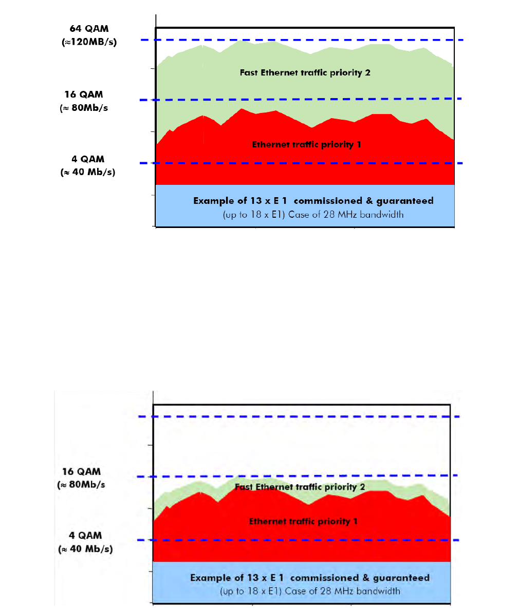
PRELIMINARY
3EM23952AL
Issue 0.1, November 2012
9500 MPR-A general system description
2-78
6.35 The 13xE1’s are saved even in the case of a degradation of the
modulation down to 4QAM. Remaining available capacity is used to transmit
other types of traffic.
6.36 When the modulation is degraded from 64QAM to 16QAM
(Figure 6-2), the E1 flows are maintained while the Ethernet traffic with
lowest priority (Fast Ethernet traffic #2) is reduced.
Figure 6-1. Example of traffic 28MHz bandwidth and admission control
Figure 6-2. Example of traffic 28MHz bandwidth and modulation downgraded to 16QAM
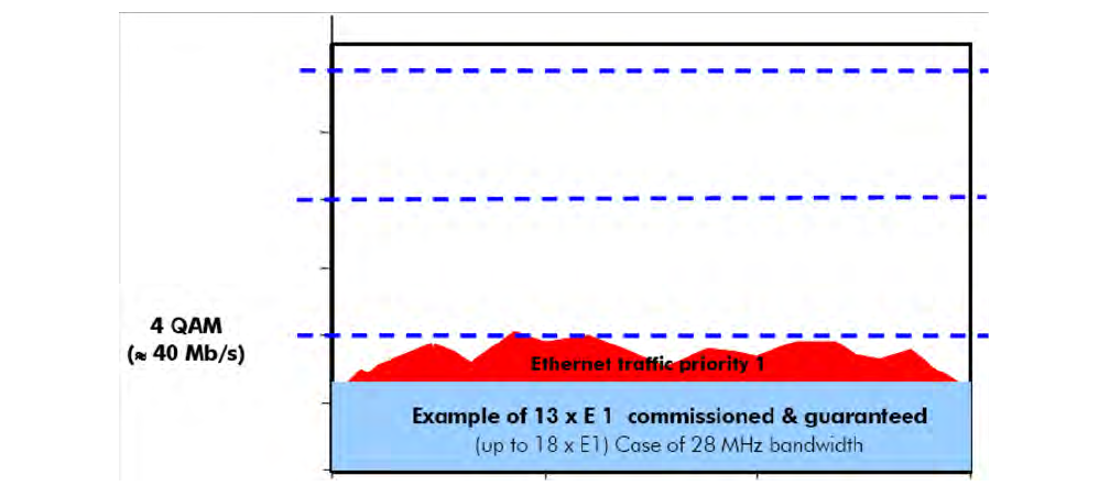
3EM23952AL
Issue 0.1, November 2012
PRELIMINARY
9500 MPR-A general system description 2-79
6.37 When the modulation is further degraded to 4QAM (Figure 6-3), the
E1 flows are still maintained while the Ethernet traffic with the lowest priority
is dropped (Fast Ethernet traffic #2) and the Ethernet traffic with the highest
priority is reduced (Ethernet traffic #1) to fit the remaining available
bandwidth.
Adaptive equalization
6.38 Adaptive equalization (AE) is employed to improve reliability of
operation under dispersive fade conditions, typically encountered over long and
difficult paths.
6.39 This is achieved through a multi-tap equalizer consisting of two
registers, one with feed-forward taps, the other with feed-back taps. Each of
these registers multiply successive delayed samples of the received signal by
weighting-coefficients to remove propagation induced inter-symbol
interference.
Fiber-microwave protection
6.40 The Fiber-Microwave Protection feature allows to protect an Optical
Fiber link with a Microwave link.
6.41 The Main protection resource is the Optical Fiber, while the Spare
protection resource is the Microwave link.
Figure 6-3. Example of traffic 28MHz bandwidth and modulation downgraded to 4QAM
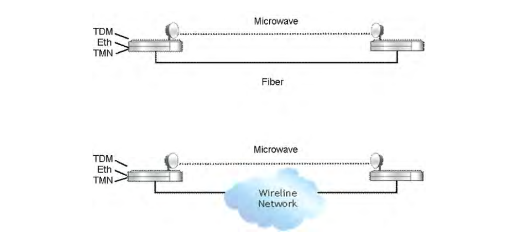
PRELIMINARY
3EM23952AL
Issue 0.1, November 2012
9500 MPR-A general system description
2-80
6.42 The Optical Fiber link can be either a physical connection between two
MPR NEs or a connection between two MPR NEs by a Wireline network, where
the access to that Wireline network by MPR NEs is made by Optical Fiber
connections. See Figure 6-4.
6.43 Normally the traffic (Ethernet and TDM) is transmitted on the Optical
Fiber link.
6.44 In case of failure of the Optical Fiber link, the traffic is rerouted
automatically to the Microwave link. When the Optical Fiber connection is
restored, the traffic is rerouted again on the Optical Fiber link following a
Revertive behavior. See Figure 6-5.
6.45 The switching criteria for the Optical fiber link are:
– Ethernet LOS (Core unit)
– SFP Card Missing
– SFP Card Fail
Figure 6-4. Fiber-microwave protection
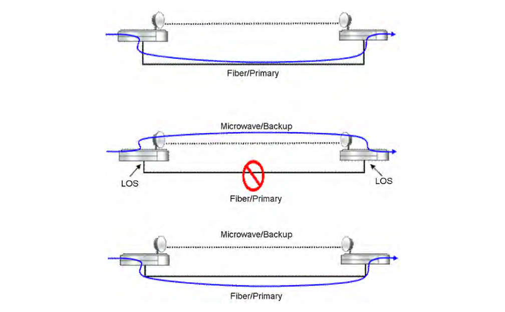
3EM23952AL
Issue 0.1, November 2012
PRELIMINARY
9500 MPR-A general system description 2-81
6.46 The Fiber-Microwave Protection feature is supported by MPR NE
using ERPS performing the following configuration:
– Create a Topology having a radio interface and an optical User
Ethernet interface as Ring Ports;
– Create a single Instance in the Topology created before. Since it is
requested to manage the overall traffic either over Fiber
connection or over radio link, the usage of two Instances to load
balance traffic in the Ring is not supported;
– Define one of the two NEs as RPL Owner and configure the radio
interface as RPL. In no-fault condition, this will set the Ring Port
related to the radio interface in blocking, allowing the traffic to be
forwarded over Ethernet optical connection.
6.47 In case of Core protection the following configuration has to performed
by the operator in order to guarantee a consistent behavior of the Fiber-
Microwave Protection:
– Usage of optical splitter;
Figure 6-5. Fiber-microwave protection - operation
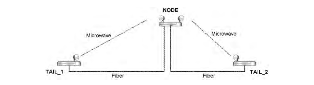
PRELIMINARY
3EM23952AL
Issue 0.1, November 2012
9500 MPR-A general system description
2-82
– Disable auto-negotiation on optical User Ethernet interface;
– Disable Ethernet LOS as switching criteria for Core protection;
– Disable Static-LAG.
6.48 The Fiber-Microwave Protection feature is applicable to Tail links at
the leaf of the backhauling tree.
6.49 The Fiber-Microwave Protection can be implemented also on Tail links
having one MPR NE working as Node, according to the following scenario. See
Figure 6-6.
6.50 The scenario is supported by the MPR NE using ERPS performing the
following configuration:
– Create two Topologies in the NE acting as Node, each Topology
having a radio interface and an optical User Ethernet interface as
Ring Ports;
– Create a single Instance in both the Topologies created before;
– For each Instance, define the NE acting as Node or the other NE
at Tail end as RPL Owner and configure the radio interface as
RPL. In no-fault condition, this will left Ring Port related to radio
interface in blocking, allowing the traffic to be forwarded over
Ethernet optical connection.
Note: The TDM traffic in the Node cannot transit between the two Topologies.
The tagged Ethernet traffic with same VLANs can transit between the two
Topologies. This means that the same VLAN ID can be associated to both the
Instances belonging to the two Topologies in the NE acting as Node.
Figure 6-6. Fiber-microwave protection on tail links
3EM23952AL
Issue 0.1, November 2012
PRELIMINARY
9500 MPR-A general system description 2-83
Frequency agility
6.51 Frequency Agility provides the ability to provision the working RF
frequency within the supported sub-band of the transceiver. This provides
benefits for spare parts, order processing, and frequency coordination.
Link identifier
6.52 Link Identifier coding blocks unwanted received signals from being
propagated further downstream. The number of microwave links, especially in
urban areas, creates a problem of possible interferences during installation and
turn-on phase.
6.53 The digital frame incorporates link identity coding capabilities to
prevent the capture of an unwanted signal. In case of “Link Identifier
Mismatch” all the traffic is dropped.
Loopback
6.54 To facilitate installation, commissioning, remote maintenance, and
troubleshooting various radio loopbacks are supported by the system.
6.55 The system supports the following radio loopback types:
•Core facing radio digital loopback
•Radio facing circuit loopback
•Core facing IF cable loopback
•Core facing RF loopback
6.56 For a detailed description of radio loopbacks, refer to Loopback in this
manual.
Performance monitoring
6.57 To facilitate commissioning, remote maintenance, and
troubleshooting various radio PM counters are supported by the system.
6.58 The system supports the following radio PM counters:
•Adaptive modulation PM
PRELIMINARY
3EM23952AL
Issue 0.1, November 2012
9500 MPR-A general system description
2-84
•Radio analog PM
•Radio ethernet PM
•Radio hop PM
•Radio link PM
•Radio QoS PM
•Radio RSL PM
6.59 For a detailed description of radio PM, refer to Performance
monitoring in this manual.
Power monitoring
6.60 The radio transceivers incorporate a detector for Tx power
measurement. It is used to provide measurement of forward power as a
performance parameter, and to provide a calibration input for transmitter
operation over temperature and output range.
6.61 Viewed Tx power ranges always match the capabilities of the radio
transceivers for a given modulation. When modulation is changed, the CT
automatically adjusts/restricts Tx Power to be within valid range.
Radio direction label
6.62 Radio Direction Label provides an aid to users in the identification of
radio directions. Radio direction labels may be up to fifteen characters in
length. Labels are supported on Radio LAG. The radio direction label is
displayed on applicable Craft Terminal screens (Cross-Connection, Port
Segregation, Equipment Tree, etc.)
Radio L1 LAG
6.63 Layer1 Link Aggregation allows the aggregation of multiple links in
order to obtain a unique logical connection with increased traffic capacity.
6.64 A Layer1 Link Aggregation Group (L1 LAG) represents the group of
links bundled together between two Aggregation Systems (NEs connected
through the L1 LAG).
6.65 Each Aggregation System comprises the following entities:
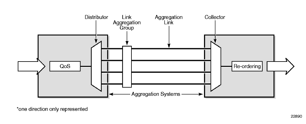
3EM23952AL
Issue 0.1, November 2012
PRELIMINARY
9500 MPR-A general system description 2-85
•QoS: performs buffering and scheduling functions based on the L1
LAG aggregated bandwidth
•Distributor: spreads the traffic over aggregation links belonging to L1
LAG according to a distribution algorithm
•Collector: receives traffic from aggregation links belonging to L1 LAG
and combines them together to create a single traffic flow
•Re-ordering: based on Sequence Number fields inserted at the
transmitter side, restores the original traffic ordering
A block diagram of L1 Link Aggregation system is shown in Figure 6-7.
6.66 In Layer1 Link Aggregation, the Distributor performs a packet-based
traffic distribution over multiple links regardless of the content of the packets.
Distributor takes into account the number of bytes sent over a specific link and
loads links according to the available bandwidth. As a consequence, Layer1
Link Aggregation allows a traffic load balancing independently of traffic
content. Since the distribution does not depend on Layer2 or Layer3 header
content, this kind of Link Aggregation is called Layer1 (i.e., associated to the
physical layer).
6.67 L1 LAG ports are supported on MPT-HC, MPT-HL, and MPT-XP radio
interfaces configured with P8ETH SFP ports.
6.68 Supported L1 LAG port configurations:
•up to eight L1 LAG ports per NE
Figure 6-7. L1 LAG block diagram Update
PRELIMINARY
3EM23952AL
Issue 0.1, November 2012
9500 MPR-A general system description
2-86
•up to four MPT-HC/XP ports per L1 LAG port
•up to four MPT-HL ports per L1 LAG port
•static and adaptive modulation
6.69 Members of a L1 LAG port must be configured:
•All the same radio interface type (MPT-HC/XP or MPT-HL)
•All radio interfaces configured with the same modem profile
– modulation type (mode)
– channel spacing (Reference Channel Spacing)
– modulation
–option
•MPT-HC/MPT-HL/MPT-XP radio interface must be configured with
P8ETH card. The following radio configurations are supported:
– 1+0 MPT-HC/XP connected to P8ETH SFP port
– 1+0 MPT-HL connected to P8ETH SFP port
– 1+1 MPT-HL connected to P8ETH SFP port
•radio interfaces must reside on the same horizontal shelf row (i.e.,
MSS-8 shelf, slots 3 and/or 4)
6.70 Radio interfaces configured for adaptive modulation must be
configured with Modulation and Supported Modulation parameters set to the
same value (i.e., if Modulation is 64 QAM, Supported Modulation must also be
set to 64 QAM).
Types of L1 link aggregation
6.71 L1 Link Aggregation is implemented inside the P8ETH card.
6.72 Two configuration are supported to create L1 LAG:
•Intra plug-in LAG
•Cross Plug-in LAG
A block diagram of L1 Link Aggregation configurations is shown in Figure 6-8.
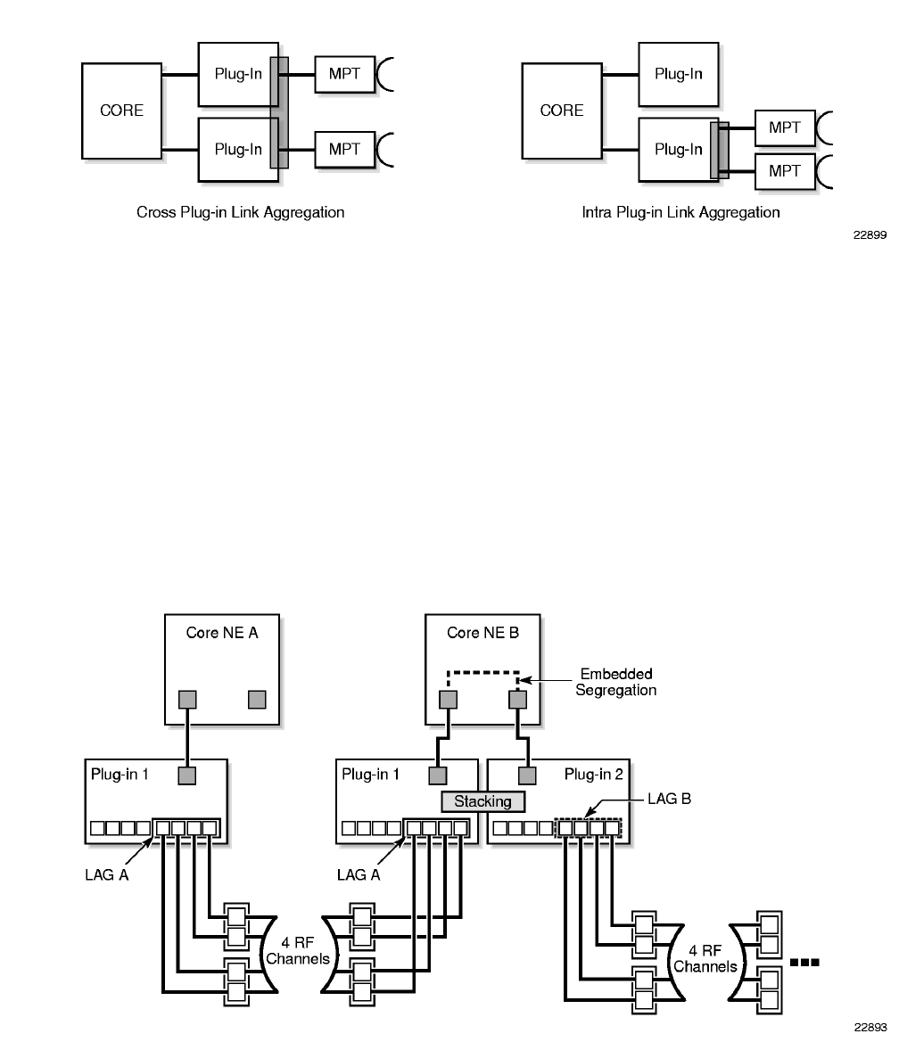
3EM23952AL
Issue 0.1, November 2012
PRELIMINARY
9500 MPR-A general system description 2-87
Intra Plug-in L1 link aggregation scenario
6.73 Intra plug-in LAG is a LAG with MPT-HCs/HLs/XPs connected to the
same P8ETH card.
6.74 An example of Intra Plug-in LAG implementation is shown in
Figure 6-9. Site A is configured with four radio links in an Intra Plug-in LAG
configuration. Site B is configured with two intra Plug-in LAGs to implement
a radio repeater configuration.
Figure 6-8. Types of L1 LAG Update
Figure 6-9. Intra plug-in L1 link aggregation scenario—Update
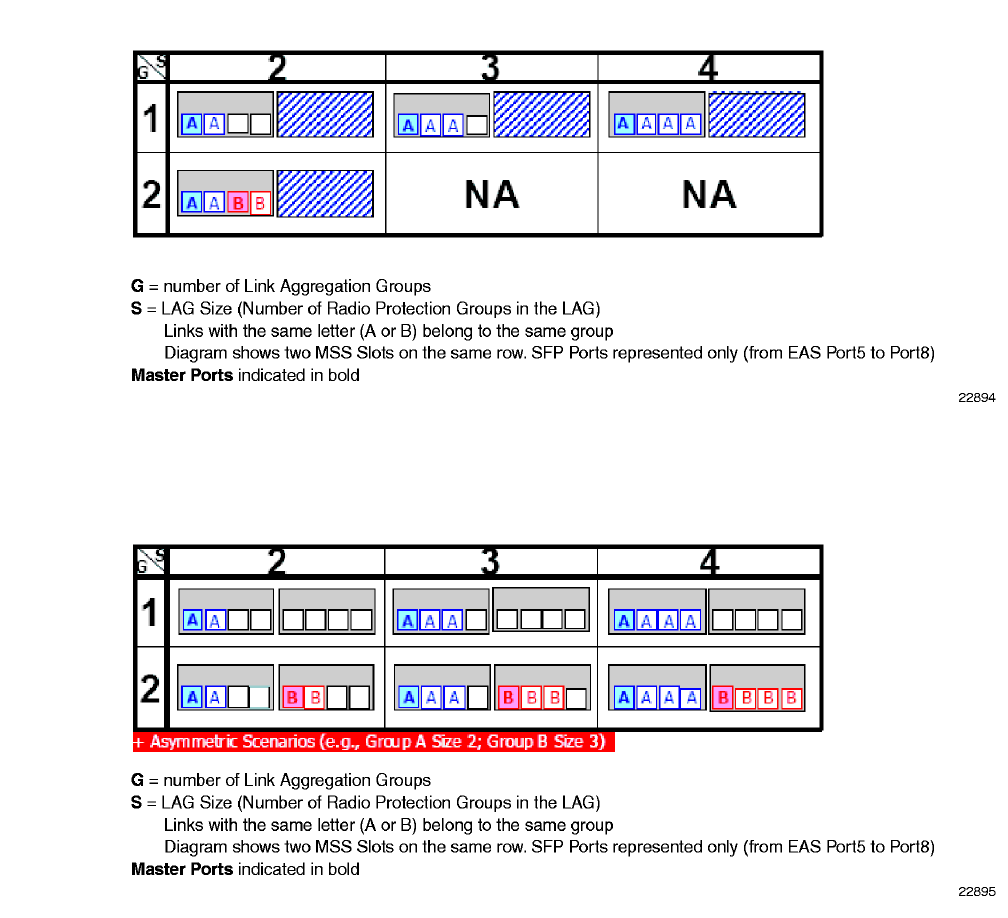
PRELIMINARY
3EM23952AL
Issue 0.1, November 2012
9500 MPR-A general system description
2-88
6.75 In the event of a radio link failure, the capacity of the LAG is reduced
by the capacity of the radio link.
6.76 In the event of a Plug-in (P8ETH) failure, the associated LAG direction
is lost.
6.77 Single P8ETH card, Intra Plug-in supported L1 LAG configurations
are shown in Figure 6-10. Dual P8ETH cards, Intra Plug-in supported L1 LAG
configurations are shown in Figure 6-11.
Figure 6-10. Single P8ETH 1+0 intra plug-in L1 LAG configurations Update
Figure 6-11. Dual P8ETH 1+0 intra plug-in L1 LAG configurations Update
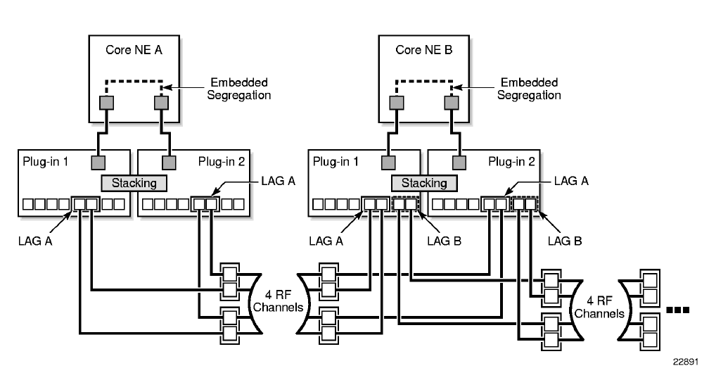
3EM23952AL
Issue 0.1, November 2012
PRELIMINARY
9500 MPR-A general system description 2-89
Cross plug-in L1 LAG sceneries
6.78 Cross Plug-in LAG is a LAG with MPT-HCs/HLs/XPs connected to two
P8ETH cards on the same MSS row.
6.79 An example of Cross Plug-in LAG implementation is shown in
Figure 6-12. Site A is configured with four radio links in a Cross Plug-in LAG
configuration. Site B is configured with two Cross Plug-in LAGs to implement
a radio repeater configuration.
6.80 In the event of a radio link failure, the capacity of the LAG is reduced
by the capacity of the radio link.
6.81 In the event of a Plug-in (P8ETH) failure, the LAG capacity is reduced,
but the LAG direction is maintained utilizing the remaining radio interfaces
supported by the other Plug-in.
6.82 Supported Cross Plug-in L1 LAG configurations are shown in
Figure 6-13.
Figure 6-12. Cross plug-in L1 link aggregation scenario Update