Alcatel USA 9558L-D 5 GHz rack-mounted point to point transceiver User Manual INTRO01 FCC
Alcatel USA Marketing, Inc. 5 GHz rack-mounted point to point transceiver INTRO01 FCC
Users Manual

9500 MPR Product Information 57
1 — FCC part 15 subpart B
1.1 — 9500 MPR-A unlicensed radio
The JF6-9558H/6933B-9500MPT (MPT-HL) unlicensed radio provides fast deployment
of service with microwave radio. No license and small antennas (no FCC and Industry
Canada requirements) allow immediate turn-up. After the license is received, the
unlicensed MPT-HL radio can be easily converted to the lower 6 GHz licensed band.
The JF6-9558L/6933B-9558L and JF6-9558L-D/6933B-9558L-D (MPT-HLC) unlicensed
radio provides fast deployment of service with microwave radio. No license and small
antennas (no FCC and Industry Canada requirements) allow immediate turn-up. After the
license is received, the unlicensed MPT-HLC radio can be easily converted to the lower 6
GHz licensed band.
The JF6-9558HC/6933B-9558HC (9558HC) unlicensed radio provides fast deployment of
service with microwave radio. No license and small antennas (no FCC and Industry Canada
requirements) allow immediate turn-up. The 9558HC unlicensed radio can not be upgraded
to licensed operation.
The JF6-9558H/6933B-9500MPT, JF6-9558HC/6933B-9558HC, JF6-9558L/6933B-
9558L and JF6-9558L-D/6933B-9558L-D unlicensed radio operates in the 5725-5850
Information, Scientific, and Medical (ISM) band in accordance with FCC Part 15.247 and
IC RSS-210. This unlicensed radio, although operating in the same band as a spread
spectrum radio, operates using narrower bandwidths than spread spectrum.
The 9558HC 5.8 Unlicensed band (JF6-9558HC/6933B-9558HC) has been certified by the
FCC and Industry Canada as of August 7, 2012.
1.2 — FCC Class B compliance statement
The JF6-9558H/6933B-9500MPT, JF6-9558HC/6933B-9558HC, JF6-9558L/6933B-
9558L, and JF6-9558L-D/6933B-9558L-D unlicensed radio have been tested and found to
comply with the limits for a Class B digital device, pursuant to Part 15 of the FCC Rules
and IC RSS-210. These limits are designed to provide reasonable protection against
harmful interference when the equipment is operated in a commercial environment. This
DRAFT
FCC Class B requirements
58 9500 MPR Product Information
equipment generates, uses, and can radiate radio frequency energy and, if not installed and
used in accordance with the instruction manual, may cause harmful interference to radio
communications. Operation of this equipment in a residential area is likely to cause harmful
interference in which case the user will be required to correct the interference at his own
expense.
1.3 — FCC Class B requirements
This device complies with part 15 of the FCC Rules and IC RSS-210. Operation is subject
to the following three conditions: (1) this device may not cause harmful interference. (2)
This device must accept any interference received, including interference that may cause
undesired operation. (3) This device must be professionally installed.
Cet appareil radio est conforme à IC RSS-210. Son fonctionnement respecte les trois
conditions suivantes: 1) cette radio ne cause pas d’interférences néfastes, 2) cette radio peut
recevoir des interférences, ainsi que des interférences qui peuvent causer des opérations
non désirées, et 3) cette radio doit être installée par des Professionnels.
The MPT-HLC 5.8 Unlicensed band JF6-9558L/6933B-9558L and JF6-9558L-D/6933B-
9558L-D is not available for quote, sale, or deployment until certification is received.
Caution: Changes or modifications not expressly approved by Alcatel-Lucent could void
the authority to operate the JF6-9558H/6933B-9500MPT, JF6-9558HC/6933B-9558HC,
JF6-9558L/6933B-9558L, and JF6-9558L-D/6933B-9558L-D (unlicensed) radio.
Caution: Installation, Turn-Up, Maintenance, and Operation Instruction supplied with the
JF6-9558H/6933B-9500MPT, JF6-9558HC/6933B-9558HC, JF6-9558L/6933B-9558L, and
JF6-9558L-D/6933B-9558L-D (unlicensed) radio require strict adherence for continued
part 15 of the FCC Rules and IC RSS-210 compliance.
Warning: Regulatory compliance warning: Physical changes or modifications to the
JF6-9558H/6933B-9500MPT, JF6-9558HC/6933B-9558HC, JF6-9558L/6933B-9558L, and
JF6-9558L-D/6933B-9558L-D (unlicensed) radio are strictly prohibited.
Avertissement pour conformité réglementaire: changements physiques ou modifications
sur les radios JF6-9558H/6933B-9500MPT, JF6-9558HC/6933B-9558HC, JF6-9558L/6933B-
9558L, and JF6-9558L-D/6933B-9558L-D (sans licence) sont strictement interdit.
DRAFT

JF6-9558H and JF6-9558HC (unlicensed) radio
9500 MPR Product Information 89
•IETF RFC 2474
•IETF RFC 2475
•IETF RFC 3550
•IETF RFC 0793
•IETF RFC 0791
•IETF RFC 1157
•IETF RFC 768
•IETF RFC 2616
•ITU-T G.664
•ITU-T G.703
•ITU-T G.704
•ITU-T G.706
•ITU-T G.775
•ITU-T G.823
•ITU-T G.8261
•ITU-T G.826
•ITU-T G.921
•ITU-T Recommendation K20
•ITU-T Recommendation K21
•ITU-T Recommendation K45
•ITU-T Recommendation K44
•MEF 8
•NAR EIA-310
•Safety (Canada)
•SR-332
•TR NWT 000499
•TR TSY 000191
3.7 — JF6-9558H and JF6-9558HC (unlicensed) radio
The JF6-9558H/6933B-9500MPT (MPT-HL) and JF6-9558HC/6933B-9558HC (MPT-
HC) unlicensed radio provides fast deployment of service with microwave radio. No
license and small antennas (no FCC and Industry Canada requirements) allow immediate
turn-up. After the license is received, the unlicensed radio can be easily converted to the
lower 6 GHz licensed band.
DRAFT

JF6-9558H and JF6-9558HC (unlicensed) radio
90 9500 MPR Product Information
The JF6-9558H/6933B-9500MPT and JF6-9558HC/6933B-9558HC unlicensed radio
operates in the 5725-5850 Information, Scientific, and Medical (ISM) band in accordance
with FCC Part 15.247 and IC RSS-210. This unlicensed radio, although operating in the
same band as a spread spectrum radio, operates using narrower bandwidths than spread
spectrum.
The MPT-HC 5.8 Unlicensed band (JF6-9558HC/6933B-9558HC) is currently being
certified and is not available for quote, sale, or deployment.
3.7.1 — FCC class B compliance statement
The JF6-9558H/6933B-9500MPT and JF6-9558HC/6933B-9558HC unlicensed radio have
been tested and found to comply with the limits for a Class B digital device, pursuant to
Part 15 of the FCC Rules and IC RSS-210. These limits are designed to provide reasonable
protection against harmful interference when the equipment is operated in a commercial
environment. This equipment generates, uses, and can radiate radio frequency energy and,
if not installed and used in accordance with the instruction manual, may cause harmful
interference to radio communications. Operation of this equipment in a residential area is
likely to cause harmful interference in which case the user will be required to correct the
interference at his own expense.
3.7.2 — FCC class B requirements
This device complies with part 15 of the FCC Rules and IC RSS-210. Operation is subject
to the following three conditions: (1) this device may not cause harmful interference. (2)
This device must accept any interference received, including interference that may cause
undesired operation. (3) This device must be professionally installed.
Caution: Changes or modifications not expressly approved by Alcatel-Lucent could void
the authority to operate the JJF6-9558H/6933B-9500MPT and JF6-9558HC/6933B-9558HC
unlicensed radio.
Caution: Installation, Turn-Up, Maintenance, and Operation Instruction supplied with the
JF6-9558H/6933B-9500MPT and JF6-9558HC/6933B-9558HC unlicensed radio require
strict adherence for continued part 15 of the FCC Rules and IC RSS-210 compliance.
DRAFT

Radio
9500 MPR Product Information 347
For the management of mono-directional radio links, different configurations are needed
on each side of the link.
On the node where the link works in Tx only:
•ATPC, ACM should not be enabled: they cannot work
•LAG L1, Ring should not be created: they cannot work
•Radio PM should not be enabled: they work Rx side
•Link Identifier should not be enabled: it works Rx side
•PPP must be disabled (otherwise a PPP Failure alarm will be raised)
•For monodirectional links with the MPT-HLS, the space diversity combiner should
not be equipped on the transmitter side.
•For monodirectional links with the MPT-HLS, the RF switch should be mounted and
connected.
•“No Rx Radio Alarms” alarm profile must be configured in the radio panel (otherwise
all the Rx Radio alarms will be raised)
On the node where the link works in Rx only:
•Transmitter must be muted with a TX Mute command
•ATPC, ACM should not be enabled: they cannot work
•LAG L1, Ring should not be created: they cannot work
•PPP must be disabled (otherwise a PPP Failure alarm will be raised)
•For monodirectional links with the MPT-HLS, the space diversity combiner should
be equipped only on the receiver side.
•For monodirectional links with the MPT-HLS, the RF switch should be mounted and
connected.
•“No Tx Radio Alarms” alarm profile must be configured in the radio panel (otherwise
all the Tx Radio alarms will be raised)
8.2.28 — Unlicensed radio for MPT-HL, MPT-HLC and 9558HC in
the ANSI market
The JF6-9558H/6933B-9500MPT (MPT-HL) unlicensed radio provide fast deployment of
service with microwave radio. No license and small antennas (no FCC and Industry Canada
(IC) requirements) allow immediate Turn-Up. After the license is received, the unlicensed
MPT-HL radio can be easily converted to the lower 6 GHz licensed band.
DRAFT
Radio
348 9500 MPR Product Information
The JF6-9558L/6933B-9558L and JF6-9558L-D/6933B-9558L-D (MPT-HLC) unlicensed
radio provides fast deployment of service with microwave radio. No license and small
antennas (no FCC and Industry Canada requirements) allow immediate turn-up. After the
license is received, the unlicensed MPT-HLC radio can be easily converted to the lower 6
GHz licensed band.
The JF6-9558HC/6933B-9558HC (9558HC) unlicensed radio provide fast deployment of
service with microwave radio. No license and small antennas (no FCC and Industry Canada
(IC) requirements) allow immediate Turn-Up. The 9558HC unlicensed radio can not be
upgraded to licensed operation.
Refer to 9500 MPR-A Equipping Options drawing, found in Alcatel-Lucent 9500 MPR-A
Engineering Support Documentation for unlicensed radio configurations and equipping
options.
The MPT-HL/HLC and 9558HC unlicensed radio operate in the 5725-5850 Information,
Scientific, and Medical (ISM) band in accordance with FCC Part 15.247 and IC RSS-210.
This unlicensed radio, although operating in the same band as a spread spectrum radio,
operates using narrower bandwidths than spread spectrum. Advantages, disadvantages, and
antenna recommendations for the unlicensed radio follow:
Advantages:
•Fast installation and Turn-Up
•Between 6.6 — 185 Mb/s user configurable data payload capacity consisting of a
combination of E1/DS1, DS3, STM-1/OC-3, and/or Ethernet traffic
•Field convertible to lower 6 GHz licensed band (MPT-HL/HLC)
Caution: Changes or modifications not expressly approved by Alcatel-Lucent could void
the authority to operate the JF6-9558H/6933B-9500MPT, JF6-9558HC/6933B-9558HC,
JF6-9558L/6933B-9558L, and JF6-9558L-D/6933B-9558L-D (unlicensed) radio.
Caution: Installation, Turn-Up, Maintenance, and Operation Instruction supplied with the
JF6-9558H/6933B-9500MPT, JF6-9558HC/6933B-9558HC, JF6-9558L/6933B-9558L, and
JF6-9558L-D/6933B-9558L-D (unlicensed) radio require strict adherence for continued
part 15 of the FCC Rules and IC RSS-210 compliance.
Table 8.25 — Unlicensed radio
Transceiver FCC ID Industry Canada ID
9558HC JF6-9558HC 6933B-9558HC
MPT-HL JF6-9558H 6933B-9500MPT
MPT-HLC JF6-9558L 6933B-9558L
MPT-HLC JF6-9558L-D 6993-9558L-D
DRAFT

Radio
9500 MPR Product Information 349
•Field expandable to higher capacities.
•Common network management with licensed radios.
•Common spares and training with licensed radios
•Adaptive Modulation - automatic interference countermeasures
Disadvantages:
•Interference from other 5725-5850 ISM band transmissions are possible
•Operating restrictions
•5.725 to 5.850 GHz band
•Performance could deteriorate due to interference as the frequency band becomes
congested.
Antenna Recommendations:
•Frequency – 5.8 GHz
•Size and Type – 2, 4, 6, 8, or 10 foot parabolic; 1 or 2 foot flat panel.
•Parabolic antennas, See Table 8.26.
•Flat antennas, See Table 8.26.
•Gain and 3 dB Beamwidth
This device has been designed to operate with the antennas listed below, and having a
maximum gain of 42.5 dB. Antennas not included in this list or having a gain greater than
42.5 dB are strictly prohibited for use with this device. The required antenna impedance is
50 ohms.
These antennas can only be used in a fixed point-to-point configuration.
To reduce potential radio interference to other users, the antenna type and its gain should
be so chosen that the equivalent isotropically radiated power (e.i.r.p.) is not more than that
permitted for successful communication.
Table 8.26 — 5.8 GHz unlicensed antenna options
PARABOLIC FLAT
MPT-HL/HLC/9558HC MPT-HL/HLC/9558HC
2 ft parabolic – 29 dB/6° 1 ft flat panel – 23 dB/9°
4 ft parabolic – 35 dB/3°2 ft flat panel – 28 dB/3.5°
6 ft parabolic – 38 dB/2°—
8 ft parabolic – 41 dB/1.5°—
10 ft parabolic – 42.5 dB/1.2°—
DRAFT
Radio
350 9500 MPR Product Information
The antenna(s) used for this transmitter must be installed to provide a separation distance
of at least 12 meters from all persons and must not be co-located or operating in conjunction
with any other antenna or transmitter.
Frequency Plan:
•For MPT-HL frequency plan for the 5.725 and 5.850 GHz unlicensed band, refer to
Figure 8.77.
•For MPT-HLC frequency plan for the 5.725 and 5.850 GHz unlicensed band, refer to
Figure 8.78.
•For 9558HC frequency plan for the 5.725 and 5.850 GHz unlicensed band, refer to
Figure 8.79.
Output Power: A requirement of operating in the unlicensed band is to limit transmit output
power to not more than +30.0 dBm at the antenna port. It is the responsibility of the user to
transmit not more than +30.0 dBm.
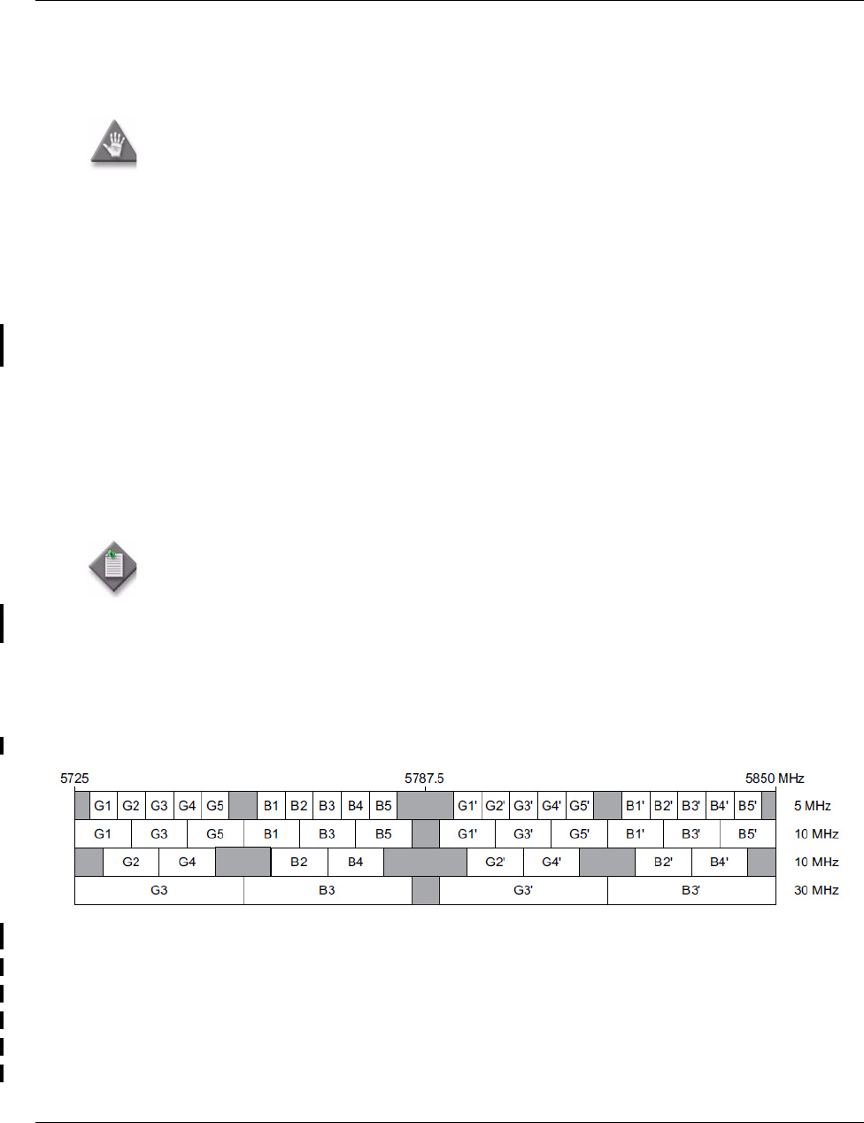
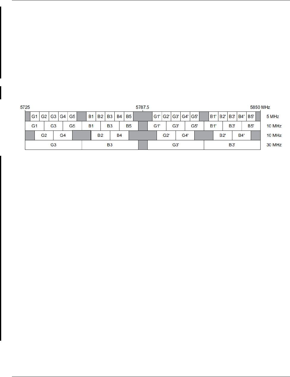
Figure 8.77 — Frequency plan MPT-HL: 5.725 to 5.850 GHz unlicensed band (FCC Part 15 and IC RSS-
210)
Caution: Danger of public exposure to long term RF radiated energy. When using a 1 ft
flat panel antenna with a 1 watt (+30 dBm) output power, the antenna must be located
in an area that does not allow the general population access to within 12 meters (5.8 Ghz)
of the antenna.
Note: To meet FCC part 15 requirements, output power for 9558HC 30 MHz 4QAM and
8QAM channels must not be provisioned greater than 24 dBm. This is not enforced by the
user interface and is the responsibility of the operator to guarantee provisioning of the
radio transmit power. For transmit power specification, refer to the 9500 MPR-A MPT-HL/
HLC Engineering Specifications.
Transmit Channel Frequency (MHz) Receive Channel Frequency (MHz)
G1 5730 G1’ 5795
G2 5735 G2’ 5800
G3 5740 G3’ 5805
G4 5745 G4’ 5810
G5 5750 G5’ 5815
DRAFT
Radio
9500 MPR Product Information 351
Notes:
1. The drawing above shows the 5 MHz channels used by the JF6-9558H/5933B-
9558MPT radio. Gray channels are designated “G”. Blue channels are designated
“B”. Transmit and receive channels have a 65 MHz separation.
2. RF filters are centered on channels G3, B3, G3’, and B3’.
3. The flexibility of the JF6-9558H/6933B-9500MPT allows any radio to grow to
183 Mb/s without a hardware upgrade.
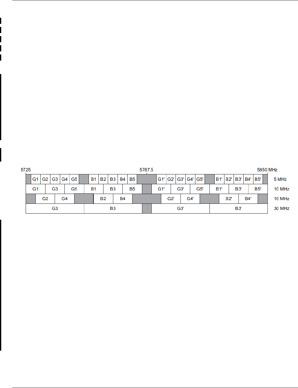
Figure 8.78 — Frequency plan 9558HLC: 5.725 to 5.850 GHz unlicensed band (FCC Part 15 and IC
RSS-210)
Notes:
B1 5760 B1’ 5825
B2 5765 B2’ 5830
B3 5770 B3’ 5835
B4 5775 B4’ 5840
B5 5780 B5’ 5845
Transmit Channel Frequency (MHz) Receive Channel Frequency (MHz)
G1 5731 G1’ 5794
G2 5736 G2’ 5799
G3 5741 G3’ 5804
G4 5746 G4’ 5809
G5 5751 G5’ 55814
B1 5761 B1’ 5824
B2 5766 B2’ 5829
B3 5771 B3’ 5834
B4 5776 B4’ 5839
B5 5781 B5’ 5844
DRAFT
Radio
352 9500 MPR Product Information
1. The drawing above shows the 5 MHz channels used by the F6-9558L-D/6933B-
9558L-D radio. Gray channels are designated “G”. Blue channels are designated “B”.
Transmit and receive channels have a 63 MHz separation.
2. RF filters are centered on channels G3, B3, G3’, and B3’.
3. The flexibility of the F6-9558L-D/6933B-9558L-D allows any radio to grow to
183 Mb/s without a hardware upgrade.
The MPT-HLC 5.8 Unlicensed band JF6-9558L/6933B-9558L and JF6-9558L-D/6933B-
9558L-D is not available for quote, sale, or deployment until certification is received.
Figure 8.79 — Frequency plan 9558HC: 5.725 to 5.850 GHz unlicensed band (FCC Part 15 and IC RSS-
210)
Notes:
1. The drawing above shows the 5 MHz channels used by the JF6-9558HC/6933B-
9558HC radio. Gray channels are designated “G”. Blue channels are designated “B”.
Transmit and receive channels have a 64 MHz separation.
2. RF filters are centered on channels G3, B3, G3’, and B3’.
3. The flexibility of the JF6-9558HC/6933B-9558HC allows any radio to grow to
185 Mb/s without a hardware upgrade.
Transmit Channel Frequency (MHz) Receive Channel Frequency (MHz)
G1 5730.5 G1’ 5794.5
G2 5735.5 G2’ 5799.5
G3 5740.5 G3’ 5804.5
G4 5745.5 G4’ 5809.5
G5 5750.5 G5’ 5814.5
B1 5760.5 B1’ 5824.5
B2 5765.5 B2’ 5829.5
B3 5770.5 B3’ 5834.5
B4 5775.5 B4’ 5839.5
B5 5780.5 B5’ 5844.5
DRAFT

9500 MPR Product Information 1089
46 — UDS-129 MPT-HLC transceiver
Table 46.1 — MPT-HLC transceiver
PART NUMBER/
MNEMONIC NAME CLEI ECI/ BAR CODE CPR STATUS
3DB76123AA MPT-HLC Transceiver U4,
HP, WO/Diversity 4400 -
5000 MHz
N/A N/A N/A Active
3DB76123BA MPT-HLC Transceiver U4,
HP, W/Diversity 4400 - 5000
MHz
N/A N/A N/A Active
3DB19060AA MPT-HLC Transceiver L6,
WO/Diversity 5725-6425 MHz N/A N/A N/A Active
3DB19060BA MPT-HLC Transceiver L6, W/
Diversity 5725-6425 MHz N/A N/A N/A Active
3DB19060CA MPT-HLC Transceiver L6, HP,
WO/Diversity 5725-6425 MHz N/A N/A N/A Active
3DB19060DA MPT-HLC Transceiver L6, HP,
W/Diversity 5725-6425 MHz N/A N/A N/A Active
3DB76047AA MPT-HLC Transceiver U6,
WO/Diversity 6425-7125 MHz N/A N/A N/A Active
3DB76047BA MPT-HLC Transceiver U6, W/
Diversity 6425-7125 MHz N/A N/A N/A Active
3DB76047CA MPT-HLC Transceiver U6,
HP, WO/Diversity 6425-7125
MHz
N/A N/A N/A Active
3DB76047DA MPT-HLC Transceiver U6,
HP, W/Diversity 6425-7125
MHz
N/A N/A N/A Active
3DB76048AA MPT-HLC Transceiver 7, WO/
Diversity 7125-7775 MHz N/A N/A N/A Active
3DB76048BA MPT-HLC Transceiver 7, W/
Diversity 7125-7775 MHz N/A N/A N/A Active
DRAFT

Features and application notes
1090 9500 MPR Product Information
46.1 — Features and application notes
3DB76048CA MPT-HLC Transceiver 7, HP,
WO/Diversity 7125-7775 MHz N/A N/A N/A Active
3DB76048DA MPT-HLC Transceiver 7, HP,
W/Diversity 7125-7775 MHz N/A N/A N/A Active
3DB76049AA MPT-HLC Transceiver 8, WO/
Diversity 7725-8500 MHz N/A N/A N/A Active
3DB76049BA MPT-HLC Transceiver 8, W/
Diversity 7725-8500 MHz N/A N/A N/A Active
3DB76049CA MPT-HLC Transceiver 8, HP,
WO/Diversity 7725-8500 MHz N/A N/A N/A Active
3DB76049DA MPT-HLC Transceiver 8, HP,
W/Diversity 7725-8500 MHz N/A N/A N/A Active
3DB76078AA MPT-HLC Transceiver 10.5,
HP, WO/Diversity 10400-
10700 MHz
N/A N/A N/A Active
3DB76078BA MPT-HLC Transceiver 10.5,
HP, W/Diversity 10400-
10700 MHz
N/A N/A N/A Active
3DB76050AA MPT-HLC Transceiver 11,
WO/Diversity 10700-11700
MHz
N/A N/A N/A Active
3DB76050BA MPT-HLC Transceiver 11, W/
Diversity 10700-11700 MHz N/A N/A N/A Active
3DB76050CA MPT-HLC Transceiver 11, HP,
WO/Diversity 10700-11700
MHz, TX LO
N/A N/A N/A Active
3DB76050DA MPT-HLC Transceiver 11, HP,
W/Diversity 10700-11700
MHz, TX LO
N/A N/A N/A Active
3DB76050EA MPT-HLC Transceiver 11, HP,
WO/Diversity, TX HIGH N/A N/A N/A Active
3DB76050FA MPT-HLC Transceiver 11, HP,
W/Diversity, TX HIGH N/A N/A N/A Active
Table 46.1 — MPT-HLC transceiver (Continued)
PART NUMBER/
MNEMONIC NAME CLEI ECI/ BAR CODE CPR STATUS
DRAFT

Features and application notes
9500 MPR Product Information 1091
•High-capacity, long-haul RF transmission shelf
•Supported on EASv2, P8ETH, Core-E, CorEvo, and MSS-1 SFP ports in 1+0 and 1+1
configurations, L1 and L2 Radio LAG ports
•Support for the following RF configurations when connected to Core-E, CorEvo,
EASv2, P8ETH and MSS-1 SFP ports:
•Non-Standby
•Non-Standby with Space Diversity
•Hot Standby
•Hot Standby with Space Diversity
•Frequency Diversity
•2+0 LAG
•2+0 LAG with Space Diversity
•2x(1+0) single shelf repeater with and without Space Diversity
•Up to 8+0 LAG, with and without Space Diversity
•XPIC
•Support for the following channel plans:
•5.8 GHz unlicensed
•Lower 6 GHz
•Upper 6 GHz
•7 GHz
•8 Ghz
•10.5 GHz
•11 GHz
•Support for the following fixed radio profiles (fixed and adaptive modulations, Std
and XPIC):
•30 MHz 4/16/32/64/128/256/512/1024 QAM
•40 MHz 4/16/32/64/128/256/512/1024 QAM
•60 MHz 4/16/32/64/128/256/512/1024 QAM
•1+1 HSB, 1+1 SD, 1+1 FD, 2x(1+0) XPIC, 4x(1+0), XPIC, 2x(1+1) HSB XPIC radio
configuration support with XPIC license
•Automatic Transmit Power Control (ATPC) support
•Gigabit Ethernet connection to 9500 MPR MSS indoor unit using standard SFPs
•Diversity variants provide an optional second receiver (SD)
For modem profile information, see Alcatel-Lucent 9500 MPR-A MPT-HL Engineering
Specifications.
DRAFT
Description
1092 9500 MPR Product Information
46.2 — Description
The MPT-HLC Transceiver card is a microprocessor controlled RF transceiver that
interfaces the Core-E card, CorEvo card, EASv2 card, P8ETH card, or MSS-1 unit
MPT-HLC port with the antenna. The MPT-HLC Transceiver microprocessor manages
transmit and receive frequencies, transmit power, alarming, and performance monitoring.
The MPT-HLC Transceiver resides in the MPT-HL shelf.
46.3 — Indicators, connectors, and control
The MPT-HLC Transceiver card has the following indicators, connectors, and controls.
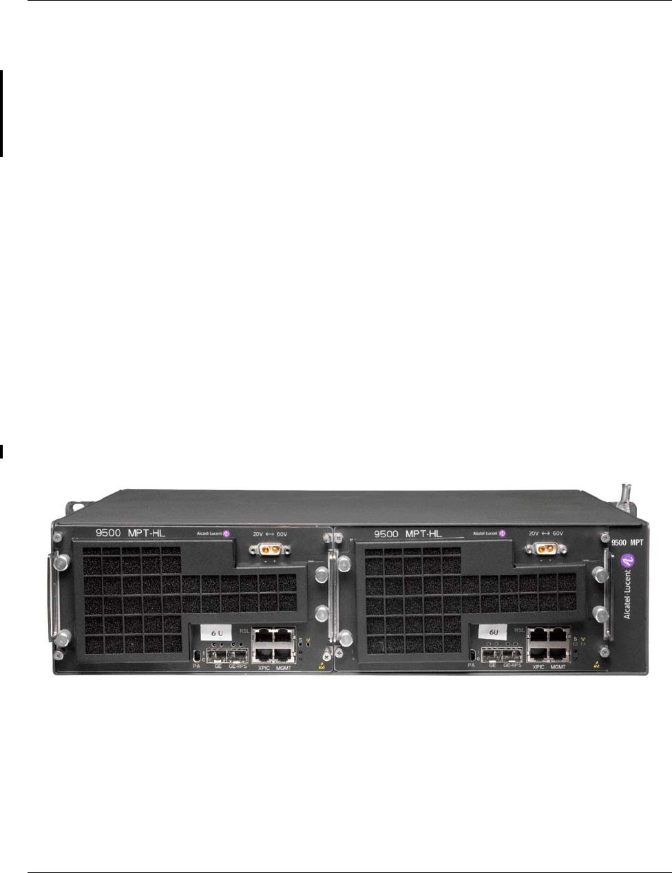
See Figure 46.1 for MPT-HLC Transceiver card front panel indicator and connector
locations.
Refer to Table 46.2 for MPT-HLC Transceiver card indicators details.
Refer to Table 46.3 for MPT-HLC Transceiver card connector details.
Refer to Table 46.4 for MPT-HLC Transceiver card control details.
Figure 46.1 — MPT-HLC transceiver
DRAFT

Indicators, connectors, and control
9500 MPR Product Information 1093
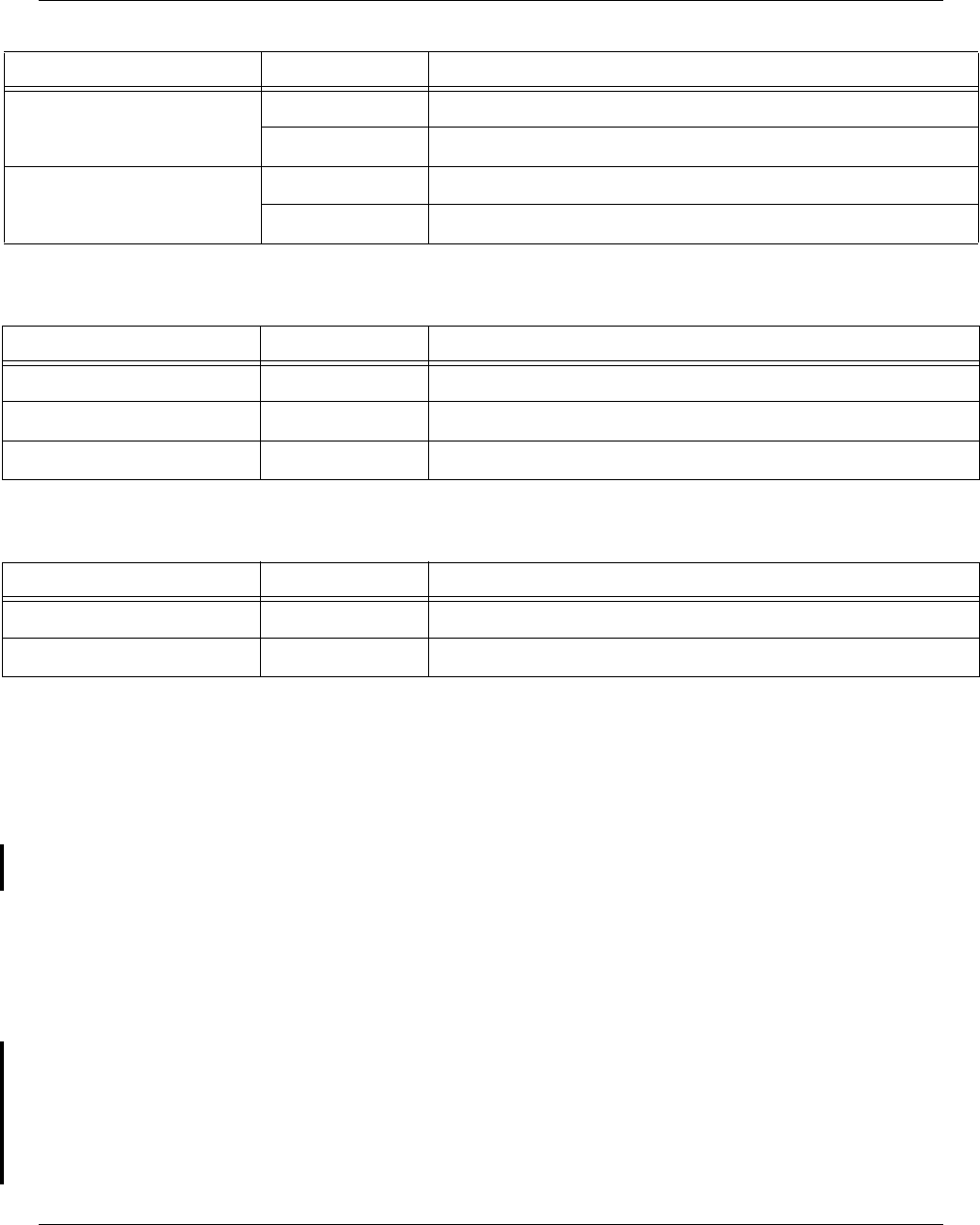
Table 46.2 — MPT-HLC transceiver front panel indicator details
INDICATOR STATUS DEFINITION
Status (S) Off Card not powered
Green Blinking FPGA Downloading, or SW Booting. (Different blink rates
identify each step of the startup process.)
Green In Service, Normal Operation, and Properly Provisioned. EPS
or RPS currently In-Service/Active.
Yellow Card Properly Equipped and Provisioned in 1+1, currently in
Standby.
Green/Red
Blinking Card Properly Equipped and Provisioned, Rx signal fault, EPS
and RPS in Standby.
Yellow/Red
Blinking Card Properly Equipped and Provisioned, RX signal Fault, EPS
and RPS currently in Standby. Traffic may be affected.
Red •HW Card Fail
•Power supply failure (Autotest failure)
•FPGA failures
•LO alarms
•Modem Tx sync alarm
•PA switch active
•Diversity board card fail (only in combiner mode)
•RF switch fail (only for the spare MPT-HLC in HSB
configuration)
In a PA critical temperature condition, the LED remains
green.
Red Blinking MAP Communication Time-out: Communication between the
MPT-HLC Transceiver and the EAS cards is lost. This occurs in
split-mount configuration only.
Power Emission Off MPT-HLC Transceiver is not emitting power, according to the
known configuration, for example, Hot Standby.
Green MPT-HLC Transceiver is emitting power as expected
according to the known configuration.
Yellow MPT-HLC Transceiver is not emitting power due to an
operator command, including manual PA PSU switch or Tx
mute.
Red MPT-HLC Transceiver is abnormally emitting power, in
contrast with the known configuration (for example, when Tx
power alarm is raised during normal operative mode)
SFP interface LEDs
DRAFT
Functional overview
1094 9500 MPR Product Information
46.4 — Functional overview
In the TX direction, the MPT-HLC Transceiver converts Ethernet packet data from the
EAS (Ethernet Access Switch - P8ETH or EASv2) card MPT-HL port or Core-E or CorEvo
Ethernet port into a modulated IF output signal. The modulated IF signal is converted into
a RF signal which is amplified by the Power Amplifier (PA) and routed through a band-
pass filter to the antenna.
In the RX direction, the MPT-HLC Transceiver card amplifies the incoming RF signal.
Converts the RF signal into a first IF signal. The first IF signal is then converted to a second
IF signal. The second IF signal is filtered, demodulated, and converted into Ethernet packet
data. The Ethernet packet data is then sent to the EAS card MPT-HL port.
For each frequency two different versions of the MPT-HLC are available and supported in
this release: standard and space diversity version. The space diversity version includes a
second receiver and a baseband combiner, which provide a combination of main receiver
and second receiver signals.
Link (L) Off Link Down
On Link Up
Activity (A) Off No Tx/Rx activity
Blinking Tx/Rx activity
Table 46.2 — MPT-HLC transceiver front panel indicator details (Continued)
INDICATOR STATUS DEFINITION
Table 46.3 — MPT-HLC transceiver front panel connector details
CONNECTOR TYPE FUNCTION
Battery Power D-SUB MPT-HLC Transceiver Power Input
SFP Port SFP Communication link with the EAS card
Craft Terminal/CT RJ45 Not supported in this release.
Table 46.4 — MPT-HLC transceiver front panel control details
CONTROL POSITION FUNCTION
PA 0 Transmit OFF (TxMute)
1Transmit ON
DRAFT

RSSI monitoring point
9500 MPR Product Information 1095
46.5 — RSSI monitoring point
The RSSI is available on the maintenance LEMO connector and is used to manually align
the antenna in the field.
The Higher the RSSI voltage is the better the antenna is aligned.
Table 46.5 — Typical RSSI voltage levels with RSL for MPT-HLC
Units Measurements (with MPT-HLC)
PRX
cord
(Vdc)
4.94 4.31 3.72 3.10 2.46 1.86 1.25 0.62 0.26
RSL
(dBm) -20 -30 -40 -50 -60 -70 -80 -90 -100
DRAFT

RSSI monitoring point
1096 9500 MPR Product Information
DRAFT