Alcatel USA 9928RB LMDS Base Station Transceiver User Manual
Alcatel USA Marketing, Inc. LMDS Base Station Transceiver
User Manual
document, use and communication of its contents
not permitted without written authorization from ALCATEL
All rights reserved. Passing on and copying of this
Issue 02 -January, 10 2000 1/1363CC10875AAAA TQ BJA 02
Alcatel 9900
Multiservice broadband
wireless access solution
Base Station – release 2.0
USER MANUAL

document, use and communication of its contents
not permitted without written authorization from ALCATEL
All rights reserved. Passing on and copying of this
2/136 3CC10875AAAA TQ BJA 02
Issue 02 -January, 10 2000
PAGE INTENTIONALLY LEFT BLANK

document, use and communication of its contents
not permitted without written authorization from ALCATEL
All rights reserved. Passing on and copying of this
Issue 02 -January, 10 2000 3/1363CC10875AAAA TQ BJA 02
Table of contents
1 – Foreword 7. . . . . . . . . . . . . . . . . . . . . . . . . . . . . . . . . . . . . . . . . . . . . . . . . . . . . . . . . . . . . . . . . . . . . . . . . .
1.1 – Structure of the manual 7. . . . . . . . . . . . . . . . . . . . . . . . . . . . . . . . . . . . . . . . . . . . . . . . . . . . . . . . .
1.2 – Using the manual 7. . . . . . . . . . . . . . . . . . . . . . . . . . . . . . . . . . . . . . . . . . . . . . . . . . . . . . . . . . . . . .
1.3 – Safety instructions 8. . . . . . . . . . . . . . . . . . . . . . . . . . . . . . . . . . . . . . . . . . . . . . . . . . . . . . . . . . . . .
1.3.1 – General rules 8. . . . . . . . . . . . . . . . . . . . . . . . . . . . . . . . . . . . . . . . . . . . . . . . . . . . . . . . . .
1.3.2 – Symbols on products 8. . . . . . . . . . . . . . . . . . . . . . . . . . . . . . . . . . . . . . . . . . . . . . . . . . .
1.3.3 – Symbols used in the document 9. . . . . . . . . . . . . . . . . . . . . . . . . . . . . . . . . . . . . . . . . . .
2 – Equipment overview 11. . . . . . . . . . . . . . . . . . . . . . . . . . . . . . . . . . . . . . . . . . . . . . . . . . . . . . . . . . . . . . .
2.1 – Overview of the A9900 system 11. . . . . . . . . . . . . . . . . . . . . . . . . . . . . . . . . . . . . . . . . . . . . . . . . . .
2.2 – Composition of the A9900 system 12. . . . . . . . . . . . . . . . . . . . . . . . . . . . . . . . . . . . . . . . . . . . . . . .
2.3 – A9900 system specifications 13. . . . . . . . . . . . . . . . . . . . . . . . . . . . . . . . . . . . . . . . . . . . . . . . . . . . .
2.3.1 – Frequency bands used 13. . . . . . . . . . . . . . . . . . . . . . . . . . . . . . . . . . . . . . . . . . . . . . . . . .
2.3.2 – Radio transmission specifications 13. . . . . . . . . . . . . . . . . . . . . . . . . . . . . . . . . . . . . . . . .
2.3.3 – Capacity 14. . . . . . . . . . . . . . . . . . . . . . . . . . . . . . . . . . . . . . . . . . . . . . . . . . . . . . . . . . . . . .
2.4 – Simplified description of the Base Station (9900BS) 16. . . . . . . . . . . . . . . . . . . . . . . . . . . . . . . . .
2.5 – Examples of configuration of the Base Station (9900BS) 17. . . . . . . . . . . . . . . . . . . . . . . . . . . .
2.6 – Technical specifications of the Base Station (9900BS) 18. . . . . . . . . . . . . . . . . . . . . . . . . . . . . . .
2.6.1 – RBS specifications 18. . . . . . . . . . . . . . . . . . . . . . . . . . . . . . . . . . . . . . . . . . . . . . . . . . . . .
2.6.2 – DBS specifications 18. . . . . . . . . . . . . . . . . . . . . . . . . . . . . . . . . . . . . . . . . . . . . . . . . . . . .
2.6.3 – Common characteristics of the RBS and DBS 20. . . . . . . . . . . . . . . . . . . . . . . . . . . . . .
2.7 – Equipment power consumption 21. . . . . . . . . . . . . . . . . . . . . . . . . . . . . . . . . . . . . . . . . . . . . . . . . .
2.7.1 – RBS 21. . . . . . . . . . . . . . . . . . . . . . . . . . . . . . . . . . . . . . . . . . . . . . . . . . . . . . . . . . . . . . . . . .
2.7.2 – DBS 21. . . . . . . . . . . . . . . . . . . . . . . . . . . . . . . . . . . . . . . . . . . . . . . . . . . . . . . . . . . . . . . . . .
3 – Installation of the Base Station 23. . . . . . . . . . . . . . . . . . . . . . . . . . . . . . . . . . . . . . . . . . . . . . . . . . . . .
3.1 – Equipment delivery 23. . . . . . . . . . . . . . . . . . . . . . . . . . . . . . . . . . . . . . . . . . . . . . . . . . . . . . . . . . . . .
3.1.2 – Checking the delivered configuration 26. . . . . . . . . . . . . . . . . . . . . . . . . . . . . . . . . . . . . .
3.2 – Labels on the equipment 28. . . . . . . . . . . . . . . . . . . . . . . . . . . . . . . . . . . . . . . . . . . . . . . . . . . . . . . .
3.3 – Installing the equipment 29. . . . . . . . . . . . . . . . . . . . . . . . . . . . . . . . . . . . . . . . . . . . . . . . . . . . . . . . .
3.3.1 – Information required for installation 29. . . . . . . . . . . . . . . . . . . . . . . . . . . . . . . . . . . . . . .
3.3.2 – Precautions 29. . . . . . . . . . . . . . . . . . . . . . . . . . . . . . . . . . . . . . . . . . . . . . . . . . . . . . . . . . .
3.3.3 – Tools required 29. . . . . . . . . . . . . . . . . . . . . . . . . . . . . . . . . . . . . . . . . . . . . . . . . . . . . . . . .
3.4 – Installation of outdoor equipment 30. . . . . . . . . . . . . . . . . . . . . . . . . . . . . . . . . . . . . . . . . . . . . . . . .
3.4.1 – Definition of assemblies 31. . . . . . . . . . . . . . . . . . . . . . . . . . . . . . . . . . . . . . . . . . . . . . . . .
3.4.2 – Installation and orientation of the mechanical system 34. . . . . . . . . . . . . . . . . . . . . . . .
3.4.3 – Installation of the RBS radio antenna 35. . . . . . . . . . . . . . . . . . . . . . . . . . . . . . . . . . . . . .
3.4.4 – Installation of the RBS Radio Unit (ODU) 35. . . . . . . . . . . . . . . . . . . . . . . . . . . . . . . . . .
3.4.5 – Antenna alignment 36. . . . . . . . . . . . . . . . . . . . . . . . . . . . . . . . . . . . . . . . . . . . . . . . . . . . .
3.4.6 – Grounding of the outdoor equipment 38. . . . . . . . . . . . . . . . . . . . . . . . . . . . . . . . . . . . . .
3.5 – Installation of the link between RBS and DBS 40. . . . . . . . . . . . . . . . . . . . . . . . . . . . . . . . . . . . . .
3.6 – Base Station indoor equipment installation 42. . . . . . . . . . . . . . . . . . . . . . . . . . . . . . . . . . . . . . . . .

document, use and communication of its contents
not permitted without written authorization from ALCATEL
All rights reserved. Passing on and copying of this
4/136 3CC10875AAAA TQ BJA 02
Issue 02 -January, 10 2000
3.6.1 – Mechanical installation 43. . . . . . . . . . . . . . . . . . . . . . . . . . . . . . . . . . . . . . . . . . . . . . . . . .
3.6.2 – Electrical connection 44. . . . . . . . . . . . . . . . . . . . . . . . . . . . . . . . . . . . . . . . . . . . . . . . . . . .
3.6.3 – Customer access connections (circuits interfaces) 45. . . . . . . . . . . . . . . . . . . . . . . . . .
3.6.4 – Customer access connections (ATM network interface) 51. . . . . . . . . . . . . . . . . . . . . .
3.6.5 – RBS/DBS Connection 53. . . . . . . . . . . . . . . . . . . . . . . . . . . . . . . . . . . . . . . . . . . . . . . . . . .
4 – 9900LT software overview 55. . . . . . . . . . . . . . . . . . . . . . . . . . . . . . . . . . . . . . . . . . . . . . . . . . . . . . . . . .
4.1 – General information 55. . . . . . . . . . . . . . . . . . . . . . . . . . . . . . . . . . . . . . . . . . . . . . . . . . . . . . . . . . . .
4.1.1 – Functionalities 55. . . . . . . . . . . . . . . . . . . . . . . . . . . . . . . . . . . . . . . . . . . . . . . . . . . . . . . . .
4.1.2 – Principles of the Man–Machine Interface (MMI) of the 9900LT 55. . . . . . . . . . . . . . . .
4.1.3 – Rearrangement of active windows 57. . . . . . . . . . . . . . . . . . . . . . . . . . . . . . . . . . . . . . . .
4.2 – Running and quitting the software 58. . . . . . . . . . . . . . . . . . . . . . . . . . . . . . . . . . . . . . . . . . . . . . . .
4.2.1 – Installation of the 9900LT software 58. . . . . . . . . . . . . . . . . . . . . . . . . . . . . . . . . . . . . . . .
4.2.2 – Accessing and running 9900LT 58. . . . . . . . . . . . . . . . . . . . . . . . . . . . . . . . . . . . . . . . . . .
4.2.3 – Quitting the 9900LT 59. . . . . . . . . . . . . . . . . . . . . . . . . . . . . . . . . . . . . . . . . . . . . . . . . . . . .
4.3 – Connection and Disconnection 60. . . . . . . . . . . . . . . . . . . . . . . . . . . . . . . . . . . . . . . . . . . . . . . . . . .
4.3.1 – BS Connection 60. . . . . . . . . . . . . . . . . . . . . . . . . . . . . . . . . . . . . . . . . . . . . . . . . . . . . . . . .
4.3.2 – Disconnecting the NE assembly 61. . . . . . . . . . . . . . . . . . . . . . . . . . . . . . . . . . . . . . . . . .
4.4 – Supervision Principles 62. . . . . . . . . . . . . . . . . . . . . . . . . . . . . . . . . . . . . . . . . . . . . . . . . . . . . . . . . .
4.4.1 – Supervision activation/ deactivation 62. . . . . . . . . . . . . . . . . . . . . . . . . . . . . . . . . . . . . . .
4.4.2 – Data retrieval 62. . . . . . . . . . . . . . . . . . . . . . . . . . . . . . . . . . . . . . . . . . . . . . . . . . . . . . . . . .
4.4.3 – Local access requests 62. . . . . . . . . . . . . . . . . . . . . . . . . . . . . . . . . . . . . . . . . . . . . . . . . .
4.4.4 – Administrative statuses 63. . . . . . . . . . . . . . . . . . . . . . . . . . . . . . . . . . . . . . . . . . . . . . . . .
4.5 – Base Station Supervision 64. . . . . . . . . . . . . . . . . . . . . . . . . . . . . . . . . . . . . . . . . . . . . . . . . . . . . . . .
4.5.1 – General parameters 65. . . . . . . . . . . . . . . . . . . . . . . . . . . . . . . . . . . . . . . . . . . . . . . . . . . .
4.5.2 – DBS 66. . . . . . . . . . . . . . . . . . . . . . . . . . . . . . . . . . . . . . . . . . . . . . . . . . . . . . . . . . . . . . . . . .
4.5.3 – Memory initalization 70. . . . . . . . . . . . . . . . . . . . . . . . . . . . . . . . . . . . . . . . . . . . . . . . . . . .
4.5.4 – RBS 71. . . . . . . . . . . . . . . . . . . . . . . . . . . . . . . . . . . . . . . . . . . . . . . . . . . . . . . . . . . . . . . . . .
4.6 – NT Supervision 72. . . . . . . . . . . . . . . . . . . . . . . . . . . . . . . . . . . . . . . . . . . . . . . . . . . . . . . . . . . . . . . .
4.6.1 – Declaring a new NT 73. . . . . . . . . . . . . . . . . . . . . . . . . . . . . . . . . . . . . . . . . . . . . . . . . . . .
4.6.2 – NT Details 74. . . . . . . . . . . . . . . . . . . . . . . . . . . . . . . . . . . . . . . . . . . . . . . . . . . . . . . . . . . . .
4.6.3 – NT deletion 75. . . . . . . . . . . . . . . . . . . . . . . . . . . . . . . . . . . . . . . . . . . . . . . . . . . . . . . . . . . .
4.6.4 – NT reset 75. . . . . . . . . . . . . . . . . . . . . . . . . . . . . . . . . . . . . . . . . . . . . . . . . . . . . . . . . . . . . .
4.7 – Radio supervision and parameters 76. . . . . . . . . . . . . . . . . . . . . . . . . . . . . . . . . . . . . . . . . . . . . . . .
4.8 – NE supervision: Events log 77. . . . . . . . . . . . . . . . . . . . . . . . . . . . . . . . . . . . . . . . . . . . . . . . . . . . . .
4.9 – Interface parameters 78. . . . . . . . . . . . . . . . . . . . . . . . . . . . . . . . . . . . . . . . . . . . . . . . . . . . . . . . . . .
4.9.1 – ATM 78. . . . . . . . . . . . . . . . . . . . . . . . . . . . . . . . . . . . . . . . . . . . . . . . . . . . . . . . . . . . . . . . . .
4.9.2 – IP addresses 78. . . . . . . . . . . . . . . . . . . . . . . . . . . . . . . . . . . . . . . . . . . . . . . . . . . . . . . . . .
4.9.3 – Synchronization 80. . . . . . . . . . . . . . . . . . . . . . . . . . . . . . . . . . . . . . . . . . . . . . . . . . . . . . . .
4.9.4 – Network address 81. . . . . . . . . . . . . . . . . . . . . . . . . . . . . . . . . . . . . . . . . . . . . . . . . . . . . . .
4.10 – Alarms 82. . . . . . . . . . . . . . . . . . . . . . . . . . . . . . . . . . . . . . . . . . . . . . . . . . . . . . . . . . . . . . . . . . . . . .
4.10.1 – Activation / Deactivation of alarms 82. . . . . . . . . . . . . . . . . . . . . . . . . . . . . . . . . . . . . . .
4.10.2 – Current alarms synthesis 82. . . . . . . . . . . . . . . . . . . . . . . . . . . . . . . . . . . . . . . . . . . . . . .
4.10.3 – Alarms list 82. . . . . . . . . . . . . . . . . . . . . . . . . . . . . . . . . . . . . . . . . . . . . . . . . . . . . . . . . . . .
4.10.4 – Alarms color code 83. . . . . . . . . . . . . . . . . . . . . . . . . . . . . . . . . . . . . . . . . . . . . . . . . . . . .
4.10.5 – Sound adjustment of alarms 83. . . . . . . . . . . . . . . . . . . . . . . . . . . . . . . . . . . . . . . . . . . .
4.11 – Client services 85. . . . . . . . . . . . . . . . . . . . . . . . . . . . . . . . . . . . . . . . . . . . . . . . . . . . . . . . . . . . . . . .
4.11.1 – Leased lines (E1) 85. . . . . . . . . . . . . . . . . . . . . . . . . . . . . . . . . . . . . . . . . . . . . . . . . . . . . .
4.11.2 – IP links 92. . . . . . . . . . . . . . . . . . . . . . . . . . . . . . . . . . . . . . . . . . . . . . . . . . . . . . . . . . . . . . .
4.12 – Utilities 97. . . . . . . . . . . . . . . . . . . . . . . . . . . . . . . . . . . . . . . . . . . . . . . . . . . . . . . . . . . . . . . . . . . . . .

document, use and communication of its contents
not permitted without written authorization from ALCATEL
All rights reserved. Passing on and copying of this
Issue 02 -January, 10 2000 5/1363CC10875AAAA TQ BJA 02
4.12.1 – Downloading 97. . . . . . . . . . . . . . . . . . . . . . . . . . . . . . . . . . . . . . . . . . . . . . . . . . . . . . . . .
5 – Commissioning the 9900BS Base Station 101. . . . . . . . . . . . . . . . . . . . . . . . . . . . . . . . . . . . . . . . . . . .
5.1 – Initialisation and configuration of parameters 101. . . . . . . . . . . . . . . . . . . . . . . . . . . . . . . . . . . . . . .
5.1.1 – Equipment required 102. . . . . . . . . . . . . . . . . . . . . . . . . . . . . . . . . . . . . . . . . . . . . . . . . . . . .
5.1.2 – Powering up RBS and DBS equipment in site configuration 102. . . . . . . . . . . . . . . . . .
6 – Operation and maintenance 109. . . . . . . . . . . . . . . . . . . . . . . . . . . . . . . . . . . . . . . . . . . . . . . . . . . . . . . .
6.1 – Network supervision 109. . . . . . . . . . . . . . . . . . . . . . . . . . . . . . . . . . . . . . . . . . . . . . . . . . . . . . . . . . . .
6.2 – Preventive maintenance 109. . . . . . . . . . . . . . . . . . . . . . . . . . . . . . . . . . . . . . . . . . . . . . . . . . . . . . . .
6.3 – Corrective maintenance 109. . . . . . . . . . . . . . . . . . . . . . . . . . . . . . . . . . . . . . . . . . . . . . . . . . . . . . . . .
6.3.1 – Alarms processing 109. . . . . . . . . . . . . . . . . . . . . . . . . . . . . . . . . . . . . . . . . . . . . . . . . . . . . .
6.3.2 – Definition of 9900NE alarms 110. . . . . . . . . . . . . . . . . . . . . . . . . . . . . . . . . . . . . . . . . . . . .
7 – Changes of configuration 115. . . . . . . . . . . . . . . . . . . . . . . . . . . . . . . . . . . . . . . . . . . . . . . . . . . . . . . . . .
7.1 – Use of local supervision 115. . . . . . . . . . . . . . . . . . . . . . . . . . . . . . . . . . . . . . . . . . . . . . . . . . . . . . . . .
7.2 – Change of bit rate 115. . . . . . . . . . . . . . . . . . . . . . . . . . . . . . . . . . . . . . . . . . . . . . . . . . . . . . . . . . . . . .
7.3 – Change of frequency 116. . . . . . . . . . . . . . . . . . . . . . . . . . . . . . . . . . . . . . . . . . . . . . . . . . . . . . . . . . .
7.3.1 – Change of frequency in the same sub–band 116. . . . . . . . . . . . . . . . . . . . . . . . . . . . . . .
7.3.2 – Change of frequency in a different sub–band or band 116. . . . . . . . . . . . . . . . . . . . . . .
7.4 – Change of power level (RBS) 117. . . . . . . . . . . . . . . . . . . . . . . . . . . . . . . . . . . . . . . . . . . . . . . . . . . .
7.5 – Changing the physical address of the equipment 117. . . . . . . . . . . . . . . . . . . . . . . . . . . . . . . . . . .
7.6 – Updating the software 117. . . . . . . . . . . . . . . . . . . . . . . . . . . . . . . . . . . . . . . . . . . . . . . . . . . . . . . . . .
7.6.1 – Updating the 9900LT on PC 117. . . . . . . . . . . . . . . . . . . . . . . . . . . . . . . . . . . . . . . . . . . . .
7.6.2 – Downloading software 117. . . . . . . . . . . . . . . . . . . . . . . . . . . . . . . . . . . . . . . . . . . . . . . . . .
Appendix 1 – Installation sheet 119. . . . . . . . . . . . . . . . . . . . . . . . . . . . . . . . . . . . . . . . . . . . . . . . . . . . . . . . .
A.1.1 – 9900 DBS 119. . . . . . . . . . . . . . . . . . . . . . . . . . . . . . . . . . . . . . . . . . . . . . . . . . . . . . . . . . . . . . . .
A.1.2 – 9900 RBS 120. . . . . . . . . . . . . . . . . . . . . . . . . . . . . . . . . . . . . . . . . . . . . . . . . . . . . . . . . . . . . . . .
Appendix 2 – Installation of 9900LT Craft Terminal 121. . . . . . . . . . . . . . . . . . . . . . . . . . . . . . . . . . . . . . .
A.2.1 – Stage 1: Pre–requirements 121. . . . . . . . . . . . . . . . . . . . . . . . . . . . . . . . . . . . . . . . . . . . . . . . . . . .
A.2.1.1 – Checking a previous Craft Terminal installation 121. . . . . . . . . . . . . . . . . . . . . . . . . . .
A.2.1.2 – Closing all other applications 121. . . . . . . . . . . . . . . . . . . . . . . . . . . . . . . . . . . . . . . . . . .
A.2.1.3 – Renaming DLLs 121. . . . . . . . . . . . . . . . . . . . . . . . . . . . . . . . . . . . . . . . . . . . . . . . . . . . . .
A.2.2 – Stage 2: Installation of the Craft Terminal 122. . . . . . . . . . . . . . . . . . . . . . . . . . . . . . . . . . . . . . . .
A.2.3 – Stage 3: Registering the OCX license 123. . . . . . . . . . . . . . . . . . . . . . . . . . . . . . . . . . . . . . . . . . .
A.2.4 – Stage 4: Configuring the Craft.ini file (optional) 124. . . . . . . . . . . . . . . . . . . . . . . . . . . . . . . . . . .
A.2.5 – Stage 5: Installation of NFS server 124. . . . . . . . . . . . . . . . . . . . . . . . . . . . . . . . . . . . . . . . . . . . .
A.2.5.1 – Reference of NFS server product 124. . . . . . . . . . . . . . . . . . . . . . . . . . . . . . . . . . . . . .
A.2.5.2 – Installation of NFS server 125. . . . . . . . . . . . . . . . . . . . . . . . . . . . . . . . . . . . . . . . . . . . .
A.2.5.3 – Configuring the NFS server 127. . . . . . . . . . . . . . . . . . . . . . . . . . . . . . . . . . . . . . . . . . .
A.2.6 – Installation of Software Packages 128. . . . . . . . . . . . . . . . . . . . . . . . . . . . . . . . . . . . . . . . . . . . . .
A.2.7 – How to deinstall the Craft Terminal ? 128. . . . . . . . . . . . . . . . . . . . . . . . . . . . . . . . . . . . . . . . . . . .
A.2.8 – Installing the Craft Terminal from an account without “administrator” rights 128. . . . . . . . . . .

document, use and communication of its contents
not permitted without written authorization from ALCATEL
All rights reserved. Passing on and copying of this
6/136 3CC10875AAAA TQ BJA 02
Issue 02 -January, 10 2000
A.2.9 – Is the NFS server available on the PC? 129. . . . . . . . . . . . . . . . . . . . . . . . . . . . . . . . . . . . . . . .
Appendix 3 – Mounting coaxial connector 131. . . . . . . . . . . . . . . . . . . . . . . . . . . . . . . . . . . . . . . . . . . . . .
Appendix 4 – List of abbreviations/Liste des abréviations 135. . . . . . . . . . . . . . . . . . . . . . . . . . . . . . . .

document, use and communication of its contents
not permitted without written authorization from ALCATEL
All rights reserved. Passing on and copying of this
Issue 02 -January, 10 2000 7/1363CC10875AAAA TQ BJA 02
1 – Foreword
1.1 –Structure of the manual
This manual is for users with a sound knowledge of how to operate and install point–multipoint microwave
systems and how to use a PC-based craft terminal running the Windowst operating system. With it, you
should quickly be able to operate the equipment. It is not intended to replace the training services that we can
provide for your particular needs.
The manual is divided into seven sections followed by appendixes:
– Foreword
– Description of the equipment
– Installation of the equipment
– Servicing
– Maintenance
– Upgrading configurations
– Appendixes
1.2 –Using the manual
With this manual, you should be able to commission and operate the described equipment to a basic level.
You should always read this manual in conjunction with the attached “Update” document (if provided) so that
you are aware of the latest equipment upgrades.
Manual updates
This edition of the manual describes hardware and software releases of the following revision indexes and
above:
Hardware revision: 01
In cases where an equipment upgrade affects the content of the manual, the relevant modification should be
inserted in the “Update” document, with the same reference number, but with code type VE (instead of TQ).
When the number or extent of the changes justifies it, they should be incorporated in the body of the manual
and the manual’s revision index should be incremented. Revision bars will show the differences from the
previous version.
Note: MS-DOS, MICROSOFT and WINDOWS are registered trademarks of Microsoft Corporation.

document, use and communication of its contents
not permitted without written authorization from ALCATEL
All rights reserved. Passing on and copying of this
8/136 3CC10875AAAA TQ BJA 02
Issue 02 -January, 10 2000
1.3 –Safety instructions
1.3.1 – General rules
The following general safety precautions must be observed by the installer and the operator. ALCATEL
assumes no liability for the customer’s failure to comply with these requirements.
Ground the equipment:
For Safety Class 1 equipment, always connect the earth conductor of the power cable to an appropriate earthing
device.
DO NOT operate the product in an explosive atmosphere or in presence of flammable gases or fumes.
For protection against fire:
replace the line fuse(s) only with fuse(s) of the same voltage and current rating and type.
Dangerous voltages:
Users must not remove equipment covers or shields. The installation and maintenance procedures described
in this manual are for use by service–trained personnel only.
DO NOT operate equipment which may be damaged:
Whenever it is possible that the safety protection features built into this equipment have been impaired,
ISOLATE FROM THE POWER SUPPLY and do not use the equipment until safe operation can be verified by
service–trained personnel. If necessary, return the equipment to Alcatel After Sales for service and repair.
DO NOT substitute parts or modify equipment:
Return the product to Alcatel Customer Service for servicing and repair.
1.3.2 – Symbols on products
1.3.2.1 – Danger symbols
When subsystems and modules have warning labels, it is extremely important to follow their instructions.
These labels are designed to indicate dangerous situations; they may contain any standard symbol or any text
considered necessary to protect users and employees.
The most frequent danger situations and symbols are:
Danger or general warning
Prompts the user to refer to the manual.
Dangerous electrical voltages
Close to dangerous voltages (>42.4 V AC peak, 60 V DC; power level >240 VA) you will find
this warning label
Presence of heat-radiating mechanical parts
document, use and communication of its contents
not permitted without written authorization from ALCATEL
All rights reserved. Passing on and copying of this
Issue 02 -January, 10 2000 9/1363CC10875AAAA TQ BJA 02
1.3.2.2 – Earth symbols
Terminal for connecting the protective earth conductor in power supply wiring
Other earth terminal
1.3.2.3 – Other symbols
Indicates compliance with European standards
1.3.3 – Symbols used in the document
These symbols alert the reader the possible risks. They indicate:
– the cause and type of danger,
– the possible consequences,
– the preventive action.
1.3.3.1 – Warning
–protection of personnel,
– warning of a possible dangerous situation,
– danger of fatal or serious injury.
1.3.3.2 – Precautions
–protection of equipment,
– warning of a procedure, practice or condition that could be dangerous to
equipment or its environment,
– danger of damage to the equipment or its environment; permanent loss of data
possible.
– This symbol, introducing the description of a procedure, indicates that it will
cause the link to be temporarily disconnected.
$
– This symbol, introducing the description of a procedure, indicates that it cannot
be continued without a full knowledge of the data contained in the procedure
sheet concerning the stations concerned.
STOP

document, use and communication of its contents
not permitted without written authorization from ALCATEL
All rights reserved. Passing on and copying of this
10/136 3CC10875AAAA TQ BJA 02
Issue 02 -January, 10 2000
PAGE INTENTIONALLY LEFT BLANK
document, use and communication of its contents
not permitted without written authorization from ALCATEL
All rights reserved. Passing on and copying of this
Issue 02 -January, 10 2000 11/1363CC10875AAAA TQ BJA 02
2 – Equipment overview
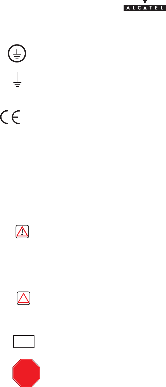
2.1 –Overview of the A9900 system
The Alcatel 9900 is a multi–service broadband wireless local loop system designed to provide telecom
services to small and medium–sized enterprises.
Broad band WLL (Wireless Local Loop) system, Alcatel 9900 allows operators to offer rapid provision – to a
large number of client sites – of a comprehensive range of telephone and data transmission services.
For cellular phone network operators, Alcatel 9900 offers the possibility of linking base stations to base
station controllers. This makes Alcatel 9900 an economical transmission solution, for the implementation or
extension of high traffic density areas coverage.
For mixed network operators (fixed and mobile), Alcatel 9900 enables to connect, with the same system, fixed
professional end user as well as base stations of cellular telephony.
Figure 1 – A9900 System – Local point–multipoint service distribution –
SME
Company D
Company C
Company A
Company B
Independant profession
Independant profession
document, use and communication of its contents
not permitted without written authorization from ALCATEL
All rights reserved. Passing on and copying of this
12/136 3CC10875AAAA TQ BJA 02
Issue 02 -January, 10 2000
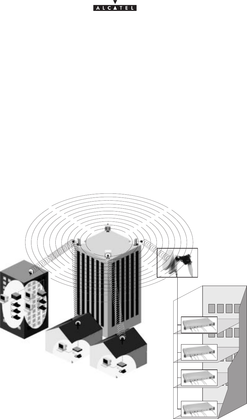
2.2 –Composition of the A9900 system
An A9900 network cell mainly consists of the following:
Sa common Base Station designated 9900BS;
Sand several Terminal Stations distributed across the user sites, and designated 9900TS.
Figure 2 – Base Station and Terminal Stations
“Digital Base Station”
DBS
“Terminal Stations”
“Radio Base Station”
RBS
9900BS
nx9900TS
document, use and communication of its contents
not permitted without written authorization from ALCATEL
All rights reserved. Passing on and copying of this
Issue 02 -January, 10 2000 13/1363CC10875AAAA TQ BJA 02
2.3 –A9900 system specifications
2.3.1 – Frequency bands used
25 GHz frequency band:
– CEPT T/R 13–02E European recommendation 24.5 – 26.5 GHz
26 GHz frequency band:
– MPT (Japan) 25.25 – 27 GHz
28 GHz frequency band:
– 27 GHz (LMCS – Canada) 27.35 – 28.35
– 28 GHz (CEPT) 27.5 – 28.6, 29.1 – 29.5
– 29 GHz (LMD – USA) 27.5 – 28.35, 29.10 – 29.25
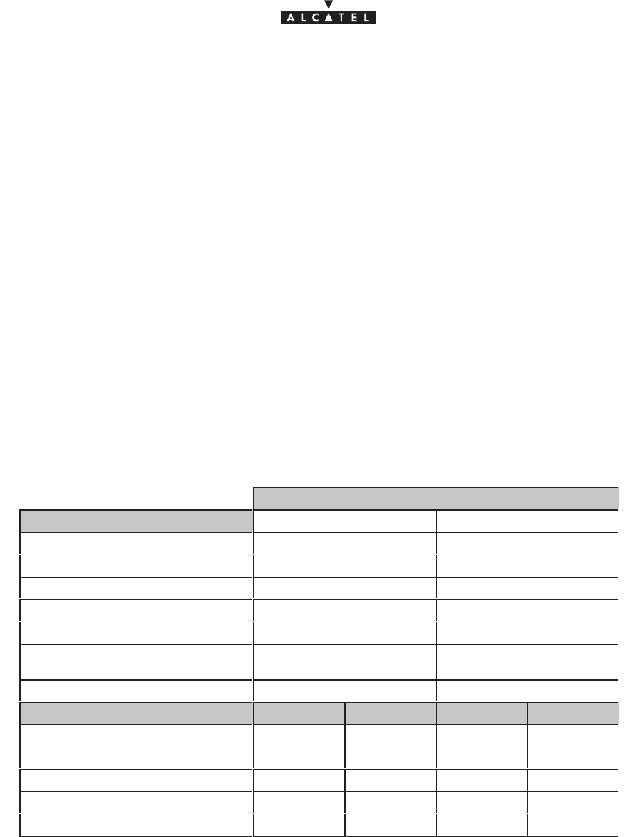
2.3.2 – Radio transmission specifications
The following table gives the main radio characteristics of the A9900 wireless system.
A downstream (BS to TS)carrier is combined with up to four upstream (TS to BS) carriers.
Downstream
Channel bandwidth 14 MHz 28 MHz
Occupied bandwidth 13.63 MHz 27.25 MHz
Modulation QPSK QPSK
Cross bit rate 20.19 Mbit/s 40.37 Mbit/s
Code Convol. 7/8 (k=7) Convol. 7/8 (k=7)
Interlace depth 12 depth 12
Code Reed–Solomon
(204,188,8) Reed–Solomon
(204,188,8)
Bit rate before coding 16.19 Mbit/s 32.38 Mbit/s
Link budget 25 GHz 28 GHz 25 GHz 28 GHz
RBS output power 17 dBm 17 dBm 17 dBm 17 dBm
Transmit antenna gain 15 dB 15 dB 15 dB 15 dB
Receive antenna gain 35 dB 34.5 dB 35 dB 34.5 dB
Rx RF level for error ratio = 10–10 – 83.5 dBm – 83,5 dBm – 80,5 dBm – 80,5 dBm
System gain 150.5 dB 150 dB 147.5 dB 147 dB
document, use and communication of its contents
not permitted without written authorization from ALCATEL
All rights reserved. Passing on and copying of this
14/136 3CC10875AAAA TQ BJA 02
Issue 02 -January, 10 2000
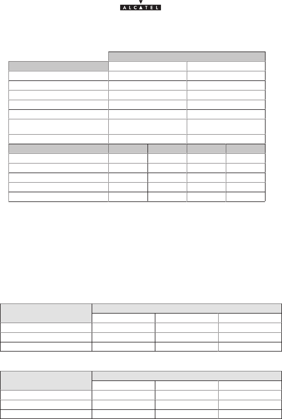
Upstream
Channel bandwidth 3.5 MHz 7 MHz
Occupied bandwidth 3.36 MHz 6.72 MHz
Modulation D–QPSK D–QPSK
Cross bit rate 5.38 Mbit/s 10.75 Mbit/s
Code Convol. 7/8 (k=7) Convol. 7/8 (k=7)
Interface Convol. 7/8 (k=7) Convol. 7/8 (k=7)
Code Reed–Solomon
(63,53,5) Reed–Solomon
(63,53,5)
Bit rate before coding 4.19 Mbit/s 8.38 Mbit/s
Link budget 25 GHz 28 GHz 25 GHz 28 GHz
RBS output power 12 dBm 12 dBm 12 dBm 12 dBm
Transmit antenna gain 35 dB 34.5 dB 35 dB 34.5 dB
Receive antenna gain 15 dB 15 dB 15 dB 15 dB
Rx RF level for error ratio = 10–10 – 87 dBm – 87 dBm – 84 dBm – 84 dBm
System gain 149 dB 148.5 dB 146 dB 145.5 dB
2.3.3 – Capacity
The network capacity depends on the traffic distribution betwen the data and circuit services (leased lines
and telephony). It also depends on the channeling and the number of upstream channels.
The following tables give the characteristics of three combinations: minimum, medium and maximum circuit
throughput; however, any intermediate combination is possible.
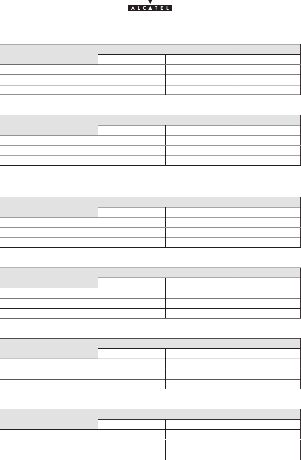
28 / 7 MHz channeling:
Downlink: 28 MHz Trafic MIX: circuit capacity
Uplink: 1 x 7 MHz Minimum Medium Maximum
nb of circuits: 64 kbit/s 0 60 121
ATM uplink capacity (cells/s) 18.980 9.569 0
ATM downlink capacity (cells/s)* 76.141 67.084 57.877
Downlink : 28 MHz Trafic MIX: circuit capacity
Uplink : 2 x 7 MHz Minimum Medium Maximum
nb of circuits: 64 kbit/s 0 120 242
ATM uplink capacity (cells/s) 37.961 19.137 0
ATM downlink capacity (cells/s)* 76.141 58.028 39.613
document, use and communication of its contents
not permitted without written authorization from ALCATEL
All rights reserved. Passing on and copying of this
Issue 02 -January, 10 2000 15/1363CC10875AAAA TQ BJA 02
Downlink : 28 MHz Trafic MIX: circuit capacity
Uplink : 3 x 7 MHz Minimum Medium Maximum
nb of circuits: 64 kbit/s 0 180 363
ATM uplink capacity (cells/s) 56.941 28.706 0
ATM downlink capacity (cells/s)* 76.141 48.971 21.349
Downlink : 28 MHz Trafic MIX: circuit capacity
Uplink : 4 x 7 MHz Minimum Medium Maximum
nb of circuits: 64 kbit/s 0 240 484
ATM uplink capacity (cells/s) 75.922 38.275 0
ATM downlink capacity (cells/s)* 76.141 39.915 3.084
14/3.5 MHz channeling:
Downlink: 14 MHz Trafic MIX: circuit capacity
Uplink: 1 x 3.5 MHz Minimum Medium Maximum
nb of circuits: 64 kbit/s 0 30 60
ATM uplink capacity (cells/s) 9.412 4.706 0
ATM downlink capacity (cells/s)* 38.047 33.519 28.990
Downlink : 14 MHz Trafic MIX: circuit capacity
Uplink : 2 x 3,5 MHz Minimum Medium Maximum
nb of circuits: 64 kbit/s 0 60 120
ATM uplink capacity (cells/s) 18.824 9.412 0
ATM downlink capacity (cells/s)* 38.047 28.990 19.934
Downlink : 14 MHz Trafic MIX: circuit capacity
Uplink : 3 x 3,5 MHz Minimum Medium Maximum
nb of circuits: 64 kbit/s 0 90 180
ATM uplink capacity (cells/s) 28.235 14.118 0
ATM downlink capacity (cells/s)* 38.047 24.462 10.877
Downlink : 14 MHz Trafic MIX: circuit capacity
Uplink : 4 x 3,5 MHz Minimum Medium Maximum
nb of circuits: 64 kbit/s 0 120 240
ATM uplink capacity (cells/s) 37.647 18.824 0
ATM downlink capacity (cells/s)* 38.047 19.934 1.821

document, use and communication of its contents
not permitted without written authorization from ALCATEL
All rights reserved. Passing on and copying of this
16/136 3CC10875AAAA TQ BJA 02
Issue 02 -January, 10 2000
* : part of the ATM downlink bit rate can be used for dynamic bandwidth allocation. This proportion varies within
the following limits:
– 2.5 % of the bit rate , if one upstream channel is used,
– 4 % of the bit rate , if two upstream channels are used,
– 5.5 % of the bit rate , if three upstream channels are used,
– 7 % of the bit rate , if four upstream channels are used.
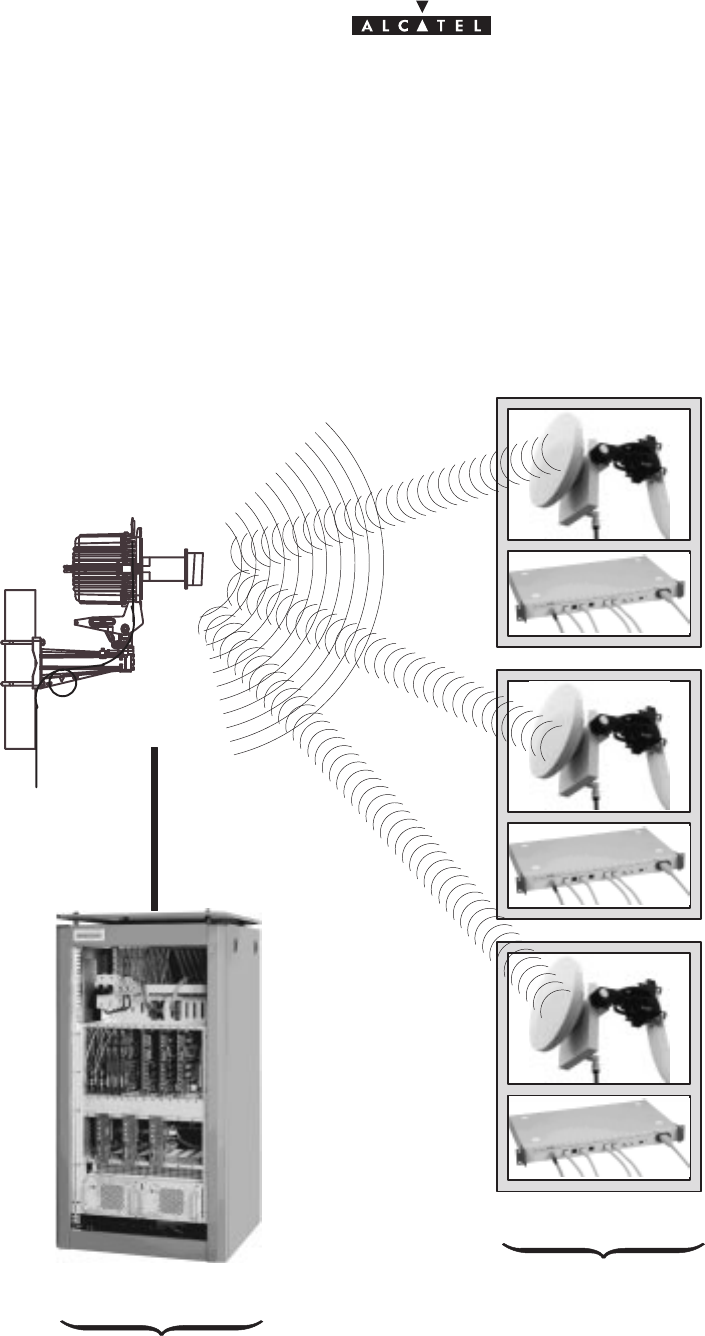
2.4 –Simplified description of the Base Station (9900BS)
The A9900 system Base Station (9900BS) consists of the following main elements:
Sone or more (up to 8) external transceivers, comprising the radio and the antenna part and
designated “RBS” (Radio Base Station);
Sone modem rack, including the power supply unit and interfaces, comprising the “indoor” part and
designated DBS (Digital Base Station);
Sa cable linking the RBS and the DBS and called the indoor–outdoor cable (or RBS/DBS link);
Sa network management and configuration station (9900LT), based on the use of a PC with
appropriate software.
document, use and communication of its contents
not permitted without written authorization from ALCATEL
All rights reserved. Passing on and copying of this
Issue 02 -January, 10 2000 17/1363CC10875AAAA TQ BJA 02
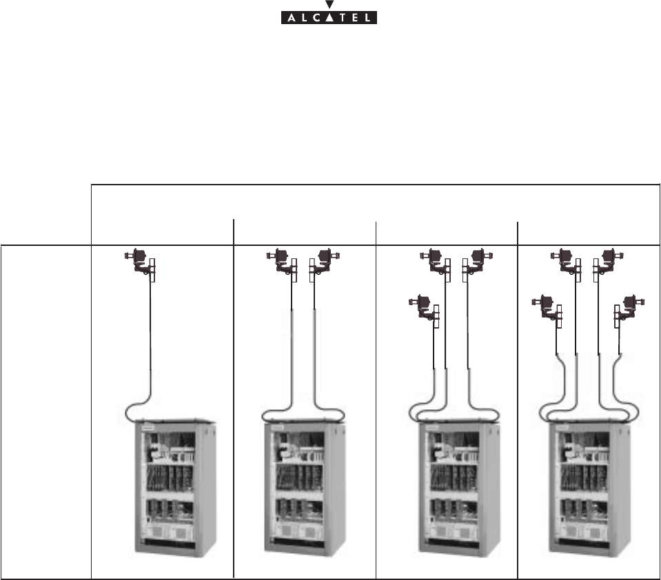
2.5 –Examples of configuration of the Base Station (9900BS)
Figure 3 – Examples of configuration of the 9900BS Base Station
1234
Number of sectors
Configuration
1 + 0
document, use and communication of its contents
not permitted without written authorization from ALCATEL
All rights reserved. Passing on and copying of this
18/136 3CC10875AAAA TQ BJA 02
Issue 02 -January, 10 2000
2.6 –Technical specifications of the Base Station (9900BS)
2.6.1 – RBS specifications
Designation Description Standards Observations
Mechanical specifications of the RBS assembly (antenna + pole mounting)
HxLxD 644(mm)x221(mm)x720(mm)
D taken from axial tube
(diameter = 50 to114mm)
cf. diagram in
§ 3 Installation
Weight 15 kg
Physical interfaces: RBS/DBS indoor–outdoor cable
Connector type N/female weatherproof
Medium 50 Ω coaxial cable
Environmental specifications
RBS Classification
ETS 300 019–2–4
IEC 721 3–4/
classes 4K2–4Z1–
4Z5–4Z7–4B1–4C2
–4S2–4M5
equipment for premises
not sheltered from the
weather.
Operating temperature –33°C to + 55°C
Relative humidity at
30°C100%
2.6.2 – DBS specifications
Designation Description Standards Observations
Mechanical specifications: Rack–mounted DBS assembly
HxLxD 1200(mm)x600(mm)x600(mm) cf. diagram in
§ 3 Installation
Weight
135 kg
(including 85 kg for empty
rack)
ETSI ETS 300–119
Mechanical specifications: DBS shelf without rack
HxLxD 880(mm)x482.6(mm)x440(mm) ETSI ETS 300–119
19–inch
cf. diagram in
§ 3 Installation
Weight < 50 kg
document, use and communication of its contents
not permitted without written authorization from ALCATEL
All rights reserved. Passing on and copying of this
Issue 02 -January, 10 2000 19/1363CC10875AAAA TQ BJA 02
Designation Description Standards Observations
Power supply and consumption
Primary voltage range 36 V to 60 V
none–referenced 48 V rated voltage
Maximum consumption < 1kW
ETSI ETS 300 132
including 8 RBS
Protection
overvoltage, short–circuit (40
A fuse), polarity inversion,
thermal protection (ventilation
failure)
ETSI ETS 300–132
Physical interfaces: ATM network interface (UNI)
Connector type SC/PC ITU–T.432.2/§3.1 1300 nm
1 for each direction
Medium single mode fiber
(SMF; 9/125 µm) ITU–T G.652 1300 nm
1 for each direction
Environment class 1 LASER product IEC 825
Bitrate
nominal
tolerance
155.520 Mbps
+/– 20 ppm
ITU–T.432.2/§3.1
Line coding NRZ
Instability cf. standard masks ITU–T G.958
Physical interfaces: E1, TDM circuit interface (75/120 Ω)
standard DBS female sub–D pins 8 connectors, 8 TDM
interfaces per connector
75 Ω interface BNC or 1.6/5.6 connector 1 per direction
120 Ω interface STP specific connector 1 per direction
Nominal bitrate 2.048 Mbps (+/– 50 ppm) ITU–T G.703/§6.1
Line coding HDB3
tolerated input jitter
residual output jitter cf. standard template ITU–T G.823/§3
ITU–T G.823/§2
Environmental specifications
DBS Classification
ETS 300 019–2–3
IEC 721 3–3/
classes 3K5–3Z2–
3Z4–3B1–3C2–3S2
–3M1
Operating temperature –5°C to + 55°C
Relative humidity
at 30°C93%

document, use and communication of its contents
not permitted without written authorization from ALCATEL
All rights reserved. Passing on and copying of this
20/136 3CC10875AAAA TQ BJA 02
Issue 02 -January, 10 2000
2.6.3 – Common characteristics of the RBS and DBS
Designation Description Standards Observations
Logistics
Transport Public transport: class 2.3
ETS 300 019–2–2
IEC 721–3–2
classes 2K4, 2B2,
2C2, 2S2, 2M3
Ambient temperature –40°C to+ 70°C
Relative humidity
at 45°C95%
Storage Class 1.2
ETS 300 019–2–1
IEC 721–3–1
classes 1K4, 1Z2,
1Z3, 1Z5, 1B2, 1C2,
1S3, 1M2
storage premises
sheltered from the
weather, without
air–conditioning.
Ambient temperature –40°C to + 70°CIEC 721–3–1/class
1K5
Relative humidity
at 30°C
Condensation
100%
90 to 100 %

document, use and communication of its contents
not permitted without written authorization from ALCATEL
All rights reserved. Passing on and copying of this
Issue 02 -January, 10 2000 21/1363CC10875AAAA TQ BJA 02
2.7 –Equipment power consumption
2.7.1 – RBS
The power consumption of the RBS is 31 W.
2.7.2 – DBS
DBS configuration type Power consumption
basic configuration
(1 sector, 1+0) 130 W
per additional sector 100 W
1+1 redundancy
(per sector) 100 W
ANT board (per board) 25 W
TNT board (per board) 30 W

document, use and communication of its contents
not permitted without written authorization from ALCATEL
All rights reserved. Passing on and copying of this
22/136 3CC10875AAAA TQ BJA 02
Issue 02 -January, 10 2000
PAGE INTENTIONALLY LEFT BLANK
document, use and communication of its contents
not permitted without written authorization from ALCATEL
All rights reserved. Passing on and copying of this
Issue 02 -January, 10 2000 23/1363CC10875AAAA TQ BJA 02
3 – Installation of the Base Station
3.1 –Equipment delivery
When you receive the equipment in its packaging:
– Check the condition of the packaging.
– If damaged, make your reservations known to the carrier without delay.
3.1.1 – Unpacking
Considerations
You are recommended to:
– Unpack the equipment according to the instructions on the packaging.
– Take an inventory and identify any missing items. If the delivery does not match the delivery advice note,
notify ALCATEL within 48 hours of receipt of the equipment.
Unpacking the RBS unit (also called RBS radio or RBS)
IMPORTANT NOTE: NEVER REMOVE THE ROUND YELLOW PADS USED TO SEAL
THE OUTDOOR SYSTEM.
document, use and communication of its contents
not permitted without written authorization from ALCATEL
All rights reserved. Passing on and copying of this
24/136 3CC10875AAAA TQ BJA 02
Issue 02 -January, 10 2000
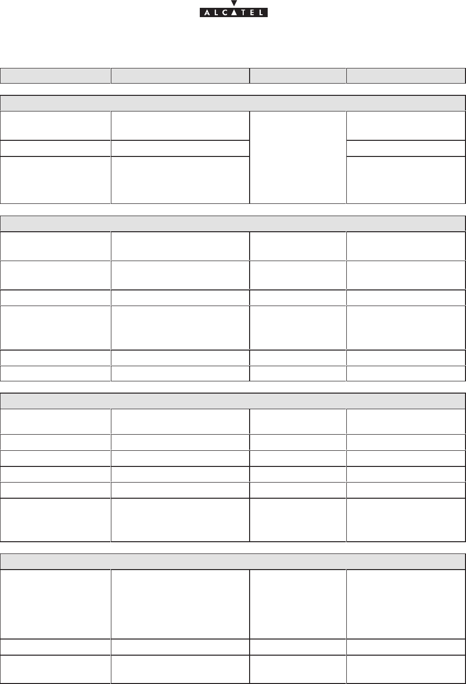
Unpacking the RBS radio antenna
Figure 4 – Unpacking the RBS radio antenna
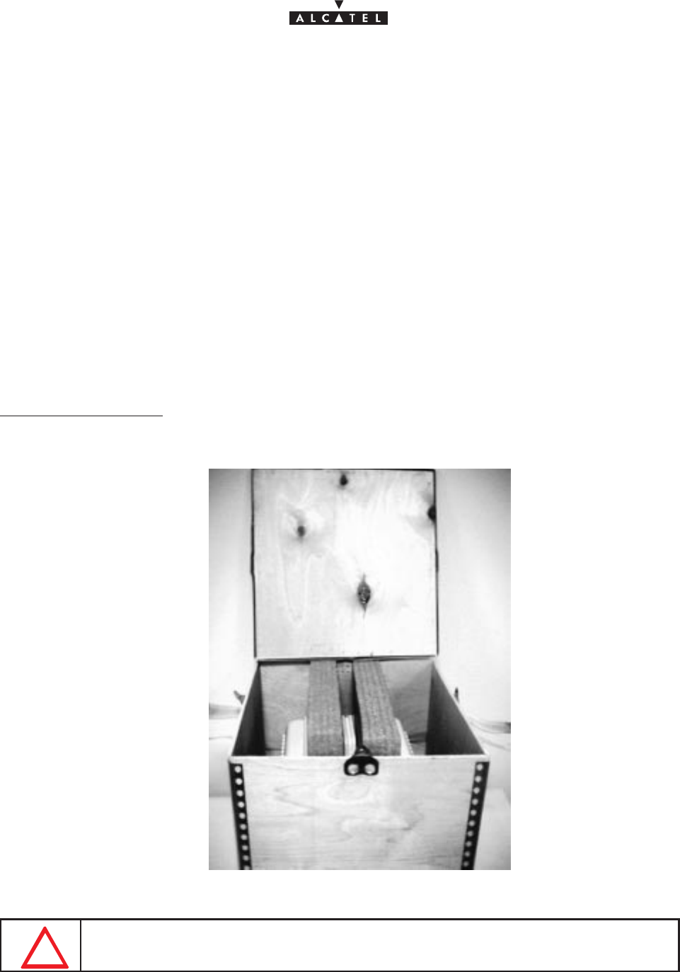
Unpacking the pole–mounting mechanical system
Figure 5 – Unpacking the pole–mounting mechanical system
document, use and communication of its contents
not permitted without written authorization from ALCATEL
All rights reserved. Passing on and copying of this
Issue 02 -January, 10 2000 25/1363CC10875AAAA TQ BJA 02
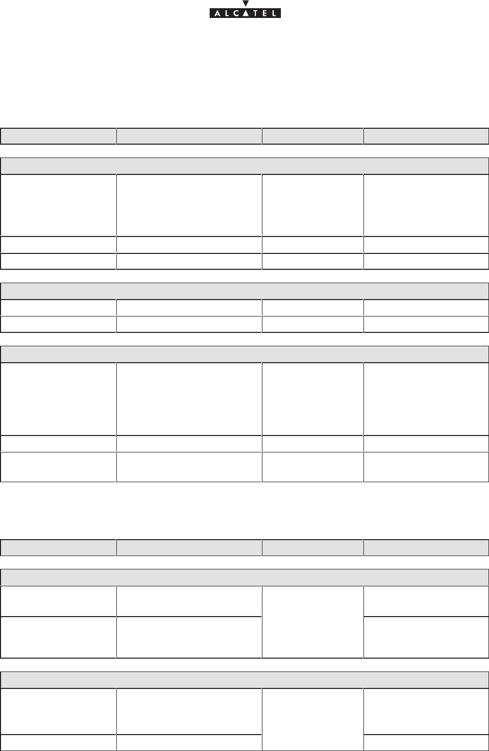
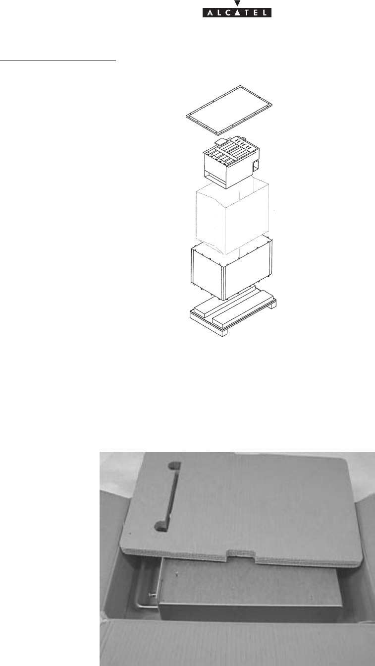
Unpacking the DBS rack
Figure 6 – Unpacking the DBS rack
Figure 7 – Unpacking power supply units

document, use and communication of its contents
not permitted without written authorization from ALCATEL
All rights reserved. Passing on and copying of this
26/136 3CC10875AAAA TQ BJA 02
Issue 02 -January, 10 2000
3.1.2 – Checking the delivered configuration
The following Base Station (9900BS) components are delivered:
– the RBS radio and its installation hardware: in a cardboard box,
– the RBS radio antenna: in a cardboard box,
– the pole mounting mechanical system: in a cardboard box,
– the DBS rack and the installation kit: in a crate/pallet,
– the DC/DC power supply units: in a cardboard box,
– the connection cable between RBS radio and DBS rack: on a reel.
Depending on the delivery site configurations, the delivery may include separate crates containing standard
22U 19” racks.
3.1.2.1 – Content of boxes
EQUIPMENT CONTENTS
RBS radio 1 RBS radio assembly
EQUIPMENT CONTENTS
RBS radio
antenna 1 RBS antenna assembly
EQUIPMENT CONTENTS
Pole mounting 1 pole–mounting mechanical system assembly
2 U–bolts and their hardware
grounding lugs and its hardware; antenna attachment parts
EQUIPMENT CONTENTS
DBS rack
1 rack containing the electronic boards specific to the client configuration
DBS
rac
k
cables (RBS/DBS connection inside rack), in accordance with the site configuration
fiber optic jumpers, in accordance with the site configuration
2 fiber optic cable winding cassettes
1 installation manual

document, use and communication of its contents
not permitted without written authorization from ALCATEL
All rights reserved. Passing on and copying of this
Issue 02 -January, 10 2000 27/1363CC10875AAAA TQ BJA 02
EQUIPMENT CONTENTS
DC/DC power
supply 2 DC/DC power supply units
EQUIPMENT CONTENTS
Standard 20U
19” rack 1 rack with lid and removable feet
3.1.2.2 – Storage
If the installation is not to be carried out immediately, the type of packaging will determine the equipment storage
conditions:
– the cardboard boxes should be warehoused indoors, in a well–ventilated and dry space,
– the wooden or laminated crates may be stored outdoors, provided that they are protected from the rain
and direct sunlight.
document, use and communication of its contents
not permitted without written authorization from ALCATEL
All rights reserved. Passing on and copying of this
28/136 3CC10875AAAA TQ BJA 02
Issue 02 -January, 10 2000
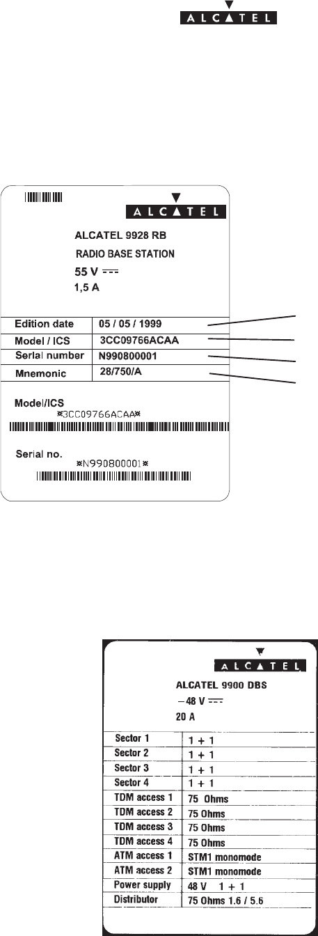
3.2 –Labels on the equipment
The RBS labels are affixed to the packaging to indicate its contents.
Figure 8 – Example of a label for the RBS unit
Issue date
Outdoor Unit model / status index
Serial number
Commercial reference
}
}
Outdoor unit model –
bar code and plain text
Serial number –
bar code and plain text
The DBS labels are fixed to the packaging to indicate its contents. These labels are not affixed to the equipment
because the DBS configuration changes in accordance with the site modifications.
Figure 9 – Example of a label for the DBS rack

document, use and communication of its contents
not permitted without written authorization from ALCATEL
All rights reserved. Passing on and copying of this
Issue 02 -January, 10 2000 29/1363CC10875AAAA TQ BJA 02
3.3 –Installing the equipment
3.3.1 – Information required for installation
Appendix 1 contains a sheet for you to complete to collate all the general information needed for the installation
procedure.
3.3.2 – Precautions
Installation is designed to meet all requirements concerning electromagnetic compatibility and safety.
The performance of the equipment decreases if the installation practices (cable installation, ground
connections, etc.)are not respected: installation should be based on best trade practices.
3.3.3 – Tools required
The installation personnel must possess a standard installation toolkit (containing, in particular: drill, drill bits,
soldering iron, cable tie pliers, terminal pliers).
The list of tools required for the mechanical installation of the equipment is given below:
Tool Use
No. 6 Allen key (for 8 mm screw) Antenna alignment
16/17 mm box wrench and flat
wrench Used for pole mounting and for fine adjustment of the antenna and
various tightening operations
Torque wrench Used for pole mounting and various tightening operations
20 mm flat wrench For attaching the “N” coaxial connectors
A compass and an inclinometer (not supplied) are essential for pointing the antenna.
Depending on the installations, additional equipment may prove useful:
– Compax “ Mars Actel “OSA3 insertion and extraction tool, for terminal strip wiring
(mars actel cad) COMPAX;
– Crimping tool for the sub–D connectors, ref.:608868–1 (AMP) .

document, use and communication of its contents
not permitted without written authorization from ALCATEL
All rights reserved. Passing on and copying of this
30/136 3CC10875AAAA TQ BJA 02
Issue 02 -January, 10 2000
3.4 –Installation of outdoor equipment
Considerations
– Outdoor equipment installation involves:
Sinstallation of the mechanical system (also called “pole–mounting” system) which supports the
RBS radio and facilitates antenna alignment,
Sinstallation of the RBS radio assembly and its antenna,
Sinstallation of the connection cable connecting the RBS radio to the DBS rack.
– Outdoor equipment installation should garantee a precise and fixed antenna pointing.
– The RBS location and its antenna orientation should arise from a planning analysis in order to optimize
the sector coverage. These elements are essential for the installation staff.
– Antenna orientation is only carried out according to geometric criterion (using compass and
inclinometer).
– All the outdoor equipment assemblies are designed for installation without any particular protection.
However, the following recommendations should be respected:
Smake sure that the reception metallic structure has a perfect stability,
Savoid installation below bird nesting areas,
Savoid attaching to chimneys which give off fat deposits, dust and other aerosols which are liable
to be deposited on the equipment,
Savoid proximity to sources of heat,
Savoid placing the equipment in proximity to corrosive gas outputs,
Savoid placing the equipment below roof run–offs not equipped with guttering (high risk of
microwave short–circuit),
Savoid attaching to a structure prone to vibrations,
Savoid to cross the antenna field of action.
– The type of installation used:
Son a tube or pole, using threaded U–bolts and nuts.
Nota : The tube selected should be sufficiently rigid to resist vibrations that may give rise to antenna
misalignment.
SWall mounting possible.
document, use and communication of its contents
not permitted without written authorization from ALCATEL
All rights reserved. Passing on and copying of this
Issue 02 -January, 10 2000 31/1363CC10875AAAA TQ BJA 02
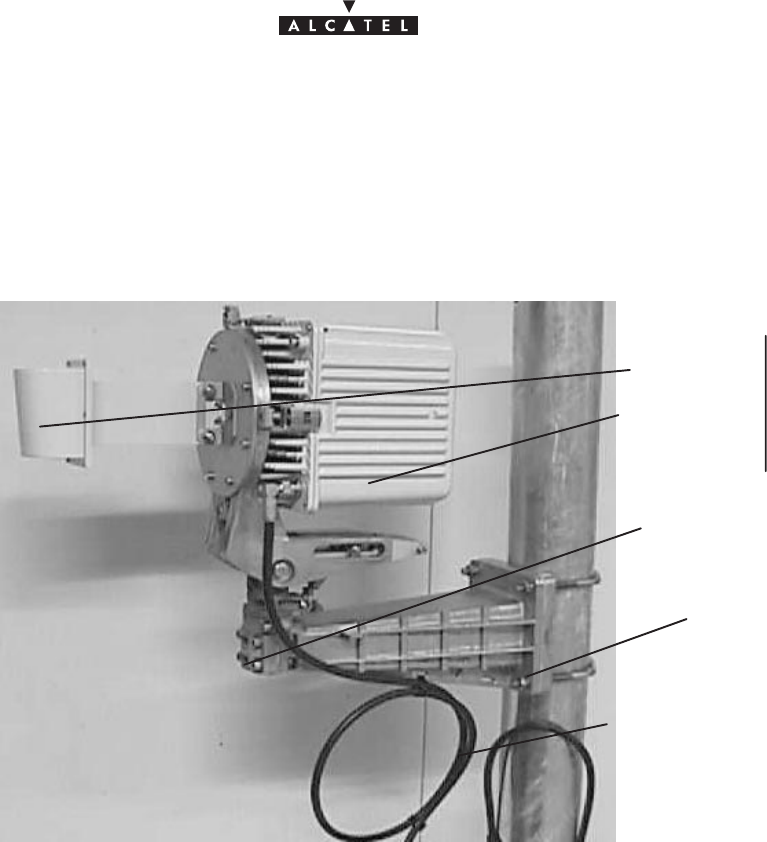
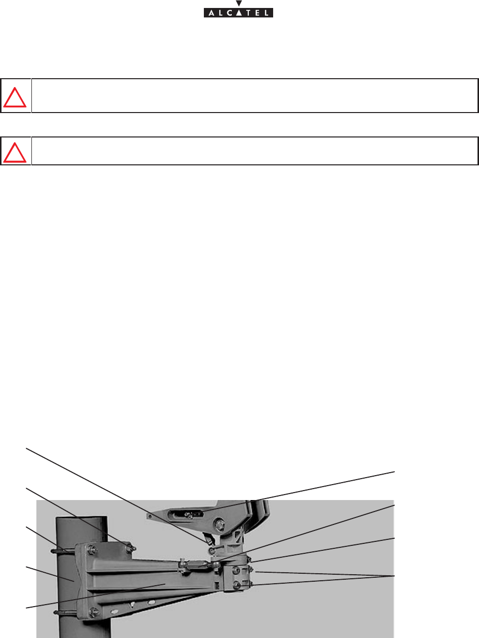
3.4.1 – Definition of assemblies
The 9900BS outdoor equipment includes:
– the mechanical mounting and alignment (pole mounting) system,
– the transceiver (also known as RBS unit or “ODU”) ,
– the sectored antenna.
Tube or pole
RBS/DBS connection cable
Mechanical “pole mount-
ing” system
Sectored antenna
Transceiver assembly RBS
unit
Figure 10 – Definition of 9900BS outdoor equipment
document, use and communication of its contents
not permitted without written authorization from ALCATEL
All rights reserved. Passing on and copying of this
32/136 3CC10875AAAA TQ BJA 02
Issue 02 -January, 10 2000
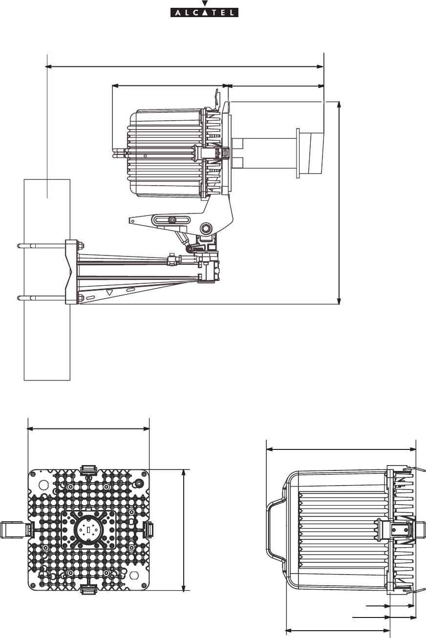
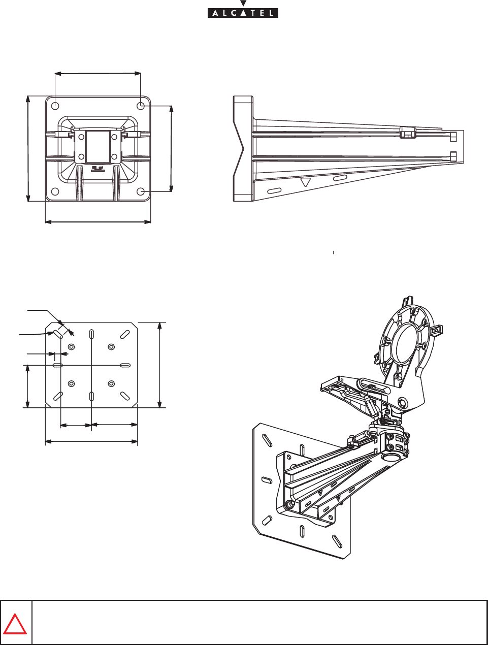
Figure 11 – Dimensions of the RBS radio unit.
288,2 238
689,3
503,4
221
221
273
189
47
42
document, use and communication of its contents
not permitted without written authorization from ALCATEL
All rights reserved. Passing on and copying of this
Issue 02 -January, 10 2000 33/1363CC10875AAAA TQ BJA 02
130
160
130
160
Figure 12 – Direct wall mounting.
300
100 150
300
25
20
150
R6
Thickness 5mm.
Figure 13 – Wall mounting option with mounting plate 3CC11109AAAA.
Use bolt size M10 or more check relevant local regulations before installing (minimum 10 mm
diameter).
document, use and communication of its contents
not permitted without written authorization from ALCATEL
All rights reserved. Passing on and copying of this
34/136 3CC10875AAAA TQ BJA 02
Issue 02 -January, 10 2000
3.4.2 – Installation and orientation of the mechanical system
VERTICALITY OF THE BEARING: + – 0.5 º FOR STANDARD ANTENNAS.
+ – 0,25 º FOR LARGE GAIN ANTENNAS.
NEVER INSTALL THE BEARING AXIS HORIZONTALLY; THE ODU MUST BE ABOVE THE
POLE MOUNTING AND NOT PROJECT LATERALLY.
Considerations
– Installation can be carried out on an existing or newly installed tube or pole.
– The external diameter of the tube or pole is 114 mm in standard configuration.
Nota : Other tube diameters may be used depending on the loads to be supported: minimum diameter 76 mm.
– The tube or pole along with the U–bolts must be clean and (apart from threads) grease–free.
– Wall mounting possible with or without wall plate: see figures 12 and 13.
Stages (Figure 14)
1. On the pole mounting (ref. 1), loosen the four “bearing” locking screws (ref. 6) and the coarse “bearing”
locking screw (ref. 7) to facilitate the subsequent RBS unit mounting.
2. Fit the pole mounting (ref. 1) on the tube or pole (ref. 2) using the U–bolts (ref. 3). Secure it using flat
washers, “grower” washers, nuts and lock–nuts (ref. 4).
3. Roughly orientate the bearing of the pole mounting in the desired topographical direction. The bearing
turnbuckle (ref. 8) should remain in mid–position. Use the “top” marking of the antenna and a compass,
then tighten the U–bolts (ref. 3). U–bolt tightening torque = 3daN.m.
4. Roughly orientate the elevation of the antenna support by loosening the “elevation” locking screw (ref.
9). The elevation turnbuckle (ref. 5) should remain in mid–position; pivot the antenna support through the
vertical to adjust, then tighten the “elevation” locking screw (ref. 9).
Figure 14 – Installation and orientation of the mechanical system
2
4
7
3
8
9
6
5
1
document, use and communication of its contents
not permitted without written authorization from ALCATEL
All rights reserved. Passing on and copying of this
Issue 02 -January, 10 2000 35/1363CC10875AAAA TQ BJA 02
3.4.3 – Installation of the RBS radio antenna
Considerations
– The form of the sectored antennas may vary. Always refer to the “TOP” marking on the antenna when
installing on the pole mounting.
–The orientation of the waveguide is not linked to the polarization for this type of antenna. It is
always necessary to conform you to the “POLAR H” or “POLAR V” constructor’s marking on the
antenna and not to the orientation of the waveguide.
– The antenna must be installed before the RBS radio unit.
Storage (Figure 15)
1. Position the RBS radio antenna against the pole mounting support (ref. 2), and install it at the oposite side
of the RBS radio unit.
2. Secure the RBS radio antenna using seven M6 x 25 screws (ref.3) and onduflex washers.
TAKE CARE NOT TO DAMAGE THE O–JOINT ON THE NOSE OF THE ANTENNA
CONNECTION.
IF THE RBS RADIO UNITS ARE NOT TO BE MOUNTED IMMEDIATELY AFTER THE
MOUNTING OF THE ANTENNA, PROTECT THE CONNECTION NOSE (FROM WATER,
DIRT AND IMPACT).
Figure 15 – Installing the RBS unit antenna
2
1
3
ODU side
antenna side
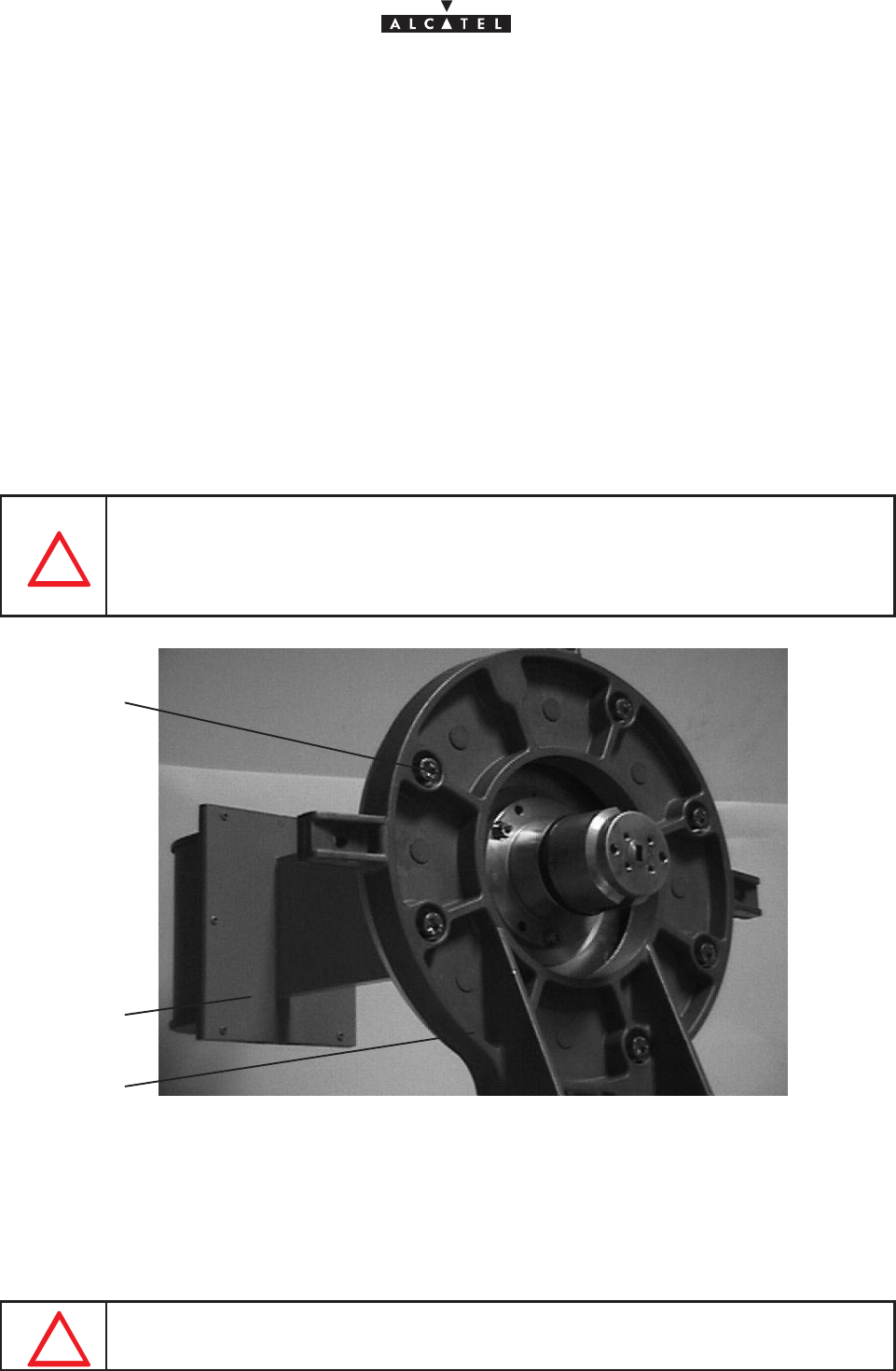
3.4.4 – Installation of the RBS Radio Unit (ODU)
IMPORTANT: THE RADIO UNIT ASSEMBLY MUST ALWAYS BE MANIPULATED BY ITS
HANDLE ONLY.
document, use and communication of its contents
not permitted without written authorization from ALCATEL
All rights reserved. Passing on and copying of this
36/136 3CC10875AAAA TQ BJA 02
Issue 02 -January, 10 2000
Stages
1. Take the ODU by the handle and place the two bosses in the “nose” of the unit against the two slots in the
“nose” of the antenna (the ODU–IDU link cable should be towards the base of the ODU).
Nota : According to the RBS antenna used, the ODU unit should be installed in horizontal or vertical handle
position. This installation is not within polarization control. Refer to the antenna installation kayways.
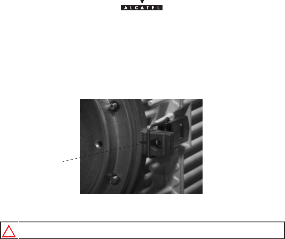
2. While holding the radio unit, begin by locking (Figure 16 ) the two side snap–locks on the support, then
that at the bottom, followed by that at the top.
Figure 16 – Locking the Radio unit
Locking position
NEVER USE THE EXTERNAL KAYWAYS TO LOCK THE RADIO UNIT.
REMINDER: The ODU/antenna assembly requires no additional seal on the SHF flanges; the two ends
are smooth. Sealing is provided by the O–ring seal around the male “noses”.
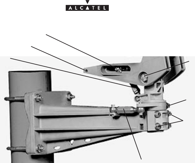
3.4.5 – Antenna alignment
3.4.5.1 – Mechanical adjustments and deflection characteristics
The mechanical adjustment mechanisms are shown in Figure 17 :
document, use and communication of its contents
not permitted without written authorization from ALCATEL
All rights reserved. Passing on and copying of this
Issue 02 -January, 10 2000 37/1363CC10875AAAA TQ BJA 02
Figure 17 – Antenna alignment adjustment mechanisms
Coarse elevation (tilt) locking screw
Coarse bearing locking
screw
Bearing locking screw
Bearing turn-
buckle
Ground connection hole
Elevation (tilt) turn-
buckle Elevation (tilt) locking
screw
Deflection characteristics:
– The total deflection is: bearing = 270_, elevation = + – 25_; these values are obtained with the
turnbuckles set to “maximum”.
– The deflection obtained with the turnbuckles is : elevation = + – 9_ bearing = + – 9_.
3.4.5.2 – Alignment adjustment procedure
Stages
1. Using a control system (graduated level or inclinometer) positioned on the straight part of the antenna
(Figure 18), ensure that it is perfectly horizontal (tilt 0_).
2. Make a bearing alignment in the direction intended by the radio planners (compass, ”TopoChaix”, etc.).
3. To avoid obstacles during installation, the “bearing” turnbuckle may be mechanically reversed on the
pole–mounting. However, the bearing axis
must
remain vertical.
4. Tighten the “coarse” bearing locking screw. Turn the bearing turn–buckle. Tighten the four bearing front
screws (alternate diagonal tightening) torque of 1.5m daN.
5. Check that the rough elevation screw is locked to a torque of 1.5m daN.
6. Using the “fine” elevation adjustment on the pole mounting (site elevation turnbuckle), set the tilt angle
intended by the radio planners (e.g., tilt down 5_). Check this value with the control system (graduated level,
inclinometer, ”TopoChaix”, etc.) positioned on the straight horizontal part of the antenna or the pole
mounting.
Nota : To minimize the unscrewing of the elevation turnbuckle, make careful use of the “coarse” adjustment
in the first stage. The turnbuckle must remain in the mid–position (
85mm center distance ). Never
exceed a center distance of 94mm.
7. Secure the two “elevation” side locking screws. Tighten completely the screws to lock the assembly in
position, to a torque of 3 mdaN. Finish the operation by tightening the turnbuckle counter–screws to an
reference torque of 2 mdaN. This ends the antenna alignment.
8. Check the bearing and elevation of the antenna once the assembly has been firmly secured. If a shift is
noted, repeat the adjustement(s) in question.

document, use and communication of its contents
not permitted without written authorization from ALCATEL
All rights reserved. Passing on and copying of this
38/136 3CC10875AAAA TQ BJA 02
Issue 02 -January, 10 2000
Figure 18 – Checking antenna positioning
3.4.5.3 – Definitions
Tilt or Elevation: Angle of tilt from the horizontal.
Tilt UP: The antenna points upwards.
Tilt 0: The antenna is horizontal.
Tilt DOWN: The antenna points downwards.
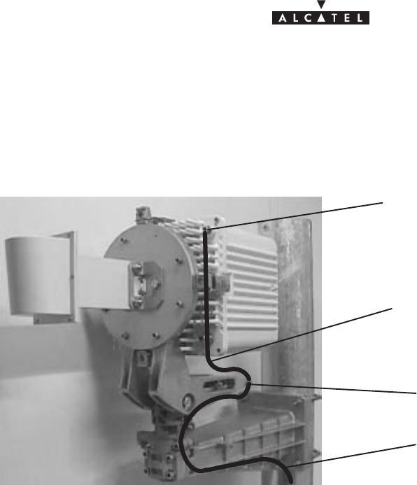
3.4.6 – Grounding of the outdoor equipment
Grounding of the outdoor equipment consists of:
– connecting the grounding of the RBS Unit with the pole–mounting grounding
– connecting the coupled RBS unit and pole–mounting grounding to the earthing system.
Considerations
– For grounding the RBS radio unit, a green/yellow cable with insulating sheath must be used. The
minimum cross–section of the conducting wire is 16 mm2.
– On the pole–mounting assembly, the ground terminal comprises two tapped holes et the rear of the
metal cast supporting the RBS radio (see Figure 19). According to the installation, choose the most
suitably positioned tapped hole. The grounding screw screws on in one of the two nuts inserted into
the metal cast supporting the RBS. When changing the grounding position block the nut to avoid
to lose it.
Storage
1. Crimp a terminal lug (ref. 16–6 CT) at each end of the cable linking the RBS unit and pole–mounting ground
connections.
document, use and communication of its contents
not permitted without written authorization from ALCATEL
All rights reserved. Passing on and copying of this
Issue 02 -January, 10 2000 39/1363CC10875AAAA TQ BJA 02
2. Screw one of the grounding cable lug into the tapped hole on the front of the RBS radio unit (see Figure
19). Use an M6 screw.
3. Crimp a lug (ref. 16–6 CT) on to the grounding cable of the pole–mounting and RBS assembly.
4. Connect both grounding cables to the one of the holes on the support back panel.
Figure 19 – Grounding the outdoor equipment
Screw for grounding RBS unit
Screw for grounding pole–mounting
Grounding cable between RBS and
pole–mounting
Grounding cable of the RBS and pole–
mounting assembly
document, use and communication of its contents
not permitted without written authorization from ALCATEL
All rights reserved. Passing on and copying of this
40/136 3CC10875AAAA TQ BJA 02
Issue 02 -January, 10 2000
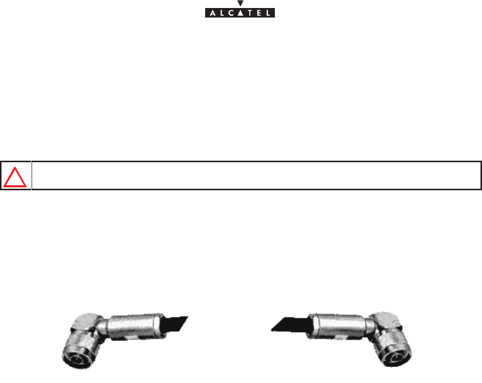
3.5 –Installation of the link between RBS and DBS
Considerations
– The electrical link between RBS unit and DBS rack of the Base Station is by one single coaxial cable
per T/R (Figure 20). This cable, using double–shielding, is of the ET 390998 type.
USE ONLY THE
ET 390998
CABLE.
– Physical cable characteristics:
Sdiameter = 11 mm,
Smaximum installed cable length = 200 meters,
Sminimum bend radius: 60 mm.
Figure 20 – RBS / DBS connection
DBS side connectorRBS side connector
– It is essential to measure and record the length of cable actually deployed.
Storage
1. Fit the cable(s) with male “N” type elbow connectors, supplied with the equipment. To assemble the coaxial
plugs, refer to the manufacturer’s Assembly handbook. The packaging of each plug also contains assembly
instructions and tools.
Nota : Crimping on to the cable can be carried out using the Daniels M 22520/5–01 tool and Y215P clamping
jaws.
Nota : If soldering is used, do not overheat for fear of damage to the cable dielectric.
2. Attach the cable at the RBS side to the pole–mounting via the rectangular clamp attachment windows.
Nota : The cable should be attached as rigidly as possible to avoid all repetitive movements related to
mechanical or atmospheric vibrations, which could eventually lead to damage of the cable or connector.
3. Plug in the RBS / DBS connection cable.
4. Carry out the wiring between RBS and DBS.
Nota : Make a drip groove where the cable enters the buildings, respecting the cables radius, in order to
prevent water infiltration.
Nota : Lock the cable every meter using adapted clamps for the type of cable running.
document, use and communication of its contents
not permitted without written authorization from ALCATEL
All rights reserved. Passing on and copying of this
Issue 02 -January, 10 2000 41/1363CC10875AAAA TQ BJA 02
Nota : Avoid a too long parallel walk between RBS/DBS coaxial link and electrical cables.
NOT OVERTIGHTEN THE CABLE TIE ON THE CABLE; THIS COULD CAUSE DEFOR-
MATION OF THE DIELECTRIC AND SUBSEQUENT LOSS OF PERFORMANCE.
5. Note the length of the cable installed. This information will be entered into the database when the equipment
is commissioned using the configuration software.
Nota : The accuracy required by the configuration software is + 10%.
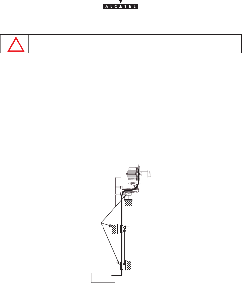
Grounding the RBS/DBS connection
– Cable grounding kits (reference 1AB128500002) may be supplied as an option.
– These kits are used for sites with high radioelectric interference, such as radio broadcasting stations,
television transmitters, etc.
– The grounding diagram for these kits is illustrated in Figure 21.
– For the cable preparation and grounding operations, refer to the technical documentation of the cable
supplier.
D
DBS unit
only necessary if
D > 80 m
Grounding Kits
Figure 21 – Grounding the RBS/DBS connection in option
document, use and communication of its contents
not permitted without written authorization from ALCATEL
All rights reserved. Passing on and copying of this
42/136 3CC10875AAAA TQ BJA 02
Issue 02 -January, 10 2000
3.6 –Base Station indoor equipment installation
Considerations
Nota : This manual deals with the DBS sub–rack and the DC/DC power supply units (PSU) installed in a rack
(standard 20U 19” rack or other standardized 19”–wide rack).
– The rack containing the DBS sub–rack assembly and DC/DC PSUs is for indoor installation only.
– The 9900BS indoor rack will be positioned according to user needs and technical constraints (e.g.,
respect of minimum distances, connections layout, RDS/DBS connection accessibility, power supply).
– The power supply is to be connected after installation of the 9900BS indoor rack, at the time of its
commissioning.
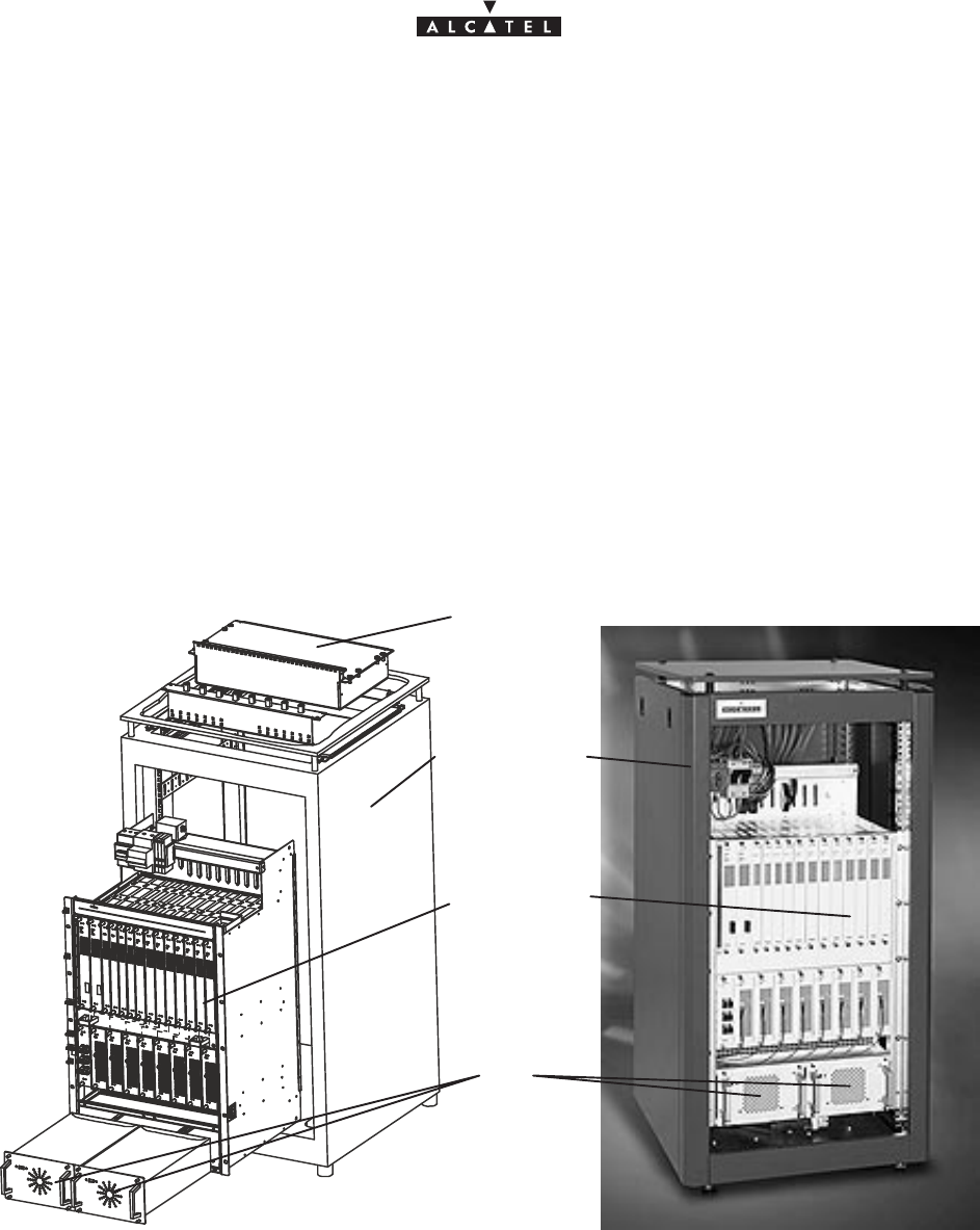
Definition of racks
All components comprising the indoor station can be integrated:
Seither in a standard, 22U 19” rack (see Figure 22),
DBS sub–rack
assembly
DC/DC power supply
units
Standard 20U 19” rack
Distributors
(according to
options)
Figure 22 – Example of configuration of a 9900BS station in a standard rack
Sor in another type of standardized, 19” rack.
document, use and communication of its contents
not permitted without written authorization from ALCATEL
All rights reserved. Passing on and copying of this
Issue 02 -January, 10 2000 43/1363CC10875AAAA TQ BJA 02
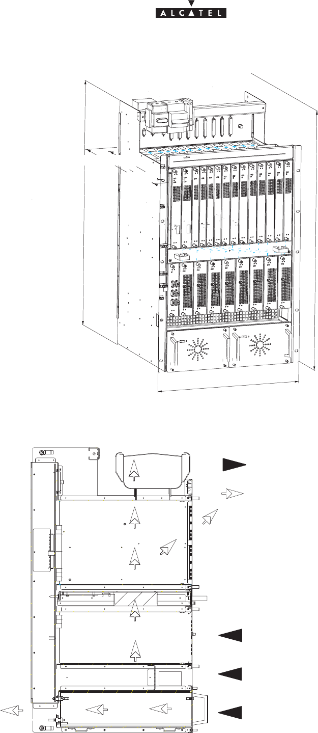
3.6.1 – Mechanical installation
800
* 850
* 490 440
* 50
483
Figure 23 – Dimensions and equipment of the DBS subrack (in mm).
–Respect the requested clearances for the wiring, in order to avoid damage to the connecters(marked
with an *)
Heated air
Figure 24 – Ventilation of the DBS subrack (cross–section).
do not obstruct outlet
Ambient air
do not obstruct inlet
document, use and communication of its contents
not permitted without written authorization from ALCATEL
All rights reserved. Passing on and copying of this
44/136 3CC10875AAAA TQ BJA 02
Issue 02 -January, 10 2000
–The installation of rack and subrack must enable the ventilation shown here. Do not obstruct the air inlets and
outlets.
Storage
1. Choose the location where the equipment is to be assembled and unpack the standard rack. If its top cover
is fitted, remove it (quarter–turn screw).
Nota : Place the rack in such a way that the cable connections are accessible before the rack is installed
definitively.
2. Unpack the DBS sub–rack assembly and install it inside the rack. Screw into place.
3. Unpack the DC/DC PSUs; install and attach to the DBS sub–rack.
4. Carry out the electrical connection, cf.§ 3.6.2
5. Carry out the client terminal connections, cf.§ 3.6.3 and 3.6.4
6. Connect the RBS/DBS connection cable(s) cf.§ 3.6.5 .
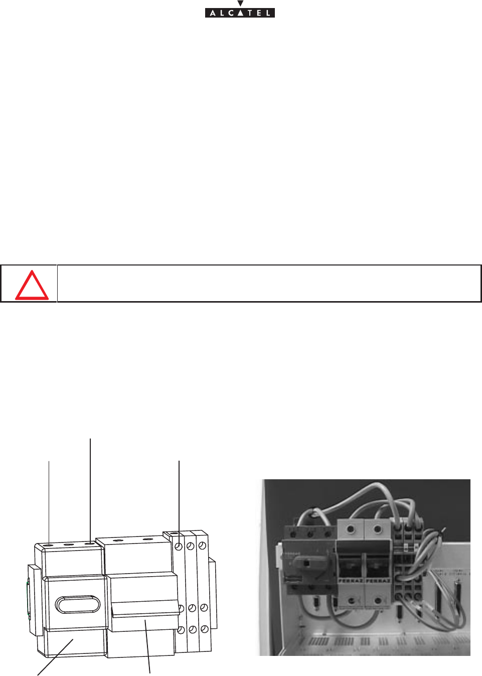
3.6.2 – Electrical connection
WHEN MAKING THE POWER CONNECTIONS TURN OFF ALL DBS SUB–RACK
EXTERNAL POWER SOURCES.
Considerations
– The DBS sub–rack is supplied from the rated DC voltage of –48V (minimum – 35V, maximum – 60V).
– The cable connecting the external DC power source to the DBS sub–rack will have a minimum
cross–section of 3x10 mm2 and a maximum length of 20 meters.
– The rack must be grounded to the general grounding system. For this, the rack mechanism will be
connected by a cable with a minimum cross–section of 16 mm2, attached using a 6 mm bolt
– For the power supply block diagram, refer to Figure 25:
Figure 25 – DBS sub–rack power supply
0V
–48V
Grounding
Fuse holder
ON – OFF switch
document, use and communication of its contents
not permitted without written authorization from ALCATEL
All rights reserved. Passing on and copying of this
Issue 02 -January, 10 2000 45/1363CC10875AAAA TQ BJA 02
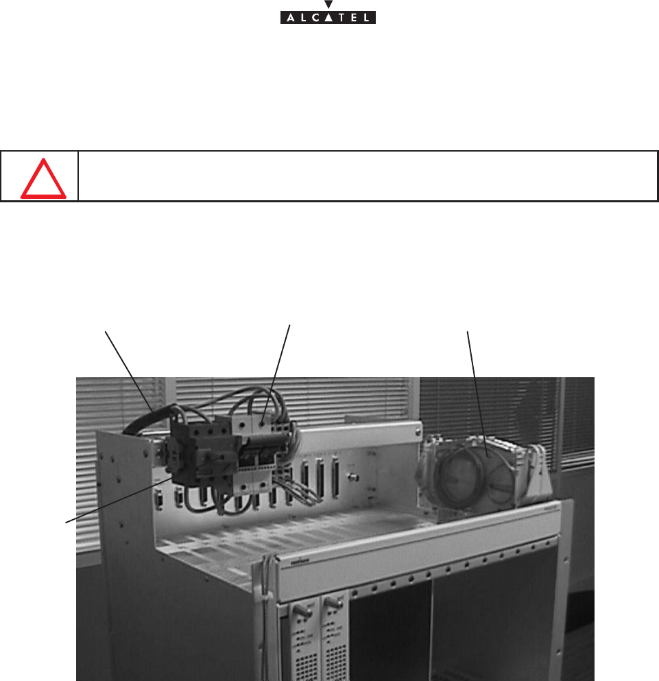
Storage (Figure 26)
1. Connect the three–pole switch assembly at the top of the DBS sub–rack to the external DC power source.
You are recommended to pass the power supply cable via the top of the rack.
DO NOT CONNECT THE GROUNDING CABLE TO THE THREE–POLE SWITCH BUT TO
THE YELLOW/GREEN TERMINAL BLOCK.
2. Ground the rack and the DBS sub–rack.
3. Make sure that the fuses are inserted in the fuse–holder.
Figure 26 – DBS sub–rack power connection
Fuse–holderPower supply cables Winding cassette for fiber optic
cables
ON – OFF
switch
3.6.3 – Customer access connections (circuits interfaces)
Considerations
– This involves the use of:
Sconnectors TNT1 to TNT4, at the top of the DBS sub–rack, if no distribution frames
Sthe distribution frames at the top of the DBS sub–rack or standard rack (coaxial cables for the 75
ohm links, balanced pair cables for the 120 ohm links).
document, use and communication of its contents
not permitted without written authorization from ALCATEL
All rights reserved. Passing on and copying of this
46/136 3CC10875AAAA TQ BJA 02
Issue 02 -January, 10 2000
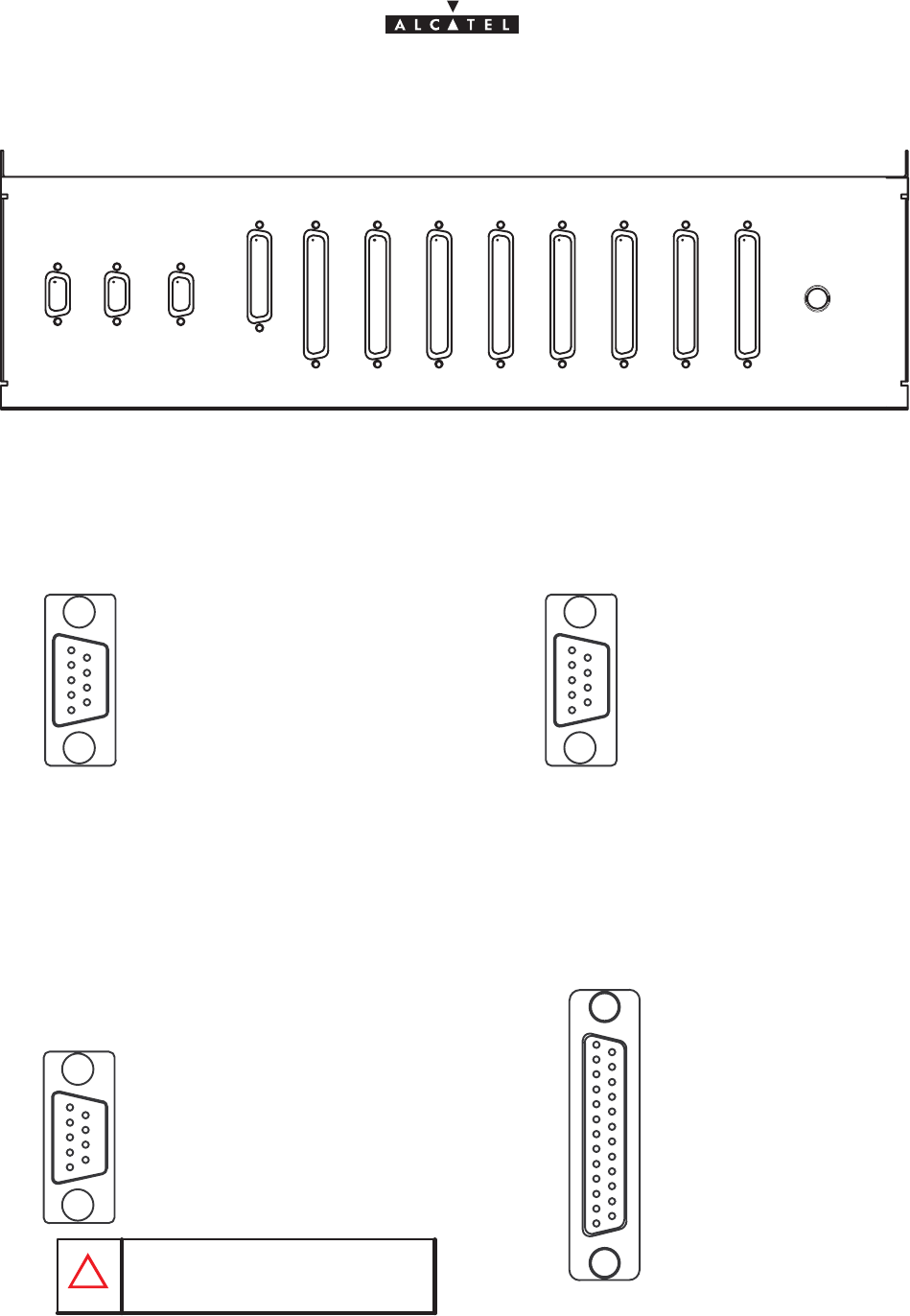
3.6.3.1 – Direct connections to the connectors of the top panel of the DBS subrack.
TEST#1 NMS
(10baseT) SYNCHRO
2,048Mz
ALARMS
I/O TNT#1
E1/T1#1–8
TNT#1
E1/T1#9–16 TNT#2
E1/T1#1–8
TNT#2
E1/T1#9–16 TNT#3
E1/T1#1–8
TNT#3
E1/T1#9–16 TNT#4
E1/T1#1–8
TNT#4
E1/T1#9–16
TEST#2
J101 J102 J104
J103
J105 J106 J107 J108 J109 J110 J111 J112
J113
Figure 27 – DBS connections, connectors location
Pin 01 ––––>not connected
Pin 02 ––––>ground
Pin 03 ––––>ground
Pin 05 ––––>not connected
Pin 07 ––––>10BT_RxD_P
Pin 08 ––––>10BT_TxD_M
Pin 04 ––––>ground
Pin 06 ––––>10BT_RxD_M
CONNECTOR NMS J102
Pin 01 ––––>SDA_Fdp
Pin 02 ––––>ground
Pin 03 ––––>ground
Pin 07 ––––>ground
Pin 08 ––––>PC_RS232_Tx_1
Pin 04 ––––>PC_RS232_Rx_1
Pin 06 ––––>SCL_Fdp
CONNECTOR TEST#1 J101
Pin 05 ––––>PC_RS232_Rx_0
Pin 09 ––––>PC_RS232_Tx_0 Pin 09 ––––>10BT_TxD_P
51
69
51
69
Pin 01 ––––>Clk_2M_Out_P
Pin 02 ––––>ground
Pin 03 ––––>ground
Pin 05 ––––>Clk_2M_In_M
Pin 07 ––––>ground
Pin 08 ––––>ground
Pin 04 ––––>ground
Pin 06 ––––>Clk_2M_Out_M
Pin 09 ––––>Clk_2M_In_P
CONNECTOR SYNCHRO J103
51
69
1
13
14
25
CONNECTOR J104
(do not connect)
(do not connect)
do not connect pins 01 et 06
Figure 28 – DBS connections, affectation access points
DO NOT CONNECT

document, use and communication of its contents
not permitted without written authorization from ALCATEL
All rights reserved. Passing on and copying of this
Issue 02 -January, 10 2000 47/1363CC10875AAAA TQ BJA 02
Figure 29 – DBS connections, affectation of access points
Pin 01 ––––>ground
Pin 04 ––––>Input_3_P_1
Pin 05 ––––>Input_4_P_1
Pin 06 ––––>Input_5_P_1
Pin 07 ––––>Input_6_P_1
Pin 08 ––––>Input_7_P_1
Pin 09 ––––>Input_8_P_1
Pin 10 ––––>ground
Pin 11 ––––>ground
Pin 12 ––––>Output_1_P_1
Pin 13 ––––>Output_2_P_1
Pin 14 ––––>Output_3_P_1
Pin 15 ––––>Output_4_P_1
Pin 16 ––––>Output_5_P_1
Pin 17 ––––>Output_6_P_1
Pin 18 ––––>Output_7_P_1
Pin 19 ––––>Output_8_P_1
Pin 20 ––––>ground
Pin 21 ––––>Input_1_M_1
Pin 22 ––––>Input_2_M_1
Pin 23 ––––>Input_3_M_1
Pin 24 ––––>Input_4_M_1
Pin 25 ––––>Input_5_M_1
Pin 26 ––––>Input_6_M_1
Pin 27 ––––>Input_7_M_1
Pin 28 ––––>Input_8_M_1
Pin 29 ––––>ground
Pin 30 ––––>Output_1_M_1
Pin 31 ––––>Output_2_M_1
Pin 32 ––––>Output_3_M_1
Pin 33 ––––>Output_4_M_1
Pin 34 ––––>Output_5_M_1
Pin 35 ––––>Output_6_M_1
Pin 36 ––––>Output_7_M_1
Pin 37 ––––>Output_8_M_1
Pin 02 ––––>Input_1_P_1
Pin 03 ––––>Input_2_P_1
ground
Input_11_P_2
Input_12_P_2
Input_13_P_2
Input_14_P_2
Input_15_P_2
Input_16_P_2
ground
ground
Output_9_P_2
Output_10_P_2
Output_11_P_2
Output_12_P_2
Output_13_P_2
Output_14_P_2
Output_15_P_2
Output_16_P_2
ground
Input_9_M_2
Input_10_M_2
Input_11_M_2
Input_12_M_2
Input_13_M_2
input_14_M_2
Input_15_M_2
Input_16_M_2
ground
Output_9_M_2
Output_10_M_2
Output_11_M_2
Output_12_M_2
Output_13_M_2
Output_14_M_2
Output_15_M_2
Output_16_M_2
Input_9_P_2
Input_10_P_2
ground
Input_3_P_3
Input_4_P_3
Input_5_P_3
Input_6_P_3
Input_7_P_3
Input_8_P_3
ground
ground
Output_1_P_3
Output_2_P_3
Output_3_P_3
Output_4_P_3
Output_5_P_3
Output_6_P_3
Output_7_P_3
Output_8_P_3
ground
Input_1_M_3
Input_2_M_3
Input_3_M_3
Input_4_M_3
Input_5_M_3
input_6_M_3
Input_7_M_3
Input_8_M_3
ground
Output_1_M_3
Output_2_M_3
Output_3_M_3
Output_4_M_3
Output_5_M_3
Output_6_M_3
Output_7_M_3
Output_8_M_3
Input_1_P_3
Input_2_P_3
ground
Input_11_P_4
Input_12_P_4
Input_13_P_4
Input_14_P_4
Input_15_P_4
Input_16_P_4
ground
ground
Output_9_P_4
Output_10_P_4
Output_11_P_4
Output_12_P_4
Output_13_P_4
Output_14_P_4
Output_15_P_4
Output_16_P_4
ground
Input_9_M_4
Input_10_M_4
Input_11_M_4
Input_12_M_4
Input_13_M_4
input_14_M_4
Input_15_M_4
Input_16_M_4
ground
Output_9_M_4
Output_10_M_4
Output_11_M_4
Output_12_M_4
Output_13_M_4
Output_14_M_4
Output_15_M_4
Output_16_M_4
Input_9_P_4
Input_10_P_4
TNT#1
E1/T1#1–8
J105
TNT#1
E1/T1#9–16
J106
TNT#2
E1/T1#1–8
J107
TNT#2
E1/T1#9–16
J108
37
19 1
20

document, use and communication of its contents
not permitted without written authorization from ALCATEL
All rights reserved. Passing on and copying of this
48/136 3CC10875AAAA TQ BJA 02
Issue 02 -January, 10 2000
37
19 1
20
ground
Input_11_P_6
Input_12_P_6
Input_13_P_6
Input_14_P_6
Input_15_P_6
Input_16_P_6
ground
ground
Output_9_P_6
Output_10_P_6
Output_11_P_6
Output_12_P_6
Output_13_P_6
Output_14_P_6
Output_15_P_6
Output_16_P_6
ground
Input_9_M_6
Input_10_M_6
Input_11_M_6
Input_12_M_6
Input_13_M_6
input_14_M_6
Input_15_M_6
Input_16_M_6
ground
Output_9_M_6
Output_10_M_6
Output_11_M_6
Output_12_M_6
Output_13_M_6
Output_14_M_6
Output_15_M_6
Output_16_M_6
Input_9_P_6
Input_10_P_6
ground
Input_3_P_7
Input_4_P_7
Input_5_P_7
Input_6_P_7
Input_7_P_7
Input_8_P_7
ground
ground
Output_1_P_7
Output_2_P_7
Output_3_P_7
Output_4_P_7
Output_5_P_7
Output_6_P_7
Output_7_P_7
Output_8_P_7
ground
Input_1_M_7
Input_2_M_7
Input_3_M_7
Input_4_M_7
Input_5_M_7
input_6_M_7
Input_7_M_7
Input_8_M_7
ground
Output_1_M_7
Output_2_M_7
Output_3_M_7
Output_4_M_7
Output_5_M_7
Output_6_M_7
Output_7_M_7
Output_8_M_7
Input_1_P_7
Input_2_P_7
ground
Input_11_P_8
Input_12_P_8
Input_13_P_8
Input_14_P_8
Input_15_P_8
Input_16_P_8
ground
ground
Output_9_P_8
Output_10_P_8
Output_11_P_8
Output_12_P_8
Output_13_P_8
Output_14_P_8
Output_15_P_8
Output_16_P_8
ground
Input_9_M_8
Input_10_M_8
Input_11_M_8
Input_12_M_8
Input_13_M_8
input_14_M_8
Input_15_M_8
Input_16_M_8
ground
Output_9_M_8
Output_10_M_8
Output_11_M_8
Output_12_M_8
Output_13_M_8
Output_14_M_8
Output_15_M_8
Output_16_M_8
Input_9_P_8
Input_10_P_8
TNT#3
E1/T1#1–8
J109
TNT#3
E1/T1#9–16
J110
TNT#4
E1/T1#1–8
J111
TNT#4
E1/T1#9–16
J112
Pin 01 ––––>ground
Pin 04 ––––>Input_3_P_5
Pin 05 ––––>Input_4_P_5
Pin 06 ––––>Input_5_P_5
Pin 07 ––––>Input_6_P_5
Pin 08 ––––>Input_7_P_5
Pin 09 ––––>Input_8_P_5
Pin 10 ––––>ground
Pin 11 ––––>ground
Pin 12 ––––>Output_1_P_5
Pin 13 ––––>Output_2_P_5
Pin 14 ––––>Output_3_P_5
Pin 15 ––––>Output_4_P_5
Pin 16 ––––>Output_5_P_5
Pin 17 ––––>Output_6_P_5
Pin 18 ––––>Output_7_P_5
Pin 19 ––––>Output_8_P_5
Pin 20 ––––>ground
Pin 21 ––––>Input_1_M_5
Pin 22 ––––>Input_2_M_5
Pin 23 ––––>Input_3_M_5
Pin 24 ––––>Input_4_M_5
Pin 25 ––––>Input_5_M_5
Pin 26 ––––>Input_6_M_5
Pin 27 ––––>Input_7_M_5
Pin 28 ––––>Input_8_M_5
Pin 29 ––––>ground
Pin 30 ––––>Output_1_M_5
Pin 31 ––––>Output_2_M_5
Pin 32 ––––>Output_3_M_5
Pin 33 ––––>Output_4_M_5
Pin 34 ––––>Output_5_M_5
Pin 35 ––––>Output_6_M_5
Pin 36 ––––>Output_7_M_5
Pin 02 ––––>Input_1_P_5
Pin 03 ––––>Input_2_P_5
Pin 37 ––––>Output_8_M_5
Figure 30 – Raccordement DBS, schéma
3.6.3.2 – Connections to 75 ohm coaxial distributors.
Connections are made beneath the roof of the standard rack or on the front panel for a different type of rack.
1.6 / 5.6, 75 ohm distributor for16 E1 / T1, ref: 3CC08061AAAA.
SOne distributor per TNT board.
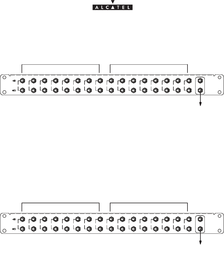
document, use and communication of its contents
not permitted without written authorization from ALCATEL
All rights reserved. Passing on and copying of this
Issue 02 -January, 10 2000 49/1363CC10875AAAA TQ BJA 02
STNT connectors (J105 to J112) connected to the top panel of the DBS subrack
with (n) 3CC11236AAAA cable(s).
Figure 31 – 1.6/5.6, 75 ohms distributor
1 2345678910111213141516 AUX
E1/T1 1 – 8 E1/T1 9 – 16
not connected
75 ohms BNC distributor for16 E1 / T1 ref,: 3CC08061ABAA.
SOne distributor per TNT board.
STNT connectors (J105 to J112) connected to the top panel of the DBS subrack
with (n) 3CC11237AAAA cable(s).
Figure 32 – BNC 75 ohms distributor
1 2345678910111213141516 AUX
E1/T1 1 – 8 E1/T1 9 – 16
not connected
3.6.3.3 – Connections to 120 ohm distributors.
SConnections are made beneath the roof of the standard rack.
TNT connectors (J105 to J112) connected to the top panel of the DBS subrack with (n)
3CC11238AAAA cable(s).
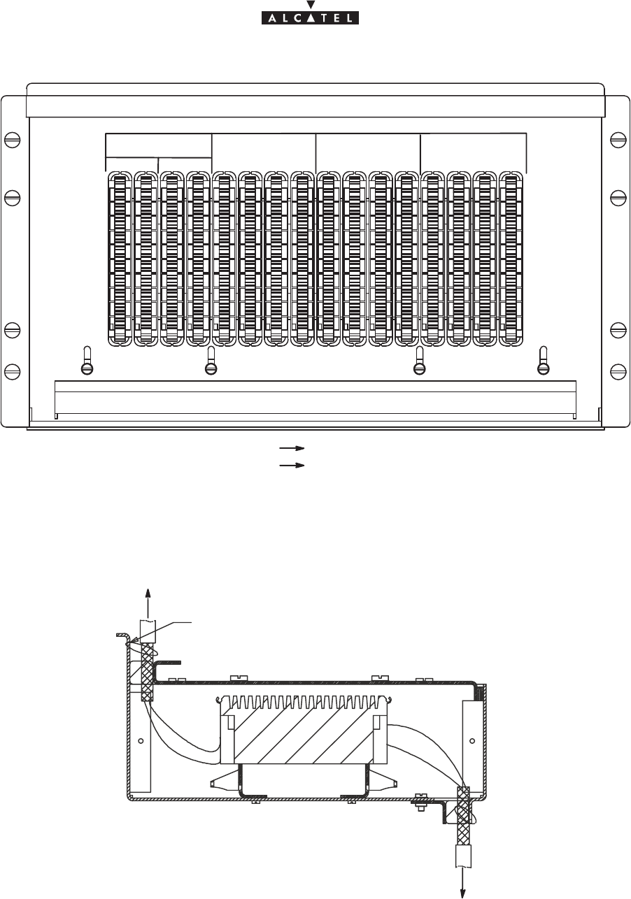
document, use and communication of its contents
not permitted without written authorization from ALCATEL
All rights reserved. Passing on and copying of this
50/136 3CC10875AAAA TQ BJA 02
Issue 02 -January, 10 2000
Figure 33 – Connection panel beneath the roof of the standard rack.
1
2
3
4
5
6
7
8
1/8
9/16
9
0
1
1
1
2
3
4
5
6
7
8
1
1
2
1
3
1
4
1
5
1
6
1 – 8 9 – 16
E1/T1 TNT1 E1/T1 TNT2 E1/T1 TNT3 E1/T1 TNT4
TX RX TX RX TX RX TX RX TX RX TX RX TX RX TX RX
Out put DBS
In put DBS
RX access
TX access
Figure 34 – Cable mounting and grounding.
TY–RAP
CLIENT ACCESS
TO DBS
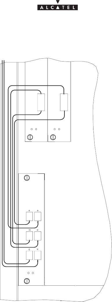
document, use and communication of its contents
not permitted without written authorization from ALCATEL
All rights reserved. Passing on and copying of this
Issue 02 -January, 10 2000 51/1363CC10875AAAA TQ BJA 02
3.6.4 – Customer access connections (ATM network interface)
Suse the fiber optic connections on the FO board front panel.
ANTANT
IN
OUT OUT
IN
IN OUT
CPL
Figure 35 – Fiber optic cables connection
– To avoid damaging the fiber optic cables:
Sinsert the jumpers in the direction indicated in Figure 37,
Sconnect the fiber optic connection cable, fitted with its SC/PC connector, to the optical coupler
board by passing it through the top of the rack and along the cable run provided.
– Use a winding cassette when connecting one or more fiber optic cables of over 10 meters in length.
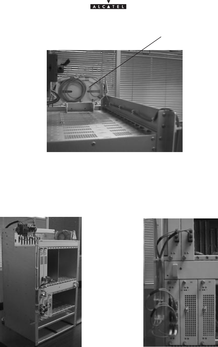
document, use and communication of its contents
not permitted without written authorization from ALCATEL
All rights reserved. Passing on and copying of this
52/136 3CC10875AAAA TQ BJA 02
Issue 02 -January, 10 2000
Figure 36 – DBS fiber optic winding cassettes
Winding cassettes
Storage
1. According to the site configuration, prepare the connection cables and fit them with the required connectors.
Figure 37 – Fiber optic cables wiring
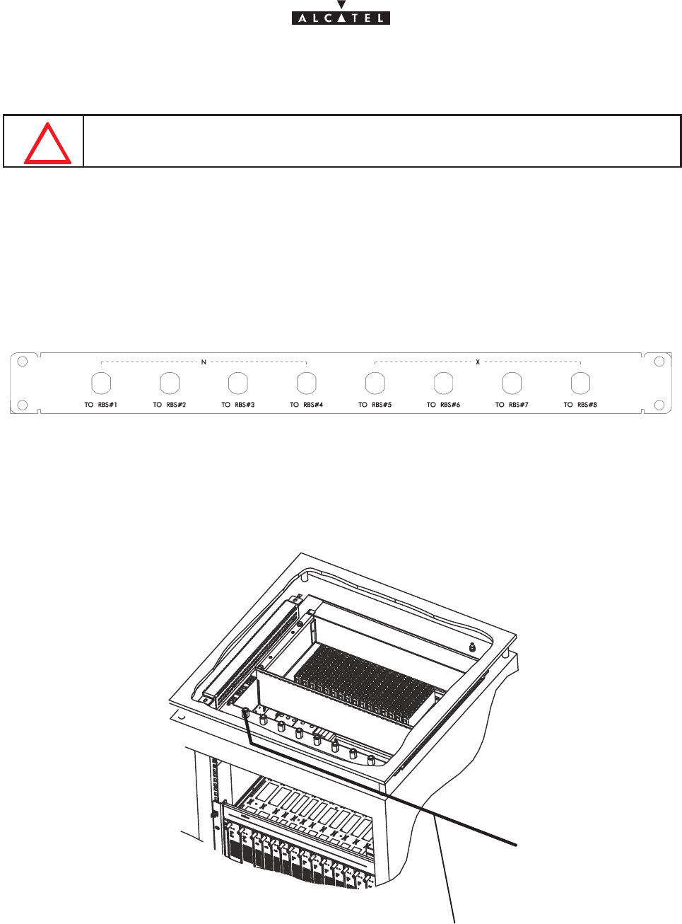
document, use and communication of its contents
not permitted without written authorization from ALCATEL
All rights reserved. Passing on and copying of this
Issue 02 -January, 10 2000 53/1363CC10875AAAA TQ BJA 02
2. Connect the fiber optic jumpers (see Figure 36 and Figure 37) and the main cables.
DO NOT SET THE FIBER OPTIC IN FRONT OF THE VENTILATION PLUG–IN UNIT: SET
IT AS SHOWN IN FIGURE 37.
3. Replace the (removable) top cover of the rack and secure.
3.6.5 – RBS/DBS Connection
– Each coaxial access is linked to an IBS board, via a coaxial cable included in the DBS sub–rack.
– Connect the RBS/DBS cables on the pannel located at the top of the rack or above the DBS sub–rack.
Figure 38 – RBS connection pannel
Figure 39 – RBS Cnnection
Câble

document, use and communication of its contents
not permitted without written authorization from ALCATEL
All rights reserved. Passing on and copying of this
54/136 3CC10875AAAA TQ BJA 02
Issue 02 -January, 10 2000
PAGE INTENTIONALLY LEFT BLANK

document, use and communication of its contents
not permitted without written authorization from ALCATEL
All rights reserved. Passing on and copying of this
Issue 02 -January, 10 2000 55/1363CC10875AAAA TQ BJA 02
4 – 9900LT software overview
4.1 –General information
The purpose of this chapter is to present the different screens of the 9900LT software supplied with the Base
Station. The following chapters will make reference to this presentation each time the user needs to access the
software for a particular action (commissioning, maintenance or evolution of the configuration). The same
screen may apply for several types of action.
4.1.1 – Functionalities
The 9900LT software enables:
– supervision of both the system assembly as a whole (the NE (Network Element)), and of its
sub–assemblies (DBS, RBS, NT);
– configuration of the sub–assemblies (DBS, RBS, etc.) (used when Commissioning, § 5);
–setting up services (E1 leased lines, IP cross–connection), (used when Commissioning, § 5);
– downloading (used in Maintenance, § 6).
Nota : The 9900LT software does not manage the radio part of the terminal stations (ODU). These
generate no alarms, and therefore require no other configuration apart from the installation
configuration
4.1.2 – Principles of the Man–Machine Interface (MMI) of the 9900LT
The user of the 9900LT software is expected to be familiar with the operation of software in the Windows NTt
environment. There follows a description of some of the basic principles of the Windows NTt MMI along with
others, more specific to the 9900LT.
4.1.2.1 – Opening, closing and resizing a window
Here is a reminder of how the boxes at the top right of an active window are used:
Click on.... To......
...minimize the active window to place the application on the taskbar.
Click on the taskbar icon to restore the window.
...maximize the window to full–screen size.
...restore a window which was in full–screen size to its original size.
...close the active window.
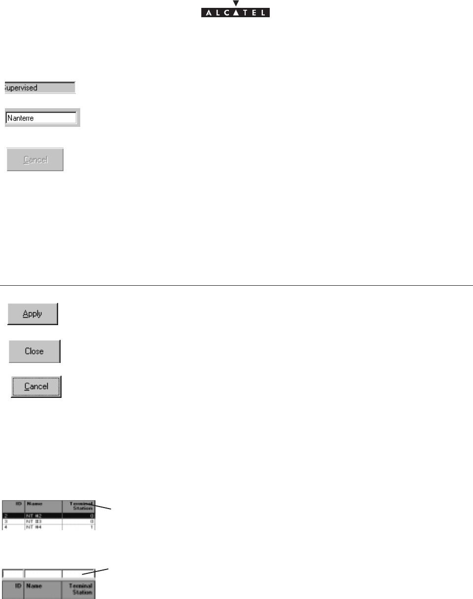
document, use and communication of its contents
not permitted without written authorization from ALCATEL
All rights reserved. Passing on and copying of this
56/136 3CC10875AAAA TQ BJA 02
Issue 02 -January, 10 2000
4.1.2.2 – Entry fields
The grayed out fields are for consultation only: their content cannot be modified;
The fields on a white background can be modified: left–click to make the cursor appear
inside the field, then enter the character string required.
According to the same principle, the buttons, icons and items in the pull–down menus
become grayed out when they are inactive.
4.1.2.3 – Confirmation, closing a window, canceling an entry
In the lower part of the windows there may be buttons (which may or may not be active; cf. § 4.1.2.2), the
principle of which is as follows:
Click on.... To......
confirm the data entry, while keeping the window open.
close the active window, thereby canceling any unconfirmed data entries.
cancel the data entry, while keeping the window open.
4.1.2.4 – Sorting and searching in a list
Certain screens contain lists which may contain many lines; a sort and/or search tool is therefore available via
the MMI, in order to facilitate data management:
Left–click once on any column title in order to sort the alphanumeric entries in
increasing order of magnitude; click a second time to sort in the opposite order
(and so on).
When the lists have empty boxes above the titles, it is possible to carry out a
search to display the line required:
click on the box above the title under which to be searched, then enter the first
characters of the sequence in question: the first line to correspond is selected.
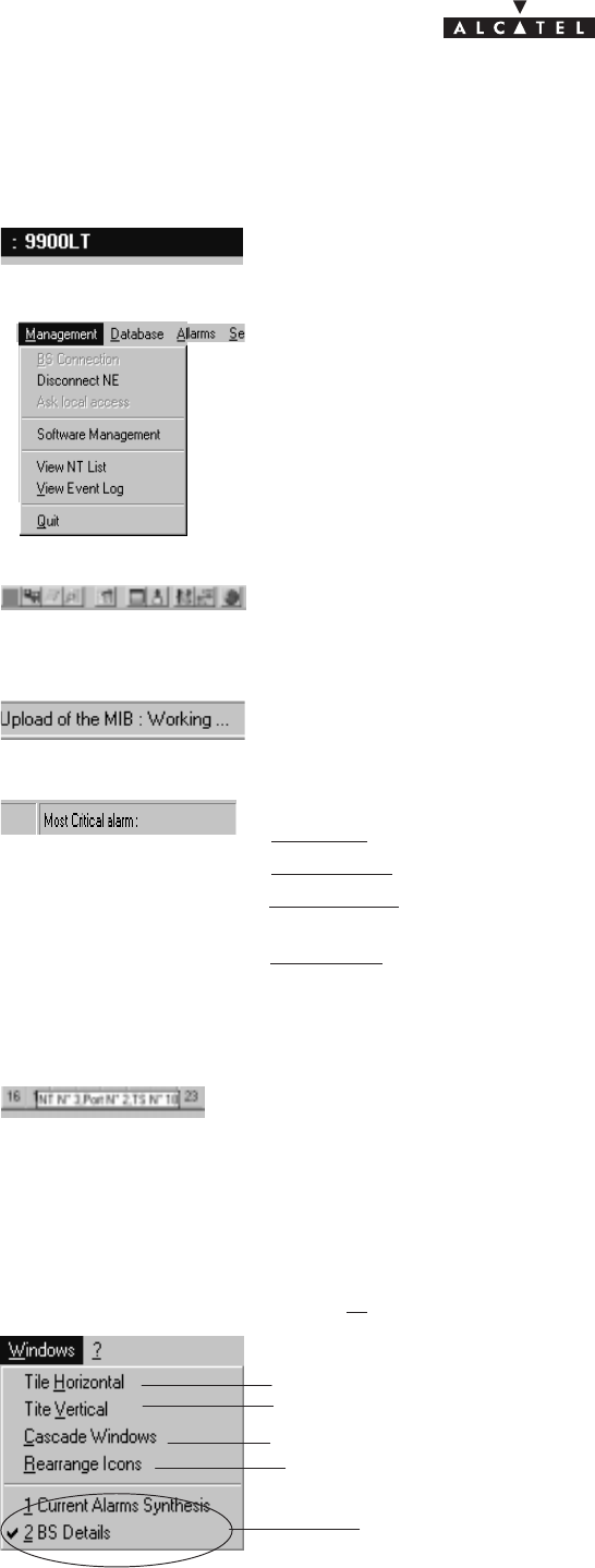
document, use and communication of its contents
not permitted without written authorization from ALCATEL
All rights reserved. Passing on and copying of this
Issue 02 -January, 10 2000 57/1363CC10875AAAA TQ BJA 02
4.1.2.5 – Title, menu, button and status message bars
The various information and functionalities of the 9900LT are accessible in several forms of MMI:
Title bars (at the top of the main window): for information only; this is the title of
the window.
Menu bar (below the title bar): each menu contains items.
To access, open the pull–down menu by left–clicking on the title, then click on the
desired item (for execution it must be active, cf. § 4.1.2.2).
Button bar (below the title bar): certain menu functionalities are also directly
accessible by clicking on the buttons displayed at the top of the window.
Message bar (at the bottom of the active window): messages linked to current
events are displayed on the fly in certain windows.
Status bar (at the bottom of the 9900LT main window), divided into 4 areas:
– on the left: global user’s messages (states of progress, error messages, etc.)
– left of center:
local access
: information about write access (cf. § 4.4.3 )
– right of center:
Number of NTs
: displays the number of NTs declared in the system
by the Manager.
– on the right: “
Most critical alarm
”: displays the color of the most critical alarm (see
alarm color codes, § 4.10.4).
4.1.2.6 – Dynamic keys
Each time the cursor rests for several moments on a button (and sometimes on a
field), a textual key on a yellow background defining this button (or field) is
displayed.
4.1.3 – Rearrangement of active windows
During the use of the 9900LT software, several windows may be active simultaneously. The MMI allows you
to rearrange them to optimize their visibility, in classic Windows fashion.
Access this function by opening the Windows pull–down menu:
horizontal rearrangement: horizontal display of several windows
vertical rearrangement: vertical juxtaposition of several windows
cascade rearrangement: diagonal alignment of several windows
list of active windows: select the particular one
that you wish to display
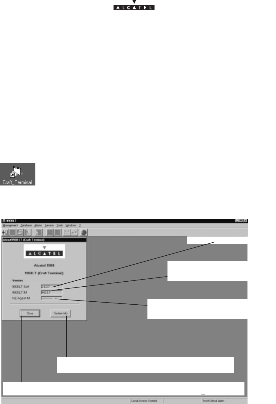
document, use and communication of its contents
not permitted without written authorization from ALCATEL
All rights reserved. Passing on and copying of this
58/136 3CC10875AAAA TQ BJA 02
Issue 02 -January, 10 2000
4.2 –Running and quitting the software
4.2.1 – Installation of the 9900LT software
The 9900LT is either loaded on the PC which came with the BS, or comes on an installation medium (e.g.,
CD–ROM).
If you need to install the 9900LT software, refer to the “A9900 Craft installation” Appendix; otherwise, go directly
to the next paragraph to run the already installed software.
4.2.2 – Accessing and running 9900LT
To run 9900LT, go to the WindowsR taskbar and left–click on the
Start
button: the
Start
menu is displayed. Next,
select the
Progams
menu followed by the line
Craft_Terminal
.
or:
Click on the icon shown here which is on the desktop .
To run 9900LT, the following screen is displayed:
9900LT software version
Short–cut to the MicrosoftW system management function
(refer to corresponding documentation)
Click here to close the
About
window and work on the main window of the 9900LT. You
can access it again by selecting the heading
About Craft_Terminal
in the ? menu.
Version of the “Info Model” common exchange
database at the Agent (NE) side, filled in au-
tomatically upon connection to the BS
Version of the “Info Model” common
exchange database at the Manager
(9900LT) side
Nota : The common IM database versions at the Manager and Agent sides must be identical.
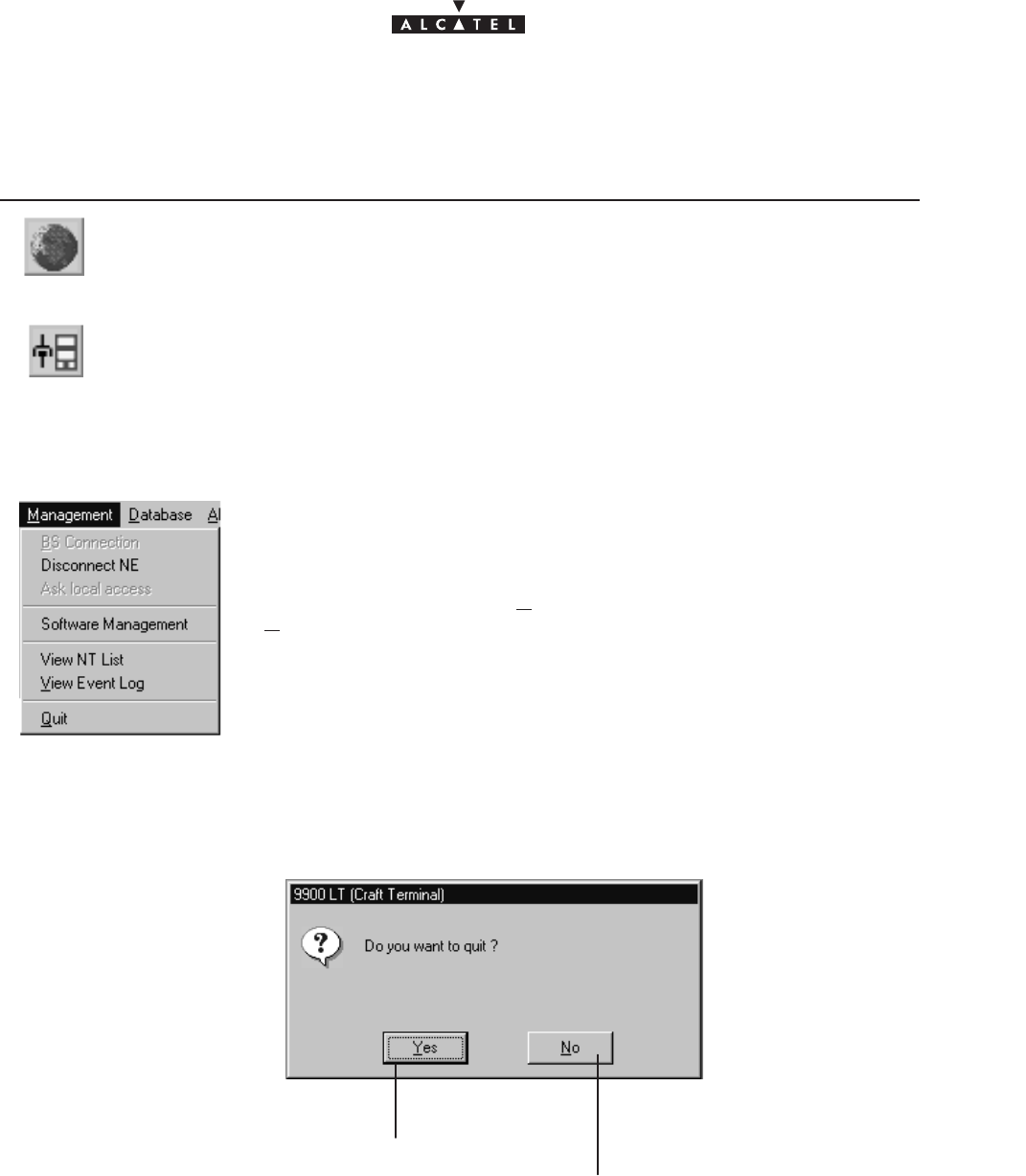
document, use and communication of its contents
not permitted without written authorization from ALCATEL
All rights reserved. Passing on and copying of this
Issue 02 -January, 10 2000 59/1363CC10875AAAA TQ BJA 02
On the screen displayed, only two icons are active: the choice of language and the BS connection:
Click on.... To....
...access the choice of language: French or (by default) English
...access the BS connection (cf. comments in paragraph 4.3.1)
4.2.3 – Quitting the 9900LT
To quit the 9900LT, open the
Management
pull–down menu and click on
Quit
.
A confirmation dialog box is displayed:
Click here to cancel the request to quit the
9900LT and return to the previous window.
Click here to confirm.
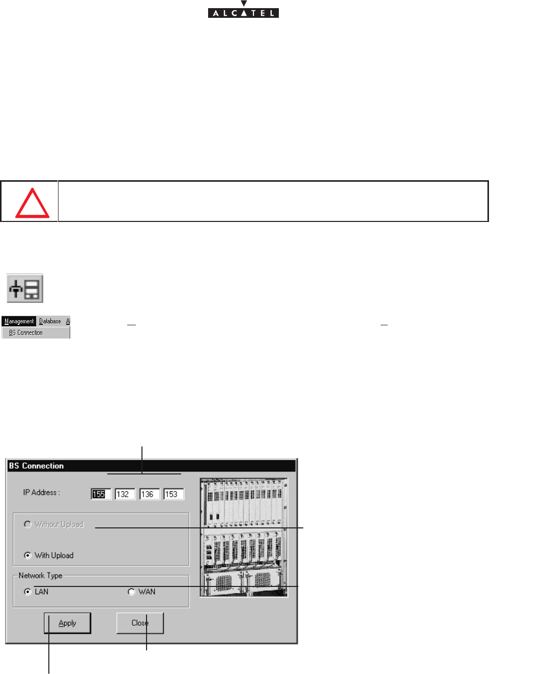
document, use and communication of its contents
not permitted without written authorization from ALCATEL
All rights reserved. Passing on and copying of this
60/136 3CC10875AAAA TQ BJA 02
Issue 02 -January, 10 2000
4.3 –Connection and Disconnection
4.3.1 – BS Connection
The BS connection process consists partly in the NE “Agent” identifying the “Manager” and partly in the retrieval
of data for the NE assembly on the 9900LT software by manual request: this involves the updating of site
information.
ONLY ONE LT SESSION IS OPERATIONEL ON ONE BS.FOR EXEMPLE A LOCAL LT
CONNECTION AND A REMOTE LT CONNECTION AT THE SAME TIME ON THE SAME
BS,IS NOT POSIIBLE.
There are two possible ways of accessing the BS Connection:
– click on the first button (provided that it is active; cf.§ 4.1.2.2) of the main menu button
bar,
or else,
– open the
Management
pull–down menu and select the first item:
BS Connection
.
The following screen is displayed:
IP Address of the BS to be connected: click in a byte field to modify the value;
by default, the address of the last BS to be connected is the value entered.
connection type: with data upload
(default selection)
Click here to return to the previous screen.
Click here to run the data update procedure.
(not applicable)
(not applicable)
network type: there are two types of
network: local (LAN) or remote (WAN):
check the button for the type of network
corresponding to the system configura-
tion (see Commissioning, section 5).
Throughout the update, an animated display indicates to the user that data transmission is underway, with
on–screen indication of the progress of the processed files.
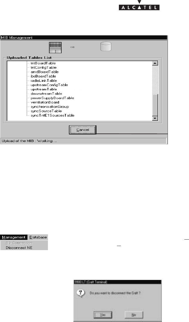
document, use and communication of its contents
not permitted without written authorization from ALCATEL
All rights reserved. Passing on and copying of this
Issue 02 -January, 10 2000 61/1363CC10875AAAA TQ BJA 02
click here to cancel the data update pro-
cedure.
Once the update is completed, two new windows are displayed:
– one screen providing a global view of the base station (cf. § 4.5);
– and one screen summarising the current alarms (cf. § 4.10)
4.3.2 – Disconnecting the NE assembly
The NE disconnection process consists in closing the current session relating to a given BS in order to connect
to another BS of the system.
To access the NE disconnection function, open the
Management
pull–down menu
then select the first item:
Disconnect NE
.
A confirmation screen is displayed:
document, use and communication of its contents
not permitted without written authorization from ALCATEL
All rights reserved. Passing on and copying of this
62/136 3CC10875AAAA TQ BJA 02
Issue 02 -January, 10 2000
4.4 –Supervision Principles
The 9900LT can be used for supervising the whole A9900 Network Element (NE) system.
The NE comprises of:
–a Base Station (9900BS) which mainly includes a Radio unit (RBS) and a MODEM rack (DBS)
– one or more Terminal Stations (9900TS) which mainly include a Radio unit (RT) and a User connection
unit (NT). Nevertheless the 9900LT software does not manage RT units.
The display allows system control; alarms are activated in particular to signify any intervention.
The supervision items themselves are by definition grayed out and therefore unmodifiable, whereas those
reserved for configuration can be configured by the user. They will be used in the following chapters concerning
commissioning, maintenance and configuration evolution. For the modifications to be taken into account, two
conditions must prevail: you must be in supervision mode (cf. section 4.4.1) and have write access
authorization (cf. section 4.4.3).
4.4.1 – Supervision activation/ deactivation
It is possible to delete the supervision function for a sub–assembly (BS or NT) or assembly (NE), in order to
avoid a stream of data and alarms (e.g. when modifying a sub–assembly).
The supervision activation/deactivation buttons are similar for each of the various screens relating to the
different sub–assemblies. Supervision is symbolized by an eye:
Click on..... To....
ou ...activate supervision of the BS or NT respectively.
ou ...stop supervision of the BS or NT respectively.
4.4.2 – Data retrieval
According to the same principle as for starting up the 9900LT (automatic data retrieval following connection),
this update can be carried out for each individual equipment item; data recovery is symbolized by a red
arrow on the screen buttons relative to the equipment:
Click on... To...
or or ...activate the data recovery function for the NE, BS, and NT respectively.
Nota : these operations may take quite a long time (in particular for the NE) since they depend on the allocated
bit rate of the connection between BS and manager.
4.4.3 – Local access requests
The general status bar (cf. section 4.1.2.5) displays in its central part the messages concerning write access
authorization: “
Local Access : Denied / granted
”. Where there are two system managers (9900LT and an
Operating System (OS : ex:1353)), these access rights are allocated by the OS manager; otherwise, write
access is authorized by default for the 9900LT.

document, use and communication of its contents
not permitted without written authorization from ALCATEL
All rights reserved. Passing on and copying of this
Issue 02 -January, 10 2000 63/1363CC10875AAAA TQ BJA 02
4.4.4 – Administrative statuses
Locking the administrative status of sub–assemblies allows the maintenance operator to disable the
sub–assembly manifesting an anomaly without disturbing the system.
Unlocking sub–assembly administrative status frees service use for the end user.
Operator is not able to modify the administrative state assembly. He only can change the ports and
cross–connections.
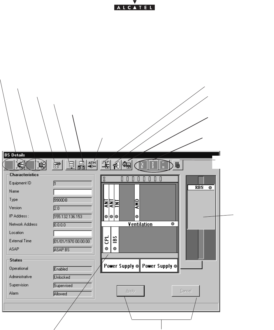
document, use and communication of its contents
not permitted without written authorization from ALCATEL
All rights reserved. Passing on and copying of this
64/136 3CC10875AAAA TQ BJA 02
Issue 02 -January, 10 2000
4.5 –Base Station Supervision
RBS display:
cf. § 4.5.4
become accessible when “
Name
” or
“
Location
” fields are modified
DBS display:
cf. § 4.5.2
BS UpLoad: cf. § 4.4.2
Activation/Cancellation of BS supervision: cf. § 4.4.1
Activation/Cancellation of BS alarm: cf. § 4.10.1
Actions on the BS boards:
cf. § 4.5.2
ATM parameters:
cf. § 4.9.1
Local IP address parameters: cf. § 4.9.2
Synchronisation parameters:
cf. § 4.9.3
Radio parameters:
cf. § 4.7
Memory initialization:
cf. § 4.5.3
Sending the Clock
to the agent
Configuration of
the interfaces : cf.
§ 4.9.4
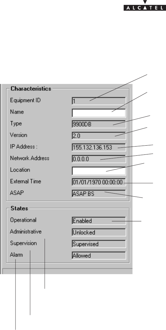
document, use and communication of its contents
not permitted without written authorization from ALCATEL
All rights reserved. Passing on and copying of this
Issue 02 -January, 10 2000 65/1363CC10875AAAA TQ BJA 02
4.5.1 – General parameters
The left side of the BS supervision screen shows the characteristics and associated states:
BS manufacturer No.
Identification No.: 1 for the BS
BS name: click to enter the BS name: it will appear
in the title bar.
BS version No.
BS Location: click to enter the town or geographical
sector where the BS is located.
Last BS time setting
Name of the alarms correspondence base:
cf. § 4.10.4
Operational state (enabled/disabled): indicates
the technical availability status of the equipment
with respect to service provision.
Administrative state (locked/unlocked): indicates whether locked or unlocked for
modification at the network management level (cf. section 4.4.4).
Supervision state (supervised/unsupervised): cf.§ 4.4.1
Alarm state (allowed/locked): cf. § 4.10.1
IP address of BS access via 10 Bt Eth port
IP address of BS access via ATM port
Demo Manu
Nanterre
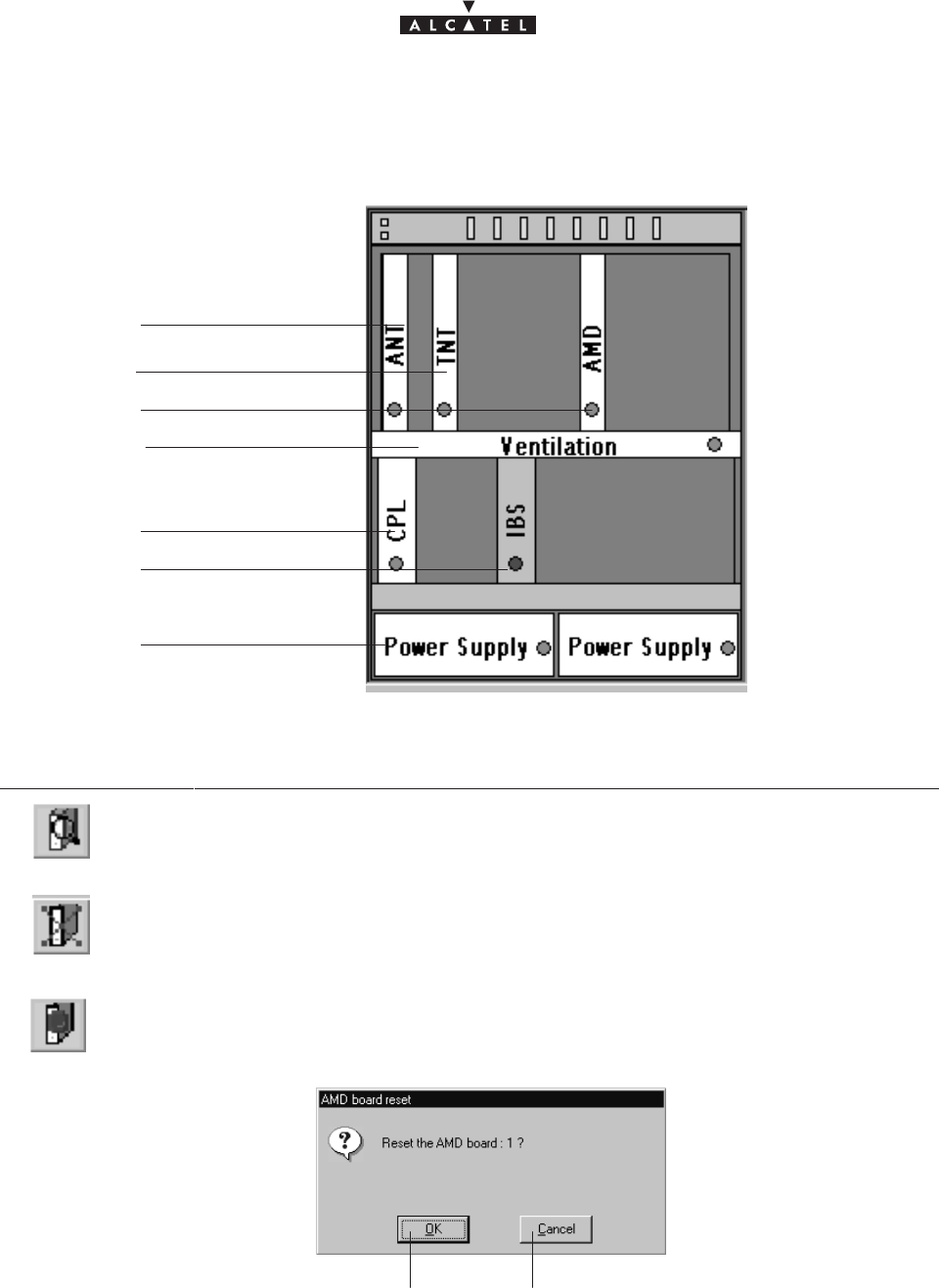
document, use and communication of its contents
not permitted without written authorization from ALCATEL
All rights reserved. Passing on and copying of this
66/136 3CC10875AAAA TQ BJA 02
Issue 02 -January, 10 2000
4.5.2 – DBS
The central part of the BS supervision screen shows the rack and its sub–assemblies as detected by the 9900LT:
cf. §4.5.2.1
cf. §4.5.2.2
cf. §4.5.2.3
cf. §4.5.2.6
cf. §4.5.2.7
cf. §4.5.2.4
cf. §4.5.2.5
On the BS screen button bar:
Click on..... To....
...access the details of a selected sub–assembly (or double–click directly on one of
the sub–assemblies)
...delete a selected sub–assembly; the data retrieval phase (BS upload) will be run au-
tomatically.
...reset a selected board.
A confirmation screen is displayed:
Click here to confirm
reset of the selected board.
Click here to cancel the reset request
for the selected board.
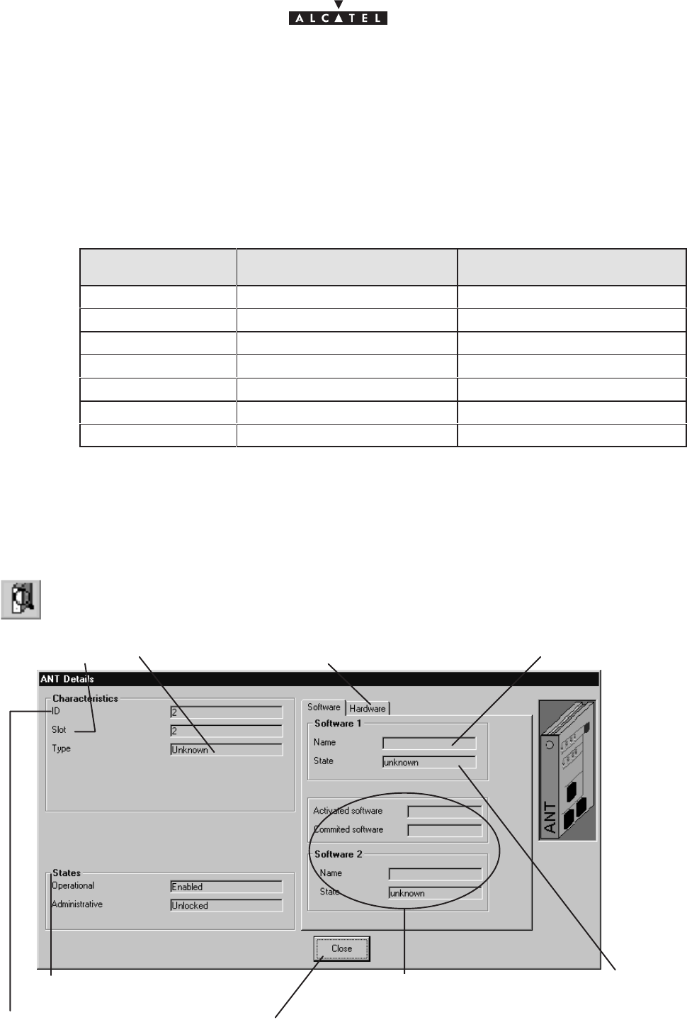
document, use and communication of its contents
not permitted without written authorization from ALCATEL
All rights reserved. Passing on and copying of this
Issue 02 -January, 10 2000 67/1363CC10875AAAA TQ BJA 02
Symbols on the equipment representations:
– green spot: no alarm is detected;
– colored spot (other than green): alarm detected: the color displayed corresponds to the most critical alarm
level (cf. §4.10.4);
– white board: board physically present in the rack;
– gray board: board physically removed but still present in the system management.
Number of equipments in the rack:
Equipment designation Maximum number of equipments
managed by the system Maximum number of equipments
that can be included in the BS
ANT board 1 2
TNT board 4 4
AMD board 4 8
CPL board 1 1
IBS board 4 8
Power Supply Unit 2 2
RBS 4 8
Nota: To activate a radio sector, the triplet of AMD, IBS and RBS must be present in the rack and configured
on the 9900LT. When you physically insert in the rack, for example, an AMD board, an IBS board and
an RBS ODU will automatically be created on the 9900LT.
4.5.2.1 – ANT board screen
ANT (ATM Network Termination): NE input board for network management.
Board family ID No.
Name of ANT integrated sofware
Board states: only two states are
defined for the boards: cf. § 4.5.1
Click here to return to the BS screen.
Board slot No.
State of ANT in
tegrated
sofware
Board type Click on this tab to display the screen
relating to the hardware part of the board.
Fields completed after downloading:
cf. § 4.12.1
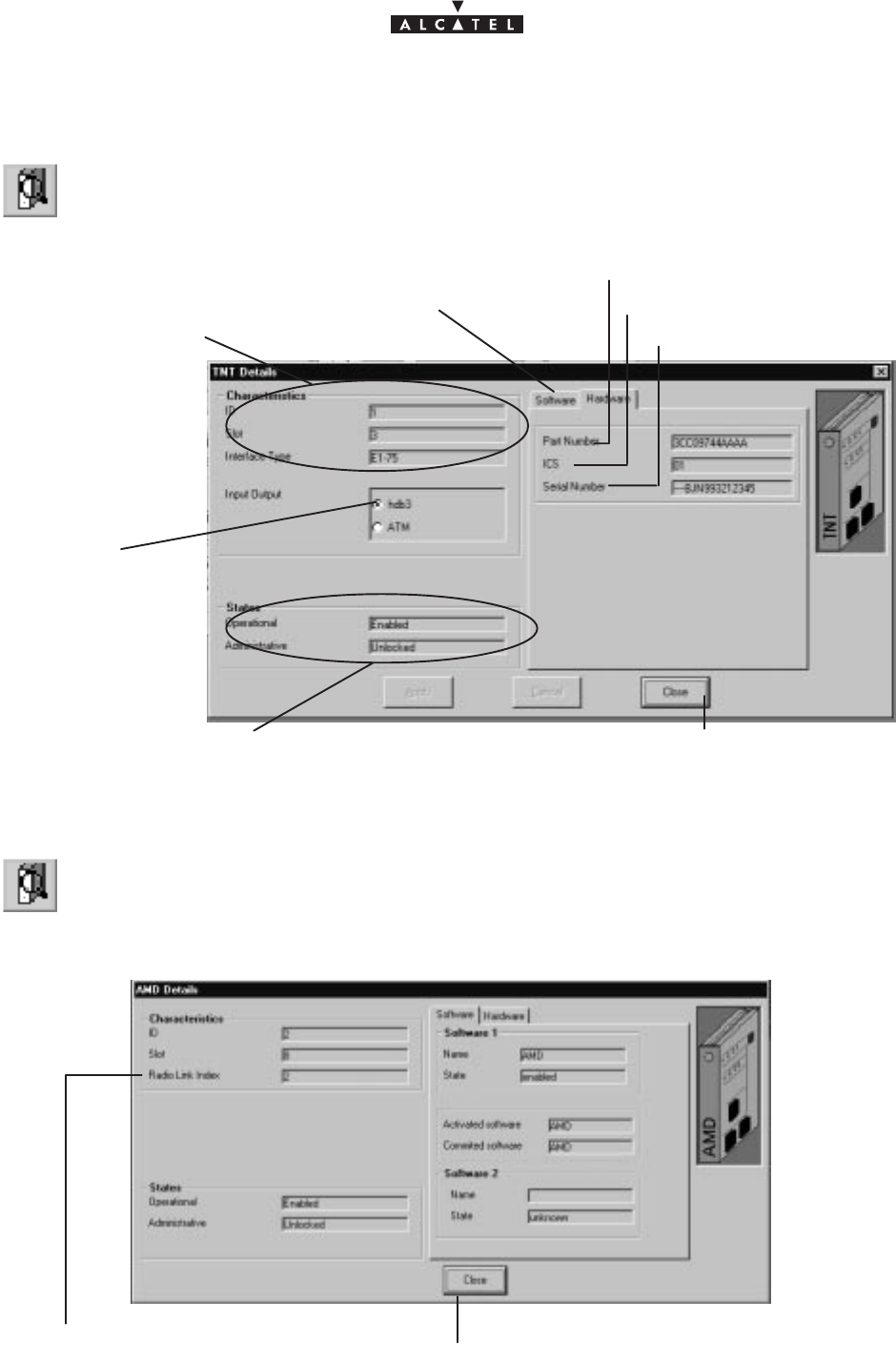
document, use and communication of its contents
not permitted without written authorization from ALCATEL
All rights reserved. Passing on and copying of this
68/136 3CC10875AAAA TQ BJA 02
Issue 02 -January, 10 2000
4.5.2.2 – TNT board screen
TNT (Telephony Network Termination): board providing the leased line service (E1).
cf. previous section
cf. previous §
Click here to return to the BS screen
Input type used
on the TNT
(currently the only
one available)
Part No.
Status change
Board serial No.
Click on this tab to display the
screen relating to the
software part of the board
4.5.2.3 – AMD board screen
AMD (Air MODEM) : modem board
Click here to return to the BS screen
for the items on this screen, refer to the description of the ANT board (§ 4.5.2.1)
No. of radio sector covered by the board
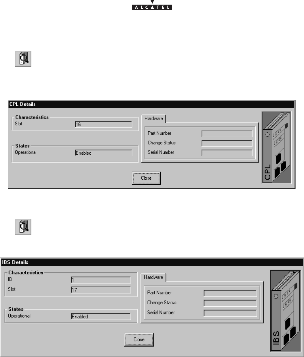
document, use and communication of its contents
not permitted without written authorization from ALCATEL
All rights reserved. Passing on and copying of this
Issue 02 -January, 10 2000 69/1363CC10875AAAA TQ BJA 02
4.5.2.4 – CPL board screen
CPL (Coupler): network interface coupler board.
for the items on this screen, refer to the description of the ANT board (§ 4.5.2.1)
4.5.2.5 – IBS board screen
IBS: radio link intermediate board
for the items on this screen, refer to the description of the ANT board (§ 4.5.2.1)
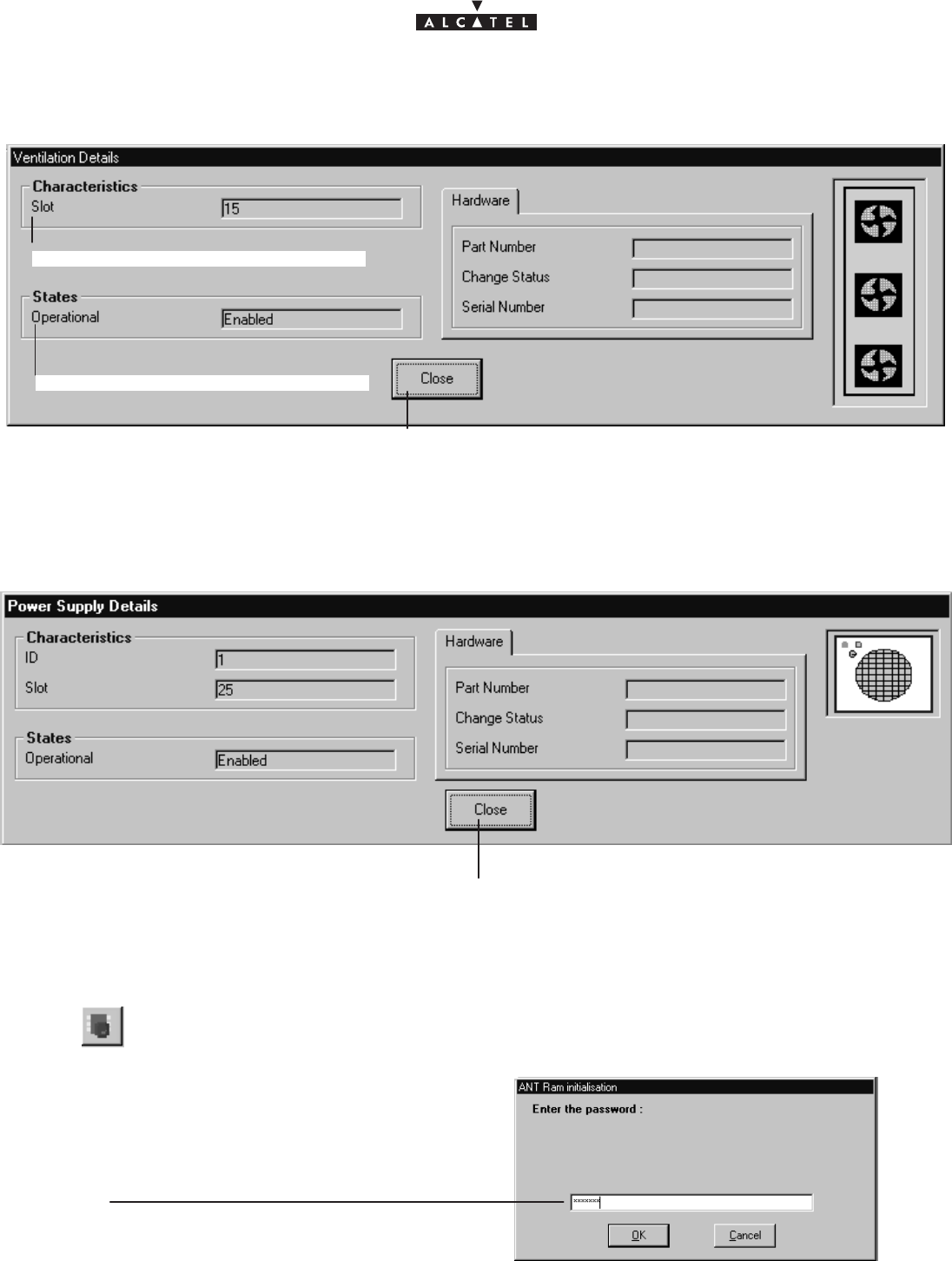
document, use and communication of its contents
not permitted without written authorization from ALCATEL
All rights reserved. Passing on and copying of this
70/136 3CC10875AAAA TQ BJA 02
Issue 02 -January, 10 2000
4.5.2.6 – Ventilation
Click here to return to the BS display screen.
Number of ventilation slot
Operation state: enable / disable
for the items on this screen, refer to the description of the ANT board (§ 4.5.2.1)
4.5.2.7 – Power supply
Click here to return to the BS display screen.
for the items on this screen, refer to the description of the ANT board (§ 4.5.2.1)
4.5.3 – Memory initalization
This function allows memory initialization by the SNMP agent located in ANT board.
The function, maintenance restricted, is destructive of the current configuration.
Operator has to enter the password to starting this
function.
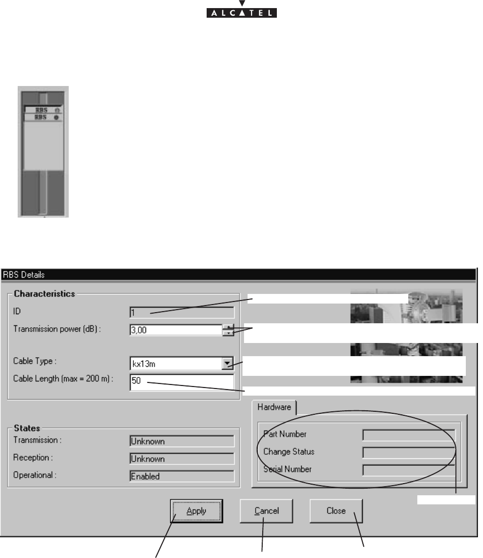
document, use and communication of its contents
not permitted without written authorization from ALCATEL
All rights reserved. Passing on and copying of this
Issue 02 -January, 10 2000 71/1363CC10875AAAA TQ BJA 02
4.5.4 – RBS
On the right of the BS supervision screen are all the ODUs (RBS) associated with the
BS:
Double–click on the RBS whose details you require, in order to display the following
screen:
Click here to take into ac-
count the modifications Click here to close the
window and to retourn to
the BS window
Click here to cancel
the modifications
RBS identification number
Click on the arrows to display the power trans-
mission (in dB, one step every 0,25 dB)
Click on the arrow to open the list and to select-
the cable type
Click here to enter the reel cable lenght
cf. § 4.5.2.2
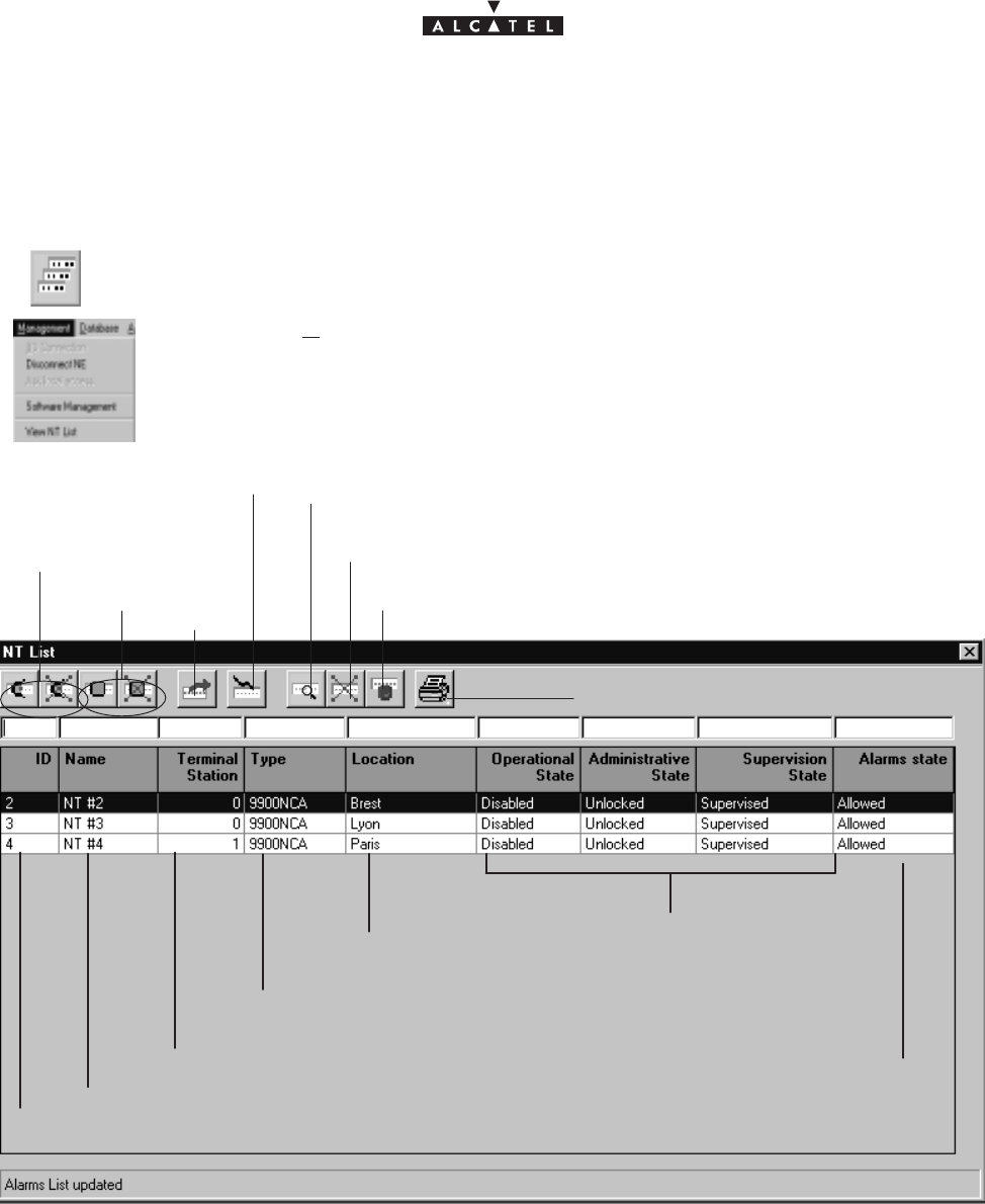
document, use and communication of its contents
not permitted without written authorization from ALCATEL
All rights reserved. Passing on and copying of this
72/136 3CC10875AAAA TQ BJA 02
Issue 02 -January, 10 2000
4.6 –NT Supervision
To access the list of declared NTs associated with the BS:
click on the third button of the main menu button bar,
or else,
open the
Management
pull–down menu and choose the first item:
View NT List
.
Names of NTs cf. §4.6.1
Click here to add an NT: cf. §4.6.1
ID Nos. of NTs: from 2 to 4001
Click here to access the characteristics of the NT
chosen from the list: cf. §4.6.2
Click here to delete an NT: cf. §4.6.3
Click here to reset an NT: cf.§ 4.6.4
Link TS cf. § 4.6.1
Location of NTs Operational, administrative and
supervision states of the NTs
Type of NTs: automatically entered after declaration of NTs
Click here to print the list of NTs
cf. §4.4.1
cf. §4.4.1
cf. §4.10.1
Alarms state
of NTs
Nota : The number of NTs present in the list corresponds to the “number of NTs” displayed permanently on
the main screen status bar (cf. § 4.1.2.5).
Nota : Remember that it is possible to access a given NT rapidly from the list of all NTs via the sort and search
functions (cf. § 4.1.2.4).
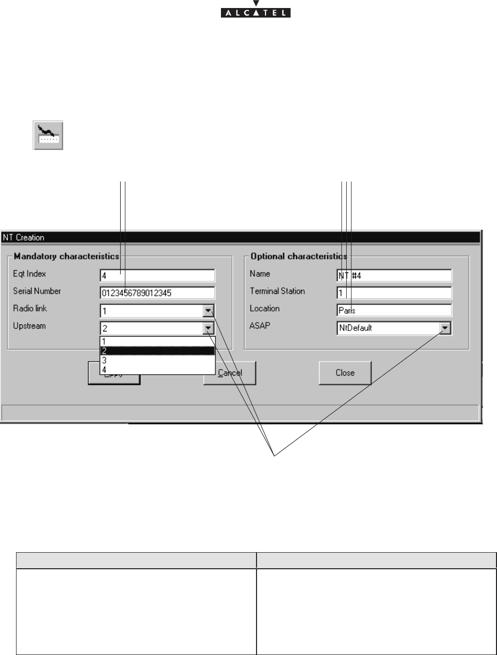
document, use and communication of its contents
not permitted without written authorization from ALCATEL
All rights reserved. Passing on and copying of this
Issue 02 -January, 10 2000 73/1363CC10875AAAA TQ BJA 02
4.6.1 – Declaring a new NT
To add an NT :
Click on the button shown here (on the NT screen button bar).
An input screen is displayed:
Click in the fields to enter the various information (described below)
Click on the arrows to display the list
then select : – the radio sector (radio link)
– the sub–band (upstream)
– the list of correspondence bases (ASAP)
Mandatory NT characteristics to be entered Optional NT characteristics to be entered
NT identification number (equipment index)
(from 2 to 4001): see data supplied by planner.
NT serial number: see data supplied by planner.
The corresponding Radio sector: from 1 to 4
Connected sub–band number: from 1 to 4
Name of NT: by default displays NT#
Eqt Index
ID
Terminal Station link: numerical entry supplied by
the planner
Location: town or geographical sector
ASAP name: alarms correspondence base.
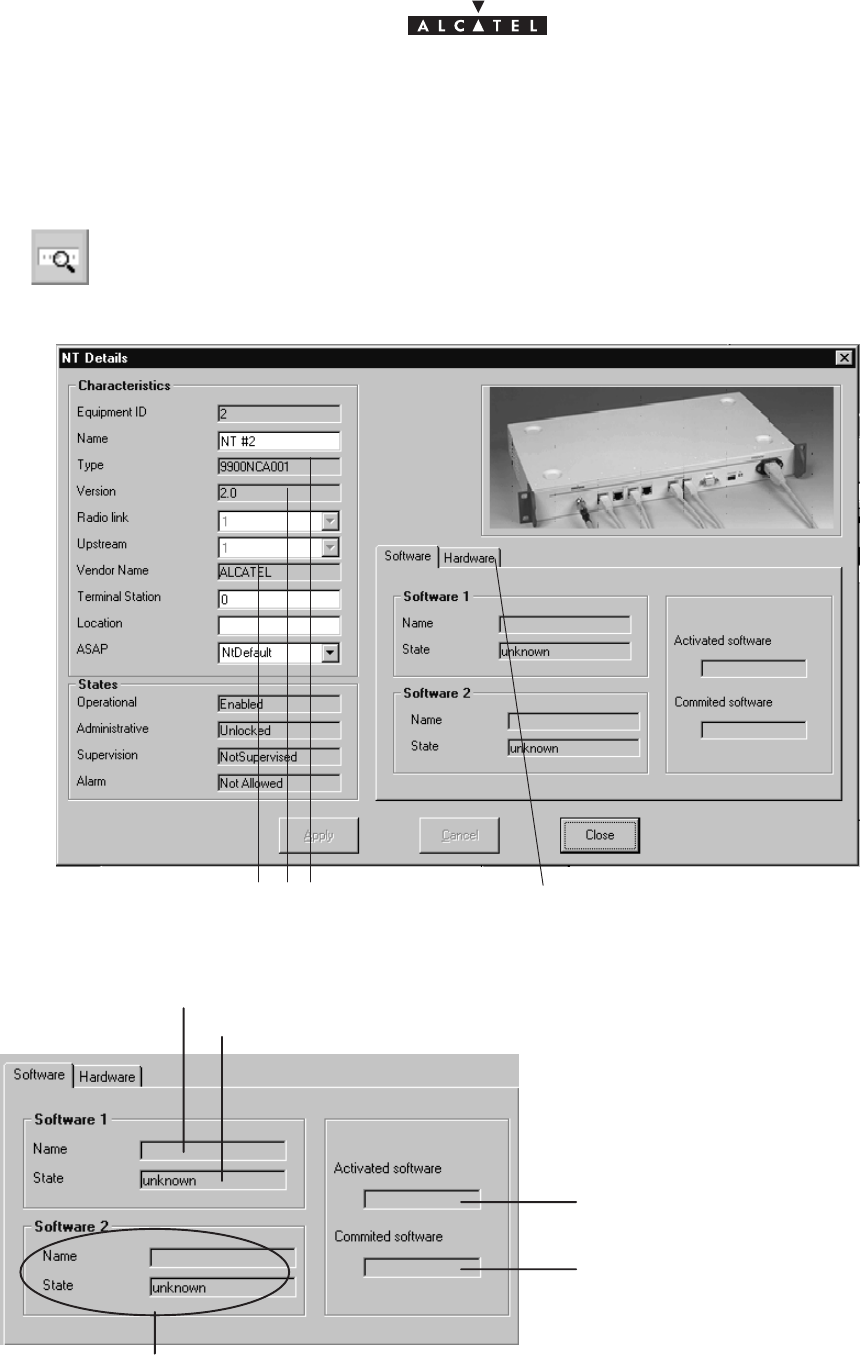
document, use and communication of its contents
not permitted without written authorization from ALCATEL
All rights reserved. Passing on and copying of this
74/136 3CC10875AAAA TQ BJA 02
Issue 02 -January, 10 2000
4.6.2 – NT Details
To access the characteristics of an NT:
click on the button shown here (NT screen button bar) or else double–click directly on a
line from the list of NTs.
A global screen is displayed in which (under
Characteristics
) the majority of the items in
the previous section are to be found:
Click on this tab to display the
hardware characteristics.
automatically filled in after de-
claration of the NTs
– NT software:
second software storage zone
name of the activated software
name of software
to be activated automatically
after reset
name of the software of the first storage zone
state of the software of the first storage zone
– NT hardware:
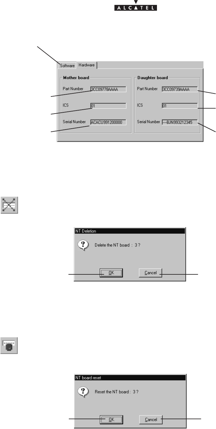
document, use and communication of its contents
not permitted without written authorization from ALCATEL
All rights reserved. Passing on and copying of this
Issue 02 -January, 10 2000 75/1363CC10875AAAA TQ BJA 02
Click on this tab to return to the NT software
Reference number
of the mather board
Status indication
Serial number
Reference number
of the daughter board
Status indication
Serial number
4.6.3 – NT deletion
To delete an NT :
– click on the NT in the list
– click on the button shown here (NT screen button bar)
A confirmation screen is displayed :
Click here to confirm NT
deletion. Click here to cancel the NT
deletion request.
4.6.4 – NT reset
To reset an NT:
– click on the NT in the list
– click on the button shown here (NT screen button bar); a confirmation screen is dis-
played :
Click here to confirm NT
reset. Click here to cancel the
NT deletion request.
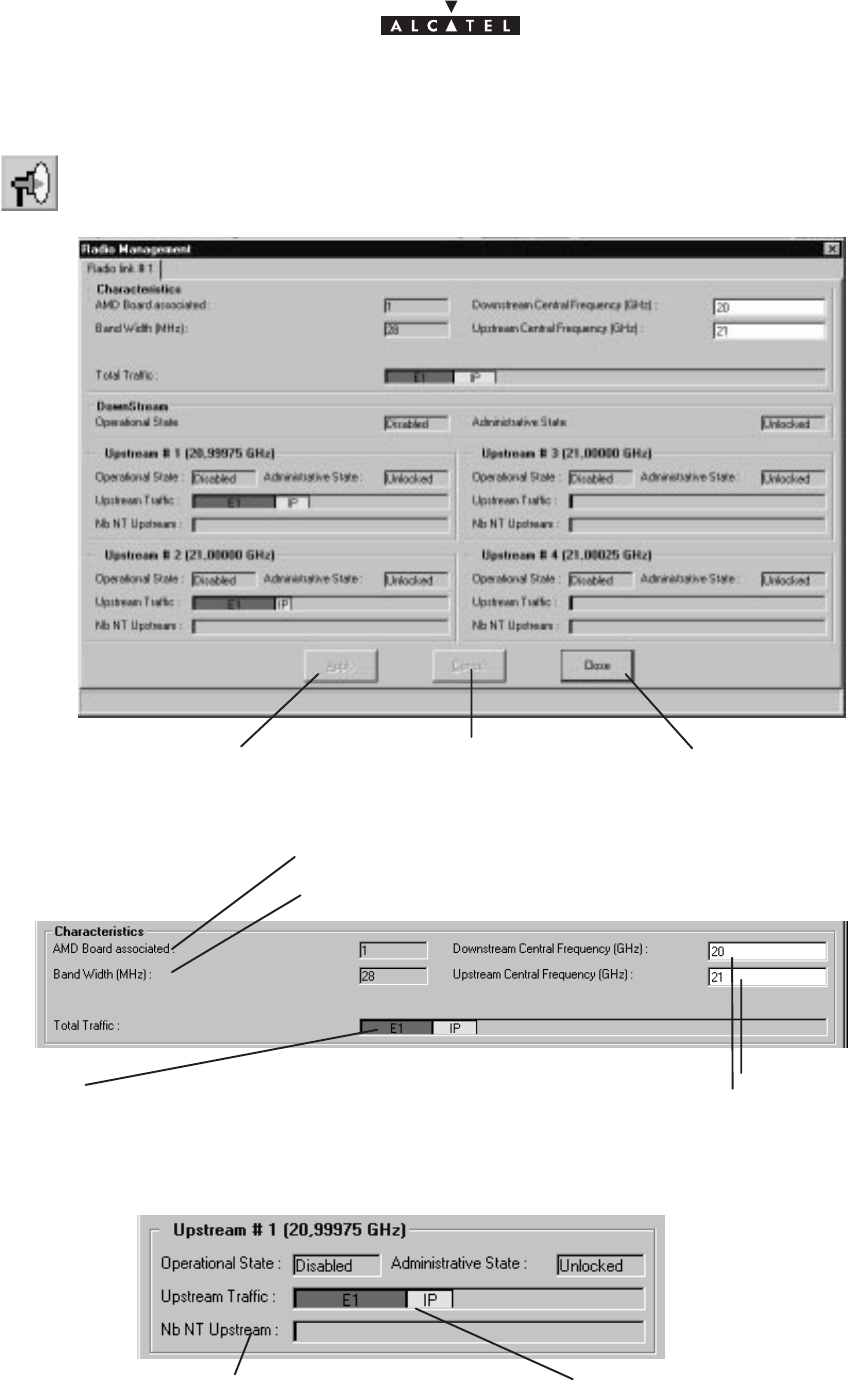
76/136 3CC10875AAAA TQ BJA 02
Issue 02 -January, 10 2000
4.7 –Radio supervision and parameters
To access the supervision and parameters of the Radio link, click on the button shown
here (BS screen button bar).
Click here to return to
the BS screen.
Click here to apply the
modifications. Click here to cancel the
modifications.
–
Radio characteristics
:
No. of the AMD board associated with the sector
Bandwidth
Click here to enter
the central frequen-
cies.
Progress bar indicating the traffic on the E1 and IP lines:
the total space available represents the maximum possi-
ble flow on this radio link in the downstream direction
– Upstream channel traffic
number of NTs connected to
Upstream channel No. 1 progress bar indicating the traffic on the E1 and IP lines:
the total space available represents the maximum possi-
ble flow on this radio link in the upstream direction
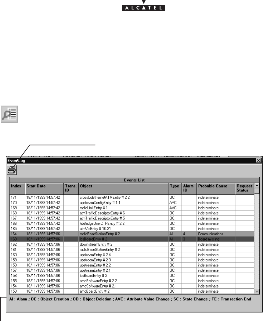
Issue 02 -January, 10 2000 77/1363CC10875AAAA TQ BJA 02
4.8 –NE supervision: Events log
The 9900LT software keeps a log of all the events taking place between the Agent (NE) and the Manager
(9900LT). The main utility of this supervision tool is for maintenance purposes (cf.§6).
Nota : The events log (in read only) is presented in reverse chronological order. The most recent event is at
the top of the list.
To access the
events log
:
– click on the button shown here (on the main screen of the 9900LT),
– or, open the
Management
pull–down menu and choose
View Event Log
.
Key of the different possible event types
Click here to print the events log on the default printer.
Index
: this is the event number; an incremental cyclic counter is activated each time an event takes place.
Start date
: time–stamping of the event (format: day/month/year, hour/minute/second)
Transaction ID
: number of the transaction enabling a link to be made between an action and all the events that
lead from it; in the above example, the action corresponding to event No. 181 has generated 10 other events
(cf. ID 18 group).
Object
: indicates the part of the system affected by the event (format: equipment ID designation followed by
port number)
Type
: Abbreviation (the key for which is permanently displayed at the foot of the window) of the event type:
alarm, deletion, creation, etc.
Alarme ID
: if an alarm is associated with the event, its number is entered.
Probable cause
: field associated with the alarm: description of the cause of the problem; the ASAP only gives
the severity for a given probable cause.
Request status
: abbreviation (the key for which is permanently displayed at the foot of the window) of the status
of the event in question.
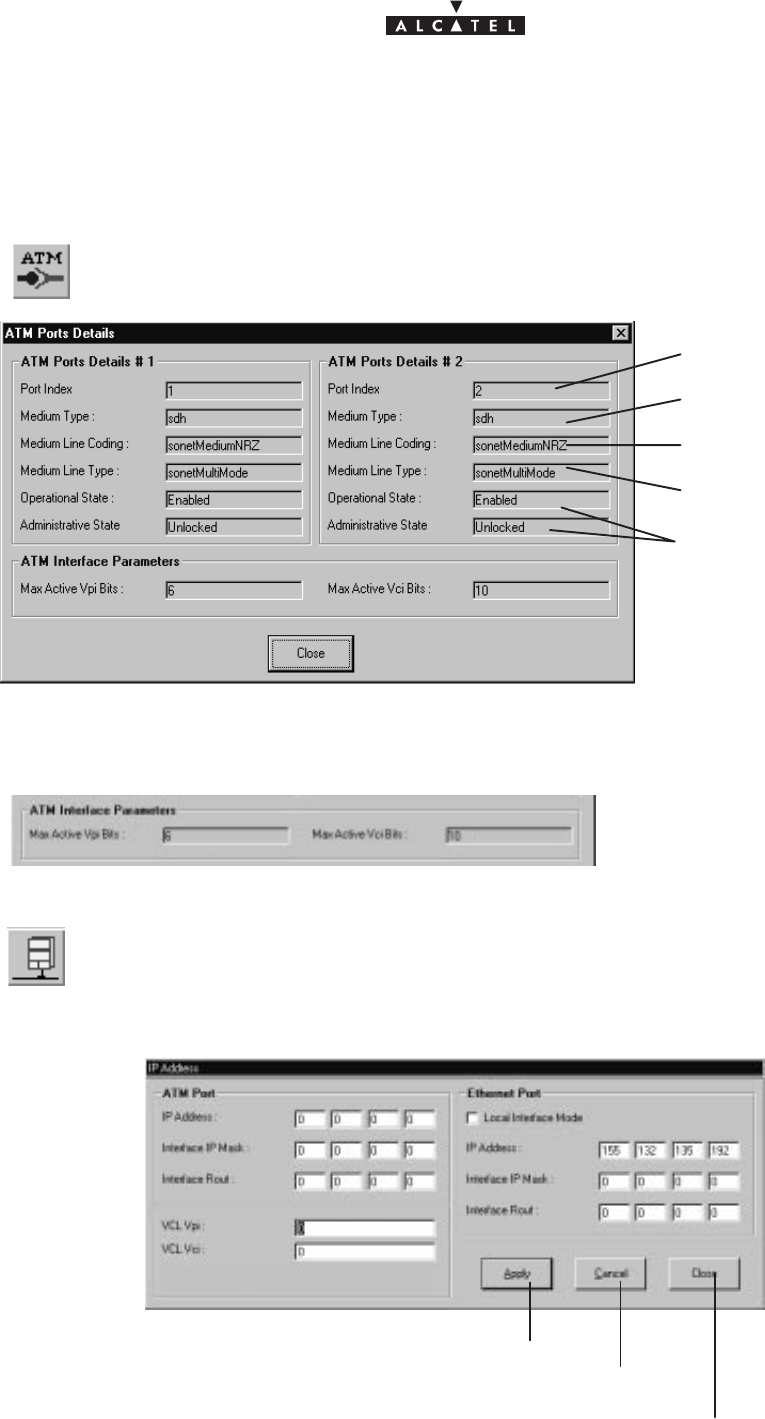
document, use and communication of its contents
not permitted without written authorization from ALCATEL
All rights reserved. Passing on and copying of this
78/136 3CC10875AAAA TQ BJA 02
Issue 02 -January, 10 2000
4.9 –Interface parameters
4.9.1 – ATM
To access the parameters of the ATM link, click on the button shown here (in the button
bar of the BS screen).
number of the ATM port
ATM transport medium type
ATM port states
line type
line coding
– ATM port parametres.
Display the number of VPI bits onthe ATM interface.
4.9.2 – IP addresses
To access the parameters of the IP addresses of the BS, click on the button “Close”
shown here in the button bar of the BS screen.
A configuration screen is displayed:
Click here to apply the modifications.
Click here to cancel the modifications.
Click here to return to the BS screen.
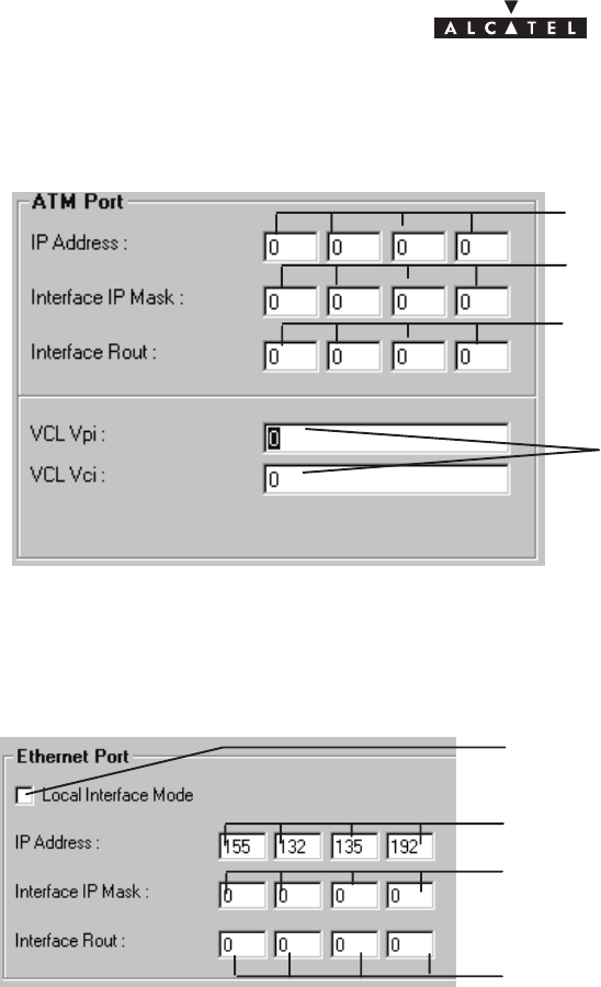
document, use and communication of its contents
not permitted without written authorization from ALCATEL
All rights reserved. Passing on and copying of this
Issue 02 -January, 10 2000 79/1363CC10875AAAA TQ BJA 02
–
TNT board side of the BS
:
Click here to enter the 4 bytes of the ad-
dress of the BS at the ATM input.
Click here to enter the 4 bytes of the address
of the router of the BS at the ATM input.
Click here to enter the 4 bytes of the address
of the IP mask of the BS at the ATM input.
Click here to enter the VCL coordina-
tes (supplied by the provider) for the
management link between a manager
and the BS.
–
ANT board side of the BS
:
Click here to enter the 4 bytes of the IP ad-
dress of the BS at the Ethernet input.
Click here to enter the 4 bytes of the address of the
router of the BS at the Ethernet input.
Click here to enter the 4 bytes of the address of
the IP mask of the BS at the Ethernet input.
Click here if the system is in local mode.
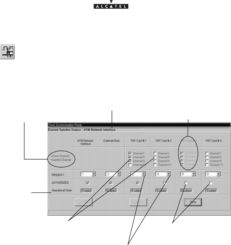
document, use and communication of its contents
not permitted without written authorization from ALCATEL
All rights reserved. Passing on and copying of this
80/136 3CC10875AAAA TQ BJA 02
Issue 02 -January, 10 2000
4.9.3 – Synchronization
To access the synchronization parameters, click on the button shown here (in the but-
ton bar of the BS screen).
This involves defining the setup rules for the synchronization sources used .
There is one default sync source (internal oscillator) and six configurable sources: ATM, external clock and the
four TNT boards. The TNT boards have 16 E1 ports and 4 can be used as synchronization ports: these are ports
1, 5, 9 and 13.
The message indicates the synchronization source currently
used (chosen automatically by the system from the source
configurations shown below).
grayed out – unavailable
Active channels are green,
and inactive channels are red.
1. On each of the boards, choose the reserved channels
to act as potential synchronization sources.
2. Allocate to each sub–assembly an order of priority number (chosen from pull–
down list). Each order number must be unique (1 specific No. / sub–assembly).
operational state of
sub–assemblies
3. Checkboxes for enabling/ di-
sabling sub–assemblies as
synchronization sources.
– Priority principle
: the
order of priority
numbers take precedence, followed by the channel numbers, in
increasing order of appearance.
Two sub–assemblies cannot be assigned the same order of priority (an error message is displayed).
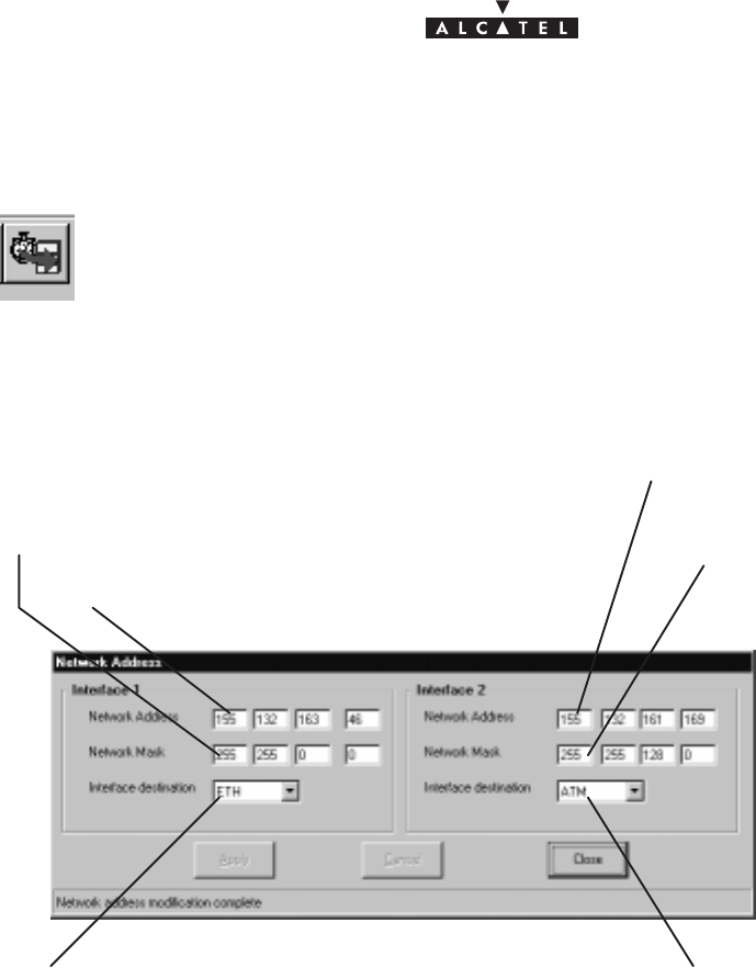
document, use and communication of its contents
not permitted without written authorization from ALCATEL
All rights reserved. Passing on and copying of this
Issue 02 -January, 10 2000 81/1363CC10875AAAA TQ BJA 02
4.9.4 – Network address
To access the settings for configuring the interfaces, click the button on the BS screen
button bar, shown here.
This involves informing the system of the interfaces used by the managers.
The manager is the network supervision software (9900LT or 1353)
IP address of manager connected on interface 1
Network mask used on interface1
Type of interface used on the BS to
connect the manager (LT ou 1353)
IP address of manager connected
to interface 2
Network mask used on
interface 2
Type of interface used on the BS to
connect the manager (LT ou 1353)
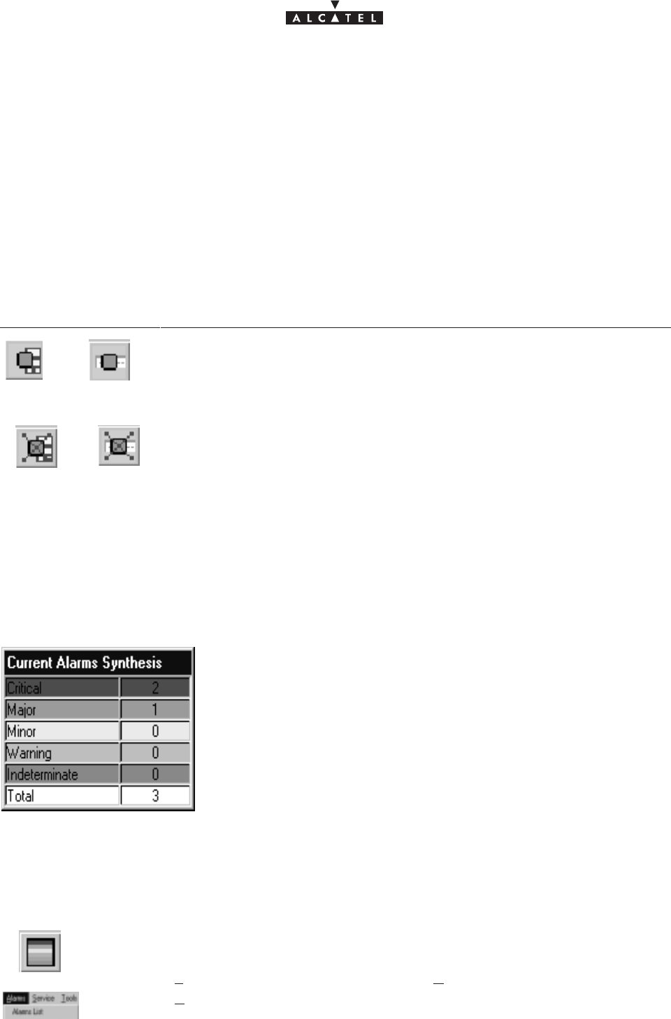
document, use and communication of its contents
not permitted without written authorization from ALCATEL
All rights reserved. Passing on and copying of this
82/136 3CC10875AAAA TQ BJA 02
Issue 02 -January, 10 2000
4.10 –Alarms
For complete alarm management, refer to chapter 6 of this manual.
4.10.1 – Activation / Deactivation of alarms
It is possible to delete the alarm function for a sub–assembly (BS or NT, cf. § 4.5), or for the assembly (NE,
cf. § 4.4), to avoid alarms overload (e.g., when replacing a sub–assembly, etc.), then to reactivate it once more.
The alarm activation/deactivation buttons are similar for the different sub–assemblies, with the alarm function
being symbolized by a green square:
Click on... To...
or ...activate the alarm function of (respectively) the BS, and NT.
or ...deactivate the alarm function of (respectively) the BS, and NT.
4.10.2 – Current alarms synthesis
The current alarms synthesis window is opened automatically for the first connection and remains active as long
as the connection to the BTS is supervised.
This window offers a view of the number of active alarms in the system
in terms of critical levels. There are five levels.
note: the highest level of criticality is displayed at the bottom right of the
general status bar (cf. § 4.2.2)
The final line, “
Total
”, totalizes the number of active alarms.
By double–clicking on one of the levels, the list of same level alarms is
displayed; by double–clicking on the last line, the list of all the alarms is
displayed (cf. next section).
4.10.3 – Alarms list
To display at any time the alarms list:
– click on the button shown here (in the main screen of the 9900LT),
– or, open the
File
pull–down menu and choose the line
Current alarms synthesis
– or, open the
Alarms
pull–down menu and choose the item
Alarms List.
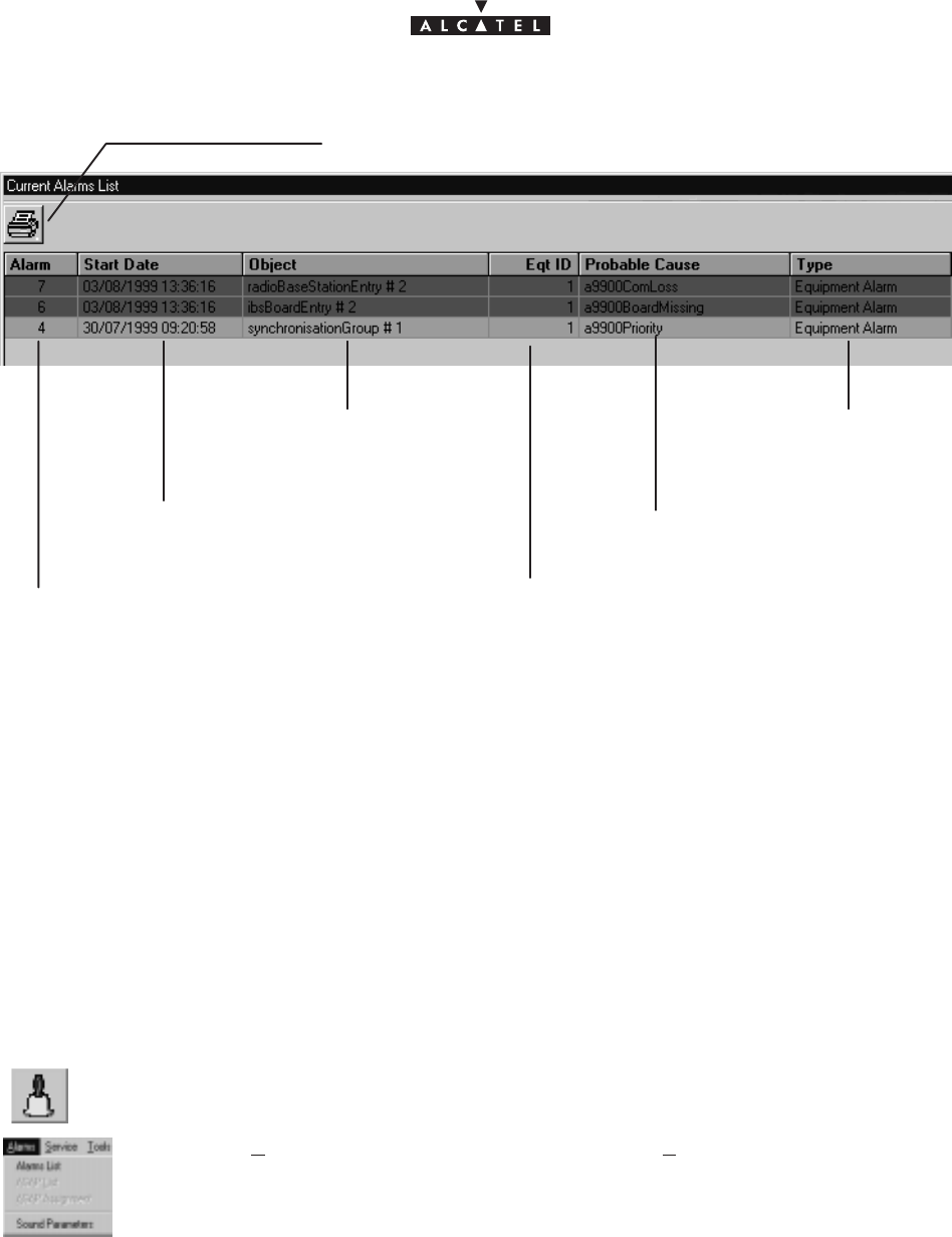
document, use and communication of its contents
not permitted without written authorization from ALCATEL
All rights reserved. Passing on and copying of this
Issue 02 -January, 10 2000 83/1363CC10875AAAA TQ BJA 02
Click here to print the list of alarms on the default
printer.
alarm number: counter increases
incrementally in order of appearance
time–stamping of the alarm (for-
mat: day/month/year hours/minutes/
seconds)
the part of the system affec-
ted by the alarm (format:
name and number)
number of the equipment to
which the alarm is assigned
alarm type
probable cause of the alarm
4.10.4 – Alarms color code
A color code has been adopted to symbolize the five critical levels:
red: critical alarm; orange: major alarm; yellow: minor alarm; light blue: warning alarm (note: configurable
values); and mauve: indeterminate alarm.
Nota : The correspondence between the alarms and the critical levels is determined by an ASAP data table.
4.10.5 – Sound adjustment of alarms
It is possible to associate or disassociate the emission of a sound warning for alarms corresponding to a certain
critical level:
To access the alarm sound parameters:
– click on the button shown here (on the main screen of the 9900LT),
– or, open the
Alarms
pull–down menu and choose the item
Sound Parameters
.
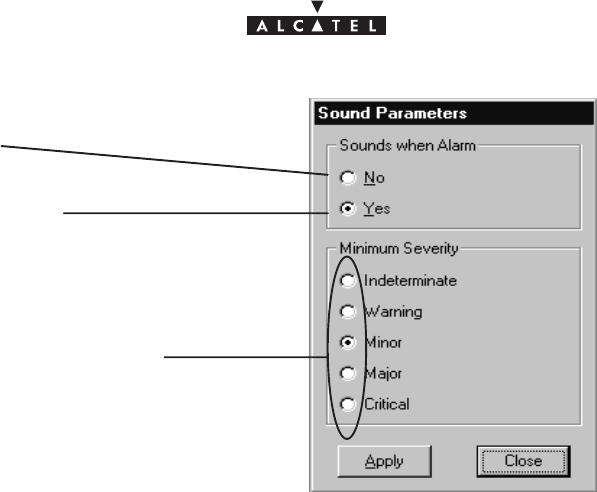
document, use and communication of its contents
not permitted without written authorization from ALCATEL
All rights reserved. Passing on and copying of this
84/136 3CC10875AAAA TQ BJA 02
Issue 02 -January, 10 2000
Check
Yes
to activate the sounds associated with
the alarms.
Check
No
to deactivate the sounds associated
with the alarms.
Choose the critical level starting from which the
sound warning should be emitted.

document, use and communication of its contents
not permitted without written authorization from ALCATEL
All rights reserved. Passing on and copying of this
Issue 02 -January, 10 2000 85/1363CC10875AAAA TQ BJA 02
4.11 –Client services
There are two types of service: leased lines and IP lines. For service traffic supervision, refer to § 4.7. For
synchronization, refer to § 4.9.3.
4.11.1 – Leased lines (E1)
The purpose of this section is to explain the use of the 9900LT to carry out E1 type cross–connection (up to 2
Mbits/s), i.e. a link between a TNT card of the BS linked to the network and the NT terminal linked to the user
peripheral devices.
To access E1 line management:
– click on the button shown here (in the main screen button bar),
or else,
– open the
Service
pull–down menu and choose the first item:
E1
.
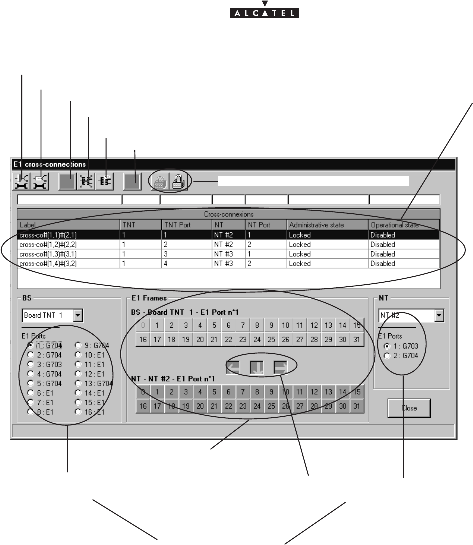
document, use and communication of its contents
not permitted without written authorization from ALCATEL
All rights reserved. Passing on and copying of this
86/136 3CC10875AAAA TQ BJA 02
Issue 02 -January, 10 2000
4.11.1.1 – Presentation
cross–connect zone
display of the 16 E1 ports of the
chosen TNT:
Click here to access the TNT ports configuration.
Click here to access the NT ports configuration.
display of the 2 E1
ports of the chosen
NT
list of E1 links
cf: § 4.11.1.2
Click here to delete the chosen link.
– “E1” port: not configured
– “G703” port: unstructured
– “G704” port: structured
cf. §4.11.1.3 and 4.11.1.4
flèches de brassage
E1 Xco creation
cancel the current cross–connect
indicator of cross–connect po-
sition
locking/unlocking the administrative status
allow to modify the name of the selected cross–connection, cf.: § 4.11.1.10
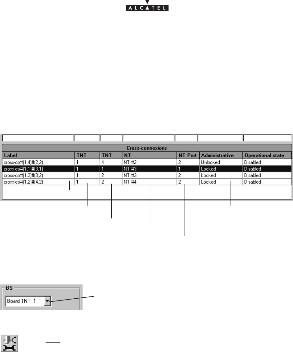
document, use and communication of its contents
not permitted without written authorization from ALCATEL
All rights reserved. Passing on and copying of this
Issue 02 -January, 10 2000 87/1363CC10875AAAA TQ BJA 02
The implementation stages for an E1 cross–connection are as follows:
1. Ports configuration: BS side and NT side: cf. § 4.11.1.3;
2. Selection of configured ports for cross–connect: cf. § 4.11.1.4;
3. Cross–connect between time–slots of selected ports: cf. § 4.11.1.5;
4. Creation of an E1 link: cf. § 4.11.1.8;
4.11.1.2 – List of cross–connections
Link designation
TNT port used in the link
NT used in the link
TNT used in the link
NT port used in the link
unlocking: authorizes termi-
nal traffic: normal state
locking: an E1 link can be
deleted without disturbing traf-
fic: maintenance operation.
4.11.1.3 – Configuration of BS ports
Select first of all the TNT board concerned by the cross–connect by
scrolling down the list.
Next, access the ports configuration of the TNT board selected by clicking on the first
button, shown here (on the button bar of the E1 cross–connections screen).
The screen listing the E1 ports of the TNT is displayed:
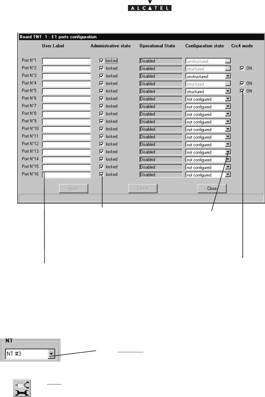
document, use and communication of its contents
not permitted without written authorization from ALCATEL
All rights reserved. Passing on and copying of this
88/136 3CC10875AAAA TQ BJA 02
Issue 02 -January, 10 2000
Check box to lock/unlock the
port’s administrative status; by
default, the port is locked.
Click here to specify the
port designation.
Reference for operator with a view to “hard” configuration:
appears if the configuration state is structured; to be chec-
ked if the corresponding hardware generates a checksum
Scroll down list to confi-
gure the port: structured
or unstructured
4.11.1.4 – Configuration of NT ports
Select first of all the NT board concerned by the
cross–connect by scrolling down the list..
Next, access the ports configuration of the chosen NT by clicking on the second but-
ton, shown here (on the button bar of the E1 cross–connections screen).
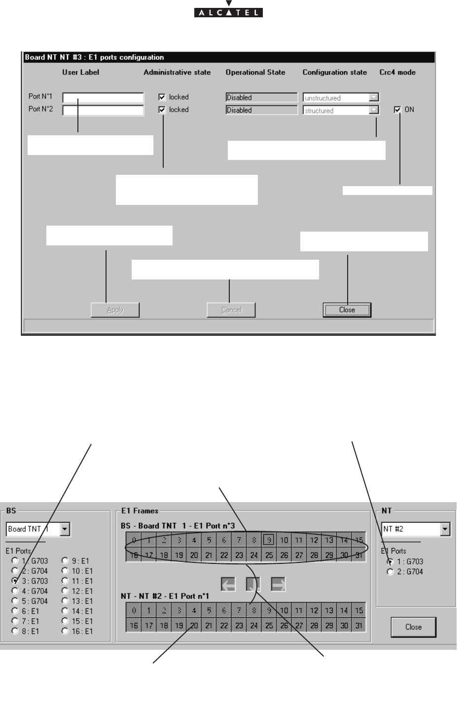
document, use and communication of its contents
not permitted without written authorization from ALCATEL
All rights reserved. Passing on and copying of this
Issue 02 -January, 10 2000 89/1363CC10875AAAA TQ BJA 02
Click here to enter the port
designation.
Click here to confirm a
modification.
Click here to cancel a modification and
return to the previous screen.
Click here to return to the
cross–connections screen.
Scroll down list to configure the
port: structured or unstructured.
cf. previous section
Check box to lock/unlock the
port’s administrative status; by
default, the port is locked
4.11.1.5 – Cross–connect
There are two types of cross–connect: between structured ports and between unstructured ports.
–
Unstructured case
:
In this case, the maximum bitrate (2 Mbit/s) is supplied by connecting all the time–slots of the selected TNT
port to the time–slots of the NT port.
1. Select the unstructured ports that you wish to connect.
2. Select the block of time–slots at
the TNT by pressing a time–slot of
the time slots bock at the TNT.
4. Release the buttons: all the slots are selected.
5. Confirm the cross–connect by creating the cross–connection: § 4.11.1.8
3. Press the CTRL key while
clicking the left button of the
mause on a TNT time–slot
and slide the mouse pointer
towards NT time–slots.
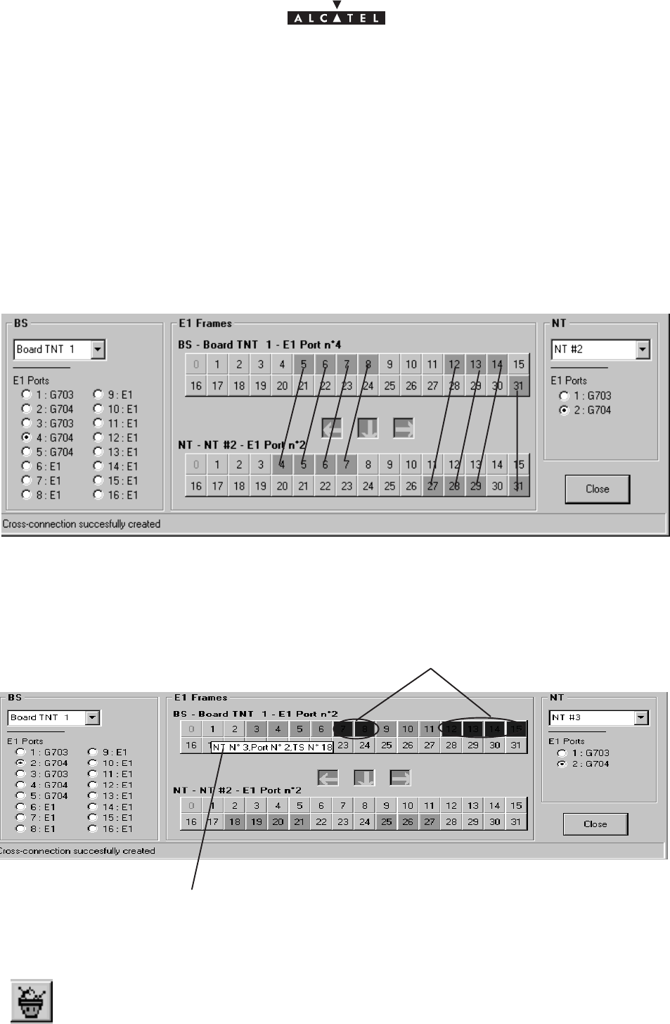
document, use and communication of its contents
not permitted without written authorization from ALCATEL
All rights reserved. Passing on and copying of this
90/136 3CC10875AAAA TQ BJA 02
Issue 02 -January, 10 2000
–
Structured case
:
In this case, 31 time–slots can be cross–connected for each port; the maximum bitrate is 31*64 kbits/s, with
the first time–slot (grayed out) reserved for synchronization.
To implement the cross–connect, proceed in the same way as for non–structured ports, but this time selecting
the time–slots individually.
The cross–connect arrows offer you guidance for dragging the TNT slots to the available NT slots; if the current
cross–connect correspond to “unauthorized” ones, an error message is displayed at the foot of the window and
the cross–connect arrows indicate the NT time–slots to which the cross–connect is directed.
The slots of a real cross–connection (following the creation phase: cf.§ 4.11.1.8) are colored green.
Cross–connect illustration
4.11.1.6 – Grooming
Several NTs can be fed from a single TNT board and a single E1 port. This is known as “grooming”.
a textual key describes the links between time–slots
“blue” slots (inactive): correspond to another NT
4.11.1.7 – Cancelling a current cross–connection
To cancel a cross–connection: click on the button shown here (in the button bar of the “E1
cross–connections” screen).
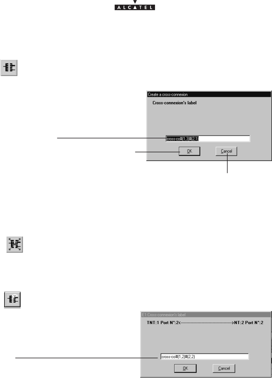
document, use and communication of its contents
not permitted without written authorization from ALCATEL
All rights reserved. Passing on and copying of this
Issue 02 -January, 10 2000 91/1363CC10875AAAA TQ BJA 02
4.11.1.8 – Creation of an E1 link (E1 cross–connection)
Following cross–connection, access cross–connect creation by clicking on the button
shown here (in the button bar of the “E1 cross–connections” screen).
Click in this field to modify the designation by de-
fault
Click here to cancel the E1 “cross–
connection” creation and to return to the
previous screen
Click here to create the E1 “cross–
connection”
4.11.1.9 – Suppression of an E1 link
To leave out an E1 link : select the link in the “cross–connections” list (cf. § 4.11.1.2),
then click on the button shown here opposite (on button bar of the IP screen).
Nota :
(for commissioning refer to § 5) : To increase resources: firstly delete a “cross–connection” and then
create a new one.
4.11.1.10 – Editing the name of an E1 link
Modify in this field
the E1 link name
To edit an E1 link: select the link in the “cross–connections” list (cf. § 4.11.1.2), then click
on the button shown here opposite (on button bar of the IP screen).
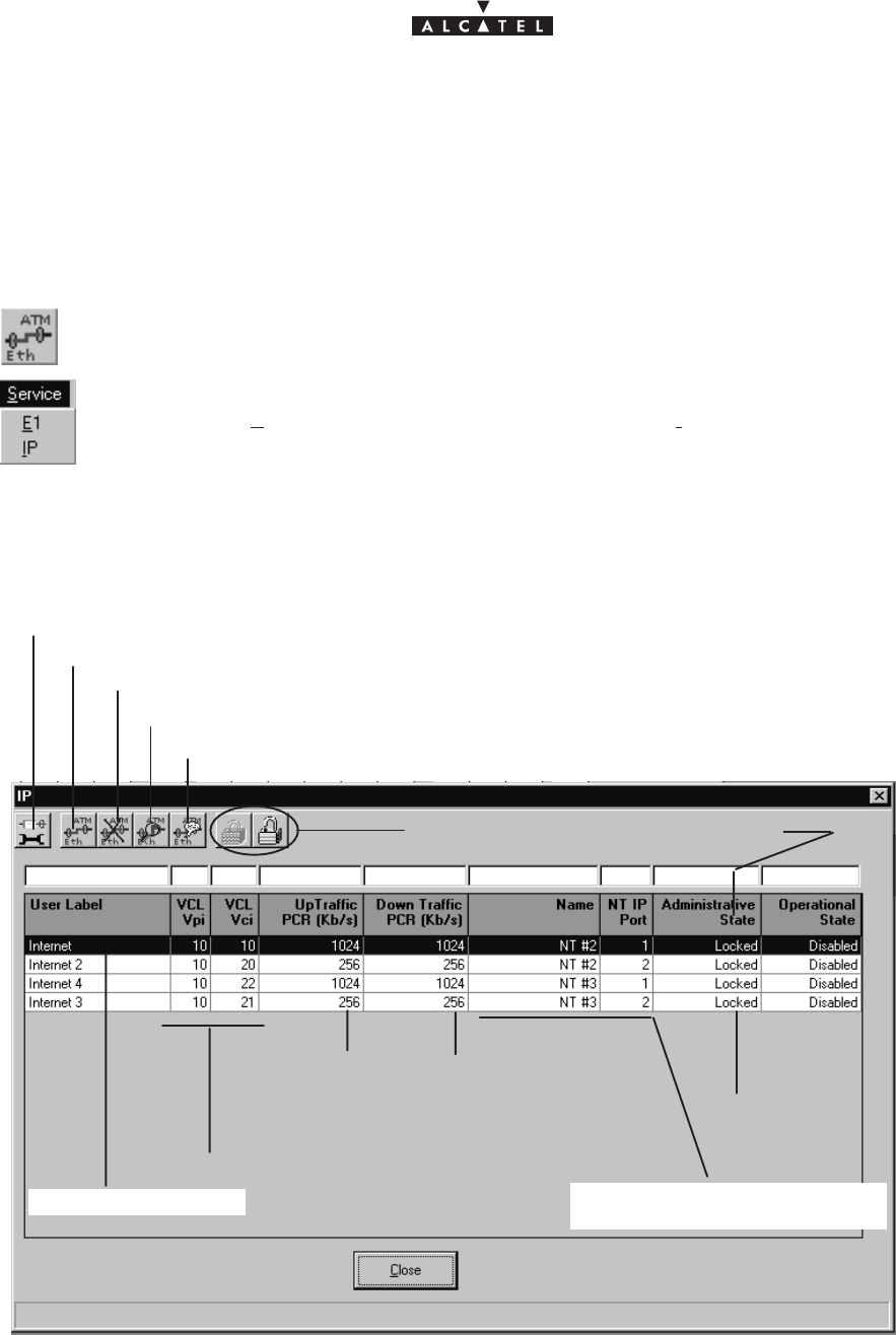
document, use and communication of its contents
not permitted without written authorization from ALCATEL
All rights reserved. Passing on and copying of this
92/136 3CC10875AAAA TQ BJA 02
Issue 02 -January, 10 2000
4.11.2 – IP links
The purpose of this section is to explain the use of the 9900LT to carry out IP type cross–connection (4 Mbits/s
maximum), i.e. a link between an ATM input of the BS linked to the network and an Ethernet port of the NT
terminal linked to the user peripheral devices.
To access IP services management :
– click on the button shown here (in the main screen button bar),
or else,
– open the
Service
pull–down menu and choose the item:
IP
.
4.11.2.1 – List of IPs
click here to access the NT ports configuration cf. § 4.11.2.2
click here to create an IP cross–connection cf. § 4.11.2.3
click here to delete the IP link chosen from the list: cf. §4.11.2.6
locking/unlocking the administrative state
Designation of IP link
Downlink traffic:
from the BS to the
NT
Name and number of NT port
used in the link
Uplink traffic: from
the NT to the BS
VCL coordinates
cf. 4.4.4
click here to access the details of the IP link chosen from the list: cf. § 4.11.2.4
allow to modify the name of the selected “cross–connection”
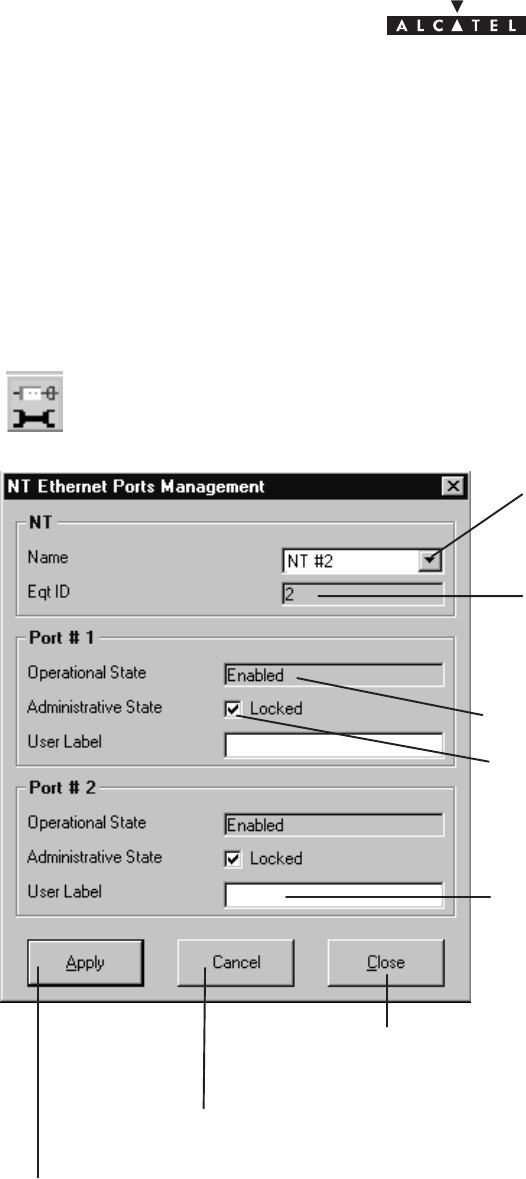
document, use and communication of its contents
not permitted without written authorization from ALCATEL
All rights reserved. Passing on and copying of this
Issue 02 -January, 10 2000 93/1363CC10875AAAA TQ BJA 02
The implementation stages for an IP cross–connection are as follows:
1. ATM board configuration at the BS: cf. § 4.9.1;
2. Configuration of the NT Ethernet ports: cf. § 4.11.2.2;
3. IP link creation: cf. § 4.11.2.3;
4.11.2.2 – Configuration of NT Ethernet ports
To access the NT Ethernet ports configuration, click on the button shown here (on the
button bar of the IP screen).
Click on the arrow to select the NT used
in the cross–connection from the pull–
down list.
The NT ID number is displayed automa-
tically once the NT is selected.
Operational state
of the first Ethernet port
of the selected NT:
enabled/disabled
Administrative state of the first Ethernet port
of the selected NT: locked or unlocked
Click here to enter the designation of the
second Ethernet port of the selected NT.
Click here to apply the ports configuration.
Click here to cancel the current configuration.
Click here to return to the IP links list.
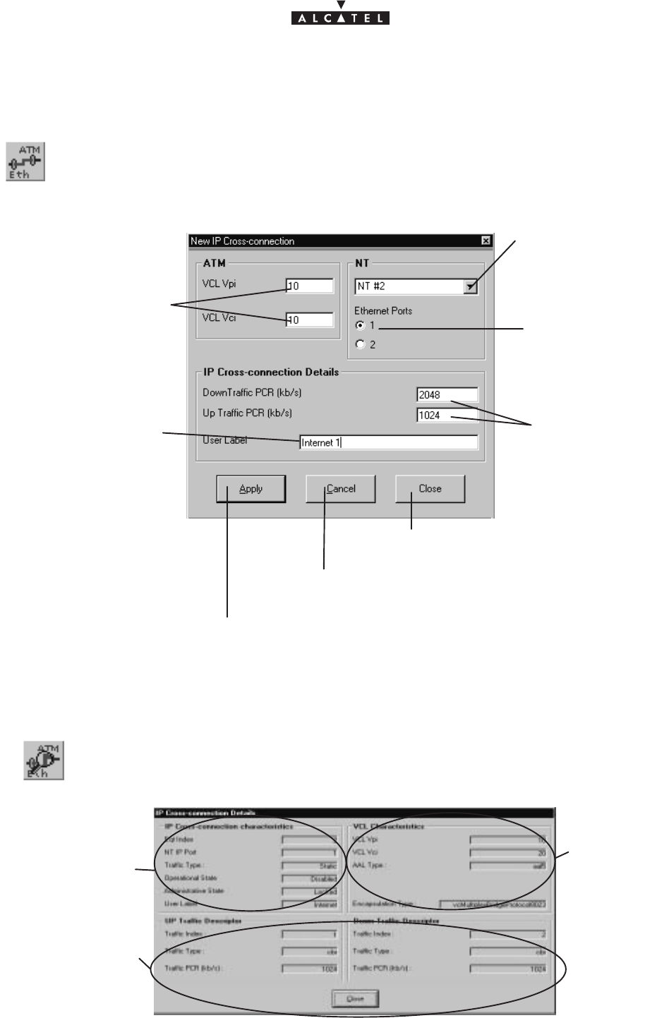
document, use and communication of its contents
not permitted without written authorization from ALCATEL
All rights reserved. Passing on and copying of this
94/136 3CC10875AAAA TQ BJA 02
Issue 02 -January, 10 2000
4.11.2.3 – Creation of an IP link
To access creation of an IP link, click on the button shown here (in the button bar of the
IP screen).
Click here to enter the
VCL coordinates of the
ATM board.
Click on the arrow to
select the NT used in
the cross–connection
from the pull–down
menu.
select the Ethernet
port used in the
cross–connection
Click here to create the IP cross–connection.
Click here to cancel creation of the IP cross–connection.
Click here to return to the IP links list.
Click here to specify
the uplink and down-
link bitrates, in steps
of 64 kbits/s
(max: 4 Mbps).
Click here to enter the
name of the cross–
connection to be created.
4.11.2.4 – Characteristics and traffic of an IP link
To access the characteristics of an IP link chosen from the list of IP cross–connections,
click on the button shown here (in the button bar of the IP screen).
IP cross–connection
characteristics
IP cross–connection
traffic characteristics
VCL
characteris-
tics
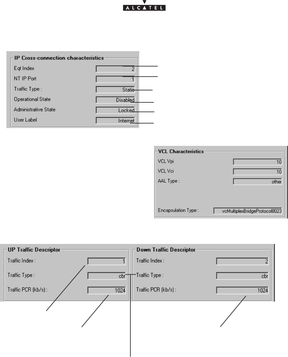
document, use and communication of its contents
not permitted without written authorization from ALCATEL
All rights reserved. Passing on and copying of this
Issue 02 -January, 10 2000 95/1363CC10875AAAA TQ BJA 02
–
IP cross–connection characteristics
:
NT identification number
NT Ethernet port number
traffic type: IP static
name of IP cross–connection
administrative state
: locked/unlocked
operational state
: enabled/disabled
–
VCL characteristics
:
– Uplink and downlink traffic description
:
Traffic index number
traffic type: cbr (staticIP, constant bit rate)
CBR Down flow from cross–connection
max= 64x32 kbit/s
CBR Up flow from cross–connection
max= 64x32 kbit/s
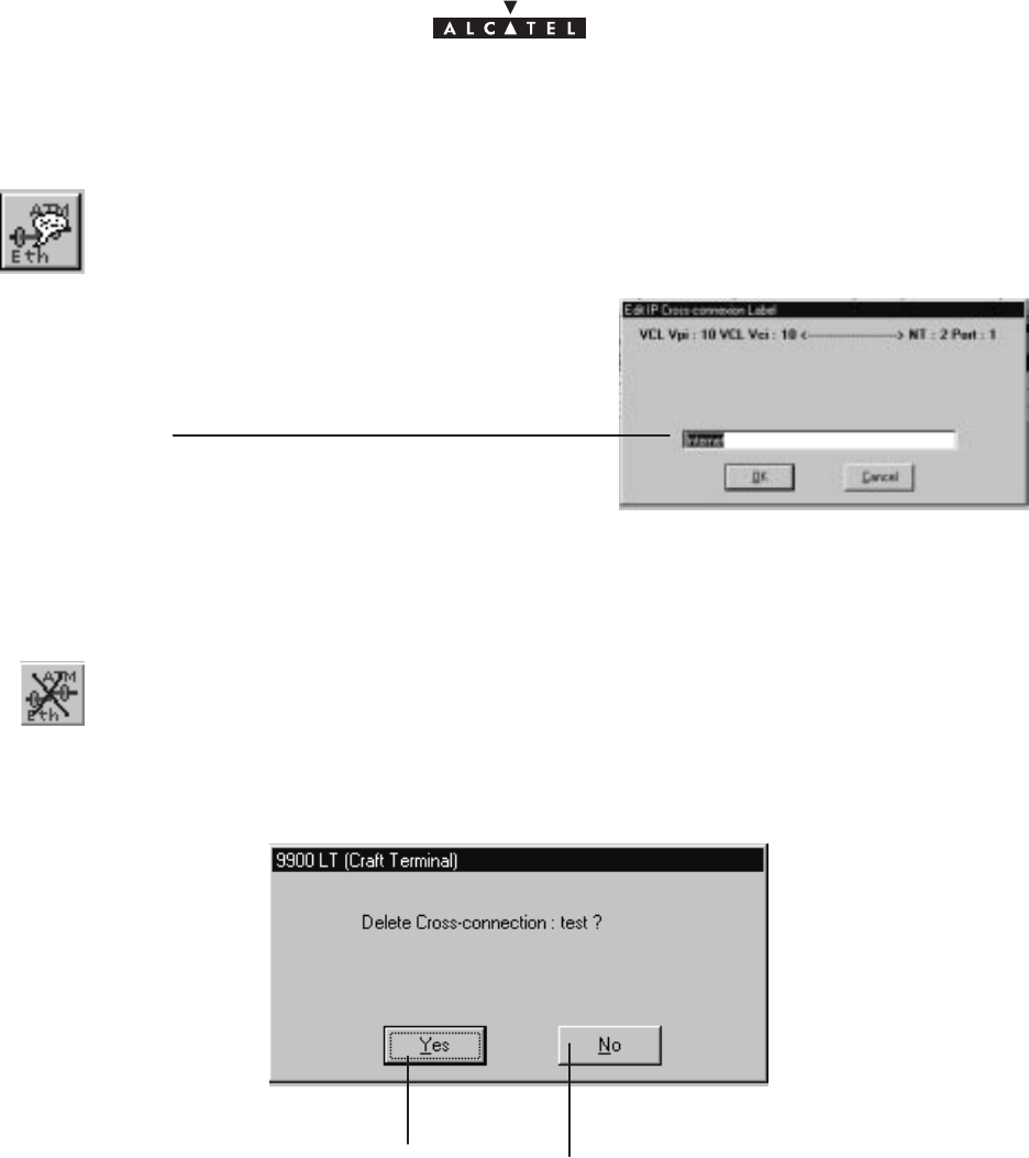
document, use and communication of its contents
not permitted without written authorization from ALCATEL
All rights reserved. Passing on and copying of this
96/136 3CC10875AAAA TQ BJA 02
Issue 02 -January, 10 2000
4.11.2.5 – Editing the name of an IP link
Modify in this field the
name of an IP link
To modify the name of an IP link, selected in the IP “cross–connections” list, click on the
button shown here opposite (on button bar of the IP screen).
4.11.2.6 – Deleting an IP link
To delete an IP link chosen from the list of IP cross–connections, click on the button
shown here (on button bar of the IP screen).
A confirmation screen is displayed:
Click here to delete the IP
cross–connection.
Click here to cancel the request to delete
the IP cross–connection.
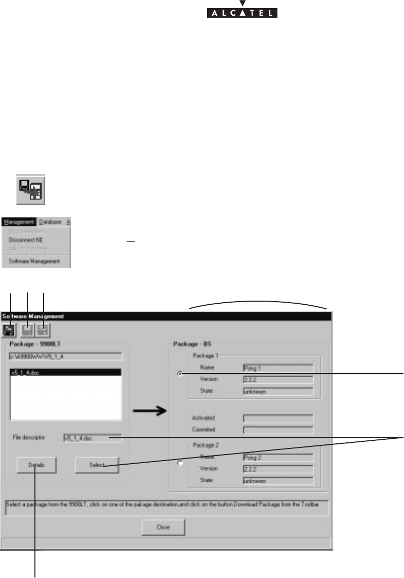
document, use and communication of its contents
not permitted without written authorization from ALCATEL
All rights reserved. Passing on and copying of this
Issue 02 -January, 10 2000 97/1363CC10875AAAA TQ BJA 02
4.12 –Utilities
4.12.1 – Downloading
Downloading, mainly used during maintenance, replaces or upgrades the component software of the NE (BS
+ NTs).
To access the downloading function:
– click on the first button (provided it is active, cf.§4.1.2.2) on the button bar of the main menu
(shown here),
or else,
– open the
Management
pull–down menu and choose the first item:
Software Manage-
ment
.
1
3
2
45 recapitulated data in the detail screens of the boards, § 4.5.2
click here to access the listing for the selected file
The downloading stages are as follows:
1. select the file describing the software configuration,
2. select the software storage zone on the BS,
3. download the software,
4. activate the selected software configuration,
5. referencing of the software to be run by default, following reset.
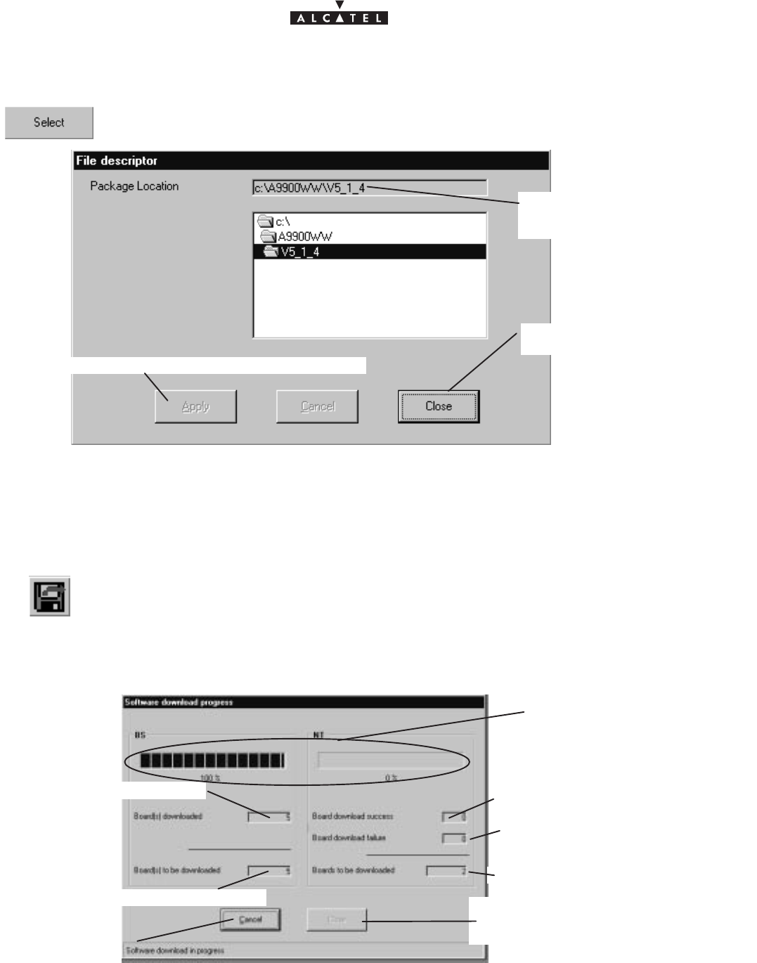
document, use and communication of its contents
not permitted without written authorization from ALCATEL
All rights reserved. Passing on and copying of this
98/136 3CC10875AAAA TQ BJA 02
Issue 02 -January, 10 2000
4.12.1.1 – Object and destination of the file to be imported
To select the software to be downloaded, click on the button shown here; the updated list of
software is displayed; click on the file to be imported
click here (if active) to select the file to be downloaded
Click here to return to
the previous screen.
location of the directo-
ry containing the soft-
ware configuration
Next, select one of the two board storage areas: cf stage 2 of the “Downloading” screen, § 4.12.1.
4.12.1.2 – Data import
To load the software in the chosen storage area:
click on the button (provided it is active) of the button bar on the “Downloading” screen.
Nota :
This button is activated once the selections described in the previous paragraph have been made.
A screen indicating the progress of the downloading is displayed:
number of boards still to be downloaded
number of boards downloaded number of NTs downloaded
No. of NTs to be downloaded
Click here to cancel
downloading.
Once the process is over, click
here to display the downloading
report: cf. following paragraph.
Progress bars
No. of NTs that could not
be downloaded
4.12.1.3 – Downloading report
Once the downloading phase is over (cf. previous paragraph), a report is provided detailing the software present
for the different board types of the BS :
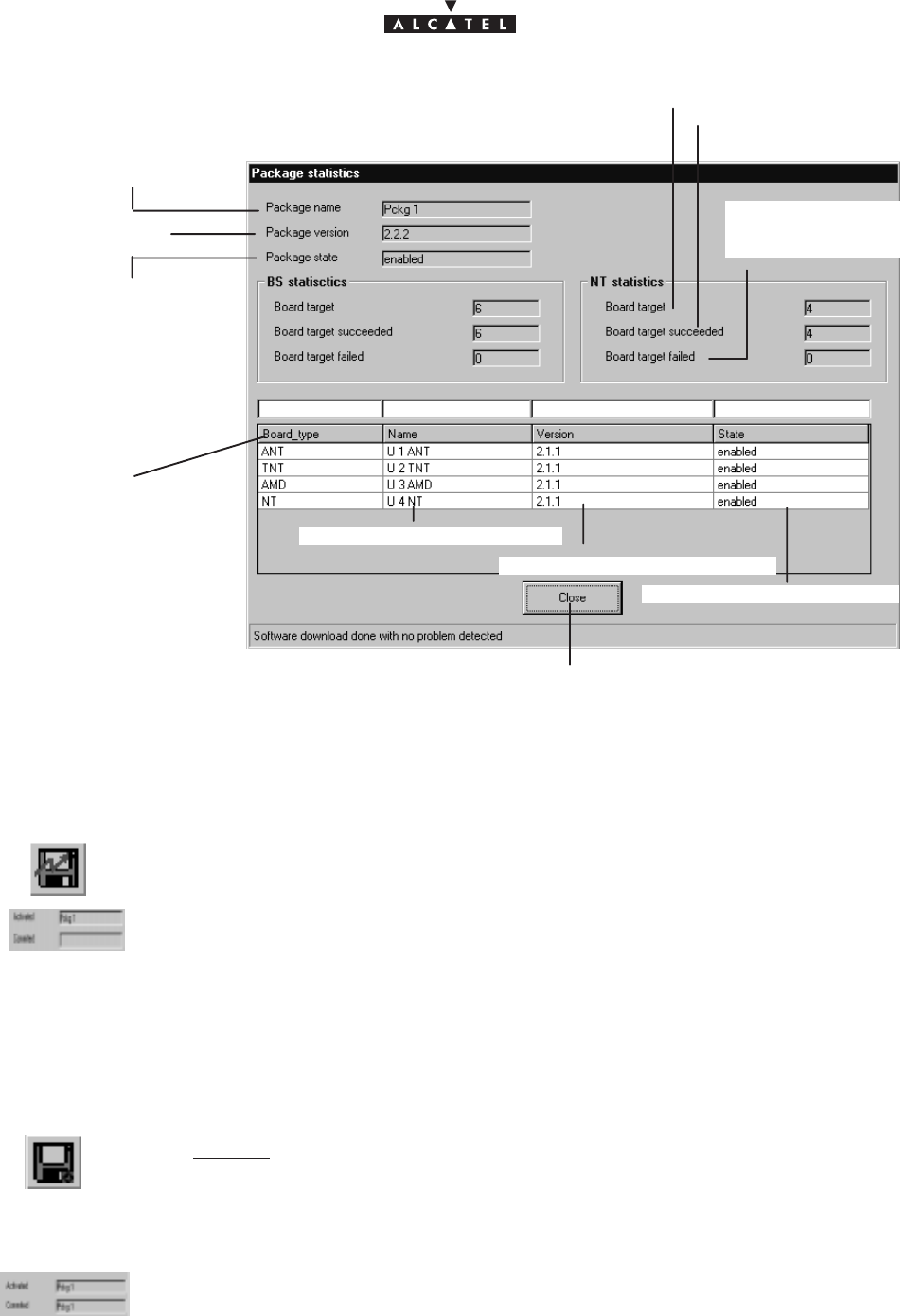
document, use and communication of its contents
not permitted without written authorization from ALCATEL
All rights reserved. Passing on and copying of this
Issue 02 -January, 10 2000 99/1363CC10875AAAA TQ BJA 02
version of downloaded software
name of downloaded software
state of downloaded software
BS board types
state of storage area
name of storage area
version of storage
area
Click here to return to “Downloading” screen.
number of boards
to be downloaded
number of boards
downloaded
number of boards that
could not be downloa-
ded
4.12.1.4 – Activation of data
To run the downloaded software:
click on the button of the button bar on the “Downloading” screen shown here.
The “Activated” field in the “Downloading” screen is automatically filled in.
4.12.1.5 – Reference software
The reference software is activated by default when restarted:
select first of all the required storage area,
then click on the button of the button bar on the “Downloading” screen shown here.
Nota :
This button is activated if the state of the software is “activated”.
The “Committed” field in the “Downloading” screen is automatically completed.
Nota :
Once the software activated and in reference, a dowloading has to be done again if a new NT comes
into the network.

document, use and communication of its contents
not permitted without written authorization from ALCATEL
All rights reserved. Passing on and copying of this
100/136 3CC10875AAAA TQ BJA 02
Issue 02 -January, 10 2000
PAGE INTENTIONALLY LEFT BLANK
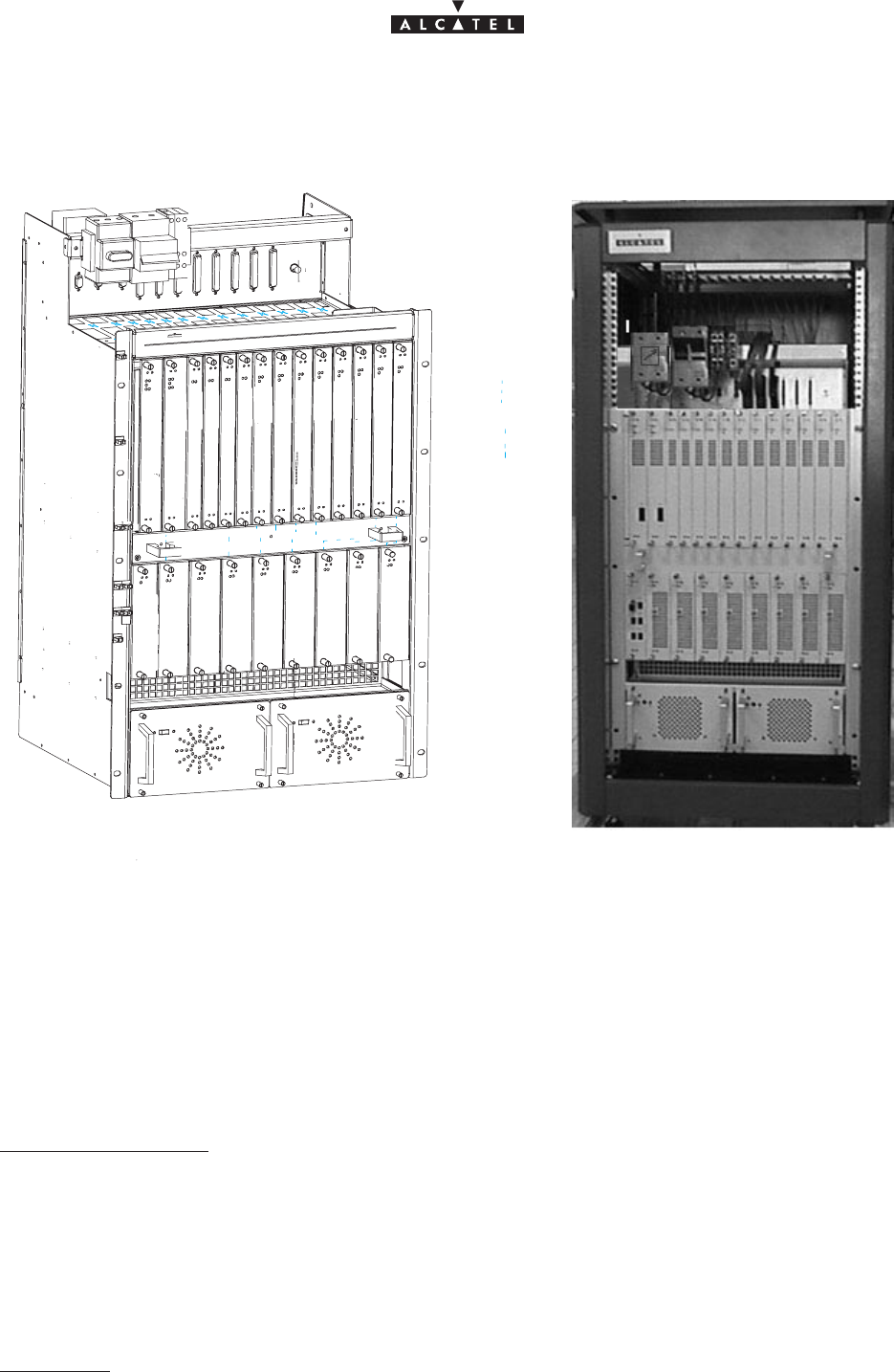
document, use and communication of its contents
not permitted without written authorization from ALCATEL
All rights reserved. Passing on and copying of this
Issue 02 -January, 10 2000 101/1363CC10875AAAA TQ BJA 02
5 – Commissioning the 9900BS Base Station
Figure 40 – Configuration of the base station.
#
ANT
ANT
TNT
TNT
TNT
TNT
AMD
AMD
AMD
AMD
R12341234
CPL
IBS
IBS
IBS
IBS
1234
PSU 1 PSU 2
Vent
L
Base Station commissioning is carried out using a compatible laptop PC fitted with the 9900LT installation and
programming softare. The PC is connected directly to the DBS rack using a cable supplied with the equipment.
Commissioning involves:
– initialisation and configuration of Base Station parameters,
– control and validation of the installed parameters before running the system (see Figure 41 Base station
configuratuion).
5.1 –Initialisation and configuration of parameters
Preliminary conditions
To commission a Base Station it is necessary:
– to have access to all sub–assemblies required for Base Station creation associated with the site specific
installation sheet,
– to have access to the 9900LT software version corresponding to the site configuration,
– to have access, on the laptop PC, to an installation software compatible with the boards to be installed,
– that the network operator gives the mission order to the installer.
Main stages
To commission a Base Station it is necessary to carry out the following:

document, use and communication of its contents
not permitted without written authorization from ALCATEL
All rights reserved. Passing on and copying of this
102/136 3CC10875AAAA TQ BJA 02
Issue 02 -January, 10 2000
– installation of the DBS rack (see section 3 – “Base Station Installation” of the present manual),
– installation and configuration of the associated RBS(s) (see section 3 – “Base Station Installation” of
the present manual),
– configuration and commissioning of the station using the 9900LT.
5.1.1 – Equipment required
To configure the Base Station parameters the following equipment is required:
– the RBS ODU(s),
–A 50 ohm N/N connector coaxial cable (ref. 3CC07568AAA) or equivalent.
– the DBS rack assembly,
– a laptop PC equipped with:
–the 9900LT Base Station initialisation and programming software,
–the Windows NT4 Workstation system,
–a data transfer application (e.g., OMNI NFS).
The minimum PC specifications are as follows:
–microprocessor: Pentium II 300 MHz,
–RAM: 64 MB,
–Hard disk: min. 2 GB,
–Graphics board: 2 MB,
–3“ 1/2 floppy drive (internal or external),
–12x CD drive (internal or external),
–ports: 1 available serial (DB9) and one available parallel (centronix) port,
–mouse: 2 buttons (PS2 series) or tracking device,
–network board: Ethernet 10/100BT (RJ45), 10B2 (BNC),
–12” monitor (1024x768).
5.1.2 – Powering up RBS and DBS equipment in site configuration
Stages
1. Power up the DBS rack using the general ON/OFF switch (see Figure 26).
2. Check the DC/DC power coupling: the power supply is present if the LEDs on the front panel of the power
modules are lit.
3. Check the power supply boards:
– board operational if green LED is lit, switch at ON, red LED unlit;
– board fault if green LED is lit, switch at ON, red LED lit;
4. Connect laptop PC to DBS rack using a dedicated cable (Ethernet link). Use the connector situated on the
top panel of the DBS rack (see Figure 41).
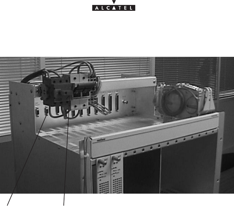
document, use and communication of its contents
not permitted without written authorization from ALCATEL
All rights reserved. Passing on and copying of this
Issue 02 -January, 10 2000 103/1363CC10875AAAA TQ BJA 02
Figure 41 – Connecting laptop PC to DBS rack
ON/OFF switchPC connection
connector
5. Connect the PC to a power source and power up.
6. Define for the PC an IP address on the same network as the Craft Terminal for it to be able to connect. A valid
address would be for example: 192.168.99.2, with the subnet mask: 255.255.255.0.
7. Check the initialization of the boards:
– board operational if switch is ON, green LED lit, red LED unlit;
– board inoperational if switch is ON, green LED unlit, red LED lit.
8. Implement Ethernet ANT/LT link (use appropriate cable and connectors).
9. Initialize and connect the system by running the 9900LT software: to do this, the configuration stages listed
in the following table are executed by the system installer:

document, use and communication of its contents
not permitted without written authorization from ALCATEL
All rights reserved. Passing on and copying of this
104/136 3CC10875AAAA TQ BJA 02
Issue 02 -January, 10 2000
Order
number
of
stages
Designation of stages linked
to the 9000LT Comments
reference of
screen or
paragraph
(§4)
IStarting up the LT Follow the instructions described previously in
the manual (§4.2.2) to start up the 9900LT
software.
Close the information window displayed when
the program is run in order to access the
9900LT main screen.
4.2.2
II Choosing the User
Interface language If you wish to change the User Interface
language offered by default, follow the
instructions in §4.2.2
4.2.2
III Connection to the BS Connect the BS following the instructions in
§4.3.1.
.
IP address
: enter the address which is blank
on first start–up; for subsequent connections,
the IP address is displayed by default
Click ”Apply” to activate retrieval of MIBs on PC;
this terminates with the opening of the BS
supervision screen (§4.5).
4.3.1
IV Initializing the RAM
ANT board On first start–up, it is wise to initialize the ANT
board SNMP agent memory.
To do this, follow the instructions in §4.5.3.
Warning: this destructive function is not to be
used subsequently for an operation, but is
reserved for maintenance operations.
This initialization causes a reboot of the 9900LT;
return to stage III to reconnect.
4.5.3
10. Check, test and initialize the RBS locally (without installation on pole). To do this:
– connect the RBS (use a test coaxial cable) to the test assembly or the DBS subrack,
– the RBS is initialized using the 9900LT,
– follow stage V (checking) below:
Order
number
of
stages
Designation of stages linked
to the 9000LT Comments
reference of
screen or
paragraph
(§4)
VChecking recognition of
sub–assemblies (boards
and RBS) by the LT
Check on the rack represented in the BS
supervision screen (§4.5) that the physically
present sub–assemblies are taken into account
by the LT.
Running the 9900LT software automatically
retrieves the serial number for each board, their
modification index and their software version.
Check the conformity of the data against the
delivery slip.
4.5
4.5.2.1 à
4.5.2.7
4.5.4
11. Disconnect the RBS test assembly.
12. Carry out the RBS pole–mounting (cf. § 3.4 – “Installation of outdoor equipment”).
13. Connect the RBS to the DBS using the dedicated cable (cf. § 3.5 – “Installation of link between RBS and
DBS”).
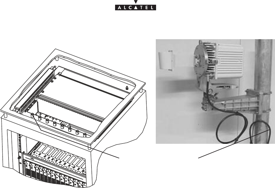
document, use and communication of its contents
not permitted without written authorization from ALCATEL
All rights reserved. Passing on and copying of this
Issue 02 -January, 10 2000 105/1363CC10875AAAA TQ BJA 02
Figure 42 – Connecting RBS ODU to DBS rack
RBS / DBS link cable
– resume start–up stages I and III described previously; the RBS is initialized when the 9900LT is run,
– follow the previously described stage V.
Next, follow the configuration stages using the 9900LT as described below:

document, use and communication of its contents
not permitted without written authorization from ALCATEL
All rights reserved. Passing on and copying of this
106/136 3CC10875AAAA TQ BJA 02
Issue 02 -January, 10 2000
Order
number
of
stages
Designation of stages
linked to the 9000LT Comments
reference
of screen
or
paragraph
(§4)
VI Synchronization This involves defining the priority rules for the possible
timing sources for the station.
Priority 1 of course relates to an external source, since
this allows the station to be immune to user error.
For the moment, it is not possible to select one of the
channels (1, 5, 9 or 13) of the TNT board present
since they are not yet defined. You should come back
to them once at least one has been configured.
.
Operational State
: the effective presence of a signal
used for synchronization is signaled by the wording
”Enabled”.
If no signal is valid, the station works off its internal
clock.
––> Confirm the modifications and quit the screen to
return to the BS supervision screen (§4.5).
NB: Note the disappearance of the alarm in the ”Current
Alarme Synthesis” table, which was due to the fault in the
definition of the order of priorities.
4.9.3
VII Configuration of ODUs
RBS parameters:
transmission power, type
and length of cable.
Characteristics:
. ID
: field filled automatically with the radio link number.
. Transmission power
(offset value of 0 to 10 dB; 0
defines an output power of +7dBm) :
Adjust the display value to give that required for the
link study. If no value is supplied, use by default the
value 10, which gives the greatest range.
NB : If the specified value is 0, it is recommended not to
leave it in this state, but to quit the value and return to it by
using the up and down arrows.
. Cable type
: select the type of cable from the scroll
menu.
.
Cable length:
enter the length of the cable which
connects the ODU to the IDU.
NB: Never leave at 0, even for a tabletop bench.
––> Confirm the settings to return to the BS
supervision screen (§4.5)
NB : Note that the alarm indicator on the RBS connection
strip has changed from yellow to green, and that the number
of alarms given in the “Current Alarm Synthesis“ table has
diminished by one.
Repeat the same operations for all the ODUs.
4.5.4

document, use and communication of its contents
not permitted without written authorization from ALCATEL
All rights reserved. Passing on and copying of this
Issue 02 -January, 10 2000 107/1363CC10875AAAA TQ BJA 02
Order
number
of
stages
Designation of stages linked
to the 9000LT Comments
reference
of screen
or
paragraph
(§4)
VIII Setting traffic frequencies ODU characteristics:
. AMD Board associated
&
Band Width
: fields filled
automatically: check that the parameters are those
anticipated.
.
DownStream Central
: Enter the frequency of the
downstream channel of the four upstream
channels.
.
Upstream Central
: Enter the central frequency of
the four upstream channels.
––> Confirm settings: after a few seconds, the four
frequencies of the upstream channels, Upstream #
1, Upstream # 2, Upstream # 3 et Upstream # 4,
are calculated and displayed.
NB: there are as many tabs as installed AMD boards.
Quit the screen to return to the BS supervision
screen (§4.5).
Note that the alarm indicator of the AMD card(s)
has switched from yellow to green, to indicate the
settings have been accepted.
4.7
IX Information about the BS .
Name
: enter the name of the base station (e.g.,
Base ST #1)
.
Location
: enter the location of the base station
(e.g., Orlando)
4.5
14. Quit the 9900LT software (cf. § 4.3.2)
15. Fill in the Installation Sheet (cf. Annex 1 of this Manual).

document, use and communication of its contents
not permitted without written authorization from ALCATEL
All rights reserved. Passing on and copying of this
108/136 3CC10875AAAA TQ BJA 02
Issue 02 -January, 10 2000
PAGE INTENTIONALLY LEFT BLANK

document, use and communication of its contents
not permitted without written authorization from ALCATEL
All rights reserved. Passing on and copying of this
Issue 02 -January, 10 2000 109/1363CC10875AAAA TQ BJA 02
6 – Operation and maintenance
6.1 –Network supervision
The status of the system is controlled in permanence by the supervision function provided by the 9900LT
software. This function is described in sections 4.4 and 4.5 of the present Manual.
6.2 –Preventive maintenance
Preventive maintenance is carried out by:
– permanent monitoring of the system provided by the supervision function,
– periodic inspection of the equipment to ensure that:
– the link cables between the NE elements are not damaged,
– the external equipment is properly assembled,
– the internal equipment is correctly in place.
6.3 –Corrective maintenance
6.3.1 – Alarms processing
Knowledge of the implicitly induced alarms may be necessary for the operator to be able to carry out
maintenance and estimate the quality of the services offered by the 9900NE. This is why the present document
offers, in this chapter, a basic knowledge to the operator of the alarm correlation.
6.3.1.1 – Checking alarms for each equipment management function
The “alarms control” functions of each board’s equipment management for a given type of element are
responsible for supervision, clearing and masking of alarms for this element. Each of its functions is responsible
for notification to the SNMP agent of the starts and ends of alarms that it controls.
The ANT board is in addition responsible for the processing of alarm indicators of the three dry loops reserved for
the BS (“ Critical ”, “ Major ” and “ Minor ” indicators).
This processing is not carried out for the NR2.0
.
The AMD board implements an equipment management function for each of the following types of element:
•The AMD itself
•The IBS
•The RBS
•The NT
•The static cross–connects on the channels of a radio link
The TNT board implements an equipment management function for each of the following types of element:
•The TNT itself
•The E1–G703 port of the TNT
The NT implements an equipment management function for each of the following types of element:
•The E1–G703 port of the NT

document, use and communication of its contents
not permitted without written authorization from ALCATEL
All rights reserved. Passing on and copying of this
110/136 3CC10875AAAA TQ BJA 02
Issue 02 -January, 10 2000
•The E1–G704 port of the NT
•The Ethernet port of the NT
6.3.1.2 – Terminology relating to the alarms
Active alarm: an alarm is active as soon as the start of this alarm is notified to the ANT board, and remains so as
long as its end is not notified
Anomaly: Discrepancy between the intended and real characteristics of an item. An anomaly may or may not
affect the capacity of this item to carry out a required function. Several successive anomalies of the same type
are generally considered a fault.
Defect: Limited interruption of the capacity of an item to carry out the required function. A defect may or may not
necessitate maintenance action.
Alarm clearance: Clearing an alarm initiation by notifying its end.
Board alarm function: For AMD, TNT, IBS, RBS or NT boards, the alarm function is the totality of the “Alarms
control” functions of the elements that they manage.
Alarm masking: Storage of an alarm without immediate notification of alarm initiation. Masking allows the
seriousness of the alarms for a given element to be hierarchically ordered: masking is carried out when a higher
order alarm appears. If on unmasking (carried out at the end of the higher order alarm) the alarm which was
masked is still present, an alarm initiation must be notified.
6.3.1.3 – Abbreviations relating to the alarms
AIS Alarm indication signal
CRC Cyclic redundancy check
FAS Frame alignment signal
LMFA Loss of multiframe alignment
LOF Loss of frame alignment
LOP Loss of pointer
LOPC Loss of polling cell
LORF Loss of Radio Frame
LOS Loss of signal
MSC Message sequence chart
OOF Out of Frame
PAIS Pointer Alarm indication signal
RAI Remote alarm indicator
RDI Remote defect indication
REI Remote error indication
6.3.2 – Definition of 9900NE alarms
6.3.2.1 – Alarms relating to boards
The actions described are not necessarily controlled by the management software (they can be controlled by
the equipment itself). In this table, the term “board” may related to a board of the DBS (ANT, TNT, AMD, IBS,
CPL, RBS, PSU, FANS) or of the NT.

document, use and communication of its contents
not permitted without written authorization from ALCATEL
All rights reserved. Passing on and copying of this
Issue 02 -January, 10 2000 111/1363CC10875AAAA TQ BJA 02
6.3.2.2 – Alarms relating to the boards of 9900NE
Alarm name Definition Internal NE actions
Board_missing The Board element is physically
absent from the 9900NE, but
known to the agent.
Depends on the functionalities and use of this
board in the 9900NE.
Comm_loss The connection (for management
link set–up) between the active
ANT board and the Board ele-
ment is not set up or is l ost.
Reset (automatic or controlled) of the Board ele-
ment if the board is a TNT or AMD board or a
WW–NT
No impact if the Board is an IBS or RBS board:
these two elements can continue to function wi-
thout their management link.
The set–up or re–establishment of the connec-
tion requires the complete (re)configuration of
this element. This procedure of (re) confguration
is automatic and internal to the BS (as long as all
the element’s configuration parameters are valid)
Board_typeerror The Board element configuration
parameters, completed by the
manager, are not compatible with
this element type.
Rejection of new parameter values by the BS
agent: error message sent to manager.
Board_configerror The Board element configuration
parameters list that must be com-
pleted by the manager is incom-
plete.
The configuration of the Board element by the
ANT board is prohibited: error message sent to
manager and wait for complete configuration.
Board_temperatu-
re Detection by the Board element
that the temperature threshold
had been exceeded
The Board element goes “out of service”, i.e., it
blocks all its external interfaces, except the ma-
nagement link. If the management link is cut (ina-
bility of the microprocessor to operaate beyond
the temperature threshold), the ANT board will
detect the connection for this element.
Interruption of all traffic supported by this board.
Upon notification of the end of the “ Board_tem-
perature ” alarm, the agent resets the board
concerned.
Board_softwa-
re_version Alarms being downloaded: the
downloaded version has been in-
correctly saved, or part of the ver-
sion data being downloaded is in-
correct, or a request has been
made for the abandonment of the
version transfer.
Alarms when activating the soft-
ware: the software version to be
activated has not been saved
(and so is unknown to the Board
element).
No action on the Board element during downloa-
ding.
Rejection of the activation command if the soft-
ware version to be activated is unknown to the
Board element.
HW_failure Hardware failure detected by a
board. Indicates that the board must be replaced.
Storage_pb Indicates overloading of a buffer No action, loss of management data or traffic.
FAN_degraded The fans of an element function
in degraded mode, i.e., a single
fan is faulty.
No action

document, use and communication of its contents
not permitted without written authorization from ALCATEL
All rights reserved. Passing on and copying of this
112/136 3CC10875AAAA TQ BJA 02
Issue 02 -January, 10 2000
Alarm name Definition Internal NE actions
Synth Synthesiser problem For the RBS, automatic cut–out of the transcei-
ver
For the IBS, no action
TX_power RBS output power Automatic cut–out of the transmitter
6.3.2.3 – Alarms relating to ports
Table 2 provides the list of alarms specific to the 9900NE ports, along with their definition and describes the
automatic actions internal to the 9900NE–NR2.0 caused by the presence of each of these alarms. The actions
described are not necessarily controlled by the management software (they may be controlled by the equipment
itself).
Alarm name Definition Internal NE actions
Ais Detection of “all–1” signal in the useful
data (either in the data transported in
the G.704 frame or in the SDH frame
container).
No action
LAIS Detection of “all–1” ATM signal received
on line (i.e., before unframing; this
alarm only exists for the ATM port (ATM
over SDH).
No action
Crc (*) Detection of errored blocks in the recei-
ved frame No action
Fas (*) Detection of frame alignment word of
errored frame No action
Lmfa (*) Loss of multi–frame alignment No action
Lof (*) Detection of loss of frame alignment
word No action
Lop (*) Errored container pointer No action
Los Absence of received signal: detection of
the absence of transition in the received
signal (”frame” level).
No action
Rai (*) Alarm indication on the transmitted si-
gnal, signalled by remote No action
Rei (*) Error indication on the transmitted si-
gnal, signalled by remote No action
Rdi (*) Fault indication on the transmitted and
unframed signal, signalled by remote
(either for the G.704 frame or in the
SDH container)
No action
LRdi (*) Fault indication on the ATM signal
transmitted on line. No action
(*) : this alarm can only exist if the signal transmitted/received by the port is framed.

document, use and communication of its contents
not permitted without written authorization from ALCATEL
All rights reserved. Passing on and copying of this
Issue 02 -January, 10 2000 113/1363CC10875AAAA TQ BJA 02
6.3.2.4 – Functional alarms
Table 3: 9900NE functional alarms provides the list of alarms specific to the functions of the 9900NE, along with
their definition and describes the automatic internal actions to the 9900NE caused by the presence of each of
these alarms. The actions described are not necessarily controlled by the management software (they may be
controlled by the equipment itself).
The 9900NE functions, for which the “Alarm” function of the ANT board manages the alarms, are as follows:
•Time management of the 9900NE
•Synchronisation of the 9900NE
•Security
•Activation of leased line cross–connects.
Alarm name Definition Internal NE actions
Clock_missing Loss of BS internal clock used for sla-
ving PLL of the ANT board No direct immediate impact
Priority Absence or loss of priority reference
clock for 9900NE synchronisation Fallback to next priority clock
Synchro Desynchronisation of the PLL of the
ANT board. No action
Unknown_mana-
ger Intrusion of an unknown manager in the
9900NE No impact
NT_crypt_key Intrusion of a non–declared NT in the
9900NE Interruption of the network entry procedure
Alloc_error Impossible to allocate resources to set
up a Leased Line cross–connection, sin-
ce the Round Trip Delay minimisation
requirement cannot be respected (and
yet the number of resources required for
setting up this cross–connection are suf-
ficient => Defragmentation).
Rejection of the cross–connection set–up
request by the AMD board.

document, use and communication of its contents
not permitted without written authorization from ALCATEL
All rights reserved. Passing on and copying of this
114/136 3CC10875AAAA TQ BJA 02
Issue 02 -January, 10 2000
PAGE INTENTIONALLY LEFT BLANK

document, use and communication of its contents
not permitted without written authorization from ALCATEL
All rights reserved. Passing on and copying of this
Issue 02 -January, 10 2000 115/1363CC10875AAAA TQ BJA 02
7 – Changes of configuration
The changes to the transmission network may require changes to the equipment configurations in order to meet
new requirements. The A9900 equipment is likely to satisfy these changes either by modifying just the
equipment software configuration or by physically modifying the equipment and its configuration
These changes may involve either changes of configuration with or without physical intervention on the
equipment, or changes to the 9900LT itself.
The possible changes using the 9900LT software only are:
– use of local supervision,
– change of bit rate,
– modification of channel frequency:
Schange of frequency in the same sub–band,
Schange of frequency in another sub–band or a different band,
– change of transmit power level,
– change of physical address of the equipment,
The possible changes with physical intervention are:
– change of DBS rack,
– change of RBS unit,
– change of DC/DC power supply unit for DBS racks,
Before any configuration change, block all remote command signals
(Procedure to be detailed subsequently.)
For carrying out work of any kind on boards (disassembly/assembly, configuration
modification), the operator must be equipped with a grounding strap (e.g., a “Dispo-
sable Wrist Strap” 3M, reference 2209).
THESE OPERATIONS ARE ONLY TO BE CARRIED OUT BY QUALIFIED TECHNICIANS
AUTHORISED BY ALCATEL.
Update the reference documents and labels in order for them to comply with the new
configuration.
The presence of the symbol $at the start of the description of an intervention indicates that this involves the
temporary interruption of the link.
7.1 –Use of local supervision
For the use of this function, carry out the commands indicated in sections 4.4 and 4.5 of the present Manual.
7.2 –Change of bit rate
To make this change:
– update the “Installation information” sheet required for station installation (refer to Annex 1 of the
present Manual),.
– modify the bit rate via the “Radio Management“ screen menu (refer to section 4.7 of the present
Manual),
document, use and communication of its contents
not permitted without written authorization from ALCATEL
All rights reserved. Passing on and copying of this
116/136 3CC10875AAAA TQ BJA 02
Issue 02 -January, 10 2000
– validate by clicking on “Apply” and close the application,
– use the 9900LT software applications to check the absence of alarms (see section 4.10).
7.3 –Change of frequency
7.3.1 – Change of frequency in the same sub–band
$
To make this change:
– update the “Installation information” sheet required for station installation (refer to Appendix 1 of the
present Manual),
– modify the output power via the “Radio Management“ screen menu (refer to section 4.7 of the present
Manual),
– validate by clicking on “Apply” and close the application,
– use the 9900LT software applications to check the absence of alarms (see section 4.10 of the present
Manual).
7.3.2 – Change of frequency in a different sub–band or band
$
The change of frequency in a different sub–band requires the RBS to be changed.
The change of frequency in a different band requires, in addition, the antenna(s) to be changed.
In both cases, therefore, the change of frequency requires the physical presence of the technician in each
station. The change of software configuration is carried out locally in each station.
The operations described below must be carried out in each station:
– update the “Installation information” sheet required for station installation (refer to Annex 1 of the
present Manual),
– turn off the power to the DBS rack(s),
– modify the Outdoor part with respect to the new configuration (exchange of RBS(s) and, where
applicable, antenna(s)), with reference to Chapter 3 of the present Manual,
– repeat the commissioning operations by programming the new operational parameters, as indicated
in Chapter 5 of the present Manual,
– use the 9900LT software applications to check that the duplex spacing between transmission and
reception frequencies is respected (see section 4.7),
– validate by clicking on “Apply” and close the application,
– use the 9900LT software applications to check the absence of alarms (see section 4.10 of the present
Manual).

document, use and communication of its contents
not permitted without written authorization from ALCATEL
All rights reserved. Passing on and copying of this
Issue 02 -January, 10 2000 117/1363CC10875AAAA TQ BJA 02
7.4 –Change of power level (RBS)
To make this change:
– update the “Installation information” sheet required for station installation (refer to Appendix 1 of the
present Manual),
– modify the output power using the “RBS Details” screen menu (refer to section 4.5.3 of the present
Manual),
– validate by clicking on “Apply” and close the application,
– use the 9900LT software applications to check the absence of alarms (see section 4.10 of the present
Manual).
7.5 –Changing the physical address of the equipment
To make this change:
– update the “Installation information” sheet required for station installation (refer to Annex 1 of the
present Manual),
– open the 9900LT application as indicated in section 4.9.2 of the present Manual.
– use the 9900LT software applications to change the physical address number of the NE,
– validate by clicking on “Apply”, close the application and wait (several minutes) for the terminal to be
configured,
– use the 9900LT software applications to check the absence of alarms (see section 4.10 of the present
Manual).
– signal the physical address to the network supervisor.
7.6 –Updating the software
7.6.1 – Updating the 9900LT on PC
For NE operation, the 9900LT installation and programming software version must
always correspond to the system hardware configuration.
For any modification of the 9900LT software, remember to update the “Installation
information” sheet in Annex 1.
To update the software:
– install the diskette (or CD–ROM) containing the update in the appropriate drive of the laptop PC used
for system supervision,
– from the Windows program, run the software installation on the PC hard disk,
– use the 9900LT software applications to check the absence of alarms (see section 4.10 of the present
Manual).
7.6.2 – Downloading software
For updating the NE component (BS and NTs) software, the system is provided with a download facility.
To carry out the download procedures, refer to section 4.12.1 of the present Manual.

document, use and communication of its contents
not permitted without written authorization from ALCATEL
All rights reserved. Passing on and copying of this
118/136 3CC10875AAAA TQ BJA 02
Issue 02 -January, 10 2000
PAGE INTENTIONALLY LEFT BLANK

document, use and communication of its contents
not permitted without written authorization from ALCATEL
All rights reserved. Passing on and copying of this
Issue 02 -January, 10 2000 119/1363CC10875AAAA TQ BJA 02
Appendix 1 – Installation sheet
A.1.1 –9900DBS Operator...................... Date.......... Visa..........
General information
Name
Address
...................................................................
No ..... Street..............................................
Bld...... Stair............. Floor..............
Town .........................................
Country ......................................
Operator
Site identification
Name of Base Station
Version
Equipment characteristics
Designation Reference ICS Serial No.
Subrack
Fan
Power sup 1
Power sup 2
CPL
IBS 1
IBS 2
IBS 3
IBS 4
Equipment characteristics and onboard software
Designation Référence ICS Serial No. Boot Downloaded software
ANT
TNT 1
TNT 2
TNT 3
TNT 4
AMD 1
AMD 2
AMD 3
AMD 4

document, use and communication of its contents
not permitted without written authorization from ALCATEL
All rights reserved. Passing on and copying of this
120/136 3CC10875AAAA TQ BJA 02
Issue 02 -January, 10 2000
A.1.2 –9900 RBS Operator...................... Date.......... Visa..........
General information
Name
Address
...................................................................
No ..... Street..............................................
Bld ...... Stair ............. Floor ..............
Town .........................................
Country ......................................
Operator
Site identification
Name of Base Station
Version
Equipment characteristics
Designation 1 2 3 4
Mains
Reference
ICS
Serial No.
Tx level
Band
Sub–band
Onboard
software version
Type of cable
Length of
cable
Tilt
Azimuth
Height of ODU
Type of
mounting

Issue 02 -January, 10 2000 121/1363CC10875AAAA TQ BJA 02
Appendix 2 – Installation of 9900LT Craft Terminal
A.2.1 –Stage 1: Pre–requirements
Log onto the PC to an account with “administrator” rights.
To install the Craft Terminal from a different account, follow the restrictions detailed in paragraph 2.8 Installing
the Craft Terminal from an account without “administrator” rights.
A.2.1.1 – Checking a previous Craft Terminal installation
To know if an installation has already been carried out on the PC, click in succession on the following icons:
•Workstation (Windows desktop)
•Control panel
•Add/remove programs
The list of applications present appears in the window: “Add/Remove Programs Properties”.
If the application ” 9900LT (Craft_Terminal) ” appears in the list, deinstall the Craft Terminal (cf. How to
deinstall the Craft Terminal ?) before going to 2.1.3, or go directly to 2.1.3.
A.2.1.2 – Closing all other applications
A.2.1.3 – Renaming DLLs
WARNING
•If the 9900LT version to be installed is less recent or equivalent to version 2.0.3.7,
=> GO TO STAGE 2
•If the 9900LT version to be installed is more recent than version 2.0.3.7:
•If no version of 9900LT more recent than version 2.0.3.7 has already been installed,
=> RENAME THE DLLs AS SHOWN BELOW
•If a more recent version of 9900LT than version 2.0.3.7 has already been installed,
=> GO TO STAGE 2
Before going to stage 2, rename the following DLL files (in c:\Winnt\System32) :
Files Renamed files
MFC42.dll MFC42.dll.old
MSVCRT40.dll MSVCRT40.dll.old
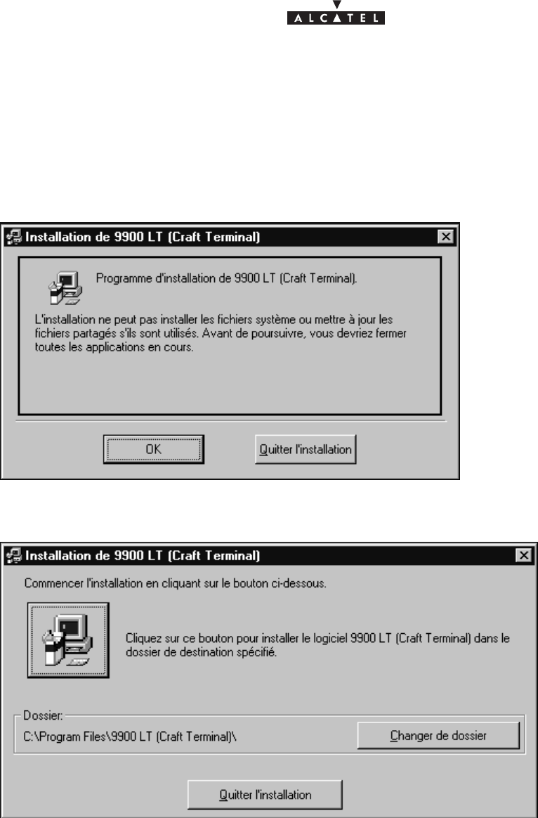
122/136 3CC10875AAAA TQ BJA 02
Issue 02 -January, 10 2000
A.2.2 –Stage 2: Installation of the Craft Terminal
•Run the Setup.exe program
If the delivery kit is in the form of diskettes, insert the installation diskette and double–click A:\Setup.exe in
Windows Explorer.
If not, copy the installation kit into a temporary file (c:\Temp par exemple) and run Setup.exe.
The following window is displayed:
•Click OK
This window is then displayed:
•Click the button representing a PC (top left of window) to continue installation.
Follow the progress of the installation program.
A window indicating that installation has been successful terminates the process.
The installation program asks to reboot the PC: click OK.
After reboot, log on and go to stage 3.
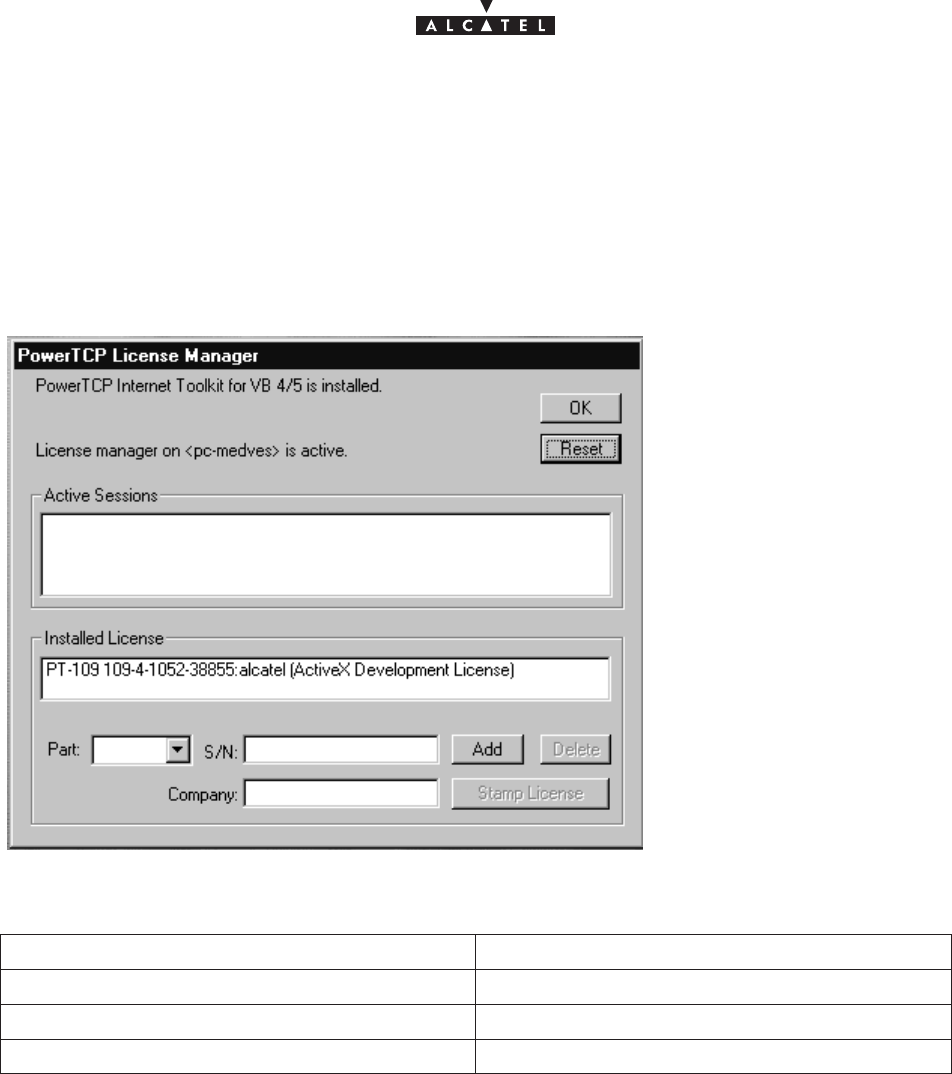
Issue 02 -January, 10 2000 123/1363CC10875AAAA TQ BJA 02
A.2.3 –Stage 3: Registering the OCX license
•Run the Ptlic32.exe program:
C:\Program_files\9900LT (Craft Terminal)\Ptlic32.exe
The ” Power TCP ” window is displayed
•Click the ” Licensing ” button
The following window is displayed
•Complete the following fields:
Text field Field value
Part (scroll menu) PT–109
S/N 109–4–1052–38855
Company Alcatel CIT
•Click ADD
The license appears in the ”Installed License” zone
•Click on the license
•Click on the ” Stamp License ” button
•Select the OCX file to register the license:
C:\WINNT\System32\ptsnmp32.ocx
A window indicates that the registration has succeeded
•Return to the main window (above) and click on the license displayed in the ” Installed License ” block,
then click Delete
•Click OK then OK in the following window
Remarque :
124/136 3CC10875AAAA TQ BJA 02
Issue 02 -January, 10 2000
An error message may appear when registering the OCX license.
In this case, make sure that no other application using the OCX is active.
A.2.4 –Stage 4: Configuring the Craft.ini file (optional)
In the Craft.ini file ( C:\ProgramFiles\9900LT\Craft.ini) check the value of the following parameters:
Parameter Value
IP Address IP address of the BS
Local port 161 (Tx port for SNMP requests from the Craft Terminal)
Remote port 161 (Rx port for SNMP requests to agent)
Trap port 161 (Rx port for ”Traps” to Craft Terminal)
A.2.5 –Stage 5: Installation of NFS server
This procedure is necessary to be able to implement the Craft Terminal’s “Software Download” feature.
If the server installation has already been carried out on the PC (cf. Is the NFS server available on the PC?),
go to the stage: Installation of Software Packages.
A.2.5.1 –
Reference of NFS server product
Product Omni–NFS Server for NT/98/95 – Xlink Techno-
logy
Version 4.01
Serial Number/Password cf. Certificate of Authenticity
Documentation Omni–NFS for Windows 98/95 & NT – User Guide
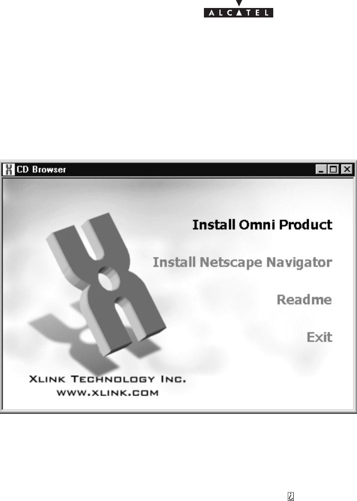
Issue 02 -January, 10 2000 125/1363CC10875AAAA TQ BJA 02
A.2.5.2 –
Installation of NFS server
•Log on to an account with administrator rights
From the Windows NT Explorer:
•Click on the D: drive
•Double–click on the Setup.exe program
The following window is displayed:
•Click on the menu: ”Install Omni Product”
A window requesting the product serial number and a password appears.
•Enter the requested information (cf. paragraph Reference of NFS server product) and click OK
A window containing the following phrase appears:
”This program requires a member of Administrator group to setup ”
•Click YES
A window titled ”Omni NFS”, ”full screen” is displayed along with a small ”Welcome” window
•Click Next
A window titled ”Software License agreement” appears
•Click YES
The following window appears:
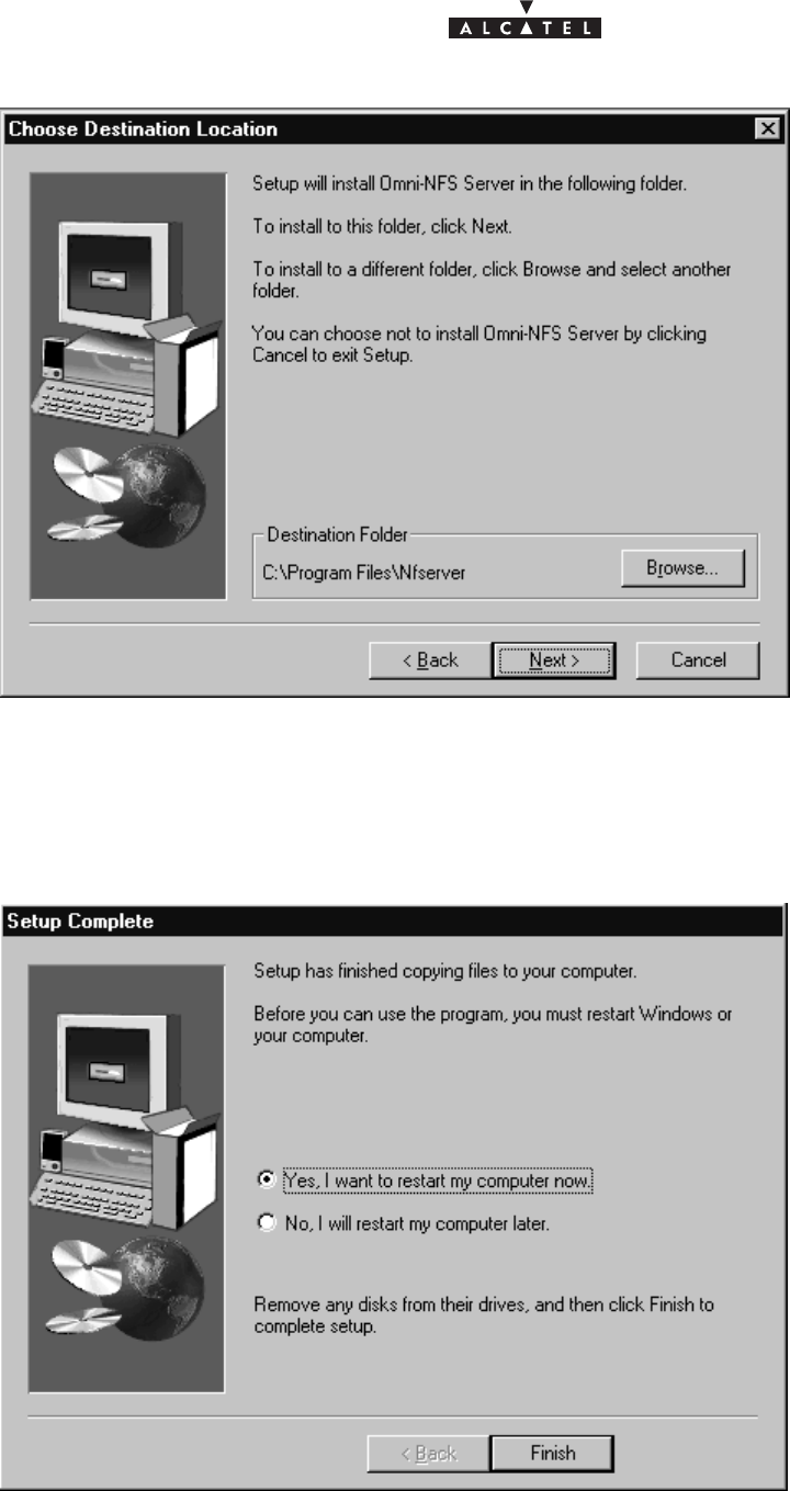
126/136 3CC10875AAAA TQ BJA 02
Issue 02 -January, 10 2000
•Click Next
A window titled ”Select Program Folder” appears
•Click Next
Installation begins.
After about ten seconds, the following window appears:
•Click ”Yes, I want to restart my computer now” then Finish
The PC reboots.
•Log on to an Administrator account before going to stage 5.2
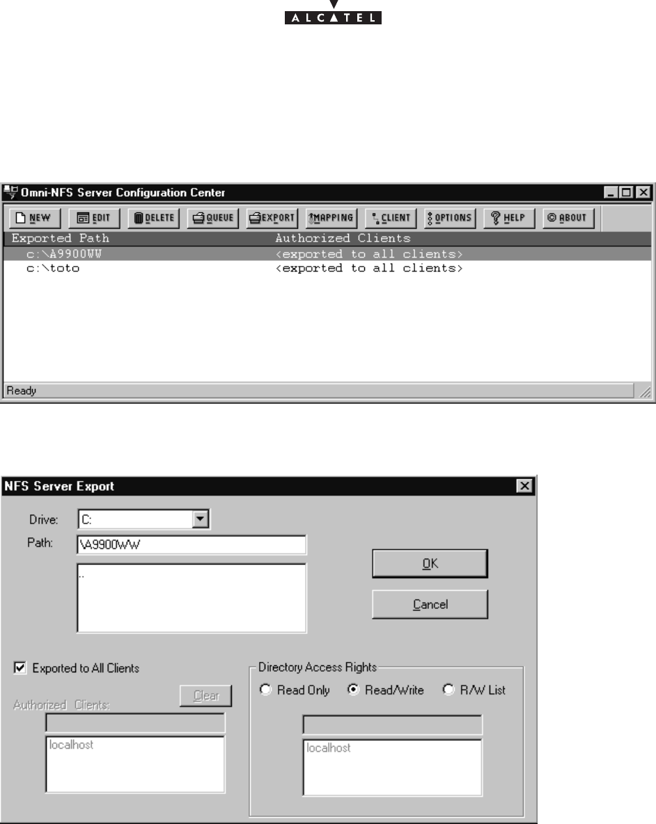
Issue 02 -January, 10 2000 127/1363CC10875AAAA TQ BJA 02
A.2.5.3 –
Configuring the NFS server
•Run the wnfsd.exe program:
C:\Program_files\nfserver\wnfsd.exe
A window similar to the following appears:
•Click on ”New” in the tool bar
The following window appears:
For the path, select the directory where the Craft Terminal software packages are to be installed.
Choose the following options:
– Exported to All Clients
– Directory Access Rigths : Read/Write
Click OK
Note:
In case of access error to a sub–directory of an exported directory, export each of the directories containing a
package.

128/136 3CC10875AAAA TQ BJA 02
Issue 02 -January, 10 2000
A.2.6 – Installation of Software Packages
From Windows NT Explorer, copy the directories containing the software packages to be downloaded to the NFS
assembly directory.
A.2.7 –How to deinstall the Craft Terminal ?
In Windows desktop, click successively on the following icons:
•Workstation (desktop)
•Control Panel
•Add/Remove Programs
•In the ” Add/Remove Programs Properties ” window , select the 9900LT program
•Click ” Add/Remove ”
•Confirm removal of application
Note
If a message is displayed indicating that certain components could not be removed from the computer:
•Click OK
•Click OK in the ” Add/Remove Programs Properties ” window
•In Windows Explorer, remove the folder:
C:\ProgramFiles\9900LT (Craft Terminal)
A.2.8 –Installing the Craft Terminal from an account without
“administrator” rights
During stage 2, no window appears to indicate the end of the Craft Terminal installation, and the installation
program remains blocked.
It is then necessary to stop “manually” the installation of the Craft Terminal when the installation program has
finished installing all the files.
Installation is over once the following conditions are fulfilled:
– the installation progress window indicates that all files have been installed,
– no disk access is detectable,
– a “reasonable” time (around 5 minutes) has elapsed since the end of file installation.
To stop the Craft Terminal installation program:
– Press simultaneously Alt,Ctrl, Del
The ”Windows NT Security” window appears.
– Click ”Task manager..”
– Select the Setup.exe program and click ”End of task”
Reboot the PC, log on and go to stage 3.

Issue 02 -January, 10 2000 129/1363CC10875AAAA TQ BJA 02
A.2.9 – Is the NFS server available on the PC?
To know if the NFS server is available on PC:
•Press simultaneously Alt,Ctrl, Del
The ”Windows NT Security” window appears.
•Click ”Task manager..”
If the line ”nfsd.exe” is present in the list of tasks, the NFS server is available on the PC.

130/136 3CC10875AAAA TQ BJA 02
Issue 02 -January, 10 2000
PAGE INTENTIONALLY LEFT BLANK
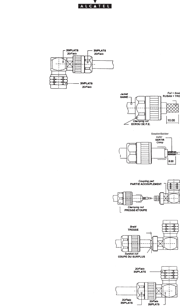
Issue 02 -January, 10 2000 131/1363CC10875AAAA TQ BJA 02
Appendix 3 – Mounting coaxial connector
Mounting on cable ET 390 998
Dénuder la gaine sur 10 mm, mettre l’écrou sur la gaine.
Strip cable (10 mm), put the clamping nut on the cable.
Rabattre les 10 mm de tresse sur la gaine.
Flange the 10 mm of braid on the jacket.
Couper le diélectrique et le ruban sur 6 mm.
Cut dielectric & foil on 6 mm.
Souder ou sertir le contact central.
Solder or crimp the contact on the inner conductor.
Monter la partie accouplement entre le ruban et
la tresse du câble.
Mount the coupling part between the foil and the
braid of the cable.
Rabattre la tresse vers l’avant du connecteur et
couper le surplus.
Flange the braid to the front of the connector
and cut the braid surplus close to the connector.
Assembler la partie presse étoupe et
accouplement, serrer avec une clé plate 20 mm.
(couple maxi 35 N/m)
Mount the clamping part and the coupling part,
press with end, wrench the clamping nut (20 mm)
(Max coupling torque 35 N/m)
connector DELTA
OHM
08 250 173

132/136 3CC10875AAAA TQ BJA 02
Issue 02 -January, 10 2000
PAGE INTENTIONALLY LEFT BLANK

document, use and communication of its contents
not permitted without written authorization from ALCATEL
All rights reserved. Passing on and copying of this
Issue 02 -January, 10 2000 133/1363CC10875AAAA TQ BJA 02
PAGE INTENTIONALLY LEFT BLANK
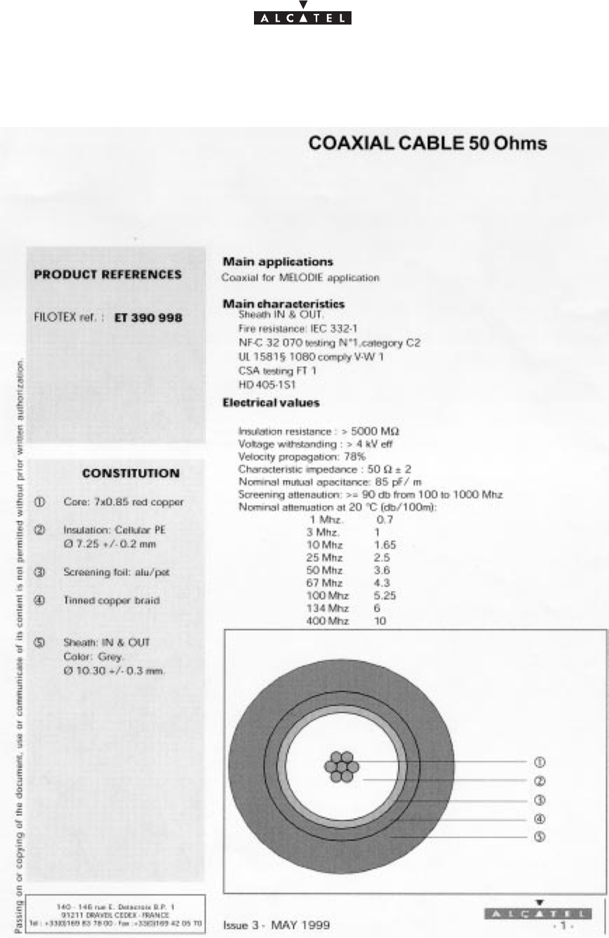
document, use and communication of its contents
not permitted without written authorization from ALCATEL
All rights reserved. Passing on and copying of this
134/136 3CC10875AAAA TQ BJA 02
Issue 02 -January, 10 2000
Informations non contractuelles
Code Alcatel: 1AC001100022

document, use and communication of its contents
not permitted without written authorization from ALCATEL
All rights reserved. Passing on and copying of this
Issue 02 -January, 10 2000 135/1363CC10875AAAA TQ BJA 02
Appendix 4 – List of abbreviations/Liste des
abréviations
MNEMONIC ENGLISH FRENCH
ADM Add and Drop Multiplexer (MIE) Multiplex insertion extraction
AGC Automatic Gain Control (CAG) Commande Automatique de Gain
AIS Alarm Indication Signal (SIA) Signal d’indication d’alarme
AMD AirModem
ANT ATM Network Termination
ATM Asynchronous Transfer Mode (?) Mode de transfert asynchrone
AS Automatic switching (CA) Commutation automatique
AT Attend alarm (on CT) (AT) Alarme en attente (sur PEX)
BER Bit Error Rate (TEB) Taux d’erreur binaire
BNC Bayonet–locking Connector (BNC) connecteur BNC
BS Base Station (BS) Station de base
CEPT Conference of European Post and Tele-
communications administrations (CEPT) Conférence Européenne des
Postes et Télécommunications
CCIR International radio consultative comitee (CCIR) Comité consultatif international des
radiocommunications
CPL coupling (in CPL board) (CPL) coupleur (carte CPL)
CT Craft Terminal (ECT, NCT or RCT) (PEX) Poste d’exploitation (PEE, PER ou
PED)
DBS Digital Base Station (DBS) Station de base numérique
EMC ElectroMagnetic Compatibility (CEM) Compatibilité ElectroMagnétique
EPROM Electronically Programmable Read–Only
Memory (EPROM) Mémoire fixe programmable de
façon électronique
ETSI European Telecommunications Standards
Institute (ETSI) Institut de standardisation des
télécommunications éuropéennes
FEC Forward error correction (CCE) Code correcteur d’erreurs
HDB3 High Density Binary 3 code (3rd order) Code Haute Densité Binaire d’ordre 3
I2C or IIC Inter Integrated Circuit (I2C or IIC) Inter Circuits Intégrés
IDU InDoor Unit (IDU) Coffret intérieur
IEC International Electrotechnical Commission (IEC) Commission internetionale
d’électrotechnique
IP Internet Protocol (IP) Protocole internet
ITU International Telecommunication Union Union Internationale des
Télécommunications
LED Light Emitting Diode Diode électroluminescente
LMCS Local Multipoint Communication Systems (LMCS) Système de communication
multipoint en mode local

document, use and communication of its contents
not permitted without written authorization from ALCATEL
All rights reserved. Passing on and copying of this
136/136 3CC10875AAAA TQ BJA 02
Issue 02 -January, 10 2000
MNEMONIC FRENCHENGLISH
LMD(S) Local Multipoint Distribution (System) (LMD(S)) Distribution multipoint en mode
local
MAC Medium Access Control (MAC) sous couche MAC de l’OSI
MUX Multiplexer (MUX) Multiplexeur
ODU OutDoor Unit (ODU) Coffret extérieur
NE Network Element (NE) Elément de réseau
NRZ Non return to zero (NRZ) Non retour à zéro
NT Network Terminal (NT) Terminal de réseau
PC Personal Computer (PC) Odinateur individuel
QAM Quadrature amplitude Modulation (MAQ) Modulation d’amplitude en
quadrature
RBS Radio of Base Station (RBS) Radio de la station de base
RF Radio Frequency (FR) Fréquence radio
RT Radio Terminal (RT) Terminal radio
RX Receiver (Rx) Récepteur
STP Shielded Twisted Pair (STP) Câble 1 paire trssadée blindé
SMD Surface Mounted Device (SMD) Composant monté en surface
TNT Telefony Network Termination (TNT) Terminal réseau téléphonique
TS Terminal Station (TS) Station Terminale
TX Transmitter (Tx) Emetteur
END OF DOCUMENT