Alcon LenSx 8065998162 LenSx Laser User Manual
Alcon LenSx, Inc. LenSx Laser
User Manual

DRAFT
LENSXLASERSYSTEM
OPERATOR’SMANUAL
AlconLenSx,Inc.
33Journey
AlisoViejo,CA92656
0086
DateofIssue:January2011
DistrubutedBy:
AlconLaboratories,Inc.
6201SouthFreeway
FortWorth,TX76134‐2099
AlconLaboratories,UKLtd.
PentagonPark,BoundaryWay
HemelHempstead
Hertfordshire,HP27UD,UK

LENSXLASERSYSTEM
OPERATOR’SMANUAL
80‐0001Rev.A ii
LenSxLaserSystem
Operator’sManual
TheinformationcontainedinthisdocumentistheconfidentialandproprietarypropertyofAlconLenSx,Inc.
(LenSx).Anyreproduction,dissemination,ordistributionofthisdocumentinwholeorinpartwithoutprior
writtenpermissionofLenSxisstrictlyprohibited.Whileeveryefforthasbeenmadetoensuretheaccuracy
ofinformationprovidedinthisdocument,pleasenotethattheinformation,figures,illustrations,tables,
specifications,andschematicscontainedhereinaresubjecttochangewithoutnotice.
PleasedirectallinquiriesregardingthismanualorforserviceassistancetoAlconLenSx,Inc.,33Journey,
AlisoViejo,California92656.Telephone(949)360‐6010(intheUnitedStates)
LenSxandtheLenSxlogoareregisteredtrademarksofAlconLenSxInc.©2011LenSxLasers,Inc.Allrights
reserved.Noportionofthismanualmaybereproducedortransmittedinanyformorbyanymeans
withouttheexpresspriorwrittenconsentofLenSx.
DRAFT
TableofContents
TABLEOFCONTENTS............................................................................................................................0
1LENSXLASERSYSTEM..................................................................................................................3
1.1INDICATIONSFORUSE.......................................................................................................................3
1.2SUMMARYDESCRIPTION...................................................................................................................3
1.3CONTRAINDICATIONS........................................................................................................................3
1.4COMPLICATIONS..............................................................................................................................4
2GENERALWARNINGSANDPRECAUTIONS....................................................................................6
2.1WARNINGS.....................................................................................................................................6
2.1.1UnauthorizedUseoftheLaser................................................................................................7
2.1.2Electrical..................................................................................................................................7
2.1.3EyeSafetyandNominalOpticalHazardDistance...................................................................7
2.1.4Mechanical/Motion.................................................................................................................8
2.1.5Combustion/Fire......................................................................................................................8
2.1.6Environmental/Chemical.........................................................................................................8
2.1.7Sterilization/BiologicalContamination...................................................................................9
2.1.8EmergencyOff.........................................................................................................................9
2.2PRECAUTIONS..................................................................................................................................9
2.2.1General....................................................................................................................................9
2.2.2PatientSelection......................................................................................................................9
2.2.3SurgicalProcedure...................................................................................................................9
2.2.4PowerFailureorEmergencyOff..............................................................................................9
2.3SAFETYFEATURES..........................................................................................................................10
2.3.1KeySwitch.............................................................................................................................10
2.3.2LaserEnabling.......................................................................................................................10
2.3.3LaserEmissionIndicator........................................................................................................10
2.3.4ProtectiveHousingandSafetyInterlock...............................................................................10
2.3.5Labels.....................................................................................................................................10
2.3.6SafetyShutterMonitor..........................................................................................................11
2.3.7FootswitchControl................................................................................................................11
2.3.8RemoteInterlockConnector..................................................................................................11
2.3.9EmergencyOFFSwitch..........................................................................................................11
2.3.10LaserCoolingSystem........................................................................................................11
2.3.11ManualGantryLift............................................................................................................12
2.3.12PatientInterfaceRFID.......................................................................................................12
2.3.13ConsoleFootbrake............................................................................................................12
2.4DEVICEELECTRICALCLASSIFICATION..................................................................................................12
3SYSTEMDESCRIPTION................................................................................................................13
3.1INTRODUCTION..............................................................................................................................13
3.2SYSTEMOVERVIEW........................................................................................................................13
3.2.1FemtosecondLaserEngine....................................................................................................15
3.2.2EnergyMonitor......................................................................................................................15
3.2.3DeliverySystem.....................................................................................................................15
3.2.4VideoMicroscope..................................................................................................................15

LENSXLASERSYSTEM
OPERATOR’SMANUAL
80‐0001Rev.A 1
3.2.5OpticalCoherenceTomography(OCT)imagingdevice.........................................................16
3.2.6PatientInterface....................................................................................................................16
3.2.7SurgeonControls...................................................................................................................17
3.2.8SystemElectronics.................................................................................................................17
3.2.9ConsoleChassis.....................................................................................................................18
3.3PROCEDUREOVERVIEW...................................................................................................................18
3.3.1Pre‐Operative........................................................................................................................19
3.3.2AnteriorCapsulotomy...........................................................................................................19
3.3.3Phacofragmentation.............................................................................................................20
3.3.4CombinedTreatments...........................................................................................................20
3.3.5Post‐Operative.......................................................................................................................20
4CONTROLS,INDICATORSANDDISPLAYS....................................................................................21
4.1DISPLAYPANEL&KEYBOARD...........................................................................................................21
4.2SURGICALDISPLAY.........................................................................................................................21
4.2.1VideoMicroscope..................................................................................................................21
4.2.2OpticalCoherenceTomography(OCT)Device......................................................................21
4.3DELIVERYSYSTEMPANEL.................................................................................................................22
4.3.1Joystick..................................................................................................................................22
4.3.2DeliverySystemTouchScreen...............................................................................................22
4.3.3ApplanationIndicator............................................................................................................22
4.3.4IlluminationandMicroscopeFocus.......................................................................................22
4.3.5FixationLight.........................................................................................................................23
4.4SYSTEMPOWER.............................................................................................................................23
4.4.1MainInputSwitch.................................................................................................................23
4.4.2KeySwitch.............................................................................................................................23
4.4.3Emergencyoffswitch............................................................................................................23
4.5FOOTSWITCH.................................................................................................................................23
4.6SOFTWARECONTROLS....................................................................................................................23
4.6.1SystemStartup......................................................................................................................23
4.6.2ProcedureProgrammingWindow.........................................................................................24
4.6.3SystemChecks.......................................................................................................................24
4.6.4UserRegistration...................................................................................................................24
4.6.5Shutdown..............................................................................................................................24
4.6.6About.....................................................................................................................................24
4.7ACCESSORIES&DETACHABLEPARTS.................................................................................................25
5SYSTEMREQUIREMENTS............................................................................................................26
5.1ELECTRICAL...................................................................................................................................26
5.2ENVIRONMENTAL...........................................................................................................................26
6PROCEDUREGUIDE....................................................................................................................27
6.1PREPARATIONANDTREATMENTPLANNING........................................................................................27
6.2STARTUP&PROCEDURESELECTION.................................................................................................27
6.2.1ProgrammingtheLensPattern.............................................................................................31
6.2.2ProgrammingtheCapsulotomyPattern...............................................................................32
6.2.3ProgrammingthePrimaryIncisionPattern...........................................................................32
6.2.4ProgrammingtheSecondaryIncisionPattern.......................................................................33
6.2.5ProgrammingtheArcuateIncisionPatterns.........................................................................34

LENSXLASERSYSTEM
OPERATOR’SMANUAL
80‐0001Rev.A 2
6.2.6CombiningPatterns...............................................................................................................35
6.2.7CompletingPatternSelection................................................................................................36
6.3PREPARINGTHEPATIENTINTERFACE.................................................................................................37
6.4DOCKING......................................................................................................................................38
6.5PATTERNPOSITIONING....................................................................................................................40
6.5.1Overview................................................................................................................................40
6.5.2VideoMicroscope,OCTImageGuidesandPatternGraphics...............................................41
6.5.3LimbusCentration.................................................................................................................41
6.5.4PrimaryandSecondaryIncisionAlignment...........................................................................42
6.5.5LensAlignment......................................................................................................................43
6.5.6CapsuleDepthAdjustment....................................................................................................44
6.5.7LensDepthAdjustment.........................................................................................................47
6.5.8CornealPrimaryandSecondaryIncisionsThicknessAdjustment.........................................49
6.5.9ArcuateIncisionThicknessAdjustments...............................................................................51
6.6CONFIRMATION.............................................................................................................................52
6.7TREATMENT..................................................................................................................................53
6.8PROCEDURECOMPLETION...............................................................................................................55
7CALIBRATIONANDALIGNMENT.................................................................................................56
7.1ENERGYCALIBRATION.....................................................................................................................56
7.2BEAMSTEERING............................................................................................................................56
8SERVICEANDMAINTENANCE.....................................................................................................57
8.1TRANSPORTANDSTORAGE..............................................................................................................57
9TROUBLESHOOTING..................................................................................................................58
10LABELS.......................................................................................................................................60
10.1CONSOLELABELS...........................................................................................................................60
11SYSTEMSPECIFICATIONS...........................................................................................................63
12WARRANTYINFORMATION.......................................................................................................64
13ABBREVIATIONSANDTERMS.....................................................................................................65
13.1GENERALABBREVIATIONS................................................................................................................65
13.2TERMS.........................................................................................................................................65
14NOMINALOPTICALHAZARDDISTANCE(NOHD).........................................................................66
15DECLARATIONOFCOMPLIANCE.................................................................................................69

LENSXLASERSYSTEM
OPERATOR’SMANUAL
80‐0001Rev.A 3
1 LenSxLaserSystem
1.1 IndicationsforUse
TheLenSxLaserisindicatedforuseinpatientsundergoingcataractsurgeryforremovalofthe
crystallinelens.Intendedusesincataractsurgeryincludeanteriorcapsulotomy,
phacofragmentation,andthecreationofsingleplaneandmulti‐planearccuts/incisionsinthe
cornea,eachofwhichmaybeperformedeitherindividuallyorconsecutivelyduringthesame
procedure.
1.2 SummaryDescription
TheLenSxLasercreatesincisionsthroughtightlyfocusedfemtosecondlaserpulsesthatcut
tissuewithmicron‐scaleprecision.Theincisionisachievedbycontiguouslyplacedmicro‐
photodisruptionsscannedbyacomputer‐controlleddeliverysystem.TheLenSxLaserSystem
shouldonlybeoperatedbyaphysiciantrainedinitsuse.
TheLenSxLaserdeliverysystememploysonesteriledisposableLenSxLaserPatientInterface
consistingofanapplanationlensandsuctionring.ThePatientInterfaceisintendedforsingle‐
use,only.RefertotheInstructionforUsesuppliedwiththeLenSxLaserPatientInterfacefor
preparationandapplicationinstructionsforthepatientinterface.
Thephysicianshouldbasepatientselectioncriteriaonprofessionalexperience,published
literature,andeducationalcourses.Adultpatientsshouldbescheduledtoundergocataract
extraction.
1.3 Contraindications
Contraindicationsfortheanteriorcapsulotomy,phacofragmentationofthelensusingtheLenSx
Laserincludethefollowing:
Cornealdiseasethatprecludesapplanationofthecorneaortransmissionoflaserlight
at1030nmwavelength
Descemetocelewithimpendingcornealrupture
Cornealopacitythatwouldinterferewiththelaserbeam
Presenceofbloodorothermaterialintheanteriorchamber
Hypotony,glaucoma,orthepresenceofacornealimplant
Poorlydilatingpupil,suchthattheirisisnotperipheraltotheintendeddiameterforthe
capsulotomy

LENSXLASERSYSTEM
OPERATOR’SMANUAL
80‐0001Rev.A 4
Conditionswhichwouldcauseinadequateclearancebetweentheintendedcapsulotomy
depthandtheendothelium(applicabletocapsulotomyonly)
Residual,recurrent,activeocularoreyeliddisease,includinganycornealabnormality
(forexample,recurrentcornealerosion,severebasementmembranedisease)
Ahistoryoflensorzonularinstability
Anycontraindicationstocataractorkeratoplastysurgery
Thisdeviceisnotintendedforuseinpediatricsurgery.
ContraindicationsforcornealincisionsusingtheLenSxLaserincludethefollowing:
Previouscornealincisionsthatmightprovideapotentialspaceintowhichthegas
producedbytheprocedurecanescape
Cornealthicknessrequirementsthatarebeyondtherangeofthesystem
Cornealopacitythatwouldinterferewiththelaserbeam
Hypotony,glaucoma,orthepresenceofacornealimplant
Residual,recurrent,activeocularoreyeliddisease,includinganycornealabnormality
(forexample,recurrentcornealerosion,severebasementmembranedisease)
Thisdeviceisnotintendedforuseinpediatricsurgery.
Potentialcontraindicationsarenotlimitedtothoseincludedinthislist.
1.4 Complications
Possiblecomplicationsresultingfromanteriorcapsulotomy,phacofragmentation,orcreationof
apartialthicknessorfull‐thicknesscutorincisioninclude:
Capsulotomy,phacofragmentation,orcutorincisiondecentration
Interruptedcapsulotomy,fragmentation,orcornealincisionprocedure
Capsulartear
Cornealabrasionordefect
Pain
Infection
Bleeding
Damagetointraocularstructures
Anteriorchamberfluidleakage,anteriorchambercollapse
Inthecaseofanincompleteorinterruptedcapsulotomy,theproceduremaybeimmediately
repeatedwithaslightlylargerdiametertocompletethecapsulotomy.Inthecaseofan
incompleteorinterruptedfragmentationorpartialthicknessorfull‐thicknessarccut/incision,
theprocedurecanberepeatedataslightlydifferentpositionusingthecentrationfeature.

LENSXLASERSYSTEM
OPERATOR’SMANUAL
80‐0001Rev.A 5
Inthecaseofanincompleteorinterrupted360‐degreekeratoplastyincision,theprocedure
maybeimmediatelyrepeatedwithaslightlylargerdiametertotherecipientandaresized
cornealdonorbutton.Inthecaseofaninterruptedprocedureduringdonortissuepreparation,
repeatingtheprocedureatalargerdiametermaynotberecommendediftherecipientcornea
hasbeenalreadypreparedataoriginaldiameter.Inthiscase,anewdonorcorneamaybe
required.
CataractremovalshouldbeperformedafteranteriorcapsulotomywiththeLenSxLaser.Inthe
initialclinicalprotocolusingtheLenSx,cataractremovalwasbegunwithin30minutesafterthe
laserprocedure.InpreviousstudiesusingtheNd:YAGlasertoperformanteriorcapsulotomy,
anteriorchamberinflammationandelevatedintraocularpressurewerenotedwhencataract
surgerywasdelayedfromonehourtouptoonedayfollowinglasertreatment.1,2TheNd:YAG
laserrequires100timesmoreenergyperpulsethanfemtosecondlaserstoinduce
photodisruption.
Potentialcomplicationsarenotlimitedtothoseincludedinthislist.Thesecomplicationsmay
besurgicallyormedicallymanagedusingcurrentlyacceptedtechniquesforcataractor
keratoplastyprocedures.
1WoodwardPM.AnteriorCapsulotomyusinganeodymiumYAGlaser.
AnnOphthalmol:16:534‐9,1984.
2SzwedaE.PreoperativeanteriorcapsulotomyusingYAGlaserincataractextractionbythe
envelopmethod.KlinOczna:93:334‐6,1991.

LENSXLASERSYSTEM
OPERATOR’SMANUAL
80‐0001Rev.A 6
2 WarningsandPrecautions
2.1 Warnings
TheLenSxLaserisindicatedforuseinpatientsundergoingcataractsurgeryforremovalofthe
crystallinelens.Intendedusesincataractsurgeryincludeanteriorcapsulotomy,
phacofragmentation,andthecreationofsingleplaneandmulti‐planearccuts/incisionsinthe
cornea,eachofwhichmaybeperformedeitherindividuallyorconsecutivelyduringthesame
procedure.
UnitedStatesFederalLawrestrictsthisdevicetosaleandusebyorontheorderofaphysician
orlicensedeyecarepractitioner.UnitedStatesFederalLawrestrictstheuseofthisdeviceto
practitionerswhohavebeentrainedintheoperationofthisdevice.
Theperformanceofsurgicalprocedures,operationofcontrols,oranyotheradjustmentsother
thanthosespecifiedhereinmayresultinhazardousconditionsforbothpatientsandpersonnel.
Whiletheriskoffireisextremelylow,theLenSxLasershouldnotbeoperatedinthepresence
offlammableanesthetics,volatilesubstances,oroxygenflowlines.
WARNING:DonotusecellphonesorpagersofanykindinthesameroomastheLenSxLaser.
TheLenSxLasercomplieswith47CRF15FederalCommunicationCommissionRulesforradio
frequencydevices.ChangesormodificationsnotexpresslyapprovedbyAlconLenSxInc.can
voidtheoperator’sauthoritytooperatethisradiofrequencydevice.
OnlytrainedLenSxrepresentativesshouldperformunpacking,installation,andservicingofthe
LenSxLaser.CoversarenottoberemovedbyanyoneotherthanLenSxpersonnel.Accidental
contactwiththehighvoltageelectricalcircuitsintheinterioroftheLenSxLaserconsolemay
resultinseriousinjuryordeath.Ocularexposuretocollimatedbeamscontainedintheconsole
interiorcanproduceretinaldamage.
SurgicallasersmustmeetrequirementsestablishedbytheFoodandDrugAdministration(FDA)
CenterforDevicesandRadiologicalHealthandinternationalstandardsandregulationsfor
surgicallasers.Specificcontrolsarerequiredthatpreventaccidentalexposureoflaserenergy
totheeyeandskinfrombothdirectandreflectedlaserbeams.Inaddition,precautionsmust
betakeninthesurgicalareatopreventfireandelectricalhazards.ImproperuseoftheLenSx
Lasermayresultinpatientcornealtrauma,infection,complications,ormechanicaltraumato
eitherpatientorpersonnel.Allwarnings,labelingandinstructionsmustbeobserved.

LENSXLASERSYSTEM
OPERATOR’SMANUAL
80‐0001Rev.A 7
2.1.1 UnauthorizedUseoftheLaser
Whennotinuse,themasterkeyshouldberemovedfromtheLenSxLaserandkeptinasecure
locationtopreventuseofthelaserbyunauthorizedpersonnel.Oncetheconsoleisswitched
ON,passwordprotectionisrequiredtoaccessanylaserfunctions.
2.1.2 Electrical
Highvoltageelectricalcircuitsareaccessibleiftheconsolepanelsareremoved.Onlytrained
LenSxservicerepresentativesshouldattempttoopentheconsolepanels.Seriousinjuryor
deathmayoccurwhilecontactingelectricalcircuitsintheunitinterior.Toolsarerequiredto
removetheconsolepanels.PanelsshouldnotberemovedbyanyoneotherthanLenSxservice
personnel.WhiletheLenSxLaserrequires120VAC,60Hz,10Aelectricalservice,thesystemis
configurableforthefollowinginputvoltages:100VAC/12A,120V/10A,220‐240V/7A,and
50/60Hz.Thelinevoltageshouldbetestedpriortolaserinstallationandmustbewithin
specifiedlimitsforproperoperationoftheunit.
Aninterlockconnectionallowstheuseofsafetyinterlockswitchesontheoperatingsuitedoors
thatautomaticallyplacethelaserinSTANDBYmodewhenthesuitedoor(s)isopened.
TheareaaroundtheLenSxLaserandthefootswitchshouldbekeptdry.Thelasershouldnot
beoperatedifthereisanyleakageofwaterfromtheconsole.ALenSxservicerepresentative
shouldbecontactedimmediately.
Iftheunitpowercordisfrayedorotherwisedamaged,donotuseunituntilcordhasbeen
replaced.
AtrippinghazardexistsiftheACpowercordisnotprotectedfromfoottraffic.Caremustbe
takentoavoidaccidentalunpluggingoftheLenSxLaserduringtreatment.
2.1.3 EyeSafetyandNominalOpticalHazardDistance
TheNOHDisdefinedaccordingtoAmericanNationalStandardsInstituteZ136.1‐2007,
“AmericanNationalStandardforSafeUseofLasers”.TheNOHDiscomputedintermsofthe
MaximumPermissibleExposure(MPE)allowedontotheeye.FortheLenSxLasertheNOHD
calculatedusingthisstandardisshortduetothesmallpulseenergiesemittedbythelaser.The
mostconservativeNOHDforadirectbeamexposurefromtheLenSxLaseris106cm(See
Appendix2).Thismeansthatonlythepatientoperativeeyewillbeexposedtolaserradiation
exceedingtheMPE.
Thepracticalconsequenceisthatoperatorsandsupportpersonnelarenotatriskofoptical
radiationduringnormalandroutineoperationofthelaser.Anyserviceoperationrequiringthe
removalofanycoversorshieldsontheconsolewillrequireeyewearofOD≥5atawavelength

LENSXLASERSYSTEM
OPERATOR’SMANUAL
80‐0001Rev.A 8
of1030nm.OnlyauthorizedLenSxservicerepresentativesshouldattempttoremoveconsole
coversortoservicetheLenSxLaser.
Standardlasersafetyprotocolrequiresthatawarningsignbeplacedonthedooroftheroom
whenthelaserisinuse,towarnpersonneloflaserusageinprogressbeforetheyenterthe
controlledarea.Thedoorshouldbeclosedduringtheoperationofthelaser.
Removingtheconsolecoversincreasestheriskofeyeinjury.OnlytrainedLenSxservice
representativesshouldremovetheconsolecoversorattemptservicingoftheLenSxLaser.
Aninterlockconnectionallowstheuseofsafetyinterlockswitchesontheoperatingsuite
door(s)thatautomaticallydisableslaseremissionwhenthesurgicalsuitedoor(s)isopened.
ThePatientInterfacedisposablecannotbereusedorre‐sterilized;theLenSxLaserwillnotbe
operablewithapreviouslyusedPatientInterface.
2.1.4 Mechanical/Motion
TheLenSxLaserconsoleisstableandmobilewithinanoperatingroom.Nosignificanttipping
orrollinghazardexistsoncetheconsoleisplacedinthelockedpositionforsurgery.Only
trainedpersonnelshouldmovetheconsole.Iftheconsolemustbemovedforanyreason,a
LenSxservicerepresentativeshouldbecontacted.
Wheninstalled,afootbrakeatthebackoftheunitpreventstheconsolefromrolling.The
footbrakemustbeengagedduringtreatment.
Removingtheconsolecoversisapotentialmechanicalhazard.Thisoperationshouldbe
performedonlybytrainedLenSxservicerepresentatives.
Afterdockingiscomplete,theusershouldnotmovethedeliverysystemuntilpatientis
disengagedfromthesystem.
2.1.5 Combustion/Fire
Althoughthepossibilityofcombustionisremote,flammableanestheticsshouldnotbeused
withtheLenSxLaser.Oxygenlinesandflammablematerialsshouldbekeptclearofthe
immediateareasurroundingthelaseraperture.
2.1.6 Environmental/Chemical
NohazardousgasesorchemicalsareusedintheLenSxLaser.

LENSXLASERSYSTEM
OPERATOR’SMANUAL
80‐0001Rev.A 9
2.1.7 Sterilization/BiologicalContamination
TheLenSxLaserisusedwiththeLenSxLaserPatientInterface.Thissterileassemblycannotbe
reusedandshouldbedisposedofasmedicalwaste.
2.1.8 EmergencyOff
Intheeventofanemergency,theLenSxLasershouldbeimmediatelyshutdownbypressing
theredemergencyOFFbuttonlocatedattopcenteronthefrontpanel.
IftheLenSxLaserisshutdown(bypressingtheEmergencyOffbuttonorbyalossofpower),
thepatientmayberemovedfromunderthedeliverysystembyloweringthebedorby
actuatingthemanualgantryliftlocatedatthebaseofthedeliverysystemgantry.
2.2 Precautions
2.2.1 General
ThePatientInterfacewillincreaseintraocularpressureduringtheprocedure.Caremustbe
takentominimizeapplanationtimes.Incompleteapplanationmayresultinnon‐uniformor
incompleteincisions.
2.2.2 PatientSelection
Patientsmustbeabletolieflatandmotionlessinasupineposition.
Patientmustbeabletounderstandandgiveaninformedconsent.
Patientsmustbeabletotoleratelocalortopicalanesthesia.PatientswithelevatedIOP
shouldusetopicalsteroidsonlyunderclosemedicalsupervision.
2.2.3 SurgicalProcedure
Fullthicknesscutsorincisionsshouldbeperformedwithinstrumentsandsuppliesonstandby
tosealtheeyeincaseofanteriorchambercollapseorfluidleakage.
SurgicaltreatmentshouldbehaltediftheOCTimageispoorordisrupted.
Duringuse,theusershouldnotmove,shakeorbumpthedeliverysystemafterdockingis
completeduntilpatientisdisengagedfromthesystem.
2.2.4 PowerFailureorEmergencyOff
IntheeventofpowerfailureorinitiationoftheEmergencyOffbutton,removethepatient
interfacetubefromthevacuumporttoreleasetheeyefromsuction.Graspthedelivery
systemobjectiveandraiseit1to2inchestosafelyremovethepatientfromthesurgicalfield.

LENSXLASERSYSTEM
OPERATOR’SMANUAL
80‐0001Rev.A 10
TheManualGantryLift,locatedatthebaseofthegantry,allowstheusertolifttheunpowered
gantryifadditionalpatientclearanceisneeded.Alternatively,thepatientbedmaybelowered
toprovideclearance.
2.3 SafetyFeatures
TheLenSxLasercomplieswithallperformancestandardsspecifiedbytheCenterforDevices
andRadiologicalHealthoftheU.S.FoodandDrugAdministrationandinternationalstandards
forsurgicallasers,andincludesthefollowingsafetyfeatures:
2.3.1 KeySwitch
ThelaserconsolecanbeturnedONonlywiththeappropriatemasterkeythatcontrolsthe
masterswitch.ThekeyONswitchislocatedatthebottomcenterofthefrontpanelofthelaser
console.WhenthemasterkeyisturnedON,powerisavailabletotheinstrument.Themaster
keycannotberemovedwhenswitchedtotheONposition,andthelaserwilloperateonlywith
thekeyinplace.
2.3.2 LaserEnabling
Whenthekeyswitchturnsonthesystempower,aLoginwindowappears.Loginprevents
unauthorizeduse.Followingsuccessfullogin,laseroperationisdisabledwhilethe
microprocessorchecksforbasicfaultconditionsandthesystemstabilizes.Afterthisperiod,
theProcedurewindowwillappearontheDisplayPanel.
2.3.3 LaserEmissionIndicator
LaseremissionisindicatedbyaredLASEREMISSIONindicatorontheDisplayPanel.
2.3.4 ProtectiveHousingandSafetyInterlock
TheLenSxLaserhasaprotectivehousingthatpreventsunintentionalaccesstolaserradiation.
ThishousingshouldbeopenedonlybyaqualifiedLenSxrepresentative.
2.3.5 Labels
Appropriatewarninglabelsaremountedinspecifiedlocationsonthelasersystemtoindicate
conditionsunderwhichtheusercouldbesubjectedtolaserradiation(SeeSection10).

LENSXLASERSYSTEM
OPERATOR’SMANUAL
80‐0001Rev.A 11
2.3.6 SafetyShutterMonitor
Dualsafetyshutters,closedunlessthesystemisintheTREATMENTmode,preventlaser
radiationfromexitingtheinstrument.Shutterstatusiscontinuouslymonitored.Shoulda
malfunctionoccur(i.e.asafetyshutteropensintheabsenceofafootswitchpress)thelaser
consoleisdisabledandamessagedisdisplayed.TheLenSxLasercannotbere‐enableduntil
thefaultconditionhasbeencleared.
2.3.7 FootswitchControl
Thefootswitchishousedinanindustrialgradeenclosureandcannotbeactivatedunlessthe
LenSxLaserhascompletedallstepsinpreparationforlaserincision.Positionswitchesinthe
housingarearrangedsuchthatthefootswitchpedalpositionisredundantlymonitored.
2.3.8 RemoteInterlockConnector
Thesystemisequippedwithanoutletfortheinterlockingofroomdoors.Amessageonthe
systemdisplayappearswhentheremoteinterlockisnotconnectedproperlyorhasbeen
brokenbysomeaction,suchastheopeningofanoperatingroomdoor.LenSxrepresentatives
shouldbecontactedforassistanceinestablishingaremoteinterlock.
2.3.9 EmergencyOFFSwitch
TheemergencyOFFswitchisaredbuttonlocatedonthefrontpaneloftheconsole.When
pressed,theemergencyoffswitchshutsoffthemainsystempower.Thiscontrolshouldbe
usedonlyintheeventofanemergency.
IftheLenSxLaserisshutdown(bypressingtheEmergencyOffbuttonorbyalossofpower),
thepatientmayberemovedfromunderthedeliverysystembyloweringthebedorby
actuatingthemanualgantryliftlocatedatthebaseofthedeliverysystemgantry.
Torestartthesystemaftertheemergencyoffswitchisactuated,twisttheredemergencyoff
buttonuntilitdisengages;turnthekeyswitchtotheOFFpositionandreturnittotheON
position.Thesystemwillthenrebootnormally.FollowtheSystemStartupinstructionin
section4.6.1.
2.3.10 LaserCoolingSystem
TheLenSxLaserusesaninternalre‐circulatingcoolingsystemwhosefluidlevelsarechecked
duringpreventivemaintenance.Coolantlevelsareautomaticallymonitoredbythesystemand
ifalowcoolanterroroccurs,amessageisdisplayed.AnauthorizedLenSxservice
representativeshouldbecalledifacoolanterroroccurs.

LENSXLASERSYSTEM
OPERATOR’SMANUAL
80‐0001Rev.A 12
2.3.11 ManualGantryLift
Themanualgantryliftallowstheusertoraisethegantrymechanismupusingamanualscrew.
Themanualliftknobisfoundatthebaseofthegantryafewinchesabovethefloor.Whenthe
systemisunpowered,theknobisfreetoturn.
2.3.12 PatientInterfaceRFID
EachLenSxLaserPatientInterfaceisinstrumentedwithanRFIDtag.TheRFIDtagauthenticates
thePatientInterfaceforusewiththeLenSxLaserandpreventsreuseorusebyunauthorized
patientinterfaces.
2.3.13 ConsoleFootbrake
Whenthelasersystemisinstalled,afootbrakeatthebackoftheunitpreventstheconsole
fromrolling.Thefootbrakemustbeengagedduringtreatment.
2.4 DeviceElectricalClassification
Protectionagainstelectricshock:ClassIEquipment
ProtectionagainstelectricshockPatientAppliedPart:TypeBF
ModeofOperation:ContinuousOperation

LENSXLASERSYSTEM
OPERATOR’SMANUAL
80‐0001Rev.A 13
3 SystemDescription
3.1 Introduction
TheLenSxLaserSystemusesfocusedfemtosecondlaserpulsestocreateincisionsand
separatestissueinthelenscapsule,crystallinelensandcornea.Individualphotodisruption
locationsarecontrolledbyrepeatedlyrepositioningthelaserfocus.Thelightpulseisfocused
intoasufficientlysmallspotinordertoachievephotodisruptionofthetissueinsidethefocus.
Atinyvolumeoftissue,afewmicronsindiameter,isphotodisruptedatthelaserfocus.The
surgicaleffectisproducedbyscanningthousandsofindividualpulsespersecondtoproducea
continuousincisionortissueseparation.Thelocationofthetissuephotodisruptionis
controlledbymovingthefocusofthelaserbeamtothedesiredsurgicaltargetlocation.A
computer‐controlledscanningsystemdirectsthelaserbeamthroughoutathree‐dimensional
patterntoproduceanincision.Thelaserpulsesaredeliveredthroughasterile,disposable
applanationlensandsuctionringassemblythatcontactsthecorneaandfixestheeyewith
respecttothedeliverysystem.
3.2 SystemOverview
TheLenSxLaserisaCDRHCFR1040class3BandaIEC60825‐1class3Rlasersystemforocular
surgeryconsistingofthefollowingcomponents:
alasersourcetoproducefemtosecondlaserpulses;
anaimingdevicetolocalizespecifictargetsintheeye;
anopticaldeliverysystemtopreciselydeliverlaserpulsestodesiredtargetsintheeye;
computercontrollerstoperformclinicalprocedures;
adisposablepatientinterfaceopticallycouplingtheeyetotheopticaldeliverysystemin
ordertopreventeyemovement.
TheLenSxLaserisastand‐aloneunitrequiringnoexternalwaterorgasconnections.The
deviceconsolehousesthelasersource,powersupplies,controlelectronics,coolingsystem,
beamdeliverydevice,opticalcoherencetomography(OCT)device,videomicroscopeand
computers.TheconsoleitselfisdesignedforuseinamedicalsettingmeetingUSand
internationalstandards(ETL)forelectromagneticemissionsformedicaldevices.Thelaser
beamandallcollateralradiationarecompletelyenclosedinsidetheconsole.TheKeyON
switchandEmergencyOffbuttonarelocatedonthefrontpaneloftheconsolewheretheyare
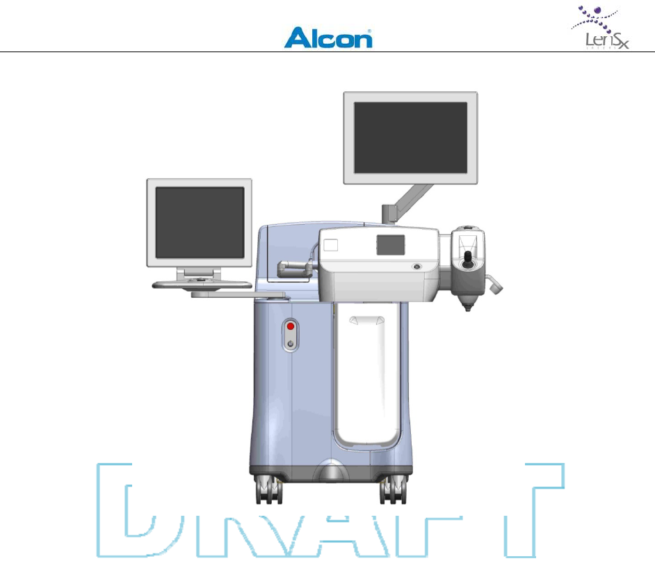
easilyidentifiedandaccessed.TheLenSxLaserSystemisshowninFigure3‐1.
LENSXLASERSYSTEM
OPERATOR’SMANUAL
80‐0001Rev.A 14
Figure3‐1:LenSxLaserSystem
Anall‐solid‐statelasersourceproducesakHzpulsetrainoffemtosecondpulses.Theamplified
pulsetrainisroutedthroughabeammonitoringassemblycomprisedofenergymonitors,an
energyattenuatorandtheprimarysafetyshutter.Anopticalarticulatedarmdirectslaserlight
tothedeliverysystemwhereasecondshuttercontrolsthebeam.Computercontrolled
scanningmirrorsdirectthelightthroughabeamexpanderandthroughafocusingobjective
ontoaspotatpre‐determineddepthwithintheeye.Anopticalcoherencetomography(OCT)
imagingdeviceandavideocameramicroscope(VM)areusedtolocalizespecifictargetsandto
viewthepatient’seye.
TheLenSxLaserSystemusesasteriledisposablepatientinterfacethatattachestothedistal
endofthefocusingobjective.Thepatientinterfaceisloweredtotheeyeuntilitcontactsthe
eye.Suctionthenholdstheeyeinposition.Onceparametersforthedesiredprocedureare
selectedusingthesoftwareinterface,theprocedureisinitiatedbypressingthefootswitch.
Althoughthesystemcomputercontrolsthelaseroperationduringtheincisionandlaserpulse
positioning,theproceduremaybestoppedatanytimebyreleasingthefootswitch.
ThefollowingsectionsbrieflydescribethemajorcomponentsoutlinedinFigure3‐1.

LENSXLASERSYSTEM
OPERATOR’SMANUAL
80‐0001Rev.A 15
3.2.1 FemtosecondLaserEngine
Consistentwithwell‐establishedfemtosecondlaserprinciples,thelaserengineusesa
conventionalamplifiedlaserdesigninwhichpulseswithsufficientbandwidtharegeneratedby
anoscillator,amplifiedtohigherenergies,andfinallycompressedintimetofemtosecondpulse
duration.
Theoscillatorproducesfemtosecondlaserpulsesofnanojouleenergy.Thesepulsesare
temporallyexpandedbyapulse“stretcher”andarethendirectedintoadiode‐pumped
regenerativeamplifierwherethepulseenergyisincreasedasthepulsecompletesanumberof
round‐tripswithintheamplifiercavity.Whenthepulseenergyreachesmicrojouleenergies,
thepulseisswitchedoutoftheamplifiercavity.Amplifiedpulsesareroutedtoagrating
compressortotemporallycompressthepulsesbacktothefemtosecondrange.
3.2.2 EnergyMonitor
Thebeamofcompressedpulsesfromthelaserthenenterstheenergymonitoringassembly.A
computercontrolledenergyattenuatoradjuststhebeamenergytoprogrammedlevelsand
energymonitorsverifythebeamenergy.Aprimaryshutter,thatisnormallyclosedwhennot
energized,controlsthereleaseofthebeamfromtheenergymonitor.Electronichardware
closestheshuttersintheeventthattheenergymonitorsreportanunexpectedorout‐of‐
tolerancepulse.
3.2.3 DeliverySystem
Thedeliverysystemfocusesthebeamoflaserpulsesontoafocusspotataprogrammed
location.Uponexitingtheenergymonitor,thebeamentersanarticulatedarmthatterminates
atthedeliverysystem.Asecondshutteratthedeliverysystemcontrolsthelaserbeam
throughthedeliverysystem.Thebeamthenentersasetofcomputercontrolledscanning
mirrorsthatscanthebeamintoabeam‐expandingtelescope.Eachscannedpositionofthe
beamcorrespondstoanX,Ylocationinthefocalplaneofthefocusingobjective.TheZposition
ofthefocusedlaserspotiscomputercontrolledbyopticalzoomlenseslocatedinthebeam
expander.Theentiredeliverysystemismountedonamotorizedgantryattachedtothesystem
consoletoallowtheusertopositionthedeliverysystem.
Thealignmentofthebeamthroughthedeliverysystemisautomaticallyverifiedbeforeeach
procedure.UserscanalsorequestthatanalignmentcheckbeperformedusingtheBeam
SteeringselectionintheSystemChecksmenu.
3.2.4 VideoMicroscope
ThedeliverysystemincludesaSurgicalDisplaythatprovidesavideomicroscopeviewofthe
surgicalfieldatalltimes.Illuminationofthefieldiscontrolledwithaninternalelectronic
controllerandatouchscreeninterfacemountedontheconsole.Thevideoimageprovidesthe

LENSXLASERSYSTEM
OPERATOR’SMANUAL
80‐0001Rev.A 16
surgeonwithsurgicaldetailssuchasthepositionofthepupil.Thesurgeonobservesthevideo
imagetoadjustandverifythepositionofthesurgicalpatternsduringprogrammingand
performanceoftheprocedure.
3.2.5 OpticalCoherenceTomography(OCT)ImagingDevice
TheSurgicalDisplayalsoincludesanopticalcoherencetomography(OCT)basedimagingdevice
thatassistsinlocalizingspecifictargetlocations.TheOCTconsistsofalowpowervisible
wavelengthlightsourcethatisscannedthroughoutthetransparentstructuresoftheanterior
chamberoftheeye.Lightscatteredfromocularstructuresandsurfaceswithintheeyeis
analyzedtoproducecrosssectionalimagesoftheeye’santeriorsegment.Varioussectioned
imagesmaybeproduced,includingawidefieldlinescanoftheanteriorchamber,magnified
crosssectionsofthecorneaatthepointsofplannedincisions,andcircleandlinescansofthe
lensandcapsule.ThesurgeonusestheseOCTimagestoadjustandverifythepositionand
orientationoftheselectedsurgicalpatterns.
3.2.6 PatientInterface
TheLenSxLaserusesasterile,disposablePatientInterface(Figure3‐2).ThePatientInterfaceis
comprisedofanapplanationlens,suctionringandtubing.Thesuctionringandcurved
applanationlensareintegratedintoasinglepieceandmountedonthelaserdeliverysystem.
ThePatientInterfaceismountedontothedistalendofthelaserfocusingobjectiveandserves
asasterilebarrierbetweenthepatientandthelaser.Tubingisconnectedtoafilterandtoa
vacuumportonthelasersystem.ThePatientInterfacealsocontainsanintegratedpassive
RFIDidentificationdevice.TheRFIDidentifierissensedbyareaderlocatedinsidetheLenSx
LaserSystemconsole.Thelensisloweredontothepatient’seyeuntilthecorneaisapplanated;
suctionisthenactivated.
Figure3‐2:LenSxLaserPatientInterface–(1)Interface
Coneandgripper;(2)tubing;(3)filterandRFID;(4)
vacuumport.

LENSXLASERSYSTEM
OPERATOR’SMANUAL
80‐0001Rev.A 17
Usingthegantryjoystickandvisualizationviathevideomicroscope,thecurvedapplanation
cone(thatisattachedtothelaserdeliverysystem)isloweredtomakecontactontotheeye.
Theapplanationforceindicatorisintheyelloworgreenzonewhenadequateapplanationforce
isachieved,allowingthesurgeontoapplysuctionviatouchscreenactivationofaninternal
pumptofixatetheeye.Graphicaloverlaysoftwaretools(referencetoalivevideoimageofthe
eyeonthegraphicaluserinterface)areusedtoadjustthecentrationoftheprogrammed
cuttingpatterntothedesiredposition.
Whentheprocedureiscompleted,suctionisreleasedandthefocusingobjectiveislifted,
removingtheapplanationlensfromthesurfaceoftheeye.Theapplanationlensandtubing
arethendisposed.
3.2.7 SurgeonControls
ThesurgeoncontrolstheLenSxLaserprimarilybyaconsoleinterfacecomprisedoftwodisplay
monitors(theDisplayPanelandSurgicalDisplay),akeyboard,atouchpadandatrackball.
Parametersforphotodisruptionpatternandsysteminformationareenteredattheconsole
interface.Thesystemsoftwareallowsthesurgeontoselectpatternparametersandtoprepare
thelaserfortreatment.Directlynexttotheconsoleinterfacearethemasterkeyswitch,which
isusedtostartthesystem,andtheemergencyOFFswitch.
OtherimportantsurgeoncontrolsincludeanX,Y,&Zjoystickthatactuatethemotorized
gantrysupportingthedeliverysystem.Thejoystickisusedtoalignthedeliverysystemoverthe
patientandtomakecontactwiththepatienteye.Asmalltouchscreenisusedtocontrolthe
utilitiesassociatedwiththedeliverysystem,includingtheilluminationcontrols,docking
controlsandvideomicroscopefocusingcontrols.
Afootswitchallowsthesurgeontostartandstoplasertreatment.Thesurgeoninitiateslaser
treatmentbyfirstnavigatingthesoftwareinterfaceuntilthesystemisREADYandstartsthe
treatmentbypressingthefootswitch.Thesurgeoncaninterrupttheprocedureatanytimeby
releasingthefootswitch.Afterinterruption,thesurgeonrestartstheprocedurebypressing
andholdingdownthefootswitchagain.Thelaserwillcontinuethetreatmentuntilthe
programmedpatterniscomplete.
3.2.8 SystemElectronics
TheLenSxLaserconsolecanbeconfiguredfor100V,120V,220‐240V,50/60Hzoperation.ACto
DCconverterssupplysystemelectronics,laserdiodesandthermoelectriccoolerswithlow
voltageDCcurrent.Themaximumpowerdrawislessthan1.2kW.

LENSXLASERSYSTEM
OPERATOR’SMANUAL
80‐0001Rev.A 18
Electronicsensorsmonitorthepositionofthepatientinterfacewhenmountedontothe
deliverysystem.Iftheapplanationlensisunlockedoroutofposition,hardwaresendsanerror
tothecomputerandpreventstheprocedurefromstarting.Inaddition,sensorsauthenticate
thepatientinterfaceviatheRFIDtagoneachpatientinterface.
Acomputermonitorsandcontrolsthebeamenergy,repetitionrate,safetyshutters,
footswitch,laserdiagnostics,thepositionofthescannersandthepositionofthescanning
objectivelens.Hardwaremonitorsthefunctioningofthecomputerandcomputersoftware.If
anunsafeconditionoccurs,thesafetyshuttersareimmediatelyclosedandthesurgeonalerted.
Inaddition,thesurgeonmonitorstheprocedurethroughthevideomicroscopeandcanhaltthe
procedureatanytimebyreleasingthefootswitch.
3.2.9 ConsoleChassis
Theentirelaserconsoleisenclosedbyametalskin.Thesecoveringscannotberemoved
withoutspecialtools.Thelaserradiationisnotaccessibleoutsidetheconsolechassisuntilthe
treatmentbeamexitsthesystematthepatientinterface.Theconsoleisdesignedforuseina
surgicalsetting,itiseasytoclean,andmeetsUSandinternationalstandardsfor
electromagneticemissionsfrommedicaldevices.Thepatientappliedpartisclassifiedas
floating“BF”deviceandiselectricallyisolatedfromthesystemelectronicsandmainsinput.
3.3 ProcedureOverview
TheLenSxLaserisindicatedforuseinpatientsundergoingcataractsurgeryforremovalofthe
crystallinelens.Intendedusesincataractsurgeryincludeanteriorcapsulotomy,
phacofragmentation,andthecreationofsingleplaneandmulti‐planearccuts/incisionsinthe
cornea,eachofwhichmaybeperformedeitherindividuallyorconsecutivelyduringthesame
procedure.
TheLenSxLaserfocusesabeamoflowenergypulsesofinfraredlightintotheeye.Eachpulse
ofenergycreatesphotodisruptionofamicro‐volumeoftissueatthefocusofthebeam.When
scanned,thebeamplacesindividualphotodisruptionsitesinacontiguouspatterntoform
continuousincisions.Thespacingbetweenphotodisruptionsitesisprogrammedbytheuser.A
typicalincisionconsistsofseveraltensofthousandsmicro‐disruptions.Byprogrammingthe
size,shapeandlocationofthescanningpattern,incisionsarecreated.
Ananteriorcapsulotomyincisionconsistsofacylindricalcutstartingfrombelowthesurfaceof
theanteriorcapsuleandcontinuingthroughthecapsuleafewmicronsintotheanterior
chamber.
Alensphacofragmentationincisionconsistsoftwoormoreverticallyorientedelliptical‐shaped
planesthatintersectatthecenterofthelens.Themaximumcuttingdepthshouldbeatleast

LENSXLASERSYSTEM
OPERATOR’SMANUAL
80‐0001Rev.A 19
500mabovetheposteriorcapsule.Thecutsproceedfromthedeepestpointandmove
anteriorly,endingbelowtheanteriorcapsule.
Apartialthicknessorfullthicknesscutforcataractsurgeryconsistsofanarccutstartingfrom
thedesiredcornealthicknessandcontinuinganteriorlytowardsthecornealepithelium.These
cutscanconsistof1,2or3planes.
3.3.1 Pre‐OperativeSteps
TheLenSxLaserusesaproprietarysteriledisposablePatientInterface.ThePatientInterfaceis
comprisedofanintegratedapplanationlens,suctionring,andtubingthatconnectstothe
suctionportoftheLenSxsystem.Thepatientinterfaceismountedontothedistalendofthe
systemfocusingobjectiveandservesasasterilebarrierbetweenthepatientandthelaser.
SensorsintheLenSxconsoleauthenticatethepatientinterface.ThesurgeonusestheX,Yand
Zjoystickcontroltocontacttheoperativeeye.Followingapplanation,mildsuctionisapplied
viathetubinginordertostabilizetheeye.RefertotheInstructionforUsesuppliedwiththe
LenSxLaserPatientInterfaceforpreparationandapplicationinstructionsforthePatient
Interface.
Thesurgeonobservesapplanationofthecorneausingthevideomicroscope,andthenapplies
suctionwhenthecorneaisproperlyapplanated.
TheSurgicalDisplaypresentsalivevideomicroscopeimageofthesurgicalfield.Graphicslaid
overtheimageareusedtoprogramthelateralpositionoftheincision.Whenthelateral
positionisacceptable,OCTimagesappearontherightsideofSurgicalDisplay.Thesurgeon
identifiesthedepth,positionofthelensandcornealsurfacesusingtheOCTimages.Graphical
toolsallowthesurgeontoprogramtheincisiondepthsontheOCTimages.
Anteriorcapsulotomypatternsareprogrammedtocutfromatleast100micronsbelowto100
micronsabovetheanteriorcapsule.Lensphacofragmentationpatternsareprogrammedtocut
fromatleast500micronsabovetheposteriorcapsuletoatleast500micronsbelowthe
anteriorcapsule.Partialandfullthicknesscornealincisionsareprogrammedasapercentageof
cornealthicknessatthepositionthecutisbeingmade.Whenprogrammingiscomplete,the
systemperformsinternalchecksandnotifiesthesurgeonwhenthesystemisreadytofire.
3.3.2 AnteriorCapsulotomy
Whenthesurgeonpressesthefootswitch,themainshutterisopenedandthetreatment
begins.Thetreatmentpatternbeginsasascannedcirclelocatedbelowthedepthofthe
anteriorcapsule.Onceascannedcircleiscompleted,anewcircleisscannedafewmicrons
abovethefirstcircle.Aseachcircleiscompleted,acylindricalincisioniscreated.Thepattern
isautomaticallycompletedwhentheanteriorextentoftheincisionisreached.Whenthe

LENSXLASERSYSTEM
OPERATOR’SMANUAL
80‐0001Rev.A 20
patterniscompleted,thesystemautomaticallyclosesthemainshutterandnotifiesthe
surgeon.
3.3.3 Phacofragmentation
Whenthesurgeonpressesthefootswitch,themainshutterisopenedandthetreatment
begins.Thetreatmentpatternbeginsattheprogrammedposteriordepthasaninitialx‐shaped
scaniscomplete,followedbysuccessivex‐shapedscanscreatedafewmicronsapart.Aseach
scaniscompleted,thelateralextentofthescansisadjustedtofill‐intheellipticallyshaped
volume.Theresultistwoormoreverticallyoriented,ellipticallyshapedplanesthatintersectat
thelenscenter.Thepatternisautomaticallycompletedwhentheprogrammedanteriordepth
isreached.Whenthepatterniscompleted,thesystemautomaticallyclosesthemainshutter
andnotifiesthesurgeon.
3.3.4 CombinedTreatments
Treatmentpatternsmaybecombinedbyselectingappropriatecombinationsofindividual
patterns.Notallcombinationsareallowed.Thesystemsoftwareenablesallowable
combinationsasthepatternselectionsaremade.Whenthesurgeonpressesthefootswitch,
themainshutterisopenedandthefirsttreatmentbegins.Afterthefirstpatterniscompleted,
thenextpatternbeginsautomatically.Whenthepatterniscompleted,thesystem
automaticallyclosesthemainshutterandnotifiesthesurgeon.
3.3.5 Post‐OperativeSteps
Followingcompletionofthelaserprocedure,thesuctiontothePatientInterfaceis
automaticallyreleased.Thesurgeonthenusesthegantryjoysticktoliftthedeliverysystem
fromthepatient’seye.ThePatientInterfaceisdisposedofasmedicalwaste.

LENSXLASERSYSTEM
OPERATOR’SMANUAL
80‐0001Rev.A 21
4 Controls,IndicatorsandDisplays
4.1 DisplayPanel&Keyboard
Computercontrolandsoftwareinterfacefunctionsareperformedusingthetouchpadand
keyboardinconjunctionwiththedisplaymonitors.Thesearemountedontheconsoletothe
leftofthedeliverysystem.Theentirestationmaybeswiveledonitsmountingposttooptimize
viewingandcontrolaccess.Softwarefunctionsmaybeselectedbymovingadisplaycursor
withthetouchpadandclickingtheleftbutton.Selectingasoftwarefunctioncauseseithera
controlfunctionoramenutoappear.Alphanumericdatamaybeenteredusingthekeyboard.
4.2 SurgicalDisplay
TheSurgicalDisplayismountedoverthedeliverysystem.Itdisplaysthevideomicroscopeand
OCTimagesaswellasthegraphicaloverlaysforpatternpositioning.Atrackballisusedto
controltheinputtotheSurgicalDisplay.
4.2.1 VideoMicroscope
ThevideomicroscopeimageisshownontheSurgicalDisplay.Overlaygraphicsofthesurgical
patternsandcentrationmarksindicatetheprogrammedpositionofthetreatment.The
positionandsizeofgraphicalmarkscanbeadjustedusingtheSurgicalDisplaytouchpad.The
laserprocedureismonitoredliveusingthevideomicroscopeview.
4.2.2 OpticalCoherenceTomography(OCT)Device
TheOCTimagesareshownontheSurgicalDisplay.GraphicslaidovertheOCTimageindicate
thedepthsofincisions.Thegraphicscanbevertically(axially)adjustedforpositionanddepth
usingtheSurgicalDisplaytouchpad.AlthoughOCTimagesarenotupdatedinrealtime,OCT
imagesmaybetakenafterthelensphacofragmentationtore‐adjustcapsulotomyorcorneal
incisions.

LENSXLASERSYSTEM
OPERATOR’SMANUAL
80‐0001Rev.A 22
4.3 DeliverySystemPanel
Thedeliverysystempanelislocatedonthefrontofthedeliverysystem,justbelowthevideo
microscope.Thispanelcontainsthefollowingcontrols:
4.3.1 Joystick
Thedeliverysystemismountedonamotorizedgantrythatpositionsthedeliverysystem.The
joystickcontrolsthegantryx‐y‐zpositioning:twistingthestickvariestheheightwhiledeflecting
itcontrolsthelateralpositioning.Thedegreeoftwistordeflectioncontrolsthespeedofthe
translations.Thedirectionoflateralmotioncorrespondstothedeflectiondirection.Duringa
procedure,thejoystickcontrolsaredisabled.
4.3.2 DeliverySystemTouchScreen
Asmalltouchscreenpanelmounteddirectlyonthedeliverysystemisusedtomonitorand
controlsomefunctionsofthedeliverysystem.Thecontrolsandindicatorsavailableonthe
touchscreenincludeilluminationlevels,applanationforceindicator,videomicroscopezoom
andfocuscontrols,andthefixationlighton/offswitch.Touchingthescreenallowstheuserto
adjustorselectthecontrols.
4.3.3 ApplanationIndicator
Theobjectivelensofthedeliverysystemisspring‐loadedtocontroltheapplanationforce
exertedbytheobjective.ThedeliverysystemislowereduntilthePatientInterfacemakes
contactwiththepatient’seye.Wheninitialcontactismade,theobjectivelensmovesupward.
Sensorsinthedeliverysystemdetecttheobjective’spositionandapplanationforce.The
applanationforceisindicatedontheDeliverySystemtouchscreen.Astheobjectiveislowered,
theindicatedapplanationforceincreasesuntil,atapresetposition,themaximumapplanation
forceisachievedandfurtherdownwardmotionceases.Onlymotionintheupwarddirectionis
enabled.
4.3.4 IlluminationandMicroscopeFocus
TwoilluminationsourcesareavailableontheLenSxsystem:internaltothepatientinterface
andexternalfromtheobjective.ExternalfieldandinternalfieldIlluminationlevelsare
continuouslyvariedusingthedeliverysystemtouchscreen.Thecamerafocusforthevideo
microscopecanbechangedusingtheFocuscontrols.Focusingofthemicroscopeviewisuseful
forvisualizationofthesubjecteyeduringDocking,PatternPositioningandLasertreatment.
TheZoomandIlluminationcontrolsarelocatedontheDeliverySystemtouchscreen.Section6
–ProcedureGuidedescribestheuseofthesecontrols.

LENSXLASERSYSTEM
OPERATOR’SMANUAL
80‐0001Rev.A 23
4.3.5 FixationLight
AfixationlightisavailabletohelpapatientorienttheeyeduringtheDockingprocedure.The
switchforthefixationlightisabuttonontheDeliverySystemtouchscreen.
4.4 SystemPower
4.4.1 MainInputSwitch
AftertheLenSxSystemisconnectedtolinepower,electricalservicetotheconsoleisswitched
onwiththerockerswitchlocatedonthebackpaneloftheconsole.WhenswitchedON,power
isswitchedtothetransformersandtothelaserchiller.Thelaserengineandcomputersystems
arenotturnedON.
4.4.2 KeySwitch
Locatedonthefrontconsolepanel,thekeyswitchhastwopositions:“O”and“I”.Rotatingthe
keyfromOtoIturnsonthemainpowertothesystemcomputersandinitiateslaserwarmup
andself‐checkingroutines.Normalshutdownofthesystempowerisaccomplishedbyrotating
thekeyonswitchfromItoO.
4.4.3 Emergencyoffswitch
Locatedontheconsolefrontpanel,theemergencyoffswitchisaneasilyaccessible,largered
button.Whenpressed,thesystempowerisimmediatelycutoff.Useoftheemergencyoff
switchshouldbelimitedtoemergenciesandnotfornormalshutdownofthesystem.
4.5 Footswitch
Whenthesystemisreadytocommenceatreatment,thesurgeonstartsthetreatmentby
pressingthefootswitch.Thefootswitchisactuatedbyplacingafootinsidethehousingand
pressingthehinged,spring‐loadedpedaluntilitcontactsthebottomofthefootswitch.The
footswitchmustbeconnectedtotheconsolewhilethesystemisswitchedON.
4.6 SoftwareControls
4.6.1 SystemStartup
WhenpowertotheLenSxLaserisswitchedon,theuserencountersthesystemaccessLogin.
Followingsuccessfuluserlogin,awarm‐upandself‐checkphaseisinitiated.Statusofthe

LENSXLASERSYSTEM
OPERATOR’SMANUAL
80‐0001Rev.A 24
systemduringthewarmupandself‐testphaseisindicatedonthescreen.Attheconclusionof
thewarmupphase,thesystemisreadyforuse.
4.6.2 ProcedureProgrammingWindow
Followingsuccessfullogin,systemwarmupandself‐test,theProcedurewindowwillbe
displayed.SeeSection6–ProcedureGuideforprogramminginstructions.
4.6.3 SystemChecks
Allnon‐proceduresystemfunctionsareaccessedusingtheSystemChecksbutton.Selecting
thisbuttonbringsupamenu,including:
TheEnergyCalibrationoptionwillcausetheLenSxLasertoinitiateaprocedurethatwill
verifythesystem’senergycalibration.
SelectingBeamSteeringwillcausetheLenSxLasertoinitiatearoutinethatchecksand
adjusts,ifnecessary,thealignmentofthelaserbeamintotheBeamDeliverySystem.
4.6.4 UserRegistration
UserRegistrationallowsforaddingorremovingusers.
4.6.5 Shutdown
Thesystemisshutdownbyturningthekeyswitchtothe“O”position.
4.6.6 About
TheAboutbuttonproducesawindowdisplayingcontactinformation,thesystemserialnumber
andcurrentsoftwareversionnumber.

LENSXLASERSYSTEM
OPERATOR’SMANUAL
80‐0001Rev.A 25
4.7 Accessories&DetachableParts
ThefollowingaccessoriesanddetachablepartsareusedwiththeLenSxLasers:
ACCESSORY/PARTLOCATIONINSPECTION/REPLACEMENTSCHEDULE
FootswitchRearPanelInspectedatinstallation
Fuse:
3AG,FastActing,250V,
15A(x2)
RearPanelInspectedatinstallation/replacedas
needed
LenSxPatientInterfaceAttachestodeliver
system
Singleuse,disposabledevice.Dispose
asmedicalwaste.

LENSXLASERSYSTEM
OPERATOR’SMANUAL
80‐0001Rev.A 26
5 SystemRequirements
5.1 Electrical
TheLenSxLaserisconfigurablefor100V/12A,120V/10A,220‐240V/7A,50/60Hz.The
maximumpowerdrawislessthanorequalto1.2kW.Thelinevoltageshouldbetestedupon
installationtoensureproperoperationandshouldnotvarybymorethan+/‐10%fromnominal.
ThelineandNeutralvoltageisfusedprotectedattherearpanel:3AG,FastActing,250V,15A.
5.2 Environmental
AmbienttemperatureintheroomcontainingtheLenSxLasershouldremainbetween18°Cand
24°C(65°Fand75°F).Theidealclimateshouldbebetween30%and40%humidity.

LENSXLASERSYSTEM
OPERATOR’SMANUAL
80‐0001Rev.A 27
6 ProcedureGuide
TheLenSxLaserSystemallowsthesurgeontoprogramphacofragmentation,anterior
capsulotomy,partialthicknessandfullthicknesscornealincisionsforcataractsurgery,
individuallyorcombinedinasingletreatmentsession.Thepurposeofthissectionistoprovide
step‐by‐stepinstructionsintheuseoftheLenSxLasertoprogramandexecuteatreatment
session.
TheLenSxLaserSystemallowsthesurgeontotailorspecifictreatmentpatternsforeach
patient.Afterprogrammingatreatmentpatternanddockingthesystem,thesurgeonmay
adjustthetreatmentpatternpositionusinginformationprovidedbythevideomicroscopeand
OCTimages.Afterconfirmingthetreatment,thesurgeoninitiatesandmonitorsthelaser
treatment.
6.1 PreparationandTreatmentPlanning
Priortotheactualtreatment,theLenSxLaserSystemisturnedonandusedtospecifyandplan
thesurgicalprocedureusingthesystemsoftwareandgraphicaluserinterface.
6.2 StartUp&ProcedureSelection
Rotatethekeyonswitchfromthe“O”positiontothe"I"position.
TheLenSxLaserSystemsoftwarewillbeinitiatedandtheDisplayPanelwilldisplaygraphical
userinterface(GUI)information.UserinputstotheGUIaremadewiththetouchpadand
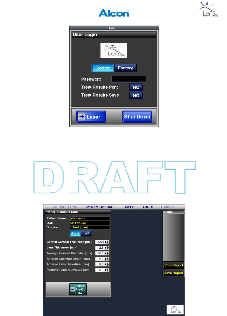
keyboardperipheraldevices.ThefirstscreendisplayedistheLoginscreen(Figure6‐1).Select
the“doctor”option,enteravalidpassword.
L
EN
S
X
L
ASER
S
YSTEM
O
PERATOR
’
S
M
ANUAL
80‐0001Rev.A 28
Figure6‐1:Log‐inscreenfortheLenSxLaserSystem
Inthisfirstscreen,optionsforsavingorprintingtreatmentparametersmayalsobeselected.
Savingorprintingparametersmaybeusefulastheinitialchoiceofparameterscanchange
duringthepatternpositioningstepstakenafterdockingandundervisualizationwiththevideo
microscopeandOCTimagingdevices.
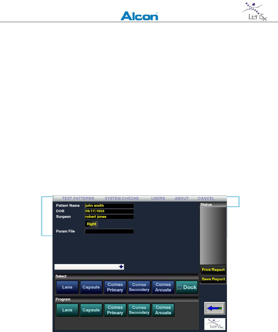
Aftersystemwarmupandself‐checkshavebeencompleted,theBiometricswindowwill
appearontheDisplayPanel(Figure6‐2).Astatusindicatorlocatedontherightsideofthe
biometricswindowdisplaysrelevantsystemstatus.
Figure6‐2:Patientbiometricdatascreen
LENSXLASERSYSTEM
OPERATOR’SMANUAL
80‐0001Rev.A 29
WithintheBiometricsscreen,patientbiometricdatacollectedduringpre‐surgicalvisitsmaybe
entered.Biometricdataincludesthelensthickness,andcentralcornealthickness.Other
patientdataincludespatientandphysicianidentificationinformation.
Thebiometricsdatamaybeusedtodefinethepositioningandorientationofthepatternsif
someoralloftheOCTimageguidesarenotused.Forexample,somelensesmayhavehigh‐
gradecataractsoropacitiesthatpreventvisualizationoftheposteriorcapsule.Intheeventof
poorvisualizationoftheposteriorcapsule,biometricdatafromA‐scanultrasoundmaybeused
todefinetheextentoftheLenspatternforphacofragmentation.
Oncethebiometricdatahasbeenenteredandverified,press“AcceptPre‐OpData”tocontinue
withtreatmentplanning.
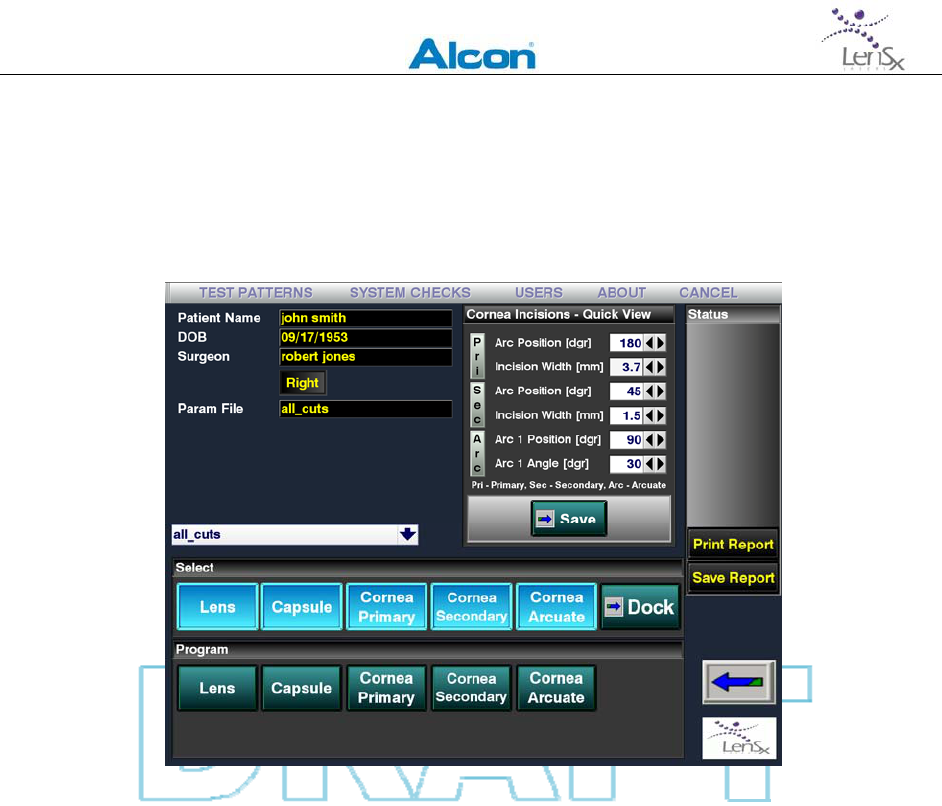
TheBiometricsscreenisnowreplacedwiththePatternSelectionwindowshowninFigure6‐3.
ThePatternSelectionwindowdisplaysthepatientID,controlsforselectingandinitiating
programmingofproceduretypes,anabbreviatedviewoftheselectedparametersforthe
variouscornealincisions,thesystemstatusindicatorbox,andtheDockbutton.
Figure6‐3:PatternSelectionscreen.
Fromthewhitepull‐downmenu,selectadefaultorpreviouslysavedpattern.
UsingtheSelectbar,theusermayselectacuttingpatternfromtherowofbluebuttons.These
selectionsdeterminethecombinationprogrammedtreatmentsforasinglesession.When
selected,thebuttonishighlightedtoindicatethatselection.
LENSXLASERSYSTEM
OPERATOR’SMANUAL
80‐0001Rev.A 30
Alternatively,previouslysavedpatternsmayberecalledusingtheSavedPatternpulldown
menulocatedbetweenthepatientIDinformationandtheSelectbar.
Pressingthearrowbuttonlocatedatthelowerrightcornerofthescreenreturnsthedisplayto
theBiometricsscreen.
Figure6‐4:PatternSelectionscreenappearanceafterasaved
patternfilehasbeenrecalled.Thecorneaincisionsloadedfrom
thesavedfilearedisplayedinabbreviatedformintheQuick
Viewboxatthetoprightsideofthescreen.
Afterselectingasavedpattern,orselectingappropriatepatternelementsfromtheSelectbar,
parametersmaybespecifiedforeachpatternsegment.LocateddirectlybelowtheSelectbaris
theProgrambar.EachProgrambarbuttoncorrespondstoaPatternbuttonfromtheSelectbar
above.SelectingoneoftheProgrambarbuttonsopenstheparameterwindowforthe
correspondingpatternelement.Notethatselectingparametersfrominsideaparticular
ProgrambarselectionwindowwillnotcausethePatterntobeenableduntilthecorresponding
Selectbarbuttonhasbeenpressed.
AfteraPatternhasbeenloadedorselected,theCorneaIncisions–QuickViewfieldis
populatedwithparametersforthevariouscornealincisionsselected(upperrightsectionof
Figure6‐4).
EachPatternhasanumberofparametersassociatedwiththeparticulartypeofcutandtissue.
ForeachPatternselected,theparametersmustbespecifiedorverifiedpriortoinitiatingthe
lasersurgicalprocedure.Inthefollowingsections,theprocessofspecifyingorprogramming
appropriatePatternsisoutlined.
LENSXLASERSYSTEM
OPERATOR’SMANUAL
80‐0001Rev.A 31
6.2.1 ProgrammingtheLensPattern
TheLensPatternisusedtoperformphacofragmentationofthecrystallinelens.LensPatterns
maybespecifiedaseitherChoporCylinderpatterns.TheChopPatternisaseriesofvertical
planesarrangedradiallyinthelens,resemblingthespokesofawheelcenteredonthelens.
TheCylinderPatternaseriesofverticallyorientedconcentriccylinderscenteredonthelens.
WhentheLensbuttonhasbeenpressedundertheProgrambar,theLensPatternparameter
screenisdisplayed(Figure6‐5).User‐settableparametersaredisplayed,withthepresentvalue
foreachparametershown.Usetheindividualparameterbuttonstoincrementordecrement
eachvalue.Ontherightsideofthescreen,columnsofparametersmaybespecifiedforeither
theChoporCylinderpatterns.
Figure6‐5:LensPatternparameterscreen
Selectableparametersmaybegeometricorlaserscanningparameters.Geometricparameters
includetheanteriorcapsuledepth,theposteriorcapsuledepth,andthelensdiameter.Laser
scanningparametersfortheLensscreenincludetheseparationofconsecutivelasershots(spot
separation)andthelaserpulseenergy.Theparametersdisplayeddependontheparticular
patternselected.

LENSXLASERSYSTEM
OPERATOR’SMANUAL
80‐0001Rev.A 32
FortheLensPatternonly,OCTimagesofthepost‐lasertreatmentlensmaybesavedinorderto
evaluatetheeffectoftheLensPatternonthepositioningofsubsequentpatternsonthe
capsuleandcornealpatterns.IfthePost‐LensOCTimageisselected,thelaserprocedurewill
haltandprovideanopportunityfortheusertore‐positionthesubsequentpatternsbefore
completingtheprocedure.
Selectappropriateparameters.PresstheAcceptandSavebuttonsatthebottomoftheLens
Patternparameters.Adialogwindowforenteringafilenametobesavedisdisplayed.
PreviouslysavedparametersfilesmayalsoberecalledandloadedbyselectingtheParamFiles
button.ThesystemsoftwarereturnsthedisplaytothePatternSelectionscreen.
6.2.2 ProgrammingtheCapsulotomyPattern
TheCapsulePatternisusedtoperformananteriorcapsulotomyofthecrystallinelens.The
anteriorcapsulotomyiscreatedbyscanningacylindricalshellextendingfromapositioninthe
lensvolumethroughthecapsuleandintotheanteriorchamber.Thecylindricalscanpattern
penetratesthecapsuleinacompletecircularshape.
TheCapsulePatternparameterscreenisusedtoselecttreatmentparameters.Theseinclude
thecapsulotomydiameter,theestimatedcapsuleposteriordepth,theestimatedcapsule
anteriordepth,thecapsuledeltaupdistance,andthecapsuledeltadowndistance.Asinthe
LensPattern,laserenergy,spotandlineseparationdistancesmaybespecified.
ThesurgeoncanelecttoperformthecapsulotomycuteitherbeforeoraftertheLensPatternis
executedbyselectingtheCapsulotomyFirstbutton.TheCapsulePatternscancanalsobe
selectedtobegineitherattheposterior(bottom)oranterior(top)endofthescanpatternby
togglingtheScanStartparameter.
Aftertheinformationhasbeenenteredcorrectly,presstheAcceptandSavebuttonsdisplayed
atthebottomoftheCapsuleIncisionparameterscreen.ThesystemreturnstotheSelect
Patternsscreen.
6.2.3 ProgrammingthePrimaryIncisionPattern
ThePrimaryIncisionPatternisusedtocreatecornealincisionsforpenetratingkeratoplastyor
forcataractsurgery.
ThegeometryofthePrimaryIncisionPatternisconstructedfromone,twoorthreeangled
planesarrangedalongadefinedarcatthecornealperiphery.Theplanesareconnectedto
createasingleopening.ThePrimaryIncisionPatternmayrepresentacompletelypenetrating
cutorapartialthicknesscut.Partialthicknesscutscanbecreatedandlateropenedmanually
bythesurgeon.
LENSXLASERSYSTEM
OPERATOR’SMANUAL
80‐0001Rev.A 33
PrimaryIncisionPatternsbeginattheprogrammedmaximumposteriordepthandprogress
anteriorlyuntiltheprogrammedanteriordepthisreached.Depthsareexpressedasa
percentageofthecornealthickness.Cornealthicknesscanbedefinedpre‐operativelyorby
usingtheOCTimage.(Figure6‐6)
Figure6‐6:PrimaryIncisionPatternparameterscreen
ThePrimaryIncisionPatternparameterscreenallowstheusertospecifypatterngeometryand
laserscanningparameters.Thebasicshapeisanarccutattheperipheryofthecornea.Users
canselectone,twoorthreeplaneincisions.Thedepthofeachplaneissetwiththe%Poster
Depthparameter.TheSideCutAngleisanglethattheplanemakeswiththecornealanterior
surface.TheplanesmaybeoverlappedtoensurecompletecutsusingtheAntOverlap
parameter.
Aftertheinformationhasbeenenteredcorrectly,presstheAcceptandSavebuttonsdisplayed
atthebottomofthePrimaryIncisionPatternparameterscreen.Thesystemreturnstothe
SelectProceduresscreen.
6.2.4 ProgrammingtheSecondaryIncisionPattern
TheSecondaryIncisionPatternisusedtocreateacornealincisionandissimilartothePrimary
IncisionPattern.SecondaryIncisionPatternsmaybeusedtoaidcataractsurgery.

LENSXLASERSYSTEM
OPERATOR’SMANUAL
80‐0001Rev.A 34
TheSecondaryIncisionPatternasingleangledplanelocatedalonganarconthecorneal
periphery.Thepatternisdefinedbythedistanceofthearcfromthelimbus,theradiusof
curvatureofthearc,andtheangularlocationofthearc.TheSideCutAngledefinestheangle
thattheplanarcutmakeswithrespecttothecorneasurface.TheSecondaryIncisionPatternis
specifiedasapenetratingorapartialthicknesskeratoplastycutbyselectingtheappropriate
valueforthe%PosteriorDepthparameter.Theamountofovercutabovethecornealanterior
surfacecanbespecifiedwiththeAnteriorOverlapparameter.
Afterallparametershavebeenentered,presstheAcceptandSavebuttonsdisplayedatthe
bottomofthescreen.ThesystemreturnstotheSelectProceduresscreen.
6.2.5 ProgrammingtheArcuateIncisionPatterns
ArcuatecornealcutscanbemadeusingtheArcuateIncisionPattern.ArcuateIncisionPattern
cutsaremadeinthecornealperiphery,andarearc‐shapedpartialthicknesscuts.Arcuate
IncisionPatterncutsstartatauser‐programmedposteriordepthandprogressintheanterior
direction.Thepatterndepthchosenusingthe%PosteriorDepthbuttonandisexpressedasa
percentageofcornealthickness.ChoosingtheDiameterparameterdeterminesthecircle
diameterwhereinthearccutslie.EitheroneortwoarcsmaybeselectedusingtheTwo
Arcs/OneArcbuttonnearthebottomofthescreen(seeFigure6‐7).Thedepthofthearccuts
isspecifiedwiththe%PosteriorDepthparameter.
TheBeforeCorneaIncisionsbuttoncanbeusedtodeterminewhetherthepatternisexecuted
beforeorafterothercornealincisionpatterns.
Afterallparametershavebeenentered,presstheAcceptandSavebuttonsdisplayedatthe
bottomofthescreen.ThesystemreturnstotheSelectProceduresscreen.
LENSXLASERSYSTEM
OPERATOR’SMANUAL
80‐0001Rev.A 35
Figure6‐7:PrimaryIncisionPatternparameterscreen
6.2.6 CombiningPatterns
Patternsmaybecombinedinvariouswaystoachieveadesiredsurgicalprocedure.Select
appropriatepatternbuttonsinthePatternSelectionscreenallowsthesurgeontocreatethe
desiredpatterncombinations.However,noteverycombinationofpatternsisallowable.To
viewtheallowedcombinationsinanypatternscreen,selecttheSelectCutsbutton.Atableof
combinationsisshowninawindow(Figure6‐8below).Thiswindowalsoshowsthecurrently
selectedcombinationofpatterns.
Duringlasertreatment,thepatternswillbeexecutedinasequencethatgenerallyproceeds
fromthemostposteriorcutstothemostanteriorcuts.Insomecases,theorderofcutsmaybe
specifiedwithinthepatternparameterscreen.
LENSXLASERSYSTEM
OPERATOR’SMANUAL
80‐0001Rev.A 36
Figure6‐8:Allowedpatterncombinations.
6.2.7 CompletingPatternSelection
Onceallthepatternselectionandparameterprogramminghasbeencompleted,presstheSave
buttonlocatedintheCornealIncisions–QuickViewboxatthetopofthePatternSelection
screen.ToproceedtoDocking,presstheDockbuttonlocatedatthefarrightsideoftheSelect
barchoices.TheTreatscreenwillbethenbedisplayed(Figure6‐9below)

LENSXLASERSYSTEM
OPERATOR’SMANUAL
80‐0001Rev.A 37
Figure6‐9:DisplayPanelshowingtheTreatscreenimmediately
afterpressingtheDockbuttoninthePatternSelectscreen.The
Treatscreenindicatesthesystemstatusintheboxattheupper
rightandisusedtoinitiatesuction.
6.3 PreparingthePatientInterface
Whenallpatternselectionsandparameterchoicesarecomplete,thesystemisreadytodock
withthepatient.AfterDockinghasbeensuccessfullycompleted,theplannedtreatment
patternsareorientedandadjustedwithrespecttothetargetedoculartissuesinthePattern
Positioningprocess(Section6.5)
TheLenSxLaserSystemusesaproprietarydisposablePatientInterface(PI).ThesterilePIis
comprisedofanapplanationlens,suctionring,andtubing(seeFigure3‐2).
OpenthepackagingandplacethePIontoasterilefield.InspectthecomponentsofthePIfor
damageordisconnection.GraspthecontactlensmountofthePI.Placethecontactlens
mountonthedeliverysystemlaseraperture;twistthecontactlensmountuntilitlocksinto
place.GraspthevacuumtubeandinsertitontothevacuumportontheLenSxLaserSystem.
ThePIalsocontainsanintegratedpassiveRFIDidentificationdevice.TheRFIDidentifieris
sensedbyareaderlocatedinsidetheLenSxLaserSystemconsole.TheTreatscreenstatus
indicatorPIisdisplayedwhenthePIhasbeenproperlyinstalledandtheRFIDtransponder
detectsavalididentificationcodeonthePI.

LENSXLASERSYSTEM
OPERATOR’SMANUAL
80‐0001Rev.A 38
OncethePIhasbeenproperlyinstalledontheLenSxLaserSystem,thepatientshouldbe
preparedforDocking.
6.4 Docking
PlacethepatientinasupinepositionunderthedeliverysystemandPatientInterface.Applya
topicalantiseptictotheeyepriortoDocking.
UsethejoysticktocontrolthegantryandroughlyalignthePatientInterfacetotheeye.
Whilethepatient’seyeislocatedatdistancesgreaterthan1centimeterfromthePI,usethe
ZoombuttonontheDeliverySystemTouchscreentoadjustthevideomicroscope
magnification.
TouchtheexternalilluminationbarontheDeliverySystemTouchscreentosetthedesired
levelofIllumination.Touchthefixationlightbuttontoswitchonthepatientfixationlight.
InstructthepatienttomaintainfixationonthelightduringtheDockingprocess.
UsethejoysticktocenterandlowerthegantryuntilthePatientInterfacecontactstheeye.The
DeliverySystemTouchscreenmonitorstheapplanationforcecontinuously.TheTreatscreen
willshowtheCONTACTstatusindicatorwhentheforcesensorintegratedinthedelivery
systemdetectsaninitialapplanationforce.Graphicalindicatorsshowboththedesiredrange
offorceandthemeasuredforce(seeFigure6‐10below).Usethejoysticktoadjustthe
applanationforcetothedesiredrange.
SwitchoffthemicroscopeZoom.TheSurgicalDisplaynowshowsonlytheinternalviewofthe
eye.Touchtheinternalilluminationbartosetthedesiredlevelofillumination.
LENSXLASERSYSTEM
OPERATOR’SMANUAL
80‐0001Rev.A 39
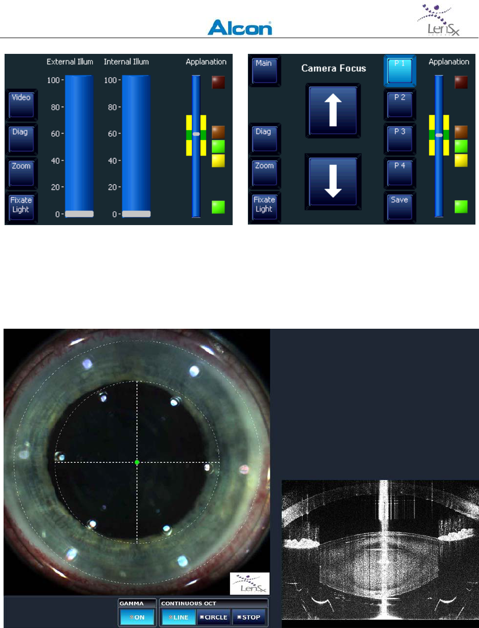
Figure6‐10:LeftimageshowsthemainDeliverySystemtouchscreendisplay.Set
illuminationlevelsbytouchingthewideverticalbars.Rightimageisdisplayedafterselecting
Video.AdjustingthecamerafocuszoomallowsgoodvisualizationbeforethePIcontactsthe
cornea.P1‐P4arefocalpositionpre‐sets.Theapplanationforceindicatorisontherightside
ofeveryscreen.Theapplanationforceiscorrectwhenthewhiteellipseisinthegreenrange.
Figure6‐11:SurgicalDisplayduringDocking.Thedashedlinesrepresentcentrationguides
andareusedtopositionthedeliverysystemandPIwithrespecttothepatienteye.

LENSXLASERSYSTEM
OPERATOR’SMANUAL
80‐0001Rev.A 40
UsetheSurgicalDisplaytoverifythatthePIisnominallycenteredonthecornea,slowly
adjustingthejoystickasnecessarytocenterthePIonthecornea.OncethePIhasbeen
properlycentered,pressthePISUCTIONcontrolbuttonlocatedatthelowerleftcornerofthe
Treatscreen.AlowvacuumlevelappliedtothePIgentlyfixatestheeyetothecontactlens.
Thejoystickcontrolisnowinactiveandthegantrycannotbemoveduntilthesuctionis
released.TheSurgicalDisplayscreenthenchangestoshowalivevideoimageofthe
applanatedeyeandanindicationthattheOCThasbeenactivated.TheLenSxLaserSystemis
nowreadyforpositioningoftheselectedpatterns.
6.5 PatternPositioning
6.5.1 Overview
OncethedeliverydeviceandPatientInterfacehasbeendockedontothepatient’seye,the
selectedandprogrammedpatternsmaybere‐positioned.
TheVideoMicroscopeandOCTareusedtoguidethepositioningsteps.TheSurgicalDisplay
overlaystheselectedpatternsontothevideomicroscopeandtheOCTimages.Theoverlay
patternsareshownastheoutlinesandcentersofthepatterns,alongwithgraphicaltoolsfor
manipulatingandpositioningthepatterns.
TheLenSxLaserSystemsoftwareassiststheuserinthepositioningprocess.Ateachstep,the
user’snextactionishighlightedandappropriatebuttonsandviewsareenabled.Adjustments
madebytheoperatorwiththeaidofvideomicroscopeandOCTimageguidesareusedto
updatethepatternpositioninginformationstoredbytheLenSxLaserSystem.
Thegeneralorderofpatternpositioningandcentrationadjustmentsisasfollows:
Docking/PISuction
Limbuscentration
Primaryandsecondaryincisionpatternalignment
Lenscentration
Capsulotomyandlensdiameteradjustment
Arcuateincisionangleanddiameteradjustment
Capsuledepthandcuttingrangeadjustments
Capsule/lenspositioningalignment
Corneathicknessmeasurements(primary,secondaryandarcuateincisions)
Somepatternpositioningstepsmaybeomitted,dependingonthepatternsselected.The
progressionofpatternpositioningstepsisshownbychangesinthestatusindicatorslocatedat
thebottomoftheSurgicalDisplay.Highlightedactionbuttonsindicatetherequirednextsteps
fortheuser.

LENSXLASERSYSTEM
OPERATOR’SMANUAL
80‐0001Rev.A 41
Atanypointinthepatternpositioningprocess,selectingtheactionbuttonwithanarrowallows
theusertoreturntotheprevioussteportoexitthepatternpositioningprocess.
6.5.2 VideoMicroscope,OCTImageGuidesandPatternGraphics
Duringpatternpositioning,theSurgicalDisplayshowsalivevideoimageoftheeyeonthetop
leftsideandOCTimagesonthetopandbottomrightside.Onthebottomofthedisplay,the
statusindicatorandactionbuttonsaredisplayed.
GraphicaloverlaysontheSurgicalDisplayandOCTimagesindicatetheplannedincision
patternsandtheirrelationshiptotheoculartissues.Solidlinesinthegraphicaloverlays
representtheouterboundariesofthepatterns.Dashedlinesrepresentcentrationorpositional
informationrelativetothevideomicroscopeandOCTimages.
Controlpointsaresmallsolidcirclesthatrepresentuser‐adjustableparameters.Pointthe
cursorandclickonacontrolpointtomakeitactive.Activecontrolpointscanbemovedby
draggingthecursortothedesiredlocation.Asecondclickonthecontrolpointdeactivatesthe
controlpoint.Activecontrolpointsareadifferentcolorthaninactivecontrolpoints.Onlyone
controlpointisactiveatanytime.
6.5.3 LimbusCentration
AfterPISuctionhasbeeninitiated,limbuscentrationlinesareoverlaidontheSurgicalDisplay.
NoOCTscansareusedinthispositioningstep.
Thelimbuscentrationcontrolpointsinthevideomicroscopedisplayareactive.Placethe
cursoronthecontrolpoint.Clickanddragthecontrolpointtocenterthelimbuscentration
linesonthelimbus.Clickagainonthecontrolpointwhencentrationiscomplete.Thecontrol
pointindicatorchangesappearancetoindicatecompletionofthisstep.SeeFigure6‐12.
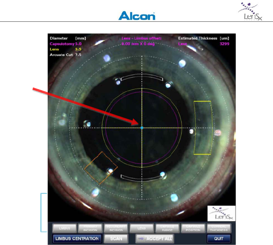
LENSXLASERSYSTEM
OPERATOR’SMANUAL
80‐0001Rev.A 42
Figure6‐12.Limbuscentration.Redarrowpointstocontrol
point(bluedot)usedtopositiontheguides(whitedashedlines)
onthelimbus.Inthisexample,thePrimary(heavyyellow),
Secondary(orange),Arcuate(white),Capsule(pink)andLens
(lightyellow)patternshavebeenselected.
6.5.4 PrimaryandSecondaryIncisionAlignment
IfPrimaryorSecondaryIncisionPatternsareselected,thenextstepinpatternpositioningisthe
radiallocationofthesepatterns.Thepatternlocationsaredisplayedonthevideomicroscope
imageontheSurgicalDisplay.NoOCTscansareusedinthispositioningstep.Acontrolpoint
forthePrimaryIncisionPatternisactive.Movethecontrolpointbyclickinganddragging.The
SecondaryIncisionPatternissimilarlypositionedafterthePrimaryIncisionPatterncontrol
pointisdeactivatedwithasecondmouseclick.
AftercompletingthePrimaryandSecondaryIncisionPatternpositioning,anactionbutton
(eitherScanorLimbusCentration)willcausetheLenSxLaserSystemtoverifythattheadjusted
patternpositionsareconsistentwithotherpatternsandparameters.Iftheverificationstep
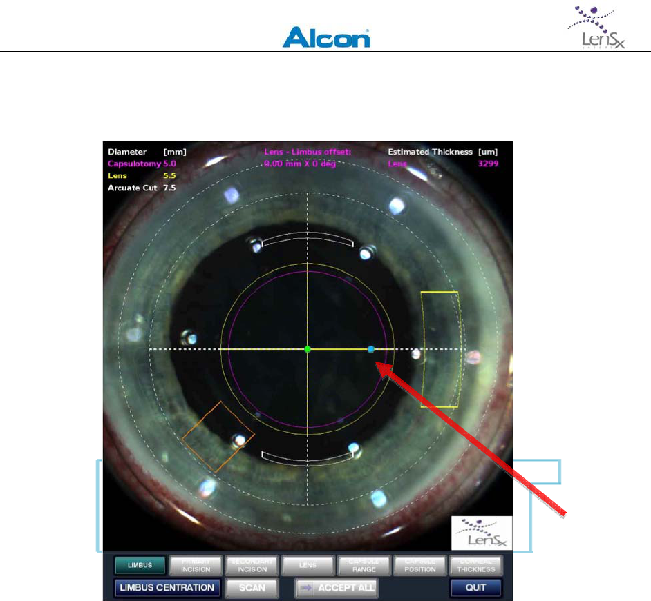
LENSXLASERSYSTEM
OPERATOR’SMANUAL
80‐0001Rev.A 43
resultsinanerror,adialogboxwillalerttheusertocorrectthepatternpositioningbefore
allowingthenextstep.
Figure6‐13:PrimaryIncisionPatternpositioning.Redarrowpoints
tocontrolpoint(bluedot)usedtomovethePrimaryIncision
Pattern(heavyyellowshapeatright)alongtheradialdirection.
SecondaryIncisionPatternpositioningproceedsinthesamemanner
afterthecontrolpointforthePrimaryIncisionPatternhasbeen
deactivatedwithasecondclick.
6.5.5 LensAlignment
Iflensorcapsulepatternsareselected,theLensCentrationactionbuttonwillappear.Iflensor
capsulepatternsarenotselected,thelensalignmentstepwillnotbeperformed.Pressthe
LensCentrationactionbutton.SeveralcontrolpointsmayappearontheVideoMicroscope
image,dependingonthecombinationofpatterns.NoOCTscansareusedinthispositioning
step.
ThecontrolpointstobeadjustedmayincludetheLensPatterncenter,theCapsulePattern
diameter,theLensPatterndiameter,andtheArcuateIncisionPatterndiameter.Selectand
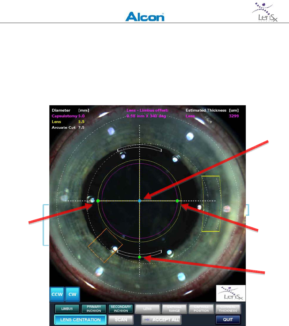
LENSXLASERSYSTEM
OPERATOR’SMANUAL
80‐0001Rev.A 44
activateeachcontrolpointinturn,andadjusttheLencenterandpatterndiametersas
appropriate.UsersshouldverifythattheLensPatterndiameterfallswithinthe8mmdiameter
lensalignmentdashedcircle.
Ifnecessary,theArcuateIncisionPatternmayberotatedineitherdirectionuptoamaximum
of20degreesfromtheoriginallyprogrammedvalue.Holddowntheclockwise(CW)or
counterclockwise(CCW)buttontoattainthedesiredrotationangle.
Figure6‐14:ControlpointsdisplayedintheLensPatternpositioning
step.Notalladjustmentsmaybeshowndependingonthepatterns
selected.Arrow1=LensPatterncentration,Arrow2=CapsulePattern
diameter,Arrow3=LensPatterndiameter,Arrow4=ArcuateIncision
Patterndiameter.Whenallpositionshavebeenadjusted,theLens
statusbarchangesindicatingcompletionofthisstep.
6.5.6 CapsuleDepthAdjustment
AftercompletingtheLenspositioningsteps,thenextpositioningadjustmentsaretherangesfor
capsuleincisions(ifCapsulePatternhasbeenselected).AcirclescanOCTimageofthelensand
1
2
4
3
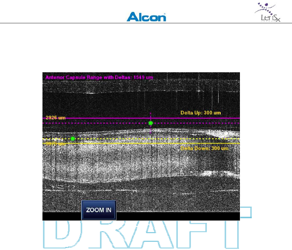
L
EN
S
X
L
ASER
S
YSTEM
O
PERATOR
’
S
M
ANUAL
80‐0001Rev.A 45
capsuleisdisplayedthetoprightareaoftheSurgicalDisplay.Thecirclescanisperformed
alongtheCapsulePatterndiameterasdefinedonthevideomicroscopeimageoftheeye.
Figure6‐15:RoughadjustmentoftheCapsulepatternrange.
Controlpointscanbemovedupordown.Thesolidlinerepresent
previouslyprogrammedvaluesfortheDeltaUpandDeltaDown
TwohorizontaldashedlinesareoverlaidontheOCTimage.Controlpointsforthedepthrange
adjustmentandtwoothersolidlineswithoutcontrolpointsareshown.Thenumericvaluesof
thepreviouslyprogrammedupdelta/downdeltavaluesaredisplayed.
TheAnteriorDepthcontrolpointcanbemovedverticallyfordepth.Itcanalsobemoved
horizontallytoindicatetheangularpositionofthehighpointofthecapsule.ThisAnterior
Depthcontrolpointhasshortdashedlinetoindicatetheabilitytomoveithorizontally.
MovetheAnteriorDepthcontrolpointtotheminimumdepthofthecapsule.Movethe
PosteriorDepthcontrolpointstothemaximumdepthofthecapsule.ThesolidDeltaUp/Delta
Downlineswillmovewiththedashedhorizontallinesassociatedwitheachcontrolpoint.The
DeltaUpandDeltaDownvaluesthemselvesdonotchange.Thepositionsofthemaximumand
minimumcapsulepositionsdeterminetheaxisoftiltofthelens.
PressZoomInwhendone.Anenlargedimageisshownandthecontrolpointsallowforfiner
adjustmentofthecapsuledepthrange.
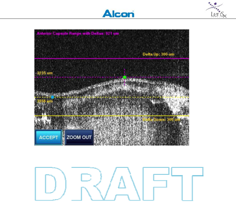
L
EN
S
X
L
ASER
S
YSTEM
O
PERATOR
’
S
M
ANUAL
80‐0001Rev.A 46
Figure6‐16:FineadjustmentoftheCapsulepatternrange.The
AnteriorDepthandPosteriorDepthcontrolpointsareproperly
positioned.PressingAcceptstorestheadjustmentsandenables
thenextCapsulerangeadjustmentstep.
WhentheCapsulerangeadjustmentsarecomplete,presstheAcceptbutton.TheLenSxLaser
Systemsoftwarechecksthattheadjustmentsarevalidforthepatternsselected.Ifthe
adjustmentscheckissuccessful,thevideomicroscopeimageshowsadashedlineindicatingthe
tiltaxisofthelens.
TheCapsuleRangestatusindicatorchangestoindicatecompletion,andthenextpattern
positioningstepisenabled.
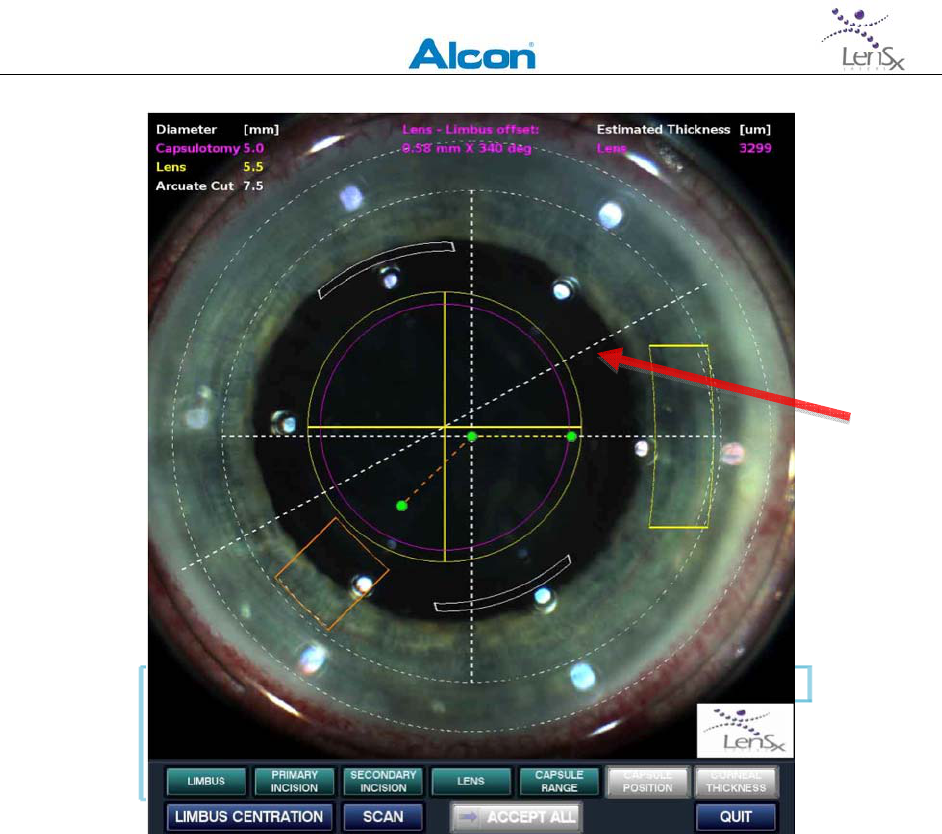
LENSXLASERSYSTEM
OPERATOR’SMANUAL
80‐0001Rev.A 47
Figure6‐17:CompletionofCapsuleRangeadjustments.Thephase
angleassociatedwiththecapsuletiltisindicatedbythedashedline
(redarrow).
6.5.7 LensDepthAdjustment
TheCapsulepositionadjustmentallowstheusertoadjustthepositionoftheLenspatternsto
matchthesurfacesandvolumeofthelens.
Theadjustmentsaremadeforthedepthscorrespondingtotheposteriorandanteriorlimitsof
thecapsuleandlenslocation.AlinescanOCTimagealongthetiltanglepreviouslydefinedis
displayedwithcontrolpointsfortheAnteriorCapsuleDepth,thePosteriorCapsuleDepth,and
themaximumallowabledepth.Thecontrolpointscanonlybeadjustedvertically.
IftheCapsulepatternisenabledbuttheLensPatternisnot,nocontrolpointswillbeavailable.
Forthiscombinationofpatternselections,theCapsulepositioningstepisonlyusedfor
displayingstoredresults.
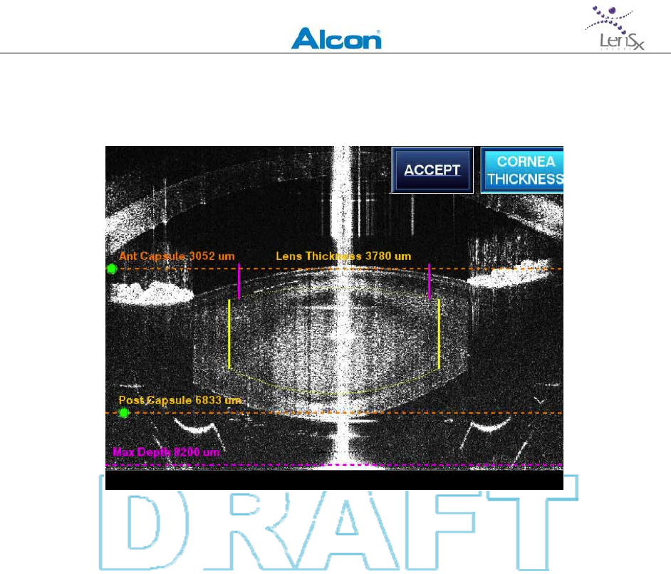
L
EN
S
X
L
ASER
S
YSTEM
O
PERATOR
’
S
M
ANUAL
80‐0001Rev.A 48
Theinitialvaluesforthecontrolpointdepthscorrespondtopre‐programmedvaluesandvalues
storedfrompreviouspatternpositioningsteps.
Figure6‐18:AdjustmentsfortheCapsulePositionstep.Anterior
CapsuledepthandPosteriorCapsuledepthcontrolpointsare
adjustedvertically.Themaximumallowabledepthisrepresented
byafixeddashedline(MaxDepth).TheOCTlinescanis
superimposedwiththediametersoftheCapsulePattern(pink)and
thevolumeoutlineoftheLensPattern(yellowlinesandcurves).
Twosolid(purple)verticallinesegmentsaredisplayedrepresentingtheCapsulotomyPattern.
ThecapsulotomydiameterrangeisrepresentedbytheseparationofthelinesandtheCapsule
depthrangeisrepresentedbythepositionandverticalheightofthelines.
TheLenstreatmentvolumeisrepresentedbyanupperarc,alowerarc,andtwoverticallines
(allinyellow).ThedistancebetweentheleftandrightverticallinesrepresentsLensdiameter
valuestoredintheLimbusCentrationpositioningstep.TheupperarcmatchestheAnterior
LensCurvatureandthelowerarccorrespondstoPosteriorLensCurvature.Bothcurvature
valuesaredefaultvaluesoruser‐suppliedvaluestakenfromtheLensparametersscreen.The
differencebetweentheAnteriorCapsuleDepthandthetopoftheupperarcisequaltothe
LensAnteriorOffsetfromtheLensparametersscreen.Thedepthdifferencebetweenthe
PosteriorCapsuleDepthandthebottomofthelowerarcisequaltotheLensPosteriorOffset
fromtheLensparametersscreen.
AdjusttheAnteriorCapsuleDepthcontrolpointtoapositioninsidetheanteriorcapsuleapex.
TheAnteriorCapsuleDepthnumericvalueandtheLensPatterntreatmentvolumeareupdated

LENSXLASERSYSTEM
OPERATOR’SMANUAL
80‐0001Rev.A 49
asthecontrolpointischanged.
AdjustthePosteriorCapsuleDepthtoapositioninsidetheposteriorcapsuleapex.The
PosteriorCapsuleDepthnumericvalueandtheLensPatterntreatmentvolumeareupdatedas
thecontrolpointischanged.
WhentheCapsulePositionadjustmentsarecomplete,presstheAcceptbutton.TheLenSx
LaserSystemsoftwarechecksthattheadjustmentsarevalidforthepatternsselected.Ifthe
adjustmentscheckissuccessful,thedisplayshowstheVideoMicroscopeimage.TheCapsule
Positionstatusindicatorchangesappearancetoindicatecompletion.
Ifcornealincisionpatternshavebeenselected,thefinalpatternpositioningstepofCorneal
Thicknessisenabled.Ifnot,presstheAcceptAllbuttontoproceedwithtreatment.
6.5.8 CornealPrimaryandSecondaryIncisionsThicknessAdjustment
Ifcornealincisionsareselected,thelaststepinpatternpositioningisadjustingthecorneal
thicknessandcornealincisiongeometryparameters.
ThePrimaryIncisionPatterngeometryandthecornealthicknessareadjustedfirst.Pressthe
ScanbuttonatthebottomoftheSurgicalDisplaytoproceed.AnOCTimageofthecorneal
regionofthePrimaryIncisionPatternisdisplayed.TheOCTimageappearsatthebottomright
corneroftheSurgicalDisplay.
AnX‐Zcross‐sectionofthePrimaryIncisionPatternisdepicted.Thisrepresentationofthe
incisionisreferredtoastheTunnel.TheTunnelmaybecomposedof1,2or3separateline
segmentsrepresentingtheplanesspecifiedinthePrimaryIncisionPatternparameter
programmingstep.
ThreecontrolpointsthatadjusttheEpithelial,EndothelialandTunnelEndarealsodisplayed.
TheEpithelialandEndothelialcontrolpointsareusedtosetthepositionsoftheanteriorand
posteriorcornea.TheTunnelEndcontrolpointisusedtopositiontheendofthetunnel.
TheEpithelialcontrolpointcanonlybemovedalongtheverticallydashedline.TheEndothelial
controlpointcanbemovedperpendicularlytothecorneaalongthenormaldashedline.The
Tunnelcontrolpointmaybemovedfreelyinthehorizontalandverticaldirections.Movingany
ofthethreecontrolpointscausesthegraphicalfeaturerepresentingthePrimaryIncision
Patterntomoveaswell.
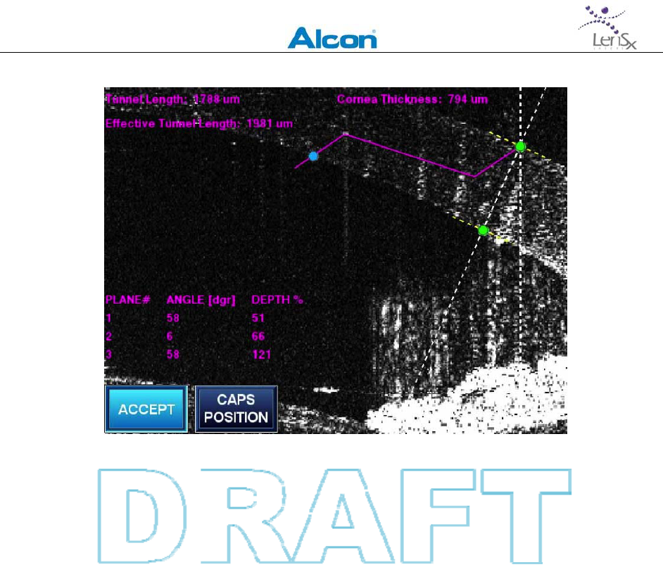
L
EN
S
X
L
ASER
S
YSTEM
O
PERATOR
’
S
M
ANUAL
80‐0001Rev.A 50
Figure6‐19:CompletedadjustmentofPrimaryIncisionPatterntunnel
parameters.PressingtheCapsPositionbuttonallowstheusertoswitch
betweenCapsulePositionadjustmentsandCornealThickness
adjustments.PresstheAcceptbuttontosavetheparametersand
proceedtothenextstep.
Thenumericvaluesofthetunnellength(distancefromEpithelialcontrolpointtoTunnel
controlpoint),effectivetunnellength(sumofdistancesofeachplanemakingupthetunnel),
cornealthicknessaredisplayed.Theanglesandthepercentdepthofcorneaforeachplane
makingupthePrimaryIncisionPatternarealsodisplayed.
Thesenumericvaluesareupdatedasthecontrolpointsaremoved.
ThecornealthicknessvalueasdeterminedbysettingtheEpithelialandEndothelialcontrol
pointsisalsousedfortheSecondaryIncisionPattern.
AsthePrimaryandSecondaryIncisionPatternsarepositioned,theCapsulePositionaction
buttonisdisplayedtoalloweasyswitchingbetweenpositioningmodes.
PresstheAcceptbuttonwhenthePrimaryandSecondaryIncisionPatternpositioningis
complete.TheLenSxLaserSystemsoftwareperformsavalidationcheckonthepattern
parameters.Anerrormessageisdisplayediftheparametersareinvalid.Theparametersmust
becorrectedbeforeproceeding.

LENSXLASERSYSTEM
OPERATOR’SMANUAL
80‐0001Rev.A 51
6.5.9 ArcuateIncisionThicknessAdjustments
IfanArcuateIncisionPatternisselected,theArcuateThicknessactionbuttonappearsafter
pressingtheAcceptbutton.SelectingtheArcuateThicknessbuttoninitiatesanOCTscanofthe
cornealregionforthearcuateincision.ThezoomedimageofthePrimaryArcuateIncision
patternisdisplayedonthetoprightportionoftheVideoMicroscopedisplay.IftheSecondary
ArcuateIncisionpatternisenabled,thezoomedimageoftheSecondaryArcuateIncisionareais
displayedonthebottomrightportionoftheSurgicalDisplay.
EpithelialandEndothelialcontrolpoints,similartothoseinthePrimaryandSecondaryIncision
Patternsabovearedisplayed.TheEpithelialcontrolpointcanonlybemovedalongthedashed
verticallineinFigureXXbelow.TheEndothelialcontrolpointismovedalongthedashedline
normaltothecornea.Asthecontrolpointsaremoved,thenumericvalueofthedistance
betweenthem,representingthecornealthickness,isdisplayedandupdated.
Movethecontrolpointstoproducethedesiredcutpositionanddepth.Repeatforboththe
PrimaryandSecondaryArcuateIncisionPatterns,ifnecessary.Thecornealthicknessvalue
usedisthesmallerofthetwoadjustedthicknesses.
WhentheArcuateIncisioncornealthicknessadjustmentsarecomplete,presstheAccept
button.TheLenSxLaserSystemsoftwareperformsavalidationcheckonthepattern
parameters.Anerrormessageisdisplayediftheparametersareinvalid.Theparametersmust
becorrectedbeforeproceeding.
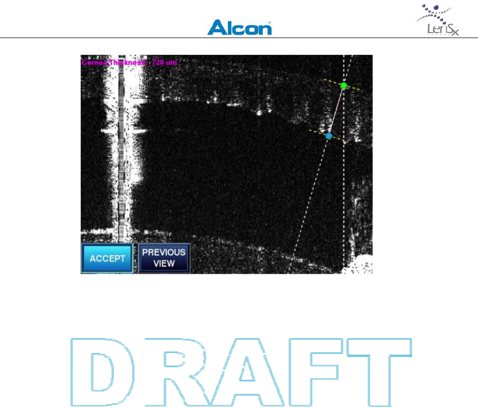
L
EN
S
X
L
ASER
S
YSTEM
O
PERATOR
’
S
M
ANUAL
80‐0001Rev.A 52
Figure6‐20:LineOCTguideandcornealthicknessadjustments
forArcuateIncisionPatterns.FigureshowsPrimaryArcuate
Incisionandcontrolpoints(notshownistheSecondaryArcuate
Incision).Thecontrolpointsareadjustedtothedesiredposition
andthicknessforthearcuatecuts.PreviousViewswitchesto
thelastdisplayedscreen.PressingtheAcceptbuttonstoresthe
adjustedvaluesandreturnsthedisplaytothePattern
PositioningScreen.
6.6 Confirmation
Ifallpositioningstepshavebeencompleted,theAcceptAllactionbuttonisactive(Seefigure6‐
21below).PresstheAcceptAllbutton.Asummaryofalteredpatternparameterswillbe
shownontheDisplayPanel.ReviewthesummaryandselecteitherRerunOCTtorepeatthe
sequenceofpositioningstepsorselectApplytoPatienttoproceedtotreatment.
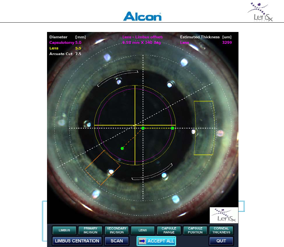
LENSXLASERSYSTEM
OPERATOR’SMANUAL
80‐0001Rev.A 53
Figure6‐21:Oncethepatternpositioningprocesshasbeen
successfullycompleted,presstheAcceptAllbuttontobeginthe
treatment.
6.7 Treatment
AftertheAcceptAllbuttonhasbeenselected,treatmentisenabled.TheSurgicalDisplayshows
alivemicroscopevideoimage,alineOCTimageoftheanteriorchamber,andacircleOCT
imageofthelensandcapsule.Graphicaloutlinesoftheselectedpatternsareoverlaidoneach
oftheseviews.AmessageisdisplayedontheDisplayPanelindicatingthatthebeamscanners
havebeenmovedtothestartingpositionfortreatment.Theestimatedlasertreatmenttimein
secondsisdisplayed.TheTreatbuttonisnowenabled.

LENSXLASERSYSTEM
OPERATOR’SMANUAL
80‐0001Rev.A 54
Figure6‐22:DisplayPanelwhensystemisreadyfortreatment.
Treatbuttonisenabledandtheproceduretimeisindicatedin
theblueprogressbar.
PresstheTreatbutton.Thetreatmentdialogwindowisdisplayedinthemiddleofthe
Treatmentscreen.TheOCTimagesareoverlaidwithprogressindicatorbars.Initially,these
verticalindicatorsareunfilled.
Whenreadytobegintreatment,pressandholdthefootswitch.Releasingthefootswitchduring
theprocedurewillimmediatelyhalttreatment.Treatmentcanberesumedbypressingthe
footswitchagain.Duringlasertreatment,aredlaseremissionmessageisshownontheDisplay
Panel.Procedureprogressmaybemonitoredwiththefollowingindicators:
verticalprogressbarscontinuouslytracktheprogressofeachincision
adisplayofthepatternselections
adisplayoftheestimatedremainingproceduretimeinseconds
alivevideocameraimageofsurgicalfield
Duringtreatment,monitorthesurgicalprogressonthevideomonitor.Ifanincorrectpattern
occurs,halttheprocedurebyreleasingthefootswitch.Theproceduremaythenbecontinued.
Alternatively,atraditionalcataractsurgicalproceduremaybeperformed.
Intheeventofpowerfailureresultinginaninterruptedprocedure,removethepatient
interfacetubefromthevacuumporttoreleasetheeyefromsuction.Graspthedelivery
systemobjectiveandraiseit1to2inchestosafelyremovethepatientfromthesurgicalfield.
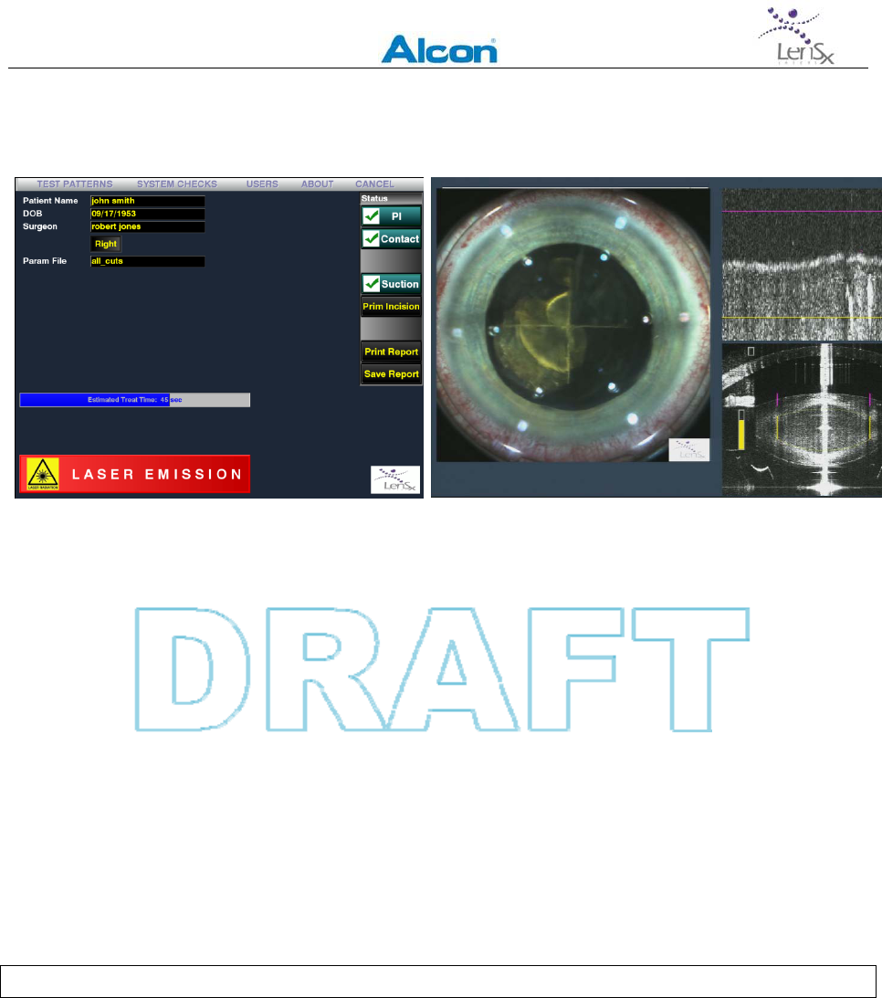
LENSXLASERSYSTEM
OPERATOR’SMANUAL
80‐0001Rev.A 55
Ifatanytimeduringthecombinationprocedurethesurgeonwishestohalttheprocedure,the
footswitchmaybereleased.
Figure6‐23:DisplayPanelandSurgicalDisplayduringtreatment.TheOCTimagesare
overlaidwithgraphicalindicatorsforthepatternsandcompletionprogressbars(lowerright
cornerofrightimage).
6.8 ProcedureCompletion
Amessagewillbedisplayedindicatingthecompletionoftheprocedure.TheSurgicalDisplay
continuestoshowalivevideoimageoftheeye.TheDisplayPanelreturnstothebiometrics
screen.
Releasethefootswitchatthistime.Completionoftheprocedurede‐activatesthefootswitch
andclosesthemainlasershutter.Vacuumisautomaticallyhaltedandtheeyeisreleasedfrom
suction.Rotatethejoystickonthecontrolpanelcounter‐clockwisetoraisethedeliverydevice
andsafelyremovethepatientfromthesurgicalfield.Unlock,removeanddiscardthePatient
Interface.
DiscardthePatientInterfaceasmedicalwaste.

LENSXLASERSYSTEM
OPERATOR’SMANUAL
80‐0001Rev.A 56
7 CalibrationandAlignment
CalibrationoftheLenSxLasershouldbeperformedbytrainedLenSxpersonnel.However,the
followinginternalcalibrationproceduresareavailabletotheuser.
7.1 EnergyCalibration
TheLenSxLaserperformsalaserenergycalibrationduringsystemstartup.Auser‐requested
calibrationcanbeperformedatanytimebyselectingEnergyCalibrationintheSystemChecks
menu.Notoolsarerequired.Useoftheconsoleisdisableduntilthecalibrationhasbeen
completed.
7.2 BeamSteering
TheLenSxLaserautomaticallyperformsabeamsteeringcheckpriortoeachprocedure.This
checkensuresthatthelaserbeamisoptimallyalignedintothedeliverysystem.Userscanalso
requestthatthischeckbeperformedusingtheBeamSteeringselectionintheSystemChecks
menu.

LENSXLASERSYSTEM
OPERATOR’SMANUAL
80‐0001Rev.A 57
8 ServiceandMaintenance
ToensurecontinuousoperationoftheLenSxLasersystem,preventivemaintenanceservice
shouldbemadeeverythreemonthsbyanauthorizedLenSxservicerepresentative.
OnlytrainedLenSxrepresentativesshouldperformunpacking,installation,andservicingofthe
LenSxLaser.CoversarenottoberemovedbyanyoneotherthanLenSxpersonnel.Accidental
contactwiththehighvoltageelectricalcircuitsintheinterioroftheLenSxLaserconsolemay
resultinseriousinjuryordeath.Ocularexposuretocollimatedbeamscontainedintheconsole
interiorcanproduceretinaldamage.
TheLenSxLaserusesaclosed,internalre‐circulatingcoolingsystemwhosefluidlevelsare
checkedduringpreventivemaintenance.Coolantlevelsareautomaticallymonitoredbythe
systemandifalowcoolanterroroccurs,amessageisdisplayed.AnauthorizedLenSxservice
representativeshouldbecalledifacoolanterroroccurs.
TheLenSxconsoleisdesignedforuseinasurgicalsetting.Theoutersurfacesoftheconsole
maybewipeddownwithacleandampclothifnecessary.Amilddisinfectingagentmaybe
used.Theconsoledoesnotrequirefurthersterilization.
Accidentfluidspillsonthedeliverysystemopticsmaybelightlywipedusinganalcoholswab.
TheLenSxLaserisdesignedforusewithaLenSxLaserPatientInterface.ThePatientInterface
istheonlycomponentthatcontactsthepatient.AllusedPatientInterfacesmustbeproperly
disposedasmedicalwaste.
8.1 TransportandStorage
ContactLenSxrepresentativestomove,transportorstoretheLenSxLaser.Thetransportand
storagetemperaturesshouldnotexceedoperatingtemperatureandhumidityspecifications.

LENSXLASERSYSTEM
OPERATOR’SMANUAL
80‐0001Rev.A 58
9 TroubleShooting
Belowisaguidetosomepossibleproblems,withthesymptoms,possiblecausesandcorrective
actions.Ifaparticularconditionisnotlistedhere,itisadvisedthataLenSxauthorizedservice
representativebecontactedforconsultation.
Table9‐A:LenSxLaser–TroubleshootingGuide
SymptomPossiblecauseCorrectiveaction
Laserconsoledoes
notstartup.FuseblownatsystemrealpanelReplacefuselocatedatthelowerrear
panel.
Laserconsolewillnot
proceedtothe
treatmentstage
FootswitchisactuatedReleasefootswitch
ParametersnotselectedEnterrequiredfields
SystemfaulthasoccurredContactLenSxrepresentative
Doorsafetyinterlockhasdisabledlaser
console
Closeoperatingsuitedoors,checkinterlock
connections
Laserconsolewillnot
treatwhenenabled
FootswitchnotconnectedConnectfootswitch
FootswitchnotfullyactuatedCompletelyactuatefootswitch
Laserconsolewillnot
energizeuponstart‐
up
PowercorddisconnectedConnectcord
FootswitchnotconnectedConnectfootswitch
CircuitbreakertrippedResetbreaker,checkelectricalservice
SystemelectricalfaultContactLenSxrepresentative
Laserbeamhalts
duringtreatment
DoorsafetyinterlockhasdisabledlaserCloseoperatingsuitedoors,checkinterlock
connections
FootswitchnotfullyactuatedMaintainfootswitchactuationduring
procedure
FaultconditionContactLenSxrepresentative
Fixationcannotbe
achievedor
maintained
SuctionnotpresentRe‐applysuctionring
SuctiontubingfailureReplacesuctionring
Improperapplanationorimpropercoupling
ofthesuctionringassembleorapplanation
lens
Re‐positiondeliverysystemandre‐
applanatecornea.
PatientmovementImmobilizepatient

LENSXLASERSYSTEM
OPERATOR’SMANUAL
80‐0001Rev.A 59
SymptomPossiblecauseCorrectiveaction
Operatingfieldnot
properlyobservable
throughmicroscope
ApplanationlenscontaminatedReplacedisposablePatientInterface.
PoorilluminationorpoorfocusAdjustilluminationorfocuscontrols.
MicroscopeopticallymisalignedVerifypositioningofmagnificationknob.
Lasertissueeffectnot
apparentduring
treatment
Applanationlenscontaminatedor
damagedReplacedisposablePatientInterface.
Applanationlostorvacuumintegrityhas
beenlost
Repositionsuctionringandfixate.Re‐
positiondeliverysystemandre‐applanate
cornea.
Laseroutputblocked
ContactLenSxservicerepresentative.
Laseroutputmisaligned
LaseropticalmalfunctionContactLenSxservicerepresentative.
Procedureincomplete
Applanationlostorvacuumintegrityhas
beenlostresultinginaninterrupted
procedure
Repositionsuctionringandfixate.Re‐
positiondeliverysystemandre‐applanate
cornea.
Repeatphacofragmentationtreatmentat
thesamecenteredpositionandusingsame
parametersasappropriate.
Repeatcapsulotomytreatmentatthesame
centerpositionandusingslightlylarger
diameter.
LaseroutputblockedInspectbeampath.Allow1hourbefore
retreatment.
LasersourcemisalignedContactLenSxservicerepresentative.
RetreatwhenLenSxLaserisrepaired.
Misalignedbeamdeliverydevice
Lossoflinepower
Releasetheeyefromsuction.Graspthe
deliverysystemobjectiveandraiseit1to2
inchestosafelyremovethepatientfrom
thesurgicalfield.
Treatmentgeometry
incorrectx‐yscanningunitfailureContactLenSx servicerepresentative.
RetreatwhenLenSxLaserisrepaired.
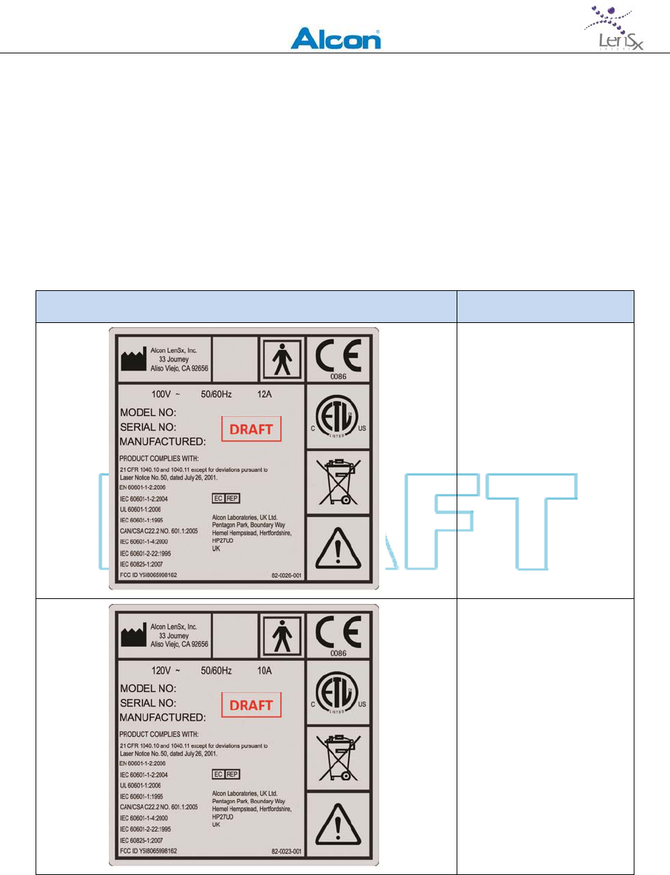
LENSXLASERSYSTEM
OPERATOR’SMANUAL
80‐0001Rev.A 60
10 Labels
10.1 ConsoleLabels
WarninglabelsarefoundontheLenSxLasertodenotespecifichazards.Observelabel
warningsatalltimes.TheLenSxLaserislabeledinaccordancewithrequirementsforallmedical
devicesaswellaswithrequirementsforlaserproducts.
Table10‐A:WarningLabelsusedwiththeLenSxLaser
LabelLabelName
IdentificationLabel
(100V)
IdentificationLabel
(120V)
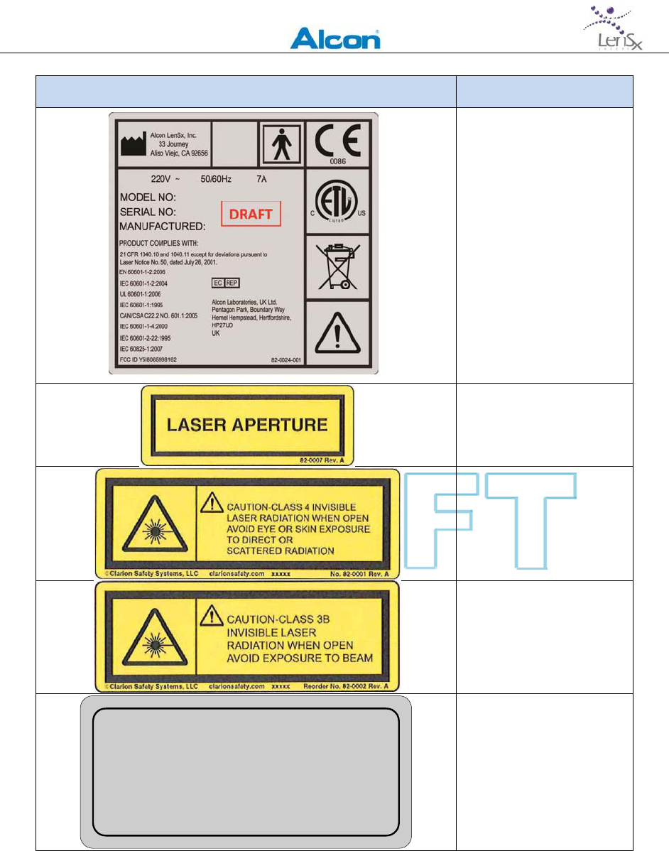
LENSXLASERSYSTEM
OPERATOR’SMANUAL
80‐0001Rev.A 61
LabelLabelName
IdentificationLabel
(220‐240V)
LaserAperture
ProtectiveHousing,
Class4
ProtectiveHousing,
Class3B
Surgical Laser Beam Maximum Output: 0.5W
Pulse Duration: <800fs
Emittied Wavelength: 1030nm
IEC 60825-1:2007 Class 3B Laser Device
82-0004 Rev. A
LaserWarning
SurgicalBeam
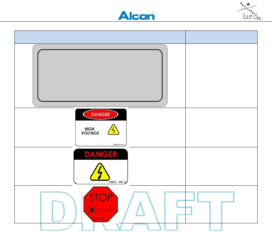
LENSXLASERSYSTEM
OPERATOR’SMANUAL
80‐0001Rev.A 62
LabelLabelName
OCT Laser Beam Maximum Output: 3.0mW
Emittied Wavelength: 820-880nm
IEC 60825-1:2007 Class 3R Laser Device
10 CFR 1040.10 Class 3B Laser Device
82-0006 Rev. A
OCTBeam
LaserWarning
HighVoltage
HighVoltage(internal)
EmergencyStop

LENSXLASERSYSTEM
OPERATOR’SMANUAL
80‐0001Rev.A 63
11 SystemSpecifications
SystemParameter Specifications
LasertypeFemtosecondInfraredlaser
ModeFundamental(TEM00)
Coneangle0.20sr(±0.05sr)halfangle
Laserpulsewidth600‐800fs(±50fs)
Centrallaserwavelength1030nm(±5nm)
Maximumpulseenergy15µJ(±1.5µJ)
OCTDeviceWavelength820–880nm(±5nm)
3.0mW(±0.2mW)maximumpower
RemoteinterlockIncludedinsystem
InputvoltageConfigurable100V/12A,120V/10A,220‐240V/7A,
50/60Hz
MaximumElectricalLoad ≤1.2kW
ExternalFuse(x2)3AG,FastActing,250V,15A
ConsoledimensionsConsolefootprint24”(W)x30”(L)x48”(H)
Beamdeliverydevice8”(W)x23”(L)x20”(H)
BeamdeliverydeviceheightMin28.1inches(floortoapplanationlens)
Max41.7inches(floortoapplanationlens)
Consoleweight1055lbs
Ambientoperatingtemperature18°Cto24°C(65°Fto75°F)

LENSXLASERSYSTEM
OPERATOR’SMANUAL
80‐0001Rev.A 64
12 WarrantyInformation
AlconLenSxInc.(AlconLenSx)warrantsthattheLenSxLaser(the“Equipment”)andsoftware
willconformtothepublishedproductspecificationsofAlconLenSxandbefreefrommaterial
defectsinmaterialsandworkmanshipforthefirstyearofcontinuousservice.AnAlconLenSx
serviceandsupportcontractbetweenAlconLenSxoranAlconaffiliateandtheendusermust
bemaintainedatalltimes.
AlconLenSxwillrepairorreplaceatnochargeanyEquipmentorsoftwarefoundupon
examinationbyAlconLenSxtobedefectiveduringthewarrantyperiod.Thiswarrantyissubject
tothefollowingexclusions,exceptions,andlimitations:a)expensessuchaslabororother
expensesduetodelaysorinabilitytorenderanyservice;b)correctionofoperatorproblems
relatedtoenvironmentalconditionsbeyondthecontrolofAlconLenSx;c)repairand
maintenancenecessitatedbyuser‐induceddamage,neglect,misuse,orimproperoperationof
theEquipmentorsoftware;d)modificationorconnectionofotherequipmenttothe
EquipmentorsoftwarewithouttheexpresswrittenauthorizationofAlconLenSx,such
authorizationwhichmaybewithheldatAlconLenSx’ssolediscretion;e)subleaseoruseof
Equipmentbyanyoneotherthantheend‐user'squalifiedandtrainedpersonnel;f)useforany
processes,procedures,experiments,oranyotheruseforwhichtheEquipmentisnotintended
foruseorapprovedforusebytheFoodandDrugAdministration(FDA);g)supplies,devices,or
electricalworkexternaltotheAlconLenSxEquipmentorsoftware;andh)repairsduetothe
user'sfailuretoperformanyroutinemaintenance,whichistheresponsibilityoftheuser.
AlconLenSxisnotresponsibleandwillchargetheuserforrepair,replacement,ormaintenance
causedbyuser‐induceddamage,neglect,misuse,improperoperation,accident,fire,water,
vandalism,unauthorizedequipmentattachedtotheEquipment,orunauthorizedmodification
ofEquipmentorsoftware.WarrantydoesnotextendtoanyEquipmentorsoftwarenot
providedbyLenSx.
THEFOREGOINGWARRANTYISINLIEUOFANDEXCLUDESALLOTHEREXPRESSORIMPLIED
WARRANTIES,ARISINGBYOPERATIONOFLAWOROTHERWISE,ANDNOOTHER
WARRANTIESEXIST,INCLUDING,WITHOUTLIMITATION,THEIMPLIEDWARRANTIESOF
MERCHANTABILITY.FURTHERMORE,ALCONLENSXDOESNOTWARRANTTHATTHE
OPERATIONOFTHESOFTWARESHALLBEUNINTERRUPTEDORERRORFREE.INNOEVENT
WILLALCONLENSXBELIABLEFORANYINCIDENTALORCONSEQUENTIALDAMAGES,
EXPENSES,LOSTPROFITS,OROTHERDAMAGESARISINGOUTOFTHEUSEORINABILITYTO
USETHEEQUIPMENTANDSOFTWARE,EVENIFALCONLENSXHASBEENADVISEDOFTHE
POSSIBILITYOFSUCHDAMAGE.

LENSXLASERSYSTEM
OPERATOR’SMANUAL
80‐0001Rev.A 65
13 AbbreviationsandTerms
13.1 GeneralAbbreviations
ANSIAmericanNationalStandardsInstitute
CDRHCenterforDeviceandRadiologicHealth(FDA)
DFUDirectionsforUse
FDAFoodandDrugAdministration(UnitedStates)
LEDLightEmittingDiode
NOHDNominalOpticalHazardZone
13.2 Terms
Applanation:flatteningofcornea
Femtosecond:measureoftime;1fs=10‐15seconds,or0.000000000000001seconds
Picosecond:measureoftime;1ps=10‐12seconds,or0.000000000001seconds
13.3 Symbols
Manufacturer
EuropeanRepresentative

LENSXLASERSYSTEM
OPERATOR’SMANUAL
80‐0001Rev.A 66
14 NominalOpticalHazardDistance(NOHD)
TheNOHDisdefinedaccordingtoAmericanNationalStandardsInstituteZ136.1‐2000,
“AmericanNationalStandardforSafeUseofLasers.”TheNOHDiscomputedintermsofthe
MaximumPermissibleExposure(MPE)allowedontotheeye.FortheLenSxLasertheNOHD
calculatedusingthisstandardisveryshortduetothesmallpulseenergiesemittedbythelaser.
Thepracticalconsequenceisthatoperatorsandsupportpersonnelarenotatendangeredby
opticalradiationnormalandroutineoperationofthelaser.Anyserviceoperationrequiringthe
removalofanycoversorshieldsontheconsolewillrequireeyewearofOD≥5atawavelength
of1030nm.OnlyauthorizedLenSxservicerepresentativesshouldattempttoremoveconsole
coversortoservicetheLenSxLaser.
ThestepsrequiredtocalculatetheNOHDaccordingtoZ136.1‐2000(referredtohereafteras
“theStandard”)aredescribedbelow.TheStandarddescribesthecalculationofMPEaccording
tothreerulesandutilizestheprescribedMPEtocomputetheNOHD.
Rule1:Single‐pulseMPE
Table5aoftheStandardliststhesingle‐pulseMPEforalaserofwavelength1030nmanda
singlepulseexposureof600fsas
72
1.5 10 J/cm
SP C
MPE C
.(1)
FromTable5oftheStandard,CC=1sothatMPESP=1.510‐7J/cm2.TocomputetheNOHD,
considerthefigurebelow.
ThisfigureissimilartoFigureB6oftheStandard.Afterthefocal,lightfillsaconeofhalf‐angle
andilluminatesaplaneatadistancer.Thefluence,F,observedonthesurfaceis
d
r=rNOHD
Figure14‐1:Geometryforcalculationforpossibleocular

LENSXLASERSYSTEM
OPERATOR’SMANUAL
80‐0001Rev.A 67
2
22
.
tan
E
Fd
E
r
(2)
HereEisthemaximumenergydeliveredbyasinglepulse.TheNOHDiscomputedbyreplacing
thefluencewiththeMPESPderivedaboveandsolvingforr.
12
2
()tan
NOHD
SP
E
rMPE
.(3)
FortheLenSxLaser,themaximumemittedenergyis15µJandθ=is14.5°.TheresultingNOHD
usingRule1is21.8cm.
Rule2:AveragePowerMPEforThermalandPhotochemicalHazards
AccordingtoTable5aoftheStandard,theaveragepower,MPEforanexposureof10sis
3 2 2( 0.700)
10 W/cm where10 .
AVG C C
MPE C C
.(4)
Usingλ=1.030mm,theaveragepowerMPEisMPEAVG=4.5710‐3W/cm2.Inorderto
computetheNOHD,considerthefigureusedinRule1andcomputetheirradianceasfollows:
2
22
.
tan
AVG
AVG
P
Id
P
r
(5)
TheNOHDiscomputedbyreplacingtheirradiancewiththeMPEAVGin(5)andsolving
forr.
12
2
()tan
AVG
NOHD
AVG
P
rMPE
.(6)
FortheLenSxLaser,theaveragemaximumpowerofthelaseris500mWat33kHzandθ=is
14.5°.TheresultingNOHDusingRule2is22.8cm.
Rule3:Multiple‐pulseMPEforThermalHazards
Section8.2.3oftheStandarddefinestheMPEforthisruleas, /SP P
MPE pulse MPE C
,
whereMPESPiscomputedfrom(1),andCP=n–1/4wherenisnumberofpulsesemittedduringa
10sexposure.Duringa10sexposureoftheLenSxLaser:

LENSXLASERSYSTEM
OPERATOR’SMANUAL
80‐0001Rev.A 68
n=3.3105;
CP=0.042;
MPEMULT=6.3010‐9J/cm2.
TheNOHDiscomputedbyreplacingMPESPinequation(3)withMPEMULT.TheresultingNOHD
usingRule3is106cm.
SinceRule3providesthemostconservativevaluesofNOHD,thereportednominaloptical
hazarddistanceis106cmfortheLenSxLaser.

LENSXLASERSYSTEM
OPERATOR’SMANUAL
80‐0001Rev.A 69
15 DeclarationofCompliance
Guidanceandmanufacturer’sdeclaration–electromagneticemissions
TheLenSxLaserSystemisintendedforuseintheelectromagneticenvironmentspecifiedbelow.Thecustomer
ortheuseroftheLenSxLasershouldassurethatitisusedinsuchanenvironment.
EmissionstestComplianceElectromagneticenvironment‐guidance
RFemissions
CISPR11
IEC60601‐1‐2
ClassA
TheLenSxLaserSystemusesRFenergyforitsinternalfunction
andanRFIDdevicefordetectionofavalidPatientInterface.
TheRFIDisalowpowersinglefrequencydevicethatcomplies
withFCCandinternationalstandardsforintentional
transmitters.Therefore,itsRFemissionsarelowandarenot
likelytocauseanyinterferenceinnearbyelectronicequipment.
Thisdevicecomplieswith47CRF15FederalCommunications
CommissionRules(FCC)forradiofrequencydevices.(1)The
LenSxLaserdoesnotcauseharmfulinterference,and(2)this
devicemustacceptanyinterferencereceived,including
interferencethatmaycauseundesiredoperation.
ChangesormodificationsnotexpresslyapprovedbyAlcon
LenSxInc.canvoidtheuser’sauthoritytooperatethisdevice.
Conductedemissions
CISPR11
IEC60601‐1‐2
ClassA
TheLenSxLaserSystemissuitableforuseinallestablishments
otherthanthosedirectlyconnectedtothepubliclow‐voltage
powersupplynetworkthatsuppliesbuildingsusedfor
domesticpurposes.
Harmonicemissions
IEC61000‐3‐2
ClassA
Voltagefluctuations/flicker
emissions
IEC61000‐3‐3
Complies

LENSXLASERSYSTEM
OPERATOR’SMANUAL
80‐0001Rev.A 70
Guidanceandmanufacturer’sdeclaration–electromagneticimmunity
TheLenSxLaserSystemisintendedforuseintheelectromagneticenvironmentspecifiedbelow.Thecustomer
ortheuseroftheLenSxLaserSystemshouldassurethatitisusedinsuchanenvironment.
ImmunitytestIEC60601testlevelCompliancelevelElectromagneticenvironment‐guidance
Electrostatic
discharge(ESD)
IEC61000‐4‐2
±6kVcontact
±8kV
±6kVcontact
±8kV
Floorsshouldbewood,concreteor
ceramictile.Iffloorsarecoveredwith
syntheticmaterial,therelativehumidity
shouldbeatleast30%.
OperatorDisplayPaneldemonstrated
susceptibilitytoESDat4kV(andabove)
whenappliedtothemetalarmandmetal
mountbracketsattherearofthe
monitorassembly.Thesusceptibility
resultsintransientflickerofthedisplay
monitor.Performanceandsafetyarenot
affected.
RadiatedEM
Field
IEC61000‐4‐3
Range
80MHz–2.5GHz
3V/m
Range
80MHz–2.5GHz
3V/m
Electro‐Magneticfieldsshouldbeat
levelscharacteristicofatypicallocation
inatypicalcommercialorhospital
environment.
Donotusecellphones,pagers,orradio
frequencydevicesofanykindinthe
sameroomastheLenSxLaser.
Electricalfast
transient/burst
IEC61000‐4‐4
±2kVforpower
supplylines
±1kVforinput/
outputlines
±2kVforpower
supplylines
±1kVforinput/
outputlines
Mainspowerqualityshouldbethatofa
typicalcommercialorhospital
environment.
SurgeImmunity
IEC61000‐4‐5
±1kVdifferential
mode
±2kVcommonmode
±1kVdifferential
mode
±2kVcommonmode
Mainspowerqualityshouldbethatofa
typicalcommercialorhospital
environment.
Conducted
Disturbances
IEC61000‐4‐6
Range
0.15–80MHz
3(VRMS)
Range
0.15–80MHz
3(VRMS)
Mainspowerqualityshouldbethatofa
typicalcommercialorhospital
environment.
Powerfrequency
(50/60Hz)
magneticfield
Immunity
IEC61000‐4‐8
3A/m
3A/m
Powerfrequencymagneticfieldsshould
beatlevelscharacteristicofatypical
locationinatypicalcommercialor
hospitalenvironment.

LENSXLASERSYSTEM
OPERATOR’SMANUAL
80‐0001Rev.A 71
Guidanceandmanufacturer’sdeclaration–electromagneticimmunity
TheLenSxLaserSystemisintendedforuseintheelectromagneticenvironmentspecifiedbelow.Thecustomer
ortheuseroftheLenSxLaserSystemshouldassurethatitisusedinsuchanenvironment.
ImmunitytestIEC60601testlevelCompliancelevelElectromagneticenvironment‐guidance
Voltagedips,
Interruptions&
Fluctuations
IEC61000‐4‐11
Dips
>95%for10ms
‐60%for1000ms
‐30%for500ms
Interruptions
>95%for5sec
Fluctuations
UNOM+10%15min
UNOM–10%15min
Dips
>95%for10ms
‐60%for1000ms
‐30%for500ms
Interruptions
>95%for5sec
Fluctuations
UNOM+10%15min
UNOM–10%15min
Mainspowerqualityshouldbethatofa
typicalcommercialorhospital
environment.
Itisarequirementthattheuserpowers
theAlconLenSxLaserSystemwithaUPS.
TheUPSmusthaveenoughback‐up
capacityforaminimumof5minutesat
systemfullload.TheratingfortheUPS
shouldbeaminimumof1400Watts
NOTE:UNOMistheA.C.mainsvoltagepriortoapplicationofthetestlevel