Alereon AL5721 Worldwide Wireless USB Device-Side Radio Card User Manual AL5721 User Guide R2
Alereon, Inc Worldwide Wireless USB Device-Side Radio Card AL5721 User Guide R2
Alereon >
Final version of UG

UG-AL5721_1.0 P.1/7
INTRODUCTION
The AL5721 PCB Radio module is a complete compact device radio reference design
that enables quick design of UWB enabled products.
The AL5721 combines the Alereon AL5000 chipset along with on board power supplies,
an antenna output, a USB function controller and a USB 2.0 system interface.
1.0 REFERENCE DESIGN FEATURES
• Optimized Performance with AL5100 (3.1GHz to 8.976GHz) WiMedia BG#1, 3, 6
• Complete Baseband Processor (BBP) and Media Access Controller (MAC)
• High Precision Data Path and Data Converters allowing reliable link at extended
ranges
• Fully Integrated MAC Protocol Engine Supports All Industry Standards WiMedia
protocols
- Certified Wireless USB
- WiMedia Link Layer Protocol
- Bluetooth 3.0 (supported by future SW releases)
• Industry Standard Interfaces
- USB 2.0 – Data
- USB 2.0 – WiMedia Cable Association
• Operates from a single (+3.3 V, regulated) supply
• Small Form Factor (Minicard form factor)
• 3 GPIO lines for LED Indicators or additional system control signals
2.0 Usage and Documentation
The AL5721 is a complete, self-contained UWB radio module requiring only +3.3V
regulated power from the host system and providing USB 2.0 interfaces to the host
system for data and the WiMedia association function. The AL5712 is intended to
provide a simple path for a wired USB product design to migrate to a UWB enabled
wireless USB product design.
The AL5721 is a wireless USB certified platform and has received FCC approval as a
Modular UWB transmitter under subpart F of the FCC rules with the FCC ID:
U9YAL5721. The product implementation can apply these approvals to the product
which incorporates the AL5721.
This document provides an outline of the purpose and functionality provided by the
AL5721, complete information for the product system designer is contained in the
Alereon Reference Design Kit (RDK) package consisting of: Schematic diagram, BOM,
and PCB fabrication information including a full Gerber data set.
UG-AL5721_1.0 P.2/7
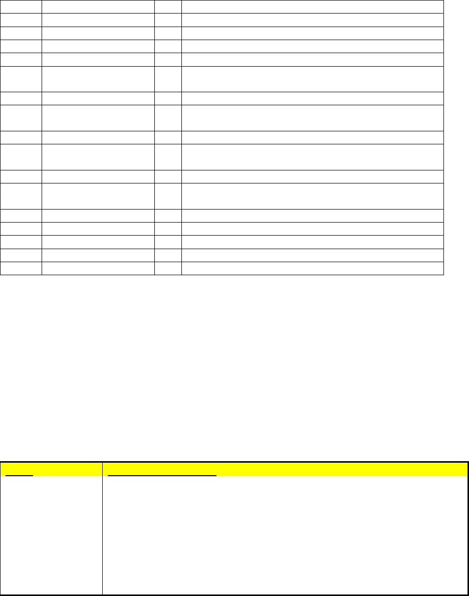
3.0 User I/O Interface
AL5721 Connector
Function Pin # Pin # Function
NC 1 2
3.3V
NC 3 4
GND
NC 5 6
NC
NC 7 8
NC
GND 9 10
NC
NC 11 12
NC
NC 13 14
NC
GND 15 16
USB VBUS(**)
Host_ Select 17 18
GND
NC 19 20
W_Disable#
GND 21 22
Association_CLR
NC 23 24
NC
NC 25 26
GND
GND 27 28
Assoc. D+(**)
GND 29 30
Assoc. D-(**)
NC 31 32
Assoc. VBUS(**)
NC 33 34
GND
GND 35 36
USB D-
C2D 37 38
USB D+
C2CLK 39 40
GND
AL_GPIO_2 41 42
Dock_LED
AL_GPIO_4 43 44
Security_LED#
AL_GPIO_5 45 46
Data_LED#
AL_GPIO_7 47 48
NC
Host_Connect_LED 49 50
GND
NC 51 52
3.3V
Figure 1, Connector Pins Configuration

UG-AL5721_1.0 P.3/7
AL5721 Pin Function Description
Pin # Pin Name I/O Description
1 NC No Connection
2 3.3V +3.3V Regulated power from host system
3 NC No Connection
4 GND Ground connection
5 NC No Connection
6 NC No Connection
7 NC No Connection
8 NC No Connection
9 GND Ground connection
10 NC No Connection
11 NC No Connection
12 NC No Connection
13 NC No Connection
14 NC No Connection
15 GND Ground connection
16 USB VBUS I +5V USB Vbus Signal from host system
17 Host_Select I (1) High = True 3.3V CMOS signal, allows host
system to provide control of selection among
multiple hosts associated to UWB radio.
(2) Test function, holding Host_Select high at
+3.3V power application to the AL5721 and then
switching it low places the aL5721 into
Administrative Mode for control by Alereon
manufacturing test utility software
18 GND Ground connection
19 NC No Connection
20 W_Disable# I Low = True 3.3V CMOS signal, assertion of
W_Disable# completely disables the radio system.
21 GND Ground connection
22 Association_CLR I High = True 3.3V CMOS signal, assertion of
Association_CLR clears all stored host
associations
23 NC No Connection
24 NC No Connection
25 NC No Connection
26 GND Ground connection
27 GND Ground connection
28 Assoc. D+ I/O USB D+ of Association signal
29 GND Ground connection
30 Assoc. D- I/O USB D- of Association signal
31 NC No Connection
32 Assoc. VBUS I +5V USB Vbus Signal from association connector
33 NC No Connection
34 GND Ground connection
35 GND Ground connection
UG-AL5721_1.0 P.4/7
36 USB D- I/O USB D- data signal from host system
37 C2D I/O Test signal for 8051CF326 USB controller
38 USB D+ I/O USB D+ data signal from host system
39 C2CLK I/O Test signal for 8051CF326 USB controller
40 GND Ground connection
41 AL_GPIO_2 I/O MAC GPIO signal, functionality may be determined
by customer definition
42 Dock_LED O LED drive pin, functionality per table 2
43 AL_GPIO_4 I/O MAC GPIO signal, functionality may be determined
by customer definition
44 Security_LED# O LED drive pin, functionality per table 2
45 AL_GPIO_5 I/O MAC GPIO signal, functionality may be determined
by customer definition
46 Data_LED# O LED drive pin, functionality per table 2
47 AL_GPIO_7 I/O MAC GPIO signal, functionality may be determined
by customer definition
48 NC No Connection
49 Host_Connect_LED O LED drive pin, functionality per table 2
50 GND Ground connection
51 NC No Connection
52 3.3V +3.3V Regulated power from host system
Table 1. Pin Descriptions
4.0 DESIGN CONSIDERATIONS
4.1 Power
One +3.3 V power supply at max data rate average current of 500 mA with peak at 750
mA. Connector pins #2 and 52 (+3.3V) are connected in common, both should connect
to the host system power rail. Connector pins #4, 9, 15, 18, 21, 26, 27, 29, 34, 35, 40,
and 50 are connected in common, all should connect to the host system ground.
4.2 LED Indicator Functions
Name Functional Description
Dock LED
Steady flashing when dock power is applied and radio is beaconing but not connected to a host.
LED is solid when a wireless connection is made to a Host PC.
Security LED
Normally off, Flashes during cable association process, Goes solid when a successful cable
association is made.
During wireless operation, this LED is off when there is not wireless connection to a host,
when successful Secure wireless connection is made to a pre-associated host, the LED goes solid.
Data LED
Flashes when data is being passed wireless in either direction.
Host Connect LED
Normally off. The LED goes solid when a wireless connection is made with the host.
This "Host Connect" LED indicates that the dock is successfully connected to the host.
Table 2. LED Indicator Functionality
UG-AL5721_1.0 P.5/7
4.3 UWB Antenna
The AL5721 has received FCC approval when employed with either of two antennas.
These two alternatives are provided for the system integrator to chose one that best
suits the particular installation. The approved antennas are:
• ACON (Taiwan) model number ADM6P-700047
• Alereon model number AL500001
These are the only antennas approved by the FCC for use with the Alereon AL5721, any
substitution of any other antenna automatically invalidates the FCC approval.
5.0 Regulatory Information
The AL5721 is approved under subpart F of the FCC rules as a Modular UWB
Transmitter.
The product into which the AL5721 is incorporated must bear a label per the FCC
requirements which shows the FCC ID assigned to the AL5721 as follows.
FCC ID: U9YAL5721
The following information must be conveyed in the information supplied to the End User
of the product into which the AL5721 is incorporated.
The compliance statement exactly as prescribed by the FCC:
This device complies with part 15 of the FCC Rules. Operation is subject to the
following two conditions: (1) this device may not cause harmful interference, and
(2) this device must accept any interference received, including interference that
may cause undesired operation.
This device is authorized under 47 CFR 15.519 (the FCC Rules and Regulations).
The operation of this device is subject to the following restriction: This UWB
device shall transmit only when it is sending information to an associated
receiver. This UWB device shall cease transmission within 10 seconds unless it
receives an acknowledgement from the associated receiver that its transmission
is being received. An acknowledgement of reception must continue to be
received by the transmitting device at least every 10 seconds of operation or the
UWB device must cease transmitting.
The users manual or instruction manual shall caution the user that changes or
modifications to the equipment not expressly approved by the party responsible for the
grant of equipment authorization issued by the FCC could void the user’s authority to
operate the equipment under the grant of equipment authorization, an example:
Warning: Changes or modifications to this device not expressly approved by
Alereon could void the users authority to operate the device under the FCC
Equipment Authorization. This includes changes or substitutions of the antenna
which is furnished with the device.
UG-AL5721_1.0 P.6/7
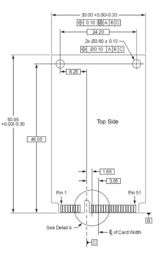
6.0 Mechanical
Recommended connector: Molex 67910-0002 PCI Express Mini Card Connector with
Molex 48099-4000 PCI Express Mini Card Latch.
UG-AL5721_1.0 P.7/7