Alfa Romeo 147 Owners Manual ManualsLib Makes It Easy To Find Manuals Online!
2014-12-12
: Alfa-Romeo Alfa-Romeo-147-Owners-Manual-118851 alfa-romeo-147-owners-manual-118851 alfa-romeo pdf
Open the PDF directly: View PDF ![]() .
.
Page Count: 286 [warning: Documents this large are best viewed by clicking the View PDF Link!]
1
Dear Client,
Thank you for choosing Alfa Romeo.
Your
Alfa 147
has been designed to guarantee the safety, comfort and driving pleasure typical of Alfa Romeo.
This booklet will help you to get to know the characteristics and operation of your car.
The following pages contain all the indications necessary for you to be able to maintain the high standards of performance, quality, safety and
respect for the environment which characterize this
Alfa 147
.
The Warranty Booklet also containes the regulations, the warranty certificate and a guide to the services offered by Alfa Romeo.
Services which are essential and precious because, when you purchase an Alfa Romeo, you are not only acquiring a car, but the tranquillity that
comes from knowing that an efficient, willing and widespread organisation is at your service for any assistance problems you may have.
Nature benefits in two ways: there’s no pollution from waste disposal and the demand for raw materials is reduced.
Enjoy the reading and have a good trip.
This booklet describes all the versions of the
Alfa 147
, so you should only consider the information concerning
the trim level, engine and version purchased by you.
001-057 Alfa 147 Q2 GB 4-07-2008 11:58 Pagina 1
2
VERY IMPORTANT!
FUEL CAPACITY
Petrol engines: only refuel with unleaded petrol with octane rating (RON) no less than 95.
Diesel engines: only refuel with diesel fuel conforming to the European specification EN590. The use of other products or
mixtures may irreparably damage the engine with invalidation of the warranty due to the damage caused.
NOTE The use of Eurodiesel fuel is recommended only for markets/ versions where required. In case it is not available, use
fuel conforming to EN590 European Specification.
STARTING THE ENGINE
Petrol engines with mechanical transmission: make sure that the handbrake is engaged; set the gearshift lever
to neutral, fully depress the clutch without pressing the accelerator, then turn the ignition key to AVV and release it as soon
as the engine has started.
Petrol engine with Selespeed transmission: keep the brake pedal fully depressed, turn the ignition key to
AVV and release it as soon as the engine has started; the transmission sets to neutral automatically (the display shows
position N).
JTD engines: make sure that the handbrake is engaged; set the gearshift lever to neutral, fully depress the clutch without
pressing the accelerator, then turn the handbrake is engaged; set the gearshift lever to neutral, fully depress the clutch with-
out pressing the accelerator, then turn the ignition key to MAR and wait for the
¢
and
m
warning lights to go off; turn
the ignition key to AVV and release it as soon as the engine starts.
PARKING ON FLAMMABLE MATERIAL
While working, the catalyst develops a very high temperature. Do not park the car over grass, dry leaves, pine needles or
any other inflammable materials: risk of fire.
K
001-057 Alfa 147 Q2 GB 4-07-2008 11:58 Pagina 2
3
ACCESSORY ELECTRICAL DEVICES
If after purchasing the car you wish to install accessories that need an electrical supply (with the risk of gradually draining
the battery), contact Alfa Romeo Authorised Services who will assess the overall electrical absorption and check whether the
car system is able to withstand the load required.
쇵
CODE CARD (for versions/markets where applicable)
Keep it in a safe place, not in the car. It is advisable to always keep the electronic code on the CODE card with you in case
emergency starting is necessary.
SCHEDULED SERVICING
Correct maintenance makes it possible to preserve car performance levels and safety, respect for the environment and low
running costs unaltered over the course of time.
THE OWNER HANDBOOK…
…you will find important information, advice and warnings for correct use, driving safety and car maintenance over time.
Pay particular attention to the symbols
"
(personal safety)
#
(protecting the environment)
â
(car safety).
RESPECTING THE ENVIRONMENT
The car is fitted with a system that allows continuous diagnosis of the components correlated with emissions to ensure bet-
ter respect for the environment.
001-057 Alfa 147 Q2 GB 4-07-2008 11:58 Pagina 3
4
Any queries concerning servicing should be forwarded to the showroom from which the car was purchased, the subsidiary company or to our
branch offices or any point of the Alfa Romeo Network.
Warranty Booklet
The Warranty Booklet is delivered together with every new car and contains the regulations tied to the services given by Alfa Romeo Services
and to the warranty conditions.
Correctly carrying out the scheduled services specified by the manufacturer is the best way to maintain the performance, safety characteristics
and low running costs of your car. It is also necessary to maintain warranty cover.
“Service” guide
This contains Alfa Romeo Authorised Services. The Services can be recognised by the presence of the Alfa Romeo badge and logo.
The Alfa Romeo organisation in Italy can be found in the telephone directory under the letter “A” Alfa Romeo.
Not all of the models described in this booklet are available in all countries. Only some of the fittings described in this booklet are fitted as stan-
dard to the car. The list of available accessories should be requested from the Alfa Romeo Dealers.
001-057 Alfa 147 Q2 GB 4-07-2008 11:58 Pagina 4
5
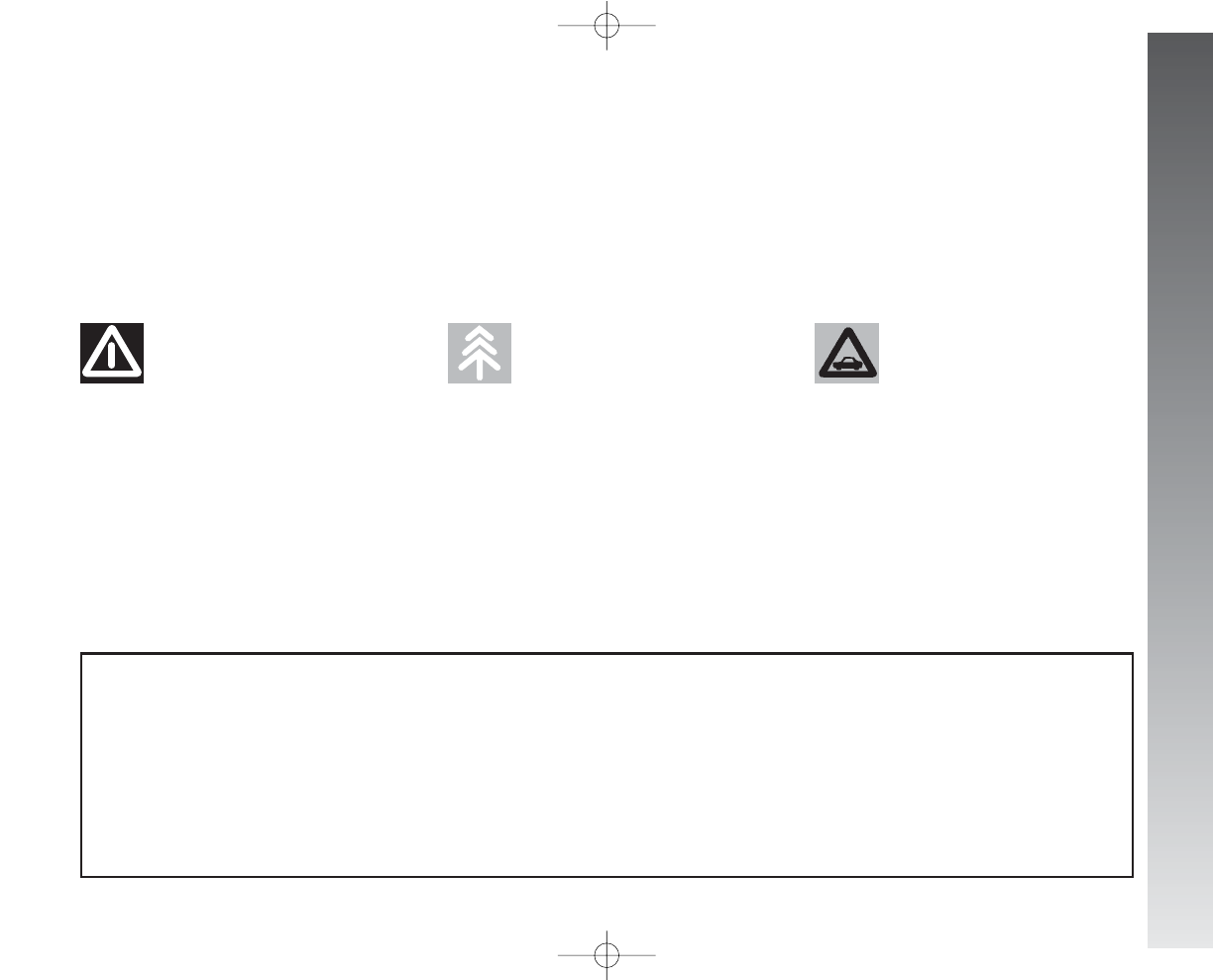
THE SYMBOLS USED IN THIS BOOKLET
The symbols illustrated in these pages show the subjects
which should, in particular, be closely studied.
This indicates the correct procedures
to be followed to prevent the car
from damaging the environment.
Warning. Partially or fully ignoring
these rules may lead to serious injury.
Warning. Partially or fully ignoring these
rules may lead to serious damage being
caused to the car which, in some
circumstances, may cause forfeiture of the
warranty cover.
PERSONAL
SAFETY
PROTECTING THE
ENVIRONMENT CAR SAFETY
The texts, illustrations and specifications given in this booklet refer to the car
at the time of going to press.
As part of our ongoing striving to improve our products, Alfa Romeo may introduce technical changes during production,
therefore the specifications and fittings may be altered without prior notice.
For details on this subject, please apply to the manufacturer’s sales network.
001-057 Alfa 147 Q2 GB 4-07-2008 11:58 Pagina 5
GETTING TO KNOW YOUR CAR
6
THE ALFA ROMEO
CODE SYSTEM
To increase protection against attempted
theft, the car is fitted with an electronic en-
gine lock system (Alfa Romeo CODE) which
is activated automatically when the key is
removed from the ignition. In fact the grip
of each key contains an electronic device
which modulates the radio frequency signal
transmitted when the engine is started by a
special aerial incorporated in the ignition
switch. This modulated signal is the “pass-
word” by which the control unit recognises
the key and only in this condition can the
engine be started.
KEYS
The car is delivered with a key with met-
al insert (upon request for models/markets
where required) and a key with remote con-
trol. For models/markets where required
two keys with remote control can be pro-
vided.
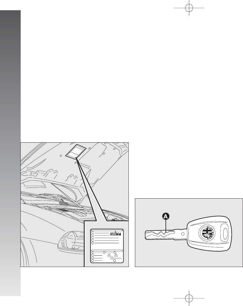
KEY WITHOUT REMOTE CONTROL
(for versions/markets
where applicable)
The fixed metallic insert A-fig. 2 oper-
ates:
– the ignition switch;
– the driver’s door lock;
– the passenger’s Air bag deactivation (up-
on request for versions/markets where ap-
plicable);
– the fuel filler cap lock.
IMPORTANT In order to ensure perfect
efficiency of the electronic devices contained
inside the keys, they should never be directly
exposed to the rays of the sun.
G
GE
ET
TT
TI
IN
NG
GT
TO
OK
KN
NO
OW
WY
YO
OU
UR
RC
CA
AR
R
fig. 2
A0A0736m
fig. 1
A0A1000m
SYMBOLS
Special coloured labels have been attached
near to or actually on some of the compo-
nents making up your
Alfa 147
. These
labels bear symbols that remind you of the
precautions to be taken as regards that par-
ticular component. A summary list of the
symbols (fig.1) is to be found under the
bonnet.
001-057 Alfa 147 Q2 GB 4-07-2008 11:58 Pagina 6
GETTING TO KNOW YOUR CAR
7
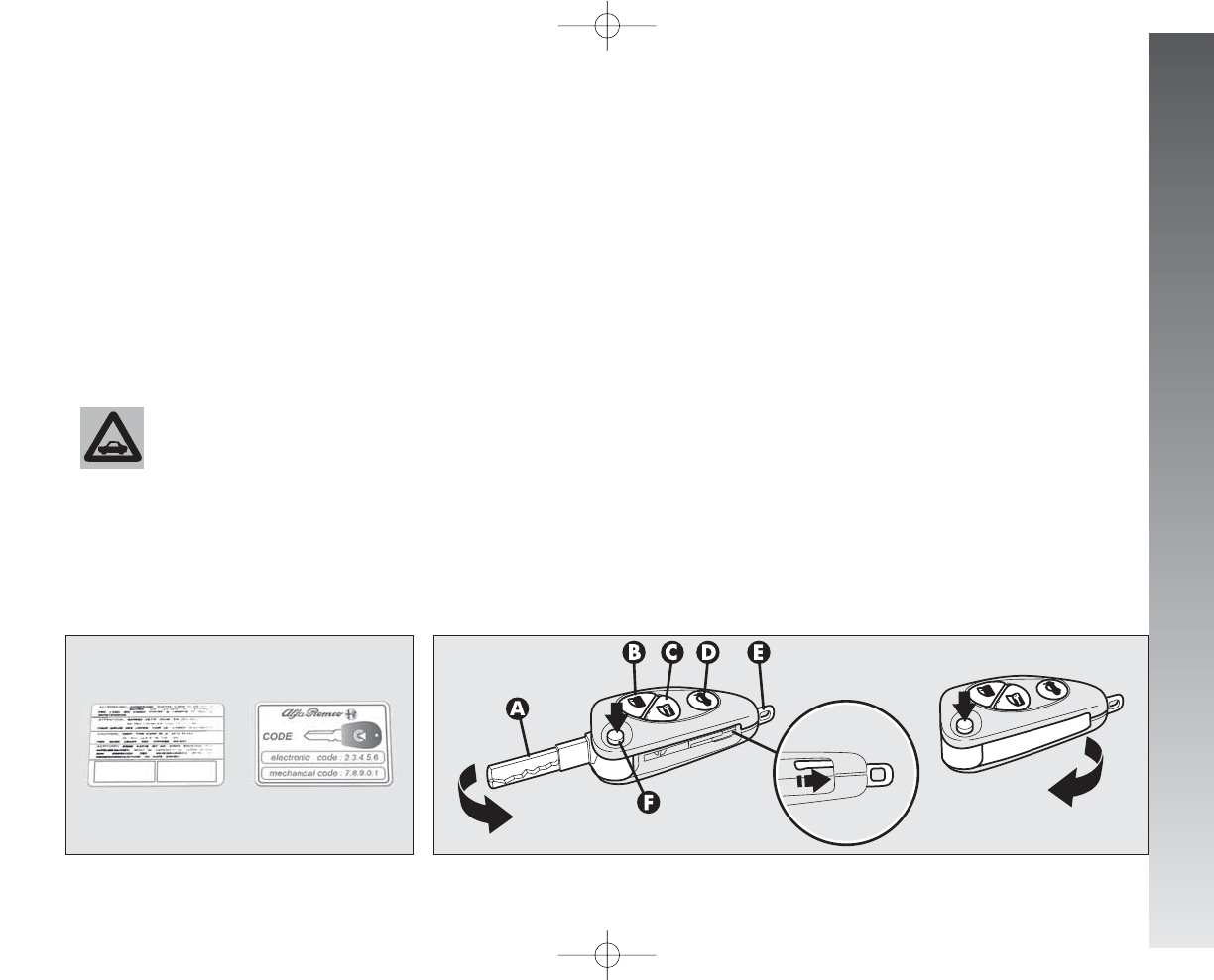
Together with the keys the CODE card is
provided (for versions/markets where ap-
plicable) (fig. 3), bearing in print the key
codes (both mechanical and electronic for
emergency start up).
The code numbers on the CODE card must
be kept in a safe place , not in the car.
The driver should always keep the elec-
tronic CODE card with him/her in the event
of having to carry out emergency starting.
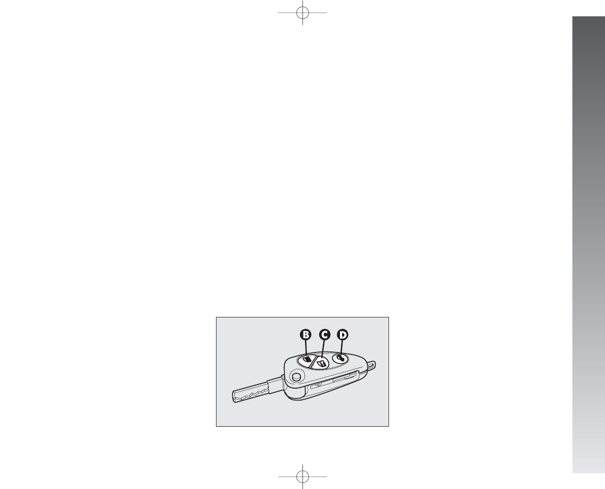
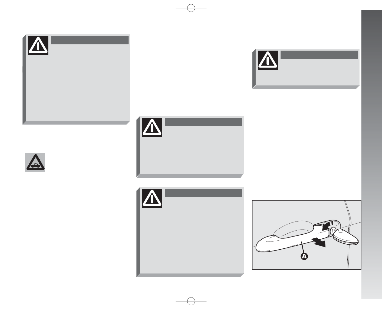
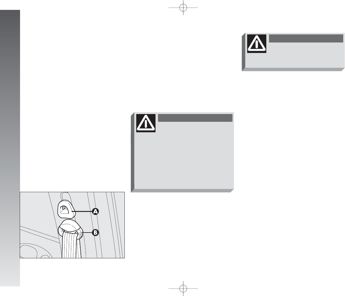
KEY WITH REMOTE CONTROL
For versions/markets where applicable,
the key is fitted with (fig. 4:
– a metal insert (A) that can be enclosed
in the key grip
– button (B) for remote opening of the
doors and turning the electronic alarm off
– button (C) for remote closing of the
doors and turning the electronic alarm on
– button (D) for remote boot opening
– tow hook ring (E)
– button (F) for power-assisted opening
of the metallic insert.
fig. 3
A0A0003m
If the car changes owner,
the new owner must be
given all the keys and the
CODE card.
fig. 4
A0A0705m
The metal insert (A) of the key operates:
– the ignition switch
– the driver’s door lock
– the passenger’s Air bag deactivation
switch (on request for versions/markets
where applicable)
– the fuel filler cap lock.
001-057 Alfa 147 Q2 GB 4-07-2008 11:58 Pagina 7
GETTING TO KNOW YOUR CAR
8
OPENING THE TAILGATE
The boot can be opened by remote control
from outside pressing button (D), also when
the electronic alarm is on. The boot opening
is accompanied by a double flashing of the di-
rection indicators; the boot closing is accom-
panied by a single flashing of the direction
indicators.
If the electronic alarm is fitted, when the
tailgate is opened the alarm system switch-
es off volumetric protection and the tailgate
control sensor, the system (with the excep-
tion of versions for certain markets)”beeps”
twice.
Closing the tailgate again, the control func-
tions are restored, the system (with the ex-
ception of versions for certain markets)
“beeps” twice.
To insert the metallic insert in the key grip,
press the button (F) to release the insert
and turn it in the direction of the arrow un-
til it clicks. Once it clicks into position, re-
lease the button (F).
To open the doors by remote control, press
the button (B), the doors will unlock and the
direction indicators will flash twice. To close
the doors by remote control, press the button
(C), the doors will lock and the direction in-
dicators will flash once. By pressing button
(B) the doors unlock, if in the next 60 sec-
onds neither a door or the boot open, the sys-
tem will automatically lock them.
On cars fitted with electronic alarm system,
pressing button (B) turns the alarm off,
pressing button (C) turns the alarm on while
the transmitter sends the code to the re-
ceiver. This rolling code changes at each
transmission.
When button (F) is
pressed, take the utmost
care to prevent the metal insert
from causing injury or damage
when it comes out. Button (F) must
only be pressed when the key is
away from the body, in particular
the eyes, and from objects that coul
be spoilt (e.g. clothes). Never leave
the key unattended to prevent
anyone, especially children, from
holding it and pressing button (F)
inadvertently.
WARNING
001-057 Alfa 147 Q2 GB 4-07-2008 11:58 Pagina 8
The codes of any keys not
presented during the mem-
orising procedure are
erased. The reason for this is to en-
sure that any lost or stolen keys
cannot be used to start the engine.
GETTING TO KNOW YOUR CAR
9
OPERATION
Each time the ignition key is turned to the
STOP position the Alfa Romeo CODE system
deactivates the functions of the engine elec-
tronic control unit.
Each time the car is started turning the ig-
nition key to MAR, the Alfa Romeo CODE
control unit sends a recognition code to the
engine control unit to deactivate the in-
hibitor. The code is crypted and variable be-
tween over four billion possible combina-
tions, and it is sent only if the system con-
trol unit has recognised the code transmit-
ted from the key which contains an elec-
tronic transmitter, through an aerial wound
around the ignition switch.
IMPORTANT Turning on of the Alfa
Romeo CODE warning light (
Y
) when trav-
elling with the ignition key at MAR:
1) If the warning light turns on, this means
that the system is running a self-test (for ex-
ample for a voltage drop). At the first stop,
it will be possible to test the system: switch
off the engine turning the ignition key to
STOP; then turn the ignition key to MAR:
the warning light turns on and should go off
in about one second. If the warning light
stays on, repeat the procedure described pre-
viously leaving the key at STOP for over
30 seconds. Should the inconvenience per-
sists, contact Alfa Romeo Authorised Ser-
vices.
If the code has not been recognised cor-
rectly, the Alfa Romeo CODE warning light
(
Y
) on the cluster turns on.
In this case, the key should be moved to
the STOP position and then back to MAR;
if the lock continues, possibly try again with
the other key provided with the car. If it is
still not possible to start the car, follow the
instructions given in the “In an emergency”
chapter and then contact Alfa Romeo Au-
thorised Services.
IMPORTANT Every key has its own
code, which must be memorised by the sys-
tem control unit. To memorise new keys, up
to a maximum of eight, apply solely to Al-
fa Romeo Authorised Services taking with
you all the keys in your possession, the
CODE card, a personal identity document
and the car’s ownership documents.
001-057 Alfa 147 Q2 GB 4-07-2008 11:58 Pagina 9
GETTING TO KNOW YOUR CAR
10
2) For versions without the reconfigurable
multifunction display, the flashing of the
warning light means that the car is not pro-
tected by the engine inhibitor device. This
condition for cars with reconfigurable mul-
tifunction display is shown by the turning on
of the warning light together with the dis-
play of the message: “CODE SYSTEM NOT PRO-
GRAMMED”. Contact Alfa Romeo Authorised
Services immediately to have all the keys
memorised.
If after about 2 seconds
with the ignition key at
MAR, for versions without
reconfigurable multifunction dis-
play, the Alfa Romeo CODE warn-
ing light (
Y
) turns on again flash-
ing, or for versions with reconfig-
urable multifunction display, the
warning light turns on again to-
gether with the message “CODE
SYSTEM NOT PROGRAMMED”, this
means that the code of the keys
has not been stored, therefore the
car is not protected by the Alfa
Romeo CODE system against at-
tempted theft. In this case contact
Alfa Romeo Authorised Services to
have the key codes stored.
KEY BATTERY REPLACEMENT
If when the button (BCor D-fig. 4) is
pressed, the command is rejected or not car-
ried out, the battery may be replaced with
other of an equivalent type available from
normal outlets.
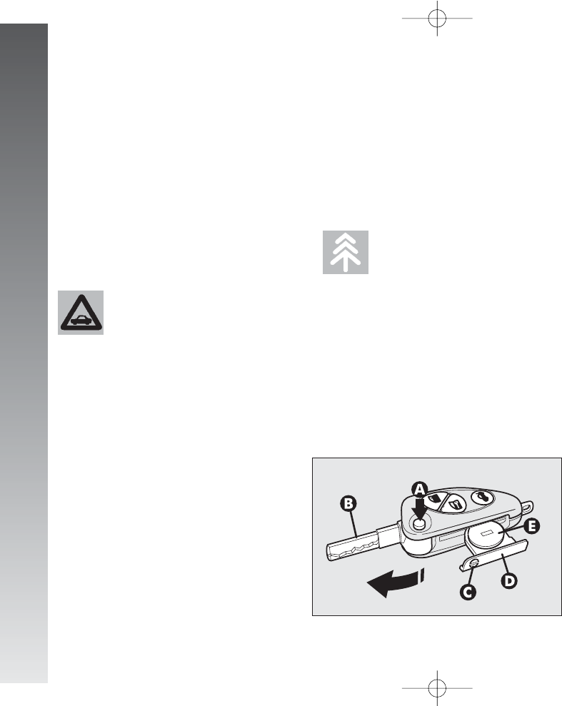
To change the battery:
– press button (A-fig. 5) and move the
metal insert (B) to the open position;
– using a finely-tipped screwdriver, turn
the opening device (C) and pull out the bat-
tery holder (D);
– replace the battery (E) making sure that
the bias is correct;
– insert the holder back in the key and
lock it, turning the device (C).
Dead batteries are harm-
ful for the environment.
They must be disposed of
in special containers as specified by
current regulations. Avoid expo-
sure to naked flames and high tem-
peratures. Keep out of reach of
children.
fig. 5
A0A0006m
001-057 Alfa 147 Q2 GB 4-07-2008 11:58 Pagina 10
GETTING TO KNOW YOUR CAR
11
ELECTRONIC ALARM
DESCRIPTION
The system comprises: a transmitter, re-
ceiver, control unit with siren and volumet-
ric sensors. The electronic alarm is controlled
by the receiver incorporated in the instru-
ment cluster and it is turned on and off by
the remote control in the key which sends
the crypted and variable code. The electronic
alarm controls: the unlawful opening of
doors, bonnet and boot (perimetral protec-
tion), operation of the ignition key, battery
cable cutting, the presence of moving bod-
ies in the passenger compartment (volu-
metric protection), any abnormal rais-
ing/sloping of the car (for versions/mar-
kets where applicable) and central door lock-
ing. It also makes it possible to cut off the
volumetric protection.
IMPORTANT The engine inhibitor func-
tion is guaranteed by the Alfa Romeo CODE
system which is activated automatically
when the ignition key is removed.
REQUEST FOR ADDITIONAL
KEYS WITH REMOTE CONTROL
The receiver can recognise up to 5 keys
with incorporated remote control. Should a
new key with remote control be necessary
for any reason during the life of the car, con-
tact directly Alfa Romeo Authorised Services,
taking with you the CODE card, a personal
identity document and the car’s ownership
documents.
ACTIVATING THE ALARM
With the doors, bonnet and boot shut and
the ignition key in the STOP or PARK po-
sition (key removed), point the key with the
remote control in the direction of the car, then
press and release the button (C-fig. 6).
With the exception of certain markets, the
system sounds a “beep” and the doors are
locked.
Engagement of the alarm is preceded by
a self-diagnosis phase characterised by a
change in the frequency at which the de-
terrent led (A-fig. 7) on the dashboard
flashes. If an anomaly is detected the sys-
tem gives off a furter beep.
fig. 6
A0A0010m
001-057 Alfa 147 Q2 GB 4-07-2008 11:58 Pagina 11

GETTING TO KNOW YOUR CAR
12
Surveillance
After switching on, the flashing of the de-
terrent led (A-fig. 7) on the dashboard in-
dicates the system surveillance mode. The
led flashes throughout this period.
IMPORTANT Operation of the electronic
alarm is adapted at the origin to the rules
of the different countries.
Self-diagnostic functions
and door, bonnet, boot control
If, after engaging the alarm, a second
“beep” is sounded, switch off the system
pressing the button (B-fig. 6), check that
the doors, bonnet and tailgate are properly
shut, then switch the system on again press-
ing the button (C).
Otherwise, the door, bonnet or tailgate that
is not shut properly will be excluded from
the alarm system control.
If the doors, bonnet and boot are shut cor-
rectly and the control signal is repeated, the
system self-diagnostic has detected a sys-
tem operating fault. It is therefore necessary
to contact Alfa Romeo Authorised Services.
HOW TO DEACTIVATE
THE ALARM
To deactivate the alarm press the button (B-
fig. 6) of the key with remote control. The
system will react as follows (with the ex-
ception of certain markets):
– two brief flashes of the direction indi-
cators
– two brief “beeps” of the system
– door unlocking.
IMPORTANT If when the system is
turned off the deterrent led (A-fig. 7) on
the dashboard stays on (maximum 2 min-
utes or until the ignition key is set to MAR)
the following should be borne in mind:
fig. 7
A0A0005m
001-057 Alfa 147 Q2 GB 4-07-2008 11:58 Pagina 12

GETTING TO KNOW YOUR CAR
13
– if the led continues flashing, but at dif-
ferent intervals than normal, this means that
different attempts to break in have occurred.
Through the number of flashes it is possi-
ble to identify the type of attempt:
1 flash: one or more doors
2 flashes: tailgate
3 flashes: bonnet
4 flashes: ultrasounds
5 flashes: abnormal car lifting/slop-
ing (for versions/markets
where applicable)
6 flashes: tampering with car starting
cables
7 flashes: tampering with battery ca-
bles or cutting emergency
key cables
8 flashes: connection line to sensors
and siren
9 flashes: at least three causes of
alarm.
WHEN THE ALARM
IS TRIGGERED
When the system is on, the alarm comes
into action in the following cases:
– opening of one of the doors, bonnet or
tailgate;
– disconnection of the battery or section-
ing of electric cables;
– intrusion in the passenger compartment,
for example breakage of windows (volu-
metric protection);
– attempt to start the engine (key in
MAR position);
– abnormal car lifting/sloping (for ver-
sions/markets where applicable).
Depending on the markets, the cutting in
of the alarm causes operation of the siren
and hazard warning ligths (for about 26 sec-
onds). The ways of operating and the num-
ber of cycles may vary depending on the
markets.
A maximum number of cycles is however
envisaged.
Once the alarm cycle has ended, the sys-
tem resumes its normal control function.
VOLUMETRIC PROTECTION
To make sure that the protection system
works correctly the side windows and sun-
roof (if fitted) must be properly shut.
The function can be cut off (if, for exam-
ple, leaving animals in the car) carrying out
the following operations in rapid succession:
starting from the condition with the igni-
tion key at MAR, move the key to STOP,
then immediately back to MAR and then
to STOP again, then remove the ignition
key.
The deterrent led (A-fig. 7) on the dash-
board lights up for about 2 seconds to con-
firm that the function has been cut off.
To restore volumetric protection, move the
and keep the ignition key at MAR for over
30 seconds.
If, with the volumetric protection function
deactivated, an electric control controlled by
the ignition key at MAR (e.g. power win-
dows) turn the ignition key to MAR, op-
erate the control and move the key to
STOP in a maximum time of 30 seconds.
This way volumetric protection is not re-
stored.
001-057 Alfa 147 Q2 GB 4-07-2008 11:58 Pagina 13
GETTING TO KNOW YOUR CAR
14
HOW TO CUT OFF
THE ALARM SYSTEM
To deactivate the alarm system complete-
ly (for instance during prolonged inactivity
of the car) simply lock the car turning the
key in the lock.
MINISTERIAL CERTIFICATION
In accordance with the law in force in each
country, on the subject of radio frequency,
we wish to point out that for the markets in
which the transmitter needs to be marked,
the certification number is given on the com-
ponent.
Depending on the versions/markets, the
code may also be given on the transmitter
and/or on the receiver.
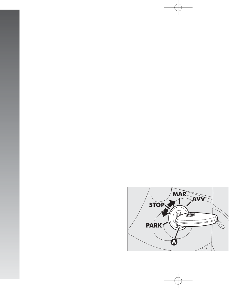
IGNITION DEVICE
SWITCH
(fig. 8)
The key can be turned to one of four po-
sitions:
–STOP: engine switched off, key can be
removed, engine inhibitor engaged, steer-
ing lock engaged, services excluded apart
from those supplied directly (e.g. hazard
warning lights).
–MAR: drive position. The engine lock
is deactivated and all electrical devices are
powered.
IMPORTANT Do not leave the key in
this position when the engine is stopped.
–AVV: unstable position for starting the
engine.
IMPORTANT If the engine fails to start
move the key back to STOP and repeat.
The ignition switch has a safety device
which prevents passage to AVV when the
engine is running.
–PARK: engine switched off, key can
be removed, engine lock engaged, steer-
ing lock engaged, sidelights switched on au-
tomatically.
IMPORTANT To turn the key to the
PARK position, button (A) on the switch
must be pressed first.
fig. 8
A0A0016m
001-057 Alfa 147 Q2 GB 4-07-2008 11:58 Pagina 14
GETTING TO KNOW YOUR CAR
15
If the ignition device is
tampered with (for exam-
ple during an attempted
break-in) have it checked over by
Alfa Romeo Authorized Services
before travelling again.
STEERING LOCK
Engaging:
– move the key to STOP or PARK, then
remove the key and turn the steering wheel
slightly to facilitate the locking action.
Disengaging:
– turn the key to the MAR position and
gently rock the steering wheel.
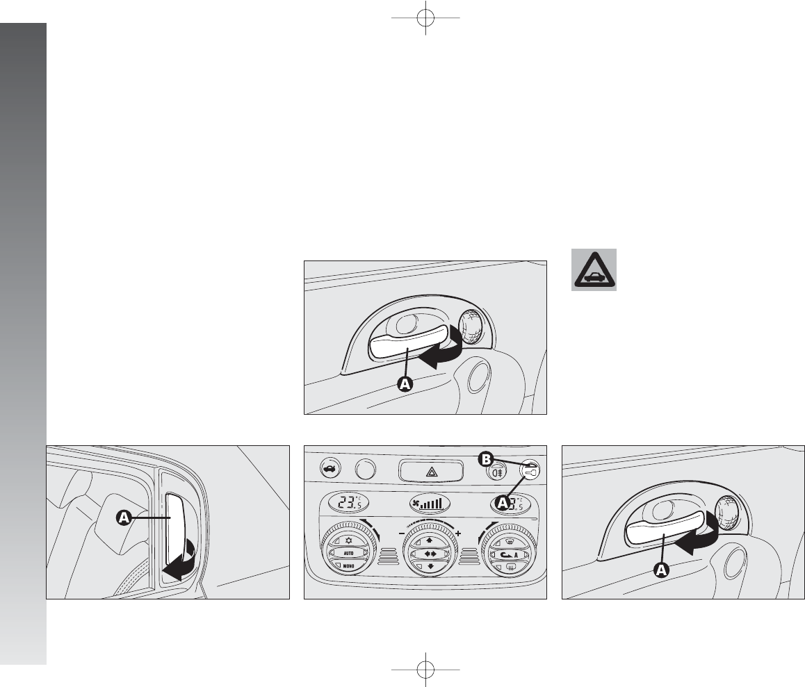
DOORS
OPENING/CLOSING FROM
OUTSIDE
Front door on driver’s side
– To open the driver’s door turn the key
clockwise and then remove the key and pull
the handle (A-fig. 9).
– To close the door turn the key counter-
clockwise.
fig. 9
A0A0017m
When leaving the car, al-
ways remove the key from
the ignition to prevent any pas-
senger in the car from inadver-
tently activating the controls. Nev-
er leave children unattended in the
car. Remember to engage the hand-
brake and if the car is facing uphill,
first gear and if the car is facing
downhill, reverse.
Never remove the key
with the car on the move.
The steering wheel would lock au-
tomatically the first time the steer-
ing wheel is turned. This also oc-
curs if the car is towed.
WARNING
WARNING
It is absolutely forbidden to
carry out aftermarket oper-
ations on the car which would tam-
per with the steering wheel or col-
umn (for example the installation of
the antitheft system) and might
cause not only the system and war-
ranty decay, but also serious safe-
ty problems and alter the car type-
approval compliance.
WARNING
Before opening a door, al-
ways make sure that it can
be done safely.
WARNING
001-057 Alfa 147 Q2 GB 4-07-2008 11:58 Pagina 15
OPENING/CLOSING FROM
INSIDE
Front doors
– To open the door, pull the handle
(A-fig. 11).
fig. 11
A0A0324m
fig. 12
A0A1002m
GETTING TO KNOW YOUR CAR
16
Front door on passenger’s side
– To open the door, deactivate the cen-
tralized locking and pull the handle.
– To close the door, push the flap.
Rear doors (5-door versions)
– To open the door, deactivate the cen-
tralized locking and pull the handle (A-fig.
10).
– To close the door, push the flap.
– To close the door, pull the flap. To pre-
vent the door from being opened from out-
side press the button (A-fig. 12) on the
dashboard, the deterrent led (B) on the but-
ton will turn on with a yellow light to con-
firm locking.
Rear doors (5-door versions)
fig. 10
A0A1001m
The rear doors can only
be opened if the child safe-
ty lock has been released.
fig. 13
A0A0324m
– To open the door pull the handle (A-
fig. 13).
– To close the door pull the flap.
001-057 Alfa 147 Q2 GB 4-07-2008 11:58 Pagina 16
GETTING TO KNOW YOUR CAR
17
CENTRAL LOCKING
This allows central locking of the door
locks.
To engage central locking, the doors must
be perfectly shut, otherwise locking is de-
nied.
IMPORTANT With central locking en-
gaged, pulling the inside lever for opening
one of the front doors causes the unlock-
ing of all the doors.
In the event of a power cut off (blown
fuse, battery disconnected, etc.) it is still pos-
sible to work the lock by hand.
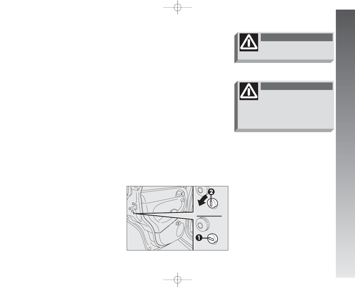
CHILD SAFETY LOCK
(
5-door versions
)
The rear doors are equipped with a special
device (fig. 14) which prevents the door
being opened from inside.
IMPORTANT Each device only acts on
the door on which it is installed.
The device can only be engaged with the
doors open:
position 1 – device engaged (door
locked);
position 2 – device released (door can
be opened from inside).
fig. 14
A0A0325m
Always use this device
when carrying children.
WARNING
After activating the safety
device on both rear doors,
check that it is working correcttly
by pulling on the inner lever used
to open the door.
WARNING
001-057 Alfa 147 Q2 GB 4-07-2008 11:58 Pagina 17
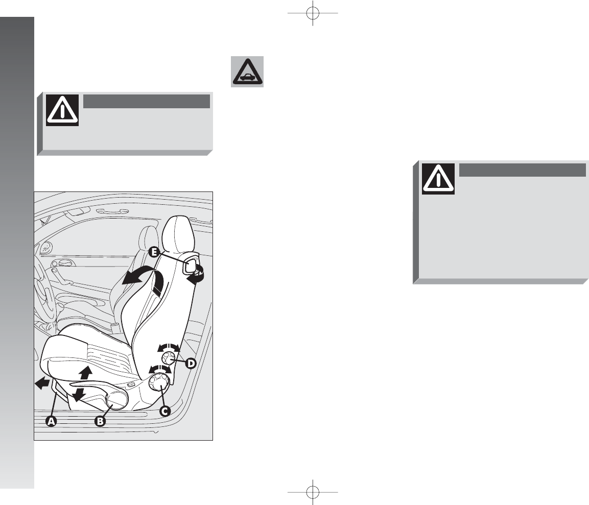
LENGTHWISE ADJUSTMENT
(fig. 15)
Raise the lever (A) and push the seat
backwards or forwards; in the driving posi-
tion the arms should be slightly flexed and
the hands should rest on the rim of the steer-
ing wheel.
After releasing the adjust-
ment lever, always check
that the seat is locked on the run-
ners, trying to move it to and fro.
The lack of this clamping action
could cause the seat to move un-
expectedly and cause loss of car
control.
WARNING
GETTING TO KNOW YOUR CAR
18
FRONT SEATS
fig. 15
A0A0020m
Any adjustments are to be
carried out only with the
car stationary.
WARNING
The car upholstery can re-
sist wear resulting from
the normal use of the car.
However, it is necessary to avoid
excessive and/or prolonged fric-
tion with clothing accessories such
as metal buckles, studs, velcro and
similar material, as this friction,
acting locally and with a high pres-
sure over the knitted fabric, may
cause some threads to break and
thus damage the seat cover/lining.
001-057 Alfa 147 Q2 GB 4-07-2008 11:58 Pagina 18
GETTING TO KNOW YOUR CAR
19
BACK REST TILTING
(fig. 15)
To gain access to the rear seats, pull the
handle (E), the back rest folds and the seat
is free to run forwards.
A recovery mechanism with memory
makes it possible to take the seat back to
its previous position.
Once the seat back has been returned to
the travelling condition, make sure that it
is correctly clamped, checking that the “red
band” on the upper part of the handle (E)
is concealed. In fact, this “red band” indi-
cates that the seat back is not clamped.
Also check that the seat is firmly locked on
the runners, trying to move it to and fro.
DRIVER’S SEAT LUMBAR
ADJUSTMENT
(fig. 15)
Adjustment is done by turning the knob
(D) until reaching the most comfortable po-
sition.
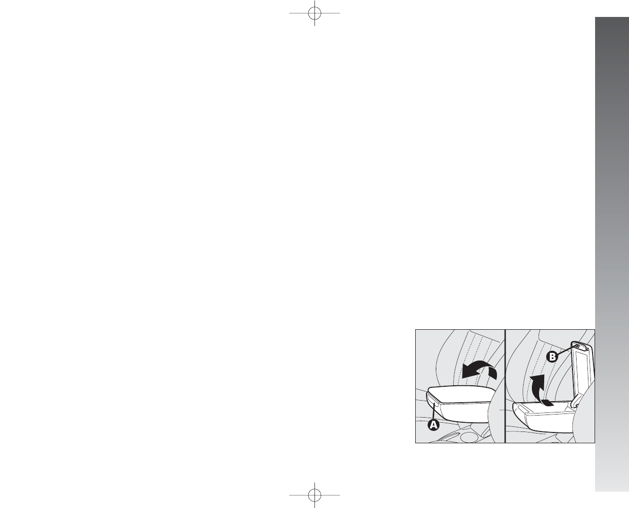
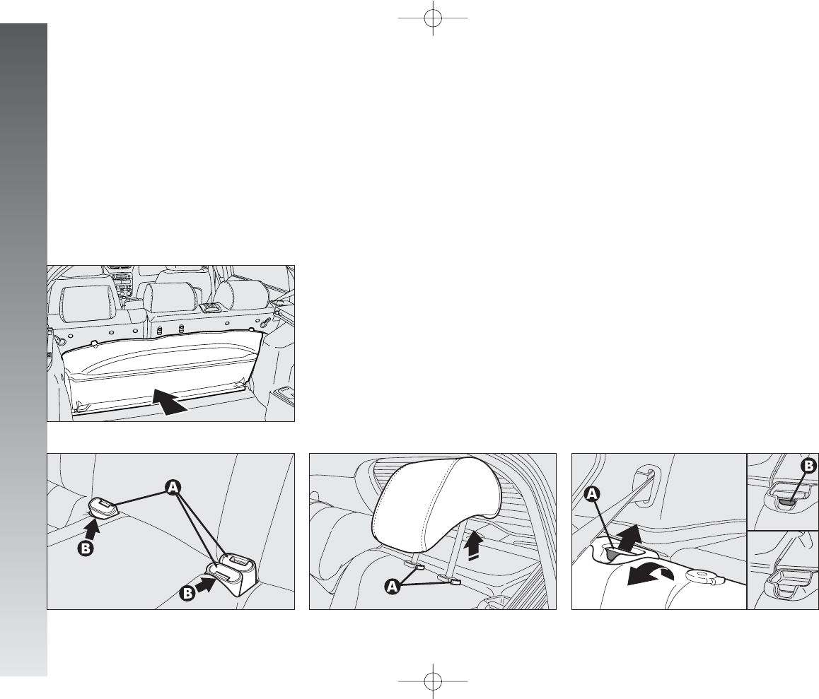
CENTRAL ARMREST
(fig. 16)
(upon request for versions/markets
where applicable)
The armrest can be adjusted, raised and
lowered.
To adjust, slightly raise the armrest, then
press the the release device (A).
Inside the armrest there is an oddments
compartment, to use it, raise the cover,
pressing the device (B).
fig. 16
A0A0023m
ADJUSTING THE HEIGHT
(fig. 15)
(upon request for
versions/markets where
applicable)
To raise the seat, pull the lever (B) up-
wards, then work the lever (up and down)
until reaching the required height, then re-
lease it. To lower the seat, push the lever
(B) downwards, then work the lever (up
and down) until reaching the required
height.
IMPORTANT Adjustment must be car-
ried out only seated in the driver’s seat.
BACK REST ANGLE
ADJUSTMENT
(fig. 15)
This can be done by turning the knob (C)
until the desired position is reached.
001-057 Alfa 147 Q2 GB 4-07-2008 11:58 Pagina 19
GETTING TO KNOW YOUR CAR
20
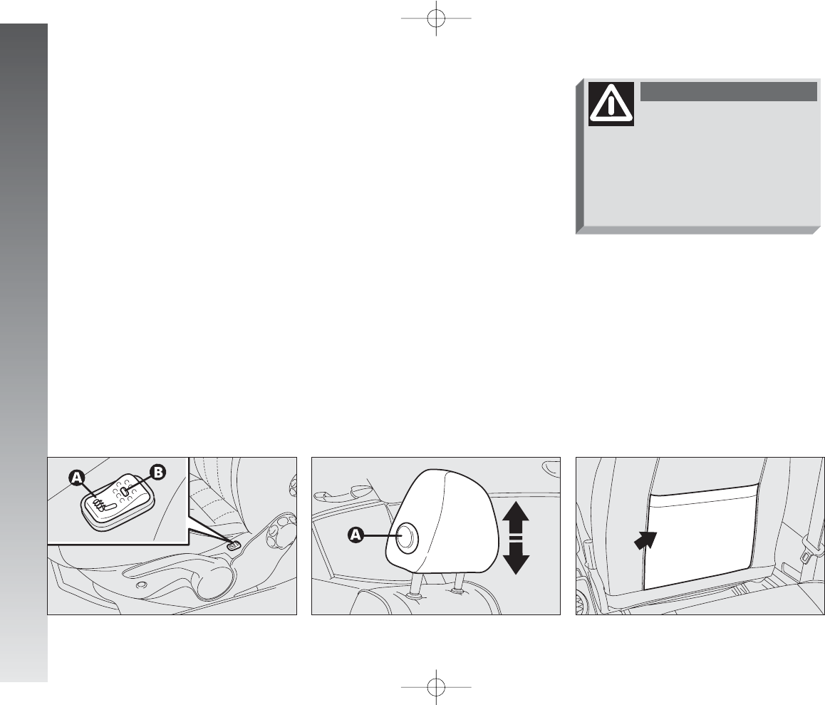
REAR POCKET
(fig. 19)
(
for versions/markets where
applicable)
The front passenger’s seat is provided with
a pocket in the rear of the seat back.
SEAT WARMING
(fig. 17)
Seat warming, fitted on certain versions,
is turned on and off through the switch (A)
on the outer side of the seat.
Switching on is shown by the lighting up
of the led (B) on the switch itself.
HEADREST ADJUSTMENT
(fig. 18)
To increase passengers’ safety, the head-
rests are adjustable in height.
To adjust, press the button (A) and move
the headrest up or down until it clicks into
place.
IMPORTANT The configuration of the
headrest cushion may vary depending on
the versions and markets. The purpose of
the illustration is only to show how it is ad-
justed.
fig. 17
A0A0024m
fig. 18
A0A0025m
fig. 19
A0A0026m
Remember that the head re-
straints must be positioned
so that they are supporting the back
of the head and not the neck. They
will only be able to provide effective
protection in the event of a collision
if they are in this position.
WARNING
001-057 Alfa 147 Q2 GB 4-07-2008 11:58 Pagina 20
GETTING TO KNOW YOUR CAR
21
REAR SEATS
The car upholstery can re-
sist wear resulting from
the normal use of the car.
However, it is necessary to avoid
excessive and/or prolonged fric-
tion with clothing accessories such
as metal buckles, studs, velcro and
similar material, as this friction,
acting locally and with a high pres-
sure over the knitted fabric, may
cause some threads to break and
thus damage the seat cover/lining.
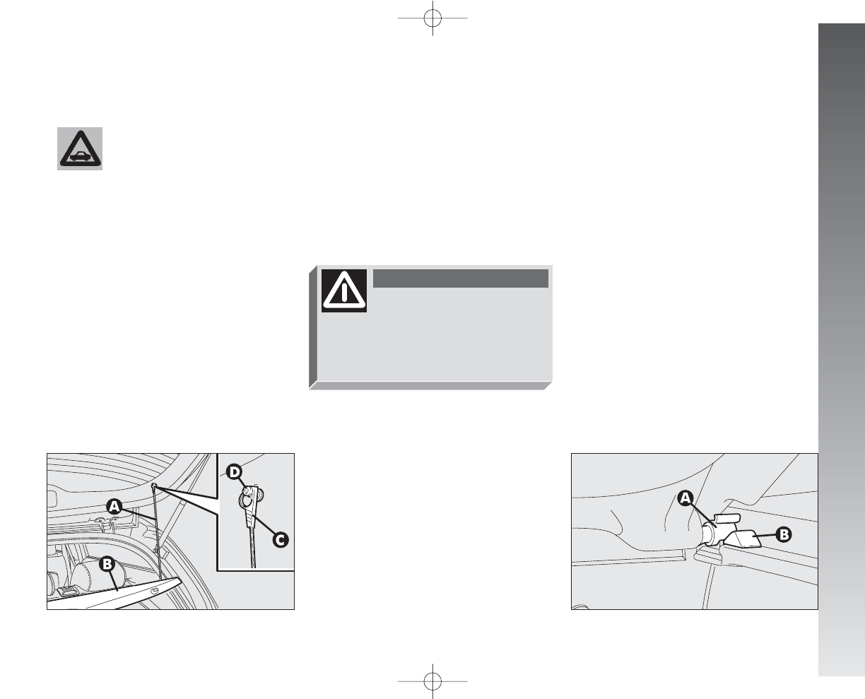
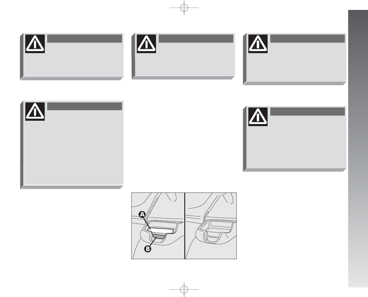
Removing the rear parcel shelf
Proceed as follows:
– free the ends of the two rods (A-fig.
20) supporting the parcel shelf (B) pulling
the eyelets (C) off the pins (D);
– release the pins (A-fig. 21) at the out-
side of the shelf from their housings (B) ob-
tained in the side supports, then remove the
shelf pulling it outwards.
Once the shelf beneath the rear window
has been removed, it can be arranged in two
ways:
– across in the luggage compartment as
illustated in fig. 22;
– across between the front seat backs and
the tilted cushions of the rear seats when
the luggage compartment is completely ex-
tended (see fig. 26).
fig. 20
A0A1004m
fig. 21
A0A0028m
If a particularly heavy load
is placed in the boot, when
travelling at night, it is wise to
check the height of the high beams
(see “Headlamps” paragraph).
WARNING
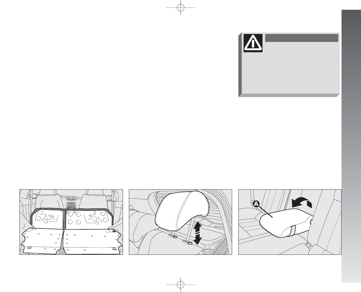
EXTENDING THE
LUGGAGE COMPARTMENT
The split of rear seat makes it possible to
extend the luggage compartment totally or
partially, acting separately on one of the two
parts, thereby offering different possibilities
of load depending on the number of rear
passengers.
001-057 Alfa 147 Q2 GB 4-07-2008 11:58 Pagina 21
GETTING TO KNOW YOUR CAR
22
– raise the headrests to the maximum
height and then press both the buttons (A-
fig. 24) on the two supports side, then pull
the headrests upwards and remove them;
– move the seat belts to the side extend-
ing them correctly without twisting;
– raise the levers (A-fig. 25) retaining
the back rests and tilt them forwards to ob-
tain a single loading surface (fig. 26).
Partial extension
For partial extension, proceed as follows:
– tilt the cushion required pulling the han-
dle at the centre of the cushion, then tilt-
ing the actual cushion;
– raise the headrest to the maximum
height and then press both the buttons on
the two supports side, then pull the headrest
upwards and remove them;
– move the seat belt to the side extending
it correctly without twisting;
– raise the lever (A-fig. 25) retaining
the back rest and tilt.
fig. 24
A0A1005m
fig. 25
A0A1065m
Total extension
Proceed as follows:
– fit the buckles of the seat belts (A-fig.
23) in their housings (B) on the cushion;
– pull the handles in the centre of the cush-
ions, then tilt them forwards;
fig. 23
A0A0029m
fig. 22
A0A1003m
001-057 Alfa 147 Q2 GB 4-07-2008 11:58 Pagina 22
GETTING TO KNOW YOUR CAR
23
HEADREST ADJUSTMENT
(fig. 27)
The car is fitted with headrests for the side
and central seats.
The headrests can be set in 2 positions
(high/low) according to the passenger’s
height.
If needed, it is possible to remove the
headrests operating as described above (see
“Extension of luggage compartment”).
fig. 27
A0A1006m
fig. 28
A0A0036m
CENTRAL ARMREST
(fig. 28)
To use the armrest (A), present only on
certain versions, lower it as illustrated.
Remember that the head re-
straints must be positioned
so that they are supporting the back
of the head and not the neck. They
will only be able to provide effective
protection in the event of a collision
if they are in this position.
WARNING
To restore the seat normal
position
Proceed as follows:
– move the seat belts to one side ex-
tending them correctly without twisting;
– raise the back rests and push them back-
wards until you hear them click into posi-
tion, then check that they are locked cor-
rectly by making sure that the “red band”
(B-fig. 25) on the lever top side is no
longer visible. If this “red band” is still vis-
ible it means that the seat is not locked cor-
rectly;
– put the cushions back into horizontal po-
sition keeping the central seat belt raised;
– refit the headrests in their housings.
fig. 26
A0A0032m
001-057 Alfa 147 Q2 GB 4-07-2008 11:58 Pagina 23
GETTING TO KNOW YOUR CAR
24
fig. 31
A0A0328m
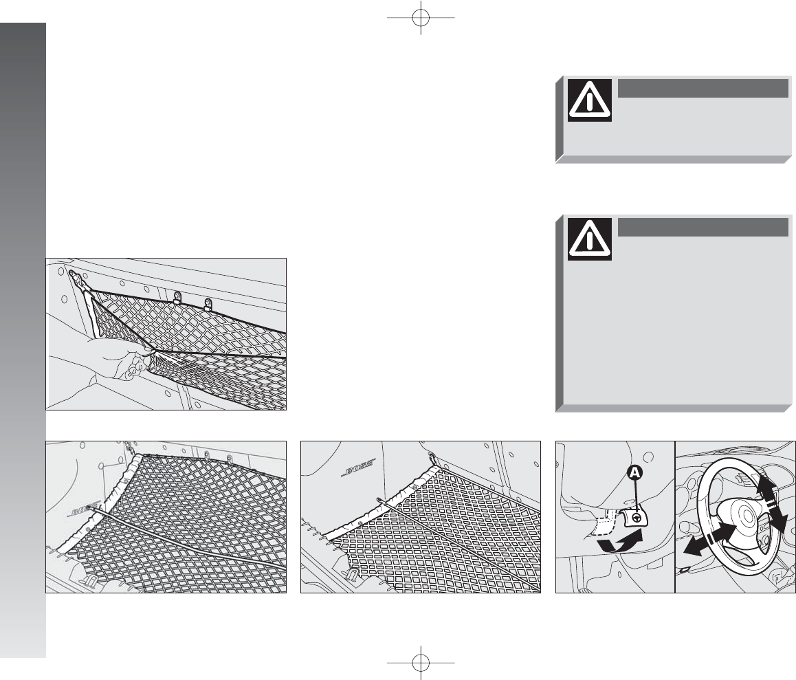
STEERING WHEEL
ADJUSTMENTS
The driver can adjust the steering wheel
position in rake and height.
To do this, release the lever (A-fig. 32)
pulling it towards the steering wheel.
After moving the steering wheel to the
most suitable position, lock it pushing the
lever fully forwards.
fig. 32
A0A1049m
The steering wheel position
must only be adjusted with
the car stationary.
WARNING
It is absolutely forbidden to
carry out aftermarket oper-
ations on the car which would tam-
per with the steering wheel or col-
umn (for example the installation of
the antitheft system) and might
cause not only the system and war-
ranty decay, but also serious safe-
ty problems and alter the car type-
approval compliance.
WARNING
LUGGAGE RETAINING
NET
Fitted only on some versions, the luggage
retaining net is useful for the correct posi-
tioning of the load and/or the transport of
light materials. The following figures 29,
30, 31 illustrate the different net fasten-
ing solutions in the luggage compartment.
fig. 29
A0A0326m
fig. 30
A0A0327m
001-057 Alfa 147 Q2 GB 4-07-2008 11:58 Pagina 24
GETTING TO KNOW YOUR CAR
25
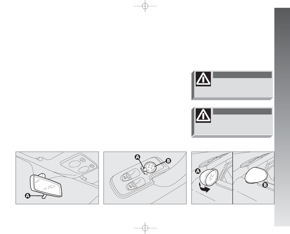
Folding (fig. 35)
– If necessary (for example when the size
of the mirror causes difficulty in narrow
spaces) the door mirror can be folded in to-
wards the car from position (A) to position
(B).
fig. 35
A0A0041m
OUTER
Electric adjustment (fig. 34)
– use the switch (A) to select the mirror
required (right or left);
– pressing the button (B) in one of the
four directions, move the mirror selected pre-
viously;
– position the switch (A) in the interme-
diate locking position.
IMPORTANT Adjustment is possible on-
ly with the ignition key at MAR.
fig. 34
A0A0040m
When travelling the door
mirrors must always be in
position (A).
WARNING
As the driver’s door mirror
is curved, it may slightly
alter the perception of distance.
WARNING
REAR-VIEW MIRROR
ADJUSTMENT
INNER
The mirror, fitted with a safety device that
causes it to be released in the event of a
violent crash, can be moved using the lever
(A-fig. 33) to two different positions, nor-
mal or antiglare.
On some versions/markets the mirror is
automatically set in the position for the
day/night use.
fig. 33
A0A0039m
001-057 Alfa 147 Q2 GB 4-07-2008 11:58 Pagina 25
GETTING TO KNOW YOUR CAR
26
fig. 37
A0A0043m
POWER WINDOWS
IMPORTANT With the ignition key at
STOP or removed, the power windows can
be opened for about 3 minutes and imme-
diately deactivate at opening of one of the
doors.
3-DOOR VERSIONS
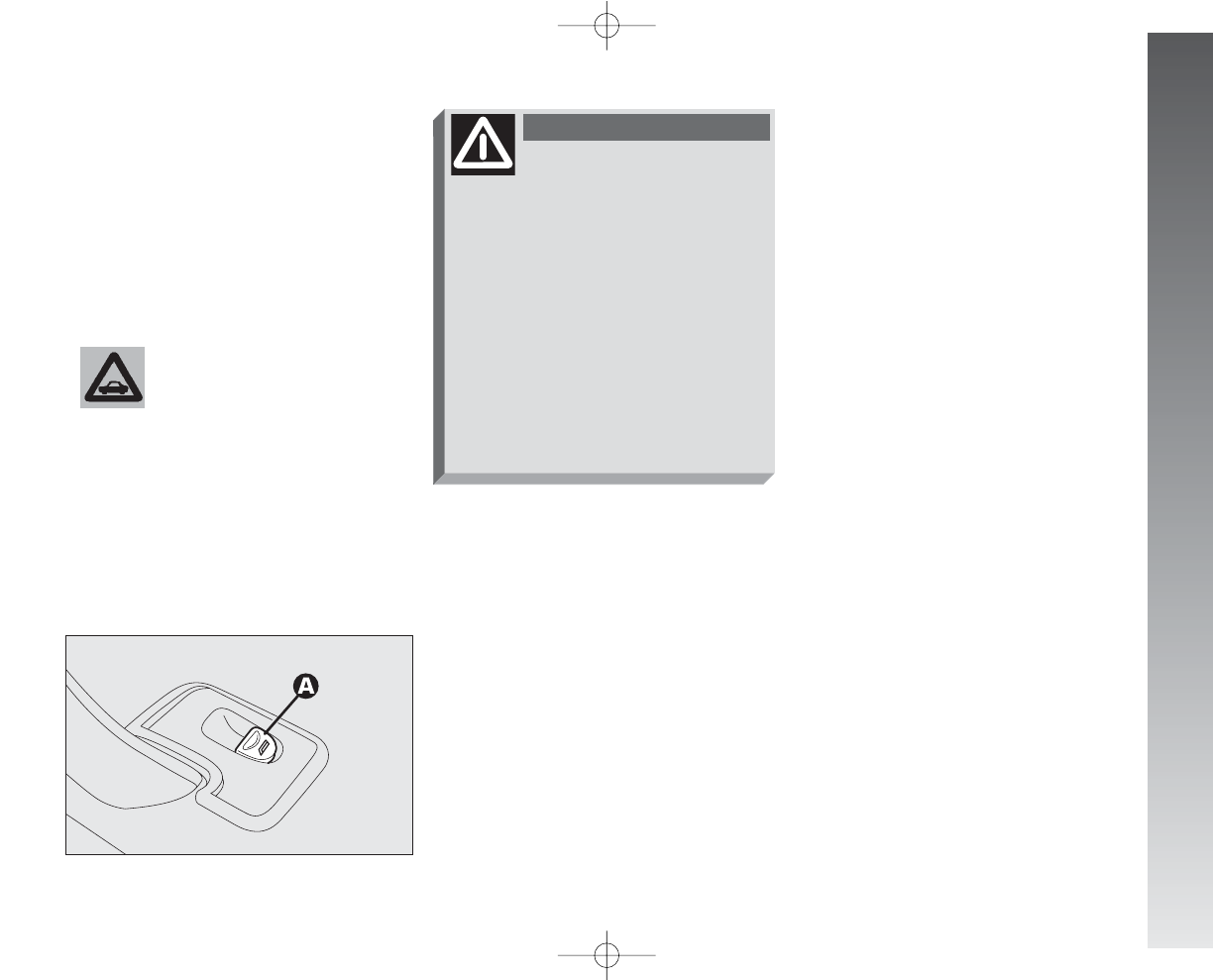
Driver’ side (fig. 37)
The driver’s door panel contains the but-
tons that control the following windows,
with the ignition key at MAR:
A- left front window
B- right front window.
Press the button to lower the window. Pull
to raise it.
IMPORTANT The driver’s power window
is fitted with the “continuous automatic op-
eration” device for both lowering and raising
the window. A brief press on the upper or
lower part of the button will cause it to move
and continue automatically: the window
stops in the required position by pressing ei-
ther the upper or lower part of the button
again.
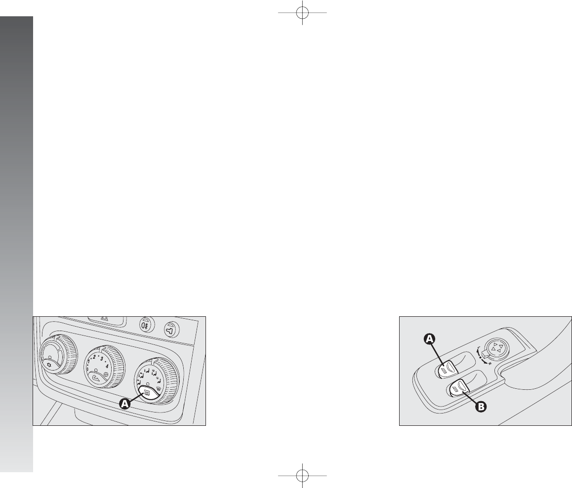
Defrosting/demisting (fig. 36)
The electric mirrors are fitted with heat-
ing coils which come into operation with
rearscreen heating pressing the button (A)
thereby defrosting and/or demisting the mir-
rors.
IMPORTANT The function is timed and
automatically switched off after a few min-
utes.
fig. 36
A0A0042m
001-057 Alfa 147 Q2 GB 4-07-2008 11:58 Pagina 26
GETTING TO KNOW YOUR CAR
27
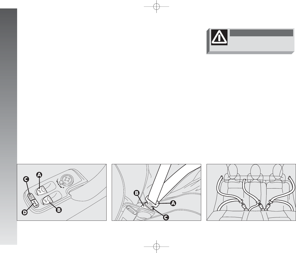
5-DOOR VERSIONS
Front door on driver’s side
(fig. 39)
The driver’s door panel plate contains the
buttons which, with the ignition key at
MAR, operate the following windows:
A– left front/rear window
B– right front/rear window.
Press the button to lower the window. Pull
to raise it.
IMPORTANT The driver’s power window
is fitted with the “continuous automatic op-
eration” device for both lowering and raising
the window. A brief press on the upper or
lower part of the button will cause it to move
and continue automatically: the window
stops in the required position by pressing ei-
ther the upper or lower part of the button
again.
Incorrect use of the power
windows can be danger-
ous. Before and during operation
of them always make sure that the
passengers are not exposed to the
risk of harm caused either directly
by the windows in motion or by
personal objects drawn or knocked
by them. When leaving the car al-
ways remove the ignition key to
prevent passengers (especially chil-
dren) from being injured by the
power windows inadvertently op-
erated.
WARNING
IMPORTANT On some versions after
unlocking the doors, keeping the relevant
button on the remote control pressed for
about 2 seconds will cause the windows to
open. It is necessary to keep the remote
control button pressed until the windows
have reached the full travel; releasing the
button before the windows reach the limit
switch, they will stop in the position they
are at that moment.
fig. 38
A0A0044m
Passenger’s side (fig. 38)
The button (A) controls the passenger’s
side window.
IMPORTANT The passenger’s window
is fitted with a device for “continuous au-
tomatic operation” only for lowering it.
Do not keep the button
pressed when the window
is completely raised or
lowered.
001-057 Alfa 147 Q2 GB 4-07-2008 11:58 Pagina 27
GETTING TO KNOW YOUR CAR
28
SEAT BELTS
USING THE SEAT BELTS
The belt should be worn keeping the chest
straight and rested against the seat back.
Fasten the belt by inserting the tab
(A-fig. 40) into the clip (B), until hear-
ing the locking click.
At removal, if it jams, let it rewind for a
short stretch, then pull it out again without
jerking.
To unfasten the seat belts, press button (C).
Guide the seat belt with your hand while it
is rewinding, to prevent it from twisting.
fig. 40
A0A0045m
Through the reel, the belt automatically
adapts to the body of the passenger wear-
ing it, allowing freedom of movement.
When the car is parked on a steep slope
the reel mechanism may block; this is nor-
mal. The reel mechanism prevents the wee-
bing coming out when it is jerked or if the
car brakes sharply, in a collision or when cor-
nering at high speed.
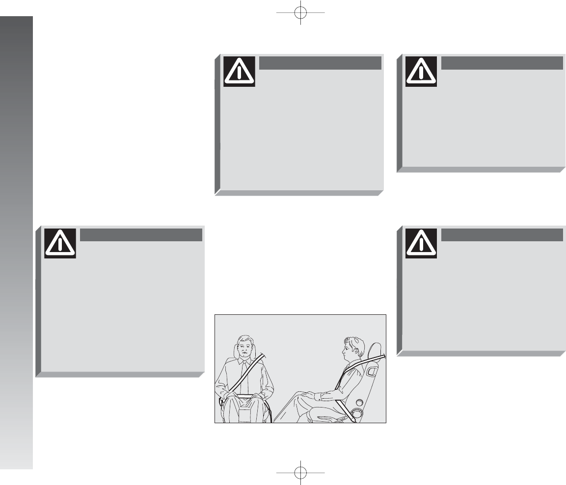
Rear seat belts shall be worn as shown in
fig. 41.
IMPORTANT The centre rear seatbelt is
installed on request only for versions/mar-
kets on which it is required.
Never press button (C)
when travelling.
WARNING
fig. 41
A0A1008m
fig. 39
A0A1007m
Fitted only on some versions:
C– rear door window control inhibitor
(with the inhibitor activated the button led
is on, press again to renable the rear but-
tons).
D– (REAR) front/rear window control
switch (with the button led on, the buttons
(A) and (B) operate the rear windows, with
the led off, they operate the front windows).
Front door on passenger’s side
and (on some versions) rear doors
(fig. 38)
On each door panel plate there is a button
(A) which controls the related window.
IMPORTANT The passenger’s window
is fitted with a device for “continuous au-
tomatic operation” only for lowering it.
001-057 Alfa 147 Q2 GB 4-07-2008 11:58 Pagina 28
GETTING TO KNOW YOUR CAR
29
When the rear seats are not occupied the
appropriate spaces between the backrest
and cushion should be used to stow the seat
belt clips neatly.
Remember that in the event
of an accident, any passen-
gers occupying the rear seats who
are not wearing a seat belt not on-
ly subject themselves to great per-
sonal risk, but constitute a danger
to the occupants of the front seats.
WARNING
fig. 42
A0A1074m
The correct locking of the
backrest is ensured by the
disappearance of the “red band”
(B-fig. 42) on the backrest tilting
levers (A). If the “red band” is still
visible it means that the backrest
is not correctly locked. When
restoring its normal using position
make sure you hear the backrest
click into position.
WARNING
Check that the backrest is
correctly locked on both
side (“red bands” (B-fig. 42) not
visible) to prevent the backrest
from tilting and injuring passengers.
WARNING
After putting the backrest
into its normal position af-
ter tilting, make sure the seat belts
are positioned correctly for use .
WARNING
To offer the highest level of
protection, the rear seat
belts should be fastened as shown
in fig. 41.
WARNING
001-057 Alfa 147 Q2 GB 4-07-2008 11:58 Pagina 29
GETTING TO KNOW YOUR CAR
30
FRONT SEAT BELT HEIGHT
ADJUSTMENT
(upon request for versions/markets
where applicable)
The height of the seat belt attachment
should always be adjusted to suit the height
of the person wearing the seat belt. This pre-
caution makes it possible to improve the ef-
ficiency of the seat belt which greatly reduces
the risk of injury in the event of an accident.
The correct adjustment is obtained when
the belt passes about half way between the
tip of the shoulder and the neck.
fig. 43
A0A0419m
After adjustment, always
check that the slider (B-fig.
43) is anchored in one of the po-
sitions provided. To do this, with
the grip (A-fig. 43) released, ex-
ert a further pressure to allow the
anchor device to catch if release did
not take place at one of the pre-
set positions.
WARNING
The height of the seat belts
shall always be adjusted
with the car stationary.
WARNING
LOAD LIMITERS
To increase passive safety, the front seat
belt reels contain a load limiter which allows
controlled sag in such a way as to dose the
force acting on the shpulder during the belt
restraining action.
The ring attached to the front seat belts
can be moved to several positions allowing
the belts to be adjusted.
To adjust the attachment, raise or lower
the grip (A-fig. 43) of the locking device,
at the same time moving the ring (B) to the
most appropriate of the allowed positions.
001-057 Alfa 147 Q2 GB 4-07-2008 11:58 Pagina 30
GETTING TO KNOW YOUR CAR
31
PRE-TENSIONING DEVICES
To increase the efficiency of the front seat
belts, the car is fitted with pre-tensioning de-
vices. These devices “feel” that the car is
being subject to a violent impact by way of
a sensor and rewind the seat belts a few
centimetres. In this way they ensure that
the seat belt adheres to the wearer before
the restraining action begins.
The seat belt locks to indicate that the pre-
tensioner has intervened; the seat belt can-
not be drawn back up even when guiding
it manually.
IMPORTANT The pretensioner will give
maximum protection when the seat belt ad-
heres snugly to wearer’s chest and hips.
A small amount of smoke may be pro-
duced. This smoke is in no way toxic and
presents no fire hazard.
The pretensioner needs no maintenance or
lubrication. Any modification to its original
features will nullify the retractor’s effective-
ness. If, due to unusual natural events
(floods, high waves, etc.), the device has
been affected by water and mud, it must be
replaced.
Operations involving
banging, vibrations or
heating (above 100°C for
a maximum of 6 hours) in the area
of the pretensioners may damage
or trigger off the device. Vibrations
from rough road surfaces or acci-
dental jolting caused by mounting
pavements etc. do not have any ef-
fect on the pretensioner. If, how-
ever, you need assistance, go to Al-
fa Romeo Authorised Services.
Pre-tensioning devices can
only be used once. After
they have been triggered contact
Alfa Romeo Authorised Services to
have them replaced. The validity of
the device is shown on the plate
fitted on the front left door near
the lock; the pretensioners should
be changed at an Alfa Romeo Au-
thorised Service as this date ap-
proaches.
WARNING
Never disassemble or tam-
per with the pretensioner
components. All interventions must
be carried out by qualified and au-
thorised personnel. Always contact
Alfa Romeo Authorised Services.
WARNING
001-057 Alfa 147 Q2 GB 4-07-2008 11:58 Pagina 31
GETTING TO KNOW YOUR CAR
32
GENERAL INSTRUCTIONS
FOR THE USE OF THE SEAT
BELTS
All the occupants of the car are obliged to
respect the local traffic laws regarding the
wearing of seat belts.
Always fasten the seat belts before start-
ing off.
fig. 44
A0A0050m
To ensure the highest de-
gree of protection, you are
recommended to keep the seat
backrest in the straightest position
possible, and the belt adhering well
to the chest and pelvis.
Seat belts should always be worn
in both the front and rear positions!
Travelling without seat belt in-
creases the risk of serious injury or
death in the case of accident.
WARNING
The seat belt must not be
twisted and should cling
tightly to the body. The upper part
must pass over the shoulder and
diagonally across the chest. The
lower part must rest across the
pelvis (fig. 44) and not across the
stomach. Do not use devices (clips,
stoppers, etc.) which keep the belts
away from the body.
WARNING
Under no circumstances
should the components of
the seat belts and pretensioner be
tampered with or removed. Any
operation should be carried out by
qualified and authorised personnel.
Always contact an Alfa Romeo Au-
thorised Service.
WARNING
If the seat belt has been
subjected to shock, for ex-
ample during an accident, it must
be completely replaced together
with the attachments and their
screws, and the pretensioning de-
vices, even if visible defects are not
detected as the belt may have lost
its resilience.
WARNING
001-057 Alfa 147 Q2 GB 4-07-2008 11:58 Pagina 32
GETTING TO KNOW YOUR CAR
33
Seat belts are also to be worn by expect-
ing mothers: the risk of injury in the case
of accident is greatly reduced for them and
the unborn child if they are wearing a seat
belt.
Pregnant women must of course position
the lower part of the belt very low down
so that it passes under the abdomen (fig.
46).
HOW TO KEEP
THE SEAT BELTS
ALWAYS IN EFFICIENT
CONDITIONS
– Always use the belts with the tape well
taut and never twisted; make sure that it
is free to run without impediments.
– After a serious accident, replace the belt
being worn at that time, even if it does not
appear damaged. Always replace the seat
belts if pretensioners have been activated.
– To clean the belts, wash by hand with
natural soap, rinse and leave to dry in the
shade. Never use strong detergents, bleach
or dyes or any other chemical substance that
might weaken the fibres.
– Prevent the reels from getting wet: cor-
rect operation of them is only guaranteed
if water does not get inside.
– Replace the seat belt if it shows signif-
icant wear or cut signs.
fig. 45
A0A0051m
fig. 46
A0A0052m
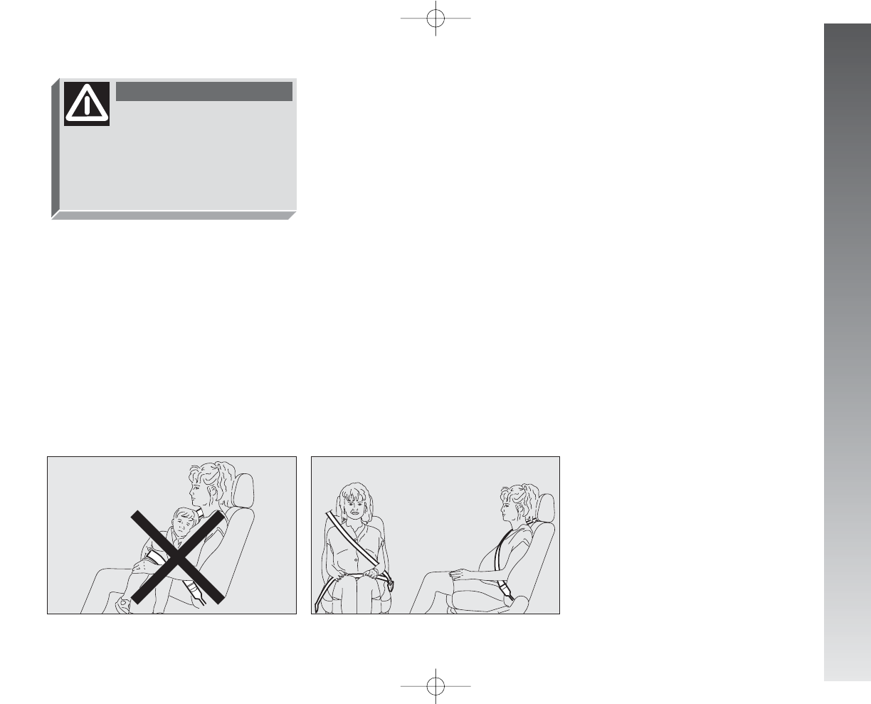
Each seat belt must be
worn by one person only;
do not carry children on your knee
using a single seat belt for both
(fig. 45). Do not fasten other ob-
jects to the body.
WARNING
001-057 Alfa 147 Q2 GB 4-07-2008 11:58 Pagina 33
GETTING TO KNOW YOUR CAR
34
CARRYING CHILDREN SAFELY
For the best level of protection in the event
of a crash, all occupants must travel seated
and secured by suitable restraint systems.
This is even more important for children.
This prescription is mandatory, according
to directive 2003/20/EC, in every country
of the European Union.
Compared with adults, a child’s head is pro-
portionately larger and heavier than the rest
of the body, while muscles and bone struc-
ture are not completely developed. There-
fore, in order to restrain them correctly in
the event of a crash, different systems are
needed than adult seat belts.
fig. 47
A0A0388m
SERIOUS DANGER! If
it is necessary to car-
ry a child on the front passenger’s
seat with the cradle child’s seat fac-
ing opposite the travelling direction,
the passenger’s air bag must be de-
activated through the key switch and
its deactivation must be checked
through the related warning light
F
on the instrument panel (see
paragraph “Front passenger’s air
bag”). In addition, the front passen-
ger’s seat shall be adjusted in the
most backward position to prevent
any contact between the child’s seat
and the dashboard.
WARNING
Never place cradle child’s
seats on the front passen-
ger’s seat of cars equipped with
passenger’s air bag since the air
bag activation could cause serious
injuries, event mortal. You are ad-
vised to cary children always on
the rear seat, as this is the most
protected position in the case of a
crash.
WARNING
001-057 Alfa 147 Q2 GB 4-07-2008 11:58 Pagina 34
GETTING TO KNOW YOUR CAR
35
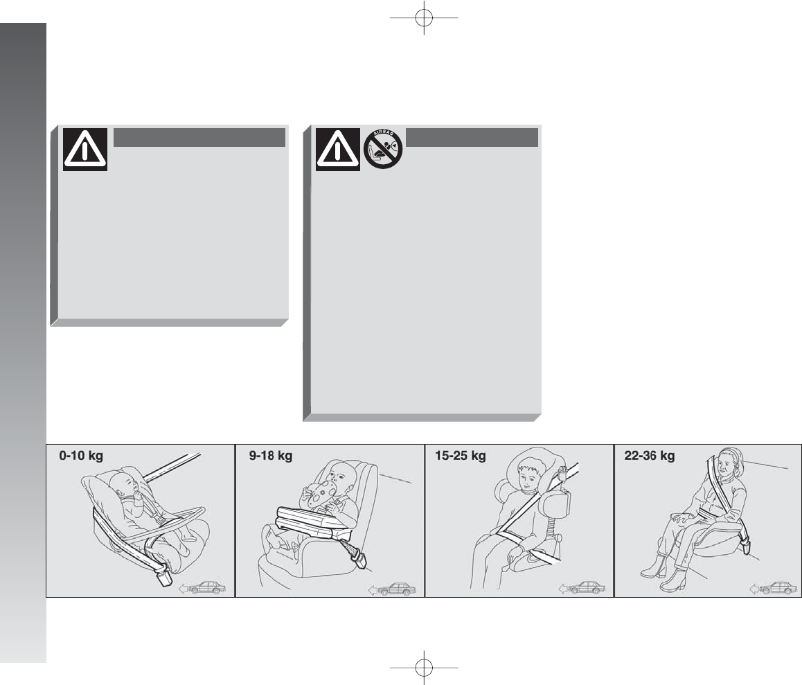
The results of research on the best pro-
tection for a child are summarised in Euro-
pean Standard ECE-R44, which in addition
to making them compulsory, subdivides re-
straint systems into five groups:
Group 0 - until 10 kg in weight
Group 0+ - until 13 kg in weight
Group 1 9-18 kg in weight
Group 2 15-25 kg in weight
Group 3 22-36 kg in weight
As it may be noted, the groups partially
overlap and in fact, in commerce it is pos-
sible to find devices that cover more than
one weight group (fig. 47).
All the restraint devices must bear the ho-
mologation data, together with the control
brand, on a solidly fixed label which must
absolutely not be removed.
Over 1.50 m in height, from the point of
view of restraint systems, children are con-
sidered as adults and wear belts normally.
The Lineaccessori Alfa Romeo includes
seats for each weight group, which are the
recommended choice because they have
been designed and specifically experiment-
ed for Alfa Romeo cars.
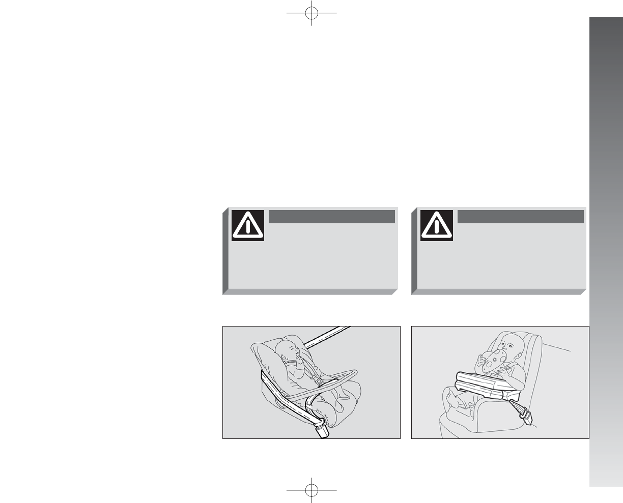
GROUP 0 and 0+
Babies up to 13 kg must be carried fac-
ing behind (fig. 48) on a cradle seat,
which supprting the head, does not induce
strain on the neck in the event of sharp de-
celeration.
The cradle is restrained by the car safety
belts, as illustrated, and it should in turn
restrain the child with the belts incorporat-
ed on it.
GROUP 1
Starting from 9 to 18 kg in weight, chil-
dren may be carried facing forwards with
seats fitted with front cushion (fig. 49),
through which the car seat belts restrains
both child and seat.
fig. 48
A0A0389m
fig. 49
A0A0390m
The illustration is indicative
only for assembly. Assem-
ble the seat according to the com-
pulsory instructions provided with
it.
WARNING
The illustration is indicative
only for assembly. Assem-
ble the seat according to the com-
pulsory instructions provided with
it.
WARNING
001-057 Alfa 147 Q2 GB 4-07-2008 11:58 Pagina 35
GETTING TO KNOW YOUR CAR
36
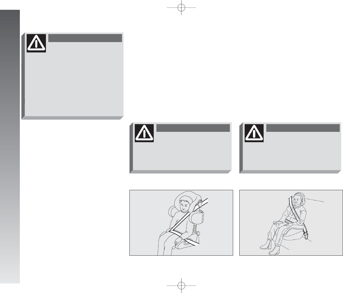
GROUP 2
Starting from 15 to 25 kg in weight, chil-
dren may be restrained directly by the car
seat belts. Child seats only have the func-
tion of positioning the child correctly in re-
lation to the belts, so that the diagonal part
adheres to the chest and never to the neck
and that the horizontal part adheres to the
child’s pelvis and not to the abdomen (fig.
50).
GROUP 3
For children from 22 up to 36 kg the child’s
chest is thick enough not to need the spac-
er back rest any more.
Fig. 51 shows proper child’s seat posi-
tioning on the rear seat.
Over 1.50 m in height, children may wear
seat belts like adults.
fig. 50
A0A0391m
fig. 51
A0A0392m
Seats exist which are suit-
able for covering weight
groups 0 and 1 with a rear con-
nection to the car belts and its own
belts to restrain the child. Because
of their mass, they can be danger-
ous if installed incorrectly fastened
to the car belts with a cushion.
Strictly adhere to the assembly in-
structions provided.
WARNING
The illustration is indicative
only for assembly. Assem-
ble the seat according to the com-
pulsory instructions provided with
it.
WARNING
The illustration is indicative
only for assembly. Assem-
ble the seat according to the com-
pulsory instructions provided with
it.
WARNING
001-057 Alfa 147 Q2 GB 4-07-2008 11:58 Pagina 36
GETTING TO KNOW YOUR CAR
37
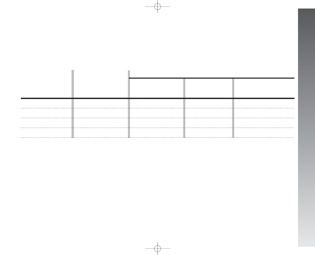
PASSENGER’S SEAT COMPLIANCE WITH REGULATIONS ON CHILD’S SEAT USE
Vehicle complies with the new EC Directive 2000/3 regulating child’s seat assembling on the different car seats according to the following
table:
Rear seat for 3 and 5-door versions
Key:
U= suitable for child’s restraint systems of the “Universal” category, according to European Standard ECE-R44 for the specified “Groups”
L= suitable for certain child’s restraint systems at Lineaccessori Alfa Romeo for the specified group
U
U
U
U
U
U
U
U
L
L
L
L
up to 13 kg
9 -18 kg
15 - 25 kg
22 - 36 kg
Group Range of weight SEAT
Front passenger Rear passenger Rear passenger
side centre (inertial
seat belt with three anchor points)
Group 0,0+
Group 1
Group 2
Group 3
001-057 Alfa 147 Q2 GB 4-07-2008 11:58 Pagina 37
GETTING TO KNOW YOUR CAR
38
Below is a summary of the safe-
ty rules to be observed when car-
rying children:
1) The recommended position for in-
stalling a child’s seat is on the rear seat, as
it is the most protected in the event of a
crash;
2) If the passenger’s Air bag is deactivat-
ed (upon request for versions/markets
where applicable) always check the warn-
ing light
F
on the cluster to make sure
that it has actually been deactivated.
3) Carefully follow the instructions pro-
vided with the child’s seat, which the sup-
plier is obliged to attach. Keep them in the
car together with the documents and this
booklet. Do not use used seats without the
instructions for use.
4) Always pull the tape to check that the
belts are buckled.
5) All restraint systems are strictly for one
child only: never use for two children at the
same time.
6) Always make sure that the belts do not
rest on the child’s neck.
7) During the journey, do not allow the
child to stay in abnormal positions or release
the belts.
8) Do not carry children in your arms, not
even small babies. No-one, however strong,
can keep hold of them in a crash.
9) In the case of accidents, replace the
child’s seat with a new one.
FRONT AND SIDE
AIR BAGS
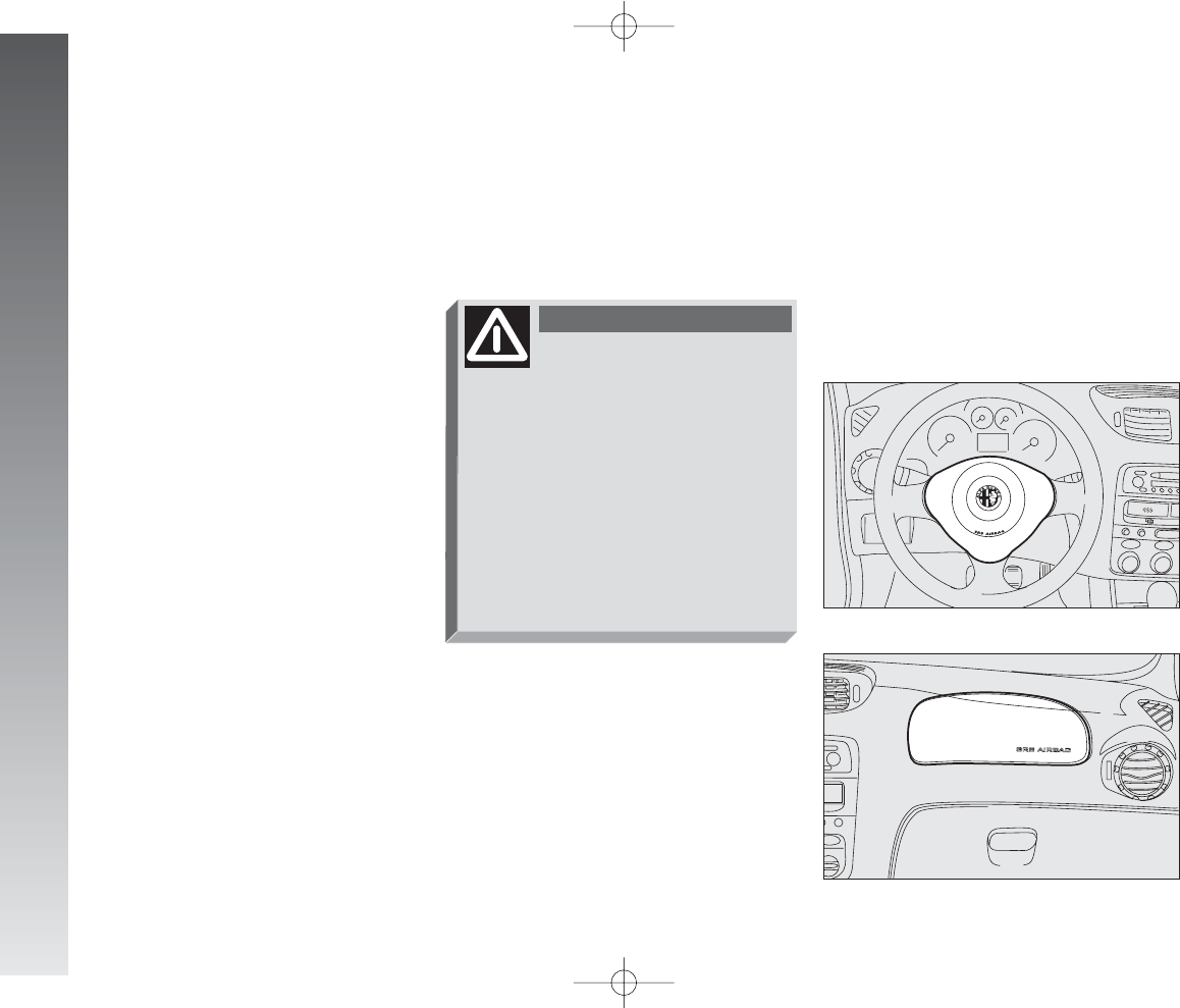
The car is fitted with front Air bags for the
driver (fig. 52, for the passenger (fig. 53,
side bags (fig. 54) and window bags (fig.
55).
fig. 52
A0A1009m
fig. 53
A0A0057m
If the passenger’s Air bag
is activated, children should
never travel on the front seat. The
activation of the air bag in the
event of a crash may cause mor-
tal injuries to the child regardless
of the crash severity. Therefore
you are recommended to carry chil-
dren always on the child’s restraint
system on the rear seat, as it is the
most protected in the event of a
crash.
WARNING
001-057 Alfa 147 Q2 GB 4-07-2008 11:58 Pagina 38
GETTING TO KNOW YOUR CAR
39
It is formed of an instantly-inflating cush-
ion contained in a special recess:
– in the centre of the steering wheel for
the driver;
– in the dahsboard and with a larger-sized
cushion for the passenger.
The front Air bag (driver’s and passenger’s)
is a device designed to protect the occupants
in the event of a head-on collision of medi-
um-high severity by the interposition of the
cushion between the occupant and the steer-
ing wheel or dashboard.
In the event of a crash, the electronic con-
trol unit processes the signals leading from
a deceleration sensor and when necessary
triggers inflation of the cushion.
The cushion inflates instantly as a protec-
tive barrier between the occupants’ bodies
and the structures which could cause injury.
The cushion deflates immediately after-
wards.
The front Air bag (driver’s and passenger’s)
does not replace but is complementary to
the use of belts, which should always be
worn, as specifed by law in Europe and most
non-European countries.
In the event of a crash a person that is not
wearing the seat belt moves forwards and
may come into contact with the cushion
while it is still opening. Under these cir-
cumstances the protection offered by the
cushion is reduced.
Front Air bags are designed to protect car’s
occupants in front crashes and therefore non-
activation in other types of collisions (side
collisions, rear-end shunts, roll-overs, etc...)
is not a system malfunction.
In collisions against highly deformable or
mobile objects (road signposts, heaps of ice
or snow, etc.), rear collisions (hit from be-
hind by another car), side collisions, wedg-
ing under other cars or protective barriers
(for example under a lorry or guard rail) cut-
ting in of the air bag is not activated as it
does not offer any more protection than the
seat belts, therefore activaton would be in-
appropriate.
Therefore the failure to be triggered does
not mean that the system is not working.
FRONT AIR BAGS
Description and operation
The front Air bag (driver’s and passenger’s)
is a safety device that comes into action in
the event of a head-on collision.
fig. 54
A0A1010m
fig. 55
A0A1011m
Never put stickers or other
objects on the steering wheel,
on the cover of the passenger’s Air
bag or on the right side cover of the
roof. Never put objects on the dash-
board in front of the passenger (for
example mobile phones) which might
interfere with the correct inflation of
the passenger’s Air bag and therefore
injure the car’s occupants.
WARNING
001-057 Alfa 147 Q2 GB 4-07-2008 11:58 Pagina 39
GETTING TO KNOW YOUR CAR
40
PASSENGER’S FRONT AIR BAG
The passenger’s front Air bag has been de-
signed to improve the protection of a person
wearing a seat belt. Its volume at maximum
inflation fills most of the space between the
dashboard and the passenger.
fig. 56
A0A0061m
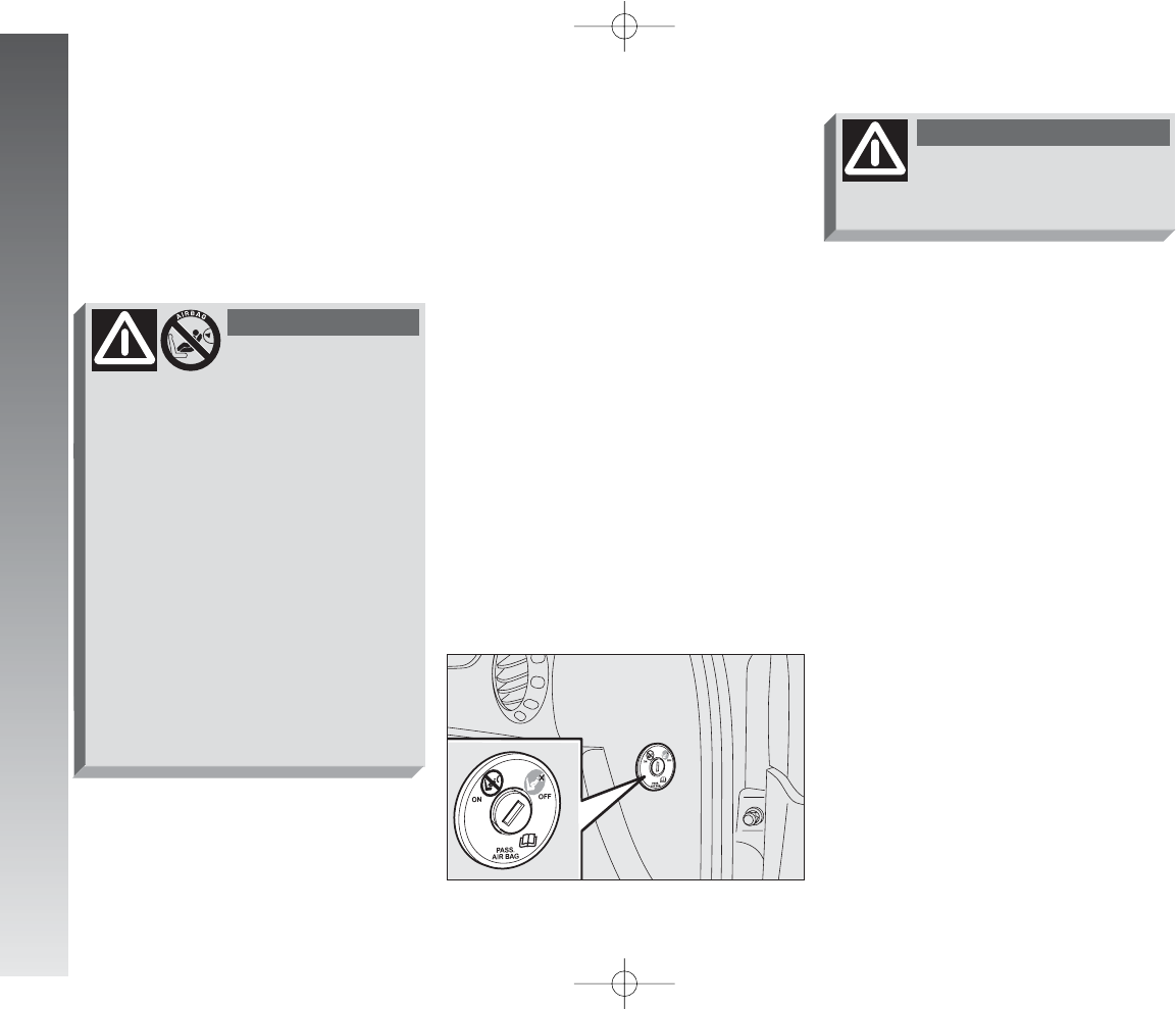
MANUAL DEACTIVATION
OF PASSENGER’S FRONT
AIR BAG
(upon request for versions/
markets where applicable)
Should it be absolutely necessary to car-
ry a child on the front seat, the passenger’s
front air bag can be deactivated.
Deactivation/reactivation takes place with
ignition key at STOP and operating it in
the special key switch on the right-hand side
of the dashboard (fig. 56). Access to the
switch is only possible with the door open.
The key switch (fig. 56) has two posi-
tions:
1) Passenger’s front Air bag active: (ON
position
P
) warning light on check panel
off; it is absolutely prohibited to carry chil-
dren on the front seat.
2) Passenger’s front Air bag deactivated:
(OFF position
F
) warning light on check
panel on; it is possible to carry children pro-
tected by special restraint systems on the
front seat.
The warning light
F
on the check pan-
el glows steadily until the passenger’s Air
bag is reactivated.
Deactivation of the front passenger’s Air
bag does not prevent operation of the side
Air bags.
With the door open the key can be inserted
and removed in both positions.
Use the switch only with
the engine off and the ig-
nition key removed.
WARNING
SERIOUS DANGER:
The car is fitted with
front passenger’s air bag. Never
place cradle child’s seats on the front
passenger’s seat of cars equipped
with passenger’s air bag since the air
bag activation could cause serious in-
juries, even mortal. In the case of
need, always deactivate the pas-
senger’s air bag when a child’s seat
is placed on the front seat. The front
passenger’s seat shall be adjusted in
the most backward position to pre-
vent any contact between child’s seat
and dashboard. Even if not ruled by
law, for better protection of adults
you are recommended to reactivate
the air bag immediately as soon as a
child transport is no longer necessary.
WARNING
001-057 Alfa 147 Q2 GB 4-07-2008 11:58 Pagina 40
GETTING TO KNOW YOUR CAR
41
IMPORTANT The front and/or side air
bags may be activated if the car is subjected
to heavy shocks or accidents that involve the
underbody area, such as for example violent
bumps against steps, pavements or fixed ob-
stacles on the ground, falling into big holes
or bumpy roads.
IMPORTANT The triggering of air bags
releases a small amount of powder. This pow-
der is not harmful and does not indicate a
start of fire; also the surfaces of the deployed
bag and the car interior may be covered with
dusty residue: this may irritate the skin and
eyes. In the event of exposure, wash with
neutral soap and water.
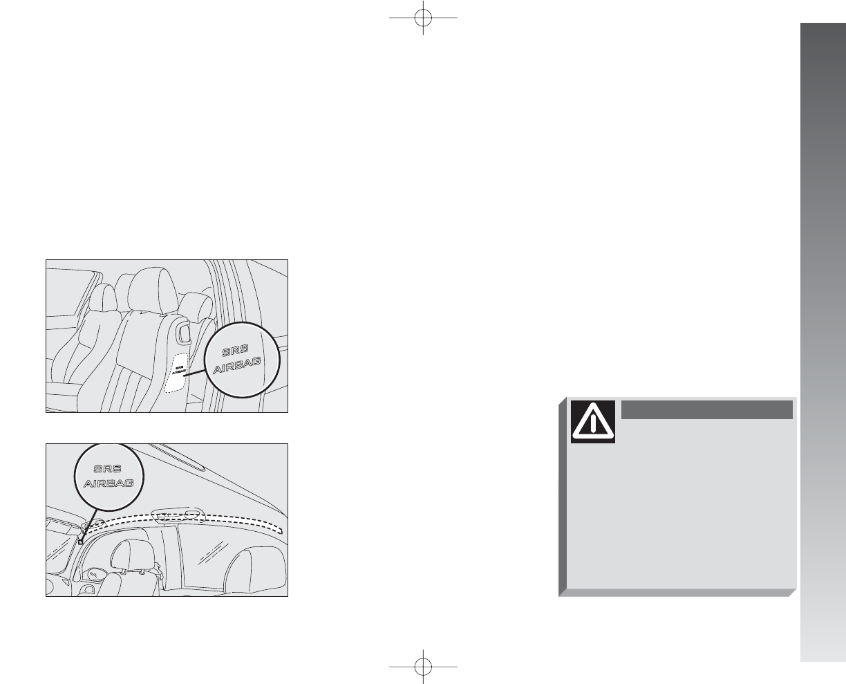
SIDE AIR BAGS
(SIDE BAG - WINDOW BAG)
The side bag and window bag have the
task of increasing protection of the occu-
pants in the event of a side crash of medi-
um-high severity.
They are formed of two types of instanta-
neously-inflating cushions:
– the side bag is housed in the back rest
of the front seats; with this solution it is al-
ways possible to have the cushion in the op-
timum position in relation to the passenger,
regardless of the adjustment of the seat;
– the window bags, which are “curtain”
cushions, are housed in the side roof lining
covered by a special trim, which makes it
possible to extend the cushion downwards.
This solution, designed to protect the head,
makes it possible to offer the highest degree
of protection to the front and rear occupants
in the event of side crash, thanks to the wide
cushion inflation surface.
In the event of a side crash, an electronic
control unit processes the signals leading
from a deceleration sensor and activates,
when necessary, inflation of the bags.
The bags inflate instantaneously, setting
themselves between the body of the front
passengers and the car door. The bags de-
flate immediately afterwards.
In the event of minor side crashes (for
which the restraining action of the seat belts
is sufficient), the air bags are not deployed.
Also in this case it is of vital importance to
wear the seat belts since in case of side
crash they guarantee proper positioning of
the occupant and prevent the occupant to
be pitched out of the car in case of violent
crashes.
Therefore the side air bags do not replace
but are complementary to the use of belts,
which you are recommended to always
wear, as specified by law in Europe and most
non-European countries.
Operation of the side air bags and window
bags is not disabled by the front air bag de-
activation switch, as described in the previ-
ous paragraphs.
IMPORTANT In the event of side crash,
you can obtain the best protection by the
system keeping a correct position on the
seat, thus allowing correct window bag un-
folding.
Never rest head, arms and
elbows on the door, on the
windows and in the window bag
area to prevent possible injuries
during the inflation phase.
WARNING
Never lean head, arms and
elbows out of the window.
WARNING
001-057 Alfa 147 Q2 GB 4-07-2008 11:58 Pagina 41
GETTING TO KNOW YOUR CAR
42
Always keep your hands
on the steering wheel rim
when driving, so that if the Air bag
is triggered, it can inflate without
meeting any obstacles. Do not dri-
ve with the body bent forwards,
keep the seat back rest in the erect
position and lean your back well
against it.
WARNING
If the car has been stolen
or an attempt to steal it
has been made, if it has been sub-
jected to vandals or floods, have
the Air bag system checked by Al-
fa Romeo Authorized Services.
WARNING
Never put stickers or other
objects on the steering wheel,
on the cover of the passenger’s Air
bag or on the right side cover of the
roof. Never put objects on the dash-
board in front of the passenger (for
example mobile phones) which might
interfere with the correct inflation of
the passenger’s Air bag and therefore
injure the car’s occupants.
WARNING
The deadlines concerning the pyrotechni-
cal charge and the twisted contact are
shown on the label placed on the front doors
(lock area). As these deadlines approach go
to Alfa Romeo Authorized Services to have
them replaced.
IMPORTANT If an accident has trig-
gered the air bag, Alfa Romeo Authorized
Services must be contacted to have the de-
vices activated replaced and to have the
whole system checked.
All operations involving checking, repairing
and replacing components concerning the Air
bag must be carried out by Alfa Romeo Au-
thorized Services. If the car is to be demol-
ished, Alfa Romeo Authorized Services should
be contacted beforehand to have the system
deactivated.
If the car changes ownership, the new
owner must be informed of the instructions
for use and of the above warnings and be
given this “Owner’s Manual“.
IMPORTANT The triggering of the pre-
tensioners, front air bags and side bags is
decided by the electronic control unit in a
differentiated manner depending on the type
of crash. The failure to trigger one or more
of them does not necessarily indicate a sys-
tem malfunction.
GENERAL CAUTIONS
If warning light
¬
does
not come on turning the ig-
nition key to MAR or stays on
while travelling, there might be a
failure in the restraining systems;
in this case the air bags or preten-
sioners may not activate in the
event of a crash or, in a more lim-
ited number of cases, may activate
by mistake. Before going on, ask
Alfa Romeo Authorized Services to
check the whole system immedi-
ately.
WARNING
Do not cover the back rest
of the front and rear seats
with trims or covers whose use is
not compatible with Side-bags.
WARNING
Never travel with objects
on your lap, in front of the
chest or with a pipe, pencil, etc. be-
tween your lips. Serious injury may
result in the case of the air bag be-
ing triggered.
WARNING
001-057 Alfa 147 Q2 GB 4-07-2008 11:58 Pagina 42
GETTING TO KNOW YOUR CAR
43
Your are reminded that
when the igntion key is en-
gaged and in the MAR position, the
Air bags can be triggered also on a
stationary car, if it is bumped by
another moving car. Therefore,
even with the car stationary, nev-
er allow children on the front seat.
You are also reminded that with
the car stationary, without the key
engaged and turned, the Air bags
are not triggered in the event of an
impact; in this case the failure to
trigger the air bags should not be
considered a system failure.
WARNING
Turning the ignition key to
MAR the warning light
F
(with the passenger’s front Air bag
deactivation switch at ON) turns
on for about 4 seconds, and then
flashes for another 4 seconds to
remind that the passenger’s Air
bag and corresponding side Air
bags will be activated in the event
of a crash, then it goes off.
WARNING
Do not wash the seat back
with pressurised water or
steam (by hand or at automatic
seat washing stations).
WARNING
The front Air bags are de-
signed to be triggered for
heavier crashes than the preten-
sioners. It is therefore normal for
the pretensioners only to be trig-
gered for crashes within the two
activation thresholds.
WARNING
Do not hook rigid objects to
the coat hooks and to the
support handles.
WARNING
The air bag does not replace
the seat belts, but increases
their effectiveness. Additionally, as
the front air bags are not triggered
for head-on collision at low speed,
side crashes, crashes from behind or
overturning, in these cases the oc-
cupants are protected only by the
seat belts, which must, therefore, al-
ways be fastened.
WARNING
001-057 Alfa 147 Q2 GB 4-07-2008 11:58 Pagina 43
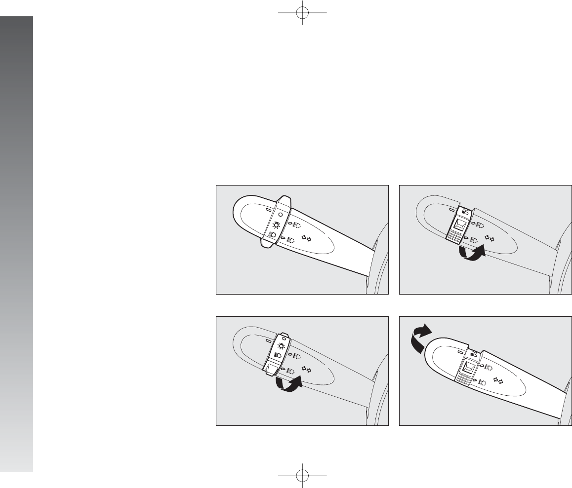
GETTING TO KNOW YOUR CAR
44
Main beams (fig. 60)
To turn the main beams on, set the knurled
ring to position
2
and push the lever to-
wards the dashboard (stable position);
warning light
1
on the instrument panel
will turn on.
To set dipped-beams back pull the lever to-
wards the steering wheel.
fig. 59
A0A0065m
fig. 60
A0A0066m
STEERING WHEEL
LEVERS
The devices and services controlled by the
levers on the steering wheel can only be ac-
tivated with the ignition key at MAR.
LEFT-HAND LEVER
The left-hand lever controls the outer lights
except for the fog lamps and rear fog
guards.
When the outer lights are switched on, the
various controls on the dashboard are illu-
minated.
Only with the ignition key at PARK, re-
gardless of the position of the knurled ring,
the sidelights and number plate lights stay
on.
Position (1or 2-fig. 62) of the lever
causes the turning on only of the sidelights
(front and rear), on the right or left respec-
tively.
Lights switched off (fig. 57)
When the pointer in the knurled ring is op-
posite the symbol O, the outer lights are
switched off.
Sidelights (fig. 58)
The sidelights are switched on by turning
the knurled ring from Oto
6
.
The
3
warning light on the instrument
cluster will come on at the same time.
Dipped-beam headlights (fig. 59)
These are switched on by turning the
knurled ring from
6
to
2
.
fig. 57
A0A0063m
fig. 58
A0A0064m
001-057 Alfa 147 Q2 GB 4-07-2008 11:58 Pagina 44
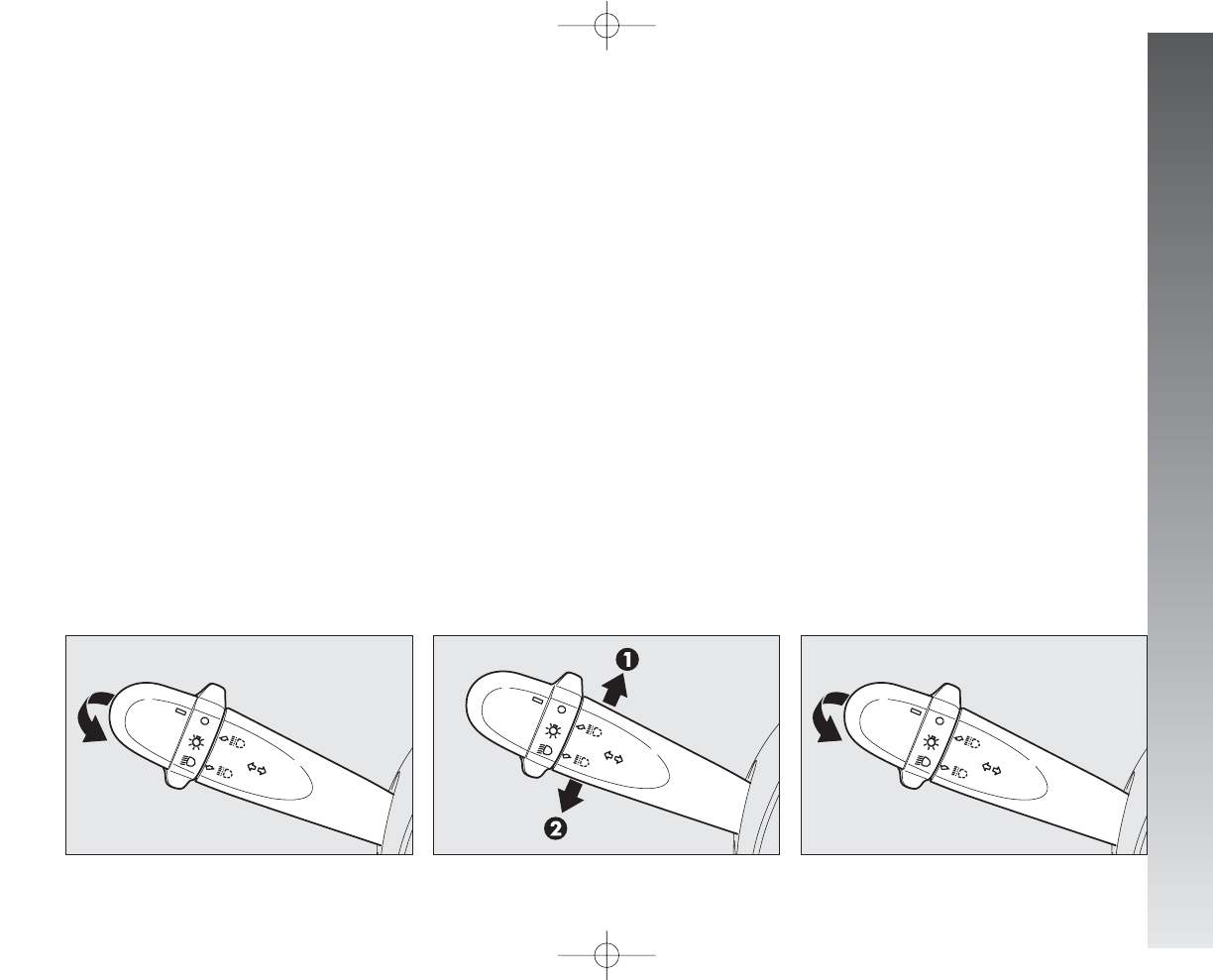
GETTING TO KNOW YOUR CAR
45
Flashing (fig. 61)
The headlights are flashed pulling the lever
towards the steering wheel (instable posi-
tion) regardless of the position of the
knurled ring. The
1
warning light on the
cluster will come on at the same time.
IMPORTANT Only the main-beam lights
are flashed. To avoid penalties follow local
regulations.
Direction indicators
(fig. 62)
Regardless of the position of the knurled
ring, moving the lever to the stable position
will:
up, position (1) - engage the right-hand
direction indicators.
down, position (2) - engage the left-hand
direction indicators.
When the dipped beam headlights and the
fog lamps are switched on, the outer light
control unit (integrated in the Body Com-
puter) works according to the following log-
ics:
– turning on the main beams, the dipped
beams turn off while the fog lamps stay on,
when restoring the starting condition at
dipped beam setting;
or
– turning on the main beams, the fog
lamps turn off and then turn on again au-
tomatically as the main beams are switched
off.
Therefore, in the event of Body Comput-
er replacement, the outer light operating log-
ic may be different.
fig. 61
A0A0067m
fig. 62
A0A0068m
One of the warning lights (
R
or
E
) will
come on on the instrument cluster at the
same time.
The lever is returned to its position auto-
matically and the indicators are switched off
when the steering wheel is straightened.
IMPORTANT If you wish to signal a
rapid change of direction involving only a
minimal movement of the steering wheel,
the lever can be removed up or down with-
out it clicking (unstable position). When re-
leased, the lever will return to its home po-
sition.
fig. 63
A0A0067m
001-057 Alfa 147 Q2 GB 4-07-2008 11:58 Pagina 45
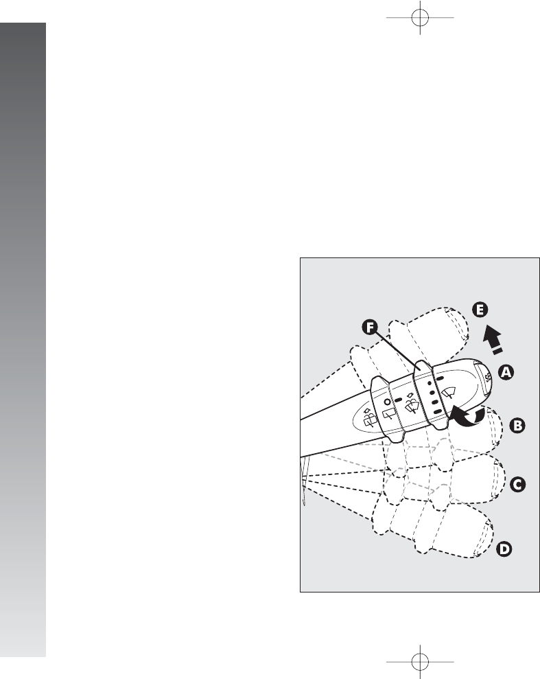
GETTING TO KNOW YOUR CAR
46
With the lever in position (B), turning the
ring (F) four possible intermittent speeds
are obtained:
■
= intermittent slow.
■■
= intermittent medium.
■■■
= intermittent medium-fast.
■■■■
= intermittent fast.
C- Continuous, slow.
D- Continuous, fast.
E- Fast, temporary (unstable position).
Operation in position (E) is limited to the
time the lever is held in this position. When
the lever is released, it returns to position
(A) automatically stopping the wiper.
IMPORTANT When the wiper is on, en-
gaging reverse gear automatically turns on
the rearscreen wiper.
“Follow me home” device
(fig. 63)
This function allows the illumination of the
space in front of the car for the length of
time set, and is activated with the ignition
key at STOP or removed, pulling the left-
hand lever towards the steering wheel.
This function is activated pulling the lever
within 2 minutes from when the engine is
turned off. At each single movement of the
lever, the staying on of the dipped beams
and sidelights is extended by 30 seconds up
to a maximum of 3.5 minutes; the lights
switch off automatically after the time set.
Each time the lever is operated, the
1
warning light on the cluster turns on.
This function can be interrupted by keep-
ing the lever pulled towards the steering
wheel for more than 2 seconds.
RIGHT-HAND LEVER
The right-hand lever is used to operate the
windscreen wiper and windscreen washer.
The control used to activate the windscreen
washers also activates the headlight wash-
ers, if fitted.
Windscreen wiper - Windscreen
washer (fig. 64-65)
The lever can be moved to five different
positions, corresponding to:
A- Windscreen wiper off.
B- Intermittent.
fig. 64
A0A0070m
001-057 Alfa 147 Q2 GB 4-07-2008 11:58 Pagina 46
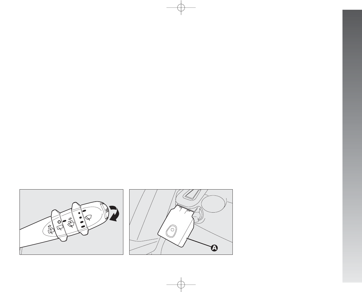
GETTING TO KNOW YOUR CAR
47
Rain sensor (fig. 66)
The rain sensor (A), fitted only on cer-
tain versions, is an electronic device com-
bined with the windscreen wiper which has
the purpose of automatically adjusting the
number of wipes during intermittent opera-
tion to the intensity of the rain.
All the other functions controlled by the
right-hand lever remain unchanged.
The rain sensor is activated automatically
moving the right-hand lever to position (B-
fig. 64) and it has a range of adjustment
that gradually varies between wiper sta-
tionary (no wiping) when the windscreen is
dry, to wiper at first continuous speed (con-
tinuous, slow) with heavy rain.
“SMART WASHING” FUNCTION
Pulling the lever towards the steering
wheel (unstable position) operates the wind-
screen washer.
Keeping the lever pulled, with only one
movement it is possible to operate the wash-
er jet and the wiper at the same time; in-
deed, the latter comes into action auto-
matically if the lever is pulled for more than
half a second.
The wiper stops working a few strokes af-
ter releasing the lever; a further “cleaning
stroke” after a few seconds completes the
wiping operation.
fig. 65
A0A0071m
fig. 66
A0A1012m
Turning the knurled ring (F-fig. 64) it
is possible to increase the sensitivity of the
rain sensor, obtaining a quicker change from
stationary, when the windscreen is dry, to
first continuous speed (continuous, slow).
Operating the windscreen washer with the
rain sensor activated (lever at position B)
the normal washing cycle is performed at
the end of which the rain sensor resumes its
normal automatic function.
Turning the ignition key to STOP the rain
sensor is deactivated and the next time the
engine is started (MAR position) it will not
be reactivated even if the lever has remained
in position (B). In this case to activate the
rain sensor, simply move the lever to (A)
or (C) and then back to (B).
When the rain sensor is reactivated in this
way, the wiper performs at least one stroke,
even if the windscreen is dry, to indicate that
reactivation has occurred.
The rain sensor is located behind the inner
rear-view mirror in contact with the wind-
screen and inside the area cleaned by the
wiper and it controls an electronic control
unit which in turn controls the wiper motor.
001-057 Alfa 147 Q2 GB 4-07-2008 11:58 Pagina 47
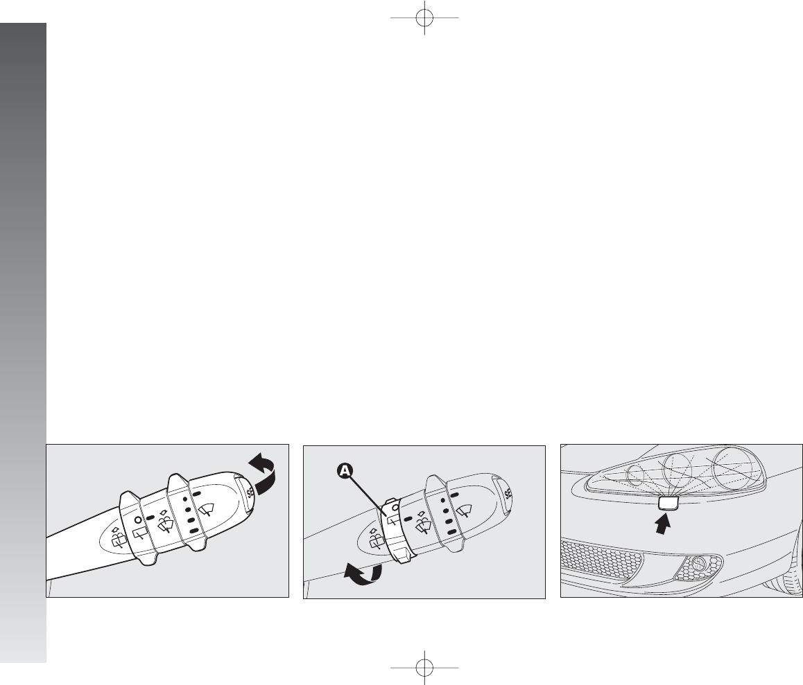
GETTING TO KNOW YOUR CAR
48
Headlamp washers (fig. 69)
These come into operation when the wind-
screen washer is turned on with the
dipped/main beam headlights on.
IMPORTANT On certain versions when
the headlamp washer is operating, the cli-
mate control system automatically engages
inside air re-circulation, to prevent the smell
of liquid detergent from entering the pas-
senger compartment.
fig. 69
A0A1013m
At each start, the rain sensor automatically
stabilises at a temperature of about 40°C
to eliminate any condensation from the con-
trol surface and prevent the formation of ice.
The rain sensor is able to detect and au-
tomatically adapt to the presence of the fol-
lowing particular conditions which require
different sensitivity:
– impurities on the control surface (salt,
dirt, etc.);
– streaks of water caused by worn wiper
blades;
– difference between day and night (the
human eye is more disturbed during the
night by the wet glass surface).
Rearscreen wiper - washer
(fig. 67-68)
Pushing the lever towards the dashboard
(unstable position) operates the rearscreen
washer jet and continous operation of the
rearscreen wiper. Operation ends when the
lever is released.
Turning the knurled ring (A) from position
Oto position
'
operates the rearscreen
wiper intermittently.
The activation of the rear windshield wiper
occurs also with the front windshield wipe
on and reverse gear inserted.
fig. 67
A0A0073m
fig. 68
A0A0075m
001-057 Alfa 147 Q2 GB 4-07-2008 11:58 Pagina 48
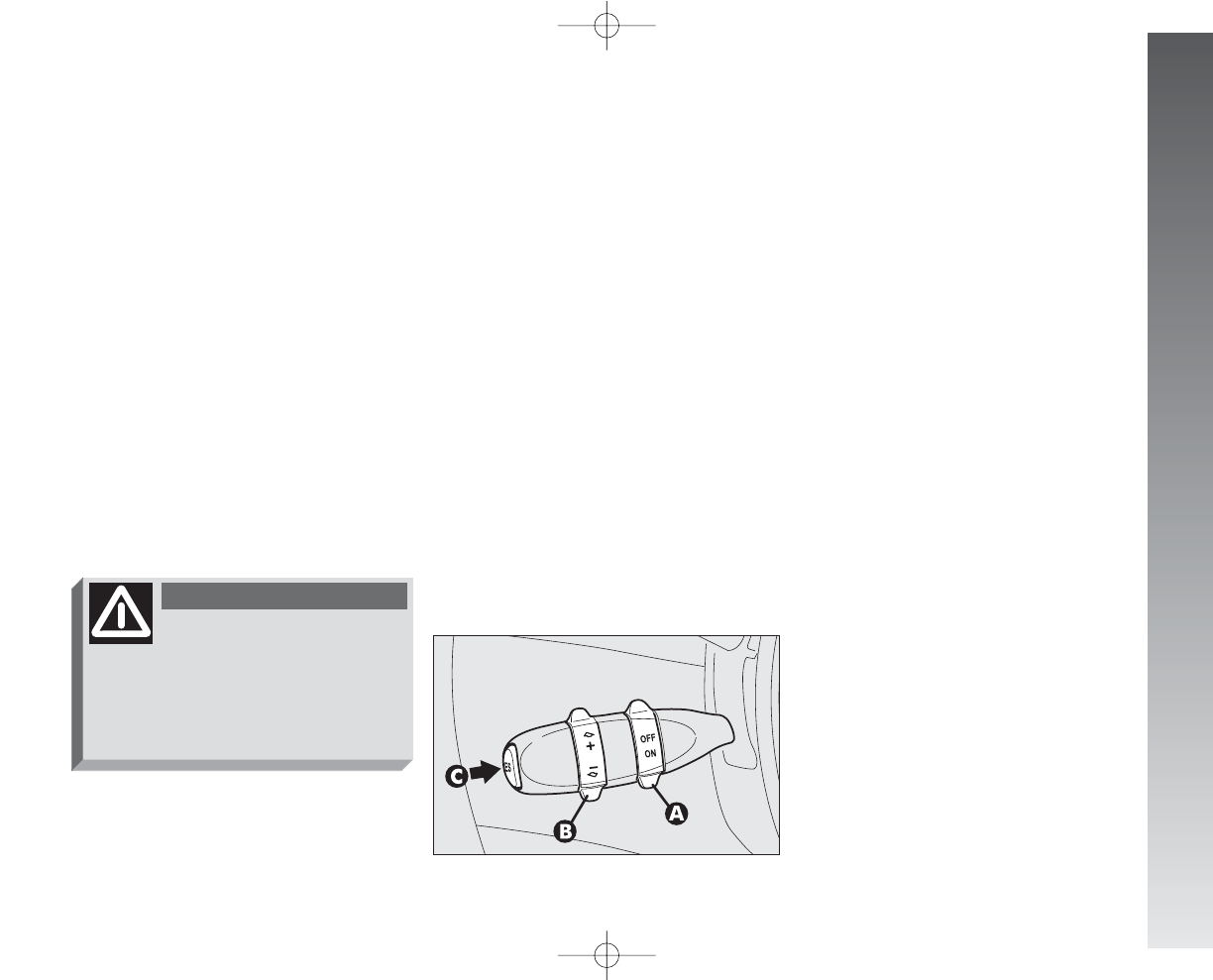
GETTING TO KNOW YOUR CAR
49
The device is disengaged automatically in
any of the following cases:
– pressing the brake pedal;
– pressing the clutch pedal;
– if the ASR, MSR OR VDC systems cut in;
– with Selespeed transmission if a gear is
changed;
– inadvertently moving the Selespeed
gear control lever to N.
CONTROLS
(fig. 70)
Cruise Control is controlled by the
ON/OFF knurled ring (A), by the +/–
ring(B) and by the RES button (C).
Ring (A) has two positions:
–OFF in this position the device is deac-
tivated;
CRUISE CONTROL
GENERAL
The speed regulator (CRUISE CON-
TROL), with electronic control, makes it
possible to drive the car at the required
speed without pressing the accelerator ped-
al. This reduces driving fatigue during long
journeys because the speed memorised is
automatically maintained.
IMPORTANT The device can only be en-
gaged at speeds between 30 and 190
km/h.
fig. 70
A0A0077m
Cruise Control must be ac-
tivated only when the
route and traffic allow a constant
speed for a sufficiently long dis-
tance completely safely.
WARNING
–ON is the normal operating position of
the device. When the ring (A) is in this
position, the warning light
Ü
on the instru-
ment cluster turns on.
Ring (B) serves for memorising and main-
taining the car sped or for increasing or low-
ering the speed memorised.
Turn the ring (B) to (+) to memorise the
speed reached or increase the speed memo-
rised.
Turn the ring (B) to (–) to lower the speed
memorised.
Each time the ring is actuated (B) the speed
increases or lowers by about 1.5 km/h.
Keeping the ring turned the speed changes
continuously. The new speed reached will be
maintained automatically.
The RES button (C) resets the memorised
speed.
IMPORTANT Turning the ignition key to
STOP or the ring (A) to OFF, the speed
memorised is cleared and the system is
switched off.
001-057 Alfa 147 Q2 GB 4-07-2008 11:58 Pagina 49

GETTING TO KNOW YOUR CAR
50
TO REDUCE THE
MEMORISED SPEED
The speed memorised can be reduced in
two ways:
1) disengaging the device (for instance
pressing the brake pedal) and then memo-
rising the new speed (turning the ring (B)
to (+) for at least three seconds);
2) keeping the ring pressed (B) at (–)
until reaching the new speed which will be
memorised automatically.
TO MEMORISE
THE SPEED
Move the ring (A) to ON and take the car
to the required speed normally. Turn the ring
(B) to (+) for at least three seconds, then
release it. The car speed is memorised and
it is therefore possible to release the acceler-
ator pedal.
The car will continue to travel at the mem-
orised constant speed until one of the fol-
lowing conditions takes place:
– pressing the brake pedal;
– pressing the clutch pedal;
– if the ASR, MSR or VDC systems cut in;
– with Selespeed transmission if a gear is
changed;
– inadvertent movement of the Selespeed
gear control lever to position N.
IMPORTANT In the case of need (when
overtaking for instance) acceleration is pos-
sible simply pressing the accelerator pedal;
later, releasing the accelerator pedal, the car
will return to the speed memorised previ-
ously.
TO RESET THE
MEMORISED SPEED
If the device has been disengaged for ex-
ample pressing the brake or clutch pedal,
the memorised speed can be reset as fol-
lows:
– accelerate gradually until reaching a
speed approaching the one memorised;
– engage the gear selected at the time
of speed memorising (4th, 5th or 6th
speed);
– press the RES button (C).
TO INCREASE THE
MEMORISED SPEED
The speed memorised can be increased
in two ways:
1) pressing the accelerator and then mem-
orising the new speed reached (turning the
ring to (B) for more than three seconds);
or
2) momentaneously turning the ring (B) to
(+): each pulse of the ring will correspond to
a slight increase in speed (about 1.5 km/h),
while pressing continuously wull correspond
to a continuous speed increase. Releasing the
ring (B) the new speed will be memorised
automatically.
001-057 Alfa 147 Q2 GB 4-07-2008 11:58 Pagina 50
GETTING TO KNOW YOUR CAR
51
The device may only be engaged in 4th,
5th or 6th gear, depending on the speed
of the car. Travelling downhill with the de-
vice engaged the car speed may increase
more that the memorised one, due to the
change in the engine load.
The ring (A) may be left constantly at ON
without damaging the device. You are, how-
ever, advised to switch the device off when
not in use, turning the ring to OFF, to avoid
memorising speeds by accident.
It is advisable to engage the cruise control
only when the conditions of the traffic or
roads so permit under completely safe con-
ditions, i.e.: straight and dry roads, dual car-
riage ways or motorways, flowing traffic and
smooth road surface. Do not engage the de-
vice in town or in heavy traffic conditions.
When travelling with the
cruise control on, do not
move the gearshift lever to neutral
and do not move the Selespeed se-
lector to N.
WARNING
Cruise control may only be
engaged at speeds
between 30 and 190 km/h.
WARNING
If the device is faulty or
not working, turn the ring
(A) to OFF and contact Alfa Romeo
Authorised Services after checking
that the protection is intact.
WARNING
RESETTING THE MEMORISED
SPEED
The memorised speed is automatically re-
set turning off the engine or moving the ring
(A) to OFF.
001-057 Alfa 147 Q2 GB 4-07-2008 11:58 Pagina 51
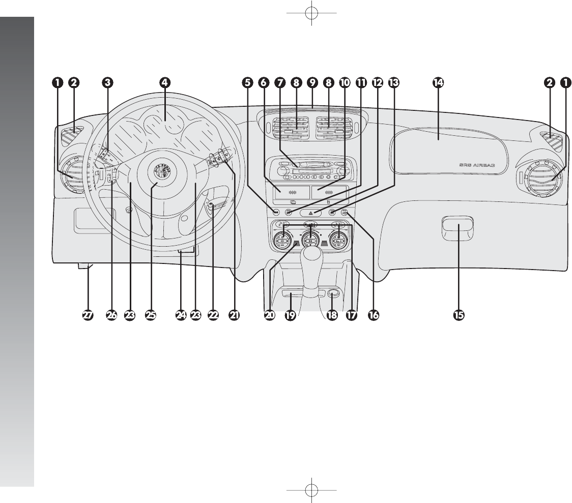
GETTING TO KNOW YOUR CAR
52
DASHBOARD
1. Side swivel air vents - 2. Fixed side window air vents - 3. Outer light control lever - 4. Instrument panel - 5. Tailgate release button - 6. Card
holder (upon request for versions/markets where applicable) - 7. Radio (upon request for versions/markets where applicable) - 8. Centre swivel
air vents - 9. Fixed upper vent - 10. Glass holder (upon request for versions/markets where applicable) - 11. Fog lamp button (upon request for
versions/markets where applicable) - 12. Hazard warning light switch - 13. Rear fog guard button - 14. Passenger’s front Air bag - 15. Glove
compartment - 16. Door locking button - 17. Controls for heating, ventilation and climate control - 18. Cigar lighter - 19. Ashtray - 20. Temper-
ature sensor - 21. Windscreen/rearscreen wiper control lever - 22. Ignition key and switch - 23. Horn - 24. Steering wheel locking/release lever
-25. Driver’s front Air bag - 26. Set of controls - 27. Bonnet openining lever.
fig. 71
A0A1115m
001-057 Alfa 147 Q2 GB 4-07-2008 11:58 Pagina 52
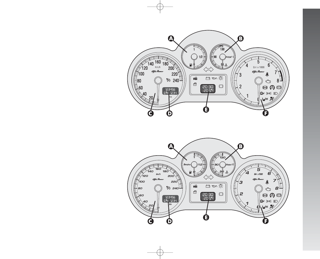
GETTING TO KNOW YOUR CAR
53
A. Fuel level gauge with reserve warning
light - B. Engine coolant fluid temperature
gauge with maximum temperature warning
light - C. Speedometer - D. Odometer dis-
play (mileage recorder, trip recorder with
headlamp position display) - E. Clock/out-
side temperature display - F. Rev counter
NOTE On JTDM versions the scale bottom
is at 6000 revs.
A. Fuel level gauge with reserve warning
light - B. Engine coolant fluid temperature
gauge with maximum temperature warning
light - C. Speedometer - D. Odometer dis-
play (mileage recorder, trip recorder with
headlamp position display) - E. Clock/out-
side temperature display - F. Rev counter
NOTE On Q2 diesel versions the scale bot-
tom is at 6000 revs.
fig. 72 - petrol versions
INSTRUMENT PANEL
Versions with
digital multifunction display
fig. 73 - Black Line petrol versions
A0A1111m
A0A1127m
001-057 Alfa 147 Q2 GB 4-07-2008 11:58 Pagina 53
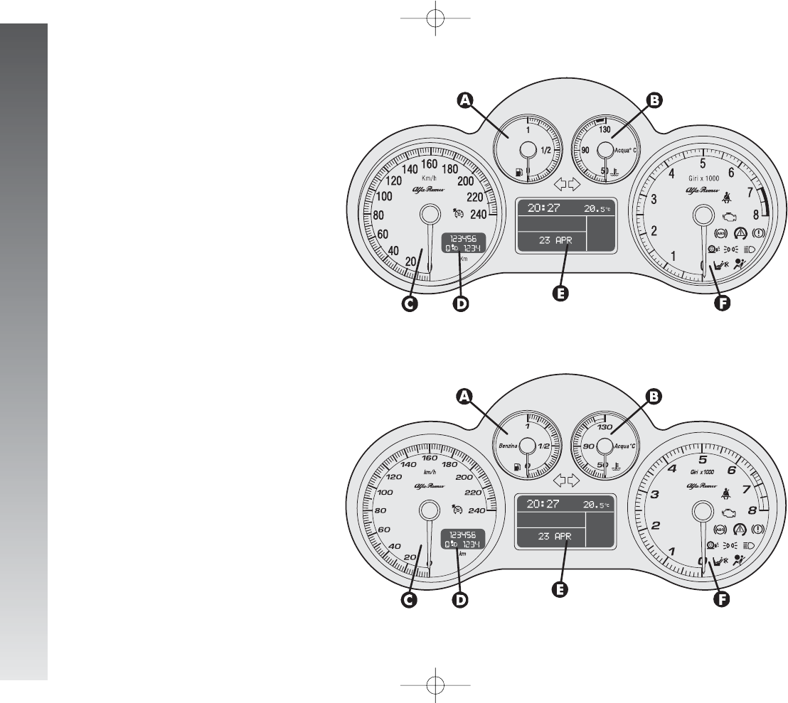
GETTING TO KNOW YOUR CAR
54
A. Fuel level gauge with reserve warning
light - B. Engine coolant fluid temperature
gauge warning light - C. Speedometer - D.
Odometer display (mileage recorder, trip
recorder with headlamp position display) -
E. Reconfigurable multifunction display
F. Rev counter
NOTE On Q2 diesel versions the scale bot-
tom is at 6000 revs.
fig. 75 - Black Line petrol versions
fig. 74 - petrol versions
Versions with reconfigurable
multifunction display
A. Fuel level gauge with reserve warning
light - B. Engine coolant fluid temperature
gauge warning light - C. Speedometer - D.
Odometer display (mileage recorder, trip
recorder with headlamp position display) - E.
Reconfigurable multifunction display - F. Rev
counter
NOTE On JTDM versions the scale bottom
is at 6000 revs.
A0A1129m
A0A1112m
001-057 Alfa 147 Q2 GB 4-07-2008 11:58 Pagina 54
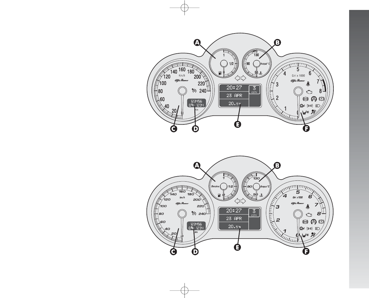
GETTING TO KNOW YOUR CAR
55
fig. 75a - 2.0 T. SPARK Selespeed versions
Versions with reconfigurable
multifunction display
A. Fuel level gauge with reserve warning
light - B. Engine coolant fluid temperature
gauge warning light - C. Speedometer - D.
Odometer display (mileage recorder, trip
recorder with headlamp position display) - E.
Reconfigurable multifunction display - F. Rev
counter
A. Fuel level gauge with reserve warning
light - B. Engine coolant fluid temperature
gauge warning light - C. Speedometer - D.
Odometer display (mileage recorder, trip
recorder with headlamp position display) - E.
Reconfigurable multifunction display - F. Rev
counter
A0A1113m
A0A1130m
fig. 75b - 2.0 T. SPARK Selespeed Black Line versions
001-057 Alfa 147 Q2 GB 4-07-2008 11:58 Pagina 55
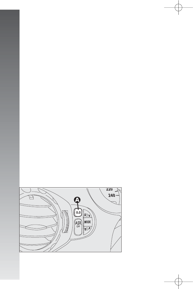
GETTING TO KNOW YOUR CAR
56
MILEAGE RECORDER
Odometer display with double meter (to-
tal and trip) and headlamp position display.
The display shows:
– the mileage on the first line (6 figures)
– the trip meter on the second line (4 fig-
ures)
– the position relating to the headlamp
aiming device.
To reset the trip meter, keep the button
(A-fig. 76) on the plate at the side of the
steering column pressed for a few seconds.
IMPORTANT If the battery is discon-
nected the trip meter reading is not stored.
REV COUNTER
The danger zone (red, or white on certain
versions) indicates excessively high engine
speed. Do not drive for long periods with the
pointer in this area.
IMPORTANT The electronic injection
control system gradually shuts off the flow
of fuel when the engine is “over-revving”
resulting in a gradual loss of engine power.
When the engine is idling, the rev counter
may indicate a gradual or sudden highering of
the speed, this is normal as it takes place dur-
ing normal operation, for example when en-
gaging the climate control system or the fan.
In particular a slow change in the speed pre-
serves the battery charge.
fig. 76
A0A1118m
001-057 Alfa 147 Q2 GB 4-07-2008 11:58 Pagina 56

GETTING TO KNOW YOUR CAR
57
FUEL LEVEL GAUGE WITH
RESERVE INDICATOR
This shows the amount of fuel left in the
fuel tank.
The warning light
K
turns on to indicate that
approx. 7 litres of fuel are left in the tank.
IMPORTANT Under certain conditions
(heavy slopes, for instance), the reading on
the gauge may differ from the actual amount
of fuel in the tank and changes in level may
be indicated late.
This condition falls within the operation log-
ics of the electronic control circuit to avoid
highly unstable readings due to swaying of
the fuel when travelling.
IMPORTANT Refuelling shall always be
performed with engine off and ignition key at
STOP. If the engine is off but the key is at
MAR, a wrong fuel level could temporarily
be indicated. This is due to the internal sys-
tem control logic and cannot be considered as
a system malfunctioning.
ENGINE COOLANT FLUID
TEMPERATURE GAUGE WITH
MAXIMUM TEMPERATURE
WARNING LIGHT
This shows the temperature of the engine
coolant fluid and begins when the fluid tem-
perature exceeds approx. 50°C.
Normally the pointer should be towards
the middle of the scale. If the pointer reach-
es the higher temperatures of the scale (red
section, or white on certain versions) the re-
quest for car performance should be de-
creased.
The turning on of the
u
warning light (ver-
sions with digital multifunction display) or
of the message + symbol (versions with re-
configurable multifunction display) indicates
that the coolant fluid temperature is too
high; in this case, stop the engine and con-
tact Alfa Romeo Authorized Services.
IMPORTANT The temperature of the en-
gine coolant may rise towards the maximum
values (red section, or white on certain ver-
sions) when the car is driven at low speeds,
especially when the ambient air tempera-
ture is high. In this case it is advisable to
stop the car and switch off the engine for
a few minutes, after which the journey can
be resumed, preferably at a higher speed.
001-057 Alfa 147 Q2 GB 4-07-2008 11:58 Pagina 57
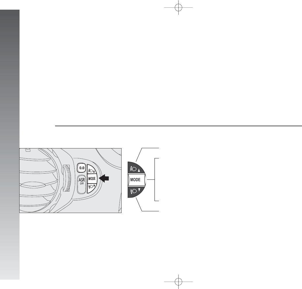
GETTING TO KNOW YOUR CAR
58
DIGITAL MULTIFUNCTION DISPLAY
The digital multifunction display shows the following: clock, outside temperature, buzzer setting (buzzer on/off), rheostat (light adjustment),
condition of the inertial fuel cut-off switch (FPS on) and engine oil level (for JTD versions).
CONTROL BUTTONS (fig. 77)
To make use of the information the digital display (with the ignition key at MAR) is able to give, you should firstly familiarise with the con-
trol buttons on the plate at the side of the steering column, using them as described in the following paragraphs. Before doing anything at all,
you are advised to read this chapter in full.
To increase the value displayed
To decrease the value displayed
Press for less than 1 second (pulse), indicated with Qin the following de-
scriptions, to access the various adjustments
Press for more than 2 seconds, indicated with Rin the following descrip-
tions, to confirm the choice required and return to the previous display
fig. 77
A0A1117m
058-085_Alfa147 Q2 GB 4-07-2008 11:59 Pagina 58
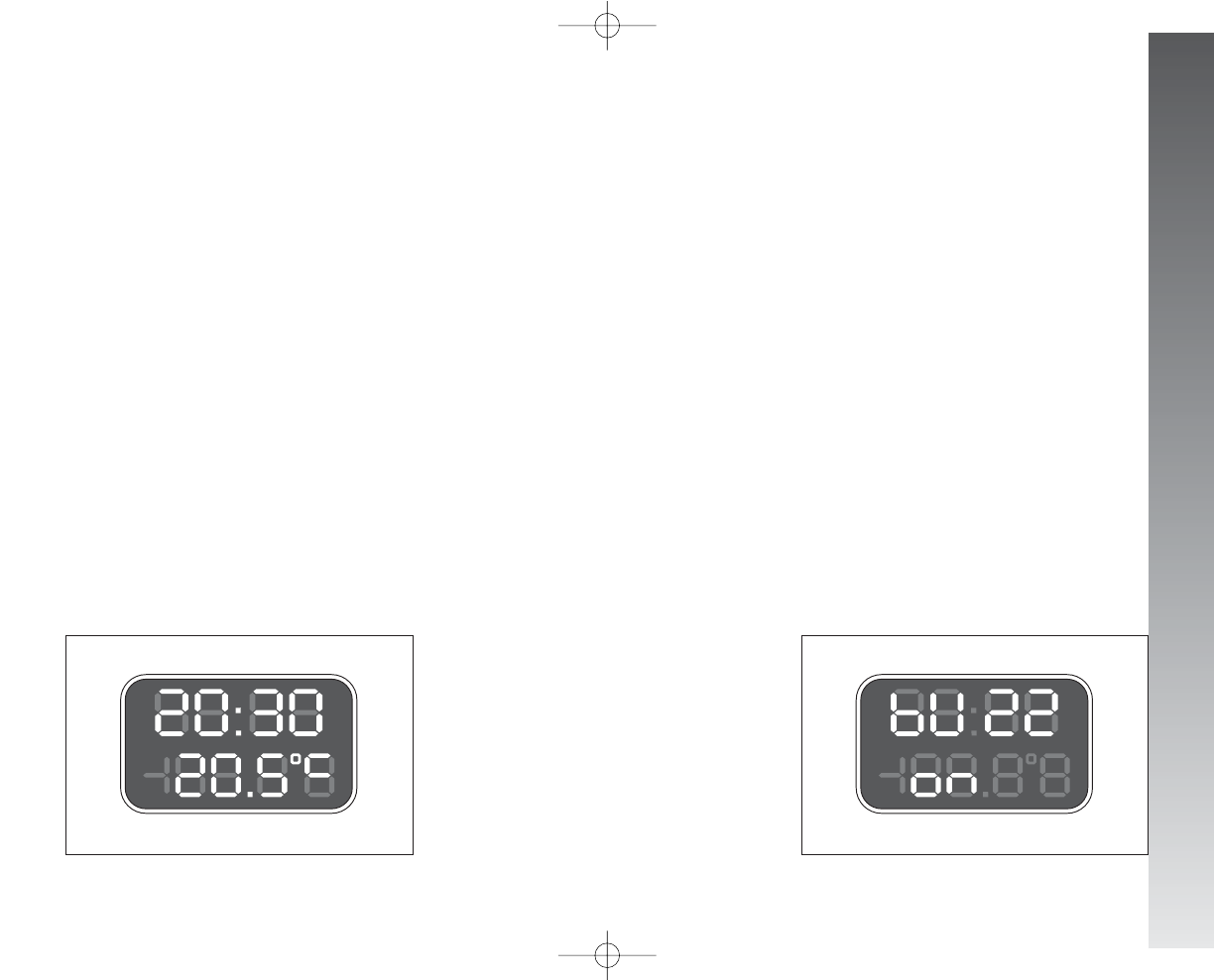
GETTING TO KNOW YOUR CAR
59
CLOCK
(fig. 78)
Adjusting the hours
Press the MODE button in Q, the hours
will flash. Set the hour required using button
▲
or
▼
.
Every press on the button will increase by
one unit.
Keeping the button pressed obtains auto-
matic fast increase or decrease.
When you are near the value required, re-
lease the control and complete adjustment
with single presses.
Then press the MODE button in Rto
store.
fig. 78
Adjusting the minutes
Press the MODE button twice in Q, the
minutes will flash. Set the minutes required
using button
▲
or
▼
.
Every press on the button will increase by
one unit.
Keeping the button pressed obtains auto-
matic fast increase or decrease.
When you are near the value required, re-
lease the control and complete adjustment
with single presses.
Then press the MODE button in Rto
store.
OUTSIDE TEMPERATURE
(fig. 79)
Outside temperature can be viewed on the
display lower side, under the hour indica-
tion. When the outside temperature is be-
low or 3° C, the indicator starts flashing
together with the buzzer, to warn the driver
about the possible presence of ice on the
road. The acoustic signal lasts about 2 sec-
onds, while the outside temperature indi-
cator flashes for about 10 seconds. The sig-
nal of possible presence of ice on the road
is repeated only if the outside temperature
is over 6° C and then reaches again 3° C.
A0A0009m
fig. 79
A0A0083m
BUZZER
(fig. 79-80)
The buzzer which accompanies the con-
trols may be activated (ON) or deactivated
(OFF); proceed as follows:
Press the MODE button 3 times Q, then
use button
▲
or
▼
to turn the buzzer on
or off.
The press the MODE button in Rto
store the condition chosen.
clock and
outside temperature display buzzer activated display (ON)
058-085_Alfa147 Q2 GB 4-07-2008 11:59 Pagina 59
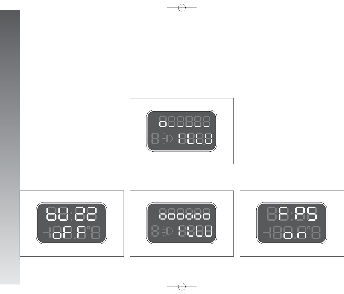
GETTING TO KNOW YOUR CAR
60
fig. 81
A0A0012m
fig. 82
A0A0013m
fig. 83
A0A0007m
is turned off with the exception of the
speedometer.
Keeping the
▲
button pressed (on the
plate at the side of the steering column) for
more than 4 seconds the compelte cluster
lighting is turned on again.
INERTIAL FUEL CUT-OFF
SWITCH ON DISPLAY
(fig. 83)
(for versions/markets where
applicable)
The display shown appears automatically
when the inertial fuel cut-off switch cuts in,
following a crash of a certain magnitude.
The switch shuts off the supply of fuel.
IMPORTANT See the description in the
Controls paragraph under the Inertial fuel
cut-off switch.
display
with minimum brightness
display
with maximum brightness
inertial fuel cut-off switch
on display
fig. 80
A0A0014m
buzzer deactivated display (OFF)
LIGHT RHEOSTAT
(fig. 81-82)
This function makes it possible to adjust
the lighting (dimming/increasing) of the in-
strument cluster, odometer display (total
and trip meter, headlamp aiming device dis-
play) of the clock/outside temperature dis-
play and of the radio display.
To access the light rheostat, open the
menu by pressing button MODE, select “IL-
LU” (first option displayed) by pressing
again button MODE and then set the re-
quired level using buttons
▲
or
▼
).
“ILLU” function is available when at least
the side/taillights on.
Partial lighting
Keeping the
▼
button pressed (on the
plate at the side of the steering column) for
more than 4 seconds the instrument cluster
058-085_Alfa147 Q2 GB 4-07-2008 11:59 Pagina 60
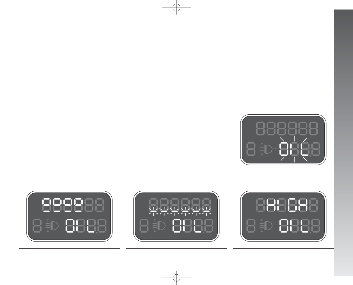
GETTING TO KNOW YOUR CAR
61
Engine oil level check
(JTD versions)
Turning the ignition key to MAR the dig-
ital multifunction display shows the writing
“OIL” for about 10 seconds.
Then, the engine oil level is detected for
some seconds, during which the display
shows six bars. At the end of this operation,
the display will show the oil quantity (fig.
84) and then the information concerning
the partial and total kilometres travelled.
Fig. 84 refers to the correct engine oil
display. As the oil level gradually falls, the
full bars go off.
IMPORTANT To make sure that the en-
gine oil level displayed is correct, carry out
the check with the car on the level ground.
Fig. 85 refers to the display with an oil
level below the foreseen minimum. In this
condition the display shows the flashing bars
and the message “OIL” for about 10 sec-
onds.
IMPORTANT In this case the correct en-
gine oil level should be restored as soon as
possible, see “Checking levels” in the “car
maintenance” chapter.
In case of fuel system failure, after turn-
ing the ignition key to MAR, the display
shows only the message “OIL” flashing for
about 10 seconds (fig. 86).
Fig. 87 refers to the display with an oil
level above the foreseen maximum. In this
condition the display shows the message
“HIGH OIL”.
IMPORTANT In this case, contact Alfa
Romeo Authorised Services who will restore
the correct engine oil level.
fig. 84
A0A0711m
fig. 85
A0A0712m
fig. 87
A0A0714m
fig. 86
A0A0713m
058-085_Alfa147 Q2 GB 4-07-2008 11:59 Pagina 61
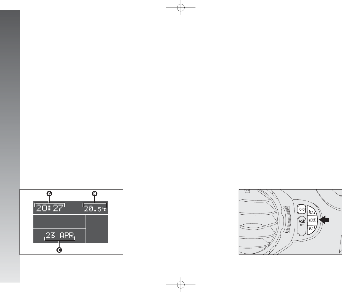
GETTING TO KNOW YOUR CAR
62
RECONFIGURABLE MULTIFUNCTION DISPLAY
The reconfigurable multifunction display is
able to display all the useful and necessary
information when driving, in particular:
INFORMATION
ON STANDARD DISPLAY
- Clock (A-fig. 88);
- Outside temperature (B);
- Date (C).
INFORMATION ABOUT
CAR CONDITION
- Trip computer;
- Lighting adjustment (rheostat);
- Display of failure messages with corre-
sponding symbol;
- Display of warning messages with cor-
responding symbol (e.g.: possible ice
on road);
- Gear selected (only for 2.0 T.SPARK Se-
lespeed versions);
- Engine oil level (only JTDMversions).
CONTROL BUTTONS fig. 89
MODE
Short pressing of button to confirm
the choice required and/or move to the next
screen;
Long pressing of button to confirm the
choice required and return to the standard
screen;
▲
/
▼
to scroll up/down the “Setup
menu” options or increase/decrease the val-
ue displayed .
fig. 89
A0A1117m
fig. 88
A0A9117g
058-085_Alfa147 Q2 GB 4-07-2008 11:59 Pagina 62
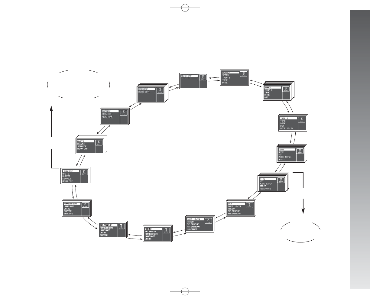
GETTING TO KNOW YOUR CAR
63
DIMMER
MENU OFF
SPEED
TRIP B
TIME
DATE
DST
MODE 12/24
RADIO
TELEPHONE
NAVIGATION
LANGUAGE
UNITS
BUZZER
SERVICE
“SETUP MENU”
In addition there is a “Setup Menu” which makes it possible, through the MODE and
▲
/
▼
(see fig. 89) buttons, to carry out the adjust-
ments and/or setting described on the following pages. It can be activated by pressing shortly MODE and comprises a series of functions
arranged in a “circular fashion” fig. 90.
Day
Year Month
Q
English
Nederlands
Espãnol
Français
Deutsch
Italiano
Q
fig. 90
From the standard screen to access navigation press the button MODE for a short time. To navigate inside the menu press the buttons
▲
or
▼
. For safety reasons, when the car is moving, it is possible to access only the limited menu (adjustment of instrument panel lighting on
“DIMMER” and setting at “SPEED”). When the car is stationary it is possible to access the extended menu.
058-085_Alfa147 Q2 GB 4-07-2008 11:59 Pagina 63
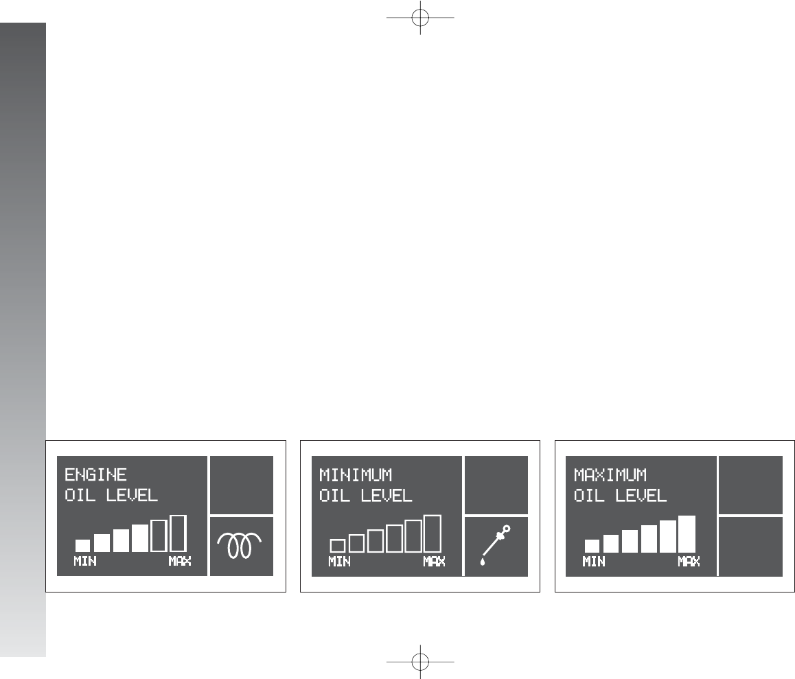
GETTING TO KNOW YOUR CAR
64
Engine oil level check
(JTDMversions)
Turning the ignition key to MAR the dis-
play shows the engine oil level for some sec-
onds. During this phase, to clear the display
and move to next screen, press the MODE
button shortly.
IMPORTANT To make sure that the en-
gine oil level displayed is correct, carry out
the check with the car on a level ground.
Fig. 91 refers to the correct engine oil
level display. As the oil level gradually falls,
the full bars go off leaving room for the emp-
ty ones.
Fig. 92 refers to the display with an oil
level below the foreseen minimum. In this
condition the bars are all empty.
IMPORTANT In this case the correct en-
gine oil level should be restored as soon as
possible, see “Checking levels” in the “Car
Maintenance” chapter.
Fig. 93 refers to the display with an oil
level above the foreseen maximum. In this
condition the bars are all full.
IMPORTANT In this case, contact Alfa
Romeo Authorised Services who will restore
the correct engine oil level.
fig. 91
A0A9101g
fig. 92
A0A9102g
fig. 93
A0A9103g
058-085_Alfa147 Q2 GB 4-07-2008 11:59 Pagina 64

GETTING TO KNOW YOUR CAR
65
To cancel the set value:
❒
press the MODE button briefly: the dis-
play shows OFF;
❒
press the
▼
button: the display shows
OFF;
❒
press the MODE button briefly to re-
turn to the menu screen or press the but-
ton for a longer time to return to the
standard screen.
SPEED
With this function it is possible to set the
car speed limit (km/h) (or mph) which, if
exceeded, automatically sounds a buzzer
and displays a specific message (see chap-
ter “Warning lights and indications”).
To set the limit speed, proceed as follows:
❒
press the MODE button briefly: the dis-
play shows ON;
❒
press the MODE button briefly and
then use the
▲
/
▼
buttons to set the
speed required (during setting operation,
the value flashes on the screen).
❒
press the MODE button briefly to return
to the menu screen or press the button
for a longer time to return to the stan-
dard screen.
IMPORTANT The possible setting is be-
tween 30 and 250 km/h or between 20
and 150 mph depending on the unit set pre-
viously (see paragraph “UNITS” described lat-
er). Every press (pulse) of the
▲
/
▼
but-
ton increases or decreases by one unit. Keep-
ing the
▲
/
▼
button pressed obtains fast
increase or decrease. When you are near the
required setting, release the button and com-
plete adjustment with single presses.
DIMMER
With this function it is possible to adjust the
lighting (dimming/brightening) of the in-
strument cluster, odometer display (total and
trip meter), headlamp aiming display, radio
display, radio-navigator display (if fitted) and
two-zone climate control (if fitted).
To adjust, proceed as follows:
❒
press the MODE button briefly: the dis-
play shows a graduated scale;
❒
press the buttons
▲
/
▼
to carry out
adjustment.
❒
press the MODE button briefly to return
to the menu screen or press the button
for a longer time to return to the stan-
dard screen.
Partial lighting
Keeping the
▼
button pressed for more
than 4 seconds, the rev counter lighting is
turned off.
Keeping the
▲
button pressed for more
than 4 seconds, the complete instrument
cluster lighting is turned on again.
IMPORTANT In the event of any faults,
lighting adjustment (rheostat) is not possi-
ble and the display is shown at its maximum
brightness.
058-085_Alfa147 Q2 GB 4-07-2008 11:59 Pagina 65

GETTING TO KNOW YOUR CAR
66
TRIP B
With this option it is possible to turn
ON/OFF the TRIP B function (partial trip)
which displays the figures relating to: AVER-
AGE CONSUMPTION B, AVERAGE SPEED B,
TRAVEL TIME B and TRAVEL DISTANCE B dur-
ing a “partial mission” contained in the “gen-
eral mission” (for further information see
“Trip Computer”).
To turn on/off this function, proceed as fol-
lows:
❒
press the MODE button briefly: the dis-
play shows ON;
❒
use buttons
▲
/
▼
to select activation
or deactivation;
❒
press the MODE button briefly to re-
turn to the menu screen or press the
button for a longer time to return to the
standard screen.
TIME
With this function it is possible to adjust the
clock (hours - minutes).
Proceed as follows:
❒
press the MODE briefly: the display
shows the hour;
❒
press the
▲
/
▼
buttons to adjust;
❒
press the MODE button briefly to ad-
just the minutes (instead pressing the
button for a longer time you return to
the standard screen);
❒
press the
▲
/
▼
buttons to adjust;
❒
press the MODE button briefly to re-
turn to the menu screen or press the but-
ton for a longer time to return to the
standard screen.
IMPORTANT Each press on the
▲
/
▼
button increases or decreases by one unit.
Keeping the
▲
/
▼
button pressed obtains
the automatic fast increase or decrease.
When you are near the required value, re-
lease the button and complete adjustment
with single presses.
DATE
With this function it is possible to adjust the
date (day - month - year).
Proceed as follows:
❒
press the MODE button briefly: the dis-
play shows the date;
❒
press the
▲
/
▼
buttons to adjust the
day;
❒
press the MODE button briefly to ad-
just the month (or press the button for
a longer time to return to the standard
screen);
❒
press the
▲
/
▼
buttons to adjust;
❒
press the MODE button briefly to ad-
just the year (or press the button for a
longer time to return to the standard
screen);
❒
press the
▲
/
▼
buttons to adjust;
❒
press the MODE button briefly to re-
turn to the menu screen or press the
button for a longer time to return to the
standard screen.
058-085_Alfa147 Q2 GB 4-07-2008 11:59 Pagina 66

GETTING TO KNOW YOUR CAR
67
DST (SUMMER TIME)
With this option it is possible to turn
ON/OFF the summer time function (which
corresponds to + 1 hour in relation to the
daylight time).
Proceed as follows:
❒
press the MODE button briefly: the dis-
play shows ON;
❒
use the
▲
/
▼
buttons to select acti-
vation or deactivation;
❒
press the MODE button briefly to re-
turn to the menu screen or press the but-
ton for a longer time to return to the
standard screen.
Selecting and activating the “DST ON”
function, the display switches from daylight
time and vice versa, with no need to inter-
vene manually on the “TIME” function de-
scribed previously.
MODE 12/24
This function is used to set the clock in the
12h or 24h mode.
To adjust proceed as follows:
❒
press the MODE button briefly: the dis-
play shows 12h;
❒
press the
▲
/
▼
buttons to set (12h
or 24h);
❒
press the MODE button briefly to re-
turn to the menu screen or press the but-
ton for a longer time to return to the
standard screen.
RADIO
With this function it is possible to turn
ON/OFF the repetition of the information
displayed by the radio front panel on the in-
strument cluster display.
To activate/deactivate this function, pro-
ceed as follows:
❒
press the MODE button briefly: the dis-
play shows ON;
❒
use the
▲
/
▼
buttons to select acti-
vation/deactivation;
❒
press the MODE button briefly to re-
turn to the menu screen or press the but-
ton for a longer time to return to the
standard screen.
Selecting and activating the “RADIO
DISPLAY ON” function, when the radio is
turned on, the dispay repeats the display on
the front panel of the radio itself.
NOTE For versions with CD MP3 sound
system only, if the active radio source is
“MP3”, the RADIO function is disabled
even if ON.
058-085_Alfa147 Q2 GB 4-07-2008 11:59 Pagina 67

GETTING TO KNOW YOUR CAR
68
TELEPHONE
With this option it is possible to turn
ON/OFF the function which shows the
name (if listed) and phone number of the
caller on the instrument panel display.
To activate/deactivate this function, pro-
ceed as follows:
❒
press the MODE button briefly: the dis-
play shows ON;
❒
use the
▲
/
▼
buttons to select acti-
vation/deactivation;
❒
press the MODE button briefly to re-
turn to the menu screen or press the but-
ton for a longer time to return to the
standard screen.
Selecting and activating the “TELE-
PHONE DISPLAY ON” function, when
a phone call arrives, the display shows the
name (if listed) and phone number of the
caller.
NAVIGATION
With this option it is possible, during use of
the radionavigator, to turn ON/OFF the
function to view the pictograms shown on
the radionavigator display on the instrument
cluster display.
To activate/deactivate proceed as follows:
❒
press the MODE button briefly: the dis-
play shows ON;
❒
use the
▲
/
▼
buttons to select acti-
vation or deactivation;
❒
press the MODE button briefly to re-
turn to the menu screen or press the but-
ton for a longer time to return to the
standard screen.
Selecting and activating the “NAVIGA-
TION DISPLAY ON” function, the in-
strument cluster display repeats the display
(pictograms) on the radionavigator display
itself.
LANGUAGE
With this function it is possible to select the
language required for the texts and messages
shown on the display.
Proceed as follows:
❒
press the MODE button briefly: the dis-
play shows the “language” set previ-
ously;
❒
press the
▲
/
▼
buttons to adjust;
❒
press the MODE button briefly to re-
turn to the menu screen or press the but-
ton for a longer time to return to the
standard screen.
058-085_Alfa147 Q2 GB 4-07-2008 11:59 Pagina 68

GETTING TO KNOW YOUR CAR
69
UNITS
With this function it is possible to set the
unit of measurement for the travel distance
(km or mi), the fuel consumption (l/100
km, km/l or mpg) and the temperature (°C
or °F).
To set the units, proceed as follows:
❒
press the MODE button briefly, the dis-
play shows “km” or “mi” (depending
on what set previously);
❒
press the
▲
/
▼
buttons to adjust;
❒
press the MODE button briefly to select
the temperature unit (or press the button
for a longer time to return to the standard
screen): the display shows °Cor °F(de-
pending on what set previously);
❒
press the
▲
/
▼
buttons to adjust;
❒
press the MODE button briefly to se-
lect the fuel consumption unit (or press
the button for a longer time to return
to the standard screen);
❒
if the travel distance unit is “km”, the
display shows “l/100km” or
“km/l”: press the
▲
/
▼
buttons to
adjust. Instead, if the travel distance unit
is “mi” the display shows “mpg”;
❒
press the MODE button briefly to re-
turn to the menu screen or press the
button for a longer time to return to the
standard screen.
IMPORTANT The temperature unit (°C
or °F) set on the display is also shown on the
bi-zone display (if fitted) and on the radion-
avigator display (if fitted).
BUZZER
With this function it is possible to adjust
the volume of the buzzer which accompa-
nies the controls in the car and any failure
signals shown on the display.
To adjust the volume, proceed as follows:
❒
press the MODE button briefly: the dis-
play shows the “level” of the volume
previously set;
❒
press the
▲
/
▼
buttons to adjust;
❒
press the MODE button briefly to re-
turn to the menu screen or press the but-
ton for a longer time to return to the
standard screen.
IMPORTANT In the buzzer OFF con-
dition any buzzer failure warnings are main-
tained.
058-085_Alfa147 Q2 GB 4-07-2008 11:59 Pagina 69

GETTING TO KNOW YOUR CAR
70
SERVICE
With this function it is possible to view the
information connected with the correct car
maintenance.
To consult this information, proceed as fol-
lows:
❒
press the MODE button briefly: the dis-
play shows the deadline in “km” or
“mi” depending on what set previous-
ly (see paragraph “UNITS”);
❒
press the
▲
/
▼
buttons to view the
required information on the display;
❒
press the MODE button briefly to re-
turn to the menu screen or press the
button for a longer time to return to the
standard screen.
IMPORTANT The programmed Mainte-
nance Schedule includes car maintenance
every 20,000 km; this is shown automati-
cally, with the ignition key at MAR, start-
ing from 2,000 km (or miles) from this
deadline and it is shown again every 200
km. This display can only be reset by Alfa
Romeo Authorised Services.
MENU OFF
Selecting this function you return to the
standard screen.
058-085_Alfa147 Q2 GB 4-07-2008 11:59 Pagina 70
GETTING TO KNOW YOUR CAR
71
TRIP COMPUTER
General
The “Trip computer” function gives information relating to the operating status of the car on the display. This function comprises the GENERAL
TRIP concerning the complete mission of the car and TRIP B concerning the the partial car mission. This function (as shown in the graph below)
is contained within the complete mission. Both functions are resettable (reset - start of a new mission).
End of partial mission
Start of new partial mission
Reset TRIP B
˙
Reset TRIP B
End of partial mission
Start of new partial mission
˙
˙
Reset TRIP B
˙
˙
˙
TRIP B
TRIP B
TRIP B
End of partial mission
Start of new partial mission End of partial mission
Start of new partial mission
Reset TRIP B
GENERAL TRIP
End of complete mission
Start of new mission
Reset GENERAL TRIP
˙
End of complete mission
Start of new mission
Reset GENERAL TRIP
˙
058-085_Alfa147 Q2 GB 4-07-2008 11:59 Pagina 71

GETTING TO KNOW YOUR CAR
72
The GENERAL TRIP displays the figures re-
lating to:
❒
Average consumption
❒
Actual consumption
❒
Average speed
❒
Travel time
❒
Range
❒
Travel distance
TRIP B displays the figures relating to:
❒
Average consumption B
❒
Average speed B
❒
Travel time B
❒
Travel distance B
Displayed figures
Average consumption
Represents the indicative average of con-
sumptions from the beginning of the new
mission.
Actual consumption
It shows the variation of the fuel consump-
tion updated constantly. If parking with en-
gine running, the display will show “- - - -”.
Average speed
It shows the car average speed according
to the overall time elapsed from the start of
the new mission.
Travel time
Time elapsed from the start of the new
mission (travel time).
Range
It shows the distance the car can still cover
before needing fuel if keeping the same dri-
ving conditions.
The display shows “- - - -“ when the fol-
lowing conditions occur:
- range value below 50 km (or 30 mi);
- car left parked with engine running for
long.
IMPORTANT The variation of the au-
tonomy value can be influenced by different
factors: driving style (see what is described
in paragraph “Driving style” in the chapter
“Correct use of the car”), type of route
(highways, urban, mountain, etc…), use
conditions of the car (load transported, tire
pressure, etc…). What was described pre-
viously must be taken in consideration when
planning a trip.
Travel distance
It shows the distance travelled by the car
from the start of a new mission.
At the beginning of a new mission, due
to battery reconnection (reset), the display
shows value “0.0”.
058-085_Alfa147 Q2 GB 4-07-2008 11:59 Pagina 72
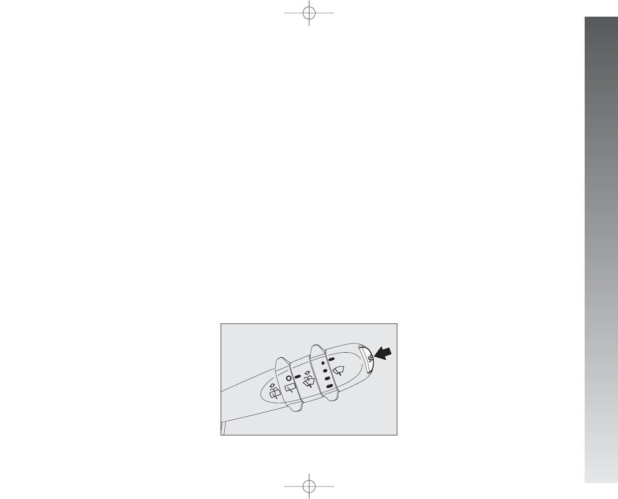
GETTING TO KNOW YOUR CAR
73
New mission
It starts when the reset operation is carried
out:
- “manually” by the user, through pro-
longed pressure of the SET button;
- “automatically” when the “travel dis-
tance” is equal to 9999.9 km (or mi),
when the “travel time” is 99:59 (99
hours and 59 minutes) or after recon-
necting the battery.
SET BUTTON
The button fitted on the right lever
(fig. 94) makes it possible, with the ig-
nition key at MAR, to access the GENER-
AL TRIP and TRIP B functions.
The SET button also makes it possible to
reset the GENERAL TRIP and TRIP B functions
to start a new mission:
-short pressing: to go to next screen
view;
-long pressing: to reset and start a
new journey.
Start of journey procedure
(reset)
To start a new journey monitored by the
GENERAL TRIP, with the ignition key at
MAR, press the SET button for more than
2 seconds.
The reset operation (pressing the SET but-
ton for more than 2 seconds) in the presence
of the screens concerning the GENERAL TRIP
also makes it possible to reset TRIP B.
The reset operation (pressing the SET but-
ton for more than 2 seconds) in the pres-
ence of the screens concerning the TRIP B
also makes it possible to reset only the in-
formation associated with this function.
IMPORTANT The RANGE and ACTUAL
CONSUMPTION information cannot be reset.
fig. 94
A0A0021m
058-085_Alfa147 Q2 GB 4-07-2008 11:59 Pagina 73
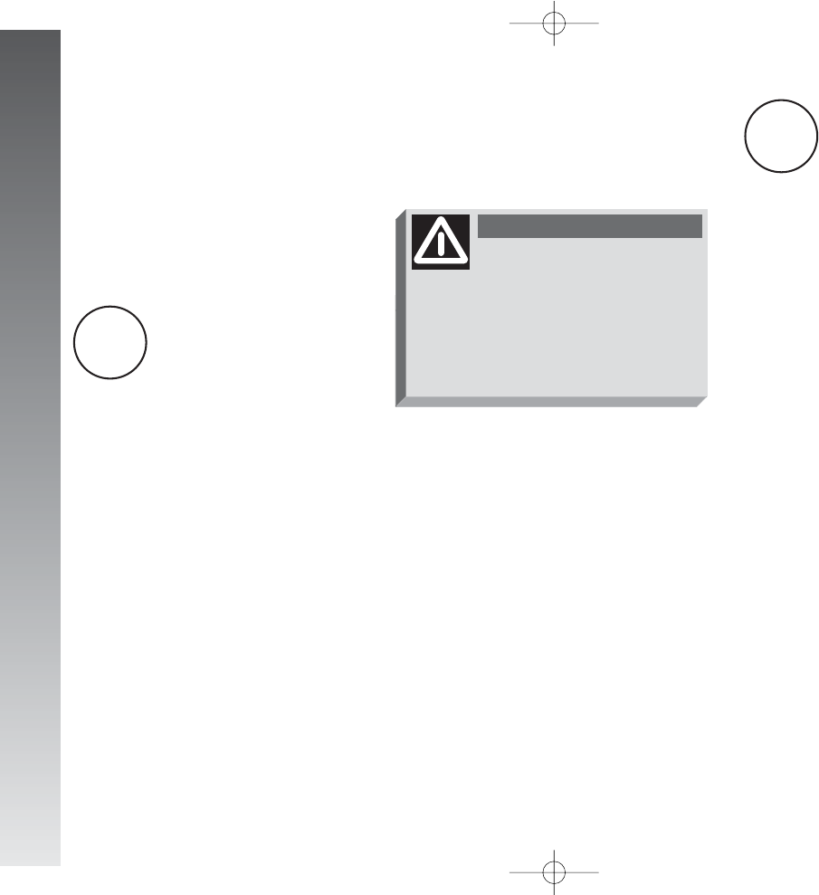
GETTING TO KNOW YOUR CAR
74
WARNING LIGHTS
AND INDICATIONS
IMPORTANT The presence or absence
of the warning lights depends on the type
of engine and equipment with which the car
is fitted.
LOW BRAKE FLUID
(red)
HANDBRAKE ON
(red)
Turning the ignition key to MAR the warn-
ing light turns on, but it should go off after
a few seconds.
Low brake fluid
The warning light turns on (on some ver-
sions together with the message + symbol
shown on the display) when the level of the
brake fluid in the reservoir falls below the
minimum level, due to a possible leak in the
circuit.
Handbrake on
The warning light turns on when the hand-
brake is engaged.
HIGH ENGINE
COOLANT FLUID
TEMPERATURE (red)
Turning the ignition key to MAR the warn-
ing light (if fitted) turns on, but it should go
off after a few seconds.
The warning light turns on (on some ver-
sions together with the message + symbol
shown on the display) when the engine is
overheated. If it turns on when travelling, stop
the car leaving the engine on and slightly ac-
celerated to further activate the circulation
of the coolant fluid.
If the warning light (on some versions to-
gether with the message + symbol shown on
the display) does not go off within the next
2 or 3 minutes, stop the engine and contact
Alfa Romeo Authorised Services.
If the
x
warning light turns
on when travelling check
that the handbrake is not engaged.
If the warning light stays on with the
handbrake off, stop the car immedi-
ately and contact Alfa Romeo Au-
thorised Services.
WARNING
x
u
058-085_Alfa147 Q2 GB 4-07-2008 11:59 Pagina 74
GETTING TO KNOW YOUR CAR
75
AIR BAG FAILURE
(red)
Turning the ignition key to MAR the warn-
ing light turns on, but it should go off after
a few seconds.
The warning lights stays on glowing steadi-
ly if there is an operating failure in the Air bag
system.
LOW ENGINE OIL
PRESSURE (red)
Turning the ignition key to MAR the warn-
ing light (if fitted) turns on, but it should go
off after a few seconds.
LOW BATTERY
CHARGE (red)
Turning the ignition key to MAR the warn-
ing light (if fitted) turns on, but it should go
out as soon as the engine is started (with the
engine running at idle speed a brief delay in
going out is allowed).
If the warning light (on some versions there
is also the message + symbol shown on the
display) stays on, contact immediately Alfa
Romeo Authorised Services.
If the
v
warning light
turns on when the car is
travelling (on some versions there
also the message + symbol shown
on the display), stop the engine im-
mediately and contact Alfa Romeo
Authorised Services.
WARNING
¬
If the
¬
warning light does
not switch on turning the
ignition key to MAR or stays on
when the car is travelling there
might be a failure in the restrain-
ing systems; in this case the air
bags or pretensioners may not ac-
tivate in case of accident or, in a
limited number of cases, they may
activate by mistake. Before carry-
ing on the journey, contact Alfa
Romeo Authorised Services to have
the system checked. The failure of
the
¬
warning light (warning light
off) is also indicated by the flash-
ing for more than 4 seconds of the
air bag warning light
¬
.
WARNING
vw
058-085_Alfa147 Q2 GB 4-07-2008 11:59 Pagina 75
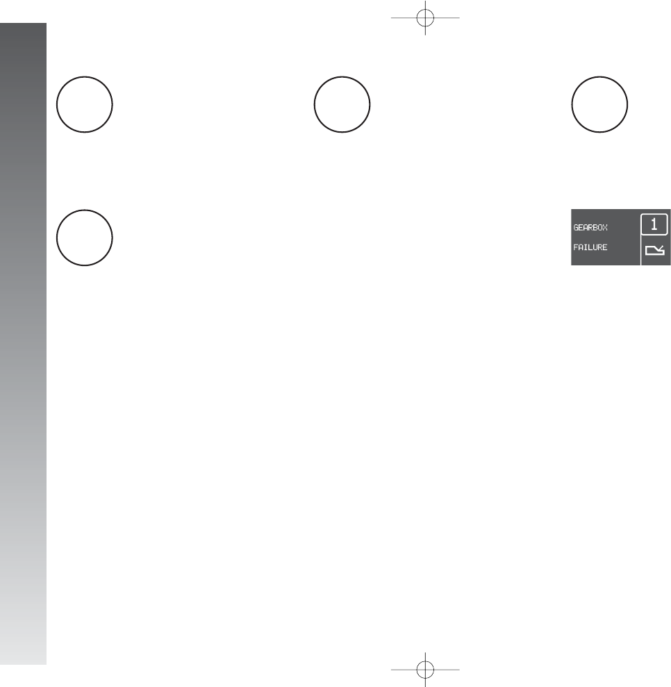
GETTING TO KNOW YOUR CAR
76
SEAT BELTS NOT
FASTENED (red)
The warning light turns on glowing steadi-
ly when, with the ignition key at MAR, the
driver’s seat belt is not correctly fastened.
INCOMPLETE
DOOR CLOSING
(red)
The warning light (if fitted) turns on (on
some versions there is also the message +
symbol shown on the display) when one or
more doors or the tailgate are not properly
shut.
BRAKE PAD WEAR
(red)
The warning light (if fitted) turns on with
the brake pedal pressed (on some versions
there is also the message + symbol shown
on the display) if the front brake pads are
worn; in this case have them changed as
soon as possible.
IMPORTANT As the car is fitted with
wear sensors for the front brake pads, when
changing them, also check the rear brake
pads
SELESPEED
TRANSMISSION
FAILURE
(2.0 versions
T.SPARK Selespeed)
Transmission failure
The message is shown on the display in
case of transmission failure. In this case con-
tact Alfa Romeo Authorised Services as soon
as possible.
<
´
dt
058-085_Alfa147 Q2 GB 4-07-2008 11:59 Pagina 76
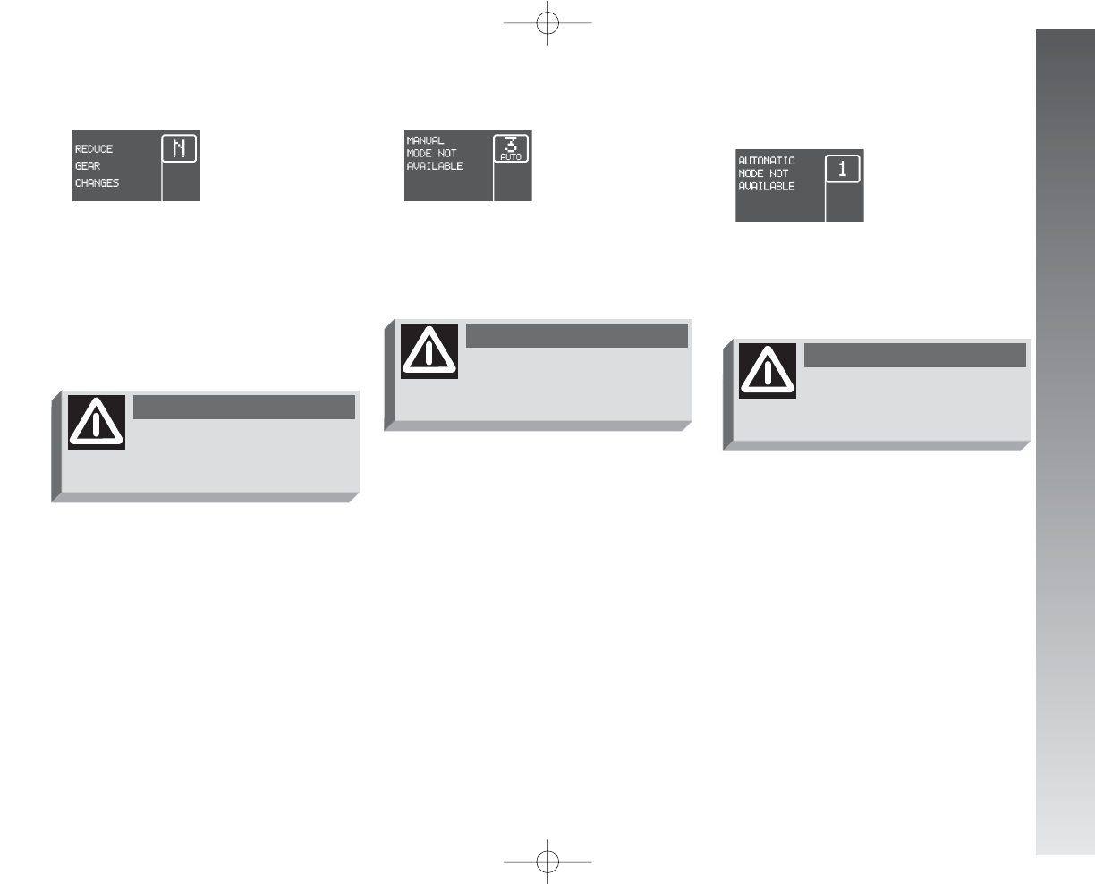
GETTING TO KNOW YOUR CAR
77
Reduction of gearshifting
The message is shown on the display to sig-
nal a transmission overuse by the driver.
The irregular use (by the driver) may start
automatically a procedure for the protection
of the system.
Manual mode not available
The message is shown on the display when,
with the engine running, it is not possible to
select the MANUAL mode.
Automatic mode
not available
The message is shown on the display when,
with the engine running, it is not possible to
select the AUTO mode.
If the message remains on
the display, contact Alfa
Romeo Authorised Services.
WARNING
If the message remains on
the display, contact Alfa
Romeo Authorised Services.
WARNING
If the message remains on
the display, contact Alfa
Romeo Authorised Services.
WARNING
058-085_Alfa147 Q2 GB 4-07-2008 11:59 Pagina 77
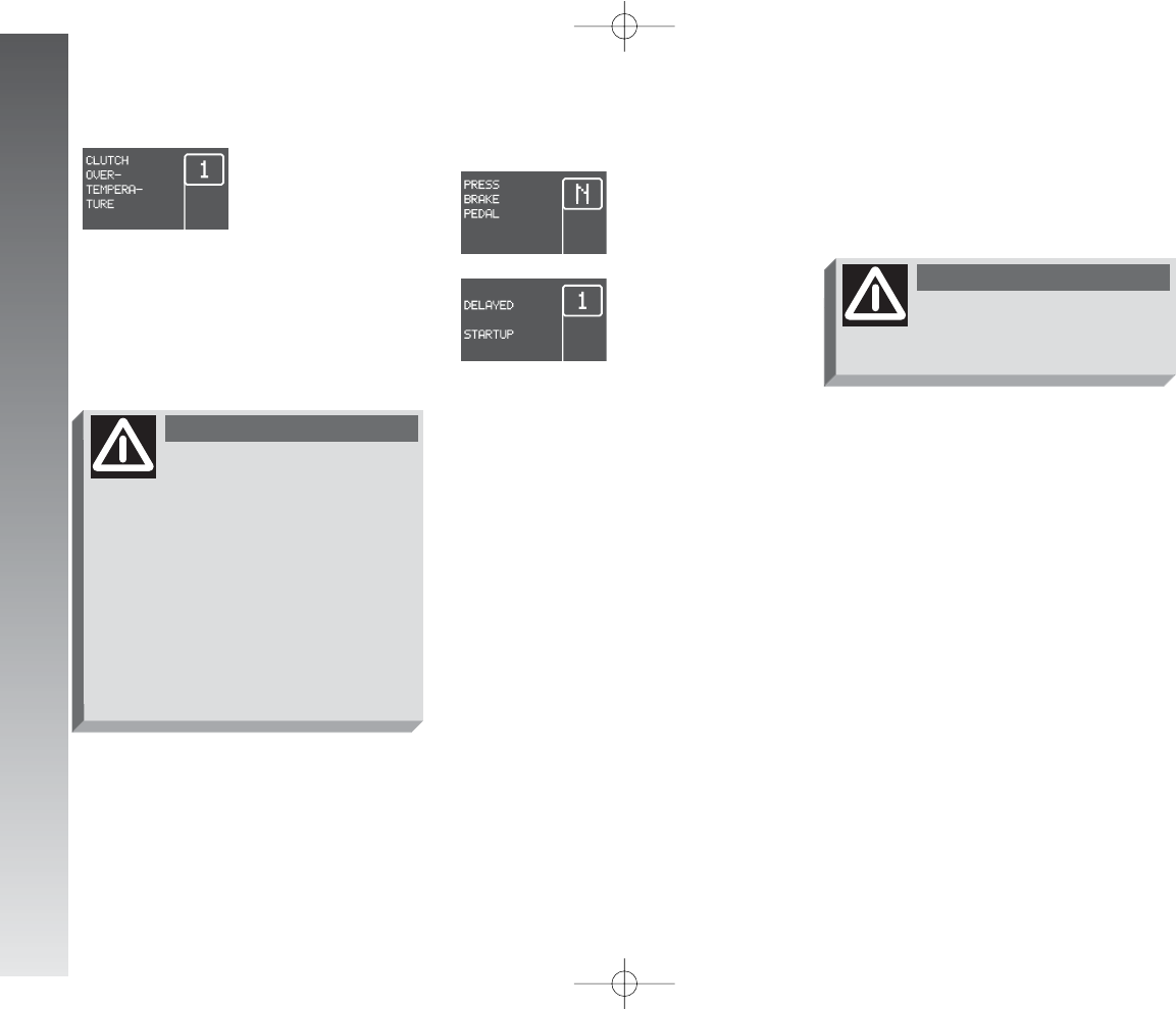
GETTING TO KNOW YOUR CAR
78
Clutch overheating
The message is shown on the display ac-
companied by a buzzer when there is clutch
overheating.
Press the brake -
Delayed start-up
The messages are alternatively shown on
the display, accompanied by a buzzer,
when, during start up, the system recognises
that the brake pedal is operating.
Under this condition, keep the key in the
AVV position for at least 6 seconds, with
the brake held down: the engine will start.
The system is now in the recovery mode
(maximum gear allowed: 2nd).
If parking or stopping the
car uphill (e.g. at the traf-
fic lights), do not use the acceler-
ator to keep the car stopped, to
prevent overheating and thus dam-
aging the clutch. Instead, use the
brake pedal and press the acceler-
ator pedal only when about to
leave off. If the message remains
on the display, contact Alfa Romeo
Authorised Services.
WARNING
If the message remains on
the display, contact Alfa
Romeo Authorised Services.
WARNING
IMPORTANT The messages are shown
only if start-up is carried out with any gear
engaged but neutral (N).
058-085_Alfa147 Q2 GB 4-07-2008 11:59 Pagina 78
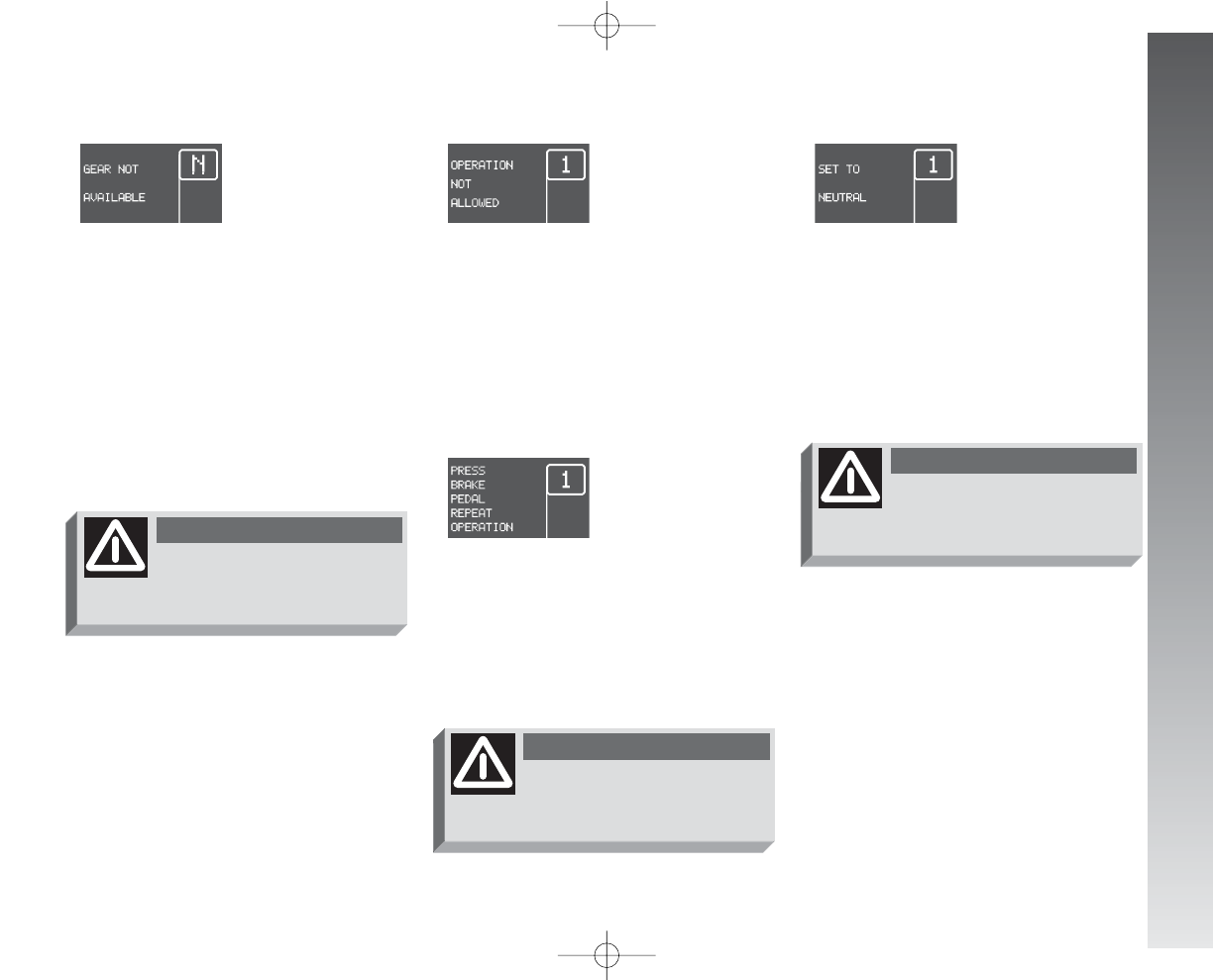
GETTING TO KNOW YOUR CAR
79
Operation not allowed
The message is shown on the display, ac-
companied by a buzzer, when the system
does not accept the gearshift by the con-
trol lever as the necessary conditions for ac-
cepting the gearshift are not present.
Press the brake pedal -
repeat operation
The message is shown on the display, ac-
companied by a buzzer, when in some con-
ditions, due to safety reasons, there is an
attempt to change gear without pressing the
brake pedal first.
Engage N (neutral)
The message is shown on the display, ac-
companied by a buzzer, when the system
asks the driver to carry out the manoeuvre.
Shifting the gear to (N) the message on
the display must go off.
Gear not available
The message is shown on the display, ac-
companied by a buzzer, in the following cas-
es:
- when, because of a system failure, it
is not possible to change gear;
or
- when, because of a system failure, it
is possible only to engage 1st (1), 2nd
(2) or reverse (R).
If the message remains on
the display, contact Alfa
Romeo Authorised Services.
WARNING
If the message remains on
the display, contact Alfa
Romeo Authorised Services.
WARNING
If the message remains on
the display, contact Alfa
Romeo Authorised Services.
WARNING
058-085_Alfa147 Q2 GB 4-07-2008 11:59 Pagina 79
GETTING TO KNOW YOUR CAR
80
EOBD ENGINE
CONTROL SYSTEM
FAILURE (amber)
(for versions/
markets where
applicable)
In normal conditions, turning the ignition
key to MAR, the warning light turns on,
but it should go off when the engine has
started. The initial turning on indicates that
the warning light is working properly.
If the warning light stays on or turns on
when travelling (on some versions the mes-
sage + symbol are shown on the display):
glowing steadily - means a fault in the
supply/ignition system which could cause
high emissions at the exhaust, possible lack
of performance, poor handling and high con-
sumption levels. In these conditions it is pos-
sible to continue driving without however
demanding heavy effort or high speeds. Pro-
longed use of the car with the warning light
on may cause damage. Contact Alfa Romeo
Authorised Services as soon as possible. The
warning light goes off if the fault disappears,
but it is still stored by the system;
a flashing - indicates the possibility of
damage to catalyst (see “EOBD system”
in this chapter). If the warning light flashes,
it is necessary to release the accelerator ped-
al to lower the speed of the engine until the
warning light stops flashing; continue the
journey at moderate speed, tyring to avoid
driving conditions that may cause further
flashing and contact Alfa Romeo Authorised
Services as soon as possible.
ALFA ROMEO CODE
SYSTEM
(amber)
Turning the ignition key to MAR the warn-
ing light (if fitted) flashes only once and
then go off. If, with the ignition key at
MAR, the warning light stays on, this in-
dicates a possible failure (see “Alfa Romeo
CODE system”).
IMPORTANT The turning on at the
same time of the
U
and
Y
warning lights
indicates a failure of the Alfa Romeo CODE
system.
For the versions equipped with reconfig-
urable multifunction display: if with the en-
gine running the message + symbol are
shown on the display, contact Alfa Romeo
Authorised Services.
If, with the engine running, the
Y
warn-
ing light flashes (on some versions togeth-
er with the message + symbol on the dis-
play), this means that the car is not pro-
tected by the engine inhibitor device (see
“Alfa Romeo CODE system” in this chapter).
Contact Alfa Romeo Authorised Services to
have all the keys memorised.
If, turning the ignition
key to MAR, the
U
warn-
ing light does not turn on
or if it turns on glowing steadily or
flashing when travelling, contact
Alfa Romeo Authorised Services as
soon as possible.
UY
058-085_Alfa147 Q2 GB 4-07-2008 11:59 Pagina 80
GETTING TO KNOW YOUR CAR
81
GLOW PLUGS
WARMING
(diesel versions)
(amber)
GLOW PLUGS WARNING
FAILURE (diesel versions)
(amber)
Glow plug warming
Turning the ignition key to MAR, the
warning light turns on (on some versions it
is shown on the reconfigurable multifunction
display). The warning light turns off when
the glow plugs have reached the pre-estab-
lished temperature. Start the engine as soon
as the warning light goes off.
IMPORTANT With a high environment
temperature, the warning light may turn on
for an imperceptible length of time.
Glow plug warming failure
The warning light (if fitted) turns on (on
some versions the message + symbol are
shown on the display) when there is a fail-
ure in the glow plug warming system. Con-
tact Alfa Romeo Authorised Services as soon
as possible to have the fault eliminated.
WATER IN FUEL
OIL FILTER
(diesel versions)
(amber)
The warning light (if fitted) turns on (on
some versions the message + symbol are
shown on the display) when there is water
in the fuel oil filter.
The presence of water in
the supply circuit may
cause serious damage to
the entire injection system and
cause irregular engine operation. If
the
c
warning light turns on (or,
on some versions, the message +
symbol are shown on the recon-
figurable multifunction display)
contact Alfa Romeo Authorised
Services as soon as possible to
have the system relieved. If the
same warning is shown after re-
fuelling, maybe some water was
introduced in the reservoir: in this
case turn the engine off immedi-
ately and contact Alfa Romeo Au-
thorised Services.
mc
058-085_Alfa147 Q2 GB 4-07-2008 11:59 Pagina 81
GETTING TO KNOW YOUR CAR
82
DIESEL PARTICULATE
FILTER CLOGGED
(diesel versions)
(amber)
The warning light (if fitted) turns on (on
some versions the message + symbol are
shown on the display) when the particulate
filter is clogged and the driving profile does
not make it possible to start automatically
the regeneration procedure.
To allow the regeneration procedure and
to clean the filter, it is advisable to keep the
car travelling until the warning light goes off
(or, on some versions, the symbol goes off
on the display).
INERTIAL FUEL
CUT-OFF SWITCH
(for versions/markets
where applicable)
The message on the display is shown
when the inertial fuel cut-off switch is trig-
gered, on some versions together with the
warning light
s
).
INEFFICIENT
ABS SYSTEM
(amber)
Turning the ignition key to MAR the warn-
ing light (if fitted) turns on, but it should go
off after a few seconds.
The warning light turns on (on some ver-
sions the message + symbol are shown on
the display) when the system is inefficient.
In this case, the braking system keeps its ef-
fectiveness unchanged, but without the po-
tential offered by the ABS system.
Caution is advisable, particularly in all cas-
es of less than perfect grip. It is also nec-
essary to contact Alfa Romeo Authorised Ser-
vices as soon as possible.
hs>
If, after the display of the
message, the smell of fuel
or leaks from the supply system
are noted, do not re-engage the
switch to avoid the risk of fire.
WARNING
058-085_Alfa147 Q2 GB 4-07-2008 11:59 Pagina 82
INEFFICIENT EBD
(red) (amber)
The turning on at the same
time of the
x
and
>
warning
lights (on some versions the
message + symbol are shown
on the display) with the engine
running indicates an EBD system failure; in
this case heavy braking may cause rear
wheels to lock before time, with the possi-
bility of skidding.
Driving extremely carefully, immediately
contact the nearest Alfa Romeo Authorised
Service to have the system checked.
GETTING TO KNOW YOUR CAR
83
PASSENGER’S
FRONT AIR BAG
DEACTIVATED
(amber)
(upon request for versions/
markets where applicable)
With the passenger’s Air bag engaged,
turning the ignition key to MAR the warn-
ing light turns on, but it should go off after
approximately 4 seconds.
The warning light turns on when the pas-
senger’s front Air bag is deactivated.
VDC SYSTEM
(if fitted) (amber)
Turning the ignition key to MAR the warn-
ing light turns on, but it should go off after
a few seconds.
If the warning light does not go out or
stays on when travelling (on some versions
together with the message + symbol shown
on the display), contact Alfa Romeo Autho-
rised Services.
The flashing of the warning light when trav-
elling indicates the cutting in of the VDC sys-
tem.
The warning light
F
also
shows a failure of the
¬
warning light. This condition is sig-
nalled by the flashing of the
F
warning light over the normal 4 sec-
onds. In this case the
¬
warning
light may fail to signal possible faults
in the restraining systems. Before
going on, contact Alfa Romeo Au-
thorised Services to have the sys-
tem checked.
WARNING
x
>
Fá
058-085_Alfa147 Q2 GB 4-07-2008 11:59 Pagina 83
GETTING TO KNOW YOUR CAR
84
ASR SYSTEM
(WHEEL ANTISKID
SYSTEM) (if fitted)
(amber)
Turning the ignition key to MAR, the
warning light turns on, but it should go off
after a few seconds.
The warning light turns on when the sys-
tem is switched off. The warning light flash-
es when the system cuts in, to alert the dri-
ver that the system is adapting to the road
surface grip conditions.
The turning on of the warning light (on
some versions together with the message +
symbol shown on the display) also indicates
a failure of the ASR system. In this case con-
tact Alfa Romeo Authorised Services as soon
as possible.
LIGHT FAILURE
(amber)
Turning the ignition key to MAR, the
warning light (if fitted) turns on, but it
should go off after a few seconds.
The warning light turns on (on some ver-
sions together with the message + symbol
shown on the display) when a fault to any-
one of the following lights is detected:
- sidelights
- braking lights and corresponding fuse
- rear fog lights
- number plate lights.
The failure referring to these lights could
be: one or more blown bulbs, a blown pro-
tection fuse or a cut-off electric connection.
FUEL RESERVE
(amber)
The the warning light turns on (on some
versions together with the message + sym-
bol shown on the display) when about 7
litres of fuel are left in the tank and on cer-
tain versions when autonomy is below 50
km.
LEFT-HAND
DIRECTION
INDICATOR (green)
The warning light turns on when the di-
rection indicator control lever is moved
downwards or, together with the right indi-
cator, when the hazard warning light button
is pressed.
RIGHT-HAND
DIRECTION
INDICATOR (green)
The warning light turns on when the di-
rection indicator control lever is moved up-
wards or, together with the left indicator,
when the hazard warning light button is
pressed.
V
W
K
R
E
058-085_Alfa147 Q2 GB 4-07-2008 11:59 Pagina 84

GETTING TO KNOW YOUR CAR
85
SIDE/TAILLIGHTS
(green)
The warning light turns on when side/tail-
lights or low beams are turned on.
CRUISE CONTROL
(where provided)
(green)
The warning light turns on when turning
the Cruise Control knurled ring to ON.
MAIN BEAMS
(blue)
The warning light turns on when the side-
lights or dipped beams are turned on.
POSSIBLE PRESENCE
OF ICE ON THE
ROAD
On some versions the message + symbol
are shown on the display
√
to warn the dri-
ver of the possible presence of ice on the
road, together with a buzzer which sounds
when the outside temperature reaches or
falls below 3° C.
The buzzer sounds for about 2 seconds
while the message is shown for about 10
seconds; after this time, only the symbol re-
mains until the temperature exceeds 6°C or
the engine turns off.
If, during travelling, after the displayed
warning about the possible presence of ice
on the road, the temperature exceeds 6°C,
the symbol
√
will go off and, if the tem-
perature reaches again 3°C, a new message
will be shown (with the outside tempera-
ture flashing) + symbol
√
accompanied by
a buzzer.
WARNING LIGHT FAILURE
On some versions the display shows a
message when a fault is detected to one the
following warning lights: ABS warning light,
EBD warning light, ASR warning light, VDC
warning light.
ENGINE OIL SENSOR FAILURE
On some versions the display shows a
message when a fault is detected to one the
following warning lights: ABS warning light,
EBD warning light, ASR warning light, VDC
warning light.
SPEED LIMIT EXCEEDED
On some versions the warning light turns
on, together with the message + symbol on
the display and the sounding of the buzzer,
when the vehisle exceeds the speed limit
set previously (see “Reconfigurable multi-
function display”).
RANGE (Trip Computer)
On some versions the message + symbol
are shown on the display when range is be-
low 50 km.
SCHEDULED MAINTENANCE
On some versions the message + symbol
are shown on the display 2000 km from
the deadline given in the Scheduled Main-
tenance Programme.
The message is shown again at timed in-
tervals, turning the ignition key to MAR
every 200 km.
Ü
1
√
3
058-085_Alfa147 Q2 GB 4-07-2008 11:59 Pagina 85
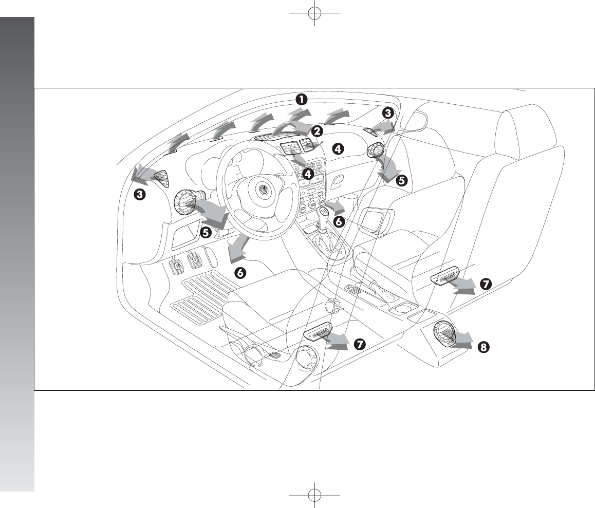
GETTING TO KNOW YOUR CAR
86
1Upper stationary vent for defrosting or demisting windscreen - 2Upper centre adjustable vent - 3Stationary vents for defrosting or demist-
ing side windows - 4Adjustable centre, swivel vents - 5Side adjustable and swivel outlets - 6Front feet area fixed vents - 7Rear feet area
fixed vents - 8Rear adjustable swivel outlet (upon request for versions/markets where applicable).
CLIMATE CONTROL SYSTEM
fig. 95
A0A1019m
086-109_Alfa147 Q2 GB 4-07-2008 12:00 Pagina 86
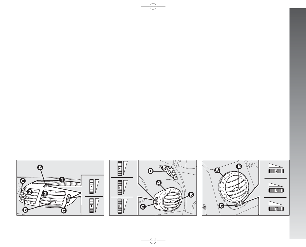
GETTING TO KNOW YOUR CAR
87
fig. 96 fig. 97 fig. 98
UPPER CENTRE VENT
ADJUSTMENT
(fig. 96)
The vent (1) has an opening/closing con-
trol (A).
•
= Completely closed.
I= Completely open
CENTRE SWIVEL VENT
ADJUSTMENT
(fig. 96)
Each vent (2) has a lever (B) which
makes it possible to direct the flow of air (in
the 4 directions: up/down, right/left).
To adjust the air flow, use control (C):
•
= Completely closed.
I= Completely open
SIDE SWIVEL OUTLET
ADJUSTMENT
(fig. 97)
To direct the flow of air, turn the knurled
ring (A) and/or directly use control (B) as
required.
To adjust the air flow, use control (C):
•
= Completely closed.
I= Partially open.
II = Completely open
D- fixed vent for defrosting or demisting
side windows.
REAR SWIVEL OUTLET
ADJUSTMENT
(fig. 98) (upon request for
versions/markets where
applicable)
To direct the flow of air, turn the knurled
ring (A) and/or directly use control (B) as
required.
To adjust the air flow, use control (C):
•
= Completely closed.
I= Partially open.
II = Completely open
A0A0085m A0A0086m A0A0087m
086-109_Alfa147 Q2 GB 4-07-2008 12:00 Pagina 87
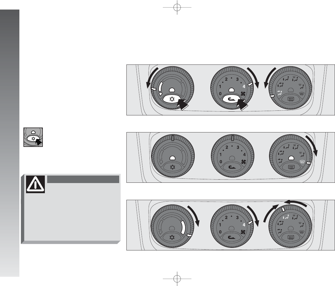
GETTING TO KNOW YOUR CAR
88
Below is a brief description of the heating
and manual climate control system (upon re-
quest for versions/markets where applicable).
The only difference between the two systems
is the climate control compressor button
√
,
fitted only on the versions with manual climate
control system. To obtain the maximum func-
tions of both systems in the different condi-
tions of use, set the pointer on the rings of the
corresponding knobs as illustrated.
A0A0139m
MANUAL CLIMATE CONTROL SYSTEM
(upon request for versions/markets where applicable)
MAXIMUM COOLING POWER
A0A0107m
MAXIMUM COOLING POWER
A0A0122m
MAXIMUM COOLING POWER
IMPORTANT An important fea-
ture of the manual climate control
system is airdehumification. It is
always advisable to turn the climate control
compressor on to prevent possible misting.
fig. 99
fig. 100
fig. 101
With low external tem-
perature the climate con-
trol compressor is unable to
work. It is therefore inadvisable
to use the inside air recirculation
function
v
with low outside
temperature as windows may
mist over quickly.
WARNING
086-109_Alfa147 Q2 GB 4-07-2008 12:00 Pagina 88
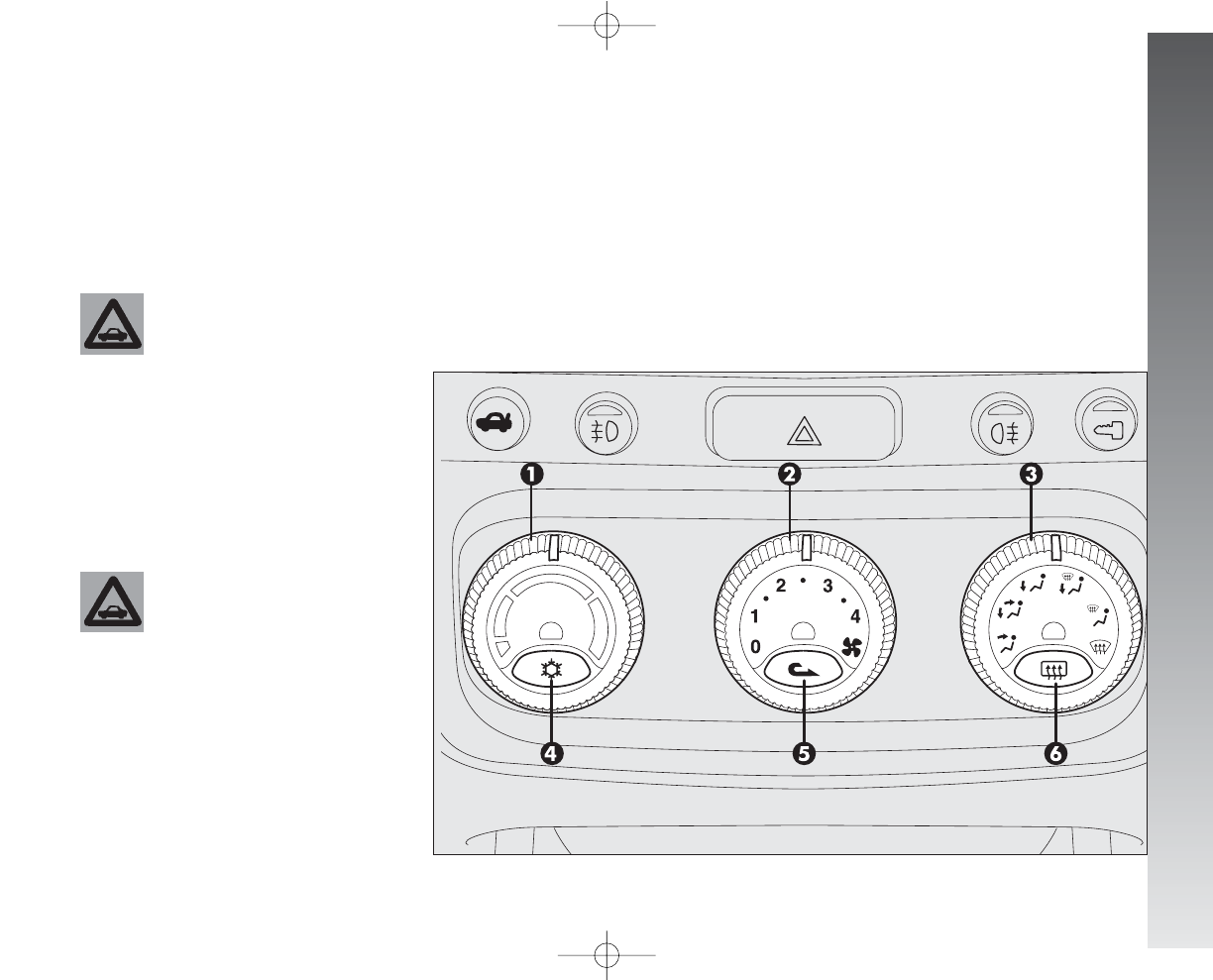
GETTING TO KNOW YOUR CAR
89
CONTROLS
(fig. 102)
1- Air temperature adjustment knob
2- Fan speed adjustment knob
3- Air distribution selector knob
fig. 102
A0A0088m
4- Climate control compressor on/off but-
ton
√
(only versions with manual climate
control system)
5- Inside air re-circulation on /off button
v
6- Rearscreen heating on/off button
(
.
The coolant used for the
climate control system is
R134a which meets cur-
rent regulations and does not harm
the environment in the event of ac-
cidental spillage.
Absolutely avoid the use of oth-
er fluids which are incompatible
with the system components.
For more detailed information about the
system and how to make the best use of it,
read the instructions given in the following
pages.
At any battery re-
moval/reconnection wait
for at least 3 minutes be-
fore starting the engine, to let the
climate control unit reset the po-
sition of the electrical actuators
controlling the temperature and the
air distribution.
086-109_Alfa147 Q2 GB 4-07-2008 12:00 Pagina 89
GETTING TO KNOW YOUR CAR
90
AIR TEMPERATURE
ADJUSTMENT KNOB
Turn the ring of knob (1-fig. 102) clock-
wise or counter-clockwise respectively to
higher or lower the temperature of the air
admitted to the passenger compartment.
FAN SPEED ADJUSTMENT
KNOB
Turning th ring of knob (2-fig. 102) it
is possible to select one of the fan speeds to
personalise the amount of air admitted to the
passenger compartment.
Position 0turns off the fan and automat-
ically engages inside air re-circulation (shown
by the lighting up of the led next to the but-
ton 5
v
) thereby shutting off the inlet of
outside air to the car.
To switch off inside air re-circulation, press
button (5)
v
.
If the fan is at 0air recirculation will turn
on automatically. When switching the engine
off, at next restarting if the fan is at 0yet,
air recirculation will turn on again although pre-
viously turned off.
AIR DISTRIBUTION KNOB
Turning the knob ring (3-fig. 102), the
following positions are selected in sequence:
Air flow towards the upper centre, front cen-
tre vents and from the front and rear
outlets (if fitted) with the possibili-
ty of adjustment using the controls on the
actual vents.
Splitting of air flow between the previous
vents and the lower part of the pas-
senger compartment.
Air flow to the lower part of the passenger
compartment (front and rear).
Splitting of air flow between the
windscreen/front side windows and
the lower part of the passenger com-
partment.
Air flow towards the windscreen and front
side windows for demisting/de-
frosting.
Flow air to allow quick demisting/defrost-
ing of the windscreen and front side
windows, turning on rearscreen heat-
ing for defrosting/demisting (function called
MAX-DEF)
CLIMATE CONTROL
COMPRESSOR ON/OFF
BUTTON
√
(only versions with manual
climate control system)
The climate control compressor is engaged
pressing button (4-fig. 102)
√
and the
fan is also operated automatically at first
speed even if the knob (2) is at position 0.
When the system is operating the corre-
sponding led next to the button turns on.
The climate control compressor can only
work with the engine running and external
temperature not very low. If the climate con-
trol compressor is turned off, air re-circulation
is engaged automatically, turning off the cor-
responding led, to prevent the windows from
misting. Inside air re-circulation may also be
engaged pressing the button (5)
v
. If the
fan is at 0the climate control system com-
pressor will not turn on.
μ
w
≤
y
-
¥
Operation of the climate
control compressor is nec-
essary for cooling and dehumidify-
ing the air; it is advisable to keep
this function always on, to prevent
window misting problems.
WARNING
086-109_Alfa147 Q2 GB 4-07-2008 12:00 Pagina 90
GETTING TO KNOW YOUR CAR
91
INSIDE AIR RE-CIRCULATION
ON/OFF BUTTON v
Pressing button (5-fig. 102)
v
ac-
tivates inside air re-circulation and the led
next to the button lights up.
In this case the climate control system di-
rectly treats the air contained in the pas-
senger compartment, the fan is on.
To switch the air re-circulation feature off
and withdraw air from outside, press the but-
ton again.
IMPORTANT The condition and operat-
ing mode of the climate control compres-
sor and inside air re-circulation, shown by
the turning on of the leds next to the but-
tons (4)
√
and (5)
v
, are also stored
when the engine is off. Therefore, when the
engine is started the selectionschosen be-
fore turning off are resumed.
REARSCREEN HEATING
ON/OFF BUTTON
(
Pressing the button (6-fig. 102)
(
turns on the demisting/defrosting of the
rearscreen, and if present, the wing mirror
heating coils; simultaneously the led next to
the button turns on. This function is timed
and switched off automatically after 20 min-
utes. To turn off earlier, press the button
again.
IMPORTANT The system automatically
turns on rearscreen heating if the tempera-
ture is below 3°C.
IMPORTANT Do not apply stickers on
the inside of the rearscreen over the heat-
ing filaments to avoid damage which might
cause it to stop working properly.
With low external tem-
perature the climate con-
trol compressor is unable to
work. It is therefore inadvisable
to use the inside air recirculation
function
v
with low outside
temperature as windows may
mist over quickly
WARNING
The inside air re-circulation
system makes it possible to
reach the required “heating” or
“cooling” conditions faster. It is
however inadvisable to use it on
rainy/cold days as it would con-
siderably increase the possibility of
the windows misting inside, espe-
cially if the climate control system
is off.
WARNING
It is advisable to turn on
the inside air re-circulation
system
v
in queues or tunnels to
avoid admitting polluted air from
outside. The prolonged use of this
function should however be avoid-
ed, especially with several people
on board, to avoid the possibility
of the windows mistinginside.
WARNING
086-109_Alfa147 Q2 GB 4-07-2008 12:00 Pagina 91
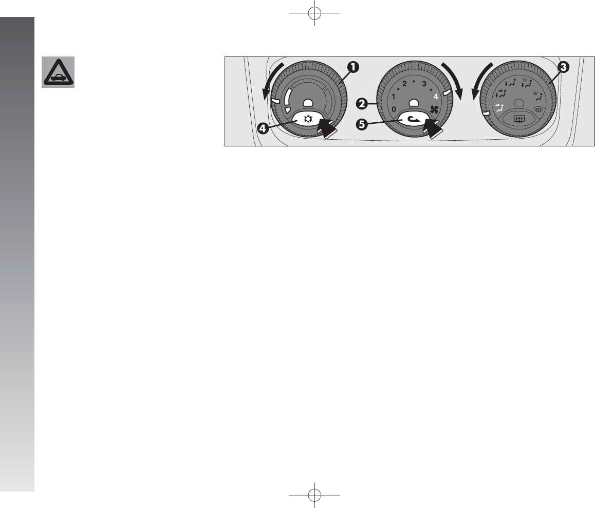
GETTING TO KNOW YOUR CAR
92
AIR COOLING
AND DEHUMIDIFYING
(fig. 102/a)
To cool and dehumidify the air with the en-
gine running and the windows shut, proceed
as follows:
- temperature adjustment knob (1), point-
er on blue sector.
- air quantity adjustment (2), knob point-
er on the speed required to personalise the
amount of air admitted
- air distribution (3), knob pointer at the
required symbol.
- air vents completely open.
- compressor on enable button(4) pressed
√
(for versions/markets where applicable)
(led next to button on) (only for versions
with manual climate control system).
Wishing to moderate the cooling action,
increase the temperature turning the knob
ring (1) towards the red sector, until ob-
taining the required temperature.
Proceed as follows to obtain the maximum
cooling power:
- set the pointer of knob (1) as far as it
will go counter-clockwise (minimum tem-
perature blue sector);
- set the pointer of knob (2) to the max-
imum fan speed.
- press the inside air re-circulation on but-
ton (5)
v
.
- set the pointer of the air distribution knob
(3) to the required position (position
¥
is
recommended).
- air vents completely open.
- compressor on enable button (4)
√
pressed (led next to button on) (only for
versions with manual climate control sys-
tem).
The use of the climate control system at
minimum temperature should be restricted
to short lengths of time and very hot cli-
mates, to avoid over-cooling the passenger
compartment.
A0A0220m
fig. 102/a
When cleaning the inside
of the rearscreen, take
care not to damage the
heating filaments.
086-109_Alfa147 Q2 GB 4-07-2008 12:00 Pagina 92
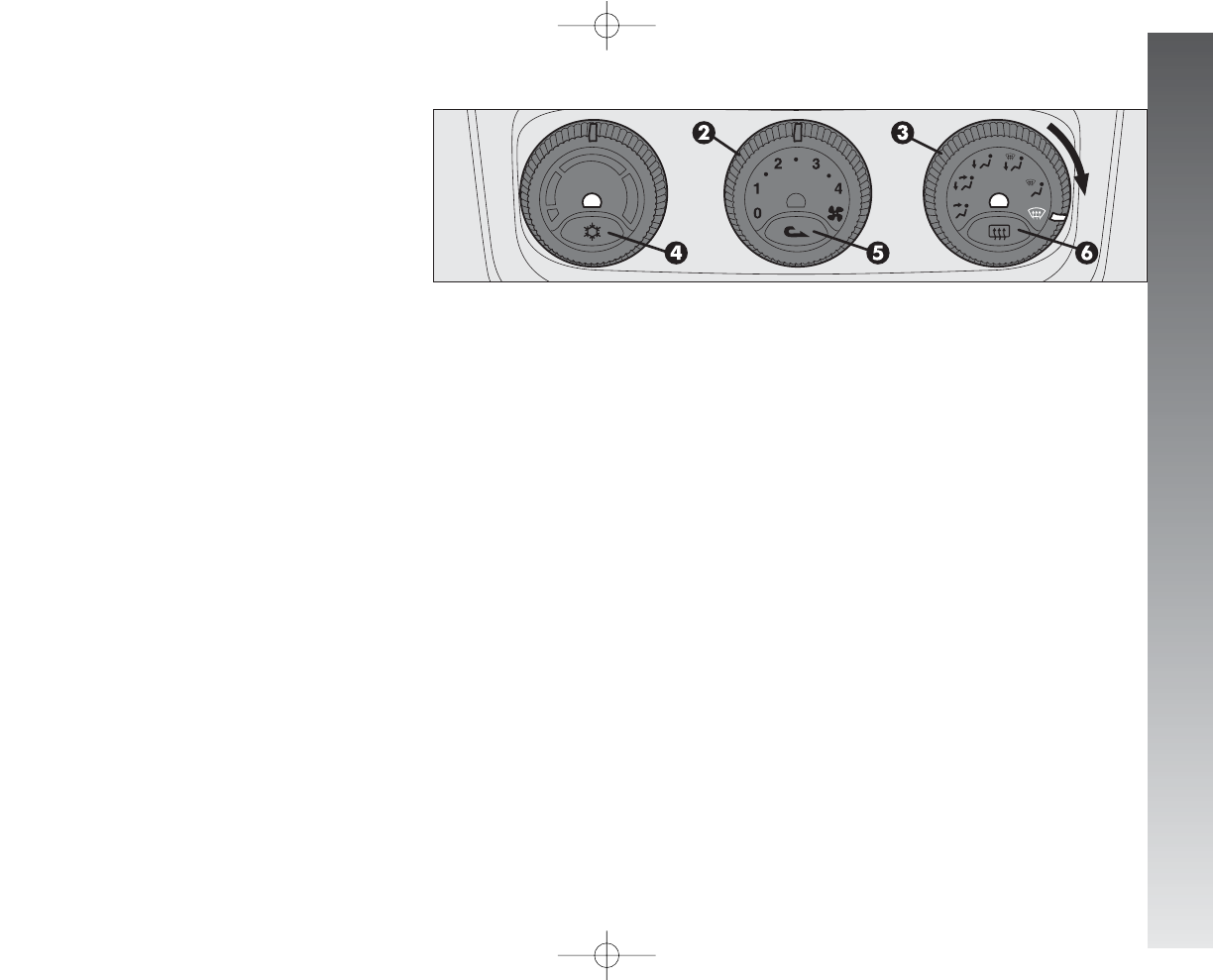
GETTING TO KNOW YOUR CAR
93
DEMISTING
AND/OR DEFROSTING THE
WINDSCREEN AND FRONT
SIDE WINDOWS, REARSCREEN
AND WING MIRRORS
(
-
MAX-DEF function) (fig. 103)
Proceed as follows:
- turn the ring of the air distribution knob
(3) to the
-
symbol.
The climate control activates all the functions
necessary to quicken demisting/defrosting of
the windscreen and side windows with timing
(switching off automatically after 3minutes),
as follows:
- it turns on the climate control compres-
sor (only for versions with manual climate
control system);
- switches off air re-circulation, if engaged;
- sets the maximum air temperature;
- operates the fan at a predefined speed;
- directs the flow of air towards the wind-
screen and front side window vents;
- turns on rearscreen heating and, if pre-
sent, the wing mirror coils.
When the max def function is on, the fol-
lowing are on: the led next to the rearscreen
heating button (6)
(
, the led next to the
climate control compressor on/off enable
button (4)
√
(only for versions with man-
ual climate control system)
IMPORTANT If the engine is not hot
enough, the function does not immediate-
ly engage the pre-established fan speed, to
restrict the inlet of air to the passenger com-
partment that is not warm enough to demist
the windows.
After demisting/defrosting, simply use the
controls to maintain the optimum conditions
of vision and comfort.
IMPORTANT The hotter the engine the
more effective defrosting will be.
IMPORTANT In cases of heavy damp
and/or rain and/or big differences in tem-
perature between inside the car and outside,
it is advisable to proceed as follows to
demist the windows:
- air re-circulation off, led next to button
(5)
v
off;
- pointer of knob (2) at fan second speed
at least;
- pointer of knob (3) on symbol
≤
with
the possibility of passing to position
y
if
more misting is noted;
- climate control compressor button (4)
√
pressed, led next to button on (only for
versions with manual climate control sys-
tem).
To defrost/demist the rearscreen, press
button (6)
(
, led next to button on.
A0A0221m
fig. 103
086-109_Alfa147 Q2 GB 4-07-2008 12:00 Pagina 93
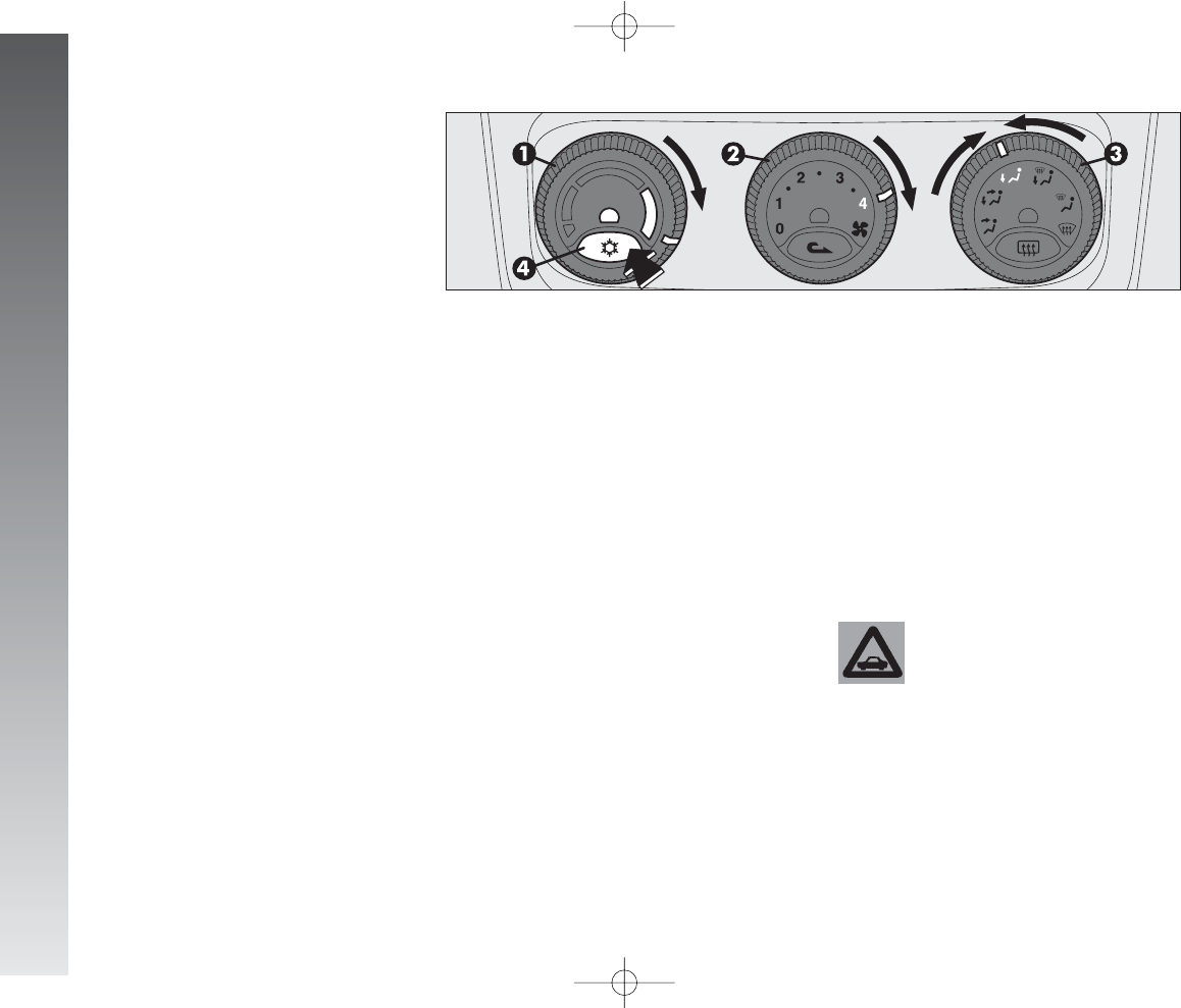
GETTING TO KNOW YOUR CAR
94
HEATING
(fig. 104)
To obtain the temperature required, pro-
ceed as follows:
- temperature adjustment knob pointer (1)
on the red sector as required;
- air quantity adjustment knob pointer (2)
on the fan speed required to personalise the
amount of air admitted;
- air distribution knob pointer (3) on the
required position.
To obtain the maximum heating power pro-
ceed as follows:
- knob pointer (1) as far as it will go clock-
wise (maximum temperature red sector);
- knob pointer (2) on maximum fan
speed;
- air distribution knob pointer (3) on the
required position (position
w
) is recom-
mended.
To keep the air in the passenger compart-
ment dehumidified, you are recommended
to press the climate control compressor en-
able button (4) (for versions/markets
where applicable)
√
(only for versions with
manual climate control system).
IMPORTANT To be able to obtain sat-
isfactory passenger compartment warming,
the engine should have reached normal op-
erating temperature.
The filter has the specific capability of fil-
tering external air, thus admitting to the pas-
senger compartment purified air, free from
particles such as dust, pollen, etc.
In addition to the above mentioned func-
tions, is also reduces the concentration of
pollutants.
The filtering action is active in all air inlet
conditions and it is clearly more effective
with the windows closed.
Have the conditions of the filter checked
at least once a year, preferably at the on-
set of summer by Alfa Romeo Authorised
Services.
If the car is habitually used in dusty or pol-
luted areas, the filter should be checked and
replaced at shorter intervals than those spec-
ified in the Programmed Maintenance
Schedule.
If the filter is not replaced
the efficiency of the cli-
mate control system may
be seriously compromised up to
blocking the air flow at the outlets
and vents.
POLLEN FILTER
(for versions/markets where applicable)
A0A0222m
fig. 104
086-109_Alfa147 Q2 GB 4-07-2008 12:00 Pagina 94
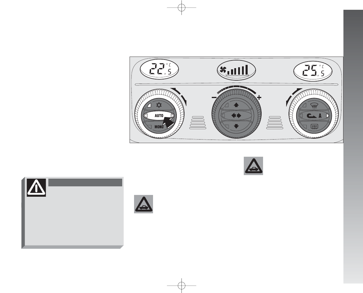
GETTING TO KNOW YOUR CAR
95
AUTOMATIC TWO-ZONE CLIMATE CONTROL SYSTEM
(upon request for
versions/markets where applicable)
To start the system (fig. 105):
- turn the knob rings to set the required
temperatures (driver’s side - passenger’s
side).
- press the AUTO button.
IMPORTANT The climate control sys-
tem makes it possible to personalise the
temperatures required on the two side with
a maximum difference of 7°C between the
driver’s side and the passenger’s side.
IMPORTANT The climate control com-
pressor only works with the engine running
and an outside temperature above 4°C. For more detailed information about the
system and how to make the best use of
it, read the instructions given in the follow-
ing pages.
A0A1020m
fig. 105
The coolant used for the
climate control system is
R134a which meets cur-
rent regulations and does not harm
the environment in the event of ac-
cidental spillage. Absolutely avoid
the use of other fluids which are in-
compatible with the system com-
ponents.
With low external tem-
perature the climate con-
trol compressor is unable to
work. It is therefore inadvisable
to use the inside air recirculation
function
v
with low outside
temperature as windows may
mist over quickly
WARNING
At any battery re-
moval/reconnection wait
for at least 3 minutes be-
fore starting the engine, to let the
climate control unit reset the po-
sition of the electrical actuators
controlling the temperature and the
air distribution.
086-109_Alfa147 Q2 GB 4-07-2008 12:00 Pagina 95
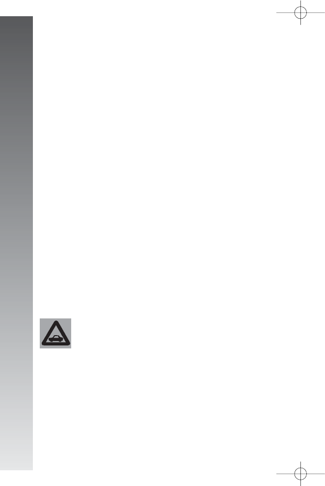
GETTING TO KNOW YOUR CAR
96
Air quality control is also entrusted to a
combined particle and activated carbon fil-
ter. The climate control system automatically
controls and adjusts the following parame-
ters and functions:
- inside temperature (separately on driver’s
side and passenger’s side)
- fan speed
- air distribution
- inside air re-circulation on/off
- climate control compressor on/off en-
able.
It is possible to change the setting of the
following functions manually:
- fan speed
- air distribution
- inside air re-circulation on/off
- climate control compressor on/off en-
able.
The control of functions not changed man-
ually remains automatic and in any case the
temperature of the air admitted to the pas-
senger compartment is controlled automat-
ically according to the temperatures set on
the driver’s and passenger’s displays.
IMPORTANT Manual selections prevail
over automatic ones and remain in storage
until the user decides to resume automatic
control. The settings selected manually are
stored when the engine is switched off and
resumed the next time it is started.
To ensure correct opera-
tion of the incipient mist-
ing sensor, stickers must
not be applied (road licence holder,
time card, etc.) in the “control”
area between the sensor and the
windscreen. Care should also be
given to cleaning the windscreen
and the actual sensor, avoiding the
accumulation of dust and other sub-
stances.
IMPORTANT The demisting procedure
is enabled each time the ignition key is
turned to MAR or pressing the AUTO but-
ton. When this procedure is working it can
be turned off pressing one of the following
buttons: compressor, air recirculation, air
flow, air capacity. This operation inhibits the
incipient misting sensor signal until the AU-
TO button is pressed again or the next time
the ignition key is turned to MAR.
On certain versions, the system is inte-
grated by an antipollution sensor capable of
automatically switching on inside air re-cir-
culation to lessen the harmful effects of pol-
luted air in cities, queues, tunnels and op-
eration of the windscreen washer (with the
typical smell of spirit).
IMPORTANT The function of the anti-
pollution sensor is subordinate to safety con-
ditions; therefore disabling the climate con-
trol compressor or with low external tem-
perature, the sensor is disabled. In any case,
the sensor can be re-enabled pressing the
recirculation button
v
until taking it to
the automatic mode.
GENERAL
The car is fitted with a two-zone climate con-
trol system, controlled by an electronic control
unit which makes it possible to separately ad-
just the air temperature on the driver’s side
and on the passenger’s side. To obtain opti-
mum temperature control in the two areas
of the passenger’s compartment, the system
has an outside sensor, a passenger’s com-
partment sensor and a two-zone sun ray sen-
sor. On some versions the system is integrat-
ed with an incipient misting sensor installed
behind the inside rear-view mirror, capable of
“controlling” a predefined area of the wind-
screen inner surface which can automatically
act on the system to prevent or reduce mist-
ing through a series of operations such as:
opening air re-circulation, enabling the com-
pressor, air flow to the windscreen, fan speed
sufficient for demisting; in the case of heavy
misting, enabling the MAX-DEF function.
086-109_Alfa147 Q2 GB 4-07-2008 12:00 Pagina 96
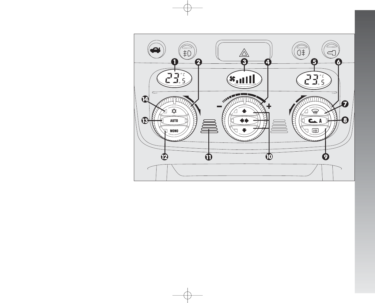
GETTING TO KNOW YOUR CAR
97
CONTROLS
(fig. 106)
1- Inside temperature set display (driver’s
side)
2- Inside temperature adjustment knob
(driver’s side)
3- Fan speed set and system off display
(OFF)
4- Knob for adjusting the fan speed and
switching the system off
5- Inside temperature set display (pas-
senger’s side)
6- Inside temperature adjustment knob
(passenger’s side)
7- Maximum defrosting/demisting
on/off button for windscreen and front side
windows, rearscreen heating and wing mir-
ror coils (MAX-DEF function
-
)
8- Inside air re-circulation on/off button
v
(manual/automatic)
9- Rearscreen heating and wing mirror de-
frosting on/off button
(
10 - Air distribution selection buttons
11 - Inside air temperature sensor
12 - Button for aligning the temperature
set on the passenger’s side with that on the
driver’s side MONO
13 - Button for selecting the system au-
tomatic mode AUTO
14 - Climate control compressor on/off
enable button
√
fig. 106
A0A1021m
086-109_Alfa147 Q2 GB 4-07-2008 12:00 Pagina 97

GETTING TO KNOW YOUR CAR
98
HOW TO USE THE AUTOMATIC
TWO-ZONE CLIMATE CONTROL
SYSTEM
(fig. 106)
IMPORTANT The knob rings do not
have a mechanical stopper therefore, once
the maximum or minimum value has been
reached, they are free to turn in both direc-
tions.
The system can be started in different
ways, but it is advisable to set the temper-
atures required on the displays; then press
the (13)AUTO button.
This way the system will start working
completely automatically to reach the tem-
peratures set as quickly as possible and then
maintain them.
During completely automatic system op-
eration, the temperatures set can be
changed at any time; the system will auto-
matically change its settings to adjust to the
new requirements.
IMPORTANT To be able to be accept-
ed by the system, the difference in the tem-
perature between the driver’s and passen-
ger’s side must be within a range of 7°C.
It is possible to personalise the choices
made automatically by the system inter-
veningmanually on the following controls:
- fan speed adjustment knob (4)
- air distribution selection buttons (10)
- inside air re-circulation on/off button (8)
v
- climate control on enable button (14)
√
.
Manually selecting one or more of these
functions turns off the right led on the but-
ton (13)AUTO.
With one or more functions engaged man-
ually, the adjustment of the temperature of
the air admitted to the passenger compart-
ment continues to be controlled automati-
cally by the system (left led on button 13
AUTO on) except with the climate control
compressor off.
In fact, in this condition the air admitted
to the passenger compartment cannot have
a lower temperature than the outside air;
this condition is indicated by the turning off
of the two leds on button (13)AUTO and
flashing on the display (1) and/or (5) re-
lated with the temperature rate that can-
not be obtained.
086-109_Alfa147 Q2 GB 4-07-2008 12:00 Pagina 98
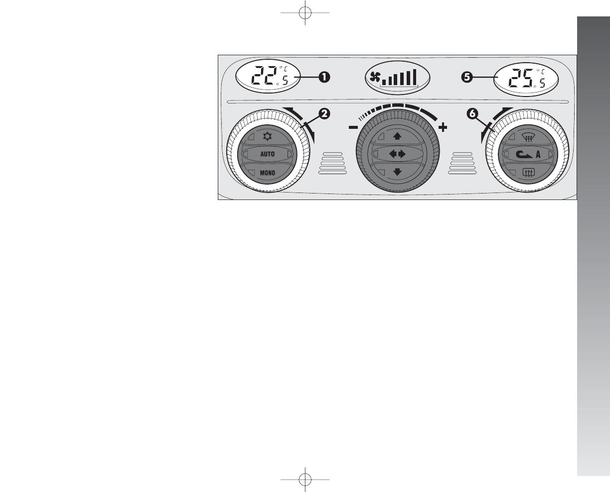
GETTING TO KNOW YOUR CAR
99
AIR TEMPERATURE
ADJUSTMENT KNOBS
(fig. 107)
Turning the rings of knobs (2or 6), clock-
wise or counter-clockwise, respectively high-
ers or lowers the temperature of the air re-
quired respectively in the left zone (knob 2)
or right zone (knob 6) of the passenger
compartment. The temperatures set are
shown on the displays (1) and (5) above
the knobs.
Separate operation of the temperatures set
is restored automatically using knob (6).
Turning the knob rings clockwise or
counter-clockwise until they reach the ex-
treme selections HI or LO, the maximum
heating or cooling functions are respective-
ly engaged:
A0A1022m
fig. 107
086-109_Alfa147 Q2 GB 4-07-2008 12:00 Pagina 99
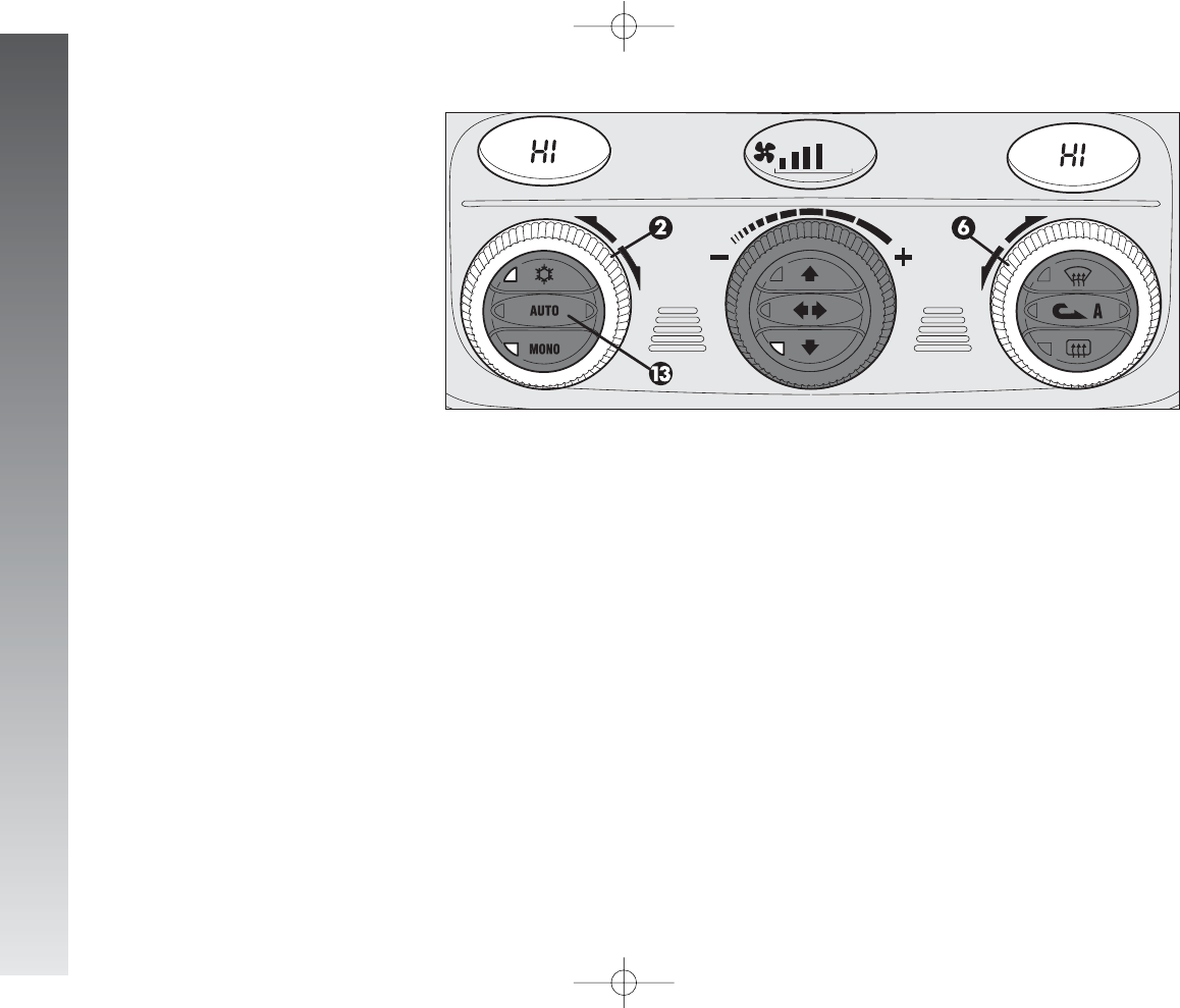
GETTING TO KNOW YOUR CAR
100
HI function
(highest heating power - fig. 108)
This is turned on setting on the display a
temperature above 32.5°C, and can be ac-
tivated independently from the driver’s or
passenger’s side or both; this setting brings
the system to the “monozone” mode and
is shown on both displays.
This function can be engaged when re-
quiring to heat the passenger compartment
as quickly as possible, exploiting the maxi-
mum potential of the system.
This function uses the maximum temper-
ature of the coolant fluid, while air distribu-
tion and fan speed are controlled according
to the system settings.
This function is unadvisable with
the engine cold to prevent admit-
ting air that is not warm enough to
the passenger compartment.
All manual settings are possible with this
function on.
To switch the system off, simply turn the
ring of knob (2) or (6) of the temperature
set to a value below 32.5°C; the opposite
display will show 32.5°C.
A0A1023m
fig. 108
Pressing key (13)AUTO the display will
show a temperature of 32.5°C and returns
to an operating condition with automatic tem-
perature adjustment.
086-109_Alfa147 Q2 GB 4-07-2008 12:00 Pagina 100
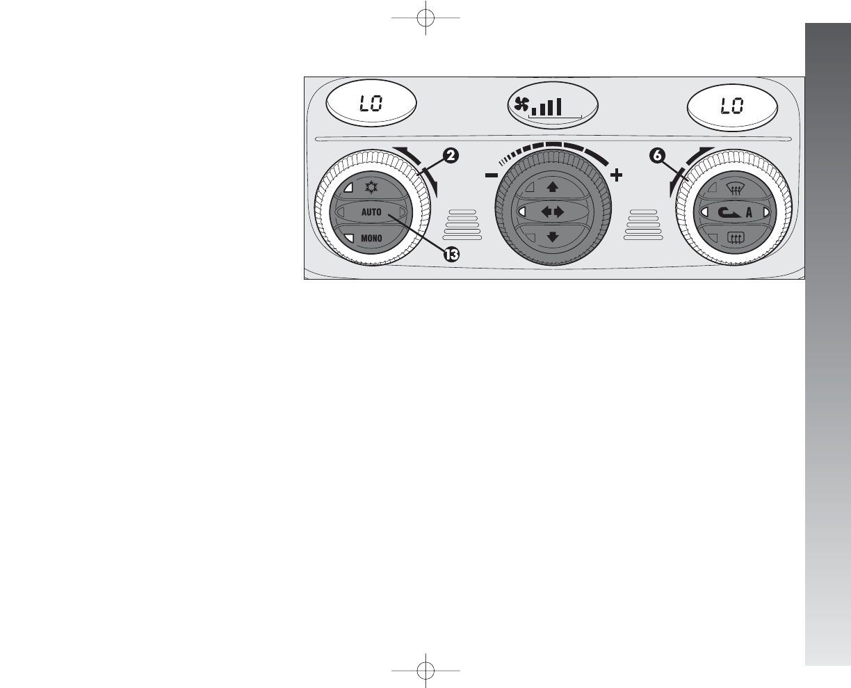
GETTING TO KNOW YOUR CAR
101
LO function
(highest cooling power - fig. 109)
This is turned on setting on the display a
temperature below 16.5°C; this setting is
shown on both displays.
This function can be engaged when re-
quiring to cool the passenger compartment
as quickly as possible, exploiting the maxi-
mum potential of the system.
The function cuts off air heating, engages
inside air re-circulation (to prevent admitting
hot air to the passenger compartment) and
the climate control compressor, takes air dis-
tribution to
RE
and the fan speed as set
by the system.
All manual settings are possible with this
function on.
To switch the function off, simply turn the
ring of knob (2) or (6) of the temperature
set on a value above 16.5°C; the opposite
display will show 16.5°C.
Pressing key (13)AUTO the display will
show a temperature of 16.5°C and returns
to an operating condition with automatic
temperature adjustment.
A0A1024m
fig. 109
086-109_Alfa147 Q2 GB 4-07-2008 12:00 Pagina 101
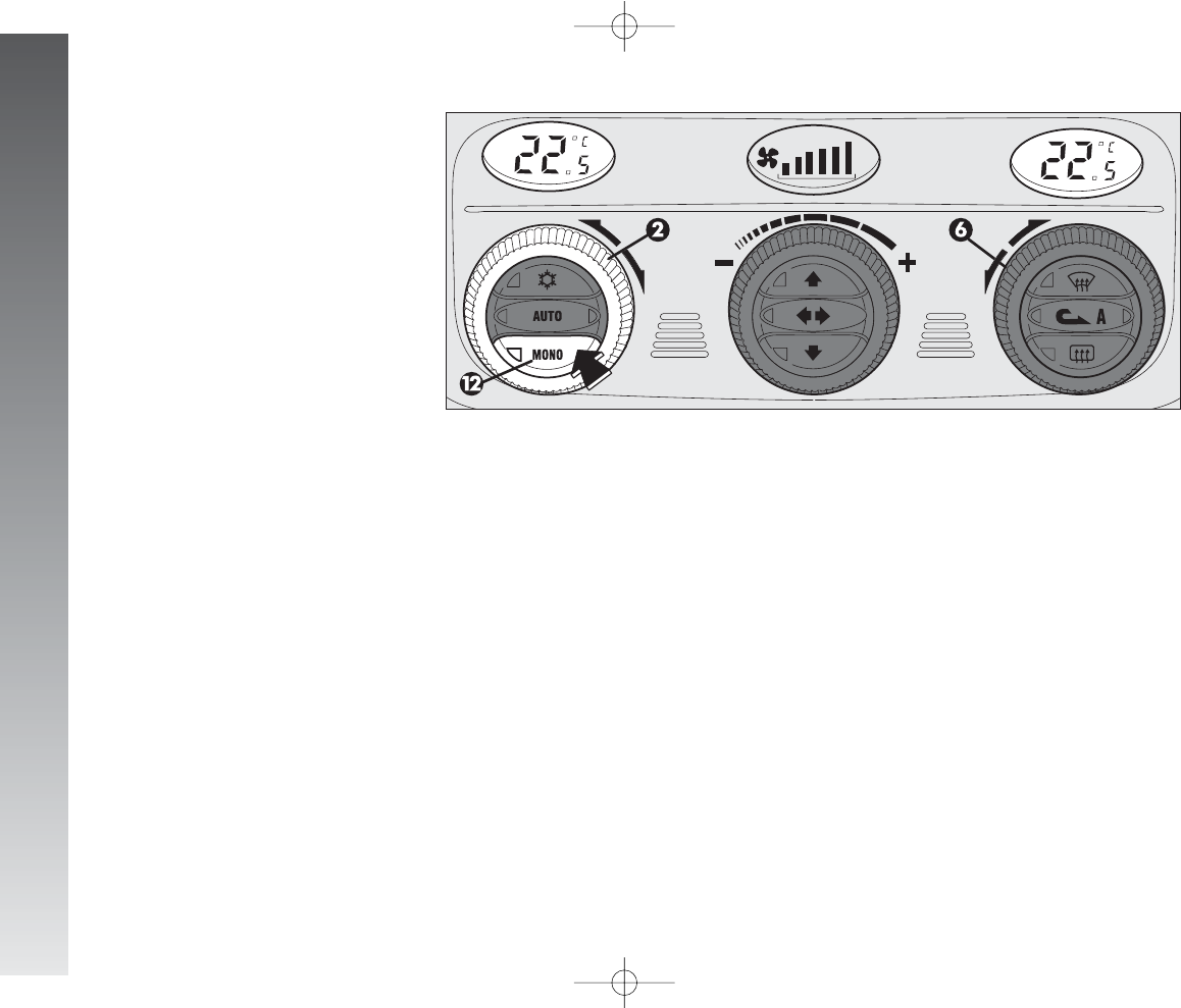
GETTING TO KNOW YOUR CAR
102
MONO BUTTON FOR
ALIGNMENT OF THE
TEMPERATURE SET
(fig. 110)
Pressing button (12)MONO automatically
aligns the temperature on the passenger’s
side with that on the driver’s side, therefore
it is possible to set the same temperature
between the two zones simply turning the
ring of knob (2) on the driver’s side.
This function is provided to simplify tem-
perature adjustment of the whole passen-
ger compartment when only the driver is on
board.
Separate operation of the temperatures set
is automatically restored when the passen-
ger uses the ring on knob (6) or presses
button (12)MONO.
A0A1025m
fig. 110
086-109_Alfa147 Q2 GB 4-07-2008 12:00 Pagina 102
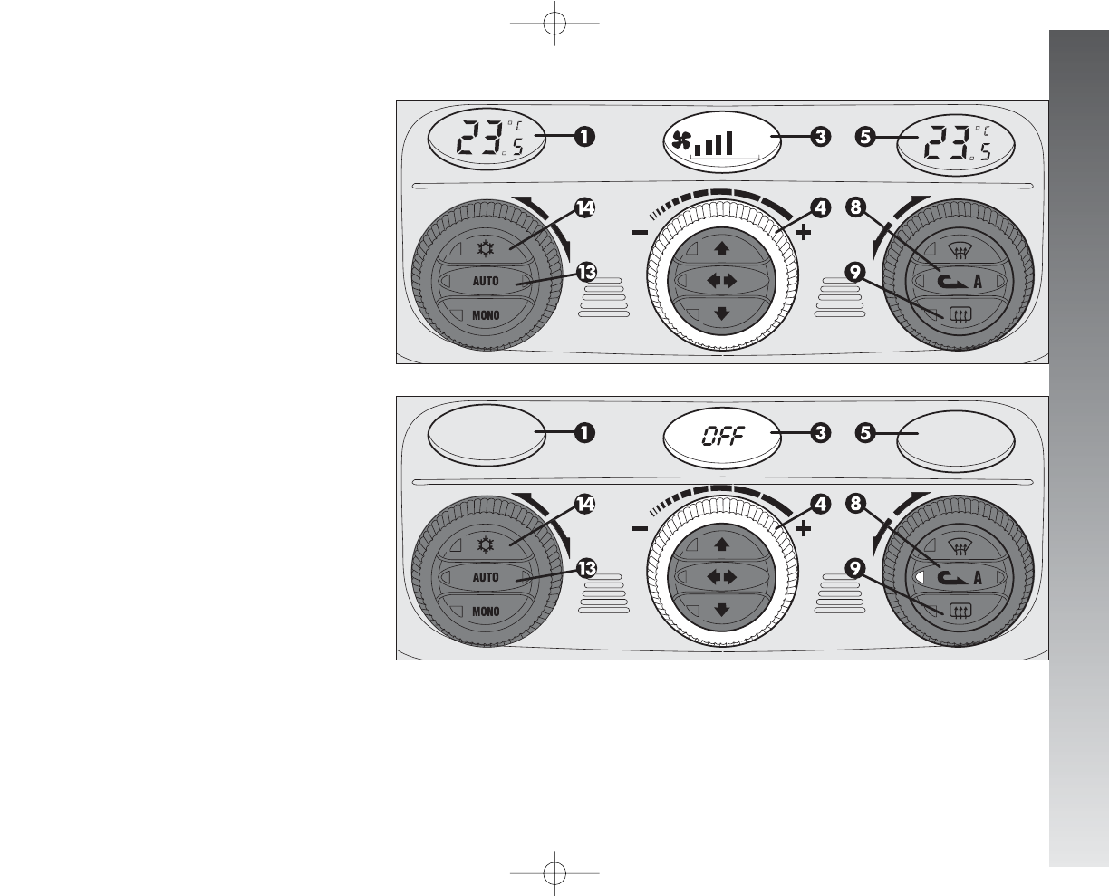
GETTING TO KNOW YOUR CAR
103
FAN SPEED
ADJUSTMENT KNOB
(fig. 111-112)
Turning the ring of knob(4), clockwise or
counter-clockwise, increases or decreases
the speed of the fan, thus the amount of air
admitted to the passenger compartment;
the 16 selectable speeds are shown on a
bar (in steps of 3), up to a maximum of 6
bars lit:
- maximum fan speed = all bars lit;
- minimum fan speed = one bar lit.
The fan can be cut off (all bars off) only
if the climate control compressor has been
switched off pressing button (14)
√
. To
restore automatic fan speed control, after a
manual adjustment, press button (13)AU-
TO. Completely turning the ring of knob (4)
counter-clockwise switches the system off,
with the following situation: display (1) off;
display (5) off; centre display (3) with lit-
display OFF and left led on inside air re-cir-
culation button (8)
v
on.
IMPORTANT Pressing the inside air re-
circulation button (8)
v
it is possible to
obtain the inlet of untreated outside air to
the passenger compartment.
To turn the system on again, simply turn
the ring of knob (4) clockwise, or press any
one button, except the inside air re-circula-
tion (8) and rearscreen (9) buttons; this
operation restores all the operating condi-
tions stored previously.
IMPORTANT On leaving the OFF con-
dition, inside air re-circulation
v
returns
to the condition prior to switching off.
A0A1026m
A0A1027m
fig. 111
fig. 112
086-109_Alfa147 Q2 GB 4-07-2008 12:00 Pagina 103
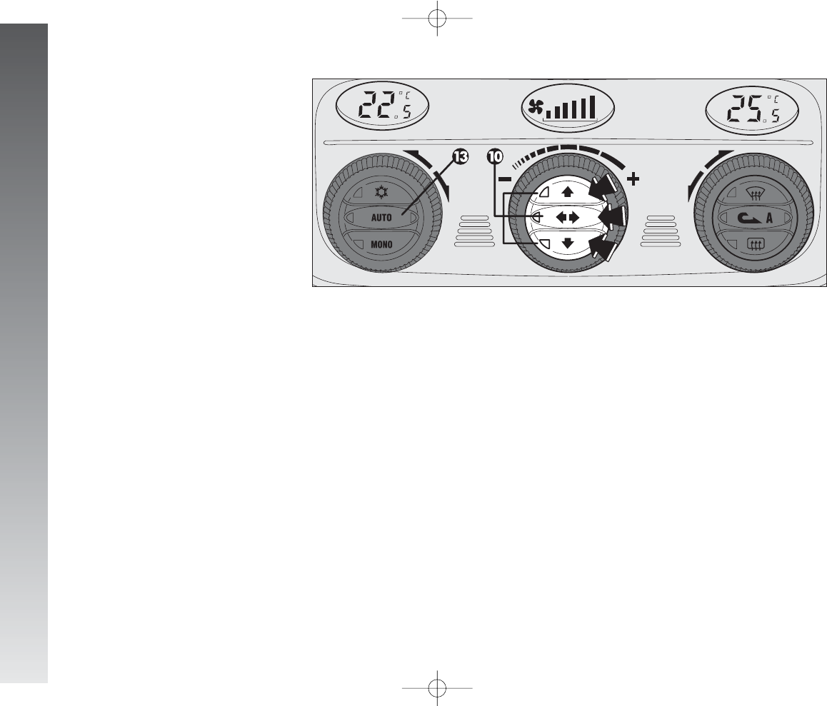
GETTING TO KNOW YOUR CAR
104
AIR DISTRIBUTION SELECTION
BUTTONS
(fig. 113)
Pressing one or more buttons (10) it is
possible to manually choose one of the 5
possible air distributions to the passenger
compartment:
RE
Flow of air to the dashboard centre
and side outlets and rear outlet (if fit-
ted).
RE
Splitting of the air flow between the
vents to the lower part of the pas-
senger’s compartment (warmest air)
and the dashboard centre and side
outlets and the rear outlet (if fitted)
(coolest air). The air flow distribution
is particularly useful in spring and au-
tumn, when the sun is shining.
Z
Air flow towards the front and rear
lower parts of the passenger’s com-
partment. Due to the natural tenden-
cy of heat to spread upwards, this
type of distribution allows heating of
the passenger’s compartment in the
shortest time, also giving a prompt
feeling of warmth to the coldest parts
of the body.
A0A1028m
Q
Splitting of the air flow between the
windscreen and side window defrost-
ing/demisting vents and the lower
part of the car. This type of air distri-
bution allows satisfactory heating of
the passenger’s compartment while
preventing possible misting of the win-
dows.
Q
Air flow to the windscreen and front
side window vents to demist or de-
frost them.
IMPORTANT Pressing one of these but-
tons turns on (led on button itself on) or off
(led on button off) the associated functions
if the combination chosen is among the 5
possible ones; if not it only activates the
main function of the button pressed, with-
out the possibility of turning off with another
press (at least in one distribution the air flow
should be spread in the passenger com-
partment).
To restore automatic air distribution control
after a manual selection, press button
(13)AUTO.
Z
Z
fig. 113
086-109_Alfa147 Q2 GB 4-07-2008 12:00 Pagina 104
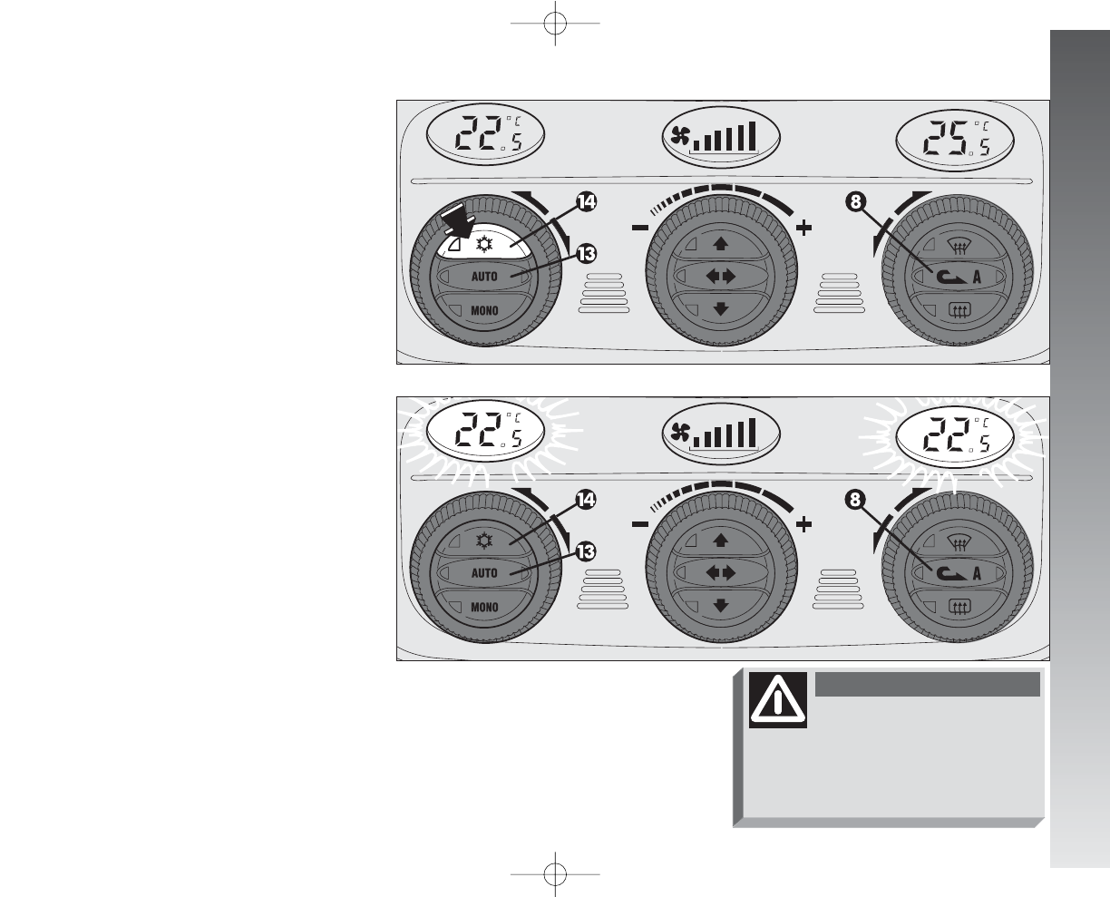
GETTING TO KNOW YOUR CAR
105
press button (13)AUTO; in which case,
however, the other manual settings set will
be cancelled.
CLIMATE CONTROL
COMPRESSOR ON/OFF
ENABLE BUTTON
√
(fig. 114)
Pressing button (14)
√
enables the turn-
ing on of the climate control compressor.
This condition is shown by the lighting up of
the led on the button itself.
When the climate control compressor is
turned off, the leds on buttons (13)AUTO
and (14)
√
go off; automatic inside air re-
circulation control is also excluded (both leds
off on button 8
v
) which always stays
off to prevent misting the windows; even
if unadvisable, it is still possible to restore
automatic operation of inside air re-circula-
tion pressing button (8)
v
.
With the climate control compressor off, it
is not possible to admit air to the passenger
compartment with a temperature below the
outside temperature; in this case, the val-
ue flashes on the display concerning the
temperature that cannot be reached and the
left led on button (13 AUTO - fig. 115)
goes off.
The switching off of the climate control
compressor remains in storage even when
the engine has been stopped. To restore au-
tomatic control for switching on the climate
control compressor, press button (14)
√
again, the led on the button turns on, or
A0A1029m
A0A1030m
fig. 114
fig. 115
Operation of the climate con-
trol compressor is necessary
for cooling and dehumidifying the air; it
is advisable to keep this function al-
ways on, to prevent window misting
problems.
WARNING
086-109_Alfa147 Q2 GB 4-07-2008 12:00 Pagina 105
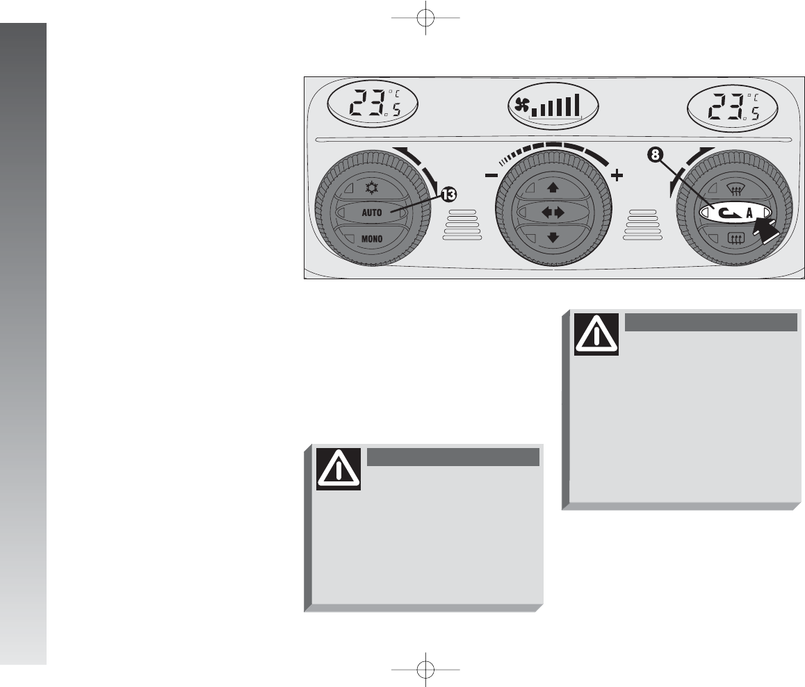
GETTING TO KNOW YOUR CAR
106
INSIDE AIR RE-CIRCULATION
ON/OFF BUTTON
v
(fig. 116)
Inside air re-circulartion is controlled ac-
cording to three operating logics:
- automatic control, indicated by the turn-
ing on of the right led on the button;
- forced engagement (inside air re-circula-
tion always on), indicated by the turning on
of the left led on the button (and by the right
led going off at the same time);
- forced switching off (inside air re-circula-
tion always off with air inlet from outside),
indicated by the turning off of both leds.
These operating conditions are obtained
pressing in sequence the inside air re-circu-
lation button (8)
v
.
When inside air re-circulation is controlled
automatically by the system, the right led
on the air re-circulation button (8)
v
stays on all the time and the left led shows
the air re-circulation condition:
on = air re-circulation operating;
off = air re-circulation off.
If inside air re-circulation has been turned
on or off manually, the led on button (13)
AUTO turns off.
In automatic operation , inside air re-cir-
culation is turned automatically when the
antipollution sensor detects the presence
of polluted air, for example in cities, queues,
tunnels and operation of the windscreen
washer (with the typical smell of spirits).
A0A1031m
fig. 116
With low external tem-
perature the climate con-
trol compressor is unable to
work. It is therefore inadvisable
to use the inside air recirculation
function
v
with lzow outside
temperature as windows may
mist over quickly.
WARNING
The inside air re-circulation
system makes it possible
to reach the required “heating” or
“cooling” conditions faster. It is
however inadvisable to use it on
rainy/cold days as it would con-
siderably increase the possibility of
the windows misting inside, espe-
cially if the climate control system
is off.
WARNING
086-109_Alfa147 Q2 GB 4-07-2008 12:00 Pagina 106
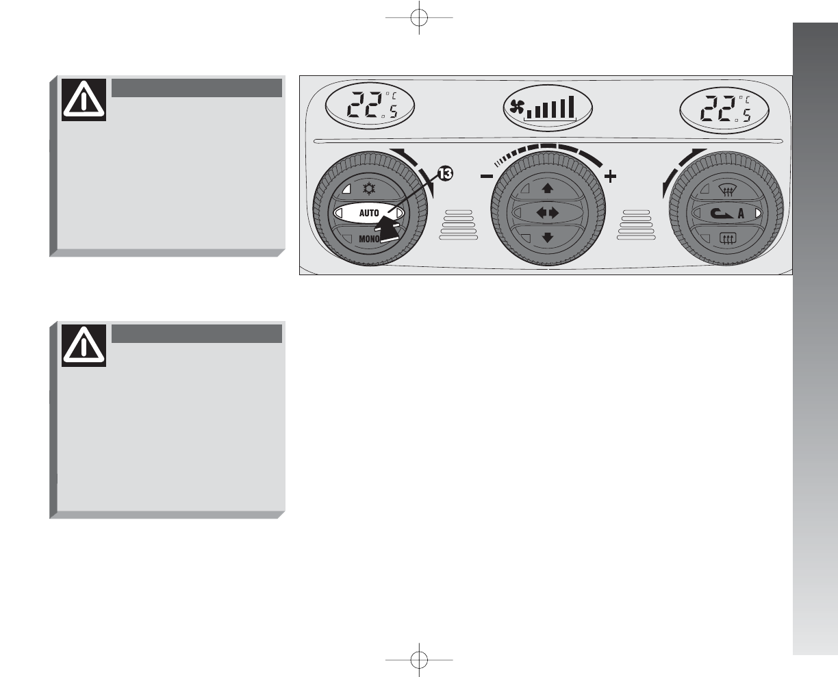
GETTING TO KNOW YOUR CAR
107
AUTOMATIC OPERATION AUTO
BUTTON
(fig. 117)
Pressing the (13)AUTO button the sys-
tem automatically adjusts the amount and
distribution of the air admitted to the pas-
senger compartment, cancelling all the pre-
vious manual adjustments.
This condition is indicated by the lighting
up of both leds on the button itself.
When the right led, on button (13)AU-
TO is off, this means that one or more man-
ual operations have been carried out and
therefore automatic control is not complete
(except temperature control which is always
automatic) indicated by the left led on, or
that the system is in the OFF condition.
A0A1032m
fig. 117
It is advisable to turn on
the inside air re-circulation
system
v
in queues or tunnels to
avoid admitting polluted air from
outside. The prolonged use of this
function should however be avoid-
ed, especially with several people
on board, to avoid the possibility of
the windows misting.
WARNING
In certain weather condi-
tions (e.g.: outside tem-
perature around 0°C) and with au-
tomatic air re-circulation control on,
mist may form on the windows. In
this case press the inside air re-cir-
culation button (8)
v
, to switch
off re-circulation (led on button off)
and if necessary increase the flow
of air to the windscreen.
WARNING
086-109_Alfa147 Q2 GB 4-07-2008 12:00 Pagina 107
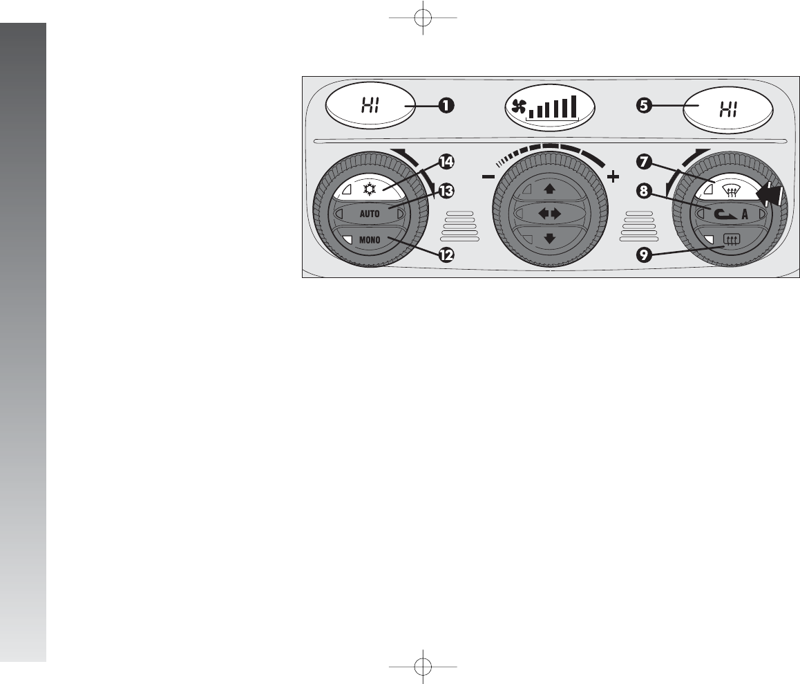
GETTING TO KNOW YOUR CAR
108
QUICK FRONT WINDOW
DEMISTING/DEFROSTING
BUTTON
(
-
MAX-DEF function) (fig. 118)
Pressing button (7)
-
the climate con-
trol automatically activates timed operation
of all the functions needed to quicken
demisting/defrosting of the windscreen and
front side windows, i.e.:
- it turns on the climate control compres-
sor;
- switches off inside air re-circulation, if on
(both leds off);
- sets the maximum air temperature (HI)
on both displays (1) and (5);
- operates the fan at a predefined speed;
- directs the flow of air towards the wind-
screen and front side window vents;
- turns on rearscreen heating and, if pre-
sent, the wing mirror coils.
When the maximum demisting/defrosting
feature is on, the led on button (7)
-
,
the led on the rearscreen heating button (9)
(
(and the led on button (14)
√
turn on;
at the same time the leds on button (8)
v
.
IMPORTANT If the engine is not hot
enough, the function does not immediate-
ly engage the pre-established fan speed, to
restrict the inlet of air to the passenger com-
partment that is not warm enough to demist
the windows.
When the maximum demisting/defrost-
ing function is on, the only manual opera-
tion possible are manual adjustment of the
fan and switching rearscreen heating off.
Pressing one of the following buttons
again: (7)
-
, (8)
v
, (12)MONO,
(13)AUTO or (14)
√
the system switch-
es off the maximum demisting/defrosting
function, restoring the operating conditions
of the system prior to turning it on, in ad-
dition to activating the last function required,
if any.
A0A1033m
fig. 118
086-109_Alfa147 Q2 GB 4-07-2008 12:00 Pagina 108
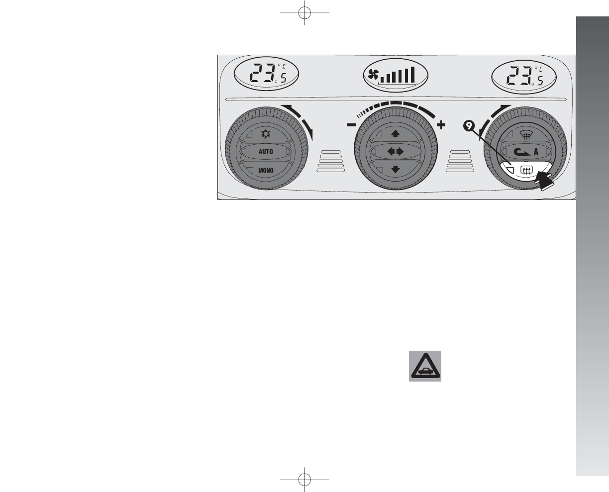
GETTING TO KNOW YOUR CAR
109
WING MIRROR AND
REARSCREEN
DEFROSTING/DEMISTING
BUTTON
(
(fig. 119)
Pressing button (9)
(
(turns on demist-
ing/defrosting of the rearscreen and, if pre-
sent, the wing mirror coils.
The turning on of this function is shown by
the turning on of the led on the button.
This function is timed and switches off au-
tomatically after 20 minutes, or pressing the
button again; the function is also switched
off when the engine is stopped and will not
be switched on again the next time the en-
gine is started.
IMPORTANT The system automatically
turns on rearscreen heating if the tempera-
ture is below 3°C.
IMPORTANT Do not apply stickers on
the inside of the rearscreen over the heat-
ing filaments to avoid damage that might
cause it to stop working properly.
POLLEN FILTER
Have the conditions of the filter checked
by Alfa Romeo Authorised Services at least
once a year, preferably at the onset of sum-
mer.
If the car is used mainly in dusty or pol-
luted areas it should be checked and, if nec-
essary, replaced at shorter intervals.
A0A1034m
The filter has the specific capability of fil-
tering external air, thus admitting to the pas-
senger compartment purified air, free from
particles such as dust, pollen, etc.
In addition to the above mentioned func-
tions, is also reduces the concentration of
pollutants.
The filtering action takes place under all
air inlet conditions and it is clearly most ef-
fective with the windows shut. The failure to replace the
filter may considerably re-
duce the effectiveness of
the climate control system up to
blocking the air flow from the out-
lets and vents.
fig. 119
086-109_Alfa147 Q2 GB 4-07-2008 12:00 Pagina 109
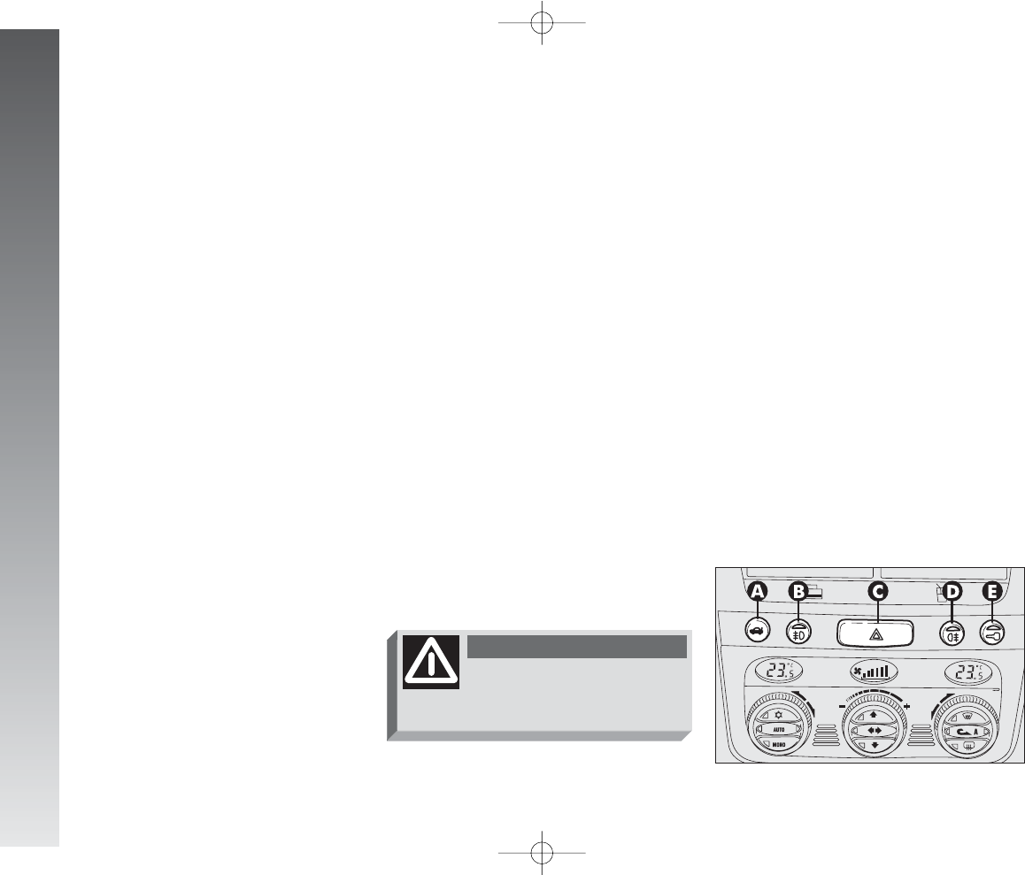
GETTING TO KNOW YOUR CAR
110
ADDITIONAL HEATER
(upon request for
versions/markets where
applicable)
The car is fitted with an additional heater
which supports the engine during cold or
winter weather to quickly reach a comfort-
able temperature in the passenger’s com-
partment.
The heater works with the engine running
when the outside temperature is below
20°C and the engine has not yet reached
normal operating temperature.
HAZARD WARNING LIGHTS
(fig. 120)
These are switched on by pressing button
(C), on the centre console panel, regardless
of the position of the ignition key.
When the hazard warning lights are
switched on, the switch itself begins to flash
together with the direction indicators and
the direction indicator warning lights on the
instrument cluster. This function is switched
off by pressing the button again.
FOG LIGHTS
(fig. 120)
(upon request for
versions/markets where
applicable)
These are turned on pressing button (B),
on the centre console panel, when the out-
er lights are already on, at the same time
the led on the button itself turns on.
Press button (B) again to switch off.
IMPORTANT The front foglights should
be used in compliance with local traffic laws.
fig. 120
A0A1035m
CONTROLS
TAILGATE OPENING
(fig. 120)
Electric tailgate release is only allowed with
the ignition key in the ignition switch at
MAR car stationary, at STOP or PARK
for 3 minutes without opening/closing a
door. To release the tailgate, press button
(A) on the centre console panel.
Use the hazard warning
lights in compliance with
local regulations.
WARNING
110-185_Alfa147 Q2 GB 4-07-2008 12:02 Pagina 110
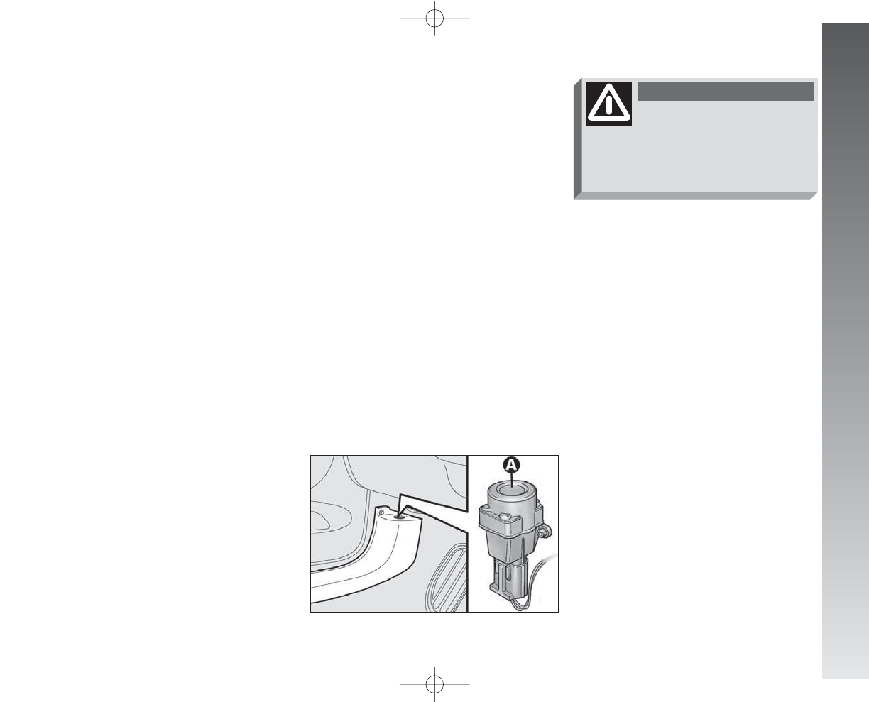
GETTING TO KNOW YOUR CAR
If no leaks are found the car can be restart-
ed. Press button (A) to activate the fuel sup-
ply system again.
fig. 121
A0A0092m
REAR FOG GUARDS
(fig. 120)
These are turned on, with the dipped beam
headlights or fog lights on, pressing button
(D) on the centre console panel, at the
same time the warning light on the button
itself turns on.
Turning the ignition key to STOP the fog
guards are automatically turned off and they
do not come on the next time the engine
is started unless button (D) is pressed. To
turn them off press button (D).
IMPORTANT Always use the rear fog
guards in compliance with local regulations.
DOOR LOCKING SYSTEM
(fig. 120)
To lock the doors simultaneously, press but-
ton (E), on the centre console panel, re-
gardless of the position of the ignition key.
The deterrent led turns on as follows:
– with the ignition key at MAR glowing
steadily with a yellow light;
– with the ignition key at STOP flash-
ing with a red light (deterrence condition).
INERTIAL FUEL CUT-OFF
SWITCH
(fig. 121)
(for versions/markets where
applicable)
This is an automatic safety switch, to be
found on the floor next to the driver’s door
pillar, which is triggered in the event of a
crash of a certain magnitude to interrupt the
flow of fuel.
The cutting in of the inertial switch is shown
on the display of the instrument cluster.
If a smell of fuel is noted
following an accident, or
the fuel system is leaking, to avoid
the risk of fire do not reset the
switch.
WARNING
111
110-185_Alfa147 Q2 GB 4-07-2008 12:02 Pagina 111
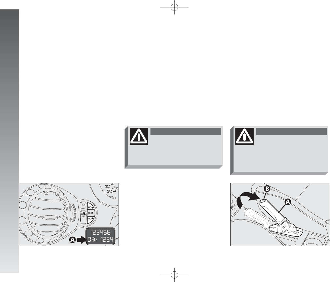
GETTING TO KNOW YOUR CAR
112
HAND BRAKE
(fig. 123)
The hand brake lever is located between
the two front seats.
To operate the brake when the car is sta-
tionary, pull lever (A) upwards, until the re-
quired braking action is obtained.
When the ignition key is at MAR, the
warning light on the instrument cluster
x
will come on.
fig. 123
A0A0094m
For correct adjustment, bear in mind the
following conditions:
– position 0: one or two people occupy-
ing the the front seats
– position 1: five people;
– position 2: five people + load in the
boot;
– posizione 3: driver + 350 kg in luggage
compartment
fig. 122
A0A1116m
HEADLIGHT AIMING DEVICE
(fig. 122)
The headlights should be aimed correctly
depending on the car load.
To do this (only with dipped beams turned
on) use the buttons
▲
/
▼
:
– press the button to increase by one po-
sition (e.g.: 0
➟
1
➟
2
➟
3);
– press the button to lower by one posi-
tion (e.g.: 3
➟
2
➟
1
➟
0);
The display (A), in the tachometer, shows
the positions during adjustment.
Check the positioning of
the headlight beams every
time you change the load to be car-
ried.
WARNING
The wheels should be locked
after a few clicks of the
hand brake. If it does not occur con-
tact Alffa Romeo Authorised Services
to have the hand brake adjusted.
WARNING
110-185_Alfa147 Q2 GB 4-07-2008 12:02 Pagina 112
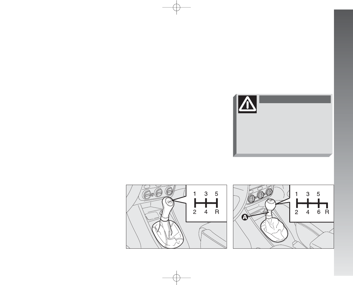
GETTING TO KNOW YOUR CAR
To release the hand brake:
– slightly lift the lever (A) and press there-
lease button (B);
– keeping the button pressed lower the
lever, the warning light
x
on the instru-
ment cluster will go out.
To prevent the car from moving acciden-
tally, keep the brake pedal pressed when
engaging the hand brake.
IMPORTANT The hand brake lever (A)
is fitted with a safety device which prevents
the brake from being released when, with
the lever pulled, button (B) is pressed.
Therefore, to release the brake, in addition
to pressing button (B), it is also necessary
to pull lever (A) further upwards to release
the safety device, then lower the lever com-
pletely.
IMPORTANT On certain versions a
buzzer sounds to alert the driver if the car
is moved with the hand brake engaged.
GEARSHIFT LEVER
(fig. 124-125)
The position of the single gears is shown
by the pictogram on the gearshift lever
knob.
When shifting gear, always fully depress
the clutch pedal. Before engaging reverse
gear (R) wait for the car to be stationary.
For the versions with 6 gears, to engage
reverse (R) lift (with the fingers of the same
hand holding the lever) the ring (A-fig.
125) positioned under the lever.
After engaging the reverse, release the
ring. To change from reverse to another gear,
it is not necessary to lift the ring on the lever.
fig. 124
A0A0095m
fig. 125
A0A1077m
,
To change gear smoothly,
the clutch pedal must be
fully depressed. Therefore, there
should be no obsstacles on the floor
under the pedal unit: make sure
that any mats are well laid and do
not interfereewith the pedals.
WARNING
IMPORTANT Reverse gear may only be
engaged with the car completely at a stand-
still. With the engine running, before en-
gaging reverse gear it is necessary to wait
for at least 3 seconds with the clutch pedal
fully depressed to prevent clashing and the
possibility of damaging the gears.
113
110-185_Alfa147 Q2 GB 4-07-2008 12:02 Pagina 113
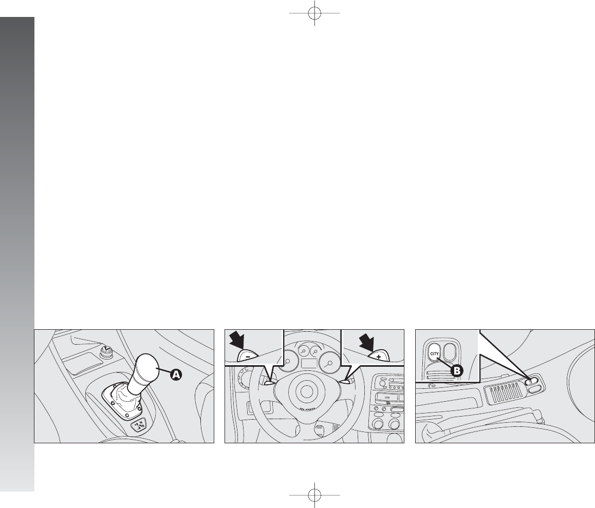
GETTING TO KNOW YOUR CAR
114
There are also two levers on the steering
wheel spokes (fig. 127) through which
it is possible to shift gear up or down (also
with the car stationary).
The gearbox can work in two operating
modes:
– the first is semiautomatic (then called
MANUAL), in which the driver directly re-
quests gearshifting through the lever on the
centre console or the levers on the steering
wheel spokes;
– the second i automatic, called CITY
(mode selectable with the special button B-
fig. 128, the word CITY is shown on the
display fig. 130). With this mode the sys-
tem decides directly when to shift gear.
SELESPEED
TRANSMISSION
(on request for versions/markets
where applicable)
The 2.0 T.SPARK version can be supplied
with a mechanical gearbox with electronic
control, called “Selespeed”.
The Selespeed considerably simplifies use
of the car, reducing the fatigue of city dri-
ving or when frequent gearshifting is re-
quired, at the same time offering brilliant
performance.
IMPORTANT To be able to use the Se-
lespeed correctly, this chapter should be read
in full to understand the correct, permissible
operations to be carried out right from the
start.
This device comprises a conventional me-
chanical gearbox to which an electronical-
ly-operated electro-hydraulic device has been
added which automatically controls the
clutch and gear engagement. The clutch ped-
al has been eliminated and the car moves
off using only the accelerator pedal.
Gearshifting takes place through the con-
trol lever (A-fig. 126) which is of the
floating type with a “single central stable
position”. Using the lever it is possible to re-
quest an increase/decrease of the gear ra-
tio engaged and/or reverse gear engage-
ment (R) or neutral (N).
fig. 127
A0A1075m
fig. 128
A0A1121m
fig. 126
A0A0097m
110-185_Alfa147 Q2 GB 4-07-2008 12:02 Pagina 114
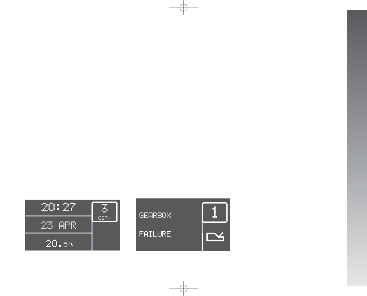
GETTING TO KNOW YOUR CAR
SYSTEM ACTIVATION
IMPORTANT Opening the driver’s door
the Selespeed starts the hydraulic part of
the system to prepare it for when the en-
gine is started.
Turning the ignition key to MAR, all the
segments of the gear display (fig. 129),
the gearbox failure warning light (fig.
130) and the word CITY light up. After
about one second, the display indicates the
gear engaged (N,1,2,3,4,5,R).
IMPORTANT If after 10 seconds the dis-
play segments do not display the gear en-
gaged or the failure warning light stays on,
turn the ignition key to STOP and wait for
the display to go off, then repeat the sys-
tem activation procedure. If the fault pre-
sists, contact Alfa Romeo Authorised Ser-
vices.
With gearshift to CITY gears can still be
shifted manually using the gearshift lever or
the steering wheel controls. Geashift stays
in CITY.
The gear engaged (fig. 129) is shown
on the display regardless of the mode se-
lected.
N= neutral;
1= first gear;
2= second gear;
3= third gear;
4= fourth gear;
5= fifth gear;
R= reverse.
In the CITY mode the selected position is
shown.
A warning light connected with the corre-
sponding failure message (“GEARBOX FAIL-
URE”) (fig. 130) and a buzzer attract the
attention of the driver in the event of a fault
of the Selespeed transmission.
fig. 129
A0A9017g
fig. 130
A0A9118g
115
110-185_Alfa147 Q2 GB 4-07-2008 12:02 Pagina 115
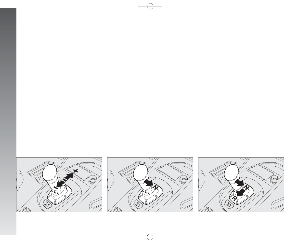
GETTING TO KNOW YOUR CAR
116
system will engage neutral (N) and the ma-
noeuvre will be repeated.
IMPORTANT Once a gear has been
changed it is necessary to immediately re-
lease the gearshift control lever after mak-
ing the request. A manoeuvre prolonged
(over 10 seconds) makes the system au-
tomatically switch to CITY mode; every-
thing stops releasing the gearshift lever.
IMPORTANT If wanting to leave the car
parked on a sloping road with a gear en-
gaged to keep it braked, it is necessary to
check that the display shows the new gear
engaged and then wait for 1 or 2 seconds
before releasing the brake pedal to allow
complete clutch engagement.
fig. 133
A0A0103m
OPERATION WITH ENGINE OFF
IMPORTANT Before operating the
gearshift control lever, always check the gear
engaged on the display (N,1,2,3,4,
5,R).
With the engine off and the car station-
ary it is possible to engage all the gears.
With the car stationary and with the brake
pedal pressed, requests to shift gear are ac-
cepted both if they are carried out through
the control lever on the central console and
the levers on the steering wheel.
To request gearshifting, in addition to keep-
ing the brake pedal pressed:
– to increase gear (+) (fig. 131) push
the lever “forwards” (if the car is in first gear
this shifts to second, if it is in second gear
it goes to third and so on up to fifth). If the
system is in neutral (N) or reverse (R) the
forward movement on the lever causes en-
gagement of first gear (1).
– to shift down (–) (fig. 131) push the
lever backwards (if the car is in fifth gear it
moves to fourth, if fourth is engaged it shifts
to third and so on down to first).
To put the gearbox in neutral (N), starting
from the condition with the car stationary and
the brake pedal pressed, it is necessary to
move the gearshift control lever to the right
(fig. 132).
From any gear (N,1,2,3,4,5) and with
the car practically at a standstill, it is possi-
ble to request engagement of reverse gear,
pushing the lever to the right and then back-
wards (fig. 133). If the car is on the move,
the request is accepted if, within 3 seconds
from the request, the car speed is below 3
Km/h: if the request is not carried out, the
fig. 131
A0A0101m
fig. 132
A0A0102m
110-185_Alfa147 Q2 GB 4-07-2008 12:02 Pagina 116
GETTING TO KNOW YOUR CAR
STARTING THE ENGINE
The engine can be started with the gear
engaged or in neutral (N), provided that the
brake pedal is pressed down.
IMPORTANT Keep the brake pedal
pressed during the starting operation. As the
brake pedal stiffens if it is pressed repeat-
edly with the engine off, in this situation, to
allow the engine to be started, it is neces-
sary to increase the pressure exerted on the
pedal itself.
After starting, the gearbox sets to neutral
automatically, the display shows the letter
(N) and the system selects the operating
mode memorised before switching off.
IMPORTANT If the engine is started
with the gearbox in a position different from
Nand without the brake pedal pressed, the
display shows a dedicated message. In this
case repeat the starting operation and press
the brake pedal.
IMPORTANT Should the starting-up pro-
cedure be executed with the gearbox not
in working order, carry out the “Delayed
start-up” procedure (see also the relative
messages): keeping the key in the AVV
position for at least 10 seconds, with the
brake held down, the engine will start. The
system will remain in the recovery mode
(maximum gear allowed: 2nd, Auto mode
SWITCHING OFF THE ENGINE
AND SYSTEM DEACTIVATION
Turning the ignition key to STOP the en-
gine turns off and the gear selected before
switching off the engine remains engaged.
If the engine is stopped with the gearbox
in neutral (N), the buzzer and the flash-
ing of (N) call the driver’s attention so that
the car can be put in safety conditions en-
gaging first gear (1) or reverse (R). In this
case, the ignition key should be turned to
MAR and with the brake pedal pressed,
engage first gear (1) or reverse ( R).
If the engine fails to start
with the gear engaged, the
driver is alerted of the potentially
dangerous situation due to the fact
that the gearbox has automatically
set to neutral by the buzzer and thee
display.
WARNING
NEVER leave the car with
the gear in neutral (N).
WARNING
Never remove the ignition
key when the car is mov-
ing. In addition to the fact that the
Selespeed ssystem would not work
properly up to stopping the car,
the steering wheel would lock au-
tomatically the first time it is
turned.
WARNING
It is absolutely necessary
to turn off the engine and
then turn off the Selespeed sys-
tem keeping tthe brake pedal
pressed: ONLY release the pedal
when the display on the cluster
has gone out.
WARNING
117
is not available). Should the engine not
start, seek assistance from the Alfa Romeo
Authorised Services.
110-185_Alfa147 Q2 GB 4-07-2008 12:02 Pagina 117
GETTING TO KNOW YOUR CAR
118
MOVING OFF THE CAR
With the engine on and the car stationary,
the gears that can be engaged for moving
off are only first (1), second (2) or reverse
(R).
To engage them it is possible, keeping the
brake pedal pressed, to use the gearshift
lever on the centre console as well as the
levers on the steering wheel.
IMPORTANT Reverse gear (R) can be
engaged from any of the following other ra-
tios: neutral (N), first (1) or second (2).
If the car is moving, the request will be ac-
cepted and carried out if, within 3 seconds
from the request, the car speed is below 3
Km/h: if the request is not accepted, the
system will engaged neutral (N) and the
manoeuvre will be repeated.
The driver is informed of the reverse gear
engaged condition by the display and the in-
termittent sound of a buzzer.
IMPORTANT If when shifting from re-
verse (R)/first (1) or neutral (N)/first (1)
sticking occurs on first gear, the system au-
tomatically engages second gear (2).
WARNINGS
– With the car stopped and a gear en-
gaged always keep the brake pedal pressed
until deciding to move off;
– during prolonged halts with the engine
running it is advisable to keep the gearbox
in neutral;
– when the car is parked facing uphill, do
not use the moving off manoeuvre to keep
the car still; use the brake pedal and press
the accelerator pedal only when deciding to
move off;
– use second gear only when more con-
trol is needed for moving off manoeuvres at
low speed;
– if, in reverse gear, first gear is engaged
or vice versa, shift gear only when the car
is stopped completely and with the brake
pedal pressed.
After a request to shift
gear with the car station-
ary, before pressing the accelera-
tor pedal to make the car move,
the driver must always check the
display to see that the gear en-
gaged is the onne required.
WARNING
This is not to be considered as a fault as
it is part of the operating logic. For the same
reason, in the case of sticking on reverse
gear, the system partially closes the clutch
to allow gear engagement; in this case the
engagement of reverse gear (R) will not be
as smooth as usual.
Moving off the car is obtained:
1) releasing the brake pedal;
2) gradually pressing the accelerator ped-
al.
The more the accelerator is pressed the
higher the pickup torque.
110-185_Alfa147 Q2 GB 4-07-2008 12:02 Pagina 118

GETTING TO KNOW YOUR CAR
OPERATING MODES
The gearbox can work in two operating
modes:
– the first is semiautomatic (MANU-
AL), in which the driver directly decides
when to shift gear;
– the second is completely automatic
(CITY), in which the system decides di-
rectly when to shift gear according to the dri-
ving style.
The CITY mode is selected by pressing the
CITY button on the gearshift lever knob;
when the automatic mode is selected the
word CITY is shown on the display.
Though highly unadvisable, if when trav-
elling downhill for some unexpected reason
the car is set to neutral (N), when the en-
gagement of a gear is requested, the sys-
tem automatically engages the best gear
in relation to the speed of the car to allow
the correct transmission of torque to the
wheels.
When travelling downhill with a gear en-
gaged and the accelerator released (if the
car is moving), beyond a pre-established
speed, the system engages the clutch au-
tomatically to give the car adequate engine
braking.
For safety reasons the Selespeed system
activates the buzzer when:
– clutch overheating occurs while the car
is being started; in this case it is necessary
to “force” starting avoiding hesitation or, if
the car is on a slope, release the accelera-
tor and use the brake pedal to stop the car;
Still due to safety reasons, with the car sta-
tionary, the engine running and gear (1), (2)
or (R) engaged, the system activates the
buzzer and automatically shifts to neutral (N)
when:
– no action is made on the accelerator
and/or brake pedals for at least 3 minutes;
– the brake is pressed for over 10 minutes;
– the driver’s door is opened and the ac-
celerator and brake are not touched for at
least 1.5 seconds.
STOPPING THE CAR
To stop the car, simply release the acceler-
ator pedal and, if necessary, press the brake
pedal.
Regardless of the gear engaged and the op-
erating mode activated (MANUAL or
CITY) the system automatically disengages
the clutch and shifts to a lower gear.
If deciding to move off again without hav-
ing stopped the car completely, the most suit-
able ratio will be available for accelerator
again.
Stopping the car the system automatically
engages first gear (1).
119
110-185_Alfa147 Q2 GB 4-07-2008 12:02 Pagina 119

GETTING TO KNOW YOUR CAR
120
SEMIAUTOMATIC OPERATION
(MANUAL)
In the MANUAL operating mode, the dis-
play shows the gear engaged.
In this operating mode, the decision to
change gear is left to the driver who decides
the most appropriate moment.
The requests to change gear may take
place through:
– the control lever on the centre console
(A-fig. 134);
– the levers on the steering wheel (fig.
135).
If the gearshifting request compromises
the correct engine and gearbox operation,
the system will not allow gearshifting but
will automatically shift down the gears to
let the engine run idle (e.g. during deceler-
ations).
In these cases the system informs the dri-
ver about the impossibility of shifting gears
through a dedicated message on the display
and a buzzer.
The MANUAL operating mode is set
when, with the CITY mode selected, the
CITY (B-fig. 136) button is pressed
again, thereby cutting out the previously se-
lected mode.
When changing gear it is not necessary
to release the accelerator pedal because the
Selespeed system directly controls the en-
gine in such a way as to:
– reduce and then increase engine torque;
– adapt the engine speed to the latest
gear engaged.
When downshifting, the engine is accel-
erated automatically to bring it to the speed
necessary with the new gear ratio.
The neutral command (N) is accepted at
any car speed.
Reverse (R) is only accepted and engaged
with the car almost stationary.
fig. 134
A0A0097m
fig. 135
A0A1075m
fig. 136
A0A1121m
110-185_Alfa147 Q2 GB 4-07-2008 12:02 Pagina 120
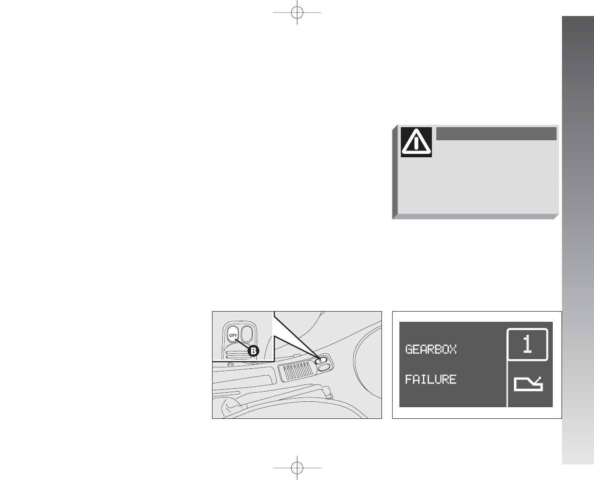
GETTING TO KNOW YOUR CAR
With the accelerator pedal pressed to over
60% of its stroke and an engine speed
above 5000 rpm, gearshifting becomes
quicker. In the MANUAL operating mode
there are certain automatic/security devices
which simplify driving:
– when slowing down the clutch is opened
and the transmission ratio is automatically
reduced to be ready for picking up again;
otherwise, when the car is stopped, the
gearbox will automatically be in first gear
(1);
– requests to change gear that would take
the engine to above maximum speed or be-
low minimum speed are not accepted;
– if jamming occurs during gear engage-
ment, the system firstly tries to engage the
gear required again and, if it is still not pos-
sible, it automatically engages the imme-
diately higher one to avoid leaving the car
in neutral.
IMPORTANT It is advisable to wait for
the end of a gear shifting operation before
requesting another one, to avoid multiple
requests in rapid succession.
AUTOMATIC OPERATION (CITY)
The automatic operating mode CITY is se-
lected pressing the button (A-fig. 137)
at the base of the gearshift lever.
In addition to the gear, the display shows
the word CITY.
The system decides directly when to
change gear depending on the engine rpm
and the driving style.
Releasing the accelerator pedal quickly, the
system does not engage a higher gear in or-
der to maintain an adequate level of engine
brake.
fig. 136
A0A1121m
FAILURE WARNING
Failures of the Selespeed gearbox are
shown by the
t
(fig. 137/a) warning
light accompanied by a message and a
buzzer.
fig. 137/a
A0A9118g
In the case of a fault to the gearshift con-
trol lever, the system automatically engages
the automatic operating mode CITY to
make it possible to reach the nearest Alfa
Romeo Authorised Service to have the fault
eliminated.
If the warning light
t
and the message are
shown on the display contact Alfa
Romeo Authorised Services as soon
as possible tto have the fault elim-
inated.
WARNING
121
110-185_Alfa147 Q2 GB 4-07-2008 12:02 Pagina 121
GETTING TO KNOW YOUR CAR
122
In the case of a fault to other gearbox com-
ponents, the system only allows the en-
gagement of certain gears: first gear (1),
second gear (2) and reverse (R).
– the system has automatically engaged
neutral (N) after:
there is no action on the accelerator
and/or brake pedal for at least 3 minutes;
or the brake is pressed for over 10 min-
utes;
or the driver’s door is opened and no ac-
tion is made on the accelerator and brake
for at least 1.5 seconds;
or detection of a gearbox fault;
– in the event of gearbox failure.
PARKING THE CAR
To park the car safely it is absolutely nec-
essary to engage first gear (1) or reverse
(R) and also the hand brake if the road is
on a slope.
Turning off the engine with the car on an
uphill slope and a gear engaged, it is ab-
solutely necessary to wait for the display
to go off before releasing the brake pedal,
so that the clutch is completely closed.
If the gearbox is in neutral (N) and want-
ing to engage a parking gear, the system
should be activated and with the foot on the
brake pedal it is necessary to engage first
gear (1) or (R).
IMPORTANT NEVER abandon the car
with the gear in neutral (N).
BUZZER WARNINGS
The buzzer is activated when:
– reverse gear is engaged (R);
– the car is parked with the gearbox in
neutral (N); signal that can be noted turn-
ing the ignition key to STOP;
– clutch overheating takes place during
pick-up;
TOWING THE CAR
IMPORTANT For towing the car follow
local regulations. Make sure that the gear-
box is in neutral (N) (checking that the car
moves if pushed) and tow as for a car with
normal mechanical gearbox following the
instructions given in the chapter “In an emer-
gency”.
Should it be impossible to set to neutral,
do not tow the car; contact Alfa Romeo Au-
thorised Services.
In the event of a gearbox
fault (to any component),
contact Alfa Romeo Authorised
Services as soon aas possible to
have the system checked over.
WARNING
While towing the car do not
start the engine.
WARNING
110-185_Alfa147 Q2 GB 4-07-2008 12:02 Pagina 122
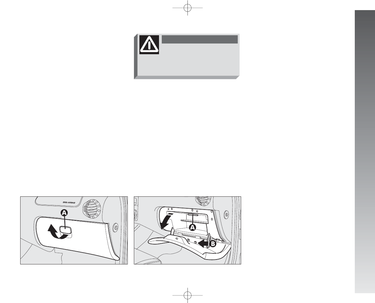
GETTING TO KNOW YOUR CAR
INTERIOR FITTINGS
GLOVEBOX
On the dashboard there is a glovebox with
lid and light.
To open use handle (A-fig. 138).
When the glovebox is opened with the key
at MAR an inside courtesy light turns on
(A-fig. 139). The fitting is completed by device (B), on
the lid, for inserting a pen or pencil.
IMPORTANT Turning the ignition key to
STOP, opening the glovebox, the light in-
side can only be turned on for 15 minutes;
after which the system turns it off to avoid
draining the battery.
GRAB HANDLES
Suitable grab handles are fitted above the
rear side windows.
For versions/markets where applicable
there is also a grab handle above the front
passenger’s door.
fig. 138
A0A0108m
fig. 139
A0A0109m
Never travel with the
glovebox open: the lid
might harm the passenger in the
event of an accident.
WARNING
123
110-185_Alfa147 Q2 GB 4-07-2008 12:02 Pagina 123
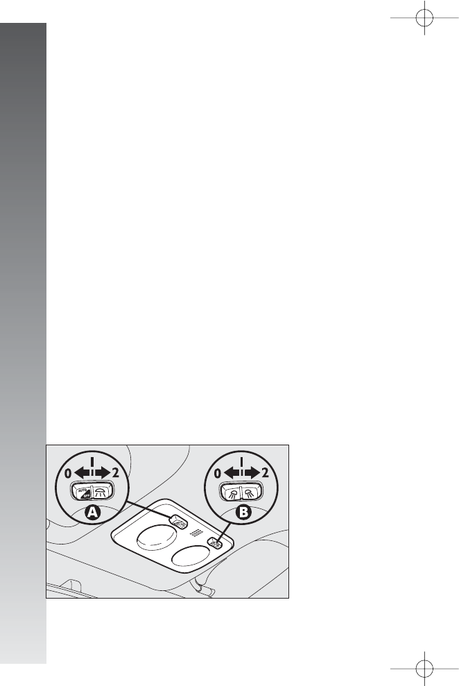
GETTING TO KNOW YOUR CAR
124
FRONT ROOF LIGHT
(fig. 140)
The roof light comprises two courtesy lights
with corresponding control switch.
IMPORTANT When a door is opened,
the roof light turns on and timing of about
3 minutes is activated automatically, after
which it goes off; closing the doors (within
the 3 minutes) a second timing of about 7
seconds is activated to allow car starting.
Unlocking the doors using the remote con-
trol, the roof light turns on gradually and tim-
ing is activated automatically for about 15
seconds. Locking the doors with the remote
control the roof light turns off gradually.
The lights are turned off moving the igni-
tion key to MAR (with the doors closed).
With switch (A) in the central position
(1), both lights are turned on when a door
is opened.
Pressing switch (A) to the left (position
0), the lights stay off (OFF position).
Pressing switch (A) to the right (position
2) both lights stay on.
Switch (B) turns the lights on individual-
ly.
Pressing switch (B) to the left (position
0) the left light is turned on. Pressing the
switch to the right (position 2) the right light
is turned on.
With switch (B) in the central position (po-
sition 1) the lights stay off.
IMPORTANT Turning the ignition key to
STOP, turning the roof light on is only pos-
sible for 15 minutes; after which the system
turns it off to avoid draining the battery.
IMPORTANT Before leaving the car,
make sure that both switches are in the cen-
tral position. By so doing, the roof lights will
turn off when the doors are closed. Forget-
ting a door open the lights will turn off au-
tomatically after a few seconds.
fig. 140
A0A0111m
110-185_Alfa147 Q2 GB 4-07-2008 12:02 Pagina 124
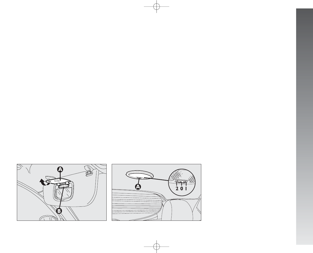
GETTING TO KNOW YOUR CAR
COURTESY LIGHTS
(fig. 141) (for versions/markets
where applicable)
On the back of the driver’s or passenger’s
sun visor, opening the cover (A), with the
ignition key at MAR, the roof lights turn
on (B). These lights allow use of the cour-
tesy mirror when the light is poor.
IMPORTANT Turning the ignition key to
STOP the lights can be activated only for
15 minutes; after which the system turns
them off to avoid draining the battery.
On the light there is a switch with three
positions.
When switch (A) is in the central posi-
tion (0) the light turns on automatically
when a door is opened.
Moving the switch to the right (position 1)
the light stays off.
Moving the switch to the left (position 2)
the light stays on.
IMPORTANT Turning the ignition key to
STOP the roof light can be turned on for
only 15 minutes; after which it is turned off
to avoid draining the battery.
IMPORTANT Before leaving the car,
make sure that the switch (A) is in the cen-
tral position (0), so that the roof light turns
off when the doors are closed.
fig. 141
A0A1043m
fig. 142
A0A0113m
REAR ROOF LIGHT
(fig. 142)
IMPORTANT When a door is opened,
the roof light turns on and timing of about
3 minutes is activated automatically, after
which it goes off; closing the doors (within
the 3 minutes) a second timing of about 7
seconds is activated to allow car starting.
Unlocking the doors using the remote con-
trol, the roof light turns on gradually and tim-
ing is activated automatically for about 15
seconds. Locking the doors with the remote
control the roof light turns off gradually.
The light turns off in any case turning the
ignition key to MAR (with the door
closed).
125
110-185_Alfa147 Q2 GB 4-07-2008 12:02 Pagina 125
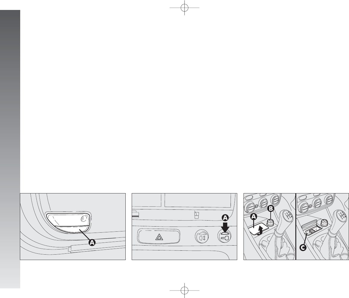
GETTING TO KNOW YOUR CAR
126
PUDDLE LIGHTS
(fig. 143)
(
for versions/markets where
applicable
)
The light (A) housed in the doors turns on
when the associated door is opened, re-
gardless of the position of the ignition key.
DETERRENT LED
(fig. 144)
The led (A) on the instrument cluster
comes into operation when the doors are
locked (ignition key at STOP or removed)
and it remains in the “deterrence” condi-
tion, flashing with a red light until the next
time the doors are unlocked.
IMPORTANT If a door or the tailgate
are not closed perfectly, the deterrent led
flashes at a higher frequency for 4 seconds
and then flashes at normal frequency again.
FRONT ASHTRAY AND CIGAR
LIGHTER
(fig. 145)
To use the ashtray open the lid (A).
To use the cigar lighter, with the key at
MAR, press button (B); after a few sec-
onds the button will return automatically
to its initial position and the cigar lighter is
ready for use.
Remove the tray to empty and clean the
ashtray (C).
The position of the cigar lighter in relation
to the ashtray and viceversa, may vary de-
pending on the trim level.
fig. 143
A0A0243m
fig. 144
A0A0005m
fig. 145
A0A0114m
110-185_Alfa147 Q2 GB 4-07-2008 12:02 Pagina 126
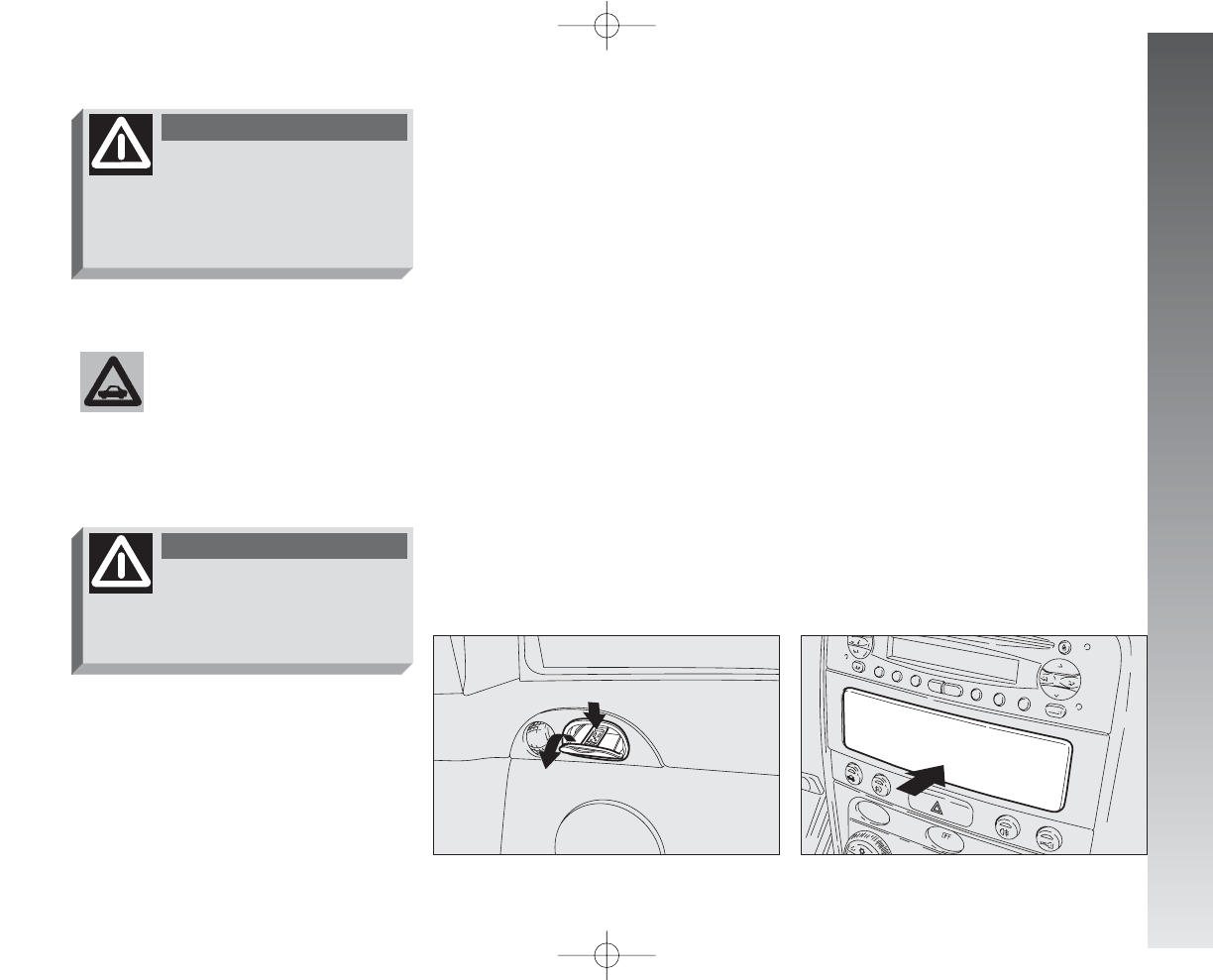
GETTING TO KNOW YOUR CAR
REAR ASHTRAYS
(fig. 146)
For the rear passengers there are two con-
cealed ashtrays.
To use or remove pull in the direction of
the arrow.
GLOVEBOX
(fig. 147)(for versions/markets
where applicable)
To use the glovebox push it as shown by
the arrow.
fig. 146
A0A0115m
Always ensure that the
cigar lighter has turned off.
fig. 147
A0A1045m
The cigar lighter gets ex-
tremely hot. Handle with
care and prevent its use by chil-
dren: danger oof fire and/or burn-
ing.
WARNING
Do not use the ashtray as
waste paper basket: it
might set on fire in contact with
cigarette stubs.
WARNING
127
110-185_Alfa147 Q2 GB 4-07-2008 12:02 Pagina 127
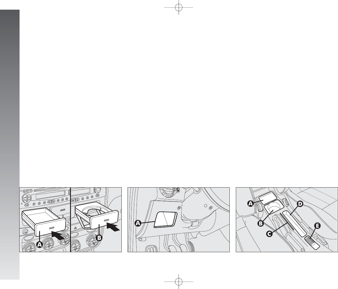
GETTING TO KNOW YOUR CAR
128
fig. 150
A0A0735m
CARD HOLDER
AND GLASS HOLDER
(fig. 148) (upon request for
versions/markets where
applicable)
The interior fittings are completed by the
removable card holder recess (A) and glass
holder (B) located on the centre of the dash-
board. To use them, press as shown.
fig. 148
A0A0116m
fig. 149
A0A1048m
ODDMENT COMPARTMENT ON
CENTRE CONSOLE
(fig. 150)
On the centre console, at the side of the
hand brake lever, depending on the versions,
the following recesses are provided:
– oddment recess (A);
– can holder (B);
– magnetic card or toll ticket holder (C);
– pen or pencil holder (D);
– coin holder (E).
ODDMENT COMPARTMENT ON
DASHBOARD
(fig. 149)
An oddment recess (A) is provided on the
left of the dashboard, on the cover of the
fuse box.
110-185_Alfa147 Q2 GB 4-07-2008 12:02 Pagina 128
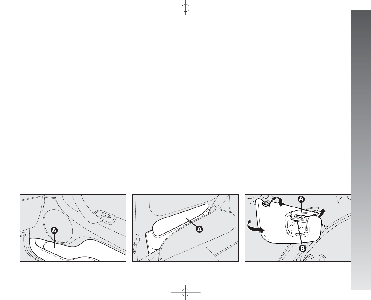
GETTING TO KNOW YOUR CAR
SUN VISORS
(fig. 153)
The visors can be directed at the front and
side.
For versions/markets where applicable,
behind the visors there is a courtesy mirror
with a light at the side (B). To use, open
the cover (A).
The lights allow use of the mirrors with dim
light.
POCKETS
ON FRONT DOORS
(fig. 151)
Each front door has an oddment pocket
(A).
REAR POCKETS
(fig. 152)
These are at the side of the rear seats in
the side trim (A).
fig. 152
A0A0120m
fig. 151
A0A0117m
fig. 153
A0A1047m
129
110-185_Alfa147 Q2 GB 4-07-2008 12:02 Pagina 129
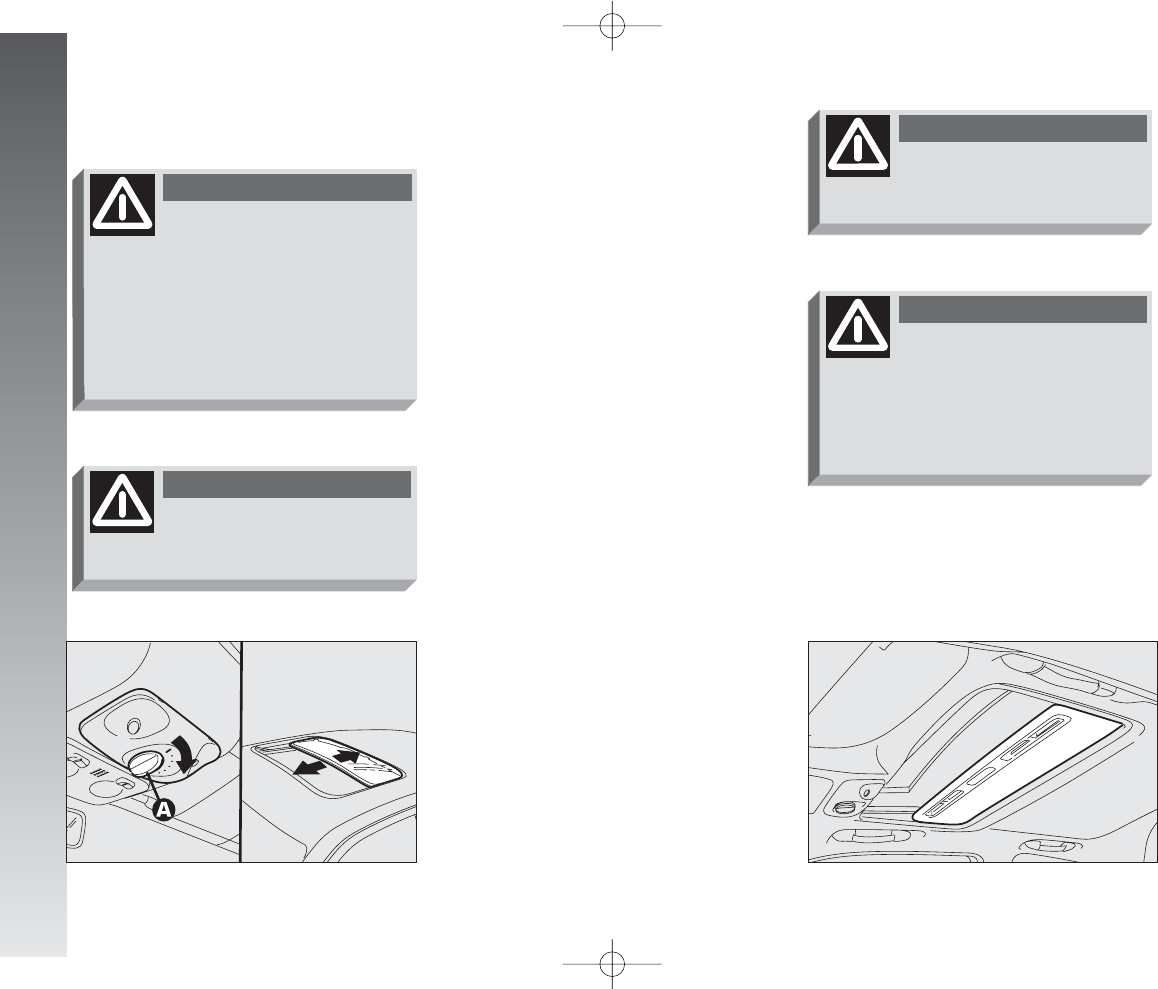
GETTING TO KNOW YOUR CAR
130
SLIDING FORWARDS/
BACKWARDS
With the ignition key at MAR turn the
control knob (A-fig. 154) in the direction
of the arrow, choosing one of the 6 open-
ing positions available.
To close the roof, take the control knob
(A) to the centre position.
The sunroof is fitted with a sliding curtain
below, which prevents sun radiation and is
drawn by hand using a catch.
The curtain is drawn by the roof when it
opens and is pushed completely inside the
roof panel when the sunroof is opened com-
pletely. With the closing movement, it will
come out partially so that the hand catch
is accessible (fig. 155).
fig. 154
A0A0123m
fig. 155
A0A0125m
SUNROOF
Improper use of the sun-
roof can be dangerous. Be-
fore and while operating it, always
make sure thhat the passengers are
not exposed to the risk of harm
caused either directly by the sun-
roof in mottion or by personal items
drawn or knocked by it.
WARNING
Do not open the sunroof
with snow or ice on it:
damage may result.
WARNING
Open and close the sunroof
only with the car station-
ary.
WARNING
When leaving the car the
ignition key should be re-
moved to prevent the sunroof from
being operateddinadvertently and
harming anyone remaining in the
car.
WARNING
110-185_Alfa147 Q2 GB 4-07-2008 12:02 Pagina 130
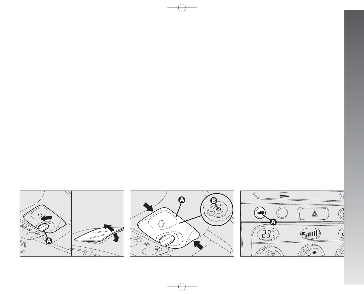
GETTING TO KNOW YOUR CAR
RAISING AT THE REAR
With the ignition key at MAR turn the
control knob (A-fig. 156) in the direction
of the arrow, choosing one of the three
opening positions available.
To close the roof, move the control knob
(A) to the centre position.
EMERGENCY OPERATION
If the electrical control device does not
work, the sunroof can be operated manu-
ally as follows:
– apply leverage in the points shown by
the arrows and remove the plate (A-fig.
157);
– insert a special Allen wrench in the seat
(B) with hexagon slot;
– then turn the wrench clockwise to open
the roof or counter-clockwise to close.
LUGGAGE
COMPARTMENT
The tailgate can be opened:
from the outside of the car - by a
remote control impulse;
from the inside of the door - by de-
pressing the button (A-fig. 158).
IMPORTANT If the boot is not proper-
ly shut, the
´
warning light will come on
(on certain versions accompanied by the
message on the reconfigurable multifunction
display).
fig. 156
A0A0124m
fig. 157
A0A0126m
fig. 158
A0A1050m
131
110-185_Alfa147 Q2 GB 4-07-2008 12:02 Pagina 131
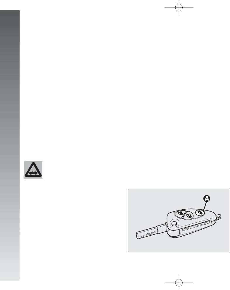
GETTING TO KNOW YOUR CAR
132
OPENING FROM INSIDE
(fig. 158)
Tailgate is released electrically and this can
be performed only when the ignition key
is in position MAR with car at a standstill
or in STOP or PARK position for 3 min-
utes without unlocking/locking one of the
doors.
To unlock the tailgate, press button (A)
on the centre console panel.
Tailgate raising is facilitated by the gas
shock springs.
OPENING WITH REMOTE
CONTROL
(fig. 159)
The tailgate can be opened by remote con-
trol from outside pressing the button (A),
also when the electronic alarm is engaged.
Opening of the tailgate is accompanied by
a double flash of the direction indicators;
closing is accompanied by a single flash.
If an electronic alarm is fitted, with the
opening of the tailgate, the alarm system
switches off volumetric protection and the
tailgate control sensor, the system “beeps”
twice (with the exception of certain mar-
kets).
The gas springs are cali-
brated to ensure correct
tailgate raising with the
weights foreseen by the manufac-
turer. The arbitrary addition of
items (such spoilers, etc.) may
compromise the correct operation
and safety of the actual tailgate.
fig. 159
A0A0131m
Closing the tailgate again, the control func-
tions are restored, the system “beeps” twice
(with the exception of certain markets).
TAILGATE CLOSING
To lock, push in correspondence with the
Alfa Romeo badge to lower tailgate, until
you feel the click of the lock.
110-185_Alfa147 Q2 GB 4-07-2008 12:02 Pagina 132
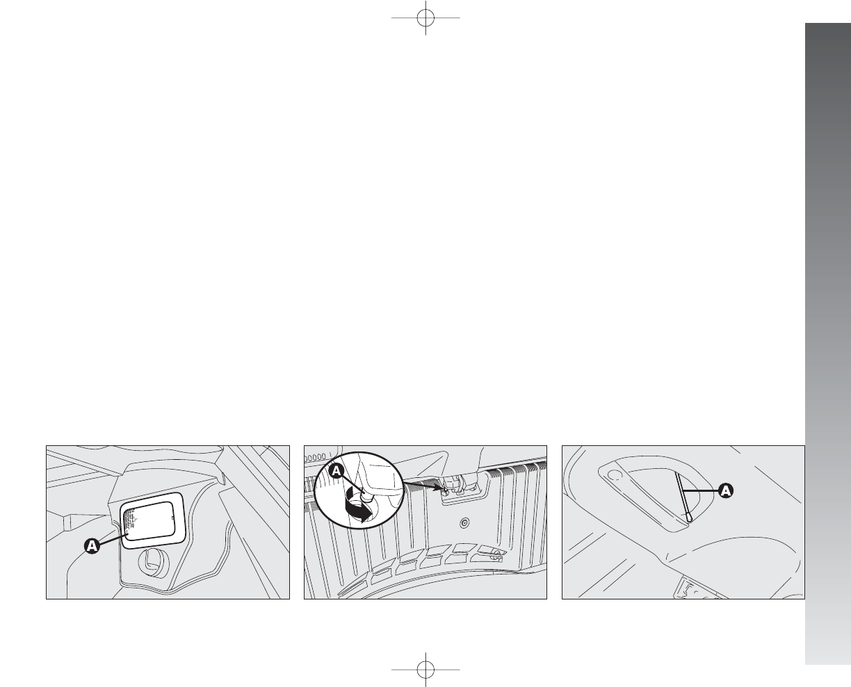
GETTING TO KNOW YOUR CAR
fig. 161/a
A0A0734m
– operate the lever (A-fig. 161) as
shown to achieve the tailgate mechanical
release, operating from the inside of the lug-
gage compartment;
– for versions/markets where applicable
unlock the lock by pulling the string
(A-fig. 161/a) (the string is located in-
side the right recess in the tailgate).
BOOT LIGHT
(fig. 160)
When the tailgate is opened the light turns
on automatically (A) in the right-hand side
of the boot. Closing the tailgate, the light
turns off automatically.
IMPORTANT Turning the ignition key to
STOP, opening the tailgate, turning on the
light will only be possible for 15 minutes;
after which the system turns it off to avoid
draining the battery.
fig. 160
A0A0132m
AEMERGENCY OPENING OF
TAILGATE
To succeed in opening the tailgate from the
inside, should the car battery be flat, or be-
cause of a defect of the electric lock of the
tailgate itself, proceed as follows (refer to
“Extending the luggage compartment” in
the chapter “Getting to know your car”):
– remove the rear headrests;
– tilt the rear seat cushions;
– tilt the backrests;
133
fig. 161
A0A0373m
110-185_Alfa147 Q2 GB 4-07-2008 12:02 Pagina 133
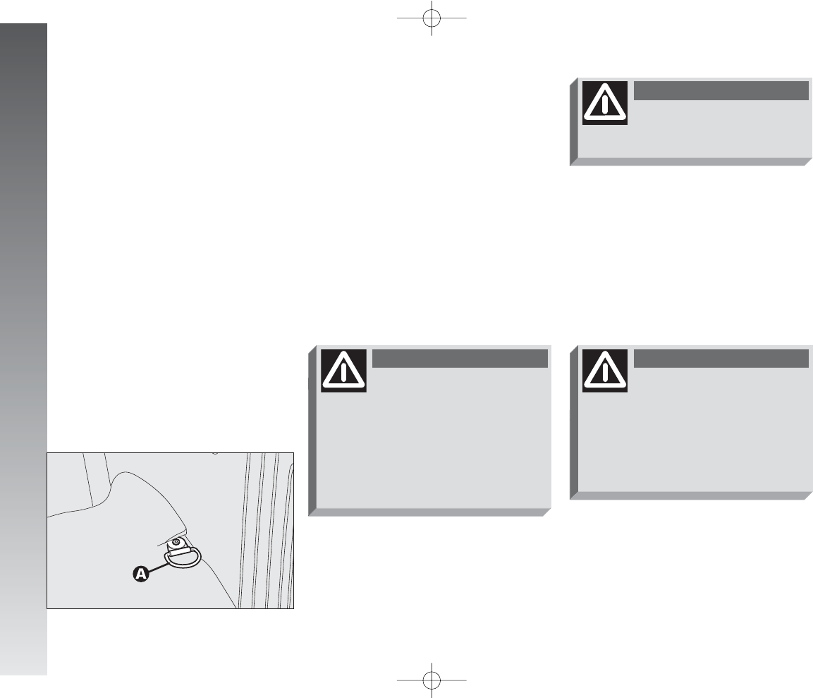
GETTING TO KNOW YOUR CAR
134
SECURING THE LOAD
(fig. 162)
The loads carried may be secured with
straps hooked to the special rings (A) in the
boot.
The rings also serve for fastening the lug-
gage restrainer, if present (in any case avail-
able c/o Alfa Romeo Authorised Services).
fig. 162
A0A0133m
Do not load the boot above
the permitted maximum
(see “Technical specifications”). Al-
so make sure that the objects con-
tained in the boot are well secured
to prevent them from being thrown
forward,,causing harm to the pas-
sengers.
WARNING
A heavy load that has not
been secured may cause
serious harm to passengers.
WARNING
If you want to carry re-
serve fuel in a can, follow
legal regulations, only using a cer-
tified cann, suitably fastened to the
load securing eyelets. Even in this
way the risk of fire is increased in
tthe case of an accident.
WARNING
CAUTIONS FOR CARRYING
LUGGAGE
Travelling at night with a load in the boot
it is necessary to adjust the height of the low
beam headlights (see next paragraph
“Headlights” in this chapter). For correct use
of the aiming device, also make sure that
the load does not exceed the values given
in the same paragraph.
110-185_Alfa147 Q2 GB 4-07-2008 12:02 Pagina 134
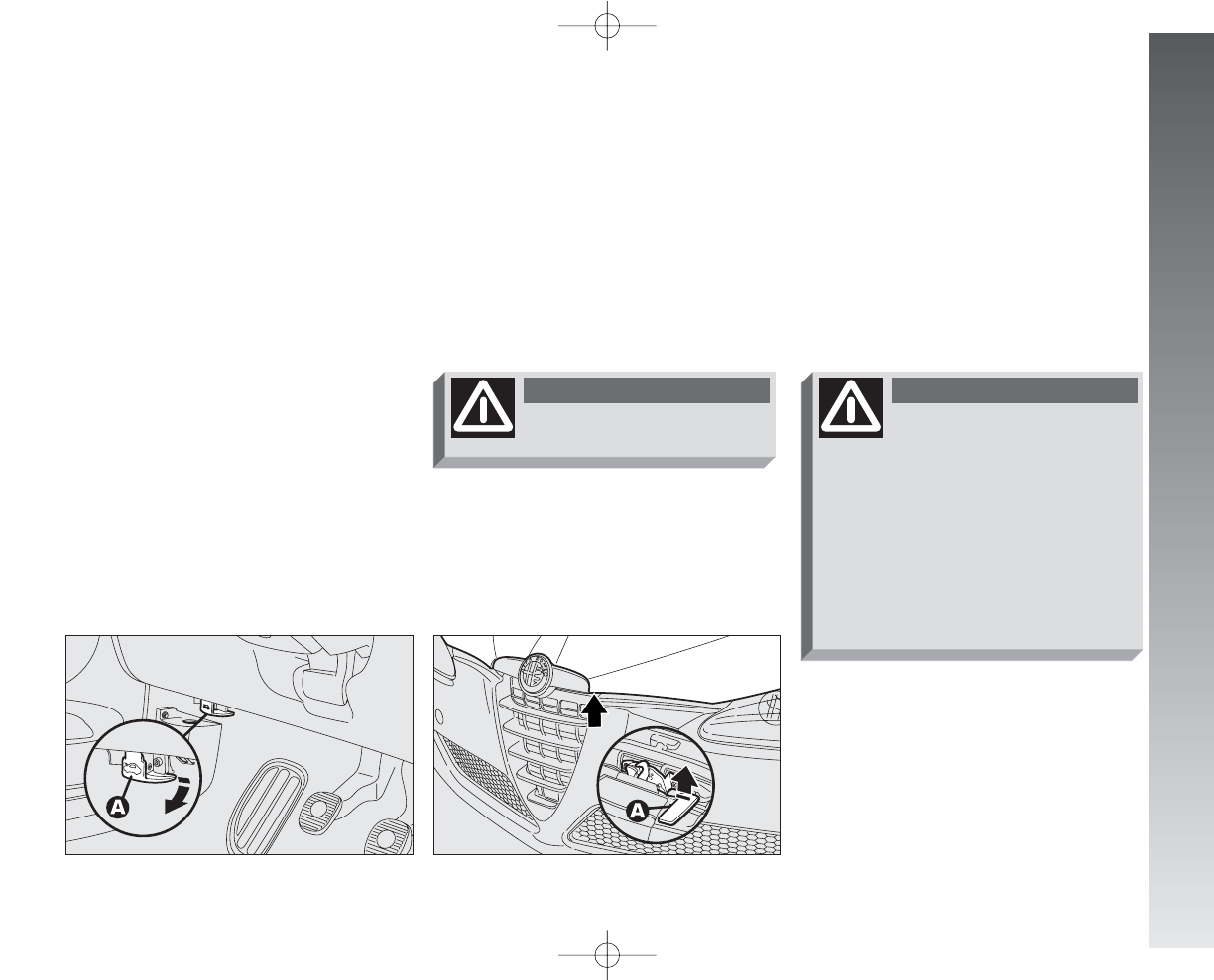
GETTING TO KNOW YOUR CAR
fig. 164
A0A1051m
BONNET
The bonnet opening lever is under the left
end of the dashboard.
To open:
– pull the lever (A-fig. 163) until the
bonnet clicks open.
– press the safety lever (A-fig. 164) up-
wards.
– raise the bonnet.
fig. 163
A0A0135m
Do this only with the car
stationary.
WARNING
For safety reasons the
bonnet must always be
closed when the car is travelling.
For this reason alwaays check that
the bonnet is closed properly mak-
ing sure that the catch is engaged.
If during traveelling you realise that
the catch is not perfectly engaged,
stop immediately and close the
bonnet in the correct way.
WARNING
To close: lower the bonnet until approx.
20 cm from the engine compartment and
then let it drop, ensuring that it is fully closed
and not just held in position by the safety
catch.
If the bonnet does not close properly do
not push it down but open it again and re-
peat the above procedure.
IMPORTANT Bonnet raising is aided by
two gas springs. Do not tamper with these
springs and accompany the bonnet while
raising it.
135
110-185_Alfa147 Q2 GB 4-07-2008 12:02 Pagina 135
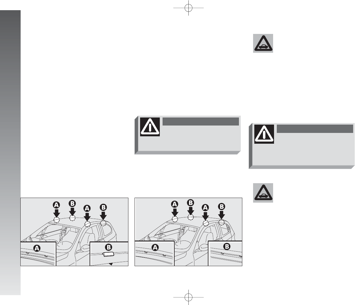
GETTING TO KNOW YOUR CAR
136
ROOF RACK
PROVISION
3-door versions
The front hooks are in points (A-fig.
165).
The rear hooks are located in the points (B)
shown by the serigraph (
▼
) on the side rear
windows.
Follow the regulations in
force concerning maximum
clearances.
IMPORTANT Closely follow the assem-
bly instructions provided in the kit. Assem-
bly must be carried out by skilled personnel.
Never exceed the maxi-
mum permissible loads (see
“Technical specifications”
chapter).
After a few kilometres,
check that the fastening
screws are firmly tightened.
WARNING
Distribute the load evenly
and when driving, bear in
mind the increased sensitivity to
side wind.
WARNING
5-door versions
The front hooks are in points (A-fig.
166).
The rear hooks are located in points (B).
fig. 166
A0A0334m
fig. 165
A0A0232m
110-185_Alfa147 Q2 GB 4-07-2008 12:02 Pagina 136
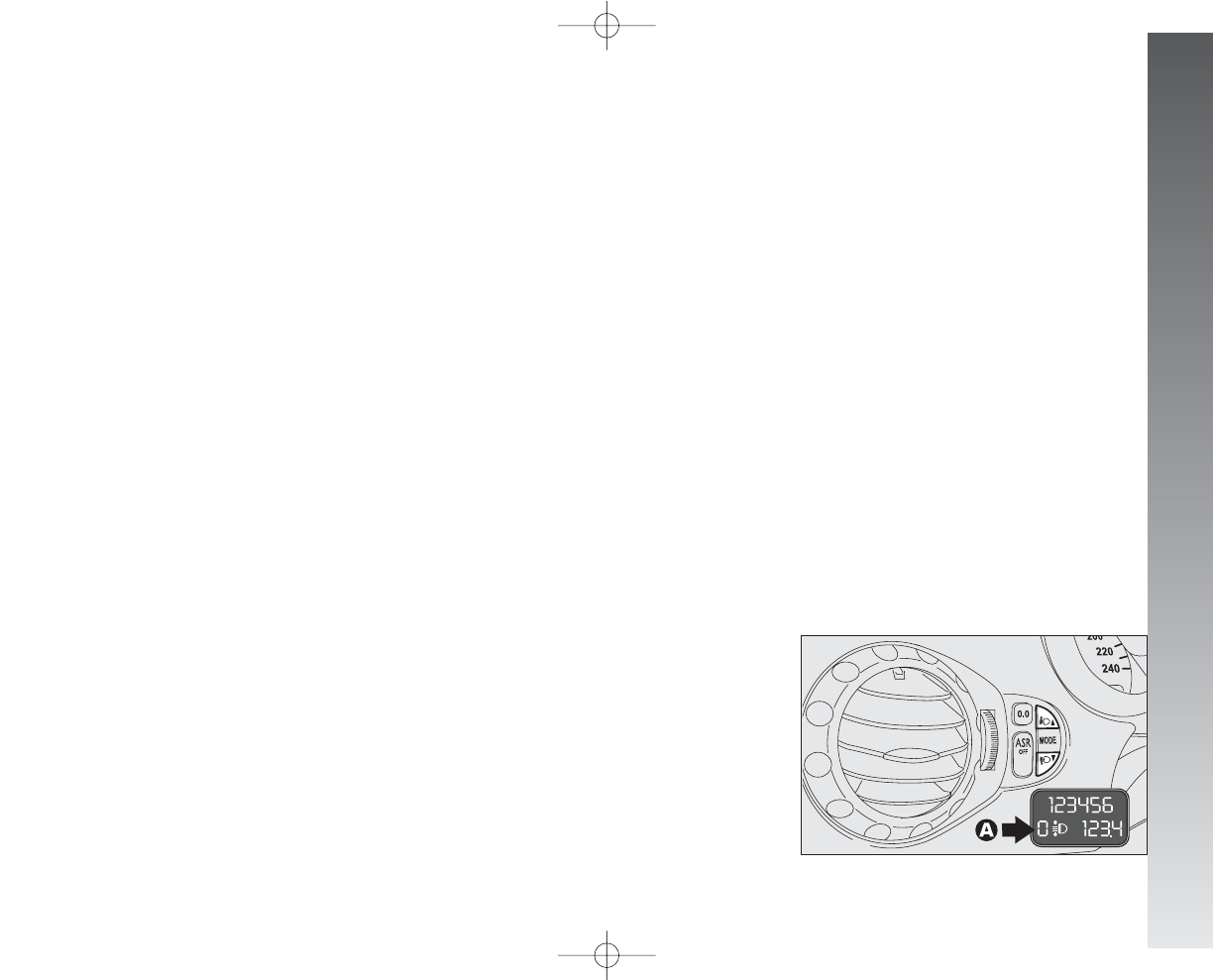
GETTING TO KNOW YOUR CAR
To do this (possible only with dipped
beams turned on) proceed as follows
▲
/
▼
:
– press the button to increase by one po-
sition (e.g.: 0
➟
1
➟
2
➟
3);
– press the button to decrease by one po-
sition (e.g.: 3
➟
2
➟
1
➟
0);
The display (A), in the tachometer, shows
the positions while adjustment is being
made.
fig. 167
A0A1116m
HEADLIGHTS
The adjustment of the headlights is vital to
your safety and comfort and to that of oth-
er road users.
The adjustment of the headlights is also
governed by precise regulations.
Contact Alfa Romeo Authorised Services to
have the headlights correctly adjusted.
IMPORTANT A slight layer of steam
(fogging) can appear on the inside surface
of the beam transparent cover: this is not
a defect. The presence of condensate traces
in beams is a natural phenomenon, due to
a low temperature and to the degree of hu-
midity in the air. These traces will disappear
when the beams are turned on. Drops of wa-
ter inside the headlight indicate instead wa-
ter infiltration: contact Alfa Romeo Autho-
rised Services.
137
COMPENSATION FOR TILT
(fig. 167)
When the car is loaded, the beam from the
headlights is raised due to the backwards
tilt of the car.
In this case the headlights must be ad-
justed correctly.
110-185_Alfa147 Q2 GB 4-07-2008 12:02 Pagina 137
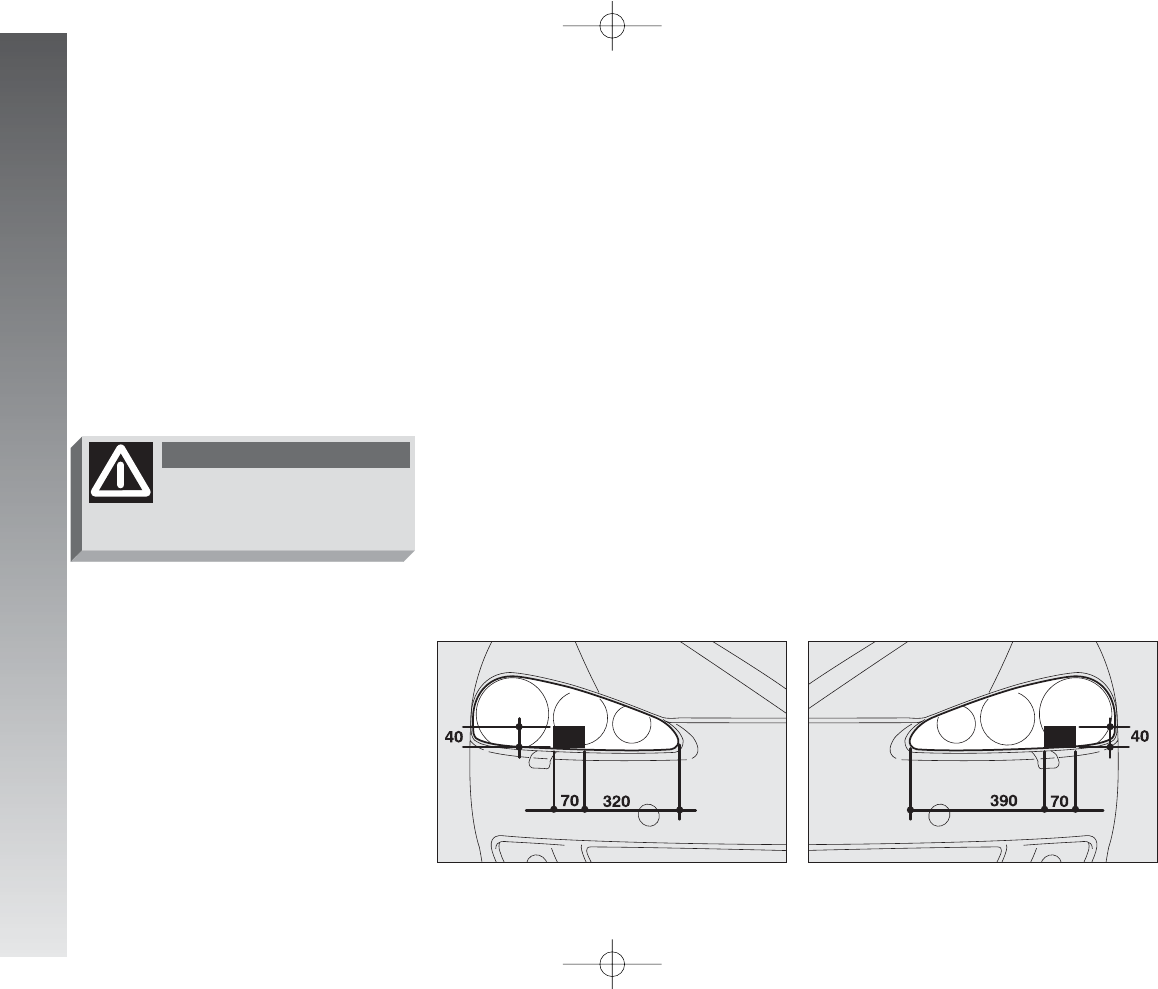
GETTING TO KNOW YOUR CAR
138
fig. 169
A0A1037m
fig. 168
A0A1038m
HEADLIGHT ADJUSTMENT
ABROAD
(fig. 168-169)
The dipped-beam headlights are adjusted
for circulation in the country in which the car
is marketed. In countries with opposite cir-
culation, to avoid glaring oncoming cars it
is necessary to cover the areas of the head-
light as shown below; this is done using non-
transparent sticker tape.
The illustration refers to passng from right-
hand drive to left-hand drive.
Check beam aiming every
time the load carried
changes.
WARNING
For correct adjustment, bear in mind the
following conditions:
– position 0: one or two people occupy-
ing the the front seats
– position 1: five people;
– position 2: five people + load in the
boot;
– position 3: driver + 350 kg stowed in
luggage compartment
110-185_Alfa147 Q2 GB 4-07-2008 12:02 Pagina 138
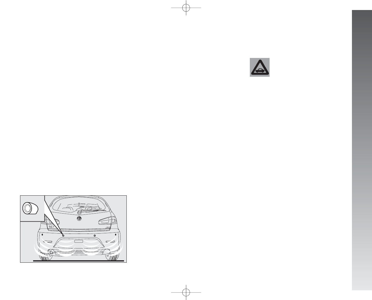
GETTING TO KNOW YOUR CAR
PARKING SENSORS
(upon request for versions/
markets where applicable)
These sensors are located in the car rear
bumper (fig. 170); their function is to de-
tect and warn the driver , through an inter-
mittent buzzer, about the presence of ob-
stacles in the car rear area.
TOWING TRAILERS
The operation of the rear
sensors is automatically
deactivated as soon as the
electric cable plug of the trailer is
inserted in the car tow hook out-
let.
The rear sensors are automatically re-acti-
vated when the trailer cable plug is removed.
139
fig. 170
A0A1053m
ACTIVATION
The sensors are activate automatically
when reverse gear is engaged.
As the distance from the obstacle behind
the car diminishes,the buzzer frequency will
increase.
BUZZER
Engaging reverse gear an intermittent
buzzer is automatically activated.
The buzzer:
– increases as the distance between the
car and the obstacle diminishes;
– becomes continuous as the distance be-
tween the car and the obstacle is below ap-
prox. 30 cm and stops immediately if the
distance increases.
– remains constant if the distance be-
tween the car and the obstacle is the same,
while, if this situation occurs for the side sen-
sors, the signal is interrupted after about 3
seconds to avoid, for example, signalling
in the event of manoeuvres along the walls.
110-185_Alfa147 Q2 GB 4-07-2008 12:02 Pagina 139
GETTING TO KNOW YOUR CAR
140
ABS
The car is fitted with an ABS braking system,
which prevents the wheels from locking when
braking, makes full use of the grip and with-
in the limits of the grip available, keeps the
car controllable also in emergency braking.
When braking a slight pulsing accompanied
by noise may be felt on the brake pedal due
to the action of the ABS system.
This should not be interpreted as a braking
malfunction. It is the signal to the driver that
the ABS has come into action: it is the warn-
ing that the car is travelling at the limit of its
grip and therefore the speed should be adapt-
ed to the type of road.
The ABS system is an additional part of the
braking system; in the event of a failure it dis-
abled, leaving the braking system in the same
conditions as a car without ABS. In the case
of failure, the anti-lock action is no longer pre-
sent, the braking capacity of the car is not
adversely affected at all.
If you have never previously used cars fitted
with ABS, it is advisable to practice a little on
a slippery surface, naturally in safety condi-
tions and in accordance with the local High-
way Code; you are also advised to read the
following instructions carefully.
The ABS better exploits the
grip available, but cannot
increase it; caution is therefore nec-
essaryyon slippery surfaces, with-
out taking unnecessary risks.
WARNING
If the ABS cuts in it means
that the limit of the grip is
being reached between the tyre
and the road surface: it is therefore
necessary to slow down to adapt
driving to the grip available.
WARNING
In the event of a system
failure, with the turning on
of the
>
warning light on the in-
strument cluster, have the car
checked immediately by Alfa
Romeo Authorised Services driving
slowly, to be able to have the sys-
tem restored to fully efficient con-
ditions.
WARNING
When the ABS cuts in, and
you feel the pulsing on the
pedal, do not lighthen the pressure,
but keep the pedal firmly pressed
with no fear; this way you will
stop in the least space possible,
compatiblly with the conditions of
the road surface.
WARNING
The advantage of the ABS over a conven-
tional system is that it makes it possible to
obtain the highest degree of handling also
when braking completely under limited grip
conditions, preventing the wheels from lock-
ing.
However, with the ABS do not expect the
braking distance to always shorten: for ex-
ample, on soft surfaces like gravel or fresh
snow or a slippery surface, the space might
increase. To better exploit the possibilities of
the antilock system in the case of need, the
advice given below should be followed. Always take due care when braking on
bends, even with the help of the ABS.
The most important advice of all, howev-
er, is this:
Following these instructions you will be
in the best braking condition under all cir-
cumstances.
110-185_Alfa147 Q2 GB 4-07-2008 12:02 Pagina 140
GETTING TO KNOW YOUR CAR
IMPORTANT Cars fitted with ABS may
only be fitted with the wheel rims, tyres and
brake linings of type and brand approved by
the Manufacturer.
The system is completed by the EBD (Elec-
tronic Brake Distributor) which distributes the
braking action through the control unit and the
ABS system sensors.
IMPORTANT If the battery is run down
the
>
and
x
warning lights might turn on
when starting the engine and go off after
starting. This should not be considered as
a fault but as a warning that during start-
ing the ABS is not active. The turning off
of the warning lights ensures normal system
operation.
If the compact spare wheel
is used, operation of the
ABS system is cut off and the
>
warning light on the instrument
cluster turns on.
WARNING
The car is fitted with an
electronic braking distribu-
tor (EBD). If the
>
and
x
warn-
ing lights turn on simultaneously
with the engine running, this indi-
cates an EBD system failuure; in this
case with sharp braking the rear
wheels might lock too early, with
the possibility of skidding. Driving
extremely carefully, go to the near-
est Alfa Romeo Authorised Service
to have the ssystem checked.
WARNING
The turning on of only the
>
warning light with the
engine running normally indicates
a fault to the ABS system only. In
this caseethe braking system is still
efficient, though without the aid
of the anti-lock device. Under
these conditions performance of
the EBD system may be reduced.
In this case too, you are advised
to go immmediately to the nearest
Alfa Romeo Authorised Service to
have the system checked over, dri-
ving in such a way as to avoid
sharp braking.
WARNING
If the low brake fluid level
x
warning light turns on,
stop the car immediately and con-
tact the nearest Alfa Romeo Au-
thorised Seervice. Any loss of fluid
from the hydraulic system will neg-
atively affect the operation of the
braaking system be it of the conven-
tional type or of the type with ABS.
WARNING
141
110-185_Alfa147 Q2 GB 4-07-2008 12:02 Pagina 141
GETTING TO KNOW YOUR CAR
142
VDC SYSTEM
(Vehicle Dynamics Control)
(upon request for
versions/markets where
applicable)
It is an electronic system that controls the
car stability and, in the lack of grip, it helps
to bring the car back to the correct direction.
The action of the VDC system is particu-
larly useful when the road grip conditions
change.
HOW THE VDC
SYSTEM WORKS
The VDC system is engaged automatical-
ly when the car is started and cannot be
switched off.
CUTTING IN
OF THE VDC SYSTEM
The cutting in of the VDC system is indi-
cated by the flashing of the
á
warning light
on the instrument cluster, to inform the dri-
ver that the car is in critical conditions of sta-
bility and grip.
The performance of the
system should not induce
the driver to take pointless and
unnecessary risks. The style of
driving must in any case always
be adapted to the conditions of
the road surface, visibbility and
traffic. The responsibility for road
safety is always and in any case
the driver’s.
WARNING
After using the spare wheel
and refitting the standard
wheel, it is necessary to travel for
approx. 30 km (20 minutes) on a
mixed road or approx. 15 km (10
minutes) on a highway until the soft-
ware oof the ABS/ASR control unit
recognises the size of the “normal”
wheel; in this period of time the carr
may slightly go adrift on a side dur-
ing brakig and the ASR warning light
(if fitted) may come on..Therefore
it is recommended to travel careful-
ly and to avoid, where possible,
sharp braking. On ccars fitted with
ASR travel for the above mentioned
distance with the ASR turned off
through the suittable button.
WARNING
VERSIONS WITH VDC SYSTEM
EXCLUDED
110-185_Alfa147 Q2 GB 4-07-2008 12:02 Pagina 142
GETTING TO KNOW YOUR CAR
VDC SYSTEM FAILURE
WARNING
In the event of a failure of the VDC system
disengages automatically and the
á
warn-
ing light on the instrument cluster turns on
glowing steadily, together with the message
on the reconfigurable multifunction display.
In the event of a VDC system failure the
car behaves like a car not fitted with this sys-
tem: in any case it is advisable to contact
Alfa Romeo Authorised Services as soon as
possible.
During use of the compact
spare wheel, the VDC sys-
tem continues working. It should
be borne in minnd that the spare
wheel is smaller than a normal
tyre, therefore its grip is lower
than that of the oother tyres of the
car.
WARNING
For the VDC system to
work correctly, the tyres
must be of the same brand and
type on all wheels, innperfect con-
ditions and above all of the speci-
fied type, brand and size.
WARNING
143
110-185_Alfa147 Q2 GB 4-07-2008 12:02 Pagina 143
GETTING TO KNOW YOUR CAR
144
ASR SYSTEM
(Antislip Regulation)
(upon request for
versions/markets where
applicable)
The ASR function controls the car drive and
cuts in automatically every time one or both
driving wheels slip.
In slipping conditions, tow different control
systems are activated:
1) if slipping involves both driving wheels,
being caused by excessive power transmit-
ted, the ASR device cuts in reducing the pow-
er transmitted by the engine.
2) if slipping involves only one driving
wheel, the ASR system cuts in automatical-
ly braking the wheel that is slipping, with
an effect similar to that of a self-locking dif-
ferential.
The performance of the
system in terms of active
safety should not induce the driver
to take pointleess and unnecessary
risks. The style of driving must in
any case be adapted to the condi-
tions of thhe road surface, visibili-
ty and traffic. Road surface is al-
ways the driver’s responsibility.
WARNING
The action of the ASR is particularly help-
ful in the following circumstances:
– slipping of the inner wheel on a bend,
due to the effect of dynamic load changes
or excessive acceleration.
– too much power transmitted to the
wheels also in relation to the conditions of
the road surface.
– acceleration on slippery, snowy or frozen
surfaces.
– in the case of loss of grip on a wet sur-
face (aquaplaning).
110-185_Alfa147 Q2 GB 4-07-2008 12:02 Pagina 144
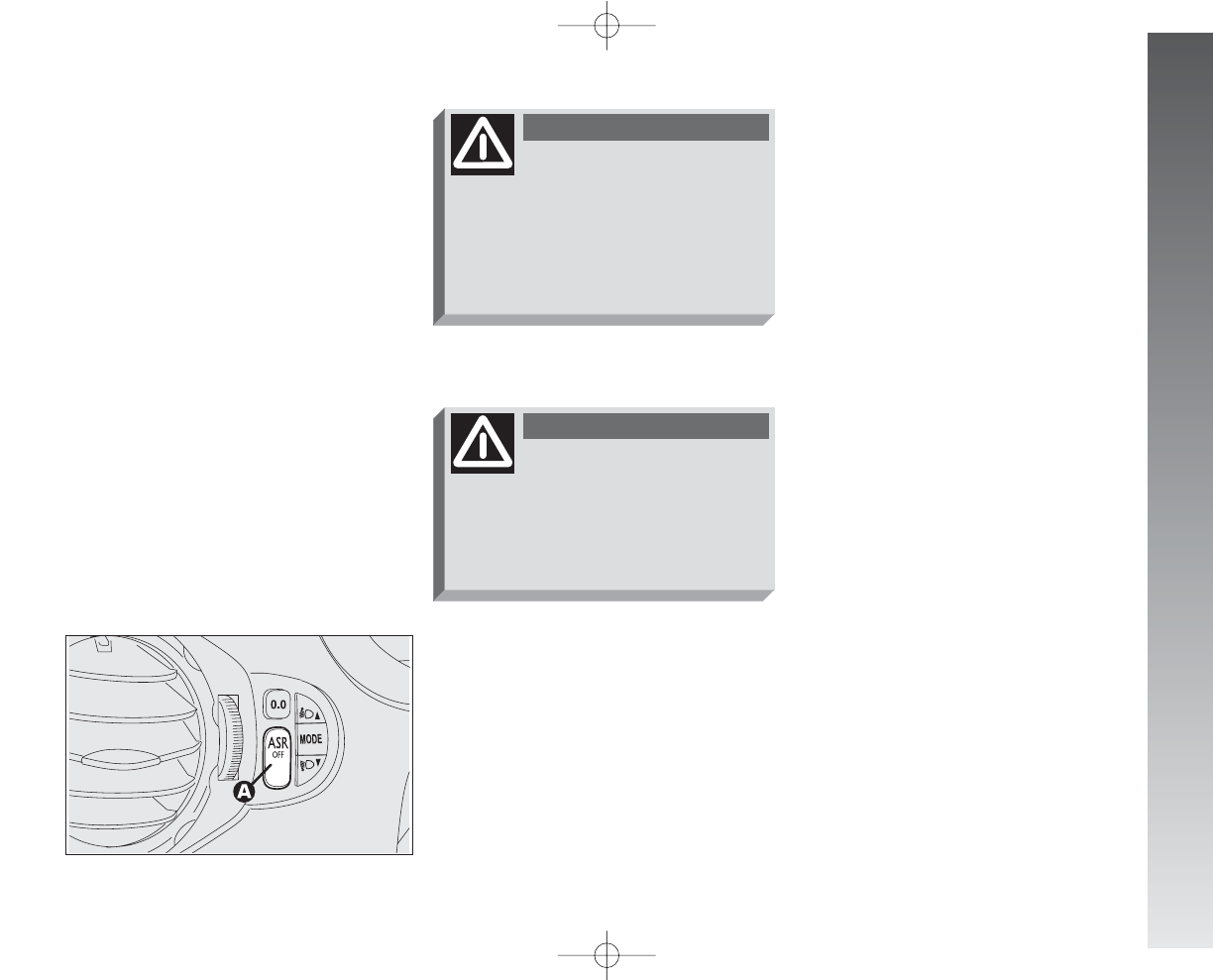
GETTING TO KNOW YOUR CAR
ASR SYSTEM FAILURE
INDICATION
In the event of a fault, the ASR system
switches off automatically and the
V
warn-
ing light on the instrument cluster turns on,
together with the message on the reconfig-
urable multifunction display.
In the event of an ASR system operating
failure, the car behaves in the same way
as a car that is not fitted with this system:
in any case, it is advisable to contact Alfa
Romeo Authorised Services as soon as pos-
sible.
During use of the compact
spare wheel, the ASR func-
tion is cut off and the
V
warning
light on the instrument cluster
turns on glowing steadily togeth-
er with the message on the recon-
figurable multifunction display.
WARNING
For correct operation of the
ASR system the tyres must
absolutely be of the same brand
and type on aall wheels, in perfect
conditions and, above all, of the
specified type, brand and size.
WARNING
SWITCHING ON
THE ASR FUNCTION
The ASR function switches on automati-
cally each time the engine is started.
When travelling the device can be switched
off and on again pressing switch (A-fig.
171).
When the function is turned off, the in-
strument panel warning light (
V
) turns on.
If the function is switched off when trav-
elling, it will turn on again automatically the
next time the engine is started.
fig. 171
A0A1119m
IMPORTANT When travelling on snow
with snow chains, it may be helpful to turn
the ASR device off: in fact, in these condi-
tions, slipping of the driving wheels when
moving off makes it possible to obtain bet-
ter drive.
145
110-185_Alfa147 Q2 GB 4-07-2008 12:02 Pagina 145
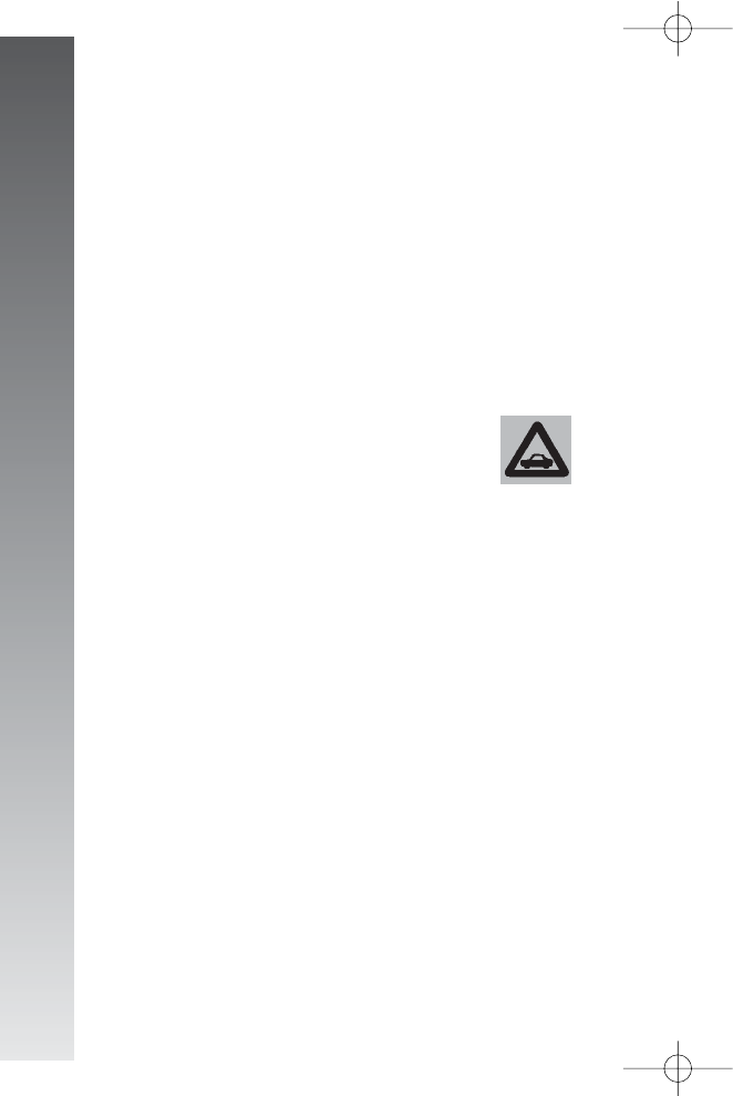
IMPORTANT After eliminating the in-
convenience, to check the system com-
pletely, Alfa Romeo Authorised Services are
obliged to run a bench test and, if necessary,
road tests which may also call for a long jour-
ney.
If, turning the ignition key
to MAR, the warning light
U
does not turn on or if,
while travelling it turns on glow-
ing steadily or flashing (on some
versions together with the mes-
sage + symbol on the reconfig-
urable multifunction display), con-
tact Alfa Romeo Authorised Ser-
vices as soon as possible.
GETTING TO KNOW YOUR CAR
146
EOBD SYSTEM
(for versions/markets where
applicable)
The EOBD system (European On Board Di-
agnosis) allows continuous diagnosis of the
components on the car correlated with emis-
sions; it also alerts the driver, by turning on
the warning light
U
(on some versions to-
gether with the message + symbol on the
reconfigurable multifunction display) on the
instrument panel when these components
are no longer in peak conditions.
The objective is:
– to keep the system efficiency under con-
trol;
– warn when a fault causes emission lev-
els to increase over the threshold established
by European law;
– warn of the need to replace deteriorat-
ed components.
The system also has a diagnostic connector
that can be interfaced with appropriate tools,
which makes it possible to read the error codes
stored in the control unit, together with a se-
ries of specific parameters for engine opera-
tion and diagnosis.
110-185_Alfa147 Q2 GB 4-07-2008 12:02 Pagina 146
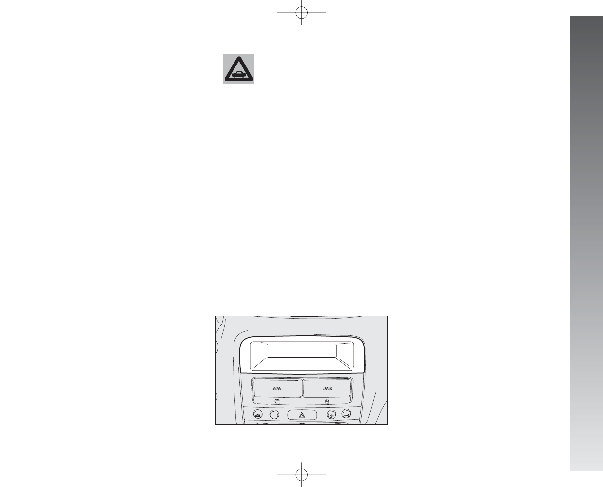
GETTING TO KNOW YOUR CAR
SOUND SYSTEM
PRESETTING
(for versions/markets where
applicable)
The car, if requested without radio, is fit-
ted with a glove compartment on the dash-
board (fig. 172).
The radio system presetting consists of:
– cables for sound system power supply;
– cables for front and rear loudspeaker
power supply;
– cable for aerial power supply;
– housing for sound system;
– aerial on car roof.
The radio is to be fitted in the housing lo-
cated in the glove compartment which can
be removed pressing the two retaining catch-
es in the compartment: here it is possible to
find the power cables.
If you wish to fit the ra-
dio system after purchas-
ing the car, first it is nec-
essary to contact Alfa Romeo Au-
thorised Services who will be able
to advise you on how to preserve
the battery charge. The excessive
useless power asboption may dam-
age the battery and make the bat-
tery warranty null.
fig. 172
A0A1055m
TECHNICAL INFORMATION
Speakers
In the cars fitted with radio presetting the,
sound system consists of:
– No. 4 tweeters: 2 front and 2 back (on
markets where applicable) with 30W pow-
er;
– No. 4 speakers with a diameter of 165
mm (2 front and 2 back) and 40W power.
Aerial
The aerial is located on the car roof. You
are recommended to slacken and remove
the aerial from the roof to avoid damaging
it when washing the car in automatic sys-
tem.
147
110-185_Alfa147 Q2 GB 4-07-2008 12:02 Pagina 147

GETTING TO KNOW YOUR CAR
148
SOUND SYSTEM
(for versions/markets where
applicable)
The car sound system, fitted with CD play-
er (radio with Compact Disc player) or MP3
CD player (radio with MP3 CD player) has
been designed in accordance with the spe-
cial features of the passenger compartment,
with a personalised design that blends with
the style of the dashboard. The sound sys-
tem cannot be adapted to other vehicles and
for this reason it cannot be removed.
The radio is installed in a user-friendly po-
sition for the driver and passenger and the
graphics on the front panel make location
of the controls quick, facilitating use.
The CD Changer is available at Lineacces-
sori Alfa Romeo.
In the following pages you will find the
instructions for use, which you are advised
to read through carefully. The instructions al-
so contain the procedure for controlling the
CD Changer (if provided) through the radio.
For the instructions for use of the CD Chang-
er refer to the specific manual.
ADVICE
Road safety
You are advised to learn how to use the
various radio functions (e.g.: storing sta-
tions) before starting to drive.
Reception conditions
Reception conditions change constantly
when driving. Reception may be disturbed
by the presence of mountains, buildings or
bridges particularly when far away from the
station being listened to.
IMPORTANT When receiving traffic in-
formation, the volume may be higher than
normal.
110-185_Alfa147 Q2 GB 4-07-2008 12:02 Pagina 148
GETTING TO KNOW YOUR CAR
149
Care and maintenance
The radio structure ensures long operation
with no need for particular maintenance.
In the event of a fault, contact Alfa Romeo
Authorized Services.
To clean the front panel only use a soft,
antistatic cloth. Cleaning and polishing prod-
ucts might spoil the surface.
Compact Disc
Remember that dirt, marks or distortion on
Compact Disc can cause skipping. To obtain
optimum playing conditions we give the fol-
lowing advice:
– Only use Compact Discs which have the
following brand:
– Carefully clean all Compact Discs of fin-
gerprints and dust using a soft cloth. Sup-
port Compact Discs from the outer circum-
ference and clean from the centre outwards;
– Never use chemical products for clean-
ing (e.g.: spray cans, antistatic or thinners)
as they might damage the surface of Com-
pact Discs;
– After use, put Compact Discs back in
their container, to avoid marks or scratches
that may cause skipping when playing;
– Do not expose Compact Discs to direct
sunlight, high temperatures or damp for pro-
longed lengths of time to prevent them from
bending;
– Do not stick labels or write on the record-
ed surface of Compact Discs.
Too high a volume when dri-
ving can put the driver’s life
at risk and that of other people.
Therefoore the volume should always
be adjusted in such a way that it is
always possible to hear the noises
oof the surrounding environment
(e.g.: horns, ambulance, police
sirens, etc.).
WARNING
110-185_Alfa147 Q2 GB 4-07-2008 12:02 Pagina 149
GETTING TO KNOW YOUR CAR
150
To remove a Compact Disc from its con-
tainer, press the centre and raise the disc
carefully, holding it by the outer circumfer-
ence.
Always hold Compact Discs by the outer
circumference. Never touch the surface.
To remove fingerprints and dust, use a soft
cloth starting from the centre of the Com-
pact Disc outwards.
Do not use highly scratched, cracked, or
distorted discs, etc. The use of these discs
will involve malfunctioning or damage to the
player.
For optimal playing use original CDs only.
Regular operation is not guaranteed if using
R/RW CDs not properly mastered and/or
CDs with max. capacity higher than 650
MB.
IMPORTANT Do not use the protective
sheets for CD in commerce or discs with sta-
bilisers, etc. as they might get stuck in the
internal mechanism and damage the disc.
IMPORTANT Should copy-protected CDs
be used, then, few seconds may be required
for playing them. Moreover, due to the pro-
liferation of always new and different pro-
tection methods, it is not guaranteed that
the CD player can play whatever protected
disc. Copy protection is often indicated on
the CD cover in small letters or hard to read
characters. Usually it is indicated by writings
like: “COPY CONTROL”, “COPY PROTECT-
ED”, “THIS CD CANNOT BE PLAYED ON A
PC/MAC”, or it is identified by symbols like:
110-185_Alfa147 Q2 GB 4-07-2008 12:02 Pagina 150
GETTING TO KNOW YOUR CAR
151
Protected discs (and their cover) very of-
ten are not marked with the audio CD iden-
tification symbol:
IMPORTANT The CD player can read
most of the compression systems currently
on sale (e.g.: LAME, BLADE, XING, FRAUN-
HOFER) however, due to the evolution of
these systems, reading of all compression for-
mats is not guaranteed.
IMPORTANT When loading a multi-ses-
sion CD, only the first session will be played.
TECHNICAL DATA
Radio
Maximum power: 4 x 30W.
Aerial
The aerial is located on the car roof. You
are recommended to slacken and remove
the aerial from the roof to avoid damaging
it when washing the car in automatic sys-
tem.
Speakers
The sound system is formed of a system
comprising:
– 4 tweeters: 2 front and 2 rear (for ver-
sions/markets where applicable) with 30W
power
– 4 speakers with a diameter of 165 mm
(2 front and 2 rear) with 40W power.
110-185_Alfa147 Q2 GB 4-07-2008 12:02 Pagina 151

GETTING TO KNOW YOUR CAR
152
Protection fuse
The radio has a 10A fuse located in the
rear part of the set. To replace the fuse, the
radio needs to be pulled out: therefore con-
tact Alfa Romeo Authorised Services.
HI-FI BOSE SYSTEM
(optional for versions/
markets where applicable)
The HI-FI BOSE system installed on your
car has been accurately designed to offer
outstanding sound quality and reproduce the
musical realism of a live concert, for all the
seats in the passenger compartment.
The system’s features include outstanding
faithful reproduction of crystalline treble
tones and full, rich basses which among oth-
er things, make the Loudness function su-
perfluous. In addition, the complete range
of the sounds is reproduced in the whole pas-
senger compartment enveloping the occu-
pants with the natural spatial sensation that
is felt when listening to live music.
The components adopted are patented and
are the result of the most sophisticated tech-
nology, but at the same time they are easy
and intuitive to use, so that even less expert
people can use the system.
Technical information
System comprises:
– No. 4 high efficiency woofers with di-
ameter 165 mm, two at the front and two
at the back, each having a coaxial tweeter
inside;
– No. 1 bass box with a volume of 12 dm3
housed on the left-hand side of the boot;
– No. 1 high power HI-FI amplifier
(150W) with 6 channels, analogue equal-
ising in amplitude signal phase and with
130 mm diameter sub-woofer.
110-185_Alfa147 Q2 GB 4-07-2008 12:02 Pagina 152
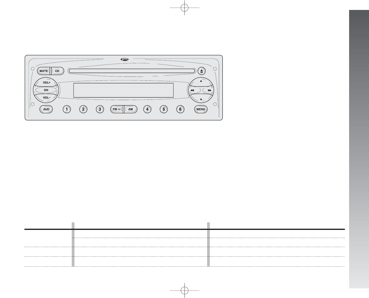
GETTING TO KNOW YOUR CAR
153
CONTROLS ON FRONT PANEL
Audio section
– Loudness function (excluding versions
with Bose HI-FI system)
– Standard equalization (excluding ver-
sions with Bose HI-FI system)
– Personal equalization (excluding ver-
sions with Bose HI-FI system)
– Automatic volume changing according
to car speed
– MUTE function
CD / CD MP3 section
– Play / Pause
– Previous / next track selection
– FF / FR
– Previous / next directory selection
Button GENERAL FUNCTIONS Mode
ON
VOL+
VOL
Radio section
– Traffic information reception (TA)
– Automatic storage of 6 stations in the
dedicated FM band - FMT (AS – Autostore)
fig. 167
A0A1125m
On
Off
Volume up
Volume down
Short push on button
Long push on button
Press button
Press button
110-185_Alfa147 Q2 GB 4-07-2008 12:02 Pagina 153
GETTING TO KNOW YOUR CAR
154
Button GENERAL FUNCTIONS Mode
FM AS
AM
CD
MUTE
AUD
MENU
Radio band selection FM1, FM2, FM Autostore
Radio band selection MW, LW
Audio source selection (radio/CD/CD-Changer)
Volume on/off (MUTE / PAUSE)
Audio settings: bass (BASS), treble (TREBLE),
right/left sound adjustment (BALANCE),
front/rear sound adjustment (FADER)
Advanced functions adjustment
Brief cyclic button pressing
Brief cyclic button pressing
Brief cyclic button pressing
Brief button pressing
Menu activation: brief button pressing
Adjustment selection: press button
▲
or
▼
Value adjustment: press button
÷
or
˜
Menu activation: brief button pressing
Adjustment selection: press button
▲
or
▼
Value adjustment: press button
÷
or
˜
Button CD FUNCTIONS Mode
˚
÷˜
▲
▼
CD ejection
Previous/next track playback
CD track fast forward/backward
Previous/next CD playback (for CD Changer)
Previous/next directory playback (for MP3 CD)
Brief button pressing
Brief pressing on buttons
÷
or
˜
Long pressing on buttons
÷
or
˜
Brief pressing on buttons
▲
or
▼
Brief pressing on buttons
▲
or
▼
Button RADIO FUNCTIONS Mode
1 2 3 4 5 6
Radio station tuning:
• Automatic tuning
• Manual tuning
Current radio station storage
Stored station recall
Automatic tuning: press button
÷
or
˜
(long pressing for fast forward)
Manual tuning: press button
▲
or
▼
(long pressing for fast forward)
Long button pressing
respectively for preset/memories from 1 to 6
Brief button pressing
respectively for preset/memories from 1 to 6
▲
÷˜
▼
110-185_Alfa147 Q2 GB 4-07-2008 12:02 Pagina 154
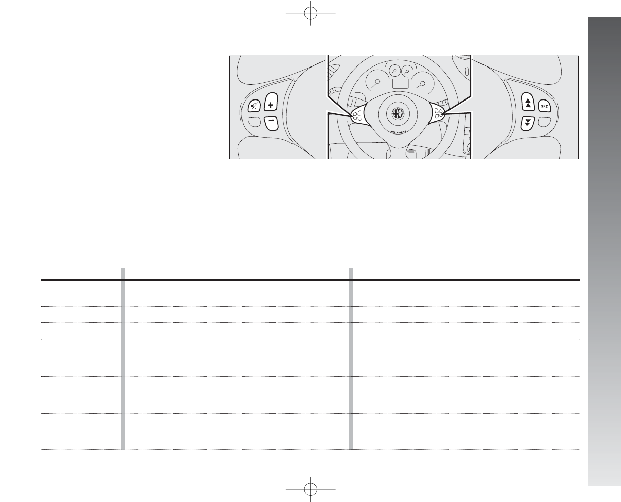
GETTING TO KNOW YOUR CAR
fig. 174
A0A1126m
Button FUNCTION Mode
z
+
–
SRC
ô
ó
Audio Mute on/off
(with sound system on)
Volume up
Volume down
Radio frequency
(FM1, FM2, FMT, MW, LW) and audio source
(Radio - CD - MP3 - CD Changer) selection button
Radio: recall preset stations (1 to 6)
MP3: select next directory
CD Changer: select next CD in the CD Changer
Radio: recall preset stations (6 to 1)
MP3: select previous directory
CD Changer: select previous CD in the CD Changer
Brief button pressing
Press button
Press button
Press button
Press button
Press button
155
STEERING WHEEL CONTROLS
(where provided)
110-185_Alfa147 Q2 GB 4-07-2008 12:02 Pagina 155

GETTING TO KNOW YOUR CAR
156
GENERAL
The set possesses the following functions:
Radio section
– PLL tuning with FM/AM/MW/LW fre-
quency bands;
– RDS (Radio Data System) with TA (traf-
fic announcements) - TP (Program Type) -
EON (Enhanced Other Network) - REG (Re-
gional programmes);
– AF: alternative frequency search selec-
tion in RDS mode;
– emergency alarm presetting;
– automatic/manual station tuning;
– FM Multipath detector;
– manual storage of 36 stations: 18 in
the FM band (6 in FM1, 6 in FM2, 6 in
FMT), 6 in the MW band and 6 in the LW
band;
– automatic storage (Autostore function)
of 6 stations in FM band;
– SVC function (excluding versions with
Bose HI-FI system): automatic volume ad-
justment with car speed;
– automatic Stereo/Mono switching.
CD section
– Direct disc selection;
– Track selection (forward/backward);
– Fast forward/backward;
– CD Display function: displaying CD
name/time elapsed from start of track;
– Playing audio CDs and R/RW CDs.
CD MP3 section
– Directory selection (previous/next);
– Track selection (forward/backward);
– Fast forward/backward;
– MP3 DISP function: directory name, ID3-
tag info, time elapsed from start of track,
file name);
– Playing audio CDs and R/RW CDs.
Audio section
– Mute/Pause function;
– Soft Mute function;
– Loudness function (excluding versions
with Bose HI-FI system);
– 7 band graphic equalizer (excluding ver-
sions with Bose HI-FI system);
– Separate bass/treble adjustment;
– Right/left channel balancing.
On multimedia CDs in addi-
tion to sound tracks also
data tracks are recorded.
Playing one of these CDs may cause
rustling and such a volume as to
compromise road safety, as well as
causing damage to the final stages
and speakers.
110-185_Alfa147 Q2 GB 4-07-2008 12:02 Pagina 156

GETTING TO KNOW YOUR CAR
157
FUNCTIONS AND
ADJUSTMENTS
Turning the sound system on
The set is switched on pressing button ON.
When turning the sound system on, the
volume level will be brought to 20 if it was
set to over.
If the radio is turned on when the key is
not fitted into the ignition device, it will turn
off automatically after about 20 minutes.
After automatic switching off, it is however
possible to turn the radio on again for oth-
er 20 minutes by pressing button ON (see
paragraph “IGN TIME function”).
Turning the sound system off
Keep button ON pressed.
Selecting radio functions
Pressing briefly and repeatedly button
FMAS it is possible to select the following
functions in sequence:
– TUNER (“FM1”, “FM2”, “FMT”);
Pressing briefly and repeatedly button AM
it is possible to select the following functions
in sequence:
– TUNER (“MW”, “LW”).
Selecting CD/CD Changer
functions
Pressing briefly and repeatedly button CD
it is possible to select the following audio
sources in sequence:
– CD (only if the Compact Disc is insert-
ed);
– CHANGER (only if the CD Changer is con-
nected).
Audio source memory function
If while listening to a CD another function
is selected (e.g.: the radio), playing is
stopped and when the CD mode is resumed,
it starts again from the point in which it was
stopped.
If while listening to the radio another func-
tion is selected, when the Radio mode is
resumed, it is tuned to the last station se-
lected.
Volume adjustment
Adjust volume through VOL+ and VOL–
buttons.
If the volume level is changed during the
broadcast of a traffic bulletin, the new set-
ting is maintained only until the end of the
bulletin.
SVC function
(excluding versions with HI-FI
Bose system)
The SVC function makes it possible to au-
tomatically adapt the volume level to the
speed of the car, increasing it as the speed
increases to maintain the ratio with the noise
level inside the passenger compartment.
See section MENU for activating/deacti-
vating this function.
110-185_Alfa147 Q2 GB 4-07-2008 12:02 Pagina 157

GETTING TO KNOW YOUR CAR
158
Mute /pause function
(turning off the volume
completely)
To switch on the Mute function, briefly
press the button MUTE. Volume will gradu-
ally lower and the display will show the word
“MUTE” (when in radio mode) or “PAUSE”
(when in CD or CD-Changer mode).
To switch off the Mute function, press the
button MUTE again. Volume will gradually
become louder returning to the value set be-
fore switching on the Mute function.
Changing volume will deactivate the Mute
function and the volume will be set to the
new level selected.
With the Mute function on:
– if an emergency alarm or a traffic bul-
letin arrives with the TA function on, the mes-
sage ignores the Mute function. The Mute
function will be resumed at the end of the
traffic announcement.
Audio adjustments
The options proposed by the audio menu
differ according to the audio source select-
ed: AM/FM/CD/CDC.
To change Audio functions, press briefly
button AUD. The display will show “BASS”.
To scroll the Menu options, use buttons
▲
or
▼
. To change the setting of the option
selected, press buttons
÷
or
˜
.
The display will show the current status
of the function selected.
The functions controlled by the menu are
the following:
– BASS (bass adjustment);
– TREBLE (treble adjustment);
– BALANCE (right/left balance);
– FADER (excluding versions with Bose HI-
FI system) (front/rear balance);
– LD (excluding versions with Bose HI-FI
system) (Loudness on/off);
– PRESET (excluding versions with Bose
HI-FI system) (standard equalization acti-
vation and selection);
– XX USER (personal equalization set-
ting).
Tone adjustment
(bass/treble)
Proceed as follows:
– Use button
▲
or
▼
to select “BASS”
or “TREBLE” in the AUDIO menu;
– press button
÷
or
˜
to in-
crease/decrease the basses or trebles.
Pressing the buttons briefly the change is
gradual by steps. Pressing longer, chang-
ing is faster.
Balance adjustment
Proceed as follows:
– Use button
▲
or
▼
to select “BAL-
ANCE” in the AUDIO menu;
– press button
÷
to increase the sound
from the right speakers or button
˜
to
increase the sound from the left speakers.
Pressing the buttons briefly the change is
gradual by steps. Pressing longer, chang-
ing is faster.
Select “
÷
0
˜
” to set the same val-
ue for both right and left speakers.
110-185_Alfa147 Q2 GB 4-07-2008 12:02 Pagina 158

GETTING TO KNOW YOUR CAR
159
Fader adjustment
Proceed as follows:
– Use button
▲
or
▼
to select “FADER”
in the AUDIO menu;
– press button
÷
to increase the sound
from the rear speakers or button
˜
to
increase the sound from the front speakers.
Pressing the buttons briefly the change is
gradual by steps. Pressing longer, chang-
ing is faster.
Select “
÷
0
˜
” to set the same val-
ue for both front and rear speakers.
LD function
(excluding versions with Bose
HI-FI system)
The Loudness function improves the sound
volume when listening at low level, in-
creasing the basses and trebles.
To switch the function on/off, use button
▲
or
▼
to select “LD” in the AUDIO menu.
The function condition (on or off) is shown
on the display for few seconds by “LD ON”
or “LD OFF”.
PRESET/XX EQ SET*/CLASSIC/
ROCK/JAZZ functions
(equalizer on/off)
(excluding versions with Bose
HI-FI system)
The integrated equalizer can be turned on
or off. With the equalizer off, it is possible
to change the sound settings only adjust-
ing the bass (“BASS”) and treble tones
(“TREBLE”), while activating the function
makes it possible to adjust the sound curves.
To turn the equalizer off, select “PRESET”
by means of button
÷
or
˜
.
To turn the equalizer on, use button
÷
or
˜
to select one of the following op-
tions:
– “USER” (adjustment of the 7 equaliz-
er bands that can be changed by the user);
– “CLASSIC” (predefined equalizer ad-
justment for best playing of classic music);
– “ROCK” (predefined equalizer adjust-
ment for best playing of rock and pop mu-
sic);
– “JAZZ” (predefined equalizer adjust-
ment for best playing of jazz music).
When one of the equalizer settings is on,
the display shows “EQ”.
*XX EQ SET function
(only if the USER equalizer
setting has been selected)
(excluding versions with Bose
HI-FI system)
To set a personal equalizer adjustment, use
button
▲
or
▼
to select USER and then
press button
▼
for long.
The display will show for about 2 seconds
“XX EQ SET” and then a graph with 7 bars,
where each bar represents a frequency.
Choose the bar to be adjusted using button
÷
or
˜
; the bar chosen starts to flash
and it is possible to adjust it using button
▲
or
▼
.
To store the new settings, press button
AUD again or wait for about 10 seconds.
The display will show the word “MEN” to-
gether with the graph with 7 bars.
Antitheft protection
Refer to paragraph “CD Player”.
110-185_Alfa147 Q2 GB 4-07-2008 12:02 Pagina 159

GETTING TO KNOW YOUR CAR
160
RADIO (TUNER)
Introduction
When the set is turned on the last function
selected before turning off is played (Radio,
CD or CD Changer).
To select the Tuner source while listening
to another audio source, press briefly but-
tons FMAS or AM, according to the required
frequency band.
When Tuner is on, the display will show
the selected station name (RDS stations on-
ly) (or frequency), the frequency band (e.g.:
FM1) and the preselection button number
(e.g.: P1).
Selecting the frequency band
If in the Tuner mode, briefly and repeat-
edly press button FMAS or AM to select the
required frequency band.
Every time the button is pressed the fol-
lowing bands are selected in sequence:
– Pressing button FMAS: “FM1”, “FM2”,
“FMT”;
– Pressing button AM: “MW” and “LW”.
Each band is shown by the respective
wording on the display.
The last station selected in the respective
frequency band will be tuned.
The FM band is divided into sections: FM1,
FM2 and FMT. The FMT reception band is
reserved to the stations stored automatically
with the Autostore function.
Presetting buttons
The buttons with symbols from 1 to 6
make it possible to set the following pre-
settings:
– 18 in the FM band (6 in FM1, 6 in
FM2, 6 in FMT);
– 6 in the MW band;
– 6 in the LW band;
To call a preset station, choose the required
frequency band and then press briefly the
corresponding preset button (from 1 to 6).
Pressing the respective preset button for
longer than 2 seconds will store the tuned
station. Storing is confirmed by a beep.
Storing the last station heard
The radio automatically keeps in storage
the last station heard for each reception
band, which is then tuned when the radio is
turned on or the reception band is changed.
Automatic tuning
Briefly press button
÷
or
˜
to start
automatically searching the tuning for the
next station that it is possible to receive in
the direction chosen.
If button
÷
or
˜
is pressed for
longer, quick searching takes place. When
the button is released, the tuner stops on
the next receivable station.
If the TA function is on (traffic information),
the tuner only searches stations which broad-
cast traffic bulletins.
110-185_Alfa147 Q2 GB 4-07-2008 12:02 Pagina 160

GETTING TO KNOW YOUR CAR
161
Manual tuning
This allows manual station searching in the
chosen band.
Select the required frequency band and
then press briefly and repeatedly button
N
or
O
to start searching in the chosen band.
Pressing one of the buttons
N
or
O
longer
obtains fast forward searching, which is
stopped when the button is released.
A-STORE function
(automatic station storage)
To switch on the A-STORE function, keep
button FMAS pressed until receiving the con-
firmation beep. With this function the ra-
dio automatically stores the six stations with
the strongest signal in decreasing order of
intensity of the FMT frequency band.
IMPORTANT Activating the A-STORE
function cancels the stations stored previ-
ously in the FMT band.
If the TA function is on (traffic information),
only the stations that send traffic informa-
tion will be stored.
During automatic storage the display
shows “A-STORE”.
To interrupt A-STORE press button FMAS
again: the radio will automatically tune to
the station heard before activation of the Au-
toSTore function.
At the end of the A-STORE function the ra-
dio automatically tunes on the first preset
station in the FMT band stored on preset but-
ton 1.
On buttons numbered from 1 to 6, the sta-
tions are automatically stored that give a
strong signal in that moment in the present
band.
Activating the A-STORE function in MW or
LW bands will automatically select the FMT
band where the function is then run.
IMPORTANT Sometimes the A-STORE
function is unable to find 6 stations with a
strong signal. In this case the previous sta-
tions will be stored on the free preset but-
tons.
110-185_Alfa147 Q2 GB 4-07-2008 12:02 Pagina 161

GETTING TO KNOW YOUR CAR
162
Emergency alarm reception
In the RDS mode the radio is set to receive
emergency announcements in the case of
exceptional circumstances or events that
may cause general danger (earthquakes,
floods, etc.), if they are broadcast by the
station tuned.
This function is activated automatically and
cannot be deactivated.
During emergency announcement the dis-
play will show the message “ALARM”. Dur-
ing this announcement the volume will
change as described for traffic announce-
ments (see paragraph “TA function”).
EON function
(Enhanced Other Network)
Certain countries have circuits which group
together several stations enabled to broad-
cast traffic information. In this case the pro-
gramme of the station being heard will be
interrupted temporarily:
– to receive traffic information (only with
TA function on);
– to listen to regional programmes every
time these bulletins are given by one of the
stations of the same circuits.
Stereophonic stations
If the signal received is weak, the device
switches automatically from Stereo to Mono.
MENU
MENU button functions
To activate the menu function, briefly press
button MENU. The display shows the word
“MENU”.
To scroll the menu functions use button
▲
or
▼
. To change the setting of the select-
ed function use button
÷
or
˜
.
The display will show the current status
of the function selected.
The functions controlled by the menu are
the following:
– AF (alternative frequency search);
– TA (traffic information);
– REG (regional programmes);
– MP3 DISP (MP3 CD data display);
– SVC (automatic volume control in rela-
tion to speed);
– EXT VOL (external audio sources con-
trol);
– IGN TIME (System power off mode ra-
dio);
– DEFAULT (reset original settings).
To exit the menu function, press button
MENU again.
110-185_Alfa147 Q2 GB 4-07-2008 12:02 Pagina 162

GETTING TO KNOW YOUR CAR
163
AF function
(alternative frequency search)
Within the RDS system the radio can work
in two different modes:
– “AF ON”: alternative frequency search on
(the display shows “AF”);
– “AF OFF”: alternative frequency search
off.
With “AF ON”, the radio is automatically
tuned to the station with the strongest sig-
nal that is broadcasting the same programme.
During the journey it will thus be possible to
continue listening to the station chosen with-
out having to change the frequency when
changing area.
Of course, the station being listened to must
be receivable in the area the car is crossing.
To turn the AF function on/off, press but-
ton MENU, and then select “AF ON” or “AF
OFF”. If the AF function has been turned on
the display shows “AF”.
If the radio is working in the AM band, when
the AF function is activated, it passes to the
FM1 band on the last station selected.
TA function
(traffic information)
Certain stations in the FM band (FM1, FM2
and FMT) are enabled to also broadcast in-
formation about traffic conditions. In this case
the display shows “TP”.
To turn the TA (traffic announcement) func-
tion on/off, briefly press button MENU and
then select “TA ON” or “TA OFF”.
IMPORTANT If the TA function (traffic in-
formation) is on, with CD, CD Changer (if in-
stalled), Telephone or Mute/Pause active:
automatic station tuning will start.
With the TA function it is possible:
– to search only RDS stations that trans-
mit in the FM band, enabled to broadcast traf-
fic information;
– to receive traffic information although CD
player or CD Changer are being used;
– to receive traffic information at a prede-
fined minimum volume even with the radio
volume off.
IMPORTANT In certain countries radio
stations exist which, even if the TP function
is on (the display shows “TP”), do not trans-
mit traffic information.
If the radio is working in the AM band, when
TA is activated, it passes to the FM1 band
on the last station heard.
The volume with which the traffic bulletin is
transmitted varies depending on the listening
volume:
– listening volume below 20: traffic bulletin
volume = 20 (fixed value);
– listening volume above 20: traffic bulletin
volume = listening volume +1.
If the volume is changed during a traffic bul-
letin the value is not shown on the display
and the new value is kept only for the bul-
letin in progress.
The TA function is interrupted by pressing
any sound system button.
110-185_Alfa147 Q2 GB 4-07-2008 12:02 Pagina 163

GETTING TO KNOW YOUR CAR
164
REG function
(regional broadcast reception)
Certain national broadcasters, at determi-
nate times of the day, transmit regional pro-
grammes which differ from region to region.
This function makes it possible to tune in on-
ly on local stations (regional) (see “EON
function”).
Activate this function if you want to tune
automatically to regional stations broad-
casting in the selected band.
To turn the function on/off use button
÷
or
˜
.
The display will show the current status
of the function:
– “REG ON”: function on.
– “REG OFF”: function off.
If the function is off and a regional pro-
gramme is tuned that works in a determi-
nate area and the car enters a different area,
the regional station of the new area is re-
ceived.
IMPORTANT If AF and REG are both ac-
tive, when passing from one region to an-
other the radio could not tune properly to
a valid alternative frequency.
MP3 DISP function
(CD MP3 data display)
With this function it is possible to choose
the information shown on the display, when
listening to a MP3 CD.
This function can be selected only if a MP3
CD is loaded: in this event the display shows
“MP3 DISP”.
To change the function use buttons
÷
or
˜
.
The display shows the setting among the
six possible:
– TITLE (track title, if ID3-TAG available)
– AUTHOR (track author, if ID3-TAG avail-
able)
– ALBUM (album title, if ID3-TAG avail-
able)
– DIR (directory name);
– FILENAME (MP3 file name);
– TIME (time elapsed from start of track).
110-185_Alfa147 Q2 GB 4-07-2008 12:02 Pagina 164

GETTING TO KNOW YOUR CAR
165
SVC function
(volume changing with speed)
(excluding versions with
Bose HI-FI system)
This function makes it possible to auto-
matically adapt the volume level to the
speed of the car, increasing it as the speed
increases to maintain the ratio with the noise
level inside the passenger compartment.
To turn the function on/off use button
÷
or
˜
. The display will show the cur-
rent status of the function:
– SVC OFF: function off
– SVC LOW: function on
(low sensitivity)
– SVC HIGH: function on
(high sensitivity).
EXT function
(external audio source control)
With this function it is possible to adjust
(setting from 0 to 40) or exclude (OFF) ex-
ternal audio sources.
To turn this function on/off, use button
÷
or
˜
.
The display will show the current status
of the function:
– “EXT VOL”: function on.
– “EXT OFF”: function off.
– “EXT 23”: function on with volume lev-
el 23.
IGN TIME function
(system power on/off mode
radio)
This function enables to switch off the
sound system according to two different
modes. To turn the function on use button
÷
or
˜
.
The display will show “IGN TIME” and
then:
– “00 MIN”: deactivation dependent on
ignition key. Sound system will switch off
automatically when turning the ignition key
to STOP;
– “20 MIN”: deactivation independent of
ignition key. After having turned the ignition
key to STOP the sound system will stay on
for 20 minutes max.
IMPORTANT When the sound system
is switched off automatically after turning
the ignition key to STOP (for both immedi-
ate or 20-minute delayed power off), it will
switch on automatically turning the ignition
key to MAR. If the sound system has been
switched off pressing button ON, when turn-
ing the key to MAR it will stay off.
RESTORE function
This function enables to restore default set-
tings. Options available are the following:
– NO: no restore;
– YES: restore default settings. During this
operation the display will show the message
“RESTORE”. At the end of this operation,
the audio source will not be changed and
the previous situation is displayed.
110-185_Alfa147 Q2 GB 4-07-2008 12:02 Pagina 165
GETTING TO KNOW YOUR CAR
166
COMPACT DISC PLAYER
Introduction
This section only describes CD player op-
eration variants: as concerns sound system
operation, refer to paragraph “Functions and
adjustments”.
Selecting the compact disc player
To turn on the Compact Disc player inte-
grated in the set, proceed as follows:
– insert a CD with the set on: the first track
will be played;
or
– if a CD is already inserted, turn the set
on and press briefly button CD to select
“CD”: the last heard track will be played.
For optimal playing use only original CDs.
When using R/RW CDs, use top quality CDs
mastered at the as low as possible speed.
Inserting/ejecting a CD
To insert the CD set it gently in place to ac-
tivate the powered loading system, which
will position it correctly.
Press button
˚
, with the device on, to op-
erate the powered CD eject system. After
ejection, the source heard before playing the
CD will return.
If CD is not ejected, the device will reload
it automatically after about 20 seconds and
then will set to Tuner (Radio).
CD cannot be ejected if the device is off.
Inserting the ejected CD without fully re-
moving it from the slot, the tuner will not
change the source to CD.
110-185_Alfa147 Q2 GB 4-07-2008 12:02 Pagina 166

GETTING TO KNOW YOUR CAR
167
Possible error messages
If the CD inserted is illegible (e.g.: CD-ROM
inserted, CD not inserted properly or read-
ing error), the display will show the mes-
sage “CD ERROR” for about 2 seconds.
The CD is then ejected and the previous
source before CD was selected returns.
Display information
When the CD player is working, the dis-
play shows the following information which
means:
“T05”: shows the number of the track on
the CD;
“03:42”: shows the time elapsed since
the start of the track (if the corresponding
Menu function is on);
Select track
(forward/backward)
Briefly press button
÷
to play the pre-
vious track and button
˜
to play the next
one. Tracks are played in sequence: after the
last track, the first one will be played and
vice versa.
If playing the track started more than 3
seconds ago, pressing briefly button
÷
the track is played again from the start. In
this case if wanting to play the previous
track, press the button twice consecutively.
Fast forward/backward
Keep button
˜
pressed to move the
track selected forward at high speed and
keep button
÷
pressed to move it quick-
ly backward. Fast forward/backward is
stopped once the button is released.
Pause function
To pause the CD player, press button
MUTE. The display will show “PAUSE”.
To resume playing the track, press button
MUTE again.
The pause function is deactivated chang-
ing the sound source.
110-185_Alfa147 Q2 GB 4-07-2008 12:02 Pagina 167

GETTING TO KNOW YOUR CAR
168
Antitheft protection
The radio is fitted with an antitheft pro-
tection system based on the exchange of in-
formation between the radio and the elec-
tronic control unit (Body Computer) installed
on the car.
This system warrants the highest level of
security and prevents entry of the secret
code every time the radio supply is discon-
nected.
If the result of the check is positive, the set
starts working, whereas if the comparison
codes are not the same or if the electronic
control unit (Body Computer) is replaced,
the device informs the user of the need to
enter the secret code according to the pro-
cedure described in the following paragraph.
Entering the secret code
When turning the sound system on (in the
event of code request), the display will show
the word “CDC CODE” for about 2 seconds,
followed by four dashes “- - - -”.
The secret code comprises four figures from
1 to 6, each corresponding to one of the
dashes.
To enter the first digit of the code, press
the corresponding key of the preset stations
(from 1 to 6). Enter the other code digits in
the same way.
If the four figures are not entered within
20 seconds, the display shows the word
“CDC CODE” for 2 seconds and then fours
dashes “- - - -”. This is not to be considered
as an incorrect code entry.
After entering the fourth digit (within 20
seconds), the radio starts working.
If a wrong code is entered, the radio
sounds a beep, the display shows the word
“CDC CODE” for 2 seconds and then fours
dashes “- - - -” to warn the user that it is nec-
essary to enter the correct code.
Every time the user enters a wrong code,
the waiting time increases gradually (1 min,
2 min, 4 min, 8 min, 16 min, 30 min,1h,
2h, 4h, 8h, 16h, 24h) until reaching a max-
imum of 24 hours. The waiting time will
be shown on the display with the word “CDC
WAIT”. When this goes off it is possible to
start the new code entry procedure.
Code Card
This the document that certifies possession
of the radio. The Code Card contains the ra-
dio model, serial number and secret code.
IMPORTANT Keep the Code Card care-
fully to be able to give the related data to
the competent authorities in the event of
theft.
110-185_Alfa147 Q2 GB 4-07-2008 12:02 Pagina 168

GETTING TO KNOW YOUR CAR
169
MP3 CD PLAYER
(where provided)
Introduction
This section only describes MP3 CD play-
er operation variants: as concerns sound sys-
tem operation, refer to paragraph “Functions
and adjustments”.
NOTE MPEG Layer-3 audio decoding tech-
nology licensed from Fraunhofer IIS and
Thomson multimedia.
MP3 mode
In addition to standard audio CDs, the
sound system can also play audio files in
MP3 format. Sound system will operate as
described in “Compact Disc player” para-
graph when inserting a conventional audio
CD.
For optimal playing use only top quality
CDs mastered at a speed as low as possible.
MP3 CD files are structured by directories,
with sequential lists of all directories con-
taining MP3 tracks (directories and sub-di-
rectories are all brought to the same lev-
el), directories not containing MP3 tracks
cannot be selected.
Technical data and operating conditions for
MP3 files are as follows:
– adopted CD-ROM shall be mastered ac-
cording to ISO9660 Standard;
– music files shall be renamed as “.mp3”
otherwise they cannot be played;
– sampling frequencies are: 44.1 kHz,
stereo (96 to 320 kbit/s) - 22.05 kHz,
mono or stereo (32 to 80 kbit/s);
– it is possible to play variable bit-rate
tracks (files).
IMPORTANT Characters: blank, ‘ (apos-
trophe), ( and ) (open and closed brackets)
are not admitted in MP3 track names. When
sampling MP3 CD you must not use these
characters to name files otherwise the sound
system will not be able to play it.
110-185_Alfa147 Q2 GB 4-07-2008 12:02 Pagina 169

GETTING TO KNOW YOUR CAR
170
DISPLAY INFORMATION
ID3-tag info display
(track informations)
In addition to time elapsed, directory name
and file name, also ID3-tag info relevant to
track Title, Artist, Author (see “MP3 disp
function”) are displayed.
The MP3 directory name shown on the dis-
play corresponds to the name with which
the directory is stored on the CD, followed
by an asterisk.
Example of full MP3 directory name: BEST
OF *.
If you want to display one ID3-tag info (Ti-
tle, Artist, Album) and the track being played
has no ID3-tag info then, the file name will
be displayed.
Select next/previous directory
Press button
N
to select the next directory
or press button
O
to select the previous one.
The name of the new selected directory will
be shown on the display.
Directories are selected in cyclic sequence:
after the last directory the first one is se-
lected and vice versa.
If no other directory/track is selected in
the following 2 seconds, the first track in the
new directory will be played.
If the last track in the currently selected di-
rectory is played, the next will then be
played.
Antitheft protection
Refer to paragraph “Compact Disc player”.
110-185_Alfa147 Q2 GB 4-07-2008 12:02 Pagina 170
GETTING TO KNOW YOUR CAR
171
CD CHANGER (CDC)
Installation and connection
of a Lineaccessori CD
Changer shall only be
performed by Alfa Romeo
Authorized Services.
Introduction
This section only describes CD Changer
(where provided) operation variants: as con-
cerns sound system operation, refer to para-
graph “Functions and adjustments”.
Selecting the CD changer
Turn on the set, then press briefly and re-
peatedly button CD until selecting “CHANG-
ER”.
Possible error messages
Error messages will be displayed in the fol-
lowing cases:
– no CD in the CD Changer: the display
will show “CD ERROR” until changing the
sound source;
– selected CD is illegible (CD not in the se-
lected position or CD not inserted properly):
the display shows “CD ERROR” after the
number of the selected CD. The next CD will
be selected; if there are no other CDs or if
they are also illegible the display will show
the wording “NO CD” until the sound source
is changed;
– error in CD reading: the display shows
“CD ERROR”. The next CD will be selected;
if there are no other CDs in the CD Chang-
er (after the last CD search will restart from
the first one) or they are also illegible, if the
sound source is not changed, the display will
show the following:
❒
“CD Changer” for about 2.5 seconds;
❒
“CD Error” for about 5 seconds;
❒
plays next source for other 5 seconds;
– a CD-ROM is inserted: next CD will be
selected.
Selecting the CD
Press button
N
to select the next CD and
button
O
to select the previous CD. If the
loader does not contain a disc in the posi-
tion selected, the display briefly shows the
wording “CD ERROR”, and the next CD is
played automatically.
110-185_Alfa147 Q2 GB 4-07-2008 12:02 Pagina 171

GETTING TO KNOW YOUR CAR
172
TROUBLESHOOTING
Overview
Low volume
The Fader function shall only be set to “F”
(front), to prevent sound system output
power reduction and volume muting if the
Fader level set is = R+9.
Required source cannot be
selected
No CD loaded. Load the CD or the MP3 CD
you want to play.
Compact disc player
CD not played
Loaded CD is dirty. Clean the CD.
Loaded CD is scratched. Try to play another
CD.
Required CD cannot be loaded
Another CD is already loaded. Press button
˚
and remove the CD.
MP3 file reading
Skipping when reading MP3 files
Loaded CD is scratched or dirty. Clean the
CD as described in paragraph “CD” in “Ad-
vice” paragraph.
MP3 track length not displayed
correctly
In certain cases (due to recording) MP3
track length can be displayed incorrectly.
110-185_Alfa147 Q2 GB 4-07-2008 12:02 Pagina 172
GETTING TO KNOW YOUR CAR
173
MOBILE TELEPHONE
PROVISION
The car may be fitted with a provision for
installing a cell phone.
The mobile phone provision consists of:
– radio + cell phone dual-purpose anten-
na;
– connection and supply cables with spe-
cific connector for connecting hands-free kit.
For the installation of a
cell phone and connection
to the provision in the car,
contact only Alfa Romeo Autho-
rised Services; this will guarantee
first-rate results with no possibil-
ity of any inconvenience that may
compromise the safety of the car.
The voice kit should be
purchased by the customer
as it must be compatible
with the customer’s phone.
ACCESSORIES
PURCHASED
BY THE OWNER
If after buying the car, you decide to install
electrical accessories that require a perma-
nent electric supply (alarm, voice feature,
radionavigator with satellite antitheft, etc.)
or accessories that in any case burden the
electric supply, contact Alfa Romeo Autho-
rised Services, whose qualified personnel,
besides suggesting the most suitable devices
belonging to Lineaccessori Alfa Romeo, will
also evaluate the overall electric absorption,
checking whether the car electric system is
able to withstand the load required, or
whether it needs to be integrated with a
more powerful battery.
110-185_Alfa147 Q2 GB 4-07-2008 12:02 Pagina 173
GETTING TO KNOW YOUR CAR
174
INSTALLATION OF
ELECTRIC/ELECTRONIC
DEVICES
Electric/electronic devices installed after
buying the car or in aftermarket shall bear
the and marking:
Fiat Auto S.p.A. authorizes the installation
of transceivers provided that installation is
carried out at a specialized shop, work-
manlike performed and in compliance with
manufacturer's specifications.
IMPORTANT Installation of devices re-
sulting in modifications of car characteristics
may cause driving license seizing by traffic
agents and also the lapse of the warranty
as concerns defects due to the abovemen-
tioned modification or traceable back to it
directly or indirectly.
Fiat Auto S.p.A. declines all responsibility
for damages caused by the installation of
non-genuine accessories or not recom-
mended by Fiat Auto S.p.A. and installed
not in compliance with the specified re-
quirements.
RADIO
TRANSMITTERS
AND CELLULAR
TELEPHONES
Mobile phones and other radio transceiv-
er equipment (e.g.: HAM radio systems and
the like) shall not be used inside the car un-
less a separate aerial is mounted.
IMPORTANT The use of mobile phones,
HAM radio systems or other similar devices
inside the passenger compartment (without
separate aerial) may cause electronic sys-
tems equipping the car to malfunction. This
could compromise safety in addition to con-
stituting a potential hazard for the passen-
gers.
In addition, transmission and reception of
these devices may be affected by the shield-
ing effect of the car body.
As concerns the use of mobile phones
(GSM, GPRS, UMTS) with homologa-
tion, keep strictly to the mobile phone man-
ufacturer's specifications.
110-185_Alfa147 Q2 GB 4-07-2008 12:02 Pagina 174

GETTING TO KNOW YOUR CAR
175
HANDSFREE SYSTEM
WITH VOICE
COMMANDS AND
Bluetooth®
TECHNOLOGY
GENERAL
The Bluetooth
®
technology allows dia-
logue without electrical connections (wire-
less) between your cellular telephone and
the handsfree system in the car.
Communication is based on the transmis-
sion of short-radius radio waves which ex-
changes data and voice at a speed of about
1 Mb (Megabyte) per second in a range of
10 metres.
The radio frequency used by the Blue-
tooth
®
technology is not subject to any re-
strictions and is completely free.
The handsfree system with voice com-
mands makes it possible to make telephone
calls safely, freely and comfortably in any
driving situation, receiving and making tele-
phone calls without taking the hands off the
steering wheel, as prescribed by the law.
The system installed on the car includes the
following functions:
– radio sound cut off during telephone calls
– handsfree conversation
– transmission of conversation through the
car speakers, with optimal sound quality
– possibility of connecting up to three cel-
lular telephones with the activation of one cel-
lular at a time (the setting of the connection
priority will be described later)
– voice recognition (according to the type
of cellular phone)
– automatic storing of telephone numbers
in the directory
– storing of more telephone numbers for
each single contact (e.g. home, work, cellu-
lar depending on the type of cellular phone)
– forwarding/accepting/rejecting calls with
voice command (depending on the type of
cellular phone)
– volume control with the cellular telephone
menu and the radio volume control buttons
(see the Radio paragraph)
– “confidential” conversation mode, to
transfer the sound from the handsfree system
directly to the cellular phone (depending on
the type of cellular phone)
– reduction of echo and background noise.
110-185_Alfa147 Q2 GB 4-07-2008 12:02 Pagina 175
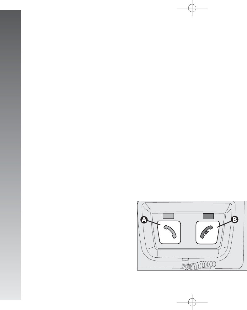
SYSTEM COMPONENTS
The main components of the system are:
– electronic control unti
– microphone
– button control panel
The electronic control unit is housed in the
dashboard, and contains the transmitter with
the Bluetooth
®
technology, the micro-
processor for the signals and the software.
The microphone located in the front pan-
el is a high-quality component, designed to
ensure the optimum communication in every
condition.
The button control panel (fig. 175) is on
the central console and has two buttons, one
green (A) and one red (B), which make
it possible to activate all the functions of the
system.
Press the green button (A) to:
– activate the voice recognition
– accept the call or double call
– dial the last number called
– turn on the “confidential” mode.
Press the red button (B) to:
– end a call
– refuse a call.
fig. 175
A0A1036m
GETTING TO KNOW YOUR CAR
176
Pressing simultaenously the green
(A) and red (B) buttons for at least
2 seconds clears the memory.
IMPORTANT Clearing the memory im-
plies the disconnection of all the telephones
memorised, the clearing of all the numbers
stored in the memory of the handsfree sys-
tem and then calls for a new connection pro-
cedure to use the system again.
110-185_Alfa147 Q2 GB 4-07-2008 12:02 Pagina 176
GETTING TO KNOW YOUR CAR
COMPATIBLE CELLULAR
TELEPHONES
The cellular phones compatible with the
system are shown in the following table:
Brand Model
BLACKBERRY 7100, 7290
ERICSSON R520, T39m, T68m
MOTOROLA
V3, V500, V501, V525, V547, V551,
V555, V600, V635, V80, E398,
E1000, MPX 220, E680, A779, A780,
SLVR L7 o V8, KRZR K1, RAZR2 V8,
RIZR Z3, RIZR Z8
NOKIA
3110, 3650, 3660, 6131, 6230,
6230i, 6233, 6234, 6260, 6288,
6300, 6310, 6310i, 6600, 6650,
6670, 6680, 6230, 6810, 6820,
6630, 7280, 7600, 7610, 8800,
8910, 8910i, 9300, N-Gage,
N-Gage QD, N73, N90, X5700
PANASONIC X700
XDA2 SPV M1000, XDA2
PHILIPS Fisio 820, Fisio 825
SAMSUNG
SGH-D500, SGH-E730, SGH-E640,
SGH-E370, SGH-E950, SGH-U700
SHARP GX15, GZ 15, GZ-100, GX30,
GX31, GX32, TM200
SIEMENS S55, S56, S65, S66, SL75, SK65, SX1
PDA/SMARTPHONES SPV E200, SPV C500, M1000
SONY ERICSSON
T68i, P800, P900, P910i, T606,
T610, Z600, Z608, V800, K750i,
K800i, T630, T650i, W850i, W880i
TELITAL NeoFone
SPV E200, C500
QTEK 8020, S100
177
SYSTEM ACTIVATION
To activate the system after the first con-
nection, turn the ignition key to MAR. When
the system is active, the two leds on the but-
tons light on. To connect your cellular tele-
phone to the system after the first connection
it is necessary to get inside car with the cel-
lular phone on and the Bluetooth
®
function
activated.
FIRST CONNECTION
OF THE CELLULAR TELEPHONE
TO THE SYSTEM
To carry out the first connection between
the cellular telephone and the handsfree sys-
tem it is necessary to activate the Blue-
tooth
®
function on your phone, following the
related instructions (see your cellular tele-
phone user’s handbook). When the function
is on, the related icon is displayed.
When connecting for the first time to the
system, you will hear the instruction “Please,
pair device”. Now connect the cellular phone
to the system (see your cellular telephone
user’s handbook.
IMPORTANT If wanting to use the
Bluetooth
®
handsfree system, it is possible
to avoid repeating the message ““Please, pair
device” setting the minimum value of the
radio PHONE function (see Radio paragraph).
To hear the message “Please, pair device”
it is necessary to turn the radio on.
110-185_Alfa147 Q2 GB 4-07-2008 12:02 Pagina 177

GETTING TO KNOW YOUR CAR
178
CONNECTION OF OTHER
TELEPHONES
To connect another cellular phone, repeat
the procedure carried out for the first con-
nection, up to a maximum of 3 cellular
phones. For the connection of other cellular
phones it will be necessary to clear the sys-
tem (see following paragraph).
CLEARING THE SYSTEM
To clear the system memory press the green
(A) and red (B) buttons for at least 2 sec-
onds.
IMPORTANT Clearing the memory im-
plies the disconnection of all the telephones
memorised, the clearing of all the numbers
stored in the memory of the handsfree sys-
tem and then calls for a new connection pro-
cedure to use the system again.
CONNECTION PRIORITY
If at least 2 cellular phones have been con-
nected, the first one to be connected (in time)
will be that with the highest priority. It means
that when getting inside the car, with the sys-
tem active (ignition key at MAR), it will
be the first one to be searched and, if present,
connected. If it is not found, the system will
search for the other cellular phones.
MANAGING TELEPHONE CALLS
Below are the general procedures for man-
aging telephone calls, generally applied to all
cellular telephones.
To make a telephone call
manually
– Dial the required number on the cellular
telephone keyboard
– press enter on the phone to start the tele-
phone call
– the telephone call will be automatically
switched over to the handsfree mode (on
some cellular telephone models it is neces-
sary to press the green button (A) to
switchover to the handsfree mode).
During the connection procedure,
the cellular telephone display will
show a message to enter the con-
nection code; enter code “1234”
and then confirm.
Afterwards the connection will be carried out
automatically, provided that the two sets are
at very close distance. A beep will communi-
cate that the connection has been established.
Below are some examples of the operations
to make for the first connection on some of
the most known cellular telephones.
IMPORTANT The system works only
when the ignition key is turned to MAR. The
connecting procedure must be carried out on-
ly the first time the cellular phone is matched
to the system. If at the first connection, the
handsfree system does not say “Please, pair
device”, reset the system pressing (A) and
(B) simultaneously for at least 2 seconds.
110-185_Alfa147 Q2 GB 4-07-2008 12:02 Pagina 178

GETTING TO KNOW YOUR CAR
To make a telephone call with
the voice commands (after
matching voice samples to the
numbers in the phone directory)
– press the green button (A)
– wait for the beep and/or the word
“PHONE” to be shown on the radio display
– pronounce the name of the person
you wish to call
– the system will repeat the pronounced
name to confirm it and then make the
telephone call
– if the name pronounced by the system
for confirmation is different from the wished
one, press the red button (B) and repeat
the procedure.
The telephone call made with the voice
commands is possible only for the names
in the directory matched to a voice sample.
The handsfree system can recognise all
the voice samples recorded on the cellular
phone, thus making it possible to call with
the voice command all the numbers
matched to the voice samples.
Anyway, it is possible to memorise (depend-
ing on the type of cellular telephone) the voice
samples directly in the handsfree system direc-
tory, but, in this case, the handsfree system
will recognise only these voice samples.
IMPORTANT To be recognised by the
system the voice commands must be pro-
nounced keeping a natural tone, articulat-
ing the words well and clearly.
For an optimal result, it is suggested to
associate the voice samples in the follow-
ing conditions:
– with doors and windows closed
– with ventilation and engine off (igni-
tion key at MAR)
– from the driver’s seat
– preferably using long names (for
example: “Mario Rossi” instead of
“Mario”); the system records a voice sam-
ple for max 2 seconds.
IMPORTANT Before using the voice
commands make sure that on the cellular
phone the following functions are on:
Bluetooth
®
, “Voice commands” and
“Wordspotting” (according to the type of
cellular phone). The performance of the
voice recognition are variable and depend
on the model of the cellular phone used.
179
110-185_Alfa147 Q2 GB 4-07-2008 12:02 Pagina 179

To manage a second telephone
call (depending on the type of cel-
lular phone)
– To refuse the second oncoming call
press the red button (B).
– To communicate with the new caller
press the green button (A) once.
– To go back to the first telephone call
press the green button (A) again.
– To end communication, press the red
button (B) once.
IMPORTANT The system can manage
the second call only if the ”Call notice”
function is active on the cellular phone.
For additional information about the
association between vocal samples and
numbers in the address book, calls by
means of keywords, and other settings,
refer to the cell phone manual.
GETTING TO KNOW YOUR CAR
180
To accept a telephone call
Press the green button (A).
To reject a telephone call
Press the red button (B).
To end a call
Press the red button (B).
To dial the last number called
Press and keep the green button (A)
pressed until the number is dialled.
110-185_Alfa147 Q2 GB 4-07-2008 12:02 Pagina 180
GETTING TO KNOW YOUR CAR
181
SOLUTION
Make sure that the ignition key is turned to MAR
Turn off the cellular phone and then on again (if the handsfree system does not respond to commands)
Turn off the cellular phone and then on again
Check that the Bluetooth
®
function of the cellular phone is on
(if necessary, see the instructions of your cellular phone)
Repeat the connection phase
Speak clearly towards the microphone
Lower the cellular telephone volume. If necessary, lower also the volume of the radio PHONE
function (see Radio paragraph)
Adjust the cellulat telephone volume and, if needed, check the volume of the radio PHONE
function (see Radio paragraph)
Return to the main menu and repeat the connection phase
Set the user’s priority (see the “Connection priority” paragraph)
Check that the name has been associated to a voice sample
Repeat the name clearly in the microphone direction
Check that the “Call notice” function has been activated on the cellular telephone
Check that these numbers are present in the cellular telephone directory and not only in the memory of
the SIM card
Check that the Bluetooth
®
, “Voice commands” and “Wordspotting” functions have been activated
on the cellular phone
PROBLEM SOLVING
PROBLEM
The system is not operative
The system signals
a connection problem with the Bluetooth
®
The telephone does not detect the handsfree system
The cellular telephone is not detected
The interlocutor complains about the bad audio quality
during communication
The interlocutor complains about the echo
during communication
The interlocutor’s voice cannot be heard
After entering the code “1234”
no connection can be established
The cellular telephone is detected too much slowly
by the system
When trying to make a telephone call
with the voice command, the system says that
the name is not recorded
The system does not make it possible to manage the double call
Some numbers in the telephone directory
are not copied in the system memory
The system does not recognise the voice commands
IMPORTANT For the checks, service or possible repairing of the system, contact only Alfa Romeo Authorised Services.
110-185_Alfa147 Q2 GB 4-07-2008 12:02 Pagina 181
GETTING TO KNOW YOUR CAR
182
REFUELLING
PETROL ENGINES
To prevent accidentally filling with leaded
petrol, the diameter of the fuel tank filler
is of such a size as not to accept the noz-
zle of this type of petrol
The antipollution devices
on the car oblige the use of
only four-star unleaded
petrol with octane number (R.O.N.)
of 95 or over.
Never use leaded petrol,
as this would irreversibly
damage the exhaust gas
catalyst. If leaded fuel is added to
the fuel tank, no matter how small
the quantity, DO NOT START THE
ENGINE. Do not attempt to dilute
the fuel in the tank, completely
drain the fuel circuit and tank.
An inneficient catalyst
leads to harmful emission
at the exhaust, thus envi-
ronment pollution.
JTD ENGINES
The car must only be filled
with fuel oil for motor ve-
hicles, in compliance with
European Specification EN590. The
use of other products or mixtures
may irreparably damage the engine
with invalidatoion of the warran-
ty due to the damage caused. In
the event of accidentally filling
with another type of fuel, do not
start the engine and empty the
tank. If the engine has been run
even for only a very short time, in
addition to the tank, it is also nec-
essary to empty the whole supply
circuit.
If the outside temperature is very low, the
diesel thickens due to the formation of paraf-
fins and could clog the diesel fuel filter.
In order to avoid these problems, different
types of diesel are distributed according to
the season: summer type, winter type arc-
tic type (mountains/cold areas).
If refuelling with diesel fuel not suitable for
the current temperature, mix diesel fuel with
TUTELA DIESEL ART additive in the pro-
portions stated on the can, putting first the
antifreeze in the tank and then the diesel
fuel.
TUTELA DIESEL ART shall be added to
diesel fuel before the due to cold take place.
Adding it later will be worthless. If driving or
parking the vehicle for a long period in cold
areas/mountains, refuel with the diesel fu-
el available at local filling stations. In this
situation you are also recommended to have
in the tank an amount of fuel 50% higher
than usable capacity.
110-185_Alfa147 Q2 GB 4-07-2008 12:02 Pagina 182
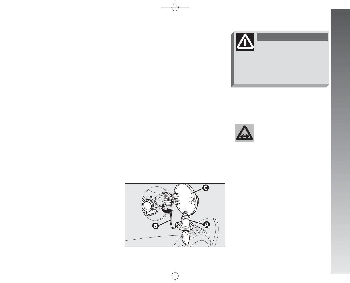
GETTING TO KNOW YOUR CAR
183
FUEL CAP
(fig. 176)
The fuel cap (A) is key-lockable and has a
catch to prevent misplacing it (B) that fas-
tens it to the flap (C); to gain access to it,
open the flap then use the ignition key to turn
counter-clocwise and remove the cap.
When refuelling, hook the cap to the device
on the inner flap, as illustrated.
In the case of need, only
replace the cap with an-
other genuine one, or the
efficiency of the fuel vapour re-
covery system could be adversely
affected.
fig. 176
A0A0146m
Do not go near the fuel
filler with naked flames or
lit cigarettes: danger of fire. Avoid
going too near the fuel filler with
your face, to avoid inhaling harm-
ful vapours.
WARNING
IMPORTANT The sealing of the tank
may cause light pressurising. A little breath-
ing off, while slackening the cap, is ab-
solutely normal.
After refuelling, turn the cap clockwise un-
til one or more clicks are heard; then turn
the key clockwise to lock. Close the flap.
IMPORTANT For your safety, before
starting the engine, also make sure that the
fuel nozzle is correctly inserted in the fuel
distributor.
110-185_Alfa147 Q2 GB 4-07-2008 12:02 Pagina 183

GETTING TO KNOW YOUR CAR
184
The emission reducing devices are:
– Oxidising catalyst;
– Exhaust gas re-circulation system
(E.G.R.);
– Particulate filter (DPF) (only for ver-
sions/markets where applicable).
Due to the high tempera-
tures reached during oper-
ation of the catalytic silencer and
the particullate filter (DPF) (only for
versions/markets where applica-
ble) the car should not be parked
over innflammable materials (grass,
dry leaves, pine needles, etc.): dan-
ger of fire.
WARNING
ENVIRONMENTAL
PROTECTION
The devices used to reduce petrol engine
emissions are:
– Trivalent catalytic converter (catalytic si-
lencer);
– Lambda sensors;
– Anti-evaporation system.
Do not run the engine, even for a test, with
one or more glow plugs disconnected.
110-185_Alfa147 Q2 GB 4-07-2008 12:02 Pagina 184

GETTING TO KNOW YOUR CAR
DPF (Diesel Particulate Filter)
(only for versions/
markets where applicable)
It is a mechanical filter, fitted in the ex-
haust system, which traps the carbon parti-
cles present in the exhaust gases of diesel
engines.
The filter function is to eliminate almost
completely the emissions of carbon particles,
in accordance with the current/future reg-
ulations.
During normal use of the car, the engine
control unit records a series of data con-
cerning the use (time, type of road, tem-
perature reached, etc.) and calculates the
quantity of particulate in the filter.
As this filter is an accumulating system
which must be regenerated (cleaned) burn-
ing the carbon particles, the regeneration
procedure is managed automatically by the
engine control unit according to the filter con-
ditions and the car using conditions. During
the filter regeneration the following phe-
nomena may occur: raising of idling, acti-
vation of electric fan, limited growth of
smoke level, high temperature at the ex-
haust.
These situations must no be considered as
faults and do not affect the car performance
and the environment.
Particulate filter clogged
When the particulate filter is clogged, the
instrument cluster
h
warning light
(on some versions the symbol
h
is
displayed) turns on. In this case you are
advised to keep the car travelling until the
h
warning light goes off (or the sym-
bol
h
on the display goes off).
185
110-185_Alfa147 Q2 GB 4-07-2008 12:02 Pagina 185
CORRECT USE OF THE CAR
186
The ignition switch is fitted with a safety
device which obliges the driver to return the
key to the STOP position before repeat-
ing the starting operation if the engine does
not start immediately.
Similarly, when the engine is running, the
device prevents the key being moved from
the MAR to the AVV position.
STARTING
THE ENGINE
IMPORTANT The car is fitted with an
electronic engine lock device. If the engine
fails to start, see the “Alfa Romeo CODE
system”.
C
CO
OR
RR
RE
EC
CT
TU
US
SE
EO
OF
FT
TH
HE
EC
CA
AR
R
We recommend that dur-
ing the initial period you do
not drive to full car perfor-
mance (for example excessive ac-
celeration, long journeys at top
speed, hard braking, etc.).
When the engine is
switched off never leave
the ignition key in the
MAR position to prevent pointless
current absoption from draining the
battery.
Running the engine in con-
fined areas is extremely
dangerous. The engine consumes
oxygen and produces carbon
monoxide which is a highly toxic
and lethal gas.
ATTENZIONE
186-196_Alfa147 Q2 GB 4-07-2008 12:03 Pagina 186
CORRECT USE OF THE CAR
187
STARTING PROCEDURE
FOR PETROL VERSIONS
1) Make sure the handbrake is
engaged.
2) Set the gearshift lever to neutral.
3) Turn the ignition key to MAR. The re-
configurable multifunction display will show
the
m
warning light.
4) Wait for the
m
to turn off, which
takes place sooner, the warmer the
engine. With the engine very warm the
light might stay on for such a short time
as to pass unnoticed.
5) Fully depress the clutch pedal.
6) Turn the ignition key to AVV as
soon as the
m
warning light has gone
out. Waiting too long, makes the warming
work of the glow plugs useless.
STARTING PROCEDURE
FOR JTD VERSIONS
IMPORTANT It is important never to
press the accelerator before the engine
has started.
1) Make sure the handbrake is engaged.
2) Move the gear lever to neutral.
3) Fully depress the clutch pedal, so that
the starter motor is not forced to crank the
gears.
4) Ensure that the electric systems and
devices, especially if they absorb high
quantities of energy (e.g. heated
rearscreen), are switched off.
5) Turn the ignition key to the AVV po-
sition and release it as soon as the engine
starts.
6) If the engine does not start, return
the key to STOP, then repeat the proce-
dure.
IMPORTANT If it is difficult to start
the engine do not insist with extended
attempts which may damage the catalyst,
but contact Alfa Romeo Authorised
Services.
IMPORTANT The electric devices that
absorb a high amount of energy (cli-
mate control, rearscreen heating, etc.) are
cut off automatically during starting.
If the engine does not start at the first
attempt, move the ignition key to STOP
before repeating starting.
If starting is difficult (with the Alfa
Romeo CODE system working properly),
do not insist with prolonged attempts.
Only use an auxiliary battery if the cause
is due to low battery charge. Never use a
battery charger to start the engine.
186-196_Alfa147 Q2 GB 4-07-2008 12:03 Pagina 187
CORRECT USE OF THE CAR
188
IMPORTANT If the engine turns off with
the car on the move, the next time it is start-
ed, the Alfa Romeo CODE warning light may
turn on (
Y
). In this case, check that switch-
ing off and starting the engine again with
the car stationary, the warning light stays
off. If not, contact Alfa Romeo Authorised
Services.
For cars with turbocharg-
er in particular, but for all
cars in general, sharp ac-
celerating should be avoided be-
fore switching the engine off. A
“kick” on the accelerator serves
no purpose, consumes fuel point-
lessly and may cause serious dam-
age to the turbocharger impeller
bearings.
EMERGENCY STARTING
If the Alfa Romeo CODE system does not
recognise the code transmitted by the igni-
tion key (warning light
Y
on the instru-
ment cluster glowing on steadily) emer-
gency starting may be carried out using the
code of the CODE card.
For the correct procedure see the chapter
“In an emergency”.
Never bump, tow, or
coast start the car as this
would cause fuel to flow
into the catalyst causing irre-
versible damage.
Remember that the ser-
vobrake and power steer-
ing are not operational until the
engine has been started, there-
fore much more effort than usual
is required on the brake pedal and
steering wheel.
WARNING
WARMING THE ENGINE
– Drive off slowly, at medium revs with-
out accelerating abruptly.
– Do not drive at full performance for the
initial kilometres of the journey. Wait un-
til the engine coolant temperature reaches
50-60 °C.
SWITCHING OFF
– Release the accelerator pedal and wait
until the engine reaches idle speed.
– Turn the ignition key to the STOP
position and switch off the engine.
IMPORTANT After a tiring journey it is
advisable to let the engine “get its breath
back” allowing it to idle a while to lower the
temperature in the engine compartment.
186-196_Alfa147 Q2 GB 4-07-2008 12:03 Pagina 188
CORRECT USE OF THE CAR
189
PARKING
When the car is parked, proceed as fol-
lows:
– Switch off the engine.
– Engage the handbrake.
– Engage first gear if the car is faced up-
hill or reverse if the car is facing downhill.
– Turn the front wheels so that the car-
will immediately come to a halt if the
handbrake slips.
FUEL ECONOMY
By following a few simple guidelines, it
is possible to save car running costs and re-
duce harmful emissions.
GENERAL CONSIDERATIONS
Car maintenance
To take care of the car maintenance
have the checks and adjustments carried
out in accordance with the “Scheduled
Maintenance Programme”.
Tyres
Check the pressure of the tyres routinely
at an interval of no more than 4 weeks: if
the pressure is too low consumption levels
increase as resistance to rolling is higher.
Useless loads
Never travel with an overload in the
boot. The weight of the car (especially in
urban traffic), and its geometry heavily
affect consumption levels and stability.
When the engine is
switched off never leave
the ignition key in the
MAR position to prevent point-
less current absorption from
draining the battery.
Never leave children
unattended in the car.
Always remove the ignition key
when leaving the car and take it
with you.
WARNING
Electric services
Use electric devices only for the amount
of time needed. Rearscreen heating, addi-
tional headlights, windscreen wipers and
heater fan need a considerable amount of
energy, therefore increasing the require-
ment of current fuel consumption (up to
+25% in the urban cycle).
Climate control system
The climate control system is a further
load bearing heavily on the engine indu-
cing higher consumption levels(up to
+20% on average). Outside temperature
permitting, preferably use the air vents.
Aerodynamic items
The use of non-certified aerodynamic
items may adversely affect air drag and
consumption levels.
186-196_Alfa147 Q2 GB 4-07-2008 12:03 Pagina 189

CORRECT USE OF THE CAR
190
DRIVING STYLE
Starting
Do not warm the engine with the car at a
standstill or at idle or high speed: under
these conditions the engine warms up much
more slowly, increasing electrical consump-
tion and emissions. It is therefore advisable
to move off immediately, slowly, avoiding
high speeds. This way the engine will warm
faster.
Pointless manoeuvres
Avoid accelerating when waiting at traffic
lights or before switching off the engine. This
and also double declutching is absolutely
pointless on modern cars and also increase
consumption and pollution.
Gearshifting
As soon as the conditions of the traffic and
road allow, use a higher gear.
Using a low gear to obtain brilliant per-
formance increases consumption.
In the same way improper use of a high
gear increases consumption, emissions and
engine wear.
Top speed
Fuel consumption considerably increases
with speed. Maintain an even as possible
speed, avoiding superfluous braking and
accelerating, which cost in terms of both
fuel and emissions.
Acceleration
Accelerating heavily taking the engine to
a high speed has a considerably adverse
effect on consumption and emission lev-
els; it is wise to accelerate gradually and not
exceed the maximum torque.
CONDITIONS OF USE
Cold starting
Short journeys and frequent cold starts
do not allow the engine to reach optimum
operating temperature. This results in a
significant increase in consumption levels
(from +15 to +30% on the urban cycle)
and emission of harmful substances.
Traffic situations and road
conditions
Rather high consumption levels are tied
to situations with heavy traffic, for ex-
ample in queues with frequent use of the
lower gears or in cities with many traffic
lights. Also winding mounting roads and
rough road surfaces adversely affect con-
sumption.
Stopping in the traffic
During prolonged stops (e.g. level cross-
ings) it is advisable to switch the engine
off.
186-196_Alfa147 Q2 GB 4-07-2008 12:03 Pagina 190

CORRECT USE OF THE CAR
191
WINTER TYRES
Use winter tyres of the same size as the
normal tyres provided on the car.
Alfa Romeo Authorised Services will be
pleased to advise you on the choice of the
tyre most suited to the use the Customer
intends to make of it.
For the type of tyre to be used, inflation
pressures and specifications of winter tyres,
follow the instructions given in the
“Technical Specifications” chapter.
The winter features of these tyres are
reduced considerably when the tread
depths is below 4 mm. In this case they
should be replaced.
Due to the winter features, under normal
conditions of use or long motorway jour-
neys, the performance of these tyres is
lower than that of normal tyres.
It is necessary therefore to limit their use
to the purposes for which they are certified.
COMFORT
SUSPENSIONS
(for versions/markets where
applicable)
The car can be fitted with a particular
type of suspension trim, able to increase
the comfort during travelling.
IMPORTANT When winter tyres are
used with a maximum speed index below
the one that can be reached by the car
(increased by 5%), place a notice in the
passenger’s compartment, plainly in the dri-
ver’s view, which states the maximum per-
missible speed of the winter tyres (as per
CE Directive).
Fit the same type of tyre on all four wheels
(brand and profile) to ensure higher driving
safety when braking and good handling.
Remember that it is inappropriate to
change the direction of rotation of tyres.
186-196_Alfa147 Q2 GB 4-07-2008 12:03 Pagina 191
CORRECT USE OF THE CAR
192
Keep your speed
down when snow
chains are fitted.
Do not exceed 50 km/h. Avoid
potholes, steps and pavements to
prevent damaging the tyres, sus-
pension and steering.
Snow chains cannot be
fitted to the compact
spare wheel. So, if a front
(drive) wheel is punctured and
chains are needed, a rear wheel
should be fitted to the front of
the car (inflate the tyres to the
specified pressure as soon as
possible) and the spare wheel
should be fitted to the rear. This
way, with two normal drive
wheels, snow chains can be fitted
to them to solve an emergency.
With snow chains fitted it
is advisable to turn off
the ASR system. Press
the ASR-OFF button, led on but-
ton on.
Snow chains may not be
used on tyres type 205/
55 R16” 91V - 205/55
R16” 91W or 215/45 R17” 87W
due to interference with the front
suspension strut.
Snow chains should only be applied to the
drive wheels (front).
Before purchasing or using snow chains,
you are recommended to contact Alfa
Romeo Authorised Services.
Check the tensions of the chain after the
first few metres have been driven.
SNOW CHAINS
Use of snow chains should be in compli-
ance with local regulations.
Use snow chains with reduced size with
maximum protrusion beyond the tyre pro-
file of 12 mm.
186-196_Alfa147 Q2 GB 4-07-2008 12:03 Pagina 192

CORRECT USE OF THE CAR
193
– cover the rubber windscreen and
rearscreen wiper blades with talcum pow-
der and raise them off the glass;
– open the windows slightly;
– cover the car with a fabric or perforat-
ed plastic cover. Do not use compact plas-
tic covers which prevent the humidity on
the surface on the car from evaporating;
– inflate the tyres to a pressure of +0.5
bars above normal and check it periodical-
ly;
– if the battery is not disconnected from
the electric system, check its charge every
thirty days and if the indicator shows a
dark colour in the green area, charge the
battery;
– do not empty the engine cooling sys-
tem.
CAR INACTIVITY
If the car is to be left inactive for long
periods, the following precautions should
be noted:
– house the car under acover in a dry
and possibly ventilated place;
– engage a gear;
– check that the handbrake is not
engaged;
– disconnect the battery negative termi-
nal from the battery and check the battery
charge. This check should be repeated
every three months during stowage.
Charge the battery if the indicator shows
(where provided) a dark colour in the cen-
tral green area;
– clean and protect the paintwork by
protective wax;
– clean and protect the metal polished
parts with marketed products;
TOWING TRAILERS
WARNINGS
For towing caravans or trailers the car
must be fitted with a certified tow hook
and an adequate electric system.
Installation should be carried out by spe-
cialised personnel who release a special
document for circulation on the road.
Install any specific and/or additional
rearview mirrors as specified by law.
Remember that when towing a trailer,
steep hills are harder to climb, the braking
spaces increase and overtaking takes
longer depending on the overall weight.
Engage a low gear when driving down-
hill, rather than constantly using the brake.
The weight the trailer exerts on the car
tow hook reduces by the same amount
the actual car loading capacity.
186-196_Alfa147 Q2 GB 4-07-2008 12:03 Pagina 193
CORRECT USE OF THE CAR
194
The ABS system with
which the car may be fitted
does not control the trailer braking
system. Particular care is therefore
necessary on slippery surfaces.
WARNING
Under no circumstances
should the car brake sys-
tem be altered to control the
trailer brake. The trailer braking
system must be fully independent
of the car’s hydraulic system.
WARNING
To make sure the maximum towable
weight is not exceeded (given in the log
book) account should be taken of the fully
laden trailer, including accessories and per-
sonal belongings.
Drive within the specific speed limit in
every country for car trailers. In any case the
maximum speed should never exceed 100
km/h.
INSTALLING
THE TOW HOOK
The towing device should be fastened to
the body by specialised personnel accord-
ing to the following instructions and any
additional and/or integrative information
supplied by the Manufacturer of the device
itself.
The towing device must meet current
regulations with reference to Directive
94/20/CEE and subsequent amend-
ments.
For any version the towing device used
must match the towable weight of the car
on which it is to be installed.
For the electric connection a unified con-
nector should be used which is generally
placed on a special bracket normally fas-
tened to the towing device itself.
For the electric connection a 7 or 13
pole 12VDC connection must be used
(CUNA/UNI and ISO/DIN standards) fol-
lowing any reference instructions given by
the car Manufacturer and/or towing device
Manufacturer.
186-196_Alfa147 Q2 GB 4-07-2008 12:03 Pagina 194

CORRECT USE OF THE CAR
195
INSTALLATION LAYOUT
(fig. 2)
The tow hook structure must be fastened
in the points shown by the symbol
Ø
using 8 M10 screws and 4 M12 screws.
The counter-plates (1), (2) should have
a minimum thickness of 6 mm.
The counter-plates (3), (4) should have
a minimum thickness of 5 mm.
The fastening points (5) should be fitted
with Ø 20 x 4.5 mm spacers.
The hook should be fastened to the body
avoiding any type of drilling and trimming
of the rear bumps that remains visible when
the hook is removed.
IMPORTANT It is compulsory to fasten
a label (plainly visible) of suitable size and
material with the following wording:
MAX LOAD ON BALL 60 kg.
Any electric brake should be supplied di-
rectly by the battery through a cable with
a cross-section of no less than 2.5 mm2.
In addition to the electrical branches, the car
electric system can only be connected to the
supply cable for an electric brake and to the
cable for an internal light, though not above
15W.
186-196_Alfa147 Q2 GB 4-07-2008 12:03 Pagina 195
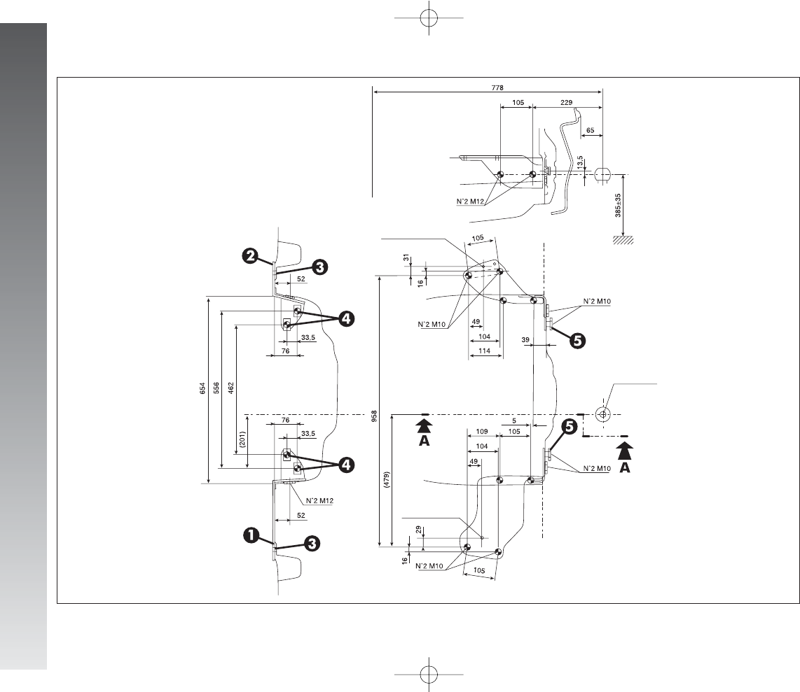
CORRECT USE OF THE CAR
196
A0A0339m
Rear wheel axis
fully laden
Centering hole
SEZ. A-A
Regulation ball
Centering hole
fig. 2
186-196_Alfa147 Q2 GB 4-07-2008 12:03 Pagina 196

IN AN EMERGENCY
197
3) Fully depress the accelerator pedal and
keep it pressed. The
U
warning light will
come on for eight seconds and then go off,
now release the accelerator pedal.
4) The
U
warning light begins to flash:
after it has flashed the same number of
times as the first digit on the CODE card,
press the accelerator pedal and keep it
pressed until the
U
warning light turns on
(for four seconds) and then goes off; now
release the accelerator pedal.
5) The
U
warning light starts to flash: af-
ter the number of flashes corresponding to
the second digit on the CODE card, press the
accelerator pedal and keep it pressed.
6) Repeat this procedure for the remain-
ing digits on the CODE card.
7) After entering the last figure, keep the
accelerator pedal pressed. The
U
warning
light turns on (for four seconds) and then
goes off; now release the accelerator pedal.
8) A quick flash of the
U
warning light
(for about four seconds) confirms that the
operation has been carried out correctly.
9) Start the engine turning the ignition key
from MAR to AVV without returning the
key to the STOP position.
Conversely, if the
U
warning light stays
on, turn the key to STOP and repeat the
procedure starting from point 1).
IMPORTANT After emergency starting
it is advisable to contact Alfa Romeo Au-
thorised Services, because the emergency
procedure must be repeated each time the
engine is started.
EMERGENCY
STARTING
If it is not possible to deactivate the engine
inhibitor with the Alfa Romeo CODE system,
the
Y
and
U
warning lights stay on and
the engine will not start. Emergency start-
ing is needed to start the engine.
IMPORTANT You are advised to care-
fully read the entire procedure before car-
rying it out.
If a mistake is made during the emergency
procedure, the ignition key should be turned
to STOP and the operations must be re-
peated from the start (point 1).
1) Read the 5-figure electronic code on the
CODE card.
2) Turn the ignition key to MAR.
I
IN
NA
AN
NE
EM
ME
ER
RG
GE
EN
NC
CY
Y
In an emergency we recommend that you call the freephone number found in the Warranty Booklet.
You can also consult www.alfaromeo.com to find Alfa Romeo Authorised Services your nearest
197-233_Alfa147 Q2 GB 4-07-2008 12:04 Pagina 197
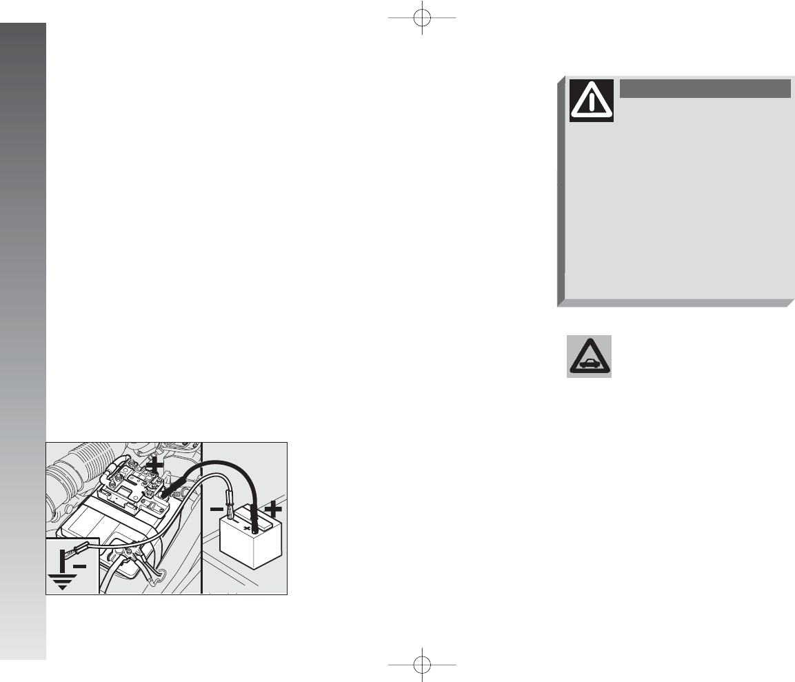
IN AN EMERGENCY
198
STARTING WITH AN AUXILIARY
BATTERY
If the battery is flat (for battery with
optical hydrometer: dark colour without
green area in the centre), it is possible to
start the engine using an auxiliary battery
with the same capacity or a little higher than
the flat one.
Proceed as follows (fig. 1):
1) Remove the protective cover on the
positive battery post pressing on the open-
ing catches (front), then connect the posi-
tive terminals (+sign next to the termi-
nal) of the two batteries using a special
cable.
2) Connect the end of the second jump
lead to the negative terminal (–) of the
auxiliary battery with an earth point
E
on
the engine or gearbox of the car to be
started.
IMPORTANT Do not directly connect
the negative terminals of the two batter-
ies: any sparks may ignite the detonating
gas which could come out of the battery.
If the auxiliary battery is installed on
another car, avoid metal parts touching
accidentally between this car and the one
with the flat battery.
3) Start the engine.
4) When the engine has started, remove
the cables, reversing the sequence followed
for connection.
If after a few attempts the engine does not
start, do not insist but contat the nearest
Alfa Romeo Authorised Service.
fig. 1
A0A0149m
Never use a battery charg-
er to start the engine as
this could damage the elec-
tronic systems of your car, partic-
ularly the ignition and fuel supply
control units.
This starting procedure
must be carried out by
qualified personnel because incor-
rect operations may cause electri-
cal discharge of considerable
intensity. The liquid contained in
the battery is poisonous and cor-
rosive. Avoid contact with the
skin and eyes. Keep naked flames
and lighted cigarettes away from
the battery and do not cause
sparks.
WARNING
197-233_Alfa147 Q2 GB 4-07-2008 12:04 Pagina 198
IN AN EMERGENCY
199
STARTING BY INERTIA
IMPORTANT If the car is equipped
with “Kit for tyre quick repair Fix&Go“,
see the instructions contained in the fol-
lowing chapter.
GENERAL INSTRUCTIONS
Wheel changing and correct use of the
jack and compact spare wheel (for ver-
sions/markets where applicable) call for
some precautions as listed below.
IN THE EVENT OF A PUNCTURE
Never push, tow or coast
start the car. This could
cause fuel to flow into the
catalyst damaging it irreversibly
Remember that the engine
brake and power steering
are not operational until the engine
is started, therefore, much greater
effort than usual is needed on the
brake pedal and steering wheel.
WARNING
Signal the presence of the
stationary car according
to current regulations: hazard
warning lights, reflecting triangle
etc..
Any passengers should leave the
car and wait for the wheel to be
changed out of harm of the traf-
fic.
If parked on a slope or rough sur-
face, chock the wheels with
wedges or other suitable devices
to prevent the car from rolling.
WARNING
Never start the engine
with the car jacked. When
driving with a trailer, disconnect
the trailer before raising the car.
The compact spare wheel is specif-
ic to your car, do not use it on
other models, or use the spare
wheel of other models on your
cars.
Should the type of wheels used
be changed (alloy rims instead of
steel), it is also necessary to
change the whole set of fastening
bolts with others of suitable size.
The compact spare wheel is nar-
rower than normal wheels, it
should be used only for the dis-
tance necessary to reach a ser-
vice point to have the punctured
tyre repaired and during its use,
the car speed must not exceed 80
km/h.
WARNING
197-233_Alfa147 Q2 GB 4-07-2008 12:04 Pagina 199
IN AN EMERGENCY
200
The spare wheel has a
sticker that summarises
the main cautions for use and lim-
itations. Ths sticker should never
be removed or covered. Th stick-
er contains the following in four
languages:
CAUTION! FOR TEMPORARY USE
ONLY! MAX 80 km/h! REPLACE
BY NORMAL WHEEL AS SOON AS
POSSIBLE. DO NOT COVER THIS
LABEL IN USE.
Never fit a wheel cap on a compact
spare wheel.
The car will handle differently with
the spare wheel fitted: avoid
heavy braking and accelerating,
sharp corners and a bends.
WARNING
The life of the spare wheel
is approx. 3000 km, after
this distance it should be replaced
with another of the same type.
Never attempt to fit a convention-
al tyre on a rim designed for use as
a compact spare wheel. Have the
punctured wheel repaired and re-
fitted as soon as possible. Two or
more compact spare wheels should
never be used together. Do not
grease the threads of bolts before
installing them; they might slip out.
The jack only serves for changing
the wheels on the car with which it
is provided or on cars of the same
model. It must not be used for
other purposes such as for instance
raising cars of other models. In no
case should it be used for repairs
under the car. Incorrect positioning
of the jack may cause the jacked
car to fall. Do not use the jack for
higher capacities than stated on its
label.
WARNING
Snow chains cannot be
fitted on the compact
spare wheel, so, if a front wheel
is punctured and chains need to
be fitted, the front axle should be
fitted with normal wheels and
the compact spare wheel fitted to
the rear. This way, with two nor-
mal wheels at the front, snow
chain can be fitted thereby solv-
ing the emergency situation.
Never tamper with the inflation
valve.
Do not insert tools of any kind
between the rim and the tyre.
Check, and if necessary, restore
the pressure of the tyres and of
the compact spare wheel to the
values given in the “Technical
Specifications” chapter.
WARNING
197-233_Alfa147 Q2 GB 4-07-2008 12:04 Pagina 200
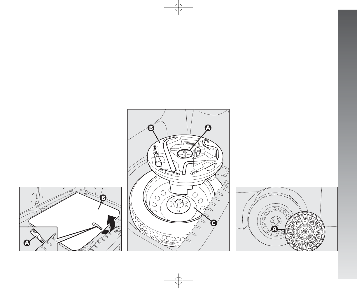
IN AN EMERGENCY
201
CHANGING A WHEEL
Please be informed that:
– the jack mass is 2.100 kg.
– the jack requires no adjustment.
– the jack cannot be repaired. In the
event of breakage, it must be replaced by
another original one.
– no tools other than its operating crank
can be fitted to the jack.
To change a wheel, proceed as follows:
– Stop the car in such a position that it is
not dangerous for the traffic, where it is pos-
sible to change the wheel safely. Where pos-
sible, park on a level, compact surface.
– Switch off the engine and engage the
handbrake.
– Engage first gear or reverse.
– Use the handle (A) to remove the piece
of stiff cover (B).
– Loosen the clamping device (A-fig.
3).
– Take out the tool container (B) and take
it near the wheel to be changed.
– Take the spare wheel (C).
– Remove the wheel cap (A-fig. 4) (on-
ly versions with steel rims)
– Using the wrench provided (A-fig.
5), loosen the fastening bolts by about
one turn.
– Set the jack under the car, near the
wheel to be changed taking care not to dam-
age the plastic streamlined guard.
– Work the jack crank (A-fig. 6), to
extend it until the groove (B) on the
upper part of jack is correctly inserted on the
lower profile of the body (C) approx. 40 cm
from the profile of the wheelhouse.
– Work the jack and raise the car until
the wheel is a few centimetres from the
ground.
fig. 2
A0A0150m
fig. 3
A0A0151m
fig. 4
A0A1059m
197-233_Alfa147 Q2 GB 4-07-2008 12:04 Pagina 201
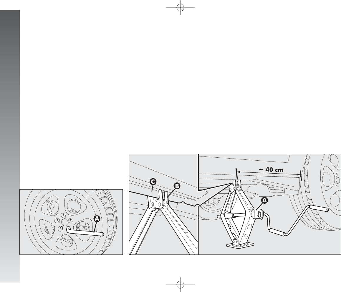
IN AN EMERGENCY
202
– Completely unscrew the fastening bolts
and remove the wheel.
– Make sure that the contact surfaces of
the spare wheel with the hub are clean
and free of impurities which may later cause
the fastening bolts to slacken.
– Install the spare wheel matching the
hole (A-fig. 7) with the corresponding
pin (B).
– Using the wrench provided, fasten the
five bolts.
– Lower the car and remove the jack.
– Using the wrench provided, fully tighten
the bolts in the sequence shown in fig. 8.
REFITTING A
NORMAL WHEEL
– Following the procedure described pre-
viously, raise the car and remove the spare
wheel.
For versions with steel rims:
– Fit the normal wheel matching the
hole (A-fig. 7) with the corresponding
pin (B).
– Make sure that the contact surfaces of
the wheel with the hub are clean and free
of impurities which may later cause the fas-
tening bolts to slacken.
– Using the wrench provided, tighten the
fastening bolts.
– Lower the car and remove the jack.
– Using the wrench provided, fully tight-
en the bolts in the sequence shown previ-
ously for the compact spare wheel fig. 8.
– Place the cap near the wheel so that
the inflation valve can come through the
slot provided on the cap.
– Press the circumference of the cap,
starting from the parts nearest to the infla-
tion valve until it is inserted completely.
IMPORTANT Incorrect fitting may
cause the wheel cap to come off when the
car is travelling
fig. 5
A0A0152m
fig. 6
A0A1140m
197-233_Alfa147 Q2 GB 4-07-2008 12:04 Pagina 202
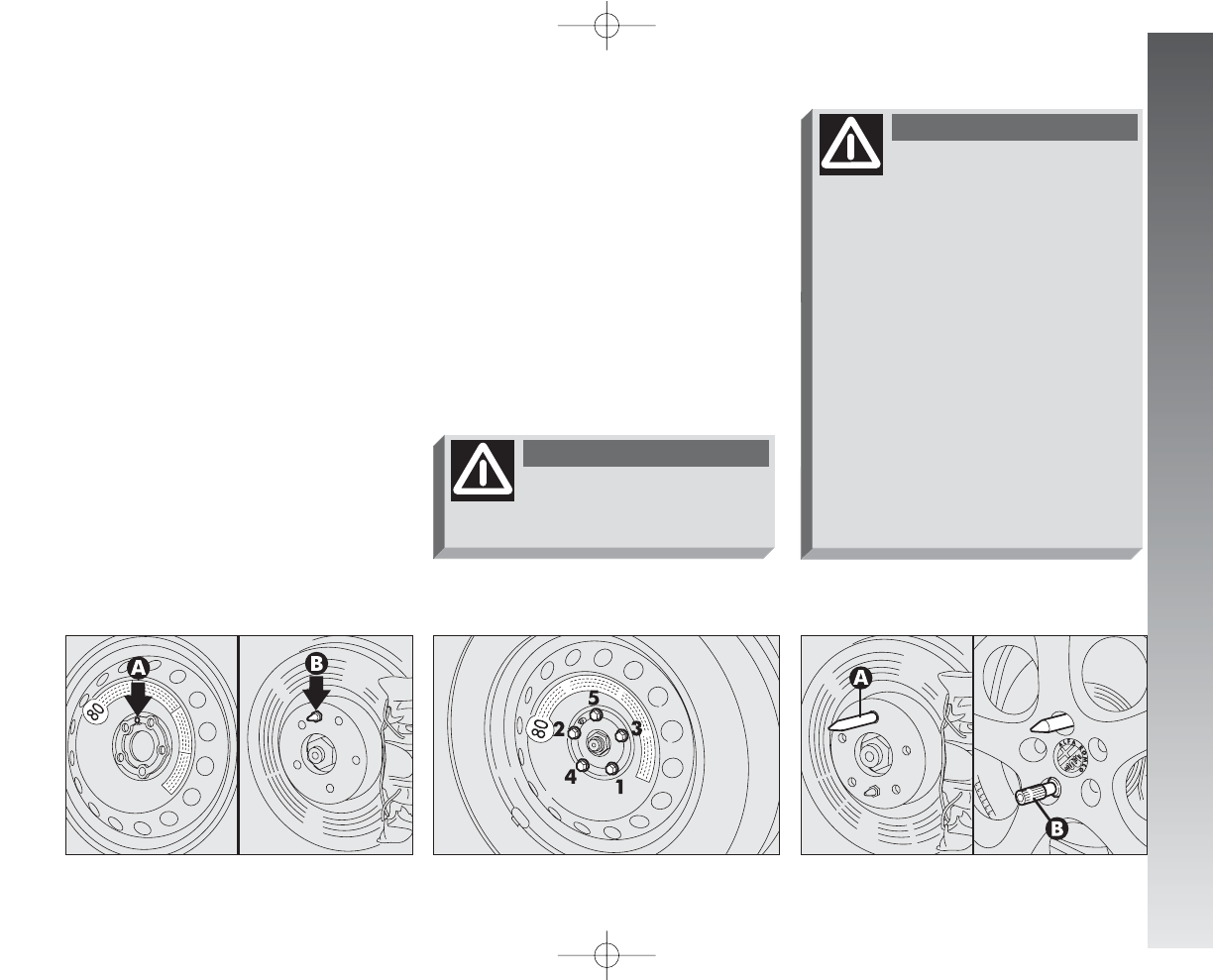
IN AN EMERGENCY
203
For versions with alloy rims:
– Tighten the pin (A-fig. 9) in one of
the fastening bolt holes on the wheel hub.
– Insert the wheel on the pin and, using
the wrench provided, tighten the four bolts
available. This is facilitated by the exten-
sion provided (B).
– Remove the pin (A-fig. 9) and tight-
en the last fastening bolt.
– Lower the car and remove the jack.
– Using the wrench provided, tighten
the bolts in the sequence shown previously
for the compact spare wheel fig. 8.
After refitting a wheel:
– stow the spare wheel in the space pro-
vided in the boot
– insert the jack in its container forcing
it lightly to prevent it from vibrating when
travelling
– place the tools used in the housings in
the container
– stow the container complete with tools
on the spare wheel and secure every
thing with the clamping device (A-fig.
3)
– correctly re-position the stiff cover.
Versions with VDC excluded
fig. 7
A0A0155m
fig. 8
A0A0156m
fig. 9
A0A0157m
travel for approx. 30 km
(20 minutes) on a mixed
road or approx. 15 km (10 min-
utes) on a highway until the soft-
ware of the ABS/ASR control unit
recognises the size of the “normal”
wheel; in this period of time the car
may slightly go adrift on a side
during brakig and the ASR warn-
ing light (if fitted) may come on.
Therefore it is recommended to
travel carefully and to avoid,
where possible, sharp braking. On
cars fitted with ASR travel for the
above mentioned distance with
the ASR turned off through the
suitable button.
WARNING
After using the spare
wheel and refitting the
standard wheel, it is necessary to
WARNING
197-233_Alfa147 Q2 GB 4-07-2008 12:04 Pagina 203
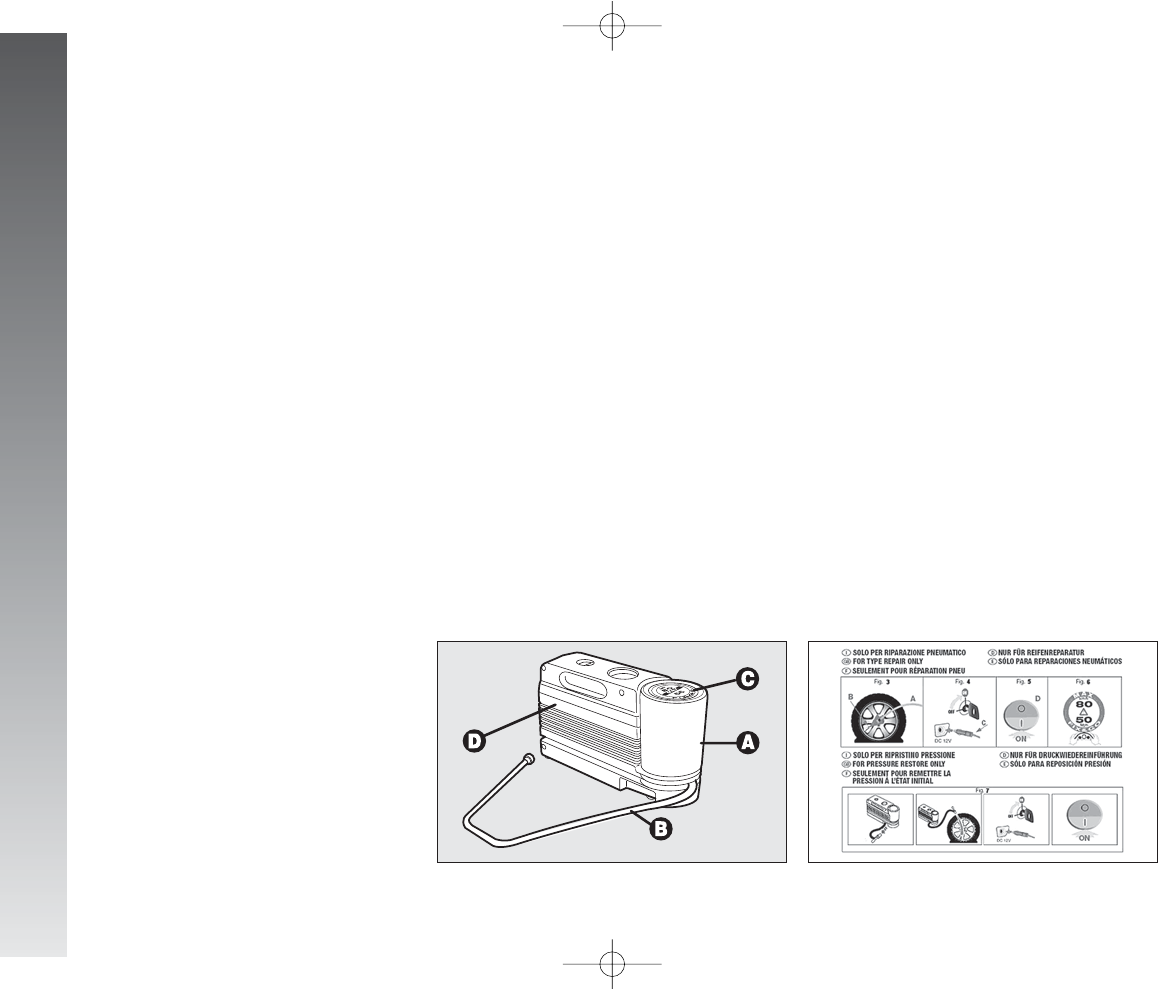
IN AN EMERGENCY
204
FIX&GO KIT FOR
QUICK TYRE
REPAIRING
(for versions/markets where
applicable)
The car can be equipped with a tyre
quick repairing kit called FIX&GO, replac-
ing the tools and the compact spare wheel
provided with the car.
The quick repairing kit fig. 10 is placed
in the boot inside the appropriate contain-
er, which includes also the screwdriver and
the tow ring.
The quick repairing kit includes:
– a bottle A-fig. 10 containing sealer
and fitted with:
❒filling pipe B
❒a sticker Cbearing the notice “max.
80 km/h”, to be placed in a position
visible to the driver (on the instrument
panel) after fixing the tyre;
– a compressor Dwith pressure gauge
and fittings;
– a leaflet with the instructions fig. 11
for a correct use of the quick repairing kit;
this leaflet shall be delivered to the per-
sonnel who will handle the tyre treated
with the quick repairing kit;
– a pair of protective gloves in the side
compartment of the compressor;
– adapters for inflating different elements.
fig. 10
A0A1095m
fig. 11
A0A1096m
197-233_Alfa147 Q2 GB 4-07-2008 12:04 Pagina 204
In the event of a puncture
caused by foreign bodies,
it is possible to fix tyres
having cracks with maximum di-
ameter up to 4 mm.
IN AN EMERGENCY
205
Give the leaflet to the
personnel who will handle
the tyre treated with the quick
repaiting kit.
WARNING
It is not possible to fix
cracks on the tyre sides. Do
not use the quick repairing kit if the
tyre is damaged due to driving
with the wheel flattened.
WARNING
In case of damages to the
wheel rim (the deformation
is such that there is an air leakage)
fixing is not possible. Do not re-
move foreign bodies (screws or
nails) which have penetrated the
tyre.
WARNING
It is necessary to know that:
The sealer included in the quick repairing
kit is good for temperatures between
–20°C and +50°C.
The bottle contains ethyl-
ene glycol. It contains
latex which might cause an aller-
gy reaction. This substance is
toxic: do not swallow it and
avoid contact with the eyes. It
may provoke sensitisation due to
inhalation and contact. Avoid con-
tact with the eyes, the skin and
the clothes. In case of contact,
rinse with abundant water. If
swallowed do not induce vomit,
rinse the mouth, drink a lot of
water and contact a medical doc-
tor immediately. Keep the bottle
away from children. The product
must not be used by asthmatic
subjects. Do not inhale the
vapours during fitting and suction
operations. If any allergy reac-
tion should take place call a med-
ical doctor. Keep the bottle in the
suitable compartment and keep
away from heat. The sealer has
expiry date.
WARNING
The sealer has expiry date.
Replace the bottle whose
sealer due date is expired.
WARNING
197-233_Alfa147 Q2 GB 4-07-2008 12:04 Pagina 205
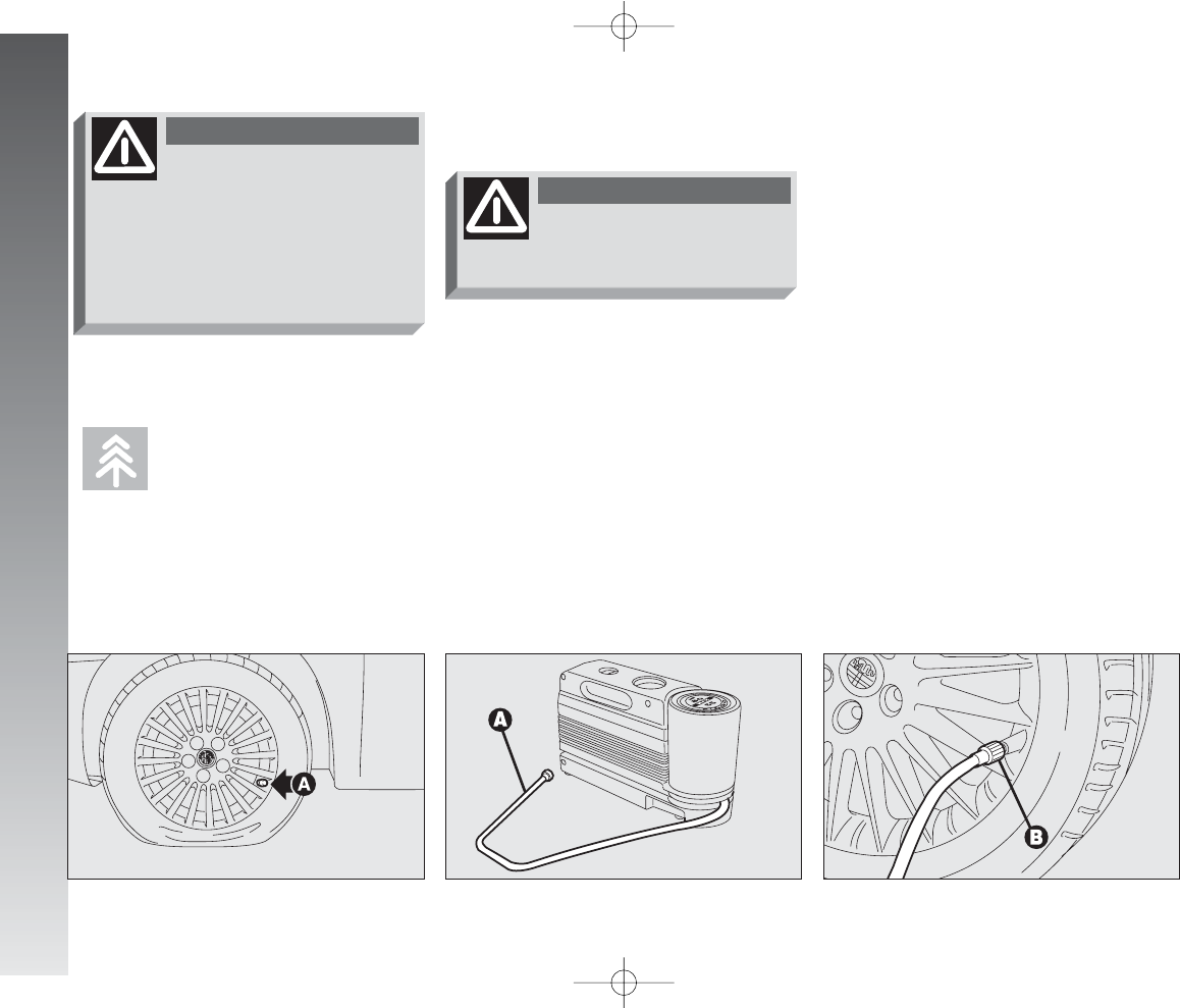
Do not disperse the bot-
tle and the sealer in the
environment. Dispose of
it according to the national and
local regulations.
IN AN EMERGENCY
206
INFLATING PROCEDURE
– unscrew the tyre valve plug, take off the
filling pipe A-fig. 13 and screw the ring
nut B-fig. 14 on the tyre valve;
– make sure that the compressor switch
A-fig. 15 is in position 0(off), start the
engine, insert the plug G-fig. 16 in the
socket/lighter on the front tunnel and
start the compressor by taking the switch
to A-fig. 15 position I(on);
– inflate the tyre to the correct pressure
value. You are advised to check the tyre
pressure value on the pressure gauge B-
fig. 15 with the compressor off, in order
to have a more accurate reading;
fig. 12
A0A1097m
fig. 13
A0A1098m
fig. 14
A0A1099m
Do not operate the com-
pressor for more than 20
minutes: risk of overheating. The
quick repairing kit is not suitable
for a final repairing, therefore
repaired tyres must be used only
temporarily.
WARNING
Wear the protective gloves
provided with the quick re-
pairing kit.
WARNING
Proceed as follows:
– place the wheel with the valve A-fig.
12 in the position illustrated in the figure,
engage the handbrake, then remove
the quick repairing kit and place it on the
ground next to the wheel;
197-233_Alfa147 Q2 GB 4-07-2008 12:04 Pagina 206
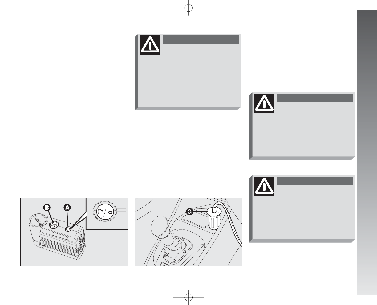
IN AN EMERGENCY
207
– if in 5 minutes a pressure of at least
1.5 bars is not obtained, disengage the
compressor from the valve and the socket;
then move the car forwards by about 10
metres to distribute the sealer inside the
tyre and repeat the inflating procedure;
– if, also in this case, in 5 minutes from
the compressor turning on a pressure of at
least 1.8 bars is not obtained, do not trav-
el any further: the quick repairing kit can-
not guarantee proper hold because the
tyre is too much damaged. Contact Alfa
Romeo Authorised Services;
– once the correct tyre pressure has
been reached, start driving immediately;
fig. 15
A0A1100m
fig. 16
A0A1039m
WARNING
– if at least 1.8 bars are detected, restore
the correct pressure (with the engine run-
ning and the handbrake engaged) and start
driving the car;
– drive the car with great care to Alfa
Romeo Authorised Services.
If the pressure is below
1.8 bars, do not travel
any further: the quick repairing
kit cannot guarantee proper hold
because the tyre is too much
damaged. Contact Alfa Romeo
Authorised Services.
WARNING
Place the sticker in a posi-
tion where it can be clear-
ly seen by the driver as a notice
that the tyre has been treated
with the quick repairing kit. Drive
carefully especially in a bend. Do
not overcome 80 km/h. Avoid
sudden acceleration or braking.
– after about 10 minutes, stop and check
the tyre pressure once again; remember
to engage the hzandbrake;
It is absolutely necessary
to communicate that the
tyre has been repaired with the
quick repairing kit. Give the leaflet
to the personnel who will handle
the tyre treated with the quick
repairing kit.
WARNING
197-233_Alfa147 Q2 GB 4-07-2008 12:04 Pagina 207
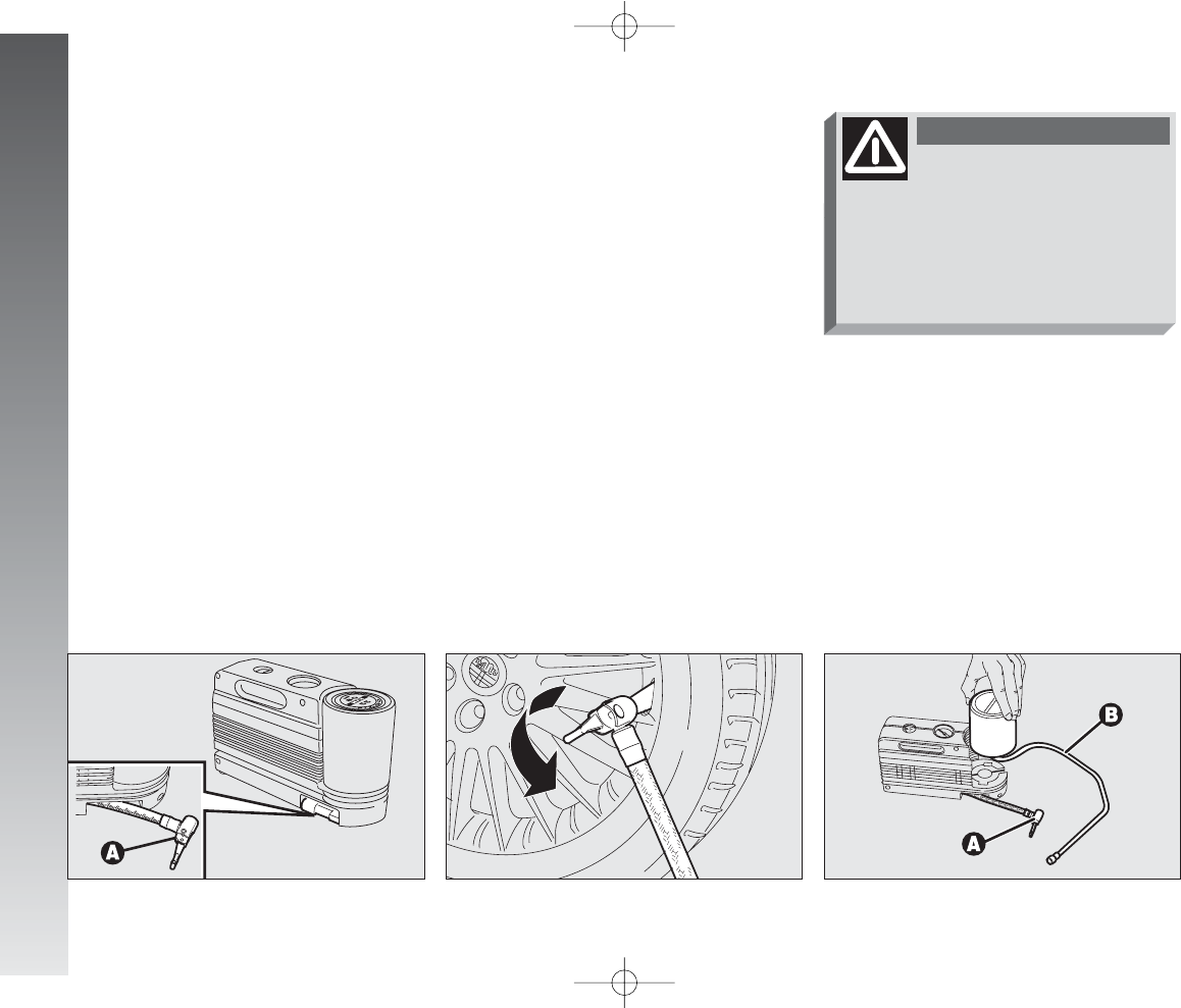
IN AN EMERGENCY
208
fig. 17
A0A1101m
fig. 18
A0A1102m
fig. 19
A0A1103m
PROCEDURE FOR CHANGING
THE BOTTLE
Proceed as follows:
– disengage the coupling A-fig. 19 and
disconnect the pipe B;
– turn the bottle to be changed counter-
clockwise and raise it;
– fit the new bottle and turn it clockwise;
– fit the coupling Aor connect the pipe
Binto its housing.
It is absolutely necessary
to communicate that the
tyre has been repaired with the
quick repairing kit. Give the
sticker to the personnel who will
carry out the restoring opera-
tions.
WARNING
ONLY FOR PRESSURE
CHECKING AND RESTORING
The compressor can also be used only for
restoring the tyre pressure. Disengage the
quick coupling A-fig. 17 and connect it
directly to the valve of the tyre to be inflat-
ed fig. 18; this way the bottle will not be
connected to the compressor and no sealer
will be injected.
197-233_Alfa147 Q2 GB 4-07-2008 12:04 Pagina 208
IN AN EMERGENCY
209
Alterations or repairs to
the electric system not car-
ried out correctly and without tak-
ing account of the system specifi-
cations may cause failures and the
risk of fire.
WARNING
Where possible, it is ad-
visable to have bulbs
changed c/o Alfa Romeo Autho-
rised Services. The correct opera-
tion and aiming of the outer lights
are vital to the safety of the car
and its passengers and the subject
to specific laws.
WARNING
Halogen bulbs must be
handled touching only the
metallic part. If the transparent
bulb is touched with the fingers,
its lighting intensity is reduced
and the life of the bulb may be
compromised. If touched acciden-
tally, rub the bulb with a cloth
moistened with methylated spirit
and allow to dry.
WARNING
Halogen bulbs contain
pressurised gas, in the case
of breakage they may burst.
WARNING
Because of the high
supply voltage, possi-
ble replacement of Xenon
lamps must be carried out by
skilled personnel only: danger
of death! Contact Alfa Romeo
Authorised Services.
WARNING
WHEN NEEDING TO
CHANGE A BULB
197-233_Alfa147 Q2 GB 4-07-2008 12:04 Pagina 209
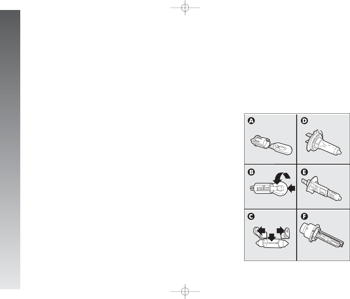
IN AN EMERGENCY
210
D.-E.Halogen bulbs
To remove, free it from the clip on
its housing.
F. Xenon lamps
To remove the bulb, slacken the fas-
tening ring nut and release the
retaining ring.
GENERAL INSTRUCTIONS
– When a light is not working, check that
the corresponding fuse is intact before
changing a bulb.
– For the location of fuses, refer to the
paragraph “In the event of a burnt fuse”
in this chapter.
– Before changing a bulb check the con-
tacts for oxidation.
– Burnt bulbs must be replaced by oth-
ers of the same type and power.
– Always check headlight aiming after
changing a bulb to ensure they are safe.
TYPES OF BULBS
(fig. 20)
Various types of bulbs are fitted to your
car:
A. All glass bulbs
These are pressed on. Pull to
remove.
B. Bayonet type bulbs
Press the bulb, turn counter-clock-
wise to remove this type of bulb
from its holder.
C. Tubular bulbs
Free them from their contacts to
remove.
fig. 20
A0A0503m
197-233_Alfa147 Q2 GB 4-07-2008 12:04 Pagina 210
IN AN EMERGENCY
211
BULBS
High beam
Low beam
Anabbaglianti a scarica di gas Xenon
Front sidelights
Foglights
Front direction indicators
Side direction indicators
Rear direction indicators
Rear sidelights - braking lights
Third stop (additional braking lights)
Reversing light
Rear foglights
Number plate light
Puddle lights
Front roof light
Rear roof light
Courtesy mirror light
Glovebox light
Boot light
FIGURE 20
D
D
F
B
E
B
A
B
B
A
B
B
A
C
C
C
A
A
C
POWER
55W
55W
35W
6W
55W
21W
5W
21W
5W/21W
2.3W
21W
21W
5W
5W
10W
10W
1.2W
5W
5W
TYPE
H1
H7
DS2
H6W
H1
PY21W
W5W
P21W
P21/5W
W2.3W
P21W
P21W
W5W
C5W
C10W
C10W
W1.2W
W5W
C5W
197-233_Alfa147 Q2 GB 4-07-2008 12:04 Pagina 211
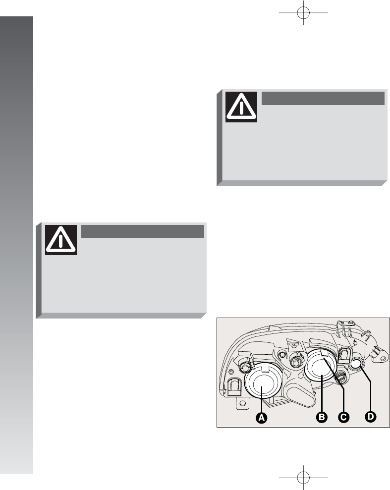
HALOGEN HEADLIGHTS
IMPORTANT See the previous chapter
“When needing to change a bulb” for the
type of bulb and power rating.
fig. 21
A0A1066m
Alterations or repairs to
the electric system not
carried out correctly and without
taking account of the system
specifications may cause failures
and the risk of fire.
WARNING
IN AN EMERGENCY
212
IF AN EXTERIOR
LIGHT GOES OUT
REPLACEMENT OF XENON
LIGHTS
Xenon lights have a very long life, there-
fore breakdowns are unlikely.
The front light units contain the side light,
dipped beam, main beam and fog light
bulbs.
The front light units contain the side light,
dipped beam, main beam and front direc-
tion indicator bulbs.
The bulbs are arranged inside the light unit
as follows (fig. 21):
(A) Dipped beam headlights
(B) Main beam headlights
(C) Sidelights
(D) Front direction indicators.
IMPORTANT A slight layer of steam
(fogging) can appear on the inside surface
of the beam transparent cover: this is not
a defect. The presence of condensate traces
in beams is a natural phenomenon, due to
low temperature and to the degree of hu-
midity in the air. These traces will disappear
when the beams are turned on. Instead the
presence of drops inside the beam indicates
water infiltration: in ths case contact Alfa
Romeo Authorised Services.
Because of the high
supply voltage, possible
replacement of Xenon lamps must
be carried out by skilled person-
nel only: danger of death! Contact
Alfa Romeo Authorised Services.
WARNING
197-233_Alfa147 Q2 GB 4-07-2008 12:04 Pagina 212
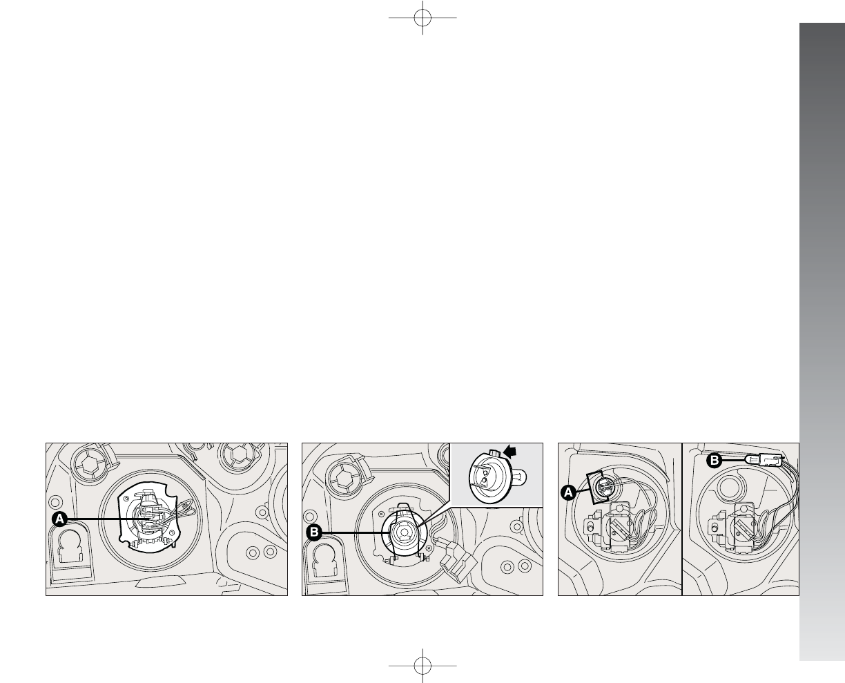
IN AN EMERGENCY
213
Dipped beam headlights
(fig. 22-23)
To change the bulb, proceed as follows:
– Remove the protective rubber cover.
– Disconnect the electric connector (A).
– Release the bulb catch (B).
– Remove the bulb and replace it.
fig. 23
A0A1068m
fig. 22
A0A1067m
Front side lights
(fig. 24)
To change the bulb, proceed as follows:
– Remove the protective rubber cover.
– Press the clips (A) and remove the bulb
holder.
– Withdraw the bult holder (B) which is
snap-fitted and change it.
– Refit the bulb holder making sure that
the retaining clips click into place (A).
– Refit the protective cover correctly.
fig. 24
A0A1069m
– Fit a new bulb, making the tabs on the
metallic part coincide with the grooves on
the reflector, then hook the bulb holder catch
(B).
– Re-connect the electric connector (A).
– Refit the protective cover correctly.
197-233_Alfa147 Q2 GB 4-07-2008 12:04 Pagina 213
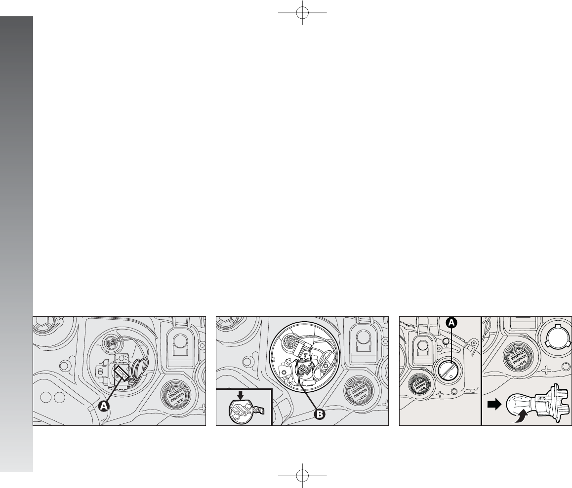
IN AN EMERGENCY
214
Main beam headlights
(fig. 25-26)
To change the bulb, proceed as follows:
– Remove the protective rubber cover.
– Disconnect the electric connector (A).
– Release the bulb catch (B).
– Remove the bulb and replace it.
fig. 26
A0A1071m
fig. 25
A0A1070m
– Fit a new bulb, making the tab of the
metal part coincide with the one on the
lamp unit, then hook the bulb holder catch
(B).
– Re-connect the electric connector (A).
– Refit the protective cover correctly.
Front direction indicators
(fig. 27)
To change the bulb (orange), proceed as
follows:
– Turn the bulb holder counterclockwise
(A) and remove it.
– Remove the bulb pushing lightly and
turning counterclockwise.
– Fit the new bulb pushing lightly and turn-
ing clockwise .
– Refit the bulb holder turning clockwise,
checking that it is secured correctly.
fig. 27
A0A1072m
197-233_Alfa147 Q2 GB 4-07-2008 12:04 Pagina 214
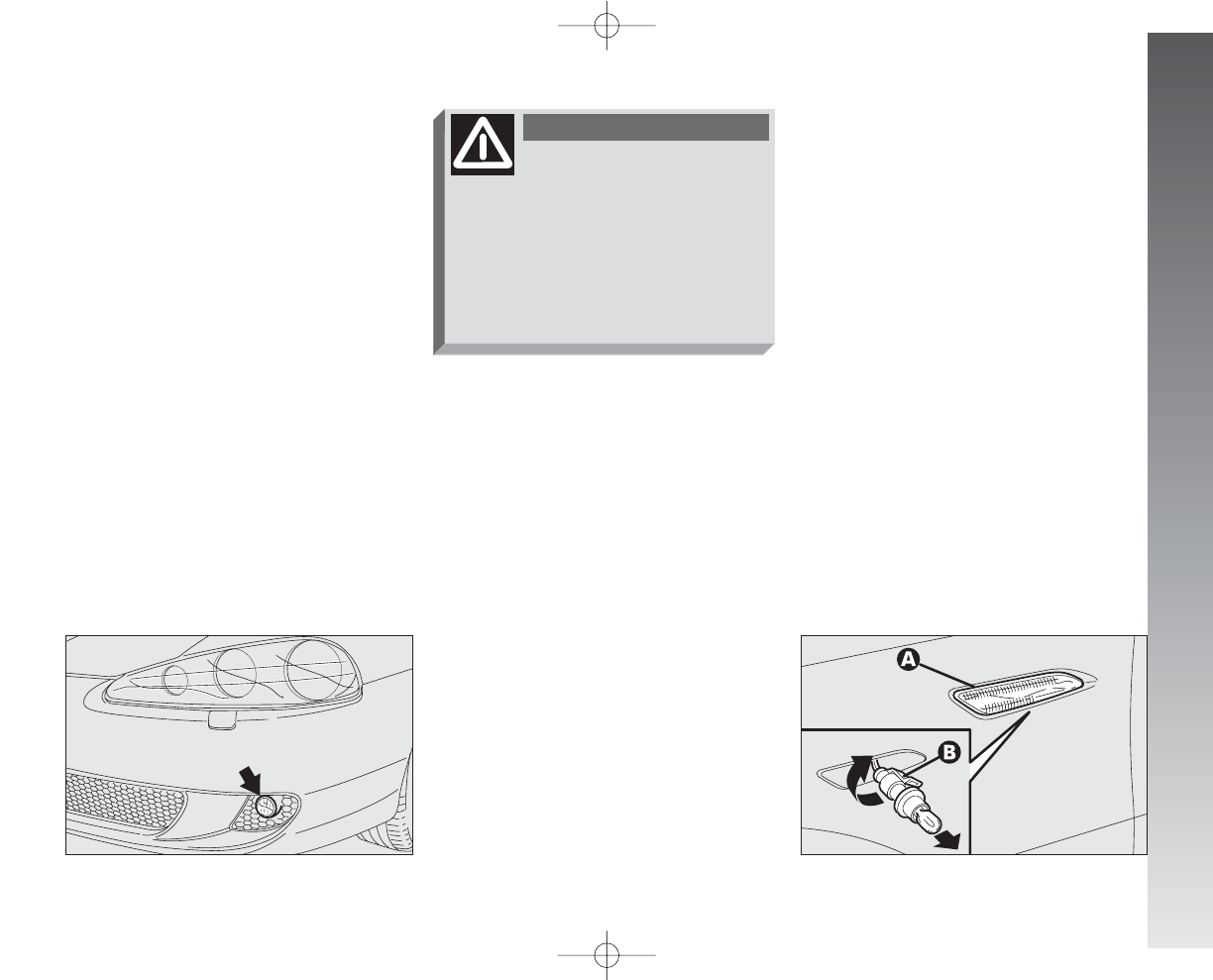
IN AN EMERGENCY
215
FOG LIGHTS
(fig. 28)
IMPORTANT To replace the front fog-
light bulbs and adjust the headlights contact
Alfa Romeo Authorised Services.
SIDE DIRECTION INDICATORS
(fig. 29)
– Push the transparent cover (A)
towards the rear of the car to compress
the catch. Release the front part and
remove this unit.
– Turn the bulb holder (B) counter-clock-
wise and remove it from the cover.
– Remove the snap-fitted bulb and
replace it.
– Insert the bulb holder (B) in the trans-
parent cover (A), then position the unit
making sure the catch clicks into place.
fig. 28
A0A1073m
fig. 29
A0A1040m
The efficiency of the lights
will be decreased and may
cause incovenience to other road
users if the light units are not
correctly adjusted. If in doubt
contact Alfa Romeo Authorised
Services to have them checked
and adjusted if necessary.
WARNING
197-233_Alfa147 Q2 GB 4-07-2008 12:04 Pagina 215
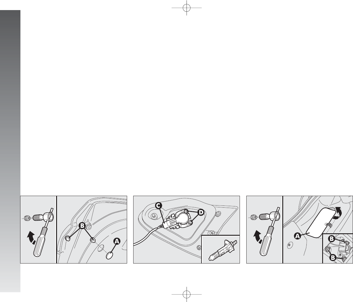
IN AN EMERGENCY
216
REVERSING LIGHT
AND REAR FOG GUARDS
(fig. 30-31)
The reversing light and rear fog guard are
in the tail light until fastened to the tailgate;
they are to be found respectively one on the
right and the other on the left of the car fac-
ing forwards.
To change the bulb, proceed as follows:
– Open the tailgate.
– Remove the cap (A) then, using the ex-
tension with the screwdriver provided (work-
ing as illustrated), loosen the fastening nuts
(B) of the light unit concerned.
fig. 30
A0A0167m
fig. 32
A0A0169m
– Withdraw the light unit outwards.
– Slacken the electric connector (C).
– Slacken the screws (D), and remove
the bulb holder.
– Remove the bulb pushing gently and
turning counterclockwise.
– Replace the bulb, then refit the bulb
holder and tighten the screws (D).
– Re-tighten the electric connector (C).
– Refit the light unit on the tailgate tight-
ening the nuts (B), then refit the cap (A)
pressing it on.
REAR DIRECTION INDICATORS
AND REAR SIDELIGHTS-
BRAKING LIGHTS
(fig. 32-33)
The rear direction indicators and the side
lights-braking lights are in the tail light unit
fastened to the body.
To change the bulb, proceed as follows:
– From inside the boot, open the pre-
formed trim (A) then, using the extension
and the screwdriver provided (working as il-
lustrated), slacken the nuts (B) fastening
the light unit.
– Withdraw the light unit outwards.
fig. 31
A0A0168m
197-233_Alfa147 Q2 GB 4-07-2008 12:04 Pagina 216
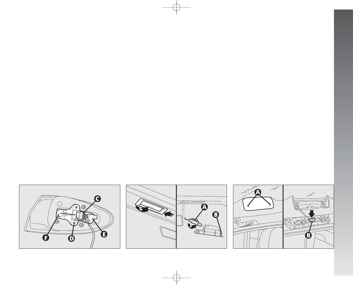
IN AN EMERGENCY
217
NUMBER PLATE LIGHTS
(fig. 34)
To change the bulbs, proceed as follows:
– Work on the transparent cover frame,
in the point shown by the arrow to compress
the catch (B). Free the opposite end and re-
move the unit.
– Turn the bulb holder counter-clockwise (A)
and remove it from the transparent cover.
– Remove the snap-fitted bulb and replace it.
– Insert the bulb holder (A) in the trans-
parent cover then refit the unit checking that
the catch clicks into place (B).
ADDITIONAL BRAKING LIGHT
(THIRD STOP)
(fig. 35-36)
To change the bulbs, proceeed as follows:
– Open the tailgate, slacken the screws
(A) then disconnect the electric connec-
tion (B).
– Remove the transparent cover- bulb
holder (C) from the support (D).
– Working on the side catches (E), release
the bulb holder.
– Remove the bulb to be changed.
fig. 34
A0A0171m
fig. 35
A0A0172m
– Disconnect the electric connector (C).
– Slacken the screw (D), and remove the
bulb holder.
– Remove the bulb to be changed push-
ing gently and turning counterclockwise:
(E) - bulb for rear sidelight/braking light.
(F) - bulb for rear direction indicator.
– Replace the bulb, then refit the bulb
holder and tighten the screw (D).
– Re-connect the electric connector (C).
– Refit the light unit on the body tightening
the screws (B).
– Close the preformed trim (A).
fig. 33
A0A0170m
197-233_Alfa147 Q2 GB 4-07-2008 12:04 Pagina 217
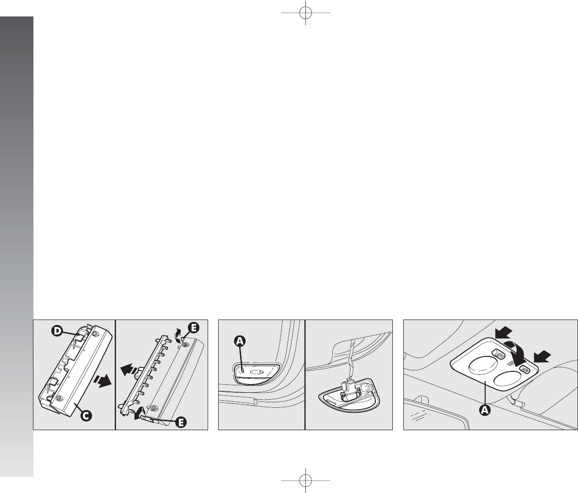
IN AN EMERGENCY
218
– Insert the bulb holder making sure the
side catches click into place (E).
– Refit the transparent cover-bulb holder
(C) in the support (D).
– Re-connect the electric connector (B).
– Refit the unit on the tailgate tightening
the screws (A).
fig. 36
A0A0173m
fig. 38
A0A0175m
PUDDLE LIGHT
(fig. 37)
(for versions/markets where
applicable)
To change the bulb, proceed as follows:
– Open the door and slacken the screw
(A) fastening the transparent covers.
– Remove the unit composed of the two
transparent covers then change the bulb, re-
leasing it from the side contacts making sure
that the new bulb is correctly clamped be-
tween the contacts.
– Realign the two transparent covers and
tighten the fastening screw (A).
IF AN INTERIOR
LIGTH GOES OUT
FRONT ROOF LIGHT
(fig. 38-39)
To change the bulbs, proceed as follows:
– Remove the light unit (A) levering in
the points shwon by the arrow (in corre-
spondence with the retainer catches).
– Open the protective cover (B).
– Replace the bulb concerned releasing it
from the side contacts making sure that the
new bulb is correctly clamped between the
contacts.
fig. 37
A0A0174m
197-233_Alfa147 Q2 GB 4-07-2008 12:04 Pagina 218
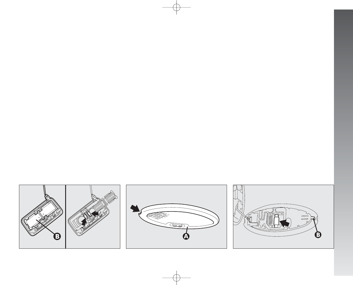
IN AN EMERGENCY
219
REAR ROOF LIGHT
(fig. 40-41)
To change the bulb, proceed as follows:
– Remove the light unit (A) levering in
the point shown by the arrow.
– Replace the bulb releasing it from the
side contacts making sure that the new bulb
is correctly clamped between the contacts.
– Refit the light unit in the correct position
inserting first the side with the connector,
then pressing the other side until the catch
clicks into place (B).
fig. 40
A0A0177m
fig. 41
A0A0178m
– Close the protective cover (B).
– Refit the light unit pressing gently in cor-
respondence with the retainer catches, un-
til hearing the click.
fig. 39
A0A0176m
197-233_Alfa147 Q2 GB 4-07-2008 12:04 Pagina 219
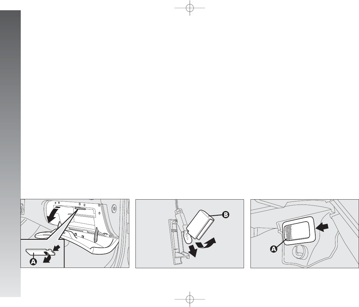
IN AN EMERGENCY
220
GLOVEBOX LIGHT
(fig. 42-43)
To change the bulb, proceed as follows:
– Open the glovebox, then remove the
light unit (A) levering in the point shown by
the arrow.
– Open the protection (B) and change the
snap-fitted bulb.
– Close the protection (B) on the trans-
parent cover.
fig. 42
A0A0181m
BOOT LIGHT
(fig. 44-45)
To change the bulb, proceed as follows:
– Open the tailgate.
– Remove the light unit (A) levering in
the point shown by the arrow.
– Refit the light unit inserting it in its cor-
rect position firstly on one end and then on
the other until it clicks into place.
fig. 43
A0A0182m
fig. 44
A0A0183m
197-233_Alfa147 Q2 GB 4-07-2008 12:04 Pagina 220
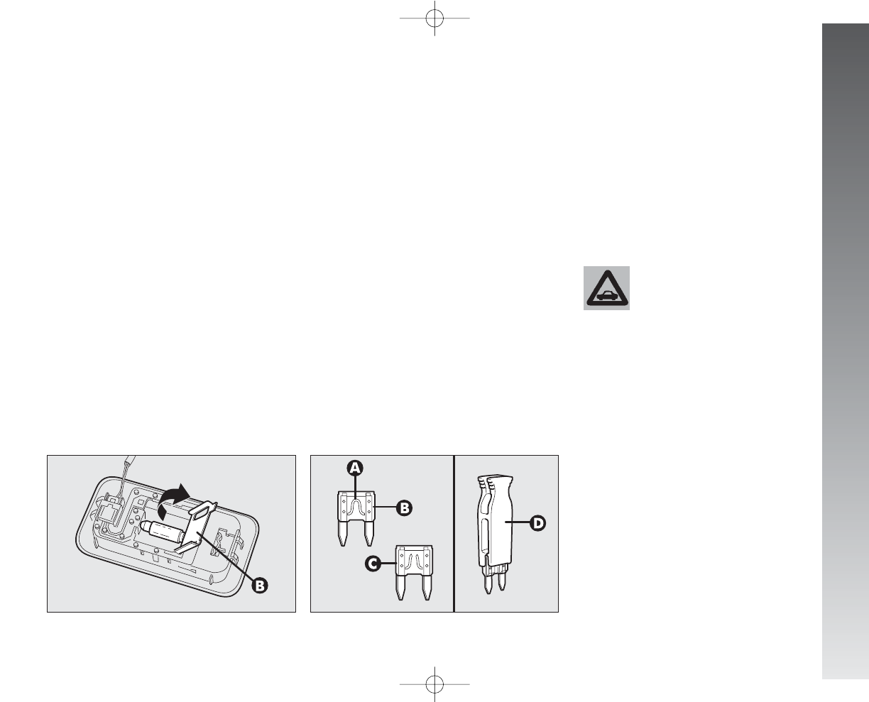
IN AN EMERGENCY
221
IN THE EVENT OF A BLOWN FUSE
GENERAL
The fuse is a protective device for the elec-
tric system: it comes into action (i.e. it cuts
off) mainly due to a fault or improper action
on the system.
When a device does not work, check the
efficiency of its fuse. The conductor ele-
ment(A-fig. 46) must be intact; if not,
replace the fuse with one of the same amp
rating (same colour).
(B) - Undamaged fuse
(C) - Fuse with damaged filament.
Remove the blown fuse using the pincer
provided (D), in the control box.
fig. 46
A0A0185m
Never replace a fuse with
metal wires or anything
else. Always use an intact
fuse of the same colour.
– Open the the protective cover (B) and
replace the bulb releasing it from the side
contacts, making sure that the new bulb is
correctly clamped between the contacts.
– Close the protective cover (B).
– Refit the light unit inserting it in its cor-
rect position firstly on one end and then on
the other until it clicks into place.
fig. 45
A0A0184m
197-233_Alfa147 Q2 GB 4-07-2008 12:04 Pagina 221
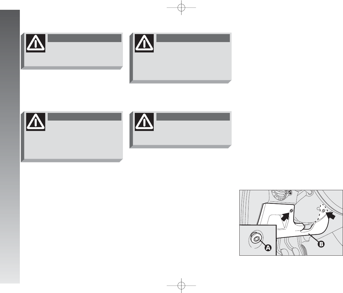
IN AN EMERGENCY
222
Never replace a fuse with
another with a higher amp
rating; DANGER OF FIRE.
WARNING
If a general fuse (MAXI-
FUSE or MEGA-FUSE) cuts
in, do not attempt any repair and
contact Alfa Romeo Authorised
Services.
WARNING
Before replacing a fuse,
make sure the ignition key
has been removed and that all the
other services are switched off
and/or disengaged.
WARNING
If a fuse blows again, con-
tact an Alfa Romeo Autho-
rised Service.
WARNING
Fuses of the car are grouped in three con-
trol boxes, to be found respectively on the
dashboard, on the battery positive pole and
next to the actual battery.
Access is gained to the control box on the
dashboard by slackening the two retainers
(A-fig. 47) and removing the protective
trim (B).
To gain access to the fuses in the fusebox
on the battery post, remove the protective
cover pressing the opening catches (front).
fig. 47
A0A1082m
197-233_Alfa147 Q2 GB 4-07-2008 12:04 Pagina 222
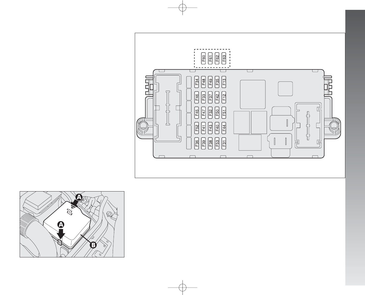
IN AN EMERGENCY
223
Access is gained to the control box next to
the battery releasing the perimetral catches
(A-fig. 48) and removing the protective
cover (B).
To locate the protection fuses, consulting
the summary table on the following pages,
refer to the following illustrations fig. 49,
fig. 50 and 51.
fig. 48
A0A0187m
fig. 49 - Control box on dashboard
A0A0134m
197-233_Alfa147 Q2 GB 4-07-2008 12:04 Pagina 223
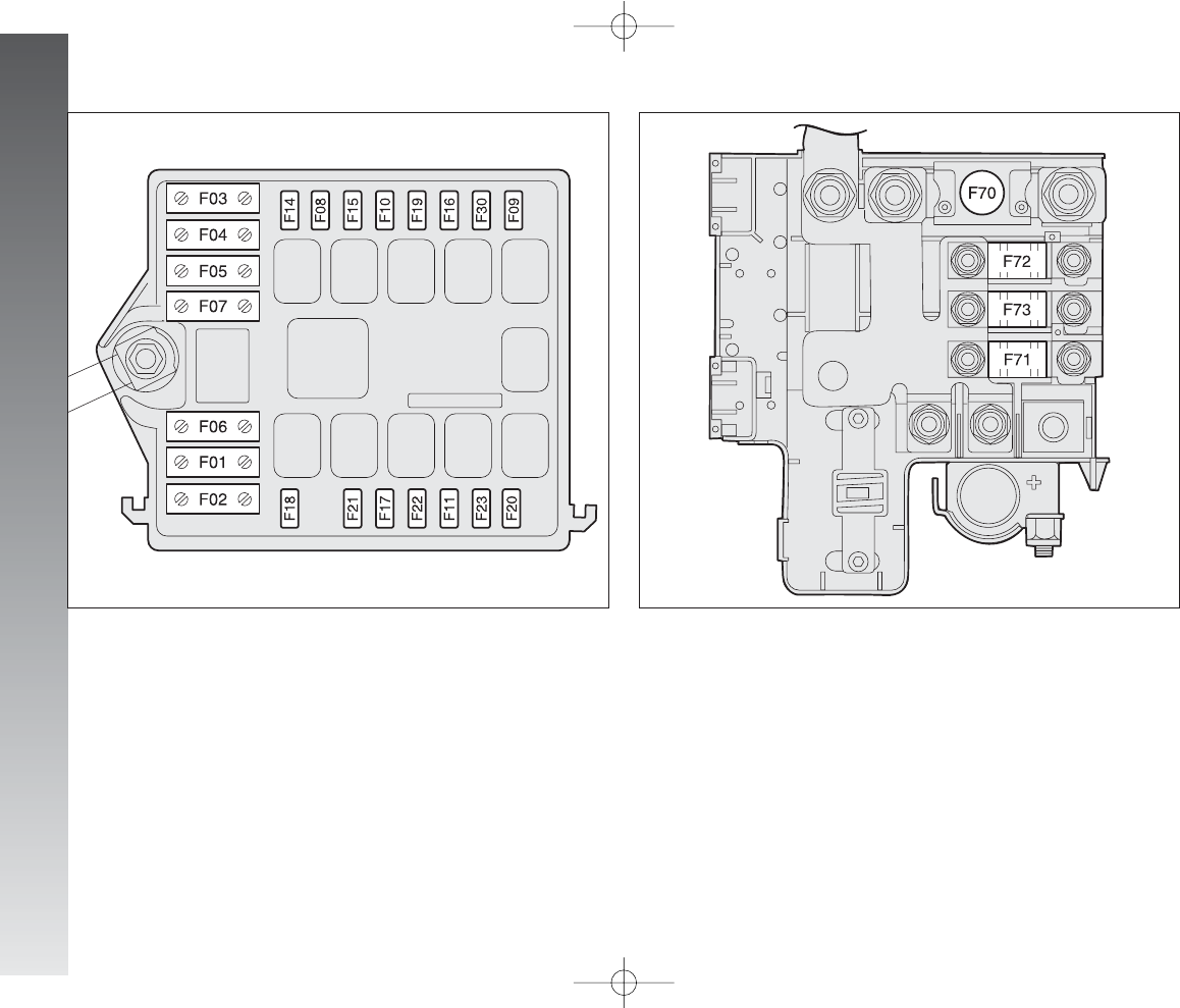
IN AN EMERGENCY
224
fig. 50 - Control box next to battery
A0A0137m
fig. 51 - Control box on battery positive pole
A0A0215m
197-233_Alfa147 Q2 GB 4-07-2008 12:04 Pagina 224

IN AN EMERGENCY
225
30
30
10
7.5
15
7.5
7.5
F03 (MAXI-FUSE)
F73 (MAXI-FUSE)
F13
F31
F39
F19
F31
SERVICES FIGURE FUSE AMPERES
Hazard lights
Right dipped-beam headlight
Left dipped-beam headlight
Right main-beam headlight
Left main-beam headlight
Foglights
Braking light
Reversing light
+30 direction indicators
10
10
10
10
10
15
10
7.5
10
F53
F12
F13
F14
F15
F30
F37
F35
F53
LIGHTS FIGURE FUSE AMPERES
FUSE SUMMARY TABLE
Selespeed transmission pump
Additional heater
Headlight aiming device
Climate control system
Climate control system
Climate control compressor
Heater unit relay coils
IMPORTANT Strictly observe the fuse amp: in case of doubt contact Alfa Romeo Authorised Services
49
49
49
50
50
50
49
49
49
50
51
49
49
49
50
49
197-233_Alfa147 Q2 GB 4-07-2008 12:04 Pagina 225
IN AN EMERGENCY
226
15
15
7.5
15
15
15
20
20
30
30
20
15
7.5
7.5
20
20
15
7.5
15
7.5
F32
F32
F51
F39
F39
F52
F33
F34
F40
F43
F44
F45
F41
F35
F38
F09
F39
F17
F11
F49
SERVICES FIGURE FUSE AMPERES
Key-operated +30
Selespeed transmission
Selespeed transmission
Radio
Navigator
Rearscreen wiper
Rear left power window
Rear right power window
Rearscreen heating
Windscreen - rearscreen washer (two-way pump)
Cigar lighter
Seats with electric heating
Heated wing mirrors – heated nozzles
Cruise control
Central door locking
Headlight washer
Services + 30
Primary services (electronic injection)
Secondary services (electronic injection)
Secondary services
49
49
49
49
49
49
49
49
49
49
49
49
49
49
49
50
49
50
50
49
197-233_Alfa147 Q2 GB 4-07-2008 12:04 Pagina 226

IN AN EMERGENCY
227
Volumetric sensors
VDC system sensor
Steering angle sensor
EOBD system diagnosis socket
Cell phone provision
Driver’s door control unit supply
Passenger’s door control unit supply
Control lighting
Climate control system control lighting
Instrument cluster
Instrument cluster
Driver’s door control unit
ABS control unit
ABS control unit
Dashboard control unit
Boot control unit
Air - bag control unit
Electronic injection control unit +30
Engine compartment control box (petrol versions)
Dashboard control unit
Trailer control unit
15
7.5
7.5
15
15
20
20
7.5
7.5
10
10
15
7.5
50
50
15
7.5
7.5
125
70
10
F39
F42
F42
F39
F39
F47
F48
F49
F35
F37
F53
F39
F42
F04 (MAXI-FUSE)
F02 (MAXI-FUSE)
F39
F50
F18
F70 (MEGA-FUSE)
F71 (MAXI-FUSE)
F36
49
49
49
49
49
49
49
49
49
49
49
49
49
50
50
49
49
50
51
51
49
SERVICES FIGURE FUSE AMPERES
197-233_Alfa147 Q2 GB 4-07-2008 12:04 Pagina 227
IN AN EMERGENCY
228
40
30
50
15
15
15
15
25
7.5
15
15
20
15
30
30
50
20
150
40
60
20
F05 (MAXI-FUSE)
F06 (MAXI-FUSE)
F07 (MAXI-FUSE)
F10
F21
F22
F21
F60 (*)
F16
F61 (*)
F62 (*)
F63 (*)
F46
F08
F72 (MAXI-FUSE)
F01 (MAXI-FUSE)
F20
F70 (MEGA-FUSE)
F06 (MAXI-FUSE)
F07 (MAXI-FUSE)
F22
50
50
50
50
50
50
50
49
50
49
49
49
49
50
51
50
50
51
50
50
50
SERVICES FIGURE FUSE AMPERES
(*) Fuse behind dashboard control box on an auxiliary bracket.
Climate control fan
Radiator fan (first speed - petrol versions)
Radiator fan (second speed - petrol versions)
Horn
Fuel pump
Injectors (petrol versions)
Ignition coils
Tailgate electric unlocking
Electronic injection system
Bose system
Bose system
Sunroof
Sunroof
Additional heater
Ignition switch
Glow plug warming (diesel versions)
Heated fuel oil filter (diesel versions)
Engine compartment control box (diesel versions)
Radiator fan (first speed – diesel versions)
Radiator fan (second speed – diesel versions)
Injectors (diesel versions)
197-233_Alfa147 Q2 GB 4-07-2008 12:04 Pagina 228
IN AN EMERGENCY
229
IN THE EVENT OF A FLAT BATTERY
Before anything else, you are advised to
read the precautions for preventing the bat-
tery from draining and for ensuring long life
in the “Car maintenance” chapter.
CHARGING THE BATTERY
IMPORTANT The battery charging pro-
cedure is described only for information pur-
poses. This operation should be carried out
by Alfa Romeo Authorised Services.
Charging should be slow at a low amp rat-
ing for 24 hours. Charging for a longer time
may damage the battery.
Charge the battery as follows:
– Disconnect the battery negative termi-
nal (–).
– Connect the charger cables to the battery
terminal ensuring that the bias is correct.
– Turn on the charger.
– After charging, turn off the charger be-
fore disconnecting it from the battery.
– Re-connect the battery negative termi-
nal (–).
STARTING WITH AN
AUXILIARY BATTERY
See “Starting with an auxiliary battery” in
this chapter.
Strictly avoid using a bat-
tery charger to start the
engine: you may damage
the electronic systems, in particu-
lar the ignition and fuel supply con-
trol units.
The liquid contained in the
battery is poisonous and
corrosive. Avoid contact with the
skin or eyes. The battery should be
charged in a well ventilated place,
away from naked flames or pos-
sible sources of sparks: danger of
explosion and fire.
WARNING
Never attempt to charge a
frozen battery: it must
firstly be thawed, otherwise it
may burst. If freezing has occurred,
the battery should be checked be-
fore charging by specialised per-
sonnel, to make sure that the in-
ternal elements are not damaged
and that the body is not cracked,
with the risk of leaking poisonous
and corrosive acid.
WARNING
197-233_Alfa147 Q2 GB 4-07-2008 12:04 Pagina 229
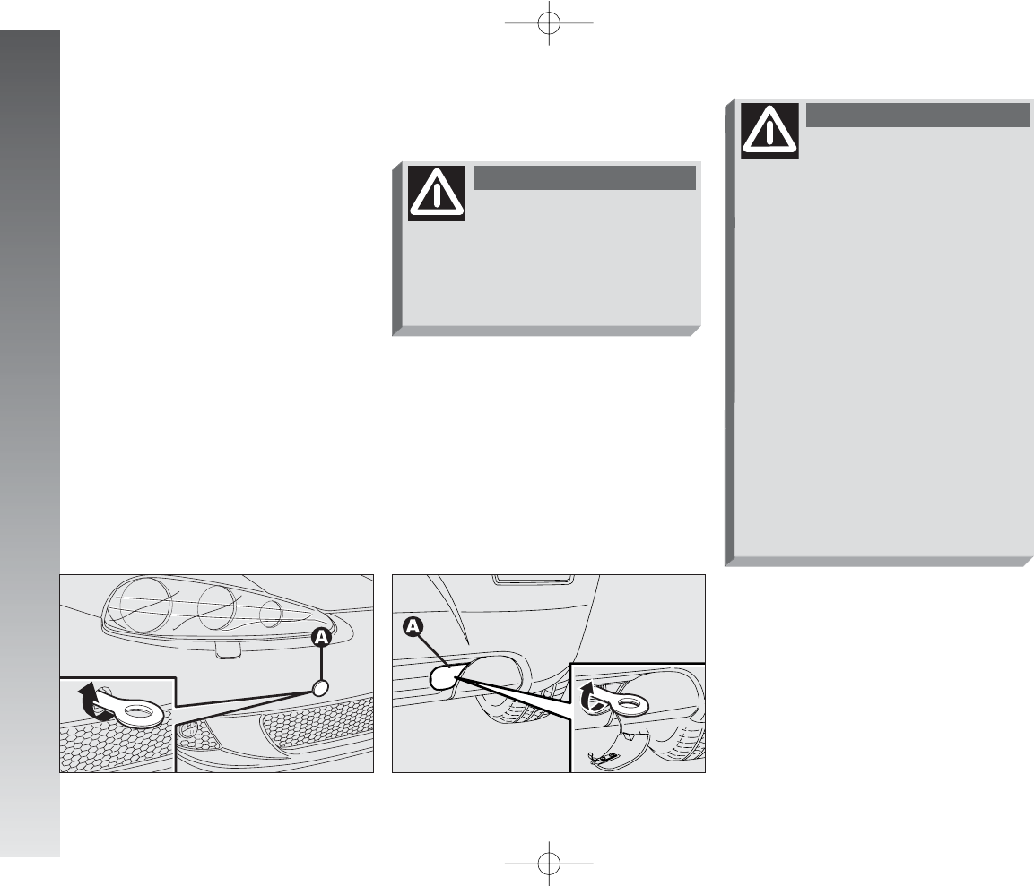
IN AN EMERGENCY
230
IF THE CAR IS TO BE TOWED
The tow ring supplied with the car is
housed in the tool box under the boot mat.
To install the tow ring, proceed as follows:
– Take the tow ring from the tool box.
– Remove the cover (A) snap-fitted on
the front (fig. 52) or rear bumper (fig.
53). To do this, if using the flat-bladed
screwdriver provided, protect the tip with a
soft cloth to avoid damaging the car.
– Firmly screw the ring in its housing.
fig. 52
A0A1083m
fig. 53
A0A1084m
Before tightening the ring
carefully clean the thread-
ed housing. Before beginning to
tow the car, make sure that the
ring is firmly tightened in its
threaded housing.
WARNING
Before starting to tow,
turn the ignition key to
MAR and back to STOP again with-
out removing it. Removing the key
automatically engages the steering
lock resulting in the impossibility
to steer the wheels. When towing
remember that without the help of
the engine brake and power steer-
ing greater effort is required on the
pedal and steering wheel. Do not
use flexible cables for towing and
avoid jerks. During towing opera-
tions make sure that fastening the
joints does not damage the com-
ponents in contact with it. When
towing the car, it is compulsory to
follow specific traffic regulations
concerning both the towing device
and behaviour on the road.
WARNING
197-233_Alfa147 Q2 GB 4-07-2008 12:04 Pagina 230
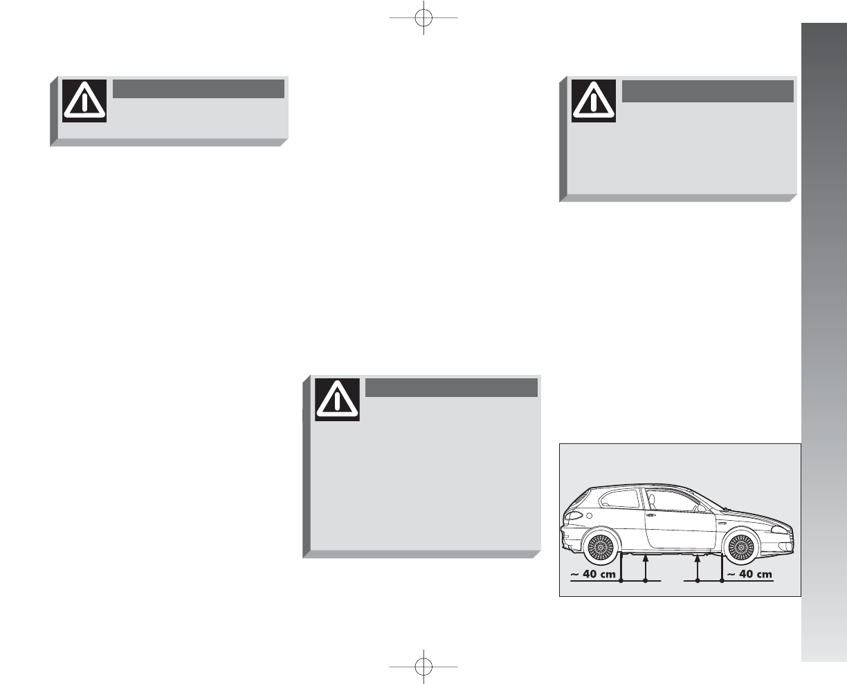
IN AN EMERGENCY
231
IMPORTANT For versions with Sele-
speed transmission, make sure that the
gears are in neutral (N) (checking that the
car moves if pushed) and then proceed as
for towing a normal car with mechanical
transmission, following the instructions giv-
en previously.
Should it be impossible to set the gears to
neutral, do not tow the car and contact Al-
fa Romeo Authorised Services.
USING THE JACK
See paragraph “In the event of a punc-
ture” in this chapter.
Please be informed that:
– lthe jack mass is approx. 2.100 kg;
– the jack requires no adjustment;
– the jack cannot be repaired and in the
event of a fault it must be replaced by an-
other original one;
– no tool other than its crancking device
may be fitted on the jack.
IF THE CAR IS TO BE
LIFTED
Do not start the engine
when towing the car.
WARNING
The purpose of the jack is
only for replacing wheels
on the car with which it is provid-
ed or on cars of the same model. It
must never be used for other pur-
poses such as for example raising
cars of other models. In no case
must it be used for repairs under
the car.
WARNING
The car may fall if the jack
is not positioned correctly.
Never use the jack for higher ca-
pacities than the one stated on the
label.
WARNING
USING AN ARM LIFT OR
WORKSHOP LIFT
The car should be lifted only at the side
setting the ends of the arms of the work-
shop lift in the area shown in fig. 54-55.
fig. 54
A0A1085m
197-233_Alfa147 Q2 GB 4-07-2008 12:04 Pagina 231
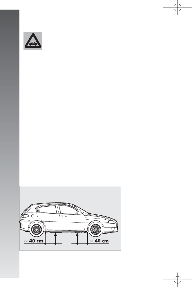
IN AN EMERGENCY
232
– In motorways pileups, especially with
poor visibility, the risk of being involved in
other crashes is high. Leave the car imme-
diately and go beyond the guard-rail.
– If doors are blocked, do not try to get
out of the car breaking the windscreen which
is stratified. The windows and rear screen
are easier to break.
– Remove the ignition key of the cars in-
volved.
– If you note a smell of fuel or other chem-
ical product, do not smoke and have ciga-
rettes stubbed out.
– To put out fires, even small ones, use
the extinguisher, blankets, sand, or earth.
Never use water.
– If use of the lighting system is not nec-
essary, disconnect the battery negative ter-
minal (–).
IN THE EVENT
OF AN ACCIDENT
– It is important to keep calm.
– If you are not directly involved, stop at
least a few dozen metres away from the ac-
cident.
– On motorways, stop without blocking
the emergency lane.
– Turn the engine off and the hazard warn-
ing lights on.
– At night, illuminate the place of the ac-
cident with the headlights.
– Take care, do not risk being run over.
– Signal the accident placing the triangle
at regulation distance in a clearly visible place.
– Call the emergency organisation, giv-
ing the most accurate information possible.
On motorways use the special phones pro-
vided.
Take care when position-
ing the arms of the lift or
workshop lift to avoid
damaging the side strips.
fig. 55
A0A1086m
197-233_Alfa147 Q2 GB 4-07-2008 12:04 Pagina 232

IN AN EMERGENCY
233
IF PEOPLE ARE INJURED
– An injured person must never be aban-
doned. Helping is compulsory also for per-
sons not directly involved in the accident.
– Do not crowd around injured people.
– Reassure the injured person that help
is on the way, and stay near to overcome
any panic.
– Release or cut the seat belt restraining
injured persons.
– Do not give injured persons anything
to drink.
– An injured person should never be
moved except in the following circum-
stances.
– Remove an injured person from the car
only in danger of fire, sinking or falling.
When removing an injured person: do not
pull the limbs or bend the head and keep
the body as horizontal as possible.
FIRST AID KIT
In addition to the first-aid kit, it is also wise
to keep an extinguisher and a blanket in
the car.
197-233_Alfa147 Q2 GB 4-07-2008 12:04 Pagina 233

VEHICLE MAINTENANCE
234
It is however wise to remember that Pro-
grammed Maintenance does not complete-
ly cover all the car’s requirements: also in
the initial period before the 20,000 km ser-
vice coupon and later, between one coupon
and another, ordinary care is still necessary
such as for example routinely checking and
topping up the level of fluids, checking the
tyre pressure, etc...
IMPORTANT The Programmed Mainte-
nance coupons are specified by the Manu-
facturer. The failure to have them carried out
may invalidate the warranty.
The Programmed Maintenance service is
carried out by all Alfa Romeo Authorised Ser-
vices, at pre-established times.
If during each operation, in addition to the
ones programmed, the need arises for fur-
ther replacements or repairs, these may be
carried out only with the explicit agreement
of the customer.
IMPORTANT You are advised to contact
Alfa Romeo Authorised Services in the event
of any minor operating faults, without wait-
ing for the next service coupon.
SCHEDULED
SERVICING
Correct maintenance is determined in en-
suring long car life under the best conditions.
This is why Alfa Romeo has programmed
a series of checks and maintenance opera-
tions every 20,000 km.
IMPORTANT On versions fitted with re-
configurable multifunction display, at 2000
km from the maintenance deadline, the dis-
play will show “REFER TO SERVICE MANU-
AL” which is shown again turning the igni-
tion key to MAR, every 200 km. For fur-
ther details, see “Service” in the “Recon-
figurable multifunction display”.
V
VE
EH
HI
IC
CL
LE
EM
MA
AI
IN
NT
TE
EN
NA
AN
NC
CE
E
234-257_Alfa147 Q2 GB 4-07-2008 12:05 Pagina 234
●●●●●●●●●
●●●●●●●●●
●●●●●●●●●
●●●●●●●●●
●●●●●●●●●
●●●●
●●●●●●●●●
●●●●●●●●●
●●
●●●●
●●●●
●●●●●●●●●
●●●●●●●●●
●●●●●●●●●
VEHICLE MAINTENANCE
235
SCHEDULED MAINTENANCE PROGRAMME
20 40 60 80 100 120 140 160 180Thousands of km
Check tyre conditions/wear and adjust pressure if necessary
Check operation of lighting system (headlights, direction indicators, hazard
warning lights, boot, passenger compartment, glovebox lights, warning lights, etc..)
Check operation of windscreen washer system, adjust spray jets
Check position/wear of windscreen/rearscreen wiper blades
Check operation of front disk brake pad wear indicator
Check wear conditions of rear disk brake pads
Sight check the conditions of: body exterior, underbody protection,
stiff pipes and hoses (exhaust - fuel supply - brakes),
rubber parts (boots - sleeves - bushes etc.)
Sight check boot and bonnet lock cleaning conditions, lever cleaning and lubrication
Sight check for accessory drive belt conditions
Check handbrake lever stroke adjustment
Change air cleaner cartridge (petrol versions)
Change air cleaner cartridge (JTD versions)
Top up fluid levels (engine coolant, brakes, windscreen washer, battery, etc..)
Check and if necessary top up the automatic transmission oil level
(versions with Selespeed transmission)
234-257_Alfa147 Q2 GB 4-07-2008 12:05 Pagina 235
20 40 60 80 100 120 140 160 180
VEHICLE MAINTENANCE
236
Thousands of km
●●
●●●●
●●●
●●
●●●●
●
●●●
●
●
●
●●●
●●●●●●●●●
●●●●●●●●●
●●●
●●●●●●●●●
●●●●●●●●●
Sight check for conditions of timing gear drive toothed belt (diesel versions)
Check operation of engine control system (through diagnosis socket)
Check valve clearance (JTD
M
120HP versions)
Check mechanical transmission oil level
Check emissions/smoke at the exhaust (diesel versions)
Change counter-rotating shaft drive belt (2.0 T.SPARK versions)
Change timing gear drive belt (T.SPARK versions) (*)
Change timing gear drive belt (diesel versions) (*)
Change accessory poly-V drive belt
Change spark plugs (petrol versions)
Change spark plugs (1.6 T.SPARK 105HP versions)
Change engine oil and oil filter (petrol versions) (or every 24 months)
Change engine oil and oil filter (diesel versions without DPF)(**)
(or every 24 months)
Change engine oil and oil filter (diesel versions with DPF)(**)
(or every 24 months)
Change brake fluid (or every 24 months)
Change fuel filter (diesel versions)
Change pollen filter (or every year)
(*) Regardless of the km covered, the timing belt shall be replaced every 4 years for particularly demanding use (cold climates, driving in the city, idling for a long time) or in any case every 5 years.
(**) The engine oil and oil filter should be changed depending on their actual condition, which is indicated by a warning light/message on the control panel or at least every 2 years.
If the car is used mainly on urban routes or if the yearly kilometres travelled are less than 10,000 km, the engine oil and filter must be changed every 12 months.
234-257_Alfa147 Q2 GB 4-07-2008 12:05 Pagina 236

VEHICLE MAINTENANCE
237
ADDITIONAL
OPERATIONS
Every 1000 km or before long journeys,
check and if necessary top up:
– engine coolant fluid level
– brake/hydraulic clutch control fluid
level
– power steering fluid level
– windscreen/rearscreen and headlamp
washer fluid level
– tyre pressure and conditions.
Every 3000 km check and if necessary
top up the engine oil level.
The use of FL Selenia products is rec-
ommended which have been designed and
made expressly for Alfa Romeo cars (see
“Refuelling” in the “Technical Specifica-
tions” chapter).
ANNUAL INSPECTION
PROGRAMME
For cars with an annual mileage
of below 20,000 km (for example
about 10,000 km) the following
yearly inspection programme is ad-
vised:
– Check tyre conditions/wear and if nec-
essary adjust the pressure (including spare
wheel)
– Check operation of lighting system
(headlights, direction indicators, hazard
warning lights, boot, passenger compart-
ment, glovebox lights, warning lights, etc.)
– Check operation of windscreen wiper
system, spray jet adjustment
– Check position/wear of windscreen/
rearscreen wiper blades
– Check front disk brake pad conditions
and wear
– Check boot and bonnet lock cleaning
conditions, lever cleaning and lubrication
– Sight check for conditions of: engine,
gearbox, transmission, pipes (exhaust - fu-
el supply - brakes), rubber parts (boots -
sleeves - bushes etc..), brake and fuel sup-
ply system hoses
– Check battery charge
– Sight check for conditions of various
drive belts
– Check and if necessary top up fluid lev-
els (engine coolant, brakes, windscreen
washer, battery etc. )
– Change engine oil and filter
– Change pollen filter.
234-257_Alfa147 Q2 GB 4-07-2008 12:05 Pagina 237
VEHICLE MAINTENANCE
238
IMPORTANT
Engine oil
Should prevailing use of the car be under
one of the following specially heavy condi-
tions:
– trailer or caravan towing
– dusty roads
– short distances (less than 7-8 km) re-
peated and with external temperatures be-
low zero
– frequently idling engines or long distance
low speed driving (e.g. taxis or door-to-door
deliveries) or in case of a long term inac-
tivity.
Replace engine oil more frequently than
required on Service Schedule.
IMPORTANT
Diesel filter
The different grades of purity in diesel fu-
el normally available might make it neces-
sary to replace the filter more frequently
than indicated in the Service Schedule. If
the engine misfires it shows the filter needs
changing.
IMPORTANT
Air cleaner
Using the car on dusty roads change the
air cleaner more frequently than specified in
the Schedule Maintenance Programme.
For any doubts concerning the intervals be-
tween the engine oil and air cleaner re-
placement in relation to how the car is used,
contact Alfa Romeo Authorised Services.
IMPORTANT
Battery
It is advisable to check the battery charge,
preferably at the onset of winter, to prevent
the possibility of the electrolyte freezing.
This check should be carried out more fre-
quently if the car is used mainly for short
trips, or if it is fitted with accessories that
permanently absorb electricity even with the
ignition key removed, especially in the case
of after market accessories.
If the car is used in hot climates or partic-
ularly harsh conditions it is wise to check the
level of the battery fluid (electrolyte) more
frequently than specified in the Scheduled
Maintenance Programme.
Car maintenance should be
entrusted to Alfa Romeo
Authorised Services. For
routine and minor maintenance op-
erations you wish to carry out
yourself, always make sure you
have the proper equipment, gen-
uine Alfa Romeo spares and the
necessary fluids; do not however
carry out these operations if you
have no experience.
IMPORTANT
Pollen filter
If the car is used frequently in dusty or
heavily polluted environments it is advisable
to replace the filtering element more fre-
quently; in particular it should be replaced if
a reduction of the amount of air admitted to
the passenger compartment is noted.
234-257_Alfa147 Q2 GB 4-07-2008 12:05 Pagina 238
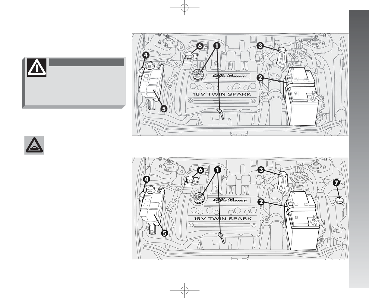
VEHICLE MAINTENANCE
239
fig. 2 - 2.0 T.SPARK Selespeed versions
fig. 1 - Versions 1.6 T.SPARK (105HP) - 1.6 T.SPARK (120HP) - 2.0 T.SPARK
1Engine oil - 2Battery - 3Brake fluid -
4Windscreen/rearscreen/headlamp wash-
er fluid - 5Engine coolant fluid - 6Power
steering fluid - 7Selespeed transmission oil
A0A0192m
A0A0194m
CHECKING LEVELS
When topping up take
care not to confuse the var-
ious types of fluids: they
are all incompatible with one an-
other and could seriously damage
the car.
Never smoke while work-
ing in the engine compart-
ment; gas and inflammable
vapours may be present, with the
risk of fire.
WARNING
234-257_Alfa147 Q2 GB 4-07-2008 12:05 Pagina 239
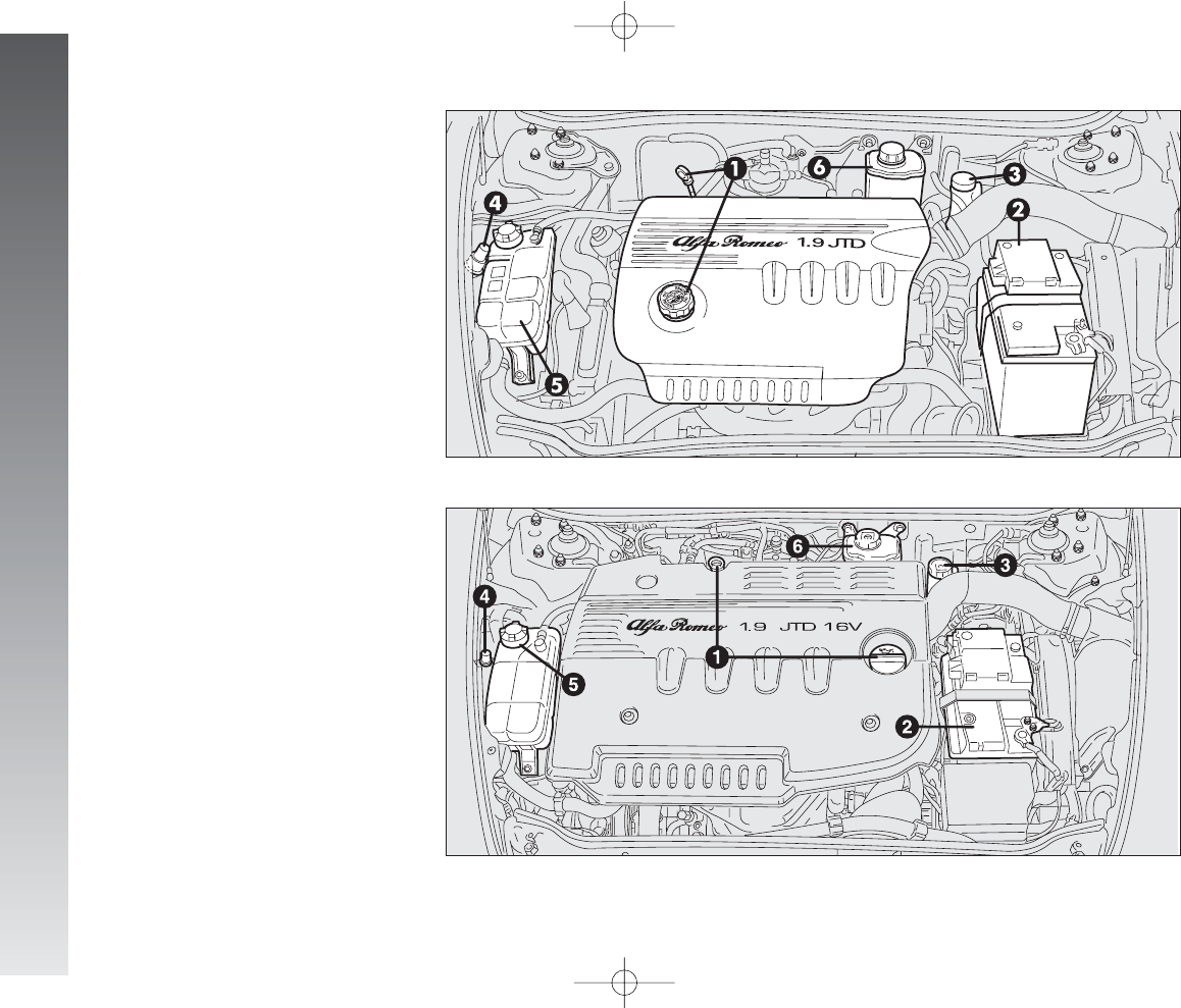
VEHICLE MAINTENANCE
240
fig. 4 - JTDM(150HP) versions
A0A0396m
1Engine oil - 2Battery - 3Brake fluid -
4Windscreen/rearscreen/headlamp wash-
er fluid - 5Engine coolant fluid - 6Power
steering fluif
fig. 3 - JTDM(120HP) versions
A0A0345m
1Engine oil - 2Battery - 3Brake fluid -
4Windscreen/rearscreen/headlamp wash-
er fluid - 5Engine coolant fluid - 6Power
steering fluid
234-257_Alfa147 Q2 GB 4-07-2008 12:05 Pagina 240
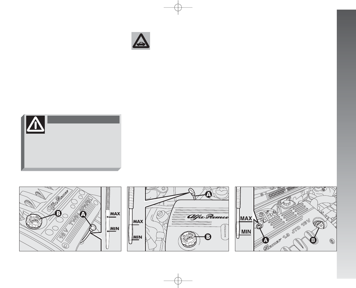
VEHICLE MAINTENANCE
241
ENGINE OIL
(fig. 5-6-7)
The engine oil should be checked with the
car on a level surface a few minutes (about
5) after the engine has been switched off.
Remove the dipstick (A), clean it, put it
back in completely, remove it and check that
the level is within the MIN and MAX
marks on the dipstick. The interval between
the MIN and MAX marks correspond to
about one litre of oil. If the oil level is near or even below the
MIN mark, add oil through the filter neck
(B), until reaching the MAX mark.
IMPORTANT If a routine check reveals
that the level is above the MAX mark, con-
tact Alfa Romeo Authorised Services to have
the correct level restored.
IMPORTANT After topping up the oil,
before checking the level again, run the en-
gine a few seconds and wait for a few min-
utes ater stopping it.
fig. 5 - T.SPARK versions
A0A0195m
Do not add oil with spec-
ifications (classification,
viscosity) other than those
of the oil already in the engine.
fig. 6 - JTDM(120HP) versions
A0A0347m
fig. 7 - JTDM(150HP) versions
A0A0398m
When the engine is hot,
take care when working
inside the engine compartment to
avoid burns. Remember that when
the engine is hot, the fan may cut
in: danger of injury.
WARNING
234-257_Alfa147 Q2 GB 4-07-2008 12:05 Pagina 241
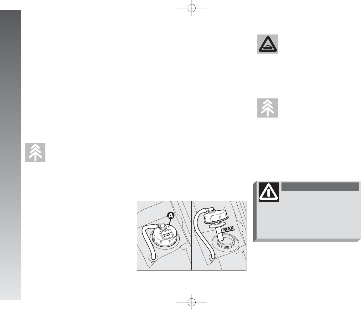
VEHICLE MAINTENANCE
242
SELESPEED GEARBOX OIL
(fig. 8)
The Selespeed transmission oil should be
checked with the car on a level surface and
with the engine stopped and cold.
To check the level, proceed as follows:
– turn the ignition key to MAR;
– disconnect the breather tube and re-
move the cap (A) checking that the level
corresponds with the MAX mark on the dip-
stick integrated with the cap;
– if the oil is below the MAX mark, top
up to reach the correct level;
– after refitting the cap, insert the breather
tube firmly on the housing on the cap and
turn the ignition to STOP.
Do not add oil with spec-
ifications other than that
already in the gearbox.
fig. 8
A0A0197m
Used gearbox oil contains
dangerous substances for
the environment. For chang-
ing the oil we advise contacting Al-
fa Romeo Authorised Services who
are equipped for disposing of used
oil respecting nature and the law.
Used engine oil and filter
contain harmful substances
for the environment. Con-
tact Alfa Romeo Authorised Ser-
vices to have the oil and the filter
changed, as they are equipped to
dispose of the waste oil and filters
respecting nature and the law.
Be very careful working in-
side the engine compart-
ment if the engine is hot: danger of
burns. Remember that the fan may
cut in if the engine is very hot: dan-
ger of injury.
WARNING
Engine oil consumption
Max engine oil consumption is usually 400
grams every 1000 km.
During the initial period of use the engine
settles, therefore engine oil consumption
may be considered stabilised only after the
first 5000 ÷ 6000 km.
IMPORTANT Engine oil consumption de-
pends on the way of driving and the condi-
tions of use of the car.
234-257_Alfa147 Q2 GB 4-07-2008 12:05 Pagina 242
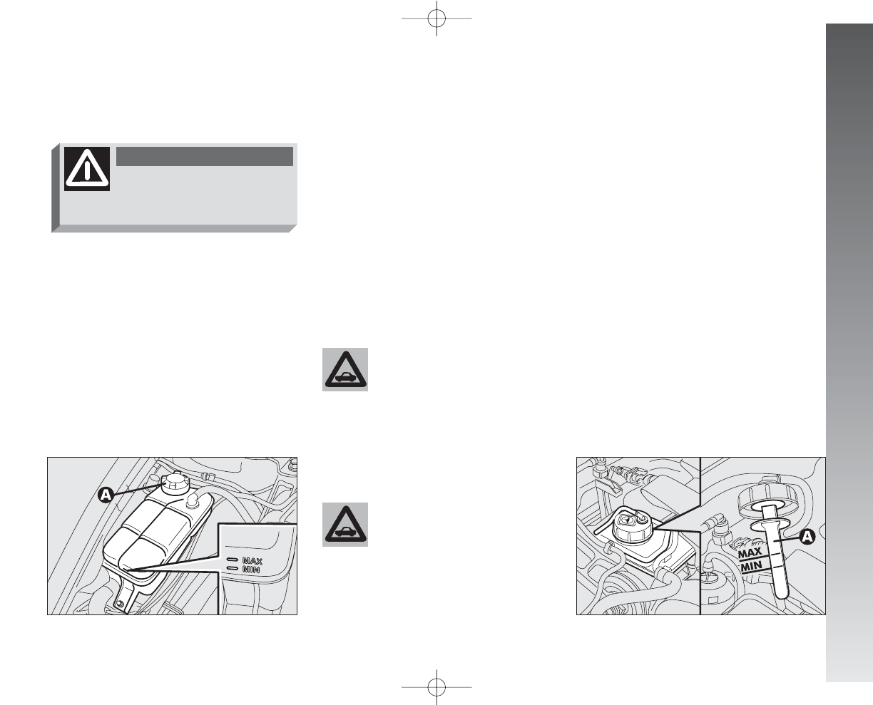
VEHICLE MAINTENANCE
243
POWER STEERING FLUID
(fig. 10-11)
Check that the level of the oil in the reser-
voir is at maximum.
This operation should be carried out with
the car on a level surface and the engine
switched off and cold.
Check that the level reaches the MAX
mark on the reservoir or coincides with the
upper notch (maximum level) on the dip-
stick (A) integral with the reservoir cap.
The cooling system is
pressurised. If necessary,
replace the cap only with
another genuine one, otherwise
system efficiency could be compro-
mised.
fig. 10 - T.SPARK versions
A0A0216m
ENGINE COOLANT FLUID
(fig. 9)
The level of the coolant in the header tank
(reservoir) should be checked with the en-
gine cold and the car on a level surface and
it should be between the MIN and MAX
marks on the tank.
fig. 9
A0A0240m
If the level is low, loosen the header tank
cap (A) and slowly pour through the filler
the fluid specified in the “Fluids and Lubri-
cants” table in the “Technical Specifications”
chapter until nearing the MAX mark; for
this operations contact Alfa Romeo Autho-
rised Services.
The antifreeze mixture contained in the
cooling circuit guarantees protection down
to –40°C.
For particularly hard climate conditions, we
recommend use of a 60% PARAFLU UP
and 40% demineralized water mixture.
For topping up use fluids
of the same type contained
in the cooling system.
Do not remove the cap
when the engine is hot:
danger of burns.
WARNING
234-257_Alfa147 Q2 GB 4-07-2008 12:05 Pagina 243
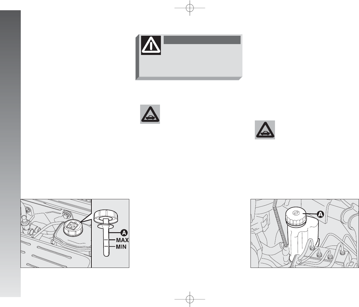
VEHICLE MAINTENANCE
244
NOTE Clean accurately the tank cap A
and the surrounding surface. When opening
the cap take the utmost care to prevent im-
purities entering the tank. When topping up,
always use a funnel with built-in filter with
mesh equal to or lower than 0.12 mm.
IMPORTANT For this operation it is
however recommended to contact Alfa
Romeo Authorised Services.
fig. 12
A0A0217m
fig. 11 - JTDMversions
A0A0400m
Make sure that the high-
ly corrosive brake fluid
does not drip onto the
paintwork. If it does, wash it off
immediately with water.
If the oil level in the reservoir is below the
specified one, top up only with one of the
products listed in the “Fluids and Lubricants”
table in the “Technical Specifications” chap-
ter proceeding as follows:
– Start the engine and wait for the oil lev-
el in the reservoir to stabilise.
– With the engine running, turn the steer-
ing wheel lock to lock a few times.
– Top up to the MAX level notch, then
refit the cap.
Oil consumption is very
low, if topping up again is
needed shortly afterwards,
have the system checked for pos-
sible leaks by Alfa Romeo Autho-
rised Services.
Do not allow the power
steering fluid to touch hot
parts of the engine: it is inflam-
mable.
WARNING
BRAKE AND HYDRAULIC
CLUTCH FLUID
(fig. 12)
Check that the fluid level in the reservoir
is at maximum. Top up with the brake flu-
id specified in the table “Fluids and lubri-
cants” (see section “Technical Specifica-
tions").
234-257_Alfa147 Q2 GB 4-07-2008 12:05 Pagina 244
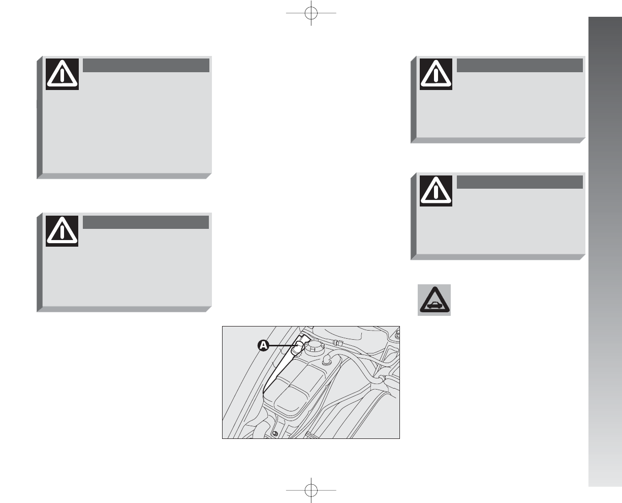
VEHICLE MAINTENANCE
245
To avoid damaging the
pump motor, do not use
the windscreen/rearscreen
washers when the reservoir is
empty.
IMPORTANT Brake and hydraulic clutch
fluid is hygroscopic (i.e. it absorbs moisture).
For this reason, if the car is mainly used in
areas with a high degree of atmospheric hu-
midity, the fluid should be replaced at more
frequent intervals than specified in the
Scheduled Maintenance Programme.
WINDSCREEN/
REARSCREEN/HEADLIGHT
WASHER FLUID
(fig. 13)
Open the cap (A) and check the level in
the reservoir.
If necessary top up using a mixture of wa-
ter and TUTELA PROFESSIONAL
SC 35 fluid as follows:
– 30% of TUTELA PROFESSIONAL
SC 35 and 70% water in summer;
– 50% of TUTELA PROFESSIONAL
SC 35 and 50% water in winter;
– in the case of temperatures below -20°C
use TUTELA PROFESSIONAL SC 35
fluid neat.
fig. 13
A0A0242m
Brake and clutch fluid is
poisonous and highly cor-
rosive. In the event of accidental
contact, wash the parts concerned
immediately with neutral soap and
water, then rinse thoroughly. See
a doctor at once if the fluid is swal-
lowed.
WARNING
The
π
, symbol on the con-
tainer indicates synthetic
brake fluid, distinguishing it from
the mineral kind. Using mineral flu-
ids irreversibly damages the spe-
cial braking system rubber seals.
WARNING
Some commercial additives
for windscreen washers
are inflammable. The engine com-
partment contains hot components
which may set it on fire.
WARNING
Do not travel with the wind-
screen/rearscreen washer
reservoir empty: the action of the
windscreen washer is fundamental
for improving vision.
WARNING
234-257_Alfa147 Q2 GB 4-07-2008 12:05 Pagina 245
VEHICLE MAINTENANCE
246
DIESEL FUEL FILTER
(diesel versions)
DRAINING CONDENSATION
WATER
The presence of water in
the supply circuit may
cause serious damage to
the entire injection system and
cause irregular running of the en-
gine. If the
c
warning light turns
on (or, on some versions, symbol +
message are shown on the recon-
figurable multifunction display)
contact Alfa Romeo Authorised
Services as soon as possible to
have the system relieved. If the
same warning appears immediate-
ly after refuelling, some water
could have been introduced in the
reservoir: in this case turn off the
engine immediately and contact Al-
fa Romeo Authorised Services.
AIR CLEANER
The air cleaner is connected to the tem-
perature and air flow sensors which send
to the control unit the electric signals need-
ed for correct operation of the injection and
ignition system.
It must therefore always be in perfect con-
ditions, to ensure correct operation of the
engine, low consumption and exhaust emis-
sion levels.
If the operations concern-
ing cleaner replacement de-
scribed below are not car-
ried out correctly and with the due
precautions, they may compromise
the travelling safety of the car. You
are recommended to have this op-
eration carried out by Alfa Romeo
Authorised Services.
If the car is habitually
used in dusty areas, the
cleaner should be replaced
at shorter intervals than those
specified in the Programmed Main-
tenance Schedule.
Any attempt to clean the
cleaner may damage it,
leading to serious engine
damage.
234-257_Alfa147 Q2 GB 4-07-2008 12:05 Pagina 246
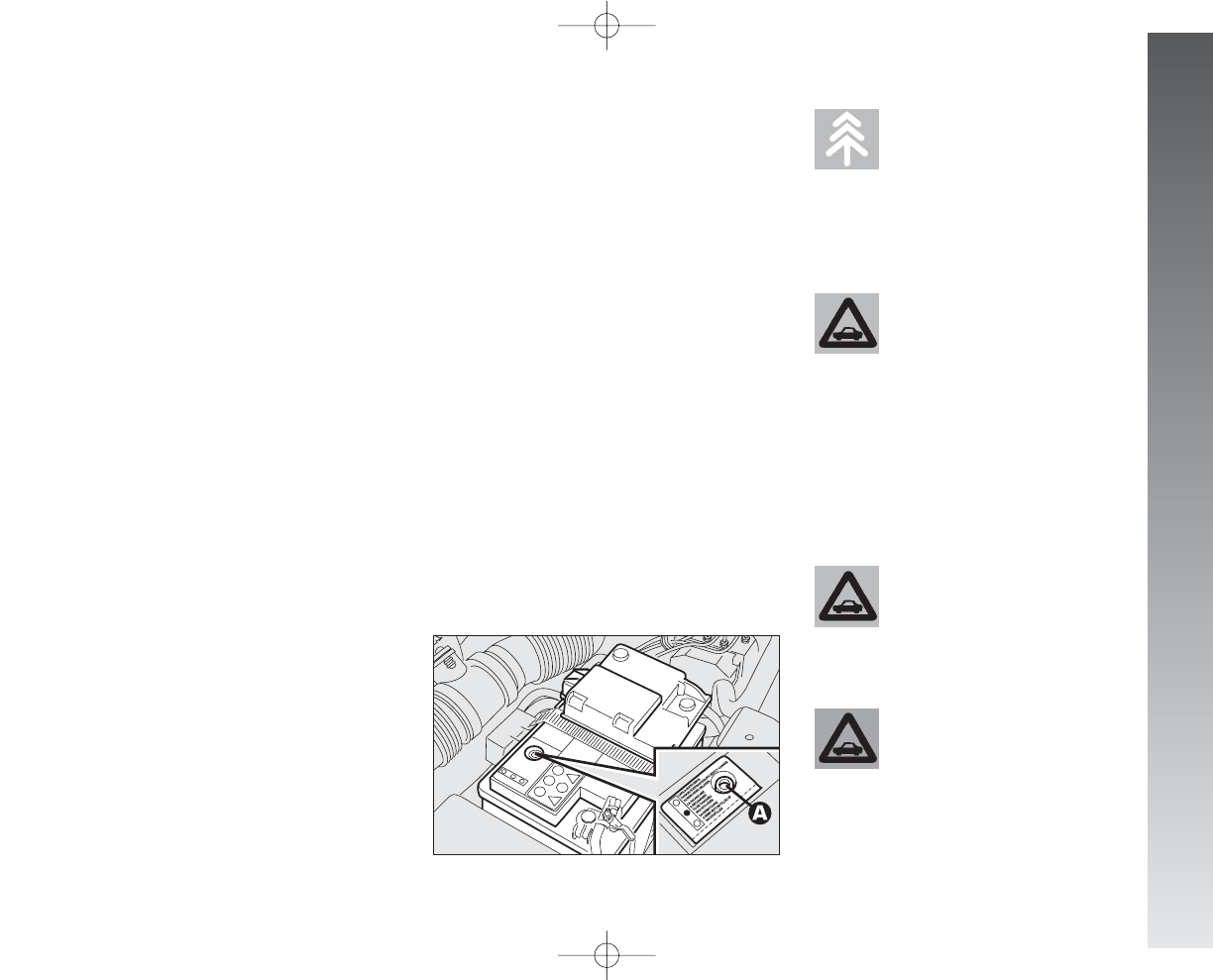
VEHICLE MAINTENANCE
247
BATTERY
The battery is of the “Limited mainte-
nance” type: under normal conditions of use
the electrolyte does not need topping up
with distilled water.
Contact Alfa Romeo Authorised Services to
have the battery checked/replaced.
fig. 14
A0A0224m
Batteries contain harmful
substances for the envi-
ronment. To change the
battery we advise contacting Alfa
Romeo Authorised Services who
are equipped for disposal respect-
ing nature and the law.
The incorrect installation
of electric accessories may
cause seiour damage to the
car. If after buying the car you wish
to install accessories (alarm, radio,
radiotelephone, etc.) contact Alfa
Romeo Authorised Services who
will be able to suggest the most
suitable devices and above all ad-
vise about the need to use a more
powerful battery.
If the car is to remain in-
active for a long time in
very cold conditions, re-
move the battery and take it to a
warm place, otherwise it may
freeze.
POLLEN FILTER
This has a mechanical/electrostatic air fil-
tering action, provided that the windows and
the doors are shut.
Have the pollen filter checked once a year
by Alfa Romeo Authorised Services, prefer-
ably at the onset of summer.
If the car is mainly used in dusty or heav-
ily polluted areas, the filter should be
changed at more frequent intervals than
ìspecified in the Scheduled Maintenance Pro-
gramme.
IMPORTANT The failure to replace the
filter can considerably reduce the effective-
ness of the climate control system.
At any battery re-
moval/refitting wait for
at least 3 minutes before
starting the enigne, to allow the
climate control unit to reset the po-
sition of the electric actuators
which control the air temperature
and distribution.
234-257_Alfa147 Q2 GB 4-07-2008 12:05 Pagina 247
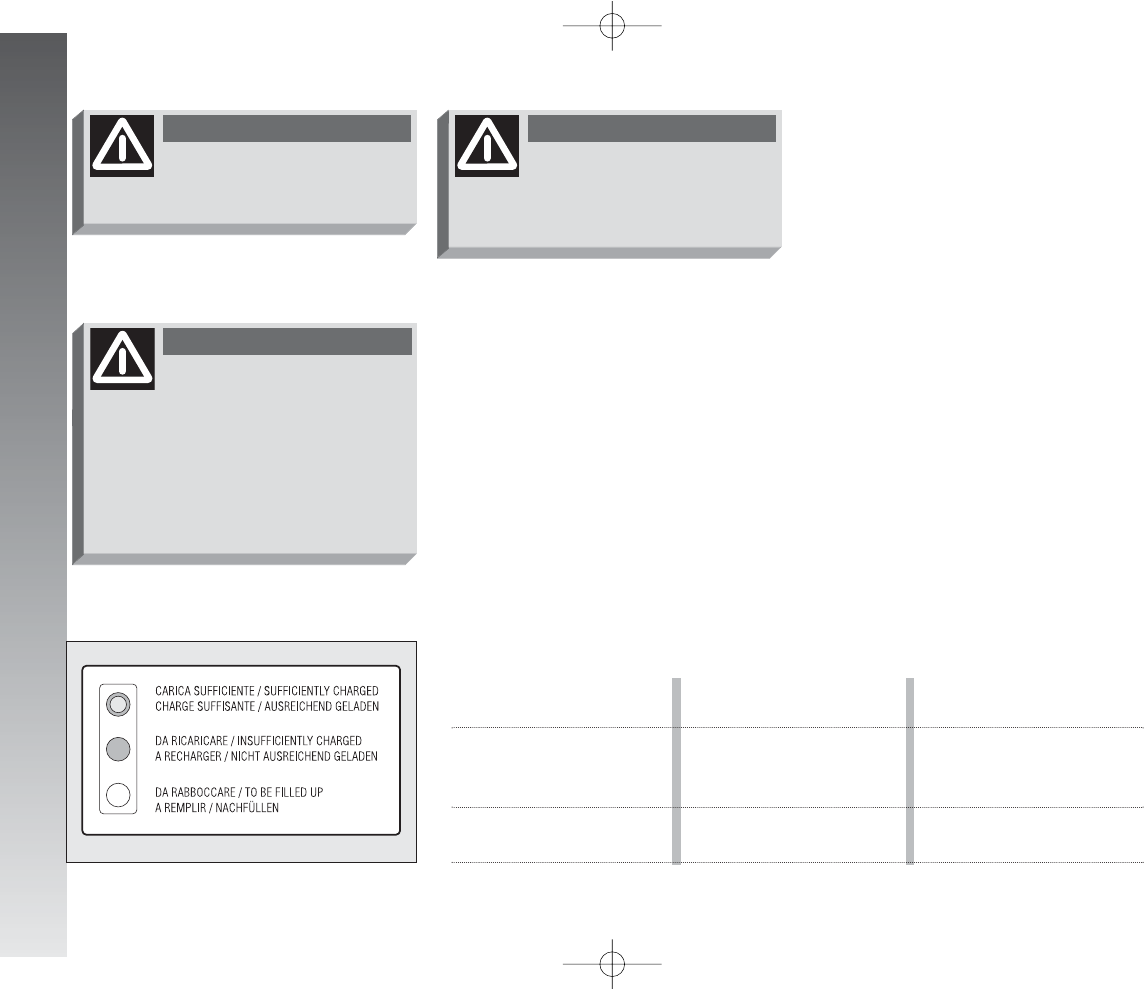
VEHICLE MAINTENANCE
248
CHARGING THE BATTERY
IMPORTANT The battery charging pro-
cedure is described only for information pur-
poses. This operation should be carried out
by Alfa Romeo Authorised Services. Charg-
ing should be slow at a low amp rating for
24 hours. Charging for a longer time may
damage the battery.
Charge the battery as follows:
– Disconnect the battery negative termi-
nal (–).
– Connect the charger cables to the bat-
tery terminal ensuring that the bias is cor-
rect.
– Turn on the charger.
– After charging, turn off the charger be-
fore disconnecting it from the battery.
– Re-connect the battery negative termi-
nal (–).
CHECKING THE CHARGE
The battery charge may be checked
through the indicator A-fig. 14 (where re-
quired) set on the battery cover and acting
according to the colour the indicator shows.
Should the battery be not fitted with bat-
tery charge inspection device (optical elec-
trolyte indicator), inspection operations shall
be carried out by skilled personnel only.
Refer to the table below or to the label
(fig. 15) on the battery itself.
Brilliant
white colour
Dark colour
without green
area in the centre
Dark colour with green
area in the centre
Top up the electrolyte
Low charge level
Sufficient electrolyte level
and charge
Contact Alfa Romeo
Authorised Services
Charge the battery
(you are advised to contact
Alfa Romeo Authorised Services)
No action
fig. 15
A0A0393m
When working on the bat-
tery or close to it, always
protect the eyes with goggles.
WARNING
The liquid contained in the
battery is poisonous and
corrosive. Avoid contact with the
skin or eyes. The battery should be
charged in a well ventilated place
away from naked flames or pos-
sible sources of sparks: danger of
explosion and fire.
WARNING
Working with a low fluid
level may damage the bat-
tery irreversibly, even causing it to
burst.
WARNING
234-257_Alfa147 Q2 GB 4-07-2008 12:05 Pagina 248
VEHICLE MAINTENANCE
249
CHANGING THE BATTERY
When changing the battery it should be re-
placed with another original one with the
same characteristics. If it is replaced by a
battery with different characteristics, the
maintenance intervals given in the Sched-
uled Maintenance Programme in this chap-
ter are no longer valid and for maintenance
it will be necessary to follow the battery
Manufacturer’s instructions.
USEFUL HINTS TO EXTEND
THE LIFE OF YOUR BATTERY
To avoid rapidly draining the battery and
ensure that it continues to work correctly,
the following should be noted:
– The terminals must always be firmly
tightened.
– Within reason, avoid using electrical de-
vices for a long time when the engine is
switched off (radio, hazard warning lights,
parking lights, etc.).
– When the car is parked in a garage, en-
sure that the doors, bonnet, boot and in-
ner lids are closed properly so that the lights
do not stay on permanently.
IMPORTANT If the battery is kept with
a charge of below 50% it is damaged by sul-
phation, its starting capability is reduced and
it is also more subject to the possibility of
freezing (this may occur already at –10
°C). In the event of a prolonged inactivity,
refer to the paragraph “car inactivity”, in the
chapter “Correct use of the car”.
– Before carrying out any work on the
electric system, disconnect the negative ca-
ble from the battery.
– If after buying the car, you wish to in-
stall electric accessories which require a per-
manent electric supply (alarm, voice feature,
radionavigator with satellite antitheft func-
tion etc.) or accessories that burden the elec-
tric system, contact Alfa Romeo Authorised
Services whose qualified personnel, in ad-
dition to suggesting the most suitable de-
vices belonging to Lineaccessori Alfa Romeo,
will evaluate the overall electric absorption,
checking whether the car’s electric system
is capable of withstanding the load required,
or whether it should be integrated with a
more powerful battery. In fact, as some of
these devices continue absorbing energy
even when the ignition key is off (car sta-
tionary, engine off), they gradually drain the
battery.
Never attempt to charge a
frozen battery: it must
firstly be thawed, otherwise it
may burst. If freezing has occurred,
the battery should be checked be-
fore charging by specialised per-
sonnel, to make sure that the in-
ternal elements are not damaged
and that the body is not cracked,
with the risk of leaking poisonous
and corrosive acid.
WARNING
234-257_Alfa147 Q2 GB 4-07-2008 12:05 Pagina 249
VEHICLE MAINTENANCE
250
– Do not check for current in the cables by
short-circuiting the ends.
– If electric welding is to be carried out on
the body, remember to disconnect the elec-
tronic control units, or remove them if the
work involves high temperatures.
You are also reminded that services with
high current absorption switched on by the
user, such as for example: baby bottle warm-
ers, vacuum cleaner, mobile phone, mini
fridge, etc., quicken the battery drain-
ing process if they are turned on with the
engine off or running at idle speed.
IMPORTANT When installing addition-
al systems on the car, bear in mind that im-
proper branches on connections of the car
wiring are dangerous, particularly if safety
devices are involved.
ELECTRONIC
CONTROL UNITS
With normal use of the car, no particular
precautions need to be taken.
In the event of work on the electric system
or emergency starting, the instructions giv-
en below must absolutely be adhered to:
– Always switch off the engine before dis-
connecting the battery from the electric sys-
tem.
– If it is necessary to charge the battery,
always disconnect it from the electric sys-
tem.
– When starting in an emergency, only
use an auxiliary battery and not a battery
charger.
– Check that the bias is correct and that
the connections between the battery and
the electric system are in efficient conditions.
– Before disconnecting or connecting the
terminals of electronic units, ensure that the
ignition key is not in the MAR position.
Battery
50 Ah
60 Ah
70 Ah
Maximum permissible
loadless absorption
30 mA
36 mA
42 mA
The maximum absorption of all the ac-
cessories (standard and fitted afterwards)
should be 0,6 mA x Ah (of the battery), as
shown in the following table:
Alterations or repairs to
the electric system carried
out incorrectly and without taking
account of the specifications of the
system, may cause operating faults
with the risk of fire.
WARNING
234-257_Alfa147 Q2 GB 4-07-2008 12:05 Pagina 250
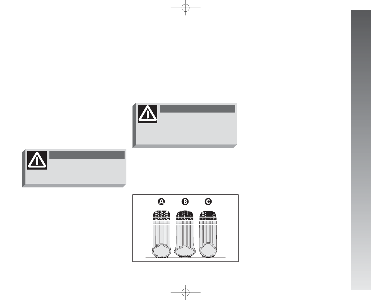
VEHICLE MAINTENANCE
251
WHEELS AND TYRES
TYRE PRESSURE
Check the tyre pressure of every wheel, in-
cluding the spare, every two weeks and be-
fore a long journey.
The pressure should be checked with the
tyre rested and cold.
It is normal for the pressure to increase
when the car is in use. For the correct tyre
inflation pressure, see “Wheels” in “Tech-
nical specifications” section.
Incorrect pressure causes abnormal tyre
wear (fig. 16):
A- Normal pressure; tread evenly worn.
B- Low pressure: tread particularly worn
at edges.
C- High pressure: tread particularly worn
in the centre.
Tyres should be changed when the tread
thickness is reduced to 1.6 mm. In any case
follow local regulations.
fig. 16
A0A0225m
WARNINGS
Where possible, avoid sudden braking, tyre
squealing starts, etc.
Particularly avoid violent bumps against
kerbs, potholes or obstacles of various kinds.
Prolonged driving on rough roads may dam-
age the tyres. Routinely check the tyres for
cuts on the sides, swelllings or uneven tread
wear. If necessary contact Alfa Romeo Au-
thorised Serrvices.
Avoid overloading the car when travelling:
this may cause serious damage to the
wheels and tyres.
If a tyre is punctured, stop immediately
and change it to avoid damage to the tyre
itself, the rim, suspensions and steering sys-
tem. Tyres age even if they are not used
much. Cracks in the tread rubber are a sign
of aging. In any case, if the tyres have been
on the car for 6 years, they should be
checked by specialised personnel, to see if
they can still be used. Also remember to
check the compact spare wheel.
In the case of replacement, always fit new
tyres, avoiding those of dubious origin.
Excessively low pressure
causes overheating of tyre
with the possibility of serious dam-
age to it.
WARNING
Remember that car road
holding also depends on
correct tyre inflation pressure.
WARNING
234-257_Alfa147 Q2 GB 4-07-2008 12:05 Pagina 251
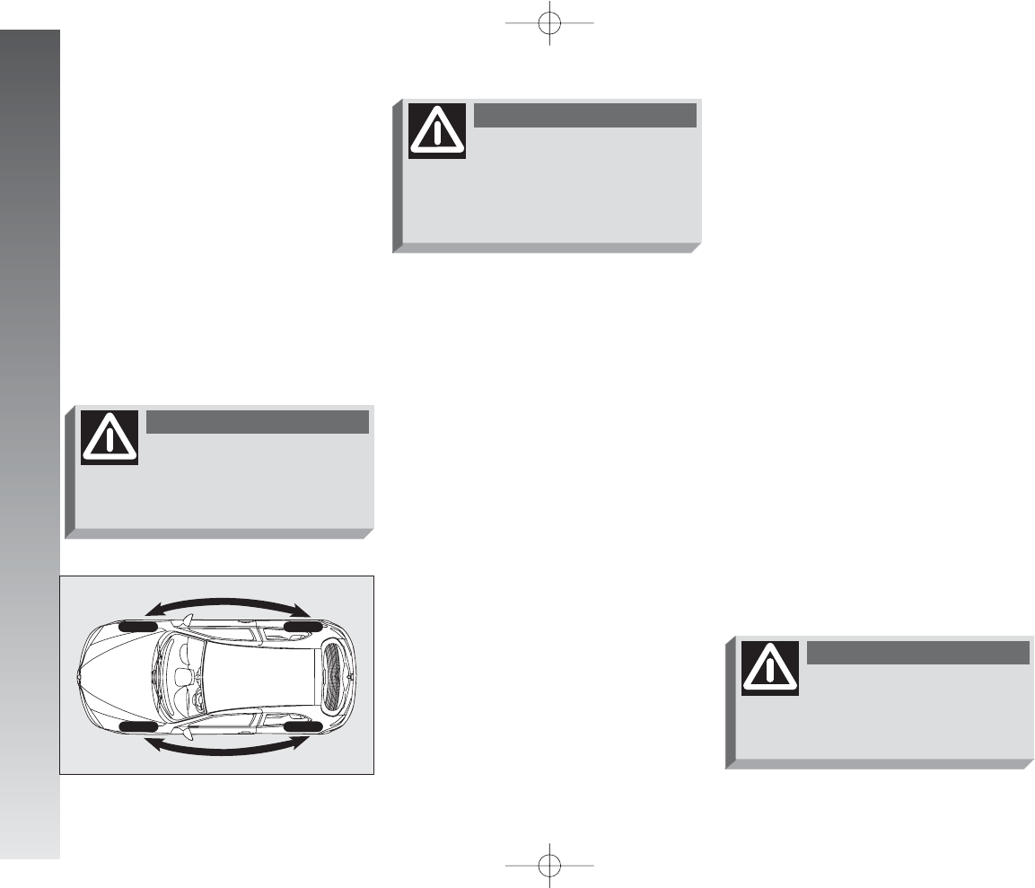
VEHICLE MAINTENANCE
252
WINDSCREEN/
REARSCREEN WIPERS
BLADES
Periodically clean the rubber part using spe-
cial products; TUTELA PROFESSIONAL
SC 35 is recommended.
If the rubber blades are bent or worn they
should be replaced. In any case they should
be changed once a year.
A few simple notions can reduce the pos-
sibility of damage to the blades:
– If the temperature falls below zero make
sure that ice has not frozen the rubber
against the glass. If necessary, thaw using
an antifreeze product.
– Remove any snow from the glass: in ad-
dition to protecting the blades, this prevents
effort on the motor and overheating.
– Do not operate the windscreen and
rearscreen wipers on dry glass.
The
Alfa 147
uses Tubeless tyres.
Never use an inner tube with these tyres.
If a tyre is changed, also change the in-
flation valve.
To allow even wear between the front and
rear tyres it is advisable to change over every
10-15 thousand kilometres, keeping them
on the same side of the car so as not to re-
verse the direction of rotation (fig. 17).
RUBBER HOSES
As far as the brake system and fuel sup-
ply rubber hoses are concerned, carefully fol-
low the Scheduled Maintenance Pro-
gramme. Indeed, ozone, high temperatures
and the prolonged lack of fluid in the sys-
tem may cause hardening and cracking of
the hoses, with possible leaks. Careful con-
trol is therefore necessary.
fig. 17
A0A1087m
Do not cross switch the
tyres, moving them from
the right of the car to the left and
vice versa.
WARNING
Alloy rim painting involv-
ing temperatures exceed-
ing 150°C should be avoided since
wheel mechanical characteristics
could be impaired.
WARNING
Driving with worn wiper
blades is a serious hazard,
because visibility is reduced in bad
weather.
WARNING
234-257_Alfa147 Q2 GB 4-07-2008 12:05 Pagina 252
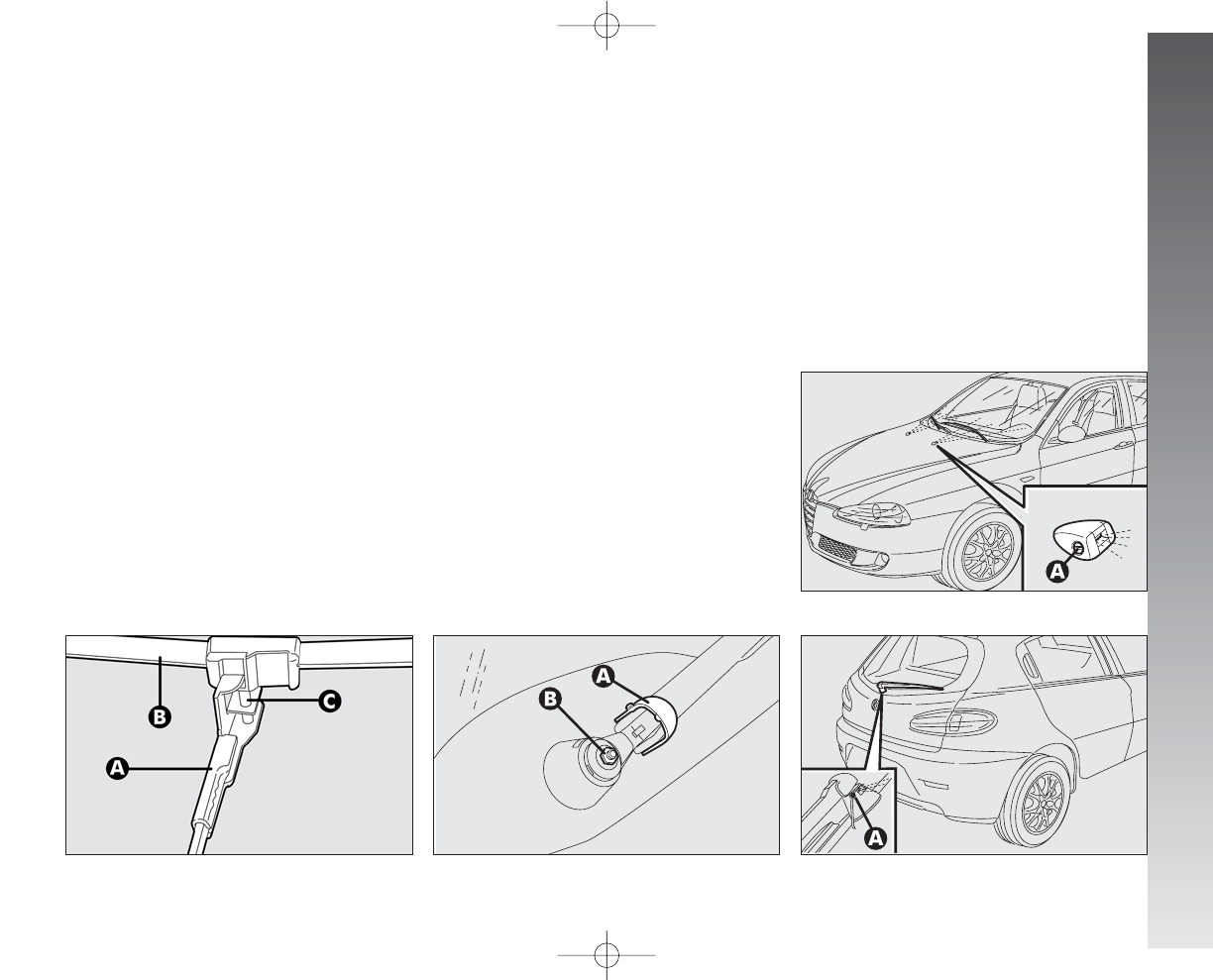
VEHICLE MAINTENANCE
253
Changing the windscreen wiper
blade (fig. 18)
Instructions to remove the blade
Proceed as follows:
– raise the windscreen wiper arm (A);
– turn the blade (B) by 90° around the
tab (C) fitted on the arm final part;
– remove the blade from the tab (C).
Instructions to fit the blade
Proceed as follows:
– fit the tab (C) in the hole on the blade
central part (B);
– refit the arm with the blade on the wind-
screen.
Changing the rearscreen blade
(fig. 19)
– Raise the cover (A) and remove the arm
from the car, slackening the nut (B) that
fastens it to the pivot pin.
– Correctly position the new arm and firm-
ly tighten the nut.
– Lower the cover.
fig. 18
A0A0728m
fig. 19
A0A0227m
SPRAY JETS
(fig. 20-21)
If the jet of fluid is inadequate, firstly check
that there is fluid in the reservoir: see
“Checking levels” in this chapter.
Then check that the nozzle holes are not
clogged, if necessary use a needle.
If necessary, direct the jet of fluid work-
ing on the adjustment screw (A).
fig. 20
A0A1088m
fig. 21
A0A1089m
234-257_Alfa147 Q2 GB 4-07-2008 12:05 Pagina 253
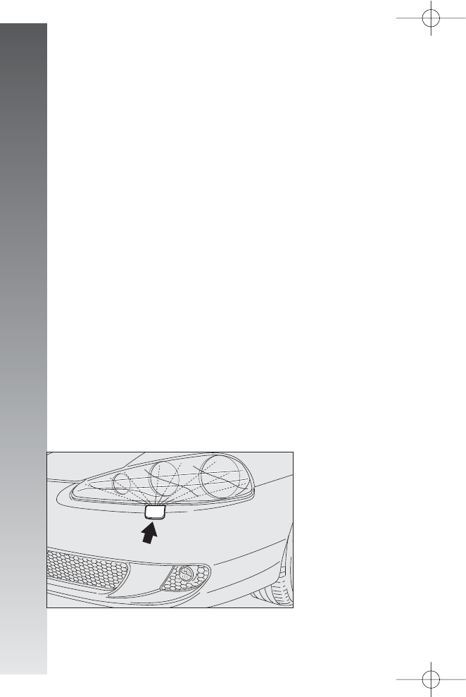
VEHICLE MAINTENANCE
254
HEADLIGHT WASHERS
Regularly check that the spray jets are in-
tact and clean (fig. 22).
If it is necessary to direct the jet, contact
an Alfa Romeo Authorised Service.
BODYWORK
PROTECTION FROM
ATMOSPHERIC AGENTS
The main causes of corrosion are:
– atmospheric pollution
– salty air and humidity (coastal areas, or
hot humid climates)
– seasonal environment conditions.
Not to be underestimated is also the abra-
sive action of wind-borne atmospheric dust
and sand and mud and gravel raised by oth-
er cars.
On your
Alfa 147
, Alfa Romeo has
implemented the best manufacturing tech-
nologies to effectively protect the bodywork
against corrosion.
fig. 22
A0A1013m
These include:
– Painting products and systems which
give the car particular resistance to corrosion
and abrasion.
– Use of galvanised (or pretreated) steel
sheets, with high resistance to corrosion.
– Spraying of the underbody, engine com-
partment, wheel arches and other parts with
highly protective wax products.
– Spraying of plastic parts, with a protec-
tive function, in the more exposed points:
underdoor, inner wheel arch linings, etc.
– Use of “open” boxed sections to pre-
vent condensation and pockets of moisture
from triggering rust inside.
CAR EXTERIOR AND
UNDERBODY WARRANTY
The
Alfa 147
is guaranteed against
perforation due to rust of any original ele-
ment of the structure or body. For the gen-
eral terms of this warranty, refer to the War-
ranty booklet.
234-257_Alfa147 Q2 GB 4-07-2008 12:05 Pagina 254
VEHICLE MAINTENANCE
255
ADVICE FOR PRESERVING
THE BODYWORK
Paint
The paintwork does not only serve an aes-
thetic purpose but also protects the underly-
ing sheet metal. In the case of deep scrapes
or scores, you are advised to have the nec-
essary touching up carried out immediately
to avoid the formation of rust. Only original
products should be used for touching up paint
(see “Body paint identification plate” in the
“Technical Specifications” chapter).
Normal paint maintenance consists in
washing at intervals depending on the con-
ditions and environment of use. For exam-
ple, in highly polluted areas, or if the roads
are sprayed with salt, it is wise to wash the
car more frequently.
When drying, take particular care with the
less visible parts like door surrounds, bon-
net and around the headlights where wa-
ter may stagnate. The car should not be tak-
en to a closed area immediately, but left in
the open so that residual water can evapo-
rate.
Do not wash the car after it has been left
in the sun or with the bonnet hot: this may
alter the shine of the paintwork.
Exterior plastic parts must be cleaned in
the same way as the rest of the car.
Where possible, do not park under trees;
the resinous substance many species release
give the paint a dull appearance and in-
crease the possibility of triggering rust
processes.
IMPORTANT Bird droppings must be
washed off immediately and thoroughly as
the acid they contain is particularly aggres-
sive.
Detergents cause water
pollution. Therefore the en-
gine compartment should
be washed in areas equipped for
collecting and purifying the liquid
used in the washing process.
To correctly wash the car:
1) Spray the car with a low pressure jet of
water.
2) Pass a sponge moistened with a light
detergent solution, rinsing the sponge fre-
quently.
3) Rinse well with water and dry with a
jet of air or chamois leather.
f the vehicle is washed in an automatic car
wash, follow these recommendations:
– remove the antenna from the roof to
avoid damages;
– water with a cleansing solution must be
used for washing;
– rinse accurately to avoid cleansing so-
lution residues which may remain on the
body or hidden parts.
Some automatic systems
provided with old genera-
tion and/or not correctly
maintained brushes may damage the
varnish, easing the creation of mi-
cro-scratches, especially on dark
colours. To remove those scratches,
slightly polish with a specific prod-
uct.
234-257_Alfa147 Q2 GB 4-07-2008 12:05 Pagina 255
VEHICLE MAINTENANCE
256
Detergents pollute water.
The car should therefore be
washed in areas equipped
for the collection and purification
of the liquid used in the washing
process.
IMPORTANT The car should be washed
with the engine cold and the ignition key at
STOP. After washing, make sure that the
various protections (e.g. rubber caps and
various covers) have not been damaged or
removed.
Windows
Use specific products to clean the windows.
Use clean cloths to avoid scratching or al-
tering the transparency of the glass.
IMPORTANT The inside of the
rearscreen should be wiped gently with a
cloth in the direction of the filaments to
avoid damaging the heating device.
Engine compartment
At the end of the winter the engine com-
partment should be carefully washed, with-
out directing the jet against electronic con-
trol units. Contact a specialised workshop to
have this done.
INTERIOR FITTINGS
Periodically check that water is not trapped
under the mats (due to water dripping off
shoes, umbrellas, etc.) which could cause
oxidisation on the sheet metal.
Never use inflammable
products like fuel oil ether
or rectified petrol for cleaning in-
side the car. The electrostatic
charges generated when rubbing to
clean may cause fire.
WARNING
CLEANING SEATS AND FABRIC
AND VELVET PARTS
– Use a soft brush or a vacuum cleaner to
remove dust. Velvet is cleaned better if the
brush is moistened.
– Rub the seat with a sponge moistened
with a solution of water and neutral deter-
gent.
CLEANING LEATHER SEATS
– Remove dried on dirt with a lightly
moistened chamois leather or cloth with-
out pressing too hard.
– Remove liquid and grease stains with
a dry absorbent cloth without rubbing. Then
wipe with a soft cloth or chamois leather
with water and neutral soap. If the stain per-
sists, use specific products, carefully follow-
ing the instructions for use.
IMPORTANT Never use spirit or alcohol-
based products, even at low concentrations.
234-257_Alfa147 Q2 GB 4-07-2008 12:05 Pagina 256
VEHICLE MAINTENANCE
257
The car upholstery can re-
sist wear resulting from
the normal use of the car.
However, it is necessary to avoid
excessive and/or prolonged fric-
tion with clothing accessories such
as metal buckles, studs, velcro and
similar material, as this friction,
acting locally and with a high pres-
sure over the knitted fabric, may
cause some threads to break and
thus damage the seat cover/lining.
Do not keep aerosol cans in
the car. They might ex-
plode. Aerosol cans must never be
exposed to a temperature above
50°C. The temperature inside the
car exposed to the sun may go well
beyond that figure.
WARNING
STEERING WHEEL/GEARBOX
LEVER KNOB COVERED WITH
TRUE LEATHER
These components must be cleaned only
with water and neutral soap. Never use spir-
it or alcohol-based products.
Before using specific products for clean-
ing interior fittings, read the instructions on
the label carefully to make sure that the
product does not contain spirit and/or al-
cohol-based substances.
If, when cleaning the windscreen with spe-
cific products for glass, some drops fall on
the leather of the steering wheel/gerabox
lever knob, it is necessary to remove them
immediately and then to wash the involved
area with water and neutral soap.
IMPORTANT It is advisable, in the event
of steering wheel locking device, to operate
with great care to avoid damaging the cov-
ering leather.
INTERIOR PLASTIC PARTS
Use appropriate products designed to pre-
serve the appearance of components.
IMPORTANT Never use spirit or petro-
leum to clean the instrument cluster.
234-257_Alfa147 Q2 GB 4-07-2008 12:05 Pagina 257
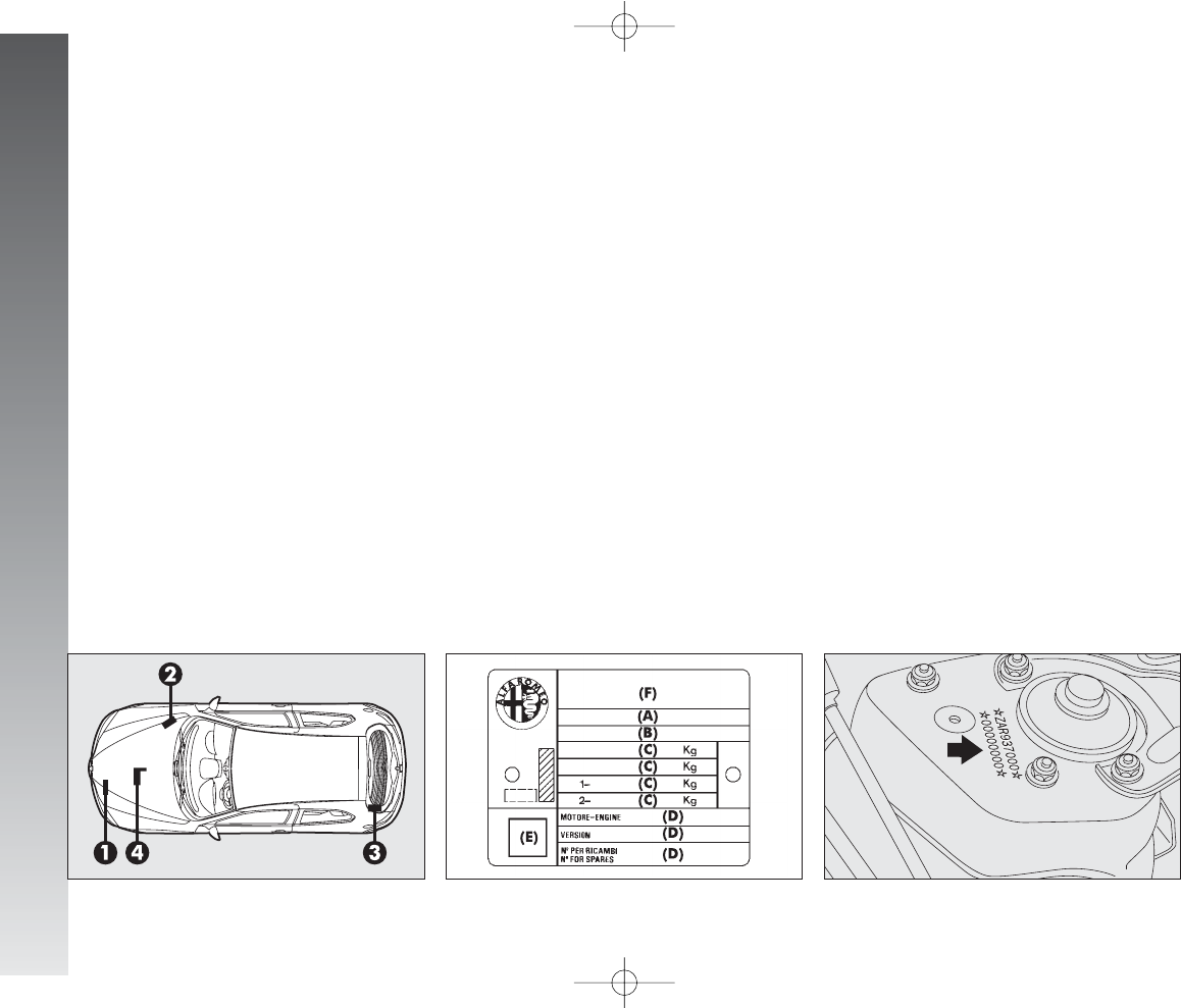
TECHNICAL SPECIFICATIONS
258
IDENTIFICATION LABEL
This (fig. 2) is to be found on the front
crossmember of the engine compartment.
It contains the following information:
(A)Space for details of national ho-
mologation
(B)Space for punching the consecutive
chassis number
(C)Space available for maximum
weights authorised by various na-
tional regulations
(D)Space for version and any supple-
mentary indications to those speci-
fied
(E)Space for smoke coefficient (JTDM
versions)
(F)Space for punching manufacturer’s
name.
BODYWORK LABEL
This is located in the engine bay, to one
side of the upper right shock absorber
(fig. 3) and contains:
– Type of vehicle: ZAR 937000
– Manufacturer’s serial number (chassis
number).
IDENTIFICATION DATA
You are advised to note the identification
codes. The identification datastamped and
given on the labels and their position are
the following (fig. 1):
1- Identification label
2- Body label
3- Bodywork paint identification label
4- Engine label.
T
TE
EC
CH
HN
NI
IC
CA
AL
LS
SP
PE
EC
CI
IF
FI
IC
CA
AT
TI
IO
ON
NS
S
fig. 1
A0A1090m
fig. 2
A0A0246m
fig. 3
A0A0247m
258-277_Alfa147 Q2 GB 4-07-2008 12:06 Pagina 258
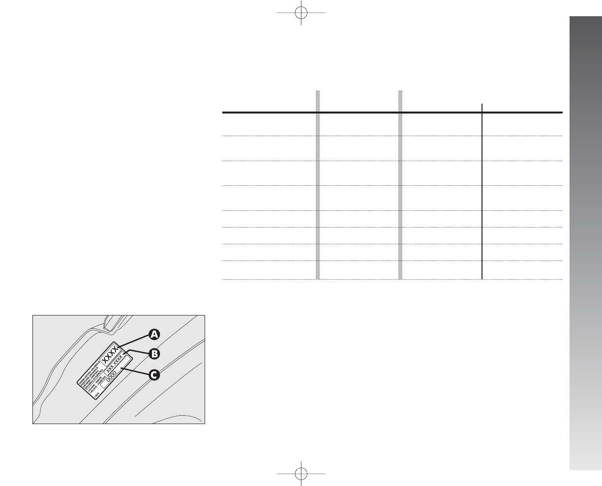
TECHNICAL SPECIFICATIONS
259
BODYWORK PAINT
IDENTIFICATION LABEL
The label (fig. 4) is on the inner left edge
of the tailgate. It contains the following in-
formation:
A. Paint manufacturer.
B. Name of colour.
C. Colour code.
ENGINE STAMP
Theengine marking is stamped on the gear-
box side of the crankcase, in correspondence
with the exhaust manifold.
ENGINE CODES - BODY VERSIONS
fig. 4
A0A0248m
1.6 T.SPARK (105HP)
1.6 T.SPARK (120HP)
2.0 T.SPARK
2.0 T.SPARK Selespeed
JTD
M
(120HP)
JTD
M
(115HP)
JTD
M
(150HP)
JTD
M
(136HP)
(*) For specific markets
3 doors
937AXA1A 00G
937AXA1A 00H (*)
937AXB1A 01G
937AXB1A 01H (*)
937AXC1A 03G
937AXC1A 03E (*)
937AXC11 02G
937AXC11 02H (*)
937AXU1A 32B
937AXV1A 34 (*)
937AXN1B 30C
937AXS1B 27C (*)
5 doors
937BXA1A 05G
937BXA1A 05H (*)
937BXB1A 06G
937BXB1A 06H (*)
937BXC1A 09G
937BXC1A 09H (*)
937BXC11 07G
937BXC11 07H (*)
937BXU1A 33B
937BXV1A 35 (*)
937BXN1B 31C
937BXS1B 28C (*)
Code type
AR37203
AR32104
AR32103 (*)
AR32310
AR32310
937A3000
939A7000 (*)
937A5000
192B1000 (*)
Body version
258-277_Alfa147 Q2 GB 4-07-2008 12:06 Pagina 259
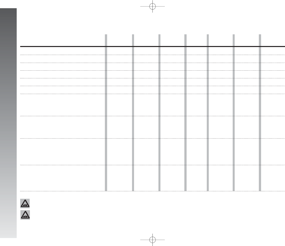
TECHNICAL SPECIFICATIONS
260
ENGINE
Code type
Cycle
Number and position of cylinders
Piston bore and stroke mm
Total displacement cm3
Compression ratio
Maximum horsepower (EEC):
kW
HP
at rpm
Maximum torque (EEC):
Nm
kgm
at rpm
Spark plugs (*)
Fuel
1.6 T.SPARK
(105HP)
AR37203
Otto
4 in line
82 x 75.65
1598
10.3
77
105
5600
140
14.3
4200
NGK
BKUR6ETB
(central)
NGK CR7EKC
(side)
Unleaded pre-
mium petrol
95 RON
(Specification
EN228)
1.6 T.SPARK
(120HP)
AR32104
Otto
4 in line
82 x 75.65
1598
10.3
88
120
6200
146
14.9
4200
NGK
BKR6EKPA
(central)
NGK PMR7A
(Side)
Unleaded pre-
mium petrol
95 RON
(Specification
EN228)
2.0 T.SPARK
AR32310
Otto
4 in line
83 x 91
1970
10.0
110
150
6300
181
18.5
3800
NGK
BKR6EKPA
(central)
NGK PMR7A
(side)
Unleaded pre-
mium petrol
95 RON
(Specification
EN228)
JTDM
(120HP)
937A3000
Diesel
4 in line
82 x 90.4
1910
18
88
120
4000
280
28.5
2000
–
Diesel fuel
for motor
vehicles
(Specification
EN590)
JTDM
(150HP)
937A5000
Diesel
4 in line
82 x 90.4
1910
17.5
110
150
4000
305
31
2000
–
Diesel fuel
for motor
vehicles
(Specification
EN590)
JTDM
(115HP) (**)
939A7000
Diesel
4 in line
82 x 90.4
1910
18
85
115
4000
280
28.5
2000
–
Diesel fuel
for motor
vehicles
(Specification
EN590)
JTDM
(136HP) (**)
192B1000
Diesel
4 in line
82 x 90.4
1910
17.5
100
136
4000
305
31
2000
–
Diesel fuel
for motor
vehicles
(Specification
EN590)
(*) There are two different spark plugs for each cylinder, one per type (**) Version for specific markets
To change plugs contact Alfa Romeo Authorized Services.
The use of Eurodiesel fuel is recommended only for markets/versions where required. In case it is not avail-
able, use fuel conforming to EN590 European Specification.
258-277_Alfa147 Q2 GB 4-07-2008 12:06 Pagina 260
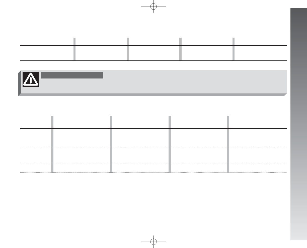
TECHNICAL SPECIFICATIONS
261
FUEL SUPPLY
JTDM
(136HP-150HP)
Five forward gears plus reverse all
synchronised
Dry single disk with hydraulic
control
Front
TRANSMISSION
Gearbox
Clutch
Drive
Alterations or repairs to the fuel supply system carried out incorrectly and
without taking account of the technical features of the system, may cause op-
erating faults with the risk of fire.
WARNING
Supply
2.0 T.SPARK
Multi Point electric injection
2.0 T.SPARK Selespeed
Five forward gears plus reverse
with electronic control
Dry single disk with
electrohydraulic control
Front
1.6 T.SPARK (105HP)
Multi Point electric injection
1.6 T.SPARK (120HP)
Multi Point electric injection
JTDM
Multijet direct injection
with supercharging
1.6 T.SPARK (105HP-120HP)
2.0 T.SPARK
Five forward gears plus reverse
with synchronisers for forward
speeds
Dry single disk with hydraulic
control
Front
JTDM(120HP)
Six forward gears plus reverse all
synchronised
Dry single disk with hydraulic
Front
FRONT WHEEL DRIVE WITH SELF-LOCKING DIFFERENTIAL
(optional for versions/markets where applicable)
Alfa Q2 characteristics are such as to guarantee top performance with whatever road condition. Alfa Q2 features front wheel drive with front mechanical
self-locking differential LSD (Limited Slip Differential). Torque level between right and left wheel is modulated according to the TORSEN B front differential
grip. Mechanical modulation is continuous and gradual thus optimizing drive under whatever running condition and guaranteeing smooth drive, high stability
and keeping top comfort conditions. This type of differential enables to exploit the tyre-road grip at the best even under poor grip conditions: the driver is how-
ever charged with observing common safety rules since road safety is always the driver's responsibility.
258-277_Alfa147 Q2 GB 4-07-2008 12:06 Pagina 261
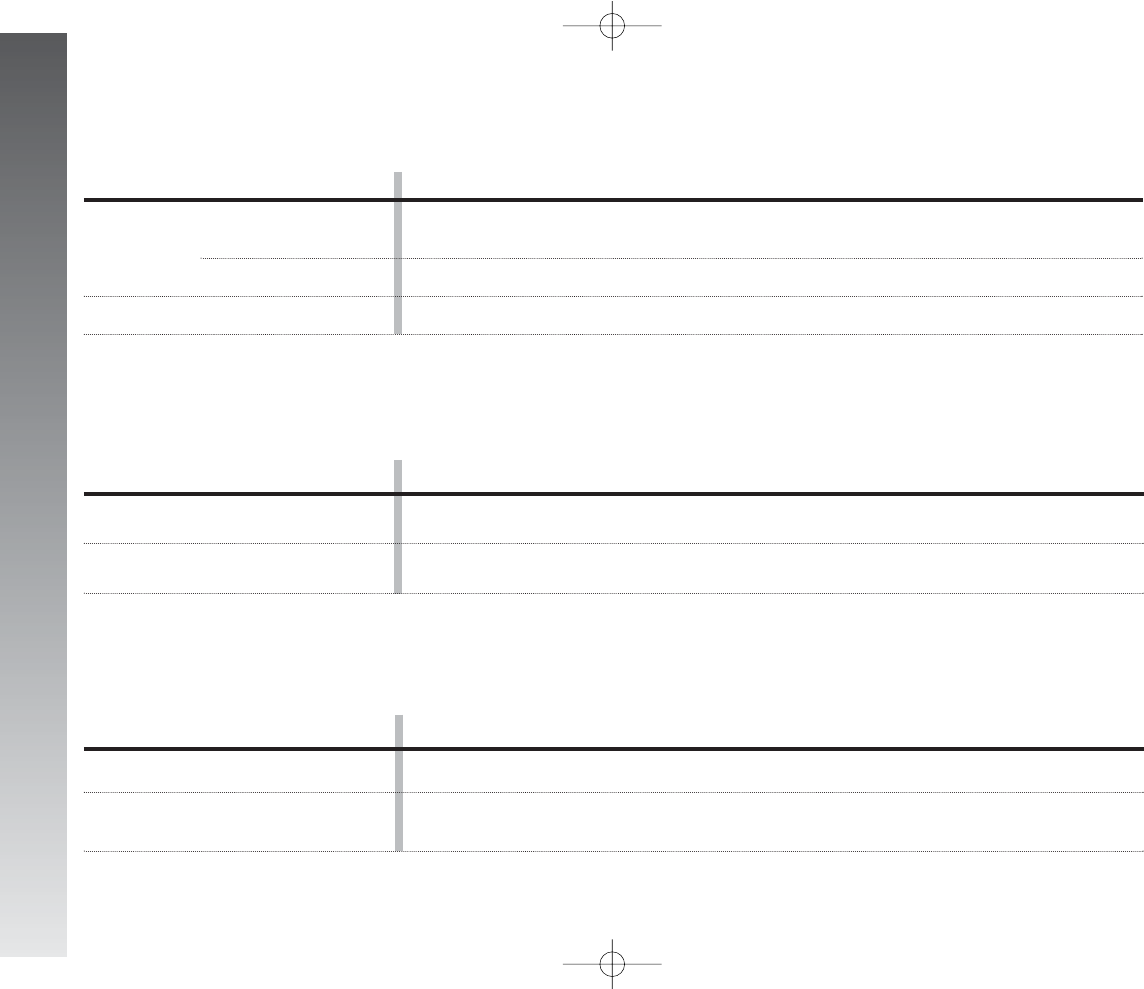
TECHNICAL SPECIFICATIONS
262
Service brakes:
– front
– rear
Parking brake
BRAKES
Front
Rear
Type
Turning radius
(between pavements) m
1.6 T.SPARK (105HP-120HP) - 2.0 T.SPARK -
JTDM
rack and pinion with hydraulic power steering
11.5
SUSPENSION
STEERING SYSTEM
1.6 T.SPARK (105HP-120HP) - 2.0 T.SPARK -
JTDM
Disk
Disk
Controlled by hand lever, acting on the rear brakes
1.6 T.SPARK (105HP-120HP) - 2.0 T.SPARK -
JTDM
quadrilateral system with stabiliser bar
Mc Pherson type
258-277_Alfa147 Q2 GB 4-07-2008 12:06 Pagina 262

2.0 T.SPARK -
2.0 T.SPARK Selespeed -
JTDM
DISTINCTIVE
6.5J x 16” (alloy)
205/55 R16” 91V
(
6
)
205/55 R16” 91W
(
6
)
4J x 15”
125/80 R15” 95M
6.5J x 15” (alloy)
7J x 17” (alloy)
195/60 R15” 88V
215/45 R17” 87W
(
•
)
205/55 R16” 91T (M+S)
215/45 R17” 87H (M+S)
Tyres
215/45 R17”
front rear
2.4 2.3
2.7 2.6
Tyres
195/60 R15”
front rear
2.2 2.2
2.5 2.5
Compact spare
wheel
125/80 R15”
4.2
Tyres
185/65 R15”
front rear
2.2 2.2
2.5 2.5
Tyres
205/55 R16”
front rear
2.3 2.3
2.6 2.6
Tyres
215/40 ZR18”
Reinforced
front rear
2.4 2.4
2.7 2.7
TECHNICAL SPECIFICATIONS
263
1.6 T.SPARK DISTINCTIVE
(105HP - 120HP)
-
JTDM
DISTINCTIVE
6.5J x 15” (alloy)
195/60 R15” 88V
4J x 15”
125/80 R15” 95M
6.5J x 16” (alloy)
7J x 17” (alloy)
205/55 R16” 91V
(
•
)
215/45 R17” 87W
(
•
)
195/60 R15” 88Q (M+S)
205/55 R16” 91T (M+S)
(
•
) Unchainable tyres - (
6
) Alternative tyres. Unchainable tyres
TYRE INFLATION PRESSURES COLD (bar)
With the tyre hot the inflating pressure should be +0.3 bar compared with the specified rating
With winter tyres the inflation pressure should be +0.2 bar compared with the specified rating
Inflate tyres to full load pressures if driving at continuous speed exceeding 160 km/h.
For versions/markets
where applicable
7J x 17” (alloy)
215/45 R17” 87W
(
•
)
4J x 15”
125/80 R15” 95M
7J x 18” (alloy)
215/40 ZR18” 89W
(
•
)
Reinforced
215/45 R17” 87H (M+S)
reduced load
full loadr
WHEELS
1.6 T.SPARK IMPRESSION - PROGRESSION
(105HP - 120HP) -
JTDM
IMPRESSION -
PROGRESSION(120 HP) -
JTDM
PROGRESSION
6J x 15” (steel)
185/65 R15” 88H
4J x 15”
125/80 R15” 95M
6.5J x 15” (alloy)
6.5J x 16” (alloy)
7J x 17” (alloy)
195/60 R15” 88V
205/55 R16” 91V
(
•
)
215/45 R17” 87W
(
•
)
185/65 R15” 88Q (M+S)
205/55 R16” 91T (M+S)
Standard fittings
Rims
Tyres
Compact – rim
spare wheel: – tyre
Optional items
Rims
Tyres
Winter tyres
258-277_Alfa147 Q2 GB 4-07-2008 12:06 Pagina 263
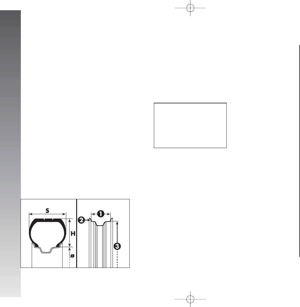
TECHNICAL SPECIFICATIONS
264
RIMS AND TYRES
Pressed steel or alloy rims.
Radial tubeless tyres.
The log book shows all the homologated
tyres.
IMPORTANT In the event of any dis-
crepancies between this Handbook and the
car Log Book, only the latter should be con-
sidered.
While the specified dimensions remain the
same, for driving safety, the car must be fit-
ted with tyres of the same brand and type
on all wheels.
IMPORTANT Do not use inner tubes
with Tubeless tyres.
CORRECT TYRE READING
(fig. 5)
Below, please find the instructions need-
ed to understand the meaning of the code
stamped on the tyre.
The code may be in one of the ways giv-
en in the example.
Load index (capacity)
60 = 250 kg
61 = 257 kg
62 = 265 kg
63 = 272 kg
64 = 280 kg
65 = 290 kg
66 = 300 kg
67 = 307 kg
68 = 315 kg
69 = 325 kg
70 = 335 kg
71 = 345 kg
72 = 355 kg
73 = 365 kg
74 = 375 kg
75 = 387 kg
76 = 400 kg
77 = 412 kg
78 = 425 kg
79 = 437 kg
80 = 450 kg
81 = 462 kg
82 = 475 kg
83 = 487 kg
84 = 500 kg
85 = 515 kg
86 = 530 kg
87 = 545 kg
88 = 560 kg
89 = 580 kg
90 = 600 kg
91 = 615 kg
92 = 630 kg
93 = 650 kg
94 = 670 kg
95 = 690 kg
96 = 710 kg
97 = 730 kg
98 = 750 kg
99 = 775 kg
100 = 800 kg
101 = 825 kg
102 = 850 kg
103 = 875 kg
104 = 900 kg
105 = 925 kg
106 = 950 kg
Example:
205/55 R 16 91 W
or
205/55 ZR 16
205 = Nominal width (S, distance in mm
between sides).
55 = Percentage height/width (H/S)
ratio.
R= Radial tyre.
ZR = Radial tyre, with speed over 240
km/h.
16 = Rim diameter in inches (Ø).
91 = Load index (capacity), e.g. 91 =
615 kg. Not present in ZR tyres.
W,Z= Maximum speed index. In ZR tyres
the speed index Z is before the R.
fig. 5
A0A0718m
258-277_Alfa147 Q2 GB 4-07-2008 12:06 Pagina 264

TECHNICAL SPECIFICATIONS
265
Maximum speed index
Q= up to 160 km/h.
R= up to 170 km/h
S= up to 180 km/h.
T= up to 190 km/h.
U= up to 200 km/h.
H= up to 210 km/h.
V= over 210 km/h.
ZR = over 240 km/h.
W= up to 270 km/h.
Y= up to 300 km/h.
Maximum speed index
for snow tyres
Q M +S= up to 160 km/h.
T M +S= up to 190 km/h.
H M +S= up to 210 km/h.
COMPACT SPARE WHEEL
Pressed steel rim.
Tubeless tyre.
For specific markets normally-sized spare
wheel.
CORRECT RIM READING
Below, please find the instructions need-
ed to understand the meaning of the code
stamped on the rim, as shown in (fig. 5).
Example:
6.5 J x 16 H2 ET 43
6.5 = rim width in inches (1)
J= rim drop centre outline (side pro-
jection where the tyre bead rests)
(2)
16 = rim nominal diameter in inches
(corresponds to diameter of the
tyre to be mounted) (3=ø)
H2 = “hump” shape and number (relief
on the circumference holding the
Tubeless tyre bead on the rim).
ET 43 = camber angle (distance between
disk/rim line and wheel rim cen-
tre line)
258-277_Alfa147 Q2 GB 4-07-2008 12:06 Pagina 265
TECHNICAL SPECIFICATIONS
266
All versions
–0° 48’ ± 20’
+ 3° 55’ ± 30’
– 1 ± 0.6 mm (*)
(– 9 ± 5’)
– 44’ ± 20’
+ 3 ± 1 mm
(+ 27’ ± 9’)
Maximum speed
km/h
185
195
208
208
193
208
PERFORMANCE
1.6 T.SPARK (105HP)
1.6 T.SPARK (120HP)
2.0 T.SPARK
2.0 T.SPARK Selespeed
JTD
M
(120HP)
JTD
M
(150HP)
WHEEL GEOMETRY
– camber
Front wheels: – caster
– toe-in
Rear wheels:
– camber
– toe-in
(*) The toe-in values, conversion from ‘ to mm, is calculated considering a 15” rim, regardless of the rims actually used; if it is not possible to fit a 15” rim
on the check stand, make reference to the value in. Also remember that the tow-in value including tolerance must be equally subdivided between the two
wheels.
Acceleration
from 0-100 km/h
sec.
11.3
10.6
9.3
9.3
9.6
8.8
Kilometer with standing start
sec.
33
31.8
30.2
30.2
32.2
30.0
258-277_Alfa147 Q2 GB 4-07-2008 12:06 Pagina 266
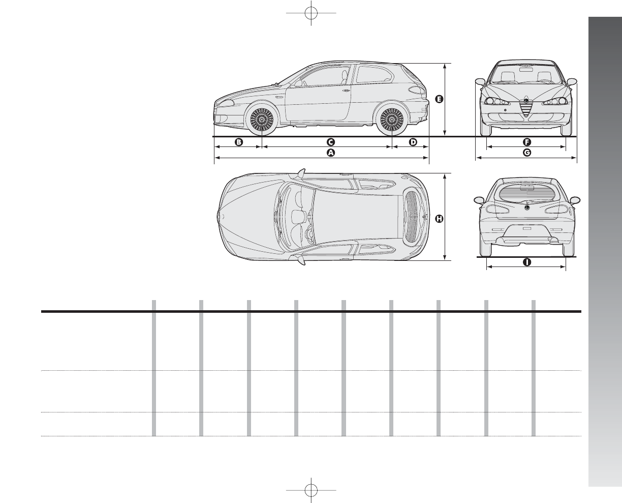
TECHNICAL SPECIFICATIONS
267
DIMENSIONS
fig. 6
A0A1091m
3-door versions A B C D E F G H I
1.6 T.SPARK IMPRESSION -
PROGRESSION
(105HP - 120HP) - JTD
M
IMPRESSION - PROGRESSION
4223 946 2546 731 1442 (
●
) 1518 (
●
) 1892 1729 1502 (
●
)
(120HP) -
JTD
M
PROGRESSION
1.6 T.SPARK DISTINCTIVE
(105HP - 120HP) -
JTD
M
DISTINCTIVE - 4223 946 2546 731 1442 (
■
) 1509 (
■
) 1892 1729 1494 (
■
)
JTD
M
DISTINCTIVE
2.0 T.SPARK -
2.0 T.SPARK Selespeed 4223 946 2546 731 1421 (
▲
) 1509 (
▲
) 1892 1729 1494 (
▲
)
LThe sizes are
in mm and
refer to the car fitted with
standard tyres.
Slight changes with
optional tyres.
Height with
unladen car.
(
●
) With 185/65 R15” tyres (
■
) With 195/60 R15” tyres (
▲
) With 205/55 R16” tyres
LUGGAGE COMPARTMENT
VOLUME
Capacity ................................... 292 dm3
Capacity with rear seat
back rest folded ........................ 1042 dm3
258-277_Alfa147 Q2 GB 4-07-2008 12:06 Pagina 267
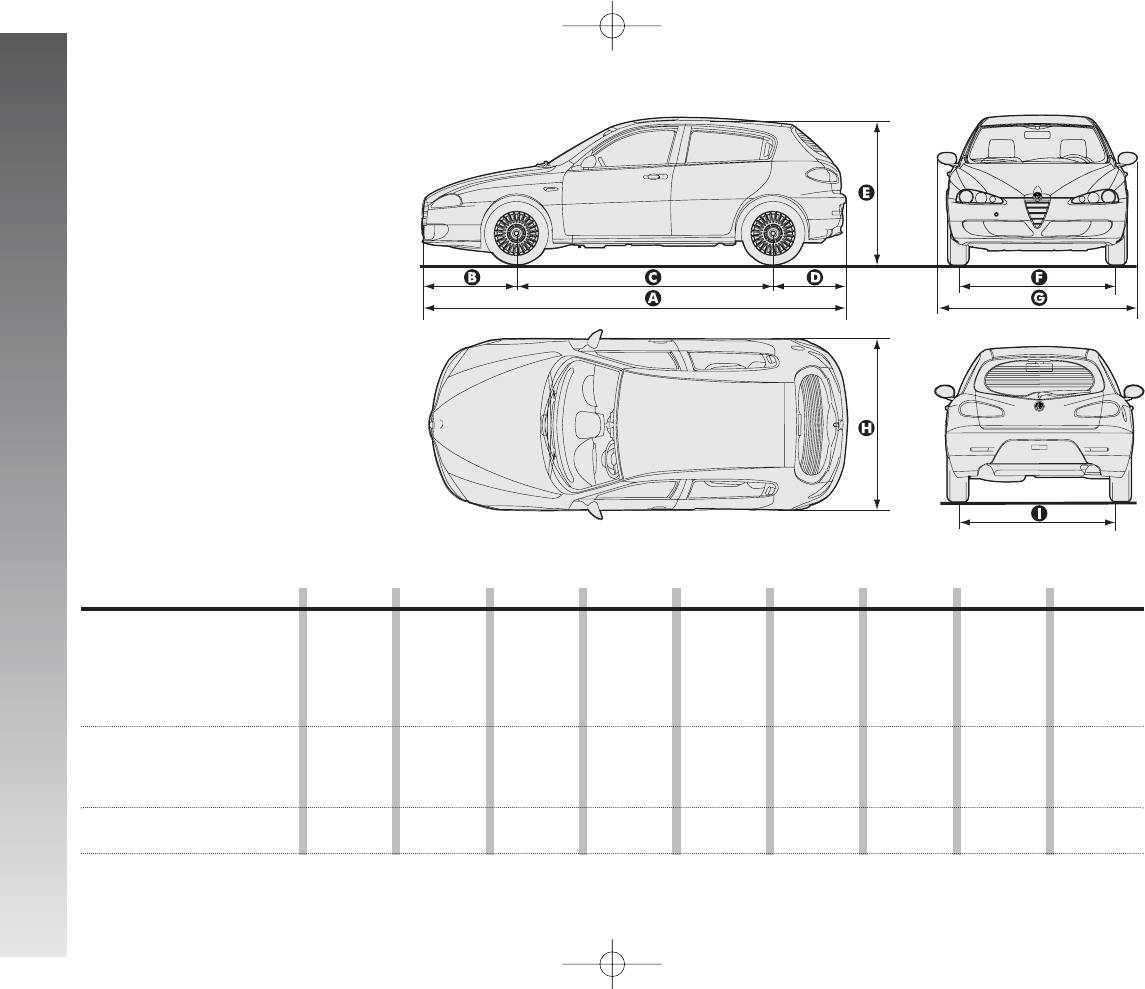
TECHNICAL SPECIFICATIONS
268
fig. 7
The sizes are
in mm and
refer to the car fitted with
standard tyres.
Slight changes with
optional tyres.
Height with
unladen car.
A0A1092m
LUGGAGE COMPARTMENT
VOLUME
Capacity ................................... 292 dm3
Capacity with rear seat
back rest folded ........................ 1042 dm3
5-door versions A B C D E F G H I
1.6 T.SPARK IMPRESSION -
PROGRESSION
(105HP - 120HP) - JTD
M
IMPRESSION - PROGRESSION
4223 946 2546 731 1442 (
●
) 1518 (
●
) 1892 1729 1502 (
●
)
(120HP) -
JTD
M
PROGRESSION
1.6 T.SPARK DISTINCTIVE
(105HP - 120HP) -
JTD
M
DISTINCTIVE - 4223 946 2546 731 1442 (
■
) 1509 (
■
) 1892 1729 1494 (
■
)
JTD
M
DISTINCTIVE
2.0 T.SPARK -
2.0 T.SPARK Selespeed 4223 946 2546 731 1421 (
▲
) 1509 (
▲
) 1892 1729 1494 (
▲
)
(
●
) With 185/65 R15” tyres (
■
) With 195/60 R15” tyres (
▲
) With 205/55 R16” tyres
258-277_Alfa147 Q2 GB 4-07-2008 12:06 Pagina 268
TECHNICAL SPECIFICATIONS
269
WEIGHTS
Kerb weight
(with fuel oil and fluids,
spare wheel, tools
and accessories) kg
Payload (*) including
driver kg
Max permissible
weights(**):
– front axle kg
– rear axle kg
– total kg
Towable weights:
– braked trailer kg
– trailer without brake kg
Maximum load on roof kg
Maximum load on ball
(braked trailer) kg
JTD
M
(136HP-150HP)
3 doors 5 doors
1290 1310
520 520
990 990
980 980
1810 1830
1300 1300
400 400
50 50
60 60
1.6 T.SPARK
(105HP)
3 doors 5 doors
1190 1210
520 520
980 980
980 980
1710 1730
1300 1300
400 400
50 50
60 60
(*) With special equipment (sunroof, trailer towing device, etc.) the loadless weight increases, thereby reducing the payload, with regard to the maximum
permissible loads.
IMPORTANT If only the luggage compartment is used for storing the goods, the maximum load in the compartment must not exceed 350 kg in the load
condition with just one person onboard.
(**)Loads not to be exceeded. It is the driver’s responsibility to place goods in the boot and/or on the loading surface in accordance with the maximum per-
missible loads.
1.6 T.SPARK
(120HP)
3 doors 5 doors
1200 1220
520 520
980 980
980 980
1720 1740
1300 1300
400 400
50 50
60 60
2.0 T.SPARK
3 doors 5 doors
1250 1270
520 520
980 980
980 980
1770 1790
1300 1300
400 400
50 50
60 60
2.0 T.SPARK
Selespeed
3 doors 5 doors
1250 1270
520 520
980 980
980 980
1770 1790
1300 1300
400 400
50 50
60 60
JTD
M
(120HP)
3 doors 5 doors
1270 1290
520 520
980 980
980 980
1790 1810
1300 1300
400 400
50 50
60 60
258-277_Alfa147 Q2 GB 4-07-2008 12:06 Pagina 269
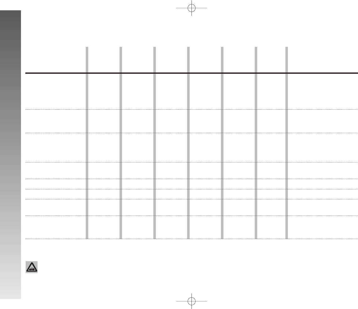
TECHNICAL SPECIFICATIONS
270
REFILLING
1.6 T.SPARK
(105HP)
60
●
7
●
6.8
4.4
■
2.01
–
1.2
0.52
3.2
6.4
2.0 T.SPARK
Selespeed
60
●
7
●
7,2
4.4
❍
2.01
0.6
1.2
0.5
3.2
6.4
JTDM
(120HP)
60
❍
7
❍
7.2
4.4
❑
2.01
–
1.2
0.52
3.2
6.4
JTDM
(136HP -
150HP)
60
❍
7
❍
7.2
4.5
❑
2.1
–
1.2
0.52
3.2
6.4
Fuel tank: litres
– including a reserve of litres
Engine cooling
system litres
Oil sump and filter litres
Mechanical transmission/
differential litres
Selespeed transmission
Hydraulic power steering litres
Hydraulic brake circuit
with ABS litres
Windscreen and rearscreen
washer reservoir: litres
– with headlamp washer litres
Specified fuels
and original lubricants
●
Unleaded Premium petrol with
no less than 95 R.O.N
(Specification EN228)
❍
Diesel fuel for motor vehicles
(Specification EN228)
Mixture of distilled water and
PARAFLU UP at 50% (▲)
■
SELENIA 20K for Alfa Romeo
❍
SELENIA RACING
❑
SELENIA WR
TUTELA CAR
TECHNYX
TUTELA CAR CS SPEED
TUTELA GI/A
TUTELA CAR TOP 4
for
Alfa Romeo
Mixture of water and fluid
TUTELA
PROFESSIONAL SC 35
1.6 T.SPARK
(120HP)
60
●
7
●
7
4.4
■
2.01
–
1.2
0.52
3.2
6.4
2.0 T.SPARK
60
●
7
●
7.2
4.4
❍
2.01
–
1.2
0.52
3.2
6.4
(▲)
For particularly hard climate conditions, we recommend use of a 60% PARAFLU UP and 40% demineralized water mixture.
The use of Eurodiesel fuel is recommended only for markets/versions where required. In case it is not avail-
able, use fuel conforming to EN590 European Specification.
258-277_Alfa147 Q2 GB 4-07-2008 12:06 Pagina 270
TECHNICAL SPECIFICATIONS
271
LUBRICANT AND FLUID SPECIFICATIONS
USABLE PRODUCTS AND THEIR SPECIFICATIONS
Use Quality features of fluids and lubricants Recommended fluids Applications
for correct car operation and lubricants original
Synthetic-based engine oil, grade SAE 10W-60.
FIAT 9.55535-H3 qualification
Synthetic-based engine oils, grade SAE 10W-40
that pass ACEA A3 and API SL specifications.
FIAT 9.55535-G2 qualification
Synthetic-based engine oils, grade SAE 5W-40
that pass ACEA B3 and API CF specifications
FIAT 9.55535-N2 qualification
SELENIA RACING
SELENIA 20K
for Alfa Romeo
SELENIA WR
For regular operation of Multijet versions fitted with DPF, use the genuine lubricant only. In the event of an emergency, lacking the genuine lubricant, top up just once with max.
0.5 l and go to Alfa Romeo Authorized Services as soon as possible.
In case not original SAE 5W-40 products are used, with the same viscosity degree with minimum performance ACEA C3 for gasoline engines and ACEA B4 for Diesel engines are
accepted; in this case, the best engine performance is not ensured.
Using low-quality products, not compliant with ACEA A3 and ACEA B4 properties and specifications could cause engine damages not covered by warranty.
For very cold temperatures, consult Alfa Romeo Authorized Services for the proper Selenia product to use.
Lubricants for
petrol engines
2.0 T.SPARK,
2.0 T.SPARK Selespeed
Lubricants for
petrol engines
1.6 T.SPARK
Lubricants for
diesel engines
As per Service Schedule
As per Service Schedule
258-277_Alfa147 Q2 GB 4-07-2008 12:06 Pagina 271
Lubricants and greases
for transmissions
TECHNICAL SPECIFICATIONS
272
Use
Brake fluid
Protective agent for radiators
Additive for diesel fuel
Windscreen/rearscreen/
headlamp washer fluid
Quality features of fluids and lubricants
for correct car operation
Synthetic-based lubricant, SAE 75W-85 grade.
Pass API GL-4 PLUS, FIAT 9.55550 specifications
Specific fluid for gear selector electrohydraulic actuators
Automatic transmission lubricant Exceeding the
"ATF DEXRON II D LEV" specification.
Synthetic oil F.M.V.S.S. n. 116, DOT 4, ISO 4925,
SAE J1704, CUNA NC 956-01
Protective with antifreeze action (red colour) based on inhibited
monoethylene glycol with organic formulation based on O.A.T. technology
that meets CUNA NC 956-16, ASTM D 3306 specifications
Additive for fuel oil with protective action for Diesel engines
Mixture of spirits and surfactants CUNA NC 956-II
Recommended fluids
and lubricants
TUTELA CAR
TECHNYX
TUTELA CAR
CS SPEED
TUTELA GI/A
TUTELA CAR TOP 4
for Alfa Romeo
PARAFLU UP (*)
TUTELA DIESEL ART
TUTELA
PROFESSIONAL SC35
Applications
Mechanical gearbox and
differential
Selespeed transmission
electrically-operated
electrochydraulic
drive
Hydraulic power steering
Hydraulic brakes
and clutches
Radiator antifreeze
proportion: 50% distilled
water and 50%
PARAFLU UP (❑)
To be mixed with the fuel
oil (25 cc per 10 litres)
To be used neat
or diluted
(*) IMPORTANT Do not top up or mix with fluids having characteristics different from those specified.
(❑) For particularly hard climate conditions, we recommend use of a 60% PARAFLU UP and 40% demineralized water mixture.
258-277_Alfa147 Q2 GB 4-07-2008 12:06 Pagina 272
TECHNICAL SPECIFICATIONS
273
2.0
T.SPARK
12.1
7.0
8.9
JTDM
(120
HP
)
7.4
4.4
5.5
2.0 T.SPARK
Selespeed
12.1
7.0
8.9
1.6 T.SPARK
(105HP)
11.1
6.3
8.1
1.6 T.SPARK
(105HP
) (*)
11.3
6.4
8.2
1.6 T.SPARK
(120HP)
11.2
6.4
8.2
FUEL CONSUMPTION
The fuel consumption figures given in the
table below are determined on the basis of
the homologation tests set down by specific
European directives.
The procedures below are followed for
measuring consumption:
–urban cycle: cold starting followed by
driving that simulates urban use of the car;
–extraurban cycle: frequent acceler-
ating in all gears, simulating extraurban use
of the car; the speed varies between 0 and
120 km/h;
–combined consumption: is calcu-
lated weighing about 37% of urban cycle
consumtpion and about 63% of extraurban
consumption.
IMPORTANT The type of route,
traffic situations, weather condi-
tions, driving style, general condi-
tions of the car, trim level/equip-
ment/accessories, load, presence
of a roof rack, use of the climate
control system, other situations
that affect air drag may lead to dif-
ferent fuel consumption levels than
those measured (see “Reducing
running costs and environment pol-
lution” in the chapter “Correct use
of the car”).
CO2EMISSIONS
The CO2emission levels shown in the fol-
lowing tables are measured on a mixed
cycle.
CO2emissions according to directive
2004/3/CE (g/km)
1.6 T.SPARK
(105HP)
1.6 T.SPARK
(120HP)
2.0 T.SPARK
2.0 T.SPARK
Selespeed
JTD
M
(120HP)
JTD
M
(150HP)
(*) EURO4 versions (for specific markets)
(**) For versions/markets where applicable
192 - 196 (*)
194 - 197 (*)
211 - 211 (*)
211 - 211 (*)
153/145 (**)
157/151 (**)
JTDM
(150HP)
7.8
4.5
5.7
Fuel consumption according to
Directive 2004/3/CE
(litres x 100 km)
Urban
Extraurban
Combined
(*) EURO 4 versions (for specific markets)
258-277_Alfa147 Q2 GB 4-07-2008 12:06 Pagina 273
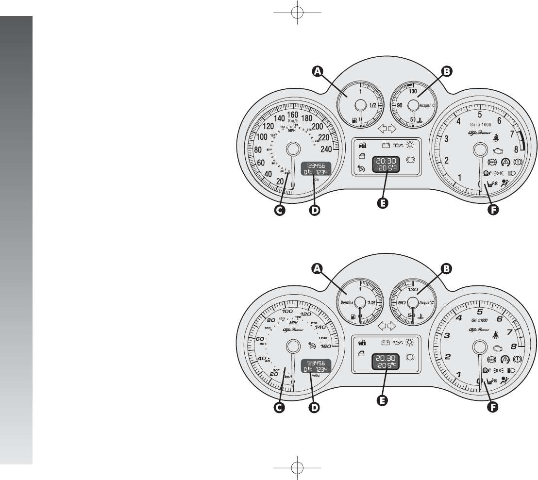
RIGHT HAND DRIVE VERSIONS
274
INSTRUMENT
PANEL
Digital multifunction display
versions
A. Fuel level gauge with reserve warning
light - B. Engine coolant fluid temperature
gauge with maximum temperature warning
light - C. Speedometer - D. Display mileage
recorder, trip meter with headlamp position -
E. Clock/outside temperature display -
F. Rev counter
NOTE JTDMversions are fitted with warning
lights
m
and
c
and the rev counter end
scale value is at 6000 rpm.
A. Fuel level gauge with reserve warning
light - B. Engine coolant fluid temperature
gauge with maximum temperature warning
light - C. Speedometer - D. Display mileage
recorder, trip meter with headlamp position -
E. Clock/outside temperature display -
F. Rev counter
NOTE JTDMversions are fitted with warn-
ing lights
m
and
c
and the rev counter
end scale value is at 6000 rpm.
A0A1122m
A0A1131m
fig. 1 - Petrol versions
fig. 2 - Black Line and Q2 versions
258-277_Alfa147 Q2 GB 4-07-2008 12:06 Pagina 274
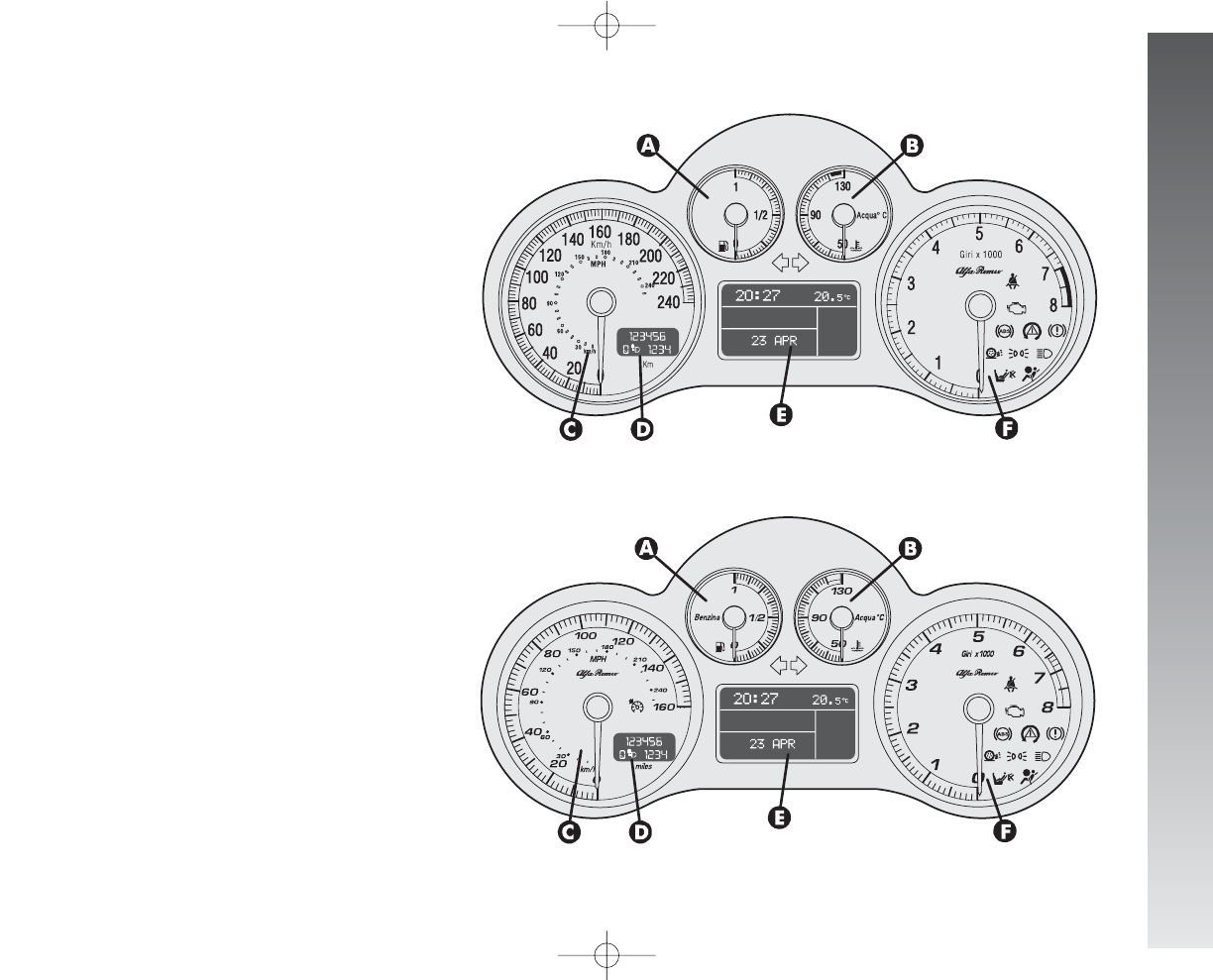
RIGHT HAND DRIVE VERSIONS
275
Reconfigurable multifunction
display versions
A. Fuel level gauge with reserve warning
light - B. Engine coolant fluid temperature
gauge with maximum temperature warning
light - C. Speedometer - D. Display mileage
recorder, trip meter with headlamp position -
E. Reconfigurable multifunction display -
F. Rev counter
NOTE JTDMversions are fitted with warning
lights
m
and
c
and the rev counter end
scale value is at 6000 rpm.
A. Fuel level gauge with reserve warning
light - B. Engine coolant fluid temperature
gauge with maximum temperature warning
light - C. Speedometer - D. Display mileage
recorder, trip meter with headlamp position -
E. Reconfigurable multifunction display -
F. Rev counter
NOTE JTDMversions are fitted with warning
lights
m
and
c
and the rev counter end
scale value is at 6000 rpm.
A0A1123m
A0A1132m
fig. 3 - Petrol versions
fig. 4 - Black Line and Q2 versions
258-277_Alfa147 Q2 GB 4-07-2008 12:06 Pagina 275
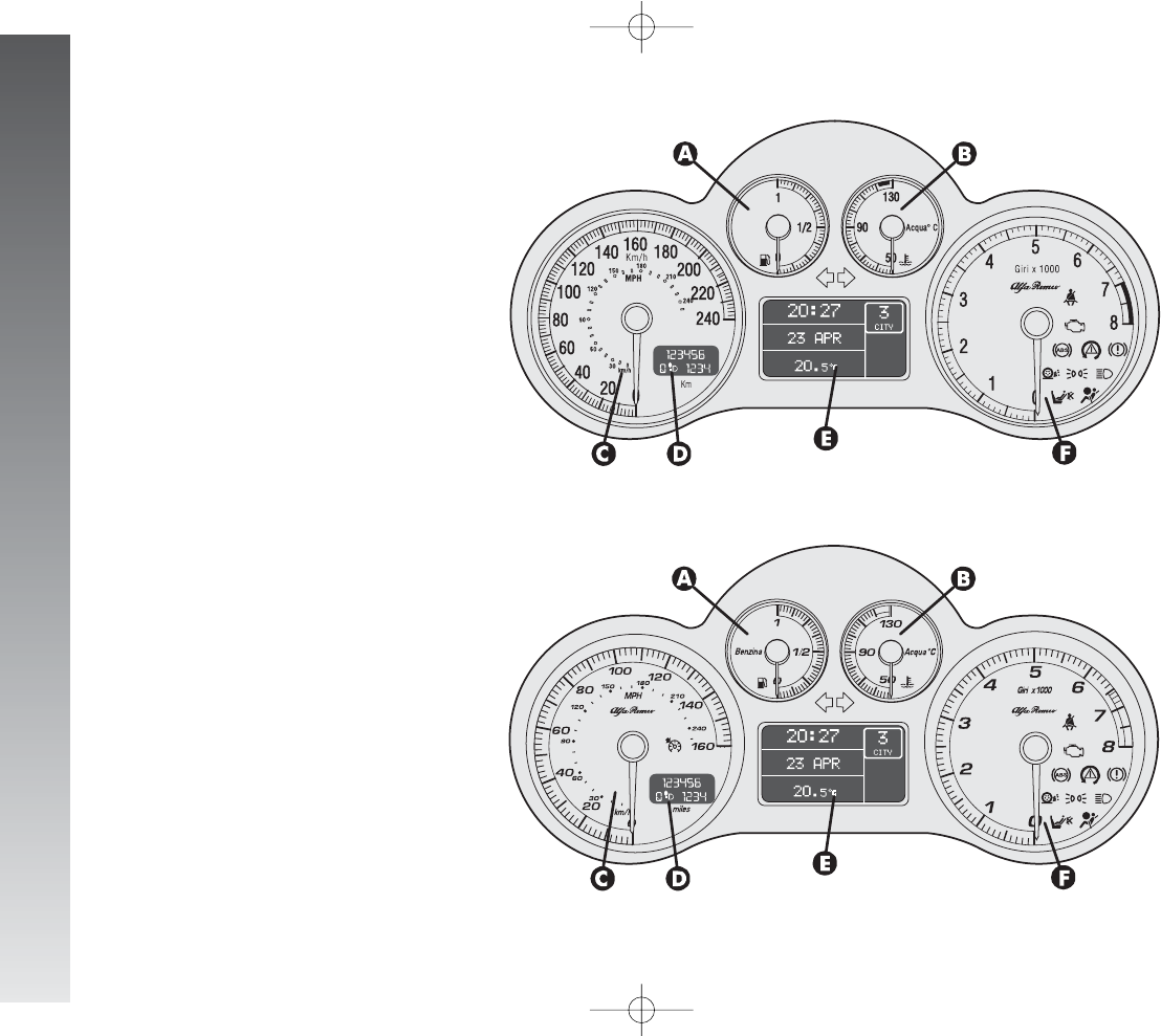
RIGHT HAND DRIVE VERSIONS
276
A. Fuel level gauge with reserve warning
light - B. Engine coolant fluid temperature
gauge with maximum temperature warning
light - C. Speedometer - D. Display mileage
recorder, trip meter with headlamp position
E. Reconfigurable multifunction display -
F. Rev counter
A. Fuel level gauge with reserve warning
light - B. Engine coolant fluid temperature
gauge with maximum temperature warning
light - C. Speedometer - D. Display mileage
recorder, trip meter with headlamp position
E. Reconfigurable multifunction display -
F. Rev counter
A0A1124m
A0A1133m
fig. 5 - 2.0 T.SPARK Selespeed
fig. 6 - 2.0 T.SPARK Selespeed Black Line and Q2
258-277_Alfa147 Q2 GB 4-07-2008 12:06 Pagina 276
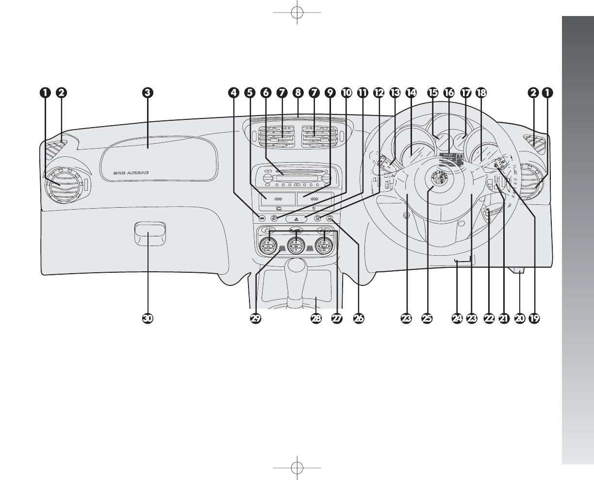
RIGHT HAND DRIVE VERSIONS
277
DASHBOARD
fig. 7
A0A1104m
1. Side swivel air vents - 2. Fixed side window air vents - 3. Passenger's air bag - 4. Tailgate release button - 5. Card holder (for ver-
sions/markets where applicable) - 6. Sound system (for versions/markets where applicable) - 7. Centre swivel air vents - 8. Fixed upper
vent - 9. Glass holder (for versions/markets where applicable) - 10. Front fog light button - 11. Hazard light switch - 12. Rear fog light but-
ton - 13. Outside light control lever - 14. Speedometer with display for mileage recorder, trip meter and headlamp aiming device - 15. Fuel
level gauge with reserve warning light - 16. Multifunction display - 17. Engine coolant temperature gauge - 18. Rev. counter - 19. Wind-
screen wiper control lever - 20. Bonnet opening lever - 21. Set of controls: trip meter reset, headlamp aiming device, trip computer - 22. Ig-
nition key and switch - 23. Horn - 24. Steering wheel locking/release lever - 25. Driver's air bag - 26. Door locking button - 27. Controls
for heating, ventilation and climate control - 28. Cigar lighter/ashtray housing door - 29. Temperature sensor - 30. Glove box.
258-277_Alfa147 Q2 GB 4-07-2008 12:06 Pagina 277

ALPHABETICAL INDEX
278
A
AL
LP
PH
HA
AB
BE
ET
TI
IC
CA
AL
LI
IN
ND
DE
EX
X
ABS ......................................... 140
Accessories purchased by the user... 173
Additional heater.......................... 110
Additional stop light (third stop)..... 217
Air bags (front and side) ............... 38
Air cleaner................................... 246
Alfa Romeo CODE......................... 6
Armrest (front/rear) ................... 19-23
Ashtray.................................. 126-127
ASR (system).............................. 144
At the filling station...................... 182
Battery ..................................... 247
Bluetooth (hands-free kit) ............. 174
Bonnet ....................................... 135
Boot ......................................... 131
Boot light
- changing bulbs........................ 220
Brakes........................................ 262
Braking lights
- changing bulbs........................ 216
Bulbs ......................................... 209
Car inactivity.............................. 193
Card holder recess........................ 128
Cell phones provision.................... 173
Changing a wheel ........................ 201
Changing bulbs............................ 209
Checking levels............................ 239
Children (carrying safely).............. 34
Children’s safety device................. 17
Cigar lighter ................................ 126
Climate control
(automatic two-zone) ............... 95
Climate control (manual)................ 88
Climate control system.................. 86
Clock.......................................... 59
CO2emissions ............................. 273
CODE card................................... 7
Comfort suspensions..................... 191
Controls...................................... 110
Correct use of the car............ 186
Courtesy light .............................. 125
Cruise control .............................. 49
Dashboard................................. 52
Diesel fuel filter............................ 246
Digital multifunction display........... 58
Dimensions ................................. 267
Direction indicators
- changing front bulbs................. 214
- changing rear bulbs.................. 216
- changing side bulbs.................. 215
- switching on ........................... 45
Display (reconfigurable
multifunction)........................... 62
Door lights .................................. 126
- changing bulbs ........................ 218
Door locking system ..................... 111
Doors......................................... 7
DPF (Diesel Particulate Filter) ........ 185
Electronic alarm system ............... 11
Electronic control units .................. 250
Emergency starting....................... 197
- starting with an auxiliary battery 198
Engine........................................ 260
Engine compartment .................... 135
278-284_Alfa147 Q2 GB 4-07-2008 12:07 Pagina 278

ALPHABETICAL INDEX
279
Engine oil (consumption) .............. 241
Engine starting ............................ 186
EOBD ......................................... 146
External lights (switching on) ........ 44
First-aid kit................................. 233
Fix&Go automatic........................ 204
Fluids and lubricants..................... 271
Follow me home device ................ 46
Foglights
- changing bulbs........................ 215
- switching on ........................... 110
Front ceiling light ......................... 124
- changing bulbs........................ 218
Front seats.................................. 18
Fuel (consumption)...................... 273
Fuel economy.............................. 189
Fuel flap..................................... 183
Fuel supply ................................. 261
Fuses ......................................... 221
Getting to know your car.... 6
Glass stand/Card holder................ 128
Glove compartment...................... 123
Glove compartment light
- changing bulbs........................ 220
Handbrake lever......................... 112
Hands-free kit (Bluetooth)............. 174
Hazard warning lights
- switching on ........................... 110
Headlamp beam adjustment.......... 112
Headlight washers................... 47-254
Headlights
- adjustment abroad................... 138
- compensation for tilt ................ 137
Headrests ................................... 20
Heater........................................ 88
Hoses......................................... 252
Ignition device............................ 14
In an emergency..................... 197
In the event of an accident............ 232
Inertial fuel cut off switch.............. 111
Installation of electric/
electronic devices ..................... 174
Instrument cluster ........................ 53
Intelligent washing
(windscreen)............................ 47
Interior (cleaning)........................ 256
Interior fittings............................. 123
Keys......................................... 6
Levers at steering wheel .............. 44
Lights (switching on).................... 44
Low beam headlights
- changing bulbs........................ 213
- switching on ........................... 44
Luggage compartment .................. 131
Luggage restrainer net .................. 24
Main beam headlights
- changing bulbs........................ 214
- switching on ........................... 44
Maintenance
- additional operations................ 237
- annual inspection programme.... 237
- scheduled maintenance ............ 234
- scheduled maintenance
programme............................. 235
Mechanical gearbox...................... 113
Mileage recorder.......................... 56
Number plate lights
- changing bulbs........................ 217
Oddment recesses................. 127-128
278-284_Alfa147 Q2 GB 4-07-2008 12:07 Pagina 279

ALPHABETICAL INDEX
280
Paintwork (maintenance)............ 255
Parking....................................... 189
Parking sensors............................ 139
Performance................................ 266
Pollen filter...................... 94-109-247
Power windows ........................... 26
Radio transmitters and
cellular telephones..................... 174
Rain sensor ................................. 47
Raising the car............................. 231
Rear ceiling light .......................... 125
- changing bulbs........................ 219
Rear fog guards
- changing bulbs........................ 216
- switching on ........................... 111
Rear oddment pockets .................. 129
Rear seats................................... 21
Rearscreen washer ....................... 48
- spray jet................................. 253
Rearscreen wiper
- blade replacement ................... 253
- operation................................ 48
Rearview mirrors.......................... 25
Refilling...................................... 270
Remote control............................ 7
Rev counter................................. 56
Reversing light
- changing bulbs........................ 216
Right hand drive versions..... 274
Roof rack (provision).................... 136
Safeguarding the environment...... 184
Seat belts ................................... 28
Selespeed gearbox....................... 114
Sidelights
- changing front bulbs................. 213
- changing rear bulbs.................. 216
- switching on ........................... 44
Snow chains................................ 192
Sound system presetting............... 147
Sound system.............................. 148
Spark plugs................................. 260
Steering lock............................... 15
Steering system........................... 262
Sunroof ...................................... 130
Sun visors................................... 129
Suspensions................................ 262
Symbols ..................................... 5-6
Technical specifications......... 258
Towing the car............................. 230
Towing trailers ............................. 193
Transmission................................ 261
VDC system .............................. 142
Vehicle maintenance .............. 234
Warning lights and messages...... 73
Weights...................................... 269
Wheel geometry .......................... 266
Wheels and tyres ......................... 251
Windscreen washer
- intelligent washing function....... 47
- operation................................ 46
- spray jets ............................... 253
Windscreen wiper
- blade replacement ................... 252
- operation................................ 46
- spray jets ............................... 253
278-284_Alfa147 Q2 GB 4-07-2008 12:07 Pagina 280

PROVISIONS FOR THE PROCESSING OF A VEHICLE
AT THE END OF ITS LIFE-CYCLE
For years now Alfa Romeo has been developing its global commitment towards the safeguarding and protection of the Environment through
the continuous improvement of its production processes and the making of increasingly more “eco friendly” products. With a view to guaran-
teeing the best possible service to clients in full observance of environmental standards and in response to the obligations imposed by Euro-
pean Directive 2000/53/EC on end-of-life vehicles, Alfa Romeo offers its clients the possibility to hand in their vehicle* at the end of its life
span without additional costs.
The European Directive, in fact, provides for the take-back of the vehicle without the last holder or owner of the same incurring expenses due
to the fact that the market value of the vehicle is zero or negative. In particular, in almost all of the countries of the
European Union, up until 1st January 2007, take-back of the vehicle free of charge only applies to vehicles registered from 1 July 2002 on,
while, from 2007 on, take-back will be carried out free of charge, independently of the year of registration, provided that the vehicle still con-
tains all its essential component parts (especially engine and body) and is free from additional waste materials.
Our contracted network of authorised treatment facilities has been carefully selected in order to provide a quality service to our customers by
de-polluting and recycling “End of Life Vehicles” to approved environmental standards. To find out the location of your nearest authorised
treatment facility, offering free of charge take-back, simply contact one of our dealers or refer to the Alfa Romeo web site or call the toll free
number 00800 2532 0000.
*Passenger transportation vehicles to seat a max. of nine persons, having a total admissible weight of 3.5 t
278-284_Alfa147 Q2 GB 4-07-2008 12:07 Pagina 281
278-284_Alfa147 Q2 GB 4-07-2008 12:07 Pagina 282
278-284_Alfa147 Q2 GB 4-07-2008 12:07 Pagina 283
COLD TYRE INFLATION PRESSURES
CUSTOMER SERVICES
TECHNICAL SERVICES - SERVICE ENGINEERING
Largo Senatore G. Agnelli, 5 - 10040 Volvera - Torino (Italia)
Fiat Group Automobiles S.p.A.
Pubblication no. 60431857 - 1st Edition - 06/2008
All rights reserved. Reproduction, even in part, is prohibited without written permission
from Fiat Group Automobiles S.p.A.
S E R V I C E
ENGINE OIL REPLACEMENT
Oil sump and filter ...................... litres 4.4 (4.5 for JTDMversions)
Do not discard used oil in the environment.
REFUELLING
Fuel tank capacity............................................................ litres 60
Reserve ............................................................................ litres 7
For cars with petrol engine, only use unleaded petrol with over 95 R.O.N.
(Specification EN228).
For cars with diesel engine, only use Diesel fuel for motor vehicles (Spec-
ification EN590).
Tyres
215/40 ZR18” (
•
)
Reinforced
front rear
2.4 2.4
2.7 2.7
Tyres
195/60 R15”
front rear
2.2 2.2
2.5 2.5
Compact spare wheel
125/80 R15”
4.2
Tyres
185/65 R15”
front rear
2.2 2.2
2.5 2.5
Tyres
205/55 R16” (
•
)
front rear
2.3 2.3
2.6 2.6
Tyres
215/45 R17” (
•
)
front rear
2.4 2.3
2.7 2.6
reduced load
full loadr
(
•
) Unchainable tyres
With the tyre hot the inflating pressure should be +0.3 bar compared with the specified rating.
With winter tyres the inflation pressure should be +0.2 bar higher than the rating specified for standard tyres.
Inflate tyres to full load pressures if driving at continuous speed exceeding 160 km/h.
278-284_Alfa147 Q2 GB 4-07-2008 12:07 Pagina 284