Alien Technology ALR9640 FHSS Tag Reader Transceiver User Manual Users Guide for RFID Readers
Alien Technology Corporation FHSS Tag Reader Transceiver Users Guide for RFID Readers
Users Manual

ALR-9780
ALR-9750-A
915MHz
Passive
ALIEN TECHNOLOGY®
HARDWARE
SETUP GUIDE
8001467-000 Revision B
ALR-9640
Legal Notices
Copyright © 2004 Alien Technology Corporation. All rights reserved.
Alien Technology Corporation has intellectual property rights relating to technology embodied in the products
described in this document, including without limitation certain patents or patent pending applications in the U.S. or
other countries.
This document and the products to which it pertains are distributed under licenses restricting their use, copying,
distribution and decompilation. No part of this product documentation may be reproduced in any form or by any
means without the prior written consent of Alien Technology Corporation and its licensors, if any. Third party
software is copyrighted and licensed from Licensors. Alien, Alien Technology, the Alien logo, Nanoblock, Fluidic
Self Assembly, FSA, Alien RFID Gateway, Gen2Ready, Nanoscanner and other graphics, logos, and service names
used in this document are trademarks of Alien Technology Corporation in the U.S. and other countries. All other
trademarks are the property of their respective owners. U.S. Government approval required when exporting the
product described in this documentation.
Federal Acquisitions: Commercial Software -- Government Users Subject to Standard License Terms and
Conditions. U.S. Government: If this Software is being acquired by or on behalf of the U.S. Government or by a
U.S. Government prime contractor or subcontractor (at any tier), then the Government's rights in the Software and
accompanying documentation shall be only as set forth in this license; this is in accordance with 48 C.F.R. 227.7201
through 227.7202-4 (for Department of Defense (DoD) acquisitions) and with 48 C.F.R. 2.101 and 12.212 (for non-
DoD acquisitions).
DOCUMENATION IS PROVIDED “AS IS” AND ALL EXPRESS OR IMPLIED CONDITIONS,
REPRESENTATIONS AND WARANTEES, INCLUDING ANY IMPLIED WARRANTY OF
MERCHANTABILITY, FITNESS FOR A PARTICULAR PURPOSE OR NON-INFRINGMENT ARE HEREBY
DISCLAIMED, EXCEPT TO THE EXTENT THAT SUCH DISCLAIMERS ARE HELD TO BE LEGALLY
INVALID.
FCC Compliance
This equipment has been tested and found to comply with the limits for Class A digital device, pursuant to Part 15 of
the FCC Rules. These limits are designed to provide reasonable protection against harmful interference when the
equipment is operated in a commercial environment. This equipment generates, uses and can radiate radio frequency
energy and, if not installed and used in accordance with instruction manual, may cause harmful interference with
radio communications. Operation of this equipment in a residential area is likely to cause harmful interference in
which case the user will be required to correct the interference at his own expense.
Any change or modification to this product voids the user’s authority to operate per FCC Part 15 Subpart A. Section
15.21 regulations.
Industry Canada Compliance
Operation is subject to the following two conditions: (1) this device may not cause interference and (2) this device
must accept any interference, including interference that may cause undesired operation of the device.
This device has been designed to operate with an antenna having a maximum gain of 6dBi. Antenna having a higher
gain is strictly prohibited per regulations of Industry Canada. The required antenna impedance is 50 ohms.
To reduce potential radio interference to other users, the antenna type and its gain should be so chosen that the
equivalent isotropically radiated power (EIRP) is not more than that required for successful communication.
Caution
To meet FCC and Industry Canada RF Exposure guidelines the reader antennas shall be positioned so that
personnel in the area for prolonged periods may safely remain at least 23 cm (9 in) in an uncontrolled environment
from the antenna's surface. See FCC OET Bulletin 56 "Hazards of radio frequency and electromagnetic fields" and
Bulletin 65 "Human exposure to radio frequency electromagnetic fields. The antennas shall not be co-located with
other transmitting devices.

TABLE OF CONTENTS
Alien Technology®
Hardware Setup Guide
ALR-9640
8001467-000 Revision A
Table of Contents
CHAPTER 1 INTRODUCTION .....................................................................................................................1
Audience .......................................................................................................................................................1
RFID Reader Overview.................................................................................................................................1
Class 1 NanoBlock Tags...............................................................................................................................2
Requirements................................................................................................................................................2
Specifications ................................................................................................................................................3
RFID Reader...........................................................................................................................................3
Mechanical..............................................................................................................................................4
RS-232 Port Pinouts...............................................................................................................................5
RS232 Connector (Female) – Looking at Reader ...........................................................................5
IO Port Connector Pinouts......................................................................................................................5
I/O Port Connector (Male) – Looking at Reader ..............................................................................5
Reader Schematics ................................................................................................................................6
CHAPTER 2 READER HARDWARE INSTALLATION AND OPERATION................................................7
Receiving the RFID Reader ..........................................................................................................................7
Reader I/O Panel....................................................................................................................................8
Diagnostic LEDs .....................................................................................................................................8
Diagnostic LEDs .....................................................................................................................................8
System Assembly and Bench Test ...............................................................................................................9
Bench Test Configuration.....................................................................................................................10
Bench Test Procedure..........................................................................................................................11
Installation ...................................................................................................................................................12
Requirements .......................................................................................................................................12
Hardware Installation Procedure ..........................................................................................................13
System Operation: Software Control ..........................................................................................................14
Reader Interface Guide ........................................................................................................................14
Demonstration Software Guide ............................................................................................................14
HARDWARE SETUP GUIDE, ALR-9640
DOC. CONTROL # 8001467-000 REVISION B i

TABLE OF CONTENTS
(This page intentionally left blank)
HARDWARE SETUP GUIDE
DOC. CONTROL # 8001467-000 REVISION B
ii

CHAPTER 1 INTRODUCTION
CHAPTER 1
Introduction
This Hardware Setup Guide provides instructions for installing and operating the
ALR-9640 readers.
This document is designed for use by RFID system integrators and software
developer - those who wish to develop software products and extended systems
that take full advantage of the RFID Reader's capabilities.
For an overview of RFID technology and a glossary of terms, please refer to the
RFID Primer included with your RFID Reader Developer’s Kit.
For an overview of the communication interfaces to the Readers, please refer to
the Reader Interface Guide included with your RFID Reader Developer’s Kit.
Audience
For the purposes of this document, we assume the readers of the Hardware
Setup Guide:
are competent PC users
have minimal previous knowledge of radio-frequency identification
technology
are experienced in software development and/or hardware systems
integration
RFID Reader Overview
The Alien RFID reader is designed to read and program Class I NanoBlock tags
(see below) and issue event reports to a host computer system. The host
computer can be locally connected to the reader via RS-232, or at a remote
network location.
The RFID Reader is delivered with the following components and accessories:
One ARL-9640 RFID Reader
One RS-232 serial cable (for host computer)
One power supply
Documentation on CD-ROM
HARDWARE SETUP GUIDE
DOC. CONTROL # 8001467-000 REVISION B 1

INTRODUCTION CHAPTER 1
Class 1 NanoBlock Tags
The ALR-9640 RFID readers are
designed to read and program Alien’s
Class 1 RFID Tags.
These tags comply with the MIT A
Center's open specification for RFID.
utoID
lass I tags are “passive” devices. That
er
municate with the Reader by
eans of “Backscatter Modulation”.
e with the RFID Reader you will need the following:
e and an
software or your own custom software)
ith grounded, 3-pronged plugs
C
is, they do not have an onboard pow
source. They are powered by the RF
energy transmitted by the reader.
They com
m
That is, they do not actually transmit
anything; they merely change their
reflective characteristics in a systematic way and reflect RF energy back to the
reader. An analogy to this is the way you can use a mirror to transmit information
by reflecting light from the Sun.
Examples of Alien NanoBlock tag
and antenna designs.
Requirements
To interfac
a PC running Windows 98 or higher, with CD-ROM driv
available RS-232 serial port
standard 120 VAC power
host software (Alien demo
RFID Tags (AIDC Class 1 compliant)
standard power cord (desired length) w
HARDWARE SETUP GUIDE
DOC. CONTROL # 8001467-000 REVISION B
2

CHAPTER 1 INTRODUCTION
Specifications
Specifications for key components of the ARL-9640 RFID Reader system are
provided in the tables below:
RFID Reader
Name Alien RFID Reader
Part Number ALR-9640
Architecture Point-to-multipoint reader network
Frequency 902.8 MHz – 927.6 MHz
Hopping Channels 63
Channel Spacing 400 KHz
Channel Dwell Time < 0.4 Seconds
RF Transmitter < 30 dBm
Antenna Dual switching 6dBi Linear Antenna
Modulation Method On Off Keying (OOK)
20 db Modulation Bandwidth < 400 KHz
RF Receiver 2 Channels
Power Consumption 25 Watts (120 VAC at 500 mW)
Communications Interface RS-232, LAN TCPI/IP
Inputs/Outputs 4 logic I/O, com port, LAN, power
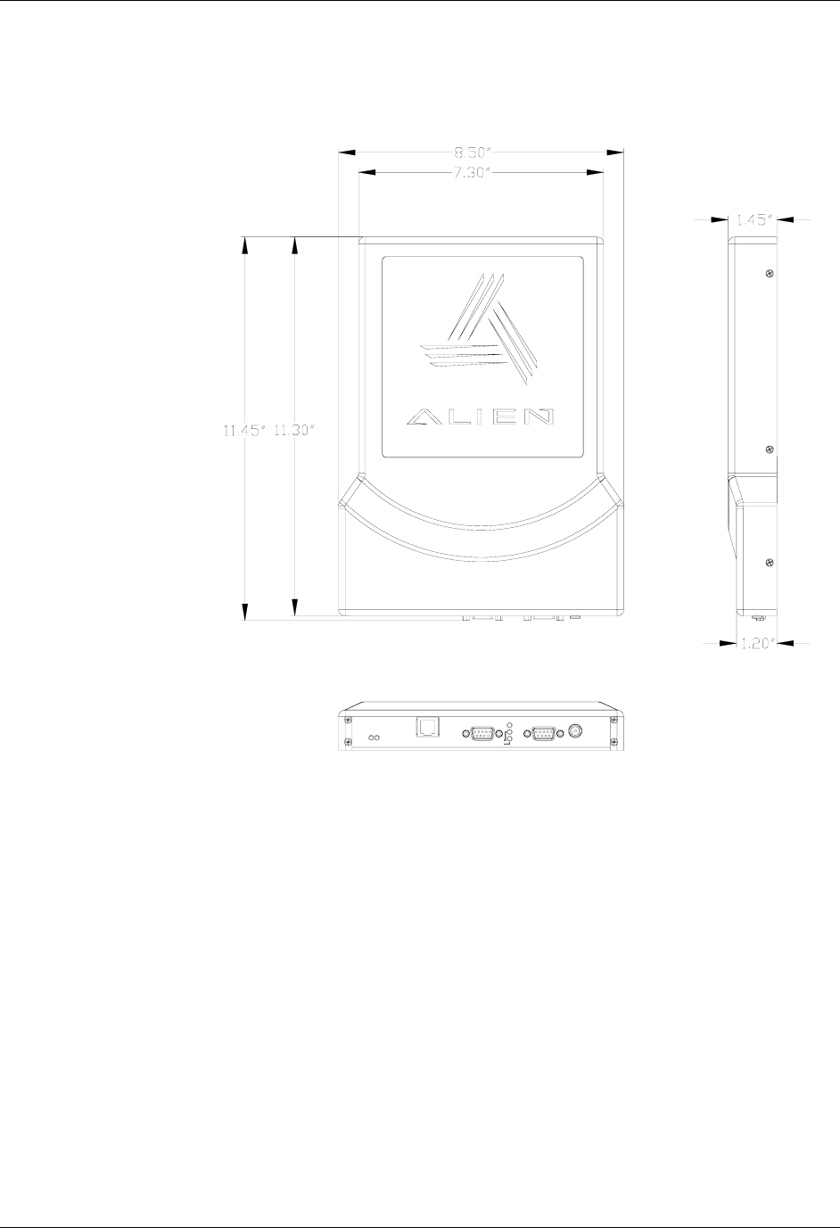
Dimensions (L) 11.45in (29 cm) x (W) 8.50 in (21 cm) x (D) 1.45 in (3.68 cm)
Weight Approximately 1.8 lb (0.82 Kg)
Operating Temperature +32 °F to +122°F ( 0°C to +50°C)
HARDWARE SETUP GUIDE
DOC. CONTROL # 8001467-000 REVISION B 3
INTRODUCTION CHAPTER 1
Mechanical
Tolerance: xx = ± 0.10"
Power
I/O PortRS-232
TCP/IP
LINK
ACTIVE
RF
SNIFF
LOCK
Figure 1 - Outline Drawing of the ALR-9640
HARDWARE SETUP GUIDE
DOC. CONTROL # 8001467-000 REVISION B
4
CHAPTER 1 INTRODUCTION
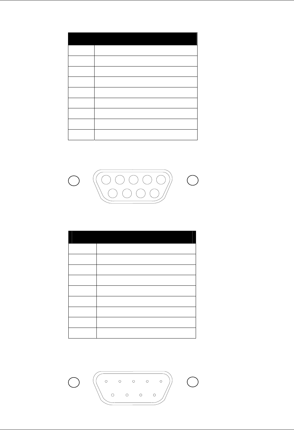
RS-232 Port Pinouts
RS-232 Connector (Female DB-9F)
Pin 1 DCD Connected to Pin 6
Pin 2 TR1 Transmit Data (Output)
Pin 3 RC1 Receive Data (Input)
Pin 4 DTR Connected to Pin 6
Pin 5 Ground
Pin 6 DSR Connected to Pin 4
Pin 7 RTS Connected to Pin 8
Pin 8 CTS Connected to Pin 7
Pin 9 Not Connected
RS232 CONNECTOR (FEMALE) – LOOKING AT READER
54321
9 8 7 6
IO Port Connector Pinouts
I/O Port Connector (Male DB-9M)
Pin 1 Output 0
Pin 2 Output 2
Pin 3 Input 0
Pin 4 Input 2
Pin 5 Ground
Pin 6 Output 1
Pin 7 Output 3
Pin 8 Input 1
Pin 9 Input 3
I/O PORT CONNECTOR (MALE) – LOOKING AT READER
12345
6 7 8 9
HARDWARE SETUP GUIDE
DOC. CONTROL # 8001467-000 REVISION B 5
INTRODUCTION CHAPTER 1
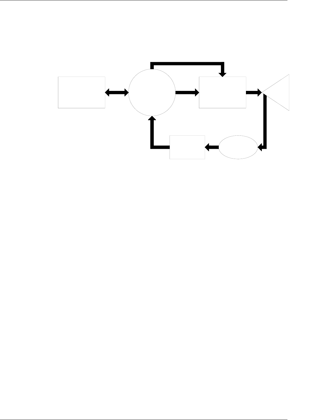
Reader Block Diagram
Host
Comunication
Interface Circuitry
Control
Digital
Transmitter
RF
Decoder
Antenna
Receiver
Antenna
Figure 2 - System Architecture for the ALR-9640 Reader
HARDWARE SETUP GUIDE
DOC. CONTROL # 8001467-000 REVISION B
6
CHAPTER 2 READER HARDWARE INSTALLATION AND OPERATION
CHAPTER 2
Reader Hardware Installation and Operation
This chapter describes the RFID Reader and provides installation and operation
information.
Receiving the RFID Reader
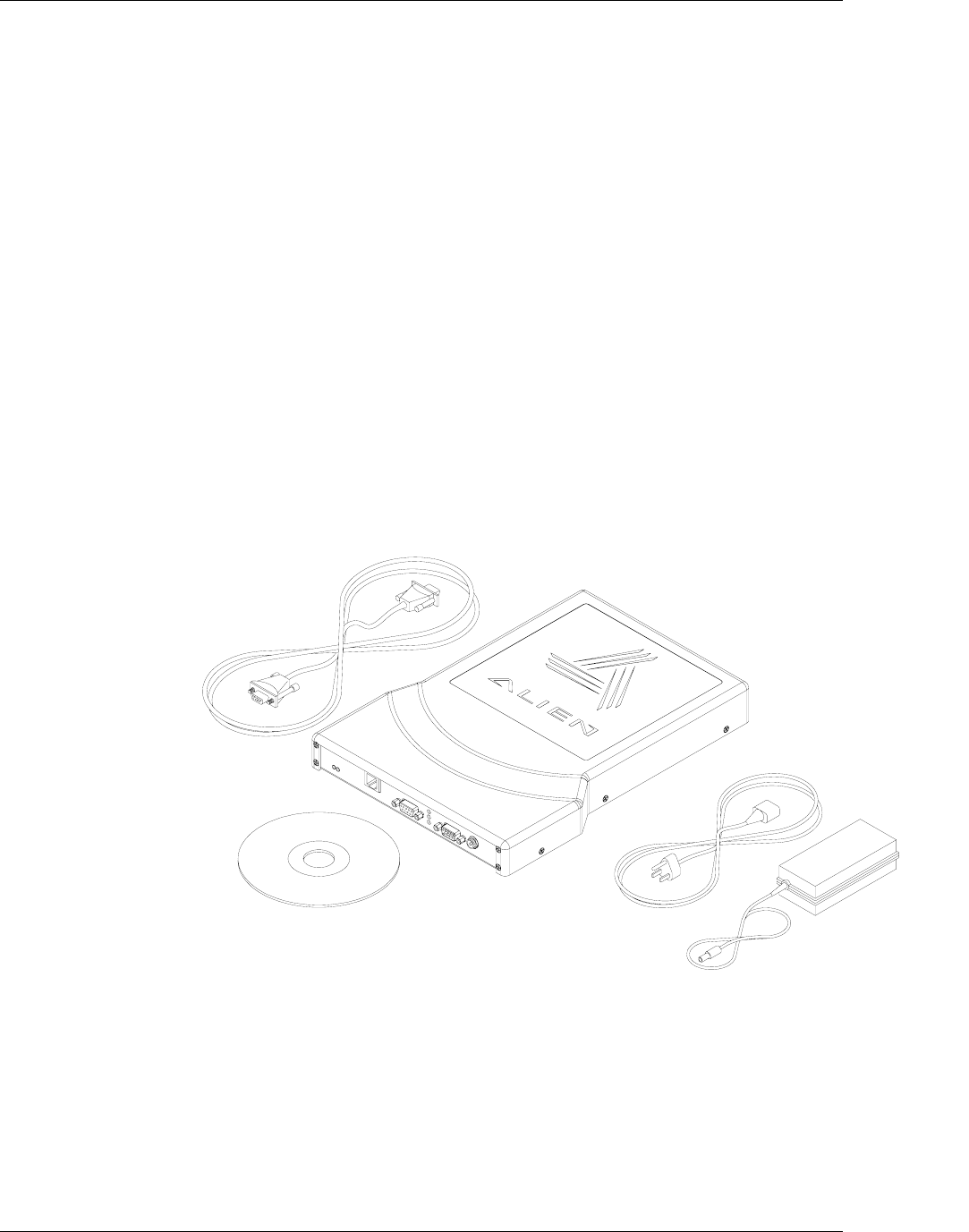
Your RFID Reader Developer’s Kit is shipped with the items listed below. Please
verify the contents of your received shipment before assembling.
RFID Reader with integrated antennas
RS-232 reader-to-PC cable
Reader power supply and cables.
CD-ROM containing demonstration software, user guides and
documentation
Figure 3 - ALR-9640
HARDWARE SETUP GUIDE
DOC. CONTROL # 8001467-000 REVISION B 7
READER HARDWARE INSTALLATION AND OPERATION CHAPTER 2
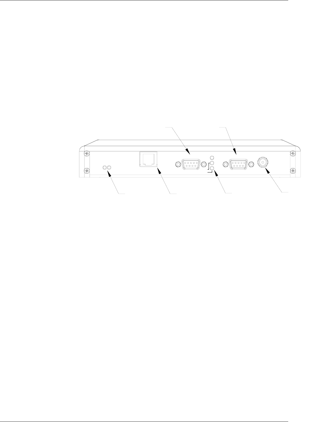
Reader I/O Panel
The I/O panel (shown below) houses the following:
Power connector
9-pin D male I/O connector
3 Diagnostic LEDs (RF Power, Sniff and Lock)
9-pin D female RS-232 serial port
LAN TCP/IP port
network activity LEDs
Power
Connector
Diagnostic
LEDs
LAN
Connector
LAN
LEDs
RS-232
Connector Connector
I/O
ACTIVE
LINK
Power
RS-232
TCP/IP SNIFF
LOCK
RF I/O Port
Diagnostic LEDs
Figure 4 - Reader Connections and LEDs
The diagnostic LEDs provide external indication of various conditions:
RF On (red) - indicates that RF is being emitted by the reader
Sniff (yellow) - indicates a tag signal has been detected, though it may
not yet be strong enough to complete a transaction
Lock (green) - indicates a tag has been read
HARDWARE SETUP GUIDE
DOC. CONTROL # 8001467-000 REVISION B
8
CHAPTER 2 READER HARDWARE INSTALLATION AND OPERATION
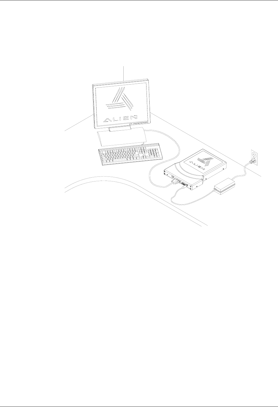
System Assembly and Bench Test
Assembling the RFID Reader system is easy. We recommend you set up the
system and verify its operation in a bench test configuration (shown below)
before installing it in a production setting.
Figure 6 - Typical Bench Test Setup
CAUTION: To meet FCC and Industry Canada RF Exposure
guidelines the reader antennas shall be positioned so that
personnel in the area for prolonged periods may safely remain
at least 23 cm (9 in) in an uncontrolled environment from the
antenna's surface. See FCC OET Bulletin 56 "Hazards of radio
frequency and electromagnetic fields" and Bulletin 65 "Human
exposure to radio frequency electromagnetic fields. The
antennas shall not be co-located with other transmitting
devices.
HARDWARE SETUP GUIDE
DOC. CONTROL # 8001467-000 REVISION B 9
READER HARDWARE INSTALLATION AND OPERATION CHAPTER 2
Bench Test Configuration
1. Situate the Reader on a tabletop. Ensure the following conditions:
Two standard 120 VAC outlets are available nearby (one for the reader,
one for the PC if needed).
Power Connector.
(To the power
supply and &120 VAC
wall outlet)
RS-232
Connector
(To PC)
Figure 7 - RS-232 and Power Connections
Sufficient space is available on the tabletop for the PC, reader and
antenna.
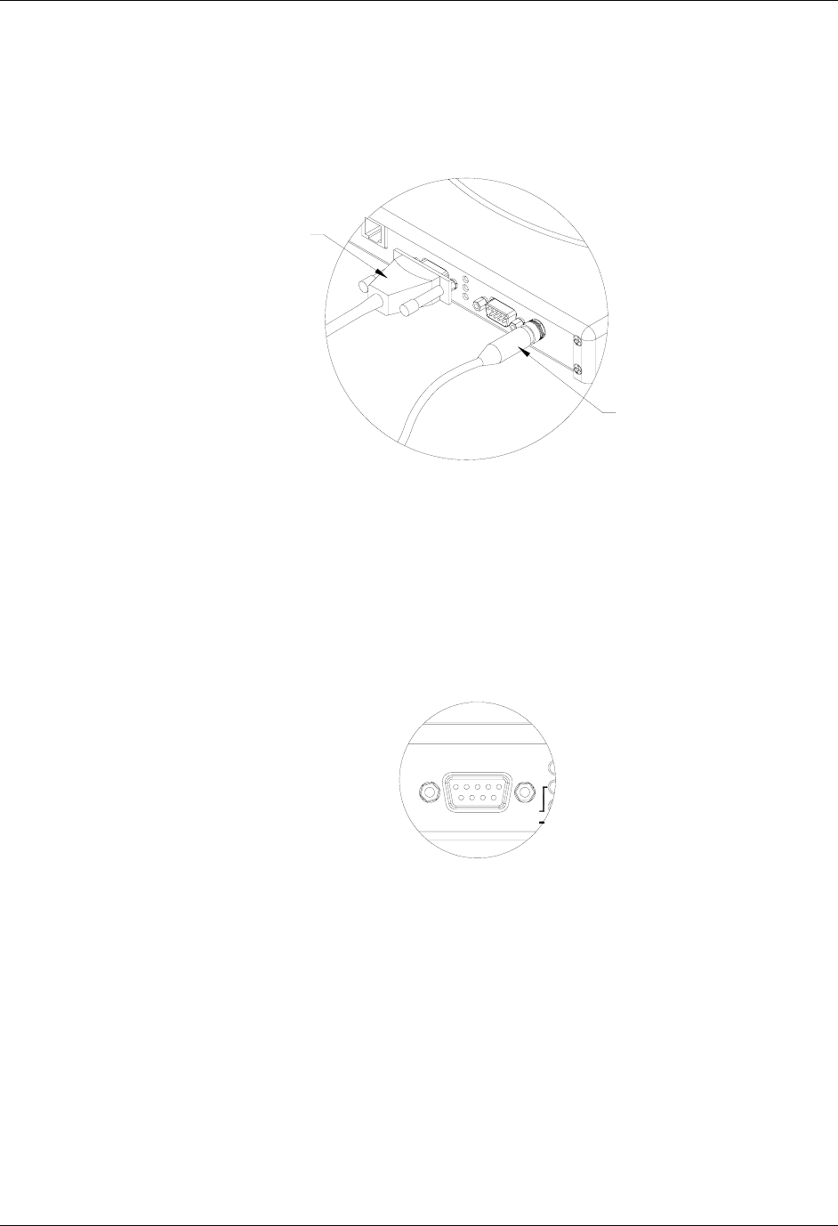
2. Connect the RS-232 cable to the reader.
Align the male cable connector so that its shape and pins match the
shape and holes of the female DB-9 RS-232 port.
RF
RS-232
LOCK
SNIFF
Figure 8 - RS-232 Connector
Push the aligned connector into the port.
Finger-tighten the screws to secure the cable/connector to the reader.
3. Connect the RS-232 cable to the serial port on the PC.
4. Connect the power supply to the reader.
Using the thin cable attached to power supply, push the connector into
the port until it is securely seated. Do not plug the power supply into the
wall outlet yet.
HARDWARE SETUP GUIDE
DOC. CONTROL # 8001467-000 REVISION B
10

CHAPTER 2 READER HARDWARE INSTALLATION AND OPERATION
5. Plug power cord into power supply.
Use the female end of a standard 3-pronged power cord.
6. Plug the power supply cable into the wall outlet and verify power.
The LEDs will illuminate when power is on.
7. Plug in the PC (if necessary) and turn it on.
8. Launch the desired host software application.
You may use Alien’s demo system software or custom software
developed per the reader-host protocol for your specific application.
You are now ready to bench test or demonstrate the RFID Reader system.
Bench Test Procedure
1. Access an operational mode suitable for bench testing.
Select a mode that will allow multiple consecutive reads of a single tag.
Refer to the applicable software application user guide for specific
instructions.
2. Position the reader to you can see the LEDs.
You may also want to position the PC so you can view the monitor
simultaneously for later tests.
3. Move a tag slowly into the antenna’s range.
Begin with the tag well outside the expected range (~15-20 ft) and move
it toward the antenna while observing the LEDs.
4. Verify the Lock LED illuminates when the tag is inside the read window.
Lock is the green LED.
5. Verify the host receives the tag data.
Refer to indications specified in applicable user guide to verify the tag
was read successfully.
6. If bench test conditions are verified, proceed to installation.
NOTE: To perform a hard reboot of the system, simply cycle power on the reader.
HARDWARE SETUP GUIDE
DOC. CONTROL # 8001467-000 REVISION B 11
READER HARDWARE INSTALLATION AND OPERATION CHAPTER 2
Installation
This section provides guidance for configuring components in your RFID system.
You should consider the overall design of your specific system before
permanently mounting the equipment.
Installation involves all the same connection steps required for bench test.
However, instead of situating equipment on a tabletop, the reader and its
accessories are mounted in your application environment.
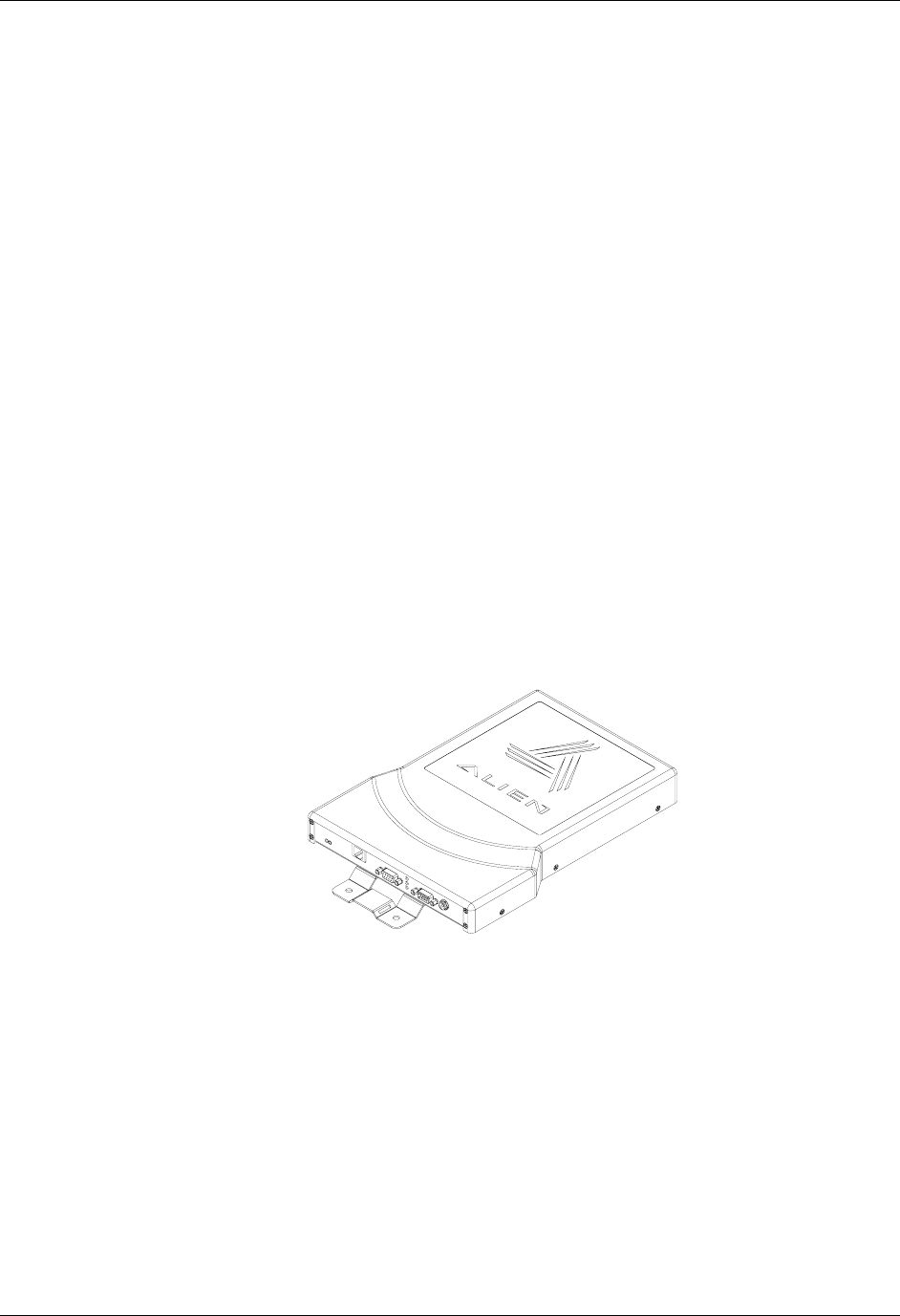
Requirements
Before installing your RFID Reader system, you will need the following:
a PC running Windows 98 or higher, with CD-ROM drive (for demo
system software) and one available RS-232 serial port
standard 120 VAC power for the reader and PC
host software
additional RS-232 cables or antenna coax cables needed to
accommodate routing requirements
standard grounded, three-pronged power cord of desired length
mounting hardware suitable for the surface to which equipment is to be
attached (e.g., wood screws, moly-bolts, brackets, etc.)
Figure 9 - View of the Reader showing optional mounting kit 0500126-001
HARDWARE SETUP GUIDE
DOC. CONTROL # 8001467-000 REVISION B
12

CHAPTER 2 READER HARDWARE INSTALLATION AND OPERATION
Hardware Installation Procedure
1. Select mounting position for ALR-9640
CAUTION: To meet FCC and Industry Canada RF Exposure guidelines the
reader antennas shall be positioned so that personnel in the area for
prolonged periods may safely remain at least 23 cm (9 in) in an uncontrolled
environment from the antenna's surface. See FCC OET Bulletin 56 "Hazards
of radio frequency and electromagnetic fields" and Bulletin 65 "Human
exposure to radio frequency electromagnetic fields. The antennas shall not
be co-located with other transmitting devices.
Mount the ARL-9640 at the periphery of the desired read window (either
overhead or at the side), so that the position of the most distant tag
passing through the window is no farther from the antenna than the
maximum range specified for your system design.
Position the ARL-9640 at a height approximately midway between the
highest and lowest expected tag position. (For example, a pallet tag may
be the lowest tag position to be read, while the top-most case on a fully
stacked pallet may represent your highest tag position.)
Be sure power is available at the selected reader location.
2. Select location for host PC.
Situate the host PC within 50 ft of the reader in a safe location away from
vehicular and foot traffic.
3. Connect reader power.
Push the power supply connector into the reader port.
Plug the female end of the power cord into the power supply.
Plug the male end of the power cord into the 120 VAC outlet.
4. Connect reader to host PC.
Align the RS-232 connector with the corresponding serial port on the
reader and push the connector onto the pins. Finger-tighten the screws
to secure the cable to the reader.
Align and connect the other end of the RS-232 with the serial port on the
PC.
5. Connect power to the PC.
HARDWARE SETUP GUIDE
DOC. CONTROL # 8001467-000 REVISION B 13

READER HARDWARE INSTALLATION AND OPERATION CHAPTER 2
System Operation: Software Control
ARL-9640 is controlled from software running on a host system that
communicates with the reader using a text-based protocol. All applications use
this protocol to communicate with the reader.
You may operate the ARL-9640 from your own application code using this
interface, use the example code provided on the CD or use the Alien RFID
Gateway application - a demonstration program also included on the CD.
For details, refer to either the Reader Interface Guide or the Demonstration
Software Guide described briefly below.
Reader Interface Guide
The text-based interface mentioned above is described in detail in the Reader
Interface Guide. Using this interface, the reader can be configured to read tags
when queried or after one of a variety of event triggers (e.g., a rising edge on one
of the I/O pins, or a timer).
Tag data acquired in response to these triggers can be transmitted to the host in
a number of formats (e.g., terse, text, XML or custom) and under a number of
conditions (e.g., on a new tag being observed, or a tag disappearing from view).
If you are a software developer, the Reader Interface Guide provides the
information you will need to connect to the reader from a host computer,
communicate with it, and customize its performance.
Demonstration Software Guide
The Demonstration Software Guide describes the installation and operation of
the Alien RFID Gateway Application.
The Alien RFID Gateway Application is a useful demonstration program that
allows users to explore the reader’s functionality and build customizable demos
with a user-friendly interface.
Using the Gateway, the various operating modes of the reader can be controlled
and custom interactive demos can be constructed using sounds, images, and
text.
HARDWARE SETUP GUIDE
DOC. CONTROL # 8001467-000 REVISION B
14