Alien Technology ALR9780 FHSS Tag Reader Transceiver User Manual Users Guide for RFID Readers
Alien Technology Corporation FHSS Tag Reader Transceiver Users Guide for RFID Readers
Users Manual

Hardware Se
Doc. Control
ALR-9780
915MHz
Passive tup Guide: ALR-9780 and ALR-9750-A
#:
© 2003 Alien Technology TM
ALIEN TECHNOLOGY
Hardware Setup Guide
For The
ALR-9780 and ALR-9750-A
RFID Readers
Four Antenna and Two Antenna
915MHz Passive Tag Readers
Release: v01.03.00
i
ALR-9750-A

COPYRIGHT ACKNOWLEDGEMENTS
The contents of this document are the property of Alien Technology™ Corporation and are
copyrighted. All rights reserved. Any reproduction, in whole or in part, is strictly prohibited.
For additional copies if this document please contact:
Alien Technology Corporation
18220 Butterfield Blvd.
Morgan Hill, CA 95037
www.alientechnology.com
The information contained herein has been carefully checked and is believed to be
accurate; however, no responsibility is assumed for inaccuracies. Alien Technology
Corporation reserves the right to make changes without prior notice. This document is not
covered by any warranty either expressed or implied. Any correction, comments, or
additions to the contents of this document should be directed to Alien Technology
Corporation at the above address.
Copyright 2003 Alien Technology Corporation. Printed in USA.
NanoBlock and FSA are registered trademarks of Alien Technology Corporation. Alien
Technology is a trademark of Alien Technology Corporation. All other trademarks are the
property of their respective owners.
FCC COMPLIANCE
This equipment has been tested and found to comply with the limits for Class A digital
device, pursuant to Part 15 of the FCC Rules. These limits are designed to provide
reasonable protection against harmful interference when the equipment is operated in a
commercial environment. This equipment generates, uses and can radiate radio
frequency energy and, if not installed and used in accordance with instruction manual,
may cause harmful interference with radio communications. Operation of this equipment in
a residential area is likely to cause harmful interference in which case the user will be
required to correct the interference at his own expense.
Any change or modification to this product voids the user’s authority to operate per FCC
Part 15 Subpart A. Section 15.21 regulations.
INDUSTRY CANADA COMPLIANCE
Operation is subject to the following two conditions: (1) this device may not cause
interference and (2) this device must accept any interference, including interference that
may cause undesired operation of the device.
This device has been designed to operate with an antenna having a maximum gain of
6dBi. Antenna having a higher gain is strictly prohibited per regulations of Industry
Canada. The required antenna impedance is 50 ohms.
To reduce potential radio interference to other users, the antenna type and its gain should
be so chosen that the equivalent isotropically radiated power (EIRP) is not more than that
required for successful communication.
CAUTION
Reader antennas should be positioned so that personnel in the area for prolonged
periods may safely remain at least 23 cm (9 in) in an uncontrolled environment from
the antenna’s surface. See FCC OET Bulletin 56 “Hazards of radio frequency and
electromagnetic fields” and Bulletin 65 “Human exposure to radio frequency
electromagnetic fields.”

TABLE OF CONTENTS
Alien Technology
RFID Reader User’s Guide
(ALR-9780 and ALR-9750-A RFID Readers)
Table of Contents
CHAPTER 1 INTRODUCTION............................................................................................................................1
AUDIENCE ..................................................................................................................................................................1
RFID READER OVERVIEW .........................................................................................................................................1
CLASS 1 NANOBLOCK TAGS ......................................................................................................................................2
REQUIREMENTS ..........................................................................................................................................................2
SPECIFICATIONS .........................................................................................................................................................3
RFID Reader ...................................................................................................3
RFID Reader External Antenna....................................................................... 3
Mechanical ...................................................................................................... 4
RS-232 Port Pinouts........................................................................................ 5
RS232 Connector (Female) –Looking at Reader ..................................................5
IO Port Connector Pinouts .............................................................................. 6
I/O Port Connector (Male) –Looking at Reader.....................................................6
Reader Schematics ......................................................................................... 7
CHAPTER 2 READER HARDWARE INSTALLATION AND OPERATION...............................................8
REQUIREMENTS ..........................................................................................................................................................8
RECEIVING THE RFID READER ..................................................................................................................................8
Reader I/O Panel............................................................................................. 9
Diagnostic LEDs ............................................................................................ 10
Antenna Panel ............................................................................................... 11
SYSTEM ASSEMBLY AND BENCH TEST .....................................................................................................................12
Bench Test Configuration .............................................................................. 12
Bench Test Procedure................................................................................... 14
INSTALLATION..........................................................................................................................................................15
Requirements ................................................................................................ 15
Hardware Installation Procedure ................................................................... 16
SYSTEM OPERATION: SOFTWARE CONTROL.............................................................................................................18
Software Interface Guide............................................................................... 18
Demonstration Software Guide ..................................................................... 18
Hardware Setup Guide: ALR-9780 and ALR-9750-A
Doc. Control #:
© 2003 Alien Technology TM
iii

CHAPTER 1 INTRODUCTION
CHAPTER 1
Introduction
This Hardware Setup Guide provides instructions for installing and operating the
ALR 9780 and ALR 9750-A RFID Readers.
This book is designed for use by RFID system integrators and software
developers. (Those who wish to develop software products and extended
systems that take full advantage of the RFID Readers’ capabilities.)
For an overview of RFID technology and a glossary of terms, please refer to the
RFID Primer included with your RFID Reader Developer’s Kit.
For an overview of the communication interfaces to the Readers, please refer to
the Software Interface Guide included with your RFID Reader Developer’s Kit.
Audience
For the purposes of this book, we assume the readers of the Hardware Setup
Guide:
Are competent PC users
Have minimal previous knowledge of radio-frequency identification
technology.
Are experienced in software development and/or hardware systems
integration.
RFID Reader Overview
The Alien RFID reader is designed to read and program Class I NanoBlock tags
(see below) and issue event reports to a host computer system. The host
computer can be locally connected to the reader or at a remote network location.
The RFID Reader is delivered with the following components and accessories:
RFID Reader and Class 1 NanoBlock Tags
External antenna(s) and coaxial cable(s)
One RS-232 serial cable (for host computer)
Power supply
Documentation on CD-ROM
Hardware Setup Guide: ALR-9780 and ALR-9750-A
Doc. Control #:
© 2003 Alien Technology TM
1

CHAPTER 1 INTRODUCTION
Class 1 NanoBlock Tags
The ALR-9780 and ALR-9750-A RFID
readers are designed to read and program
Alien’s Class 1, NanoBlock Tags.
These tags comply with the MIT Auto ID
Centers’ open specification for RFID.
Class I tags are “Passive” devices. That is
they do not have an onboard power source.
They are powered by the RF energy
transmitted by the reader.
They communicate with the Reader by
means of “Backscatter Modulation”. That is,
they do not actually transmit anything; they
merely change their reflective characteristics in a systematic way and reflect RF
energy back to the reader. An analogy to the way the tag works is the way you
can use a mirror to transmit information using light from the sun.
Examples of Alien NanoBlock tag and
antenna designs.
Requirements
To interface with the RFID Reader you will need the following:
A PC running Windows 98 or higher, with CD-ROM drive and an available
RS-232 serial port.
Standard 120 VAC power.
Host software (Alien demo software or your own custom software).
RFID Tags (AIDC Class 1 compliant)
Standard power cord (desired length) with grounded, 3-pronged plugs
Hardware Setup Guide: ALR-9780 and ALR-9750-A
Doc. Control #:
© 2003 Alien Technology TM
2
CHAPTER 1 INTRODUCTION
Specifications
Specifications for key components of the RFID Reader system are provided in
the tables below:
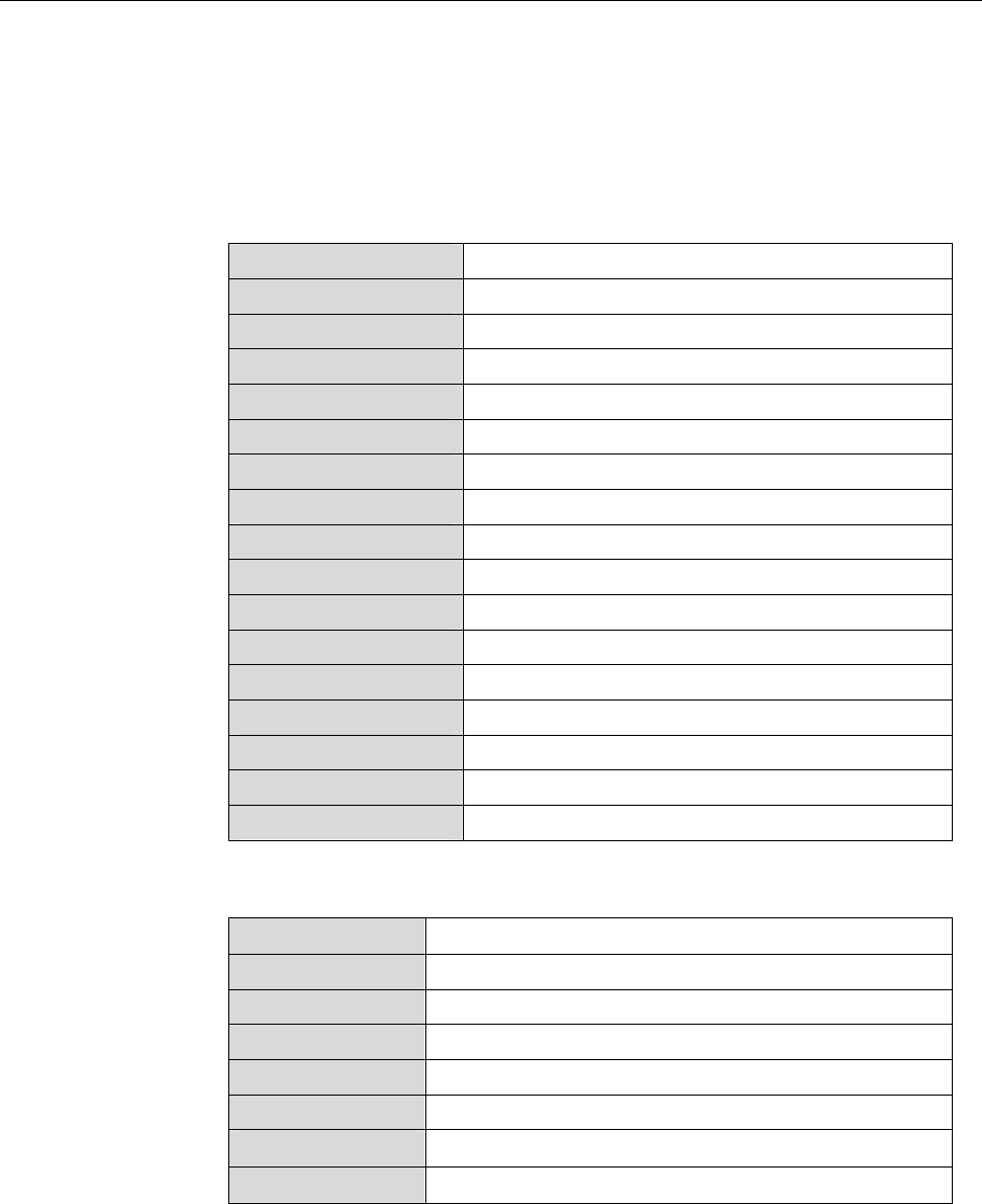
RFID Reader
Name Alien Multi-Port General Purpose RFID Reader
Part Number ALR 9780 or ALR 9750-A
Architecture Point-to-multipoint reader network
Frequency 902.6 MHz – 927.4 MHz
Hopping Channels 63
Channel Spacing 400 KHz
Channel Dwell Time < 0.4 Seconds
RF Transmitter < 30 dBm at the end of 15 ft LMR-195 cable.
Modulation Method On Off Keying (OOK)
20 db Modulation Bandwidth < 400 KHz
RF Receiver 2 Channels
Power Consumption 25 Watts (120 VAC at 500 mW)
Communications Interface RS-232, LAN TCPI/IP
Inputs/Outputs 2 or 4 coax antenna, 8 logic I/O, com port, LAN, power
Dimensions (L) 19 cm (7.5 in) x (W) 28 cm (11 in) x (D) 5 cm (2 in)
Weight Approximately 1.8 kg (4 lb)
Operating Temperature 0°C to +50°C (+32 °F to +122°F)
RFID Reader External Antenna
3 dB Beamwidth E-plane: 65 degrees • H-plane: 65 degrees
Frequency 902-928 MHz
Gain (dBi) 5.73 dBi
Polarization Circular
RF Connector 15 ft LMR-195 with Reverse-Polarity TNC
VSWR 1.5:1
Dimensions (cm) 22 x 27 x 4 • (in) 8.5 x 10.5 x 1.65
Weight .57 kg • 1.25 lb
Hardware Setup Guide: ALR-9780 and ALR-9750-A
Doc. Control #:
© 2003 Alien Technology TM
3
CHAPTER 1 INTRODUCTION
3 dB Beamwidth E-plane: 40 degrees
Frequency 902-928 MHz
Gain (dBi) 6.0 dBi
Polarization Linear
RF Connector 15 ft LMR-195 with Reverse-Polarity TNC
VSWR 1.5:1
Dimensions (cm) 19.5 x 28 x 4 • (in) 7.75 x 11.25 x 1.65
Weight .57 kg • 1.25 lb
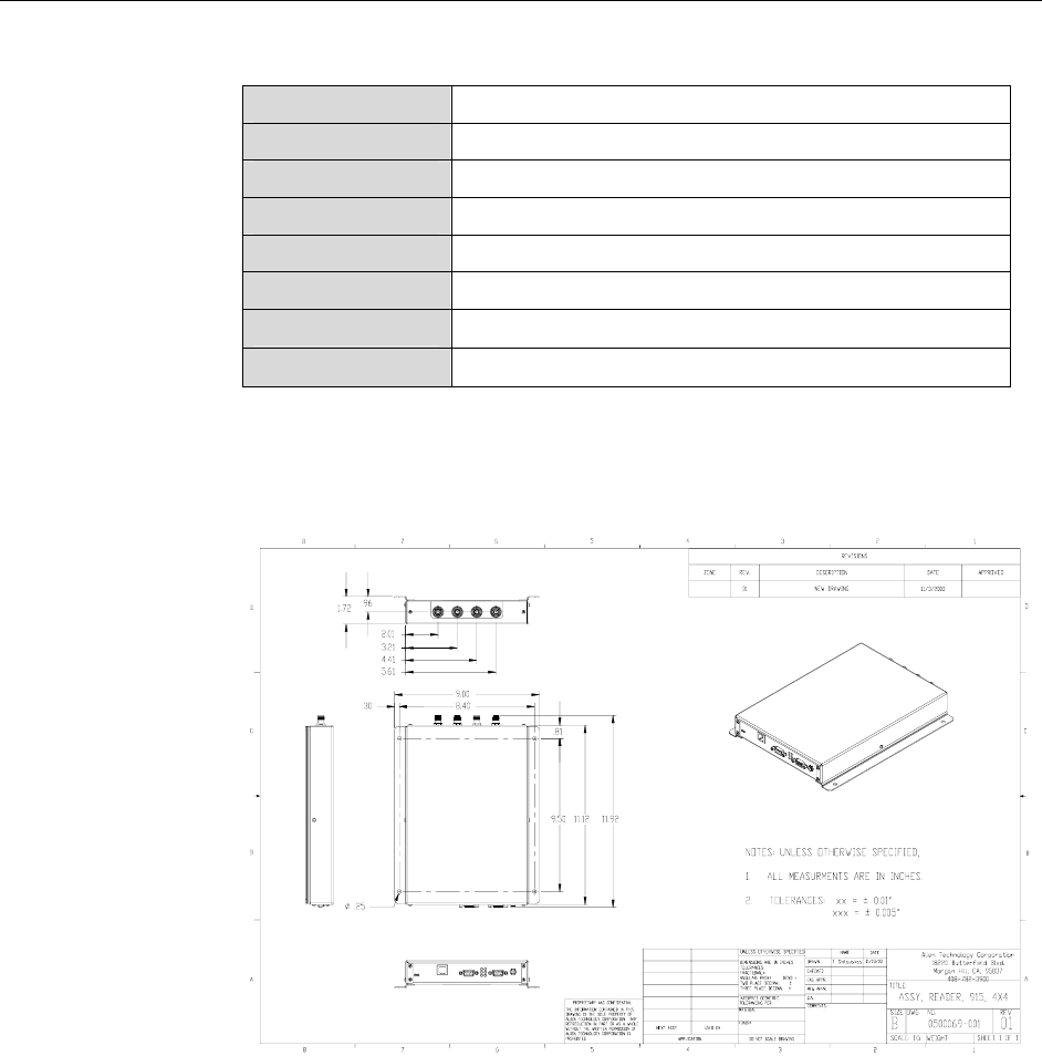
Mechanical
Figure 1. Outline Drawing of the ALR-9780 (ALR-9750-A has the same physical
layout with two antenna ports.)
Hardware Setup Guide: ALR-9780 and ALR-9750-A
Doc. Control #:
© 2003 Alien Technology TM
4
CHAPTER 1 INTRODUCTION
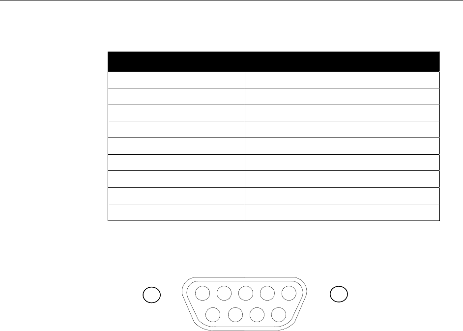
RS-232 Port Pinouts
RS232 Connector (Female DB-9F)
Pin 1 DCD Connected to Pin 6
Pin 2 TR1 Transmit Data (Output)
Pin 3 RC1 Receive Data (Input)
Pin 4 DTR Connected to Pin 6
Pin 5 Ground
Pin 6 DSR Connected to Pin 4
Pin 7 RTS Connected to Pin 8
Pin 8 CTS Connected to Pin 7
Pin 9 Not Connected
RS232 CONNECTOR (FEMALE) –LOOKING AT READER
54321
9 8 7 6
Hardware Setup Guide: ALR-9780 and ALR-9750-A
Doc. Control #:
© 2003 Alien Technology TM
5

CHAPTER 1 INTRODUCTION
IO Port Connector Pinouts
I/O Port Connector (Male DB-9M)
Pin 1 Output 0
Pin 2 Output 2
Pin 3 Input 0
Pin 4 Input 2
Pin 5 Ground
Pin 6 Output 1
Pin 7 Output 3
Pin 8 Input 1
Pin 9 Input 3
I/O PORT CONNECTOR (MALE) –LOOKING AT READER
12345
6 7 8 9
Hardware Setup Guide: ALR-9780 and ALR-9750-A
Doc. Control #:
© 2003 Alien Technology TM
6
CHAPTER 1 INTRODUCTION
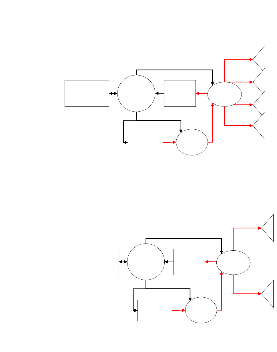
Reader Schematics
RF
Modulator
RF
Receiver
RF Source
Digital
Control
Circuitry
Host
Communication
Interface
A0
A1
A2
A3
Antenna
Switch
Figure 2. System Architecture for the ALR 9780 Reader
RF
Modulator
RF
Receiver
RF Source
Digital
Control
Circuitry
Host
Communication
Interface
A0
A1
Antenna
Switch
Figure 3. System Architecture for the ALR 9750-A
Hardware Setup Guide: ALR-9780 and ALR-9750-A
Doc. Control #:
© 2003 Alien Technology TM
7

CHAPTER 7 WEB BASED APPLICATION EXAMPLES
CHAPTER 2 Reader Hardware Installation and
Operation
This chapter describes the RFID Reader and provides installation and operation
information.
Requirements
In order to interface with the RFID Reader you will need the following:
PC running Windows 98 or higher, with CD-ROM drive (for demo system
software) and one available RS-232 serial port.
Standard 120 VAC power.
Host software (either Alien’s demo software or your own custom software).
Tags (AIDC Class 1 compliant)
Standard power cord (desired length) with grounded, 3-pronged plugs
Receiving the RFID Reader
Your RFID Reader Developer’s Kit will be shipped with the items listed below.
Please verify the contents of your received shipment before assembling.
• RFID Reader
• Antenna with coaxial cable
• RS-232 reader-to-PC cable
• Reader power supply and cables (two sections: one attached, one detached)
• CD-ROM containing demonstration software, user guides and documentation
• Assortment of tags
Picture of Developer’s Kit Contents
The RFID Reader contains two types of external interfaces: connector ports and
LEDs. One panel contains I/O connectors and LEDs. The opposite panel
contains the antenna ports
Hardware Setup Guide: ALR-9780 and ALR-9750-A
Doc. Control #:
© 2003 Alien Technology TM
8
CHAPTER 7 WEB BASED APPLICATION EXAMPLES
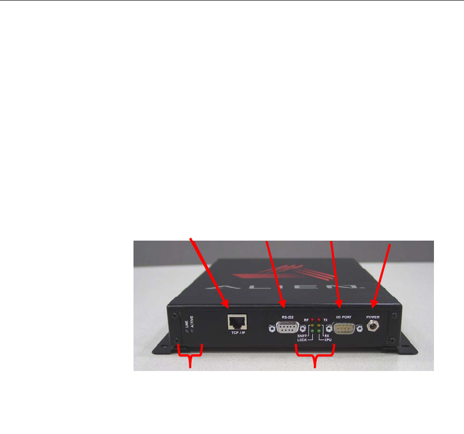
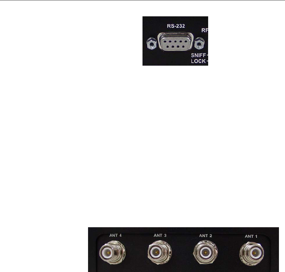
Reader I/O Panel
The I/O panel (shown below) contains the following features:
• Power connector
• 9-pin D male I/O connector
• 6 Diagnostic LEDs (RF Power, RX, TX, CPU Power, Sniff/, Lock/green)
• 9-pin D female RS-232 serial port
• LAN TCP/IP port
• Network Activity LEDs
Power
Connector
I/O
Connector
RS 232
Connector
LAN
Connector
Diagnostic
LEDs
LAN
LEDs
Figure 4. Reader Connections and LEDs
Hardware Setup Guide: ALR-9780 and ALR-9750-A
Doc. Control #:
© 2003 Alien Technology TM
9
CHAPTER 7 WEB BASED APPLICATION EXAMPLES
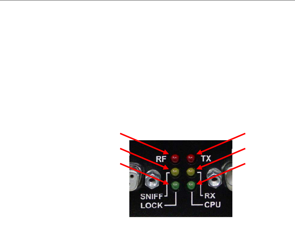
Diagnostic LEDs
The LEDs provide external indication of three conditions:
• CPU Power (green). Indicates power is applied to the reader.
• RF On (red). Indicates that RF is being emitted by the reader.
• Sniff (yellow). Indicates tag signal has been detected, though it may not yet
be strong enough to complete a transaction.
• Lock (green). Indicates a tag has been read.
• TX (red). Indicates transmission of data on serial line to a host.
• RX (yellow). Indicates receipt of data on serial line from a host.
(Red)
(Yellow)
(Green)
(Red)
(Yellow)
(Green)
Figure 5. Reader Diagnostic LEDs
Hardware Setup Guide: ALR-9780 and ALR-9750-A
Doc. Control #:
© 2003 Alien Technology TM
10
CHAPTER 7 WEB BASED APPLICATION EXAMPLES
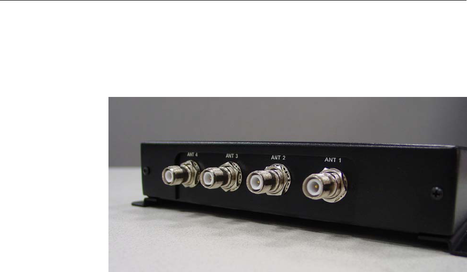
Antenna Panel
The antenna panel (opposite the reader’s I/O panel) contains either two or four
coax antenna connector ports as shown below. These are reverse-polarity TNC
connectors.
Figure 6. Antenna Connections
Hardware Setup Guide: ALR-9780 and ALR-9750-A
Doc. Control #:
© 2003 Alien Technology TM
11
CHAPTER 7 WEB BASED APPLICATION EXAMPLES
System Assembly and Bench Test
Assembling the RFID Reader system is very easy. We recommend you set up
the system and verify its operation in a bench test configuration (shown below)
before installing it in a live application.
Picture of Typical Test Setup
Figure 7. Typical Bench Test Setup
Bench Test Configuration
1. Situate the Reader on a tabletop. Ensure the following conditions:
• Two standard 120 VAC outlets are available nearby (one for reader, one
for PC if needed).
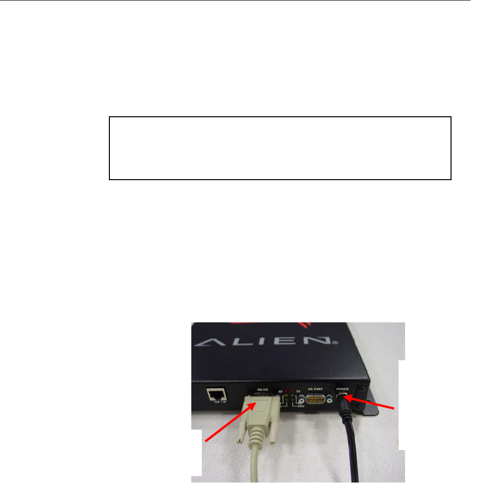
RS232
Connector
(to PC)
Power
Connector
(To power
supply &
120VAC
wall outlet)
Figure 8. RS232 and Power Connections
• Sufficient space is available on the tabletop for the PC, reader and
antenna.
2. Connect the RS-232 cable to the reader.
• Align the male cable connector so that its shape and pins match the
shape and holes of the female DB-9 serial port.
Hardware Setup Guide: ALR-9780 and ALR-9750-A
Doc. Control #:
© 2003 Alien Technology TM
12
CHAPTER 7 WEB BASED APPLICATION EXAMPLES
Figure 9. RS232 Connector
• Push the aligned connector into the port.
• Finger-tighten the screws to secure the cable/connector to the reader.
3. Connect the RS-232 cable to the serial port on the PC.
4. Connect the power supply to the reader.
• Using the thin cable attached to power supply, push the connector into
the port until it is securely seated.
5. Connect the coaxial cable(s) to antenna port(s) (1-4).
• Antenna port 1 is on the right if viewing reader with flange side down.
The ALR 9780 has four (4) antenna ports. The ALR 9750-A has two (2)
antenna ports.
• Align the coax cable’s center pin and push into the port
• Screw the fitting from the cable end onto the reader connector clockwise
until finger tight to secure the cable to the reader.
Figure 10. Antenna Connections
• Connect additional antennas to their respective port and tighten fittings
clockwise until finger tight.
6. Plug power cord into power supply.
• Use the female end of a standard 3-pronged power cord.
7. Plug the power supply cable into the wall outlet and verify power.
• The red LED will be illuminated when power is on.
8. Plug in the PC (if necessary) and turn it on.
• If the PC is a laptop operating on battery power, it is not necessary to
plug it into the wall outlet.
9. Launch the desired host software application.
Hardware Setup Guide: ALR-9780 and ALR-9750-A
Doc. Control #:
© 2003 Alien Technology TM
13

CHAPTER 7 WEB BASED APPLICATION EXAMPLES
• You may use Alien’s demo system software or custom software
developed per the reader-host protocol for your specific application.
You are now ready to bench test or demonstrate the RFID Reader system.
Bench Test Procedure
1. Access an operational mode suitable for bench testing.
• Select a mode that will allow multiple consecutive reads of a single tag.
• Refer to the applicable software application user guide for specific
instructions.
2. Position the reader to you can see the LEDs.
• You may also want to position the PC so you can view the monitor
simultaneously for later tests.
3. Move a tag slowly into the antenna’s range.
• Begin with the tag well outside the expected range (~15-20 ft) and move
it toward the antenna while observing the LEDs.
4. Verify the Sniff LED illuminates when the tag approaches the read
window.
• Sniff is the yellow LED.
5. Verify the Lock LED illuminates when the tag is inside the read window.
• Lock is the green LED.
6. Verify the host receives the tag data.
• Refer to indications specified in applicable user guide to verify the tag
was read successfully.
7. If bench test conditions are verified, proceed to installation.
NOTE: To perform a hard reboot of the system, simply cycle power on the reader.
Hardware Setup Guide: ALR-9780 and ALR-9750-A
Doc. Control #:
© 2003 Alien Technology TM
14

CHAPTER 7 WEB BASED APPLICATION EXAMPLES
Installation
The following Installation section provides basic guidance for configuring
components in your RFID system. You should consider the overall design of your
specific system before permanently mounting the equipment.
Installation involves all the same connection steps required for bench test.
However, instead of situating equipment on a tabletop, the reader and antenna
and their accessories will mounted in your application environment.
The photo below shows a reader with single antenna side-mounted at a loading
dock door for a portal application. This configuration may be used to
automatically identify tagged objects moving in and out of this door. Those
tagged objects may be pallets and cases on pallets, crates, equipment and
vehicles, or personnel.
A second or more (optional) antenna(s) may be mounted on the opposite side of
the portal to better capture tags in a less than optimal position relative to the first
antenna (for example, tagged cases on the opposite side of a pallet).
Picture of a system configured at a dock door.
Requirements
Before installing your RFID Reader system, you will need the following:
PC running Windows 98 or higher, with CD-ROM drive (for demo system
software) and one available RS-232 serial port
Standard 120 VAC power for the reader location and PC location
Host software
(Optional) extra antennas (if desired for additional coverage)
Any additional RS-232 cables or antenna coax cables needed to
accommodate routing requirements
Standard grounded, three-pronged power cord of desired length
Mounting hardware suitable for the surface to which equipment is to be
attached (e.g., wood screws, moly-bolts, brackets, etc.)
Figure 11.RFID Reader system configured for a single-antenna portal
a
pp
lication.
Hardware Setup Guide: ALR-9780 and ALR-9750-A
Doc. Control #:
© 2003 Alien Technology TM
15

CHAPTER 7 WEB BASED APPLICATION EXAMPLES
Mounting
Holes
Figure 12. View of the Reader Showing Mounting Holes
Hardware Installation Procedure
1. Select mounting position for antenna(s).
CAUTION: Reader antennas should be positioned so that personnel in the
area for prolonged periods may safely remain at least 23 cm (9 in) in an
uncontrolled environment from the antenna’s surface. See FCC OET Bulletin
56 “Hazards of radio frequency and electromagnetic fields” and Bulletin 65
“Human exposure to radio frequency electromagnetic fields.”
• Mount the antenna(s) at the periphery of the desired read window (either
overhead or at the side), so that the position of the most distant tag
passing through the window is no farther from the antenna than the
maximum range specified for your system design.
• Position the antenna(s) at a height approximately midway between the
highest and lowest expected tag position. (For example, a pallet tag may
be the lowest tag position to be read, while the top-most case on a fully
stacked pallet may represent your highest tag position.)
• If you are using two antennas, mount the second antenna in a mirror-
image of the first antenna’s position, unless otherwise indicated in your
system design specification.
• NOTE: To maintain compliance with FCC regulations, only use antennas
supplied with the unit.
2. Select mounting position for reader.
• Reader should be positioned close enough to the antenna to
accommodate the cable length without putting strain on the connectors.
• Be sure power is available to the selected reader location.
3. Select location for host PC.
• Situate the host PC within 50 ft of the reader in a safe location away from
vehicular and foot traffic.
Hardware Setup Guide: ALR-9780 and ALR-9750-A
Doc. Control #:
© 2003 Alien Technology TM
16

CHAPTER 7 WEB BASED APPLICATION EXAMPLES
4. Install reader.
• Secure the reader through the two mounting holes on either flange to its
mounting location (wall, post, mounting bracket) using appropriate
hardware.
• If desired, position the reader so that the LEDs are easily observed.
5. Install antennas.
• Secure each antenna through the mounting holes on either flange to its
mounting location using appropriate hardware.
6. Connect antennas to reader.
• Route coax cables from antennas to reader according to your system
design specifications and secure them properly.
• Align the connector for each cable with the reader antenna port, push
into the port, and finger-tighten screw fitting.
7. Connect reader power.
• Push the power supply connector into the reader port.
• Plug the female end of the power cord into the power supply.
• Plug the male end of the power cord into the 120 VAC outlet.
8. Connect reader to host PC.
• Align the RS-232 connector with the corresponding serial port on the
reader and push the connector onto the pins. Finger-tighten the screws
to secure the cable to the reader.
• Align and connect the other end of the RS-232 with the serial port on the
PC.
9. Connect power to the PC.
Hardware Setup Guide: ALR-9780 and ALR-9750-A
Doc. Control #:
© 2003 Alien Technology TM
17

CHAPTER 7 WEB BASED APPLICATION EXAMPLES
Hardware Setup Guide: ALR-9780 and ALR-9750-A
Doc. Control #:
© 2003 Alien Technology TM
18
System Operation: Software Control
The RFID Reader is controlled from software running on a host system that
communicates with the reader using a text-based protocol. All applications use
this protocol to communicate with the reader.
You may operate the reader from your own application code using this interface,
use the example code provided on the Developer’s Kit CD or use the Alien RFID
Gateway application; a demonstration program, also included on your
Developer’s Kit CD.
For details, refer to either the Software Interface Guide or the Demonstration
Software Guide described briefly below.
Software Interface Guide
The text-based interface mentioned above is described in detail in the Software
Interface Guide. Using this interface, the reader can be configured to read tags
when queried or on one of a variety of event triggers (e.g., a rising edge on one
of the I/O pins or a timer.).
Tag data acquired in response to these triggers can be transmitted to the host in
a number of formats (e.g., text, XML or custom) and under a number of
conditions (e.g., on a new tag being observed, or a tag disappearing from view).
If you are a software developer, the Software Interface Guide provides the
information you will need to connect to the reader from a host computer,
communicate with it, and customize its performance.
Demonstration Software Guide
The Demonstration Software Guide describes the installation and operation of
the Alien RFID Gateway Application.
The Alien RFID Gateway Application is a useful demonstration program that
allows users to explore the reader’s functionality and build customizable demos
with a user-friendly interface.
Using the Gateway, the various operating modes of the reader can be controlled
and custom interactive demos can be constructed using sounds images and text.