Alien Technology ALR9890RR Non-multilateration ALR 9890 RFID Reader User Manual revised
Alien Technology Corporation Non-multilateration ALR 9890 RFID Reader revised
UserManual.wiki
>
Alien Technology
>
ALR9890RR User Manual
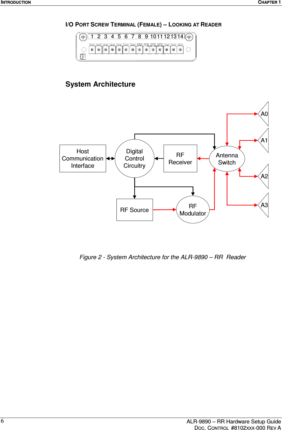
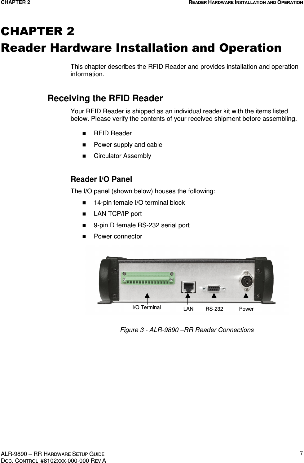
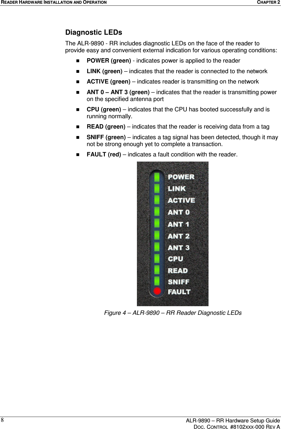
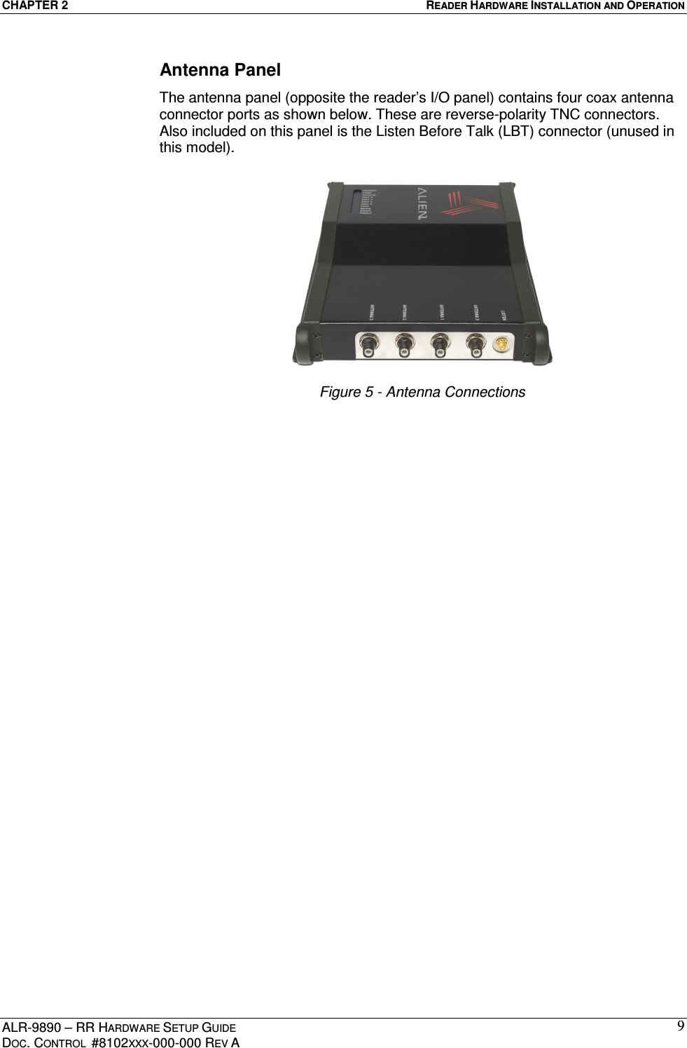
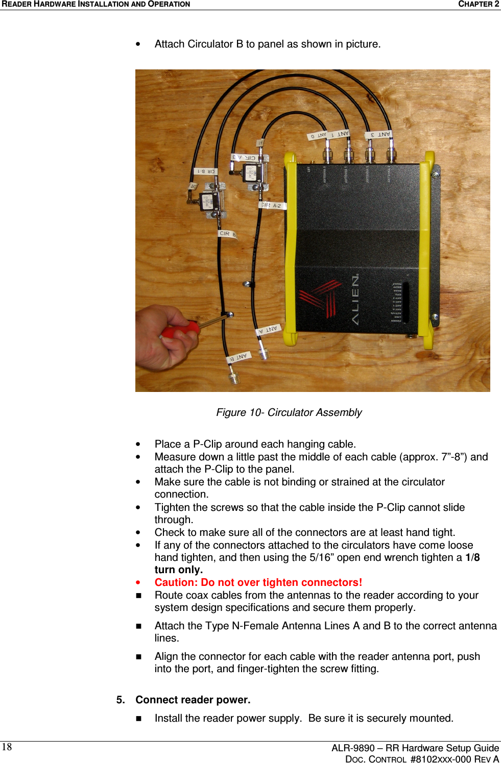
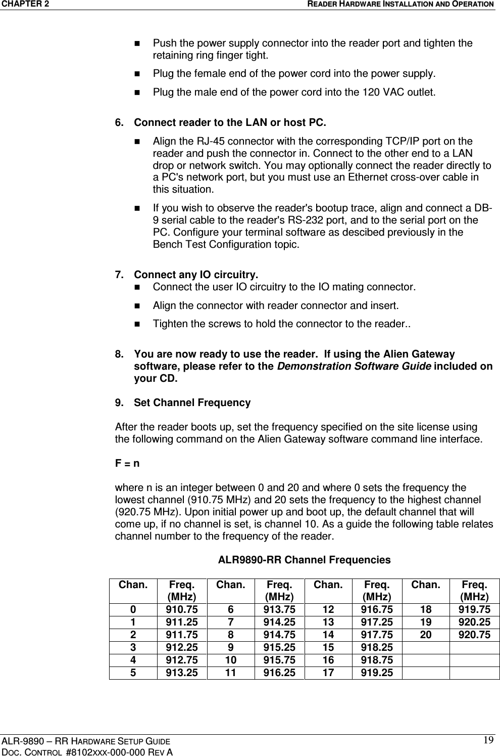
user maual
Navigation menu
Upload a User Manual
Namespaces
Wiki Guide
HTML
PDF
Info
Views
User Manual
Discussion / Help
Navigation