Alien Technology B2450R01-A FHSS Transceiver User Manual User Guide
Alien Technology Corporation FHSS Transceiver User Guide
Users Manual Revised

2450MHz
Battery
ALIEN TECHNOLOGY
2450MHz Battery System
v01.02.00
USER GUIDE

NANOSCANNER READER USER GUIDE • DOC # 8101029-000 REV A i
© 2003 Alien Technology™
COPYRIGHT ACKNOWLEDGEMENTS
The contents of this document are the property of Alien Technology™ Corporation and are
copyrighted. All rights reserved. Any reproduction, in whole or in part, is strictly prohibited.
For additional copies if this document please contact:
Alien Technology Corporation
18220 Butterfield Blvd.
Morgan Hill, CA 95037
www.alientechnology.com
The information contained herein has been carefully checked and is believed to be
accurate; however, no responsibility is assumed for inaccuracies. Alien Technology
Corporation reserves the right to make changes without prior notice. This document is not
covered by any warranty either expressed or implied. Any correction, comments, or
additions to the contents of this document should be directed to Alien Technology
Corporation at the above address.
Copyright 2003 Alien Technology Corporation. Printed in USA.
NanoBlock and FSA are registered trademarks of Alien Technology Corporation. Alien
Technology is a trademark of Alien Technology Corporation. All other trademarks are the
property of their respective owners.
FCC COMPLIANCE
This equipment has been tested and found to comply with the limits for Class A digital
device, pursuant to Part 15 of the FCC Rules. These limits are designed to provide
reasonable protection against harmful interference when the equipment is operated in a
commercial environment. This equipment generates, uses and can radiate radio
frequency energy and, if not installed and used in accordance with instruction manual,
may cause harmful interference with radio communications. Operation of this equipment in
a residential area is likely to cause harmful interference in which case the user will be
required to correct the interference at his
own expense.
Any change or modification to this product voids the user’s authority to operate per FCC
Part 15 Subpart A Section 15.21 regulations.
CAUTION
To meet FCC/Industry Canada RF Safety guidelines, reader antennas should be
positioned so that personnel in the area for prolonged periods may safely remain at
least 20 cm (7.9 in) in an uncontrolled environment from the antenna’s surface. This
device must not be co-located or operating in conjunction with any other antenna
or transmitter. See FCC OET Bulletin 56 “Hazards of radio frequency and
electromagnetic fields” and Bulletin 65 “Human exposure to radio frequency
electromagnetic fields.”

TABLE OF CONTENTS
NANOSCANNER READER USER GUIDE • DOC # 8101029-000 REV A ii
© 2003 Alien Technology™
Alien Technology
Nanoscanner Reader
User Guide
Table of Contents
CHAPTER 1 INTRODUCTION .............................................................................. 1
AUDIENCE ................................................................................................................ 1
NANOSCANNER READER OVERVIEW.......................................................................... 1
Requirements .................................................................................................. 2
Specifications .................................................................................................. 2
Nanoscanner Reader............................................................................................2
Nanoscanner Reader Transmit and Receive Antennas ........................................3
RS-232 Port Pinouts .............................................................................................3
Other Components................................................................................................4
Tag Overview .................................................................................................. 4
Features and benefits ...........................................................................................4
Internal and external interface capabilities............................................................4
Benefits of Battery-powered over Beam-powered Backscatter Tags ....................4
Benefits of Backscatter Tags over “Active” Transmitter Tags ...............................5
Tag Block Diagram ...............................................................................................5
Applications for 2450 MHz Battery-powered Backscatter Tag/Reader
Systems ........................................................................................................... 5
Reader Block Diagrams................................................................................... 6
CHAPTER 2 INSTALLATION AND OPERATION................................................ 7
REQUIREMENTS ....................................................................................................... 7
RECEIVING THE NANOSCANNER DEVELOPER’S KIT..................................................... 7
Nanoscanner Reader Features ....................................................................... 8
I/O Panel...............................................................................................................8
LED Designations .................................................................................................8
Antenna Panel ......................................................................................................9
SYSTEM ASSEMBLY AND BENCH TEST ..................................................................... 10
Bench Test or Demo Connections ................................................................10
Bench Test Procedure................................................................................... 12
SYSTEM DESIGN .................................................................................................... 13
INSTALLATION ........................................................................................................ 13
Installation Procedure.................................................................................... 14
SYSTEM OPERATION .............................................................................................. 16
Software Developers...........................................................................................16
Custom System Users ........................................................................................16
Alien RFID Gateway Demo Software Users........................................................16

TABLE OF CONTENTS
NANOSCANNER READER USER GUIDE • DOC # 8101029-000 REV A iii
© 2003 Alien Technology™
CHAPTER 3 NANOSCANNER SYSTEM FUNDAMENTALS ............................ 17
INTRODUCTION ....................................................................................................... 17
COMMUNICATING WITH THE NANOSCANNER ............................................................. 17
Overview........................................................................................................ 17
Serial Communication.........................................................................................18
Network Communication.....................................................................................18
Web Based Communication................................................................................18
READER DISCOVERY AND THE READER HEARTBEAT................................................. 18
DHCP and Device Auto Discovery ................................................................ 18
Serial Interrogation ........................................................................................ 19
Network Heartbeats....................................................................................... 19
Heartbeats and Software ....................................................................................20
TAG LIST CONCEPTS .............................................................................................. 21
Persist Time................................................................................................... 21
Tag Details ....................................................................................................21
Tag List Size.................................................................................................. 22
READING TAGS OVER THE NETWORK....................................................................... 22
INTERACTIVE MODE ................................................................................................ 22
Basic Tag Read Command .................................................................................22
XML Tag Read Command ..................................................................................22
AUTONOMOUS MODE.............................................................................................. 23
Defining the Autonomous Read Operation.................................................... 23
Enter Autonomous Mode (Not shown on the state diagram.).............................23
Waiting State.......................................................................................................23
Start Working Trigger..........................................................................................24
Working State .....................................................................................................24
Stop Working Trigger ..........................................................................................25
Evaluation ...........................................................................................................25
True/False Pause................................................................................................25
Notify...................................................................................................................25
Autonomous Mode Examples ....................................................................... 25
Example 1. Background Reading.......................................................................25
Example 2. Triggered Reading ..........................................................................26
Example 3. Triggered Reading with Notification .................................................26
NOTIFICATION MODE .............................................................................................. 27
Defining the Notification Address .................................................................. 28
Defining the Notification Format .................................................................... 28
LISTENING FOR TAGS OVER THE NETWORK.............................................................. 29
CHAPTER 4 TAG READING FUNDAMENTALS ............................................... 30
INTRODUCTION ....................................................................................................... 30
ACQUIRE MODE ..................................................................................................... 30
Global Scroll........................................................................................................30
Inventory .............................................................................................................31
Compatibility Chart..............................................................................................31
MASKS AND TAG MEMORY STRUCTURE................................................................... 32
Class I Tag Memory............................................................................................32
Class BPT Tags ..................................................................................................32
Mask Command Format .....................................................................................33
Addressing All Tags ............................................................................................33
Addressing A Single Tag ....................................................................................33
Address a Subset of Tags...................................................................................33
Compatibility Chart..............................................................................................34
PERSISTENT SLEEP AND WAKE ............................................................................... 35
AcquireSleep.......................................................................................................35
AcquireWakeCount .............................................................................................35
Sleep, Wake and Masks .....................................................................................36
Compatibility Chart..............................................................................................36

TABLE OF CONTENTS
NANOSCANNER READER USER GUIDE • DOC # 8101029-000 REV A iv
© 2003 Alien Technology™
CHAPTER 5 READERHOST COMMUNICATIONS INSTALLATION............ 37
INTRODUCTION ....................................................................................................... 37
Audience........................................................................................................ 37
Requirements ................................................................................................ 38
Conventions................................................................................................... 38
SETTING UP READER-HOST COMMUNICATIONS ........................................................ 38
Command Line Operation: Direct Serial Communication ............................. 38
Command Line Operation: Telnet Communication ....................................... 39
HTML-Based Operation: Web Communication ............................................. 39
INSTALLING READER ON HOST VIA SERIAL PORT (ALL) ............................................ 39
NETWORK INSTALLATION (OPTIONAL) ...................................................................... 41
CHAPTER 6 READERHOST PROTOCOL..................................................... 44
INTRODUCTION ....................................................................................................... 44
READER OPERATION OVERVIEW ............................................................................. 44
Text-Based Command Line Operation.......................................................... 45
Web-based HTML Operation ........................................................................ 45
COMMANDS OVERVIEW........................................................................................... 47
Interactive Commands ........................................................................................47
Autonomous Commands ....................................................................................47
Command Format.......................................................................................... 47
Suppressing Command Prompts .................................................................. 48
Interactive Command Format..............................................................................48
Non-Interactive Command Format......................................................................48
XML Commands............................................................................................ 48
Command List with Functions ....................................................................... 49
General Commands............................................................................................49
Network Configuration Commands .....................................................................49
Time Commands.................................................................................................50
External IO Commands.......................................................................................50
Tag List Commands............................................................................................50
Autonomous Mode Commands...........................................................................50
Notify Mode Commands .....................................................................................51
USING THE COMMANDS .......................................................................................... 52
General Commands – Text Based ................................................................ 52
Help (h) ...............................................................................................................52
Info (i)..................................................................................................................52
!...........................................................................................................................52
Q (Quit) ...............................................................................................................52
Get TagList .........................................................................................................52
Get ReaderName................................................................................................52
Set ReaderName ................................................................................................52
Get ReaderType .................................................................................................53
Get ReaderVersion .............................................................................................53
Get Username.....................................................................................................53
Set Username .....................................................................................................53
Get Password .....................................................................................................53
Set Password......................................................................................................53
Get AntennaSequence........................................................................................54
Set AntennaSequence ........................................................................................54
Reboot ................................................................................................................55
FactorySettings ...................................................................................................55
General Commands – Web Based................................................................ 55
Commands/Operations via Web General Tab ...................................................55
Network Configuration Commands – Text Based ......................................... 57
Get DHCP ...........................................................................................................57
Set DHCP ...........................................................................................................57
Get IPAddress.....................................................................................................57
Set IPAddress .....................................................................................................57

TABLE OF CONTENTS
NANOSCANNER READER USER GUIDE • DOC # 8101029-000 REV A v
© 2003 Alien Technology™
Get Gateway .......................................................................................................57
Set Gateway .......................................................................................................57
Get Netmask .......................................................................................................58
Set Netmask .......................................................................................................58
Get DNS..............................................................................................................58
Set DNS..............................................................................................................58
Get HeartbeatPort...............................................................................................59
Set HeartbeatPort ...............................................................................................59
Get HeartbeatTime .............................................................................................59
Set HeartbeatTime..............................................................................................59
Get CommandPort ..............................................................................................60
Set CommandPort ..............................................................................................60
Network Commands – Web Based ............................................................... 60
Commands/Operations via Web Network Tab ....................................................61
Time Commands – Text Based..................................................................... 62
Get Time .............................................................................................................62
Set Time..............................................................................................................62
Get TimeZone .....................................................................................................62
Set TimeZone .....................................................................................................62
Get TimeServer...................................................................................................63
Set TimeServer ...................................................................................................63
Time Commands – Web Based .................................................................... 64
Commands/Operations via Web Time Tab .........................................................64
External I/O Commands ................................................................................ 65
Set ExternalOutput..............................................................................................65
Get ExternalOutput .............................................................................................65
Get ExternalInput ................................................................................................65
External I/O Commands – Web Based ......................................................... 66
Commands/Operations on Web External I/O Tab...............................................66
Tag List Commands – Command Line.......................................................... 67
Get TagList (n) ....................................................................................................67
Set TagListFormat ..............................................................................................67
Get TagListFormat ..............................................................................................67
NOTE: Changes made with this command will take effect immediately.Set
TagListCustomFormat ........................................................................................68
Set TagListCustomFormat ..................................................................................69
Get TagListCustomFormat..................................................................................69
Get AcquireMode ................................................................................................70
Get AcquireSleep................................................................................................70
Get AcquireWakeCount ......................................................................................71
Get Mask.............................................................................................................71
Set Mask.............................................................................................................71
Clear TagList.......................................................................................................72
Get PersistTime ..................................................................................................72
Set PersistTime...................................................................................................72
Wake...................................................................................................................73
Sleep...................................................................................................................73
Tag List Commands – Web Based................................................................ 74
Commands/Operations on Web Tag List Tab .....................................................74
Autonomous Mode Commands..................................................................... 75
Get AutoMode.....................................................................................................75
Get AutoWaitOutput............................................................................................75
Get AutoStartTrigger...........................................................................................76
Get AutoWorkOutput...........................................................................................76
Get AutoAction....................................................................................................76
Get AutoStopTrigger ...........................................................................................77
Get AutoStopTimer .............................................................................................77
Get AutoTrueOutput............................................................................................78
Get AutoTruePause ............................................................................................78
Get AutoFalseOutput ..........................................................................................78
Get AutoFalsePause...........................................................................................79

TABLE OF CONTENTS
NANOSCANNER READER USER GUIDE • DOC # 8101029-000 REV A vi
© 2003 Alien Technology™
Get AutoModeStatus...........................................................................................79
AutoModeReset ..................................................................................................80
AutoModeTriggerNow .........................................................................................80
Autonomous Mode Commands – Web Based .............................................. 81
Commands/Operations on Web Autonomous Mode Tab....................................81
Notify Mode Commands ................................................................................ 82
Get NotifyMode ...................................................................................................82
Get NotifyAddress...............................................................................................82
Set NotifyAddress ...............................................................................................82
Get NotifyTime ....................................................................................................83
Set NotifyTime ....................................................................................................83
Get NotifyTrigger.................................................................................................83
Set NotifyTrigger .................................................................................................83
Get NotifyFormat................................................................................................84
Set NotifyFormat .................................................................................................84
Get MailServer ....................................................................................................85
Set MailServer ....................................................................................................85
Get MailFrom ......................................................................................................85
Set MailFrom.......................................................................................................85
NotifyNow............................................................................................................86
Notify Mode Commands – Web Based ......................................................... 87
Commands/Operations on Web Autonomous Mode Tab....................................87
CHAPTER 7 READERHOST PROTOCOL EXTENSIONS FOR BATTERY
POWERED BACKSCATTER TAGS................................................................... 88
INTRODUCTION ....................................................................................................... 88
Masks ............................................................................................................ 88
Tags............................................................................................................... 88
Memory.......................................................................................................... 88
Sensors ......................................................................................................... 88
Logging.......................................................................................................... 88
Command List with Functions ....................................................................... 89
Tag Commands ..................................................................................................89
Memory Commands............................................................................................89
Sensor Commands .............................................................................................89
Logging Commands............................................................................................89
USING THE COMMANDS .......................................................................................... 90
Tag Commands ............................................................................................. 90
Get Tagid ............................................................................................................90
Get Taginfo .........................................................................................................90
Get TagVersion...................................................................................................91
Get Tagtime ........................................................................................................91
Set Tagtime.........................................................................................................91
Memory Commands ......................................................................................92
Set Memory.........................................................................................................92
Get Memory ........................................................................................................92
Set MemoryPacketSize.......................................................................................93
Get MemoryPacketSize ......................................................................................93
Clear Memory .....................................................................................................93
Sensor Commands........................................................................................ 94
Get SensorValue.................................................................................................94
Logging Commands ...................................................................................... 94
Get LoggingMode ...............................................................................................94
Set LoggingMode................................................................................................94
Get LoggingInterval.............................................................................................95
Set LoggingInterval .............................................................................................95
CHAPTER 8 WEB BASED APPLICATION EXAMPLES ................................... 96
READOMETER ........................................................................................................ 96
TAG LIST................................................................................................................ 97

TABLE OF CONTENTS
NANOSCANNER READER USER GUIDE • DOC # 8101029-000 REV A vii
© 2003 Alien Technology™
OPTIMIZE READER SETTINGS.................................................................................. 98
Readometer Settings..................................................................................... 98
Tag List Settings............................................................................................ 98
Advanced Tag List Options ...........................................................................99
Running Tag List using Global Scroll as the Acquire Mode ................................99
Running Tag List in duty cycle mode ..................................................................99

CHAPTER 1 INTRODUCTION
NANOSCANNER READER USER GUIDE • DOC # 8101029-000 REV A 1
© 2003 Alien Technology™
CHAPTER 1
Introduction
The Nanoscanner Reader User Guide provides instructions for installing and
operating the Nanoscanner reader. It also covers the reader firmware protocol in
detail for use in configuring reader-host communications and developing
application software.
This book is designed for use by those who wish to develop software products
and extended systems that take full advantage of the Nanoscanner reader’s
capabilities.
For an overview of RFID technology and a glossary of terms, please refer to the
RFID Primer included with your Nanoscanner Reader Developer’s Kit.
Audience
For the purposes of this book, we assume the readers of the Nanoscanner User
Guide:
Are competent PC users.
Have minimal previous knowledge of radio-frequency identification
technology.
Are experienced in software development and/or hardware systems
integration.
Nanoscanner Reader Overview
The Nanoscanner is delivered with the following components and accessories:
• Nanoscanner reader and tags
• Two antennas (1 transmit, 1 receive) with 2 coaxial cables
• RS-232 reader-to-PC cable (with 9-pin male and female connectors)
• Reader power supply and cables (two sections: one attached, one detached)
• Nanoscanner Reader User Guide on CD-ROM

CHAPTER 1 INTRODUCTION
NANOSCANNER READER USER GUIDE • DOC # 8101029-000 REV A 2
© 2003 Alien Technology™
Requirements
In order to fully interface with the Nanoscanner reader you will need the
following:
PC running Windows 98 or higher, with CD-ROM drive and one available
RS-232 serial port.
Standard 120 VAC power.
Host software (Alien demo software or your own custom software).
Alien battery-powered backscatter tags
Standard power cord (desired length) with grounded, 3-pronged plugs
Specifications
Specifications for key components of the Nanoscanner reader system are
provided in the tables below:
NANOSCANNER READER
Name Nanoscanner Reader
Part Number 0500017-001
Model Number B2450R01-A
Architecture Point-to-multipoint reader network
Frequency 2410 MHz – 2471.64 MHz
Hopping Channels 75
Channel Spacing 833 KHz
Channel Dwell Time < 0.3 Seconds
RF Transmitter < 30 dBm
Modulation Method On Off Keying (OOK)
20 db Modulation Bandwidth 500KHz
RF Receiver 2 channels
Power Consumption 25 Watts (120 VAC at 500 mW)
Communications Interface RS-232, LAN TCPI/IP
Inputs/Outputs 2 coax antenna, 8 logic I/O, comm ports, power
Dimensions (cm) 17.8 x 24.1 x 6.7 (in) 7 x 9.5 x 2.63
Weight Approximately 1.8 kg (4 lb)
Operating Temperature 0°C to +50°C (+32 °F to +122°F)
CHAPTER 1 INTRODUCTION
NANOSCANNER READER USER GUIDE • DOC # 8101029-000 REV A 3
© 2003 Alien Technology™
NANOSCANNER READER TRANSMIT AND RECEIVE ANTENNAS
3 dB Beamwidth Azimuth 55° Elevation 55°
Frequency 2410 MHz – 2471.64 MHz
Gain (dBi) ≤ 6 dBi
Polarization Circular
RF Connector Reverse-gender TNC
VSWR 1.5:1
Dimensions (cm) 15.2 x 15.2 x 3.2 • (in) 6 x 6 x 1.25
Weight .27 kg • 0.6 lb
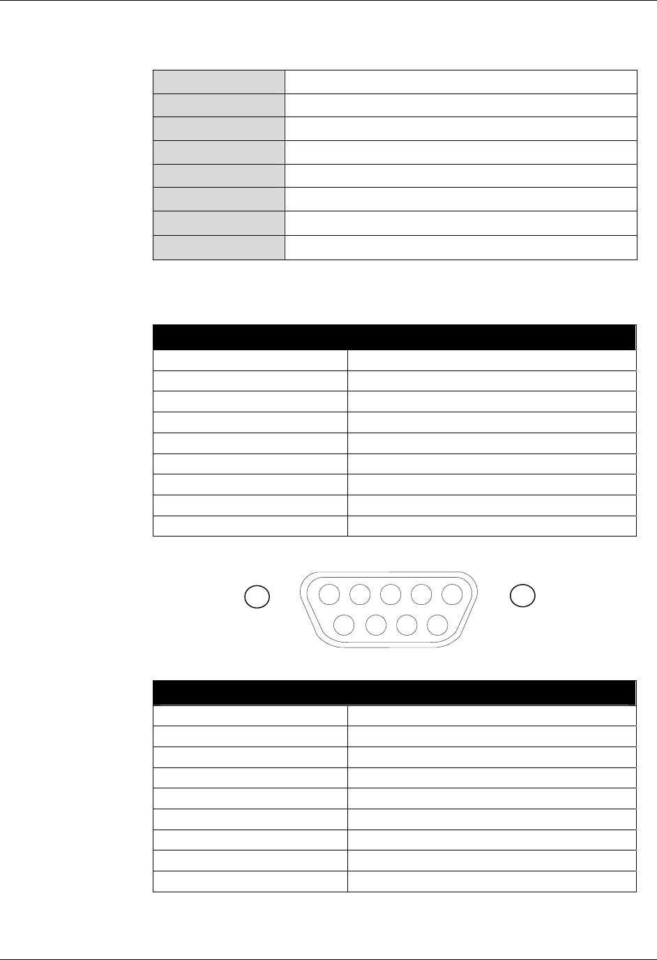
RS-232 PORT PINOUTS
RS232 Connector (female)
Pin 1 Connected to pins 4 and 6
Pin 2 Request to send from host
Pin 3 Clear to send to host
Pin 4 Connected to pins 1 and 6
Pin 5 Ground
Pin 6 Connected to pins 1 and 4
Pin 7 Receive (Rx) from host
Pin 8 Transmit (Tx) to host
Pin 9 Not Connected
I/O Port Connector (male)
Pin 1 Out 0
Pin 2 Out 1
Pin 3 Out 2
Pin 4 Out 3
Pin 5 Ground
Pin 6 In 0
Pin 7 In 1
Pin 8 In 2
Pin 9 In 3
NOTE: Reader I/O pins can be configured for high-to-low or low-to-high
transitions through software control.
54321
9 8 7 6
CHAPTER 1 INTRODUCTION
NANOSCANNER READER USER GUIDE • DOC # 8101029-000 REV A 4
© 2003 Alien Technology™
OTHER COMPONENTS
RS-232 Serial Cable DB-9 male/female serial
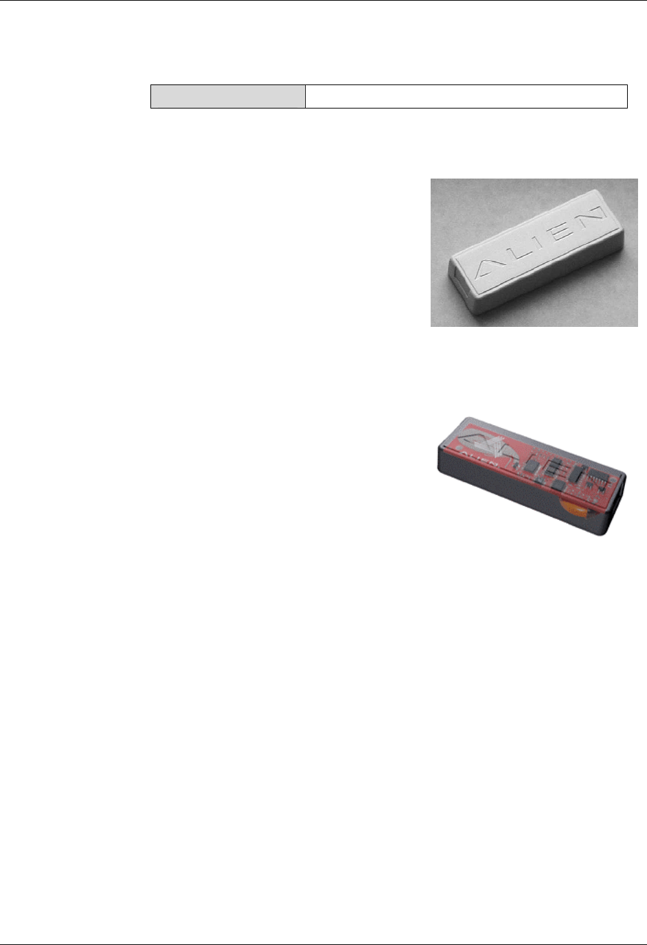
Tag Overview
Battery-powered backscatter tags are used
exclusively in this Alien 2450 MHz system.
FEATURES AND BENEFITS
• Long-range tag/sensor/actuator – up to
30 meters
• 2450MHz, FCC Part 15 unlicensed
power levels
• 12 byte ID (read-write memory)
• 4 I/O pins, with A->D and D->A
converter
• Expandable read/write NV memory,
capable of being expanded to 256K
INTERNAL AND EXTERNAL INTERFACE
CAPABILITIES
• Temperature sensing/recording
• Tamper detection (banding material
broken, box opened, etc.)
• Shock, vibration, tilt and acceleration monitoring
• Enabling and disabling electronic devices (security)
• Beeping or blinking tags for quick location and alarms
BENEFITS OF BATTERY-POWERED OVER BEAM-POWERED BACKSCATTER TAGS
• Higher performance-to-price ratio
• Monitoring (e.g., temperature logging, time-based tamper detection)
• Better accuracy (longer range = more margin at a shorter range
• Lower-power readers (unlicensed)
• Multi-region (worldwide) antenna (Only needs to modulate and backscatter
the reader‘s signal. RF energy is not powering the device.)
• Range and bearing – positioning possible
A
lien battery
-
p
owered backscatter tag: outer
case (above) and (transparent case
showing internal circuitry (below).
CHAPTER 1 INTRODUCTION
NANOSCANNER READER USER GUIDE • DOC # 8101029-000 REV A 5
© 2003 Alien Technology™
BENEFITS OF BACKSCATTER TAGS OVER “ACTIVE” TRANSMITTER TAGS
• Lower cost, simpler circuitry
• Longer battery life
• Stealthier (safer in sensitive environments, e.g., airplane)
• No transmitter tags can be used worldwide due to licensing issues, spectral
pollution, etc.
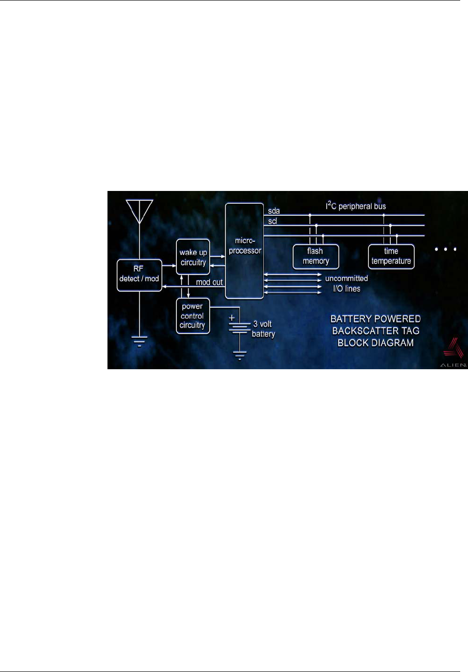
TAG BLOCK DIAGRAM
The following diagram illustrates the design of the battery-powered backscatter
tag.
Applications for 2450 MHz Battery-powered Backscatter
Tag/Reader Systems
A variety of applications have already been identified that can benefit from the
use of battery-powered backscatter tags and readers, including the following:
• Long range identification
• Vehicle-asset tracking
• Supply chain automation
• Time temperature monitoring
• Tamper detection (safe/secure supply chain)
• Security/ access systems
• Sensor monitoring
• Immobilizer / beeper / LED (can control outputs)
• Passive tag data storage for hierarchical asset tracking systems
• Location capability has been proven
CHAPTER 1 INTRODUCTION
NANOSCANNER READER USER GUIDE • DOC # 8101029-000 REV A 6
© 2003 Alien Technology™
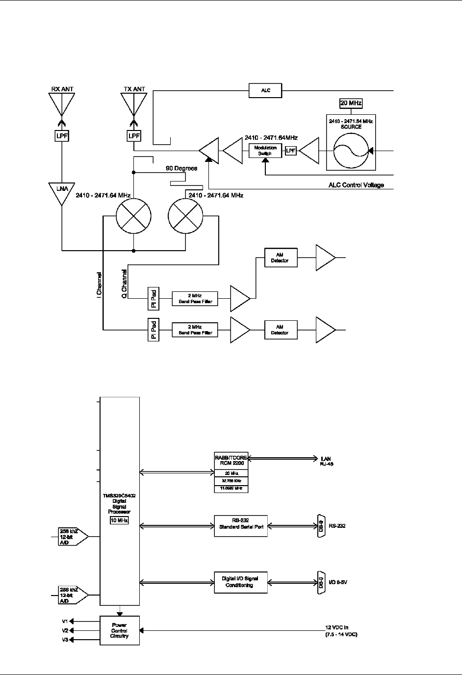
Reader Block Diagrams
2450 MHz Reader Front End
2450 MHz Reader Logic Blocks

CHAPTER 2 INSTALLATION AND OPERATION
NANOSCANNER READER USER GUIDE • DOC # 8101029-000 REV A 7
© 2003 Alien Technology™
CHAPTER 2
Installation and Operation
This chapter describes the Nanoscanner reader and provides installation and
operation information. Later chapters detail networking and the Reader<–>Host
protocol, which will allow you to create software that will interact with the reader
and perform the desired processing functions.
Requirements
In order to fully interface with the Nanoscanner reader you will need the
following:
PC running Windows 98 or higher, with CD-ROM drive (for demo system
software) and one available RS-232 serial port.
Standard 120 VAC power.
Host software (either Alien’s demo software or your own custom software).
Alien battery-powered backscatter tags
Standard power cord (desired length) with grounded, 3-pronged plugs
Receiving the Nanoscanner Developer’s Kit
Your Nanoscanner Reader Developer’s Kit
will be shipped with the items listed below.
Please verify the contents of your received
shipment before assembling.
• Nanoscanner reader
• Two antennas (1 transmit (Tx), 1
receive (Rx)) with 2 coaxial cables
• RS-232 reader-to-PC cable (with 9-pin
male and female connectors)
• Reader power supply and cables (two
sections: one attached, one detached)
• CD-ROM containing demonstration
software, user guides and documentation
• Assortment of tags
CHAPTER 2 INSTALLATION AND OPERATION
NANOSCANNER READER USER GUIDE • DOC # 8101029-000 REV A 8
© 2003 Alien Technology™
Nanoscanner Reader Features
The Nanoscanner reader contains only two types of external user interface:
connector ports and LEDs. One panel contains I/O connectors and LEDs. The
side panel contains the antenna ports
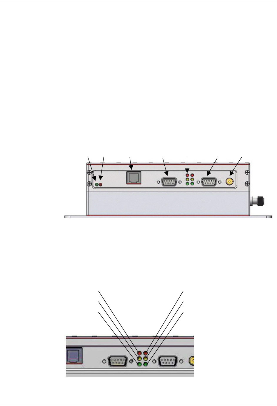
I/O PANEL
The I/O panel (shown below) contains the following features:
• Network LEDs (2)
• LAN TCP/IP port
• 9-pin D male I/O port
• Reader LEDs (6)
• 9-pin D female RS-232 serial port
• Power connector
LED DESIGNATIONS
Reader LEDs provide external indication of six conditions as shown in both the
illustration below and the table that follows it:
Reader I/O panel
Power connect
I/O
(male)
LEDs
RS-232
(female)
LAN
TCP/IP
Network LEDs
Link Active
A
ntenna
ports
(Tx, Rx)
RF Powe
r
Snif
f
Lock
TX
RX
Processor Running
Reader LED designations on I/O panel
CHAPTER 2 INSTALLATION AND OPERATION
NANOSCANNER READER USER GUIDE • DOC # 8101029-000 REV A 9
© 2003 Alien Technology™
Reader LEDs
Left Column LEDs Right Column LEDs
Red RF on Red Comm TX
Communications transmit
to processor
Yellow Sniff
Detect tag signal
Yellow Comm RX
Communications receive
from processor
Green Lock
Lock on tag signal
Green Processor Running
Network LEDs
Green Link Red Active
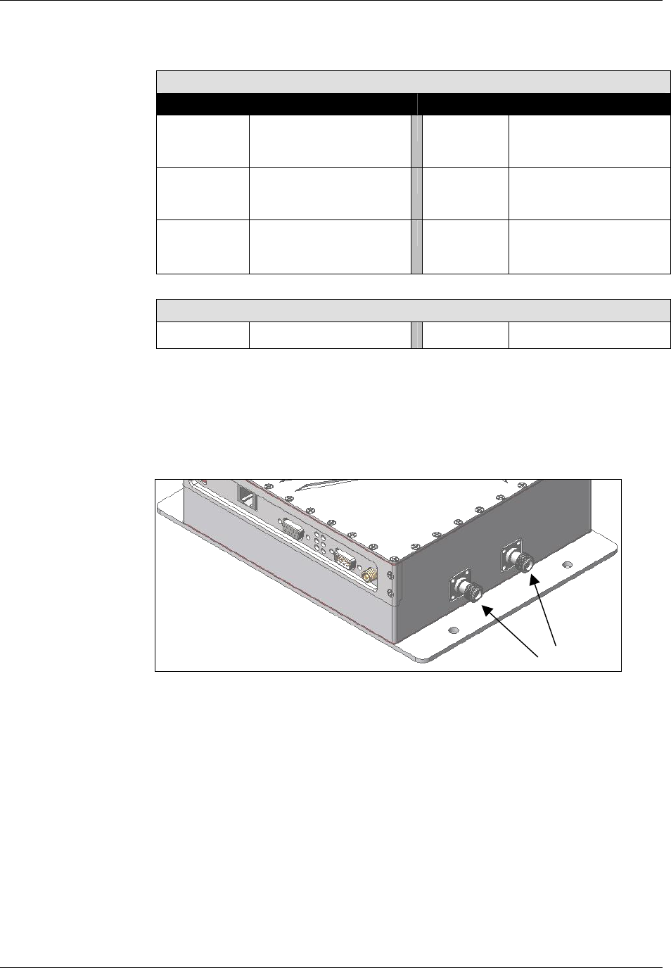
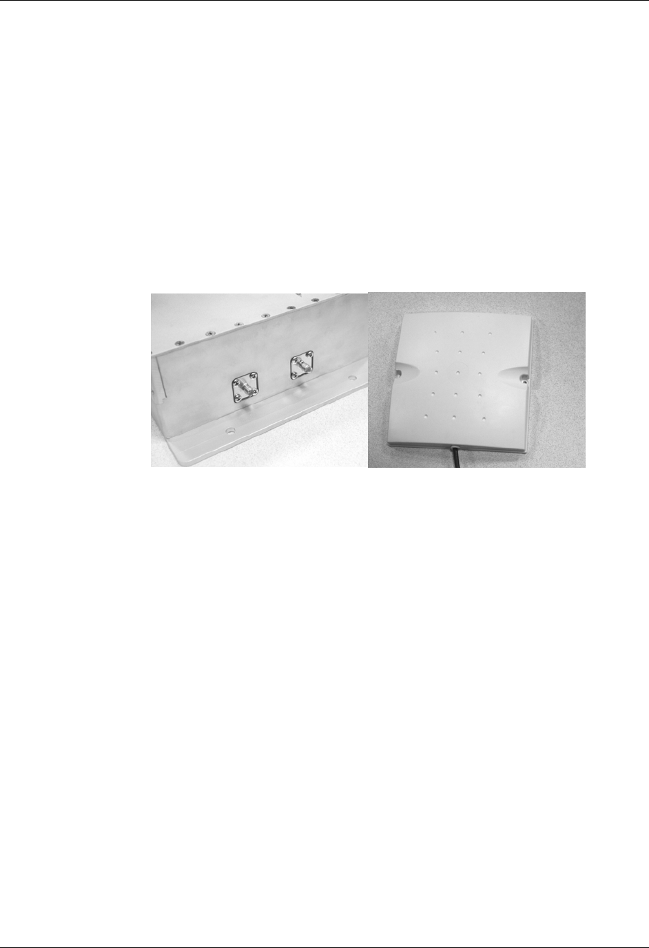
ANTENNA PANEL
The antenna panel (perpendicular to the reader’s I/O panel) contains two coax
antenna connector ports as shown below. These are reverse-gender connectors.
Use the antenna marked Tx on the Tx connector and the antenna marked Rx on
the Rx connector.
Antenna connectors (reverse gender)
Tx Rx
CHAPTER 2 INSTALLATION AND OPERATION
NANOSCANNER READER USER GUIDE • DOC # 8101029-000 REV A 10
© 2003 Alien Technology™
System Assembly and Bench Test
Assembling the Nanoscanner reader system is very easy.
We recommend you set up the system and verify its operation in a bench test
configuration before installing it in a live application.
You will need two available 120 VAC wall outlets.
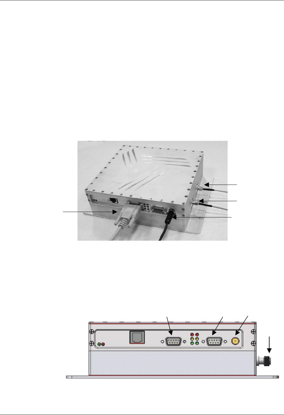
Bench Test or Demo Connections
1. Situate the PC on a tabletop. Ensure the following conditions:
• Two standard 120 VAC outlets are available nearby (one for reader, one
for PC if needed).
• Sufficient space is available on the tabletop for the PC, reader and
antenna.
2. Connect the RS-232 cable to the reader.
• Align the cable connector so that its shape and pins match the shape
and holes of the DB-9 serial port.
• Push the aligned connector into the port.
• Finger-tighten the screws to secure the cable/connector to the reader.
Antennas
Ports
To power supply &
120 VAC wall outlet
RS-232 to PC
Reader I/O panel
Power connect
I/O
(male)
A
nntena
Ports
RS-232
(female)
Tx
Rx
CHAPTER 2 INSTALLATION AND OPERATION
NANOSCANNER READER USER GUIDE • DOC # 8101029-000 REV A 11
© 2003 Alien Technology™
3. Connect the RS-232 cable to the serial port on the PC.
4. Connect antenna coaxial cables to each antenna connectors.
• Connect the antenna marked Tx to the Tx connector of the reader and
connect the antenna marked Rx on the Rx connector.
• Align the coax cable’s center pin and push into the port
• Screw the fitting from the cable end onto the reader connector clockwise
until finger tight to secure the cable to the reader.
CAUTION: Antennas must be attached before connecting power to the
reader. Applying power without both antennas connected (or the ports properly
terminated) can damage the reader.
5. Connect the power supply to the reader.
• Using the thin cable attached to power supply, push the connector into
the port until it is securely seated.
6. Plug power cord into power supply.
• Use the female end of a standard 3-pronged power cord.
7. Plug the power supply cable into the wall outlet and verify power.
• The red LED will be illuminated when power is on.
8. Plug in the PC (if necessary) and turn it on.
• If the PC is a laptop operating on battery power, it is not necessary to
plug it into the wall outlet.
9. Launch the desired host software application.
• You may use Alien’s RFID Gateway demo system software or custom
software developed per the reader-host protocol for your specific
application.
You are now ready to bench test or demonstrate the Nanoscanner system.
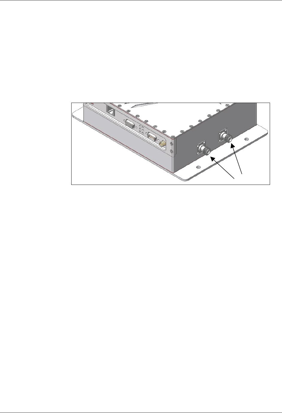
Antenna ports (reverse gender)
Rx
Tx

CHAPTER 2 INSTALLATION AND OPERATION
NANOSCANNER READER USER GUIDE • DOC # 8101029-000 REV A 12
© 2003 Alien Technology™
Bench Test Procedure
1. Access an operational mode suitable for bench testing.
• Select a mode that will allow multiple consecutive reads of a single tag.
• Refer to the applicable software application user guide for specific
instructions.
2. Position the reader to you can see the LEDs.
• You may also want to position the PC so you can view the monitor
simultaneously for later tests.
3. Shield a tag in a metal enclosure or enclosed in your hand.
• Begin with the tag shielded from the reader antennas and move it toward
the antenna while observing the LEDs.
4. Verify the Sniff LED illuminates when the tag approaches the read
window.
• Sniff is the yellow LED on the left-hand column of LEDs at the center of
the reader I/O panel.
5. Verify the Lock LED illuminates when the tag is inside the read window.
• Lock is the green LED in the left-hand column of LEDs at the center of
the reader I/O panel.
6. Verify the host receives the tag data.
• Refer to indications specified in applicable user guide to verify the tag
was read successfully.
7. If bench test conditions are verified, proceed to installation.
NOTE: If all conditions appear to be operational but system fails to read tags,
disconnect system power and reapply power to perform a hard reset.
CHAPTER 2 INSTALLATION AND OPERATION
NANOSCANNER READER USER GUIDE • DOC # 8101029-000 REV A 13
© 2003 Alien Technology™
System Design
The following Installation section provides basic guidance for configuring
components in your RFID system. You should consider the overall design of your
specific system before permanently mounting the equipment.
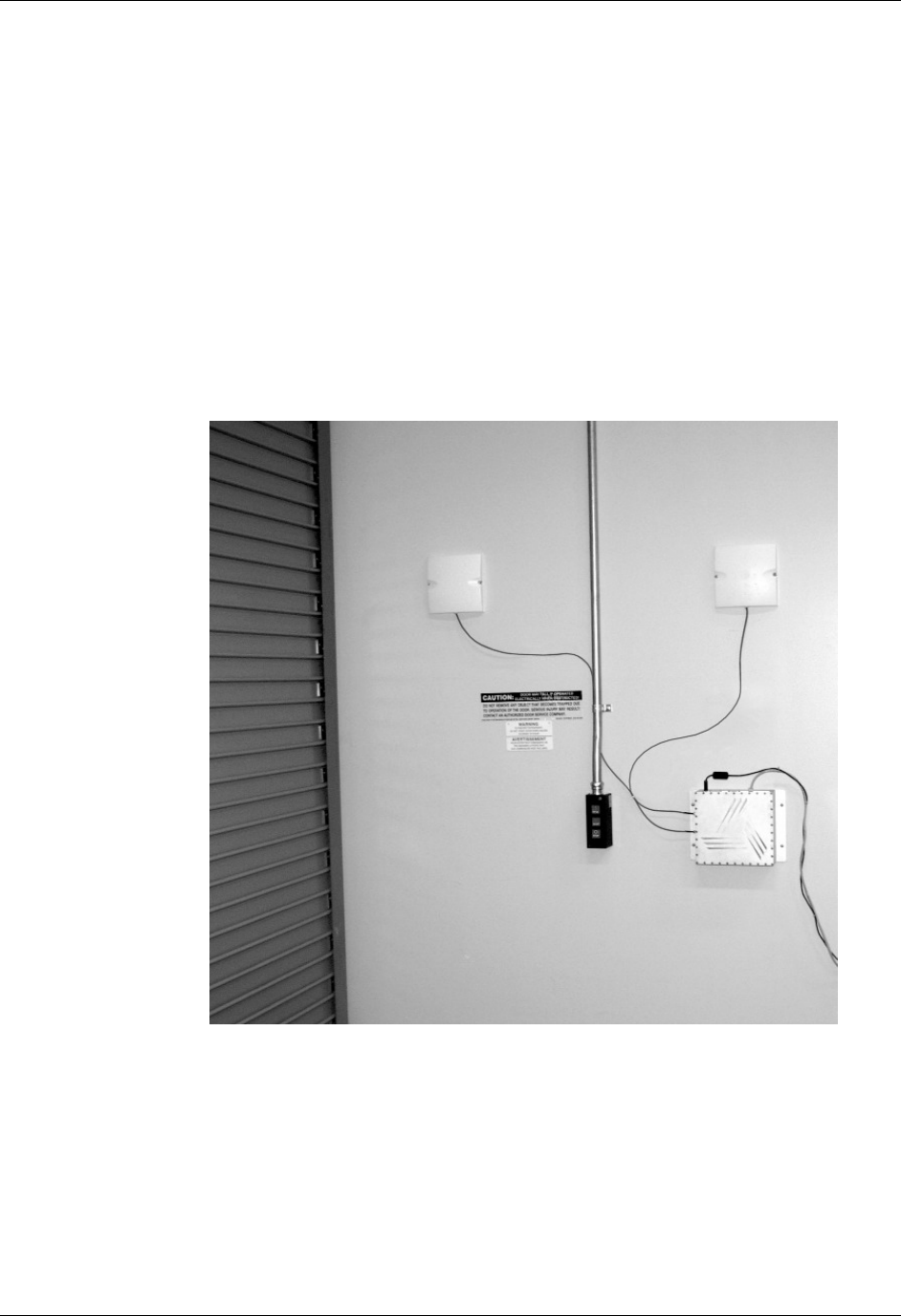
Installation
Installation involves all the same connection steps required for bench test.
However, instead of situating equipment on a tabletop, the reader and antenna
and their accessories will mounted in your application environment.
Antennas should be mounted at least ½ meter (1.5 ft) apart, situated at the
average height at which tags are expected to be presented to the system.
CHAPTER 2 INSTALLATION AND OPERATION
NANOSCANNER READER USER GUIDE • DOC # 8101029-000 REV A 14
© 2003 Alien Technology™
Requirements
Before installing your Nanoscanner reader system you will need the following:
PC running Windows 98 or higher, with CD-ROM drive (for demo system
software) and one available RS-232 serial port
Standard 120 VAC power for the reader location and PC location
Host software
Any additional RS-232 cables or connectorized antenna coax cables needed
to accommodate routing requirements
Standard grounded, three-pronged power cord of desired length
Mounting hardware suitable for the surface to which equipment is to be
attached (e.g., wood screws, moly-bolts, brackets, etc.)
Installation Procedure
1. Select mounting position for antenna(s).
CAUTION: To meet FCC/Industry Canada RF Safety guidelines, reader
antennas should be positioned so that personnel in the area for prolonged
periods may safely remain at least 20 cm (7.9 in) in an uncontrolled
environment from the antenna’s surface. This device must not be co-located
or operating in conjunction with any other antenna or transmitter. See FCC
OET Bulletin 56 “Hazards of radio frequency and electromagnetic fields” and
Bulletin 65 “Human exposure to radio frequency electromagnetic fields.”
Note: Only the antennas supplied with the unit can be used in order to
comply with FCC regulations.
• Mount the antennas at the periphery of the desired read window (either
overhead or at the side), so that the position of the most distant tag
passing through the window is no farther from the antenna than the
maximum range specified for your system design.
• Place the antennas within about 1/2 meter (1.5 ft) apart. Mounting them
closer than may result in crosstalk between the two antennas.
• Position the antennas at a height approximately midway between the
highest and lowest expected tag position. (For example, a pallet tag may
be the lowest tag position to be read, while the top-most case on a fully
stacked pallet may represent your highest tag position.)
Tx
Rx

CHAPTER 2 INSTALLATION AND OPERATION
NANOSCANNER READER USER GUIDE • DOC # 8101029-000 REV A 15
© 2003 Alien Technology™
2. Select mounting position for reader.
• Reader should be positioned close enough to the antenna to
accommodate the cable length without putting strain on the connectors.
• Be sure power is available to the selected reader location.
3. Select location for host PC.
• Situate the host PC within 50 ft of the reader in a safe location away from
vehicular and foot traffic.
4. Install reader.
• Secure the reader through the three mounting holes on either flange to
its mounting location (wall, post, mounting bracket) using appropriate
hardware.
• If desired, position the reader so that the LEDs are easily observed.
5. Install antennas.
• Secure each antenna through the mounting holes on either flange to its
mounting location using appropriate hardware.
6. Connect antennas to reader.
• Route coax cables from antennas to reader according to your system
design specifications and secure them properly.
• Align the connector for each cable with the reader antenna port, push
into the port, and finger-tighten screw fitting.
7. Connect reader to host PC.
• Align the RS-232 connector with the corresponding serial port on the
reader and push the connector onto the pins. Finger-tighten the screws
to secure the cable to the reader.
• Align and connect the other end of the RS-232 with the serial port on the
PC.
CAUTION: Antennas must be attached before connecting power to the
reader. Applying power without both antennas connected can damage the
reader.
8. Connect power to the reader.
• Push the power supply connector into the reader port.
• Plug the female end of the power cord into the power supply.
• Plug the male end of the power cord into the 120 VAC outlet.
9. Connect power to the PC.

CHAPTER 2 INSTALLATION AND OPERATION
NANOSCANNER READER USER GUIDE • DOC # 8101029-000 REV A 16
© 2003 Alien Technology™
System Operation
SOFTWARE DEVELOPERS
If you are a software developer, the balance of this document provides the
information you will need to install the reader on the host computer, communicate
with it, and customize its performance via text commands to enable reader
operation tailored to the desired application.
CUSTOM SYSTEM USERS
If you are a custom system user, please refer to your host software user guide for
information regarding system and software operations.
ALIEN RFID GATEWAY DEMO SOFTWARE USERS
If you are using the Alien RFID Gateway demonstration software, please refer to
the Demonstration Software Guide for further information.

CHAPTER 3 NANOSCANNER SYSTEM FUNDAMENTALS
NANOSCANNER READER USER GUIDE • DOC # 8101029-000 REV A 17
© 2003 Alien Technology™
CHAPTER 3
Nanoscanner System Fundamentals
This chapter provides an overview of the major features found in a Nanoscanner
reader.
Specific instructions for setting up a reader are provided in the chapter Reader-
Host Communications Installation.
Reader commands and their uses are covered in the chapter Reader-Host
Protocol.
Introduction
The most basic function of the Nanoscanner reader is to read RFID tags and to
allow a user or application access to a list of these tags.
The Nanoscanner reader is designed to perform this function either connected to
a host via serial cable, or on a network as a standalone unit or in conjunction with
other readers on the network.
To assist in the networked operation, the reader has two important features
designed to simplify network management:
• Reader Heartbeats allow network applications to easily discover readers on a
network.
• Autonomous Mode reading allows unattended readers to look for tags and
send notification messages to listening services on the network when certain
conditions arise.
These important concepts, along with the basics of communicating with the
reader, are discussed in this chapter.
Communicating with the Nanoscanner
Overview
Commands can be issued to the Nanoscanner in one of three ways:
• Serial communication
• Network communication
• Web-based interaction

CHAPTER 3 NANOSCANNER SYSTEM FUNDAMENTALS
NANOSCANNER READER USER GUIDE • DOC # 8101029-000 REV A 18
© 2003 Alien Technology™
SERIAL COMMUNICATION
Commands can be issued to the Nanoscanner using a direct serial connection
from a computer to the reader. The following settings are required for the serial
communication:
Baud Rate : 115200
Data Bits : 8
Parity : None
Stop Bits : 1
Flow Control : None
NETWORK COMMUNICATION
Commands can be issued to the Nanoscanner over the Internet or Intranet. The
reader is equipped with a standard Ethernet port (10 Base T) allowing it to be
physically connected to a network. By default the Nanoscanner will use DHCP to
wake up and join a network. If DHCP is not available on the network, the
Nanoscanner can be manually configured for the network via Serial
communication.
By default the Nanoscanner will listen to incoming commands over port 23, the
standard Telnet port.
WEB BASED COMMUNICATION
The Nanoscanner contains a built in Web-server that allows all aspects of the
reader to be controlled and configured via web pages served up by the reader.
This web server operates on the standard port 80 used by most web servers.
Reader Discovery and the Reader Heartbeat
One of the problems common to many network appliances is simply discovering
where the device is on the network. To operate these devices over the network,
users must know the device’s IP address.
If an IP address is hard-coded into the device, this problem is solved, and often a
label on the device will detail this IP address.
However, many systems do not use a hard-coded IP address, requiring the user
or system to assign an address each time the device is booted up (this is called
DHCP, dynamic host configuration protocol).
DHCP and Device Auto Discovery
The DHCP mode of operation eliminates the need for the user to perform
network configuration for the device. The device simply is plugged into the
network socket, booted-up and immediately becomes a citizen of the network.
However, the user still needs to learn the IP address of the device; all that is
known at this point is that the device does have an IP address and has booted
itself on the network. The actual IP address the device is using is still not known.

CHAPTER 3 NANOSCANNER SYSTEM FUNDAMENTALS
NANOSCANNER READER USER GUIDE • DOC # 8101029-000 REV A 19
© 2003 Alien Technology™
Serial Interrogation
One of the simplest methods to find out the reader’s IP address is to connect via
the serial connection and type the command “get IPaddress’” to return the IP
address currently in use by the device.
However, this requires a physical connection between a host computer and the
reader—a connection that in many cases is simply impractical to set up.
Network Heartbeats
The preferred way to find out a reader’s IP address is to listen for it on a network.
Once a reader has booted successfully onto a network it will repeatedly send out
an electronic heartbeat to this network. This heartbeat can be listened for by
network applications, and provides enough information about the reader to locate
it on the network and begin communication with it.
In network parlance, the heartbeat message is sent via UDP packets (universal
datagram packets) to all network addresses on the reader’s subnet.
There are two relevant configuration options available via the reader’s command
line or web interface to affect this heartbeat:
• Set | Get HeartbeatTime: This command specifies the time interval
separating successive heartbeat messages sent out over the network. The
time is specified in seconds, with a value of zero turning off the heartbeats.
The default value for this setting is 30 seconds, i.e., send out a heartbeat
message every 30 seconds.
• Set | Get HeartbeatPort. This command specifies the port number to
address the UDP heartbeat messages to. This port number is the port
number that must be listened to by interested parties on the network. The
default value for this setting is 3988, i.e., send out a heartbeat message to
UDP port 3988 of every machine on the subnet.
The format of the heartbeat is a small XML text-based message, containing
information about the reader (name and type), the reader’s network connection
(IP address and command port) and the length of time before the next heartbeat
will be sent out.
<Alien-RFID-Reader-Heartbeat>
<ReaderName>Alien RFID Reader</ReaderName>
<ReaderType>Alien RFID Tag Reader (Class 1 / 915Mhz)</ReaderType>
<IPAddress>10.1.60.5</IPAddress>
<CommandPort>23</CommandPort>
<HeartbeatTime>30</HeartbeatTime>
</Alien-RFID-Reader-Heartbeat>
The Reader Name parameter in the message is the user-defined name
associated with the reader. This name can be set by a user to help identify which
reader is which.
• For example, multiple readers in a warehouse may be named “loading bay
1”, “loading bay 2” etc., thus providing a clear indication as to the physical
location of the reader.

CHAPTER 3 NANOSCANNER SYSTEM FUNDAMENTALS
NANOSCANNER READER USER GUIDE • DOC # 8101029-000 REV A 20
© 2003 Alien Technology™
The Reader Type parameter details the specific type of reader sending out the
heartbeat. This information is hard-coded into the reader’s firmware and is not
user-configurable.
The IP Address and Command Port parameters detail the location of the
reader on the network. The IP address is simply the network address of the
reader. The command port is the port number on which the reader is listening for
incoming user commands. Typically this is port 23, the standard telnet port,
allowing a user to communicate with the reader over the network by typing “telnet
[ipAddress]” into most computers.
Heartbeat Time parameter. The final piece of information in the heartbeat
message is the time to the next heartbeat. This time (in seconds) enables any
application software to detect whether a reader is powered-down or the network
connection breaks; if a new heartbeat is not received after the expected time
period, then such an interruption to normal service can be detected.
HEARTBEATS AND SOFTWARE
The Nanoscanner Reader Developer’s Kit that accompanies the Nanoscanner
reader provides source code and software libraries to listen for and understand
these network heartbeats in both Java and Visual Basic languages.
The Alien RFID Gateway application, also bundled with the development kit,
uses the Java version of these libraries to build its active reader list on the main
screen.
CHAPTER 3 NANOSCANNER SYSTEM FUNDAMENTALS
NANOSCANNER READER USER GUIDE • DOC # 8101029-000 REV A 21
© 2003 Alien Technology™
Tag List Concepts
During normal operation the Nanoscanner maintains an internal list of the tags
that are active.
Active tags are those read by the reader at least once within a predefined time
period. Any new tags presented to the reader are added to this list, and any tags
that have not been seen for a while are removed from the list.
At any time a programmatic call can be made to the reader to retrieve this list of
tags.
The reader always has a concept of “what’s out there”, internally represented by the
reader Tag List
Persist Time
The persist time defines the duration between the time a tag was last read and
the time it is removed from the Tag List. Setting this value to a small time (~1
second) will cause the Tag List to contain only what the reader has seen in the
last second, i.e., a fair representation of what the reader sees at any one time.
Setting the persist time to a long duration allows a history of tags to be built up.
For example, setting the persist time to 1 hour allows a list to be built up detailing
all the tags read over the last hour.
Tag Details
Each entry in the Tag List is stored as the Tags’ unique 64-bit ID, followed by a
16 bit checksum (used to verify the ID was correctly read), followed by the read
count (the number of times the tag has been read in the current session), the
discovery time (the time the tag was first seen), and the antenna (the antenna ID
that tag was last read from).
8000 0100 8820 FFA4
8000 0100 8820 3F02
8000 0400 0232 3F06
8020 0150 2057 3F12
8000 0200 8020 3F16
8001 02DE 34FF 3F17
8000 0100 8820 3F09
New tags detected are added to the
ta
g
list.
Reader Tag List...
A
ll tags listed are active.
Tags not read for a while are
removed from the list.

CHAPTER 3 NANOSCANNER SYSTEM FUNDAMENTALS
NANOSCANNER READER USER GUIDE • DOC # 8101029-000 REV A 22
© 2003 Alien Technology™
Tag List Size
The Tag List is currently configured to hold up to 1000 unique tag IDs and their
associated data.
Reading Tags over the Network
The Alien RFID reader provides two methods with which to read tags: interactive
mode and autonomous mode.
• In interactive mode, the controlling application must issue commands to the
reader to read tags. This command will always return immediately with a list
of tags in view of the reader.
• In autonomous mode, the reader is set up to constantly reads tags, and to
initiate a conversation with a network listener when certain events arise.
While both methods are equally valid, the choice of method will usually be
determined by the needs of the controlling application.
Although it may be easier and require less coding to work in interactive mode, a
little investment in programming effort lets the user set up autonomous mode to
provide a more scalable system for multiple readers.
Interactive Mode
Reading tags in interactive mode is as simple as issuing a single command to the
reader via its network interface.
BASIC TAG READ COMMAND
This command is “get taglist”. The result is a text-based list of tags that the
reader can see, for example:
Tag:041C 1820 2812 4080, CRC:97FC, Disc:2003/01/21 02:24:00, Count:1, Ant:0
Tag:1155 8B14 5661 D40B, CRC:04C1, Disc:2003/01/21 04:14:47, Count:1, Ant:0
XML TAG READ COMMAND
At any time the format of the taglist can be specified using the set tagListFormat
command. One of the options is XML format which would return the same tag list
as:
<Alien-RFID-Tag-List>
<Alien-RFID-Tag>
<TagID>041C 1820 2812 4080</TagID>
<CRC>97FC</CRC>
<DiscoveryTime>2003/01/21 02:24:00</DiscoveryTime>
<ReadCount>1</ReadCount>
<Antenna>0</Antenna>
</Alien-RFID-Tag>
<Alien-RFID-Tag>
<TagID>1155 8B14 5661 D40B </TagID>
<CRC>04C1</CRC>
<DiscoveryTime>2003/01/21 02:24:00</DiscoveryTime>

CHAPTER 3 NANOSCANNER SYSTEM FUNDAMENTALS
NANOSCANNER READER USER GUIDE • DOC # 8101029-000 REV A 23
© 2003 Alien Technology™
<ReadCount>1</ReadCount>
<Antenna>0</Antenna>
</Alien-RFID-Tag>
</Alien-RFID-Tag-List>
Autonomous Mode
Autonomous mode is a multi-stage configuration and operation mode that
enables hands-free monitoring of tags.
• The first stage requires you to issue a series of configuration commands to
the reader. These commands detail how and when to read tags, and then
when tags are found, who to tell.
• Once configured, the reader can be left to operate on its own.
The application can then optionally set up a listening service to listen for
messages from the reader detailing any tags that it has read.
One of the major benefits to this mode of operation is that many readers can be
configured to send tag messages to a single network application. Thus, a single
application can listen for and process data from multiple readers over the
network.
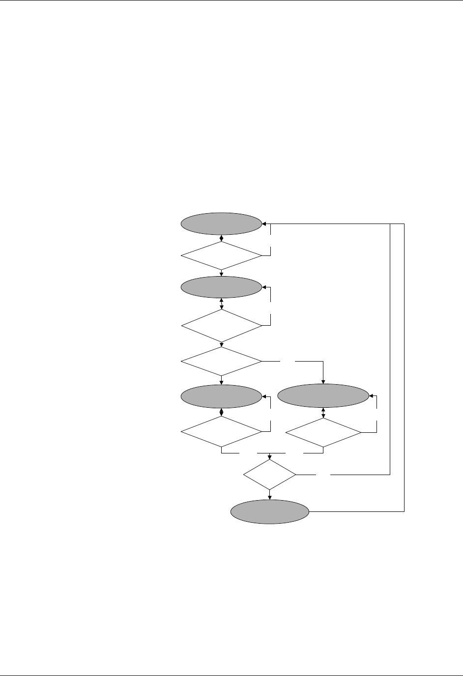
Defining the Autonomous Read Operation
Autonomous mode functionality is summarized in the state diagram shown
below. Fundamentally, a reader operating in Autonomous Mode moves between
several states: Waiting, Working, Evaluation and Notification. Waiting, Working
and Evaluation states have associated with them an optional digital output state
that is set upon entering the state. Movement from one state to another is
initiated by an expiration of a timer, a trigger event on one or more of the digital
input lines or changes to the tag list.
Each element of the State Diagram is described below. Associated with each
element are one or more commands that are used to configure the reader.
ENTER AUTONOMOUS MODE (Not shown on the state diagram.)
The user puts the reader into Autonomous Mode with the AutoMode command.
Set AutoMode = On puts the Reader into Autonomous Mode. Set AutoMode
= Off returns it to Interactive Mode.
WAITING STATE
Upon entering Autonomous Mode, the reader automatically enters the Waiting
State. While waiting for a Start Working Trigger (see below) the reader holds the
digital output lines at a value set by the AutoWaitOutput command. (i.e., Set
AutoWaitOutput=3 would cause both output lines to go high when the reader
is in the Waiting state.)
CHAPTER 3 NANOSCANNER SYSTEM FUNDAMENTALS
NANOSCANNER READER USER GUIDE • DOC # 8101029-000 REV A 24
© 2003 Alien Technology™
START WORKING TRIGGER
The receipt of a trigger pattern on the digital input lines will cause the reader to
move from the Waiting state to the Working state. The start condition is set by
the AutoStartTrigger command. The AutoStartTrigger command takes
two parameters, a rising edge pattern and a falling edge pattern. Set
AutoStartTrigger = 2,0 would cause the reader to enter the working state
on receipt of a rising edge on pin 2. Set AutoStartTrigger= 0,3 would
cause the reader to enter the working state after the receipt of a falling edge on
both pins one and two. Set AutoStartTrigger= 0,0 causes the reader to
immediately drop into the Working state. Note: One cannot mix rising and falling
edge patterns with the current version of Nanoscanner firmware.
Autononmous Mode State Diagram
WORKING STATE
In the working state, the reader holds the digital output lines at the value defined
by the AutoWorkOutput command. Set AutoWorkOutput =3 would hold
both output lines high while the reader is working. The action the reader performs
while in the working state is determined by the AutoAction command. Set
AutoAction = Acquire causes the reader to repeatedly acquire tag list data
(1) Wait
(Wait Output)
(2) Start?
(R/F Edges)
(3) Doing Action
(Work Output)
(4) Stop?
(Time/Trig)
(5) Eval
Found?
Prog?
(6a) True Pause
(True Output)
(6b) False Pause
(False Output)
no
(7a) Pause
Expired?
(7b) Pause
Expired?
yes
(8) Notify
Needed?
(9) Issue
Notification
no
yes
yes
no
no
no
no

CHAPTER 3 NANOSCANNER SYSTEM FUNDAMENTALS
NANOSCANNER READER USER GUIDE • DOC # 8101029-000 REV A 25
© 2003 Alien Technology™
using the parameters set in the AcquireMode and PersistTime commands.
The reader continues working until the Stop Working Trigger conditions are met.
(See below)
STOP WORKING TRIGGER
Like the Start Working Trigger, the Stop Working Trigger can be a change on the
digital input lines. Use the AutoStopTrigger command with a rising, falling
edge pattern to set the trigger conditions. Set AutoStopTrigger = 1,0
would look for a rising edge on pin 1 to leave the Working state. In addition, one
may use the AutoStopTimer command to repeat the Working action for a
specified period of time. (i.e., Set AutoStopTimer = 1300 would cause the reader
to perform the Working action for 1.3 seconds and then perform the Evaluation.)
EVALUATION
At the Evaluation decision point, the reader looks to see if new Tags have been
added to the tag list since the last evaluation. If so, it drops to the True Pause
state, if not, it drops to the False Pause state. Note: the Evaluation looks at the
tag list and thereby is dependent on the state of the PersistTime variable.
TRUE/FALSE PAUSE
After evaluation, the Reader sets the output lines to the values specified in the
AutoTrueOutput and AutoFalseOutput commands. This condition is held
for AutoTruePause or AutoFalsePause milliseconds before the test for
Notification. Set AutoTrueOutput = 1 and Set AutoTruePause=20 would
cause the reader to hold pin 1 high and pin 2 low for 20 milliseconds before
returning to the Waiting State.
NOTIFY
The reader checks if Automatic Notification is enabled, (NotifyMode=On) and if
the notification conditions are met to see if a notification should be issued. Notify
conditions are set by the state of the NotifyTrigger command and may be set
to “add” “remove” “change” or “true” “false”.
If a notification is to be issued, the tag list data is sent to the NotifyAddress.
The Reader then returns to the Waiting state.
Autonomous Mode Examples
EXAMPLE 1. BACKGROUND READING
In this case, we would like the reader to monitor the tag field continuously. The
application will periodically poll for the tag list. If a new tag is seen, pin 1 will be
flashed high for 50 msec. Otherwise, pin 2 will be flashed high for 50 msec.
AutoModeReset
Set AutoAction=Acquire

CHAPTER 3 NANOSCANNER SYSTEM FUNDAMENTALS
NANOSCANNER READER USER GUIDE • DOC # 8101029-000 REV A 26
© 2003 Alien Technology™
Set AutoStartTrigger=0,0
Set AutoStopTimer = 0
Set AutoTrueOutput =1
Set AutoTruePause =50
Set AutoFalseOutput = 2
Set AutoFalsePause = 50
Set AutoMode=On
EXAMPLE 2. TRIGGERED READING
Here a forklift will cause an electric eye to send a pulse to the reader. We want
the reader to look for the rising edge on this pulse and look for tags for 1.8
seconds before going back to the Wait state. We wont make any changes to the
output pins.
AutoModeReset
Set AutoAction=Acquire
Set AutoStartTrigger=1,0
Set AutoStopTimer = 1800
Set AutoTruePause =0
Set AutoFalsePause = 0
Set AutoMode=On
EXAMPLE 3. TRIGGERED READING WITH NOTIFICATION
A trigger is used to start the reading. If a tag is found, send an email message.
After the email is sent, return to the waiting state.
AutoModeReset
Set AutoAction=Acquire
Set AutoStartTrigger=1,0
Set AutoStopTimer = 0
Set AutoTruePause =0
Set AutoFalsePause = 0
Set NotifyAddress = Borg@AlienTechnology.com
Set MailServer= sigourney.alien.com
Set NotifyTrigger=Add
Set NotifyMode=On
Set AutoMode=On

CHAPTER 3 NANOSCANNER SYSTEM FUNDAMENTALS
NANOSCANNER READER USER GUIDE • DOC # 8101029-000 REV A 27
© 2003 Alien Technology™
Notification Mode
The last stage in configuring the autonomous mode is to tell the reader under
what conditions to notify listeners about tag lists. Listeners (network applications /
people) will be notified only when preset conditions arise, such as when new tags
are read, or tags disappear from view.
• Set NotifyTime = time (secs)
The NotifyTime command instructs the reader to send out a copy of its tag
list to a listener every n seconds, regardless of changes to the tag list or not.
Thus, this is a simple, predetermined way to force the reader to send out its
tag list to a listener.
• Set NotifyTrigger = trigger
The NotifyTrigger command specifies a trigger that must occur before a tag
list is sent out to a listener. There are a number of permissible triggers than
can be set:
Trigger Name Meaning
ADD Send message when new tag is read and added to the tag list
REMOVE Send message when a tag is removed from the tag list
CHANGE Send message when a tag is either added to or removed from
the tag list
TRUE Send messages when the evaluation task of the autonomous
state loop evaluates to true, i.e., typically when tags are added
FALSE Send messages when the evaluation task of the autonomous
state loop evaluates to false, i.e., typically when tags are not
found
TRUEFALSE Send messages when the evaluation task of the autonomous
state loop evaluates to true or false

CHAPTER 3 NANOSCANNER SYSTEM FUNDAMENTALS
NANOSCANNER READER USER GUIDE • DOC # 8101029-000 REV A 28
© 2003 Alien Technology™
Defining the Notification Address
You must tell the reader where to send notification messages to when it is
operating in autonomous mode.
The Alien reader can be instructed to send out messages over the internet to a
specified machine or over email to specified email address. This is configured
using a single command:
• Set NotifyAddress = address
The format of the address indicates the method of delivery:
NotifyAddress Description
user@domain.com
Send a message via e-mail to the address specified. The
address is specified in standard email form, i.e.,
user@domain.com
NOTE: the MailServer parameter must be configured for this to
work.
hostname:port Send a message to a specified port on a networked machine.
The address takes the form “hostname:port.” For example,
“123.01.02.98:3450” or “listener.alientechnology.com:10002”
serial Send a message to the serial connection. The word “serial” is
used as the address. The word is not case sensitive.
Defining the Notification Format
You must tell the reader the format required for any tag list that it sends out.
When a notification message is sent out it contains two parts to its document:
• The first part of the document details the reader that sent the message and
the reason the message was sent.
• The second part to the message is a list of tags (either newly added or
removed tags, or the complete list of tags as seen by the reader).
The format of the message is configured using a single command:
• Set NotifyFormat = format
The format may be one of the following:
NotifyFormat Description
text
Tag lists are sent out as plain text messages, one tag ID per
line.
xml Tag lists are sent out as an XML text format
custom Tag lists are sent out as plain text messages, each line being
defined by the TagListCustomFormat specification

CHAPTER 3 NANOSCANNER SYSTEM FUNDAMENTALS
NANOSCANNER READER USER GUIDE • DOC # 8101029-000 REV A 29
© 2003 Alien Technology™
• Text formatted tag lists take the form:
#Alien RFID Reader Auto Notification Message
#ReaderName: Spinner Reader
#ReaderType: Alien RFID Tag Reader (Class 1 / 915Mhz)
#IPAddress: 10.1.70.13
#CommandPort: 23
#Time: 2003/01/21 12:48:59
#Reason: TEST MESSAGE
Tag:1115 F268 81C3 C012, CRC:2483, Disc:2003/01/21 09:00:51, Count:1, Ant:0
Tag:0100 0100 0002 0709, CRC:8594, Disc:2003/01/21 11:00:10, Count:1, Ant:0
Tag:1054 A334 54E1 7409, CRC:2083, Disc:2003/01/21 11:50:03, Count:1, Ant:0
#End of Notification Message
• XML Formatted tag lists take the form:
<Alien-RFID-Reader-Auto-Notification>
<ReaderName>Spinner Reader</ReaderName>
<ReaderType>Alien RFID Tag Reader (Class 1 / 915Mhz)</ReaderType>
<IPAddress>10.1.70.13</IPAddress>
<CommandPort>23</CommandPort>
<Time>2003/01/21 12:49:22</Time>
<Reason>TEST MESSAGE</Reason>
<Alien-RFID-Tag-List>
<Alien-RFID-Tag>
<TagID>0102 0304 0506 0709</TagID>
<CRC>87B4</CRC>
<DiscoveryTime>2003/01/17 11:37:01</DiscoveryTime>
<Antenna>0</Antenna>
<ReadCount>1413726</ReadCount>
</Alien-RFID-Tag>
<Alien-RFID-Tag>
<TagID>2283 1668 ADC3 E804</TagID>
<CRC>9FD0</CRC>
<DiscoveryTime>2003/01/19 07:01:19</DiscoveryTime>
<Antenna>0</Antenna>
<ReadCount>1</ReadCount>
</Alien-RFID-Tag>
</Alien-RFID-Tag-List>
</Alien-RFID-Reader-Auto-Notification>
Listening for Tags over the Network
When a reader has been configured for autonomous mode, all interactive
communications with the reader can be stopped and it can be left to work on its
own.
It is then up to the network application to listen for any notification messages
from the reader.
Libraries are provided in the Nanoscanner Reader Developer’s Kit to provide this
functionality in both Java and Visual Basic languages. In both cases, setting up a
listening service is a simple coding task, involving less than 10 lines of code.

CHAPTER 4 TAG READING FUNDAMENTALS
NANOSCANNER READER USER GUIDE • DOC # 8101029-000 REV A 30
© 2003 Alien Technology™
CHAPTER 4
Tag Reading Fundamentals
This chapter provides an overview of the major tag reading concepts found in all
Alien RFID systems.
A good understanding of this chapter is highly recommended to get the most of
out this Nanoscanner system.
Introduction
RFID tag reading is not just about getting the tag ID from a tag into the reader.
There are different methods available to perform this basic operation, and
different parameters and settings that can be altered to tweak the performance of
this basic operation.
Acquire Mode
The Acquire Mode defines the method used to read tags in the field. There are
two distinct methods for reading tags, and the choice of one method over another
depends on the application at hand.
The Acquire Mode is specified by issuing the ‘Set AcquireMode’ command. It
can take one of two values, ‘inventory’ or ‘global scroll’.
GLOBAL SCROLL
Global Scroll is the most primitive of tag ID reading operations supported by the
Alien Nanoscanner system. When a global scroll command is issued, the
Nanoscanner sends a single command over the air to all and any tags. That
command is simply a request for any tag to immediately send back its ID to the
Nanoscanner.
The simplicity of this command is both its advantage and its downfall: The
command is very quick to execute as it involves only one round trip between the
reader and the tag. However because the command is so simple, problems will
arise if there are more than one tag in the field. At this point, multiple tags will all
receive the same command, and will all send back their ID to the reader at the
same time. A case such as this makes it very difficult for the reader to discern
individual IDs among the general noise. Typically one or two of the loudest or
closest tags will be decoded, but the majority will not be discerned.
This is analogous to walking into a dark room full of people and shouting out the
command “if anyone can hear me, shout your name back now”. If there is one
person in the room with you, you will be able to hear their name. If there are
multiple people in the room, the results will be noise. Maybe you will be able to
make out one or two names, but typically not more than that.

CHAPTER 4 TAG READING FUNDAMENTALS
NANOSCANNER READER USER GUIDE • DOC # 8101029-000 REV A 31
© 2003 Alien Technology™
There are many applications where global scroll is the best tag reading method
to use. These applications typically expect just one or two tags in the field of view
at any one time, such as conveyor belt applications or toll-booth application. For
these systems, global scroll outperforms a full inventory by a factor of 3 as far as
individual read rates are concerned.
INVENTORY
The inventory command is a full featured system for discerning the IDs of
multiple tags in the field at the same time. This single high-level command
transforms itself into a complex series of reader-tag interrogations, that
eventually resolve themselves into a single list of tag IDs seen by the
Nanoscanner. This method of interrogation and evaluation of multiple tags is
known as an anti-collision search.
Continuing the analogy used in the global scroll description, the anti-collision sort
works in the following way: You walk into a dark room full of people and instruct
everyone to stand up. Then you start with the letter ‘A’ and tell anyone who’s
name begins with this letter to shout their name back. You may get zero replies,
one reply or multiple noisy replies. If you can clearly make out any individual
name from the noise, you shout back telling that person to sit down and be quite
from now on. Next repeat the series of events, this time telling anyone who’s
name begins with ‘AA’ to shout back their name. If you can pick out one name,
tell that person to sit down and be quite. You repeat this until no names are
heard at all, each time adding a letter such as ‘AB’, ‘AC’. When it gets to the point
that there are no more names to be heard, you move on to the letter ‘B’ and
repeat the series. By the time you’ve been through the letter ‘Z’, you should have
been able to get everyone’s name, and everyone should be sitting down. At this
point the sort has been finished.
Obviously this sort algorithm is far more complex than the global scroll algorithm,
requiring many more reader-tag instructions. However the Alien Nanoscanner
considerably optimizes this basic sort method, and in doing so still provides a
very fast and efficient sort algorithm.
COMPATIBILITY CHART
The following chart shows which Alien systems support the different Acquire
Modes.
915 MHz Passive 2450 MHz Passive 2450 MHz Battery
Global Scroll D D D
Inventory D D D

CHAPTER 4 TAG READING FUNDAMENTALS
NANOSCANNER READER USER GUIDE • DOC # 8101029-000 REV A 32
© 2003 Alien Technology™
Masks and Tag Memory Structure
Many commands aimed at Alien RFID tags require the setting of a mask, which
directs the commands only at the tags who’s ID matches the mask. This
mechanism allows commands to be sent to one specific tag, a selective group of
tags or the whole field of tags.
However to understand the use of masks, a basic understanding of tag memory
structure is first required.
CLASS I TAG MEMORY
Class I tags from Alien contain 96 bits of programmable memory, of which 64 bits
are user-programmable. The remaining 32 bits are controlled by the reader to
record state and checksum information inside the tag.
Class I Tag Memory Structure
Tag memory is address from left to right, where the leftmost byte is byte zero,
and the leftmost bit is bit zero.
The 64 bit ID code (either a fully qualified EPC code or user-defined ID code)
resides from bytes 2 to 9, or bits 16 to 79.
Bytes 0 and 1 contain a 2 byte checksum calculated over the 64 bits of tag ID
only. The checksum is calculated and programmed into the tag automatically by
the reader. This checksum is calculated using the CCITT-16 standard.
The Lock and Pass Code (PC) bytes stored at the end of tag memory are used to
lock a tag and kill a locked tag. Each of these codes takes exactly one byte. The
user can control the value of the pass code, passing it in as a parameter to the
Lock command. The reader takes full control of the Lock byte, allowing it to flag
the tag as either locked or unlocked.
(For further details on programming tag IDs and tag memory, please see the Tag
Programming Guide).
CLASS BPT TAGS
Class BPT tags from Alien support 96 bits of programmable ID memory. Unlike
the Class I tag, all 96 bits are user-addressable and user-programmable. There
are no pre-requisites for the content of this memory space.
0 1 23456789 10 11
EPC Code (or User ID Code) Lock PC Checksum
Byte
Bit
0-7 8-15 16-23 24-31 32-39 40-47 48-55 56-63 64-71 72-79 80-87 88-95

CHAPTER 4 TAG READING FUNDAMENTALS
NANOSCANNER READER USER GUIDE • DOC # 8101029-000 REV A 33
© 2003 Alien Technology™
Class BPT Tag Memory Structure
MASK COMMAND FORMAT
The Mask command is a simple get and set pair, where the parameters comprise
three parts:
• Bit Length of Mask, as a decimal number
• Bit Pointer of Mask, as a decimal number
• Array of Hex Bytes separated by white spaces
ADDRESSING ALL TAGS
The simplest mask setting is one that addresses all tags in the field. This is
specified with the command parameter of ‘all’, or can be specified using the three
parameters method, where length = 0, pointer = 0, and data = 0. i.e.,
Set mask = all
Or
Set mask = 0, 0, 0
Issuing a command such as global scroll (i.e., set acquiremode=global scroll; get
taglist) will cause all tags in the field of view to return their tag IDs to the reader.
If there are multiple tags in the field, this may result in un-discernable noise.
ADDRESSING A SINGLE TAG
The next simplest use of a mask is the exact singulation of a tag. By setting the
mask to be the full tag ID of a known tag, the Nanoscanner will send out
commands addressed to that tag only. No other tags will respond. This mode of
operation is particularly useful for the battery tags that can have their memory or
sensor interrogated.
For example, given that there is a known battery tag in the field with a tag ID of
’8000 0000 8001 0203 0300’ , the following mask setting can be used:
Set mask = 96, 0, 80 00 00 00 80 01 02 03 03 00
Subsequent commands to get sensorvalue will now be directed solely at this
tag, and be answered only by this tag.
ADDRESS A SUBSET OF TAGS
One of the more useful, but more complex applications of the mask command is
to address a subset of tags in the field. This is achieved using partial masks.
0 1 23456789 10 11
EPC Code (or User ID Code)
Byte
Bit
0-7 8-15 16-23 24-31 32-39 40-47 48-55 56-63 64-71 72-79 80-87 88-95

CHAPTER 4 TAG READING FUNDAMENTALS
NANOSCANNER READER USER GUIDE • DOC # 8101029-000 REV A 34
© 2003 Alien Technology™
For example, the following mask command can be issued to address only tag IDs
that start with the numbers ’8000 0040’:
Set mask = 32, 0, 80 00 00 40
i.e., length = 32 bits, (4 x 8 bytes), starting at bit zero from left.
Subsequent commands that use a mask will now only be replied to by a tag that
starts with this tag ID. This can be useful if for example the reader is scanning
food items, but is only interested in finding a certain brand of breakfast cereal. By
setting the mask to identify only the breakfast cereal tag IDs, any acquire
command on the food items will only return the items of interest. This
methodology works particularly well when combined with the EPC code strategy,
where each product type and manufacture code use well defined memory codes
that can be masked.
Another example is to search for all Class I tags whose last 3 bits of EPC code
are set to one. The mask settings for this would be:
Set mask = 3, 77, 7
i.e., length = 3 bits, starting at bit 77, and matching value 7 (binary 111)
NOTE:
• Class I tag IDs start at bit 16 of tag memory
• Class BPT tag IDs start at bit 0 of tag memory
COMPATIBILITY CHART
The following chart shows which Alien systems support Masks with various
commands.
915 MHz Passive 2450 MHz Passive 2450 MHz Battery
Global Scroll D D D
Inventory U1 U1 U1
Wake D D D
Sleep D D D
1. Future releases of the Nanoscanner firmware will support Masked Inventory.

CHAPTER 4 TAG READING FUNDAMENTALS
NANOSCANNER READER USER GUIDE • DOC # 8101029-000 REV A 35
© 2003 Alien Technology™
Persistent Sleep and Wake
Tags have the ability to be put to sleep and awakened on command. Once tags
have been put to sleep they will ignore any subsequent commands, even if
addressed directly to them. The only command that these slept tags will respond
to is wake, which will bring them back to life and make them respond to all
commands again.
The Sleep and Wake commands can act together in a powerful way to help
address multiple tags in the field.
By default the inventory and global scroll commands will read tags in the field,
and leave them in an awake state. This means that the very next time an acquire
action is made, the same tags will answer back to the reader, resulting in an
identical tag list.
However it is possible to sleep tags are they are found. Both the inventory and
global scroll modes support this action. In this scenario, as a tag is discovered by
the reader, it is told to sleep. The very next time an acquire command is issued,
the reader will scan the field of tags, but as they are all asleep, they will not
answer and the tag list returned will be empty.
The effects of the sleep-as-found mode can be reverted at any time by issuing a
Wake command. This will immediately wake up all tags in the field of view,
making them ready for subsequent acquire commands.
This is a useful mode to use when dealing with very large numbers of tags in the
field at once (>100 tags). Using these modes, the acquire command can discern
as many tags as it can in one pass, leaving these tags asleep as it finds them.
Then any subsequent acquire commands will now only be dealing with tags it
missed in previous rounds, or tags that have entered the field since the last
round. Thus a large population of tags can be sorted in smaller, more
manageable rounds.
Wake, Sleep and Acquire commands can all be entered at the command line
interface in interactive mode. However there are also two parameters that can be
used to automate these functions:
ACQUIRESLEEP
The AcquireSleep command accepts either an On or Off parameter. If set to On,
all subsequent acquire commands will sleep tags as they are found. If set to Off,
all subsequent acquire commands will leave a tag awake once it has been read.
ACQUIREWAKECOUNT
The AcquireWakeCount is the partner parameter to the AcquireSleep count.
AcquireWakeCount takes a single integer argument that determines after how
many acquire commands should a Wake command be issued. If this is set to
zero, Wake commands will never be automatically issued. If set to 10, a Wake
command will be issued after every 10 acquire commands.

CHAPTER 4 TAG READING FUNDAMENTALS
NANOSCANNER READER USER GUIDE • DOC # 8101029-000 REV A 36
© 2003 Alien Technology™
SLEEP, WAKE AND MASKS
The Sleep and Wake commands always work with the current Mask setting.
Therefore it is possible to Sleep a subset of tags before performing an acquire, or
to Sleep all tags, then Wake a subset before acquire. Combining Sleep, Wake,
Masks and Acquire Modes offers up many interesting possibilities for tag reading
that will virtually address all problems in the field.
COMPATIBILITY CHART
The following chart shows which Alien systems support Persistent Sleep and
Wake commands.
915 MHz Passive 2450 MHz Passive 2450 MHz Battery
Wake U1 U1 D
Sleep U1 U1 D
1. Future releases of Class I tags from Alien Technology will support Persistent
Sleep and Wake (expected Summer 2003)

CHAPTER 5 READER-HOST COMMUNICATIONS INSTALLATION
NANOSCANNER READER USER GUIDE • DOC # 8101029-000 REV A 37
© 2003 Alien Technology™
CHAPTER 5
ReaderHost Communications Installation
The Nanoscanner reader is designed to be programmed using simple ASCII text-
based commands from any programming language.
Introduction
The CD provided with your Nanoscanner Reader Developer’s Kit includes
extensive examples of code developed by Alien for the Nanoscanner using Java
and VisualBasic programming languages. These examples will serve as models
for developing new software for the reader.
This section of the Nanoscanner Reader Developer’s Guide describes how to
install the reader on a host computer, as well as how to issue commands and
interact with the reader using three different methods:
• Command line operation over serial communication.
• Command line operation over Telnet communication.
• HTML based operation over Web communication.
Whether using direct serial communication with the reader or using one of the
network communication options, you will require serial communications for initial
reader installation.
Audience
For the purposes of this chapter, it is assumed that users:
• May be IT specialists, network specialists or programmers.
• Will operate the reader via the host either with direct serial communication or
via network.
• Have minimal previous knowledge of radio-frequency identification
technology.
Additionally, it is assumed that:
• Users installing the reader via direct serial communication are skilled in the
application of RS-232 serial protocol.
• Users installing the reader for network communication are skilled in basic
network configuration.

CHAPTER 5 READER-HOST COMMUNICATIONS INSTALLATION
NANOSCANNER READER USER GUIDE • DOC # 8101029-000 REV A 38
© 2003 Alien Technology™
• Programmers are competent in at least one programming or scripting
language and have the ability to issue ASCII-based commands with that
language.
Requirements
Serial communication requires:
• A text-based serial communications program (such as Windows
HyperTerminal) running on any computer.
Ethernet communication requires:
• An Ethernet network.
• Standard Web browser or Telnet communication program
Conventions
The following conventions are used in this section:
• Keys to be pressed are shown in brackets and all caps. Example: Press the
[ENTER] key.
• Upon entering any command instruction, you must press [ENTER] to send
the command.
• Specific characters and commands to be typed in are shown within quotation
marks. Example: At the prompt type “Set DHCP=ON”.
• Values to be provided and typed in by the user are shown within brackets in
upper and lowercase. Example: At the prompt type “Set IPaddress=[ IP
address value]” or “Set IPaddress=xxx.xxx.xxx.xxx.” The actual command
typed in would appear as: “Set IPaddress=10.1.60.5”.
• Nanoscanner reader commands are case insensitive. Although, for clarity,
the commands may be shown in upper and lower case in this document, you
may type them in all lowercase characters, if you prefer.
• A space is required between the command (verb) such as “get” or “set” and
the specific parameters as in the example “Get IPaddress.” However, no
space is required between the parameter elements such as “IP” and
“address.”
Setting up Reader-Host Communications
You can interact with the reader via the three methods mentioned earlier: direct
serial, Telnet and Web. Serial and Telnet communications both involve command
line operation. Web communication uses HTML.
Command Line Operation: Direct Serial Communication
This method is required for installing a new Nanoscanner, whether directly or via
network. Serial communications requires no preconfiguration and can be
performed easily with most computers.

CHAPTER 5 READER-HOST COMMUNICATIONS INSTALLATION
NANOSCANNER READER USER GUIDE • DOC # 8101029-000 REV A 39
© 2003 Alien Technology™
This method enables real-time operation of the reader via a serial
communications (“comm.”) port. Serial communication is the simplest means by
which to connect the reader to the host and implement ASCII command protocol.
Command Line Operation: Telnet Communication
Telnet communication requires a network connection via the reader’s Ethernet
port and allows the reader to operate like a Telnet server.
This mode offers the same form of command line interaction with the
Nanoscanner, but requires the Nanoscanner to be configured for and running on
a network in order to use it.
HTML-Based Operation: Web Communication
This mode allows you to operate and interact with the reader via the Web
interface. Web mode offers the simplest means of interaction via a series of
HTML pages and Java Applets served up by the Nanoscanner itself. All
interaction with the reader takes place inside a standard Web browser such as
Internet Explorer or Netscape Navigator.
NOTE: Before for you can configure the reader for network (Telnet or Web)
access, you must first set up the reader for direct serial communications.
By default, all Nanoscanner readers are preconfigured to use DHCP when
presented with an Ethernet connection. However, you must first establish a direct
serial connection in order to learn the reader’s IP Address.
Installing Reader on Host via Serial Port (ALL)
Whether you will ultimately be operating the reader directly via serial
communications or via a network connection, you will need to install the reader
initially using the serial port instructions.
NOTE: Example screens shown in this section are from HyperTerminal.
1. Ensure the reader is properly connected to power and at least one antenna
per installation instructions in Chapter 2.
2. Connect one end of the serial cable to the reader’s COM port and the other
end to either COM port 1 or COM port 2 on the host computer.
3. Launch the desired serial communications program (such as HyperTerminal
which is supplied with Windows 98 and 2000).
4. Enter (or verify) the following settings to configure the serial communications
program:
• Baud Rate: 115200
• Data Bits: 8
• Parity: None
• Stop Bits: 1
• Flow Control: None
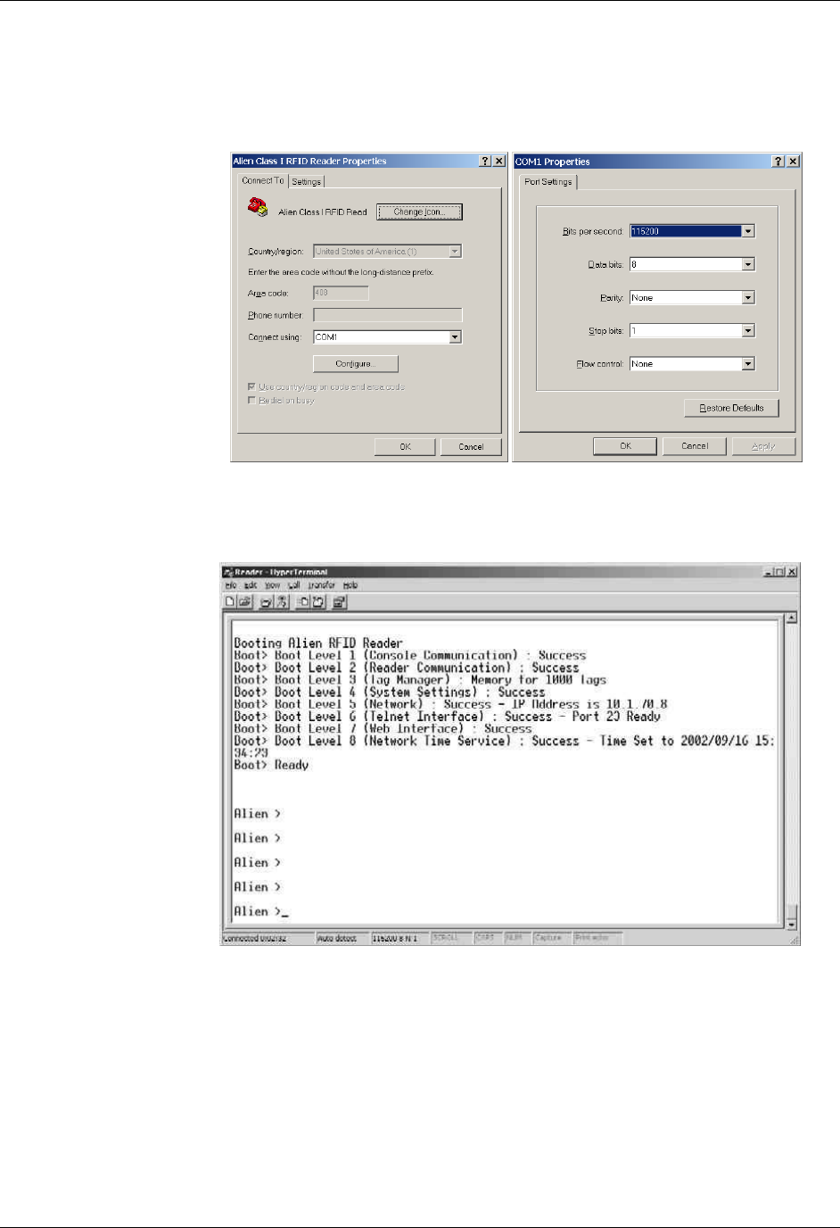
CHAPTER 5 READER-HOST COMMUNICATIONS INSTALLATION
NANOSCANNER READER USER GUIDE • DOC # 8101029-000 REV A 40
© 2003 Alien Technology™
Once configured, the software should allow you to communicate with the
Nanoscanner.
• HyperTerminal example configuration screens are shown below:
5. At the command prompt, you may now type any command followed by the
[ENTER] key to submit the command.
The following basic commands are helpful in verifying the reader-host
interface:
• Help (or “h”) – Provides a list of all commands available
• Info (or “i”) – Provides a list of current settings for the reader
• Get TagList – Scans field immediately for tags and reports the results
NOTE: Nanoscanner reader commands are case insensitive and may be typed in
all lowercase characters, if preferred.

CHAPTER 5 READER-HOST COMMUNICATIONS INSTALLATION
NANOSCANNER READER USER GUIDE • DOC # 8101029-000 REV A 41
© 2003 Alien Technology™
For a detailed explanation of all commands available, please refer to the chapter
entitled Reader–Host Protocol.
Network Installation (Optional)
To configure the system for network operation, you will use the commands
shown under the NETWORK heading.
There are 5 NETWORK commands that may be used for network configuration:
• Get | Set DHCP (On of Off)
• Get | Set IP address
• Get | Set Netmask
• Get | Set Gateway
• Get | Set DNS
1. To access the command list, type “H” or “Help”.
2. If DHCP (Dynamic Host Configuration Protocol - an automatic configuration
protocol that runs on many networks) is supported at your site, proceed to
step 3.
If DHCP is NOT supported at your site, skip to step 6.
If DHCP is supported at your site:
3. Type “Set DHCP=ON”.
• DHCP will automatically configure the other four parameters.
4. Issue the command “Get IPaddress” and the reader will return its assigned
address.
5. Skip to step 9.
If DHCP is not supported at your site:
6. Type “Set DHCP=OFF”.
• Reader will return the message “DHCP = OFF”.
7. Contact your system administrator for the following parameter values:
IPaddress
Netmask (or sub-netmask)
Gateway
DNS
8. Type each of the 4 commands below with the assigned values:
Set IPaddress=xxx.xxx.xxx.xxx
Set Netmask=xxx.xxx.xxx.xxx (or sub-netmask)
Set Gateway=xxx.xxx.xxx.xxx
Set DNS=xxx.xxx.xxx.xxx
• If value is accepted, the reader will return accepted value.
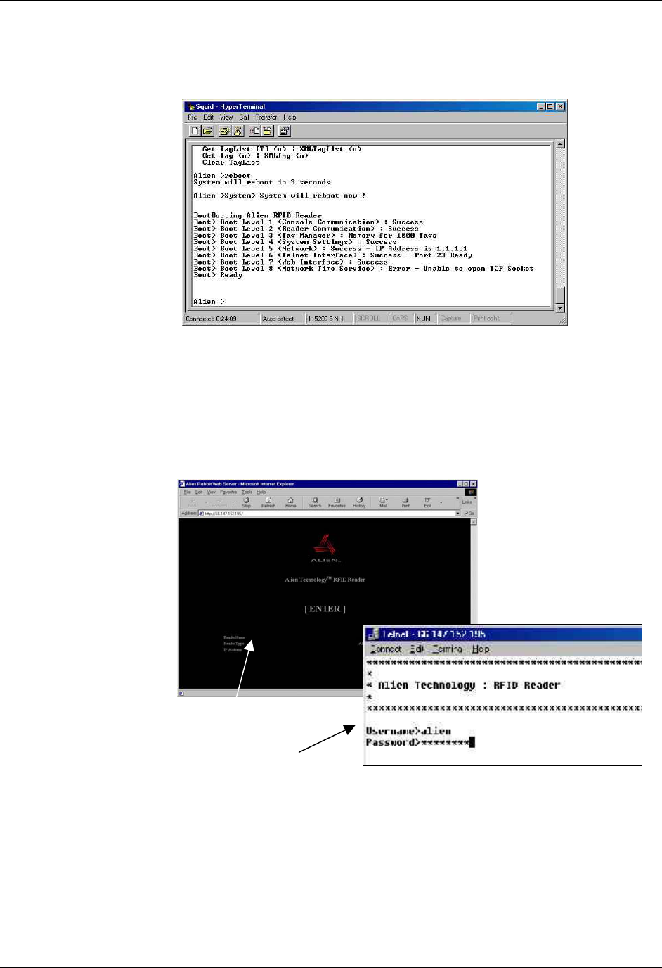
CHAPTER 5 READER-HOST COMMUNICATIONS INSTALLATION
NANOSCANNER READER USER GUIDE • DOC # 8101029-000 REV A 42
© 2003 Alien Technology™
• If value is not accepted, reader will return “0.0.0.0”.
9. Type “Reboot” to reboot the reader and implement the commands.
To verify your network connection to the reader:
10. Launch a browser.
11. Enter the reader’s assigned IP address into the web page location bar.
• If the IP address is valid, the Alien reader portal will display.
12. For Web access, click the [ENTER] box.
For Telnet access, skip to step 13.
13. At the prompt, enter your username and password. (These are case
sensitive and must be typed as specified.)
Current settings are:
• Username = alien
Web portal (above)
Telnet portal (right)

CHAPTER 5 READER-HOST COMMUNICATIONS INSTALLATION
NANOSCANNER READER USER GUIDE • DOC # 8101029-000 REV A 43
© 2003 Alien Technology™
• Password = password
14. You are now ready to interact with the reader via commands.
• For Telnet operation, you will be using the text command lines in the
same manner as in direct serial communication. The only difference is in
the use of the “Q” command to quit the Telnet session.
• For Web operation, you will be using the HTML screens as shown.
Reader commands and instructions for their use in both command line and
HTML operations are provided in the next chapter, Reader-Host Protocol.

CHAPTER 6 READER-HOST PROTOCOL
NANOSCANNER READER USER GUIDE • DOC # 8101029-000 REV A 44
© 2003 Alien Technology™
CHAPTER 6
ReaderHost Protocol
The Reader Host protocol is a text-based communications protocol for
configuring and operating the Alien Nanoscanner RFID reader for enterprise host
systems connectivity.
Introduction
This chapter describes the programming interface that links the Alien
Nanoscanner RFID reader to the outside world.
For a overview of the reader system, see the chapters entitled: Nanoscanner
System Fundamentals and Tag Reading Fundamentals.
For instructions on setting up reader operation via a host computer, see the
chapter entitled Reader-Host Communications Installation.
Reader Operation Overview
As detailed in the previous chapter, you may interact with the reader and
configure its operation using either of two methods:
• Text-based command line operation (via direct serial or Telnet connection)
• Web-based HTML operation
For the purposes of these instructions, the serial and Telnet operations will be
considered essentially identical. Where any significant differences exist in the
command line operation methods or the Web-based HTML operation, the
instructions will note those exceptions.
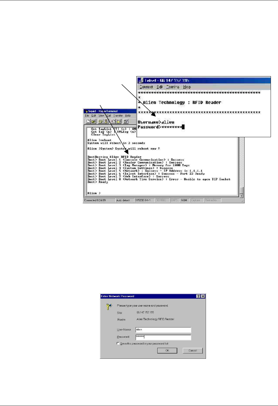
CHAPTER 6 READER-HOST PROTOCOL
NANOSCANNER READER USER GUIDE • DOC # 8101029-000 REV A 45
© 2003 Alien Technology™
Text-Based Command Line Operation
To interact with the reader via command line operation you must either be
communicating directly with the reader via the serial port connection to the host,
or via the Internet and a Telnet connection.
In both cases the screens will look similar and will thus be considered identical
for the purposes of the instructions that follow.
Telnet Exceptions:
• In Telnet operation you must issue the command “Q” to quit the session.
• Accessing reader controls via Telnet requires an authorized user name and
password (both of which can be changed via the General command set).
Web-based HTML Operation
The Nanoscanner reader includes a built-in Web server that can serve up a
number of easy-to-use Web pages for configuring and using the reader.
Like Telnet, the Web connection also requires an authorized user name and
password.
Telnet connection (right)
Direct serial connection via
HyperTerminal (below)
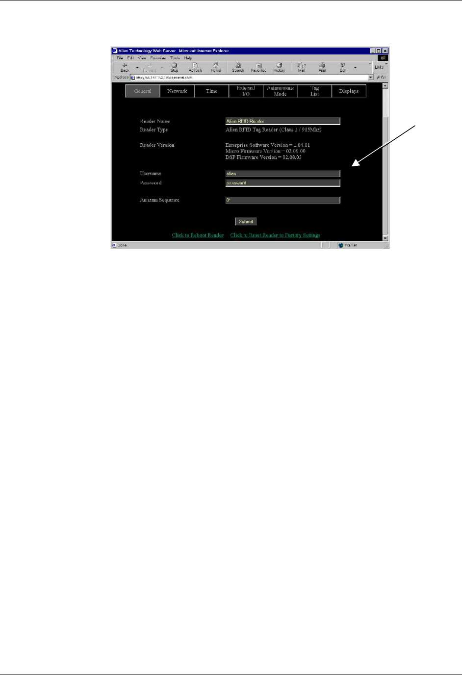
CHAPTER 6 READER-HOST PROTOCOL
NANOSCANNER READER USER GUIDE • DOC # 8101029-000 REV A 46
© 2003 Alien Technology™
Most of the pages served up by the Web server are simple HTML pages.
However there also a number of simple Java Applets that are used to provide an
interactive environment for reading tags in the field. These Java Applets are all
Java 1.1 compliant applets and will work in standard Netscape and Internet
Explorer browsers.
Once access with the reader has been established through the Web, you may
execute any of the reader commands discussed in this chapter. The presentation
of these commands differs from command-line operation only in the simplicity
and convenience of the HTML screens and prompts.
Web-based
HTML screen
showing general
commands tab
with username
and password
fields.

CHAPTER 6 READER-HOST PROTOCOL
NANOSCANNER READER USER GUIDE • DOC # 8101029-000 REV A 47
© 2003 Alien Technology™
Commands Overview
There are two distinct categories of reader-host command: those initiated by the
enterprise host (interactive commands), and those initiated by the reader itself
(autonomous commands).
INTERACTIVE COMMANDS
Interactive commands are initiated by a programmer, who creates and issues a
command to the reader. The reader always responds to these commands with an
immediate reply.
Interactive commands are used to configure and operate the reader, as well as to
interrogate tags and retrieve stored lists on demand.
AUTONOMOUS COMMANDS
Autonomous commands instruct the reader to perform certain tasks, without
human intervention, according to conditions set by the programmer.
These commands typically tell the reader to read tags and then send messages
to the outside world based on user-defined triggers. For example, the reader can
be instructed to search the field until it sees a tag, then to read the tag and mail
the tag ID to a specified email address.
Command Format
All commands between the enterprise host system and the reader are human
readable ASCII text-based messages. For example, a command to set the logical
name of the reader using the Set Reader Name command takes the form:
Set ReaderName = My Alien Reader [CR][LF]
All commands to the reader are single line ASCII commands. These commands
are always terminated by a single carriage return / line feed character pair
[CR][LF], ascii code 0x0D followed by ascii 0x0A.
All replies from the reader are either single line or multiple line ASCII replies.
These replies are always terminated by a single carriage return / line feed
character pair [CR][LF] followed by a NULL character, ASCII codes 0x0D, 0x0A,
0x00. Where a reply comprises multiple text lines, each line is separated by a
single carriage return / line feed character pair [CR][LF], ascii code 0x0D followed
by ASCII 0x0A.
An example of a single line command / response is:
>Get ReaderName[CR][LF]
>ReaderName = Alien Reader[CR][LF][0]

CHAPTER 6 READER-HOST PROTOCOL
NANOSCANNER READER USER GUIDE • DOC # 8101029-000 REV A 48
© 2003 Alien Technology™
An example of a multiple line command / response is:
>Get ReaderVersion[CR][LF]
>ReaderVersion = 1.0[CR][LF]
FirmwareVersion = 1.0[CR][LF]
SoftwareVersion = 1.0[CR][LF][0]
Commands are case insensitive, i.e., “set readername” is equivalent to “Set
ReaderName.”
Suppressing Command Prompts
By default all commands are set up for interactive use over a serial console or
telnet style interface. Consequently replies are always followed by a command
prompt indicating that user input is required. Often this command prompt is not
required, especially when client software is written that programmatically
communicates with the reader. To account for these applications, all command
prompts can be suppressed by making the first character of any command be an
0x1 character. For example:
INTERACTIVE COMMAND FORMAT
Alien> get ReaderName[CR][LF]
ReaderName = Alien Reader[CR][LF][0]
Alien>[CR][LF]
NON-INTERACTIVE COMMAND FORMAT
[1]get ReaderName[CR][LF]
ReaderName = Alien Reader[CR][LF][0]
XML Commands
There are a few cases where text-based replies and messages are formatted in
XML format for easier computer parsing. The following messages are sent in
XML format:
• Heartbeat Messages (see Heartbeat command description).
• Notification Messages (if notifyFormat = xml; see Notify command
description).
• The Get TagList commands (if tagListFormat = xml)

CHAPTER 6 READER-HOST PROTOCOL
NANOSCANNER READER USER GUIDE • DOC # 8101029-000 REV A 49
© 2003 Alien Technology™
Command List with Functions
GENERAL COMMANDS
Command Description
Help (or “h”) List all reader commands available.
Info (or (“i”) List all current reader settings.
Get TagList Scan the field, read tags and report. (see Tag List
Commands for details.)
! (exclamation mark) Repeats the last command issued.
Q Quit session (TELNET ONLY)
Get ReaderName
Set ReaderName
Allows an arbitrary name to be associated with and
retrieved from the reader.
Get ReaderType Get a description of the reader type.
Get ReaderVersion Get the reader software/hardware versions.
Get Username
Set Username
Get and Set the Username used for the Network
based access control.
Get Password
Set Password
Get and Set the Password used for the Network based
access control.
Get AntennaSequence
Set AntennaSequence
Get and Set the antenna port sequence the reader
should use.
Reboot Reboot the reader.
FactorySettings Reset the reader to its original factory settings.
NETWORK CONFIGURATION COMMANDS
Command Description
Get DHCP
Set DHCP
Turn on or off the DHCP mode for the reader. If DHCP
is on, the reader will automatically configure itself for
the network on power-up.
Get IPAddress
Set IPAddress
Set and Get the network ID (IP Address) of the reader.
If DHCP is enabled this will be set automatically.
Get Gateway
Set Gateway
Set and Get the network gateway. If DHCP is enabled
this will be set automatically.
Get Netmask
Set Netmask
Set and Get the subnet mask. If DHCP is enabled this
will be set automatically.
Get DNS
Set DNS
Set and Get the domain name server. If DHCP is
enabled this will be set automatically.
Get HeartbeatPort
Set HeartbeatPort
The reader periodically sends out heartbeat messages
to the network. The port over which this is done can
configured.
Get HeartbeatTime
Set HeartbeatTime
Set and Get the time interval, in seconds, between
successive heartbeats.
Get CommandPort
Set CommandPort
The reader reacts to commands over the network only
if they are directed at a specific command port on the
reader. This port can be configured using these
commands.

CHAPTER 6 READER-HOST PROTOCOL
NANOSCANNER READER USER GUIDE • DOC # 8101029-000 REV A 50
© 2003 Alien Technology™
TIME COMMANDS
Command Description
Get Time
Set Time
Get and Set the real time clock on the reader in Local
time.
Get TimeZone
Set TimeZone
Get and Set the time zone offset from UTC for the real
time clock.
Get TimeServer
Set TimeServer
Get and Set the location of a network time server.
EXTERNAL IO COMMANDS
Command Description
Get ExternalOutput
Set ExternalOutput
Get and Set the External Output pin values.
Get ExternalInput Get the External Input pin values.
TAG LIST COMMANDS
Command Description
Get AcquireMode
Set AcquireMode
Specify how the Nanoscanner reads tags.
Get AcquireSleep
Set AcquireSleep
On or Off setting that determines whether tags are
slept as they are read
Get AcquireWakeCount
Set AcquireWakeCount
Specify how often to issue a Wake command to all
tags in the field
Set Mask
Get Mask
Get and Set the current mask as an array of bytes.
Get PersistTime
Set PersistTime
Get and Set the persistence time for tags in the tag
list.
Get TagList (n)
Get the current list of active tags from the reader.
Get TagListFormat
Set TagListFormat
Set and Get the format for tag lists.
Get TagListCustomFormat
Set TagListCustomFormat
Specify a custom format for text based tag lists.
Clear TagList Clear the list of active tags on the reader.
Wake Wake tags addressed by the Mask settings
Sleep Sleep tags addressed by the Mask settings
AUTONOMOUS MODE COMMANDS
Command Description
Get AutoMode
Set AutoMode
Switch auto mode on and off.
Get AutoWaitOutput
Set AutoWaitOutput
Specify the value of the output pins while in wait mode.

CHAPTER 6 READER-HOST PROTOCOL
NANOSCANNER READER USER GUIDE • DOC # 8101029-000 REV A 51
© 2003 Alien Technology™
Get AutoStartTrigger
Get AutoStartTrigger
Get and Set the trigger that sends the auto mode state
into working state.
Get AutoWorkOutput
Set AutoWorkOutput
Specify the value of the output pins while in work
mode.
Get AutoAction
Set AutoAction
Get and Set the action to perform in auto mode.
Get AutoStopTrigger
Set AutoStopTrigger
Set and Get the external trigger that will move the auto
mode state from work mode to evaluate mode.
Get AutoStopTimer
Set AutoStopTimer
Set and Get the timer that will move the auto mode
state from work mode to evaluate mode.
Get AutoTrueOutput
Set AutoTrueOutput
Specify the value of the output pins when the auto
mode evaluation returns a True condition.
Get AutoTruePause
Set AutoTruePause
Set and Get the pause time after the auto mode
evaluation returns a True condition.
Get AutoFalseOutput
Set AutoFalseOutput
Specify the value of the output pins when the auto
mode evaluation returns a False condition.
Get AutoFalsePause
Set AutoFalsePause
Set and Get the pause time after the auto mode
evaluation returns a False condition.
Get AutoModeStatus Get the current status of auto mode.
AutoModeReset Reset all automode values to their default states.
AutoModeTriggerNow Force a trigger event to occur if AutoStartTrigger is
waiting for a trigger.
NOTIFY MODE COMMANDS
Command Description
Get NotifyMode
Set NotifyMode
Switch notify mode on and off.
Get NotifyFormat
Set NotifyFormat
Get and Set the format for tag lists pushed out in notify
mode.
Get NotifyAddress
Set NotifyAddress
Get and Set the address to push tag lists to.
Get NotifyTime
Set NotifyTime
Get and Set the time interval for automatically pushing
tag lists.
Get NotifyTrigger
Set NotifyTrigger
Get and Set the trigger for pushing tag lists.
Get MailServer
Set MailServer
Set and Get an SMTP mail server. This is only
required if notification email messages are sent out.
Get MailFrom
Set MailFrom
Set and Get the email address of the Nanoscanner.
NotifyNow Send an immediate message via the notification
system.

CHAPTER 6 READER-HOST PROTOCOL
NANOSCANNER READER USER GUIDE • DOC # 8101029-000 REV A 52
© 2003 Alien Technology™
Using the Commands
This section describes each command, its use and the response formats.
NOTE: Nanoscanner reader commands are case insensitive, that is, you can
use upper or lower case, or any combination thereof, and the reader will
understand the command. Capitalization of commands is used in this document
and in actual command responses solely for the purpose of readability.
General Commands – Text Based
General commands cover basic reader and antenna functions and information.
HELP (H)
This command lists all reader commands available. You may also type just the
letter “h” to send this command.
INFO (I)
This provides a list of current reader settings. You may also type just the letter “i”
to send this command.
!
This command (exclamation mark) asks the reader to repeat the last command
issued.
Q (QUIT)
(For Telnet operation only) The Quit command allows you to exit the current
Telnet session.
GET TAGLIST
This instructs the reader to scan the field for tags, read them and report the
results. (For more details, see the Get TagList command under the Tag List
Commands section.)
GET READERNAME
SET READERNAME
The reader can be assigned an arbitrary text name to aid identification in
multiple-reader environments. This name can be retrieved and changed at any
time throughout reader operation.
Example
Command
Response
>Get ReaderName
>ReaderName = My First Alien Reader
Command
Response
>Set ReaderName = My Second Alien Reader
>ReaderName = My Second Alien Reader

CHAPTER 6 READER-HOST PROTOCOL
NANOSCANNER READER USER GUIDE • DOC # 8101029-000 REV A 53
© 2003 Alien Technology™
GET READERTYPE
The reader type can be retrieved using this command. The resulting text will be a
single-line reply describing the model number of the reader and related
information.
Example
Command
Response
>Get ReaderType
>ReaderType = Alien RFID Tag Reader (Class 1 / 915MHz)
GET READERVERSION
The reader version can be retrieved using this command. The resulting text is a
multi-line reply. Each line of the reply describes the version number of a major
reader component.
Example
Command
Response
>Get ReaderVersion
>Enterprise Software Version = 1.05.01
Micro Firmware Version = 02.04.18
DSP Firmware Version = 02.13.02
GET USERNAME
SET USERNAME
The reader can be operated over the network. When operated in this mode it
uses a simple username/password authentication scheme to stop unwelcome
visitors accessing it. This command allows the username to be defined and
obtained.
• A username/password pair is not required when operating the reader via
serial connection.
• The default username setting is “alien” NOTE: The username is case
sensitive and must be entered in all lowercase.
Example
Command
Response
>Get Username
>Username = alien
Command
Response
>Set Username = hal
>Username = hal
GET PASSWORD
SET PASSWORD
The reader can be operated over the network. When operated in this mode it
uses a simple username/password authentication scheme to stop unwelcome
visitors accessing it. This command allows the password to be defined and
obtained.

CHAPTER 6 READER-HOST PROTOCOL
NANOSCANNER READER USER GUIDE • DOC # 8101029-000 REV A 54
© 2003 Alien Technology™
• A username/password pair is not required when operating the reader via
serial connection.
• The default password setting is “password” NOTE: The password is case
sensitive and must be entered in all lowercase.
Example
Command
Response
>Get Password
>Password = password
Command
Response
>Set Password = 1234fab
>Password = 1234fab
GET ANTENNASEQUENCE
SET ANTENNASEQUENCE
The reader can support the use of multiple antennas. This command allows the
user to select which antenna port(s) to use and in what sequence.
NOTE: Currently, the reader supports antenna ports 0 and 1.
• If using only one antenna, you will assign just one antenna port number.
• To instruct the reader to cycle through the antenna list on each
successive tag read, enter the port designations for all antennas to be used
(0 and 1) and the order in which they should be used.
Multiple antennas are specified by passing in a comma separated list as the
argument. An asterisk (*) by a number indicates the antenna currently in use.
The default value is 0.
Example
Command
Response
>Get AntennaSequence
>AntennaSequence = 0*
Command
Response
>Get AntennaSequence
>AntennaSequence = 0, 1*
To always use antenna 1:
Command
Response
>Set AntennaSequence =1
>AntennaSequence =1
To cycle between antenna 0 and antenna 1:
Command
Response
>Set AntennaSequence =0, 1
>AntennaSequence =0*, 1
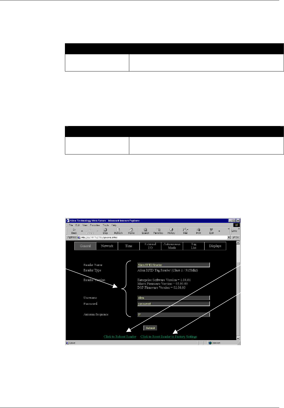
CHAPTER 6 READER-HOST PROTOCOL
NANOSCANNER READER USER GUIDE • DOC # 8101029-000 REV A 55
© 2003 Alien Technology™
REBOOT
The Reboot command will immediately cause the reader to reboot itself.
Example
Command
Response
>Reboot
>Reader is rebooting now !
FACTORYSETTINGS
The FactorySettings command will reset all settings in the reader to their default
values.
Example
Command
Response
>FactorySettings
>All settings have been reset !
General Commands – Web Based
General commands are issued via the Web page to manipulate reader and
antenna functions and access information.
COMMANDS/OPERATIONS VIA WEB GENERAL TAB
Command equivalents found on the Web-based “General” tab are:
• Get | Set ReaderName
• Get ReaderType and Reader Version
Web vie
w
General tab
covers all Get
and Set
general
commands...
...Plus
Reboot
and
Factory
Settings
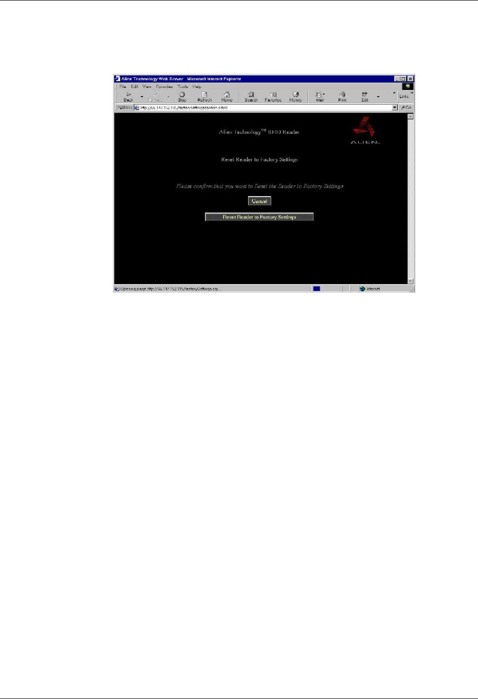
CHAPTER 6 READER-HOST PROTOCOL
NANOSCANNER READER USER GUIDE • DOC # 8101029-000 REV A 56
© 2003 Alien Technology™
• Get | Set Username
• Get | Set Password
• Get | Set AntennaSequence
• Reboot
• Factory settings (see below)
When you click on the “Reset reader factory settings” option at the bottom of
the General tab screen, you will have an opportunity to change your mind
before the command is accepted.
At this second screen you may click -[CANCEL] to stop the reset, or you can
click the [Reset Reader Factory Settings] button to proceed.
This screen
lets you
cancel o
r
continue to
reset reade
r
to factor
y
settings.

CHAPTER 6 READER-HOST PROTOCOL
NANOSCANNER READER USER GUIDE • DOC # 8101029-000 REV A 57
© 2003 Alien Technology™
Network Configuration Commands – Text Based
These commands allow you to configure and retrieve settings related to reader
communications with the network.
GET DHCP
SET DHCP
The reader supports automatic network configuration using the widely available
DHCP protocol. If DHCP is available at the reader installation site, this protocol
can be switched on. If DHCP is not available or not desired the use of this
protocol can be switched off.
• Valid command parameters are ON and OFF.
• The default setting is ON.
NOTE: After making changes with this command, you must reboot the reader to
implement the changes.
Example
Command
Response
>Get DHCP
>DHCP=ON
Command
Response
>Set DHCP=OFF
>DHCP=OFF
GET IPADDRESS
SET IPADDRESS
If DHCP is not used for automatic configuration, the reader must be manually
configured for use on a network. The IPAddress command pair allow you to
assign and retrieve the host’s IP address.
NOTE: After making changes with this command, you must reboot the reader to
implement the changes.
Example
Command
Response
>Get IPAddress
>IPAddress =12.34.56.78
Command
Response
>Set IPAddress =34.55.33.12
>IPAddress =34.55.33.12
GET GATEWAY
SET GATEWAY
If DHCP is not used for automatic configuration, the reader must be manually
configured for use on a network. The gateway command pair allow the network
gateway to be assigned and retrieved.
• Gateway must be specified as a numerical IP address.
NOTE: After making changes with this command, you must reboot the reader to
implement the changes.

CHAPTER 6 READER-HOST PROTOCOL
NANOSCANNER READER USER GUIDE • DOC # 8101029-000 REV A 58
© 2003 Alien Technology™
Example
Command
Response
>Get Gateway
>Gateway=34.56.78.90
Command
Response
>Set Gateway=12.56.23.01
>Gateway=12.56.23.01
GET NETMASK
SET NETMASK
If DHCP is not used for automatic configuration, the reader must be manually
configured for use on a network. The subnet mask command pair allow the
subnet mask to be assigned and retrieved.
• A subnet mask must be specified as a numerical IP address.
NOTE: After making changes with this command, you must reboot the reader to
implement the changes.
Example
Command
Response
>Get Netmask
>Netask=255.255.255.128
Command
Response
>Set Netmask=255.255.255.0
>Netmask=255.255.255.0
GET DNS
SET DNS
If DHCP is not used for automatic configuration, the reader must be manually
configured for use on a network. The DNS command pair allow the DNS server
location to be assigned and retrieved.
• A DNS server must be specified as a numerical IP address.
NOTE: After making changes with this command, you must reboot the reader to
implement the changes.
Example
Command
Response
>Get DNS
>DNS=12.34.56.78
Command
Response
>Set DNS=45.224.124.34
>DNS=45.224.124.34

CHAPTER 6 READER-HOST PROTOCOL
NANOSCANNER READER USER GUIDE • DOC # 8101029-000 REV A 59
© 2003 Alien Technology™
GET HEARTBEATPORT
SET HEARTBEATPORT
The reader can be configured to periodically send out a heartbeat message to
the network. This heartbeat takes the form of a single UDP packet (Universal
Datagram Packet) broadcast out to the entire subnet that the reader is configured
for.
The Set HeartbeatPort command allows you to configure the actual port number
that this packet is sent out to.
Listening for this heartbeat can be used to initially locate a reader on a network
and subsequently make sure that the reader is still alive.
• The default port setting for this command is 3988
The format of the UDP packet is a single XML document detailing the reader:
<Alien-RFID-Reader-Heartbeat>
<ReaderName>Alien RFID Reader</ReaderName>
<ReaderType>Alien RFID Tag Reader (Class 1 / 915Mhz)</ReaderType>
<IPAddress>10.1.60.5</IPAddress>
<CommandPort>23</CommandPort>
<HeartbeatTime>30</HeartbeatTime>
</Alien-RFID-Reader-Heartbeat>
NOTE: Changes made with this command will take effect immediately.
Example
Command
Response
>Get HeartbeatPort
>HeartbeatPort=3004
Command
Response
>Set HeartbeatPort=10002
>HeartbeatPort=10002
GET HEARTBEATTIME
SET HEARTBEATTIME
The reader can be configured to periodically send out a heartbeat message to
the network. This heartbeat takes the form of a single UDP packet (Universal
Datagram Packet) broadcast out to the entire subnet that the reader is configured
for.
The time interval between heartbeats can be assigned and retrieved using this
command.
• All intervals are specified in seconds.
• A setting of zero (seconds) will suspend the output of any further heartbeats.
• The default setting for this command is 30 seconds.
NOTE: Changes made with this command will take effect immediately.
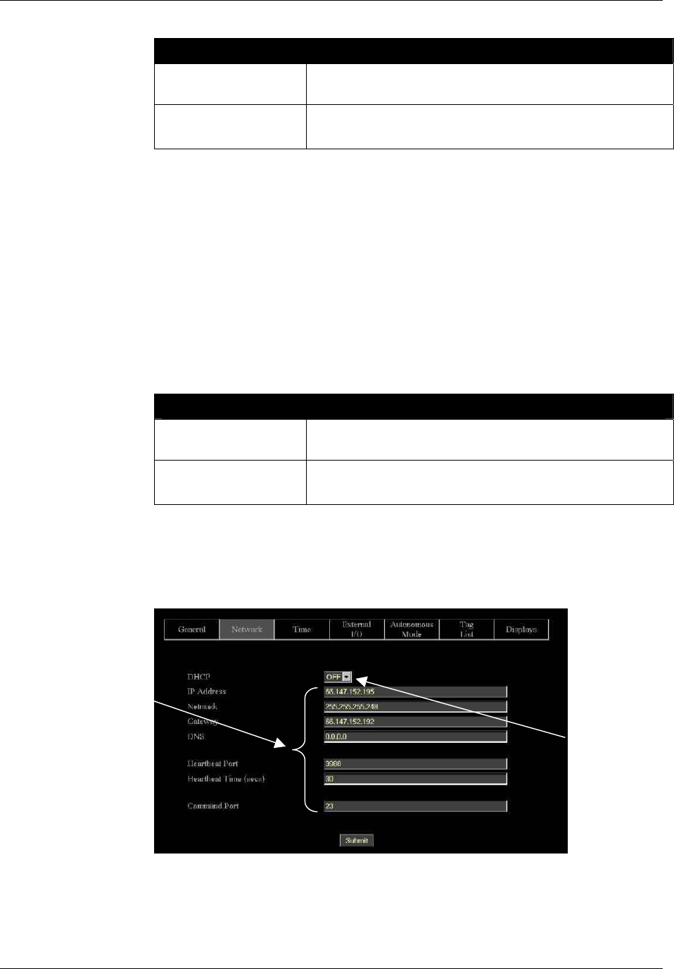
CHAPTER 6 READER-HOST PROTOCOL
NANOSCANNER READER USER GUIDE • DOC # 8101029-000 REV A 60
© 2003 Alien Technology™
Example
Command
Response
>Get HeartbeatTime
>HeartbeatTime=30
Command
Response
>Set HeartbeatTime=60
>HeartbeatTime=60
GET COMMANDPORT
SET COMMANDPORT
The reader can be configured and operated over the network using standard
network sockets. The CommandPort settings are used to assign and retrieve the
exact port number used by the reader for this network connectivity.
• The default setting for this command is 23 (the standard Telnet port)
Changes to this setting do not affect serial communication and/or Web
communication with the reader.
NOTE: Changes made with this command will take effect immediately.
Example
Command
Response
>Get CommandPort
>CommandPort=23
Command
Response
>Set CommandPort=10004
>CommandPort=10004
Network Commands – Web Based
Network commands are issued via the Web page to set up and access reader
networking parameters.
Toggles DHCP
On and Off
Web vie
w
Network tab
covers all Get
and Set
network
commands.

CHAPTER 6 READER-HOST PROTOCOL
NANOSCANNER READER USER GUIDE • DOC # 8101029-000 REV A 61
© 2003 Alien Technology™
COMMANDS/OPERATIONS VIA WEB NETWORK TAB
Command equivalents found on the Web-based “Network” tab are:
• Get DHCP
• Set DHCP (toggles DHCP On and OFF)
• Get | Set IPaddress
• Get | Set Gateway
• Get | Set Netmask
• Get | Set DNS
• Get | Set HeartbeatPort
• Get | Set HearbeatTime
• Get | Set CommandPort

CHAPTER 6 READER-HOST PROTOCOL
NANOSCANNER READER USER GUIDE • DOC # 8101029-000 REV A 62
© 2003 Alien Technology™
Time Commands – Text Based
The time at which tags are read by a reader is particularly important for many
applications. For this reason, the reader has three time commands to ensure that
the onboard real-time clock is always set accurately.
GET TIME
SET TIME
These commands allow the current time to be assigned to or retrieved from the
reader.
• Times used by this command are always specified in local time, as defined
by the TimeZone command.
• Times are always specified by the format YYYY/MM/DD hh:mm:ss.
NOTE: Changes made with this command will take effect immediately.
Example
Command
Response
>Get Time
>Time = 2002/6/3 9:23:01
>Set Time = 2002/6/3 19:23:01
>Time = 2002/6/3 19:23:01
GET TIMEZONE
SET TIMEZONE
These commands allow the current time zone to be assigned to or retrieved from
the reader. The time zone specifies the number of hours that must be added to or
subtracted from UTC (Coordinated Universal Time; also known as GMT or Zulu)
to determine a local time reference.
For example, to convert from UTC to Pacific Standard Time, set the TimeZone to
–8. To convert from UTC to Pacific Daylight Time, set the TimeZone to –7.
• The default setting for this command is -7 hours (Pacific Daylight Time)
because PDT is UTC time minus 7 hours.
• For more information about time zones, servers and UTC, refer to the
Website listed under the Get/Set TimeServer command.
The TimeZone parameter is only useful if the TimeServer is used to automatically
set the system clock. In this case, the TimeServer always retrieves the time in
UTC format and will need to be offset to reflect local time using this parameter.
NOTE: Changes made with this command will take effect immediately.

CHAPTER 6 READER-HOST PROTOCOL
NANOSCANNER READER USER GUIDE • DOC # 8101029-000 REV A 63
© 2003 Alien Technology™
Example
Command
Response
>Get TimeZone
>TimeZone = -8
>Set TimeZone = 3
>TimeZone = 3
GET TIMESERVER
SET TIMESERVER
The reader uses the Internet to accurately set its internal clock every time it is
rebooted. The protocol it uses is called the Daytime Protocol (RFC-867) which
typically returns the time in UTC format.
In order to use this feature, a TimeServer must be specified. This is the network
address of a machine that is constantly running the Daytime Protocol. In the US
there are a number of machines owned and operated by the Government
explicitly providing the time and date to Internet users.
• By default the reader is configured to connect to one of these machines on
boot-up to get the current time.
• For a more in-depth description of this server, and a list of other publicly
accessible Daytime Protocol Servers, see:
http://www.boulder.nist.gov/timefreq/service/its.htm
• The default setting for this command is 132.163.4.101, a primary NIST
network time server. Some alternative time servers are:
time-a.nist.gov / 129.6.15.28
time-b.nist.gov / 129.6.15.29
time.nist.gov / 192.43.244.18
NOTE: After making changes with this command, you must reboot the reader to
implement the changes.
Example
Command
Response
>Get TimeServer
>TimeServer = 129.6.15.28
>Set TimeServer = 129.6.15.28
>TimeServer = 129.6.15.28
The TimeServer is only used once when the reader is booted up. A message in
the boot sequence (sent out to the serial console) indicates success or failure of
this option.
For example, a successful boot sequence will report the following messages to
the serial console:
Booting Alien RFID Reader
Boot> Boot Level 1 (Console Communication) : Success
Boot> Boot Level 2 (Reader Communication) : Success
Boot> Boot Level 3 (Tag Manager) : Memory for 1000 Tags
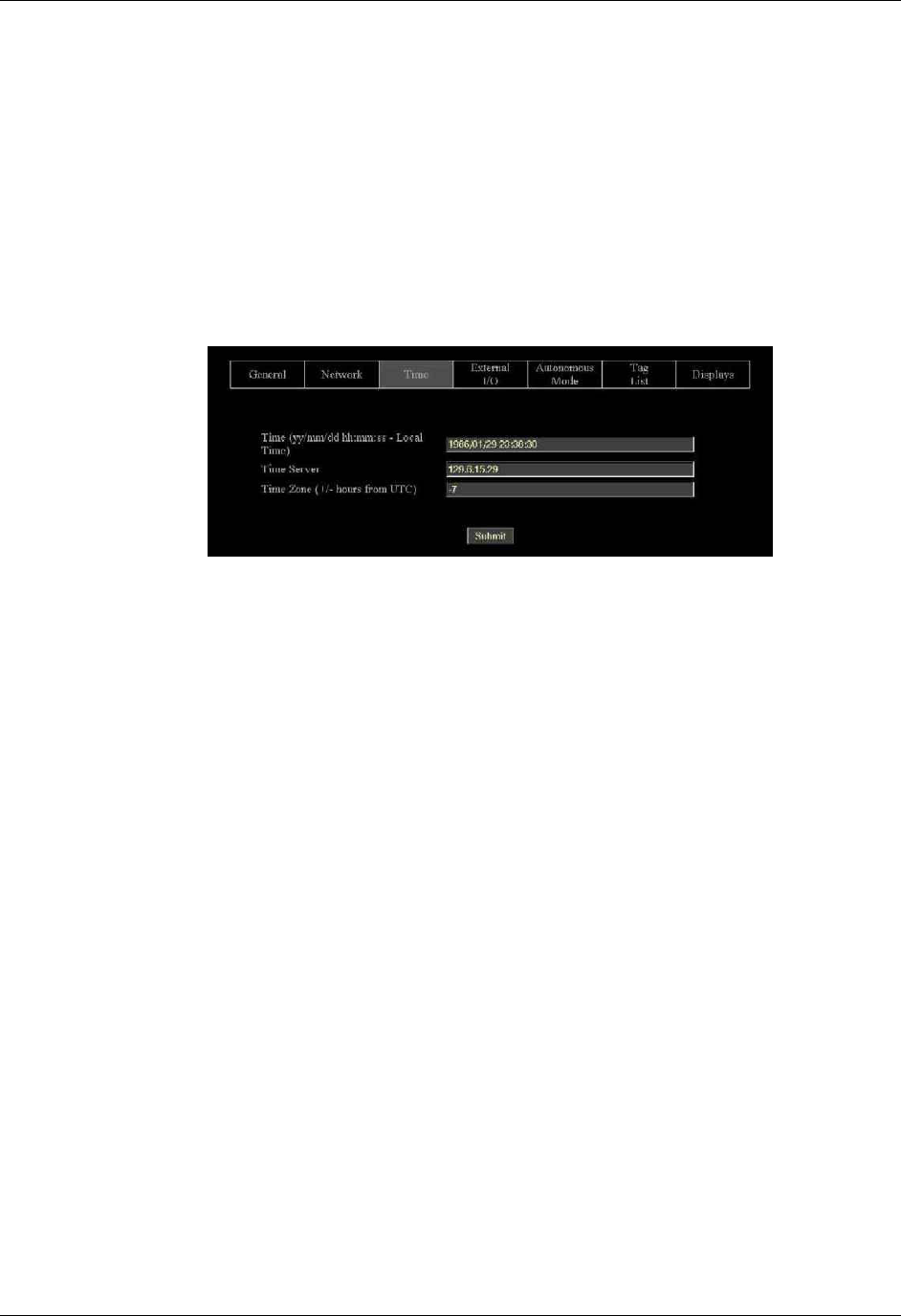
CHAPTER 6 READER-HOST PROTOCOL
NANOSCANNER READER USER GUIDE • DOC # 8101029-000 REV A 64
© 2003 Alien Technology™
Boot> Boot Level 4 (System Settings) : Success
Boot> Boot Level 5 (Network) : Success - IP Address is 10.1.60.4
Boot> Boot Level 6 (Telnet Interface) : Success - Port 23 Ready
Boot> Boot Level 7 (Web Interface) : Success
Boot> Boot Level 8 (Network Time Service) : Success - Time Set to
2002/08/23 16:50:24
Boot> Ready
Time Commands – Web Based
Time commands are issued via the Web page to set up and access reader time
parameters.
COMMANDS/OPERATIONS VIA WEB TIME TAB
Command equivalents found on the Web-based “Time” tab are:
• Get | Set Time
• Get | Set TimeZone
• Get | Set TimeServer
Web view Time
tab covers all
Get and Set
time
commands.

CHAPTER 6 READER-HOST PROTOCOL
NANOSCANNER READER USER GUIDE • DOC # 8101029-000 REV A 65
© 2003 Alien Technology™
External I/O Commands
These commands allow you to configure and retrieve current data regarding the
reader’s external output functions.
SET EXTERNALOUTPUT
GET EXTERNALOUTPUT
The reader controls two external output pins, which can subsequently be used to
control external devices such a doors/gates, security lights. etc. Please refer to
Chapter 1, Specifications section in this document for pinout diagrams.
With this command you can set the external output pin values. The command
takes a single parameter that represents the bit mask settings of the external
pins.
• Bit 0 represents the state of pin 0, and Bit 1 represents the state of pin 1.
For example, to set pin 1 to high and pin 0 on low, use the bit mask of
10binary which translates to 2decimal
NOTE: Changes made with this command will take effect immediately.
Example
Command
Response
>Set ExternalOuput = 2
>ExternalOutput = 2
Command
Response
>Get ExternalOuput
>ExternalOutput = 2
GET EXTERNALINPUT
The reader also monitors two external input pins, which can subsequently be
controlled by external proximity detectors and other input devices such as
“magic-eyes” and magnetic switches. This command allows these external input
pin values to be obtained. Please refer to Chapter 1, Specifications section in this
document for pinout diagrams.
• The command returns a single byte result that represents the bit mask
settings of the external pins. Bit 0 represents the state of pin 0, and Bit 1
represents the state of pin 1.
NOTE: Changes made with this command will take effect immediately.
Example
Command
Response
>Get ExternalInput
>ExternalInput = 2 (i.e., binary 10)

CHAPTER 6 READER-HOST PROTOCOL
NANOSCANNER READER USER GUIDE • DOC # 8101029-000 REV A 66
© 2003 Alien Technology™
External I/O Commands – Web Based
External I/O commands are issued via the Web page to set up and access
external input and output parameters.
COMMANDS/OPERATIONS ON WEB EXTERNAL I/O TAB
Command equivalents found on the Web-based “External I/O” tab are:
• Get | Set ExternalOutput
• Get ExternalInput
Web view I/O
tab covers all
Get and Set
External I/O
commands.

CHAPTER 6 READER-HOST PROTOCOL
NANOSCANNER READER USER GUIDE • DOC # 8101029-000 REV A 67
© 2003 Alien Technology™
Tag List Commands – Command Line
Tag list commands allow you to retrieve immediate listings of tags that have been
read and saved by the reader, and to assign and retrieve tag list functional
parameters.
NOTE: Web versions of these operations are shown in the next section.
GET TAGLIST (N)
You can retrieve the reader’s stored tag list either a single time (Get TagList) or
multiple times (Get TagList n).
• The maximum number of tags that can be stored in the tag list is 1000.
Using the Get TagList to retrieve the stored list only once:
• If the reader is currently in interactive mode, the reader will immediately
perform a full tag search (read and report) and display its current internal tag
list. The reply will be a multi-line command with each line listing an active tag.
If the tag list is empty, the message “(No Tags)” will be returned.
• If the reader is in Autonomous mode, the reader will display its current
internal tag list only.
Using the Get TagList with an optional integer ‘n’ instructs the command to be
repeated ‘n’ times before a combined result is returned.
The format of the data returned by this command is specified using the Set
TagListFormat command, described below.
Example
Command
Response
Get TagList
Tag: 0002 0030 A233 0400, CRC: B340, Disc: 2002/03/23
15:36:33, Count: 4, Ant: 0
Tag: 8080 AAAB ECF0 0000, CRC: 3021, Disc: 2002/03/22
12:26:01, Count: 3, Ant: 1
Command
Response
Get TagList
(No Tags)
SET TAGLISTFORMAT
GET TAGLISTFORMAT
The Get and Set TagListFormat commands specify the formatting of tag lists.
The command itself takes a text string as its argument, and can be one of the
following:

CHAPTER 6 READER-HOST PROTOCOL
NANOSCANNER READER USER GUIDE • DOC # 8101029-000 REV A 68
© 2003 Alien Technology™
TagListFormat Description
text
Tag lists displayed as plain text messages, one tag ID per line.
xml Tag lists are displayed in XML text format
custom Tag lists are displayed in the format described by
TagListCustomFormat.
• Text formatted tag lists take the following form:
Tag:1115 F268 81C3 C012, CRC:2483, Disc:2003/01/21 09:00:51, Count:1, Ant:0
Tag:0100 0100 0002 0709, CRC:8594, Disc:2003/01/21 11:00:10, Count:1, Ant:0
Tag:1054 A334 54E1 7409, CRC:2083, Disc:2003/01/21 11:50:03, Count:1, Ant:0
• XML Formatted tag lists take the form:
<Alien-RFID-Tag-List>
<Alien-RFID-Tag>
<TagID>0102 0304 0506 0709</TagID>
<CRC>87B4</CRC>
<DiscoveryTime>2003/01/17 11:37:01</DiscoveryTime>
<Antenna>0</Antenna>
<ReadCount>1413726</ReadCount>
</Alien-RFID-Tag>
<Alien-RFID-Tag>
<TagID>2283 1668 ADC3 E804</TagID>
<CRC>9FD0</CRC>
<DiscoveryTime>2003/01/19 07:01:19</DiscoveryTime>
<Antenna>0</Antenna>
<ReadCount>1</ReadCount>
</Alien-RFID-Tag>
</Alien-RFID-Tag-List>
In all cases the following information is reported per tag:
• TagID: The 64 bit tag ID.
• CRC: The checksum built into the tag that guarantees that the tagID was
read correctly.
• Disc: The time the tag was first read by the reader in the current session.
• Count: The number of times the tag has been read in the current session.
• Ant: The antenna port number that the tag was LAST seen at.
Example
Command
Response
Set TagListFormat = XML
TagListFormat = XML
Command
Response
Get TagListFormat
TagListFormat = Text
NOTE: Changes made with this command will take effect immediately.

CHAPTER 6 READER-HOST PROTOCOL
NANOSCANNER READER USER GUIDE • DOC # 8101029-000 REV A 69
© 2003 Alien Technology™
SET TAGLISTCUSTOMFORMAT
GET TAGLISTCUSTOMFORMAT
The Get and Set TagListCustomFormat allows a customized tag list to be
defined. Once the format has been defined it can be applied by issuing the
command ‘set taglistFormat = custom’
The tagListCustomFormat command takes a single text line argument that
defines how each tag should be represented on-screen. This argument can be
made up of a mixture of text and tokens, where the tokens are defined in the
table below.
When the Nanoscanner is required to print a taglist, the tokens in the custom
format are replaced with their runtime values.
Tokens Description
%i Tag ID with a white space between each pair of bytes i.e.,
8000 00FE 8010 2AB7
%k Tag ID with no spaces between i.e.,
800000FE80102AB7
%d Discovery date of tag, in format YY/MM/DD
%t Discovery time of tag, in format hh:mm:ss
%a Antenna the tag was last seen at
%c Checksum (CRC) of the tag ID (see programming guide for
more details on the checksum format)
%r Read Count of tags, i.e., how many times the tag has been
read
Example
Command
Response
Get TagList
Set TagListCustomFormat = Here is a tag %i
TagListFormat = Here is a tag %i
Here is a tag 8000 0000 0000 0808
Here is a tag 102F ED3D 0303 0001
Command
Response
Get TagList
Set TagListCustomFormat = Tag %k, read %r times from
antenna %a
TagListFormat = = Tag %k, read %r times from antenna %a
Tag 8000000000000808, read 3 times from antenna 0
Tag 102FED3D03030001, read 120 times from antenna 1
NOTE: Changes made with this command will take effect immediately.

CHAPTER 6 READER-HOST PROTOCOL
NANOSCANNER READER USER GUIDE • DOC # 8101029-000 REV A 70
© 2003 Alien Technology™
SET ACQUIREMODE
GET ACQUIREMODE
Whenever the reader is called upon to read a tag it does so using the current
AcquireMode. Currently the allowable modes are as follows:
AcquireMode Description
Inventory
Perform full inventory of multiple tags.
Global Scroll Perform fast search for single tag.
The default setting is Inventory. For a detailed description of the different modes,
please refer to the earlier chapter entitled ‘Tag Reading Fundamentals’
• Inventory
The Inventory acquire mode performs a full anti-collision search on tags in
the reader’s field of view. This method will locate and distinguish multiple
tags in front of the reader at the same time.
• Global Scroll
The Global Scroll acquire mode instructs the reader to read a single tag
repeatedly. This is a very fast tag reading method which is most effective
when only one tag at a time is expected to be within reader range, as in
conveyor belt applications. Under such circumstances, the performance for
single tag reading is considerably faster than repeatedly doing a full tag
search using the Inventory mode.
NOTE: If multiple tags are in range of the reader when this mode is used, the
reader will either select one of the tags (usually the “strongest’” or “loudest”)
to read and report it, or will read none of the tags.
Example
Command
Response
Set AcquireMode = Global Scroll
>AcquireMode = Global Scroll
Command
Response
Set AcquireMode = Inventory
>AcquireMode = Inventory
NOTE: Changes made with this command will take effect immediately.
SET ACQUIRESLEEP
GET ACQUIRESLEEP
AcquireSleep is an On or Off parameter.

CHAPTER 6 READER-HOST PROTOCOL
NANOSCANNER READER USER GUIDE • DOC # 8101029-000 REV A 71
© 2003 Alien Technology™
If AcquireSleep is set to On, any tags read by auto mode or interactive mode will
be put to sleep as they are found. Subsequent reads of the tag field will return no
more tags, until Wake commands are issued to the tags.
If AcquireSleep is set to Off, tags will be left awake once they have been read.
Thus repeated reads will return the same tag IDs.
Example
Command
Response
Set AcquireSleep = on
>AcquireSleep = ON
Command
Response
Set AcquireSleep = off
>AcquireSleep = OFF
NOTE: Changes made with this command will take effect immediately.
SET ACQUIREWAKECOUNT
GET ACQUIREWAKECOUNT
AcquireWakeCount takes a single integer parameter.
If AcquireWakeCount is greater than zero, it specifies after how many Acquire
events a Wake command should be issued.
For example, is AcquireWakeCount is set to 10, a Wake command will be issued
after every 10 acquire commands (either global scrolls or inventories).
If AcquireWakeCount is set to zero or less, no Wake commands will be issued.
.
Example
Command
Response
Set AcquireWakeCount = 0
>AcquireWakeCount = 0
Command
Response
Set AcquireWakeCount = 10
>AcquireWakeCount = 10
NOTE: Changes made with this command will take effect immediately.
GET MASK
SET MASK
The Get and Set Mask commands will control the current mask that the reader
uses. Masks are important in both addressing tags and interrogating them. For a
detailed description of Masks, please refer to the earlier chapter entitled ‘Tag
Reading Fundamentals’
The Set Mask command takes three parameters:

CHAPTER 6 READER-HOST PROTOCOL
NANOSCANNER READER USER GUIDE • DOC # 8101029-000 REV A 72
© 2003 Alien Technology™
Bit Length of Mask, as a decimal number
Bit Pointer of Mask, as a decimal number
Array of Hex Bytes separated by white spaces
Note: Class I tags IDs start at bit 16, not bit 0. The first 16 bits of a Class I tag are
used to store the checksum for the tag.
The Get Mask command takes no parameters but returns the three parameters
described above.
Note:
Setting the mask to ‘All’ will address all tags currently in the RF field. i.e., “set
mask= all’
Example
Command
Response
>Set Mask = all
>Mask (BitLen, BitPtr, XX XX) = All Tags
Command
Response
>Set Mask = 8, 0, 3
>Mask (BitLen, BitPtr, XX XX) = 8, 0, 3
Command
Response
>Set Mask = 16, 0, 00 03
>Mask (BitLen, BitPtr, XX XX) = 16, 0, 00 03
Command
Response
>Get Mask
>Mask (BitLen, BitPtr, XX XX) = 16, 0, 00 03
CLEAR TAGLIST
The Clear TagList command instructs the reader to immediately clear its internal
tag list.
Example
Command
Response
>Clear TagList
>Tag List has been reset!
NOTE: Changes made with this command will take effect immediately.
GET PERSISTTIME
SET PERSISTTIME
The PersistTime specifies the length of time a tag’s data will remain in the
reader’s internal list of active tags.
• Persist times are specified in seconds.
• The default setting is 10 seconds.
• Setting the persist time to a positive number (1-n) will establish a persist time
of the desired number of seconds

CHAPTER 6 READER-HOST PROTOCOL
NANOSCANNER READER USER GUIDE • DOC # 8101029-000 REV A 73
© 2003 Alien Technology™
• A zero persist time (0) will guarantee that tags are not stored in the tag list.
However issuing a get taglist command in interactive mode will return any
tags immediately found even though they won’t be stored in the taglist.
• Setting the persist time to –1 will cause the history to build indefinitely until a
get taglist command is issued; at this point the tag list is returned, and then
immediately cleared.
The maximum number of tags that can be stored in the tag list is 1000. Once this
tag limit is reached, error messages will be reported to the serial console, and no
new tags will be added to the list until room is available.
NOTE: Changes made with this command will take effect immediately.
Example
Command
Response
>Get PersistTime
>PersistTime=10
Command
Response
>Set PersistTime=300
>PersistTime=10
WAKE
The Wake command will request all tags in the field to wake up. This command
is directed by the Mask settings, allowing all tags to be awakened or a subset
only.
Example
Command
Response
>Wake
>Wake=OK
SLEEP
The Sleep command will request all tags in the field to sleep. A sleeping tag will
ignore any commands sent to it except the Wake command. This command is
directed by the Mask settings, allowing all tags to be slept or a subset only.
Example
Command
Response
>Sleep
>Sleep=OK
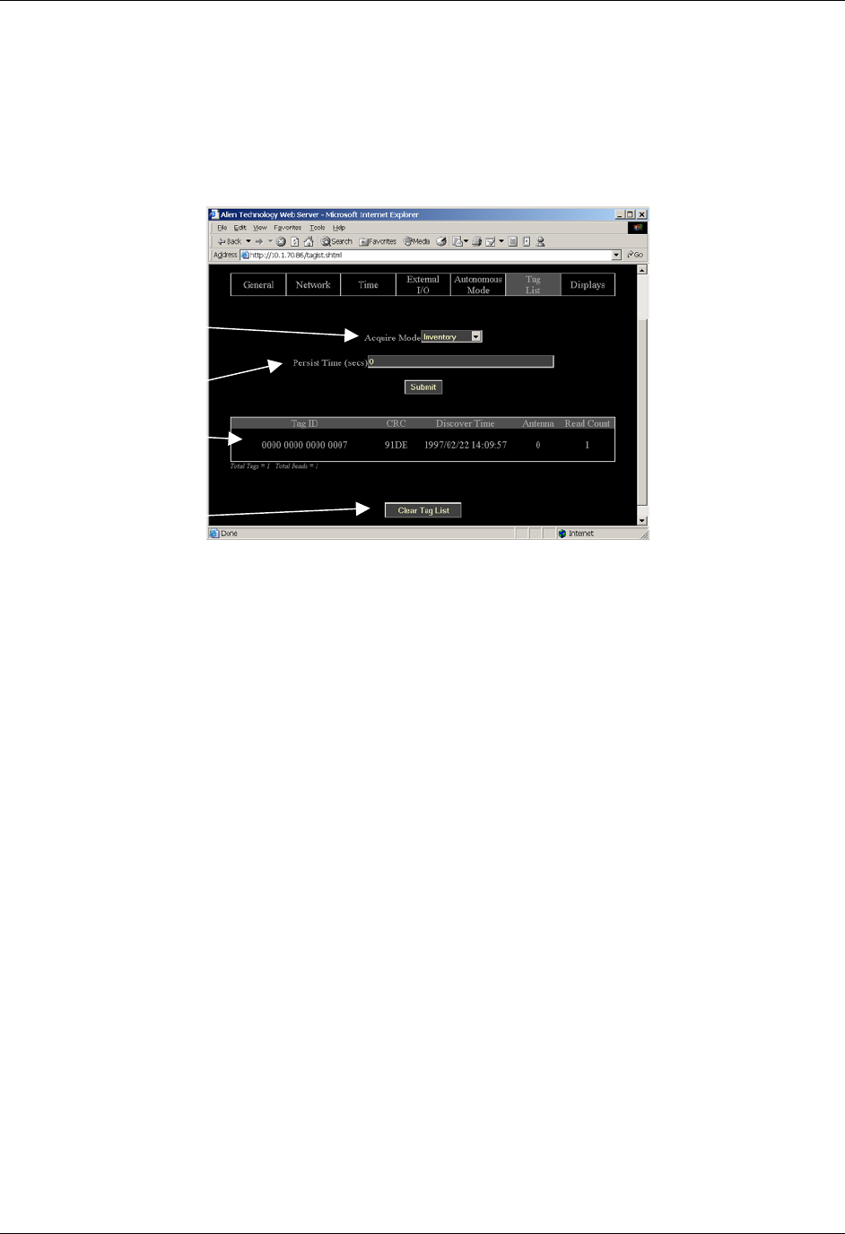
CHAPTER 6 READER-HOST PROTOCOL
NANOSCANNER READER USER GUIDE • DOC # 8101029-000 REV A 74
© 2003 Alien Technology™
Tag List Commands – Web Based
Tag List commands are issued via the Web page to set up and access tag
information.
COMMANDS/OPERATIONS ON WEB TAG LIST TAB
NOTE : Every time the Tag List page is loaded / refreshed, it is the equivalent of
issuing a Get Taglist command to the reader. The results are displayed on the
page.
Command equivalents found on the Web-based “Tag List” tab are:
• Get | Set AcquireMode
• Get | Set PersistTime
• Get TagList(n)
Includes tag ID, crc, discover time, reading antenna and read count.
• Clear Taglist
Tag List displays:
• Tag ID
• CRC
• Discover time
• Reading
Antenna
• Read count
Allows you to:
Get and Set
Acquire
Mode…
Get and Set
Persist Time...
Displa
y
TagList...
and
Clear TagList.

CHAPTER 6 READER-HOST PROTOCOL
NANOSCANNER READER USER GUIDE • DOC # 8101029-000 REV A 75
© 2003 Alien Technology™
Autonomous Mode Commands
Autonomous mode is a multi-stage configuration and operation mode that
enables hands-free monitoring of tags.
• The first stage requires you to issue a series of configuration commands to
the reader. These commands detail how and when to read tags, and then
when tags are found, who to tell.
• Once configured, the reader can be left to operate on its own.
For a detailed description of the Automonous mode system please refer to
Chapter 4 of this guide.
SET AUTOMODE
GET AUTOMODE
The AutoMode command turns on or off the automode.
• Valid command parameters are ON and OFF
• The default setting is OFF
NOTE: Changes made with this command will take effect immediately.
Example
Command
Response
>Get AutoMode
>AutoMode=ON
Command
Response
>Set AutoMode=on
>AutoMode=ON
SET AUTOWAITOUTPUT
GET AUTOWAITOUTPUT
The AutoWaitOutput specifies the output pin settings to effect while in the wait
state of autonomous mode. The parameter is a bit mask for the two external
output pins, where a ‘1’ sets a pin to high, and a ‘0’ sets a pin to low. Pin 1 is
specified by bit one in the mask, and Pin 0 is specified by bit zero in the mask.
NOTE: Changes made with this command will take effect immediately.
Example
Command
Response
>Get AutoWaitOutput
> AutoWaitOutput =0
Command
Response
>Set AutoWaitOutput =3 //Turn pins 0 and 1 to high
> AutoWaitOutput =3

CHAPTER 6 READER-HOST PROTOCOL
NANOSCANNER READER USER GUIDE • DOC # 8101029-000 REV A 76
© 2003 Alien Technology™
SET AUTOSTARTTRIGGER
GET AUTOSTARTTRIGGER
The AutoStartTrigger specifies the external input pins to monitor to cause the
automode to jump from wait state to work state. Triggers can either be a pin
going from low to high (rising edge) to high to low (falling edge). For each type of
change, an integer bit mask must be provided to specify the pins to listen for
changes on.
The command takes two parameters, a rising edge bit mask and a falling edge
bit mask.
NOTE: Changes made with this command will take effect immediately.
Example
Command
Response
>Get AutoStartTrigger
> AutoStartTrigger(rising, falling)= 0, 0
Command
Response
>Set AutoStartTrigger =3, 0 //Listen for rising edges on pins 0
and 1
> AutoStartTrigger (rising, falling)= 3, 0
SET AUTOWORKOUTPUT
GET AUTOWORKOUTPUT
The AutoWorkOutput specifies the output pin settings to effect while in the work
state of autonomous mode. The parameter is a bit mask for the two external
output pins, where a ‘1’ sets a pin to high, and a ‘0’ sets a pin to low. Pin 1 is
specified by bit one in the mask, and Pin 0 is specified by bit zero in the mask.
NOTE: Changes made with this command will take effect immediately.
Example
Command
Response
>Get AutoWorkOutput
> AutoWorkOutput =0
Command
Response
>Set AutoWorkOutput =3 //Turn pins 0 and 1 to high
> AutoWorkOutput =3
SET AUTOACTION
GET AUTOACTION
The AutoAction command specifies the action to perform when running in the
work mode of auto mode. This can be one of the following options:
AutoAction Description
None Perform no action
Acquire
Perform an acquire action, as specified by the AcquireMode
options.

CHAPTER 6 READER-HOST PROTOCOL
NANOSCANNER READER USER GUIDE • DOC # 8101029-000 REV A 77
© 2003 Alien Technology™
• The default setting is Acquire
NOTE: Changes made with this command will take effect immediately.
Example
Command
Response
>Get AutoAction
> AutoAction = Acquire
Command
Response
>Set AutoAction =Acquire
> AutoAction = Acquire
SET AUTOSTOPTRIGGER
GET AUTOSTOPTRIGGER
The AutoStopTrigger specifies the external input pins to monitor to cause the
automode to jump from work state to evaluate state. Triggers can either be a pin
going from low to high (rising edge) to high to low (falling edge). For each type of
change, an integer bit mask must be provided to specify the pins to listen for
changes on.
The command takes two parameters, a rising edge bit mask and a falling edge
bit mask.
NOTE: Changes made with this command will take effect immediately.
Example
Command
Response
>Get AutoStopTrigger
> AutoStopTrigger(rising, falling)= 0, 0
Command
Response
>Set AutoStopTrigger =3, 0 //Listen for rising edges on pins 0
and 1
> AutoStopTrigger (rising, falling)= 3, 0
SET AUTOSTOPTIMER
GET AUTOSTOPTIMER
The AutoStopTimer offers an alternative way to jump from work state to evaluate
state. This is a time based jump, that will happen after the timer period specified
by this command expires. The parameter is a single time period, specified in
milliseconds.
NOTE: Changes made with this command will take effect immediately.

CHAPTER 6 READER-HOST PROTOCOL
NANOSCANNER READER USER GUIDE • DOC # 8101029-000 REV A 78
© 2003 Alien Technology™
Example
Command
Response
>Get AutoStopTimer
> AutoStopTrimer (ms) = 0
Command
Response
>Set AutoStopTimer =1000 //Acquire for 1sec then evaluate
> AutoStopTimer (ms)= 1000
SET AUTOTRUEOUTPUT
GET AUTOTRUEOUTPUT
The AutoTrueOutput specifies the output pin settings to effect if the evaluate
mode of autonomous mode evaluates to true. The parameter is a bit mask for the
two external output pins, where a ‘1’ sets a pin to high, and a ‘0’ sets a pin to low.
Pin 1 is specified by bit one in the mask, and Pin 0 is specified by bit zero in the
mask.
NOTE: Changes made with this command will take effect immediately.
Example
Command
Response
>Get AutoTrueOutput
> AutoTrueOutput =0
Command
Response
>Set AutoTrueOutput =3 //Turn pins 0 and 1 to high
> AutoTrueOutput =3
SET AUTOTRUEPAUSE
GET AUTOTRUEPAUSE
The AutoTruePause specifies a millisecond pause to effect if the autonomous
evaluation mode evaluates to true. This pause will occur after the
AutoTrueOutput command has been processed.
NOTE: Changes made with this command will take effect immediately.
Example
Command
Response
>Get AutoTruePause
> AutoTruePause (ms)=0
Command
Response
>Set AutoTruePause =500 //Pause for half a sec.
> AutoTruePause = 500
SET AUTOFALSEOUTPUT
GET AUTOFALSEOUTPUT
The AutoFalseOutput specifies the output pin settings to effect if the evaluate
mode of autonomous mode evaluates to false. The parameter is a bit mask for
the two external output pins, where a ‘1’ sets a pin to high, and a ‘0’ sets a pin to

CHAPTER 6 READER-HOST PROTOCOL
NANOSCANNER READER USER GUIDE • DOC # 8101029-000 REV A 79
© 2003 Alien Technology™
low. Pin 1 is specified by bit one in the mask, and Pin 0 is specified by bit zero in
the mask.
NOTE: Changes made with this command will take effect immediately.
Example
Command
Response
>Get AutoFalseOutput
> AutoFalseOutput =0
Command
Response
>Set AutoFalseOutput =3 //Turn pins 0 and 1 to high
> AutoFalseOutput =3
SET AUTOFALSEPAUSE
GET AUTOFALSEPAUSE
The AutoFalsePause specifies a millisecond pause to effect if the autonomous
evaluation mode evaluates to false. This pause will occur after the
AutoFalseOutput command has been processed.
NOTE: Changes made with this command will take effect immediately.
Example
Command
Response
>Get AutoFalsePause
> AutoFalsePause (ms)=0
Command
Response
>Set AutoFalsePause =500 //Pause for half a sec.
> AutoFalsePause = 500
GET AUTOMODESTATUS
The Get AutoModeStatus command will return an integer representing the
current state of the auto mode state machine.
Additionally the status may be followed by an asterisk character (*). If present it
indicates that a complete auto mode cycle has occurred since the last get
AutoModeStatus command was issued. Calling this method will always clear the
* flag.
The following table details the different states returned:
AutoModeStatus : States Returned
0 Auto Mode is OFF
10 Auto Mode is initializing
20 Auto Mode is listening for a start trigger
30 Auto Mode is starting its Action
40 Auto Mode is processing its Action
50 Auto Mode is listening for a Stop condition
60 Auto Mode is entering its evaluation stage
70 Auto Mode is in its true or false pause stage
80 Auto Mode is in notify stage

CHAPTER 6 READER-HOST PROTOCOL
NANOSCANNER READER USER GUIDE • DOC # 8101029-000 REV A 80
© 2003 Alien Technology™
.
Example
Command
Response
>Get AutoModeStatus
> AutoModeStatus =0 //Auto Mode is off
Command
Response
> Get AutoModeStatus
> AutoModeStatus =30 * //Auto is starting its AutoAction
but the asterisk also indicates that a complete auto mode cycle
has completed since we last enquired.
AUTOMODERESET
The AutoModeReset command will reset all auto mode parameters to their
default values, including setting the auto mode to off.
NOTE: Changes made with this command will take effect immediately.
Example
Command
Response
>AutoModeReset
> All AutoMode settings have been reset !
AUTOMODETRIGGERNOW
The AutoModeTriggerNow command will emulate an external IO trigger event to
effect auto mode. This command will only work if the Nanoscanner is already in
auto mode and is waiting for a start trigger condition. At this point, issuing the
AutoModeTriggerNow command will be identical to a real external trigger event,
forcing the auto mode into its action cycle.
NOTE: Changes made with this command will take effect immediately.
Example
Command
Response
>AutoModeTriggerNow
> Auto Mode Triggering Now
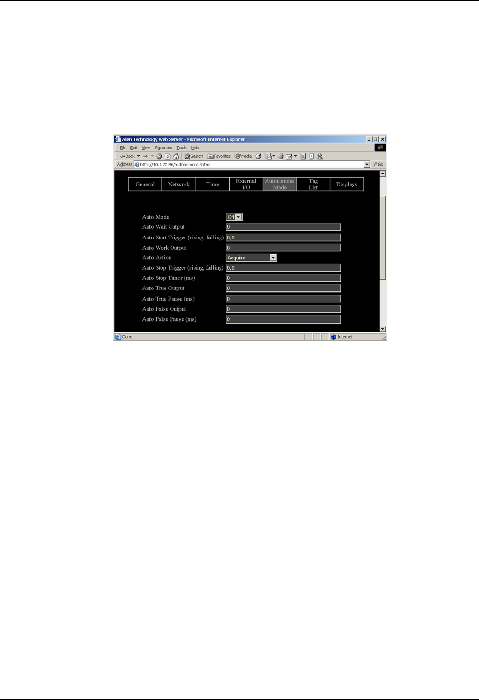
CHAPTER 6 READER-HOST PROTOCOL
NANOSCANNER READER USER GUIDE • DOC # 8101029-000 REV A 81
© 2003 Alien Technology™
Autonomous Mode Commands – Web Based
Autonomous Mode commands are issued via the Web page to set up and access
autonomous mode parameters.
COMMANDS/OPERATIONS ON WEB AUTONOMOUS MODE TAB
Command equivalents found on the Web-based “Autonomous Mode” tab are:
• Get | Set AutoMode
• Get | Set AutoWaitOutput
• Get | Set AutoStartTrigger
• Get | Set AutoWorkOutput
• Get | Set AutoAction
• Get | Set AutoStopTrigger
• Get | Set AutoStopTimer
• Get | Set AutoTrueOutput
• Get | Set AutoTruePause
• Get | Set AutoFalseOutput
• Get | Set AutoFalsePause
Web vie
w
Autonomous Mode
tab covers all Get
and Set
autonomous mode
commands.

CHAPTER 6 READER-HOST PROTOCOL
NANOSCANNER READER USER GUIDE • DOC # 8101029-000 REV A 82
© 2003 Alien Technology™
Notify Mode Commands
The Notify Mode commands are used to set up automated event notification
when the reader is running in Auto Mode.
SET NOTIFYMODE
GET NOTIFYMODE
The NotifyMode command turns on or off the notify mode.
• Valid command parameters are ON and OFF
• The default setting is OFF
NOTE: Changes made with this command will take effect immediately.
Example
Command
Response
>Get NotifyMode
> NotifyMode =ON
Command
Response
>Set NotifyMode =on
> NotifyMode =ON
GET NOTIFYADDRESS
SET NOTIFYADDRESS
The Notify Address command pair specify where notification messages should
be sent when they occur and how they should be sent. The form of the address
determines the method of delivery.
Currently there are 3 delivery methods supported as shown in the table below:
NotifyAddress Description
user@domain.com
Send a message via e-mail to the address specified. The
address is specified in standard email form, i.e.,
user@domain.com
NOTE: the MailServer parameter must be configured for this to
work. Optionally the MailFrom parameter can be used.
hostname:port Send a message to a specified port on a networked machine.
The address takes the form “hostname:port.” For example,
“123.01.02.98:3450” or “listener.alientechnology.com:10002”
serial Send a message to the serial connection. The word “serial” is
used as the address. The word is not case sensitive.
NOTE: Changes made with this command will take effect immediately.

CHAPTER 6 READER-HOST PROTOCOL
NANOSCANNER READER USER GUIDE • DOC # 8101029-000 REV A 83
© 2003 Alien Technology™
Example
Command
Response
>Get NotifyAddress
>NotifyAddress=10.1.0.12:4000
Command
Response
>Set NotifyAddress=user@msn.com
>NotifyAddress=user@msn.com
GET NOTIFYTIME
SET NOTIFYTIME
The Notify Time commands assign and retrieve the time interval for automatic
tag list pushing to a listening machine.
• The time is specified in seconds.
• The minimum allowed time is 30 seconds.
• If set to zero or a negative number the time-based automatic notification is
disabled.
• When set to a positive number of seconds, a standard notification message
will be sent out each period.
NOTE: Changes made with this command will take effect immediately.
Example
Command
Response
>Get NotifyTime
>NotifyTime=30
Command
Response
>Set NotifyTime=30
>NotifyTime=30
GET NOTIFYTRIGGER
SET NOTIFYTRIGGER
The NotifyTrigger commands specify and retrieve the event conditions (other
than time-based) upon which a notification message is sent out to any listener.
Notify messages can be triggered under any of the following conditions:
Trigger Name Meaning
ADD Send message when new tag is read and added to the TagList
REMOVE Send message when a tag is removed from the TagList
CHANGE Send message when a tag is either added to or removed from
the TagList
TRUE Send messages when the evaluation task of the autonomous
state loop evaluates to true, i.e., typically when tags are added
FALSE Send messages when the evaluation task of the autonomous
state loop evaluates to false, i.e., typically when tags are not
found

CHAPTER 6 READER-HOST PROTOCOL
NANOSCANNER READER USER GUIDE • DOC # 8101029-000 REV A 84
© 2003 Alien Technology™
TRUEFALSE Send messages when the evaluation task of the autonomous
state loop evaluates to true or false
NOTE: Changes made with this command will take effect immediately.
Example
Command
Response
>Get NotifyTrigger
>NotifyTrigger= REMOVE
Command
Response
>Set NotifyTrigger=ADD
>NotifyTrigger=ADD
GET NOTIFYFORMAT
SET NOTIFYFORMAT
The NotifyFormat parameter specifies the format of any notification message.
The format may be one of the following:
NotifyFormat Description
text
Tag lists are sent out as plain text messages, one tag ID per
line.
xml Tag lists are sent out in XML text format
custom Tag lists are sent out as defined by the TagListCustomFormat
command
• Text formatted tag lists take the form:
#Alien RFID Reader Auto Notification Message
#ReaderName: Spinner Reader
#ReaderType: Alien RFID Tag Reader (Class 1 / 915Mhz)
#IPAddress: 10.1.70.13
#CommandPort: 23
#Time: 2003/01/21 12:48:59
#Reason: TEST MESSAGE
Tag:1115 F268 81C3 C012, CRC:2483, Disc:2003/01/21 09:00:51, Count:1, Ant:0
Tag:0100 0100 0002 0709, CRC:8594, Disc:2003/01/21 11:00:10, Count:1, Ant:0
Tag:1054 A334 54E1 7409, CRC:2083, Disc:2003/01/21 11:50:03, Count:1, Ant:0
#End of Notification Message
• XML Formatted tag lists take the form:
<Alien-RFID-Reader-Auto-Notification>
<ReaderName>Spinner Reader</ReaderName>
<ReaderType>Alien RFID Tag Reader (Class 1 / 915Mhz)</ReaderType>
<IPAddress>10.1.70.13</IPAddress>
<CommandPort>23</CommandPort>
<Time>2003/01/21 12:49:22</Time>

CHAPTER 6 READER-HOST PROTOCOL
NANOSCANNER READER USER GUIDE • DOC # 8101029-000 REV A 85
© 2003 Alien Technology™
<Reason>TEST MESSAGE</Reason>
<Alien-RFID-Tag-List>
<Alien-RFID-Tag>
<TagID>0102 0304 0506 0709</TagID>
<CRC>87B4</CRC>
<DiscoveryTime>2003/01/17 11:37:01</DiscoveryTime>
<Antenna>0</Antenna>
<ReadCount>1413726</ReadCount>
</Alien-RFID-Tag>
<Alien-RFID-Tag>
<TagID>2283 1668 ADC3 E804</TagID>
<CRC>9FD0</CRC>
<DiscoveryTime>2003/01/19 07:01:19</DiscoveryTime>
<Antenna>0</Antenna>
<ReadCount>1</ReadCount>
</Alien-RFID-Tag>
</Alien-RFID-Tag-List>
</Alien-RFID-Reader-Auto-Notification>
GET MAILSERVER
SET MAILSERVER
The MailServer command pair allow you to define an SMTP (simple mail transfer
protocol) mail server. This mail server is used only when automatic notification is
configured (see Notify commands) and is set to use Mail as its delivery method.
NOTE: Changes to this setting will take immediate effect.
Example
Command
Response
>Get MailServer
>MailServer=12.34.56.78
Command
Response
>Set MailServer=45.224.124.34
>MailServer=45.224.124.34
GET MAILFROM
SET MAILFROM
The MailFrom command pair allow you to define the email address associated
with the Nanoscanner. The emails sent out by the Nanoscanner will have this
parameter set in the From: field of the email header.
NOTE: Changes to this setting will take immediate effect.
Example

CHAPTER 6 READER-HOST PROTOCOL
NANOSCANNER READER USER GUIDE • DOC # 8101029-000 REV A 86
© 2003 Alien Technology™
Command
Response
>Get MailFrom
>MailFrom = AlienRFIDReader
Command
Response
>Set MailFrom = reader@mycompany.com
MailFrom = reader@mycompany.com
NOTIFYNOW
The NotifyNow command instructs the reader to send out an immediate
notification of its tag list to the address currently set by the NotifyAddress
command.
Example
Where the reader is set to notify an
internet address.
Command
Response
>NotifyNow
>Notification sent to 34.322.21.01:494
Where no NotifyAddress has been set.
Command
Response
>NotifyNow
>Notification Address not set
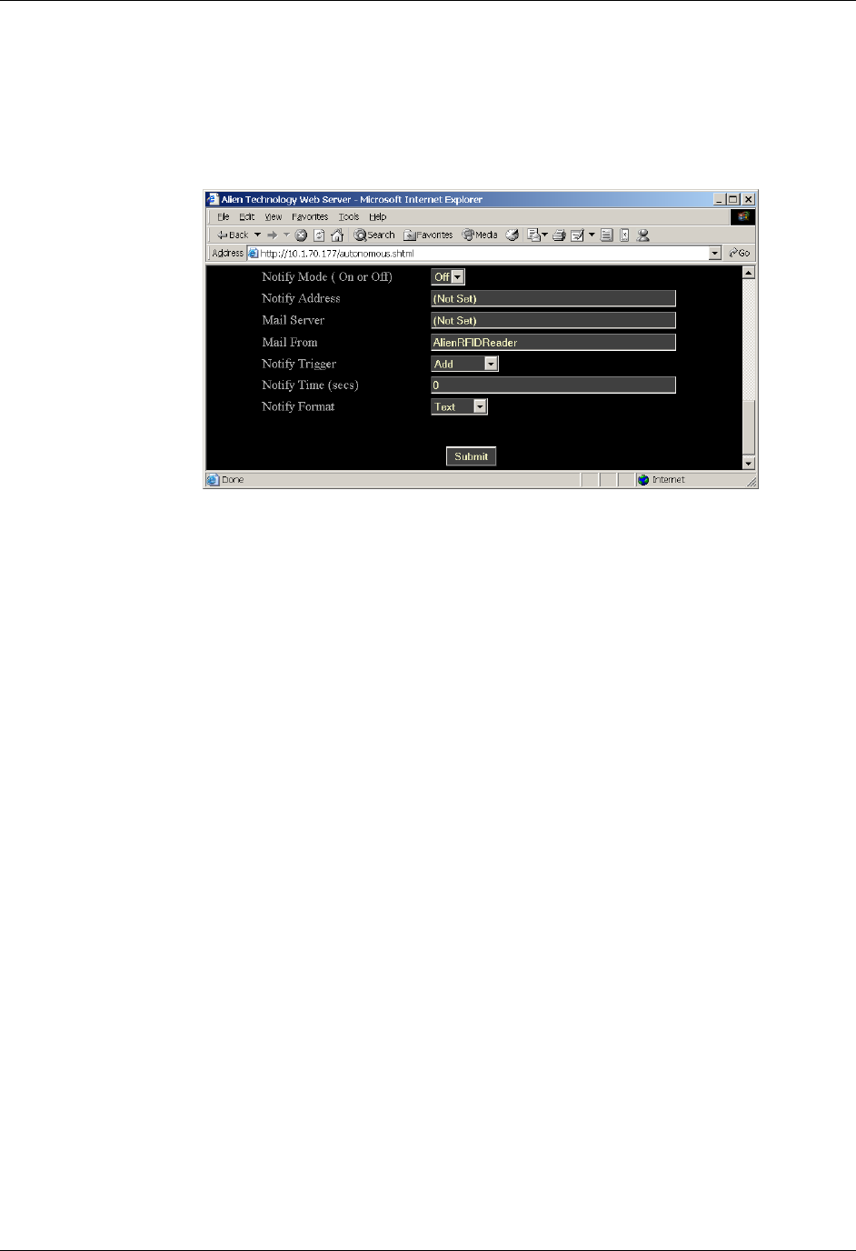
CHAPTER 6 READER-HOST PROTOCOL
NANOSCANNER READER USER GUIDE • DOC # 8101029-000 REV A 87
© 2003 Alien Technology™
Notify Mode Commands – Web Based
Notify Mode commands are issued via the Web page to set up and access notify
mode parameters. The commands are accessed at the bottom of the
Autonomous Web Page section.
COMMANDS/OPERATIONS ON WEB AUTONOMOUS MODE TAB
Command equivalents found on the Web-based “Autonomous Mode” tab are:
• Get | Set NotifyMode
• Get | Set NotifyAddress
• Get | Set MailServer
• Get | Set MailFrom
• Get | Set NotifyTrigger
• Get | Set NotifyTime
• Get | Set NotifyFormat
Web view Notif
y
Mode tab covers all
Get and Set notif
y
mode commands.
This web page is
located at the
bottom of the
Autonomous Mode
web page.

CHAPTER 7 READER-HOST PROTOCOL EXTENSIONS FOR BATTERY POWERED BACKSCATTER TAGS
NANOSCANNER READER USER GUIDE • DOC # 8101029-000 REV A 88
© 2003 Alien Technology™
CHAPTER 7
ReaderHost Protocol Extensions for Battery
Powered Backscatter Tags
The Reader <–> Host protocol detailed in the previous chapter is a text-based
communications protocol for configuring and operating the entire family of Alien
Nanoscanner RFID readers. This chapter details extensions to this standard
protocol that directly address the extended functionality of the Battery Powered
Backscatter tags running at 2450Mhz.
Introduction
The Battery Powered Backscatter readers fully support the Class I protocol as
described in the previous chapter of this document. In addition to the basic Class
I command set, these readers also support extra commands especially designed
to address the enhanced functionality of the Battery Powered Backscatter tags.
These extra commands fall into one of five categories:
Masks
In order to address a single tag with any of the following commands, a suitable
Mask must be set. Please see the description of the Mask command in the
previous chapter of this document.
Tags
The tag commands are used to explicitly communicate with a tag, to either
interrogate its features and functionality, or its ID.
Memory
The Battery Powered Backscatter tags can optionally support a read-write on-
board memory typically in the range of 4K bytes to 16K bytes. The memory
commands described in this document allow this tag memory to be read and
written in discrete blocks via RF communication.
Sensors
The Battery Powered Backscatter tags can optionally support the use of on-
board sensors such as temperature or vibration sensors. The sensor commands
can be used to interrogate and control the use of these on-board devices.
Logging
If a tag is equipped with one or more sensors and on-board memory, they can be
instructed to autonomously log data to tag memory even in the absence of an RF
field. The logging commands are the interface to this functionality.

CHAPTER 7 READER-HOST PROTOCOL EXTENSIONS FOR BATTERY POWERED BACKSCATTER TAGS
NANOSCANNER READER USER GUIDE • DOC # 8101029-000 REV A 89
© 2003 Alien Technology™
Command List with Functions
TAG COMMANDS
Command Description
Get TagID Get the ID of a tag.
Get TagInfo Get information about a tag.
Get TagVersion Get the tag firmware version.
Get TagTime
Set TagTime
Get and Set the time and date on the tag’s built in
clock.
MEMORY COMMANDS
Command Description
Get Memory
Set Memory
Get and Set data from the tag memory.
Get MemoryPacketSize
Set MemoryPacketSize
Get and Set the size of the memory packets used in
get and set memory commands.
Clear Memory Clear the tag memory.
SENSOR COMMANDS
Command Description
Get SensorValue
Get the current value from a tag’s sensor.
LOGGING COMMANDS
Command Description
Get LoggingMode
Set LoggingMode
Get and Set the automatic logging mode.
Get LoggingInterval
Set LoggingInterval
Set and Get the interval between automatic log
recording events.

CHAPTER 7 READER-HOST PROTOCOL EXTENSIONS FOR BATTERY POWERED BACKSCATTER TAGS
NANOSCANNER READER USER GUIDE • DOC # 8101029-000 REV A 90
© 2003 Alien Technology™
Using the Commands
This section describes each command, its use and the response formats.
NOTE: Nanoscanner reader commands are case insensitive, that is, you can
use upper or lower case, or any combination thereof, and the reader will
understand the command. Capitalization of commands is used in this document
and in actual command responses is solely for the purpose of readability.
Tag Commands
These commands allow a unique tag (as specified by the mask commands) to be
interrogated.
GET TAGID
Get TagID is used to return the ID of a unique tag specified by the mask
commands. If no unique tag can be found (either the mask is incorrect or not
specific enough to singulate a tag), the result will be “no tags”
Example
Command
Response
>Get TagID
>1010 2033 0330 3334 DE90 EE02
Command
Response
>Get TagID
>No Tags
GET TAGINFO
Get TagInfo command will return information about a single tag defined using the
set mask command. The information returned will be a multi-line reply containing
the following elements:
Memory Size
Sensor Type
Note: Please refer to the Nanoscanner Tag Guide for detailed descriptions of tag
types.
Example
Command
Response
>get taginfo
Memory = 4 Kbytes
Sensor = Dallas Semiconductor Temperature Sensor

CHAPTER 7 READER-HOST PROTOCOL EXTENSIONS FOR BATTERY POWERED BACKSCATTER TAGS
NANOSCANNER READER USER GUIDE • DOC # 8101029-000 REV A 91
© 2003 Alien Technology™
GET TAGVERSION
Get TagVersion command will return information about a the firmware running on
a tag.
Example
Command
Response
>get tagversion
Tag Firmware Version = 2.1.2
GET TAGTIME
SET TAGTIME
Each tag has an on-board real-time clock. The time represented by this clock can
be obtained or set using these commands. Times are specified by the format:
yy/mm/dd hh:mm:ss
The Set TagTime command can take one special parameter, ‘now’, which
causes the reader to synchronize the tag’s clock with its own.
Example
Command
Response
>Set TagTime = 02/12/03 16:13:00
>TagTime = 02/12/03 16:13:00
Command
Response
Set TagTime = now
>TagTime = 02/12/03 16:13:00 //Current reader clock setting
Command
Response
>Get TagTime
>TagTime = 02/12/03 16:13:00

CHAPTER 7 READER-HOST PROTOCOL EXTENSIONS FOR BATTERY POWERED BACKSCATTER TAGS
NANOSCANNER READER USER GUIDE • DOC # 8101029-000 REV A 92
© 2003 Alien Technology™
Memory Commands
Each tag may have on-board memory that can be used for arbitrary user data
storage, or for holding sensor logging data. These commands allow this memory
to be interrogated and programmed. As always, use the ‘set mask’ command to
identify the unique tag to communicate with.
SET MEMORY
GET MEMORY
Set and Get Memory commands allow the direct manipulation and interrogation
of the tag memory. The Get Memory command will return blocks of the tag
memory, and the Set Memory command will write data to the tag memory.
Get Memory takes two parameters (length, address). Parameter one is the
number of bytes to get expressed as a single decimal number. Parameter two is
the start address of the memory to get, expressed as a single decimal number.
The maximum number of bytes that this command will return is 4Kb, i.e., 4096
bytes. The results of the Get Memory command are multiple lines of ascii data,
where each line of data will represent up to 16 hexadecimal bytes of memory. A
line of data may include asterisk characters instead of expected data – this
indicates that the request for a particular block of memory failed (usually RF
communications failure). The data can usually be extracted by repeating the
command after repositioning the tag.
Set Memory takes two parameters (address, data). Parameter one is the start
address of the memory to set, expressed as a single decimal number. The
second parameter is an ascii string of hex bytes, up to a total of
memoryPacketSize. After the packet of data is written, it is read back for
verification. If the data is verified the message “Memory@0000 = Written and
Verified” will be output. If the data was not verified, the message “Error: Memory
Written but not Verified” will be output.
Note: Memory is transferred to and from the tag in blocks of memory defined by
the memorypacketsize command. The smaller the packet (i.e. 1 or 2 bytes) the
smaller the transmission rate but also the smaller the error rate. Likewise the
higher the packet size (i.e. 16 bytes) the higher the transmission rate but also the
higher the error rate in a noisy environment.
Note: Please refer to the Nanoscanner Tag Guide for detailed descriptions of
formatted tag memory. Because there are many different types of sensors
attached to the Nanoscanner tags, the memory formatting may change due to
the type of data being stored. All details can be found in this separate guide.

CHAPTER 7 READER-HOST PROTOCOL EXTENSIONS FOR BATTERY POWERED BACKSCATTER TAGS
NANOSCANNER READER USER GUIDE • DOC # 8101029-000 REV A 93
© 2003 Alien Technology™
Example
Command
Response
>Get Memory = 20, 0
Memory@0000 = AF 00 A5 17 59 01 01 01 01 01 A5 0A 00 00 A5 80
Memory@0010 = 16 80 16 80
Command
Response
>Set Memory = 0, 01 02 03 04 05 06 07 08 09 0A 0B
Memory@0000 = Written and Verified
SET MEMORYPACKETSIZE
GET MEMORYPACKETSIZE
Set and Get MemoryPacketSize commands determine the number of bytes to
use in each memory related transmission packet to and from the tag.
The smaller the packet (i.e. 1 or 2 bytes) the smaller the transmission rate but
also the smaller the error rate. Likewise the higher the packet size (i.e. 16 bytes)
the higher the transmission rate but also the higher the error rate in a noisy
environment.
The default setting for this value is 16 bytes. The allowable range is 1 to 16
bytes.
Example
Command
Response
>Set MemoryPacketSize =4
MemoryPacketSize=4
Command
Response
>Get MemoryPacketSize
MemoryPacketSize=16
CLEAR MEMORY
Clear memory will completely erase the memory of a tag.
Example
Command
Response
>Clear Memory
Memory has been Cleared !

CHAPTER 7 READER-HOST PROTOCOL EXTENSIONS FOR BATTERY POWERED BACKSCATTER TAGS
NANOSCANNER READER USER GUIDE • DOC # 8101029-000 REV A 94
© 2003 Alien Technology™
Sensor Commands
The sensor commands deal exclusively with a tag’s onboard sensor.
GET SENSORVALUE
Get SensorValue will return the sensor’s current value. If the sensor was already
switched off, this command will start the sensor before returning a value, which
may take up to 1 second. Sensors will automatically be switched off two seconds
after this command has been completed in order to preserve the battery life of
the tag.
Typically the tag has no knowledge of the type of sensor attached to it.
Consequently this command simply returns the raw number as returned by the
sensor. No attempt is made to process this number into a humanly
understandable form.
Note: Please refer to the Nanoscanner Tag Guide for detailed descriptions of to
format of raw sensor values. Because there are many different types of sensors
attached to the Nanoscanner tags, the format of the raw sensor values may
change due to the type of data being acquired. All details can be found in this
separate guide.
Example
Command
Response
>Get SensorValue
>SensorValue = 4539
Logging Commands
These commands control the automatic logging of sensor data into the tags
memory. Once set up, a tag can be removed from an RF field and still have
sensor data logged periodically to memory. Bringing the tag back into an RF field
will allow the memory to be retrieved and examined.
GET LOGGINGMODE
SET LOGGINGMODE
The automatic, time based logging of sensor data to a tag memory is controlled
by setting the logging mode on the tag.
Setting a logging mode to OFF will turn off all automatic logging.
Setting a logging mode to ON will turn on the automatic logging as defined by the
logging interval command. Turning on the logging mode like this will not erase
the tag’s memory; it will simply cause logged data to be appended to the current
memory store. (Use the clear memory command to erase the memory before
logging).

CHAPTER 7 READER-HOST PROTOCOL EXTENSIONS FOR BATTERY POWERED BACKSCATTER TAGS
NANOSCANNER READER USER GUIDE • DOC # 8101029-000 REV A 95
© 2003 Alien Technology™
Example
Command
Response
>Get LoggingMode
>LoggingMode =Off
Command
Response
>Set LoggingMode = On
>LoggingMode =On
GET LOGGINGINTERVAL
SET LOGGINGINTERVAL
When automatic logging is active, the tag will retrieve a value from the sensor
and store it in tag memory on a periodic basis until the memory is full. At this
point logging will cease. The periodicity of this logging is controlled by the logging
interval parameter. This parameter is defined in terms of hours:mins:secs and
defines the period between sensor logs.
Note: The minimum allowable logging interval is 1 minute.
Note: The tag will sleep while not in use, and then will wake up to take a sensor
reading and then sleep again. This mode of operation ensures a long battery life.
The logging interval command takes three parameters, each separated by a
colon, in the form hh:mm:ss.
Example
Command
Response
>Get LoggingInterval
>LoggingInterval = 00:01:00
Command
Response
>Set LoggingInterval = 03:21:00
>LoggingInterval = 03:21:00
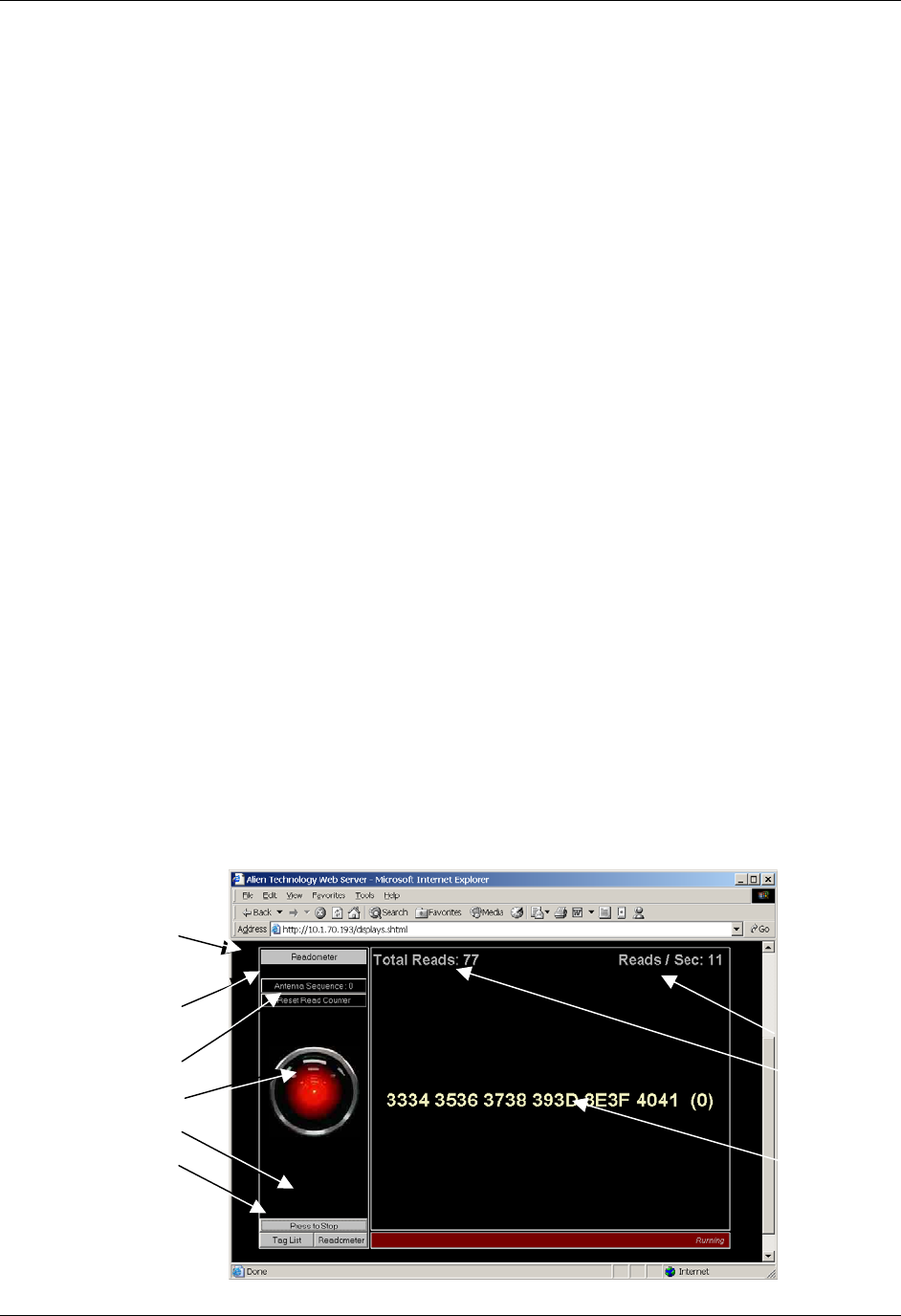
CHAPTER 8 WEB BASED APPLICATION EXAMPLES
NANOSCANNER READER USER GUIDE • DOC # 8101029-000 REV A 96
© 2003 Alien Technology™
CHAPTER 8
Web Based Application Examples
As part of the standard functionality of the Nanoscanner reader, the built-in web
server is able to serve up a simple web based application example.
This application example can be found under the last tab on the Web pages,
named “Applications.” Under this tab is a simple Applet running two applications
that use reader commands. These provide an interactive environment for reading
tags in the field.
NOTE: The Java Applets are all Java 1.1 compliant applets and will work in
standard Netscape and Internet Explorer browsers.
Readometer
The “readometer” graphically displays a single tag and antenna information in
real time.
This screen allows the user to:
• View a single tag (as returned by the Get TagList / Set AcquireMode= Global
Scroll command) and the reading antenna
• View a cumulative and dynamic number of reads since starting or resetting
this value
• View a dynamic Reads per Second value for the current tag
• Change the antenna sequence (see “General Commands”)
• Reset the Total Reads counter
• Stop/start the tag reading operation
• Switch to a different display mode
Reads / second
Total cumulative
reads (since
reset)
Current tag ID
and reading
antenna (in
parentheses)
Readomete
r
mode is active
Antenna
Sequence
selector/displa
y
Click to reset
total reads
Click either to
stop/start tag
reads
Click to select an
alternative read
mode
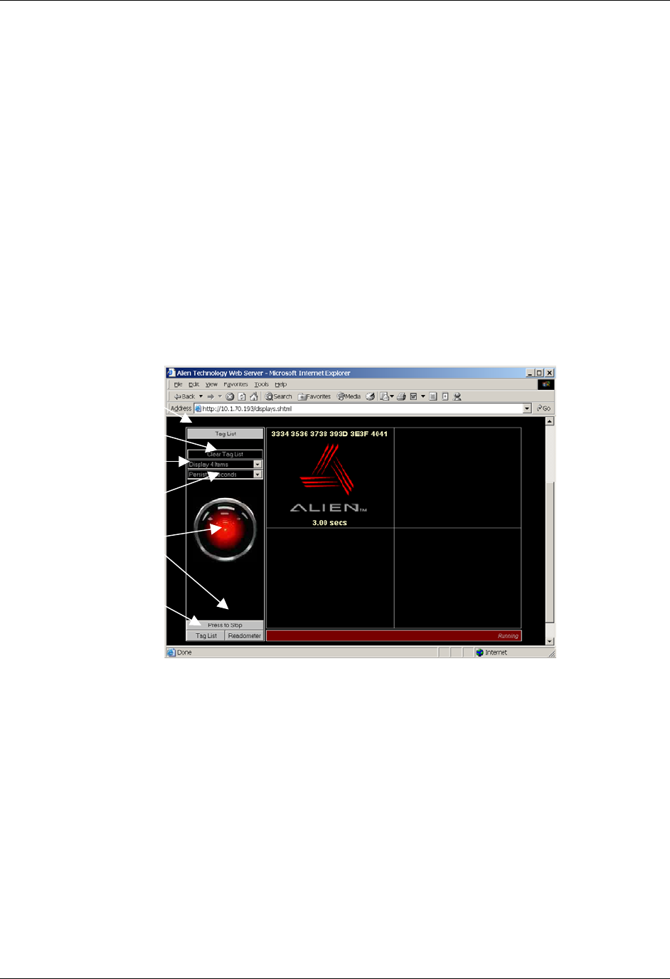
CHAPTER 8 WEB BASED APPLICATION EXAMPLES
NANOSCANNER READER USER GUIDE • DOC # 8101029-000 REV A 97
© 2003 Alien Technology™
Tag List
The Tag List applet provides a graphical view of the reader’s current tag list.
This screen allows the user to:
• View tags that have been read and acquired by the reader most recently
(typically using get tagList / set acquireMode = Inventory)
• View the Persist Time countdown for each tag after it is read
• Clear the tag list manually
• Change the number of cells in the display grid via pulldown menu
• Change the Persist Time via pulldown menu
• Start/stop tag reading
• Switch to a different tag display mode.
Displays data for
all tags currently
and recently read,
including...
• Tag ID...
• Product icon
(optional)...
and
• Persist Time
countdown.
Current displa
y
mode
Clear Tag List
Display (n)
Items
Persist (n)
Seconds
Start/Stop
reading
Switch displa
y
mode

CHAPTER 8 WEB BASED APPLICATION EXAMPLES
NANOSCANNER READER USER GUIDE • DOC # 8101029-000 REV A 98
© 2003 Alien Technology™
Optimize Reader Settings
On each of the Tag List and Readometer screens is a small checkbox option
entitled ‘Optimize Reader Settings’, which by default is checked (a tick mark is
present).
When checked this tells the applet to optimize the reader settings the next time
one of the two applications is started (i.e., the HAL eye turns to red). The
following optimization settings are made to the reader depending on the
application that is started:
Readometer Settings
When the Readometer is started with the optimize option checked, the following
commands are issued to the reader to put it into an optimized state for
readometer readings.
• Set PersistTime = 0
• Set TagListFormat = Text
• AutoModeReset
• Set AcquireMode = Global Scroll
When running, the readometer performs repeated bursts of ‘get taglist 25’
followed by a 200 ms pause. The timing results displayed on the screen are
calculated based on each ‘get taglist 25’ command. Thus for optimal timings,
Global Scroll is used for the Acquire Mode.
The auto mode is reset, and left off; the readometer screen always works in
foreground mode.
When the optimize option is turned off, only one command is issued to the reader
when readometer is started:
• Set TagListFormat = Text
Tag List Settings
When the Tag List is started with the optimize option checked, the following
commands are issued to the reader to put it into an optimized state for tag list
readings.
• Set PersistTime = -1
• Set TagListFormat = Text
• AutoModeReset
• Set AcquireMode = Inventory
When running, the application switches on auto mode, forcing the reader into
autonomous acquisitions as fast as it can. The optimized acquisition mode is
Inventory and the persist time is –1, telling the reader to build up a tag list until
next interrogated. While the reader is building its tag list, the applet periodically

CHAPTER 8 WEB BASED APPLICATION EXAMPLES
NANOSCANNER READER USER GUIDE • DOC # 8101029-000 REV A 99
© 2003 Alien Technology™
(~every 250ms) issues a ‘get taglist’ command, forcing the full tag list to be
returned and the reader to reset its internal tag list.
When the optimize option is turned off, only one command is issued to the reader
when the application is started:
• Set TagListFormat = Text
Advanced Tag List Options
By turning off the optimization check box and running the tag list application, the
reader can be set up manually to perform different actions:
RUNNING TAG LIST USING GLOBAL SCROLL AS THE ACQUIRE MODE
In some instances it is desirable to set the acquire mode to Global Scroll. By
default, with the application optimize checkbox on, the application will set the
reader into Inventory mode. However with the optimize checkbox off, the
following manual settings can be made:
• Set AcquireMode = Global Scroll
The next time the application is started, it will run using the new settings.
RUNNING TAG LIST IN DUTY CYCLE MODE
In some instances it is desirable to run the reader in duty cycle mode, where
instead of reading tags without a break, a timed pause is inserted into the read-
cycle. By default, with the optimize checkbox on, the tag list application will set
the reader into full time acquire mode. However with the optimize checkbox off,
the following manual settings can be made:
• Set AutoStopTimer = 500
• Set AutoTruePause = 200
• Set AutoFalsePause = 200
The next time the tag list application is started, it will run using the new settings,
forcing it into a cylce of reading tags for 500ms, followed by a 200ms pause
regardless of whether tags were found or not. For further details on these
commands and other autonomous mode options, please refer to the autonomous
mode overview in this document.