Alitronika DVS AT40USB AT40 User Manual dvsstation3 user manual 30 11 2009
Alitronika DVS B.V. AT40 dvsstation3 user manual 30 11 2009
UserManual.wiki
>
Alitronika DVS
>
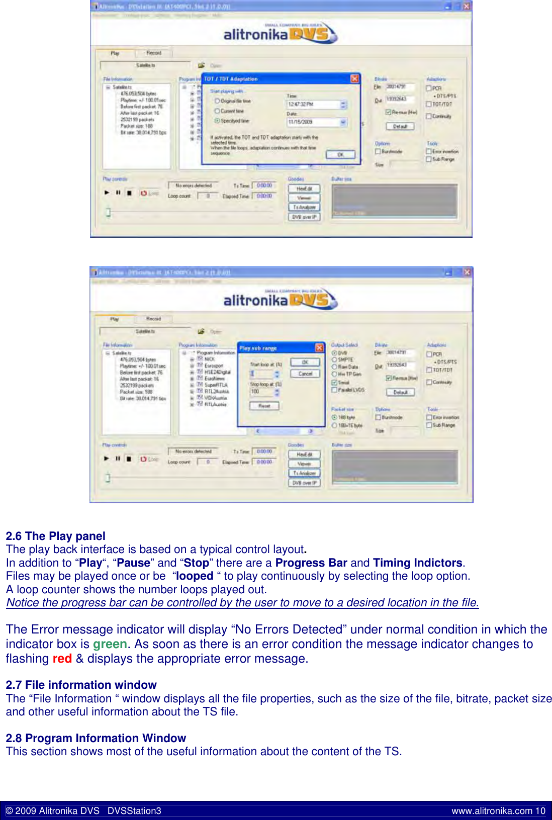
AT40USB User Manual
User Manual
Navigation menu
Upload a User Manual
Namespaces
Wiki Guide
HTML
PDF
Info
Views
User Manual
Discussion / Help
Navigation
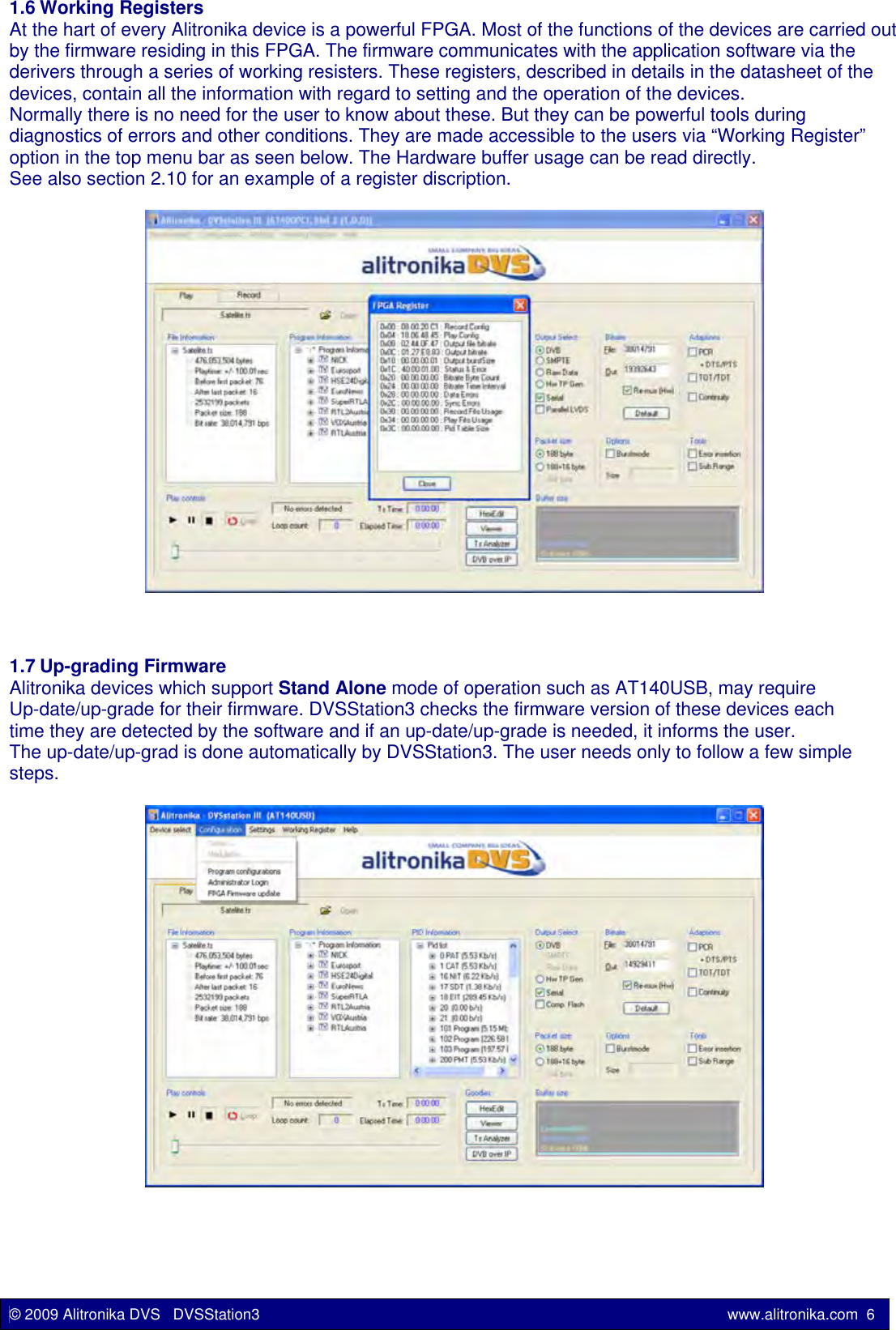
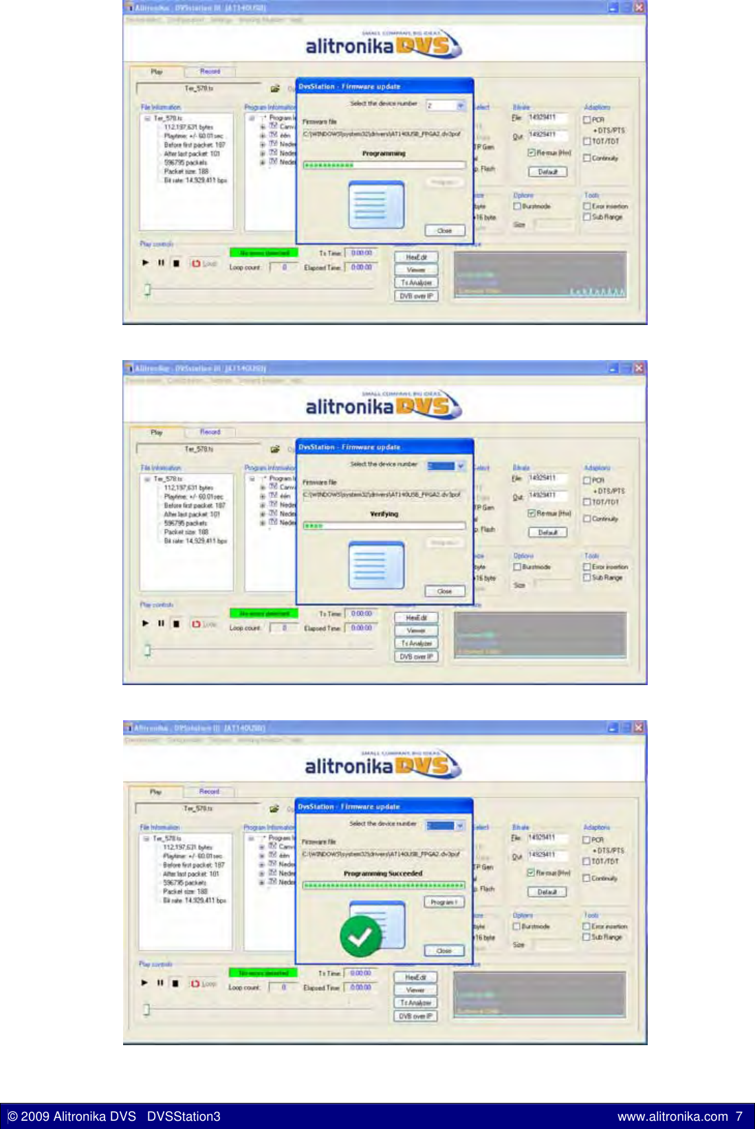
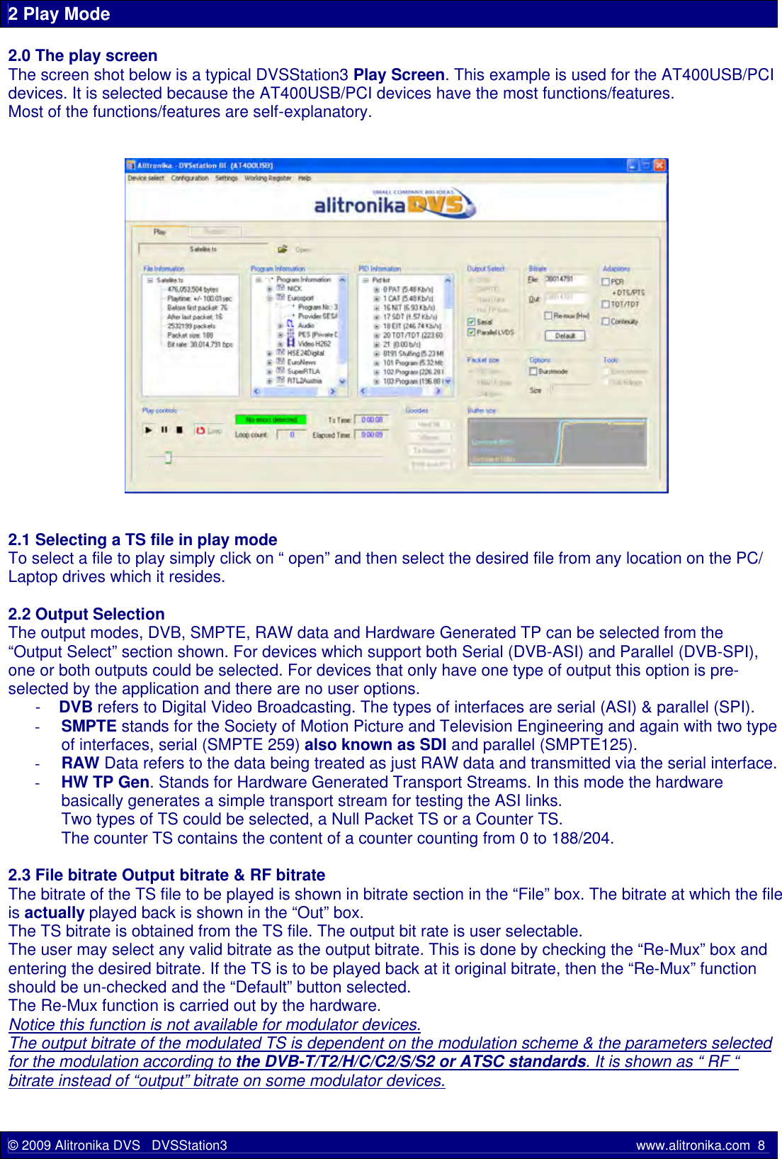
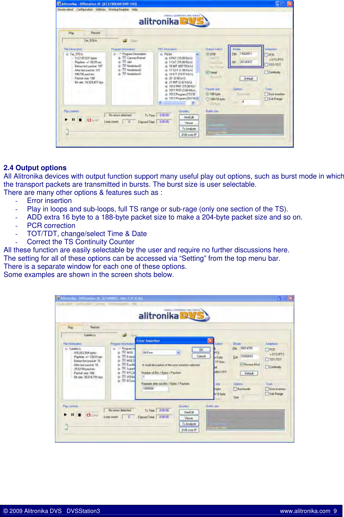
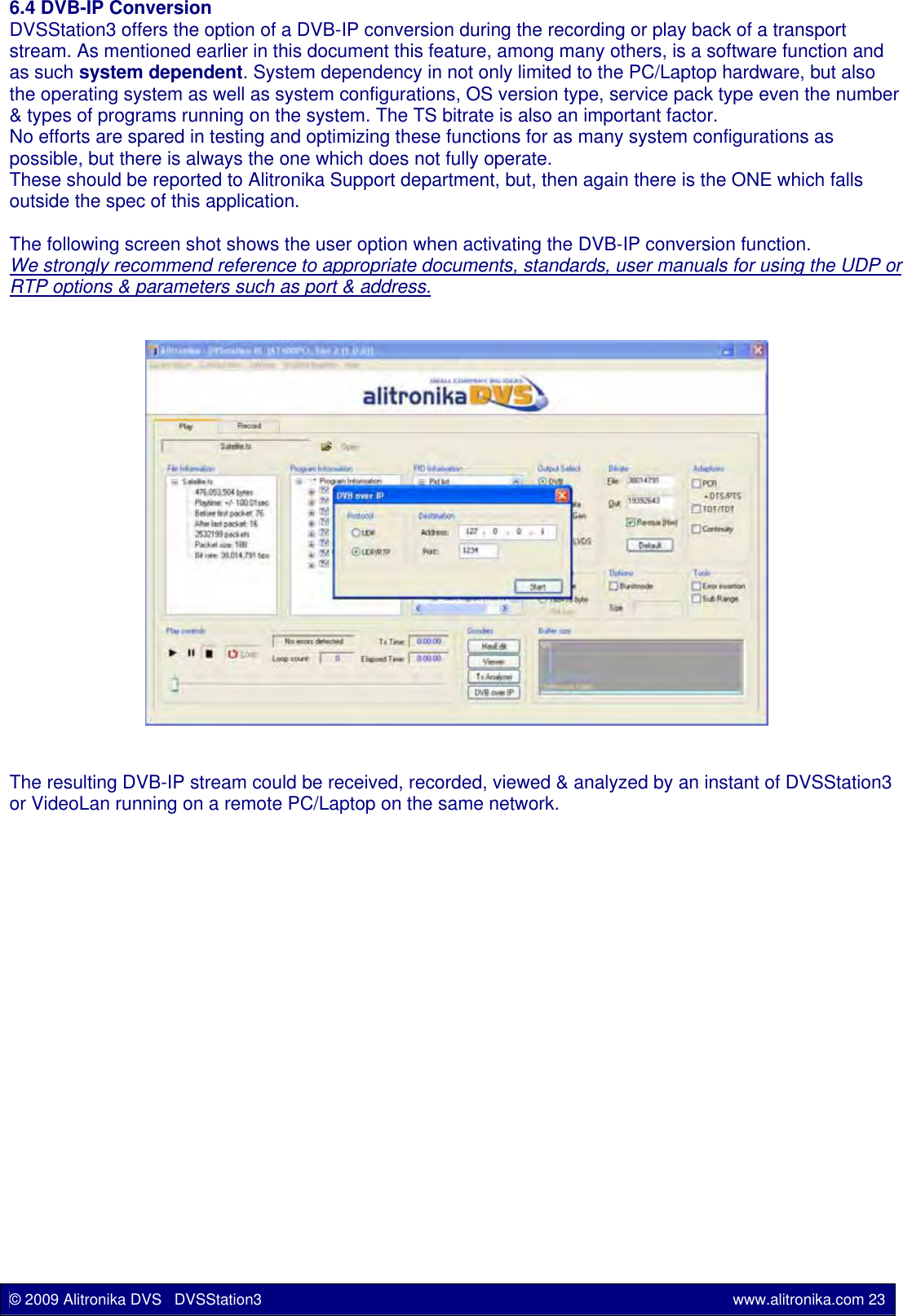
![2.9 PID Information Window The Quick Real Time Integrated Transport Stream Analyzer displays the result of the stream analyses in this window. This is not a full transport stream analyser, since it does not display all the information about the TS which is being recorded or played back, but when working with a lot of TS a simple tool is sufficient to show what is in the TS streams. 2.10 Buffer Usage Display All Alitronika devices have 8 or 16 MB SDRAM on board, used as hardware buffer. In addition there two software buffer of 6 and 10 MB to ensure the smooth buffering and provide sufficient memory resources during play and record. Although in most cases the bitrate on the incoming or out going transport streams are far lower than to be of any concerns, but there are situations in which the memory usage may be of some concern. The “ Buffer Size” window displays the memory usage graphically. In addition the actual numerical values of memory in use are also made available to the user via the Working Registers.An example of one such register is the “Record Configuration Register” Shown below.Record_Config Address = H”00” Bit Name Function level0 DVB Selects DVB Mode High = Enabled1 SMP Selects SMPTE Mode High = Enabled2 RAW Select Raw Mode High = Enabled3 RSV Reserved (not use in current design) Normally Low4 LEN Enable loop through output High = Enabled7:5 GRSET Settings for GS9060 device Set by software8 ETS Enable Time Stamping High = Enabled9 PID Enable PID filtering High = Enabled10 TEX PID Table Exclusive High = Exclusive Table12:11 RSV Reserved (not use in current design) Normally Low14:13 ISEL [1:0] Select input source “0X”: USB “10”: SPI“11” : ASI/Tuner15 PCLR Clears PID table High = Clear PID Table16 RSPM SPI input mode selection 0: Constant clock mode1: Standard DVB-SPI mode28:17 RSV Reserved (not use in current design) Normally Low29 TRST Tuner reset High = Reset Tuner30 RRST Record reset, resets input modules High = Reset31 REN Record Enable High = Enabled© 2009 Alitronika DVS DVSStation3 www.alitronika.com 11](https://usermanual.wiki/Alitronika-DVS/AT40USB/User-Guide-1476488-Page-11.png)