Allflex USA 930021 Low Power RFID Tag Reader User Manual
Allflex SA/Boulder Low Power RFID Tag Reader Users Manual
Users Manual
Allflex ISO Compatible RFID Stick Reader
With Integral Battery Pack and LCD Readout
Model Series RS320
User Manual
(Revision A2/ September 2003/Software V2.08+)
Preparing for Use
Unpacking
The Allflex RS320 Stick Reader is shipped in a box with this instruction guide, one
9.6 VDC NiMH rechargeable battery pack, AC Adapter/Charger, Power/Data Cable
and Configurator® software diskette. Information contained in this guide pertains to
installing the Battery Pack, connecting and using the Power/Data Cable, setting
configuration options using Configurator®, and operating the Reader. In order to
proceed, it is necessary first to charge fully the Battery Pack as described on page 2
of this guide, and to have an assortment of ISO transponders (electronic
identification eartags) available for performance and configuration verification.
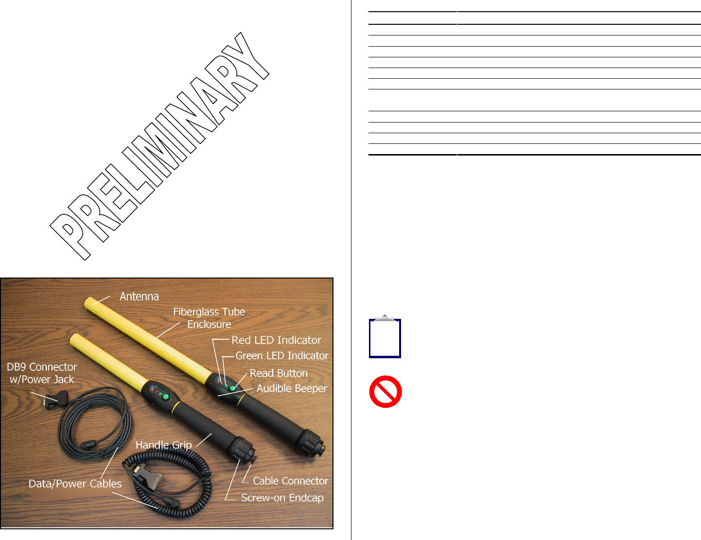
Stick Reader User Interface
Figure 1 below illustrates the Stick Reader’s features that comprise the user interface
and that are pertinent to its operation. Each feature and its corresponding functional
description is described in Table 1.
Figure 1 - Stick Reader Features and User Interface
1
Table 1 - Stick Reader Features and Descriptions of Use
Feature Description of Use
Antenna 1 Emits activation signal and receives transponder signal
Red LED Indicator Illuminates whenever antenna is emitting activation signal
Green LED Indicator Illuminates whenever a transponder has been read
Audible Beeper 1 Beeps once on first transponder reading and twice for repeat
Read Button Applies power and activates exciter signal for reading transponder
Data/Power Cable Conveys power to Reader and serial data to and from Reader
DB9 Connector w/
DC Power Jack Connects serial data to PC or data logger RS232 port
Accepts 6 to 12 VDC input as Reader power source
Fiberglass Tube Rugged, watertight enclosure
Screw-on Endcap Provides access to battery compartment
Handle Grip Rubber anti-slip gripping surface
Cable Connector Electrical interface for attaching Data/Power Cable
1 Item is internal to enclosure and cannot be seen
Power Source Requirements
The RS320 Stick Reader contains a rechargeable and removable 9.6 VDC NiMH
Battery Pack, which serves as its primary power source. Alternately, the RS320 can
be powered from its external AC Adapter/Charger, or from any external DC power
source rated between 9 VDC and 12 VDC with at least 1 ampere current capability.
Internal 9.6 VDC Battery Pack - Prior to operating the RS320 Stick Reader from
its integral Battery Pack, the Battery Pack must be charged. This can be
accomplished by either of two methods: (1) install the Battery Pack into the Stick
Reader, attach the Data/Power Cable, and connect the AC Adapter to the DC input
jack located on the DB9 connector, or (2) install the Battery Pack into the Allflex
Model AK320 Fast Charger.
Note 1 - Battery Pack charging using the AC Adapter/Charger applies a slow-
charge, which requires approximately 12 hours to complete. During this slow-
charge cycle, the Stick Reader can be simultaneously operated from the AC
Adapter. The AK320 Fast Charger provides 2 hour charging of up to 3 Battery
Packs, simultaneously.
Note 2 - The RS320 Stick Reader is designed to operate only with the Battery
Pack provided. The RS320 will not operate with individual battery cells of either
disposable or rechargeable variety.
AC Adapter - The RS320 Stick Reader can be powered using its AC
Adapter/Charger regardless of the charge state of the Battery Pack. The AC Adapter
can be used as a power source even if the Battery Pack has been removed from the
Stick Reader. If the AC Adapter has been connected, the user may proceed with
configuration and performance testing while the Battery Pack is charging.
Other External DC Power Sources - The Stick Reader can be powered from
external DC power sources, such as 12 VDC vehicle batteries, or from the Allflex
PW50/PW250 series Battery Pack units that are used with RS250 type Stick Readers.
External DC power sources can be connected through either the DB9 connector pins
2
i
9 (+) and 5(-), or by using the 2.5mm coaxial jack located on the DB9 connector
(center conductor negative).
Note 3 - Certain weigh scales and other equipment to which the Stick Reader can
be attached provide DC power on pin 9 of the DB9 interface connector. Such DC
power sources are acceptable as long as the voltage is between 9 and 12 volts DC,
and are capable of providing at least 1.0 ampere continuous current. Pin 5 of the
DB9 connector is ground.
Note 4 - When an external power source, such as the AC Adapter, is connected to
the DC Power Jack, inserting the plug causes electrical continuity to pin 9 of the
DB9 connector to be interrupted. Polarity on the DC Power Jack is sleeve + and
center pin -. The DC power plug specification is a 2.5mm x 5.5mm DC Coaxial
(9.5mm length). See Figure 3 for the wiring details of this connector.
Note 5 - The Stick Reader is protected against accidental reverse polarity voltage
application and will not be damaged by such.
Note 6 - The Stick Reader’s integral Battery Pack is affected by temperature. At
0°C (32°F), the Battery Pack will deliver only about half of its rated energy
capacity. At lower temperatures, the Battery Pack may deliver unsatisfactory
performance. When the RS320 Stick Reader is used in low temperature
environments, connection to an external power source, such as the Allflex PW50 Battery Pack,
and placement of this external Battery Pack close to the user’s body, is recommended.
Note 7 - To ensure proper Battery Pack charging, charging should be conducted
only in an environment where the temperature is between 15°C and 30°C (60°F
to 85°F). Charging at temperatures outside these boundaries will result in
unsatisfactory charge acceptance by the Battery Pack. For more information
about the characteristics of rechargeable batteries, please see the white paper at
[http://www.national.com/appinfo/power/files/f19.pdf#page=10].
Activating the RS320 Stick Reader
With the Battery Pack fully charged and installed, or with the AC Adapter connected
by means of the Data/Power Cable, the Stick Reader is ready to be used. To turn on
the Stick Reader, press the green Read button, holding it down until the red and
green indicators light and extinguish, and until the beeper stops sounding (this is
about ¼ second duration).
Note 8 - Very brief presses of the Read button will cause the indicators to light
and the beeper to sound, but will not be sufficiently long to latch the Stick Reader
into its power on state. Be sure to hold the Read button down until the beeper
stops sounding.
3
Upon power-up, the Stick Reader’s LCD readout will appear as shown below:
0000 READY TO
READ
This power-on message is indicative that the Stick Reader’s internal ID Code
memory has been cleared, and that the Stick Reader is prepared to read new tags.
If the Reader has been previously used, and there are ID Codes stored in memory,
the LCD readout will resemble the display shown below:
0012 HDX ISO:
982 000006975374
In this display, the 4 digits on the left side of the top line indicate the tag counter, and
the information on the right side of the top line displays the tag type. On the bottom
line appears the 3 digit ISO Country Code or Manufacturer Code, followed by the 12
digit decimal ISO National ID Code.
Display formats for other tags that can be read by the RS320 Stick Reader are shown
below for ISO FDX-B and HDX Industrial coded tags.
0013 FDX-B ISO: 0014 HDX-I: 2048
982 009101723121 0000000000053925
Note 9 - Configurator® provides the capability to select the LCD readout ID
code format to (a) decimal or hexadecimal, (b) numeric or alpha country codes,
and (c) suppression or inclusion of ID code leading zeroes. Please see the section
on the Configurator® program beginning on page 12 of this User Manual.
Note 10 - Upon power-up, the LCD readout will always display the information
from the last tag read, unless the internal ID Code memory has been cleared. The
RS320 Stick Reader does not have the capability to recall and display ID codes
from tags read prior to the last tag. For information about retrieving ID Codes
from memory and clearing the memory, please see the section titled “Retrieving
ID Codes Stored in Memory” which begins on page 15 of this User Manual.
Note 11 - The RS320 Stick Reader is delivered with configuration options set in
the “default” state (see “Default Configuration” on pages 16-17.). Among these
default settings is the “Power On Read” option that determines the behavior of the
Stick Reader when the Read button is pressed. In the default “Don’t Read” state,
the power-on behavior is as described above. By changing this option setting to
“Read”, the Stick Reader will begin scanning for a tag immediately upon power-up, and will
not first enter the idle LCD readout states as illustrated above. This option and other Stick
Reader operational modes can be selected using the Configurator® program.
Note 12 - Each ID Code is stored internally in the Stick Reader’s non-volatile
memory until the user deliberately erases the stored ID codes after downloading
them into a recording device, such as a PC database. Up to 1638 ID codes can be
stored and retrieved later at the user’s convenience.
4
i
i
i
i
i
i
i
!
!
!
Note 13 - The Tag Counter feature on the LCD readout can be reset to zero at
any time by double clicking the Read button, and observing the LCD’s
enunciation “Reset Counter?”. Pressing the Read button again once while this
enunciation is on the LCD will force the Tag Counter to reset to the value “0000”.
Resetting the Tag Counter does not alter the ID codes previously read and stored
in the Stick Reader’s internal memory.
Note 14 - The Stick Reader provides a Null Memory Marker Code option that
inserts an all zeroes code number (Manufacturer Code and National ID Code)
whenever the Tag Counter is reset. This feature is easily enabled using the
Configurator® program’s “Memory Marker” option.
Note 15 - The Stick Reader can be optioned to process duplicate tag numbers in
either of two ways. In the default mode, any tag can be read, counted, and stored
multiple times whenever any other tag(s) is read interventionally. The Stick
Reader can also be optioned to check for duplicate tags within the most recent
number of tags as indicated by the Tag Counter, up to a maximum of 75 tags. In
this selected mode, a tag will always be read and displayed, but will be counted and stored
only if it has not been read within the last “n” tags where “n” is the Tag Counter indication,
and “n” is or less than or equal to 75. When a tag is read more than once in this mode, the ID
code is displayed, and the audible beeper provides a double beep indication, but it is not
counted again or stored again in memory, unless at least 75 other tags have been read and
stored in the interim. See “Counter Duplicate” in Stick Reader Configuration Options on
pages 11-14.
Reading Transponder Tags
The Stick Reader is always ready to read a transponder tag either immediately after
power has been activated (as is indicated by the presence of information on the LCD
readout), or from its off state (if the Power On Read option has been set to “Read” –
see Note 11). Initiating a tag reading event requires only a press of the Read button.
When the Read button is pressed and released, the tag activation signal is present for
a 3 second interval. Alternately, the Read button can be held down, and the
activation signal will remain on until the Read button is released, or until a tag is
read. The tag activation state is indicated by the red LED indicator illuminating.
When a tag is successfully read, the tag’s ID code information will appear on the
LCD readout, and for non-duplicate tag readings, the Tag Counter indication will
increment, and the ID code is automatically stored in the Stick Reader’s internal
memory. In addition, the Stick Reader’s green LED indicator will flash, and the
audible beeper will sound. A single flash/beep indication occurs the first time a tag
is read, and a double flash/beep indication occurs when a duplicate tag reading
occurs. (See Note 15 above for the option and definition of a duplicate tag read.)
Note 16 - The 3 second tag activation on signal interval can be configured for
times ranging between 1 second and 9 seconds, in 1 second increments, using
Configurator®. The default time interval is 3 seconds. See Configurator® option
“Read Time”
5
Note 17 - The Stick Reader can be configured to transmit tag data upon any one
of three possible conditions: (1) Send Repeats (the default setting); (2) Do not
send Repeats; and (3) Send Repeats upon Re-Read. See Configurator® option
“Send Duplicates”.
The LCD Readout
When the Read button is pressed, and the Stick Reader is activated to scan a tag, the
Red LED indicator flashes, and the LCD produces the indication as shown below:
( ( ID TAG ) )
( ( READING ) )
At the end of the tag scanning interval (which is the shorter of 3 seconds or until a
tag is successfully read), the LCD readout either displays the ID code information
from the tag, or provides an indication that no tag was detected. These two displays
appear as follows:
0009 NO ID TAG 0010 HDX ISO:
DETECTED! 982 000003705995
In the event that no tag was detected, the above display indication lasts for about 3
seconds, and then the display reverts to display the tag ID code information from the
previously read ID tag.
The LCD readout contains a backlight that illuminates the display and makes it
easier to read tags in dimly lit environments. This backlight illuminates for an
interval of approximately 5 seconds upon initial powering of the Stick Reader, and
upon the successful reading of a tag. This illumination time is purposefully limited
in order to conserve battery life.
As described in Note 13, the Tag Counter function can be reset to zero at any time by
double clicking the Read button while the Stick Reader is powered on and in its idle
mode. Upon double clicking the Read button, the LCD will produce the following
display indication:
RESET COUNTER?
> PRESS BUTTON
Pressing the Read Button again while this display indication is present will cause the
Tag Counter to be reset to zero. If the Read button is not pressed during this
approximate 3 second period, the LCD display will revert to the previously read tag
indication, and the Tag Counter will remain at its previous count total. Resetting the
Tag Counter does not alter the contents of the ID Code Memory.
6
i
i
i
i
i
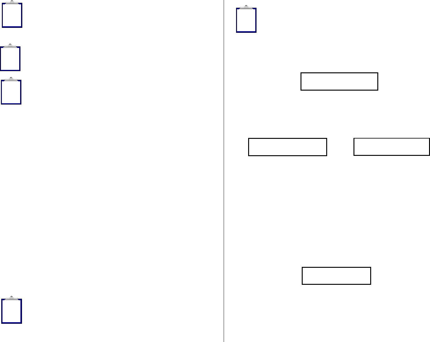
Read Range Performance
Figure 2 illustrates the read zone of the Stick Reader, within which tags can be
successfully detected and read. Optimum read distance occurs when the tag antenna
is aligned with the Stick Reader’s antenna as shown. When the tag is at the end of
the Stick Reader, optimum read distance coincides with a coaxial orientation of the
antennas, and when the tag is adjacent to the Stick Reader, optimum read distance
coincides with a planar orientation of the antennas.
Figure 2 - Optimum Read Distance Tag Orientation
Table 2 lists typical read distances that can be expected when reading different types
of Allflex eartags, in the optimum tag orientation at the end of the Stick Reader (as
shown in Figure 2).
Table 2 - Typical Read Distances for Various Allflex Eartags
Tag Type 9.6 VDC
(84 dBuV/m @10m)
HDX/HP Eartag 35 cm
HDX/LW Eartag 28 cm
FDX-B/HP Eartag 22 cm
FDX-B/LW Eartag 20 cm
Factors Affecting Read Range Performance
Tag readers are frequently assessed with respect to performance by their reading
distance. The read distance performance of the Stick Reader will be affected by the
following:
Transponder Orientation - For maximum reading distance, the axes of the transponder and
reader antenna coils must be optimally oriented (see Figure 2).
7
Transponder Quality - Each manufacturer’s transponder differs in (a) the amount of exciter
signal energy necessary to sufficiently operate the transponder’s internal circuitry, and (b) the
signal level of the ID Code information that is returned to the reader. Consequently, it is
normal for transponders of a common type (FDX-B, for example) made by different
manufacturers to exhibit different read range performance characteristics.
Transponder Motion - Most portable readers have small antenna geometries, and
consequently produce small effective “read zones”. Portable readers are generally designed
for reading transponders under quasi-static conditions. Transponders that are moving quickly
past the reader may not be present within the reader’s read zone sufficiently long for all the ID
Code information to be obtained.
Transponder Size - Physically larger transponders generally contain larger receiving coils
which produce longer reading distances than smaller transponders.
Transponder Type - HDX transponders generally exhibit greater reading distances than FDX-
B transponders of comparable size.
Proximal Metallic Objects - Metal objects located near the transponder or Reader can
attenuate and distort the electromagnetic fields generated in RFID systems, and thus diminish
read distance performance.
Electrical Noise Interference - RFID transponders and readers use electromagnetic signals as
a premise of operation. Other electromagnetic phenomena – radiated electrical noise from
computer displays, for example – can interfere with the transmission and reception of RFID
signals, and consequently reduce reading distance.
Transponder/Reader Interference - Multiple transponders within the sensing range of the
reader, or other readers emitting excitation energy in the immediate vicinity can adversely
affect the reading performance or prevent operation of the Stick Reader.
Depleted Battery Pack Charge - As the Battery Pack discharges, less energy becomes
available to generate the activation field, and this reduced field will result in a decreased read
range.
ID Code Memory
The Stick Reader contains an internal non-volatile memory capable of storing 1638
ID codes. ID codes are stored automatically upon being read. A transponder ID
code will not be stored multiple times if read multiple times successively, but can be
stored in memory multiple times if other tags are read interventionally. All ID codes
are retained when power to the Stick Reader is shut off. If more than 1638 ID codes
are read, the new ID codes are written over the oldest ID codes in a wrap-around
manner.
ID Codes can be retrieved from the Stick Reader via its RS232 serial port by issuing
to the Reader the G command (see Table 4 on page 14). The G command can be
issued as many times as desired, and the complete memory contents will be
transferred upon each event. ID codes are not erased from the memory until the
C{Enter} command is received. 8
Eartag
Implant
Stick Reader Antenna
Read Zone
Each ID code is followed by a {CR}{LF} (carriage return/line feed) which will
cause each ID code to appear on a separate line of a PC display.
Note 18 - The Stick Reader contains a Configurator® option that automatically
inserts a null identification code in memory whenever the Tag Counter is reset
(see Notes 13, 14, and 15). The combined functions of Tag Counter and Memory
Marker provides a means of establishing partitions in memory between blocks of
ID codes that represent separate groups of identified animals, thus facilitating the
management of ID code data once downloaded to a PC database. To set this partitioning
marker, select the “Generate” setting in the Configurator® Memory Marker option.
Using the Stick Reader’s Serial Data Interface
Serial Data Interface Requirements
The RS232 serial data interface is available on the RS320 by connecting the
detachable Data/Power Cable to the Cable Connector located on the Endcap. The
Stick Reader’s Cable Connector is covered with a protective cap to guard against
foreign material contamination. Remove this cap and install the Data/Power Cable
by engaging the connector and rotating the lock-ring.
The RS232 serial interface comprises a 3-wire arrangement with a DB9F connector,
and consists of transmit (TxD/pin 2), receive (RxD/pin 3), and ground (GND/pin 5).
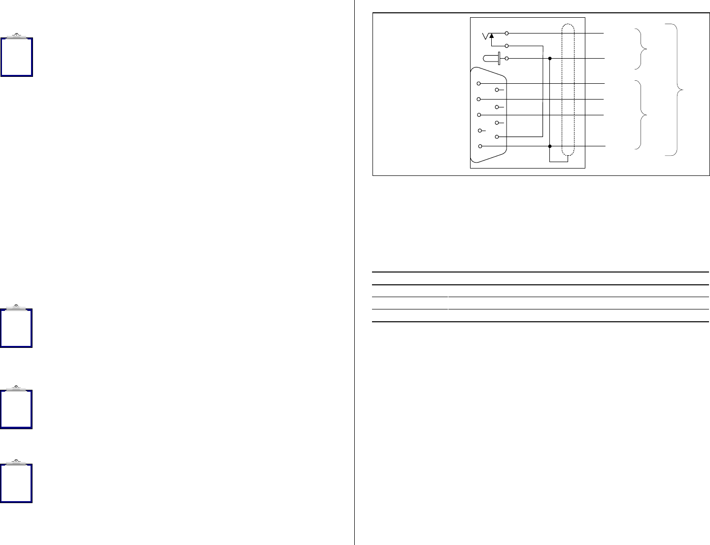
Figure 3 illustrates the power and data wiring of the Power Jack and Data Connector.
This interface is factory configured with the default settings of 9600 bits/second, no
parity, 8 bits/word, and 1 stop bit (“9600N81”). These parameters can be changed
by using the options included in the Configurator® program.
Note 19 - The RS320 Stick Reader is provided with the connectorized endcap
and detachable Data/Power cable in its standard configuration. Also available is
the optional AY300 Rugged Environment Endcap Kit, which includes a Blank
Endcap with no connector (for mobilized Stick Reader use) and a Cable Endcap
with a permanent and strain relieved cable attached (for tethered Stick Reader use). This
Cable Endcap can be used to connect the Stick Reader in an equivalent manner as the
detachable cable.
Note 20 - The Stick Reader RS232 interface is wired as a DCE (data
communications equipment) type that connects directly to the serial port of a PC
or any other device that is designated as a DTE (data terminal equipment) type.
When the Stick Reader is connected to other equipment that is wired as DCE also
(such as a Palm Pilot or Pocket PC), a “null modem” adapter is required in order to properly
cross-wire transmit and receive signals so that communications can occur.
Note 21 - The Stick Reader’s serial data connection can be extended using a
standard DB9M to DB9F cable. Extensions longer than 20 meters (~65 feet) are
not recommended for data, and extensions longer that 2 meters (~6 feet) are not
recommended for data and power. The Allflex AY005 and AY006 Extension
Cables provide suitable 10 and 20 meter extensions for data.
9
Figure 3 - Stick Reader Power Jack and Data Connector Wiring Diagram
Serial output data appears on the Stick Reader’s TxD/pin 2 connection in ASCII
format, which is compatible with most PC terminal emulator programs, such as
Hyperterminal®. Configurator® provides options for flexible parsing and
formatting of transponder ID code information (see “Configuration Options” on
pages 11-14 of this guide). The default formats for ISO transponder tag types are
listed in Table 3.
Table 3 - Default Serial Data ID Code Formats
Tag Type Default Format
HDX ISO LA_982_000001088420{CR}{LF}
HDX Industrial LR_0006_0000000018514243{CR}{LF}
FDX-B ISO LA_982_000000255895{CR}{LF}
Note: _ = space; {CR} = carriage return; {LF} = line feed
Interpreting Tag ID Code Information
Table 3 lists the default data formats that are transmitted from the Stick Reader’s
serial communications port, in response to reading compatible type tags. For ISO
type tags, there is no contextual differentiation between HDX and FDX-B outputs.
Both types of tags produce a default format:
LA_982_000001088420{CR}{LF}
where the underscore “_” represents a space character, and {CR}{LF} is a carriage
return /line feed (unprinted control characters which cause a PC’s display cursor to
jump to the beginning of the next line prior to displaying the next ID number).
In the above data output, the prefix “LA” represents “line mode – animal coded read
only tag”, “982” is the Allflex manufacturer number assigned by ICAR, and the last
12 digits comprise a unique number sequence for the particular tag being read.
10
i
i
i
i
To Stick
Reader
+ Pwr
TxD
RxD
Gnd
2
9
5
3
2
3
1Gnd
#20
AWG
#26
AWG
1Aux
DB9(F)
2.5mm
Coaxial Jack

The TIRIS S2000 output format has become a de facto standard for many users, and
appends the reserved field and data block bits contained in the ISO coded eartag to
the Stick Reader’s default format, causing the ID code information to appear in the
format:
LA_00000_0_982_000001088420{CR}{LF}
This output is easily configured using either the Configurator® utility, or by issuing
the Command “BE40239” to the Stick Reader (See Serial Command Language on
page 14).
Note 22 - The manufacturer code “982” will be different for another
manufacturer’s tag, and can also be replaced by an ISO country code (“250” =
France, for example). When other manufacturer codes or country codes exist,
there can exist the same 12 digit ID number.
Note 23 - While HDX and FDX-B type transponders have an identical context,
they are guaranteed by Allflex to be unique. That is, HDX tag type ID numbers
are never duplicated in FDX-B type tags, despite their sharing the same
manufacturer ID code (“982”) or the same country code.
For HDX Industrial coded tags, the output format is:
LR_0006_0000000018514348{CR}{LF}
In this tag format, the prefix “LR” represents “line mode – industrial coded read only
tag”, “0006” is an application code unique to Allflex, and the last 16 digits comprise
a unique identifying number sequence.
The above default formats can be changed using the features described in the
following section “Stick Reader Configuration Options”.
Stick Reader Configuration Options
Basic Operating Procedure
The Stick Reader is configured at the factory with default configuration settings that
make it immediately functional upon application of power. These settings are
selected for compatibility with most users’ applications, and should be changed only
once a thorough understanding of options and the effect of each is understood by the
user. The Configurator® screen illustrated in Figure 4 is shown with all options
listed in their default states, and Table 5 on page 17 describes the behavior of the
RS320 Stick Reader with these default settings in effect.
11
Using Configurator® to Select Stick Reader Options
Configurator® is an easy to install and use PC-based utility that provides users a
convenient means of customizing the Stick Reader’s behavior and ID code
formatting. Configurator® is provided on a 3.5” diskette with the RS320 Stick
Reader in self-extracting and installing format. To install Configurator®, simply
install the diskette into the PC’s floppy drive, and run the executable file
“install.exe”. Follow the directions as they appear on the screen to complete the
installation process, and then launch Configurator® by clicking on the Allflex icon
which appears on the PC’s desktop screen.
Configurator is a single window program with numerous drop-down menus that
contain the available selections for each option. Configurator® contains an
extensive Help facility that is thoroughly instructive about its use, and so information
provided in this User Manual is only cursory. Figure 4 is an illustration of the
Configurator® screen.
The main toolbar at the top of the Configurator® window provides the familiar MS-
Windows® style drop-down menus, which are also presented in alternative icon and
menu form on the two lines immediately beneath. These toolbar functions provide
the ability to define and save custom configurations that can be later recalled and
used to reconfigure Stick Readers for specific applications.
To change the configuration of an RS320 Stick Reader, connect it to the PC’s COM1
serial port that is running Configurator®, power-on the Stick Reader by pressing its
Read button, and click on “Get Settings” on the second toolbar line to retrieve the
Stick Reader’s current configuration. If the Stick Reader and PC establish
communications, the Stick Reader’s configuration settings will appear in the several
drop-down menu boxes. Also, at the very bottom of the Configurator® window, the
Hardware, Software, and communications Protocol version information retrieved
from the Stick Reader will appear.
Note 24 - If communications are not automatically established, check the PC’s
COM port to which the Stick Reader has been connected, and ensure this COM
port is the one that appears in the drop-down menu in the third toolbar line
“Configurator Communication”. Normally, this will be COM1, but may be
another COM port depending on the user’s PC configuration.
Note 25 - Once the Stick Reader is powered on, Configurator® will
automatically keep the Stick Reader’s power on. If the user is planning to work
for an extended period of time with Configurator® and the RS320 Stick Reader,
use of the AC Adapter is recommended in order to conserve battery life.
Note 26 - At the top of the ID Code Format option group is a line of characters
that appear as “LT EEEE IIIIIIIIIIII”. This is a dynamic literal representation of
the selected format. As format options are changed, these will be reflected in the
appearance of this line. Once all format options have been selected, the user can
read a test tag, and confirm that the desired format appears in the lower box
labeled “Tag Read”, where the ID Code number appears in Figure 4.
12
i
i
i
i
i
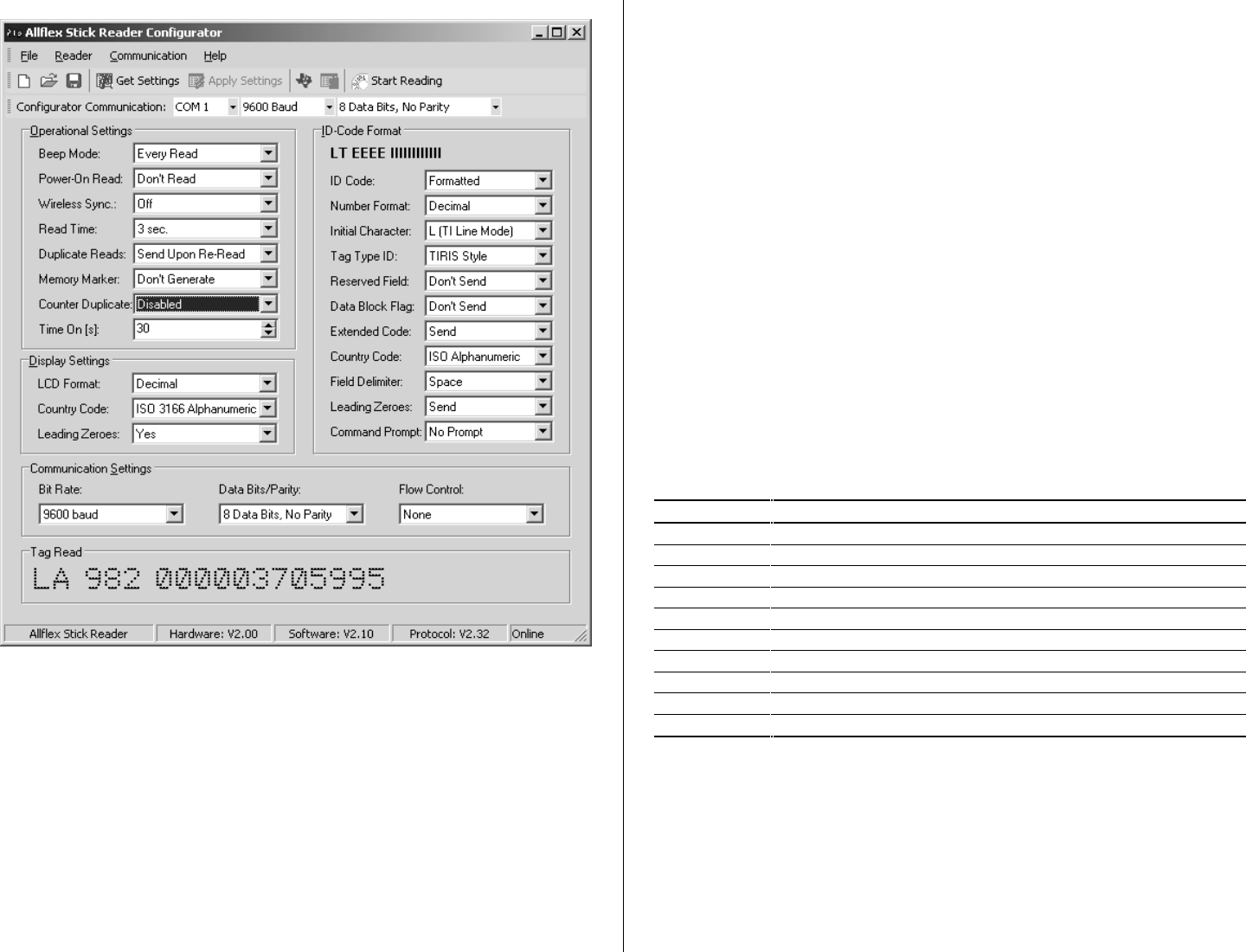
Figure 4 - Configurator® Window
The Configurator® options are categorized in four areas: (1) Operational Settings,
(2) Display Settings, (3) ID Code Format, and (4) Communications Settings. When
the user moves the PC’s cursor over the name of the option (such as “Memory
Marker”), a cursor information bubble momentarily appears and provides a brief
information caption. More detailed information about every option and the effect of
the available selections can be obtained in the Configurator® Help facility.
Operational Settings are used to select the Stick Reader’s behavioral traits, such as
the Reader’s exciter on interval (Read Time) and its power on interval (Time On).
Display Settings determine how the ID code information is exhibited on the Stick
Reader’s LCD readout. Communications Settings set the data rate and format of the
data sent to and from the Stick Reader’s RS232 serial port, and ID Code Format
establishes the appearance of the data sent on the serial port.
13
Near the bottom of the screen is a box labeled “Tag Read”, and this box displays the
ID code information that is sent from the Stick Reader when a tag is read. This box
is useful in confirming the format and appearance of the serial data after setting the
options contained in the ID Code Format box. After making changes to ID Code
Format options, the user can read sample tags and see if the resulting data format is
that which is desired. This facility also provides a convenient means of observing
the effect of the available options on the appearance of the serial port data.
Serial Command Language
Although Configurator® provides the most convenient means of establishing options
for the Stick Reader, all options can also be set using a set of literal alphanumeric
commands, which are sent to the Stick Reader over its serial communications port.
In particular, commands which download the Stick Reader’s internally stored ID
codes and which clear the internal memory are useful to users who intend to transfer
ID codes to PC database programs.
Table 4 lists these literal commands to which the Stick Reader responds by altering
its setup configuration or providing informational responses. For a complete
description of all commands and configuration option variables, please refer to the
Allflex Stick Reader Serial Command Language Manual.
Table 4 - Frequently Used Command Language Characters
Command Application
P Reader’s current settings are sent in command language format
Bnnnnnn Configures ID code serial data format
Snn Sets serial data communications parameters
Inn Sets miscellaneous options
r Resends the last tag read
R Initiates reading (Stick Reader must already be on)
G Retrieves all ID codes stored in memory
M Sets ID code memory options
C{Enter} Clears ID memory
? or H Retrieves list of valid Command Language characters
Note: Commands followed with “n” (hexadecimal characters) require the user to press the PC’s {Enter}
key after typing in all command characters. Single letter commands do not require {Enter} to be pressed,
except as noted in Table 4.
14

Retrieving ID Codes Stored in the Stick Reader’s Memory
The RS320 Stick Reader has internal memory capacity that will store up to 1638 ID
codes. Retrieving these ID codes can be accomplished using the Serial Command
Language “G” command.
The format in which the ID codes appear are determined by the user’s configuration
settings, as is described in Stick Reader Configuration Options on pages 10-13. The
default format is of the form LA 982 1234567890{CR}{LF}, where there is a single
space character that occurs between the “LA” and “982”, and between “982” and
“1234567890”. The {CR}{LF} designates the non-printable carriage return and line
feed control characters, which forces each ID code to appear on a separate line.
An easy way to transfer the ID code memory stored tag numbers into an MS-
Windows® applications, such as Excel, is to download the tag numbers into the
Hyperterminal® program first. To accomplish this, set up a direct connection in
Hyperterminal® using the COM1 port set to 9600 bits/second, 8 bits/word, no parity,
1 stop bit, and no flow control (9600N81nf). With communications established with
the RS320 Stick Reader, first send the command language character P (upper case),
and observe the Stick Reader’s response. The number shown on the second to last
line, in the form *L-nnnn indicates the number of ID codes stored in the Stick
Reader.
Then send the G command, and the ID codes will be received from the Stick Reader,
appearing one per line on the Hyperterminal® screen. When all ID codes have been
received, used the Edit/Select All and Edit/Copy commands to copy all the ID codes
to the MS-Windows® Clipboard. Then open MS-Windows Notepad, and use the
Edit/Paste command to copy the ID code list, and save the file in a convenient
directory using a specified file name.
Excel can be opened, and using the Data/Get External Data/Import Text File
command, select the file just created with the ID codes, and click on Import. Excel
then opens a Text Import Wizard window that allows the user to specify how the tag
numbers will be imported into a spreadsheet. For example, the entire sequence LA
982 1234567890 can be imported into a single cell, or parts of the tag number can be
discarded or split into separate cells. Upon completing the Text Import Wizard
steps, all the ID codes will be entered in the Excel, and the spreadsheet can be saved
and modified as necessary.
Once all tag number data has been transferred into its destination application, and the
number of entries has been checked against the number *L-nnnn to ensure complete
transfer, the temporary Notepad file can be deleted. Then, return to Hyperterminal®
and send the C{Enter} command to the Stick Reader in order to erase its internal ID
code memory.
15
Note 27 - If problems are encountered with Hyperterminal® or Notepad, the G
command can be sent as many times as necessary to download the ID code
memory. If data is imported into Excel in a format other than that which is
desired it can be re-imported from Notepad using the Text Import Wizard again.
Note 28 - If an alternate ID code format is desired, even though tag numbers
have already been read and stored, it is still possible to use Configurator® to
change the format, and download the ID codes into Hyperterminal in this changed
form.
Note 29 - Caution! Once the C{Enter} command is sent, the ID code memory
contents are forever lost. Be certain the ID codes have been entirely obtained in
their desired format prior to erasing them.
Default Configuration
The Configurator® window shown in Figure 4 lists the default configuration settings
of the RS320 Stick Reader as it is shipped. Table 5 provides a brief explanation of
these option settings.
The default configuration can also be assessed using the serial port interface
connected to a PC running a terminal emulator program, such as MS-Windows®
Hyperterminal®. In response to an upper case P command, the RS320 Stick Reader
will respond with the following sequence:
*Allflex Stick Reader
*HW V2.00
*SW V2.05
*PR V2.31
*B-822239
*S-0C
*I-0000
*Y-20
*M-00
*O-1E
*N-05
*A-3
*L-0000
*F-1638
The first four lines of this response identify the device as the Allflex Stick Reader,
and the version of hardware, software, and communications protocol used by the
Reader. The next eight lines provide literal configuration codes that are further
described in the Allflex Serial Command Language document. The last two lines
indicate the number of ID codes currently stored in the Stick Reader’s memory (L),
and the number of ID code storage locations that remain available (F). As shipped
from the factory, the memory has been cleared such that there are no ID codes
stored, and there are 1638 ID code storage locations available.
16
i
i
!

Table 5 - Default Configuration Options
Option Default Configuration Behavior
Operational Settings
Beep Mode Reader beeps twice on duplicate reading
Power-On Read Reader powers up in idle condition
Wireless Sync Reader does not synchronize to other active readers
Read Time Momentary Read button press activates reader for 3 sec.
Duplicate Reads Reader sends tag data on serial port every time it is read
Memory Marker Memory marker is not inserted upon reset of tag counter
Counter Duplicate Duplicates not checked for within Tag Counter contents
Time On Reader shuts off after 30 seconds of idle
Display Settings
LCD Format LCD ID code display format is decimal
Country Code Country is displayed as 3 letter alpha per ISO 3166
Leading Zeroes Zeroes preceding ID code significant digits are present
ID Code Format
ID Code Format Reader transmits ID code in a formatted style
Number Format ID Code is presented in decimal format
Initial Character First character transmitted is “L”
Tag Type ID Tag type identification scheme is TIRIS compatible
Reserved Field ISO 11784 Reserved Field is not transmitted
Data Block Flag ISO 11784 Data Block Flag is not transmitted
Extended Code Country/Manufacturer or Application code is transmitted
Country Code Country Codes are transmitted in ISO 3166 alpha format
Field Delimiter ID code fields are separated with a space character
Leading Zeroes Zeroes preceding ID code significant digits are transmitted
Command Prompt ID code transmission is not terminated with “>”
Communications Settings
Bit Rate 9600 bits per second transmit and receive
Data Bits / Parity 8 data bits per character / no parity bit
Flow Control No flow control to start and stop communications
RS320 Stick Reader Software Upgrades
The RS320 Stick Reader has the ability to accept software upgrades whenever these
are made available for the purpose of improving performance and adding features
and functions. Software upgrades are installed from a PC using the Stick Reader’s
serial communications. Typically, an upgrade file is provided to the user either by
way of Internet download, or in diskette format. Once the upgrade file is stored on
the user’s PC, all that is required is double-clicking on the file, and following the
instructions provided on the PC’s screen.
17
Optional RS320 Stick Reader Accessories
Model No. Item Description
AY300 Ruggedized Cable Kit (Cable Endcap and Blank Endcap)
AC300 Replacement Connectorized Endcap
PW320 Replacement/Spare Rechargeable Battery Pack (9.6 VDC NiMH)
AK320 Battery Pack Fast Charger
AY005 Data/Power Extension Cable - 10 meter
AY006 Data/Power Extension Cable - 20 meter
AY007 Coaxial Power Pigtail
PW410 12VDC Cigarette Lighter Adapter/Charger
AY008 1 Meter Coiled Data/Power Cable
AY009 3 Meter Straight Data/Power Cable
433 MHz Wireless RF Communications Module
RFL200 433 MHz Wireless RF Communications PC Base Station
Bluetooth® RF Communications Module
Bluetooth® RF Communications PC Adapter
IrDA® Communications Module
IrDA® Communications PC Adapter
PW50 External Battery Pack (NiCd)
PW250 External Battery Pack (NiMH)
RFL100 External Battery Pack w/433 MHz RF
Stick Reader Physical Integrity
The Stick Reader has been constructed from rugged and durable materials to provide long
periods of service in harsh environments. It is water proof, and can withstand immersion in
water in use and for cleaning. The Stick Reader contains electronic components, however,
that can be damaged if subjected to extreme intentional abuse, and such damage can
deteriorate or terminate the Reader’s functioning. The user should refrain from intentionally
striking other surfaces and objects with the Stick Reader. Damage resulting from such is not
covered by the Limited Product Warranty described below.
Limited Product Warranty
Allflex warrants this product against any defects that are due to faulty material or
workmanship for a period of one year after date of purchase. This warranty does not apply to
any damage to the product resulting from accident, misuse, modification, or application other
than that for which it is intended and that is described within this User Manual.
If the product should become defective within the warranty period, Allflex will repair or
replace it at no charge. Allflex will return the product, shipping paid, provided it is shipped at
customer cost to Allflex. To obtain a return material authorization (RMA) code, please call
Allflex at 303/449-4509, or contact your Allflex sales representative.
18
SPECIFICATIONS
GENERAL
RFID Compatibility: ISO 11784 & 11785 HDX and FDX-B
Form Factor: Portable Handheld Fiberglass Tube Enclosure w/Rubber Handle Grip
User Interface: Single “Press to Read” Activation Button
Red LED “Exciter Active” Visual Indicator
Audible Beeper and Green LED “Good Read” Visual Indicator
2x16 Character LCD Readout for tag number, tag type, and tag counter
RS232 Serial Data Port
Software upgradeable via RS232 serial port
RS232 Serial Port: 1200 BPS to 57.6 KBPS (9600N81 default setting)
Serial Data Format Decimal or Hexadecimal Mfr/Country Code + National ID Code
Memory: Stores up to 1638 transponder codes in non-volatile memory for download
User Options: Non-volatile mode control options selectable via RS232 serial port interface
Power/Data Interface: 1 meter coiled cable (extends to 3 meters) or 3 meter straight cable
w/DB9(f) connector & 2.5mm x 5.5mm coaxial power jack
Battery Power: Internal/Removable 9.6 VDC Rechargeable NiMH Battery Pack
AC Adapter: 12 VDC @ 1.1 A AC Adapter and Battery Pack trickle charger
Agency Certifications:
(PENDING) Electromagnetic Compatibility - FCC Part 15 Class A, Industry Canada
RSS-210, and CISPR 22 (EN55022), and EN50082-1
Product Safety - UL1950, IEC950 (CE Marked)
ISPRA Certification
PHYSICAL/ENVIRONMENTAL
Dimensions: 45cm L(RS320-45) or 60 cm L x 32mm diameter
Weight: 0.62 kg. (22 ounces)
Material: UL94V0 Fiberglass and ABS UL94 HB Plastic
Color: Yellow / Black
Operate Temperature -10ºC to +55ºC (IEC68.2.1/.2)
Storage Temperature -40ºC to +85ºC (IEC68.2.1/.2)
Humidity: 0 to 95% (IEC68.2.56)
Altitude: -100 to +3,000 meters
Mechanical Shock: Per IEC 68-2-27 (15g/11mS sawtooth) & 1 meter free-fall drop onto
concrete)
Vibration: Per IEC 68-2-6 (10-55 Hz sinusoidal/0.75mm displ./1 oct/min./10 cycles)
Hermeticity: IP-67 (dust-tight/immersible) per IEC 529
RELIABILITY
MTBF: 50,000 hours
MTTR: 0.5 hours (not field serviceable)
Expected Life: 5 years, minimum
PERFORMANCE
Read Distance
@ 9.6 VDC
35cm (minimum - Allflex 30mm HDX/HP eartag)
22cm (minimum – Allflex 31mm FDX-B eartag)
Reading Orientation: 0º to 45º with less than 10% range decrease
Read Zone: 360º in radial and axial planes with respect to end of reader enclosure
Interrogation Rate: ~ 9 times/second
Read Error Rate: Less than 1 in 106
Exciter Signal
Field Strength: 84 dBuV/m @ 10 meters with 9.6VDC power input
19
Allflex Worldwide Sales Offices:
Allflex Europe Allflex USA, Inc. Allflex Australasia
ZI. de Plagué P.O. Box 612266 Private Bag 11003
Route des Eaux, B.P. 70 Dallas/Ft. Worth Airport Palmerston North
F-35502 Vitre Cedex, France Texas 75261-2266 New Zealand
Tel 33 (0)2.99.75.77.00 Tel (972) 456-3686 Tel 64 (06) 356-7199
Fax 33 (0)2.99.75.77.29 Fax (972) 456-3882 Fax 64 (06) 358-5982
http://www.allflex-boulder.com
FCC ID: NQY-
This device complies with Part 15 of the FCC Rules. Operation is subject to the following two
conditions: (1) this device may not cause harmful interference, and (2) this device must accept any
interference received, including interference that may cause undesired operation.
This device has been tested and meets the Electromagnetic Compatibility (EMC) requirements of
EN50082-1 and EN50022 for the CE Declaration of Conformity (DoC).
Caution
This equipment has been designed, constructed, and tested for compliance
with FCC Rules that regulate intentional and unintentional radiators. The
user is not permitted to make any modifications to this equipment or use it
in any manner inconsistent with the methods described in this User Manual,
without express approval from Allflex. Doing so will void the user’s authority to
operate this equipment.
Other Agency Certification Notices
Industry Canada EMC Certification No.
Trademark Notices
Hyperterminal® is a registered trademark of Hilgraeve, Inc.
MS-Windows® is a registered trademark of Microsoft, Inc.
Configurator® is a registered trademark of Allflex USA, Inc.
20
!