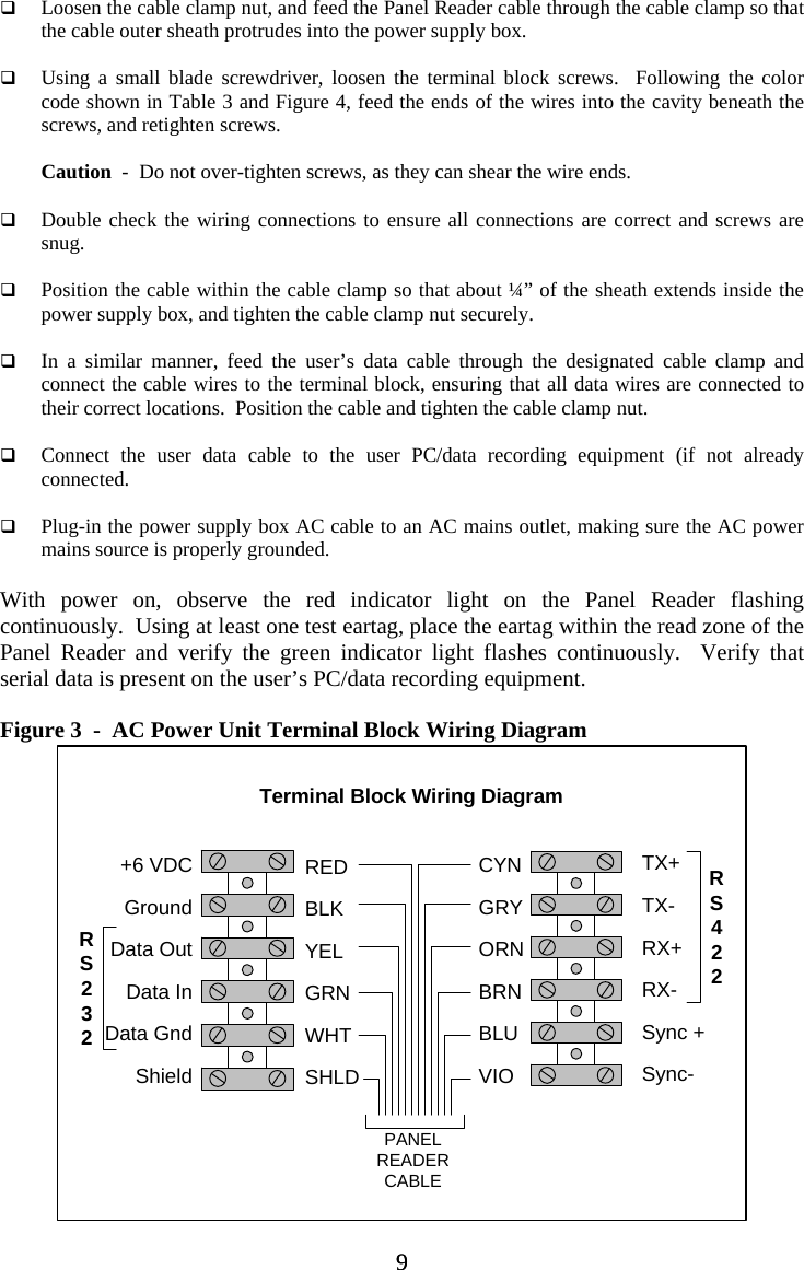
Allflex USA 930039 ISO Compatible RF/ID Panel Reader User Manual users manual

Allflex SA/Boulder ISO Compatible RF/ID Panel Reader users manual

users manual

  Installation Guide ISO Compatible RF/ID Panel Readers (P/N  PNL2532-V2, PNL4060-V2, PNL7070-V2, PNL60120-V2)   Introduction The Allflex Panel Readers comprise ISO reader electronics and antenna integrated within a hermetic plastic panel enclosure, ready for immediate use.  A single 3 meter (~10 ft.) length cable exiting the panel provides data and power connections to external serial data and DC power source.  Each Panel Reader is factory tuned for optimum performance, and operates without user adjustment in many installations.  Pre-drilled mounting holes facilitate user installation, so that total system setup is fast and easy.  This instruction guide provides the user/installer with information about mechanical installation, electrical wiring, configuration, operation, and performance characteristics of the Panel Readers.  The 3 Panel Readers described in this manual are identical in all respects except for physical size and consequential performance attributes of identification tag reading distance and reading zone.  Additional technical information is contained in companion documents, including (a) the Allflex Panel Reader Configurator® User Guide, (b) the Allflex Panel Reader User Technical Reference, and (c) the Allflex Panel Reader Serial Communications Command Language.  Figure 1  -  Allflex Small, Medium, and Large Panel Readers Contents: Introduction...................................1 Preparing for Installation  .............2 Changing Configuration Settings .........................................3 Mechanical Installation.................4 Electrical Interface Wiring............6 Power Source Requirements.........7 Serial Data Communications ........7 AC/DC Power Unit.......................8 Performance Verification............11 Interpreting ID Codes .................13 Panel Reader Configurator®......14 Configuration Options ................15 Panel Reader Tuning...................16 Panel Reader Synchronization....16 Technical Specifications............. 17 Warranty..................................... 18 Regulatory Compliance Notices .18 1 1
Caution! Please read the information contained within this Installation Guide completely prior to attempting installation and operation of the Panel Reader.  Failure to install and operate the Panel Reader in accordance with the information contained in this manual may result in unsatisfactory performance and/or irreparable damage to the equipment.  Preparing for Installation  The Panel Reader is shipped with this Installation Guide, a diskette copy of a PC Microsoft Windows® compatible application program Configurator®,  and a Wiring Adapter for connecting the Panel Reader to a PC.  Configurator® is an easy to use PC based utility that facilitates changing the factory set default options in the event the user wishes to customize the behavior of the Reader and the ID number format.  Configurator® is a self-installing program requiring only the user follow the simple procedure printed on its diskette label.  The Wiring Adapter is a connector that plugs into a PC’s DB9 serial port and provides a means of connecting the Panel Reader’s RS232 data cable wires to the user’s PC for use with Configurator®  Note 1  -  If the user is unfamiliar with the Panel Reader characteristics, it is strongly recommended that prior to installation, the Panel Reader be connected to a PC, and using Configurator® and some eartags, experiment with the various modes of operation that are possible, to verify the performance characteristics as are listed in Table 4.  This procedure will be especially useful in determining the format of the serial data output in which the eartag’s ID code information will be presented to the user’s data logging equipment.  Please see “Changing Configuration Settings” on page 3 of this installation guide.  Factory Default Configuration The factory  default configuration establishes the operating characteristics of the Panel Reader so that it is immediately operable upon customer receipt and application of power.  This default configuration includes the settings listed in Tables 1and 2 below.  Table 1  -  Factory Default Configuration Option Default Configuration Serial  Data Format  Per table 2, with duplicate tag reads transmitted Serial Hardware  9600 BPS, no parity, 8 BPW, 1 stop bit, no flow control Miscellaneous LED Indicators on, Continuous Reading on, Wireless Sync off Serial Bus Address  Disabled (not assigned)  Table 2  - Default Serial Data ID Code Formats Tag Type  Default Format HDX ISO  LA_982_000001088420<CR><LF> HDX Industrial  LR_0006_0000000018514243<CR><LF> FDX-B ISO  LA_982_000000255895<CR><LF> Note:  _ = space; <CR> = carriage return; <LF> = line feed 2 2
 If these settings are acceptable for the planned application, please proceed to the next section “Mechanical Installation”.  If any of the configuration settings require changing, please continue by following the procedure below.  Changing Configuration Settings  In order to change the Panel Reader’s configuration settings using Configurato®, the user must provide a suitable 6VDC power source to the Panel Reader, connect the data cable’s RS232 data signal wires to the Wiring Adaptor, and plug this connector into a PC on which Configurator® has been installed.  A suitable power source is any 6 volt DC power supply capable of providing at least 2.5 amperes of current.  Many users may find a 6 volt battery, rated at 4 ampere-hours or greater, convenient.  A Duracell type MN908 or Energizer type 528 alkaline battery will work well in this application and are readily available at most retail stores that sell batteries.  Connect the Panel Reader’s cable wires to the power source and the Configuration Adapter as illustrated in Figure 2.  With power connected, the user should observe the red LED indicator flashing, and if an eartag is brought within the Panel Reader’s read zone, the green LED will begin flashing also.  Figure 2  -  Connections for Configurator® PC Interfacing  YellowGreenWhite+               -6 VDCBatteryYellowGreenWhiteBlackRedPanel ReaderPower/Data Cable Wiring Adapter(DB9 Serial Port Connector)  Note 2  -  If the Panel Reader is located close by (less than 2 meters) the PC being used for configuration, the Reader’s read range performance will likely be reduced.  This has no affect on the configuration setting process, but will interfere with any performance measurements the user might wish to make.  Connect the Configuration Adapter to the PC’s serial port connector, and launch the Allflex Configurator® program.  Select the appropriate PC COM port at the top of the 3 3
screen, and Configurator® will automatically poll the serial port, identify the Panel Reader, and display the current configuration settings.  Configurator® comprises a single window display within which all options are listed and all possible settings are viewable in drop-down menu boxes.  Clicking on any down-arrow on any option item causes the drop-down menu to appear, from which the user can select any of the listed alternate option settings.  Once all selections have been made, clicking on the “Write Settings”  toolbar icon will place the user’s settings into the reader, where they will remain permanently, until altered by Configurator®.  When a tag is read, the resulting ID code information is displayed at the bottom of the screen in the format that has been determined by the configuration settings which have been selected.  For more information and detailed instructions, please refer to the Configurator® instruction guide.  Note 3  -  The Configurator® program will automatically determine the communications parameters that are effective in the Panel Reader.  The factory default settings are 9600 bits/second, no parity, 8 bits/word, 1 stop bit, and no flow control.  If these parameters are changed by the user, these settings will be automatically detected by Configurator® so that communications remain possible in the future.  Once all configuration settings have been established by the user, tags may be read and the corresponding output formats displayed in the Configurator® window.  Checking this with several sample tags will ensure that the configuration, and especially the data format, has been set compatibly with the user’s intended application.  After this verification has been completed, the Panel Reader may be disconnected from its power source and from the user’s PC, and installed in the intended physical location.   Mechanical Installation  Choosing an Installation Site Several factors should be considered when selecting and/or constructing an installation site in order to ensure optimum performance of the Panel Reader.  Prior to making structural changes to the target installation site, the user should temporarily install the reader in a manner that as closely as possible simulates the permanent installation, and verify that sufficient read range performance is possible (see Performance Verication on page 11).  The user should consider the following influences on overall system performance.  (a)  Metal surfaces and structures  -  The Panel Reader uses radio frequency techniques to communicate with the eartags.  Metal objects, especially magnetic metals and objects comprising surfaces and closed loop structures, can seriously degrade the read range performance through absorption and deflection of the Panel Reader’s electromagnetic fields.  Ideally, the Panel Reader should be mounted on or suspended from non-metallic structural members, and be free of metal surfaces parallel to the Panel Reader’s plane.  Structurally sound wood, fiberglass, plastic, or concrete (not containing steel re-bar) are suitable materials against which the 4 4
panel may be mounted.  Metal surfaces and structures should remain away from the Panel Reader by a distance at least equal to the diagonal dimension of the Panel Reader, in order to preserve the Panel Reader’s read range.  (b)  Electrical Machinery  -  Most AC operated electrical machinery will not interfere with the Panel Reader’s electrical signals.  However, machinery that is electrically controlled by electronic methods, such as motor speed controls, light dimmers, and solid state relays can produce high frequency emissions that can cause interference.  When the Panel Reader is being trial installed, the user should exercise all the machinery in the vicinity to ensure that potential interfering sources do not exist.  When wiring an AC mains operated power supply for use with the Panel Reader, avoid wiring the AC connection to the same line phase as such electric machinery is wired.  (c)  Other Eartags  -  If the Panel Reader is being installed in a location where eartagged animals will exist on all sides of the Reader (such as a feeder), precautions must be taken to ensure that only animals within the designated reading zone are read.  Presence of eartags anywhere around the Panel Reader will result in the tag being read by the Reader, and if multiple eartags are simultaneously present, neither eartag might be read.  In such installations, shielding with sheet metal may be necessary to prevent unwanted eartag reading, and such shielding may decrease read range within the desired read zone.  (d)  Other Eartag Readers  -  Operating multiple Panel Readers within close proximity, or operating a mobile hand-held reader nearby a Panel Reader, can reduce the read range of all readers present, and in some cases can totally inhibit reading of all readers.  If multiple readers are planned for proximal installations, it will be necessary to synchronize the readers.  Prior to permanent installation, ensure a suitable location for mounting the power supply box is available within 3 meters (~10 feet) of the Panel Reader, and ensure sufficient cable length will be available to route the cable in a secure and protected manner.  To avoid damage from animals, the cable should be routed through protective conduit in areas where animals may have access to it.  Note 4  -  It is acceptable to extend the power and data cable connections if it becomes necessary.  The power connections can be lengthened by 3 meters (~10 feet) using wire that is 16AWG or larger.  Data wiring can be extended by 12 meters (~40 feet) for RS232 interfaces and up to 1500 meters (5000 feet) for RS422 interfaces.  If the cable is extended, ensure the cable splices are implemented with electrical integrity and are suitably sealed against moisture and airborne corrosive substances.  Once a suitable location site and installation method had been determined, the Panel Reader can be permanently mounted in position using the ¼” (6mm) pre-drilled mounting holes.  If it is necessary, alternate or additional mounting holes may be drilled by the user, using caution to drill only within the rectangle defined by the existing holes.  Non-magnetic mounting hardware is recommended (stainless steel, brass, or 5 5
nylon bolts), but standard steel bolts will not compromise Panel Reader performance in most installations.  Note 5  -  The Panel Reader is designed to be completely water-tight.  While not intended for installation immersed in water, contact with water spray, such as heavy rain or power washers is acceptable.  Caution!  -  Ensure that the mounting structure itself is sufficiently strong to endure impact by animals that will come into contact with it.  Do not rely on the Panel Reader to contribute to the structural strength of the installation.   Electrical Installation  Electrical installation consists of making the appropriate power and data connections to the user’s equipment, and in some installations where multiple Panel Readers are located, connecting synchronization wiring.  Details about data communications and synchronization are contained in the companion document “Allflex Panel Reader User Technical Reference”.  Table 3 lists the functions, wire identifying colors, and wire size for the conductors contained within the Panel Reader cable.  Many users will not require use of all wires and functions provided.  Unused wires should have their exposed leads snipped off, and should be stowed in a protective fashion so that they do not accidentally come into contact with hazardous foreign voltage potentials, such as may exist in wiring termination boxes.  Table 3  -  Panel Reader Cable Wire Function Assignments Function  Wire Size (AWG)  Wire Color Power Input  #20  Red Power Ground  #20  Black RS232 TxD   (Data Output)  #26  Yellow RS232 RxD   (Data Input)  #26  Green RS232 GND  (Ground)  #26  White RS422 TX+   (Data Output)  #26  Cyan RS422 TX-    (Data Output)  #26  Gray RS422 RX+   (Data Input)  #26  Orange RS422 RX-   (Data Input)  #26  Brown Synchronization +  (Input/Output)  #26  Blue Synchronization -  (Input/Output)  #26  Violet Valid Read Indication  #26  Light Green Shield #22 (No insulation)  Caution!  -  The Panel Reader models ending with “-00X” are intended for 6 volt operation only.  Panel Reader models ending with “10X” can be operated at voltages between 6 volts DC and 12 volts DC. 6 6
Power Source Requirements  The Panel Reader can be powered from a variety of DC power source options.  The recommended power source is the Allflex P/N 930014-002 AC/DC Power Supply, which is housed in a steel NEMA 4X weather-tight enclosure, provides hermetic cable entry clamps for panel reader, AC input power, and data, and provides convenient internal terminal blocks on which to make panel reader cable connections.  Note 6  -  A user provided AC power supply must be a “linear” regulated type unit rated at 6 to 12 VDC output and 3.0 amperes minimum.  Some AC power supplies may exhibit excessive noise that can compromise read range of FDX-B type transponders.  Suitable AC power supplies should be rated at 3 millivolts or less output ripple.  Note 7  -  The Panel Reader does not contain a power on/off switch.  When a power source is connected to the designated power wires, the Panel Reader will commence immediate operation, characterized by continuous reading.  When powered from a battery source, be sure to disconnect the battery when the Panel Reader is not in use in order to conserve battery life.  Note 8  -  The Panel Reader is polarity protected against accidental reverse voltage application and will not be damaged by such.  However, reversing the power connections will prevent the Panel Reader’s operation.  Serial Data Communications  The Panel Reader is provided with RS232 and with RS422/RS485 serial communications interfaces.  RS232 is generally used in short run (less than 15 meters/50 feet) configurations where the data recording equipment is provided with a compatible RS232 interface.  Longer cable lengths are possible also when data communications rates are low (9600 bits/second and lower).  When long cable lengths are required between the Panel Reader and the data recording equipment, when fast data communications rates (greater than 9600 bits/second) are being used, or when bus communications are being used, the Panel Reader’s RS422/RS485 interface should be used.  Note 9  -  Serial communications for all interfaces are half duplex – that is, communication exists both to and from the Panel Reader, but not simultaneously.  While ID Code data is being transmitted from the Panel Reader, communications to the Panel Reader cannot be received simultaneously.  Note 10  -  RS232 and RS422/RS485 interfaces are concurrently enabled.  At all times, the Panel Reader can receive commands through either interface.  However, both interfaces are coupled to a single receive input pin on the Panel Reader’s internal circuitry.  Consequently, if inputs are applied simultaneously on both RS232 and RS422/RS485 interfaces, the commands will collide and be unrecognizable to the Panel Reader.  The user should employ only one of the interfaces for sending commands to the Panel Reader.  Note 11  -  Both RS232 and RS422/RS485 outputs can be simultaneously used.  For example, the RS232 output could be connected to a weigh-scale and the RS422 output could be connected to a data recording device.  Only one of these two user equipments should, however, have its transmit output connected to the Panel Reader’s receive input, as is explained in Note 10.  7 7
RS232 Serial Data Interface The RS232 serial data interface comprises a 3-wire arrangement, consisting of transmit (TxD/yellow), receive (RxD/green), and ground (GND/white).  This interface can be configured for a variety of communications parameters, but is factory configured with default settings of 9600 bits/second, no parity, 8 bits/word, and 1 stop bit (“9600N81”), and no flow control.  To determine the required settings, refer to the interface requirements for the data recording application that is being used with the Panel Reader.  To change these default settings, please see “Configuration Options” on pages 15 and 16 of this guide.    Serial data appears on the Panel Reader’s TxD connection in ASCII format, and is compatible with most PC terminal emulator programs, such as Hyperterminal®.  Configuration options provide flexible parsing and formatting of transponder ID code information (see “Configuration Options” on pages 15 and 16 of this guide).  The default formats for ISO transponder tag types are listed in Table 2 on page 2 of this guide.   RS422/RS485 Serial Data Interface The Panel Reader’s RS422/RS485 serial data interface comprises a balanced 4-wire (RS422) or balanced 2-wire (RS485) arrangement, which is capable of being used in any of several wiring configurations.  The balanced nature of this interface provides the ability to achieve long data communications cable lengths of up to 1500 meters (5000 feet) at the maximum communications data rate of 57,600 bits/second.    An excellent technical guide to RS422/RS485 communications can be found on, and downloaded from, B&B Electronics’ Internet web-site at:   http://www.bb-elec.com/tech_articles/rs422_485_app_note/table_of_contents.asp Users who are planning to connect several Panel Readers on an RS422/RS485 bus should consult the Allflex Panel Reader User Technical Reference for further information about serial data communications and bus addressing requirements.   Installation and Connection with the Allflex AC/DC Power Unit  Electrical installation consists only of connecting power and data wires to the terminal block in the power supply box, or connecting these wires in an alternate manner conducive to the user’s application.  Figure 3 illustrates the Allflex P/N 930014-002 AC/DC Power Unit terminal blocks where power and data wires are connected, and shows the wire color code and functions.  All connections should be made with power turned off to the Allflex Power Supply and to the user’s PC/data recording equipment.  Once the Panel Reader cable is routed in an acceptable and protected manner to the location where the power supply enclosure is mounted, installation is as follows, referring to Figures 3 and 4: 8 8
  Loosen the cable clamp nut, and feed the Panel Reader cable through the cable clamp so that the cable outer sheath protrudes into the power supply box.    Using a small blade screwdriver, loosen the terminal block screws.  Following the color code shown in Table 3 and Figure 4, feed the ends of the wires into the cavity beneath the screws, and retighten screws.  Caution  -  Do not over-tighten screws, as they can shear the wire ends.    Double check the wiring connections to ensure all connections are correct and screws are snug.    Position the cable within the cable clamp so that about ¼” of the sheath extends inside the power supply box, and tighten the cable clamp nut securely.    In a similar manner, feed the user’s data cable through the designated cable clamp and connect the cable wires to the terminal block, ensuring that all data wires are connected to their correct locations.  Position the cable and tighten the cable clamp nut.    Connect the user data cable to the user PC/data recording equipment (if not already connected.    Plug-in the power supply box AC cable to an AC mains outlet, making sure the AC power mains source is properly grounded.  With power on, observe the red indicator light on the Panel Reader flashing continuously.  Using at least one test eartag, place the eartag within the read zone of the Panel Reader and verify the green indicator light flashes continuously.  Verify that serial data is present on the user’s PC/data recording equipment.  Figure 3  -  AC Power Unit Terminal Block Wiring Diagram +6 VDCGroundData OutData InData GndShieldTX+TX-RX+RX-Sync +Sync-RS422RS232REDBLKYELGRNWHTSHLDCYNGRYORNBRNBLUVIOPANELREADERCABLETerminal Block Wiring Diagram 9 9
  Figure 4  -  Allflex 930014-002 AC/DC Power Unit Layout  DC Power SupplyAC MainsFilter+6 VGndTxDRxDRtnTX+Syn-Syn+RX-RX+TX-PanelReaderCableUser DataCable AC PowerCableShld 10 10
Performance Verification  Using several test eartags of the types to be used with the Panel Reader, the user can verify read range and read zone area of the installed system using only the green light as an indication of when the Panel Reader is correctly reading the eartags.  Under optimum conditions and without interference from aforementioned compromising influences, the read ranges listed in Table 4 are typical expected performances.  Table 4  -  Nominal Read Distance Performance Panel Reader Model Transponder Type / Input Voltage  PNL-2530-001 PNL-4060-001 PNL-60120-001 HDX/HP @ 6 VDC  60 cm  80 cm  100 cm HDX/LW @ 6 VDC  45 cm  55 cm  75 cm FDX-B @ 6 VDC  45 cm  55 cm  75 cm HDX/HP @ 12 VDC  72 cm  95 cm  120 cm HDX/LW @ 12 VDC  55 cm  65 cm  90 cm FDX-B @ 12 VDC  50 cm  60 cm  80 cm  Among many influences, the read distance performance of the Panel Reader will be affected by the following:  Eartag Orientation  -  For maximum reading distance, the axes of the eartag and reader antenna coils must be optimally oriented (see Figure 5).  Eartag Quality  -  Each manufacturer’s eartag differs in (a) the amount of exciter signal energy necessary to sufficiently operate the eartag’s internal circuitry, and (b) the signal level of the ID Code information that is returned to the reader.  Consequently, it is normal for eartags of a common type (FDX-B, for example) made by different manufacturers to exhibit different read range performance characteristics.  Eartag Motion  -  The Panel Readers have different size antennas, and the smaller antennas produce smaller effective “read zones”.  Panel Readers are generally designed for reading eartags while in motion, both translating and rotational.  An eartag that is moving quickly through the read zone while simultaneously changing orientation may not be present within the reader’s read zone sufficiently long for all the ID Code information to be obtained.  Eartag Size  - Physically larger eartags generally contain larger antenna coils which produce longer reading distances than smaller eartags having small antenna coils.  Eartag Type  -  HDX eartags generally exhibit greater reading distances than FDX-B eartags of comparable size.  Proximal Metallic Objects  -  Metal objects located near the eartag or Reader can attenuate and distort the electromagnetic fields generated in RFID systems, and thus diminish read distance performance.  Electrical Noise Interference  -  RFID eartags and readers use electromagnetic signals as a premise of operation.  Other electromagnetic phenomena – radiated electrical noise from 11 11
computer displays, for example – can interfere with the transmission and reception of RFID signals, and consequently reduce reading distance.  Eartag/Reader Interference  -  Multiple eartags within the sensing range of the reader, or other readers emitting excitation energy in the immediate vicinity can adversely affect the reading performance or prevent operation of the Panel Reader.  Panel Reader Read Zone Geometry The read zone is the 3-dimensional space within which an eartag can be read when held in a static and optimum orientation.  Figure 5 approximates the Panel Reader’s read zone in a 2-dimension perspective, as viewed from either the side or top, and illustrates eartag orientation for maximum and null reading.  The read zone is symmetrical around a centerline that bisects the plane of the Panel Reader.  Optimum read distance is achieved when the Panel Reader’s magnetic field lines intersect the surface of the eartag perpendicularly.  More practicably, the eartag’s read range is maximized when the eartag’s axis is perpendicular to the midpoint of the Panel Reader’s planar surface.  As the eartag is shifted from midpoint toward an edge of the Panel Reader, maximum read distance is usually achieved by tilting the eartag so as to maintain perpendicularity with the magnetic field lines as shown in Figure 5.  Figure 5  -  Panel Reader Read Zone and Tag Orientation  EartagOptimum OrientationEartagOptimum OrientationEartagNull OrientationEartagNull OrientationEartagOblique OrientationAntenna CoilWindingPanel Reader(Top CutawayView)MagneticField LineRead ZoneBoundary  12 12
Interpreting Tag ID Code Information  Table 2 lists the default data formats that are transmitted from the Panel Reader’s serial communications port, in response to reading compatible type tags.  For ISO type tags, there is no contextual differentiation between HDX and FDX-B outputs.  Both types of tags produce a default format:  LA_982_000001088420<CR><LF>  where the underscore “_” represents a space character, and <CR><LF> is a carriage return /line feed (unprinted control characters which cause a PC’s display cursor to jump to the beginning of the next line prior to displaying the next ID number).  In the above data output, the prefix “LA” represents “line mode – animal coded read only tag”, “982” is the Allflex manufacturer number assigned by ICAR, and the last 12 digits comprise a unique number sequence for this particular transponder.  The TIRIS S2000 output format has become a de facto standard for many users, and appends the reserved field and data block bits contained in the ISO coded eartag to the Panel Reader’s default format, causing the ID code information to appear in the format:  LA_00000_0_982_000001088420<CR><LF>  This output is easily configured using either the Configurator® utility, or by issuing the Command “BE40239” to the Panel Reader  (see “Configuration Options on pages 15 and 16).  Note 12  -  The manufacturer code “982” will be different for another manufacturer’s tag, and can also be replaced by an ISO country code (“250” = France, for example).  When other manufacturer codes or country codes exist, there can exist the same 12 digit ID number.  Note 13  -  While HDX and FDX-B type transponders have an identical context, they are guaranteed by Allflex to be unique.  That is, HDX tag type ID numbers are never duplicated in FDX-B type tags.  For HDX Industrial coded tags, the output format is:  LR_0006_0000000018514348<CR><LF>  In this tag format, the prefix “LR” represents “line mode – industrial coded read only tag”, “0006” is an application code unique to Allflex, and the last 16 digits comprise a unique identifying number sequence.      13 13
Panel Reader Configurator®  Configurator® provides an easy means of customizing the behavior and data format characteristics of the Panel Reader.  Figure 6 illustrates the single window screen from which all option settings can be made.  Especially useful are the boxes “ID Code Format Preview” which dynamically changes as format changes are made in the box immediately above it, and “Tag Read” which displays the output of an eartag when read by the Panel Reader connected to the PC running Configurator®.  When the cursor is placed over the option title name (such as “Initial Character”), a pop-up prompt explains the function and effect of that particular option.  For further information, please consult the Configurator® User Guide.  Figure 6  -  Panel Reader Configurator® Screen          14 14
Configuration Options  Configuration options can be set using alphanumeric commands from a PC terminal emulator program, such as Microsoft Windows Hyperterminal®, or from a user proprietary program that is capable of similar communications, using the Panel Reader Serial Command Language.  Serial Command Language Method  -  Basic Instructions The following instructions describe some of the basic and more frequently used configuration options, and illustrates how to implement them using the Panel Reader Serial Command Language in conjunction with Hyperterminal®.  The Command Language method uses upper and lower case alpha characters combined with hexadecimal characters to establish the Reader’s configuration.  The most common commands are listed in Table 5.  Table 5  -  Frequently Used Command Language Characters Command Application P  Reader’s current settings are sent in command language format Bnnnnnn  Configures ID code serial data format Snn  Sets serial data communications parameters Inn Sets miscellaneous options W00  Sets serial bus mode address ? or H  Retrieves list of valid Command Language characters  Note 14  -  In Table 5, commands followed with “n” (hexadecimal characters) require the user to press the PC’s <Enter> key after typing in all command characters.  Single letter commands do not require <Enter> to be pressed, except as noted in Table 5.  Command Language Examples:  Retrieve Current Configuration Settings: User:   P    Comment Reader:   *Allflex Panel Reader    Product Identity   *HW V1.01   Hardware Version Number   *SW  V1.05   Software Version Number   *PR V2.24   Protocol Version Number   *B-840239   Serial Data Format Setting   *S-0C00   RS232/RS422 Settings   *I-01    Miscellaneous Settings   *W-00    Serial Bus Address   Example - Change Communications Bit Rate to 1200 BPS: User:   S0900<CR><LF>   (<CR><LF> same as ‘Enter’) Reader:   *S-0900<CR><LF>   Command Confirmed   15 15
Example - Change ID Code Transmit Format to Hexadecimal: User:   B850239<CR><LF>    (<CR><LF> same as ‘Enter’) Reader:   *B-850239   Command Confirmed  Example - Start Read Cycle (Requested read mode): User:   R    (<CR><LF> not required) Reader:   LA_982_000000678234<CR><LF>  (if tag found)  For a complete description of all commands and configuration option variables, please refer to the Panel Reader Serial Command Language Manual.   Panel Reader Tuning  The Panel Reader is factory tuned for optimum performance in the absence of nearby metallic objects.  In some mechanical installations, mounting the panel reader near stationary metal objects in unavoidable, and sometimes it becomes necessary to install metal shields behind the Panel Reader in order to limit its effective read zone.  In these instances, the presence of metal can detune the Panel Reader’s antenna circuit, and compromise performance.  The easiest way to determine this is simply to measure the Panel Reader’s reading distance with and without the metal object’s presence.  When it has been determined that a metal object does compromise the read distance performance, it is possible to attempt retuning the Panel Reader antenna.  In order to do this, the Panel Reader has to mounted or positioned as closely as possible to its intended installation location and orientation.  Then, the Panel Reader electronic module compartment cover must be removed in order to access the tuning options located on the circuit board mounted inside.  A detailed procedure for Panel Reader Tuning is contained in the Panel Reader User Technical Reference.  The user should consult the instructions contained therein, prior to attempting any retuning of the Panel Reader.   Panel Reader Synchronization  When multiple Panel Readers are installed nearby one another, in some instances there may be mutual interference induced among them due to their independent exciter signal timing.  If Panel Reader performance is compromised or inhibited when a second Panel Reader is activated, the user should employ the wired synchronization feature.  In order to synchronize multiple Panel Readers, one unit must be configured as a master unit, and all others must be configured as slave units, using Configurator®.  Then, the violet and blue colored wires from each Panel Reader must be connected to the same wires on all other Panel Readers, to form two common wiring buses.  Detailed instructions are contained in the Panel Reader User Technical Reference document.  16 16
PANEL READER TECHNICAL SPECIFICATIONS GENERAL   RFID Compatibility:  ISO 11784 & 11785 HDX and FDX-B Form Factor:  Flat Laminated Plastic Enclosure w/accessible electronics compartment User Interface:  Red LED “Exciter Active” Visual Indicator Green LED “Good Read” Visual Indicator RS232/RS422 Serial Data Port RS232 Serial Port:  300 BPS to 57.6 KBPS (9600N81 default setting) Serial Data ID Code  Format  Decimal or Hexadecimal w/flexible formatting options Memory:  Retains last ID Code read in non-volatile memory for retransmission User Options:  Non-volatile mode control options selectable via RS232 serial port interface Power/Data Interface:  3 meter straight cable (unterminated) / can be extended Antenna Tuning:  Capacitor array located inside reader compartment Battery Power:  6 to 12 VDC (“-10x” models only / “-00x” models limited to 6VDC operation only) (External Battery or Mains Powered Linear Regulated Supply) Electromagnetic Compatibility (EMC) Certifications:  FCC Part 15 Class A CISPR 22 (EN55022), and EN50082-1 ETSI 300 330-2 Industry Canada RSS-210 PHYSICAL/ENVIRONMENTAL Panel Reader Model  PNL2532-V2  PNL4060-V2  PNL7070-V2  PNL60120-V2 Dimensions:  25 x 30 x 3 cm  40 x 60 x 3 cm  70 x 70 x 3 cm  60 x 120 x3 cm Weight:  ~ 2 kg  ~ 6 kg  ~ 12 kg.  ~ 18 kg. Material:  ABS UL94 HB Plastic Color: Black ABS Operate Temperature  -10ºC to +55ºC  (IEC68.2.1/.2) Storage Temperature  -40ºC to +85ºC  (IEC68.2.1/.2) Humidity:  0 to 100% (IEC68.2.56) Altitude:  -100 to +3,000 meters Mechanical Shock:  Per IEC 68-2-27  (15g/11mS sawtooth) & 1 meter free-fall drop onto concrete) Vibration:  Per IEC 68-2-6  (10-55 Hz sinusoidal/0.75mm displ./1 oct/min./10 cycles) Hermeticity:  IP-67 (dust-tight/immersible) per IEC 529 RELIABILITY   MTBF: 50,000 hours MTTR: 0.5 hours (field replaceable electronics module) Expected Life:  5 years, minimum PERFORMANCE   Panel Reader Model  PNL2532-V2  PNL4060-V2  PNL7070-V2  PNL60120-V2 Read Distance:   (@ 6 VDC battery) (add ~ 20% for 12VDC) 60 cm (HDX)145 cm (FDX-B)280 cm (HDX)155 cm (FDX-B)290 cm (HDX)1 65 cm (FDX-B)2100 cm (HDX)1 75 cm (FDX-B)2Reading Orientation:  0º to 45º with less than 10% range decrease Read Zone:  80% of read distance across entire panel surface on either side Interrogation Rate:  ~ 9 times/second Read Error Rate:  Less than 1 in 106Exciter Signal Radiated Field Strength:3 @ 10 meters w/6VDCinput @ 10 meters w/12VDC input   94  dBuV/m 100  dBuV/m   103  dBuV/m 109  dBuV/m   106 dBuV/m 112 dBuV/m   112  dBuV/m 118  dBuV/m     1Allflex 30mm HDX eartag  2Allflex 31mm FDX-B eartag    Panel Reader Physical Integrity 17 17
 The Panel Reader has been constructed from rugged and durable materials to provide long periods of service in harsh environments.  It is water proof, and can withstand direct water spray in use and for cleaning.  The Panel Reader does contains electronic components, however, that can be damaged if subjected to extreme intentional abuse, and such damage can deteriorate or terminate the Reader’s functioning.  Damage resulting from such is not covered by the Limited Product Warranty describe below.  Limited Product Warranty  Allflex warrants this product against any defects that are due to faulty material or workmanship for a period of one year after date of purchase.  This warranty does not apply to any damage to the product resulting from accident, misuse, modification, or application other than that for which it is intended and that is described within this User Manual.  If the product should become defective within the warranty period, Allflex will repair or replace it at no charge.  Allflex will return the product, shipping paid, provided it is shipped at customer cost to Allflex.  To obtain a return material authorization (RMA) code, please call Allflex at 303/449-4509, or contact your Allflex sales representative.  Allflex Worldwide Sales Offices:  Allflex Europe  Allflex USA, Inc.  Allflex Australasia ZI. de Plagué  P.O. Box 612266  Private Bag 11003 Route des Eaux, B.P. 70  Dallas/Ft. Worth Airport  Palmerston North F-35502 Vitre Cedex, France  Texas  75261-2266  New Zealand Tel   33 (0)2.99.75.77.00  Tel   (972) 456-3686  Tel   64 (06) 356-7199 Fax   33 (0)2.99.75.77.29  Fax   (972) 456-3882  Fax   64 (06) 358-5982 http://www.allflex-boulder.com  FCC ID:   NQY-930039   Note:  This equipment has been tested and found to comply with the limits for a Class A digital device pursuant to Part 15 of the FCC Rules.  These limits are designed to provide reasonable protection against harmful interference when the equipment is operated in a commercial environment.  This equipment generates, uses, and can radiate radio frequency energy, and if not installed and used in accordance with the instruction manual, may cause harmful interference to radio communications.  Operation of this equipment in a residential area is likely to cause harmful interference in which case the user will be required to correct the interference at his own expense.  This device has been tested and meets the Electromagnetic Compatibility (EMC) requirements of EMC Directive 2004/108/EC and R&TTE Directive 99/5/EC.  Caution This equipment has been designed, constructed, and tested for compliance with FCC Rules that regulate intentional and unintentional radiators.  The user is not permitted to make any modifications to this equipment or use it in any manner inconsistent with the methods described in this User Manual, without express approval from Allflex.  Doing so will void the user’s authority to operate this equipment. 18 18

Navigation menu