Allflex USA 930040 RFID Stick Reader User Manual RS250V2 User Manual
Allflex SA/Boulder RFID Stick Reader RS250V2 User Manual
users manual
Allflex Worldwide Sales Offices:
Allflex Europe Allflex USA, Inc. Allflex Australasia
ZI. de Plagué P.O. Box 612266 Private Bag 11003
Route des Eaux, B.P. 90219 Dallas/Ft. Worth Airport Palmerston North
35502 Vitre Cedex, France Texas 75261-2266 New Zealand
Tel 33 (0)2.99.75.77.00 Tel (972) 456-3686 Tel 64 (06) 356-7199
Fax 33 (0)2.99.75.77.29 Fax (972) 456-3882 Fax 64 (06) 358-5982
http://www.allflex-boulder.com
FCC ID: NQY-930040
Note: This equipment has been tested and found to comply with the limits for a Class A digital
device pursuant to Part 15 of the FCC Rules. These limits are designed to provide reasonable
protection against harmful interference when the equipment is operated in a commercial
environment. This equipment generates, uses, and can radiate radio frequency energy, and if not
installed and used in accordance with the instruction manual, may cause harmful interference to
radio communications. Operation of this equipment in a residential area is likely to cause harmful
interference in which case the user will be required to correct the interference at his own expense.
This device has been tested and meets the Electromagnetic Compatibility (EMC) requirements of
EMC Directive 2004/108/EC and R&TTE Directive 99/5/EC.
Caution
This equipment has been designed, constructed, and tested for compliance with FCC
Rules that regulate intentional and unintentional radiators. The user is not permitted to
make any modifications to this equipment or use it in any manner inconsistent with the
methods described in this User Manual, without express approval from Allflex. Doing
so will void the user’s authority to operate this equipment.
Trademark Notices
Hyperterminal® is a registered trademark of Hilgraeve, Inc.
MS-Windows® is a registered trademark of Microsoft, Inc.
Configurator® is a registered trademark of Allflex USA, Inc.
Other Agency Certification Notices
Industry Canada EMC Certification No. 4246A- __________
12
Allflex ISO Compatible RFID Stick Reader
Model RS250-V2
User Manual
(Revision B - June 2006 / Software V3.05+)
Preparing for Use
Unpacking
The Allflex Stick Reader is shipped in a box with this instruction guide, DC power
plug pigtail cable (for battery connection), and Configurator® diskette. Information
contained in this guide pertains to providing power to the Reader, connecting its
serial data port, setting configuration options using the Reader’s serial port, and
operating the Reader. In order to proceed, it is necessary that the user have a suitable
power source (see Page 2 of this guide) and an assortment of ISO transponders.
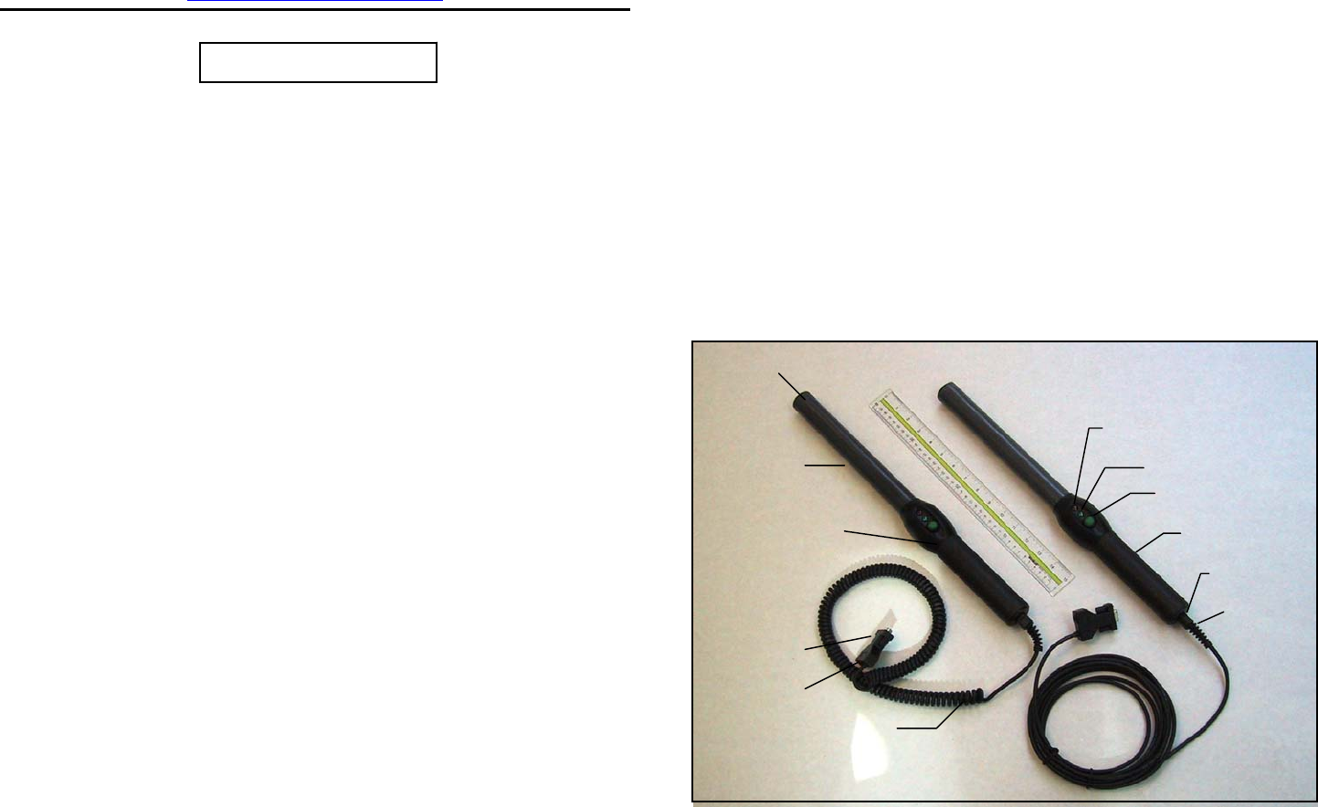
Stick Reader User Interface
The photograph (Figure 1) below illustrates the Stick Reader’s features that comprise
the user interface and are pertinent to its operation. Each feature and its
corresponding functional description of use are described in Table 1.
Figure 1 - Stick Reader Features and User Interface
Antenna
Red Indicator
Green Indicator
Audible Beeper
Read Button
Data/Power Cable
DB9F Connector
DC Power Jack
Enclosure
Attachment Ring
Handle Grip
Strain Relief

1
Table 1 - Stick Reader Features and Descriptions of Use
Feature Description of Use
Antenna Coil 1 Emits activation signal and receives transponder signal
Red Indicator Illuminates whenever antenna is emitting activation signal
Green Indicator Illuminates whenever a transponder has been read
Audible Beeper 1 Beeps once on first transponder reading and twice for repeat
READ Button Initiates activation signal for reading transponder
Data/Power Cable Conveys power to Reader and serial data from Reader
DB9F Connector Connects serial data to PC or data logger RS232 port
DC Power Jack Accepts 6 to 12 VDC input as Reader power source
Enclosure Rugged, fiberglass, watertight case
Attachment Ring Allows lanyard attachment for hanging
Handle Grip Rubber anti-slip gripping surface
Strain Relief Watertight cable entry
1 Item is internal to enclosure and cannot be seen in Figure 1 photograph
Power Source Requirements
The Stick Reader can be powered from a variety of DC power source options, either
through the DC power jack or through pin 9 on the DB9F connector. Recommended
DC Power sources are the Allflex PW50, PW250, or RFL100 Portable Rechargeable
Battery Pack, or PW409 AC Power Supply, which attaches to the DC Power Jack.
Note 1 - Certain weigh scales and other equipment to which the Stick Reader can be attached
provide DC power on pin 9 of the DB9 interface connector. Such DC power sources are
acceptable as long as the voltage is between 6 and 12 volts DC, and are capable of providing
at least 500 milliamperes continuous current, and at least 1.0 ampere peak current. Pin 5 of
the DB9 connector is ground. A rechargeable sealed lead acid battery rated at 6 volts and 4.5
ampere-hours or greater is an excellent choice for portable and field applications.
Note 2 - When an external power source is connected to the DC Power Jack, inserting the
plug causes electrical continuity to pin 9 of the DB9 connector to be interrupted. Polarity on
the DC Power Jack is sleeve + and center pin -. The DC power plug specification is a 2.5mm
x 5.5mm DC Coaxial (9.5mm length).
Note 3 - An AC power supply must be a linear regulated type unit rated at 6 to 12 VDC
output and 1.0 amperes minimum. Some AC power supplies may exhibit excessive noise that
can compromise read range of FDX-B type transponders. Suitable AC power supplies should
be rated at 3 millivolts or less output ripple.
Note 4 - The Stick Reader does not contain a power on/off switch. When a power source is
connected to either the power jack of pin 9 of the DB9F connector, the Stick Reader will
consume an idle current of approximately 25 milliamperes. When powered from a battery
source, be sure to disconnect the battery when the Stick Reader is not in use in order to
conserve battery life.
Note 5 - The Stick Reader is polarity protected against accidental reverse voltage application
and will not be damaged by such.
2
SPECIFICATIONS:
GENERAL
RFID Compatibility: ISO 11784 & 11785 HDX and FDX-B
Form Factor: Portable Handheld Fiberglass Rod Enclosure w/Rubber Handle Grip
User Interface: Single “Press to Read” Activation Button
Red LED “Exciter Active” Visual Indicator
Audible Beeper and Green LED “Good Read” Visual Indicator
RS232 Serial Data Port
Software upgradeable via RS232 serial port
RS232 Serial Port: 1200 BPS to 57.6 KBPS (9600N81 default setting)
Serial Data Format Decimal or Hexadecimal Mfr/Country Code + National ID Code
Memory: Stores up to 1638 transponder codes in non-volatile memory for download
User Options: Non-volatile mode control options selectable via RS232 serial port interface
Power/Data Interface: 1 meter coiled cable (extends to 3 meters) or 5 meter straight cable
w/DB9(f) connector & 2.5mm x 5.5mm coaxial power jack
Battery Power: 6 to 12 VDC External Battery or Mains Powered Supply
Electromagnetic
Compatibility (EMC)
Certifications:
FCC Part 15 Class A
CISPR 22 (EN55022), and EN50082-1
ETSI 300 330-2
Industry Canada RSS-210
PHYSICAL/ENVIRONMENTAL
Dimensions: RS250-45: 45cm L x 32mm diameter (18” x 1.25”)
RS250-60: 60cm L x 32mm diameter (24” x 1.25”)
Weight: 0.62 kg. (22 ounces)
Material: UL94V0 Fiberglass and ABS UL94 HB Plastic
Color: Black/Gray
Operate Temperature -40ºC to +55ºC (IEC68.2.1/.2)
Storage Temperature -40ºC to +85ºC (IEC68.2.1/.2)
Humidity: 0 to 95% (IEC68.2.56)
Altitude: -100 to +3,000 meters
Mechanical Shock: Per IEC 68-2-27 (15g/11mS sawtooth) & 1 meter free-fall drop onto
concrete)
Vibration: Per IEC 68-2-6 (10-55 Hz sinusoidal/0.75mm displ./1 oct/min./10 cycles)
Hermeticity: IP-67 (dust-tight/immersible) per IEC 529
RELIABILITY
MTBF: 50,000 hours
MTTR: 0.5 hours (not field serviceable)
Expected Life: 5 years, minimum
PERFORMANCE
Read Distance:
(@ 6 VDC)
(add 5 cm for 12VDC)
27cm (minimum - Allflex 30mm HDX/HP eartag)
20cm (minimum – Allflex 31mm FDX-B eartag)
Reading Orientation: 0º to 45º with less than 10% range decrease
Read Zone: 360º in radial and axial planes with respect to end of reader enclosure
Interrogation Rate: ~ 9 times/second
Read Error Rate: Less than 1 in 106
Exciter Signal
Field Strength: 81 dBuV/m @ 10 meters with 6VDC power input
87 dBuV/m @ 10 meters with 12VDC power input
11
ID Code Memory
The Stick Reader contains an internal non-volatile memory capable of storing 1638
ID codes. ID codes are stored automatically upon being read. A transponder ID
code will not be stored multiple times if read multiple times successively, but can be
stored in memory multiple times if other tags are read in between. All ID codes are
retained when power to the Stick Reader is shut off. If more than 1638 ID codes are
read, the new ID codes are written over the oldest ID codes in a wrap-around
manner.
ID Codes can be retrieved from the Stick Reader via its RS232 serial port by issuing
to the Reader a <G> command (see Table 5 on page 9). The <G> command can be
issued as many times as desired, and the complete memory contents will be
transferred upon each event. ID codes are not erased from the memory until a <C>
command is received.
Each ID code is followed by a <CR><LF> (carriage return/line feed) which will
cause each ID code to appear on a separate line of a PC display. The Stick Reader
contains a configuration option that automatically inserts a null identification code in
memory upon application of power to the Reader. This provides a means of
establishing partitions in memory between blocks of ID codes that represent separate
groups of identified animals, thus facilitating the management of ID code data once
downloaded to a PC database. To set this partitioning marker, use the command
<M02> (the default state is M00).
Stick Reader Physical Integrity
The Stick Reader has been constructed from rugged and durable materials to provide long
periods of service in harsh environments. It is water proof, and can withstand immersion in
water in use and for cleaning. The Stick Reader does contains electronic components,
however, that can be damaged if subjected to extreme intentional abuse, and such damage can
deteriorate or terminate the Reader’s functioning. The user should refrain from intentionally
striking other surfaces and objects with the Stick Reader. Damage resulting from such is not
covered by the Limited Product Warranty describe below.
Limited Product Warranty
Allflex warrants this product against any defects that are due to faulty material or
workmanship for a period of one year after date of purchase. This warranty does not apply to
any damage to the product resulting from accident, misuse, modification, or application other
than that for which it is intended and that is described within this User Manual.
If the product should become defective within the warranty period, Allflex will repair or
replace it at no charge. Allflex will return the product, shipping paid, provided it is shipped at
customer cost to Allflex. To obtain a return material authorization (RMA) code, please call
Allflex at 303/449-4509, or contact your Allflex sales representative.
10
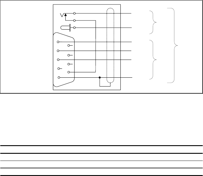
Serial Data Interface Requirements
The RS232 serial data interface comprises a 3 wire arrangement with a DB9F
connector, and consists of transmit (TxD/pin 2), receive (RxD/pin 3), and ground
(GND/pin 5). This interface can be configured for a variety of communications
parameters, and is factory configured with default settings of 9600 bits/second, no
parity, 8 bits/word, and 1 stop bit (“9600N81”). To change these default settings,
please see “Configuration Options” on pages 8 and 9 of this guide. Figure 2
illustrates the power and data wiring of the Power Jack and Data Connector.
Note 6 - The Stick Reader RS232 interface is wired as a DCE (data communications
equipment) type that connects directly to the serial port of a PC or any other device that is
designated as a DTE (data terminal equipment) type. When the Stick Reader is connected to
other equipment that is also wired as DCE (such as a PDA), a “null modem” adapter is
required in order to properly cross-wire transmit and receive signals so that communications
can occur.
Note 7 - The Stick Reader’s serial data connection can be extended using the Allflex AY005
(10 meter) or AY006 (20 meter) extension cable. Extensions longer than 20 meters (~65 feet)
are not recommended.
Figure 2 - Stick Reader Power Jack and Data Connector Wiring Diagram
Serial data appears on the Stick Reader’s TxD/pin 2 connection in ASCII format,
which is compatible with most PC terminal emulator programs, such as
Hyperterminal®. Configuration options provide flexible parsing and formatting of
transponder ID code information (see “Configuration Options” on pages 8 and 9 of
this guide). The default formats for ISO transponder tag types are listed in Table 2.
Table 2 - Default Serial Data ID Code Formats
Tag Type Default Format
HDX ISO LA_982_000001088420<CR><LF>
HDX Industrial LR_0006_0000000018514243<CR><LF>
FDX-B ISO LA_982_000000255895<CR><LF>
Note: _ = space; <CR> = carriage return; <LF> = line feed
3
To Stick
Reader
+ Pwr
TxD
RxD
Gnd
2
9
5
3
DB9(f)
2.5mm
Coaxial
2
3
1Gnd
#20
AWG
#26
AWG
1Aux

Stick Reader Setup
Basic Operating Procedure
The Stick Reader is configured at the factory with default configuration settings that
make it immediately functional upon application of power. These settings are
selected for compatibility with most users’ applications, and should be changed only
once a thorough understanding of options and the effect of each is understood by the
user.
Note 8 - In the event configuration options are inadvertently changed, it is possible to lose
the ability to communicate with the Reader as a consequence of not knowing the
communications parameters that are in effect. Factory default configuration (see page 8) can
be restored by holding down the READ button while applying power. After approximately 2
seconds, the Reader will respond with 6 flashes of its green LED indicator (and 6 audible
beeps) indicating that default settings have been restored.
Step 1 - Determine the method by which power will be applied to the Stick Reader
(see Power Source Requirements on page 2 of this guide), and connect power
accordingly. Observe a brief flashing by both LED indicators and audible beep.
Step 2 - Press the READ button momentarily, and observe the red LED flashes for
approximately 3 seconds, and then extinguishes.
Step 3 - Press the READ button again, and bring a transponder tag within 15 cm
(6”) of the end of the antenna where antenna is located (see Figure 3). Observe the
green LED indicator illuminates simultaneously with the audible beeper, indicating a
successful read, and the red LED ceases flashing.
Step 4 - Repeat Step 3 using the same transponder, and observe a double
flash/double beep, indicating that the same transponder tag has been read.
Step 5 - Connect the DB9F serial data connector to a PC’s COM1 port (usually the
port assigned to RS232 serial communications), and launch a terminal emulator
program such as Hyperterminal®. Set the PC’s communications parameters to 9600
bits/second, no parity, 8 bits/word, 1 stop bit, and no flow control (9600N81).
Step 6 - Using a different transponder tag than first used in Step 3, repeat Steps 3
and 4. Observe that the transponder ID code is sent from the Reader to the PC each
time it is read. Also observe that the tag data format conforms with those examples
listed in Table 2.
Note 9 - Even if the user’s application intends the Stick Reader to be connected to equipment
other than a PC, proceeding as described above will confirm the establishment of
communications with a PC so that (a) Stick Reader operation is verified, (b) the user becomes
familiar with the basic operation, and (c) configuration options can be changed via the PC in
the event the user’s application requires settings other than the default settings.
4
Table 5 - Frequently Used Command Language Characters
Command Application
P Reader’s current settings are sent in command language format
Bnnnnnn Configures ID code serial data format
Snn Sets serial data communications parameters
Inn Sets miscellaneous options
r Resends the last tag read
G Retrieves all ID codes stored in memory
M Sets ID code memory options
C Clears ID memory (requires <CR>)
? or H Retrieves list of valid Command Language characters
Note 15 - In Table 5, commands followed with “n” (hexadecimal characters) require the user
to press the PC’s <Enter> key after typing in all command characters. Single letter commands
do not require <Enter> to be pressed, except as noted in Table 5.
Command Language Examples:
Retrieve Current Configuration Settings:
User: P
Reader: Allflex Stick Reader Product Identity
*HW V1.00 Hardware Version Number
*SW V1.06 Software Version Number
*PR V2.21 Protocol Version Number
*B-840239 Serial Data Format Setting
*S-4C RS232 Settings
*I-01 Miscellaneous Settings
*M-00 Memory Options
*A-3 Read Time Interval
*L-0000 Memory ID Codes Stored
*F-1638 Memory ID Codes Vacant
Change Communications Bit Rate to 1200 BPS:
User: S49<CR><LF> (<CR><LF> same as ‘Enter’)
Reader: *S-49<CR><LF> Command Confirmed
Change ID Code Transmit Format to Hexadecimal:
User: B850239<CR><LF> (<CR><LF> same as ‘Enter’)
Reader: *B-850239 Command Confirmed
Start Read Cycle:
User: R (<CR><LF> not required)
Reader: LA_982_000000678234<CR><LF> (if tag found)
For a complete description of all commands and configuration option variables,
please refer to the Stick Reader Serial Command Language Manual.
9
Configuration Options
The Stick Reader provides a variety of user customization features that allow its
operation, behavior, and output data format to be configured for compatibility with
the user’s application. All of these options are set by sending the Stick Reader
certain commands via its RS232 serial communications interface. Once changed, the
Stick Reader retains these settings in memory permanently (even when power is
disconnected) until they are intentionally changed by the user.
Default Configurations
Table 4 lists the default configuration settings with which the Stick Reader is
optioned when shipped.
Table 4 - Default Configuration Options
Option Default Configuration
Serial Data Format Per table 2, duplicate tag reads transmitted
Serial Hardware 9600 BPS, no parity, 8 BPW, 1 stop bit, no flow control
Miscellaneous Beeper/LED = on, push-to-read, wireless sync = off
Read Time 3 seconds
Briefly, Serial Data Format settings determine the presentation of the ID code data to
the user’s device that is connected to the Stick Reader’s serial port. Serial Hardware
settings establish the Reader’s communications parameters for compatibility with the
user’s device. Miscellaneous settings control various operational characteristics of
the Reader. Read Time is the interval for which the Reader’s tag activation signal
remains on when the READ button is pressed an released.
Changing Configuration Options
Configuration options are changed by connecting the Stick Reader’s data cable to the
serial port on a PC, and applying power to the Reader. Once communications have
been established (see “Stick Reader Setup” on page 4 of this guide), either of two
methods can be used to change the Reader’s configuration. The first method uses a
terminal emulator program, such as Hyperterminal®, and requires the user to send
short alphanumeric coded command instructions to the reader. The second method
uses the Allflex Configurator® MS-Windows® based PC utility software program,
which allows the user to select configuration options from a series of drop-down
menu choices.
Serial Command Language Method - Basic Instructions
The following instructions describe some of the basic and more frequently used
configuration options, and illustrates how to implement them using the Stick Reader
Serial Command Language in conjunction with Hyperterminal®. The Command
Language method uses upper and lower case alpha characters combined with
hexadecimal characters to establish the Reader’s configuration. The most common
commands are listed in Table 5. 8
Reading Transponder Tags
The Stick Reader is always ready to read a transponder tag when power has been
applied to it. Initiating a tag reading event requires only a press of the READ button.
When the READ button is pressed and released, the tag activation signal is present
for a 3 second interval. Alternately, the READ button can be held down, and the
activation signal will remain on until the READ button is released or until a tag has
been read. The tag activation on state is always indicated by the red LED indicator
illuminating.
Note 10 - The 3 second tag activation on signal interval can be configured for times ranging
between 1 second and 9 seconds, in 1 second increments. The default time interval is 3
seconds.
Note 11 - The Stick Reader can be configured for a continuously on activation signal, thus
eliminating the need to press the READ button. In this mode the activation signal
automatically continues after every tag read. This mode should be used only when (a)
powering the Stick Reader from a 6 VDC source, (b) when interference with other tag readers
is not likely, and (c) when powering the Reader from a source that can provide sufficient
operating time. Use the command <I05> to activate continuous reading (see page 9).
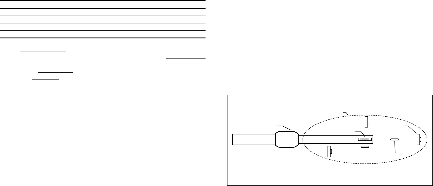
Figure 3 illustrates the read zone of the Stick Reader, within which tags can be
successfully detected and read. Optimum read distance occurs when the tag antenna
is aligned with the Stick Reader’s antenna as shown. When the tag is at the end of
the Stick Reader, optimum read distance coincides with a coaxial orientation of the
antennas, and when the tag is adjacent to the Stick Reader, optimum read distance
coincides with a planar orientation of the antennas.
Figure 3 - Optimum Read Distance Tag Orientation
Table 3 lists typical read distances that can be expected when operating the Stick
Reader at different power levels and when reading different types of Allflex eartags,
in the optimum tag orientation at the end of the Stick Reader (as shown in Figure 3).
5
Eartag
Implant
Stick Reader Antenna
Read Zone

Table 3 - Typical Read Distances for Various Allflex Eartags
Tag Type 6 VDC
(81 dBuV/m @10m) 12 VDC
(87 dBuV/m @10m)
HDX/HP Eartag 28 cm 35 cm
HDX/LW Eartag 22 cm 30 cm
FDX-B/HP Eartag 24 cm 27 cm
FDX-B/LW Eartag 20 cm 24 cm
Note 12 - Figures listed in Table 3 underneath input voltage levels represent field strength
levels. It is the user’s responsibility to ensure that the Stick Reader is operated within the legal
power limits regulated by the local telecommunications authority.
Read Range Performance
Tag readers are frequently assessed with respect to performance by their reading distance.
The read distance performance of the Stick Reader will be affected by the following:
Transponder Orientation - For maximum reading distance, the axes of the transponder and
reader antenna coils must be optimally oriented (see Figure 3).
Transponder Quality - Each manufacturer’s transponder differs in (a) the amount of exciter
signal energy necessary to sufficiently operate the transponder’s internal circuitry, and (b) the
signal level of the ID Code information that is returned to the reader. Consequently, it is
normal for transponders of a common type (FDX-B, for example) made by different
manufacturers to exhibit different read range performance characteristics.
Transponder Motion - Most portable readers have small antenna geometries, and
consequently produce small effective “read zones”. Portable readers are generally designed
for reading transponders under quasi-static conditions. Transponders that are moving quickly
past the reader may not be present within the reader’s read zone sufficiently long for all the ID
Code information to be obtained.
Transponder Size - Physically larger transponders generally contain larger receiving coils
which produce longer reading distances than smaller transponders.
Transponder Type - HDX transponders generally exhibit greater reading distances than FDX-
B transponders of comparable size.
Proximal Metallic Objects - Metal objects located near the transponder or Reader can
attenuate and distort the electromagnetic fields generated in RFID systems, and thus diminish
read distance performance.
Electrical Noise Interference - RFID transponders and readers use electromagnetic signals as
a premise of operation. Other electromagnetic phenomena – radiated electrical noise from
computer displays, for example – can interfere with the transmission and reception of RFID
signals, and consequently reduce reading distance.
Transponder/Reader Interference - Multiple transponders within the sensing range of the
reader, or other readers emitting excitation energy in the immediate vicinity can adversely
affect the reading performance or prevent operation of the Stick Reader.
6
Interpreting Tag ID Code Information
Table 2 lists the default data formats that are transmitted from the Stick Reader’s
serial communications port, in response to reading compatible type tags. For ISO
type tags, there is no contextual differentiation between HDX and FDX-B outputs.
Both types of tags produce a default format:
LA_982_000001088420<CR><LF>
where the underscore “_” represents a space character, and <CR><LF> is a carriage
return /line feed (unprinted control characters which cause a PC’s display cursor to
jump to the beginning of the next line prior to displaying the next ID number).
In the above data output, the prefix “LA” represents “Line mode – Animal coded
read only tag”, “982” is the Allflex manufacturer number assigned by ICAR, and the
last 12 digits comprise a unique number sequence for this particular transponder.
The TIRIS S2000 output format has become a de facto standard for many users, and
appends the reserved field and data block bits contained in the ISO coded eartag to
the Stick Reader’s default format, causing the ID code information to appear in the
format:
LA_00000_0_982_000001088420<CR><LF>
This output is easily configured using either the Configurator® utility, or by issuing
the Command “BE40239” to the Stick Reader (See Serial Command Language on
page 8).
Note 13 - The manufacturer code “982” will be different for another manufacturer’s tag, and
can also be replaced by an ISO country code or abbreviation (“250” or “FRA” = France, for
example). When other manufacturer codes or country codes exist, there can exist the same 12
digit ID number.
Note 14 - While HDX and FDX-B type transponders have an identical context, they are
guaranteed by Allflex to be unique. That is, HDX tag type ID numbers are never duplicated in
FDX-B type tags.
For HDX Industrial coded tags, the output format is:
LR_0006_0000000018514348<CR><LF>
In this tag format, the prefix “LR” represents “Line mode – industrial coded Read
only tag”, “0006” is an application code unique to Allflex, and the last 16 digits
comprise a unique identifying number sequence.
The above default formats can be changed using the features described in the section
“Configuration Options” on pages 8 and 9 of this guide.
7