Allflex USA 930041 RFID Stick Reader User Manual RS320 V2 User Manual
Allflex SA/Boulder RFID Stick Reader RS320 V2 User Manual
UserManual.wiki
>
Allflex USA
>
930041 User Manual
user manual
Navigation menu
Upload a User Manual
Namespaces
Wiki Guide
HTML
PDF
Info
Views
User Manual
Discussion / Help
Navigation
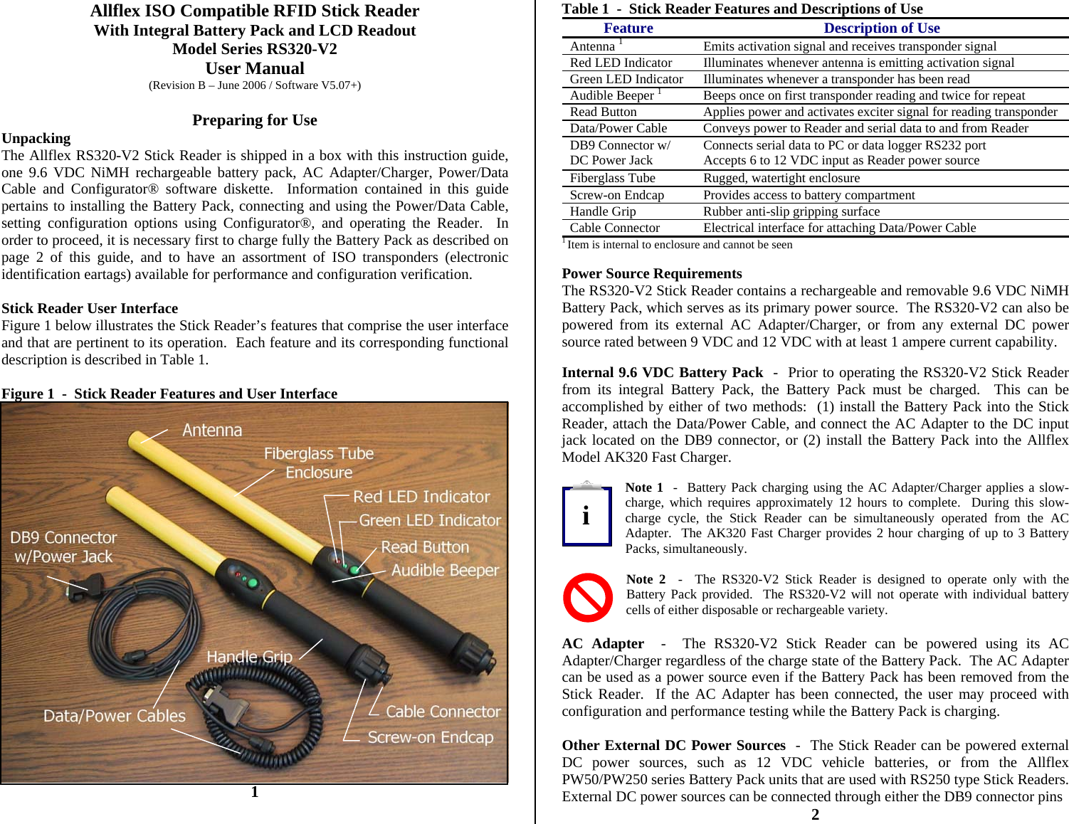
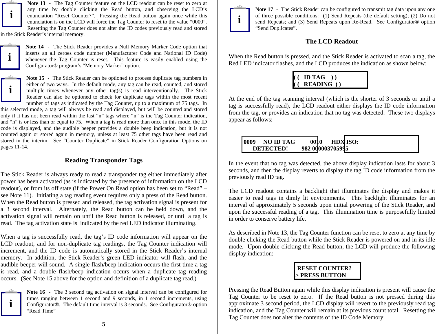
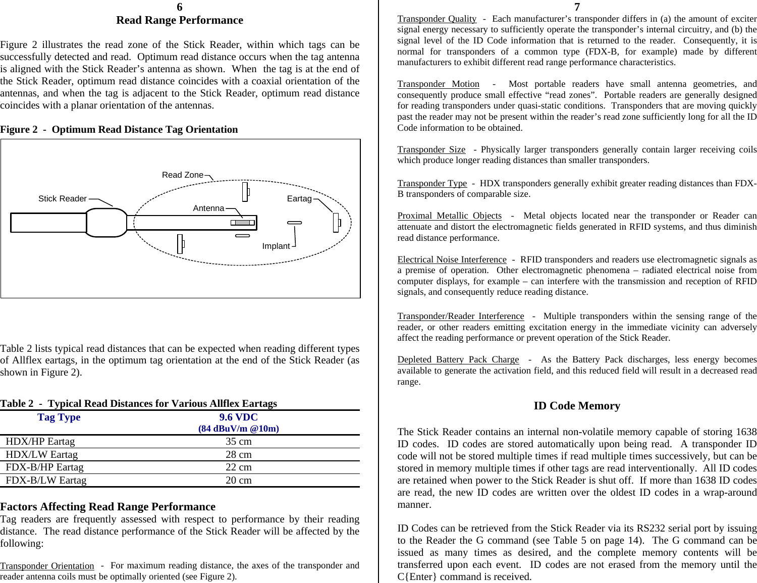
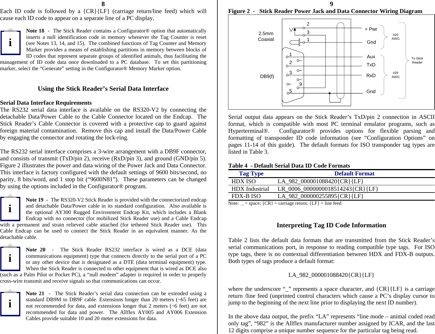
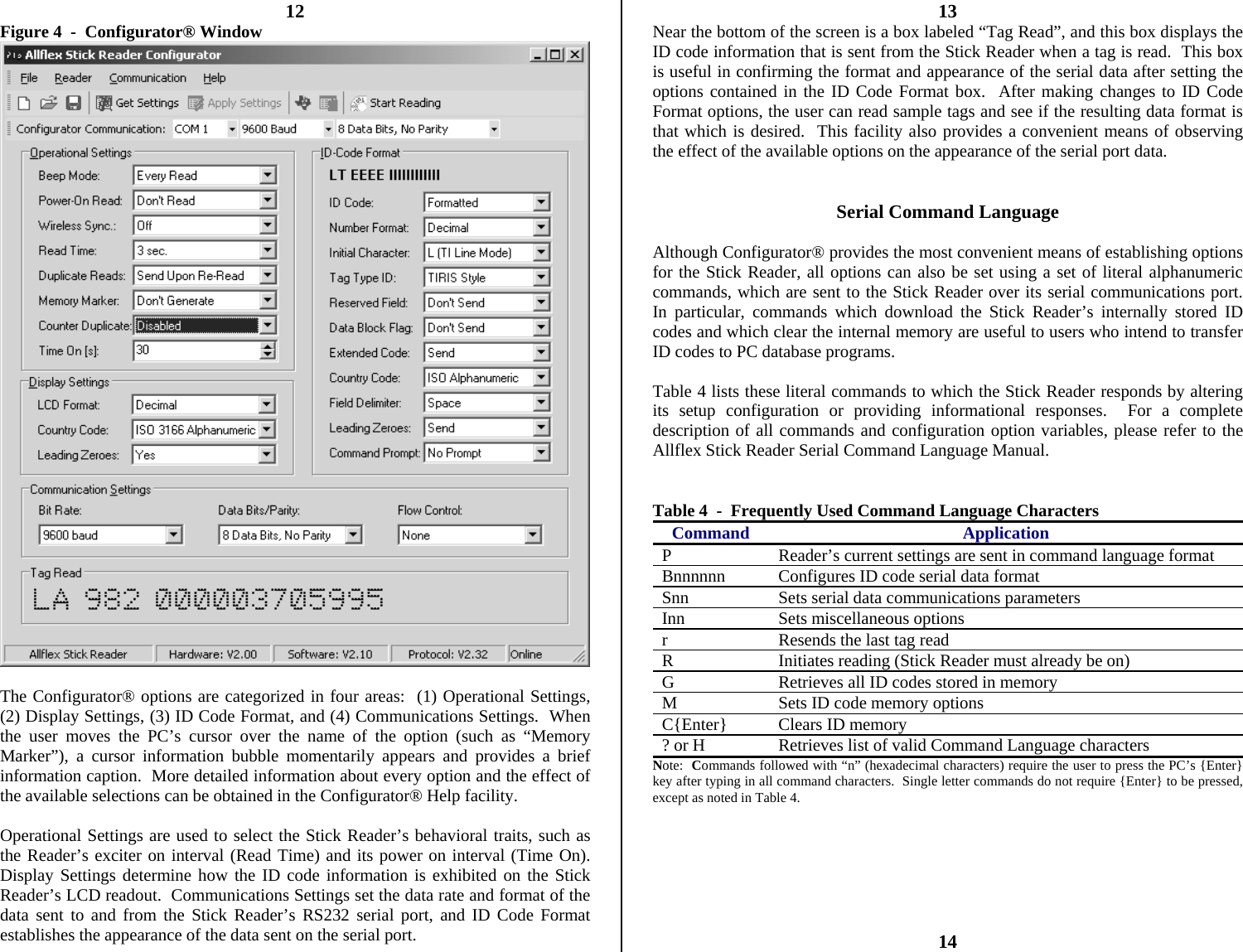
![9 (+) and 5(-), or by using the 2.5mm coaxial jack located on the DB9 connector (center conductor negative). Note 3 - Certain weigh scales and other equipment to which the Stick Reader can be attached provide DC power on pin 9 of the DB9 interface connector. Such DC power sources are acceptable as long as the voltage is between 9 and 12 volts DC, and are capable of providing at least 1.0 ampere continuous current. Pin 5 of the DB9 connector is ground. Note 4 - When an external power source, such as the AC Adapter, is connected to the DC Power Jack, inserting the plug causes electrical continuity to pin 9 of the DB9 connector to be interrupted. Polarity on the DC Power Jack is sleeve + and center pin -. The DC power plug specification is a 2.5mm x 5.5mm DC Coaxial (9.5mm length). See Figure 3 for the wiring details of this connector. Note 5 - The Stick Reader is protected against accidental reverse polarity voltage application and will not be damaged by such. Note 6 - The Stick Reader’s integral Battery Pack is affected by temperature. At 0°C (32°F), the Battery Pack will deliver only about half of its rated energy capacity. At lower temperatures, the Battery Pack may deliver unsatisfactory performance. When the RS320-V2 Stick Reader is used in low temperature environments, connection to an external power source, such as the Allflex PW50 Battery Pack, and placement of this external Battery Pack close to the user’s body, is recommended. Note 7 - To ensure proper Battery Pack charging, charging should be conducted only in an environment where the temperature is between 15°C and 30°C (60°F to 85°F). Charging at temperatures outside these boundaries will result in unsatisfactory charge acceptance by the Battery Pack. For more information about the characteristics of rechargeable batteries, please see the white paper at [http://www.national.com/appinfo/power/files/f19.pdf#page=10]. Activating the RS320-V2 Stick Reader With the Battery Pack fully charged and installed, or with the AC Adapter connected by means of the Data/Power Cable, the Stick Reader is ready to be used. To turn on the Stick Reader, press the green Read button, holding it down until the red and green indicators light and extinguish, and until the beeper stops sounding (this is about ¼ second duration). Note 8 - Very brief presses of the Read button will cause the indicators to light and the beeper to sound, but will not be sufficiently long to latch the Stick Reader into its power on state. Be sure to hold the Read button down until the beeper stops sounding. 3 Upon power-up, the Stick Reader’s LCD readout will appear as shown below: 0000 READY TO READ This power-on message is indicative that the Stick Reader’s internal ID Code memory has been cleared, and that the Stick Reader is prepared to read new tags. If the Reader has been previously used, and there are ID Codes stored in memory, the LCD readout will resemble the display shown below: 0012 HDX ISO: 982 000006975374 In this display, the 4 digits on the left side of the top line indicate the tag counter, and the information on the right side of the top line displays the tag type. On the bottom line appears the 3 digit ISO Country Code or Manufacturer Code, followed by the 12 digit decimal ISO National ID Code. Display formats for other tags that can be read by the RS320-V2 Stick Reader are shown below for ISO FDX-B and HDX Industrial coded tags. 0013 FDX-B ISO: 0014 HDX-I: 2048 982 009101723121 0000000000053925 Note 9 - Configurator® provides the capability to select the LCD readout ID code format to (a) decimal or hexadecimal, (b) numeric or alpha country codes, and (c) suppression or inclusion of ID code leading zeroes. Please see the section on the Configurator® program beginning on page 12 of this User Manual. Note 10 - Upon power-up, the LCD readout will always display the information from the last tag read, unless the internal ID Code memory has been cleared. The RS320-V2 Stick Reader does not have the capability to recall and display ID codes from tags read prior to the last tag. For information about retrieving ID Codes from memory and clearing the memory, please see the section titled “Retrieving ID Codes Stored in Memory” which begins on page 15 of this User Manual. Note 11 - The RS320-V2 Stick Reader is delivered with configuration options set in the “default” state (see “Default Configuration” on pages 16-17.). Among these default settings is the “Power On Read” option that determines the behavior of the Stick Reader when the Read button is pressed. In the default “Don’t Read” state, the power-on behavior is as described above. By changing this option setting to “Read”, the Stick Reader will begin scanning for a tag immediately upon power-up, and will not first enter the idle LCD readout states as illustrated above. This option and other Stick Reader operational modes can be selected using the Configurator® program. Note 12 - Each ID Code is stored internally in the Stick Reader’s non-volatile memory until the user deliberately erases the stored ID codes after downloading them into a recording device, such as a PC database. Up to 1638 ID codes can be stored and retrieved later at the user’s convenience. 4 iiiiiii!!!](https://usermanual.wiki/Allflex-USA/930041/User-Guide-681482-Page-2.png)