Alliance Laundry Systems Hx Users Manual Washer Extractor Service
UX OPL 9001900_alliance_washer-extractor_hx_sx_ux_opl_cabinet_freestanding
SX to the manual bf3ab4ff-3d0a-4c33-8e65-f2f049ab8a22
2015-02-05
: Alliance-Laundry-Systems Alliance-Laundry-Systems-Hx-Users-Manual-506611 alliance-laundry-systems-hx-users-manual-506611 alliance-laundry-systems pdf
Open the PDF directly: View PDF ![]() .
.
Page Count: 78
- Cover
- Table of Contents
- Model Identification
- Safety Information
- Introduction
- Troubleshooting
- 1. WE-8 Control Has No Visible Display (P and N-Voltage Models)
- 2. WE-8 Control Has No Visible Display (Q and X-Voltage Models)
- 3. No Fill Analysis
- 4. Water Runs Continuously into the Washer-Extractor
- 5. Door Lock Switch Analysis: Display Shows “Door Error”
- 6. Door Lock Switch Analysis: Display Reads “Please Close Door”
- 7. Door Lock Switch Analysis: “Door Won’t Unlock”
- 8. No Output Voltage to Components
- 9. No Motor Operation With No AC Drive Fault
- 10. No Motor Operation With AC Drive Fault
- 11. The Motor is Running, But at an Abnormal Speed
- 12. No Spin
- 13. Machine Did Not Fill Alarm Analysis
- 14. Empty Alarm Analysis
- 15. Automatic Supply Dispenser Analysis
- 16. No Keypad Board Functions
- 17. Excessive Cycle Time
- 18. Excessive Vibration and/or Noise During Spin
- Service Procedures
- 19. Top Cover Removal and Replacement
- 20. Keypad Removal and Installation
- 21. Computer Board Removal and Installation
- 22. Keymode Switch Removal and Installation
- 23. AC Drive Switch Removal and Installation
- 24. Rear Panel Removal and Replacement
- 25. Side Panel Removal and Installation
- 26. Drive Belt Removal and Replacement
- 27. Water Valve Removal and Replacement
- 28. Drain Valve
- 29. Door Gasket Removal and Replacement
- 30. Motor Removal and Replacement (18, 25, 35, 55 and 75-Pound Capacity Models)
- 31. Motor Removal and Replacement (100, 135 and 165-Pound Capacity Models)
www.comlaundry.com
CFS462N
Part No. 9001900
December 2005
Service
Washer-Extractor
Cabinet Freestanding
HX, SX and UX OPL Models
Refer to Page 8 for Model Numbers
9001900 1
© Copyright 2005, Alliance Laundry Systems LLC
All rights reserved. No part of the contents of this book may be reproduced or transmitted in any form or by any means without
the expressed written consent of the publisher.
© Copyright, Alliance Laundry Systems LLC – DO NOT COPY or TRANSMIT
Table of Contents
Section 1 – Safety Information
General Safety Precautions .....................................3
Important Safety Instructions ..................................4
Locating an Authorized Servicer ............................6
Section 2 – Introduction
Customer Service ....................................................7
Model Identification ................................................8
Section 3 – Troubleshooting
1. WE-8 Control Has No Visible Display (P and
N-Voltage Models) ........................................10
2. WE-8 Control Has No Visible Display (Q and
X-Voltage Models) ........................................14
3. No Fill Analysis .............................................18
4. Water Runs Continuously into the Washer-
Extractor .........................................................22
5. Door Lock Switch Analysis: Display Shows
“Door Error” ..................................................26
6. Door Lock Switch Analysis: Display Reads
“Please Close Door” .......................................30
7. Door Lock Switch Analysis: “Door Won’t
Unlock” ..........................................................34
8. No Output Voltage to Components ................38
9. No Motor Operation With No AC
Drive Fault .....................................................42
10. No Motor Operation With AC Drive Fault ....46
11. The Motor is Running, But at an Abnormal
Speed ..............................................................50
Preliminary Checks:.....................................50
Secondary Checks:.......................................50
Calibration of the Machine...........................50
12. No Spin ..........................................................51
13. Machine Did Not Fill Alarm Analysis ...........52
14. Empty Alarm Analysis ...................................56
15. Automatic Supply Dispenser Analysis ..........60
16. No Keypad Board Functions ..........................62
17. Excessive Cycle Time ....................................63
18. Excessive Vibration and/or Noise
During Spin ....................................................64
Section 4 – Service Procedures
19. Top Cover Removal and Replacement ..........65
20. Keypad Removal and Installation ..................65
21. Computer Board Removal and Installation ...66
22. Keymode Switch Removal and Installation ...69
23. AC Drive Switch Removal and Installation ..70
24. Rear Panel Removal and Replacement ..........71
25. Side Panel Removal and Installation .............71
26. Drive Belt Removal and Replacement ...........72
27. Water Valve Removal and Replacement .......73
28. Drain Valve ....................................................74
29. Door Gasket Removal and Replacement .......74
30. Motor Removal and Replacement
(18, 25, 35, 55 and 75-Pound Capacity
Models) ..........................................................75
31. Motor Removal and Replacement
(100, 135 and 165-Pound Capacity Models) .76
29001900
© Copyright, Alliance Laundry Systems LLC – DO NOT COPY or TRANSMIT

9001900 3
© Copyright, Alliance Laundry Systems LLC – DO NOT COPY or TRANSMIT
Section 1
Safety Information
Throughout this manual and on machine decals, you will find precautionary statements (“CAUTION,”
“WARNING,” and “DANGER”) followed by specific instructions. These precautions are intended for the personal
safety of the operator, user, servicer and those maintaining the machine.
aDANGER
Indicates an imminently hazardous situation that, if not avoided, will cause severe personal injury or death.
aWARNING
Indicates a hazardous situation that, if not avoided, could cause severe personal injury or death.
aCAUTION
Indicates a hazardous situation that, if not avoided, may cause minor or moderate personal injury or property
damage.
Additional precautionary statements (“IMPORTANT” and “NOTE”) are followed by specific instructions.
IMPORTANT
The word “IMPORTANT” is used to inform the reader of specific procedures where minor machine damage will
occur if the procedure is not followed.
NOTE
The word “NOTE” is used to communicate installation, operation, maintenance or servicing information that is
important but not hazard related.
General Safety Precautions
In the interest of safety, some general precautions relating to the operation of this machine follow.
• Failure to install, maintain and/or operate this product according to the manufacturer’s
instructions may result in conditions which can produce serious injury, death and/or property
damage.
• Do not repair or replace any part of the product or attempt any servicing unless specifically
recommended or published in this Service Manual and unless you understand and have the
skills to carry out the servicing.
• Whenever ground wires are removed during servicing, these ground wires must be
reconnected to ensure that the product is properly grounded and to reduce the risk of fire,
electric shock, serious injury or death.
W006R2
WARNING
(continued)

49001900
Section 1 Safety Information
© Copyright, Alliance Laundry Systems LLC – DO NOT COPY or TRANSMIT
Always contact your dealer, distributor, service agent or the manufacturer about any problems or conditions you do
not understand.
Important Safety Instructions
1. Read all instructions before using the washer-extractor.
2. Refer to the GROUNDING INSTRUCTIONS in the INSTALLATION manual (supplied with your washer-
extractor) for the proper grounding of the washer-extractor.
3. Do not wash textiles that have been previously cleaned in, washed in, soaked in or spotted with gasoline, dry-
cleaning solvents or other flammable or explosive substances. They give off vapors that could ignite or
explode.
4. Do not add gasoline, dry-cleaning solvents or other flammable or explosive substances to the wash water.
These substances give off vapors that could ignite or explode.
5. Under certain conditions, hydrogen gas may be produced in a hot water system that has not been used for two
weeks or more. HYDROGEN GAS IS EXPLOSIVE. If the hot water system has not been used for such a
period, before using a washer-extractor, turn on all hot water faucets and let the water flow from each for
several minutes. This will release any accumulated hydrogen gas. The gas is flammable. Do not smoke or use
an open flame during this time.
To reduce the risk of electric shock, fire, explosion, serious injury or death:
• Disconnect electric power to the washer-extractor before servicing.
• Never start the washer-extractor with any guards/panels removed.
• Whenever ground wires are removed during servicing, these ground wires must be
reconnected to ensure that the washer-extractor is properly grounded.
W460
WARNING
Repairs that are made to your products by unqualified persons can result in hazards due to
improper assembly or adjustments subjecting you or the inexperienced person making such
repairs to the risk of serious injury, electrical shock or death.
W007
WARNING
If you or an unqualified person perform service on your product, you must assume the
responsibility for any personal injury or property damage which may result. The manufacturer
will not be responsible for any injury or property damage arising from improper service and/or
service procedures.
W008
WARNING
To reduce the risk of fire, electric shock, serious injury or death to persons when using your
washer, follow these basic precautions:
W023E
WARNING
9001900 5
Section 1 Safety Information
© Copyright, Alliance Laundry Systems LLC – DO NOT COPY or TRANSMIT
6. Do not allow children to play on or in a washer-extractor. Close supervision of children is necessary when the
washer-extractor is used near children.
7. Before the washer-extractor is removed from service or discarded, remove the door to the washing
compartment.
8. Do not reach into the washer-extractor if the wash basket is moving.
9. Do not install or store the washer-extractor where it will be exposed to water and/or weather.
10. Do not tamper with the washer-extractor’s controls.
11. Do not repair or replace any part of the washer-extractor or attempt any servicing unless specifically
recommended in the user-maintenance instructions or in published user-repair instructions that the user
understands and has the skills to carry out.
12. To reduce the risk of an electrical shock or fire, DO NOT use an extension cord or an adapter to connect the
washer-extractor to an electrical power source.
13. Use the washer-extractor only for its intended purpose, washing clothes.
14. ALWAYS disconnect the washer-extractor from its electrical supply before attempting any service.
15. Install the washer-extractor according to the INSTALLATION INSTRUCTIONS. All connections for water,
drain, electrical power and grounding must comply with local codes and, when required, be made by licensed
personnel.
16. To reduce the risk of fire, textiles which have traces of any flammable substances such as vegetable oil,
cooking oil, machine oil, flammable chemicals, thinner, etc. or anything containing wax or chemicals such as
in mops or cleaning cloths, must not be put into the washer-extractor. These flammable substances may cause
the fabric to ignite.
17. Do not use fabric softeners or products to eliminate static unless recommended by the manufacturer of the
fabric softener or product.
18. Keep the washer-extractor in good condition. Bumping or dropping the washer-extractor can damage its safety
features. If this occurs, have the washer-extractor checked by a qualified service person.
19. Replace worn power cords and/or loose plugs.
20. Be sure that water connections have a shut-off valve and that fill hose connections are tight. CLOSE the shut-
off valves at the end of each wash day.
21. The loading door MUST BE CLOSED any time the washer-extractor is to fill, tumble or spin. DO NOT by-
pass the loading door switch and permit the washer-extractor to operate with the loading door open.
22. Always read and follow the manufacturer’s instructions on packages of laundry and cleaning aids. Heed all
warnings and precautions. To reduce the risk of poisoning or chemical burns, keep them out of the reach of
children at all times (preferably in a locked cabinet).
23. Always follow the fabric care instructions supplied by the textile manufacturer.
24. Never operate the washer-extractor with any guards and/or panels removed.
25. DO NOT operate the washer-extractor with missing or broken parts.
26. DO NOT by-pass any safety devices.
27. Failure to install, maintain and/or operate this washer-extractor according to the manufacturer's instructions
may result in conditions that can produce bodily injury and/or property damage.
NOTE: The WARNING and IMPORTANT SAFETY INSTRUCTIONS appearing in this manual are not
meant to cover all possible conditions and situations that may occur. Common sense, caution and care must
be exercised when installing, maintaining and operating the washer-extractor.
Any problems or conditions not understood should be reported to the dealer, distributor, service agent or the
manufacturer.
69001900
Section 1 Safety Information
© Copyright, Alliance Laundry Systems LLC – DO NOT COPY or TRANSMIT
Locating an Authorized Servicer
Alliance Laundry Systems is not responsible for personal injury or property damage resulting from improper
service. Review all service information before beginning repairs.
Warranty service must be performed by an authorized technician, using authorized factory parts. If service is
required after the warranty expires, Alliance Laundry Systems also recommends contacting an authorized
technician and using authorized factory parts.
9001900 7
© Copyright, Alliance Laundry Systems LLC – DO NOT COPY or TRANSMIT
Section 2
Introduction
Customer Service
Alliance Laundry Systems is not responsible for
personal injury or property damage resulting from
improper service. Review all service information
before beginning repairs.
If literature or replacement parts are required, contact
the source from whom the machine was purchased or
contact Alliance Laundry Systems at (920) 748-3950
for the name of the nearest authorized parts distributor.
For technical assistance, call (920) 748-3121.
89001900
Section 2 Introduction
© Copyright, Alliance Laundry Systems LLC – DO NOT COPY or TRANSMIT
Model Identification
Information in this manual is applicable to these washer-extractors.
HX18PVQM6
HX18PVQU6
HX18PVXM6
HX18PVXU6
HX25PVQM6
HX25PVQU6
HX25PVXM6
HX25PVXU6
HX35PVQM6
HX35PVQU6
HX35PVXM6
HX35PVXU6
HX55PVNU6
HX55PVQU6
HX55PVXU6
HX75PVNU6
HX75PVQU6
HX100PVNU6
HX100PVQU6
HX135PVNU6
HX135PVQU6
HX165PVNU6
HX165PVQU6
SX18PVQM6
SX18PVQU6
SX18PVXM6
SX18PVXU6
SX25PVQM6
SX25PVQU6
SX25PVXM6
SX25PVXU6
SX35PVQM6
SX35PVQU6
SX35PVXM6
SX35PVXU6
SX55PVNU6
SX55PVQU6
SX55PVXU6
SX75PVNU6
SX75PVQU6
SX100PVNU6
SX100PVQU6
SX135PVNU6
SX135PVQU6
SX165PVNU6
SX165PVQU6
UX18PVNA6
UX18PVNU6
UX18PVPA6
UX18PVPU6
UX18PVQA6
UX18PVQM6
UX18PVQU6
UX18PVXA6
UX18PVXM6
UX18PVXU6
UX25PVNA6
UX25PVNU6
UX25PVPA6
UX25PVPU6
UX25PVQA6
UX25PVQM6
UX25PVQU6
UX25PVXA6
UX25PVXM6
UX25PVXU6
UX35PVNA6
UX35PVNU6
UX35PVPA6
UX35PVPU6
UX35PVQA6
UX35PVQM6
UX35PVQU6
UX35PVXA6
UX35PVXM6
UX35PVXU6
UX55PVNU6
UX55PVPU6
UX55PVQU6
UX55PVXU6
UX75PVNU6
UX75PVPU6
UX75PVQU6
UX100PVNU6
UX100PVPU6
UX100PVQU6
UX135PVNU6
UX135PVPU6
UX135PVQU6
UX165PVNU6
UX165PVPU6
UX165PVQU6

9001900 9
To reduce the risk of electrical shock, fire, explosion, serious injury or death:
• Disconnect electrical power to the washer-extractor before servicing it.
• Close the gas shut-off valve to the washer-extractor (when applicable) before servicing it.
• Never start the washer-extractor with any guards/panels removed.
• Whenever ground wires are removed during servicing, these ground wires must be
reconnected to ensure that the washer-extractor is properly grounded.
W461R1
WARNING
© Copyright, Alliance Laundry Systems LLC – DO NOT COPY or TRANSMIT
Section 3
Troubleshooting
10 9001900
Section 3 Troubleshooting
© Copyright, Alliance Laundry Systems LLC – DO NOT COPY or TRANSMIT
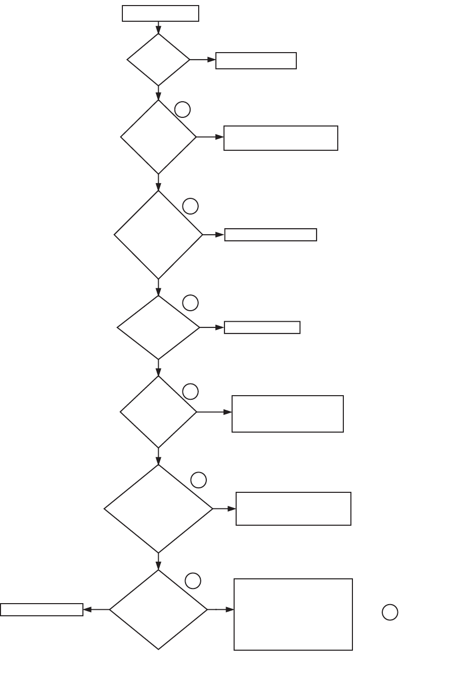
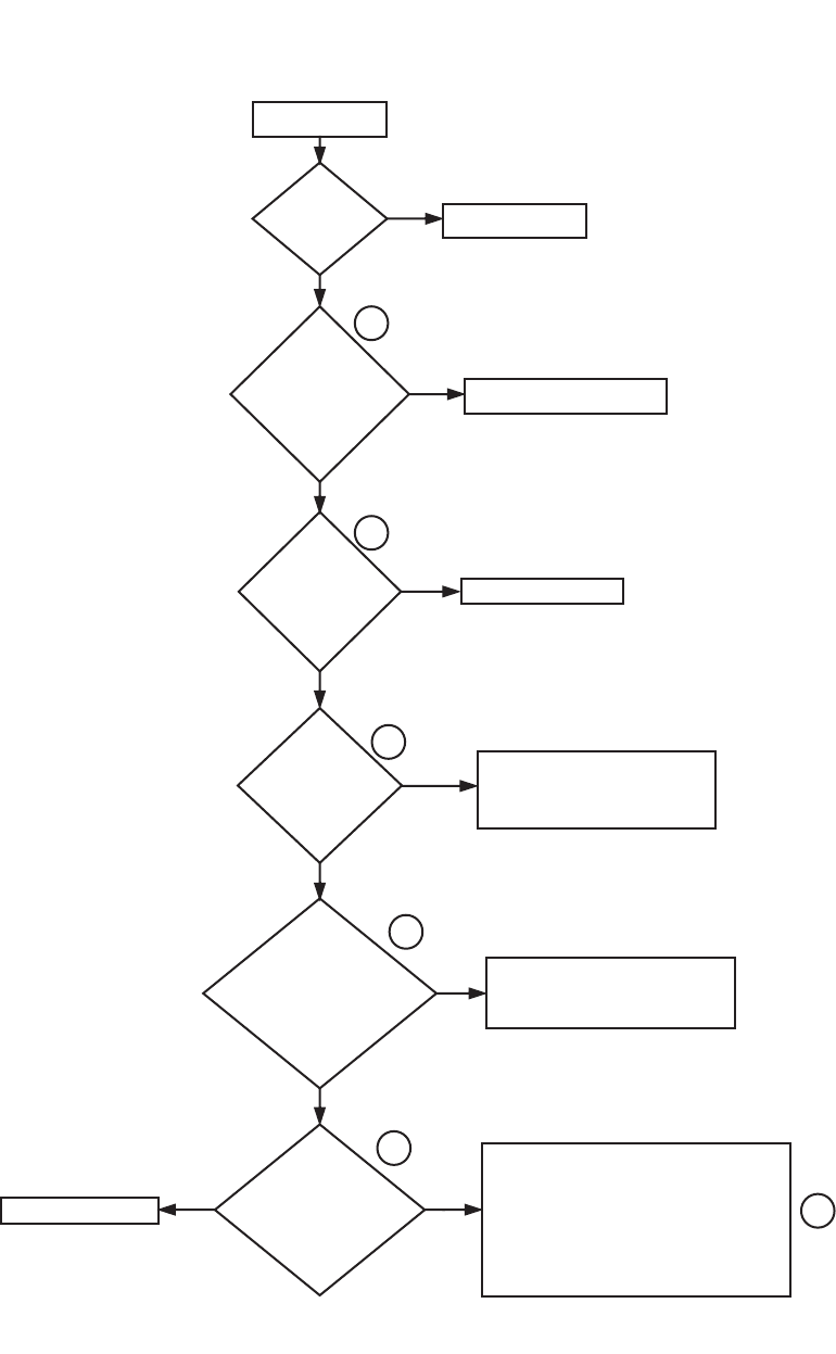
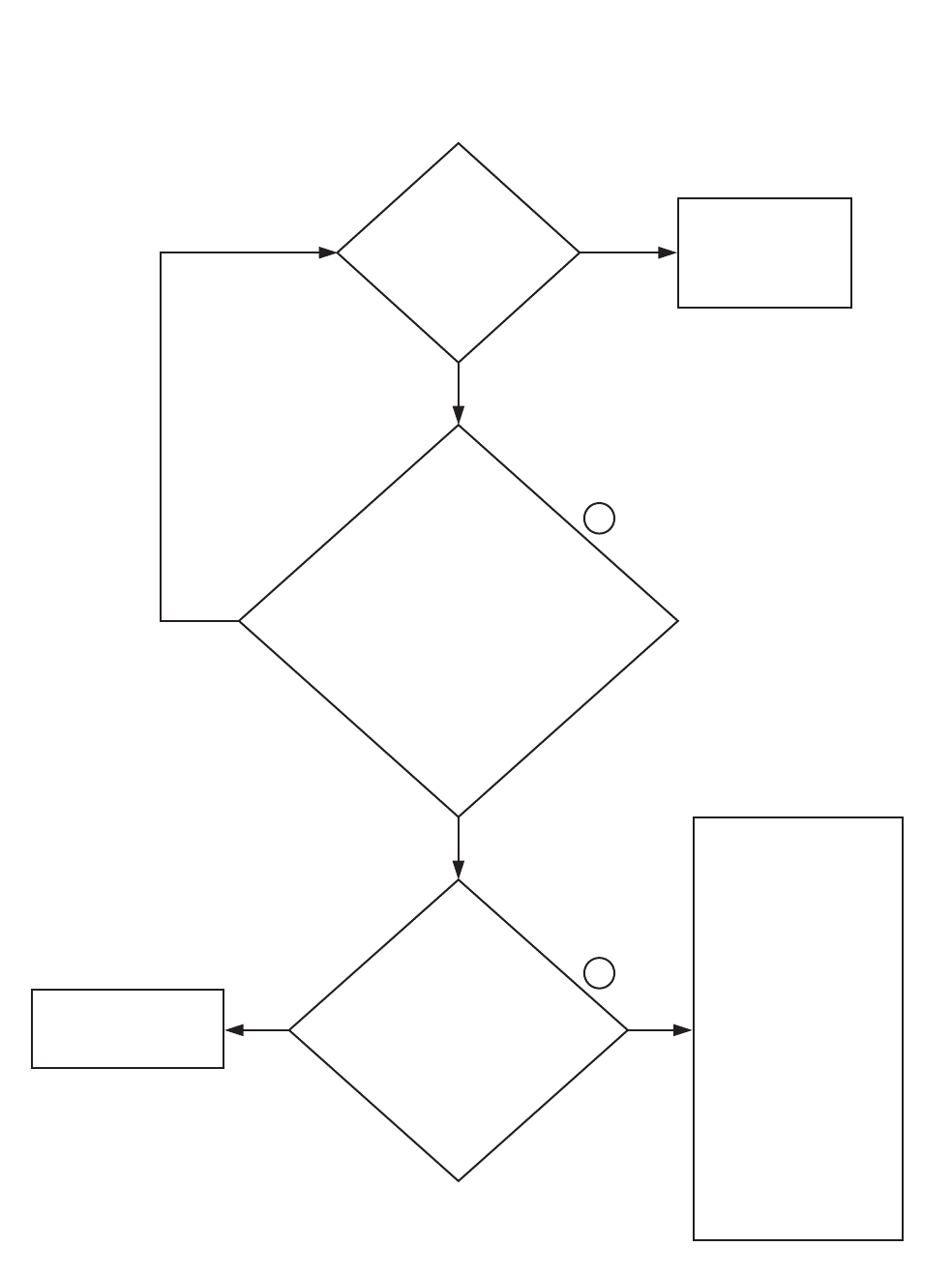
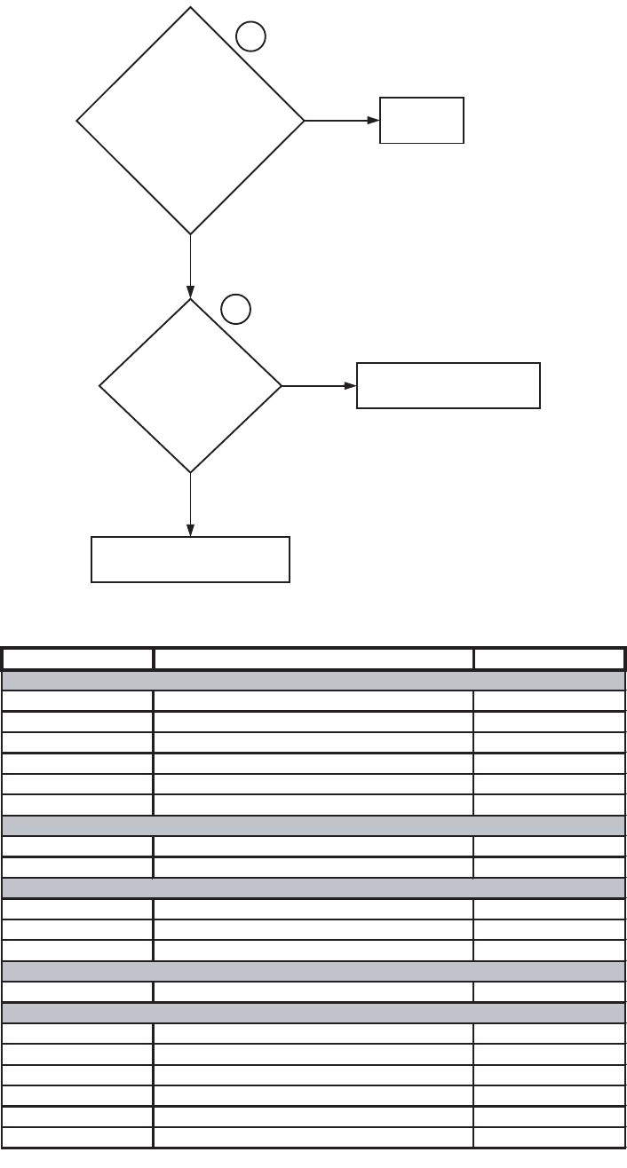
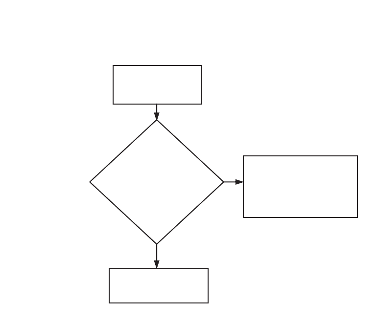
1. WE-8 CONTROL HAS NO VISIBLE DISPLAY (P AND N-VOLTAGE MODELS)
Is there
voltage
(200-240 Volts)
out of the
control
transformer?
Is there
voltage
(380-480 Volts)
into the control
transformer?
The WE-8 control has
no visible display.
Is
the main
power circuit
breaker
on?
Turn on the main power
circuit breaker.
NO
YES
Replace the 3.15 Amp fuse.
NO
Is there
voltage (120
Volts) into
and out of the
3.15 Amp
fuse?
YES
Reset and return (either by pulling or by
twisting and pulling) the E-stop switch.
If, after resetting and returning, there is
still no voltage, replace the E-stop
switch.
Check the L2 (blue) and L1 (brown) wires
between the E-stop switch and the power
connector on the main board. Repair or
replace the wires as needed.
Check the cable between the main board
and the keypad for any loose or broken
connections. Repair or replace the cable
as needed.
If the cable is intact, please contact
Alliance Laundry Systems’ customer
service department before replacing
the main board, keypad or cable between
the main board and keypad.
Is there
voltage (120
Volts) into and
out of both sides of
the E-stop
switch?
NO
Is there
voltage (220
Volts) between the
L2 (blue) and L1 (brown)
wires going into the
power connector
on the main
board?
Is the
125 mA fuse
below the power
connector on the
main board blown?
An ohms test is the
recommended
check for
the fuse.
YES
YES
NO
YES
NO
1
2
3
4
5
YES
6
NO
Check the wiring between the main
power block and the control transformer.
Repair or replace the wiring as needed.
Replace the 125 mA fuse.
Replace the control transformer.
NO
YES
7
CFD2S
9001900 11
Section 3 Troubleshooting
© Copyright, Alliance Laundry Systems LLC – DO NOT COPY or TRANSMIT
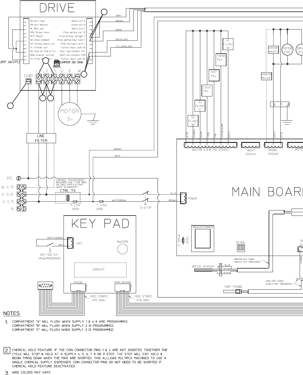
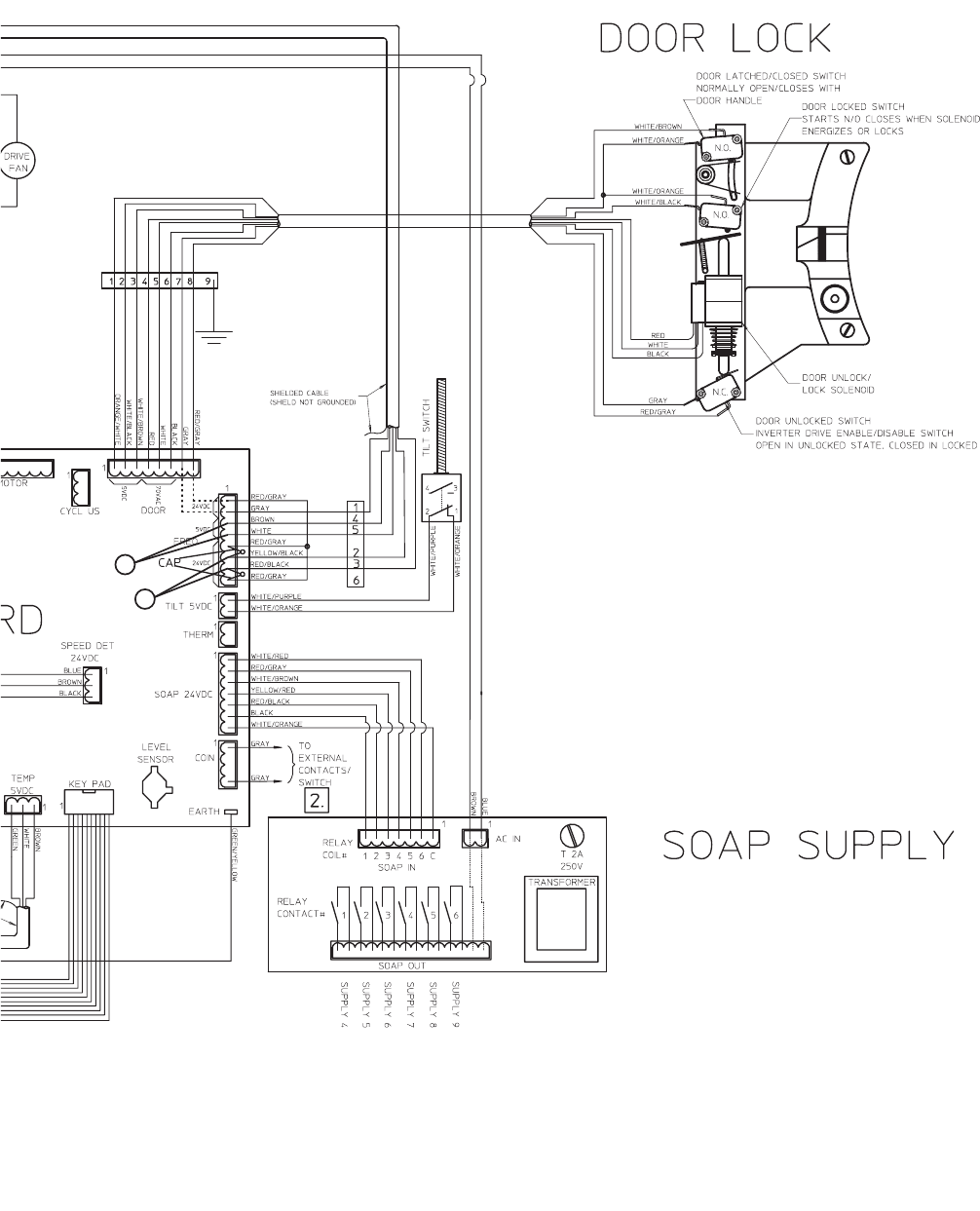
Please refer to the following 2 pages for wiring diagram information.
12 9001900
Section 3 Troubleshooting
© Copyright, Alliance Laundry Systems LLC – DO NOT COPY or TRANSMIT
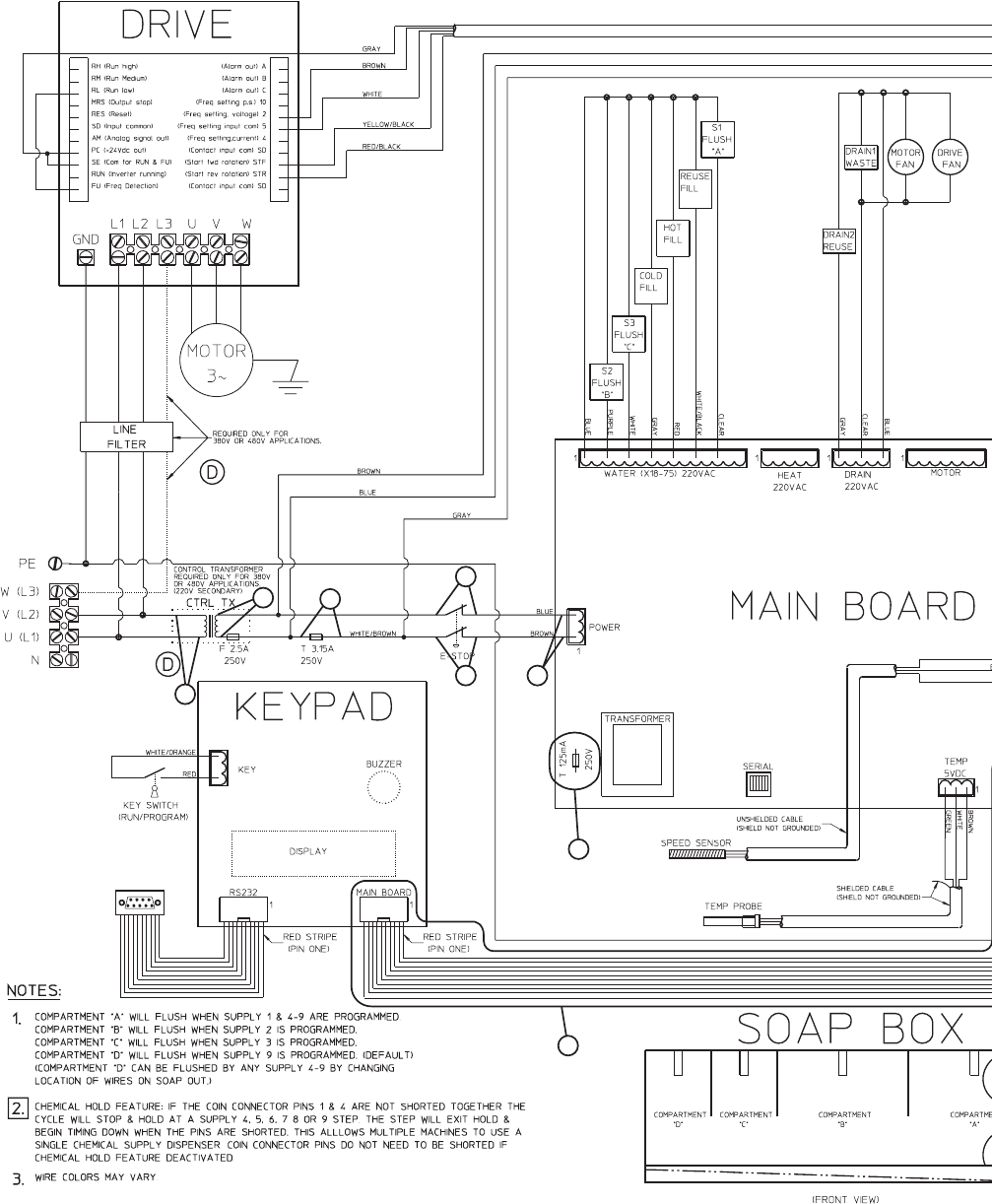
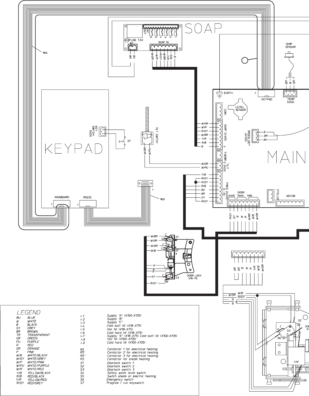
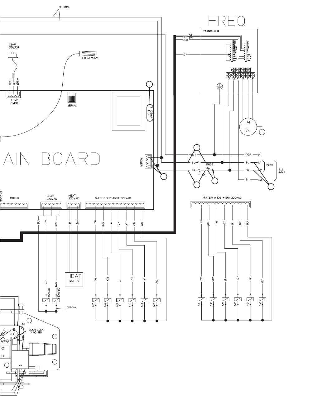
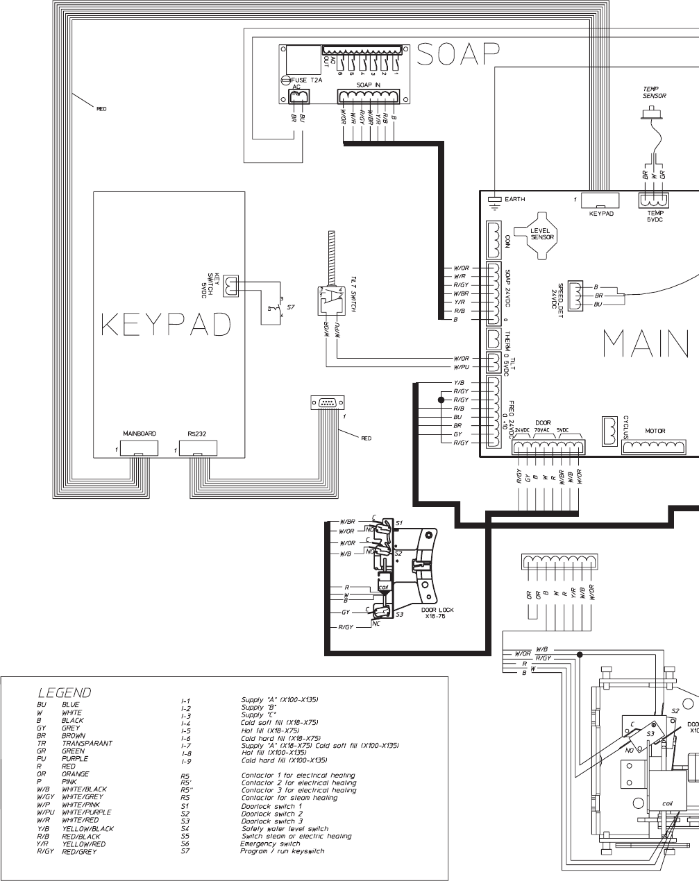
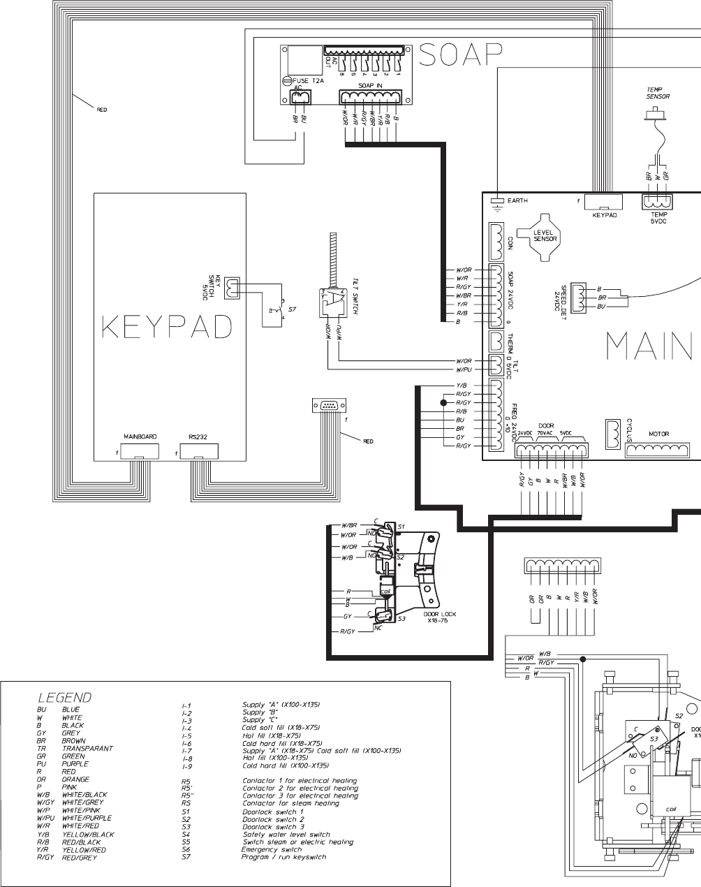
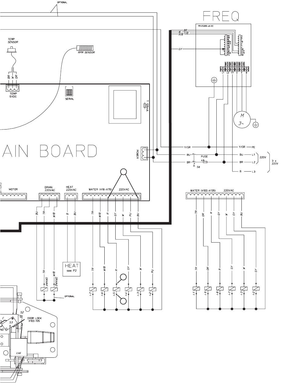
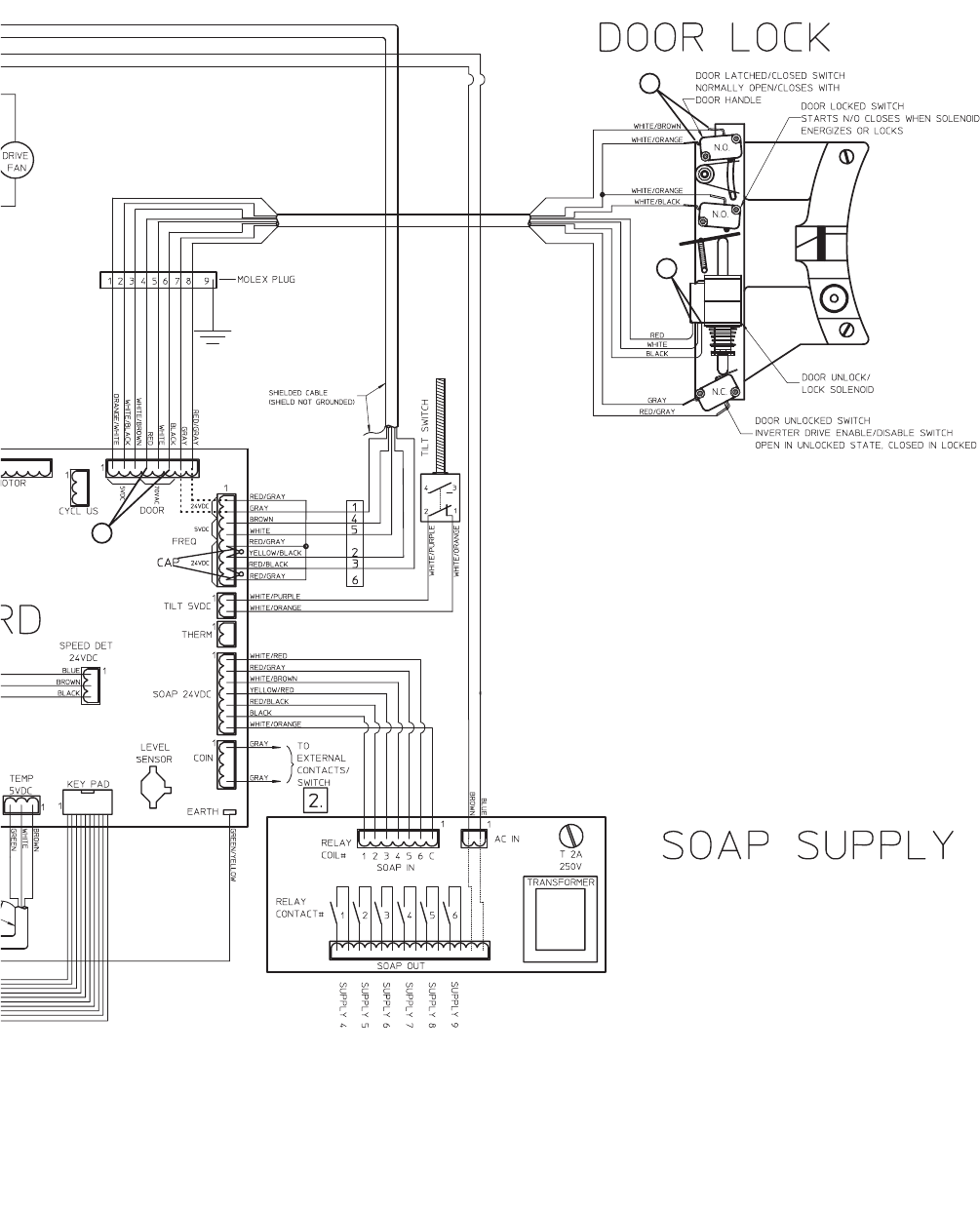
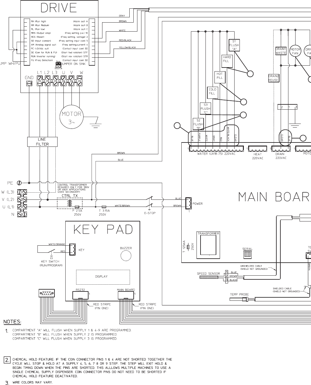
WE-8 Control Has No Visible Display (P and N-Voltage Models) (Sheet 1 of 2)
NOTE: Refer to the wiring diagram supplied with your machine.
7
6
54
4
3
2
1
9001900 13
Section 3 Troubleshooting
© Copyright, Alliance Laundry Systems LLC – DO NOT COPY or TRANSMIT
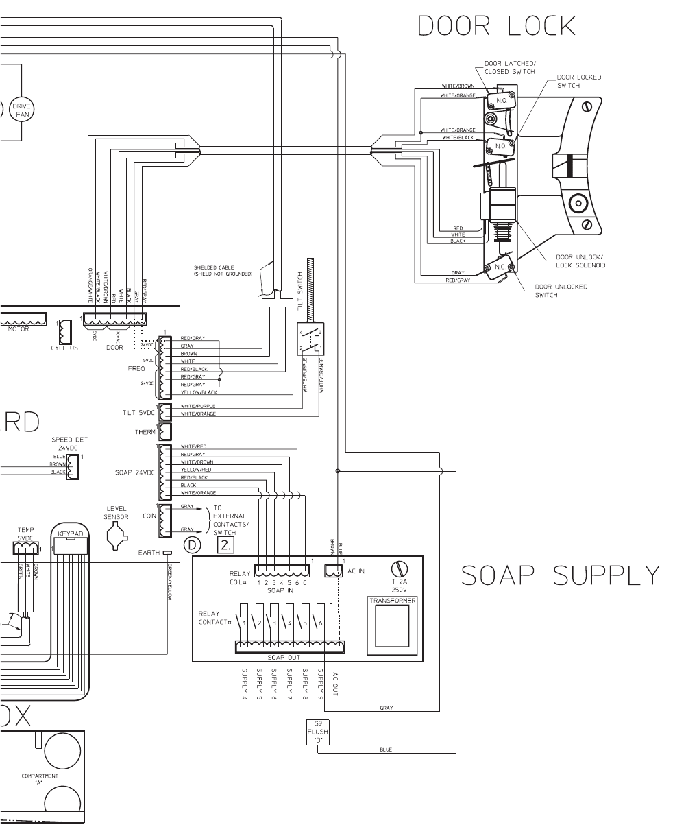
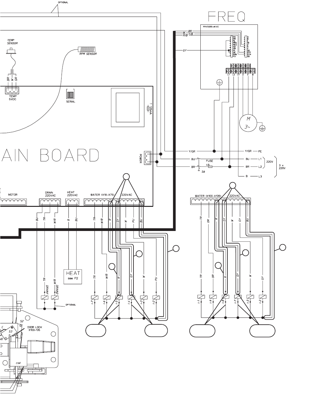
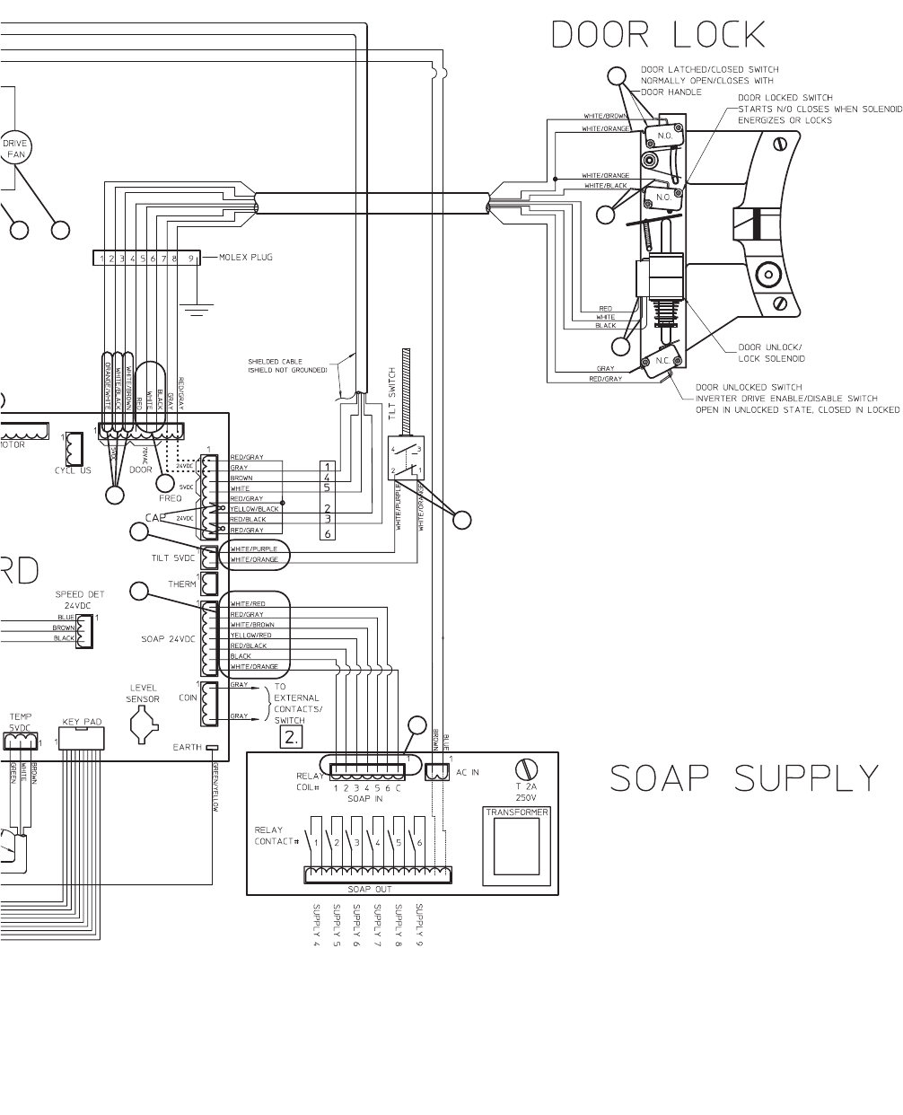
WE-8 Control Has No Visible Display (P and N-Voltage Models) (Sheet 2 of 2)
CFD3S
063787600D
14 9001900
Section 3 Troubleshooting
© Copyright, Alliance Laundry Systems LLC – DO NOT COPY or TRANSMIT
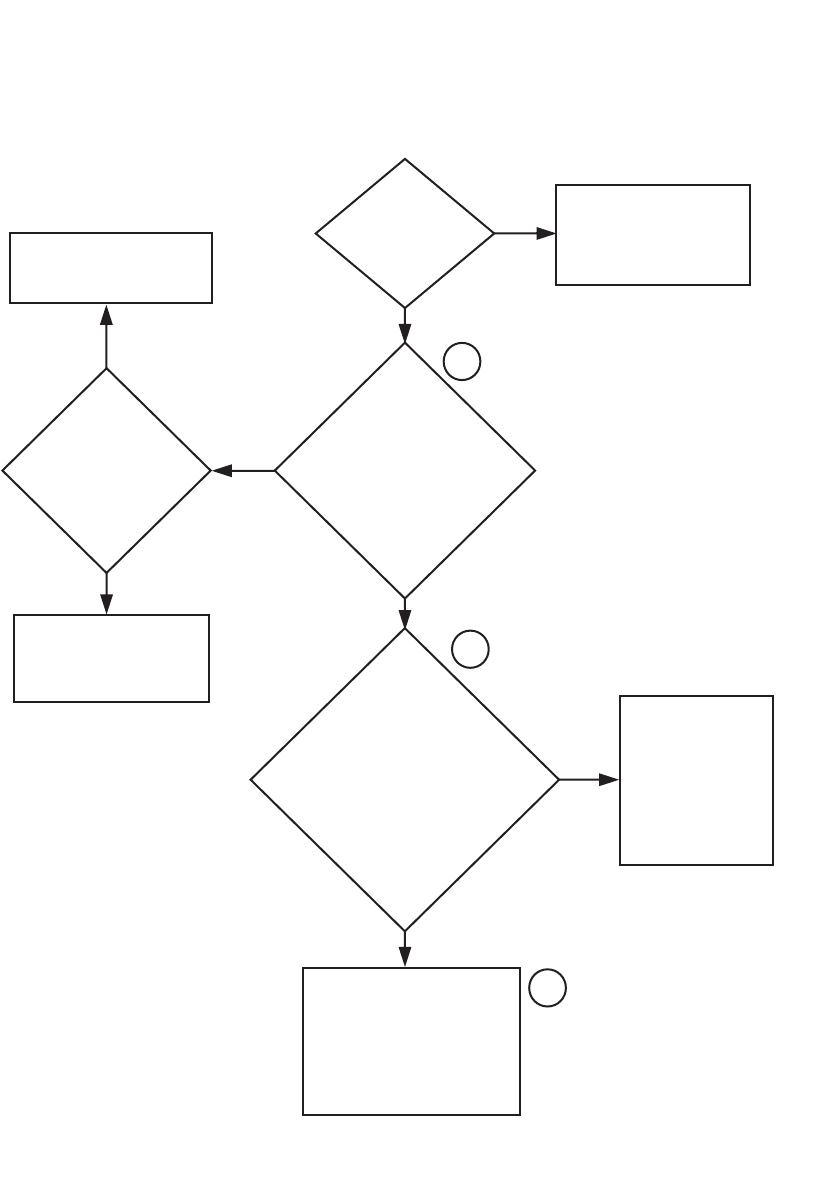
2. WE-8 CONTROL HAS NO VISIBLE DISPLAY (Q AND X-VOLTAGE MODELS)
Is there
Voltage (120
Volts) into
and out of the
3.15 Amp
fuse?
NO
YES
NO
Reset and return (either by pulling or by
twisting and pulling) the E-stop switch.
If, after resetting and returning, there is
still no voltage, replace the E-stop
switch.
Check the L2 (blue) and L1 (brown) wires
between the E-stop switch and the power
connector on the main board. Repair or
replace the wires as needed.
Check the cable between the main board
and the keypad for any loose or broken
connections. repair or replace the cable
as needed.
If the cable is intact, please contact
Alliance Laundry Systems’ customer
service department before replacing
the main board, keypad or cable between
the main board and keypad.
Is there
voltage (120
Volts) into and
out of both sides of
the e-stop
switch?
Is there
voltage (220
Volts) between the
L2 (blue) and L1 (brown)
wires going into the
power connector
on the main
board?
Is the
125 mA fuse
above the power
connector on the
main board blown?
An ohms test is the
recommended
check for
the fuse.
YES
NO
YES
NO
2
1
3
4
YES
5
6
NO
Replace the 3.15 Amp fuse.
Replace the 125 mA fuse.
YES
CFD4S
The WE-8 control has
no visible display.
Is
the main
power circuit
breaker
on?
Turn on the main power
circuit breaker.
NO
YES
Is
there
voltage
(200-240 Volts)
coming out of the
main power block
between wires
L2 (blue) and
L1 (brown)?
Check the main power circuit
breaker and power to the machine.
9001900 15
Section 3 Troubleshooting
© Copyright, Alliance Laundry Systems LLC – DO NOT COPY or TRANSMIT
Please refer to the following 2 pages for wiring diagram information.
16 9001900
Section 3 Troubleshooting
© Copyright, Alliance Laundry Systems LLC – DO NOT COPY or TRANSMIT
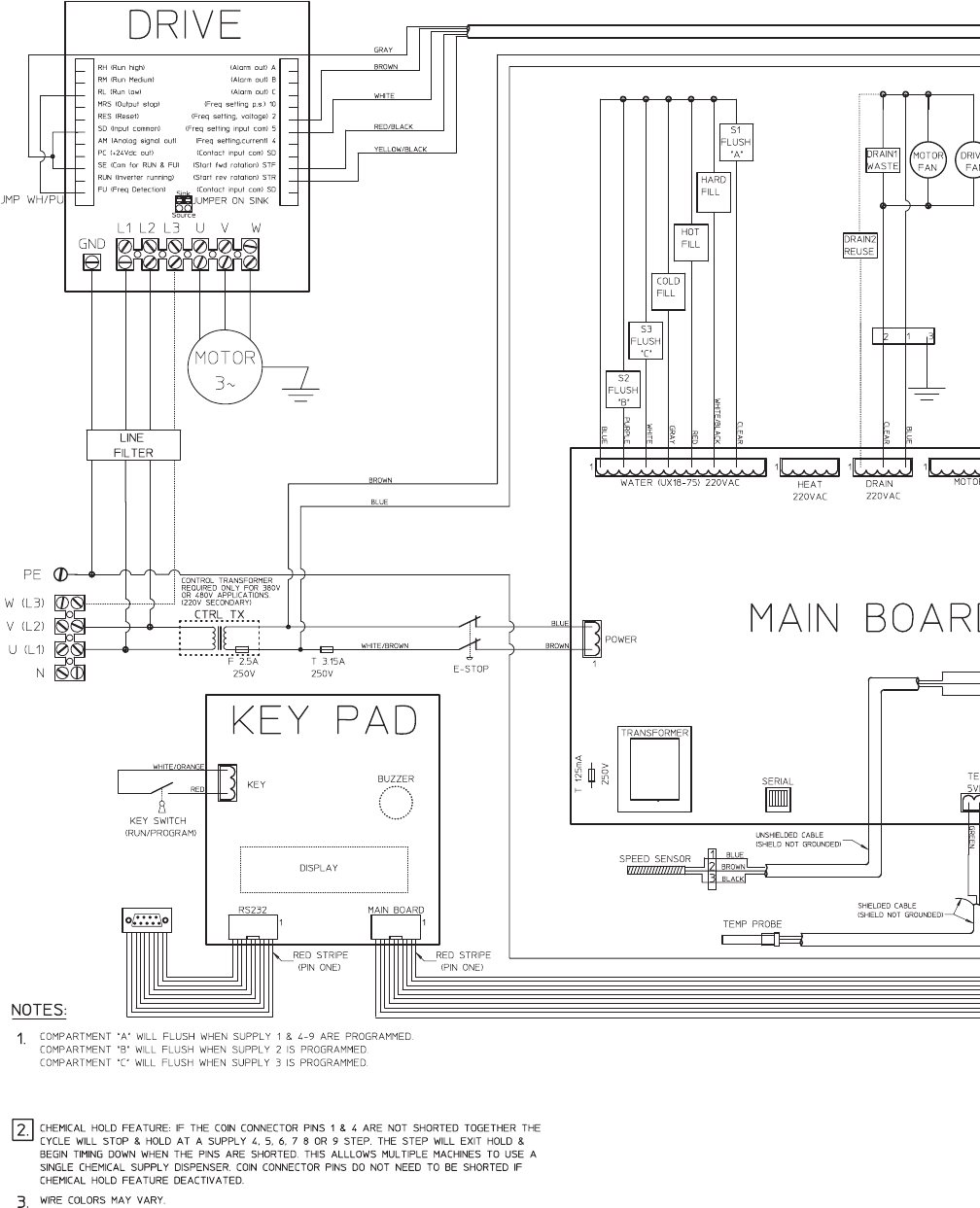
WE-8 Control Has No Visible Display (Q and X-Voltage Models) (Sheet 1 of 2)
NOTE: Refer to the wiring diagram supplied with your machine.
6
9001900 17
Section 3 Troubleshooting
© Copyright, Alliance Laundry Systems LLC – DO NOT COPY or TRANSMIT
WE-8 Control Has No Visible Display (Q and X-Voltage Models) (Sheet 2 of 2)
CFD5S
3
3.15 A
4
5
31
2
18 9001900
Section 3 Troubleshooting
© Copyright, Alliance Laundry Systems LLC – DO NOT COPY or TRANSMIT
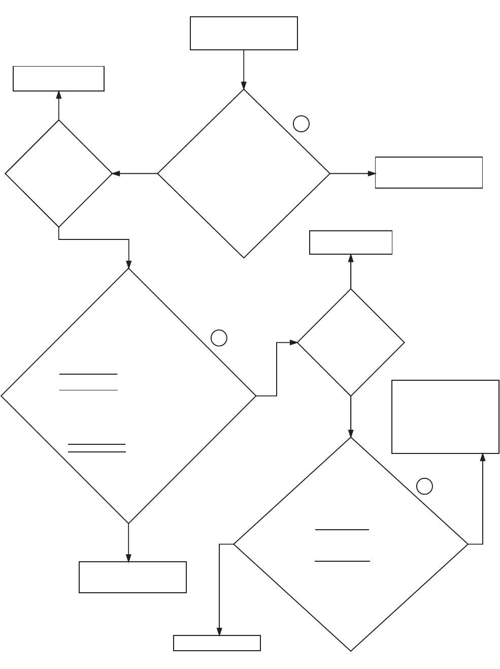
3. NO FILL ANALYSIS
CFD18S
NO
NO
Check the wiring between the
main board and the water valve
that has been programmed to
turn on. Repair or replace the
wiring as needed.
Note: There may be a modular
connector between the wire
and the main board.
2
1
3
YES
Replace or repair the
mechanical parts of the valve
with a repair kit if available. If
a repair kit isn’t available,
replace the entire valve.
YES
NO
Assuming that all
checks were done
correctly, replace the
main board or contact
Alliance Laundry
Systems’ customer
service department to
verify that all checks
have been done
correctly.
Is
there water
coming in through
the water supply
lines?
Check the main water valve
shut-offs to make sure that
they are turned on. Check
inside of the water hoses and
in-line screens for any
blockages.
NO
YES
YES
Is there voltage
(220 Volts) between the
two wires of the
water valve that
has been
programmed to turn
on?
Is
there voltage
(220 Volts) between
the wire from the main
board harness on the water
valve that has been programmed
to turn on?
The red wire is the hot fill,
the gray wire is the cold fill
and the blue wire
is the neutral.
Is there
magnetism within
the center
walls of the
valve
solenoid?
Replace the valve’s solenoid if
available. If the solenoid isn’t
available, replace the entire
valve.
9001900 19
Section 3 Troubleshooting
© Copyright, Alliance Laundry Systems LLC – DO NOT COPY or TRANSMIT
Please refer to the following 2 pages for wiring diagram information.
20 9001900
Section 3 Troubleshooting
© Copyright, Alliance Laundry Systems LLC – DO NOT COPY or TRANSMIT
No Fill Analysis (Sheet 1 of 2)
NOTE: Refer to the wiring diagram supplied with your machine.
9001900 21
Section 3 Troubleshooting
© Copyright, Alliance Laundry Systems LLC – DO NOT COPY or TRANSMIT
No Fill Analysis (Sheet 2 of 2)
CFD19S
1 Hot Fill
X18 - 75
3
2
2
3
3
3
3
3
1 Cold Fill
X18 - 75 1 Hot Fill
X100 - 135 1 Cold Fill
X100 - 135
22 9001900
Section 3 Troubleshooting
© Copyright, Alliance Laundry Systems LLC – DO NOT COPY or TRANSMIT
4. WATER RUNS CONTINUOUSLY INTO THE WASHER-EXTRACTOR
CFD20S
1
Turn the main
power to the
machine off.
Does the water
shut off?
2
YES
Clean the valve or
install a repair kit inside
the valve if available. If
a repair kit isn
’
t
available, replace the
entire valve.
NO
NO
Is there voltage (220 Volts)
between the two wires of the
solenoid on the water valve
that is staying on?
For example, if the 1-5 (hot fill
on X18-75) is staying on, is
there voltage (220 Volts)
between the common (red) and
neutral (blue) wires of the
solenoid?
Is the
main board
(water) harness
connected correctly
as shown on the wiring
schematic and is it intact?
Note: Make sure there are
no wires loose, shorted
or disconnected
from the main
board (water)
harness.
Repair or replace the
main board (water)
harness as needed.
Check the microprocessor
display to make sure that
the microprocessor isn
’
t
calling for the water
valve to turn on when it
shouldn
’
t be. If it is, turn
off the power to the machine
for at least 20 seconds and
then turn the power back
on. Make sure that the
display reads “CYCLE 00.”
If the microprocessor is
still calling for the water
valve to turn on when it
shouldn
’
t be, assuming
that all checks were done
correctly, replace the
main board or contact
Alliance Laundry Systems
’
customer service
department to verify that
all checks have been done
correctly.
NOTE: This information applies to the three main fill valves as well as the three supply valves. The first task in this
process is to determine which valve is staying on. This may be done by individually shutting off the water supply t
o
each valve. Find the location where the water is flushing into the machine and follow the hose back to the solenoi
d
Once the valve has been identified, proceed as follows:
NO
YES
YES
9001900 23
Section 3 Troubleshooting
© Copyright, Alliance Laundry Systems LLC – DO NOT COPY or TRANSMIT
Please refer to the following 2 pages for wiring diagram information.
24 9001900
Section 3 Troubleshooting
© Copyright, Alliance Laundry Systems LLC – DO NOT COPY or TRANSMIT
Water Runs Continuously into the Washer-Extractor (Sheet 1 of 2)
NOTE: Refer to the wiring diagram supplied with your machine.
9001900 25
Section 3 Troubleshooting
© Copyright, Alliance Laundry Systems LLC – DO NOT COPY or TRANSMIT
Water Runs Continuously into the Washer-Extractor (Sheet 2 of 2)
CFD21S
2
1
1

26 9001900
Section 3 Troubleshooting
© Copyright, Alliance Laundry Systems LLC – DO NOT COPY or TRANSMIT
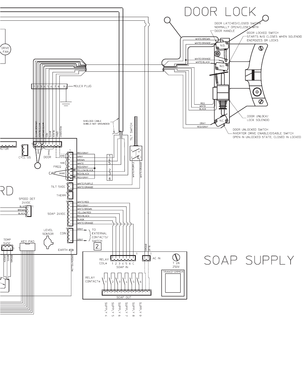
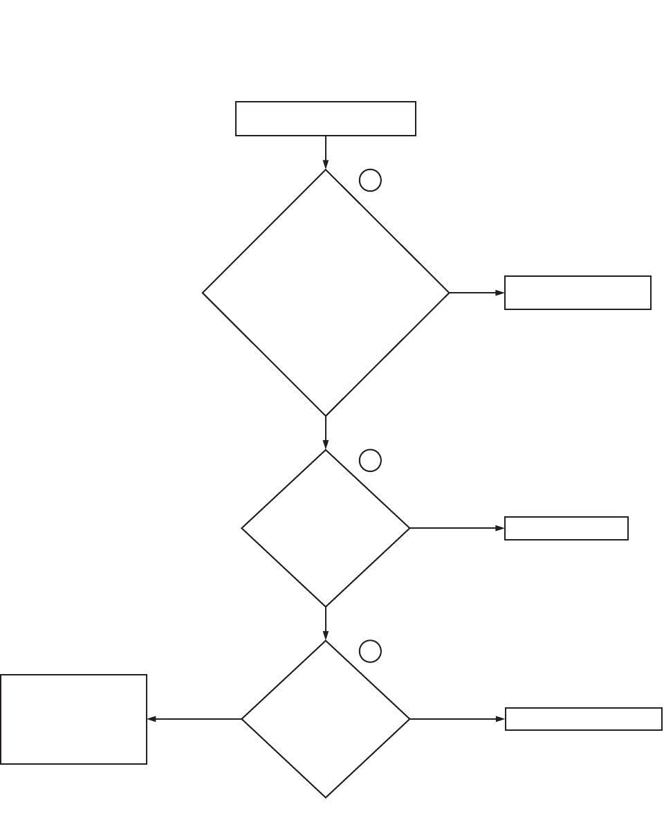
5. DOOR LOCK SWITCH ANALYSIS: DISPLAY SHOWS “DOOR ERROR”
CFD1993S
1
The display reads “door error”.
Check
the wiring from the
door terminal on the main
board to the molex plug
(75-165 models only)
and from the molex plug to
the door lock switches and
solenoid. Is the wiring intact
and properly
connected?
YES
2
3
Repair/replace the wiring as
needed.
NO
Is
there voltage (70
Volts AC) between
the white/brown and
white/orange wires
on the top
switch?
Replace the top switch.
YES
Is
there voltage (70
Volts AC) between
the black and red
wires wires on the
solenoid?
NO
Replace the solenoid.
YES
Is
there voltage (70
Volts AC) between the
black and red
terminals on the main
board's door
terminal?
NO
Replace the main board.
NO
YES
9001900 27
Section 3 Troubleshooting
© Copyright, Alliance Laundry Systems LLC – DO NOT COPY or TRANSMIT
Please refer to the following 2 pages for wiring diagram information.

28 9001900
Section 3 Troubleshooting
© Copyright, Alliance Laundry Systems LLC – DO NOT COPY or TRANSMIT
Door Lock Switch Analysis: Display Shows “Door Error” (Sheet 1 of 2)
NOTE: Refer to the wiring diagram supplied with your machine.
9001900 29
Section 3 Troubleshooting
© Copyright, Alliance Laundry Systems LLC – DO NOT COPY or TRANSMIT
Door Lock Switch Analysis: Display Shows “Door Error” (Sheet 2 of 2)
CFD1994S
UX75
1
2
3
30 9001900
Section 3 Troubleshooting
© Copyright, Alliance Laundry Systems LLC – DO NOT COPY or TRANSMIT
6. DOOR LOCK SWITCH ANALYSIS: DISPLAY READS “PLEASE CLOSE DOOR”
YES
1
The display reads
“
Please Close Door
”
.
Is
the door
closed?
2
Close the door.
NO
Check
the orange/white and
white/brown wires from the door
terminal on the main board,
through the molex plug (75-165
models only) and from the molex
plug to the door lock top door
switch. Is the wiring intact and
properly connected?
Repair/replace the wiring as
needed.
YES
NO
Check the top switch with a
continuity test to see if it opens
and closes properly. Replace
the switch if it does not open
and close properly.
CFD1995S
9001900 31
Section 3 Troubleshooting
© Copyright, Alliance Laundry Systems LLC – DO NOT COPY or TRANSMIT
Please refer to the following 2 pages for wiring diagram information.
32 9001900
Section 3 Troubleshooting
© Copyright, Alliance Laundry Systems LLC – DO NOT COPY or TRANSMIT
Door Lock Switch Analysis: Display Reads “Please Close Door” (Sheet 1 of 2)
NOTE: Refer to the wiring diagram supplied with your machine.
9001900 33
Section 3 Troubleshooting
© Copyright, Alliance Laundry Systems LLC – DO NOT COPY or TRANSMIT
Door Lock Switch Analysis: Display Reads “Please Close Door” (Sheet 2 of 2)
CFD1996S
UX75
1
1
2
34 9001900
Section 3 Troubleshooting
© Copyright, Alliance Laundry Systems LLC – DO NOT COPY or TRANSMIT
7. DOOR LOCK SWITCH ANALYSIS: “DOOR WON’T UNLOCK”
1
The display reads
“
Please Open the
Door
”
, but the door can't be opened.
2
NO
Check
the black and white wires
from the door terminal on the
main board, through the molex
plug (75-165 models only) and
from the molex plug to the door
solenoid. Is the wiring
intact and properly
connected?
YES
Repair/replace the wiring as
needed.
Is
there voltage (70
Volts AC) between the
black and white
terminals on the main
board's door
terminal?
Replace the main board.
NO
Is
there voltage (70
Volts AC) between the
black and white
terminals on the door
lock solenoid?
YES
3
Replace the door lock solenoid.
NO
Is there voltage (70 Volts AC)
on the wiring between the
computer board and the door
lock solenoid?
Repair/replace the wiring as
needed.
YES
CFD1997S
9001900 35
Section 3 Troubleshooting
© Copyright, Alliance Laundry Systems LLC – DO NOT COPY or TRANSMIT
Please refer to the following 2 pages for wiring diagram information.
36 9001900
Section 3 Troubleshooting
© Copyright, Alliance Laundry Systems LLC – DO NOT COPY or TRANSMIT
Door Lock Switch Analysis: “Door Won’t Unlock” (Sheet 1 of 2)
NOTE: Refer to the wiring diagram supplied with your machine.
9001900 37
Section 3 Troubleshooting
© Copyright, Alliance Laundry Systems LLC – DO NOT COPY or TRANSMIT
Door Lock Switch Analysis: “Door Won’t Unlock” (Sheet 2 of 2)
CFD1998S
UX75
1
1
3
2
3
38 9001900
Section 3 Troubleshooting
© Copyright, Alliance Laundry Systems LLC – DO NOT COPY or TRANSMIT
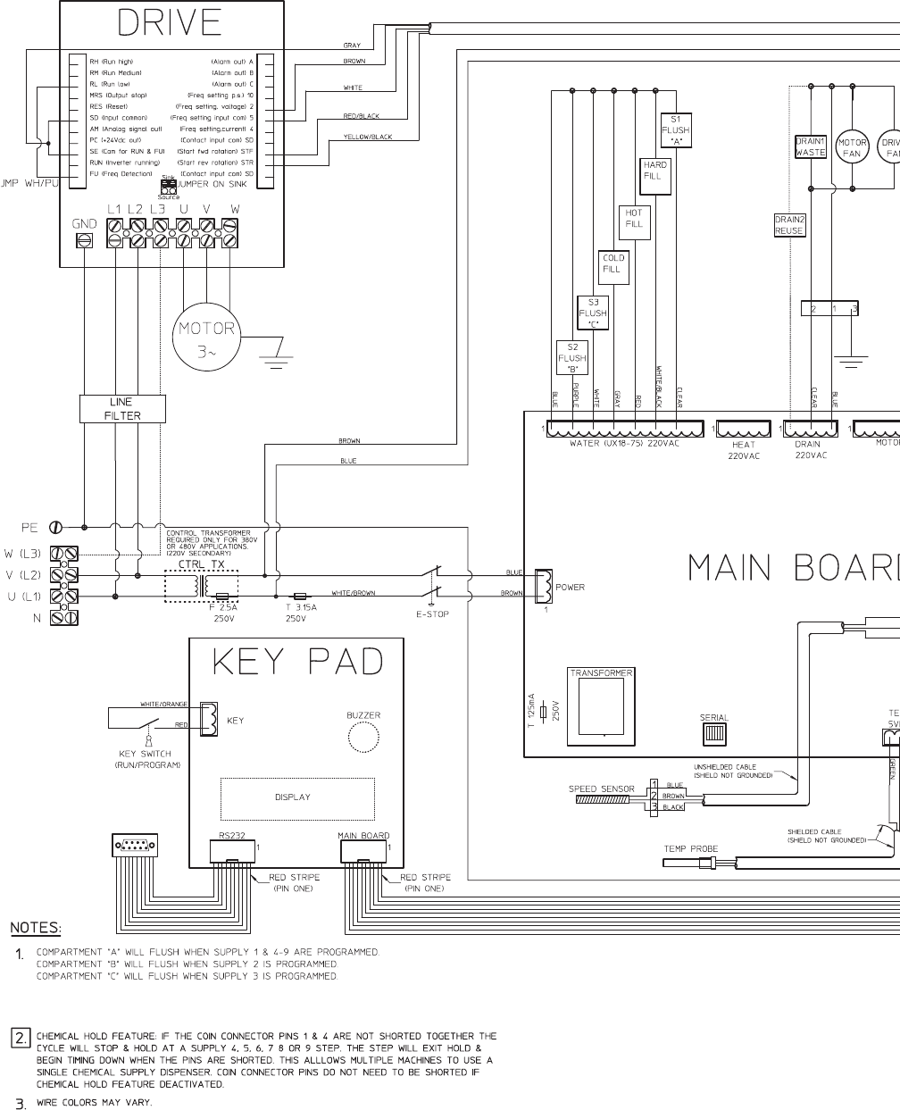
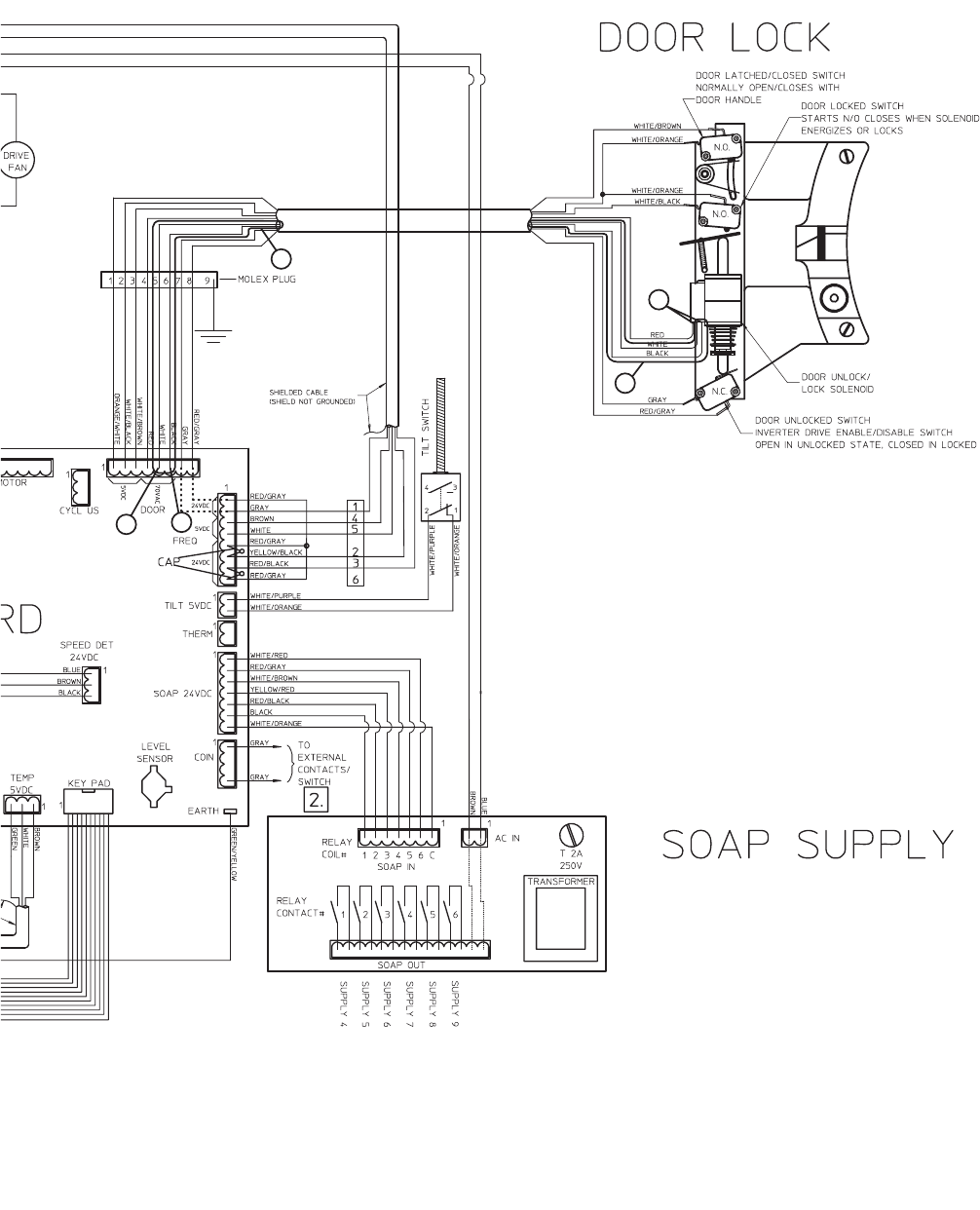
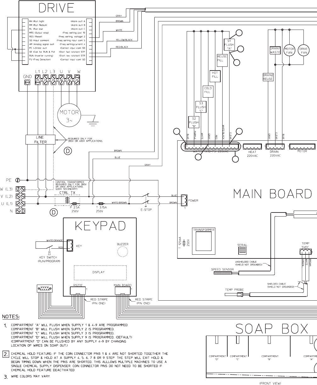
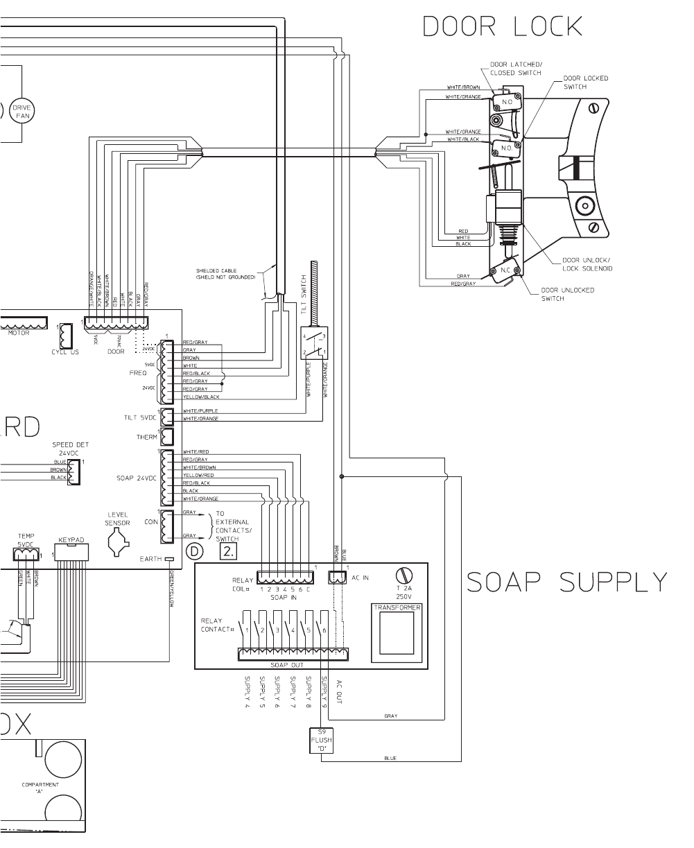
8. NO OUTPUT VOLTAGE TO COMPONENTS
Figure 1
Component Voltage Reading Points Voltage Reading
Water
Flush A Clear wire to Blue wire 220 Volts AC
Hard Fill White/Black wire to Blue wire 220 Volts AC
Hot Fill Red wire to Blue wire 220 Volts AC
Cold Fill Gray wire to Blue wire 220 Volts AC
Flush C White wire to Blue wire 220 Volts AC
Flush B Purple wire to Blue wire 220 Volts AC
Drain
Drain Motor Fan Clear wire to Blue wire 220 Volts AC
Drive Fan Clear wire to Blue wire 220 Volts AC
Door
Door Latch Switch Orange/White wire to White/Brown wire 5 Volts DC
Door Lock Switch Orange/White wire to White/Black wire 5 Volts DC
Door Solenoid Black wire to Red or White wire 70 Volts AC
Tilt
Tilt White/Purple wire to White/Orange wire 5 Volts DC
Soap
S4 White/Orange wire to Black wire 24 Volts DC
S5 Red/Black wire to Black wire 24 Volts DC
S6 Yellow/Red wire to Black wire 24 Volts DC
S7 White/Brown wire to Black wire 24 Volts DC
S8 Red/Gray wire to Black wire 24 Volts DC
S9 White/Red wire to Black wire 24 Volts DC
Component Voltage/Reading Points Chart
CFD2000S
Figure 1
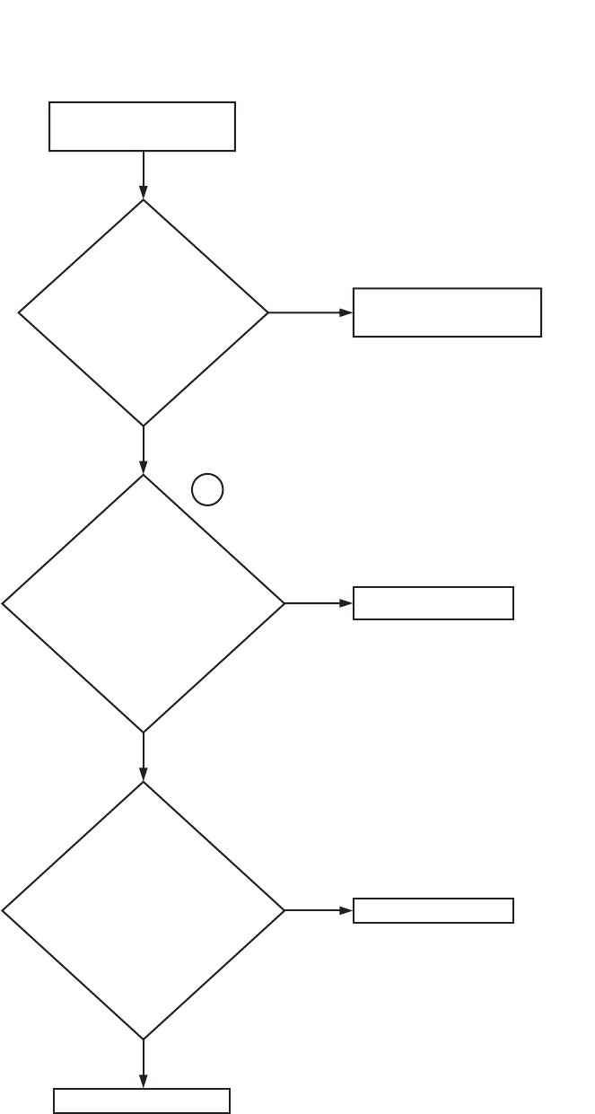
1
Is there
voltage (refer to
Figure 1) on the main
board terminals that
the wires going to the
component are
connected
to?
2
Replace the
main board.
NO
Repair/replace the wiring as
needed.
YES
NO
Is
there
voltage (refer to
Figure 1) on the
wires on the input
side of the
components?
Repair/replace the component
as needed.
YES
9001900 39
Section 3 Troubleshooting
© Copyright, Alliance Laundry Systems LLC – DO NOT COPY or TRANSMIT
Please refer to the following 2 pages for wiring diagram information.
40 9001900
Section 3 Troubleshooting
© Copyright, Alliance Laundry Systems LLC – DO NOT COPY or TRANSMIT
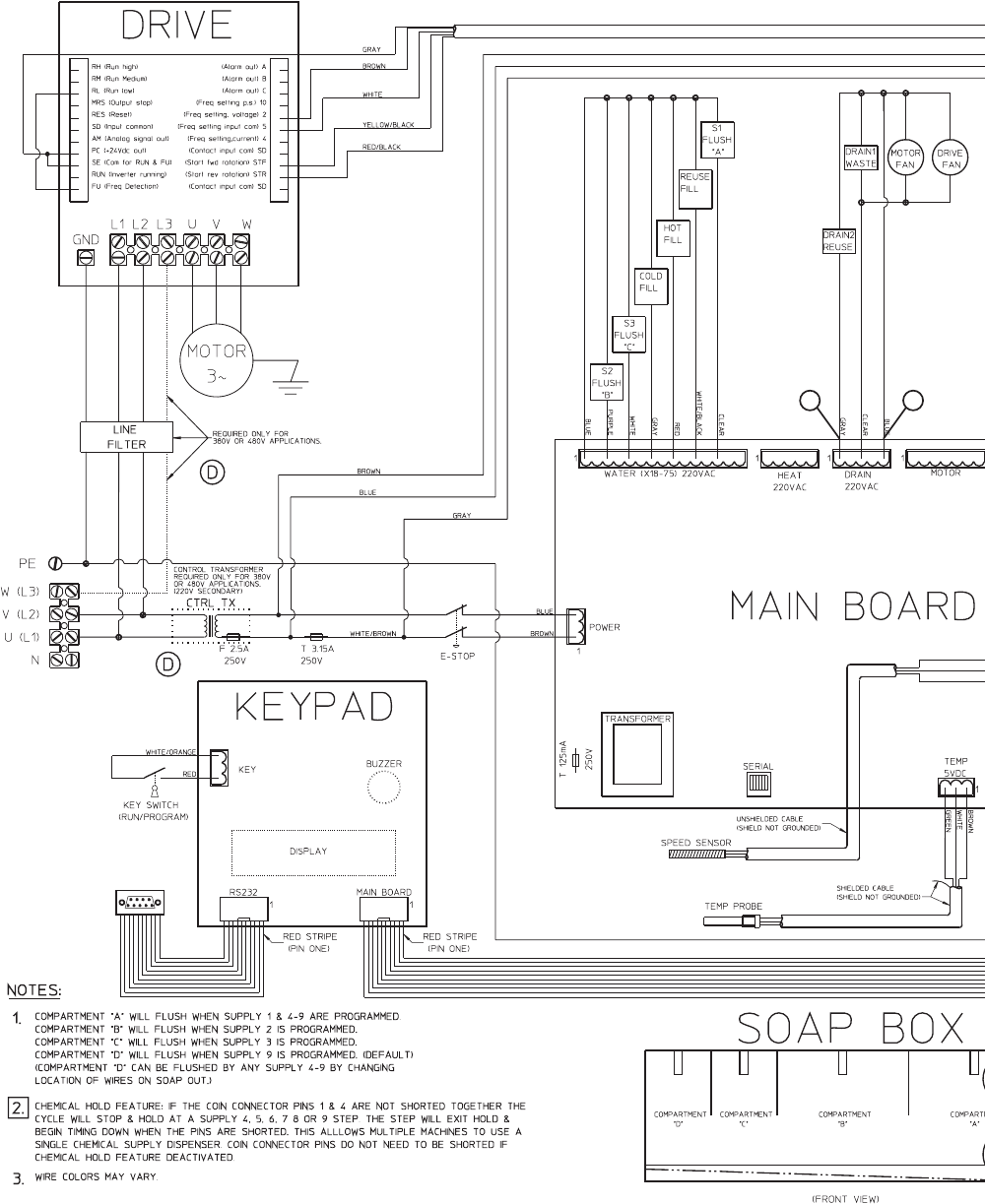
No Output Voltage to Components (Sheet 1 of 2)
NOTE: Refer to the wiring diagram supplied with your machine.
1
2
2
2
2
1
9001900 41
Section 3 Troubleshooting
© Copyright, Alliance Laundry Systems LLC – DO NOT COPY or TRANSMIT
No Output Voltage to Components (Sheet 2 of 2)
CFD2001S
UX75
2 2
2
2
2
2
2
11
1
1
42 9001900
Section 3 Troubleshooting
© Copyright, Alliance Laundry Systems LLC – DO NOT COPY or TRANSMIT
9. NO MOTOR OPERATION WITH NO AC DRIVE FAULT
CFD2002S
1
The motor does not operate and
there are no apparent AC drive
faults present.
For
single-phase models, is
there voltage (200 Volts AC)
from L1 to L2 on the AC drive?
For 3-phase models, is there
voltage (200 Volts AC) from L1
to L2, from L1 to L3 and from
L2 to L3 on the
AC drive?
YES
2
3
Check for incoming voltage
from the main breaker to the
machine.
NO
Is the
drive system
(e.g., motor, belt,
pulleys) operating
properly?
Repair and/or replace the
drive system as needed.
NO
YES
Refer to the "No Motor
Operation (With AC Drive
Fault)" flowchart.
YES
Are
the wires on
the FREQ terminal
on the Main Board
connected
properly?
Repair and/or replace
the wires as needed.
NO
YES
Are the
following voltage (24 Volts DC)
readings present?
Forward Rotation (STF):
From the red/black wire to the brown wire.
From the red/black wire to the white wire.
Reverse Rotation (STR):
From the yellow/black wire to the brown
wire. From the yellow/black wire to the
white wire.
NO
Replace the main board.
NO
Check the AC drive parameter
settings.
Contact Alliance Laundry
Systems' Customer Service
Department for the parameter
setting for your machine.
YES
For 18, 25, 35 and 55 - pound capacity
models, are the following voltage (24 Volts
DC) readings present? NOTE: The readings
must be taken during a cycle.
Forward Rotation: From the stf to the white
wire and from the stf to the brown wire
Reverse Rotation: From the str to the white
wire and from the str to the brown wire
For 75, 100, 135 and 165 -pound capacity
models, are the following voltage (24 Volts
DC) readings present? NOTE: The readings
must be taken during a cycle.
Forward Rotation: From stf to ground
Reverse Rotation: From str to ground
9001900 43
Section 3 Troubleshooting
© Copyright, Alliance Laundry Systems LLC – DO NOT COPY or TRANSMIT
Please refer to the following 2 pages for wiring diagram information.
44 9001900
Section 3 Troubleshooting
© Copyright, Alliance Laundry Systems LLC – DO NOT COPY or TRANSMIT
No Motor Operation With No AC Drive Fault (Sheet 1 of 2)
NOTE: Refer to the wiring diagram supplied with your machine.
1
1 1
2
2
2
9001900 45
Section 3 Troubleshooting
© Copyright, Alliance Laundry Systems LLC – DO NOT COPY or TRANSMIT
No Motor Operation With No AC Drive Fault (Sheet 2 of 2)
CFD2003S
UX75
3
3
46 9001900
Section 3 Troubleshooting
© Copyright, Alliance Laundry Systems LLC – DO NOT COPY or TRANSMIT
10. NO MOTOR OPERATION WITH AC DRIVE FAULT
NO
Symptom: The Motor Is Not Running And There Is An Apparent AC Drive Fault Present.
YES
Install a parameter unit
and find the AC drive
fault present.
Refer to the “no motor
operation (with no AC drive
fault)” flow chart.
Find the fault code listed in the
chart shown on the following
pages. There is a corrective
action listed for each fault.
Perform the action listed for
the fault displayed.
CFD1999S
Try to
clear the
fault by powering
down the machine
and restoring power.
Does the
fault return?

9001900 47
Section 3 Troubleshooting
© Copyright, Alliance Laundry Systems LLC – DO NOT COPY or TRANSMIT
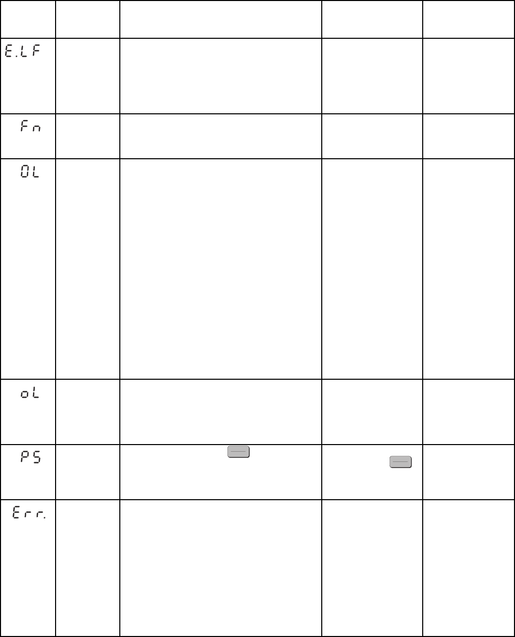
No Motor Operation With AC Drive Fault
Operation
Panel
Indication Name Description and NOTES Check point Corrective action
Overcurrent
shut-off during
acceleration
When the inverter output current reaches or exceeds
approximately 200% of the rated current during
acceleration, the protective circuit is activated to stop
the inverter output.
• Check for sudden
acceleration.
• Check for output
short-circuit/ground
fault.
Increase the
acceleration time.
Overcurrent
shut-off during
constant speed
When the inverter output current reaches or exceeds
approximately 200% of the rated current during
constant speed, the protective circuit is activated to
stop the inverter output.
• Check for sudden load
change.
• Check for output short-
circuit/ground fault.
Keep load stable.
Overcurrent
shut-off during
deceleration
When the inverter output current reaches or exceeds
approximately 200% of the rated current during
deceleration (other than acceleration or constant
speed), the protective circuit is activated to stop the
inverter output.
• Check for sudden speed
reduction.
• Check for output
short-circuit/ground
fault.
• Check for too fast
operation of motor's
mechanical brake.
Increase the
deceleration time.
Adjust brake operation.
Regenerative
overvoltage
shut-off during
acceleration
If regenerative energy causes the inverter's internal
main circuit DC voltage to reach or exceed the
specified value, the protective circuit is activated to
stop the inverter output. It may also be activated by a
surge voltage generated in the power supply system
Check for too slow
acceleration.
Decrease the
acceleration time.
Regenerative
overvoltage
shut-off during
constant speed
If regenerative energy causes the inverter's internal
main circuit DC voltage to reach or exceed the
specified value, the protective circuit is activated to
stop the inverter output. It may also be activated by a
surge voltage generated in the power supply system.
Check for sudden load
change.
Keep load stable. Use
the brake unit or high
power factor converter
(FR-HC) as required.
Regenerative
overvoltage
shut-off during
deceleration or
stop
If regenerative energy causes the inverter's internal
main circuit DC voltage to reach or exceed the
specified value, the protective circuit is activated to
stop the inverter output. It may also be activated by a
surge voltage generated in the power supply system.
Check for sudden speed
reduction.
• Increase the
deceleration time.
(Set the deceleration
time which matches
the inertia moment of
the load.)
• Decrease the braking
duty.
• Use the brake unit or
high power factor
converter (FR-HC) as
required.
Motor overload
shut-off
(electronic
overcurrent
protection)
The electronic overcurrent protection in the inverter
detects motor overheat due to overload or reduced
cooling capability during constant-speed operation to
stop the inverter output.When a multi-pole motor or
two or more motors are run, provide a thermal relay
in the output side of the inverter.
Check the motor for use
under overload. • Reduce the load
weight.
•For the
constant-torque
motor, change the Pr.
71 setting to the
constant-torque
motor setting.
Inverter
overload shut-
off (electronic
overcurrent
protection)
If a current of more than 150% of the rated output
current flows and overcurrent shut-off does not occur
(200% or less) inverse-time characteristics cause the
electronic overcurrent protection to be activated to
stop the inverter output in order to protect the output
transistors.
Note: Resetting the inverter initializes the internal
heat integrating data of the electronic overcurrent
protection.
Check the motor for use
under overload. Reduce the load
weight.
Fin overheat If the cooling fin overheats, the overheat sensor is
actuated to stop the inverter output.
• Check for too high
ambient temperature.
• Check for cooling fin
clogging.
Set the ambient
temperature to within
the specifications.

48 9001900
Section 3 Troubleshooting
© Copyright, Alliance Laundry Systems LLC – DO NOT COPY or TRANSMIT
Brake transistor
alarm detection If a brake transistor fault occurs due to excessively
large regenerative energy from the motor, for
example, that fault is detected to stop the inverter
output. In this case, the inverter power must be
switched off immediately.
Note: This function is activated only when the
optional brake resistor is connected.
Check for improper
braking duty. • Change the inverter.
• Please contact your
sales representative.
Output side
ground fault
overcurrent
protection
This function stops the inverter output if a ground
fault overcurrent flows due to a ground fault which
occurred in the inverter's output (load) side. Use Pr.
249 "ground fault detection at start” to set whether
the protective function is to be activated or not. (In the
400V class, the protective function is always active.)
Check for a ground fault
in the motor and
connection cable.
Remedy the ground
fault portion.
External
thermal relay
operation
If the external thermal relay designed for motor
overheat protection or the internally mounted
temperature relay in the motor switches on (contacts
open), the inverter output is stopped. If the relay
contacts are reset automatically, the inverter will not
restart unless it is reset.
Note: This function is activated only when OH has
been set to any of Pr. 180 to Pr. 183 (input terminal
function selection).
• Check for motor
overheating.
• Check that the value of
7 (OH signal) is set
correctly in any of Pr.
180 to Pr. 183 (input
terminal function
selection).
Reduce the load and
operating duty.
Stall prevention The running frequency has fallen to 0 by stall
prevention activated. (OL while stall prevention is
being activated.)
Check the motor for use
under overload. Reduce the load
weight.
Option alarm
Stops the
inverter output
if the inverter
station is
disconnected
from the system
in the NET
mode.
Also stops the inverter output if the dedicated option
used in the inverter results in setting error or
connection (connector) fault.
Note: Only when the FR-E5NC is fitted to the
three-phase 400V power input model.
Check that the plug-in
option connector is
plugged securely.
• Connect the plug-in
option securely.
• Please contact your
sales representative.
Parameter
storage device
alarm
A fault occurred in parameters stored (example:
E2PROM fault).
Check for too many
number of parameter
write times.
Please contact your
sales representative.
Parameter unit
disconnection This function stops the inverter output if
communication between the inverter and PU is
suspended, e.g. the PU is disconnected, when "2",
"3", "16" or "17" was set in Pr. 75. This function stops
the inverter output if the number of successive
communication errors is greater than the number of
permissible retries when the Pr. 121 value is "9999"
for RS-485 communication from the PU connector.
• Check for loose fitting
of the control panel
(FR-PA02-o2) or
FR-PU04.
• Check the Pr. 75 setting.
Fit the control panel
(FR-PA02-o2) and
FR-PU04 securely.
Retry count
exceeded If operation cannot be resumed properly within the
number of retries set, this function stops the inverter
output.
Find the cause of alarm
occurrence. Eliminate the cause of
the error preceding this
error indication.
CPU error If the arithmetic operation of the built-in CPU does
not end within a predetermined period, the inverter
self-determines it as an alarm and stops the output.
Please contact your
sales representative.
CPU error This function stops the inverter output if a
communication error occurs in the built-in CPU.
(400V class only)
Please contact your
sales representative.
No Motor Operation With AC Drive Fault
(continued)
Operation
Panel
Indication Name Description and NOTES Check point Corrective action
9001900 49
Section 3 Troubleshooting
© Copyright, Alliance Laundry Systems LLC – DO NOT COPY or TRANSMIT
Output phase
failure
protection
This function stops the inverter output if one of the
three phases (U, V, W) on the inverter's output side
(load side) results in open phase.
• Check the wiring
(Check the motor for a
fault.)
• Check that the capacity
of the used motor is not
smaller than the inverter
capacity.
• Wire the cables
properly.
• Check the setting of
Pr. 251 "output phase
failure protection
selection".
Fan fault For the inverter which contains a cooling fan, FN
appears on the operation panel when the cooling fan
stops due to a fault or operates differently from the
setting of Pr. 244 "cooling fan operation selection".
Check the cooling fan for
a fault.
Change the fan.
Stall prevention
(overcurrent) During acceleration—If a current of more than
150% of the rated inverter current flows in the motor,
this function stops the increase in frequency until the
overload current reduces to prevent the inverter from
resulting in overcurrent shut-off. When the overload
current has reduced below 150%, this function
increases the frequency again.
During constant-speed operation—If a current of
more than 150% of the rated inverter current flows in
the motor, this function lowers the frequency until the
overload current reduces to prevent overcurrent
shut-off. When the ~ overload current has reduced
below 150%, this function increases the frequency up
to the set value.
During deceleration—If a current of more than
150% of the rated inverter current flows in the motor,
this function stops the decrease in frequency until the
overload current reduces to prevent the inverter from
resulting in overcurrent shut-off. When the overload
current has reduced below 150%, this function
decreases the frequency again.
Check the motor for use
under overload. The acceleration/
deceleration time may
change. Increase the
stall prevention
operation level with Pr.
22 "stall prevention
operation level", or
disable stall prevention
with Pr. 156 "stall
prevention operation
selection".
Note: The stall
prevention operation
current can be set as
desired. It is
factory-set to 150%.
Stall prevention
(overvoltage) During deceleration—If the regenerative energy of
the motor increases too much to exceed the brake
capability, this function stops the decrease in
frequency to prevent overvoltage shutoff. As soon as
the regenerative energy has reduced, deceleration
resumes.
• Check for sudden speed
reduction. • The deceleration time
may change. Increase
the deceleration time
using Pr. 8
"deceleration time"
PU stop A stop made by pressing the key of the PU has
been set in Pr. 75 "PU stop
selection".
• Check for a stop made
by pressing the
key of the operation
panel during external
operation.
• Perform opeartion
correctly.
This alarm appears if:
• The RES signal is on;
• You attempted to set any parameter value in the
external operation mode;
• You attempted to change the operation mode during
operation;
• You attempted to set any parameter value outside its
setting range.
• You attempted to set any parameter value during
operation (while signal STF or STR is ON).
• You attempted to set any parameter value while
parameter write is being inhibited in Pr. 77
"parameter write inhibit selection".
• Perform operation
correctly.
No Motor Operation With AC Drive Fault
(continued)
Operation
Panel
Indication Name Description and NOTES Check point Corrective action
STOP
RESET
STOP
RESET
50 9001900
Section 3 Troubleshooting
© Copyright, Alliance Laundry Systems LLC – DO NOT COPY or TRANSMIT
11. THE MOTOR IS RUNNING, BUT AT AN ABNORMAL SPEED
Preliminary Checks:
a. Check all electrical connections between the “FREQ” plug on the main board and the AC drive. Refer to the
schematic supplied with the machine for wiring information.
Secondary Checks:
a. Recalibrate the main board by following the directions listed below.
NOTE: The main board must be recalibrated whenever either the main board or the AC drive has been
replaced.
b. Using a parameter unit, check the parameter set for your AC drive.
NOTE: Contact the factory with your washer-extractor’s model and serial number to obtain the proper AC
drive illustration.
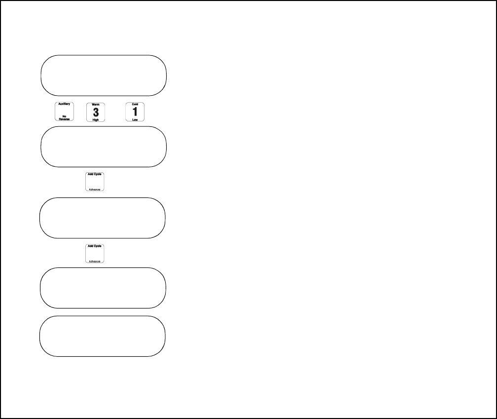
Calibration of the Machine
The _x__PV should reflect the size selected in earlier
steps.
Turn key to Program Mode.
Press “Auxiliary”, “3”, “1” and “Enter.”
The total hours the machine was running will be
displayed.
Press “Advance” and screen will show total cycles.
Press “Advance” to calibrate the water level sensor.
If the value is not zero, press “Enter” and the value
will change to zero.
Press “Advance” to calibrate the motor.
The board will lock the door and let the motor spin at
approximately 500 RPM (Firmware version 1.12).
The rpm will increase on the display. If the machine
reached approximately 500 RPM, the display will
show a reference value.
After the reference value is shown, the machine will
coast down to stop. When the machine stands still, the
board will unlock the door.
Program Cycle 00
Total working
hours : 0
level : 0.0 “
Enter to zero
Spin
XXX rpm
Reference x.xx
9001900 51
Section 3 Troubleshooting
© Copyright, Alliance Laundry Systems LLC – DO NOT COPY or TRANSMIT
12. NO SPIN
NO
NOTE: While performing this check, make sure that the washer-extractor is running
with a normal-size load.
YES
When
the WE-8
computer is
engaged in a
high-speed extract
(e.g., spin 1, spin 2,
spin 3 or spin 4),
is the basket
rotating?
Is an AC drive
fault present?
YES
NO
Is
the basket
rotating at a
slow
“
wash
”
speed and trying
to accelerate to
spin speed?
Refer to the
“
no motor
operation (with no AC
drive fault)
”
flowchart.
Refer to the
“
no motor
operation (with AC drive
fault)
”
flowchart.
NO
YES
Refer to the
“
the motor
is running but at an
abnormal speed
”
flowchart.
CFD1988S
Check the balance switch and
its wiring located under the
machine's top cover.
52 9001900
Section 3 Troubleshooting
© Copyright, Alliance Laundry Systems LLC – DO NOT COPY or TRANSMIT
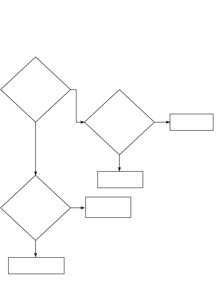
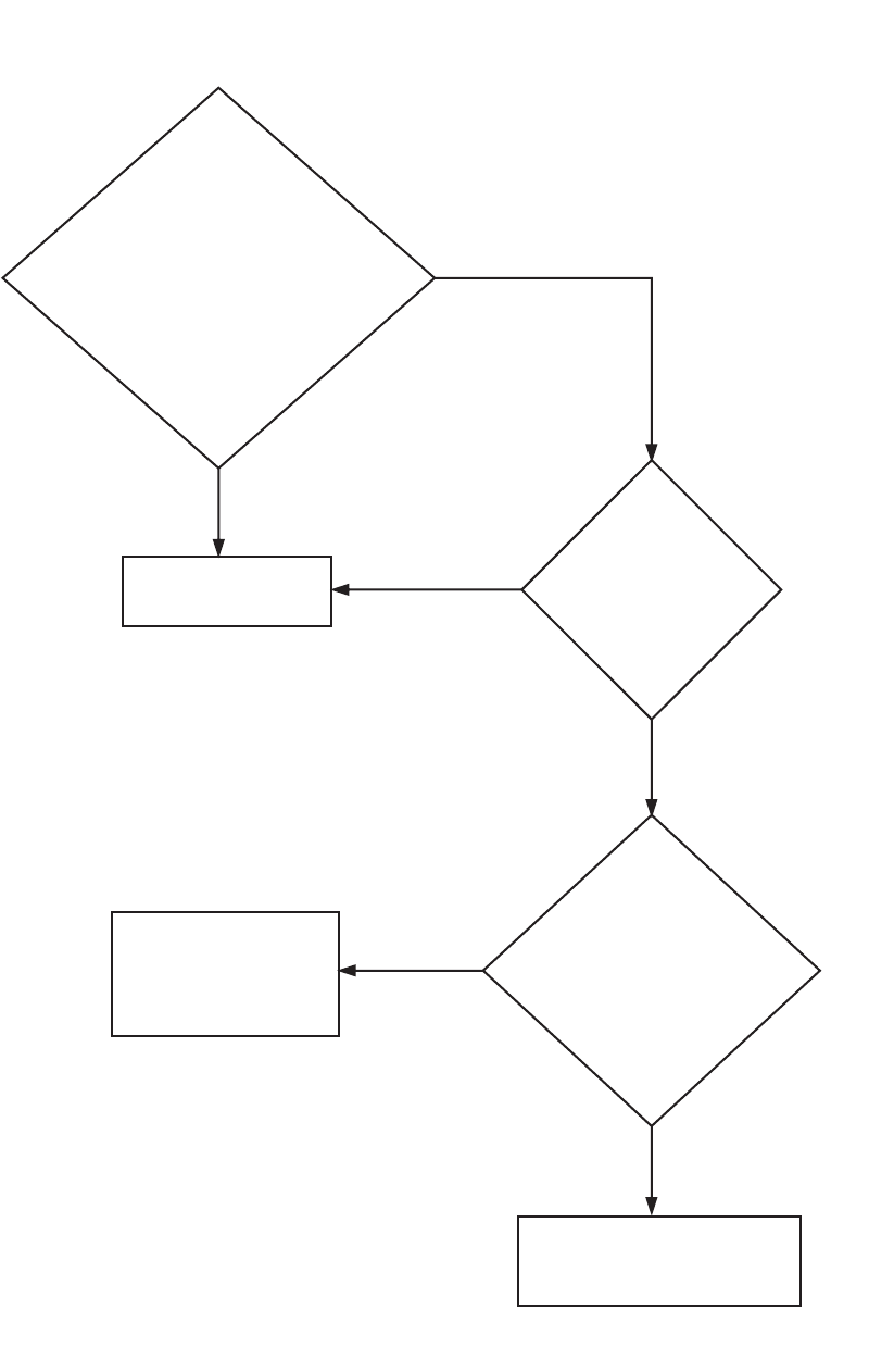
13. MACHINE DID NOT FILL ALARM ANALYSIS
CFD1989S
1
Is there water coming in
through the water supply
lines?
IS
there voltage
(220 Volts) at the
respective water
valve that should
be turning
on?
Check the main water valve
shut-offs, inside of the
water hoses and in-line
strainers.
NO
YES
Replace the water valve.
YES
Is
there
continuity
between the wire
from the main
board to the
water valve?
2
NO
Replace the main board.
YES
Is
there voltage (220
Volts) between the
drain wires on the main
board?
For example, for the
cold fill valve, is there
voltage between the
gray (cold fill) and blue
(common) wire?
3
4
NO
Replace the water valve.
YES
Is
the water plug
harness
connector on the
main board
intact?
NO
Replace the main board.
Replace the water valve
wiring harness.
YES
NO
9001900 53
Section 3 Troubleshooting
© Copyright, Alliance Laundry Systems LLC – DO NOT COPY or TRANSMIT
Please refer to the following 2 pages for wiring diagram information.
54 9001900
Section 3 Troubleshooting
© Copyright, Alliance Laundry Systems LLC – DO NOT COPY or TRANSMIT
Machine Did Not Fill Alarm Analysis (Sheet 1 of 2)
NOTE: Refer to the wiring diagram supplied with your machine.
2
1
1
3
34
2
9001900 55
Section 3 Troubleshooting
© Copyright, Alliance Laundry Systems LLC – DO NOT COPY or TRANSMIT
Machine Did Not Fill Alarm Analysis (Sheet 2 of 2)
CFD1990S
063787600D
56 9001900
Section 3 Troubleshooting
© Copyright, Alliance Laundry Systems LLC – DO NOT COPY or TRANSMIT
14. EMPTY ALARM ANALYSIS
CFD1991S
1
Check the drain valve and
drain plumbing for blockage.
The display reads
“
DID NOT
EMPTY.
”
Is
there voltage
(220 Volts) at the
drain valve?
Is
there voltage
(220 Volts) between
the blue and gray
wires going into
the drain
connection on the
main board?
NO
Replace the main board.
YES
Is
there continuity
from the drain
connection on the
main board to the
drain valve
harness?
Replace the drain harness.
NO
Replace the main board.
NO
YES
9001900 57
Section 3 Troubleshooting
© Copyright, Alliance Laundry Systems LLC – DO NOT COPY or TRANSMIT
Please refer to the following 2 pages for wiring diagram information.
58 9001900
Section 3 Troubleshooting
© Copyright, Alliance Laundry Systems LLC – DO NOT COPY or TRANSMIT
Empty Alarm Analysis (Sheet 1 of 2)
NOTE: Refer to the wiring diagram supplied with your machine.
11

9001900 59
Section 3 Troubleshooting
© Copyright, Alliance Laundry Systems LLC – DO NOT COPY or TRANSMIT
Empty Alarm Analysis (Sheet 2 of 2)
CFD1992S
063787600D
60 9001900
Section 3 Troubleshooting
© Copyright, Alliance Laundry Systems LLC – DO NOT COPY or TRANSMIT
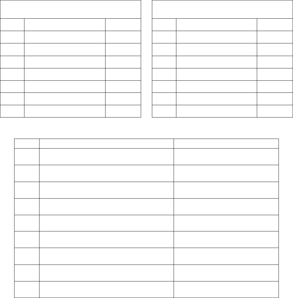
15. AUTOMATIC SUPPLY DISPENSER ANALYSIS
Run Program 38.
Run the cycle and, with the respective supply on the main display, refer to the following chart for the function
that should be occurring:
Cycle 38
Supply Setup Cycle 38
Supply Setup
Step Description Min:sec Step Description Min:sec
1 Warm Fill to Low Level 5:00 8 Warm Fill to Low Level 5:00
2 Supply 1 2:00 9 Supply 6 2:00
3 Supply 2 2:00 10 Supply 7 2:00
4 Supply 3 2:00 11 Supply 8 2:00
5 Supply 4 2:00 12 Supply 9 2:00
6 Supply 5 2:00 13 Wash 1 18/3 (80°F) 0:30
7 Drain 1 1:00 14 Drain 1 1:00
Supply Function Voltage
1 Turns on the water valve in compartment A of the
supply box.
N/A
2 Turns on the water valve in compartment B of the
supply box.
N/A
3 Turns on the water valve in compartment C of the
supply box.
N/A
4 Activates supply relay 1. Visibly inspect the relay to
see if it is closing and check for voltage.
220 Volts between terminals 1 and14
5 Activates supply relay 2. Visibly inspect the relay to
see if it is closing and check for voltage.
220 Volts between terminals 3 and14
6 Activates supply relay 3. Visibly inspect the relay to
see if it is closing and check for voltage.
220 Volts between terminals 5 and14
7 Activates supply relay 4. Visibly inspect the relay to
see if it is closing and check for voltage.
220 Volts between terminals 7 and14
8 Activates supply relay 5. Visibly inspect the relay to
see if it is closing and check for voltage.
220 Volts between terminals 9 and14
9 Activates supply relay 6. Visibly inspect the relay to
see if it is closing and check for voltage.
220 Volts between terminals 11 and14
9001900 61
Section 3 Troubleshooting
© Copyright, Alliance Laundry Systems LLC – DO NOT COPY or TRANSMIT
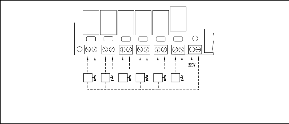
During each step, test for voltage (220 Volts) between each respective supply terminal and the common
terminal on the supply terminal board. Terminal 14 is the common terminal for the pumps.
The supply terminal board should be wired as shown in Figure 2.
Figure 2
CFS8N
Pump
1
Pump
2
Pump
3
Pump
4
Pump
5
Pump
6
Supply
Relay
1
12
Supply
Relay
2
34
Supply
Relay
3
56
Supply
Relay
4
78910
Supply
Relay
5
Supply
Relay
6
11 12 13* 14**
ELECTRICAL CONNECTION OF THE LIQUID SUPPLY PUMPS
* L1 (110 VAC) wire or terminal for remote liquid supply connection.
** L2 common wire (110 VAC) or terminal for remote liquid supply connection.
62 9001900
Section 3 Troubleshooting
© Copyright, Alliance Laundry Systems LLC – DO NOT COPY or TRANSMIT
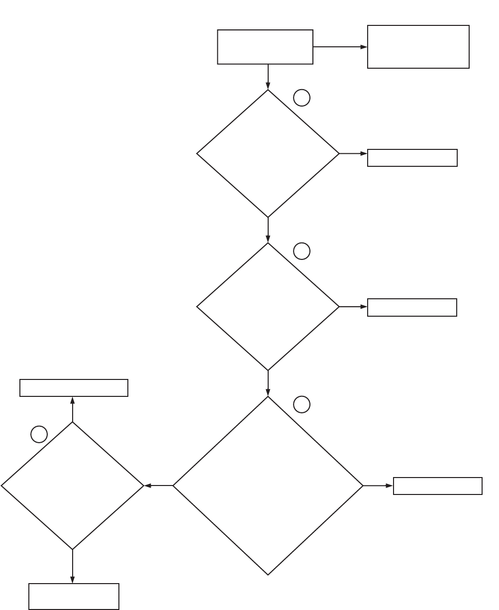
16. NO KEYPAD BOARD FUNCTIONS
Does
the display
change, indicating
that the computer has
gone into the cycle that has
been selected (e.g., does
the “NEXT09” display
change to
“STEP 01 CYCLE09”
“HOT LOW”)?
YES
Press the
start button
on the keypad.
do you hear a
single beep?
NO
If the cycle starts on the
display but no functions
are taking place, go to the
“NO OUTPUT VOLTAGE TO
COMPONENTS” flowchart,
step 1.
If you hear either double
beeps or no beeps at all,
replace the keypad board.
NO
Replace the keypad board. If the
problem persists, contact Alliance
Laundry Systems’ customer service
department.
NO
YES
YES
CFD1987S
With the
display reading
“CYCLE00,” select a
two-digit cycle (e.g.,
enter “0” and “9” for
cycle “09”). Does the
keypad react with a
single beep and by
changing the display
to “CYCLE09”?
9001900 63
Section 3 Troubleshooting
© Copyright, Alliance Laundry Systems LLC – DO NOT COPY or TRANSMIT
17. EXCESSIVE CYCLE TIME
When experiencing excessive cycle time, there are three main causes which are as follows:
a. Fill Time:
(1) Check for excessively long fill times. Refer to the “Fill Alarm Analysis” flowchart if any are found.
(2) Check for excessively long programmed fill times.
NOTE: All pre-programmed fill times are for 5 minutes. Any fill should easily complete during this time.
b. Drain Time:
(1) Look for excessively long programmed drain times (i.e., greater than one minute).
NOTE: Any drain step should not exceed 30-40 seconds.
c. Unnecessary Programming Steps:
(1) E.g., in the first fill of a cycle, if “S02 CXX 0:00:45” “SUPPLY1” is programmed for 45 seconds and
“S03 CXX 0:00:45” “SUPPLY2” is programmed for 45 seconds, the two steps can be accomplished
together at the same time, saving 45 seconds. Refer to the “Programming Multiple Supply Steps” section
of your washer-extractor’s programming manual.
64 9001900
Section 3 Troubleshooting
© Copyright, Alliance Laundry Systems LLC – DO NOT COPY or TRANSMIT
18. EXCESSIVE VIBRATION AND/OR NOISE DURING SPIN
When experiencing excessive vibration and/or noise during a spin cycle, there are three main causes,
which are as follows:
a. Improper Loading:
(1) Always make sure that full loads are used. Never wash partial loads.
(2) Do not mix various laundry items together in the same wash (e.g., do not wash towels and sheets
together).
(3) Avoid using laundry bags.
b. Improper Installation:
(1) Make sure that the washer-extractor is anchored to a flat, level surface. (Bolt down on soft mount
products is optional.)
(2) Refer to your washer-extractor’s installation manual for exact installation specifications.
c. Faulty Trunnion Bearings:
(1) Check the trunnion bearings’ noise factor.
(2) Lift up on the basket at the front of the tub. Check for any up and down play that would indicate bearing
wear.
(3) Replace the bearings as needed.
9001900 65
To reduce the risk of electrical shock, fire, explosion, serious injury or death:
• Disconnect electrical power to the washer-extractor before servicing it.
• Close the gas shut-off valve to the washer-extractor (when applicable) before servicing it.
• Never start the washer-extractor with any guards/panels removed.
• Whenever ground wires are removed during servicing, these ground wires must be
reconnected to ensure that the washer-extractor is properly grounded.
W461R1
WARNING
© Copyright, Alliance Laundry Systems LLC – DO NOT COPY or TRANSMIT
Section 4
Service Procedures
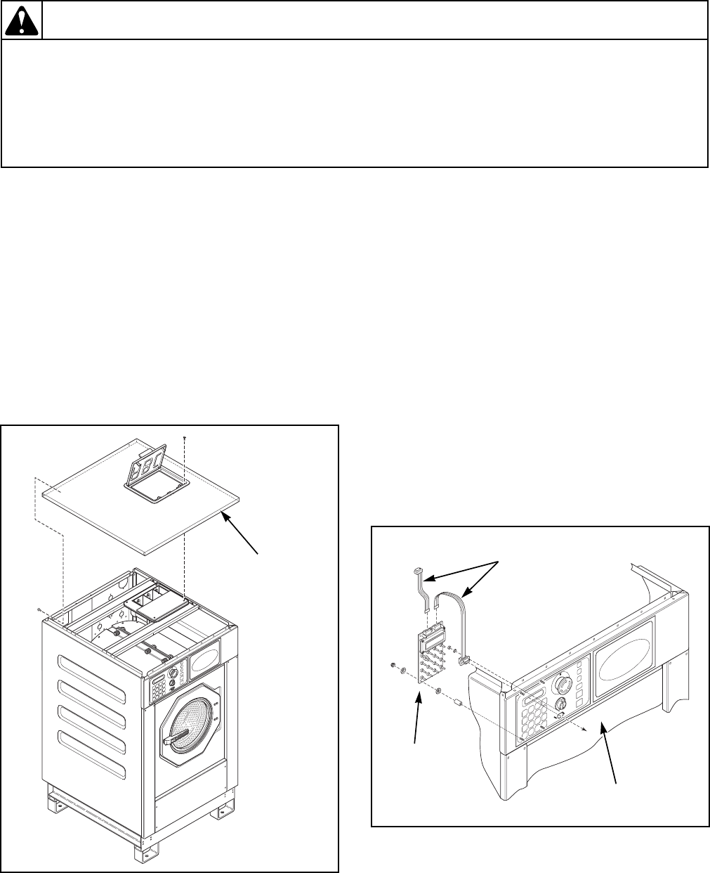
19. TOP COVER REMOVAL AND
REPLACEMENT
Refer to Figure 3.
REMOVAL
a. Turn off power to the machine.
b. Using a 10 mm socket wrench, remove the
screws that attach the top cover to the machine.
c. Lift the top cover off of the machine.
REPLACEMENT
a. Replace the top cover onto the machine.
b. Using a 10 mm socket wrench, replace the
screws that attach the top cover to the machine.
20. KEYPAD REMOVAL AND INSTALLATION
Refer to Figure 4.
REMOVAL
a. Turn off power to the machine.
b. Remove the top cover. Refer to Paragraph 19.
c. Disconnect the ribbon cables from the keypad.
d. Using a 5.5mm nut driver, remove the nuts that
attach the keypad to the control panel.
e. Remove the keypad.
INSTALLATION
a. Position the keypad.
b. Using a 5.5 mm nut driver, replace the nuts that
attach the keypad to the control panel.
c. Reconnect the ribbon cables to the keypad.
d. Replace the top cover. Refer to Paragraph 19.
e. Turn on power to the machine.
f. Test the keypad’s buttons by pressing each one
and checking for a single beep.
Figure 3
CFD6S
Top
Cover
Figure 4
CFD9S
Control
Panel
Keypad
Ribbon
Cables
66 9001900
Section 4 Service Procedures
© Copyright, Alliance Laundry Systems LLC – DO NOT COPY or TRANSMIT
To reduce the risk of electrical shock, fire, explosion, serious injury or death:
• Disconnect electrical power to the washer-extractor before servicing it.
• Close the gas shut-off valve to the washer-extractor (when applicable) before servicing it.
• Never start the washer-extractor with any guards/panels removed.
• Whenever ground wires are removed during servicing, these ground wires must be
reconnected to ensure that the washer-extractor is properly grounded.
W461R1
WARNING
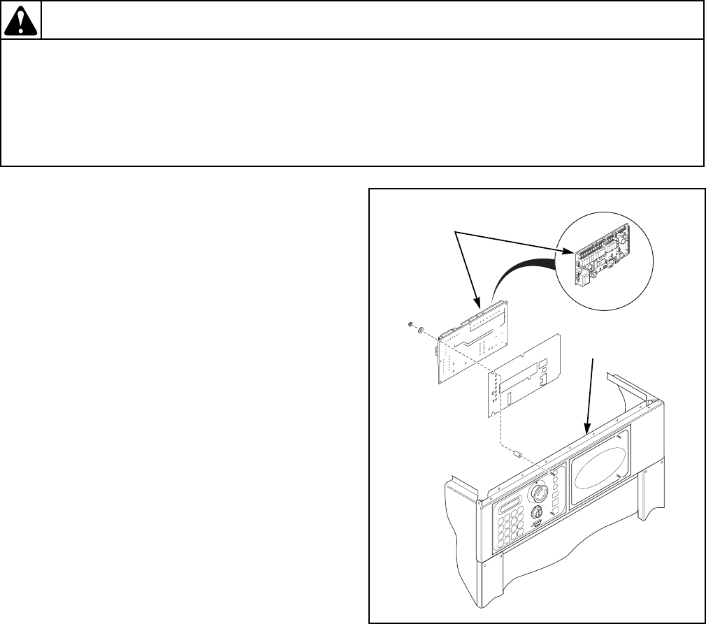
21. COMPUTER BOARD REMOVAL AND
INSTALLATION
Refer to Figure 5.
REMOVAL
a. Turn off power to the machine.
b. Remove the top cover. Refer to Paragraph 19.
c. Disconnect the wiring harness, ribbon cable, air
tube and ground wire from the computer board.
d. Using a 5 mm nut driver, remove the nuts that
attach the computer board to the control panel.
e. Remove the computer board.
INSTALLATION
a. Position the computer board.
b. Using a 5 mm nut driver, replace the nuts that
attach the computer board to the control panel.
c. Reconnect the wiring harness, ribbon cable, air
tube and ground wire to the computer board.
d. Replace the top cover. Refer to Paragraph 19.
e. Turn on power to the machine.
f. Insert the key into the keymode switch and turn
the switch to “Program.”
g. Set up the machine. Refer to the “Setup of the
Machine” section in the operating manual
supplied with your machine.
h. Calibrate the machine. Refer to the “Calibration
of the Machine” section in the programming
manual supplied with your machine.
i. Insert the key into the keymode switch and turn
the switch to “Run.”
j. Run the machine through Test Cycle 39 to test
the computer board’s function. Refer to
Table 1.
Figure 5
CFD10S
Computer
Board
Control
Panel

9001900 67
Section 4 Service Procedures
© Copyright, Alliance Laundry Systems LLC – DO NOT COPY or TRANSMIT
Cycle 39 — Test Program
Step Description Min:sec Step Definition Corrective Action
1 Cold Fill to
High Level 0:30 The machine should fill with cold water to
high level within 30 seconds and, when it
does, a buzzer will sound.
Refer to the “Machine Did Not Fill Alarm
Analysis” flowchart.
2 Drain 1 0:10 The machine should drain within 10 seconds
and, when it does, a buzzer will sound. Refer to the “Empty Alarm Analysis”
flowchart.
3 Hot Fill to Low
Level 5:00 The machine should fill with hot water to low
level within 5 minutes and, when it does, a
buzzer will sound.
Refer to the “Machine Did Not Fill Alarm
Analysis” flowchart.
4 Auxiliary Fill
to Medium
Level
5:00 The machine should fill with water to
medium level within 5 minutes and, when it
does, a buzzer will sound.
Refer to the “Machine Did Not Fill Alarm
Analysis” flowchart.
5 Heat (150°F) 1h00 This step is needed only if the machine is
equipped with auxiliary heat (e.g., steam or
electric heating). If the temperature isn’t
reached within the time programmed, an
alarm will sound.
Check the components used for the
auxiliary heating (e.g., steam valve or
heating elements).
6 Cold Fill to
High Level 0:30 The machine should fill with cold water to
high level within 30 seconds and, when it
does, a buzzer will sound.
Refer to the “Machine Did Not Fill Alarm
Analysis” flowchart.
7 Supply 1 0:30 Supply compartment A should flush for 30
seconds. Refer to the “No Fill Analysis” flowchart.
8 Supply 2 0:30 Supply compartment B should flush for 30
seconds. Refer to the “No Fill Analysis” flowchart.
9 Supply 3 0:30 Supply compartment C should flush for 30
seconds. Refer to the “No Fill Analysis” flowchart.
10 Supply 4 0:30 Supply relay 1 should be activated for 30
seconds. Refer to the “No Fill Analysis” flowchart.
11 Supply 5 0:30 Supply relay 2 should be activated for 30
seconds. Refer to the “No Fill Analysis” flowchart.
12 Supply 6 0:30 Supply relay 3 should be activated for 30
seconds. Refer to the “No Fill Analysis” flowchart.
13 Supply 7 0:30 Supply relay 4 should be activated for 30
seconds. Refer to the “No Fill Analysis” flowchart.
14 Supply 8 0:30 Supply relay 5 should be activated for 30
seconds. Refer to the “No Fill Analysis” flowchart.
15 Supply 9 0:30 Supply relay 6 should be activated for 30
seconds. Refer to the “No Fill Analysis” flowchart.
16 Wash 2 3/27
(80°F) 0:30 The basket should rotate forward 3 seconds,
pause for 27 seconds, rotate in reverse for 3
seconds, pause for 27 seconds, etc.
Refer to the “No Motor Operation (With or
With No AC Drive Fault” flowchart.
17 Wash 3, no
agitation (80°F) 0:30 The basket should not rotate for 30 seconds. If the basket does rotate, check the
program.
18 Wash 4 10/3
(80°F) 0:30 The basket should rotate forward 10 seconds,
pause for 3 seconds, rotate in reverse for 10
seconds, pause for 3 seconds, etc.
Refer to the “No Motor Operation (With or
With No AC Drive Fault” flowchart.
19 Wash 1, no
reverse (80°F) 0:30 The basket should rotate forward for 30
seconds without pausing. Refer to the “No Motor Operation (With or
With No AC Drive Fault” flowchart.
20 Drain 1 1:00 The machine should drain within 1 minute
and, when it does, a buzzer will sound. Refer to the “Empty Alarm Analysis”
flowchart.
Ta bl e 1

68 9001900
Section 4 Service Procedures
© Copyright, Alliance Laundry Systems LLC – DO NOT COPY or TRANSMIT
21 Auxiliary 1 0:05 N/A N/A
22 Auxiliary 2 0:05 N/A N/A
23 Auxiliary 3 0:05 N/A N/A
24 150°F Fill to
High Level 5:00 The water should reach 150°F and the
machine should fill to high level within 5
minutes and, when it does, a buzzer will
sound.
Refer to the “No Fill Analysis” flowchart.
25 Cold Fill to
Overflow 5:00 The machine should fill with cold water to
overflow within 5 minutes and, when it does,
a buzzer will sound.
Refer to the “Machine Did Not Fill Alarm
Analysis” flowchart.
26 Soak (150°F) 2h00 The machine should maintain a water
temperature of 150°F and a high fill level for
the time programmed.
If the machine doesn’t maintain a water
temperature of 150°F, check the
components used for the auxiliary heating
(e.g. steam valve or heating elements). If
the machine doesn’t maintain a high fill
level, refer to the “Machine Did Not Fill
Alarm Analysis” flowchart.
27 Drain 1 1:00 The machine should drain within 1 minute
and, when it does, a buzzer will sound. Refer to the “Empty Alarm Analysis”
flowchart.
28 Spin 1 2:00 The machine should spin at 500 RPM’s for 2
minutes. Refer to the “No Spin Analysis” flowchart.
29 Spin 2 2:00 The machine should spin at 650 RPM’s for 2
minutes. Refer to the “No Spin Analysis” flowchart.
30 Spin 3 2:00 The machine should spin at the following
RPM’s for 2 minutes:
• 18, 25, 35, 55, 75, 100 and 135-pound
capacity models: 800 RPM’s
• 165-pound capacity models: 750 RPM’s
Refer to the “No Spin Analysis” flowchart.
31 Spin 4 2:00 The machine should spin at the following
RPM’s for 2 minutes:
• 18, 25, 35, 55, and 75-pound capacity
models: 1000 RPM’s
• 100 and 135-pound capacity models: 800
RPM’s
• 165-pound capacity models: 750 RPM’s
Refer to the “No Spin Analysis” flowchart.
32 Auxiliary 3 0:15 N/A N/A
33 Cold Fill to
Medium Level 5:00 The machine should fill with cold water to
medium level within 5 minutes and, when it
does, a buzzer will sound.
Refer to the “Machine Did Not Fill Alarm
Analysis” flowchart.
34 Wash 1 10/3
(80°F) 0:15 The basket should rotate forward 10 seconds,
pause for 3 seconds, rotate in reverse for 10
seconds, pause for 3 seconds, etc.
Refer to the “No Motor Operation (With or
With No AC Drive Fault” flowchart.
35 Drain 1 1:00 The machine should drain within 1 minute
and, when it does, a buzzer will sound. Refer to the “Empty Alarm Analysis”
flowchart.
Cycle 39 — Test Program
(continued)
Step Description Min:sec Step Definition Corrective Action
Table 1
(continued)
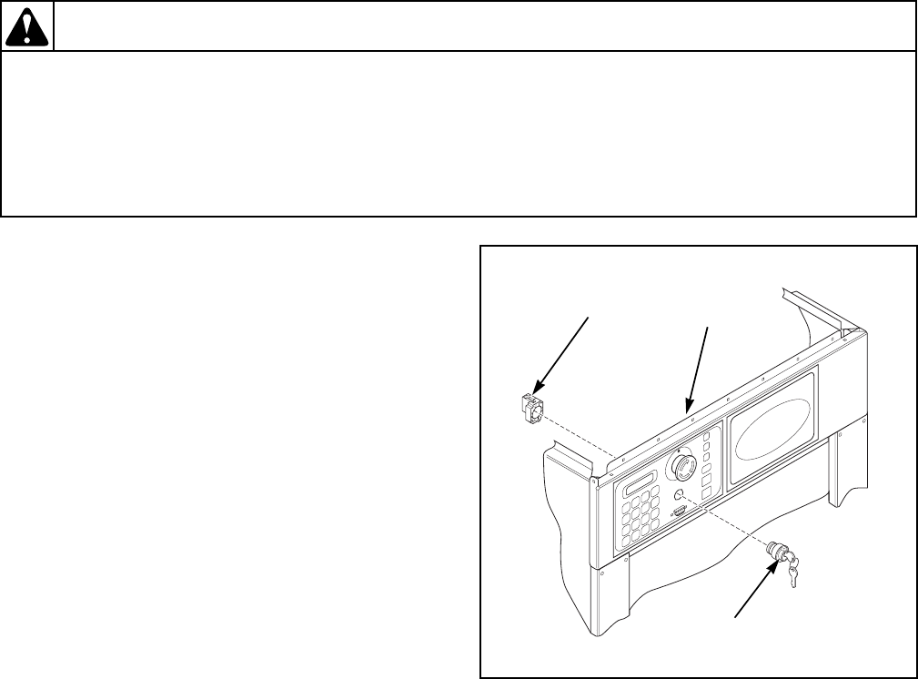
9001900 69
Section 4 Service Procedures
© Copyright, Alliance Laundry Systems LLC – DO NOT COPY or TRANSMIT
To reduce the risk of electrical shock, fire, explosion, serious injury or death:
• Disconnect electrical power to the washer-extractor before servicing it.
• Close the gas shut-off valve to the washer-extractor (when applicable) before servicing it.
• Never start the washer-extractor with any guards/panels removed.
• Whenever ground wires are removed during servicing, these ground wires must be
reconnected to ensure that the washer-extractor is properly grounded.
W461R1
WARNING
22. KEYMODE SWITCH REMOVAL AND
INSTALLATION
Refer to Figure 6.
REMOVAL
a. Turn off power to the machine.
b. Remove the top cover. Refer to Paragraph 19.
c. Disconnect the wires from the keymode switch.
d. Using a 5 mm nut driver, remove the nuts that
attach the keymode switch to the control panel.
e. Separate the keymode switch from the
keymode base and remove them.
INSTALLATION
a. Position the keymode base and keymode switch
and connect them.
b. Using a 5 mm nut driver, replace the nuts that
attach the keymode switch to the control panel.
c. Reconnect the wires to the keymode switch.
d. Replace the top cover. Refer to Paragraph 19.
e. Turn on power to the machine.
Figure 6
CFD11S
Keymode
Base
Keymode
Switch
Control
Panel
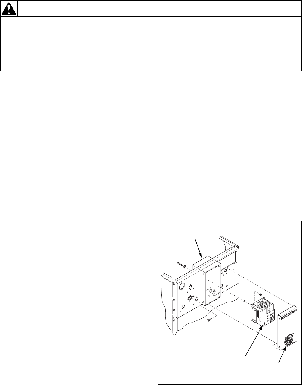
70 9001900
Section 4 Service Procedures
© Copyright, Alliance Laundry Systems LLC – DO NOT COPY or TRANSMIT
To reduce the risk of electrical shock, fire, explosion, serious injury or death:
• Disconnect electrical power to the washer-extractor before servicing it.
• Close the gas shut-off valve to the washer-extractor (when applicable) before servicing it.
• Never start the washer-extractor with any guards/panels removed.
• Whenever ground wires are removed during servicing, these ground wires must be
reconnected to ensure that the washer-extractor is properly grounded.
W461R1
WARNING
23. AC DRIVE SWITCH REMOVAL AND
INSTALLATION
Refer to Figure 7.
REMOVAL
a. Turn off power to the machine.
b. Remove the top cover. Refer to Paragraph 19.
c. Using a 10 mm nut driver, remove the screws
that attach the AC drive box cover to the AC
drive box.
d. Disconnect the wiring to the AC drive fan.
e. Remove the AC drive box cover.
f. Label and remove the wires from the AC drive.
g. Using a 5/16 inch nut driver, remove the nuts
and screws that attach the AC drive to the AC
drive box.
h. Remove the AC drive from the AC drive box.
INSTALLATION
a. Position the AC drive within the AC drive box.
b. Using a 5/16 inch nut driver, replace the screws
and nuts that attach the AC drive to the AC
drive box.
c. Reconnect the wires to the AC drive.
d. Reconnect the wiring to the AC drive fan.
e. Position the AC drive box cover.
f. Using a 10 mm nut driver, replace the screws
that attach the AC drive box cover to the AC
drive box.
g. Replace the top cover. Refer to Paragraph 19.
h. Turn on power to the machine.
i. Calibrate the machine. Refer to the “Calibration
of the Machine” section in the programming
manual supplied with your machine.
j. Test the basket rotation speeds by starting
Cycle 39 and advancing to step 28. Refer to
Table 1. Check steps 28 through 31 for the
following basket RPM’s.
NOTE: To check the RPM’s, press the “Display
Temp” keypad.
18, 25, 35, 55 and 75-Pound Capacity
Machines
• Spin 1: 500 RPM’s
• Spin 2: 650 RPM’s
• Spin 3: 800 RPM’s
• Spin 4: 1000 RPM’s
100 and 135-Pound Capacity Machines
• Spin 1: 500 RPM’s
• Spin 2: 650 RPM’s
• Spin 3: 800 RPM’s
• Spin 4: 800 RPM’s
165-Pound Capacity Machines
• Spin 1: 500 RPM’s
• Spin 2: 650 RPM’s
• Spin 3: 750 RPM’s
• Spin 4: 750 RPM’s
Figure 7
CFS12S
AC
Drive
AC Drive
Box
AC Drive
Fan
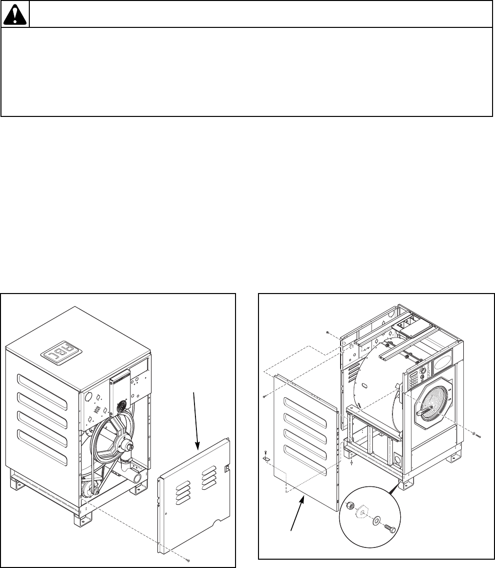
9001900 71
Section 4 Service Procedures
© Copyright, Alliance Laundry Systems LLC – DO NOT COPY or TRANSMIT
To reduce the risk of electrical shock, fire, explosion, serious injury or death:
• Disconnect electrical power to the washer-extractor before servicing it.
• Close the gas shut-off valve to the washer-extractor (when applicable) before servicing it.
• Never start the washer-extractor with any guards/panels removed.
• Whenever ground wires are removed during servicing, these ground wires must be
reconnected to ensure that the washer-extractor is properly grounded.
W461R1
WARNING
24. REAR PANEL REMOVAL AND
REPLACEMENT
Refer to Figure 8.
REMOVAL
a. Turn off power to the machine.
b. Remove the screws that attach the rear panel to
the machine.
c. Remove the rear panel from the machine.
REPLACEMENT
a. Position the rear panel on the machine.
b. Replace the screws that attach the rear panel to
the machine.
25. SIDE PANEL REMOVAL AND
INSTALLATION
Refer to Figure 9.
REMOVAL
a. Turn off power to the machine.
b. Remove the screws and nuts that attach the side
panel to the machine.
c. Remove the side panel from the machine.
INSTALLATION
a. Position the side panel on the machine.
b. Replace the screws and nuts that attach the side
panel to the machine.
Figure 8
CFD7S
Rear
Panel
Figure 9
CFD8S
Side
Panel
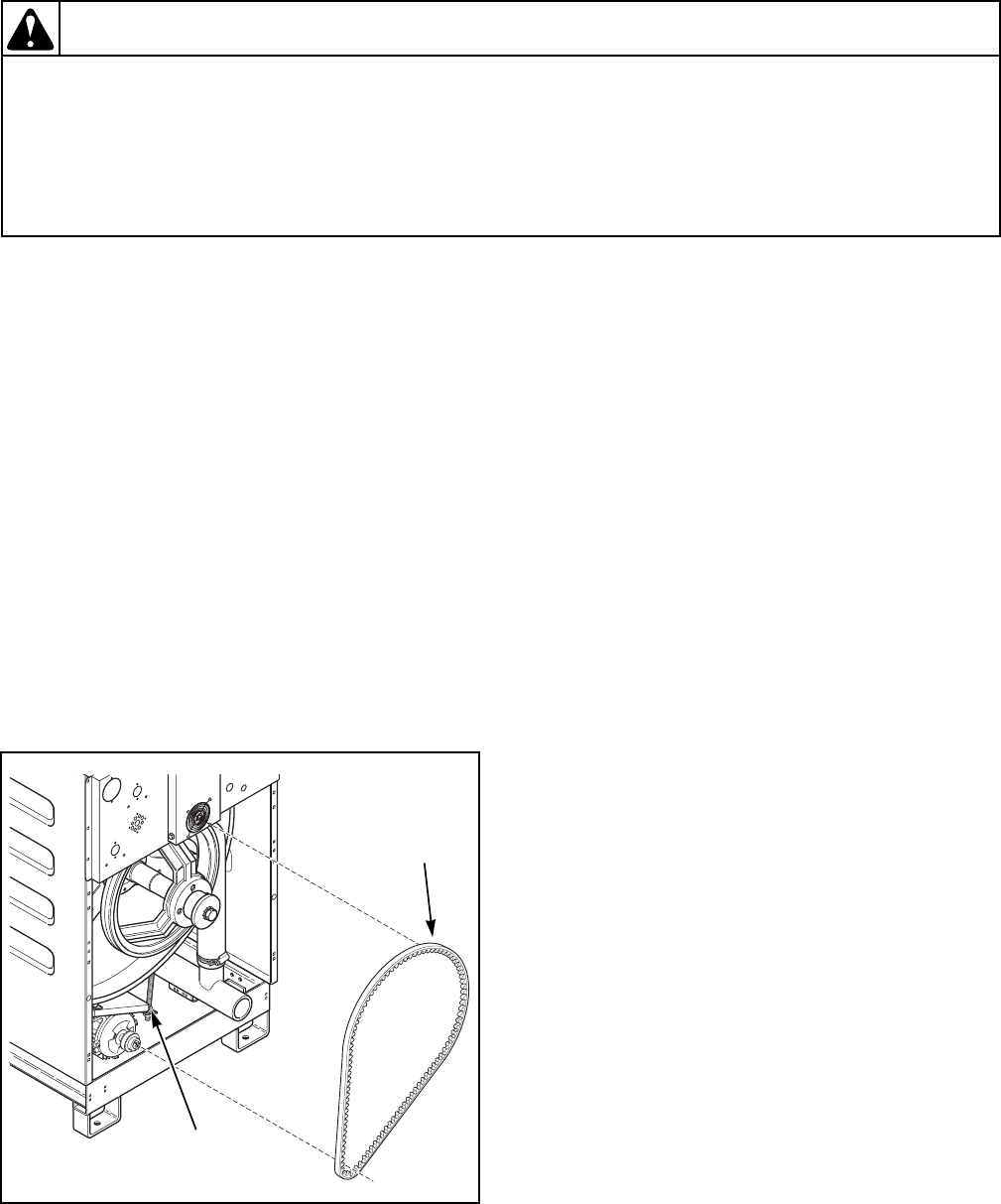
72 9001900
Section 4 Service Procedures
© Copyright, Alliance Laundry Systems LLC – DO NOT COPY or TRANSMIT
To reduce the risk of electrical shock, fire, explosion, serious injury or death:
• Disconnect electrical power to the washer-extractor before servicing it.
• Close the gas shut-off valve to the washer-extractor (when applicable) before servicing it.
• Never start the washer-extractor with any guards/panels removed.
• Whenever ground wires are removed during servicing, these ground wires must be
reconnected to ensure that the washer-extractor is properly grounded.
W461R1
WARNING
26. DRIVE BELT REMOVAL AND
REPLACEMENT
Refer to Figure 10.
If the drive belt is generating noise or if the AC
drive is generating faults because of excessive
hertz fluctuations, first inspect the belt for wear. If
the belt has uneven wear or frayed edges, replace
it. Refer to the Removal and Replacement
sections, below. If the drive belt isn’t noticeably
worn, check the belt’s tension and deflection.
Refer to the Drive Belt Re-Tensioning section,
below.
REMOVAL
a. Turn off power to the machine.
b. Remove the rear panel. Refer to Paragraph 24.
c. Relieve the belt’s tension by loosening the nuts
on the motor mounting plate bolt.
d. Remove the belt from the motor and basket
pulleys.
REPLACEMENT
a. Install the belt onto the motor and basket
pulleys.
b. Re-tension the belt. Refer to Drive Belt Re-
tensioning, below.
c. Replace the rear panel. Refer to Paragraph 24.
DRIVE BELT RE-TENSIONING
Refer to Figure 11.
a. Turn off power to the machine.
b. Remove the rear panel. Refer to Paragraph 24.
c. Check drive belt tension.
(1) Using a tension gauge, check the drive belt
tension. Belt tension should be between 70
and 90 pounds (± 5 pounds). Set the initial
belt tension toward the high end of the
range.
(2) To adjust the drive belt tension, loosen or
tighten the nuts on the motor mounting
plate bolt. Refer to Figure 10.
d. Check the belt deflection.
(1) Belt deflection measurements should be
taken as close to the center of the belt span
as possible.
(2) For every inch of span length, the drive belt
should deflect 1/64 inch (.4 mm). For
example, a belt with a span length of 50
inches should deflect 50/64 inch (19.84
mm).
(3) An initial (run-in) force of 5.25 pounds
should be used to set the belt tension. An
operating (normal) force of 3.5 pounds
should be used after the washer-extractor
has been operated for a few hours.
e. Replace the rear panel. Refer to Paragraph 24.
Figure 10
CFD14S
Motor Mounting
Plate Bolt
Belt
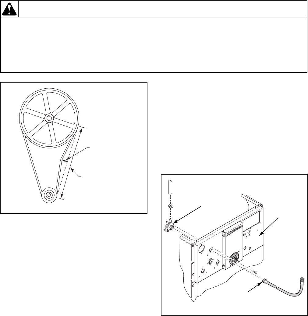
9001900 73
Section 4 Service Procedures
© Copyright, Alliance Laundry Systems LLC – DO NOT COPY or TRANSMIT
To reduce the risk of electrical shock, fire, explosion, serious injury or death:
• Disconnect electrical power to the washer-extractor before servicing it.
• Close the gas shut-off valve to the washer-extractor (when applicable) before servicing it.
• Never start the washer-extractor with any guards/panels removed.
• Whenever ground wires are removed during servicing, these ground wires must be
reconnected to ensure that the washer-extractor is properly grounded.
W461R1
WARNING
27. WATER VALVE REMOVAL AND
REPLACEMENT
Refer to Figure 12.
REMOVAL
a. Turn off power to the machine.
b. Remove the top cover. Refer to Paragraph 19.
c. Disconnect the water supply hose from the
water valve.
d. Loosen the clamps that attach the hoses to the
top of the water valve.
e. Disconnect the hoses from the top of the water
valve.
f. Remove the screws that attach the water valve
to the upper rear panel.
g. Remove the water valve.
REPLACEMENT
a. Position the water valve on the upper rear
panel.
b. Replace the screws that attach the water valve
to the upper rear panel.
c. Reconnect the hoses to the top of the water
valve.
d. Tighten the clamps that attach the hoses to the
top of the water valve.
e. Reconnect the water supply hose to the water
valve.
f. Replace the top cover. Refer to Paragraph 19.
Figure 11
Deflection
Span Length
P044IE3A
Figure 12
CFS15S
Water
Valve Upper Rear
Panel
Water Supply
Hose
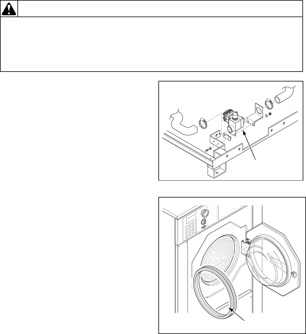
74 9001900
Section 4 Service Procedures
© Copyright, Alliance Laundry Systems LLC – DO NOT COPY or TRANSMIT
To reduce the risk of electrical shock, fire, explosion, serious injury or death:
• Disconnect electrical power to the washer-extractor before servicing it.
• Close the gas shut-off valve to the washer-extractor (when applicable) before servicing it.
• Never start the washer-extractor with any guards/panels removed.
• Whenever ground wires are removed during servicing, these ground wires must be
reconnected to ensure that the washer-extractor is properly grounded.
W461R1
WARNING
28. DRAIN VALVE
Refer to Figure 13.
If the washer-extractor doesn’t drain within 30
seconds, perform the following check:
a. Turn off power to the machine.
b. Remove any panels necessary to access the
drain valve and drain plumbing.
c. Check for a clog in the drain line.
d. Verify that the drain valve is opening.
(1) The drain valve is normally open (i.e., it
requires voltage to close).
(2) When power is removed from the machine,
the drain valve should open.
e. If the drain is not opening, check for the
following:
(1) Check the motor winding for continuity, a
short circuit or an abnormal drop in
voltage. Replace the drain valve as needed
(consult the machine’s parts manual for
drain valve part numbers).
(2) Check that the shaft and rotor of the drain
motor turns freely.
(3) Check that the internal drain valve is
closing and does not bind. A clog within
the drain valve may be preventing the drain
valve from closing. Replace the drain valve
as needed (consult the machine’s parts
manual for drain valve part numbers).
f. Check the wire continuity from the drain valve
to the plug on the computer board.
g. Re-install any panels removed in Step b.
29. DOOR GASKET REMOVAL AND
REPLACEMENT
Refer to Figure 14.
REMOVAL
a. Turn power off to the machine.
b. Remove the door glass (with the door gasket
attached) from the door.
c. Remove the door gasket from the door glass.
REPLACEMENT
a. Install the door gasket onto the door glass.
b. Insert the door glass (with the door gasket
attached) into the door.
Figure 13
Figure 14
CFD16S
Drain
Valve
CFD17S
Door
Gasket
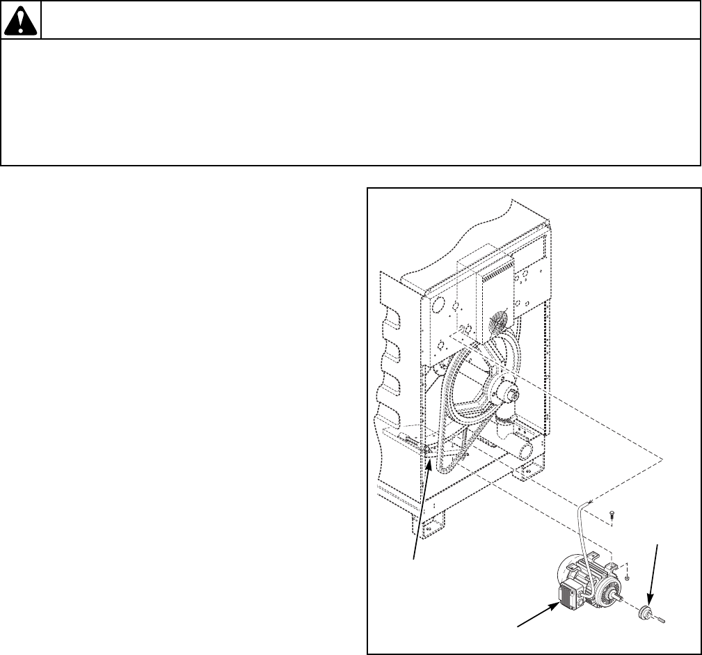
9001900 75
Section 4 Service Procedures
© Copyright, Alliance Laundry Systems LLC – DO NOT COPY or TRANSMIT
To reduce the risk of electrical shock, fire, explosion, serious injury or death:
• Disconnect electrical power to the washer-extractor before servicing it.
• Close the gas shut-off valve to the washer-extractor (when applicable) before servicing it.
• Never start the washer-extractor with any guards/panels removed.
• Whenever ground wires are removed during servicing, these ground wires must be
reconnected to ensure that the washer-extractor is properly grounded.
W461R1
WARNING
30. MOTOR REMOVAL AND REPLACEMENT
(18, 25, 35, 55 and 75-Pound Capacity Models)
REMOVAL
Refer to Figure 15.
a. Turn power off to the machine.
b. Remove the rear panel. Refer to Paragraph 24.
c. Remove the drive belt. Refer to Paragraph 26.
d. Loosen the motor pulley’s setscrew and remove
the motor pulley from the motor.
e. Remove the motor belt tensioner bolts from the
motor plate.
f. Remove the motor mounting bolts from the
motor plate.
g. Disconnect the motor wiring.
h. Remove the motor from the machine.
REPLACEMENT
a. Connect the motor wiring.
b. Reinstall the motor onto the motor plate.
c. Reinstall the motor pulley to the motor and
check the pulley’s alignment.
d. Reinstall the motor belt tensioner bolts.
e. Reinstall the belt.
f. Re-tension the belt. Refer to Paragraph 26.
g. Replace the rear panel. Refer to Paragraph 24.
Figure 15
CFD13S
Motor
Pulley
Motor
Motor
Plate
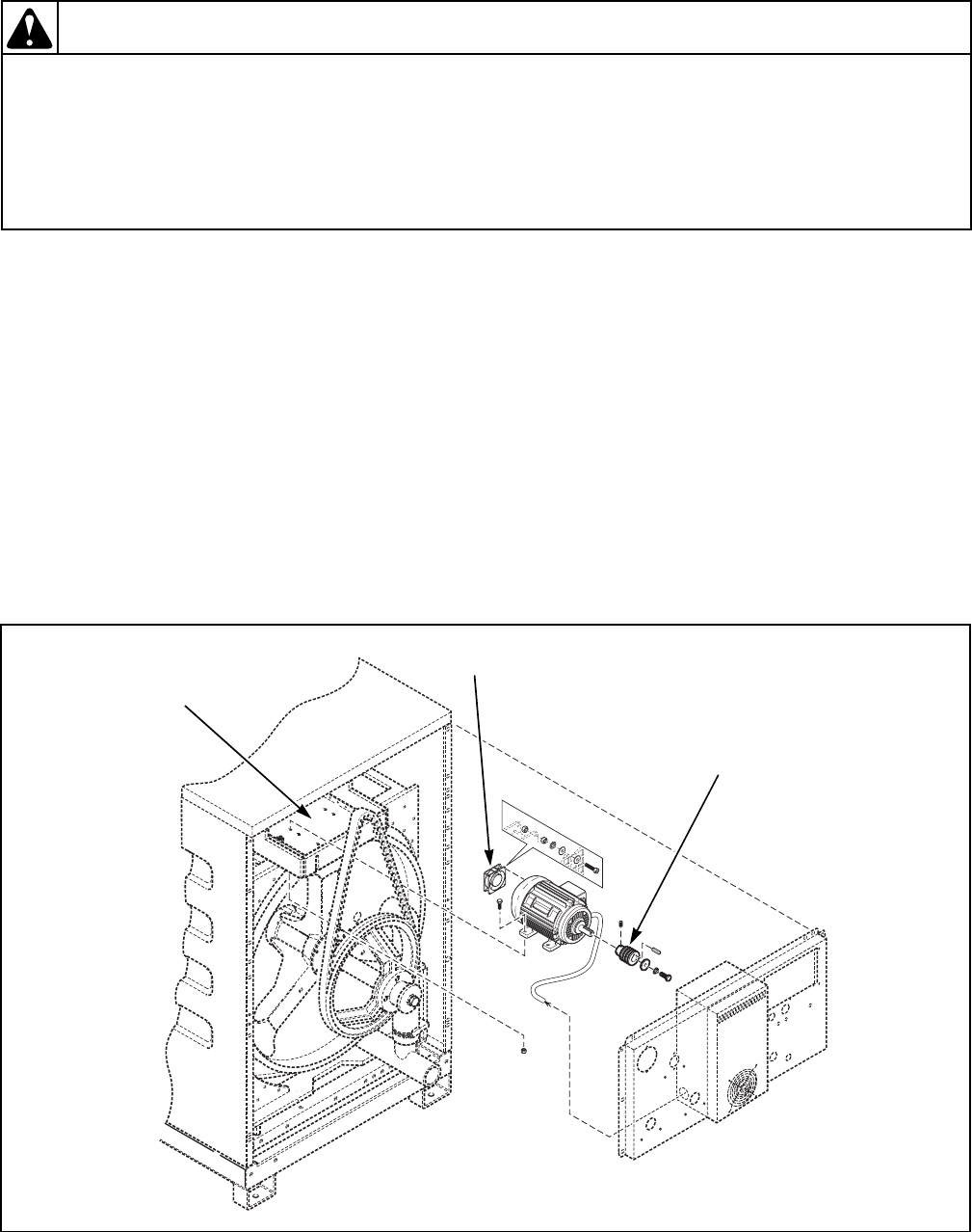
76 9001900
Section 4 Service Procedures
© Copyright, Alliance Laundry Systems LLC – DO NOT COPY or TRANSMIT
To reduce the risk of electrical shock, fire, explosion, serious injury or death:
• Disconnect electrical power to the washer-extractor before servicing it.
• Close the gas shut-off valve to the washer-extractor (when applicable) before servicing it.
• Never start the washer-extractor with any guards/panels removed.
• Whenever ground wires are removed during servicing, these ground wires must be
reconnected to ensure that the washer-extractor is properly grounded.
W461R1
WARNING
31. MOTOR REMOVAL AND REPLACEMENT
(100, 135 and 165-Pound Capacity Models)
Refer to Figure 16.
REMOVAL
a. Turn power off to the machine.
b. Remove the rear panel. Refer to Paragraph 24.
c. Remove the top cover. Refer to Paragraph 19.
d. Remove the drive belt. Refer to Paragraph 26.
e. Loosen the motor pulley’s setscrew and remove
the motor pulley from the motor.
f. Disconnect the motor wiring.
g. Disconnect the motor fan wiring.
h. Remove the motor fan from the motor.
i. Remove the motor from the motor plate.
j. Remove the motor from the machine.
REPLACEMENT
a. Connect the motor wiring.
b. Reinstall the motor onto the motor plate.
c. Reinstall the motor pulley to the motor and
check the pulley’s alignment.
d. Reinstall the belt.
e. Connect the motor fan wiring.
f. Reinstall the motor fan onto the motor.
g. Reinstall the motor pulley onto the motor and
check the pulley’s alignment.
h. Replace the rear panel. Refer to Paragraph 24.
i. Replace the top cover. Refer to Paragraph 19.
Figure 16
CFD2004S
Motor
Pulley
Motor Fan
Motor
Plate
