Allied Telesis K K TQ1402 802.11ac wave2 2x2 2.4G/5G/ wireless AP User Manual AT TQ5403 Wireless Access Point Installation Guide
Allied Telesis K.K. 802.11ac wave2 2x2 2.4G/5G/ wireless AP AT TQ5403 Wireless Access Point Installation Guide
User Manual
613-002709 Rev. A
AT-TQ1402 Series
Wireless Access Point
AT-TQ1402
AT-TQm1402
Installation Guide
4680
PWR
AT-TQ1402
2.4GHz 5GHz
LAN
Copyright 2019 Allied Telesis, Inc.
All rights reserved. No part of this publication may be reproduced without prior written permission from Allied Telesis, Inc.
Allied Telesis and the Allied Telesis logo are trademarks of Allied Telesis, Incorporated. All other product names, company names,
logos or other designations mentioned herein are trademarks or registered trademarks of their respective owners.
Allied Telesis, Inc. reserves the right to make changes in specifications and other information contained in this document without prior
written notice. The information provided herein is subject to change without notice. In no event shall Allied Telesis, Inc. be liable for
any incidental, special, indirect, or consequential damages whatsoever, including but not limited to lost profits, arising out of or related
to this manual or the information contained herein, even if Allied Telesis, Inc. has been advised of, known, or should have known, the
possibility of such damages.

AT-TQ1402 Series Wireless Access Point Installation Guide
3
Electrical Safety and Emissions
Standards
This product meets the following standards:
“Federal Communications Commission Interference Statement”
“European Union Restriction of the Use of Certain Hazardous Substances (RoHS) in Electrical
and Electronic Equipment” on page 4
“Safety and Electromagnetic Emissions” on page 4
“Translated Safety Statements” on page 7
Federal Communications Commission Interference Statement
Declaration of Conformity
Manufacturer Name: Allied Telesis
Declares that the product: 802.11ac wave2 2x2 2.4G/5G wireless AP
Model Number: AT-TQ1402 and AT-TQm1402
This device complies with Part 15 of the FCC Rules. Operation is subject to the following two
conditions: (1) This device may not cause harmful interference, and (2) this device must accept
any interference received, including interference that may cause undesired operation.
This equipment has been tested and found to comply with the limits for a Class B digital device,
pursuant to Part 15 of the FCC Rules. These limits are designed to provide reasonable protection
against harmful interference in a residential installation. This equipment generates, uses and can
radiate radio frequency energy and, if not installed and used in accordance with the instructions,
may cause harmful interference to radio communications. However, there is no guarantee that
interference will not occur in a particular installation. If this equipment does cause harmful
interference to radio or television reception, which can be determined by turning the equipment
off and on, the user is encouraged to try to correct the interference by one of the following
measures:
• Reorient or relocate the receiving antenna.
• Increase the separation between the equipment and receiver.
• Connect the equipment into an outlet on a circuit different from that to which the receiver is
connected.
• Consult the dealer or an experienced radio/TV technician for help.
4
Caution
FCC Caution: Any changes or modifications not expressly approved by the party responsible
for compliance could void the user's authority to operate this equipment. E80
Avertissement
Avertissement de la FCC: Les changements ou modifications non expressément approuvés
par la partie responsable de la conformité pourraient annuler l'autorité de l'utilisateur à utiliser
cet équipement. E80
This transmitter must not be co-located or operating in conjunction with any other antenna or
transmitter. This device is restricted to indoor use only.
Radiation Exposure Statement:
This equipment complies with FCC radiation exposure limits set forth for an uncontrolled
environment. This equipment should be installed and operated with minimum distance 20 cm
between the radiator and your body.
European Union Restriction of the Use of Certain Hazardous
Substances (RoHS) in Electrical and Electronic Equipment
This Allied Telesis RoHS-compliant product conforms to the European Union Restriction of the
Use of Certain Hazardous Substances (RoHS) in Electrical and Electronic Equipment. Allied
Telesis ensures RoHS conformance by requiring supplier Declarations of Conformity, monitoring
incoming materials, and maintaining manufacturing process controls.
Note
For additional regulatory statements, refer to Appendix B, ”Regulatory Statements” on
page 51.
Safety and Electromagnetic Emissions
Standard Compliance
• RoHs compliant
• European Union RoHS (Directive 2011/65/EU of the European Parliament and of the Council of
8 June 2011 on the restriction of the use of certain hazardous substances in electrical and
electronic equipment.)
AT-TQ1402 Series Wireless Access Point Installation Guide
5
Wire Communication
• IEEE 802.1
• IEEE 802.3
• IEEE 802.3u
• IEEE 802.3x
• IEEE 802.3af
Wireless Communication
• IEEE 802.11 DSSS
• IEEE 802.11a OFDM
• IEEE 802.11b DSSS/FHSS
• IEEE 802.11g OFDM
• IEEE 802.11n OFDM
• IEEE 802.11ac OFDM
• ARIB STD-T66
• ARIB STD-T71
Safety
CB/UL
• UL/IEC 60950-1: 2005+A1:2009+A2:2013 and
EN60950-1:2006+A11:2009+A1:2010+A12:2011+A2:2013
• UL/IEC 62368-1:2014 and EN62368-1:2014
• UL 60950-1, 2nd Edition, 2014-10-14/CSA C22.2 NO. 60950-1-07, 2nd Edition, 2014-10
• IEC 62368-1;2014 AND EN63268-1:2014
• UL 62368-1, 2nd Edition, 2014-12-01
• CSA C22.2 No. 62368-1-14, 2nd Edition, 2014-12-01
TUV
• EN60950-1+EN62368-1 (Co-license)
AEL
• Class I, US FDA/CDRH
• EN(IEC) 60825-1:1994+a11,
• EN(IEC) 60825-2:1994
• EN(IEC) 60950: 1992+A1+A2+A3
6
Electro Magnetic Interference (EMI)
• FCC part15 Subpart B/ Class B
• EN55032 Class B
• CISPR 32
• VCCI Class B
• VCCI-CISPR 32:2016
• AS/NZS CISPR 32
Electro Magnetic Susceptibility (EMS) - EN55024 and EN55035
• IEC 61000-4-2:2008
• IEC 61000-4-3: 2006+A1:2007+A2:2010
• IEC 61000-4-4:2012
• IEC 61000-4-5:2017
• IEC 61000-4-6:2013
• (IEC 61000-4-8:2009)
• IEC 61000-4-11:2014/AMD:2017
• IEC 61000-3-2:2014
• IEC 61000-3-3:2013
FCC
• 47 CFR Part15, subpart C
• 47 CFR Part15, subpart E
CE
• RED Directive 2014/53/EU
• European Council Directive 2014/30/EU
• EN55032:2015+AC:2016
• EN 55024:2010+A1:2015
• EN 301489-1 V2.1.1
• EN 301489-17 V3.1.1
• EN 300328 V2.1.1
• EN 301893 V2.1.1
• EN 62311: 2008/ 50385: 2017
• EN55035:2017

AT-TQ1402 Series Wireless Access Point Installation Guide
7
RCM
• CISPR 32:2015/COR1:2016
• AS/NZS CISPR 32: 2015
• AS/NZS 4268: 2017
Translated Safety Statements
Important: The indicates that a translation of the safety statement is available in a PDF document
titled Translated Safety Statements on the Allied Telesis website at www.alliedtelesis.com/
support.

9
Table of Contents
Preface ............................................................................................................................................................15
Product Description ......................................................................................................................................19
Overview .................................................................................................................................................... 20
Features..................................................................................................................................................... 22
Hardware Features.............................................................................................................................. 22
Management Access ........................................................................................................................... 23
LAN Port .............................................................................................................................................. 23
Redundant Power Supply .......................................................................................................................... 25
LEDs .......................................................................................................................................................... 26
Cable Specifications................................................................................................................................... 27
AT-TQ1402 Series Wireless Access Point Installation ..............................................................................29
Review Safety Precautions ........................................................................................................................ 30
Unpack Shipping Box Contents ................................................................................................................. 32
Installation Guidelines................................................................................................................................ 33
Install Access Point.................................................................................................................................... 34
General Installation Guidelines............................................................................................................ 34
Table Top Installation .......................................................................................................................... 34
Ceiling or Wall - Mounting Bracket Installation .................................................................................... 35
Install Ethernet Cable and External DC Power Supply........................................................................ 40
External AC/DC Power Adapter Installation ........................................................................................ 40
Install Anti-theft Device........................................................................................................................ 41
Ceiling or Wall - Attach Chassis to Mounting Bracket ......................................................................... 42
Start Initial Management Session .............................................................................................................. 44
Technical Specifications ...............................................................................................................................45
Physical Specifications............................................................................................................................... 45
Environmental Specifications..................................................................................................................... 45
Power Specifications.................................................................................................................................. 46
Input Power Specifications .................................................................................................................. 46
External Power Supply Specifications ................................................................................................. 46
PoE Power Requirements ................................................................................................................... 47
Cable Specifications................................................................................................................................... 48
LAN Port Specifications and Pinouts ......................................................................................................... 49
Port Specifications............................................................................................................................... 49
Port Pinouts ......................................................................................................................................... 49
Regulatory Statements .................................................................................................................................51
Federal Communication Commission Interference Statement................................................................... 52
Europe - EU Declaration of Conformity...................................................................................................... 54
Operating Frequencies and Maximum Transmission Power Levels ................................................... 54
Radiation Exposure Statement............................................................................................................ 54
Importer ............................................................................................................................................... 54

11
List of Figures
Figure 1: Top View .......................................................................................................................................... 20
Figure 2: Front Edge View............................................................................................................................... 21
Figure 3: Back Edge View ............................................................................................................................... 21
Figure 4: Acceptable Orientations on a Tabletop, Wall and Ceiling Installation .............................................. 33
Figure 5: Attach Screws to Access Point Chassis........................................................................................... 36
Figure 6: Adjust Screws on Access Point........................................................................................................ 36
Figure 7: Remove Mounting Bracket From Access Point................................................................................ 37
Figure 8: Mark and Pre-Drill Holes for Key-Hole Slots .................................................................................... 38
Figure 9: Mount Bracket On Screws Using Key-Hole Slots............................................................................. 38
Figure 10: Pre-Drill Holes for Mounting Bracket .............................................................................................. 39
Figure 11: Stationary Bracket Position ............................................................................................................ 39
Figure 12: Connect Ethernet Cable to LAN Port ............................................................................................. 40
Figure 13: Connect External AC/DC Power Adapter Cable ............................................................................ 41
Figure 14: Kensington Lock Port Location....................................................................................................... 41
Figure 15: Align/Insert Access Point into Mounting Bracket............................................................................ 42
Figure 16: Seat Access Point onto Mounting Bracket ..................................................................................... 43
Figure 17: Securely Fasten Chassis to Mounting Bracket with Thumbscrew.................................................. 43
Figure 18: Logon Prompt................................................................................................................................. 44
Figure 19: Pin Layout for RJ45 Connector on LAN Port.................................................................................. 49

13
List of Tables
Table 1. Primary Port for Power Source ......................................................................................................... 25
Table 2. LED Status Information .................................................................................................................... 26
Table 3. Shipping Box Components ............................................................................................................... 32
Table 4. Physical Specifications ..................................................................................................................... 45
Table 5. Environmental Specifications ........................................................................................................... 45
Table 6. Input Power Specifications ............................................................................................................... 46
Table 7. External Power Supply Specifications .............................................................................................. 46
Table 8. PoE Power Requirements ................................................................................................................ 47
Table 9. LAN Port Twisted Pair Cable Requirements .................................................................................... 48
Table 10. LAN Port Specifications .................................................................................................................. 49
Table 11. MDI Pin Signals (10Base-T or 100Base-TX) .................................................................................. 49
Table 12. MDI-X Pin Signals (10Base-T or 100Base-TX) .............................................................................. 50
Table 13. Connector Pinouts (1000Base-T) ................................................................................................... 50


Preface
16
Safety Symbols Used in this Document
This document uses the following conventions.
Note
Notes provide additional information.
Caution
Cautions inform you that performing or omitting a specific action
may result in equipment damage or loss of data.
Warning
Warnings inform you that performing or omitting a specific action
may result in bodily injury.

AT-TQ1402 Series Wireless Access Point Installation Guide
17
Contacting Allied Telesis
If you need assistance with this product, you may contact Allied Telesis
technical support by going to the Support & Services section of the Allied
Telesis web site at www.alliedtelesis.com/support. You can find links for
the following services on this page:
24/7 Online Support — Enter our interactive support center to
search for answers to your product questions in our knowledge
database, check support tickets, learn about Return Merchandise
Authorizations (RMAs), and contact Allied Telesis technical
experts.
USA and EMEA phone support — Select the phone number that
best fits your location and customer type.
Hardware warranty information — Learn about Allied Telesis
warranties and register your product online.
Replacement Services — Submit an RMA request via our
interactive support center.
Documentation — View the most recent installation and user
guides, software release notes, white papers, and data sheets for
your products.
Software Downloads — Download the latest software releases for
your managed products.
For sales or corporate information, go to www.alliedtelesis.com/
purchase.

19
Chapter 1
Product Description
This chapter describes the hardware components of the AT-TQ1402
Series Wireless Access Point. This chapter contains the following
sections:
“Overview” on page 20
“Features” on page 22
“LAN Port” on page 23
“Redundant Power Supply” on page 25
“LEDs” on page 26
“Cable Specifications” on page 27
Chapter 1: Product Description
20
Overview
The AT-TQ1402 Series Access Point is a dual-band access point
designed to connect wireless devices to your local area network. This
device can be mounted on a ceiling, wall or tabletop.
It is equipped with:
PoE-capable Ethernet port
DC-IN jack for an external power supply with a DC power switch
Console port for manufacturing purposes only
Power On/Off button
Reset button
Kensington lock port for physical security in your installation
environment.
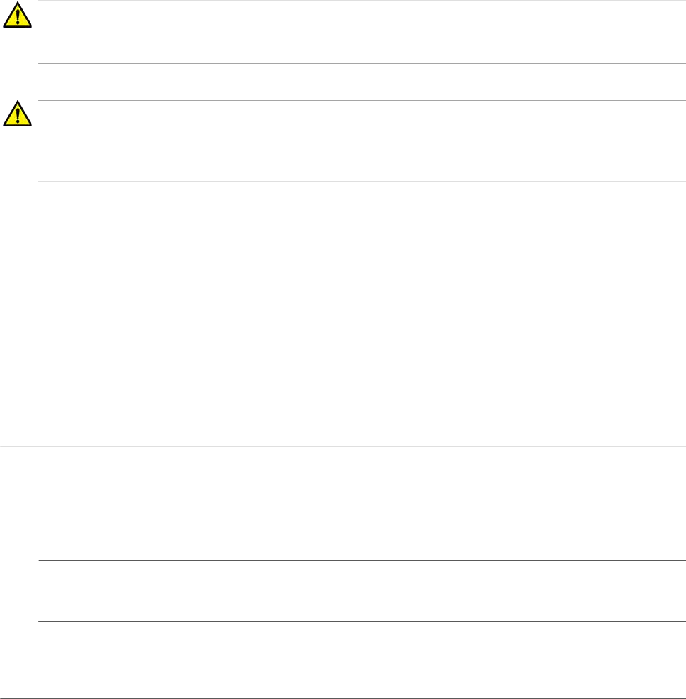
The top view of the AT-TQ1402 Series is illustrated in Figure 1.
Figure 1. Top View
4681
5GHz
2.4GHz
PWR
LAN
AT-TQ1402
Front Edge
Back Edge
AT-TQ1402 Series Wireless Access Point Installation Guide
21
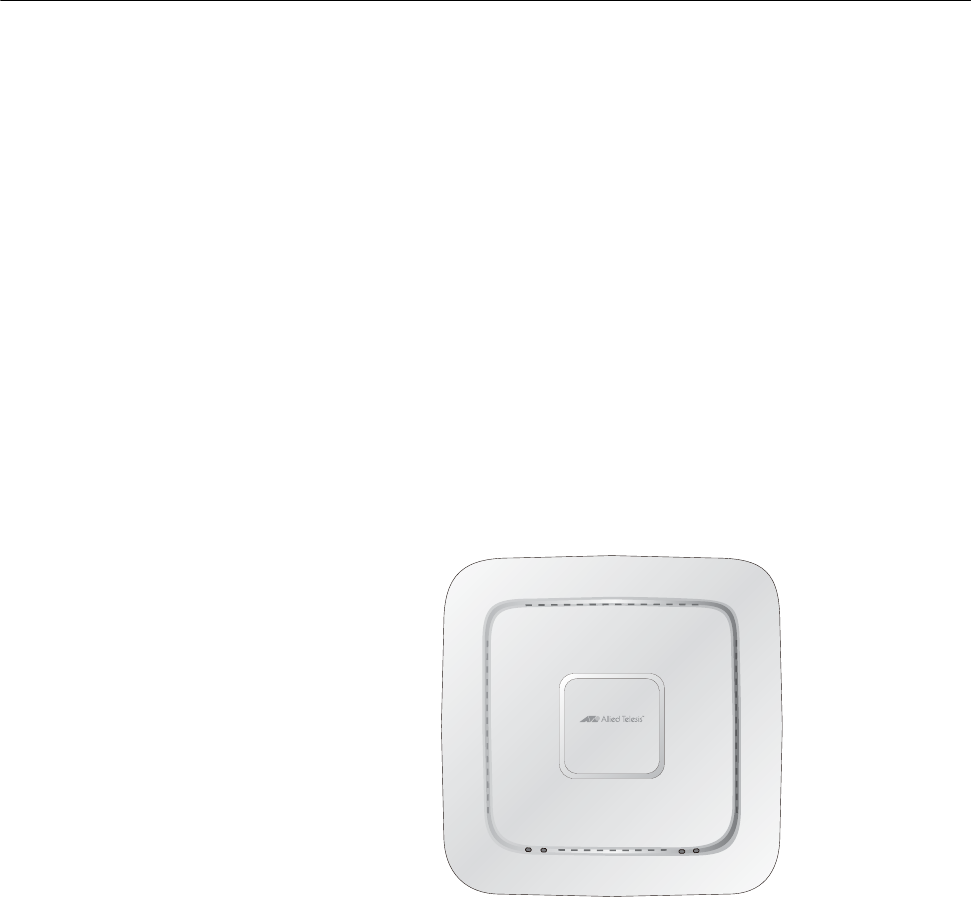
The front edge view of the AT-TQ1402 Series is illustrated in Figure 2.
Figure 2. Front Edge View
The back edge view of the AT-TQ1402 Series is illustrated in Figure 3.
Figure 3. Back Edge View
Note
The DC Power Button only controls power into the DC-IN jack only.
PoE power provided on the LAN port is not affected by this button.
4683
Mounting Bracket
Thumb Screw Hole
POE
4682
LAN CONSOLEDC INPOWER RESET
Ethernet
LAN-PoE
Port
Console
Serial Port
Reset
Button
DC Power
DC Input
Button
Jack

Chapter 1: Product Description
22
Features
This section lists the main features of the AT-TQ1402 Series Wireless
Access Point.
Hardware
Features
The hardware features are as follows:
One fixed 10/100/1000 BASE-T port (RJ-45) in dual function mode
to support IEEE standard 802.3af compliance powered device
(PD) mode of PoE. Based on parallel 12 DC in power plane from
PD power and DC-IN power source, and the power source
supplies to AP from PoE and external power supply unit (PSU) in
parallel.
Above RJ-45 ports are half- and full-duplex-compliant under IEEE
standards 802.3x and 802.3z. The port auto-negotiates wire
speed, duplex, and MDI/MDIX settings.
2x2 2.4 GHz + 2x2 5 GHz internal antennas.
One Reset Button for Device Reboot or Reset to Default functions.
One Power Jack for the supplied power source from the Power
Adapter.
One Ejector Push Button which is the hardware Power on/off
switch only for the Power Adapter.
Built-in one 16 MB SPI NOR flash and 128 MB DDR2 memory.
Supports three single-color LEDs (i.e., LAN, 2.4 GHz, 5 GHz).
Support one dual color LED (i.e., Power LED).
2.4 GHz band Frequency Range: 2412 – 2484 MHz.
5 GHz band Frequency Range: 5150 - 5250MHz, 5725-5850MHz.
IEEE802.11a/b/g/n/ac.
2.4 GHz 2x2 MIMO 20/40 MHz Bandwidth.
5 GHz 2x2 MIMO 20/40/80 MHz Bandwidth.
IEEE802.11ac function: downlink MU-MIMO, TX beamforming.
One Kensington lock port.
One RS232 RJ-45 port for software management console function
(factory use only).
Ceiling, Wall, or table top installation.

AT-TQ1402 Series Wireless Access Point Installation Guide
23
Management
Access
Access to manage the software features of the access point are:
Standalone
HTTPS
LAN Port The AT-TQ1402 Series Access Point is equipped with one Ethernet port -
LAN. The LAN port is capable of receiving PoE power (powered device
port) as the primary power or standing by as the backup power source for
an external power supply unit.
Note
For more information, see “Redundant Power Supply” on page 25.
The LAN port is capable of transmitting and receiving Ethernet traffic and
is typically connected to an Ethernet switch.
Power over Ethernet (PoE)
The AT-TQ1402 Series Access Point supports PoE on the LAN port. The
access point is a PoE Class 3 PD and its maximum power consumption is
12.95 watts. When the LAN port is connected to a PoE Ethernet power
source and no external power supply is connected, the access point
receives its power over the same LAN network cable that carries the
network traffic.
Connector Type
The LAN port has an eight-pin RJ45 connector for 10/100/1000 Mbps
communication. Refer to the tables in “Port Pinouts” on page 49 for the pin
assignments.

Chapter 1: Product Description
24
Speed
The LAN port can operate at 10/100 Mbps or 1000 Mbps. The speed is set
automatically with Auto-Negotiation. You cannot disable Auto-Negotiation
on the port.
Note
The LAN port should be connected to a network device that also
adjusts its speed with Auto-Negotiation. If the network device does
not support Auto-Negotiation, the LAN port operates at 10 Mbps,
which may reduce network performance.
Duplex Mode
The LAN port can operate in either half- or full-duplex mode at
10/100 Mbps, and full-duplex mode at 1000 Mbps. The port is IEEE
802.3u-compliant and uses Auto-Negotiation to set the duplex mode. (You
cannot disable Auto-Negotiation on the port.)
Note
The LAN port should be connected to a network device that also
sets its duplex mode with Auto-Negotiation. If the network device
does not support Auto-Negotiation, the LAN port operates at
half-duplex mode. This may result in a duplex mode mismatch if the
network device is operating at full duplex.
Automatic MDIX Detection
The 10/100/1000 Mbps twisted-pair port is IEEE 802.3ab-compliant and
features automatic MDIX detection when operating at 10/100 Mbps.
(Automatic MDIX detection does not apply to 1000 Mbps.) This feature
automatically configures the port to MDI or MDI-X depending on the wiring
configuration of the port on the Ethernet switch.
Do not disable automatic MDIX detection. For automatic MDIX detection
to work properly, it must also be present on the Ethernet switch. The LAN
port defaults to MDIX if it is connected to a network device that does not
support automatic MDIX detection.
Port Pinouts
One port without a shielded RJ45 connector is available for 10/100/1000
base copper communication and PD of PoE on the rear panel. That
connector is compliant with IEC603-7and IEEE 802.3af requirements. One
RJ45 connector is available for RS-232 communication on the rear panel.
Refer to Table 13 on page 50 for the port pinout.

AT-TQ1402 Series Wireless Access Point Installation Guide
25
Redundant Power Supply
The AT-TQ1402 Series Access Point offers a redundant power supply
system. In addition to the power supply through the DC-IN jack, the access
point has one PoE-capable LAN port (LAN). The external power supply
connected to the DC-IN jack is the primary power source for the unit. If the
power supply unit on the access point fails, power is supplied to the
access point via the PoE port. Table 1 shows power source for the
AT-TQ1402 Series Access Point under specific conditions.
Table 1. Primary Port for Power Source
Case
Power Supply
Primary Port - Power Source
DC-IN
jack LAN
1 On On The access point is supplied power via
the DC-IN jack.
2 On -
The access point is supplied power via
the DC-IN jack. No redundancy is
provided.
3 - On
The access point is supplied power
through the LAN port. No redundancy is
provided.

Chapter 1: Product Description
26
LEDs
The LEDs on the AT-TQ1402 Series Access Point top panel display the
status information. This LED display status information is given in Table 2.
Table 2. LED Status Information
LED State Description
Power
(PWR)
GREEN AT-TQ1402 Series is powered ON and
operating normally.
AMBER System is booting up.
OR
A fault condition has been detected.
BLINKING AMBER The firmware is upgrading.
OFF AT-TQ1402 Series is not receiving
power.
LAN
(PoE)
GREEN A valid link is established on the port.
BLINKING GREEN Data is being transmitted and received.
OFF No link is established.
2.4GHz
Wi-Fi
GREEN The 2.4GHz Wi-Fi interface is enabled.
OFF The 2.4GHz Wi-Fi interface is disabled.
5 GHz
Wi-Fi
GREEN The 5GHz Wi-Fi interface is enabled.
OFF The 5GHz Wi-Fi interface is disabled.


29
Chapter 2
AT-TQ1402 Series Wireless Access Point
Installation
This chapter describes how to install the AT-TQ1402 Series Access Point.
It contains the following sections:
“Review Safety Precautions” on page 30
“Unpack Shipping Box Contents” on page 32
“Installation Guidelines” on page 33
“Install Access Point” on page 34
– “General Installation Guidelines” on page 34
– “Table Top Installation” on page 34
– “Ceiling or Wall - Mounting Bracket Installation” on
page 35
– “Install Ethernet Cable and External DC Power Supply”
on page 40
– “External AC/DC Power Adapter Installation” on
page 40
– “Install Anti-theft Device” on page 41
– “Ceiling or Wall - Attach Chassis to Mounting Bracket”
on page 42
– “Start Initial Management Session” on page 44
Chapter 2: AT-TQ1402 Series Wireless Access Point Installation
30
Review Safety Precautions
Please review the following safety precautions before you begin to install
the access point.
Important: Safety statements that have the symbol are translated into
multiple languages in the Translated Safety Statements document, which
is available at www.alliedtelesis.com/library.
Remarque: Les consignes de sécurité portant le symbole sont
traduites dans plusieurs langues dans le document Translated Safety
Statements, disponible à l'adresse www.alliedtelesis.com/library.
Warning
To prevent electric shock, do not remove the cover. No
user-serviceable parts inside. This unit contains hazardous voltages
and should only be opened by a trained and qualified technician. To
avoid the possibility of electric shock, disconnect electric power to
the product before connecting or disconnecting the LAN cables.
E1
Warning
Do not work on equipment or cables during periods of lightning
activity. E2
Note
All Countries: Install product in accordance with local and National
Electrical Codes. E8
Warning
Only trained and qualified personnel are allowed to install or to
replace this equipment. E14
Warning
To reduce the risk of electric shock, the PoE ports on this product
must not connect to cabling that is routed outside the building where
this device is located. E40

AT-TQ1402 Series Wireless Access Point Installation Guide
31
Warning
This equipment shall be installed in a Restricted Access location.
E45
Warning
FCC Caution: Any changes or modifications not expressly approved
by the party responsible for compliance could void the user's
authority to operate this equipment. E80
Note
The AT-TQ1402 Series must be supplied by:
1. A UL Listed external AC/DC power supply suitable for use at
Tma 45 oC, a maximum operating altitude of 3000 m or higher, and
whose output meets separated extra-low voltage (SELV), limited
power sources (LPS) and is rated 12 VDC, 2.0 A,
OR
2. By Power over Ethernet through an UL Listed ITE. Refer to
Table 7, “External Power Supply Specifications” on page 46.
Chapter 2: AT-TQ1402 Series Wireless Access Point Installation
32
Unpack Shipping Box Contents
To unpack the AT-TQ1402 Series Access Point from the shipping box,
perform the following procedure:
1. Remove all components from the shipping box.
Note
Store the packaging material in a safe location so that if you need to
return the unit to Allied Telesis, you will have the original shipping
material available.
2. Verify that all components listed in Table 3 are included in your
shipping box. If any item is missing or damaged, contact your Allied
Telesis sales representative for assistance.
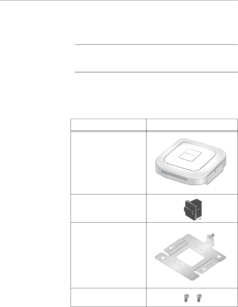
Table 3. Shipping Box Components
Name Component
AT-TQ1402 Series Access
Point
1 ea RJ-45 Dust Cap
(for Console port)
1 ea Mounting Bracket
2 ea Screws for the Chassis
(M5 x 8mm, Pan-head)
4680
PWR
AT-TQ1402
2.4GHz 5GHz
LAN
4417
AT-TQ1402 Series Wireless Access Point Installation Guide
33
Installation Guidelines
Review the following guidelines before installing the access point:
The ceiling or wall mounting surface must be of proper material to
accommodate the screws and strong enough to support the weight
of the access point and cables. (Refer to Table 4 on page 45 for
the product weight.)
Connect the Ethernet cable and power cord to the access point
before installing the access point on the ceiling or wall. These are
physically difficult to install after the chassis is installed on the
mounting bracket.
Ensure the Ethernet cable is long enough to connect to its
destination point before installing the access point. Once the
installation is complete, it is physically difficult to change the
cables.
If the primary power for the access point is to be the external power
supply (not provided with the AT-TQ1402 Series Access Point),
ensure that an AC power outlet is within six feet of the planned
installation site. (Refer to Table 6 on page 46 for the power supply
AC power specifications.)
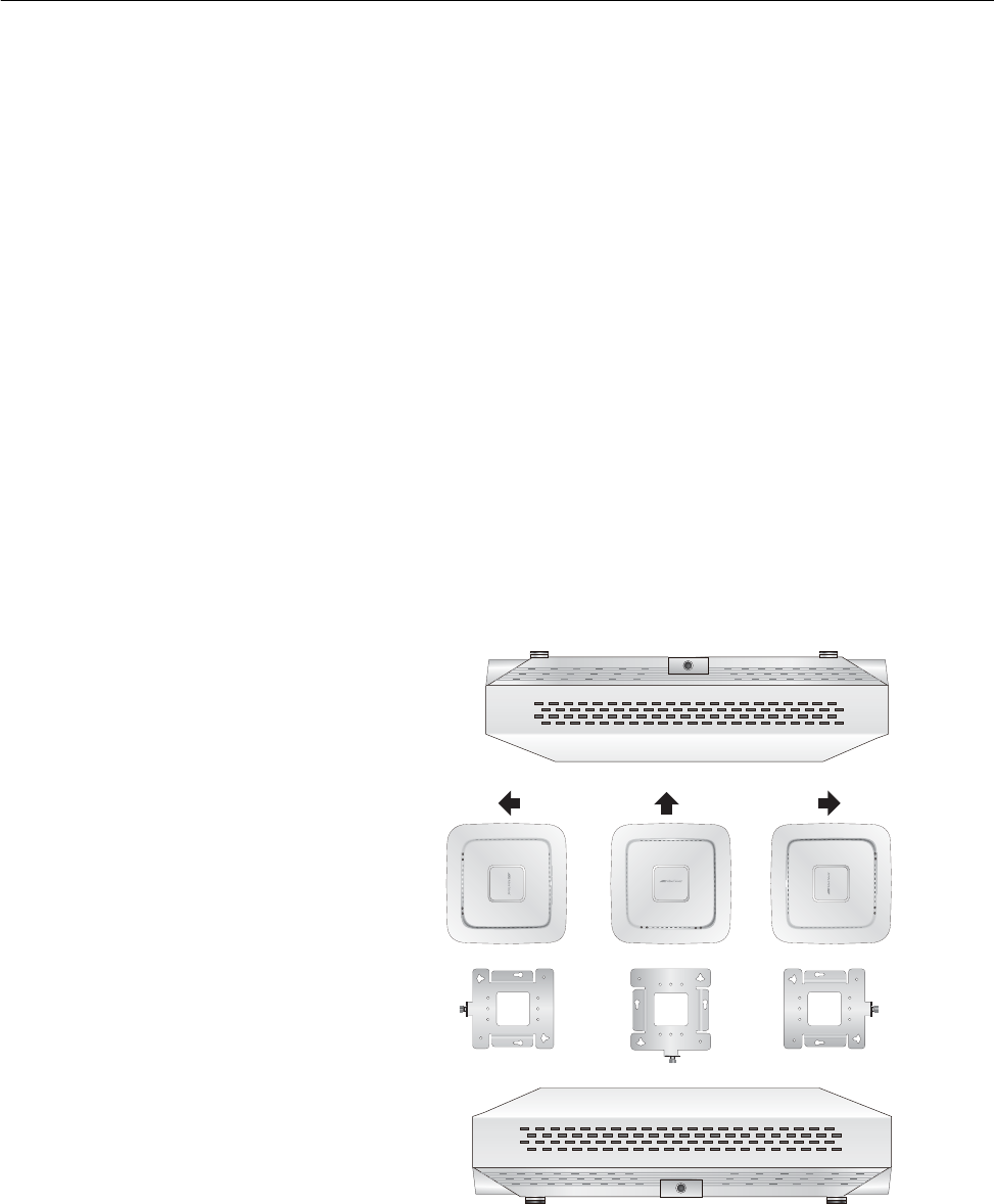
Refer to Figure 4 for the acceptable orientations for the table top,
wall and ceiling installations.
Figure 4. Acceptable Orientations on a Tabletop, Wall and Ceiling
Installation
4684
Ceiling
4485
5GHz
2.4GHz
PWR
LAN
AT-TQ1402
5GHz
2.4GHz
PWR
LAN
AT-TQ1402
5GHz
2.4GHz
PWR
LAN
AT-TQ1402
Wall
4683
Table Top

Chapter 2: AT-TQ1402 Series Wireless Access Point Installation
34
Install Access Point
This section contains the following topics:
“General Installation Guidelines” on page 34
“Table Top Installation” on page 34
“Ceiling or Wall - Mounting Bracket Installation” on page 35
“Install Ethernet Cable and External DC Power Supply” on page 40
“External AC/DC Power Adapter Installation” on page 40
“Install Anti-theft Device” on page 41
“Ceiling or Wall - Attach Chassis to Mounting Bracket” on page 42
General
Installation
Guidelines
The AT-TQ1402 Series Access Point can be mounted on a table, wall, or
hard-surface celling. The general installation guidelines are as follows:
Read “Review Safety Precautions” on page 30.
Review “Installation Guidelines” on page 33.
Select a location where both the power and Ethernet cable will
reach the power source and the partner Ethernet device.
Table Top
Installation
This section outlines the table top installation procedure.
Preparation for Table Top Installation
You need the following items to install the AT-TQ1402 Series Access
Point on a table top:
AT-TQ1402 Series Access Point
One Ethernet cable - See “Cable Specifications” on page 48
External AC/DC power supply (optional and not provided - Allied
Telesis recommends the AT-MWS0091 AC/DC Power Adapter)
Kensington Lock (optional and not provided)
Table Top Installation Procedure
Perform the following steps for the table top installation:
1. Go to “Install Ethernet Cable and External DC Power Supply” on
page 40.
2. If you choose to install a security cable to the AT-TQ1402 Series
Access Point, go to “Install Anti-theft Device” on page 41.

AT-TQ1402 Series Wireless Access Point Installation Guide
35
3. The installation of your AT-TQ1402 Series Access Point on the table
top surface is now complete.
Ceiling or Wall -
Mounting
Bracket
Installation
This section explains how to install the access point on a ceiling or wall
that consists of a hard surface. The following topics are included:
“Preparation for Ceiling or Wall Installation” on page 35
“Pre-Fit Mounting Bracket on AT-TQ1402 Series Access Point” on
page 36
“Install Mounting Bracket on Ceiling or Wall” on page 37
“External AC/DC Power Adapter Installation” on page 40
“Install Anti-theft Device” on page 41
“Ceiling or Wall - Attach Chassis to Mounting Bracket” on page 42
Preparation for Ceiling or Wall Installation
You need the following items to install the access point on a ceiling or wall:
AT-TQ1402 Series Access Point
Two screws to attach to the access point to mounting bracket
Mounting bracket
Four (4) M4, 25.0 mm flat-head wood screws and optional anchors
(not provided) for fastening the mounting bracket
Phillips head screwdriver (not provided)
Pencil (not provided)
External AC/DC power supply (optional and not provided - Allied
Telesis recommends the AT-MWS0091 AC/DC Power Adapter)
Kensington Lock (optional and not provided)
Note
The four Phillips head M4 screws/anchors, the Phillips head
screwdriver, pencil, external AC/DC power supply and Kensington
Lock are not included in the shipping box.
Chapter 2: AT-TQ1402 Series Wireless Access Point Installation
36
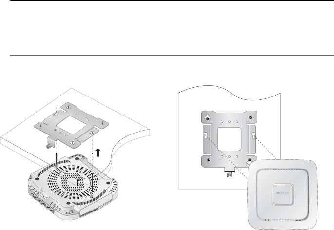
Pre-Fit Mounting Bracket on AT-TQ1402 Series Access Point
To pre-fit the access point on the mounting bracket, perform the following
procedure:
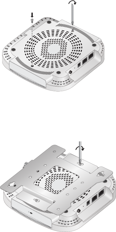
1. Install the two screws (provided) in the bottom side of the access point
chassis. Refer to Figure 5.
Figure 5. Attach Screws to Access Point Chassis
2. Align and insert the two screws installed in Step 1 into the mounting
bracket keyholes. Refer to Figure 6.
Figure 6. Adjust Screws on Access Point
4686
POE
LA1 CONSOLE
DC IN
POWER RESET
4687
POE
LA1 CONSOLE
DC IN
POWER RESET
AT-TQ1402 Series Wireless Access Point Installation Guide
37
3. Tighten the screws so that they touch the mounting bracket plate and
then loosen them by approximately 1/4 turn.
Note
Adjust the access point chassis screws so they are loose enough to
slide into the narrow end of the mounting bracket keyhole, but tight
enough to be hold the access point close without rattling against the
mounting bracket.
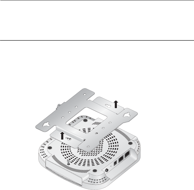
4. Slide the mounting bracket forward and temporarily remove it from the
access point chassis so the bracket can be independently mounted on
the ceiling or wall in the next steps. Refer to Figure 7.
Figure 7. Remove Mounting Bracket From Access Point
Install Mounting Bracket on Ceiling or Wall
1. Choose an allowable orientation of the access point from the examples
shown in Figure 4 on page 33.
Ensure that the thumb screw on the mounting bracket is oriented in the
same direction as the front of the access point chassis so that the
intended orientation of the chassis is achieved after installation.
4688
POE
LA1 CONSOLE
DC IN
POWER RESET
Chapter 2: AT-TQ1402 Series Wireless Access Point Installation
38
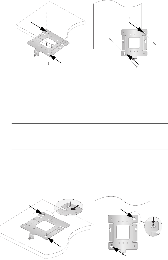
2. Using the mounting bracket as a template, mark the two key-hole slots
with a pencil in the location and orientation where you want to install
the access point. Refer to the arrows in Figure 8.
Figure 8. Mark and Pre-Drill Holes for Key-Hole Slots
3. Pre-drill the two marked locations for the keyhole slots on the
hard-surface ceiling or wall and install two M4 screws and anchors (if
required). Leave the screws loose enough so that the bracket can slide
under the screw head in Step 4.
Note
For a wooden wall or ceiling, use M4, 25.0 mm flat-head wood
screws and anchors if required. The screws and anchors are not
provided.
4. Insert the openings of the bracket key-hole slots under the two screw
heads and slide the bracket into narrow end of the key-hole slot
opening. Refer to arrows in Figure 9. Tighten the screws snugly onto
the bracket.
Figure 9. Mount Bracket On Screws Using Key-Hole Slots
4440
4436
Ceiling Wall
4441
4437
Ceiling Wall
AT-TQ1402 Series Wireless Access Point Installation Guide
39
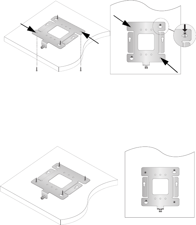
5. Secure the physical position of the mounting bracket by pre-drilling
holes through the two existing open bracket mounting holes in the
opposite corners from the key-hole slots. Refer to the arrows in
Figure 10.
Figure 10. Pre-Drill Holes for Mounting Bracket
6. Install and tighten two M4 screws (not provided) in the holes prepared
in Step 5. The physical position of the bracket is now stationary. Refer
to Figure 11.
Figure 11. Stationary Bracket Position
7. Go to the next procedure - ”Install Ethernet Cable and External DC
Power Supply”.
4437
4441
Ceiling Wall
4442
4439
Ceiling Wall
Chapter 2: AT-TQ1402 Series Wireless Access Point Installation
40
Install Ethernet
Cable and
External DC
Power Supply
The Ethernet and power cable needs to be connected before attaching the
access point to the mounting bracket.
Note
Refer to “Cable Specifications” on page 48 when selecting Ethernet
cable.
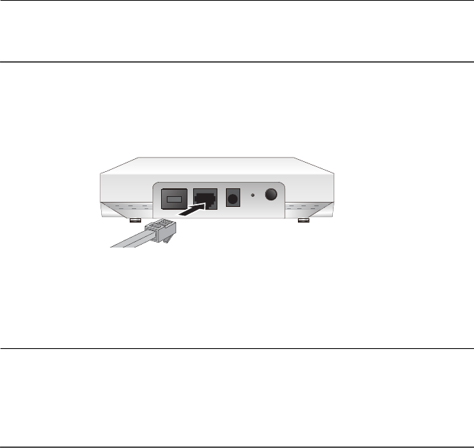
1. Connect the Ethernet cable into the RJ-45 LAN port. Refer to
Figure 12. This Ethernet port is capable of receiving PoE power.
Figure 12. Connect Ethernet Cable to LAN Port
2. Connect the opposite end of the Ethernet cable to your network
Ethernet device.
Note
If you plan to use PoE power as the primary or redundant power
source, then the Ethernet device connected to the LAN port needs
to be capable of providing PoE power. For the PoE input power
specifications, refer to “PoE Power Requirements” on page 47.
3. Depending on the primary power source for the AT-TQ1402 Series
Access Point, perform one of the following steps:
a. If the access point is to be powered with the PoE feature only, then
the PoE power source is already connected via the Ethernet cable
connected to LAN. Go to “Install Anti-theft Device” on page 41.
b. If the primary power for the access point is to be an external
AC/DC power supply, proceed to ”External AC/DC Power Adapter
Installation”.
External AC/DC
Power Adapter
Installation
If you choose to use an external AC/DC power supply, Allied Telesis
recommends that you procure an AT-MWS0091 Power Adapter by
contacting your local Allied Telesis representative.
Perform the following procedure to install the external power supply:
1. Check the AC plug on the external power supply and verify that it is the
correct plug for your region. If it is not, follow the instructions provided
with the external power supply to install the correct AC plug that is
compatible with your region.
POE
4696
LAN CONSOLEDC INPOWER RESET
AT-TQ1402 Series Wireless Access Point Installation Guide
41
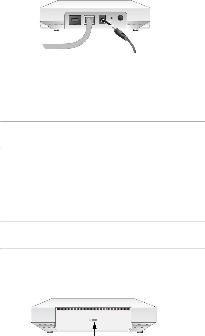
2. Plug the DC plug of the Power Adapter into the DC-IN jack on the
access point. Refer to Figure 13.
Figure 13. Connect External AC/DC Power Adapter Cable
3. Connect the external power supply AC plug to an appropriate AC
power source.
4. On the AT-TQ1402 Series chassis, push the DC Power Button to the
“IN” position to turn ON the power supply at the chassis.
Note
The DC Power Button controls power to the DC-IN jack only. PoE
power provided on the LAN port is not affected by this button.
5. Go to the ”Install Anti-theft Device” section.
Install Anti-theft
Device
Installation of an anti-theft cable/lock is optional. If you choose to install a
physical security device, the AT-TQ1402 Series has a lock port that is
compatible with a Kensington lock. The lock port can be used to physically
secure the device when it is installed on a table, wall, or a ceiling.
Note
Anti-theft devices including a Kensington lock are not available from
Allied Telesis.
1. Follow the instructions provided with the vendor’s anti-theft device
packaging for the installation. Refer to Figure 14 for the Kensington
lock port location.
Figure 14. Kensington Lock Port Location
POE
4693
LAN CONSOLEDC INPOWER RESET
4697
Kensington
Lock Port
Chapter 2: AT-TQ1402 Series Wireless Access Point Installation
42
2. If you are installing your AT-TQ1402 Series on a table top surface,
your unit is now ready for use.
3. If you are installing your AT-TQ1402 Series on the ceiling or wall
installation, go to “Ceiling or Wall - Attach Chassis to Mounting
Bracket” on page 42 section.
Ceiling or Wall -
Attach Chassis to
Mounting
Bracket
Perform this procedure to complete the ceiling or wall installation by
attaching the chassis to the mounting bracket.
1. Align and insert the two access point chassis screws into the keyhole
slots of the mounting bracket. Refer to Figure 15.
Note
These are the same two access point chassis screws that you
previously installed in the procedure “Ceiling or Wall - Mounting
Bracket Installation” on page 35.
Figure 15. Align/Insert Access Point into Mounting Bracket
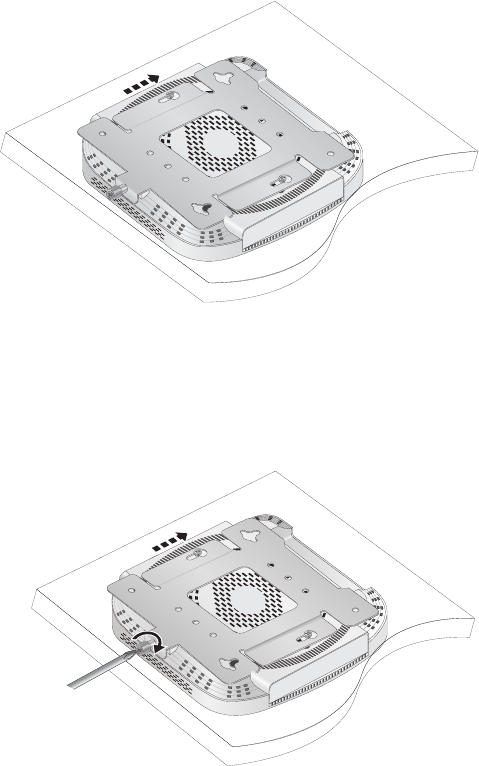
2. Slide the chassis forward until seated into the bracket keyhole slot and
the bracket thumbscrew is aligned with the screw hole on the front of
the chassis. Refer to Figure 16 on page 43.
4692
5GHz
2.4GHz
PWR
LAN
AT-TQ1402
Ceiling Wall
4689
AT-TQ1402 Series Wireless Access Point Installation Guide
43
Figure 16. Seat Access Point onto Mounting Bracket
3. Tighten the bracket thumbscrew into the front of the chassis until it is
securely fastened. Refer to Figure 17.
Figure 17. Securely Fasten Chassis to Mounting Bracket with
Thumbscrew
4. The ceiling or wall installation is now complete and your AT-TQ1402
Series Access Point is ready for use.
4690
4691

Chapter 2: AT-TQ1402 Series Wireless Access Point Installation
44
Start Initial Management Session
This section contains an abbreviated version of the procedure to start the
initial management session. For complete instructions, refer to the
AT-TQ1402 Series Wireless Access Point Series User’s Guide.
The wireless access point firmware includes a DHCP client. The default
setting for the client is enabled. When you power on the access point for
the first time, it queries the subnet on the LAN port for a DHCP server. If a
DHCP server responds to its query, the unit uses the IP address the
server assigns to it. If there is no DHCP server, the access point uses the
default IP address 192.168.1.230.
To start the initial management session, perform the following procedure:
1. Start the web browser on your management workstation.
2. Enter the IP address of the wireless access point in the URL field of
the web browser. The address is one of the following:
If your network does not have a DHCP server, enter the default
address 192.168.1.230.
If your network has a DHCP server, enter the IP address the
DHCP server assigned to the access point.
The wireless access point displays the logon prompt. Refer to
Figure 18.
Figure 18. Logon Prompt
3. Enter “manager” for the username and “friend” for the password. The
username and password are case-sensitive.
TQ1402

45
Appendix A
Technical Specifications
This appendix contains the following sections:
“Physical Specifications”
“Environmental Specifications”
“Power Specifications” on page 46
“Cable Specifications” on page 48
“LAN Port Specifications and Pinouts” on page 49
Physical Specifications
Environmental Specifications
Table 4. Physical Specifications
Parameter Specification
Dimensions (W x D x H) 163 mm x 165 mm x 40.5 mm
(6.42 in. x 6.50 in. x 1.59 in.)
Weight (AT-TQ1402 Series with
mounting bracket)
567 g (1.25 lb)
Table 5. Environmental Specifications
Parameter Specification
Operating Temperature when powered
by AC power supply
0° C to 45° C (32° F to 113° F)
Operating Temperature when powered
by PoE power source
0° C to 45° C (32° F to 122° F)
Storage Temperature - 25° C to 70° C (-13° F to 158° F)
Operating Humidity 0% to 90% non-condensing
Storage Humidity 0% to 95% non-condensing
Maximum Operating Altitude 3000 m (9843 ft)

Appendix A: Technical Specifications
46
Power Specifications
Input Power
Specifications
The power specifications for the AT-TQ1402 Series Access Point are
given in Table 6.
External Power
Supply
Specifications
The external power supply must be capable of powering the
AT-TQ1402 Series Access Point by meeting the specifications given in
Table 7.
Note
Allied Telesis recommends using the AT-MWS0091 (WA-24Q12R)
external AC/DC power supply with the AT-TQ1402 Series Access
Point. This power supply is a UL Listed power supply and is fully
compatible with the above specifications while meeting the
standards of a SELV.
Table 6. Input Power Specifications
Parameter Specification
Rated Input Voltage 12 VDC
Maximum Input Current 0.7 A
Average Input Current 0.52 A
Table 7. External Power Supply Specifications
Parameter Specification
Input Voltage Range 90 to 264 V
Input Frequency 47 to 63 Hz
Rated Output Voltage 12 VDC ±5%
Rated Output Current 2 A
Temperature Range 0° C to 45° C (32° F to 113° F)
Maximum Operating Altitude 3000 m (9843 ft)

AT-TQ1402 Series Wireless Access Point Installation Guide
47
Note
The AT-MWS0091 (WA-24Q12R) external power supply is not
supplied or shipped with the AT-TQ1402 Series Access Point
product.
PoE Power
Requirements
The AT-TQ1402 Series Access Point power requirements for the LAN PoE
port are given in Table 8.
Table 8. PoE Power Requirements
Parameter Specification
AT-TQ1402 Series 12.95 watts
PoE Device Classification Class 3 Powered Device

Appendix A: Technical Specifications
48
Cable Specifications
The AT-TQ1402 Series Access Point Ethernet cable requirements for the
LAN ports are listed in Table 9.
Note
The maximum operating distance of these cables is 100 meters
(328 feet).
Table 9. LAN Port Twisted Pair Cable Requirements
Cable Type
10 Mbps 100 Mbps 1000 Mbps
PoE PoE PoE
Standard TIA/EIA 568-A-compliant
Category 5 shielded or unshielded
cabling with 100 ohm impedance and
100 MHz frequency.
Yes Yes No
Standard TIA/EIA 568-B-compliant
Enhanced Category 5 (Cat 5e) shielded
or unshielded cabling with 100 ohm
impedance and 100 MHz frequency.
Yes Yes Yes
Standard TIA/EIA 568-B-compliant
Category 6 or 6a shielded cabling.
Yes Yes Yes
AT-TQ1402 Series Wireless Access Point Installation Guide
49
LAN Port Specifications and Pinouts
Port
Specifications
The AT-TQ1402 Series Access Point port specifications are shown in
Table 10.
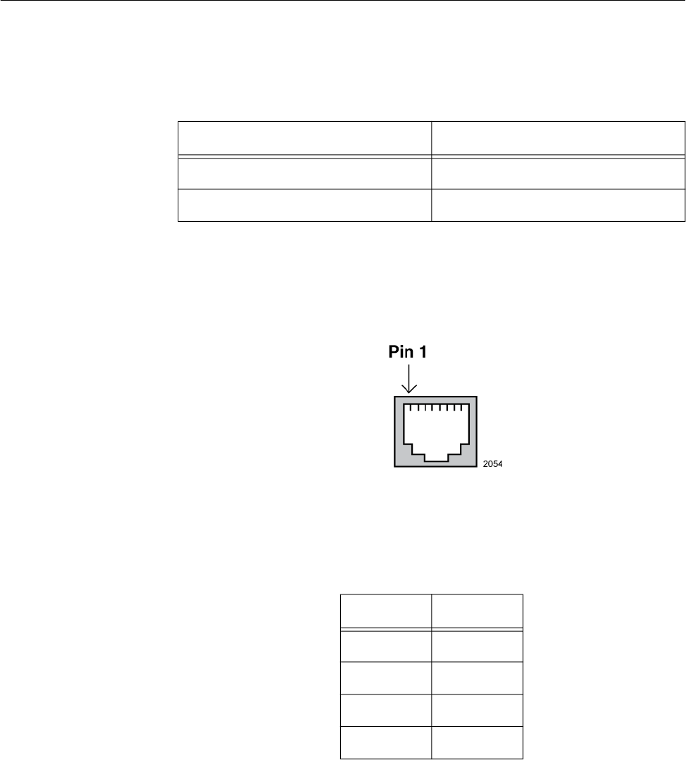
Port Pinouts The pin signal definitions for 10/100/1000 Mbps Ethernet traffic are as
follows.
Figure 19 illustrates the pin layout of the LAN ports.
Figure 19. Pin Layout for RJ45 Connector on LAN Port
Table 11 lists the pin signals when the port is operating in the MDI
configuration at 10/100 Mbps.
Table 10. LAN Port Specifications
Connector Specification
Standards - LAN IEC603-7 (10/100/1000 Base T)
PoE standard - LAN IEEE 802.3af (class 3)
Table 11. MDI Pin Signals (10Base-T or 100Base-TX)
Pin Signal
1 TX+
2 TX-
3 RX+
6 RX-

Appendix A: Technical Specifications
50
Table 12 lists the pin signals for the MDI-X configuration at 10/100 Mbps.
Table 13 lists the pin signals when the LAN port is operating at 1000
Mbps.
Table 12. MDI-X Pin Signals (10Base-T or 100Base-TX)
Pin Signal
1 RX+
2 RX-
3 TX+
6 TX-
Table 13. Connector Pinouts (1000Base-T)
Pin Pair Signal
1 1 TX and RX
2 1 TX and RX-
3 2 TX and RX+
4 3 TX and RX+
5 3 TX and RX-
6 2 TX and RX-
7 4 TX and RX+
8 4 TX and RX-

Appendix Appendix B: Regulatory Statements
52
Federal Communication Commission Interference Statement
This device complies with Part 15 of the FCC Rules. Operation is subject
to the following two conditions: (1) This device may not cause harmful
interference, and (2) this device must accept any interference received,
including interference that may cause undesired operation.
This equipment has been tested and found to comply with the limits for a
Class B digital device, pursuant to Part 15 of the FCC Rules. These limits
are designed to provide reasonable protection against harmful
interference in a residential installation. This equipment generates, uses
and can radiate radio frequency energy and, if not installed and used in
accordance with the instructions, may cause harmful interference to radio
communications. However, there is no guarantee that interference will not
occur in a particular installation. If this equipment does cause harmful
interference to radio or television reception, which can be determined by
turning the equipment off and on, the user is encouraged to try to correct
the interference by one of the following measures:
Reorient or relocate the receiving antenna.
Increase the separation between the equipment and receiver.
Connect the equipment into an outlet on a circuit different from that
to which the receiver is connected.
Consult the dealer or an experienced radio/TV technician for help.
Caution
FCC Caution: Any changes or modifications not expressly approved
by the party responsible for compliance could void the user's
authority to operate this equipment. E80
Caution
Avertissement de la FCC: Les changements ou modifications non
expressément approuvés par la partie responsable de la conformité
pourraient annuler l'autorité de l'utilisateur à utiliser cet équipement.
E80
This transmitter must not be co-located or operating in conjunction with
any other antenna or transmitter. This device is restricted to indoor use only
The band from 5600-5650MHz will be disabled by the software during the
manufacturing and cannot be changed by the end user.
This device meets all the other requirements specified in Part 15E,
Section 15.407 of the FCC Rules.
AT-TQ1402 Series Wireless Access Point Installation Guide
53
Radiation Exposure Statement
This equipment complies with FCC radiation exposure limits set forth for
an uncontrolled environment. This equipment should be installed and
operated with minimum distance 20 cm between the radiator and your
body.
Appendix Appendix B: Regulatory Statements
54
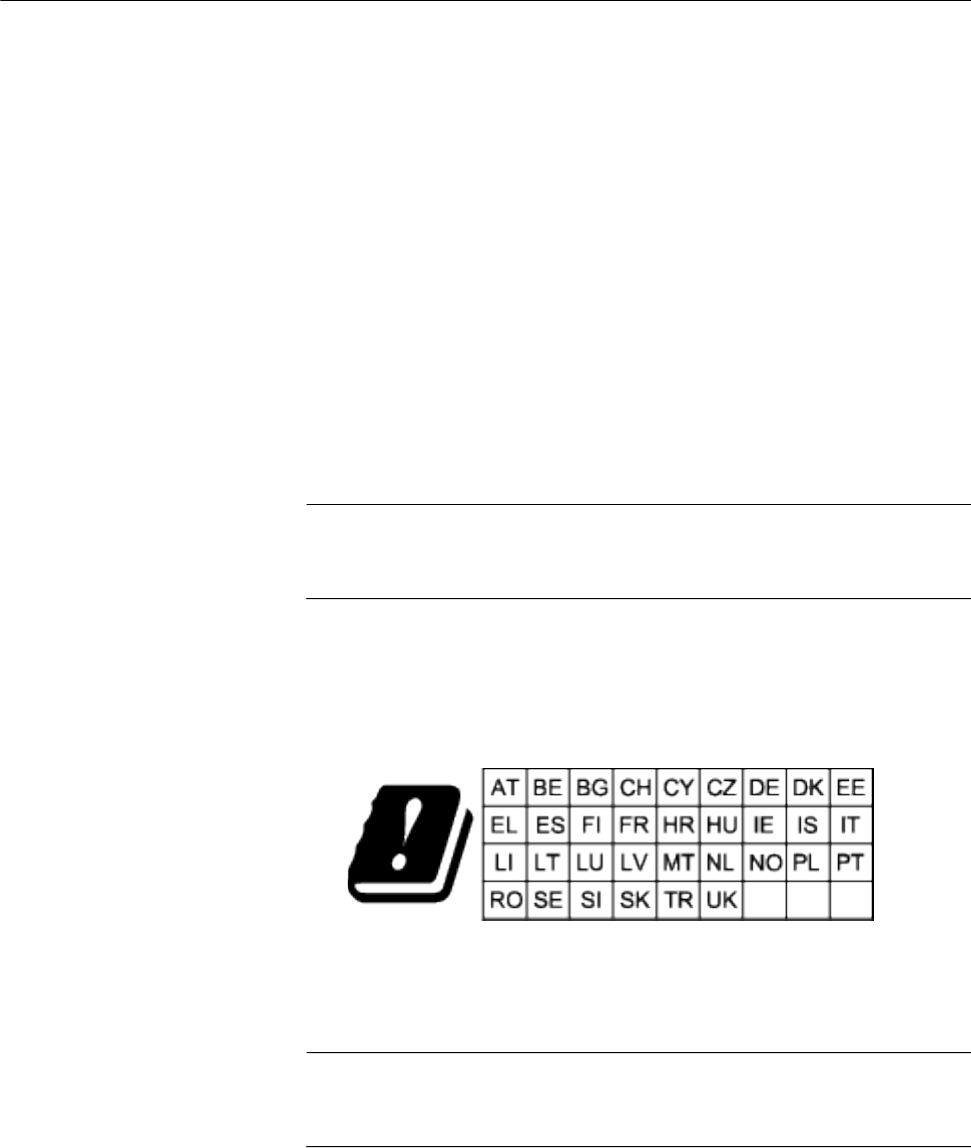
Europe - EU Declaration of Conformity
Hereby, Allied Telesis declares that the radio equipment type
[AT-TQ1402 and AT-TQm1402] is in compliance with Directive
2014/53/EU.
Operating
Frequencies and
Maximum
Transmission
Power Levels
The operating frequencies and maximum transmission power
levels for wireless devices operated in the EU are listed below:
- 2412-2472 MHz:
19.78dBm (Non-Beamforming)
- 5150-5250 MHz:
22.11 dBm (Beamforming), 22.04dBm (Non-Beamforming)
- 5250-5350 MHz:
22.22 dBm (Beamforming), 22.17dBm (Non-Beamforming)
- 5470-5725 MHz:
27.31 dBm (Beamforming), 25.29dBm (Non-Beamforming)
Note
Operations in the 5.15 - 5.35 GHz band are restricted to indoor
usage only.
Radiation
Exposure
Statement
This equipment complies with EU radiation exposure limits set
forth for an uncontrolled environment. This equipment should be
installed and operated with a minimum distance of 20 cm between
the radiator and your body.
Importer Allied Telesis International BV
Incheonweg 7, 1437 EK Rozenburg
Note
Contact Allied Telesis for the EU conformity statement. To contact
Allied Telesis, visit our web site at www.alliedtelesis.com/contact.