Allied Telesis At Img616Rf Rf Users Manual 613 000279_A
AT-IMG616RFRF+ to the manual 46492aa2-d5bc-7104-b14a-f25b89a70b6d
2015-02-02
: Allied-Telesis Allied-Telesis-At-Img616Rf-Rf-Users-Manual-414225 allied-telesis-at-img616rf-rf-users-manual-414225 allied-telesis pdf
Open the PDF directly: View PDF ![]() .
.
Page Count: 21

AT-iMG616RF/RF+
INSTALLATION GUIDE

AT-iMG616RF/RF+ Series Multiservice VoIP Gateway - User Manual 3
AT-IMG616RF/RF+ SERIES MULTISERVICE VOIP GATEWAY -
USER MANUAL
This User Manual covers the following products:
AT-iMG616RF/RF+
For a description of detailed functionality please refer to the Reference Manual. For installation
and safety instructions please refer to this User Manual.
Document Number 616-000279 REV A.
Copyright © 2006 Allied Telesis Holdings K.K.
All rights reserved. No part of this publication may be reproduced without prior written
permission from Allied Telesis.
Allied Telesis reserves the right to make changes in specifications and other information
contained in this document without prior written notice. The information provided herein is
subject to change without notice. In no event shall Allied Telesis be liable for any incidental,
special, indirect, or consequential damages whatsoever, including but not limited to lost profits,
arising out of or related to this manual or the information contained herein, even if Allied Telesis
has been advised of, known, or should have known, the possibility of such damages.
All trademarks are the property of their respective owners.
ATTENTION
All the information in this manual is property of Allied Telesis K.K., please do not copy or
reproduce all or part of this manual without permission. The company may change or revise all
or part of this manual. It may also change the specification of the product for purposes of
improvement without notice.
Thank you for choosing the AT-iMG616RF/RF+ Multiservice Gateway. Please read this manual
carefully and use the device correctly. “The device”, “this product”, “AT-iMG616RF/RF+ “, “AT-
iMG616” and “MG616” all refer to the Multiservice Gateway unit.
Please see below for the meaning of the icons used in this manual.
TABLE 1: ICONS
Icon Meaning
Useful information
Indication of risk of a serious injury and/or damage to the environment
As above
Indication of reference page and information

4 AT-iMG616RF/RF+ Series Multiservice VoIP Gateway - User Manual
Contents
IMPORTANT SAFETY INSTRUCTIONS................................................................................................................ 5
1. IMPORTANT NOTICE................................................................................................................................7
1.1. EMISSION STATEMENT............................................................................................................................................................. 7
2. CONTENTS OF THE PACKAGE.................................................................................................................. 8
2.1. WHAT CAN THE AT-IMG616RF/RF+ DO FOR YOU?....................................................................................................... 9
3. PRODUCT DETAILS ............................................................................................................................... 10
3.1. TOP VIEW OF UNIT ...............................................................................................................................................................10
3.2. FRONT VIEW OF UNIT...........................................................................................................................................................12
3.3. SIDE VIEW OF UNIT................................................................................................................................................................12
3.4. 3D VIEW OF UNIT..................................................................................................................................................................13
4. TELEPHONES AND CABLES .................................................................................................................... 14
4.1. AT-IMG616 - POTS TELEPHONE AND FAX OPERATION ..............................................................................................14
4.2. TELEPHONE CORD, UTP CABLE AND TV CABLE ..............................................................................................................15
4.3. TV ...........................................................................................................................................................................................16
4.4. OPTICAL FIBERS FOR ETHERNET AND CATV....................................................................................................................16
5. CONNECTING THE AT-IMG616RF/RF+ ............................................................................................... 17
5.1. CONNECTING THE PSTN TELEPHONE PORTS ..................................................................................................................17
5.2. UTP CABLE CONNECTION .................................................................................................................................................17
5.3. CATV CABLE CONNECTION..............................................................................................................................................18
5.4. DISCONNECTING POWER SUPPLY.......................................................................................................................................18
NOTICE ABOUT FUNCTIONS AND SERVICES .....................................................................................................................................18
6. APPENDIX A: TROUBLESHOOTING........................................................................................................ 19
7. FAULT FINDING..................................................................................................................................... 20
8. APPENDIX B: TECHNICAL SPECIFICATIONS .......................................................................................... 21
8.1. PRODUCT SPECIFICATIONS AT-IMG616RF/RF+.............................................................................................................21
9. APPENDIX C: CONTACT INFORMATION ................................................................................................ 22
AT-iMG616RF/RF+ Series Multiservice VoIP Gateway - User Manual 5
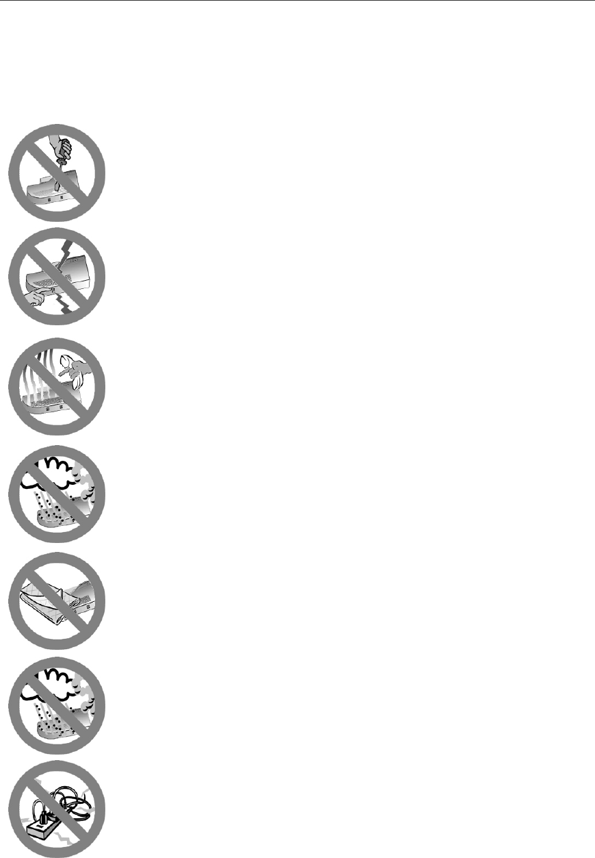
Important safety instructions
DO NOT OPEN the product, remove screws or cover. To prevent
ELECTRIC SHOCK during normal use, the plastic chassis of the product must
be kept closed.
This unit contains HAZARDOUS VOLTAGES and should only be opened by a
trained and qualified technician.
DANGER: DO NOT WORK on equipment or CABLES during periods of
LIGHTNING ACTIVITY to avoid ELECTRIC SHOCK.
Do not use the telephone to report a gas leak in the vicinity of the leak.
To avoid risk of electrical shock or fire, this device, connecting peripherals and
cables, should not be used in an outside environment.
Air vents must not be blocked. They must have free access to the
environment air for cooling to prevent fire caused by excessive heating.
To avoid the possibility of ELECTRIC SHOCK or FIRE caused by a short in
internal circuits, do not place the device in any of the environments listed on
point 2.
To avoid FIRE risk, use this unit only with industry standard plugs and wiring
suitable for your territory.
6 AT-iMG616RF/RF+ Series Multiservice VoIP Gateway - User Manual
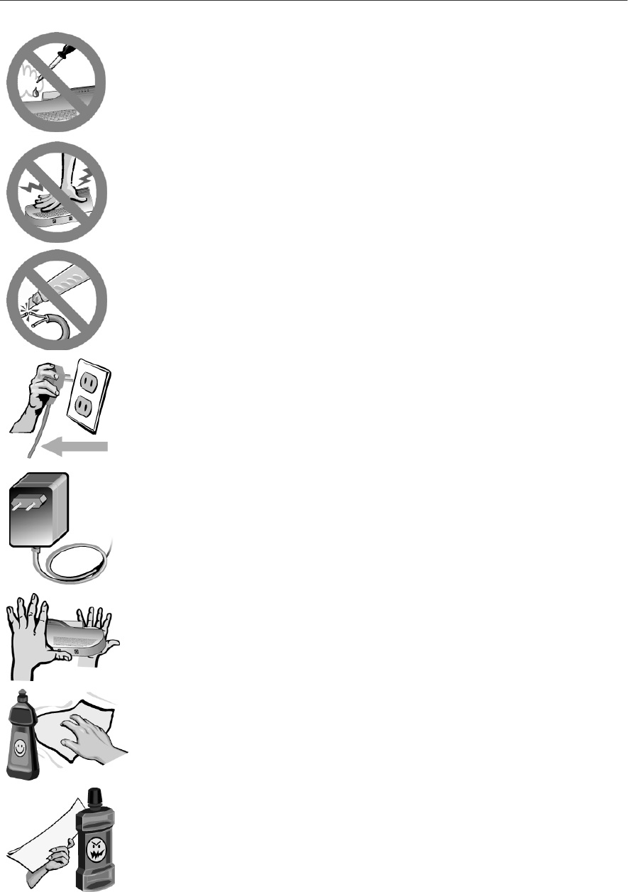
Be careful not to drop water or any other harmful substance onto the product.
This could lead to fire or electric shock. If the unit might get in contact with
liquids, unplug the power and contact your support center or sales stores.
This product contains parts that are sensitive to static shock.
Please avoid touching interface connectors with bare hands.
This could lead to fire or electric shock.
Take care when handling the power cable and plug:
• Do not strain the power cable
• Do not place near a heater or stove
• Unplug the power cable using the plug
Keep the product free away from dust and maintain it clean.
Unplug before cleaning.
Only the power adapter supplied with this unit is guaranteed to function
correctly with it.
Do not drop the unit, handle with care.
If really dirt, clean using a soft, damp cloth with a neutral detergent.
Then dry with a soft cloth.
Do not use oil, cleanser, thinner, petrol, wax, boiled water and powdered soap
(please follow the instructions when you use a chemical duster).
AT-iMG616RF/RF+ Series Multiservice VoIP Gateway - User Manual 7
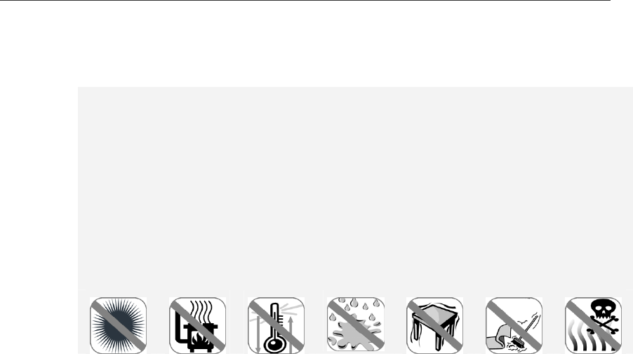
1. Important notice
Do not use or store the device:
In direct sunlight.
In a hot environment.
In a low-airflow environment, such as a drawer or a closet, while the unit is turned on. Restricting
airflow can damage the unit or cause a fire.
Where there could be a sudden temperature change
In a damp place or near a liquid such as water. Humidity must be less than 80%.
In areas subject to a lot of vibration.
In dusty and/or carpeted areas.
In the presence of corrosive gases.
1.1. Emission Statement
CE Marking Warning: This is a class B product. In a domestic environment this product may
cause radio interference in which case the user may be required to take adequate measures.
Please install and use it in accordance with this user manual.
8 AT-iMG616RF/RF+ Series Multiservice VoIP Gateway - User Manual
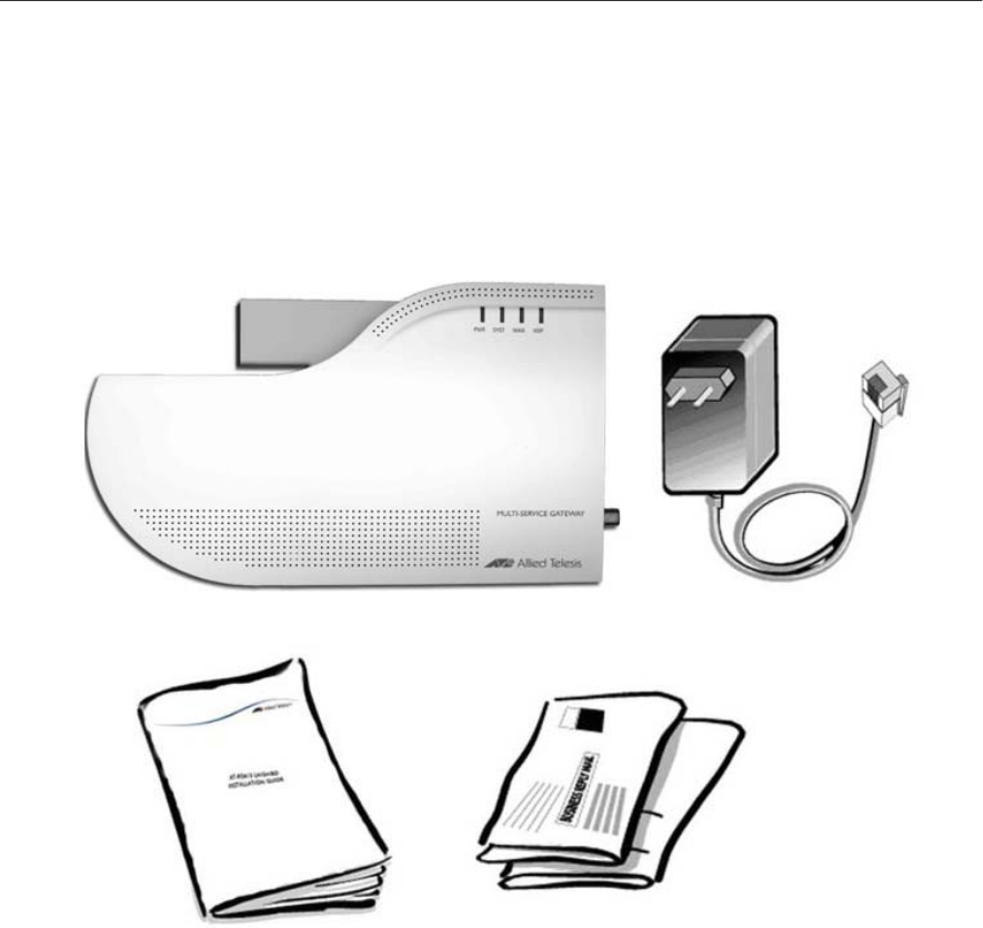
2. Contents of the package
FIGURE 1: CONTENTS OF THE PACKAGE
(Notice) The package does not contain screws.
The following items are included with each AT-iMG616RF/RF+. Contact your sales
representative if any items are damaged or missing.
One AT-iMG616RF/RF+
One AC/DC power adapter
One AT-iMG616RF/RF+ Series Multiservice VoIP Gateway User Manual
One warranty card
iMG616RF/RF+
Body
Power Adapte
r
User Manual
W
arranty Card
AT-iMG616RF/RF+ Series Multiservice VoIP Gateway - User Manual 9
2.1. What can the AT-iMG616RF/RF+ do for you?
The AT-iMG616RF/RF+ is Customer Premise Equipment (CPE) designed for being installed in a
customer residence, it interfaces with new generation fibre networks designed to support
broadband communications.
The AT-iMG616RF/RF+ is the ideal platform for operators and service providers who can access
native cable TV content for their entry-level deployment of IP Triple Play services over FTTH
networks. It also offers Cable operators and MSOs the ability to maintain their investment in
video delivery and leverage their existing video content format for delivery over Next-
generation IP/Ethernet FTTH-based broadband networks.
Using this intelligent equipment, called a "multi-service gateway", you can use broadband
integrated services for telephony, Internet, Internet Video and CATV (Community Antenna
Television of Cable TV).
The VoIP multi-service gateway is fitted with a number of ports for connection of telephones,
faxes, PC's, set top box for TV and Cable TV.
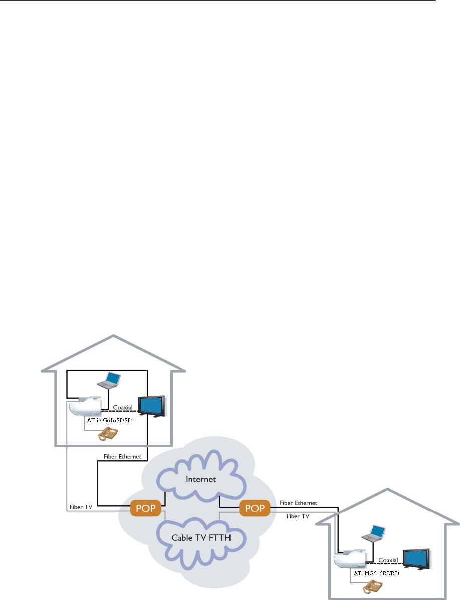
Using the internal Ethernet router you can easily build a firewall-protected Local Area Network
(LAN) in your home supporting multiple PC's as well as a set top box for TV/video services (see
figure below).
FIGURE 2: LAN CONNECTIONS
10 AT-iMG616RF/RF+ Series Multiservice VoIP Gateway - User Manual
3. Product Details
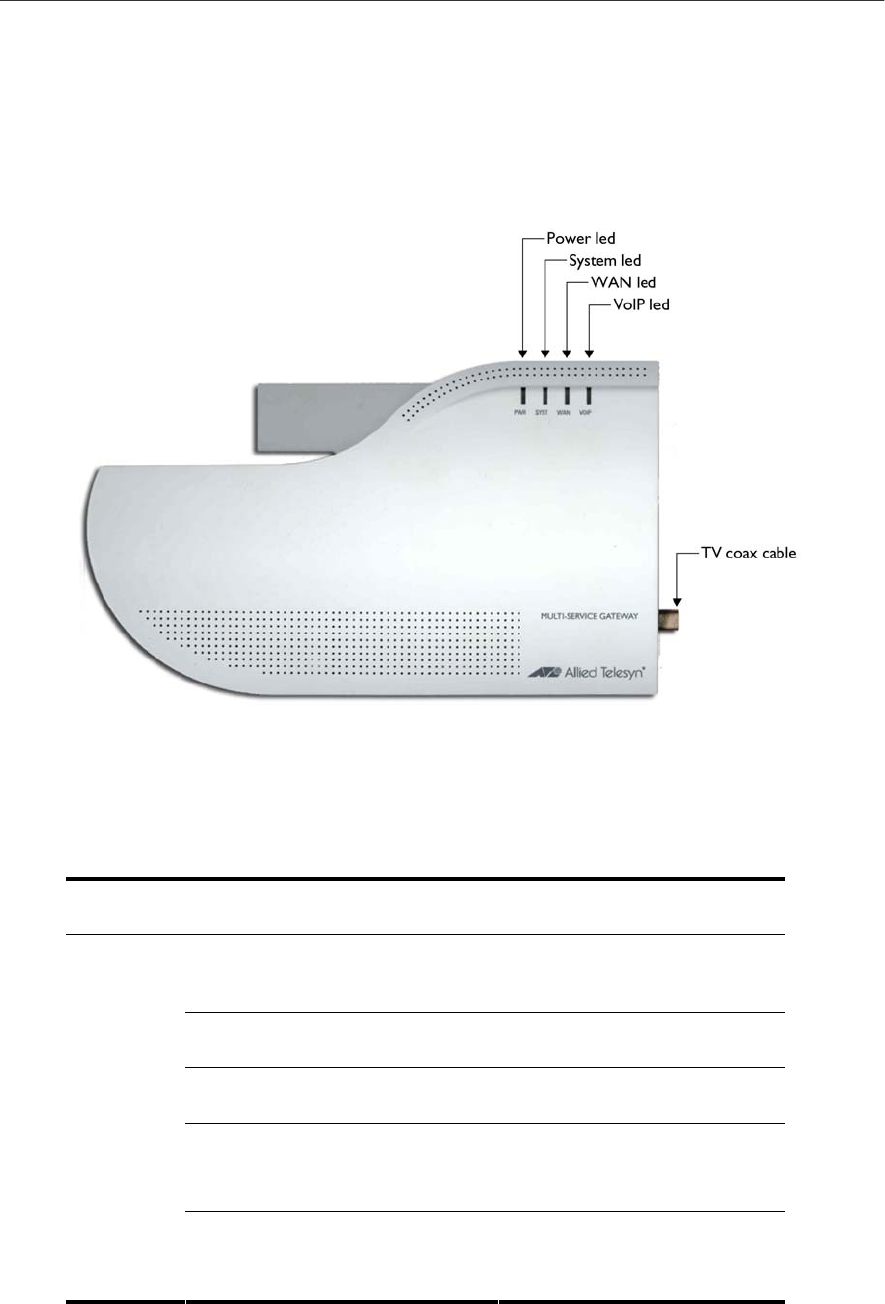
3.1. Top view of Unit
FIGURE 3: TOP VIEW
TABLE 2: POWER/SYSTEM LED INDICATIONS IMG616RF/RF+
Led State Function
Power Green light on
The device is receiving power
and the voltage is within the
acceptable range
Red light off The system is working
normally
Red light on The unit is starting up or is
malfunctioning
Red light flashing
(4 flashes followed by 1 second
off)
The unit is downloading the
software
System
Red light flashing
(2 flashes followed by 1 second
off)
The unit is writing the
software into flash

AT-iMG616RF/RF+ Series Multiservice VoIP Gateway - User Manual 11
TABLE 3: WAN LED INDICATIONS IMG616RF/RF+
Orange light off WAN link not established
Orange light on WAN link established
WAN
Orange light flashing Activity on WAN link
TABLE 4: VOIP LED INDICATIONS WHEN THE IMG616RF/RF+ TEL1 AND TEL2 PORTS ARE REGISTERED
ON A REMOTE SERVER (THE PORTS ARE ENABLED TO CALL A REMOTE NUMBER VIA A VOIP NETWORK)
Led State Function
Green light on LED is fixed on when you lift the
receiver of the telephone or fax
connected to TEL1 or TEL2 port
and remains on during the call.
VoIP
Green light flashing The VoIP network is operating.
(Both TEL1 and TEL2 receivers
are in on-hook state).
Green light off The VoIP network is not
operating.
TABLE 5: VOIP LED INDICATIONS WHEN THE IMG616RF/RF+ TEL1 AND TEL2 PORTS ARE NOT REGISTERED
ON A REMOTE SERVER (THE TEL PORTS ARE ENABLED TO CALL EACH OTHER)
Led State Function
VoIP
Green light on LED is fixed on when you lift the
receiver of the telephone or fax
connected to TEL1 or TEL2 port
and remains on during the call.
Green light off Both TEL1 and TEL2 receivers
are in on-hook state.

12 AT-iMG616RF/RF+ Series Multiservice VoIP Gateway - User Manual
3.2. Front view of unit
FIGURE 4: REAR VIEW OF AT-IMG616RF/RF+
TABLE 6: SPEED AND LINK/ACT LED INDICATIONS
Led State Function
Green light off Transmission and Reception of
packets in half duplex mode
Duplex Mode
Green light on Transmission and Reception of
packets in full duplex mode
Green light off Link not established
Green light on Link established
Link/act
Green light flashing Link activity
3.3. Side view of unit
FIGURE 5: SIDE VIEW OF AT-IMG616RF/RF+
TABLE 7: POWER CONNECTION
Link/Act
Duplex Mode
AT-iMG616RF/RF+ Series Multiservice VoIP Gateway - User Manual 13
Port Function
Power Cable Provides the 12V DC power to this product. This product
doesn’t have a power switch, you have to plug or unplug
the power cable to turn the unit off.
Tel2/Tel1 Connects analog telephone and fax.
LAN port
(MDI-X) Connects computer, HUB and switch with UTP cable.
TV Connects TV set with coax 75 ohm cable.
3.4. 3D view of unit
FIGURE 6: 3D VIEW OF AT-IMG616RF/RF+
14 AT-iMG616RF/RF+ Series Multiservice VoIP Gateway - User Manual
4. Telephones and cables
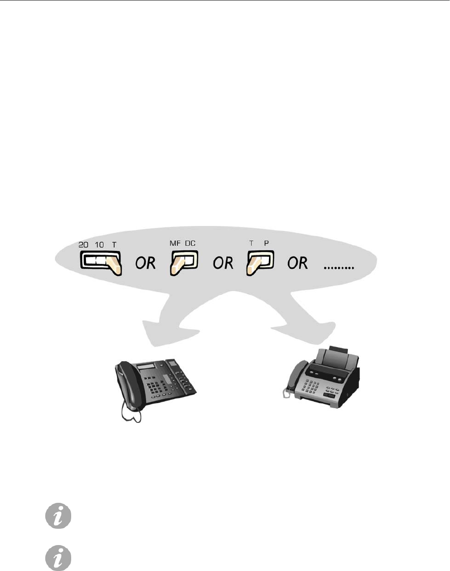
4.1. AT-iMG616 - POTS Telephone and Fax Operation
Check if the dial mode is set up for tone mode (T, Tone). If not, set the switch as shown below.
FIGURE 7: DIAL MODE SETTING
Note, as shown in the diagram, different models of phone are
likely to have different labelling on this switch.
Some models do not have this switch or the possibility to set up
the tone mode with a button. In this case please follow the
instructions of the telephone and fax used.
AT-iMG616RF/RF+ Series Multiservice VoIP Gateway - User Manual 15
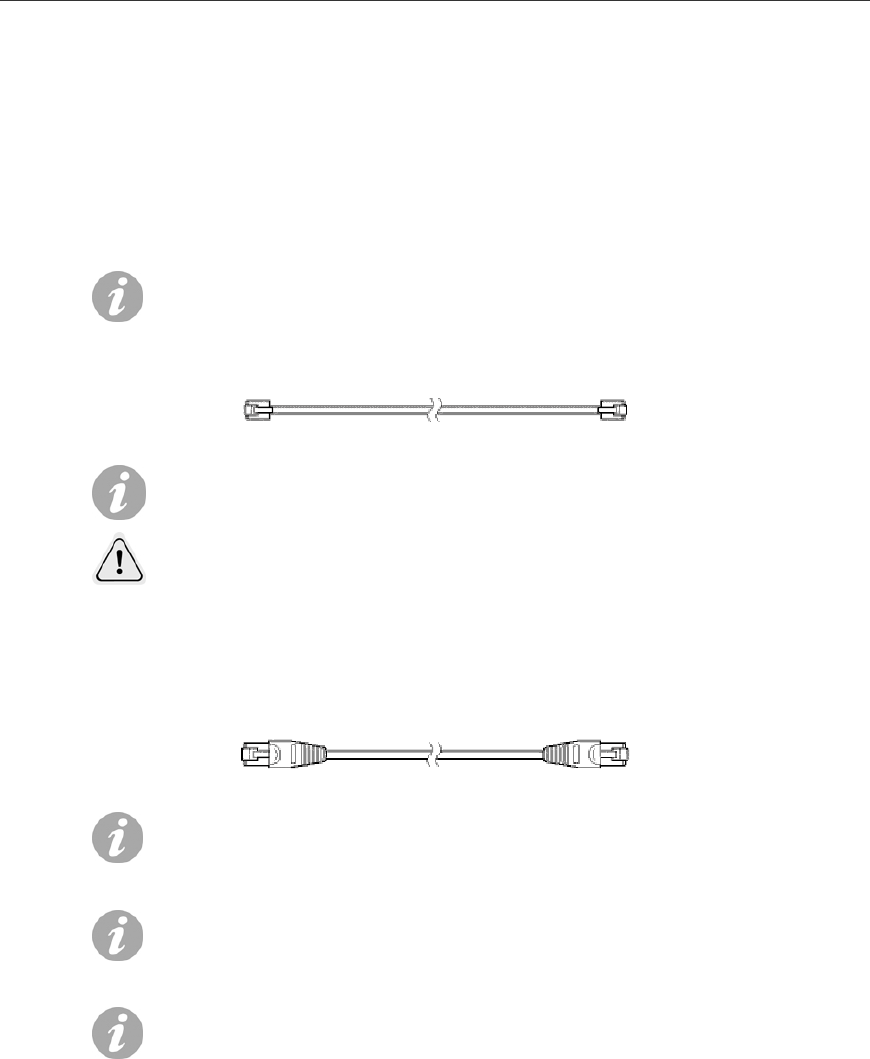
4.2. Telephone cord, UTP cable and TV cable
There are 3 kinds of user connection cables: telephone cables, Unshielded Twisted Pair (UTP)
cables used for data and TV coax cable for TV set.
See Below.
This product does not include any LAN, phone or TV cables.
The service provider or end user must provide these.
FIGURE 8: TELEPHONE CABLE
Note: The telephone cable uses the RJ11 connector
CAUTION: To reduce the risk of fire, use only No. 26AWG or
larger telecommunication line cord.
FIGURE 9: LAN CABLES
Use UTP cable category 3 or higher on 10Base-T, and UTP
cable category 5 or higher on 100BASE-TX.
There are two types of LAN cable, straight cable and crossed
cable; for the AT-iMG616RF/RF+, it does not matter which of
these types of LAN cable you use. The LAN interfaces on the
AT-iMG616RF/RF+ can auto-sense whether the cable is
straight or crossed.
If you buy a new cable, it is recommended that you choose
UTP cable - category 5 or higher

16 AT-iMG616RF/RF+ Series Multiservice VoIP Gateway - User Manual
4.3. TV
FIGURE 10: TV CABLES
4.4. Optical fibers for Ethernet and CATV
There are 2 kinds of user connection fibers: Ethernet bi-directional fiber and CATV fiber.
Ethernet fiber is a single mode fiber provided with an UPC-SC connector.
CATV fiber is a single mode fiber provided with an APC-SC connector.
To the AT-iMG-616RF/RF+ unit To the TV set
75
-
ohm coax cable
F-type male connector TV coax male connector
AT-iMG616RF/RF+ Series Multiservice VoIP Gateway - User Manual 17
5. Connecting the AT-iMG616RF/RF+
5.1. Connecting the PSTN telephone ports
Connect PSTN (POTS) telephone and PSTN fax units to the TEL ports with the appropriate
telephone cords. Push in the plug of the telephone cord to the TEL port until you hear a “click”
and make sure it is correctly fixed by pulling the telephone cord lightly.
CONNECT TO TEL 1 WHEN YOU USE ONLY ONE TELEPHONE OR FAX MACHINE
FIGURE 11: TELEPHONE PORTS CONNECTION
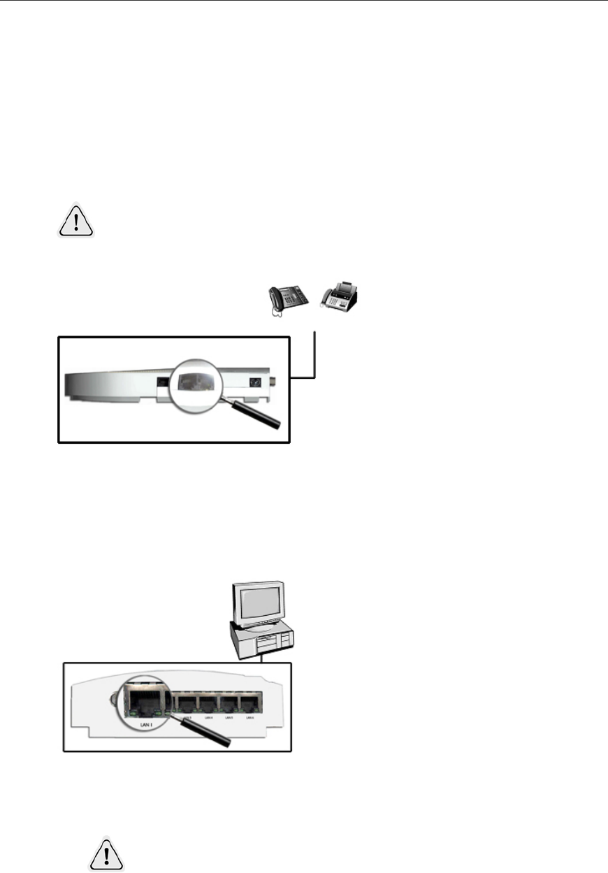
5.2. UTP Cable Connection
To connect devices to the LAN ports using UTP cables follow the procedure below:
FIGURE 12: UTP CABLE CONNECTIONS
Push in the plug of the UTP cable into the LAN port until you hear a “click” and make sure it is
correctly fixed by pulling the UTP cable lightly. In the same way connect the plug on the other
end of the UTP cable to the network inteRFace card of the computer, or other LAN device.
THE LENGTH OF ALL CABLES MUST BE LESS THAN 100 M.
o
r
18 AT-iMG616RF/RF+ Series Multiservice VoIP Gateway - User Manual
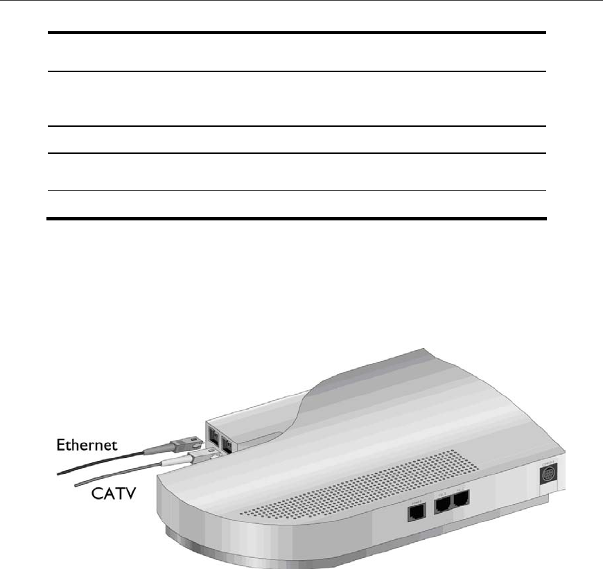
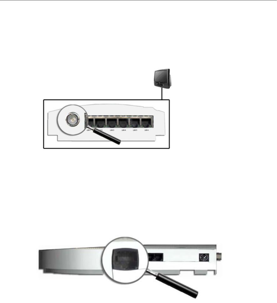
5.3. CATV Cable Connection
To connect the TV set to the CATV port using a coax 75-ohm cables follow the procedure
below:
FIGURE 13: CATV CABLE CONNECTIONS
5.4. Disconnecting power supply
This product doesn’t have a power switch; it automatically turns on when you connect the
power cable.
When you want to turn it off, just unplug the power cable.
FIGURE 14: POWER CABLE
Notice about functions and services
When using the VoIP telephony service it might be that some services usually offered by
standard telephone networks are not available. Similarly, some telephone or fax functions may
not be available on the VoIP network. Please contact your VoIP Telephony provider for further
details.

AT-iMG616RF/RF+ Series Multiservice VoIP Gateway - User Manual 19
Appendix A: Troubleshooting
This Appendix describes some of the more common problems that may occur during AT-
iMG616RF/RF+ installation and use.
In the event of a problem, please look at the LED indications and then refer to this Appendix.

20 AT-iMG616RF/RF+ Series Multiservice VoIP Gateway - User Manual
6. Fault Finding
Is the POWER LED on?
If the power LED is off, please check if the power cable is not damaged, the power cable is
correctly connected and you are using the plug with the correct power voltage.
Check if the AC plug of the power cable of the product is connected correctly. This product
doesn’t have a power switch. To turn the unit on or off you have to plug or unplug the power
cable.
Is the SYSTEM LED red?
If the SYSTEM LED lights up red, unplug the AC plug and plug it in again after 20 seconds. If you
do not resolve the problem, unplug the power plug of this product and contact your supplier
Is the WAN LED off?
Check to ensure that the iMG616 is seated correctly into the wall mounted RG001. If you have
ensured that it is correctly seated, and the WAN LED remains unlit then contact your supplier.
Are the LAN LINK/ACT LED off?
Check if the power of the connected device is on, check that there are no problems with the
network inteRFace cards installed in the attached devices, also check if the cables are correctly
connected to the network inteRF/RF+ace cards.
Check also if the length of the cable is over the limit. UTP cable must be less than 100 m.
Do you have a problem with the UTP cable?
Swap out with a known good cable.
Does VOIP LED remain off when you lift up the receiver?
Please ensure that the telephone cable is connected correctly, that the correct cable is being
used and that the cable is not damaged.
Do you have a problem with the telephone cord?
Swap out with a known good telephone cord.
For POTS phones and faxes check if the setting of the dial mode for the telephone
ad fax is correct, follow the instructions of the telephone and/or fax device.
Ensure that there is no problem with the telephone or fax machine.
Do you have a problem with the CATV signal?
Please, check the connections of the CATV fiber and the coax TV cable.
In case of malfunctioning, replace with a known good fiber or cable. If the problem persists,
check with your CATV provider.
For further information on dial mode set up please refer to Chapter 5

AT-iMG616RF/RF+ Series Multiservice VoIP Gateway - User Manual 21
Appendix B: Technical Specifications
6.1. Product Specifications AT-iMG616RF/RF+
Supported standards
IEEE 802.3 10 BASE-T, 100 BASE-TX
IEEE 802.3u 100 BASE-FX,
RFC 791, RFC1144, RFC1112, RFC2236, RFC 2516,
RFC 1334, RFC 1994, RFC 1631, RFC 2131,
RFC 3261, RFC 1350, RFC 318, RFC 826,
RTP/RTCP, H.323 4.0, MGCP/NCS 1.0, SNMP v1
Interface
WAN port 1 100BASE-FX (SC connector)
LAN port 6 10/100BASE-TX (8 pin RJ45 connector)
TEL port 2 FXS (6 pin RJ11 connector)
TV port (IN) 1 SC connector
TV port (OUT) 1 female 75-ohm F-type connector
Power
AC Input voltage AC100-240V
Standard Frequency 50-60Hz
AC Input current 0.1A (240V)
Average power 10W
Average heat 7.0kcal/h
Environment condition
Storage Temperature -20° to 70°C
Humidity Less than 95% (non condensing)
Operating Temperature 0° to 40° C
Humidity Less than 80% (non condensing)
Size (with no projection)
240(W) x 150 (D) x45 (H) mm
Weight
400g
MAC address table size
1024
Memory Capacity
RAM memory 16Mbyte
Flash memory 4Mbyte
Product Certification
CE
Compliances
IEC60950, EN60950
EN55022, EN61000-3-2, EN61000-3-3, EN55024
Class 1 Laser Product, IEC825

22 AT-iMG616RF/RF+ Series Multiservice VoIP Gateway - User Manual
Appendix C: Contact information
In the event of any problem please contact your service provider or installer.
