Allied Telesis At Wr4500 Users Manual 613 000813 RouterOS 3.0 Configuration And User Guide Rev.A 2008 03 18,d5 Rino
AT-WR4500 to the manual 52ee93f3-9181-4c2b-b886-085681183906
2015-02-02
: Allied-Telesis Allied-Telesis-At-Wr4500-Users-Manual-414230 allied-telesis-at-wr4500-users-manual-414230 allied-telesis pdf
Open the PDF directly: View PDF ![]() .
.
Page Count: 264 [warning: Documents this large are best viewed by clicking the View PDF Link!]

PN 613-000813 Rev. B
AT-WR4500 Series
IEEE 802.11abgh Outdoor Wireless Routers
RouterOS v3 Configuration and User Guide

2 AT-WR4500 Series - IEEE 802.11abgh Outdoor Wireless Routers
RouterOS v3 Configuration and User Guide
Copyright © 2009 Allied Telesis International
All rights reserved. No part of this publication may be reproduced without prior written permission from Allied Teles
is
International.
Microsoft and Internet Explorer are registered trademarks of Microsoft Corporation. Mikrotik and RouterOS are
trademarks of Mikrotikls SIA. All other product names, company names, logos or other designations mentioned herein
are trademarks or registered trademarks of their respective owners.
Parts of this manual reproduced with Mikrotik permission from Mikrotik RouterOS v3.0 Reference Manual.
Allied Telesis, Inc. reserves the right to make changes in specifications and other information co
ntained in this document
without prior written notice. The information provided herein is subject to change without notice. In no event shall
Allied Telesis, Inc. be liable for any incidental, special, indirect, or consequential damages whatsoever, includi
ng but not
limited to lost profits, arising out of or related to this manual or the information contained herein, even if Allied Telesis,
Inc. has been advised of, known, or should have known, the possibility of such damages.

AT-WR4500 Series - IEEE 802.11abgh Outdoor Wireless Routers 3
RouterOS v3 Configuration and User Guide
LIMITATION
OF
LIABILITY
AND
DAMAGES
THE PRODUCT AND THE SOFTWARES WITHIN ARE PROVIDED "AS IS," BASIS. THE
MANUFACTURER AND MANUFACTURER’S RESELLERS (COLLECTIVELY REFERRED TO AS
“THE SELLERS”) DISCLAIM ALL WARRANTIES, EXPRESS, IMPLIED OR STATUTORY,
INCLUDING WITHOUT LIMITATION THE IMPLIED WARRANTIES OF NON-
INFRINGEMENT,
MERCHANTABILITY OR FITNESS FOR A PARTICULAR PURPOSE, OR ANY WARRANTIES
ARISING FROM COURSE OF DEALING, COURSE OF PERFORMANCE, OR USAGE OF TRADE.
IN NO EVENT WILL THE SELLERS BE LIABLE FOR D
AMAGES OR LOSS, INCLUDING BUT
NOT LIMITED TO DIRECT, INDIRECT, SPECIAL WILFUL, PUNITIVE, INCIDENTAL,
EXEMPLARY, OR CONSEQUENTIAL, DAMAGES, DAMAGES FOR LOSS OF BUSINESS
PROFITS, OR DAMAGES FOR LOSS OF BUSINESS OF ANY CUSTOMER OR ANY THIRD
PARTY ARISING OUT
OF THE USE OR THE INABILITY TO USE THE PRODUCT OR THE
SOFTWARES, INCLUDING BUT NOT LIMITED TO THOSE RESULTING FROM DEFECTS IN
THE PRODUCT OR SOFTWARE OR DOCUMENTATION, OR LOSS OR INACCURACY OF
DATA OF ANY KIND, WHETHER BASED ON CONTRACT, TORT OR ANY OTHER
LEGAL
THEORY, EVEN IF THE PARTIES HAVE BEEN ADVISED OF THE POSSIBILITY OF SUCH
DAMAGES. THE ENTIRE RISK AS TO THE RESULTS AND PERFORMANCE OF THE PRODUCT
OR ITS SOFTWARE IS ASSUMED BY CUSTOMER. BECAUSE SOME STATES DO NOT ALLOW
THE EXCLUSION OR LIMITATION
OF LIABILITY FOR DAMAGES, THE ABOVE LIMITATION
MAY NOT APPLY TO THE PARTIES. IN NO EVENT WILL THE SELLERS’ TOTAL CUMULATIVE
LIABILITY OF EACH AND EVERY KIND IN RELATION TO THE PRODUCT OR ITS
SOFTWARE EXCEED THE AMOUNT PAID BY CUSTOMER FOR THE PRODUCT.

4 AT-WR4500 Series - IEEE 802.11abgh Outdoor Wireless Routers
RouterOS v3 Configuration and User Guide
CONTENTS
1
Introduction.............................................................................................................................................................12
1.1
Features ............................................................................................................................................................13
1.2
Software License ............................................................................................................................................13
2
Configuring RouterOS ..........................................................................................................................................14
2.1
Logging in the AT-WR4500 Router..........................................................................................................14
2.2
Accessing the WR4500 through WinBox ...............................................................................................14
2.3
Accessing the CLI...........................................................................................................................................15
3
Configuration and Software Management........................................................................................................18
3.1
General Information......................................................................................................................................18
3.1.1
System Backup ...............................................................................................................................18
3.1.2
The Export Command .................................................................................................................19
3.1.3
The Import Command.................................................................................................................19
3.1.4
Configuration Reset......................................................................................................................20
3.2
Software Version Management...................................................................................................................20
3.2.1
General Information .....................................................................................................................20
3.2.2
System Upgrade .............................................................................................................................21
3.2.3
Adding Package Source................................................................................................................22
3.3
Software Package Management ..................................................................................................................22
3.3.1
General Information .....................................................................................................................22
3.3.2
Installation (Upgrade) ...................................................................................................................23
3.3.3
Uninstallation..................................................................................................................................23
3.3.4
Downgrading ..................................................................................................................................24
3.3.5
Disabling and Enabling ..................................................................................................................25
3.3.6
Unscheduling...................................................................................................................................25
3.3.7
System Upgrade .............................................................................................................................26
3.3.8
Adding Package Source................................................................................................................27
3.3.9
Software Package List...................................................................................................................27
4
Configuring Interfaces ...........................................................................................................................................30
4.1
General Interface Settings............................................................................................................................30
4.1.1
General Information .....................................................................................................................30
4.1.2
Interface Status ..............................................................................................................................30
4.1.3
Traffic Monitoring .........................................................................................................................30
4.2
Ethernet Interfaces ........................................................................................................................................31
4.2.1
General Information .....................................................................................................................31
4.2.2
Ethernet Interface Configuration ..............................................................................................31
4.2.3
Monitoring the Interface Status .................................................................................................32
4.2.4
Troubleshooting ............................................................................................................................33
4.3
Wireless Interfaces........................................................................................................................................33
4.3.1
General Information .....................................................................................................................33
4.3.2
Wireless Interface Configuration..............................................................................................35
4.3.3
Nstreme Settings...........................................................................................................................40
4.3.4
Nstreme2 Group Settings...........................................................................................................41
4.3.5
Registration Table .........................................................................................................................43
4.3.6
Connect List ...................................................................................................................................45
4.3.7
Access List.......................................................................................................................................45
4.3.8
Info command.................................................................................................................................46
4.3.9
Virtual Access Point Interface....................................................................................................50
4.3.10
WDS Interface Configuration ....................................................................................................51
4.3.11
Align ..................................................................................................................................................52
4.3.12
Align Monitor .................................................................................................................................53
4.3.13
Frequency Monitor .......................................................................................................................54
4.3.14
Manual Transmit Power Table...................................................................................................54

AT-WR4500 Series - IEEE 802.11abgh Outdoor Wireless Routers 5
RouterOS v3 Configuration and User Guide
4.3.15
Network Scan.................................................................................................................................55
4.3.16
Security Profiles .............................................................................................................................56
4.3.17
Sniffer................................................................................................................................................58
4.3.18
Sniffer Sniff.......................................................................................................................................58
4.3.19
Sniffer Packets.................................................................................................................................59
4.3.20
Snooper............................................................................................................................................59
4.3.21
Application Examples....................................................................................................................60
4.3.22
Troubleshooting.............................................................................................................................74
4.4
VLAN Interfaces .............................................................................................................................................75
4.4.1
General Information .....................................................................................................................75
4.4.2
VLAN Setup ....................................................................................................................................75
4.4.3
Application Example......................................................................................................................76
4.5
Bridge Interfaces.............................................................................................................................................77
4.5.1
General Information .....................................................................................................................77
4.5.2
Bridge Interface Setup ..................................................................................................................78
4.5.3
Port Settings....................................................................................................................................79
4.5.4
Bridge Monitoring..........................................................................................................................80
4.5.5
Bridge Port Monitoring ................................................................................................................80
4.5.6
Bridge Host Monitoring ...............................................................................................................81
4.5.7
Bridge Firewall General Description ........................................................................................81
4.5.8
Bridge Packet Filter .......................................................................................................................84
4.5.9
Bridge NAT.....................................................................................................................................84
4.5.10
Bridge Brouting Facility ................................................................................................................85
4.5.11
Troubleshooting.............................................................................................................................86
5
IP and Routing .........................................................................................................................................................87
5.1
IP Addresses and ARP...................................................................................................................................87
5.1.1
General Information .....................................................................................................................87
5.1.2
IP Addressing ..................................................................................................................................87
5.1.3
Address Resolution Protocol .....................................................................................................88
5.1.4
Proxy-ARP feature ........................................................................................................................89
5.1.5
Unnumbered Interfaces ...............................................................................................................91
5.1.6
Troubleshooting.............................................................................................................................92
5.2
RIP: Routing Information Protocol ............................................................................................................92
5.2.1
General Information .....................................................................................................................92
5.2.2
General Setup.................................................................................................................................93
5.2.3
Interfaces..........................................................................................................................................94
5.2.4
Networks.........................................................................................................................................95
5.2.5
Neighbors ........................................................................................................................................95
5.2.6
Routes...............................................................................................................................................95
5.2.7
Application Examples....................................................................................................................96
5.3
OSPF..................................................................................................................................................................98
5.3.1
General Information .....................................................................................................................98
5.3.2
General Setup.................................................................................................................................99
5.3.3
OSPF Areas .................................................................................................................................. 100
5.3.4
Networks...................................................................................................................................... 101
5.3.5
Interfaces....................................................................................................................................... 102
5.3.6
Virtual Links ................................................................................................................................. 102
5.3.7
Neighbors ..................................................................................................................................... 103
5.3.8
Application Examples................................................................................................................. 104
5.4
Routes, Equal Cost Multipath Routing, Policy Routing...................................................................... 110
5.4.1
General Information .................................................................................................................. 110
5.4.2
Routes............................................................................................................................................ 111
5.4.3
Policy Rules .................................................................................................................................. 112
5.4.4
Application Examples................................................................................................................. 113
6
DHCP and DNS................................................................................................................................................... 116
6.1
DHCP Client and Server........................................................................................................................... 116
6.1.1
General Information .................................................................................................................. 116

6 AT-WR4500 Series - IEEE 802.11abgh Outdoor Wireless Routers
RouterOS v3 Configuration and User Guide
6.1.2
DHCP Client Setup.....................................................................................................................117
6.1.3
DHCP Server Setup....................................................................................................................118
6.1.4
Store Leases on Disk..................................................................................................................120
6.1.5
DHCP Networks.........................................................................................................................121
6.1.6
DHCP Server Leases..................................................................................................................121
6.1.7
DHCP Alert ..................................................................................................................................123
6.1.8
DHCP Option ..............................................................................................................................123
6.1.9
DHCP Relay..................................................................................................................................124
6.1.10
Questions & Answers ................................................................................................................125
6.1.11
Application Examples..................................................................................................................126
6.2
DNS Client and Cache ...............................................................................................................................129
6.2.1
General Information ...................................................................................................................129
6.3
DNS Cache Setup........................................................................................................................................129
6.3.1
Cache Monitoring........................................................................................................................130
6.3.2
Static DNS Entries ......................................................................................................................130
6.4
All DNS Entries ............................................................................................................................................130
6.5
Static DNS Entries .......................................................................................................................................130
6.6
Flushing DNS cache.....................................................................................................................................131
7
AAA Configuration ..............................................................................................................................................132
7.1
RADIUS client...............................................................................................................................................132
7.1.1
General Information ...................................................................................................................132
7.1.2
RADIUS Client Setup .................................................................................................................132
7.1.3
Connection Terminating from RADIUS................................................................................133
7.1.4
Suggested RADIUS Servers ......................................................................................................134
7.1.5
Supported RADIUS Attributes ................................................................................................134
7.1.6
Troubleshooting ..........................................................................................................................140
7.2
PPP User AAA ..............................................................................................................................................141
7.2.1
General Information ...................................................................................................................141
7.2.2
Local PPP User Profiles..............................................................................................................141
7.2.3
Local PPP User Database ..........................................................................................................143
7.2.4
Monitoring Active PPP Users ...................................................................................................144
7.2.5
PPP User Remote AAA .............................................................................................................145
7.3
Router User AAA........................................................................................................................................145
7.3.1
General Information ...................................................................................................................145
7.3.2
Router User Groups ..................................................................................................................146
7.3.3
Router Users................................................................................................................................147
7.3.4
Monitoring Active Router Users.............................................................................................148
7.3.5
Router User Remote AAA .......................................................................................................148
7.3.6
SSH keys ........................................................................................................................................149
8
VPNs and Tunneling ............................................................................................................................................150
8.1
EoIP..................................................................................................................................................................150
8.1.1
General Information ...................................................................................................................150
8.1.2
EoIP Setup .....................................................................................................................................151
8.1.3
EoIP Application Example..........................................................................................................152
8.1.4
Troubleshooting ..........................................................................................................................153
8.2
Interface Bonding .........................................................................................................................................154
8.3
General Information....................................................................................................................................154
8.3.1
Summary ........................................................................................................................................154
8.3.2
Quick Setup Guide......................................................................................................................154
8.3.3
Related Documents ....................................................................................................................154
8.4
IPIP Tunnel Interfaces .................................................................................................................................158
8.4.1
General Information ...................................................................................................................158
8.4.2
IPIP Setup.......................................................................................................................................159
8.4.3
Application Examples..................................................................................................................160
8.5
L2TP Interface...............................................................................................................................................161
8.5.1
General Information ...................................................................................................................161
8.5.2
L2TP Client Setup .......................................................................................................................162

AT-WR4500 Series - IEEE 802.11abgh Outdoor Wireless Routers 7
RouterOS v3 Configuration and User Guide
8.5.3
Monitoring L2TP Client ............................................................................................................ 163
8.5.4
L2TP Server Setup...................................................................................................................... 164
8.5.5
L2TP Server Users ..................................................................................................................... 164
8.5.6
L2TP Application Examples...................................................................................................... 166
8.5.7
Troubleshooting.......................................................................................................................... 170
8.6
PPPoE ............................................................................................................................................................. 170
8.6.1
General Information .................................................................................................................. 170
8.6.2
PPPoE Client Setup .................................................................................................................... 172
8.6.3
Monitoring PPPoE Client .......................................................................................................... 173
8.6.4
PPPoE Server Setup (Access Concentrator)....................................................................... 173
8.6.5
PPPoE Users................................................................................................................................. 175
8.6.6
PPPoE Server User Interfaces ................................................................................................. 175
8.6.7
Application Examples................................................................................................................. 176
8.6.8
Troubleshooting.......................................................................................................................... 178
8.7
PPTP................................................................................................................................................................ 178
8.7.1
General Information .................................................................................................................. 178
8.7.2
PPTP Client Setup ...................................................................................................................... 180
8.7.3
Monitoring PPTP Client ............................................................................................................ 181
8.7.4
PPTP Server Setup...................................................................................................................... 181
8.7.5
PPTP Users................................................................................................................................... 182
8.7.6
PPTP Tunnel Interfaces ............................................................................................................. 182
8.7.7
PPTP Application Examples...................................................................................................... 183
8.7.8
Troubleshooting.......................................................................................................................... 187
8.8
IP Security...................................................................................................................................................... 187
8.8.1
General Information .................................................................................................................. 187
8.8.2
Policy Settings.............................................................................................................................. 189
8.8.3
Peers .............................................................................................................................................. 191
8.8.4
Remote Peer Statistics .............................................................................................................. 192
8.8.5
Installed SAs ................................................................................................................................. 193
8.8.6
Flushing Installed SA Table ....................................................................................................... 194
8.8.7
Application Examples................................................................................................................. 195
9
Firewall and QoS ................................................................................................................................................. 198
9.1
Filter................................................................................................................................................................ 198
9.1.1
General Information .................................................................................................................. 198
9.1.2
Firewall Filter ............................................................................................................................... 198
9.1.3
Filter Applications....................................................................................................................... 203
9.2
Mangle ............................................................................................................................................................ 204
9.2.1
General Information .................................................................................................................. 204
9.2.2
Mangle............................................................................................................................................ 205
9.2.3
Application Examples................................................................................................................. 209
9.3
Packet Flow................................................................................................................................................... 210
9.3.1
General Information .................................................................................................................. 210
9.3.2
Packet Flow .................................................................................................................................. 210
9.3.3
Connection Tracking ................................................................................................................. 212
9.3.4
Connection Timeouts................................................................................................................ 213
9.3.5
Service Ports................................................................................................................................ 214
9.3.6
General Firewall Information................................................................................................... 215
9.4
NAT................................................................................................................................................................ 216
9.4.1
General Information .................................................................................................................. 216
9.4.2
NAT ............................................................................................................................................... 217
9.4.3
NAT Applications....................................................................................................................... 221
10
Hot Spot Service.................................................................................................................................................. 222
10.1
HotSpot Gateway........................................................................................................................................ 222
10.1.1
General Information .................................................................................................................. 222
10.1.2
Question&Answer-Based Setup.............................................................................................. 226
10.1.3
HotSpot Interface Setup ........................................................................................................... 227
10.1.4
HotSpot Server Profiles............................................................................................................ 228

8 AT-WR4500 Series - IEEE 802.11abgh Outdoor Wireless Routers
RouterOS v3 Configuration and User Guide
10.1.5
HotSpot User Profiles................................................................................................................229
10.2
HotSpot Users.................................................................................................................................................229
10.2.1
Description ...................................................................................................................................229
10.3
HotSpot Active Users.................................................................................................................................229
10.3.1
Description ...................................................................................................................................229
10.3.2
HotSpot Cookies.........................................................................................................................229
10.3.3
HTTP-level Walled Garden ......................................................................................................230
10.3.4
IP-level Walled Garden..............................................................................................................231
10.3.5
One-to-one NAT static address bindings .............................................................................231
10.3.6
Active Host List ...........................................................................................................................232
10.3.7
Command Description ..............................................................................................................232
10.3.8
Service Port ..................................................................................................................................232
10.3.9
Customizing HotSpot: Firewall Section.................................................................................233
10.3.10
Customizing HotSpot: HTTP Servlet Pages .........................................................................236
10.3.11
Possible Error Messages ............................................................................................................242
10.3.12
HotSpot How-to's.......................................................................................................................243
10.4
HotSpot User AAA .....................................................................................................................................244
10.4.1
General Information ...................................................................................................................244
10.4.2
HotSpot User Profiles................................................................................................................244
10.4.3
HotSpot Users .............................................................................................................................246
10.4.4
HotSpot Active Users ................................................................................................................247
11
High Availability protocols and techniques....................................................................................................249
11.1
VRRP ...............................................................................................................................................................249
11.1.1
General Information ...................................................................................................................249
11.1.2
VRRP Routers ..............................................................................................................................249
11.1.3
Virtual IP addresses.....................................................................................................................251
11.1.4
A simple example of VRRP fail over.......................................................................................251
11.2
System Watchdog........................................................................................................................................253
11.2.1
General Information ...................................................................................................................253
11.2.2
Hardware Watchdog Management.........................................................................................253
12
Monitoring and Management................................................................................................................255
12.1
Log Management ..........................................................................................................................................255
12.1.1
General Information ...................................................................................................................255
12.1.2
General Settings...........................................................................................................................255
12.1.3
Actions ...........................................................................................................................................256
12.1.4
Log Messages ................................................................................................................................256
12.2
SNMP Service................................................................................................................................................257
12.2.1
General Information ...................................................................................................................257
12.3
Traffic Flow....................................................................................................................................................258
12.3.1
General Information ...................................................................................................................258
12.3.2
Related Documents ....................................................................................................................258
12.3.3
General Configuration ...............................................................................................................258
12.3.4
Traffic-Flow Target .....................................................................................................................259
12.3.5
Application Examples..................................................................................................................259
12.4
Graphing.........................................................................................................................................................262
12.4.1
General Information ...................................................................................................................262
12.4.2
General Options..........................................................................................................................262
12.4.3
Health Graphing...........................................................................................................................263
12.4.4
Interface Graphing.......................................................................................................................263
12.4.5
Simple Queue Graphing.............................................................................................................263
12.4.6
Resource Graphing .....................................................................................................................264

AT-WR4500 Series - IEEE 802.11abgh Outdoor Wireless Routers 9
RouterOS v3 Configuration and User Guide
FIGURES
Figure 1: AT-WR4500 Series typical application ..................................................................................................................12
Figure 2: WinBox Loader discovering .....................................................................................................................................14
Figure 3: WinBox main window................................................................................................................................................15
Figure 4: WinBox with terminal window open .....................................................................................................................15
Figure 5: Station and AP mode example .................................................................................................................................60
Figure 6: WDS Network example............................................................................................................................................62
Figure 7: Nstreme network example.......................................................................................................................................66
Figure 8: Nstreme dual network example..............................................................................................................................68
Figure 9: WEP security example ...............................................................................................................................................70
Figure 10: WPA security example ............................................................................................................................................73
Figure 11: Proxy ARP...................................................................................................................................................................90
Figure 12: Proxy ARP with PPPoE ............................................................................................................................................91
Figure 13: OSPF Backup ........................................................................................................................................................... 104
Figure 14: OSPF Routing tables.............................................................................................................................................. 108
Figure 15: OSPF Backup ........................................................................................................................................................... 109
Figure 16: Static Equal Cost Multi-Path Routing example ............................................................................................... 113
Figure 17: Standard Policy-Based Routing with Failover.................................................................................................. 114
Figure 18: DHCP Relay............................................................................................................................................................. 126
Figure 19: DHCP with RADIUS ............................................................................................................................................. 128
Figure 20: EoIP Application Example..................................................................................................................................... 152
Figure 21: Bonding two EoIP tunnels.................................................................................................................................... 156
Figure 22: IPIP Tunnel example network............................................................................................................................. 160
Figure 23: Router-to-Router Secure Tunnel Example...................................................................................................... 166
Figure 24: Secure Remote office connection through L2TP tunnel.............................................................................. 167
Figure 25: Client to Office secure connection via L2TP tunnel..................................................................................... 169
Figure 26: PPPoE Example ....................................................................................................................................................... 176
Figure 27: Network Setup without PPTP enabled............................................................................................................. 183
Figure 28: Network Setup with encrypted PPTP Tunnel ................................................................................................ 184
Figure 29: Connecting a Remote Client via and Encrypted PPTP Tunnel................................................................... 186
Figure 30: transport mode example using ESP with automatic keying......................................................................... 195
Figure 31: Add accept and masquerading rules in SRC-NAT......................................................................................... 196
Figure 32: Packet Flow Diagram............................................................................................................................................. 211
Figure 33: Firewall Connection Tracking timeouts ........................................................................................................... 213
Figure 34: HotSpot example network .................................................................................................................................. 223
Figure 35: Simple VRRP fail over example........................................................................................................................... 251
Figure 36: Host Information.................................................................................................................................................... 260
Figure 37: Network Load Statistics Matrix ......................................................................................................................... 260
Figure 38: Network load profile by time ............................................................................................................................. 261
Figure 39: Traffic Load by protocol....................................................................................................................................... 261

10 AT-WR4500 Series - IEEE 802.11abgh Outdoor Wireless Routers
RouterOS v3 Configuration and User Guide
PREFACE
Purpose of This Guide
This guide describes the AT-WR4500 Series Outdoor Wireless Routers RouterOS command structure
and configuration for allowing users or network managers to correctly configure the router getting the
most of it.
How This Guide is organized
This guide contains the following chapters and appendices:
Chapter 1 Introduction describes the features, functions, LEDs, and ports on the equipment.
Please refer to the relevant Quick Installation guides for information on how to
install and setup each router.
Chapter 2 Configuring RouterOS describes how to access the router’s command facility and
perform the basic configuration tasts through the Command Line Interface, The
Web GUI and the WinBox application.
Chapter 3 Configuration and Software Management describes how to backup, export, and
restore the router’s configuration.
Chapters from 4 on describe all the available commands and parameters with some
configuration examples.
Document Conventions
This guide uses several conventions that you should become familiar with before you begin to install the
product:
Note
A note provides additional information. Please go to the Allied Telesis website
http://www.alliedtelesis.com for the translated safety statement in your language.
Warning
A warning indicates that performing or omitting a specific action may result in bodily injury.
Caution
A caution indicates that performing or omitting a specific action may result in equipment damage
or loss of data.

AT-WR4500 Series - IEEE 802.11abgh Outdoor Wireless Routers 11
RouterOS v3 Configuration and User Guide
CONTACTING ALLIED TELESIS
This section provides Allied Telesis contact information for technical support as well as sales and
corporate information.
Online Support
You can request technical support online by accessing the Allied Telesis Knowledge Base:
http://www.alliedtelesis.com/kb/. You can use the Knowledge Base to submit questions to our
technical support staff and review answers to previously asked questions.
Email and Telephone Support
For Technical Support via email or telephone, refer to the Support & Services section of the Allied Telesis
web site: http://www.alliedtelesis.com/support/.
Warranty
For product registration and warranty conditions please visit Allied Telesis website:
http://www.alliedtelesis.com/support/warranty/
Where to Find Web-based Guides
The installation and user guides for all Allied Telesis products are available in portable document format
(PDF) on our web site at www.alliedtelesis.com. You can view the documents online or download
them onto a local workstation or server.
Returning Products
Products for return or repair must first be assigned a return materials authorization (RMA) number. A
product sent to Allied Telesis without an RMA number will be returned to the sender at the sender’s
expense.
To obtain an RMA number, contact Allied Telesis Technical Support through our web site:
http://www.alliedtelesis.com/support/.
Sales or Corporate Information
You can contact Allied Telesis for sales or corporate information through our web site:
http://www.alliedtelesis.com/. To find the contact information for your country, select Contact Us ->
Worldwide Contacts.
Management Software Updates
New releases of management software for our managed products are available from either of the
following Internet sites:
• Allied Telesis web site: http://www.alliedtelesis.com/support/software/
• Allied Telesis FTP server: ftp://ftp.alliedtelesis.com/
If you prefer to download new software from the Allied Telesis FTP server from your workstation’s
command prompt, you will need FTP client software and you must log in to the server. Enter
“anonymous” for the user name and your email address for the password.
Tell Us What You Think
If you have any comments or suggestions on how we might improve this or other Allied Telesis
documents, please contact us at http://www.alliedtelesis.com.
12 AT-WR4500 Series - IEEE 802.11abgh Outdoor Wireless Routers
RouterOS v3 Configuration and User Guide
1 Introduction
Thank you for purchasing an AT-WR4500 series Wireless Router.
Please refer to the ATWR45xx Quick Installation Guide for information on how to install connect and
initially setup each router model.
The WR4500 family of dual band outdoor wireless base routers and routing CPEs allow the building of
wireless only or hybrid IP networks that are scalable, reliable and fully controllable.
Wireless ISPs can easily and quickly provide homes in rural areas with broadband Internet access and
VoIP telephony and, at the same time, can set-up WiFi hot spots for nomadic users.
Enterprises can connect remote buildings without the need for expensive leased lines and can extend
WiFi coverage to outdoor yards providing users with mobile intranet and Internet access everywhere.
Municipalities can build wireless IP networks for connecting remote offices and for increasing public safety
with real time monitored surveillance cameras and continuous communication with local police patrols.
Local utilities can easily control their remote equipments and read, in real time, gas, water and electricity
meters without any need for expensive fiber cabling.
Hot spot services can be provided to hotel guests and hospital patients ‘illuminating’ rooms from outside
the building with a reduced impact on medical equipments because no transmit radio will be installed
inside the hospital.
The single radio AT-WR4561 model can be used as either a base router, a hot spot or a wireless CPE
while the dual radio AT-WR4562 can be deployed at the same time as both a wireless only base router
and hot spot or base station in a Point to Multipoint configuration.
The AT-WR4542 with its embedded high gain antenna is best suited for being used as a wireless CPE
connecting to an AT-WR4561 or AT-WR4562 base router or can be deployed in couples for realizing
long reach high performances Point to Point links.
Flexibility is the primary advantage of the WR4500 family of wireless base routers. All products share the
same software and features and differ only in the number of radio interfaces.
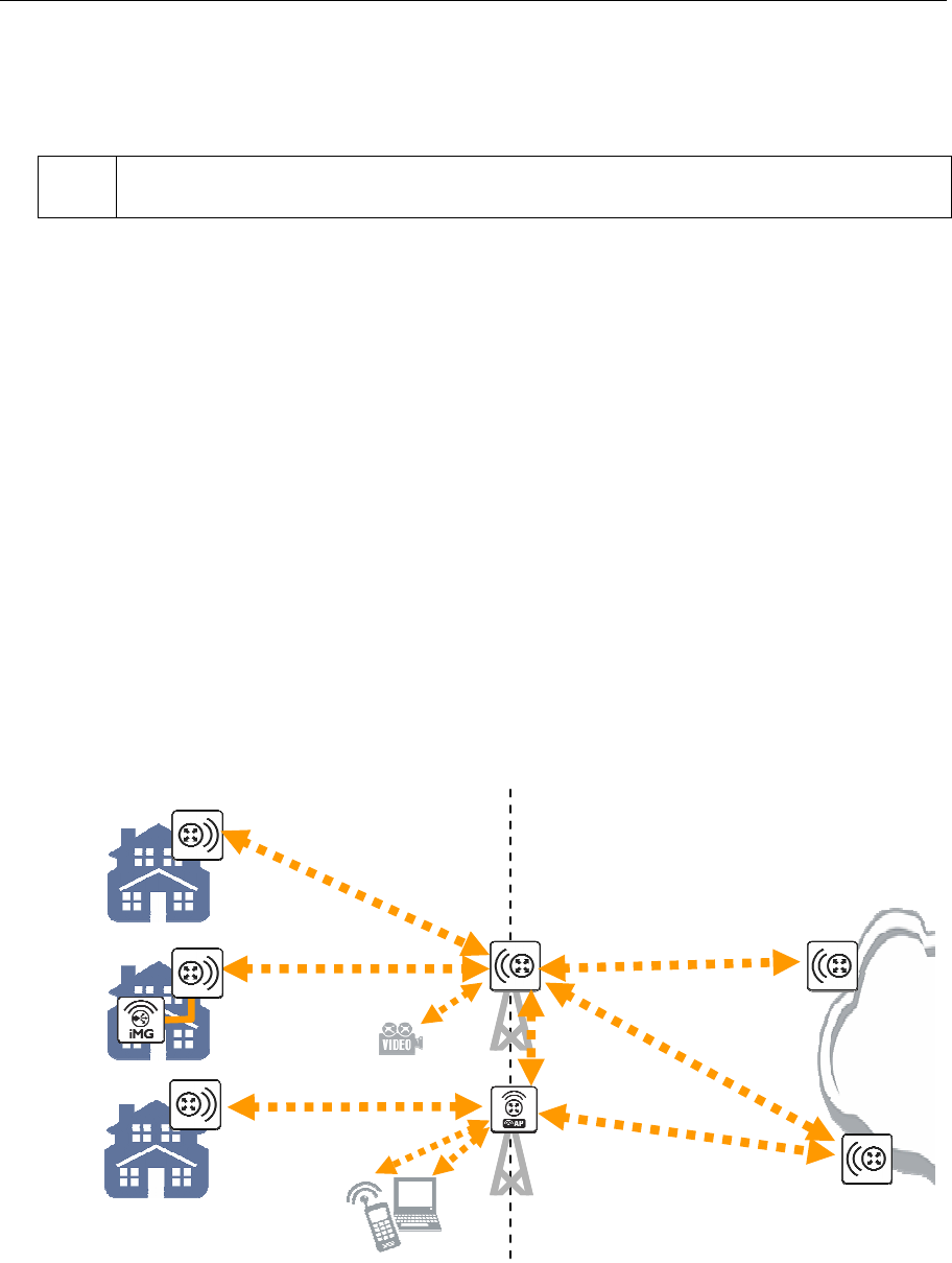
Landline
IP Net
5GHz
Access
Network
Backbone
Network
5GHz
5GHz
2.4GHz
2.4GHz
2.4 / 5GHz
Figure 1: AT-WR4500 Series typical application

AT-WR4500 Series - IEEE 802.11abgh Outdoor Wireless Routers 13
RouterOS v3 Configuration and User Guide
1.1 Features
The AT-WR4500 series RouterOS firmware is very rich of features and very flexible. Among others:
• Real IP routing functionalities
• 2.4 GHz and 5 GHz dual band operations
• IEEE 802.11a/b/g/h compliant
• Certified for HiperLAN bands operation in Europe with DFS and TPC
• IEEE 802.3af compliant PoE powering
• IP66/67 rated outdoor robust construction
• Professional look suitable for indoor installation too
• Embedded IP firewalling functionalities
• Highly configurable QoS management for multimedia applications
• High sensitivity radio interface for longer reach and higher throughput on wireless links
• Wide choice of omnidirectional, directional and sector antennas
• RoHS compliant
1.2 Software License
RouterOS licensing scheme is based on software IDs. To license the software, you must know the
software ID that is displayed during installation process or can be read from the CLI system console or
WinBox. In order to get the software ID from system console, first log in (the default user is “admin”
with no password) and type: “/system license print”.
[admin@AT-WR4541g] > /system license print
software-id: "NCL8-3TT"
upgradable-to: v4.x
nlevel: 4
features:
[admin@AT-WR4541g] >

14 AT-WR4500 Series - IEEE 802.11abgh Outdoor Wireless Routers
RouterOS v3 Configuration and User Guide
2 Configuring RouterOS
2.1 Logging in the AT-WR4500 Router
There are many options for accessing your AT-WR4500 Router command facility:
• Accessing the router Command Line Interface either via Telnet or SSH using any text-mode Telnet
or SSH client software
• Accessing the Web based Graphical User Interface via HTTP using a Web browser
• Running the MS Windows based WinBox graphical menu based configuration utility.
Every AT-WR4500 Wireless Router is factory configured with the static IP address 192.168.1.1/24 (net
mask 255.255.255.0) and both CLI and Web GUI can be accessed through this IP address.
2.2 Accessing the WR4500 through WinBox
Should the router come with a different IP address or if you do not want to change the IP address of
your PC or Workstation then it is possible to access the Router using the discovery facility of the
WinBox utility. Since WinBox can open a Layer 2 connection to the equipments, no change to the PC IP
address is needed. Please refer to the following section for instructions on how to get and use WinBox.
Downloading WinBox loader
The MS Windows based utility WinBox can be downloaded from the Allied Telesis web site accessing
http://www.alliedtelesis.com/. Select you country; access the “Software and Documentation” section
under the “Service/Support” menu; select “Wireless” in the “Product Category” drop down menu and
“AT-WR45421” in the “Product” drop down menu.
Scroll down the page and select the “AT-WR4500 WinBox loader” from the list of available Software.
Using WinBox
Connect the AT-WR4500 router with a LAN cable to your PC and launch the WinBox loader utility that
you have just downloaded.
Please make sure that the only LAN port enabled on your PC is the one connected to the WR4500
Router. Any other LAN port, either wired or wireless, shall be disabled.
Figure 2: WinBox Loader discovering
When the WinBox loader startup window appears click on the button placed besides the “Connect
To:” field and wait for some seconds. A list of AT-WR4500 connected equipments (at least one) will
appear (see Figure 2). Select the one you want to access and then click on the “Connect” button. Every
AT-WR4500 router is configured in factory with “admin” as the login user with no password set.
The first time that you use it, the WinBox Loader will start downloading the rest of the WinBox
application from the WR4500 router. Wait up to one minute until the entire application has been
downloaded and the WinBox main window will appear.
AT-WR4500 Series - IEEE 802.11abgh Outdoor Wireless Routers 15
RouterOS v3 Configuration and User Guide
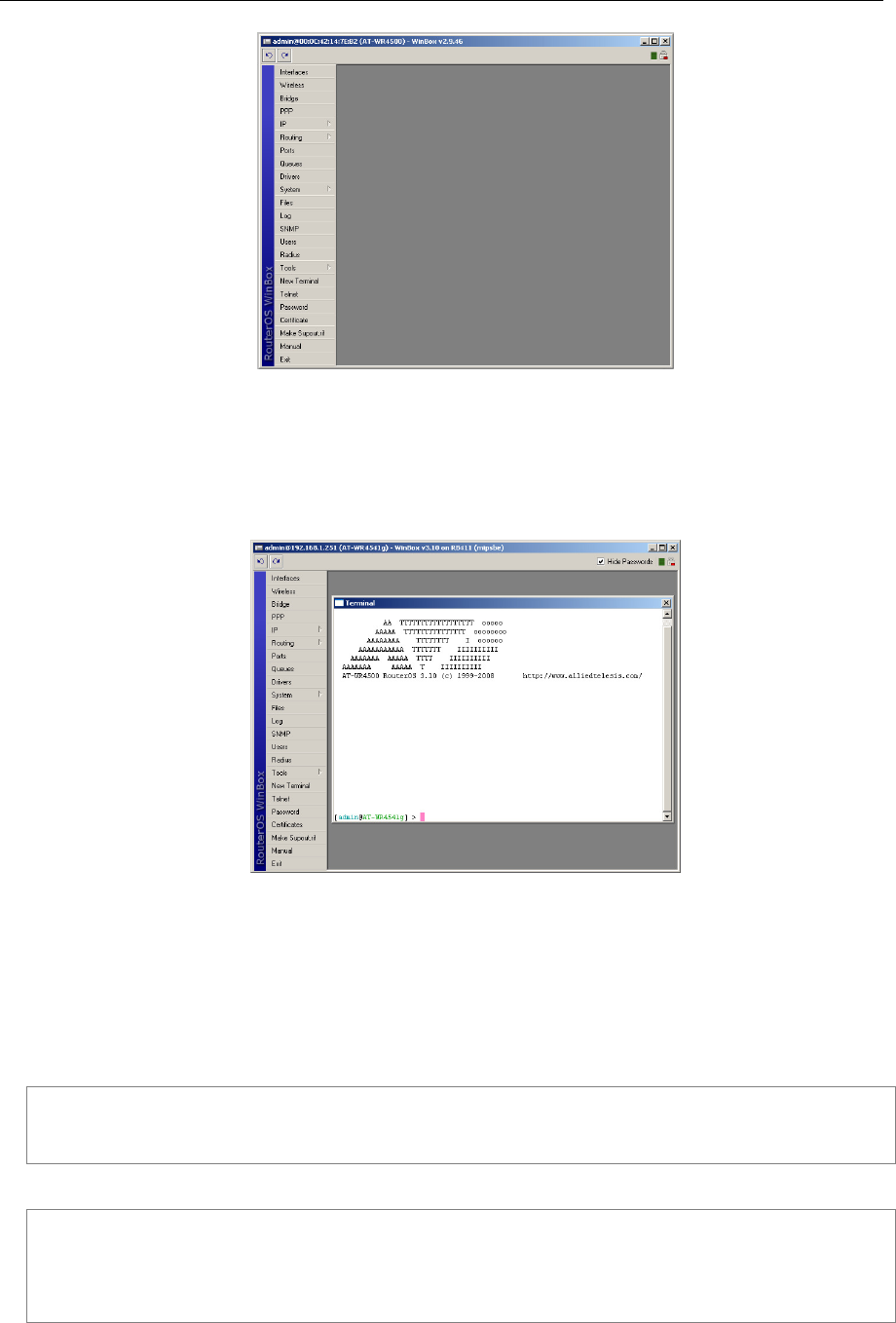
Figure 3: WinBox main window
Select from the menu bar located in the leftmost part of the window the command or menu that you
want to access and start configuring the equipment. For instance you can click on the “New Terminal”
button for opening a Telnet terminal window connected and logged into your router as shown in Figure
4.
Figure 4: WinBox with terminal window open
You can keep open as many WinBox internal windows as you need at the same time.
2.3 Accessing the CLI
When logging into the router via terminal console in telnet or SSH, you will be presented with the
RouterOS login prompt. Use 'admin' and no password (hit [Enter]) for logging into the router for the first
time
AT-WR4500 v3.0
Login: admin
Password:
The password can be changed with the /password command.
[admin@AT-WR4562] > password
old password:
new password: ************
retype new password: ************
[admin@AT-WR4562] >

16 AT-WR4500 Series - IEEE 802.11abgh Outdoor Wireless Routers
RouterOS v3 Configuration and User Guide
After logging into the router you will be presented with the RouterOS™ Welcome Screen and command
prompt, for example:
AA TTTTTTTTTTTTTTTTTT ooooo
AAAAA TTTTTTTTTTTTTTT oooooooo
AAAAAAAA TTTTTTTT I oooooo
AAAAAAAAAAA TTTTTTT IIIIIIIIII
AAAAAAA AAAAA TTTT IIIIIIIIII
AAAAAAA AAAAA T IIIIIIIIII
AT-WR4500 RouterOS 3.10 (c) 1999-2008 http://www.alliedtelesis.com/
[admin@AT-WR4562] >
The command prompt shows the identity name of the router and the current menu level, for example:
[admin@AT-WR4562] >interface
[admin@AT-WR4562] interface>
[admin@AT-WR4562] >ip address
[admin@AT-WR4562] ip address>
The list of available commands at any menu level can be obtained by entering the question mark '?',
[admin@AT-WR4541g] > ?
blink --
certificate -- Certificate management
driver -- Driver management
file -- Local router file storage.
import --
interface -- Interface configuration
ip --
log -- System logs
password -- Change password
ping -- Send ICMP Echo packets
port -- Serial ports
ppp -- Point to Point Protocol
queue -- Bandwidth management
quit -- Quit console
radius -- Radius client settings
redo -- Redo previously undone action
routing --
setup -- Do basic setup of system
snmp -- SNMP settings
special-login -- Special login users
system -- System information and utilities
tool -- Diagnostics tools
undo -- Undo previous action
user --
export -- Print or save an export script that can be used to restore configuration
[admin@AT-WR4541g] >
The list of available commands and menus has short descriptions next to the items. You can move to the
desired menu level by typing its name and hitting the [Enter] key, for example:
[admin@AT-WR4562] > | Base level menu
[admin@AT-WR4562] > driver | Enter 'driver' to move to the driver
| level menu
[admin@AT-WR4562] driver> / | Enter '/' to move to the base level menu
| from any level
[admin@AT-WR4562] > interface | Enter 'interface' to move to the
| interface level menu
[admin@AT-WR4562] interface> /ip | Enter '/ip' to move to the IP level menu
| from any level
[admin@AT-WR4562] ip> |

AT-WR4500 Series - IEEE 802.11abgh Outdoor Wireless Routers 17
RouterOS v3 Configuration and User Guide
A command or an argument does not need to be completed, if it is not ambiguous. For example, instead
of typing interface you can type just in or int. To complete a command use the [Tab] key.
The completion is optional and you can just use short command and parameter names
The commands may be invoked from the menu level, where they are located, by typing its name. If the
command is in a different menu level than the current one, then the command should be invoked using its
full (absolute) or relative path, for example:
[admin@AT-WR4562] ip route> print | Prints the routing table
[admin@AT-WR4562] ip route> .. address print | Prints the IP address table
[admin@AT-WR4562] ip route> /ip address print | Prints the IP address table
The commands may have arguments. The arguments have their names and values. Some commands, may
have a required argument that has no name.
Command Action
command [Enter] Executes the command
[?] Shows the list of all available commands
command [?] Displays help on the command and the list of arguments
command argument
[?] Displays help on the command's argument
[Tab] Completes the command/word. If the input is ambiguous, a second [Tab] gives
possible options
/ Moves up to the base level
/command Executes the base level command
.. Moves up one level
"" Specifies an empty string
"word1 word2" Specifies a string of 2 words that contain a space
You can abbreviate names of levels, commands and arguments.
For the IP address configuration, instead of using the address and netmask arguments, in most cases you
can specify the address together with the number of true bits in the network mask, i.e., there is no need
to specify the netmask separately. Thus, the following two entries would be equivalent:
/ip address add address 10.0.0.1/24 interface ether1
/ip address add address 10.0.0.1 netmask 255.255.255.0 interface ether1
You must specify the size of the network mask in the address argument, even if it is the 32-bit subnet,
i.e., use 10.0.0.1/32 for address=10.0.0.1 netmask=255.255.255.255.
At the factory an IP address (192.168.1.1/24) is pre-configured to allow to use application such us
Telnet, WinBox or HTTP Web GUI, from the Ethernet interface ether1 connecting a PC configured with
an IP Address on the same IP subnet, i.e. 192.168.1.100/24. Whenever the AT-WR4500 will be reset
back the default setting, via the command /system reset-configuration, this IP address will not be
restored into the router running configuration. Connecting the console cable is possible to configure the IP
address using the commands reported here above.

18 AT-WR4500 Series - IEEE 802.11abgh Outdoor Wireless Routers
RouterOS v3 Configuration and User Guide
3 Configuration and Software Management
Document revisi on: 1.6 (Mon Sep 19 12:55: 52 GMT 2005)
Applies to: V2.9
3.1 General Information
Summary
This chapter introduces you with commands which are used to perform the following functions:
• system backup
• system restore from a backup
• configuration export
• configuration import
• system configuration reset
Description
The configuration backup can be used for backing up RouterOS configuration to a binary file, which can
be stored on the router or downloaded from it using FTP for future use. The configuration restore can
be used for restoring the router's configuration, exactly as it was at the backup creation moment, from a
backup file. The restoration procedure (/system backup load) assumes the cofiguration is restored on
the same router, where the backup file was originally created (/system backup save), so it will create
partially broken configuration if the hardware has been changed.
The configuration export can be used for dumping out complete or partial RouterOS configuration to the
console screen or to a text (script) file, which can be downloaded from the router using FTP protocol.
The configuration dumped is actually a batch of commands that add (without removing the existing
configuration) the selected configuration to a router. The configuration import facility executes a batch of
console commands from a script file.
System reset command is used to erase all configuration on the router. Before doing that, it might be
useful to backup the router's configuration.
In order to be sure that the backup will not fail, system backup load command must be used on the
same computer with the same hardware where system backup save was done.
3.1.1 System Backup
Submenu level: /system backup
Description
The save command is used to store the entire router configuration in a backup file. The file is shown in
the /file submenu. It can be downloaded via ftp to keep it as a backup for your configuration.
To restore the system configuration, for example, after a /system reset, it is possible to upload that file
via ftp and load that backup file using load command in /system backup submenu.
Command Description
load name=[filename] - Load configuration backup from a file
save name=[filename] - Save configuration backup to a file
Example
To save the router configuration to file test:
[admin@AT-WR4562] system backup> save name=test
Configuration backup saved
[admin@AT-WR4562] system backup>

AT-WR4500 Series - IEEE 802.11abgh Outdoor Wireless Routers 19
RouterOS v3 Configuration and User Guide
To see the files stored on the router:
[admin@AT-WR4562] > file print
# NAME TYPE SIZE CREATION-TIME
0 test.backup backup 12567 sep/08/2004 21:07:50
[admin@AT-WR4562] >
To load the saved backup file test:
[admin@AT-WR4562] system backup> load name=test
Restore and reboot? [y/N]:
Y
Restoring system configuration
System configuration restored, rebooting now
3.1.2 The Export Command
Command name: /export
Description
The export command prints a script that can be used to restore configuration. The command can be
invoked at any menu level, and it acts for that menu level and all menu levels below it. The output can be
saved into a file, available for download using FTP.
Command Description
file=[filename] - saves the export to a file
Example
[admin@AT-WR4562] > ip address print
Flags: X - disabled, I - invalid, D - dynamic
# ADDRESS NETWORK BROADCAST INTERFACE
0 10.1.0.172/24 10.1.0.0 10.1.0.255 bridge1
1 10.5.1.1/24 10.5.1.0 10.5.1.255 ether1
[admin@AT-WR4562] >
To make an export file:
[admin@AT-WR4562] ip address> export file=address
[admin@AT-WR4562] ip address>
To see the files stored on the router:
[admin@AT-WR4562] > file print
# NAME TYPE SIZE CREATION-TIME
0 address.rsc script 315 dec/23/2003 13:21:48
[admin@AT-WR4562] >
3.1.3 The Import Command
Command name: /import
Description
The root level command /import [file_name] executes a script, stored in the specified file adds the
configuration from the specified file to the existing setup. This file may contain any console comands,
including scripts. is used to restore configuration or part of it after a /system reset event or anything
that causes configuration data loss.

20 AT-WR4500 Series - IEEE 802.11abgh Outdoor Wireless Routers
RouterOS v3 Configuration and User Guide
It is impossible to import the whole router configuration using this feature. It can only be used to import
a part of configuration (for example, firewall rules) in order to spare you some typing.
Command Description
file=[filename] - loads the exported configuration from a file to router
Example
To load the saved export file use the following command:
[admin@AT-WR4562] > import address.rsc
Opening script file address.rsc
Script file loaded successfully
[admin@AT-WR4562] >
3.1.4 Configuration Reset
Command name: /system reset
Description
The command clears all configuration of the router and sets it to the default including the login name and
password ('admin' and no password), IP addresses and other configuration is erased, interfaces will
become disabled. After the reset command router will reboot.
Command Description
reset - erases router's configuration
If the router has been installed using netinstall and had a script specified as the initial configuration, the
reset command executes this script after purging the configuration. To stop it doing so, you will have to
reinstall the router.
Example
[admin@AT-WR4562] > system reset
Dangerous! Reset anyway? [y/N]: n
action cancelled
[admin@AT-WR4562] >
3.2 Software Version Management
Document revisi on: 1.4 (Tue Oct 18 12:24:5 7 GMT 200 5)
Applies to: V2.9
3.2.1 General Information
Summary
To upgrade RouterOS to a more recent version, you can simply transfer the packages to router via ftp,
using the binary transfer mode, and then just rebooting the router.
This manual discusses a more advanced method how to upgrade a router automatically. If you have more
than one router then this can be useful.
Specifications
Packages required: system
License required: Level1
Submenu level: /system upgrade

AT-WR4500 Series - IEEE 802.11abgh Outdoor Wireless Routers 21
RouterOS v3 Configuration and User Guide
Standards and Technologies: None
Hardware usage: Not significant
3.2.2 System Upgrade
Submenu level: /system upgrade
Description
This submenu gives you the ability to download RouterOS software packages from a remote RouterOS
router.
Step-by-Step
Upload desired RouterOS packages to a router (not the one that you will upgrade).
Add this router's IP address, user name and password to /system upgrade upgrade-package-source
on the router(s) you will be upgrading. This step will only be needed once, and you may continue using
the same package source in future to upgrade the router(s) again. See the next section for details.
Refresh available software package list /system upgrade refresh
See available packages, using /system upgrade print command
Download selected or all packages from the remote router, using the download or download-all
command
Property Description
name (read-only: name) - package name
source (read-only: IP address) - source IP address of the router from which the package list entry is
retrieved
status (read-only: available | scheduled | downloading | downloaded | installed) - package status
version (read-only: text) - version of the package
Command Description
download - download packages from list by specifying their numbers
download-all - download all packages that are needed for the upgrade (packages which are listed in the
/system package print command output)
refresh - updates currently available package list
Example
See the available packages:
[admin@AT-WR4562] system upgrade> refresh
[admin@AT-WR4562] system upgrade> print
# SOURCE NAME VERSION STATUS COMPLETED
0 192.168.25.8 routeros-x86 2.9.44 available
1 192.168.25.8 routeros-rb500 3.0 available
[admin@AT-WR4562] system upgrade>
To upgrade chosen packages:
[admin@AT-WR4562] system upgrade> download 1
[admin@AT-WR4562] system upgrade> print
# SOURCE NAME VERSION STATUS COMPLETED
0 192.168.25.8 routeros-x86 2.9.44 available
1 192.168.25.8 routeros-rb500 3.0 available
[admin@AT-WR4562] system upgrade>

22 AT-WR4500 Series - IEEE 802.11abgh Outdoor Wireless Routers
RouterOS v3 Configuration and User Guide
3.2.3 Adding Package Source
Submenu level: /system upgrade upgrade-package-source
Description
In this submenu you can add remote routers from which to download RouterOS software packages.
Property Description
address (IP address) - source IP address of the router from which the package list entry will be retrieved
password (text) - password of the remote router
user (text) - username of the remote router
After specifying a remote router in '/system upgrade upgrade-package-source', you can type '/system
upgrade refresh' to refresh the package list and '/system upgrade print' to see all available packages.
Example
To add a router, with username admin and no password, from which the packages will be retrieved:
[admin@AT-WR4562] system upgrade upgrade-package-source> add \
\... address=192.168.25.8 user=admin
password:
[admin@AT-WR4562] ystem upgrade upgrade-package-source> print
# ADDRESS USER
0 192.168.25.8 admin
[admin@AT-WR4562] system upgrade upgrade-package-source>
3.3 Software Package Management
Document revisi on: 1.3 (Mon Jul 11 12:42:44 GMT 2005)
Applies to: V2.9
3.3.1 General Information
Summary
The RouterOS is distributed in the form of software packages. The basic functionality of the router and
the operating system itself is provided by the system software package. Other packages contain
additional software features as well as support to various network interface cards.
Specifications
License required: Level1
Submenu level: /system package
Standards and Technologies: FTP
Hardware usage: Not significant
Description
Features
The modular software package system of RouterOS has the following features:
• Ability to extend RouterOS functions by installing additional software packages
• Optimal usage of the storage space by employing modular/compressed system
• Unused software packages can be uninstalled
• The RouterOS functions and the system itself can be easily upgraded
• Multiple packages can be installed at once

AT-WR4500 Series - IEEE 802.11abgh Outdoor Wireless Routers 23
RouterOS v3 Configuration and User Guide
• The package dependency is checked before installing a software package. The package will not be
installed, if the required software package is missing
• The version of the feature package should be the same as that of the system package
• The packages can be uploaded on the router using ftp and installed only when the router is going for
shutdown during the reboot process
• If the software package file can be uploaded to the router, then the disk space is sufficient for the
installation of the package
• The system can be downgraded to an older version by uploading the needed packages to router via
FTP binary mode. After that, execute command /system package downgrade
3.3.2 Installation (Upgrade)
Description
Installation or upgrade of the RouterOS software packages can be done by uploading the newer version
of the software package to the router and rebooting it.
The software package files are compressed binary files, which can be downloaded from Allied Telesis web
site in th support section http://www.alliedtelesis.com/support/. The full name of the software package
consists of a descriptive name, version number and extension .npk, e.g. system-3.2.npk, routerboard-
3.2.npk. Package routeros-x86 contains all necessary packages for RouterOS installation and upgrading
for AT-WR456x Wireless Routers.
You should check the available hard disk space prior to downloading the package file by issuing /system
resource print command. If there is not enough free disk space for storing the upgrade packages, it can
be freed up by uninstalling some software packages, which provide functionality not required for your
needs. If you have a sufficient amount of free space for storing the upgrade packages, connect to the
router using ftp. Use user name and password of a user with full access privileges.
Step-by-Step
• Connect to the router using ftp client
• Select the BINARY mode file transfer
• Upload the software package files to the router
• Check the information about the uploaded software packages using the /file print command
• Reboot the router by issuing the /system reboot command or by pressing Ctrl+Alt+Del keys at the
router's console
• After reboot, verify that the packages were installed correctly by issuing /system package print
command
The packages uploaded to the router should retain the original name and also be in lowercase.
The installation/upgrade process is shown on the console screen (monitor) attached to the router.
Before upgrading the router, please check the current version of the system package and the additional
software packages. The versions of additional packages should match the version number of the system
software package.
The version of the RouterOS system software (and the build number) are shown before the console login
prompt. Information about the version numbers and build time of the installed RouterOS software
packages can be obtained using the /system package print command.
3.3.3 Uninstallation
Command name: /system package uninstall
Description
Usually, you do not need to uninstall software packages. However, if you have installed a wrong package,
or you need additional free space to install a new one, you have to uninstall some unused packages.

24 AT-WR4500 Series - IEEE 802.11abgh Outdoor Wireless Routers
RouterOS v3 Configuration and User Guide
If a package is marked for uninstallation, but it is required for another (dependent) package, then the
marked package cannot be uninstalled. You should uninstall the dependent package too. For the list of
package dependencies see the 'Software Package List; section below. The system package will not be
uninstalled even if marked for uninstallation.
Example
Suppose we need to uninstall security package from the router:
[admin@AT-WR4562] system package> print
Flags: X - disabled
# NAME VERSION SCHEDULED
0 routeros-rb500 3.0
1 system 3.0
2 X ipv6 3.0
3 ntp 3.0
4 wireless 3.0
5 dhcp 3.0
6 routing 3.0
7 routerboard 3.0
8 advanced-tools 3.0
9 hotspot 3.0
10 ppp 3.0
11 security 3.0
[admin@AT-WR4562] system package> uninstall security
[admin@AT-WR4562] > .. reboot
3.3.4 Downgrading
Command name: /system package downgrade
Description
Downgrade option allows you to downgrade the software via FTP without losing your license key or
reinstalling the router. It is not recommended to use older versions, however, if the newest version
introduced some unwanted behavior, you may try to downgrade. If you send a support question, you will
probably be asked to upgrade to the latest version.
Step-by-Step
• Connect to the router using ftp client
• Select the BINARY mode file transfer
• Upload the software package files to the router
• Check the information about the uploaded software packages using the /file print command
• Execute command /system package downgrade. The router will downgrade and reboot.
• After reboot, verify that the packages were installed correctly by issuing /system package print
command
Command Description
downgrade - this command asks your confirmation and reboots the router. After reboot the software is
downgraded (if all needed packages were uploaded to the router)

AT-WR4500 Series - IEEE 802.11abgh Outdoor Wireless Routers 25
RouterOS v3 Configuration and User Guide
Example
To downgrade the RouterOS (assuming that all needed packages are already uploaded):
[admin@AT-WR4562] system package> downgrade
Router will be rebooted. Continue? [y/N]:
y
system will reboot shortly
3.3.5 Disabling and Enabling
Specifications
Command name: /system package disable, /system package enable
Description
You can disable packages making them invisible for the system and later enable them, bringing the system
back to the previous state. It is useful if you don't want to uninstall a package, but just turn off its
functionality. This will save the RAM and processor resources for other applications, but will not free the
diskspace used by the package files.
If a package is marked for disabling, but it is required for another (dependent) package, then the
marked package cannot be disabled. You should disable or uninstall the dependent package too. For the
list of package dependencies see the 'Software Package List; section below.
If any of the test packages will be enabled (for example wireless-test and routing-test packages, that are
included in routeros-x86.npk) system automaticly will disable regular packages that conflict with them.
Example
Suppose we need to test ipv6 package features:
[admin@AT-WR4562] system package> print
Flags: X – disabled
# NAME VERSION SCHEDULED
0 routeros-rb500 3.0
1 system 3.0
2 X ipv6 3.0
3 ntp 3.0
4 wireless 3.0
5 dhcp 3.0
6 routing 3.0
7 routerboard 3.0
8 advanced-tools 3.0
9 hotspot 3.0
10 ppp 3.0
11 security 3.0
[admin@AT-WR4562] system package> enable ipv6
[admin@AT-WR4562] system package> .. reboot
3.3.6 Unscheduling
Command name: /system package unschedule
Description
Unschedule option allows to cancel pending uninstall, disable or enable actions for listed packages.
Packages marked for uninstallation, disabling or enabling on reboot in column "schedule" will have a
note, warning about changes.

26 AT-WR4500 Series - IEEE 802.11abgh Outdoor Wireless Routers
RouterOS v3 Configuration and User Guide
Example
Suppose we need to cancel security package uninstallation action scheduled on reboot:
[admin@AT-WR4562] system package> print
Flags: X – disabled
# NAME VERSION SCHEDULED
0 routeros-rb500 3.0
1 system 3.0
2 X ipv6 3.0
3 ntp 3.0
4 wireless 3.0
5 dhcp 3.0
6 routing 3.0
7 routerboard 3.0
8 advanced-tools 3.0
9 hotspot 3.0
10 ppp 3.0
11 security 3.0 scheduled for uninstall
[admin@AT-WR4562] system package> unschedule security
[admin@AT-WR4562] system package>
3.3.7 System Upgrade
Submenu level: /system upgrade
Description
This submenu gives you the ability to download RouterOS software packages from a remote RouterOS
router.
Step-by-Step
• Upload desired RouterOS packages to a router (not the one that you will upgrade).
• Add this router's IP address, user name and password to /system upgrade upgrade-package-
source on the router(s) you will be upgrading. This step will only be needed once, and you may
continue using the same package source in future to upgrade the router(s) again. See the next section
for details.
• Refresh available software package list /system upgrade refresh
• See available packages, using /system upgrade print command
• Download selected or all packages from the remote router, using the download or download-all
• command
Property Description
name (read-only: name) - package name
source (read-only: IP address) - source IP address of the router from which the package list entry is
retrieved
status (read-only: available | scheduled | downloading | downloaded | installed) - package status
version (read-only: text) - version of the package
Command Description
download - download packages from list by specifying their numbers
download-all - download all packages that are needed for the upgrade (packages which are listed in the
/system package print command output)
refresh - updates currently available package list

AT-WR4500 Series - IEEE 802.11abgh Outdoor Wireless Routers 27
RouterOS v3 Configuration and User Guide
Example
See the available packages:
[admin@AT-WR4562] system upgrade> refresh
[admin@AT-WR4562] system upgrade> print
# SOURCE NAME VERSION STATUS COMPLETED
0 192.168.25.8 routeros-x86 2.9.44 available
1 192.168.25.8 routeros-rb500 3.0 available
[admin@AT-WR4562] system upgrade>
To upgrade selected packages:
[admin@AT-WR4562] system upgrade> download 1
[admin@AT-WR4562] system upgrade> print
# SOURCE NAME VERSION STATUS COMPLETED
0 192.168.25.8 routeros-x86 2.9.44 available
1 192.168.25.8 routeros-rb500 3.0 downloading 16 %
[admin@AT-WR4562] system upgrade>
3.3.8 Adding Package Source
Submenu level: /system upgrade upgrade-package-source
Description
In this submenu you can add remote routers from which to download the RouterOS software packages.
Property Description
address (IP address) - source IP address of the router from which the package list entry will be retrieved
password (text) - password of the remote router
user (text) - username of the remote router
After specifying a remote router in /system upgrade upgrade-package-source, you can type
/system upgrade refresh to refresh the package list and /system upgrade print to see all available
packages.
Example
To add a router with IP address 192.168.25.8, username admin and no password:
[admin@AT-WR4562] system upgrade upgrade-package-source> add \
\... address=192.168.25.8 user=admin
password:
[admin@-WR4500] system upgrade upgrade-package-source> print
# ADDRESS USER
0 192.168.25.8 admin
[admin@AT-WR4562] system upgrade upgrade-package-source>
3.3.9 Software Package List
Description
System Software Package
The system software package provides the basic functionality of the RouterOS, namely:
• IP address management, ARP, static IP routing, policy routing, firewall (packet filtering, content
• filtering,masquerading, and static NAT), traffic shaping (queues), IP traffic accounting, Neighbour
• Discovery, IP Packet Packing, DNS client settings, IP service (servers)

28 AT-WR4500 Series - IEEE 802.11abgh Outdoor Wireless Routers
RouterOS v3 Configuration and User Guide
• Ethernet interface support
• IP over IP tunnel interface support
• Ethernet over IP tunnel interface support
• driver management for Ethernet ISA cards
• serial port management
• local user management
• export and import of router configuration scripts
• backup and restore of the router's configuration
• undo and redo of configuration changes
• network diagnostics tools (ping, traceroute, bandwidth tester, traffic monitor)
• bridge support
• system resource management
• package management
• telnet client and server
• local and remote logging facility
• winbox server as well as winbox executable with some plugins
Additional Software Feature Packages
The table below shows additional software feature packages, extended functionality provided by them,
the required prerequisites and additional licenses, if any.
Allied Telesis distributes and supports the following packages only.
Package name Contents Prerequisites
Additional License
advanced-tools email client, pingers,
netwatch and other utilities none none
calea
Call Content Connection
(CCC) data retention server
for CALEA compliance
(Communications Assistance
for Law Enforcement Act)
none
none
dhcp DHCP server and client
support none none
hotspot HotSpot gateway none any additional license
ntp network time protocol
support none none
ppp support for PPP, PPTP,
L2TP, PPPoE and ISDN PPP none none
routerboard support for RouterBoard-
specific functions and utilities
none none
routing support for RIP and OSPF none none
security support for IPSEC, SSH and
secure WinBox connections none none
user-manager embedded RADIUS server
with web interface
none none

AT-WR4500 Series - IEEE 802.11abgh Outdoor Wireless Routers 29
RouterOS v3 Configuration and User Guide
Package name Contents Prerequisites
Additional License
wireless
Support for wireless
interfaces with updated
Country Regulatory Domain
settings
none None

30 AT-WR4500 Series - IEEE 802.11abgh Outdoor Wireless Routers
RouterOS v3 Configuration and User Guide
4 Configuring Interfaces
4.1 General Interface Settings
Document revisi on: 1.1 (Fri Mar 05 08:08:52 GMT 200 4)
Applies to: V2.9
4.1.1 General Information
Summary
AT-WR4500 RouterOS supports a variety of physical and virtual interfaces (like Bonding, Bridge, VLAN
etc.). Each of them has its own submenu, but there is also a list of all interfaces where some common
properties can be configured.
Description
The Manual describes general settings of RouterOS interfaces.
4.1.2 Interface Status
Submenu level: /interface
Property Description
mtu (integer) - maximum transmission unit for the interface (in bytes)
name (text) - the name of the interface
type (read-only: arlan | bonding | bridge | cyclades | eoip | ethernet | farsync | ipip | isdn-client |
isdn-server | l2tp-client | l2tp-server | moxa-c101 | moxa-c502 | mtsync | pc | ppp-client | ppp-server |
pppoe-client | pppoe-server | pptp-client | pptp-server | pvc | radiolan | sbe | vlan | wavelan | wireless| xpeed) -
interface type
Example
To see the list of all available interfaces:
[admin@AT-WR4562] interface> print
Flags: X - disabled, D - dynamic, R - running
# NAME TYPE RX-RATE TX-RATE MTU
0 R ether1 ether 0 0 1500
1 R bridge1 bridge 0 0 1500
2 R ether2 ether 0 0 1500
3 R wlan1 wlan 0 0 1500
[admin@AT-WR4562] interface>
4.1.3 Traffic Monitoring
Command name: /interface monitor-traffic
Description
The traffic passing through any interface can be monitored.
Property Description
received-bits-per-second (read-only: integer) - number of bits that interface has received in one
second
received-packets-per-second (read-only: integer) - number of packets that interface has received
in one second
sent-bits-per-second (read-only: integer) - number of bits that interface has sent in one second
sent-packets-per-second (read-only: integer) - number of packets that interface has sent in one second

AT-WR4500 Series - IEEE 802.11abgh Outdoor Wireless Routers 31
RouterOS v3 Configuration and User Guide
One or more interfaces can be monitored at the same time.
To see overall traffic passing through all interfaces at time, use aggregate instead of interface name.
Example
Multiple interface monitoring:
/interface monitor-traffic ether1,aggregate
received-packets-per-second: 9 11
received-bits-per-second: 4.39kbps 6.19kbps
sent-packets-per-second: 16 17
sent-bits-per-second: 101kbps 101kbps
[Q quit|D dump|C-z pause]
4.2 Ethernet Interfaces
Document revisi on: 1.2 (Fri Apr 16 12:35: 37 GMT 2004)
Applies to: V2.9
4.2.1 General Information
Summary
RouterOS supports various types of Ethernet Interfaces with all available features. This section describes
how to configure the various parameters and settings.
Specifications
Packages required: system
License required: Level1
Submenu level: /interface ethernet
Standards and Technologies: IEEE 802.3
Hardware usage: Not significant
Related Topics
• Software Package Management
• IP Addresses and ARP
• DHCP and DNS
Additional Resources
• http://grouper.ieee.org/groups/802/3/
• http://en.wikipedia.org/wiki/IEEE_802.3
• http://www.ethermanage.com/ethernet/ethernet.html
• http://www.dcs.gla.ac.uk/~liddellj/nct/ethernet_protocol.html
4.2.2 Ethernet Interface Configuration
Submenu level: /interface ethernet
Property Description
arp (disabled | enabled | proxy-arp | reply-only; default: enabled) - Address Resolution Protocol
auto-negotiation (yes | no; default: yes) - when enabled, the interface "advertises" its maximum
capabilities to achieve the best connection possible to NS DP83815/6 cards)

32 AT-WR4500 Series - IEEE 802.11abgh Outdoor Wireless Routers
RouterOS v3 Configuration and User Guide
default - suport long cables
short - support short cables
standard - same as default
disable-running-check (yes | no; default: yes) - disable running check. If this value is set to 'no', the
router automatically detects whether the NIC is connected with a device in the network or not
full-duplex (yes | no; default: yes) - defines whether the transmission of data appears in two directions
simultaneously
mac-address (MAC address) - set the Media Access Control number of the card
mdix-enable (yes | no) - whether the MDI/X auto crosscable correction feature is enabled for the port
(if applicable)
mtu (integer; default: 1500) - Maximum Transmission Unit
name (name; default: etherN) - assigned interface name, whrere 'N' is the number of the ethernet
interface
speed (10 Mbps | 100 Mbps | 1 Gbps) - sets the data transmission speed of the interface. By default, this
value is the maximal data rate supported by the interface
When disable-running-check is set to no, the router automatically detects whether the NIC is
connected to a device in the network or not. When the remote device is not connected (the leds are not
blinking), the route which is set on the specific interface, becomes invalid.
Command Description
reset-mac (name) - set the MAC address of the NIC to the factory default setting
Example
[admin@AT-WR4562] > interface print
Flags: X - disabled, D - dynamic, R - running
# NAME TYPE RX-RATE TX-RATE MTU
0 X ether1 ether 0 0 1500
[admin@AT-WR4562] > interface enable ether1
[admin@AT-WR4562] > interface print
Flags: X - disabled, D - dynamic, R - running
# NAME TYPE RX-RATE TX-RATE MTU
0 R ether1 ether 0 0 1500
[admin@AT-WR4562] > interface ethernet
[admin@AT-WR4562] interface ethernet> print
Flags: X - disabled, R - running
# NAME MTU MAC-ADDRESS ARP
0 R ether1 1500 00:0C:42:03:00:F2 enabled
[admin@AT-WR4562] interface ethernet> print detail
Flags: X - disabled, R - running
0 R name="ether1" mtu=1500 mac-address=00:0C:42:03:00:F2 arp=enabled
disable-running-check=yes auto-negotiation=yes full-duplex=yes
cable-settings=default speed=100Mbps
[admin@AT-WR4562] interface ethernet>
4.2.3 Monitoring the Interface Status
Command name: /interface ethernet monitor
Property Description
auto-negotiation (done | incomplete) - fast link pulses (FLP) to the adjacent link station to negotiate the
SPEED and MODE of the link. Both stations choose the maximal speed boh support.
done - negotiation done
incomplete - negotiation failed
default-cable-setting (read-only: short | standard) - default cable length setting (only applicable to NS
DP83815/6 cards)
short - support short cables
standard - same as default

AT-WR4500 Series - IEEE 802.11abgh Outdoor Wireless Routers 33
RouterOS v3 Configuration and User Guide
full-duplex (yes | no) - whether transmission of data occurs in two directions simultaneously
rate (10 Mbps | 100 Mbps | 1 Gbps) - the actual data rate of the connection
status (link-ok | no-link | unknown) - status of the interface, one of the:
link-ok - the card is connected to the network
no-link - the card is not connected to the network (cable is not plugged in or faulty)
unknown - the connection is not recognized (if the card does not report connection status)
See the IP Addresses and ARP section of the manual for information how to add IP addresses to the
interfaces.
Example
[admin@AT-WR4562] interface ethernet> monitor ether1,ether2
status: link-ok link-ok
auto-negotiation: done done
rate: 100Mbps 100Mbps
default-cable-setting: standard standard
4.2.4 Troubleshooting
Description
Interface monitor shows wrong information
In some very rare cases it is possible that the device driver does not show correct information, but it
does not affect the NIC's performance (of course, if your card is not broken)
4.3 Wireless Interfaces
D o c u m e n t r e v i s i o n :
2 . 2 ( T u e J u l 1 8 1 4 : 5 3 : 5 8 G M T 2 0 0 6
A p p l i e s t o :
V 2 . 9
4.3.1 General Information
Summary
This manual discusses management of the Atheros chipset based wireless interfaces of the AT-WR4500
Series wireless routers that comply with IEEE 802.11 set of standards. These interfaces use radio waves
as a physical signal carrier and are capable of data transmission with speeds up to 108 Mbps (in 5GHz
turbo-mode).
RouterOS can operate wireless interfaces as wireless clients (station mode), wireless bridges (bridge
mode), wireless access points (ap-bridge mode), and for antenna positioning (alignment-only mode).
RouterOS provides a complete support for IEEE 802.11a, 802.11b and 802.11g wireless networking
standards. There are several additional features implemented for the wireless networking in RouterOS -
WPA (Wi-Fi Protected Access), WEP (Wired Equivalent Privacy), software and hardware AES
encryption, WDS (Wireless Distribution System), DFS (Dynamic Frequency Selection), Alignment mode
(for positioning antennas and monitoring wireless signal), VAP (Virtual Access Point), ability to disable
packet forwarding among clients, Nstreme wireless transmission protocol and others.
The Nstreme protocol is proprietary (i.e., incompatible with other vendors) wireless protocol aimed to
improve point-to-point and point-to-multipoint wireless links. Advanced version of Nstreme, called
Nstreme2 works with a pair of wireless interfaces (Atheros AR5210 and newer MAC chips only) - one
for transmitting data and one for receiving.
Benefits of Nstreme protocol:
• Client polling. Polling reduces media access times, because the card does not need to ensure the air
is "free" each time it needs to transmit data (the polling mechanism takes care of it)
• Very low protocol overhead per frame allowing super-high data rates

34 AT-WR4500 Series - IEEE 802.11abgh Outdoor Wireless Routers
RouterOS v3 Configuration and User Guide
• No implied protocol limits on link distance
• No implied protocol speed degradation for long link distances
• Dynamic protocol adjustment depending on traffic type and resource usage
Quick Setup Guide
Let's consider that you have a wireless interface, called wlan1.
To set it as an Access Point, working in 802.11g standard, using frequency 2442 MHz and Service Set
Identifier test, do the following configuration:
/interface wireless set wlan1 ssid=test frequency=2442 band=2.4ghz-b/g \
mode=ap-bridge disabled=no
Now your router is ready to accept wireless clients.
To make a point-to-point connection, using 802.11a standard, frequency 5805 MHz and Service Set
Identifier p2p, write:
/interface wireless set wlan1 ssid="p2p" frequency=5805 band=5ghz \
mode=bridge disabled=no
The remote interface should be configured to station as showed below.
To make the wireless interface as a wireless station, working in 802.11a standard and Service Set
Identifier p2p:
/interface wireless set wlan1 ssid="p2p" band=5ghz mode=station disabled=no
Specifications
Packages required: wireless
License required: Level4 (station and bridge mode)
Submenu level: /interface wireless
Standards and Technologies: IEEE802.11a, IEEE802.11b, IEEE802.11g
Hardware usage: Not significant
Related Topics
• IP Addresses and ARP
• Log Management
Description
The Atheros card has been tested for distances up to 20 km providing connection speed up to 17Mbit/s.
With appropriate antennas and cabling the maximum distance should be as far as 50 km.
These values of ack-timeout were approximated from the tests done by us, as well as by some of our
customers:
ack-timeout
range
5GHz
5GHz-turbo
2.4GHz-G
0km default
default default
5km 52 30 62
10km 85 48 96
15km 121 67 133
20km 160 89 174
25km 203 111 219

AT-WR4500 Series - IEEE 802.11abgh Outdoor Wireless Routers 35
RouterOS v3 Configuration and User Guide
ack-timeout
range
5GHz
5GHz-turbo
2.4GHz-G
30km 249 137 368
35km 298 168 320
40km 350 190 375
45km 405 - -
These are not the precise values. Depending on hardware used and many other factors they may vary
up to +/- 15 microseconds.
You can also use dynamic ack-timeout value - the router will determine ack-timeout setting
automatically by sending periodically packets with a different ack-timeout. Ack-timeout values by which
ACK frame was received are saved and used later to determine the real ack-timeout.
The Nstreme protocol may be operated in three modes:
• Point-to-Point mode - controlled point-to-point mode with one radio on each side
• Dual radio Point-to-Point mode (Nstreme2) - the protocol will use two radios on both sides
simultaneously (one for transmitting data and one for receiving), allowing superfast point-to-point
connection
• Point-to-Multipoint - controlled point-to-multipoint mode with client polling (like AP-controlled
TokenRing)
•
4.3.2 Wireless Interface Configuration
Submenu level: /interface wireless
Description
In this section we will discuss the most important part of the configuration.
Property Description
ack-timeout (integer | dynamic | indoors) - acknowledgement code timeout (transmission acceptance
timeout) in microseconds for acknowledgement messages. Can be one of these:
dynamic - ack-timeout is chosen automatically
indoors - standard constant for indoor usage
adaptive-noise-immunity (yes | no; default: yes) - adjust various receiver parameters dynamically to
minimize interference and noise effect on the signal quality.
allow-sharedkey (yes | no; default: no) - allow WEP Shared Key cilents to connect. Note that no
authentication is done for these clients (WEP Shared keys are not compared to anything) - they are just
accepted at once (if access list allows that)
antenna-gain (integer; default: 0) - antenna gain in dBi. This parameter will be used to calculate whether
your system meets regulatory domain's requirements in your country
antenna-mode (ant-a | ant-b | rxa-txb | txa-rxb; default: ant-a) - which antenna to use for
transmit/receive data:
ant-a - use only antenna a
ant-b - use only antenna b
rxa-txb - use antenna a for receiving packets, use antenna b for transmitting packets
txa-rxb - use antenna a for transmitting packets, antenna b for receiving packets
area (text; default: "") - string value that is used to describe an Access Point. Connect List on the
Client's side comparing this string value with area-prefix string value makes decision whether allow a
Client connect to the AP. If area-prefix match the entire area string or only the beginning of it the
Client is allowed to connect to the AP
arp (disabled | enabled | proxy-arp | reply-only; default: enabled) - Address Resolution Protocol setting

36 AT-WR4500 Series - IEEE 802.11abgh Outdoor Wireless Routers
RouterOS v3 Configuration and User Guide
band - operating band
2.4ghz-b - IEEE 802.11b
2.4ghz-b/g - IEEE 802.11g (supports also legacy IEEE 802.11b protocol)
2.4ghz-g-turbo - IEEE 802.11g using double channel, providing air rate of up to 108 Mbit
2.4ghz-onlyg - only IEEE 802.11g
5ghz - IEEE 802.11a up to 54 Mbit
5ghz-turbo - IEEE 802.11a using double channel, providing air rate of up to 108Mbit
2ghz-10mhz - variation of IEEE 802.11g with half the band, and, accordingly, twice lower speed (air rate
of up to 27Mbit)
2ghz-5mhz - variation of IEEE 802.11g with quarter the band, and, accordingly, four times lower speed
(air rate of up to 13.5Mbit)
5ghz-10mhz - variation of IEEE 802.11a with half the band, and, accordingly, twice lower speed (air rate
of up to 27Mbit)
5ghz-5mhz - variation of IEEE 802.11a with quarter the band, and, accordingly, four times lower speed
(air rate of up to 13.5Mbit)
basic-rates-a/g (multiple choice: 6Mbps, 9Mbps, 12Mbps, 18Mbps, 24Mbps, 36Mbps, 48Mbps, 54Mbps;
default: 6Mbps) - basic rates in 802.11a or 802.11g standard. This should be the minimal speed all the
wireless network nodes support (they will not be ableto connect otherwise). It is recommended to leave
this as default
basic-rates-b (multiple choice: 1Mbps, 2Mbps, 5.5Mbps, 11Mbps; default: 1Mbps) - basic rates in 802.11b
mode. This should be the minimal speed all the wireless network nodes support (they will not be ableto
connect otherwise). It is recommended to leave this as default
burst-time (time; default: disabled) - time in microseconds which will be used to send data without
stopping. Note that no other wireless cards in that network will be able to transmit data during burst-
time microseconds.
compression (yes | no; default: no) - if enabled on AP (in ap-bridge or bridge mode), it advertizes that it
is capable to use hardware data compression. If a client, connected to this AP, also supports and is
configured to use the hardware data compression, it requests the AP to use compression. This property
does not affect clients, which do not support compression.
country (albania | algeria | argentina | armenia | australia | austria | azerbaijan | bahrain | belarus | belgium
| belize | bolvia | brazil | brunei darussalam | bulgaria | canada | chile | china | colombia | costa rica | croatia
| cyprus | czech republic | denmark | dominican republic | ecuador | egypt | el salvador | estonia | finland |
france | france_res | georgia | germany | greece | guatemala | honduras | hong kong | hungary | iceland |
india | indonesia | iran | ireland | israel | italy | japan | japan1 | japan2 | japan3 | japan4 | japan5 | jordan |
kazakhstan | korea republic | korea republic2 | kuwait | latvia | lebanon | liechtenstein | lithuania |
luxemburg | macau | macedonia | malaysia | mexico | monaco | morocco | netherlands | new zealand |
no_country_set | north korea | norway | oman | pakistan | panama | peru | philippines | poland | portugal |
puerto rico | qatar | romania | russia | saudi arabia | singapore | slovak republic | slovenia | south africa |
spain | sweden | switzerland | syria | taiwan | thailand | trinidad & tobago | tunisia | turkey | ukraine |
united arab emirates | united kingdom | united states | uruguay | uzbekistan | venezuela | viet nam | yemen
| zimbabwe; default: no_country_set) - limits wireless settings (frequency and transmit power) to those
which are allowed in the respective country
no_country_set - no regulatory domain limitations
default-ap-tx-limit (integer; default: 0) - limits data rate for each wireless client (in bps)
0 - no limits
default-authentication (yes | no; default: yes) - specifies the default action on the client's side for APs
that are not in connect list or on the AP's side for clients that are not in access list
yes - enables AP to register a client if it is not in access list. In turn for client it allows to associate with
AP not listed in client's connect list
default-client-tx-limit (integer; default: 0) - limits each client's transmit data rate (in bps). Works only if
the client is also a Router
0 - no limits
default-forwarding (yes | no; default: yes) - whether to use data forwarding by default or not. If set to
'no', the registered clients will not be able to communicate with each other
dfs-mode (none | radar-detect | no-radar-detect; default: none) - used for APs to dynamically select
frequency at which this AP will operate
none - do not use DFS
no-radar-detect - AP scans channel list from "scan-list" and chooses the frequency which is with the
lowest amount of other networks detected

AT-WR4500 Series - IEEE 802.11abgh Outdoor Wireless Routers 37
RouterOS v3 Configuration and User Guide
radar-detect - AP scans channel list from "scan-list" and chooses the frequency which is with the lowest
amount of other networks detected, if no radar is detected in this channel for 60 seconds, the AP starts
to operate at this channel, if radar is detected, the AP continues searching for the next available channel
which is with the lowest amount of other networks detected
disable-running-check (yes | no; default: no) - disable running check. If value is set to 'no', the router
determines whether the card is up and running - for AP one or more clients have to be registered to it,
for station, it should be connected to an AP. This setting affects the records in the routing table in a way
that there will be no route for the card that is not running (the same applies to dynamic routing
protocols). If set to 'yes', the interface will always be shown as running
disconnect-timeout (time; default: 3s) - time since the third sending failure ( 3*(hw-retries+1) packets
have been lost) at the lowest datarate only (i.e. since the first time on-fail-retry-time has been
activated), when the client gets disconnected (logged as "extensive data loss")
frame-lifetime (integer; default: 0) - frame lifetime in centiseconds since the first sending attempt to
send the frame. Wireless normally does not drop any packets at all until the client is disconnected. If
there is no need to accumulate packets, you can set the time after which the packet will be discarded
0 - never drop packets until the client is disconnected (default value)
frequency (integer) - operating frequency of the AP (ignored for the client, which always scans through
its scan list regardless of the value set in this field)
frequency-mode (regulatory-domain | manual-tx-power | superchannel; default: regulatory-domain) -
defines which frequency channels to allow
regulatory-domain - use the channels allowed in the selected country at the allowed transmit power
(with the configured antenna-gain deducted) only. Also note that in this mode card will never be
configured to higher power than allowed by the respective regulatory domain
manual-tx-power - use the channels allowed in the selected country only, but take transmit power
from the tx-power settings
superchannel - only possible with the Superchannel license. In this mode all hardware supported
channels and transmit power settings are allowed
hide-ssid (yes | no; default: no) - whether to hide ssid or not in the beacon frames:
yes - ssid is not included in the beacon frames. AP replies only to probe-requests with the given ssid
no - ssid is included in beacon frames. AP replies to probe-requests with the given ssid ant to 'broadcast
ssid' (empty ssid)
hw-retries (integer; default: 15) - number of frame sending retries until the transmission is considered
failed. Data rate is decreased upon failure, but if there is no lower rate, 3 sequential failures activate on-
fail-retry-time transmission pause and the counter restarts. The frame is being retransmitted either
until success or until client is disconnected
interface-type (read-only: text) - adapter type and model
mac-address (MAC address) - Media Access Control (MAC) address of the interface
master-interface (name) - physical wireless interface name that will be used by Virtual Access Point
(VAP) interface
max-station-count (integer: 1..2007; default: 2007) - maximal number of clients allowed to connect to
AP. Real life experiments (from our customers) show that 100 clients can work with one AP, using traffic
shaping
mode (alignment-only | ap-bridge | bridge | nstreme-dual-slave | station | station-pseudobridge | station-
pseudobridge-clone | station-wds | wds-slave; default: station) - operating mode:
alignment-only - this mode is used for positioning antennas (to get the best direction)
ap-bridge - the interface is operating as an Access Point
bridge - the interface is operating as a bridge. This mode acts like ap-bridge with the only difference
being it allows only one client
nstreme-dual-slave - the interface is used for nstreme-dual mode
station - the interface is operating as a wireless station (client)
station-pseudobridge - wireless station that can be put in bridge. MAC NAT is performed on all traffic
sent over the wireless interface, so that it look like coming from the station's MAC address regardless of
the actual sender (the standard does not allow station to send packets with different MAC address from
its own). Reverse translation (when replies arrive from the AP to the pseudobridge station) is based on
the ARP table. Non-IP protocols are being sent to the default MAC address (the last MAC address, which
the station has received a non-IP packet from). That means that if there is more than one client that uses
non-IP protocols (for example, PPPoE) behind the station, none of them will be able to work correctly
station-pseudobridge-clone - similar to the station-pseudobridge, but the station will clone MAC
address of a particular device (set in the station-bridge-clone-mac property), i.e. it will change itsown

38 AT-WR4500 Series - IEEE 802.11abgh Outdoor Wireless Routers
RouterOS v3 Configuration and User Guide
address to the one of a different device. In case no address is set in the station-bridge-clone-mac
property, the station postpones connecting to an AP until some packet, with the source MAC address
different from any of the router itself, needs to be transmitted over that interface. It then connects to an
AP with the MAC address of the device that have sent that packet
station-wds - the interface is working as a station, but can communicate with a WDS peer
wds-slave - the interface is working as it would work in ap-bridge mode, but it adapts to its WDS peer's
frequency if it is changed
mtu (integer: 68..1600; default: 1500) - Maximum Transmission Unit
name (name; default: wlanN) - assigned interface name
noise-floor-threshold (integer | default: -128..127; default: default) - noise strength in dBm below
which the card will transmit
on-fail-retry-time (time; default: 100ms) - time, after which we repeat to communicate with a wireless
device, if a data transmission has failed 3 times on the lowest rate
periodic-calibration (default | disabled | enabled; default: default) - to ensure performance of chipset
over temperature and environmental changes, the software performs periodic calibration
periodic-calibration-interval (integer; default: 60) - interfal between periodic recalibrations, in seconds
preamble-mode (both | long | short; default: both) - sets the synchronization field in a wireless packet
long - has a long synchronization field in a wireless packet (128 bits). Is compatible with 802.11 standard
short - has a short synchronization field in a wireless packet (56 bits). Is not compatible with 802.11
standard. With short preamble mode it is possible to get slightly higher data rates
both - supports both - short and long preamble
prism-cardtype (30mW | 100mW | 200mW) - specify the output of the Prism chipset based card
proprietary-extensions (pre-2.9.25 | post-2.9.25; default: post-2.9.25) - the method to insert
additional information (RouterOS proprietary extensions) into the wireless frames. This option is needed
to workaround incompatibility between the old (pre-2.9.25) method and new Intel Centrino PCI-Express
cards
pre-2.9.25 - include extensions in the form accepted by older RouterOS versions. This will include the
new format as well, so this mode is compatiblewith all RouterOS versions. This mode is incompatible
with wireless clients built on the new Centrino wireless chipset and may as well be incompatible with
some other stations
radio-name (text) - descriptive name of the card. Only for RouterOS devices
rate-set (default | configured) - which rate set to use:
default - basic and supported-rates settings are not used, instead default values are used
configured - basic and supported-rates settings are used as configured
scan-list (multiple choice: integer | default; default: default) - the list of channels to scan
default - represents all frequencies, allowed by the regulatory domain (in the respective country). If no
country is set, these frequencies are used - for 2.4GHz mode: 2412, 2417, 2422, 2427, 2432, 2437, 2442,
2447, 2452, 2457, 2462; for 2.4GHz-g-turbo mode: 2437; for 5GHz mode: 5180, 5200, 5220, 5240, 5260,
5280, 5300, 5320, 5745, 5765, 5785, 5805, 5825; for 5GHz-turbo: 5210, 5250, 5290, 5760, 5800
security-profile (text; default: default) - which security profile to use. Define security profiles under
/interface wireless security-profiles where you can setup WPA or WEP wireless security, for further details,
see the Security Profiles section of this manual
ssid (text; default: AT-WR4560) - Service Set Identifier. Used to separate wireless networks
supported-rates-a/g (multiple choice: 6Mbps, 9Mbps, 12Mbps, 18Mbps, 24Mbps, 36Mbps, 48Mbps,
54Mbps) - rates to be supported in 802.11a or 802.11g standard
supported-rates-b (multiple choice: 1Mbps, 2Mbps, 5.5Mbps, 11Mbps) - rates to be supported in 802.11b
standard
tx-power (integer: -30..30; default: 17) - manually sets the transmit power of the card (in dBm), if tx-
power-mode is set to card rates or all-rates-fixed (see tx-power-mode description below)
tx-power-mode (all-rates-fixed | card-rates | default | manual-table; default: default) - choose the
transmit power mode for the card:
all-rates-fixed - use one transmit power value for all rates, as configured in tx-power
card-rates - use transmit power, that for different rates is calculated according the cards transmit power
algorithm, which as an argument takes tx-power value
default - use the default tx-power
manual-table - use the transmit powers as defined in /interface wireless manual-tx-power-table
update-stats-interval (time) - how often to update (request from the clients) signal strength and ccq
values in /interface wireless registration-table

AT-WR4500 Series - IEEE 802.11abgh Outdoor Wireless Routers 39
RouterOS v3 Configuration and User Guide
wds-cost-range (integer; default: 50-150) - range, within which the bridge port cost of the WDS links
are adjusted. The calculations are based on the p-throughput value of the respective WDS interface,
which represents estimated approimate rhtoughput on the interface, which is mapped on the wds-cost-
range scale so that bigger p-throughput would correspond to numerically lower port cost. The cost is
recalculated every 20 seconds or when the p-throughput changes more than by 10% since the last
recalculation
wds-default-bridge (name; default: none) - the default bridge for WDS interface. If you use dynamic
WDS then it is very useful in cases when wds connection is reset - the newly created dynamic WDS
interface will be put in this bridge
wds-default-cost (integer; default: 100) - default bridge port cost of the WDS links
wds-ignore-ssid (yes | no; default: no) - if set to 'yes', the AP will create WDS links with any other AP
in this frequency. If set to 'no' the ssid values must match on both APs
wds-mode (disabled | dynamic | static) - WDS mode:
disabled - WDS interfaces are disabled
dynamic - WDS interfaces are created 'on the fly'
static - WDS interfaces are created manually
wmm-support (disabled | enabled | required) - whether to allow (or require) peer to use WMM
extensions to provide basic quality of service
T
he IEEE 802.11 standard limitation makes it impossible for wireless interfaces in station mode to work
as expected when bridged. That means that if you need to create a bridge, you should not use station
mode on that machine. In case you need a bridge on a wireless station, use station-wds
mode (may
only be used in the AP supports WDS). Bridging on the AP side works fine.
It is strongly suggested to leave basic rates at the lowest setting possible.
Using compression, the AP can serve approximately 50 clients with compression enabled!
Compression is supported only by Atheros wireless interfaces like the ones used in AT-WR4500 series.
If disable-running-check value is set to no
, the router determines whether the network interface is
up and running - in order to show flag R
for AP, one or more clients have to be registered to it, for
station, it should be connected to an AP. If the interface does not appear as running (R
), its route in the
routing table is shown as invalid! If set to yes, the interface will always be shown as running.
On Atheros-based interfaces, encryption (WEP, WPA, etc.) does not work when compression is enabled.
The tx-power default setting is the maximum tx-
power that the card can use. If you want to use larger
tx-rates, you are able to set them, but do it at your own risk
! Usually, you can use this parameter to
reduce the tx-power.
In general tx-
power controlling properties should be left at the default settings. Changing the default
setting may help with some interfaces in some situations
, but without testing, the most common result is
degradation of range and throughput. Some of the problems that may occur are: (1) overheating of the
power amplifier chip and the card which will cause lower efficiency and more data errors; (2) overdriving
the amplifier which will cause more data errors; (3) excessive power usage for the card and this may
overload the 3.3V power supply of the board that the card is located on resulting in voltage drop and
reboot or excessive temperatures for the board.
If the wireless interfaces are put in nstreme-dual-slave mode, all configuration will take place in
/interface wireless nstreme-dual submenu, described further on in this manual. In that case,
configuration made in this submenu will be partially ignored. WDS cannot be used together with the
Nstreme-dual.
Example
This example shows how configure a wireless client.

40 AT-WR4500 Series - IEEE 802.11abgh Outdoor Wireless Routers
RouterOS v3 Configuration and User Guide
To see current interface settings:
[admin@AT-WR4562] interface wireless> print
Flags: X - disabled, R - running
Flags: X - disabled, R - running
0 name="wlan1" mtu=1500 mac-address=00:0C:42:18:5C:3D arp=enabled
interface-type=Atheros AR5413 mode=station ssid="AT-WR4560" frequency=2412
band=2.4ghz-b scan-list=default antenna-mode=ant-a wds-mode=disabled
wds-default-bridge=none wds-ignore-ssid=no default-authentication=yes
default-forwarding=yes default-ap-tx-limit=0 default-client-tx-limit=0
hide-ssid=no security-profile=default compression=no
[admin@AT-WR4562] interface wireless>
Set the ssid to mmt, band to 2.4-b/g and enable the interface. Use the monitor command to see the
connection status.
[admin@AT-WR4562] interface wireless> set 0 ssid=mmt disabled=no band=2.4ghz-b/g
[admin@AT-WR4562] interface wireless> monitor wlan1
status: connected-to-ess
band: 2.4ghz-g
frequency: 2412MHz
tx-rate: "54Mbps"
rx-rate: "54Mbps"
ssid: "mmt"
bssid: 00:0C:42:05:00:14
radio-name: "000C42050014"
signal-strength: -23dBm
tx-signal-strength: -35dBm
noise-floor: -96dBm
signal-to-noise: 73dB
tx-ccq: 79%
rx-ccq: 46%
p-throughput: 28681
overall-tx-ccq: 79%
authenticated-clients: 1
current-ack-timeout: 56
wds-link: no
nstreme: no
framing-mode: none
routeros-version: "3.0"
last-ip: 10.10.10.1
802.1x-port-enabled: yes
compression: no
current-tx-powers: 1Mbps:19(19),2Mbps:19(19),5.5Mbps:19(19),
11Mbps:19(19),6Mbps:19(19),9Mbps:19(19),
12Mbps:19(19),18Mbps:19(19),24Mbps:19(19),
36Mbps:18(18),48Mbps:17(17),54Mbps:16(16)
notify-external-fdb: no
[admin@AT-WR4562] interface wireless>
The 'ess' stands for Extended Service Set (IEEE 802.11 wireless networking).
4.3.3 Nstreme Settings
Submenu level: /interface wireless nstreme
Description
You can switch a wireless card to the nstreme mode. In that case the card will work only with nstreme
clients.
Property Description
disable-csma (yes | no; default: no) - disable CSMA/CA when polling is used (better performance)
enable-nstreme (yes | no; default: no) - whether to switch the card into the nstreme mode
enable-polling (yes | no; default: yes) - whether to use polling for clients
framer-limit (integer; default: 3200) - maximal frame size
framer-policy (none | best-fit | exact-size | dynamic-size; default: none) - the method how to combine
frames. A number of frames may be combined into a bigger one to reduce the amount of protocol

AT-WR4500 Series - IEEE 802.11abgh Outdoor Wireless Routers 41
RouterOS v3 Configuration and User Guide
overhead (and thus increase speed). The card is not waiting for frames, but in case a number of packets
are queued for transmitting, they can be combined. There are several methods of framing:
none - do nothing special, do not combine packets (framing is disabled)
best-fit - put as much packets as possible in one frame, until the framer-limit limit is met, but do not
fragment packets
exact-size - put as much packets as possible in one frame, until the framer-limit limit is met, even if
fragmentation will be needed (best performance)
dynamic-size - choose the best frame size dynamically
name (name) - reference name of the interface
The settings here (except for enabling nstreme) are relevant only on Access Point, they are ignored for
client devices! The client automatically adapts to the AP settings. WDS for Nstreme protocol requires
using station-wds mode on one of the peers. Configurations with WDS between AP modes (bridge and
ap-bridge) will not work.
Example
To enable the nstreme protocol on the wlan1 radio with exact-size framing:
[admin@AT-WR4562] interface wireless nstreme> print
0 name="wlan1" enable-nstreme=no enable-polling=yes disable-csma=no
framer-policy=none framer-limit=3200
[admin@AT-WR4562] interface wireless nstreme> set wlan1 enable-nstreme=yes \
\... framer-policy=exact-size
4.3.4 Nstreme2 Group Settings
Submenu level: /interface wireless nstreme-dual
Description
Two radios in nstreme-dual-slave mode can be grouped together to make nstreme2 Point-to-Point
connection. To put wireless interfaces into a nstreme2 group, you should set their mode to nstreme-
dual-slave. Many parameters from /interface wireless menu are ignored, using the nstreme2, except:
• frequency-mode
• country
• antenna-gain
• tx-power
• tx-power-mode
• antenna-mode
Property Description
arp (disabled | enabled | proxy-arp | reply-only; default: enabled) - Address Resolution Protocol setting
disable-csma (yes | no; default: no) - disable CSMA/CA (better performance)
disable-running-check (yes | no) - whether the interface should always be treated as running even if
there is no connection to a remote peer
framer-limit (integer; default: 2560) - maximal frame size
framer-policy (none | best-fit | exact-size; default: none) - the method how to combine frames. A
number of frames may be combined into one bigger one to reduce the amout of protocol overhead (and
thus increase speed). The card are not waiting for frames, but in case a number packets are queued for
transmitting, they can be combined. There are several methods of framing:
none - do nothing special, do not combine packets
best-fit - put as much packets as possible in one frame, until the framer-limit limit is met, but do not
fragment packets
exact-size - put as much packets as possible in one frame, until the framer-limit limit is met, even if
fragmentation will be needed (best performance)
mac-address (read-only: MAC address) - MAC address of the transmitting wireless card in the set

42 AT-WR4500 Series - IEEE 802.11abgh Outdoor Wireless Routers
RouterOS v3 Configuration and User Guide
mtu (integer: 0..1600; default: 1500) - Maximum Transmission Unit
name (name) - reference name of the interface
rates-a/g (multiple choice: 6Mbps, 9Mbps, 12Mbps, 18Mbps, 24Mbps, 36Mbps, 48Mbps, 54Mbps) - rates to
be supported in 802.11a or 802.11g standard
rates-b (multiple choice: 1Mbps, 2Mbps, 5.5Mbps, 11Mbps) - rates to be supported in 802.11b standard
remote-mac (MAC address; default: 00:00:00:00:00:00) - which MAC address to connect to (this
would be the remote receiver card's MAC address)
rx-band - operating band of the receiving radio
2.4ghz-b - IEEE 802.11b
2.4ghz-g - IEEE 802.11g
2.4ghz-g-turbo - IEEE 802.11g in Atheros proprietary turbo mode (up to 108Mbit)
5ghz - IEEE 802.11a up to 54 Mbit
5ghz-turbo - IEEE 802.11a in Atheros proprietary turbo mode (up to 108Mbit)
2ghz-10mhz - variation of IEEE 802.11g with half the band, and, accordingly, twice lower speed (air rate
of up to 27Mbit)
2ghz-5mhz - variation of IEEE 802.11g with quarter the band, and, accordingly, four times lower speed
(air rate of up to 13.5Mbit)
5ghz-10mhz - variation of IEEE 802.11a with half the band, and, accordingly, twice lower speed (air rate
of up to 27Mbit)
5ghz-5mhz - variation of IEEE 802.11a with quarter the band, and, accordingly, four times lower speed
(air rate of up to 13.5Mbit)
rx-frequency (integer; default: 5320) - Frequency to use for receiving frames
rx-radio (name) - which radio should be used for receiving frames
tx-band - operating band of the transmitting radio
2.4ghz-b - IEEE 802.11b
2.4ghz-g - IEEE 802.11g
2.4ghz-g-turbo - IEEE 802.11g in Atheros proprietary turbo mode (up to 108Mbit)
5ghz - IEEE 802.11a up to 54 Mbit
5ghz-turbo - IEEE 802.11a in Atheros proprietary turbo mode (up to 108Mbit)
2ghz-10mhz - variation of IEEE 802.11g with half the band, and, accordingly, twice lower speed (air rate
of up to 27Mbit)
2ghz-5mhz - variation of IEEE 802.11g with quarter the band, and, accordingly, four times lower speed
(air rate of up to 13.5Mbit)
5ghz-10mhz - variation of IEEE 802.11a with half the band, and, accordingly, twice lower speed (air rate
of up to 27Mbit)
5ghz-5mhz - variation of IEEE 802.11a with quarter the band, and, accordingly, four times lower speed
(air rate of up to 13.5Mbit)
tx-frequency (integer; default: 5180) - Frequency to use for transmitting frames
tx-radio (name) - which radio should be used for transmitting frames
WDS cannot be used on Nstreme-dual links.
The difference between tx-freq and rx-freq should be about 200MHz (more is recommended)
because of the interference that may occur!
You can use different bands for rx and tx links. For example, transmit in 2.4ghz-g-turbo and receive
data, using 2.4ghz-b band.
Example
To enable the nstreme2 protocol on a router:
Having two wireless interfaces which are not used for anything else, to group them into an nstreme
interface, switch both of them into nstreme-dual-slave mode:

AT-WR4500 Series - IEEE 802.11abgh Outdoor Wireless Routers 43
RouterOS v3 Configuration and User Guide
[admin@AT-WR4562] interface wireless> print
Flags: X - disabled, R - running
0 R name="wlan1" mtu=1500 mac-address=00:0C:42:05:00:14 arp=enabled
interface-type=Atheros AR5413 mode=station ssid="AT-WR4560"
frequency=2412 band=2.4ghz-b/g scan-list=default antenna-mode=ant-a
wds-mode=disabled wds-default-bridge=none wds-ignore-ssid=no
default-authentication=yes default-forwarding=yes
default-ap-tx-limit=0 default-client-tx-limit=0 hide-ssid=no
security-profile=default compression=no
1 name="wlan2" mtu=1500 mac-address=00:80:48:41:AF:2A arp=enabled
interface-type=Atheros AR5413 mode=station ssid="AT-WR4560" frequency=2412
band=2.4ghz-b/g scan-list=default antenna-mode=ant-a wds-mode=disabled
wds-default-bridge=none wds-ignore-ssid=no default-authentication=yes
default-forwarding=yes default-ap-tx-limit=0 default-client-tx-limit=0
hide-ssid=no security-profile=default compression=no
[admin@AT-WR4562] interface wireless> set 0,1 mode=nstreme-dual-slave
Then add nstreme2 interface with exact-size framing:
[admin@AT-WR4562] interface wireless nstreme-dual> add \
\... framer-policy=exact-size
Configure which card will be receiving and which - transmitting and specify remote receiver card's MAC
address:
[admin@AT-WR4562] interface wireless nstreme-dual> print
Flags: X - disabled, R - running
0 X name="n-streme1" mtu=1500 mac-address=00:00:00:00:00:00 arp=enabled
disable-running-check=no tx-radio=(unknown) rx-radio=(unknown)
remote-mac=00:00:00:00:00:00 tx-band=5GHz tx-frequency=5180
rx-band=5GHz rx-frequency=5320 disable-csma=no
rates-b=1Mbps,2Mbps,5.5Mbps,11Mbps
rates-a/g=6Mbps,9Mbps,12Mbps,18Mbps,24Mbps,36Mbps,48Mbps,54Mbps
framer-policy=exact-size framer-limit=4000
[admin@AT-WR4562] interface wireless nstreme-dual> set 0 disabled=no \
\... tx-radio=wlan1 rx-radio=wlan2 remote-mac=00:0C:42:05:0B:12
[admin@AT-WR4562] interface wireless nstreme-dual> print
Flags: X - disabled, R - running
0 R name="n-streme1" mtu=1500 mac-address=00:0C:42:05:0B:12 arp=enabled
disable-running-check=no tx-radio=wlan1 rx-radio=wlan2
remote-mac=00:00:00:00:00:00 tx-band=5GHz tx-frequency=5180
rx-band=5GHz rx-frequency=5320 disable-csma=no
rates-b=1Mbps,2Mbps,5.5Mbps,11Mbps
rates-a/g=6Mbps,9Mbps,12Mbps,18Mbps,24Mbps,36Mbps,48Mbps,54Mbps
framer-policy=exact-size framer-limit=4000
[admin@AT-WR4562] interface wireless nstreme-dual>
4.3.5 Registration Table
Submenu level: /interface wireless registration-table
Description
In the registration table you can see various information about currently connected clients. It is used only
for Access Points.
Property Description
802.1x-port-enabled (read-only: yes | no) - whether the data exchange is allowed with the peer (i.e.,
whether 802.1x authentication is completed, if needed)
ack-timeout (read-only: integer) - current value of ack-timeout
ap (read-only: yes | no) - whether the connected device is an Access Point or not
ap-tx-limit (read-only: integer) - transmit rate limit on the AP, in bits per second
authentication-type (read-only: none | wpa-psk | wpa2-psk | wpa-eap | wpa2-eap) - authentication
method used for the peer
bytes (read-only: integer, integer) - number of sent and received packet bytes

44 AT-WR4500 Series - IEEE 802.11abgh Outdoor Wireless Routers
RouterOS v3 Configuration and User Guide
client-tx-limit (read-only: integer) - transmit rate limit on the AP, in bits per second
compression (read-only: yes | no) - whether data compresson is used for this peer
encryption (read-only: aes-ccm | tkip) - unicast encryption algorithm used
frame-bytes (read-only: integer, integer) - number of sent and received data bytes excluding header
information
frames (read-only: integer, integer) - number of sent and received 802.11 data frames excluding
retransmitted data frames
framing-current-size (read-only: integer) - current size of combined frames
framing-limit (read-only: integer) - maximal size of combined frames
framing-mode (read-only: none | best-fit | exact-size; default: none) - the method how to combine
frames
group-encryption (read-only: aes-ccm | tkip) - group encryption algorithm used
hw-frame-bytes (read-only: integer, integer) - number of sent and received data bytes including header
information
hw-frames (read-only: integer, integer) - number of sent and received 802.11 data frames including
retransmitted data frames
interface (read-only: name) - interface that client is registered to
last-activity (read-only: time) - last interface data tx/rx activity
last-ip (read-only: IP address) - IP address found in the last IP packet received from the registered client
mac-address (read-only: MAC address) - MAC address of the registered client
nstreme (read-only: yes | no) - whether nstreme protocol is used for this link
p-throughput (read-only: integer) - estimated approximate throughput that is expected to the given peer,
taking into account the effective transmit rate and hardware retries. Calculated once in 5 seconds
packed-bytes (read-only: integer, integer) - number of bytes packed into larger frames for
transmitting/receiving (framing)
packed-frames (read-only: integer, integer) - number of frames packed into larger ones for
transmitting/receiving (framing)
packets (read-only: integer, integer) - number of sent and received network layer packets
radio-name (read-only: text) - radio name of the peer
routeros-version (read-only: name) - RouterOS version of the registered client
rx-ccq (read-only: integer: 0..100) - Client Connection Quality - a value in percent that shows how
effective the receive bandwidth is used regarding the theoretically maximum available bandwidth. Mostly it
depends from an amount of retransmited wireless frames.
rx-rate (read-only: integer) - receive data rate
signal-strength (read-only: integer) - average strength of the client signal recevied by the AP
signal-to-noise (read-only: text) - signal to noise ratio
strength-at-rates (read-only: text) - signal strength level at different rates together with time how long
were these rates used
tx-ccq (read-only: integer: 0..100) - Client Connection Quality - a value in percent that shows how
effective the transmit bandwidth is used regarding the theoretically maximum available bandwidth. Mostly
it depends from an amount of retransmited wireless frames.
tx-frames-timed-out (read-only: integer) - number of frames that have been discarded due to frame-
lifetime timeout
tx-rate (read-only: integer) - transmit data rate
tx-signal-strength (read-only: integer) - average power of the AP transmit signal as received by the client
device
uptime (read-only: time) - time the client is associated with the access point
wds (read-only: no | yes) - whether the connected client is using wds or not
wmm-enabled (read-only: yes | no) - whether WMM is used with this peer
Example
To see registration table showing all clients currently associated with the access point:
[admin@AT-WR4562] interface wireless registration-table> print
# INTERFACE RADIO-NAME MAC-ADDRESS AP SIGNAL... TX-RATE
0 wlan1 000C42185C3D 00:0C:42:18:5C:3D no -38dBm... 54Mbps
[admin@AT-WR4562] interface wireless registration-table>

AT-WR4500 Series - IEEE 802.11abgh Outdoor Wireless Routers 45
RouterOS v3 Configuration and User Guide
To get additional statistics:
[admin@AT-WR4562] interface wireless> registration-table print stats
0 interface=wlan1 radio-name="000C42185C3D" mac-address=00:0C:42:18:5C:3D
ap=no wds=no rx-rate="1Mbps" tx-rate="54Mbps" packets=696,4147
bytes=5589,96698 frames=696,4147 frame-bytes=5589,71816
hw-frames=770,4162 hw-frame-bytes=24661,171784 tx-frames-timed-out=0
uptime=3h50m35s last-activity=2s440ms signal-strength=-38dBm@1Mbps
signal-to-noise=54dB
strength-at-rates=-38dBm@1Mbps 2s440ms,-37dBm@2Mbps 3h50m35s180ms,-
37dBm@5.5Mbps 3h50m23s330ms,-36dBm@11Mbps 3h45m8s330ms,-
37dBm@9Mbps 3h44m13s340ms,-36dBm@12Mbps 3h43m55s170ms,-
36dBm@18Mbps 3h43m43s340ms,-36dBm@24Mbps 3h43m25s180ms,-
37dBm@36Mbps 3h43m8s130ms,-42dBm@48Mbps 55s180ms,-
41dBm@54Mbps 3s610ms
tx-signal-strength=-43dBm tx-ccq=66% rx-ccq=88% p-throughput=30119
ack-timeout=56 nstreme=no framing-mode=none routeros-version="3.0"
ap-tx-limit=0 client-tx-limit=0 802.1x-port-enabled=yes compression=no
wmm-enabled=no
[admin@AT-WR4562] interface wireless>
4.3.6 Connect List
Submenu level: /interface wireless connect-list
Description
The Connect List is a list of rules (order is important), that determine to which AP the station should
connect to.
At first, the station is searching for APs all frequencies (from scan-list) in the respective band and makes
a list of Access Points. If the ssid is set under /interface wireless, the router removes all Access Points
from its AP list which do not have such ssid
If a rule is matched and the parameter connect is set to yes, the station will connect to this AP. If the
parameter says connect=no or the rule is not matched, we jump to the next rule.
If we have gone through all rules and haven't connected to any AP, yet. The router chooses an AP with
the best signal and ssid that is set under /interface wireless.
In case when the station has not connected to any AP, this process repeats from beginning.
Property Description
area-prefix (text) - a string that indicates the beginning from the area string of the AP. If the AP's area
begins with area-prefix, then this parameter returns true
connect (yes | no) - whether to connect to AP that matches this rule
interface (name) - name of the wireless interface
mac-address (MAC address) - MAC address of the AP. If set to 00:00:00:00:00:00, all APs are accepted
security-profile (name; default: none) - name of the security profile, used to connect to the AP. If one,
then those security profile is used which is configured for the respective interface
signal-range (integer) - signal strength range in dBm. Rule is matched, if the signal from AP is within this
range
ssid (text) - the ssid of the AP. If none set, all ssid's are accepted. Different ssids will be meaningful, if the
ssid for
the respective interface is set to ""
4.3.7 Access List
Submenu level: /interface wireless access-list
Description
The access list is used by the Access Point to restrict associations of clients. This list contains MAC
addresses of clients and determines what action to take when client attempts to connect. Also, the
forwarding of frames sent by the client is controlled. Note that is is an ordered list (i.e., checked from top
to bottom).

46 AT-WR4500 Series - IEEE 802.11abgh Outdoor Wireless Routers
RouterOS v3 Configuration and User Guide
The association procedure is as follows: when a new client wants to associate to the AP that is configured
on interface wlanN, an entry with client's MAC address and interface wlanN is looked up sequentially
from top to bottom in the access-list. If such entry is found, action specified in the access list is
performed, else default-authentication and default-forwarding arguments of interface wlanN are
taken.
Property Description
ap-tx-limit (integer; default: 0) - limits data rate for this wireless client (in bps)
0 - no limits
authentication (yes | no; default: yes) - whether to accept or to reject this client when it tries to
connect
client-tx-limit (integer; default: 0) - limits this client's transmit data rate (in bps). Works only if the client
is also a RouterOS Router
0 - no limits
forwarding (yes | no; default: yes) - whether to forward the client's frames to other wireless clients
interface (name) - name of the respective interface
mac-address (MAC address) - MAC address of the client (can be 00:00:00:00:00:00 for any client)
private-algo (104bit-wep | 40bit-wep | none) - which encryption algorithm to use
private-key (text; default: "") - private key of the client. Used for private-algo
private-pre-shared-key (text) - private preshared key for that station (in case any of the PSK
authentication methods were used)
signal-range (integer) - signal strength range in dBm. Rule is matched, if the signal from AP is within this
range
time (time) - rule is only matched during the specified period of time
If you have default authentication action for the interface set to yes, you can disallow this node to
register at the AP's interface wlanN by setting authentication=no for it. Thus, all nodes except this one
will be able to register to the interface wlanN.
If you have default authentication action for the interface set to no, you can allow this node to register at
the AP's interface wlanN by setting authentication=yes for it. Thus, only the specified nodes will be able
to register to the interface wlanN.
Example
To allow authentication and forwarding for the client 00:01:24:70:3A:BB from the wlan1 interface using
WEP 40bit algorithm with the key 1234567890:
[admin@AT-WR4562] interface wireless access-list> add mac-address= \
\... 00:01:24:70:3A:BB interface=wlan1 private-algo=40bit-wep private-key=1234567890
[admin@AT-WR4562] interface wireless access-list> print
Flags: X - disabled
0 mac-address=00:01:24:70:3A:BB interface=wlan1 signal-range=-120.120
authentication=yes forwarding=yes ap-tx-limit=0 client-tx-limit=0
private-algo=40bit-wep private-key="1234567890" private-pre-shared-key=""
[admin@AT-WR4562] interface wireless access-list>
4.3.8 Info command
Submenu level: /interface wireless info
Description
This facility provides you with general wireless interface information.
Property Description
2ghz-b-channels (multiple choice, read-only: 2312, 2317, 2322, 2327, 2332, 2337, 2342, 2347, 2352, 2357,
2362, 2367, 2372, 2412, 2417, 2422, 2427, 2432, 2437, 2442, 2447, 2452, 2457, 2462, 2467, 2472, 2484,

AT-WR4500 Series - IEEE 802.11abgh Outdoor Wireless Routers 47
RouterOS v3 Configuration and User Guide
2512, 2532, 2552, 2572, 2592, 2612, 2632, 2652, 2672, 2692, 2712, 2732) - the list of 2GHz IEEE 802.11b
channels (frequencies are given in MHz)
2ghz-g-channels (multiple choice, read-only: 2312, 2317, 2322, 2327, 2332, 2337, 2342, 2347, 2352, 2357,
2362, 2367, 2372, 2412, 2417, 2422, 2427, 2432, 2437, 2442, 2447, 2452, 2457, 2462, 2467, 2472, 2512,
2532, 2552, 2572, 2592, 2612, 2632, 2652, 2672, 2692, 2712, 2732, 2484) - the list of 2GHz IEEE 802.11g
channels (frequencies are given in MHz)
5ghz-channels (multiple choice, read-only: 4920, 4925, 4930, 4935, 4940, 4945, 4950, 4955, 4960, 4965,
4970, 4975, 4980, 4985, 4990, 4995, 5000, 5005, 5010, 5015, 5020, 5025, 5030, 5035, 5040, 5045, 5050,
5055, 5060, 5065, 5070, 5075, 5080, 5085, 5090, 5095, 5100, 5105, 5110, 5115, 5120, 5125, 5130, 5135,
5140, 5145, 5150, 5155, 5160, 5165, 5170, 5175, 5180, 5185, 5190, 5195, 5200, 5205, 5210, 5215, 5220,
5225, 5230, 5235, 5240, 5245, 5250, 5255, 5260, 5265, 5270, 5275, 5280, 5285, 5290, 5295, 5300, 5305,
5310, 5315, 5320, 5325, 5330, 5335, 5340, 5345, 5350, 5355, 5360, 5365, 5370, 5375, 5380, 5385, 5390,
5395, 5400, 5405, 5410, 5415, 5420, 5425, 5430, 5435, 5440, 5445, 5450, 5455, 5460, 5465, 5470, 5475,
5480, 5485, 5490, 5495, 5500, 5505, 5510, 5515, 5520, 5525, 5530, 5535, 5540, 5545, 5550, 5555, 5560,
5565, 5570, 5575, 5580, 5585, 5590, 5595, 5600, 5605, 5610, 5615, 5620, 5625, 5630, 5635, 5640, 5645,
5650, 5655, 5660, 5665, 5670, 5675, 5680, 5685, 5690, 5695, 5700, 5705, 5710, 5715, 5720, 5725, 5730,
5735, 5740, 5745, 5750, 5755, 5760, 5765, 5770, 5775, 5780, 5785, 5790, 5795, 5800, 5805, 5810, 5815,
5820, 5825, 5830, 5835, 5840, 5845, 5850, 5855, 5860, 5865, 5870, 5875, 5880, 5885, 5890, 5895, 5900,
5905, 5910, 5915, 5920, 5925, 5930, 5935, 5940, 5945, 5950, 5955, 5960, 5965, 5970, 5975, 5980, 5985,
5990, 5995, 6000, 6005, 6010, 6015, 6020, 6025, 6030, 6035, 6040, 6045, 6050, 6055, 6060, 6065, 6070,
6075, 6080, 6085, 6090, 6095, 6100) - the list of 5GHz channels (frequencies are given in MHz)
5ghz-turbo-channels (multiple choice, read-only: 4920, 4925, 4930, 4935, 4940, 4945, 4950, 4955, 4960,
4965, 4970, 4975, 4980, 4985, 4990, 4995, 5000, 5005, 5010, 5015, 5020, 5025, 5030, 5035, 5040, 5045,
5050, 5055, 5060, 5065, 5070, 5075, 5080, 5085, 5090, 5095, 5100, 5105, 5110, 5115, 5120, 5125, 5130,
5135, 5140, 5145, 5150, 5155, 5160, 5165, 5170, 5175, 5180, 5185, 5190, 5195, 5200, 5205, 5210, 5215,
5220, 5225, 5230, 5235, 5240, 5245, 5250, 5255, 5260, 5265, 5270, 5275, 5280, 5285, 5290, 5295, 5300,
5305, 5310, 5315, 5320, 5325, 5330, 5335, 5340, 5345, 5350, 5355, 5360, 5365, 5370, 5375, 5380, 5385,
5390, 5395, 5400, 5405, 5410, 5415, 5420, 5425, 5430, 5435, 5440, 5445, 5450, 5455, 5460, 5465, 5470,
5475, 5480, 5485, 5490, 5495, 5500, 5505, 5510, 5515, 5520, 5525, 5530, 5535, 5540, 5545, 5550, 5555,
5560, 5565, 5570, 5575, 5580, 5585, 5590, 5595, 5600, 5605, 5610, 5615, 5620, 5625, 5630, 5635, 5640,
5645, 5650, 5655, 5660, 5665, 5670, 5675, 5680, 5685, 5690, 5695, 5700, 5705, 5710, 5715, 5720, 5725,
5730, 5735, 5740, 5745, 5750, 5755, 5760, 5765, 5770, 5775, 5780, 5785, 5790, 5795, 5800, 5805, 5810,
5815, 5820, 5825, 5830, 5835, 5840, 5845, 5850, 5855, 5860, 5865, 5870, 5875, 5880, 5885, 5890, 5895,
5900, 5905, 5910, 5915, 5920, 5925, 5930, 5935, 5940, 5945, 5950, 5955, 5960, 5965, 5970, 5975, 5980,
5985, 5990, 5995, 6000, 6005, 6010, 6015, 6020, 6025, 6030, 6035, 6040, 6045, 6050, 6055, 6060, 6065,
6070, 6075, 6080, 6085, 6090, 6095, 6100) - the list of 5GHz-turbo channels (frequencies are given in
MHz)
ack-timeout-control (read-only: yes | no) - provides information whether this device supports
transmission acceptance timeout control
alignment-mode (read-only: yes | no) - is the alignment-only mode supported by this interface
burst-support (yes | no) - whether the interface supports data bursts (burst-time)
chip-info (read-only: text) - information from EEPROM
default-periodic-calibration (read-only: yes | no) - whether the card supports periodic-calibration
firmware (read-only: text) - current firmware of the interface (does not apply to current AT-WR4500
routers)
interface-type (read-only: text) - shows the hardware interface type
noise-floor-control (read-only: yes | no) - does this interface support noise-floor-thershold detection
nstreme-support (read-only: yes | no) - whether the card supports n-streme protocol
scan-support (yes | no) - whether the interface supports scan function ('/interface wireless scan')
supported-bands (multiple choice, read-only: 2ghz-b, 5ghz, 5ghz-turbo, 2ghz-g) - the list of supported
bands
tx-power-control (read-only: yes | no) - provides information whether this device supports transmission
power control
virtual-aps (read-only: yes | no) - whether this interface supports Virtual Access Points ('/interface
wireless add')

48 AT-WR4500 Series - IEEE 802.11abgh Outdoor Wireless Routers
RouterOS v3 Configuration and User Guide
There is a special argument for the print command - print count-only. It forces the print command to
print only the count of information topics.
/interface wireless info print command shows only channels supported by a particular card.

AT-WR4500 Series - IEEE 802.11abgh Outdoor Wireless Routers 49
RouterOS v3 Configuration and User Guide
Example
[admin@AT-WR4562] interface wireless info> print
0 interface-type=Atheros AR5413
chip-info="mac:0xa/0x5, phy:0x61, a5:0x63, a2:0x0, eeprom:0x5002"
tx-power-control=yes ack-timeout-control=yes alignment-mode=yes
virtual-aps=yes noise-floor-control=yes scan-support=yes burst-support=yes
nstreme-support=yes default-periodic-calibration=enabled
supported-bands=2ghz-b,5ghz,5ghz-turbo,2ghz-g,2ghz-g-turbo
2ghz-b-channels=2312:0,2317:0,2322:0,2327:0,2332:0,2337:0,2342:0,2347:0,
2352:0,2357:0,2362:0,2367:0,2372:0,2377:0,2382:0,2387:0,
2392:0,2397:0,2402:0,2407:0,2412:0,2417:0,2422:0,2427:0,
2432:0,2437:0,2442:0,2447:0,2452:0,2457:0,2462:0,2467:0,
2472:0,2477:0,2482:0,2487:0,2492:0,2497:0,2314:0,2319:0,
2324:0,2329:0,2334:0,2339:0,2344:0,2349:0,2354:0,2359:0,
2364:0,2369:0,2374:0,2379:0,2384:0,2389:0,2394:0,2399:0,
2404:0,2409:0,2414:0,2419:0,2424:0,2429:0,2434:0,2439:0,
2444:0,2449:0,2454:0,2459:0,2464:0,2469:0,2474:0,2479:0,
2484:0,2489:0,2494:0,2499:0
5ghz-channels=4920:0,4925:0,4930:0,4935:0,4940:0,4945:0,4950:0,4955:0,
4960:0,4965:0,4970:0,4975:0,4980:0,4985:0,4990:0,4995:0,
5000:0,5005:0,5010:0,5015:0,5020:0,5025:0,5030:0,5035:0,
5040:0,5045:0,5050:0,5055:0,5060:0,5065:0,5070:0,5075:0,
5080:0,5085:0,5090:0,5095:0,5100:0,5105:0,5110:0,5115:0,
5120:0,5125:0,5130:0,5135:0,5140:0,5145:0,5150:0,5155:0,
5160:0,5165:0,5170:0,5175:0,5180:0,5185:0,5190:0,5195:0,
5200:0,5205:0,5210:0,5215:0,5220:0,5225:0,5230:0,5235:0,
5240:0,5245:0,5250:0,5255:0,5260:0,5265:0,5270:0,5275:0,
5280:0,5285:0,5290:0,5295:0,5300:0,5305:0,5310:0,5315:0,
5320:0,5325:0,5330:0,5335:0,5340:0,5345:0,5350:0,5355:0,
5360:0,5365:0,5370:0,5375:0,5380:0,5385:0,5390:0,5395:0,
5400:0,5405:0,5410:0,5415:0,5420:0,5425:0,5430:0,5435:0,
5440:0,5445:0,5450:0,5455:0,5460:0,5465:0,5470:0,5475:0,
5480:0,5485:0,5490:0,5495:0,5500:0,5505:0,5510:0,5515:0,
5520:0,5525:0,5530:0,5535:0,5540:0,5545:0,5550:0,5555:0,
5560:0,5565:0,5570:0,5575:0,5580:0,5585:0,5590:0,5595:0,
5600:0,5605:0,5610:0,5615:0,5620:0,5625:0,5630:0,5635:0,
5640:0,5645:0,5650:0,5655:0,5660:0,5665:0,5670:0,5675:0,
5680:0,5685:0,5690:0,5695:0,5700:0,5705:0,5710:0,5715:0,
5720:0,5725:0,5730:0,5735:0,5740:0,5745:0,5750:0,5755:0,
5760:0,5765:0,5770:0,5775:0,5780:0,5785:0,5790:0,5795:0,
5800:0,5805:0,5810:0,5815:0,5820:0,5825:0,5830:0,5835:0,
5840:0,5845:0,5850:0,5855:0,5860:0,5865:0,5870:0,5875:0,
5880:0,5885:0,5890:0,5895:0,5900:0,5905:0,5910:0,5915:0,
5920:0,5925:0,5930:0,5935:0,5940:0,5945:0,5950:0,5955:0,
5960:0,5965:0,5970:0,5975:0,5980:0,5985:0,5990:0,5995:0,
6000:0,6005:0,6010:0,6015:0,6020:0,6025:0,6030:0,6035:0,
6040:0,6045:0,6050:0,6055:0,6060:0,6065:0,6070:0,6075:0,
6080:0,6085:0,6090:0,6095:0,6100:0
5ghz-turbo-channels=4920:0,4925:0,4930:0,4935:0,4940:0,4945:0,4950:0,4955:0,
4960:0,4965:0,4970:0,4975:0,4980:0,4985:0,4990:0,4995:0,
5000:0,5005:0,5010:0,5015:0,5020:0,5025:0,5030:0,5035:0,
5040:0,5045:0,5050:0,5055:0,5060:0,5065:0,5070:0,5075:0,
5080:0,5085:0,5090:0,5095:0,5100:0,5105:0,5110:0,5115:0,
5120:0,5125:0,5130:0,5135:0,5140:0,5145:0,5150:0,5155:0,
5160:0,5165:0,5170:0,5175:0,5180:0,5185:0,5190:0,5195:0,
5200:0,5205:0,5210:0,5215:0,5220:0,5225:0,5230:0,5235:0,
5240:0,5245:0,5250:0,5255:0,5260:0,5265:0,5270:0,5275:0,
5280:0,5285:0,5290:0,5295:0,5300:0,5305:0,5310:0,5315:0,
5320:0,5325:0,5330:0,5335:0,5340:0,5345:0,5350:0,5355:0,
5360:0,5365:0,5370:0,5375:0,5380:0,5385:0,5390:0,5395:0,
5400:0,5405:0,5410:0,5415:0,5420:0,5425:0,5430:0,5435:0,
5440:0,5445:0,5450:0,5455:0,5460:0,5465:0,5470:0,5475:0,
5480:0,5485:0,5490:0,5495:0,5500:0,5505:0,5510:0,5515:0,
5520:0,5525:0,5530:0,5535:0,5540:0,5545:0,5550:0,5555:0,
5560:0,5565:0,5570:0,5575:0,5580:0,5585:0,5590:0,5595:0,
5600:0,5605:0,5610:0,5615:0,5620:0,5625:0,5630:0,5635:0,
5640:0,5645:0,5650:0,5655:0,5660:0,5665:0,5670:0,5675:0,
5680:0,5685:0,5690:0,5695:0,5700:0,5705:0,5710:0,5715:0,
5720:0,5725:0,5730:0,5735:0,5740:0,5745:0,5750:0,5755:0,
5760:0,5765:0,5770:0,5775:0,5780:0,5785:0,5790:0,5795:0,
5800:0,5805:0,5810:0,5815:0,5820:0,5825:0,5830:0,5835:0,
5840:0,5845:0,5850:0,5855:0,5860:0,5865:0,5870:0,5875:0,
5880:0,5885:0,5890:0,5895:0,5900:0,5905:0,5910:0,5915:0,
5920:0,5925:0,5930:0,5935:0,5940:0,5945:0,5950:0,5955:0,

50 AT-WR4500 Series - IEEE 802.11abgh Outdoor Wireless Routers
RouterOS v3 Configuration and User Guide
5960:0,5965:0,5970:0,5975:0,5980:0,5985:0,5990:0,5995:0,
6000:0,6005:0,6010:0,6015:0,6020:0,6025:0,6030:0,6035:0,
6040:0,6045:0,6050:0,6055:0,6060:0,6065:0,6070:0,6075:0,
6080:0,6085:0,6090:0,6095:0,6100:0
2ghz-g-channels=2312:0,2317:0,2322:0,2327:0,2332:0,2337:0,2342:0,2347:0,
2352:0,2357:0,2362:0,2367:0,2372:0,2377:0,2382:0,2387:0,
2392:0,2397:0,2402:0,2407:0,2412:0,2417:0,2422:0,2427:0,
2432:0,2437:0,2442:0,2447:0,2452:0,2457:0,2462:0,2467:0,
2472:0,2477:0,2482:0,2487:0,2492:0,2497:0,2314:0,2319:0,
2324:0,2329:0,2334:0,2339:0,2344:0,2349:0,2354:0,2359:0,
2364:0,2369:0,2374:0,2379:0,2384:0,2389:0,2394:0,2399:0,
2404:0,2409:0,2414:0,2419:0,2424:0,2429:0,2434:0,2439:0,
2444:0,2449:0,2454:0,2459:0,2464:0,2469:0,2474:0,2479:0,
2484:0,2489:0,2494:0,2499:0
2ghz-g-turbo-channels=2312:0,2317:0,2322:0,2327:0,2332:0,2337:0,2342:0,
2347:0,2352:0,2357:0,2362:0,2367:0,2372:0,2377:0,
2382:0,2387:0,2392:0,2397:0,2402:0,2407:0,2412:0,
2417:0,2422:0,2427:0,2432:0,2437:0,2442:0,2447:0,
2452:0,2457:0,2462:0,2467:0,2472:0,2477:0,2482:0,
2487:0,2492:0,2497:0,2314:0,2319:0,2324:0,2329:0,
2334:0,2339:0,2344:0,2349:0,2354:0,2359:0,2364:0,
2369:0,2374:0,2379:0,2384:0,2389:0,2394:0,2399:0,
2404:0,2409:0,2414:0,2419:0,2424:0,2429:0,2434:0,
2439:0,2444:0,2449:0,2454:0,2459:0,2464:0,2469:0,
2474:0,2479:0,2484:0,2489:0,2494:0,2499:0
[admin@AT-WR4562] interface wireless>
4.3.9 Virtual Access Point Interface
Submenu level: /interface wireless
Description
Virtual Access Point (VAP) interface is used to have an additional AP. You can create a new AP with
different ssid and mac-address. It can be compared with a VLAN where the ssid from VAP is the
VLAN tag and the hardware interface is the VLAN switch.
You can add up to 128 VAP interfaces for each hardware interface.
RouterOS supports VAP feature for Atheros AR5212 and newer.
Property Description
area (text; default: "") - string value that is used to describe an Access Point. Connect List on the
Client's side comparing this string value with area-prefix string value makes decision whether allow a
Client connect to the AP. If area-prefix match the entire area string or only the beginning of it the
Client is allowed to connect to the AP
arp (disabled | enabled | proxy-arp | reply-only) - ARP mode
default-ap-tx-limit (integer; default: 0) - limits data rate for each wireless client (in bps)
0 - no limits
default-authentication (yes | no; default: yes) - whether to accept or reject a client that wants to
associate, but is not in the access-list
default-client-tx-limit (integer; default: 0) - limits each client's transmit data rate (in bps). Works only if
the client is also a Router
0 - no limits
default-forwarding (yes | no; default: yes) - whether to forward frames to other AP clients or not
disable-running-check (yes | no; default: no) - disable running check. For 'broken' cards it is a good
idea to set this value to 'yes'
disabled (yes | no; default: yes) - whether to disable the interface or not
hide-ssid (yes | no; default: no) - whether to hide ssid or not in the beacon frames:
yes - ssid is not included in the beacon frames. AP replies only to probe-requests with the given ssid
no - ssid is included in beacon frames. AP replies to probe-requests with the given ssid and to 'broadcast
ssid'
mac-address (MAC address; default: 02:00:00:AA:00:00) - MAC address of VAP. You can define your
own value for mac-address
master-interface (name) - hardware interface to use for VAP

AT-WR4500 Series - IEEE 802.11abgh Outdoor Wireless Routers 51
RouterOS v3 Configuration and User Guide
max-station-count (integer; default: 2007) - number of clients that can connect to this AP
simultaneously
mtu (integer: 68..1600; default: 1500) - Maximum Transmission Unit
name (name; default: wlanN) - interface name
proprietary-extensions (pre-2.9.25 | post-2.9.25; default: post-2.9.25) - the method to insert
additional information (MikroTik proprietary extensions) into the wireless frames. This option is needed
to workaround incompatibility between the old (pre-2.9.25) method and new Intel Centrino PCI-Express
cards
pre-2.9.25 - include extensions in the form accepted by older RouterOS versions. This will include the
new format as well, so this mode is compatiblewith all RouterOS versions. This mode is incompatible
with wireless clients built on the new Centrino wireless chipset and may as well be incompatible with
some other stations
security-profile (text; default: default) - which security profile to use. Define security profiles under
/interface wireless security-profiles where you can setup WPA or WEP wireless security, for further details,
see the Security Profiles section of this manual
ssid (text; default: AT-WR4560) - the service set identifier
update-stats-interval (time) - how often to update (request from the clients) signal strength and ccq
values in /interface wireless registration-table
wds-cost-range (integer; default: 50-150) - range, within which the bridge port cost of the WDS links
are adjusted. The calculations are based on the p-throughput value of the respective WDS interface,
which represents estimated approimate rhtoughput on the interface, which is mapped on the wds-cost-
range scale so that bigger p-throughput would correspond to numerically lower port cost. The cost is
recalculated every 20 seconds or when the p-throughput changes more than by 10% since the last
recalculation
wds-default-bridge (name; default: none) - the default bridge for WDS interface. If you use dynamic
WDS then it is very useful in cases when wds connection is reset - the newly created dynamic WDS
interface will be put in this bridge
wds-default-cost (integer; default: 100) - default bridge port cost of the WDS links
wds-ignore-ssid (yes | no; default: no) - if set to 'yes', the AP will create WDS links with any other AP
in this frequency. If set to 'no' the ssid values must match on both APs
wds-mode (disabled | dynamic | static) - WDS mode:
disabled - WDS interfaces are disabled
dynamic - WDS interfaces are created 'on the fly'
static - WDS interfaces are created manually
wmm-support (disabled | enabled | required) - whether to allow (or require) peer to use WMM
extensions to provide basic quality of service
The VAP MAC address is set by default to the same address as the physical interface has, with the
second bit of the first byte set (i.e., the MAC address would start with 02). If that address is already used
by some other wireless or VAP interface, it is
increased by 1 until a free spot is found. When manually
assigning MAC address, keep in mind that it should have the first bit of the first byte unset (so it should
not be like 01, or A3). Note also that it is recommended to keep the MAC adress of VAP as
similar (in
terms of bit values) to the MAC address of the physical interface it is put onto, as possible, because the
more different the addresses are, the more it affects performance.
4.3.10 WDS Interface Configuration
Submenu level: /interface wireless wds
Description
WDS (Wireless Distribution System) allows packets to pass from one wireless AP (Access Point) to
another, just as if the APs were ports on a wired Ethernet switch. APs must use the same standard
(802.11a, 802.11b or 802.11g) and work on the same frequencies in order to connect to each other.
There are two possibilities to create a WDS interface:
• dynamic - is created 'on the fly' and appers under wds menu as a dynamic interface
• static - is created manually

52 AT-WR4500 Series - IEEE 802.11abgh Outdoor Wireless Routers
RouterOS v3 Configuration and User Guide
Property Description
arp (disabled | enabled | proxy-arp | reply-only; default: enabled) - Address Resolution Protocol
disabled - the interface will not use ARP
enabled - the interface will use ARP
proxy-arp - the interface will use the ARP proxy feature
reply-only - the interface will only reply to the requests originated to its own IP addresses. Neighbor
MAC addresses will be resolved using /ip arp statically set table only
disable-running-check (yes | no; default: no) - disable running check. For 'broken' wireless interfaces it
is a good idea to set this value to 'yes'
mac-address (read-only: MAC address; default: 00:00:00:00:00:00) - MAC address of the master-
interface. Specifying master-interface, this value will be set automatically
master-interface (name) - wireless interface which will be used by WDS
mtu (integer: 0..65336; default: 1500) - Maximum Transmission Unit
name (name; default: wdsN) - WDS interface name
wds-address (MAC address) - MAC address of the remote WDS host
When the link between WDS devices, using wds-mode=dynamic
, goes down, the dynamic WDS
interfaces disappear and if there are any IP addresses set on this interface, their 'interface' setting will
change to (unknown). When the link comes up again, the 'interface' value will not change - it will
remain as (unknown)
. That's why it is not recommended to add IP addresses to dynamic WDS
interfaces.
If you want to use dynamic WDS in a bridge, set the wds-default-bridge
value to desired bridge
interface name. When
the link will go down and then it comes up, the dynamic WDS interface will be
put in the specified bridge automatically.
As the routers which are in WDS mode have to communicate at equal frequencies, it is not
recommended to use WDS and DFS simultaneously -
it is most probable that these routers will not
connect to each other.
WDS significantly faster than EoIP (up to 10-
20%), so it is recommended to use WDS whenever
possible.
Example
[admin@AT-WR4562] interface wireless wds> add master-interface=wlan1 \
\... wds-address=00:0B:6B:30:2B:27 disabled=no
[admin@AT-WR4562] interface wireless wds> print
Flags: X - disabled, R - running, D - dynamic
0 R name="wds1" mtu=1500 mac-address=00:0B:6B:30:2B:23 arp=enabled
disable-running-check=no master-inteface=wlan1
wds-address=00:0B:6B:30:2B:27
[admin@AT-WR4562] interface wireless wds>
4.3.11 Align
Submenu level: /interface wireless align
Description
This feature is created to position wireless links. The align submenu describes properties which are used
if /interface wireless mode is set to alignment-only. In this mode the interface 'listens' to those
packets which are sent to it from other devices working on the same channel. The interface also can send
special packets which contains information about its parameters.
Property Description
active-mode (yes | no; default: yes) - whether the interface will receive and transmit 'alignment' packets
or it will only receive them
audio-max (integer; default: -20) - signal-strength at which audio (beeper) frequency will be the highest

AT-WR4500 Series - IEEE 802.11abgh Outdoor Wireless Routers 53
RouterOS v3 Configuration and User Guide
audio-min (integer; default: -100) - signal-strength at which audio (beeper) frequency will be the lowest
audio-monitor (MAC address; default: 00:00:00:00:00:00) - MAC address of the remote host which
will be 'listened'
filter-mac (MAC address; default: 00:00:00:00:00:00) - in case if you want to receive packets from only
one remote host, you should specify here its MAC address
frame-size (integer: 200..1500; default: 300) - size of 'alignment' packets that will be transmitted
frames-per-second (integer: 1..100; default: 25) - number of frames that will be sent per second (in
active-mode)
receive-all (yes | no; default: no) - whether the interface gathers packets about other 802.11 standard
packets or it will gather only 'alignment' packets
ssid-all (yes | no; default: no) - whether you want to accept packets from hosts with other ssid than
yours
Command Description
test-audio (integer) - test the beeper for 10 seconds
If you are using the command /interface wireless align monitor then it will automatically change the
wireless interface's mode from station, bridge or ap-bridge to alignment-only.
Example
[admin@AT-WR4562] interface wireless align> print
frame-size: 300
active-mode: yes
receive-all: yes
audio-monitor: 00:00:00:00:00:00
filter-mac: 00:00:00:00:00:00
ssid-all: no
frames-per-second: 25
audio-min: -100
audio-max: -20
[admin@AT-WR4562] interface wireless align>
4.3.12 Align Monitor
Command name: /interface wireless align monitor
Description
This command is used to monitor current signal parameters to/from a remote host.
Property Description
address (read-only: MAC address) - MAC address of the remote host
avg-rxq (read-only: integer) - average signal strength of received packets since last display update on
screen
correct (read-only: percentage) - how many undamaged packets were received
last-rx (read-only: time) - time in seconds before the last packet was received
last-tx (read-only: time) - time in seconds when the last TXQ info was received
rxq (read-only: integer) - signal strength of last received packet
ssid (read-only: text) - service set identifier
txq (read-only: integer) - the last received signal strength from our host to the remote one

54 AT-WR4500 Series - IEEE 802.11abgh Outdoor Wireless Routers
RouterOS v3 Configuration and User Guide
Example
[admin@AT-WR4562] interface wireless align> monitor wlan2
# ADDRESS SSID RXQ AVG-RXQ LAST-RX TXQ LAST-TX CORRECT
0 00:01:24:70:4B:FC wirelesa -60 -60 0.01 -67 0.01 100 %
[admin@AT-WR4562] interface wireless align>
4.3.13 Frequency Monitor
Description
Aproximately shows how loaded are the wireless channels.
Property Description
freq (read-only: integer) - shows current channel
use (read-only: percentage) - shows usage in current channel
Example
Monitor 802.11b network load:
[admin@AT-WR4562] interface wireless> frequency-monitor wlan1
FREQ USE
2412MHz 3.8%
2417MHz 9.8%
2422MHz 2%
2427MHz 0.8%
2432MHz 0%
2437MHz 0.9%
2442MHz 0.9%
2447MHz 2.4%
2452MHz 3.9%
2457MHz 7.5%
2462MHz 0.9%
To monitor other bands, change the the band setting for the respective wireless interface.
4.3.14 Manual Transmit Power Table
Submenu level: /interface wireless manual-tx-power-table
Description
In this submenu you can define signal strength for each rate. You should be aware that you can damage
your wireless card if you set higher output power than it is allowed.
The values in this table are set in dBm! NOT in mW! Therefore this table is used mainly to reduce the
transmit power of the card.
Property Description
manual-tx-powers (text) - define tx-power in dBm for each rate, separate by commas

AT-WR4500 Series - IEEE 802.11abgh Outdoor Wireless Routers 55
RouterOS v3 Configuration and User Guide
Example
To set the following transmit powers at each rates: 1Mbps@10dBm, 2Mbps@10dBm, 5.5Mbps@9dBm,
11Mbps@7dBm, do the following:
[admin@AT-WR4562] interface wireless manual-tx-power-table> print
0 name="wlan1" manual-tx-powers=1Mbps:17,2Mbps:17,5.5Mbps:17,11Mbps:17,6Mbps:17
,
9Mbps:17,12Mbps:17,18Mbps:17,24Mbps:17,
36Mbps:17,48Mbps:17,54Mbps:17
[admin@AT-WR4562] interface wireless manual-tx-power-table> set 0 \
manual-tx-powers=1Mbps:10,2Mbps:10,5.5Mbps:9,11Mbps:7
[admin@AT-WR4562] interface wireless manual-tx-power-table> print
0 name="wlan1" manual-tx-powers=1Mbps:10,2Mbps:10,5.5Mbps:9,11Mbps:7
[admin@AT-WR4562] interface wireless manual-tx-power-table>
4.3.15 Network Scan
Command name: /interface wireless scan interface_name
Description
This is a feature that allows you to scan all available wireless networks. While scanning, the card
unregisters itself from the access point (in station mode), or unregisters all clients (in bridge or ap-bridge
mode). Thus, network connections are lost while scanning.
Property Description
address (read-only: MAC address) - MAC address of the AP
band (read-only: text) - in which standard does the AP operate
bss (read-only: yes | no) - basic service set
freeze-time-interval (time; default: 1s) - time in seconds to refresh the displayed data
freq (read-only: integer) - the frequency of AP
interface_name (name) - the name of interface which will be used for scanning APs
privacy (read-only: yes | no) - whether all data is encrypted or not
signal-strength (read-only: integer) - signal strength in dBm
ssid (read-only: text) - service set identifier of the AP
Example
Scan the 5GHz band:
[admin@AT-WR4562] interface wireless> scan wlan1
Flags: A - active, B - bss, P - privacy, R - routeros-network, N - nstreme
ADDRESS SSID BAND FREQ SIG RADIO-NAME
AB R 00:0C:42:05:00:28 test 5ghz 5180 -77 000C42050028
AB R 00:02:6F:20:34:82 aap1 5ghz 5180 -73 00026F203482
AB 00:0B:6B:30:80:0F www 5ghz 5180 -84
AB R 00:0B:6B:31:B6:D7 www 5ghz 5180 -81 000B6B31B6D7
AB R 00:0B:6B:33:1A:D5 R52_test_new 5ghz 5180 -79 000B6B331AD5
AB R 00:0B:6B:33:0D:EA short5 5ghz 5180 -70 000B6B330DEA
AB R 00:0B:6B:31:52:69 AT-WR4500 5ghz 5220 -69 000B6B315269
AB R 00:0B:6B:33:12:BF long2 5ghz 5260 -55 000B6B3312BF
-- [Q quit|D dump|C-z pause]
[admin@AT-WR4562] interface wireless>

56 AT-WR4500 Series - IEEE 802.11abgh Outdoor Wireless Routers
RouterOS v3 Configuration and User Guide
4.3.16 Security Profiles
Submenu level: /interface wireless security-profiles
Description
This section provides WEP (Wired Equivalent Privacy) and WPA/WPA2 (Wi-Fi Protected Access)
functions to wireless interfaces.
WPA
The Wi-Fi Protected Access is a combination of 802.1X, EAP, MIC, TKIP and AES. This is a easy to
configure and secure wireless mechanism. It has been later updated to version 2, to provide greater
security.
Pairwise master key caching for EAP authentification is supported for WPA2. This means that
disconnected client can connect without repeated EAP authentication if keys are still valid (changed to
interface or security profile configuration, restart, or Session-Timeout in case of RADIUS authentication).
WEP
The Wired Equivalent Privacy encrypts data only between 802.11 devices, using static keys. It is not
considered a very secure wireless data encryption mechanism, though it is better than no encryption at
all.
The configuration of WEP is quite simple, using RouterOS security profiles.
Property Description
authentication-types (multiple choice: wpa-psk | wpa2-psk | wpa-eap | wpa2-eap; default: "") - the list of
accepted authentication types. APs will advertise the listed types. Stations will choose the AP, which
supports the "best" type from the list (WPA2 is always preferred to WPA1; EAP is preferred to PSK)
eap-methods (multiple choice: eap-tls | passthrough) - the ordered list of EAP methods. APs will to
propose to the stations one by one (if first method listed is rejected, the next one is tried). Stations will
accept first proposed method that will be on the list
eap-tls - Use TLS certificates for authentication
passthrough - relay the authentication process to the RADIUS server (not used by the stations)
group-ciphers (multiple choice: tkip | aes-ccm) - a set of ciphers used to encrypt frames sent to all
wireless station (broadcast transfers) in the order of preference
tkip - Temporal Key Integrity Protocol - encryption protocol, compatible with lagacy WEP equipment,
but enhanced to correct some of WEP flaws
aes-ccm - more secure WPA encryption protocol, based on the reliable AES (Advanced Encryption
Standard). Networks free of WEP legacy should use only this
group-key-update (time; default: 5m) - how often to update group key. This parameter is used only if
the wireless card is configured as an Access Point
interim-update (time) - default update interval for RADIUS accounting, if RADIUS server has not
provided different value
mode (none | static-keys-optional | static-keys-required | dynamic-keys; default: none) - security mode:
none - do not encrypt packets and do not accept encrypted packets
static-keys-optional - if there is a static-sta-private-key set, use it. Otherwise, if the interface is set
in an AP mode, do not use encryption, if the the interface is in station mode, use encryption if the static-
transmit-key is set
static-keys-required - encrypt all packets and accept only encrypted packets
dynamic-keys - generate encryptioon keys dynamically
name (name) - descriptive name for the security profile
radius-eap-accounting (yes | no; default: no) - use RADUIS accounting if EAP authentication is used
radius-mac-accounting (yes | no; default: no) - use RADIUS accounting, providing MAC address as
username
radius-mac-authentication (no | yes; default: no) - whether to use RADIUS server for MAC
authentication
radius-mac-caching (time; default: disabled) - how long the RADIUS authentication reply for MAC
address authentication if considered valid (and thus can be cached for faster reauthentication)
radius-mac-format (text; default: XX:XX:XX:XX:XX:XX) - MAC address format to use for
communication with RADIUS server

AT-WR4500 Series - IEEE 802.11abgh Outdoor Wireless Routers 57
RouterOS v3 Configuration and User Guide
radius-mac-mode (as-username | as-username-and-password; default: as-username) - whether to use
MAC address as username only or ad both username and password for RADIUS authentication
static-algo-0 (none | 40bit-wep | 104bit-wep | aes-ccm | tkip; default: none) - which encryption
algorithm to use:
none - do not use encryption and do not accept encrypted packets
40bit-wep - use the 40bit encryption (also known as 64bit-wep) and accept only these packets
104bit-wep - use the 104bit encryption (also known as 128bit-wep) and accept only these packets
aes-ccm - use the AES-CCM (Advanced Encryption Standard in Counter with CBC-MAC) encryption
algorithm and accept only these packets
tkip - use the TKIP (Temporal Key Integrity Protocol) and accept only these packets
static-algo-1 (none | 40bit-wep | 104bit-wep | aes-ccm | tkip; default: none) - which encryption
algorithm to use:
none - do not use encryption and do not accept encrypted packets
40bit-wep - use the 40bit encryption (also known as 64bit-wep) and accept only these packets
104bit-wep - use the 104bit encryption (also known as 128bit-wep) and accept only these packets
aes-ccm - use the AES-CCM (Advanced Encryption Standard in Counter with CBC-MAC) encryption
algorithm and accept only these packets
tkip - use the TKIP (Temporal Key Integrity Protocol) and accept only these packets
static-algo-2 (none | 40bit-wep | 104bit-wep | aes-ccm | tkip; default: none) - which encryption
algorithm to use:
none - do not use encryption and do not accept encrypted packets
40bit-wep - use the 40bit encryption (also known as 64bit-wep) and accept only these packets
104bit-wep - use the 104bit encryption (also known as 128bit-wep) and accept only these packets
aes-ccm - use the AES-CCM (Advanced Encryption Standard in Counter with CBC-MAC) encryption
algorithm and accept only these packets
tkip - use the TKIP (Temporal Key Integrity Protocol) and accept only these packets
static-algo-3 (none | 40bit-wep | 104bit-wep | aes-ccm | tkip; default: none) - which encryption
algorithm to use:
none - do not use encryption and do not accept encrypted packets
40bit-wep - use the 40bit encryption (also known as 64bit-wep) and accept only these packets
104bit-wep - use the 104bit encryption (also known as 128bit-wep) and accept only these packets
aes-ccm - use the AES-CCM (Advanced Encryption Standard in Counter with CBC-MAC) encryption
algorithm and accept only these packets
tkip - use the TKIP (Temporal Key Integrity Protocol) and accept only these packets
static-key-0 (text) - hexadecimal key which will be used to encrypt packets with the 40bit-wep or
104bit-wep algorithm (algo-0). If AES-CCM is used, the key must consist of even number of characters
and must be at least 32 characters long. For TKIP, the key must be at least 64 characters long and also
must consist of even number characters
static-key-1 (text) - hexadecimal key which will be used to encrypt packets with the 40bit-wep or
104bit-wep algorithm (algo-1). If AES-CCM is used, the key must consist of even number of characters
and must be at least 32 characters long. For TKIP, the key must be at least 64 characters long and also
must consist of even number characters
static-key-2 (text) - hexadecimal key which will be used to encrypt packets with the 40bit-wep or
104bit-wep algorithm (algo-2). If AES-CCM is used, the key must consist of even number of characters
and must be at least 32 characters long. For TKIP, the key must be at least 64 characters long and also
must consist of even number characters
static-key-3 (text) - hexadecimal key which will be used to encrypt packets with the 40bit-wep or
104bit-wep algorithm (algo-3). If AES-CCM is used, the key must consist of even number of characters
and must be at least 32 characters long. For TKIP, the key must be at least 64 characters long and also
must consist of even number characters
static-sta-private-algo (none | 40bit-wep | 104bit-wep | aes-ccm | tkip) - algorithm to use if the static-
sta-private-key is set. Used to commumicate between 2 devices
static-sta-private-key (text) - if this key is set in station mode, use this key for encryption. In AP mode
you have to specify static-private keys in the access-list or use the Radius server using radius-mac-
authentication. Used to commumicate between 2 devices
static-transmit-key (static-key-0 | static-key-1 | static-key-2 | static-key-3; default: static-key-0) -
which key to use for broadcast packets. Used in AP mode
supplicant-identity (text) - EAP supplicant identity to use for RADIUS EAP authentication
tls-certificate (name) - select the certificate for this device from the list of imported certificates

58 AT-WR4500 Series - IEEE 802.11abgh Outdoor Wireless Routers
RouterOS v3 Configuration and User Guide
tls-mode (no-certificates | dont-verify-certificate | verify-certificate; default: no-certificates) - TLS
certificate mode
no-certificates - certificates are negotiated dynamically using anonymous Diffie-Hellman MODP 2048 bit
algorithm
dont-verify-certificate - require a certificate, but do not chack, if it has been signed by the available CA
certificate
verify-certificate - require a certificate and verify that it has been signed by the available CA certificate
unicast-ciphers (multiple choice: tkip | aes-ccm) - a set of ciphers used to encrypt frames sent to
individual wireless station (unicast transfers) in the order of preference
tkip - Temporal Key Integrity Protocol - encryption protocol, compatible with lagacy WEP equipment,
but enhanced to correct some of WEP flaws
aes-ccm - more secure WPA encryption protocol, based on the reliable AES (Advanced Encryption
Standard). Networks free of WEP legacy should use only this
wpa-pre-shared-key (text; default: "") - string, which is used as the WPA Pre Shared Key. It must be
the same on AP and station to communicate
wpa2-pre-shared-key (text; default: "") - string, which is used as the WPA2 Pre Shared Key. It must be
the same on AP and station to communicate
The keys used for encryption are in hexadecimal form. If you use 40bit-wep, the key has to be 10
characters long, if you use 104bit-wep, the key has to be 26 characters long.
Wireless encryption cannot work together with wireless compression.
4.3.17 Sniffer
Submenu level: /interface wireless sniffer
Description
With wireless sniffer you can sniff packets from wireless networks.
Property Description
channel-time (time; default: 200ms) - how long to sniff each channel, if multiple-channels is set to yes
file-limit (integer; default: 10) - limits file-name's file size (measured in kilobytes)
file-name (text; default: "") - name of the file where to save packets in PCAP format. If file-name is not
defined, packets are not saved into a file
memory-limit (integer; default: 1000) - how much memory to use (in kilobytes) for sniffed packets
multiple-channels (yes | no; default: no) - whether to sniff multiple channels or a single channel
no - wireless sniffer sniffs only one channel in frequency that is configured in /interface wireless
yes - sniff in all channels that are listed in the scan-list in /interface wireless
only-headers (yes | no; default: no) - sniff only wireless packet heders
receive-errors (yes | no; default: no) - whether to receive packets with CRC errors
streaming-enabled (yes | no; default: no) - whether to send packets to server in TZSP format
streaming-max-rate (integer; default: 0) - how many packets per second the router will accept
0 - no packet per second limitation
streaming-server (IP address; default: 0.0.0.0) - streaming server's IP address
4.3.18 Sniffer Sniff
Submenu level: /interface wireless sniffer sniff
Description
Wireless Sniffer Sniffs packets
Property Description
file-over-limit-packets (read-only: integer) - how many packets are dropped because of exceeding file-
limit
file-saved-packets (read-only: integer) - number of packets saved to file

AT-WR4500 Series - IEEE 802.11abgh Outdoor Wireless Routers 59
RouterOS v3 Configuration and User Guide
file-size (read-only: integer) - current file size (kB)
memory-over-limit-packets (read-only: integer) - number of packets that are dropped because of
exceeding memory-limit
memory-saved-packets (read-only: integer) - how many packets are stored in mermory
memory-size (read-only: integer) - how much memory is currently used for sniffed packets (kB)
processed-packets (read-only: integer) - number of sniffed packets
real-file-limit (read-only: integer) - the real file size limit. It is calculated from the beginning of sniffing to
reserve at least 1MB free space on the disk
real-memory-limit (read-only: integer) - the real memory size limit. It is calculated from the beginning of
sniffing to reserve at least 1MB of free space in the memory
stream-dropped-packets (read-only: integer) - number of packets that are dropped because of
exceeding streaming-max-rate
stream-sent-packets (read-only: integer) - number of packets that are sent to the streaming server
Command Description
save - saves sniffed packets from the memory to file-name in PCAP format
4.3.19 Sniffer Packets
Description
Wireless Sniffer sniffed packets. If packets Cyclic Redundancy Check (CRC) field detects error, it will be
displayed by crc-error flag.
Property Description
band (read-only: text) - wireless band
dst (read-only: MAC address) - the receiver's MAC address
freq (read-only: integer) - frequency
interface (read-only: text) - wireless interface that captures packets
signal@rate (read-only: text) - at which signal-strength and rate was the packet received
src (read-only: MAC address) - the sender's MAC address
time (read-only: time) - time when the packet was received, starting from the beginning of sniffing
type (read-only: assoc-req | assoc-resp | reassoc-req | reassoc-resp | probe-req | probe-resp | beacon |
atim | disassoc | auth | deauth | ps-poll | rts | cts | ack | cf-end | cf-endack | data | d-cfack | d-cfpoll | d-
cfackpoll | data-null | nd-cfack | nd-cfpoll | nd-cfackpoll) - type of the sniffed packet
Example
Sniffed packets:
[admin@AT-WR4562] interface wireless sniffer packet> pr
Flags: E - crc-error
# FREQ SIGNAL@RATE SRC DST TYPE
0 2412 -73dBm@1Mbps 00:0B:6B:31:00:53 FF:FF:FF:FF:FF:FF beacon
1 2412 -91dBm@1Mbps 00:02:6F:01:CE:2E FF:FF:FF:FF:FF:FF beacon
2 2412 -45dBm@1Mbps 00:02:6F:05:68:D3 FF:FF:FF:FF:FF:FF beacon
3 2412 -72dBm@1Mbps 00:60:B3:8C:98:3F FF:FF:FF:FF:FF:FF beacon
4 2412 -65dBm@1Mbps 00:01:24:70:3D:4E FF:FF:FF:FF:FF:FF probe-req
5 2412 -60dBm@1Mbps 00:01:24:70:3D:4E FF:FF:FF:FF:FF:FF probe-req
6 2412 -61dBm@1Mbps 00:01:24:70:3D:4E FF:FF:FF:FF:FF:FF probe-req
4.3.20 Snooper
Submenu level: /interface wireless snooper
Description
With wireless snooper you can monitor the traffic load on each channel.

60 AT-WR4500 Series - IEEE 802.11abgh Outdoor Wireless Routers
RouterOS v3 Configuration and User Guide
Property Description
channel-time (time; default: 200ms) - how long to snoop each channel, if multiple-channels is set to yes
multiple-channels (yes | no; default: no) - whether to snoop multiple channels or a single channel
no - wireless snooper snoops only one channel in frequency that is configured in /interface wireless
yes - snoop in all channels that are listed in the scan-list in /interface wireless
receive-errors (yes | no; default: no) - whether to receive packets with CRC errors
Command Description
snoop - starts monitoring wireless channels
wireless interface name - interface that monitoring is performed on
BAND - operating band
Example
Snoop 802.11b network:
[admin@AT-WR4562] interface wireless snooper> snoop wlan1
BAND FREQ USE BW NET-COUNT STA-COUNT
2.4ghz-b 2412MHz 1.5% 11.8kbps 2 2
2.4ghz-b 2417MHz 1.3% 6.83kbps 0 1
2.4ghz-b 2422MHz 0.6% 4.38kbps 1 1
2.4ghz-b 2427MHz 0.6% 4.43kbps 0 0
2.4ghz-b 2432MHz 0.3% 2.22kbps 0 0
2.4ghz-b 2437MHz 0% 0bps 0 0
2.4ghz-b 2442MHz 1% 8.1kbps 0 0
2.4ghz-b 2447MHz 1% 8.22kbps 1 1
2.4ghz-b 2452MHz 1% 8.3kbps 0 0
2.4ghz-b 2457MHz 0% 0bps 0 0
2.4ghz-b 2462MHz 0% 0bps 0 0
[admin@AT-WR4562] interface wireless snooper>
4.3.21 Application Examples
Station and AccessPoint
This example shows how to configure 2 RouterOS routers - one as Access Point and the other one as a
station on 5GHz (802.11a standard).
Interface: To-AP
IP: 10.1.0.2
Interface: AP
IP: 10.1.0.1
Access Point
Station
Figure 5: Station and AP mode example
• On Access Point:
• mode=ap-bridge
• frequency=5805
• band=5ghz
• ssid=test

AT-WR4500 Series - IEEE 802.11abgh Outdoor Wireless Routers 61
RouterOS v3 Configuration and User Guide
• disabled=no
• On client (station):
• mode=station
• band=5ghz
• ssid=test
• disabled=no
Configure the Access Point and add an IP address (10.1.0.1) to it:
[admin@AccessPoint] interface wireless> set wlan1 mode=ap-bridge frequency=5805 \
band=5ghz disabled=no ssid=test name=AP
[admin@AccessPoint] interface wireless> print
Flags: X - disabled, R - running
0 name="AP" mtu=1500 mac-address=00:0C:42:05:00:22 arp=enabled
disable-running-check=no interface-type=Atheros AR5413
radio-name="000C42050022" mode=ap-bridge ssid="test" area=""
frequency-mode=superchannel country=no_country_set antenna-gain=0
frequency=5805 band=5ghz scan-list=default rate-set=default
supported-rates-b=1Mbps,2Mbps,5.5Mbps,11Mbps
supported-rates-a/g=6Mbps,9Mbps,12Mbps,18Mbps,24Mbps,36Mbps,48Mbps,
54Mbps
basic-rates-b=1Mbps basic-rates-a/g=6Mbps max-station-count=2007
ack-timeout=dynamic tx-power=default tx-power-mode=default
noise-floor-threshold=default periodic-calibration=default
burst-time=disabled fast-frames=no dfs-mode=none antenna-mode=ant-a
wds-mode=disabled wds-default-bridge=none wds-ignore-ssid=no
update-stats-interval=disabled default-authentication=yes
default-forwarding=yes default-ap-tx-limit=0 default-client-tx-limit=0
hide-ssid=no security-profile=default disconnect-timeout=3s
on-fail-retry-time=100ms preamble-mode=both
[admin@AccessPoint] interface wireless> /ip add
[admin@AccessPoint] ip address> add address=10.1.0.1/24 interface=AP
[admin@AccessPoint] ip address> print
Flags: X - disabled, I - invalid, D - dynamic
# ADDRESS NETWORK BROADCAST INTERFACE
0 10.1.0.1/24 10.1.0.0 10.1.0.255 AP
[admin@AccessPoint] ip address>
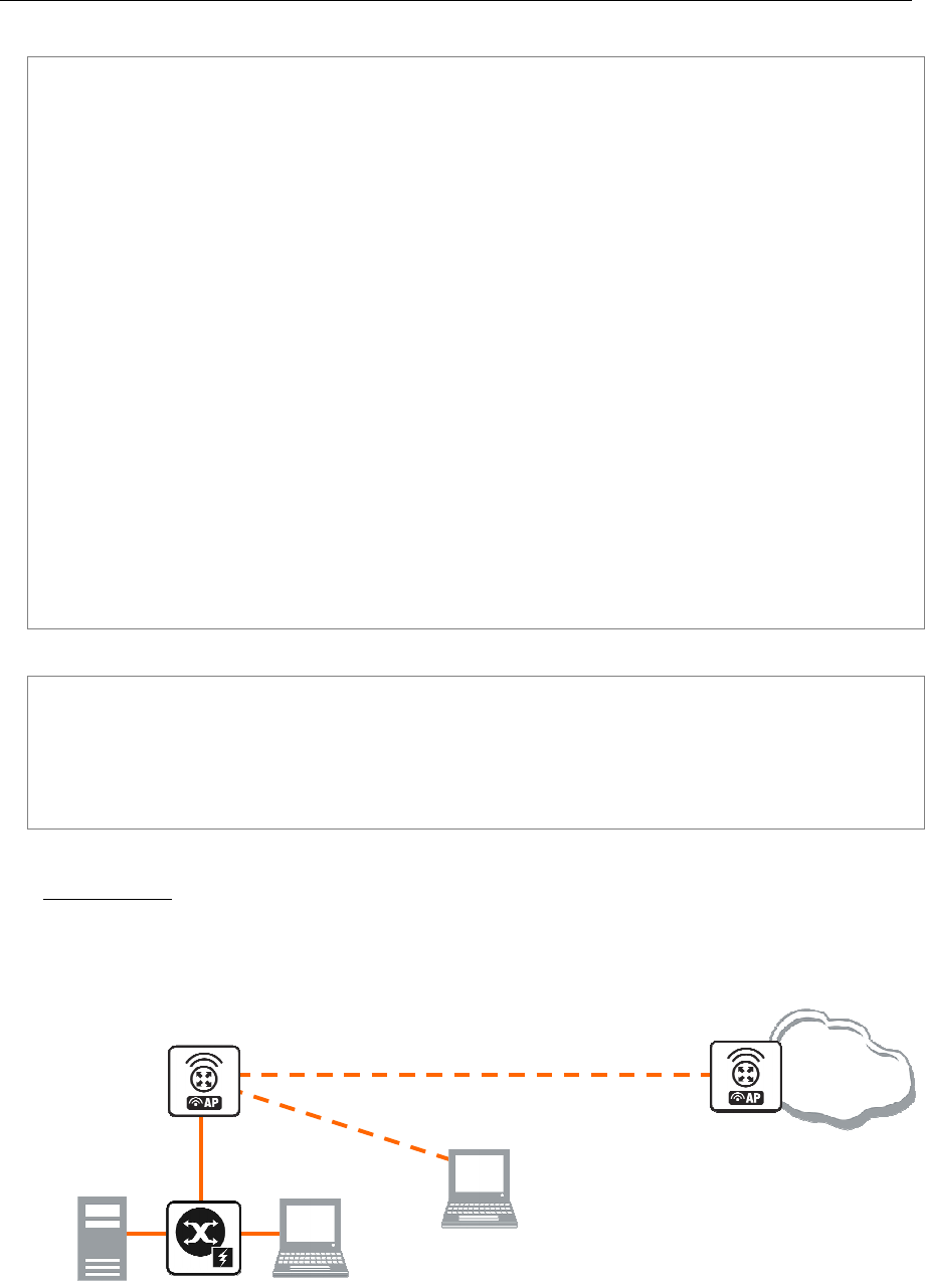
62 AT-WR4500 Series - IEEE 802.11abgh Outdoor Wireless Routers
RouterOS v3 Configuration and User Guide
Configure the station and add an IP address (10.1.0.2) to it:
[admin@Station] interface wireless> set wlan1 name=To-AP mode=station \
ssid=test band=5ghz disabled=no
[admin@Station] interface wireless> print
Flags: X - disabled, R - running
0 R name="To-AP" mtu=1500 mac-address=00:0B:6B:34:5A:91 arp=enabled
disable-running-check=no interface-type=Atheros AR5213
radio-name="000B6B345A91" mode=station ssid="test" area=""
frequency-mode=superchannel country=no_country_set antenna-gain=0
frequency=5180 band=5ghz scan-list=default rate-set=default
supported-rates-b=1Mbps,2Mbps,5.5Mbps,11Mbps
supported-rates-a/g=6Mbps,9Mbps,12Mbps,18Mbps,24Mbps,36Mbps,48Mbps,
54Mbps
basic-rates-b=1Mbps basic-rates-a/g=6Mbps max-station-count=2007
ack-timeout=dynamic tx-power=default tx-power-mode=default
noise-floor-threshold=default periodic-calibration=default
burst-time=disabled fast-frames=no dfs-mode=none antenna-mode=ant-a
wds-mode=disabled wds-default-bridge=none wds-ignore-ssid=no
update-stats-interval=disabled default-authentication=yes
default-forwarding=yes default-ap-tx-limit=0 default-client-tx-limit=0
hide-ssid=no security-profile=default disconnect-timeout=3s
on-fail-retry-time=100ms preamble-mode=both
[admin@Station] interface wireless> /ip address
[admin@Station] ip address> add address=10.1.0.2/24 interface=To-AP
[admin@Station] ip address> print
Flags: X - disabled, I - invalid, D - dynamic
# ADDRESS NETWORK BROADCAST INTERFACE
0 172.16.0.2/24 172.16.0.0 172.16.0.255 To-AP
1 192.168.2.3/24 192.168.2.0 192.168.2.255 To-AP
2 10.1.0.2/24 10.1.0.0 10.1.0.255 To-AP
[admin@Station] ip address>
Check whether you can ping the Access Point from Station:
[admin@Station] > ping 10.1.0.1
10.1.0.1 64 byte ping: ttl=64 time=3 ms
10.1.0.1 64 byte ping: ttl=64 time=3 ms
10.1.0.1 64 byte ping: ttl=64 time=3 ms
3 packets transmitted, 3 packets received, 0% packet loss
round-trip min/avg/max = 3/3.0/3 ms
[admin@Station] >
WDS Station
Using 802.11 set of standards you cannot simply bridge wireless stations. To solve this problem, the wds-
station mode was created - it works just like a station, but connects only to APs that support WDS.
This example shows you how to make a transparent network, using the Station WDS feature:
Interface: To-WDS-AP
IP: 10.1.0.2
Interface: WDS-AP
SSID=wds-sta-test
[WDS_AP]
Internet
[WDS_Station]
Interface: Local
Wireless Client on
192.168.0.0/24
Figure 6: WDS Network example
• On WDS Access Point:

AT-WR4500 Series - IEEE 802.11abgh Outdoor Wireless Routers 63
RouterOS v3 Configuration and User Guide
• Configure AP to support WDS connections
• Set wds-default-bridge to bridge1
• On WDS station:
• Configure it as a WDS Station, using mode=station-wds
•
Configure the WDS Access Point. Configure the wireless interface and put it into a bridge, and define
that the dynamic WDS links should be automatically put into the same bridge:
[admin@WDS_AP] > interface bridge
[admin@WDS_AP] interface bridge> add
[admin@WDS_AP] interface bridge> print
Flags: X - disabled, R - running
0 R name="bridge1" mtu=1500 arp=enabled mac-address=B0:62:0D:08:FF:FF stp=no
priority=32768 ageing-time=5m forward-delay=15s
garbage-collection-interval=4s hello-time=2s max-message-age=20s
[admin@WDS_AP] interface bridge> port
[admin@WDS_AP] interface bridge port> add interface=ether1 bridge=bridge1
[admin@WDS_AP] interface bridge port> /interface wireless
[admin@WDS_AP] interface wireless> set wlan1 mode=ap-bridge ssid=wds-sta-test \
wds-mode=dynamic wds-default-bridge=bridge1 disabled=no band=2.4ghz-b/g \
frequency=2437
[admin@WDS_AP] interface wireless> print
Flags: X - disabled, R - running
0 name="wlan1" mtu=1500 mac-address=00:0C:42:05:00:22 arp=enabled
disable-running-check=no interface-type=Atheros AR5413
radio-name="000C42050022" mode=ap-bridge ssid="wds-sta-test" area=""
frequency-mode=superchannel country=no_country_set antenna-gain=0
frequency=2437 band=2.4ghz-b/g scan-list=default rate-set=default
supported-rates-b=1Mbps,2Mbps,5.5Mbps,11Mbps
supported-rates-a/g=6Mbps,9Mbps,12Mbps,18Mbps,24Mbps,36Mbps,48Mbps,
54Mbps
basic-rates-b=1Mbps basic-rates-a/g=6Mbps max-station-count=2007
ack-timeout=dynamic tx-power=default tx-power-mode=default
noise-floor-threshold=default periodic-calibration=default
burst-time=disabled fast-frames=no dfs-mode=none antenna-mode=ant-a
wds-mode=dynamic wds-default-bridge=bridge1 wds-ignore-ssid=no
update-stats-interval=disabled default-authentication=yes
default-forwarding=yes default-ap-tx-limit=0 default-client-tx-limit=0
hide-ssid=no security-profile=default disconnect-timeout=3s
on-fail-retry-time=100ms preamble-mode=both

64 AT-WR4500 Series - IEEE 802.11abgh Outdoor Wireless Routers
RouterOS v3 Configuration and User Guide
Now configure the WDS station and put the wireless (wlan1) and ethernet (Local) interfaces into a
bridge:
[admin@WDS_Station] > interface bridge
[admin@WDS_Station] interface bridge> add
[admin@WDS_Station] interface bridge> print
Flags: X - disabled, R - running
0 R name="bridge1" mtu=1500 arp=enabled mac-address=11:05:00:00:02:00 stp=no
priority=32768 ageing-time=5m forward-delay=15s
garbage-collection-interval=4s hello-time=2s max-message-age=20s
[admin@WDS_Station] interface bridge> port
[admin@WDS_Station] interface bridge port> add interface=ether1 bridge=bridge1
[admin@WDS_Station] interface bridge port> add interface=wlan1 bridge=bridge1
[admin@WDS_Station] interface bridge port> /interface wireless
[admin@WDS_Station] interface wireless> set wlan1 mode=station-wds disabled=no \
\... ssid=wds-sta-test band=2.4ghz-b/g
[admin@WDS_Station] interface wireless> print
Flags: X - disabled, R - running
0 R name="wlan1" mtu=1500 mac-address=00:0B:6B:34:5A:91 arp=enabled
disable-running-check=no interface-type=Atheros AR5213
radio-name="000B6B345A91" mode=station-wds ssid="wds-sta-test" area=""
frequency-mode=superchannel country=no_country_set antenna-gain=0
frequency=2412 band=2.4ghz-b/g scan-list=default rate-set=default
supported-rates-b=1Mbps,2Mbps,5.5Mbps,11Mbps
supported-rates-a/g=6Mbps,9Mbps,12Mbps,18Mbps,24Mbps,36Mbps,48Mbps,
54Mbps
basic-rates-b=1Mbps basic-rates-a/g=6Mbps max-station-count=2007
ack-timeout=dynamic tx-power=default tx-power-mode=default
noise-floor-threshold=default periodic-calibration=default
burst-time=disabled fast-frames=no dfs-mode=none antenna-mode=ant-a
wds-mode=disabled wds-default-bridge=none wds-ignore-ssid=no
update-stats-interval=disabled default-authentication=yes
default-forwarding=yes default-ap-tx-limit=0 default-client-tx-limit=0
hide-ssid=no security-profile=default disconnect-timeout=3s
on-fail-retry-time=100ms preamble-mode=both
Virtual Access Point
Virtual Access Point (VAP) enables you to create multiple Access Points with different Service Set
Identifier, WDS settings, and even different MAC address, using the same hardware interface. You can
create up to 7 VAP interfaces from a single physical interface. To create a Virtual Access Point, simply add
a new interface, specifying a master-interface which is the physical interface that will do the hardware
function to VAP.

AT-WR4500 Series - IEEE 802.11abgh Outdoor Wireless Routers 65
RouterOS v3 Configuration and User Guide
This example will show you how to create a VAP:
[admin@VAP] interface wireless> print
Flags: X - disabled, R - running
0 name="wlan1" mtu=1500 mac-address=00:0C:42:05:00:22 arp=enabled
disable-running-check=no interface-type=Atheros AR5413
radio-name="000C42050022" mode=ap-bridge ssid="test" area=""
frequency-mode=superchannel country=no_country_set antenna-gain=0
frequency=2437 band=2.4ghz-b/g scan-list=default rate-set=default
supported-rates-b=1Mbps,2Mbps,5.5Mbps,11Mbps
supported-rates-a/g=6Mbps,9Mbps,12Mbps,18Mbps,24Mbps,36Mbps,48Mbps,
54Mbps
basic-rates-b=1Mbps basic-rates-a/g=6Mbps max-station-count=2007
ack-timeout=dynamic tx-power=default tx-power-mode=default
noise-floor-threshold=default periodic-calibration=default
burst-time=disabled fast-frames=no dfs-mode=none antenna-mode=ant-a
wds-mode=disabled wds-default-bridge=none wds-ignore-ssid=no
update-stats-interval=disabled default-authentication=yes
default-forwarding=yes default-ap-tx-limit=0 default-client-tx-limit=0
hide-ssid=no security-profile=default disconnect-timeout=3s
on-fail-retry-time=100ms preamble-mode=both
[admin@VAP] interface wireless> add master-interface=wlan1 ssid=virtual-test \
\... mac-address=00:0C:42:12:34:56 disabled=no name=V-AP
[admin@VAP] interface wireless> print
Flags: X - disabled, R - running
0 name="wlan1" mtu=1500 mac-address=00:0C:42:05:00:22 arp=enabled
disable-running-check=no interface-type=Atheros AR5413
radio-name="000C42050022" mode=ap-bridge ssid="test" area=""
frequency-mode=superchannel country=no_country_set antenna-gain=0
frequency=2437 band=2.4ghz-b/g scan-list=default rate-set=default
supported-rates-b=1Mbps,2Mbps,5.5Mbps,11Mbps
supported-rates-a/g=6Mbps,9Mbps,12Mbps,18Mbps,24Mbps,36Mbps,48Mbps,
54Mbps
basic-rates-b=1Mbps basic-rates-a/g=6Mbps max-station-count=2007
ack-timeout=dynamic tx-power=default tx-power-mode=default
noise-floor-threshold=default periodic-calibration=default
burst-time=disabled fast-frames=no dfs-mode=none antenna-mode=ant-a
wds-mode=disabled wds-default-bridge=none wds-ignore-ssid=no
update-stats-interval=disabled default-authentication=yes
default-forwarding=yes default-ap-tx-limit=0 default-client-tx-limit=0
hide-ssid=no security-profile=default disconnect-timeout=3s
on-fail-retry-time=100ms preamble-mode=both
1 name="V-AP" mtu=1500 mac-address=00:0C:42:12:34:56 arp=enabled
disable-running-check=no interface-type=virtual-AP
master-interface=wlan1 ssid="virtual-test" area=""
max-station-count=2007 wds-mode=disabled wds-default-bridge=none
wds-ignore-ssid=no default-authentication=yes default-forwarding=yes
default-ap-tx-limit=0 default-client-tx-limit=0 hide-ssid=no
security-profile=default
[admin@VAP] interface wireless>
When scanning from another router for an AP, you will see that you have 2 Access Points instead of one:
[admin@AT-WR4562] interface wireless> scan Station
Flags: A - active, B - bss, P - privacy, R - routeros-network, N - nstreme
ADDRESS SSID BAND FREQ SIG RADIO-NAME
AB R 00:0C:42:12:34:56 virtual-test 2.4ghz-g 2437 -72 000C42050022
AB R 00:0C:42:05:00:22 test 2.4ghz-g 2437 -72 000C42050022
-- [Q quit|D dump|C-z pause]
[admin@AT-WR4562] interface wireless>
The master-interface must be configured as an Access Point (ap-bridge or bridge mode)!
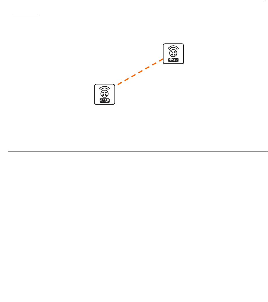
66 AT-WR4500 Series - IEEE 802.11abgh Outdoor Wireless Routers
RouterOS v3 Configuration and User Guide
Nstreme
This example shows you how to configure a point-to-point Nstreme link.
Nstreme 2
Nstreme 1
Figure 7: Nstreme network example
The setup of Nstreme is similar to usual wireless configuration, except that you have to do some changes
under /interface wireless nstreme.
Set the Nstreme-AP to bridge mode and enable Nstreme on it:
[admin@Nstreme-AP] interface wireless> set 0 mode=bridge ssid=nstreme \
\... band=5ghz frequency=5805 disabled=no
[admin@Nstreme-AP] interface wireless> print
Flags: X - disabled, R - running
0 name="wlan1" mtu=1500 mac-address=00:0C:42:05:00:22 arp=enabled
disable-running-check=no interface-type=Atheros AR5413
radio-name="000C42050022" mode=bridge ssid="nstreme" area=""
frequency-mode=superchannel country=no_country_set antenna-gain=0
frequency=5805 band=5ghz scan-list=default rate-set=default
supported-rates-b=1Mbps,2Mbps,5.5Mbps,11Mbps
supported-rates-a/g=6Mbps,9Mbps,12Mbps,18Mbps,24Mbps,36Mbps,48Mbps,
54Mbps
basic-rates-b=1Mbps basic-rates-a/g=6Mbps max-station-count=2007
ack-timeout=dynamic tx-power=default tx-power-mode=default
noise-floor-threshold=default periodic-calibration=default
burst-time=disabled fast-frames=no dfs-mode=none antenna-mode=ant-a
wds-mode=disabled wds-default-bridge=none wds-ignore-ssid=no
update-stats-interval=disabled default-authentication=yes
default-forwarding=yes default-ap-tx-limit=0 default-client-tx-limit=0
hide-ssid=no security-profile=default disconnect-timeout=3s
on-fail-retry-time=100ms preamble-mode=both
[admin@Nstreme-AP] interface wireless> nstreme
[admin@Nstreme-AP] interface wireless nstreme> set wlan1 enable-nstreme=yes
[admin@Nstreme-AP] interface wireless nstreme> print
0 name="wlan1" enable-nstreme=yes enable-polling=yes framer-policy=none
framer-limit=3200
[admin@Nstreme-AP] interface wireless nstreme>

AT-WR4500 Series - IEEE 802.11abgh Outdoor Wireless Routers 67
RouterOS v3 Configuration and User Guide
Configure Nstreme-Client wireless settings and enable Nstreme on it:
[admin@Nstreme-Client] interface wireless> set wlan1 mode=station ssid=nstreme \
band=5ghz frequency=5805 disabled=no
[admin@Nstreme-Client] interface wireless> print
Flags: X - disabled, R - running
0 name="wlan1" mtu=1500 mac-address=00:0B:6B:34:5A:91 arp=enabled
disable-running-check=no interface-type=Atheros AR5213
radio-name="000B6B345A91" mode=station ssid="nstreme" area=""
frequency-mode=superchannel country=no_country_set antenna-gain=0
frequency=5805 band=5ghz scan-list=default rate-set=default
supported-rates-b=1Mbps,2Mbps,5.5Mbps,11Mbps
supported-rates-a/g=6Mbps,9Mbps,12Mbps,18Mbps,24Mbps,36Mbps,48Mbps,
54Mbps
basic-rates-b=1Mbps basic-rates-a/g=6Mbps max-station-count=2007
ack-timeout=dynamic tx-power=default tx-power-mode=default
noise-floor-threshold=default periodic-calibration=default
burst-time=disabled fast-frames=no dfs-mode=none antenna-mode=ant-a
wds-mode=disabled wds-default-bridge=none wds-ignore-ssid=no
update-stats-interval=disabled default-authentication=yes
default-forwarding=yes default-ap-tx-limit=0 default-client-tx-limit=0
hide-ssid=no security-profile=default disconnect-timeout=3s
on-fail-retry-time=100ms preamble-mode=both
[admin@Nstreme-Client] interface wireless> nstreme
[admin@Nstreme-Client] interface wireless nstreme> set wlan1 enable-nstreme=yes
[admin@Nstreme-Client] interface wireless nstreme> print
0 name="wlan1" enable-nstreme=yes enable-polling=yes framer-policy=none
framer-limit=3200
[admin@Nstreme-Client] interface wireless nstreme>
And monitor the link:
[admin@Nstreme-Client] interface wireless> monitor wlan1
status: connected-to-ess
band: 5ghz
frequency: 5805MHz
tx-rate: 24Mbps
rx-rate: 18Mbps
ssid: "nstreme"
bssid: 00:0C:42:05:00:22
radio-name: "000C42050022"
signal-strength: -70dBm
tx-signal-strength: -68dBm
tx-ccq: 0%
rx-ccq: 3%
wds-link: no
nstreme: yes
polling: yes
framing-mode: none
routeros-version: "3.2"
current-tx-powers: 1Mbps:11,2Mbps:11,5.5Mbps:11,11Mbps:11,6Mbps:28,
9Mbps:28,12Mbps:28,18Mbps:28,24Mbps:28,36Mbps:25,
48Mbps:23,54Mbps:22
-- [Q quit|D dump|C-z pause]
[admin@Nstreme-Client] interface wireless>
Dual Nstreme
The purpose of Nstreme2 (Dual Nstreme) is to make superfast point-to-point links, using 2 wireless
interfaces on each router - one for receiving and the other one for transmitting data (you can use
different bands for receiving and transmitting). This example will show you how to make a point-to-point
link, using Dual Nstreme.
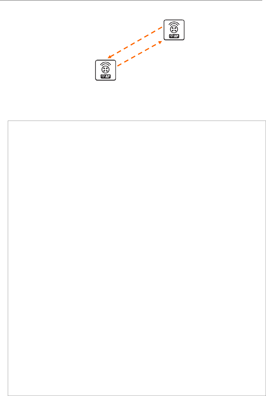
68 AT-WR4500 Series - IEEE 802.11abgh Outdoor Wireless Routers
RouterOS v3 Configuration and User Guide
5180 MHz
[DualNS
-
2]
[DualNS
-
1]
5805 MHz
Figure 8: Nstreme dual network example
Configure DualNS-1:
[admin@DualNS-1] interface wireless> set wlan1,wlan2 mode=nstreme-dual-slave
[admin@DualNS-1] interface wireless> print
Flags: X - disabled, R - running
0 name="wlan1" mtu=1500 mac-address=00:0C:42:05:04:36 arp=enabled
disable-running-check=no interface-type=Atheros AR5413
radio-name="000C42050436" mode=nstreme-dual-slave ssid="AT-WR4500"
area="" frequency-mode=superchannel country=no_country_set
antenna-gain=0 frequency=5180 band=5ghz scan-list=default
rate-set=default supported-rates-b=1Mbps,2Mbps,5.5Mbps,11Mbps
supported-rates-a/g=6Mbps,9Mbps,12Mbps,18Mbps,24Mbps,36Mbps,48Mbps,
54Mbps
basic-rates-b=1Mbps basic-rates-a/g=6Mbps max-station-count=2007
ack-timeout=dynamic tx-power=default tx-power-mode=default
noise-floor-threshold=default periodic-calibration=default
burst-time=disabled fast-frames=no dfs-mode=none antenna-mode=ant-a
wds-mode=disabled wds-default-bridge=none wds-ignore-ssid=no
update-stats-interval=disabled default-authentication=yes
default-forwarding=yes default-ap-tx-limit=0 default-client-tx-limit=0
hide-ssid=no security-profile=default disconnect-timeout=3s
on-fail-retry-time=100ms preamble-mode=both
1 name="wlan2" mtu=1500 mac-address=00:0C:42:05:00:28 arp=enabled
disable-running-check=no interface-type=Atheros AR5413
radio-name="000C42050028" mode=nstreme-dual-slave ssid="AT-WR4500"
area="" frequency-mode=superchannel country=no_country_set
antenna-gain=0 frequency=5180 band=5ghz scan-list=default
rate-set=default supported-rates-b=1Mbps,2Mbps,5.5Mbps,11Mbps
supported-rates-a/g=6Mbps,9Mbps,12Mbps,18Mbps,24Mbps,36Mbps,48Mbps,
54Mbps
basic-rates-b=1Mbps basic-rates-a/g=6Mbps max-station-count=2007
ack-timeout=dynamic tx-power=default tx-power-mode=default
noise-floor-threshold=default periodic-calibration=default
burst-time=disabled fast-frames=no dfs-mode=none antenna-mode=ant-a
wds-mode=disabled wds-default-bridge=none wds-ignore-ssid=no
update-stats-interval=disabled default-authentication=yes
default-forwarding=yes default-ap-tx-limit=0 default-client-tx-limit=0
hide-ssid=no security-profile=default disconnect-timeout=3s
on-fail-retry-time=100ms preamble-mode=both
[admin@DualNS-1] interface wireless> nstreme-dual
[admin@DualNS-1] interface wireless nstreme-dual> add rx-radio=wlan1 \
tx-radio=wlan2 rx-frequency=5180 tx-frequency=5805 disabled=no
[admin@DualNS-1] interface wireless nstreme-dual> print
Flags: X - disabled, R - running
0 R name="nstreme1" mtu=1500 mac-address=00:0C:42:05:04:36 arp=enabled
disable-running-check=no tx-radio=wlan2 rx-radio=wlan1
remote-mac=00:00:00:00:00:00 tx-band=5ghz tx-frequency=5805
rx-band=5ghz rx-frequency=5180 rates-b=1Mbps,2Mbps,5.5Mbps,11Mbps
rates-a/g=6Mbps,9Mbps,12Mbps,18Mbps,24Mbps,36Mbps,48Mbps,54Mbps
framer-policy=none framer-limit=4000
[admin@DualNS-1] interface wireless nstreme-dual>

AT-WR4500 Series - IEEE 802.11abgh Outdoor Wireless Routers 69
RouterOS v3 Configuration and User Guide
As we have not configured the DualNS-2 router, we cannot define the remote-mac parameter on
DualNS-1. We will do it after configuring DualNS-2!
The configuration of DualNS-2:
[admin@DualNS-2] interface wireless> set wlan1,wlan2 mode=nstreme-dual-slave
[admin@DualNS-2] interface wireless> print
Flags: X - disabled, R - running
0 name="wlan1" mtu=1500 mac-address=00:0C:42:05:00:22 arp=enabled
disable-running-check=no interface-type=Atheros AR5413
radio-name="000C42050022" mode=nstreme-dual-slave ssid="AT-WR4500"
area="" frequency-mode=superchannel country=no_country_set
antenna-gain=0 frequency=5180 band=5ghz scan-list=default
rate-set=default supported-rates-b=1Mbps,2Mbps,5.5Mbps,11Mbps
supported-rates-a/g=6Mbps,9Mbps,12Mbps,18Mbps,24Mbps,36Mbps,48Mbps,
54Mbps
basic-rates-b=1Mbps basic-rates-a/g=6Mbps max-station-count=2007
ack-timeout=dynamic tx-power=default tx-power-mode=default
noise-floor-threshold=default periodic-calibration=default
burst-time=disabled fast-frames=no dfs-mode=none antenna-mode=ant-a
wds-mode=disabled wds-default-bridge=none wds-ignore-ssid=no
update-stats-interval=disabled default-authentication=yes
default-forwarding=yes default-ap-tx-limit=0 default-client-tx-limit=0
hide-ssid=no security-profile=default disconnect-timeout=3s
on-fail-retry-time=100ms preamble-mode=both
1 name="wlan2" mtu=1500 mac-address=00:0C:42:05:06:B2 arp=enabled
disable-running-check=no interface-type=Atheros AR5413
radio-name="000C420506B2" mode=nstreme-dual-slave ssid="AT-WR4500"
area="" frequency-mode=superchannel country=no_country_set
antenna-gain=0 frequency=5180 band=5ghz scan-list=default
rate-set=default supported-rates-b=1Mbps,2Mbps,5.5Mbps,11Mbps
supported-rates-a/g=6Mbps,9Mbps,12Mbps,18Mbps,24Mbps,36Mbps,48Mbps,
54Mbps
basic-rates-b=1Mbps basic-rates-a/g=6Mbps max-station-count=2007
ack-timeout=dynamic tx-power=default tx-power-mode=default
noise-floor-threshold=default periodic-calibration=default
burst-time=disabled fast-frames=no dfs-mode=none antenna-mode=ant-a
wds-mode=disabled wds-default-bridge=none wds-ignore-ssid=no
update-stats-interval=disabled default-authentication=yes
default-forwarding=yes default-ap-tx-limit=0 default-client-tx-limit=0
hide-ssid=no security-profile=default disconnect-timeout=3s
on-fail-retry-time=100ms preamble-mode=both
[admin@DualNS-2] interface wireless> nstreme-dual
[admin@DualNS-2] interface wireless nstreme-dual> add rx-radio=wlan1 \
\... tx-radio=wlan2 rx-frequency=5805 tx-frequency=5180 disabled=no \
\... remote-mac=00:0C:42:05:04:36
[admin@DualNS-2] interface wireless nstreme-dual> print
Flags: X - disabled, R - running
0 R name="nstreme1" mtu=1500 mac-address=00:0C:42:05:00:22 arp=enabled
disable-running-check=no tx-radio=wlan2 rx-radio=wlan1
remote-mac=00:0C:42:05:04:36 tx-band=5ghz tx-frequency=5180
rx-band=5ghz rx-frequency=5805 rates-b=1Mbps,2Mbps,5.5Mbps,11Mbps
rates-a/g=6Mbps,9Mbps,12Mbps,18Mbps,24Mbps,36Mbps,48Mbps,54Mbps
framer-policy=none framer-limit=4000
[admin@DualNS-2] interface wireless nstreme-dual>
Now complete the configuration for DualNS-1:
[admin@DualNS-1] interface wireless nstreme-dual> set 0 remote-mac=00:0C:42:05:00:22
[admin@DualNS-1] interface wireless nstreme-dual> print
Flags: X - disabled, R - running
0 R name="nstreme1" mtu=1500 mac-address=00:0C:42:05:04:36 arp=enabled
disable-running-check=no tx-radio=wlan2 rx-radio=wlan1
remote-mac=00:0C:42:05:00:22 tx-band=5ghz tx-frequency=5805
rx-band=5ghz rx-frequency=5180 rates-b=1Mbps,2Mbps,5.5Mbps,11Mbps
rates-a/g=6Mbps,9Mbps,12Mbps,18Mbps,24Mbps,36Mbps,48Mbps,54Mbps
framer-policy=none framer-limit=4000
[admin@DualNS-1] interface wireless nstreme-dual>
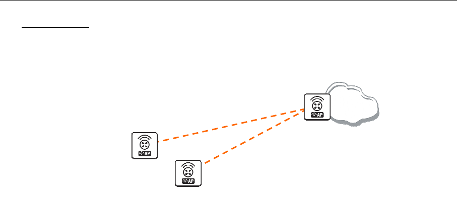
70 AT-WR4500 Series - IEEE 802.11abgh Outdoor Wireless Routers
RouterOS v3 Configuration and User Guide
WEP Security
This example shows how to configure WEP (Wired Equivalent Privacy) on Access Point and Clients. In
example we will configure an Access Point which will use 104bit-wep for one station and 40bit-wep for
other clients. The configuration of stations is also present.
Interface: WEP-STA1
MAC: 00:0C:42:05:00:22
Interface: WEP-AP
ssid=mt_wep
[W
EP
_AP]
Internet
[WEP_Station1]
40bit-wep
104bit-wep
[W
EP
_
StationX
]
Interface: WEP-STAX
MAC: 00:0C:42:05:06:B2
Figure 9: WEP security example
The key, used for connection between WEP_AP and WEP_Station1 will be
65432109876543210987654321, key for WEP_AP and WEP_StationX will be 12345678

AT-WR4500 Series - IEEE 802.11abgh Outdoor Wireless Routers 71
RouterOS v3 Configuration and User Guide
Configure the Access Point:
[admin@WEP_AP] interface wireless security-profiles> add name=StationX \
\... mode=static-keys-required static-algo-1=40bit-wep static-key-1=1234567890 \
\... static-transmit-key=key-1
[admin@WEP_AP] interface wireless security-profiles> print
0 name="default" mode=none wpa-unicast-ciphers="" wpa-group-ciphers=""
pre-shared-key="" static-algo-0=none static-key-0="" static-algo-1=none
static-key-1="" static-algo-2=none static-key-2="" static-algo-3=none
static-key-3="" static-transmit-key=key-0 static-sta-private-algo=none
static-sta-private-key="" radius-mac-authentication=no group-key-update=5m
1 name="StationX" mode=static-keys-required wpa-unicast-ciphers=""
wpa-group-ciphers="" pre-shared-key="" static-algo-0=none static-key-0=""
static-algo-1=40bit-wep static-key-1="1234567890" static-algo-2=none
static-key-2="" static-algo-3=none static-key-3=""
static-transmit-key=key-1 static-sta-private-algo=none
static-sta-private-key="" radius-mac-authentication=no group-key-update=5m
[admin@WEP_AP] interface wireless security-profiles> ..
[admin@AT-WR4562] interface wireless> set wlan1 name=WEP-AP mode=ap-bridge \
\... ssid=mt_wep frequency=5320 band=5ghz disabled=no security-profile=StationX
[admin@WEP_AP] interface wireless> print
Flags: X - disabled, R - running
0 name="WEP-AP" mtu=1500 mac-address=00:0C:42:05:04:36 arp=enabled
disable-running-check=no interface-type=Atheros AR5413
radio-name="000C42050436" mode=ap-bridge ssid="mt_wep" area=""
frequency-mode=superchannel country=no_country_set antenna-gain=0
frequency=5320 band=5ghz scan-list=default rate-set=default
supported-rates-b=1Mbps,2Mbps,5.5Mbps,11Mbps
supported-rates-a/g=6Mbps,9Mbps,12Mbps,18Mbps,24Mbps,36Mbps,48Mbps,
54Mbps
basic-rates-b=1Mbps basic-rates-a/g=6Mbps max-station-count=2007
ack-timeout=dynamic tx-power=default tx-power-mode=default
noise-floor-threshold=default periodic-calibration=default
burst-time=disabled fast-frames=no dfs-mode=none antenna-mode=ant-a
wds-mode=disabled wds-default-bridge=none wds-ignore-ssid=no
update-stats-interval=disabled default-authentication=yes
default-forwarding=yes default-ap-tx-limit=0 default-client-tx-limit=0
hide-ssid=no security-profile=StationX disconnect-timeout=3s
on-fail-retry-time=100ms preamble-mode=both
[admin@WEP_AP] interface wireless> access-list
[admin@WEP_AP] interface wireless access-list> add private-algo=104bit-wep \
\... private-key=65432109876543210987654321 interface=WEP-AP forwarding=yes \
\... mac-address=00:0C:42:05:00:22
[admin@WEP_AP] interface wireless access-list> print
Flags: X - disabled
0 mac-address=00:0C:42:05:00:22 interface=WEP-AP authentication=yes
forwarding=yes ap-tx-limit=0 client-tx-limit=0 private-algo=104bit-wep
private-key="65432109876543210987654321"
[admin@WEP_AP] interface wireless access-list>

72 AT-WR4500 Series - IEEE 802.11abgh Outdoor Wireless Routers
RouterOS v3 Configuration and User Guide
Configure WEP_Station1:
[admin@WEP_Station1] interface wireless security-profiles> add name=Station1 \
\... mode=static-keys-required static-sta-private-algo=104bit-wep \
\... static-sta-private-key=65432109876543210987654321
[admin@WEP_Station1] interface wireless security-profiles> print
0 name="default" mode=none wpa-unicast-ciphers="" wpa-group-ciphers=""
pre-shared-key="" static-algo-0=none static-key-0="" static-algo-1=none
static-key-1="" static-algo-2=none static-key-2="" static-algo-3=none
static-key-3="" static-transmit-key=key-0 static-sta-private-algo=none
static-sta-private-key="" radius-mac-authentication=no group-key-update=5m
1 name="Station1" mode=static-keys-required wpa-unicast-ciphers=""
wpa-group-ciphers="" pre-shared-key="" static-algo-0=none static-key-0=""
static-algo-1=none static-key-1="" static-algo-2=none static-key-2=""
static-algo-3=none static-key-3="" static-transmit-key=key-0
static-sta-private-algo=104bit-wep
static-sta-private-key="65432109876543210987654321"
radius-mac-authentication=no group-key-update=5m
[admin@WEP_Station1] interface wireless security-profiles> ..
[admin@WEP_Station1] interface wireless> set wlan1 mode=station ssid=mt_wep \
\... band=5ghz security-profile=Station1 name=WEP-STA1 disabled=no
[admin@WEP_Station1] interface wireless> print
Flags: X - disabled, R - running
0 R name="WEP-STA1" mtu=1500 mac-address=00:0C:42:05:00:22 arp=enabled
disable-running-check=no interface-type=Atheros AR5413
radio-name="000C42050022" mode=station ssid="mt_wep" area=""
frequency-mode=superchannel country=no_country_set antenna-gain=0
frequency=5180 band=5ghz scan-list=default rate-set=default
supported-rates-b=1Mbps,2Mbps,5.5Mbps,11Mbps
supported-rates-a/g=6Mbps,9Mbps,12Mbps,18Mbps,24Mbps,36Mbps,48Mbps,
54Mbps
basic-rates-b=1Mbps basic-rates-a/g=6Mbps max-station-count=2007
ack-timeout=dynamic tx-power=default tx-power-mode=default
noise-floor-threshold=default periodic-calibration=default
burst-time=disabled fast-frames=no dfs-mode=none antenna-mode=ant-a
wds-mode=disabled wds-default-bridge=none wds-ignore-ssid=no
update-stats-interval=disabled default-authentication=yes
default-forwarding=yes default-ap-tx-limit=0 default-client-tx-limit=0
hide-ssid=no security-profile=Station1 disconnect-timeout=3s
on-fail-retry-time=100ms preamble-mode=both
[admin@WEP_Station1] interface wireless>

AT-WR4500 Series - IEEE 802.11abgh Outdoor Wireless Routers 73
RouterOS v3 Configuration and User Guide
Config of WEP_StationX:
[admin@WEP_StationX] interface wireless security-profiles> add name=StationX \
\... mode=static-keys-required static-algo-1=40bit-wep static-key-1=1234567890 \
\... static-transmit-key=key-1
[admin@WEP_StationX] interface wireless security-profiles> print
0 name="default" mode=none wpa-unicast-ciphers="" wpa-group-ciphers=""
pre-shared-key="" static-algo-0=none static-key-0="" static-algo-1=none
static-key-1="" static-algo-2=none static-key-2="" static-algo-3=none
static-key-3="" static-transmit-key=key-0 static-sta-private-algo=none
static-sta-private-key="" radius-mac-authentication=no group-key-update=5m
1 name="StationX" mode=static-keys-required wpa-unicast-ciphers=""
wpa-group-ciphers="" pre-shared-key="" static-algo-0=none static-key-0=""
static-algo-1=40bit-wep static-key-1="1234567890" static-algo-2=none
static-key-2="" static-algo-3=none static-key-3=""
static-transmit-key=key-1 static-sta-private-algo=none
static-sta-private-key="" radius-mac-authentication=no group-key-update=5m
[admin@WEP_StationX] interface wireless security-profiles> ..
[admin@WEP_StationX] interface wireless> set wlan1 name=WEP-STAX ssid=mt_wep \
\... band=5ghz security-profile=StationX mode=station disabled=no
[admin@WEP_StationX] interface wireless> print
0 R name="WEP-STAX" mtu=1500 mac-address=00:0C:42:05:06:B2 arp=enabled
disable-running-check=no interface-type=Atheros AR5413
radio-name="000C420506B2" mode=station ssid="mt_wep" area=""
frequency-mode=superchannel country=no_country_set antenna-gain=0
frequency=5180 band=5ghz scan-list=default rate-set=default
supported-rates-b=1Mbps,2Mbps,5.5Mbps,11Mbps
supported-rates-a/g=6Mbps,9Mbps,12Mbps,18Mbps,24Mbps,36Mbps,48Mbps,
54Mbps
basic-rates-b=1Mbps basic-rates-a/g=6Mbps max-station-count=2007
ack-timeout=dynamic tx-power=default tx-power-mode=default
noise-floor-threshold=default periodic-calibration=default
burst-time=disabled fast-frames=no dfs-mode=none antenna-mode=ant-a
wds-mode=disabled wds-default-bridge=none wds-ignore-ssid=no
update-stats-interval=disabled default-authentication=yes
default-forwarding=yes default-ap-tx-limit=0 default-client-tx-limit=0
hide-ssid=no security-profile=StationX disconnect-timeout=3s
on-fail-retry-time=100ms preamble-mode=both
[admin@WEP_StationX] interface wireless>
WPA Security
This example shows WPA (Wi-Fi Protected Access) configuration on Access Point and Client to secure
all data which will be passed between AP and Client
Interface:
wlan1
Pre-shared-key=1234567890
Wpa-group-cipher=aes-ccm
Wpa-unicast-cipher=tkip
Interface:
wlan1
ssid=AT-WR4500
[WPA_AP]
[WPA_Station]
Pre
-
shared
-
key=1234567890
Wpa-group-cipher=aes-ccm
Wpa-unicast-cipher=tkip
Figure 10: WPA security example

74 AT-WR4500 Series - IEEE 802.11abgh Outdoor Wireless Routers
RouterOS v3 Configuration and User Guide
On the AP in default or in your own made profile as an encryption algorithm choose wpa-psk. Specify
the pre-shared-key, wpa-unicast-ciphers and wpa-group-cipher
[admin@WPA_AP] interface wireless security-profiles> set default mode=wpa-psk\
\... pre-shared-key=1234567890 wpa-unicast-ciphers=aes-ccm,tkip wpa-group-ciphers=aes-
ccm,tkip
[admin@WPA_AP] interface wireless security-profiles> pr
0 name="default" mode=wpa-psk wpa-unicast-ciphers=tkip,aes-ccm
wpa-group-ciphers=tkip,aes-ccm pre-shared-key="1234567890"
static-algo-0=none static-key-0="" static-algo-1=none static-key-1=""
static-algo-2=none static-key-2="" static-algo-3=none static-key-3=""
static-transmit-key=key-0 static-sta-private-algo=none
static-sta-private-key="" radius-mac-authentication=no group-key-update=5m
[admin@WPA_AP] interface wireless security-profiles>
On the Client do the same. Encryption algorithm, wpa-group-cipher and pre-shared-key must be the
same as specified on AP, wpa-unicast-cipher must be one of the ciphers supported by Access Point
[admin@WPA_Station] interface wireless security-profiles> set default mode=wpa-psk\
\... pre-shared-key=1234567890 wpa-unicast-ciphers=tkip wpa-group-ciphers=aes-ccm,tkip
[admin@WPA_Station] interface wireless security-profiles> pr
0 name="default" mode=wpa-psk wpa-unicast-ciphers=tkip
wpa-group-ciphers=tkip,aes-ccm pre-shared-key="1234567890"
static-algo-0=none static-key-0="" static-algo-1=none static-key-1=""
static-algo-2=none static-key-2="" static-algo-3=none static-key-3=""
static-transmit-key=key-0 static-sta-private-algo=none
static-sta-private-key="" radius-mac-authentication=no group-key-update=5m
[admin@WPA_Station] interface wireless security-profiles>
Test the link between Access point and the client
[admin@WPA_Station] interface wireless > print
Flags: X - disabled, R - running
0 R name="wlan1" mtu=1500 mac-address=00:0B:6B:35:E5:5C arp=enabled
disable-running-check=no interface-type=Atheros AR5213
radio-name="000B6B35E55C" mode=station ssid="AT-WR4500" area=""
frequency-mode=superchannel country=no_country_set antenna-gain=0
frequency=5180 band=5ghz scan-list=default rate-set=default
supported-rates-b=1Mbps,2Mbps,5.5Mbps,11Mbps
supported-rates-a/g=6Mbps,9Mbps,12Mbps,18Mbps,24Mbps,36Mbps,48Mbps,
54Mbps
basic-rates-b=1Mbps basic-rates-a/g=6Mbps max-station-count=2007
ack-timeout=dynamic tx-power-mode=default noise-floor-threshold=default
periodic-calibration=default burst-time=disabled dfs-mode=none
antenna-mode=ant-a wds-mode=disabled wds-default-bridge=none
wds-ignore-ssid=no update-stats-interval=disabled
default-authentication=yes default-forwarding=yes default-ap-tx-limit=0
default-client-tx-limit=0 hide-ssid=no security-profile=default
disconnect-timeout=3s on-fail-retry-time=100ms preamble-mode=both
compression=no allow-sharedkey=no
[admin@WPA_Station] interface wireless >
4.3.22 Troubleshooting
Description
If I use WDS and DFS, the routers do not connect to each other!
As the WDS routers must operate at the same frequency, it is very probable that DFS will not select the
frequency that is used by the peer router.
RouterOS does not send any traffic through Cisco Wireless Access Point or Wireless Bridge
If you use CISCO/Aironet Wireless Ethernet Bridge or Access Point, you should set the
Configuration/Radio/I80211/Extended (Allow proprietary extensions) to off, and the
Configuration/Radio/I80211/Extended/Encapsulation (Default encapsulation method) to RFC1042. If left
to the default on and 802.1H, respectively, you won't be able to pass traffic through the bridge.

AT-WR4500 Series - IEEE 802.11abgh Outdoor Wireless Routers 75
RouterOS v3 Configuration and User Guide
4.4 VLAN Interfaces
Document revisi on: 1.2 (Mon Sep 19 13:46: 34 GMT 2005)
Applies to: V2.9
4.4.1 General Information
Summary
VLAN is an implementation of the 802.1Q VLAN protocol for RouterOS. It allows you to have multiple
Virtual LANs on a single ethernet or wireless interface, giving the ability to segregate LANs efficiently. It
supports up to 4095 vlan interfaces, each with a unique VLAN ID, per ethernet device.
A VLAN is a logical grouping that allows end users to communicate as if they were physically connected
to a single isolated LAN, independent of the physical configuration of the network. VLAN support adds a
new dimension of security and cost savings permitting the sharing of a physical network while logically
maintaining separation among unrelated users.
Specifications
Packages required: system
License required: Level1 (limited to 1 vlan) , Level3
Submenu level: /interface vlan
Standards and Technologies: VLAN (IEEE 802.1Q)
Hardware usage: Not significant
Related Topics
• IP Addresses and ARP
Description
VLANs are simply a way of grouping a set of switch ports together so that they form a logical network,
separate from any other such group. It may also be understood as breaking one physical switch into
several independent parts. Within a single switch this is straightforward local configuration. When the
VLAN extends over more than one switch, the inter-switch links have to become trunks, on which
packets are tagged to indicate which VLAN they belong to.
You can use RouterOS to mark these packets as well as to accept and route marked ones.
As VLAN works on OSI Layer 2, it can be used just as any other network interface without any
restrictions. VLAN successfully passes through regular Ethernet bridges.
You can also transport VLANs over wireless links and put multiple VLAN interfaces on a single wireless
interface. Note that as VLAN is not a full tunnel protocol (i.e., it does not have additional fields to
transport MAC addresses of sender and recipient), the same limitation applies to bridging over VLAN as
to bridging plain wireless interfaces. In other words, while wireless clients may participate in VLANs put
on wireless interfaces, it is not possible to have VLAN put on a wireless interface in station mode
bridged with any other interface.
Additional resources
http://www.ieee802.org/1/pages/802.1Q.html
http://en.wikipedia.org/wiki/IEEE_802.1Q
4.4.2 VLAN Setup
Submenu level: /interface vlan
Property Description
arp (disabled | enabled | proxy-arp | reply-only; default: enabled) - Address Resolution Protocol mode
disabled - the interface will not use ARP protocol
enabled - the interface will fully use ARP protocol
proxy-arp - the interface will be an ARP proxy

76 AT-WR4500 Series - IEEE 802.11abgh Outdoor Wireless Routers
RouterOS v3 Configuration and User Guide
reply-only - the interface will only reply to the requests for to its own IP addresses, but neighbor MAC
addresses will be gathered from /ip arp statically set table only
interface (name) - physical interface to the network where the VLAN is put
mtu (integer; default: 1500) - Maximum Transmission Unit
name (name) - interface name for reference
vlan-id (integer; default: 1) - Virtual LAN identifier or tag that is used to distinguish VLANs. Must be
equal for all computers that belong to the same VLAN.
MTU should be set to 1500 bytes as on Ethernet interfaces. But this may not work with some Ethernet
interfaces that do not support receiving/transmitting of full size Ethernet packets with VLAN header
added (1500 bytes data + 4 bytes VLAN header + 14 bytes Ethernet header). In this situation MTU
1496 can be used, but note that this will cause packet fragmentation if larger packets have to be sent
over interface. At the same time remember that MTU 1496 may cause problems if path MTU discovery
is not working properly between source and destination.
Example
To add and enable a VLAN interface named test with vlan-id=1 on interface ether1:
[admin@AT-WR4562] interface vlan> add name=test vlan-id=1 interface=ether1
[admin@AT-WR4562] interface vlan> print
Flags: X - disabled, R - running
# NAME MTU ARP VLAN-ID INTERFACE
0 X test 1500 enabled 1 ether1
[admin@AT-WR4562] interface vlan> enable 0
[admin@AT-WR4562] interface vlan> print
Flags: X - disabled, R - running
# NAME MTU ARP VLAN-ID INTERFACE
0 R test 1500 enabled 1 ether1
[admin@AT-WR4562] interface vlan>
4.4.3 Application Example
VLAN example on AT-WR4500 Routers
Let us assume that we have two or more RouterOS routers connected with a hub. Interfaces to the
physical network, where VLAN is to be created is ether1 for all of them (it is needed only for example
simplification, it is NOT a must).
To connect computers through VLAN they must be connected physically and unique IP addresses should
be assigned them so that they could ping each other. Then on each of them the VLAN interface should be
created:
[admin@AT-WR4562] interface vlan> add name=test vlan-id=32 interface=ether1
[admin@AT-WR4562] interface vlan> print
Flags: X - disabled, R - running
# NAME MTU ARP VLAN-ID INTERFACE
0 R test 1500 enabled 32 ether1
[admin@AT-WR4562] interface vlan>
If the interfaces were successfully created, both of them will be running. If computers are connected
incorrectly (through network device that does not retransmit or forward VLAN packets), either both or
one of the interfaces will not be running.
When the interface is running, IP addresses can be assigned to the VLAN interfaces.

AT-WR4500 Series - IEEE 802.11abgh Outdoor Wireless Routers 77
RouterOS v3 Configuration and User Guide
On Router 1:
[admin@AT-WR4562] ip address> add address=10.10.10.1/24 interface=test
[admin@AT-WR4562] ip address> print
Flags: X - disabled, I - invalid, D - dynamic
# ADDRESS NETWORK BROADCAST INTERFACE
0 10.0.0.204/24 10.0.0.0 10.0.0.255 ether1
1 10.20.0.1/24 10.20.0.0 10.20.0.255 pc1
2 10.10.10.1/24 10.10.10.0 10.10.10.255 test
[admin@AT-WR4562] ip address>
On Router 2:
[admin@AT-WR4562] ip address> add address=10.10.10.2/24 interface=test
[admin@AT-WR4562] ip address> print
Flags: X - disabled, I - invalid, D - dynamic
# ADDRESS NETWORK BROADCAST INTERFACE
0 10.0.0.201/24 10.0.0.0 10.0.0.255 ether1
1 10.10.10.2/24 10.10.10.0 10.10.10.255 test
[admin@AT-WR4562] ip address>
If it set up correctly, then it is possible to ping Router 2 from Router 1 and vice versa:
[admin@AT-WR4562] ip address> /ping 10.10.10.1
10.10.10.1 64 byte pong: ttl=255 time=3 ms
10.10.10.1 64 byte pong: ttl=255 time=4 ms
10.10.10.1 64 byte pong: ttl=255 time=10 ms
10.10.10.1 64 byte pong: ttl=255 time=5 ms
4 packets transmitted, 4 packets received, 0% packet loss
round-trip min/avg/max = 3/10.5/10 ms
[admin@AT-WR4562] ip address> /ping 10.10.10.2
10.10.10.2 64 byte pong: ttl=255 time=10 ms
10.10.10.2 64 byte pong: ttl=255 time=11 ms
10.10.10.2 64 byte pong: ttl=255 time=10 ms
10.10.10.2 64 byte pong: ttl=255 time=13 ms
4 packets transmitted, 4 packets received, 0% packet loss
round-trip min/avg/max = 10/11/13 ms
[admin@AT-WR4562] ip address>
4.5 Bridge Interfaces
D o c u m e n t r e v i s i o n :
2 . 3 ( F r i A u g 1 8 1 1 : 5 6 : 4 5 G M T 2 0 0 6
A p p l i e s t o :
V 2 . 9
4.5.1 General Information
Summary
MAC level bridging of Ethernet, Ethernet over IP (EoIP) and Atheros wireless interfaces are supported.
All 802.11a, 802.11b, and 802.11g client wireless interfaces (ad-hoc, infrastructure or station mode)
do not support this because of the limitations of 802.11. However, it is possible to bridge over a wireless
link using the WDS feature or Ethernet over IP protocol.
For preventing loops in a network, you can use the Spanning Tree Protocol (STP). This protocol is also
used for configurations with backup links.
Main features:
• Spanning Tree Protocol (STP) and Rapid Spanning Tree Protocol (RSTP)
• Multiple bridge interfaces
• Bridge associations on a per-interface basis
• MAC address table can be monitored in real time
• IP address assignment for router access
• Bridge interfaces can be filtered and NATed
• Support for brouting based on bridge packet filter

78 AT-WR4500 Series - IEEE 802.11abgh Outdoor Wireless Routers
RouterOS v3 Configuration and User Guide
Quick Setup Guide
To put interface ether1 and ether2 in a bridge.
Add a bridge interface, called MyBridge:
/interface bridge add name="MyBridge" disabled=no
Add ether1 and ether2 to MyBridge interface:
/interface bridge port add interface=ether1 bridge=MyBridge
/interface bridge port add interface=ether2 bridge=MyBridge
Specifications
Packages required: system
License required: Level3
Submenu level: /interface bridge
Standards and Technologies: IEEE801.1D
Hardware usage: Not significant
Related Topics
• IP Addresses and ARP
• EoIP
Description
Ethernet-like networks (Ethernet, Ethernet over IP, IEEE802.11 in ap-bridge or bridge mode, WDS,
VLAN) can be connected together using MAC bridges. The bridge feature allows the interconnection of
hosts connected to separate LANs (using EoIP, geographically distributed networks can be bridged as well
if any kind of IP network interconnection exists between them) as if they were attached to a single LAN.
As bridges are transparent, they do not appear in traceroute list, and no utility can make a distinction
between a host working in one LAN and a host working in another LAN if these LANs are bridged
(depending on the way the LANs are interconnected, latency and data rate between hosts may vary).
Network loops may emerge (intentionally or not) in complex topologies. Without any special treatment,
loops would prevent network from functioning normally, as they would lead to avalanche-like packet
multiplication. Each bridge runs an algorithm which calculates how the loop can be prevented. STP allows
bridges to communicate with each other, so they can negotiate a loop free topology. All other alternative
connections that would otherwise form loops, are put to standby, so that should the main connection fail,
another connection could take its place. This algorithm exchange configuration messages (BPDU - Bridge
Protocol Data Unit) periodically, so that all bridges would be updated with the newest information about
changes in network topology. STP selects root bridge which is responosible for network reconfiguration,
such as blocking and opening ports of the other bridges. The root bridge is the bridge with lowest bridge
ID.
Additional Resources
http://www.ieee802.org/1/pages/802.1D.html
http://en.wikipedia.org/wiki/IEEE_802.1D
http://ebtables.sourceforge.net/
4.5.2 Bridge Interface Setup
Submenu level: /interface bridge
Description
To combine a number of networks into one bridge, a bridge interface should be created (later, all the
desired interfaces should be set up as its ports). One MAC address will be assigned to all the bridged
interfaces (the smallest MAC address will be chosen automatically).

AT-WR4500 Series - IEEE 802.11abgh Outdoor Wireless Routers 79
RouterOS v3 Configuration and User Guide
Property Description
admin-mac: (MAC address) - MAC address assigned to the bridge if auto-mac = no
ageing-time (time; default: 5m) - how long a host information will be kept in the bridge database
arp (disabled | enabled | proxy-arp | reply-only; default: enabled) - Address Resolution Protocol setting
auto-mac (yes | no; default:yes ) - if yes bridge use the lowest MAC address available from its ports, else
use the MAC address specifed in the admin-mac field.
forward-delay (time; default: 15s) - time which is spent during the initialization phase of the bridge
interface (i.e., after router startup or enabling the interface) in listening/learning state before the bridge
will start functioning normally
mac-address (read-only: MAC address) - MAC address for the interface
max-message-age (time; default: 20s) - how long to remember Hello messages received from other
bridges
mtu (integer; default: 1500) - Maximum Transmission Unit
name (name; default: bridgeN) - a descriptive name of the bridge interface
priority (integer: 0..65535; default: 32768) - bridge interface priority. The priority argument is used by
Spanning Tree Protocol to determine, which port remains enabled if at least two ports form a loop
protocol mode (none | rstp | stp; default: none) - whether to enable the Spanning Tree Protocol or the
Rapid Spanning Tree Protocol. Bridging loops will only be prevented if this property is turned on
transmit-hold-count
Example
To add and enable a bridge interface that will forward all the protocols:
[admin@AT-WR4562] interface bridge> add; print
Flags: X - disabled, R - running
1 R name="bridge1" mtu=1500 arp=enabled mac-address=00:0D:B9:12:B3:F9
protocol-mode=none priority=0x8000 auto-mac=yes admin-mac=00:00:00:00:00:00
max-message-age=20s forward-delay=15s transmit-hold-count=6 ageing-time=5m
4.5.3 Port Settings
Submenu level: /interface bridge port
Description
The submenu is used to enslave interfaces in a particular bridge interface.
Property Description
edge (auto | no | no-discover | yes | yes-discover; default: auto ) - an edge port is a switch port that is
never intended to be connected to another bidge device
external-fdb (auto | no | yes; default: auto ) external forwarding layer 2 database
point-to-point (auto | no | yes; default: auto ) - in a point-to-poiny link it is assumed that the port is
connected to a single device at the other end of the link
bridge (name; default: none) - the bridge interface the respective interface is grouped in
none - the interface is not grouped in any bridge
interface (read-only: name) - interface name, which is to be included in a bridge
path-cost (integer: 0..65535; default: 10) - path cost to the interface, used by STP to determine the 'best'
path
priority (integer: 0..255; default: 128) - interface priority compared to other interfaces, which are
destined to the same network
Starting from version 2.9.9, the ports in this list should be added, not set, see the following examples.

80 AT-WR4500 Series - IEEE 802.11abgh Outdoor Wireless Routers
RouterOS v3 Configuration and User Guide
Example
To group ether1 and ether2 in the already created bridge1 bridge (versions from 2.9.9):
[admin@AT-WR4562] interface bridge port> add interface=ether1 bridge=bridge1
[admin@AT-WR4562] interface bridge port> add interface=ether2 bridge=bridge1
[admin@AT-WR4562] interface bridge port> print
# INTERFACE BRIDGE PRIORITY PATH-COST
0 ether1 bridge1 128 10
1 ether2 bridge1 128 10
[admin@AT-WR4562] interface bridge port>
Note that there is no wlan1 interface anymore, as it is not added as bridge port
4.5.4 Bridge Monitoring
Command name: /interface bridge monitor
Description
Used to monitor the current status of a bridge.
Property Description
current-mac-address (MAC address) - MAC address currently assigned to the bridge
root-bridge (yes ! no) – if this bridge is the root bridge
root-bridge-id (text) - the bridge ID, which is in form of bridge-priority.bridge-MAC-address
root-path-cost (integer) - the total cost of the path to the root-bridge
root-port (name) - port to which the root bridge is connected to
Example
To monitor a bridge:
[admin@AT-WR4562] interface bridge> monitor bridge1
state: enabled
current-mac-address: 00:0D:B9:12:B3:F8
root-bridge: yes
root-bridge-id: 0x8000.00:00:00:00:00:00
root-path-cost: 0
root-port: none
port-count: 2
designated-port-count: 0
[admin@AT-WR4562] interface bridge>
4.5.5 Bridge Port Monitoring
Command name: /interface bridge port monitor
Description
Statistics of an interface that belongs to a bridge

AT-WR4500 Series - IEEE 802.11abgh Outdoor Wireless Routers 81
RouterOS v3 Configuration and User Guide
Example
To monitor a bridge port:
[admin@AT-WR4562] interface bridge port> mo 0
status: in-bridge
port-number: 1
role: designated-port
edge-port: no
edge-port-discovery: yes
point-to-point-port: no
external-fdb: no
sending-rstp: no
learning: yes
forwarding: yes
-- [Q quit|D dump|C-z pause]
4.5.6 Bridge Host Monitoring
Command name: /interface bridge host
Property Description
age (read-only: time) - the time since the last packet was received from the host
bridge (read-only: name) - the bridge the entry belongs to
local (read-only: flag) - whether the host entry is of the bridge itself (that way all local interfaces are
shown)
mac-address (read-only: MAC address) - host's MAC address
on-interface (read-only: name) - which of the bridged interfaces the host is connected to
Example
To get the active host table:
[admin@AT-WR4562] interface bridge host> print
Flags: L - local
BRIDGE MAC-ADDRESS ON-INTERFACE AGE
bridge1 00:00:B4:5B:A6:58 ether1 4m48s
bridge1 00:30:4F:18:58:17 ether1 4m50s
L bridge1 00:50:08:00:00:F5 ether1 0s
L bridge1 00:50:08:00:00:F6 ether2 0s
bridge1 00:60:52:0B:B4:81 ether1 4m50s
bridge1 00:C0:DF:07:5E:E6 ether1 4m46s
bridge1 00:E0:C5:6E:23:25 prism1 4m48s
bridge1 00:E0:F7:7F:0A:B8 ether1 1s
[admin@AT-WR4562] interface bridge host>
4.5.7 Bridge Firewall General Description
Specifications
Submenu level: /interface bridge filter, /interface bridge nat, /interface bridge broute
Description
The bridge firewall implements packet filtering and thereby provides security functions that are used to
manage data flow to, from and through bridge.
Packets between bridged interfaces, just like any other IP traffic, are also passed through the 'generic' /ip
firewall rules (but bridging filters are always applied before IP filters/NAT of the built-in chain of the
same name, except for the output which is executed after IP Firewall Output). These rules can be used
with real, physical receiving/transmitting interfaces, as well as with bridge interface that simply groups
the bridged interfaces.

82 AT-WR4500 Series - IEEE 802.11abgh Outdoor Wireless Routers
RouterOS v3 Configuration and User Guide
There are three bridge filter tables:
• filter - bridge firewall with three predefined chains:
• input - filters packets, which destination is the bridge (including those packets that will be routed, as
they are anyway destined to the bridge MAC address)
• output - filters packets, which come from the bridge (including those packets that has been routed
normally)
• forward - filters packets, which are to be bridged (note: this chain is not applied to the packets that
should be routed through the router, just to those that are traversing between the ports of the same
bridge)
• nat - bridge network address translation provides ways for changing source/destination MAC
addresses of the packets traversing a bridge. Has two built-in chains:
• scnat - used for "hiding" a host or a network behind a different MAC address. This chain is applied to
the packets leaving the router through a bridged interface
• dstnat - used for redirecting some pakets to another destinations
• broute - makes bridge a brouter - router that performs routing on some of the packets, and bridging
- on others. Has one predefined chain: brouting, which is traversed right after a packet enters an
enslaved interface (before "Bridging Decision")
The bridge destination NAT is executed before bridging decision.
You can put packet marks in bridge firewall (filter, broute and NAT), which are the same as the packet
marks in IP firewall put by mangle. So packet marks put by bridge firewall can be used in IP firewall, and
vice versa
General bridge firewall properties are described in this section. Some parameters that differ between nat,
broute and filter rules are described in further sections.
Property Description
802.3-sap (integer) - DSAP (Destination Service Access Point) and SSAP (Source Service Access Point)
are 2 one byte fields, which identify the network protocol entities which use the link layer service. These
bytes are always equal. Two hexadecimal digits may be specified here to match an SAP byte
802.3-type (integer) - Ethernet protocol type, placed after the IEEE 802.2 frame header. Works only if
802.3-sap is 0xAA (SNAP - Sub-Network Attachment Point header). For example, AppleTalk can be
indicated by SAP code of 0xAA followed by a SNAP type code of 0x809B
arp-dst-address (IP address; default: 0.0.0.0/0) - ARP destination address
arp-dst-mac-address (MAC address; default: 00:00:00:00:00:00) - ARP destination MAC address
arp-hardware-type (integer; default: 1) - ARP hardware type. This normally Ethernet (Type 1)
arp-opcode (arp-nak | drarp-error | drarp-reply | drarp-request | inarp-request | reply | reply-reverse |
request | request-reverse) - ARP opcode (packet type)
arp-nak - negative ARP reply (rarely used, mostly in ATM networks)
drarp-error - Dynamic RARP error code, saying that an IP address for the given MAC address can not be
allocated
drarp-reply - Dynamic RARP reply, with a temporaty IP address assignment for a host
drarp-request - Dynamic RARP request to assign a temporary IP address for the given MAC address
inarp-request -
reply - standard ARP reply with a MAC address
reply-reverse - reverse ARP (RARP) reply with an IP address assigned
request - standard ARP request to a known IP address to find out unknown MAC address
request-reverse - reverse ARP (RARP) request to a known MAC address to find out unknown IP address
(intended to be used by hosts to find out their own IP address, similarly to DHCP service)
arp-packet-type (integer) -
arp-src-address (IP address; default: 0.0.0.0/0) - ARP source IP address
arp-src-mac-address (MAC address; default: 00:00:00:00:00:00) - ARP source MAC address
chain (text) - bridge firewall chain, which the filter is functioning in (either a built-in one, or a user
defined)

AT-WR4500 Series - IEEE 802.11abgh Outdoor Wireless Routers 83
RouterOS v3 Configuration and User Guide
dst-address (IP address; default: 0.0.0.0/0) - destination IP address (only if MAC protocol is set to IPv4)
dst-mac-address (MAC address; default: 00:00:00:00:00:00) - destination MAC address
dst-port (integer: 0..65535) - destination port number or range (only for TCP or UDP protocols)
flow (text) - individual packet mark to match
in-bridge (name) - bridge interface through which the packet is coming in
in-interface (name) - physical interface (i.e., bridge port) through which the packet is coming in
ip-protocol (ipsec-ah | ipsec-esp | ddp | egp | ggp | gre | hmp | idpr-cmtp | icmp | igmp | ipencap | encap |
ipip | iso-tp4 | ospf | pup | rspf | rdp | st | tcp | udp | vmtp | xns-idp | xtp) - IP protocol (only if MAC
protocol is set to IPv4)
ipsec-ah - IPsec AH protocol
ipsec-esp - IPsec ESP protocol
ddp - datagram delivery protocol
egp - exterior gateway protocol
ggp - gateway-gateway protocol
gre - general routing encapsulation
hmp - host monitoring protocol
idpr-cmtp - idpr control message transport
icmp - internet control message protocol
igmp - internet group management protocol
ipencap - ip encapsulated in ip
encap - ip encapsulation
ipip - ip encapsulation
iso-tp4 - iso transport protocol class 4
ospf - open shortest path first
pup - parc universal packet protocol
rspf - radio shortest path first
rdp - reliable datagram protocol
st - st datagram mode
tcp - transmission control protocol
udp - user datagram protocol
vmtp - versatile message transport
xns-idp - xerox ns idp
xtp - xpress transfer protocol
jump-target (name) - if action=jump specified, then specifies the user-defined firewall chain to process
the packet
limit (integer/time{0,1},integer) - restricts packet match rate to a given limit. Usefull to reduce the amount
of log messages
Count - maximum average packet rate, measured in packets per second (pps), unless followed by Time
option
Time - specifies the time interval over which the packet rate is measured
Burst - number of packets to match in a burst
log-prefix (text) - defines the prefix to be printed before the logging information
mac-protocol (integer | 802.2 | arp | ip | ipv6 | ipx | rarp | vlan) - Ethernet payload type (MAC-level
protocol)
mark-flow (name) - marks existing flow
packet-type (broadcast | host | multicast | other-host) - MAC frame type:
broadcast - broadcast MAC packet
host - packet is destined to the bridge itself
multicast - multicast MAC packet
other-host - packet is destined to some other unicast address, not to the bridge itself
src-address (IP address; default: 0.0.0.0/0) - source IP address (only if MAC protocol is set to IPv4)
src-mac-address (MAC address; default: 00:00:00:00:00:00) - source MAC address
src-port (integer: 0..65535) - source port number or range (only for TCP or UDP protocols)
stp-flags (topology-change | topology-change-ack) - The BPDU (Bridge Protocol Data Unit) flags. Bridge
exchange configuration messages named BPDU peridiocally for preventing from loop
topology-change - topology change flag is set when a bridge detects port state change, to force all other
bridges to drop their host tables and recalculate network topology
topology-change-ack - topology change acknowledgement flag is sen in replies to the notification
packets

84 AT-WR4500 Series - IEEE 802.11abgh Outdoor Wireless Routers
RouterOS v3 Configuration and User Guide
stp-forward-delay (time: 0..65535) - forward delay timer
stp-hello-time (time: 0..65535) - stp hello packets time
stp-max-age (time: 0..65535) - maximal STP message age
stp-msg-age (time: 0..65535) - STP message age
stp-port (integer: 0..65535) - stp port identifier
stp-root-address (MAC address) - root bridge MAC address
stp-root-cost (integer: 0..65535) - root bridge cost
stp-root-priority (time: 0..65535) - root bridge priority
stp-sender-address (MAC address) - stp message sender MAC address
stp-sender-priority (integer: 0..65535) - sender priority
stp-type (config | tcn) - the BPDU type
config - configuration BPDU
tcn - topology change notification
vlan-encap (802.2 | arp | ip | ipv6 | ipx | rarp | vlan) - the MAC protocol type encapsulated in the VLAN
frame
vlan-id (integer: 0..4095) - VLAN identifier field
vlan-priority (integer: 0..7) - the user priority field
Stp matchers are only valid if destination MAC address is 01:80:C2:00:00:00/FF:FF:FF:FF:FF:FF (Bridge
Group address), also stp should be enabled.
ARP matchers are only valid if mac-protocol is arp or rarp
VLAN matchers are only valid for vlan ethernet protocol
IP-related matchers are only valid if mac-protocol is set as ipv4
802.3 matchers are only consulted if the actual frame is compliant with IEEE 802.2 and IEEE 802.3
standards (note: it is not the industry-standard Ethernet frame format used in most networks
worldwide!). These matchers are ignored for other packets.
4.5.8 Bridge Packet Filter
Submenu level: /interface bridge filter
Description
This section describes bridge packet filter specific filtering options, which were omitted in the general
firewall description
Property Description
action (accept | drop | jump | log | mark | passthrough | return; default: accept) - action to undertake if
the packet matches the rule, one of the:
accept - accept the packet. No action, i.e., the packet is passed through without undertaking any action,
and no more rules are processed in the relevant list/chain
drop - silently drop the packet (without sending the ICMP reject message)
jump - jump to the chain specified by the value of the jump-target argument
log - log the packet non presente nel manual pdf
mark - mark the packet to use the mark later
passthrough - ignore this rule and go on to the next one. Acts the same way as a disabled rule, except
for ability to count packets
return - return to the previous chain, from where the jump took place
out-bridge (name) - outgoing bridge interface
out-interface (name) - interface via packet is leaving the bridge
4.5.9 Bridge NAT
Submenu level: /interface bridge nat
Description
This section describes bridge NAT options, which were omitted in the general firewall description

AT-WR4500 Series - IEEE 802.11abgh Outdoor Wireless Routers 85
RouterOS v3 Configuration and User Guide
Property Description
action (accept | arp-reply | drop | dst-nat | jump | log | mark | passthrough | redirect | return | src-nat;
default: accept) - action to undertake if the packet matches the rule, one of the:
accept - accept the packet. No action, i.e., the packet is passed through without undertaking any action,
and no more rules are processed in the relevant list/chain
arp-reply - send a reply to an ARP request (any other packets will be ignored by this rule) with the
specified MAC address (only valid in dstnat chain)
drop - silently drop the packet (without sending the ICMP reject message)
dst-nat - change destination MAC address of a packet (only valid in dstnat chain)
jump - jump to the chain specified by the value of the jump-target argument
log - log the packet
mark - mark the packet to use the mark later
passthrough - ignore this rule and go on to the next one. Acts the same way as a disabled rule, except
for ability to count packets
redirect - redirect the packet to the bridge itself (only valid in dstnat chain)
return - return to the previous chain, from where the jump took place
src-nat - change source MAC address of a packet (only valid in srcnat chain)
out-bridge (name) - outgoing bridge interface
out-interface (name) - interface via packet is leaving the bridge
to-arp-reply-mac-address (MAC address) - source MAC address to put in Ethernet frame and ARP
payload, when action=arp-reply is selected
to-dst-mac-address (MAC address) - destination MAC address to put in Ethernet frames, when
action=dst-nat is selected
to-src-mac-address (MAC address) - source MAC address to put in Ethernet frames, when action=src-
nat is selected
4.5.10 Bridge Brouting Facility
Submenu level: /interface bridge broute
Description
This section describes broute facility specific options, which were omitted in the general firewall
description
The Brouting table is applied to every packet entering a forwarding enslaved interface (i.e., it does not
work on regular interfaces, which are not included in a bridge)
Property Description
action (accept | drop | dst-nat | jump | log | mark | passthrough | redirect | return; default: accept) -
action to undertake if the packet matches the rule, one of the:
accept - let the bridging code decide, what to do with this packet
drop - extract the packet from bridging code, making it appear just like it would come from a not-bridged
interface (no further bridge decisions or filters will be applied to this packet except if the packet would be
router out to a bridged interface, in which case the packet would be processed normally, just like any
other routed packet )
dst-nat - change destination MAC address of a packet (only valid in dstnat chain), an let bridging code to
decide further actions
jump - jump to the chain specified by the value of the jump-target argument
log - log the packet
mark - mark the packet to use the mark later
passthrough - ignore this rule and go on to the next one. Acts the same way as a disabled rule, except
for ability to count packets
redirect - redirect the packet to the bridge itself (only valid in dstnat chain), an let bridging code to
decide further actions
return - return to the previous chain, from where the jump took place
to-dst-mac-address (MAC address) - destination MAC address to put in Ethernet frames, when
action=dst-nat is selected

86 AT-WR4500 Series - IEEE 802.11abgh Outdoor Wireless Routers
RouterOS v3 Configuration and User Guide
4.5.11 Troubleshooting
Description
Router shows that my rule is invalid
• in-interface, in-bridge (or in-bridge-port) is specified, but such an interface does not exist
• there is an action=mark-packet, but no new-packet-mark
• there is an action=mark-connection, but no new-connection-mark
• there is an action=mark-routing, but no new-routing-mark Non presente nel manual pdf

AT-WR4500 Series - IEEE 802.11abgh Outdoor Wireless Routers 87
RouterOS v3 Configuration and User Guide
5 IP and Routing
5.1 IP Addresses and ARP
Document revisi on: 1.3 (Tue Sep 20 19:02: 32 GMT 2005)
Applies to: V2.9
5.1.1 General Information
Summary
The following Manual discusses IP address management and the Address Resolution Protocol settings. IP
addresses serve as identification when communicating with other network devices using the TCP/IP
protocol. In turn, communication between devices in one physical network proceeds with the help of
Address Resolution Protocol and ARP addresses.
Specifications
Packages required: system
License required: Level1
Submenu level: /ip address, /ip arp
Standards and Technologies: IPv4, ARP
Hardware usage: Not significant
Related Topics
Configuring Interfaces
DHCP and DNS
5.1.2 IP Addressing
Submenu level: /ip address
Description
IP addresses serve for a general host identification purposes in IP networks. Typical (IPv4) address
consists of four octets. For proper addressing the router also needs the network mask value, id est which
bits of the complete IP address refer to the address of the host, and which - to the address of the
network. The network address value is calculated by binary AND operation from network mask and IP
address values. It's also possible to specify IP address followed by slash "/" and the amount of bits that
form the network address.
In most cases, it is enough to specify the address, the netmask, and the interface arguments. The network
prefix and the broadcast address are calculated automatically.
It is possible to add multiple IP addresses to an interface or to leave the interface without any addresses
assigned to it. In case of bridging or PPPoE connection, the physical interface may bot have any address
assigned, yet be perfectly usable. Putting an IP address to a physical interface included in a bridge would
mean actually putting it on the bridge interface itself. You can use /ip address print detail to see to
which interface the address belongs to.
RouterOS has following types of addresses:
Static - manually assigned to the interface by a user
Dynamic - automatically assigned to the interface by DHCP or an estabilished PPP connections

88 AT-WR4500 Series - IEEE 802.11abgh Outdoor Wireless Routers
RouterOS v3 Configuration and User Guide
Property Description
actual-interface (read-only: name) - only applicable to logical interfaces like bridges or tunnels. Holds
the name of the actual hardware interface the logical one is bound to.
address (IP address) - IP address
broadcast (IP address; default: 255.255.255.255) - broadcasting IP address, calculated by default from an
IP address and a network mask
disabled (yes | no; default: no) - specifies whether the address is disabled or not
interface (name) - interface name the IP address is assigned to
netmask (IP address; default: 0.0.0.0) - specifies network address part of an IP address
network (IP address; default: 0.0.0.0) - IP address for the network. For point-to-point links it should be
the address of the remote end
You cannot have two different IP addresses from the same network assigned to the router. Exempli
gratia, the combination of IP address 10.0.0.1/24 on the ether1 interface and IP address
10.0.0.132/24 on the ether2 interface is invalid (unless both interfaces are bridged together), because
both addresses belong to the same network 10.0.0.0/24. Use addresses from different networks on
different interfaces.
Example
[admin@AT-WR4562] ip address> add address=10.10.10.1/24 interface=ether2
[admin@AT-WR4562] ip address> print
Flags: X - disabled, I - invalid, D - dynamic
# ADDRESS NETWORK BROADCAST INTERFACE
0 2.2.2.1/24 2.2.2.0 2.2.2.255 ether2
1 10.5.7.244/24 10.5.7.0 10.5.7.255 ether1
2 10.10.10.1/24 10.10.10.0 10.10.10.255 ether2
[admin@AT-WR4562] ip address>
5.1.3 Address Resolution Protocol
Submenu level: /ip arp
Description
Even though IP packets are addressed using IP addresses, hardware addresses must be used to actually
transport data from one host to another. Address Resolution Protocol is used to map OSI level 3 IP
addresses to OSI level 2 MAC addresses. A router has a table of currently used ARP entries. Normally
the table is built dynamically, but to increase network security, it can be built statically by means of adding
static entries.
Property Description
address (IP address) - IP address to be mapped
interface (name) - interface name the IP address is assigned to
mac-address (MAC address; default: 00:00:00:00:00:00) - MAC address to be mapped to
Maximum number of ARP entries is 8192.

AT-WR4500 Series - IEEE 802.11abgh Outdoor Wireless Routers 89
RouterOS v3 Configuration and User Guide
If ARP feature is turned off on the interface, i.e., arp=disabled is used, ARP requests from clients are
not answered by the router. Therefore, static ARP entry should be added to the clients as well. For
example, the router's IP and MAC addresses should be added to the Windows workstations using the
arp command:
C:\> arp -s 10.5.8.254 00-aa-00-62-c6-09
If arp property is set to reply-only on the interface, then router only replies to ARP requests. Neighbour
MAC addresses will be resolved using /ip arp statically, but there will be no need to add the router's
MAC address to other hosts' ARP tables.
Example
[admin@AT-WR4562] ip arp> add address=10.10.10.10 interface=ether2 mac-address=06 \
\... :21:00:56:00:12
[admin@AT-WR4562] ip arp> print
Flags: X - disabled, I - invalid, H - DHCP, D - dynamic
# ADDRESS MAC-ADDRESS INTERFACE
0 D 2.2.2.2 00:30:4F:1B:B3:D9 ether2
1 D 10.5.7.242 00:A0:24:9D:52:A4 ether1
2 10.10.10.10 06:21:00:56:00:12 ether2
[admin@AT-WR4562] ip arp>
If static arp entries are used for network security on an interface, you should set arp to 'reply-only' on
that interface. Do it under the relevant /interface menu:
[admin@AT-WR4562] ip arp> /interface ethernet set ether2 arp=reply-only
[admin@AT-WR4562] ip arp> print
Flags: X - disabled, I - invalid, H - DHCP, D - dynamic
# ADDRESS MAC-ADDRESS INTERFACE
0 D 10.5.7.242 00:A0:24:9D:52:A4 ether1
1 10.10.10.10 06:21:00:56:00:12 ether2
[admin@AT-WR4562] ip arp>
5.1.4 Proxy-ARP feature
Description
A router with properly configured proxy ARP feature acts like a transparent ARP proxy between directly
connected networks. Consider the following network diagram.
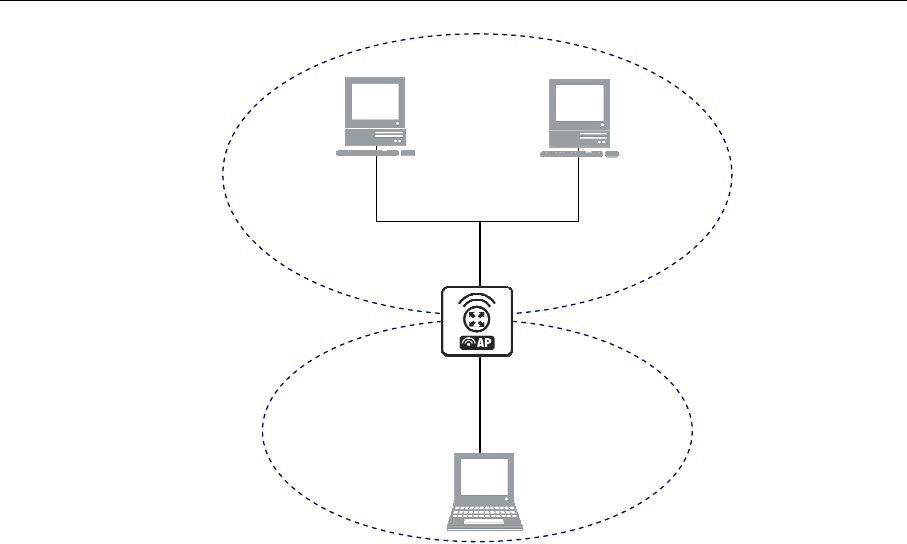
90 AT-WR4500 Series - IEEE 802.11abgh Outdoor Wireless Routers
RouterOS v3 Configuration and User Guide
Network A
192.168.0.0/24
198.168.0.130/25
Network B
192.168.0.128/25
ether2
198.168.0.129/25
198.168.0.20/24
198.168.0.30/24
198.168.0.1/25
ether1
A
B
C
Figure 11: Proxy ARP
Suppose the host A needs to communicate to host C. To do this, it needs to know host's C MAC
address. As shown on the diagram above, host A has /24 network mask. That makes host A to believe
that it is directly connected to the whole 192.168.0.0/24 network. When a computer needs to
communicate to another one on a directly connected network, it sends a broadcast ARP request.
Therefore host A sends a broadcast ARP request for the host C MAC address.
Broadcast ARP requests are sent to the broadcast MAC address FF:FF:FF:FF:FF:FF. Since the ARP request
is a broadcast, it will reach all hosts in the network A, including the router R1, but it will not reach host
C, because routers do not forward broadcasts by default. A router with enabled proxy ARP knows that
the host C is on another subnet and will reply with its own MAC adress. The router with enabled proxy
ARP always answer with its own MAC address if it has a route to the destination.
This behaviour can be usefull, for example, if you want to assign dial-in (ppp, pppoe, pptp) clients IP
addresses from the same address space as used on the connected LAN.
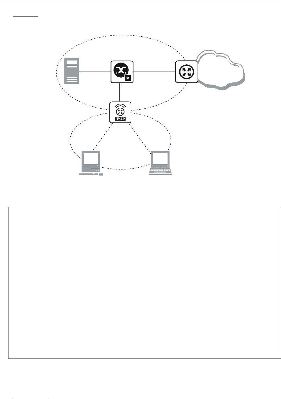
AT-WR4500 Series - IEEE 802.11abgh Outdoor Wireless Routers 91
RouterOS v3 Configuration and User Guide
Example
Consider the following configuration:
Reserved for dial in
10.0.0.230..240
Pppoe
-
inX addresses
10.0.0.217/32
10.0.0.217/24
ether1
10.0.0.1/24
Internet
Laptop
10.0.0.231/24
Server
10.0.0.2/24
WS
10.0.0.230/24
Figure 12: Proxy ARP with PPPoE
The Router setup is as follows:
admin@AT-WR4562] ip arp> /interface ethernet print
Flags: X - disabled, R - running
# NAME MTU MAC-ADDRESS ARP
0 R eth-LAN 1500 00:50:08:00:00:F5 proxy-arp
[admin@AT-WR4562] ip arp> /interface print
Flags: X - disabled, D - dynamic, R - running
# NAME TYPE MTU
0 eth-LAN ether 1500
1 prism1 prism 1500
2 D pppoe-in25 pppoe-in
3 D pppoe-in26 pppoe-in
[admin@AT-WR4562] ip arp> /ip address print
Flags: X - disabled, I - invalid, D - dynamic
# ADDRESS NETWORK BROADCAST INTERFACE
0 10.0.0.217/24 10.0.0.0 10.0.0.255 eth-LAN
1 D 10.0.0.217/32 10.0.0.230 0.0.0.0 pppoe-in25
2 D 10.0.0.217/32 10.0.0.231 0.0.0.0 pppoe-in26
[admin@AT-WR4562] ip arp> /ip route print
Flags: X - disabled, I - invalid, D - dynamic, J - rejected,
C - connect, S - static, R - rip, O - ospf, B - bgp
# DST-ADDRESS G GATEWAY DISTANCE INTERFACE
0 S 0.0.0.0/0 r 10.0.0.1 1 eth-LAN
1 DC 10.0.0.0/24 r 0.0.0.0 0 eth-LAN
2 DC 10.0.0.230/32 r 0.0.0.0 0 pppoe-in25
3 DC 10.0.0.231/32 r 0.0.0.0 0 pppoe-in26
[admin@AT-WR4562] ip arp>
5.1.5 Unnumbered Interfaces
Description
Unnumbered interfaces can be used on serial point-to-point links. If your AT-WR4500 ROUTER is not
equipped with such interfaces, please disregard this description. A private address should be put on the

92 AT-WR4500 Series - IEEE 802.11abgh Outdoor Wireless Routers
RouterOS v3 Configuration and User Guide
interface with the network being the same as the address on the router on the other side of the p2p link
(there may be no IP on that interface, but there is an IP for that router).
Example
[admin@AT-WR4562] ip address> add address=10.0.0.214/32 network=192.168.0.1 \
\... interface=pppsync
[admin@AT-WR4562] ip address> print
Flags: X - disabled, I - invalid, D - dynamic
# ADDRESS NETWORK BROADCAST INTERFACE
0 10.0.0.214/32 192.168.0.1 192.168.0.1 pppsync
[admin@AT-WR4562] ip address>
[admin@AT-WR4562] ip address> .. route print detail
Flags: X - disabled, I - invalid, D - dynamic, J - rejected,
C - connect, S - static, R - rip, O - ospf, B - bgp
0 S dst-address=0.0.0.0/0 preferred-source=0.0.0.0 gateway=192.168.0.1
gateway-state=reachable distance=1 interface=pppsync
1 DC dst-address=192.168.0.1/32 preferred-source=10.0.0.214
gateway=0.0.0.0 gateway-state=reachable distance=0 interface=pppsync
[admin@AT-WR4562] ip address>
As you can see, a dynamic connected route has been automatically added to the routes list. If you want
the default gateway be the other router of the p2p link, just add a static route for it. It is shown as 0 in
the example above.
5.1.6 Troubleshooting
Description
Router shows that the IP address is invalid
Check whether the interface exists to which the IP address is assigned. Or maybe it is disabled. It is also
possible that the system has crashed - reboot the router.
Router shows that the ARP entry is invalid
Check whether the interface exists to which the ARP entry is assigned. Or maybe it is disabled. Check
also for an IP address for the particular interface.
5.2 RIP: Routing Information Protocol
Document revisi on: 1 (Wed Mar 24 12:32:12 GMT 2004)
Applies to: V2.9
5.2.1 General Information
Summary
RouterOS implements RIP Version 1 (RFC1058) and Version 2 (RFC 2453). RIP enables routers in an
autonomous system to exchange routing information. It always uses the best path (the path with the
fewest number of hops (i.e. routers)) available.
Specifications
Packages required: routing
License required: Level3
Submenu level: /routing rip
Standards and Technologies: RIPv1, RIPv2
Hardware usage: Not significant

AT-WR4500 Series - IEEE 802.11abgh Outdoor Wireless Routers 93
RouterOS v3 Configuration and User Guide
Related Topics
IP Addresses and ARP
Routes, Equal Cost Multipath Routing, Policy Routing
Description
Routing Information Protocol (RIP) is one protocol in a series of routing protocols based on Bellman-
Ford (or distance vector) algorithm. This Interior Gateway Protocol (IGP) lets routers exchange routing
information across a single autonomous system in the way of periodic RIP updates. Routers transmit their
own RIP updates to neighboring networks and listen to the RIP updates from the routers on those
neighboring networks to ensure their routing table reflects the current state of the network and all the
best paths are available. Best path considered to be a path with the fewest hop count (id est that include
fewer routers).
The routes learned by RIP protocol are installed in the route list (/ip route print) with the distance of
120.
Additional Resources
• http://www.ietf.org/rfc/rfc1058.txt (RIP v1)
• http://www.ietf.org/rfc/rfc2453.txt (RIP v2)
• http://en.wikipedia.org/wiki/Routing_Information_Protocol
5.2.2 General Setup
Property Description
distribute-default (always | never | if-installed; default: never) - specifies whether to redistribute the
default route 0.0.0.0/0 or not
redistribute-static (yes | no; default: no) - specifies whether to redistribute static routes to neighbor
routers or not
redistribute-connected (yes | no; default: no) - specifies whether to redistribute connected routes to
neighbor routers or not
redistribute-ospf (yes | no; default: no) - specifies whether to redistribute routes learned via OSPF
protocol to neighbor routers or not
redistribute-bgp (yes | no; default: no) - specifies whether to redistribute routes learned via bgp
protocol to neighbor routers or not
metric-default (integer; default: 1) - specifies metric (the number of hops) for the default route
metric-static (integer; default: 1) - specifies metric (the number of hops) for the static routes
metric-connected (integer; default: 1) - specifies metric (the number of hops) for the connected routes
metric-ospf (integer; default: 1) - specifies metric (the number of hops) for the routes learned via OSPF
protocol
metric-bgp (integer; default: 1) - specifies metric (the number of hops) for the routes learned via BGP
protocol
update-timer (time; default: 30s) - specifies frequency of RIP updates
timeout-timer (time; default: 3m) - specifies time interval after which the route is considered invalid
garbage-timer (time; default: 2m) - specifies time interval after which the invalid route will be dropped
from neighbor router table
The maximum metric of RIP route is 15. Metric higher than 15
is considered 'infinity' and routes with
such metric are considered unreachable. Thus RIP cannot be used on networks with more than 15 hops
between any two routers, and using redistribute metrics larger that 1
further reduces this maximum
hop count.

94 AT-WR4500 Series - IEEE 802.11abgh Outdoor Wireless Routers
RouterOS v3 Configuration and User Guide
Example
To enable RIP protocol to redistribute the routes to the connected networks:
[admin@AT-WR4562] routing rip> set redistribute-connected=yes
[admin@AT-WR4562] routing rip> print
distribute-default: never
redistribute-static: no
redistribute-connected: no
redistribute-ospf: no
redistribute-bgp: no
metric-default: 1
metric-static: 1
metric-connected: 1
metric-ospf: 1
metric-bgp: 1
update-timer: 30s
timeout-timer: 3m
garbage-timer: 2m
[admin@AT-WR4562] routing rip>
5.2.3 Interfaces
Submenu level: /routing rip interface
Description
In general you do not have to configure interfaces in order to run RIP. This command level is provided
only for additional configuration of specific RIP interface parameters.
Property Description
interface (name; default: all) - interface on which RIP runs all - sets defaults for interfaces not having any
specific settings
send (v1 | v1-2 | v2; default: v2) - specifies RIP protocol update versions to distribute
receive (v1 | v1-2 | v2; default: v2) - specifies RIP protocol update versions the router will be able to
receive
authentication (none | simple | md5; default: none) - specifies authentication method to use for RIP
messages
none - no authentication performed
simple - plain text authentication
md5 - Keyed Message Digest 5 authentication
authentication-key (text; default: "") - specifies authentication key for RIP messages
in-prefix-list (name; default: "") - name of the filtering prefix list for received routes
out-prefix-list (name; default: "") - name of the filtering prefix list for advertised routes
It is recommended not to use RIP version 1 wherever it is possible due to security issues
Example
To add an entry that specifies that when advertising routes through the ether1 interface, prefix list
plout should be applied:
[admin@AT-WR4562] routing rip> interface add interface=ether1 \
\... prefix-list-out=plout
[admin@AT-WR4562] routing rip> interface print
Flags: I - inactive
0 interface=ether1 receive=v2 send=v2 authentication=none
authentication-key="" prefix-list-in=plout prefix-list-out=none
[admin@AT-WR4562] routing rip>

AT-WR4500 Series - IEEE 802.11abgh Outdoor Wireless Routers 95
RouterOS v3 Configuration and User Guide
5.2.4 Networks
Submenu level: /routing rip network
Description
To start the RIP protocol, you have to define the networks on which RIP will run.
Property Description
network (IP address mask; default: 0.0.0.0/0) - specifies the network on which RIP will run. Only directly
connected networks of the router may be specified
For point-to-point links you should specify the remote endpoint IP address as the network IP address. For
this case the correct netmask will be /32.
Example
To enable RIP protocol on 10.10.1.0/24 network:
[admin@AT-WR4562] routing rip network> add network=10.10.1.0/24
[admin@AT-WR4562] routing rip network> print
# ADDRESS
0 10.10.1.0/24
[admin@AT-WR4562] routing rip>
5.2.5 Neighbors
Description
This submenu is used to define a neighboring routers to exchange routing information with. Normally
there is no need to add the neighbors, if multicasting is working properly within the network. If there are
problems with exchanging routing information, neighbor routers can be added to the list. It will force the
router to exchange the routing information with the neighbor using regular unicast packets.
Property Description
address (IP address; default: 0.0.0.0) - IP address of neighboring router
Example
To force RIP protocol to exchange routing information with the 10.0.0.1 router:
[admin@AT-WR4562] routing rip> neighbor add address=10.0.0.1
[admin@AT-WR4562] routing rip> neighbor print
Flags: I - inactive
# ADDRESS
0 10.0.0.1
[admin@AT-WR4562] routing rip>
5.2.6 Routes
Submenu level: /routing rip route
Property Description
dst-address (read-only: IP address mask) - network address and netmask of destination
gateway (read-only: IP address) - last gateway on the route to destination
metric (read-only: integer) - distance vector length to the destination network
from (IP address) - specifies the IP address of the router from which the route was received

96 AT-WR4500 Series - IEEE 802.11abgh Outdoor Wireless Routers
RouterOS v3 Configuration and User Guide
This list shows routes learned by all dynamic routing protocols (RIP, OSPF and BGP)
Example
To view the list of the routes:
[admin@AT-WR4562] routing rip route> print
Flags: S - static, R - rip, O - ospf, C - connect, B - bgp
0 O dst-address=0.0.0.0/32 gateway=10.7.1.254 metric=1 from=0.0.0.0
...
33 R dst-address=159.148.10.104/29 gateway=10.6.1.1 metric=2 from=10.6.1.1
34 R dst-address=159.148.10.112/28 gateway=10.6.1.1 metric=2 from=10.6.1.1
[admin@AT-WR4562] routing rip route>
5.2.7 Application Examples
Example
Let us consider an example of routing information exchange between a RouterOS router, an Alliedware+
router and the ISP RouterOS router.
RouterOS Router Configuration:
[admin@AT-WR4562] > interface print
Flags: X - disabled, D - dynamic, R - running
# NAME TYPE MTU
0 R ether1 ether 1500
1 R ether2 ether 1500
[admin@AT-WR4562] > ip address print
Flags: X - disabled, I - invalid, D - dynamic
# ADDRESS NETWORK BROADCAST INTERFACE
0 10.0.0.174/24 10.0.0.174 10.0.0.255 ether1
1 192.168.0.1/24 192.168.0.0 192.168.0.255 ether2
[admin@AT-WR4562] > ip route print
Flags: X - disabled, I - invalid, D - dynamic, J - rejected,
C - connect, S - static, R - rip, O - ospf, B - bgp
# DST-ADDRESS G GATEWAY DISTANCE INTERFACE
0 DC 192.168.0.0/24 r 0.0.0.0 0 ether2
1 DC 10.0.0.0/24 r 0.0.0.0 0 ether1
[admin@AT-WR4562] >
No default route has been configured. The route will be obtained using the RIP.

AT-WR4500 Series - IEEE 802.11abgh Outdoor Wireless Routers 97
RouterOS v3 Configuration and User Guide
The necessary configuration of the RIP general settings is as follows:
[admin@AT-WR4562] routing rip> set redistribute-connected=yes
[admin@AT-WR4562] routing rip> print
distribute-default: never
redistribute-static: no
redistribute-connected: yes
redistribute-ospf: no
redistribute-bgp: no
metric-default: 1
metric-static: 1
metric-connected: 1
metric-ospf: 1
metric-bgp: 1
update-timer: 30s
timeout-timer: 3m
garbage-timer: 2m
[admin@AT-WR4562] routing rip>
The minimum required configuration of RIP interface is just enabling the network associated with the
ether1 interface:
[admin@AT-WR4562] routing rip network> add network=10.0.0.0/2
[admin@AT-WR4562] routing rip network> print
# ADDRESS
0 10.0.0.0/24
[admin@AT-WR4562] routing rip network>
There is no need to run RIP on the ether2, as no propagation of RIP information is required into the
Remote network in this example.
The routes obtained by RIP can be viewed in the /routing rip route menu:
[admin@AT-WR4562] routing rip> route print
Flags: S - static, R - rip, O - ospf, C - connect, B - bgp
0 R dst-address=0.0.0.0/0 gateway=10.0.0.26 metric=2 from=10.0.0.26
1 C dst-address=10.0.0.0/24 gateway=0.0.0.0 metric=1 from=0.0.0.0
2 C dst-address=192.168.0.0/24 gateway=0.0.0.0 metric=1 from=0.0.0.0
3 R dst-address=192.168.1.0/24 gateway=10.0.0.26 metric=1 from=10.0.0.26
4 R dst-address=192.168.3.0/24 gateway=10.0.0.26 metric=1 from=10.0.0.26
[admin@AT-WR4562] routing rip>
The regular routing table is:
[admin@AT-WR4562] routing rip> /ip route print
Flags: X - disabled, I - invalid, D - dynamic, J - rejected,
C - connect, S - static, R - rip, O - ospf, B - bgp
# DST-ADDRESS G GATEWAY DISTANCE INTERFACE
0 R 0.0.0.0/0 r 10.0.0.26 120 ether1
1 R 192.168.3.0/24 r 10.0.0.26 120 ether1
2 R 192.168.1.0/24 r 10.0.0.26 120 ether1
3 DC 192.168.0.0/24 r 0.0.0.0 0 ether2
4 DC 10.0.0.0/24 r 0.0.0.0 0 ether1
[admin@AT-WR4562] routing rip>

98 AT-WR4500 Series - IEEE 802.11abgh Outdoor Wireless Routers
RouterOS v3 Configuration and User Guide
Alliedware+ Router Configuration
...
interface Ethernet0
ip address 10.0.0.26 255.255.255.0
no ip directed-broadcast
!
interface Serial1
ip address 192.168.1.1 255.255.255.252
ip directed-broadcast
!
router rip
version 2
redistribute connected
redistribute static
network 10.0.0.0
network 192.168.1.0
!
ip classless
!
The routing table of the Alliedware+ router is:
awplus#show ip route
Codes: C - connected, S - static, I - IGRP, R - RIP, M - mobile, B - BGP
D - EIGRP, EX - EIGRP external, O - OSPF, IA - OSPF inter area
N1 - OSPF NSSA external type 1, N2 - OSPF NSSA external type 2
E1 - OSPF external type 1, E2 - OSPF external type 2, E - EGP
i - IS-IS, L1 - IS-IS level-1, L2 - IS-IS level-2, * - candidate default
U - per-user static route, o - ODR
Gateway of last resort is 192.168.1.2 to network 0.0.0.0
10.0.0.0/24 is subnetted, 1 subnets
C 10.0.0.0 is directly connected, Ethernet0
R 192.168.0.0/24 [120/1] via 10.0.0.174, 00:00:19, Ethernet0
192.168.1.0/30 is subnetted, 1 subnets
C 192.168.1.0 is directly connected, Serial1
R 192.168.3.0/24 [120/1] via 192.168.1.2, 00:00:05, Serial1
R* 0.0.0.0/0 [120/1] via 192.168.1.2, 00:00:05, Serial1
awplus#
As we can see, the Alliedware+ router has learned RIP routes both from the RouterOS router
(192.168.0.0/24), and from the ISP router (0.0.0.0/0 and 192.168.3.0/24).
5.3 OSPF
Document revisi on: 1.4 (Wed Dec 21 1 7:26:39 GMT 2 005)
Applies to: V2.9
5.3.1 General Information
Summary
RouterOS implements OSPF Version 2 (RFC 2328). The OSPF protocol is the link-state protocol that
takes care of the routes in the dynamic network structure that can employ different paths to its
subnetworks. It always chooses shortest path to the subnetwork first.
Specifications
Packages required: routing
License required: Level3
Submenu level: /routing ospf
Standards and Technologies: OSPF
Hardware usage: Not significant

AT-WR4500 Series - IEEE 802.11abgh Outdoor Wireless Routers 99
RouterOS v3 Configuration and User Guide
Related Topics
• IP Addresses and ARP
• Routes, Equal Cost Multipath Routing, Policy Routing
• Log Management
Description
Open Shortest Path First protocol is a link-state routing protocol. It's uses a link-state algorithm to
build and calculate the shortest path to all known destinations. The shortest path is calculated using the
Dijkstra algorithm. OSPF distributes routing information between the routers belonging to a single
autonomous system (AS). An AS is a group of routers exchanging routing information via a common
routing protocol.
In order to deploy the OSPF all routers it will be running on should be configured in a coordinated
manner.
It also means that the routers should have the same MTU for all the networks advertised by the OSPF
protocol
The OSPF protocol is started after you will add a record to the OSPF network list. The routes learned by
the OSPF protocol are installed in the routes table list with the distance of 110.
5.3.2 General Setup
Submenu level: /routing ospf
Description
In this section you will learn how to configure basic OSPF settings.
Property Description
distribute-default (never | if-installed-as-type-1 | if-installed-as-type-2 | always-as-type-1 | always-as-
type-2; default: never) - specifies how to distribute default route. Should be used for ABR (Area Border
router) or ASBR (Autonomous System boundary router) settings
never - do not send own default route to other routers
if-installed-as-type-1 - send the default route with type 1 metric only if it has been installed (a static
default route, or route added by DHCP, PPP, etc.)
if-installed-as-type-2 - send the default route with type 2 metric only if it has been installed (a static
default route, or route added by DHCP, PPP, etc.)
always-as-type-1 - always send the default route with type 1 metric
always-as-type-2 - always send the default route with type 2 metric
metric-bgp (integer; default: 20) - specifies the cost of the routes learned from BGP protocol
metric-connected (integer; default: 20) - specifies the cost of the routes to directly connected
networks
metric-default (integer; default: 1) - specifies the cost of the default route
metric-rip (integer; default: 20) - specifies the cost of the routes learned from RIP protocol
metric-static (integer; default: 20) - specifies the cost of the static routes
redistribute-bgp (as-type-1 | as-type-2 | no; default: no) - with this setting enabled the router will
redistribute the information about all routes learned by the BGP protocol
redistribute-connected (as-type-1 | as-type-2 | no; default: no) - if set, the router will redistribute the
information about all connected routes, i.e., routes to directly reachable networks
redistribute-rip (as-type-1 | as-type-2 | no; default: no) - with this setting enabled the router will
redistribute the information about all routes learned by the RIP protocol
redistribute-static (as-type-1 | as-type-2 | no; default: no) - if set, the router will redistribute the
information about all static routes added to its routing database, i.e., routes that have been created using
the /ip route add command
router-id (IP address; default: 0.0.0.0) - OSPF Router ID. If not specified, OSPF uses the largest IP
address configured on the interfaces as its router ID

100 AT-WR4500 Series - IEEE 802.11abgh Outdoor Wireless Routers
RouterOS v3 Configuration and User Guide
Within one area, only the router that is connected to another area (i.e. Area border router) or to another
AS (i.e. Autonomous System boundary router) should have the propagation of the default route enabled.
OSPF protocol will try to use the shortest path (path with the smallest total cost) if available.
OSPF protocol supports two types of metrics:
• type1 -
external metrics are expressed in the same units as OSPF interface cost. In
other words the router expects the cost of a link to a network which is ex
ternal to AS
to be the same order of magnitude as the cost of the internal links.
• type2 - external metrics are an order of magnitude larger; any type2
metric is
considered greater than the cost of any path internal to the AS. Use of type2
external
metric
assumes that routing between AS is the major cost of routing a packet, and
climinates the need conversion of external costs to internal link state metrics.
Both Type 1 and Type 2 external metrics can be used in the AS at the same time. In that event, Type
1
external metrics always take precedence.
In /ip route you can see routes with Io status. Because router receives routers from itself.
The metric cost can be calculated from line speed by using the formula 10e+8/line speed. The table
contains some examples:
Example
To enable the OSPF protocol redisrtibute routes to the connected networks as type1 metrics with the
cost of 1, you need do the following:
[admin@AT-WR4562] routing ospf> set redistribute-connected=as-type-1 \
\... metric-connected=1
[admin@AT-WR4562] routing ospf> print
router-id: 0.0.0.0
distribute-default: never
redistribute-connected: no
redistribute-static: no
redistribute-rip: no
redistribute-bgp: no
metric-default: 1
metric-connected: 20
metric-static: 20
metric-rip: 20
metric-bgp: 20
mpls-te-area: unspecified
mpls-te-router-id: unspecified
[admin@AT-WR4562] routing ospf>
5.3.3 OSPF Areas
Submenu level: /routing ospf area
Description
OSPF allows collections of routers to be grouped together. Such group is called an area. Each area runs a
separate copy of the basic link-state routing algorithm. This means that each area has its own link-state
database and corresponding graph
The structure of an area is invisible from the outside of the area. This isolation of knowledge enables the
protocol to effect a marked reduction in routing traffic as compared to treating the entire Autonomous
System as a single link-state domain
60-80 routers have to be the maximum in one area
Property Description
area-id (IP address; default: 0.0.0.0) - OSPF area identifier. Default area-id=0.0.0.0 is the backbone
area. The OSPF backbone always contains all area border routers. The backbone is responsible for
distributing routing information between non-backbone areas. The backbone must be contiguous.

AT-WR4500 Series - IEEE 802.11abgh Outdoor Wireless Routers 101
RouterOS v3 Configuration and User Guide
However, areas do not need to be physical connected to backbone. It can be done with virtual link. The
name and area-id for this area can not be changed
authentication (none | simple | md5; default: none) - specifies authentication method for OSPF
protocol messages
none - do not use authentication
simple - plain text authentication
md5 - keyed Message Digest 5 authentication
default-cost (integer; default: 1) - specifies the default cost used for stub areas. Applicable only to area
boundary routers
name (name; default: "") - OSPF area's name
type (default | stub; default: default) - a stub area is an area which is out from part with no routers or
areas beyond it. A stub area is configured to avoid AS External Link Advertisements being flooded into
the Stub area. One of the reason to configure a Stub area is that the size of the link state database is
reduced along with the routing table and less CPU cycles are used to process. Any router which is trying
access to a network outside the area sends the packets to the default route.
Example
To define additional OSPF area named local_10 with area-id=0.0.10.5, do the following:
[admin@WiFi] routing ospf area> add area-id=0.0.10.5 name=local_10
[admin@WiFi] routing ospf area> print
Flags: X - disabled, I - invalid
# NAME AREA-ID STUB DEFAULT-COST AUTHENTICATION
0 backbone 0.0.0.0 none
1 local_10 0.0.10.5 no 1 none
[admin@WiFi] routing ospf area>
5.3.4 Networks
Submenu level: /routing ospf network
Description
There can be Point-to-Point networks or Multi-Access networks. Multi-Access network can be a
broadcast network (a single message can be sent to all routers)
To start the OSPF protocol, you have to define the networks on which it will run and the area ID for
each of those networks
Property Description
area (name; default: backbone) - the OSPF area to be associated with the specified address range
network (IP address mask; default: 20) - the network associated with the area. The network argument
allows defining one or multiple interfaces to be associated with a specific OSPF area. Only directly
connected networks of the router may be specified
You should set the network address exactly the same as the remote point IP address for point-to-point
links. The right netmask in this case is /32
Example
To enable the OSPF protocol on the 10.10.1.0/24 network, and include it into the backbone area, do the
following:
[admin@AT-WR4562] routing ospf network> add area=backbone network=10.10.1.0/24
[admin@AT-WR4562] routing ospf network> print
Flags: X - disabled
# NETWORK AREA
0 10.10.1.0/24 backbone
[admin@AT-WR4562] routing ospf>

102 AT-WR4500 Series - IEEE 802.11abgh Outdoor Wireless Routers
RouterOS v3 Configuration and User Guide
5.3.5 Interfaces
Submenu level: /routing ospf interface
Description
This facility provides tools for additional in-depth configuration of OSPF interface specific parameters.
You do not have to configure interfaces in order to run OSPF
Property Description
authentication-key (text; default: "") - authentication key have to be used by neighboring routers that
are using OSPF's simple password authentication
cost (integer: 1..65535; default: 1) - interface cost expressed as link state metric
dead-interval (time; default: 40s) - specifies the interval after which a neighbor is declared as dead. The
interval is advertised in the router's hello packets. This value must be the same for all routers and access
servers on a specific network
hello-interval (time; default: 10s) - the interval between hello packets that the router sends on the
interface. The smaller the hello-interval, the faster topological changes will be detected, but more routing
traffic will ensue. This value must be the same on each end of the adjacency otherwise the adjacency will
not form
interface (name; default: all) - interface on which OSPF will run
all - is used for the interfaces not having any specific settings
priority (integer: 0..255; default: 1) - router's priority. It helps to determine the designated router for the
network. When two routers attached to a network both attempt to become the designated router, the
one with the higher router's priority takes precedence
retransmit-interval (time; default: 5s) - time between retransmitting lost link state advertisements.
When a router sends a link state advertisement (LSA) to its neighbor, it keeps the LSA until it receives
back the acknowledgment. If it receives no acknowledgment in time, it will retransmit the LSA. The
following settings are recommended: for Broadcast network are 5 seconds and for Point-to-Point
network are 10 seconds
transmit-delay (time; default: 1s) - link state transmit delay is the estimated time it takes to transmit a
link state update packet on the interface
Example
To add an entry that specifies that ether2 interface should send Hello packets every 5 seconds, do the
following:
[admin@AT-WR4562] routing ospf> interface add interface=ether2 hello-interval=5s
[admin@AT-WR4562] routing ospf> interface print
0 interface=ether2 cost=1 priority=1 authentication-key=""
retransmit-interval=5s transmit-delay=1s hello-interval=5s
dead-interval=40s
[admin@AT-WR4562] routing ospf>
5.3.6 Virtual Links
Submenu level: /routing ospf virtual-link
Description
As stated in OSPF RFC, the backbone area must be contiguous. However, it is possible to define areas in
such a way that the backbone is no longer contiguous. In this case the system administrator must restore
backbone connectivity by configuring virtual links. Virtual link can be configured between two routers
through common area called transit area, one of them should have to be connected with backbone.
Virtual links belong to the backbone. The protocol treats two routers joined by a virtual link as if they
were connected by an unnumbered point-to-point network

AT-WR4500 Series - IEEE 802.11abgh Outdoor Wireless Routers 103
RouterOS v3 Configuration and User Guide
Property Description
neighbor-id (IP address; default: 0.0.0.0) - specifies router-id of the neighbor
transit-area (name; default: (unknown)) - a non-backbone area the two routers have in common
Virtual links can not be established through stub areas
Example
To add a virtual link with the 10.0.0.201 router through the ex area, do the following:
[admin@AT-WR4562] routing ospf virtual-link> add neighbor-id=10.0.0.201 \
\... transit-area=ex
[admin@AT-WR4562] routing ospf virtual-link> print
Flags: X - disabled, I - invalid
# NEIGHBOR-ID TRANSIT-AREA
0 10.0.0.201 ex
[admin@AT-WR4562] routing ospf virtual-link>
Virtual link should be configured on both routers
5.3.7 Neighbors
Submenu level: /routing ospf neighbor
Description
The submenu provides an access to the list of OSPF neighbors, id est the routers adjacent to the current
router, and supplies brief statistics
Property Description
address (read-only: IP address) - appropriate IP address of the neighbor
backup-dr-id (read-only: IP address) - backup designated router's router id for this neighbor
db-summaries (read-only: integer) - number of records in link-state database advertised by the neighbor
dr-id (read-only: IP address) - designated router's router id for this neighbor
ls-requests (read-only: integer) - number of link-state requests
ls-retransmits (read-only: integer) - number of link-state retransmits
priority (read-only: integer) - the priority of the neighbor which is used in designated router elections via
Hello protocol on this network
router-id (read-only: IP address) - the router-id parameter of the neighbor
state (read-only: Down | Attempt | Init | 2-Way | ExStart | Exchange | Loading | Full) - the state of the
connection:
Down - the connection is down
Attempt - the router is sending Hello protocol packets
Init - Hello packets are exchanged between routers to create a Neighbor Relationship
2-Way - the routers add each other to their Neighbor database and they become neighbors
ExStart - the DR (Designated Router) and BDR (Backup Designated Router) create an adjancency with
each other and they begin creating their link-state databases using Database Description Packets
Exchange - is the process of discovering routes by exchanging Database Description Packets
Loading - receiving information from the neighbor
Full - the link-state databases are completely synchronized. The routers are routing traffic and continue
sending each other hello packets to maintain the adjacency and the routing information
state-changes (read-only: integer) - number of connection state changes
The neighbor's list also displays the router itself with 2-Way state
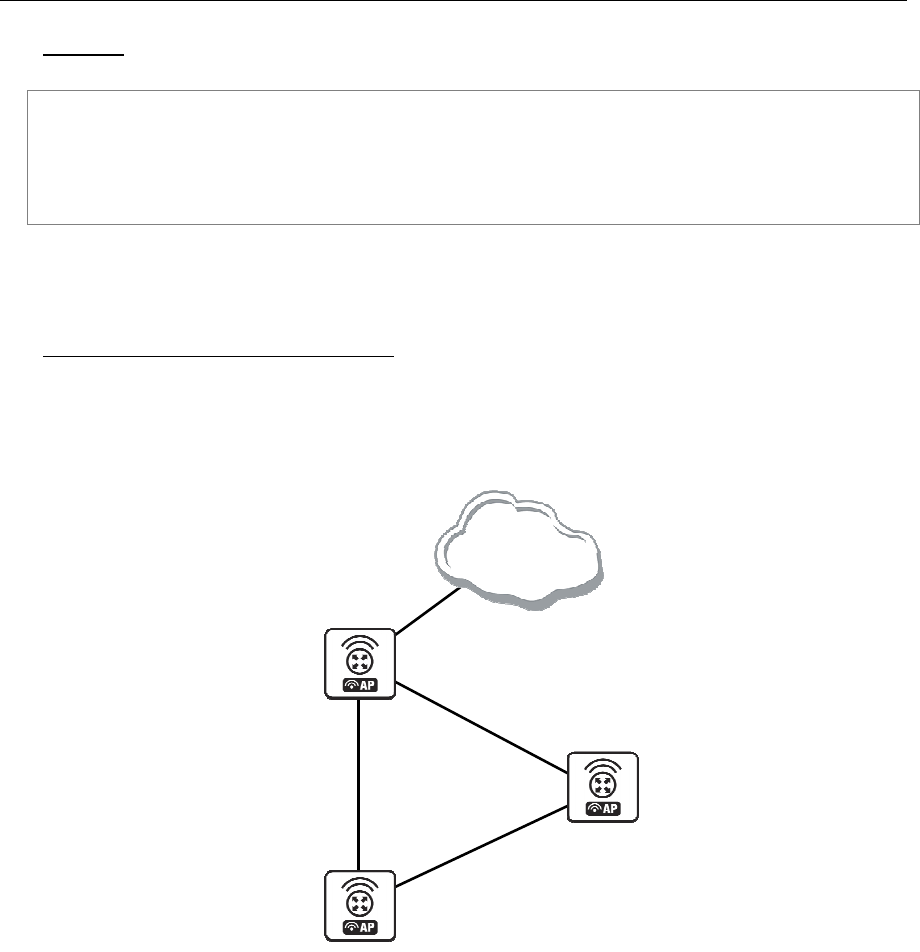
104 AT-WR4500 Series - IEEE 802.11abgh Outdoor Wireless Routers
RouterOS v3 Configuration and User Guide
Example
The following text can be observed just after adding an OSPF network:
admin@AT-WR4562] routing ospf> neighbor print
router-id=10.0.0.204 address=10.0.0.204 priority=1 state="2-Way"
state-changes=0 ls-retransmits=0 ls-requests=0 db-summaries=0
dr-id=0.0.0.0 backup-dr-id=0.0.0.0
[admin@AT-WR4562] routing ospf>
5.3.8 Application Examples
OSPF backup without using a tunnel
Let us assume that the link between the routers OSPF-Main and OSPF-peer-1 is the main one. If it goes
down, we want the traffic switch over to the link going through the router OSPF-peer-2.
This example shows how to use OSPF for backup purposes, if you are controlling all the involved routers,
and you can run OSPF on them.
main_gw 192.168.0.11
[OSPF_peer_2]
Cost=1
Cost=1
Cost=1
to_peer1 10.3.0.2
to_main 10.2.0.1
backup 10.3.0.1
to_peer2 10.2.0.2
to_peer1 10.1.0.2
[OSPF_MAIN]
to_main 10.1.0.1
[OSPF_peer_1]
Internet
Figure 13: OSPF Backup
In this example:
1. We introduce an OSPF area with area ID=0.0.0.1, which includes all three routers shown on the
diagram
2. Only the OSPF-Main router will have the default route configured. Its interfaces peer1 and peer2
will be configured for the OSPF protocol. The interface main_gw will not be used for distributing
the OSPF routing information
3. The routers OSPF-peer-1 and OSPF-peer-2 will distribute their connected route information, and
receive the default route using the OSPF protocol

AT-WR4500 Series - IEEE 802.11abgh Outdoor Wireless Routers 105
RouterOS v3 Configuration and User Guide
Now let's setup the OSPF_MAIN router.
The router should have 3 NICs:
[admin@OSPF_MAIN] interface> print
Flags: X - disabled, D - dynamic, R - running
# NAME TYPE RX-RATE TX-
RATE MTU
0 R main_gw ether 0 0
1500
1 R to_peer_1 ether 0 0
1500
2 R to_peer_2 ether 0 0
1500
Add all needed ip addresses to interfaces as it is shown here:
[admin@OSPF_MAIN] ip address> print
Flags: X - disabled, I - invalid, D - dynamic
# ADDRESS NETWORK BROADCAST INTERFACE
0 192.168.0.11/24 192.168.0.0 192.168.0.255 main_gw
1 10.1.0.2/24 10.1.0.0 10.1.0.255 to_peer_1
2 10.2.0.2/24 10.2.0.0 10.2.0.255 to_peer_2
You should set distribute-default as if-installed-as-type-2, redistribute-connected as as-type-1 and
redistribute-static as as-type-2. Metric-connected, metric-static, metric-rip, metric-bgp should be zero
[admin@OSPF_MAIN] routing ospf> print
router-id: 0.0.0.0
distribute-default: if-installed-as-type-2
redistribute-connected: as-type-1
redistribute-static: as-type-2
redistribute-rip: no
redistribute-bgp: no
metric-default: 1
metric-connected: 0
metric-static: 0
metric-rip: 0
metric-bgp: 0
Define new OSPF area named local_10 with area-id 0.0.0.1:
[admin@OSPF_MAIN] routing ospf area> print
Flags: X - disabled, I - invalid
# NAME AREA-ID STUB DEFAULT-COST
AUTHENTICATION
0 backbone 0.0.0.0
none
1 local_10 0.0.0.1 no 1
none
Add connected networks with area local_10 in ospf network:
[admin@OSPF_MAIN] routing ospf network> print
Flags: X - disabled, I - invalid
# NETWORK AREA
0 10.1.0.0/24 local_10
1 10.2.0.0/24 local_10
For main router the configuration is done. Next, you should configure OSPF_peer_1 router.
Enable followong interfaces on OSPF_peer_1:
[admin@OSPF_peer_1] interface> print
Flags: X - disabled, D - dynamic, R - running
# NAME TYPE RX-RATE TX-RATE MTU
0 R backup ether 0 0 1500
1 R to_main ether 0 0 1500

106 AT-WR4500 Series - IEEE 802.11abgh Outdoor Wireless Routers
RouterOS v3 Configuration and User Guide
Assign IP addresses to these interfaces:
[admin@OSPF_peer_1] ip address> print
Flags: X - disabled, I - invalid, D - dynamic
# ADDRESS NETWORK BROADCAST INTERFACE
0 10.1.0.1/24 10.1.0.0 10.1.0.255 to_main
1 10.3.0.1/24 10.3.0.0 10.3.0.255 backup
Set redistribute-connected as as-type-1. Metric-connected, metric-static, metric-rip, metric-bgp should be
zero.
[admin@OSPF_peer_1] routing ospf> print
router-id: 0.0.0.0
distribute-default: never
redistribute-connected: as-type-1
redistribute-static: no
redistribute-rip: no
redistribute-bgp: no
metric-default: 1
metric-connected: 0
metric-static: 0
metric-rip: 0
metric-bgp: 0
Add the same area as in main router:
[admin@OSPF_peer_1] routing ospf area> print
Flags: X - disabled, I - invalid
# NAME AREA-ID STUB DEFAULT-COST
AUTHENTICATION
0 backbone 0.0.0.0 none
1 local_10 0.0.0.1 no 1 none
Add connected networks with area local_10:
[admin@OSPF_peer_1] routing ospf network> print
Flags: X - disabled, I - invalid
# NETWORK AREA
0 10.3.0.0/24 local_10
1 10.1.0.0/24 local_10
Finally, set up the OSPF_peer_2 router. Enable the following interfaces:
[admin@OSPF_peer_2] interface> print
Flags: X - disabled, D - dynamic, R - running
# NAME TYPE RX-RATE TX-
RATE MTU
0 R to_main ether 0 0
1500
1 R to_peer_1 ether 0 0
1500
Add the needed IP addresses:
[admin@OSPF_peer_2] ip address> print
Flags: X - disabled, I - invalid, D - dynamic
# ADDRESS NETWORK BROADCAST INTERFACE
0 10.2.0.1/24 10.2.0.0 10.2.0.255 to_main
1 10.3.0.2/24 10.3.0.0 10.3.0.255 to_peer_1

AT-WR4500 Series - IEEE 802.11abgh Outdoor Wireless Routers 107
RouterOS v3 Configuration and User Guide
Add the same area as in previous routers:
[admin@OSPF_peer_2] routing ospf area> print
Flags: X - disabled, I - invalid
# NAME AREA-ID STUB DEFAULT-COST
AUTHENTICATION
0 backbone 0.0.0.0
none
1 local_10 0.0.0.1 no 1
none
Add connected networks with the same area:
[admin@OSPF_peer_2] routing ospf network> print
Flags: X - disabled, I - invalid
# NETWORK AREA
0 10.2.0.0/24 local_10
1 10.3.0.0/24 local_10
After all routers have been set up as described above, and the links between them are operational, the
routing tables of the three routers look as follows:
[admin@OSPF_MAIN] ip route> print
Flags: X - disabled, I - invalid, D - dynamic, J - rejected,
C - connect, S - static, r - rip, o - ospf, b - bgp
# DST-ADDRESS G GATEWAY DISTANCE INTERFACE
0 Io 192.168.0.0/24 110
1 DC 192.168.0.0/24 r 0.0.0.0 0 main_gw
2 Do 10.3.0.0/24 r 10.2.0.1 110 to_peer_2
r 10.1.0.1 to_peer_1
3 Io 10.2.0.0/24 110
4 DC 10.2.0.0/24 r 0.0.0.0 0 to_peer_2
5 Io 10.1.0.0/24 110
6 DC 10.1.0.0/24 r 0.0.0.0 0 to_peer_1
[admin@OSPF_peer_1] ip route> print
Flags: X - disabled, I - invalid, D - dynamic, J - rejected,
C - connect, S - static, r - rip, o - ospf, b - bgp
# DST-ADDRESS G GATEWAY DISTANCE INTERFACE
0 Do 192.168.0.0/24 r 10.1.0.2 110 to_main
1 Io 10.3.0.0/24 110
2 DC 10.3.0.0/24 r 0.0.0.0 0 backup
3 Do 10.2.0.0/24 r 10.1.0.2 110 to_main
r 10.3.0.2 backup
4 Io 10.1.0.0/24 110
5 DC 10.1.0.0/24 r 0.0.0.0 0 to_main
[admin@OSPF_peer_2] ip route> print
Flags: X - disabled, I - invalid, D - dynamic, J - rejected,
C - connect, S - static, r - rip, o - ospf, b - bgp
# DST-ADDRESS G GATEWAY DISTANCE INTERFACE
0 Do 192.168.0.0/24 r 10.2.0.2 110 to_main
1 Io 10.3.0.0/24 110
2 DC 10.3.0.0/24 r 0.0.0.0 0 to_peer_1
3 Io 10.2.0.0/24 110
4 DC 10.2.0.0/24 r 0.0.0.0 0 to_main
5 Do 10.1.0.0/24 r 10.3.0.1 110 to_peer_1
r 10.2.0.2 to_main
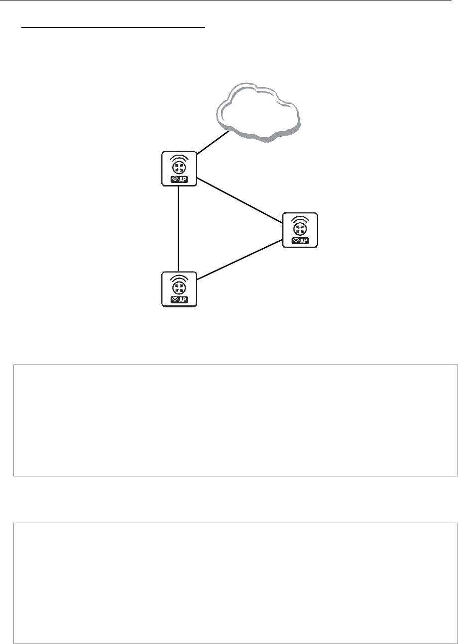
108 AT-WR4500 Series - IEEE 802.11abgh Outdoor Wireless Routers
RouterOS v3 Configuration and User Guide
Routing tables with Revised Link Cost
This example shows how to set up link cost. Let us assume, that the link between the routers
OSPF_peer_1 and OSPF_peer_2 has a higher cost (might be slower, we have to pay more for the
traffic through it, etc.).
main_gw 192.168.0.11
[OSPF_peer_2]
Cost=1
Cost=1
Cost=1
to_peer1 10.3.0.2
to_main 10.2.0.1
backup 10.3.0.1
to_peer2 10.2.0.2
to_peer1 10.1.0.2
[OSPF_MAIN]
to_main 10.1.0.1
[OSPF_peer_1]
Internet
Figure 14: OSPF Routing tables
We should change cost value in both routers: OSPF_peer_1 and OSPF_peer_2 to 50. To do this, we
need to add a following interface:
[admin@OSPF_peer_1] routing ospf interface> add interface=backup cost=50
[admin@OSPF_peer_1] routing ospf interface> print
0 interface=backup cost=50 priority=1 authentication-key=""
retransmit-interval=5s transmit-delay=1s hello-interval=10s
dead-interval=40s
[admin@OSPF_peer_2] routing ospf interface> add interface=to_peer_1 cost=50
[admin@OSPF_peer_2] routing ospf interface> print
0 interface=to_peer_1 cost=50 priority=1 authentication-key=""
retransmit-interval=5s transmit-delay=1s hello-interval=10s
dead-interval=40s
After changing the cost settings, we have only one equal cost multipath route left - to the network
10.3.0.0/24 from OSPF_MAIN router.
Routes on OSPF_MAIN router:
[admin@OSPF_MAIN] ip route> print
Flags: X - disabled, I - invalid, D - dynamic, J - rejected,
C - connect, S - static, r - rip, o - ospf, b - bgp
# DST-ADDRESS G GATEWAY DISTANCE INTERFACE
0 Io 192.168.0.0/24 110
1 DC 192.168.0.0/24 r 0.0.0.0 0 main_gw
2 Do 10.3.0.0/24 r 10.2.0.1 110 to_peer_2
r 10.1.0.1 to_peer_1
3 Io 10.2.0.0/24 110
4 DC 10.2.0.0/24 r 0.0.0.0 0 to_peer_2
5 Io 10.1.0.0/24 110
6 DC 10.1.0.0/24 r 0.0.0.0 0 to_peer_1
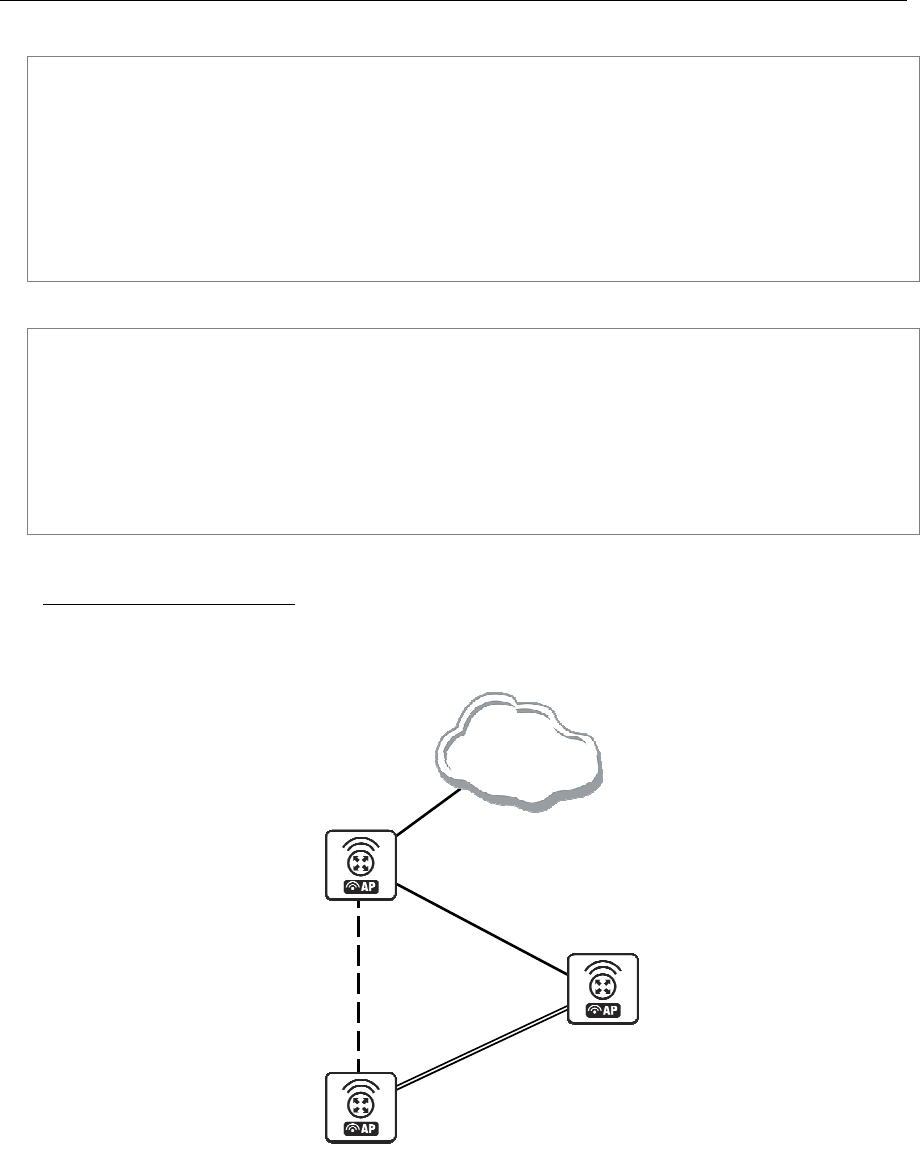
AT-WR4500 Series - IEEE 802.11abgh Outdoor Wireless Routers 109
RouterOS v3 Configuration and User Guide
On OSPF_peer_1:
[admin@OSPF_peer_1] > ip route pr
Flags: X - disabled, I - invalid, D - dynamic, J - rejected,
C - connect, S - static, r - rip, o - ospf, b - bgp
# DST-ADDRESS G GATEWAY DISTANCE INTERFACE
0 Do 192.168.0.0/24 r 10.1.0.2 110 to_main
1 Io 10.3.0.0/24 110
2 DC 10.3.0.0/24 r 0.0.0.0 0 backup
3 Do 10.2.0.0/24 r 10.1.0.2 110 to_main
4 Io 10.1.0.0/24 110
5 DC 10.1.0.0/24 r 0.0.0.0 0 to_main
On OSPF_peer_2:
[admin@OSPF_peer_2] > ip route print
Flags: X - disabled, I - invalid, D - dynamic, J - rejected,
C - connect, S - static, r - rip, o - ospf, b - bgp
# DST-ADDRESS G GATEWAY DISTANCE INTERFACE
0 Do 192.168.0.0/24 r 10.2.0.2 110 to_main
1 Io 10.3.0.0/24 110
2 DC 10.3.0.0/24 r 0.0.0.0 0 to_peer_1
3 Io 10.2.0.0/24 110
4 DC 10.2.0.0/24 r 0.0.0.0 0 to_main
5 Do 10.1.0.0/24 r 10.2.0.2 110 to_main
Functioning of the Backup
If the link between routers OSPF_MAIN and OSPF_peer_1 goes down, we have the following
situation:
main_gw 192.168.0.11
[OSPF_peer_2]
Cost=1
Cost=1
Cost=1
to_peer1 10.3.0.2
to_main 10.2.0.1
backup 10.3.0.1
to_peer2 10.2.0.2
to_peer1 10.1.0.2
[OSPF_MAIN]
to_main 10.1.0.1
[OSPF_peer_1]
Internet
Figure 15: OSPF Backup

110 AT-WR4500 Series - IEEE 802.11abgh Outdoor Wireless Routers
RouterOS v3 Configuration and User Guide
The OSPF routing changes as follows:
Routes on OSPF_MAIN router:
[admin@OSPF_MAIN] ip route> print
Flags: X - disabled, I - invalid, D - dynamic, J - rejected,
C - connect, S - static, r - rip, o - ospf, b - bgp
# DST-ADDRESS G GATEWAY DISTANCE INTERFACE
0 Io 192.168.0.0/24 110
1 DC 192.168.0.0/24 r 0.0.0.0 0 main_gw
2 Do 10.3.0.0/24 r 10.2.0.1 110 to_peer_2
3 Io 10.2.0.0/24 110
4 DC 10.2.0.0/24 r 0.0.0.0 0 to_peer_2
5 Io 10.1.0.0/24 110
6 DC 10.1.0.0/24 r 0.0.0.0 0 to_peer_1
On OSPF_peer_1:
[admin@OSPF_peer_1] ip route> print
Flags: X - disabled, I - invalid, D - dynamic, J - rejected,
C - connect, S - static, r - rip, o - ospf, b - bgp
# DST-ADDRESS G GATEWAY DISTANCE INTERFACE
0 Do 192.168.0.0/24 r 10.3.0.2 110 backup
1 Io 192.168.0.0/24 110
2 DC 10.3.0.0/24 r 0.0.0.0 0 backup
3 Do 10.2.0.0/24 r 10.3.0.2 110 backup
4 Io 10.1.0.0/24 110
5 DC 10.1.0.0/24 r 0.0.0.0 0 to_main
On OSPF_peer_2:
[admin@OSPF_peer_2] ip route> print
Flags: X - disabled, I - invalid, D - dynamic, J - rejected,
C - connect, S - static, r - rip, o - ospf, b - bgp
# DST-ADDRESS G GATEWAY DISTANCE INTERFACE
0 Do 192.168.0.0/24 r 10.2.0.2 110 to_main
1 Io 10.3.0.0/24 110
2 DC 10.3.0.0/24 r 0.0.0.0 0 to_peer_1
3 Io 10.2.0.0/24 110
4 DC 10.2.0.0/24 r 0.0.0.0 0 to_main
5 Do 10.1.0.0/24 r 10.2.0.2 110 to_main
The change of the routing takes approximately 40 seconds (the hello-interval setting). If required, this
setting can be adjusted, but it should be done on all routers within the OSPF area!
5.4 Routes, Equal Cost Multipath Routing, Policy Routing
Document revisi on: 2.3 (July 20, 2007, 13: 21 GMT)
Applies to: V2.9
5.4.1 General Information
Summary
The following manual surveys the IP routes management, equal-cost multi-path (ECMP) routing technique,
and policy-based routing.
Specifications
Packages required: system
License required: Level1
Submenu level: /ip route
Standards and Technologies: IP (RFC 791)
Hardware usage: Not significant
Related Topics
IP Addresses and ARP

AT-WR4500 Series - IEEE 802.11abgh Outdoor Wireless Routers 111
RouterOS v3 Configuration and User Guide
Filter
NAT
Description
RouterOS has following types of routes:
dynamic routes - automatically created routes for networks, which are directly accessed through an
interface. They appear automatically, when adding a new IP address. Dynamic routes are also added by
routing protocols.
static routes - user-defined routes that specify the router which can forward traffic to the specified
destination network. They are useful for specifying the default gateway. The gateway for static routes may
be checked (with either ARP or ICMP protocol) for reachability, so that different gateways with different
priorities (costs) may be assigned for one destination network to provide failover.
ECMP (Equal Cost Multi-Path) Routing
This routing mechanism enables packet routing along multiple paths with equal cost and ensures load
balancing. With ECMP routing, you can use more than one gateway for one destination network (this
approach may also be configured to provide failover). With ECMP, a router potentially has several
available next hops towards a given destination. A new gateway is chosen for each new source/destination
IP pair. It means that, for example, one FTP connection will use only one link, but new connection to a
different server will use another link. ECMP routing has another good feature - single connection packets
do not get reordered and therefore do not kill TCP performance.
The ECMP routes can be created by routing protocols (RIP or OSPF), or by adding a tatic route with
multiple gateways, separated by a comma (e.g., /ip route add gateway=192.168.0.1,192.168.1.1). The
routing protocols may create multipath dynamic routes with equal cost automatically, if the cost of the
interfaces is adjusted propery. For more information on using routing protocols, please read the
corresponding Manual.
Policy-Based Routing
It is a routing approach where the next hop (gateway) for a packet is chosen, based on a policy, which is
configured by the network administrator. In RouterOS the procedure the follwing:
• mark the desired packets, with a routing-mark
• choose a gateway for the marked packets
In routing process, the router decides which route it will use to send out the packet. Afterwards, when
the packet is masqueraded, its source address is taken from the prefsrc field.
5.4.2 Routes
Submenu level: /ip route
Description
In this submenu you can configure Static, Equal Cost Multi-Path and Policy-Based Routing and see the
routes.
Property Description
bgp-as-path (text) - manual value of BGP's as-path for outgoing route
bgp-atomic-aggregate (yes | no) - indication to receiver that it cannot "deaggregate" the prefix
bgp-communities (multiple choice: integer) - administrative policy marker, that can travel through
different autonomous systems
internet - communities value 0
bgp-local-pref (integer) - local preference value for a route
bgp-med (integer) - a BGP attribute, which provides a mechanism for BGP speakers to convey to an
adjacent AS the optimal entry point into the local AS

112 AT-WR4500 Series - IEEE 802.11abgh Outdoor Wireless Routers
RouterOS v3 Configuration and User Guide
bgp-origin (incomplete | igp | egp) - the origin of the route prefix
bgp-prepend (integer: 0..16) - number which indicates how many times to prepend AS_NAME to
AS_PATH
check-gateway (arp | ping; default: ping) - which protocol to use for gateway reachability
distance (integer: 0..255) - administrative distance of the route. When forwarding a packet, the router
will use the route with the lowest administrative distance and reachable gateway
dst-address (IP address/netmask; default: 0.0.0.0/0) - destination address and network mask, where
netmask is number of bits which indicate network number. Used in static routing to specify the
destination which can be reached, using a gateway
0.0.0.0/0 - any network
gateway (IP address) - gateway host, that can be reached directly through some of the interfaces. You
can specify multiple gateways separated by a comma "," for ECMP routes
pref-src (IP address) - source IP address of packets, leaving router via this route
0.0.0.0 - pref-src is determined automatically
routing-mark (name) - a mark for packets, defined under /ip firewall mangle. Only those packets which
have the according routing-mark, will be routed, using this gateway
scope (integer: 0..255) - a value which is used to recursively lookup the nexthop addresses. Nexthop is
looked up only through routes that have scope <= target-scope of the nexthop
target-scope (integer: 0..255) - a value which is used to recursively lookup the next-hop addresses. Each
nexthop address selects smallest value of target-scope from all routes that use this nexthop address.
Nexthop is looked up only through routes that have scope <= target-scope of the nexthop
You can specify more than one or two gateways in the route. Moreover, you can repeat some routes in
the list several times to do a kind of cost setting for gateways.
Example
To add two static routes to networks 10.1.12.0/24 and 0.0.0.0/0 (the default destination address) on a
router with two interfaces and two IP addresses:
[admin@AT-WR4562] ip route> add dst-address=10.1.12.0/24 gateway=192.168.0.253
[admin@AT-WR4562] ip route> add gateway=10.5.8.1
[admin@AT-WR4562] ip route> print
Flags: X - disabled, A - active, D - dynamic,
C - connect, S - static, r - rip, b - bgp, o - ospf
# DST-ADDRESS G GATEWAY DISTANCE INTERFACE
0 A S 10.1.12.0/24 r 192.168.0.253 Local
1 ADC 10.5.8.0/24 Public
2 ADC 192.168.0.0/24 Local
3 A S 0.0.0.0/0 r 10.5.8.1 Public
[admin@AT-WR4562] ip route>
5.4.3 Policy Rules
Submenu level: /ip route rule
Property Description
action (drop | unreachable | lookup; default: unreachable) - action to be processed on packets matched
by this rule:
drop - silently drop packet
unreachable - reply that destination host is unreachable
lookup - lookup route in given routing table
dst-address (IP address mask) - destination IP address/mask
interface (name; default: "") - interface through which the gateway can be reached
routing-mark (name; default: "") - mark of the packet to be mached by this rule. To add a routing mark,
use '/ip firewall mangle' commands
src-address (IP address mask) - source IP address/mask
table (name; default: "") - routing table, created by user
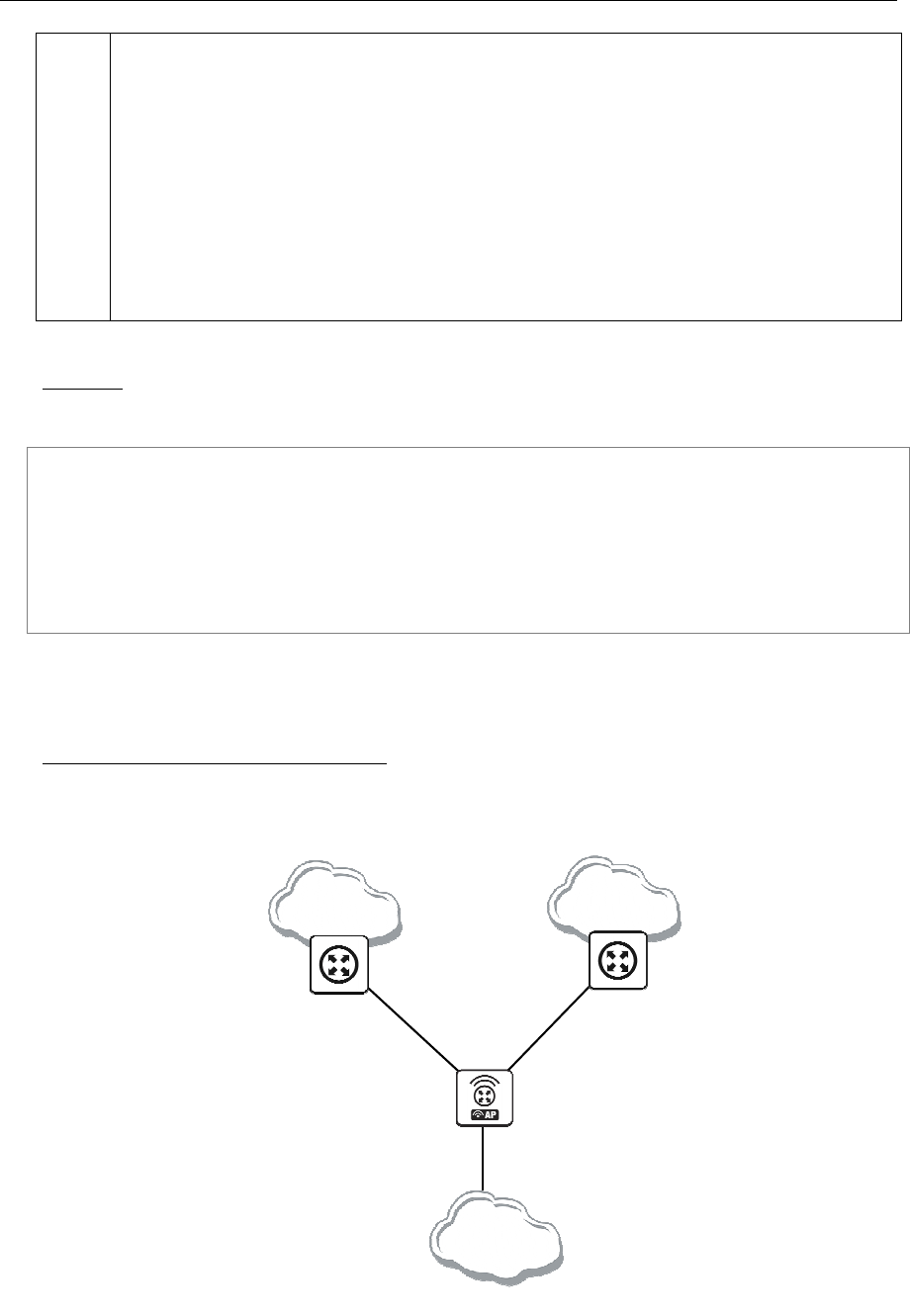
AT-WR4500 Series - IEEE 802.11abgh Outdoor Wireless Routers 113
RouterOS v3 Configuration and User Guide
You can use policy routing even if you use masquerading on your private networks. The source address
will be the same as it is in the local network. In previous versions of RouterOS the source address
changed to 0.0.0.0
It is impossible to recognize peer-to-peer traffic from the first packet. Only already established
connections can be matched. That also means that in case source NAT is treating Peer-to-Peer traffic
differently from the regular traffic, Peer-to-Peer programs will not work (general application is policy-
routing redirecting regular traffic through one interface and Peer-to-Peer traffic - through another). A
known workaround for this problem is to solve it from the other side: making not Peer-to-Peer traffic to
go through another gateway, but all other useful traffic go through another gateway. In other words, to
specify what protocols (HTTP, DNS, POP3, etc.) will go through the gateway A, leaving all the rest (so
Peer-to-Peer traffic also) to use the gateway B (it is not important, which gateway is which; it is only
important to keep Peer-to-Peer together with all traffic except the specified protocols).
Example
To add the rule specifying that all the packets from the 10.0.0.144 host should lookup the at routing
table:
[admin@AT-WR4562] ip firewall mangle add action=mark-routing new-routing-mark=at \
\... chain=prerouting
[admin@AT-WR4562] ip route> add gateway=10.0.0.254 routing-mark=mt
[admin@AT-WR4562] ip route rule> add src-address=10.0.0.144/32 \
\... table=mt action=lookup
[admin@AT-WR4562] ip route rule> print
Flags: X - disabled, I - invalid
0 src-address=192.168.0.144/32 action=lookup table=mt
[admin@AT-WR4562] ip route rule>
5.4.4 Application Examples
Static Equal Cost Multi-Path routing
Consider the following situation where we have to route packets from the network 192.168.0.0/24 to 2
gateways - 10.1.0.1 and 10.1.1.1:
10.1.0.1/28
2 Mbps
Interface: Public1
IP: 10.1.0.2/28
ISP 1
ISP 2
10.1.1.1/28
4 Mbps
192.168.0.0/24
Interface: Public2
IP: 10.1.1.2/28
Interface: Local
IP: 192.168.0.1/24
Figure 16: Static Equal Cost Multi-Path Routing example
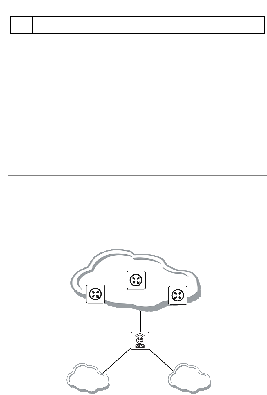
114 AT-WR4500 Series - IEEE 802.11abgh Outdoor Wireless Routers
RouterOS v3 Configuration and User Guide
ISP1 gives us 2Mbps and ISP2 - 4Mbps so we want a traffic ratio 1:2 (1/3 of the source/destination IP
pairs from 192.168.0.0/24 goes through ISP1, and 2/3 through ISP2).
IP addresses of the router:
[admin@ECMP-Router] ip address> print
Flags: X - disabled, I - invalid, D - dynamic
# ADDRESS NETWORK BROADCAST INTERFACE
0 192.168.0.254/24 192.168.0.0 192.168.0.255 Local
1 10.1.0.2/28 10.1.0.0 10.1.0.15 Public1
2 10.1.1.2/28 10.1.1.0 10.1.1.15 Public2
[admin@ECMP-Router] ip address>
Add the default routes - one for ISP1 and 2 for ISP2 so we can get the ratio 1:3:
[admin@ECMP-Router] ip route> add gateway=10.1.0.1,10.1.1.1,10.1.1.1
[admin@ECMP-Router] ip route> print
Flags: X - disabled, A - active, D - dynamic,
C - connect, S - static, r - rip, b - bgp, o - ospf
# DST-ADDRESS G GATEWAY DISTANCE INTERFACE
0 ADC 10.1.0.0/28 Public1
1 ADC 10.1.1.0/28 Public2
2 ADC 192.168.0.0/24 Local
3 A S 0.0.0.0/0 r 10.1.0.1 Public1
r 10.1.1.1 Public2
r 10.1.1.1 Public2
[admin@ECMP-Router] ip route>
Standard Policy-Based Routing with Failover
This example will show how to route packets, using an administrator defined policy. The policy for this
setup is the following: route packets from the network 192.168.0.0/24, using gateway 10.0.0.1, and
packets from network 192.168.1.0/24, using gateway 10.0.0.2. If GW_1 does not respond to pings, use
GW_Backup for network 192.168.0.0/24, if GW_2 does not respond to pings, use GW_Backup also for
network 192.168.1.0/24 instead of GW_2.
The setup:
Network
10.0.0.0/24
192.168.0.0/24
Interface: Public
IP: 10.0.0.7/24
Interface: Local1
IP: 192.168.0.1/24
192.168.1.0/24
Interface: Local2
IP: 192.168.1.1/24
[GW_1]
IP: 10.0.0.2
[GW_2]
IP: 10.0.0.3
[GW_Backup]
IP: 10.0.0.1
Figure 17: Standard Policy-Based Routing with Failover

AT-WR4500 Series - IEEE 802.11abgh Outdoor Wireless Routers 115
RouterOS v3 Configuration and User Guide
Configuration of the IP addresses:
[admin@PB-Router] ip address> print
Flags: X - disabled, I - invalid, D - dynamic
# ADDRESS NETWORK BROADCAST INTERFACE
0 192.168.0.1/24 192.168.0.0 192.168.0.255 Local1
1 192.168.1.1/24 192.168.1.0 192.168.1.255 Local2
2 10.0.0.7/24 10.0.0.0 10.0.0.255 Public
[admin@PB-Router] ip address>
To achieve the described result, follow these configuration steps:
Mark packets from network 192.168.0.0/24 with a new-routing-mark=net1, and packets from network
192.168.1.0/24 with a new-routing-mark=net2:
[admin@PB-Router] ip firewall mangle> add src-address=192.168.0.0/24 \
\... action=mark-routing new-routing-mark=net1 chain=prerouting
[admin@PB-Router] ip firewall mangle> add src-address=192.168.1.0/24 \
\... action=mark-routing new-routing-mark=net2 chain=prerouting
[admin@PB-Router] ip firewall mangle> print
Flags: X - disabled, I - invalid, D - dynamic
0 chain=prerouting src-address=192.168.0.0/24 action=mark-routing
new-routing-mark=net1
1 chain=prerouting src-address=192.168.1.0/24 action=mark-routing
new-routing-mark=net2
[admin@PB-Router] ip firewall mangle>
Route packets from network 192.168.0.0/24 to gateway GW_1 (10.0.0.2), packets from network
192.168.1.0/24 to gateway GW_2 (10.0.0.3), using the according packet marks. If GW_1 or GW_2 fails
(does not reply to pings), route the respective packets to GW_Main (10.0.0.1):
[admin@PB-Router] ip route> add gateway=10.0.0.2 routing-mark=net1 \
\... check-gateway=ping
[admin@PB-Router] ip route> add gateway=10.0.0.3 routing-mark=net2 \
\... check-gateway=ping
[admin@PB-Router] ip route> add gateway=10.0.0.1
[admin@PB-Router] ip route> print
Flags: X - disabled, A - active, D - dynamic,
C - connect, S - static, r - rip, b - bgp, o - ospf
# DST-ADDRESS PREFSRC G GATEWAY DISTANCE INTERFACE
0 ADC 10.0.0.0/24 10.0.0.7 Public
1 ADC 192.168.0.0/24 192.168.0.1 Local1
2 ADC 192.168.1.0/24 192.168.1.1 Local2
3 A S 0.0.0.0/0 r 10.0.0.2 Public
4 A S 0.0.0.0/0 r 10.0.0.3 Public
5 A S 0.0.0.0/0 r 10.0.0.1 Public
[admin@PB-Router] ip route>

116 AT-WR4500 Series - IEEE 802.11abgh Outdoor Wireless Routers
RouterOS v3 Configuration and User Guide
6 DHCP and DNS
6.1 DHCP Client and Server
Document revisi on: 2.7 (Mon Apr 18 22:24: 18 GMT 2005)
Applies to: V2.9
6.1.1 General Information
Summary
The DHCP (Dynamic Host Configuration Protocol) is needed for easy distribution of IP addresses in a
network. The RouterOS implementation includes both - server and client parts and is compliant with
RFC2131.
General usage of DHCP:
• IP assignment in LAN, cable-modem, and wireless systems
• Obtaining IP settings on cable-modem systems
IP addresses can be bound to MAC addresses using static lease feature.
DHCP server can be used with RouterOS HotSpot feature to authenticate and account DHCP clients.
See the HotSpot Manual for more information.
Quick Setup Guide
This example will show you how to setup DHCP-Server and DHCP-Client on RouterOS.
Setup of a DHCP-Server.
1. Create an IP address pool
/ip pool add name=dhcp-pool ranges=172.16.0.10-172.16.0.20
2. Add a DHCP network which will concern to the network 172.16.0.0/12 and will distribute a
gateway with IP address 172.16.0.1 to DHCP clients:
/ip dhcp-server network add address=172.16.0.0/12 gateway=172.16.0.1
3. Finally, add a DHCP server:
/ip dhcp-server add interface=wlan1 address-pool=dhcp-pool
Setup of the DHCP-Client (which will get a lease from the DHCP server, configured above).
1. Add the DHCP client:
/ip dhcp-client add interface=wlan1 use-peer-dns=yes \
add-default-route=yes disabled=no
2. Check whether you have obtained a lease:
[admin@Server] ip dhcp-client> print detail
Flags: X - disabled, I - invalid
0 interface=wlan1 add-default-route=yes use-peer-dns=yes status=bound
address=172.16.0.20/12 gateway=172.16.0.1 dhcp-server=192.168.0.1
primary-dns=159.148.147.194 expires-after=2d23:58:52
[admin@Server] ip dhcp-client>
Specifications
Packages required: dhcp
License required: Level1
Submenu level: /ip dhcp-client, /ip dhcp-server, /ip dhcp-relay
Standards and Technologies: DHCP
Description
The DHCP protocol gives and allocates IP addresses to IP clients. DHCP is basically insecure and should
only be used in trusted networks. DHCP server always listens on UDP 67 port, DHCP client - on UDP

AT-WR4500 Series - IEEE 802.11abgh Outdoor Wireless Routers 117
RouterOS v3 Configuration and User Guide
68 port. The initial negotiation involves communication between broadcast addresses (on some phases
sender will use source address of 0.0.0.0 and/or destination address of 255.255.255.255). You should
be aware of this when building firewall.
Additional Resources
http://www.isc.org/index.pl?/sw/dhcp/
http://en.tldp.org/HOWTO/DHCP/index.html
http://en.wikipedia.org/wiki/Dhcp
6.1.2 DHCP Client Setup
Submenu level: /ip dhcp-client
Description
The RouterOS DHCP client may be enabled on any Ethernet-like interface at a time. The client will
accept an address, netmask, default gateway, and two dns server addresses. The received IP address will
be added to the interface with the respective netmask. The default gateway will be added to the routing
table as a dynamic entry. Should the DHCP client be disabled or not renew an address, the dynamic
default route will be removed. If there is already a default route installed prior the DHCP client obtains
one, the route obtained by the DHCP client would be shown as invalid.
Property Description
add-default-route (yes | no; default: yes) - whether to add the default route to the gateway specified by
the DHCP server
address (read-only: IP address/netmask) - IP address and netmask, which is assigned to DHCP Client from
the Server
client-id (text) - corresponds to the settings suggested by the network administrator or ISP. Commonly
it is set to the client's MAC address, but it may as well be any text string
dhcp-server (read-only: IP address) - IP address of the DHCP server
expires-after (read-only: time) - time, when the lease expires (specified by the DHCP server)
gateway (read-only: IP address) - IP address of the gateway which is assigned by DHCP server
host-name (text) - the host name of the client as sent to a DHCP server
interface (name) - any Ethernet-like interface (this includes wireless and EoIP tunnels) on which the
client searches for a DHCP server
primary-dns (read-only: IP address) - IP address of the primary DNS server, assigned by the DHCP server
primary-ntp (read-only: IP address) - IP address of the primary NTP server, assigned by the DHCP server
secondary-dns (read-only: IP address) - IP address of the secondary DNS server, assigned by the DHCP
server
secondary-ntp (read-only: IP address) - IP address of the secondary NTP server, assigned by the DHCP
server
status (read-only: bound | error | rebinding... | renewing... | requesting... | searching... | stopped) - shows
the status of DHCP slient
use-peer-dns (yes | no; default: yes) - whether to accept the DNS settings advertized by DHCP server
(they will override the settings put in the /ip dns submenu)
use-peer-ntp (yes | no; default: yes) - whether to accept the NTP settings advertized by DHCP server
(they will override the settings put in the /system ntp client submenu)
Command Description
release - release current binding and restart DHCP client
renew - renew current leases. If the renew operation was not successful, client tries to reinitialize lease
(i.e. it starts lease request procedure (rebind) as if it had not received an IP address yet)

118 AT-WR4500 Series - IEEE 802.11abgh Outdoor Wireless Routers
RouterOS v3 Configuration and User Guide
If host-name property is not specified, client's system identity will be sent in the respective field of
DHCP request.
If client-id property is not specified, client's MAC address will be sent in the respective field of DHCP
request.
If use-peer-dns property is enabled, the DHCP client will unconditionally rewrite the settings in /ip dns
submenu. In case two or more DNS servers were received, first two of them are set as primary and
secondary servers respectively. In case one DNS server was received, it is put as primary server, and the
secondary server is left intact.
Example
To add a DHCP client on ether1 interface:
/ip dhcp-client add interface=ether1 disabled=no
[admin@AT-WR4562] ip dhcp-client> print detail
Flags: X - disabled, I - invalid
0 interface=ether1 add-default-route=yes use-peer-dns=yes use-peer-ntp=yes
status=bound address=192.168.0.65/24 gateway=192.168.0.1
dhcp-server=192.168.0.1 primary-dns=192.168.0.1 primary-ntp=192.168.0.1
expires-after=9m44s
[admin@AT-WR4562] ip dhcp-client>
6.1.3 DHCP Server Setup
Submenu level: /ip dhcp-server
Description
The router supports an individual server for each Ethernet-like interface. The RouterOS DHCP server
supports the basic functions of giving each requesting client an IP address/netmask lease, default gateway,
domain name, DNS-server(s) and WINS-server(s) (for Windows clients) information (set up in the
DHCP networks submenu).
In order DHCP server to work, you must set up also IP pools (do not include the DHCP server's IP
address into the pool range) and DHCP networks.
It is also possible to hand out leases for DHCP clients using the RADIUS server, here are listed the
parameters for used in RADIUS server.
Access-Request:
• NAS-Identifier - router identity
• NAS-IP-Address - IP address of the router itself
• NAS-Port - unique session ID
• NAS-Port-Type - Ethernet
• Calling-Station-Id - client identifier (active-client-id)
• Framed-IP-Address - IP address of the client (active-address)
• Called-Station-Id - name of DHCP server
• User-Name - MAC address of the client (active-mac-address)
• Password - ""
Access-Accept:
• Framed-IP-Address - IP address that will be assigned to client
• Framed-Pool - ip pool from which to assign ip address to client
• Rate-Limit - Datarate limitation for DHCP clients. Format is: rx-rate[/tx-rate] [rx-burst-rate[/tx-
burst
• rate] [rx-burst-threshold[/tx-burst-threshold] [rx-burst-time[/tx-burst-time][priority] [rx-rate min[/tx
• rate-min]]]]. All rates should be numbers with optional 'k' (1,000s) or 'M' (1,000,000s). If tx-rate is
not

AT-WR4500 Series - IEEE 802.11abgh Outdoor Wireless Routers 119
RouterOS v3 Configuration and User Guide
• specified, rx-rate is as tx-rate too. Same goes for tx-burst-rate and tx-burst-threshold and tx-burst-
time.
• If both rx-burst-threshold and tx-burst-threshold are not specified (but burst-rate is specified), rx-
rate
• and tx-rate are used as burst thresholds. If both rx-burst-time and tx-burst-time are not specified, 1s
is
• used as default. Priority takes values 1..8, where 1 implies the highest priority, but 8 - the lowest. If
rx-rate-min and tx-rate-min are not specified rx-rate and tx-rate values are used. The rx-rate-min and
tx-rate-min values can not exceed rx-rate and tx-rate values.
• Ascend-Data-Rate - tx/rx data rate limitation if multiple attributes are provided, first limits tx data
rate, second - rx data rate. If used together with Ascend-Xmit-Rate, specifies rx rate. 0 if unlimited
• Ascend-Xmit-Rate - tx data rate limitation. It may be used to specify tx limit only instead of
sending two sequental Ascend-Data-Rate attributes (in that case Ascend-Data-Rate will specify the
receive rate). 0 if unlimited
• Session-Timeout - max lease time (lease-time)
Property Description
add-arp (yes | no; default: no) - whether to add dynamic ARP entry:
no - either ARP mode should be enabled on that interface or static ARP entries should be
administratively defined in /ip arp submenu
address-pool (name | static-only; default: static-only) - IP pool, from which to take IP addresses for
clients
static-only - allow only the clients that have a static lease (i.e. no dynamic addresses will be given to
clients, only the ones added in lease submenu)
always-broadcast (yes | no; default: no) - always send replies as broadcasts
authoritative (after-10sec-delay | after-2sec-delay | no | yes; default: after-2sec-delay) - whether the
DHCP server is the only one DHCP server for the network
after-10sec-delay - to clients request for an address, dhcp server will wait 10 seconds and if there is
another request from the client after this period of time, then dhcp server will offer the address to the
client or will send DHCPNAK, if the requested address is not available from this server
after-2sec-delay - to clients request for an address, dhcp server will wait 2 seconds and if there is
another request from the client after this period of time, then dhcp server will offer the address to the
client or will send DHCPNAK, if the requested address is not available from this server
no - dhcp server ignores clients requests for addresses that are not available from this server
yes - to clients request for an address that is not available from this server, dhcp server will send negative
acknowledgment (DHCPNAK)
bootp-support (none | static | dynamic; default: static) - support for BOOTP clients
none - do not respond to BOOTP requests
static - offer only static leases to BOOTP clients
dynamic - offer static and dynamic leases for BOOTP clients
delay-threshold (time; default: none) - if secs field in DHCP packet is smaller than delay-threshold, then
this packet is ignored
none - there is no threshold (all DHCP packets are processed)
interface (name) - Ethernet-like interface name
lease-time (time; default: 72h) - the time that a client may use the assigned address. The client will try to
renew this address after a half of this time and will request a new address after time limit expires
name (name) - reference name
relay (IP address; default: 0.0.0.0) - the IP address of the relay this DHCP server should process requests
from:
0.0.0.0 - the DHCP server will be used only for direct requests from clients (no DHCP really allowed)
255.255.255.255 - the DHCP server should be used for any incomming request from a DHCP relay
except for those, which are processed by another DHCP server that exists in the /ip dhcp-server
submenu
src-address (IP address; default: 0.0.0.0) - the address which the DHCP client must send requests to in
order to renew an IP address lease. If there is only one static address on the DHCP server interface and

120 AT-WR4500 Series - IEEE 802.11abgh Outdoor Wireless Routers
RouterOS v3 Configuration and User Guide
the source-address is left as 0.0.0.0, then the static address will be used. If there are multiple addresses
on the interface, an address in the same subnet as the range of given addresses should be used
use-radius (yes | no; default: no) - whether to use RADIUS server for dynamic leases
Client will only receive a DHCP lease in case it is directly reachable by its MAC address through that
interface (some wireless bridges may change client's MAC address).If authoritative property is set to
yes, the DHCP server is sending rejects for the leases it cannot bind or renew. It also may (although not
always) help to prevent the network users to run their own DHCP servers illicitly, disturbing the proper
way the network should be functioning.If relay property of a DHCP server is not set to 0.0.0.0 the
DHCP server will not respond to the direct requests from clients.
Example
To add a DHCP client on ether1 interface:
/ip dhcp-server add name=dhcp-office disabled=no
[admin@AT-WR4562] ip dhcp-server> print detail
Flags: X - disabled, I – invalid
0 interface=ether1 add-default-route=yes use-peer-dns=yes use-peer-ntp=yes
status=bound address=192.168.0.65/24 gateway=192.168.0.1
dhcp-server=192.168.0.1 primary-dns=192.168.0.1 primary-ntp=192.168.0.1
expires-after=9m44s
dhcp-clients 02:00:00
[admin@AT-WR4562] ip dhcp-server>
Client will only receive a DHCP lease in case it is directly reachable by its MAC address through that
interface (some wireless bridges may change client's MAC address).If authoritative property is set to
yes, the DHCP server is sending rejects for the leases it cannot bind or renew. It also may (although not
always) help to prevent the network users to run their own DHCP servers illicitly, disturbing the proper
way the network should be functioning.If relay property of a DHCP server is not set to 0.0.0.0 the
DHCP server will not respond to the direct requests from clients.
Example
To add a DHCP server to interface ether1, lending IP addresses from dhcp-clients IP pool for 2 hours:
/ip dhcp-server add name=dhcp-office disabled=no address-pool=dhcp-clients \
interface=ether1 lease-time=2h
[admin@AT-WR4562] ip dhcp-server> print
Flags: X - disabled, I – invalid
# NAME INTERFACE RELAY ADDRESS-POOL LEASE-TIME ADD-ARP
0 dhcp-office ether1 dhcp-clients 02:00:00
[admin@AT-WR4562] ip dhcp-server>
6.1.4 Store Leases on Disk
Submenu level: /ip dhcp-server config
Description
Leases are always stored on disk on graceful shutdown and reboot. If on every lease change it is stored
on disk, a lot of disk writes happen. There are no problems if it happens on a hard drive, but is very bad
on Compact Flash (especially, if lease times are very short). To minimize writes on disk, all changes are
flushed together every store-leases-disk seconds. If this time will be very short (immediately), then no
changes will be lost even in case of hard reboots and power losts. But, on CF there may be too many
writes in case of short lease times (as in case of hotspot). If this time will be very long (never), then there
will be no writes on disk, but information about active leases may be lost in case of power loss. In these
cases dhcp server may give out the same ip address to another client, if first one will not respond to ping
requests.

AT-WR4500 Series - IEEE 802.11abgh Outdoor Wireless Routers 121
RouterOS v3 Configuration and User Guide
Property Description
store-leases-disk (time-interval | immediately | never; default: 5min) - how frequently lease changes
should be stored on disk
6.1.5 DHCP Networks
Submenu level: /ip dhcp-server network
Property Description
address (IP address/netmask) - the network DHCP server(s) will lend addresses from
boot-file-name (text) - Boot file name
dhcp-option (text) - add additional DHCP options from /ip dhcp-server option list. You cannot redefine
parameters which are already defined in this submenu:
Subnet-Mask (code 1) - netmask
Router (code 3) - gateway
Domain-Server (code 6) - dns-server
Domain-Name (code 15) - domain
NTP-Servers (code 42) - ntp-server
NETBIOS-Name-Server (code 44) - wins-server
dns-server (text) - the DHCP client will use these as the default DNS servers. Two comma-separated
DNS servers can be specified to be used by DHCP client as primary and secondary DNS servers
domain (text) - the DHCP client will use this as the 'DNS domain' setting for the network adapter
gateway (IP address; default: 0.0.0.0) - the default gateway to be used by DHCP clients
netmask (integer: 0..32; default: 0) - the actual network mask to be used by DHCP client
0 - netmask from network address is to be used
next-server (IP address) - IP address of next server to use in bootstrap
ntp-server (text) - the DHCP client will use these as the default NTP servers. Two comma-separated
NTP servers can be specified to be used by DHCP client as primary and secondary NTP servers
wins-server (text) - the Windows DHCP client will use these as the default WINS servers. Two comma-
separated WINS servers can be specified to be used by DHCP client as primary and secondary WINS
servers
The address field uses netmask to specify the range of addresses the given entry is valid for. The actual
netmask clients will be using is specified in netmask property.
6.1.6 DHCP Server Leases
Submenu level: /ip dhcp-server lease
Description
DHCP server lease submenu is used to monitor and manage server's leases. The issued leases are
showed here as dynamic entries. You can also add static leases to issue the definite client (determined by
MAC address) the specified IP address.
Generally, the DHCP lease it allocated as follows:
1. an unused lease is in waiting state
2. if a client asks for an IP address, the server chooses one
3. if the client will receive statically assigned address, the lease becomes offered, and then bound
with the respective lease time
4. if the client will receive a dynamic address (taken from an IP address pool), the router sends a ping
packet and waits for answer for 0.5 seconds. During this time, the lease is marked testing
5. in case, the address does not respond, the lease becomes offered, and then bound with the
respective lease time
6. in other case, the lease becomes busy for the lease time (there is a command to retest all busy
addresses), and the client's request remains unanswered (the client will try again shortly)
A client may free the leased address. When the dynamic lease is removed, and the allocated address is
returned to the address pool. But the static lease becomes busy until the client will reacquire the
address.

122 AT-WR4500 Series - IEEE 802.11abgh Outdoor Wireless Routers
RouterOS v3 Configuration and User Guide
Note that the IP addresses assigned statically are not probed.
Property Description
active-address (read-only: IP address) - actual IP address for this lease
active-client-id (read-only: text) - actual client-id of the client
active-mac-address (read-only: MAC address) - actual MAC address of the client
active-server (read-only: list) - actual dhcp server, which serves this client
address (IP address) - specify ip address (or ip pool) for static lease
0.0.0.0 - use pool from server
agent-circuit-id (read-only: text) - circuit ID of DHCP relay agent
agent-remote-id (read-only: text) - Remote ID, set by DHCP relay agent
always-broadcast (yes | no) - send all repies as broadcasts
block-access (yes | no; default: no) - block access for this client (drop packets from this client)
blocked (read-only: flag) - whether the lease is blocked
client-id (text; default: "") - if specified, must match DHCP 'client identifier' option of the request
expires-after (read-only: time) - time until lease expires
host-name (read-only: text) - shows host name option from last received DHCP request
lease-time (time; default: 0s) - time that the client may use the address
0s - lease will never expire
mac-address (MAC address; default: 00:00:00:00:00:00) - if specified, must match the MAC address of
the client
radius (read-only: yes | no) - shows, whether this dynamic lease is authenticated by RADIUS or not
rate-limit (read-only: text; default: "") - sets rate limit for active lease. Format is: rx-rate[/tx-rate] [rx-
burst-rate[/tx-burst-rate] [rx-burst-threshold[/tx-burst-threshold] [rx-burst-time[/tx-burst-time]]]]. All
rates should be numbers with optional 'k' (1,000s) or 'M'
(1,000,000s). If tx-rate is not specified, rx-rate is
as tx-rate too. Same goes for tx-burst-rate and tx-burst-threshold and tx-burst-time. If both rx-burst-
threshold and tx-burst-threshold are not specified (but burst-rate is specified), rx-rate and tx-rate is used
as burst thresholds. If both rx-burst-time and tx-burst-time are not specified, 1s is used as default
server (read-only: name) - server name which serves this client
src-mac-address (MAC address) - source MAC address
status (read-only: waiting | testing | authorizing | busy | offered | bound) - lease status:
waiting - not used static lease
testing - testing whether this address is used or not (only for dynamic leases) by pinging it with timeout
of 0.5s
authorizing - waiting for response from radius server
busy - this address is assigned statically to a client or already exists in the network, so it can not be
leased
offered - server has offered this lease to a client, but did not receive confirmation from the client
bound - server has received client's confirmation that it accepts offered address, it is using it now and
will free the address not later, than the lease time will be over
use-src-mac (MAC address) - use this source MAC address instead
Command Description
check-status - Check status of a given busy dynamic lease, and free it in case of no response
make-static - convert a dynamic lease to static one
If rate-limit is specified, a simple queue is added with corresponding parameters when lease enters
bound state. Arp entry is added right after adding of queue is done (only if add-arp is enabled for dhcp
server). To be sure, that client cannot use his ip address without getting dhcp lease and thus avoiding
rate-limit, reply-only mode must be used on that ethernet interface.
Even though client address may be changed (with adding a new item) in lease print list, it will not
change for the client. It is true for any changes in the DHCP server configuration because of the nature
of the DHCP protocol. Client tries to renew assigned IP address only when half a lease time is past (it
tries to renew several times). Only when full lease time is past and IP address was not renewed, new
lease is asked (rebind operation).
The deault mac-address value will never work! You should specify a correct MAC address there.

AT-WR4500 Series - IEEE 802.11abgh Outdoor Wireless Routers 123
RouterOS v3 Configuration and User Guide
Example
To assign 10.5.2.100 static IP address for the existing DHCP client (shown in the lease table as item #0):
[admin@AT-WR4562] ip dhcp-server lease> print
Flags: X - disabled, R - radius, D - dynamic, B - blocked
# ADDRESS MAC-ADDRESS HOST-NAME SERVER RATE-LIMIT STATUS
0 D 10.5.2.90 00:04:EA:C6:0E:40 switch bound
1 D 10.5.2.91 00:04:EA:99:63:C0 switch bound
[admin@AT-WR4562] ip dhcp-server lease> add copy-from=0 address=10.5.2.100
[admin@AT-WR4562] ip dhcp-server lease> print
Flags: X - disabled, R - radius, D - dynamic, B - blocked
# ADDRESS MAC-ADDRESS HOST-NAME SERVER RATE-LIMIT STATUS
0 D 10.5.2.91 00:04:EA:99:63:C0 switch bound
1 10.5.2.100 00:04:EA:C6:0E:40 switch bound
[admin@AT-WR4562] ip dhcp-server lease>
6.1.7 DHCP Alert
Submenu level: /ip dhcp-server alert
Description
To find any rogue DHCP servers as soon as they appear in your network, DHCP Alert tool can be used.
It will monitor ethernet for all DHCP replies and check, whether this reply comes from a valid DHCP
server. If reply from unknown DHCP server is detected, alert gets triggered:
[admin@AT-WR4562] ip dhcp-server alert>/log print
00:34:23 dhcp,critical,error,warning,info,debug dhcp alert on Public:
discovered unknown dhcp server, mac 00:02:29:60:36:E7, ip 10.5.8.236
[admin@AT-WR4562] ip dhcp-server alert>
When the system alerts about a rogue DHCP server, it can execute a custom script.
As DHCP replies can be unicast, rogue dhcp detector may not receive any offer to other dhcp clients at
all. To deal with this, rogue dhcp server acts as a dhcp client as well - it sends out dhcp discover requests
once a minute
Property Description
alert-timeout (none/time; default: none) - time, after which alert will be forgotten. If after that time the
same server will be detected, new alert will be generated
none - infinite time
interface (name) - interface, on which to run rogue DHCP server finder
invalid-server (read-only: text) - list of MAC addresses of detected unknown DHCP servers. Server is
removed from this list after alert-timeout
on-alert (text) - script to run, when an unknown DHCP server is detected
valid-server (text) - list of MAC addresses of valid DHCP servers
All alerts on an interface can be cleared at any time using command: /ip dhcp-server alert reset-
alert <interface>
Note, that e-mail can be sent, using /system logging action add target=email
6.1.8 DHCP Option
Submenu level: /ip dhcp-server option
Description
With help of DHCP Option, it is possible to define additional custom options for DHCP Server to
advertise..

124 AT-WR4500 Series - IEEE 802.11abgh Outdoor Wireless Routers
RouterOS v3 Configuration and User Guide
Property Description
code (integer: 1..254) - dhcp option code. All codes are available at
http://www.iana.org/assignments/bootp-dhcp-parameters
name (name) - descriptive name of the option
value (text) - parameter's value in form of a string. If the string begins with "0x", it is assumed as a
hexadecimal value
The defined options you can use in /ip dhcp-server network submenu
According to the DHCP protocol, a parameter is returned to the DHCP client only if it requests this
parameter, specifying the respective code in DHCP request Parameter-List (code 55) attribute. If the
code is not included in Parameter-List attribute, DHCP server will not send it to the DHCP client.
Example
This example shows how to set DHCP server to reply on DHCP client's Hostname request (code 12)
with value Host-A.
Add an option named Option-Hostname with code 12 (Hostname) and value Host-A:
[admin@AT-WR4562] ip dhcp-server option> add name=Hostname code=12 \
value="Host-A"
[admin@AT-WR4562] ip dhcp-server option> print
# NAME CODE VALUE
0 Option-Hostname 12 Host-A
[admin@AT-WR4562] ip dhcp-server option>
Use this option in DHCP server network list:
[admin@AT-WR4562] ip dhcp-server network> add address=10.1.0.0/24 \
\... gateway=10.1.0.1 dhcp-option=Option-Hostname dns-server=159.148.60.20
[admin@AT-WR4562] ip dhcp-server network> print detail
0 address=10.1.0.0/24 gateway=10.1.0.1 dns-server=159.148.60.20
dhcp-option=Option-Hostname
[admin@AT-WR4562] ip dhcp-server network>
Now the DHCP server will reply with its Hostname Host-A to DHCP client (if requested)
6.1.9 DHCP Relay
Submenu level: /ip dhcp-relay
Description
DHCP Relay is just a proxy that is able to receive a DHCP request and resend it to the real DHCP
server
Property Description
delay-threshold (time; default: none) - if secs field in DHCP packet is smaller than delay-threshold, then
this packet is ignored
dhcp-server (text) - list of DHCP servers' IP addresses which should the DHCP requests be forwarded
to
interface (name) - interface name the DHCP relay will be working on
local-address (IP address; default: 0.0.0.0) - the unique IP address of this DHCP relay needed for DHCP
server to distinguish relays:
0.0.0.0 - the IP address will be chosen automatically
name (name) - descriptive name for relay
DHCP relay does not choose the particular DHCP server in the dhcp-server list, it just sent to all the
listed servers.

AT-WR4500 Series - IEEE 802.11abgh Outdoor Wireless Routers 125
RouterOS v3 Configuration and User Guide
Example
To add a DHCP relay named relay on ether1 interface resending all received requests to the 10.0.0.1
DHCP server:
[admin@AT-WR4562] ip dhcp-relay> add name=relay interface=ether1 \
\... dhcp-server=10.0.0.1 disabled=no
[admin@AT-WR4562] ip dhcp-relay> print
Flags: X - disabled, I - invalid
# NAME INTERFACE DHCP-SERVER LOCAL-ADDRESS
0 relay ether1 10.0.0.1 0.0.0.0
[admin@AT-WR4562] ip dhcp-relay>
6.1.10 Questions & Answers
Command name: /ip dhcp-server setup
Questions
addresses to give out (text) - the pool of IP addresses DHCP server should lease to the clients
dhcp address space (IP address/netmask; default: 192.168.0.0/24) - network the DHCP server will lease
to the clients
dhcp relay (IP address; default: 0.0.0.0) - the IP address of the DHCP relay between the DHCP server
and the DHCP clients
dhcp server interface (name) - interface to run DHCP server on
dns servers (IP address) - IP address of the appropriate DNS server to be propagated to the DHCP
clients
gateway (IP address; default: 0.0.0.0) - the default gateway of the leased network
lease time (time; default: 3d) - the time the lease will be valid
Depending on current settings and answers to the previous questions, default values of following
questions may be different. Some questions may disappear if they become redundant (for example,
there is no use of asking for 'relay' when the server will lend the directly connected network)
Example
To configure DHCP server on ether1 interface to lend addresses from 10.0.0.2 to 10.0.0.254 which
belong to the 10.0.0.0/24 network with 10.0.0.1 gateway and 159.148.60.2 DNS server for the time of
3 days:
[admin@AT-WR4562] ip dhcp-server> setup
Select interface to run DHCP server on
dhcp server interface: ether1
Select network for DHCP addresses
dhcp address space: 10.0.0.0/24
Select gateway for given network
gateway for dhcp network: 10.0.0.1
Select pool of ip addresses given out by DHCP server
addresses to give out: 10.0.0.2-10.0.0.254
Select DNS servers
dns servers: 159.148.60.20
Select lease time
lease time: 3d
[admin@AT-WR4562] ip dhcp-server>
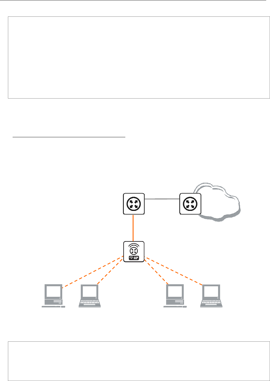
126 AT-WR4500 Series - IEEE 802.11abgh Outdoor Wireless Routers
RouterOS v3 Configuration and User Guide
The wizard has made the following configuration based on the answers above:
[admin@AT-WR4562] ip dhcp-server> print
Flags: X - disabled, I - invalid
# NAME INTERFACE RELAY ADDRESS-POOL LEASE-TIME ADD-ARP
0 dhcp1 ether1 0.0.0.0 dhcp_pool1 3d no
[admin@AT-WR4562] ip dhcp-server> network print
# ADDRESS GATEWAY DNS-SERVER WINS-SERVER DOMAIN
0 10.0.0.0/24 10.0.0.1 159.148.60.20
[admin@AT-WR4562] ip dhcp-server> /ip pool print
# NAME RANGES
0 dhcp_pool1 10.0.0.2-10.0.0.254
[admin@AT-WR4562] ip dhcp-server>
6.1.11 Application Examples
Dynamic Addressing, using DHCP-Relay
Let us consider that you have several IP networks 'behind' other routers, but you want to keep all DHCP
servers on a single router. To do this, you need a DHCP relay on your network which relies DHCP
requests from clients to DHCP server.
This example will show you how to configure a DHCP server and a DHCP relay which serve 2 IP
networks - 192.168.1.0/24 and 192.168.2.0/24 that are behind a router DHCP-Relay.
[
DHCP
-
Server]
Local1
192.168.1.1/24
Public
10.1.0.2/24
Internet
[DHCP-Relay]
Local
192.168.0.1/24
Public
192.168.0.2/24
Local2
192.168.2.1/24
Figure 18: DHCP Relay
IP addresses of DHCP-Server:
[admin@DHCP-Server] ip address> print
Flags: X - disabled, I - invalid, D - dynamic
# ADDRESS NETWORK BROADCAST INTERFACE
0 192.168.0.1/24 192.168.0.0 192.168.0.255 To-DHCP-Relay
1 10.1.0.2/24 10.1.0.0 10.1.0.255 Public
[admin@DHCP-Server] ip address>

AT-WR4500 Series - IEEE 802.11abgh Outdoor Wireless Routers 127
RouterOS v3 Configuration and User Guide
IP addresses of DHCP-Relay:
[admin@DHCP-Relay] ip address> print
Flags: X - disabled, I - invalid, D - dynamic
# ADDRESS NETWORK BROADCAST INTERFACE
0 192.168.0.1/24 192.168.0.0 192.168.0.255 To-DHCP-Server
1 192.168.1.1/24 192.168.1.0 192.168.1.255 Local1
2 192.168.2.1/24 192.168.2.0 192.168.2.255 Local2
[admin@DHCP-Relay] ip address>
To setup 2 DHCP Servers on DHCP-Server router add 2 pools. For networks 192.168.1.0/24 and
192.168.2.0:
/ip pool add name=Local1-Pool ranges=192.168.1.11-192.168.1.100
/ip pool add name=Local1-Pool ranges=192.168.2.11-192.168.2.100
[admin@DHCP-Server] ip pool> print
# NAME RANGES
0 Local1-Pool 192.168.1.11-192.168.1.100
1 Local2-Pool 192.168.2.11-192.168.2.100
[admin@DHCP-Server] ip pool>
Create DHCP Servers:
/ip dhcp-server add interface=To-DHCP-Relay relay=192.168.1.1 \
address-pool=Local1-Pool name=DHCP-1 disabled=no
/ip dhcp-server add interface=To-DHCP-Relay relay=192.168.2.1 \
address-pool=Local2-Pool name=DHCP-2 disabled=no
[admin@DHCP-Server] ip dhcp-server> print
Flags: X - disabled, I - invalid
# NAME INTERFACE RELAY ADDRESS-POOL LEASE-TIME ADD-ARP
0 DHCP-1 To-DHCP-Relay 192.168.1.1 Local1-Pool 3d00:00:00
1 DHCP-2 To-DHCP-Relay 192.168.2.1 Local2-Pool 3d00:00:00
[admin@DHCP-Server] ip dhcp-server>
Configure respective networks:
/ip dhcp-server network add address=192.168.1.0/24 gateway=192.168.1.1 \
dns-server=159.148.60.20
/ip dhcp-server network add address=192.168.2.0/24 gateway=192.168.2.1 \
dns-server 159.148.60.20
[admin@DHCP-Server] ip dhcp-server network> print
# ADDRESS GATEWAY DNS-SERVER WINS-SERVER DOMAIN
0 192.168.1.0/24 192.168.1.1 159.148.60.20
1 192.168.2.0/24 192.168.2.1 159.148.60.20
[admin@DHCP-Server] ip dhcp-server network>
Configuration of DHCP-Server is done. Now let's configure DHCP-Relay:
/ip dhcp-relay add name=Local1-Relay interface=Local1 \
dhcp-server=192.168.0.1 local-address=192.168.1.1 disabled=no
/ip dhcp-relay add name=Local2-Relay interface=Local2 \
dhcp-server=192.168.0.1 local-address=192.168.2.1 disabled=no
[admin@DHCP-Relay] ip dhcp-relay> print
Flags: X - disabled, I - invalid
# NAME INTERFACE DHCP-SERVER LOCAL-ADDRESS
0 Local1-Relay Local1 192.168.0.1 192.168.1.1
1 Local2-Relay Local2 192.168.0.1 192.168.2.1
[admin@DHCP-Relay] ip dhcp-relay>
IP Address assignment, using FreeRADIUS Server
Let us consider that we want to assign IP addresses for clients, using the RADIUS server.
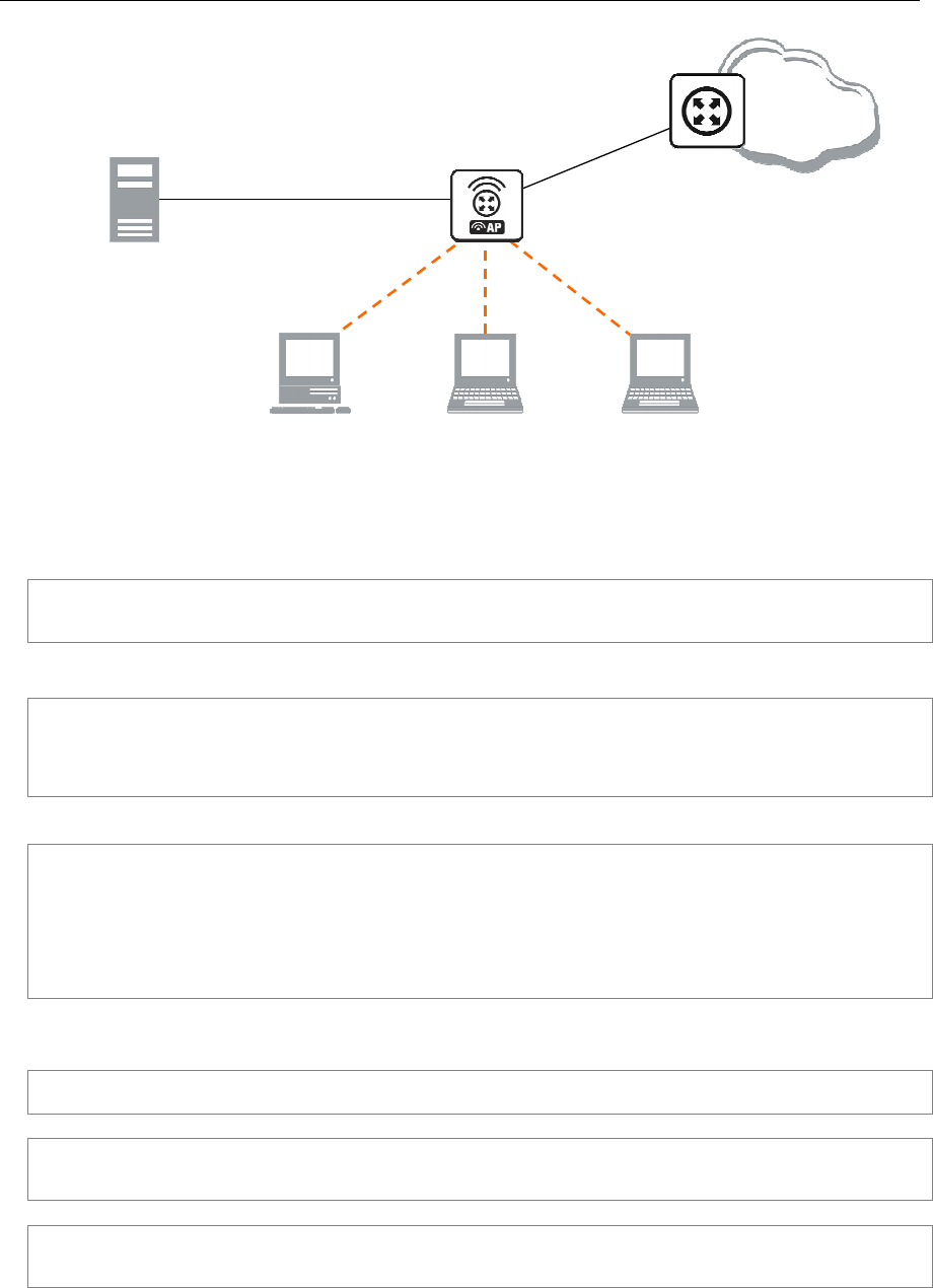
128 AT-WR4500 Series - IEEE 802.11abgh Outdoor Wireless Routers
RouterOS v3 Configuration and User Guide
[DHCP-Server]
Local
192.168.0.1/24
Public
10.1.0.2/24
Internet
RADIUS
Server
172.16.0.2/24
To
-
Radius
172.16.0.1/24
Local Network Address Range : 192.168.0.0/24
Figure 19: DHCP with RADIUS
We assume that you already have installed FreeRADIUS. Just add these lines to specified files:
• users file:
00:0B:6B:31:02:4B Auth-Type := Local, Password == ""
Framed-IP-Address = 192.168.0.55
• clients.conf file
client 172.16.0.1 {
secret = MySecret
shortname = Server
}
Configure Radius Client on RouterOS:
/radius add service=dhcp address=172.16.0.2 secret=MySecret
[admin@DHCP-Server] radius> print detail
Flags: X - disabled
0 service=dhcp called-id="" domain="" address=172.16.0.2 secret="MySecret"
authentication-port=1812 accounting-port=1813 timeout=00:00:00.300
accounting-backup=no realm=""
[admin@DHCP-Server] radius>
Setup DHCP Server:
1. Create an address pool:
/ip pool add name=Radius-Clients ranges=192.168.0.11-192.168.0.100
2. Add a DHCP server:
/ip dhcp-server add address-pool=Radius-Clients use-radius=yes interface=Local \
disabled=no
3. Configure DHCP networks:
/ip dhcp-server network add address=192.168.0.0/24 gateway=192.168.0.1 \
dns-server=159.148.147.194,159.148.60.20
Now the client with MAC address 00:0B:6B:31:02:4B will always receive IP address 192.168.0.55.

AT-WR4500 Series - IEEE 802.11abgh Outdoor Wireless Routers 129
RouterOS v3 Configuration and User Guide
6.2 DNS Client and Cache
Document revisi on: 1.2 (Fri Apr 15 17:37: 43 GMT 2005)
Applies to: V2.9
6.2.1 General Information
Summary
DNS cache is used to minimize DNS requests to an external DNS server as well as to minimize DNS
resolution time. This is a simple recursive DNS server with local items.
Specifications
Packages required: system
License required: Level1
Submenu level: /ip dns
Standards and Technologies: DNS
Hardware usage: Not significant
Related Topics
IP and Routing
Description
The RouterOS router with DNS cache feature enabled can be set as a primary DNS server for any DNS-
compliant clients. Moreover, RouterOS router can be specified as a primary DNS server under its dhcp-
server settings. When the DNS cache is enabled, the RouterOS router responds to DNS TCP and UDP
requests on port 53.
Additional Resources
http://www.ietf.org/rfc/rfc1035.txt?number=1035
http://www.freesoft.org/CIE/Course/Section2/3.htm
http://www.networksorcery.com/enp/protocol/dns.htm
http://en.wikipedia.org/wiki/Domain_Name_System
6.3 DNS Cache Setup
Submenu level: /ip dns
Description
DNS facility is used to provide domain name resolution for router itself as well as for the clients
connected to it..
Property Description
allow-remote-requests (yes | no) - specifies whether to allow network requests
cache-max-ttl (time; default: 1w) - specifies maximum time-to-live for cahce records. In other words,
cache records will expire after cache-max-ttl time.
cache-size (integer: 512..10240; default: 2048KiB) - specifies the size of DNS cache in KiB
cache-used (read-only: integer) - displays the currently used cache size in KiB
primary-dns (IP address; default: 0.0.0.0) - primary DNS server
secondary-dns (IP address; default: 0.0.0.0) - secondary DNS server
If the property use-peer-dns under /ip dhcp-client is set to yes then primary-dns under /ip dns
will change to a DNS address given by DHCP Server.

130 AT-WR4500 Series - IEEE 802.11abgh Outdoor Wireless Routers
RouterOS v3 Configuration and User Guide
Example
To set 159.148.60.2 as the primary DNS server and allow the router to be used as a DNS server, do the
following:
[admin@AT-WR4562] ip dns> set primary-dns=159.148.60.2 \
\... allow-remote-requests=yes
[admin@AT-WR4562] ip dns> print
primary-dns: 159.148.60.2
secondary-dns: 0.0.0.0
allow-remote-requests: yes
cache-size: 2048KiB
cache-max-ttl: 1w
cache-used: 17KiB
[admin@AT-WR4562] ip dns>
6.3.1 Cache Monitoring
Submenu level: /ip dns cache
Property Description
address (read-only: IP address) - IP address of the host
name (read-only: name) - DNS name of the host
ttl (read-only: time) - remaining time-to-live for the record
6.3.2 Static DNS Entries
Submenu level: /ip dns static
Description
The RouterOS has an embedded DNS server feature in DNS cache. It allows you to link the particular
domain names with the respective IP addresses and advertize these links to the DNS clients using the
router as their DNS server.
Property Description
address (IP address) - IP address to resolve domain name with
name (text) - DNS name to be resolved to a given IP address
ttl (time) - time-to-live of the DNS record
6.4 All DNS Entries
Submenu level: /ip dns cache all
Description
This menu provides a complete list with all DNS records stored on the server
Property Description
data (read-only: text) - DNS data field. IP address for type "A" records. Other record types may have
different contents of the data field (like hostname or arbitrary text)
name (read-only: name) - DNS name of the host
ttl (read-only: time) - remaining time-to-live for the record
type (read-only: text) - DNS record type
6.5 Static DNS Entries
Submenu level: /ip dns static

AT-WR4500 Series - IEEE 802.11abgh Outdoor Wireless Routers 131
RouterOS v3 Configuration and User Guide
Description
The RouterOS has an embedded DNS server feature in DNS cache. It allows you to link the
particular domain names with the respective IP addresses and advertize these links to the DNS clients
using the router as their DNS server. This feature can also be used to provide fake DNS information to
your network clients. For example, resolving any DNS request for a certain set of domains (or for the
whole Internet) to your own page.
The server is capable of resolving DNS requests based on POSIX basic regular expressions, so that
multiple requets can be matched with the same entry. In case an entry does not conform with DNS
naming standards, it is considered a regular expression and marked with ‘R’ flag.
The list is ordered and is checked from top to bottom. Regular expressions are checked first, then the
plain records.
Property Description
address (IP address) - IP address to resolve domain name with
name (text) - DNS name to be resolved to a given IP address. May be a regular expression
ttl (time) - time-to-live of the DNS record
Reverse DNS lookup (Address to Name) of the regular expression entries is not possible. You can,
however, add an additional plain record with the same IP address and specify some name for
it.Remember that the meaning of a dot (.) in regular expressions is any character, so the expression
should be escaped properly. For example, if you need to match anything within example.com domain
but not all the domains that just end with example.com, like www.another-example.com, use
name=".*\\.example\\.com"Regular expression matching is significantly slower than of the plain entries,
so it is advised to minimize the number of regular expression rules and optimize the expressions
themselves.
Example
To add a static DNS entry for www.example.com to be resolved to 10.0.0.1 IP address:
[admin@AT-WR4562] ip dns static> add name www.example.com address=10.0.0.1
[admin@AT-WR4562] ip dns static> print
Flags: D - dynamic, X - disabled, R - regexp
# NAME ADDRESS TTL
0 www.example.com 10.0.0.1 1d
[admin@AT-WR4562] ip dns static>
6.6 Flushing DNS cache
Command name: /ip dns cache flush
Command Description
flush - clears internal DNS cache
Example
[admin@AT-WR4562] ip dns> cache flush
[admin@AT-WR4562] ip dns> print
primary-dns: 159.148.60.2
secondary-dns: 0.0.0.0
allow-remote-requests: yes
cache-size: 2048 KiB
cache-max-ttl: 1w
cache-used: 10 KiB
[admin@AT-WR4562] ip dns>

132 AT-WR4500 Series - IEEE 802.11abgh Outdoor Wireless Routers
RouterOS v3 Configuration and User Guide
7 AAA Configuration
7.1 RADIUS client
Document revisi on: 1.6 (February 14, 200 7, 12:00 GMT)
Applies to: V2.9
7.1.1 General Information
Summary
This document provides information about RouterOS built-in RADIUS client configuration, supported
RADIUS attributes and recommendations on RADIUS server selection.
Specifications
Packages required: system
License required: Level1
Submenu level: /radius
Standards and Technologies: RADIUS
Related Topics
HotSpot User AAA
Router User AAA
PPP User AAA
IP Addresses and ARP
Description
RADIUS, short for Remote Authentication Dial-In User Service, is a remote server that provides
authentication and accounting facilities to various network apliances. RADIUS authentication and
accounting gives the ISP or network administrator ability to manage PPP user access and accounting from
one server throughout a large network. The RouterOS has a RADIUS client which can authenticate for
HotSpot, PPP, PPPoE, PPTP, L2TP and ISDN connections. The attributes received from RADIUS server
override the ones set in the default profile, but if some parameters are not received they are taken from
the respective default profile.
The RADIUS server database is consulted only if no matching user acces record is found in router's local
database.
Traffic is accounted locally with RouterOS Traffic Flow and snapshot image can be gathered using Syslog
utilities. If RADIUS accounting is enabled, accounting information is also sent to the RADIUS server
default for that service.
7.1.2 RADIUS Client Setup
Submenu level: /radius
Description
This facility allows you to set RADIUS servers the router will use to authenticate users.
Property Description
accounting-backup (yes | no; default: no) - this entry is a backup RADIUS accounting server
accounting-port (integer; default: 1813) - RADIUS server port used for accounting
address (IP address; default: 0.0.0.0) - IP address of the RADIUS server
authentication-port (integer; default: 1812) - RADIUS server port used for authentication
called-id (text; default: "") - value depends on Point-to-Point protocol:
ISDN - phone number dialled (MSN)
PPPoE - service name
PPTP - server's IP address
L2TP - server's IP address

AT-WR4500 Series - IEEE 802.11abgh Outdoor Wireless Routers 133
RouterOS v3 Configuration and User Guide
domain (text; default: "") - Microsoft Windows domain of client passed to RADIUS servers that require
domain validation
realm (text) - explicitly stated realm (user domain), so the users do not have to provide proper ISP
domain name in user name
secret (text; default: "") - shared secret used to access the RADIUS server
service (multiple choice: hotspot | login | ppp | telephony | wireless | dhcp; default: "") - router services
that will use this RADIUS server
hotspot - HotSpot authentication service
login - router's local user authentication
ppp - Point-to-Point clients authentication
telephony - IP telephony accounting
wireless - wireless client authentication (client's MAC address is sent as User-Name)
dhcp - DHCP protocol client authentication (client's MAC address is sent as User-Name)
timeout (time; default: 100ms) - timeout after which the request should be resend
The order of the items in this list is meaningful.
Microsoft Windows clients send their usernames in form domain\username
When RADIUS server is authenticating user with CHAP, MS-CHAPv1, MS-CHAPv2, it is not using shared
secret, secret is used only in authentication reply, and router is verifying it. So if you have wrong shared
secret, RADIUS server will accept request, but router won't accept reply. You can see that with /radius
monitor command, "bad-replies" number should increase whenever somebody tries to connect.
Example
To set a RADIUS server for HotSpot and PPP services that has 10.0.0.3 IP address and ex shared
secret, you need to do the following:
[admin@AT-WR4562] radius> add service=hotspot,ppp address=10.0.0.3 secret=ex
[admin@AT-WR4562] radius> print
Flags: X - disabled
# SERVICE CALLED-ID DOMAIN ADDRESS SECRET
0 ppp,hotspot 10.0.0.3 ex
[admin@AT-WR4562] radius>
AAA for the respective services should be enabled too:
[admin@AT-WR4562] radius> /ppp aaa set use-radius=yes
[admin@AT-WR4562] radius> /ip hotspot profile set default use-radius=yes
To view some statistics for a client:
[admin@AT-WR4562] radius> monitor 0
pending: 0
requests: 10
accepts: 4
rejects: 1
resends: 15
timeouts: 5
bad-replies: 0
last-request-rtt: 0s
[admin@AT-WR4562] radius>
7.1.3 Connection Terminating from RADIUS
Submenu level: /radius incoming
Description
This facility supports unsolicited messages sent from RADIUS server. Unsolicited messages extend
RADIUS protocol commands that allow terminating a session which has already been connected from
RADIUS server. For this purpose DM (Disconnect-Messages) are used. Disconnect messages cause a user
session to be terminated immediately
Property Description
accept (yes | no; default: no) - Whether to accept the unsolicited messages

134 AT-WR4500 Series - IEEE 802.11abgh Outdoor Wireless Routers
RouterOS v3 Configuration and User Guide
port (integer; default: 1700) - The port number to listen for the requests on
RouterOS doesn't support POD (Packet of Disconnect) the other RADIUS access request packet that
performs a similar function as Disconnect Messages
7.1.4 Suggested RADIUS Servers
Description
RouterOS RADIUS Client should work well with all RFC compliant servers. It has been tested with:
• FreeRADIUS
• XTRadius (does not currently support MS-CHAP)
• Steel-Belted Radius
7.1.5 Supported RADIUS Attributes
Description
MikroTik RADIUS Dictionaries
Here you can download MikroTik reference dictionary, which incorporates all the needed RADIUS
attributes. This dictionary is the minimal dictionary, which is enough to support all features of RouterOS.
It is designed for FreeRADIUS, but may also be used with many other UNIX RADIUS servers (eg.
XTRadius).
It may conflict with the default configuration files of RADIUS server, which have references to the
Attributes, absent in this dictionary. Please correct the configuration files, not the dictionary, as no other
Attributes are supported by RouterOS.
There is also dictionary.mikrotik that can be included in an existing dictionary to support RouterOS
vendor-specific Attributes.
Definitions
• PPPs - PPP, PPTP, PPPoE and ISDN
• default configuration - settings in default profile (for PPPs) or HotSpot server settings (for
HotSpot)
Access-Request
• Service-Type - always is "Framed" (only for PPPs)
• Framed-Protocol - always is "PPP" (only for PPPs)
• NAS-Identifier - router identity
• NAS-IP-Address - IP address of the router itself
• NAS-Port - unique session ID
• Acct-Session-Id - unique session ID
• NAS-Port-Type - async PPP - "Async"; PPTP and L2TP - "Virtual"; PPPoE - "Ethernet"; ISDN -
"ISDN Sync"; HotSpot - "Ethernet | Cable | Wireless-802.11" (according to the value of nas-port-
type parameter in /ip hotspot profile
• Calling-Station-Id - PPPoE and HotSpot- client MAC address in capital letters; PPTP and L2TP -
client public IP address; ISDN - client MSN
• Called-Station-Id - PPPoE - service name; PPTP and L2TP - server IP address; ISDN - interface
MSN; HotSpot - name of the HotSpot server

AT-WR4500 Series - IEEE 802.11abgh Outdoor Wireless Routers 135
RouterOS v3 Configuration and User Guide
• NAS-Port-Id - async PPP - serial port name; PPPoE - ethernet interface name on which server is
running; HotSpot - name of the physical HotSpot interface (if bridged, the bridge port name is
showed here); not present for ISDN, PPTP and L2TP
• Framed-IP-Address - IP address of HotSpot client after Universal Client translation
• Mikrotik-Host-IP - IP address of HotSpot client before Universal Client translation (the original IP
address of the client)
• User-Name - client login name
• MS-CHAP-Domain - User domain, if present
• Mikrotik-Realm - If it is set in /radius menu, it is included in every RADIUS request as Mikrotik-
Realm attribute. If it is not set, the same value is sent as in MS-CHAP-Domain attribute (if MS-
CHAP-Domain is missing, Realm is not included neither)
• WISPr-Location-ID - text string specified in radius-location-id property of the HotSpot server
• WISPr-Location-Name - text string specified in radius-location-name property of the HotSpot
server
• WISPr-Logoff-URL - full link to the login page (for example, http://10.48.0.1/lv/logout)
HotSpot uses CHAP by default and may use also PAP if unencrypted passwords are enabled, it can not
use MSCHAP
Depending on authentication methods:
• User-Password - encrypted password (used with PAP authentication)
• CHAP-Password, CHAP-Challenge - encrypted password and challenge (used with CHAP
authentication)
• MS-CHAP-Response, MS-CHAP-Challenge - encrypted password and challenge (used with MS-
CHAPv1 authentication)
• MS-CHAP2-Response, MS-CHAP-Challenge - encrypted password and challenge (used with
MS-CHAPv2 authentication)
Access-Accept
• Framed-IP-Address - IP address given to client. If address belongs to 127.0.0.0/8 or 224.0.0.0/3
networks, IP pool is used from the default profile to allocate client IP address. If Framed-IP-Address is
specified, Framed-Pool is ignored
• Framed-IP-Netmask - client netmask. PPPs - if specified, a route will be created to the network
Framed-IP-Address belongs to via the Framed-IP-Address gateway; HotSpot - ignored by HotSpot
• Framed-Pool - IP pool name (on the router) from which to get IP address for the client. If Framed-
IP-Address is specified, this attribute is ignored
If Framed-IP-Address or Framed-Pool is specified it overrides remote-address in default configuration
• Idle-Timeout - overrides idle-timeout in the default configuration
• Session-Timeout - overrides session-timeout in the default configuration
• Port-Limit - maximal mumber of simultaneous connections using the same username (overrides te
shared-users property of the HotSpot user profile)
• Class - cookie, will be included in Accounting-Request unchanged
• Framed-Route - routes to add on the server. Format is specified in RFC2865 (Ch. 5.22), can be
specified as many times as needed
• Filter-Id - firewall filter chain name. It is used to make a dynamic firewall rule. Firewall chain name
can have suffix .in or .out, that will install rule only for incoming or outgoing traffic. Multiple Filter-id
can be provided, but only last ones for incoming and outgoing is used. For PPPs - filter rules in ppp
chain that will jump to the specified chain, if a packet has come to/from the client (that means that

136 AT-WR4500 Series - IEEE 802.11abgh Outdoor Wireless Routers
RouterOS v3 Configuration and User Guide
you should first create a ppp chain and make jump rules that would put actual traffic to this chain).
The same applies for HotSpot, but the rules will be created in hotspot chain
• Mikrotik-Mark-Id - firewall mangle chain name (HotSpot only). The RouterOS RADIUS client upon
receiving this attribute creates a dynamic firewall mangle rule with action=jump chain=hotspot
and jump-target equal to the atribute value. Mangle chain name can have suffixes .in or .out, that
will install rule only for incoming or outgoing traffic. Multiple Mark-id attributes can be provided, but
only last ones for incoming and outgoing is used.
• Acct-Interim-Interval - interim-update for RADIUS client. PPP - if 0 uses the one specified in
RADIUS client; HotSpot - only respected if radius-interim-update=received in HotSpot server
profile
• MS-MPPE-Encryption-Policy - require-encryption property (PPPs only)
• MS-MPPE-Encryption-Types - use-encryption property, non-zero value means to use encryption
(PPPs only)
• Ascend-Data-Rate - tx/rx data rate limitation if multiple attributes are provided, first limits tx data
rate, second - rx data rate. If used together with Ascend-Xmit-Rate, specifies rx rate. 0 if
unlimited. Ignored if Rate-Limit attribute is present
• Ascend-Xmit-Rate - tx data rate limitation. It may be used to specify tx limit only instead of
sending two sequental Ascend-Data-Rate attributes (in that case Ascend-Data-Rate will specify
the receive rate). 0 if unlimited. Ignored if Rate-Limit attribute is present
• MS-CHAP2-Success - auth. response if MS-CHAPv2 was used (for PPPs only)
• MS-MPPE-Send-Key, MS-MPPE-Recv-Key - encryption keys for encrypted PPPs provided by
RADIUS server only is MS-CHAPv2 was used as authentication (for PPPs only)
• Ascend-Client-Gateway - client gateway for DHCP-pool HotSpot login method (HotSpot only)
• Mikrotik-Recv-Limit - total receive limit in bytes for the client
• Mikrotik-Recv-Limit-Gigawords - 4G (2^32) bytes of total receive limit (bits 32..63, when bits
0..31 are delivered in Mikrotik-Recv-Limit)
• Mikrotik-Xmit-Limit - total transmit limit in bytes for the client
• Mikrotik-Xmit-Limit-Gigawords - 4G (2^32) bytes of total transmit limit (bits 32..63, when bits
0..31 are delivered in Mikrotik-Recv-Limit)
• Mikrotik-Wireless-Forward - not forward the client's frames back to the wireless infrastructure if
this attribute is set to "0" (Wireless only)
• Mikrotik-Wireless-Skip-Dot1x - disable 802.1x authentication for the particulat wireless client if
set to non-zero value (Wireless only)
• Mikrotik-Wireless-Enc-Algo - WEP encryption algorithm: 0 - no encryption, 1 - 40-bit WEP, 2 -
104-bit WEP (Wireless only)
• Mikrotik-Wireless-Enc-Key - WEP encruption key for the client (Wireless only)
• Mikrotik-Rate-Limit - Datarate limitation for clients. Format is: rx-rate[/tx-rate] [rx-burst-
rate[/tx-burst-rate] [rx-burst-threshold[/tx-burst-threshold] [rx-burst-time[/tx-burst-
time] [priority] [rx-rate-min[/tx-rate-min]]]] from the point of view of the router (so "rx" is
client upload, and "tx" is client download). All rates should be numbers with optional 'k' (1,000s) or
'M' (1,000,000s). If tx-rate is not specified, rx-rate is as tx-rate too. Same goes for tx-burst-rate and
tx-burst-threshold and tx-burst-time. If both rx-burst-threshold and tx-burst-threshold are not
specified (but burst-rate is specified), rx-rate and tx-rate is used as burst thresholds. If both rx-burst-
time and tx-burst-time are not specified, 1s is used as default. Priority takes values 1..8, where 1
implies the highest priority, but 8 - the lowest. If rx-rate-min and tx-rate-min are not specified rx-rate
and tx-rate values are used. The rx-rate-min and tx-rate-min values can not exceed rx-rate and tx-
rate values.
• Mikrotik-Group - Router local user group name (defines in /user group) for local users. HotSpot
default profile for HotSpot users.
• Mikrotik-Advertise-URL - URL of the page with advertisements that should be displayed to
clients. If this attribute is specified, advertisements are enabled automatically, including transparent
proxy, even if they were explicitly disabled in the corresponding user profile. Multiple attribute

AT-WR4500 Series - IEEE 802.11abgh Outdoor Wireless Routers 137
RouterOS v3 Configuration and User Guide
instances may be send by RADIUS server to specify additional URLs which are choosen in round
robin fashion.
• Mikrotik-Advertise-Interval - Time interval between two adjacent advertisements. Multiple
attribute instances may be send by RADIUS server to specify additional intervals. All interval values
are threated as a list and are taken one-by-one for each successful advertisement. If end of list is
reached, the last value is continued to be used.
• WISPr-Redirection-URL - URL, which the clients will be redirected to after successfull login
• WISPr-Bandwidth-Min-Up - minimal datarate (CIR) provided for the client upload
• WISPr-Bandwidth-Min-Down - minimal datarate (CIR) provided for the client download
• WISPr-Bandwidth-Max-Up - maxmal datarate (MIR) provided for the client upload
• WISPr-Bandwidth-Max-Down - maxmal datarate (MIR) provided for the client download
• WISPr-Session-Terminate-Time - time, when the user should be disconnected; in "YYYY-MM-
DDThh:mm:ssTZD" form, where Y - year; M - month; D - day; T - separator symbol (must be
written between date and time); h - hour (in 24 hour format); m - minute; s - second; TZD - time
zone in one of these forms: "+hh:mm", "+hhmm", "-hh:mm", "-hhmm"
The received attributes override the default ones (set in the default profile), but if an attribute is not
received from RADIUS server, the default one is to be used.
Rate-Limit takes precedence over all other ways to specify data rate for the client. Ascend data rate
attributes are considered second; and WISPr attributes takes the last precedence.
Here are some Rate-Limit examples:
• 128k - rx-rate=128000, tx-rate=128000 (no bursts)
• 64k/128M - rx-rate=64000, tx-rate=128000000
• 64k 256k - rx/tx-rate=64000, rx/tx-burst-rate=256000, rx/tx-burst-threshold=64000, rx/tx-burst-
time=1s
• 64k/64k 256k/256k 128k/128k 10/10 - rx/tx-rate=64000, rx/tx-burst-rate=256000, rx/tx-burst-
threshold=128000, rx/tx-burst-time=10s
Accounting-Request
The accounting request carries the same attributes as Access Request, plus these ones:
• Acct-Status-Type - Start, Stop, or Interim-Update
• Acct-Authentic - either authenticated by the RADIUS or Local authority (PPPs only)
• Class - RADIUS server cookie, as received in Access-Accept
• Acct-Delay-Time - how long does the router try to send this Accounting-Request packet
Stop and Interim-Update Accounting-Request
Additionally to the accounting start request, the following messages will contain the following attributes:
• Acct-Session-Time - connection uptime in seconds
• Acct-Input-Octets - bytes received from the client
• Acct-Input-Gigawords - 4G (2^32) bytes received from the client (bits 32..63, when bits 0..31 are
delivered in Acct-Input-Octets)
• Acct-Input-Packets - nubmer of packets received from the client
• Acct-Output-Octets - bytes sent to the client
• Acct-Output-Gigawords - 4G (2^32) bytes sent to the client (bits 32..63, when bits 0..31 are
delivered in Acct-Output-Octets)
• Acct-Output-Packets - number of packets sent to the client
Stop Accounting-Request
These packets will, additionally to the Interim Update packets, have:
• Acct-Terminate-Cause - session termination cause (see RFC2866 ch. 5.10)

138 AT-WR4500 Series - IEEE 802.11abgh Outdoor Wireless Routers
RouterOS v3 Configuration and User Guide
Change of Authorization
RADIUS disconnect and Change of Authorization (according to RFC3576) are supported as well. These
attributes may be changed by a CoA request from the RADIUS server:
• Mikrotik-Group
• Mikrotik-Recv-Limit
• Mikrotik-Xmit-Limit
• Mikrotik-Rate-Limit
• Ascend-Data-Rate (only if Mikrotik-Rate-Limit is not present)
• Ascend-XMit-Rate (only if Mikrotik-Rate-Limit is not present)
• Mikrotik-Mark-Id
• Filter-Id
• Mikrotik-Advertise-Url
• Mikrotik-Advertise-Interval
• Session-Timeout
• Idle-Timeout
• Port-Limit
It is not possible to change IP address, pool or routes that way - for such changes a user must be
disconnected first.
Attribute Numeric Values
Name VendorID
Value
RFC where it is defined
Acct-Authentic
45 RFC2866
Acct-Delay-Time
41 RFC2866
Acct-Input-Gigawords
52 RFC2869
Acct-Input-Octets
42 RFC2866
Acct-Input-Packets
47 RFC2866
Acct-Interim-Interval
85 RFC2869
Acct-Output-Gigawords
53 RFC2869
Acct-Output-Octets
43 RFC2866
Acct-Output-Packets
48 RFC2866
Acct-Session-Id
44 RFC2866
Acct-Session-Time
46 RFC2866
Acct-Status-Type
40 RFC2866
Acct-Terminate-Cause
49 RFC2866
Ascend-Client-Gateway 529 132
Ascend-Data-Rate 529 197
Ascend-Xmit-Rate 529 255

AT-WR4500 Series - IEEE 802.11abgh Outdoor Wireless Routers 139
RouterOS v3 Configuration and User Guide
Name VendorID
Value
RFC where it is defined
Called-Station-Id
30 RFC2865
Calling-Station-Id
31 RFC2865
CHAP-Challenge
60 RFC2866
CHAP-Password
3 RFC2865
Class
25 RFC2865
Filter-Id
11 RFC2865
Framed-IP-Address
8 RFC2865
Framed-IP-Netmask
9 RFC2865
Framed-Pool
88 RFC2869
Framed-Protocol
7 RFC2865
Framed-Route
22 RFC2865
Idle-Timeout
28 RFC2865
Mikrotik-Advertise-Interval 14988 13
Mikrotik-Advertise-URL 14988 12
Mikrotik-Group 14988 3
Mikrotik-Host-IP 14988 10
Mikrotik-Mark-Id 14988 11
Mikrotik-Rate-Limit 14988 8
Mikrotik-Realm 14988 9
Mikrotik-Recv-Limit 14988 1
Mikrotik-Recv-Limit-Gigawords 14988 14
Mikrotik-Wireless-Enc-Algo 14988 6
Mikrotik-Wireless-Enc-Key 14988 7
Mikrotik-Wireless-Forward 14988 4
Mikrotik-Wireless-Skip-Dot1x 14988 5
Mikrotik-Xmit-Limit 14988 2
Mikrotik-Xmit-Limit-Gigawords
14988 15
MS-CHAP-Challenge 311 11 RFC2548
MS-CHAP-Domain 311 10 RFC2548
MS-CHAP-Response 311 1 RFC2548
MS-CHAP2-Response 311 25 RFC2548

140 AT-WR4500 Series - IEEE 802.11abgh Outdoor Wireless Routers
RouterOS v3 Configuration and User Guide
Name VendorID
Value
RFC where it is defined
MS-CHAP2-Success 311 26 RFC2548
MS-MPPE-Encryption-Policy 311 7 RFC2548
MS-MPPE-Encryption-Types 311 8 RFC2548
MS-MPPE-Recv-Key 311 17 RFC2548
MS-MPPE-Send-Key 311 16 RFC2548
NAS-Identifier
32 RFC2865
NAS-Port
5 RFC2865
NAS-IP-Address
4 RFC2865
NAS-Port-Id
87 RFC2869
NAS-Port-Type
61 RFC2865
Port-Limit
62 RFC2865
Service-Type
6 RFC2865
Session-Timeout
27 RFC2865
User-Name
1 RFC2865
User-Password
2 RFC2865
WISPr-Bandwidth-Max-Down 14122 8 wi-fi.org
WISPr-Bandwidth-Max-Up 14122 7 wi-fi.org
WISPr-Bandwidth-Min-Down 14122 6 wi-fi.org
WISPr-Bandwidth-Min-Up 14122 5 wi-fi.org
WISPr-Location-Id 14122 1 wi-fi.org
WISPr-Location-Name 14122 2 wi-fi.org
WISPr-Logoff-URL 14122 3 wi-fi.org
WISPr-Redirection-URL 14122 4 wi-fi.org
WISPr-Session-Terminate-Time
14122 9 wi-fi.org
7.1.6 Troubleshooting
Description
My radius server accepts authentication request from the client with "Auth: Login OK:...", but the user
cannot log on. The bad replies counter is incrementing under radius monitor
This situation can occur, if the radius client and server have high delay link between them. Try to increase
the radius client's timeout to 600ms or more instead of the default 300ms! Also, double check, if the
secrets match on client and server.

AT-WR4500 Series - IEEE 802.11abgh Outdoor Wireless Routers 141
RouterOS v3 Configuration and User Guide
7.2 PPP User AAA
Document revisi on: 2.5 (Fri Jul 07 14:52:59 GMT 2006)
Applies to: V2.9
7.2.1 General Information
Summary
This document provides summary, configuration reference and examples on PPP user management. This
includes asynchronous PPP, PPTP, PPPoE and ISDN users.
Specifications
Packages required: system
License required: Level1
Submenu level: /ppp
Related Topics
HotSpot User AAA
Router User AAA
RADIUS client
Software Package Management
IP Addresses and ARP
PPPoE
PPTP
L2TP Interface
Description
The RouterOS provides scalable Authentication, Athorization and Accounting (AAA) functionality.
Local authentication is performed using the User Database and the Profile Database. The actual
configuration for the given user is composed using respective user record from the User Database,
associated item from the Profile Database and the item in the Profile database which is set as default for a
given service the user is authenticating to. Default profile settings from the Profile database have lowest
priority while the user access record settings from the User Database have highest priority with the only
exception being particular IP addresses take precedence over IP pools in the local-address and
remote-address settings, which described later on.
Support for RADIUS authentication gives the ISP or network administrator the ability to manage PPP user
access and accounting from one server throughout a large network. The RouterOS has a RADIUS client
which can authenticate for PPP, PPPoE, PPTP, L2TP and ISDN connections. The attributes received from
RADIUS server override the ones set in the default profile, but if some parameters are not received they
are taken from the respective default profile.
7.2.2 Local PPP User Profiles
Submenu level: /ppp profile
Description
PPP profiles are used to define default values for user access records stored under /ppp secret
submenu. Settings in /ppp secret User Database override corresponding /ppp profile settings except
that single IP addresses always take precedence over IP pools when specified as local-address or
remote-address parameters.
Property Description
bridge (name) - bridge interface name, which the PPP tunnel will automatically be added in case BCP
negotiation will be successful (i.e., in case both peers support BCP and have this parameter configured)
change-tcp-mss (yes | no | default; default: default) - modifies TCP connection MSS settings
yes - adjust connection MSS value
no - do not atjust connection MSS value

142 AT-WR4500 Series - IEEE 802.11abgh Outdoor Wireless Routers
RouterOS v3 Configuration and User Guide
default - derive this value from the interface default profile; same as no if this is the interface default
profile
dns-server (IP address{1,2}) - IP address of the DNS server to supply to clients
idle-timeout (time) - specifies the amount of time after which the link will be terminated if there was no
activity present. There is no timeout set by default
0s - no link timeout is set
incoming-filter (name) - firewall chain name for incoming packets. Specified chain gets control for each
packet coming from the client. The ppp chain should be manually added and rules with action=jump
jump-target=ppp should be added to other relevant chains in order for this feature to work. For more
information look at the Examples section
local-address (IP address | name) - IP address or IP address pool name for PPP server
name (name) - PPP profile name
only-one (yes | no | default; default: default) - defines whether a user is allowed to have more then one
connection at a time
yes - a user is not allowed to have more than one connection at a time
no - the user is allowed to have more than one connection at a time
default - derive this value from the interface default profile; same as no if this is the interface default
profile
outgoing-filter (name) - firewall chain name for outgoing packets. Specified chain gets control for each
packet going to the client. The ppp chain should be manually added and rules with action=jump jump-
target=ppp should be added to other relevant chains in order for this feature to work. For more
information look at the Examples section
rate-limit (text; default: "") - rate limitation in form of rx-rate[/tx-rate] [rx-burst-rate[/tx-burst-
rate] [rx-burst-threshold[/tx-burst-threshold] [rx-burst-time[/tx-burst-time] [priority] [rx-
rate-min[/tx-rate-min]]]] from the point of view of the router (so "rx" is client upload, and "tx" is
client download). All rates are measured in bits per second, unless followed by optional 'k' suffix (kilobits
per second) or 'M' suffix (megabits per second). If tx-rate is not specified, rx-rate serves as tx-rate too.
The same applies for tx-burst-rate, tx-burst-threshold and tx-burst-time. If both rx-burst-threshold and
tx-burst-threshold are not specified (but burst-rate is specified), rx-rate and tx-rate are used as burst
thresholds. If both rx-burst-time and tx-burst-time are not specified, 1s is used as default. Priority takes
values 1..8, where 1 implies the highest priority, but 8 - the lowest. If rx-rate-min and tx-rate-min are not
specified rx-rate and tx-rate values are used. The rx-rate-min and tx-rate-min values can not exceed rx-
rate and tx-rate values.
remote-address (IP address | name) - IP address or IP address pool name for PPP clients
session-timeout (time) - maximum time the connection can stay up. By default no time limit is set
0s - no connection timeout
use-compression (yes | no | default; default: default) - specifies whether to use data compression or
not
yes - enable data compression
no - disable data compression
default - derive this value from the interface default profile; same as no if this is the interface default
profile
use-encryption (yes | no | required | default; default: default) - specifies whether to use data
encryption or not
yes - enable data encryption
no - disable data encryption
requided - enable and require encryption
default - derive this value from the interface default profile; same as no if this is the interface default
profile
use-vj-compression (yes | no | default; default: default) - specifies whether to use Van Jacobson header
compression algorithm
yes - enable Van Jacobson header compression
no - disable Van Jacobson header compression
default - derive this value from the interface default profile; same as no if this is the interface default
profile
wins-server (IP address{1,2}) - IP address of the WINS server to supply to Windows clients

AT-WR4500 Series - IEEE 802.11abgh Outdoor Wireless Routers 143
RouterOS v3 Configuration and User Guide
There are two default profiles that cannot be removed:
[admin@rb13] ppp profile> print
Flags: * - default
0 * name="default" use-compression=default use-vj-compression=default use-
encryption=default only-one=default change-tcp-mss=yes
1 * name="default-encryption" use-compression=default use-vj-
compression=default use-encryption=yes
only-one=default change-tcp-mss=yes
[admin@rb13] ppp profile>
Use Van Jacobson compression only if you have to because it may slow down the communications on
bad or congested channels.
incoming-filter and outgoing-filter arguments add dynamic jump rules to chain ppp, where the
jump-target argument will be equal to incoming-filter or outgoing-filter argument in /ppp
profile. Therefore, chain ppp should be manually added before changing these arguments.
only-one parameter is ignored if RADIUS authentication is used.
If there are more that 10 simultaneous PPP connections planned, it is recommended to turn the
change-mss property off, and use one general MSS changing rule in mangle table instead, to reduce
CPU utilization.
Example
To add the profile ex that assigns the router itself the 10.0.0.1 address, and the addresses from the ex
pool to the clients, filtering traffic coming from clients through mypppclients chain:
[admin@rb13] ppp profile> add name=ex local-address=10.0.0.1 remote-address=ex incoming-
filter=mypppclients
[admin@rb13] ppp profile> print
Flags: * - default
0 * name="default" use-compression=default use-vj-compression=default
use-encryption=default only-one=default change-tcp-mss=yes
1 * name="default-encryption" use-compression=default
use-vj-compression=default use-encryption=yes only-one=default
change-tcp-mss=yes
2 name="ex" local-address=10.0.0.1 remote-address=ex use-compression=default
use-vj-compression=default use-encryption=default only-one=default
change-tcp-mss=default incoming-filter=mypppclients
[admin@rb13] ppp profile>
7.2.3 Local PPP User Database
Submenu level: /ppp secret
Description
PPP User Database stores PPP user access records with PPP user profile assigned to each user.
Property Description
caller-id (text; default: "") - for PPTP and L2TP it is the IP address a client must connect from. For
PPPoE it is the MAC address (written in CAPITAL letters) a client must connect from. For ISDN it is
the caller's number (that may or may not be provided by the operator) the client may dial-in from
"" - no restrictions on where clients may connect from
limit-bytes-in (integer; default: 0) - maximal amount a client can upload, in bytes, for a session
limit-bytes-out (integer; default: 0) - maximal amount a client can download, in bytes, for a session
local-address (IP address | name) - IP address or IP address pool name for PPP server
name (name) - user's name used for authentication
password (text; default: "") - user's password used for authentication
profile (name; default: default) - profile name to use together with this access record for user
authentication
remote-address (IP address | name) - IP address or IP address pool name for PPP clients

144 AT-WR4500 Series - IEEE 802.11abgh Outdoor Wireless Routers
RouterOS v3 Configuration and User Guide
routes (text) - routes that appear on the server when the client is connected. The route format is: dst-
address [[gateway] [metric]] (for example, 10.1.0.0/24 10.0.0.1 1). Several routes may be specified
separated with commas. If gateway is not specified, the remote address is used. If metric is not
speciefied, the metric of 1 is used
service (any | async | l2tp | ovpn | pppoe | pptp; default: any) - specifies the services available to a
particular user
Example
To add the user ex with password lkjrht and profile ex available for PPTP service only, enter the
following command:
[admin@rb13] ppp secret> add name=ex password=lkjrht service=pptp profile=ex
[admin@rb13] ppp secret> print
Flags: X - disabled
# NAME SERVICE CALLER-ID PASSWORD PROFILE REMOTE-ADDRESS
0 ex pptp lkjrht ex 0.0.0.0
[admin@rb13] ppp secret>
7.2.4 Monitoring Active PPP Users
Command name: /ppp active print
Property Description
address (read-only: IP address) - IP address the client got from the server
bytes (read-only: integer/integer) - amount of bytes transfered through this connection. First figure
represents amount of transmitted traffic from the router's point of view, while the second one shows
amount of received traffic
caller-id (read-only: text) - for PPTP and L2TP it is the IP address the client connected from. For
PPPoE it is the MAC address the client connected from. For ISDN it is the caller's number the client
dialed-in from
"" - no restrictions on where clients may connect from
encoding (read-only: text) - shows encryption and encoding (separated with '/' if asymmetric) being used
in this connection
limit-bytes-in (read-only: integer) - maximal amount of bytes the user is allowed to send to the router
limit-bytes-out (read-only: integer) - maximal amount of bytes the router is allowed to send to the client
name (read-only: name) - user name supplied at authentication stage
packets (read-only: integer/integer) - amount of packets transfered through tis connection. First figure
represents amount of transmitted traffic from the router's point of view, while the second one shows
amount of received traffic
service (read-only: async | l2tp | ovpn | pppoe | pptp) - the type of service the user is using
session-id (read-only: text) - shows unique client identifier
uptime (read-only: time) - user's uptime
Example
[admin@rb13] > /ppp active print
Flags: R - radius
# NAME SERVICE CALLER-ID ADDRESS UPTIME ENCODING
0 ex pptp 10.0.11.12 10.0.0.254 1m16s MPPE128...
[admin@rb13] > /ppp active print detail
Flags: R - radius
0 name="ex" service=pptp caller-id="10.0.11.12" address=10.0.0.254
uptime=1m22s encoding="MPPE128 stateless" session-id=0x8180002B
limit-bytes-in=200000000 limit-bytes-out=0
[admin@rb13] > /ppp active print stats
Flags: R - radius
# NAME BYTES PACKETS
0 ex 10510/159690614 187/210257
[admin@rb13] >

AT-WR4500 Series - IEEE 802.11abgh Outdoor Wireless Routers 145
RouterOS v3 Configuration and User Guide
7.2.5 PPP User Remote AAA
Submenu level: /ppp aaa
Property Description
accounting (yes | no; default: yes) - enable RADIUS accounting
interim-update (time; default: 0s) - Interim-Update time interval
use-radius (yes | no; default: no) - enable user authentication via RADIUS
RADIUS user database is queried only if the required username is not found in local user database.
Example
To enable RADIUS AAA:
[admin@AT-WR4562] ppp aaa> set use-radius=yes
[admin@AT-WR4562] ppp aaa> print
use-radius: yes
accounting: yes
interim-update: 0s
[admin@AT-WR4562] ppp aaa>
7.3 Router User AAA
Document revisi on: 2.3 (Fri Jul 08 11:58:32 GMT 2005)
Applies to: V2.9
7.3.1 General Information
Summary
This documents provides summary, configuration reference and examples on router user management.
Specifications
Packages required: system
License required: Level1
Submenu level: /user
Hardware usage: Not significant
Related Topics
PPP User AAA
Software Package Management
Description
RouterOS router user facility manage the users connecting the router from the local console, via serial
terminal, telnet, SSH or Winbox. The users are authenticated using either local database or designated
RADIUS server.
Each user is assigned to a user group, which denotes the rights of this user. A group policy is a
combination of individual policy items.
In case the user authentication is performed using RADIUS, the RADIUS client should be previously
configured under the /radius submenu.

146 AT-WR4500 Series - IEEE 802.11abgh Outdoor Wireless Routers
RouterOS v3 Configuration and User Guide
7.3.2 Router User Groups
Submenu level: /user group
Description
The router user groups provide a convenient way to assign different permissions and access rights to
different user classes.
Property Description
name (name) - the name of the user group
policy (multiple choice: local | telnet | ssh | ftp | reboot | read | write | policy | test | winbox | password |
web | sniff) - group policy item set
local - policy that grants rights to log in locally via local console
telnet - policy that grants rights to log in remotely via telnet
ssh - policy that grants rights to log in remotely via secure shell protocol
ftp - policy that grants remote rights to log in remotely via FTP and to transfer files from and to the
router. Keep in mind that the user allowed to transfer files, may also upload a new RouterOS version
that will be applied upon the next reboot
reboot - policy that allows rebooting the router
read - policy that grants read access to the router's configuration. All console commands that do not
alter router's configuration are allowed
write - policy that grants write access to the router's configuration, except for user management. This
policy does not allow to read the configuration, so make sure to enable read policy as well
policy - policy that grants user management rights. Should be used together with write policy
test - policy that grants rights to run ping, traceroute, bandwidth-test and wireless scan, sniffer and
snooper commands
winbox - policy that grants rights to connect to the router remotely using WinBox interface
password - policy that grants user option to change own password
web - policy that grants rights to log in remotely via WebBox
sniff - policy that grants access to the packet sniffer facility
There are three system groups which cannot be deleted:
0 name="read" policy=local,telnet,ssh,reboot,read,test,winbox,password,web,
sniff,!ftp,!write,!policy
1 name="write" policy=local,telnet,ssh,reboot,read,write,test,winbox,password,
web,sniff,!ftp,!policy
2name="full"policy=local,telnet,ssh,ftp,reboot,read,write,policy,test,winbox,passw
ord,web,sniff
Exclamation sign '!' just before policy item name means NOT.

AT-WR4500 Series - IEEE 802.11abgh Outdoor Wireless Routers 147
RouterOS v3 Configuration and User Guide
Example
To add reboot group that is allowed to reboot the router locally or using telnet, as well as read the
router's configuration, enter the following command:
[admin@rb13] user group> add name=reboot policy=telnet,reboot,read,local
[admin@rb13] user group> print
0 name="read" policy=local,telnet,ssh,reboot,read,test,winbox,password,web,
sniff,!ftp,!write,!policy
1 name="write" policy=local,telnet,ssh,reboot,read,write,test,winbox,password,
web,sniff,!ftp,!policy
2 name="full" policy=local,telnet,ssh,ftp,reboot,read,write,policy,test,winbox,
password,web,sniff
3 name="reboot" policy=local,telnet,reboot,read,!ssh,!ftp,!write,!policy,!test,
!winbox,!password,!web,!sniff
[admin@rb13] user group>
7.3.3 Router Users
Submenu level: /user
Description
Router user database stores the information such as username, password, allowed access addresses and
group about router management personnel.
Property Description
address (IP address/netmask; default: 0.0.0.0/0) - host or network address from which the user is
allowed to log in
group (name) - name of the group the user belongs to
name (name) - user name. Although it must start with an alphanumeric character, it may contain "*", "_",
"." and "@" symbols
password (text; default: "") - user password. If not specified, it is left blank (hit [Enter] when logging in).
It conforms to standard Unix characteristics of passwords and may contain letters, digits, "*" and "_"
symbols
There is one predefined user with full access rights:
[admin@AT-WR4562] user> print
Flags: X - disabled
# NAME GROUP ADDRESS
0 ;;; system default user
admin full 0.0.0.0/0
[admin@AT-WR4562] user>
There always should be at least one user with fulls access rights. If the user with full access rights is the
only one, it cannot be removed.

148 AT-WR4500 Series - IEEE 802.11abgh Outdoor Wireless Routers
RouterOS v3 Configuration and User Guide
Example
To add user joe with password j1o2e3 belonging to write group, enter the following command:
[admin@AT-WR4562] user> add name=joe password=j1o2e3 group=write
[admin@AT-WR4562] user> print
Flags: X - disabled
0 ;;; system default user
name="admin" group=full address=0.0.0.0/0
1 name="joe" group=write address=0.0.0.0/0
[admin@AT-WR4562] user>
7.3.4 Monitoring Active Router Users
Command name: /user active print
Description
This command shows the currently active users along with respective statisics information.
Property Description
address (read-only: IP address) - host IP address from which the user is accessing the router
0.0.0.0 - the user is logged in locally from the console
name (read-only: name) - user name
radius (read-only: flag) - the user has been authenticated through a RADIUS server
via (read-only: console | telnet | ssh | winbox) - user's access method
console - user is logged in locally
telnet - user is logged in remotely via telnet
ssh - user is logged in remotely via secure shell protocol
winbox - user is logged in remotely via WinBox tool
when (read-only: date) - log in date and time
Example
To print currently active users, enter the following command:
[admin@rb13] user> active print
Flags: R - radius
# WHEN NAME ADDRESS
VIA
0 feb/27/2004 00:41:41 admin 1.1.1.200
ssh
1 feb/27/2004 01:22:34 admin 1.1.1.200
winbox
[admin@rb13] user>
7.3.5 Router User Remote AAA
Submenu level: /user aaa
Description
Router user remote AAA enables router user authentication and accounting via RADIUS server.
Property Description
accounting (yes | no; default: yes) - specifies whether to use RADIUS accounting
default-group (name; default: read) - user group used by default for users authenticated via RADIUS
server
interim-update (time; default: 0s) - RADIUS Interim-Update interval

AT-WR4500 Series - IEEE 802.11abgh Outdoor Wireless Routers 149
RouterOS v3 Configuration and User Guide
use-radius (yes | no; default: no) - specifies whether a user database on a RADIUS server should be
consulted
The RADIUS user database is queried only if the required username is not found in the local user
database
Example
To enable RADIUS AAA, enter the following command:
[admin@AT-WR4562] user aaa> set use-radius=yes
[admin@AT-WR4562] user aaa> print
use-radius: yes
accounting: yes
interim-update: 0s
default-group: read
[admin@AT-WR4562] user aaa>
7.3.6 SSH keys
Submenu level: /user ssh-keys
Description
Remote users may be allowed to log in without using password authentication and even ever entering
their password, but by using pregenerated DSA openssh SSH keys instead. Note that if you use puttygen,
convert generated keys to right type.
Property Description
key-owner (read-only: text) - emote user, as specified in the key file
user (name) - the user that is allowed to log in using this key (must exist in the user list)
Command Description
import - import the uploaded DSA key
user - the user the imported key is linked to
file - filename of the DSA key to import
Example
Generating key on a linux machine:
sh-3.00$ ssh-keygen -t dsa -f ./id_dsa
Generating public/private dsa key pair.
Enter passphrase (empty for no passphrase):
Enter same passphrase again:
Your identification has been saved in ./id_dsa.
Your public key has been saved in ./id_dsa.pub.
The key fingerprint is:
91:d7:08:be:b6:a1:67:5e:81:02:cb:4d:47:d6:a0:3b admin-ssh@test
Importing the generated (ang uploaded) key:
[admin@AT-WR4562] user ssh-keys> print
# USER KEY-OWNER
[admin@AT-WR4562] user ssh-keys> import file=id_dsa.pub user=admin-ssh
[admin@AT-WR4562] user ssh-keys> print
# USER KEY-OWNER
0 admin-ssh admin-ssh@test
[admin@AT-WR4562] user ssh-keys>

150 AT-WR4500 Series - IEEE 802.11abgh Outdoor Wireless Routers
RouterOS v3 Configuration and User Guide
8 VPNs and Tunneling
8.1 EoIP
Document revisi on: 1.4 (Fri Nov 04 20: 53:13 GMT 2005)
Applies to: V2.9
8.1.1 General Information
Summary
Ethernet over IP (EoIP) Tunneling is a RouterOS protocol that creates an Ethernet tunnel between two
routers on top of an IP connection. The EoIP interface appears as an Ethernet interface. When the
bridging function of the router is enabled, all Ethernet traffic (all Ethernet protocols) will be bridged just
as if there where a physical Ethernet interface and cable between the two routers (with bridging enabled).
This protocol makes multiple network schemes possible.
Network setups with EoIP interfaces:
• Possibility to bridge LANs over the Internet
• Possibility to bridge LANs over encrypted tunnels
• Possibility to bridge LANs over 802.11b 'ad-hoc' wireless networks
Quick Setup Guide
To make an EoIP tunnel between 2 routers which have IP addresses 10.5.8.1 and 10.1.0.1:
On router with IP address 10.5.8.1, add an EoIP interface and set its MAC address:
/interface eoip add remote-address=10.1.0.1 tunnel-id=1 mac-address=00-00-5E-80-00-01 \
\... disabled=no
On router with IP address 10.1.0.1, add an EoIP interface and set its MAC address:
/interface eoip add remote-address=10.5.8.1 tunnel-id=1 mac-address=00-00-5E-80-00-02 \
\... disabled=no
Now you can add IP addresses to the created EoIP interfaces from the same subnet.
Specifications
Packages required: system
License required: Level1 (limited to 1 tunnel) , Level3
Submenu level: /interface eoip
Standards and Technologies: GRE (RFC1701)
Hardware usage: Not significant
Related Topics
IP Addresses and ARP
Bridge Interfaces
PPTP
Description
EoIP interface may be configured between two routers that have active IP level connection. The EoIP
tunnel may run over an IPIP tunnel, a PPTP 128bit encrypted tunnel, a PPPoE connection, or any other
connection that transports IP.
Specific Properties:
Each EoIP tunnel interface can connect with one remote router which has a corresponding interface
configured with the same 'Tunnel ID'.

AT-WR4500 Series - IEEE 802.11abgh Outdoor Wireless Routers 151
RouterOS v3 Configuration and User Guide
The EoIP interface appears as an Ethernet interface under the interface list.
This interface supports all features of an Ethernet interface. IP addresses and other tunnels may be run
over the interface.
The EoIP protocol encapsulates Ethernet frames in GRE (IP protocol number 47) packets (just like PPTP)
and sends them to the remote side of the EoIP tunnel.
Maximal number of EoIP tunnels is 65536.
WDS significantly faster than EoIP on wireless links (up to 10-20%), so it is recommended to use WDS
whenever possible.
8.1.2 EoIP Setup
Submenu level: /interface eoip
Property Description
arp (disabled | enabled | proxy-arp | reply-only; default: enabled) - Address Resolution Protocol
mac-address (MAC address) - MAC address of the EoIP interface. You can freely use MAC addresses
that are in the range from 00-00-5E-80-00-00 to 00-00-5E-FF-FF-FF
mtu (integer; default: 1500) - Maximum Transmission Unit. The default value provides maximal
compatibility
name (name; default: eoip-tunnelN) - interface name for reference
remote-address - the IP address of the other side of the EoIP tunnel - must be a RouterOS router
tunnel-id (integer) - a unique tunnel identifier
tunnel-id is method of identifying tunnel. There should not be tunnels with the same tunnel-id on the
same router. tunnel-id on both participant routers must be equal.
mtu should be set to 1500 to eliminate packet refragmentation inside the tunnel (that allows
transparent bridging of Ethernet-like networks, so that it would be possible to transport full-sized
Ethernet frame over the tunnel).
When bridging EoIP tunnels, it is highly recommended to set unique MAC addresses for each tunnel for
the bridge algorithms to work correctly. For EoIP interfaces you can use MAC addresses that are in the
range from 00-00-5E-80-00-00 to 00-00-5E-FF-FF-FF, which IANA has reserved for such cases.
Alternatively, you can set the second bit of the first byte to mark the address as locally administered
address, assigned by network administrator, and use any MAC address, you just need to ensure they are
unique between the hosts connected to one bridge.
Example
To add and enable an EoIP tunnel named to_mt2 to the 10.5.8.1 router, specifying tunnel-id of 1:
[admin@AT-WR4562] interface eoip> add name=to_mt2 remote-address=10.5.8.1 \
\... tunnel-id 1
[admin@AT-WR4562] interface eoip> print
Flags: X - disabled, R - running
0 X name="to_mt2" mtu=1500 arp=enabled remote-address=10.5.8.1 tunnel-id=1
[admin@AT-WR4562] interface eoip> enable 0
[admin@AT-WR4562] interface eoip> print
Flags: X - disabled, R - running
0 R name="to_mt2" mtu=1500 arp=enabled remote-address=10.5.8.1 tunnel-id=1
[admin@AT-WR4562] interface eoip>
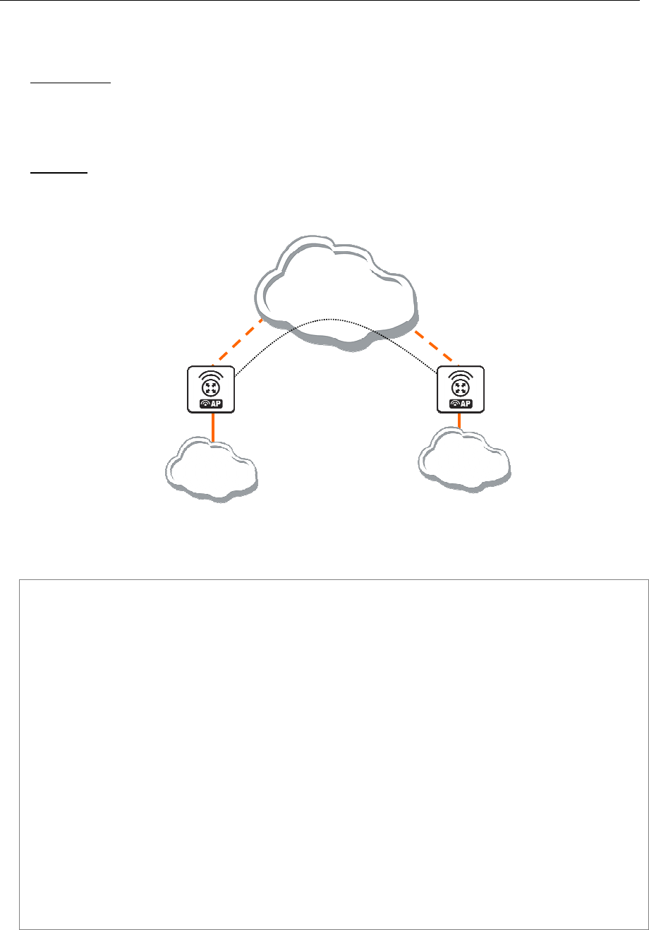
152 AT-WR4500 Series - IEEE 802.11abgh Outdoor Wireless Routers
RouterOS v3 Configuration and User Guide
8.1.3 EoIP Application Example
Description
Let us assume we want to bridge two networks: 'Office LAN' and 'Remote LAN'. The networks are
connected to an IP network through the routers [Our_GW] and [Remote]. The IP network can be a
private intranet or the Internet. Both routers can communicate with each other through the IP network.
Example
Our goal is to create a secure channel between the routers and bridge both networks through it. The
network setup diagram is as follows:
[
Our_GW
]
192.168.1.1
[
Remote
]
192.168.2.1
IP Network
Remote
LAN
Office
LAN
10.0.0.2
10.0.0.1
PPTP Tunnel
Figure 20: EoIP Application Example
To make a secure Ethernet bridge between two routers you should:
Create a PPTP tunnel between them. Our_GW will be the pptp server:
[admin@Our_GW] interface pptp-server> /ppp secret add name=joe service=pptp \
\... password=top_s3 local-address=10.0.0.1 remote-address=10.0.0.2
[admin@Our_GW] interface pptp-server> add name=from_remote user=joe
[admin@Our_GW] interface pptp-server> server set enable=yes
[admin@Our_GW] interface pptp-server> print
Flags: X - disabled, D - dynamic, R - running
# NAME USER MTU CLIENT-ADDRESS UPTIME ENC...
0 from_remote joe
[admin@Our_GW] interface pptp-server>
The Remote router will be the pptp client:
[admin@Remote] interface pptp-client> add name=pptp user=joe \
\... connect-to=192.168.1.1 password=top_s3 mtu=1500 mru=1500
[admin@Remote] interface pptp-client> enable pptp
[admin@Remote] interface pptp-client> print
Flags: X - disabled, R - running
0 R name="pptp" mtu=1500 mru=1500 connect-to=192.168.1.1 user="joe"
password="top_s2" profile=default add-default-route=no
[admin@Remote] interface pptp-client> monitor pptp
status: "connected"
uptime: 39m46s
encoding: "none"
[admin@Remote] interface pptp-client>
See the PPTP Interface Manual for more details on setting up encrypted channels.

AT-WR4500 Series - IEEE 802.11abgh Outdoor Wireless Routers 153
RouterOS v3 Configuration and User Guide
Configure the EoIP tunnel by adding the eoip tunnel interfaces at both routers. Use the ip addresses of
the pptp tunnel interfaces when specifying the argument values for the EoIP tunnel:
[admin@Our_GW] interface eoip> add name="eoip-remote" tunnel-id=0 \
\... remote-address=10.0.0.2
[admin@Our_GW] interface eoip> enable eoip-remote
[admin@Our_GW] interface eoip> print
Flags: X - disabled, R - running
0 name=eoip-remote mtu=1500 arp=enabled remote-address=10.0.0.2 tunnel-id=0
[admin@Our_GW] interface eoip>
[admin@Remote] interface eoip> add name="eoip" tunnel-id=0 \
\... remote-address=10.0.0.1
[admin@Remote] interface eoip> enable eoip-main
[admin@Remote] interface eoip> print
Flags: X - disabled, R - running
0 name=eoip mtu=1500 arp=enabled remote-address=10.0.0.1 tunnel-id=0
[Remote] interface eoip>
Enable bridging between the EoIP and Ethernet interfaces on both routers.
On the Our_GW:
[admin@Our_GW] interface bridge> add
[admin@Our_GW] interface bridge> print
Flags: X - disabled, R - running
0 R name="bridge1" mtu=1500 arp=enabled mac-address=00:00:00:00:00:00
protocol-mode=none priority=0x8000 auto-mac=yes
admin-mac=00:00:00:00:00:00 max-message-age=20s forward-delay=15s
transmit-hold-count=6 ageing-time=5m
[admin@Our_GW] interface bridge> port add bridge=bridge1 interface=eoip-remote
[admin@Our_GW] interface bridge> port add bridge=bridge1 interface=ether1
[admin@Our_GW] interface bridge> port print
Flags: X - disabled, I - inactive, D - dynamic
# INTERFACE BRIDGE PRIORITY PATH-COST
0 eoip-remote bridge1 128 10
1 ether1 bridge1 128 10
[admin@Our_GW] interface bridge>
And the same for the Remote:
[admin@Remote] interface bridge> add
[admin@Remote] interface bridge> print
Flags: X - disabled, R - running
0 R name="bridge1" mtu=1500 arp=enabled mac-address=00:00:00:00:00:00 stp=no
priority=32768 ageing-time=5m forward-delay=15s
garbage-collection-interval=4s hello-time=2s max-message-age=20s
[admin@Remote] interface bridge> add bridge=bridge1 interface=ether1
[admin@Remote] interface bridge> add bridge=bridge1 interface=eoip-main
[admin@Remote] interface bridge> port print
Flags: X - disabled, I - inactive, D - dynamic
# INTERFACE BRIDGE PRIORITY PATH-COST
0 ether1 bridge1 128 10
1 eoip-main bridge1 128 10
[admin@Remote] interface bridge> port print
Addresses from the same network can be used both in the Office LAN and in the Remote LAN.
8.1.4 Troubleshooting
Description
The routers can ping each other but EoIP tunnel does not seem to work!
Check the MAC addresses of the EoIP interfaces - they should not be the same!

154 AT-WR4500 Series - IEEE 802.11abgh Outdoor Wireless Routers
RouterOS v3 Configuration and User Guide
8.2 Interface Bonding
Document revisi on: 1.1 (oct-26-2004)
Applies to: V2.9
8.3 General Information
8.3.1 Summary
Bonding is a technology that allows to aggregate multiple ethernet-like interfaces into a single virtual link,
thus getting higher data rates and providing failover.
8.3.2 Quick Setup Guide
Let us assume that we have 2 NICs in each router (Router1 and Router2) and want to get maximum
data rate between 2 routers. To make this possible, follow these steps:
Make sure that you do not have IP addresses on interfaces which will be enslaved for bonding interface!
Add bonding interface on Router1:
[admin@Router1] interface bonding> add slaves=ether1,ether2
And on Router2:
[admin@Router2] interface bonding> add slaves=ether1,ether2
Add addresses to bonding interfaces:
[admin@Router1] ip address> add address=172.16.0.1/24 interface=bonding1
[admin@Router2] ip address> add address=172.16.0.2/24 interface=bonding1
Test the link from Router1:
[admin@Router1] interface bonding> /pi 172.16.0.2
172.16.0.2 ping timeout
172.16.0.2 ping timeout
172.16.0.2 ping timeout
172.16.0.2 64 byte ping: ttl=64 time=2 ms
172.16.0.2 64 byte ping: ttl=64 time=2 ms
A bonding interface needs a couple of seconds to get connectivity with its peer.
Specifications
Packages required: system
License required: Level1
Submenu level: /interface bonding
Standards and Technologies: None
Hardware usage: Not significant
8.3.3 Related Documents
Linux Ethernet Bonding Driver mini-howto

AT-WR4500 Series - IEEE 802.11abgh Outdoor Wireless Routers 155
RouterOS v3 Configuration and User Guide
Description
To provide a proper failover, you should specify link-monitoring parameter. It can be:
• MII (Media Independent Interface) type1 or type2 - Media Independent Interface is an abstract layer
between the operating system and the NIC which detects whether the link is running (it performs
also other functions, but in our case this is the most important).
• ARP - Address Resolution Protocol periodically (for arp-interval time) checks the link status.
link-monitoring is used to check whether the link is up or not.
Property Description
arp (disabled | enabled | proxy-arp | reply-only; default: enabled) - Address Resolution Protocol for the
interface
disabled - the interface will not use ARP
enabled - the interface will use ARP
proxy-arp - the interface will use the ARP proxy feature
reply-only - the interface will only reply to the requests originated to its own IP addresses. Neighbour
MAC addresses will be resolved using /ip arp statically set table only
arp-interval (time; default: 00:00:00.100) - time in milliseconds which defines how often to monitor
ARP requests
arp-ip-targets (IP address; default: "") - IP target address which will be monitored if link-monitoring is
set to arp. You can specify multiple IP addresses, separated by comma
down-delay (time; default: 00:00:00) - if a link failure has been detected, bonding interface is disabled for
down-delay time. Value should be a multiple of mii-interval
lacp-rate (1sec | 30secs; default: 30secs) - Link Aggregation Control Protocol rate specifies how often
to exchange with LACPDUs between bonding peer. Used to determine whether link is up or other
changes have occured in the network. LACP tries to adapt to these changes providing failover.
link-monitoring (arp | mii-type1 | mii-type2 | none; default: none) - method to use for monitoring the
link (whether it is up or down)
arp - uses Address Resolution Protocol to determine whether the remote interface is reachable
mii-type1 - uses Media Independent Interface type1 to determine link status. Link status determenation
relies on the device driver. If bonding shows that the link status is up, when it should not be, then it
means that this card don't support this possibility.
mii-type2 - uses MII type2 to determine link status (used if mii-type1 is not supported by the NIC)
none - no method for link monitoring is used. If a link fails, it is not considered as down (but no traffic
passes through it, thus).
mac-address (read-only: MAC address) - MAC address of the bonding interface
mii-interval (time; default: 00:00:00.100) - how often to monitor the link for failures (parameter used
only if link-monitoring is mii-type1 or mii-type2)
mode (802.3ad | active-backup | balance-alb | balance-rr | balance-tlb | balance-xor | broadcast; default:
balance-rr) - interface bonding mode. Can be one of:
802.3ad - IEEE 802.3ad dynamic link aggregation. In this mode, the interfaces are aggregated in a group
where each slave shares the same speed. If you use a switch between 2 bonding routers, be sure that this
switch supports IEEE 802.3ad standard. Provides fault tolerance and load balancing.
active-backup - provides link backup. Only one slave can be active at a time. Another slave becomes
active only, if first one fails.
balance-alb - adaptive load balancing. It includes balance-tlb and received traffic is also balanced.
Device driver should support for setting the mac address, then it is active. Otherwise balance-alb
doesn't work. No special switch is required.
balance-rr - round-robin load balancing. Slaves in bonding interface will transmit and receive data in
sequential order. Provides load balancing and fault tolerance.
balance-tlb - Outgoing traffic is distributed according to the current load on each slave. Incoming traffic
is received by the current slave. If receiving slave fails, then another slave takes the MAC address of the
failed slave. Doesn't require any special switch support.
balance-xor - Use XOR policy for transmit. Provides only failover (in very good quality), but not load
balancing, yet.
broadcast - Broadcasts the same data on all interfaces at once. This provides fault tolerance but slows
down traffic throughput on some slow machines.
mtu (integer: 68..1500; default: 1500) - Maximum Transmit Unit in bytes
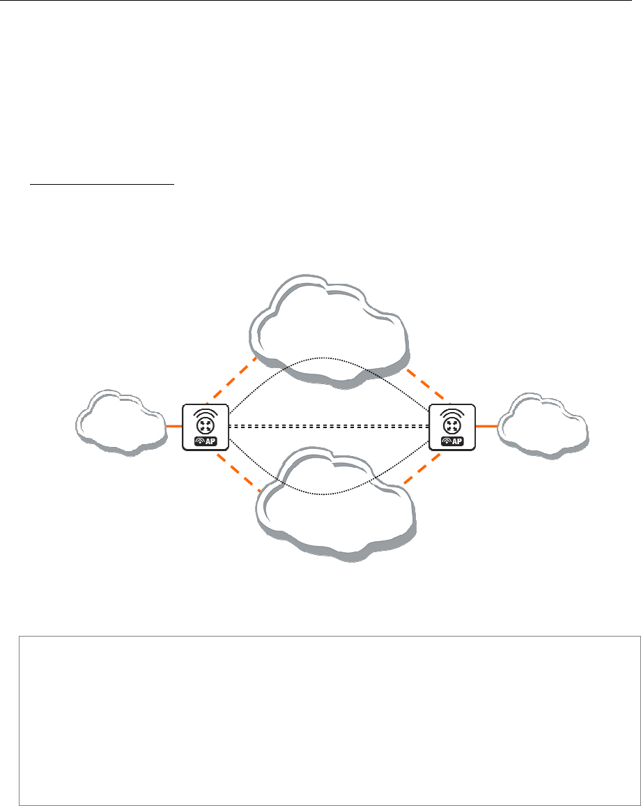
156 AT-WR4500 Series - IEEE 802.11abgh Outdoor Wireless Routers
RouterOS v3 Configuration and User Guide
name (name) - descriptive name of bonding interface
primary (name; default: none) - Interface is used as primary output media. If primary interface fails, only
then others slaves will be used. This value works only with mode=active-backup
slaves (name) - at least two ethernet-like interfaces separated by a comma, which will be used for
bonding
up-delay (time; default: 00:00:00) - if a link has been brought up, bonding interface is disabled for up-
delay time and after this time it is enabled. Value should be a multiple of mii-interval
Application Examples
Bonding two EoIP tunnels
Assume you need to configure the AT-WR4500 router for the following network setup, where you have
two offices with 2 ISP for each. You want combine links for getting double speed and provide failover:
[
Office1
]
[
Office2
]
Internet ISP2
Local Net
Local net
10.0.0.1
Eoip
-
tunnel 1
Eoip
-
tunnel 2
Internet ISP1
bonding1
Figure 21: Bonding two EoIP tunnels
We are assuming that connections to Internet through two ISP are configured for both routers.
Office1 configuration:
[admin@office1] > /interface print
Flags: X - disabled, D - dynamic, R - running
# NAME TYPE RX-RATE TX-RATE MTU
0 R isp1 ether 0 0 1500
1 R isp2 ether 0 0 1500
[admin@office1] > /ip address print
Flags: X - disabled, I - invalid, D - dynamic
# ADDRESS NETWORK BROADCAST INTERFACE
0 1.1.1.1/24 1.1.1.0 1.1.1.255 isp2
1 10.1.0.111/24 10.1.0.0 10.1.0.255 isp1

AT-WR4500 Series - IEEE 802.11abgh Outdoor Wireless Routers 157
RouterOS v3 Configuration and User Guide
Office2 configuration:
[admin@office2] interface> print
Flags: X - disabled, D - dynamic, R - running
# NAME TYPE RX-RATE TX-RATE MTU
0 R isp2 ether 0 0 1500
1 R isp1 ether 0 0 1500
[admin@office2] interface> /ip add print
Flags: X - disabled, I - invalid, D - dynamic
# ADDRESS NETWORK BROADCAST INTERFACE
0 2.2.2.1/24 2.2.2.0 2.2.2.255 isp2
1 10.1.0.112/24 10.1.0.0 10.1.0.255 isp1
EoIP tunnel configuration
for Office1 through ISP1
[admin@office1] > interface eoip add remote-address=10.1.0.112 tunnel-id=2
\... mac-address=FE:FD:00:00:00:04
[admin@office1] > interface eoip print
Flags: X - disabled, R - running
0 R name="eoip-tunnel2" mtu=1500 mac-address==FE:FD:00:00:00:04 arp=enabled
\... remote-address=10.1.0.112 tunnel-id=2
for Office2 through ISP1
[admin@office2] > interface eoip add remote-address=10.1.0.111 tunnel-id=2
\... mac-address=FE:FD:00:00:00:02
[admin@office2] > interface eoip print
Flags: X - disabled, R - running
0 R name="eoip-tunnel2" mtu=1500 mac-address=FE:FD:00:00:00:02 arp=enabled
\... remote-address=10.1.0.111 tunnel-id=2
for Office1through ISP2
[admin@office1] > interface eoip add remote-address=2.2.2.1 tunnel-id=1
\... mac-address=FE:FD:00:00:00:03
[admin@office1] interface eoip> print
Flags: X - disabled, R - running
0 R name="eoip-tunnel1" mtu=1500 mac-address=FE:FD:00:00:00:03 arp=enabled
remote-address=2.2.2.1 tunnel-id=1
1 R name="eoip-tunnel2" mtu=1500 mac-address=FE:FD:00:00:00:04 arp=enabled
remote-address=10.1.0.112 tunnel-id=2
for Office2through ISP2
[admin@office2] > interface eoip add remote-address=1.1.1.1 tunnel-id=1
\... mac-address=FE:FD:00:00:00:01
[admin@office2] interface eoip> print
Flags: X - disabled, R - running
0 R name="eoip-tunnel1" mtu=1500 mac-address=FE:FD:00:00:00:01 arp=enabled
remote-address=1.1.1.1 tunnel-id=1
1 R name="eoip-tunnel2" mtu=1500 mac-address=FE:FD:00:00:00:02 arp=enabled
remote-address=10.1.0.111 tunnel-id=2

158 AT-WR4500 Series - IEEE 802.11abgh Outdoor Wireless Routers
RouterOS v3 Configuration and User Guide
Bonding configuration
for Office1
[admin@office1] interface bonding> add slaves=eoip-tunnel1,eoip-tunnel2
[admin@office1] interface bonding> print
Flags: X - disabled, R - running
0 R name="bonding1" mtu=1500 mac-address=00:0C:42:03:20:E7 arp=enabled
slaves=eoip-tunnel1,eoip-tunnel2 mode=balance-rr primary=none
link-monitoring=none arp-interval=00:00:00.100 arp-ip-targets=""
mii-interval=00:00:00.100 down-delay=00:00:00 up-delay=00:00:00
lacp-rate=30secs
[admin@office1] ip address> add address=3.3.3.1/24 interface=bonding1
[admin@office1] ip address> print
Flags: X - disabled, I - invalid, D - dynamic
# ADDRESS NETWORK BROADCAST INTERFACE
0 1.1.1.1/24 1.1.1.0 1.1.1.255 isp2
1 10.1.0.111/24 10.1.0.0 10.1.0.255 isp1
2 3.3.3.1/24 3.3.3.0 3.3.3.255 bonding1
for Office2
[admin@office2] interface bonding> add slaves=eoip-tunnel1,eoip-tunnel2
[admin@office2] interface bonding> print
Flags: X - disabled, R - running
0 R name="bonding1" mtu=1500 mac-address=00:0C:42:03:20:E7 arp=enabled
slaves=eoip-tunnel1,eoip-tunnel2 mode=balance-rr primary=none
link-monitoring=none arp-interval=00:00:00.100 arp-ip-targets=""
mii-interval=00:00:00.100 down-delay=00:00:00 up-delay=00:00:00
lacp-rate=30secs
[admin@office2] ip address> add address=3.3.3.2/24 interface=bonding1
[admin@office2] ip address> print
Flags: X - disabled, I - invalid, D - dynamic
# ADDRESS NETWORK BROADCAST INTERFACE
0 2.2.2.1/24 2.2.2.0 2.2.2.255 isp2
1 10.1.0.112/24 10.1.0.0 10.1.0.255 isp1
2 3.3.3.2/24 3.3.3.0 3.3.3.255 bonding1
[admin@office2] ip address> /ping 3.3.3.1
3.3.3.1 64 byte ping: ttl=64 time=2 ms
3.3.3.1 64 byte ping: ttl=64 time=2 ms
2 packets transmitted, 2 packets received, 0% packet loss
round-trip min/avg/max = 2/2.0/2 ms
8.4 IPIP Tunnel Interfaces
Document revisi on: 1.1 (Fri Mar 05 08:25:43 GMT 200 4)
Applies to: V2.9
8.4.1 General Information
Summary
The IPIP tunneling implementation on the RouterOS is RFC 2003 compliant. IPIP tunnel is a simple
protocol that encapsulates IP packets in IP to make a tunnel between two routers. The IPIP tunnel
interface appears as an interface under the interface list. This protocol makes multiple network schemes
possible.
IP tunneling protocol adds the following possibilities to network setup:
• to tunnel Intranets over the Internet
• to use it instead of source routing
Quick Setup Guide
To make an IPIP tunnel between two RouterOS routers with IP addresses 10.5.8.104 and 10.1.0.172,
using IPIP tunnel addresses 10.0.0.1 and 10.0.0.2, follow the next steps.
Configuration on router with IP address 10.5.8.104:

AT-WR4500 Series - IEEE 802.11abgh Outdoor Wireless Routers 159
RouterOS v3 Configuration and User Guide
Add an IPIP interface (by default, its name will be ipip1):
[admin@10.5.8.104] interface ipip> add local-address=10.5.8.104 \
remote-address=10.1.0.172 disabled=no
Add an IP address to created ipip1 interface:
[admin@10.5.8.104] ip address> add address=10.0.0.1/24 interface=ipip1
Configuration on router with IP address 10.1.0.172:
Add an IPIP interface (by default, its name will be ipip1):
[admin@10.1.0.172] interface ipip> add local-address=10.1.0.172 \
remote-address=10.5.8.104 disabled=no
Add an IP address to created ipip1 interface:
[admin@10.1.0.172] ip address> add address=10.0.0.2/24 interface=ipip1
Specifications
Packages required: system
License required: Level1 (limited to 1 tunnel) , Level3 (200 tunnels) , Level5 (unlimited)
Submenu level: /interface ipip
Standards and Technologies: IPIP (RFC 2003)
Hardware usage: Not significant
Related Topics
IP Addresses and ARP
Log Management
Additional Resources
http://www.ietf.org/rfc/rfc1853.txt?number=1853
http://www.ietf.org/rfc/rfc2003.txt?number=2003
http://www.ietf.org/rfc/rfc1241.txt?number=1241
8.4.2 IPIP Setup
Submenu level: /interface ipip
Description
An IPIP interface should be configured on two routers that have the possibility for an IP level connection
and are RFC 2003 compliant. The IPIP tunnel may run over any connection that transports IP. Each IPIP
tunnel interface can connect with one remote router that has a corresponding interface configured. An
unlimited number of IPIP tunnels may be added to the router. For more details on IPIP tunnels, see RFC
2003.
Property Description
local-address (IP address) - local address on router which sends IPIP traffic to the remote host
mtu (integer; default: 1480) - Maximum Transmission Unit. Should be set to 1480 bytes to avoid
fragmentation of packets. May be set to 1500 bytes if mtu path discovery is not working properly on
links
name (name; default: ipipN) - interface name for reference
remote-address (IP address) - the IP address of the remote host of the IPIP tunnel - may be any RFC
2003 compliant router
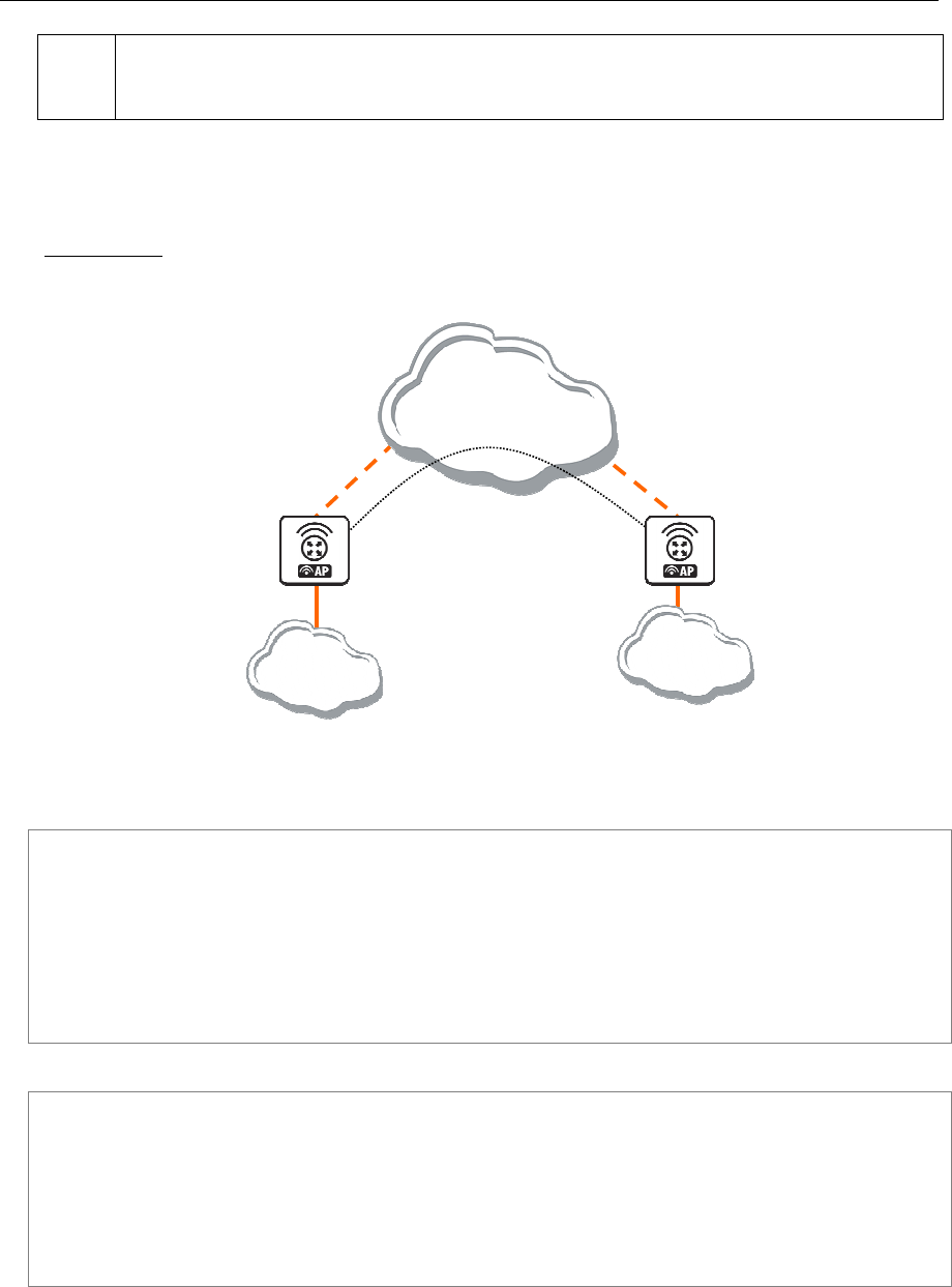
160 AT-WR4500 Series - IEEE 802.11abgh Outdoor Wireless Routers
RouterOS v3 Configuration and User Guide
Use /ip address add command to assign an IP address to the IPIP interface.
There is no authentication or 'state' for this interface. The bandwidth usage of the interface may be
monitored with the monitor feature from the interface menu.
8.4.3 Application Examples
Description
Suppose we want to add an IPIP tunnel between routers R1 and R2:
[
R2
]
22.63.11.6
[
R
1
]
10.0.0.1
IP Network
Local Net
Local Net
1.
1
.
1
.
1
1.
1
.
1
.
2
IPI
P Tunnel
Figure 22: IPIP Tunnel example network
At first, we need to configure IPIP interfaces and then add IP addresses to them.
The configuration for router R1 is as follows:
[admin@AT-WR4562] interface ipip> add
local-address: 10.0.0.1
remote-address: 22.63.11.6
[admin@AT-WR4562] interface ipip> print
Flags: X - disabled, R - running
# NAME MTU LOCAL-ADDRESS REMOTE-ADDRESS
0 X ipip1 1480 10.0.0.1 22.63.11.6
[admin@AT-WR4562] interface ipip> en 0
[admin@AT-WR4562] interface ipip> /ip address add address 1.1.1.1/24 interface=ipip1
The configuration of the R2 is shown below:
[admin@AT-WR4562] interface ipip> add local-address=22.63.11.6 remote-address=10.
0.0.1
[admin@AT-WR4562] interface ipip> print
Flags: X - disabled, R - running
# NAME MTU LOCAL-ADDRESS REMOTE-ADDRESS
0 X ipip1 1480 22.63.11.6 10.0.0.1
[admin@AT-WR4562] interface ipip> enable 0
[admin@AT-WR4562] interface ipip> /ip address add address 1.1.1.2/24 interface=ipip1

AT-WR4500 Series - IEEE 802.11abgh Outdoor Wireless Routers 161
RouterOS v3 Configuration and User Guide
Now both routers can ping each other:
[admin@AT-WR4562] interface ipip> /ping 1.1.1.2
1.1.1.2 64 byte ping: ttl=64 time=24 ms
1.1.1.2 64 byte ping: ttl=64 time=19 ms
1.1.1.2 64 byte ping: ttl=64 time=20 ms
3 packets transmitted, 3 packets received, 0% packet loss
round-trip min/avg/max = 19/21.0/24 ms
[admin@AT-WR4562] interface ipip>
8.5 L2TP Interface
Document revisi on: 1.1 (Fri Mar 05 08:26:01 GMT 200 4)
Applies to: V2.9
8.5.1 General Information
Summary
L2TP (Layer 2 Tunnel Protocol) supports encrypted tunnels over IP. The RouterOS implementation
includes support for both L2TP client and server.
General applications of L2TP tunnels include:
secure router-to-router tunnels over the Internet
linking (bridging) local Intranets or LANs
extending PPP user connections to a remote location (for example, to separate authentication and
Internet access points for ISP)
accessing an Intranet/LAN of a company for remote (mobile) clients (employees)
Each L2TP connection is composed of a server and a client. The RouterOS may function as a server or
client or, for various configurations, it may be the server for some connections and client for other
connections.
Quick Setup Guide
To make a L2TP tunnel between two RouterOS routers with IP addresses 10.5.8.104 (L2TP server) and
10.1.0.172 (L2TP client), follow the next steps.
Configuration on L2TP server router:
Add a L2TP user:
[admin@L2TP-Server] ppp secret> add name=james password=pass \
\... local-address=10.0.0.1 remote-address=10.0.0.2
Enable the L2TP server
[admin@L2TP-Server] interface l2tp-server server> set enabled=yes
Configuration on L2TP client router:
Add a L2TP client:
[admin@L2TP-Client] interface l2tp-client> add user=james password=pass \
\... connect-to=10.5.8.104
Specifications
Packages required: ppp
License required: Level1 (limited to 1 tunnel) , Level3 (limited to 200 tunnels) , Level5
Submenu level: /interface l2tp-server, /interface l2tp-client
Standards and Technologies: L2TP (RFC 2661)
Hardware usage: Not significant

162 AT-WR4500 Series - IEEE 802.11abgh Outdoor Wireless Routers
RouterOS v3 Configuration and User Guide
Related Topics
IP Addresses and ARP
AAA Configuration
EoIP
IP Security
Additional Resources
http://www.linuxguide.it/docs.php?Networking:VPN:IPSec%2FL2TP
http://en.wikipedia.org/wiki/L2tp
Description
L2TP is a secure tunnel protocol for transporting IP traffic using PPP. L2TP encapsulates PPP in virtual
lines that run over IP, Frame Relay and other protocols (that are not currently supported by RouterOS).
L2TP incorporates PPP and MPPE (Microsoft Point to Point Encryption) to make encrypted links. The
purpose of this protocol is to allow the Layer 2 and PPP endpoints to reside on different devices
interconnected by a packet-switched network. With L2TP, a user has a Layer 2 connection to an access
concentrator - LAC (e.g., modem bank, ADSL DSLAM, etc.), and the concentrator then tunnels
individual PPP frames to the Network Access Server - NAS. This allows the actual processing of PPP
packets to be separated from the termination of the Layer 2 circuit. From the user's perspective, there is
no functional difference between having the L2 circuit terminate in a NAS directly or using L2TP.
It may also be useful to use L2TP just as any other tunneling protocol with or without encryption. The
L2TP standard says that the most secure way to encrypt data is using L2TP over IPsec (Note that it is
default mode for Microsoft L2TP client) as all L2TP control and data packets for a particular tunnel
appear as homogeneous UDP/IP data packets to the IPsec system.
Multilink PPP (MP) is supported in order to provide MRRU (the ability to transmit full-sized 1500 and
larger packets) and bridging over PPP links (using Bridge Control Protocol (BCP) that allows to send raw
Ethernet frames over PPP links). This way it is possible to setup bridging without EoIP. The bridge should
either have an administratively set MAC address or an Ethernet-like interface in it, as PPP links do not
have MAC addresses.
This is the default mode for Microsoft L2TP client
L2TP includes PPP authentication and accounting for each L2TP connection. Full authentication and
accounting of each connection may be done through a RADIUS client or locally.
MPPE 40bit RC4 and MPPE 128bit RC4 encryption are supported.
L2TP traffic uses UDP protocol for both control and data packets. UDP port 1701 is used only for link
establishment, further traffic is using any available UDP port (which may or may not be 1701). This means
that L2TP can be used with most firewalls and routers (even with NAT) by enabling UDP traffic to be
routed through the firewall or router.
8.5.2 L2TP Client Setup
Submenu level: /interface l2tp-client
Property Description
add-default-route (yes | no; default: no) - whether to use the server which this client is connected to
as its default router (gateway)
allow (multiple choice: mschap2, mschap1, chap, pap; default: mschap2, mschap1, chap, pap) - the
protocol to allow the client to use for authentication
connect-to (IP address) - The IP address of the L2TP server to connect to
max-mru (integer; default: 1460) - Maximum Receive Unit. The optimal value is the MRU of the
interface the tunnel is working over decreased by 40 (so, for 1500-byte Ethernet link, set the MRU to
1460 to avoid fragmentation of packets)
max-mtu (integer; default: 1460) - Maximum Transmission Unit. The optimal value is the MTU of the
interface the tunnel is working over decreased by 40 (so, for 1500-byte Ethernet link, set the MTU to
1460 to avoid fragmentation of packets)

AT-WR4500 Series - IEEE 802.11abgh Outdoor Wireless Routers 163
RouterOS v3 Configuration and User Guide
mrru (integer: 512..65535; default: disabled) - maximum packet size that can be received on the link. If a
packet is bigger than tunnel MTU, it will be split into multiple packets, allowing full size IP or Ethernet
packets to be sent over the tunnel
disabled - disable MRRU on this link
name (name; default: l2tp-outN) - interface name for reference
password (text; default: "") - user password to use when logging to the remote server
profile (name; default: default) - profile to use when connecting to the remote server
user (text) - user name to use when logging on to the remote server
Specifying MRRU means enabling MP (Multilink PPP) over single link. This protocol is used to split big
packets into smaller ones. Under Windows it can be enabled in Networking tag, Settings button,
"Negotiate multi-link for single link connections". Their MRRU is hardcoded to 1614. This setting is
usefull to overcome PathMTU discovery failures. The MP should be enabled on both peers.
Example
To set up L2TP client named test2 using username john with password john to connect to the
10.1.1.12 L2TP server and use it as the default gateway:
[admin@AT-WR4562] interface l2tp-client> add name=test2 connect-to=10.1.1.12 \
\... user=john add-default-route=yes password=john
[admin@AT-WR4562] interface l2tp-client> print
Flags: X - disabled, R - running
0 X name="test2" mtu=1460 mru=1460 connect-to=10.1.1.12 user="john"
password="john" profile=default add-default-route=yes
allow=pap,chap,mschap1,mschap2
[admin@AT-WR4562] interface l2tp-client> enable 0
8.5.3 Monitoring L2TP Client
Command name: /interface l2tp-client monitor
Property Description
encoding (text) - encryption and encoding (if asymmetric, separated with '/') being used n this connection
idle-time (read-only: time) - time since the last packet has been transmitted over this link
mru (read-only: integer) - effective MRU of the link
mtu (read-only: integer) - effective MTU of the link
status (text) - status of the client
dialing - attempting to make a connection
verifying password... - connection has been established to the server, password verification in progress
connected - self-explanatory
terminated - interface is not enabled or the other side will not establish a connection uptime (time) -
connection time displayed in days, hours, minutes and seconds
Example
Example of an established connection
[admin@AT-WR4562] interface l2tp-client> monitor test2
status: "connected"
uptime: 6h44m9s
idle-time: 6h44m9s
encoding: "MPPE128 stateless"
mtu: 1460
mru: 1460
[admin@AT-WR4562] interface l2tp-client>

164 AT-WR4500 Series - IEEE 802.11abgh Outdoor Wireless Routers
RouterOS v3 Configuration and User Guide
8.5.4 L2TP Server Setup
Submenu level: /interface l2tp-server server
Description
The L2TP server creates a dynamic interface for each connected L2TP client. The L2TP connection count
from clients depends on the license level you have. Level1 license allows 1 L2TP client, Level3 or Level4
licenses up to 200 clients, and Level5 or Level6 licenses do not have L2TP client limitations.
To create L2TP users, you should consult the PPP secret and PPP Profile manuals. It is also possible
to use the RouterOS router as a RADIUS client to register the L2TP users, see the manual how to do
it.
Property Description
authentication (multiple choice: pap | chap | mschap1 | mschap2; default: mschap2) – authentication
algorithm
default-profile - default profile to use
enabled (yes | no; default: no) - defines whether L2TP server is enabled or not
keepalive-timeout (time; default: 30) - defines the time period (in seconds) after which the router is
starting to send keepalive packets every second. If no traffic and no keepalive responses has came for that
period of time (i.e. 2 * keepalive-timeout), not responding client is proclaimed disconnected
max-mru (integer; default: 1460) - Maximum Receive Unit. The optimal value is the MRU of the
interface the tunnel is working over decreased by 40 (so, for 1500-byte ethernet link, set the MRU to
1460 to avoid fragmentation of packets)
max-mtu (integer; default: 1460) - Maximum Transmission Unit. The optimal value is the MTU of the
interface the tunnel is working over decreased by 40 (so, for 1500-byte ethernet link, set the MTU to
1460 to avoid fragmentation of packets)
mrru (integer: 512..65535; default: disabled) - maximum packet size that can be received on the link. If a
packet is bigger than tunnel MTU, it will be split into multiple packets, allowing full size IP or Ethernet
packets to be sent over the tunnel
disabled - disable MRRU on this link
Example
To enable L2TP server:
[admin@AT-WR4562] interface l2tp-server server> set enabled=yes
[admin@AT-WR4562] interface l2tp-server server> print
enabled: yes
max-mtu: 1460
max-mru: 1460
mrru: disabled
authentication: mschap2,mschap1
keepalive-timeout: 30
default-profile: default
[admin@AT-WR4562] interface l2tp-server server>
8.5.5 L2TP Server Users
Submenu level: /interface l2tp-server
Description
There are two types of interface (tunnel) items in PPTP server configuration - static users and dynamic
connections. An interface is created for each tunnel established to the given server. Static interfaces are
added administratively if there is a need to reference the particular interface name (in firewall rules or
elsewhere) created for the particular user. Dynamic interfaces are added to this list automatically
whenever a user is connected and its username does not match any existing static entry (or in case the
entry is active already, as there can not be two separate tunnel interfaces referenced by the same name).
Dynamic interfaces appear when a user connects and disappear once the user disconnects, so it is
impossible to reference the tunnel created for that use in router configuration (for example, in firewall),

AT-WR4500 Series - IEEE 802.11abgh Outdoor Wireless Routers 165
RouterOS v3 Configuration and User Guide
so if you need a persistent rules for that user, create a static entry for him/her. Otherwise it is safe to use
dynamic configuration.
In both cases PPP users must be configured properly.
Property Description
client-address (read-only: IP address) - shows the IP address of the connected client
encoding (read-only: text) - encryption and encoding (if asymmetric, separated with '/') being used in this
connection
mru (read-only: integer) - client's MRU
mtu (read-only: integer) - client's MTU
name (name) - interface name
uptime (read-only: time) - shows how long the client is connected
user (name) - the name of the user that is configured statically or added dynamically
Example
To add a static entry for ex1 user:
[admin@AT-WR4562] interface l2tp-server> add user=ex1
[admin@AT-WR4562] interface l2tp-server> print
Flags: X - disabled, D - dynamic, R - running
# NAME USER MTU CLIENT-ADDRESS UPTIME ENC...
0 DR <l2tp-ex> ex 1460 10.0.0.202 6m32s none
1 l2tp-in1 ex1
[admin@AT-WR4562] interface l2tp-server>
In this example an already connected user ex is shown besides the one we just added. Now the interface
named l2tp-in1 can be referenced from anywhere in RouterOS configuration like a regular interface.
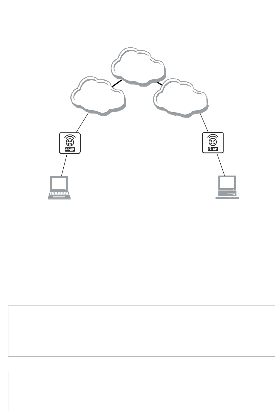
166 AT-WR4500 Series - IEEE 802.11abgh Outdoor Wireless Routers
RouterOS v3 Configuration and User Guide
8.5.6 L2TP Application Examples
Router-to-Router Secure Tunnel Example
W
ISP#1
192.168.80.0/24
W
ISP#
2
192.168.81.0/24
Home Office
To Internet
192.168.80.1/24
LAN
10.150.2.254/24
Remote Office
To Internet
192.168.81.1/24
LAN
10.150.1.254/24
10.150.2.1/24
10.150.1.1/24
Network Setup without L2TP
enabled
Big
Internet
Figure 23: Router-to-Router Secure Tunnel Example
There are two routers in this example:
[HomeOffice]
Interface LocalHomeOffice 10.150.2.254/24
Interface ToInternet 192.168.80.1/24
[RemoteOffice]
Interface ToInternet 192.168.81.1/24
Interface LocalRemoteOffice 10.150.1.254/24
Each router is connected to a different ISP. One router can access another router through the Internet.
On the L2TP server a user must be set up for the client:
[admin@HomeOffice] ppp secret> add name=ex service=l2tp password=lkjrht
local-address=10.0.103.1 remote-address=10.0.103.2
[admin@HomeOffice] ppp secret> print detail
Flags: X - disabled
0 name="ex" service=l2tp caller-id="" password="lkjrht" profile=default
local-address=10.0.103.1 remote-address=10.0.103.2 routes==""
[admin@HomeOffice] ppp secret>
Then the user should be added in the L2TP server list:
[admin@HomeOffice] interface l2tp-server> add user=ex
[admin@HomeOffice] interface l2tp-server> print
Flags: X - disabled, D - dynamic, R - running
# NAME USER MTU CLIENT-ADDRESS UPTIME ENC...
0 l2tp-in1 ex
[admin@HomeOffice] interface l2tp-server>
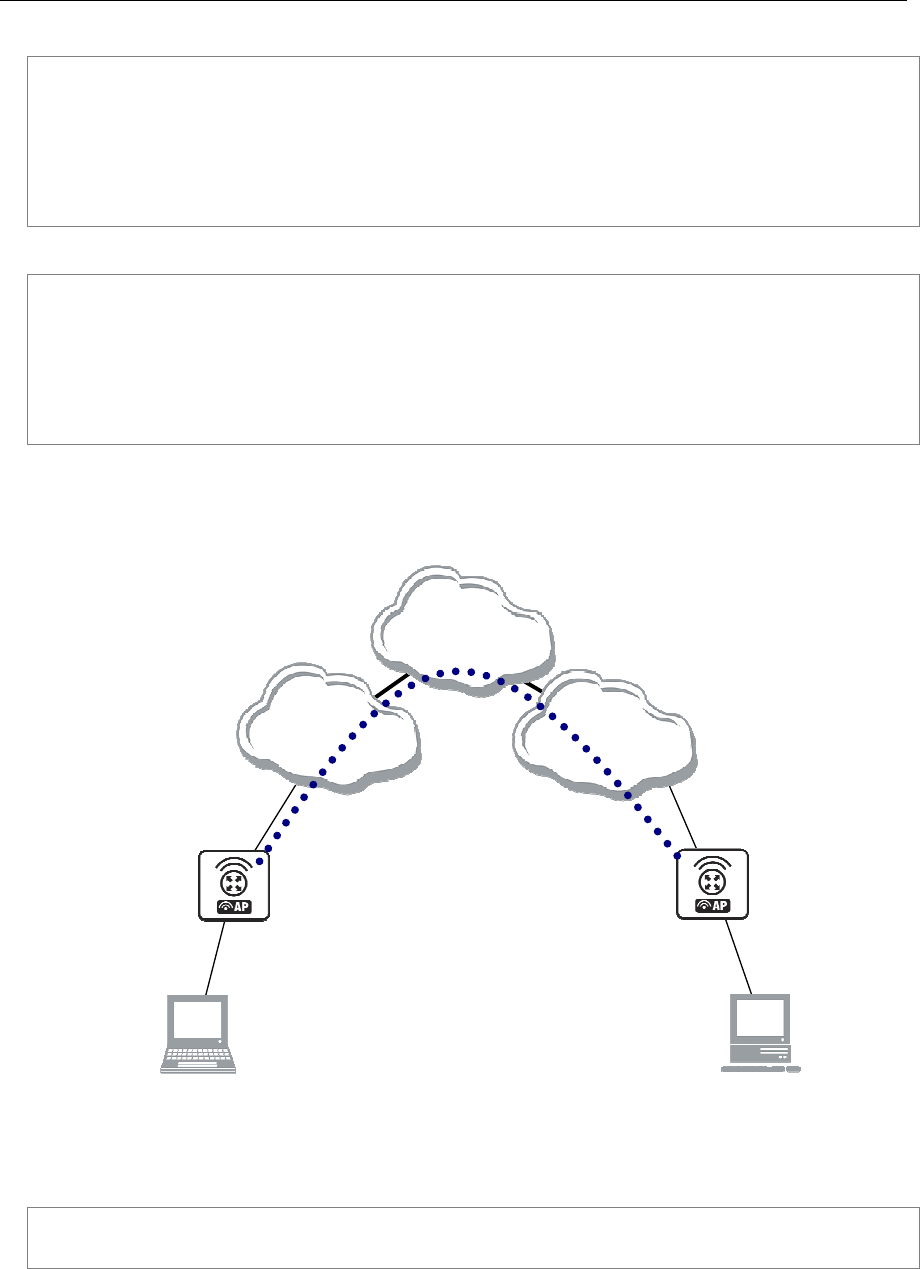
AT-WR4500 Series - IEEE 802.11abgh Outdoor Wireless Routers 167
RouterOS v3 Configuration and User Guide
And finally, the server must be enabled:
[admin@HomeOffice] interface l2tp-server server> set enabled=yes
[admin@HomeOffice] interface l2tp-server server> print
enabled: yes
mtu: 1460
mru: 1460
authentication: mschap2
default-profile: default
[admin@HomeOffice] interface l2tp-server server>
Add a L2TP client to the RemoteOffice router:
[admin@RemoteOffice] interface l2tp-client> add connect-to=192.168.80.1 user=ex \
\... password=lkjrht disabled=no
[admin@RemoteOffice] interface l2tp-client> print
Flags: X - disabled, R - running
0 R name="l2tp-out1" mtu=1460 mru=1460 mrru=disabled connect-to=192.168.80.1
user="ex" password="lkjrht" profile=default add-default-route=no
allow=pap,chap,mschap1,mschap2
[admin@RemoteOffice] interface l2tp-client>
Thus, a L2TP tunnel is created between the routers. This tunnel is like an Ethernet point-to-point
connection between the routers with IP addresses 10.0.103.1 and 10.0.103.2 at each router. It enables
'direct' communication between the routers over third party networks.
W
ISP#1
192.168.80.0/24
W
ISP#
2
192.168.81.0/24
Home Office
To Internet
192.168.80.1/24
LAN
10.150.2.254/24
Remote Office
To Internet
192.168.81.1/24
LAN
10.150.1.254/24
10.150.2.1/24
10.150.1.1/24
Network Setup with L2TP
Big
Internet
Encrypted L2TP tunnel
From
10. 0.103.1/24
To
10. 0.103.2/24
Figure 24: Secure Remote office connection through L2TP tunnel
To route the local Intranets over the L2TP tunnel you need to add these routes:
[admin@HomeOffice] > ip route add dst-address 10.150.1.0/24 gateway 10.0.103.2
[admin@RemoteOffice] > ip route add dst-address 10.150.2.0/24 gateway 10.0.103.1

168 AT-WR4500 Series - IEEE 802.11abgh Outdoor Wireless Routers
RouterOS v3 Configuration and User Guide
On the L2TP server it can alternatively be done using routes parameter of the user configuration:
[admin@HomeOffice] ppp secret> print detail
Flags: X - disabled
0 name="ex" service=l2tp caller-id="" password="lkjrht" profile=default
local-address=10.0.103.1 remote-address=10.0.103.2 routes==""
[admin@HomeOffice] ppp secret> set 0 routes="10.150.1.0/24 10.0.103.2 1"
[admin@HomeOffice] ppp secret> print detail
Flags: X - disabled
0 name="ex" service=l2tp caller-id="" password="lkjrht" profile=default
local-address=10.0.103.1 remote-address=10.0.103.2
routes="10.150.1.0/24 10.0.103.2 1"
[admin@HomeOffice] ppp secret>
Test the L2TP tunnel connection:
[admin@RemoteOffice]> /ping 10.0.103.1
10.0.103.1 pong: ttl=255 time=3 ms
10.0.103.1 pong: ttl=255 time=3 ms
10.0.103.1 pong: ttl=255 time=3 ms
ping interrupted
3 packets transmitted, 3 packets received, 0% packet loss
round-trip min/avg/max = 3/3.0/3 ms
Test the connection through the L2TP tunnel to the LocalHomeOffice interface:
[admin@RemoteOffice]> /ping 10.150.2.254
10.150.2.254 pong: ttl=255 time=3 ms
10.150.2.254 pong: ttl=255 time=3 ms
10.150.2.254 pong: ttl=255 time=3 ms
ping interrupted
3 packets transmitted, 3 packets received, 0% packet loss
round-trip min/avg/max = 3/3.0/3 ms
To bridge a LAN over this secure tunnel, please see the example in the 'EoIP' section of the manual. To
set the maximum speed for traffic over this tunnel, please consult the 'Queues' section.
Connecting a Remote Client via L2TP Tunnel
The following example shows how to connect a computer to a remote office network over L2TP
encrypted tunnel giving that computer an IP address from the same network as the remote office has
(without need of bridging over EoIP tunnels).
Please, consult the respective manual on how to set up a L2TP client with the software you are using.
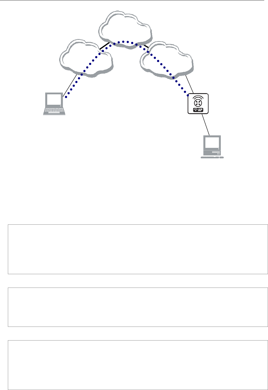
AT-WR4500 Series - IEEE 802.11abgh Outdoor Wireless Routers 169
RouterOS v3 Configuration and User Guide
ISP#1
192.168.80.0/24
W
ISP#
2
192.168.81.0/24
Remote Office
To Internet
192.168.81.1/24
LAN
10.150.1.254/24
192.168.80.111/24
1
0
.1
50
.
1
.
1
/24
Big
Internet
Encrypted L2TP tunnel
To Office
10.150.1.2/32
From Laptop
10.150.1.254/32
Figure 25: Client to Office secure connection via L2TP tunnel
The router in this example:
[RemoteOffice]
Interface ToInternet 192.168.81.1/24
Interface Office 10.150.1.254/24
The client computer can access the router through the Internet.
On the L2TP server a user must be set up for the client:
[admin@RemoteOffice] ppp secret> add name=ex service=l2tp password=lkjrht
local-address=10.150.1.254 remote-address=10.150.1.2
[admin@RemoteOffice] ppp secret> print detail
Flags: X - disabled
0 name="ex" service=l2tp caller-id="" password="lkjrht" profile=default
local-address=10.150.1.254 remote-address=10.150.1.2 routes==""
[admin@RemoteOffice] ppp secret>
Then the user should be added in the L2TP server list:
[admin@RemoteOffice] interface l2tp-server> add name=FromLaptop user=ex
[admin@RemoteOffice] interface l2tp-server> print
Flags: X - disabled, D - dynamic, R - running
# NAME USER MTU CLIENT-ADDRESS UPTIME ENC...
0 FromLaptop ex
[admin@RemoteOffice] interface l2tp-server>
And the server must be enabled:
[admin@RemoteOffice] interface l2tp-server server> set enabled=yes
[admin@RemoteOffice] interface l2tp-server server> print
enabled: yes
mtu: 1460
mru: 1460
authentication: mschap2
default-profile: default
[admin@RemoteOffice] interface l2tp-server server>

170 AT-WR4500 Series - IEEE 802.11abgh Outdoor Wireless Routers
RouterOS v3 Configuration and User Guide
Finally, the proxy APR must be enabled on the 'Office' interface:
[admin@RemoteOffice] interface ethernet> set Office arp=proxy-arp
[admin@RemoteOffice] interface ethernet> print
Flags: X - disabled, R - running
# NAME MTU MAC-ADDRESS ARP
0 R ToInternet 1500 00:30:4F:0B:7B:C1 enabled
1 R Office 1500 00:30:4F:06:62:12 proxy-arp
[admin@RemoteOffice] interface ethernet>
L2TP Setup for Windows
Microsoft provides L2TP client support for Windows XP, 2000, NT4, ME and 98. Windows 2000 and XP
include support in the Windows setup or automatically install L2TP. For 98, NT and ME, installation
requires a download from Microsoft (L2TP/IPsec VPN Client).
For more information, see:
Microsoft L2TP/IPsec VPN Client Microsoft L2TP/IPsec VPN Client
On Windows 2000, L2TP setup without IPsec requires editing registry:
Disabling IPsec for the Windows 2000 Client
Disabling IPSEC Policy Used with L2TP
8.5.7 Troubleshooting
Description
I use firewall and I cannot establish L2TP connection
Make sure UDP connections can pass through both directions between your sites.
My Windows L2TP/IPsec VPN Client fails to connect to L2TP server with "Error 789" or "Error
781"
The error messages 789 and 781 occur when IPsec is not configured properly on both ends. See the
respective documentation on how to configure IPsec in the Microsoft L2TP/IPsec VPN Client and in the
RouterOS. If you do not want to use IPsec, it can be easily switched off on the client side.
If you are using Windows 2000, you need to edit system registry using regedt32.exe or regedit.exe.
Add the following registry value to
HKEY_LOCAL_MACHINE\System\CurrentControlSet\Services\Rasman\Parameters:
Value Name: ProhibitIpSec
Data Type: REG_DWORD
Value: 1
You must restart the Windows 2000 for the changes to take effect
8.6 PPPoE
Document revisi on: 1.6 (Mon Jul 17 14:11:18 GMT 2006)
Applies to: V2.9
8.6.1 General Information
Summary
The PPPoE (Point to Point Protocol over Ethernet) protocol provides extensive user management,
network management and accounting benefits to ISPs and network administrators. Currently PPPoE is
used mainly by ISPs to control client connections for xDSL and cable modems as well as plain Ethernet
networks. PPPoE is an extension of the standard Point to Point Protocol (PPP). The difference between
them is expressed in transport method: PPPoE employs Ethernet instead of modem connection.

AT-WR4500 Series - IEEE 802.11abgh Outdoor Wireless Routers 171
RouterOS v3 Configuration and User Guide
Generally speaking, PPPoE is used to hand out IP addresses to clients based on the user (and workstation,
if desired) authentication as opposed to workstation only authentication, when static IP addresses or
DHCP are used. It is adviced not to use static IP addresses or DHCP on the same interfaces as PPPoE for
obvious security reasons.
RouterOS can act as a RADIUS client - you can use a RADIUS server to authenticate PPPoE clients and
use accounting for them.
A PPPoE connection is composed of a client and an access concentrator (server). The client may be any
computer that has the PPPoE client protocol support installed. The RouterOS supports both - client and
access concentrator implementations of PPPoE. The PPPoE client and server work over any Ethernet
level interface on the router - wireless 802.11, 10/100/1000 Mbit/s Ethernet and EoIP (Ethernet over IP
tunnel). No encryption, MPPE 40bit RSA and MPPE 128bit RSA encryption is supported.
When RADIUS server is authenticating a user with CHAP, MS-CHAPv1 or MS-CHAPv2, the RADIUS
protocol does not use shared secret, it is used only in authentication reply. So if you have a wrong shared
secret, RADIUS server will accept the request. You can use /radius monitor command to see bad-
replies parameter. This value should increase whenever a client tries to connect.
Supported connections:
• RouterOS PPPoE client to any PPPoE server (access concentrator)
• RouterOS server (access concentrator) to multiple PPPoE clients (clients are avaliable for almost all
operating systems and most routers)
Quick Setup Guide
To configure RouterOS to be a PPPoE client Just add a pppoe-client:
/interface pppoe-client add name=pppoe-user-mike user=mike password=123 \
\... interface=wlan1 service-name=internet disabled=no
To configure RouterOS to be an Access Concentrator (PPPoE Server)
Add an address pool for the clients from 10.1.1.62 to 10.1.1.72, called pppoe-pool:
/ip pool add name="pppoe-pool" ranges=10.1.1.62-10.1.1.72
Add PPP profile, called pppoe-profile where local-address will be the router's address and clients will
have an address from pppoe-pool:
/ppp profile add name="pppoe-profile" local-address=10.1.1.1 remote-address=pppoe-pool
Add a user with username mike and password 123:
/ppp secret add name=mike password=123 service=pppoe profile=pppoe-profile
Now add a pppoe server:
/interface pppoe-server server add service-name=internet interface=wlan1 \
\... default-profile=pppoe-profile
Specifications
Packages required: ppp
License required: Level1 (limited to 1 interface) , Level3 (limited to 200 interfaces) , Level4 (limited to
200 interfaces) , Level5 (limited to 500 interfaces) , Level6 (unlimited)
Submenu level: /interface pppoe-server, /interface pppoe-client
Standards and Technologies: PPPoE (RFC 2516)
Hardware usage: PPPoE server may require additional RAM (uses approx. 9KiB (plus extra 10KiB for
packet queue, if data rate limitation is used) for each connection) and CPU power. Maximum of 65535
connections is supported.

172 AT-WR4500 Series - IEEE 802.11abgh Outdoor Wireless Routers
RouterOS v3 Configuration and User Guide
Related Topics
IP Addresses and ARP
RADIUS client
PPP User AAA
Log Management
Additional Resources
Links for PPPoE documentation:
http://www.faqs.org/rfcs/rfc2516.html
PPPoE Clients:
RASPPPoE for Windows 95, 98, 98SE, ME, NT4, 2000, XP, .NET
http://support.microsoft.com/kb/283070
http://www.raspppoe.com/
8.6.2 PPPoE Client Setup
Submenu level: /interface pppoe-client
Description
The PPPoE client supports high-speed connections. It is fully compatible with the RouterOS PPPoE server
(access concentrator).
For Windows: some connection instructions may use the form where the "phone number", such as
"WR4500_AC\mt1", to indicate that "WR4500_AC" is the access concentrator name and "mt1" is the
service name.
Property Description
ac-name (text; default: "") - this may be left blank and the client will connect to any access concentrator
that offers the "service" name selected
add-default-route (yes | no; default: no) - whether to add a default route automatically
allow (multiple choice: mschap2, mschap1, chap, pap; default: mschap2, mschap1, chap, pap) - the
protocol to allow the client to use for authentication
dial-on-demand (yes | no; default: no) - connects to AC only when outbound traffic is generated and
disconnects when there is no traffic for the period set in the idle-timeout value
interface (name) - interface the PPPoE server can be reached through
max-mru (integer; default: 1460) - Maximum Receive Unit. The optimal value is the MRU of the
interface the tunnel is working over decreased by 40 (so, for 1500-byte Ethernet link, set the MRU to
1460 to avoid fragmentation of packets)
max-mtu (integer; default: 1460) - Maximum Transmission Unit. The optimal value is the MTU of the
interface the tunnel is working over decreased by 40 (so, for 1500-byte Ethernet link, set the MTU to
1460 to avoid fragmentation of packets)
mrru (integer: 512..65535; default: disabled) - maximum packet size that can be received on the link. If a
packet is bigger than tunnel MTU, it will be split into multiple packets, allowing full size IP or Ethernet
packets to be sent over the tunnel
disabled - disable MRRU on this link
name (name; default: pppoe-out1) - name of the PPPoE interface
password (text; default: "") - a user password used to connect the PPPoE server
profile (name) - default profile for the connection
service-name (text; default: "") - specifies the service name set on the access concentrator. Leave it
blank unless you have many services and need to specify the one you need to connect to
use-peer-dns (yes | no; default: no) - whether to set the router's default DNS to the PPP peer DNS (i.e.
whether to get DNS settings from the peer)
user (text; default: "") - a user name that is present on the PPPoE server

AT-WR4500 Series - IEEE 802.11abgh Outdoor Wireless Routers 173
RouterOS v3 Configuration and User Guide
Example
To add and enable PPPoE client on the gig interface connecting to the AC that provides testSN service
using user name john with the password password:
[admin@RemoteOffice] interface pppoe-client> add interface=gig \
\... service-name=testSN user=john password=password disabled=no
[admin@RemoteOffice] interface pppoe-client> print
Flags: X - disabled, R - running
0 R name="pppoe-out1" max-mtu=1480 max-mru=1480 mrru=disabled interface=ether1
user="user" password="passwd" profile=default service-name="testSN"
ac-name="" add-default-route=no dial-on-demand=no use-peer-dns=no
allow=pap,chap,mschap1,mschap2
[admin@RemoteOffice] interface pppoe-client>
8.6.3 Monitoring PPPoE Client
Command name: /interface pppoe-client monitor
Property Description
ac-mac (MAC address) - MAC address of the access concentrator (AC) the client is connected to
ac-name (text) - name of the AC the client is connected to
encoding (text) - encryption and encoding (if asymmetric, separated with '/') being used in this
connection
mru (read-only: integer) - effective MRU of the link
mtu (read-only: integer) - effective MTU of the link
service-name (text) - name of the service the client is connected to
status (text) - status of the client
dialing - attempting to make a connection
verifying password... - connection has been established to the server, password verification in progress
connected - self-explanatory
terminated - interface is not enabled or the other side will not establish a connection
uptime (time) - connection time displayed in days, hours, minutes and seconds
Example
To monitor the pppoe-out1 connection:
[admin@AT-WR4562] interface pppoe-client> monitor pppoe-out1
status: "connected"
uptime: 6s
idle-time: 6s
encoding: "MPPE128 stateless"
service-name: "testSN"
ac-name: "AT-WR4562"
ac-mac: 00:0C:42:04:00:73
mtu: 1480
mru: 1480
[admin@AT-WR4562] interface pppoe-client>
8.6.4 PPPoE Server Setup (Access Concentrator)
Submenu level: /interface pppoe-server server
Description
The PPPoE server (access concentrator) supports multiple servers for each interface - with differing
service names. Currently the throughput of the PPPoE server has been tested to 160 Mb/s on a Celeron
600 CPU. Using higher speed CPUs, throughput should increase proportionately.
The access concentrator name and PPPoE service name are used by clients to identity the access
concentrator to register with. The access concentrator name is the same as the identity of the
router displayed before the command prompt. The identity may be set within the /system identity
submenu.

174 AT-WR4500 Series - IEEE 802.11abgh Outdoor Wireless Routers
RouterOS v3 Configuration and User Guide
If no service name is specified in WindowsXP, it will use only service with no name. So if you want to
serve WindowsXP clients, leave your service name empty.
Property Description
authentication (multiple choice: mschap2 | mschap1 | chap | pap; default: mschap2, mschap1, chap,
pap) - authentication algorithm
default-profile (name; default: default) - default user profile to use
interface (name) - interface, which the clients are connected to
keepalive-timeout (time; default: 10) - defines the time period (in seconds) after which the router is
starting to send keepalive packets every second. If no traffic and no keepalive responses has came for that
period of time (i.e. 2 * keepalive-timeout), not responding client is proclaimed disconnected.
max-mru (integer; default: 1480) - Maximum Receive Unit. The optimal value is the MTU of the
interface the tunnel is working over decreased by 20 (so, for 1500-byte Ethernet link, set the MTU to
1480 to avoid fragmentation of packets)
max-mtu (integer; default: 1480) - Maximum Transmission Unit. The optimal value is the MTU of the
interface the tunnel is working over decreased by 20 (so, for 1500-byte Ethernet link, set the MTU to
1480 to avoid fragmentation of packets)
max-sessions (integer; default: 0) - maximum number of clients that the AC can serve
0 - unlimited
mrru (integer: 512..65535; default: disabled) - maximum packet size that can be received on the link. If a
packet is bigger than tunnel MTU, it will be split into multiple packets, allowing full size IP or Ethernet
packets to be sent over the tunnel
disabled - disable MRRU on this link
one-session-per-host (yes | no; default: no) - allow only one session per host (determined by MAC
address). If a host will try to establish a new session, the old one will be closed
service-name (text) - the PPPoE service name
The default keepalive-timeout value of 10 is OK in most cases. If you set it to 0, the router will not
disconnect clients until they log out or router is restarted. To resolve this problem, the one-session-per-
host property can be used.
Security issue: do not assign an IP address to the interface you will be receiving the PPPoE requests on
Specifying MRRU means enabling MP (Multilink PPP) over single link. This protocol is used to split big
packets into smaller ones. Under Windows it can be enabled in Networking tag, Settings button,
"Negotiate multi-link for single link connections". Their MRRU is hardcoded to 1614. This setting is
usefull to overcome PathMTU discovery failures. The MP should be enabled on both peers..
Example
To add PPPoE server on ether1 interface providing ex service and allowing only one connection per
host:
[admin@AT-WR4562] interface pppoe-server server> add interface=ether1 \
\... service-name=ex one-session-per-host=yes
[admin@AT-WR4562] interface pppoe-server server> print
Flags: X - disabled
0 X service-name="ex" interface=ether1 mtu=1480 mru=1480
authentication=mschap2,mschap,chap,pap keepalive-timeout=10
one-session-per-host=yes default-profile=default
[admin@AT-WR4562] interface pppoe-server server>

AT-WR4500 Series - IEEE 802.11abgh Outdoor Wireless Routers 175
RouterOS v3 Configuration and User Guide
8.6.5 PPPoE Users
Description
The PPPoE users are authenticated through a RADIUS server (if configured), and if RADIUS fails, then the
local PPP user databese is used. See the respective manual sections for more information:
• RADIUS client
• PPP User AAA
8.6.6 PPPoE Server User Interfaces
Submenu level: /interface pppoe-server
Description
There are two types of interface (tunnel) items in PPTP server configuration - static users and dynamic
connections. An interface is created for each tunnel established to the given server. Static interfaces are
added administratively if there is a need to reference the particular interface name (in firewall rules or
elsewhere) created for the particular user. Dynamic interfaces are added to this list automatically
whenever a user is connected and its username does not match any existing static entry (or in case the
entry is active already, as there can not be two separate tunnel interfaces referenced by the same name).
Dynamic interfaces appear when a user connects and disappear once the user disconnects, so it is
impossible to reference the tunnel created for that use in router configuration (for example, in firewall),
so if you need a persistent rules for that user, create a static entry for him/her. Otherwise it is safe to use
dynamic configuration.
In both cases PPP users must be configured properly - static entries do not replace PPP configuration.
Property Description
encoding (read-only: text) - encryption and encoding (if asymmetric, separated with '/') being used in this
connection
mru (read-only: integer) - client's MRU
mtu (read-only: integer) - client's MTU
name (name) - interface name
remote-address (read-only: MAC address) - MAC address of the connected client
service (name) - name of the service the user is connected to
uptime (read-only: time) - shows how long the client is connected
user (name) - the name of the connected user (must be present in the user darabase anyway)
Example
To view the currently connected users:
[admin@AT-WR4562] interface pppoe-server> print
Flags: X - disabled, D - dynamic, R - running
# NAME USER SERVICE REMOTE... ENCODING UPTIME
0 DR <pppoe-ex> user ex 00:0C:... MPPE12... 40m45s
[admin@AT-WR4562] interface pppoe-server>
To disconnect the user ex:
[admin@AT-WR4562] interface pppoe-server> remove [find user=ex]
[admin@AT-WR4562] interface pppoe-server> print
[admin@AT-WR4562] interface pppoe-server>
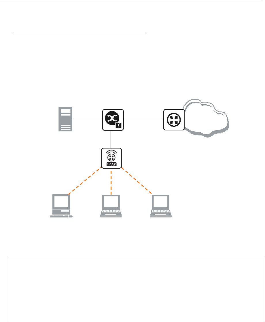
176 AT-WR4500 Series - IEEE 802.11abgh Outdoor Wireless Routers
RouterOS v3 Configuration and User Guide
8.6.7 Application Examples
PPPoE in a multipoint wireless 802.11g network
In a wireless network, the PPPoE server may be attached to an Access Point (as well as to a regular
station of wireless infrastructure). Either our RouterOS client or Windows PPPoE clients may connect to
the Access Point for PPPoE authentication. Further, for RouterOS clients, the radio interface may be set
to MTU 1600 so that the PPPoE interface may be set to MTU 1500. This optimizes the transmission of
1500 byte packets and avoids any problems associated with MTUs lower than 1500. It has not been
determined how to change the MTU of the Windows wireless interface at this moment.
Let us consider the following setup where the WR4500 Wireless AP offers wireless clients transparent
access to the local network with authentication:
Reserved for Wireless PPPoE Clients 10.1.0.100 – 10.1.0.200
[PPPoE
-
Server]
Ssid=mt
Frequency=2442
10.1.0.3/24
ether1
10.1.0.1/24
Internet
Server
10.1.0.2/24
10.1.0.200/32
10.1.0.199/32
10.1.0.198/32
Dynamic Interfaces: pppoe
-
inX
10.1.0.3/24
Figure 26: PPPoE Example
First of all, the wireless interface should be configured:
[admin@PPPoE-Server] interface wireless> set 0 mode=ap-bridge \
frequency=2442 band=2.4ghz-b/g ssid=mt disabled=no
[admin@PPPoE-Server] interface wireless> print
Flags: X - disabled, R - running
0 X name="wlan1" mtu=1500 mac-address=00:0C:42:18:5C:3D arp=enabled
interface-type=Atheros AR5413 mode=ap-bridge ssid="mt" frequency=2442
band=2.4ghz-b/g scan-list=default antenna-mode=ant-a wds-mode=disabled
wds-default-bridge=none wds-ignore-ssid=no default-authentication=yes
default-forwarding=yes default-ap-tx-limit=0 default-client-tx-limit=0
hide-ssid=no security-profile=default compression=no
[admin@PPPoE-Server] interface wireless>

AT-WR4500 Series - IEEE 802.11abgh Outdoor Wireless Routers 177
RouterOS v3 Configuration and User Guide
Now, configure the Ethernet interface, add the IP address and set the default route:
[admin@PPPoE-Server] ip address> add address=10.1.0.3/24 interface=Local
[admin@PPPoE-Server] ip address> print
Flags: X - disabled, I - invalid, D - dynamic
# ADDRESS NETWORK BROADCAST INTERFACE
0 10.1.0.3/24 10.1.0.0 10.1.0.255 Local
[admin@PPPoE-Server] ip address> /ip route
[admin@PPPoE-Server] ip route> add gateway=10.1.0.1
[admin@PPPoE-Server] ip route> print
Flags: X - disabled, A - active, D - dynamic,
C - connect, S - static, r - rip, b - bgp, o - ospf
# DST-ADDRESS G GATEWAY DISTANCE INTERFACE
0 ADC 10.1.0.0/24 Local
1 A S 0.0.0.0/0 r 10.1.0.1 1 Local
[admin@PPPoE-Server] ip route> /interface ethernet
[admin@PPPoE-Server] interface ethernet> set Local arp=proxy-arp
[admin@PPPoE-Server] interface ethernet> print
Flags: X - disabled, R - running
# NAME MTU MAC-ADDRESS ARP
0 R Local 1500 00:0C:42:03:25:53 proxy-arp
[admin@PPPoE-Server] interface ethernet>
We should add PPPoE server to the wireless interface:
[admin@PPPoE-Server] interface pppoe-server server> add interface=wlan1 \
service-name=mt one-session-per-host=yes disabled=no
[admin@PPPoE-Server] interface pppoe-server server> print
Flags: X - disabled
0 service-name="mt" interface=wlan1 max-mtu=1480 max-mru=1480
authentication=pap,chap,mschap1,mschap2 keepalive-timeout=10
one-session-per-host=yes max-sessions=0 default-profile=default
[admin@PPPoE-Server] interface pppoe-server server>
Finally, we can set up PPPoE clients:
[admin@PPPoE-Server] ip pool> add name=pppoe ranges=10.1.0.100-10.1.0.200
[admin@PPPoE-Server] ip pool> print
# NAME RANGES
0 pppoe 10.1.0.100-10.1.0.200
[admin@PPPoE-Server] ip pool> /ppp profile
[admin@PPPoE-Server] ppp profile> set default use-encryption=yes \
local-address=10.1.0.3 remote-address=pppoe
[admin@PPPoE-Server] ppp profile> print
Flags: * - default
0 * name="default" local-address=10.1.0.3 remote-address=pppoe
use-compression=no use-vj-compression=no use-encryption=yes only-one=no
change-tcp-mss=yes
1 * name="default-encryption" use-compression=default
use-vj-compression=default use-encryption=yes only-one=default
change-tcp-mss=default
[admin@PPPoE-Server] ppp profile> .. secret
[admin@PPPoE-Server] ppp secret> add name=w password=wkst service=pppoe
[admin@PPPoE-Server] ppp secret> add name=l password=ltp service=pppoe
[admin@PPPoE-Server] ppp secret> print
Flags: X - disabled
# NAME SERVICE CALLER-ID PASSWORD PROFILE REMOTE-ADDRESS
0 w pppoe wkst default 0.0.0.0
1 l pppoe ltp default 0.0.0.0
[admin@PPPoE-Server] ppp secret>
Thus we have completed the configuration and added two users: w and l who are able to connect to
Internet, using PPPoE client software.
Windows XP built-in client supports encryption, but RASPPPOE does not. So, if it is planned not to
support Windows clients older than Windows XP, it is recommended to switch require-encryption to
yes value in the default profile configuration. In other case, the server will accept clients that do not
encrypt data.

178 AT-WR4500 Series - IEEE 802.11abgh Outdoor Wireless Routers
RouterOS v3 Configuration and User Guide
8.6.8 Troubleshooting
Description
I can connect to my PPPoE server. The ping goes even through it, but I still cannot open web
pages
Make sure that you have specified a valid DNS server in the router (in /ip dns or in /ppp profile the
dns-server parameter).
The PPPoE server shows more than one active user entry for one client, when the clients
disconnect, they are still shown and active
Set the keepalive-timeout parameter (in the PPPoE server configuration) to 10 if You want clients to
be considered logged off if they do not respond for 10 seconds.
If the keepalive-timeout parameter is set to 0 and the only-one parameter (in PPP profile settings)
is set to yes then the clients might be able to connect only once. To resolve this problem one-session-
per-host parameter in PPPoE server configuration should be set to yes
I can get through the PPPoE link only small packets (eg. pings)
You need to change mss of all the packets passing through the PPPoE link to the value of PPPoE link's
MTU-40 at least on one of the peers. So for PPPoE link with MTU of 1480:
[admin@MT] interface pppoe-server server> set 0 max-mtu=1440 max-mru=1440
[admin@MT] interface pppoe-server server> print
Flags: X - disabled
0 service-name="mt" interface=wlan1 max-mtu=1440 max-mru=1440
authentication=pap,chap,mschap1,mschap2 keepalive-timeout=10
one-session-per-host=yes max-sessions=0 default-profile=default
[admin@MT] interface pppoe-server server>
My Windows XP client cannot connect to the PPPoE server.
You have to specify the "Service Name" in the properties of the XP PPPoE client. If the service name is
not set, or it does not match the service name of the RouterOS PPPoE server, you get the "line is busy"
errors, or the system shows "verifying password - unknown error"
I want to have logs for PPPoE connection establishment
Configure the logging feature under the /system logging facility and enable the PPP type logs
8.7 PPTP
Document revisi on: 1.4 (Tue Aug 09 12:01:2 1 GMT 200 5)
Applies to: V2.9
8.7.1 General Information
Summary
PPTP (Point to Point Tunnel Protocol) supports encrypted tunnels over IP. The RouterOS
implementation includes support for PPTP client and server.
General applications of PPTP tunnels:
secure router-to-router tunnels over the Internet
linking (bridging) local Intranets or LANs
accessing an Intranet/LAN of a company for remote (mobile) clients (employees)
Each PPTP connection is composed of a server and a client. The RouterOS may function as a server or
client - or, for various configurations, it may be the server for some connections and client for other
connections. For example, the client created below could connect to a Windows 2000 server, another
RouterOS Router, or another router which supports a PPTP server.

AT-WR4500 Series - IEEE 802.11abgh Outdoor Wireless Routers 179
RouterOS v3 Configuration and User Guide
Quick Setup Guide
To make a PPTP tunnel between 2 RouterOS routers with IP addresses 10.5.8.104 (PPTP server) and
10.1.0.172 (PPTP client), follow the next steps.
Configuration on PPTP server router:
Add a user:
[admin@PPTP-Server] ppp secret> add name=jack password=pass \
\... local-address=10.0.0.1 remote-address=10.0.0.2
Enable the PPTP server:
[admin@PPTP-Server] interface pptp-server server> set enabled=yes
Configuration on PPTP client router:
Add the PPTP client:
[admin@PPTP-Client] interface pptp-client> add user=jack password=pass \
\... connect-to=10.5.8.104 disabled=no
Specifications
Packages required: ppp
License required: Level1 (limited to 1 tunnel) , Level3 (limited to 200 tunnels) , Level5
Submenu level: /interface pptp-server, /interface pptp-client
Standards and Technologies: PPTP (RFC 2637)
Hardware usage: Not significant
Related Topics
IP Addresses and ARP
PPP User AAA
EoIP
Description
PPTP is a secure tunnel for transporting IP traffic using PPP. PPTP encapsulates PPP in virtual lines that
run over IP. PPTP incorporates PPP and MPPE (Microsoft Point to Point Encryption) to make encrypted
links. The purpose of this protocol is to make well-managed secure connections between routers as well
as between routers and PPTP clients (clients are available for and/or included in almost all OSs including
Windows).
Multilink PPP (MP) is supported in order to provide MRRU (the ability to transmit full-sized 1500 and
larger packets) and bridging over PPP links (using Bridge Control Protocol (BCP) that allows to send raw
Ethernet frames over PPP links). This way it is possible to setup bridging without EoIP. The bridge should
either have an administratively set MAC address or an Ethernet-like interface in it, as PPP links do not
have MAC addresses.
PPTP includes PPP authentication and accounting for each PPTP connection. Full authentication and
accounting of each connection may be done through a RADIUS client or locally.
MPPE 40bit RC4 and MPPE 128bit RC4 encryption are supported.
PPTP traffic uses TCP port 1723 and IP protocol GRE (Generic Routing Encapsulation, IP protocol ID
47), as assigned by the Internet Assigned Numbers Authority (IANA). PPTP can be used with most
firewalls and routers by enabling traffic destined for TCP port 1723 and protocol 47 traffic to be routed
through the firewall or router.
PPTP connections may be limited or impossible to setup though a masqueraded/NAT IP connection.
Please see the Microsoft and RFC links listed below for more information.

180 AT-WR4500 Series - IEEE 802.11abgh Outdoor Wireless Routers
RouterOS v3 Configuration and User Guide
Additional Resources
http://msdn.microsoft.com/library/backgrnd/html/understanding_pptp.htm
http://support.microsoft.com/support/kb/articles/q162/8/47.asp
http://support.microsoft.com/kb/154062/en-us
http://www.ietf.org/rfc/rfc2637.txt?number=2637
http://www.ietf.org/rfc/rfc3078.txt?number=3078
http://www.ietf.org/rfc/rfc3079.txt?number=3079
8.7.2 PPTP Client Setup
Submenu level: /interface pptp-client
Property Description
add-default-route (yes | no; default: no) - whether to use the server which this client is connected to
as its default router (gateway)
allow (multiple choice: mschap2, mschap1, chap, pap; default: mschap2, mschap1, chap, pap) - the
protocol to allow the client to use for authentication
connect-to (IP address) - The IP address of the PPTP server to connect to
max-mru (integer; default: 1460) - Maximum Receive Unit. The optimal value is the MRU of the
interface the tunnel is working over decreased by 40 (so, for 1500-byte Ethernet link, set the MRU to
1460 to avoid fragmentation of packets)
max-mtu (integer; default: 1460) - Maximum Transmission Unit. The optimal value is the MTU of the
interface the tunnel is working over decreased by 40 (so, for 1500-byte Ethernet link, set the MTU to
1460 to avoid fragmentation of packets)
mrru (integer: 512..65535; default: disabled) - maximum packet size that can be received on the link. If a
packet is bigger than tunnel MTU, it will be split into multiple packets, allowing full size IP or Ethernet
packets to be sent over the tunnel
disabled - disable MRRU on this link
name (name; default: pptp-outN) - interface name for reference
password (text; default: "") - user password to use when logging to the remote server
profile (name; default: default) - profile to use when connecting to the remote server
user (text) - user name to use when logging on to the remote server
Specifying MRRU means enabling MP (Multilink PPP) over single link. This protocol is used to split big
packets into smaller ones. Under Windows it can be enabled in Networking tag, Settings button,
"Negotiate multi-link for single link connections". Thei
r MRRU is hardcoded to 1614. This setting is
usefull to overcome PathMTU discovery failures. The MP should be enabled on both peers.
Example
To set up PPTP client named test2 using unsername john with password john to connect to the
10.1.1.12 PPTP server and use it as the default gateway:
[admin@AT-WR4562] interface pptp-client> add name=test2 connect-to=10.1.1.12 \
\... user=john add-default-route=yes password=john
[admin@AT-WR4562] interface pptp-client> print
Flags: X - disabled, R - running
0 X name="test2" mtu=1460 mru=1460 connect-to=10.1.1.12 user="john"
password="john" profile=default add-default-route=yes
allow=pap,chap,mschap1,mschap2
[admin@AT-WR4562] interface pptp-client> enable 0

AT-WR4500 Series - IEEE 802.11abgh Outdoor Wireless Routers 181
RouterOS v3 Configuration and User Guide
8.7.3 Monitoring PPTP Client
Command name: /interface pptp-client monitor
Property Description
encoding (text) - encryption and encoding (if asymmetric, separated with '/') being used in this
connection
idle-time (read-only: time) - time since the last packet has been transmitted over this link
mru (read-only: integer) - effective MRU of the link
mtu (read-only: integer) - effective MTU of the link
status (text) - status of the client
dialing - attempting to make a connection
verifying password... - connection has been established to the server, password verification in progress
connected - self-explanatory
terminated - interface is not enabled or the other side will not establish a connection
uptime (time) - connection time displayed in days, hours, minutes and seconds
Example
Example of an established connection:
[admin@AT-WR4562] interface pptp-client> monitor test2
status: "connected"
uptime: 6h44m9s
idle-time: 6h44m9s
encoding: "MPPE128 stateless"
mtu: 1460
mru: 1460
[admin@AT-WR4562] interface pptp-client>
8.7.4 PPTP Server Setup
Submenu level: /interface pptp-server server
Description
The PPTP server creates a dynamic interface for each connected PPTP client. The PPTP connection count
from clients depends on the license level you have. Level1 license allows 1 PPTP client, Level3 or Level4
licenses up to 200 clients, and Level5 or Level6 licenses do not have PPTP client limitations.
Property Description
authentication (multiple choice: pap | chap | mschap1 | mschap2; default: mschap2) - authentication
algorithm
default-profile - default profile to use
enabled (yes | no; default: no) - defines whether PPTP server is enabled or not
keepalive-timeout (time; default: 30) - defines the time period (in seconds) after which the router is
starting to send keepalive packets every second. If no traffic and no keepalive responses has came for that
period of time (i.e. 2 * keepalive-timeout), not responding client is proclaimed disconnected
max-mru (integer; default: 1460) - Maximum Receive Unit. The optimal value is the MRU of the
interface the tunnel is working over decreased by 40 (so, for 1500-byte ethernet link, set the MRU to
1460 to avoid fragmentation of packets)
max-mtu (integer; default: 1460) - Maximum Transmission Unit. The optimal value is the MTU of the
interface the tunnel is working over decreased by 40 (so, for 1500-byte ethernet link, set the MTU to
1460 to avoid fragmentation of packets)
mrru (integer: 512..65535; default: disabled) - maximum packet size that can be received on the link. If a
packet is bigger than tunnel MTU, it will be split into multiple packets, allowing full size IP or Ethernet
packets to be sent over the tunnel
disabled - disable MRRU on this link

182 AT-WR4500 Series - IEEE 802.11abgh Outdoor Wireless Routers
RouterOS v3 Configuration and User Guide
Specifying MRRU means enabling MP (Multilink PPP) over single link. This protocol is used to split big
packets into smaller ones. Under Windows it can be enabled in Networking tag, Settings button,
"Negotiate multi-link for single link connections". Thei
r MRRU is hardcoded to 1614. This setting is
usefull to overcome PathMTU discovery failures. The MP should be enabled on both peers.
Example
To enable PPTP server:
[admin@AT-WR4562] interface pptp-server server> set enabled=yes
[admin@AT-WR4562] interface pptp-server server> print
enabled: yes
mtu: 1460
mru: 1460
authentication: mschap2,mschap1
keepalive-timeout: 30
default-profile: default
[admin@AT-WR4562] interface pptp-server server>
8.7.5 PPTP Users
Description
The PPTP users are authenticated through a RADIUS server (if configured), and if RADIUS fails, then the
local PPP user databese is used. See the respective manual sections for more information:
• RADIUS client
• PPP User AAA
8.7.6 PPTP Tunnel Interfaces
Submenu level: /interface pptp-server
Description
There are two types of interface (tunnel) items in PPTP server configuration - static users and dynamic
connections. An interface is created for each tunnel established to the given server. Static interfaces are
added administratively if there is a need to reference the particular interface name (in firewall rules or
elsewhere) created for the particular user. Dynamic interfaces are added to this list automatically
whenever a user is connected and its username does not match any existing static entry (or in case the
entry is active already, as there can not be two separate tunnel interfaces referenced by the same name).
Dynamic interfaces appear when a user connects and disappear once the user disconnects, so it is
impossible to reference the tunnel created for that use in router configuration (for example, in firewall),
so if you need a persistent rules for that user, create a static entry for him/her. Otherwise it is safe to use
dynamic configuration.
In both cases PPP users must be configured properly.
Property Description
client-address (read-only: IP address) - shows the IP address of the connected client
encoding (read-only: text) - encryption and encoding (if asymmetric, separated with '/') being used in this
connection
mru (read-only: integer) - client's MRU
mtu (read-only: integer) - client's MTU
name (name) - interface name
uptime (read-only: time) - shows how long the client is connected
user (name) - the name of the user that is configured statically or added dynamically
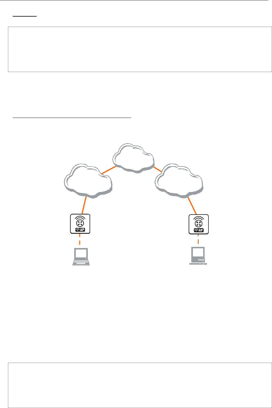
AT-WR4500 Series - IEEE 802.11abgh Outdoor Wireless Routers 183
RouterOS v3 Configuration and User Guide
Example
To add a static entry for ex1 user:
[admin@AT-WR4562] interface pptp-server> add user=ex1
[admin@AT-WR4562] interface pptp-server> print
Flags: X - disabled, D - dynamic, R - running
# NAME USER MTU CLIENT-ADDRESS UPTIME ENC...
0 DR <pptp-ex> ex 1460 10.0.0.202 6m32s none
1 pptp-in1 ex1
[admin@AT-WR4562] interface pptp-server>
In this example an already connected user ex is shown besides the one we just added. Now the interface
named pptp-in1 can be referenced from anywhere in RouterOS configuration like a regular interface.
8.7.7 PPTP Application Examples
Router-to-Router Secure Tunnel Example
The following is an example of connecting two Intranets using an encrypted PPTP tunnel over the
Internet.
[
Remote Office
]
192.168.81.1/24
[
Home Office
]
192.168.80.1/24
Internet
ISP #2
192.168.81.0/24
ISP #1
192.168.80.0/24
10.150.2.254/24
10.150.2.1/24
10.150.1.1/24
10.150.1.254/24
Figure 27: Network Setup without PPTP enabled
There are two routers in this example:
[HomeOffice]
Interface LocalHomeOffice 10.150.2.254/24
Interface ToInternet 192.168.80.1/24
[RemoteOffice]
Interface ToInternet 192.168.81.1/24
Interface LocalRemoteOffice 10.150.1.254/24
Each router is connected to a different ISP. One router can access another router through the Internet.
On the Preforma PPTP server a user must be set up for the client:
[admin@HomeOffice] ppp secret> add name=ex service=pptp password=lkjrht
local-address=10.0.103.1 remote-address=10.0.103.2
[admin@HomeOffice] ppp secret> print detail
Flags: X - disabled
0 name="ex" service=pptp caller-id="" password="lkjrht" profile=default
local-address=10.0.103.1 remote-address=10.0.103.2 routes==""
[admin@HomeOffice] ppp secret>
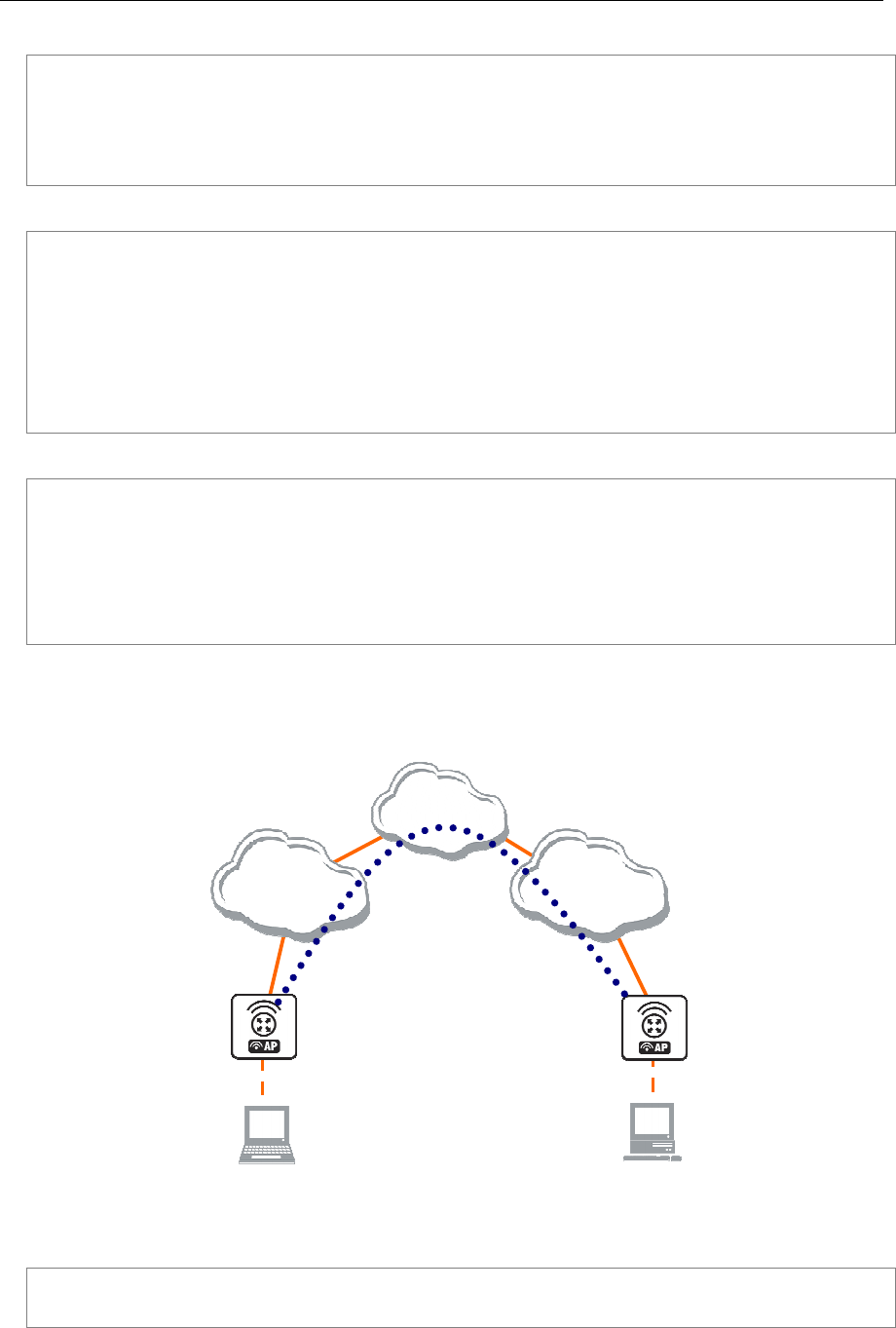
184 AT-WR4500 Series - IEEE 802.11abgh Outdoor Wireless Routers
RouterOS v3 Configuration and User Guide
Then the user should be added in the PPTP server list:
[admin@HomeOffice] interface pptp-server> add user=ex
[admin@HomeOffice] interface pptp-server> print
Flags: X - disabled, D - dynamic, R - running
# NAME USER MTU CLIENT-ADDRESS UPTIME ENC...
0 pptp-in1 ex
[admin@HomeOffice] interface pptp-server>
And finally, the server must be enabled:
[admin@HomeOffice] interface pptp-server server> set enabled=yes
[admin@HomeOffice] interface pptp-server server> print
enabled: yes
max-mtu: 1460
max-mru: 1460
mrru: disabled
authentication: mschap2
keepalive-timeout: 30
default-profile: default
[admin@HomeOffice] interface pptp-server server>
Add a PPTP client to the RemoteOffice router:
[admin@RemoteOffice] interface pptp-client> add connect-to=192.168.80.1 user=ex \
\... password=lkjrht disabled=no
[admin@RemoteOffice] interface pptp-client> print
Flags: X - disabled, R - running
0 R name="pptp-out1" mtu=1460 mru=1460 connect-to=192.168.80.1 user="ex"
password="lkjrht" profile=default add-default-route=no
allow=pap,chap,mschap1,mschap2
[admin@RemoteOffice] interface pptp-client>
Thus, a PPTP tunnel is created between the routers. This tunnel is like an Ethernet point-to-point
connection between the routers with IP addresses 10.0.103.1 and 10.0.103.2 at each router. It enables
'direct' communication between the routers over third party networks.
[
Remote Office
]
192.168.81.1/24
[
Home Office
]
192.168.80.1/24
Internet
ISP #2
192.168.81.0/24
ISP #1
192.168.80.0/24
10.150.2.254/24
10.150.2.1/24
10.150.1.1/24
10.150.1.254/24
FromRemoteOffice
10.0.103.1/24
Tunnel_To_Home
Office
10.0.103.2/24
Encrypted
PPTP Tunnel
Figure 28: Network Setup with encrypted PPTP Tunnel
To route the local Intranets over the PPTP tunnel you need to add these routes:
[admin@HomeOffice] > ip route add dst-address 10.150.1.0/24 gateway 10.0.103.2
[admin@RemoteOffice] > ip route add dst-address 10.150.2.0/24 gateway 10.0.103.1

AT-WR4500 Series - IEEE 802.11abgh Outdoor Wireless Routers 185
RouterOS v3 Configuration and User Guide
On the PPTP server it can alternatively be done using routes parameter of the user configuration:
[admin@HomeOffice] ppp secret> print detail
Flags: X - disabled
0 name="ex" service=pptp caller-id="" password="lkjrht" profile=default
local-address=10.0.103.1 remote-address=10.0.103.2 routes==""
[admin@HomeOffice] ppp secret> set 0 routes="10.150.1.0/24 10.0.103.2 1"
[admin@HomeOffice] ppp secret> print detail
Flags: X - disabled
0 name="ex" service=pptp caller-id="" password="lkjrht" profile=default
local-address=10.0.103.1 remote-address=10.0.103.2
routes="10.150.1.0/24 10.0.103.2 1"
[admin@HomeOffice] ppp secret>
Test the PPTP tunnel connection:
[admin@RemoteOffice]> /ping 10.0.103.1
10.0.103.1 pong: ttl=255 time=3 ms
10.0.103.1 pong: ttl=255 time=3 ms
10.0.103.1 pong: ttl=255 time=3 ms
ping interrupted
3 packets transmitted, 3 packets received, 0% packet loss
round-trip min/avg/max = 3/3.0/3 ms
Test the connection through the PPTP tunnel to the LocalHomeOffice interface:
[admin@RemoteOffice]> /ping 10.150.2.254
10.150.2.254 pong: ttl=255 time=3 ms
10.150.2.254 pong: ttl=255 time=3 ms
10.150.2.254 pong: ttl=255 time=3 ms
ping interrupted
3 packets transmitted, 3 packets received, 0% packet loss
round-trip min/avg/max = 3/3.0/3 ms
To bridge a LAN over this secure tunnel, please see the example in the 'EoIP' section of the manual. To
set the maximum speed for traffic over this tunnel, please consult the 'Queues' section.
Connecting a Remote Client via PPTP Tunnel
The following example shows how to connect a computer to a remote office network over PPTP
encrypted tunnel giving that computer an IP address from the same network as the remote office has
(without need of bridging over EoIP tunnels)
Please, consult the respective manual on how to set up a PPTP client with the software you are using.
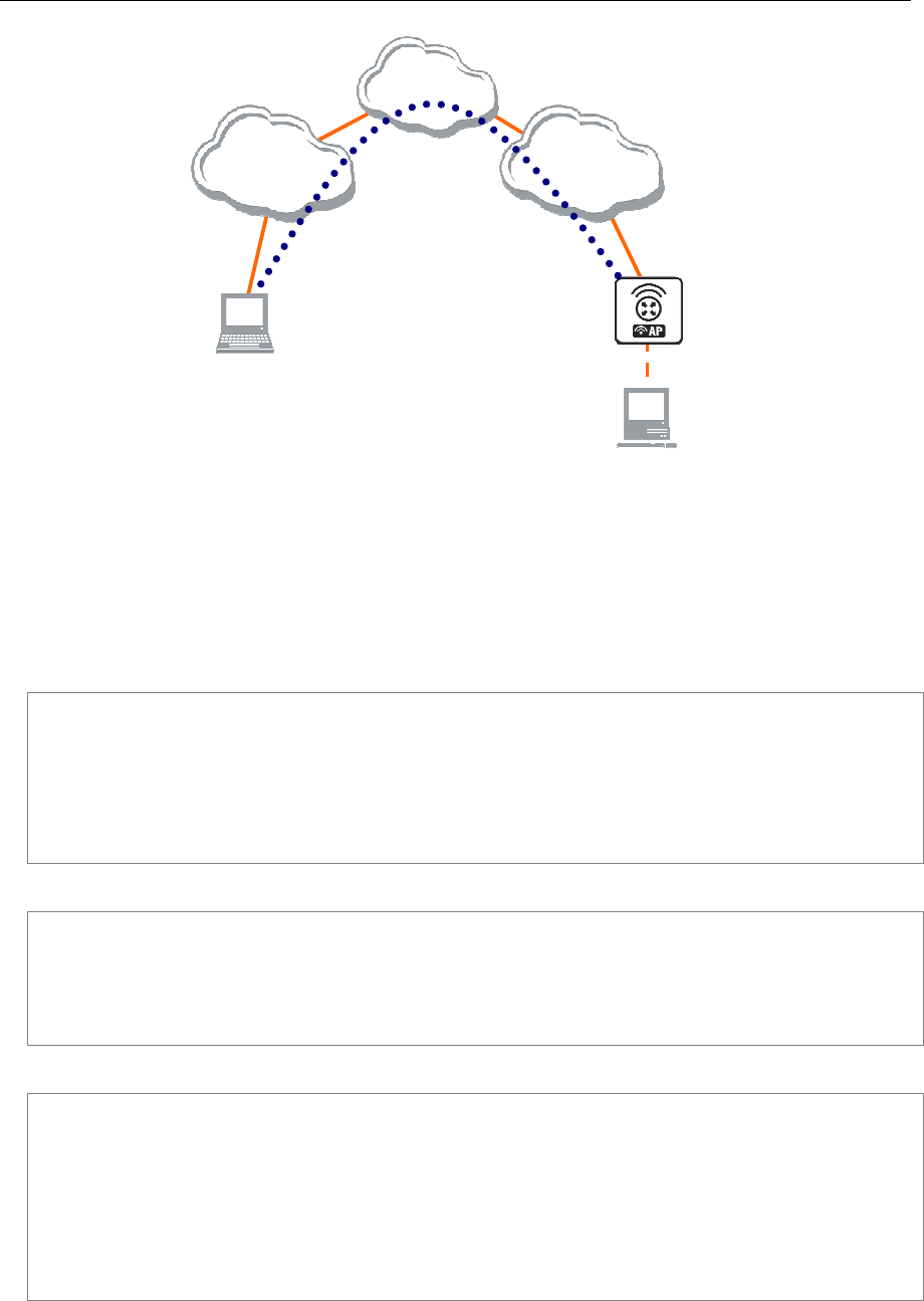
186 AT-WR4500 Series - IEEE 802.11abgh Outdoor Wireless Routers
RouterOS v3 Configuration and User Guide
[
Remote Office
]
192.168.81.1/24
Internet
ISP #2
192.168.81.0/24
ISP #1
192.168.80.0/24
192
.1
68
.
80
.
111
/
24
10.150.1.1/24
10.150.1.254/24
To
RemoteOffice
10.150.1.1/32
Tunnel_To_Home
Office
10.150.1.254/32
Encrypted
PPTP Tunnel
Figure 29: Connecting a Remote Client via and Encrypted PPTP Tunnel
The router in this example:
[RemoteOffice]
Interface ToInternet 192.168.81.1/24
Interface Office 10.150.1.254/24
The client computer can access the router through the Internet.
On the PPTP server a user must be set up for the client:
[admin@RemoteOffice] ppp secret> add name=ex service=pptp password=lkjrht
local-address=10.150.1.254 remote-address=10.150.1.2
[admin@RemoteOffice] ppp secret> print detail
Flags: X - disabled
0 name="ex" service=pptp caller-id="" password="lkjrht" profile=default
local-address=10.150.1.254 remote-address=10.150.1.2 routes==""
[admin@RemoteOffice] ppp secret>
Then the user should be added in the PPTP server list:
[admin@RemoteOffice] interface pptp-server> add name=FromLaptop user=ex
[admin@RemoteOffice] interface pptp-server> print
Flags: X - disabled, D - dynamic, R - running
# NAME USER MTU CLIENT-ADDRESS UPTIME ENC...
0 FromLaptop ex
[admin@RemoteOffice] interface pptp-server>
And the server must be enabled:
[admin@RemoteOffice] interface pptp-server server> set enabled=yes
[admin@RemoteOffice] interface pptp-server server> print
enabled: yes
max-mtu: 1460
max-mru: 1460
mrru: disabled
authentication: mschap2
keepalive-timeout: 30
default-profile: default
[admin@RemoteOffice] interface pptp-server server>

AT-WR4500 Series - IEEE 802.11abgh Outdoor Wireless Routers 187
RouterOS v3 Configuration and User Guide
Finally, the proxy APR must be enabled on the 'Office' interface:
[admin@RemoteOffice] interface ethernet> set Office arp=proxy-arp
[admin@RemoteOffice] interface ethernet> print
Flags: X - disabled, R - running
# NAME MTU MAC-ADDRESS ARP
0 R ToInternet 1500 00:30:4F:0B:7B:C1 enabled
1 R Office 1500 00:30:4F:06:62:12 proxy-arp
[admin@RemoteOffice] interface ethernet>
PPTP Setup for Windows
Microsoft provides PPTP client support for Windows NT, 2000, ME, 98SE, and 98. Windows 98SE, 2000,
and ME include support in the Windows setup or automatically install PPTP. For 95, NT, and 98,
installation requires a download from Microsoft. Many ISPs have made help pages to assist clients with
Windows PPTP installation.
Sample instructions for PPTP (VPN) installation and client setup - Windows 98SE
If the VPN (PPTP) support is installed, select 'Dial-up Networking' and 'Create a new connection'. The
option to create a 'VPN' should be selected. If there is no 'VPN' options, then follow the installation
instructions below. When asked for the 'Host name or IP address of the VPN server', type the IP address
of the router. Double-click on the 'new' icon and type the correct user name and password (must also be
in the user database on the router or RADIUS server used for authentication).
The setup of the connections takes nine seconds after selection the 'connect' button. It is suggested that
the connection properties be edited so that 'NetBEUI', 'IPX/SPX compatible', and 'Log on to network' are
unselected. The setup time for the connection will then be two seconds after the 'connect' button is
selected.
To install the 'Virtual Private Networking' support for Windows 98SE, go to the 'Setting' menu from the
main 'Start' menu. Select 'Control Panel', select 'Add/Remove Program', select the 'Windows setup' tab,
select the 'Communications' software for installation and 'Details'. Go to the bottom of the list of
software and select 'Virtual Private Networking' to be installed.
8.7.8 Troubleshooting
Description
I use firewall and I cannot establish PPTP connection
Make sure the TCP connections to port 1723 can pass through both directions between your sites. Also,
IP protocol 47 should be passed through.
8.8 IP Security
Document revisi on: 3.4 (Tue Nov 22 14: 19:15 GMT 2005)
Applies to: V2.9
8.8.1 General Information
Specifications
Packages required: security
License required: Level1
Submenu level: /ip ipsec
Standards and Technologies: IPsec
Hardware usage: consumes a lot of CPU time (Intel Pentium MMX or AMD K6 suggested as a minimal
configuration)
Related Topics
IP Addresses and ARP
Firewall and QoS

188 AT-WR4500 Series - IEEE 802.11abgh Outdoor Wireless Routers
RouterOS v3 Configuration and User Guide
Description
IPsec (IP Security) supports secure (encrypted) communications over IP networks.
Encryption
After packet is src-natted (if needed), but before putting it into interface queue, IPsec policy database is
consulted to find out if packet should be encrypted. Security Policy Database (SPD) is a list of rules that
have two parts:
Packet matching - packet source/destination, protocol and ports (for TCP and UDP) are compared to
values in policy rules, one after another
Action - if rule matches action specified in rule is performed:
none - continue with the packet as if there was no IPsec
discard - drop the packet
encrypt - apply IPsec transformations to the packet
Each SPD rule can be associated with several Security Associations (SA) that determine packet encryption
parameters (key, algorithm, SPI).
Note that packet can only be encrypted if there is a usable SA for policy rule. Same SA may be used for
different policies, unless especially prohibited by a policy. By setting SPD rule security "level" user can
control what happens when there is no valid SA for policy rule:
use - if there is no valid SA, send packet unencrypted (like accept rule)
require - drop packet, and ask IKE daemon to establish a new SA.
unique - same as require, but establish a unique SA for this policy (i.e., this SA may not be shared with
other policy)
Decryption
When encrypted packet is received for local host (after dst-nat and input filter), the appropriate SA is
looked up to decrypt it (using packet source, destination, security protocol and SPI value). If no SA is
found, the packet is dropped. If SA is found, packet is decrypted. Then decrypted packet's fields are
compared to the policy rule that SA is linked to. If the packet does not match the policy rule, it is
dropped. If the packet is decrypted fine (or authenticated fine) it is "received once more" - it goes
through dst-nat and routing (which finds out what to do - either forward or deliver locally) again.
before forward and input firewall chains, a packet that was not decrypted on local host is
compared with SPD reversing its matching rules. If SPD requires encryption (there is valid SA
associated with matching SPD rule), the packet is dropped. This is called incoming policy
check.
Internet Key Exchange
The Internet Key Exchange (IKE) is a protocol that provides authenticated keying material for Internet
Security Association and Key Management Protocol (ISAKMP) framework. There are other key exchange
schemes that work with ISAKMP, but IKE is the most widely used one. Together they provide means for
authentication of hosts and automatic management of security associations (SA).
Most of the time IKE daemon is doing nothing. There are two possible situations when it is activated:
• There is some traffic caught by a policy rule which needs to become encrypted or authenticated, but
the policy doesn't have any SAs. The policy notifies IKE daemon about that, and IKE daemon initiates
connection to remote host.
• IKE daemon responds to remote connection.
In both cases, peers establish connection and execute 2 phases:
• Phase 1 - The peers agree upon algorithms they will use in the following IKE messages and
authenticate. The keying material used to derive keys for all SAs and to protect following ISAKMP
exchanges between hosts is generated also.

AT-WR4500 Series - IEEE 802.11abgh Outdoor Wireless Routers 189
RouterOS v3 Configuration and User Guide
• Phase 2 - The peers establish one or more SAs that will be used by IPsec to encrypt data. All SAs
established by IKE daemon will have lifetime values (either limiting time, after which SA will become
invalid, or amount of data that can be encrypted by this SA, or both).
There are two lifetime values - soft and hard. When SA reaches it's soft lifetime treshold, the IKE daemon
receives a notice and starts another phase 2 exchange to replace this SA with fresh one. If SA reaches
hard lifetime, it is discarded.
IKE can optionally provide a Perfect Forward Secrecy (PFS), which is a property of key exchanges, that, in
turn, means for IKE that compromising the long term phase 1 key will not allow to easily gain access to all
IPsec data that is protected by SAs established through this phase 1. It means an additional keying material
is generated for each phase 2.
Generation of keying material is computationally very expensive. Exempli gratia, the use of modp8192
group can take several seconds even on very fast computer. It usually takes place once per phase 1
exchange, which happens only once between any host pair and then is kept for long time. PFS adds this
expensive operation also to each phase 2 exchange.
.
Diffie-Hellman MODP Groups
Diffie-Hellman (DH) key exchange protocol allows two parties without any initial shared secret to create
one securely. The following Modular Exponential (MODP) Diffie-Hellman (also known as "Oakley")
Groups are supported:
Diffie-Hellman Group Modulus Reference
Group 1 768 bits RFC2409
Group 2 1024 bits MODP group RFC2409
Group 3 EC2N group on GP(2^155) RFC2409
Group 4 EC2N group on GP(2^185) RFC2409
Group 5 1536 bits MODP group RFC3526
IKE Traffic
To avoid problems with IKE packets hit some SPD rule and require to encrypt it with not yet established
SA (that this packet perhaps is trying to establish), locally originated packets with UDP source port 500
are not processed with SPD. The same way packets with UDP destination port 500 that are to be
delivered locally are not processed in incoming policy check.
Setup Procedure
To get IPsec to work with automatic keying using IKE-ISAKMP you will have to configure policy, peer
and proposal (optional) entries.
For manual keying you will have to configure policy and manual-sa entries.
8.8.2 Policy Settings
Submenu level: /ip ipsec policy
Description
Policy table is needed to determine whether security settings should be applied to a packet.
Property Description
action (none | discard | encrypt; default: accept) - specifies what action to undertake with a packet that
matches the policy
none - pass the packet unchanged
discard - drop the packet
encrypt - apply transformations specified in this policy and it's SA
dont-fragment (clear | inherit | set; default: clear) - The state of the don't fragment IP header field
clear - clear (unset) the field, so that packets previously marked as don't fragment can be fragmented.
This setting is recommended as the packets are getting larger when IPsec protocol is applied to them, so

190 AT-WR4500 Series - IEEE 802.11abgh Outdoor Wireless Routers
RouterOS v3 Configuration and User Guide
large packets with don't fragment flag will not be able to pass the router
inherit - do not change the field
set - set the field, so that each packet matching the rule will not be fragmented. Not recommended
dst-address (IP address/netmask:port; default: 0.0.0.0/32:any) - destination IP address
dynamic (read-only: flag) - whether the rule has been created dynamically
in-accepted (integer) - how many incoming packets were passed through by the policy without an
attempt to decrypt
in-dropped (integer) - how many incoming packets were dropped by the policy without an attempt to
decrypt
in-transformed (integer) - how many incoming packets were decrypted (ESP) and/or verified (AH) by
the policy
inactive (read-only: flag) - whether the rule is inactive (it may become inactive due to some
misconfiguration)
ipsec-protocols (multiple choice: ah | esp; default: esp) - specifies what combination of Authentication
Header and Encapsulating Security Payload protocols you want to apply to matched traffic. AH is applied
after ESP, and in case of tunnel mode ESP will be applied in tunnel mode and AH - in transport mode
level (unique | require | use; default: require) - specifies what to do if some of the SAs for this policy
cannot be found:
use - skip this transform, do not drop packet and do not acquire SA from IKE daemon
require - drop packet and acquire SA
unique - drop packet and acquire a unique SA that is only used with this particular policy
manual-sa (name; default: none) - name of manual-sa template that will be used to create SAs for this
policy
none - no manual keys are set
out-accepted (integer) - how many outgoing packets were passed through by the policy without an
attempt to encrypt
out-dropped (integer) - how many outgoing packets were dropped by the policy without an attempt to
encrypt
out-transformed (integer) - how many outgoing packets were encrypted (ESP) and/or signed (AH)
ph2-state (read-only: expired | no-phase2 | established) - indication of the progress of key establishing
expired - there are some leftovers from previous phase2. In general it is similar to no-phase2
no-phase2 - no keys are estabilished at the moment
estabilished - Appropriate SAs are in place and everything should be working fine
priority (integer; default: 0) - policy ordering classificator (signed integer). Larger number means higher
priority
proposal (name; default: default) - name of proposal information that will be sent by IKE daemon to
establish SAs for this policy
protocol (name | integer; default: all) - IP packet protocol to match
sa-dst-address (IP address; default: 0.0.0.0) - SA destination IP address (remote peer)
sa-src-address (IP address; default: 0.0.0.0) - SA source IP address (local peer)
src-address (IP address/netmask:port; default: 0.0.0.0/32:any) - source IP address
tunnel (yes | no; default: no) - specifies whether to use tunnel mode
All packets are IPIP encapsulated in tunnel mode, and their new IP header src-address and dst-
address are set to sa-src-address and sa-dst-address va
lues of this policy. If you do not use tunnel
mode (id est
you use transport mode), then only packets whose source and destination addresses are the
same as sa-src-address and sa-dst-address
can be processed by this policy. Transport mode can only
work wit
h packets that originate at and are destined for IPsec peers (hosts that established security
associations). To encrypt traffic between networks (or a network and a host) you have to use tunnel
mode.
It is good to have dont-fragment cleared because encrypt
ed packets are always bigger than original
and thus they may need fragmentation.
If you are using IKE to establish SAs automatically, then policies on both routers must exactly match
each other, id est src-address=1.2.3.0/27 on one router and dst-address=1.2.3.0/28
on another
would not work. Source address values on one router MUST be equal to destination address values on
the other one, and vice versa.

AT-WR4500 Series - IEEE 802.11abgh Outdoor Wireless Routers 191
RouterOS v3 Configuration and User Guide
Example
To add a policy to encrypt all the traffic between two hosts (10.0.0.147 and 10.0.0.148), we need do the
following:
[admin@WiFi] ip ipsec policy> add sa-src-address=10.0.0.147 \
\... sa-dst-address=10.0.0.148 action=encrypt
[admin@WiFi] ip ipsec policy> print
Flags: X - disabled, D - dynamic, I - inactive
0 src-address=10.0.0.147/32:any dst-address=10.0.0.148/32:any protocol=all
action=encrypt level=require ipsec-protocols=esp tunnel=no
sa-src-address=10.0.0.147 sa-dst-address=10.0.0.148 proposal=default
manual-sa=none priority=0
[admin@WiFi] ip ipsec policy>
to view the policy statistics, do the following:
[admin@WiFi] ip ipsec policy> print stats
Flags: X - disabled, D - dynamic, I - invalid
0 src-address=10.0.0.147/32:any dst-address=10.0.0.148/32:any
protocol=all ph2-state=no-phase2 in-accepted=0 in-dropped=0
out-accepted=0 out-dropped=0 encrypted=0 not-encrypted=0 decrypted=0
not-decrypted=0
[admin@WiFi] ip ipsec policy>
8.8.3 Peers
Submenu level: /ip ipsec peer
Description
Peer configuration settings are used to establish connections between IKE daemons (phase 1
configuration). This connection then will be used to negotiate keys and algorithms for SAs.
Property Description
address (IP address/netmask:port; default: 0.0.0.0/32:500) - address prefix. If remote peer's address
matches this prefix, then this peer configuration is used while authenticating and establishing phase 1. If
several peer's addresses matches several configuration entries, the most specific one (i.e. the one with
largest netmask) will be used
auth-method (pre-shared-key | rsa-signature; default: pre-shared-key) - authentication method
pre-shared-key - authenticate by a password (secret) string shared between the peers
rsa-signature - authenticate using a pair of RSA certificates
certificate (name) - name of a certificate on the local side (signing packets; the certificate must have
private key). Only needed if RSA signature authentication method is used
dh-group (multiple choice: ec2n155 | ec2n185 | modp768 | modp1024 | modp1536; default: modp1024) -
Diffie-Hellman group (cipher strength)
enc-algorithm (multiple choice: des | 3des | aes-128 | aes-192 | aes-256; default: 3des) - encryption
algorithm. Algorithms are named in strength increasing order
exchange-mode (multiple choice: main | aggressive | base; default: main) - different ISAKMP phase 1
exchange modes according to RFC 2408. Do not use other modes then main unless you know what you
are doing
generate-policy (yes | no; default: no) - allow this peer to establish SA for non-existing policies. Such
policies are created dynamically for the lifetime of SA. This way it is possible, for example, to create IPsec
secured L2TP tunnels, or any other setup where remote peer's IP address is not known at the
configuration time
hash-algorithm (multiple choice: md5 | sha1; default: md5) - hashing algorithm. SHA (Secure Hash
Algorithm) is stronger, but slower
lifebytes (integer; default: 0) - phase 1 lifetime: specifies how much bytes can be transferred before SA is
discarded
0 - SA expiration will not be due to byte count excess

192 AT-WR4500 Series - IEEE 802.11abgh Outdoor Wireless Routers
RouterOS v3 Configuration and User Guide
lifetime (time; default: 1d) - phase 1 lifetime: specifies how long the SA will be valid; SA will be discarded
after this time
nat-traversal (yes | no; default: no) - use Linux NAT-T mechanism to solve IPsec incompatibility with
NAT routers inbetween IPsec peers. This can only be used with ESP protocol (AH is not supported by
design, as it signes the complete packet, including IP header, which is changed by NAT, rendering AH
signature invalid). The method encapsulates IPsec ESP traffic into UDP streams in order to overcome
some minor issues that made ESP incompatible with NAT
proposal-check (multiple choice: claim | exact | obey | strict; default: strict) - phase 2 lifetime check
logic:
claim - take shortest of proposed and configured lifetimes and notify initiator about it
exact - require lifetimes to be the same
obey - accept whatever is sent by an initiator
strict - if proposed lifetime is longer than the default then reject proposal otherwise accept proposed
lifetime
remote-certificate (name) - name of a certificate for authenticating the remote side (validating packets;
no private key required). Only needed if RSA signature authentication method is used
secret (text; default: "") - secret string (in case pre-shared key authentication is used). If it starts with
'0x', it is parsed as a hexadecimal value
send-initial-contact (yes | no; default: yes) - specifies whether to send initial IKE information or wait
for remote side
AES (Advanced Encryption Standard) encryption algorithms are much faster than DES, so it is
recommended to use this algorithm class whenever possible. But, AES's speed is also its drawback as it
potentially can be cracked faster, so use AES-256 when you need security or AES-128 when speed is also
important. Both peers MUST have the same encryption and authentication algorithms, DH group and
exchange mode. Some legacy hardware may support only DES and MD5.You should set generate-
policy flag to yes only for trusted peers, because there is no verification done for the established policy.
To protect yourself against possible unwanted events, add policies with action=none for all networks you
don't want to be encrypted at the top of policy list. Since dynamic policies are added at the bottom of the
list, they will not be able to override your configuration. Alternatively you can use policy priorities to enforce
some policies to be active always.
Example
To define new peer configuration for 10.0.0.147 peer with secret=gwejimezyfopmekun:
[admin@WiFi] ip ipsec peer>add address=10.0.0.147/32 \
\... secret=gwejimezyfopmekun
[admin@WiFi] ip ipsec peer> print
Flags: X - disabled
0 address=10.0.0.147/32:500 secret="gwejimezyfopmekun" generate-policy=no
exchange-mode=main send-initial-contact=yes proposal-check=obey
hash-algorithm=md5 enc-algorithm=3des dh-group=modp1024 lifetime=1d
lifebytes=0
[admin@WiFi] ip ipsec peer>
8.8.4 Remote Peer Statistics
Submenu level: /ip ipsec remote-peers
Description
This submenu provides you with various statistics about remote peers that currently have established
phase 1 connections with this router. Note that if peer doesn't show up here, it doesn't mean that no
IPsec traffic is being exchanged with it. For example, manually configured SAs will not show up here.
Property Description
local-address (read-only: IP address) - local ISAKMP SA address

AT-WR4500 Series - IEEE 802.11abgh Outdoor Wireless Routers 193
RouterOS v3 Configuration and User Guide
remote-address (read-only: IP address) - peer's IP address
side (multiple choice, read-only: initiator | responder) - shows which side initiated the connection
initiator - phase 1 negotiation was started by this router
responder - phase 1 negotiation was started by peer
state (read-only: text) - state of phase 1 negotiation with the peer
estabilished - normal working state
Example
To see currently estabilished SAs:
[admin@WiFi] ip ipsec> remote-peers print
0 local-address=10.0.0.148 remote-address=10.0.0.147 state=established
side=initiator
[admin@WiFi] ip ipsec>
8.8.5 Installed SAs
Submenu level: /ip ipsec installed-sa
Description
This facility provides information about installed security associations including the keys
Property Description
add-lifetime (read-only: time) - soft/hard expiration time counted from installation of SA
addtime (read-only: text) - time when this SA was installed
auth-algorithm (multiple choice, read-only: none | md5 | sha1) - authentication algorithm used in SA
auth-key (read-only: text) - authentication key presented as a hex string
current-bytes (read-only: integer) - amount of data processed by this SA's crypto algorithms
dst-address (read-only: IP address) - destination address of SA taken from respective policy
enc-algorithm (multiple choice, read-only: none | des | 3des | aes) - encryption algorithm used in SA
enc-key (read-only: text) - encryption key presented as a hex string (not applicable to AH SAs)
lifebytes (read-only: integer) - soft/hard expiration threshold for amount of processed data
replay (read-only: integer) - size of replay window presented in bytes. This window protects the receiver
against replay attacks by rejecting old or duplicate packets
spi (read-only: integer) - SPI value of SA, represented in hexadecimal form
src-address (read-only: IP address) - source address of SA taken from respective policy
state (multiple choice, read-only: larval | mature | dying | dead) - SA living phase
use-lifetime (read-only: time) - soft/hard expiration time counted from the first use of SA
usetime (read-only: text) - time when this SA was first used

194 AT-WR4500 Series - IEEE 802.11abgh Outdoor Wireless Routers
RouterOS v3 Configuration and User Guide
Example
Sample printout looks as follows:
[admin@WiFi] ip ipsec> installed-sa print
Flags: A - AH, E - ESP, P - pfs
0 E spi=E727605 src-address=10.0.0.148 dst-address=10.0.0.147
auth-algorithm=sha1 enc-algorithm=3des replay=4 state=mature
auth-key="ecc5f4aee1b297739ec88e324d7cfb8594aa6c35"
enc-key="d6943b8ea582582e449bde085c9471ab0b209783c9eb4bbd"
addtime=jan/28/2003 20:55:12 add-lifetime=24m/30m
usetime=jan/28/2003 20:55:23 use-lifetime=0s/0s current-bytes=128
lifebytes=0/0
1 E spi=E15CEE06 src-address=10.0.0.147 dst-address=10.0.0.148
auth-algorithm=sha1 enc-algorithm=3des replay=4 state=mature
auth-key="8ac9dc7ecebfed9cd1030ae3b07b32e8e5cb98af"
enc-key="8a8073a7afd0f74518c10438a0023e64cc660ed69845ca3c"
addtime=jan/28/2003 20:55:12 add-lifetime=24m/30m
usetime=jan/28/2003 20:55:12 use-lifetime=0s/0s current-bytes=512
lifebytes=0/0
[admin@WiFi] ip ipsec>
8.8.6 Flushing Installed SA Table
Command name: /ip ipsec installed-sa flush
Description
Sometimes after incorrect/incomplete negotiations took place, it is required to flush manually the installed
SA table so that SA could be renegotiated. This option is provided by the flush command.
Property Description
sa-type (multiple choice: ah | all | esp; default: all) - specifies SA types to flush
ah - delete AH protocol SAs only
esp - delete ESP protocol SAs only
all - delete both ESP and AH protocols SAs
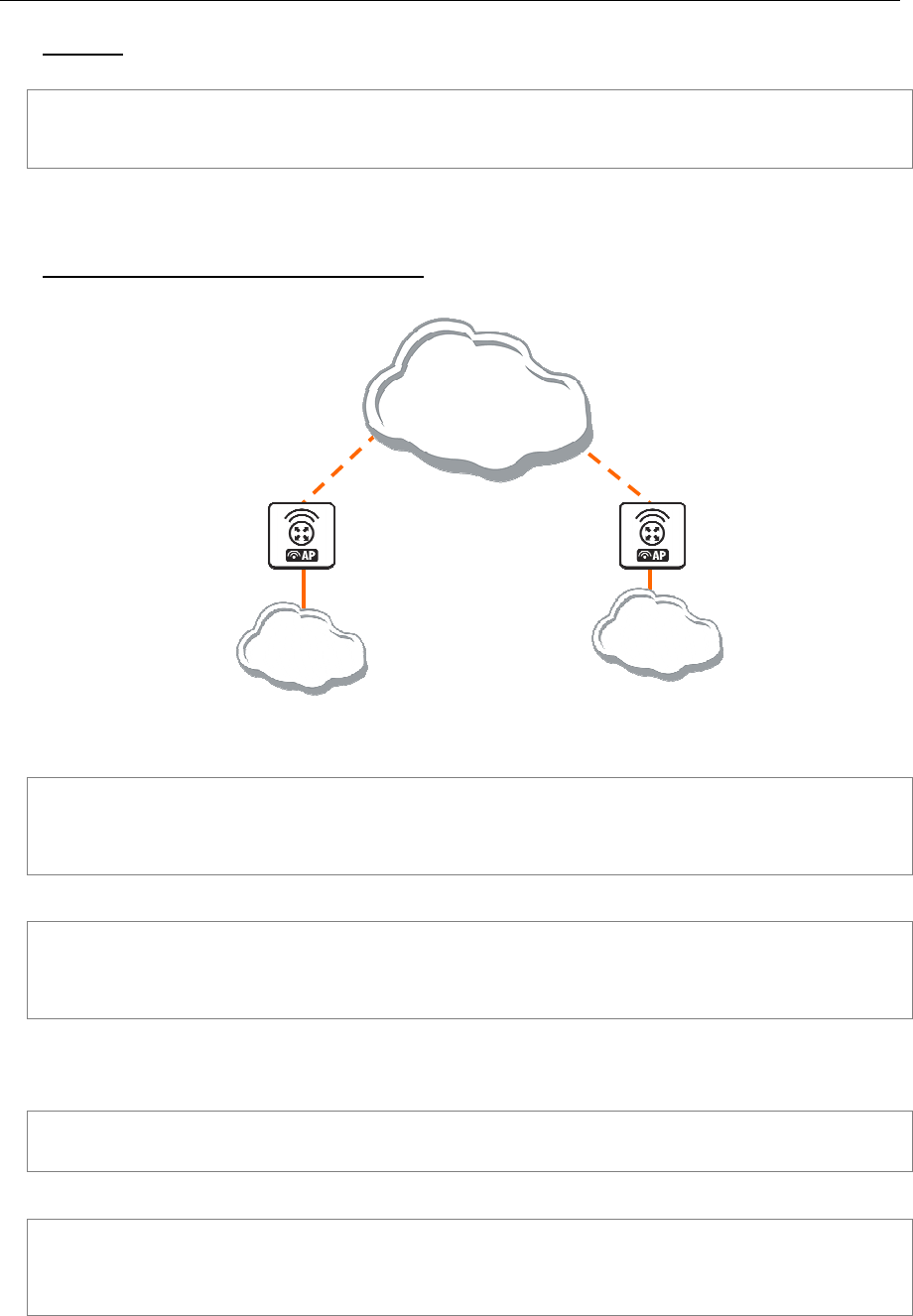
AT-WR4500 Series - IEEE 802.11abgh Outdoor Wireless Routers 195
RouterOS v3 Configuration and User Guide
Example
To flush all the SAs installed:
[admin@AT-WR4562] ip ipsec installed-sa> flush
[admin@AT-WR4562] ip ipsec installed-sa> print
[admin@AT-WR4562] ip ipsec installed-sa>
8.8.7 Application Examples
RouterOS Router to RouterOS Router
[
Router2
]
1.0.0.2
[
R
outer1
]
1.0.0.1
IP Network
10.1.0.0/24
10.2.0.0/24
1.0.0.0/24
Figure 30: transport mode example using ESP with automatic keying
for Router1
[admin@Router1] > ip ipsec policy add sa-src-address=1.0.0.1 sa-dst-address=1.0.0.2 \
\... action=encrypt
[admin@Router1] > ip ipsec peer add address=1.0.0.2 \
\... secret="gvejimezyfopmekun"
for Router2
[admin@Router2] > ip ipsec policy add sa-src-address=1.0.0.2 sa-dst-address=1.0.0.1 \
\... action=encrypt
[admin@Router2] > ip ipsec peer add address=1.0.0.1 \
\... secret="gvejimezyfopmekun"
Transport mode example using ESP with automatic keying and automatic policy generating on Router 1
and static policy on Router 2
for Router1
[admin@Router1] > ip ipsec peer add address=1.0.0.0/24 \
\... secret="gvejimezyfopmekun" generate-policy=yes
for Router2
[admin@Router2] > ip ipsec policy add sa-src-address=1.0.0.2 sa-dst-address=1.0.0.1 \
\... action=encrypt
[admin@Router2] > ip ipsec peer add address=1.0.0.1 \
\... secret="gvejimezyfopmekun"
tunnel mode example using AH with manual keying
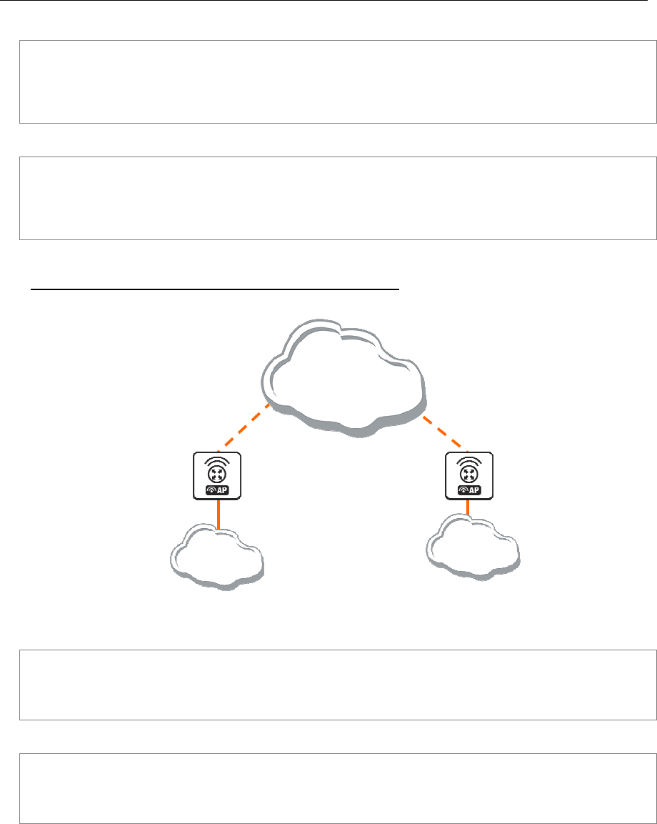
196 AT-WR4500 Series - IEEE 802.11abgh Outdoor Wireless Routers
RouterOS v3 Configuration and User Guide
for Router1
[admin@Router1] > ip ipsec manual-sa add name=ah-sa1 \
\... ah-spi=0x101/0x100 ah-key=abcfed
[admin@Router1] > ip ipsec policy add src-address=10.1.0.0/24 \
\... dst-address=10.2.0.0/24 action=encrypt ipsec-protocols=ah \
\... tunnel=yes sa-src=1.0.0.1 sa-dst=1.0.0.2 manual-sa=ah-sa1
for Router2
[admin@Router2] > ip ipsec manual-sa add name=ah-sa1 \
\... ah-spi=0x100/0x101 ah-key=abcfed
[admin@Router2] > ip ipsec policy add src-address=10.2.0.0/24 \
\... dst-address=10.1.0.0/24 action=encrypt ipsec-protocols=ah \
\... tunnel=yes sa-src=1.0.0.2 sa-dst=1.0.0.1 manual-sa=ah-sa1
IPsec Between two Masquerading RouterOS Routers
[
Router2
]
1.0.0.2
[
Router1
]
1.0.0.1
IP Network
10.1.0.0/24
10.2.0.0/24
1.0.0.0/24
Figure 31: Add accept and masquerading rules in SRC-NAT
for Router1
[admin@Router1] > ip firewall nat add chain=srcnat src-address=10.1.0.0/24 \
\... dst-address=10.2.0.0/24
[admin@Router1] > ip firewall nat add chain=srcnat out-interface=public \
\... action=masquerade
for Router2
[admin@Router2] > ip firewall nat chain=srcnat add src-address=10.2.0.0/24 \
\... dst-address=10.1.0.0/24
[admin@Router2] > ip firewall nat chain=srcnat add out-interface=public \
\... action=masquerade

AT-WR4500 Series - IEEE 802.11abgh Outdoor Wireless Routers 197
RouterOS v3 Configuration and User Guide
configure IPsec
for Router1
[admin@Router1] > ip ipsec policy add src-address=10.1.0.0/24 \
\... dst-address=10.2.0.0/24 action=encrypt tunnel=yes \
\... sa-src-address=1.0.0.1 sa-dst-address=1.0.0.2
[admin@Router1] > ip ipsec peer add address=1.0.0.2 \
\... exchange-mode=aggressive secret="gvejimezyfopmekun"
for Router2
[admin@Router2] > ip ipsec policy add src-address=10.2.0.0/24 \
\... dst-address=10.1.0.0/24 action=encrypt tunnel=yes \
\... sa-src-address=1.0.0.2 sa-dst-address=1.0.0.1
[admin@Router2] > ip ipsec peer add address=1.0.0.1 \
\... exchange-mode=aggressive secret="gvejimezyfopmekun"

198 AT-WR4500 Series - IEEE 802.11abgh Outdoor Wireless Routers
RouterOS v3 Configuration and User Guide
9 Firewall and QoS
9.1 Filter
Document revisi on: 2.7 (Fri Nov 04 16: 04:37 GMT 2005)
Applies to: V2.9
9.1.1 General Information
Summary
The firewall implements packet filtering and thereby provides security functions that are used to manage
data flow to, from and through the router. Along with the Network Address Translation it serve as a tool
for preventing unauthorized access to directly attached networks and the router itself as well as a filter
for outgoing traffic.
Quick Setup Guide
To add a firewall rule which drops all TCP packets that are destined to port 135 and going through the
router, use the following command:
/ip firewall filter add chain=forward dst-port=135 protocol=tcp action=drop
To deny acces to the router via Telnet (protocol TCP, port 23), type the following command:
/ip firewall filter add chain=input protocol=tcp dst-port=23 action=drop
To only allow not more than 5 simultaneous connections from each of the clients, do the following:
/ip firewall filter add chain=forward protocol=tcp tcp-flags=syn connection-limit=6,32
action=drop
Specifications
Packages required: system
License required: Level1 (P2P filters limited to 1) , Level3
Submenu level: /ip firewall filter
Standards and Technologies: IP, RFC2113
Hardware usage: Increases with filtering rules count
Related Topics
IP Addresses and ARP
Routes, Equal Cost Multipath Routing, Policy Routing
NAT
Mangle
Packet Flow
9.1.2 Firewall Filter
Submenu level: /ip firewall filter
Description
Network firewalls keep outside threats away from sensitive data available inside the network. Whenever
different networks are joined together, there is always a threat that someone from outside of your
network will break into your LAN. Such break-ins may result in private data being stolen and distributed,
valuable data being altered or destroyed, or entire hard drives being erased. Firewalls are used as a means
of preventing or minimizing the security risks inherent in connecting to other networks. Properly
configured firewall plays a key role in efficient and secure network infrastrure deployment.

AT-WR4500 Series - IEEE 802.11abgh Outdoor Wireless Routers 199
RouterOS v3 Configuration and User Guide
RouterOS has very powerful firewall implementation with features including:
• stateful packet filtering
• peer-to-peer protocols filtering
• traffic classification by:
source MAC address
IP addresses (network or list) and address types (broadcast, local, multicast, unicast)
port or port range
IP protocols
protocol options (ICMP type and code fields, TCP flags, IP options and MSS)
interface the packet arrived from or left through
internal flow and connection marks
ToS (DSCP) byte
packet content
rate at which packets arrive and sequence numbers
packet size
packet arrival time
and much more!
General Filtering Principles
The firewall operates by means of firewall rules. A rule is a definitive form expression that tells the router
what to do with a particular IP packet. Each rule consists of two parts that are the matcher which
matches traffic flow against given conditions and the action which defines what to do with the mathched
packets. Rules are organized in chains for better management.
The filter facility has three default chains: input, forward and output that are responsible for traffic
coming from, throurh and to the router, respectively. New user-defined chains can be added, as
necessary. Since these chains have no default traffic to match, rules with action=jump and relevant
jump-target should be added to one or more of the three default chains.
Filter Chains
As mentioned before, the firewall filtering rules are grouped together in chains. It allows a packet to be
matched against one common criterion in one chain, and then passed over for processing against some
other common criteria to another chain. For example a packet should be matched against the IP
address:port pair. Of course, it could be achieved by adding as many rules with IP address:port match
as required to the forward chain, but a better way could be to add one rule that matches traffic from a
particular IP address, e.g.: /ip firewall filter add src-address=1.1.1.2/32 jump-target="mychain"
and in case of successfull match passes control over the IP packet to some other chain, id est mychain in
this example. Then rules that perform matching against separate ports can be added to mychain chain
without specifying the IP addresses.
There are three predefined chains, which cannot be deleted:
• input - used to process packets entering the router through one of the interfaces with the
destination IP address which is one of the router's addresses. Packets passing through the router are
not processed against the rules of the input chain
• forward - used to process packets passing through the router
• output - used to process packets originated from the router and leaving it through one of the
interfaces. Packets passing through the router are not processed against the rules of the output
chain
• When processing a chain, rules are taken from the chain in the order they are listed there from top
to bottom. If a packet matches the criteria of the rule, then the specified action is performed on it,
and no more rules are processed in that chain (the exception is the passthrough action). If a packet
has not matched any rule within the chain, then it is accepted.

200 AT-WR4500 Series - IEEE 802.11abgh Outdoor Wireless Routers
RouterOS v3 Configuration and User Guide
Property Description
action (accept | add-dst-to-address-list | add-src-to-address-list | drop | jump | log | passthrough | reject |
return | tarpit; default: accept) - action to undertake if the packet matches the rule
accept - accept the packet. No action is taken, i.e. the packet is passed through and no more rules are
applied to it
add-dst-to-address-list - adds destination address of an IP packet to the address list specified by
address-list parameter
add-src-to-address-list - adds source address of an IP packet to the address list specified by address-
list parameter
drop - silently drop the packet (without sending the ICMP reject message)
jump - jump to the chain specified by the value of the jump-target parameter
log - each match with this action will add a message to the system log
passthrough - ignores this rule and goes on to the next one
reject - reject the packet and send an ICMP reject message
return - passes control back to the chain from where the jump took place
tarpit - captures and holds incoming TCP connections (replies with SYN/ACK to the inbound TCP SYN
packet)
address-list (name) - specifies the name of the address list to collect IP addresses from rules having
action=add-dst-to-address-list or action=add-src-to-address-list actions. These address lists could
be later used for packet matching
address-list-timeout (time; default: 00:00:00) - time interval after which the address will be removed
from the address list specified by address-list parameter. Used in conjunction with add-dst-to-
address-list or add-src-to-address-list actions
00:00:00 - leave the address in the address list forever
chain (forward | input | output | name) - specifies the chain to put a particular rule into. As the different
traffic is passed through different chains, always be careful in choosing the right chain for a new rule. If the
input does not match the name of an already defined chain, a new chain will be created
comment (text) - a descriptive comment for the rule. A comment can be used to identify rules form
scripts
connection-bytes (integer-integer) - matches packets only if a given amount of bytes has been transfered
through the particular connection
0 - means infinity, exempli gratia: connection-bytes=2000000-0 means that the rule matches if more
than 2MB has been transfered through the relevant connection
connection-limit (integer,netmask) - restrict connection limit per address or address block
connection-mark (name) - matches packets marked via mangle facility with particular connection mark
connection-state (estabilished | invalid | new | related) - interprets the connection tracking analysis data
for a particular packet
estabilished - a packet which belongs to an existing connection, exempli gratia a reply packet or a packet
which belongs to already replied connection
invalid - a packet which could not be identified for some reason. This includes out of memory condition
and ICMP errors which do not correspond to any known connection. It is generally advised to drop these
packets
new - a packet which begins a new TCP connection
related - a packet which is related to, but not part of an existing connection, such as ICMP errors or a
packet which begins FTP data connection (the later requires enabled FTP connection tracking helper
under /ip firewall service-port)
connection-type (ftp | gre | h323 | irc | mms | pptp | quake3 | tftp) - matches packets from related
connections based on information from their connection tracking helpers. A relevant connection helper
must be enabled under /ip firewall service-port
content (text) - the text packets should contain in order to match the rule
dscp (integer: 0..63) - DSCP (ex-ToS) IP header field value
dst-address (IP address/netmask | IP address-IP address) - specifies the address range an IP packet is
destined to. Note that console converts entered address/netmask value to a valid network address,
i.e.:1.1.1.1/24 is converted to 1.1.1.0/24
dst-address-list (name) - matches destination address of a packet against user-defined address list
dst-address-type (unicast | local | broadcast | multicast) - matches destination address type of the IP
packet, one of the:

AT-WR4500 Series - IEEE 802.11abgh Outdoor Wireless Routers 201
RouterOS v3 Configuration and User Guide
unicast - IP addresses used for one point to another point transmission. There is only one sender and
one receiver in this case
local - matches addresses assigned to router's interfaces
broadcast - the IP packet is sent from one point to all other points in the IP subnetwork
multicast - this type of IP addressing is responsible for transmission from one or more points to a set of
other points
dst-limit (integer/time{0,1},integer,dst-address | dst-port | src-address{+},time{0,1}) - limits the packet per
second (pps) rate on a per destination IP or per destination port base. As opposed to the limit match,
every destination IP address / destination port has it's own limit. The options are as follows (in order of
appearance):
count - maximum average packet rate, measured in packets per second (pps), unless followed by time
option
time - specifies the time interval over which the packet rate is measured
burst - number of packets to match in a burst
mode - the classifier(-s) for packet rate limiting
expire - specifies interval after which recorded IP addresses / ports will be deleted
dst-port (integer: 0..65535-integer: 0..65535{*}) - destination port number or range
fragment (yes | no) - whether the packet is a fragment of an IP packet. Starting packet (i.e., first
fragment) does not count. Note that is the connection tracking is enabled, there will be no fragments as
the system automatically assembles every packet
hotspot (multiple choice: auth | from-client | http | local-dst | to-client) - matches packets received from
clients against various HotSpot conditions. All values can be negated
auth - true, if a packet comes from an authenticted HotSpotclient
from-client - true, if a packet comes from any HotSpot client
http - true, if a HotSpot client sends a packet to the address and port previously detected as his proxy
server (Universal Proxy technique) or if the destination port is 80 and transparent proxying is enabled for
that particular client
local-dst - true, if a packet has local destination IP address
to-client - true, if a packet is sent to a client
icmp-options (integer:integer) - matches ICMP Type:Code fields
in-bridge-port (name) - actual interface the packet has entered the router through (if bridged, this
property matches the actual bridge port, while in-interface - the bridge itself)
in-interface (name) - interface the packet has entered the router through (if the interface is bridged,
then the packet will appear to come from the bridge interface itself)
ingress-priority (integer: 0..63) - INGRESS (received) priority of the packet, if set (0 otherwise). The
priority may be derived from either VLAN or WMM priority
ipv4-options (any | loose-source-routing | no-record-route | no-router-alert | no-source-routing | no-
timestamp | none | record-route | router-alert | strict-source-routing | timestamp) - match ipv4 header
options
any - match packet with at least one of the ipv4 options
loose-source-routing - match packets with loose source routing option. This option is used to route
the internet datagram based on information supplied by the source
no-record-route - match packets with no record route option. This option is used to route the
internet datagram based on information supplied by the source
no-router-alert - match packets with no router alter option
no-source-routing - match packets with no source routing option
no-timestamp - match packets with no timestamp option
record-route - match packets with record route option
router-alert - match packets with router alter option
strict-source-routing - match packets with strict source routing option
timestamp - match packets with timestamp
jump-target (forward | input | output | name) - name of the target chain to jump to, if the
action=jump is used
layer7-protocol (name) - Layer 7 filter name as set in the /ip firewall layer7-protocol menu. Caution:
this matcher needs high computational power
limit (integer/time{0,1},integer) - restricts packet match rate to a given limit. Usefull to reduce the amount
of log messages
count - maximum average packet rate, measured in packets per second (pps), unless followed by time
option

202 AT-WR4500 Series - IEEE 802.11abgh Outdoor Wireless Routers
RouterOS v3 Configuration and User Guide
time - specifies the time interval over which the packet rate is measured
burst - number of packets to match in a burst
log-prefix (text) - all messages written to logs will contain the prefix specified herein. Used in
conjunction with action=log
nth (integer,integer: 0..15,integer{0,1}) - match a particular Nth packet received by the rule. One of 16
available counters can be used to count packets
every - match every every+1th packet. For example, if every=1 then the rule matches every 2nd
packet
counter - specifies which counter to use. A counter increments each time the rule containing nth match
matches
packet - match on the given packet number. The value by obvious reasons must be between 0 and
every. If this option is used for a given counter, then there must be at least every+1 rules with this
option, covering all values between 0 and every inclusively.
out-bridge-port (name) - actual interface the packet is leaving the router through (if bridged, this
property matches the actual bridge port, while out-interface - the bridge itself)
out-interface (name) - interface the packet is leaving the router through (if the interface is bridged, then
the packet will appear to leave through the bridge interface itself)
p2p (all-p2p | bit-torrent | blubster | direct-connect | edonkey | fasttrack | gnutella | soulseek | warez |
winmx) - matches packets from various peer-to-peer (P2P) protocols
packet-mark (text) - matches packets marked via mangle facility with particular packet mark
packet-size (integer: 0..65535-integer: 0..65535{0,1}) - matches packet of the specified size or size range
in bytes
min - specifies lower boundary of the size range or a standalone value
max - specifies upper boundary of the size range
port (port{0-16}) - matches if any (source or destination) port matches the specified list of ports or port
ranges (note that the protocol must still be selected, just like for the regular src-port and dst-port
matchers)
protocol (ddp | egp | encap | ggp | gre | hmp | icmp | idrp-cmtp | igmp | ipencap | ipip | ipsec-ah | ipsec-
esp | iso-tp4 | ospf | pup | rdp | rspf | st | tcp | udp | vmtp | xns-idp | xtp | integer) - matches particular IP
protocol specified by protocol name or number. You should specify this setting if you want to specify
ports
psd (integer,time,integer,integer) - attempts to detect TCP and UDP scans. It is advised to assign lower
weight to ports with high numbers to reduce the frequency of false positives, such as from passive mode
FTP transfers
WeightThreshold - total weight of the latest TCP/UDP packets with different destination ports coming
from the same host to be treated as port scan sequence
DelayThreshold - delay for the packets with different destination ports coming from the same host to
be treated as possible port scan subsequence
LowPortWeight - weight of the packets with privileged (<=1024) destination port
HighPortWeight - weight of the packet with non-priviliged destination port
random (integer: 1..99) - matches packets randomly with given propability
reject-with (icmp-admin-prohibited | icmp-echo-reply | icmp-host-prohibited | icmp-host-unreachable |
icmp-net-prohibited | icmp-network-unreachable | icmp-port-unreachable | icmp-protocol-unreachable |
tcp-reset | integer) - alters the reply packet of reject action
routing-mark (name) - matches packets marked by mangle facility with particular routing mark
src-address (IP address/netmask | IP address-IP address) - specifies the address range an IP packet is
originated from. Note that console converts entered address/netmask value to a valid network
address, i.e.:1.1.1.1/24 is converted to 1.1.1.0/24
src-address-list (name) - matches source address of a packet against user-defined address list
src-address-type (unicast | local | broadcast | multicast) - matches source address type of the IP packet,
one of the:
unicast - IP addresses used for one point to another point transmission. There is only one sender and
one receiver in this case
local - matches addresses assigned to router's interfaces
broadcast - the IP packet is sent from one point to all other points in the IP subnetwork
multicast - this type of IP addressing is responsible for transmission from one or more points to a set of
other points
src-mac-address (MAC address) - source MAC address
src-port (integer: 0..65535-integer: 0..65535{*}) - source port number or range

AT-WR4500 Series - IEEE 802.11abgh Outdoor Wireless Routers 203
RouterOS v3 Configuration and User Guide
tcp-flags (ack | cwr | ece | fin | psh | rst | syn | urg) - tcp flags to match
ack - acknowledging data
cwr - congestion window reduced
ece - ECN-echo flag (explicit congestion notification)
fin - close connection
psh - push function
rst - drop connection
syn - new connection
urg - urgent data
tcp-mss (integer: 0..65535) - matches TCP MSS value of an IP packet
time (time-time,sat | fri | thu | wed | tue | mon | sun{+}) - allows to create filter based on the packets'
arrival time and date or, for locally generated packets, departure time and date
Because the NAT rules are applied first, it is important to hold this in min
d when setting up firewall rules,
since the original packets might be already modified by the NAT
9.1.3 Filter Applications
Protect your RouterOS router
To protect your router, you should not only change admin's password but also set up packet filtering. All
packets with destination to the router are processed against the ip firewall input chain. Note, that the
input chain does not affect packets which are being transferred through the router.
/ ip firewall filter
add chain=input connection-state=invalid action=drop \
comment="Drop Invalid connections"
add chain=input connection-state=established action=accept \
comment="Allow Established connections"
add chain=input protocol=udp action=accept \
comment="Allow UDP"
add chain=input protocol=icmp action=accept \
comment="Allow ICMP"
add chain=input src-address=192.168.0.0/24 action=accept \
comment="Allow access to router from known network"
add chain=input action=drop comment="Drop anything else"
Protecting the Customer's Network
To protect the customer's network, we should check all traffic which goes through router and block
unwanted. For icmp, tcp, udp traffic we will create chains, where will be droped all unwanted packets:
/ip firewall filter
add chain=forward protocol=tcp connection-state=invalid \
action=drop comment="drop invalid connections"
add chain=forward connection-state=established action=accept \
comment="allow already established connections"
add chain=forward connection-state=related action=accept \
comment="allow related connections"
Block IP addreses called "bogons":
add chain=forward src-address=0.0.0.0/8 action=drop
add chain=forward dst-address=0.0.0.0/8 action=drop
add chain=forward src-address=127.0.0.0/8 action=drop
add chain=forward dst-address=127.0.0.0/8 action=drop
add chain=forward src-address=224.0.0.0/3 action=drop
add chain=forward dst-address=224.0.0.0/3 action=drop

204 AT-WR4500 Series - IEEE 802.11abgh Outdoor Wireless Routers
RouterOS v3 Configuration and User Guide
Make jumps to new chains:
add chain=forward protocol=tcp action=jump jump-target=tcp
add chain=forward protocol=udp action=jump jump-target=udp
add chain=forward protocol=icmp action=jump jump-target=icmp
Create tcp chain and deny some tcp ports in it:
add chain=tcp protocol=tcp dst-port=69 action=drop \
comment="deny TFTP"
add chain=tcp protocol=tcp dst-port=111 action=drop \
comment="deny RPC portmapper"
add chain=tcp protocol=tcp dst-port=135 action=drop \
comment="deny RPC portmapper"
add chain=tcp protocol=tcp dst-port=137-139 action=drop \
comment="deny NBT"
add chain=tcp protocol=tcp dst-port=445 action=drop \
comment="deny cifs"
add chain=tcp protocol=tcp dst-port=2049 action=drop comment="deny NFS"
add chain=tcp protocol=tcp dst-port=12345-12346 action=drop comment="deny NetBus"
add chain=tcp protocol=tcp dst-port=20034 action=drop comment="deny NetBus"
add chain=tcp protocol=tcp dst-port=3133 action=drop comment="deny BackOriffice"
add chain=tcp protocol=tcp dst-port=67-68 action=drop comment="deny DHCP"
Deny udp ports in udp chain:
add chain=udp protocol=udp dst-port=69 action=drop comment="deny TFTP"
add chain=udp protocol=udp dst-port=111 action=drop comment="deny PRC portmapper"
add chain=udp protocol=udp dst-port=135 action=drop comment="deny PRC portmapper"
add chain=udp protocol=udp dst-port=137-139 action=drop comment="deny NBT"
add chain=udp protocol=udp dst-port=2049 action=drop comment="deny NFS"
add chain=udp protocol=udp dst-port=3133 action=drop comment="deny BackOriffice"
Allow only needed icmp codes in icmp chain:
add chain=icmp protocol=icmp icmp-options=0:0 action=accept \
comment="drop invalid connections"
add chain=icmp protocol=icmp icmp-options=3:0 action=accept \
comment="allow established connections"
add chain=icmp protocol=icmp icmp-options=3:1 action=accept \
comment="allow already established connections"
add chain=icmp protocol=icmp icmp-options=4:0 action=accept \
comment="allow source quench"
add chain=icmp protocol=icmp icmp-options=8:0 action=accept \
comment="allow echo request"
add chain=icmp protocol=icmp icmp-options=11:0 action=accept \
comment="allow time exceed"
add chain=icmp protocol=icmp icmp-options=12:0 action=accept \
comment="allow parameter bad"
add chain=icmp action=drop comment="deny all other types"
9.2 Mangle
Document revisi on: 3 (Fri Nov 04 19:22: 14 GMT 2005)
Applies to: V2.9
9.2.1 General Information
Summary
The mangle facility allows marking IP packets with special marks. These marks are used by various other
router facilities to identify the packets. Additionaly, the mangle facility is used to modify some fields in the
IP header, like TOS (DSCP) and TTL fields.
Specifications
Packages required: system
License required: Level1

AT-WR4500 Series - IEEE 802.11abgh Outdoor Wireless Routers 205
RouterOS v3 Configuration and User Guide
Submenu level: /ip firewall mangle
Standards and Technologies: IP
Hardware usage: Increases with count of mangle rules
Related Topics
• IP Addresses and ARP
• Routes, Equal Cost Multipath Routing, Policy Routing
• NAT
• Filter
• Packet Flow
9.2.2 Mangle
Submenu level: /ip firewall mangle
Description
Mangle is a kind of 'marker' that marks packets for future processing with special marks. Many other
facilities in RouterOS make use of these marks, e.g. queue trees and NAT. They identify a packet based
on its mark and process it accordingly. The mangle marks exist only within the router, they are not
transmitted across the network.
Property Description
action (accept | add-dst-to-address-list | add-src-to-address-list | change-dscp | change-mss | change-ttl |
jump | log | mark-connection | mark-packet | mark-routing | passthrough | return | set-priority | strip-
ipv4-options; default: accept) - action to undertake if the packet matches the rule
accept - accept the packet. No action, i.e., the packet is passed through and no more rules are applied to
it
add-dst-to-address-list - add destination address of an IP packet to the address list specified by
address-list parameter
add-src-to-address-list - add source address of an IP packet to the address list specified by address-
list parameter
change-dscp - change Differentiated Services Code Point (DSCP) field value specified by the new-dscp
parameter
change-mss - change Maximum Segment Size field value of the packet to a value specified by the new-
mss parameter
change-ttl - change Time to Live field value of the packet to a value specified by the new-ttl parameter
jump - jump to the chain specified by the value of the jump-target parameter
log - each match with this action will add a message to the system log
mark-connection - place a mark specified by the new-connection-mark parameter on the entire
connection that matches the rule
mark-packet - place a mark specified by the new-packet-mark parameter on a packet that matches
the rule
mark-routing - place a mark specified by the new-routing-mark parameter on a packet. This kind of
marks is used for policy routing purposes only
passthrough - ignore this rule go on to the next one
return - pass control back to the chain from where the jump took place
set-priority - set priority speciefied by the new-priority parameter on the packets sent out through a
link that is capable of transporting priority (VLAN or WMM-enabled wireless interface)
strip-ipv4-options - strip IPv4 option fields from the IP packet
address-list (name) - specify the name of the address list to collect IP addresses from rules having
action=add-dst-to-address-list or action=add-src-to-address-list actions. These address lists could
be later used for packet matching
address-list-timeout (time; default: 00:00:00) - time interval after which the address will be removed
from the address list specified by address-list parameter. Used in conjunction with add-dst-to-
address-list or add-src-to-address-list actions
00:00:00 - leave the address in the address list forever

206 AT-WR4500 Series - IEEE 802.11abgh Outdoor Wireless Routers
RouterOS v3 Configuration and User Guide
chain (forward | input | output | postrouting | prerouting) - specify the chain to put a particular rule into.
As the different traffic is passed through different chains, always be careful in choosing the right chain for
a new rule. If the input does not match the name of an already defined chain, a new chain will be created
comment (text) - free form textual comment for the rule. A comment can be used to refer the
particular rule from scripts
connection-bytes (integer-integer) - match packets only if a given amount of bytes has been transfered
through the particular connection
0 - means infinity, exempli gratia: connection-bytes=2000000-0 means that the rule matches if more
than 2MB has been transfered through the relevant connection
connection-limit (integer,netmask) - restrict connection limit per address or address block
connection-mark (name) - match packets marked via mangle facility with particular connection mark
connection-state (estabilished | invalid | new | related) - interprets the connection tracking analysis data
for a particular packet
estabilished - a packet which belongs to an existing connection, exempli gratia a reply packet or a packet
which belongs to already replied connection
invalid - a packet which could not be identified for some reason. This includes out of memory condition
and ICMP errors which do not correspond to any known connection. It is generally advised to drop these
packets
new - a packet which begins a new TCP connection
related - a packet which is related to, but not part of an existing connection, such as ICMP errors or a
packet which begins FTP data connection (the later requires enabled FTP connection tracking helper
under /ip firewall service-port)
connection-type (ftp | gre | h323 | irc | mms | pptp | quake3 | tftp) - match packets from related
connections based on information from their connection tracking helpers. A relevant connection helper
must be enabled under /ip firewall service-port
content (text) - the text packets should contain in order to match the rule
dscp (integer: 0..63) - DSCP (ex-ToS) IP header field value
dst-address (IP address/netmask | IP address-IP address) - specify the address range an IP packet is
destined to. Note that console converts entered address/netmask value to a valid network address,
i.e.:1.1.1.1/24 is converted to 1.1.1.0/24
dst-address-list (name) - match destination address of a packet against user-defined address list
dst-address-type (unicast | local | broadcast | multicast) - match destination address type of the IP
packet, one of the:
unicast - IP addresses used for one point to another point transmission. There is only one sender and
one receiver in this case
local - match addresses assigned to router's interfaces
broadcast - the IP packet is sent from one point to all other points in the IP subnetwork
multicast - this type of IP addressing is responsible for transmission from one or more points to a set of
other points
dst-limit (integer/time{0,1},integer,dst-address | dst-port | src-address{+},time{0,1}) - limit the packet per
second (pps) rate on a per destination IP or per destination port base. As opposed to the limit match,
every destination IP address / destination port has it's own limit. The options are as follows (in order of
appearance):
count - maximum average packet rate, measured in packets per second (pps), unless followed by time
option
time - specifies the time interval over which the packet rate is measured
burst - number of packets to match in a burst
mode - the classifier(-s) for packet rate limiting
expire - specifies interval after which recorded IP addresses / ports will be deleted
dst-port (integer: 0..65535-integer: 0..65535{*}) - destination port number or range
fragment (yes | no) - whether the packet is a fragment of an IP packet. Starting packet (i.e., first
fragment) does not count. Note that is the connection tracking is enabled, there will be no fragments as
the system automatically assembles every packet
hotspot (multiple choice: auth | from-client | http | local-dst | to-client) - matches packets received from
clients against various HotSpot conditions. All values can be negated
auth - true, if a packet comes from an authenticted HotSpotclient
from-client - true, if a packet comes from any HotSpot client
http - true, if a HotSpot client sends a packet to the address and port previously detected as his proxy
server (Universal Proxy technique) or if the destination port is 80 and transparent proxying is enabled for

AT-WR4500 Series - IEEE 802.11abgh Outdoor Wireless Routers 207
RouterOS v3 Configuration and User Guide
that particular client
local-dst - true, if a packet has local destination IP address
to-client - true, if a packet is sent to a client
icmp-options (integer:integer) - match ICMP Type:Code fields
in-bridge-port (name) - actual interface the packet has entered the router through (if bridged, this
property matches the actual bridge port, while in-interface - the bridge itself)
in-interface (name) - interface the packet has entered the router through (if the interface is bridged,
then the packet will appear to come from the bridge interface itself)
ingress-priority (integer: 0..63) - INGRESS (received) priority of the packet, if set (0 otherwise). The
priority may be derived from either VLAN or WMM priority
ipv4-options (any | loose-source-routing | no-record-route | no-router-alert | no-source-routing | no-
timestamp | none | record-route | router-alert | strict-source-routing | timestamp) - match ipv4 header
options
any - match packet with at least one of the ipv4 options
loose-source-routing - match packets with loose source routing option. This option is used to route
the internet datagram based on information supplied by the source
no-record-route - match packets with no record route option. This option is used to route the
internet datagram based on information supplied by the source
no-router-alert - match packets with no router alter option
no-source-routing - match packets with no source routing option
no-timestamp - match packets with no timestamp option
record-route - match packets with record route option
router-alert - match packets with router alter option
strict-source-routing - match packets with strict source routing option
timestamp - match packets with timestamp
jump-target (forward | input | output | postrouting | preroutingname) - name of the target chain to
jump to, if the action=jump is used
layer7-protocol (name) - Layer 7 filter name as set in the /ip firewall layer7-protocol menu. Caution:
this matcher needs high computational power
limit (integer/time{0,1},integer) - restrict packet match rate to a given limit. Usefull to reduce the amount
of log messages
count - maximum average packet rate, measured in packets per second (pps), unless followed by time
option
time - specify the time interval over which the packet rate is measured
burst - number of packets to match in a burst
log-prefix (text) - all messages written to logs will contain the prefix specified herein. Used in
conjunction with action=log
new-connection-mark (name) - specify the new value of the connection mark to be used in
conjunction with action=mark-connection
new-dscp (integer: 0..63) - specify the new value of the DSCP field to be used in conjunction with
action=change-dscp
new-mss (integer) - specify MSS value to be used in conjunction with action=change-mss
new-packet-mark (name) - specify the new value of the packet mark to be used in conjunction with
action=mark-packet
new-priority (integer) - specify the new value of packet priority for the priority-enabled interfaces, used
in conjunction with action=set-priority
from-dscp - set packet priority form its DSCP field value
from-ingress - set packet priority from the INGRESS priority of the packet (in case packet has been
received from an interface that supports priorities - VLAN or WMM-enabled wireless interface; 0 if not
set)
new-routing-mark (name) - specify the new value of the routing mark used in conjunction with
action=mark-routing
new-ttl (decrement | increment | set:integer) - specify the new TTL field value used in conjunction with
action=change-ttl
decrement - the value of the TTL field will be decremented for value
increment - the value of the TTL field will be incremented for value
set: - the value of the TTL field will be set to value
nth (integer,integer: 0..15,integer{0,1}) - match a particular Nth packet received by the rule. One of 16
available counters can be used to count packets

208 AT-WR4500 Series - IEEE 802.11abgh Outdoor Wireless Routers
RouterOS v3 Configuration and User Guide
every - match every every+1th packet. For example, if every=1 then the rule matches every 2nd
packet
counter - specifies which counter to use. A counter increments each time the rule containing nth match
matches
packet - match on the given packet number. The value by obvious reasons must be between 0 and
every. If this option is used for a given counter, then there must be at least every+1 rules with this
option, covering all values between 0 and every inclusively.
out-bridge-port (name) - actual interface the packet is leaving the router through (if bridged, this
property matches the actual bridge port, while out-interface - the bridge itself)
out-interface (name) - interface the packet is leaving the router through (if the interface is bridged, then
the packet will appear to leave through the bridge interface itself)
p2p (all-p2p | bit-torrent | direct-connect | edonkey | fasttrack | gnutella | soulseek | warez | winmx) -
match packets belonging to connections of the above P2P protocols
packet-mark (name) - match the packets marked in mangle with specific packet mark
packet-size (integer: 0..65535-integer: 0..65535{0,1}) - matches packet of the specified size or size range
in bytes
min - specifies lower boundary of the size range or a standalone value
max - specifies upper boundary of the size range
passthrough (yes | no; default: yes) - whether to let the packet to pass further (like action
passthrough) after marking it with a given mark (property only valid if action is mark packet, connection
or routing mark)
port (port{0-16}) - matches if any (source or destination) port matches the specified list of ports or port
ranges (note that the protocol must still be selected, just like for the regular src-port and dst-port
matchers)
protocol (ddp | egp | encap | ggp | gre | hmp | icmp | idrp-cmtp | igmp | ipencap | ipip | ipsec-ah | ipsec-
esp | iso-tp4 | ospf | pup | rdp | rspf | st | tcp | udp | vmtp | xns-idp | xtp | integer) - matches particular IP
protocol specified by protocol name or number. You should specify this setting if you want to specify
ports
psd (integer,time,integer,integer) - attempts to detect TCP and UDP scans. It is advised to assign lower
weight to ports with high numbers to reduce the frequency of false positives, such as from passive mode
FTP transfers
WeightThreshold - total weight of the latest TCP/UDP packets with different destination ports coming
from the same host to be treated as port scan sequence
DelayThreshold - delay for the packets with different destination ports coming from the same host to
be treated as possible port scan subsequence
LowPortWeight - weight of the packets with privileged (<=1024) destination port
HighPortWeight - weight of the packet with non-priviliged destination port
random (integer: 1..99) - matches packets randomly with given propability
routing-mark (name) - matches packets marked with the specified routing mark
src-address (IP address/netmask | IP address-IP address) - specifies the address range an IP packet is
originated from. Note that console converts entered address/netmask value to a valid network
address, i.e.:1.1.1.1/24 is converted to 1.1.1.0/24
src-address-list (name) - matches source address of a packet against user-defined address list
src-address-type (unicast | local | broadcast | multicast) - matches source address type of the IP packet,
one of the:
unicast - IP addresses used for one point to another point transmission. There is only one sender and
one receiver in this case
local - matches addresses assigned to router's interfaces
broadcast - the IP packet is sent from one point to all other points in the IP subnetwork
multicast - this type of IP addressing is responsible for transmission from one or more points to a set of
other points
src-mac-address (MAC address) - source MAC address
src-port (integer: 0..65535-integer: 0..65535{*}) - source port number or range
tcp-flags (multiple choice: ack | cwr | ece | fin | psh | rst | syn | urg) - tcp flags to match
ack - acknowledging data
cwr - congestion window reduced
ece - ECN-echo flag (explicit congestion notification)
fin - close connection
psh - push function

AT-WR4500 Series - IEEE 802.11abgh Outdoor Wireless Routers 209
RouterOS v3 Configuration and User Guide
rst - drop connection
syn - new connection
urg - urgent data
tcp-mss (integer: 0..65535) - matches TCP MSS value of an IP packet
time (time-time,sat | fri | thu | wed | tue | mon | sun{+}) - allows to create filter based on the packets'
arrival time and date or, for locally generated packets, departure time and date
Instead of making two rules if you want to mark a packet, connection or routing-mark and finish mangle
table processing on that event (in other words, mark and simultaneously accept the packet), you may
disable the set by default passthrough property of the marking rule.
Usually routing-mark is not used for P2P, since P2P traffic always is routed over a default getaway.
9.2.3 Application Examples
Description
The following section discusses some examples of using the mangle facility.
Peer-to-Peer Traffic Marking
To ensure the quality of service for network connection, interactive traffic types such as VoIP and HTTP
should be prioritized over non-interactive, such as peer-to-peer network traffic. RouterOS QOS
implementation uses mangle to mark different types of traffic first, and then place them into queues with
different limits.
The following example enforces the P2P traffic will get no more than 1Mbps of the total link capacity
when the link is heavily used by other traffic otherwice expanding to the full link capacity:
[admin@AT-WR4562] > /ip firewall mangle add chain=forward \
\... p2p=all-p2p action=mark-connection new-connection-mark=p2p_conn
[admin@AT-WR4562] > /ip firewall mangle add chain=forward \
\... connection-mark=p2p_conn action=mark-packet new-packet-mark=p2p
[admin@AT-WR4562] > /ip firewall mangle add chain=forward \
\... connection-mark=!p2p_conn action=mark-packet new-packet-mark=other
[admin@AT-WR4562] > /ip firewall mangle print
Flags: X - disabled, I - invalid, D - dynamic
0 chain=forward p2p=all-p2p action=mark-connection new-connection-mark=p2p_conn
1 chain=forward connection-mark=p2p_conn action=mark-packet new-packet-mark=p2p
2 chain=forward packet-mark=!p2p_conn action=mark-packet new-packet-mark=other
[admin@AT-WR4562] >
[admin@AT-WR4562] > /queue tree add parent=Public packet-mark=p2p limit-at=1000000 \
\... max-limit=100000000 priority=8
[admin@AT-WR4562] > /queue tree add parent=Local packet-mark=p2p limit-at=1000000 \
\... max-limit=100000000 priority=8
[admin@AT-WR4562] > /queue tree add parent=Public packet-mark=other limit-at=1000000 \
\... max-limit=100000000 priority=1
[admin@AT-WR4562] > /queue tree add parent=Local packet-mark=other limit-at=1000000 \
\... max-limit=100000000 priority=1
Mark by MAC address
To mark traffic from a known MAC address which goes to the router or through it, do the following:
[admin@AT-WR4562] > / ip firewall mangle add chain=prerouting \
\... src-mac-address=00:01:29:60:36:E7 action=mark-connection new-connection-
mark=known_mac_conn
[admin@AT-WR4562] > / ip firewall mangle add chain=prerouting \
\... connection-mark=known_mac_conn action=mark-packet new-packet-mark=known_mac

210 AT-WR4500 Series - IEEE 802.11abgh Outdoor Wireless Routers
RouterOS v3 Configuration and User Guide
Change MSS
It is a well known fact that VPN links have smaller packet size due to incapsulation overhead. A large
packet with MSS that exceeds the MSS of the VPN link should be fragmented prior to sending it via that
kind of connection. However, if the packet has DF flag set, it cannot be fragmented and should be
discarded. On links that have broken path MTU discovery (PMTUD) it may lead to a number of
problems, including problems with FTP and HTTP data transfer and e-mail services.
In case of link with broken PMTUD, a decrease of the MSS of the packets coming through the VPN link
solves the problem. The following example demonstrates how to decrease the MSS value via mangle:
[admin@AT-WR4562] > /ip firewall mangle add out-interface=pppoe-out \
\... protocol=tcp tcp-flags=syn action=change-mss new-mss=1300 chain=forward
[admin@AT-WR4562] > /ip firewall mangle print
Flags: X - disabled, I - invalid, D - dynamic
0 chain=forward out-interface=pppoe-out protocol=tcp tcp-flags=syn
action=change-mss new-mss=1300
[admin@AT-WR4562] >
9.3 Packet Flow
Document revisi on: 2.7 (Mon Jun 05 12:0 4:15 GMT 2006)
Applies to: V2.9
9.3.1 General Information
Summary
This manual describes the order in which an IP packet traverses various internal facilities of the router
and some general information regarding packet handling, common IP protocols and protocol options.
Specifications
Packages required: system
License required: Level3
Submenu level: /ip firewall
Standards and Technologies: IP
Hardware usage: Increases with NAT, mangle and filter rules count
Related Topics
IP Addresses and ARP
Routes, Equal Cost Multipath Routing, Policy Routing
NAT
Mangle
Filter
9.3.2 Packet Flow
Description
RouterOS is designed to be easy to operate in various aspects, including IP firewall. Therefore regular
firewall policies can be created and deployed without the knowledge about how the packets are
processed in the router. For example, if all that required is just natting internal clients to a public address,
the following command can be issued (assuming the interface to the Internet in named Public):
/ip firewall nat add action=masquerade out-interface=Public chain=srcnat
Regular packet filtering, bandwith management or packet marking can be configured with ease in a similar
manner. However, a more complicated configuration could be deployed only with a good understanding
of the underlying processes in the router.
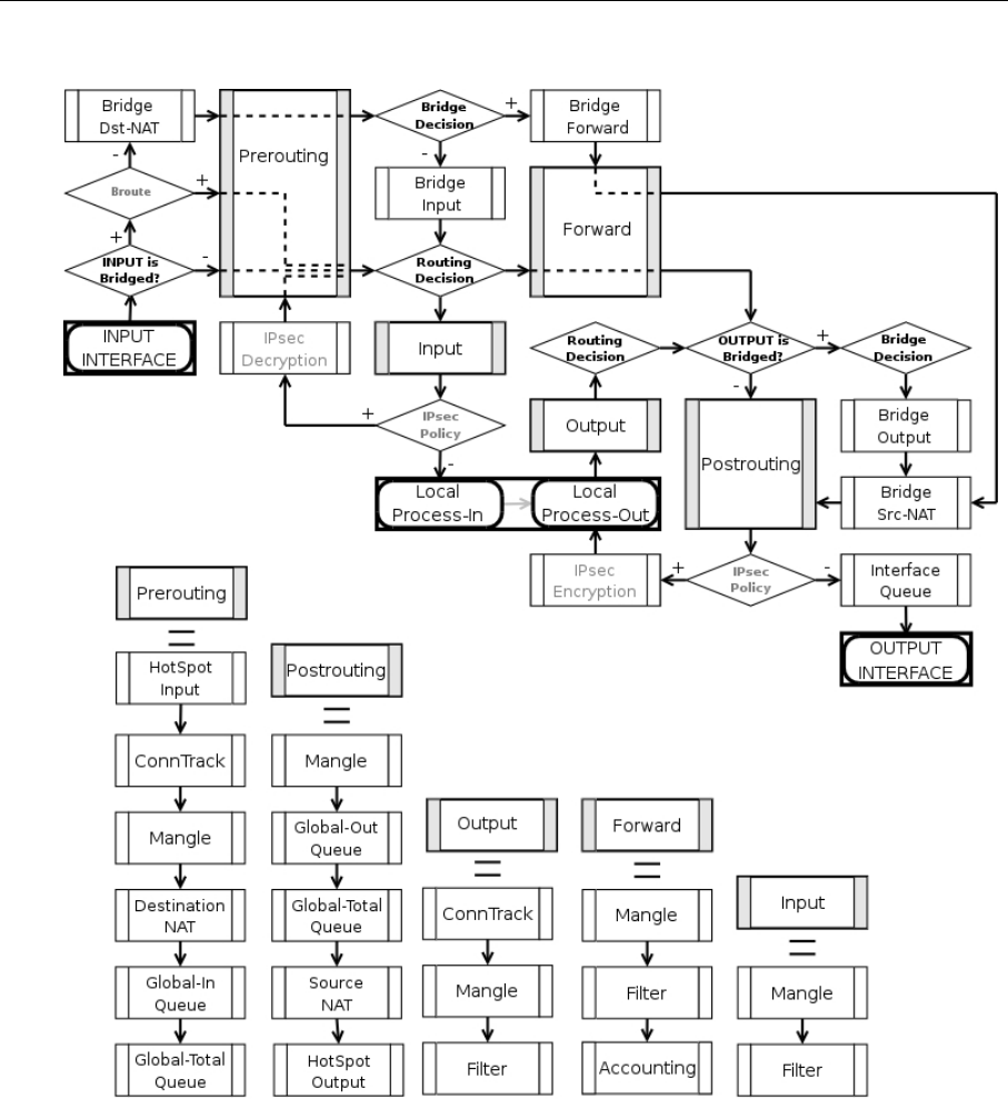
AT-WR4500 Series - IEEE 802.11abgh Outdoor Wireless Routers 211
RouterOS v3 Configuration and User Guide
The packet flow through the router is depicted in the following diagram:
Figure 32: Packet Flow Diagram
As can be seen on the diagram, there are five chains in the processing pipeline. These are prerouting,
input, forward, output and postrouting. The actions performed on a packet in each chain are
discussed later in this chapter.
Additional arrows from IPsec boxes shows the processing of encrypted packets (they need to be
encrypted / decrypted first and then processed as usual, id est from the point an ordinal packet enters the
router).
A paket can enter processing conveyer of the router in two ways. First, a packet can come from one of
the interfaces present in the roter (then the interface is referred as input interface). Second, it can be
originated from a local process, like web proxy, VPN or others. Alike, there are two ways for a packet to
leave the processing pipeline. A packet can leave through the one of the router's interfaces (in this case
the interface is referred as output interface) or it can end up in the local process. In general, traffic can
be destined to one of the router's IP addresses, it can originate from the router or simply should be
passed through. To further complicate things the traffic can be bridged or routed one, which is
determined during the Bridge Decision stage.

212 AT-WR4500 Series - IEEE 802.11abgh Outdoor Wireless Routers
RouterOS v3 Configuration and User Guide
Routed traffic
The traffic received for the router's MAC address on the respective port, is passed to the routing
procedures and can be of one of these four types:
• the traffic which is destined to the router itself. The IP packets has destination address equal to one
of the router's IP addresses. A packet enters the router through the input interface, sequentially
traverses prerouting and input chains and ends up in the local process. Consequently, a packet can
be filtered in the input chain filter and mangled in two places: the input and the prerouting chain
filters.
• the traffic is originated from the router. In this case the IP packets have their source addresses
identical to one of the router's IP addresses. Such packets travel through the output chain, then they
are passed to the routing facility where an appropriate routing path for each packet is determined
and leave through the postrouting chain.
• routable traffic, which is received at the router's MAC address, has an IP address different from any
of the router's own addresses, and its destination can be found in the routing tables. These packets
go through the prerouting, forward and postrouting chains.
• unroutable traffic, which is received at the router's MAC address, has an IP address different from
any of the router's own addresses, but its destination can not be found in the routing tables. These
packets go through the prerouting and stop in the routing recision.
The actions imposed by various router facilities are sequentially applied to a packet in each of the default
chains. The exact order they are applied is pictured in the bottom of the flow diagram. Exempli gratia, for
a packet passing postrouting chain the mangle rules are applied first, two types of queuing come in
second place and finally source NAT is performed on packets that need to be natted.
Note, that any given packet can come through only one of the input, forward or output chains.
Bridged Traffic
In case the incoming traffic needs to be bridged (do not confuse it with the traffic coming to the bridge
interface at the router's own MAC address and, thus, classified as routed traffic) it is first determined
whether it is an IP traffic or not. After that, IP traffic goes through the prerouting, forward and
postrouting chains, while non-IP traffic bypasses all IP firewall rules and goes directly to the interface
queue. Both types of traffic, however, undergo the full set of bridge firewall chains anyway, regardless of
the protocol.
9.3.3 Connection Tracking
Submenu level: /ip firewall connection
Description
Connection tracking refers to the ability to maintain the state information about connections, such as
source and destination IP address and ports pairs, connection states, protocol types and timeouts.
Firewalls that do connection tracking are known as "stateful" and are inherently more secure that those
who do only simple "stateless" packet processing.
The state of a particular connection could be estabilished meaning that the packet is part of already
known connection, new meaning that the packet starts a new connection or belongs to a connection that
has not seen packets in both directions yet, related meaning that the packet starts a new connection,
but is associated with an existing connection, such as FTP data transfer or ICMP error message and,
finally, invalid meaning that the packet does not belong to any known connection and, at the same time,
does not open a valid new connection.
Connection tracking is done in the prerouting chain, or the output chain for locally generated packets.
Another function of connection tracking which cannot be overestimated is that it is needed for NAT. You
should be aware that no NAT can be performed unless you have connection tracking enabled, the same
applies for p2p protocols recognition. Connection tracking also assembles IP packets from fragments
before further processing.
The maximum number of connections the /ip firewall connection state table can contain is determined
by the amount of physical memory present in the router.
Please ensure that your router is equipped with sufficient amount of physical memory to properly handle
all connections.
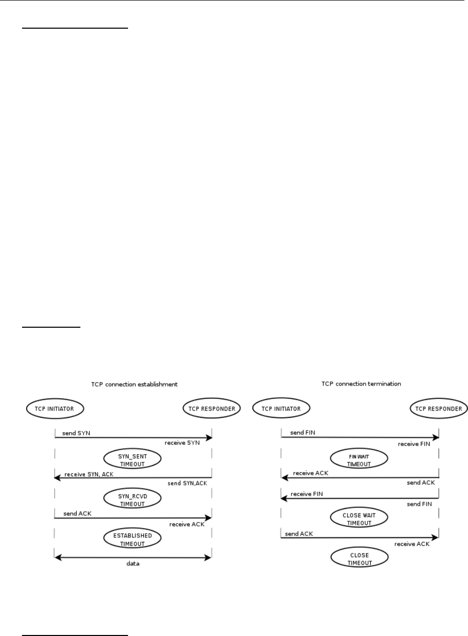
AT-WR4500 Series - IEEE 802.11abgh Outdoor Wireless Routers 213
RouterOS v3 Configuration and User Guide
Property Description
assured (read-only: true | false) - shows whether replay was seen for the last packet matching this entry
connection-mark (read-only: text) - Connection mark set in mangle
dst-address (read-only: IP address:port) - the destination address and port the connection is established to
icmp-id (read-only: integer) - contains the ICMP ID. Each ICMP packet gets an ID set to it when it is sent,
and when the receiver gets the ICMP message, it sets the same ID within the new ICMP message so that
the sender will recognize the reply and will be able to connect it with the appropriate ICMP request
icmp-option (read-only: integer) - the ICMP type and code fields
p2p (read-only: text) - peer to peer protocol
protocol (read-only: text) - IP protocol name or number
reply-dst-address (read-only: IP address:port) - the destination address and port the reply connection is
established to
reply-icmp-id (read-only: integer) - contains the ICMP ID of received packet
reply-icmp-option (read-only: integer) - the ICMP type and code fields of received packet
reply-src-address (read-only: IP address:port) - the source address and port the reply connection is
established from
src-address (read-only: IP address:port) - the source address and port the connection is established from
tcp-state (read-only: text) - the state of TCP connection
timeout (read-only: time) - the amount of time until the connection will be timed out
unreplied (read-only: true | false) - shows whether the request was unreplied
9.3.4 Connection Timeouts
Submenu level: /ip firewall connection tracking
Description
Connection tracking provides several timeouts. When particular timeout expires the according entry is
removed from the connection state table. The following diagram depicts typical TCP connection
establishment and termination and tcp timeouts that take place during these processes:
Figure 33: Firewall Connection Tracking timeouts
Property Description
enable (yes | no; default: yes) - whether to allow or disallow connection tracking
generic-timeout (time; default: 10m) - maximal amount of time connection state table entry that keeps
tracking of packets that are neither TCP nor UDP (for instance GRE) will survive after having seen last
packet matching this entry. Creating PPTP connection this value will be increased automaticly
icmp-timeout (time; default: 10s) - maximal amount of time connection tracking entry will survive after
having seen ICMP request

214 AT-WR4500 Series - IEEE 802.11abgh Outdoor Wireless Routers
RouterOS v3 Configuration and User Guide
max-entries (read-only: integer) - the maximum number of connections the connection state table can
contain, depends on an amount of total memory
tcp-close-timeout (time; default: 10s) - maximal amount of time connection tracking entry will survive
after having seen connection reset request (RST) or an acknowledgment (ACK) of the connection
termination request from connection release initiator
tcp-close-wait-timeout (time; default: 10s) - maximal amount of time connection tracking entry will
survive after having seen an termination request (FIN) from responder
tcp-established-timeout (time; default: 1d) - maximal amount of time connection tracking entry will
survive after having seen an acknowledgment (ACK) from connection initiator
tcp-fin-wait-timeout (time; default: 10s) - maximal amount of time connection tracking entry will
survive after having seen connection termination request (FIN) from connection release initiator
tcp-syn-received-timeout (time; default: 1m) - maximal amount of time connection tracking entry will
survive after having seen a matching connection request (SYN)
tcp-syn-sent-timeout (time; default: 1m) - maximal amount of time connection tracking entry will
survive after having seen a connection request (SYN) from connection initiator
tcp-syncookie (yes | no; default: no) - enable TCP SYN cookies for connections destined to the router
itself (this may be useful for HotSpot and tunnels)
tcp-time-wait-timeout (time; default: 10s) - maximal amount of time connection tracking entry will
survive after having seen connection termination request (FIN) just after connection request (SYN) or
having seen another termination request (FIN) from connection release initiator
total-entries (read-only: integer) - number of connections currently recorded in the connection state
table
udp-stream-timeout (time; default: 3m) - maximal amount of time connection tracking entry will
survive after replay is seen for the last packet matching this entry (connection tracking entry is assured).
It is used to increase timeout for such connections as H323, VoIP, etc.
udp-timeout (time; default: 10s) - maximal amount of time connection tracking entry will survive after
having seen last packet matching this entry
The maximum timeout value depends on amount of entries in connection state table. If amount of
entries in the table is more than:
• 1/16 of maximum number of entries the maximum timeout value will be 1 day
• 3/16 of maximum number of entries the maximum timeout value will be 1 hour
• 1/2 of maximum number of entries the maximum timeout value will be 10 minute
• 13/16 of maximum number of entries the maximum timeout value will be 1 minute
The shortest timeout will always be choden between the configured timeout and the value listed above.
If connection tracking timeout value is less than the normal interval between the data packets rate
(timeout expires before the next packet arives), NAT and statefull-firewalling stop working.
9.3.5 Service Ports
Submenu level: /ip firewall service-port
Description
Some network protocols are not compatible with network address translation, for example due to some
additional infomation about the actual addresses or ports is present in the packet payload, which is not
known for the NAT procedures, as they only look at the IP, UDP and TCP headers, not inside the
packets. For these protocols to work correctly, a connection tracking helper is needed to work around
such design issues. You may enable and disable helpers here (you may want to disable some of them to
increase performance or if you are experiencing problems with some protocols detected incorrectly).
Note that you can not add or remove the helpers, just enable or disable the existing ones.
Property Description
name - protocol name
ports (integer) - port range that is used by the protocol (only some helpers need this)

AT-WR4500 Series - IEEE 802.11abgh Outdoor Wireless Routers 215
RouterOS v3 Configuration and User Guide
9.3.6 General Firewall Information
Description
ICMP TYPE:CODE values
In order to protect your router and attached private networks, you need to configure firewall to drop or
reject most of ICMP traffic. However, some ICMP packets are vital to maintain network reliability or
provide troubleshooting services.
The following is a list of ICMP TYPE:CODE values found in good packets. It is generally suggested to
allow these types of ICMP traffic.
• Ping
8:0 - echo request
0:0 - echo reply
• Trace
11:0 - TTL exceeded
3:3 - Port unreachable
• Path MTU discovery
3:4 - Fragmentation-DF-Set
General suggestion to apply ICMP filtering:
• Allow ping—ICMP Echo-Request outbound and Echo-Reply messages inbound
• Allow traceroute—TTL-Exceeded and Port-Unreachable messages inbound
• Allow path MTU—ICMP Fragmentation-DF-Set messages inbound
• Block everything else
Type of Service
Internet paths vary in quality of service they provide. They can differ in cost, reliability, delay and
throughput. This situation imposes some tradeoffs, exempli gratia the path with the lowest delay may be
among the ones with the smallest throughput. Therefore, the "optimal" path for a packet to follow
through the Internet may depend on the needs of the application and its user.
As the network itself has no knowledge on how to optimize path choosing for a particular application or
user, the IP protocol provides a method for upper layer protocols to convey hints to the Internet Layer
about how the tradeoffs should be made for the particular packet. This method is implemented with the
help of a special field in the IP protocol header, the "Type of Service" field.
The fundamental rule is that if a host makes appropriate use of the TOS facility, its network service
should be at least as good as it would have been if the host had not used this facility.
Type of Service (ToS) is a standard field of IP packet and it is used by many network applications and
hardware to specify how the traffic should be treated by the gateway.
RouterOS works with the full ToS byte. It does not take account of reserverd bits in this byte (because
they have been redefined many times and this approach provides more flexibility). It means that it is
possible to work with DiffServ marks (Differentiated Services Codepoint, DSCP as defined in RFC2474)
and ECN codepoints (Explicit Congestion Notification, ECN as defined in RFC3168), which are using the
same field in the IP protocol header. Note that it does not mean that RouterOS supports DiffServ or
ECN, it is just possible to access and change the marks used by these protocols.
RFC1349 defines these standard values:
• normal - normal service (ToS=0)
• low-cost - minimize monetary cost (ToS=2)
• max-reliability - maximize reliability (ToS=4)
• max-throughput - maximize throughput (ToS=8)
• low-delay - minimize delay (ToS=16)
Peer-to-Peer protocol filtering
Peer-to-peer protocols also known as p2p provide means for direct distributed data transfer between
individual network hosts. While this technology powers many brilliant applications (like Skype), it is

216 AT-WR4500 Series - IEEE 802.11abgh Outdoor Wireless Routers
RouterOS v3 Configuration and User Guide
widely abused for unlicensed software and media destribution. Even when it is used for legal purposes,
p2p may heavily disturb other network traffic, such as http and e-mail. RouterOS is able to recognize
connections of the most popular P2P protocols and filter or enforce QOS on them.
The protocols which can be detected, are:
• Fasttrack (Kazaa, KazaaLite, Diet Kazaa, Grokster, iMesh, giFT, Poisoned, mlMac)
• Gnutella (Shareaza, XoLoX, , Gnucleus, BearShare, LimeWire (java), Morpheus, Phex, Swapper,
Gtk-Gnutella (linux), Mutella (linux), Qtella (linux), MLDonkey, Acquisition (Mac OS), Poisoned,
Swapper, Shareaza, XoloX, mlMac)
• Gnutella2 (Shareaza, MLDonkey, Gnucleus, Morpheus, Adagio, mlMac)
• DirectConnect (DirectConnect (AKA DC++), MLDonkey, NeoModus Direct Connect, BCDC++,
CZDC++ )
• eDonkey (eDonkey2000, eMule, xMule (linux), Shareaza, MLDonkey, mlMac, Overnet)
• Soulseek (Soulseek, MLDonkey)
• BitTorrent (BitTorrent, BitTorrent++, Shareaza, MLDonkey, ABC, Azureus, BitAnarch, SimpleBT,
BitTorrent.Net, mlMac)
• Blubster (Blubster, Piolet)
• WPNP (WinMX)
• Warez (Warez, Ares; starting from 2.8.18) - this protocol can only be dropped, speed limiting is
impossible
9.4 NAT
Document revisi on: 2.8 (Tue Feb 28 15:15:00 GMT 2006)
Applies to: V2.9
9.4.1 General Information
Summary
Network Address Translation (NAT) is a router facility that replaces source and (or) destination IP
addresses of the IP packet as it pass through thhe router. It is most commonly used to enable multiple
host on a private network to access the Internet using a single public IP address.
Specifications
Packages required: system
License required: Level1 (number of rules limited to 1) , Level3
Submenu level: /ip firewall nat
Standards and Technologies: IP, RFC1631, RFC2663
Hardware usage: Increases with the count of rules
Related Topics
IP Addresses and ARP
Routes, Equal Cost Multipath Routing, Policy Routing
Filter
Mangle
Packet Flow
Additional Resources
http://en.wikipedia.org/wiki/Network_address_translation

AT-WR4500 Series - IEEE 802.11abgh Outdoor Wireless Routers 217
RouterOS v3 Configuration and User Guide
9.4.2 NAT
Description
Network Address Translation is an Internet standard that allows hosts on local area networks to use one
set of IP addresses for internal communications and another set of IP addresses for external
communications. A LAN that uses NAT is referred as natted network. For NAT to function, there should
be a NAT gateway in each natted network. The NAT gateway (NAT router) performs IP address
rewriting on the way a packet travel from/to LAN.
There are two types of NAT:
• source NAT or srcnat. This type of NAT is performed on packets that are originated from a natted
network. A NAT router replaces the private source address of an IP packet with a new public IP
address as it travels through the router. A reverse operation is applied to the reply packets travelling
in the other direction.
• destination NAT or dstnat. This type of NAT is performed on packets that are destined to the natted
network. It is most comonly used to make hosts on a private network to be acceesible from the
Internet. A NAT router performing dstnat replaces the destination IP address of an IP packet as it
travel through the router towards a private network.
NAT Drawbacks
Hosts behind a NAT-enabled router do not have true end-to-end connectivity. Therefore some Internet
protocols might not work in scenarios with NAT. Services that require the initiation of TCP connection
from outside the private network or stateless protocols such as UDP, can be disrupted. Moreover, some
protocols are inherently incompatible with NAT; a bold example is AH protocol from the IPsec suite.
RouterOS includes a number of so-called NAT helpers that enable NAT traversal for various protocols.
Redirect and Masquerade
Redirect and masquerade are special forms of destination NAT and source NAT, respectively. Redirect is
similar to the regular destination NAT in the same way as masquerade is similar to the source NAT -
masquerade is a special form of source NAT without need to specify to-addresses - outgoing interface
address is used automatically. The same is for redirect - it is a form of destination NAT where to-
addresses is not used - incoming interface address is used instead. Note that to-ports is meaningful for
redirect rules - this is the port of the service on the router that will handle these requests (e.g. web
proxy).
When packet is dst-natted (no matter - action=nat or action=redirect), dst address is changed.
Information about translation of addresses (including original dst address) is kept in router's internal
tables. Transparent web proxy working on router (when web requests get redirected to proxy port on
router) can access this information from internal tables and get address of web server from them. If you
are dst-natting to some different proxy server, it has no way to find web server's address from IP header
(because dst address of IP packet that previously was address of web server has changed to address of
proxy server). Starting from HTTP/1.1 there is special header in HTTP request which tells web server
address, so proxy server can use it, instead of dst address of IP packet. If there is no such header (older
HTTP version on client), proxy server can not determine web server address and therefore can not
work.
It means, that it is impossible to correctly transparently redirect HTTP traffic from router to some other
transparent-proxy box. Only correct way is to add transparent proxy on the router itself, and configure it
so that your "real" proxy is parent-proxy. In this situation your "real" proxy does not have to be
transparent any more, as proxy on router will be transparent and will forward proxy-style requests
(according to standard; these requests include all necessary information about web server) to "real"
proxy.
Property Description
action (accept | add-dst-to-address-list | add-src-to-address-list | dst-nat | jump | log | masquerade |
netmap | passthrough | redirect | return | same | src-nat; default: accept) - action to undertake if the
packet matches the rule
accept - accepts the packet. No action is taken, i.e. the packet is passed through and no more rules are
applied to it
add-dst-to-address-list - adds destination address of an IP packet to the address list specified by

218 AT-WR4500 Series - IEEE 802.11abgh Outdoor Wireless Routers
RouterOS v3 Configuration and User Guide
address-list parameter
add-src-to-address-list - adds source address of an IP packet to the address list specified by address-
list parameter
dst-nat - replaces destination address of an IP packet to values specified by to-addresses and to-ports
parameters
jump - jump to the chain specified by the value of the jump-target parameter
log - each match with this action will add a message to the system log
masquerade - replaces source address of an IP packet to an automatically determined by the routing
facility IP address
netmap - creates a static 1:1 mapping of one set of IP addresses to another one. Often used to
distribute public IP addresses to hosts on private networks
passthrough - ignores this rule goes on to the next one
redirect - replaces destination address of an IP packet to one of the router's local addresses
return - passes control back to the chain from where the jump took place
same - gives a particular client the same source/destination IP address from supplied range for each
connection. This is most frequently used for services that expect the same client address for multiple
connections from the same client
src-nat - replaces source address of an IP packet to values specified by to-addresses and to-ports
parameters
address-list (name) - specifies the name of the address list to collect IP addresses from rules having
action=add-dst-to-address-list or action=add-src-to-address-list actions. These address lists could
be later used for packet matching
address-list-timeout (time; default: 00:00:00) - time interval after which the address will be removed
from the address list specified by address-list parameter. Used in conjunction with add-dst-to
address-list or add-src-to-address-list actions
00:00:00 - leave the address in the address list forever
chain (dstnat | srcnat | name) - specifies the chain to put a particular rule into. As the different traffic is
passed through different chains, always be careful in choosing the right chain for a new rule. If the input
does not match the name of an already defined chain, a new chain will be created
dstnat - a rule placed in this chain is applied before routing. The rules that replace destination addresses
of IP packets should be placed there
srcnat - a rule placed in this chain is applied after routing. The rules that replace the source addresses of
IP packets should be placed there
comment (text) - a descriptive comment for the rule. A comment can be used to identify rules form
scripts
connection-bytes (integer-integer) - matches packets only if a given amount of bytes has already been
transfered through the particular connection
0 - means infinity, exempli gratia: connection-bytes=2000000-0 means that the rule matches if more
than 2MB has been transfered through the relevant connection
connection-limit (integer,netmask) - restrict connection number per address or address block (matches
if the specified number of connection has already been established)
connection-mark (name) - matches packets marked via mangle facility with particular connection mark
connection-type (ftp | gre | h323 | irc | mms | pptp | quake3 | tftp) - matches packets from related
connections based on information from their connection tracking helpers. A relevant connection helper
must be enabled under /ip firewall service-port
content (text) - the text packets should contain in order to match the rule
dscp (integer: 0..63) - DSCP (ex-ToS) IP header field value
dst-address (IP address/netmask | IP address-IP address) - specifies the address range an IP packet is
destined to. Note that console converts entered address/netmask value to a valid network address,
i.e.:1.1.1.1/24 is converted to 1.1.1.0/24
dst-address-list (name) - matches destination address of a packet against user-defined address list
dst-address-type (unicast | local | broadcast | multicast) - matches destination address type of the IP
packet, one of the:
unicast - IP addresses used for one point to another point transmission. There is only one sender and
one receiver in this case
local - matches addresses assigned to router's interfaces
broadcast - the IP packet is sent from one point to all other points in the IP subnetwork
multicast - this type of IP addressing is responsible for transmission from one or more points to a set of
other points

AT-WR4500 Series - IEEE 802.11abgh Outdoor Wireless Routers 219
RouterOS v3 Configuration and User Guide
dst-limit (integer/time{0,1},integer,dst-address | dst-port | src-address{+},time{0,1}) - limits the packet per
second (pps) rate on a per destination IP or per destination port base. As opposed to the limit match,
every destination IP address / destination port has it's own limit. The options are as follows (in order of
appearance):
count - maximum average packet rate, measured in packets per second (pps), unless followed by time
option
time - specifies the time interval over which the packet rate is measured
burst - number of packets to match in a burst
mode - the classifier(-s) for packet rate limiting
expire - specifies interval after which recorded IP addresses / ports will be deleted
dst-port (integer: 0..65535-integer: 0..65535{*}) - destination port number or range
fragment (yes | no) - whether the packet is a fragment of an IP packet. Starting packet (i.e., first
fragment) does not count. Note that is the connection tracking is enabled, there will be no fragments as
the system automatically assembles every packet
hotspot (multiple choice: auth | from-client | http | local-dst | to-client) - matches packets received from
clients against various HotSpot conditions. All values can be negated
auth - true, if a packet comes from an authenticted HotSpotclient
from-client - true, if a packet comes from any HotSpot client
http - true, if a HotSpot client sends a packet to the address and port previously detected as his proxy
server (Universal Proxy technique) or if the destination port is 80 and transparent proxying is enabled for
that particular client
local-dst - true, if a packet has local destination IP address
to-client - true, if a packet is sent to a client
icmp-options (integer:integer) - matches ICMP Type:Code fields
in-bridge-port (name) - actual interface the packet has entered the router through (if bridged, this
property matches the actual bridge port, while in-interface - the bridge itself)
in-interface (name) - interface the packet has entered the router through (if the interface is bridged,
then the packet will appear to come from the bridge interface itself)
ingress-priority (integer: 0..63) - INGRESS (received) priority of the packet, if set (0 otherwise). The
priority may be derived from either VLAN or WMM priority
ipv4-options (any | loose-source-routing | no-record-route | no-router-alert | no-source-routing | no-
timestamp | none | record-route | router-alert | strict-source-routing | timestamp) - match ipv4 header
options
any - match packet with at least one of the ipv4 options
loose-source-routing - match packets with loose source routing option. This option is used to route
the internet datagram based on information supplied by the source
no-record-route - match packets with no record route option. This option is used to route the
internet datagram based on information supplied by the source
no-router-alert - match packets with no router alter option
no-source-routing - match packets with no source routing option
no-timestamp - match packets with no timestamp option
record-route - match packets with record route option
router-alert - match packets with router alter option
strict-source-routing - match packets with strict source routing option
timestamp - match packets with timestamp
jump-target (dstnat | srcnatname) - name of the target chain to jump to, if the action=jump is used
layer7-protocol (name) - Layer 7 filter name as set in the /ip firewall layer7-protocol menu. Caution:
this matcher needs high computational power
limit (integer/time{0,1},integer) - restricts packet match rate to a given limit. Usefull to reduce the amount
of log messages
count - maximum average packet rate, measured in packets per second (pps), unless followed by time
option
time - specifies the time interval over which the packet rate is measured
burst - number of packets to match in a burst
log-prefix (text) - all messages written to logs will contain the prefix specified herein. Used in
conjunction with action=log
nth (integer,integer: 0..15,integer{0,1}) - match a particular Nth packet received by the rule. One of 16
available counters can be used to count packets

220 AT-WR4500 Series - IEEE 802.11abgh Outdoor Wireless Routers
RouterOS v3 Configuration and User Guide
every - match every every+1th packet. For example, if every=1 then the rule matches every 2nd
packet
counter - specifies which counter to use. A counter increments each time the rule containing nth match
matches
packet - match on the given packet number. The value by obvious reasons must be between 0 and
every. If this option is used for a given counter, then there must be at least every+1 rules with this
option, covering all values between 0 and every inclusively.
out-bridge-port (name) - actual interface the packet is leaving the router through (if bridged, this
property matches the actual bridge port, while out-interface - the bridge itself)
out-interface (name) - interface the packet is leaving the router through (if the interface is bridged, then
the packet will appear to leave through the bridge interface itself)
packet-mark (text) - matches packets marked via mangle facility with particular packet mark
packet-size (integer: 0..65535-integer: 0..65535{0,1}) - matches packet of the specified size or size range
in bytes
min - specifies lower boundary of the size range or a standalone value
max - specifies upper boundary of the size range
port (port{0-16}) - matches if any (source or destination) port matches the specified list of ports or port
ranges (note that the protocol must still be selected, just like for the regular src-port and dst-port
matchers)
protocol (ddp | egp | encap | ggp | gre | hmp | icmp | idrp-cmtp | igmp | ipencap | ipip | ipsec-ah | ipsec-
esp | iso-tp4 | ospf | pup | rdp | rspf | st | tcp | udp | vmtp | xns-idp | xtp | integer) - matches particular IP
protocol specified by protocol name or number. You should specify this setting if you want to specify
ports
psd (integer,time,integer,integer) - attempts to detect TCP and UDP scans. It is advised to assign lower
weight to ports with high numbers to reduce the frequency of false positives, such as from passive mode
FTP transfers
WeightThreshold - total weight of the latest TCP/UDP packets with different destination ports coming
from the same host to be treated as port scan sequence
DelayThreshold - delay for the packets with different destination ports coming from the same host to
be treated as possible port scan subsequence
LowPortWeight - weight of the packets with privileged (<=1024) destination port
HighPortWeight - weight of the packet with non-priviliged destination port
random (integer) - match packets randomly with given propability
routing-mark (name) - matches packets marked by mangle facility with particular routing mark
same-not-by-dst (yes | no) - specifies whether to account or not to account for destination IP address
when selecting a new source IP address for packets matched by rules with action=same
src-address (IP address/netmask | IP address-IP address) - specifies the address range an IP packet is
originated from. Note that console converts entered address/netmask value to a valid network
address, i.e.:1.1.1.1/24 is converted to 1.1.1.0/24
src-address-list (name) - matches source address of a packet against user-defined address list
src-address-type (unicast | local | broadcast | multicast) - matches source address type of the IP packet,
one of the:
unicast - IP addresses used for one point to another point transmission. There is only one sender and
one receiver in this case
local - matches addresses assigned to router's interfaces
broadcast - the IP packet is sent from one point to all other points in the IP subnetwork
multicast - this type of IP addressing is responsible for transmission from one or more points to a set of
other points
src-mac-address (MAC address) - source MAC address
src-port (integer: 0..65535-integer: 0..65535{*}) - source port number or range
tcp-mss (integer: 0..65535) - matches TCP MSS value of an IP packet
time (time-time,sat | fri | thu | wed | tue | mon | sun{+}) - allows to create filter based on the packets'
arrival time and date or, for locally generated packets, departure time and date
to-addresses (IP address-IP address{0,1}; default: 0.0.0.0) - address or address range to replace original
address of an IP packet with
to-ports (integer: 0..65535-integer: 0..65535{0,1}) - port or port range to replace original port of an IP
packet with

AT-WR4500 Series - IEEE 802.11abgh Outdoor Wireless Routers 221
RouterOS v3 Configuration and User Guide
9.4.3 NAT Applications
Description
In this section some NAT applications and examples of them are discussed.
Basic NAT configuration
Assume we want to create router that:
"hides" the private LAN "behind" one address
provides Public IP to the Local server
creates 1:1 mapping of network addresses
Example of Source NAT (Masquerading)
If you want to "hide" the private LAN 192.168.0.0/24 "behind" one address 10.5.8.109 given to you by the
ISP, you should use the source network address translation (masquerading) feature of the RouterOS
router. The masquerading will change the source IP address and port of the packets originated from the
network 192.168.0.0/24 to the address 10.5.8.109 of the router when the packet is routed through it.
To use masquerading, a source NAT rule with action 'masquerade' should be added to the firewall
configuration:
/ip firewall nat add chain=srcnat action=masquerade out-interface=Public
All outgoing connections from the network 192.168.0.0/24 will have source address 10.5.8.109 of the
router and source port above 1024. No access from the Internet will be possible to the Local addresses.
If you want to allow connections to the server on the local network, you should use destination Network
Address Translation (NAT).
Example of Destination NAT
If you want to link Public IP 10.5.8.200 address to Local one 192.168.0.109, you should use destination
address translation feature of the RouterOS router. Also if you want allow Local server to talk with
outside with given Public IP you should use source address translation, too
Add Public IP to Public interface:
/ip address add address=10.5.8.200/32 interface=Public
Add rule allowing access to the internal server from external networks:
/ip firewall nat add chain=dstnat dst-address=10.5.8.200 action=dst-nat \
to-addresses=192.168.0.109
Add rule allowing the internal server to talk to the outer networks having its source address translated to
10.5.8.200:
/ip firewall nat add chain=srcnat src-address=192.168.0.109 action=src-nat \
to-addresses=10.5.8.200
Example of one to one mapping
If you want to link Public IP subnet 11.11.11.0/24 to local one 2.2.2.0/24, you should use destination
address translation and source address translation features with action=netmap.
/ip firewall nat add chain=dstnat dst-address=11.11.11.1-11.11.11.254 \
action=netmap to-addresses=2.2.2.1-2.2.2.254
/ip firewall nat add chain=srcnat src-address=2.2.2.1-2.2.2.254 \
action=netmap to-addresses=11.11.11.1-11.11.11.254

222 AT-WR4500 Series - IEEE 802.11abgh Outdoor Wireless Routers
RouterOS v3 Configuration and User Guide
10 Hot Spot Service
10.1 HotSpot Gateway
Document revisi on: 4.2 (Tue Jul 04 14:49:38 GMT 2006)
Applies to: V2.9
10.1.1 General Information
Summary
The RouterOS HotSpot Gateway enables providing of public network access for clients using wireless or
wired network connections.
HotSpot Gateway features:
• authentication of clients using local client database, or RADIUS server
• accounting using local database, or RADIUS server
• Walled-garden system (accessing some web pages without authorization)
Quick Setup Guide
Given a router with two interfaces: Local (where HotSpot clients are connected to) and Public, which is
connected to the Internet. To set up HotSpot on the Local interface:
1. first, a valid IP configuration is required on both interfaces. This can be done with /setup command
or by setting up the router manually. In this example we will assume the configuration with DHCP
server already enabled on the Local interface
2. valid DNS configuration must be set up in the /ip dns submenu
3. To put HotSpot on the Local interface, using the same IP address pool as DHCP server uses for that
interface: /ip hotspot add interface=local address-pool=dhcp-pool-1
4. and finally, add at least one HotSpot user: /ip hotspot user add name=admin
These simple steps should be sufficient to enable HotSpot system
Please find HotSpot How-to's, which will answer most of your questions about configuring a HotSpot
gateway, at the end of this manual. It is still recommended that you read and understand all the
Description section below before deploying a HotSpot system.
If this does not work:
• check that /ip dns contains valid DNS servers, try to /ping www.example.com to see, that DNS
resolving works
• make sure that connection tracking is enabled: /ip firewall connection tracking set enabled=yes
Specifications
Packages required: hotspot, dhcp(optional)
License required: Level1 (Limited to 1 active user) , Level3 (Limited to 1 active user) , Level4 (Limited to
200 active users) , Level5 (Limited to 500 active users) , Level6
Submenu level: /ip hotspot
Standards and Technologies: ICMP, DHCP
Hardware usage: Not significant
Description
RouterOS HotSpot Gateway should have at least two network interfaces:
1. HotSpot interface, which is used to connect HotSpot clients
2. LAN/WAN interface, which is used to access network resources. For example, DNS and RADIUS
server(s) should be accessible
The diagram below shows a sample HotSpot setup.
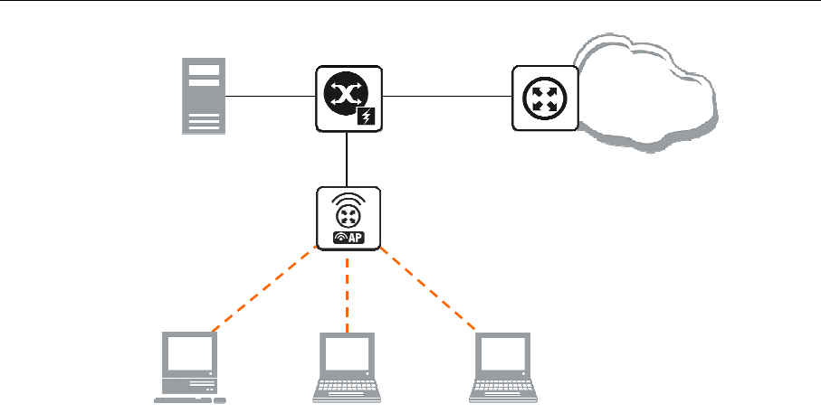
AT-WR4500 Series - IEEE 802.11abgh Outdoor Wireless Routers 223
RouterOS v3 Configuration and User Guide
[HotSpot Gateway]
WAN/LAN
Interface
Internet
RADIUS
HotSpot
Interface
Figure 34: HotSpot example network
The HotSpot interface should have an IP address assigned to it. Physical network connection has to be
established between the HotSpot user's computer and the gateway. It can be wireless (the wireless card
should be registered to AP), or wired (the NIC card should be connected to a hub or a switch).
Introduction to HotSpot
HotSpot is a way to authorize users to access some network resources. It does not provide traffic
encryption. To log in, users may use almost any web browser (either HTTP or HTTPS protocol), so they
are not required to install additional software. The gateway is accounting the uptime and amount of traffic
each of its clients have used, and also can send this information to a RADIUS server. The HotSpot system
may limit each particular user's bitrate, total amount of traffic, uptime and some other parameters
mentioned further in this document.
The HotSpot system is targeted to provide authentication within a local network (to access the Internet),
but may as well be used to authorize access from outer networks to access local resources. Configuring
Walled Garden feature, it is possible to allow users to access some web pages without the need of prior
authentication.
Getting Address
First of all, a client must get an IP address. It may be set on the client statically, or leased from a DHCP
server. The DHCP server may provide ways of binding lent IP addresses to clients MAC addresses, if
required. The HotSpot system does not care how did a client get an address before he/she gets to the
HotSpot login page.
Moreover, HotSpot server may automatically and transparently change any IP address (yes, meaning really
any IP address) of a client to a valid unused address from the selected IP pool. This feature gives a
possibility to provide a network access (for example, Internet access) to mobile clients that are not
willing (or are disallowed, not qualified enough or otherwise unable) to change their networking settings.
The users will not notice the translation (i.e., there will not be any changes in the users' config), but the
router itself will see completely different (from what is actually set on each client) source IP addresses on
packets sent from the clients (even firewall mangle table will 'see' the translated addresses). This
technique is called one-to-one NAT, but is also known as "Universal Client" as that is how it was called in
the RouterOS version 2.8.
One-to-one NAT accepts any incoming address from a connected network interface and performs a
network address translation so that data may be routed through standard IP networks. Clients may use
any preconfigured addresses. If the one-to-one NAT feature is set to translate a client's address to a
public IP address, then the client may even run a server or any other service that requires a public IP
address. This NAT is changing source address of each packet just after it is received by the router (it is
like source NAT that is performed earlier, so that even firewall mangle table, which normally 'sees'
received packets unaltered, can only 'see' the translated address).
Note also that arp mode must be enabled on the interface you use one-to-one NAT on.

224 AT-WR4500 Series - IEEE 802.11abgh Outdoor Wireless Routers
RouterOS v3 Configuration and User Guide
Before the authentication
When enabling HotSpot on an interface, the system automatically sets up everything needed to show
login page for all clients that are not logged in. This is done by adding dynamic destination NAT rules,
which you can observe on a working HotSpot system. These rules are needed to redirect all HTTP and
HTTPS requests from unauthorized users to the HotSpot servlet (i.e., the authentication procedure, e.g.,
the login page). Other rules that are also inserted, we will describe later in a special section of this
manual.
In most common setup, opening any HTTP page will bring up the HotSpot servlet login page (which can
be customized extensively, as will be described later on). As normal user behavior is to open web pages
by their DNS names, a valid DNS configuration should be set up on the HotSpot gateway itself (it is
possible to reconfigure the gateway so that it will not require local DNS configuration, but such a
configuration is impractical and thus not recommended).
Walled Garden
You may wish not to require authorization for some services (for example to let clients access the web
server of your company without registration), or even to require authorization only to a number of
services (for example, for users to be allowed to access an internal file server or another restricted area).
This can be done by setting up Walled Garden system.
When a not logged-in user requests a service allowed in the Walled Garden configuration, the HotSpot
gateway does not intercept it, or in case of HTTP, simply redirects the request to the original destination.
Other requests are redirected to the HotSpot servlet (login page infrastructure). When a user is logged
in, there is no effect of this table on him/her.
Walled Garden for HTTP requests is using the embedded proxy server (/ip proxy). This means that all
the configured parameters of that proy server will also be effective for the WalledGarden clients (as well
as for all clients that have transparent proxy enabled)
Authentication
There are currently 6 different authentication methods. You can use one or more of them simultaneously:
HTTP PAP - simplest method, which shows the HotSpot login page and expect to get the authentication
info (i.e. username and password) in plain text. Note that passwords are not being encrypted when
transferred over the network. Another use of this method is the possibility of hard-coded authentication
information in the servlet's login page simply creating the appropriate link.
HTTP CHAP - standard method, which includes CHAP challenge in the login page. The CHAP MD5
hash challenge is to be used together with the user's password for computing the string which will be sent
to the HotSpot gateway. The hash result (as a password) together with username is sent over network to
HotSpot service (so, password is never sent in plain text over IP network). On the client side, MD5
algorithm is implemented in JavaScript applet, so if a browser does not support JavaScript (like, for
example, Internet Explorer 2.0 or some PDA browsers) or it has JavaScipt disabled, it will not be able to
authenticate users. It is possible to allow unencrypted passwords to be accepted by turning on HTTP PAP
authentication method, but it is not recommended (due to security considerations) to use that feature.
HTTPS - the same as HTTP PAP, but using SSL protocol for encrypting transmissions. HotSpot user just
send his/her password without additional hashing (note that there is no need to worry about plain-text
password exposure over the network, as the transmission itself is encrypted). In either case, HTTP POST
method (if not possible, then - HTTP GET method) is used to send data to the HotSpot gateway.
HTTP cookie - after each successful login, a cookie is sent to the web browser and the same cookie is
added to active HTTP cookie list. Next time the same user will try to log in, web browser will send the
saved HTTP cookie. This cookie will be compared with the one stored on the HotSpot gateway and only
if source MAC address and randomly generated ID match the ones stored on the gateway, user will be
automatically logged in using the login information (username and password pair) was used when the
cookie was first generated. Otherwise, the user will be prompted to log in, and in the case authentication
is successful, old cookie will be removed from the local HotSpot active cookie list and the new one with
different random ID and expiration time will be added to the list and sent to the web browser. It is also
possible to erase cookie on user manual logoff (not in the default server pages, but you can modify them
to perform this). This method may only be used together with HTTP PAP, HTTP CHAP or HTTPS
methods as there would be nothing to generate cookies in the first place otherwise.
MAC address - try to authenticate clients as soon as they appear in the hosts list (i.e., as soon as they
have sent any packet to the HotSpot server), using client's MAC address as username.
Trial - users may be allowed to use the service free of charge for some period of time for evaluation, and
be required to authenticate only after this period is over. HotSpot can be configured to allow some

AT-WR4500 Series - IEEE 802.11abgh Outdoor Wireless Routers 225
RouterOS v3 Configuration and User Guide
amount of time per MAC address to be freely used with some limitations imposed by the provided user
profile. In case the MAC address still has some trial time unused, the login page will contain the link for
trial login. The time is automatically reset after the configured amount of time (so that, for example, any
MAC address may use 30 minutes a day without ever registering). The username of such a user (as seen
in the active user table and in the login link) is "T-XX:XX:XX:XX:XX:XX" (where XX:XX:XX:XX:XX:XX
is his/her MAC address). The authentication procedure will not ask RADIUS server permission to
authorise such a user.
HotSpot can authenticate users consulting the local user database or a RADIUS server (local database is
consulted first, then - a RADIUS server). In case of HTTP cookie authentication via RADIUS server, the
router will send the same information to the server as was used when the cookie was first generated. If
authentication is done locally, profile corresponding to that user is used, otherwise (in case RADIUS reply
did not contain the group for that user) the default profile is used to set default values for parameters,
which are not set in RADIUS access-accept message. For more information on how the interaction with a
RADIUS server works, see the respective manual section.
The HTTP PAP method also makes it possible to authenticate by requesting the page
/login?username=username&password=password . In case you want to log in using telnet connection, the
exact HTTP request would look like that: GET /login?username=username&password=password
HTTP/1.0 (note that the request is case-sensitive)
Authorization
After authentication, user gets access to the Internet, and receives some limitations (which are user
profile specific). HotSpot may also perform a one-to-one NAT for the client, so that a particular user
would always receive the same IP address regardless of what PC is he/she working at.
The system will automatically detect and redirect requests to a proxy server a client is using (if any; it
may be set in his/her settings to use an unknown to us proxy server) to the proxy server embedded in
the router.
Authorization may be delegated to a RADIUS server, which delivers similar configuration options as the
local database. For any user requiring authorization, a RADIUS server gets queried first, and if no reply
received, the local database is examined. RADIUS server may send a Change of Authorization request
according to standards to alter the previously accepted parameters.
Advertisement
The same proxy used for unauthorized clients to provide Walled-Garden facility, may also be used for
authorized users to show them advertisement popups. Transparent proxy for authorized users allows to
monitor http requests of the clients and to take some action if required. It enables the possibility to open
status page even if client is logged in by mac address, as well as to show advertisements time after time
When time has come to show an advertisement, the server redirects client's web browser to the status
page. Only requests, which provide html content, are redirected (images and other content will not be
affected). The status page displays the advertisement and next advertise-interval is used to schedule next
advertisement. If status page is unable to display an advertisement for configured timeout starting from
moment, when it is scheduled to be shown, client access is blocked within walled-garden (as unauthorized
clients are). Client is unblocked when the scheduled page is finally shown. Note that if popup windows
are blocked in the browser, the link on the status page may be used to open the advertisement manually.
While client is blocked, FTP and other services will not be allowed. Thus requiring client to open an
advertisement for any Internet activity not especially allowed by the Walled-Garden.
Accounting
The HotSpot system implement accounting internally, you are not required to do anything special for it
to work. The accounting information for each user may be sent to a RADIUS server.
Configuration menus
• /ip hotspot - HotSpot servers on particular interfaces (one server per interface). HotSpot server
must be added in this menu in order for HotSpot system to work on an interface
• /ip hotspot profile - HotSpot server profiles. Settings, which affect login procedure for HotSpot
clients are configured here. More than one HotSpot servers may use the same profile
• /ip hotspot host - dynamic list of active network hosts on all HotSpot interfaces. Here you can also
find IP address bindings of the one-to-one NAT
• /ip hotspot ip-binding - rules for binding IP addresses to hosts on hotspot interfaces

226 AT-WR4500 Series - IEEE 802.11abgh Outdoor Wireless Routers
RouterOS v3 Configuration and User Guide
• /ip hotspot service-port - address translation helpers for the one-to-one NAT
• /ip hotspot walled-garden - Walled Garden rules at HTTP level (DNS names, HTTP request
substrings)
• /ip hotspot walled-garden ip - Walled Garden rules at IP level (IP addresses, IP protocols)
• /ip hotspot user - local HotSpot system users
• /ip hotspot user profile - local HotSpot system users profiles (user groups)
• /ip hotspot active - dynamic list of all authenticated HotSpot users
• /ip hotspot cookie - dynamic list of all valid HTTP cookies
10.1.2 Question&Answer-Based Setup
Command name: /ip hotspot setup
Questions
address pool of network (name) - IP address pool for the HotSpot network
dns name (text) - DNS domain name of the HotSpot gateway (will be statically configured on the local
DNS proxy
dns servers (IP address,[IP address]) - DNS servers for HotSpot clients
hotspot interface (name) - interface to run HotSpot on
ip address of smtp server (IP address; default: 0.0.0.0) - IP address of the SMTP server to redirect SMTP
requests (TCP port 25) to (0.0.0.0 - no redirect )
local address of network (IP address; default: 10.5.50.1/24) - HotSpot gateway address for the interface
masquerade network (yes | no; default: yes) - whether to masquerade the HotSpot network
name of local hotspot user (text; default: admin) - username of one automatically created user
passphrase (text) - the passphrase of the certificate you are importing
password for the user (text) - password for the automatically created user
select certificate (name | none import-other-certificate) - choose SSL certificate from the list of the
imported certificates
• none - do not use SSL
• import-other-certificate - setup the certificates not imported yet, and ask this question again
Depending on current settings and answers to the previous questions, default values of following
questions may be different. Some questions may disappear if they become redundant
Example
To configure HotSpot on ether1 interface (which is already configured with address of 192.0.2.1/25), and
adding user admin with password rubbish:
[admin@AT-WR4562] > ip hotspot setup
hotspot interface: ether1
local address of network: 192.0.2.1/24
masquerade network: yes
address pool of network: 192.0.2.2-192.0.2.126
select certificate: none
ip address of smtp server: 0.0.0.0
dns servers: 192.0.2.254
dns name: hs.example.net
name of local hotspot user: admin
password for the user: rubbish
[admin@AT-WR4562] >

AT-WR4500 Series - IEEE 802.11abgh Outdoor Wireless Routers 227
RouterOS v3 Configuration and User Guide
10.1.3 HotSpot Interface Setup
Submenu level: /ip hotspot
Description
HotSpot system is put on individual interfaces. You can run completely different HotSpot configurations
on different interfaces
Property Description
HTTPS (read-only: flag) - whether the HTTPS service is actually running on the interface (i.e., it is set up
in the server profile, and a valid certificate is imported in the router)
address-pool (name | none; default: none) - IP address pool name for performing one-to-one NAT. You
can choose not to use the one-to-one NAT
none - do not perform one-to-one NAT for the clients of this HotSpot interface
addresses-per-mac (integer | unlimited; default: 2) - number of IP addresses allowed to be bind with any
particular MAC address (it is a small chance to reduce denial of service attack based on taking over all
free IP addresses in the address pool). Not available if address-pool is set to none
unlimited - number of IP addresses per one MAC address is not limited
idle-timeout (time | none; default: 00:05:00) - idle timeout (maximal period of inactivity) for
unauthorized clients. It is used to detect, that client is not using outer networks (e.g. Internet), i.e., there
is NO TRAFFIC coming from that client and going through the router. Reaching the timeout, user will be
dropped of the host list, and the address used buy the user will be freed
none - do not timeout idle users
interface (name) - interface to run HotSpot on
ip-of-dns-name (read-only: IP address) - IP address of the HotSpot gateway's DNS name set in the
HotSpot interface profile
keepalive-timeout (time | none; default: none) - keepalive timeout for unauthorized clients. Used to
detect, that the computer of the client is alive and reachable. If check will fail during this period, user will
be dropped of the host list, and the address used buy the user will be freed
none - do not timeout unreachable users
profile (name; default: default) - default HotSpot profile for the interface
Command Description
reset-html (name) - overwrite the existing HotSpot servlet with the original HTML files. It is used if you
have changed the servlet and it is not working after that
addresses-per-mac property works only if address pool is defined. Also note that in case you are
authenticating users connected through a router, than all the IP addresses will seem to have come from
one MAC address.
Example
To add HotSpot system to the local interface, allowing the system to do one-to-one NAT for each client
(addresses from the HS-real address pool will be used for the NAT):
[admin@AT-WR4562] ip hotspot> add interface=local address-pool=HS-real
[admin@AT-WR4562] ip hotspot> print
Flags: X - disabled, I - invalid, S - HTTPS
# NAME INTERFACE ADDRESS-POOL PROFILE IDLE-TIMEOUT
0 hs-local local HS-real default 00:05:00
[admin@AT-WR4562] ip hotspot>

228 AT-WR4500 Series - IEEE 802.11abgh Outdoor Wireless Routers
RouterOS v3 Configuration and User Guide
10.1.4 HotSpot Server Profiles
Submenu level: /ip hotspot profile
Property Description
dns-name (text) - DNS name of the HotSpot server. This is the DNS name used as the name of the
HotSpot server (i.e., it appears as the location of the login page). This name will automatically be added as
a static DNS entry in the DNS cache
hotspot-address (IP address; default: 0.0.0.0) - IP address for HotSpot service
html-directory (text; default: hotspot) - name of the directory (accessible with FTP), which stores the
HTML servlet pages (when changed, the default pages are automatically copied into specified directory if
it does not exist already)
http-cookie-lifetime (time; default: 3d) - validity time of HTTP cookies
http-proxy (IP address; default: 0.0.0.0) - address of the proxy server the HotSpot service will use as a
[parent] proxy server for all those requests intercepted by Universal Proxy system and not defined in the
/ip proxy direct list. If not specified, the address defined in parent-proxy parameter of /ip proxy. If
that is absent as well, the request will be resolved by the local proxy
login-by (multiple choice: cookie | http-chap | http-pap | https | mac | trial; default: cookie,http-chap) -
which authentication methods to use
cookie - use HTTP cookies to authenticate, without asking user credentials. Other method will be used
in case the client does not have cookie, or the stored username and password pair are not valid anymore
since the last authentication. May only be used together with other HTTP authentication methods
(HTTP-PAP, HTTP-CHAP or HTTPS), as in the other case there would be no way for the cookies to be
generated in the first place
http-chap - use CHAP challenge-response method with MD5 hashing algorithm for hashing passwords.
This way it is possible to avoid sending clear-text passwords over an insecure network. This is the default
authentication method
http-pap - use plain-text authentication over the network. Please note that in case this method will be
used, your user passwords will be exposed on the local networks, so it will be possible to intercept them
https - use encrypted SSL tunnel to transfer user communications with the HotSpot server. Note that in
order this to work, a valid certificate must be imported into the router (see a separate manual on
certificate management)
mac - try to use client's MAC address first as its username. If the matching MAC address exists in the
local user database or on the RADIUS server, the client will be authenticated without asking to fill the
login form
trial - does not require authentication for a certain amount of time
mac-auth-password (text) - if MAC authentication is used, this field can be used to specify password for
the users to be authenticated by their MAC addresses
nas-port-type (text; default: wireless-802.11) - NAS-Port-Type attribute value to be sent to the
RADIUS server
radius-accounting (yes | no; default: yes) - whether to send RADIUS server accounting information on
each user once in a while (the "while" is defined in the radius-interim-update property)
radius-default-domain (text; default: "") - default domain to use for RADIUS requests. It allows to
select different RADIUS servers depending on HotSpot server profile, but may be handful for single
RADIUS server as well.
radius-interim-update (time | received; default: received) - how often to sent cumulative accounting
reports.
0s - same as received
received - use whatever value received from the RADIUS server
radius-location-id (text) - Raduis-Location-Id attribute value to be sent to the RADIUS server
radius-location-name (text) - Raduis-Location-Name attribute value to be sent to the RADIUS server
rate-limit (text; default: "") - Rate limitation in form of rx-rate[/tx-rate] [rx-burst-rate[/tx-burst-
rate] [rx-burst-threshold[/tx-burst-threshold] [rx-burst-time[/tx-burst-time]]]] [priority]
[rx-rate-min[/tx-rate-min]] from the point of view of the router (so "rx" is client upload, and "tx" is
client download). All rates should be numbers with optional 'k' (1,000s) or 'M' (1,000,000s). If tx-rate is
not specified, rx-rate is as tx-rate too. Same goes for tx-burst-rate and tx-burst-threshold and tx-burst-
time. If both rx-burst-threshold and tx-burst-threshold are not specified (but burst-rate is specified), rx-
rate and tx-rate is used as burst thresholds. If both rx-burst-time and tx-burst-time are not specified, 1s is
used as default. rx-rate-min and tx-rate min are the values of limit-at properties

AT-WR4500 Series - IEEE 802.11abgh Outdoor Wireless Routers 229
RouterOS v3 Configuration and User Guide
smtp-server (IP address; default: 0.0.0.0) - default SMTP server to be used to redirect unconditionally all
user SMTP requests to
split-user-domain (yes | no; default: no) - whether to split username from domain name when the
username is given in "user@domain" or in "domain\user" format
ssl-certificate (name | none; default: none) - name of the SSL certificate to use for HTTPS
authentication. Not used for other authentication methods
trial-uptime (time/time; default: 30m/1d) - is used only when authentication method is trial. Specifies
the amount of time the user identified by MAC address can use HotSpot services without authentication
and the time, that has to pass that the user is allowed to use HotSpot services again
trial-user-profile (name; default: default) - is used only only when authentication method is trial.
Specifies user profile, that trial users will use
use-radius (yes | no; default: no) - whether to use RADIUS to authenticate HotSpot users
If dns-name property is not specified, hotspot-address is used instead. If hotspot-address is also
absent, then both are to be detected automatically.
In order to use RADIUS authentication, the /radius menu must be set up accordingly.
Trial authentication method should always be used together with one of the other authentication
methods.
10.1.5 HotSpot User Profiles
Submenu level: /ip hotspot user profile
See HotSpot AAA section
10.2 HotSpot Users
Submenu level: /ip hotspot user
10.2.1 Description
Article moved to: HotSpot AAA section
10.3
HotSpot Active Users
Submenu level: /ip hotspot active
10.3.1 Description
Article moved to: HotSpot AAA section
10.3.2 HotSpot Cookies
Submenu level: /ip hotspot cookie
Description
Cookies can be used for authentication in the Hotspot service
Property Description
domain (read-only: text) - domain name (if split from username)
expires-in (read-only: time) - how long the cookie is valid
mac-address (read-only: MAC address) - user's MAC address
user (read-only: name) - username

230 AT-WR4500 Series - IEEE 802.11abgh Outdoor Wireless Routers
RouterOS v3 Configuration and User Guide
There can be multiple cookies with the same MAC address. For example, there will be a separate cookie
for each web browser on the same computer.
Cookies can expire - that's the way how it is supposed to be. Default validity time for cookies is 3 days
(72 hours), but it can be changed for each individual HotSpot server profile, for example :
/ip hotspot profile set default http-cookie-lifetime=1d
Example
To get the list of valid cookies:
[admin@AT-WR4562] ip hotspot cookie> print
# USER DOMAIN MAC-ADDRESS EXPIRES-IN
0 ex 01:23:45:67:89:AB 23h54m16s
[admin@AT-WR4562] ip hotspot cookie>
10.3.3 HTTP-level Walled Garden
Submenu level: /ip hotspot walled-garden
Description
Walled garden is a system which allows unauthorized use of some resources, but requires authorization
to access other resources. This is useful, for example, to give access to some general information about
HotSpot service provider or billing options.
This menu only manages Walled Garden for HTTP and HTTPS protocols. Other protocols can also be
included in Walled Garden, but that is configured elsewhere (in /ip hotspot walled-garden ip; see the
next section of this manual for details)
Property Description
action (allow | deny; default: allow) - action to undertake if a request matches the rule:
allow - allow the access to the page without prior authorization
deny - authorization is required to access this page
dst-address (read-only: IP address) - IP address of the destination web server (installed by IP-level walled
garden)
dst-host (wildcard; default: "") - domain name of the destination web server
dst-port (integer; default: "") - the TCP port a client has send the request to
hits (read-only: integer) - how many times has this rule been used
method (text) - HTTP method of the request
path (wildcard; default: "") - the path of the request
server (name) - name of the HotSpot server this rule applies to
src-address (IP address) - IP address of the user sending the request
Wildcard properties (dst-host and dst-path) match a complete string (i.e., they will not match
"example.com" if they are set to "example"). Available wildcards are '*' (match any number of any
characters) and '?' (match any one character). Regular expressions are also accepted here, but if the
property should be treated as a regular expression, it should start with a colon (':').
Small hits in using regular expressions:
\\ symbol sequence is used to enter \ character in console
\. pattern means . only (in regular expressions single dot in pattern means any symbol)
to show that no symbols are allowed before the given pattern, we use ^
symbol at the beginning of
the pattern
to specify that no symbols are allowed after the given pattern, we use $ symbol at the end of the pattern
You can not use path property for HTTPS requests as router can not (and should not - that is what the
HTTPS protocol was made for!) decrypt the request.

AT-WR4500 Series - IEEE 802.11abgh Outdoor Wireless Routers 231
RouterOS v3 Configuration and User Guide
Example
To allow unauthorized requests to the www.example.com domain's /paynow.html page:
[admin@AT-WR4562] ip hotspot walled-garden> add path="/paynow.html" \
\... dst-host="www.example.com"
[admin@AT-WR4562] ip hotspot walled-garden> print
Flags: X - disabled, D - dynamic
0 dst-host="www.example.com" path="/paynow.html" action=allow
[admin@AT-WR4562] ip hotspot walled-garden>
10.3.4 IP-level Walled Garden
Submenu level: /ip hotspot walled-garden ip
Description
This menu is manages Walled Garden for generic IP requests. See the previous section for managing
HTTP and HTTPS protocol specific properties (like the actual DNS name, HTTP method and path used
in requests).
Property Description
action (accept | drop | reject; default: accept) - action to undertake if a packet matches the rule:
accept - allow the access to the page without prior authorization
drop - the authorization is required to access this page
reject - the authorization is required to access this page, in case the page will be accsessed withot
authorization ICMP reject message host-unreachable will be generated
dst-address (IP address) - IP address of the destination web server
dst-host (text; default: "") - domain name of the destination web server (this is not a regular expression
or a wildcard of any kind). The DNS name specified is resolved to a list of IP addresses when the rule is
added, and all those IP addresses are used
dst-port (integer; default: "") - the TCP or UDP port (protocol MUST be specified explicitly in the
protocol property) a client has send the request to
protocol (integer | ddp egp encap ggp gre hmp icmp idpr-cmtp igmp ipencap ipip ipsec-ah ipsec-esp iso-
tp4 ospf pup rdp rspf st tcp udp vmtp xns-idp xtp) - IP protocol name
server (name) - name of the HotSpot server this rule applied to
src-address (IP address) - IP address of the user sending the reques
10.3.5 One-to-one NAT static address bindings
Submenu level: /ip hotspot ip-binding
Description
You can setup NAT translations statically based on either the original IP address (or IP network), or the
original MAC address. You can also allow some addresses to bypass HotSpot authentication (i.e., they will
be able work without having to log in to the network first) and completely block some addresses.
Property Description
address (IP address / [netmask]; default: "") - the original IP address or network of the client
mac-address (MAC address; default: "") - the source MAC address of the client
server (name|all; default: all) - the name of the server the client is connecting to
to-address (IP address; default: "") - IP address to translate the original client address to. If address
property is given as network, this is the starting address for the translation (i.e., the first address is
translated to to-address, address + 1 to to-address + 1, and so on)
type (regular | bypassed | blocked) - type of the static binding entry
regular - perform a one-to-one NAT translation according to the values set in this entry
bypassed - perform the translation, but exclude the client from having to log in to the HotSpot system
blocked - the translation will not be preformed, and all packets from the host will be dropped

232 AT-WR4500 Series - IEEE 802.11abgh Outdoor Wireless Routers
RouterOS v3 Configuration and User Guide
This is an ordered list, so you can put more specific entries on the top of the list for them to override
more common rules that appear lower. You can even put an entry with 0.0.0.0/0 address at the end of
the list to make the desired action default for those addresses that will not match any other entry.
10.3.6 Active Host List
Submenu level: /ip hotspot host
Description
This menu shows all active network hosts that are connected to the HotSpot gateway. This list includes
all one-to-one NAT translations
Property Description
address (read-only: IP address) - the original IP address of the client
authorized (read-only: flag) - whether the client is successfully authenticated by the HotSpot system
bridge-port (read-only: name) - the actual physical interface, which the host is connected to. This is used
when HotSpot service is put on a bridge interface to determine the host's actual port within the bridge.
bypassed (read-only: flag) - whether the client does not need to be authorized by the HotSpot system
bytes-in (read-only: integer) - how many bytes did the router receive from the client
bytes-out (read-only: integer) - how many bytes did the router send to the client
found-by (read-only: text) - how was this host discovered (first packet type, sender, recipient)
host-dead-time (read-only: time) - how long has the router not received any packets (including ARP
replies, keepalive replies and user traffic) from this host
idle-time (read-only: time) - the amount of time has the user been idle
idle-timeout (read-only: time) - the exact value of idle-timeout that applies to this user. This property
shows how long should the user stay idle for it to be logged off automatically
keepalive-timeout (read-only: time) - the exact value of keepalive-timeout that applies to this user.
This property shows how long should the user's computer stay out of reach for it to be logged off
automatically
mac-address (read-only: MAC address) - the actual MAC address of the user
packets-in (read-only: integer) - how many packets did the router receive from the client
packets-out (read-only: integer) - how many packets did the router send to the client
server (read-only: name) - name of the server, which the host is connected to
static (read-only: flag) - whether this translation has been taken from the static IP binding list
to-address (read-only: IP address) - what address is the original IP address of the host translated to
uptime (read-only: time) - current session time of the user (i.e., how long has the user been in the active
host list)
10.3.7 Command Description
make-binding - copy a dynamic entry from this list to the static IP bindings list
Input Parameters
unnamed (name) - item number
comment (text) - custom comment to the static entry to be created
type (regular | bypassed | blocked) - the type of the static entry
10.3.8 Service Port
Submenu level: /ip hotspot service-port
Description
Just like for classic NAT, the HotSpot embedded one-to-one NAT 'breaks' some protocols that are
incompatible with address translation. To leave these protocols consistent, helper modules must be used.
For the one-to-one NAT the only such a module is for FTP protocol.

AT-WR4500 Series - IEEE 802.11abgh Outdoor Wireless Routers 233
RouterOS v3 Configuration and User Guide
Property Description
name (read-only: name) - protocol name
ports (read-only: integer) - list of the ports on which the protocol is working
Example
To set the FTP protocol uses both 20 and 21 TCP port:
[admin@AT-WR4562] ip hotspot service-port> print
Flags: X - disabled
# NAME PORTS
0 ftp 21
[admin@AT-WR4562] ip hotspot service-port> set ftp ports=20,21
[admin@AT-WR4562] ip hotspot service-port> print
Flags: X - disabled
# NAME PORTS
0 ftp 20
21
[admin@AT-WR4562] ip hotspot service-port>
10.3.9 Customizing HotSpot: Firewall Section
Description
Apart from the obvious dynamic entries in the /ip hotspot submenu itself (like hosts and active users),
some additional rules are added in the firewall tables when activating a HotSpot service. Unlike RouterOS
version 2.8, there are relatively few firewall rules added in the firewall as the main job is made by the one-
to-one NAT algorithm.
NAT rules
From /ip firewall nat print dynamic command, you can get something like this (comments follow after
each of the rules):
0 D chain=dstnat action=jump jump-target=hotspot hotspot=from-client
Putting all HotSpot-related tasks for packets from all HotSpot clients into a separate chain
1 I chain=hotspot action=jump jump-target=pre-hotspot
Any actions that should be done before HotSpot rules apply, should be put in the pre-hotspot chain.
This chain is under full administrator control and does not contain any rules set by the system, hence the
invalid jump rule (as the chain does not have any rules by default).
2 D chain=hotspot action=redirect to-ports=64872 dst-port=53 protocol=udp
3 D chain=hotspot action=redirect to-ports=64872 dst-port=53 protocol=tcp
Redirect all DNS requests to the HotSpot service. The 64872 port provides DNS service for all HotSpot
users. If you want HotSpot server to listen also to another port, add rules here the same way, changing
dst-port property
4 D chain=hotspot action=redirect to-ports=64873 hotspot=local-dst dst-port=80
protocol=tcp
Redirect all HTTP login requests to the HTTP login servlet. The 64873 is HotSpot HTTP servlet port.
5 D chain=hotspot action=redirect to-ports=64875 hotspot=local-dst dst-port=443
protocol=tcp
Redirect all HTTPS login requests to the HTTPS login servlet. The 64875 is HotSpot HTTPS servlet port.
6 D chain=hotspot action=jump jump-target=hs-unauth hotspot=!auth protocol=tcp

234 AT-WR4500 Series - IEEE 802.11abgh Outdoor Wireless Routers
RouterOS v3 Configuration and User Guide
All other packets except DNS and login requests from unauthorized clients should pass through the hs-
unauth chain
7 D chain=hotspot action=jump jump-target=hs-auth hotspot=auth protocol=tcp
And packets from the authorized clients - through the hs-auth chain
8 D ;;; www.alliedtelesis.com
chain=hs-unauth dst-address=159.148.147.196 protocol=tcp dst-port=80
action=return
First in the hs-unauth chain is put everything that affects TCP protocol in the /ip hotspot walled-
garden ip submenu (i.e., everything where either protocol is not set, or set to TCP). Here we are
excluding www.alliedtelesis.com from being redirected to the login page.
9 D chain=hs-unauth action=redirect to-ports=64874 dst-port=80 protocol=tcp
All other HTTP requests are redirected to the Walled Garden proxy server which listens the 64874 port.
If there is an allow entry in the /ip hotspot walled-garden menu for an HTTP request, it is being
forwarded to the destination. Otherwise, the request will be automatically redirected to the HotSpot
login servlet (port 64873).
10 D chain=hs-unauth action=redirect to-ports=64874 dst-port=3128 protocol=tcp
11 D chain=hs-unauth action=redirect to-ports=64874 dst-port=8080 protocol=tcp
HotSpot by default assumes that only these ports may be used for HTTP proxy requests. These two
entries are used to "catch" client requests to unknown proxies. I.e., to make it possible for the clients
with unknown proxy settings to work with the HotSpot system. This feature is called "Universal Proxy". If
it is detected that a client is using some proxy server, the system will automatically mark that packets
with the http hotspot mark to work around the unknown proxy problem, as we will see later on. Note
that the port used (64874) is the same as for HTTP requests in the rule #8 (so both HTTP and HTTP
proxy requests are processed by the same code).
11 D chain=hs-unauth protocol=tcp dst-port=443 action=redirect to-ports=64875
HTTPS proxy is listening on the 64875 port
13 I chain=hs-unauth action=jump jump-target=hs-smtp dst-port=25 protocol=tcp
Redirect for SMTP protocol may also be defined in the HotSpot configuration. In case it is, a redirect rule
will be put in the hs-smtp chain. This is done so that users with unknown SMTP configuration would be
able to send their mail through the service provider's (your) SMTP server instead of going to the [possibly
unavailable outside their network of origin] SMTP server users have configured on their computers. The
chain is empty by default, hence the invalid jump rule.
15 I chain=hs-auth action=jump jump-target=hs-smtp dst-port=25 protocol=tcp
Providing HTTP proxy service for authorized users. Authenticated user requests may need to be subject
to the transparent proxying (the "Universal Proxy" technique and for the advertisement feature). This
http mark is put automatically on the HTTP proxy requests to the servers detected by the HotSpot
HTTP proxy (the one that is listening on the 64874 port) to be HTTP proxy requests to unknown proxy
servers. This is done so that users that have some proxy settings would use the HotSpot gateway instead
of the [possibly unavailable outside their network of origin] proxy server users have configured in their
computers. The mark is as well put on any HTTP requests done form the users whoose profile is
configured to transparently proxy their requests.
14 D chain=hs-auth protocol=tcp dst-port=25 action=jump jump-target=hs-smtp
Providing SMTP proxy for authorized users (the same as in rule #12)

AT-WR4500 Series - IEEE 802.11abgh Outdoor Wireless Routers 235
RouterOS v3 Configuration and User Guide
Packet filter rules
From /ip firewall filter print dynamic command, you can get something like this (comments follow
after each of the rules):
0 D chain=forward action=jump jump-target=hs-unauth hotspot=from-client,!auth
Any packet that traverses the router from unauthorized client will be sent to the hs-unauth chain. The
hs-unauth implements the IP-based Walled Garden filter.
1 D chain=forward action=jump jump-target=hs-unauth-to hotspot=to-client,!auth
Everything that comes to clients through the router, gets redirected to another chain, called hs-unauth-
to. This chain should reject unauthorized requests to the clients
2 D chain=input action=jump jump-target=hs-input hotspot=from-client
Everything that comes from clients to the router itself, gets to another chain, called hs-input.
3 I chain=hs-input action=jump jump-target=pre-hs-input
Before proceeding with [predefined] dynamic rules, the packet gets to the administratively controlled
pre-hs-input chain, which is empty by default, hence the invalid state of the jump rule.
4 D chain=hs-input action=accept dst-port=64872 protocol=udp
5 D chain=hs-input action=accept dst-port=64872-64875 protocol=tcp
Allow client access to the local authentication and proxy services (as described earlier)
6 D chain=hs-input action=jump jump-target=hs-unauth hotspot=!auth
All other traffic from unauthorized clients to the router itself will be treated the same way as the traffic
traversing the routers
7 D chain=hs-unauth protocol=icmp action=return
8 D ;;; www.alliedtelesis.com
chain=hs-unauth dst-address=159.148.147.196 protocol=tcp dst-port=80
action=return
Unlike NAT table where only TCP-protocol related Walled Garden entries were added, in the packet
filter hs-unauth chain is added everything you have set in the /ip hotspot walled-garden ip menu.
That is why although you have seen only one entry in the NAT table, there are two rules here.
9 D chain=hs-unauth action=reject reject-with=tcp-reset protocol=tcp
10 D chain=hs-unauth action=reject reject-with=icmp-net-prohibited
Everything else that has not been while-listed by the Walled Garden will be rejected. Note usage of TCP
Reset for rejecting TCP connections.
11 D chain=hs-unauth-to action=return protocol=icmp
12 D ;;; www.alliedtelesis.com
chain=hs-unauth dst-address=159.148.147.196 protocol=tcp src-port=80
action=return
Same action as in rules #7 and #8 is performed for the packets destined to the clients (chain hs-unauth-
to) as well.
13 D chain=hs-unauth-to action=reject reject-with=icmp-host-prohibited
Reject all packets to the clients with ICMP reject message

236 AT-WR4500 Series - IEEE 802.11abgh Outdoor Wireless Routers
RouterOS v3 Configuration and User Guide
10.3.10 Customizing HotSpot: HTTP Servlet Pages
Description
You can create a completely different set of servlet pages for each HotSpot server you have, specifying
the directory it will be stored in html-directory property of a HotSpot server profile (/ip hotspot
profile). The default servlet pages are copied in the directory of your choice right after you create the
profile. This directory can be accessed by connecting to the router with an FTP client. You can modify
the pages as you like using the information from this section of the manual.
Available Servlet Pages
Main HTML servlet pages, which are shown to user:
redirect.html - redirects user to another url (for example, to login page)
login.html - login page shown to a user to ask for username and password. This page may take the
following parameters:
username - username
password - either plain-text password (in case of PAP authentication) or MD5 hash of chap-id variable,
password and CHAP challenge (in case of CHAP authentication). This value is used as e-mail address for
trial users
dst - original URL requested before the redirect. This will be opened on successfull login
popup - whether to pop-up a status window on successfull login
radius<id> - send the attribute identified with <id> in text string form to the RADIUS server (in case
RADIUS authentication is used; lost otherwise)
radius<id>u - send the attribute identified with <id> in unsigned integer form to the RADIUS server (in
case RADIUS authentication is used; lost otherwise)
radius<id>-<vnd-id> - send the attribute identified with <id> and vendor ID <vnd-id> in text string
form to the RADIUS server (in case RADIUS authentication is used; lost otherwise)
radius<id>-<vnd-id>u - send the attribute identified with <id> and vendor ID <vnd-id> in unsigned
integer form to the RADIUS server (in case RADIUS authentication is used; lost otherwise)
md5.js - JavaScript for MD5 password hashing. Used together with http-chap login method
alogin.html - page shown after client has logged in. It pops-up status page and redirects browser to
originally requested page (before he/she was redirected to the HotSpot login page)
status.html - status page, shows statistics for the client. It is also able to display advertisements
automatically
logout.html - logout page, shown after user is logged out. Shows final statistics about the finished
session. This page may take the following additional parameters:
erase-cookie - whether to erase cookies from the HotSpot server on logout (makes impossible to log in
with cookie next time from the same browser, might be useful in multiuser environments)
error.html - error page, shown on fatal errors only
Some other pages are available as well, if more control is needed:
rlogin.html - page, which redirects client from some other URL to the login page, if authorization of the
client is required to access that URL
rstatus.html - similarly to rlogin.html, only in case if the client is already logged in and the original URL
is not known
radvert.html - redirects client to the scheduled advertisement link
flogin.html - shown instead of login.html, if some error has happened (invalid username or password,
for example)
fstatus.html - shown instead of redirect, if status page is requested, but client is not logged in
flogout.html - shown instead of redirect, if logout page is requested, but client is not logged in
Serving Servlet Pages
The HotSpot servlet recognizes 5 different request types:
request for a remote host
if user is logged in and advertisement is due to be displayed, radvert.html is displayed. This
page makes redirect to the scheduled advertisment page
if user is logged in and advertisement is not scheduled for this user, the requested page is served
if user is not logged in, but the destination host is allowed by walled garden, then the request is
also served
if user is not logged in, and the destination host is disallowed by walled garden, rlogin.html is
displayed; if rlogin.html is not found, redirect.html is used to redirect to the login page
request for "/" on the HotSpot host

AT-WR4500 Series - IEEE 802.11abgh Outdoor Wireless Routers 237
RouterOS v3 Configuration and User Guide
if user is logged in, rstatus.html is displayed; if rstatus.html is not found, redirect.html is
used to redirect to the status page
if user is not logged in, rlogin.html is displayed; if rlogin.html is not found, redirect.html is
used to redirect to the login page
request for "/login" page
if user has successfully logged in (or is already logged in), alogin.html is displayed; if
alogin.html is not found, redirect.html is used to redirect to the originally requested page or
the status page (in case, original destination page was not given)
if user is not logged in (username was not supplied, no error message appeared), login.html is
showed
if login procedure has failed (error message is supplied), flogin.html is displayed; if flogin.html
is not found, login.html is used
in case of fatal errors, error.html is showed
request for "/status" page
if user is logged in, status.html is displayed
if user is not logged in, fstatus.html is displayed; if fstatus.html is not found, redirect.html is
used to redirect to the login page
request for '/logout' page
if user is logged in, logout.html is displayed
if user is not logged in, flogout.html is displayed; if flogout.html is not found, redirect.html
is used to redirect to the login page
Note that if it is not possible to meet a request using the pages stored on the router's FTP server, Error
404 is displayed
There are many possibilities to customize what the HotSpot authentication pages look like:
The pages are easily modifiable. They are stored on the router's FTP server in the directory you choose
for the respective HotSpot server profile.
By changing the variables, which client sends to the HotSpot servlet, it is possible to reduce keyword
count to one (username or password; for example, the client's MAC address may be used as the other
value) or even to zero (License Agreement; some predefined values general for all users or client's MAC
address may be used as username and password)
Registration may occur on a different server (for example, on a server that is able to charge Credit
Cards). Client's MAC address may be passed to it, so that this information need not be written in
manually. After the registration, the server should change RADIUS database enabling client to log in for
some amount of time.
To insert variable in some place in HTML file, the $(var_name) syntax is used, where the "var_name" is
the name of the variable (without quotes). This construction may be used in any HotSpot HTML file
accessed as '/', '/login', '/status' or '/logout', as well as any text or HTML (.txt, .htm or .html) file stored
on the HotSpot server (with the exception of traffic counters, which are available in status page only, and
error, error-orig, chap-id, chap-challenge and popup variables, which are available in login page
only). For example, to show a link to the login page, following construction can be used:
<a href="$(link-login)">login</a>
Variables
All of the Servlet HTML pages use variables to show user specific values. Variable names appear only in
the HTML source of the servlet pages - they are automatically replaced with the respective values by the
HotSpot Servlet. For each variable there is an example of its possible value included in brackets. All the
described variables are valid in all servlet pages, but some of them just might be empty at the time they
are accesses (for example, there is no uptime before a user has logged in).
Common server variables:
hostname - DNS name or IP address (if DNS name is not given) of the HotSpot Servlet
("hotspot.example.net")
identity - RouterOS identity name ("AT-WR4562")
login-by - authentication method used by user
plain-passwd - a "yes/no" representation of whether HTTP-PAP login method is allowed ("no")
server-address - HotSpot server address ("10.5.50.1:80")
ssl-login - a "yes/no" representation of whether HTTPS method was used to access that servlet
page ("no")

238 AT-WR4500 Series - IEEE 802.11abgh Outdoor Wireless Routers
RouterOS v3 Configuration and User Guide
server-name - HotSpot server name (set in the /ip hotspot menu, as the name property)
Links:
link-login - link to login page including original URL requested
("http://10.5.50.1/login?dst=http://www.example.com/")
link-login-only - link to login page, not including original URL requested ("http://10.5.50.1/login")
link-logout - link to logout page ("http://10.5.50.1/logout")
link-status - link to status page ("http://10.5.50.1/status")
link-orig - original URL requested ("http://www.example.com/")
General client information
domain - domain name of the user ("example.com")
interface-name - physical HotSpot interface name (in case of bridged interfaces, this will return
the actual bridge port name)
ip - IP address of the client ("10.5.50.2")
logged-in - "yes" if the user is logged in, otherwise - "no" ("yes")
mac - MAC address of the user ("01:23:45:67:89:AB")
trial - a "yes/no" representation of whether the user has access to trial time. If users trial time
has expired, the value is "no"
username - the name of the user ("John")
User status information:
idle-timeout - idle timeout ("20m" or "" if none)
idle-timeout-secs - idle timeout in seconds ("88" or "0" if there is such timeout)
limit-bytes-in - byte limit for send ("1000000" or "---" if there is no limit)
limit-bytes-out - byte limit for receive ("1000000" or "---" if there is no limit)
refresh-timeout - status page refresh timeout ("1m30s" or "" if none)
refresh-timeout-secs - status page refresh timeout in seconds ("90s" or "0" if none)
session-timeout - session time left for the user ("5h" or "" if none)
session-timeout-secs - session time left for the user, in seconds ("3475" or "0" if there is such
timeout)
session-time-left - session time left for the user ("5h" or "" if none)
session-time-left-secs - session time left for the user, in seconds ("3475" or "0" if there is such
timeout)
uptime - current session uptime ("10h2m33s")
uptime-secs - current session uptime in seconds ("125")
Traffic counters, which are available only in the status page:
bytes-in - number of bytes received from the user ("15423")
bytes-in-nice - user-friendly form of number of bytes received from the user ("15423")
bytes-out - number of bytes sent to the user ("11352")
bytes-out-nice - user-friendly form of number of bytes sent to the user ("11352")
packets-in - number of packets received from the user ("251")
packets-out - number of packets sent to the user ("211")
remain-bytes-in - remaining bytes until limit-bytes-in will be reached ("337465" or "---" if there
is no limit)
remain-bytes-out - remaining bytes until limit-bytes-out will be reached ("124455" or "---" if
there is no limit)
Miscellaneous variables
session-id - value of 'session-id' parameter in the last request
var - value of 'var' parameter in the last request
error - error message, if something failed ("invalid username or password")
error-orig - original error message (without translations retrieved from errors.txt), if
something failed ("invalid username or password")
chap-id - value of chap ID ("\371")
chap-challenge - value of chap challenge
("\357\015\330\013\021\234\145\245\303\253\142\246\133\175\375\316")
popup - whether to pop-up checkbox ("true" or "false")
advert-pending - whether an advertisement is pending to be displayed ("yes" or "no")
RADIUS-related variables
radius<id> - show the attribute identified with <id> in text string form (in case RADIUS
authentication was used; "" otherwise)

AT-WR4500 Series - IEEE 802.11abgh Outdoor Wireless Routers 239
RouterOS v3 Configuration and User Guide
radius<id>u - show the attribute identified with <id> in unsigned integer form (in case RADIUS
authentication was used; "0" otherwise)
radius<id>-<vnd-id> - show the attribute identified with <id> and vendor ID <vnd-id> in text
string form (in case RADIUS authentication was used; "" otherwise)
radius<id>-<vnd-id>u - show the attribute identified with <id> and vendor ID <vnd-id> in
unsigned integer form (in case RADIUS authentication was used; "0" otherwise)
Working with variables
$(if <var_name>) statements can be used in theses pages. Following content will be included, if
value of <var_name> will not be an empty string. It is an equivalent to $(if <var_name> != "") It
is possible to compare on equivalence as well: $(if <var_name> == <value>) These
statements have effect until $(elif <var_name>), $(else) or $(endif). In general case it looks
like this:
some content, which will always be displayed
$(if username == john)
Hey, your username is john
$(elif username == dizzy)
Hello, Dizzy! How are you? Your administrator.
$(elif ip == 10.1.2.3)
You are sitting at that crappy computer, which is damn slow...
$(elif mac == 00:01:02:03:04:05)
This is an ethernet card, which was stolen few months ago...
$(else)
I don't know who you are, so lets live in peace.
$(endif)
other content, which will always be displayed
Only one of those expressions will be shown. Which one - depends on values of those variables for each
client.
Customizing Error Messages
All error messages are stored in the errors.txt file within the respective HotSpot servlet directory. You
can change and translate all these messages to your native language. To do so, edit the errors.txt file.
You can also use variables in the messages. All instructions are given in that file.
Multiple Versions of HotSpot Pages
Multiple hotspot page sets for the same hotspot server are supported. They can be chosen by user (to
select language) or automatically by JavaScript (to select PDA/regular version of HTML pages).
To utilize this feature, create subdirectories in HotSpot HTML directory, and place those HTML files,
which are different, in that subdirectory. For example, to translate everything in Latvian, subdirectory "lv"
can be created with login.html, logout.html, status.html, alogin.html, radvert.html and errors.txt files,
which are translated into Latvian. If the requested HTML page can not be found in the requested
subdirectory, the corresponding HTML file from the main directory will be used. Then main login.html file
would contain link to "/lv/login?dst=$(link-orig-esc)", which then displays Latvian version of login page: <a
href="/lv/login?dst=$(link-orig-esc)">Latviski</a> . And Latvian version would
contain link to English version: <a href="/login?dst=$(link-orig-esc)">English</a>
Another way of referencing directories is to specify 'target' variable:
<a href="$(link-login-only)?dst=$(link-orig-esc)&target=lv">Latviski</a>
<a href="$(link-login-only)?dst=$(link-orig-esc)&target=%2F">English</a>
After preferred directory has been selected (for example, "lv"), all links to local HotSpot pages will
contain that path (for example, $(link-status) = "http://hotspot.mt.lv/lv/status").
So, if all hotspot pages reference links using "$(link-xxx)" variables, then no more changes are to be made
- each client will stay within the selected directory all the time.

240 AT-WR4500 Series - IEEE 802.11abgh Outdoor Wireless Routers
RouterOS v3 Configuration and User Guide
If you want to use HTTP-CHAP authentication method it is supposed that you include the doLogin()
function (which references to the md5.js which must be already loaded) before the Submit action of
the login form. Otherwise, CHAP login will fail.
The resulting password to be sent to the HotSpot gateway in case of HTTP-CHAP method, is formed
MD5-hashing the concatenation of the following: chap-id, the password of the user and chap-challenge
(in the given order)
In case if variables are to be used in link directly, then they must be escaped accordingly. For example, in
login page, <a href="https://login.example.com/login?mac=$(mac)&user=$(username)">link</a> will
not work as intended, if username will be "123&456=1 2". In this case instead of $(user), its escaped
version must be used: $(user-esc): <a href="https://login.server.serv/login?mac=$(mac-esc)&user=$(user-
esc)">link</a>. Now the same username will be converted to "123%26456%3D1+2", which is the valid
representation of "123&456=1 2" in URL. This trick may be used with any variables, not only with
$(username).
There is a boolean parameter "erase-cookie" to the logout page, which may be either "on" or "true" to
delete user cookie on logout (so that the user would not be automatically logged on when he/she opens a
browser next time.
Example
With basic HTML language knowledge and the examples below it should be easy to implement the ideas
described above.
• To provide predefined value as username, in login.html change:
<type="text" value="$(username)>
to this line:
<input type="hidden" name="user" value="hsuser">
(where hsuser is the username you are providing)
• To provide predefined value as password, in login.html change:
<input type="password">
to this line:
<input type="hidden" name="password" value="hspass">
(where hspass is the password you are providing)
• To send client's MAC address to a registration server in form of:
https://www.server.serv/register.html?mac=XX:XX:XX:XX:XX:XX
change the Login button link in login.html to:
https://www.example.com/register.html?mac=$(mac)
(you should correct the link to point to your server)
• To show a banner after user login, in alogin.html after
$(if popup == 'true')
add the following line:
open('http://your.web.server/your-banner-page.html', 'my-banner-name','');
(you should correct the link to point to the page you want to show)
• To choose different page shown after login, in login.html change:
<input type="hidden" name="dst" value="$(link-orig)">
to this line:
<input type="hidden" name="dst" value="http://www.example.com">

AT-WR4500 Series - IEEE 802.11abgh Outdoor Wireless Routers 241
RouterOS v3 Configuration and User Guide
(you should correct the link to point to your server)
• To erase the cookie on logoff, in the page containing link to the logout (for example, in status.html)
change:
open('$(link-logout)', 'hotspot_logout', ...
to this:
open('$(link-logout)?erase-cookie=on', 'hotspot_logout', ...
or alternatively add this line:
<input type="hidden" name="erase-cookie" value="on">
before this one:
<input type="submit" value="log off">
An another example is making HotSpot to authenticate on a remote server (which may, for example,
perform creditcard charging):
• Allow direct access to the external server in walled-garden (either HTTP-based, or IP-based)
• Modify login page of the HotSpot servlet to redirect to the external authentication server. The
external server should modify RADIUS database as needed
Here is an example of such a login page to put on the HotSpot router (it is redirecting to
https://auth.example.com/login.php, replace with the actual address of an external authentication server):
<html>
<title>...</title>
<body>
<form name="redirect" action="https://auth.example.com/login.php" method="post">
<input type="hidden" name="mac" value="$(mac)">
<input type="hidden" name="ip" value="$(ip)">
<input type="hidden" name="user" value="$(username)">
<input type="hidden" name="link-login" value="$(link-login)">
<input type="hidden" name="link-orig" value="$(link-orig)">
<input type="hidden" name="error" value="$(error)">
</form>
<script language="JavaScript">
<!--
document.redirect.submit();
//-->
</script>
</body>
</html>
• The external server can log in a HotSpot client by redirecting it back to the original HotSpot servlet
login page, specifying the correct username and password
Here is an example of such a page (it is redirecting to https://hotspot.example.com/login, replace with the
actual address of a HotSpot router; also, it is displaying www.alliedtelesis.com after successful login,
replace with what needed):
<html>
<title>Hotspot login page</title>
<body>
<form name="login" action="https://hotspot.example.com/login" method="post">
<input type="text" name="username" value="demo">
<input type="password" name="password" value="none">
<input type="hidden" name="domain" value="">
<input type="hidden" name="dst" value="http://www.alliedtelesis.com/">
<input type="submit" name="login" value="log in">
</form>
</body>
</html>

242 AT-WR4500 Series - IEEE 802.11abgh Outdoor Wireless Routers
RouterOS v3 Configuration and User Guide
• Hotspot will ask RADIUS server whether to allow the login or not. If not allowed, alogin.html page
will be displayed (it can be modified to do anything!). If not allowed, flogin.html (or login.html) page
will be displayed, which will redirect client back to the external authentication server.
• Note: as shown in these examples, HTTPS protocol and POST method can be used to secure
communications.
10.3.11 Possible Error Messages
Description
There are two kinds of errors: fatal non-fatal. Fatal errors are shown on a separate HTML page called
error.html. Non-fatal errors are basically indicating incorrect user actions and are shown on the login
form.
General non-fatal errors:
• You are not logged in - trying to access the status page or log off while not logged in. Solution:
log in
• already authorizing, retry later - authorization in progress. Client already has issued an
authorization request which is not yet complete. Solution: wait for the current request to be
completed, and then try again
• chap-missing = web browser did not send challenge response (try again, enable
JavaScript) - trying to log in with HTTP-CHAP method using MD5 hash, but HotSpot server does
not know the challenge used for the hash. This may happen if you use BACK buttons in browser; if
JavaScript is not enabled in web browser; if login.html page is not valid; or if challenge value has
expired on server (more than 1h of inactivity). Solution: instructing browser to reload (refresh) the
login page usually helps if JavaScript is enabled and login.html page is valid
• invalid username ($(username)): this MAC address is not yours - trying to log in using a
MAC address username different from the actual user's MAC address. Solution: no - users with
usernames that look like a MAC address (eg., 12:34:56:78:9a:bc) may only log in from the MAC
address specified as their user name
• session limit reached ($(error-orig)) - depending on licence number of active hotspot clients is
limited to some number. The error is displayed when this limit is reached. Solution: try to log in
later when there will be less concurrent user sessions, or buy an another license that allows more
simultaneous sessions
• hotspot service is shutting down - RouterOS is currently being restarted or shut down.
Solution: wait until the service will be available again
General fatal errors:
• internal error ($(error-orig)) - this should never happen. If it will, error page will be shown
displaying this error message (error-orig will describe what has happened). Solution: correct the
error reported
• configuration error ($(error-orig)) - the HotSpot server is not configured properly (error-orig
will describe what has happened). Solution: correct the error reported
• cannot assign ip address - no more free addresses from pool - unable to get an IP address
from an IP pool as there is no more free IP addresses in that pool. Solution: make sure there is a
sufficient amount of free IP addresses in IP pool
Local HotSpot user database non-fatal errors:
• invalid username or password - self-explanatory
• user $(username) is not allowed to log in from this MAC address - trying to log in from a MAC
address different from specified in user database. Solution: log in from the correct MAC address or
take out the limitation
• user $(username) has reached uptime limit - self-explanatory
• user $(username) has reached traffic limit - either limit-bytes-in or limit-bytes-out limit is reached
• no more sessions are allowed for user $(username) - the shared-users limit for the user's profile is
reached. Solution: wait until someone with this username logs out, use different login name or extend
the shared-users limit

AT-WR4500 Series - IEEE 802.11abgh Outdoor Wireless Routers 243
RouterOS v3 Configuration and User Guide
RADIUS client non-fatal errors:
• invalid username or password - RADIUS server has rejected the username and password sent to
it without specifying a reason. Cause: either wrong username and/or password, or other error.
Solution: should be clarified in RADIUS server's log files
• <error_message_sent_by_radius_server> - this may be any message (any text string) sent back
by RADIUS server. Consult with your RADIUS server's documentation for further information
RADIUS client fatal errors:
• RADIUS server is not responding - user is being authenticated by RADIUS server, but no
response is received from it. Solution: check whether the RADIUS server is running and is reachable
from the HotSpot router
10.3.12 HotSpot How-to's
Description
This section will focus on some simple examples of how to use your HotSpot system, as well as give
some useful ideas.
Setting up https authorization
At first certificate must be present with decrypted private key:
[admin@AT-WR4562] > /certificate print
Flags: K - decrypted-private-key, Q - private-key, R - rsa, D - dsa
0 KR name="hotspot.example.net"
subject=C=LV,L=Riga,O=MT,OU=dev,CN=hotspot.example.net,
emailAddress=admin@hotsot.example.net
issuer=C=LV,L=Riga,O=MT,OU=dev,CN=hotsot.example.net,
emailAddress=admin@hotsot.example.net
serial-number="0" email=admin@hotsot.example.net
invalid-before=oct/27/2004 11:43:22 invalid-after=oct/27/2005 11:43:22
ca=yes
Then we can use that certificate for hotspot:
ip hotspot profile set default login-by=cookie,http-chap,https \
ssl-certificate=hotsot.example.net
After that we can see, that HTTPS is running on hotspot interface:
[admin@AT-WR4562] > /ip hotspot print
Flags: X - disabled, I - invalid, S - HTTPS
# NAME INTERFACE ADDRESS-POOL PROFILE IDLE-TIMEOUT
0 S hs-local local default 00:05:00
Bypass hotspot for some devices in hotspot network
All IP binding entries with type property set to bypassed, will not be asked to authorize - it means that
they will have login-free access:
[admin@AT-WR4562] ip hotspot ip-binding> print
Flags: X - disabled, P - bypassed, B - blocked
# MAC-ADDRESS ADDRESS TO-ADDRESS SERVER
0 P 10.11.12.3

244 AT-WR4500 Series - IEEE 802.11abgh Outdoor Wireless Routers
RouterOS v3 Configuration and User Guide
If all fields has been filled in the ip-binding table and type has been set to bypassed, then the IP address
of this entry will be accessible from public interfaces immediately:
[admin@AT-WR4562] ip hotspot ip-binding> print
Flags: X - disabled, P - bypassed, B - blocked
# MAC-ADDRESS ADDRESS TO-ADDRESS SERVER
0 P 10.11.12.3
1 P 00:01:02:03:04:05 10.11.12.3 10.11.12.3 hs-local
[admin@AT-WR4562] ip hotspot ip-binding> .. host print
Flags: S - static, H - DHCP, D - dynamic, A - authorized, P - bypassed
# MAC-ADDRESS ADDRESS TO-ADDRESS SERVER IDLE-TIMEOUT
0 SB 00:01:02:03:04:05 10.11.12.3 10.11.12.3 hs-local
10.4 HotSpot User AAA
Document revisi on: 2.3 (Tue Sep 27 14:30: 17 GMT 2005)
Applies to: V2.9
10.4.1 General Information
Summary
This document provides information on authentication, authorization and accounting parameters and
configuration for HotSpot gateway system.
Specifications
Packages required: system
License required: Level1
Submenu level: /ip hotspot user
Standards and Technologies: RADIUS
Hardware usage: Local traffic accounting requires additional memory
Related Topics
Hot Spot Service
PPP User AAA
Router User AAA
RADIUS client
Software Package Management
IP Addresses and ARP
10.4.2 HotSpot User Profiles
Submenu level: /ip hotspot user profile
Description
HotSpot User profiles are used for common user settings. Profiles are like user groups, they are grouping
users with the same limits.
Property Description
address-pool (name | none; default: none) - the IP pool name which the users will be given IP addresses
from. This works like dhcp-pool method in earlier versions of RouterOS, except that it does not use
DHCP, but rather the embedded one-to-one NAT
none - do not reassign IP addresses to the users of this profile
advertise (yes | no; default: no) - whether to enable forced advertisement popups for this profile
advertise-interval (multiple choice: time; default: 30m,10m) - set of intervals between
showing advertisement popups. After the list is done, the last value is used for all further
advertisements
advertise-timeout (time | immediately never; default: 1m) - how long to wait for
advertisement to be shown, before blocking network access with walled-garden

AT-WR4500 Series - IEEE 802.11abgh Outdoor Wireless Routers 245
RouterOS v3 Configuration and User Guide
advertise-url (multiple choice: text; default: http://www.alliedtelesis.com/) - list of URLs to show as
advertisement popups. The list is cyclic, so when the last item reached, next time the first is shown
idle-timeout (time | none; default: none) - idle timeout (maximal period of inactivity) for authorized
clients. It is used to detect, that client is not using outer networks (e.g. Internet), i.e., there is NO
TRAFFIC coming from that client and going through the router. Reaching the timeout, user will be logged
out, dropped of the host list, the address used by the user will be freed, and the session time accounted
will be decreased by this value
none - do not timeout idle users
incoming-filter (name) - name of the firewall chain applied to incoming packets from the users of this
profile
incoming-packet-mark (name) - packet mark put on all the packets from every user of this profile
automatically
keepalive-timeout (time | none; default: 00:02:00) - keepalive timeout for authorized clients. Used to
detect, that the computer of the client is alive and reachable. If check will fail during this period, user will
be logged out, dropped of the host list, the address used by the user will be freed, and the session time
accounted will be decreased by this value
none - do not timeout unreachable users
name (name) - profile reference name
on-login (text; default: "") - script name to launch after a user has logged in
on-logout (text; default: "") - script name to launch after a user has logged out
open-status-page (always | http-login; default: always) - whether to show status page also for users
authenticated using mac login method. Useful if you want to put some information (for example, banners
or popup windows) in the alogin.html page so that all users would see it
http-login - open status page only in case of HTTP login (including cookie and https login methods)
always - open the status page in case of mac login as well once the user opens any web page
outgoing-filter (name) - name of the firewall chain applied to outgoing packets to the users of this
profile
outgoing-packet-mark (name) - packet mark put on all the packets to every user of this profile
automatically
rate-limit (text; default: "") - Rate limitation in form of rx-rate[/tx-rate] [rx-burst-rate[/tx-burst-
rate] [rx-burst-threshold[/tx-burst-threshold] [rx-burst-time[/tx-burst-time] [priority] [rx-
rate-min[/tx-rate-min]]]] from the point of view of the router (so "rx" is client upload, and "tx" is
client download). All rates should be numbers with optional 'k' (1,000s) or 'M' (1,000,000s). If tx-rate is
not specified, rx-rate is as tx-rate too. Same goes for tx-burst-rate and tx-burst-threshold and tx-burst-
time. If both rx-burst-threshold and tx-burst-threshold are not specified (but burst-rate is specified), rx-
rate and tx-rate is used as burst thresholds. If both rx-burst-time and tx-burst-time are not specified, 1s is
used as default. Priority takes values 1..8, where 1 implies the highest priority, but 8 - the lowest. If rx-
rate-min and tx-rate-min are not specified rx-rate and tx-rate values are used. The rx-rate-min and tx-
rate-min values can not exceed rx-rate and tx-rate values.
session-timeout (time; default: 0s) - session timeout (maximal allowed session time) for client. After
this time, the user will be logged out unconditionally
0 - no timeout
shared-users (integer; default: 1) - maximal number of simultaneously logged in users with the same
username
status-autorefresh (time | none; default: none) - HotSpot servlet status page autorefresh interval
transparent-proxy (yes | no; default: yes) - whether to use transparent HTTP proxy for the authorized
users of this profile
When idle-timeout or keepalive is reached, session-time for that user is reduced by the actual period of
inactivity in order to prevent the user from being overcharged.

246 AT-WR4500 Series - IEEE 802.11abgh Outdoor Wireless Routers
RouterOS v3 Configuration and User Guide
10.4.3 HotSpot Users
Submenu level: /ip hotspot user
Property Description
address (IP address; default: 0.0.0.0) - static IP address. If not 0.0.0.0, client will always get the same IP
address. A configured address implies, that only one simultaneous login for that user is allowed. Any
existing address will be replaced with this one using the embedded one-to-one NAT
bytes-in (read-only: integer) - total amount of bytes received from user
bytes-out (read-only: integer) - total amount of bytes sent to user
email (text) - e-mail address. Only basic syntax checking is done to ensure validity of this field
imit-bytes-in (integer; default: 0) - maximum amount of bytes user can transmit (i.e., bytes received from
the user)
0 - no limit
limit-bytes-out (integer; default: 0) - maximum amount of bytes user can receive (i.e., bytes sent to the
user)
0 - no limit
limit-bytes-total (integer; default: 0) - maximum aggregate amount of bytes user can receive and send
(i.e., the sum of the amount of bytes sent to the user and received from it
0 - no limit
limit-uptime (time; default: 0s) - total uptime limit for user (pre-paid time)
0s - no limit
mac-address (MAC address; default: 00:00:00:00:00:00) - static MAC address. If not
00:00:00:00:00:00, client is allowed to login only from that MAC address
name (name) - user name. If authentication method is trial, then user name will be set automaticly after
following pattern "T-MAC_adress", where MAC_address is trial user Mac address
packets-in (read-only: integer) - total amount of packets received from user (i.e., packets received from
the user)
packets-out (read-only: integer) - total amount of packets sent to user (i.e., packets sent to the user)
password (text) - user password
profile (name; default: default) - user profile
routes (text) - routes that are to be registered on the HotSpot gateway when the client is connected.
The route format is: dst-address [[gateway] [metric]] (for example, 10.1.0.0/24 10.0.0.1 1).
Several routes may be specified separated with commas. If gateway is not specified, the remote address
is used. If metric is not speciefied, the metric of 1 is used
server (name | all; default: all) - which HotSpot server is this user allowed to log in to
uptime (read-only: time) - total time user has been logged in
In case of mac authentication method, clients' MAC addresses can be used as usernames (without
password) The byte limits are total limits for each user (not for each session as at /ip hotspot active).
So, if a user has already downloaded something, then session limit will show the total limit - (minus)
already downloaded. For example, if download limit for a user is 100MB and the user has already
downloaded 30MB, then session download limit after login at /ip hotspot active will be 100MB -
30MB = 70MB. Should a user reach his/her limits (bytes-in >= limit-bytes-in or bytes-out >= limit-bytes-
out), he/she will not be able to log in anymore. The statistics is updated if a user is authenticated via
local user database each time he/she logs out. It means, that if a user is currently logged in, then the
statistics will not show current total values. Use /ip hotspot active submenu to view the statistics on
the current user sessions.If the user has IP address specified, only one simultaneous login is allowed. If
the same credentials are used again when the user is still active, the active one will be automatically
logged off.Trial users will have dynamic records here with their name written as "T-
[mac]" (where [mac]
is the user's MAC address, without the brackets), email set to the password the user has supplied,
mac-address - the client's MAC address, profile and limit-uptime - the respective values of trial-
user-profile and trial-uptime limit properties of the HotSpot server profile. The entries will be
automatically removed once the trial user times out (after trial-uptime reset time).

AT-WR4500 Series - IEEE 802.11abgh Outdoor Wireless Routers 247
RouterOS v3 Configuration and User Guide
Example
To add user ex with password ex that is allowed to log in only with 01:23:45:67:89:AB MAC address
and is limited to 1 hour of work:
[admin@AT-WR4562] ip hotspot user> add name=ex password=ex \
\... mac-address=01:23:45:67:89:AB limit-uptime=1h
[admin@AT-WR4562] ip hotspot user> print
Flags: X - disabled
# SERVER NAME ADDRESS PROFILE UPTIME
0 ex default 00:00:00
[admin@AT-WR4562] ip hotspot user> print detail
Flags: X - disabled
0 name="ex" password="ex" mac-address=01:23:45:67:89:AB profile=default
limit-uptime=01:00:00 uptime=00:00:00 bytes-in=0 bytes-out=0
packets-in=0 packets-out=0
[admin@AT-WR4562] ip hotspot user>
10.4.4 HotSpot Active Users
Submenu level: /ip hotspot active
Description
The active user list shows the list of currently logged in users. Nothing can be changed here, except user
can be logged out with the remove command
Property Description
address (read-only: IP address) - IP address of the user
blocked (read-only: flag) - whether the user is blocked by advertisement (i.e., usual due advertisement is
pending)
bytes-in (read-only: integer) - how many bytes did the router receive from the client
bytes-out (read-only: integer) - how many bytes did the router send to the client
domain (read-only: text) - domain of the user (if split from username)
idle-time (read-only: time) - the amount of time has the user been idle
idle-timeout (read-only: time) - the exact value of idle-timeout that applies to this user. This property
shows how long should the user stay idle for it to be logged off automatically
keepalive-timeout (read-only: time) - the exact value of keepalive-timeout that applies to this user.
This property shows how long should the user's computer stay out of reach for it to be logged off
automatically
limit-bytes-in (read-only: integer) - maximal amount of bytes the user is allowed to send to the router
limit-bytes-out (read-only: integer) - maximal amount of bytes the router is allowed to send to the client
limit-bytes-total (read-only: integer) - maximal aggregate amount of bytes the router is allowed to send
to the client and receive form it
login-by (multiple choice, read-only: cookie | http-chap | http-pap | https | mac | trial) - authentication
method used by user
mac-address (read-only: MAC address) - actual MAC address of the user
packets-in (read-only: integer) - how many packets did the router receive from the client
packets-out (read-only: integer) - how many packets did the router send to the client
radius (read-only: flag) - whether the user was authenticated via RADIUS
server (read-only: name) - the particular HotSpot server the used is logged on at.
session-time-left (read-only: time) - the exact value of session-time-left that applies to this user. This
property shows how long should the user stay logged-in (see uptime) for it to be logged off
automatically
uptime (read-only: time) - current session time of the user (i.e., how long has the user been logged in)
user (read-only: name) - name of the user

248 AT-WR4500 Series - IEEE 802.11abgh Outdoor Wireless Routers
RouterOS v3 Configuration and User Guide
Example
To get the list of active users:
[admin@AT-WR4562] ip hotspot active> print
Flags: R - radius, B - blocked
# USER ADDRESS UPTIME SESSION-TIMEOUT IDLE-TIMEOUT
0 ex 10.0.0.144 4m17s 55m43s
[admin@AT-WR4562] ip hotspot active>

AT-WR4500 Series - IEEE 802.11abgh Outdoor Wireless Routers 249
RouterOS v3 Configuration and User Guide
11 High Availability protocols and techniques
11.1 VRRP
Document revisi on: 1.5 (Mon Jul 10 16:51:20 GMT 2006)
Applies to: V2.9
11.1.1 General Information
Summary
Virtual Router Redundancy Protocol (VRRP) implementation in the RouterOS is RFC2338 compliant.
VRRP protocol is used to ensure constant access to some resources. Two or more routers (referred as
VRRP Routers in this context) create a highly available cluster (also referred as Virtual routers) with
dynamic fail over. Each router can participate in not more than 255 virtual routers per interface. Many
modern routers support this protocol.
Network setups with VRRP clusters provide high availability for routers without using clumsy ping-based
scripts.
Specifications
Packages required: system
License required: Level1
Submenu level: /ip vrrp
Standards and Technologies: VRRP, AH, HMAC-MD5-96 within ESP and AH
Hardware usage: Not significant
Related Topics
IP Addresses and ARP
Description
Virtual Router Redundancy Protocol is an election protocol that provides high availability for routers. A
number of routers may participate in one or more virtual routers. One or more IP addresses may be
assigned to a virtual router.
A node of a virtual router can be in one of the following states:
• MASTER state, when the node answers all the requests to the instance's IP addresses. There may
only be one MASTER node in a virtual router. This node sends VRRP advertisement packets to all the
backup routers (using multicast address) every once in a while (set in interval property).
• BACKUP state, when the VRRP router monitors the availability and state of the Master Router. It
does not answer any requests to the instance's IP addresses. Should master become unavailable (if at
least three sequential VRRP packets are lost), election process happens, and new master is
proclaimed based on its priority. For more details on virtual routers, see RFC2338.
VRRP does not currently work on VLAN interfaces, as it is impossible to have the MAC address of a
VLAN interface different from the MAC address of the physical interface it is put on.
11.1.2 VRRP Routers
Submenu level: /ip vrrp
Description
A number of VRRP routers may form a virtual router. The maximal number of clusters on one network is
255 each having a unique VRID (Virtual Router ID). Each router participating in a VRRP cluster must have
it priority set to a valid value. Each VRRP instance is configured like a virtual interface that bound to a real
interface (in a similar manner VLAN is). VRRP addresses are then put on the virtual VRRP interface
normally. The VRRP master has running flag enabled, making the address (and the associated routes and

250 AT-WR4500 Series - IEEE 802.11abgh Outdoor Wireless Routers
RouterOS v3 Configuration and User Guide
other configuration) active. A backup instance is not 'running', so all the settings attached to that interface
is inactive.
Property Description
arp (disabled | enabled | proxy-arp | reply-only; default: enabled) - Address Resolution Protocol
authentication (none | simple | ah; default: none) - authentication method to use for VRRP
advertisement packets
none - no authentication
simple - plain text authentication
ah - Authentication Header using HMAC-MD5-96 algorithm
backup (read-only: flag) - whether the instance is in the backup state
interface (name) - interface name the instance is running on
interval (integer: 1..255; default: 1) - VRRP update interval in seconds. Defines how frequently the master
of the given cluster sends VRRP advertisement packets
mac-address (MAC address) - MAC address of the VRRP instance. According to the RFC, any VRRP
instance should have its unique MAC address
master (read-only: flag) - whether the instance is in the master state
mtu (integer; default: 1500) - Maximum Transmission Unit
name (name) - assigned name of the VRRP instance
on-backup (name; default: "") - script to execute when the node switch to backup state
on-master (name; default: "") - script to execute when the node switch to master state
password (text; default: "") - password required for authentication depending on method used can be
ignored (if no authentication used), 8-character long text string (for plain-text authentication) or 16-
character long text string (128-bit key required for AH authentication)
preemption-mode (yes | no; default: yes) - whether preemption mode is enabled
no - a backup node will not be elected to be a master until the current master fail even if the backup
node has higher priority than the current master
yes - the master node always has the priority
priority (integer: 1..255; default: 100) - priority of the current node (higher values mean higher priority)
255 - RFC requires that the router that owns the IP addresses assigned to this instance had the priority
of 255
vrid (integer: 0..255; default: 1) - Virtual Router Identifier (must be unique on one interface)
All the nodes of one cluster must have the same vrid, interval, preemption-mode, authentication
and password.
To add a VRRP instance on ether1 interface, forming (because priority is 255) a virtual router with
vrid of 1:
[admin@AT-WR4562] ip vrrp> add interface=ether1 vrid=1 priority=255
[admin@AT-WR4562] ip vrrp> print
Flags: X - disabled, I - invalid, M - master, B - backup
0 I name="vr1" interface=ether1 vrid=1 priority=255 interval=1
preemption-mode=yes authentication=none password="" on-backup=""
on-master=""
[admin@AT-WR4562] ip vrrp>
Note that the instance is active at once. This is because it has the priority of 255. The instance would
wait in backup mode for a new master election process to complete in its favour before assuming the
master role otherwise. This also means that there must not be other VRRP routers with the maximal
priority
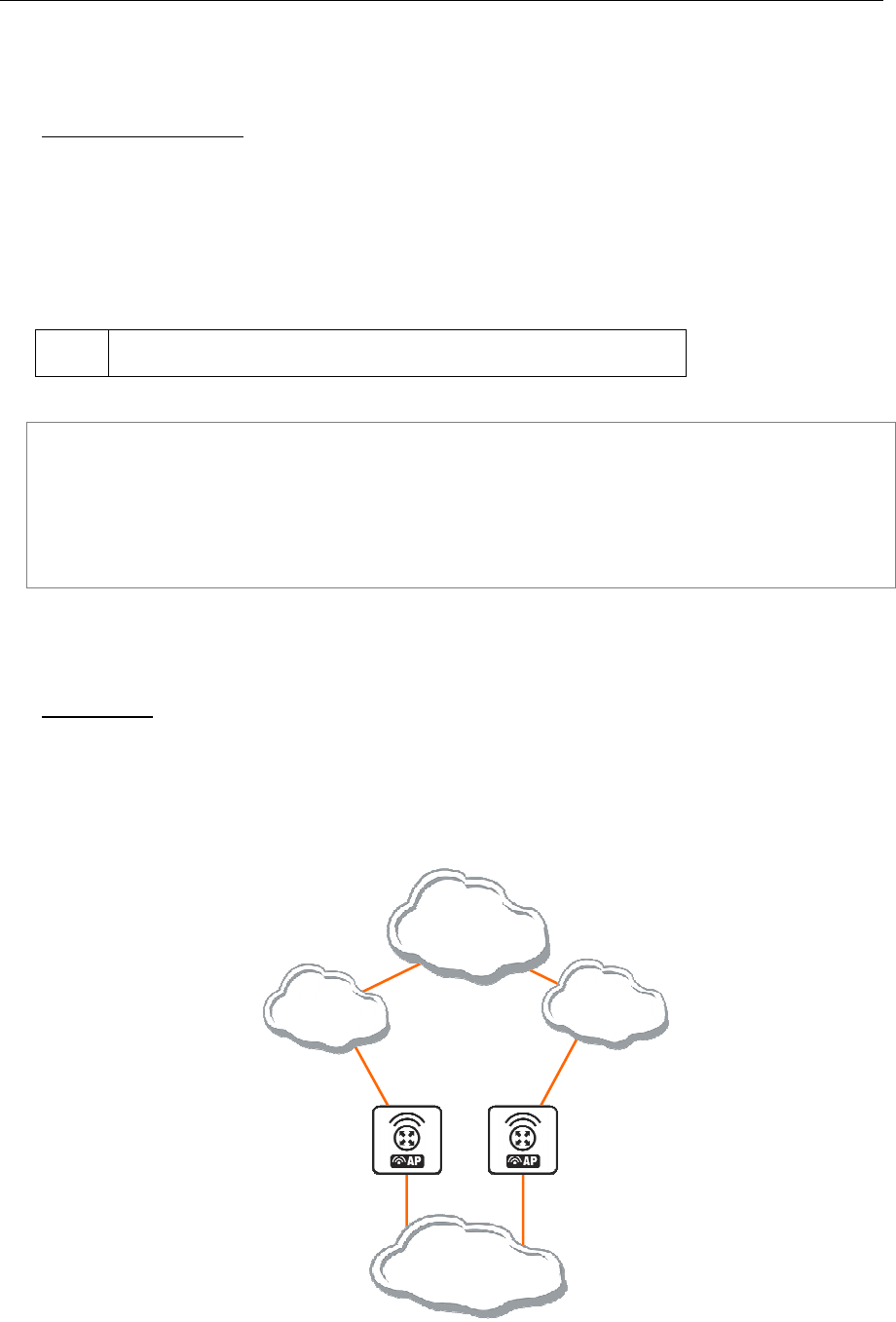
AT-WR4500 Series - IEEE 802.11abgh Outdoor Wireless Routers 251
RouterOS v3 Configuration and User Guide
11.1.3 Virtual IP addresses
Submenu level: /ip vrrp address
Property Description
address (IP address) - IP address belongs to the virtual router
broadcast (IP address) - broadcasting IP address
interface (name; default: default) - interface, where to put the address on (may be different form the
interface this VRRP instance is running on)
default - put this address on the interface the given VRRP instane is working on
network (IP address) - IP address of the network
virtual-router (name) - VRRP router's name the address belongs to
The virtual IP addresses should be the same for each node of a virtual router.
To add a virtual address of 192.168.1.1/24 to the vr1 VRRP router:
[admin@AT-WR4562] ip vrrp> address add address=192.168.1.1/24 \
\... virtual-router=vr1
[admin@AT-WR4562] ip vrrp> address print
Flags: X - disabled, A - active
# ADDRESS NETWORK BROADCAST INSTANCE INTERFACE
0 192.168.1.1/24 192.168.1.0 192.168.1.255 vr1 default
[admin@AT-WR4562] ip vrrp>
11.1.4 A simple example of VRRP fail over
Description
VRRP protocol may be used to make a redundant Internet connection with seamless fail-over. Let us
assume that we have 192.168.1.0/24 network and we need to provide highly available Internet connection
for it. This network should be NATted (to make fail-over with public IPs, use such dynamic routing
protocols as BGP or OSPF together with VRRP). We have connections to two different Internet Service
Providers (ISPs), and one of them is preferred (for example, it is cheaper or faster).
Internet
ISP1
ISP2
LAN
192.168.1.0/24
192.168.1.1
Figure 35: Simple VRRP fail over example

252 AT-WR4500 Series - IEEE 802.11abgh Outdoor Wireless Routers
RouterOS v3 Configuration and User Guide
This example shows how to configure VRRP on the two routers shown on the diagram. The routers
must have initial configuration: interfaces are enabled, each interface have appropriate IP address, and
routing table is set correctly (it should have at least a default route). SRC-NAT or masquerading should
also be configured before. See the respective manual chapters on how to make this configuration.
Both interfaces should have an IP address
We will assume that the interface the 192.168.1.0/24 network is connected to is named local on both
VRRP routers.
Configuring Master VRRP router
First of all we should create a VRRP instance on this router. We will use the priority of 255 for this
router as it should be preferred router.
[admin@AT-WR4562] ip vrrp> add interface=local priority=255
[admin@AT-WR4562] ip vrrp> print
0 RM name="vrrp1" mtu=1500 mac-address=00:00:5E:00:01:01 arp=enabled
interface=local vrid=1 priority=255 interval=1 preemption-mode=yes
authentication=none password="" on-backup="" on-master=""
[admin@AT-WR4562] ip vrrp>
Next the virtual IP address should be added to this VRRP instance
[admin@ AT-WR4500] ip address> add address=192.168.1.1/24 interface=vrrp1
[admin@M AT-WR4500] ip address> print
[admin@AT-WR4562] ip address> print
Flags: X - disabled, I - invalid, D - dynamic
# ADDRESS NETWORK BROADCAST INTERFACE
0 10.0.0.1/24 10.0.0.0 10.0.0.255 public
1 192.168.1.2/24 192.168.1.0 192.168.1.255 local
2 192.168.1.1/24 192.168.1.0 192.168.1.255 vrrp1
[admin@AT-WR4562] ip addrees>
Now this address should appear in /ip address list:
[admin@AT-WR4562] ip address> print
Flags: X - disabled, I - invalid, D - dynamic
# ADDRESS NETWORK BROADCAST INTERFACE
0 10.0.0.1/24 10.0.0.0 10.0.0.255 public
1 192.168.1.2/24 192.168.1.0 192.168.1.255 local
2 D 192.168.1.1/24 192.168.1.0 192.168.1.255 local
[admin@AT-WR4562] ip address>
Configuring Backup VRRP router
Now we will create VRRP instance with lower priority (we can use the default value of 100), so this
router will back up the preferred one:
[admin@AT-WR4562] ip vrrp> add interface=local
[admin@AT-WR4562] ip vrrp> print
Flags: X - disabled, I - invalid, M - master, B - backup
0 B name="vr1" interface=local vrid=1 priority=100 interval=1
preemption-mode=yes authentication=none password="" on-backup=""
on-master=""
[admin@AT-WR4562] ip vrrp>
Now we should add the same virtual address as was added to the master node:
[admin@AT-WR4562] ip vrrp> address add address=192.168.1.1/24 interface=vrrp1

AT-WR4500 Series - IEEE 802.11abgh Outdoor Wireless Routers 253
RouterOS v3 Configuration and User Guide
Testing fail over
Now, when we will disconnect the master router, the backup one will switch to the master state:
[admin@AT-WR4562] ip vrrp> print
Flags: X - disabled, I - invalid, R - running, M - master, B - backup
0 RM name="vrrp1" mtu=1500 mac-address=00:00:5E:00:01:01 arp=enabled
interface=local vrid=1 priority=100 interval=1 preemption-mode=yes
authentication=none password="" on-backup="" on-master=""
[admin@AT-WR4562] ip vrrp>
11.2 System Watchdog
Document revisi on: 1.2 (Tue Mar 09 08:45:4 9 GMT 200 4)
Applies to: V2.9
11.2.1 General Information
Summary
System watchdog feature is needed to reboot the system in case of software failures.
Specifications
Packages required: system
License required: Level1
Submenu level: /system watchdog
Standards and Technologies:
Hardware usage: Not significant
11.2.2 Hardware Watchdog Management
Submenu level: /system watchdog
Description
This menu allows to configure system to reboot on kernel panic, when an IP address does not respond,
or in case the system has locked up. Software watchdog timer is used to provide the last option, so in
very rare cases (caused by hardware malfunction) it can lock up by itself. There is a hardware watchdog
device available in AT-WR454x hardware, which can reboot the system in any case.
Property Description
auto-send-supout (yes | no; default: no) - after the support output file is automatically generated, it can
be sent by email
automatic-supout (yes | no; default: yes) - when software failure happens, a file named "autosupout.rif"
is generated automatically. The previous "autosupout.rif" file is renamed to "autosupout.old.rif"
no-ping-delay (time; default: 5m) - specifies how long after reboot not to test and ping watch-address.
The default setting means that if watch-address is set and is not reachable, the router will reboot about
every 6 minutes.
send-email-from (text; default: "") - e-mail address to send the support output file from. If not set, the
value set in /tool e-mail is used
send-email-to (text; default: "") - e-mail address to send the support output file to
send-smtp-server (text; default: "") - SMTP server address to send the support output file through. If
not set, the value set in /tool e-mail is used
watch-address (IP address; default: none) - if set, the system will reboot in case 6 sequental pings to the
given IP address (sent once per 10 seconds) will fail
none - disable this option
watchdog-timer (yes | no; default: no) - whether to reboot if system is unresponsive for a minute

254 AT-WR4500 Series - IEEE 802.11abgh Outdoor Wireless Routers
RouterOS v3 Configuration and User Guide
Example
To make system generate a support output file and sent it automatically to support@example.com
through the 192.0.2.1 smtp server in case of a software crash:
[admin@AT-WR4562] system watchdog> set auto-send-supout=yes \
\... send-to-email=support@example.com send-smtp-server=192.0.2.1
[admin@AT-WR4562] system watchdog> print
watch-address: none
watchdog-timer: yes
no-ping-delay: 5m
automatic-supout: yes
auto-send-supout: yes
send-smtp-server: 192.0.2.1
send-email-to: support@example.com
[admin@AT-WR4562] system watchdog>

AT-WR4500 Series - IEEE 802.11abgh Outdoor Wireless Routers 255
RouterOS v3 Configuration and User Guide
12 Monitoring and Management
12.1 Log Management
Document revisi on: 2.3 (Mon Jul 19 07:23:35 GMT 2004)
Applies to: V2.9
12.1.1 General Information
Summary
Various system events and status information can be logged. Logs can be saved in local routers file,
displayed in console, sent to an email or to a remote server running a syslog daemon.
Specifications
Packages required: system
License required: Level1
Submenu level: /system logging, /log
Standards and Technologies: Syslog
Hardware usage: Not significant
Description
Logs have different groups or topics. Logs from each topic can be configured to be discarded, logged
locally or remotely. Locally log files can be stored in memory (default; logs are lost on reboot) or on hard
drive (not enabled by default as is harmful for flash disks).
12.1.2 General Settings
Submenu level: /system logging
Property Description
action (name; default: memory) - specifies one of the system default actions or user specified action
listed in /system logging action
prefix (text) - local log prefix
topics (info | critical | firewall | keepalive | packet | read | timer | write | ddns | hotspot | l2tp | ppp |
route | update | account | debug | ike | manager | pppoe | script | warning | async | dhcp | notification |
pptp | state | watchdog | bgp | error | ipsec | radius | system | web-proxy | calc | event | isdn | ospf | raw |
telephony | wireless | e-mail | gsm | mme | ntp | open | ovpn | pim | radvd | rip | sertcp | ups; default: info)
- specifies log group or log message type
Example
To log messages that are generated by firewall by saving them in local buffer
[admin@AT-WR4562] system logging> add topics=firewall action=memory
[admin@ AT-WR4500] system logging> print
Flags: X - disabled, I - invalid
# TOPICS ACTION PREFIX
0 info memory
1 error memory
2 warning memory
3 critical echo
4 firewall memory
[admin@ AT-WR4500] system logging>

256 AT-WR4500 Series - IEEE 802.11abgh Outdoor Wireless Routers
RouterOS v3 Configuration and User Guide
12.1.3 Actions
Submenu level: /system logging action
Property Description
disk-lines (integer; default: 100) - number of records in log file saved on the disk (only if action target is
set to disk)
disk-stop-on-full (yes | no; default: no) - whether to stop to save log messages on disk after the
specified disk-lines number is reached
email-to (name) - email address logs are sent to (only if action target is set to email)
memory-lines (integer; default: 100) - number of records in local memory buffer (only if action target is
set to memory)
memory-stop-on-full (yes | no; default: no) - whether to stop to save log messages in local buffer after
the specified memory-lines number is reached
name (name) - name of an action
remember (yes | no; default: yes) - whether to keep log messages, which have not yet been displayed in
console (only if action target is set to echo)
remote (IP address:port ; default: 0.0.0.0:514) - remote logging server's IP address and UDP port (only if
action target is set to remote)
target (disk | echo | email | memory | remote; default: memory) - log storage facility or target
disk - logs are saved to the hard drive
echo - logs are displayed on the console screen
email - logs are sent by email
memory - logs are saved to the local memory buffer
remote - logs are sent to a remote host
You cannot delete or rename default actions.
Example
To add a new action with name short, that will save logs in local buffer, if number of records in buffer are
less than 50:
[admin@AT-WR4562] system logging action> add name=short \
\... target=memory memory-lines=50 memory-stop-on-full=yes
[admin@AT-WR4562] system logging action> print
# FACILITY LOCAL REMOTE PREFIX REMOTE-ADDRESS REMOTE-PORT ECHO
Flags: * - default
# NAME TARGET REMOTE
0 * memory memory
1 * disk disk
2 * echo echo
3 * remote remote 0.0.0.0:514
4 short memory
[admin@AT-WR4562] system logging action>
12.1.4 Log Messages
Submenu level: /log
Description
Displays locally stored log messages
Property Description
message (read-only: text) - message text
time (read-only: text) - date and time of the event
topics (read-only: text) - topic list the message belongs to

AT-WR4500 Series - IEEE 802.11abgh Outdoor Wireless Routers 257
RouterOS v3 Configuration and User Guide
Command Description
print - shows log messages
buffer - prints log messages that were saved in specified local buffer
follow - monitor system logs
without-paging - prints logs without paging
file - saves the log information on local ftp server with a specified file name
Example
To view the local logs:
[admin@AT-WR4562] > log print
TIME MESSAGE
dec/24/2003 08:20:36 log configuration changed by admin
dec/24/2003 08:20:36 log configuration changed by admin
dec/24/2003 08:20:36 log configuration changed by admin
dec/24/2003 08:20:36 log configuration changed by admin
dec/24/2003 08:20:36 log configuration changed by admin
dec/24/2003 08:20:36 log configuration changed by admin
-- [Q quit|D dump]
To monitor the system log:
[admin@AT-WR4562] > log print follow
TIME MESSAGE
dec/24/2003 08:20:36 log configuration changed by admin
dec/24/2003 08:24:34 log configuration changed by admin
dec/24/2003 08:24:51 log configuration changed by admin
dec/24/2003 08:25:59 log configuration changed by admin
dec/24/2003 08:25:59 log configuration changed by admin
dec/24/2003 08:30:05 log configuration changed by admin
dec/24/2003 08:30:05 log configuration changed by admin
dec/24/2003 08:35:56 system started
dec/24/2003 08:35:57 isdn-out1: initializing...
dec/24/2003 08:35:57 isdn-out1: dialing...
dec/24/2003 08:35:58 Prism firmware loading: OK
dec/24/2003 08:37:48 user admin logged in from 10.1.0.60 via telnet
Ctrl-C to quit. New entries will appear at bottom.
12.2 SNMP Service
Document revisi on: 1.7 (Wen Sep 15 1 1:00:38 GMT 2004)
Applies to: V2.9
12.2.1 General Information
Summary
SNMP is an application layer protocol. It is called simple because it works that way - the management
station makes a request, and the managed device (SNMP agent) replies to this request. In SNMPv1 there
are three main actions - Get, Set, and Trap. RouterOS supports only Get, which means that you can use
this implementation only for network monitoring.
Hosts receive SNMP generated messages on UDP port 161 (except the trap messages, which are
received on UDP port 162).
The RouterOS supports:
• SNMPv1 only
• Read-only access is provided to the NMS (network management system)
• User defined communities are supported
• Get and GetNext actions
• No Set support
• No Trap support

258 AT-WR4500 Series - IEEE 802.11abgh Outdoor Wireless Routers
RouterOS v3 Configuration and User Guide
Specifications
Packages required: system, ppp(optional)
License required: Level1
Submenu level: /snmp
Standards and Technologies: SNMP (RFC 1157)
Hardware usage: Not significant
Related Topics
Software Package Management
IP Addresses and ARP
Additional Resources
• http://www.ietf.org/rfc/rfc1157.txt
• http://en.wikipedia.org/wiki/Simple_Network_Management_Protocol
• http://www.david-guerrero.com/papers/snmp/
12.3 Traffic Flow
Document revisi on: 1.0 (30-jun-2005)
Applies to: V2.9
12.3.1 General Information
Specifications
Packages required: system
License required: Level1
Submenu level: /ip traffic-flow
Hardware usage: Not significant
12.3.2 Related Documents
NTop
Description
Traffic-Flow is a system that provides statistic information about packets which pass through the router.
Besides network monitoring and accounting, system administrators can identify various problems that
may occur in the network. With help of Traffic-Flow, it is possible to analyze and optimize the overall
network performance.
Traffic-Flow supports the following NetFlow formats:
• version 1 - the first version of NetFlow data format, do not use it, unless you have to
• version 5 - in addition to version 1, version 5 has the BGP AS and flow sequence number information
included
• version 9 - a new format which can be extended with new fields and record types thank's to its
template-style design
Additional Resources
http://www.ntop.org/netflow.html
12.3.3 General Configuration
Description
This section describes the basic configuration of Traffic-Flow.

AT-WR4500 Series - IEEE 802.11abgh Outdoor Wireless Routers 259
RouterOS v3 Configuration and User Guide
Property Description
active-flow-timeout (time; default: 30m) - maximum life-time of a flow
cache-entries (1k | 2k | 4k | 8k | 16k | 32k | 64k | 128k | 256k | 512k; default: 1k) - number of flows
which can reside in the router's memory simultaneously
enabled (yes | no) - whether to enable traffic-flow service or not
inactive-flow-timeout (time; default: 15s) - how long to keep the flow active, if it is idle
interfaces (name) - names of those interfaces which will be used to gather statistics for traffic-flow.
To specify more than one interface, separate them with a comma (",")
12.3.4 Traffic-Flow Target
Submenu level: /ip traffic-flow target
Description
With Traffic-Flow targets we specify those hosts which will gather the Traffic-Flow information from
router.
Property Description
address (IP address:port) - IP address and port (UDP) of the host which receives Traffic-Flow statistic
packets from the router
v9-template-refresh (integer; default: 20) - number of packets after which the template is sent to the
receiving host (only for NetFlow version 9)
v9-template-timeout - after how long to send the template, if it has not been sent
version (1 | 5 | 9) - which version format of NetFlow to use
12.3.5 Application Examples
Traffic-Flow Example
This example shows how to configure Traffic-Flow on a router
Enable Traffic-Flow on the router:
[admin@AT-WR4562] ip traffic-flow> set enabled=yes
[admin@AT-WR4562] ip traffic-flow> print
enabled: yes
interfaces: all
cache-entries: 1k
active-flow-timeout: 30m
inactive-flow-timeout: 15s
[admin@AT-WR4562] ip traffic-flow>
Specify IP address and port of the host, which will receive Traffic-Flow packets:
[admin@AT-WR4562] ip traffic-flow target> add address=192.168.0.2:2055 \
\... version=9
[admin@AT-WR4562] ip traffic-flow target> print
Flags: X - disabled
# ADDRESS VERSION
0 192.168.0.2:2055 9
[admin@AT-WR4562] ip traffic-flow target>
Now the router starts to send packets with Traffic-Flow information.
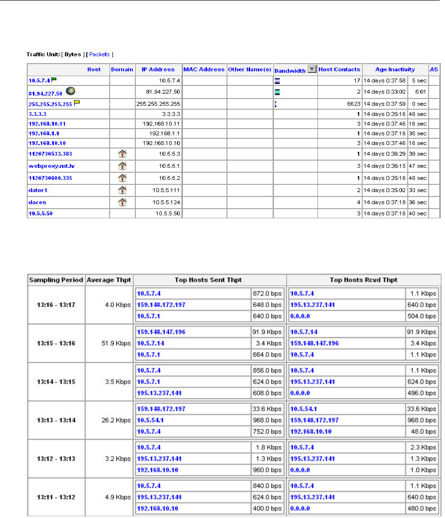
260 AT-WR4500 Series - IEEE 802.11abgh Outdoor Wireless Routers
RouterOS v3 Configuration and User Guide
Some screenshots from NTop program, which has gathered Traffic-Flow information from our router
and displays it in nice graphs and statistics. For example, where what kind of traffic has flown:
Figure 36: Host Information
Top three hosts by upload and download each minute:
Figure 37: Network Load Statistics Matrix
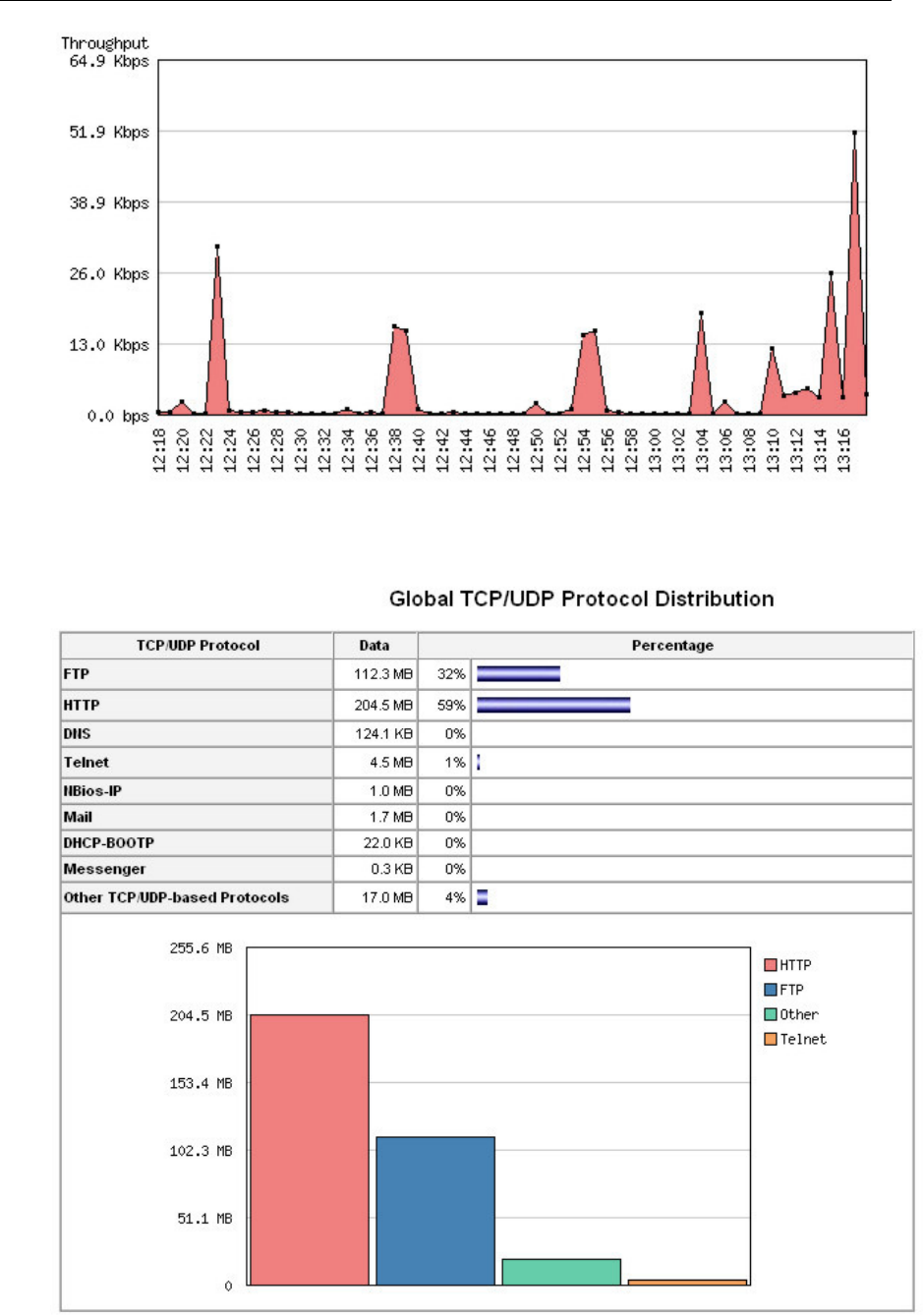
AT-WR4500 Series - IEEE 802.11abgh Outdoor Wireless Routers 261
RouterOS v3 Configuration and User Guide
Figure 38: Network load profile by time
Figure 39: Traffic Load by protocol

262 AT-WR4500 Series - IEEE 802.11abgh Outdoor Wireless Routers
RouterOS v3 Configuration and User Guide
12.4 Graphing
Document revisi on: 1.1 (Wed Mar 15 09:46: 17 GMT 2006)
Applies to: V2.9
12.4.1 General Information
Summary
Graphing is a tool which is used for monitoring various RouterOS parameters over a period of time.
Specifications
Packages required: system, routerboard(optional)
License required: Level1
Submenu level: /tool graphing
Hardware usage: Not significant
Description
The Graphing tool can display graphics for:
• Routerboard health (voltage and temperature)
• Resource usage (CPU, Memory and Disk usage)
• Traffic which is passed through interfaces
• Traffic which is passed through simple queues
Graphing consists of two parts - first part collects information and other part displays data in a Web page.
To access the graphics, type http://[Router_IP_address]/graphs/ and choose a graphic to display in
your Web browser.
Data from the router is gathered every 5 minutes, but saved on the system drive every store-every
time. After rebooting the router, graphing will display information that was last time saved on the disk
before the reboot.
RouterOS generates four graphics for each item:
• "Daily" Graph (5 Minute Average)
• "Weekly" Graph (30 Minute Average)
• "Monthly" Graph (2 Hour Average)
• "Yearly" Graph (1 Day Average)
To access each graphic from a network, specify this network in allow-address parameter for the
respective item.
12.4.2 General Options
Submenu level: /tool graphing
Property Description
store-every (5min | hour | 24hours; default: 5min) - how often to store information on system drive
Example
To store information on system drive every hour:
/tool graphing set store-every=hour
[admin@AT-WR4562] tool graphing> print
store-every: hour
[admin@AT-WR4562] tool graphing>

AT-WR4500 Series - IEEE 802.11abgh Outdoor Wireless Routers 263
RouterOS v3 Configuration and User Guide
12.4.3 Health Graphing
Submenu level: /tool graphing health
Description
This submenu provides information about RouterBoard's 'health' - voltage and temperature. For this
option, you have to install the routerboard package.
Property Description
allow-address (IP address/netmask; default: 0.0.0.0/0) - network which is allowed to view graphs of
router health
store-on-disk (yes | no; default: yes) - whether to store information about traffic on system drive or
not. If not, the information will be stored in RAM and will be lost after a reboot
12.4.4 Interface Graphing
Submenu level: /tool graphing interface
Description
Shows how much traffic is passed through an interface over a period of time.
Property Description
allow-address (IP address/netmask; default: 0.0.0.0/0) - IP address range which is allowed to view
information about the interface. If a client PC not belonging to this IP address range tries to open
http://[Router_IP_address]/graphs/, it will not see this entry
interface (name; default: all) - name of the interface which will be monitored
store-on-disk (yes | no; default: yes) - whether to store information about traffic on system drive or
not. If not, the information will be stored in RAM and will be lost after a reboot
Example
To monitor traffic which is passed through interface ether1 only from local network 192.168.0.0/24,
and write information on disk:
[admin@AT-WR4562] tool graphing interface> add interface=ether1 \
\... allow-address=192.168.0.0/24 store-on-disk=yes
[admin@AT-WR4562] tool graphing interface> print
Flags: X - disabled
# INTERFACE ALLOW-ADDRESS STORE-ON-DISK
0 ether1 192.168.0.0/24 yes
[admin@AT-WR4562] tool graphing interface>
12.4.5 Simple Queue Graphing
Submenu level: /tool graphing queue
Description
In this submenu you can specify a queue from the /queue simple list to make a graphic for it.
Property Description
allow-address (IP address/netmask; default: 0.0.0.0/0) - network which is allowed to view graphs of
router health
allow-target (yes | no; default: yes) - whether to allow access to web graphing from IP range that is
specified in /queue simple target-address
simple-queue (name; default: all) - name of simple queue which will be monitored
store-on-disk (yes | no; default: yes) - whether to store information about traffic on hard drive or not.
If not, the information will be stored in RAM and will be lost after a reboot

264 AT-WR4500 Series - IEEE 802.11abgh Outdoor Wireless Routers
RouterOS v3 Configuration and User Guide
Example
Add a simple queue to Grapher list with simple-queue name queue1, allow limited clients to access
Grapher from web, store information about traffic on disk:
[admin@AT-WR4562] tool graphing queue> add simple-queue=queue1 allow-address=yes \
\... store-on-disk=yes
12.4.6 Resource Graphing
Submenu level: /tool graphing resource
Description
Provides with router resource usage information over a period of time:
• CPU usage
• Memory usage
• Disk usage
Property Description
allow-address (IP address/netmask; default: 0.0.0.0/0) - network which is allowed to view graphs of
router health
store-on-disk (yes | no; default: yes) - whether to store information about traffic on hard drive or not.
If not, the information will be stored in RAM and will be lost after a reboot
Example
Add IP range 192.168.0.0/24 from which users are allowed to monitor Grapher's resource usage:
[admin@AT-WR4562] tool graphing resource> add allow-address=192.168.0.0/24 \
\... store-on-disk=yes
[admin@AT-WR4562] tool graphing resource> print
Flags: X - disabled
# ALLOW-ADDRESS STORE-ON-DISK
0 192.168.0.0/24 yes
[admin@AT-WR4562] tool graphing resource>
