Alligator Communications 2888 Data Transport Radio User Manual 2888D Man V1
Alligator Communications Inc Data Transport Radio 2888D Man V1
Contents
- 1. Users Manual 2888A
- 2. Users Manual 2888D V1
- 3. Users Manual 2888D V1 1
Users Manual 2888D V1 1
I
Alligator Model 2888
895 - 960 MHz
4800 Baud Data Transport Radio
MANUAL
Version 1.10
Alligator Communications, Inc.
317 Brokaw Road
Santa Clara, CA 95050
Telephone: (408) 327-0800
Fax: (408) 327-0808
Copyright 2005
Alligator Communications
All Rights Reserved

II
CHARTER 1: GENERAL INFORMATION
1.1 General Description 1
1.2 Applications 1
1.3 Technical Specifications 1
1.4 Warranty 3
1.5 Claim for Damage in Shipment 4
1.6 Information to User As Required by FCC Section 15.21 4
1.7 RF Exposure Information 4
CHARTER 2: Radio Configuration and Operational Checkout
2.1 General Discussion 5
2.2 Operational Bench Test 5
2.2.1 Antenna Connector 5
2.2.2 Power Connector 6
2.2.3 Initial Checkout 6
2.2.3A Power Checkout 7
Figure 2.1 LED Display 7
2.2.3B LED Checkout 7
Table 2.2 LED Description Table 7
2.2.3C Transmitter Test 8
2.2.3D Receiver Test 8
2.2.3E Deviation Test 9
2.2.5 Squelch Adjustment 10
2.2.7 Deviation Adjustment 12
2.2.10 Field Simulation Test 13
Figure 2.3 DB-9 Description and Pin Locator 15
Table 2.4 DB-9 Pin Function 15
Figure 2.4 2888 Internal Circuit Board 16
Figure 2.6 Diagnostic Computer Interface Port 17
Table 2.6 Diagnostic Computer Interface Port Pin Functions 17
2.6 Diagnostic Personal Computer Interface 18
2.6.1 Model 2888 Remote Radio Local Connect 18
2.6.2 Model 1800A Master Station Link Connect 19
2.6.3 Model 1800A Master Station Phone Dial-up Connect
20
Table of Contents

III
CHAPTER 3: INSTALLATION
3.1 Mechanical Installation 21
3.2 Location 21
3.3 Electrical Interconnection 22
CHAPTER 4: THEORY OF OPERATION
4.1 General Discussion 23
4.2 Microprocessor Operation 23
4.3 Functions of the 2888 Radio 23
4.3.1 Diagnostic Parameters 23
4.3.2 Alarm Limits and Conditions 24
4.3.3 Operating Parameters 24
4.3.4 Communication Parameters 26
CHAPTER 5: MAINTENANCE
5.1 General Discussion 28
5.2 Test Equipment 28
CHARPTER 6: ALLIGATOR DIAGNOSTIC SOFTWARE
6.1 General Description 29
6.2 Theory of Operation 31

1
1.1 GENERAL DESCRIPTION
The Alligator Communications Model 2888 is a microprocessor-controlled data radio
transceiver designed to operate in accordance with FCC rules, Part 101, and in Canada
under RSS-116 Issue 6. The 2888 data radio is frequency synthesized and programmable
to individual transmitter and receiver frequencies in the 928-929 MHz frequency band
(US), and in the 896-929 MHz frequency band in (Canada). The transceiver is a fixed
channel, half-duplex radio available with channel bandwidths of 12.5 kHz and 25.0 kHz.
1.2 APPLICATIONS
The 2888 data radio is designed for point-to-multipoint or point-to-point licensed
operations in the 900 MHz band. Some of the most common applications are:
Electric Utility Substation SCADA
Pipeline Flow Monitors
Energy Distribution & Metering Applications
Gas or Petroleum Production Well Head Control and Monitoring
Water Distribution and Waste Water Collection Control and Monitoring
Petroleum Production, Transmission, Storage and Distribution
1.3 TECHNICAL SPECIFICATIONS
GENERAL
Frequency Agility: 895.00 – 960.00 MHz, 6.25 kHz per Step
Channel Spacing: Available in 12.5, 25.0 KHz Bandwidths
Data Rates: 4800 bps
Input Voltage: 13.2 Vdc Nominal (11-16 Vdc)
Current Consumption:
* Receive Mode: 100 mA
* Transmit Mode (5.00 Watts): < 1.75 A
Connectors:
* Antenna: Type “N” Female
* Data: DB-9F, Subminiature
1.0 General Information
2
* Power: 2 Pin Captive Rectangular
*Diagnostics: RJ-45 Jack
Environment:
* Temperature: -30°C to +60°C
* Humidity: 95% @ +40°C
Dimensions: 6.5”W x 1.35”H x 5.5”D
Weight: 1.5 Pounds
TRANSMITTER
RF Power: 5.0 Watt (+ 37 dBm)
Impedance: 50 Ohms
Duty Cycle: Continuous
Transmitter Attack Time: Less than 1msec
Frequency Stability: +/-0.00015%, -30°C to +60°C
Modulation Deviation:
* 12.5 kHz Band: +/- 3.0 kHz
* 25.0 kHz Band: +/- 5.0 kHz
Spurious and Harmonic Emissions: -60 dB
Tx Timeout Timer (Programmable) 1-255 Seconds, or 0 for no Timeout
RECEIVER
Type: Double Conversion Superheterodyne
Frequency Stability: +/-0.00015%, -30°C to +60°C
Sensitivity: -117 dBm minimum discernable signal
10E6 BER Threshold: -97 dBm
Selectivity: -100 dB Minimum at Adjacent Channel
Desensitization:
* at 12.5 kHz Spacing: -60 dB
* at 25.0 kHz Spacing: -70 dB
Intermodulation: -70 dB (EIA)
Spurious/Image Rejection: -80 dB
Desensitization:
* at 12.5 kHz Spacing: -60 dB
* at 25.0 kHz Spacing: -70 dB
Intermodulation: -70 dB (EIA)
Spurious/Image Rejection: -80 dB
Note: If other frequencies or power levels are required but are not listed, please contact factory.
3
OPTIONS
INTERNAL MODEM: Emission Type: FSK
4800 BPS, Direct Interface, Asynchronous: RS-232
FCC INFORMATION
FCC Rules: Part 101
FCC Identifier: JIL2888
FCC Emission Designators: 12.5 KHz 9K64F1D
25.0 KHz 13K7F1D
1.4 WARRANTY
Alligator Communications, Inc., warrants each of the instruments of its manufacture to
meet the specifications when delivered to the BUYER; and to be free from defects in
material and workmanship. Alligator Communications will repair or replace, at its
expense, for a period of one year from the date of delivery of equipment, any parts that are
defective from faulty material or poor workmanship.
Instruments found to be defective during the warranty period shall be returned to the
factory with transportation charges prepaid by the BUYER. It is expressly agreed that
replacement and repair shall be the sole remedy of the SELLER with respect to any
defective equipment and parts hereof and shall be in lieu of any other remedy available by
applicable law. All returns to the factory must be authorized by the SELLER, prior to such
returns. Upon examination by the factory, if any instrument is found to be defective, the
unit will be repaired and returned to the BUYER, with transportation charges prepaid by
the SELLER.
NO OTHER WARRANTY IS EXPRESSED OR IMPLIED. ALLIGATOR
COMMUNICATIONS IS NOT LIABLE FOR CONSEQUENTIAL DAMAGES.

4
1.5 CLAIMS FOR DAMAGE IN SHIPMENT
The instrument should be inspected and tested as soon as it is received. If the instrument
is damaged in any way, or fails to operate properly, a claim should immediately be filed
with the freight carrier, or if insured separately, with the insurance company.
WE PLEDGE OUR IMMEDIATE AND FULLEST COOPERATION TO ALL USERS
OF OUR ELECTRONIC EQUIPMENT.
PLEASE ADVISE US IF WE CAN ASSIST IN ANY MANNER:
Alligator Communications, Inc.
317 Brokaw Road
Santa Clara, CA 95050
Phone: (408) 327-0800
FAX: (408) 327-0808
E-mail: sales@alligatorcom.com
Website: www.alligatorcom.com
1.6 INFORMATION TO USER, AS REQUIRED BY FCC SECTION
15.21
Changes or modifications not expressly approved in writing by Alligator Communications,
Inc. may void the user’s authority to operate this equipment.
In accordance with FCC Rules section 15.21, the user of this equipment is advised that
changes or modifications not expressly approved by the party responsible for compliance
could void the user’s authority to operate the equipment.
1.7 RF EXPOSURE INFORMATION
FCC Rule Section 1.11307 and Industry Canada RSS-102 regulations contain limits on
human RF exposure from transmitters. To meet these requirements, during operation, the
antenna of this device must be kept at a minimum distance of 112 cm from all persons.

5
2.1 GENERAL DISCUSSION
Prior to customer installation and electrical connection of the customer’s terminal
equipment to the 2888 radio, it is recommended that the installing technician conduct a
brief operational checkout of the 2888 radio and confirm that all operating parameters are
set as desired.
This initial checkout and possible reprogramming is generally performed on the
maintenance shop test bench before the radio is installed and commissioned in a link
application.
The following parts of this section provide guidance in this checkout process, and
illustrate alternate configurations and paths to perform the initial checkout. Please refer to
Figure 2.2 (DB-9 Locator), Table 2.3 (DB-9 Pin Functions), Figure 2.3 (Locations of
Adjustment Components on Main P.C. Board
For a definition of all 2888 radio functions and possible configurations, see Section 4.3.
2.2 OPERATIONAL BENCH TEST
To ensure that the 2888 radio is functional prior to installation at the desired site, it is
highly recommended that the following tests be performed in sequence (please refer to
Figure 3.1, Model 2888 External Connectors, Page 3-2):
2.2.1 ANTENNA CONNECTOR
The 2888 radio antenna port (RF Connector) is a coaxial, female, type N
connector. This connector mates with a cable connector male, type N such as
Amphenol 3900, Andrew L44N, or MIL Type UG-21. Under most circumstances,
bench tests are conducted with a service monitor (manufactured by IFR Inc.,
Marconi Instruments Ltd., Hewlett-Packard, Motorola, etc.).
2.0 Radio Configuration and Operational Check

6
CAUTION
The transmitter should not be keyed on or placed in the transmit
mode without a load on the antenna port to prevent damage to the
2888 radio Power Amplifier due to long periods (more than 10
minutes) of severely high SWR. An antenna, service monitor, or
dummy load should be attached to the antenna port. The 2888
radio power output is approximately 5.0 watt maximum, so if a
service monitor is connected to the antenna port, ensure that the
service monitor’s input port can handle at least 10 watt input to
avoid damaging the service monitor.
2.2.2 POWER CONNECTOR
The dc power input connector to the 2888 radio is a rectangular two-pin locking
connector. The radio unit is normally powered upon connection to a DC power
source delivering +11 to +16 Vdc, +13.8 Vdc nominal. The red conductor is
positive; the black conductor is negative and is internally grounded to the chassis.
2.2.3 INITIAL CHECKOUT
Alligator wireless data transport products are factory configured according to
customer configuration information received prior to shipment from the factory,
thereby minimizing customer field configuration requirements.
To verify that 2888 radio parameters are correct, we recommend the following
minimal tests be conducted with regards to the transmitter and receiver settings of
the 2888 radio.
With the service monitor connected to the antenna port, proceed to conduct the
following preliminary tests:
7
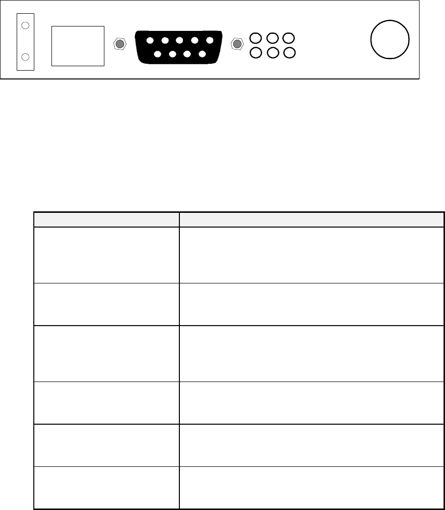
A. Power Checkout
With DC power applied to the PWR IN connector, the power LED should
illuminate and remain on. Pin 6 of the DATA connector should measure
+10.0 Vdc nominal that is the output from the voltage regulator (Note: Pin
5 is dc ground, signal ground and is also grounded to the chassis).
c
DATA
PWR IN
DIAGNOSTICS PWR DCD RXD
RTS CTS TXD ANTENNA
Figure 2.1 LED Display
B. 2888 LED Checkout
Briefly observe the behavior of each of the 6 LED indicators with reference
to the following table:
LED Description
TXD (Transmit Data) Indicates the 2888 radio is receiving incoming data
from the customer’s interconnected terminal to be
transferred to the destination.
RXD (Receive Data) Indicates the 2888 radio is receiving data over the air
from an associated radio or communications test set.
DCD (Data Carrier Detect) Indicates the 2888 radio is receiving a sufficient level
of RF carrier signal to open the receiver’s squelch
gate.
RTS (Request To Send) Indicates the customer’s interconnected terminal is
requesting to send data.
CTS (Clear To Send) Indicates the 2888 radio is ready to receive data from
the customer’s interconnected terminal.
PWR (Power) Lights up whenever the radio is powered up.
Off when radio is powered down.
Table 2.2 LED Description
8
C. Transmitter Test
CAUTION
To avoid possible damage to your service monitor, be
sure that the input port can handle at least 10 watt.
Key the Tx by pulling RTS pin 7 of the DB9 data interface port high. This
can be accomplished by shorting RTS pin 7 with DSR pin 6. At this time,
the RTS & CTS LEDs should light up. As long as the keying signal is on,
both LEDs will remain on until the time exceeds the time out timer value,
which is factory set at 30 seconds or at a customer programmed timing
interval.
Measure the RF power level as inputted to a calibrated communications
test set or to a RF power level meter to measure the 2888 transmitter
power output. Note: The output power should be about 5.0 watts (when
+13.8 Vdc is the power supply voltage), which is the factory setting.
Note the transmitted frequency on a calibrated Communications Test set
and compare this reading to the desired Transmitter frequency setting of
the 2888 radio.
Note: The Transmitter time out operating parameter can be set for 0 to 255
seconds, with 0 meaning that the transmitter will not time out and will
follow the keying signal no matter how long it lasts. Use the Alligator
Advanced Diagnostics Software to change the value of this parameter.
This can be found under the Change Operating Parameters option under
the Remote sub-menu.
D. Receiver Test
With the service monitor connected to the antenna port (Figure 3.1, ••,
Page 3-2), turn on the service monitor’s RF signal generator. Set the
frequency of the service monitor’s RF signal generator to the programmed
receive frequency of the 2888 radio.
The 2888’s DCD LED should turn on for an input level which is higher
than the receiver squelch level.

9
With the squelch level set at 0.7 ìV (-110 dBm), an RF signal level of 0.5
ìV or lower will turn squelch on (DCD LED off). For an RF input of 10
ìV, 1.2 kHz modulation frequency, and +/- 3.0 kHz deviation from the
service monitor, you should see the RXD LED light up. The DCD LED
should light up, and the RXD LED should light up for a square wave 20
volts peak-to-peak with frequency of approximately 1.2 kHz going through
Pin 2 (RXD) of the DB-9 connector. This output is RS-232 compatible.
The receiver squelch level is factory set at 0.7 uV (-110 dBm). The RSSI
level can be measured at Pin 5 of the RJ-45 connector. Approximately
+1.2 Vdc = 1 ìV (-107 dBm) RF, +2.3 Vdc = 10 ìV (-87 dBm) RF, and
+3.2 Vdc = 100 ìV (-67 dBm) RF. The RSSI will become saturated at
approximately +4 Vdc with a 1 mV (-47 dBm) or higher RF input.
E. Deviation Test
Check the deviation level of the 2888 Radio by keying on the transmitter
using RTS, and presenting an alternating square wave to the TXD input
utilizing a test data frequency of 600 Hz to 3000 Hz. The amplitude of this
wave should be at least 10 volts peak-to-peak and the low level of the
square wave must be less than 0.5 volts.
Since the IF bandwidth of a service monitor determines how much signal
goes through, a narrow bandwidth will create overshoot in the square
wave, resulting in a deviation reading which is higher than the actual
deviation. Choose the highest bandwidth setting possible for the service
monitor.
Read the deviation of the Remote Radio from the service monitor. If it
reads around +/- 3.0 kHz (+/- 5.0 kHz for wide band), no further
adjustment is necessary. The RTS, CTS, and TXD LEDs should all light
up. If for any reason a lower deviation than that set by the factory is
desired, refer to Section 2.2.7 for adjusting the deviation level.
CAUTION
For a Remote Radio with a 4800 BPS data rate, any
deviation exceeding +/- 3.0 kHz (+/- 5.0 kHz for wide band)
will violate FCC Rules Part 101. Never adjust the deviation
for more than this value.
10
2.2.5 SQUELCH ADJUSTMENT
By default, the factory sets the squelch level to 0.7 ìV (-110 dBm). If a different
squelch level is required for the 2888 Radio, you can adjust the mechanical
potentiometer located at R131 on the 2888 Radio P.C. Board (see Figure 2.3, „„).
The squelch level can be adjusted from 0 to 5 ìV .
A. Determining the Squelch Level
To properly adjust the squelch level, the squelch level should be set
according to the site where the Remote Radio is to be installed. If the
squelch level is set too low (less than 0.5 ìV or -113 dBm), it will be likely
that environmental interference or other various noise to initiate the
triggering of the squelch. This may create invalid data from noise to be
sent to the RTU and may result in invalid received data packets.
For any squelch level below 0.5 uV (-113 dBm), note invalid data can be
generated due to outside interference. A low squelch level setting is not
recommended for an RF link with a strong signal level (due to close
proximity or a good antenna setup); a higher squelch level is recommended
for these kinds of situations. A good squelch level setting is always a
compromise between interference from the environment, the receive RF
level, background noise, and the fade margin.
In order to calculate the recommended squelch level, you must first
calculate or measure the receive level. For a fairly strong receive level
(greater than 100 ìV or -67 dBm), subtract 20 to 30 dB away from the
receive level (to account for the fade margin), then set the squelch level 3
to 4 dB below that point. For example, a typical situation follows:
Receive level in RF path: -67 dBm (typically 10 miles separation)
Lowest possible receive level: -67 dBm - 20 dB (fade margin) = -87 dBm
Recommended squelch level: -87 dBm - 3 dB = -90 dBm
If the receiver level is under 5 ìV for a weak RF path under ideal
environmental conditions, the squelch level should be set to 0.5 ìV (-113
dBm).
11
The level to turn squelch on and the level to turn squelch off is
approximately 3dB difference. For example, if the level to turn squelch off
(Rx LED on) is 0.7 ìV, the level to turn squelch on (Rx LED off) has to be
approximately 0.4 ìV. The purpose of this is to prevent squelch noise
when the receive level is at this threshold point. This is the 3 dB hysteresis
gap between squelching and unsquelching the receiver.
B. Adjusting the squelch level
After determining the appropriate squelch level, set the RF signal generator
to that level. Connect the output port of the service monitor to the antenna
port of the 2888 Radio (Figure 3.1, ••, Page 3-2). Turn the Squelch
Adjustment Potentiometer located at R57 (Figure 2.3, „„)
counterclockwise to the turn limit. Then, rotate the potentiometer
clockwise slowly until you see the Rx LED solidly on, then stop turning
immediately. To verify proper adjustment, reduce the RF input to the 2888
Radio by approximately 4 dB. The Rx LED should turn off solidly. If this
is not the case, a minor counterclockwise adjustment may be required to
insure squelch to be off at the required receive level, and turned on 4 dB
below the required receive level.

12
2.2.7 DEVIATION ADJUSTMENT
If the factory setting for the deviation is not what is desired, you can use the
Alligator Advanced Diagnostics Software to set the digital potentiometer on the
P.C. Board (if the deviation adjustment option is installed), or manually adjust the
mechanical deviation potentiometer R104 (Figure 2.3,ˆˆ) after removing the top
cover. The factory presets both potentiometers for a deviation of +/- 2.2 kHz for
12.5 KHz channels (+/- 3.5 kHz for 25 KHz channels; the digital deviation
potentiometer is set at position 27 ), which is the maximum deviation allowed to
avoid violating FCC emissions rules.
To properly receive the transmitted data at the destination, deviation settings of
less than +/- 1.5 kHz are not recommended.
If for any reason a lower deviation than that set by the factory is desired, you may
change the position of the digital potentiometer by accessing the FM Deviation
Adjustment option under the Remote sub-menu. Use the <+> and <-> keys to
raise and lower the deviation, respectively.
Whenever the digital potentiometer position is changed, you must first unplug the
DB-25 connector from the radio (when doing a local adjustment) and transmit a
square wave 10 volts peak-to-peak, low level lower than +0.5 Vdc, between 600
Hz and 3000 Hz through the TXD line, with RTS high, to see the results of the
deviation adjustment on the service monitor.
The deviation digital potentiometer is already at the maximum
position of 31. If the potentiometer position is at 31 and a higher
deviation is required, you must first set the position to 27, and then adjust
the mechanical deviation potentiometer R309 (Figure 2.3,••) while
inputing the square wave as described above, until the desired level is
achieved. Turning the mechanical potentiometer counterclockwise will
result in a lower deviation. Repeat this process until the desired deviation
is achieved.
CAUTION
For a Remote Radio with a 4800 BPS data rate, any deviation
exceeding +/- 2.2 kHz (+/- 3.5 kHz for wide band) will violate
the FCC rules. Never adjust the deviation for more than this
value. For a data rate lower than 4800 BPS, a higher deviation
may be used, but +/- 2.2 kHz (+/- 3.5 kHz for wide band)
deviation is still the recommended maximum value.

13
2.2.10 FIELD SIMULATION TEST
When the 2888 Radio has passed the initial series of tests, it is now ready for field
simulation testing.
NOTE: A second 2888 Radio or a Model 1800G Master Station Radio configured
to link with the 2888 Radio under test is required to perform this test.
(1) Connect a 50 Ù Dry load to the antenna port of the Model 2888 Radio.
(2) Connect a 50 Ù Dry load to the antenna port of the 2888 Radio or
Model 1800G Master Station Radio that is configured to communicate
with the 2888 Radio under test
(3) Place the 2888 Radio 5 to 20 feet away from the 1800G Master Radio.
(4) Be sure that the transmit frequency of the 2888 Radio under test
matches the receive frequency of the opposite link end 2888 Radio or
Model 1800G Master Station Radio being utilized for the test , and that
the receive frequency of the 2888 Radio under test matches the
transmit frequency of the opposite link end test radio. Utilize the
Alligator Advanced Diagnostics Software or a service monitor to verify
the complementary frequency configuration information.
(5) Key the transmitter of the 2888 Radio under test by applying a high
logic to the RTS input pin. Observe that the SQUELCH LEDs on the
Master Radio turn on and off solidly whenever the 2888 Radio under
test is keyed off and on, respectively.
(6) Observe that the DCD LED on the Remote Radio is lit when it is not
being keyed, whenever the TX ON AIR LED on the 1800A Master
Station is lit.
(7) Repeat Steps 1 through 6, except connect the Remote and Master
Radios together using an attenuator (80 to 100 dB gain). If one is not
available, you may connect the two radios together using a series of
smaller g
ain attenuators to achieve 80 to 100 dB signal attenuation.
Ensure the attenuator(s) are rated 1.0 to 5.0 watts.

14
Model QS1 Radio
Remote Terminal
Unit 1800G Radio Host Computer
5 to 20 Ft. Separation
Model QS1 Radio
Remote Terminal
Unit 1800G Radio Host Computer
80 dB to 120 dB
Attenuation

15
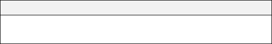
Figure 2.3 DB-9 DESCRIPTION AND PIN LOCATOR
Pin#1
Pin#6
Pin#9
Pin#5
View of the DB-9 connector from outside of the radio enclosure.
Table 2.4 DB-9 PIN FUNCTIONS
Pin Function/Comment
1 DCD (Data Carrier Detect) from Radio to RTU
2 RXD (Receive Data Output)
-Data from Radio Receiver to Field Device
3 TXD (Transmit Data Input)
- Data from Field Device to Radio Transmitter
4 Not Connected
5 Signal Ground
6 DSR (Data Set Ready) from Radio to RTU
7 RTS (Request to Send) from RTU to Radio
8 CTS (Clear to Send) from Radio to RTU
9 Not Connected
Table 2.3 Pin Assignments for DB-9 Data Interface Port
Figure 2.3 DB-9 connector; Model 2888
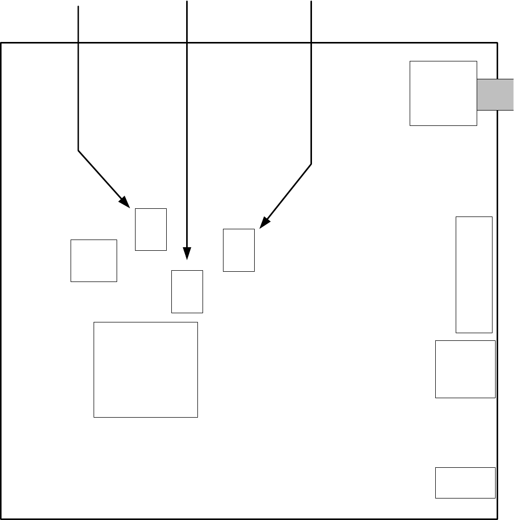
16
uProcessor
RF Connector
DB- 9
Data
Port
Diagnostic
Jack
DC Input
TCXO
R10
4
R11
0
R13
1
Tx Modulation AdjustTCXO Coarse Adjust
Squelch Adjust
Alligator
Communications
2888 Radio Circuit
Board
Figure 2.4, Model 2888 Internal Circuit Board
17
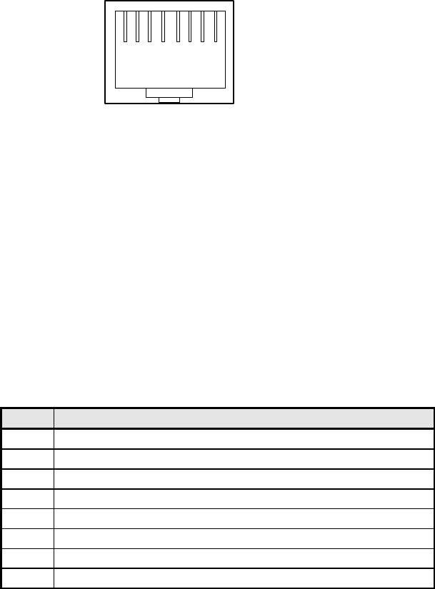
Figure 2.6 RJ-45 Diagnostic Port
1 2 43 5 6 87
View of the RJ-45 diagnostic port connector from outside of the radio enclosure
Table 2.6 RJ-45 PORT PIN FUNCTIONS
Pin Function/Comment
1 10 VDC (High)
2 Signal and DC Ground
3 PTT/ (Keys Tx when Grounded)
4 DTMF Tones Out
5 DTMF Tones In
6 RSSI Ramp Voltage (0.2 to 4.0 VDC)
7 RXMute (Mutes RX during Diagnostics)
8 Alarm Logic Output Pin
18
2.6 DIAGNOSTIC PC INTERFACE
A diagnostic computer running the Alligator Advanced Diagnostic Software can interface
with a Model 2888 Radio in a number of ways. The following sections diagram the most
common system configurations.
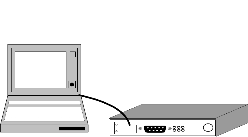
2.6.1 Model 2888 Radio Local Diagnostic Connect
c
DA
TA
PW
R
IN
DIAG
NOST
ICS
P
W
R
D
C
D
R
X
D
R
T
S
C
T
S
T
X
D
AN
TE
NN
A
Laptop computer
Figure 2.5 - Remote Radio Local Link
In this configuration the sub-menus of the diagnostic software are fully functional.
To link the computer to the Model 2888 Remote Radio: first, connect the male
DB-25 connector of the DTMF Converter Cable to the female DB-25 parallel
port of the diagnostic computer. Then connect the male RJ48 connector of the
DTMF cable to the female RJ45 connector on the QS-1 Radio.
Required Hardware: 1ea PC to DTMF converter (Part No. 4000-0002)
19
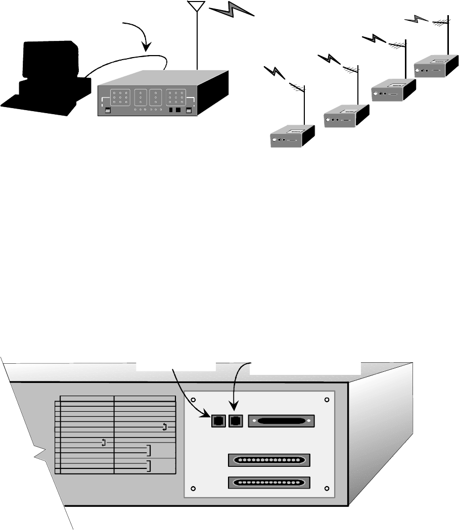
2.6.2 Model 1800A Master Station Local Connect
PC to DTMF
Converter Cable
ALLIGATOR
communications, inc.
Model 1800 Master Station
AB
Diagnostic
ComputerModel 1800 RadioRemote Radio
Network
Figure 2.6 - Model 1800A Master Station Local Link
In this configuration the Alligator diagnostics software is fully functional. To link
the computer to the Model 1800A Master Station: first, connect the male DB-25
connector of the DTMF converter cable to the female DB-25 parallel port of the
diagnostic computer. Then connect the male RJ48 connector of the DTMF cable
to the female RJ48 port on the back of the master station (See Figure 2.6, above).
The RJ48 port on the master station is labeled PC(DTMF)(See Figure 2.7,
below).
Required Hardware: 1 - PC to DTMF converter (Part No. 4000-0002)
TB1
TB2
114
1
14
PHONE
PC(DTMF)
MODEM
RJ48 Port for PC to DTMF
Converter, Local Link
RJ11 Port for Dial-
up Auto-Answer
1 TX AUDIO + EXT BAT A +
2 TX AUDIO - EXT BAT A -
3 RX AUDIO + EXT BAT B +
4 RX AUDIO - EXT BAT B -
5 RX A RSSI BATTERY ENABLE
6 RX B RSSI GROUND
7 TX CHANGE ENABLE
8 VOX ENABLE
9 GND NO
10 13.8V / 100ma COMMON
11 LOW KEYLINE NO
12 GROUND NO
13 +12V KEYLINE COMMON
14 +24/48V KEYLINE NO
MODULE
ALARM
AC
FAILURE
TB1
TB2
Figure 2.7 - Model 1800A Master Station Rear Panel
20
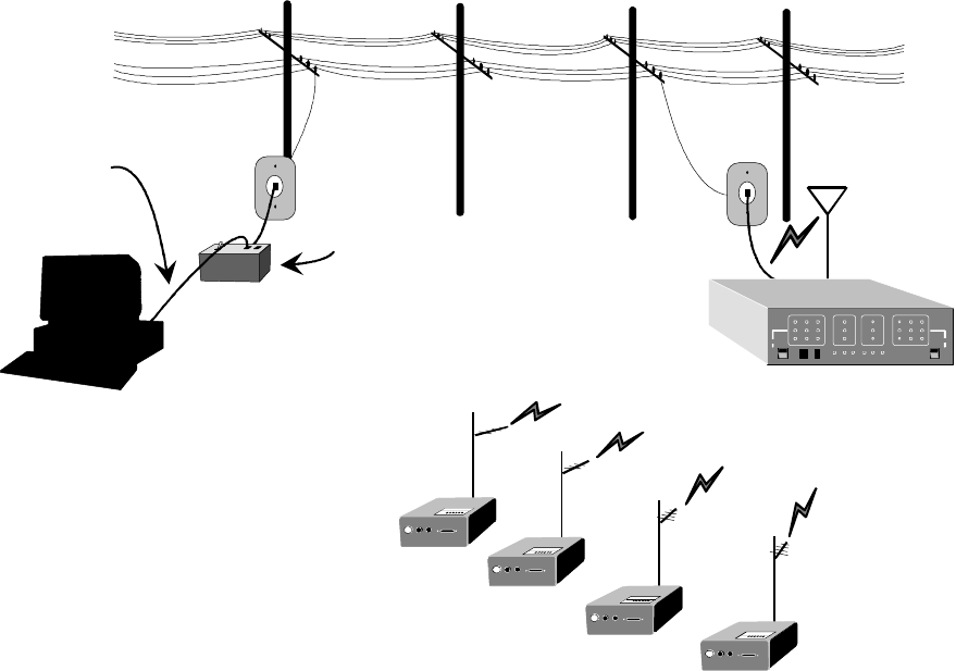
2.6.3 Model 1800A Master Station Phone Dial-up Connect
Dial-up Interface Module
Remote
Radio Network
ALLIGATOR
communications, inc.
Model 1800 Master Station
A
B
Model 1800 Master Statio
n
DTMF to PC Converter
Cable
Diagnostic
Computer
Figure 2.8 - Phone Dial-up Master Link
In this configuration, the Alligator diagnostics software is fully functional. This
configuration requires the Dial-up Auto-Answer option be installed on the
connected Model 1800A. To link the computer to the Model 1800A via telephone:
first, connect the male DB-25 connector of the DTMF Converter Cable to the
female DB-25 parallel port on the back of the diagnostic computer. Then, connect
the male RJ48 connector of the DTMF cable to the female RJ45 connector on the
Dial-up Interface Module. Then use a standard RJ11 phone cord to connect the
interface module to an operational phone jack. At the master station location,
connect the Model 1800G to an operational phone jack also using a standard RJ11
phone cord (See Figure 2.8, above). The RJ11 phone port is located on the rear
panel of the Model 1800G and is labeled PHONE (See Figure 2.7, previous page).
Required Hardware: 1 -- PC to DTMF converter (Part No. 4000-0002)
1 -- Dial-up Interface Module (Part No. 4000-0004)
1 -- Dial-up Auto-Answer option installed on Model 1800A
21
3.1 MECHANICAL INSTALLATION
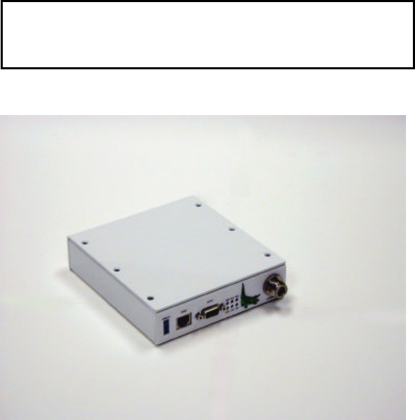
The Model 2888 radio is shipped with a universal mounting bracket which can be attached
to the radio enclosure and allow mounting the radio on a wall or other flat surface (6-32 X
5/16" round head screws are provided to secure the bracket to the enclosure). The
bracket will accommodate four 1/4" fasteners.
CAUTION
If substitute screws are necessary for the 6-32 X 5/16”
round head screws, do not use screws which extend into the
chassis more than 5/16”. Doing so might contact and
damage the P.C. Board in the radio.
Note: In the event of an uneven mounting plane, consider using two (diagonally opposite)
or three fasteners rather than four, which might distort the bracket and radio enclosure,
resulting in physical damage.
3.2 LOCATION
Monitoring the diagnostics and/or changing the parameters of the 2888 radio is possible
by using a local computer connected to the RJ-45 connector of the 2888 radio. If this is
desired, attempt to locate the radio with convenient access to the 2888 connector.
Note: Attempt to position the transceiver away from main power lines and hydraulic or
pneumatic lines. A catastrophic failure of any of these lines in close proximity to the radio
transceiver could damage the radio and disrupt communications at a time when specific
alarms are most needed. Also, service technicians repairing these types of failures require
space to work and might inadvertently damage the radio or cables.
3.0 Installation

22
3.3 ELECTRICAL INTERCONNECTION
The Model 2888 radio has four external connectors. These connectors provide access to
the antenna, power supply, associated RTU and diagnostic computer
Figure 3.1 illustrates the connector locations and their usage.
c
DATA
PWR IN
DIAGNOSTICS
PWR DCD RXD
RTS CTS TXD ANTENNA
2 3 4 1
•• Antenna Feedline: RF signals are transmitted and received via a coaxial cable
(not supplied) connected to a type "N" connector.
Note: Most feedlines are substantial in size and relative rigidity. It is suggested
that a flexible "coaxial pigtail" be used between the feedline and the radio to
preclude the application of mechanical stress to the connector and/or radio.
‚‚ Power Cable: Power is supplied to the radio transceiver via a two-conductor
cable and a power connector (supplied). Red wire to + 13.8 Vdc and black wire
to Ground If a power supply voltage other than 13.8Vdc is required, an external
DC-DC converter will result in the red wire reading the desired power supply
voltage.
ƒƒ Diagnotics Port: RJ45 connection for the DTMF diagnostic cable (P/N 4000-
0002)
„„ Interconnecting Cable: The RTU connects to the radio transceiver via a
multiconductor cable (not supplied) and a DB-9 connector. Section 2.4 includes
a pin-by-pin commentary on the function of each pin in the DB-
9 connector.
The connector should be tightened using two 4-40 X 1/4” long screws to avoid
losing contact between the cable and connector before the radio is in service.
Figure 3.1 Model 2888 External Connectors

23
4.1 GENERAL DISCUSSION
The 2888 radio is a half duplex transceiver intended for use as either a Master or a Remote Station
Radio unit in a Wireless SCADA data transmission system.
4.2 MICROPROCESSOR OPERATION
The microprocessor, U-203 is the "brain" of the 2888 radio. It enables a computer to communicate
with the 2888 radio and enables the operator to "see" everything that the Remote "sees", such as
diagnostics. The microprocessor also allows the operator to observe the operating parameters,
frequency, power output, reverse power, PLL voltages, the power output level and the frequency
offset. These and other operations may be performed locally or through the RF link.
4.3 FUNCTIONS OF THE 2888 RADIO
The Alligator Model 2888 offers diagnostic parameters which aid the user in troubleshooting potential
problems in the SCADA network. The Model 2888 also offers options which enable the radio to be a
“smart” radio. It may also be configured for use in a variety of different configurations. The Alligator
Advanced Diagnostics Software can read and/or modify all of the following parameters for each
responding Model 2888 Radio.
4.3.1 Diagnostic Parameters
Parameter Description
Alarm Status
Alerts the user that one or more of the diagnostic parameters are
not within the safety limits.
Received Signal Strength
Indicator (RSSI) An indicator of a Remote’s signal strength.
Forward Power The amount of power the carrier frequency is being transmitted.
Reverse Power An indicator of the quality of the Remote Radio’s antenna.
A reverse power reading greater than one-third of the forward
power reading indicates that the antenna is degrading, or that
cables and connectors are not properly connected to the radio.
4.0 Theory of Operation

24
Parameter Description
Supply Voltage The recommended power supply to the Remote Radio should be
no less than 11 V and no more than 16V, with 13.8V the
nominal voltage. A power supply capable of supplying at least 2
amps is required for proper operation of the radio.
PLL Voltages The voltage readings of the two Phase-Locked-Loops (PLL1 &
PLL2). For safe radio operation, this voltage should be between
0.1 to 4 Volts.
Internal Temperature Serves as a “thermometer” for the environment surrounding the
radio. Also serves as a sign if something is wrong with the
Remote Radio.
Table 4.2 Diagnostic Parameters Descriptions
4.3.2 Alarm Limits and Conditions
The Alligator Advanced Diagnostics Software provides the user with the capability to set the desired
safety limits for each diagnostic parameter. The user can set high and low limits for Supply Voltage,
PLL1 Voltage, PLL2 Voltage, Internal Temperature, Forward Power, and event (squelch, PTT, Time-
out) counters. Should any of these parameters fall outside its safety limits, an alarm condition will be
generated and displayed by the Remote Radio.
An alarm condition will also exist if the Reverse Power (reflected power) reading exceeds 30% of the
Forward Power reading, or if the VSWR (Voltage Standing Wave Ratio) reaches an unsafe value.
4.3.3 Operating Parameters
The Alligator Advanced Diagnostics Software enables the user to configure each Remote Radio to
operate in a certain configuration. Each Remote Radio can be configured to operate under any of the
following configurations:
Parameter Description
PTT Dekey Time
(0-255 msec) Whenever the 2888 Radio turns on its transmitter, the dekey
time is the number of milliseconds the transmitter stays on after
the radio is dekeyed. Some applications require squelch-tail
elimination, and other applications may require that the master
station is never squelched. By keeping each of the Remote’s
transmitters on for an extra few milliseconds, the Remotes will
overlap each other during polling cycles, thus the master
station’s receiver modules will always be receiving something.
For applications where a dekey time is not required, this

25
Parameter Description
parameter should always be programmed to 0 milliseconds. The
factory automatically sets this value to 0 milliseconds unless the
customer specifies otherwise.
Tx On Delay Time
(0-255 msec) For some applications, especially when one or more repeater
stations involved in a SCADA system, the 2888 Radio may need
to delay turning on its transmitter whenever it is keyed.
Time-out Duration
(0-255 sec) To prevent lockup of the transmitter, each 2888 Radio can be
individually programmed to shut off its transmitter if it is keyed
on for a certain number of seconds. If this value is zero, the
transmitter will never time out. When setting this parameter, be
sure that this duration is longer than the longest possible
transmit time for each data transmission.
RTS/CTS Delay for
Internal Modem
(0-255 msec)
Each Radio needs a certain amount of time to get ready for data
to be transmitted over the air. The RTS (Request To Send)
signal is the command from the RTU to key on th
e 2888 Radio.
The CTS (Clear To Send) signal is the indicator from the
Remote Radio to the RTU that it is ready to send the data
supplied by the RTU. This delay time is simply the minimum
amount of time that the data must be delayed starting from the
RTS signal. The Alligator Model 2888 Radio can handle a delay
of 1 millisecond, but the most effective value is anywhere from
10 to 20 milliseconds. The factory default setting is 10
milliseconds.
PTT Limit (per 10-
second interval)
(0-255)
This parameter is used mainly to detect problems with external
keying circuits.
Each Remote Radio is capable of counting the number of
external keys within every 10-second interval of operation. If
the number of external keys exceeds the PTT Limit, the PTT
operating parameter will automatically become disabled.
Using the Alligator Advanced Diagnostics Software, the Remote
Radio will alert the user that PTT had been disabled due to
erratic keying. Once the user investigates the problem and fixes
it, the user can then enable PTT.
The factory preset this value to 255. A value of 255 means that
there is no limit to the number of external keys that can occur
within each 10-second time frame.
Table 4.3 Descriptions of Operating Parameters

26
4.3.4 Communication Parameters
The Alligator Advanced Diagnostics Software enables the user to configure each Remote Radio to
operate in a certain configuration. Each Remote can be configured to operate under any of the
following configurations:
Parameter Description
Transmitter Frequency
Each 2888 Radio’s transmitter can be individually programmed to
frequencies in the FCC designated 895 - 960 MHz Band.
Radio Address
Each 2888 Radio’s identification address can be changed at any time.
Each address consists of a unique 4-digit number.
Mechanical Frequency
Potentiometer for
Manual Frequency
Adjustment
For users who do not like to deal with digital potentiometers or
automatic frequency adjustment schemes, it is possible to disable the
frequency digital potentiometer on the 2888 Radio and use the
mechanical potentiometer R110 to tune the Remote Radio’s reference
standard frequency at the site. This mechanical potentiometer has 25
turns and has an adjustment range of approximately +/- 7 kHz, with an
accuracy of 100 Hz. This frequency adjustment scheme can only be
enabled if the technician is at the Remote site, since changing from the
digital potentiometer to the mechanical potentiometer can be dangerous
if done over-the-air.
Digital Frequency
Potentiometer for
Manual Frequency
Adjustment
By enabling this parameter, the user can manually adjust any 2888
Radio’s frequency, remotely or locally, using the Alligator Advanced
Diagnostics Software. The software allows the user to move the
frequency digital potentiometer one step at a time. Each step of the
digital potentiometer will adjust the Remote Radio’s frequency by
approximately 200 Hz each step.
The adjustment range for this digital potentiometer is approximately +/-
3 kHz.
Automatic Global
Frequency Calibration
(AGFC)
(Optional Feature)
(YES/NO)
By enabling AGFC, each 2888 Radio will continuously and automatically
adjust its own TCXO frequency to match that of its received carrier
frequency whenever it has finished transmitting data, without using any
special hardware circuits to constantly track the TCXO bias voltage. All
adjustments are done through the on-board microprocessor to insure that
the Remote Radio does not lock onto an interfering signal or
environmental noise.
A frequency digital potentiometer is used and controlled by the on-board
microprocessor, so even if the 2888 Radio is powered down, the
frequency of the Remote will remain unchanged after power up. In other

27
Parameter Description
words, after the Remote Radio is correctly adjusted, its frequency will
remain unchanged, even if the master station’s signal has disappeared
(for Remote Radios operating under traditional AFC, the TCXO bias
voltage becomes unstable if the master station’s signal disappears and
requires some time to follow the Master Station’s signal after squelch is
off). This AGFC frequency adjustment scheme will enhance the
reliability and stability of the Remote Radio’s frequency at all times,
without the disadvantages of “traditional” AFC. The accuracy of
adjustment is 200 Hz.
This automatic frequency adjustment scheme cannot be enabled when
either of the Tx and/or Rx AFC schemes are enabled. Whenever AGFC
is enabled, Tx and Rx AFC automatically become disabled.
It is always good practice to calibrate the master station’s RF signal
before adjusting any of the 2888 Radio’s frequencies. As a safety
precaution, each frequency adjustment will be by no more than 200 Hz
every time the Remote Radio has just finished transmitting data.
Tx AFC (YES/NO)
Rx AFC (YES/NO)
By enabling Tx or Rx AFC, each 2888 Radio will automatically adjust its
own Tx or Rx frequency to match that of its received carrier frequency
whenever it is receiving an RF signal. The adjustment accuracy is 400
Hz, and offers less immunity to interfering signals compared to AGFC.
AGFC is also smart enough to adjust only when the Remote Radio has
just finished transmitting data, while Tx and Rx AFC are not.
Whenever Tx and/or Rx AFC are to be enabled, AGFC must be disabled
first.
Adjustments are done based on the AGFC Counter Limit (see above).
Table 4.3 Communication Parameters Descriptions

28
5.1 GENERAL DISCUSSION
While the 2888 is a reliable and relatively maintenance free radio, there are a few quick checks and
adjustments that may be made to ensure continued worry-free operation. These procedures should
only be performed by qualified engineers or technicians. Should any problems arise or there are any
questions that would assist in maintaining the radio, we invite you to call Alligator Communications
Customer Service Department at 1-408-327-0800, 8 A.M. to 6 P.M. Pacific Standard Time.
5.2 TEST EQUIPMENT REQUIRED
•• Communications Test Set/Service Monitor. This instrument performs the combined
functions of an RF and audio signal generator, a frequency counter, a modulation analyzer,
and an RF wattmeter. These units are usually equipped with an input-attenuated pad (or
dummy load) that allows the full output of the radio to be transmitted directly into the
instrument. If this feature is not included, a separate dummy load must be used. Suitable
monitors are made by Hewlett-Packard, Motorola Inc., Marconi Instruments Ltd., and IFR
Inc.
‚‚ Multimeter. A basic multimeter, such as a Simpson or a Fluke, will meet this requirement.
ƒƒ Oscilloscope. If the service monitor does not include a low frequency oscilloscope, then a
basic one is needed.
5.0 Maintenance

29
6.1 GENERAL DESCRIPTION
Alligator Communication's Advanced Diagnostic Software (ALLI) reads and modifies all operating
parameters on the Model 2888 radios. With this software, a technician can quickly identify possible
conditions that may eventually result in a non-responding remote radio. The technician may then
modify the current radio's parameters to correct the condition "over-the-air". Virtually all radio
maintenance no longer requires dispatching a technician to perform an on site repair, thus reducing
undesirable downtime.
The software runs on a PC/AT compatible computer system (Desktop or Laptop). When connected
directly to a Model 2888 the software can read and/or modify each of the following remote
parameters:
Diagnostic Parameters:
Alarm Status RSSI RF Power Output Mode
PLL1 Voltage PLL2 Voltage Power Supply Voltage
FM Deviation Frequency Offset Internal Temperature
Forward Power Reverse Power
Alarm Limits and Conditions (Low/High):
Power Supply Voltage PLL1 Voltage PLL2 Voltage
Forward Power Reverse Power Internal Temperature
Squelch Counter PTT Counter Tx Timeout Counter
Operating Parameters:
PTT Dekey Time PTT Limit per 10 seconds
Timeout Duration
RTS/CTS Delay Tx On Delay (repeater use)
Communication Parameters:
Transmitter Frequency Receiver Frequency Radio Address
Tx/Rx Spacing Bandwidth
6.0 Alligator Diagnostic Software
30
Frequency Adjustment Schemes:
Tx AFC Rx AFC Mechanical Frequency Pot
Automatic Global Frequency
Calibration (AGFC) Digital Frequency Pot
Event Counters:
Squelch PTT Time-out
Sleep Mode Parameters:
Clock Time Sleep Enable/Disable Wake-Up Time
Sleep Time Wake Duration Snooze Duration
Maintenance Enable Start Time End Time
When connected to a Model 1800G master station, the Alligator Advanced Diagnostics Software
(ALLI) can read and/or modify all of the previously listed parameters for each responding Model
2888 Radio. It can also switch the master transmitter, and perform a master station battery test. In
addition, the software can read the following parameters from the Model 1800A:
Master Station Diagnostic Parameters (A and B)
RF Power Output Supply Current Power Supply Voltage
Front Panel Status FM Deviation Frequency Offset
Received Signal Strength and Offset (A and B):
RSSI (dBm) Frequency Offset
Alarm Conditions:
Module Unlock TxA Power too low TxB Power too low
Primary TCXO failure Power Supply A off-line Power Supply B off-line
Communication Parameters:
TxA Frequency TxB Frequency Radio Address
RxA Frequency RxB Frequency Setup Configuration
Operating Parameters:
Repeater Operation Enable Hot-Warm-Standby Timeout Timer

31
Automatic Tx A/B Cycling Parameters:
Time of Day Switchover Countdown Switchover Interval
Tx A/B Cycling Enable Time to Switch
Dial-Up Auto Answer Parameter Settings:
Auto Answer Enable Number of Rings
Frequency and Deviation Adjustments (from any remote location)
Digital Frequency Pot Digital Deviation Pot
Transmitter Forward Power Reading Corrections
TxA Correction Factor TxB Correction Factor
For a complete description of the software installation and operation refer to the Alligator Advanced
Diagnostics Software Manual.
6.2 Diagnostics Feature Theory of Operation
The ALLI software uses a multi-address polling communications scheme to communicate with the
microprocessor of each remote radio responding to the connected master station. Each time the
software updates information to or from a remote or master, it must send a command string requesting
the appropriate action from the specified radio. The software then waits for a response. If the remote
or master does not exist or is not responding then the software will report a time-out error.
The software communicates with the radios using the DTMF protocol. It is the same protocol
researched and implemented by the U.S. telephone and emergency broadcast systems for more than
two decades. This protocol isolates the diagnostic capabilities of the radio system from the connected
SCADA equipment. In other words the radio system's diagnostic transmissions will not trip the
connected SCADA equipment and the connected SCADA equipment's data transmissions will not trip
the radios' diagnostics. However, this protocol was not designed to quickly transmit large quantities
of data. Therefore, a few of the software commands that require large amounts of data will respond
slowly. This trade off of speed for data isolation has only a minimal effect on overall system
performance. The few extra seconds spent reliably performing over-the-air calibrations is much more
desirable than the few extra hours spent visiting a remote site.
By default, Alligator programs the Model 2888 to prevent the ALLI software from interrupting any
SCADA transmission. Also by default, any SCADA transmission will interrupt the software's attempt
to communicate with any remote. However, upon a customer request, the factory can program the
master to operate in the reverse.