Alltek Marine Electronics CAMINO-201 Class B AIS Transponder User Manual 1
Alltek Marine Electronics Corporation Class B AIS Transponder 1
UserManual.wiki
>
Alltek Marine Electronics
>
CAMINO 201 User Manual
User Manual
Navigation menu
Upload a User Manual
Namespaces
Wiki Guide
HTML
PDF
Info
Views
User Manual
Discussion / Help
Navigation


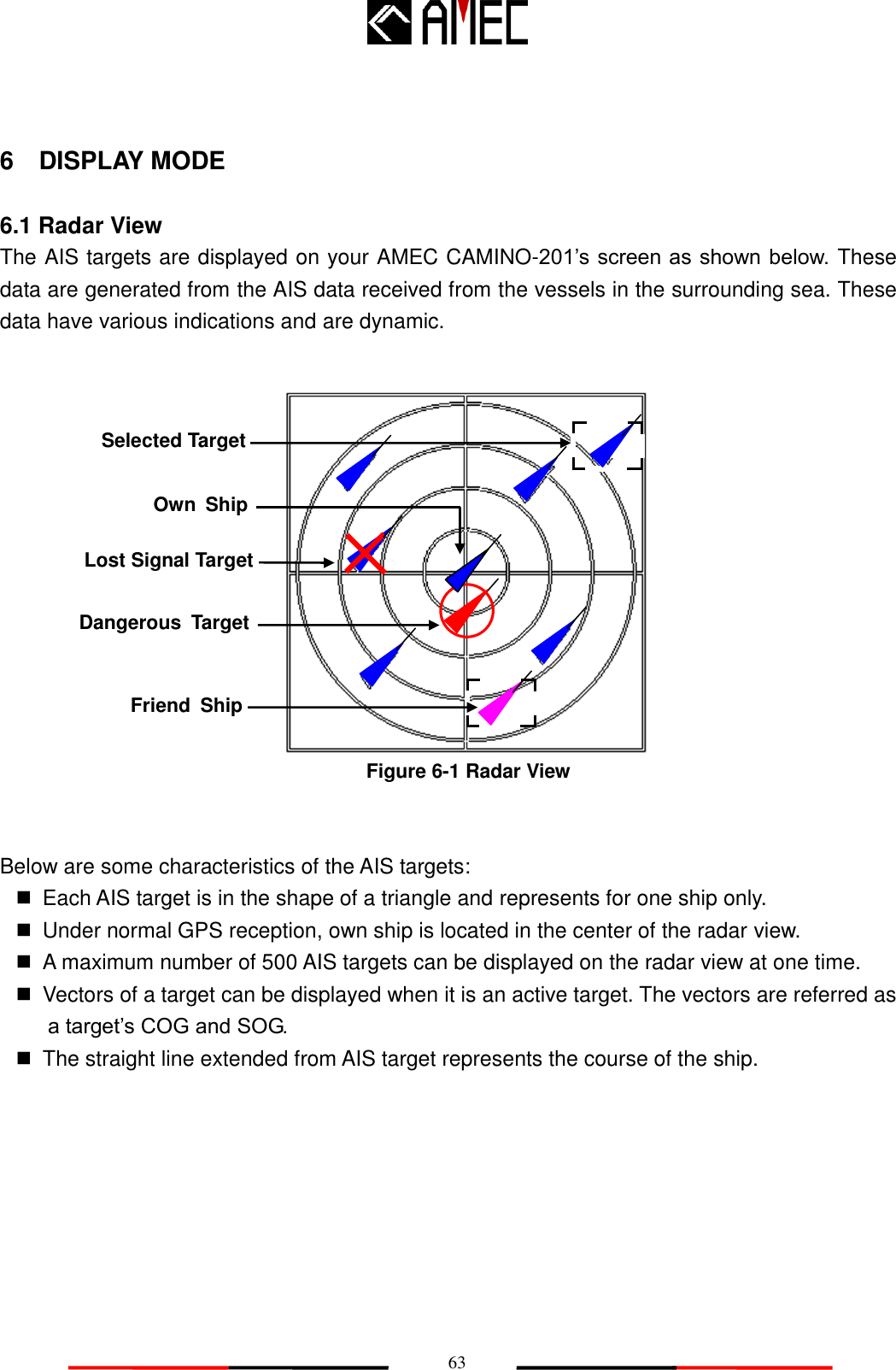
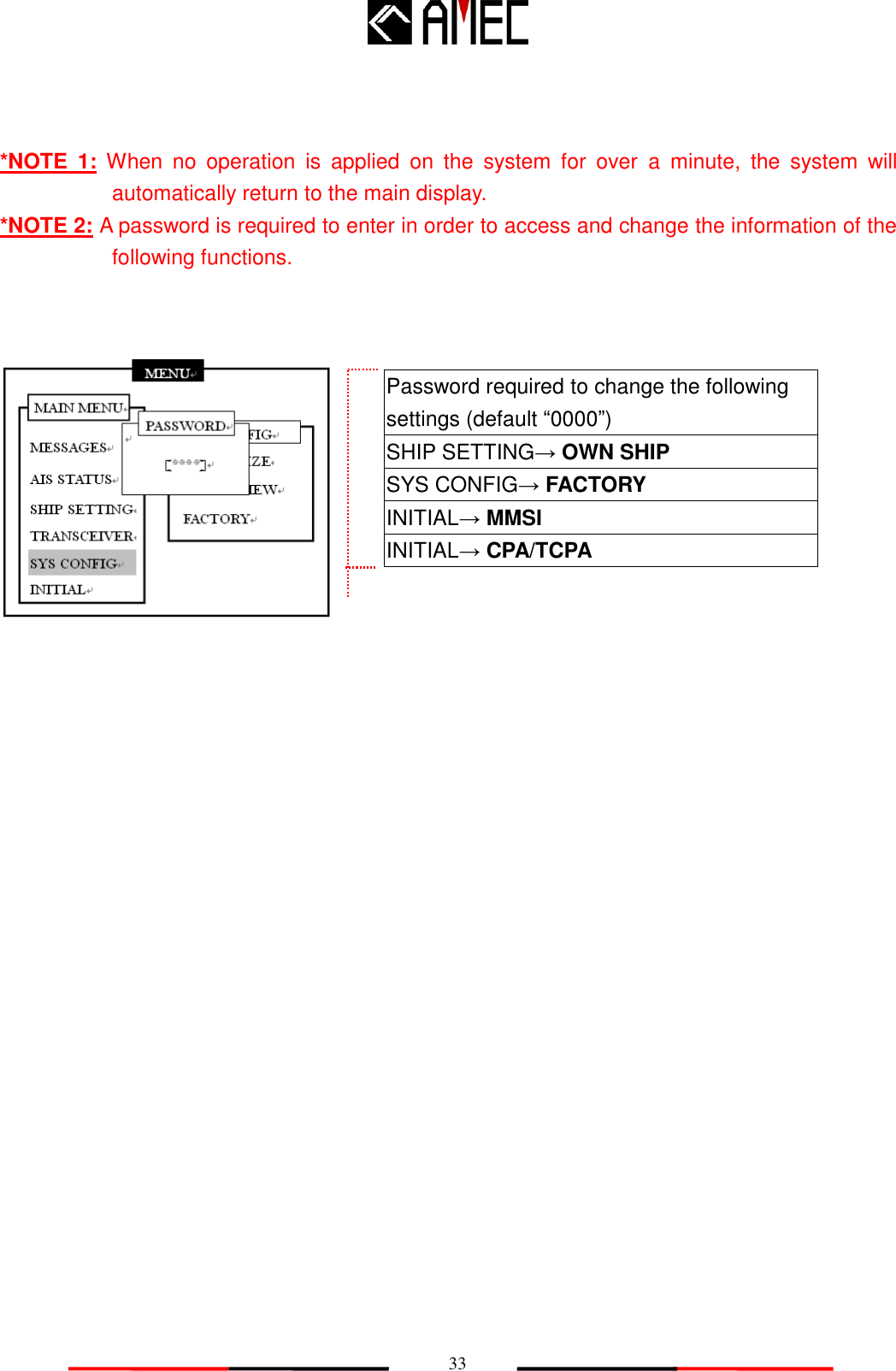
![20 MMSI SETTING MMSI [000000000] Can be programmed only once! MMSI SETTING MMSI [000000000] Save Data? OK CANCEL Warning! Can be programmed only once! Step 5: Enter the MMSI by using the arrow keys. (Refer to section 5.4. on Arrow key instructions) FOR USERS IN THE UNITED STATES OF AMERICA ONLY WARNING: It is a violation of the rules of the Federal Communications Commission to input an MMSI that has not been properly assigned to the end user, or to otherwise input any inaccurate data in this device. Step 6: When completed entering the MMSI, press the <ENT> key on the front panel and a pop out window will appear to confirm this process. Choose “CANCEL” to discard the process and NOT to store this data, and skip to step 7. Choose “OK” to store this data and to enter the main menu. Unit will now activate and function by broadcasting own ship‟s voyage related data and receiving other ships‟ AIS data.](https://usermanual.wiki/Alltek-Marine-Electronics/CAMINO-201/User-Guide-1424205-Page-28.png)
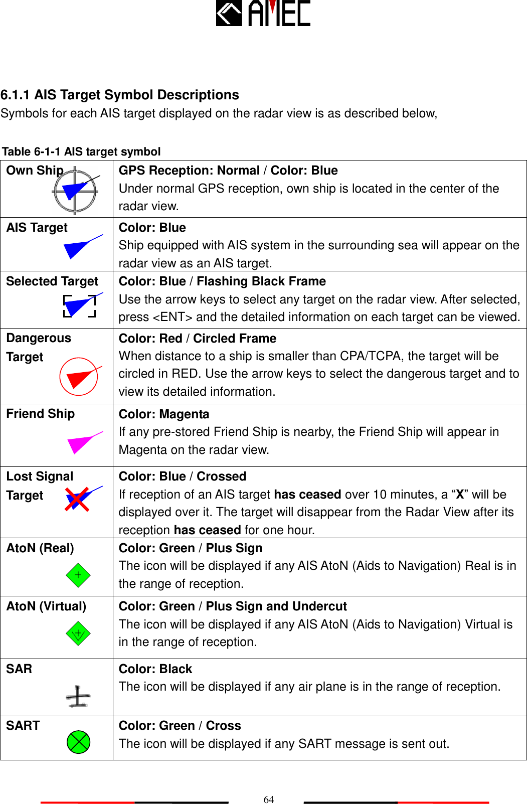
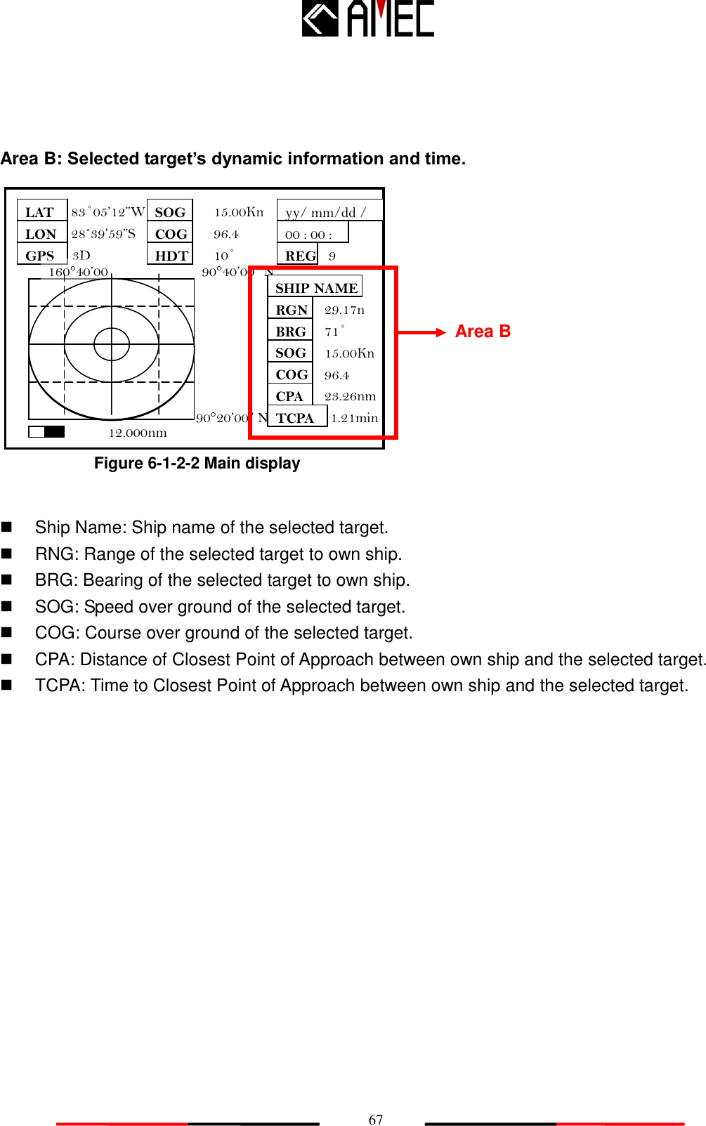
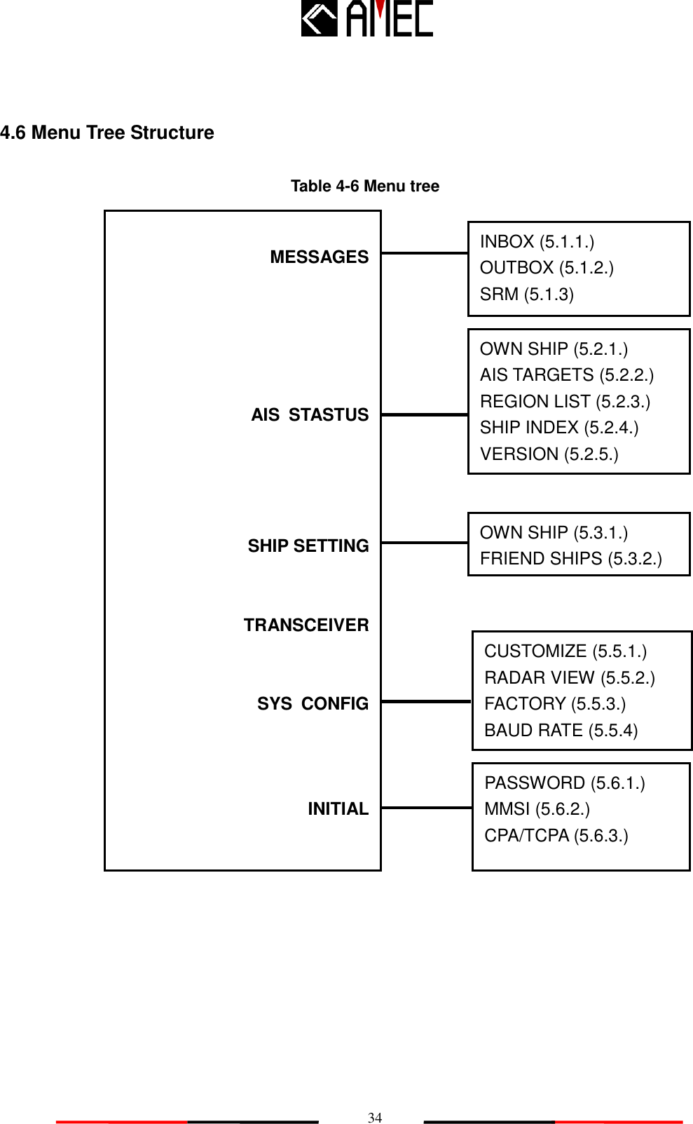
![28 (D) OWN SHIP INFORMATION: Own ship information includes own ship‟s basic, static and dynamic information. *NOTE: Use the <ENT> key or the <LEFT> or <RIGHT> key to switch between static and dynamic information pages. **Refer to section 5.2.1 for details. Figure 4-2-3 Own ship details Figure 4-2-4 Own ship details SHIP DETAIL <2/2> NAME CALL MMSI CARGO TYPE DEST ETA IMO BEAM LENGTH AMEC AIS B (CS) N/A [CLASS B] 000000000 DG, HS OR MP <POLUTANT A> HSC SHANGHAI 12/31 23:59 3m DRAFT DTE 1.5m N/A A: 6m B: 4m C: 2m D: 1m 10m 000000000 A B C D SHIP DETAIL <1/2> NAME CALL MMSI Nav. EPFD LON LAT SOG COG ROT AMEC AIS B(CS) N/A [CLASS B] 000000000 Under way using engine. Undefined 83°05’123”W 28°39’60”N 15.00Kn 96.4 0.00 RNG BRG CPA TCPA HDT 29.17nm 71° 23.26nm 1.21min P.A 68˚ Lo](https://usermanual.wiki/Alltek-Marine-Electronics/CAMINO-201/User-Guide-1424205-Page-36.png)
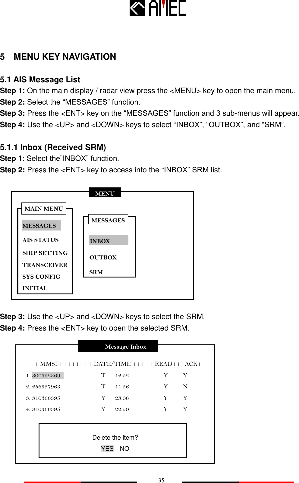
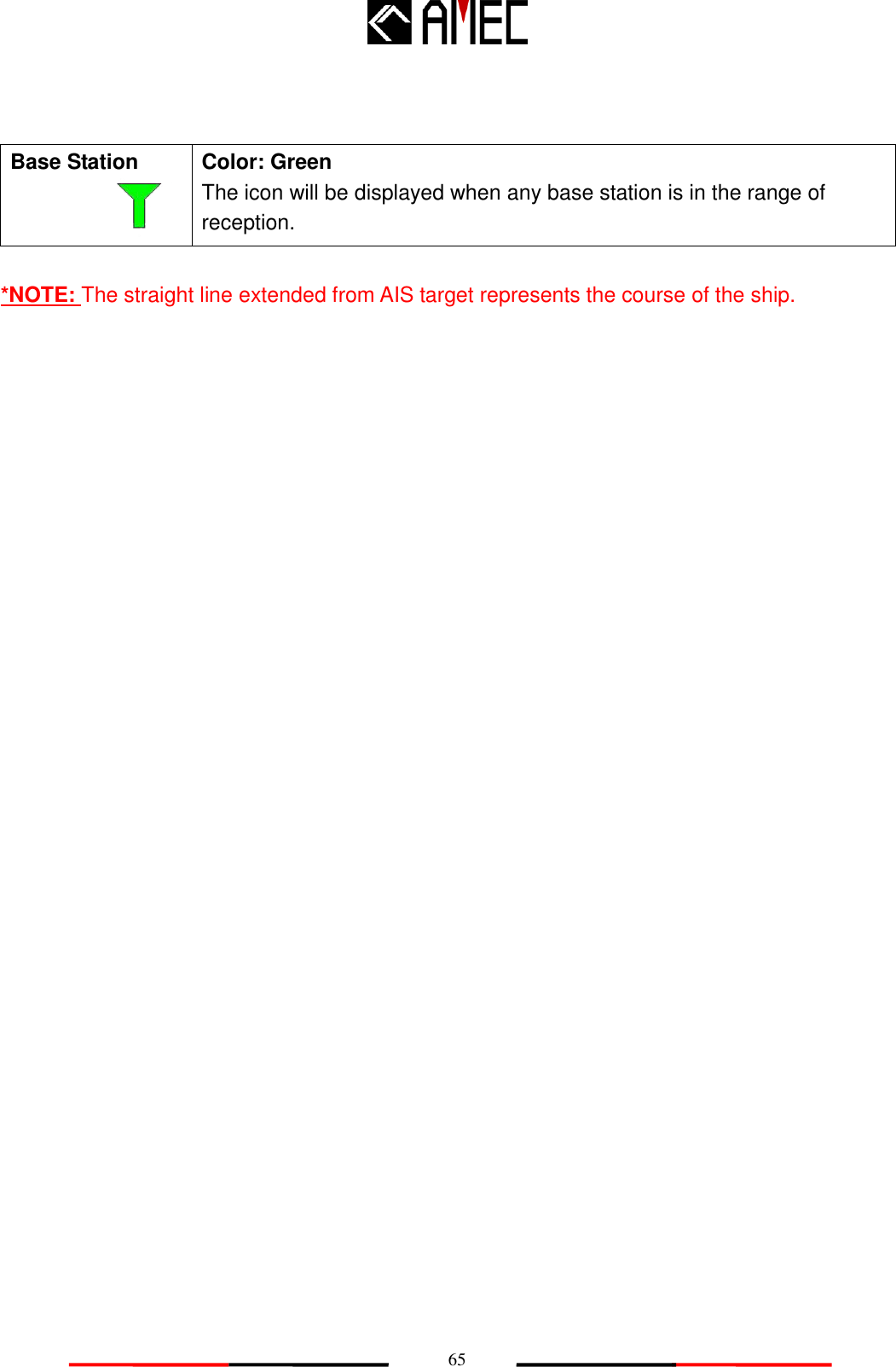
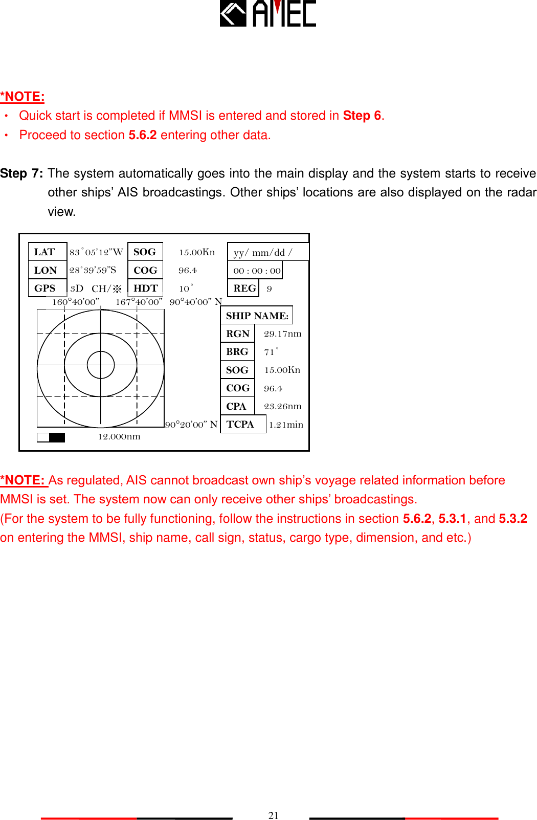
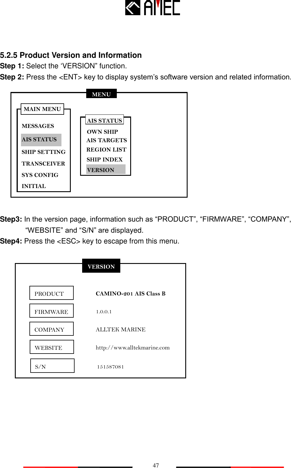
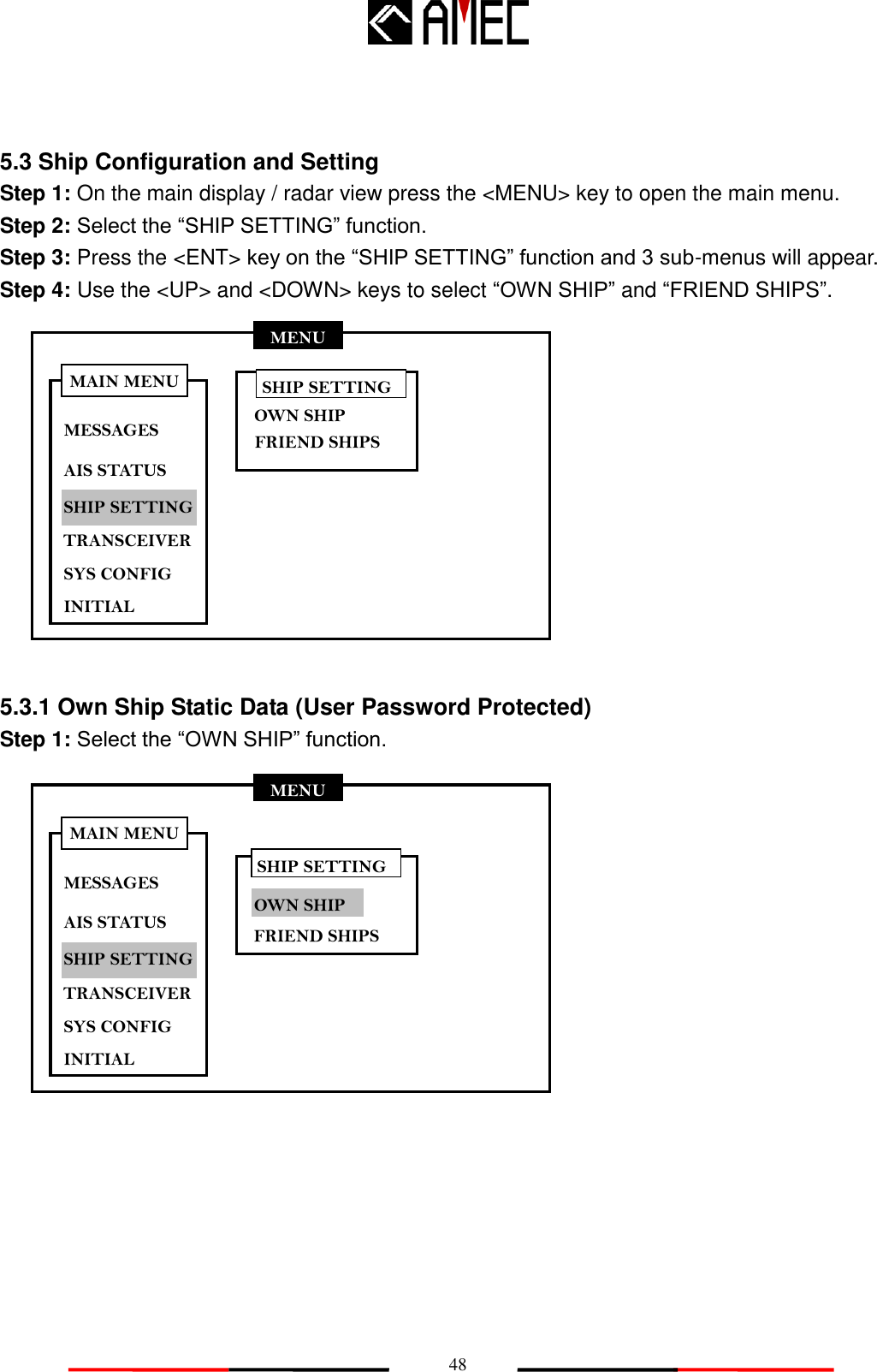
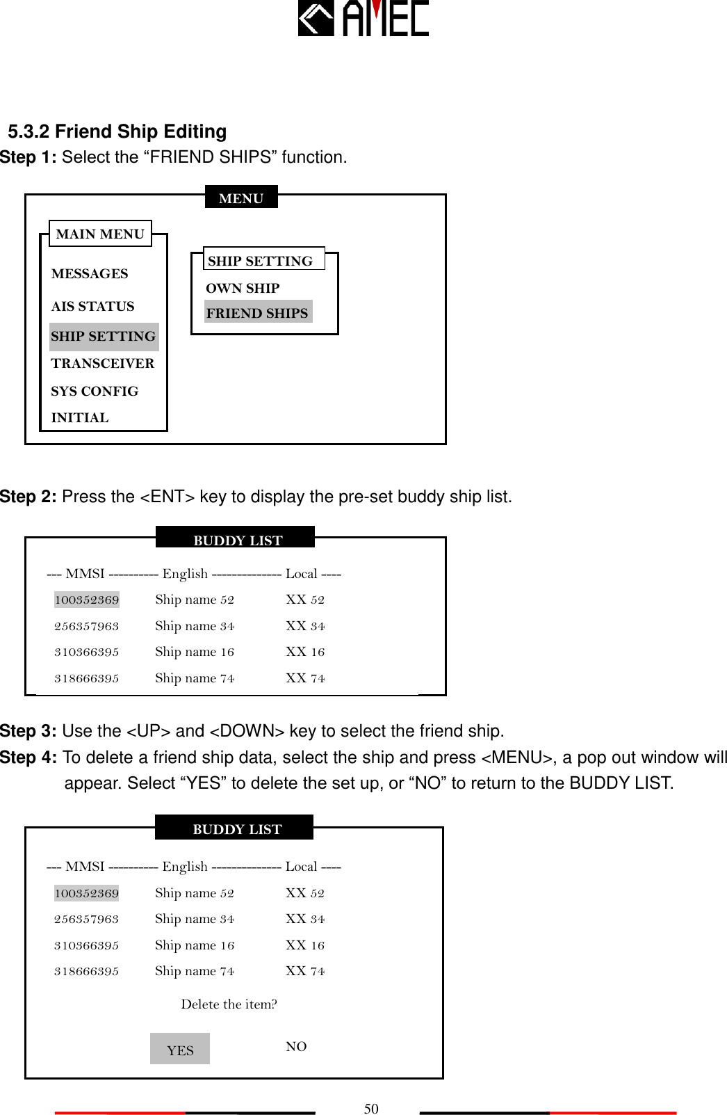
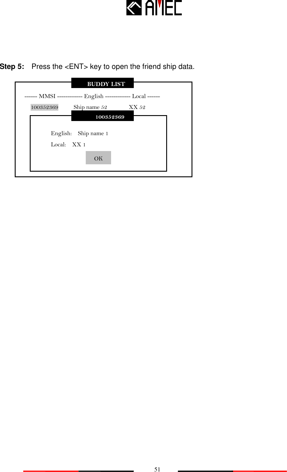
![40 MENU MESSAGES AIS STATUS SHIP SETTING SYS CONFIG INITIAL MAIN MENU TRANSCEIVER 5.2.1 Own Ship Information Settings Step 1: Select the “OWN SHIP” function. Step 2: Press the <ENT> key to display own ship‟s dynamic and static information. Step 3: Use the <RIGHT> key to view own ship‟s static information. Step 4: Use the <LEFT> key to view own ship‟s dynamic information. Step 5: The <ENT> key can also be used to switch between own ship‟s dynamic and static information. SHIP DETAIL <1/2> NAME CALL MMSI Nav. EPFD LON LAT SOG COG ROT AMEC AIS B(CS) N/A [CLASS B] 000000000 Under way using engine. Undefined 83°05.123W 28°39.600N 15.00Kn 96.4 0.00 RNG BRG CPA TCPA HDT 29.17nm 71° 23.26nm 1.21min P.A 68˚ Lo AIS STATUS OWN SHIP AIS TARGETS REGION LIST SHIP INDEX VERSION](https://usermanual.wiki/Alltek-Marine-Electronics/CAMINO-201/User-Guide-1424205-Page-48.png)
![41 Step 6: Press the <ESC> key to return to the main menu. NAME: Ship‟s name CALL: Ship‟s Call Sign MMSI: Maritime Mobile Service Identity Nav.: Navigational Status P.A.: Position Accuracy LAT: Latitude LON: Longitude SOG: Speed Over Ground TCPA: Time to Closest Point of Approach ROT: Rate of Turn RNG: Range between own ship and target ships. HDT: Heading BRG: Bearing between own ship and target ships COG: Course Over Ground CPA: Closest Point of Approach DEST: Destination ETA: Estimate Time of Arrival CARGO: Cargo Type EPFD: Electronic Position Fixing Device TYPE: Ship Type BEAM: Ship Width LENGTH: Ship Length DTE: Data Terminal Draft: Ship Draft SHIP DETAIL <2/2> DETAIL <2/2> NAME CALL MMSI CARGO TYPE DEST ETA IMO BEAM LENGTH AMEC AIS B (CS) N/A [CLASS B] 000000000 DG, HS OR MP <POLUTANT A> HSC SHANGHAI 12/31 23:59 3m DRAFT DTE 1.5m N/A A: 6m B: 4m C: 2m D: 1m 10m 000000000 A B C D Table 5-2-1 Ship details](https://usermanual.wiki/Alltek-Marine-Electronics/CAMINO-201/User-Guide-1424205-Page-49.png)
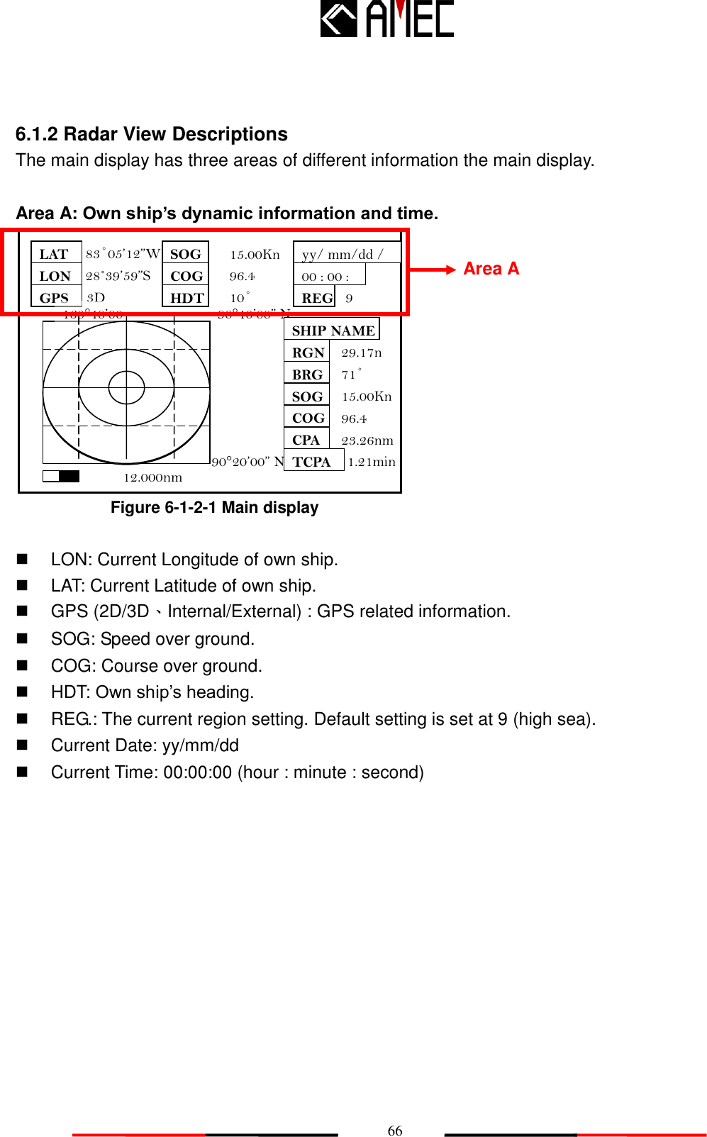
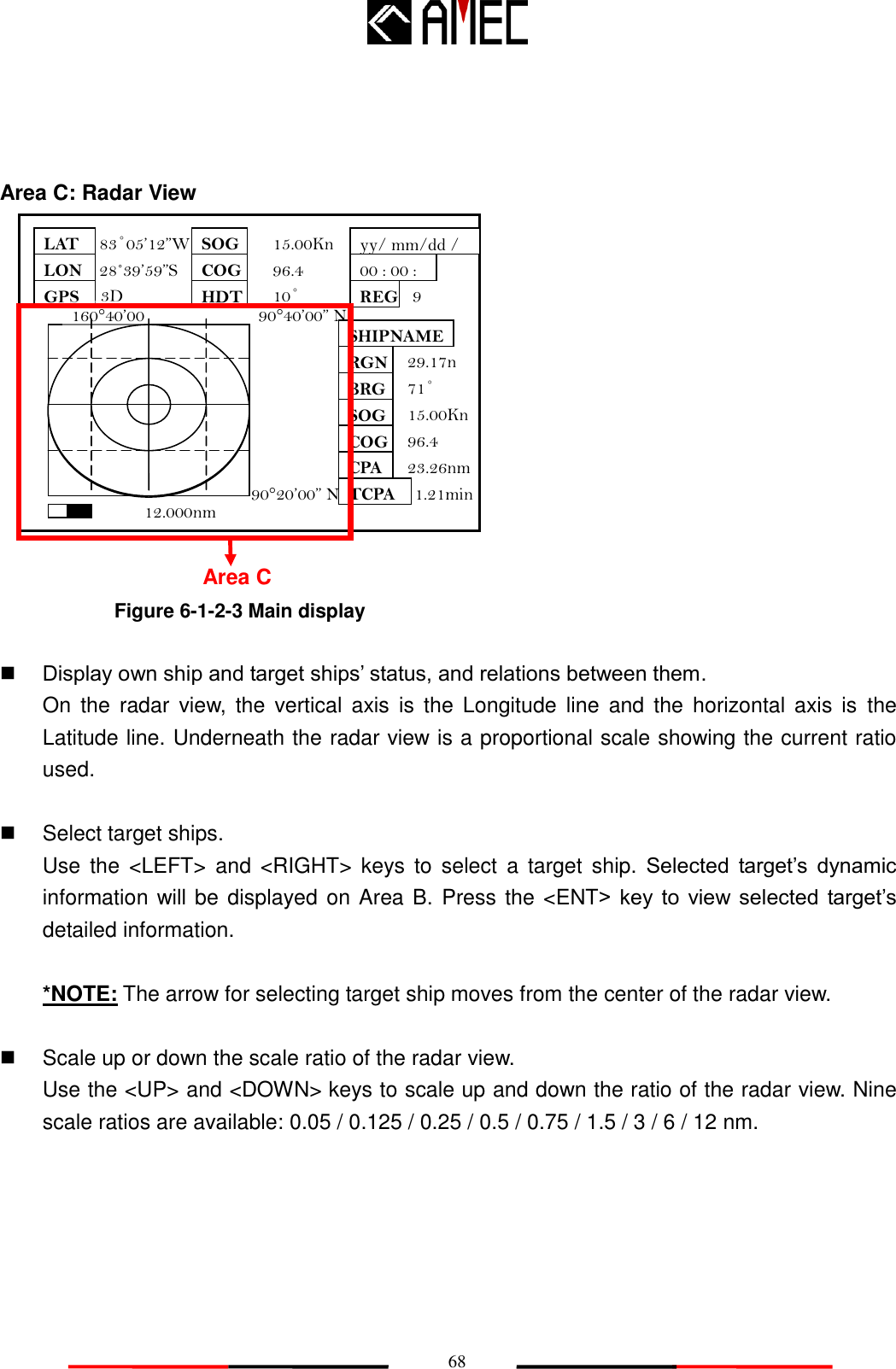
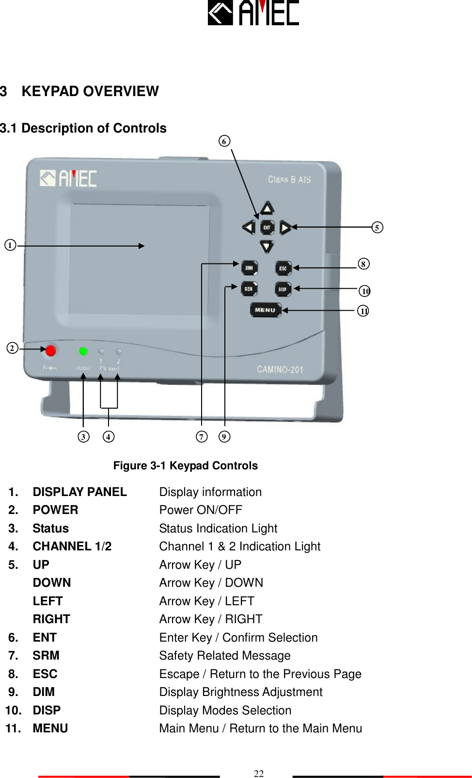
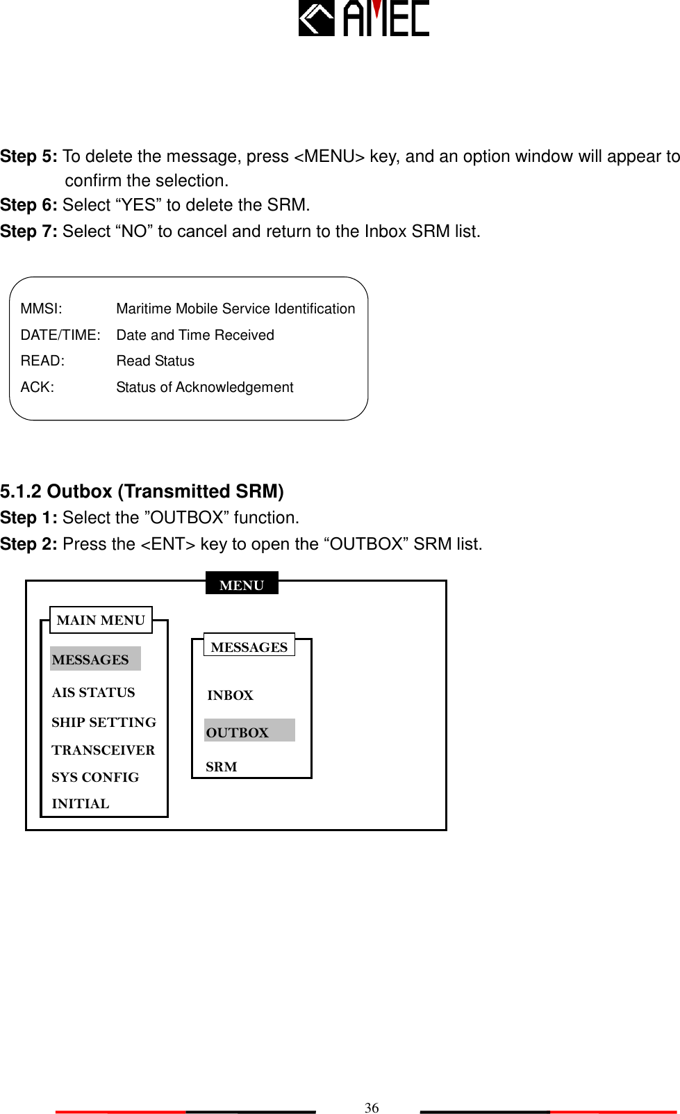
![42 MENU MESSAGES AIS STATUS SHIP SETTING SYS CONFIG INITIAL MAIN MENU TRANSCEIVER 5.2.2 AIS Target List and Friend Ships Step 1: Select “AIS TARGETS” function. Step 2: Press the <ENT> key to display list of received targets in the surroundings including target ships‟ dynamic and static information. Step 3: A total number of received targets is displayed on the top left corner. Use the <UP> and <DOWN> keys to select the target. Step 4: Use the <LEFT> and <RIGHT> keys to scroll to the next and previous page in the target list. Step 5: Press the <ENT> key to open the selected target. Step 6: Use the <RIGHT> and <LEFT> keys to view target ship‟s dynamic or static information. Use the <UP> and <DOWN> keys to switch to another target ship‟s dynamic and static information. (Refer to section 5.2 for details) Step 7: Press <MENU> to assign the selected target as a “Friend Ship.” AIS TARGET LIST [003]---[NAME]---------[MMSI]--------[BRG]-- --[RNG]---- AMEC 01 302354222 --- --- 2. AMEC 02 330025521 20.2 10.2 3. AMEC 03 336252324 56.1 33.2 1. AIS STATUS OWN SHIP AIS TARGETS REGION LIST SHIP INDEX VERSION](https://usermanual.wiki/Alltek-Marine-Electronics/CAMINO-201/User-Guide-1424205-Page-50.png)
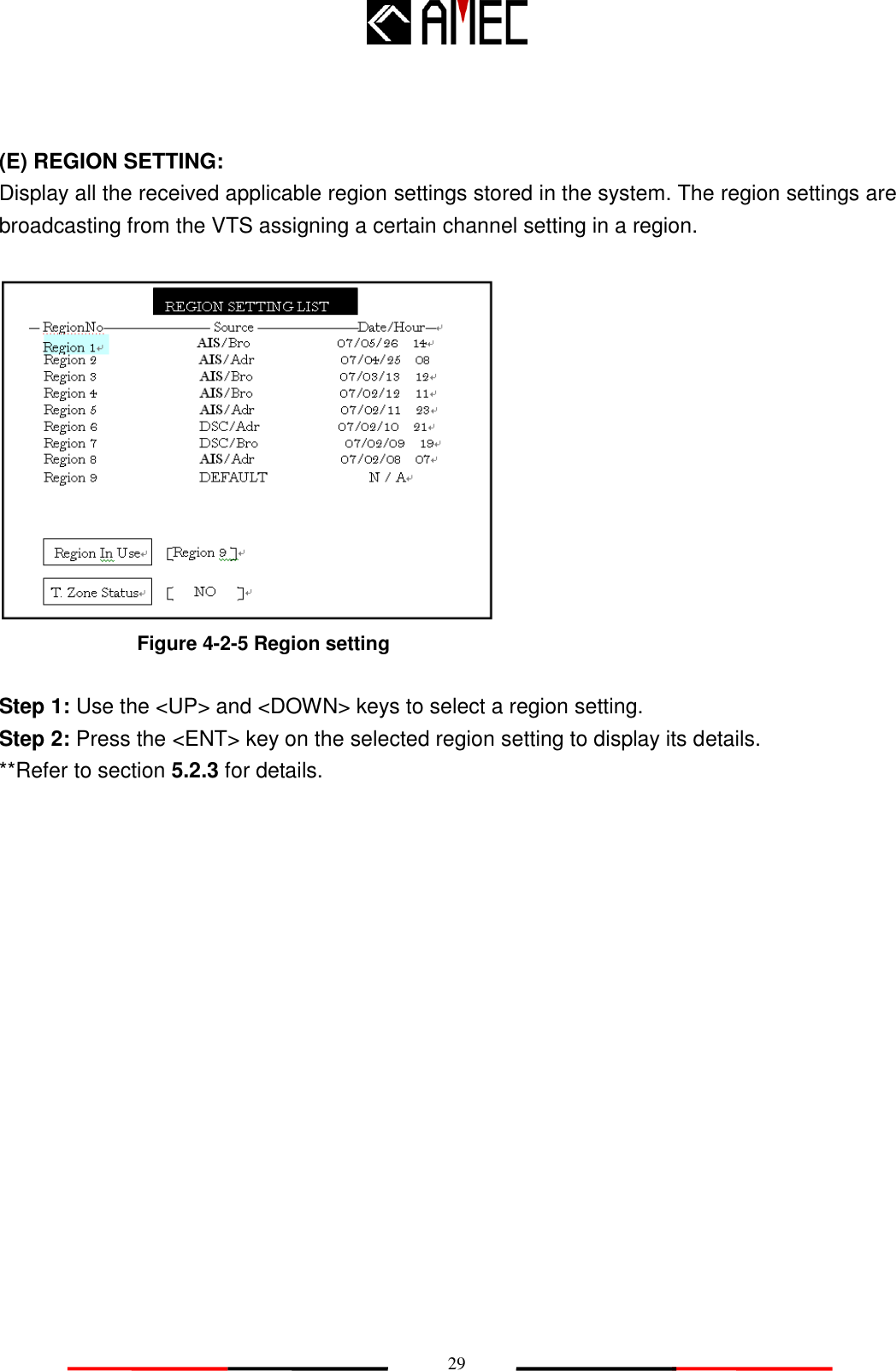
![43 MENU MESSAGES AIS STATUS SHIP SETTING SYS CONFIG INITIAL MAIN MENU TRANSCEIVER Step 8: Press the <ESC> key to return to the main menu. 5.2.3 Region List and Setting Step 1: Select the “REGION LIST” function. Step 2: Press the <ENT> key to display the entire region setting information. Step 3: Use the <UP> and <DOWN> key to select the region setting. AIS STATUS OWN SHIP AIS TARGETS REGION LIST SHIP INDEX VERSION AIS TARGET LIST [003]---[NAME]---------[MMSI]--------[BRG]-- --[RNG]---- AMEC 01 302354222 --- --- 2. AMEC 02 330025521 20.2 10.2 3. AMEC 03 336252324 56.1 33.2 1. Add New Friend? YES NO](https://usermanual.wiki/Alltek-Marine-Electronics/CAMINO-201/User-Guide-1424205-Page-51.png)
![44 REGION SETTING LIST -- RegionNo--------------------- Source --------------------Date/Hour-- 1 AIS/Bro 07/05/26 14 Region 2 AIS/Adr 07/04/25 08 Region 3 AIS/Bro 07/03/13 12 Region 4 AIS/Bro 07/02/12 11 Region 5 AIS/Adr 07/02/11 23 Region 6 DSC/Adr 07/02/10 21 Region 7 DSC/Bro 07/02/09 19 Region 8 AIS/Adr 07/02/08 07 Region 9 DEFAULT N / A Region In Use T. Zone Status [Region 9 ] [ NO ] Region 1 **e.g. Region 1: Message was received at Region 1. Received Date is 2007 / 05 / 26 Message was received from an AIS receiver hence the information source is AIS. Message status is Broadcasting mode. Information Source Description: DSC: Region setting from the DSC AIS: Region setting from the AIS Bro: Broadcasting mode Adr: Address Step 4: Press the <ENT> key to open the region setting detail.](https://usermanual.wiki/Alltek-Marine-Electronics/CAMINO-201/User-Guide-1424205-Page-52.png)
![45 LAT (NE) LON (NE) LAT (SW) LON (SW) T. Zone (nm) Channel A TX/RX Mode Addr/Broad 0o00’000”S 0o00’000”W 0o00’000”S 0o00’000”W N/A 2087 2088 TxA/TxB RxA/RxB Broadcast NE SW >TZ< Channel B Power Band Width Band Width Low 25K HZ 25K HZ REGION [1] SETTING LAT (NE): Latitude North East LON (NE): Longitude North East LAT (SW): Latitude South West LON (SW): Longitude South West T. Zone (nm): Transition Zone Band Width: Band width A Channel A: Channel A Band Width: Band width B Channel B: Channel B TX/RX mode: Transmit / Receive mode. Power: Transmit power Addr/Broad: Address/Broadcast mode. Step 5: Press the <ESC> key to return to the region setting list.](https://usermanual.wiki/Alltek-Marine-Electronics/CAMINO-201/User-Guide-1424205-Page-53.png)
![49 SHIP SETTING Call Sign Ship Name Ship Type [AMEC005] [AMEC005 AIS B ] <HSC> Antenna Position <m> A: [000] B: [000] C: [00] D: [00] A B C D Save Data? NO YES 取消 Step 2: Enter the password in the pop out window. Step 3: The following data can be set in the “OWN SHIP” function: Own ship name, call sign, type of ship, location of the GPS antenna. Call sign: input only 7 digitals. Ship name: input only 20 digitals. Step 4: When the set up is completed, press <ESC> or <ENT> key and a pop out window will appear to confirm and to save the set up. Step 5: Select “YES” to save the set up, or “NO” to escape from this menu.](https://usermanual.wiki/Alltek-Marine-Electronics/CAMINO-201/User-Guide-1424205-Page-57.png)
![54 CUSTOMIZE DIMMER LEVEL KEY TIME-OUT [050] [ 1 ] (1~5 min) Save data? LANGUAGE <ENGLISH> YES NO ALARM <ON> COLOR MODE <DAY> Lo Hi Step 2: Use the <LEFT>, <RIGHT>, <UP> or <DOWN> keys to adjust the “DIMMER LEVEL”, “KEY TIME-OUT” (1~5min), “LANGUAGE”, and “ALARM”. Step 3: Press the <ENT> key after each setting, and to proceed to the next setting. Step 4: When the set up is completed, press the <ESC> or <ENT> key and a pop out window will appear to confirm and save the settings. Step 5: Select “YES” to confirm and save the settings, or “NO” to escape from the menu. *NOTE 1: Refer to section 6.4 for details on arrow keys instruction. *NOTE 2: You can choose Color Mode available in both Day and Night. *NOTE 3: Language will vary in according to different regions. Display language is available in English, Simplified Chinese and Traditional Chinese.](https://usermanual.wiki/Alltek-Marine-Electronics/CAMINO-201/User-Guide-1424205-Page-62.png)
![55 Latitude Longitude Center position of radar view [00]∘[00]’[00]” <E> [000]∘[00]’[00]” <N> MENU MESSAGES AIS STATUS SHIP SETTING SYS CONFIG INITIAL MAIN MENU TRANSCEIVER RADAR VIEW SETTING 5.5.2 Radar View Reference Point Setting When there is no GPS reception, manually set own ship‟s longitude and latitude in the “RADAR VIEW” function, the own ship‟s reference center position will appear in the radar plotter. Step 1: Select the “RADAR VIEW” function. Step 2: Press the <ENT> key to display the radar view setting. Step 3: Use the <UP> and <DOWN> keys to enter the “Longitude” and “Latitude” value. Use the <LEFT> and <RIGHT> keys to move the digit spot of “Longitude” and “Latitude”. Step 4: Press <ESC> or <ENT> key, and a pop out window will appear to confirm and save the settings. Step 5: Select “YES” to confirm and save the settings, or “NO” to escape from the menu. *NOTE 1: Refer to section 5.4 for details on arrow keys instruction. . SYS CONFIG CUSTOMIZE RADAR VIEW FACTORY BAUD RATE](https://usermanual.wiki/Alltek-Marine-Electronics/CAMINO-201/User-Guide-1424205-Page-63.png)
![56 MENU MESSAGES AIS STATUS SHIP SETTING SYS CONFIG INITIAL MAIN MENU TRANSCEIVER MENU MESSAGES AIS STATUS SHIP SETTING SYS CONFIG INITIAL MAIN MENU TRANSCEIVER 5.5.3 Factory Default Configuration (User Password Protected) Step 1: Select the “FACTORY” function. Step 2: A password is required. Enter the password in the pop out window. Step 3: Select “OK” to confirm and to restore the factory setting. Restored factory settings include “CUSTOMIZE” and “CPA/TCPA” functions. Step 4: Select “CANCEL” to escape from this menu. SYS CONFIG CUSTOMIZE RADAR VIEW FACTORY SYS CONFIG CUSTOMIZE RADAR VIEW FACTORY [****] PASSWORD BAUD RATE](https://usermanual.wiki/Alltek-Marine-Electronics/CAMINO-201/User-Guide-1424205-Page-64.png)
![59 PASSWORD SETTING OLD Passowrd NEW Password Confirm Password [****] [****] [****] New password saved! OK MENU MESSAGES AIS STATUS SHIP SETTING SYS CONFIG INITIAL MAIN MENU TRANSCEIVER Step 3: On the password setting page, enter the “OLD Password”, “NEW Password”, and “Confirm Password”. Step 4: When the set up is completed, press the <ENT> key and a pop out window will appear to confirm and save the setting. Step 5: Select “OK” to save the setting, or press <ESC> key to escape from the menu. 5.6.2 MMSI Editting Step 1: Select the “MMSI” function. INITIAL PASSWORD MMSI CPA/TCPA](https://usermanual.wiki/Alltek-Marine-Electronics/CAMINO-201/User-Guide-1424205-Page-67.png)
![60 MENU MESSAGES AIS STATUS SHIP SETTING SYS CONFIG INITIAL MAIN MENU TRANSCEIVER MENU MESSAGES AIS STATUS SHIP SETTING SYS CONFIG INITIAL MAIN MENU TRANSCEIVER Can be programmed only once! MMSI SETTING MMSI [000000000] Save Data? YES NO Step 2: Enter the password in the pop out window and press <ENT> to access the MMSI setting. Step 3: MMSI can only be entered ONCE. A pop out window will appear to remind you. Step 4: Select “YES” to confirm and enter the MMSI. Select “NO” to escape from this menu. INITIAL PASSWORD MMSI CPA/TCPA MMSI -- WARNING Can be programmed only once! Go On? OK CANCEL [****] PASSWORD INITIAL PASSWORD MMSI CPA/TCPA MMSI -- WARNING Can be programmed only once! Go On? YES NO](https://usermanual.wiki/Alltek-Marine-Electronics/CAMINO-201/User-Guide-1424205-Page-68.png)
![61 CPA/TCPA CPA (nm) TCPA (min) [05 ] [ 10 ] Save data? YES NO MENU MESSAGES AIS STATUS SHIP SETTING SYS CONFIG INITIAL MAIN MENU TRANSCEIVER ALARM <OFF> Step 5: When the set up is completed, press the <ESC> or <ENT> key and a pop out window will appear to confirm and save the setting. Step 6: Select “YES” to confirm and save the data or “NO” to escape this menu. *NOTE: MMSI can only be entered ONCE. Make sure that the MMSI is correct before entering it. 5.6.3 CPA/TCPA Settings (User Password Protected) Step 1: Select the “CPA/TCPA” function. Step 2: A password is required. Enter the password in the pop out window. Step 3: On the “CPA/TCPA” page, CPA (Closest Point of Approach) in nm and TCPA (Time to Closest Point of Approach) in minute can be set. Step 4: Press the <ESC> or <ENT> key to confirm again and a pop out window will appear. Step 5: Select “YES” to confirm and save the data or “NO” to escape this menu. INITIAL PASSWORD MMSI CPA/TCPA](https://usermanual.wiki/Alltek-Marine-Electronics/CAMINO-201/User-Guide-1424205-Page-69.png)
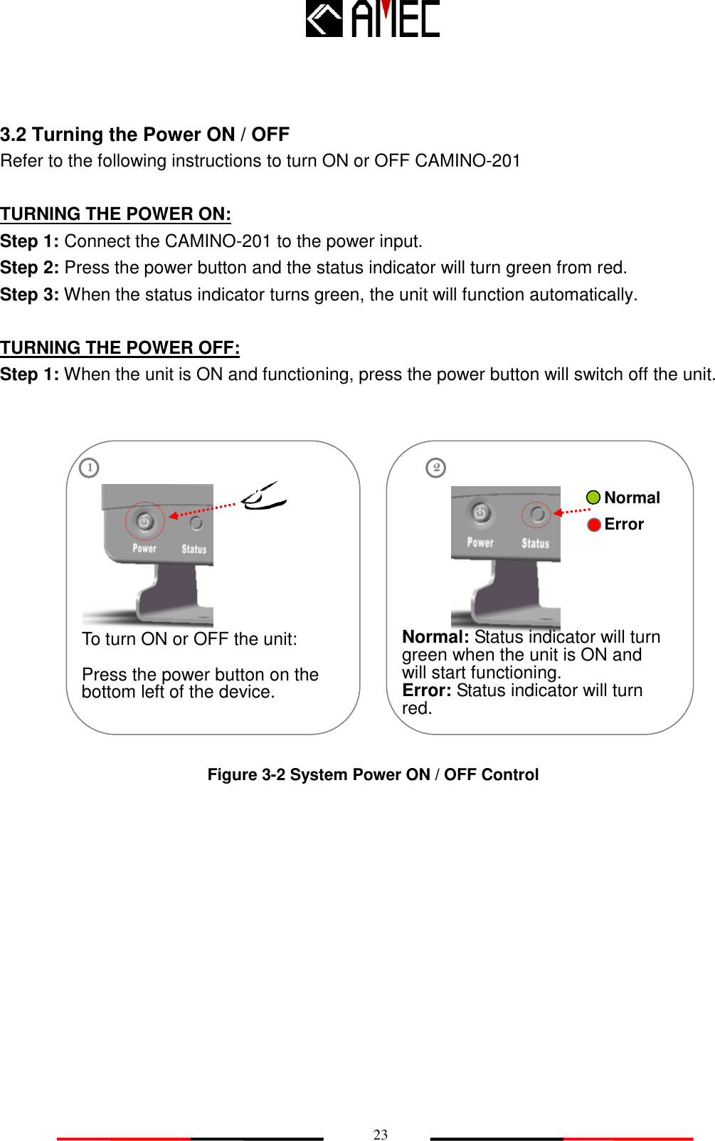
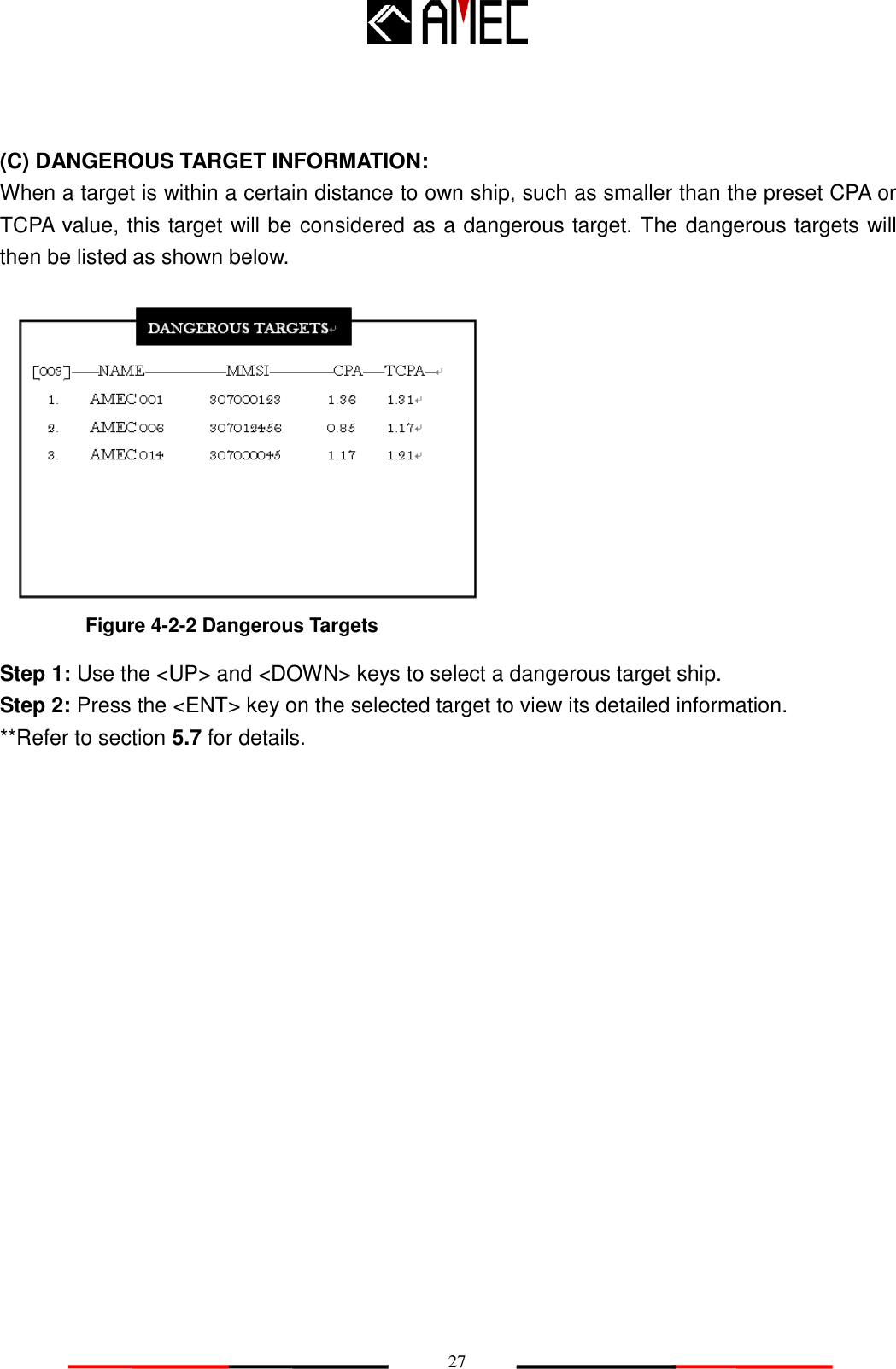
![62 DANGEROUS TARGETS [003]-----NAME---------------MMSI------------CPA----TCPA-- 1. AMEC 001 307000123 1.36 1.31 2. AMEC 006 307012456 0.85 1.17 3. AMEC 014 307000045 1.17 1.21 5.7 Dangerous Targets Information Step 1: On the main display / radar view, press the <DISP> key one time to switch to the “DANGEROUS TARGETS”. Step 2: On the dangerous targets list, the [003] on the top left corner stands for the total numer of dangrous targets. Step 3: Use the <UP> and <DOWN> keys to select the dangerous target to view. Step 4: Use the <LEFT> and <RIGHT> keys to scroll to the next or previous pages. Step 5: Press the <ENT> key on the selected dangerous target to view its ship detials. (Refer to section 7.2. for details)](https://usermanual.wiki/Alltek-Marine-Electronics/CAMINO-201/User-Guide-1424205-Page-70.png)