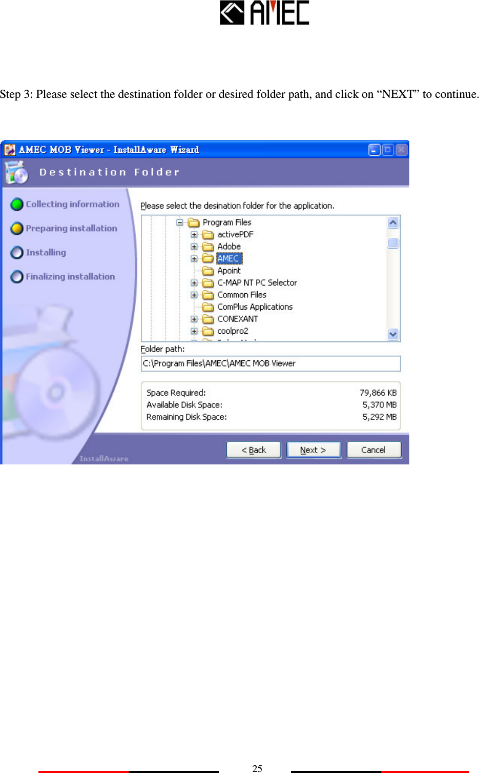
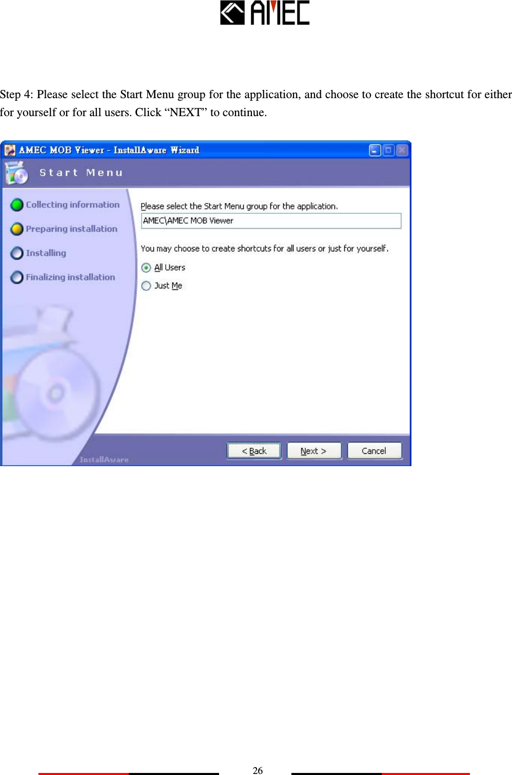
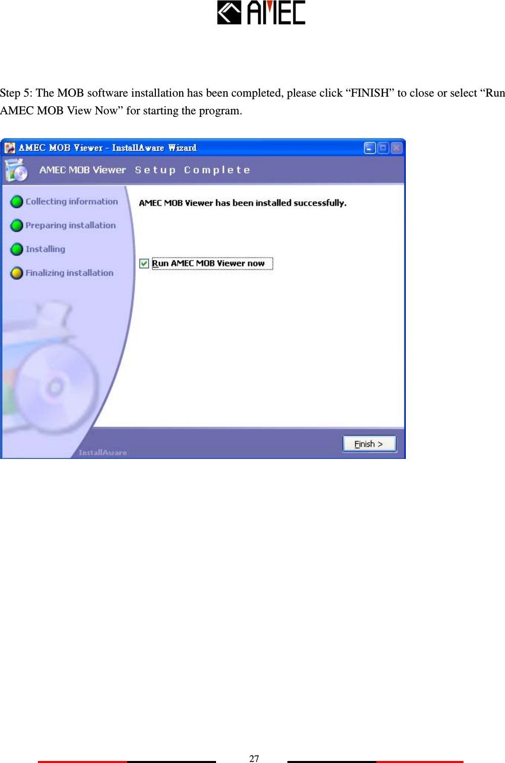
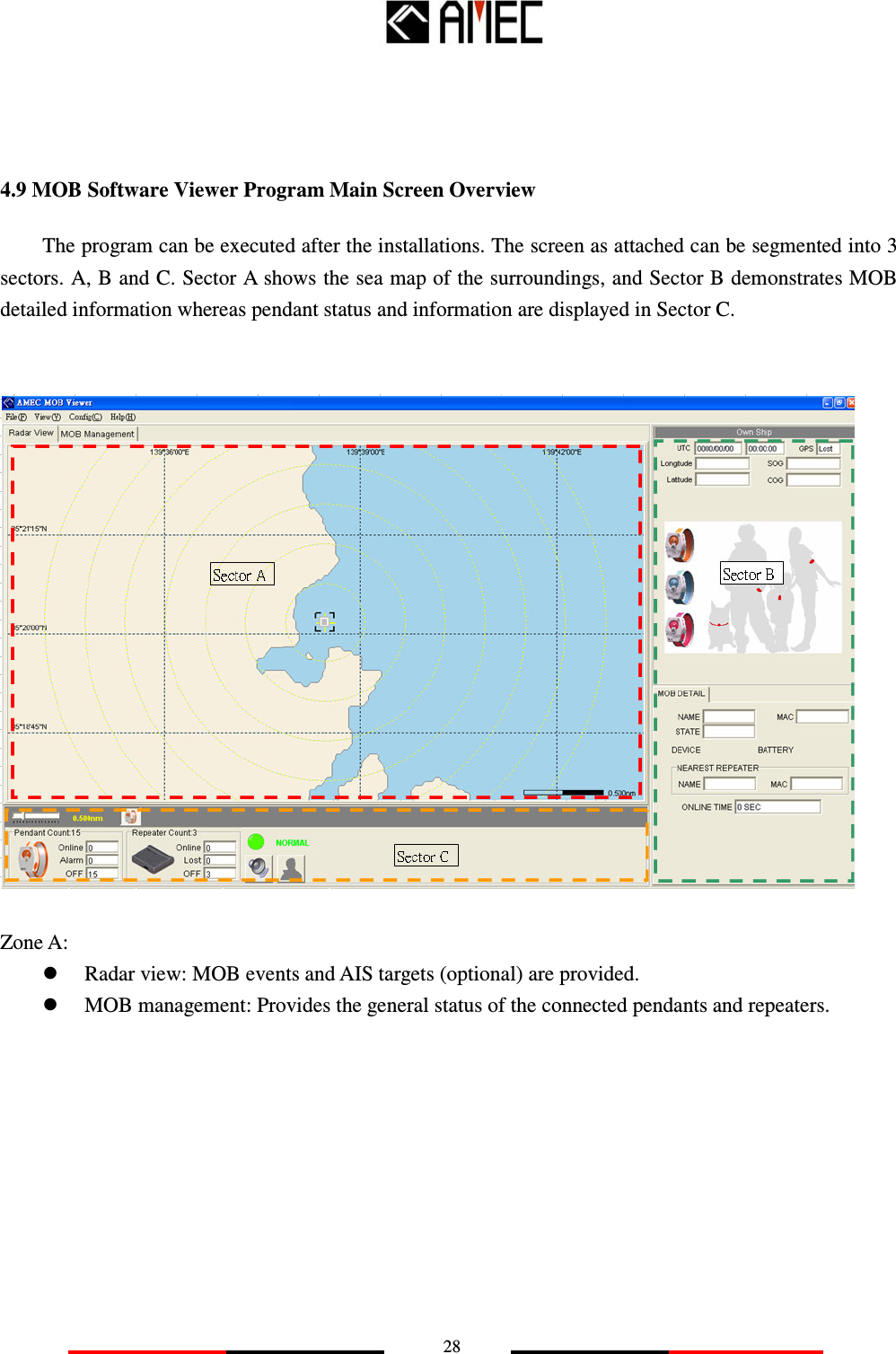
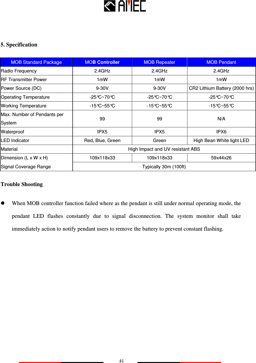
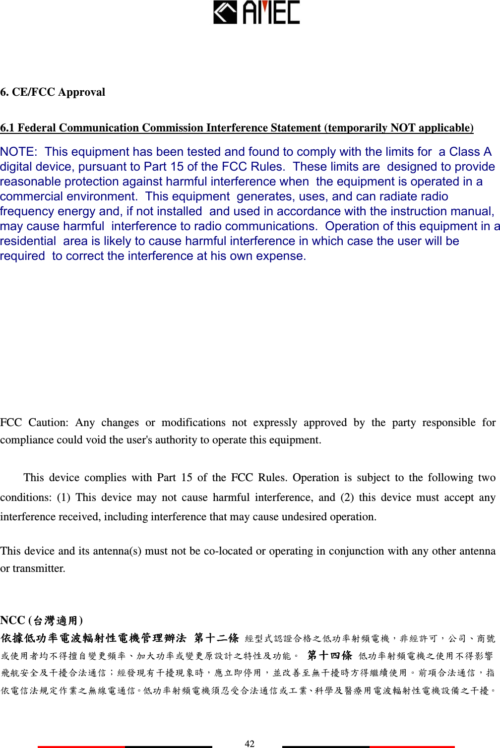
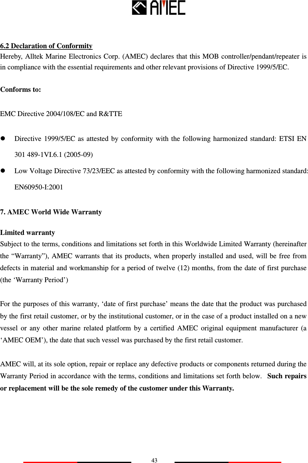
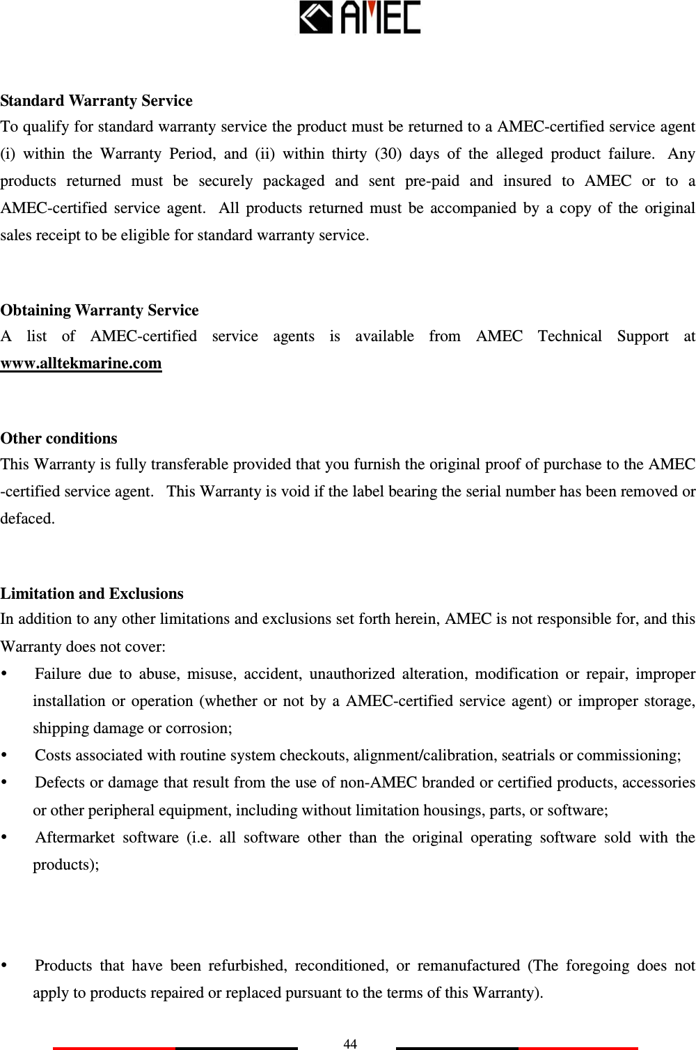
Alltek Marine Electronics MOBPENDANT MOB User Manual
Alltek Marine Electronics Corporation MOB
UserManual.wiki
>
Alltek Marine Electronics
>
MOBPENDANT User Manual
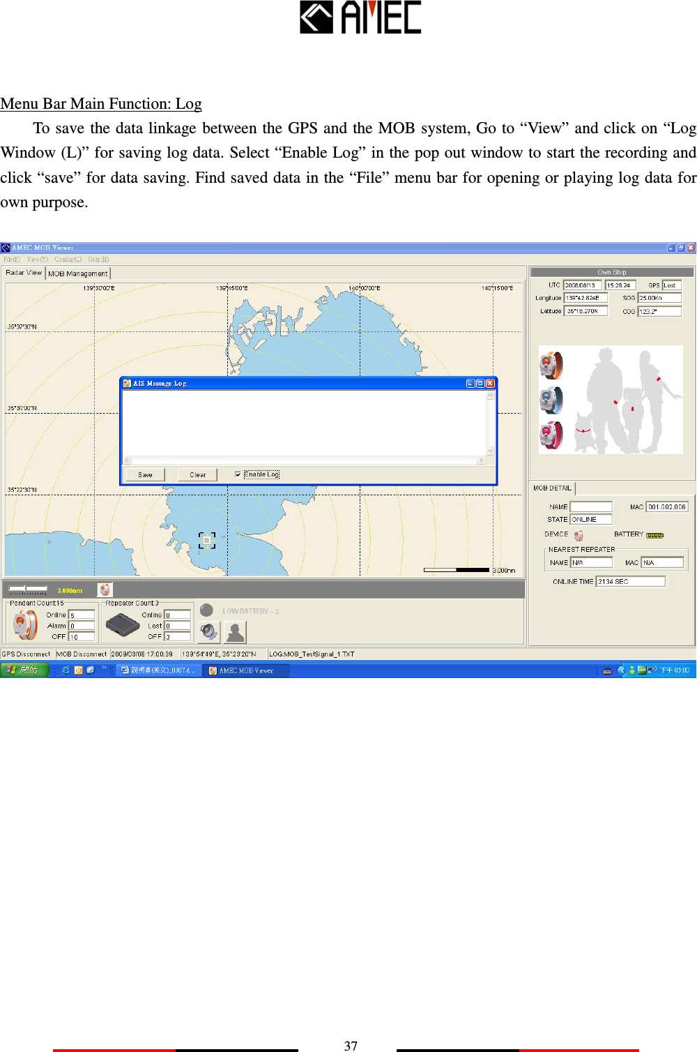
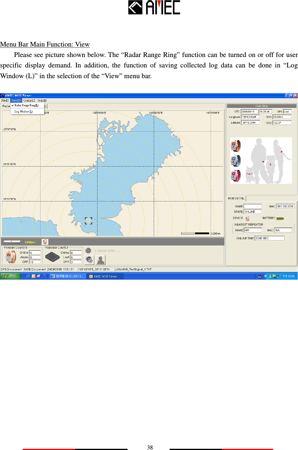
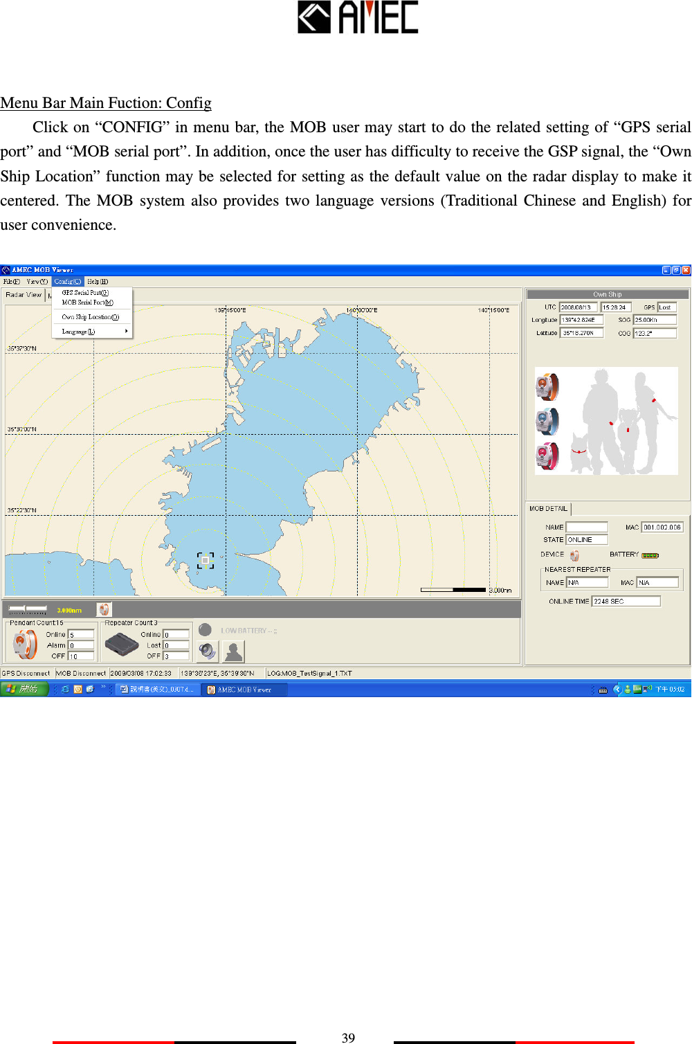
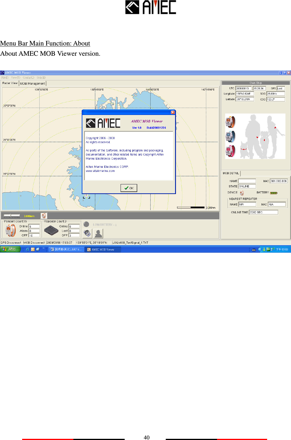
User Manual
Navigation menu
Upload a User Manual
Namespaces
Wiki Guide
HTML
PDF
Info
Views
User Manual
Discussion / Help
Navigation