Alpha Networks CS3152 Wireless HD Day/Night Cloud (Network) Camera User Manual CS3152 QIG
Alpha Networks Inc. Wireless HD Day/Night Cloud (Network) Camera CS3152 QIG
(CS-3152C, CS-3152)UserMan
CS-3152/ CS-3152C
Network Camera
Quick Installation Guide
Product Name: CS-3152C: Wireless HD Day/Night Cloud Camera ;
CS-3152: Wireless HD Day/Night Network Camera
Model No. : CS-3152C, CS-3152

ńĮĴIJĶijĩńĪ
Quick Installation Guide
FCC Warning
Federal Communication Commission Interference Statement
This device complies with Part 15 of the FCC Rules. Operation is subject to the following
two conditions: (1) This device may not cause harmful interference, and (2) this device
must accept any interference received, including interference that may cause undesired
operation.
This equipment has been tested and found to comply with the limits for a Class B digital
device, pursuant to Part 15 of the FCC Rules. These limits are designed to provide
reasonable protection against harmful interference in a residential installation. This
equipment generates, uses and can radiate radio frequency energy and, if not installed
and used in accordance with the instructions, may cause harmful interference to radio
communications. However, there is no guarantee that interference will not occur in a
particular installation. If this equipment does cause harmful interference to radio or
television reception, which can be determined by turning the equipment off and on, the
user is encouraged to try to correct the interference by one of the following measures:
- Reorient or relocate the receiving antenna.
- Increase the separation between the equipment and receiver.
- Connect the equipment into an outlet on a circuit different from that
to which the receiver is connected.
- Consult the dealer or an experienced radio/TV technician for help.
FCC Caution: Any changes or modifications not expressly approved by the party
responsible for compliance could void the user's authority to operate this equipment.
This transmitter must not be co-located or operating in conjunction with any other antenna
or transmitter.
Radiation Exposure Statement:
This equipment complies with FCC radiation exposure limits set forth for an uncontrolled
environment. This equipment should be installed and operated with minimum distance
20cm between the radiator & your body.
FOR COUNTRY CODE SELECTION USAGE (WLAN DEVICES)
Note: The country code selection is for non-US model only and is not available to all US
model. Per FCC regulation, all WiFi product marketed in US must fixed to US operation
channels only.
CE Mark Warning
This is a Class B product. In a domestic environment, this product may cause radio
interference, in which case the user may be required to take adequate measures.
NOTE:
THE MANUFACTURER IS NOT RESPONSIBLE FOR ANY RADIO OR TV
INTERFERENCE CAUSED BY UNAUTHORIZED MODIFICATIONS TO THIS
EQUIPMENT SUCH MODIFICATIONS COULD VOID THE USER’S AUTHORITY TO
OPERATE THE EQUIPMENT.

ńĮĴIJĶijĩńĪ
Quick Installation Guide
CAUTION:
1. To comply with FCC RF exposure compliance requirements, a separation distance of at
least 20 cm must be maintained between the antenna of this device and all persons.
2. This Transmitter must not be co-located or operating in conjunction with any other
antenna or transmitter.
ńĮĴIJĶijĩńĪ
Quick Installation Guide
1
Before You Begin…
System Requirements
Ⴠ 10 Base-T Ethernet or 100 Base-TX Fast Ethernet
Ⴠ CD-ROM or DVD-ROM drive
Ⴠ CPU: Intel Pentium IV 2.0 GHz and above, or AMD Athlon 64 3000+ and above
Ⴠ Memory: 512 MB or above
Ⴠ VGA resolution:1024 x 768 or above
Package Contents
Ⴠ One SOHO Internet Camera
Ⴠ This Quick Installation Guide
Ⴠ One External Antenna
Ⴠ One Installation CD-ROM
Ⴠ One Stand
Ⴠ One DC Power Adapter
Ⴠ One RJ-45 Ethernet Cable
NOTE: If any item contained is damaged or missing, please
contact your local dealer immediately.
ńĮĴIJĶijĩńĪ
Quick Installation Guide
2
Hardware Installation
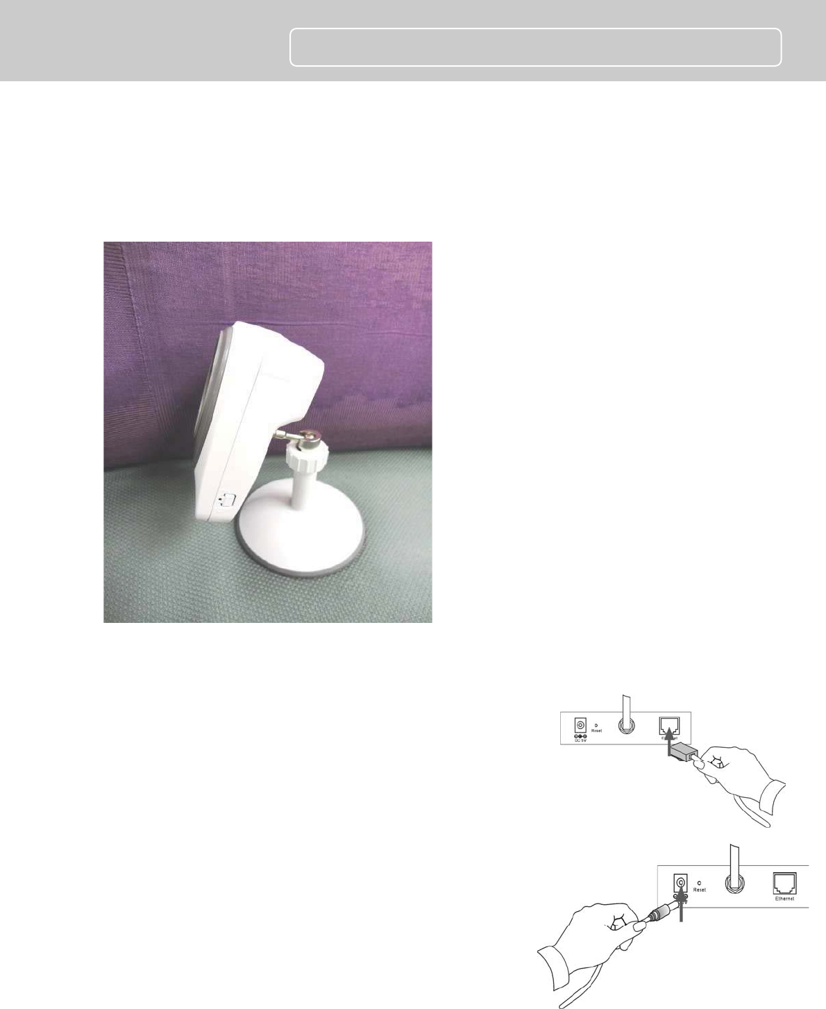
Attach the Stand
Connect the Ethernet Cable
Connect an Ethernet cable to the network cable connector
located on the camera’s rear panel, and then connect it to
the network.
Connect the Power Adapter
Connect the external power adapter to the DC power input
connector located on the camera’s rear panel, and then
connect it to your wall outlet. (Tip: You can confirm the
power source is supplied from the Power LED on the
camera.)
ńŔĮĴIJĶijĩńĪ
Quick Installation Guide
3
Running the IPCam Wizard
Launch IPCam Wizard
Use the IPCam Wizard to quickly configure IP settings for the camera that are compatible
with your computer. The IPCam Wizard is a program run separately from the web browser
video display and manager. First install the program from the Installation CD, then use the
IPCam Wizard to configure suitable IP settings for the camera. Follow the steps below to
install the IPCam Wizard program.
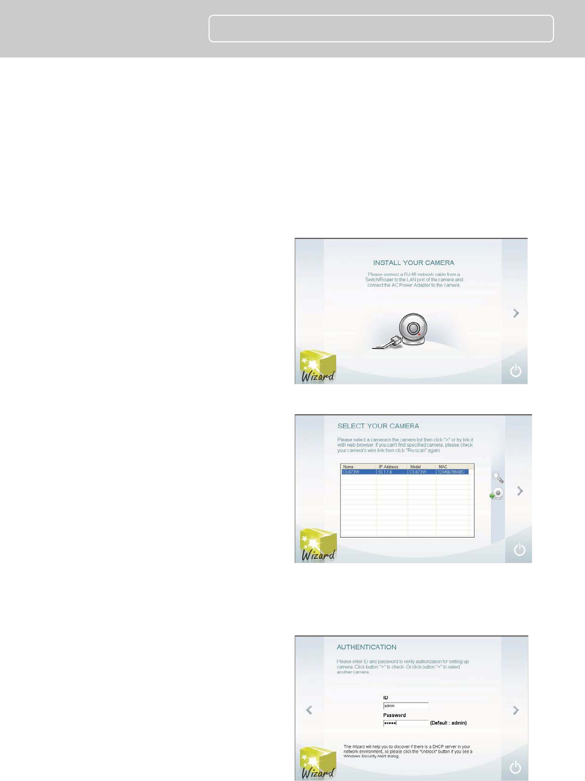
1. Insert the Installation CD-ROM into
your CD-ROM drive. Click IPCam
Wizard to launch the setup wizard
software. The following window
appears, click the > symbol to
proceed to the next setup window.
2. Choose the CS-3152/CS-3152C from
the list. If there is more than one
camera operating on the network,
these will also appear in the list. If
the camera does not appear in the
list, click the Magnifying Glass icon
to renew the search. If it still does
not appear, check the network
connection on the camera, especially
the LED indicators on the right side
of the camera.
Select the CS-3152/CS-3152C from the list and click the > symbol to begin
configuration with the IPCam Wizard.
3. Type the administrator ID (user
name) and Password to proceed to
configure the camera. The default ID
is admin and the default Password
is also admin. Click the > symbol to
proceed to the next IPCam Wizard
menu screen.
ńŔĮĴIJĶijĩńĪ
Quick Installation Guide
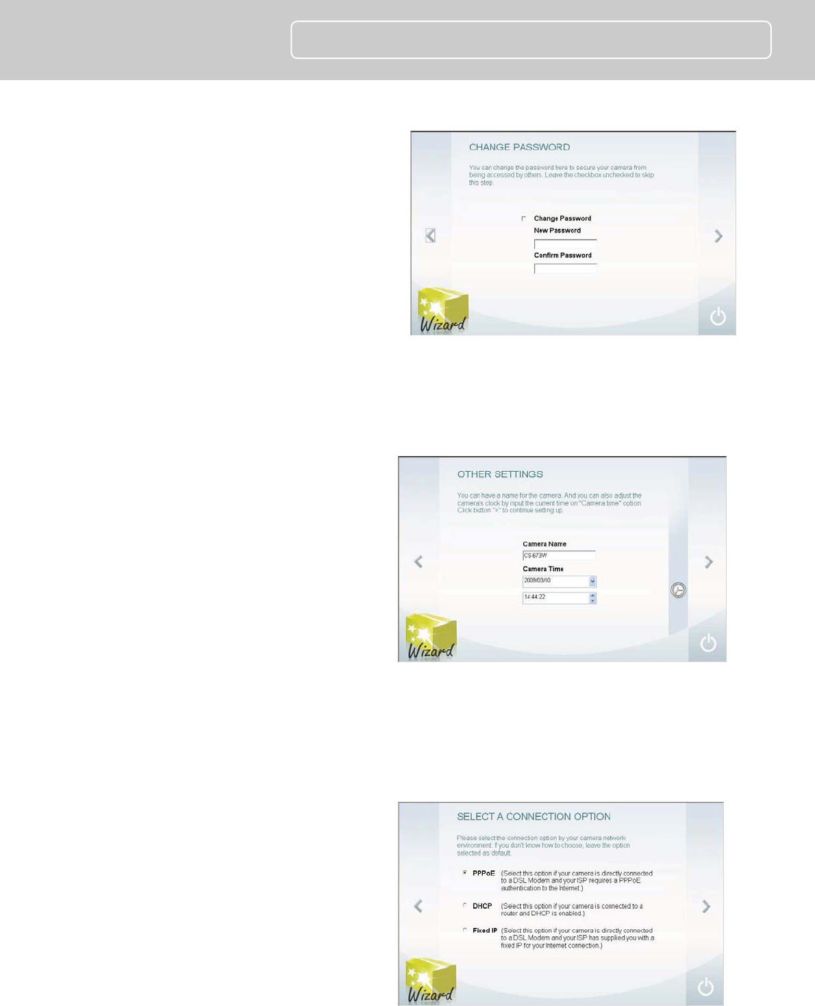
4. This screen allows you to change the
administrator password. To change
the password carry out the following:
Tick the Change Password
checkbox
Type a New Password
Type it again to Confirm
Password.
Click the > symbol to proceed to
the next IPCam Wizard menu
screen.
Leave the checkbox unchecked to skip this step.
5. This screen allows you to set a
Camera Name and configure the
date and time settings of the
Camera:
Type a name to identify your
Camera in the Camera Name field.
Use the drop-down menu to set
the Camera’s date.
Adjust the time of the camera, by
using the adjacent up and down
controls
Click the Clock icon to copy the time and date settings from your computer.
Click the > symbol to continue.
6. Choose how to configure the
network settings. The options are
PPPoE, DHCP and Fixed IP
(manually set IP).
Click the > symbol to proceed to
the next IPCam Wizard menu
screen.
If you are choosing a PPPoE network connection, proceed to step 6a to configure
PPPoE network settings.
ńŔĮĴIJĶijĩńĪ
Quick Installation Guide
If you are choosing a Fixed IP network connection, proceed to Step 6b to configure
Fixed IP network settings.
If choosing DHCP, skip ahead to step 7.
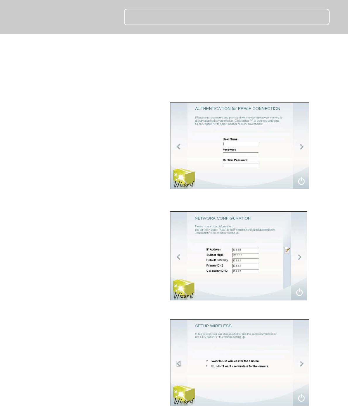
a. Type in the User Name for your
PPPoE connection in the User
Name field, the password in
the Password field and
confirm the password in the
Confirm Password field. Click
the > symbol to proceed to the
next IPCam Wizard menu
screen.
b. A Fixed IP connection requires
the IP settings to be manually
entered. Enter a compatible IP
Address, Subnet Mask,
Primary DNS and Secondary
DNS IP address. Click the >
symbol to proceed to the next
IPCam Wizard menu screen.
7. Now choose whether to configure
the wireless settings. The wireless
settings can be configured at any
time through the web manager if
preferred. Click the > symbol to
proceed to the next IPCam Wizard
menu screen. If you choose not to
configure wireless settings now,
skip ahead to step 8.
ńŔĮĴIJĶijĩńĪ
Quick Installation Guide
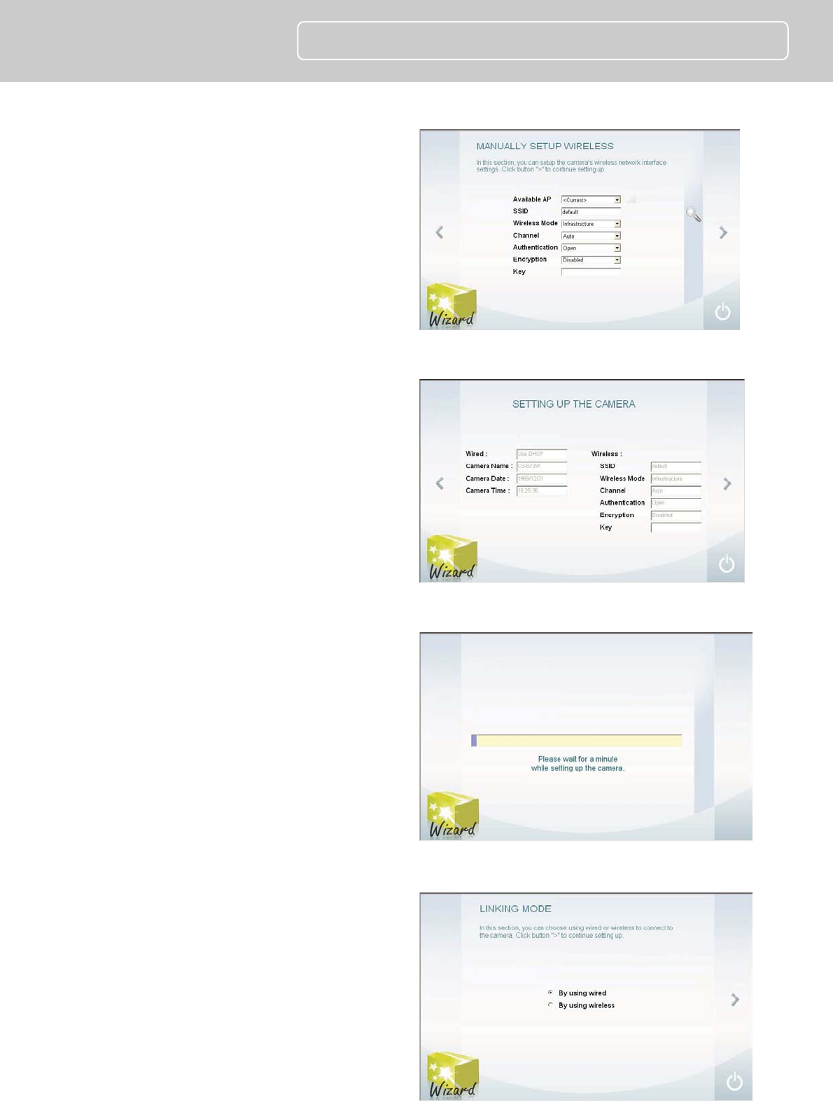
a. Wireless setup requires entry of
wireless settings including
authentication method,
encryption and key.
8. The following window appears,
summarizing the network settings of
your Camera:
When you have finished setting up
the Camera, click the > symbol to
apply the new settings.
9. The following screen appears to
indicate that the settings are being
applied to the camera.
10. After the Camera has restarted the
following screen appears:
Click a radio button to choose if you
want to connect to the Camera using
a Wired or Wireless connection.
Click the > symbol to continue.
ńŔĮĴIJĶijĩńĪ
Quick Installation Guide
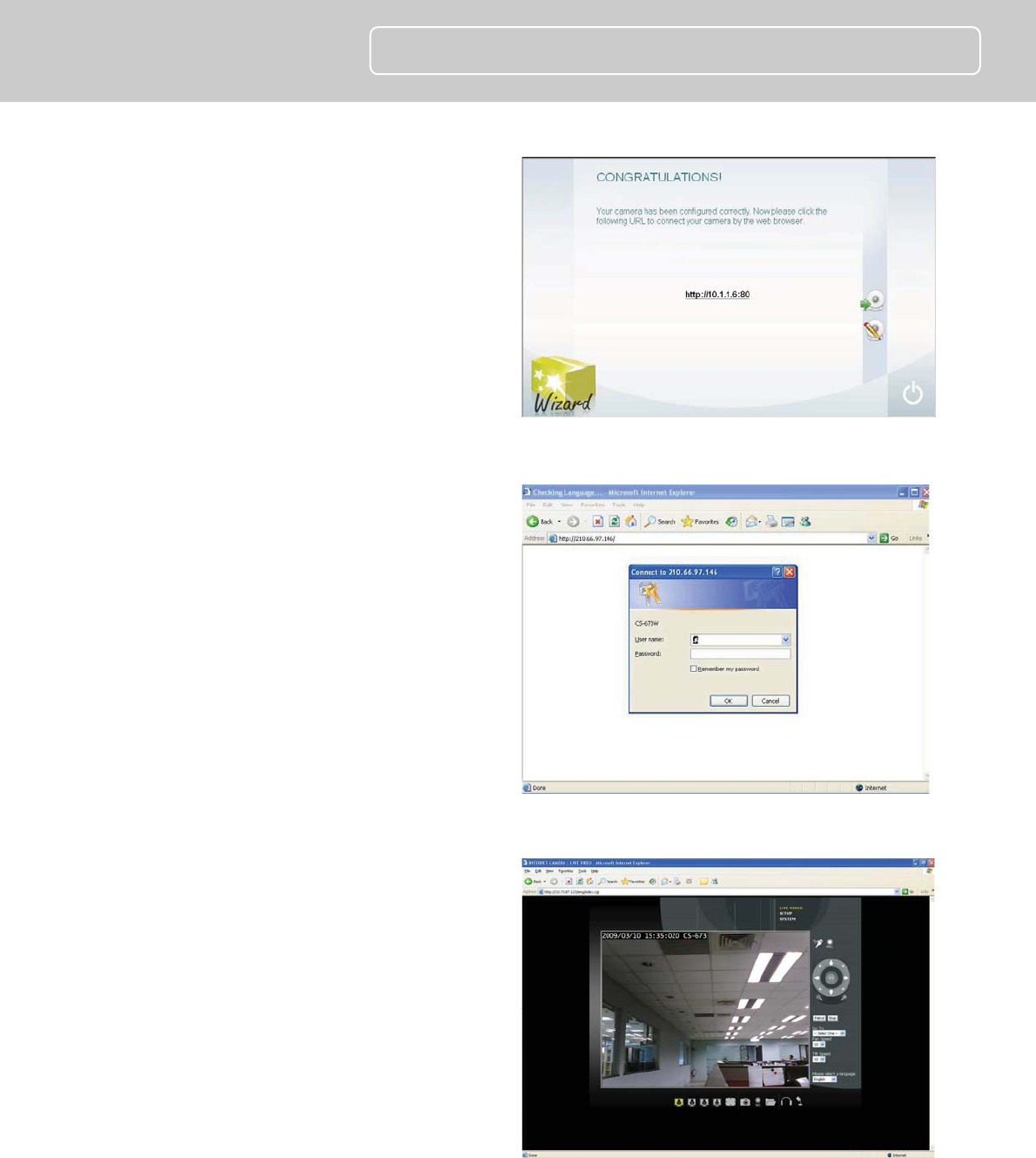
11. The camera is now ready to use. To
launch your default browser and
connect to the camera’s web
manager and live video display, click
the address of the camera in the
center of the menu.
12. Type the administrator’s User Name
(ID) and Password to access the
camera’s user interface. Default
settings is admin / admin.
13. The first menu to appear shows the
live video display and the camera
control (see followings for a
description of the controls).
ńŔĮĴIJĶijĩńĪ
Quick Installation Guide
4
Using the IP camera
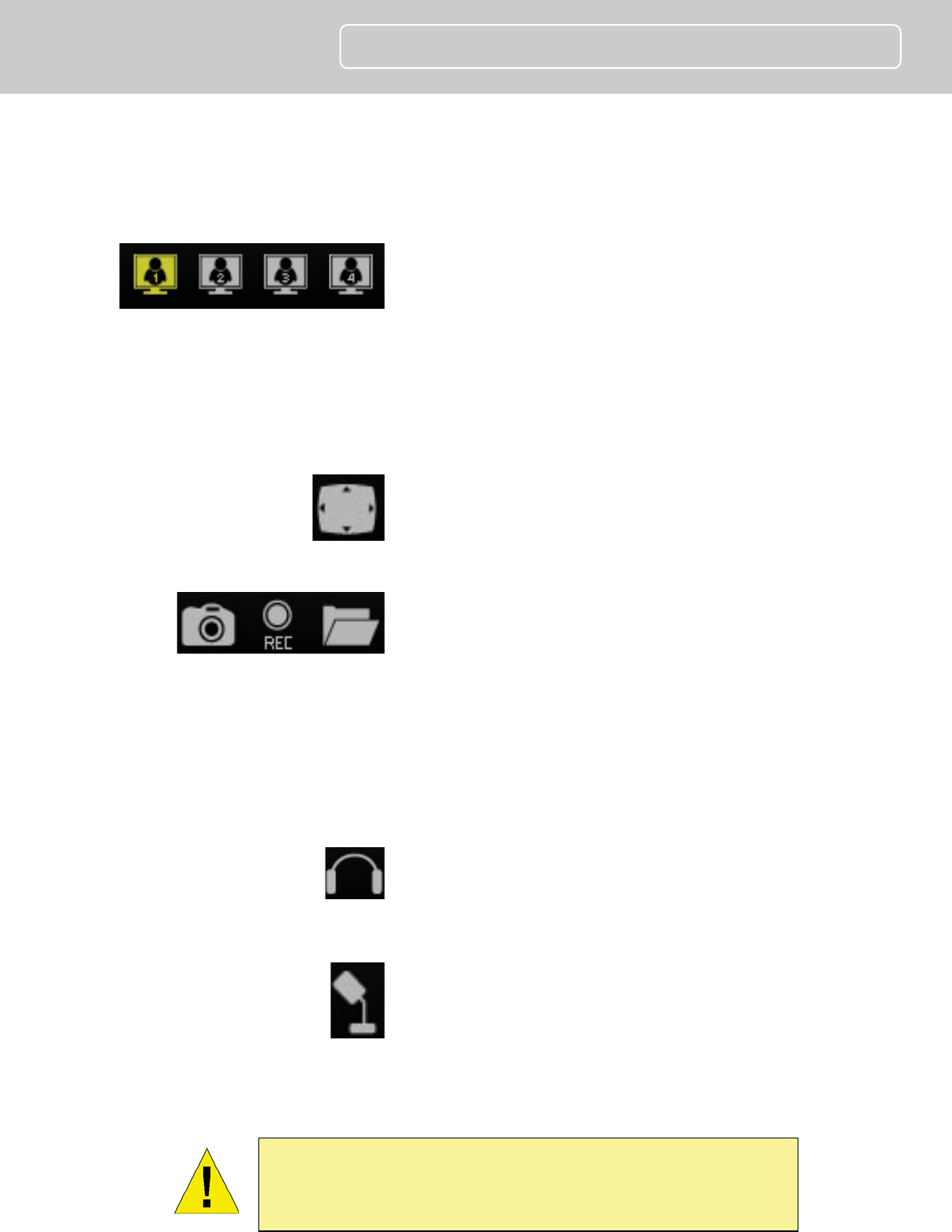
Video Display Control
Change display settings Click on the little screen icon
to quickly switch among the preconfigured formats of
the video, which correspond to the video settings profile.
Four profiles can be configured using the Video and
Audio Settings menu. See the description of the menu
below in the section of the same title. The yellow icon
shows the profile which is currently being used. Please
note browsers other than Internet Explorer show only M-
JPEG profiles.
Full Screen Click on the Full Screen icon to use the
entire monitor display area for live video.
Recording, Snapshot and Audio Controls
Record and capture Use the camera icon to take a
snapshot of the video display. This will immediately
cause the screen capture or snapshot to appear on the
desktop in a new browser window. Use the Record (REC)
icon to begin recording to the local hard disk. In order to
do either of these however, first click on the file folder
icon to select the location where the snapshot or video
recording is to be stored (by default a folder is created in
My Documents if not specified). The REC icon becomes
yellow while recording is active.
Audio input control Click to enable or disable the
camera’s built-in mic to provide audio surveillance or
voice communication from the camera. This icon
becomes yellow while audio input is active.
Audio output control Audio speakers can be
connected to the camera via the external audio mini-
plug. Use this control to enable or disable the audio
output for voice or other audio through connected
speakers. This icon becomes yellow while audio output is
active. This is disabled by default.
NOTE: Please read the User Manual for detailed information
about other camera functions, applications and features.