Alpha Networks EA-7HW03AP1 Wireless LAN Access Point User Manual rev 6
Alpha Networks Inc. Wireless LAN Access Point rev 6
User Manual rev 6.pdf
User’s Guide
Wireless LAN Access Point
Model No. EA-7HW02AP1
EA-7HW03AP1
Before operating this product, please read the instructions carefully and save this manual for future use.
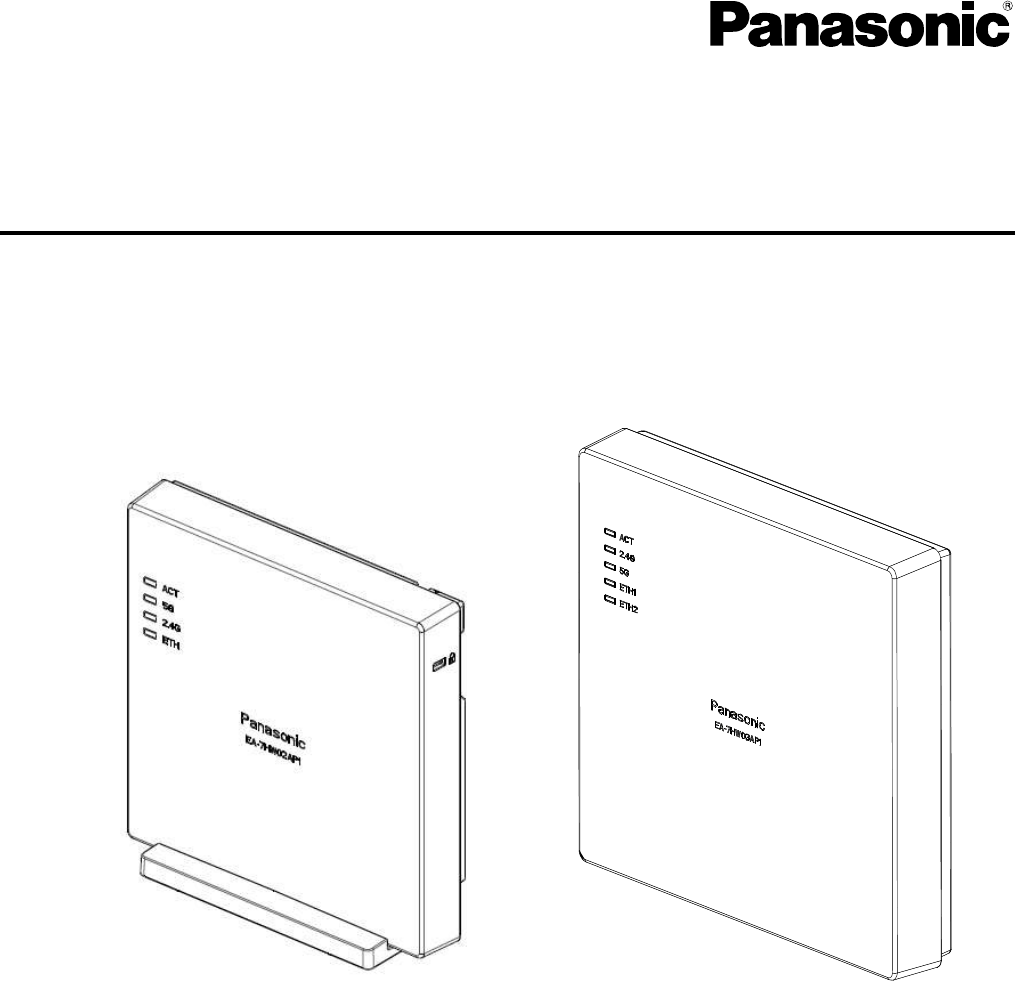
Wireless LAN Access Point(wave1)
EA-7HW02AP1
Wireless LAN Access Point(wave2)
EA-7HW03AP1

2
Introduction
Thank you for purchasing the Panasonic Enterprise Wireless LAN Access Point.
This User’s Guide described the instructions for the Enterprise Wireless LAN Access Point.
Before connecting, operating or adjusting this product, please read these instructions completely, and save this
manual for future use.
■ Trademarks and registered trademarks
• Wi-Fi is a trademark of the Wi-Fi Alliance.
• Ethernet is a trademark of Fuji Xerox Co.,Ltd.
• All other company names and product names in this document are trademarks or registered trademarks of their
respective companies.
■ Notice
• The content of this document is subject to change without notice to improve.
• All of "Access point", "AP", "Wireless unit", "EA-7HW02AP1" and "EA-7HW03AP1" indicate Wi-Fi base station
for business use.
• "PoE injector" indicates the option item "EA-7HW00PWR1".
• "PoE power feeding device" indicates the option item "EA-7HW00PWR1" or a PoE injector/power feeding hub
on the market.
■ Disclaimers
• Panasonic shall have no liability for any economic damage resulting from communication loss or recording
failure caused by a fault, malfunction, failure of this product or by external factors upon power outage.
• Panasonic shall have no liability for any damage caused by disaster such as earthquakes, lightnings, storm and
floods, fire, actions by a third party, other incidents, accidents arising from customers' intentional or negligent
misuse and use under abnormal conditions, and for any incidental loss arising from availability or unavailability
of this product.
• This product is not intended to be used with any medical equipments, life-support systems, air traffic control
devices and any other device, equipments and systems involving human lives. Panasonic shall have no liability
for any damage and loss caused by using this product with these devices, equipments and systems.

3
Safety Precautions
To prevent severe injury and loss of life/property, read this section carefully before using the unit to ensure proper
and safe operation of your unit.
WARNING:
• Changes or modifications not expressly approved by the party responsible for compliance could void the user’s
authority to operate this equipment.
• To prevent injury, this apparatus must be securely attached to the wall/ceiling in accordance with the installation
instructions.
• All work related to the installation of this product should be made by qualified service personnel or system
installers.
• The installation shall be carried out in accordance with all applicable installation rules.
• The connections should comply with local electrical code.
CAUTION:
Compliance with FCC requirement 15.407(c)
Data transmission in always initiated by software, which is the passed down through the MAC, through the digital
and analog baseband, and finally to the RF chip. Several special packets are initiated by the MAC. These are the
only ways the digital baseband portion will turn on the RF transmitter, which it then turns off at the end of the packet.
Therefore, the transmitter will be on only while one of the aforementioned packets is being transmitted. In other
words, this device automatically discontinue transmission in case of either absence of information to transmit or
operational failure.
• AC adaptor with ferrite core must be used for RF interference suppression.
Frequency Tolerance: ±20 ppm
This device is restricted for indoor use.
This device and it's antennas(s) must not be co-located or operating in conjunction with any other antenna or
transmitter except in accordance with FCC multi-transmitter product procedures.
This equipment complies with FCC radiation exposure limits set forth for an uncontrolled environment. This
equipment should be installed and operated with minimum distance 20 cm between the radiator & your body.
This equipment complies with FCC radiation exposure limits set forth for an uncontrolled environment. This
equipment should be installed and operated with minimum distance 36 cm between the radiator & your body.
4
Federal Communication Commission Interference Statement
This equipment has been tested and found to comply with the limits for a Class B digital device, pursuant to Part 15
of the FCC Rules. These limits are designed to provide reasonable protection against harmful interference in a
residential installation. This equipment generates, uses and can radiate radio frequency energy and, if not installed
and used in accordance with the instructions, may cause harmful interference to radio communications. However,
there is no guarantee that interference will not occur in a particular installation. If this equipment does cause harmful
interference to radio or television reception, which can be determined by turning the equipment off and on, the user
is encouraged to try to correct the interference by one of the following measures:
● Reorient or relocate the receiving antenna.
● Increase the separation between the equipment and receiver.
● Connect the equipment into an outlet on a circuit different from that to which the receiver is connected.
● Consult the dealer or an experienced radio/TV technician for help.
FCC Caution: Any changes or modifications not expressly approved by the party responsible
for compliance could void the user’s authority to operate this equipment.
This device complies with Part 15 of the FCC Rules. Operation is subject to the following two conditions: (1) This
device may not cause harmful interference, and (2) this device must accept any interference received, including
interference that may cause undesired operation.
For product available in the USA/Canada market, only channel 1~11 can be operated. Selection of other channels is
not possible.

5
Contents
1. Specifications ···························································································································· 13
1.1. Equipment specifications ····································································································· 14
1.2. Appearance/Dimensions (Specifications of this product are subject to change without notice) ············ 17
1.3. Major Operating Controls and Their Functions ········································································· 24
1.4. Power feeding method ········································································································ 32
1.5. Interface specifications ······································································································· 33
2. EA-7HW02AP1 installation work ··································································································· 36
2.1. Installations and Connections ······························································································· 37
2.2. Determine the installation place of wireless unit ······································································· 38
2.3. Installation work of wireless unit ···························································································· 39
2.4. Connections ····················································································································· 41
2.4.1. Connection to network ······················································································· 41
2.4.2. Connection with power supply ············································································ 41
2.5. Initialization ······················································································································ 43
2.6. Alarm display by self-test ···································································································· 44
3. EA-7HW03AP1 installation work ··································································································· 45
3.1. Installations and Connections ······························································································· 46
3.2. Determine the installation place of wireless unit ······································································· 47
3.3. Installation work of wireless unit ···························································································· 48
3.4. Connections ····················································································································· 51
3.4.1. Connection to network ······················································································· 51
3.4.2. Power feeding from AC adapter ··········································································· 51
3.5. Initialization ······················································································································ 53
3.6. Alarm display by self-test ···································································································· 54
4. Setting method ·························································································································· 55
4.1. Setting of PC for Web console use ························································································ 56
5. Response to error occurrence ······································································································· 61
5.1. Troubleshooting ················································································································ 62
6
Main unit and accessories
The main unit and the following accessories are contained in the package box.
Make sure that all of them are contained when opened the package.
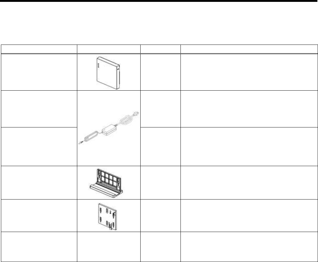
▌EA-7HW02AP1
Product name
Illustration
Total number
Remarks
Main unit
1
AC adapter
1
AC cable
1
Stand
1
Mounter
1
Safety guide
1
7
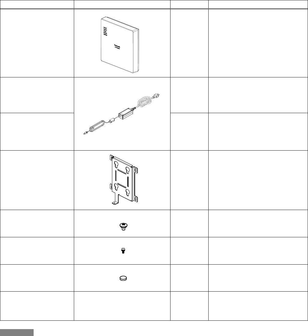
▌EA-7HW03AP1
Product name
Illustration
Total number
Remarks
Main unit
1
AC adapter
1
AC cable
1
Mounter
1
M6 screw
4
M3 screw
1
Rubber foot
4
Shipped after attaching to the main
unit
Safety guide
1
Important
1. In addition to the above, the following are required to perform the installation work. The following are not
provided with this product. Please procure separately.
• Ethernet cable (Category 5e or better, with RJ-45 modular plugs on both ends)
2. This product (EA-7HW02AP1/ EA-7HW03AP1) is water-resistant (JIS C 0920 Protection grade 2, drip-proof
type II). Avoid direct water jet and do not submerge this product in water when performing the installation work.
When installing in a place where water can splash onto this product, to protect the product from water, make
sure to install the product upright with the LED on the left side. (Do not lay the product on its side when installing
and do not install the product in any way other than the above when installing it upright.)
8
To run a radio station of the second generation low-power data communication system as an outdoor fixed station, it
is required to display both the name the owner of the corresponding radio station (or the name of the service
provider) and the contact address. The following are the content to be displayed.
• Display of radio station: Radio station of 2.4 GHz band low-power data communication system
• Name of owner or of service provider
• Contact address: Phone number or E-mail address (or home page address, etc.)
• Other useful information such as information to avoid radio wave interference, etc.
As for method of display, use a sticker or a plate, print or handwrite on a place where no special operation is required
to see such as on the radio station or on the housing case.
9
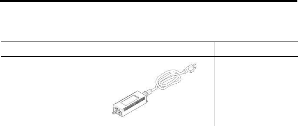
Option (Sold separately)
▌PoE injector
The following options are available to use EA-7HW02AP1 more conveniently.
Contact your dealer from whom you purchased this product for purchasing.
Product name
<Model no.>
Illustration
Total number
PoE injector
<EA-7HW00PWR1>
1

10
Precautions for use
The installation work must be carried out by a professional installer.
Incorrect installation may cause tip-over resulting in accidents.
Turn the power off when cleaning this product. Use a soft cloth to clean this product.
When dust is hard to remove, use a soft cloth soaked in diluted detergent and squeezed hard to wipe it, and
then wipe with a dry soft cloth.
Do not use any of alcohol, petroleum, thinner, benzene, boiling water, polishing powder and soap
powder for cleaning and maintenance.
When using a chemical cloth for cleaning, read the caution provided with the chemical cloth product.
Do not place this product in a place where temperature is high such as a place near a heating
equipment or a boiler.
Failure to observe this may result in deformation/deterioration of the surface/parts of the product or cause a
failure.
Do not bring fire close to the product.
Failure to observe this may result in deformation/deterioration of the surface/parts of the product or cause a
failure.
Do not place this product in a place where hydrogen sulfide, phosphorus, ammonia, sulfur, carbon,
acid, dust or noxious gas can exist.
Failure to do so may result in failure or shorten the life of the product.
Do not place this product near a source of electromagnetic wave or a magnetized object.
(High-frequency sewing machine, electric welder, magnet, etc.)
Failure to observe this may result in generation of noise or cause a failure.
Do not apply a strong impact or vibration to this product.
If a strong impact caused by a fall or a strike is applied, it may result in a failure or a damage.
When disposing of this product, handle it as an industrial waste and follow laws and regulations
appropriately.
11
Notes on radio waves
• This product is certified to radio equipment technical standards based on Radio Act (2.4 GHz ISM band
low-power data communication system and 5 GHz band low-power data communication system). Therefore, no
license of a radio station is necessary for use of this product.
• Since this product is certified to the technical standards, the following actions are punishable by law.
• Taking apart or modifying this product. (Alteration of frequency and antenna is prohibited.)
• Removing the certification label from the bottom of this product.
• In the use frequency band of 2.4 GHz band (IEEE802.11 b/g/n), in addition to industrial/scientific/medical
equipments including microwave ovens, private branch radio stations (license required) for mobile object
identification that are used in manufacturing lines at factories, specified low-power radio stations (no license
required) and amateur radio stations (license required) are being operated.
• Before using this product, make sure that any of private branch radio station for mobile object identification,
specified low-power radio station and amateur radio station is not being operated.
• If harmful radio wave interference against a private branch radio station for mobile object identification
caused by this product occur, immediately change the use frequency of this product and eliminate the radio
wave interference.
• When operating this product in 2.4 GHz band, it is recommended to select CH1, CH6 or CH11 for the
channel setting to reduce interference and to improve frequency utilization efficiency.
• If you need any assistance to deal with a trouble such as harmful radio wave interference against a private
branch radio station for mobile object identification or a specified low-power radio station caused by this
product, contact your dealer from whom you purchased this product.
Use frequency band: 2.4 GHz
Modulation system: DS-SS/OFDM
Estimated interference distance: Less than 40 m
Frequency change availability: It is possible to avoid band for private branch radio station for mobile
object identification and specified low-power radio station while using the entire band.
The following marks indicating these are labeled on the product.

12
Security-related notice on use of wireless LAN products
• In a wireless LAN, information is transmitted/received between a PC and this product using radio wave instead
of a LAN cable. Therefore, it has an advantage that the LAN connection is always available in a range which
radio waves reach.
On the other hand, since radio waves get over obstacles (wall, etc.) and reach any place within a certain range,
the following problems can occur if settings relating to security are not configured.
■ Content of communication can be peeped
• There is a possibility that a third person with malicious intention may intentionally pick up radio waves and
monitor content of communication including personal information such as ID, password, credit card number
and content of E-mails.
■ Illegal intrusion
• There is a possibility that the following may be brought by illegal intrusion.
A third person with malicious intention may invade and access a personal or a corporate network to steal
personal information or classified information (information leakage).
• Communicate by impersonating a specific person and spread illegal information (Spoofing)
• Edit monitored content of communication and transmit (Alteration)
• Spread computer virus and destroy data or a system (Attack)
Since a wireless LAN card and this product originally have security countermeasures against these problems, the
possibility of occurrence of these problems may be reduced if wireless LAN products are used after configuring the
security-related settings of the products.
Fully understand problems that may occur if using the product without configuring the security-related settings. It is
recommended to use this product after configuring the security-related settings on your own judgement and
responsibility while taking other countermeasures (use of physical security countermeasure against theft or use of
VPN function to prevent data eavesdropping) according to your use environment.

13
Chapter
1. Specifications
The following are descriptions about specifications of Wi-Fi base station for business use.

14
1.1. Equipment specifications
▌Wi-Fi base station for business use EA-7HW02AP1
Item
EA-7HW02AP1
External
interface
Wireless
IEEE802.11b/g/n, IEEE802.11a/n/ac (wave1) (Simultaneous use is
possible.)
Wired
10/100/1000BASE-T 1 port
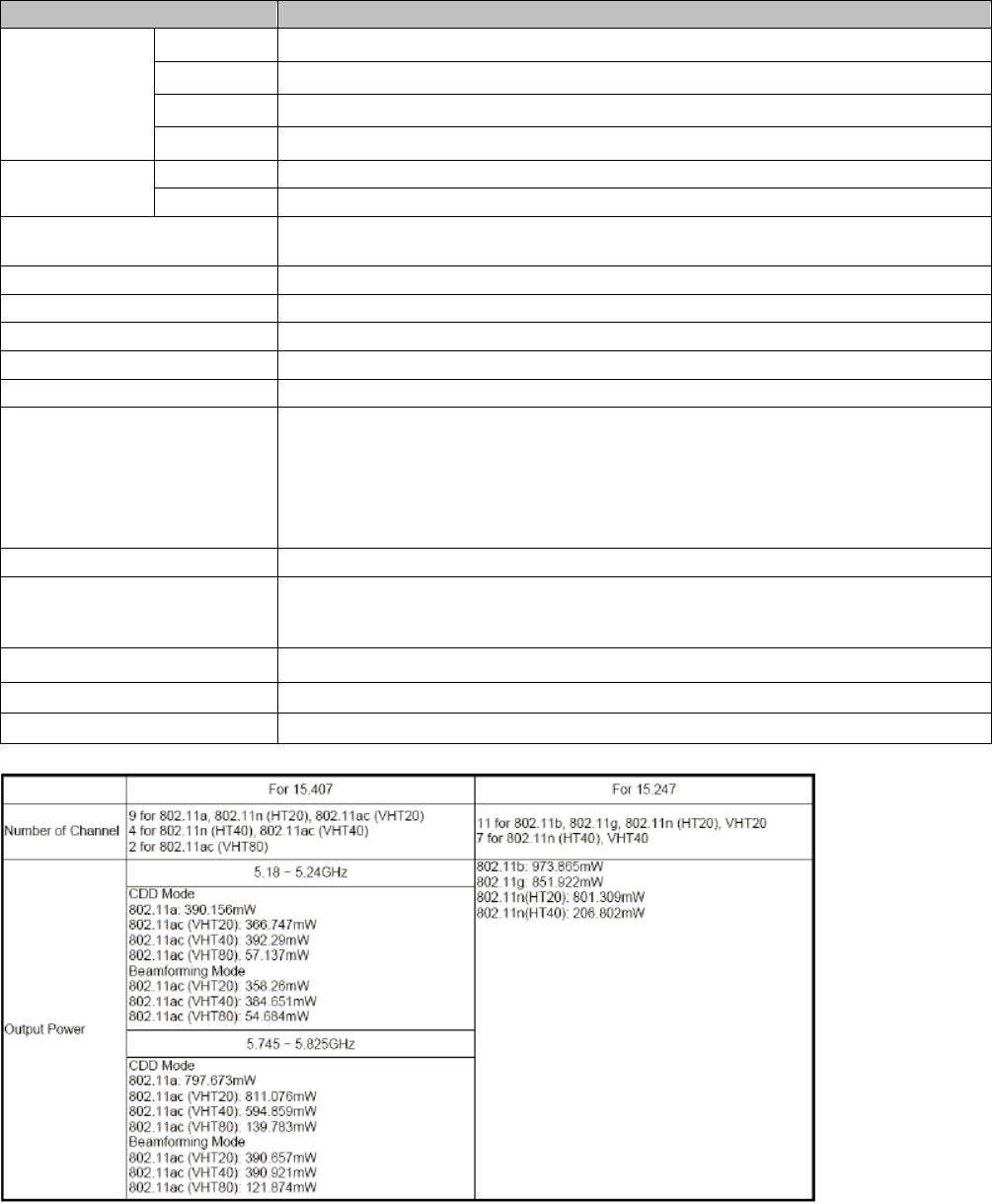
Frequency
2.4 GHz
2412-2462MHz
5 GHz
5180-5240, 5260-5320, 5500-5700, 5745-5825 MHz.
Transmission power
Maximum 2.4GHz: 28.23 dBm / Maximum 5GHz: 27.82 dBm.
Antenna
Planar inverted F antenna
Antenna gain
2.4 GHz: 3.88 dBi/ 5 GHz: Less than 5 dBi
Wireless LAN function
Multi-SSID (16), WEP/WPA2 (Personal/Enterprise), MAC authentication,
WMM
Network Interface
L2 bridge, L2/L3/L4 filtering, VLAN, PPPoE, IPsec
Maintenance function
Telnet, SSH, Web, FTP/SFTP, SNMP/TRAP, NTP, syslog
Power source
12 V DC
PoE(IEEE802.3af)
Power consumption
12.95 W or less
Required operating environment
Temperature: 0 °C- 40 °C
Humidity: 5 % - 95 % (non condensing)
Water-/dust-resistance
IP42 (except the rear panel)
Outer dimensions (excluding tolerance and
projections)/Weight
W159 mm x H159 mm x D29 mm /
Approx. 360 g
15
▌Wi-Fi base station for business use EA-7HW03AP1
Item
EA-7HW03AP1
External
interface
Wireless
IEEE802.11b/g/n, IEEE802.11a/n/ac (wave2) (Simultaneous use is possible.)
Wired
10/100/1000BASE-T 2 ports
USB
USB 3.0 2 ports
Maintenance
Console interface 1 port
Frequency
2.4 GHz
2412-2462MHz
5 GHz
5180MHz~5240MHz, 5745MHz ~ 5825MHz
Transmission power
Maximum 2G : 29.88dBm /
Maximum 5G : 25.93dBm (5180~5240MHz), 29.1dBm ( 5745 ~ 5825MHz )
Antenna
Planar inverted F antenna
Antenna gain
2.4 GHz: 3 dBi/ 5 GHz: 4 dBi
Wireless LAN function
Multi-SSID (16), WEP/WPA2 (Personal/Enterprise), MAC/ authentication, WMM
Network Interface
L2 bridge, L2/L3/L4 filtering, VLAN, PPPoE, L2TPv3, IPsec
Maintenance function
Telnet, SSH, Web, FTP/STFTP, SNMP/TRAP, NTP, syslog
Power source
24 V DC
PoE (IEEE802.3af, IEEE802.3at)
• When using IEEE802.3af
Use of USB and 2.4 GHz band becomes unavailable.
• When using IEEE802.3at
Use of USB becomes unavailable.
Power consumption
25.5 W or less
Required operating environment
Temperature: 0 °C - 40 °C
(0 °C - 50 °C Only when installing on a wall)
Humidity: 5 % RH - 95 % RH (non condensing)
Water-/dust-resistance
IP42 (except the rear panel)
Outer dimensions
W201.7 mm×H201.7 mm×D38.5 mm (excluding tolerance and projections)
Weight
Approx. 990 g

16
AC adapter
Item
Specifications
Input voltage
100 V - 240 V AC
However, the provided power cord is only for 100 V AC.
Prepare a power cord separately when using 200 V AC power supply.
Output voltage/power
24 V DC/36 W
Required operating
environment
Temperature: 0 °C - 40 °C
(0 °C - 50°C Only when 1 USB port of this product is not being used)
Humidity: 5 % RH - 90 % RH (non condensing)
Dimensions
W 48 mm×H 109 mm×D 34 mm
(Excluding tolerance and projections)
Weight
Approx. 300 g
17
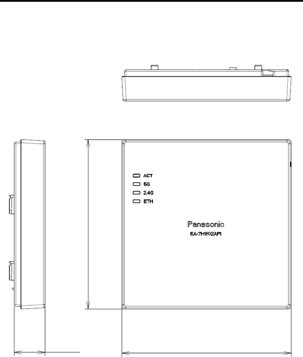
1.2. Appearance/Dimensions
(Specifications of this product are subject to change without notice)
▌EA-7HW02AP1
Main unit Outline view
(Unit: mm)
29±1.0
159±2.5
159±2.5
18
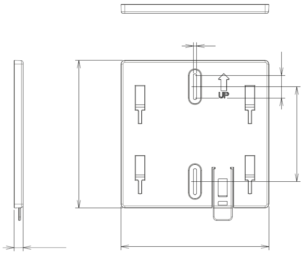
Mounter Outline view
(Unit: mm)
24±1.0
84±1.5
4.3±0.5
131±2.5
8±1.0
131±2.5
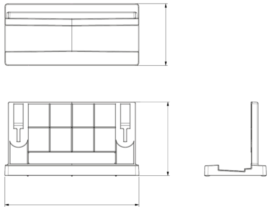
19
Stand Outline view
56.2±1.5
122±2.5
66.9±1.5
20
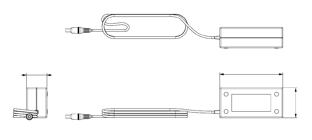
AC adapter Outline view
(Unit: mm)
95.9±1.5
28.5±1.0
43.8±1.5
21
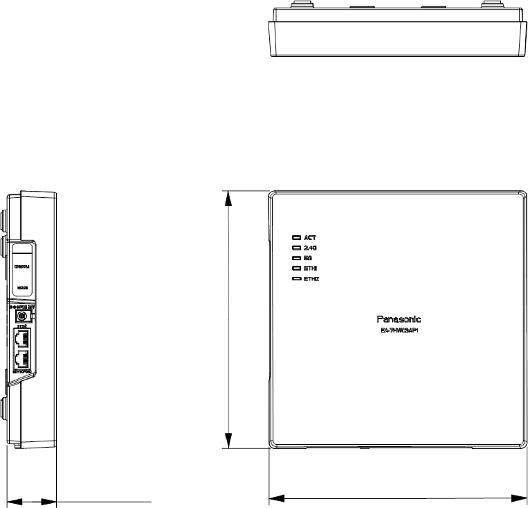
▌EA-7HW03AP1
Main unit Outline view
(Unit: mm)
38.5±1.5
201.7±2.5
201.7±2.5
22
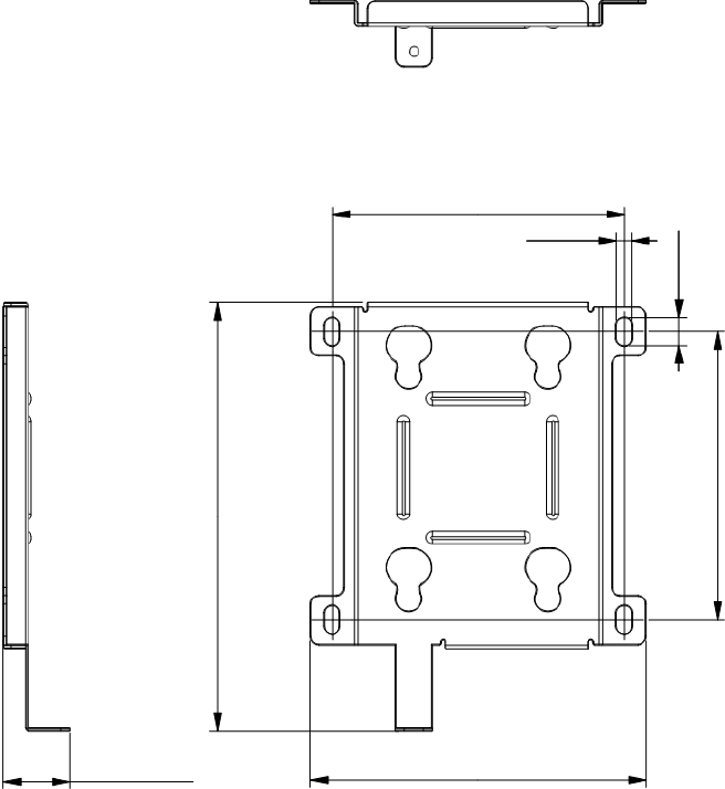
Mounter Outline view
(Unit: mm)
26.8±1.0
135±2.5
172.5±2.5
117.5±1.5
6±0.5
11.5±1.0
116.2±1.5
23
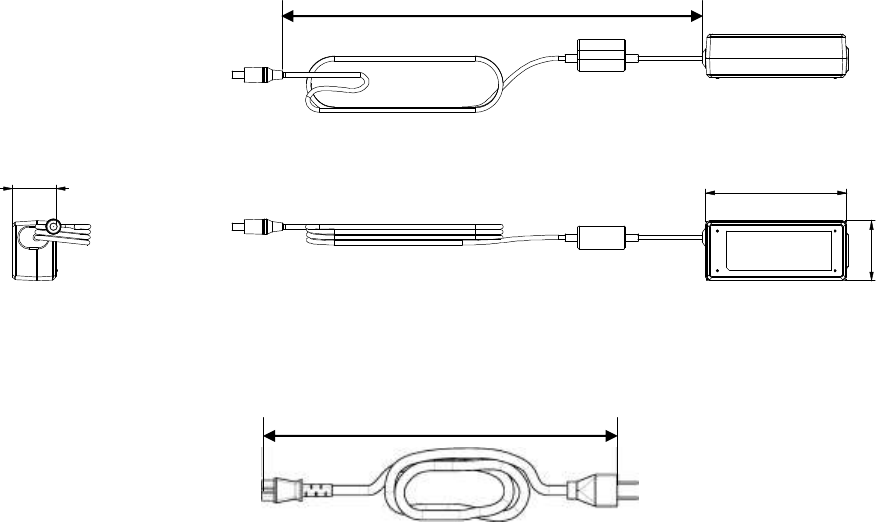
AC adapter Outline view
(Unit: mm)
Power cord Outline view
1200
+150
-50
109±1.5
34±1.5
48±1.5
1000±35
24
1.3. Major Operating Controls and Their Functions
▌Wi-Fi base station EA-7HW02AP1
The following are descriptions about the appearance of this product and names/functions of each operating control.
Mounter
To be used when mounting on a
wall/ceiling.
Status LED
Indicates the status of the
wireless unit.
Stand
To be used when
installing on a table.
MAC address
Displayed on the nameplate on
the rear..
(5) INIT switch
Rear
(7) DC IN connector
(6) LAN connector
(1) ACT LED
(2) 5G LED
(3) 2.4G LED
(4) ETH LED

25
Descriptions about each LED, switch and connector are in the following table.
No.
Signal
Function
(1)
ACT LED
Indicates the operational/error status of the unit.
Lights red
Error detection during operation
Lights green
In operation
(2)
5G LED
Displays the status of wireless IF 5 GHz
Lights green
In normal operation
Off
In the process of start-up
(3)
2.4G LED
Displays the status of wireless IF 2.4 GHz
Lights green
In normal operation
Off
In the process of start-up
(4)
ETH LED
Indicates the link status of the Ethernet port.
Blinks green
In the process of frame transmission/reception
Lights green
Link established
Off
Link disconnected
(5)
INIT switch
(Push switch)
Initializes configuration data and log data.
(6)
Ethernet IF
ETH
(RJ-45 modular jack)
Connect an Ethernet cable.
The ETH port supports power supply from a PoE power feeding equipment.
(7)
DC IN jack
Connect the DC plug of the provided AC adapter.
26
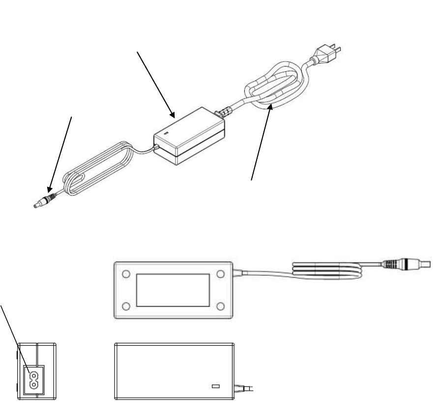
AC adapter (standard accessory)
Connect to the AC outlet to supply power to the wireless unit.
AC adapter main unit
AC power cord
DC jack
AC IN terminal
Connect the provided AC power
cord.
27
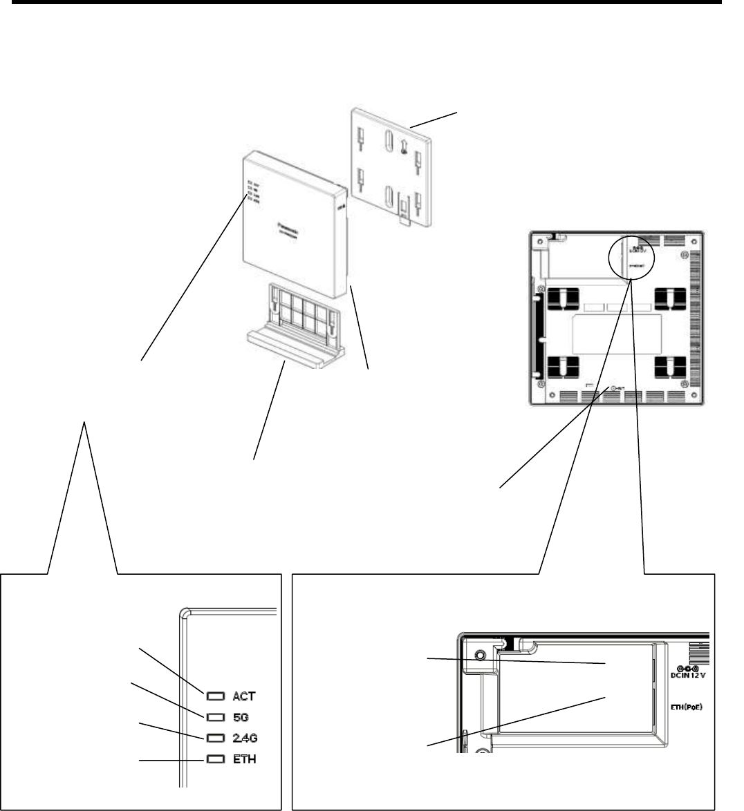
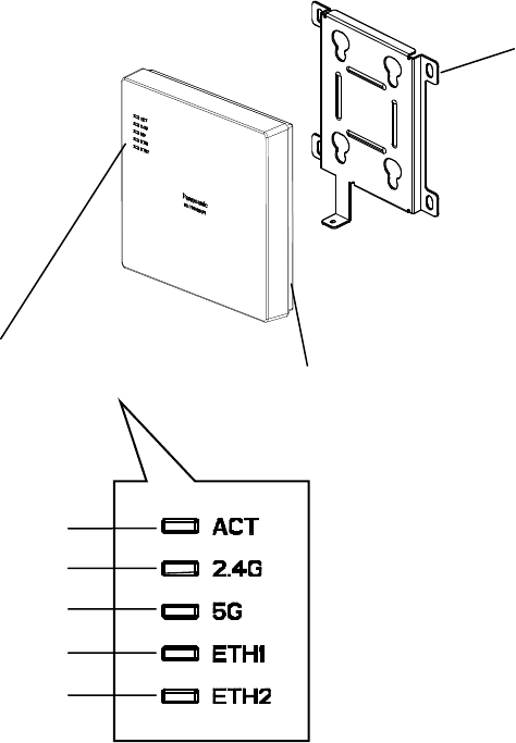
▌Wi-Fi base station for business use EA-7HW03AP1
The following are descriptions about the appearance of this product and names/functions of each operating control.
Mounter
To be used when mounting on a
wall/ceiling.
Status LED
Indicates the status of the
wireless unit.
MAC address
Displayed on the nameplate on the rear.
ACT LED
2.4G LED
5G LED
ETH1 LED
ETH2 LED
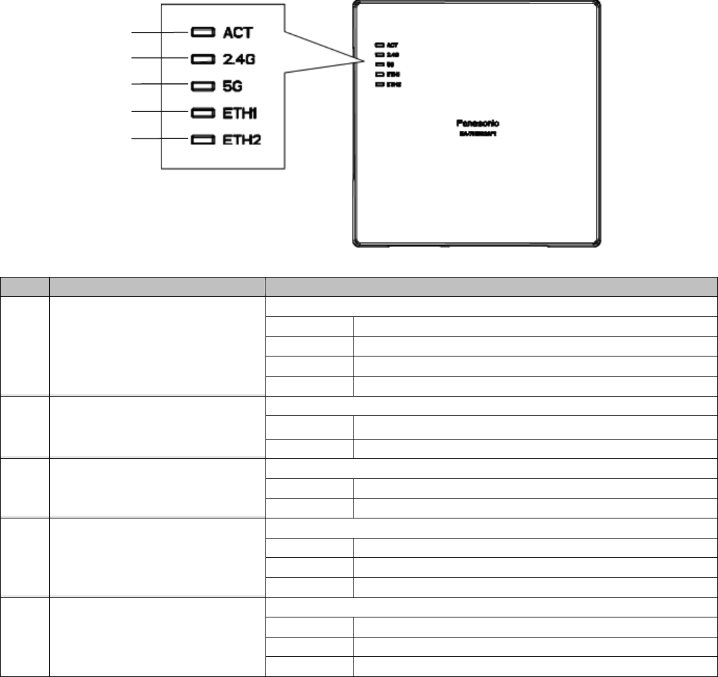
28
Front
No.
Signal
Function
(1)
ACT LED
Indicates the operational/error status of the unit.
Lights green
In operation
Blinks green
In the process of start-up
Blinks red
In the process of upgrade
Lights red
Error detection during operation
(2)
2.4G LED
Displays the status of wireless IF 2.4 GHz
Lights green
In normal operation
Off
In the process of start-up
(3)
5G LED
Displays the status of wireless IF 5 GHz
Lights green
In normal operation
Off
In the process of start-up
(4)
ETH1 LED
Indicates the link status of the Ethernet port.
Blinks green
In the process of frame transmission/reception
Lights green
Link established
Off
Link disconnected
(5)
ETH2 LED
Indicates the link status of the Ethernet port.
Blinks green
In the process of frame transmission/reception
Lights green
Link established
Off
Link disconnected
(1) ACT LED
(2) 2.4G LED
(3) 5G LED
(4) ETH1 LED
(5) ETH2 LED
29
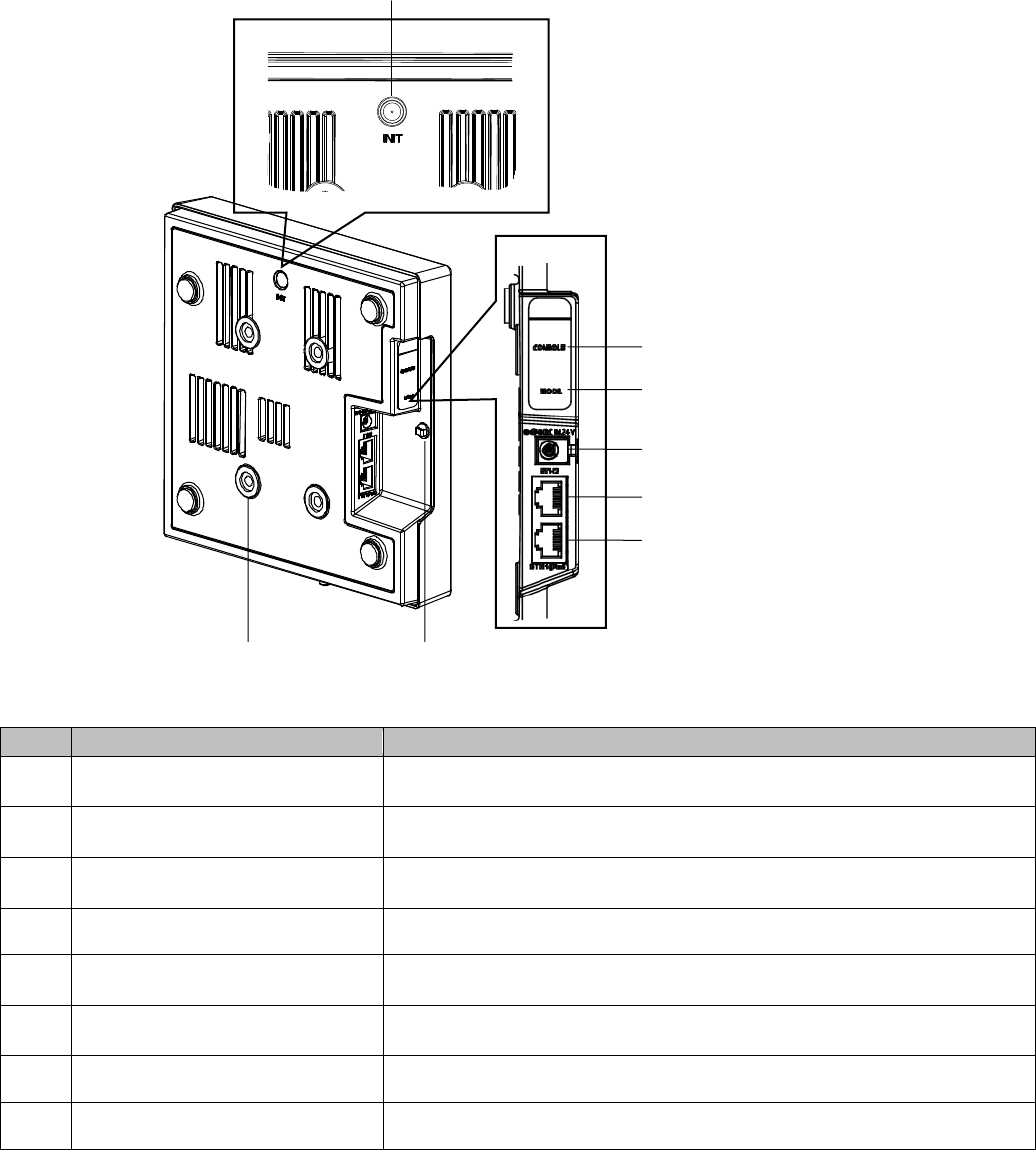
Rear/Left side
No.
Signal
Function
(1)
INIT switch
(Push switch)
Initializes configuration data and log data.
(2)
CONSOLE
(RJ-45 connector)
Connect the console for maintenance, such as a PC.
(3)
MODE 1, 2
(Slide switch)
Not be used. Do not change the default.
(4)
DC IN jack
Connect the DC plug of the provided AC adapter.
(5)
ETH2
(RJ-45 connector)
Connect an Ethernet cable.
(6)
ETH1( PoE) connector
(RJ-45 connector)
Connect an Ethernet cable and start power feeding from a PoE power feeding
equipment.
(7)
Holder
Use this with a cable tie to prevent disconnection of the AC adapter.
(8)
Claw (x4)
Attach by tightening the provided M6 screw when installing on a wall.
(1) INIT switch
(2) CONSOLE
(3) MODE switch
(4) DC IN jack
(5) ETH2
(6) ETH1 (PoE)
(7) Holder
(8) Claw (x4)
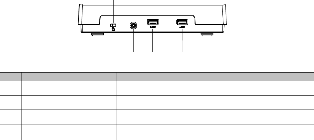
30
Bottom side
No.
Signal
Function
(1)
Kensington lock
Use for theft prevention.
(2)
Mounter fixing hole
Attach the mounter.
(3)
USB2
(USB3.0 Type A)
Connect a USB device.
(4)
USB1
(USB3.0 Type A)
Connect a USB device.
(2) Mounter fixing hole
(3) USB2
(4) USB1
(1) Kensington lock
31
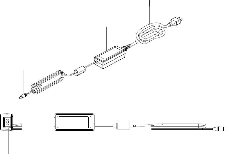
AC adapter (standard accessory)
Connect to the AC outlet to supply power to the wireless unit.
AC IN terminal
Connect the provided AC power cord.
AC adapter main unit
AC power cord
DC jack

32
1.4. Power feeding method
▌Power feeding method
The power feeding method of the wireless unit is as follows.
Access point
Available power feeding method
EA-7HW02AP1
• Power feeding from AC adapter
(Use the supplied AC adaptor.)
• Power feeding from PoE power feeding equipment compliant with
IEEE802.3af or IEEE802.3at.
EA-7HW03AP1
• Power feeding from AC adapter
(Use the supplied AC adaptor.)
• Power feeding from PoE power feeding equipment compliant with
IEEE802.3af or IEEE802.3at.
* However, there are following restrictions when using PoE power feeding for
EA-7HW03AP1.
■ When using IEEE802.3af
Use of USB and 2.4 GHz band becomes unavailable.
■ When using IEEE802.3at
Use of USB becomes unavailable.
If these conditions are not fulfilled, this product may sometimes be reset.
Refer to "2.4.2 Connection with power supply" for power feeding.
33
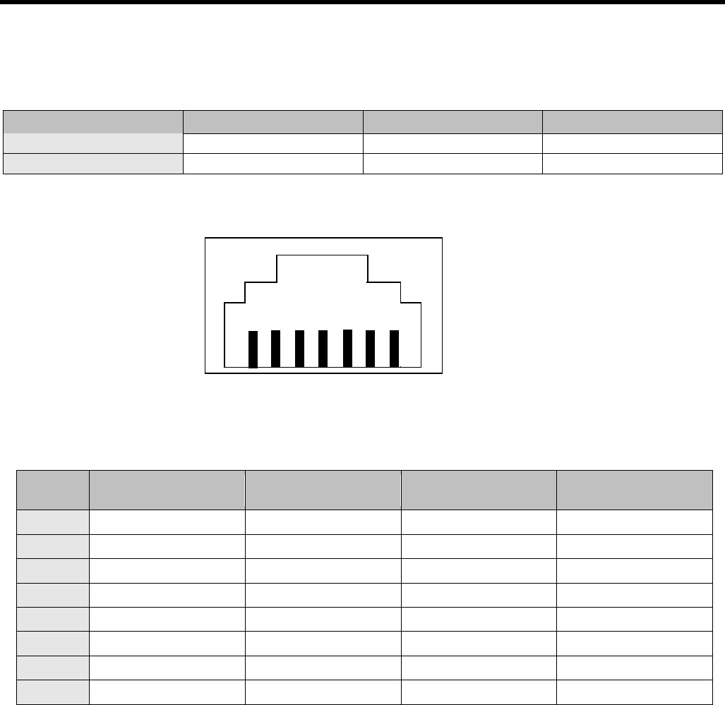
1.5. Interface specifications
▌Ethernet interface specifications
Interface specifications
Network interface
Type of connector
Type of cable
Transmission distance
10BASE-T/100BASE-TX
RJ-45
Category 5
100 m
1 000Base-T
RJ-45
Enhanced category 5
100 m
LAN (RJ-45) connector
Table 1.6 LAN (RJ-45) connector
Pin No.
10/100Base
Main unit side (MDI)
10/100Base
Main unit side (MDI-X)
1000Base-T
Main unit side (MDI)
1000Base-T
Main unit side (MDI-X)
1
Tx +
Rx +
BI_DA +
BI_DB +
2
Tx -
Rx -
BI_DA -
BI_DB -
3
Rx +
Tx +
BI_DB +
BI_DA +
4
Not used
Not used
BI_DC +
BI_DD +
5
Not used
Not used
BI_DC -
BI_DD -
6
Rx -
Tx -
BI_DB -
BI_DA -
7
Not used
Not used
BI_DD +
BI_DC +
8
Not used
Not used
BI_DD -
BI_DC -
1 2 3 4 5 6 7 8
(Connector on the main unit side)
34
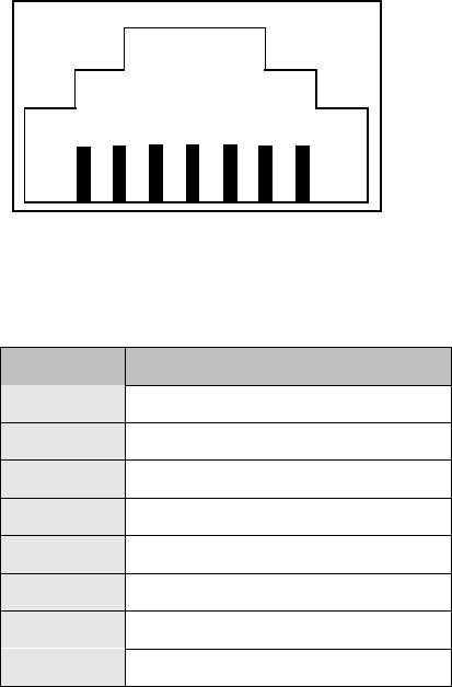
▌Console interface specifications (EA-7HE03AP1 only)
Console (RJ-45) connector
Table 1.6 LAN (RJ-45) connector
Pin No.
Main unit side (DTE)
1
RTS
2
DTR
3
TxD
4
GND
5
GND
6
RxD
7
Not used
8
Not used
(Connector on the main unit side)
1 2 3 4 5 6 7 8
35
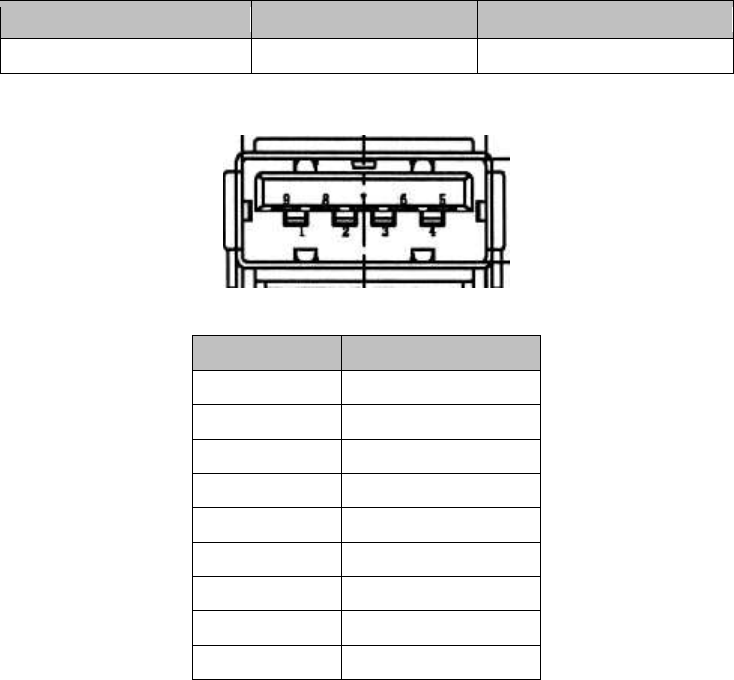
▌USB interface specifications (EA-7HE03AP1 only)
Interface specifications
Network interface
Type of connector
Transmission distance
USB 3.0
Type-A
3 m
USB connector
USB connector
Pin No.
Signal name
1
V BUS
2
D -
3
D +
4
GND
5
TX +
6
TX -
7
GND
8
RX +
9
RX -

36
Chapter
2. EA-7HW02AP1 installation work
The following are descriptions about installation work of EA-7HW02AP1 and connection method of each interface.
37
2.1. Installations and Connections
Follow the procedures below to install and connect EA-7HW02AP1.
2.2 Determine the installation
place of wireless unit
2.3 Installation work of
wireless unit
2.4 Connections
Use EA-7HW02AP1

38
2.2. Determine the installation place of wireless unit
• EA-7HW02AP1 can be installed on a wall, on a ceiling, at back of ceiling and on a desktop using the provided
mounter.
• The wireless unit shall be installed on a place having an enough strength to hold the unit and flat surface.
Weight of the main unit of the wireless unit is approx.360 g.
• The wireless unit shall be installed firmly not to loosen up and fall off due vibration and anything in future.
• Make sure that there is no factor that can affect performance of the antenna, such as a metallic or concrete
obstacle, near the wireless unit.
• Read "Safety precautions" and "Precautions" carefully and determine the installation place.
39
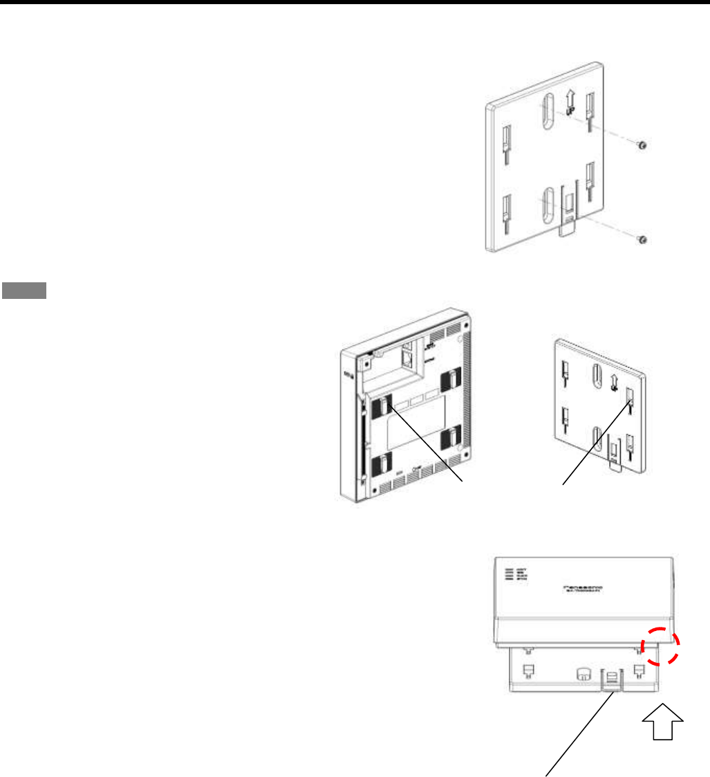
2.3. Installation work of wireless unit
Refer to "1.2 Appearance/Dimensions" for the size of the wireless unit and the mounter.
1. Wall mounting
(1) Fixing of the mounter
Fix the mounter after making sure that the installation place has an
enough strength and flat surface of concrete, metal, wood, mortar,
etc.
• Fasten a screw (x1) temporarily on the installation surface.
• Make sure that the mounter can be installed in parallel, and then
fix it firmly with 2 screws located at the upper and the lower sides.
(Recommended tightening torque: 0.85 N・m ± 0.12 N・m)
Note
Use a screw whose nominal diameter is 4mm to fix
on the installation surface.
This screw shall be prepared by the installer
according to the material of the installation surface.
(2) Installation of the wireless unit
Fix the main unit onto the mounter fixed on
the wall.
• Hook the claws (x4) of the wireless unit
into the hook holes on the mounter.
• Align the side of the mounter and the dent in the wiring groove of
the wireless unit.
(3) Slide the wireless unit downward until the "click" sound is heard.
• To remove the wireless unit from the mounter, slide the wireless
unit upward while holding down the lever to the wall side.
(1)
(2)
Claw (x4)
Hook hole (x4)
Lever
40
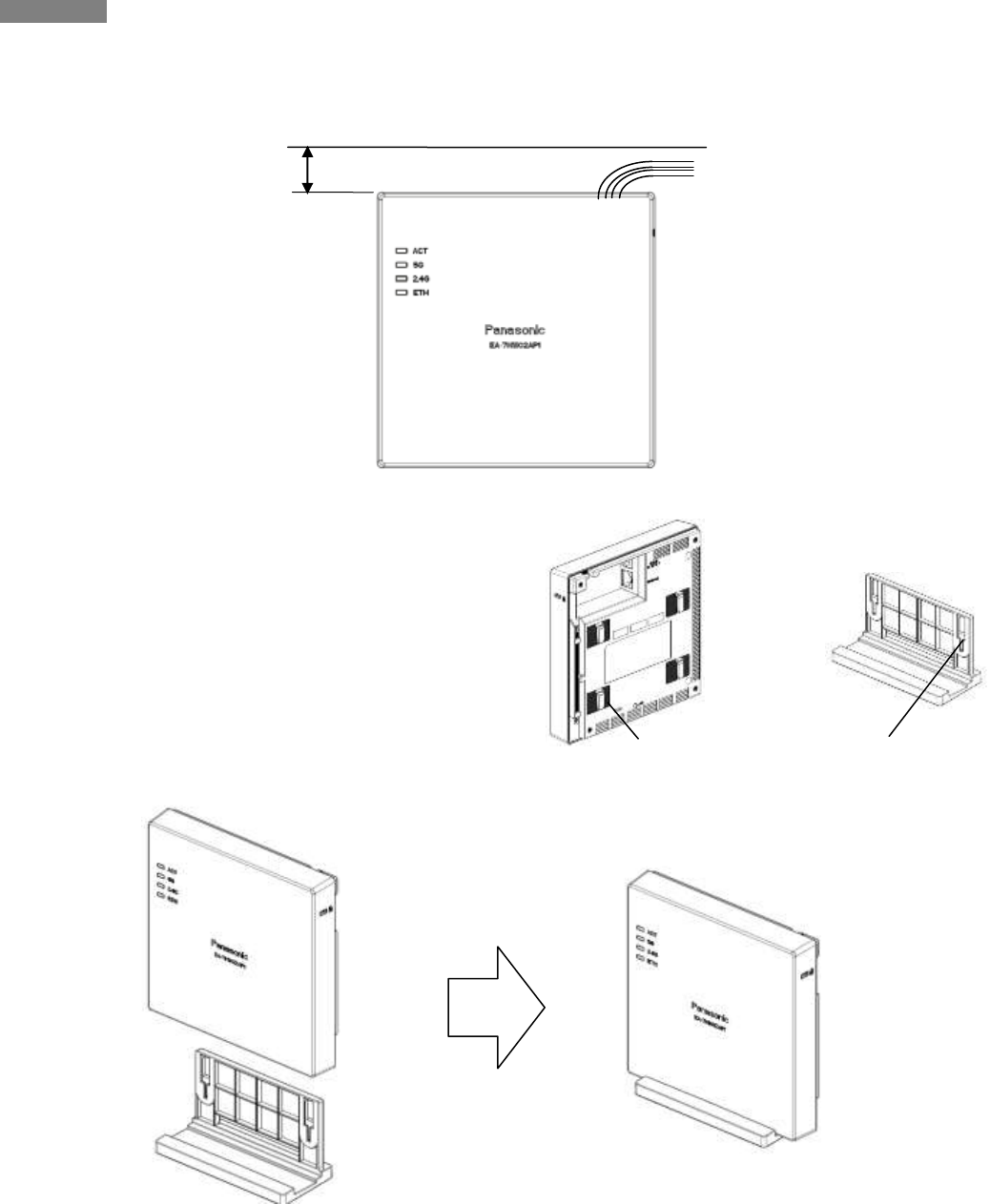
Important
• When installing the wireless unit, make sure that the LED is not hidden from your view and it is easy to check.
Secure a space of 30 mm or more above the product to secure a space allowing you to hook.
2. Installation on a desktop
(1) Fix the wireless unit onto the stand.
• Hook the claws (x2) on the rear of the wireless unit
into the hook hole on the stand.
Ceiling
30mm or more
Claw (x2 at the lower side)
Hook hole (x2)
41
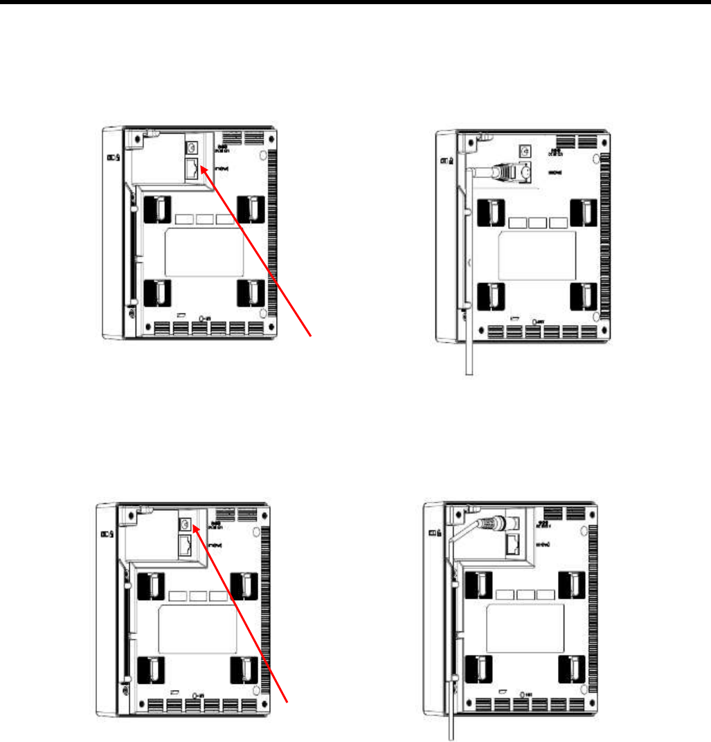
2.4. Connections
2.4.1. Connection to network
1. In case of LAN connection
Connect an Ethernet cable (enhanced category 5 or better) to the LAN connector on the right side of the main
unit.
2.4.2. Connection with power supply
1. Power feeding from AC adapter
Firmly connect the DC plug of the provided AC adapter to the DC IN connector in the external interface section
of the main unit.
LAN connector
DC IN connector
DC IN connector

42
2. Power feeding from PoE unit
Power will be fed from PoE power feeding equipment compliant with IEEE802.3af or IEEE802.3at.
In this section, descriptions of how to feed power from PoE injector are provided.
By following the procedures below, connect the PoE injector and other cables.
(1) Insert the plug of the Ethernet cable connected with the wireless unit to the "DATA & POWER OUT" port of the
PoE injector until the "click" sound is heard.
(2) Connect the provided power cable to the PoE injector.
(3) Insert the power plug of the PoE injector to an outlet of 100 V AC. (The POWER LED will light yellow and then
turn to green.)
(4) Insert the plug of the Ethernet cable connected with a host network device to the "DATA IN" port of the PoE
injector until the "click" sound is heard.
Important
• The wiring length from the wireless unit to the host network device shall be up to 100 m (total).
• Do not pull the connected cables with a strong force.
• Do not place a heavy object on the PoE injector.
• Do not perform wiring of the connection cables and the Ethernet cable connection section in a place where
water can damage them.

43
2.5. Initialization
It is possible to initialize (reset the setting data and the log data to the default) the wireless unit directly without using
the initialization command.
(1) Hold down the INIT switch using something that has a needle-like tip such as a skewer.
* Start working after removing static electricity.
(2) Connect the AC adapter and the PoE injector, and then turn on the power.
(3) Wait until the ACT LED starts blinking red.
(4) When the ACT LED blinking red turns to blinking green, release the INIT switch.
Default of each interface after the initialization
Network interface
Default
Remarks
Wi-Fi interface (2.4G)
Off
Default after validating the interface
2.4 GHz, 1ch, HT40
Wi-Fi interface (5G)
Off
Default after validating the interface
5.2 GHz, 36ch, HT80
Ethernet (ETH)
-
Default fixed IP (192.168.0.3/24)
(Access will become available after approx. 150 seconds from the
start-up.)
44
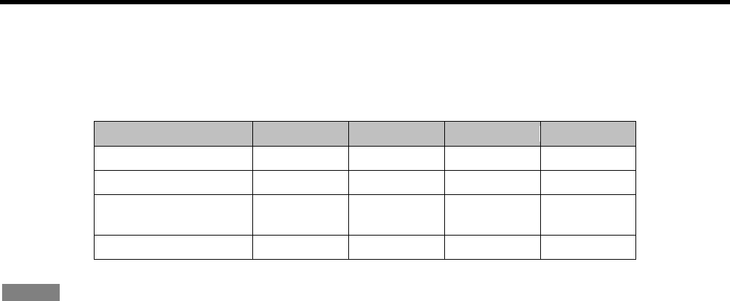
2.6. Alarm display by self-test
This product will automatically perform self-test upon the start-up. If an error is detected, the detected alarm will be
indicated by the LED display on the product. When an error is detected on the self-test, turn off the power and
contact the dealer from whom you purchased this product.
EA-7HW02AP1 Self-test alarm display
Notice
• As the test of LED, all LEDs except the LINK LED will light. After that, all LEDs except the LINK LED will be off
until the self-test finishes. Refer to "1.3 Major operating controls and their functions" for descriptions of LED
display when the self-test completed correctly.
• When started up by turning on the INIT switch (initialized state), the ACT LED will start blinking.
• The status of ETH LED will change according to the connection status of Ethernet (power supply state).
Alarm type
ACT
2.4G
5G
ETH
FROM check error
Lights red
Off
Off
-
RAM check error
Lights red
Off
Off
-
Manufacturing number
error
Blinks red
Off
Off
-
MAC address error
Blinks red
Off
Off
-

45
Chapter
3. EA-7HW03AP1 installation work
The following are descriptions about installation work of EA-7HW03AP1 and connection method of each interface.
46
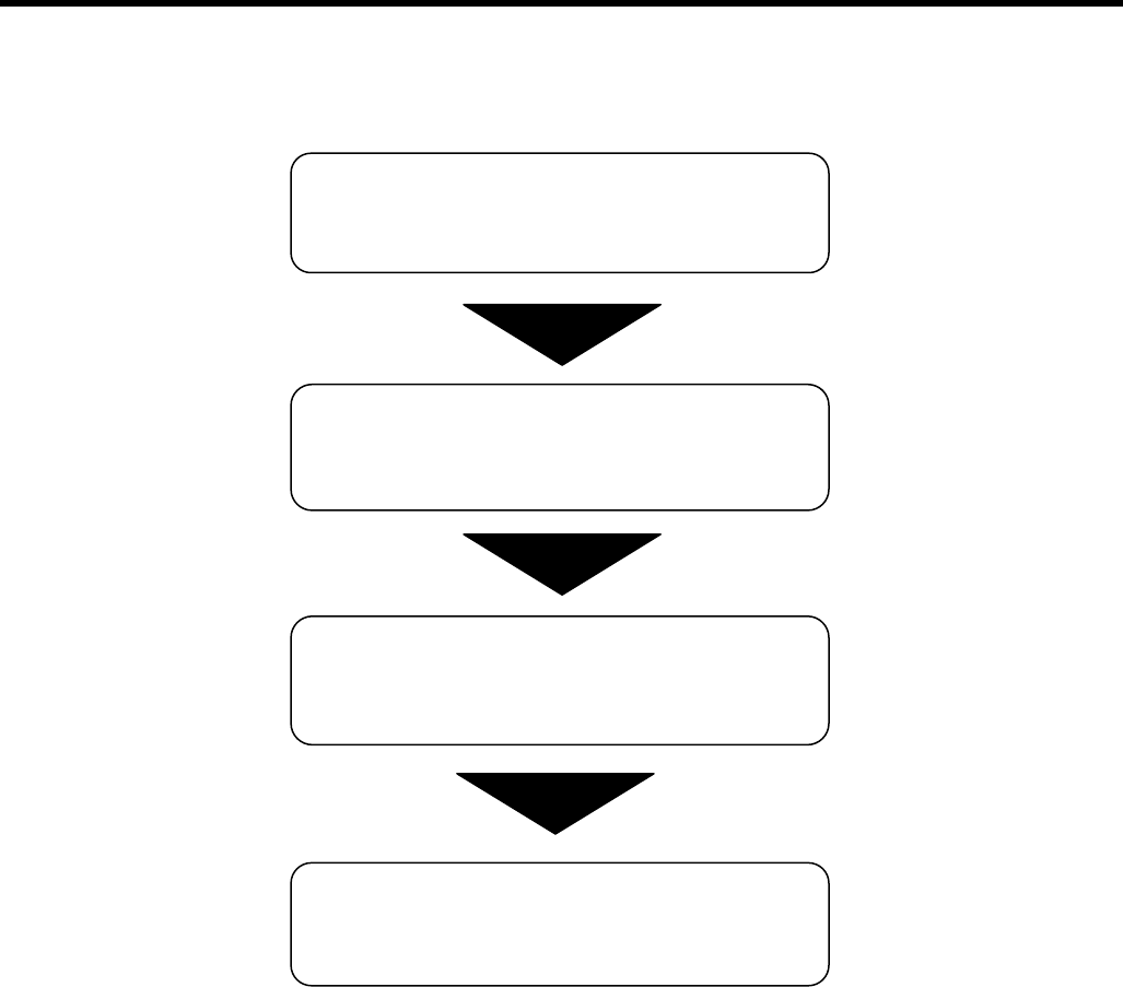
3.1. Installations and Connections
Follow the procedures below to install and connect EA-7HW03AP1.
3.2 Determine the installation
place of wireless unit
3.3 Installation work of
wireless unit
3.4 Connections
Use EA-7HW03AP1

47
3.2. Determine the installation place of wireless unit
• EA-7HW03AP1 can be installed on a wall, on a ceiling and at back of ceiling using the provided mounter.
• The wireless unit shall be installed on a place having an enough strength to hold the unit and flat surface.
Weight of the main unit of the wireless unit is approx.990 g.
• The wireless unit shall be installed firmly not to loosen up and fall off due vibration and anything in future.
• Make sure that there is no factor that can affect performance of the antenna, such as a metallic or concrete
obstacle, near the wireless unit.
• Read "Safety precautions" and "Precautions" carefully and determine the installation place.
48
3.3. Installation work of wireless unit
Refer to "1.2 Appearance/Dimensions" for the size of the wireless unit and the mounter.
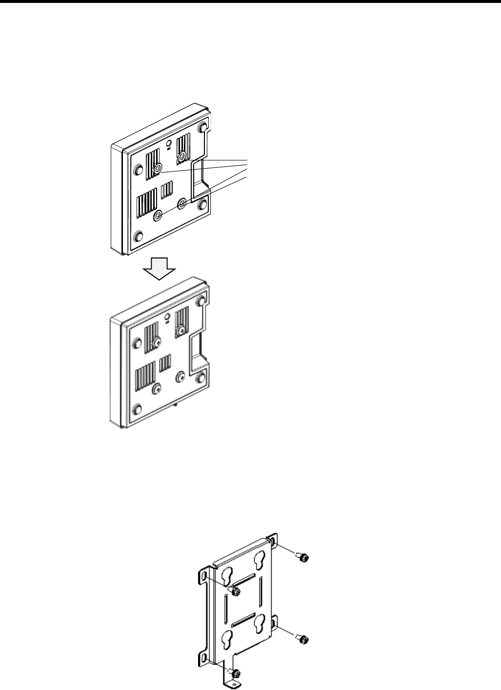
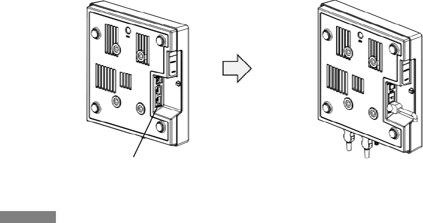
1. Wall mounting
(1) Attach the M6 screws (x4) to the rear of this product. (Recommended tightening torque: 3.0N・m ± 0.4 N・m)
(2) Fix the mounter after making sure that the installation place has an enough strength and flat surface of concrete,
metal, wood, mortar, etc.
Fasten screws (x2) temporarily on the installation surface.
Make sure that the mounter can be installed in parallel, and then fix it firmly with 4 screws located at the upper
and the lower sides.
(Recommended tightening torque: 3.0 N・m ± 0.4 N・m)
M6 screw (x4)
49
Important
Use a screw whose nominal diameter is 5 mm to fix on the installation surface.
This screw shall be prepared by the installer according to the material of the installation surface.
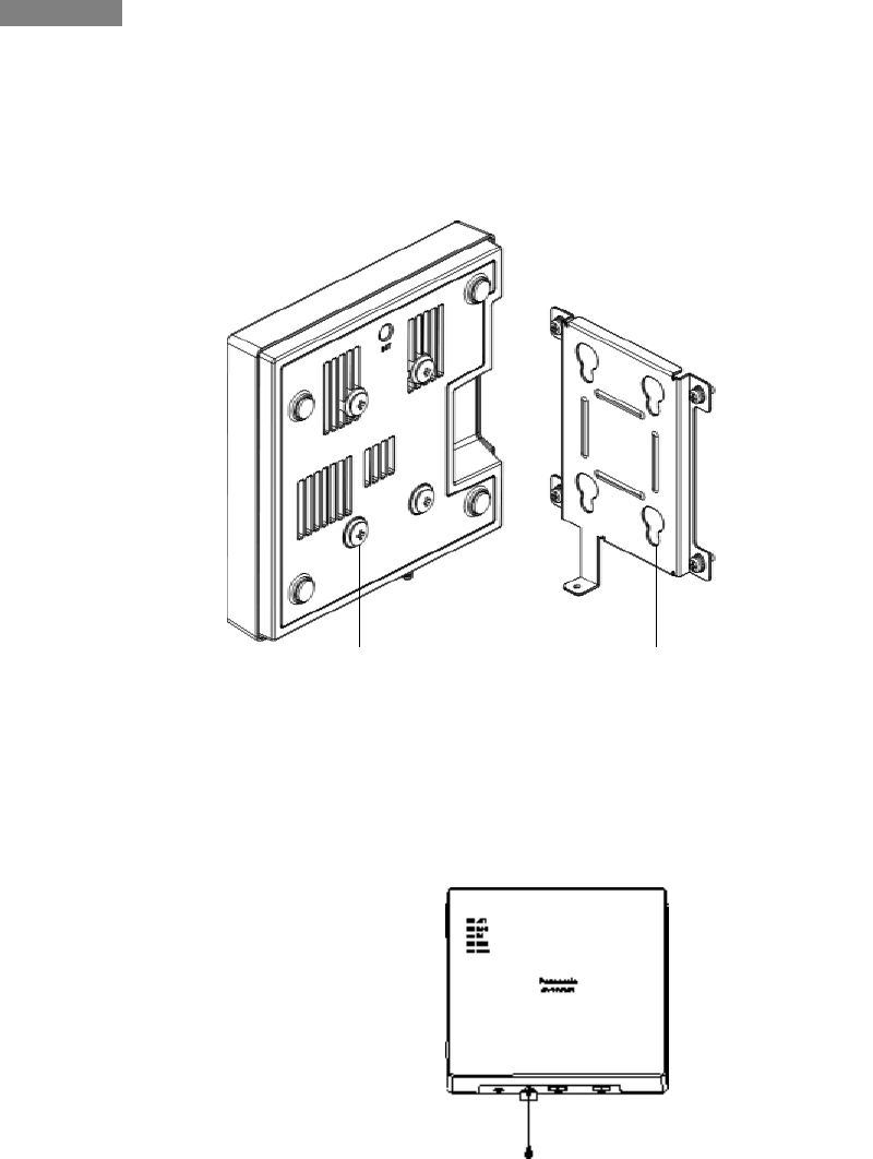
(3) Fix this product onto the mounter fixed on the wall.
Hook the M6 screws (x4) on the rear into the hook holes on the mounter.
(4) Align the hook hole on the front of the mounter and the M6 screw on the rear of this product.
(5) Hold the both sides of this product and slide it downward.
(6) Thread the M3 screw into the fixing hole firmly. (Recommended tightening torque: 0.6 N・m ± 0.1 N・m)
M6 screw (x4)
Hook hole (x4)
50
* To remove the mounter, hold the both sides of this product and slide it upward.
2. Flat installation
Install on a flat place.
51
3.4. Connections
3.4.1. Connection to network
Connect an Ethernet cable (enhanced category 5 or better) to the ETH1 (PoE) connector or the ETH2 connector on
the left side of this product.
3.4.2. Power feeding from AC adapter
Firmly connect the DC plug of the provided AC adapter to the DC IN connector in the external interface section of
this product.
ETH1 (PoE) connector or ETH2 connector
52
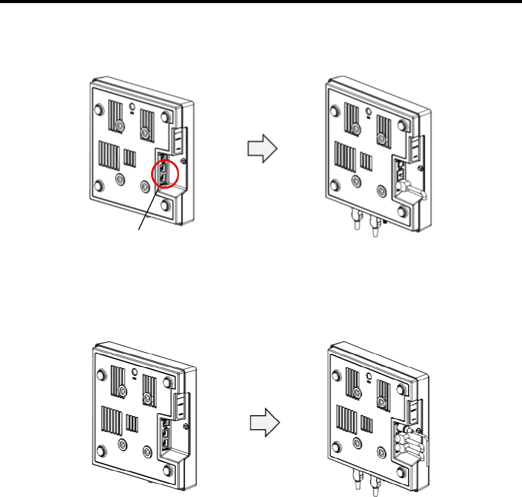
1. Power feeding from PoE unit
Power will be fed from PoE power feeding equipment compliant with IEEE802.3af or IEEE802.3at.
In this section, descriptions of how to feed power from PoE injector are provided.
By following the procedures below, connect the PoE injector and other cables.
(1) Insert the plug of the Ethernet cable connected with the ETH1 (PoE) connector of the wireless unit to the "DATA
& POWER OUT" port of the PoE injector until the "click" sound is heard.
(2) Connect the provided power cable to the PoE injector.
(3) Insert the power plug of the PoE injector to an outlet of 100 V AC. (The POWER LED will light yellow and then
turn to green.)
(4) Insert the plug of the Ethernet cable connected with a host network device to the "DATA IN" port of the PoE
injector until the "click" sound is heard.
Important
• The wiring length from the wireless unit to the host network device shall be up to 100 m (total).
• Do not pull the connected cables with a strong force.
• Do not place a heavy object on the PoE injector.
• Do not perform wiring of the connection cables and the Ethernet cable connection section in a place where
water can damage them.
ETH1( PoE) connector

53
3.5. Initialization
It is possible to initialize (reset the setting data and the log data to the default) the wireless unit directly without using
the initialization command.
1. Hold down the INIT switch using something that has a needle-like tip such as a skewer.
* Start working after removing static electricity.
2. Connect the AC adapter and the PoE injector, and then turn on the power.
3. Wait until the ACT LED starts blinking red.
4. When the ACT LED blinking red turns to blinking green, release the INIT switch.
Default of each interface after the initialization
Network interface
Default
Remarks
Wi-Fi interface (2.4G)
Off
Default after validating the interface
2412MHz, HT40
Wi-Fi interface (5G)
Off
Default after validating the interface
5180MHz, HT80
Ethernet1 (ETH1)
-
Default fixed IP (192.168.0.3/24)
(Access will become available after approx. 90 seconds from the
start-up.)
Ethernet2 (ETH2)
-
Default fixed IP (192.168.0.3/24)
(Access will become available after approx. 90 seconds from the
start-up.)

54
3.6. Alarm display by self-test
This product will automatically perform self-test upon the start-up. If an error is detected, the detected alarm will be
indicated by the LED display on the product. When an error is detected on the self-test, turn off the power and
contact the dealer from whom you purchased this product.
EA-7HW03AP1 Self-test alarm display
Notice
• As the test of LED, all LEDs except the LINK LED will light. After that, all LEDs except the LINK LED will be off
until the self-test finishes. Refer to "1.3 Major operating controls and their functions" for descriptions of LED
display when the self-test completed correctly.
• When started up by turning on the INIT switch (initialized state), the ACT LED will start blinking.
• The status of ETH1 LED/ETH2 LED will change according to the connection status of Ethernet (power supply
state),
Alarm type
ACT
2.4G
5G
ETH1
ETH2
FROM check error
Lights red
Off
Off
-
-
RAM check error
Lights red
Off
Off
-
-
Manufacturing number
error
Blinks red
Off
Off
-
-
MAC address error
Blinks red
Off
Off
-
-

55
Chapter
4. Setting method

56
4.1. Setting of PC for Web console use
The following are descriptions of how to connect a PC for web console use and of how to configure the setting of this
product.
Recommended environment of PC for Web console use
OS and TCP/IP software
Microsoft® Windows® 7
Microsoft® Windows® 8.1
TCP/IP software is provided with OS. It is unnecessary to prepare
separately.
Resolution
1024 x 768 pixels or more
LAN card
An Ethernet port is required on the PC in use to connect this product to the
PC. When using a LAN card, prepare one that can be installed on your PC.
Web browser
When using web console to configure the settings of this product, prepare
the following web browser.
Microsoft® Internet Explorer® 11 or later
* Access to the same AP from multiple web browsers is not supported.
▌Preparation of LAN card
Make sure that the PC for web console use has an Ethernet port. No Ethernet port is found.
It is required to install a LAN card on the PC. When newly installing a LAN card, installation of software for LAN card
(network driver) is required. Configure the settings correctly by following the manuals provided with the PC and the
LAN card.
▌TCP/IP protocol setting
When using the web console, it is required to complete the IP address and the subnet mask setting using the PC for
web console use.
The setting procedure varies depending on OS of the PC. On this document, descriptions are provided supposing
Microsoft® Windows® 8.1 is installed on the PC.
Configure the TCP/IP setting of the PC.
57
Setup procedure
Step 1
Open the "Control Panel" window and click [Network and Sharing Center].
Step 2
Click [Change adapter settings]. The "Network Connections" window will be displayed.
Step 3
Double click [Local Area Connection]. The "Local Area Connection Status" window will be displayed.
Step 4
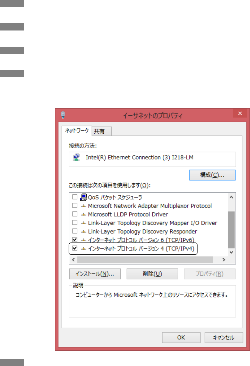
Check if "Internet Protocol Version 4 (TCP/IPv4)" is included in the displayed list.
If "Internet Protocol Version 4 (TCP/IPv4)" is not in the list, it is necessary to install TCP/IP. Install it by referring
to the manual of Microsoft® Windows® 8.1.
Step 5
Click to select "Internet Protocol Version4 (TCP/IPv4)", and then click [Properties].
58
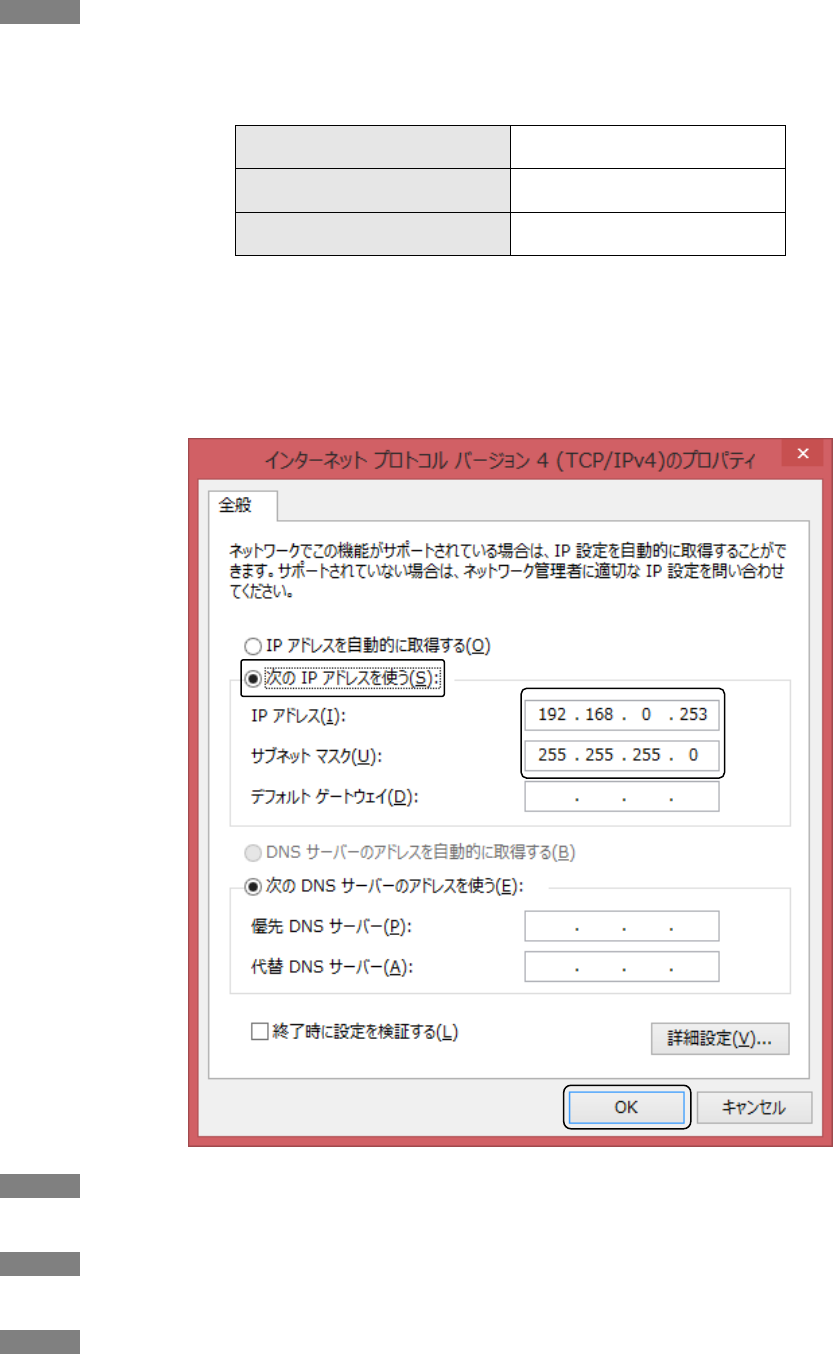
Step 6
Set the IP address of the PC. The IP address and the subnet mask shall be matched with the IP address and
the subnet mask set for this product. Refer to the following for the default IP address of this product.
IP address (Default)
IP address
192.168.0.3
Subnet mask
255.255.255.0
Default gateway
192.168.0.1
The following are examples to explain how to configure the settings.
• Select "Use the following IP address".
• Enter "192.168.0.253" for the IP address.
• Enter "255.255.255.0" for the subnet mask.
• No entry is needed for the default gateway.
Step 7
Click [OK] and return to "Properties".
Step 8
Click the [Close] button to return to "Local Area Connection Status".
Step 9
Click the [Close] button.
59
▌Preparation of web browser
The setting procedure varies depending on OS of the PC. On this document, descriptions are provided supposing
Microsoft® Windows® 8.1 is installed on the PC.
Setup procedure
Step 1
Open the "Control Panel"window and click [Internet Options]. The "Internet Properties" window will be
displayed.
Step 2
Select the [Connections] tab and click [LAN settings].
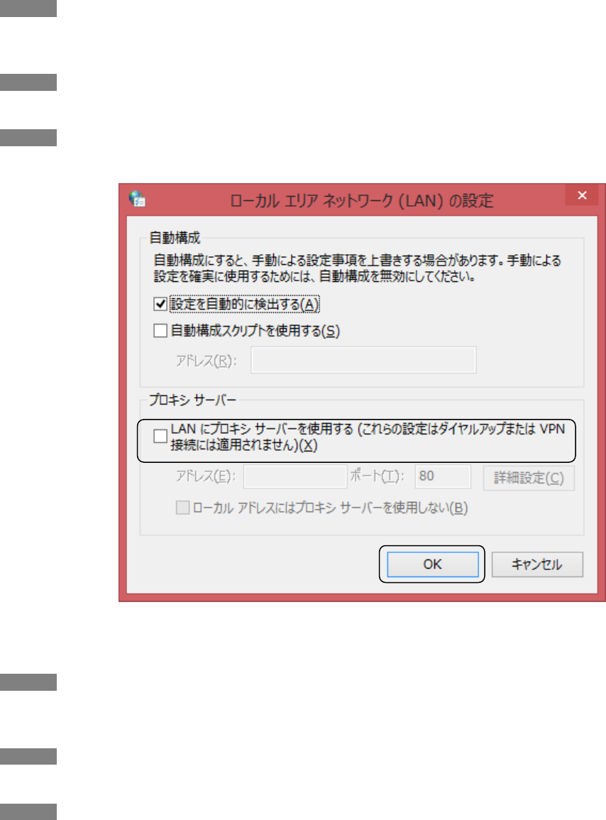
Step 3
Confirm that the "Use a proxy server for your LAN" check box is unchecked.
Local Area Network (LAN) Settings
When using a proxy server, configure not to use the proxy server for this product.
Step 4
Open the "Control Panel"window and click [Internet Options]. The "Internet Properties" window will be
displayed.
Step 5
Select the [Connections] tab and click [LAN settings].
Step 6
Check the "Use a proxy server for your LAN" check box and click [Advanced].

60
Step 7
Enter the IP address of this product to the "Do not use proxy for addresses beginning with" box under
"Exceptions".
Step 8
Click the [OK] button to return to "Local Area Network (LAN) Settings".
Step 9
Click the [OK] button and return to "Internet Properties".
Step 10
Click the [OK] button.

61
Chapter
5. Response to error occurrence

62
5.1. Troubleshooting
The following are descriptions of how to connect a PC for web console use and of how to configure the setting of this
product.
Refer to the following descriptions when an error occurred in this product.
Panasonic System Networks Co.,Ltd
1-62, 4-chome, Minoshima, Hakata-ku, Fukuoka 812-8531, Japan
©Panasonic System Networks Co., Ltd. 2015
Symptom
Inspection
Solution
The ACT LED does not
light.
Isn't the Ethernet cable detached?
Connect ETH to the "DATA & POWER OUT" port of
the PoE injector when feeding power from PoE.
(Connect to the power feeding port of the PoE
power feeding equipment.)
Isn't the DC plug of the AC adapter
detached?
Connect the DC plug to the DC IN port.
Isn't the power cord detached from of the
AC adapter/PoE injector ?
Connect the power cord to the AC adapter/PoE
injector.
Cannot
establish
the
communi-
cation.
Cannot
transmit/
receive data.
Isn't the Ethernet cable detached?
Connect the Ethernet cable correctly.
Doesn't the Ethernet cable have a
breakage?
Check if the Ethernet cable works correctly, or
replace it.
Isn't there any obstacle blocking
communication between the wireless unit
and the terminal?
Remove the obstacle or change the installation
place of the wireless unit.
Cannot
search this
product from
the Wi-Fi
terminal.
Isn't the setting configured to hide SSID?
Follow Use's Guide to cancel the setting to hide
SSID or configure the settings to make possible to
connect with the Wi-Fi terminal in advance.
Isn't power supplied to the wireless unit?
Make sure that the power of the PoE power feeding
equipment or the DC power supply unit is turned
on.
Others
Cannot log in
from the
console.
Is the setting of the communication
software of the console correctly
configured?
Follow Use's Guide and configure the setting of the
communication software.
Are the login name and password
correct?
Retry to log in using the correct login name and
password.
The setting
is not applied
to this
product.
Check if the settings are appropriate.
Follow Use's Guide and apply the corresponding
setting data using the reset command.
xxxx-xxxx