Alpine Centricstor V3 1D Users Manual V3.1D User Guide
pmn to the manual 644f3bf2-b2ef-430f-a0df-a93ee0c9b827
2015-02-05
: Alpine Alpine-Centricstor-V3-1D-Users-Manual-355893 alpine-centricstor-v3-1d-users-manual-355893 alpine pdf
Open the PDF directly: View PDF ![]() .
.
Page Count: 640 [warning: Documents this large are best viewed by clicking the View PDF Link!]
- CentricStor V3.1D
- Contents
- Introduction
- CentricStor - Virtual Tape Library
- The CentricStor principle
- Hardware architecture
- Software architecture
- Operation
- Administering the tape cartridges
- Procedures
- New system functions
- Standard system functions
- Optional system functions
- Switching CentricStor on/off
- Selected system administrator activities
- Partitioning on the basis of volume groups
- General
- Rules
- System administrator activities
- Adding a logical volume group
- Adding a physical volume group
- Adding logical volumes to a logical volume group
- Adding physical volumes to a physical volume group
- Assigning an LVG to a PVG
- Removing an assignment between an LVG and a PVG
- Changing logical volumes to another group
- Removing logical volumes
- Removing logical volume groups
- Removing physical volumes from a physical volume group
- Removing physical volume groups
- Cache management
- Dual Save
- Reorganization
- Cleaning physical drives
- Synchronization of the system time using NTP
- Partitioning on the basis of volume groups
- Operating and monitoring CentricStor
- Technical design
- Operator configuration
- Starting GXCC
- GXCC
- Main window
- Standard
- Loss of a connection
- Elements of the GXCC main window
- Message window
- Asynchronous errors
- Block diagram
- ICP object information
- IDP object information
- Functions of an ISP
- Functions for all ISPs of a particular class
- Information about the RAID systems
- RAID system functions
- Information on Fibre Channel fabric
- Functions of the Fibre Channel fabric
- Information about the FC connections
- Information on the archive systems
- ISP system messages
- SNMP messages
- Configuration Changed
- Function bar
- Overview of GXCC functions
- File
- Unit
- Options
- Autoscan
- Tools
- Configuration
- Profile
- Administration
- Show WWN’s
- Show Optional Functions
- Show CS Configuration
- Diagnostic Snapshots
- Logical Volume Operations
- Logical Volume Operations » Show Logical Volumes
- Logical Volume Operations » Show Logical Volumes (physical view)
- Logical Volume Operations » Change Volume Group
- Logical Volume Operations » Add Logical Volumes
- Logical Volume Operations » Erase Logical Volumes
- Physical Volume Operations
- Physical Volume Operations » Show Physical Volumes
- Physical Volume Operations » Link/Unlink Volume Groups
- Physical Volume Operations » Add Physical Volumes
- Physical Volume Operations » Erase Physical Volumes
- Physical Volume Operations » Reorganize Physical Volumes
- Setup for accounting mails
- Help
- Main window
- Global Status
- General
- Operation of the Global Status Monitor
- Function bar of the Global Status Monitor
- Global Status button bar
- Display of the Global Status Monitor
- History data
- General
- Data which can be called via the function bar
- Statistics » History of
- Statistics » History of » Cache Usage
- Statistics » History of » Channel/Device Performance
- Statistics » Logical Components
- Statistics » Logical Components » Logical Drives
- Statistics » Logical Components »Logical Volumes (physical view)
- Statistics » Logical Components » Logical Volumes (logical view)
- Statistics » Logical Components » Logical Volume Groups
- Statistics » Logical Components » Jobs of Logical Volume Groups
- Statistics » Physical Components
- Statistics » Physical Components » Physical Drives
- Statistics » Physical Components » Physical Volumes
- Statistics » Physical Components » Physical Volume Groups
- Statistics » Physical Components » Jobs of Physical Vol. Groups
- Statistics » Physical Components » Reorganization Status
- Statistics » Usage (Accounting)
- Data which can be called via objects of the Global Status
- History diagrams
- XTCC
- General
- Margins of the main XTCC window
- Function bar
- Elements of the XTCC window
- File viewer
- ISP
- Internal objects of the ISP
- ESCON/FICON host adapter
- Emulations of drives connected to OS/390 host adapters
- Virtual 3490 drives
- FC-SCSI host adapter
- Emulations of SCSI drives (VTD)
- Virtual SCSI drives
- VLS (Virtual Library Service)
- VMD (Virtual Mount Daemon)
- VLM (Virtual Library Manager)
- RAID systems
- PLM (Physical Library Manager)
- PLS (Physical Library Service)
- SCSI archive systems
- PDS (Physical Device Service)
- SCSI controllers
- Cartridge drives (real)
- MSGMGR (Message Manager)
- PERFLOG
- ACCOUNTD (Account Daemon)
- MIRRORD (mirror daemon)
- S80D (S80 daemon)
- VLPWATCH (VLPwatch daemon)
- Explanation of console messages
- General
- Message lines
- SXCF... (CMF: Cache Mirroring Feature)
- SXCH... (Channel: pcib/pcea)
- SXCM... (CHIM)
- SXDN... (DNA: Distribute and Activate)
- SXDT... (DTV File System)
- SXFC... (FibreChannel Driver)
- SXFP... (FibreChannel Driver)
- SXFW... (Firmware)
- SXIB... (Info Broker)
- SXLA... (LANWATCH)
- SXLV... (Log Volume)
- SXMM... (Message Manager)
- SXPL... (PLM: Physical Library Manager)
- SXPS... (PLS: Physical Library Server)
- SXRD... (FibreCAT: RAID)
- SXRP... (RPLM: Recovery Physical Library Manager)
- SXSB... (Sadm Driver: SCSI bus error)
- SXSC... (Savecore: organize coredump)
- SXSD... (SCSI Disks: driver shd)
- SXSE... (EXABYTE Tapes)
- SXSM... (Server Management)
- SXSW... (Software Mirror)
- SXTF... (Tape File System)
- SXVD... (Distributed Tape Volume Driver)
- SXVL... (VLM: Virtual Library Manager)
- SXVLS... (VT_LS: Virtual Tape and Library System)
- SXVS... (VLS: Virtual Library Server)
- SXVW... (VLPWATCH)
- SXVX... (Veritas File System)
- Message complexes
- Waste disposal and recycling
- Contacting the Help Desk
- Appendix
- Integration of CentricStor V3.1 in SNMP
- E-mail support in CentricStor
- Transferring volumes
- Licenses
- Glossary
- Figures
- Abbreviations
- Related publications
- Index

Edition July 2007
CentricStor V3.1D
User Guide

Comments…Suggestions…Corrections…
The User Documentation Department would like to know your
opinion on this manual. Your feedback helps us to optimize our
documentation to suit your individual needs.
Feel free to send us your comments by e-mail to:
manuals@fujitsu-siemens.com
Certified documentation
according to DIN EN ISO 9001:2000
To ensure a consistently high quality standard and
user-friendliness, this documentation was created to
meet the regulations of a quality management system which
complies with the requirements of the standard
DIN EN ISO 9001:2000.
cognitas. Gesellschaft für Technik-Dokumentation mbH
www.cognitas.de
Copyright and Trademarks
This manual is printed
on paper treated with
chlorine-free bleach.
Copyright © Fujitsu Siemens Computers GmbH 2007.
All rights reserved.
Delivery subject to availability; right of technical modifications reserved.
All hardware and software names used are trademarks of their respective manufacturers.
This manual was produced by
cognitas. Gesellschaft für Technik-Dokumentation mbH
www.cognitas.de

U41117-J-Z125-7-76
Contents
1 Introduction . . . . . . . . . . . . . . . . . . . . . . . . . . . . . . . . . . . . . . .19
1.1 Objective and target group for the manual . . . . . . . . . . . . . . . . . . . . . . 20
1.2 Concept of the manual . . . . . . . . . . . . . . . . . . . . . . . . . . . . . . . . . 20
1.3 Notational conventions . . . . . . . . . . . . . . . . . . . . . . . . . . . . . . . . 21
1.4 Note . . . . . . . . . . . . . . . . . . . . . . . . . . . . . . . . . . . . . . . . . . . 21
2 CentricStor - Virtual Tape Library . . . . . . . . . . . . . . . . . . . . . . . . . . . 23
2.1 The CentricStor principle . . . . . . . . . . . . . . . . . . . . . . . . . . . . . . . 23
2.2 Hardware architecture . . . . . . . . . . . . . . . . . . . . . . . . . . . . . . . . . 26
2.2.1 ISP (Integrated Service Processor) . . . . . . . . . . . . . . . . . . . . . . . . . . . 27
2.2.1.1 VLP (Virtual Library Processor) . . . . . . . . . . . . . . . . . . . . . . . . . . . 27
2.2.1.2 ICP (Integrated Channel Processor) . . . . . . . . . . . . . . . . . . . . . . . . . 28
2.2.1.3 IDP (Integrated Device Processor) . . . . . . . . . . . . . . . . . . . . . . . . . 29
2.2.1.4 ICP_IDP or IUP (Integrated Universal Processor) . . . . . . . . . . . . . . . . . . 29
2.2.2 RAID systems for the Tape Volume Cache . . . . . . . . . . . . . . . . . . . . . . . 30
2.2.3 FibreChannel (FC) . . . . . . . . . . . . . . . . . . . . . . . . . . . . . . . . . . . .31
2.2.4 FC switch (fibre channel switch) . . . . . . . . . . . . . . . . . . . . . . . . . . . . . 31
2.2.5 Host connection . . . . . . . . . . . . . . . . . . . . . . . . . . . . . . . . . . . . .32
2.3 Software architecture . . . . . . . . . . . . . . . . . . . . . . . . . . . . . . . . . 32
2.4 Operation . . . . . . . . . . . . . . . . . . . . . . . . . . . . . . . . . . . . . . . . 35
2.5 Administering the tape cartridges . . . . . . . . . . . . . . . . . . . . . . . . . . 35
2.5.1 Writing the tape cartridges according to the stacked volume principle . . . . . . . . . 35
2.5.2 Repeated writing of a logical volume onto tape . . . . . . . . . . . . . . . . . . . . . 36
2.5.3 Creating a directory . . . . . . . . . . . . . . . . . . . . . . . . . . . . . . . . . . .36
2.5.4 Reorganization of the tape cartridges . . . . . . . . . . . . . . . . . . . . . . . . . . 37

U41117-J-Z125-7-76
Contents
2.6 Procedures . . . . . . . . . . . . . . . . . . . . . . . . . . . . . . . . . . . . . . .38
2.6.1 Creating the CentricStor data maintenance . . . . . . . . . . . . . . . . . . . . . . . 38
2.6.2 Issuing a mount job from the host . . . . . . . . . . . . . . . . . . . . . . . . . . . . 39
2.6.3 Scratch mount . . . . . . . . . . . . . . . . . . . . . . . . . . . . . . . . . . . . . . 42
2.7 New system functions . . . . . . . . . . . . . . . . . . . . . . . . . . . . . . . . . 43
2.8 Standard system functions . . . . . . . . . . . . . . . . . . . . . . . . . . . . . . 44
2.8.1 Partitioning by volume groups . . . . . . . . . . . . . . . . . . . . . . . . . . . . . . 44
2.8.2 “Call Home” in the event of an error . . . . . . . . . . . . . . . . . . . . . . . . . . . 44
2.8.3 SNMP support . . . . . . . . . . . . . . . . . . . . . . . . . . . . . . . . . . . . . .45
2.8.4 Exporting and importing tape cartridges . . . . . . . . . . . . . . . . . . . . . . . . . 45
2.8.4.1 Vault attribute and vault status . . . . . . . . . . . . . . . . . . . . . . . . . . . . 46
2.8.4.2 Transfer PVG . . . . . . . . . . . . . . . . . . . . . . . . . . . . . . . . . . . . .46
2.9 Optional system functions . . . . . . . . . . . . . . . . . . . . . . . . . . . . . . . 47
2.9.1 Compression . . . . . . . . . . . . . . . . . . . . . . . . . . . . . . . . . . . . . . . 48
2.9.2 Multiple library support . . . . . . . . . . . . . . . . . . . . . . . . . . . . . . . . . .49
2.9.3 Dual Save . . . . . . . . . . . . . . . . . . . . . . . . . . . . . . . . . . . . . . . . 50
2.9.4 Extending virtual drives . . . . . . . . . . . . . . . . . . . . . . . . . . . . . . . . .52
2.9.5 System administrator’s edition . . . . . . . . . . . . . . . . . . . . . . . . . . . . . . 52
2.9.6 Fibre channel connection for load balancing and redundancy . . . . . . . . . . . . . . 52
2.9.7 Automatic VLP failover . . . . . . . . . . . . . . . . . . . . . . . . . . . . . . . . . . 52
2.9.8 Cache Mirroring Feature . . . . . . . . . . . . . . . . . . . . . . . . . . . . . . . . . 55
2.9.8.1 General . . . . . . . . . . . . . . . . . . . . . . . . . . . . . . . . . . . . . . . 55
2.9.8.2 Hardware requirements . . . . . . . . . . . . . . . . . . . . . . . . . . . . . . . 55
2.9.8.3 Software requirements . . . . . . . . . . . . . . . . . . . . . . . . . . . . . . . . 56
2.9.8.4 Mirrored RAID systems . . . . . . . . . . . . . . . . . . . . . . . . . . . . . . . 57
2.9.8.5 Presentation of the mirror function in GXCC . . . . . . . . . . . . . . . . . . . . 58
2.9.9 Accounting . . . . . . . . . . . . . . . . . . . . . . . . . . . . . . . . . . . . . . . . 59
3 Switching CentricStor on/off . . . . . . . . . . . . . . . . . . . . . . . . . . . . . 61
3.1 Switching CentricStor on . . . . . . . . . . . . . . . . . . . . . . . . . . . . . . . 61
3.2 Switching CentricStor off . . . . . . . . . . . . . . . . . . . . . . . . . . . . . . . 62
4 Selected system administrator activities . . . . . . . . . . . . . . . . . . . . . . . 63
4.1 Partitioning on the basis of volume groups . . . . . . . . . . . . . . . . . . . . . 63
4.1.1 General . . . . . . . . . . . . . . . . . . . . . . . . . . . . . . . . . . . . . . . . . 63
4.1.2 Rules . . . . . . . . . . . . . . . . . . . . . . . . . . . . . . . . . . . . . . . . . . . 64

U41117-J-Z125-7-76
Contents
4.1.3 System administrator activities . . . . . . . . . . . . . . . . . . . . . . . . . . . . . 65
4.1.3.1 Adding a logical volume group . . . . . . . . . . . . . . . . . . . . . . . . . . . . 66
4.1.3.2 Adding a physical volume group . . . . . . . . . . . . . . . . . . . . . . . . . . . 66
4.1.3.3 Adding logical volumes to a logical volume group . . . . . . . . . . . . . . . . . . 66
4.1.3.4 Adding physical volumes to a physical volume group . . . . . . . . . . . . . . . . 67
4.1.3.5 Assigning an LVG to a PVG . . . . . . . . . . . . . . . . . . . . . . . . . . . . . 67
4.1.3.6 Removing an assignment between an LVG and a PVG . . . . . . . . . . . . . . . 67
4.1.3.7 Changing logical volumes to another group . . . . . . . . . . . . . . . . . . . . . 68
4.1.3.8 Removing logical volumes . . . . . . . . . . . . . . . . . . . . . . . . . . . . . . 68
4.1.3.9 Removing logical volume groups . . . . . . . . . . . . . . . . . . . . . . . . . . 68
4.1.3.10 Removing physical volumes from a physical volume group . . . . . . . . . . . . . 69
4.1.3.11 Removing physical volume groups . . . . . . . . . . . . . . . . . . . . . . . . . 69
4.2 Cache management . . . . . . . . . . . . . . . . . . . . . . . . . . . . . . . . . . 70
4.3 Dual Save . . . . . . . . . . . . . . . . . . . . . . . . . . . . . . . . . . . . . . . . 71
4.3.1 General . . . . . . . . . . . . . . . . . . . . . . . . . . . . . . . . . . . . . . . . . 71
4.3.2 System administrator activities . . . . . . . . . . . . . . . . . . . . . . . . . . . . . 72
4.3.2.1 Assigning a logical volume group to two physical volume groups . . . . . . . . . . 72
4.3.2.2 Removing a Dual Save assignment . . . . . . . . . . . . . . . . . . . . . . . . . 72
4.4 Reorganization . . . . . . . . . . . . . . . . . . . . . . . . . . . . . . . . . . . . . 73
4.4.1 Why do we need reorganization? . . . . . . . . . . . . . . . . . . . . . . . . . . . . 73
4.4.2 How is a physical volume reorganized? . . . . . . . . . . . . . . . . . . . . . . . . . 74
4.4.3 When is a reorganization performed? . . . . . . . . . . . . . . . . . . . . . . . . . . 75
4.4.4 Which physical volume is selected for reorganization? . . . . . . . . . . . . . . . . . 76
4.4.5 Own physical volumes for reorganization backup . . . . . . . . . . . . . . . . . . . . 78
4.4.6 Starting the reorganization of a physical volume . . . . . . . . . . . . . . . . . . . . 78
4.4.7 Configuration parameters . . . . . . . . . . . . . . . . . . . . . . . . . . . . . . . . 79
4.5 Cleaning physical drives . . . . . . . . . . . . . . . . . . . . . . . . . . . . . . . . 81
4.6 Synchronization of the system time using NTP . . . . . . . . . . . . . . . . . . . 82
5 Operating and monitoring CentricStor . . . . . . . . . . . . . . . . . . . . . . . . 83
5.1 Technical design . . . . . . . . . . . . . . . . . . . . . . . . . . . . . . . . . . . . 83
5.1.1 General . . . . . . . . . . . . . . . . . . . . . . . . . . . . . . . . . . . . . . . . . 83
5.1.2 Principles of operation of GXCC . . . . . . . . . . . . . . . . . . . . . . . . . . . . . 84
5.1.3 Monitoring structure within a CentricStor ISP . . . . . . . . . . . . . . . . . . . . . . 87
5.1.4 Operating modes . . . . . . . . . . . . . . . . . . . . . . . . . . . . . . . . . . . .90
5.2 Operator configuration . . . . . . . . . . . . . . . . . . . . . . . . . . . . . . . . . 91
5.2.1 Basic configuration . . . . . . . . . . . . . . . . . . . . . . . . . . . . . . . . . . . .91
5.2.2 Expansion . . . . . . . . . . . . . . . . . . . . . . . . . . . . . . . . . . . . . . . . 91

U41117-J-Z125-7-76
Contents
5.2.3 GXCC in other systems . . . . . . . . . . . . . . . . . . . . . . . . . . . . . . . . . 92
5.2.4 Screen display requirements . . . . . . . . . . . . . . . . . . . . . . . . . . . . . . 92
5.2.5 Managing CentricStor via SNMP . . . . . . . . . . . . . . . . . . . . . . . . . . . . 92
5.2.5.1 Connection to SNMP management systems . . . . . . . . . . . . . . . . . . . . 92
5.2.5.2 SNMP and GXCC . . . . . . . . . . . . . . . . . . . . . . . . . . . . . . . . . . 93
5.3 Starting GXCC . . . . . . . . . . . . . . . . . . . . . . . . . . . . . . . . . . . . . 95
5.3.1 Differences to earlier CentricStor versions . . . . . . . . . . . . . . . . . . . . . . . 95
5.3.2 Command line . . . . . . . . . . . . . . . . . . . . . . . . . . . . . . . . . . . . . .95
5.3.2.1 Explanation of the start parameter -aspect . . . . . . . . . . . . . . . . . . . . . 97
5.3.3 Environment variable XTCC_CLASS . . . . . . . . . . . . . . . . . . . . . . . . . . 98
5.3.4 Passwords . . . . . . . . . . . . . . . . . . . . . . . . . . . . . . . . . . . . . . . . 98
5.3.4.1 Optional access control for Observe mode . . . . . . . . . . . . . . . . . . . . . 99
5.3.4.2 Authentication . . . . . . . . . . . . . . . . . . . . . . . . . . . . . . . . . . . .99
5.3.4.3 Suppressing the password query . . . . . . . . . . . . . . . . . . . . . . . . . 100
5.3.4.4 Additional password query . . . . . . . . . . . . . . . . . . . . . . . . . . . . . 101
5.3.5 Starting the CentricStor console . . . . . . . . . . . . . . . . . . . . . . . . . . . . 102
5.3.6 Starting from an X11 server . . . . . . . . . . . . . . . . . . . . . . . . . . . . . . 102
5.3.6.1 General notes on the X11 server architecture . . . . . . . . . . . . . . . . . . . 102
5.3.6.2 Using the direct XDMCP interface . . . . . . . . . . . . . . . . . . . . . . . . . 104
5.3.6.3 Starting from a UNIX system . . . . . . . . . . . . . . . . . . . . . . . . . . . 104
5.3.6.4 Starting from a Windows system via Exceed . . . . . . . . . . . . . . . . . . . 105
5.3.6.5 Starting from a Windows/NT system via XVision . . . . . . . . . . . . . . . . . 108
5.3.7 GXCC welcome screen . . . . . . . . . . . . . . . . . . . . . . . . . . . . . . . . 114
5.3.8 Selecting the CentricStor system . . . . . . . . . . . . . . . . . . . . . . . . . . . 116
5.3.9 Establishing a connection after clicking on OK . . . . . . . . . . . . . . . . . . . . 116
5.3.10 Authentication . . . . . . . . . . . . . . . . . . . . . . . . . . . . . . . . . . . . . 117
5.3.11 Software updates . . . . . . . . . . . . . . . . . . . . . . . . . . . . . . . . . . . 118
6 GXCC . . . . . . . . . . . . . . . . . . . . . . . . . . . . . . . . . . . . . . . . . 119
6.1 Main window . . . . . . . . . . . . . . . . . . . . . . . . . . . . . . . . . . . . . 119
6.1.1 Standard . . . . . . . . . . . . . . . . . . . . . . . . . . . . . . . . . . . . . . . . 119
6.1.2 Loss of a connection . . . . . . . . . . . . . . . . . . . . . . . . . . . . . . . . . . 120
6.1.3 Elements of the GXCC main window . . . . . . . . . . . . . . . . . . . . . . . . . 121
6.1.3.1 Title bar . . . . . . . . . . . . . . . . . . . . . . . . . . . . . . . . . . . . . . 121
6.1.3.2 Footer . . . . . . . . . . . . . . . . . . . . . . . . . . . . . . . . . . . . . . . 121
6.1.3.3 Function buttons and displays in the button bar . . . . . . . . . . . . . . . . . . 123
6.1.3.4 System information . . . . . . . . . . . . . . . . . . . . . . . . . . . . . . . . 123
6.1.3.5 Console messages . . . . . . . . . . . . . . . . . . . . . . . . . . . . . . . . 124
6.1.3.6 Function bar . . . . . . . . . . . . . . . . . . . . . . . . . . . . . . . . . . . . 124
6.1.4 Message window . . . . . . . . . . . . . . . . . . . . . . . . . . . . . . . . . . . 125
6.1.5 Asynchronous errors . . . . . . . . . . . . . . . . . . . . . . . . . . . . . . . . . . 125

U41117-J-Z125-7-76
Contents
6.1.6 Block diagram . . . . . . . . . . . . . . . . . . . . . . . . . . . . . . . . . . . . . 126
6.1.6.1 Status information . . . . . . . . . . . . . . . . . . . . . . . . . . . . . . . . . 133
6.1.6.2 Object information and object-related functions . . . . . . . . . . . . . . . . . . 133
6.1.7 ICP object information . . . . . . . . . . . . . . . . . . . . . . . . . . . . . . . . . 134
6.1.8 IDP object information . . . . . . . . . . . . . . . . . . . . . . . . . . . . . . . . . 135
6.1.9 Functions of an ISP . . . . . . . . . . . . . . . . . . . . . . . . . . . . . . . . . . 135
6.1.9.1 Show Details (XTCC) . . . . . . . . . . . . . . . . . . . . . . . . . . . . . . . 135
6.1.10 Functions for all ISPs of a particular class . . . . . . . . . . . . . . . . . . . . . . . 135
6.1.11 Information about the RAID systems . . . . . . . . . . . . . . . . . . . . . . . . . 136
6.1.12 RAID system functions . . . . . . . . . . . . . . . . . . . . . . . . . . . . . . . . . 137
6.1.12.1 Show complete RAID status . . . . . . . . . . . . . . . . . . . . . . . . . . . . 137
6.1.13 Information on Fibre Channel fabric . . . . . . . . . . . . . . . . . . . . . . . . . . 138
6.1.14 Functions of the Fibre Channel fabric . . . . . . . . . . . . . . . . . . . . . . . . . 138
6.1.14.1 Controller Color Scheme . . . . . . . . . . . . . . . . . . . . . . . . . . . . . 139
6.1.14.2 Show data fcswitch <Name of the switch> [(trap)] . . . . . . . . . . . . . . . . . 139
6.1.15 Information about the FC connections . . . . . . . . . . . . . . . . . . . . . . . . . 140
6.1.16 Information on the archive systems . . . . . . . . . . . . . . . . . . . . . . . . . . 140
6.1.17 ISP system messages . . . . . . . . . . . . . . . . . . . . . . . . . . . . . . . . . 141
6.1.18 SNMP messages . . . . . . . . . . . . . . . . . . . . . . . . . . . . . . . . . . . 141
6.1.19 Configuration Changed . . . . . . . . . . . . . . . . . . . . . . . . . . . . . . . . 142
6.2 Function bar . . . . . . . . . . . . . . . . . . . . . . . . . . . . . . . . . . . . . 143
6.2.1 Overview of GXCC functions . . . . . . . . . . . . . . . . . . . . . . . . . . . . . 143
6.2.2 File . . . . . . . . . . . . . . . . . . . . . . . . . . . . . . . . . . . . . . . . . . . 145
6.2.2.1 Save . . . . . . . . . . . . . . . . . . . . . . . . . . . . . . . . . . . . . . . . 145
6.2.2.2 Open . . . . . . . . . . . . . . . . . . . . . . . . . . . . . . . . . . . . . . . . 146
6.2.2.3 Show . . . . . . . . . . . . . . . . . . . . . . . . . . . . . . . . . . . . . . . . 146
6.2.2.4 Print . . . . . . . . . . . . . . . . . . . . . . . . . . . . . . . . . . . . . . . . 146
6.2.2.5 Exit . . . . . . . . . . . . . . . . . . . . . . . . . . . . . . . . . . . . . . . . . 147
6.2.3 Unit . . . . . . . . . . . . . . . . . . . . . . . . . . . . . . . . . . . . . . . . . . . 147
6.2.3.1 Select . . . . . . . . . . . . . . . . . . . . . . . . . . . . . . . . . . . . . . . 147
6.2.4 Options . . . . . . . . . . . . . . . . . . . . . . . . . . . . . . . . . . . . . . . . . 150
6.2.4.1 Settings . . . . . . . . . . . . . . . . . . . . . . . . . . . . . . . . . . . . . . 150
6.2.4.2 Show Current Aspect . . . . . . . . . . . . . . . . . . . . . . . . . . . . . . . 151
6.2.5 Autoscan . . . . . . . . . . . . . . . . . . . . . . . . . . . . . . . . . . . . . . . . 152
6.2.5.1 Start Autoscan/Stop Autoscan . . . . . . . . . . . . . . . . . . . . . . . . . . . 152
6.2.5.2 Settings . . . . . . . . . . . . . . . . . . . . . . . . . . . . . . . . . . . . . . 153
6.2.6 Tools . . . . . . . . . . . . . . . . . . . . . . . . . . . . . . . . . . . . . . . . . . 154
6.2.6.1 Global Status . . . . . . . . . . . . . . . . . . . . . . . . . . . . . . . . . . . 154
6.2.6.2 Get Remote/Expand Local File . . . . . . . . . . . . . . . . . . . . . . . . . . 154
6.2.6.3 Show Remote File . . . . . . . . . . . . . . . . . . . . . . . . . . . . . . . . . 156
6.2.6.4 Show System Messages . . . . . . . . . . . . . . . . . . . . . . . . . . . . . 158
6.2.6.5 GXCC Update/Revert Tool . . . . . . . . . . . . . . . . . . . . . . . . . . . . . 159

U41117-J-Z125-7-76
Contents
6.2.7 Configuration . . . . . . . . . . . . . . . . . . . . . . . . . . . . . . . . . . . . . . 166
6.2.7.1 RAID Filesystems . . . . . . . . . . . . . . . . . . . . . . . . . . . . . . . . . 171
6.2.7.2 Logical Volume Groups . . . . . . . . . . . . . . . . . . . . . . . . . . . . . . 173
6.2.7.3 Physical Volume Groups . . . . . . . . . . . . . . . . . . . . . . . . . . . . . . 181
6.2.7.4 Distribute and Activate . . . . . . . . . . . . . . . . . . . . . . . . . . . . . . . 188
6.2.8 Profile . . . . . . . . . . . . . . . . . . . . . . . . . . . . . . . . . . . . . . . . . 191
6.2.8.1 Add/Select Profile . . . . . . . . . . . . . . . . . . . . . . . . . . . . . . . . . 191
6.2.9 Administration . . . . . . . . . . . . . . . . . . . . . . . . . . . . . . . . . . . . . 193
6.2.9.1 Show WWN’s . . . . . . . . . . . . . . . . . . . . . . . . . . . . . . . . . . . 195
6.2.9.2 Show Optional Functions . . . . . . . . . . . . . . . . . . . . . . . . . . . . . 196
6.2.9.3 Show CS Configuration . . . . . . . . . . . . . . . . . . . . . . . . . . . . . . 197
6.2.9.4 Diagnostic Snapshots . . . . . . . . . . . . . . . . . . . . . . . . . . . . . . . 197
6.2.9.5 Logical Volume Operations . . . . . . . . . . . . . . . . . . . . . . . . . . . . 202
6.2.9.6 Logical Volume Operations » Show Logical Volumes . . . . . . . . . . . . . . . 203
6.2.9.7 Logical Volume Operations » Show Logical Volumes (physical view) . . . . . . . 207
6.2.9.8 Logical Volume Operations » Change Volume Group . . . . . . . . . . . . . . . 209
6.2.9.9 Logical Volume Operations » Add Logical Volumes . . . . . . . . . . . . . . . . 211
6.2.9.10 Logical Volume Operations » Erase Logical Volumes . . . . . . . . . . . . . . . 213
6.2.9.11 Physical Volume Operations . . . . . . . . . . . . . . . . . . . . . . . . . . . . 215
6.2.9.12 Physical Volume Operations » Show Physical Volumes . . . . . . . . . . . . . . 215
6.2.9.13 Physical Volume Operations » Link/Unlink Volume Groups . . . . . . . . . . . . 221
6.2.9.14 Physical Volume Operations » Add Physical Volumes . . . . . . . . . . . . . . . 223
6.2.9.15 Physical Volume Operations » Erase Physical Volumes . . . . . . . . . . . . . . 226
6.2.9.16 Physical Volume Operations » Reorganize Physical Volumes . . . . . . . . . . . 228
6.2.9.17 Setup for accounting mails . . . . . . . . . . . . . . . . . . . . . . . . . . . . . 229
6.2.10 Help . . . . . . . . . . . . . . . . . . . . . . . . . . . . . . . . . . . . . . . . . . 232
6.2.10.1 Readme / LIESMICH . . . . . . . . . . . . . . . . . . . . . . . . . . . . . . . 232
6.2.10.2 Direct Help / Direkthilfe . . . . . . . . . . . . . . . . . . . . . . . . . . . . . . 232
6.2.10.3 System Messages . . . . . . . . . . . . . . . . . . . . . . . . . . . . . . . . . 232
6.2.10.4 About GXCC... . . . . . . . . . . . . . . . . . . . . . . . . . . . . . . . . . . . 232
6.2.10.5 Revision Summary . . . . . . . . . . . . . . . . . . . . . . . . . . . . . . . . . 233
6.2.10.6 Hardware Summary . . . . . . . . . . . . . . . . . . . . . . . . . . . . . . . . 234
6.2.10.7 Online Manual . . . . . . . . . . . . . . . . . . . . . . . . . . . . . . . . . . . 235
7 Global Status . . . . . . . . . . . . . . . . . . . . . . . . . . . . . . . . . . . . . 237
7.1 General . . . . . . . . . . . . . . . . . . . . . . . . . . . . . . . . . . . . . . . . 237
7.2 Operation of the Global Status Monitor . . . . . . . . . . . . . . . . . . . . . . . 239
7.3 Function bar of the Global Status Monitor . . . . . . . . . . . . . . . . . . . . . 239
7.3.1 File . . . . . . . . . . . . . . . . . . . . . . . . . . . . . . . . . . . . . . . . . . . 239
7.3.1.1 Print . . . . . . . . . . . . . . . . . . . . . . . . . . . . . . . . . . . . . . . . 239

U41117-J-Z125-7-76
Contents
7.3.1.2 Exit . . . . . . . . . . . . . . . . . . . . . . . . . . . . . . . . . . . . . . . . . 240
7.3.2 Config . . . . . . . . . . . . . . . . . . . . . . . . . . . . . . . . . . . . . . . . . 241
7.3.3 Tools . . . . . . . . . . . . . . . . . . . . . . . . . . . . . . . . . . . . . . . . . . 242
7.3.3.1 Global eXtended Control Center . . . . . . . . . . . . . . . . . . . . . . . . . . 242
7.3.3.2 Show Balloon Help Summary . . . . . . . . . . . . . . . . . . . . . . . . . . . 242
7.3.4 Statistics . . . . . . . . . . . . . . . . . . . . . . . . . . . . . . . . . . . . . . . . 245
7.3.5 Help . . . . . . . . . . . . . . . . . . . . . . . . . . . . . . . . . . . . . . . . . . 245
7.4 Global Status button bar . . . . . . . . . . . . . . . . . . . . . . . . . . . . . . . 246
7.5 Display of the Global Status Monitor . . . . . . . . . . . . . . . . . . . . . . . . 247
7.5.1 Performance . . . . . . . . . . . . . . . . . . . . . . . . . . . . . . . . . . . . . . 249
7.5.2 Virtual Components . . . . . . . . . . . . . . . . . . . . . . . . . . . . . . . . . . 251
7.5.3 Physical Components . . . . . . . . . . . . . . . . . . . . . . . . . . . . . . . . . 254
7.6 History data . . . . . . . . . . . . . . . . . . . . . . . . . . . . . . . . . . . . . . 257
7.6.1 General . . . . . . . . . . . . . . . . . . . . . . . . . . . . . . . . . . . . . . . . 258
7.6.1.1 Recording analog operating data . . . . . . . . . . . . . . . . . . . . . . . . . 258
7.6.1.2 Overview of the displays . . . . . . . . . . . . . . . . . . . . . . . . . . . . . . 258
7.6.1.3 Selecting the time period . . . . . . . . . . . . . . . . . . . . . . . . . . . . . 262
7.6.1.4 Selecting the presentation mode . . . . . . . . . . . . . . . . . . . . . . . . . 263
7.6.2 Data which can be called via the function bar . . . . . . . . . . . . . . . . . . . . . 264
7.6.2.1 Statistics » History of . . . . . . . . . . . . . . . . . . . . . . . . . . . . . . . 264
7.6.2.2 Statistics » History of » Cache Usage . . . . . . . . . . . . . . . . . . . . . . . 265
7.6.2.3 Statistics » History of » Channel/Device Performance . . . . . . . . . . . . . . 266
7.6.2.4 Statistics » Logical Components . . . . . . . . . . . . . . . . . . . . . . . . . . 267
7.6.2.5 Statistics » Logical Components » Logical Drives . . . . . . . . . . . . . . . . . 268
7.6.2.6 Statistics » Logical Components »Logical Volumes (physical view) . . . . . . . . 271
7.6.2.7 Statistics » Logical Components » Logical Volumes (logical view) . . . . . . . . 272
7.6.2.8 Statistics » Logical Components » Logical Volume Groups . . . . . . . . . . . . 273
7.6.2.9 Statistics » Logical Components » Jobs of Logical Volume Groups . . . . . . . . 275
7.6.2.10 Statistics » Physical Components . . . . . . . . . . . . . . . . . . . . . . . . . 276
7.6.2.11 Statistics » Physical Components » Physical Drives . . . . . . . . . . . . . . . 277
7.6.2.12 Statistics » Physical Components » Physical Volumes . . . . . . . . . . . . . . 279
7.6.2.13 Statistics » Physical Components » Physical Volume Groups . . . . . . . . . . . 283
7.6.2.14 Statistics » Physical Components » Jobs of Physical Vol. Groups . . . . . . . . 289
7.6.2.15 Statistics » Physical Components » Reorganization Status . . . . . . . . . . . . 291
7.6.2.16 Statistics » Usage (Accounting) . . . . . . . . . . . . . . . . . . . . . . . . . . 293
7.6.3 Data which can be called via objects of the Global Status . . . . . . . . . . . . . . 297
7.7 History diagrams . . . . . . . . . . . . . . . . . . . . . . . . . . . . . . . . . . . 298
7.7.1 Function/menu bar . . . . . . . . . . . . . . . . . . . . . . . . . . . . . . . . . . . 298
7.7.1.1 File . . . . . . . . . . . . . . . . . . . . . . . . . . . . . . . . . . . . . . . . . 298
7.7.1.2 Date . . . . . . . . . . . . . . . . . . . . . . . . . . . . . . . . . . . . . . . . 300
7.7.1.3 Time . . . . . . . . . . . . . . . . . . . . . . . . . . . . . . . . . . . . . . . . 301
7.7.1.4 Range . . . . . . . . . . . . . . . . . . . . . . . . . . . . . . . . . . . . . . . 301

U41117-J-Z125-7-76
Contents
7.7.1.5 Run . . . . . . . . . . . . . . . . . . . . . . . . . . . . . . . . . . . . . . . . 301
7.7.1.6 Mode . . . . . . . . . . . . . . . . . . . . . . . . . . . . . . . . . . . . . . . . 301
7.7.1.7 Profile . . . . . . . . . . . . . . . . . . . . . . . . . . . . . . . . . . . . . . . 302
7.7.1.8 Help . . . . . . . . . . . . . . . . . . . . . . . . . . . . . . . . . . . . . . . . 302
7.7.2 Toolbar . . . . . . . . . . . . . . . . . . . . . . . . . . . . . . . . . . . . . . . . . 302
7.7.3 Status bar . . . . . . . . . . . . . . . . . . . . . . . . . . . . . . . . . . . . . . . 303
7.7.4 Diagrams for the throughput (left-hand part of the screen) . . . . . . . . . . . . . . 303
7.7.5 Diagrams for virtual components (central part of the screen) . . . . . . . . . . . . . 305
7.7.5.1 ICP emulations . . . . . . . . . . . . . . . . . . . . . . . . . . . . . . . . . . 305
7.7.5.2 Cache Usage . . . . . . . . . . . . . . . . . . . . . . . . . . . . . . . . . . . 309
7.7.6 Diagrams of the physical components (right-hand part of the screen) . . . . . . . . 310
7.7.6.1 IDP statistics . . . . . . . . . . . . . . . . . . . . . . . . . . . . . . . . . . . . 310
7.7.6.2 Tape pool values . . . . . . . . . . . . . . . . . . . . . . . . . . . . . . . . . . 313
7.7.7 Exporting history data . . . . . . . . . . . . . . . . . . . . . . . . . . . . . . . . . 314
7.7.8 Command line tool for generating the history data . . . . . . . . . . . . . . . . . . 316
8 XTCC . . . . . . . . . . . . . . . . . . . . . . . . . . . . . . . . . . . . . . . . . 325
8.1 General . . . . . . . . . . . . . . . . . . . . . . . . . . . . . . . . . . . . . . . . 325
8.2 Margins of the main XTCC window . . . . . . . . . . . . . . . . . . . . . . . . . 328
8.2.1 Title bar . . . . . . . . . . . . . . . . . . . . . . . . . . . . . . . . . . . . . . . . 328
8.2.2 Status bar . . . . . . . . . . . . . . . . . . . . . . . . . . . . . . . . . . . . . . . 328
8.3 Function bar . . . . . . . . . . . . . . . . . . . . . . . . . . . . . . . . . . . . . 330
8.3.1 File . . . . . . . . . . . . . . . . . . . . . . . . . . . . . . . . . . . . . . . . . . . 331
8.3.1.1 Select . . . . . . . . . . . . . . . . . . . . . . . . . . . . . . . . . . . . . . . 331
8.3.1.2 Save . . . . . . . . . . . . . . . . . . . . . . . . . . . . . . . . . . . . . . . . 331
8.3.1.3 Show . . . . . . . . . . . . . . . . . . . . . . . . . . . . . . . . . . . . . . . . 331
8.3.1.4 Print . . . . . . . . . . . . . . . . . . . . . . . . . . . . . . . . . . . . . . . . 332
8.3.1.5 Exit . . . . . . . . . . . . . . . . . . . . . . . . . . . . . . . . . . . . . . . . . 334
8.3.2 Unit . . . . . . . . . . . . . . . . . . . . . . . . . . . . . . . . . . . . . . . . . . . 335
8.3.2.1 Select . . . . . . . . . . . . . . . . . . . . . . . . . . . . . . . . . . . . . . . 335
8.3.3 Options . . . . . . . . . . . . . . . . . . . . . . . . . . . . . . . . . . . . . . . . . 336
8.3.3.1 Settings . . . . . . . . . . . . . . . . . . . . . . . . . . . . . . . . . . . . . . 336
8.3.3.2 Toggle Size . . . . . . . . . . . . . . . . . . . . . . . . . . . . . . . . . . . . 337
8.3.3.3 Toggle Aspect . . . . . . . . . . . . . . . . . . . . . . . . . . . . . . . . . . . 337
8.3.3.4 Show Current Aspect . . . . . . . . . . . . . . . . . . . . . . . . . . . . . . . 337
8.3.3.5 Apply Current Aspect . . . . . . . . . . . . . . . . . . . . . . . . . . . . . . . 337
8.3.4 Autoscan . . . . . . . . . . . . . . . . . . . . . . . . . . . . . . . . . . . . . . . . 338
8.3.4.1 Start . . . . . . . . . . . . . . . . . . . . . . . . . . . . . . . . . . . . . . . . 338
8.3.4.2 Stop . . . . . . . . . . . . . . . . . . . . . . . . . . . . . . . . . . . . . . . . 338
8.3.4.3 Settings . . . . . . . . . . . . . . . . . . . . . . . . . . . . . . . . . . . . . . 339

U41117-J-Z125-7-76
Contents
8.3.4.4 Scan Now . . . . . . . . . . . . . . . . . . . . . . . . . . . . . . . . . . . . . 340
8.3.4.5 Interaction Timeout . . . . . . . . . . . . . . . . . . . . . . . . . . . . . . . . 340
8.3.5 Tools . . . . . . . . . . . . . . . . . . . . . . . . . . . . . . . . . . . . . . . . . . 341
8.3.5.1 XTCC Communications . . . . . . . . . . . . . . . . . . . . . . . . . . . . . . 341
8.3.5.2 Get Remote/Expand Local File . . . . . . . . . . . . . . . . . . . . . . . . . . 342
8.3.5.3 Show Remote File . . . . . . . . . . . . . . . . . . . . . . . . . . . . . . . . . 342
8.3.5.4 Compare Local Files . . . . . . . . . . . . . . . . . . . . . . . . . . . . . . . . 343
8.3.5.5 XTCC Update/Revert . . . . . . . . . . . . . . . . . . . . . . . . . . . . . . . 343
8.3.6 Profile . . . . . . . . . . . . . . . . . . . . . . . . . . . . . . . . . . . . . . . . . 344
8.3.6.1 Select . . . . . . . . . . . . . . . . . . . . . . . . . . . . . . . . . . . . . . . 346
8.3.7 Help . . . . . . . . . . . . . . . . . . . . . . . . . . . . . . . . . . . . . . . . . . 348
8.3.7.1 README / LIESMICH . . . . . . . . . . . . . . . . . . . . . . . . . . . . . . . 348
8.3.7.2 Direct Help / Direkthilfe . . . . . . . . . . . . . . . . . . . . . . . . . . . . . . 348
8.3.7.3 Mouse Functions / Maus-Funktionen . . . . . . . . . . . . . . . . . . . . . . . 348
8.3.7.4 About XTCC... . . . . . . . . . . . . . . . . . . . . . . . . . . . . . . . . . . . 349
8.3.7.5 CentricStor User Guide . . . . . . . . . . . . . . . . . . . . . . . . . . . . . . 350
8.3.7.6 CentricStor Service Manual . . . . . . . . . . . . . . . . . . . . . . . . . . . . 351
8.4 Elements of the XTCC window . . . . . . . . . . . . . . . . . . . . . . . . . . . 352
8.4.1 Display . . . . . . . . . . . . . . . . . . . . . . . . . . . . . . . . . . . . . . . . . 352
8.4.2 Unexpected errors . . . . . . . . . . . . . . . . . . . . . . . . . . . . . . . . . . . 354
8.4.3 Message window . . . . . . . . . . . . . . . . . . . . . . . . . . . . . . . . . . . 354
8.4.4 Object-related functions . . . . . . . . . . . . . . . . . . . . . . . . . . . . . . . . 355
8.4.5 Group display . . . . . . . . . . . . . . . . . . . . . . . . . . . . . . . . . . . . . 356
8.5 File viewer . . . . . . . . . . . . . . . . . . . . . . . . . . . . . . . . . . . . . . . 360
8.5.1 Opening the file viewer . . . . . . . . . . . . . . . . . . . . . . . . . . . . . . . . 360
8.5.2 Function bar . . . . . . . . . . . . . . . . . . . . . . . . . . . . . . . . . . . . . . 360
8.5.3 File . . . . . . . . . . . . . . . . . . . . . . . . . . . . . . . . . . . . . . . . . . . 361
8.5.3.1 Open (Text)/Open (Hex) . . . . . . . . . . . . . . . . . . . . . . . . . . . . . . 361
8.5.3.2 Save As . . . . . . . . . . . . . . . . . . . . . . . . . . . . . . . . . . . . . . 361
8.5.3.3 Re-read . . . . . . . . . . . . . . . . . . . . . . . . . . . . . . . . . . . . . . 361
8.5.3.4 Print . . . . . . . . . . . . . . . . . . . . . . . . . . . . . . . . . . . . . . . . 361
8.5.3.5 Exit . . . . . . . . . . . . . . . . . . . . . . . . . . . . . . . . . . . . . . . . . 361
8.5.4 AutoUpdate . . . . . . . . . . . . . . . . . . . . . . . . . . . . . . . . . . . . . . 362
8.5.4.1 Start . . . . . . . . . . . . . . . . . . . . . . . . . . . . . . . . . . . . . . . . 362
8.5.4.2 Stop . . . . . . . . . . . . . . . . . . . . . . . . . . . . . . . . . . . . . . . . 362
8.5.5 AutoPopup . . . . . . . . . . . . . . . . . . . . . . . . . . . . . . . . . . . . . . . 362
8.5.5.1 Enable . . . . . . . . . . . . . . . . . . . . . . . . . . . . . . . . . . . . . . . 362
8.5.5.2 Disable . . . . . . . . . . . . . . . . . . . . . . . . . . . . . . . . . . . . . . . 362
8.5.6 Highlight . . . . . . . . . . . . . . . . . . . . . . . . . . . . . . . . . . . . . . . . 363
8.5.7 Search down/up . . . . . . . . . . . . . . . . . . . . . . . . . . . . . . . . . . . . 364
8.5.8 Mode . . . . . . . . . . . . . . . . . . . . . . . . . . . . . . . . . . . . . . . . . . 365
8.5.8.1 1st Line -> Ruler/Selection -> Ruler . . . . . . . . . . . . . . . . . . . . . . . . 365
8.5.8.2 Text/Hex . . . . . . . . . . . . . . . . . . . . . . . . . . . . . . . . . . . . . . 365

U41117-J-Z125-7-76
Contents
8.5.8.3 Abort . . . . . . . . . . . . . . . . . . . . . . . . . . . . . . . . . . . . . . . . 365
8.5.8.4 Enlarge Font / Reduce Font . . . . . . . . . . . . . . . . . . . . . . . . . . . . 365
8.5.8.5 Tab Stop Interval . . . . . . . . . . . . . . . . . . . . . . . . . . . . . . . . . . 366
8.5.9 Help . . . . . . . . . . . . . . . . . . . . . . . . . . . . . . . . . . . . . . . . . . 366
8.6 ISP . . . . . . . . . . . . . . . . . . . . . . . . . . . . . . . . . . . . . . . . . . . 367
8.6.1 Object information on the ISP . . . . . . . . . . . . . . . . . . . . . . . . . . . . . 367
8.6.2 ISP functions . . . . . . . . . . . . . . . . . . . . . . . . . . . . . . . . . . . . . . 368
8.6.2.1 Show Revision History . . . . . . . . . . . . . . . . . . . . . . . . . . . . . . . 369
8.6.2.2 Version Consistency Check . . . . . . . . . . . . . . . . . . . . . . . . . . . . 370
8.6.2.3 Show Diff. Curr./Prev. Version . . . . . . . . . . . . . . . . . . . . . . . . . . . 371
8.6.2.4 Show Node Element Descriptors . . . . . . . . . . . . . . . . . . . . . . . . . 372
8.6.2.5 Show Configuration Data . . . . . . . . . . . . . . . . . . . . . . . . . . . . . 373
8.6.2.6 Show System Log . . . . . . . . . . . . . . . . . . . . . . . . . . . . . . . . . 375
8.6.2.7 Show SNMP Data . . . . . . . . . . . . . . . . . . . . . . . . . . . . . . . . . 375
8.6.2.8 Clean File System . . . . . . . . . . . . . . . . . . . . . . . . . . . . . . . . . 375
8.7 Internal objects of the ISP . . . . . . . . . . . . . . . . . . . . . . . . . . . . . . 376
8.7.1 Representation of internal objects . . . . . . . . . . . . . . . . . . . . . . . . . . . 376
8.7.1.1 Hard disk drives . . . . . . . . . . . . . . . . . . . . . . . . . . . . . . . . . . 376
8.7.1.2 CD-ROM . . . . . . . . . . . . . . . . . . . . . . . . . . . . . . . . . . . . . . 377
8.7.1.3 Streamer . . . . . . . . . . . . . . . . . . . . . . . . . . . . . . . . . . . . . . 377
8.7.1.4 SCSI controller . . . . . . . . . . . . . . . . . . . . . . . . . . . . . . . . . . . 378
8.7.1.5 RAID controller . . . . . . . . . . . . . . . . . . . . . . . . . . . . . . . . . . 378
8.7.2 Functions of the ISP-internal objects . . . . . . . . . . . . . . . . . . . . . . . . . 378
8.7.2.1 Hard disk, CD-ROM, streamer, all internal objects . . . . . . . . . . . . . . . . 378
8.7.2.2 SCSI controller . . . . . . . . . . . . . . . . . . . . . . . . . . . . . . . . . . . 378
8.7.2.3 RAID controller . . . . . . . . . . . . . . . . . . . . . . . . . . . . . . . . . . 378
8.8 ESCON/FICON host adapter . . . . . . . . . . . . . . . . . . . . . . . . . . . . . 379
8.8.1 Object information for the ESCON/FICON host adapter . . . . . . . . . . . . . . . . 379
8.8.2 ESCON/FICON host adapter functions . . . . . . . . . . . . . . . . . . . . . . . . 381
8.8.2.1 Show Node ID Details . . . . . . . . . . . . . . . . . . . . . . . . . . . . . . . 381
8.8.2.2 Show Node Element Descriptors . . . . . . . . . . . . . . . . . . . . . . . . . 382
8.8.2.3 Show Dump (prkdump) . . . . . . . . . . . . . . . . . . . . . . . . . . . . . . 383
8.9 Emulations of drives connected to OS/390 host adapters . . . . . . . . . . . . 384
8.9.1 Information on emulations . . . . . . . . . . . . . . . . . . . . . . . . . . . . . . . 384
8.9.2 Functions for individual 3490 emulations . . . . . . . . . . . . . . . . . . . . . . . 385
8.9.2.1 Show Error/Transfer Statistics . . . . . . . . . . . . . . . . . . . . . . . . . . . 386
8.9.2.2 Show Short Trace . . . . . . . . . . . . . . . . . . . . . . . . . . . . . . . . . 387
8.9.2.3 Show Path Trace . . . . . . . . . . . . . . . . . . . . . . . . . . . . . . . . . . 388
8.9.2.4 Show Error Log . . . . . . . . . . . . . . . . . . . . . . . . . . . . . . . . . . 389
8.9.2.5 Show Memory Log . . . . . . . . . . . . . . . . . . . . . . . . . . . . . . . . . 390
8.9.3 Functions for all 3490 emulations . . . . . . . . . . . . . . . . . . . . . . . . . . . 390

U41117-J-Z125-7-76
Contents
8.10 Virtual 3490 drives . . . . . . . . . . . . . . . . . . . . . . . . . . . . . . . . . . 391
8.10.1 Object information and error messages for virtual 3490 drives . . . . . . . . . . . . 391
8.10.1.1 Error conditions indicated on the display . . . . . . . . . . . . . . . . . . . . . 392
8.10.1.2 Object information . . . . . . . . . . . . . . . . . . . . . . . . . . . . . . . . . 393
8.10.1.3 SIM/MIM error messages on virtual devices . . . . . . . . . . . . . . . . . . . . 393
8.10.2 Virtual drive functions . . . . . . . . . . . . . . . . . . . . . . . . . . . . . . . . . 394
8.10.2.1 Show SCSI Sense . . . . . . . . . . . . . . . . . . . . . . . . . . . . . . . . . 395
8.10.2.2 Show Medium Info (MIM) . . . . . . . . . . . . . . . . . . . . . . . . . . . . . 396
8.10.2.3 Show Service Info (SIM) . . . . . . . . . . . . . . . . . . . . . . . . . . . . . . 397
8.10.2.4 Unload and Unmount . . . . . . . . . . . . . . . . . . . . . . . . . . . . . . . 397
8.11 FC-SCSI host adapter . . . . . . . . . . . . . . . . . . . . . . . . . . . . . . . . 398
8.11.1 Object information on FC-SCSI host adapters . . . . . . . . . . . . . . . . . . . . . 398
8.11.2 FC-SCSI host adapter functions . . . . . . . . . . . . . . . . . . . . . . . . . . . . 399
8.11.2.1 Perform Link Down/Up Sequence . . . . . . . . . . . . . . . . . . . . . . . . . 399
8.12 Emulations of SCSI drives (VTD) . . . . . . . . . . . . . . . . . . . . . . . . . . 399
8.12.1 Object information on emulations of SCSI devices . . . . . . . . . . . . . . . . . . 399
8.12.2 Functions for individual VTD emulations . . . . . . . . . . . . . . . . . . . . . . . . 401
8.12.2.1 Show Trace . . . . . . . . . . . . . . . . . . . . . . . . . . . . . . . . . . . . 401
8.12.3 Functions for all VTD emulations . . . . . . . . . . . . . . . . . . . . . . . . . . . 401
8.13 Virtual SCSI drives . . . . . . . . . . . . . . . . . . . . . . . . . . . . . . . . . . 402
8.13.1 Object information on virtual tape drives . . . . . . . . . . . . . . . . . . . . . . . 402
8.13.2 Virtual generic drive functions . . . . . . . . . . . . . . . . . . . . . . . . . . . . . 404
8.13.2.1 Show SCSI Sense . . . . . . . . . . . . . . . . . . . . . . . . . . . . . . . . . 404
8.13.2.2 Show Medium Info (MIM) . . . . . . . . . . . . . . . . . . . . . . . . . . . . . 404
8.13.2.3 Show Service Info (SIM) . . . . . . . . . . . . . . . . . . . . . . . . . . . . . . 404
8.13.2.4 Unload and Unmount . . . . . . . . . . . . . . . . . . . . . . . . . . . . . . . 404
8.14 VLS (Virtual Library Service) . . . . . . . . . . . . . . . . . . . . . . . . . . . . 405
8.14.1 Object information on VLSs . . . . . . . . . . . . . . . . . . . . . . . . . . . . . . 405
8.14.2 Functions for individual VLSs . . . . . . . . . . . . . . . . . . . . . . . . . . . . . 406
8.14.2.1 Show Trace . . . . . . . . . . . . . . . . . . . . . . . . . . . . . . . . . . . . 406
8.14.3 Global functions for all VLSs of an ISP . . . . . . . . . . . . . . . . . . . . . . . . 406
8.15 VMD (Virtual Mount Daemon) . . . . . . . . . . . . . . . . . . . . . . . . . . . . 407
8.15.1 Object information on the Virtual Mount Daemon (VMD) . . . . . . . . . . . . . . . 407
8.15.2 VMD functions . . . . . . . . . . . . . . . . . . . . . . . . . . . . . . . . . . . . . 407
8.16 VLM (Virtual Library Manager) . . . . . . . . . . . . . . . . . . . . . . . . . . . . 408
8.16.1 Object information for the VLM . . . . . . . . . . . . . . . . . . . . . . . . . . . . 408
8.16.2 VLM functions . . . . . . . . . . . . . . . . . . . . . . . . . . . . . . . . . . . . . 408
8.16.2.1 Show Cache Status . . . . . . . . . . . . . . . . . . . . . . . . . . . . . . . . 408
8.16.2.2 Set HALT Mode/Set RUN Mode . . . . . . . . . . . . . . . . . . . . . . . . . . 410

U41117-J-Z125-7-76
Contents
8.17 RAID systems . . . . . . . . . . . . . . . . . . . . . . . . . . . . . . . . . . . . . 411
8.17.1 Object information on RAID systems . . . . . . . . . . . . . . . . . . . . . . . . . 411
8.17.2 Functions of RAID systems . . . . . . . . . . . . . . . . . . . . . . . . . . . . . . 414
8.17.2.1 Show Complete RAID Status (all types) . . . . . . . . . . . . . . . . . . . . . . 414
8.17.2.2 Show Mode Pages (CX500/CX3-20 and FCS80) . . . . . . . . . . . . . . . . . 415
8.17.2.3 Show Mode Page Details . . . . . . . . . . . . . . . . . . . . . . . . . . . . . 415
8.17.2.4 Show Log Pages . . . . . . . . . . . . . . . . . . . . . . . . . . . . . . . . . . 415
8.17.2.5 Show Log Page Details . . . . . . . . . . . . . . . . . . . . . . . . . . . . . . 415
8.18 PLM (Physical Library Manager) . . . . . . . . . . . . . . . . . . . . . . . . . . 416
8.18.1 Object information on the PLM . . . . . . . . . . . . . . . . . . . . . . . . . . . . 416
8.18.2 PLM functions . . . . . . . . . . . . . . . . . . . . . . . . . . . . . . . . . . . . . 416
8.19 PLS (Physical Library Service) . . . . . . . . . . . . . . . . . . . . . . . . . . . 417
8.19.1 Object information on the PLS . . . . . . . . . . . . . . . . . . . . . . . . . . . . . 417
8.19.2 Functions for individual PLSs . . . . . . . . . . . . . . . . . . . . . . . . . . . . . 417
8.19.3 Functions for all PLSs . . . . . . . . . . . . . . . . . . . . . . . . . . . . . . . . . 417
8.20 SCSI archive systems . . . . . . . . . . . . . . . . . . . . . . . . . . . . . . . . 418
8.20.1 Object information on archive systems . . . . . . . . . . . . . . . . . . . . . . . . 418
8.20.2 SCSI Archive system functions . . . . . . . . . . . . . . . . . . . . . . . . . . . . 419
8.20.2.1 Show Mode Pages . . . . . . . . . . . . . . . . . . . . . . . . . . . . . . . . . 419
8.20.2.2 Show Mode Page Details . . . . . . . . . . . . . . . . . . . . . . . . . . . . . 419
8.20.2.3 Show Log Pages . . . . . . . . . . . . . . . . . . . . . . . . . . . . . . . . . . 419
8.20.2.4 Show Log Page Details . . . . . . . . . . . . . . . . . . . . . . . . . . . . . . 419
8.21 PDS (Physical Device Service) . . . . . . . . . . . . . . . . . . . . . . . . . . . 420
8.21.1 Object information on PDS . . . . . . . . . . . . . . . . . . . . . . . . . . . . . . 420
8.21.2 PDS functions . . . . . . . . . . . . . . . . . . . . . . . . . . . . . . . . . . . . . 420
8.22 SCSI controllers . . . . . . . . . . . . . . . . . . . . . . . . . . . . . . . . . . . 421
8.22.1 Object information on SCSI controllers . . . . . . . . . . . . . . . . . . . . . . . . 421
8.22.2 SCSI controller functions . . . . . . . . . . . . . . . . . . . . . . . . . . . . . . . 422
8.22.2.1 Rescan own Bus . . . . . . . . . . . . . . . . . . . . . . . . . . . . . . . . . . 422
8.22.2.2 Rescan all Busses . . . . . . . . . . . . . . . . . . . . . . . . . . . . . . . . . 422
8.23 Cartridge drives (real) . . . . . . . . . . . . . . . . . . . . . . . . . . . . . . . . 423
8.23.1 Object information on tape drives . . . . . . . . . . . . . . . . . . . . . . . . . . . 423
8.23.2 Tape drive functions . . . . . . . . . . . . . . . . . . . . . . . . . . . . . . . . . . 425
8.23.2.1 Show SCSI Sense . . . . . . . . . . . . . . . . . . . . . . . . . . . . . . . . . 426
8.23.2.2 Show Log Pages . . . . . . . . . . . . . . . . . . . . . . . . . . . . . . . . . . 426
8.23.2.3 Show Log Page Details . . . . . . . . . . . . . . . . . . . . . . . . . . . . . . 427
8.23.2.4 Show Mode Pages . . . . . . . . . . . . . . . . . . . . . . . . . . . . . . . . . 427
8.23.2.5 Show Mode Page Details . . . . . . . . . . . . . . . . . . . . . . . . . . . . . 428
8.23.2.6 Show Vital Product Data . . . . . . . . . . . . . . . . . . . . . . . . . . . . . . 429
8.23.2.7 Show Medium Info (MIM) . . . . . . . . . . . . . . . . . . . . . . . . . . . . . 431
8.23.2.8 Show Service Info (SIM) . . . . . . . . . . . . . . . . . . . . . . . . . . . . . . 432

U41117-J-Z125-7-76
Contents
8.23.3 Global functions for tape drives . . . . . . . . . . . . . . . . . . . . . . . . . . . . 432
8.23.3.1 Remove Symbols of all Drives . . . . . . . . . . . . . . . . . . . . . . . . . . . 433
8.24 MSGMGR (Message Manager) . . . . . . . . . . . . . . . . . . . . . . . . . . . . 433
8.24.1 Object information on the Message Manager (MSGMGR) . . . . . . . . . . . . . . 433
8.24.2 MSGMGR functions . . . . . . . . . . . . . . . . . . . . . . . . . . . . . . . . . . 433
8.24.2.1 Show Trace . . . . . . . . . . . . . . . . . . . . . . . . . . . . . . . . . . . . 434
8.24.2.2 Show Trap Trace . . . . . . . . . . . . . . . . . . . . . . . . . . . . . . . . . . 434
8.25 PERFLOG . . . . . . . . . . . . . . . . . . . . . . . . . . . . . . . . . . . . . . . 435
8.25.1 Object information of PERFLOG . . . . . . . . . . . . . . . . . . . . . . . . . . . . 435
8.25.2 PERFLOG functions . . . . . . . . . . . . . . . . . . . . . . . . . . . . . . . . . . 436
8.25.2.1 Show Trace & Logging . . . . . . . . . . . . . . . . . . . . . . . . . . . . . . . 436
8.26 ACCOUNTD (Account Daemon) . . . . . . . . . . . . . . . . . . . . . . . . . . . 437
8.26.1 Object information of ACCOUNTD . . . . . . . . . . . . . . . . . . . . . . . . . . 437
8.26.2 Functions of the ACCOUNTD . . . . . . . . . . . . . . . . . . . . . . . . . . . . . 437
8.27 MIRRORD (mirror daemon) . . . . . . . . . . . . . . . . . . . . . . . . . . . . . 438
8.27.1 Object information of MIRRORD . . . . . . . . . . . . . . . . . . . . . . . . . . . . 438
8.27.2 Functions of MIRRORD . . . . . . . . . . . . . . . . . . . . . . . . . . . . . . . . 438
8.28 S80D (S80 daemon) . . . . . . . . . . . . . . . . . . . . . . . . . . . . . . . . . 439
8.28.1 Object information of S80D . . . . . . . . . . . . . . . . . . . . . . . . . . . . . . 439
8.28.2 Functions of S80D . . . . . . . . . . . . . . . . . . . . . . . . . . . . . . . . . . 439
8.29 VLPWATCH (VLPwatch daemon) . . . . . . . . . . . . . . . . . . . . . . . . . . 440
8.29.1 Object information of VLPWATCH . . . . . . . . . . . . . . . . . . . . . . . . . . . 440
8.29.2 Functions of VLPWATCH . . . . . . . . . . . . . . . . . . . . . . . . . . . . . . . 440
9 Explanation of console messages . . . . . . . . . . . . . . . . . . . . . . . . . 441
9.1 General . . . . . . . . . . . . . . . . . . . . . . . . . . . . . . . . . . . . . . . . 441
9.2 Message lines . . . . . . . . . . . . . . . . . . . . . . . . . . . . . . . . . . . . . 445
9.2.1 SXCF... (CMF: Cache Mirroring Feature) . . . . . . . . . . . . . . . . . . . . . . . 445
9.2.2 SXCH... (Channel: pcib/pcea) . . . . . . . . . . . . . . . . . . . . . . . . . . . . . 447
9.2.3 SXCM... (CHIM) . . . . . . . . . . . . . . . . . . . . . . . . . . . . . . . . . . . . 449
9.2.4 SXDN... (DNA: Distribute and Activate) . . . . . . . . . . . . . . . . . . . . . . . . 450
9.2.5 SXDT... (DTV File System) . . . . . . . . . . . . . . . . . . . . . . . . . . . . . . 450
9.2.6 SXFC... (FibreChannel Driver) . . . . . . . . . . . . . . . . . . . . . . . . . . . . . 452
9.2.7 SXFP... (FibreChannel Driver) . . . . . . . . . . . . . . . . . . . . . . . . . . . . . 454
9.2.8 SXFW... (Firmware) . . . . . . . . . . . . . . . . . . . . . . . . . . . . . . . . . . 455
9.2.9 SXIB... (Info Broker) . . . . . . . . . . . . . . . . . . . . . . . . . . . . . . . . . . 456
9.2.10 SXLA... (LANWATCH) . . . . . . . . . . . . . . . . . . . . . . . . . . . . . . . . . 458
9.2.11 SXLV... (Log Volume) . . . . . . . . . . . . . . . . . . . . . . . . . . . . . . . . . 458

U41117-J-Z125-7-76
Contents
9.2.12 SXMM... (Message Manager) . . . . . . . . . . . . . . . . . . . . . . . . . . . . . 459
9.2.13 SXPL... (PLM: Physical Library Manager) . . . . . . . . . . . . . . . . . . . . . . . 465
9.2.14 SXPS... (PLS: Physical Library Server) . . . . . . . . . . . . . . . . . . . . . . . . 482
9.2.15 SXRD... (FibreCAT: RAID) . . . . . . . . . . . . . . . . . . . . . . . . . . . . . . . 485
9.2.15.1 Messages of the monitoring daemon for the internal RAID . . . . . . . . . . . . 485
9.2.15.2 FibreCAT S80 messages . . . . . . . . . . . . . . . . . . . . . . . . . . . . . 488
9.2.15.3 FibreCAT CX500 and CX3-20 messages . . . . . . . . . . . . . . . . . . . . . 489
9.2.15.4 FibreCAT CX500 and CX3-20 messages . . . . . . . . . . . . . . . . . . . . . 490
9.2.16 SXRP... (RPLM: Recovery Physical Library Manager) . . . . . . . . . . . . . . . . . 491
9.2.17 SXSB... (Sadm Driver: SCSI bus error) . . . . . . . . . . . . . . . . . . . . . . . . 494
9.2.18 SXSC... (Savecore: organize coredump) . . . . . . . . . . . . . . . . . . . . . . . 495
9.2.19 SXSD... (SCSI Disks: driver shd) . . . . . . . . . . . . . . . . . . . . . . . . . . . 495
9.2.20 SXSE... (EXABYTE Tapes) . . . . . . . . . . . . . . . . . . . . . . . . . . . . . . 496
9.2.21 SXSM... (Server Management) . . . . . . . . . . . . . . . . . . . . . . . . . . . . 497
9.2.22 SXSW... (Software Mirror) . . . . . . . . . . . . . . . . . . . . . . . . . . . . . . . 510
9.2.23 SXTF... (Tape File System) . . . . . . . . . . . . . . . . . . . . . . . . . . . . . . 510
9.2.24 SXVD... (Distributed Tape Volume Driver) . . . . . . . . . . . . . . . . . . . . . . . 516
9.2.25 SXVL... (VLM: Virtual Library Manager) . . . . . . . . . . . . . . . . . . . . . . . . 517
9.2.26 SXVLS... (VT_LS: Virtual Tape and Library System) . . . . . . . . . . . . . . . . . 521
9.2.27 SXVS... (VLS: Virtual Library Server) . . . . . . . . . . . . . . . . . . . . . . . . . 522
9.2.28 SXVW... (VLPWATCH) . . . . . . . . . . . . . . . . . . . . . . . . . . . . . . . . . 523
9.2.29 SXVX... (Veritas File System) . . . . . . . . . . . . . . . . . . . . . . . . . . . . . 537
9.3 Message complexes . . . . . . . . . . . . . . . . . . . . . . . . . . . . . . . . . 538
9.3.1 Timeout on the RAID disk array . . . . . . . . . . . . . . . . . . . . . . . . . . . . 538
9.3.2 Timeout on the MTC drives . . . . . . . . . . . . . . . . . . . . . . . . . . . . . . 539
9.3.3 Failure of RAID systems . . . . . . . . . . . . . . . . . . . . . . . . . . . . . . . . 540
9.3.4 Failover at the RAID system . . . . . . . . . . . . . . . . . . . . . . . . . . . . . . 541
9.3.5 Bus Reset for SCSI Controller . . . . . . . . . . . . . . . . . . . . . . . . . . . . . 542
10 Waste disposal and recycling . . . . . . . . . . . . . . . . . . . . . . . . . . . . 543
11 Contacting the Help Desk . . . . . . . . . . . . . . . . . . . . . . . . . . . . . . 545
12 Appendix . . . . . . . . . . . . . . . . . . . . . . . . . . . . . . . . . . . . . . . 547
12.1 Integration of CentricStor V3.1 in SNMP . . . . . . . . . . . . . . . . . . . . . . 547
12.1.1 Structure . . . . . . . . . . . . . . . . . . . . . . . . . . . . . . . . . . . . . . . . 547
12.1.2 Activating SNMP on CentricStor . . . . . . . . . . . . . . . . . . . . . . . . . . . . 548
12.1.2.1 Configuring SNMP under CentricStor . . . . . . . . . . . . . . . . . . . . . . . 548

U41117-J-Z125-7-76
Contents
12.1.2.2 Activating the configuration . . . . . . . . . . . . . . . . . . . . . . . . . . . . 548
12.1.2.3 Changes in central files . . . . . . . . . . . . . . . . . . . . . . . . . . . . . . 548
12.1.3 Monitoring CentricStor . . . . . . . . . . . . . . . . . . . . . . . . . . . . . . . . . 549
12.1.3.1 GXCC as a monitoring tool without SNMP . . . . . . . . . . . . . . . . . . . . 549
12.1.3.2 Monitoring using any SNMP Management Station . . . . . . . . . . . . . . . . 550
12.1.3.3 CentricStor Global System State . . . . . . . . . . . . . . . . . . . . . . . . . 551
12.1.3.4 GXCC on the SNMP Management Station . . . . . . . . . . . . . . . . . . . . 551
12.1.3.5 Sending a trap to the Management Station . . . . . . . . . . . . . . . . . . . . 551
12.1.3.6 Monitoring of CentricStor V2/V3.0 and V3.1 . . . . . . . . . . . . . . . . . . . . 552
12.1.4 Installation on the Management Station CA Unicenter . . . . . . . . . . . . . . . . 552
12.1.4.1 Reading in the GUI CD . . . . . . . . . . . . . . . . . . . . . . . . . . . . . . 552
12.1.4.2 Installation of the CA Unicenter extensions for CentricStor . . . . . . . . . . . . 553
12.1.4.3 Identification and editing of the CentricStor traps . . . . . . . . . . . . . . . . . 553
12.1.5 Working with CA Unicenter and CentricStor . . . . . . . . . . . . . . . . . . . . . . 554
12.1.5.1 CentricStor icon under CA Unicenter . . . . . . . . . . . . . . . . . . . . . . . 554
12.1.5.2 Identifying a CentricStor and assigning the icon . . . . . . . . . . . . . . . . . . 555
12.1.5.3 Receipt and preparation of a CentricStor trap . . . . . . . . . . . . . . . . . . . 556
12.1.5.4 Monitoring CentricStor using ping and MIB-II . . . . . . . . . . . . . . . . . . . 557
12.1.5.5 Calling the GXCC from the pop-up menu of CA Unicenter . . . . . . . . . . . . 557
12.1.6 Monitoring of CentricStor V2/V3.0 and V3.1 with CA Unicenter . . . . . . . . . . . . 557
12.1.7 Summary . . . . . . . . . . . . . . . . . . . . . . . . . . . . . . . . . . . . . . . 557
12.2 E-mail support in CentricStor . . . . . . . . . . . . . . . . . . . . . . . . . . . . 558
12.2.1 Sendmail configuration . . . . . . . . . . . . . . . . . . . . . . . . . . . . . . . . 558
12.2.2 Setting up the DNS domain service . . . . . . . . . . . . . . . . . . . . . . . . . . 558
12.2.3 Configuring the e-mail template . . . . . . . . . . . . . . . . . . . . . . . . . . . . 560
12.2.4 Description of the e-mail formats . . . . . . . . . . . . . . . . . . . . . . . . . . . 561
12.3 Transferring volumes . . . . . . . . . . . . . . . . . . . . . . . . . . . . . . . . . 562
12.3.1 Introduction . . . . . . . . . . . . . . . . . . . . . . . . . . . . . . . . . . . . . . 562
12.3.2 Export procedure . . . . . . . . . . . . . . . . . . . . . . . . . . . . . . . . . . . 563
12.3.3 Import procedure . . . . . . . . . . . . . . . . . . . . . . . . . . . . . . . . . . . 564
12.3.4 Special features of the PVG TR-PVG . . . . . . . . . . . . . . . . . . . . . . . . . 565
12.3.5 Additional command line interface (CLI) . . . . . . . . . . . . . . . . . . . . . . . . 566
12.3.5.1 Transfer-out . . . . . . . . . . . . . . . . . . . . . . . . . . . . . . . . . . . . 566
12.3.5.2 Removing PVs and LVs . . . . . . . . . . . . . . . . . . . . . . . . . . . . . . 568
12.3.5.3 Adding a PV to the transfer-in . . . . . . . . . . . . . . . . . . . . . . . . . . . 568
12.3.5.4 Removing an LV from a transfer list . . . . . . . . . . . . . . . . . . . . . . . . 570
12.3.5.5 Skipping an LV / removing a PV . . . . . . . . . . . . . . . . . . . . . . . . . . 570
12.3.6 Special situations . . . . . . . . . . . . . . . . . . . . . . . . . . . . . . . . . . . 570
12.3.7 Library commands . . . . . . . . . . . . . . . . . . . . . . . . . . . . . . . . . . . 571
12.3.7.1 ADIC library with DAS server . . . . . . . . . . . . . . . . . . . . . . . . . . . 571
12.3.7.2 StorageTek Library with ACSLS server . . . . . . . . . . . . . . . . . . . . . . 571
12.3.7.3 Fujitsu Library with LMF server (PLP) . . . . . . . . . . . . . . . . . . . . . . . 571

U41117-J-Z125-7-76
Contents
12.4 Licenses . . . . . . . . . . . . . . . . . . . . . . . . . . . . . . . . . . . . . . . . 572
12.4.1 Xpdf, gzip . . . . . . . . . . . . . . . . . . . . . . . . . . . . . . . . . . . . . . . 572
12.4.1.1 Preamble . . . . . . . . . . . . . . . . . . . . . . . . . . . . . . . . . . . . . 572
12.4.1.2 GNU GENERAL PUBLIC LICENSE . . . . . . . . . . . . . . . . . . . . . . . . 573
12.4.1.3 Appendix: How to Apply These Terms to Your New Programs . . . . . . . . . . 577
12.4.2 Firebird . . . . . . . . . . . . . . . . . . . . . . . . . . . . . . . . . . . . . . . . . 579
12.4.3 Sendmail . . . . . . . . . . . . . . . . . . . . . . . . . . . . . . . . . . . . . . . . 589
12.4.4 XML . . . . . . . . . . . . . . . . . . . . . . . . . . . . . . . . . . . . . . . . . . 590
12.4.4.1 Licence for libxslt except libexslt . . . . . . . . . . . . . . . . . . . . . . . . . . 590
12.4.4.2 Licence for libexslt . . . . . . . . . . . . . . . . . . . . . . . . . . . . . . . . . 591
12.4.5 NTP . . . . . . . . . . . . . . . . . . . . . . . . . . . . . . . . . . . . . . . . . . 592
12.4.6 tcpd . . . . . . . . . . . . . . . . . . . . . . . . . . . . . . . . . . . . . . . . . . 596
12.4.7 PRNGD . . . . . . . . . . . . . . . . . . . . . . . . . . . . . . . . . . . . . . . . 596
12.4.8 openssh . . . . . . . . . . . . . . . . . . . . . . . . . . . . . . . . . . . . . . . . 597
12.4.9 openssl . . . . . . . . . . . . . . . . . . . . . . . . . . . . . . . . . . . . . . . . . 604
12.4.10 tcl . . . . . . . . . . . . . . . . . . . . . . . . . . . . . . . . . . . . . . . . . . . 607
12.4.11 tk . . . . . . . . . . . . . . . . . . . . . . . . . . . . . . . . . . . . . . . . . . . . 608
Glossary . . . . . . . . . . . . . . . . . . . . . . . . . . . . . . . . . . . . . . . 609
Figures . . . . . . . . . . . . . . . . . . . . . . . . . . . . . . . . . . . . . . . . 619
Related publications . . . . . . . . . . . . . . . . . . . . . . . . . . . . . . . . . 627
Index . . . . . . . . . . . . . . . . . . . . . . . . . . . . . . . . . . . . . . . . . . 629
U41117-J-Z125-7-76 19
1Introduction
With CentricStor, a virtual tape robot system is placed in front of the real tape robot system
(with the real drives and cartridges). In this way the host and the real archive are fully
decoupled. The virtual tape robot system knows what are referred to as virtual (logical)
drives and virtual (logical) volumes. The core element here consists principally of a disk
system as data cache, guaranteeing not only extremely high-speed access to the data, but
also, thanks to the large number of virtual drives (up to 512) and logical volumes (up to
500 000) which can be generated, that the bottlenecks which occur in a real robot system
can be cleared.

20 U41117-J-Z125-7-76
Objective and target group for the manual Introduction
The host is connected using the following connection technologies:
●ESCON channels
●FibreChannel
●FICON
Communication between the individual control units takes place via the LAN in CentricStor,
the transport of the user data to and from the RAID system via the FibreChannel.
The physical drives can be connected to the backend via both FibreChannel and SCSI
technology.
1.1 Objective and target group for the manual
This manual provides all the information you need to operate CentricStor. It is thus aimed
at operators and system administrators.
1.2 Concept of the manual
This manual describes how to use CentricStor in conjunction with a BS2000/MVS system
and Open Systems.
It supplies all the information you need to commission and administer CentricStor:
CentricStor - Virtual Tape Library
This chapter describes the CentricStor hardware and software architecture. It details the
operating procedures, so that you can gain an understanding of the way the system works.
It also contains information on the technical implementation, and a description of new and
optional components.
Switching CentricStor on/off
This chapter describes how to power up and shut down CentricStor.
Selected system administrator activities
This chapter contains information on selected system administrator activities in GXCC and
XTCC, the graphical user interface of CentricStor.
Operating and monitoring CentricStor
This chapter describes the technical concept for operating and monitoring CentricStor, and
explains how GXCC and XTCC are started.
GXCC
This chapter describes the GXCC program used to operate and monitor CentricStor.

U41117-J-Z125-7-76 21
Introduction Notational conventions
Global Status
The Global Status Monitor provides a graphical display of all important operating data in a
window.
XTCC
The program XTCC is used mainly to monitor the individual CentricStor computers (ISPs)
including the peripheral devices connected to the computers.
Explanation of console messages
This chapter describes the most important of the console messages. And as far as possible
suggests a way of solving the problem.
Appendix
The Appendix contains additional information concerning CentricStor.
Glossary
This chapter describes the most important CentricStor specific terms.
1.3 Notational conventions
This manual uses the following symbols and notational conventions to draw your attention
to certain passages of text:
Names, commands, and messages appear throughout the manual in typewriter font
(e.g. the SET-LOGON-PARAMETERS command).
1.4 Note
CentricStor is subject to constant development. The information contained in this manual is
subject to change without notice.
ÊThis symbol indicates actions that must be performed by the user
(e.g. keyboard input).
This symbol indicates important information (e.g. warnings).
This symbol indicates information which is particularly important for the
functionality of the product.
[ ... ] Square brackets are used to enclose cross-references to related publications,
and to indicate optional parameters in command descriptions.
!
i

Eine Dokuschablone von Frank Flachenecker
by f.f. 1992
U41117-J-Z125-7-76 23
2 CentricStor - Virtual Tape Library
2.1 The CentricStor principle
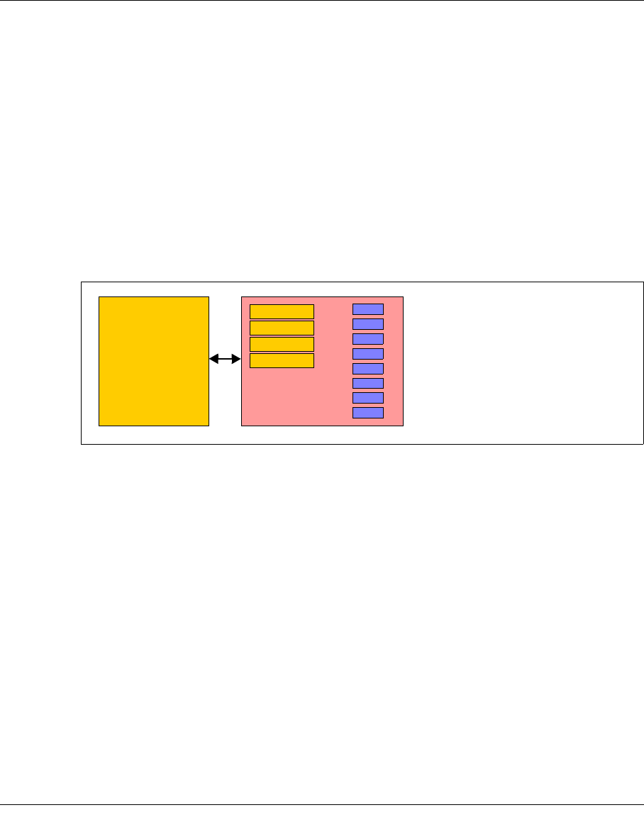
Conventional host robot system
Figure 1: Conventional host robot system
In a conventional real host robot system, the host system requests certain data cartridges
to be mounted in a defined real tape drive. As soon as the storage peripherals (robots,
drives) report that this has been completed successfully, data transfer can begin. In this
case, the host has direct, exclusive access to the drive in the archive system. It is crucial
that a completely static association be defined between the application and the physical
drive.
Host
Drive
Data cartridges
Robots
Drive
Drive
Drive
24 U41117-J-Z125-7-76
The CentricStor principle CentricStor - Virtual Tape Library
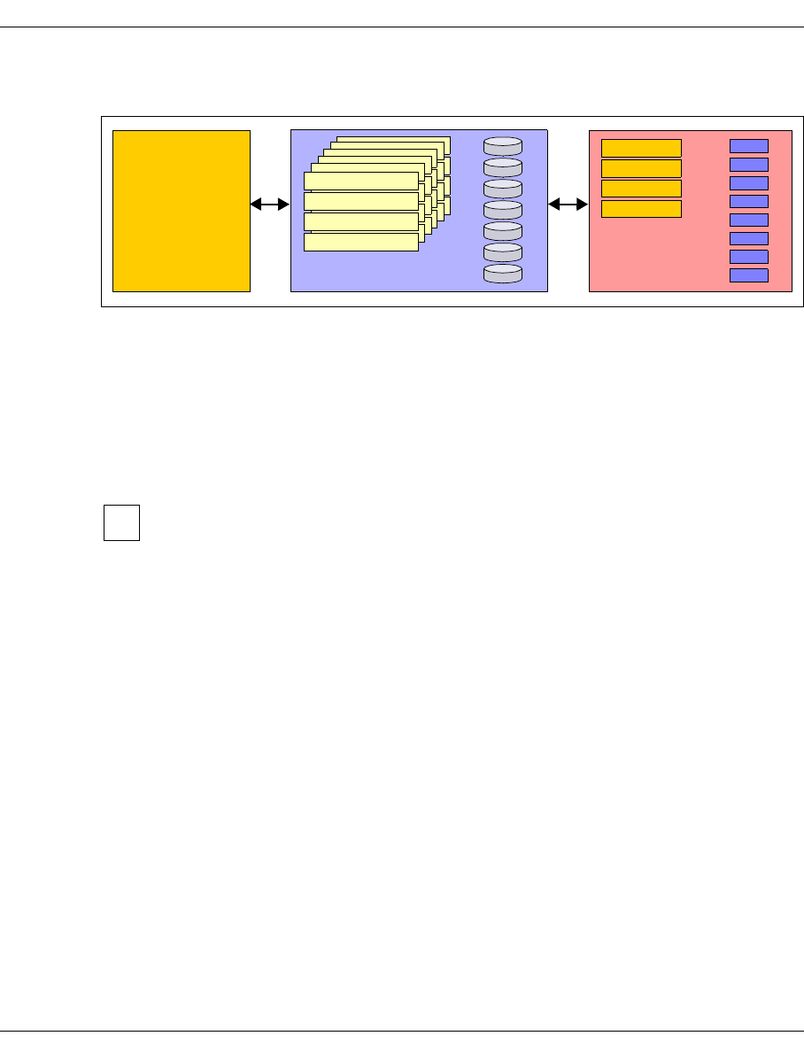
Host robot system with CentricStor
Figure 2: Host robot system with CentricStor
With CentricStor, a virtual archive system is installed upstream of the real archive system
with the physical drives and data cartridges. This enables the host to be completely isolated
from the real archive. The virtual archive system contains a series of logical drives and
volumes. At its heart is a data buffer, known as the disk cache, in which the logical volumes
are made available. This guarantees extremely fast access to the data, in most cases
allowing both read and write operations to be performed much more efficiently than in
conventional operation.
Instead of the term logical drives (or volumes), the term virtual drives (or volumes)
is sometimes also used. These terms should be regarded as synonyms. In this
manual the term logical is used consistently when drives and volumes in
CentricStor are meant, and physical when the real peripherals are meant.
The virtual archive system is particularly attractive, as it provides a large number of logical
drives compared to the number of physical drives. As a result, bottlenecks which exist in a
real archive can be eliminated or avoided.
From the host’s viewpoint, the logical drives and volumes act like real storage peripherals.
When a mount job is issued by a mainframe application or an open systems server, for
example, the requested logical volume is loaded into the disk cache. If the application then
writes data to the logical drive, the incoming data stream is written to the logical volume
created in the disk cache.
The Library Manager of the virtual archive system then issues a mount job to the real
archive system asynchronously and completely transparently to the host. The data is read
out directly from the disk cache and written to a physical tape cartridge. The physical
volume is thus updated with optimum resource utilization.
Logical volumes in the disk cache are not erased immediately. Instead, data is displaced in
accordance with the LRU principle (Least Recently Used). Sufficient space for this must be
allocated in the disk cache.
Data cartridges
Robots
Host
Disk cache
CentricStor
logical volumes
Logical drive
Logical drive
Logical drive
Logical drive
Drive
Drive
Drive
Drive
Physical volumes
Logical drive
Logical drive
Logical drive
Logical drive
Logical drive
Logical drive
Logical drive
Logical drive
Logical drive
Logical drive
Logical drive
Logical drive
Logical drive
Logical drive
Logical drive
Logical drive
Logical drive
Logical drive
Logical drive
Logical drive
i

U41117-J-Z125-7-76 25
CentricStor - Virtual Tape Library The CentricStor principle
As soon as a mount job is issued, the Library Manager checks whether the requested
volume is already in the disk cache. If so, the volume is immediately released for processing
by the application. If not, CentricStor requests the corresponding cartridge to be mounted
onto a physical drive, and reads the logical volume into the disk cache.
CentricStor thus operates as a very large, extremely powerful, highly intelligent data buffer
between the host level and the real archive system.
It offers the following advantages:
●removal of device bottlenecks through virtualization
●transparency to the host thanks to the retention of interfaces unchanged
●support for future technologies by isolating the host from the archive system
CentricStor thus provides a long-term, cost-effective basis for modern storage
management.
26 U41117-J-Z125-7-76
Hardware architecture CentricStor - Virtual Tape Library
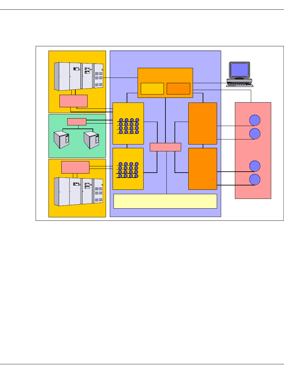
2.2 Hardware architecture
Figure 3: Example of a CentricStor configuration
In this example, CentricStor comprises the following hardware components:
●a VLP (Virtual Library Processor), which monitors and controls the CentricStor
hardware and software components
●two ICPs (Integrated Channel Processors), which communicate with the hosts via
ESCON (via ESCON Director), FICON (via FICON switch) or FC (via FC switch)
●two IDPs (Integrated Device Processors), which communicate with the tape drives in
the robot system via SCSI or FC
●one or more RAID systems for the TVC (Tape Volume Cache) for buffering logical
volumes
●an FC switch, which is used by the ICP, IDP, and VLP to transfer data
●a CentricStor console for performing configuration and administration tasks
●a LAN connection between CentricStor and the robot system
●a LAN connection, which is used by the ICP, IDP, and VLP for communication
The PLM (Physical Library Manager) and VLM (Virtual Library Manager) are software
components which are particularly important for system operation (see page 34).
CentricStor
TVC
Robots
CentricStor
Console
SCSI
SCSI
SCSI
SCSI
Real
Real
LAN
IDP
IDP
tape drives
tape drives
LAN
FC Switch
Mainframe
Mainframe
ESCON
UNIX/Windows
FC
Switch
FICON
Switch
ESCON
Director
FICON
ICP
Virtual
tape drives
ICP
Virtual
tape drives
LAN
LAN
VLP
PLMVLM
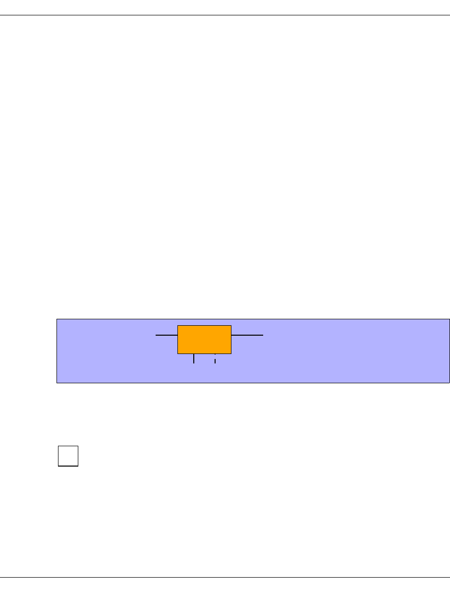
U41117-J-Z125-7-76 27
CentricStor - Virtual Tape Library Hardware architecture
2.2.1 ISP (Integrated Service Processor)
CentricStor is a group of several processors, each running special software (UNIX
derivative) as the operating system. These processors are referred to collectively as the ISP
(Integrated Service Processor). Depending on the peripheral connection, the hardware
configuration, the software configuration, and the task in the CentricStor system, a
distinction is made between the following processor types:
– VLPs (optional: SVLP = standby VLP)
–ICPs
–IDPs
–ICP_IDP
To permit communication between the processors, they are interconnected by an internal
LAN. The distinguishing characteristics of these processors are described in the following
sections.
2.2.1.1 VLP (Virtual Library Processor)
The processor of the type VLP can be included twice to provide failsafe performance. Only
one of the two plays an active role at any given time: the VLP Master. The other, the Standby
VLP (SVLP), is ready to take over the role of the VLP Master should the VLP Master fail
(see section “Automatic VLP failover” on page 52). The two VLPs are connected to each
other and to the ICPs, IDPs and TVC via FC.
Figure 4: Internal VLP connections
The main task of the VLP Master is the supervision and control of the hardware and
software components, including the data maintenance of the VLM and the PLM. Communi-
cation takes place via the LAN connection
The software which controls CentricStor (in particular, the VLM and PLM) is
installed on all the processors (VLP, ICP, and IDP) but is only activated on one
processor (the VLP Master).
CentricStor LAN
VLP
FC
FC
i
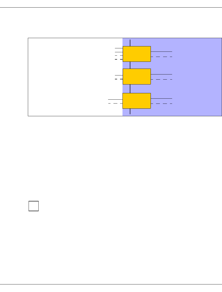
28 U41117-J-Z125-7-76
Hardware architecture CentricStor - Virtual Tape Library
2.2.1.2 ICP (Integrated Channel Processor)
The ICP is the interface to the host systems connected in the overall system.
Figure 5: External and internal ICP connections
Depending on the type of host system used, it is possible to equip an ICP with a maximum
of 4 ESCON boards on the host side (connection with BS2000/OSD, z/OS or OS/390), with
one or two FICON ports (connection with z/OS or OS/390), or with one or two FC boards
(BS2000/OSD or open systems). A mixed configuration is also possible.The ICP also has
an internal FC board (or two in the case of redundancy) for connecting to the RAID disk
system.
The main task of the ICP is to emulate physical drives to the connected host systems.
The host application issues a logical mount job for a logical drive in an ICP connected to a
host system (see section “Issuing a mount job from the host” on page 39). The data trans-
ferred for the associated logical volume is then stored by the ICP directly in the RAID disk
system.
The virtual CentricStor drives support a maximum block size of 256 KB.
Communication with the other processors takes place over a LAN connection.
FC
ESCON FC
ICP
FC
FCP FC
ICP
Hosts CentricStor
BS2000/OSD,
Open Systems
LAN
z/OS and OS/390
FC
FICON FC
ICP
z/OS and OS/390
BS2000/OSD,
i
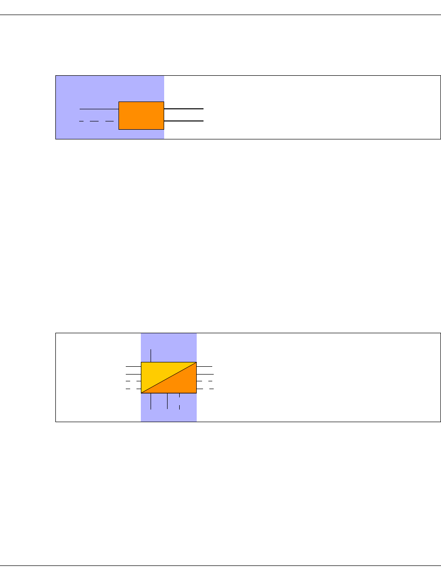
U41117-J-Z125-7-76 29
CentricStor - Virtual Tape Library Hardware architecture
2.2.1.3 IDP (Integrated Device Processor)
The IDP is the interface to the connected tape drives.
Figure 6: Internal and external IDP connections
The IDP is responsible for communication with real tape drives. To optimize performance,
only two real tape drives should be configured per IDP.
Because of the relatively short length of a SCSI cable (approx. 25 m), the CentricStor IDPs
are typically installed directly in the vicinity of the robot archive if a SCSI connection is to be
used to connect the drives.
It is capable of updating tape cartridges onto which data has already been written by
appending a further logical volume after the last one.
A cartridge filled in this way with a number of logical volumes is also referred to as a stacked
volume (see section “Administering the tape cartridges” on page 35).
Communication with the other processors takes place over a LAN connection.
2.2.1.4 ICP_IDP or IUP (Integrated Universal Processor)
An ICP_IDP provides the features of a VLP, an ICP and an IDP. This processor has inter-
faces to the hosts and to the tape drives.
However, the performance is a great deal lower than if its functions are distributed on its
own processors of the types VLP, ICP and IDP.
IUP (Integrated Universal Processor) is a synonym for ICP_IDP.
FC IDP
FC SCSI or FC
SCSI or FC
Robots
CentricStor
RobotsCentricStor
LAN
Hosts
Interfaces
to the host
Interfaces to
tape drives
FC FC
ICP_IDP

30 U41117-J-Z125-7-76
Hardware architecture CentricStor - Virtual Tape Library
2.2.2 RAID systems for the Tape Volume Cache
A TVC (Tape Volume Cache) is the heart of the entire virtual archive system. It represents
all of the Tape File Systems in which the logical volumes can be stored temporarily. One or
more RAID systems (up to 8) are used for this.
Each RAID system contains at least the basic configuration, which consists of FC disks and
2 RAID controllers. It can also be equipped with up to 7 extensions, which in turn constitute
a fully equipped shelf with FC or ATA disks. A RAID system consists of shelves which in
CentricStor are always fully equipped with disks. The TVC illustrated in the figure below
contains 2 RAID systems with a total of 12 equipped shelves:
Figure 7: 2 RAID systems form the TVC
In the case of the FibreCat CX3-20, for example, the 300-GB FC disks used offer a net ca-
pacity of 900 GB per RAID group. Here the basic configuration and each extension contain
3 RAID groups, resulting in a net capacity of 3 * 0.9 TB = 2.7 TB for each shelf. The net
capacity of the maximum configuration of a RAID system is therefore 8 * 2.7 TB = 21.6 TB.
One RAID group is used for one cache file system, which means that the basic configuration
and each extension contain 3 cache file systems and one RAID system with the maximum
configuration with 24 cache file sytems.
1st RAID system
basic config.
Shelf
extension
Shelf
extension
Shelf
extension
Shelf
extension
Shelf
extension
Shelf
extension
Shelf
extension
Shelf
2nd RAID system
basic config.
Shelf
extension
Shelf
extension
Shelf
extension
ShelfShelfShelfShelfShelf
TVC
Contr. 0 Contr. 1
Contr. 0 Contr. 1

U41117-J-Z125-7-76 31
CentricStor - Virtual Tape Library Hardware architecture
The metadata of the logical volumes to be written or read is stored on the 1st RAID system,
as a result of which the usable capacity of this RAID system is reduced by 16 GB.
A CentricStor can contain up to 8 RAID.
The number of cache file systems determines the number of logical volumes available (up
to 500,000). At least one cache file system is required for each 100,000 logical volumes.
The Cache Mirroring Feature (CMF) requires an additional cache file system for possible
recovery measures. Under these conditions the following minimum requirements conse-
quently apply for logical volumes with the standard size of 900 MB:
When larger logical volumes are used (2 - 200 GB, see the section “New system functions”
on page 43), correspondingly more cache file systems can be required. When the Cache
Mirroring Feature (see the page 55) is used, all cache file systems are mirrored to RAID
system pairs and therefore require double the disk resources. The capacity is therefore
reduced by 50%.
2.2.3 FibreChannel (FC)
The entire flow of data between all CentricStor components (ISPs and external RAID sys-
tems) is handled via an internal SAN which can provided with redundancy. It is implemented
by one high-performance FC switch or, if redundancy is provided, by two high-performance
FC switches.
2 FC technologies are available, Multi Mode and Single Mode. In Multi Mode the devices
which are connected via Fibre Channel can be located up to 300 m from each other; in Sin-
gle Mode the distance can be as much as 10 km. The FC controllers used in CentricStor
support bandwidths between 1Gb/s (Gigabits per second) and 4 Gb/s.
2.2.4 FC switch (fibre channel switch)
In the CentricStor models VTA 1500-5000, the entire flow of data between all CentricStor
components is handled by means of an FC switch.
Logical volumes Cache file systems required
100,000 At least 2
200,000 At least 3
300,000 At least 4
400,000 At least 5
500,000 At least 6
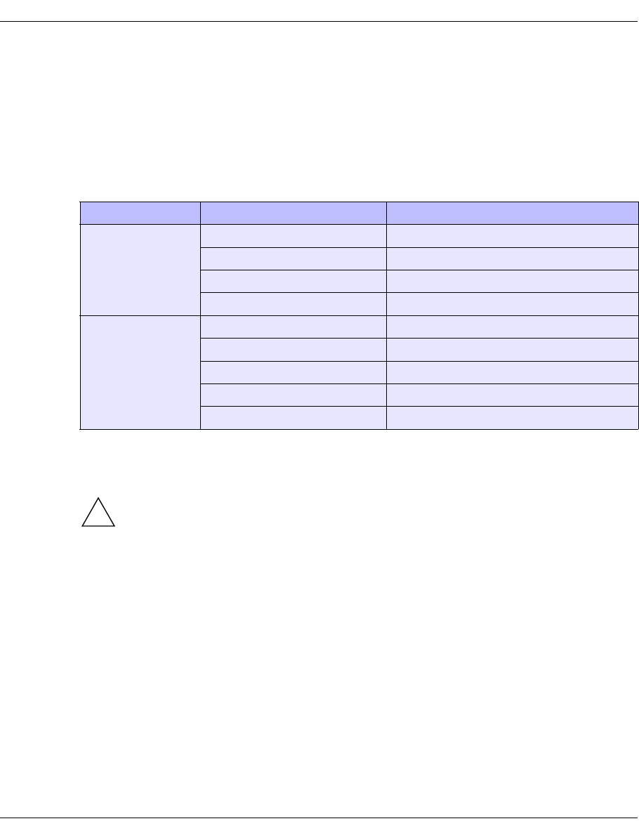
32 U41117-J-Z125-7-76
Software architecture CentricStor - Virtual Tape Library
This SAN-based design means that each CentricStor component is in a position to access
the TVC.
2.2.5 Host connection
The host connection on the ICP is implemented using the following connection
technologies:
FibreChannel with ESCON or FICON connections can be operated in mixed mode on an
ICP.
CAUTION!
Simultaneous operation of ESCON and FICON connections is not permitted on the
same ICP.
2.3 Software architecture
The functions VLP, ICP and IDP which are described in the following sections are not
necessarily separate hardware components.
In large CentricStor configurations (VTA 1500-5000) all functions are normally implemented
in separate hardware components. In smaller hardware configurations (VTA 500/1000,
VTC, SBU), several of these functions are implemented on one hardware component. In the
VTC all functions, including the RAID system, are combined in a hardware component.
If, for example, an ICP is designated an Integrated Channel Processor, this is to be under-
stood as a function and not as a hardware component.
Host system Operating system Connection
Mainframe BS2000/OSD ESCON or FibreChannel
z/OS and OS/390 ESCON or FICON
Bull ESCON
Unisys ESCON
Open Systems Reliant UNIX FibreChannel
Solaris FibreChannel
Microsoft Windows FibreChannel
AIX FibreChannel
HP-UX FibreChannel
!
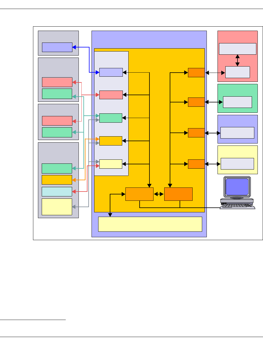
U41117-J-Z125-7-76 33
CentricStor - Virtual Tape Library Software architecture
Figure 8: Central role of the VLP in a CentricStor configuration1
VLP (Virtual Library Processor)
The VLP is responsible for the coordination of the entire CentricStor system. Although the
software can be activated on any of the ICP or IDP systems, it is recommended for perfor-
mance reasons that you either provide a separate VLP, or activate the components of the
VLP on one of the IDPs, since the CPU utilization is at its lowest here.
The use of a second VLP (SVLP) is optionally possible.
1VJUK runs on an ICP.
CentricStor
Open
ADIC
TVC
DAS-ACI
DAS
VLP
PLS
Backup
Systems
AMU/SDLC
VAMU
VDAS
VLS
VACS
ACSLS
StorageTek
ACSLS
PLS
MSP/XSP
LIB/SP
z/OS
HACC
CSC
BS2000
ROBAR
CSC
software
PLP
LMF LITE
Jukebox
Accessor
PLS
PLS
VLMF
VJUK
1
PLM
VLM
CentricStor
console
OS/390
SCSI

34 U41117-J-Z125-7-76
Software architecture CentricStor - Virtual Tape Library
VLM (Virtual Library Manager)
Each robot job from the requesting host system is registered in the VLM. To support the
libraries, corresponding emulations (VLMF, VAMU, VACS, VDAS, VJUK) are used in
CentricStor.
The TVC is administered exclusively by the VLM.
The VLM data maintenance contains the names of the logical volumes with which the TVC
is to work.
PLM (Physical Library Manager)
The PLM coordinates all jobs issued to the connected peripherals (robot drives). The PLM’s
data maintenance facility stores information about where and on which physical volume
each logical volume is stored.
VLS (Virtual Library Service)
There may be various different instances of the VLS, depending on the type and number of
connected host systems:
PLS (Physical Library Service)
The PLS is the link between CentricStor and the robot archive. Jobs to the robots, e.g.
moving a tape cartridge in the robot archive, are issued at the behest of the PLM.
Host connection Instance Library
BS2000/OSD, z/OS and OS/390 VAMU ADIC
Open Systems Server (UNIX, Windows) VDAS
CSC Clients of BS2000/OSD VACS StorageTek
Open Systems Server (UNIX, Windows) with ACSLS
LIB/SP Clients from Fujitsu VLMF Fujitsu
Open Systems Clients, UNIX and Windows VJUK SCSI
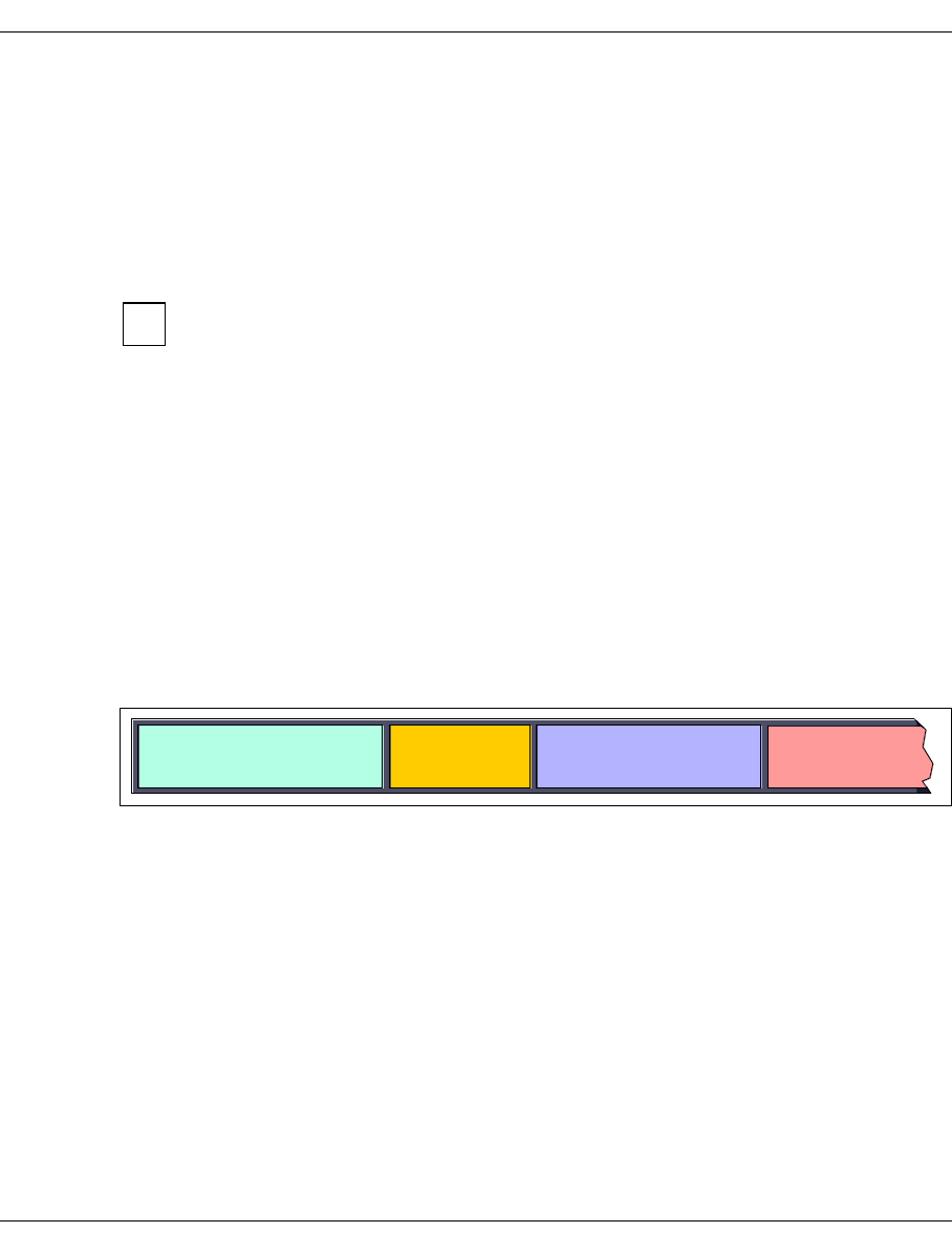
U41117-J-Z125-7-76 35
CentricStor - Virtual Tape Library Operation
2.4 Operation
CentricStor is operated via the graphical user interfaces GXCC (Global Extended Control
Center) and XTCC (Extended Tape Control Center). These are used to perform all
administration and configuration tasks.
Using this control center, it is possible to display the current operating statuses of all
CentricStor components, together with a large amount of performance and utilization data.
For a description, refer to chapter “Operating and monitoring CentricStor” on
page 83, chapter “GXCC” on page 119 and chapter “XTCC” on page 325.
2.5 Administering the tape cartridges
Tape cartridge administration is performed separately by the PLM for each physical volume
group (PVG) (see also section “Partitioning on the basis of volume groups” on page 63).
Each PVG has its own scratch pool. All reorganization parameters can be set separately for
each PVG.
2.5.1 Writing the tape cartridges according to the stacked volume principle
The figure below shows the location of logical volumes on the magnetic tape:
Figure 9: Position of the logical volumes on the magnetic tape
Each tape cartridge of the robot archive is administered by CentricStor as a stacked
volume, where a series of logical volumes is stored consecutively on the tape. In this way,
tapes are filled almost to capacity. There will be a small section of unused tape, since a
logical volume will always be written in full onto a physical tape cartridge (no continuation
tape processing).
i
Logical
volume 1
Logical
volume 2
Logical
volume 3
Logical
volume 4
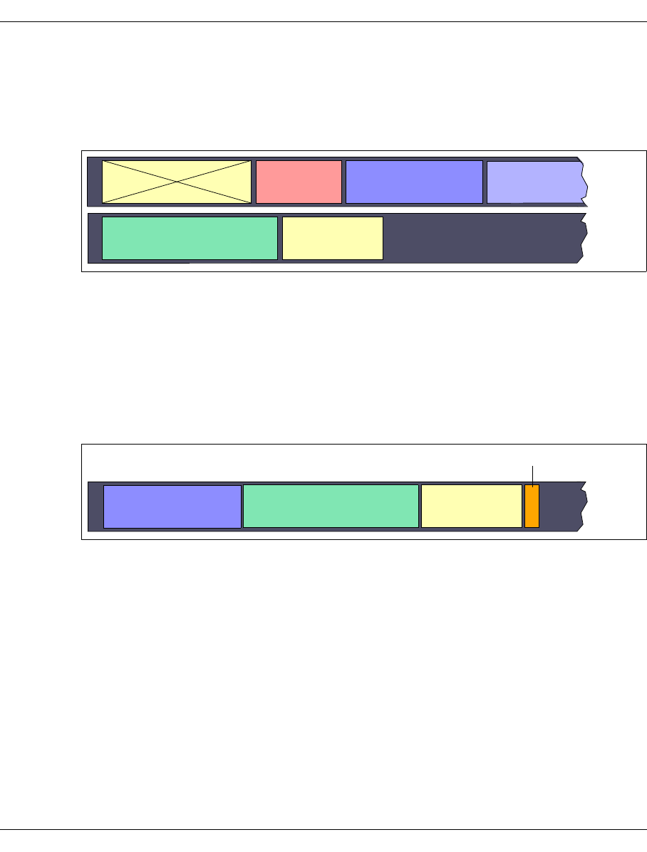
36 U41117-J-Z125-7-76
Administering the tape cartridges CentricStor - Virtual Tape Library
2.5.2 Repeated writing of a logical volume onto tape
If a logical volume which has already been saved onto tape is written to tape a second time
following an update, the first backup will be declared invalid. The current volume is
appended after the last volume of this tape or another tape with sufficient storage space.
Figure 10: Repeated writing of a logical volume onto tape
In the example above, the logical volume LV0013 on physical volume PV0000 is declared
invalid and is written anew to physical volume PV0001.
2.5.3 Creating a directory
After each write operation a directory is created at the end of the tape. This permits high-
speed data access during a later read/write operation.
Figure 11: Creating a directory on tape
LV0013 PV0000
PV0001
LV0011 LV0002 LV0021
LV0013
LV0008
Tape header Tape header
LV2413
LV2008
Tape-Header
LV0024
Contents
Directory
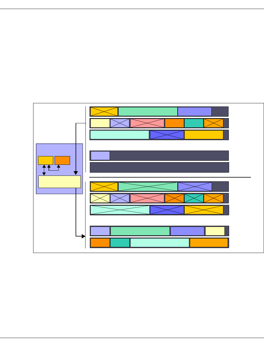
U41117-J-Z125-7-76 37
CentricStor - Virtual Tape Library Administering the tape cartridges
2.5.4 Reorganization of the tape cartridges
When a logical volume is released by the host’s volume management facility (e.g. MAREN
in BS2000/OSD), it is flagged accordingly in the CentricStor data maintenance facility which
contains the metadata for each volume. This process, combined with updates (see the
section section “Creating a directory” on page 36), will cause the areas containing invalid
data on the real tape cartridges to increase more and more over time (stacked volume with
gaps). If the number of scratch tapes for a CentricStor system falls below a configurable
lower limit, the PLM automatically performs a reorganization by using the VLM to load any
logical volumes still valid into the RAID system and then, so to speak, moving them
piecemeal onto scratch tapes.
Figure 12: Example of a reorganization
Read tape: Tape cartridge that still contains valid data but has no free space for write
operations
Scratch tape: Tape cartridge that only contains invalid data and has been released for
rewriting
Write tape: Tape cartridge that still contains space for write operations
LV0000 LV0001 LV0002
LV0003 LV0004 LV0005 LV0006 LV0007 LV0008
LV0011LV0009 LV0010
PV0000
PV0001
PV0002
PV0000
PV0001
PV0002
VLM
CentricStor
:
:
LV0037 PV0007
PV0008
:
:
LV0037 PV0007
PV0008
LV0000 LV0001 LV0002
LV0003 LV0004 LV0005 LV0006 LV0007 LV0008
LV0011LV0009 LV0010
LV0001 LV0002 LV0003
LV0006 LV0007 LV0011LV0009
Scratch tapes
:
:
:
:
Write tapes
PLM
TVC
Read tapes
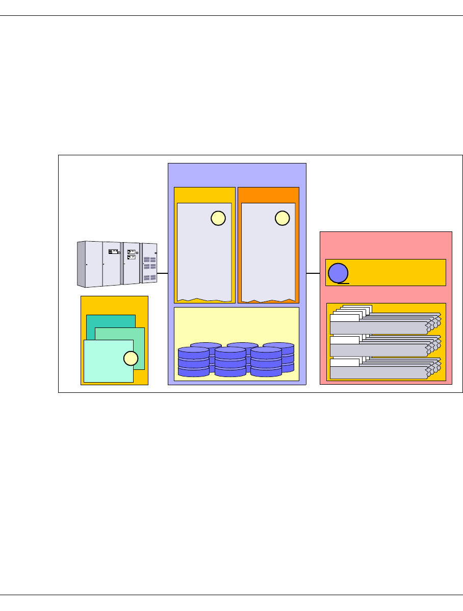
38 U41117-J-Z125-7-76
Procedures CentricStor - Virtual Tape Library
2.6 Procedures
2.6.1 Creating the CentricStor data maintenance
Initial situation: CentricStor is installed and configured. As yet, there is no data on the
RAID system. The tape cartridges of the robots are blank.
To start CentricStor, the PLM and VLM data maintenance facility must be created:
Figure 13: CentricStor after the VLM and PLM data maintenance have been created
1. The names of the logical volumes which are to be loaded into the RAID disk array later
are entered in the VLM data maintenance (see the section “Logical Volume Operations
» Add Logical Volumes” on page 211).
In the example, these are the logical volumes LV0000 to LV2000. These volumes still
do not contain any data.
2. The names (VSNs) of the physical volumes present in the robots which are to be used
in CentricStor are entered in the PLM data maintenance (see the section “Physical
Volume Operations » Add Physical Volumes” on page 223). In the example, these are
the volumes PV0000 to PV0100.
3. The logical volumes are made known in BS2000/OSD (example of a storage location:
“VTLSLOC”).
CentricStor is then ready for operation.
CSC
Logical volumes
Physical volumes
Tape drive
RAID
Robots
CentricStor
Host
VLM PLM
LV0000
LV0001 1
LV0002
LV0003
LV0004
LV0005
LV0006
LV0007
LV0008
LV0009
LV0010
LV0011
PV0000
PV0001
PV0002
PV0003
PV0004
PV0005
PV0006
PV0007
PV0008
PV0009
PV0010
PV0011
2
BS2000
ROBAR
MAREN
LV0003
3
LV0000
LV0001
LV0002
PV0000
PV0000
PV0012
PV0000
PV0000
PV0009
PV0008
PV0007
PV0006
PV0005
PV0004
PV0003
PV0002
PV0001
PV0000
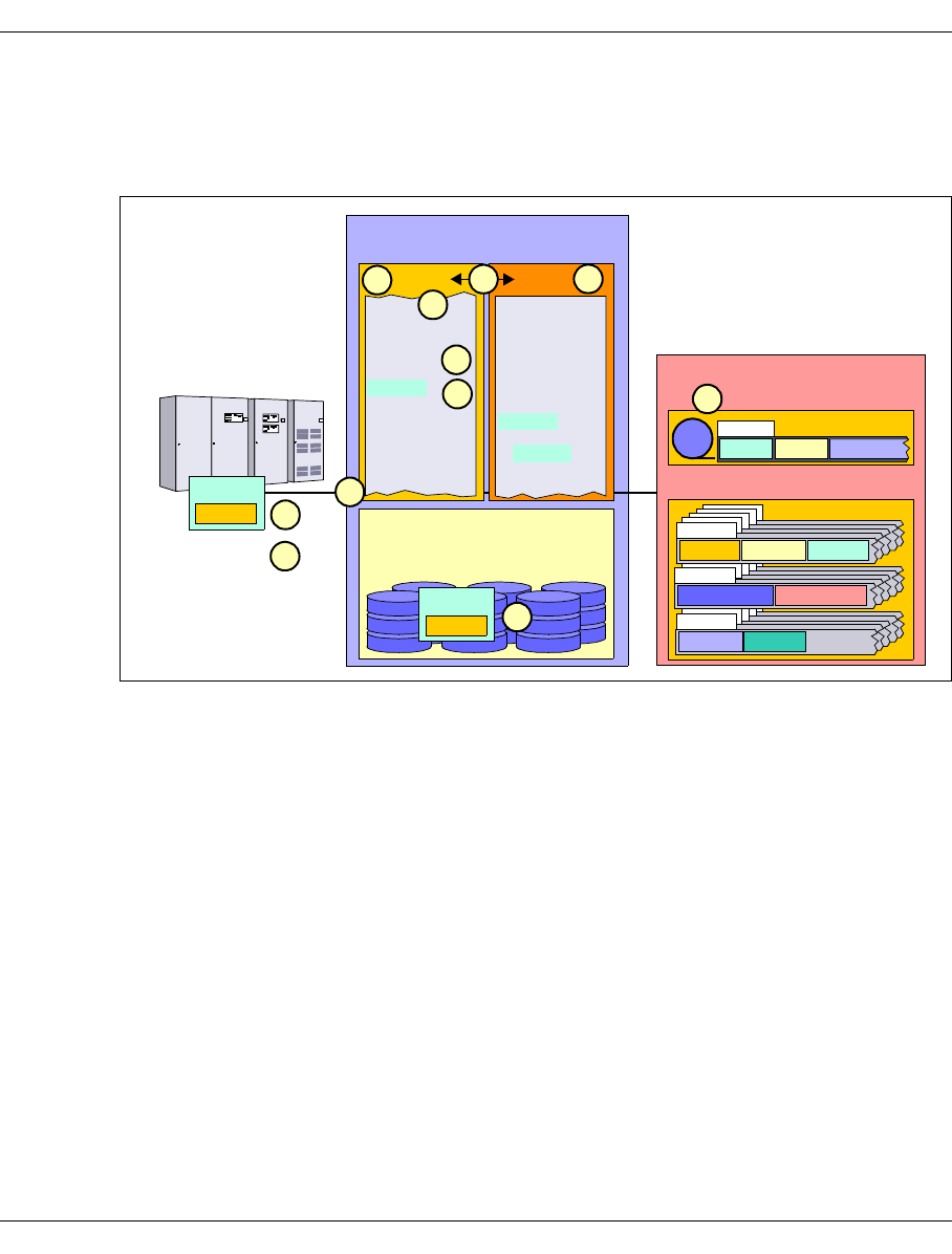
U41117-J-Z125-7-76 39
CentricStor - Virtual Tape Library Procedures
2.6.2 Issuing a mount job from the host
Initial situation: The logical volume LV0005 is already located on the physical volume
PV0002.
Figure 14: Procedure for a mount job
A mount job is executed as follows:
1. The host issues a mount job for logical volume LV0005, which is then accepted by the
VLM.
The VLM does not know at this point what task is involved:
– read the volume or a part thereof
– append a file to the end of the volume
– overwrite the entire volume
2. The VLM checks its data maintenance to establish whether the logical volume LV0005
specified by the host is available and whether there is a corresponding free storage
space on the RAID system.
If the RAID system does not have enough free capacity at this point, the LRU (Least
Recently Used) procedure is employed to delete the oldest data from the RAID system.
If a sufficient number of old files cannot be deleted, the mount job is suspended (“Mount
queued”).
Logical volumes
Physical volumes
Tape drive
RAID
Robots
CentricStor
Host
VLM PLM
LV0000
LV0001 M
1
LV0004
LV0006 M
LV0007
LV0008
LV0009 M
LV0010 D
LV0011
PV0001
LV0004
LV0017
LV0027
LV0013
PV0002
LV0005
Data
LV0003
2
PV0000
LV0000
LV0001
LV0003
4
LV0027 LV0005 LV0013
PV0004
PV0002
LV0005
LV0002
LV0005
5
b
e
3
f
a
LV0005
Data d
c
PV0000
PV0000
PV0012
PV0000
PV0000
PV0009
PV0008
PV0007
PV0006
PV0005
PV0004
PV0003
PV0001
PV0000
LV0000 LV0001 LV0003
LV0004 LV0017
PV0002
LV0061 LV0073

40 U41117-J-Z125-7-76
Procedures CentricStor - Virtual Tape Library
Depending on whether the logical volume is still in the RAID system or is only on
a physical volume, the following two situations arise:
Case 1: The volume is migrated to tape and is no longer located in the RAID system.
a) The VLM issues a request to the PLM to read the logical volume LV0005
into the RAID system.
b) The PLM checks its data maintenance to determine the physical volume
on which the requested logical volume LV0005 is located: PV0002.
c) The PLM requests the robot to mount the real tape cartridge PV0002
onto a free tape drive.
d) The data of the logical volume LV0005 is loaded from the tape drive into
the RAID system.
e) A flag is set in the VLM data maintenance to indicate that the logical
volume LV0005 is in the RAID system.
f) Only at this point does the VLM grant the host access to the volume
(mount acknowledged).
Case 2: The volume is present in the RAID system.
The VLM immediately grants the host access to the volume.
3. The host performs read and write accesses on the logical volume.
4. The host issues an unmount job.
In contrast to a real archive system, the job will be confirmed immediately.
5. The VLM checks whether the logical volume in the RAID system has been modified.
Case 1: The logical volume has not been modified.
No further action is taken, since the copy of the logical volume on the
physical volume is still valid.
i

U41117-J-Z125-7-76 41
CentricStor - Virtual Tape Library Procedures
Case 2: The logical volume has been modified.
a) The VLM informs the PLM that the logical volume is to be copied onto
tape.
b) The PLM selects a suitable tape cartridge: a completely new tape, a
scratch tape, or a tape onto which writing has not yet resulted in an
overflow. If this cartridge is not yet mounted, the PLM checks whether a
real drive is available in the robot archive at this point.
c) The PLM requests the selected real tape cartridge to be mounted, if
required, and begins data transfer from the RAID system to the tape.
The data of the logical volume is retained on the RAID system until deleted by
the VLM in accordance with the LRU procedure.
i

42 U41117-J-Z125-7-76
Procedures CentricStor - Virtual Tape Library
2.6.3 Scratch mount
To prevent reading in from the physical medium in cases where a logical volume is to be
rewritten anyway, under certain circumstances CentricStor performs a “scratch mount”.
The special features of the scratch mount in CentricStor are as follows:
– If the logical volume is migrated, i.e. it is no longer in the TVC, only a “stub” is made
available for the application. This stub contains only the tape headers.
– As this stub is always kept in the TVC a scratch mount can always be performed very
quickly as no restore is required from the physical tape.
– For the application this means that only access to the tape headers is possible.
If a scratch mount is performed incorrectly this can result in read errors when
an attempt is made to access the other data. In this case the data is not lost:
When a subsequent “normal” mount is performed it is available again.
CentricStor performs a scratch mount under the following conditions, depending on the
frontend (interface of the virtual library):
VAMU The mount command supports a flag which can be used to indicate that the
mount is to be performed as a scratch mount.
VDAS There is a special DAS_MOUNT_SCRATCH command (used only by FSC Networ-
ker). In this case CentricStor performs a scratch mount.
VACS A scratch mount is performed in the following two cases:
– “Mount_scratch” with the “pool-ID” parameter without specification of a par-
ticular volume
– Mount on a specific volume if this is contained in a pool whose pool ID is not
0
VLMF A scratch mount is performed in the following two cases:
– Mount with the “scratch” command with specification of a pool or specific vo-
lume
– Mount of a volume that is marked as “scratch”
VJUK No scratch mount is used
i

U41117-J-Z125-7-76 43
CentricStor - Virtual Tape Library New system functions
2.7 New system functions
CentricStor Version 3.1C for the first time provides the option of creating logical volumes
(LVs) more than 2 GB in size as a standard feature. The LV size can be selected in discrete
steps for each logical volume group (LVG):
The DTV file system must be migrated for CentricStor systems configured with
Version 3.0 or earlier. This is done by the service staff.
For the user, using large logical volumes is basically no different from the way logical
volumes have been used to date.
The following special aspects must be taken into consideration:
– The LV size of an existing LVG can be increased if the PVs (physical volumes) of the
PVG (physical volume group) which is linked to the LVG has the necessary capacities
(see the section “Logical Volume Groups” on page 173).
– The LV size of an existing LVG cannot be decreased (see the section “Logical Volume
Groups” on page 173).
– The size of the LVG "TR-LVG" cannot be modified (see the section “Logical Volume
Groups” on page 173).
– An LVG with LVs > 2 GB can be assigned to a PVG only if the capacity of the PVs
already assigned is twice as large as the LV size (see the section “Physical Volume
Operations » Link/Unlink Volume Groups” on page 221).
– PVs can be assigned to a PVG only if their capacity is greater than or equal to the LV
size of the LVG which is linked to the PVG (see the section “Physical Volume Opera-
tions » Add Physical Volumes” on page 223).
– The TVC must be large enough to permit the use of large LVs. If the TVC is too small,
frequent displacement of LVs must be reckoned with. This can have a significant effect
on the LV mount times depending on the volume size and the drive type (e.g. with 200
GB approx. 90-120 min.).
●STANDARD: 900 MB
●EXTENDED: 2 GB
5 GB
10 GB
20 GB
50 GB
100 GB
200 GB
i

44 U41117-J-Z125-7-76
Standard system functions CentricStor - Virtual Tape Library
2.8 Standard system functions
The following functions are standard in every CentricStor system:
●Partitioning by volume groups
●“Call Home” in the event of an error
●SNMP support
●Exporting and importing tape cartridges
2.8.1 Partitioning by volume groups
CentricStor supports a volume group concept. This provides the following benefits:
– It can be ensured that the copies of a logical volume created by an application are
stored on two different physical volumes (data security in case a magnetic tape
cartridge becomes unreadable).
– The storing of logical volumes of different host systems or applications on one and the
same magnetic tape cartridge can be prevented.
The volume group concept is a prerequisite for “Dual Save” (see the section “Dual Save” on
page 50).
2.8.2 “Call Home” in the event of an error
In the event of serious errors in CentricStor operation, the following measures are initiated
automatically:
– The error is reported to a hotline using “Call Home”.
In the event of connection via ROBAR, information is also sent to the BS2000 host via
“Hot Messages”.
– The error report can be transferred to a Service Access System (SAS) so that specific
responses can be triggered there. In addition, it is possible to send an SMS when
certain messages are issued.
– The responses to the individual error events are preset for various service provider pro-
files. One of these can be selected. In addition, the selected default can be adjusted on
a customer-specific basis.

U41117-J-Z125-7-76 45
CentricStor - Virtual Tape Library Standard system functions
2.8.3 SNMP support
It is possible to integrate CentricStor into remote monitoring by an SNMP Management
Station such as “CA Unicenter” or “Tivoli”.
In the event of system errors (error weighting EMERGENCY, ALERT, ERROR, CRITICAL),
CentricStor sends a trap to the SNMP Management Station, which causes the CentricStor
icon to change color (insofar as this is supported by the SNMP Management Station).
Furthermore, a status trap with the weightings green, yellow and red is sent periodically to
the Management Station.
Application launching enables the CentricStor administration software “GXCC” to be
started simply on the SNMP Management Station by means of a mouse click.
2.8.4 Exporting and importing tape cartridges
The options for exporting and importing tape cartridges (physical volumes) which are
offered by CentricStor can be used for various purposes:
●Storing the backup data at a disaster-proof location, e.g. in a fire-resistant room or at a
large distance from the CentricStor system
●Manual archiving of data which is accessed extremely rarely, e.g. because it is only re-
quired when a disaster occurs
●Exchanging data between independent systems at separate locations in order to guard
against local disaster sby means of redundant data storage
●Transfer of bulk data when extremely large distances are involved in order to save on
line costs or if there is a lack of infrastructure
Two standard functions are available for exporting/importing tape cartridges:
●Setting the vault attribute for a physical volume group (PVG) and setting the vault status
for a physical volume (PV)
●Use of the transfer PVG (TR-PVG)
These functions are totally separate from the tape management tool of the host applications
and are controlled solely by the CentricStor system administrator.

46 U41117-J-Z125-7-76
Standard system functions CentricStor - Virtual Tape Library
2.8.4.1 Vault attribute and vault status
The vault attribute is assigned to a physical volume group (PVG) by means of the GXCC
function Configuration ➟ Physical Volume Groups in the Type entry field (see page 187). The
associated tape cartridges (PVs) can be placed in vault status using the following com-
mand:
plmcmd conf -E -V <PV> -G <PVG>
They are then locked for all read and write operations until vault status is cancelled again
using the following command:
plmcmd conf -I -V <PV> -G <PVG>
While vault status is set, the tape cartridges can be removed from the tape library and
stored at a safe location (hence the status name vault). However, like all the logical volumes
contained on them, they are still administered by CentricStor.
An attempt to read from a tape cartridge which is in vault status is responded to with the
system message SXPL049 (see page 88). When a logical volume (LV) of such a tape cart-
ridge is saved again by a host application, a different tape cartridge is used and the old LV
on the vault tape cartridge is flagged as invalid. Tape cartridges in vault status are also ex-
cluded from reorganization (see section “Reorganization” on page 73).
2.8.4.2 Transfer PVG
A so-called transfer PVG and a transfer LVG which is linked to this are permanently installed
in CentricStor for this export/import function. The logical or physical columes which are to
be exported or imported are temporarily added to these volume groups.
The LVs to be exported are also copied to tape cartridges of the transfer PVG. The original
LVs continue to belong to their former LVG. Their backup to tape cartridges of the PVG as-
signed to this LVG and access by the host applications are not affected by the export.
The system administrator alone is reponsible for controlling the copy operation for the LVs
concerned and for synchronizing this operation with their use by the host applications. Cen-
tricStor keeps no management data for these copy operations and does not know whether
or not an LV was exported via a transfer PVG.
When the required LVs have been copied, the tape cartridges can be removed from the
transfer PVG and transported to another CentricStor system. There the tape cartridges are
added to the transfer PVG and the LVs contained on them are read in. To do this it is ne-
cessary that all these LVs should already exist and be assigned to a normal LVG.
Further information on the export/import function via transfer PVG is provided in section
“Transferring volumes” on page 562.

U41117-J-Z125-7-76 47
CentricStor - Virtual Tape Library Optional system functions
2.9 Optional system functions
CentricStor is available in a variety of configuration levels, in each of which further
customer-specific extensions (e.g. larger disk cache) are possible.
In addition to the basic configuration, optional functions are available which allow you to
customize the CentricStor functionality to suit your needs:
●Compression
●Multiple library support
●Dual Save
●Extending virtual drives
●System administrator’s edition
●Fibre channel connection for load balancing and redundancy
●Automatic VLP failover
●Cache Mirroring Feature
●Accounting
These optional system functions are released by means of key disks.
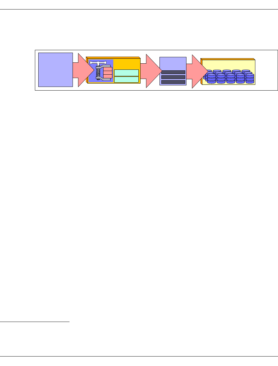
48 U41117-J-Z125-7-76
Optional system functions CentricStor - Virtual Tape Library
2.9.1 Compression
The figure below illustrates the principle of software compression of logical volumes:
Figure 15: Principle of compressing logical volumes
Just as a physical drive can perform data compression, so also can the tape drive emula-
tions (EMTAPE1 or VTD2) once they have been released3 on the ICP. In this way, the logical
volumes can be stored in compressed form in the TVC. This results in a whole range of
advantages:
●Disk cache utilization is significantly improved depending on the compression level, i.e.
without changing the cache size, it is possible to keep considerably more logical
volumes “online” in the cache than without compression, frequently resulting in a very
high-performance response time vis-à-vis the host system.
●The performance of the overall system is improved due to the fact that the load on the
FC network is reduced by the compression factor.
●In the case of data quantities greater than 900 MB, the number of logical volumes is
reduced.
Example (Standard)
To save a 4 GB file on standard volumes (900 MB) without compression, you will
need five logical volumes. If we assume a compression factor of 3, then only two
logical volumes will be necessary.
●Within the CentricStor migration concept (i.e. the relocation of volumes from the real
robot archive to the CentricStor archive while retaining the volume number), it is
currently necessary to identify all volumes whose size exceeds 800 MB after hardware
compression. If software compression is switched on for the logical drives, however,
then automatic 1:1 conversion will also be possible for these volumes.
Compression can be set separately for each drive (this is done using Service).
The “Compression” attribute can be set to “ON”, “OFF” or “HOST” for each drive.
1Mainframes
2Open systems
3Compression only works with a block size of at least 1 Kbyte.
TVC
Logical
volumes
ICP
EMTAPE
VTD
Data
from
host
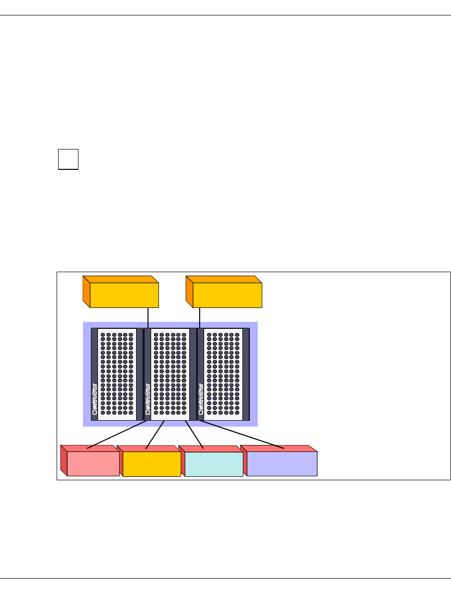
U41117-J-Z125-7-76 49
CentricStor - Virtual Tape Library Optional system functions
In BS2000/OSD (“HOST” attribute), compression is controlled on the basis of the tape type:
– TAPE-C3: compression off
– TAPE-C4: compression on
In UNIX, the compression setting can be selected by the device nodes.
The compression setting can be passed in ESCON or SCSI command to the tape
emulation, and the compressed data is stored block-by-block on the logical volume (the
VLM and PLM do not have any information about this).
If the data is already compressed on the host, e.g. if backup data is supplied in
compressed format by a NetWorker client, then compression should be switched off
for this logical volume on the ICP, so that the load on the CPU of the ICP can be kept
to a minimum.
2.9.2 Multiple library support
One of the important characteristics of CentricStor is the parallel connection of multiple real
robot archives of different types.
Figure 16: Example of multiple library support
The number of robot archives that can be operated in parallel is theoretically unlimited.
However, since at least one physical volume group is required per library, it is only possible
to support as many libraries as there are corresponding volume groups.
i
Fujitsu robot
IBM Cashion
StorageTek
ADIC
CentricStor
Hosts
Robot archive
Host1 Host2

50 U41117-J-Z125-7-76
Optional system functions CentricStor - Virtual Tape Library
All supported robot archive types are permitted:
– ADIC AML systems (with DAS)
– ADIC scalar systems (with DAS or SCSI)
– StorageTek systems (with ACSLS or SCSI)
–IBM Cashion
– Fujitsu robot (with LMF)
Please refer to the current product information for the library and drive type configurations
currently available. It is possible to have different drive types within the same archive.
However, a separate physical volume group must be configured for each drive type (see
section “Partitioning on the basis of volume groups” on page 63).
2.9.3 Dual Save
Based on the volume group functionality (see page 63), CentricStor offers the Dual Save
function. This involves making a copy of a logical volume on a second physical volume,
which may be located either in the same robot archive (Dual Local Save) or in a remote
robot archive (Dual Remote Save). This ensures the highest possible level of data security.
If a physical volume which usually contains a large number of logical volumes is in some
way corrupted (e.g. due to a tape error), CentricStor can access a copy of this logical
volume created on a different physical volume. If the copy is located in a second robot
archive, then even the complete destruction of the first robot archive would not cause any
irrevocable loss of data.
In many computer centers, for example, it is currently common practice to move the
volumes written during a backup operation (or copies generated by the application) to a
secure location directly on completion of the backup. The Dual Remote Save functionality
provides an elegant means of automating this procedure. Not only does it relieve the host
application of any copy or move operations, it also eliminates the need to transport the
cartridges to a second archive (and back again). The associated risk of data manipulation
is thus excluded.
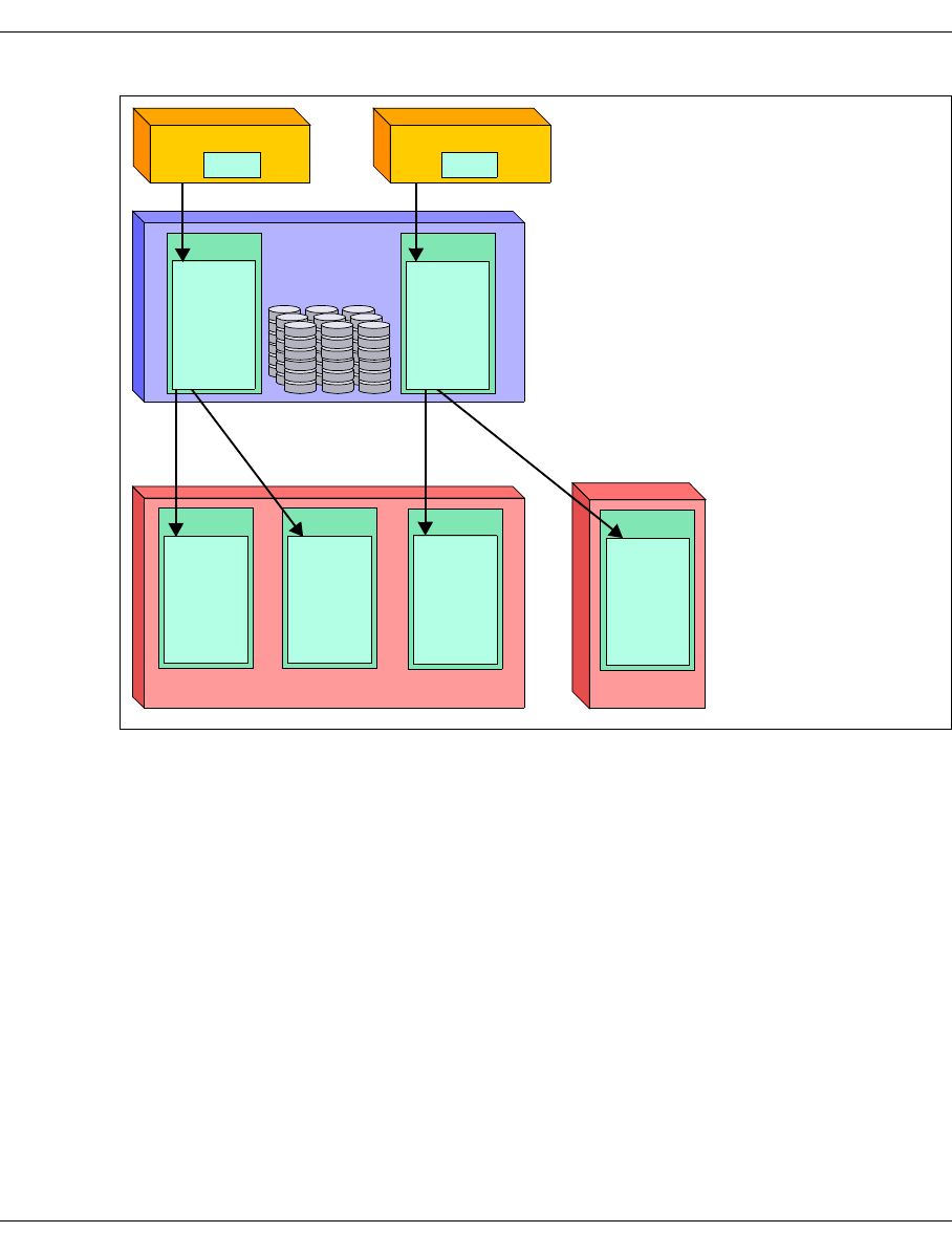
U41117-J-Z125-7-76 51
CentricStor - Virtual Tape Library Optional system functions
Figure 17: Example of Dual Save functionality
In accordance with the assignment rules for the volume group functionality (see page 64),
the logical volumes from LVG 1 (LV0001-LV3000) are mirrored on the physical volumes of
PVG 1 (PV0001-PV0300) and PVG 2 (PV0301-PV0600) in the robot Archive1. The logical
volumes of LVG 2 (LV3001-LV6000) are duplicated in Archive1 on PVG 3 (PV0701-
PV0800) and in Archive2 on PVG 4 (PV0801-PV0900), where the two robots are located
some distance apart.
LVG 1 LVG 2
CentricStor
PV0001
PV0002
PV0003
...........
PV0300
PVG 1
PV0301
PV0302
PV0303
...........
PV0600
PVG 2
PV0701
PV0702
PV0703
...........
PV0800
PVG 3
PV0801
PV0802
PV0803
...........
PV0900
PVG 4
Archive1 Archive2
LV0001
LV0002
LV0003
...........
LV3000
LV3001
LV3002
LV3003
...........
LV6000
Host1 Host2
LVG 1 LVG2

52 U41117-J-Z125-7-76
Optional system functions CentricStor - Virtual Tape Library
2.9.4 Extending virtual drives
This option allows you to increase the number of logical drives from the standard 32 per ICP
to up to 64 per ICP. This makes it possible to operate up to 256 logical drives in a single
CentricStor system.
2.9.5 System administrator’s edition
The “System Administrator Edition” (SAE) option provides a graphical user interface for
administering the CentricStor system from a remote PC workstation.
The operator PC is included as part of the scope of delivery. This machine can be used to
monitor a number of CentricStor systems.
2.9.6 Fibre channel connection for load balancing and redundancy
This option provides the CentricStor system with a second internal FC network for data
transfer. This enables operation to be continued without interruption even when a switch
fails (in normal operation the data stream is distributed to both switches).
2.9.7 Automatic VLP failover
Typically almost all CentricStor control functions run on the VLP. This processor is largely
protected against disk errors by RAID system disks. If this processor were to fail never-
theless, the CentricStor system would have no controller and thus no longer be operable.
Ongoing save jobs would be completed, but new ones would no longer be accepted.
To prevent this situation occurring, the “automatic VLP failover” function is provided
(AutoVLP failover).
A release via key is required for the "automatic VLP failover" function, and the SVLP
must be configured to use it. This is done by the maintenance staff.
Further prerequisites:
– The VLP and the standby processor SVLP must be equipped with an external and an
internal LAN interface.
– The standby processor SVLP must be equipped and configured like the VLP.
i
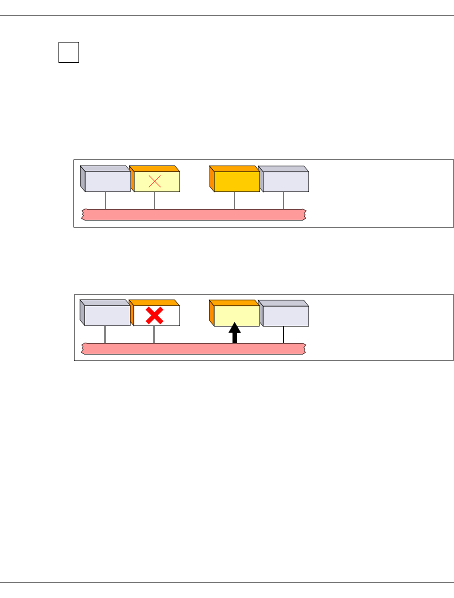
U41117-J-Z125-7-76 53
CentricStor - Virtual Tape Library Optional system functions
If the “automatic VLP failover” function has been activated, the following actions are
no longer permitted in the system:
– changing the LAN configuration
– rebooting or shutting down of the VLP (init 0 or init 6: these commands
cause a failover!)
– disconnecting a LAN or FC cable
If the VLP fails, the scenario is as follows:
1. The VLP fails in the CentricStor system:
Figure 18: Failure of the VLP
The SVLP is active in the system and monitoring the VLP. If the VLP fails, the SVLP
takes over control of CentricStor.
2. The SVLP is activated automatically:
Figure 19: Activation of the SVLP using the AutoVLP failover function
During the switchover operation, which can last up to 5 minutes, this procedure is inter-
preted on the host side as a mount delay and a new connection setup to the robot
control. All backup jobs continue to run normally.
The switchover involves reconfiguring the two ISPs (VLP/SVLP): they swap their exter-
nal IP addresses and tasks.
i
ISP
FC fabric
ISP SVLP
VLP
ISP
FC fabric
ISP SVLP
Activation
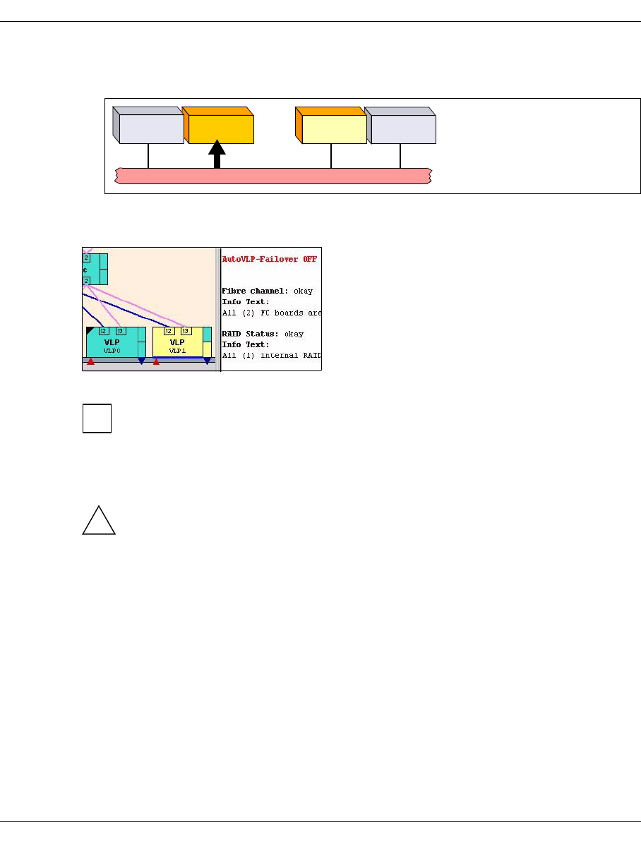
54 U41117-J-Z125-7-76
Optional system functions CentricStor - Virtual Tape Library
3. After the defective processor has been repaired, it is integrated once again into the
overall system and takes over the role of the SVLP:
Figure 20: Activation of the defective processor for the SVLP
The status, i.e. AutoVLP failover active or inactive, is clearly visible on the GUI:
Figure 21: Display of the AutoVLP failover status on the GUI
The left-hand triangle is only displayed if an SVLP is configured.
If the left-hand triangle below the VLP is green, this means that AutoVLP failover is
activated. If it is red, AutoVLP failover is not activated. In addition, the text “AutoVLP-
Failover OFF” is displayed in red in the text window on the right.
CAUTION!
The function must have the same status on the VLP and SVLP: enabled or not
enabled (ON or OFF).
When the AutoVLP failover function is configured and activated, VLP monitoring on this ISP
is activated automatically with every reboot.
ISP
ISP VLP
SVLP
Activation
FC fabric
i
!

U41117-J-Z125-7-76 55
CentricStor - Virtual Tape Library Optional system functions
2.9.8 Cache Mirroring Feature
2.9.8.1 General
CentricStor V3.1 provides users with enhanced data security and greater protection against
data loss through disasters, promptly for all nearline data. Data stored on the internal hard
disk system is mirrored synchronously to a second cluster location. This is done via 2-Gbit
FibreChannel connections, also over long distances. Even if one location is totally
destroyed, all the saved data is available which is backed up on a CentricStor configuration
of this type. As the status of the data is at all times identical on both systems, a restart is
significantly quicker and simpler. No modifications to applications or data backup processes
are required.
2.9.8.2 Hardware requirements
A functioning mirror always requires two RAID systems. In CentricStor a maximum of 8
RAID systems are supported, i.e. a maximum of 4 RAID system pairs can be set up for
mirroring.
By definition a RAID system pair can only be set up when the following conditions apply:
●The RAID IDs begin with an odd ID.
●The RAID IDs of these systems are in unbroken ascending order.
As a result, a maximum of four possible RAID ID pairs are possible: 1+2, 3+4, 5+6 and 7+8.
A CentricStor system can contain two possible types of RAID mirror pairs:
– Potential mirror pairs
These pairs do satisfy the above-mentioned hardware requirements, but secondary
caches (mirror caches) must also be provided by a corresponding LUN assignment
(see the section “Mirrored RAID systems” on page 57). This is done by customer
support.
Potential mirror pairs can be recognized in GXCC by a thicker, black separating line (see
the section “Presentation of the mirror function in GXCC” on page 58).
– Genuine mirror pairs
These pairs satisfy all hardware requirements. They contain primary and secondary
caches (section “Mirrored RAID systems” on page 57) and are identified in GXCC by a
white dot (see the section “Presentation of the mirror function in GXCC” on page 58).
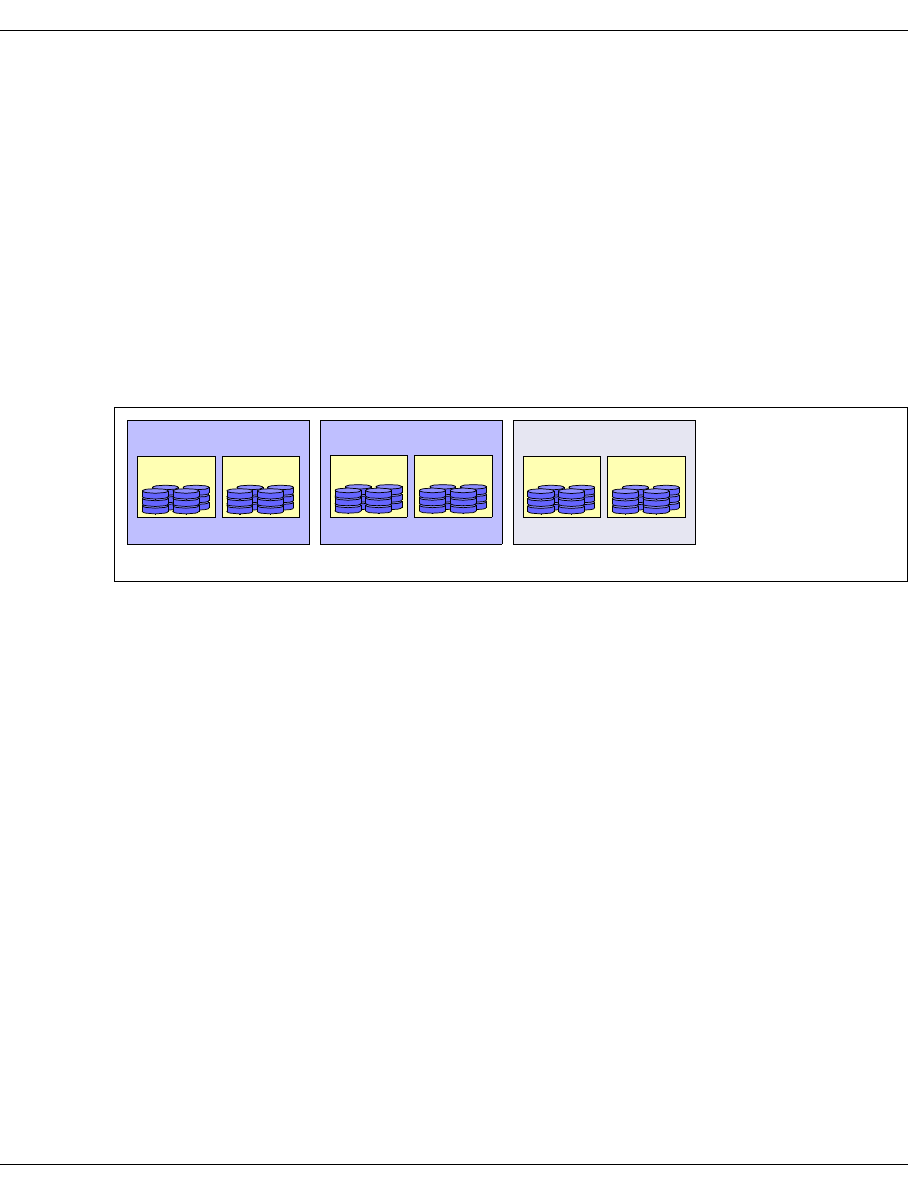
56 U41117-J-Z125-7-76
Optional system functions CentricStor - Virtual Tape Library
2.9.8.3 Software requirements
The “vtlsmirr” key must have been read in and enabled for the mirror function. This is done
by customer support.
Assuming that the hardware requirements are satisfied (see the section above) and the
RAID systems have been defined by the corresponding LUN assignment (see the section
“Mirrored RAID systems” on page 57), the overall system is configured as a mirror system
solely through the existence of the key. No operator intercvention is required for this
purpose.
Example
After the mirror key has been read into a CentricStor system with 6 RAID systems, the
following configuration is established:
Figure 22: “Genuine” and “potential” RAID mirror pairs in a CentricStor system
The first and second RAIDs and also the third and fourth RAIDs form genuine mirror pairs
as the IDs here begin with an odd number and are in unbroken ascending order.
The RAID systems with IDs 6 and 7 do not satisfy the hardware requirements and therefore
form a potential pair. They can be turned into a genuine mirror pair by changing ID 7 to ID 5.
1stRAID 2ndRAID
ID 1 ID 2
RAID mirror pair 1
3rdRAID 4thRAID
ID 3 ID 4
RAID mirror pair 2
5thRAID 6thRAID
ID 6 ID 7
RAID mirror pair 3
Genuine pair Potential pairGenuine pair
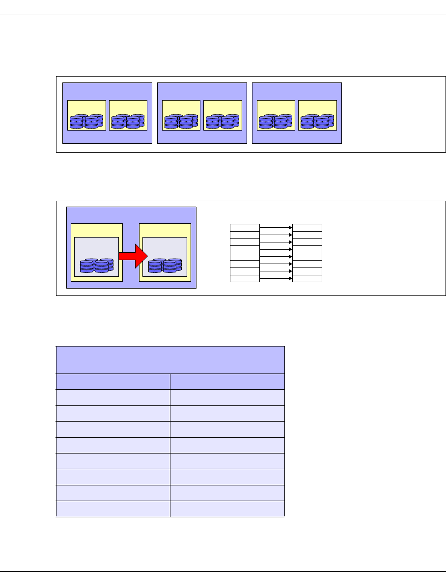
U41117-J-Z125-7-76 57
CentricStor - Virtual Tape Library Optional system functions
2.9.8.4 Mirrored RAID systems
A mirrored CentricStor system has 1 to a maximum of 4 RAID mirror pairs.
Figure 23: Example of a CentricStor mirror system with 3 RAID mirror pairs
In a RAID mirror pair, one RAID system contains only primary caches, the other only
secondary caches (mirror caches):
Figure 24: Primary and secondary caches in a RAID mirror pair
Such a mirror pair is defined by the corresponding assignment of the LUNs, as shown in the
example (where x is in the range 0 through 7) below:
Assignment of the LUNs for DTV
caches (/cache/...)
1st RAID 2nd RAID
(P) x + 0 (S) x + 8
(P) x + 1 (S) x + 9
(P) x + 2 (S) x + 10
(P) x + 3 (S) x + 11
(P) x + 4 (S) x + 12
(P) x + 5 (S) x + 13
(P) x + 6 (S) x + 14
(P) x + 7 (S) x + 15
1stRAID 2ndRAID
ID 1 ID 2
RAID mirror pair 1
3rdRAID 4thRAID
ID 3 ID 4
RAID mirror pair 2
5thRAID 6thRAID
ID 5 ID 6
RAID mirror pair 3
1st RAID
RAID mirror pair
Primary
cache
2nd RAID
Secondary
cache
(P) LUN0
(P) LUN1
(P) LUN2
(P) LUN3
(P) LUN4
(P) LUN5
(P) LUN6
(P) LUN7
(S) LUN8
(S) LUN9
(S) LUN10
(S) LUN11
(S) LUN12
(S) LUN13
(S) LUN14
(S) LUN15
Example of the LUN assignments:
1st RAID 2nd RAID
P = Primary cache
S = Secondary cache
58 U41117-J-Z125-7-76
Optional system functions CentricStor - Virtual Tape Library
2.9.8.5 Presentation of the mirror function in GXCC
In GXCC the mirror functions of a double RAID system are indicated by two arrows.
Example
Figure 25: Presentation of the mirror function in GXCC
Genuine RAID pairs are indicated with a white dot, potential pairs by a thicker black line
between the boxes on the right-hand side
The display can contain an odd number of RAID systems if, for example, a defective
RAID system has been separated from the CentricStor system. Further information
on this is provided in the section “RAID symbol for mirror mode” on page 131.
i
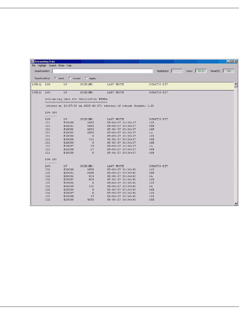
U41117-J-Z125-7-76 59
CentricStor - Virtual Tape Library Optional system functions
2.9.9 Accounting
On the one hand this function permits the accounting data of logical volume groups to be
displayed in GXCC (see the section “Statistics » Usage (Accounting)” on page 293).
Example
On the other hand this function enables the current accounting data to be sent by e-mail at
defined times (see the section “Setup for accounting mails” on page 229).

Eine Dokuschablone von Frank Flachenecker
by f.f. 1992
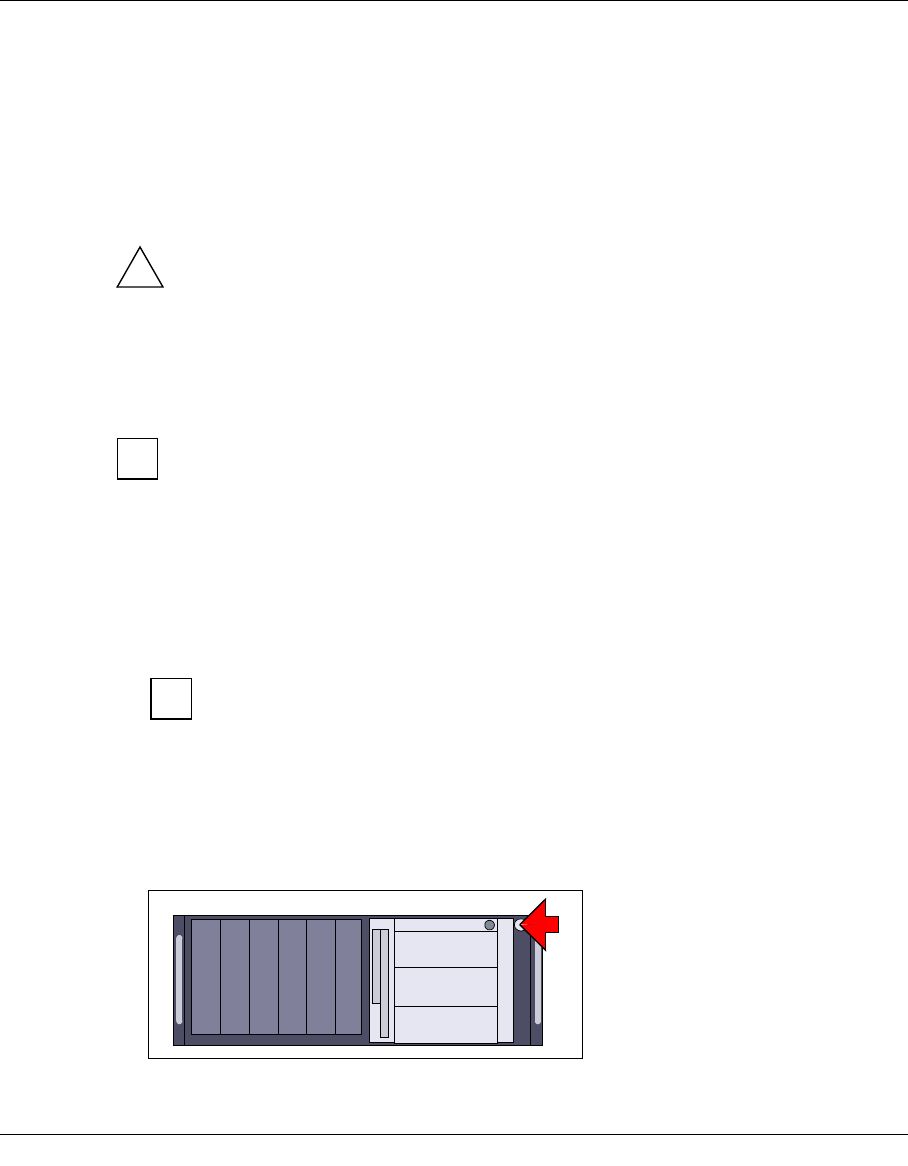
U41117-J-Z125-7-76 61
3 Switching CentricStor on/off
IMPORTANT!
The vendor recommends that CentricStor should not be switched off. This should
only be done in exceptional circumstances.
3.1 Switching CentricStor on
Before switching CentricStor on, you must ensure that the units with which
CentricStor is to communicate, i.e. host computers, ROBAR-SV systems (in the
case of host connection via ROBAR), the robot control processor, and the tape
robots are already up and running.
The following sequence must be followed when switching on the individual CentricStor
components:
1. Switch on the LAN hubs and switches (see corresponding operating instructions).
2. Switch on the fibre channel switches (see corresponding operating instructions).
When connecting open systems:
The external FC switches must now also be switched on, as otherwise the
ICPs will not establish a point-to-point connection.
3. Switch on the RAID systems (see corresponding operating instructions).
Wait a minute after the “System Ready” status has been reached after the RAID sys-
tems have been started up.
4. Switch on the ICPs/IDPs/VLP by pressing the POWER ON/OFF button:
Figure 26: POWER ON/OFF button on the ISP (example TX300)
!
i
i

62 U41117-J-Z125-7-76
Switching CentricStor off Switching CentricStor on/off
Using GXCC or XTCC check that all the necessary CentricStor processes are running
(all processor boxes must be green).
5. BS2000/OSD:
Case 1: Host connection via ROBAR
ÊStart ROBAR-SV (with the menu program robar or robar_start; see
ROBAR manual [3]).
Case 2: Host connection via CSC
ÊStart CSC (see CSC manual [4]).
3.2 Switching CentricStor off
CentricStor can be switched off only in Service mode! As this mode is explained in
the CentricStor Service Manual, only a brief description is provided below.
The following sequence must be followed when switching off the individual CentricStor
components:
1. BS2000/OSD, z/OS and OS/390:
DETACH or VARY OFFLINE all logical drives on the host.
2. CentricStor is switched off via the GXCC user interface:
ÊActivate the “Shutdown” function (see the Service Manual).
All CentricStor processors (VLP, IDPs, ICPs) and - if the “power off” option is
activated - the connected RAID system are then shut down gracefully and switched
off.
ÊWait for 5 minutes.
3. Switch off the hubs/switches (see corresponding operating instructions):
– LAN hubs
– fibre channel switches
i

U41117-J-Z125-7-76 63
4 Selected system administrator activities
4.1 Partitioning on the basis of volume groups
4.1.1 General
By partitioning on the basis of volume groups, it is possible to combine certain logical
volumes to form a logical volume group (LVG ) and certain physical volumes to form a
physical volume group (PVG).
Using rules which create associations between logical and physical volume groups, it is
possible to have CentricStor copy the logical volumes belonging to a particular LVG exclu-
sively onto the physical volumes of the assigned PVG.
Partitioning on the basis of volume groups offers the following advantages:
●It allows you to store the logical volumes of various host systems or applications on
different physical volumes.
●In the case of Dual Save1, it allows you to store copies of a logical volume on two
different physical volumes. This offers an extra degree of data security for situations
where a tape becomes unreadable, for example (see section “Dual Save” on page 71).
Normally CentricStor has four volume groups:
– the logical volume group “BASE”
– the physical volume group “BASE”
– the logical volume group “TR-LVG”
– the physical volume group “TR-PVG”
The TR-LVG and TR-PVG volume groups are used to transfer logical and physical volumes
(see the section “Transferring volumes” on page 562).
Each physical volume group has its own local free pool from which new volumes
can be taken as the need arises and to which freed volumes can be returned
(e.g. following reorganization).
1This assumes that the Dual Save functionality has been released (see page 71).
i
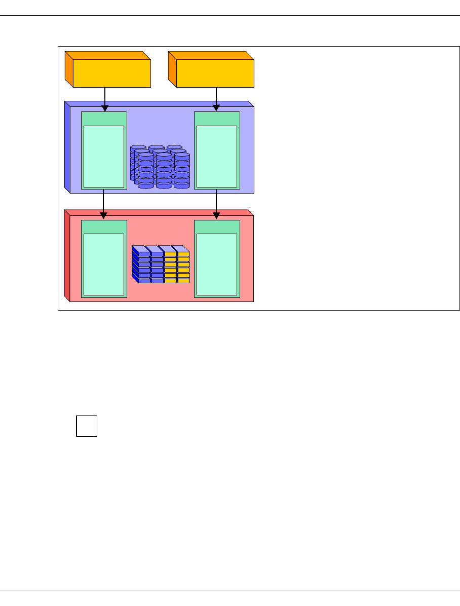
64 U41117-J-Z125-7-76
Partitioning on the basis of volume groups Selected system administrator activities
Figure 27: Example of partitioning on the basis of volume groups
4.1.2 Rules
Logical volume groups:
– It is possible to configure up to 512 logical volume groups.
By default, CentricStor always has at least two logical volume groups (“BASE”
and “TR-LVG“). These are available in addition to the freely configureable
volume groups.
– Each logical volume in CentricStor belongs to precisely one logical volume group.
You have two different systems (a BS2000
host and a UNIX system) using CentricStor
in conjunction with an archive system. By
grouping volumes, it is hoped to achieve a
situation where BS2000 data and UNIX
data are stored on different physical
volumes.
The logical volumes of the BS2000 host are
assigned to the logical volume group LVG1,
while those of the UNIX system are
assigned to the logical volume group LVG2.
These logical volumes can (but need not
necessarily) be assigned to various physical
volume groups.
As a result of these assignments, BS2000
data will now be stored on the physical
volumes PV0001 through PV0300, while
UNIX files will be stored on the physical
volumes PV0501 through PV0600.
CentricStor
PV0001
PV0002
PV0003
...........
PV0300
PVG1
PV0501
PV0502
PV0503
...........
PV0600
PVG2
Archive
BS2000
data UNIX
Data
BS2000 host UNIX system
LV0001
LV0002
LV0003
...........
LV3000
LVG 1
LV3001
LV3002
LV3003
...........
LV6000
LVG 2
i

U41117-J-Z125-7-76 65
Selected system administrator activities Partitioning on the basis of volume groups
Physical volume groups:
– It is possible to configure up to 100 physical volume groups1.
By default, CentricStor always has at least two physical volume groups (“BASE”
and “TR-LVG”). These exist in addition to the freely configurable volume groups.
– All physical volumes of a physical volume group belong to the same physical library.
– A physical volume group does not possess any tape drives, it is instead linked to a tape
library. This tape library can be part of a real tape library, and may only contain tape
drives of a single type.
– A physical library can contain several physical volume groups.
4.1.3 System administrator activities
This section contains brief information on the main system administrator activities:
–“Adding a logical volume group” on page 66
–“Adding a physical volume group” on page 66
–“Adding logical volumes to a logical volume group” on page 66
–“Adding physical volumes to a physical volume group” on page 67
–“Assigning an LVG to a PVG” on page 67
–“Removing an assignment between an LVG and a PVG” on page 67
–“Changing logical volumes to another group” on page 68
–“Removing logical volumes” on page 68
–“Removing logical volume groups” on page 68
–“Removing physical volumes from a physical volume group” on page 69
–“Removing physical volume groups” on page 69
1Cleaning and transfer groups are not included here.
i

66 U41117-J-Z125-7-76
Partitioning on the basis of volume groups Selected system administrator activities
4.1.3.1 Adding a logical volume group
●The form and detailed information are provided in the section “Logical Volume Groups”
on page 173
1. Click on the “NEW” button.
2. The following must be entered:
Name Name of the new logical volume group
Type Extended (2 GB, ... , 200 GB) or standard (900 MB)
Location Cache area (floating or defined explicitly)
Comment Comment
3. Click on the “OK” button.
The entries become effective with the next “Distribute and Activate” (see page 188).
4.1.3.2 Adding a physical volume group
●The form and detailed information are provided in the section “Physical Volume Groups”
on page 181.
1. Click on the “NEW” button.
2. A large number of entries need to be made. The description of the individual fields
is provided on page 183.
You will find further information in the section “Creating a new physical volume
group” on page 187.
3. Click on the “OK” button.
The entries become effective with the next “Distribute and Activate” (see page 188).
4.1.3.3 Adding logical volumes to a logical volume group
●The form and detailed information are provided in the section “Logical Volume Opera-
tions » Add Logical Volumes” on page 211.
The following information must be specified:
– the VSN of the first logical volume
– the logical volume group
– the number of logical volumes
The logical volumes are then incorporated in the CentricStor pool.

U41117-J-Z125-7-76 67
Selected system administrator activities Partitioning on the basis of volume groups
4.1.3.4 Adding physical volumes to a physical volume group
Only physical volumes contained in the physical library may be specified.
●The form and detailed information are provided in the section “Physical Volume Opera-
tions » Add Physical Volumes” on page 223.
The following information must be specified:
– the VSN of the first physical volume
– an entry specifying whether the header of the added volume should be uncondi-
tionally overwritten with a CentricStor header
– the physical volume group (see section “Adding a physical volume group” on
page 66)
– the number of physical volumes
– the type of physical volumes
The physical volumes are then incorporated in the CentricStor pool.
4.1.3.5 Assigning an LVG to a PVG
●The form and detailed information are provided in the section “Physical Volume Opera-
tions » Link/Unlink Volume Groups” on page 221.
The following elements must be selected:
– the logical volume group
– the physical volume group (original)
– a second physical volume group (copy, only applies for “Dual Save”)
The logical volume group is then assigned to the selected physical volume group(s).
4.1.3.6 Removing an assignment between an LVG and a PVG
Before executing this function, all logical volumes must be removed from the logical
group.
●The form and detailed information are provided in the section “Physical Volume Opera-
tions » Link/Unlink Volume Groups” on page 221.
The following elements must be selected:
– the logical volume group
– the physical volume group
The original physical volume group must be set to ’-unlinked-’. If a Dual-Save LVG
exists, the physical Dual-Save PVG must also be set to '-unlinked-'.
The assignment between the logical and physical volume groups is then removed.
i
i

68 U41117-J-Z125-7-76
Partitioning on the basis of volume groups Selected system administrator activities
4.1.3.7 Changing logical volumes to another group
●The form and detailed information are provided in the section “Logical Volume Opera-
tions » Change Volume Group” on page 209.
The following information must be specified:
– Specification whether all volumes (“all”) or just a certain number (“range”) of
volumes of the original logical volume group are to be moved to the new group.
If only part of the original group is to be transferred, the VSN of the first logical
volume and the number of affected volumes must also be specified.
– Original logical volume group (“Source Logical Volume Group”)
– New logical volume group (“Target LVG”)
The logical volumes are then assigned to the new logical volume group.
4.1.3.8 Removing logical volumes
Logical volumes should only be removed after being released by the host.
●The form and detailed information are provided in the section “Logical Volume Opera-
tions » Erase Logical Volumes” on page 213.
The following information must be specified:
– the VSN of the first logical volume
– the number of logical volumes
The logical volume group need not be specified, since all VSNs within
CentricStor are unique.
The logical volumes are then removed from the CentricStor pool.
4.1.3.9 Removing logical volume groups
Logical volume groups which have been made known to the system with the “Distribute and
Activate” function can be removed from the “Logical Volume Groups” form (see page 173).
However, this is possible only if the following prerequisites are satisfied:
– The logical volume group concerned may no longer be linked to a physical volume
group.
– The logical volume group may not contain any logical volumes.
The two logical volume groups BASE and TR-LVG cannot be removed.
1. Select the logical volume group to be removed in the list.
2. Click on the “To Be Deleted” button (see page 175) and select “YES”.
3. Click on the “OK” button.
i
i

U41117-J-Z125-7-76 69
Selected system administrator activities Partitioning on the basis of volume groups
4.1.3.10 Removing physical volumes from a physical volume group
Only scratch tapes which do not contain any valid logical volumes can be removed,
unless the physical volumes have been reorganized prior to doing this (flag is set).
●The form and detailed information are provided in the section “Physical Volume Opera-
tions » Erase Physical Volumes” on page 226.
The following information must be specified:
– the VSN of the first physical volume
– the physical volume group
– the number of physical volumes
– flag for switching on/off a preceding reorganization
The physical volumes are then removed from the CentricStor pool. They are no longer
used and can be removed from the library.
4.1.3.11 Removing physical volume groups
Physical volume groups which have been made known to the system with the “Distribute
and Activate” function can be removed from the “Physical Volume Groups” form (see
page 181). However, this is possible only if the following prerequisites are satisfied:
– The physical volume group concerned may no longer be linked to a logical volume
group.
– The physical volume group may not contain any physical volumes.
The two physical volume groups BASE and TR-PVG cannot be removed.
1. Select the physical volume group to be removed in the list.
2. Click on the “To Be Deleted” button (see page 183) and select “YES”.
3. Click on the “OK” button.
i
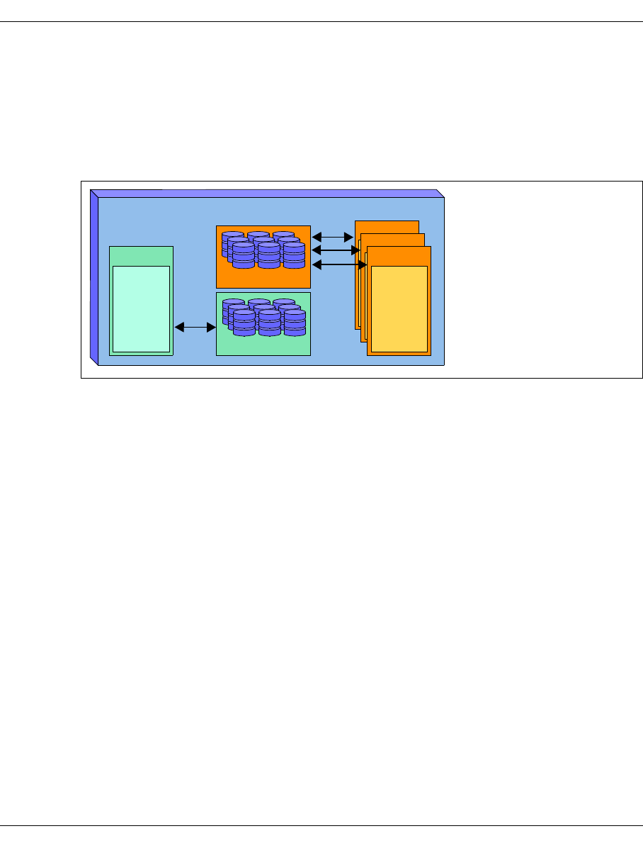
70 U41117-J-Z125-7-76
Cache management Selected system administrator activities
4.2 Cache management
This functionality enables individual cache file systems to be reserved for exclusive use by
particular LV groups.
LV groups which are not assigned to a cache file system are distributed to the remaining
caches (“FLOATING” setting).
Figure 28: Example of the exclusive use of the cache file system by LV groups
In concrete terms this means:
– An assignment of cache file system to LV group is defined by a configuration.
– An LV can be assigned to precisely one cache file system.
– Multiple LV groups can be assigned to a cache file system.
Possible applications:
●“Location” of the logical volumes
The cache management function can be used to ensure that volumes are at a particular
location or on a particular RAID system.
●Cache residence of the volumes
The volumes are always in the cache file system.
Benefit: Access to volumes of an LV group which is assigned to a particular cache
file system is extremely quick.
The reason for this is that the volumes are always in the cache file system.
The volumes are displaced only if the volume of data on these volumes
exceeds the capacity of the file system.
However, it must be ensured that the volume of data on the volumes does not exceed
the capacity of the cache file system.
LV3001
LV3002
LV3003
...........
LV6000
LVG 4
LV3001
LV3002
LV3003
...........
LV6000
LVG 3
Cache file system
LV0001
LV0002
LV0003
...........
LV3000
LVG 1
LV3001
LV3002
LV3003
...........
LV6000
LVG 2
FLOATING
In this example the LV group
LVG1 is assigned the cache
file system /cache/101.
The LV groups LVG2, LVG3
and LVG4 are distributed to
the remaining caches
(FLOATING).
/cache/101

U41117-J-Z125-7-76 71
Selected system administrator activities Dual Save
The specification of whether a logical volume group is defined as “FLOATING” or with cache
residence in a particular cache is made in the “Location” field when the logical volume group
is defined (see section “Logical Volume Groups” on page 173).
The settings for the cache file system can be altered later at any time.
4.3 Dual Save
4.3.1 General
Dual Save (see page 50) is an optional system function which must be purchased
separately from the CentricStor basic configuration. It is released by the service engineer
by means of a key disk.
In order to use the Dual Save function, you must have at least two physical volume groups
(see section “Partitioning on the basis of volume groups” on page 63).
If this prerequisite is fulfilled, the Dual Save function will cause each logical volume to be
duplicated in two different physical volume groups. If you have two robots installed at
different locations, you can enhance data security even further.
If a Dual-Save library should fail completely, logical volumes with the status “dirty”
cannot be saved to tape. They remain in the cache without being saved.
Only when the library is once more in the normal status (e.g. after a repair) are the
dirty volumes saved to tape.
If the failure of the library lasts for a long time, more and more volumes are placed
in the “dirty” status until CentricStor ultimately becomes inoperable.
i

72 U41117-J-Z125-7-76
Dual Save Selected system administrator activities
4.3.2 System administrator activities
4.3.2.1 Assigning a logical volume group to two physical volume groups
●The form and detailed information are provided in the section “Physical Volume Opera-
tions » Link/Unlink Volume Groups” on page 221.
The following information must be selected:
– the name of the logical volume group
– the names of the two physical volume groups: PVG (Original) and (Copy)
The logical volumes are then saved to two different physical volume groups.
4.3.2.2 Removing a Dual Save assignment
Before using this function, all logical volumes must be removed from the group.
●The form and detailed information are provided in the section “Physical Volume Opera-
tions » Link/Unlink Volume Groups” on page 221.
– After the logical volume group has been selected the two PVGs (Original and Copy)
must be set to ’-unlinked-’.
The Dual Save assignment between the logical volume group and the two specified
physical volume groups is then removed. The logical volume group is then an LVG
without a connection to a physical volume group.
i

U41117-J-Z125-7-76 73
Selected system administrator activities Reorganization
4.4 Reorganization
A brief overview of the reorganization of tape cartridges can be found on page 37.
4.4.1 Why do we need reorganization?
Reorganizations are performed for the following four reasons:
1. Effective use of the physical volumes’ capacity
There are two situations in which logical volumes may be rendered invalid on a physical
volume:
– When removing logical volumes (see section “Logical Volume Operations » Erase
Logical Volumes” on page 242), the VLM sends an internal delete command to the
PLM. This causes the PLM to remove the logical volumes from its pool, and flag the
affected areas of the physical volumes in its data maintenance facility (PV file) as
invalid.
– If the host modifies a logical volume, the VLM sends a save request to the PLM. This
causes the PLM to save the new version of the logical volume by appending it to the
same physical volume or a different physical volume. The old version of the logical
volume then becomes invalid.
Over time, the second situation in particular causes a build-up of invalid logical
volumes on a physical volume. If a physical volume contains nothing but invalid
logical volumes, it becomes a scratch tape and can be overwritten.
The purpose of reorganization is to free up any physical volumes with a very low
occupancy level, i.e. to relocate any logical volumes still valid to another physical
volume (write tape).
2. Refreshing the physical volumes
Physical volumes are subject to physical and chemical aging, which means that even
without read and write accesses they can become unusable after a long time. Regular
reorganization of physical volumes which have not been accessed for a long time re-
freshes the magnetization of the tapes and prevents age-related loss of the magnetiza-
tion.
3. Occurrence of a read or write error (faulty status)
Physical volumes on which a read or write error has occurred and which are thus in faul-
ty status are reorganized so that they can be taken out of service and the logical volu-
mes affected can be backed up again.
i

74 U41117-J-Z125-7-76
Reorganization Selected system administrator activities
4. Physical volume inaccessible status
The PLM can no longer access the physical volume. This can be due to the following
reasons:
– The robot cannot access the physical volume.
– The tape header cannot be read.
The logical volumes affected may need to be read in again from a backup copy (dual
save) and backed up again.
4.4.2 How is a physical volume reorganized?
To prevent the reorganization process from overloading the system, the PLM always
reorganizes only one physical volume at a time. Once this physical volume has been
completely cleared (all logical volumes on the tape are invalid) to become a scratch tape,
the reorganization of the next physical volume can begin.
Since logical volumes cannot be copied directly from one tape to another, they are stored
temporarily in the TVC as follows:
1. The PLM selects a logical volume on the physical volume which is to be reorganized
and sends a “Move” request for each logical volume to the VLM.
2. The VLM checks whether this logical volume is located in the TVC. If it is, it sends a
“Restore” request to the PLM.
3. As soon as the TVC has a copy of the logical volume (again), the VLM sends a “Save”
request to the PLM. This causes the logical volume to be copied to another write tape.
From the point of view of the PLM, the logical volume has now been moved.
The PLM issues “Move” requests to the VLM for all valid logical volumes on a physical
volume in the ascending order of the block numbers on the tape. Once again, to prevent a
system overload, only a certain number of “Move” requests are initially sent. A further
“Move” request is not released until the preceding one has been completed successfully.

U41117-J-Z125-7-76 75
Selected system administrator activities Reorganization
4.4.3 When is a reorganization performed?
Depending on the type of event or status which triggers reorganization, the PLM performs
reorganization either immediately after the event occurs or within a configurable time of day
interval.
The following three events cause reorganization to be triggered immediately regardless of
the time of day:
●Explicitly by means of a user command
It is possible for the user to explicitly request the reorganization of a physical volume via
the GXCC user interface (see section “Starting the reorganization of a physical volume”
on page 78). This event has priority over all other reasons for reorganization which may
occur simultaneously. Any reorganization which may be running for the physical volume
group concerned is aborted.
●Hard minimum event
This event has occurred whenever one of the following two conditions are fulfilled:
– The number of scratch tapes falls below the hard minimum specified in the GXCC
menu “Physical Volume Groups” (see page 187).
– There are read tapes present with any occupancy level.
If the number of scratch tapes falls below the hard minimum, the following system
message is issued (see page 75):
SXPL008 ... PLM(#8): WARNING: hard minimum of free PVs (<num>) of PV-
group <PVG> reached
Once the number of scratch tapes exceeds the hard limit again, the “all clear” is given
(see page 75):
SXPL009 ... PLM(#9): NOTICE: number of free PVs of PV-group <PVG> over
hard minimum (<num>) again
●Absolute minimum event
If the number of scratch tapes falls below the absolute minimum, the PLM will reject all
normal “Save” requests and will only process those issued in the context of the reorga-
nization.
This is because the PLM itself requires a number of scratch tapes for reorganization
purposes. Without these, it could find itself in a dead-lock situation.
If the number of scratch tapes falls below the hard minimum, the following message will
be written to the file klog.msg (see page 76):
SXPL010 ... PLM(#10): WARNING: absolute minimum of free PVs (<num>) of
PV-group <PVG> reached

76 U41117-J-Z125-7-76
Reorganization Selected system administrator activities
Once the number of scratch tapes reaches the hard limit again, the “all clear” is given
(see page 76):
SXPL011 ... PLM(#11): NOTICE: number of free PVs of PV-group <PVG> over
absolute minimum (<num>) again
For the following statuses, reorganization is only initiated within the configured time of day
interval. When several of these statuses exist simultaneously, the PLM prioritizes the reor-
ganization of the physical volumes affected in the specified order.
●Physical volumes which have reached refreshing age
Once the data on physical volumes exceeds a certain age, the physical volumes are
reorganized in accordance with the settings in the physical volume group (see section
“Physical Volume Groups” on page 187). In the process, the logical volumes are written
anew to another physical volume.
●Physical volumes in the faulty or inaccessible status
●Soft minimum status
This status exists when the number of scratch tapes has fallen below the configured soft
minimum and at the same time read tapes exist whose occupancy level is below the con-
figured percentage value (Fill Grade parameter).
When the hard minimum is fallen below and at the same time physical volumes in faulty or
inaccessible status or which have reached the refreshing age exist, these physcial volumes
are not taken into account for reorganization. When this situation occurs, highest priority is
assigned to the most effective method of obtaining new scratch tapes: physical volumes in
faulty or inaccessible status cannot be reused anyway, and those which have reached the
refreshing age normally have a high occupancy level and can easily cope with a delay of a
few hours which is slight in comparison to their age.
4.4.4 Which physical volume is selected for reorganization?
Selection of a physical volume for reorganization takes place randomly in the following
groups and does not depend on its occupancy level:
●Physical volumes selected by means of an explicit command
●Physical volumes which have reached the refreshing age
●Physical volumes in faulty or inaccessible status
Further physical volumes are queued for reorganization only if the first limit value for the
number of scratch tapes (soft minimum) is fallen below. In the group affected in this case, the
next physical volume selected is the one for which the lowest costs for copying the logical
volumes are estimated.

U41117-J-Z125-7-76 77
Selected system administrator activities Reorganization
Only physical volumes in read status on which the relative proportion of valid data is less
than the percentage value configured in the Fill Grade parameter are taken into account. If
a physical volume is in write status and the percentage value for its valid data drops below
the Fill Grade value, it is placed in read status and is therefore a candidate for reorganization.
The costs are estimated according to the following formula:
( N * estimate1 ) + ( M / estimate2 )
where
N Number of valid logical volumes on the physical volume
estimate1 Estimated overhead, in seconds, for each logical volume which is to be writ-
ten (configuration parameter Write Overhead)
M Sum, in MiB, of the data contained on the valid logical volumes
estimate2 Estimated write performance in MiB/sec (configuration parameter Write
Throughput)
When the two estimated values are configured, it must be borne in mind that these do not
depend solely on the hardware characteristics of the tape drives, but also to a large degree
on the relative size of the valid logical volumes. For example, large logical volumes have
fairly certainly been displaced from the TVC and would have to be read in first, which practi-
cally doubles the time required and halves the write performance.
Example
pos PV TL PVG state next-bl LVs - val cap/GB valid/GB valid %
:
15 CSJ016 JAGUAR JAG001 _r__ 2518971 1156 583 279.397 0.000 0
16 CSJ017 JAGUAR JAG001 _r__ 1109297 16 1 279.397 15.795 5
:
The default values (Write Overhead = 3, Write Throughput = 5) result in the following costs:
CSJ016 is therefore selected.
Example with Write Overhead = 3 and Write Throughput = 20:
CSJ017 is therefore selected.
PV Number of valid LVs Valid data volume (MiB) Estimated costs
CSJ016 583 0 1749
CSJ017 1 16155 3234
PV Number of valid LVs Valid data volume (MiB) Estimated costs
CSJ016 583 0 1749
CSJ017 1 16155 810

78 U41117-J-Z125-7-76
Reorganization Selected system administrator activities
4.4.5 Own physical volumes for reorganization backup
The PLM distinguishes between backup requests from the host and backup requests which
are caused by a reorganization. As long as the number of scratch tapes is above the hard
minimum, the PLM attempts to use a physical volume exclusively for the request type invol-
ved. The reason for this is as follows: the logical volumes affected by the same request type
are more similar to each other in terms of the retention period of their data than to those
affected by the other request type. Consequently, in the event of separate backup according
to the request type, either a very high or very low occupancy level of the physical volumes
is more probable than a medium occupancy level, and the tape backup is therefore more
efficient.
However, as a result the number of mount requests during reorganization increases. If the
separation of physical volumes for host backup requests and for reorganization conse-
quently proves to be disadvantageous, the service staff can suppress this by means of a
configuration switch.
4.4.6 Starting the reorganization of a physical volume
The form and detailed information are provided in the section “Physical Volume Operations
» Reorganize Physical Volumes” on page 257.
The following information must be specified:
– the VSN of the physical volume
– the name of the physical volume group
If another physical volume is currently being reorganized either explicitly or automatically,
this process is aborted and reorganization of the physical volume currently specified in
GXCC is initiated.

U41117-J-Z125-7-76 79
Selected system administrator activities Reorganization
4.4.7 Configuration parameters
All configuration parameters can be set specifically for each physical volume group.
It must be ensured that a dependency on the number of available drives exists and that not
too many reorganizations take place in parallel, otherwise these will be delayed unneces-
sarily on account of the lack of drives. Each reorganization requires two drives: one for rea-
ding in and one for writing.
The form and detailed information are provided in the section “Physical Volume
Operations » Reorganize Physical Volumes” on page 257.
Time Frame
This parameter defines the time of day interval within which the reorganizations resul-
ting from the soft minimum limit value being fallen below again, for refreshing and for re-
storing the backups for physical volumes in faulty or inaccessible status should take
place.
The interval should be in an off-peak period.
Default: 10:00 - 14:00
Soft Minimum
The minimum number of physical volumes (scratch tapes) which, if fallen below,
automatically triggers a reorganization process.
Default: 30
Recommendation: Empty physical volumes required per week + Absolute Minimum
Hard Minimum
If the number of free physical volumes (scratch tapes) specified here is fallen below, a
reorganization run is started immediately, i.e. regardless of the Time Frame parameter.
Default: 8
Recommendation: Empty physical volumes required per week + Absolute Minimum
Absolute Minimum
Absolute minimum number of free physical volumes (scratch tapes). When this
minimum is reached, all resources are used with priority for reorganization. The
following hierarchy must be observed:
Soft Minimum > Hard Minimum > Absolute Minimum.
Default: 4
Recommendation: Number of Physical Device Services
Fill Grade
This parameter defines a particular percentage value for the proportion of valid data in
relation to the total amount of written date on a physical volume.
All physical volumes in read status on which the percentage of valid data is below this
limit are candidates for reorganization.
i

80 U41117-J-Z125-7-76
Reorganization Selected system administrator activities
When the percentage of valid data on a physical volume which is in write status and is
not currently mounted in a Physical Device Service is below this limit value and at the
same time a reorganization is in progress because a scratch tape limit value has been
fallen below, this physical volume is placed in read status, and it is therefore a candidate
for reorganization.
Default: 70
Parallel Request Number
When a PV is reorganized, a movement request for each logical volume of this physical
volume is sent to the VLM. The parameter defines the number of such movement
requests which can be processed in parallel.
The value specified may not be too high for the following reasons:
– Space must be created in the TVC for each logical volume which is to be read in,
i.e. under certain circumstances other logical volumes are displaced unnecessarily.
– The VLM limits the number of logical volumes for reorganization per cache. When
this value is reached, subsequent “Move” requests must wait.
Default: 5
Move Cancel Time
The PLM monitors the progress of the reorganization of a physical volume. This value,
specified in seconds, is used for this purpose.
If the status of the reorganization of a physical volume remains unchanged for this pe-
riod, the reorganization of this physical volume is aborted and, if applicable, the next vo-
lume is reorganized.
The timer is reset for each of the individual steps listed in the section “When is a reor-
ganization performed?” on page 75.
Default: 1800
Write Throughput
This parameter specifies the estimated write performance, in MiB/s, for reorganization
of a physical volume. It plays a part in determining the physical volume for which the
shortest reorganization time is to be expected (see section “Which physical volume is
selected for reorganization?” on page 76).
Default: 5
Write Overhead
This parameter specifies the estimated overhead, in seconds, for each logical volume
which is to be written. It plays a part in determining the physical volume for which the
shortest reorganization time is to be expected (see section “Which physical volume is
selected for reorganization?” on page 76).
Default: 3

U41117-J-Z125-7-76 81
Selected system administrator activities Cleaning physical drives
PLM Refresh Interval
Number of days after which the physical volumes in this group are to be recopied. The
count starts with the day on which the physical volume switched from scratch status to
write status. This value must be defined in accordance with the recommendations of the
tape manufacturer.
Default: 365
4.5 Cleaning physical drives
The cleaning of physical drives can be carried out by the robots, or by CentricStor
(see section “Physical Volume Operations » Add Physical Volumes” on page 223).
Generally speaking, physical drives are cleaned automatically by the robots which means
that it is only necessary to check the cleaning tapes regularly.
However, the following robots are the exception to this rule:
●SCALAR 1000 with a direct SCSI connection (not via DAS/ACI or SDLC) with
MAGSTAR drives
Since SCALAR 1000 has no special interface to the MAGSTAR drives that allow it to
see a clean request from the MAGSTAR drives, the system administrator must regularly
check the operating panel of the MAGSTAR drives.
MAGSTAR drives indicate a clean request by issuing a *CLEAN message to their
operating panel. And then the system administrator must trigger the cleaning process
by hand from the SCALAR 1000 operating panel.
●SCALAR 100
SCALAR 100 also does not have an automatic cleaning feature. The drives indicate a
clean request via a special clean symbol (stylized broom) on the drive field of the
SCALAR 100 operating panel.
In this case, the system administrator must also trigger the cleaning process by hand
from the SCALAR 100 operating panel.
If the robots you are using do not offer an automatic cleaning function, CentricStor can also
take on the cleaning of physical drives.
Cleaning by CentricStor is carried out if the cleaning PVG that is automatically
created for each tape library provides cleaning tapes (see section “Physical Volume
Operations » Add Physical Volumes” on page 223 and section “Physical Compo-
nents” on page 254).
i
i

82 U41117-J-Z125-7-76
Synchronization of the system time using NTP Selected system administrator activities
4.6 Synchronization of the system time using NTP
In CentricStor the configuration with regard to NTP is carried out automatically, which
means that the file /etc/ntp.conf is created with the appropriate entries for each
computer.
It is no longer necessary for the system administrator to modify the files.
Exceptions
– If the first NTP server (VTLS Message Manager) is to be configured as the NTP client
of an NTP server in an external LAN, the appropriate entry must be made by hand in the
/etc/ntp.conf file on this computer.
– If the files /etc/ntp.conf are not to be updated automatically (because the computer
has been specially onfigured with regard to NTP, the entry #static must be made in
the /etc/ntp.conf file for all computers. If this is the case, these files will not be
modified.
CAUTION!
CMF is based on a correct time setting. An incorrect NTP configuration can result
in data loss.
!
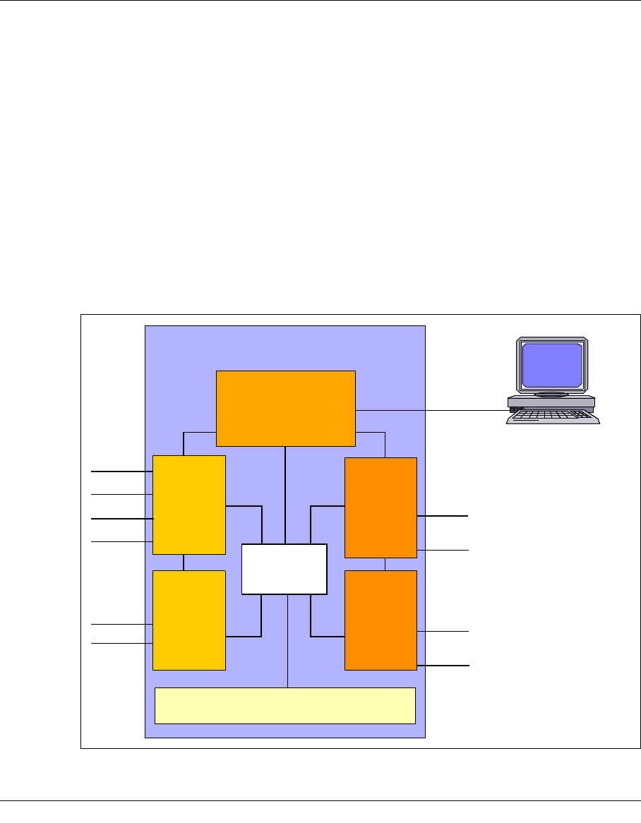
U41117-J-Z125-7-76 83
5 Operating and monitoring CentricStor
5.1 Technical design
5.1.1 General
CentricStor monitoring and operation is carried out on two levels by GXCC and XTCC.
.
Figure 29: GXCC/XTCC on the CentricStor ISPs (example VTA 2000-5000)
CentricStor
CentricStor
console
FICON
ESCON
ESCON
SCSI
SCSI
SCSI
SCSI
LAN
IDP
GXCC
XTCC
IDP
GXCC
XTCC
ICP
GXCC
XTCC
GXCC
XTCC
LAN
VLP
TVC
GXCC
FC fabric
FC
FC
FICON
ICP
GXCC
XTCC

84 U41117-J-Z125-7-76
Technical design Operating and monitoring CentricStor
GXCC (Global Extended Control Center) is a program with an X user interface that provides
a complete graphical representation of a CentricStor system, and covers all connected
devices and ISPs (Integrated Service Processors) such as ICPs (Integrated Channel
Processors), IDPs (Integrated Device Processors), and VLPs (Virtual Library Processors).
GXCC processes all ISPs and other components of a CentricStor cluster as if they were a
single unit.
Displays and operations within an ISP are implemented in the downstream XTCC appli-
cation (Extended Tape Control Center). An XTCC application is started by choosing the
“Show Details” command from the function menu of an ISP.
GTCC and XTCC are standard components of the CentricStor software package, and are
installed on all the CentricStor ISPs. They can also be operated on a computer
(workstation) that is running independently of CentricStor. To permit this, a GUI CD is
supplied with each CentricStor which can be used to install the GUI software for monitoring
a CentricStor system under the operating systems MS-Windows 95/98/NT/2000/XP,
LINUX, SOLARIS and SINIX-Z.
5.1.2 Principles of operation of GXCC
As shown in the figure below, the CentricStor user interface is represented by the interaction
of three components:
–InfoBrokers exchange information with the individual CentricStor processes. An
InfoBroker is an object-oriented data maintenance system containing all information
relevant to the system. This includes measured values supplied by the monitoring
programs of the CentricStor components.
–GXCC and XTCC receives information from the various InfoBrokers and presents it in
graphical format.
–An X11 server provides any on-screen display requied and processes commands
entered via your keyboard or mouse.
These three components communicate with each other on the basis of the TCP/IP protocol.
The InfoBroker, GXCC, and the X11 server can thus reside on the same system, or be
distributed between two or three systems connected via TCP/IP. Please note that the flow
of data between the InfoBroker and GXCC is considerably less than that between GXCC
and the X server.
Please refer to the product data sheet for information on the supported standard
and optional configurations of the user interface.
CentricStor utilizes numerous components, all of which are monitored and managed by
GXCC. There are several options for accessing these components.
i
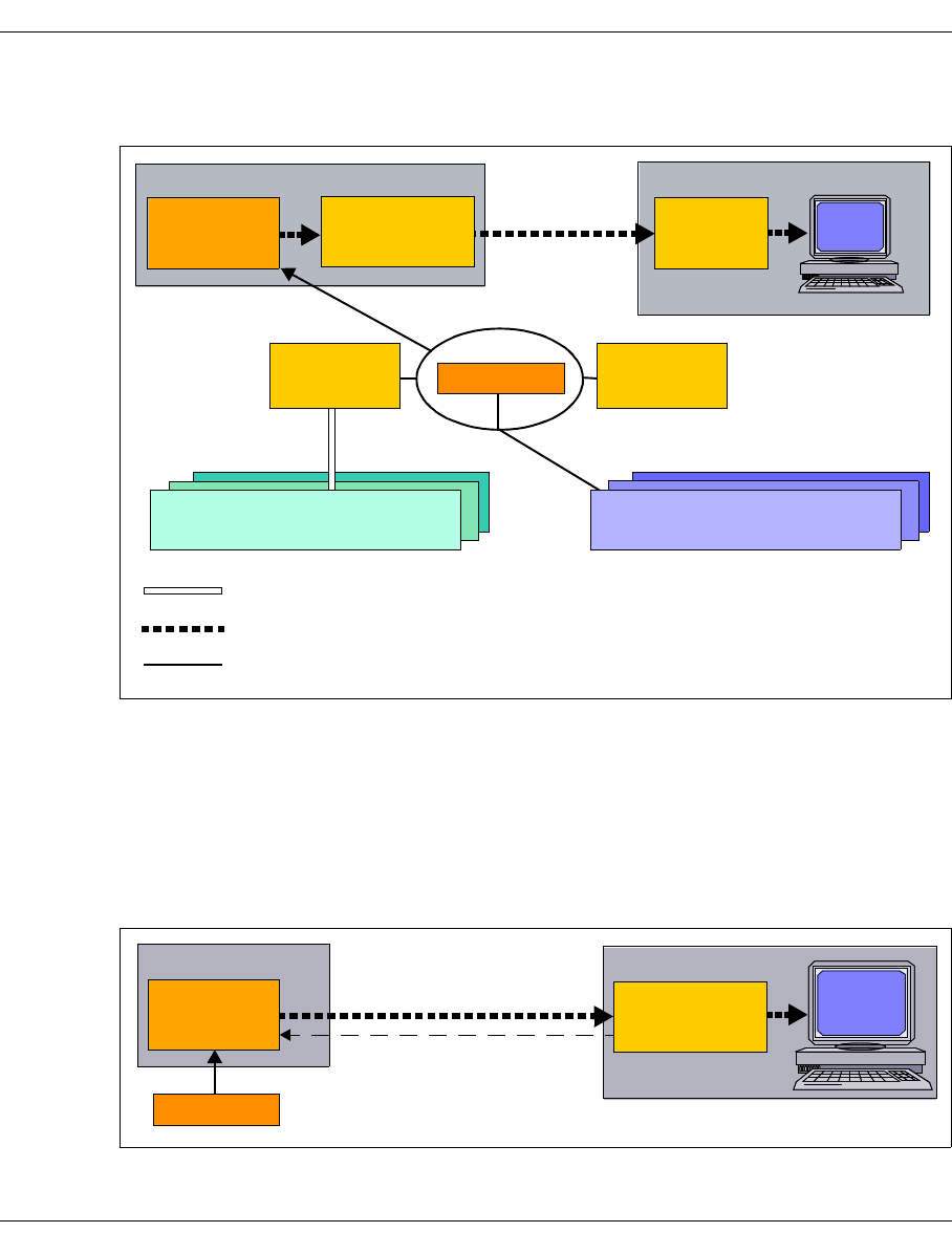
U41117-J-Z125-7-76 85
Operating and monitoring CentricStor Technical design
The figure below shows the components and the connections used for control and
monitoring (the Fibre Channel networking and the paths to the hosts are not shown):
Figure 30: GXCC components with X11 server as remote computer
In this example GXCC runs on a CentricStor computer. The data is made available by the
VLP InfoBroker. All GXCC output data is sent to the remote computer (X11 server) and
there displayed on the screen.
In the case of a low-speed data connection between CentricStor and the remote computer
the large data quantities to be transferred result in performance problems.
Consequently a configuration without X11 server provides a better solution:
Figure 31: Components of GXCC with a remote computer (not an X11 server)
GXCC
Remote computer
X11
server
GXCC
SCSI or FC interface
LAN or TCP/IP connection within processor
LAN
ICP
InfoBroker
SCSI components
IDP
InfoBroker
SNMP components
FC fabric
CentricStor
VLP
InfoBroker
GXCC
ouput data
GXCC
FC fabric
CentricStor Remote computer
VLP
InfoBroker GXCC
GXCC user data in ASCII
New data available?

86 U41117-J-Z125-7-76
Technical design Operating and monitoring CentricStor
In this configuration GXCC runs on the remote computer (e.g. Windows PC) and uses the
interfaces of its user interface directly. At short intervals GXCC inquires of the CentricStor
VLP whether there is new data. Here only 20 bytes are transferred. If new data is available,
the VLP sends the GXCC user data to the remote computer, which edits the data and
forwards it to the output screen.
ISP
Each ISP has its own InfoBroker which gathers information on the local software compo-
nents via optimized interfaces. This information is then passed on to GXCC over the local
CentricStor network.
Components managed via SNMP (FC switches)
These components can only be controlled and monitored using SNMP mechanisms. The
control component, referred to as the SNMP manager, monitors these stations and receives
traps. During configuration, you define the ISP in the CentricStor network on which the
underlying SNMP manager for GXCC is to be started.
In GXCC, all of the FC switches are represented as FC fabric.
SCSI-controlled components (tape drives, certain libraries)
All tape drives and some archives are controlled and managed by means of mechanisms
contained in the SCSI protocol. The associated InfoBroker instance is located in the ISP of
the CentricStor system to which the SCSI or FC interface leads.

U41117-J-Z125-7-76 87
Operating and monitoring CentricStor Technical design
5.1.3 Monitoring structure within a CentricStor ISP
The figure on page 89 contains a more detailed representation of how GXCC monitors the
individual CentricStor control components. This figure should also be regarded as one
example of the many configurations possible.
The figure shows the logical or physical connections used by GXCC for monitoring and
control purposes. The internal Fibre Channel system is depicted only insofar as it is used
in the management of the RAID system. The thick continuous lines represent TCP/IP
connections which alternate between processors. The broken lines represent connections
that may also exist within an ISP. All other interfaces are represented by thin lines.
The central monitoring point in each ISP is the InfoBroker and the associated Request-
Broker. All InfoBrokers in the CentricStor network have exactly the same configuration and
are considered peers. They provide special interfaces for communicating with all
CentricStor control components. These components are present in latent form in all ISPs.
During the configuration process, you define which components are actually activated in
which ISPs. Inactive control components are shown in blue in the figure below. While the
InfoBroker only ’knows’ the components of the local ISP, the affiliated RequestBrokers
exchange configuration information with the RequestBrokers of the other ISPs, and thus
’see’ CentricStor as an overall unit.
XTCC always monitors a single ISP. As a result, XTCC connects directly to the InfoBroker
of ’its’ ISP.
The following example of many possible CentricStor configurations. In principle the
individual processes can be distributed over the ISPs almost without restriction. Only those
processes which require supervisor access must be started on one ISP.

88 U41117-J-Z125-7-76
Technical design Operating and monitoring CentricStor
The table below lists the control components:
GXCC/XTCC can also run on SINIX-Z/Solaris/LINUX/Windows systems which are
independent of CentricStor. In this case, GXCC connects via the LAN to the RequestBroker
of the ISP referenced in the unit selection, exchanges information with it and, on the basis
of this information, builds the graphical display.
GXCC/XTCC also covers the CentricStor components that can only be monitored via
SNMP, such as the Fibre Channel switches. During configuration, you define the ISPs in
which the management station is to be started. In addition, an SNMP agent can be installed
in CentricStor that permits CentricStor to be monitored by an SNMP management station.
Name Function Comment
LD Logical Device: emulation of a drive. Must run on the ISP in which the
associated host interface (ESCON/
FICON/FC) is installed (ICP).
MSGMGR Message Manager: filters and stores
system messages. Triggers actions in
response to certain situations (e.g.
SNMP traps).
Only one instance throughout
CentricStor.
PDS Physical Device Service: drives one
physical tape drive.
Must run on the ISP in which the
associated SCSI interface is installed
(IDP).
PERFLOG Performance Logging: captures and
stores performance-related system
data.
Only one instance throughout
CentricStor
PLM Physical Library Manager: manages
the physical CentricStor components.
Only one instance throughout
CentricStor.
PLS Physical Library Service: drives a real
robot archive.
In the case of SCSI-controlled robots,
must be installed on the same ISP as
the associated SCSI interface.
VLM Virtual Library Manager: manages
the CentricStor virtual libraries.
One instance throughout
CentricStor, installed in the same ISP
as the PLM (VLP).
VLS Virtual Library Service VDAS, VACS and VLMF are each
provided once in CentricStor, VAMU
10 times, and VJUK 20 times.
VMD Virtual Mount Daemon In each ICP.
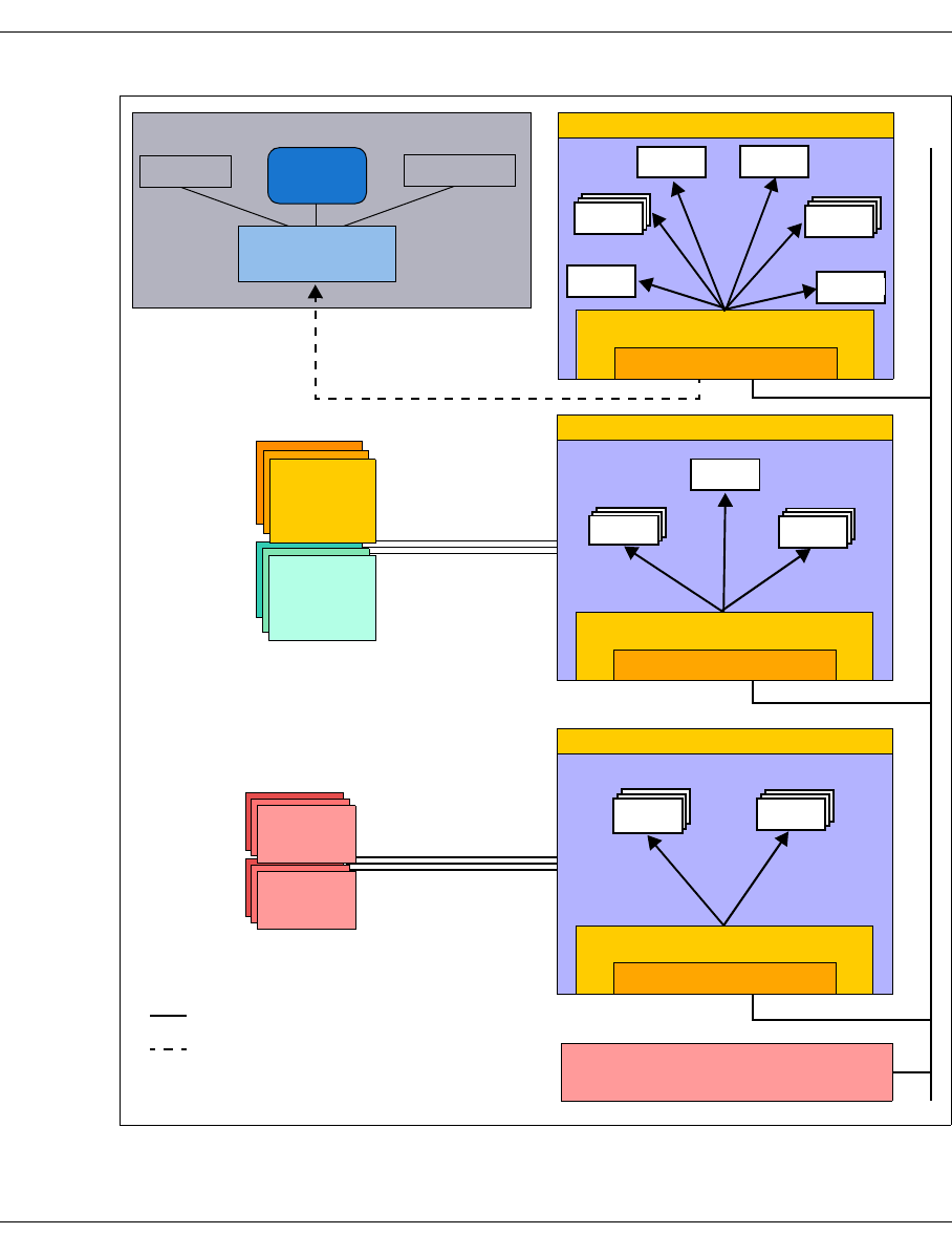
U41117-J-Z125-7-76 89
Operating and monitoring CentricStor Technical design
Figure 32: Monitoring structure in CentricStor (example VTA 2000-5000)
Screen
Keyboard Mouse
ESCON, FICON or FC
host connection
TCP/IP LAN
TCP/IP LAN or TCP/IP connection
within processor Components managed via SNMP
SCSI or FC connections to
drives and libraries
SCSI
drives
SCSI
libraries
Remote computer
PDS PLS
IDP of the CentricStor network
InfoBroker
RequestBroker
VLS
VMD
ICP of the CentricStor network
LD
InfoBroker
RequestBroker
VLS
VLM
PLM
InfoBroker
RequestBroker
PLS
PERF
MSGMGR
ISP of the CentricStor network
GXCC
Open
Systems
hosts
Mainframe
hosts

90 U41117-J-Z125-7-76
Technical design Operating and monitoring CentricStor
5.1.4 Operating modes
GXCC recognizes the following three user privilege levels:
Service mode Access to all CentricStor functions available via GXCC. Users
must use the “diag” password to identify themselves to the
CentricStor ISP with which they are connected.
User mode Access to the functions required for normal operation.
Examples of this are the addition of new logical volumes and the
inclusion of or changes to logical and physical volume groups.
Users identify themselves with the ISP “xtccuser” password.
Observe mode Monitoring function. Access to the global status and history. By
default no password is required. On CentricStor, access control
can optionally be configured for this mode. Users then legitimate
themselves with the ISP’s “xtccobsv” password.
The operating mode is set as a start parameter when GXCC is called. The password will be
queried once the connection has been established.
If the wrong password is entered, an error message is output and the query is repeated.
After a third wrong entry for Service or User mode the GXCC is started in Observe mode
provided no access control exists for this. If access control is specified for Observe mode,
three wrong password entries are also possible here, after which the program aborts.
This manual describes User mode and Observe mode. Service mode is reserved
for service personnel.
i
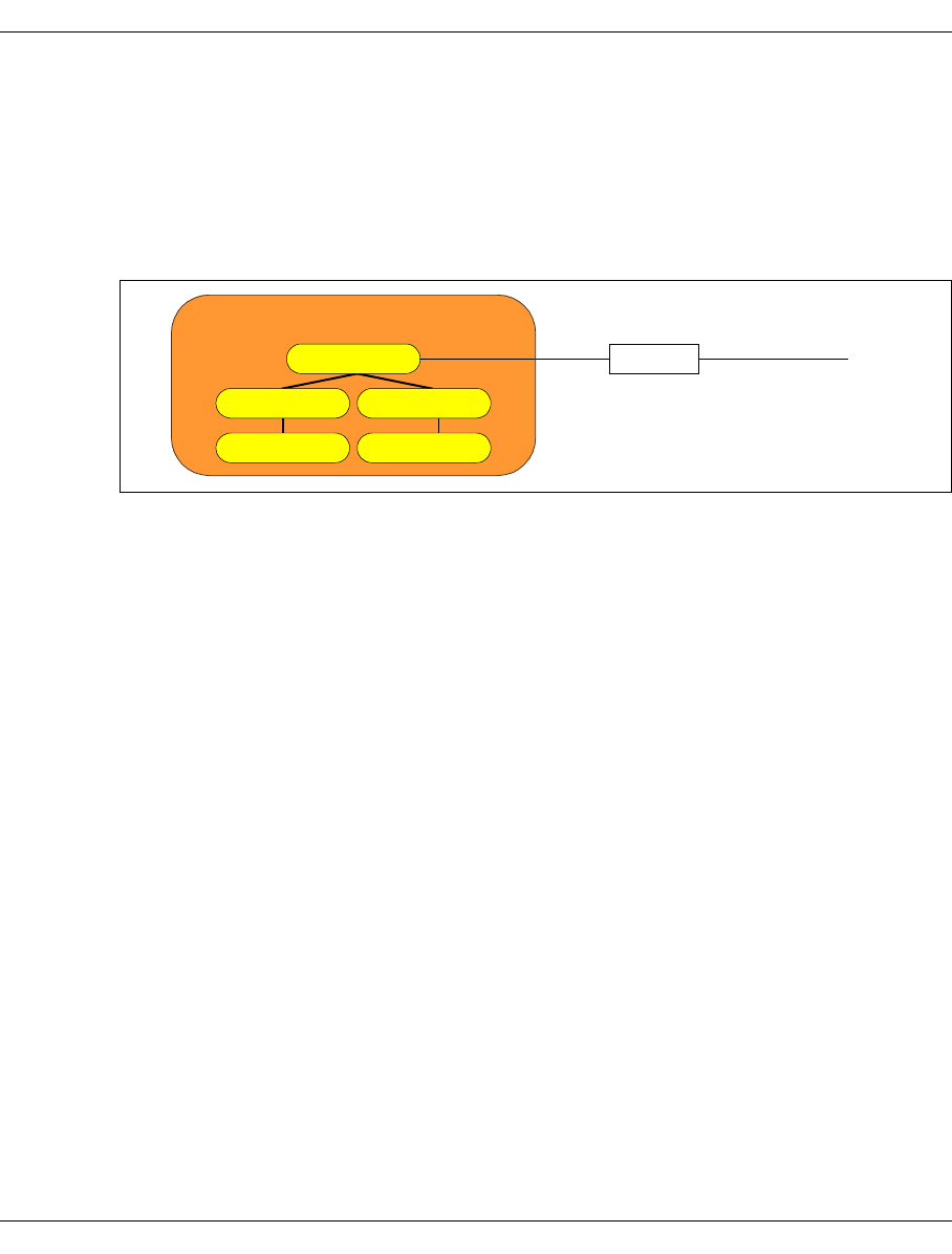
U41117-J-Z125-7-76 91
Operating and monitoring CentricStor Operator configuration
5.2 Operator configuration
5.2.1 Basic configuration
Without requiring additional hardware or further software licences, CentricStor offers the
following configuration for operation and monitoring:
Figure 33: CentricStor basic configuration
Within a CentricStor cluster, the InfoBroker will accept two connections to GXCC if this has
been started on an ISP of CentricStor. The X11 server can run internally in CentricStor,
using the local consoles, but also externally. The InfoBroker can also accept an additional
connection to a GXCC outside CentricStor if this is made using a modem (SLIP)
connection. This connection is designed to be used for remote maintenance purposes.
5.2.2 Expansion
The operating options can be expanded using the additional license 3595-RMT (CS Re-
mote Monitoring and Administration). If the RMT key is installed in a CentricStor system,
the InfoBroker accepts any number of connections to a GXCC outside its CentricStor. This
CentricStor can consequently be monitored on any number of independent computers
(workstations) with GXCC/XTCC.
For performance reasons the number of connections with GXCC within CentricStor remains
limited to two.
CentricStor
InfoBroker
GXCC
Modem
X11 server
Phone line
connecting to the
teleservice
GXCC
X11 server

92 U41117-J-Z125-7-76
Operator configuration Operating and monitoring CentricStor
5.2.3 GXCC in other systems
GXCC can also be installed and is executable in Windows 98/NT/2000/XP, LINUX and
SOLARIS systems. An installation CD is supplied with each CentricStor. This contains the
tools and information files required for installation on the relevant systems. You will find
more information on this in the installation manual.
GXCC V6.0, GXCC V3.0 and GXTCC V2.x can be installed in the same system at the same
time.
Ongoing updating of GXCC takes place semiautomatically from the connected CentricStor
systems.
5.2.4 Screen display requirements
– The operator consoles of the ISPs meet the requirements.
– An external X11 server will require a graphics-capable color monitor. The ideal
resolution is 1280 x 1024 Pixel. The minimum requirement which must be set is
1024 x 786 Pixel.
– In GXCC important information is displayed using colors. As a result, 16-bit True Color
(or better) is ideal. 8-bit color palettes may lead to incorrect color displays if GXCC is
sharing the screen with other applications.
5.2.5 Managing CentricStor via SNMP
5.2.5.1 Connection to SNMP management systems
CentricStor is prepared for connection to an SNMP management station. On the GUI-CD
of CentricStor the software and information have the settings required. Special functions
are available for CA Unicenter.
SNMP is used, above all, to forward special situations reported in console outputs, for
example, to the management station as traps. The user interface or command-line interface
should then be used for detailed diagnostics.

U41117-J-Z125-7-76 93
Operating and monitoring CentricStor Operator configuration
5.2.5.2 SNMP and GXCC
Monitoring and operation of CentricStor by GXCC runs independently of SNMP.
In addition, however, CentricStor also offers the basic functions required for management
via an SNMP station. Thanks to the great flexibility of GXCC as regards configuration, when
GXCC is used together with SNMP the monitoring and operation of CentricStor can be
adapted to suit the IT infrastructure and the requirements of the user.
The VLP of CentricStor provides the connection to the outside world. It supports “ping” and
elementary MIB-II. Thus, the operation of the carrier system can be monitored, but not the
functioning of CentricStor.
In addition to standard Traps such as coldStart, linkUp, linkDown etc., when system
messages of priority 5, 6, 7 or 8 (ERROR, CRITICAL, ALERT, EMERGENCY) occur,
CentricStor therefore sends corresponding traps to the management station.
In addition, every 300 seconds a “Global State” with the following values is sent to the
SNMP management station by means of a trap:
1 CentricStor is ready to operate (green).
4 Subcomponents of CentricStor are faulty, operation is still possible (yellow).
7 Operation of CentricStor has been disrupted (red).
Additional functions are made available for installation in management stations of the type
CA Unicenter.
Since GXCC will run on most standard systems, the startup of GXCC for detailed
diagnostics when there is a trap can be largely automated in practically all management
systems.
The current status regarding SNMP support is indicated in a text file. After GUI installation
on a type CA Unicenter management station you can find this file at “...Setup > SNMP
Integration README”.
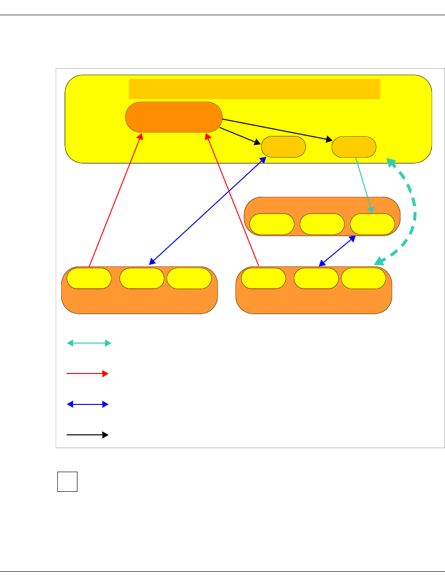
94 U41117-J-Z125-7-76
Operator configuration Operating and monitoring CentricStor
The figure below shows some of the possible configurations for an SNMP manager for
connecting GXTXCC to the triggering CentricStor on the basis of a trap:
Figure 34: Configuration options at an SNMP management station
– In the case of configurations in which there is an external connection between
GXCC and an InfoBroker (shown here in blue), an RMT license is required in
the relevant CentricStor.
– The InfoBroker accepts a maximum of two local connections. It is irrelevant here
whether the X11 server runs within CentricStor using the local console or out-
side CentricStor on a workstation.
CentricStor
Info
Broker
SNMP
agent
SNMP management station
GXCC
CentricStor
Info
Broker
SNMP
agent GXCC
Workstation
X11
server
SNMP manager
GXCC GXCC GXCC
GXCC
Application
launching
Optional if
there is no
RMT
license
X11 connection to GXCC, higher bit rate required
Traps from the SNMP agent in CentricStor to the management station
Connection between GXCC and InfoBroker; only a low bit rate required;
only with an RMT license in CentricStor.
Application launching
i

U41117-J-Z125-7-76 95
Operating and monitoring CentricStor Starting GXCC
– The GUI software must be installed explicitly on the workstation for operation of
GXCC outside CentricStor. A CD with GXCC (GUI CD) is provided free with
each CentricStor. GXCC can be installed an unlimited number of times to run
CentricStor. It will run on Windows 98/NT/2000/XP, LINUX, SOLARIS and
SINIX-Z systems.
5.3 Starting GXCC
5.3.1 Differences to earlier CentricStor versions
In CentricStor V3.0 the name of the interface had already been changed from
“GXTCC” to “GXCC”. Furthermore, Service mode is now started by the start
parameter “-service” (previously “-modify”). The access point (mostly VLP) is
selected via “-unit” (previously “-host”).
For compatibility reasons the call for GXCC and the previous start parameters will continue
to function. However, you are urgently recommended to adapt all the settings to the new
names as soon as possible.
5.3.2 Command line
GXCC is called from the remote operator console or the CentricStor console via the Root
menu. On auxiliary operator consoles a command line is entered. A number of runtime
parameters can or must be entered with this command line.
If GXCC is to be started from a graphical interface, this command line must be entered
when configuring the interface function (see section “Starting from a Windows system via
Exceed” on page 105, for example, or section “Starting from a Windows/NT system via
XVision” on page 108).
The command line has the following format:
/usr/apc/bin/GXCC <options as per table below> [&]
Example of a GXCC call:
/usr/apc/bin/GXCC -user -display 123.45.67.89:0.0 &
The start parameter settings are also transferred to the Global Status monitor.
i

96 U41117-J-Z125-7-76
Starting GXCC Operating and monitoring CentricStor
The table below lists the possible start parameters:
Parameter Meaning Comment
-aspect1 <param> Size and position of the main win-
dow on the screen
<param> has the format
[=][WxH]+|-X+|-Y
WxH: Width x height (pixels)
X,Y: Coordinates (pixels)
[*] * is optional
+|- + or -
-autoscan1Cycle duration for updating the
main window
Reduction of the data when
operating via Teleservice
-display Host name/IP address of the
X terminal at which the window is
to be displayed
Default: local X11 server
-globstat Activates the Global Status
Monitor
-lang1Language for helps. De | En In the event of other defaults En is
set.
-multiport Connection via Info and/or
RequestBroker port
If not specified: Single Port con-
nection (see page 148)
-nointro Splash screen suppression Reduction of the data when
operating via Teleservice
-observe Start in Observe mode If not specified: User mode
-profile <file> Name of the profile file (see the
section “Profile” on page 191)
If this is not specified, GXCC will
be started with the default profile.
-service Start in Service mode If not specified: User mode
-simu <file> Simulation mode <file> is the file generated in
GXCC/XTCC with File ➟ Save.
-singleport Connection only via Request-
Broker port
If not specified: Single Port con-
nection (see page 148)
-size1 n Size of the main window Default value: 80%, 100%, 120%
-unit Host name/IP address of the
CentricStor node to which GXCC
is connected after start-up
If GXCC is running on a VLP, a
connection to the local InfoBroker
is established if nothing else is
specified. In all other cases, the
Unit Select menu is opened after
the program is started.

U41117-J-Z125-7-76 97
Operating and monitoring CentricStor Starting GXCC
To start in User mode, use: gxcc <other parameters> &
or
GXCC -user <parameters> &
To start in Observe mode, use: GXCC -observe <parameters> &
5.3.2.1 Explanation of the start parameter -aspect
The argument of this parameter has the format {[=][WxH]+|-X+|-Y}
Where:
WxH The window is displayed on the screen with a width of W pixels and a height of H pi-
xels.
+X Distance of the left-hand window margin from the left edge of the screen in pixels
-X Distance of the right-hand window margin from the right edge of the screen in pixels
+Y Distance of the upper window margin from the upper edge of the screen in pixels
-Y Distance of the lower window margin from the lower edge of the screen in pixels
Examples: -aspect 500x400-100-100; -aspect 500x400; -aspect +100+100
It is possible that the specification W and / or H will be ignored by the application.
CAUTION!
Knowledge of the screen setting is required to use X and Y since if values which are
too high are specified, the window will be displayed partly or completely outside the
visible area.
-user Starts the application in User
mode
If not specified: User mode
1The command line arguments -aspect, -autoscan, -lang, -size have priority over values already stored in a profile
file.
Parameter Meaning Comment
i
!

98 U41117-J-Z125-7-76
Starting GXCC Operating and monitoring CentricStor
5.3.3 Environment variable XTCC_CLASS
GXCC supports an environment variable with this names as follows:
If this environment variable is not defined when GXCC is started, it is set to the value “Xtcc”.
Otherwise the specified value is taken.
The relevant value is is inherited by all applications called by the current GXCC instance.
This (class) name can, for example, be used by virtual window managers to place all the
applications belonging to a particular GXCC instance in the same virtual window.
On Unix systems this variable can, for example, be set as follows when GXCC is called:
XTCC_CLASS=Xtcc1 gxcc -unit A [argumente] &
XTCC_CLASS=Xtcc2 gxcc -unit B [argumente] &
5.3.4 Passwords
The following passwords are needed to start GXCC:
●The password for logging into the CentriStor system running GXCC. GXCC starts under
this password. Normally, this is the user ID “tele”; “root” is also possible.
●In User mode, GXCC requests a password which it uses for authorization when estab-
lishing a connection with the InfoBroker. Here you normally require the password of the
“xtccuser” ID.
●For Service mode you normally require the password of the “diag” ID.
●In Observe mode generally no password is required. However, if the optional access
control has been activated on a CentricStor, you normally require the password of the
“xtccobsv” ID.

U41117-J-Z125-7-76 99
Operating and monitoring CentricStor Starting GXCC
5.3.4.1 Optional access control for Observe mode
When a CentricStor V3.1 system is installed, the “xtccobsv” ID is set up by default and the
line “+ xtccobsv” entered in the home/xtccobsv/.rhosts file. As a result this optional
access control is initially inactive and no password is required for Observe mode. This
procedure is the same as in earlier CentricStor versions. To activate access control, the
administrator must modify the specified file and - as required - the password of the
“xtccobsv” ID on the
CentricStor V3.1 system (in the SINIX system of the VLP and, if required, on other access
servers).
Example
If the home/xtccobsv/.rhosts file contains only the file entries
“gui_computer_1 xtccobsv” and “gui_computer_2 xtccobsv”, only these two
computers have access without a password dialog. All the others must know the
password, which may have been modified.
5.3.4.2 Authentication
After connection setup, client authentication takes place (in the SINIX system of the VLP
and, if required, on other access servers). Authentication with a password is performed
each time the program is started.
The passwords are defined as follows:
Service mode: Password of the “diag” ID
User mode: Password of the “xtccuser” ID
Observe mode: Default: No password.
Optional as of CentricStor V3.1: Password of the “xtccobsv” ID
The authorization (Service, User or Observe) is forwarded to the applications that are
downstream (such as XTCC for monitoring/operating the ISPs). If the wrong password is
entered, an error message is issued and the query is repeated up to 3 times.

100 U41117-J-Z125-7-76
Starting GXCC Operating and monitoring CentricStor
5.3.4.3 Suppressing the password query
Releasing individual users
The password query can be suppressed if an entry in the .rhosts file permits access to
CentricStor. To do this, the monitoring system is entered in the following .rhosts file on the
monitored system:
Service mode: /usr/apc/diag/.rhosts
User mode: home/xtccuser/.rhosts
Observe mode: home/xtccobsv/.rhosts
The following options are available for an entry in the .rhosts file:
●+ <id>
In this case access can take place from any monitoring host.
●<host-name> <id>
In this case, access is permitted only from the host with the name <host-name>. The
Name Server entry, the Yellow Page entry or the IP address of the source computer
must be used for <host-name>. This depends on the current operating configuration
and network topology. The first two entries generally differ only in that the domain name
is part of the name (Name Server) or is missing (Yellow Page). It is most convenient just
to take all options into account in the .rhosts file.
The <host-name> currently being used can also be seen in the status line of the
GXCC/XTCC.
Example
If password-free access to CentricStor is to be permitted from the PC “PCjoesmith”, the
following entries must be made on CentricStor in the /.rhosts file which is dependent
on the access mode (here: Observe mode):
PCjoesmith xtccobsv
PCjoesmith.mch.xyz.de xtccobsv
Releasing indivudual computers
The /etc/hosts.equiv file enables you to grant complete computer password-free
access to CentricStor. Password-free access to all modes is permitted by entering the
computer name or its IP address.
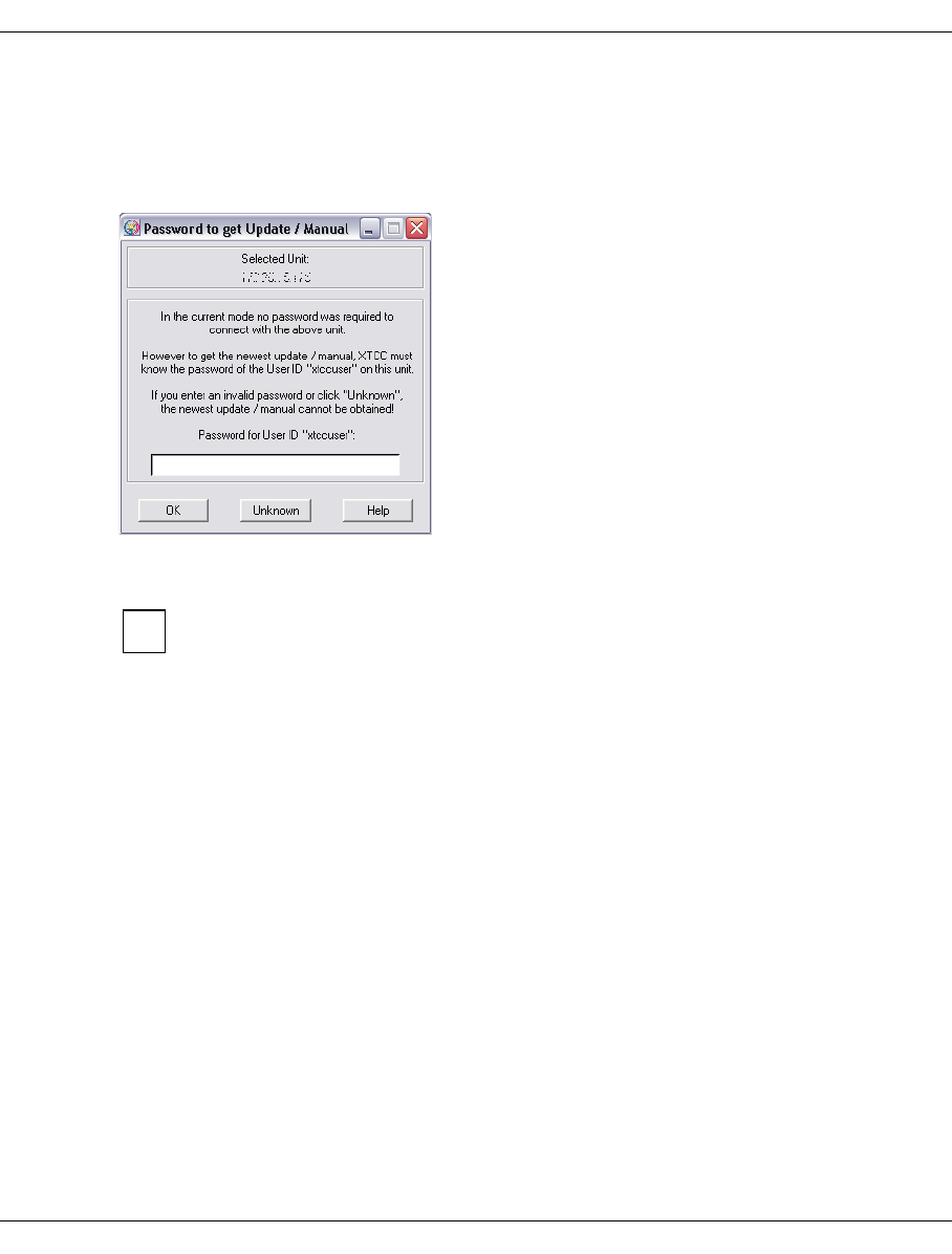
U41117-J-Z125-7-76 101
Operating and monitoring CentricStor Starting GXCC
5.3.4.4 Additional password query
If GXCC or XTCC requires a password to transfer an update (see the section “Software up-
dates” on page 118) or manual (see the section “Online Manual” on page 235), the follow-
ing window appears:
This password query is made only when the user can access the system without a primary
password query.
Information on this is provided in the sections “Optional access control for Observe
mode” on page 99 and “Suppressing the password query” on page 100.
The window consists of an input field for the password and the following buttons:
OK
The password entered is used if it is not empty. Its validity is not verified: the transfer
fails if the password is invalid.
Unknown
When you click on this button you exit the window. The update or manual is not accept-
ed.
Help
Displays a help text.
NOTES
●Depending on the context, the term “XTCC” can be replaced by “GXCC” in the window
displayed above. The user ID can be different.
●In Observe mode the password of the user ID “xtccuser” is requested.
●If an update from an earlier connection which has not yet been activated is already
available locally, this is indicated by the message Update <m.n> available.
i
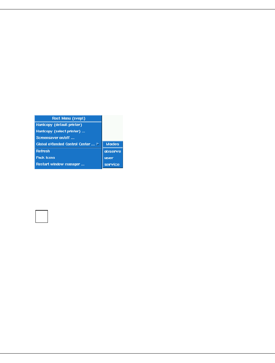
102 U41117-J-Z125-7-76
Starting GXCC Operating and monitoring CentricStor
5.3.5 Starting the CentricStor console
●Position the mouse pointer to a neutral screen area.
●Press the right mouse button.
●The Root Menu appears, including the function
“Global eXtended Control Center”.
If you select this item, you are offered the three modes of GXCC:
– Observe Mode
– User Mode
– Service Mode
When you have selected the required start mode GXCC is started.
5.3.6 Starting from an X11 server
Some X11 servers have difficulty with cascaded menus. The problem occurs when
an attempt is made to move the mouse pointer from a menu entry onto an
associated, cascaded submenu. The submenu is then closed immediately, with the
result that the desired function cannot be selected. In this case an alternative X11
server should be installed.
5.3.6.1 General notes on the X11 server architecture
CentricStor is monitored and controlled by the interoperation of three components:
– the X11 server, which presents the graphics formatted by GXCC and controls the actual
man/machine interface,
– the Global Extended Control Center GXCC, which on the one hand exchanges infor-
mation with the InfoBroker and prepares this information in graphical form as required,
and on the other hand responds to events at the man/machine interface (e.g.
movements of the mouse pointer, keyboard input, etc.),
i
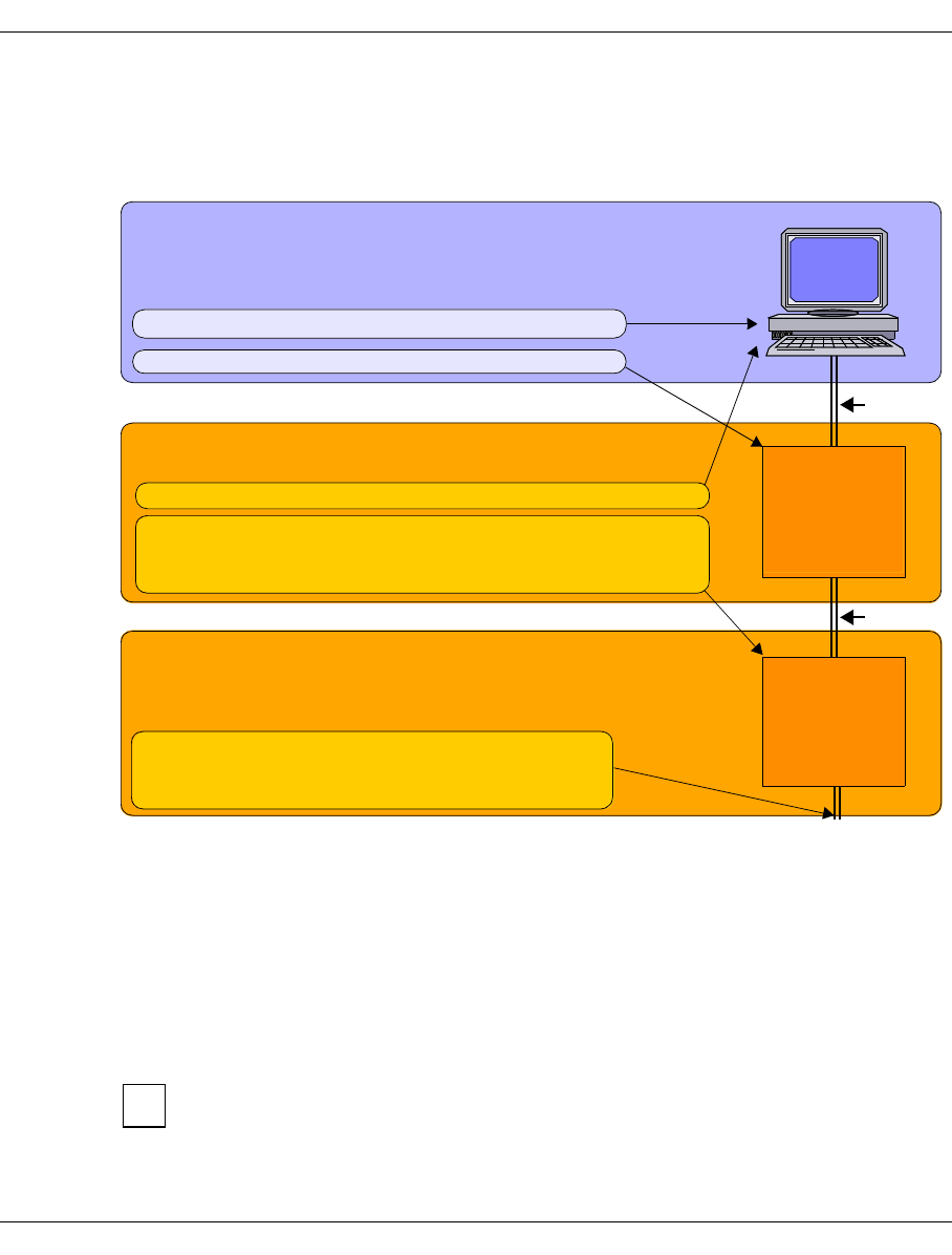
U41117-J-Z125-7-76 103
Operating and monitoring CentricStor Starting GXCC
– and the RequestBroker of the connected ISP, which gathers information from all compo-
nents and forwards commands from the man/machine interface to the respective
recipients (XTCC, which only ever handles a single ISP, connects itself directly to the
InfoBroker of this ISP).
Figure 35: X11 architecture for CentricStor operation
The three components communicate with each other using the TCP/IP protocol. They can
therefore be located on one or on up to three hosts.
If you operate GXCC at the CentricStor console for example, the X11 server, GXCC host
and request manager/InfoBroker all run in the VLP of CentricStor.
If CentricStor is operated via a computer (workstation) outside CentricStor, GXCC runs on
a host independent of CentricStor. The display console and consequently the X11 server
can reside on the same computer as GXCC or on a subprocessor.
A significantly higher transmission bandwidth is needed for the connection between
GXCC and the X11 server than for the connection between GXCC and the
InfoBroker.
The “-unit” start parameter points to this host. The passwords
of “xtccuser” or “diag” are needed on this host.
The “display” setting points to this host.
X11 server (e.g. VLP, workstation or PC, Mac, Linux etc.)
Includes the mouse, keyboard, screen. Can be a SINIX or
Windows system or another system with appropriate
software.
GXCC host (e.g. VLP or remote computer)
This runs the “Global Extended Control Center”.
The “-display” start parameter points to this host.
This host is used for the login for calling the X client
ReqBroker in connected ISP of CentricStor
The ReqBroker also transmits information between
GXCC and the other system components.
TCP/IP
The TCP/IP connections to the other components of
CentricStor are defined in the configuration.
TCP/IP
X11
server
Info
Broker
VLP
GXCC
ii
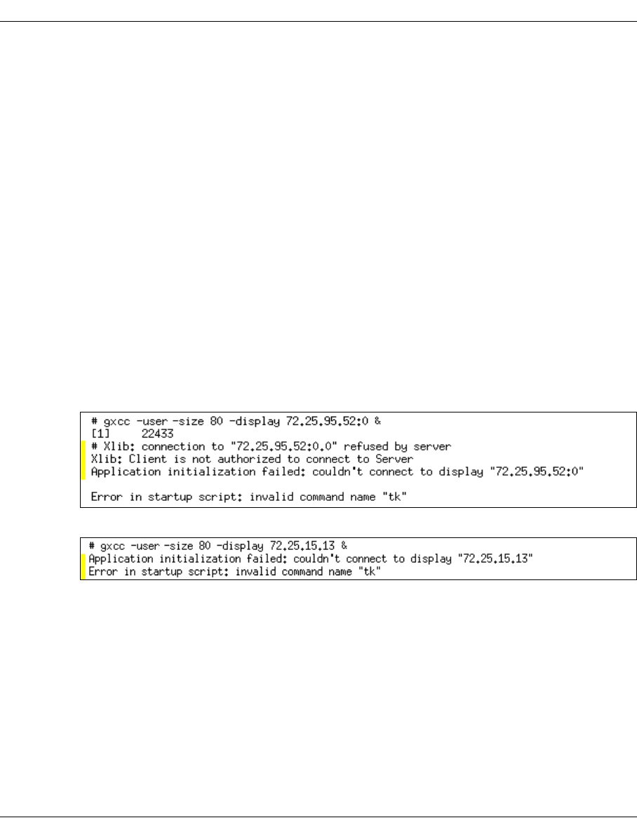
104 U41117-J-Z125-7-76
Starting GXCC Operating and monitoring CentricStor
5.3.6.2 Using the direct XDMCP interface
The full range of XDMCP (X Display Manager Control Protocol) functions cannot be used
in CentricStor 2.1.
You are strongly recommended to use the X11 servers in Passive mode.
5.3.6.3 Starting from a UNIX system
1. Make sure that the ISP to be addressed is listed in the XHOST list of the calling system.
If in doubt, enter its name or IP address with the “xhost” command
(/usr/bin/X11/xhost +<Name or IP address of the ISP>).
2. Remote login, e.g. using telnet, to the desired ISP of CentricStor (in general, this
should be the VLP) under the user ID “tele”. You will need the appropriate password.
3. Call GXCC using the command line described in the section “Command line” on
page 95. Specify the IP address or host name for the -display parameter and,
separated by “:”, the screen number of the calling system. It is advisable to terminate
the line with “&”. The telnet screen then remains open and displays any errors that occur
before the establishment of an X11 connection.
Common error messages:
The X11 server is not running or the X11 host is not in the XHOST list of the GXCC host.
The screen number was forgotten in -display.
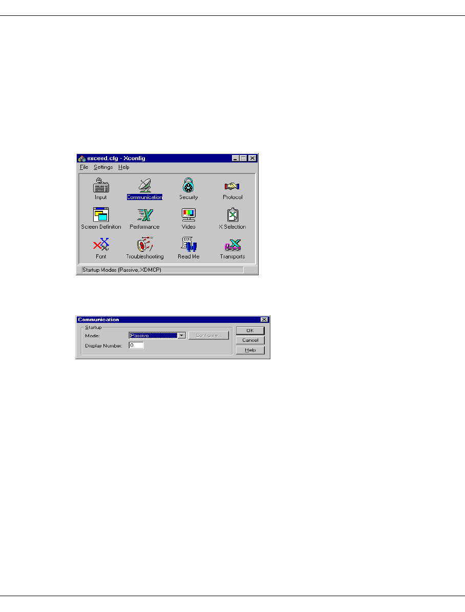
U41117-J-Z125-7-76 105
Operating and monitoring CentricStor Starting GXCC
5.3.6.4 Starting from a Windows system via Exceed
With appropriate preparation, GXCC can be started by clicking an icon on the desktop.
More details can be found in the Exceed help information. This section only describes the
GXCC-specific settings of Exceed.
Exceed preparations
ÊOpen the following window by choosing “Programs” ➟ “Exceed” ➟ “Xconfig”:
ÊClick “Communication” in the Xconfig window.
ÊSet the startup mode “Passive” shown in the diagram below.
This prevents xdm from starting on the client. The specification in the display field desig-
nates the (partial) screen you desire.
Ê“Multiple Screens” must be set in the “Screen Definition” window.
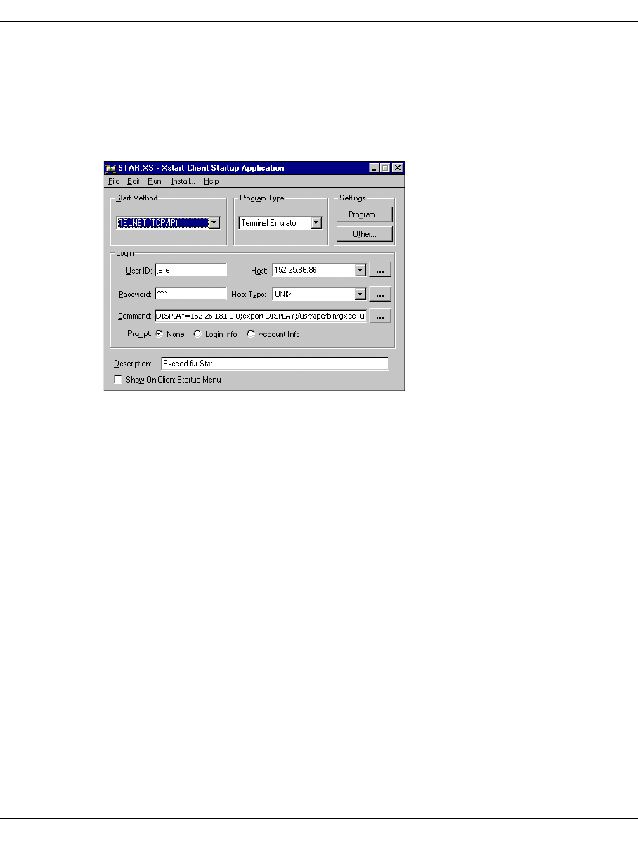
106 U41117-J-Z125-7-76
Starting GXCC Operating and monitoring CentricStor
Starting GXCC via Exceed
ÊStart Exceed (preferably via the Windows autostart function).
ÊChoose “Xstart”.
ÊActivate the Start menu as shown in the following example:
The user ID is tele, and the password entered must be the appropriate tele password.
The GXCC password is requested later in accordance with the desired operating mode.
Host contains the IP address of the ISP to be addressed (generally the VLP).
The “Command” input field contains a sequence of commands separated by “;”. The
first command indicates the host IP address and screen number of the display to be
selected. Following “export DISPLAY”, GXCC is called with all the start parameters
you desire (apart from -display). You must specify the mode (here -user) if Observe
mode is not desired. Other parameters are possible in accordance with the description
in the section “Command line” on page 95.
The absolute path (/use/apc/bin/gxcc) must be used when calling GXCC.
You can enter any comment in the “Description” field.
ÊThese settings can be saved by choosing “File” ➟ “Save” or “Save as”.
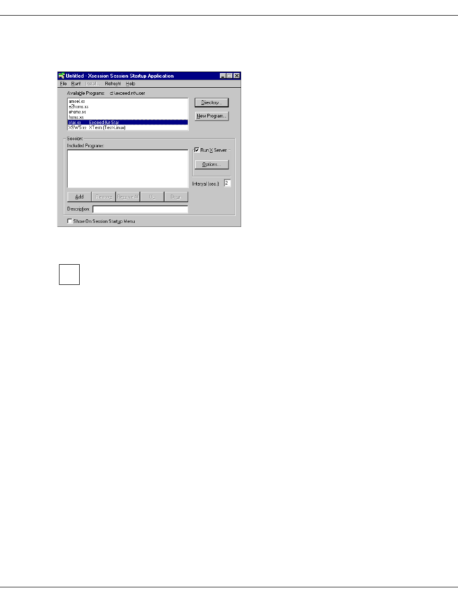
U41117-J-Z125-7-76 107
Operating and monitoring CentricStor Starting GXCC
Choose the Windows Start menu “Programs” ➟ “Hummingbird Connectivity” ➟
“Exceed” and ➟ “Xsession” to display a selection of start files:
When you have selected the start file and chosen “Run!”, GXCC will be started on the
selected unit.
However, you can also drag the start file to the desktop as a shortcut or save it on
the desktop. Then, the program is started as usual by double-clicking the icon.
i
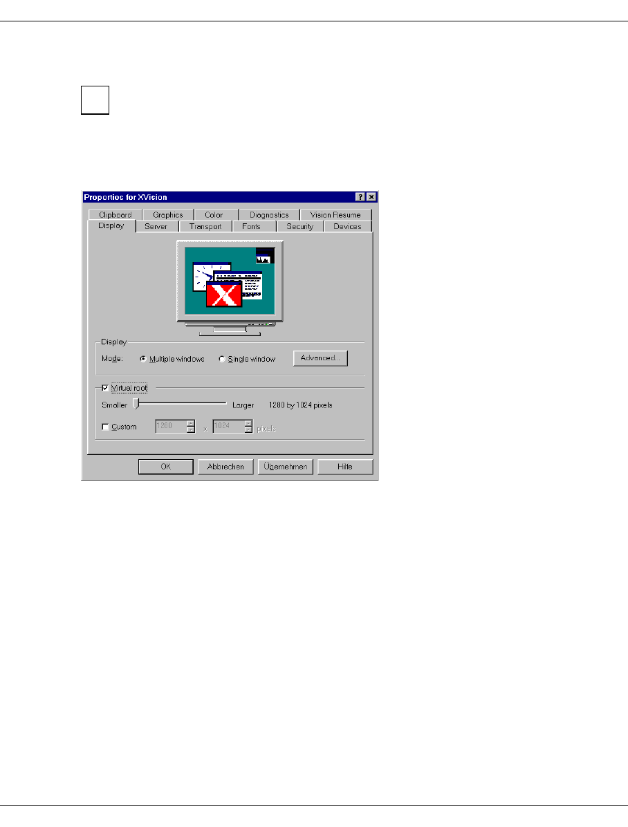
108 U41117-J-Z125-7-76
Starting GXCC Operating and monitoring CentricStor
5.3.6.5 Starting from a Windows/NT system via XVision
When installing XVision, the UNIX environment must also have been installed.
XVision setting
An example is shown in the following diagram:
It is important that the display mode “Multiple windows” is set.
i
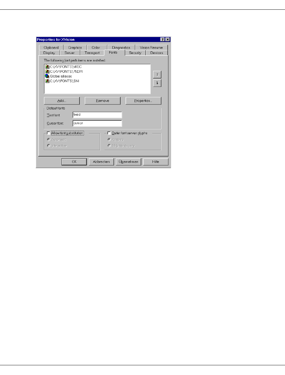
U41117-J-Z125-7-76 109
Operating and monitoring CentricStor Starting GXCC
The diagram below shows an example of the fonts setting:
ÊThe “Allow font substitution” option must be disabled.
ÊWhen specifying the font path items, the UNIX fonts must be listed before other fonts.
If different settings are defined, the layout of GXCC windows and dialog boxes may be
corrupted.
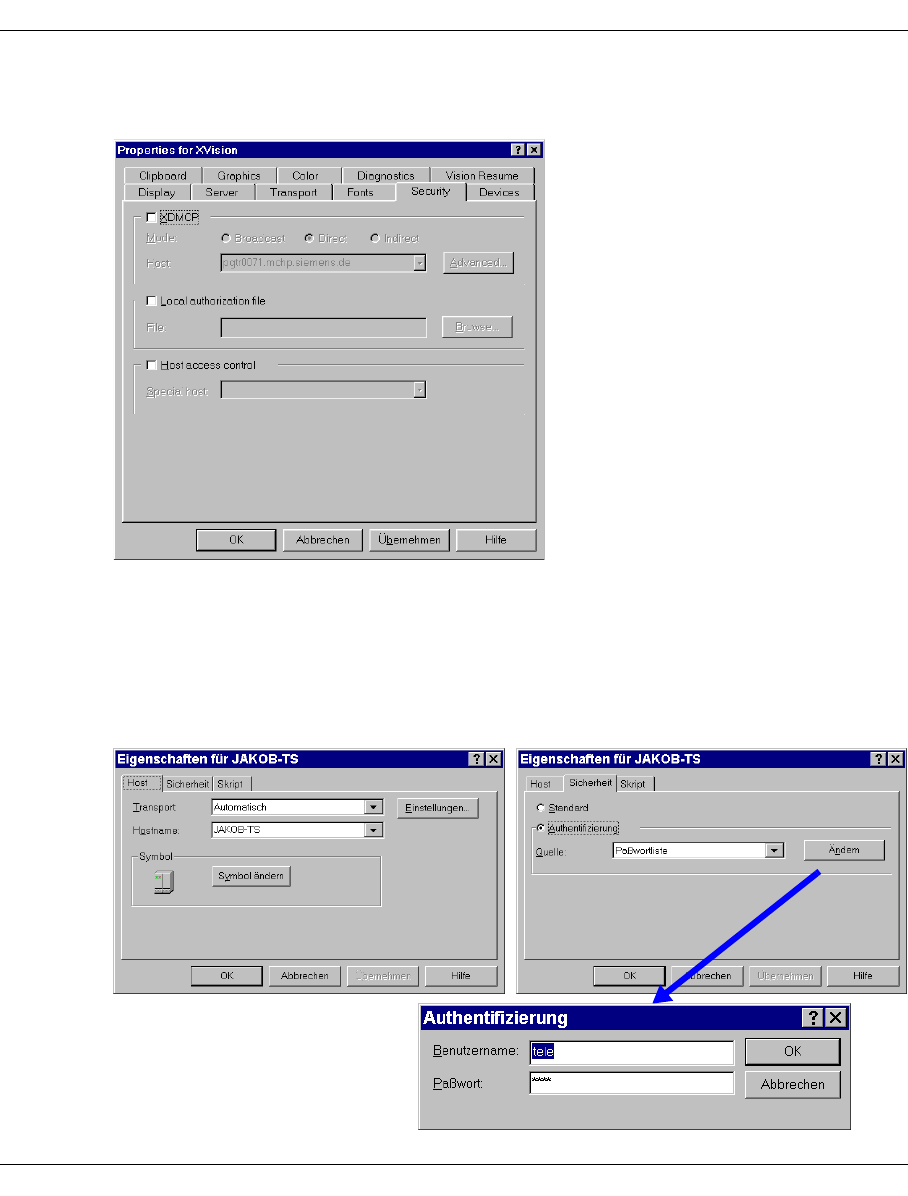
110 U41117-J-Z125-7-76
Starting GXCC Operating and monitoring CentricStor
All options must be disabled in the “Security” tab. The “XDMCP” box may not be checked,
to ensure that Passive mode is secure:
Settings for the client
The X11 server must be included in the host list of the computer on which the GXCC is
running. This can be done using the XVision Services “Host Finder” or “Host Explorer”.
You must use the user ID “tele”. To automate the login process, the ID and password should
be stored in the host characteristics.

U41117-J-Z125-7-76 111
Operating and monitoring CentricStor Starting GXCC
Starting GXCC with the “Remote Program Starter”
Ideally, GXCC should be activated via the “Remote Program Starter”. This allows the
process to be automated such that GXCC can be started by clicking an icon. When GXCC
is started in Observe mode, no further dialog is then required.
Preparing the Program Starter:
An appropriate file (*.rps file) must be created. The characteristics must be set in accor-
dance with the following example:
Host
Specify the host on which GXCC is to run. If this host is not part of CentricStor, an
additional host parameter must be specified in the command line to start GXCC.
Command line
The command line, which is only partially visible in the editing area of the sample
screen, first starts a terminal emulation. Emulations of 97801-480 or VT420 terminals
are recommended (as in the example).
The path specification must be absolute. The parameters visible in the screenshot
relate to the alphanumeric terminal and serve as an example only.
-sb Scrollbar
-ls Login shell
-j Jump scroll
-sl <no.> Size of scroll area
-name <text> Label of upper window margin
-display <IP address or hostname>:<digit>.<digit>
Address of the host running XVision: screen showing the
display.
-e <command line> This command line, which should be executed following login, is
used to start GXCC. The line should not contain a “-display”
specification. The closing “&” can be omitted.
All entries after “-e” belong to this command line. Options for
terminal emulation must therefore be entered before “-e”.
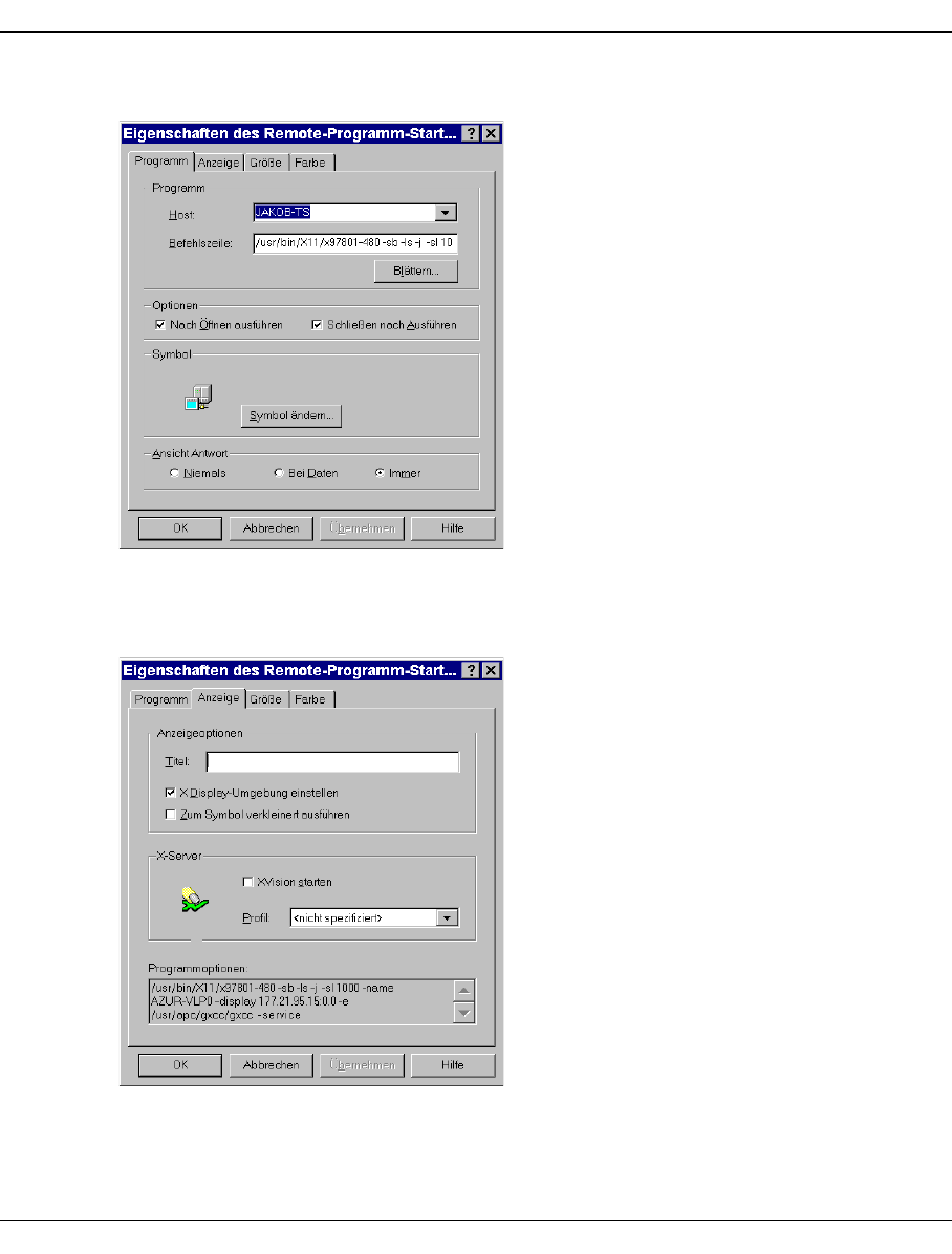
112 U41117-J-Z125-7-76
Starting GXCC Operating and monitoring CentricStor
Example
The settings under “Options” and “View Response” should correspond to those shown in
the example.
The full contents of the command line are shown in the “Display” tab:
The input field “Title” has no effect and should not be used. If you need the “-title” function
(label on the window title bar only, not on the icon), specify “-title” <label> instead of “-name”
in the command line.
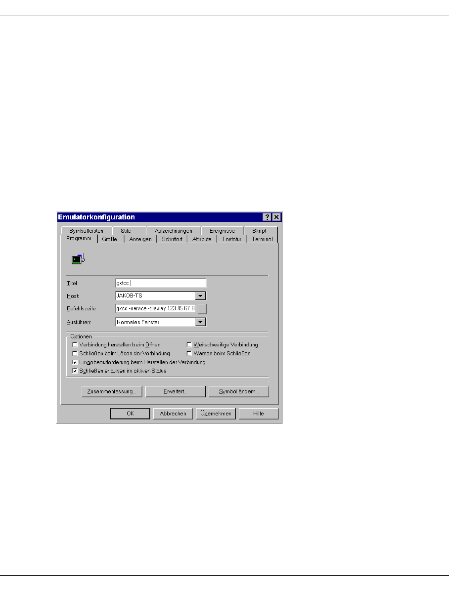
U41117-J-Z125-7-76 113
Operating and monitoring CentricStor Starting GXCC
The settings can be saved in a file with an .rps extension. When you double-click the file,
the Remote Program Starter is started and executes this file. If you create a link to this file
on the desktop, you can therefore start GXCC by double-clicking the corresponding icon.
Only the password for User or Service mode need then be entered manually.
In addition to the actual GXCC/XTCC windows, your screen also shows an alphanumeric
console which displays logging information. You can save this data by setting the terminal
emulation as appropriate.
Manual start via terminal emulation
Define the settings for the host as described above. In the case of a manual start, however,
incomplete specifications are also possible.
Ideally, the emulator configuration should be set in accordance with the following example:
In the “Command Line” field, enter the command line you want to use to start GXCC.
If you do not specify a value here, you can also enter the command following login.
The -display parameter must point to your host.
If you do not specify an ID in the “Security” dialog box, you will run through the usual login
dialog and must specify the ID and password.
If you do not enter a password, the password dialog will be displayed following login.
114 U41117-J-Z125-7-76
Starting GXCC Operating and monitoring CentricStor
This allows you to control whether everyone with access to your host can also start
GXCC.
You can save the settings. After the terminal emulation has started, you can activate the
saved settings and establish the connection.
5.3.7 GXCC welcome screen
When a connection is setup up successfully to the X11 server a welcome screen appears
(but not if the -nointro parameter was specified at GXCC startup):
When you see this screen, the connection between GXCC and the X11 server has been
established. If any errors then occur, they will be displayed in info boxes. Each error notifi-
cation must be acknowledged with “OK”.
i
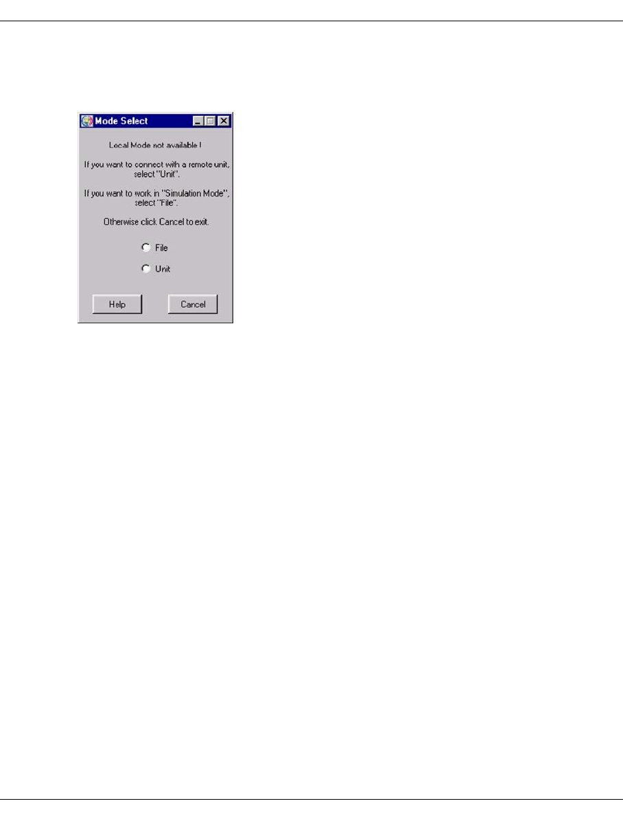
U41117-J-Z125-7-76 115
Operating and monitoring CentricStor Starting GXCC
If the local system is not part of a CentricStor network and no unit name is specified in the
start parameters, a message box will be output leading you to the “Unit Select” menu (see
the sections “Selecting the CentricStor system” on page 116 and “Unit” on page 147):
File Clicking “File” starts GXCC in Test and Demo mode. In this mode, information
is obtained from files taken from GXCC systems beforehand.
Unit Opens the Unit Select menu.
Help Opens a text box containing operating instructions.
Cancel Shuts down GXCC.
If the local system is part of a CentricStor network, GXCC connects to the ISP’s Request-
Broker. Authentication is then performed immediately (see section “Authentication” on
page 117).
If an IP address or the unit name of a VLP is transferred in the start parameters, GXCC will
attempt to open a connection to this processor. If the attempt fails, the “Unit Select” menu
is opened (see page 116).
If a GXCC window appears without an overview and with only the “File”, “Unit”, “Profile”
and “Help” functions are active, then you have addressed a completely new installation of
a CentricStor system in which no configuration data has been set as yet.
Before the system administrator or maintenance staff has performed an “Initial Configu-
ration” only a few functions are then open in User or Observe mode, such as selection of
another CentricStor (“Unit” in the function bar), opening a profile file (“Profile” in the function
bar), or exiting GXCC via “File” ➟ Exit”.
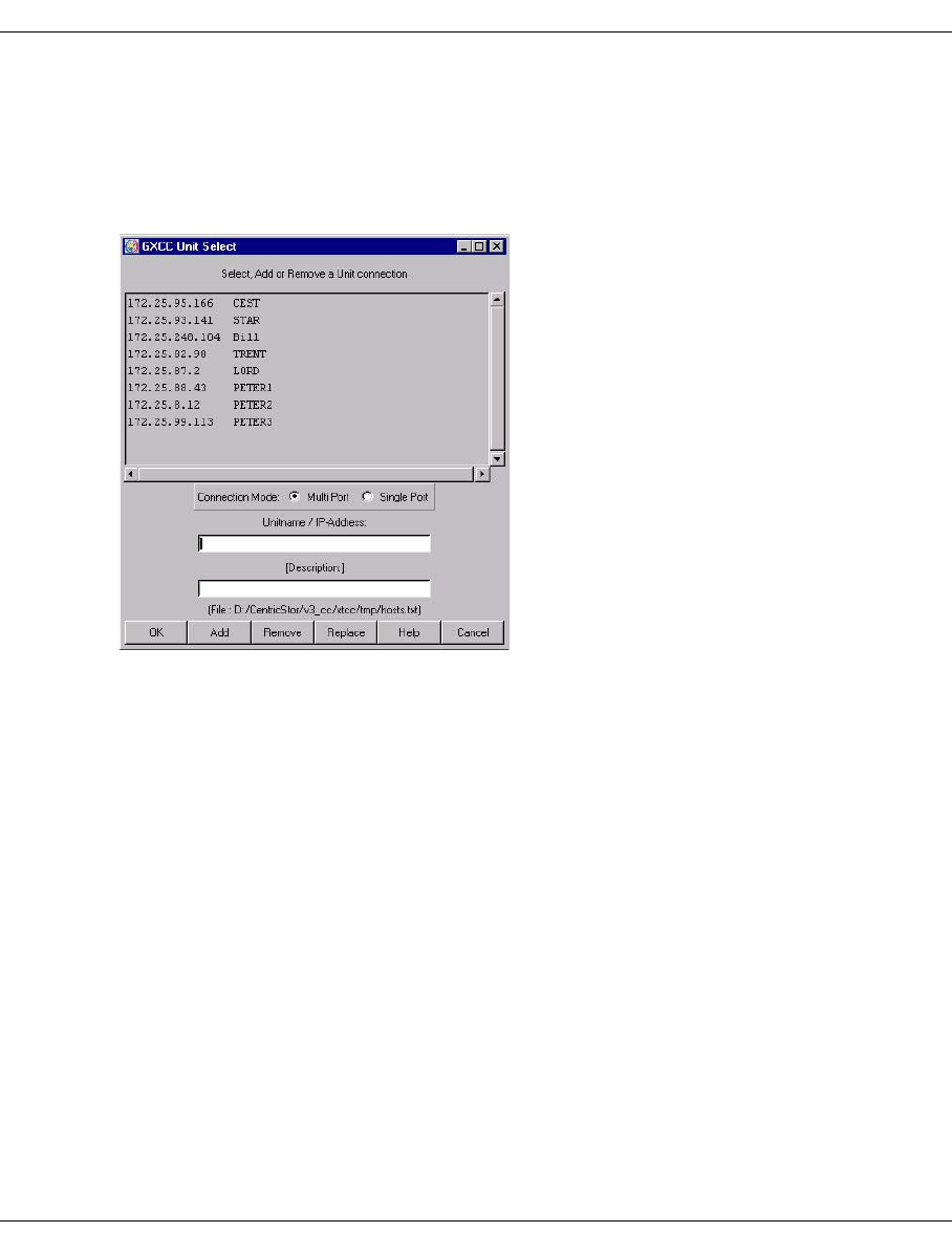
116 U41117-J-Z125-7-76
Starting GXCC Operating and monitoring CentricStor
5.3.8 Selecting the CentricStor system
If the local system is not part of CentricStor, the Unit Select menu is displayed when GXCC
is started.
Example
The operation and functions of Unit Select are described in the section “Select” on
page 147. Errors that occur when a connection is established after clicking on “OK” are
handled differently because no connection yet exists to CentricStor.
5.3.9 Establishing a connection after clicking on OK
An attempt is made to address the host selected in the list. If this is not possible, an error
message will be displayed. As soon as you acknowledge this message, the “Unit Select”
menu will reappear.
Once the connection has been established, GXCC checks whether or not an InfoBroker is
running on the processor.
– If none is running, the connection will be shut down. Once the error message has been
acknowledged, the “Unit Select” menu will be displayed again.
– If the computer contains an InfoBroker, a connection is set up between GXCC and the
InfoBroker. After a brief interval and successful authentication (see the next section),
the main window will appear on the screen.
Clicking the “Cancel” button allows you to exit GXCC. Any changes to the unit list made
using “Add”, “Remove” or “Replace” will remain effective.
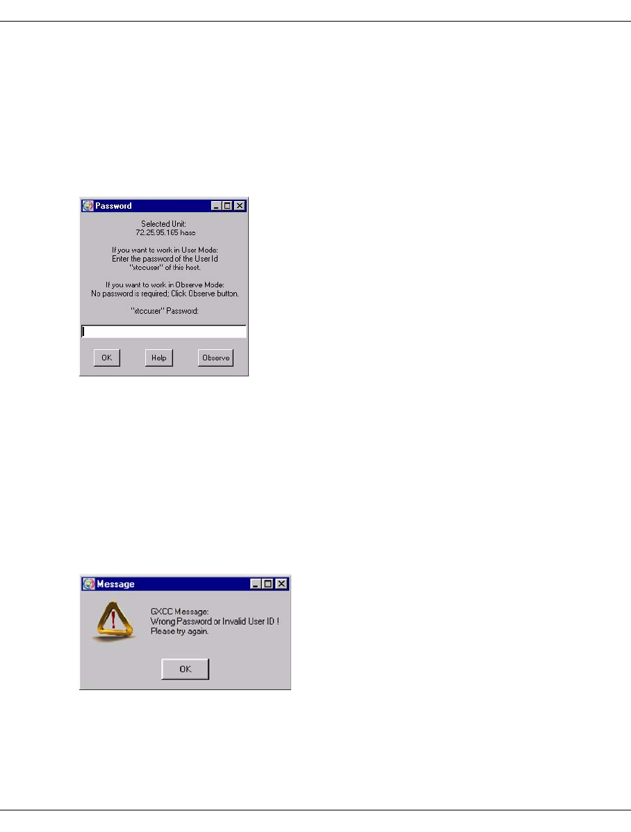
U41117-J-Z125-7-76 117
Operating and monitoring CentricStor Starting GXCC
5.3.10 Authentication
As soon as a connection has been established, client authentication takes place. Password-
based authentication is performed every time the program is started. When operating in
User mode, you will be requested by the addressed system to enter the password of the
user ID “xtccuser”. Passwords are normally not required (see the section “Operating
modes” on page 90 and the section “Passwords” on page 98) when operating in Observe
mode.
Characters in the password which you enter are displayed as “*”.
Any authorization (User or Observe) will be passed on to any downstream applications (e.g.
XTCC for monitoring/operating the ISPs).
If you do not know the password, for example, you can choose Observe mode if no access
protection is provided for Observe mode. Functions that are not available in Observe mode
are either not displayed at all, or are disabled in the associated menus.
Once access has been authorized, the GXCC main window is opened.
If the password is entered incorrectly, an error message is output and you are asked to enter
the password again:
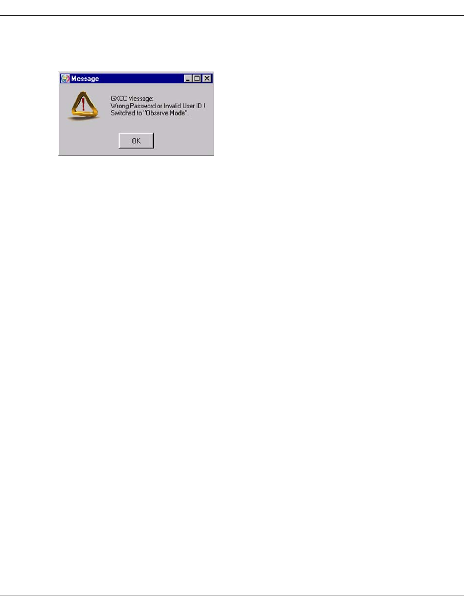
118 U41117-J-Z125-7-76
Starting GXCC Operating and monitoring CentricStor
If the password is entered incorrectly three times, GXCC will be started in Observe mode
(but only if no password protection has been set for Observe mode).
5.3.11 Software updates
If you have contacted a “remote” CentricStor system, the InfoBroker checks whether its
system contains more recent versions of GXCC and XTCC.
If required you will then be informed via a window that the InfoBroker has more recent
versions. When you acknowledge this message, the newer version is passed to your local
system and saved (under Windows the user must be logged on as the administrator to
permit this).
The next time GXCC is started in Service mode, the current versions of GXCC and XTCC
can be activated independently of each other.
Problem-free operation of CentricStor and the user interface is guaranteed for all combina-
tions of the InfoBroker and GXCC/XTCC software of a CentricStor line. All the functions of
the interface will only be available with the most up-to-date versions.
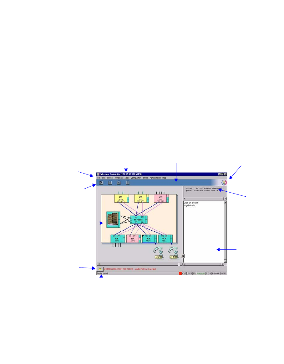
U41117-J-Z125-7-76 119
6GXCC
6.1 Main window
6.1.1 Standard
The GXCC main window shows a circuit diagram of CentricStor. If pictures of real products
(robots, drives, RAID systems) are used, these are only symbols which bear no relation to
the actual appearance of the product.
The main window consits of the following areas (from top to bottom):
●Title bar
●Function bar
●Line with special function buttons and information
Title bar (page 121)
Function bar
(page 143)
Function button
(page 123)
Information
field
(page 134)
Customer
name
System name
Console
messages
(page 124)
Scan symbol
(page 123)
Footer (page 121)
Circuit diagram
(page 126)
Button bar (page 123)

120 U41117-J-Z125-7-76
Main window GXCC
●Left half of screen
– Circuit diagram of CentricStor
●Right half of screen
– System information
– Information field
●Line with the last console alarm message and acknowledgment button
●Footer
6.1.2 Loss of a connection
If the connection to the InfoBroker is lost, the data displayed will no longer be current. An
attempt is made to establish a new connection approximately every 20 seconds.
In the line for console messages a message will appear that the display is no longer up to
date: “Displayed data invalid. Reconnecting”.
All the objects displayed are invalid during this waiting period. On the function bar, only
“Unit” (selection of another CentricStor system) and “File” (to terminate GXCC) are active.
These allow you to select a different CentricStor system or terminate GXCC. You can thus
terminate GXCC or select another unit.
After the connection has been restored, the message “Reconnected” appears in the
message line. This remains displayed until it is overwritten by a new console alarm
message.
XTCC is not directly affected by the loss of the connection between the InfoBroker and
GXCC.
In some cases, the main window displays exclusively ISPs that are not ready for
operation (pink symbols) in this situation. This indicates that the loss of the
InfoBroker connection was caused by this component being shut down.
i
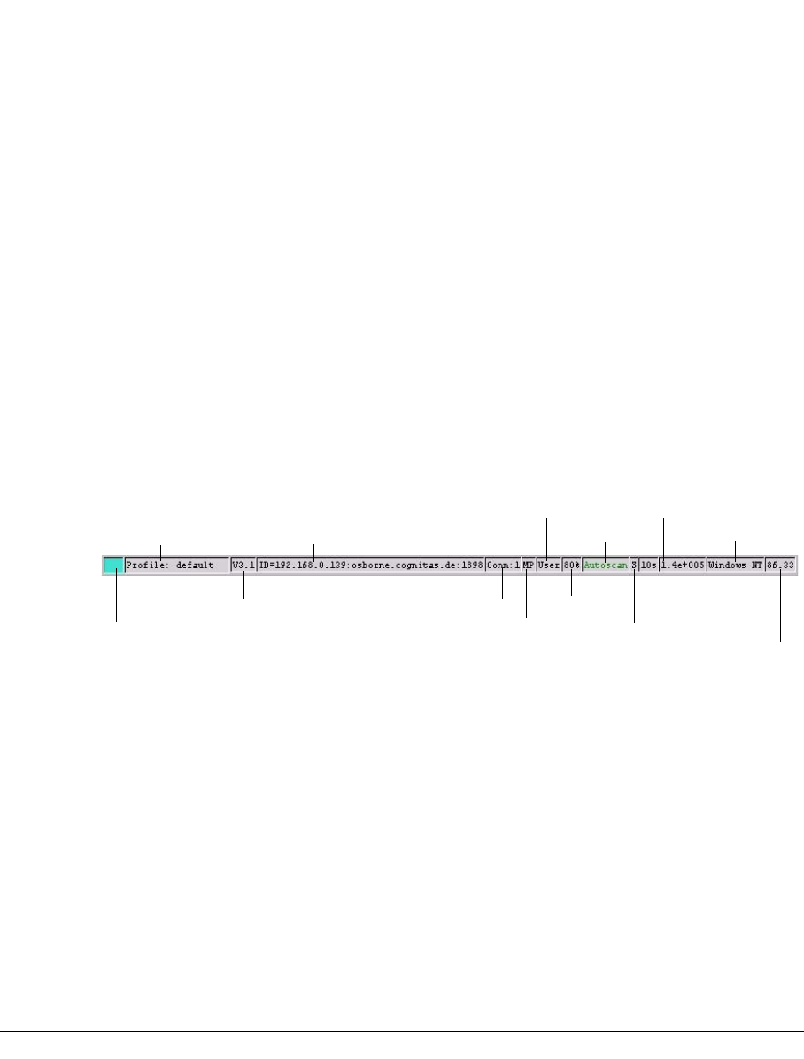
U41117-J-Z125-7-76 121
GXCC Main window
6.1.3 Elements of the GXCC main window
6.1.3.1 Title bar
The title bar is laid out as follows:
<systemname>: CentricStor(<IP-address><unit-name>)
<systemname>:
System name entered during configuration. No display if no system name has been
entered.
<IP-address><unit-name>
IP address and unit name of the ISP to which GXCC is connected. If GXCC is running
on the VLP, this is set to “local”.
In Simulation mode the title bar contains only the display “Simulation”.
6.1.3.2 Footer
The figure below is merely an example and can vary slightly depending on the GXCC
version.
The status bar at the bottom of your screen displays the following information from left to
right:
– CentricStor global system state
The “Global System State” is shown by a colored square. With it a simple statement can
be given about the operating condition of CentricStor:
turquoise: CentricStor is working (OK)
yellow: CentricStor is working with restrictions (degraded, attention)
pink: CentricStor is in fail state
If the mouse is positioned on this square, more details of the current state are shown in
form of a Balloon Help.
Connections
Operating system
Autoscan
Profile file
GXCC mode
Scan rate
Scan mode
Bit rate
Scale
GXCC version
CentricStor version
CentricStor global system state
Monitoring system
Connection mode

122 U41117-J-Z125-7-76
Main window GXCC
An error flag (yellow or pink) can be displayed only if the Infobroker has been
started and is operational. Consequently in certain situations, especially during
the boot phase of individual ISPs, it can occur that an overall status of turquoise
(OK) is displayed even though the status of individual ISPs is shown as not op-
erational in the GXCC main window.
Further information is provided in section “GXCC as a monitoring tool without
SNMP” on page 549.
– Profile file
Name of the profile file. This can be specified on startup using the -profile parameter,
or selected from the function bar at any time.
– CentricStor version
– ID=<IP-address>:<host-name>:<port-numer>
Host features with which you monitor CentricStor
– Conn:n
Number of connections which exist to the monitored system
– Connection mode (MP: Multi-Port, SP: Single-Port)
– GXCC mode
Access permissions under which GXCC is currently running:
SERVICE GXCC is running in Service mode
USER GXCC is running in User mode
OBSERVE/OBSV GXCC is running in Observe mode
–Scale
Display scale set under “Options Settings” (see the section “Settings” on page 153).
–Autoscan
Text color indicating the operating status of the Autoscan facility:
Green: Autoscan active
Yellow: Alignment with the InfoBroker currently in progress
Red, flashing: Autoscan temporarily stopped
White: Locked (Simulation mode)
The Autoscan process will also be stopped temporarily for certain operations. In this
case, the text color switches back to green once the operation in question is completed.
The Autoscan facility is described in more detail on page 152.
– Scan mode
S Scan rate determined automatically (self-adjusting)
M Scan rate set manually (see the section “Settings” on page 153)
i
i
i
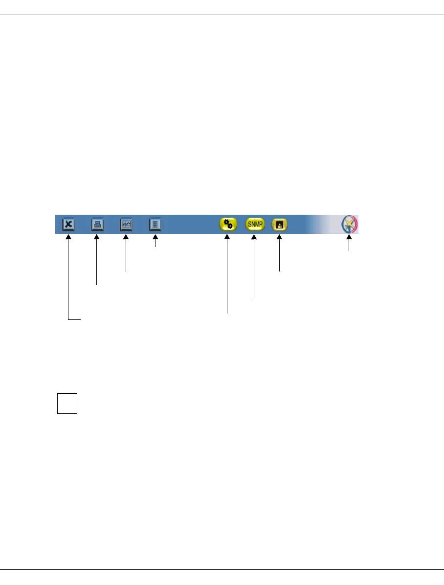
U41117-J-Z125-7-76 123
GXCC Main window
–Scan rate
Interval between scans in seconds.
–Bit rate
The floating point number shows the bit rate for communication with the InfoBroker. The
rate is calculated using the length of time taken to transfer a status information package.
This indicator is of particular interest in the case of a modem connection.
– Operating system of the host to be monitored
– GXCC version
The GXCC version is shown in the last field.
6.1.3.3 Function buttons and displays in the button bar
This area with color highlighting contains the following function buttons:
Symbols indicating special operating states appear as required to the right of the function
buttons. If you rest the mouse cursor over an icon the associated message is displayed in
a text bubble.
The GXCC logo at the right-hand end of the bar indicates a scan process by pulsating.
In the case of a scan process the system only checks whether there are status
changes in CentricStor; only approx. 20 bytes are transferred. Only if there are
really status changes in CentricStor is the status data fetched. This process can be
recognized by the word “Autoscan” at the lower edge of the screen changing color
to yellow.
6.1.3.4 System information
The following system information is displayed in the right-hand part of the screen, above the
information field:
– customer name (set during “Options”)
– system name (set during “Configuration” ➟ “System Name”)
– date and time
Starts Global Status
Opens a window with
console messages
(Only for Windows) Opens
printer menu for hardcopy
Terminates GXCC Configuration errors
Logo, pulsates during scan
SNMP trap
Configuration change to display outstanding
configuration modifications
i
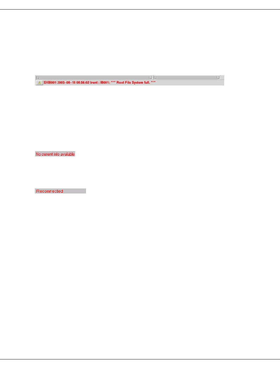
124 U41117-J-Z125-7-76
Main window GXCC
6.1.3.5 Console messages
Console messages are displayed above the footer. These can be:
– system messages
– messages relating to the system configuration
– messages relating to the connection between GXCC and the system
The last messsage is always displayed. You obtain the complete message log by clicking
on the relevant function button (see the section “Function buttons and displays in the button
bar” on page 123).
By clicking on the button to the left of the print line you acknowledge that you have read it.
The button then disappears (only in your GXCC) and reappears with the next output. The
message color changes to black.
In some cases you will see the text
in the message line. This is not an error message but merely indicates that no message has
arrived since the GXCC has been connected to the unit selection.
The message line
indicates the the connection to the InfoBroker has in the meantime been interrupted and
restored.
6.1.3.6 Function bar
The functions which can be accessed via the function bar are described in the section
“Function bar” on page 143.
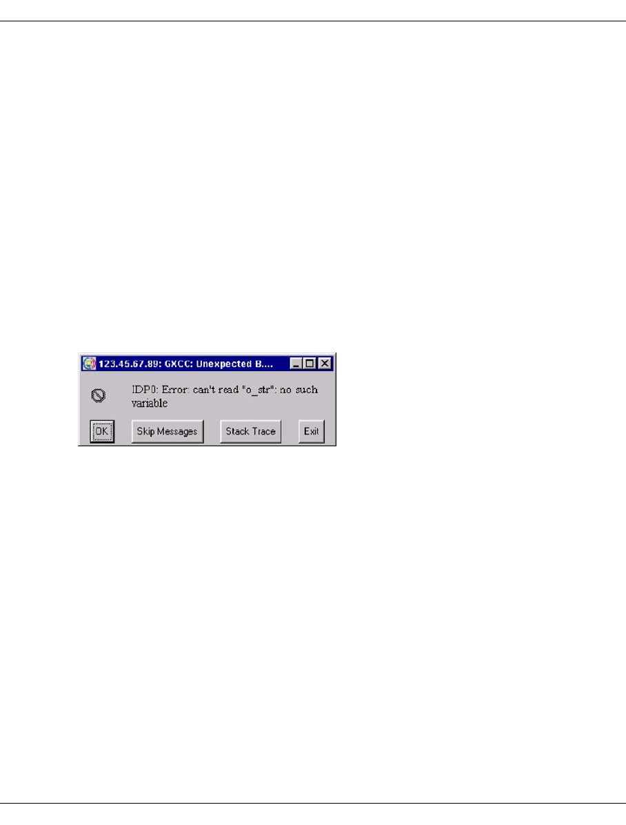
U41117-J-Z125-7-76 125
GXCC Main window
6.1.4 Message window
Many GXCC messages must be taken notice of and acknowledged by the user.
This prevents the same function or contradictory functions being started on one device.
Message windows with an “OK” button are closed after you click on this button.
Message windows without an “OK” button with texts such as “... Timeout is nn sec. Please
wait ...” are displayed if Broker data is waited for at the same time as a device function is
performed. The Autoscan process is stopped for the duration of this wait period. Such a
window can - if absolutely necessary - be closed by clicking on the relevant button specific
to the Window Manager at the top right or left in the window title bar. However, the Autoscan
process remains stopped intil the associated function can be terminated or the maximum
wait time (timeout nn sec.) has been exceeded.
6.1.5 Asynchronous errors
In the case of internal errors, such as those which occur as a result of missing (mandatory)
variables of the InfoBroker, GXCC will if possible open a window with the title:
"
GXCC-unexpected Background Error
".
This window contains the error message and buttons for further activities:
Exit
Ter m in a t e s G X C C.
Stack Trace
Opens a window with further information on the error. If you click on the “Cancel” button
in this window the window is closed and a “Continue” attempted.
OK
Continues the procedure in which the error occurred. This can lead to secondary errors,
i.e. to further background errors. In this case GXCC must be terminated.
Skip Messages
This button is optional. GXCC attempts to skip the errored procedure, which can
naturally lead to secondary errors. In this case GXCC must be terminated.

126 U41117-J-Z125-7-76
Main window GXCC
6.1.6 Block diagram
The main window displays a circuit diagram of the CentricStor system with the ISPs, RAID
systems and the connecting Fibre Channel system.
Processors
CentricStor is a group of processors, each running the SINIX-Z operating system. These
processors are referred to collectively as the ISP (Integrated Service Processor).
Depending on the peripheral configuration and the software configuration, CentricStor
recognizes various ISP types:
ICP Integrated Channel Processor
ISP with a host connection via ESCON, FICON and/or FibreChannel.
IDP Integrated Device Processor
ISP without a host adapter but with tape drives.
ICP_IDP ICP and IDP in one ISP. An ICP_IDP has both a host adapter and a SCSI or FC
controller for running real tape drives and robots.
VLP Virtual Library Processor
ISP with neither a host interface nor a device interface. This ISP hosts the VLM
and the PLM.
SVLP Standby VLP (optional)
The SVLP is an optional processor which can take over the tasks of the VLP if
the VLP should fail.
Hybrid forms are created when ISPs of the type ICP, IDP and ICP_IDP have the VLP or
SVLP functionality. In these cases the VLP or SVLP functionality is then specified in para-
entheses after their ISP names. Example: ICP_IDP (VLP)
The ISP symbol contains a large amount of information. If you click on the symbol with the
left mouse button, the status information is entered in the right-hand window area and there
constantly updated (see the section “ICP object information” on page 134 and section “IDP
object information” on page 135).
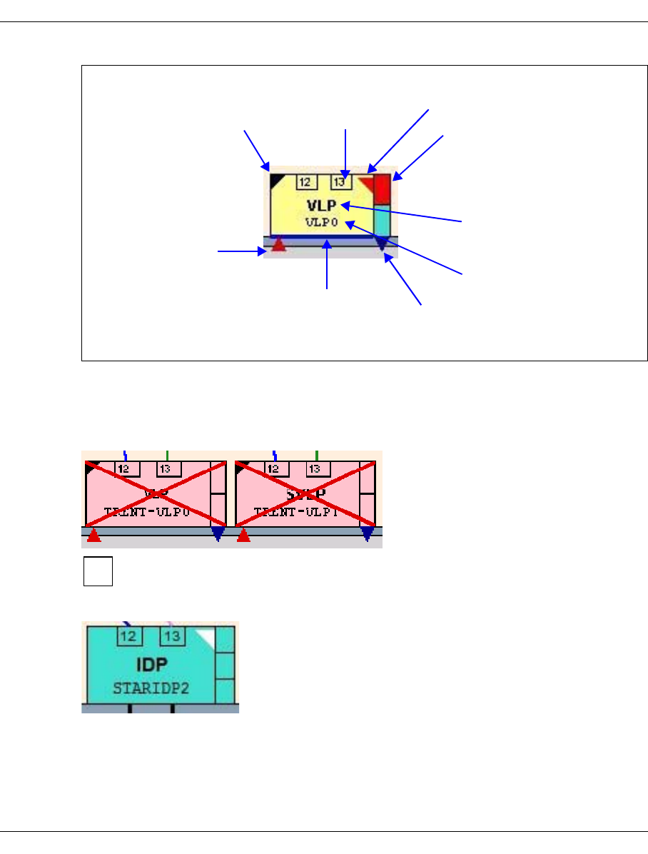
U41117-J-Z125-7-76 127
GXCC Main window
If the AutoVLP failover function has been configured, it can be activated. If the function was
activated before a shutdown took place, VLP monitoring is activated automatically on this
ISP by means of a reboot.
The CentricStor controller could not be determined:
This status also occurs temporarily during Distribute and Activate.
Mirror status:
The triangle at the top left
indicates that GXCC is
connected to this ISP.
Only for VLP/SVLP: The
blue bar indicates that
this ISP is the VLP
master in the network.
The triangle indicates that external
access via LAN to this ISP is
possible.
The status of the
hardware components
and drivers is displayed
in the right-hand margin
(see page 133).
The line in upper case
specifies the ISP type.
The second line contains
the unit name of the ISP.
On the VLP and SVLP a
triangle is displayed if the
AutoVLP failover has been
configured: If this triangle
is red, AutoVLP failover is
not activated. Green
indicates that it is
activated.
The boxes at the upper
edge contain the
numbers of the
controllers.
Triangle on the right-hand side:
Mirror status
If no configured VLP could be started as
a master, the symbol for the VLPs is
crossed through in red. In this case
CentricStor is not operational.
i
A triangle on the right-hand side of the ISP symbol (turned
inward) provides information on the mirror status in mirror
mode. If the triangle is missing, the mirror status is OK. A white
triangle indicates that the match has not yet been performed. A
red triangle indicates that the mirror status is not up to date.
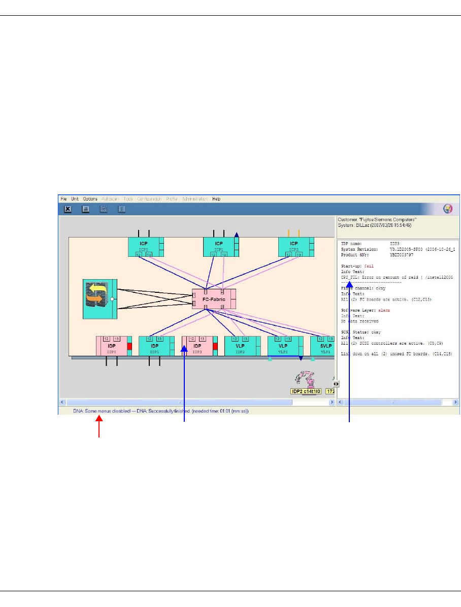
128 U41117-J-Z125-7-76
Main window GXCC
Special aspects when performing Distribute and Activate
The following special aspects must be borne in mind when performing Distribute and Activa-
te:
●Some GXCC menu items are hidden.
●The current progress is displayed in blue script in the system message line.
Messages are displayed here concerning the stage which the procedure has reached.
●The status (only in the event of an error) of each ISP is displayed.
To obtain detailed information, you must click on the relevant ISP (unit), and the infor-
mation is then provided in the info window of the GXCC.
System message line
Individ. status of ISP ... associated status text
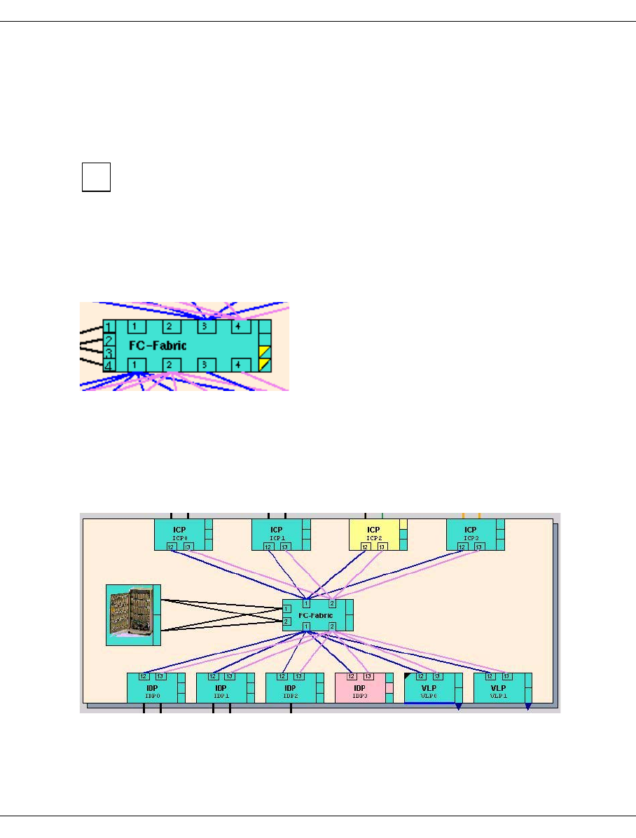
U41117-J-Z125-7-76 129
GXCC Main window
Fibre channel elements
The internal FC connections are represented in the form of an FC fabric in the center of the
figure with connections to both the ISPs and the RAID system(s). FibreChannel connec-
tions to the FC switch which are faulty are drawn with dashed lines until the SNMP trap has
been processed by the FC switch. These lines are then removed.
The VLP and the SVLP must be entered in the FC switch as the trap receiver, oth-
erwise the lines cannot be removed.
Each FC switch is symbolized by a box containing the domain number located at the edge
of the fabric. As the image on the right shows, a switch can be shown twice, once at the
upper edge and once at the lower edge of the fabric. This means that the connections can
be seen more clearly, although this bears no relevance on the function.
In the figure below the switches with the domain numbers 3 and 4 have reported a trap:
Some of the CentricStor components shown (e.g. the Fibre Channel switches) are
monitored with SNMP. If a message (=trap) from one of these components which no
management station has yet taken notice of is present, a circle highlighted in yellow with
the text “SNMP” appears in the button bar of the GXCC window.
The LAN via which the control of the system and communication with the InfoBroker runs
in CentricStor is not displayed in GXCC.
GXCC checks whether the internal CentricStor FC fabric complies with the cabling rules.
If the rules have been violated, a warning symbol (gears) is displayed in the button bar.
The incorrect connections are displayed in red.
i
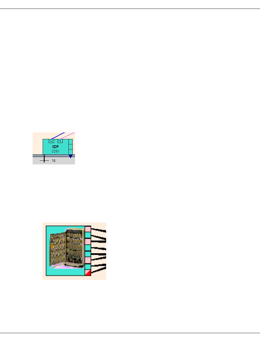
130 U41117-J-Z125-7-76
Main window GXCC
A check is made to see whether, in the case of redundant Fibre Channel systems, the
connections go from every ISP to various switches and whether the FC adapter with the
lowest number goes to the switch with the lowest number (throughput optimization).
Host connections
In the overview screen, the connections to the hosts (ESCON/FICON or Fibre Channel) are
depicted as short lines emerging from the inner frame:
black ESCON connection
orange FICON connection
dark green FC connection
If there are more than 8 connections, only one intersected line is shown; in addition, the
number of connections is specified.
The example below shows an IDP with 16 ESCON connections:
For Fibre Channel connections, the number of the controller is also displayed.
RAID systems
●RAID symbol without RAID mirroring
The RAID systems are represented together as one RAID system in the left-hand half
of the screen (in the center of the screen with VTA 1000):
On the right-hand side of the symbol there is a row of boxes which represent the RAID
systems (=cache file systems) and their FC ports.
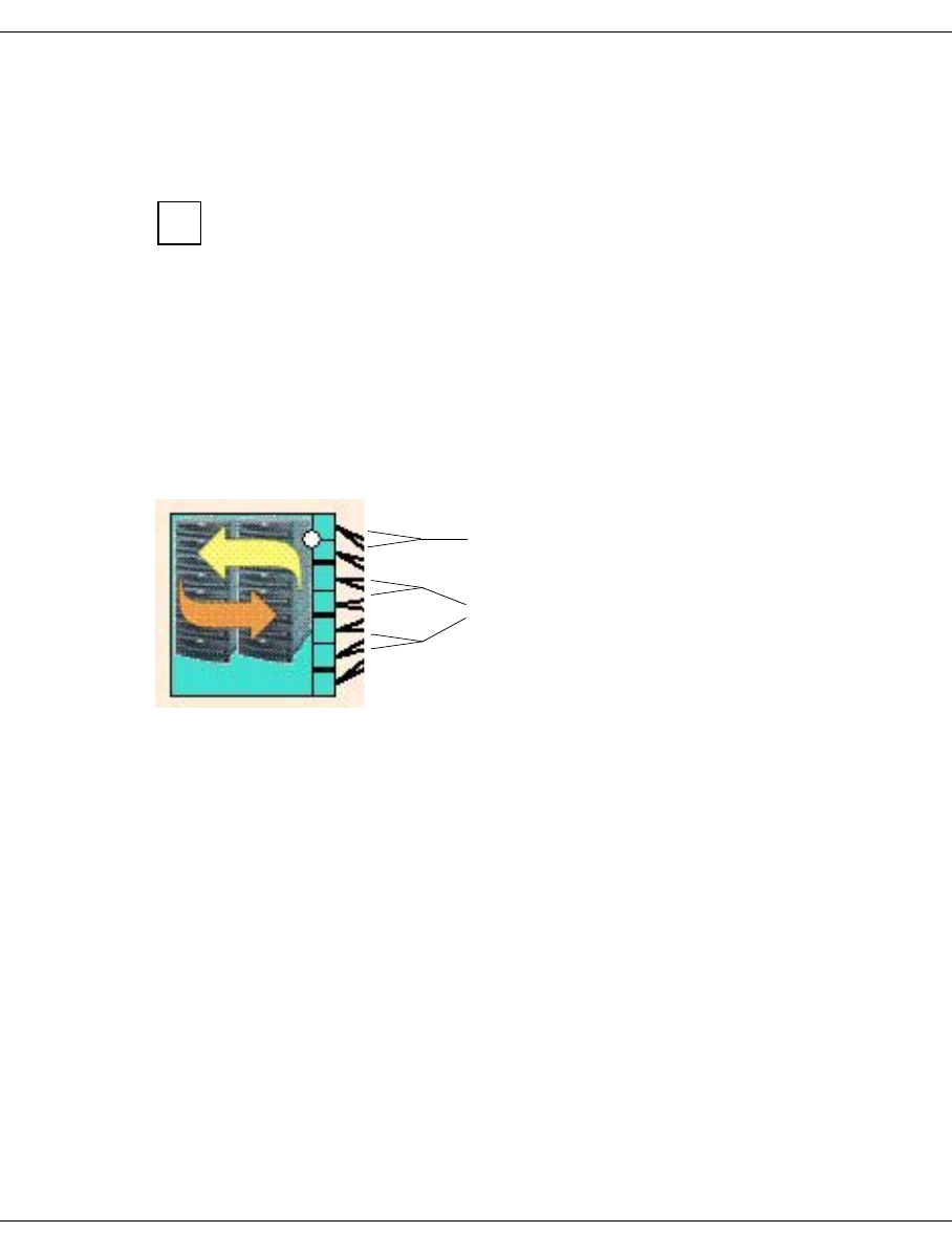
U41117-J-Z125-7-76 131
GXCC Main window
The colors have the following meaning:
Green Operational
Pink Not operational, no cache file system affected
As in the case of the FibreCAT CX500/CX3-20 or Eternus 3000/4000 it is not
possible to read the status via an FC port, the “operational” status (green) is
displayed for these RAID systems.
Exception If an FC connection to the CX500/CX3-20 fails or if the HBA of an
ISP has not been registered in the CX500/CX3-20, the
CX500/CX3-20 is displayed in red (a corresponding error message
is output in the CentricStor system messages).
●RAID symbol for mirror mode
The RAID systems are represented together as a double RAID system with two arrows
in the left-hand half of the screen:
In the event of mirror mode, additional indicators are output:
– RAID systems which cannot form a RAID pair are separated in the RAID symbol by
a thick black line. Two adjacent boxes without a thick separator line represent a
potential or genuine RAID pair.
– Genuine RAID pairs are also indicated by a white dot. Only if RAID pairs marked in
this way can be seen is the prerequisite for mirror mode satisfied.
i
Genuine pair: indicated by a white dot
Potential pairs: indicated by a thick line
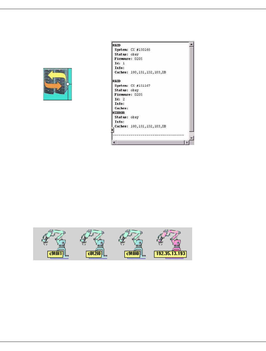
132 U41117-J-Z125-7-76
Main window GXCC
Left-clicking on the RAID symbol causes further information to be output in the right-
hand part of the GXCC info window:
This example shows a CentricStor with two RAID systems (IDs: 1 and 2).
Information on both RAID systems is output in the info window:
The primary caches 100, 101, 102, 103 und DB are located on the RAID system with
the ID 1. The associated secondary cache is located on the RAID system with the ID 2.
Archive systems
Each access system is depicted at the lower edge of the screen in the form of an industrial
robot. A label shows the internal name in the case of SCSI-controlled archives and the IP
address in the case of LAN-controlled systems.
An error has occurred on the robot shown on the right-hand side of this diagram.
RAID symbol
RAID information
in the info window

U41117-J-Z125-7-76 133
GXCC Main window
6.1.6.1 Status information
The current operating status of CentricStor elements is indicated by the background color
of the associated symbols. The bar on the right which is divided into several compartments
shows the status of hardware components and drivers.
You can obtain detailed information in the right-hand part of the window by clicking
on the object with the left mouse button.
Green: All subcomponents are online and ready to operate.
Yellow: Undefined. Some subcomponents are online and ready to operate, others are
offline. In the case of some components yellow also signifies “Attention”.
Pink: The entire component is not ready to operate.
Red: The InfoBroker has not yet established contact with this component.
The configuration is inconsistent.
Blue: The mouse pointer is located above the object. If you click a mouse button, the
function or information displayed applies to the object.
If a component consists of several subsystems, possibly with different operating statuses,
the status of each subsystem is indicated by the color of the small fields to the right of the
symbol. The color of the symbol itself indicates the collective status.
In some CentricStor models, the ICP_IDP and VLP functions reside in a single ISP.
The boxes may then have to be interpreted somewhat differently to what is
described here.
6.1.6.2 Object information and object-related functions
When the mouse pointer is positioned on a object, the following functions can be called:
Left mouse button
Clicking on an object with the left mouse button causes the object information to be
displayed in the info window in the right-hand half of the screen. This information is
updated with each scan. The icon of the component whose status is displayed is
highlighted in blue.
Shift + left mouse button
Displays object-related help.
Right mouse button
Opens the function menu.
Shift + right mouse button (on an ISP)
Opens a function menu for all objects of this class in the GXCC (e.g. all IDPs, all
cartridge drives).
i
i
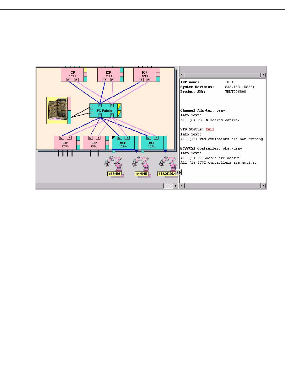
134 U41117-J-Z125-7-76
Main window GXCC
6.1.7 ICP object information
In order to be able to connect to various host types, ISPs can contain ESCON/FICON
channel adapters, FC adapters or both types of connection. The object information will vary
accordingly.
Object information of an ICP which contains only FibreChannel ports.
The following information is displayed:
– name and release version of the ICP.
– the operating status of the channel adapter(s) and the FibreChannel adapter for the
host connection (= upper box).
– the operational readiness of the logical drives (emulations = middle box)
– the status of the FC controller for the connection to the cache (= bottom box)
– the status of the SCSI controller (connection of the internal hard disk)
– possibly information on undetected or unused components, for example
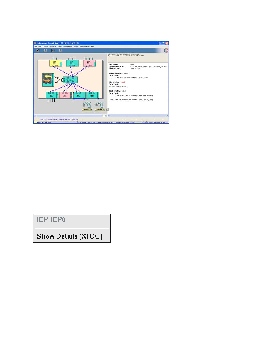
U41117-J-Z125-7-76 135
GXCC Main window
6.1.8 IDP object information
The following information is displayed:
– name and release version of the IDP
– if present: IP address of the external LAN port(in the example the external port is faulty)
– the status of the FC controller for the connection to the cache (= top box)
– the operating status of the physical device servers (= middle box)
– the operating status of the SCSI controllers for the tape drives (= bottom box)
6.1.9 Functions of an ISP
XTCC can be opened for each ISP to trace details in the ISPs (by right-clicking on the ISP
icon).
6.1.9.1 Show Details (XTCC)
An XTCC window is opened in which the details of the relevant CentricStor node are
displayed. The display and operating functions of the ISP are described in the chapter
“XTCC” on page 325.
6.1.10 Functions for all ISPs of a particular class
There are no such functions available in User/Observe mode.
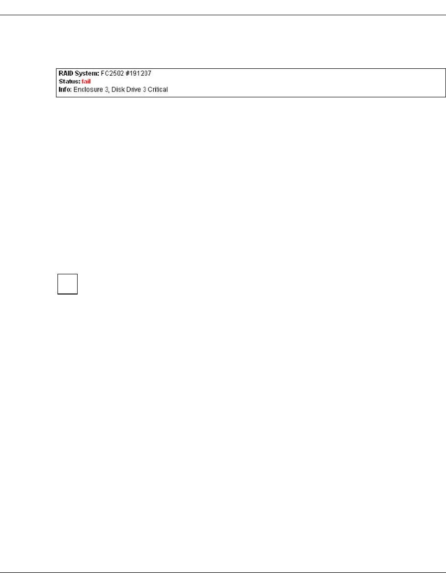
136 U41117-J-Z125-7-76
Main window GXCC
6.1.11 Information about the RAID systems
This information box shows the following information for every RAID system (by a box
symbol to the right of the RAID symbol):
– the type and target number of the RAID controller(s)
– the status of the RAID controller(s)
– any additional information available
If CentricStor has several RAID systems, the box to the right of the symbol is divided into
the corresponding number of fields.
Each field is colored to indicate the status of the RAID controller:
Turquoise: OK
Pink: Error, stopped
yellow: Attention
Red: Configuration error
As in the case of the FibreCAT CX500/CX3-20 or Eternus 3000/4000 it is not
possible to read the status via an FC port, the “OK” status (turqoise) is always
displayed for these RAID systems.
Exception If the HBA of an ISP connected via FC switch has not been registed in
the CX500/CX3-20, the CX500/CX3-20 is displayed in red (a corre-
sponding error message is output in the CentricStor system messages).
You will find more detailed information on the RAID system(s) in XTCC (see the
section “RAID systems” on page 411). Other RAID systems run with CentricStor
are also described there.
i
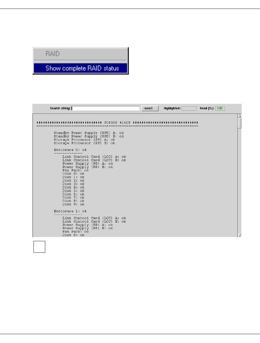
U41117-J-Z125-7-76 137
GXCC Main window
6.1.12 RAID system functions
The following window appears when you right-click on the RAID symbol:
6.1.12.1 Show complete RAID status
Selecting this option displays all the data of the RAID systems:
As in the case of the FibreCAT CX500/CX3-20 and Eternus 3000/4000 it is not
possible to read the status via an FC port, “no information available” is always
output for these RAID systems.
The full status display is described in the section “Object information on RAID systems” on
page 411.
i
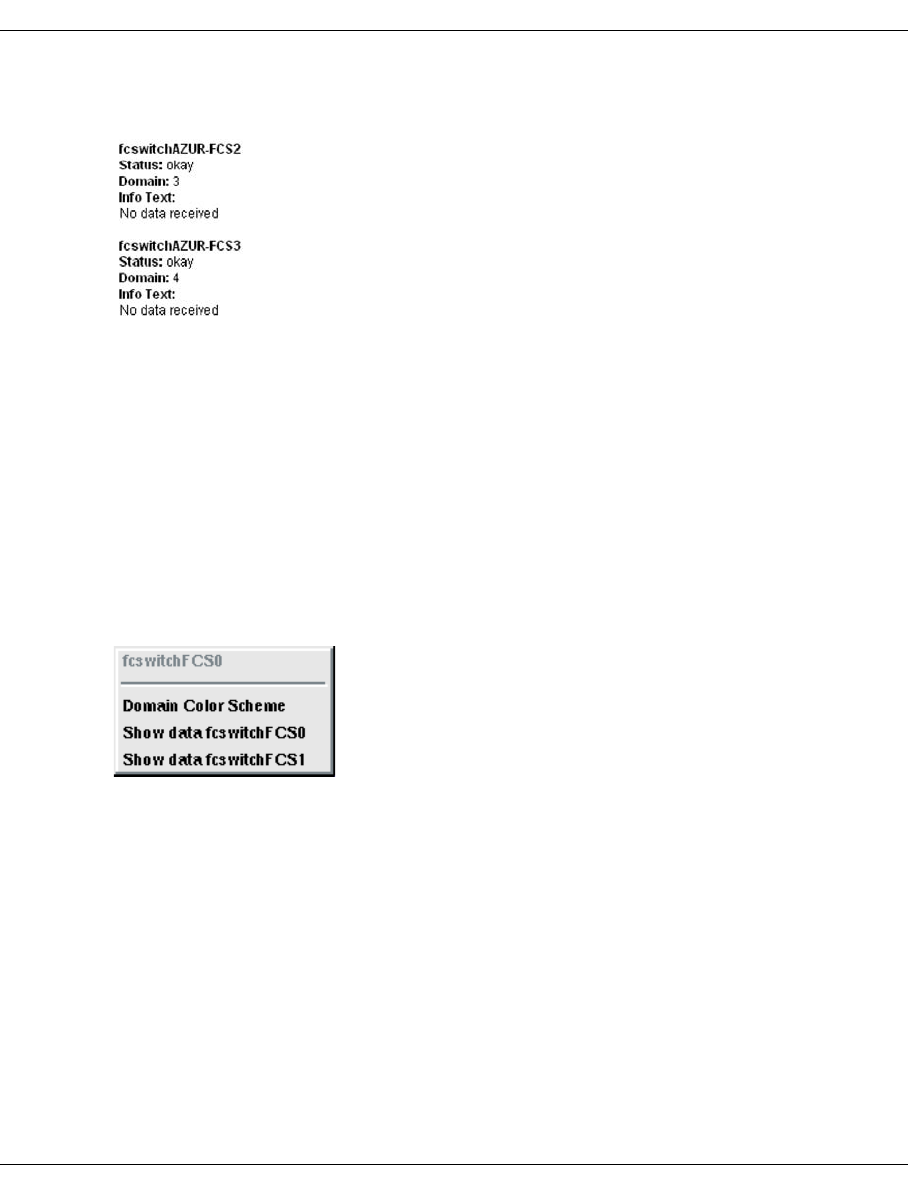
138 U41117-J-Z125-7-76
Main window GXCC
6.1.13 Information on Fibre Channel fabric
Information on FC switches can be obtained via SNMP (Simple Network Management
Protocol). The mnemonic name, operating status, and contents of the last unprocessed trap
are output. If the message “No data received” is displayed instead of this information, this
indicates that there are no unprocessed traps present.
If there is an SNMP trap from one of the FC switches that has not yet been acknowledged,
the button bar in the GXCC window will display an oval-shaped yellow symbol labeled
“SNMP”. The associated information can also be displayed using the “Show data...” function
which is described in the next chapter.
6.1.14 Functions of the Fibre Channel fabric
If one (or more) of the switches has triggered an SNMP trap, the appropriate line in the
menu will also show that information (trap).
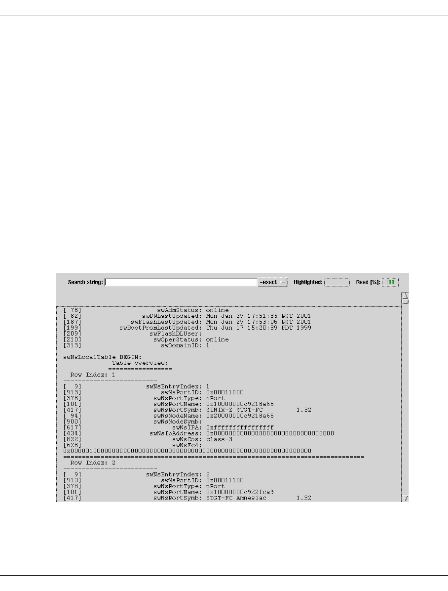
U41117-J-Z125-7-76 139
GXCC Main window
6.1.14.1 Controller Color Scheme
You can select whether you wish to display the FC connections in such a way that all
connections to a single ISP are displayed in the same color (Controller Color Scheme) or
so that all connections to a domain (a switch) are displayed in the same color (Domain Color
Scheme).
The mode that is not currently set will be offered. This setting is only relevant for the repre-
sentation.
If incorrect cabling exists, the color setting will have no effect. The incorrect corrections will
be shown in red, and the others will be shown in gray.
6.1.14.2 Show data fcswitch <Name of the switch> [(trap)]
The information about the switch as obtained via SNMP is output in a text window. The
name of the switch is given in the window title of the information about the Fibre Channel
fabric.
If a trap existed for the switch, the information “(trap)” is deleted. If this outputs all traps that
have not yet been read, then the yellow SNMP display on the fabric symbol disappears.
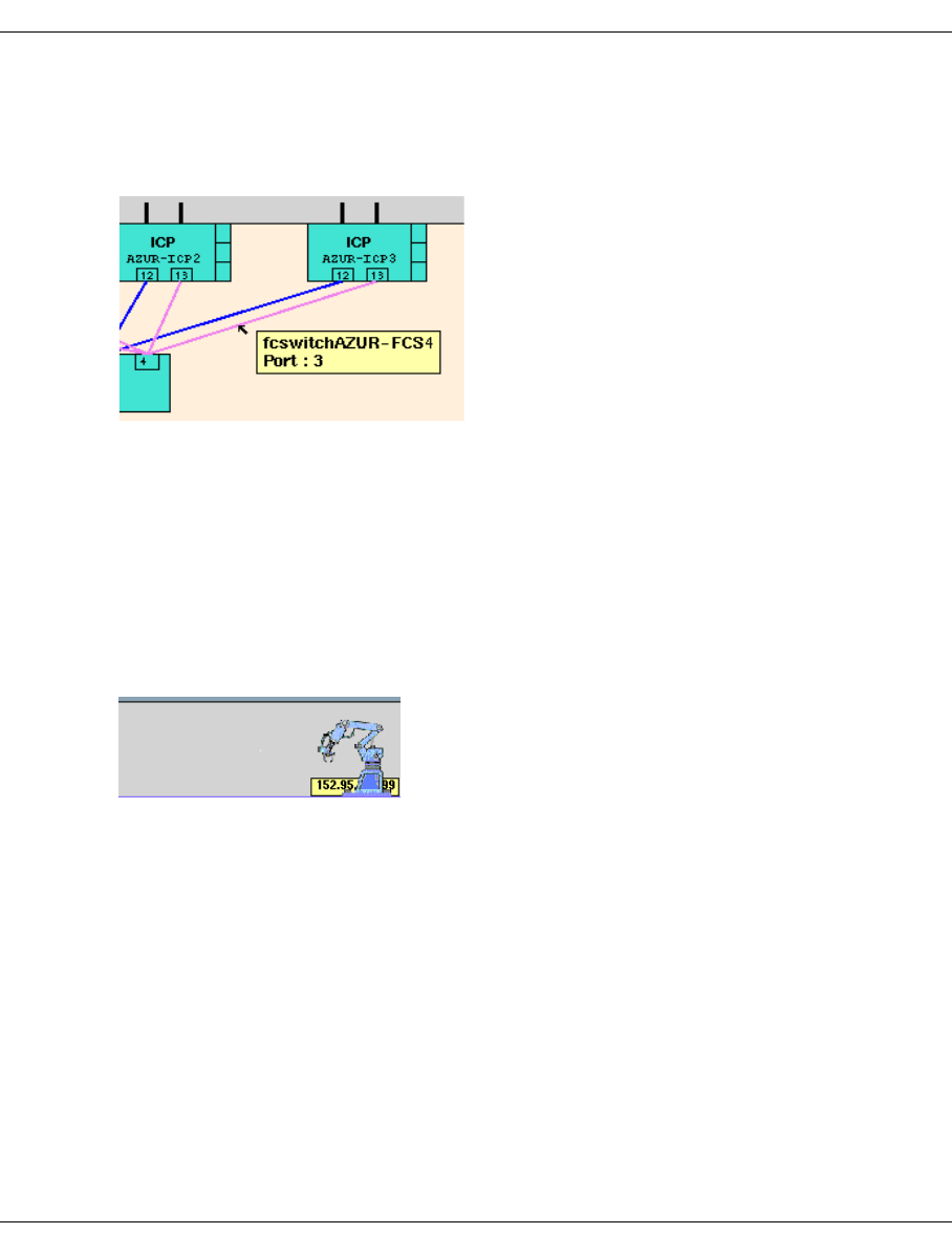
140 U41117-J-Z125-7-76
Main window GXCC
6.1.15 Information about the FC connections
If you hover the mouse pointer over an icon belonging to an FC connection, information
about this line will be displayed.
The following information is output:
– the name of the switch, as assigned during configuration, and
– the port that the line goes to.
The controller in the ISP can be read directly from the overview image (13 in the example
shown above).
6.1.16 Information on the archive systems
The following are displayed:
– The IP address or system name of the access system.
– A list of the archive systems behind it, together with their operating statuses. In addition,
the ISPs on which the PLSs run are also specified.
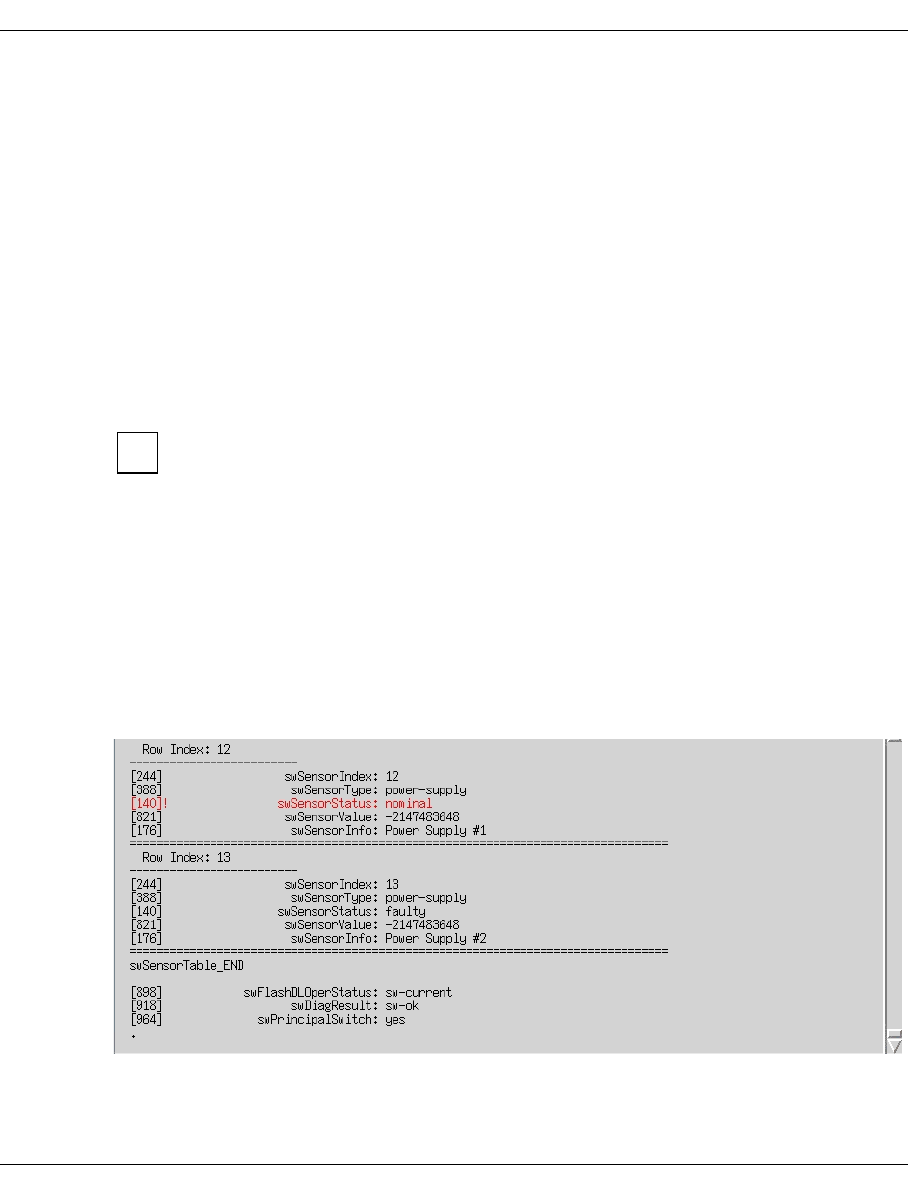
U41117-J-Z125-7-76 141
GXCC Main window
6.1.17 ISP system messages
If an important console message is entered in the log file (/usr/apc/vtls/
VTLS_MESSAGES) of one of the CentricStor ISPs, this is displayed in the lower part of the
GXCC window. Messages with the statuses “ERROR”, “CRITICAL” (red) and “ALERT”,
“EMERGENCY” (red: flashing red) are considered critical.
By clicking on the button to the left of the message line you confirm you have read the
message in your GXCC. You can thus recognize when a new message has arrived.
Clicking on the corresponding button in the button bar using the left mouse button or after
calling the “Tools” ➟ “Show System Messages” function causes a text window with the
console messages to be opened (see the section “Show System Messages” on page 158).
This display is continuously updated. You can also modify it so that it is displayed in the
foreground with each new entry (see the section “AutoPopup” on page 362).
Messages with the statuses “ALERT” and “EMERGENCY” (i.e. all messages that
flash red) trigger a teleservice call if all the other requirements for this feature are
fulfilled.
6.1.18 SNMP messages
If CentricStor components that are administered via SNMP (currently only FC switches)
report an event (trap), an oval-shaped yellow symbol labeled “SNMP” will appear in the
button bar. To display the SNMP message, simply click on this symbol.
The Fibre Channel switches are administered via SNMP. The following example shows an
extract from the status of an FC switch:
i

142 U41117-J-Z125-7-76
Main window GXCC
6.1.19 Configuration Changed
If a configuration change is currently being processed in CentricStor, a floppy disk symbol
with a yellow background will appear in the button bar. This occurs if a menu item of the
configuration complex is confirmed with “OK” after activation of the last configuration
change.
When the InfoBroker is restarted, the latent configuration changes are deleted. You
should thus not shut down the CentricStor system without an inquiry or without
issuing the “Restart InfoBroker” command when the floppy disk symbol is displayed.
CAUTION!
To prevent the “Configuration Changed” symbol from being activated incorrectly,
PVG settings should not be viewed using “Configuration”, but instead as far as
possible by using the corresponding PLM function “Statistics » Physical Compo-
nents » Physical Volume Groups” on page 283.
i
!
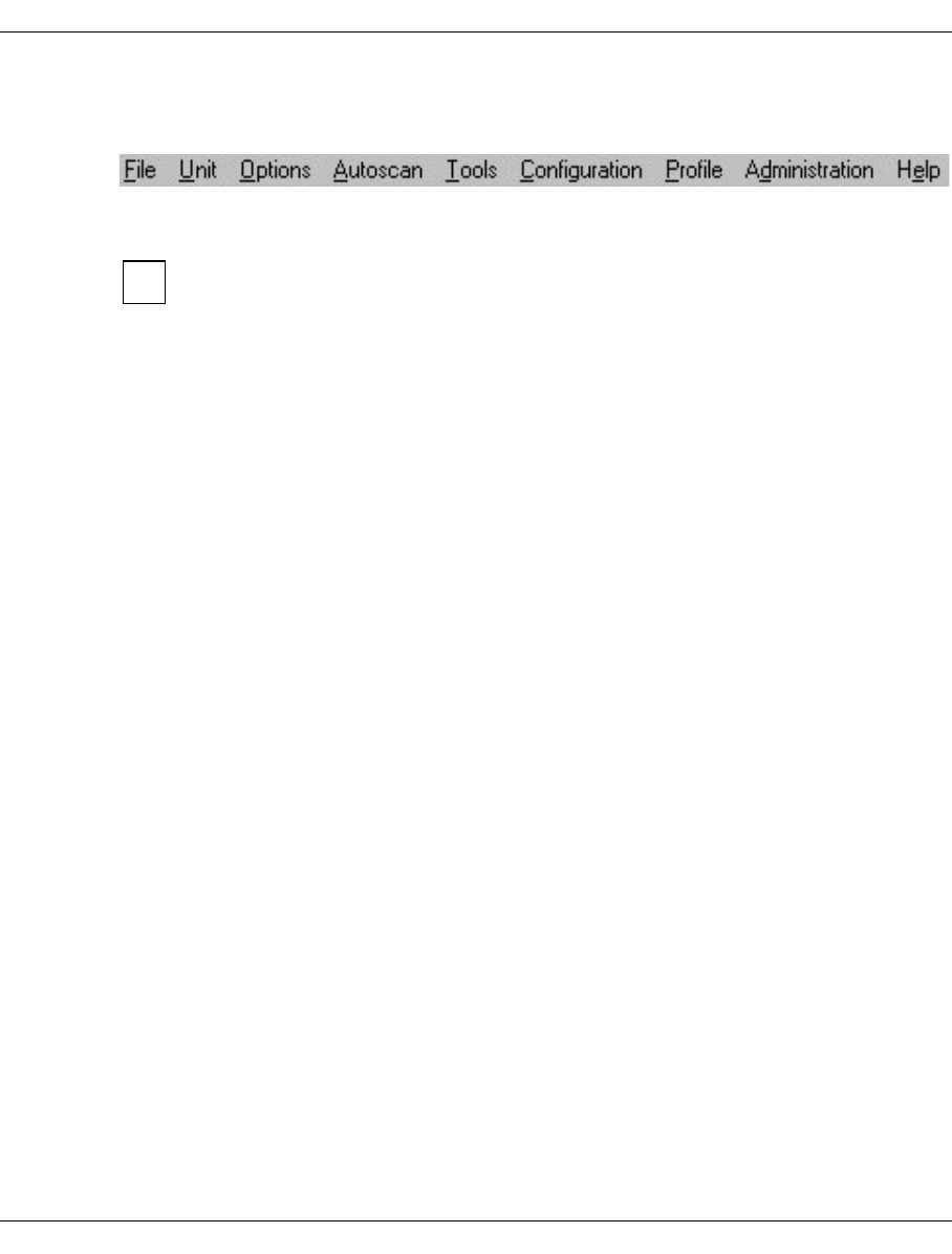
U41117-J-Z125-7-76 143
GXCC Function bar
6.2 Function bar
dd
The individual functions can be selected either by clicking on them with your mouse or by
pressing the ALT key together with the accelerator key (underlined letter).
How exactly such shortcuts are handled depends on the operating system or the
Window Manager, e.g. on whether the keys are pressed simultaneously or first ALT
and then the key for the undescored character is pressed.
6.2.1 Overview of GXCC functions
●File (page 145)
–Save (page 145)
–Open (page 146)
–Show (page 146)
–Print (page 146)
–Exit (page 147)
●Unit (page 147)
–Select (page 147)
●Options (page 150)
–Settings (page 150)
–Show Current Aspect (page 151)
●Autoscan (page 152)
–Start Autoscan/Stop Autoscan (page 152)
–Settings (page 153)
●To o ls (page 154)
–Global Status (page 154)
–Get Remote/Expand Local File (page 154)
–Show Remote File (page 156)
–Show System Messages (page 158)
–GXCC Update/Revert Tool (page 159)
i

144 U41117-J-Z125-7-76
Function bar GXCC
●Configuration (page 166)
–RAID Filesystems (page 171)
–Logical Volume Groups (page 173)
–Physical Volume Groups (page 181)
–Distribute and Activate (page 188)
●Profile (page 191)
–Add/Select Profile(page 191)
●Administration (page 193)
–Show WWN’s (page 195)
–Show Optional Functions (page 196)
–Show CS Configuration (page 197)
–Diagnostic Snapshots (page 197)
–Logical Volume Operations (page 202)
–Physical Volume Operations (page 215)
–Setup for accounting mails (page 229)
●Help (page 232)
–Readme / LIESMICH (page 232)
–Direct Help / Direkthilfe (page 232)
–System Messages (page 232)
–About GXCC... (page 232)
–Revision Summary (page 233)
–Hardware Summary (page 234)
–Online Manual (page 235)

U41117-J-Z125-7-76 145
GXCC Function bar
6.2.2 File
Es stehen folgende Funktionen zur Verfügung:
–Save
–Open
–Show
–Print
–Exit
6.2.2.1 Save
Saves the current InfoBroker data. You can thus use this to recover the system display
subsequently.
By default, configurations are saved as .gxd files.
With this function you save precisely the data which currently leads to the picture
displayed. As a result you can practically retain a snapshot in the form of source
files. This data can later be read into a GXCC. The same picture is then displayed
again, even if the situation no longer exists. You can also transfer this data to a
totally different system (arbitrary PC) and view it there with a GXCC without having
access to a CentricStor. This is called Simulation mode. Naturally you can also use
this option for analysis purposes.
Example
There is one display which cannot be understood. After the “Save” function has
been called a file is generated which is sent to the Service department. Service
can then use this data to ascertain what is wrong.
This method is better than a screenshot because Service is provided with the
actual data, which it can use to inspect every individual variable with the current
values.
i
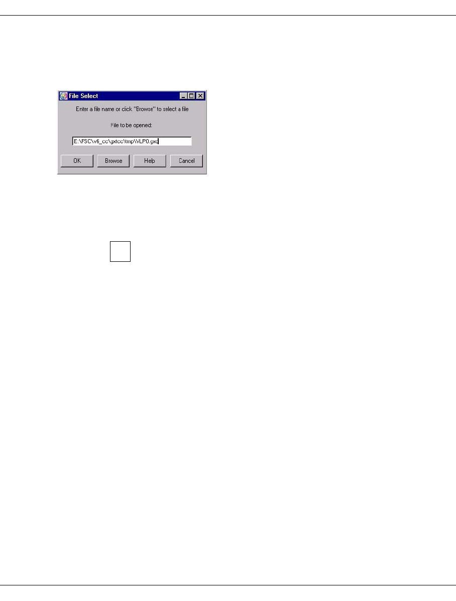
146 U41117-J-Z125-7-76
Function bar GXCC
6.2.2.2 Open
Opens a file selector window with which you can open a configuration that was generated
with “Save” (see above).
The window contains the field for entering the file name plus the following function keys:
OK Checks whether the specified file is a valid GXCC configuration file and, if so,
outputs its contents in graphical format and is displayed in Simulation mode. If
not, an error message is output.
You can only exit the simulation mode by terminating the GXCC
program.
Browse Opens a standard dialog box for searching for and selecting a file. The file type
is preset to *.gxd, and the file name is transferred to the entry field.
Instead of accepting the proposed file, you can click on any other .gxd file and
open it. If a .gxd file has been saved in a different directory then you can click
the button next to the directory bar to change to any higher-level and, therefore,
to any required directory.
Help Opens the GXCC help file.
Cancel Closes the window.
6.2.2.3 Show
Opens a file selector window for choosing a file which will then be displayed in the file
viewer.
6.2.2.4 Print
Prints a hardcopy of the main GXCC window excluding the “Print” menu. The print dialog
box is described in the section “File” on page 299. In Windows systems the “Print” function
button must be used to create a hardcopy.
i

U41117-J-Z125-7-76 147
GXCC Function bar
6.2.2.5 Exit
Shuts down GXCC. It is recommended that you use this function in preference to the button
in the top left-hand corner of the window.
When GXCC is shut down, any global status processes started from GXCC will remain
active.
6.2.3 Unit
In this manual the ISPs of a CentricStor are referred to as “units”. This is to prevent
confusion with the BS2000, z/OS, OS/390 or Open Systems computers, the hosts, which
are connected to CentricStor. IP protocol terms such as host name are naturally also
applied to the units of CentricStor as the IP protocol is used for communication between
GXCC/XTCC and the ISPs and also for intercommunication of the ISPs.
6.2.3.1 Select
Opens the “Unit Select” menu:
The “Unit Select” window is used for the following operations:
– to select an ISP from an address list
– to edit this address list
The first text box displays the unit name or IP address, while the second contains a freely
definable description. This description will also appear in the title bar of the GXCC window.
Two types of connection can be defined:
●Direct connection:
The connection entry comprises the IP address or the unit (=host) name in the form
“mmm.nnn.ooo.ppp” or “unit_name” and - separated by at least one blank - an optional
commentary.
Such connections are displayed in the title bar of the configuration display in the form
“unit_ip_address host_name”.
●Indirect connection (connection routing):
The connection entry comprises two or more IP addresses or host names in the form
“socket_host,target_host” or “socket_host,proxy_host,...,target_host” and - separated
by at least one blank - an optional commentary.
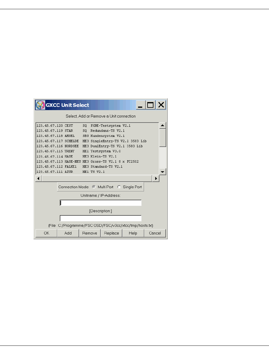
148 U41117-J-Z125-7-76
Function bar GXCC
The indirect connection is used to monitor systems which cannot be reached directly
(Example: Modem connection to the “socket_host” with “target_host” connected to a
LAN). In this case first a socket connection is set up to the “socket_host”, and this is
then continued step-by-step via the “proxy_host” on to the “target_host”. A prerequisite
for this is that the InfoBroker is available on every system of the connection chain.
Such connections are displayed in the title bar of the configuration display in the form
“socket_host_ip_address ,..., target_host_name”.
You can sort the list (and the file this is based on) either in ascending or descending order
by simultaneously pressing the keys CTRL+o.
The “Connection Mode” field displays or specifies which ports are used by the socket con-
nection. Because of the firewall requirement GXCC/XTCC now connect to the
RequestBroker in single port mode by default. Any connection to the InfoBroker which is
required is initially set up on the remote system. This setting is not stored.
Multi Port
RequestBroker port: permitted
Infobroker port: permitted
Single Port
RequestBroker port: permitted
InfoBroker port: not permitted
This menu is also offered if you call the Global Status from GXCC and no InfoBroker
connection exists.

U41117-J-Z125-7-76 149
GXCC Function bar
Buttons at the bottom of the screen
OK Establishes a connection to the ISP selected in the lise. If the unit address was
only entered in the entry field, it will not be incorporated in the list.
Add Adds the entered unit data to the list.
Remove Removes the selected entry from the list.
Replace Replaces the selected entry in the list.
Help Opens a text window which contains Help information.
Cancel Has two different effects depending on the context:
– If there is no connection to an ISP, it closes GXCC.
– If a connection exists, i.e. the menu was simply called to edit or check the
address list, it closes the window.
Any changes to the unit list which were confirmed using “Add” or “Remove” will
remain effective even after you click “Cancel”.
The Return key does not work in this dialog box. However, you can select a unit by double-
clicking the relevant line.
The name and position of the unit file are displayed above the row of command
buttons. If you take this file from another GXCC unit, copy its unit list.
Establishing a connection after clicking on OK
1. A check is carried out to establish whether or not the desired unit is accessible. If it is
not, an existing connection will be retained and, once the error message has been
acknowledged, the “Unit Select” menu is displayed again.
2. If the unit is accessible, an existing unit connection will be closed.
3. When the connection has been established, a check is carried out to determine whether
the addressed unit is an element of a CentricStor network. If it is not, an error message
will be output and, once acknowledged, the “Unit Select” menu is displayed again.
4. A check is carried out to see whether the addressed CentricStor has the software
license for a connection to an external GXCC. If it does not, an error message will be
output. Once this message has been acknowledged, the Unit Select menu will be
displayed again.
As soon as a connection has been established with any ISP in a CentricStor network, the
GXCC has access to all CentricStor elements via the request broker.
If the “Unit Select” menu is closed with “Cancel” while a connection is open, this connection
will remain in place.
If it is closed with “Cancel” while there is no unit connection, GXCC will be shut down.
i
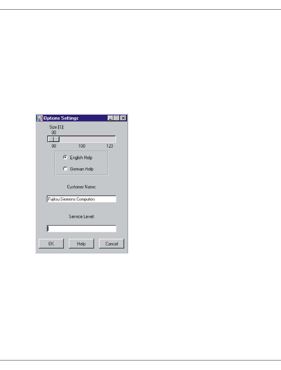
150 U41117-J-Z125-7-76
Function bar GXCC
6.2.4 Options
Allows you to set the window size and the page ratio. When defining the graphic display
settings, it is recommended that you stop the Autoscan process (see the section “Start
Autoscan/Stop Autoscan” on page 152), since otherwise the display will always return to the
original settings.
If GXCC is running under the control of a profile file that has been explicitly specified, all
changes made using the “Options” and “Autoscan” functions will be saved to this profile file.
6.2.4.1 Settings
Size
Allows you to set the scale of the display using the sliders provided.
This function affects the size of the configuration display. You can vary the scale from
80% to 100% in 20% steps. The default setting is 100%.
English Help
This displays the help information in English.
German Help
This displays the help information in German.

U41117-J-Z125-7-76 151
GXCC Function bar
Customer Name
This field contains a customer name that is a maximum of 60 characters long and which
can be edited in User or Service mode. Special characters " \ $ [ ] ' will be replaced by
underscores “_”. Each time a change is made to the string and the OK button is clicked,
the information is saved on the monitored system.
If this field is deleted GXCC uses a default name which depends on the system type.
In Simulation mode this field is called “Data from file” and is used to display path and
file names of the current configuration file.
Service Level
This is a field that is reserved for the purpose of authorizing the use of special functions
that are not described here.
Buttons at the bottom of the screen
OK Saves the settings. The window is closed.
Help Opens a text window with help information. Any changes to the language setting
will not come into effect until you press “OK”.
Cancel Closes the window without saving any changes made.
6.2.4.2 Show Current Aspect
Displays the current aspect values, the window size, and the distance from the left-hand
and top screen edges.

152 U41117-J-Z125-7-76
Function bar GXCC
6.2.5 Autoscan
6.2.5.1 Start Autoscan/Stop Autoscan
An Autoscan is a process by means of which information is transferred periodically from the
InfoBrokers to GXCC, and the graphical display is subsequently updated accordingly. It is
either active (started) or inactive (stopped), its status indicated by the color of the text in the
bottom right-hand corner of your screen. Green means that the Autoscan process is active,
in which case the function bar offers the “Stop Autoscan” function. Red means that the
Autoscan process is stopped, in which case the function bar offers the “Start Autoscan”
process.
When an information window is output or a function menu called for an object, the Autoscan
function will be stopped temporarily, as indicated by the red color of the Autoscan indicator.
It will be resumed automatically after the window or object menu is closed. If “Move Pointer”
is selected in the “Options” menu, however, the Autoscan function will not be interrupted
when an information window is opened (see the section “Settings” on page 153). If the
indicator is colored yellow, this indicates that a new data record is currently being received
and edited by InfoBroker. The interval between two Autoscan periods is normally derived
from the number of objects to be displayed, and is automatically set to a value in the range
4...20 seconds. This value may be adjusted manually. Furthermore the -autoscan start
parameter can be used to specify a time value to increase the update rate when operating
via VNC/Teleservice.
Before changing the window size or position of the configuration display on your
screen, it is recommended that you first stop the Autoscan process manually.
Otherwise, the ongoing process of updating the window contents will cause the
window to jump back to its original position. The reason for this is that the appli-
cation (GXCC/XTCC) will not be aware of your modifications (made via the Window
Manager), and will always use the parameters stored most recently to build the
display.
i
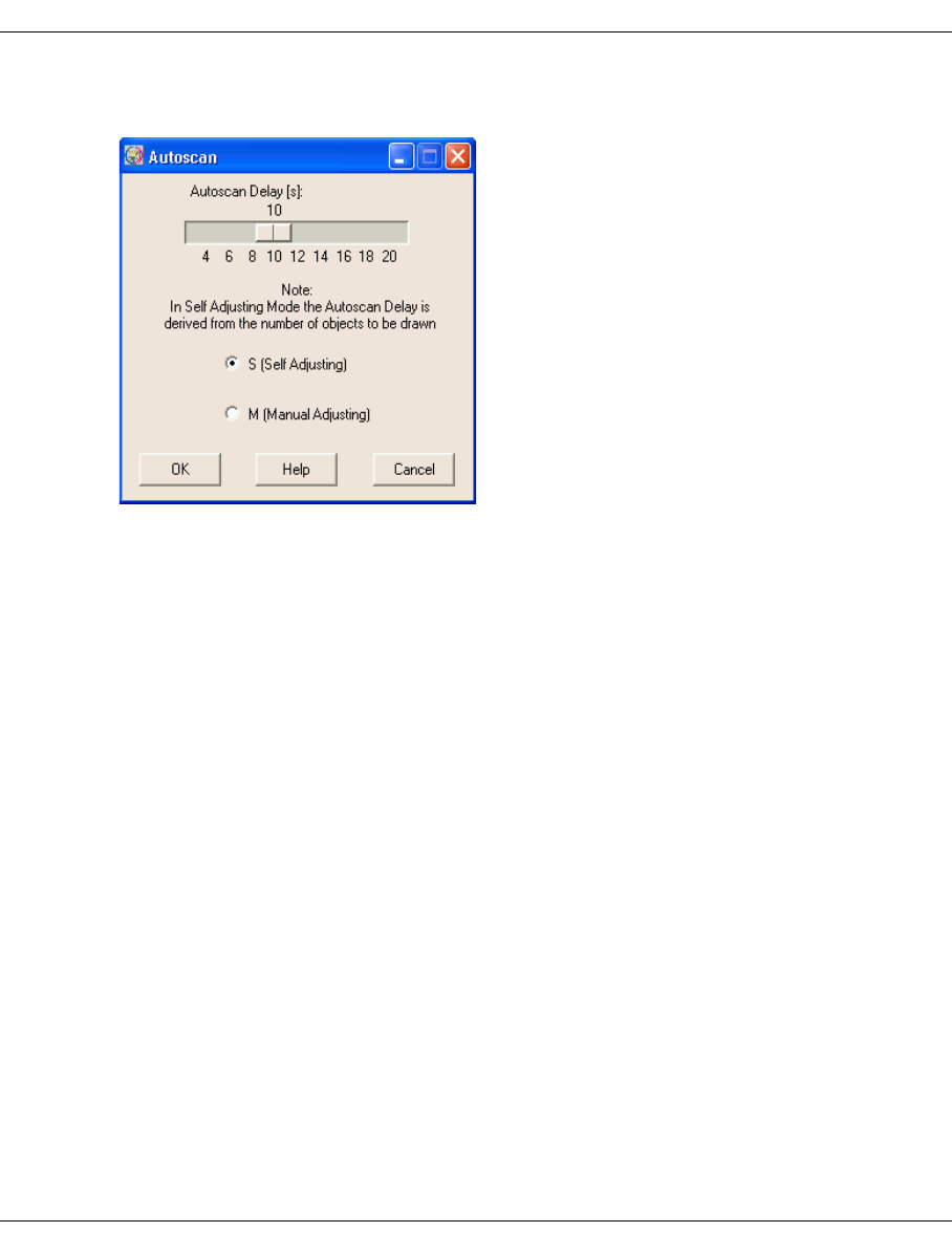
U41117-J-Z125-7-76 153
GXCC Function bar
6.2.5.2 Settings
The slider controls the Autoscan interval for exchanging information with the InfoBroker. An
Autoscan cycle consists of data transfer, display generation and autoscan delay.
The default setting is “Self Adjusting”. In this mode, the interval is automatically adapted to
the number of objects to be displayed, and varies between 4 and 20 seconds. By selecting
“Manual Adjusting” and moving the slider, you can also set the Autoscan interval manually.
The current mode and the interval value ‘t’ will be displayed in the status bar at the bottom
of the XTCC window in the form ‘S ts’ or ‘M ts’.
S GXCC optimizes the autoscan interval in accordance with the current configuration.
M The value set with the slider is used. Click “OK” to confirm the new value.
It is recommended that you operate GXCC in S mode (S = Self Adjusting).
Buttons at the bottom of the screen
OK Saves the settings. The window is closed.
Help Opens a text window with help information.
Cancel Closes the window without saving any changes made.
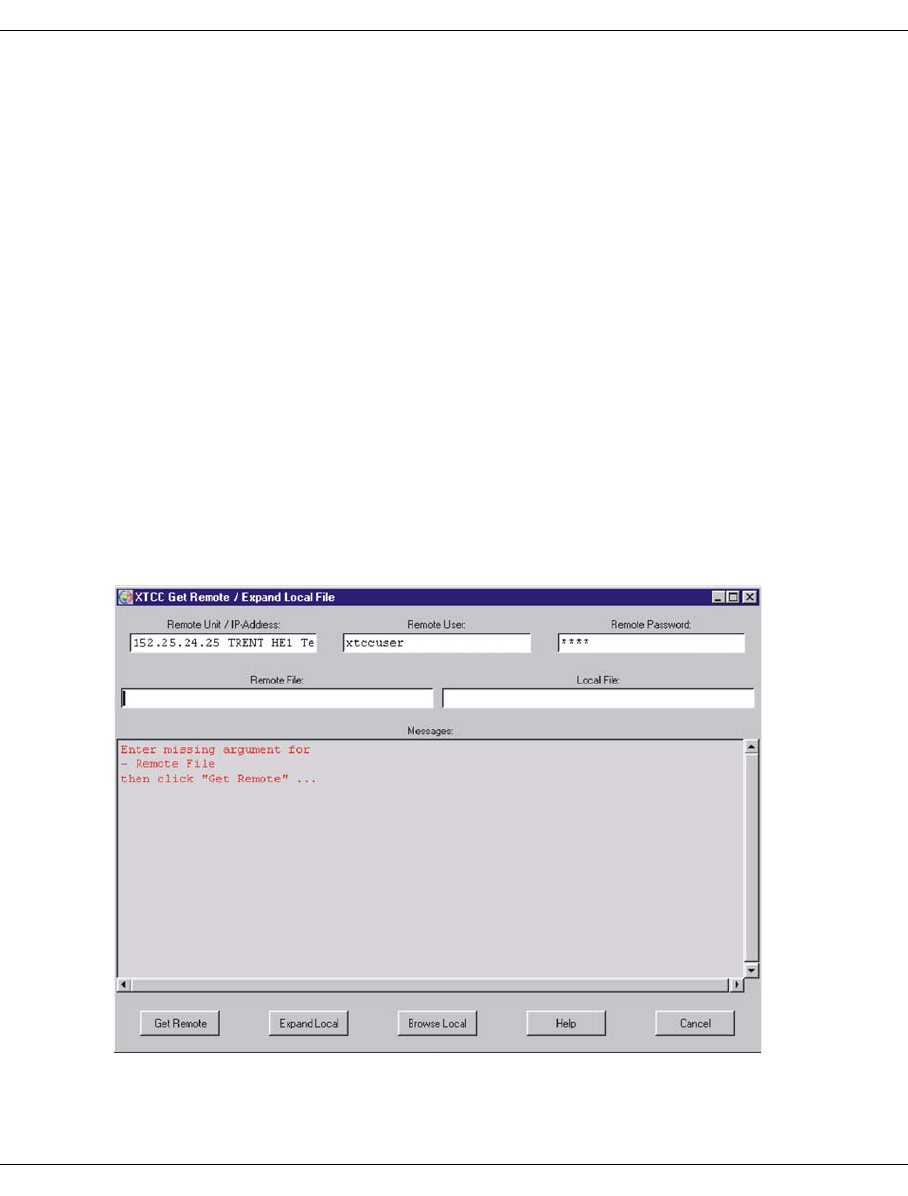
154 U41117-J-Z125-7-76
Function bar GXCC
6.2.6 Tools
The following functions are offered:
–Global Status
–Get Remote/Expand Local File
–Show Remote File
–Show System Messages
–GXCC Update/Revert Tool (only offered to authorized users)
6.2.6.1 Global Status
This function is used to call the Global Status Monitor (for a description see the chapter
“Global Status” on page 237) on the connected CentricStor.
6.2.6.2 Get Remote/Expand Local File
Opens a menu consisting of several entry fields, a message window and various keys. With
this menu you can transfer a file from a remote system to the local system, and expand it if
necessary (in the case of compressed files, such as trace packages). The two functions can
be handled separately.

U41117-J-Z125-7-76 155
GXCC Function bar
The window contains the following fields:
Remote Host / IP-Address [Description]:
Name or IP address of the remote system together with an optional comment.
Remote User:
Remote system user ID under which file transfer is performed.
Remote Password:
Password (not visible) for the remote system ID under which file transfer is performed.
Remote File:
Path and name of the remote file.
Local File:
Path and name of the local file (created from the remote file). If the specified directory
path does not exist on the local system, it will be created automatically. When the
“Expand Local” button is clicked, the system attempts to expand this file.
Messages:
Field used to output messages from the components involved in file transfer. The
following text colors are used: black and green for the process sequence, red for errors,
and (in the event of errors) blue for associated messages resulting from platform-
specific system calls or from the file transfer protocol.
The menu’s function buttons have the following meaning:
Get Remote
The following processes are started:
– Formal check of the entries
– Addressing of the remote host
– Password legitimation
In the event of problems error messages appear in the output window and you can
correct your entry.
If the entry is successful the file transfer starts.
Expand Local
Starts the decompression and extraction process for the local file, which must be
available as a compressed tar archive.
Messages indicating the success or failure of these processes are output in the output
window.

156 U41117-J-Z125-7-76
Function bar GXCC
Browse Local
Opens a dialog box in which you can select and open a local file for the “Expand Local”
function.
Help
Opens a window with help information.
Cancel
Closes the menu.
6.2.6.3 Show Remote File
Opens a menu consisting of several entry fields, a message window, a list box and various
buttons:
In this window you can transfer a file from a remote system to the local system and view it
using a file viewer.
The menu’s entry fields have the following meaning:
Remote Host / IP-Address [Description]
Name or IP address of the remote CentricStor server.
Remote User
Remote system user ID under which the file transferis performed.

U41117-J-Z125-7-76 157
GXCC Function bar
Remote Password
Password (not visible) for the remote system ID under which data transfer is performed.
Messages
Field used to output messages from the components involved in file transfer. The
following text colors are used: black and green for the process sequence, red for errors,
and (in the event of errors) blue for associated messages resulting from platform-
specific system calls or from the file transfer protocol.
Current Remote Directory:
Absolute path name of the current remote directory displayed in the list box underneath,
starting from the root directory /. The list box provides a static display of the contents
of the current remote directory.
If the menu remains open for a long period of time, you can refresh the field contents
by selecting an entry with the path name “.” (single dot in the
“PATHNAME” column) and clicking the “OK” button.
The blue title bar explains the meaning of the different columns in the list box:
FID_ACCESS – File ID and access permissions
REF – Link counter
OWNER – Owner
GROUP – Group
SIZE – Size
MTH – Month
DY – Day
HH:MM – Time
PATHNAME – Path name (name of the file, directory, link)
Use your left mouse button to select entries in the list box. Depending on the type of entry,
clicking the “OK” button will either start file transfer to the local system or cause a change
of directory. You can also start this function by double-clicking the entry. Once data transfer
to the local system has been successfully completed, the “Show” text viewer is started
automatically. Its “Save As” function can be used to copy the file to the local system.
A subdirectory of the type <host-name>.rhost is created for the remote system
in the local system’s temporary XTCC directory. The name of the local file corre-
sponds to the name of the remote file. However, the remote subdirectory structure
is not mapped. Any obligatory entries that are missing must be entered manually
afterward. The default remote user ID is service. In the event of access problems
(Permission denied message), root can be entered as an alternative ID.
i
i
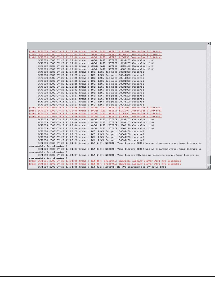
158 U41117-J-Z125-7-76
Function bar GXCC
6.2.6.4 Show System Messages
Opens a text window to display the ISP system messages. The window is automatically
positioned on the last outputs.
The console messages of all CentricStor systems are listed by priority and in the order in
which they occurred.
You can also display the system messages by clicking the symbols in the title bar.
The messages are identified by different colors depending on their urgency:
[blu] Blue WARNING Warning
[red] Red ERROR Error message
CRITICAL Critical (e.g. serious device error)
[reb] Flashing red ALERT Alarm: eliminate error immediately
EMERGENCY Alarm: system is unstable
A message comprises the following elements:
Attribute [blu],... [reb] specifies the display mode. This means that important
messages can also be identified in a black/white display.
MsgNumber ID of the message, maximum 7 characters.
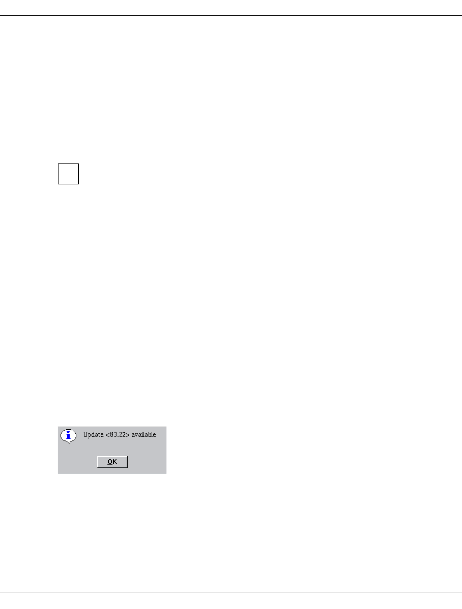
U41117-J-Z125-7-76 159
GXCC Function bar
DateTime Date and time in the form YYYY-MM-DD HH:MM:SS.
ISP-Name Name of the ISP from which the message originates.
Separator One or two characters (for their meaning see page 441)
Message text
In addition to the functions available in all text windows, the function bar of the system
message window also contains “AutoUpdate” and “AutoPopup”. These functions of the text
viewer are described on page 362.
Certain alerting actions are predefined for the messages in accordance with their
priorities. For example, the priorities EMERGENCY and ALERT (i.e. all flashing
messages in red) trigger a teleservice call (among other things) when the other
requirements for this are satisfied.
6.2.6.5 GXCC Update/Revert Tool
Principle behind software updating
The software for the user interface of CentricStor runs on a wide variety of platforms. The
delivery package of CentricStor includes a CD containing the user interface software and
installation utilities. Following initial installation the updating of the software is largely
automated.
When reading in software updates to a CentricStor system, any new versions of
GXCC/XTCC are also read in there automatically. The corresponding program files will also
be stored in compressed form. When GXCC/XTCC sets up a connection to a CentricStor
system, a check is made to see whether the CentricStor system contains newer versions of
GXCC/XTCC. If this is the case, the compressed files are transferred to the GXCC system
(usually a workstation) and saved there in an update folder.
A message is then output to the user interface. Example:
The same notice is issued to all GXCC applications that are active at the time. The same
info box is issued at the start of GXCC and each XTCC if the update folder contains a
version that is newer than the one that has just been started.
i

160 U41117-J-Z125-7-76
Function bar GXCC
If the online manuals have to be updated as well, the manuals are transferred in the
background after the program files. If the transfer is completed successfully, the new
manual is activated automatically and the older edition deleted. Thus, if you do not
activate a new software version immediately, it can happen that the online manual
is more up to date than the user interface software.
You can use the update/revert tool to:
– display the saved software versions and delete versions that are not required from the
update folder
– activate (update) a version saved in the update folder
– revert GXCC to the status it had at installation
With the update/revert tool you always remain in the same main version of GXCC/XTCC
(e.g. in version 2.xx). The installation process via CD is required to upgrade to another main
version (e.g. 3.xx).
On a workstation, the latest GXCC/XTCC version from all the monitored systems is thus
loaded automatically and activated on request. An update installation from CD is thus not
necessary on the workstation.
If GXCC is operated on a workstation by multiple users simultaneously, activation of a new
version concerns all users. The update/revert tool offers assistance to facilitate coordi-
nation and communication between the users.
Only one revision of GXCC/XTCC can be run on a computer (ISP/workstation).
A corresponding tool with the same user interface is also offered for XTCC.
– Within a product line (CentricStor V2.x or CentricStor V3.x) there are no restrictions
regarding the compatibility of different GXCC and XTCC versions. Even if a workstation
is to operate with older CentricStor versions you can upgrade the GXCC/XTCC
software to the latest version.
– The graphical user interfaces of CentricStor V2.x and V3.x are separate software lines.
They can thus be operated independently of each other on the workstation. Updates
only affect the particular line which is being used. It is not possible to upgrade GXTCC
(CentricStor V2.xx) to GXCC (CentricStor V3.xx).
i
i
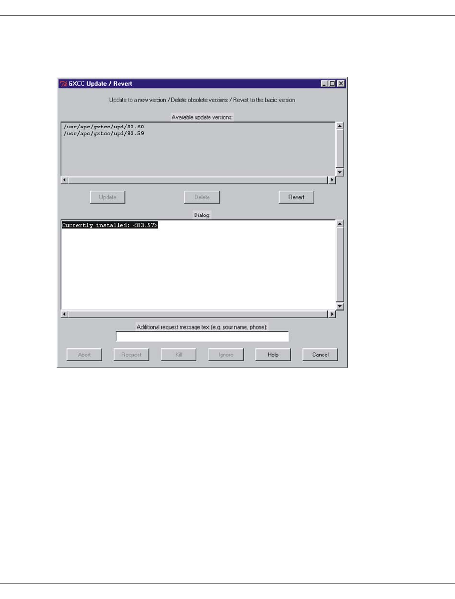
U41117-J-Z125-7-76 161
GXCC Function bar
Carrying out a software update
When you choose the menu command, the following window appears:
A list of the GXCC versions in existence is displayed in the upper part of the window, starting
with the most recent version.
The version of GXCC (or XTCC) that they are currently using is displayed in the first line of
the “Dialog” box.
“Revert” reverts to the status brought about by the initial installation.
After you select a file from the list, you can:
– choose “Delete” to delete this file
– choose “Update” to activate this status of GXCC
The installation version is not displayed in the overview and cannot be removed.
To activate a different version of GXCC, your current GXCC plus all subapplications and any
GXCCs started by other users plus all subapplications must be closed. Only the
update/revert tool remains open. GXCC applications which run on other GXCC systems
and are connected to the same CentricStor are not affected.
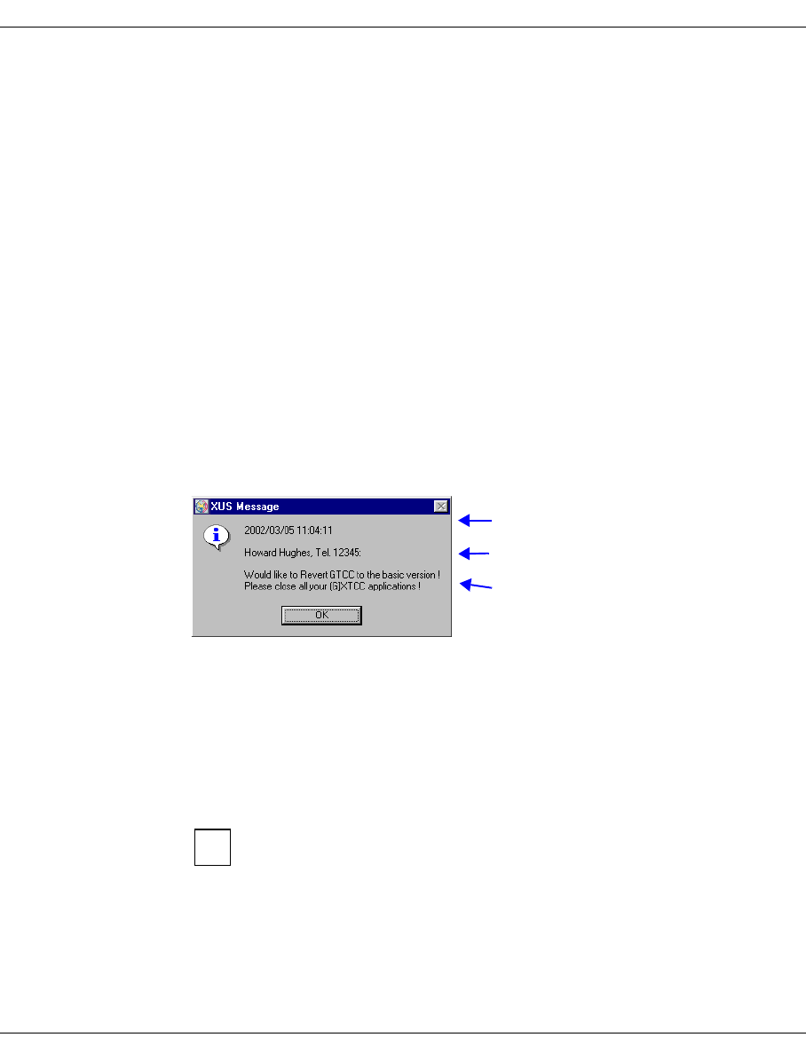
162 U41117-J-Z125-7-76
Function bar GXCC
A monitor program keeps track of all the GXCCs and their ramifications. It initiates the termi-
nation of subapplications and brings it to your attention if other users are also using GXCC.
The lower half of the screen contains the output area “Dialog”, which displays the update
status and context-sensitive instructions, and an input area for messages to other GXCC
users.
Different text colors indicate different types of text:
Black General text, instructions
Green Positive acknowledgment
Red Important text, error message, response required
Blue Messages of participating components
The buttons arranged along the lower border allow you to influence the update operation
and control communication with other users.
Abort Cancels the update/revert operation. Closes the window.
Request Sends a message to all active GXCC/XTCC applications.
As the following example shows, the message consists of a line with the date
and time, the text entered in the “Additional Request Message” field and a text
relating to the action planned.
If the applications are not closed, the following options are available to you:
Abort Aborts the operation and closes the update tool.
Kill Closes the applications and the update tool.
Kill Terminates all the active GXCC/XTCC applications. This button is only enabled
when an update/revert operation has been stopped because other
GXCC/XTCC applications are active. “Kill” also terminates the GXCC appli-
cation from which the update tool was called.
The function should only be used when, in the event of an update/revert
operation, other GXCC/XTCC users do not respond to the message
distributed with Request within an appropriate period of time.
Ignore Skips the application test. This button is only enabled if the central monitor that
checks for active GXCC/XTCC applications is not working. It is advisable before
clicking this button to ensure that there are no GXCC/XTCC applications
running.
Date/time
Entered text or “Request from another user:”
Text dependent on the button clicked
i

U41117-J-Z125-7-76 163
GXCC Function bar
Help Opens a text window containing help information. This is also an active
GXCC/XTCC application, and it is thus closed when the update operation is
executed. You thus cannot keep the window open during the update. This
should not be a problem because there are context-sensitive explanations and
instructions given, where necessary, in the dialog box.
Cancel Terminates the update tool. Before a GXCC application is started after an
update, the update tool should always be terminated with “Cancel”.
The update tool must be terminated with “Cancel” so that updates of the tool
itself can become effective immediately.
Your own GXCC/XTCC application is also recognized as a running application.
Using a “Kill” on this application does not terminate the update/revert tool.
If for any reason the GUI software cannot execute, you can often use a repair
tool to download an intact version from a CentricStor or a workstation. The
repair tool is described after the application examples.
Application example
Let’s assume you want to update GXCC. There are other GXCC/XTCC applications active
in your system.
You have to carry out the following steps:
●You open the update/revert tool and check that the version you want is there.
●You close GXCC, from which you started the update tool, and a Global Status Monitor
if you have one open.
●You select the desired GXCC version.
●You click the “Update” button.
●The first steps of the update process are logged in the “Dialog” field. If you have a Help
window open, this is now closed.
●Other applications belonging to the GXCC/XTCC family are active. This is indicated to
you by a red output text in the “Dialog” field. You enter your name, phone number and
planned update time in the optional message field, and click the “Request” button. A
message appears on all users’ screens requesting them to close the application (see
page 162). This also closes the update tool.
●You start the update tool again at the agreed time. One user has not terminated GXCC.
Because you really have to carry out the update today, you click the “Kill” button. This
closes the application.This also closes your GXCC. The update tool continues to run.
i

164 U41117-J-Z125-7-76
Function bar GXCC
●You restart again. This time the process ends with the green message “Update done”.
●It now makes sense to terminate the update tool by means of the “Cancel” button. The
service that monitors all the applications of the GXCC/XTCC family is thus restarted
with the updated version the first time one of these applications is started.
Repairing a faulty GXCC/XTCC version
In case the GXCC or XTCC version is faulty and you can therefore no longer call the
associated “Update / Revert” function and an installation CD is not available, a repair tool
has been provided as an emergency measure.
The prerequisites for using it are that you can access a system on which an operational
GXCC or XTCC version exists and that the faulty version provides a degree of basic
functionality.
If the tool cannot be run because the functionality of the faulty software is not sufficient or
one of the activities described below cannot be performed successfully, the only option is
to reinstall the GUI software from CD.
Call under SINIX/UNIX
To execute this you must switch to the XTCC directory <xtcc_path>.
cd <xtcc_path>
./repair &
Call under WINDOWS
If the following start menu entry is available:
Start » Programs » Fujitsu Siemens Computers » V6 Control Center » Setup
» Try to repair inoperable GXCC or XTCC
Otherwise:
Start » Execute » Browse
Select the file: <xtcc_path>\osd\Windows\repair.bat
» Open » OK
To do this on the WINDOWS NT/2000/XP platforms you require an ID with
administrator rights.
i

U41117-J-Z125-7-76 165
GXCC Function bar
Procedure
If you were able to start the tool, first a window will open which explains the further
procedure. This procedure consists of the following steps:
1. Select the component to be repaired: GXCC or XTCC
2. Select the remote system from which the compressed archive of the selected
component is to be fetched.
3. Execute the “Get Remote / Expand Local File” tool:
Here only the “Remote Password” need be entered; all other parameters are already
specified and may NOT be changed.
Click on “Get Remote” to start data transfer from the remote to the local system. If this
is completed successfully the message “Ready for Expand Local” appears.
Click on “Expand Local” to extract the files from the archive into the master directory of
the selected component.
If this is completed successfully the message “Extraction finished” appears. Then close
the window with “Cancel”.
4. Execute the “Update / Revert” tool:
Click on “Revert” to use the files just extracted to create a GXCC or XTCC version which
corresponds to the version of the remote system. After the message “Revert done” has
appeared click on “Cancel” to close the window.
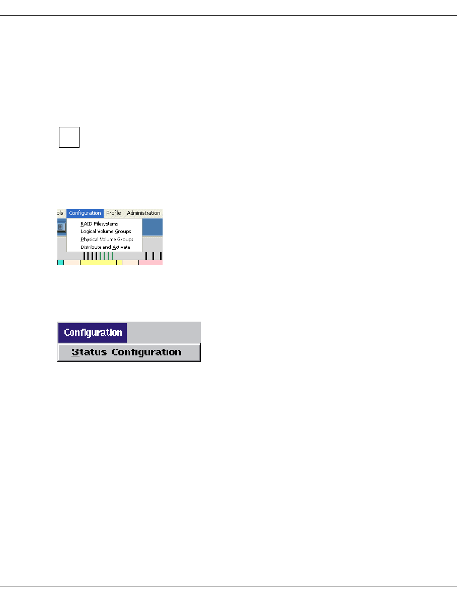
166 U41117-J-Z125-7-76
Function bar GXCC
6.2.7 Configuration
PVGs and LVGs can be configured, i.e. created, modified and deleted, in User mode.
Changed parameters are stored in the file
/usr/apc/broker/vtls_vg.conf.new
. The floppy
disk symbol appears in the CentricStor main window.
The changed data is activated using the “Distribute and Activate” function.
Changes to the LVGs affect VLM and PLM, changes to the PVGs affect only
thePLM. These components are stopped and restarted during “Distribute and
Activate”.
Afterward the file
/usr/apc/conf/vtls_vg.conf
contains the modified data. The floppy disk
symbol in the GXCC window disappears if no further configuration changes are in prepa-
ration in Service mode.
When the configuration menu is opened and the InfoBroker started the configuration data
is checked for consistency. If inconsistencies are found or if files are missing, you will not
be offered to configuration menut when Configuration is selected, but you will instead be
offered the “Status Configuration” function:
If you click this function, you will be provided with information about the error and further
instructions, if available.
i

U41117-J-Z125-7-76 167
GXCC Function bar
➟ Configuration menu on the function bar
Clicking the “Configuration” button in the toolbar opens a drop-down menu with the following
items:
–RAID Filesystems
–Logical Volume Groups
–Physical Volume Groups
–Distribute and Activate
Selecting the required function provides access to a series of dialog boxes for displaying
and setting the configuration parameters. Functions marked “!” and colored yellow in the
drop-down menu indicate settings that are not consistent with the configuration currently
active.
Disabled functions (colored white) indicate settings that are currently being edited by other
GXCC users.
In User mode PVGs and LVGs can be configured without restrictions as in Service
mode. When operating in Observe mode, however, the configuration may not be
changed in any way.
i
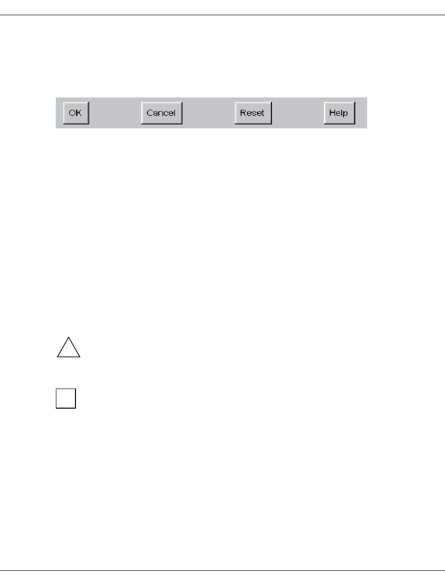
168 U41117-J-Z125-7-76
Function bar GXCC
Elements of the configuration dialog boxes
Command buttons along the lower border:
All dialog boxes used to change the configuration have the same set of buttons:
OK Temporarily saves your changes to /usr/apc/broker/vtls.conf.new or
/usr/apc/broker/vtls_vg.conf.new and ensures that they are taken into
consideration in the other dialog boxes of the configuration group. If the
…conf.new files do not yet exist, they are created by copying over the configu-
ration file currently active and modifying it in accordance with your entries. The
menu item remains selected, and further changes are possible.
In the GXCC main window a diskette icon indicates that the work file in
/usr/apc/broker no longer matches the active configuration file.
Cancel Closes the dialog box without applying your changes.
Reset Resets all fields to the values set when the dialog box was opened. The dialog
box remains open.
Help Opens a text box containing operating instructions alongside the dialog box.
Any configuration changes not yet activated with “Distribute and Activate” are stored tempo-
rarily by the InfoBroker when you click “OK” and will be retained even if GXCC is shut down.
Important:
If the system’s InfoBroker is shut down before the configuration changes have been
activated, any changes not yet activated will be lost. The same applies to any
changes not yet activated when CentricStor is shut down.
If the vtlsconf_use_new file exists in the /usr/apc/broker folder when the
InfoBroker restarts, the .new files are not deleted and the vtlsconf_use_new file
is deleted. Thus, if you want to prevent the deletion of latent configuration changes
at restart of the InfoBroker, you must create a file with this name by using the appro-
priate shell commands. The action must be repeated after every startup of the
InfoBroker. This allows you to rescue extensive configuration entries, for example,
if you discover at an initial configuration that the system has to be restarted.
!
i
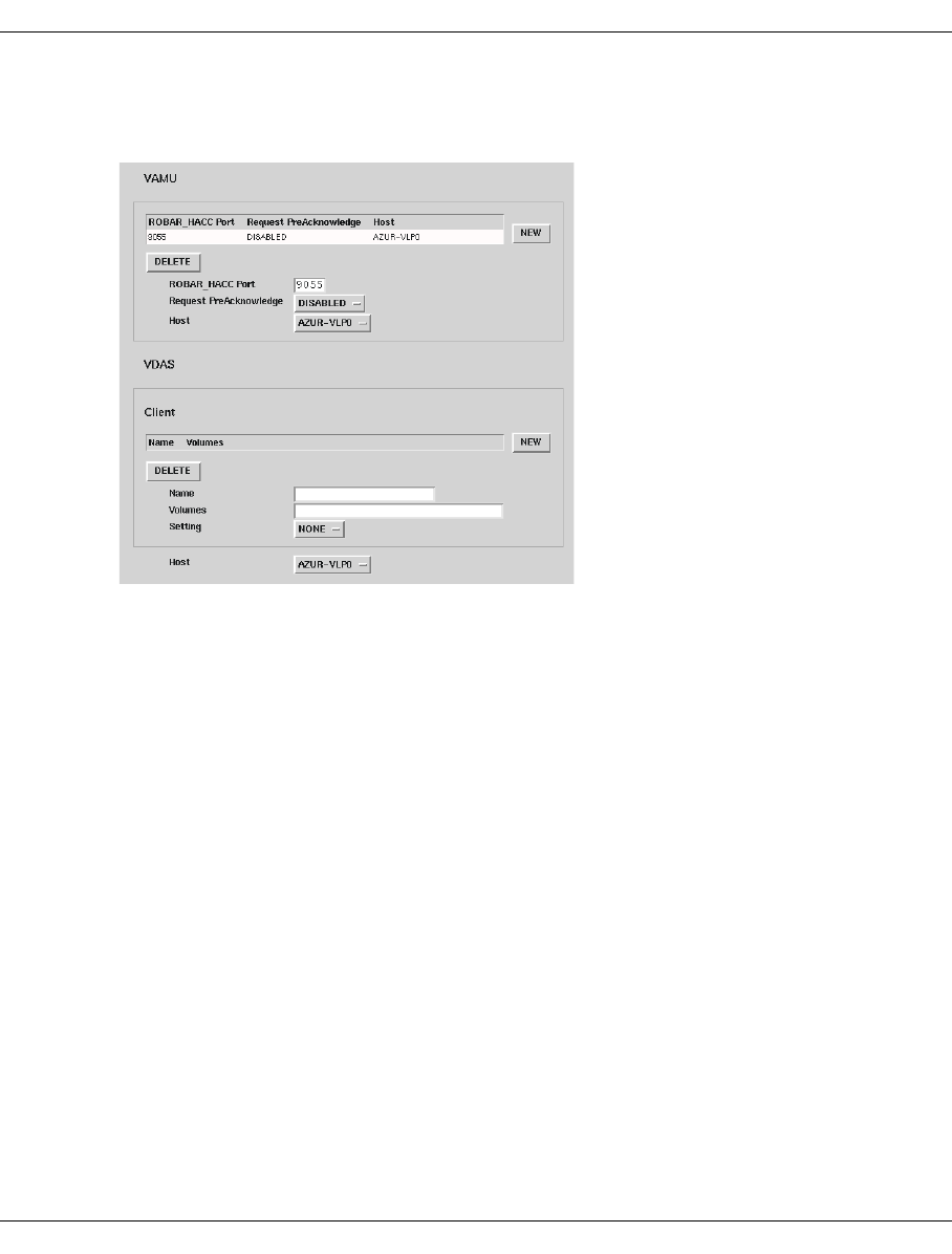
U41117-J-Z125-7-76 169
GXCC Function bar
List editor
The following example displays a configuration dialog box containing two lists:
Several objects of the same type often have to be defined at configuration (e.g. Virtual
Library Servers, PVGs, LVGs). The list editor in the configuration dialog boxes is used for
this.
An editor area consists of a list of the objects already defined and a number of elements
such as display windows, text entry fields, command buttons and radio buttons. If you click
a line in the list, it is highlighted and the data associated with the selected object is copied
to the associated elements. The dialog box thus displays all the information relating to the
object selected from several objects of the same type.
A dark gray border shows that the list and the associated elements belong together.
The “NEW” button and, after you select a line, the “DELETE” button belong to the list. These
buttons are only offered when the associated functions can actually be executed.
“NEW” adds a new object, while “DELETE” deletes the objects displayed in the selected
line.
The data offered in text areas and as labels for buttons is also either displayed or not
displayed, depending on the context. If a name can no longer be changed, for example, it
appears as text. If it can be changed, it appears in an editable field. All the command
buttons are only offered when the function behind them can be used. Radio buttons are only
offered when there really is a choice. If there is no longer a choice, the valid setting is
displayed as text.

170 U41117-J-Z125-7-76
Function bar GXCC
Adding a new object:
Click the “NEW” button. An empty entry field appears in which you can enter a name.
Depending on the type of the object, further entry fields will also be displayed. These are
filled with defaults wherever this is possible or useful.
If you enter a formally correct text in the name field and then display it by pressing the
Return key or by clicking another field or button, the new object is defined. A selected line
appears for it in the list, containing the name you entered. You then have to complete your
entries in the entry fields.
If no new object can be added because the maximum number of objects has been reached,
“NEW” is not offered.
Deleting an object:
Select the corresponding line in the list and click the “DELETE” button. This item disappears
from the list. “DELETE” is only offered for items in the list that can still be deleted.

U41117-J-Z125-7-76 171
GXCC Function bar
6.2.7.1 RAID Filesystems
After you have selected this function a form for configuring the RAID system is displayed:
In Observe and User mode the OK button is not present and all the checkboxes are disabled.
Buttons
Disable caches
Some tests on empty file systems and consistent LVG assignments are skipped (no) or
executed (yes).
FC redundancy (appears only if the function is installed in CentricStor)
Here you can enable or disable the FC redundancy function in CentricStor.

172 U41117-J-Z125-7-76
Function bar GXCC
Information
Mirroring
Whether the mirror function is enabled or disabled in CentricStor is specified here.
The attributes of a RAID system with the mirror function enabled, whether and
how it is mirrored, are defined by the assignment of the LUNs during RAID
configuration.
Configuration window
In the table the columns represent the RAIDs and the rows represent the LUNs (the rows
can also contain disk numbers in the case of internal RAIDs). The file systems are
contained in the cells.
The print color indicates the mirror status:
black Not mirrored
blue Mirrored
The cells are color coded:
white The conditions have been recognized. However, the file system is not yet
configured.
green The file system is configured and mounted on all ISPs.
red The file system is configured but has not been mounted due to an error.
yellow The file system is configured but has been mounted on only some of the ISPs.
In Observe or User mode, the checkboxes cannot be modified by the user.
Mouse functions in the configuration window
Mouse click
Detailed information on the cell or RAID system selected is displayed in the infobox to
the right.
After you click on the “mirrored” or “unmirrored” header field all file systems in the
column are selected.
1. Left mouse click
2. Shift key + left mouse click
Clicking on one of the cells with the shift-key held down and then clicking on another
cell causes the entire range to be selected. The selection is made for columns.
Ctrl key + left mouse click
Clicking on one of the cells with the Ctrl-key held down will result in a cell being added
(or removed) from a range.
i

U41117-J-Z125-7-76 173
GXCC Function bar
Key
Status The meaning of the various colors and checkbox conditions is explained. The
cells also contain a summary (e.g. “mounted 85”).
Command buttons along the lower border
Cancel
Closes the window.
Reset
The setting is reset to the value when the window was opened. The window remains
open.
Help
Shows a help file.
6.2.7.2 Logical Volume Groups
In this step at most 512 LVGs can be incorporated in CentricStor.
The top part of the form contains a list of the LVGs that have already been incorporated.
Clicking in the list selects a group.
The entry for the selected LVG has a light background. As a default the entry fields contain
the values of the selected group. You can now change these.
When you change the group selection the contents of the entry fields are buffered. They are
not yet entered in the configuration file. Only when you click on “OK” are all changes entered
which were made since the form was opened.
The following fuinctions can be implemented in this window:
●Definition of the LV size
●Setting up a cache location (location setting not equal to FLOATING, which enables
quasi-residence of the LVs to be achieved)
●Deleting LVGs (To Be Deleted)
●Changes to the comment field (Comment)
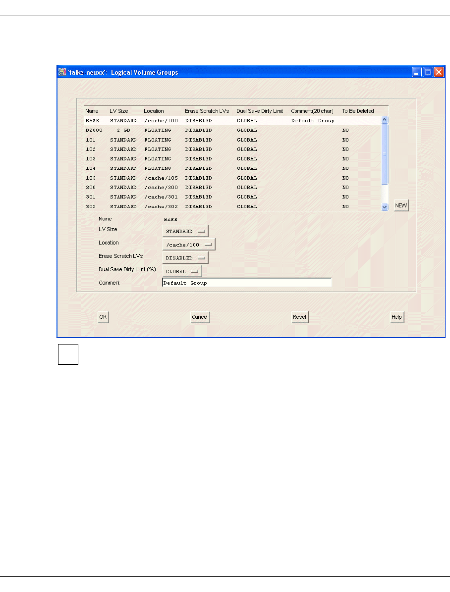
174 U41117-J-Z125-7-76
Function bar GXCC
Buttons and entry fields
In the case of LVGs already distributed with “Distribute and Activate”, the “To Be
Deleted” button is offered (as in the form above), in the case of newly entered LVGs
the “DELETE” button.
The “BASE” LVG is always present and cannot be deleted. The transfer LVG with
the name TR-LVG is also always present, but not shown in this menu.
“NEW” button:
Adds a new LVG.
When you click on “NEW” the entry field for the name is opened. The button for the LV
type and the DELETE button appear. The button “NEW” is not offered if the maximum
number of LVGs (= 512) has been reached. After you have entered a name in the entry
field (and click “Enter” or any button) a line containing the newly entered name appears
in the list.
When the groups have been established the assignments of logical to physical disks
must be specified in a further step. This is done using operating functions of the PLM
while CentricStor is running (see section “Physical Volume Operations » Link/Unlink
Volume Groups” on page 221).
i

U41117-J-Z125-7-76 175
GXCC Function bar
“DELETE” button:
Appears only if a line is selected and the selected LVG has not yet been made known
to the system. This is typically the case if you have just created an LVG and have not
yet selected “Distribute and Activate”. Not to be confused with the “Delete LVGs”
function (for details see “Input areas” ➟ “To Be Deleted”).
Deletes the selected LVG.
An LVG entry can only be removed with “Delete” if the configuration has not yet been
activated with “Distribute and Activate”. “Delete” is consequently not offered for groups
that have been activated in the system, but “To Be Deleted” instead (an explanation is
provided below).
Input areas
To Be Deleted
You use this button to change the setting of “NO” (= default = LVG is not to be deleted)
to “YES” (= LVG is to be deleted). This enables an LVG to be deleted which has already
been made known to the system with “Distribute and Activate”.
To permit this function to be used a few conditions must be met:
– The LVG concerned may not be linked to any PVG.
– No LVs may be contained in the LVG.
If the condition “no LVs in LVG” is not satisfied the request to delete the LVG is
rejected with a corresponding error message. This condition is checked twice,
once when you click on “OK” in this window and once when “Distribute and
Activate” is used. In both cases the action is rejected.
The condition “LVG may not be linked to PVG” does not lead to the action being
rejected if it is not met. but an attempt is made to perform an unlink automati-
cally. If this proves unsuccessful this leads to the LVG being marked as
“intended for deletion”.
While PVs still exist which contain a reference to the LVG to be deleted, the
action will be rejected. This case can occur if, for example, you have assigned
LVs from the LVG to be deleted to another LVG using “Change Volume Group”.
Until these LVs have been saved again under the new LVG, they are still entered
in the PLM data maintenance system with their previous LVG name.
If an LVG is marked for deletion and if this configuration data has been activated
in the system, no further actions (add LV, create new link) at all are permitted on
this LVG. If a “Distribute and Activate” is performed again at any time, the
condition is automatically checked again. If it is then satisfied, this LVG is
deleted once and for all. These procedures are fully automatic; the user need
i

176 U41117-J-Z125-7-76
Function bar GXCC
take no action. Once the request to delete an LVG has been successfully issued
and activated in the system, the action is an asynchronous action and cannot
be influenced by the user.
Name
Name of the LVG. The data of the LVG is kept under this name in CentricStor. The LVG
is defined by entering a name. The name contains a maximum of 6 characters (only
letters, numbers and “_”).
This field can only be modified until the LVG has been activated using “Distribute and
Activate”.
LV Size
This is used to specify the size of the LVs in an LVG. The following options are available:
“STANDARD” corresponds to 900 MB.
For CentricStor systems which were configured with version 3.1A or earlier the
DTV file system must be migrated before larger logical volumes are supported.
If you have not yet done this the assignment of an LV size > 2 GB is rejected
and the following message is issued:
LVGs with LVG-Type > 2 GB rejected because DTV-FileSystem has not
yet been migrated: <LVG name>
If LVs larger than 5 GB are used, adequate TVC dimensioning (caches) must
be ensured.
If large LVs are used and the TVC is too small, this results in more frequent
displacement. This can have a significant effect on the LV mount times
depending on the volume size and the drive type (e.g. with 200 GB approx. 90-
120 min.).
The cache partition must be at least as large as the size assigned to the LVG. If this is
not the case the assignment is rejected and the following message is issued:
LVG(s) rejected because at least one cache partition is too small
i
i

U41117-J-Z125-7-76 177
GXCC Function bar
Further information
Reducing the LV size of an existing LVG:
It is not possible to reduce the LV size of an existing LVG in CentricStor.
If you want a smaller LV size, you must create a new LVG with the required LV size.
The data which was written to the large LVs must then be written to the new, smaller
LVs using the customer’s (or customer system’s) backup tools (host resources).
Increasing the LV size of an existing LVG:
This is possible provided that the PVs of the LVG offer the required minimum
capacity, otherwise the assignment is rejected with the following message:
The following LVG was(s were) rejected because PV(s) in a linked PVG are
too small to store LVs of the requested LVG-Type size: <LVG_1> <LVG_2>.
Location
You can use this setting to define the assignment of the cache file system to the LVG.
An LVG can be assigned to precisely one cache file system. However, you can assign
multiple LVGs to a cache file system.
If you select “FLOATING” this means that the LVs of this LVG can be distributed over all
caches to which no LVGs have been explicitly assigned. In addition to “FLOATING” the
names of all the system’s caches (e.g. /cache/101) are offered in the selection field.
If you select a specific cache name for an LVG, the LVs of this LVG are moved to or
created in this cache only. This enables you to achieve quasi-residence. Here “quasi-
residence” means that the LVs remain in this cache provided the capacity of the cache
is not exceeded. For example, 250 LVs of 2 GB can be placed in a cache with a size of
500 GB. If you enter a 251st LV in this cache this results in some LV of the other 250
being displaced from the cache. You should always bear this in mind when filling an LVG
which is to contain quasi-resident LVs.
The following should also be taken into consideration in this context: If a logical volume
is mounted, it is always expanded to the maximum size.
Example of an LVG with 2-GB volumes
If, for example, you have already occuppied 248 GB of the available 250 GB and
now mount 4 logical volumes simultaneously each of which only occupied 1 GB in
the cache beforehand, not 4 GB but 8 GB are now required for these 4 volumes,
which exceeds the maximum size of the cache. Other logical volumes must
therefore be migrated out of this cache, thereby canceling their cache residence.

178 U41117-J-Z125-7-76
Function bar GXCC
Erase Scratch LVs
This specifies how the data of scratch volumes is to be handled:
ENABLED Only the stub data (volume header) is to be retained.
CAUTION!
With this setting it must be assumed at all times that the data on
scratch volumes - and also on the physical volumes - will auto-
matically be deleted and consequently be irretrievably lost. This
behavior was implemented as the default in early CentricStor
versions without the option of changing it by means of configu-
ration. This is contrary to the behavior of real library services.
DISABLED No data is deleted. However, the logical volumes are displaced from the
TVC. This behavior is preset and corresponds to that of real library
services.
This affects the following operations of the Virtual Library Services:
VACS “set scratch” command
VAMU “CVA” command (change volume attribute)
VDAS Not used
VLMF Not used
VJUK Not used
Dual Save Dirty Limit (%)
Determines the maximum share which logical volumes of this LVG which are “dirty” may
be assigned in the cache file system. When this value is exceeded and the selected LVG
is connected to 2 PVGs, CentricStor will switch from dual save to single save in the
event of problems on the backend, e.g. a robot error. As soon as the LVs of this LVG
have been saved their cache is released. In this way a cache overflow is prevented. As
soon as the backend errors have been corrected the second backup is performed.
DISABLED The function is disabled, i.e. no change to single save for this LVG.
GLOBAL The “Global Dual Save Dirty Limit” setting in the ”Control Components”
menu (only service mode, ) should be used.
90, ... ,10 Value in percent as of which single save is switched to.
The default setting is GLOBAL.
Comment
Freely selectable text, up to 50 characters long. The following special characters are not
permitted: ’ : $ { } .

U41117-J-Z125-7-76 179
GXCC Function bar
Command buttons along the lower border
OK
Accepts the entry. It becomes effective with “Distribute and Activate”. The “Configu-
ration Changed” symbol (floppy disk symbol) appears in the GXCC main window. The
changed configuration data is stored, even after GXCC has terminated. If the InfoBroker
is restarted or the VLP is shut down without a preceding “Distribute and Activate”, the
data which was changed is lost.
Cancel
Closes the window without accepting the entries. All the entries made since the last time
the window was opened are thus lost.
Reset
All data is reset to the status when the window was opened, even if it affects list entries
that are currently not selected. All the entries made since the last time the window was
opened are thus lost.
Help
Opens a text window containing help information.
Information on the cache management settings
The “Location” function enables individual cache file systems to be reserved for exclusive
use by certain LV groups.
Benefit: This permits cache residence of the logical volumes.
If you have ensured that the volume of data on the volumes which are assigned to a
particular cache file system does not exceed the capacity of the cache file system,
these will never be displayed from the cache. Short access times are then guaranteed
for these volumes.
Rules
– An assignment of cache file system to LV group is defined by a configuration.
– An LV group can be assigned to precisely one cache file system.
– Multiple LV groups can be assigned to a cache file system.
This has the following effects for the cache management:
– Cache file systems to which LV groups are assigned for exclusive use are reserved only
for these LV groups: The mechanisms for distributing logical volumes over the cache file
systems (when creating logical volumes, for load balancing between cache file systems,
etc.) are not used here.
– All other cache file systems are handled as before: The remaining logical volumes are
distributed over all the other caches, and load balancing takes place.

180 U41117-J-Z125-7-76
Function bar GXCC
The settings for the cache file system can be modified later at any time. After a modification
a “Distribute and Activate” operation is required in which, however, only the VLM and the
PLM must be restarted if this was the only change.
If assignments between cache file systems and LV groups are modified, this can result in
certain logical volumes having to be moved from one cache file system to another because
the old assignment no longer applies. This operation is performed automatically by the
system.
Examples
– An LV group is subsequently assigned to a cache file system which has so far not been
used exclusively:
All logical volumes which were contained in this file system but did not belong to the
assigned LV group must be moved to other file systems. Furthermore, any existing
logical volumes of the exclusively assigned LV group must now be moved into this cache
file system.
– The assignment of an LV group to a cache file system is changed, i.e. it is assigned to
another cache file system:
All logical volumes of this LV group must be moved into the other cache file system. It
may be necessary to remove logical volumes which do not belong to the assigned LV
group from this cache file system.
– The assignment of an LV group to a cache file system is canceled:
If further LV groups are assigned to this cache file system, the logical volumes of the LV
group whose assignment has been canceled must be moved to other cache file
systems.
Logical volumes are moved automatically in the background. The following points must be
noted here:
– It can take several minutes before the logical volumes have reached their destination
and the operation is terminated.
– Logical volumes which are currently in use cannot be moved (mounted volumes,
volumes which are currently required for reorganizing physical volumes). The move
takes place when the volumes are no longer being used.
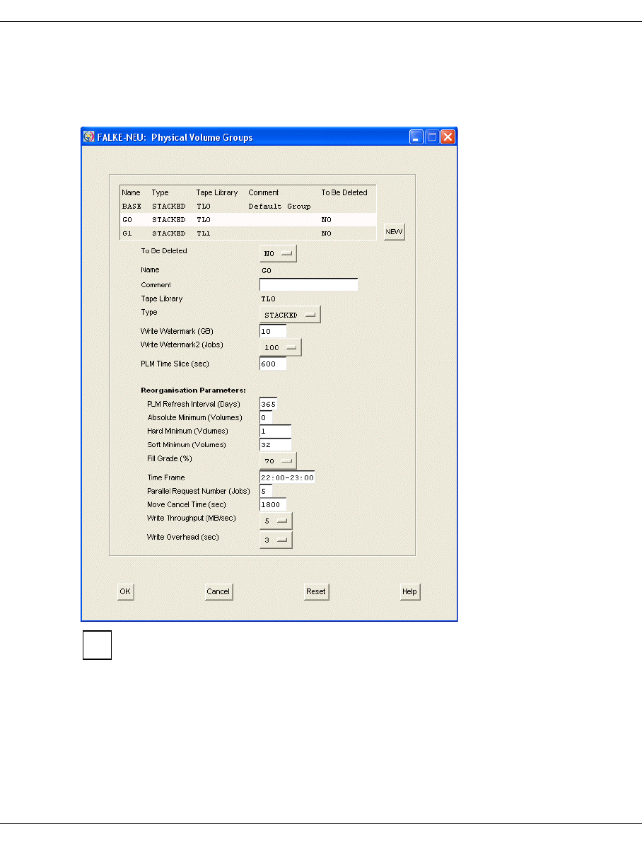
U41117-J-Z125-7-76 181
GXCC Function bar
6.2.7.3 Physical Volume Groups
In this window volume groups of the physical volumes can be created, deleted or modified.
When the window is called the existing physical volume groups are initially displayed:
In the case of PVGs already distributed with “Distribute and Activate”, the “To Be
Deleted” button is offered (as in the form above), in the case of newly entered PVGs
the “DELETE” button.
The “BASE” PVG is always present and cannot be deleted. The transfer PVG with
the name TR-PVG is also always present, but not shown in this menu.
Cleaning PVGs which can be created for the tape libraries are not shown either.
i
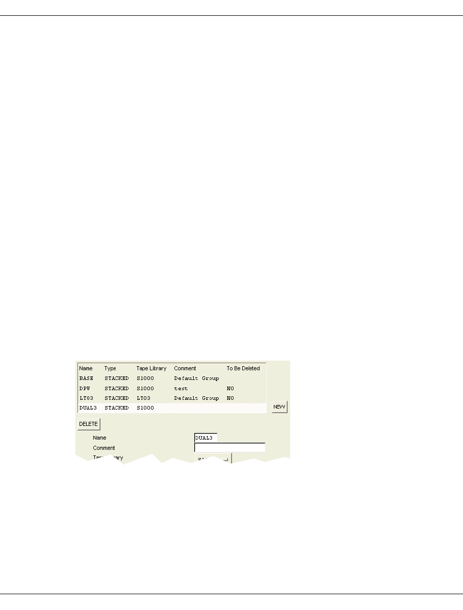
182 U41117-J-Z125-7-76
Function bar GXCC
List area
At the top of the form there is a list area with data regarding PVGs that have already been
integrated. The following is displayed:
Name Name of the PVG
Type Type of the PVG
Tape Library Tape library assigned
Comment Comment
To Be Deleted Marking for deleting the volume group
You mark a line by clicking on it. The data of the selected PVG is presented in the entry
fields and buttons below.
When you change the group selection the contents of the entry fields are buffered. They are
not yet entered in the configuration file. Only when you click on “OK” are all the changes
made since the last time the form was opened entered in the configuration file.
“NEW” button:
This button is not offered if the maximum number of PVGs (100) has been reached.
Creates a new PVG.
When you click on “NEW” the entry field for the name is opened. The fields with which
you can define the new PVG are still displayed, as is the DELETE button. After you have
entered a name in the entry field (and then press “Enter” or click any button) a line
containing the newly entered name appears in the list.
Example
The buttons and entry fields show default values.

U41117-J-Z125-7-76 183
GXCC Function bar
“DELETE” button:
Appears only if a line is selected and the selected PVG has not yet been made known
to the system. This is typically the case if you have just created a PVG and have not yet
selected “Distribute and Activate”. Not to be confused with the “Delete PVGs” function
(see below: “Entry area” ➟ “To Be Deleted”).
Deletes the selected PVG.
A PVG entry can only be removed with “DELETE” if the configuration has not yet been
activated with “Distribute and Activate”. “DELETE” is consequently not offered for
groups that have been activated in the system, but “To Be Deleted” instead (an expla-
nation is provided below).
Entry area
To Be Deleted
You use this button to change the setting of “NO” (= default = PVG is not to be deleted)
to “YES” (= PVG is to be deleted). This enables a PVG to be deleted which has already
been made known to the system with “Distribute and Activate”.
To permit this function to be used a few conditions must be met:
– The PVG concerned may not be linked to any LVG.
– No PVs may be contained in the PVG.
– The PLM must be running.
If one of these conditions is not satisfied the request to delete the PVG is
rejected with a corresponding error message.
These conditions are checked twice, once when you click on “OK” in this
window and once when “Distribute and Activate” is used. In both cases the
action is rejected if appropriate.
The BASE PVG cannot be removed.
Name
Name of the PVG. The data of the PVG is kept under this name in CentricStor. The PVG
is defined by entering a name. The name contains a maximum of 6 characters (only
letters, numbers and “_”). This field can only be modified until the PVG has been
activated using “Distribute and Activate”. As the name change is implemented by
means of a restart there is no assignment of <old name> <-> <new name> and the data
saved under the old name would no longer be accessible.
In principle the name is freely selectable. However, to prevent confusion with a clean
PVG the name should not begin with “CLNP”.
Comment
Freely selectable text, up to 50 characters long. The following special characters are not
permitted: ',:$"{}.
i

184 U41117-J-Z125-7-76
Function bar GXCC
Tape Library
The volumes of the group are stored in this physical archive. The archives defined in the
configuration are offered. This field can be changed only until the PVG has been
activated using “Distribute and Activate”.
Type
Type of the PVG. A PVG can be of the type “STACKED” or “VAULT”. STACKED means
that no external influence on the PVs is possible. VAULT means that logical deletion or
reentry of PVs in CentricStor is possible.
The default settting is “STACKED”.
Write Watermark (GB)
Write Watermark 2 (Jobs)
These two parameters control the number of drives used for the write jobs.
Write Watermark: Maximum write data volume per drive (5-digit)
Write Watermark 2: Maximum number of write jobs per drive
Explanation
The drive assignment is determined by the maximum ascertained from Watermark and
Watermark 2.
The number of drives used for save requests is defined by the PLM according to the
following formula:
n = int (1 + max (Write_data_volume/WriteWatermark,
Number_of_write_jobs/WriteWatermark_2))
n = 0 if no write jobs are present.
Only LVs with a current size of less than 10 GB are used for the calculation. Be-
cause of the anticipated backup time, LVs with a size of more than 10 GB always
require a separate drive.
Write Watermark value range: min: 5, max: 99999, default: 10
PLM Time Slice (sec)
Time in seconds for which a PDS remains assigned to a PV group. After this time has
elapsed an active job is terminated and the drive may be unloaded if required.
Depending on the load situation it is then assigned to another PVG.
The value must be >= 600 seconds.
Assignment of the physical drives to the PVGs can be controlled by different sized time
slices.
Value range: min: 600, max: 99999, default: 600
i

U41117-J-Z125-7-76 185
GXCC Function bar
Reorganisation Parameters
PLM Refresh Interval (Days)
Number of days after which this group’s volumes are to be refreshed. This value must
be defined in accordance with the tape manufacturer’s recommendations.
Value range: min: 90, max: 999, default: 365
Absolute Minimum (Volumes)
Absolute minimum number of free volumes. When this minimum is reached all
resources are used with priority for reorganization. The following hierarchy applies:
Soft Minimum > Hard Minimum > Absolute Minimum.
Hard Minimum (Volumes)
If the number of free volumes specified here is not reached, a reorganization run is
started regardless of the time.
Soft Minimum (Volumes)
If the number of free volumes specified here is not reached, reorganization takes place
in the specified reorganization time.
Fill Grade (%)
During reorganization volumes are recorded in which the share of the capacity
occupied by valid volume images falls below the specified percentage.
Time Frame
Time in which reorganization runs should usually take place. Times with a low
productive load should be chosen here.
Parallel Request Number (Jobs)
When a PV is reorganized, a movement request for each LV of this PV is sent to the
VLM.
The parameter defines the number of such movement requests which can be
processed in parallel. It is the same as the number of parallel movement requests for
the corresponding PV group as at most one PV of a PV group can be reorganized at
the same time.
It must be pointed out that disc space in the TVC will be allocated for this number of LVs.
If the parameter selected is too high, other LVs may be unnecessarily displaced from
the TVC.
Range: min: 2; max: 99; default: 5
Move Cancel Time (sec)
If a move request issued by the PLM to the VLM remains in an unchanged status
beyond this time (in seconds) it is canceled by the PLM. This does not apply for moves
started by an operator command.
Value range: min: 1800, max: 99999, default: 1800

186 U41117-J-Z125-7-76
Function bar GXCC
Write Throughput (MB/sec)
Write Overhead (sec)
The PLM uses the Write Throughput and Write Overhead parameters to select the
physical volume which it can release in the shortest time in the event of a reorgani-
zation. Write Throughput specifies the estimated write performance of the write drive in
MB/sec, Write Overhead the estimated overhead in seconds per volume to be
written.The values proposed should be changed only by an expert who is fully aware of
the effects of the settings.
Command buttons along the lower border
OK
Accepts the entry. It becomes effective with “Distribute and Activate”. The “Configu-
ration Changed” symbol (floppy disk symbol) appears in the GXCC main window.
The changed configuration data is stored, even after GXCC has terminated. If the
InfoBroker is restarted or the VLP is shut down without a preceding “Distribute and
Activate”, the data which was changed is lost.
Cancel
Closes the window without accepting the entries. All the entries made since the last time
the window was opened are thus lost.
Reset
All data is reset to the status when the window was opened, even if this concerns list
entries which are currently not selected. All the changes made since the last time the
window was opened are thus lost.
Help
Opens a text window containing help information.

U41117-J-Z125-7-76 187
GXCC Function bar
Creating a new physical volume group
A new PVG is created by clicking on the NEW button. In the PVG list an empty line is opened
and highlighted. All editing fields except for “Name” and “Comment” are filled with default
values.
The physical volume group is set up by entering a name in the text field provided. In
addition, the location must be selected from the “Tape Library” drop-down menu.
In each CentricStor the PVG “BASE” is permanently specified.
If you do not want to use the default values, you must specify the group’s other parameters.
The physical volume group thus generated is empty. You must incorporate the envisaged
number of volumes in the archive and log it on in the PLM (see “Administration” ➟ “Physical
Volume Operations” ➟ “Add Physical Volumes”).
You must plan the addition of physical volume groups carefully.
Important information
●The name of a PVG cannot be subsequently changed. If you want to change a name
you can only delete a PVG and then create a new PVG with a different name.
●The tape libraries and the PLSs in which the PVG is located can neither be deleted nor
can their names be changed.
●A PVG can be removed immediately using the Delete button before a “Distribute and
Activate” operation. It is also possible to change names and assign another library.

188 U41117-J-Z125-7-76
Function bar GXCC
6.2.7.4 Distribute and Activate
Then Distribute and Activate function is normally called after a change has been made to
the configuration.
The changed configuration files are distributed to all the CentricStor processors. The
software licenses in the VLP are distributed as required.
Options for “Mode”
Activate_pending_config
This setting is always selected by default. It causes the current configuration changes
to be distributed and activated. After this function has been executed, the identifier for
configuration changes (diskette icon) is deleted.
Activate_last_config
When this option is selected, the current configuration is stored, and then the last con-
figuration is distributed and activated. If this function is then selected once more, you
return to the starting point which existed before the first time Activate_last_config was se-
lected.
Reset_pending_config
This selection causes the configuration data which has not yet been activated to be dis-
carded. After this function has been executed, the identifier for configuration changes
(diskette icon) is deleted.
Reactivate_failed_config
This option causes the configuration to be activated without it being distributed. Activa-
tion without distribution is permitted only for ISPs which are marked by an error flag. In
the case of ISPs without an error flag, this action is an empty command. The purpose
of reactivation is to provide the option of rebooting after the original error situation on
the ISP concerned has been cleared.

U41117-J-Z125-7-76 189
GXCC Function bar
Buttons
OK
If the configuration data is correct, a security query is displayed. When you
acknowledge this, “Distribute and Activate” is executed. The new configuration data is
distributed to all ISPs. Depending on the type of change CentricStor processes are
stopped and restarted. The connection to the InfoBroker is retained. If the configuration
of the FC boards of an ISP has been changed, this ISP is rebooted.
Cancel
Closes the message window. “Distribute and Activate” is not executed.
Preview
If a configuration change which has not yet been distributed in the system exists when
this function is called (displayed by the diskette icon at the top right in the GXCC), the
difference between the configuration which has not yet been distributed and the current
configuration (vtls.conf) is output. If there is no change, the difference between the cur-
rent configuration (vtls.conf) and the last configuration (vtls.conf.bak) is always output.
Only the changes in the configuration are output via the preview function, not
the action delta. This means that other processes may well be started in the
event of Distribute and Activate although they in no way result in any change to
the configuration and are not displayed via Preview. This is always the case
when processes were not running before or during Distribute and Activate (be-
cause they had been stopped).
Help
Opens a text window containing help information.
Functions triggered by “OK”
Because of the restart the configuration data in all ISPs is set up in accordance with the
new status and evaluated by the individual processors. The software licenses present in the
VLP are distributed to all ISPs. Thus the key disks need only be installed in the VLP. The
license for 64 virtual devices/ISP is needed for configuration. If you do not want to install the
key in the ICPs you can initially only integrate 32 devices and then configure further devices
after the first “Distribute and Activate” operation.
This concludes the configuration change. The floppy disk symbol in the main window is now
no longer visible and there is no longer an item marked in the Configuration menu.
After contact is reestablished with CentricStor, the configuration must be checked, in
particular to ascertain that all the components have started up again. If this is not the case,
the log files have to be checked for messages. These messages ought to indicate errors in
the configuration file. The errors must be corrected.
i

190 U41117-J-Z125-7-76
Function bar GXCC
Notes on naming the configuration files
The active configuration files /usr/apc/conf/vtls.conf and
/usr/apc/conf/vtls_vg.conf are renamed in all ISPs of the CentricStor to
/usr/apc/conf/vtls.conf.yyyymmddhhiiss and
/usr/apc/conf/vtls_vg.conf.yyyymmddhhiiss ( yyyymmdd = YearMonthDay,
hhiiss = HourMinuteSecond).
The working files /usr/apc/broker/vtls.conf.new and
/usr/apc/broker/vtls_vg.conf.new are transferred to the active configuration files
/usr/apc/conf/vtls.conf and /usr/apc/conf/vtls_vg.conf and distributed to all
ISPs of CentricStor.
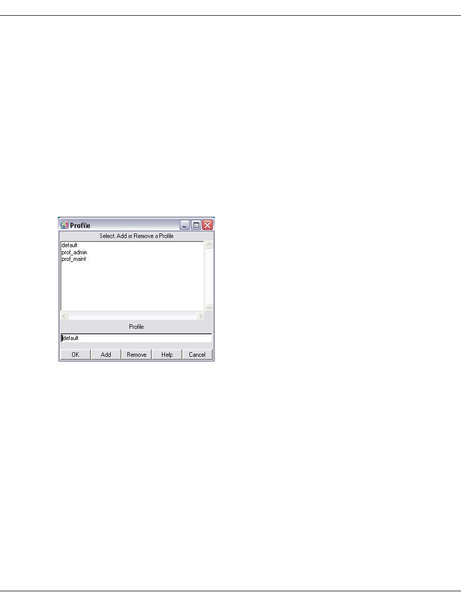
U41117-J-Z125-7-76 191
GXCC Function bar
6.2.8 Profile
The term “profile” encompasses the following:
– the settings chosen under “Options”
– the settings chosen under “Autoscan”
– the window size and position as set using the graphical user interface
The screen size can be predefined as a start parameter (-size). All other options are set to
their default values by GXCC on startup.
6.2.8.1 Add/Select Profile
The “Add/Select Profile” function is provided under “Profile”, and opens the following dialog
box:
A profile file can be selected at startup with the -profile <filename> option or by
choosing this menu command. If no profile file was selected explicitly, GXCC runs under the
control of the default file.
The name of the active profile file is shown at the bottom margin of the GXCC window.
The upper part of the window contains a list of available profile files. Click a file to select it.
The name of this file is then copied to the editing area. It is also possible to enter a new
name or change an existing name in the editing area.
If the special characters / \ [ ] " ' $ * : ? < > | are used, they are replaced by underscores “_”.
Each user can access all GXCC profile files.

192 U41117-J-Z125-7-76
Function bar GXCC
Buttons at the bottom of the screen section
OK
Applies the selected profile file. The display is immediately adapted to the new profile
settings. The newly selected file is shown at the bottom of the GXCC screen. All
changes to the profile data for the current session are recorded in this file.
Add
The file name specified in the editing field is added to the list and is also displayed at
the bottom of the GXCC screen. From now on, profile data is saved to this file.
Remove
The selected file is removed.
The profile file currently active cannot be deleted. The following message then
appears: “Actual profile cannot be deleted”.
Help
A text window is opened with help information.
Cancel
Closes the window without saving any changes made.
If you wish to save special settings, the following procedure is recommended:
– Start GXCC with the usual profile file.
– Define a name for the new file and activate it with “Add”.
– Define the special settings using the “Options” and “Autoscan” functions. These
settings are automatically stored in the new file.
– If you wish to return to the “normal” settings, you simply activate them by
selecting the “default” profile file and clicking “OK”.
If GXCC is started with the -profile <filename> option, the settings saved under this
name are effective from the very beginning. However, if the command line arguments
-aspect, -autoscan, -lang, -size were specified at startup, these are given priority over the
values already stored.
Each time the main menu functions
–“Unit-Select”,
–“File-Select”,
– “File-Exit” and
– “Profile-Select”
are called, a system-specific backup of the option settings currently used takes place
implicitly.
i
i

U41117-J-Z125-7-76 193
GXCC Function bar
6.2.9 Administration
The following functions are offered:
–Show WWN’s
–Show Optional Functions
–Show CS Configuration
–Diagnostic Snapshots
–Logical Volume Operations 1
–Physical Volume Operations 2
–Setup for accounting mails
1If the VLM is not running, this menu item is displayed against a gray background and cannot be selected.
2If the PLM is not running, this menu item is displayed against a gray background and cannot be selected.

194 U41117-J-Z125-7-76
Function bar GXCC
Depending on authorization and/or the version of the connected CentricStor system, indi-
vidual menu items are not available. The table below shows which menu items are available
in which mode:
Service
mode
User
mode
Observe
mode
Shutdown CS System x
Destroy RAID Filesystems x
Start/Stop CS Processes x
Commit SYS_MSG x
Show WWN's x x x
Show Optional Functions x x x
Show CS Configuration x x x
Diagnostic Snapshots x x
Create Snapshot(s) x x
Show survey / Delete snapshots x x
Modify threshold values x x
Install CS System x
Save CS Configuration x
Reset CS Configuration x
Reread Licence Keys x
Logical Volume Operations x x x
Show Logical Volumes x x x
Show Logical Volumes (physical view) x x x
Change Volume Group x x
Add Logical Volumes x x
Erase Logical Volumes x x
Physical Volume Operations x x x
Show Physical Volumes x x x
Link/Unlink Volume Groups x x
Add Physical Volumes x x
Erase Physical Volumes x x
Reorganize Physical Volumes x x
Setup for Accounting Mails x x x

U41117-J-Z125-7-76 195
GXCC Function bar
6.2.9.1 Show WWN’s
The following information is listed for all ISPs: the IP addresses, the World Wide Node
Names, the World Wide Port Names and the connection number of the FC connections to
the FC switches of all FC controllers.
Example
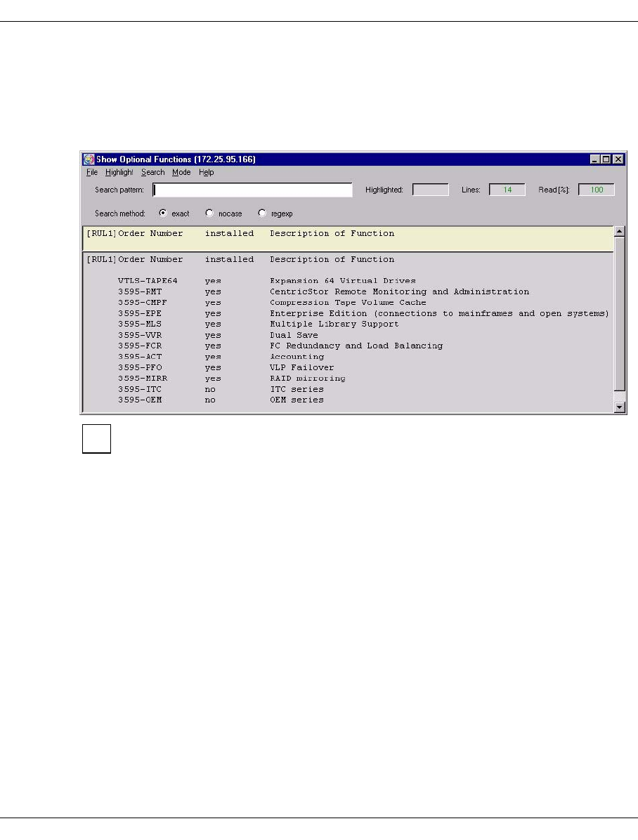
196 U41117-J-Z125-7-76
Function bar GXCC
6.2.9.2 Show Optional Functions
The optional functions (licenses which must be released using a key) are listed in a text
window with a note indicating whether or not they are licensed and installed in this system.
Example
Subsequent installation of individual keys is performed under SINIX-2000-Z using
SYSADM.
i
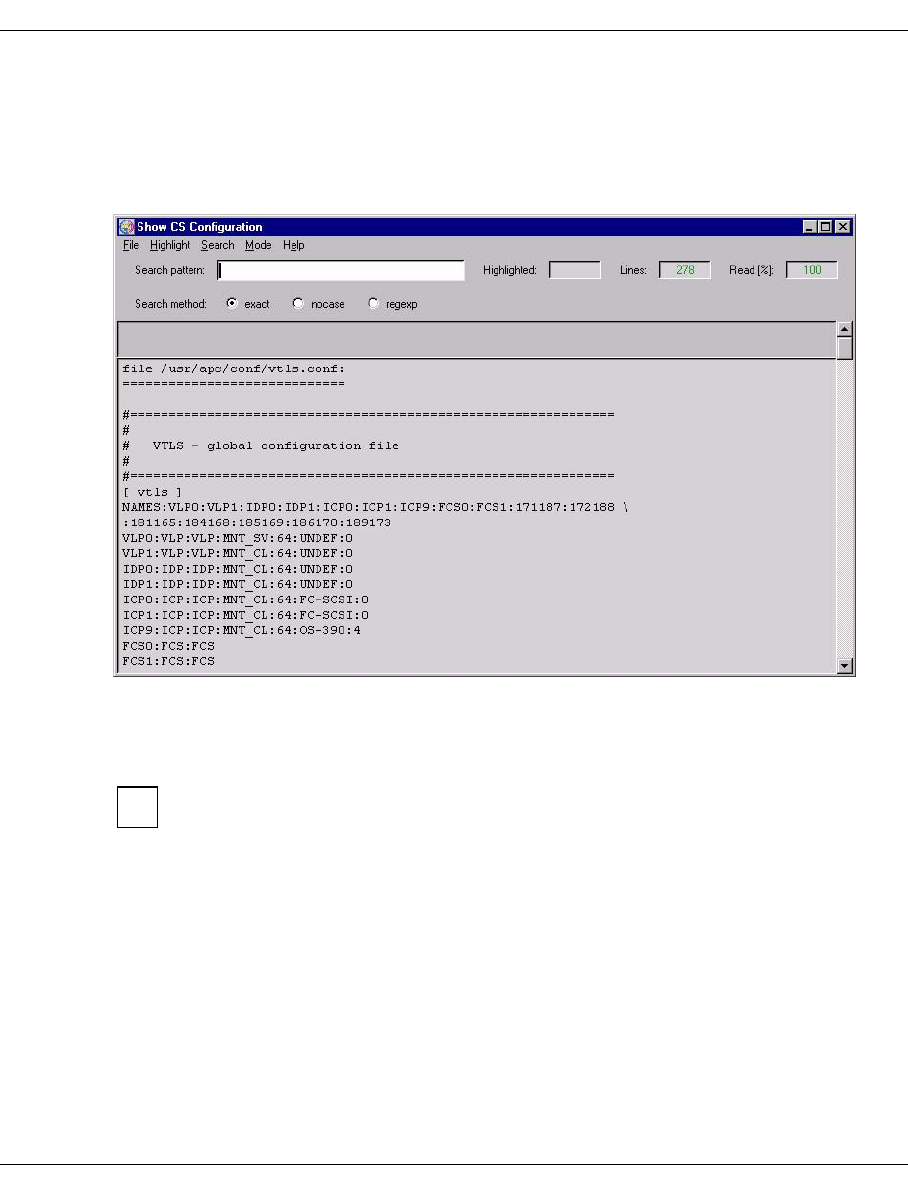
U41117-J-Z125-7-76 197
GXCC Function bar
6.2.9.3 Show CS Configuration
This function outputs the contents of the configuration files /usr/apc/conf/vtls.conf,
/usr/apc/conf/vtls_vg.conf and, if present, /usr/apc/conf/vtls_add.conf.
Example
6.2.9.4 Diagnostic Snapshots
This function is not offered in Observe mode.
This function performs a similar task to the vtrc script, but in contrast to vtrc permits
selection of the ISPs on which the function is to be performed.
A “Diagnostic Snapshot” is a collection of diagnostic data which the system stores in the
following situations:
– When the “Diagnostic Snapshots / Create Snapshot(s)” function is called
– Automatically when certain error situations occur
Each Diagnostic Snapshot contains data only of the ISP on which it was generated. The
system selects the files which are to be saved.
Submenus:
–Create snapshot(s)
–Show survey / Delete snapshots
–Modify threshold values
i
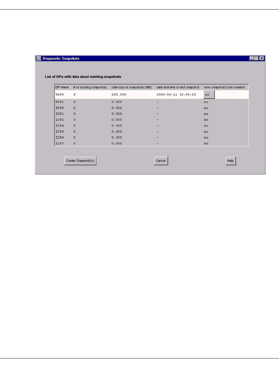
198 U41117-J-Z125-7-76
Function bar GXCC
Create snapshot(s)
When you select this function, the “Diagnostic Snapshots” window is output which contains
an overview of all ISPs in the system and the Diagnostic Snapshots there:
The columns contain the following information:
ISP Name Names of the ISPs
# of existing snapshots Number of snapshots which already exist on this ISP
total size of snapshots (MB) Total memory space in MB occupied by the snapshots
saved on the ISP
date and time of last snapshot Date and time of the last snapshot on the ISP
new snapshot to be created The user can select “yes” or “no” to decide whether or
not a Diagnostic Snapshot should be generated and
saved on this ISP.

U41117-J-Z125-7-76 199
GXCC Function bar
“Create Snapshot(s)” button:
If you have switched the “new snapshot to be created” option to “yes” (default: “no”) on the
ISPs concerned and then press the “Create Snapshot(s)” button, the snapshots are
generated and saved on the selected ISPs. The system acknowledges the user input with
an information window containing a list of the selected ISPs and the name of the directory
in which the snapshot files are saved. If you press “Create Snapshot(s)” without marking
one or more ISPs beforehand, the message “saving snapshot on 0 hosts: nothing to do” is
issued.
The snapshot files are compressed before they are saved.
Depending on the size and number of files to be save, it can take several seconds
to save them.
If you call the “Create snapshot(s)” function before a preceding call has been fully
processed, the text “snapshot in progress” appears in the second column and a
dash ´-´ in columns 3 and 4 of the lines for the ISPs concerned in the table above
to indicate that temporarily no meaningful values are available for these columns for
the ISPs involved.
If in the event of a “Create Snapshot(s)” call snapshots are saved on multiple ISPs,
the directory involved has the same name on all ISPs. This enables snapshots
which were generated with a “Create Snapshot(s)” call to be identifed easily.
i
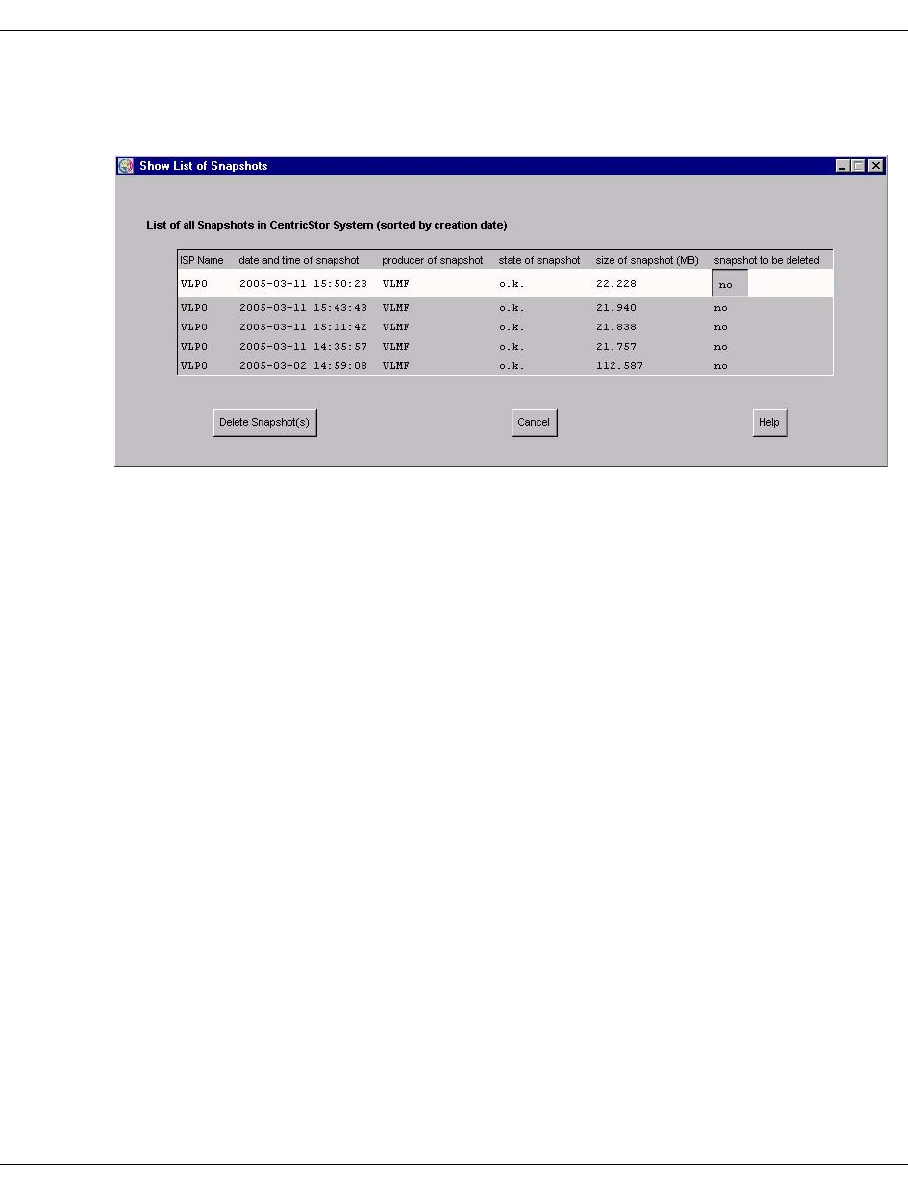
200 U41117-J-Z125-7-76
Function bar GXCC
Show survey / Delete snapshots
This function outputs the “Show List of Snapshots” window:
The window contains a list of all snapshots in the system. The most recent snapshot is
contained at the top of the list, the oldest at the bottom.
The columns contain the following information:
ISP Name Name of the ISP on which the snapshot is saved
date and time of snapshot Date and time of snapshot generation
producer of snapshot Producer of the snapshot
If snapshot generation was initiated via the “Create
snapshot(s)” window (see the preceding section), the
producer of the “user” text is entered. If the snapshot
was generated because an error has occurred, the
name of the component on which the error occurred is
shown here.
state of snapshot Status of the snapshot:
o.k. The snapshot could be output in full.
empty No snapshot could be saved as storing the
snapshot would cause the amount of free mem-
ory to drop below the configurable minimum
(see the next section for details).
size of snapshot (MB) Size of the snapshot in megabytes.
snapshot to be deleted Here you can specify whether (“yes”) or not (“no” = de-
fault) you wish to delete the snapshot.

U41117-J-Z125-7-76 201
GXCC Function bar
“Delete Snapshot(s)” button:
Clicking on this button causes all snapshots which are marked with “yes” to be deleted. The
system acknowledges the user input with an information window containing the information
”snapshot(s) will be deleted”. If you press “Delete Snapshot(s)” without marking one or
more ISPs beforehand, the message “no snapshots selected for deletion or deletion failed”
is issued.
Modify threshold values
The snapshots may require a large amount of memory, and as they can also be generated
automatically mechanisms have been implemented which are designed to prevent a
memory overflow being caused by the writing of snapshots. These mechanisms use
threshold values which you can adapt to your requiremetns using the “Modify threshold
values” function. Each of the defined values appies for the entire CentricStor system.
When the function is called, the “Limits for creation / deletion of snapshots” window is
opened:
Meaning of the individual fields:
Retention period (days)
Snapshots which are older than the number of days specified are deleted automatically.
Free space threshold (percentage)
This field shows the percentage of free memory which must not be fallen below when
snapshots are saved.
– If storing a snapshot would cause the percentage to drop below the value entered,
no snapshot is saved. However, a snapshot directory is created which is assigned
the status “empty” (see the preceding section “Show survey / Delete Snapshot(s)”).

202 U41117-J-Z125-7-76
Function bar GXCC
– A routine which runs periodically checks whether the free memory in the file
systems in which the snapshots are saved has fallen below the specified value. If
this is the case, the oldest snapshots are deleted: either until enough free memory
is available again in the file system or until only the number of snapshots defined in
the field “Minimum number of snapshots, which shall be kept” (see below) are
present.
A “Free space threshold” value of 0 is ignored.
Minimum number of snapshots, which shall be kept:
This field is used to define the minimum number of snapshots which are to be retained
when the periodic check of the memory space detects that the percentage has fallen
below the threshold value specified for free memory in the field “Free space threshold”
and snapshots are therefore deleted.
6.2.9.5 Logical Volume Operations
This submenu offers the following operations:
– Show Logical Volumes
– Show Logical Volumes (physical view)
–Change Volume Group
–Add Logical Volumes
– Erase Logical Volumes
These menu items are offered only if the VLM is running.
i
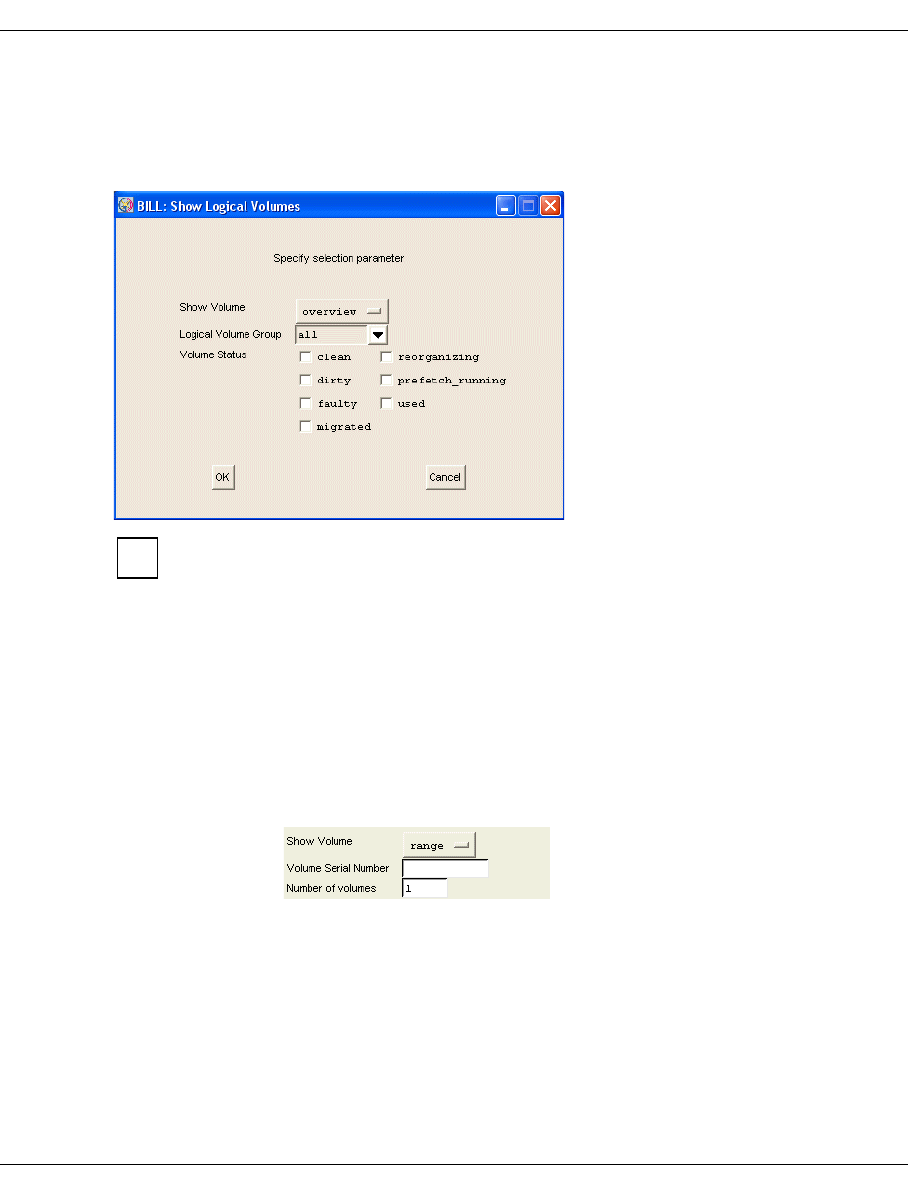
U41117-J-Z125-7-76 203
GXCC Function bar
6.2.9.6 Logical Volume Operations » Show Logical Volumes
As a CentricStor can contain up to 500 000 logical volumes selection tools are offered.
A menu containing a large number of filter functions for selecting logical volumes is opened:
If you use the settings in the screenshot above and click on OK, a list of all logical
volumes is output which match the selected filters. In large CentricStor configura-
tions (up to 500 000 volumes) this places a significant load on the system and
should only be done in exceptional cases.
Show Volume
The following display types can be selected here:
overview This setting outputs an overview of the LVs (see example on page 204).
range With this display type, the LV range to be displayed which is determined
by the first LV and the number of LVs must be selected (see example on
page 206). When this setting is selected, further input fields are display-
ed:
Volume Serial Number
The first volume to be displayed is specified with this entry.
Number of volumes
This value specifies how many volumes from the sorted volume list
are to be displayed.
i
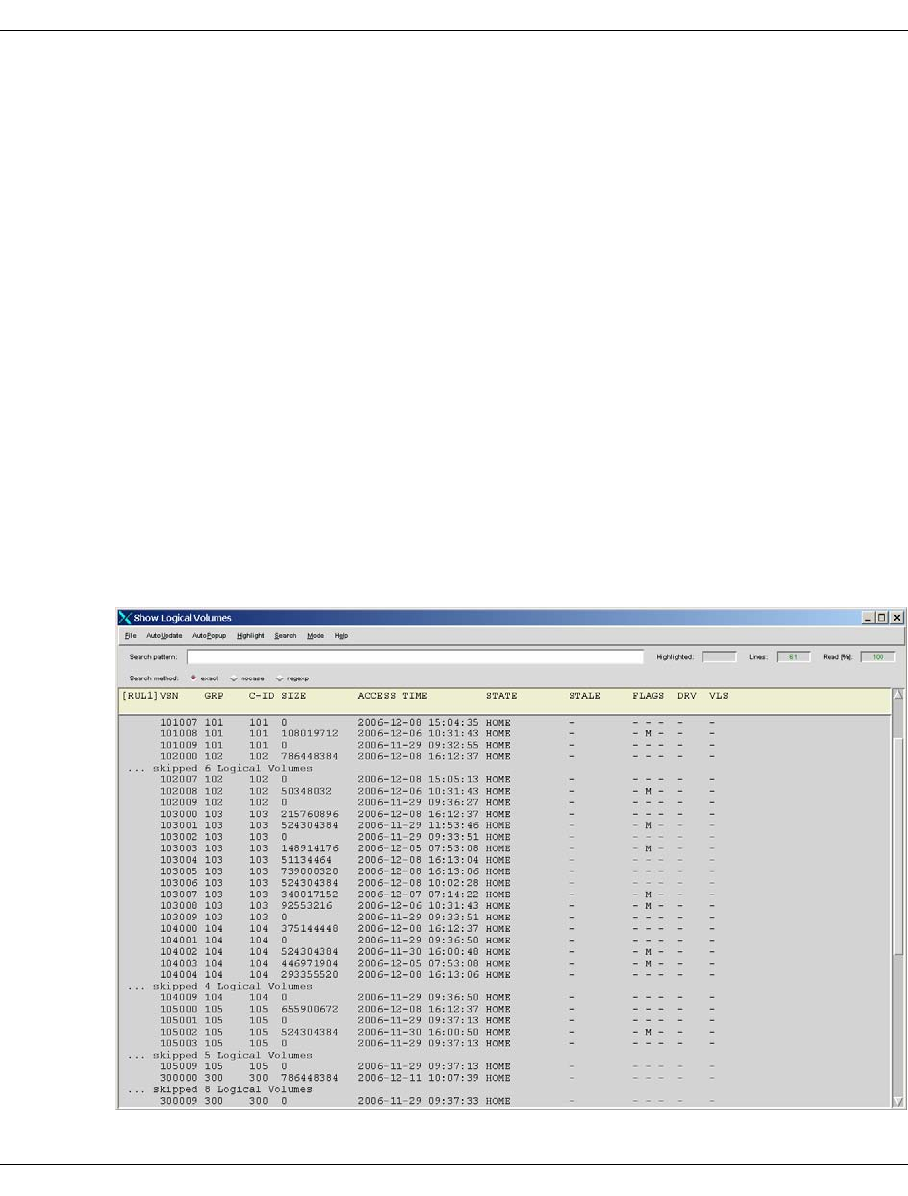
204 U41117-J-Z125-7-76
Function bar GXCC
Logical Volume Group
You can select either a logical volume group or “all”.
Volume Status
With the checkboxes you can specify that only volumes with the selected status are to
be displayed.
If no checkbox is selected all the selected volumes of the specified volume group(s) are
displayed.
A message box is used to indicate whether a volume set selected in this way is empty. After
you have acknowledged with “OK” you can start a new selection.
OK/Refresh After you have clicked on “OK”, a new window with the required data opens.
The OK button is changed to a Refresh button. If you now make a change
in the “Show logical Volumes” form and click on “Refresh”, the output screen
is updated with the new settings.
Cancel The Show Logical Volumes function is terminated.
Example 1
Output window when overview is set:

U41117-J-Z125-7-76 205
GXCC Function bar
The following data is output:
VSN Volume serial number, name of the logical volume.
GRP Logical volume group. A cartridge migrated from CentricStor Version 1
belongs to the BASE group.
C-ID Cache ID (this column appears only when “CacheID” has been enabled)
SIZE Amount of user data on the volume (decimal, in bytes).
ACCESS TIME Date and time of the last access, empty if uninitialized.
STATE State of the logical volume:
Faulty The logical volume is faulty. It can no longer be
used.
Home The logical volume is currently not being used.
Mounted The logical volume has been inserted in a logical
drive.
Mount Pending The logical volume has just been inserted in a virtual
tape drive. There is still no confirmation for this.
Mnt. Queued A mount request for the logical volume was queued
by the VLM due to a lack of resources.
Restoring The logical volume is just being read in by the phys-
ical volume.
STALE Volumes which are being restored as a result of a canceled mount re-
quest:
R “restoring”: Volume is being restored
FLAGS Flags:
D “dirty”: The volume is located in the cache but has not been
saved since the last change.
M “migrated”: The volume is no longer located in the cache and
must therefore be read in from the physical tape be-
fore it is next accessed.
Q “queued”: Job was queued
R “restore”: Volume is being restored
S “save”: Volume is just being saved
DRV Virtual drive if MOUNTED or IN_TRANSIT. If present, an alias name is
also output.
VLS Virtual library service to which the LV is assigned.
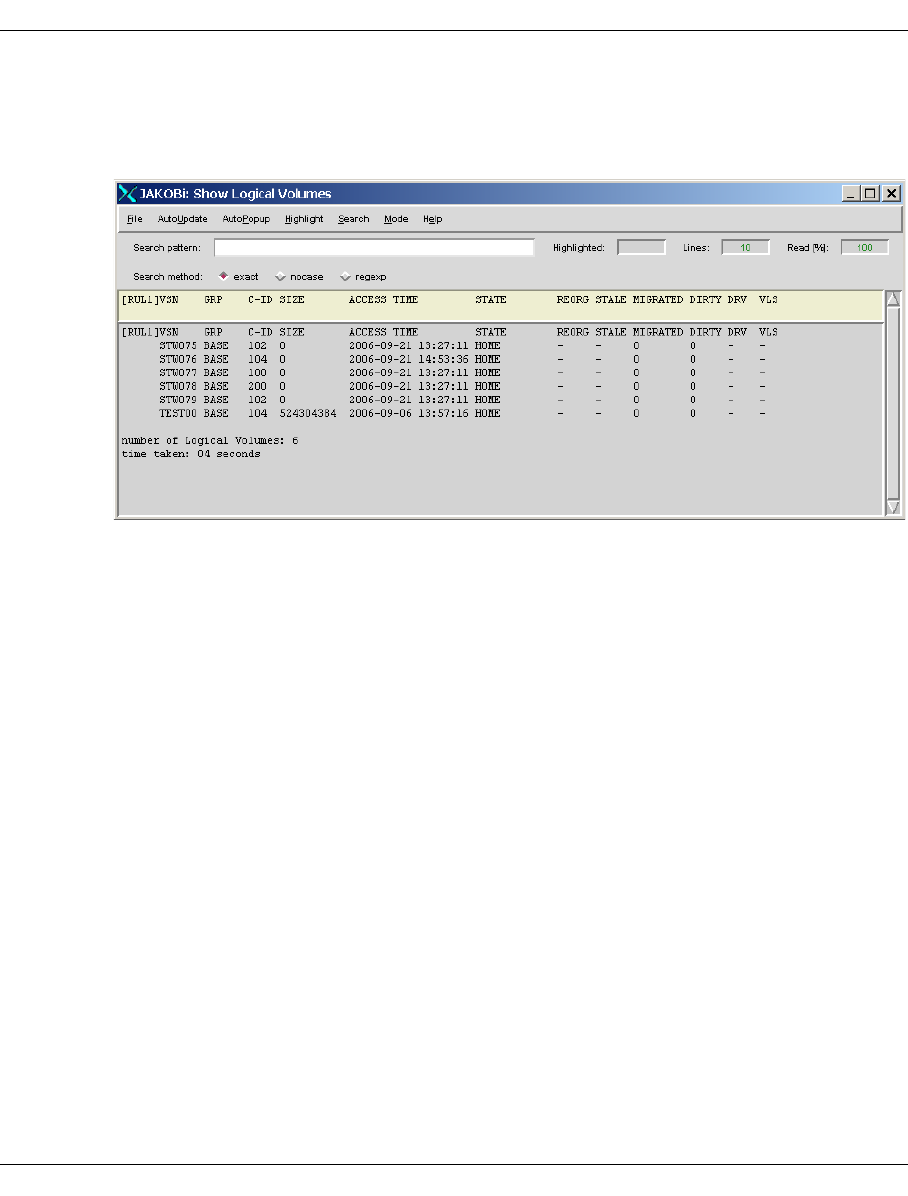
206 U41117-J-Z125-7-76
Function bar GXCC
Example 2
Output window when range is set (Volume serial number: STW075; Number of
volumes: 6):
The meaning of the columns is explained in example 1.
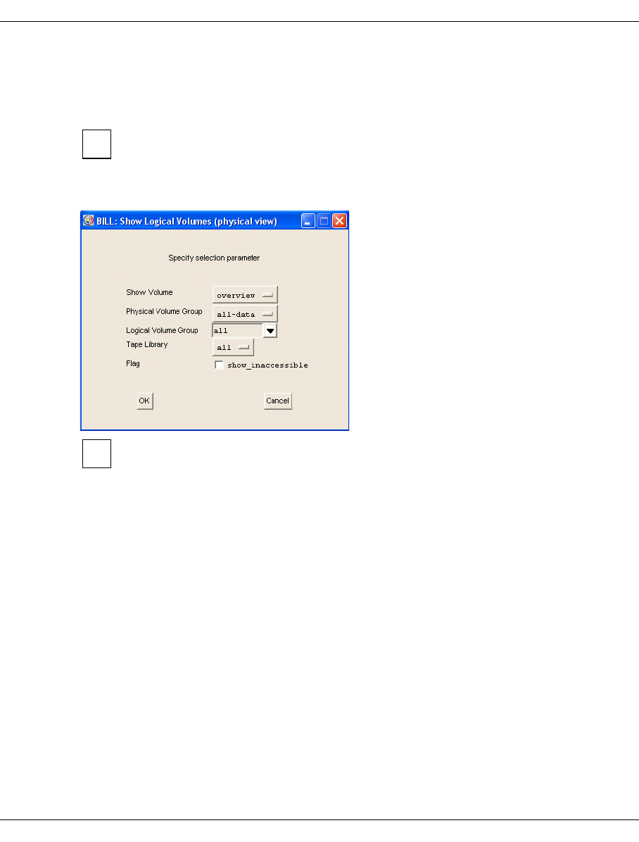
U41117-J-Z125-7-76 207
GXCC Function bar
6.2.9.7 Logical Volume Operations » Show Logical Volumes (physical view)
You use this call to display the logical volumes which are known to the PLM together with
their statuses.
You obtain statistcs on the logical volumes by calling the function of the same name
for “logical view”.
In contrast to the VLM call the PLM call does not permit the use of wildcards, allowing
instead filtering according to PVG, LVG and tape library.
This statistics function supports the refresh function. Information on this function
and the “OK” and “Cancel” buttons is provided on page 267.
If you only want logical volumes which cannot be accessed to be displayed, you must
activate the “show_inaccessible” button.
i
i

208 U41117-J-Z125-7-76
Function bar GXCC
The logical volumes are displayed in the following window:
PLM-specific data of the LVs is output:
LV Name of the LV
LVG Name of the LV group
size Size of the LV
save request at Save date and time: The save request for the LV was accepted by the
PLM at this time.
PV 1 PV on which the current map of the LV is stored. This PV is located in
the PVG which is specified in the PVG 1 column.
PVG 1 PVG to which the LV is connected.
TL 1 Tape library in which the PV specified in the PV 1 column is located.
bl_nr 1 Block in the PV which is specified in the PV 1 column.
PV 2 PV on which the current map of the LV is stored a second time (Dual
Save).
PVG 2 Second PVG to which the LV is connected (Dual Save).
TL 2 Tape library in which the PV specified in the PV 2 column is located.
bl_nr 2 Block in the PV which is specified in the PV 2 column.
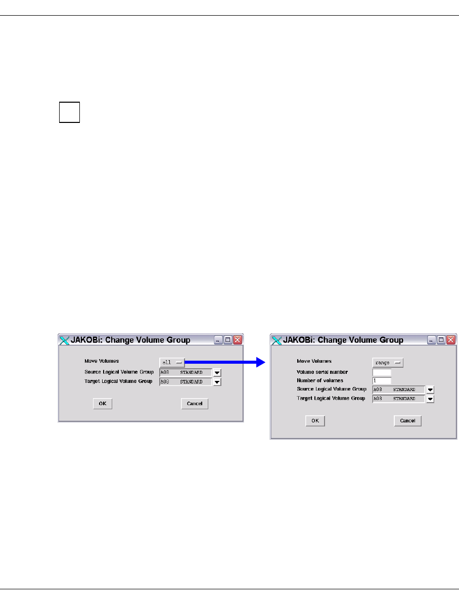
U41117-J-Z125-7-76 209
GXCC Function bar
6.2.9.8 Logical Volume Operations » Change Volume Group
This function is not available in Observe mode.
Changes the assignment of logical volumes to a logical volume group.
The data maintenance system of the VLM keeps a record for each logical volume,
showing where it is currently stored and on which physical volume group(s) it is to
be backed up, if necessary. The latter piece of information is contained implicitly in
the name of the logical volume group to which the volume belongs. “Change Volume
Group” only changes the entry of the logical volume group. The new assignment
does not come into effect until a “Save” operation is performed on the volume, i.e.
data on the volume is modified or the physical volume on which the newly assigned
logical volume is currently located is reorganized.
If the newly assigned LVG uses the Dual Save function, this is not activated until the
first “Save” operation.
Each LVG contains information on the maximum size (“Type”) of the logical volumes to be
added (see the section “Logical Volume Groups” on page 173). Thus only LVs which are
the same size as or smaller than the LV size for the target LVG defined with “Type” can be
assigned to a target LVG.
Change of group affiliation can result in LVs being moved from one cache file system to
another cache file system and possibly being set to “migrated”.
Initially, the left-hand window is offered:
If you wish to move a complete LVG, enter the names of the source and the target LVG.
If only certain volumes are to be moved, select the first option, “range”, from the drop-down
menu instead of “all”. This will open the window on the right, where you can enter the name
of the first logical volume, the number of logical volumes in the name range (see the
following section), plus both the old and the new volume group. The drop-down menus list
all the logical groups defined in the system.
The “Number of Volumes” field a name range determined by “Volume Serial Number” and
incrementing the numbers indicated to the right of the name. For example, Volume Serial
Number “VABC07” and Number of Volumes “25” stand for the volume names VABC07,
i
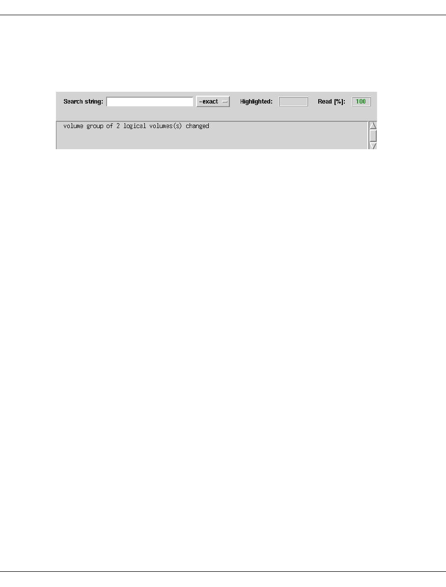
210 U41117-J-Z125-7-76
Function bar GXCC
VABC08,...,VABC031. If any volumes do not exist in the name range defined by the start
name and number specifications, then this is indicated in a ready message and the
operation is continued. Thus, in this example, the volumes VABC032 ff. would not be
moved.
This acknowledgement only indicates that the data maintenance system in VLM has been
modified accordingly. The storage location of each of the volumes is only changed the next
time that a save is actually performed. The time can be shortened by issuing reorganization
jobs for the physical volumes which have, until now, contained the images of the changed
logical volumes. This can be carried out by issuing an explicit call (see “Physical Volume
Operations » Reorganize Physical Volumes” on page 228) or by temporarily shortening the
refresh time (this can only be done in Service mode).
At the latest after the refresh time has elapsed all logical volumes will have been moved.
You can follow the progress of the action using “Statistics » Physical Components » Reorga-
nization Status” on page 291 or “Statistics » Logical Components »Logical Volumes
(physical view)” on page 271. Productive operation continues normally except for the
increased load caused by additional copy operations. Access to the moved volumes is also
possible at any time.
You can use the same procedure to move data inventories to other libraries and to other
media.
Buttons along the bottom border
OK
The process for changing the group affiliation of the volumes is started.
Cancel
The window is closed without any further activity.
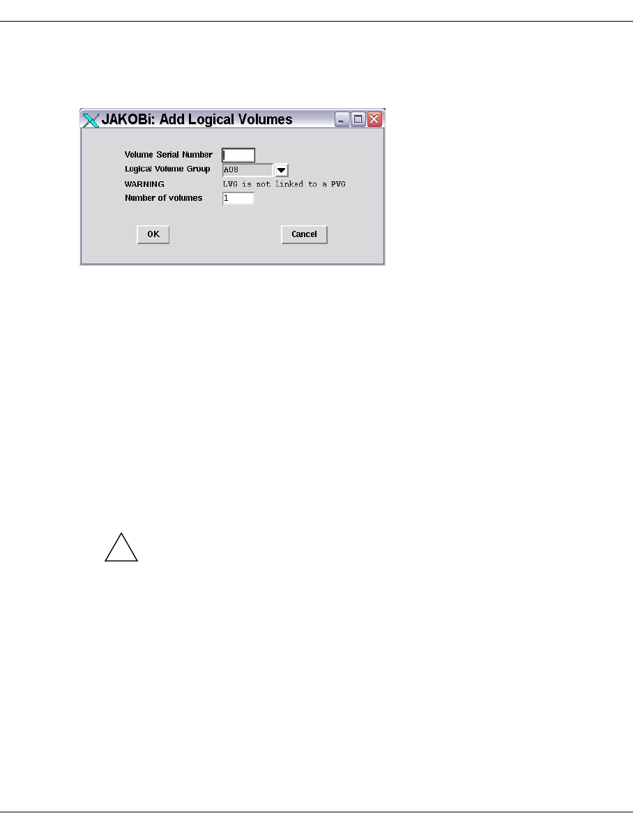
U41117-J-Z125-7-76 211
GXCC Function bar
6.2.9.9 Logical Volume Operations » Add Logical Volumes
This function is not available in Observe mode.
Input parameters
Enter the following information in the dialog window:
Volume Serial Number
Name of the logical volume (VSN or VOLSER). Any combination consisting of a
maximum of 6 characters. The following are permitted:
– Alphabetic characters in upper case.
– The special characters #, $, @, _, %, +, - (the plus and minus characters may not
be the first).
– Numbers: The end of the name must contain as many numbers as can be added in
view of the value specified in <Number of Volumes>. For more information refer to
the section “Logical Volume Operations » Change Volume Group” on page 209.
The volume serial number must be unique in the entire CentricStor network.
CAUTION!
Depending on the system fonts selected, the letter “O” may be extremely difficult
to distinguish from the digit “0” when LV names are displayed on the graphical
user interface. It is consequently advisable not to use the letter “O” in LV names.
This prevents confusion later.
Logical Volume Group
Here you specify the logical volume group to which the new volumes belong. The logical
volume groups set up in the VLM are listed. The BASE group is always set up.
Number of Volumes
Name range of the volumes that are to be added. The Volume Serial Number specified
in the first line must possess enough numbers at the end to ensure that, starting from
the entered name, the number selected in the “Number of Volumes” selection field can
be reached.
!
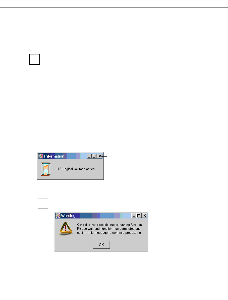
212 U41117-J-Z125-7-76
Function bar GXCC
Example
VXYZ21 results in an error message if Number of Volumes > 78.
If an existing logical volume is to be replaced by an empty volume of the same name, it must
first be deleted (see next section) and then added again.
The assignment of logical volume group to one or two physical volume group(s) is
described in the section “Physical Volume Operations » Link/Unlink Volume
Groups” on page 221.
Buttons along the bottom border
OK The add operation is started.
Cancel The window is closed without any further activity.
Actions linked with “OK”
If logical volumes already exist in the range defined by means of the start VSN and number
of volumes, these remain unchanged. However, they are taken into account in the number.
If a larger number of logical volumes are added, you will first see a message box in
which the number of volumes already added is displayed:
It is not possible to abort the function. You must therefore wait until all the
volumes have been added!
If you attempt to close the message box using the Cancel button, an additional
message window with a warning is displayed:
i
Cancel button
i
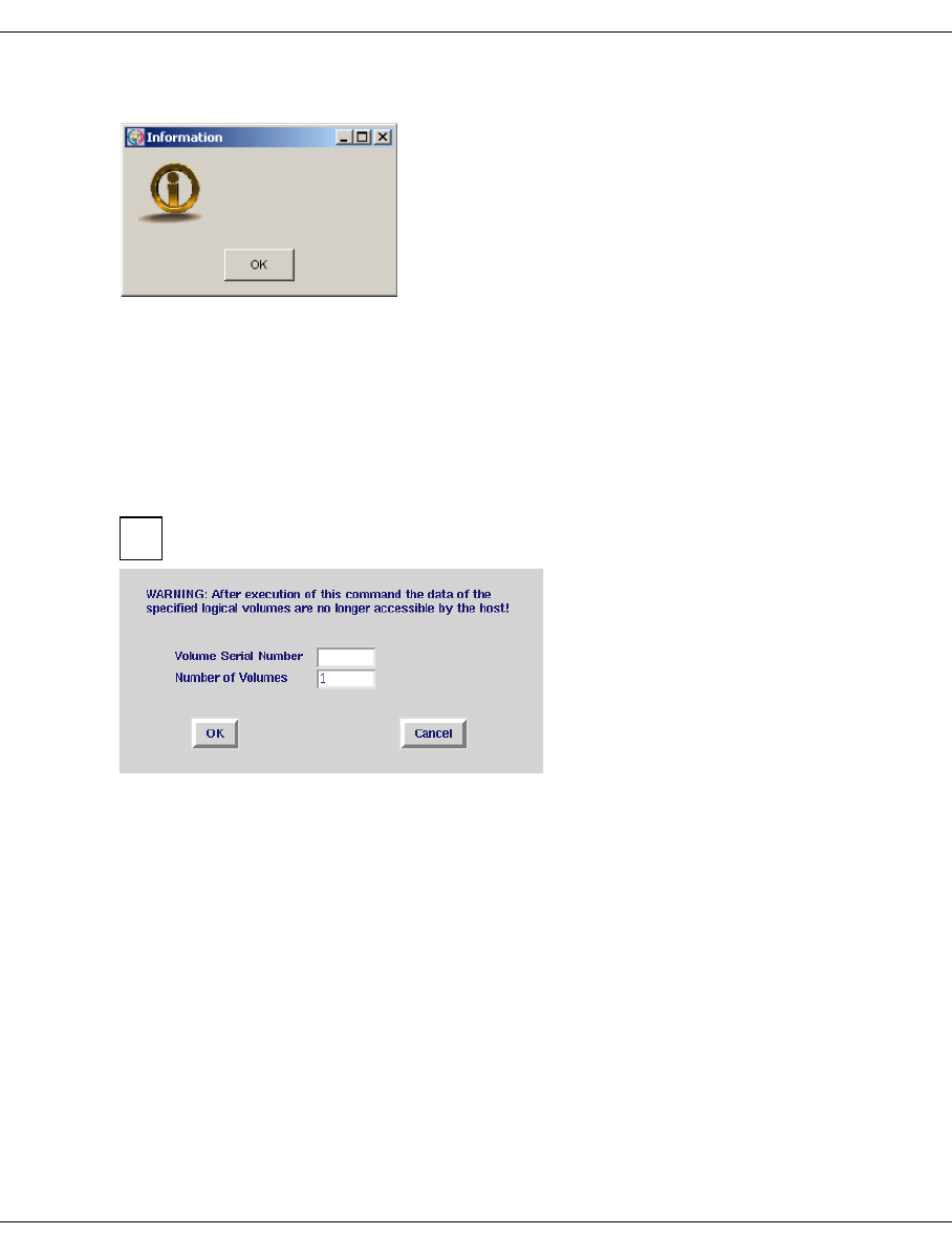
U41117-J-Z125-7-76 213
GXCC Function bar
After the function has been completed, a message box with an OK button appears:
When you click “OK”, the entry form and the message box disappear.
6.2.9.10 Logical Volume Operations » Erase Logical Volumes
This function is not available in Observe mode.
This function enables logical volumes to be removed from the library and their contents to
be deleted.
Make sure that the volumes to be erased have been released from the pool
managed by the host(s).
The conventions described in the section “Logical Volume Operations » Add Logical
Volumes” on page 211 apply for specifying the VSNs and number of volumes. Wildcards
are not permitted in the entry. The volume group does not need to be specified because all
volume names are unique throughout the entire CentricStor.
Buttons along the bottom border
OK
The delete operation is started.
Cancel
The window is closed without any further activity.
2230 logical volume(s) added
i
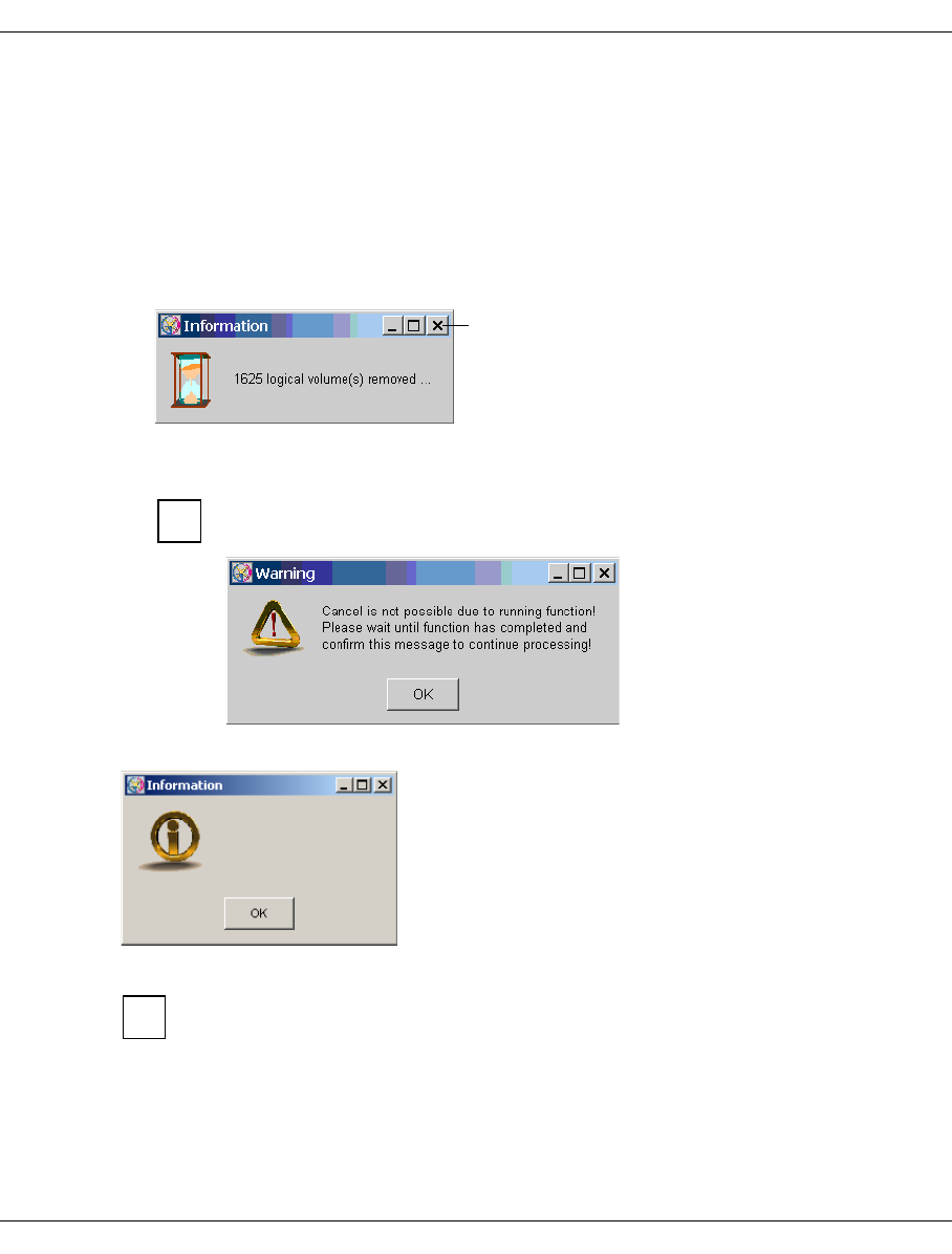
214 U41117-J-Z125-7-76
Function bar GXCC
Actions linked with “OK”
The designated logical volumes are removed from the VLM data maintenance system.
Images of the LVs on physical volumes are not deleted but merely marked as invalid.
If some volumes are not contained in the specified name range, the delete operation is
continued. The number of volumes actually deleted is specified in the completion message.
If a large number of logical volumes is to be deleted, a message box appears in which
the number of volumes already deleted is displayed:
It is not possible to abort the function. You must therefore wait until all the
volumes have been added!
If you attempt to close the message box using the Cancel button, an additional
message window with a warning is displayed:
After the function has been completed, a message box with an OK button appears:
When you click “OK”, the message box and the entry form disappear.
It takes a long time to delete a large quantity of LVs.
Rule of thumb: One hour per 100000 LVs
Cancel button
i
2147 logical volume(s) erased
i
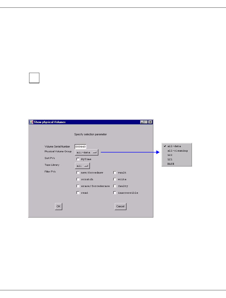
U41117-J-Z125-7-76 215
GXCC Function bar
6.2.9.11 Physical Volume Operations
This submenu offers the following functions:
–Show Physical Volumes
–Link/Unlink Volume Groups
–Add Physical Volumes
–Erase Physical Volumes
–Reorganize Physical Volumes
These menu items are offered only if the PLM is running.
6.2.9.12 Physical Volume Operations » Show Physical Volumes
An identical function is offered in the Global Status under “Statistics” (see page 257).
An intermediate menu makes it possible to identify the physical volume or volumes:
You must specify the volume ID either in full or not at all. The drop-down menus for the
specification of the volume group or library also contain the lines “all-data” and “all-
cleaning”. If you specify “all”, this means that the group or library assignment is of no impor-
tance for the selection of the volumes that are to be displayed.
i

216 U41117-J-Z125-7-76
Function bar GXCC
Therefore, you can choose to display:
– A specific physical volume (specify only the volume ID)
– All the volumes in a physical group (specify only the physical volume group)
– All the volumes in a library (specify only the library)
– All physical volumes (specify “all-data”)
– All cleaning volumes (specify “all-cleaning”)
You can also set certain criteria for the display:
new/forcednew Volumes that have not yet been initialized. “forcednew” means that they
have been added with the option “Omit Header Check”.
scratch Empty volumes
erase/forcederase The volume has been deleted. “forcederase” means that a volume that
contains user data has been removed using the “ReorganizeFirst”
option, but that the reorganization process has not yet been completed.
read Read volume, completely written volume
vault Exported volumes
write Write volume, can still be used to migrate logical volumes.
faulty Faulty volume, if this is a cleaning cartridge this signifies that the
number of possible cleaning cycles has been exhausted.
inaccessible Volumes which cannot be accessed
If you select the “ByTime” button, the list of physical volumes will be sorted according to the
age of their oldest write entry. The PLM keeps track of these times in order to be able to
trigger refresh copy processes, if necessary.
The specification of a volume number is optional. However, if you do decide to enter a speci-
fication then this must be precise (wildcards such as ?, *, etc. are not permitted).
After you have clicked on “OK”, a new window with the required data opens. The OK
button is changed to a Refresh button. If you now make a change in the “Show
physical Volumes” form and click on “Refresh”, the output screen is updated with
the new settings.
When you click on “Cancel”, both windows are closed.
i
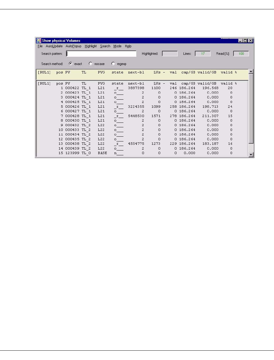
U41117-J-Z125-7-76 217
GXCC Function bar
If the query relates to multiple volumes, the following overview is displayed:
Meaning of the information
pos Line number
PV Number of the physical volume
When the number is prefixed with a plus or minus sign:
+ = LVs written but not yet securely on the PV
- = LVs invalidated but new version not yet securely on the PV
TL Tape Library: Name of the archive
PVG Name of the physical volume group
state Status; possible values:
e___ Volume ready for invalidation
E___ The PV is reorganized and then invalidated
f___ An error occurred while working with this tape: it is not reused and
automatically reorganized
f_d_ A tape fault has occurred (PV is faulty) but an attempt is still made to write
the directory onto the tape
i___ Inaccessible: the physical volume cannot currently be accessed
n___ New volume: the PV still has to be initialized before it can be used
N___ New volume; the PV was added using the “OmitHeaderCheck” option and
must be initialized before it can be used
o___ Initialized and empty
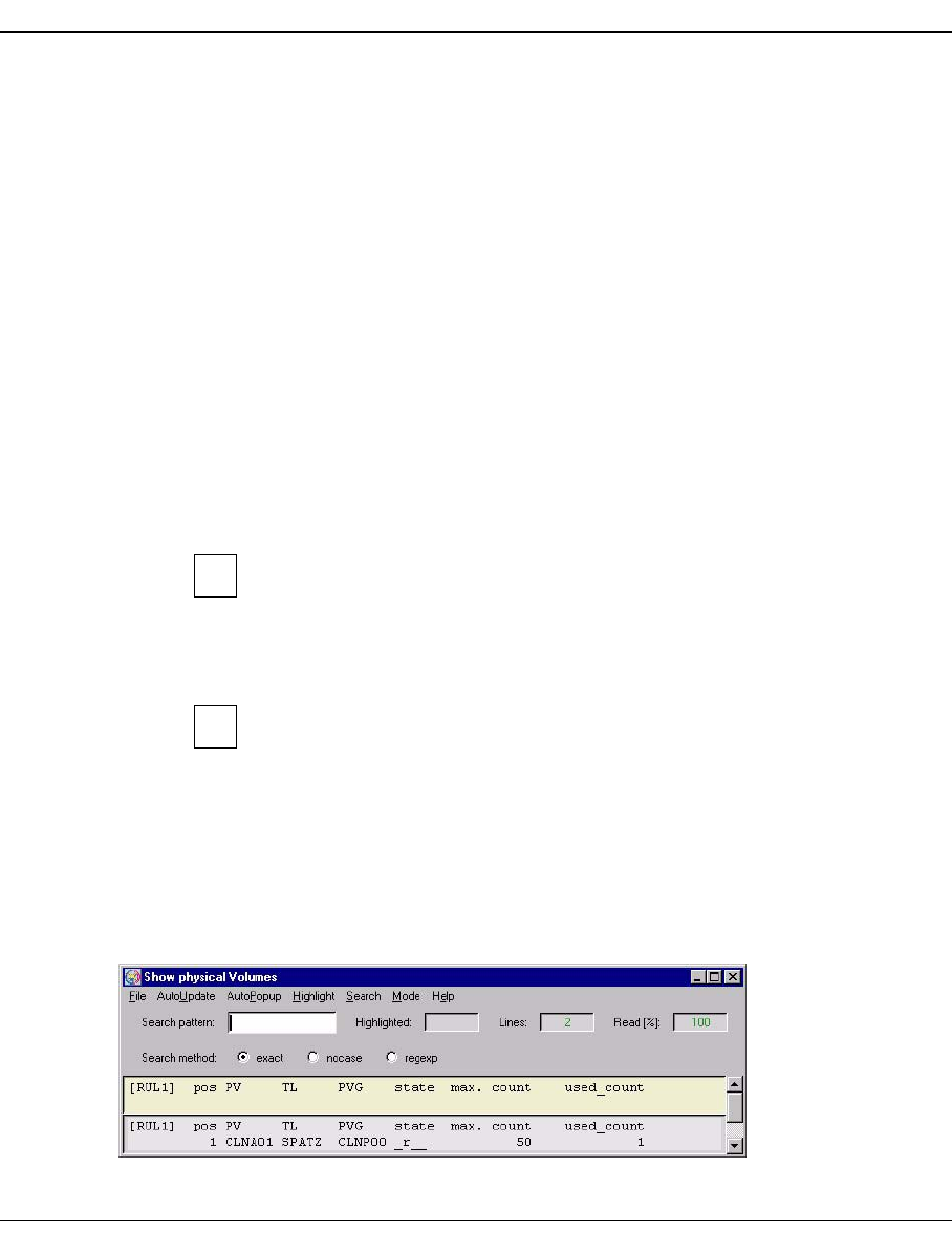
218 U41117-J-Z125-7-76
Function bar GXCC
_r__ Read volume on which no space is available for further data
_rd_ The cartridge is full but an attempt is still made to write the directory onto
the tape
s___ The PV must be scanned (used for transfer).
_v__ Ejected in the case of vault groups
_w__ Write volume that can still be used for save operations
_wd_ The cartridge is not yet full; currently there is no directory on the tape
____ Unknown: status in the case of Transfer-In for a PV that must still be
scanned
next-bl Block number of the free range. This indicates the physical utilization level.
LVs Number of saved logical volumes
val Number of valid saved logical volumes; copies of volumes not included here are no
longer relevant
cap/GB
Gross capacity without data compression. This is not specified for volumes prior to
initialization (State = new).
This value is only indicated if supplied by the drive. Otherwise, the value 0
is displayed.
valid/GB
Used capacity; volume of data actually stored. Due to data compression, this value
may exceed the total capacity (previous column).
This only takes into consideration the data compression of the drive. The
data compression of the device emulations can be displayed in “Global
Status” along with the cache data. In many cases, the compression
indicated by PLM is lower if the cache data has already been compressed.
valid %
Utilization; specifies the percentage of the stored data that is currently still relevant.
This percentage determines whether the volume is to be included in the next
reorganization.
If you have selected “all-cleaning”, you will see, for example, the following overview:
i
i
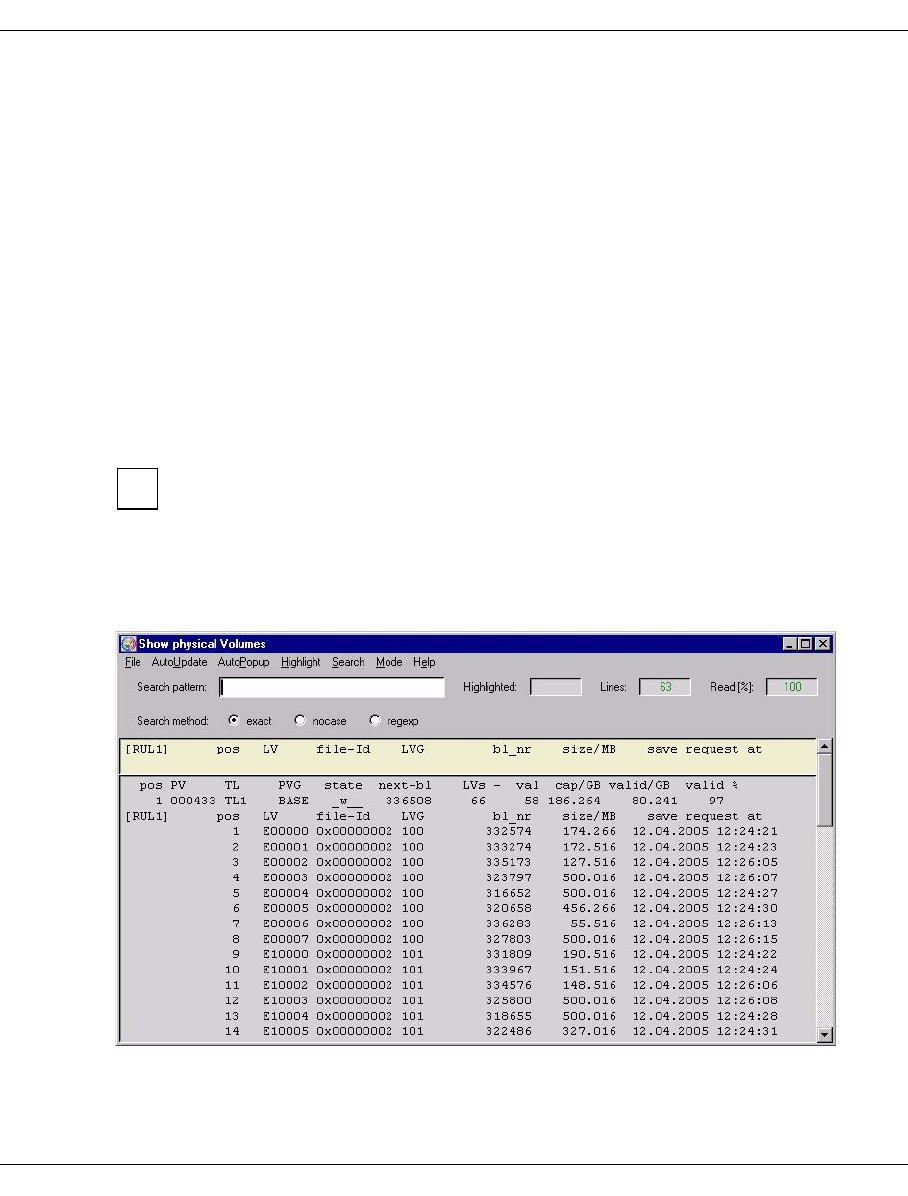
U41117-J-Z125-7-76 219
GXCC Function bar
Meaning of the information:
pos Line number
PV Number of the physical volume
TL Name of the archive
PVG Name of the physical volume group, usually starts at “CLNP”.
state status
The following values are possible for cleaning cartridges:
o___ (“scratch”) when the volume has only just been added,
_r__ Read volume, has no more space for additional data. This is the normal
state of a cleaning cartridge.
f___ (“faulty”) when all the cleaning cycles have been used up.
max. count
Initial number of cleaning cycles
used_count
Number of cleaning cycles used
The PLM uses the cleaning cartridges in such a way that one cartridge is used up
fully before the next one is started. However, if a number of cleaning requests are
to be carried out at the same time, the cartridges that are available will be used
simultaneously.
When a specific physical volume is queried (volume number specified in the query box)
a detailed overview is output:
The data for the selected PV is output in the title bar.
i
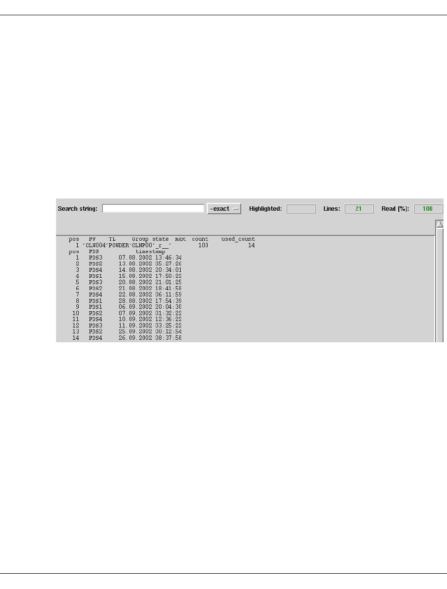
220 U41117-J-Z125-7-76
Function bar GXCC
This is followed by a list of the (valid) logical volumes stored on the PV:
pos Line number
LV Name of the logical volume
file-Id Hexadecimal: internal version number in the TVC
LVG Name of the group to which the logical volume belongs
bl_nr Number of the first block of the logical volume on the PV
size/MB Size
save request at Time at which the PLM received the save job. This timestamp allows the
Disaster Recovery mechanism to identify which of the various different
copies of a logical volume is the most recent.
The information for a cleaning cartridge contains a list showing all the cleaning runs carried
out using this cartridge along with the time and PDS of each run:
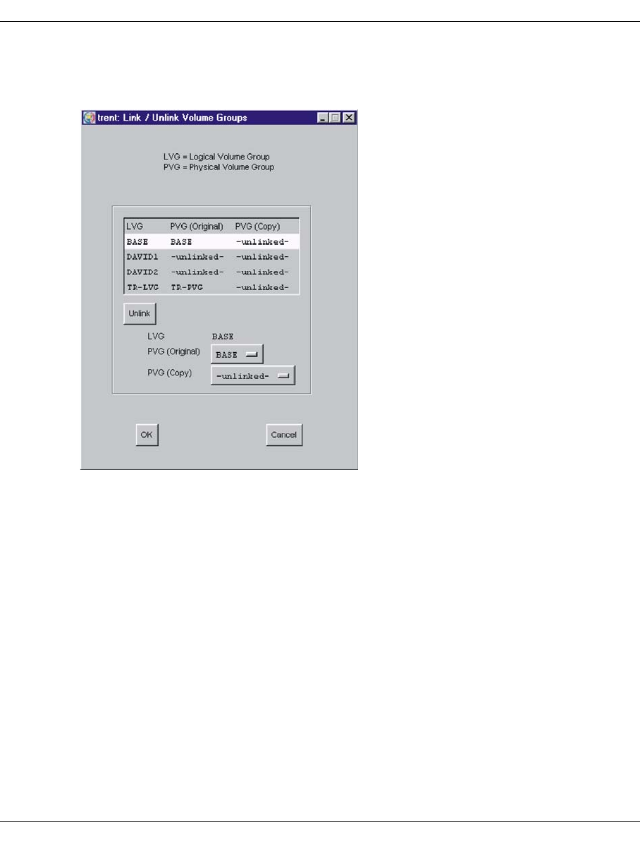
U41117-J-Z125-7-76 221
GXCC Function bar
6.2.9.13 Physical Volume Operations » Link/Unlink Volume Groups
This function is not available in Observe mode.
The assignments of LVG to one or two (with Dual Save) PVGs are established, resolved, or
changed. The list in the upper screen section contains the logical volume groups.
LVG Name of the LVG, as defined in the configuration.
PVG (Original) Name of the originally assigned PVG, or “-unlinked-”. “-unlinked-”
means that no PVG has been assigned yet.
PVG (Copy) Name of the PVG for the backup copy, or “-unlinked-”. “-unlinked-”
means that no PVG has been assigned yet.
Click a line to select the desired PVG. The line is highlighted and the entries for the PVG
are copied to the “LVG” label and to the buttons.
Buttons
Unlink All of the assignments of the LVG are deleted. Following Unlink, the list
item of the LVG displays “-undefined-” for both PVGs.
PVG (Original) Primary assignment of a PVG.
PVG (Copy) Secondary assignment of a PVG.
This button is only activated when the dual copy software licence is
available.
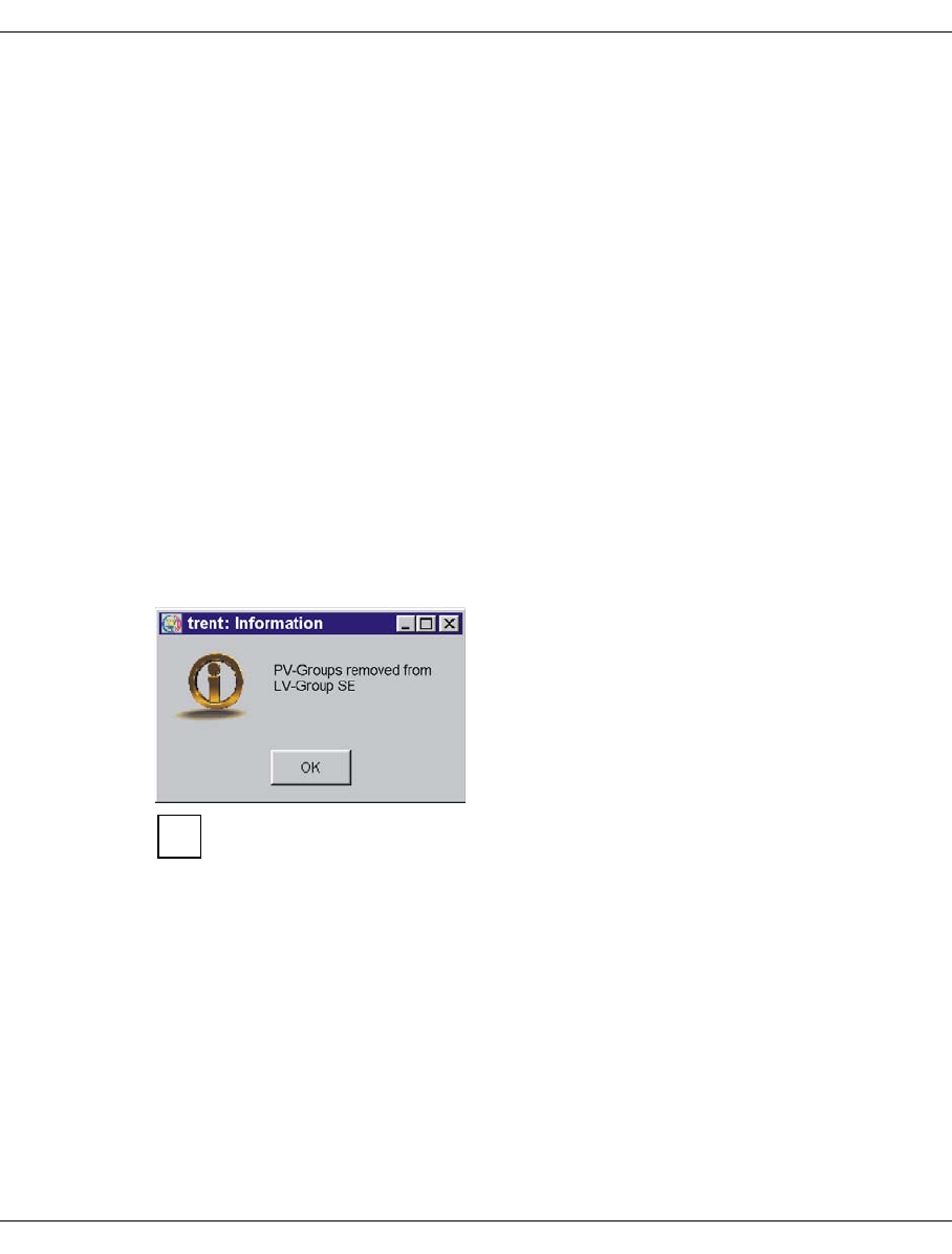
222 U41117-J-Z125-7-76
Function bar GXCC
Buttons along the bottom border
OK
Link/Unlink is started.
Cancel
The window is closed without any further activity.
Actions linked with “OK”
1. Before the PVG is linked, the logical volume size is checked: If the LV size is > 2 GB,
the capacity of the PVs already assigned must be twice as large as the LV size,
otherwise the assignment is rejected with the following message:
Attempting to link PVGs (<PVG1>,>PVG2>) to LVG (<LVG>): The capacity of
the PVs of PVG <PVG1> is too small
2. The actions entered at the graphical interface are resolved in one or more commands
to the PLM. A change in assignment leads to an “Unlink” followed by a “Link” with the
new PVG name.
The responses of the PLM, including any error messages, are displayed in an info box.
This box lists the results of all PLM commands that were initiated with “OK”.
Please note:
– After pressing “OK”, wait for the info box with the acknowledgments. The
action is not actually concluded until this box appears.
– Before logical volumes are linked again following an LVG Unlink, the LVG
must be linked to a (different) PVG.
If the LVG-PVG assignment is to be changed in exceptional cases, you can proceed as
follows:
1. Use the VLM command “Change Volume Group” to change the LVG association of
all logical volumes of the LVG.
2. Assign the now emptied LVG to a different PVG.
3. Reestablish the original assignment by issuing further “Change Volume Group”
commands.
i

U41117-J-Z125-7-76 223
GXCC Function bar
Note for linking
If practically the same number of drives is configured for the robots in dual save, restores
can be optimized through the following distribution and crossed-over PVG sequence:
Example of linking
LVG1 PVG1 PVG2
LVG2 PVG2 PVG1
Distribution to two LVGs with a crossed-over PVG sequence ensures that all drives are
available for restores. The restore times can thus be considerably reduced (but not in all
cases; e.g. multiple restores of one PV).
6.2.9.14 Physical Volume Operations » Add Physical Volumes
This function is not available in Observe mode.
The specified physical volumes are added to the selected physical volume group. If more
than one volume is to be added, then the volume serial number of the next volume is
generated by incrementing the final digit of the entered VSN. This means that a sufficient
number of digits must be defined as digits at the end of the VSN. If insufficient digits are
present then the entire job is rejected.
The volumes must previously have been introduced into the tape archive. For infor-
mation on how to do this, refer to the instructions for the robot archive in question.
i
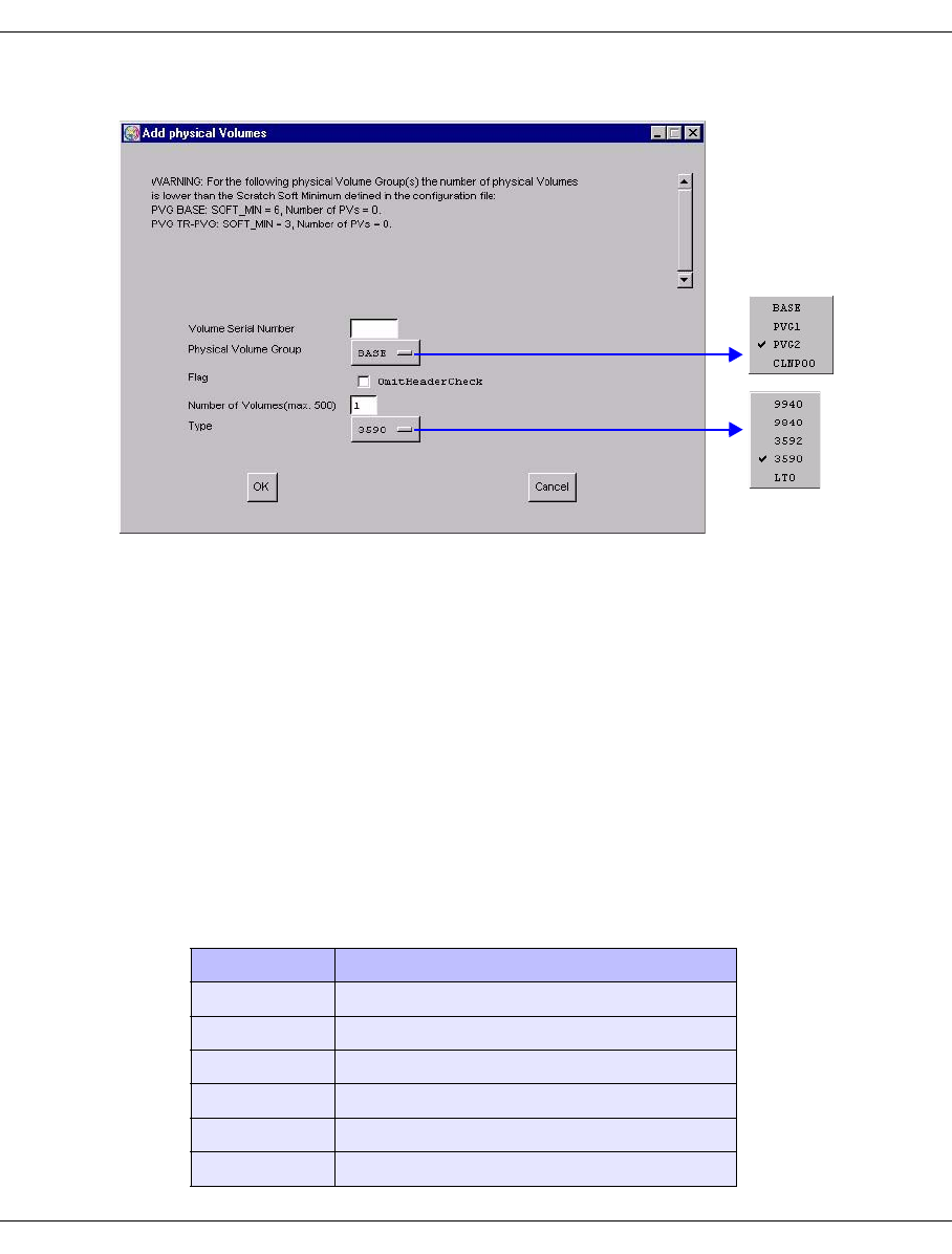
224 U41117-J-Z125-7-76
Function bar GXCC
Window for entering physical volumes:
The form shows whether levels have dropped below the defined minimum numbers for a
Volume Group. In the same way, a warning is output for cleaning cartridges when the
number of cleaning cycles left drops below the defined minimum.
In order to add one or more new volumes, you must make the following specifications.
Volume Serial Number
(First) number of the volume(s)
Physical Volume Group
PVG to which the volume is to be assigned. To add cleaning cartridges you must
select the appropriate cleaning PVG.
Type
Volume type, as selected from the range offered by the drop-down menu.
Note that in the case of a linked LVG with an LV size > 2 GB the PV must be corre-
spondingly large (see below: “Actions linked with “OK”):
Drive Possible volume capacities in GB
9940 60, 200
9840 20, 40
T10K 120, 500
3592 60, 300, 500
3590 10, 20, 30, 40, 60
LTO 100, 200, 400 (in preparation)

U41117-J-Z125-7-76 225
GXCC Function bar
Number of Cleaning Cycles
Only applies to cleaning cartridges: the number of cleaning cycles still possible for
the inserted cartridge (decimal value).
Flag “Omit Header Check”
Only applies to data cartridges: The header of an added volume is always
overwritten with a CentricStor header without exception. This means that you can
also add volumes that have been taken out of CentricStor but that have not been
deleted using “Erase” (see the section “Physical Volume Operations » Erase
Physical Volumes” on page 226).
CAUTION!
This flag should only be used under exceptional circumstances. If you use
this flag and accidently specify the number of an active volume, the user
data of this volume will be overwritten without exception.
Buttons along the bottom border
OK
The cartridges are checked (see below: “Actions linked with “OK”) and, in the event of
a positive result, included in the PLM data maintenance system.
Cancel
The window is closed without any further activity.
Actions linked with “OK”
1. If the PVG is already assigned to an LVG and the LV size of this LVG is > 2 GB, the
capacity of the new PV must be >= the defined LVG capacity. Here it must be borne in
mind that a PVG can be assigned to multiple LVGs and that the largest LV size is used
for the capacity check. If the PV capacity is lower, the assignment is rejected with the
following message:
PLM(#55): WARNING: Capacity of PV 0F3171 is too small for PVG RALF;
PV-file will be removed!
2. A check is made to see whether the cartridge type (cleaning or data) is correct. The
number of cleaning cycles cannot be verified for all cartridge types.
As cleaning cartridges are consumables a suitable number of cleaning cycles
should always be available in the libraries. When the soft limit is reached, 10
cleaning cycles are available per drive.
!
i
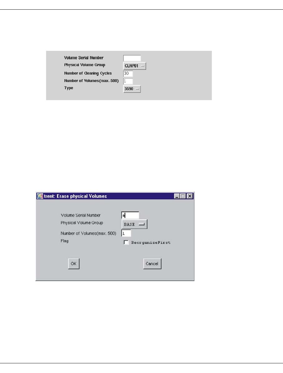
226 U41117-J-Z125-7-76
Function bar GXCC
The PLM normally uses the cartridge with the fewest available cycles for cleaning to
avoid shelves being occupied unnecessarily by partially used cartridges. An exception
to this strategy is made only if multiple cleaning requests are handled simultaneously.
It can take some time to complete this job. Processing takes place asynchronously. After a
while it is thus, for example, advisable to check in the “Global Status” to see whether the
volumes have actually been included. Any errors are displayed using system messages
(see the section “Show System Messages” on page 158).
6.2.9.15 Physical Volume Operations » Erase Physical Volumes
This function is not available in Observe mode.
The following window allows you to remove physical volumes from the PLM data mainte-
nance system so that they are not be to used in the future.
The volume is identified by the name and physical volume group. Number specification is
based on the usual CentricStor convention that you do not assign numbers but, instead,
volume names which are formed by incrementing the right-hand digits of the specified start
name. If volumes within this name space cannot be deleted, these volumes nevertheless
“count”.
The “ReorganizeFirst” option controls the process if a volume that is to be deleted still
contains valid data.

U41117-J-Z125-7-76 227
GXCC Function bar
Option is not set:
If a volume contains valid data, an error message is output and the volume is not
deleted.
Option is set:
A “Move” is carried out automatically for volumes containing valid data. The volume is
then removed from the data maintenance system.
Buttons along the bottom border
OK
The specified volumes are removed from the PLM data maintenance system.
Cancel
The window is closed without any further activity.
Actions linked with “OK”
In the event on an Erase, the first record of the volume (tape header) is overwritten in such
a way that the entire contents of the volume can no longer be accessed using CentricStor
resources.
When removing the cleaning cartridges, the number of cleaning cycles that remain are
modified if the cartridge has not been used completely.
You must make sure that the deletion of the volumes does not result in the number
of empty volumes falling below the minimum level. If this occurs a warning will be
output.
Before removing volumes from the archive physically, you must remove them
logically from the PLM data maintenance system. This process can take some time
since each volume must be loaded into a drive so that its tape header can be
overwritten. If the “ReorganizeFirst” flag is set, you must also add the time required
for reorganization. With “Show Physical Volumes” you can determine whether the
action has been completed.
i
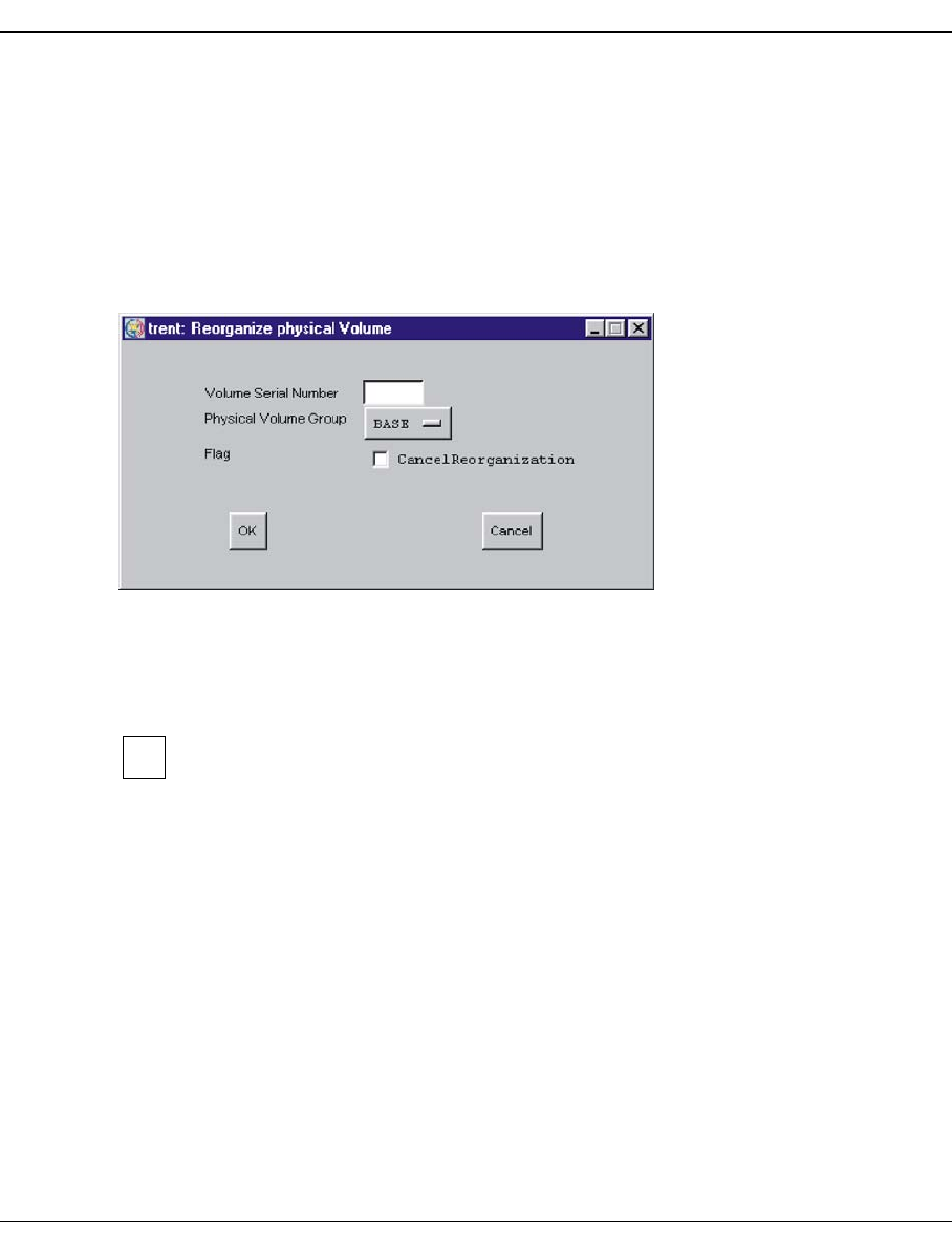
228 U41117-J-Z125-7-76
Function bar GXCC
6.2.9.16 Physical Volume Operations » Reorganize Physical Volumes
This function is not available in Observe mode.
It allows you to manually copy the contents of a physical volume to one or more volumes in
the same physical group or to interrupt such a reorganization.
After reorganization, the physical volume is empty. It is then usually available for subse-
quent writing by the PLM. However, it also possible to delete this empty physical volume
(see the section “Logical Volume Operations » Erase Logical Volumes” on page 213).
You enter the group and name of the physical volume in the window. The complete name
must be entered without wildcards.
If you have to stop an initiated reorganization run, you must also click the “Cancel Reorga-
nization” button.
Unlike automatic reorganization, the copy operation is continued even if a non-
skippable read error has occurred. Consequently this function can be used to
retrieve the greatest possible amount of data from logical volumes on a damaged
tape.
Buttons along the bottom border
OK
After the name has been checked the reorganization run is included in the relevant
queues or the reorganization of the specified volume is terminated.
Cancel
The window is closed without any further activity.
i
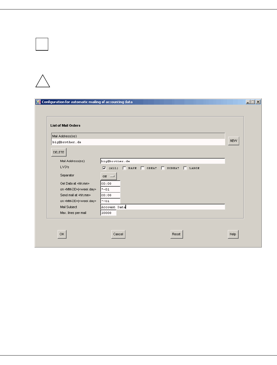
U41117-J-Z125-7-76 229
GXCC Function bar
6.2.9.17 Setup for accounting mails
This function is displayed only if an accounting license is installed.
This menu permits orders to be configured which automatically send accounting data by
e-mail.
CAUTION!
sendmail must have been configured for this function to be effective) ( see section
“Sendmail configuration” on page 558).
Displaying input options in the list area
List of Mail Orders: All orders that have already been defined are displayed.
“NEW” button: A new order can be defined.
“DELETE” button: This function enables an order defined in the “List of Mail Or-
ders” list field to be deleted.
i
!

230 U41117-J-Z125-7-76
Function bar GXCC
Mail Address(es):
In this field the user can enter one or more e-mail addresses (separated by blanks and/
or commas) to which the accounting data is to be sent.
LVGs (Logical Volume Groups):
A number of radio buttons is displayed here which enable the user to define the LVGs
for which accounting data is to be requested. The first button is labeled “(ALL)”. If this
button is enabled, accounting data is requested for all LVGs known in the system. In this
case all the other buttons are ignored. The “(ALL)” button is followed by a button each
for every LVG known in the system. Any number of LVGs can be selected. However,
selection of individual LVGs becomes effective only if the (default setting) of “(ALL)”
enabled is reset.
Default: (ALL)
“Separator” drop-down list:
The “Separator” drop-down list enables the users to have accounting data sent to them
in a format in which the individual fields are separated either by blanks (ON) or commas
(OFF).
Default: ON
Get data at <hh:mm>:
This field is used to define the time (in hours and minutes) at which the accounting data
is to be ascertained.
To enable accounting dara to be sent at the send time (Send mail at <hh:mm>),
the CentricStor system must be running (e.g. no Distribute and Activate may be
started at this time) at the time when the accounting data is ascertained (Get
data at <hh:mm>).
Default: 00:00
on <MM-DD>|<week day>:
Here the user can define the day on which the accounting data is to be ascertained in
the follow formats:
<MM-DD> Month (MM) and day (DD) can be specified as single- or two-digit
decimal numbers. Alternately, specification with * meaning “wildcard” is
also permitted. The specification *-* would thus result in the accounting
data being ascertained on avery day of every month, while *-1 would
cause the data to be ascertained on the first day of each month.
<week day> The following specifications (not case-sensitive) are permitted: Sunday,
Monday, Tuesday, Wednesday, Thursday, Friday, Saturday, or the abbre-
viations sun, mon, tue, wed, thu, fri and sat.
Default: *-1 (i.e.: first day of each month)
i

U41117-J-Z125-7-76 231
GXCC Function bar
Send mail at <hh:mm>:
This field is used to define the time (in hours and minutes) at which the accounting data
is to be sent by mail.
Default: 00:00
on <MM-DD>|<week day>:
Here the user can define the day on which the accounting data is to be sent by mail.
Format and default value: See above.
Mail subject:
Here you can enter the subject which is to be used when the mail lis sent. The system
may supplement the subject specified here by the suffix “(part <i> of <j>)” (see “Max.
lines per mail”), where <j> is the number of mails required to send the complete
accounting data and <i> is a consecutive number (starting with 1).
Default: Account Data
Max. lines per mail:
This number is used to define the maximum size of a mail. If the accounting data
comprises more than the number of lines specified here, the data is spread over more
than one mail. If the individual mails do not arrive at the receiving end in the order in
which they were sent, the recipient can reconstruct the original order of the mails using
the suffix “(part <i> of <j>)” in the subject (see: “Mail subject”).
Default: 10000
Command buttons along the lower border
OK Accepts the entries.
Cancel Closes the window without accepting the entries. All the entries made since the
last time the window was opened are thus lost.
Reset All data is reset to the status when the window was opened. All the changes
made since the last time the window was opened are thus lost.
Help Opens a text window containing help information.

232 U41117-J-Z125-7-76
Function bar GXCC
6.2.10 Help
The following entries can be selected in the “Help” menu:
–Readme / LIESMICH
–Direct Help / Direkthilfe
–System Messages
–About GXCC...
–Revision Summary
–Hardware Summary
–Online Manual
CentricStor User Guide (in Observe or User mode) or Service Manual (in Service
mode). This item appears only if a suitable manual is available in the language set.
6.2.10.1 Readme / LIESMICH
A text window containing the CentricStor Operating Manual (README) is opened. A
detailed description of working with text windows is provided starting on page 360.
6.2.10.2 Direct Help / Direkthilfe
This function enables you to obtain a description of the direct help.
6.2.10.3 System Messages
The structure and content of the system messages window are explained. The menu items
available in this messages window are also described.
6.2.10.4 About GXCC...
A copyright note and the current version of GXCC are displayed.
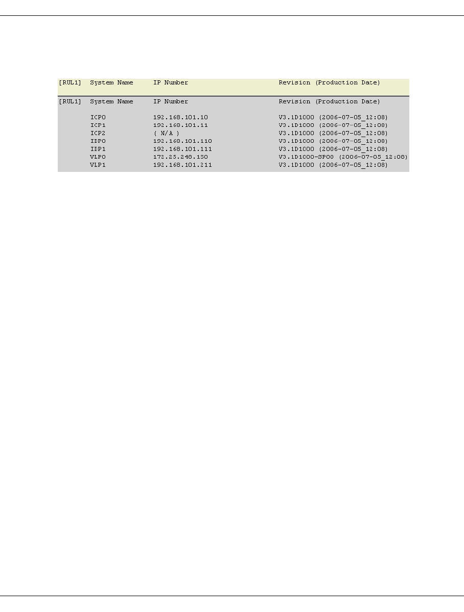
U41117-J-Z125-7-76 233
GXCC Function bar
6.2.10.5 Revision Summary
A text window with information on the installed software of all CentricStor ISPs is displayed:
System Name name of the ISP
IP Number IP address
Revision revision level of the software
Production Date production date of the software
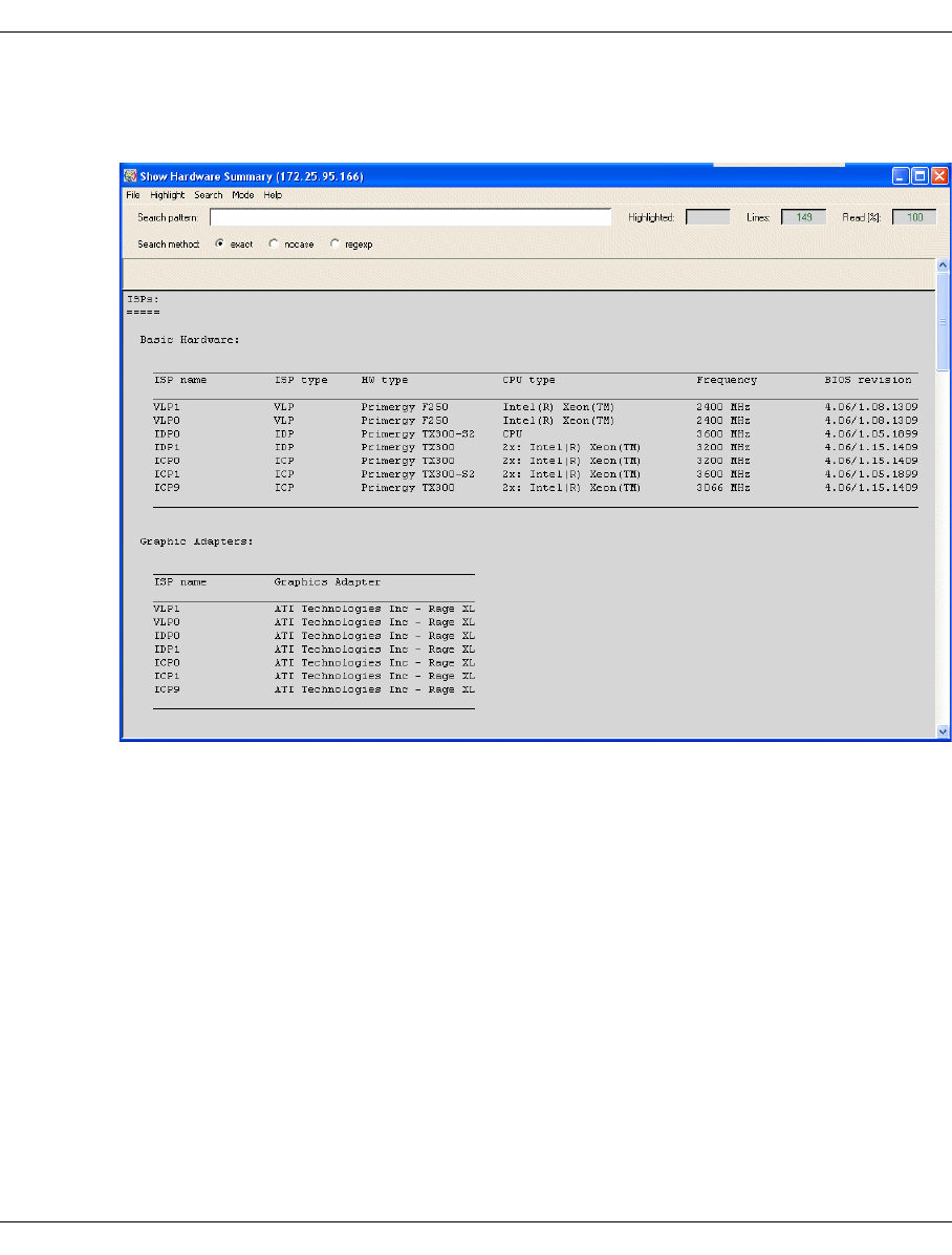
234 U41117-J-Z125-7-76
Function bar GXCC
6.2.10.6 Hardware Summary
A window with information on the hardware components installed in the system is opened:
Information on the following hardware components is output:
●ISPs
– Basic hardware
– Graphic adapters
– Internal RAID controllers
– ESCON boards
– FC boards
– SCSI boards
– Robots
●RAID systems
●FC switches

U41117-J-Z125-7-76 235
GXCC Function bar
6.2.10.7 Online Manual
This function starts a PDF reader and the most up-to-date version of the manual which is
available is displayed in the language set. If no manual is available in the language set this
menu item is omitted. When GXCC connects with a CentricStor, any more up-to-date
version of the manual which is present there is automatically transferred and enabled.
One of the menu items
– CentricStor Vm.n User Guide (complete)
– CentricStor Vm.n User Guide (GUI Part)
is displayed if
– GXCC is running in User or Observer mode and
– a PDF file is available which matches the CentricStor Version m.n and the selected
language.
In User mode the local documentation is updated by GXCC when either a new connection
is set up or the language is changed and a more recent version is found on the partner
system. In this case a more recent “User Guide (GUI Part)” has priority over an older “User
Guide (complete)”. The user is notified of the change by a message. In Observe mode this
function is not available because of the absence of the password, and this is also the case
in Simulation mode.
When GXCC connects with an InfoBroker the latter checks whether it has more
recent versions of the online manuals on its system. After transfer of a more recent
software version the manuals are also transferred to the GXCC computer if
required. Once the transfer has been completed successfully the new manuals are
enabled automatically.
If new software is only activated with a delay (this only happens interactively, see the section
“GXCC Update/Revert Tool” on page 159) the manual may temporarily be more up-to-date
than the GXCC/XTCC software.

Eine Dokuschablone von Frank Flachenecker
by f.f. 1992

U41117-J-Z125-7-76 237
7 Global Status
7.1 General
The Global Status Monitor outputs all important operating data in graphical format, and
allows you to display important system data over configurable periods.
There are several options for starting “Global Status”:
– using the optional start parameter -globstat parallel to GXCC
– using the corresponding button on the button bar of the GCXX window or
– using the function bar: Tools ➟ Global Status
– from the Root menu on the CentricStor console
The Global Status Monitor is independent of GXCC and must be terminated separately.
If there is no connection to an InfoBroker when Global Status starts up, a selection window
appears. You proceed here as described in the section “Unit” on page 147. You can use it
to select either the same CentricStor you are currently working with under GXCC or a
different one. The same unit file is used as for the GXCC unit selection.
If you select the same CentricStor to which GXCC is connected, you can then
terminate GXCC and restart it again with a mouse click (see section “Global
eXtended Control Center” on page 242).
i
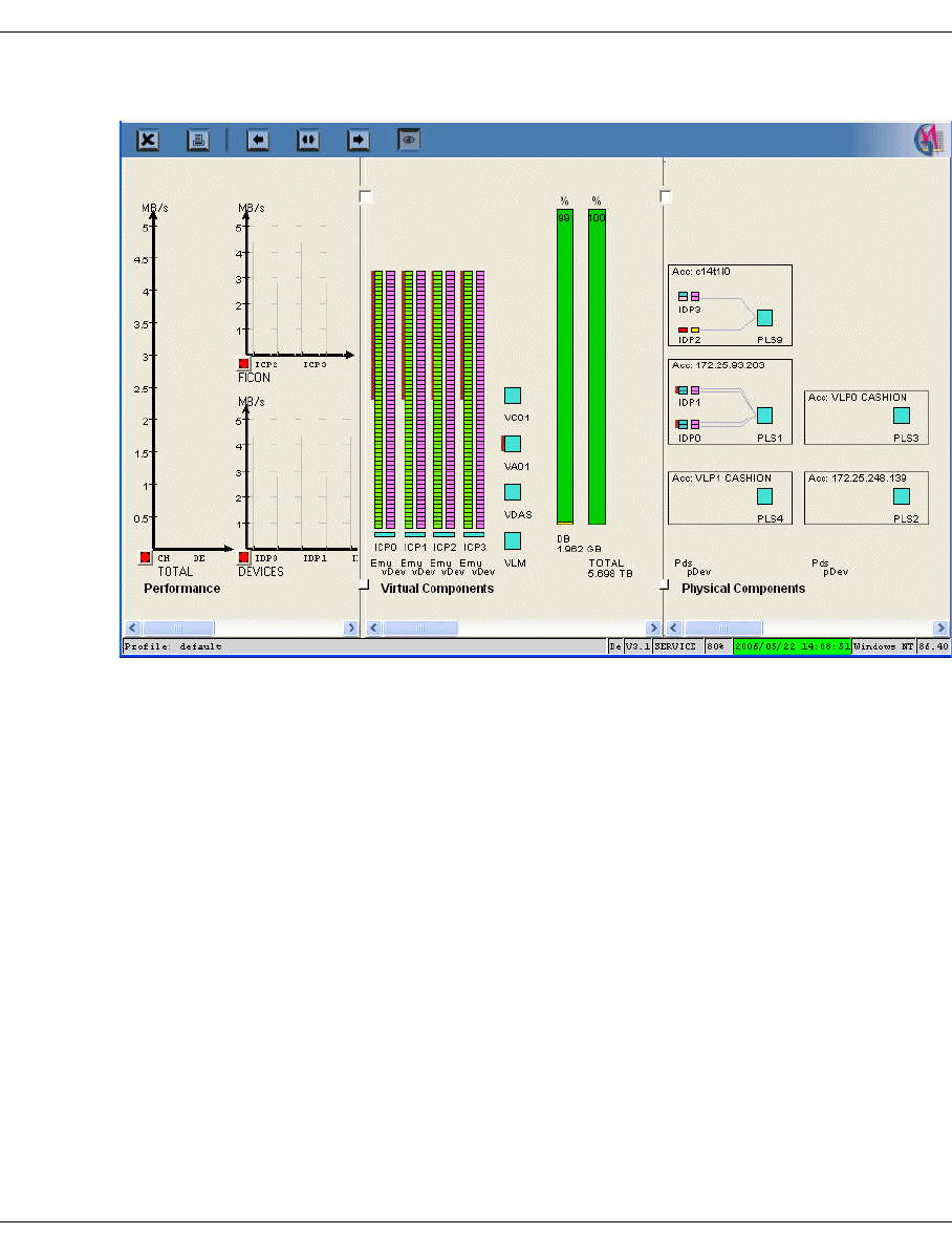
238 U41117-J-Z125-7-76
General Global Status
When “Global Status” is started, a window like the one shown below will be opened:
The figure above is just an example, it can be arranged as you wish.
Footer
The components are, from left to right:
Profile Name of the profile file. A profile file can be selected with the
-profile
parameter at startup time or at any time via the function bar.
Language Language selected: E (English), D (German)
CS Version CentricStor version
Operating mode The access rights with which the Global Status Monitor is currently run-
ning are displayed here:
SERVICE Service mode
USER User mode
OBSERVE/OBSV Observe mode
Size The imaging scale set with “Options Settings” (see the section “Set-
tings” on page 150) is displayed.
Scan Time Timestamp of the last data update
Platform Operating system of the monitoring computer
Version Version of the Global Status Monitor
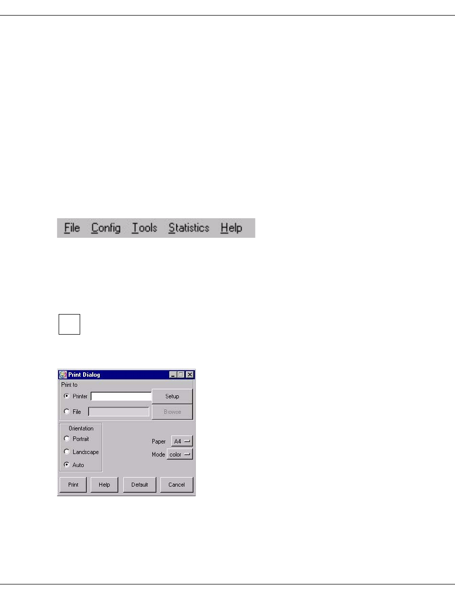
U41117-J-Z125-7-76 239
Global Status Operation of the Global Status Monitor
7.2 Operation of the Global Status Monitor
CentricStor comes with a performance monitor, which constantly records and saves
component operating data at intervals of a few seconds.
Your service staff can specify in which file system and for which time period the data is to
be stored.
The Global Status Monitor analyzes the performance data and displays individual readings,
either as they stand at present or their course over time.
7.3 Function bar of the Global Status Monitor
7.3.1 File
7.3.1.1 Print
When Global Status is running under Windows, use of the print function button is
recommended instead of this function (page 246). This opens the usual Windows
print menu.
Opens a form for printing the display:
i
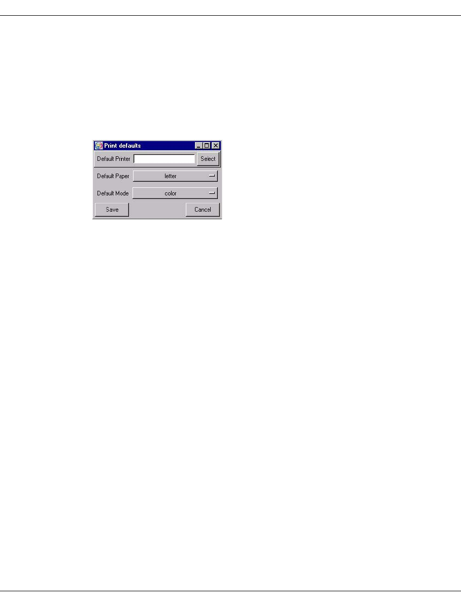
240 U41117-J-Z125-7-76
Function bar of the Global Status Monitor Global Status
Setting options
Print to
–Printer
Output is to a PostScript printer.
After you click on the “Setup” button a window is displayed for entering the printer
setup:
In this form you can make the printer default settings. After you click on the “Save”
button the settings are transferred to the previous window.
–File
Output is to a file in PostScript format.
Orientation
You use “Orientation” to select “Portrait” format, “Landscape” format or “Auto”
(automatic adjustment).
Paper
Here you can select “A4” or “letter”.
Mode
Setting options: “color” or “grayscale”.
Buttons along the lower border
Print Printout takes place with the values set.
Help A help text is output.
Default Saves all current settings.
Cancel The window is closed without the changes being accepted.
7.3.1.2 Exit
Exit terminates “Global Status”.
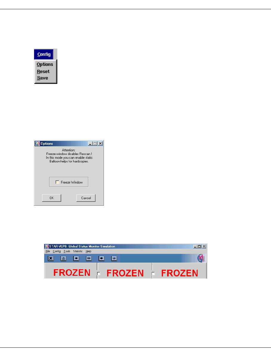
U41117-J-Z125-7-76 241
Global Status Function bar of the Global Status Monitor
7.3.2 Config
“Config” allows you to control the appearance of the display.
When you click on “Save” in the “Config” menu the position of the GLOBSTAT window on
the screen and the position of the subwindow in this window are stored and reused each
time the “Global Status” is opened again. A separate data record is created for each
monitored CentricStor.
“Reset” resets the screen settings to the values when the software was supplied.
Clicking on “Options” opens the window below:
If you activate the “Freeze Window” button and then click “OK”, the display of “Global
Status” has the following characteristics:
– Updating of the display is suppressed. This is shown by the red label “Frozen” across
all three parts of the image.
– You can left-click a field and make the associated Balloon Help permanently visible.
Click the field again to make the Help disappear again.
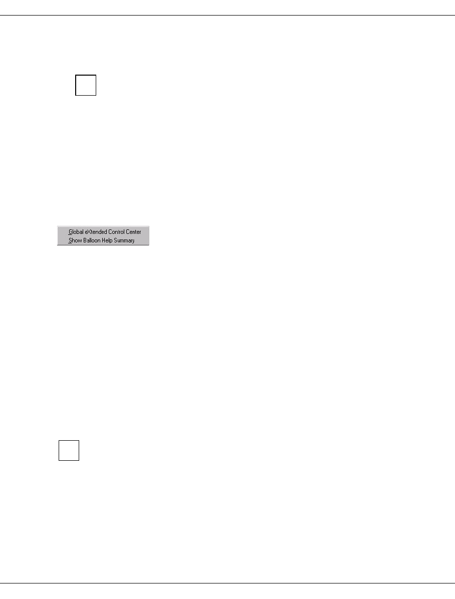
242 U41117-J-Z125-7-76
Function bar of the Global Status Monitor Global Status
– The screen division can be set in the usual manner. Permanent recording of operating
data is not affected.
Some objects are symbolized using relatively small fields, which makes it more
difficult to position the mouse. The mode described here is designed to be used
to record certain operating statuses and to describe these using the Balloon
Help fields for the purposes of training and documentation. Configuration infor-
mation can be more easily obtained using “Tools” ➟ “Show Balloon Help
Summary”.
If you deactivate “Freeze” using Config ➟ Options, the display is updated to show the
current status and the Balloon Help fields and the “Frozen” label will disappear.
7.3.3 Tools
7.3.3.1 Global eXtended Control Center
This function is only offered when Global Status is started from GXCC and GXCC is then
terminated. Global Status is an application that is independent of GXCC. Unlike XTCC,
Global Status remains active when GXCC is terminated.
You use this function to start GXCC for the CentricStor system monitored by means of
Global Status. GXCC is called in the same mode and with the same options as the GXCC
from which Global Status was started.
7.3.3.2 Show Balloon Help Summary
If you position the mouse pointer over the corresponding icons, Global Status displays
status information (“Balloon Help”). The display disappears if you click the left mouse button
on a neutral area of the Global Status window.
All the data of the virtual devices and libraries you need to create configuration data
in the BS2000/OSD, z/OS, OS/390 or open system hosts connected to CentricStor
is summarized by the “Balloon Help Summary” in a text file.
Click the “Show Balloon Help Summary” menu command to output a text window with a
snapshot of status information. The information relates to the “Physical Components” and
“Virtual Components” areas of the Global Status window.
The window header shows the data and time of the snapshot.
i
i
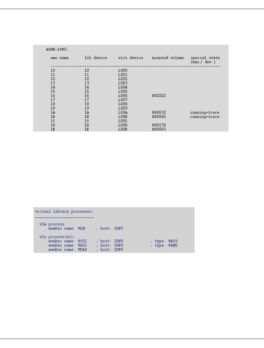
U41117-J-Z125-7-76 243
Global Status Function bar of the Global Status Monitor
The following data is listed:
Emulations
Arranged according to ICP:
emu/vid name Number of the emulation (390 emulation) / LUN (FC SCSI device).
lib. device Archive name/address of the device.
virtual device System name of the virtual tape device.
mounted volume VSN of a mounted volume; empty if no volume is mounted.
special state
(emu/device) Status of the emulation/device; in the example, two of the emula-
tions are running with activated trace.
virtual library processes
vlm process Displays which ISP is running the VLM.
vls processes vls processes name, ISP and type of the VLS
with VJUK also: controller and LUN number via which the relevant VJUK
is addressed.
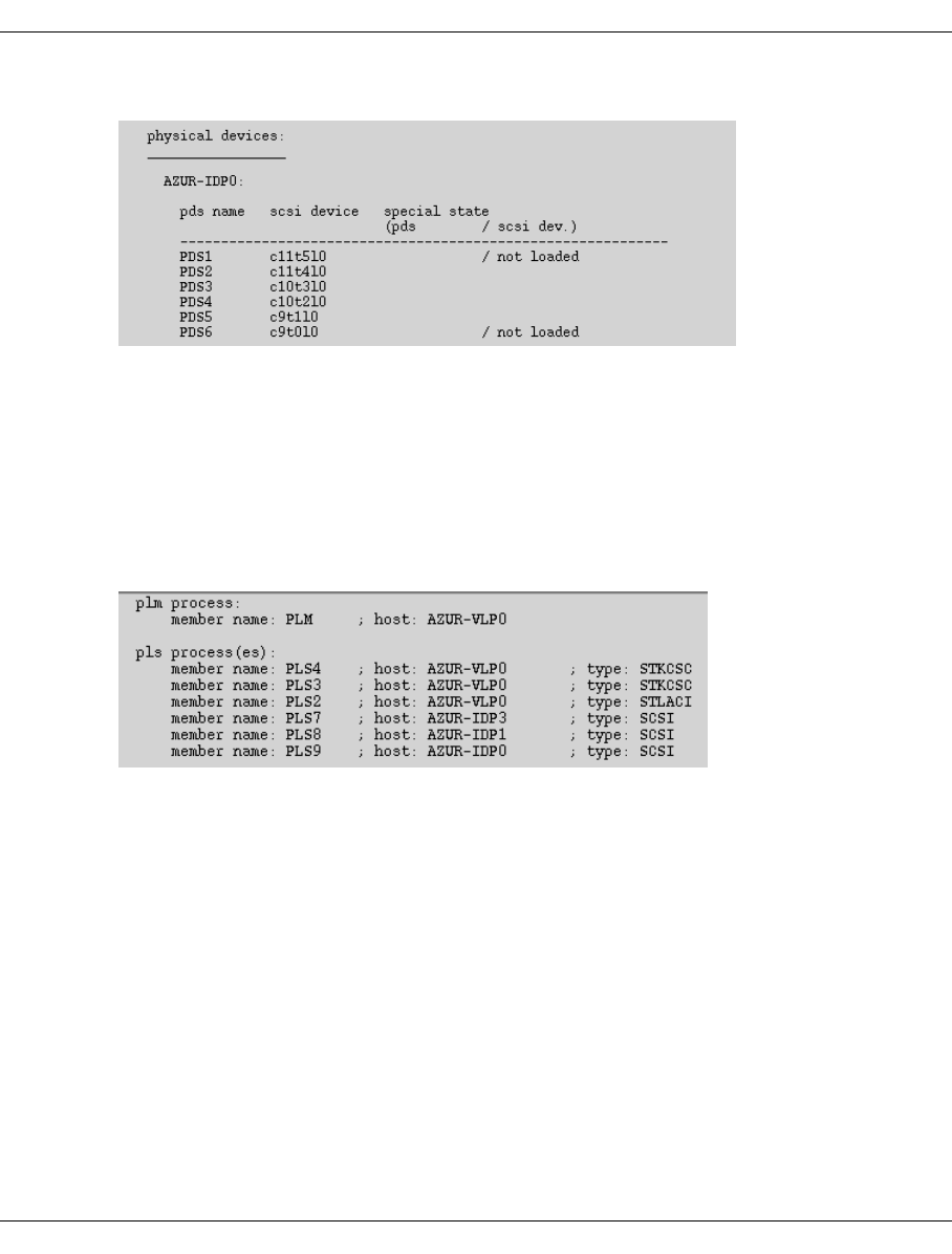
244 U41117-J-Z125-7-76
Function bar of the Global Status Monitor Global Status
Physical Devices
Arranged according to IDP:
pds name Name of the PDS.
scsi device CTL (controller, target, LUN) of the device.
manufacturer Self-explanatory
device type and model Self-explanatory
prod. rev. Firmware status
special state (pds/dev) Status information of PDS/device.
Physical Library Processes
plm process ISP running the PLM.
pls processes Name of the PLS.
host ISP running the PLS; in the case of SCSI PLS this is the ISP that
controls the SCSI interface (here PLS7-PLS9), in the case of Cashion
PLS the ISP to which the RS232C interface of the Cashion robot is
connected.
type Type of archive system.
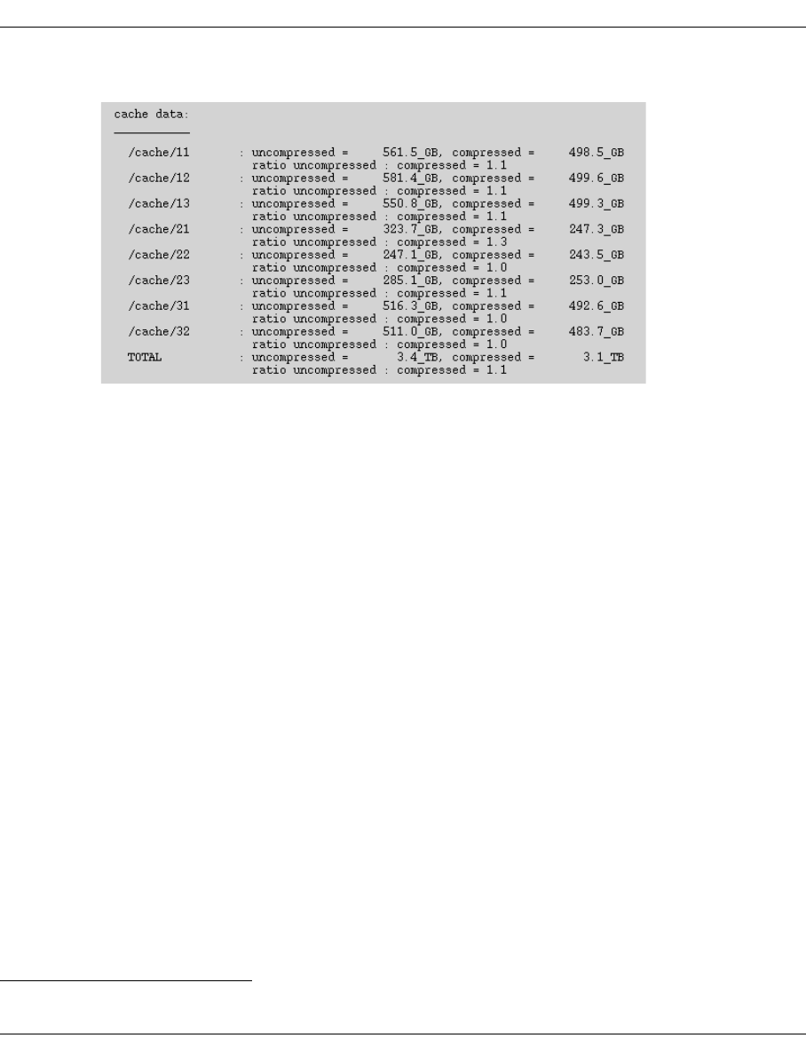
U41117-J-Z125-7-76 245
Global Status Function bar of the Global Status Monitor
Cache Data
The cache utilization data is displayed.
7.3.4 Statistics
The following menu options are available:
– History of (page 264)
– Logical Components (page 267)
– Physical Components (page 276)
– Usage (Accounting)1 (page 293)
Both records of operating data (history) and the current operating mode (statistics) can be
displayed and sorted according to various criteria. Statistical data can be displayed via
menus in the function bar or directly via object-related menus.
A detailed desription is provided in the section “History data” on page 257.
7.3.5 Help
README / LIESMICH
Shows a text window with help information.
About GLOBSTAT ...
Shows a copyright note and the revision level of “Global Status”.
1This function is displayed only if an accounting licence is installed.
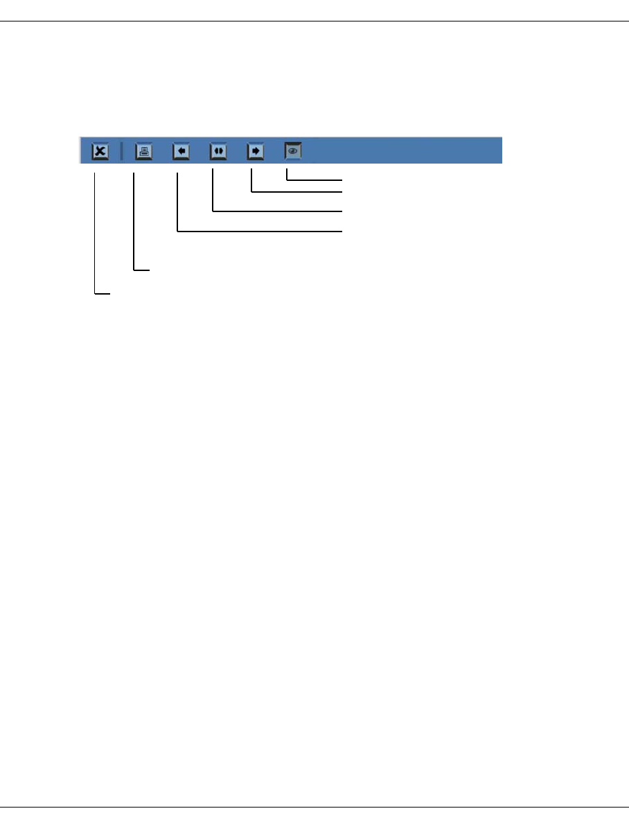
246 U41117-J-Z125-7-76
Global Status button bar Global Status
7.4 Global Status button bar
Frequently used functions can be accessed immediately after you have clicked on the
relevant button:
Shows all three subwindows
Shows only right subwindow (physical)
Shows only central subwindow (logical)
Shows only left subwin. (performance)
Terminates Global Status
Hardcopy (only if Global Sta-
tus is running on Windows)
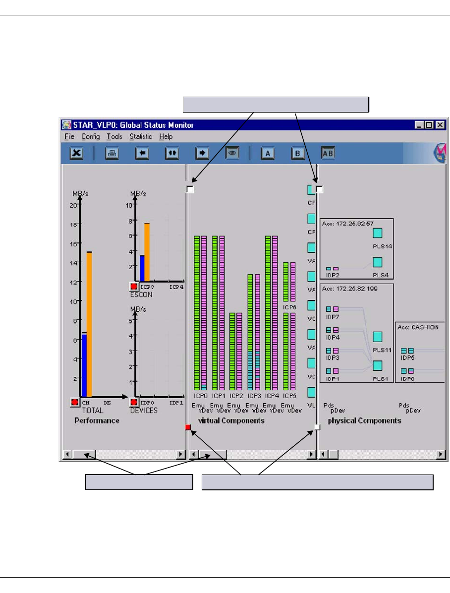
U41117-J-Z125-7-76 247
Global Status Display of the Global Status Monitor
7.5 Display of the Global Status Monitor
The Global Status Monitor window consists of three vertically aligned subwindows
separated from one another by gray lines:
The subwindows show (from left to right):
– the throughput through the host interfaces and the device SCSI or FC controllers
– the status of the virtual components (drives, tape volume caches)
– the status of the physical devices and physical control processes as well as data on the
physical volume groups (not available in the evaluation model)
Subwindow scroll bars Move image boundaries (if not fixed)
Lock image boundaries (lock buttons)

248 U41117-J-Z125-7-76
Display of the Global Status Monitor Global Status
You can set the visible section of the subwindow by dragging the handles on the separating
lines. The visible part of the subwindow can be moved in the horizontal direction for each
subwindow separately by means of the scroll bar.
The boundaries between the subwindows can be fixed by clicking on the upper control
points. Fixed boundaries are displayed with red control points. The absolute size of a
subwindow between fixed separating lines remains the same even if the size of the overall
window changes.
The analog sizes are displayed in the form of a bar chart. The current values are displayed.
When you right-click on an area in the current value display and select Show Statistics, the
temporal development of the measured variable is displayed over a user-definable period
in the form of a line chart (see the section “History data” on page 257).
The statuses are indicated by the color of the display. The key is present in the associated
subwindows to ensure that the display remains comprehensible even if there is a difference
in colors.
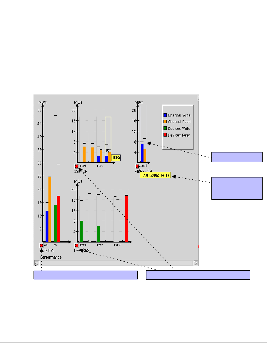
U41117-J-Z125-7-76 249
Global Status Display of the Global Status Monitor
7.5.1 Performance
The left-hand part of the window displays the current data throughput at the external inter-
faces. i.e. the ESCON/FICON channels and/or FC interfaces to the hosts and the SCSI or
FC controllers forthe tape drives.
The display area becomes visible when the mouse pointer is positioned near the maximum
display bar. The maximum bar outline is then temporarily displayed. In this way, you can still
select the corresponding measured variable for displaying temporal progress even if the
current display is zero.
The left-hand diagram which covers the entire image height represents the entire
throughput via all external interfaces.
Drag control
Reset the drag control for this area
Time the drag
control was last
reset
Reset the ’Total’ drag control

250 U41117-J-Z125-7-76
Display of the Global Status Monitor Global Status
The smaller diagrams on the right indicate the data rates via the ESCON/FICON host
connections (= 390-CH) or FC host connections (=FIBRE-CH) to the virtual drives (top
diagrams) and the data rates via the SCSI or FC controllers to the physical drives (bottom
diagram) for each controller and transfer direction. The ICPs/IDPs are identified by their
names. Long vertical, gray lines indicate the boundaries between the individual ISP areas,
whereas short lines indicate the boundaries between external controllers of a host. If you
rest the mouse pointer on an area, the exact designation will be displayed.
Diagrams relating to host adapter throughput are displayed only for components
actually present. For instance, if CentricStor has no FC host adapter, the top right
diagram will be omitted. There are no device controllers in the evaluation model.
A horizontal line above the bar indicates the maximum value attained since the window was
opened or since the last reset (drag control). The vertical scale of the display (MB/s) is
adapted to the measured data.
– To reset the drag control for total throughput, click the “Reset” button at the bottom left
of the subwindow.
– The drag controls for the individual host interfaces or drive interfaces are reset using the
buttons displayed under the relevant chart.
– When the mouse pointer hovers above the reset button, an information field appears
telling you the last time it was reset. The system time that is displayed is taken from the
system on which “Global Status” is running. If the drag control has never been reset,
the field displays the time Global Status was started.
i
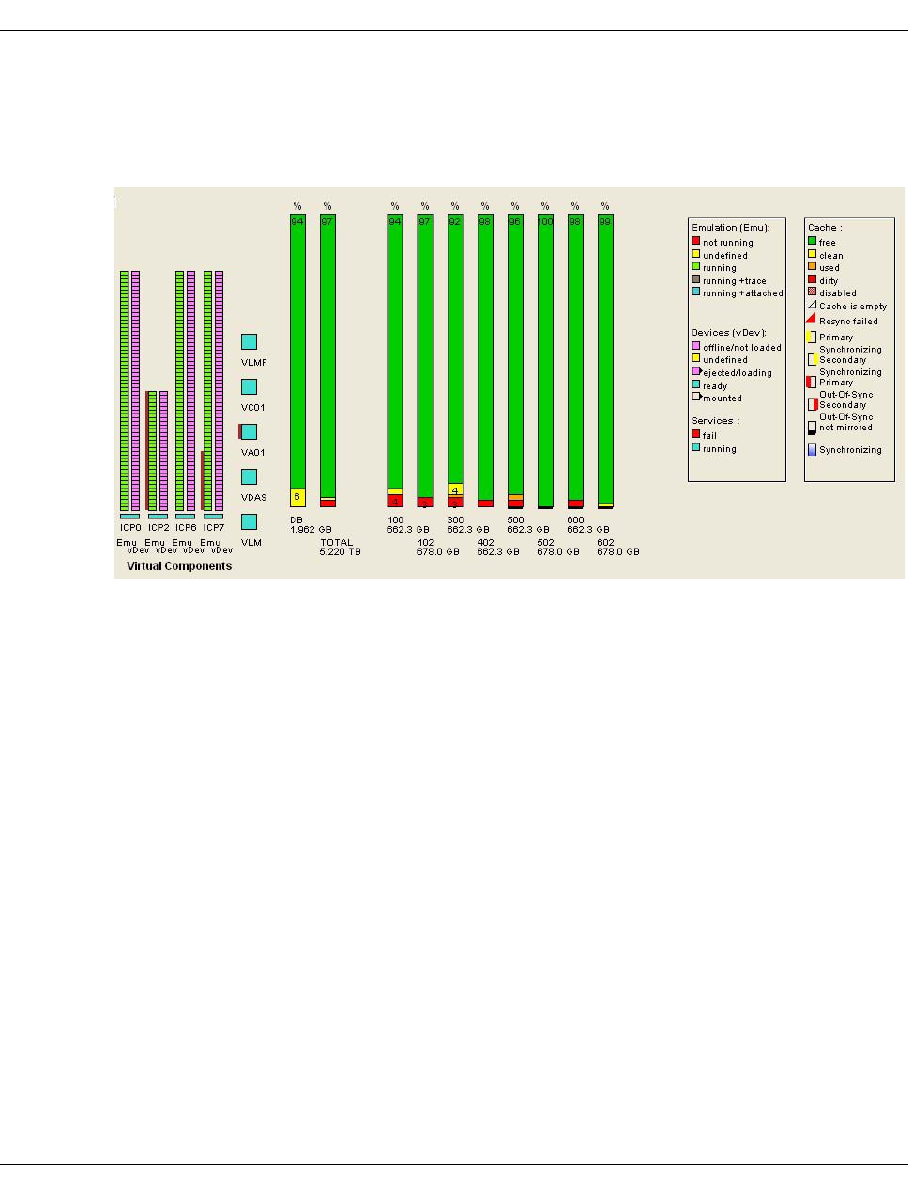
U41117-J-Z125-7-76 251
Global Status Display of the Global Status Monitor
7.5.2 Virtual Components
The middle window section displays the current statuses of the tape emulations, the virtual
devices and the occupancy of the tape volume cache(s):
Emulations and virtual drives
Emulations and virtual drives are displayed in the left-hand part of the picture and are
arranged by ICP. Each emulation and each virtual device is represented by a box. The
bottom box in a bar always represents the consecutive number 0 or the object displayed at
the outside left of the XTCC window.
The status displays for the emulations and devices are self-explanatory.
If a drive symbol is displayed with a black triangle to the right, this indicates that a virtual
volume has been loaded onto that drive or that the drive is currently being mounted or
unmounted.
If you click the left mouse button on a box which symbolizes a virtual drive, the name of a
mounted volume will also be displayed next to the name of the drive.
If you click the left mouse button on a box which symbolizes an emulation, the name of the
emulation and its address in the archive system (LibDevice) will be displayed.
At the bottom of the columns for the emulations and virtual drives a box is displayed for each
ISP as a status display for the VMD. The colors have their familiar meanings. The following
also applies: A white, empty box indicates that no VMD description data was found.

252 U41117-J-Z125-7-76
Display of the Global Status Monitor Global Status
Virtual library servers
The middle column indicates the operating statuses of the VLM and virtual library servers
(VLSs).
If you click the left mouse button on on an object, an info box is output containing further
details. In the case of control components, for example, this would indicate the host on
which the component runs.
Tape volume caches
The display of the tape volume cache occupancy in the right-hand column should be inter-
preted as follows:
free Free storage space
clean Data of virtual volumes which are no longer mounted but which have been
saved to tape, i.e. valid duplicates of these volumes are available on tape. The
“clean” area can be used at any time for data recording, without the need to
rewrite the data, if the “free” area is not sufficient.
used This area contains maps of currently mounted virtual volumes.
dirty Modified data of virtual volumes which are no longer mounted. Although this
data has been changed, the changes have not yet been written back to tape.
This area cannot be made free for other volumes until the data has been written
back to tape and therefore been made “clean”.
The proportions of the individual classes are displayed in the appropriate field of the bar,
if there is enough space.
If you click the left mouse button on a cache column, the size of the occupied area (used +
clean + dirty) and the corresponding unpacked data volume are displayed. Due to data
compression, the saved data volume can be greater than the capacity.
In the steady state, the proportion of “free” data in the cache is low. When unloading a
written volume (“dirty”), CentricStor attempts to “clean” its data as soon as possible by
rewriting and then retain it in the cache for as long as possible. CentricStor automatically
adapts the resources used for rewriting to the number and scope of write requests: the more
the cache is occupied with “dirty” data, the more drives are used for Save requests.
If you click the right mouse button on a cache column, a context menu appears which you
can use to output statistical data (“Show Statistics”). Information on this is provided in the
section “Data which can be called via objects of the Global Status” on page 297. The /DB
column represents the ufs file system containing the CentricStor metadata.
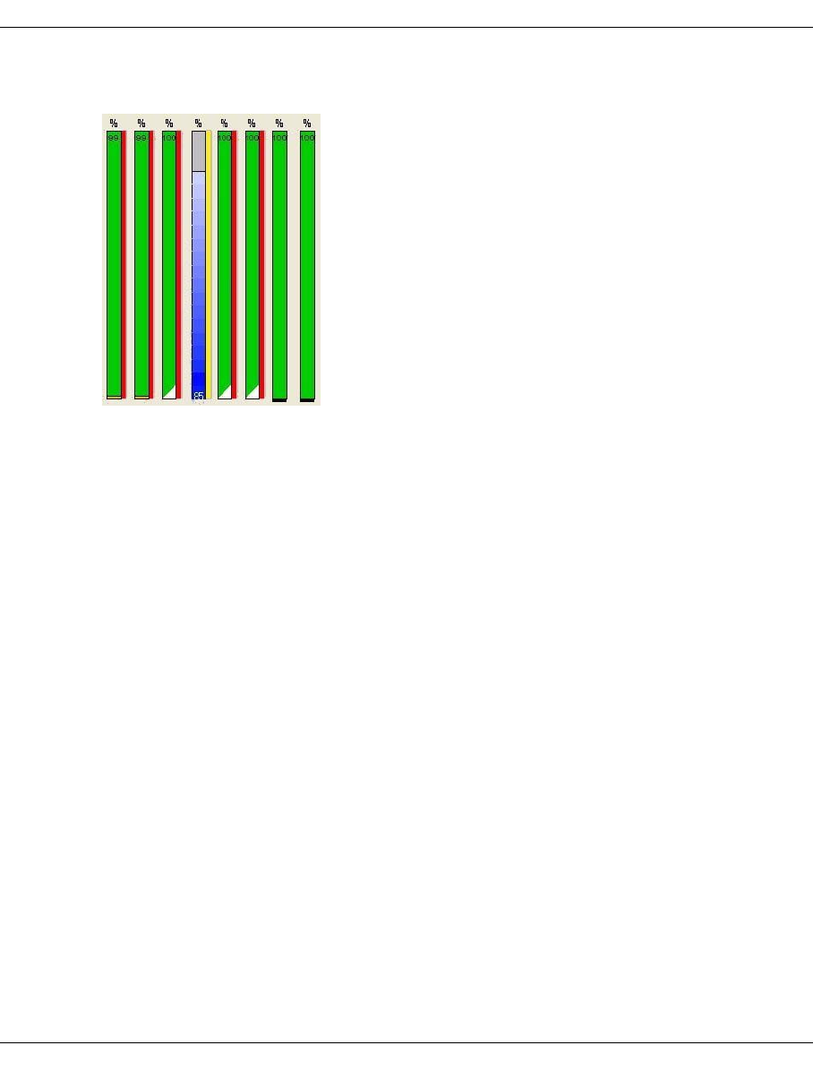
U41117-J-Z125-7-76 253
Global Status Display of the Global Status Monitor
Additional displays for mirrored systems
●Red bar on a cache column: The cache is no longer mirrored (“out of sync”).
Left: Primary cache
Right: Secondary cache
●Yellow bar on a cache column: The cache concerned is being resynchronized and is still
in the “out of sync” status.
Left: Primary cache
Right: Secondary cache
●Progress display on the cache column (a bar that goes from blue to white and expands
upward): This displays the current progress during resynchonization.
●Trinagle at the bottom right of the column:
White: Cache is empty (contains no LVs)
Red: Error during resynchronization
●Black line below a column: The cache is not mirrored.
●Cache brown: The cache is in the “disabled” status.

254 U41117-J-Z125-7-76
Display of the Global Status Monitor Global Status
7.5.3 Physical Components
This screen displays the operating status of CentricStor’s physical resources. These consist
of the cartridge drives, the physical robot controllers and the physical volumes. This part of
the display is not available in the evaluation model. The second example shows how the
screen layout changes when there are a large number of PVGs.
The display shows (from left to right) the PDS and the associated cartridge drives (pDev).
The assignment of devices to access systems is represented by a frame. An access system
consists of both the robot that handles the cartridges and the associated PLS (Physical
Library Service). Thin lines connect each pDev to the associated PLS. The status of the
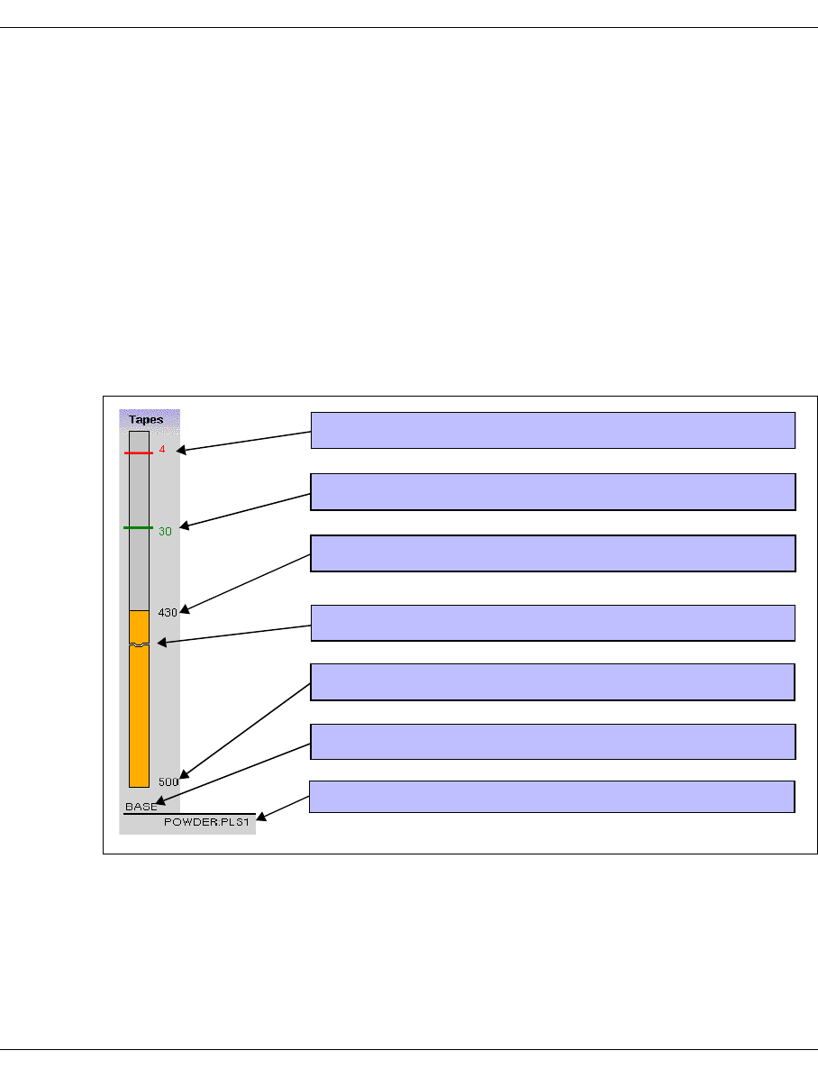
U41117-J-Z125-7-76 255
Global Status Display of the Global Status Monitor
drives, the PDS, the PLS, and the PLM are color-coded in accordance with the key
displayed at the right-hand edge of the screen section. Left-clicking on an object causes
information to be displayed.
The address (host name or SCSI Controller:Target:LUN) of the access system is specified
at the top of the box.
The bar charts in the right-hand half of the screen indicate the user statistics for the physical
volume groups and the degree to which the cleaning cartridges have been used. Separate
statistics and limit values are maintained for each physical volume group. The name of the
PVG displayed appears under each bar. PVGs from a shared library are arranged alongside
each other connected by a short line, under which the name of the library and of the
associated PLS are displayed.
Each bar represents the total number of volumes available. The proportion of used volumes
is displayed against a colored background.
The display indicates numerical scales on the right-hand side of the bar chart. In each case,
the number of volumes available is specified (on the baseline) together with the number of
free cartridges. Next to this, at the edge of the bars, the absolute numerical values for the
minimum number of available cartridges (soft minimum, hard minimum) are indicated.
These upper limits are predefined during system configuration. They are described in detail
in the section “Statistics » Physical Components » Physical Volume Groups” on page 283.
Number of free volumes when hard minimum is reached
Number of free volumes when soft minimum is reached
Number of free volumes
Name of the physical volume group
Total number of volumes in the group
Name of the PLS in which the PVG is located
Dividing line if area scale is incorrect

256 U41117-J-Z125-7-76
Display of the Global Status Monitor Global Status
Newly added volumes are not available until they have been initialized by the PLM.
The height of the bar represents the number of volumes. If less volumes are available than
the minimum values usually displayed for “Hard Minimum” and “Soft Minimum”, then the
minimum values cannot be displayed using this form of representation and thus do not
appear on the diagram. This situation occurs regularly when the PVG is being filled.
If CentricStor controls cleaning of the drives in a library, the degree of use of the cleaning
PVG will be shown to the right of the PVG of the library. The representation is, in principle,
identical to that of the PVG. The overall number given under the bar shows the total number
of cleaning cycles that are available. The counter shows how many of these cycles have
already been used. The “Soft Minimum” (green number, green line) specifies how many
cycles must still be available when the soft minimum is achieved. The “Hard Minimum” (red
number, red line) specifies the minimum for the “Hard Minimum”. These values are specified
by CentricStor according to the number of tape drives, and cannot be modified at the user
interface.
If “Hard Minimum” and “Soft Minimum” are violated, a message is output on the operator
console indicating the degree of urgency.
How to use and administer the physical volumes in CentricStor is described in the section
“Administering the tape cartridges” on page 35.
i

U41117-J-Z125-7-76 257
Global Status History data
7.6 History data
History data is system data which has been collected over a lengthy period. For this purpo-
se a Performance Monitor constantly runs in CentricStor. The Performance Monitor collects
and stores the operating data of the components, e.g. performance, mount, availability of
the devices and the device assignment, at intervals of a few seconds. The customer service
can determine the files system and period in which measured data is to be saved.
●Global Extended Control Center (GXCC) is a program which supplies a graphical map
of a CentricStor system.
●The GXCC component Global-Status-Monitor (GLOBSTAT) evaluates the measured per-
formance data and presents the current values.
●The GXCC component Global History Viewer (GLOBHIST) is used to present the chro-
nological progress.
The following options are therefore available for the history data of a CentricStor system:
– The data can be displayed graphically using the GLOBHIST program.
600 pixels are available for a line graph. In a presentation period of one hour the pixel
corresponds to 6 seconds; in a week, it corresponds to approx. 1000 seconds. The
stored measured values from this period are evaluated and displayed in accordance
with the specification (Min, Max, Average). If no measured value occurs in the period,
zeros are entered. 0 values therefore occur for periods in which CentricStor was not ac-
tive. When the presentations for a period of 1 hour are interpreted, it must be borne in
mind that only 0 - 2 measured values apply for a pixel. It is therefore normal if there is
sometimes no difference between Min, Max and Average in this presentation and if lines
occasionally yield “0”.
– The data can be exported from the GLOBHIST program into a file as text.
– The data can be extracted from the binary recording files on the CentricStor system
using a shell script and be stored in a text file.
When the data is available in a file, this file can then be transferred to another system and
be presented with an evaluation program or integrated into customer-specific controlling
processes. A macro is supplied for the Microsoft program Excel which generates a presen-
tation which is suitable for GXCC.

258 U41117-J-Z125-7-76
History data Global Status
7.6.1 General
7.6.1.1 Recording analog operating data
If you move the mouse to a Global Status display and click on the right button, “Show
Statistics” is offered. When you select this function a window opens for presenting the
chronological progress. A description of how to operate this is provided on page 262.
The chronological progress of the following measured data can be displayed:
– data rates of the host interfaces and device controllers for each physical path or globally,
separately for each transfer direction.
– cache statistics
It is possible to create a separate chart for each channel and each device controller. Read
and write operations are both plotted on the same screen.
The various cache occupancy statuses (clean, used, dirty etc.) are displayed in the same
screen for each cache.
It can take some time to build up the diagrams because a large volume of measured data
must be analyzed to present long time periods, e.g. approx. 240 000 samples for one week’s
channel throughput. It is thus possible to abort diagram setup using “Cancel” so as to avoid
quasi-blockages.
7.6.1.2 Overview of the displays
The table below shows the operating data for which chronological recording or tabular
analyses are available.
Explanation
2nd column: Type
H History: Recording over a selecteable period.
T Table with current values.
3rd column: Call
Statistics » .......<menu item>
Submenu of Statistics on the function bar
or
Object: <description of the object>.
Here you must position the mouse cursor on the object until blue highlighting
appears (the object is outlined in blue or the device name is colored blue). When
you click on the right mouse button a popup menu appears containing the entry
“Show Statistics”. Select this menu item using the left button.

U41117-J-Z125-7-76 259
Global Status History data
Measured value Type Call Description
Scratch Volumes of
a PVG
HObject: PVG column in right-hand part of
screen
page 313
Cache Usage HObject: Cache column in central part of
screen
page 265
Usage of Overall
Cache
HStatistics » History of » Cache Usage or
Object: Column for overall cache in central
part of screen
page 265
Throughput of a
PDS or Host
Adapter
HObject: Column for PDS or host adapter of
an ICP in left-hand part of screen
page 304
Overall Throughput HStatistics » History of»Channel Device
Performance or Object: “Total” column in
left-hand part of screen
page 303
Jobs of Logical
Volume Groups
TStatistics » Logical Components »Jobs of
Logical Volume Groups
page 275
Jobs of Physical
Volume Groups
TStatistics » Physical Components » Jobs of
Physical Volume Groups
page 289
Logical Drives TStatistics » Logical Components »Logical
Drives
page 268
Logical Drives Utili-
zation
HObject: Logical Drives of a ICP in central
part of screen
page 305
Logical Volume
Groups
TStatistics » Logical Components » Logical
Volume Groups
page 273
Logical Volumes
(physical view)
TStatistics » Logical Components » Logical
Volumes (physical view)
page 271
Logical Volumes
(logical view)
TStatistics » Logical Components » Logical
Volumes (logical view)
page 272
Physical Drives TStatistics » Physical Components »
Physical Drives
page 277
PDS Utilization HObject: PDS/pDev in right-hand part of
screen
page 310
Physical Drives
Utilization
HObject: PDS/pDev in right-hand part of
screen
page 310
Physical Volume
Groups
TStatistics » Physical Components »
Physical Volume Groups
page 283

260 U41117-J-Z125-7-76
History data Global Status
Physical Volume
Groups Tape
Statistics
HObject: PVG column in right-hand part of
screen
page 313
Physical Volumes
Occupancy
TStatistics » Physical Components »
Physical Volumes
page 279
Reorganization
Status
TStatistics » Physical Components »Reorga-
nization Status
page 291
Usage
(Accounting)
TStatistics » Usage (Accounting) page 293
Measured value Type Call Description
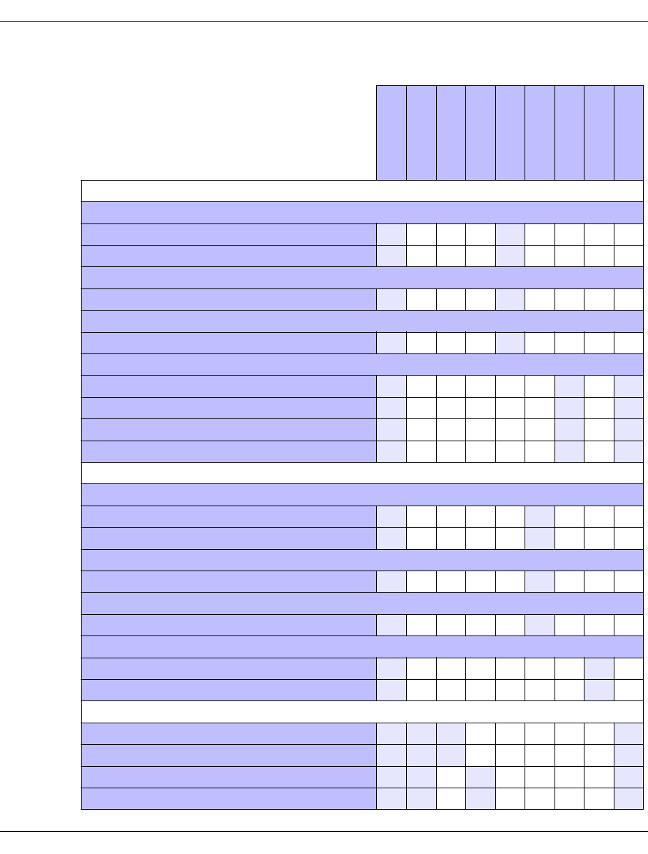
U41117-J-Z125-7-76 261
Global Status History data
The table below shows the selection and control options for the history data:
CentricStor virtual Components
CentricStor Virtual Mounts
number of Mounts x x
cumulated MountTime x x
CentricStor Total Mount Time (% of Range)
virtual drives x x
CentricStor Concurrent VTDs usage (Histogram)
% of virtual drives x x
CentricStor Cache
% free x x x
% clean x x x
% used x x x
% dirty x x x
CentricStor physical Components
CentricStor physical Mounts
number of Mounts x x
cumulated MountTime x x
CentricStor Total Mount Time (% of Range)
physical drives x x
CentricStor Concurrent VTDs usage (Histogram)
% of physical drives x x
CentricStor PVGs
used x x
total x x
CentricStor Data Transfer (Performance)
Data Read by Mainframe/Open system xxx x
Data Write by Mainframe/Open system xxx x
Data Read from physical device xx x x
Data Write to physical device xx x x
Range
Min/Max/Aver.
Channel
By Device
By ICP
By IDP
By cache
By PVG
By System
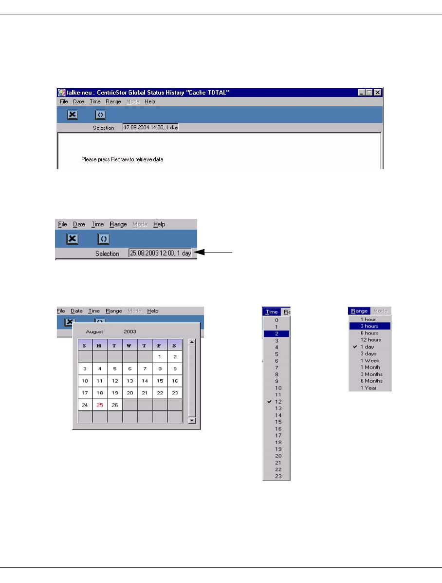
262 U41117-J-Z125-7-76
History data Global Status
7.6.1.3 Selecting the time period
The recording period or analysis period must be selected for displays of the type H. When
you have selected one of these displays a window with an empty page appears.
The function bar contains tools for defining the time period (day, time, range).
The period selected (day, time, range) is displayed in a small field below the button bar. The
default value is “the last 24 hours” or “the current hour”.
You can select the period using the tools in the function bar.
Period selected
Date Time Range

U41117-J-Z125-7-76 263
Global Status History data
The button bar below these options allows you to select the functions “Exit” and “Redraw”:
If you have selected a long recording period (e.g. months) a very large volume of
data must be analyzed and transferred. In the wait time you are offered an info box
containing the “CANCEL” button.
You should click on this button if you have accidentally selected this long recording
period. The repeated calling of large data volumes in particular can have a negative
effect on the operating behavior of CentricStor.
Hardcopy
You can print the diagrams using » File » Print in the function bar (page 239) or, if “Global
Status” is running on Windows, with the function button available in the button bar
(page 246).
7.6.1.4 Selecting the presentation mode
After the diagram has been built up some time diagrams enable you to specify (function bar
» Mode) whether the the maximum value (max), the spread (min/max) or the average value
(average) should be recorded for each display period. If you select min/max the maximum
and minimum values are separated by a slash.
Redraw: Draws the diagram with the current settings
Exit
i

264 U41117-J-Z125-7-76
History data Global Status
7.6.2 Data which can be called via the function bar
The following menus and submenus can be called under “Statistics”:
●History of
– Cache Usage (page 265)
– Channel/Device Performance (page 266)
●Logical Components
– Logical Drives (page 268)
– Logical Volumes (physical view) (page 271)
– Logical Volumes (logical view) (page 272)
– Logical Volume Groups (page 273)
– Jobs of Logical Vol. Groups (page 275)
●Physical Components
– Physical Drives (page 277)
– Physical Volumes (page 279)
– Physical Volume Groups (page 283)
– Jobs of Physical Vol. Groups (page 289)
– Reorganization Status (page 291)
●Usage (Accounting)1 (page 293)
7.6.2.1 Statistics » History of
The following submenus are available:
– Cache Usage (page 265)
– Channel/Device Performance (page 266)
1This function is displayed only if an accounting licence is installed.
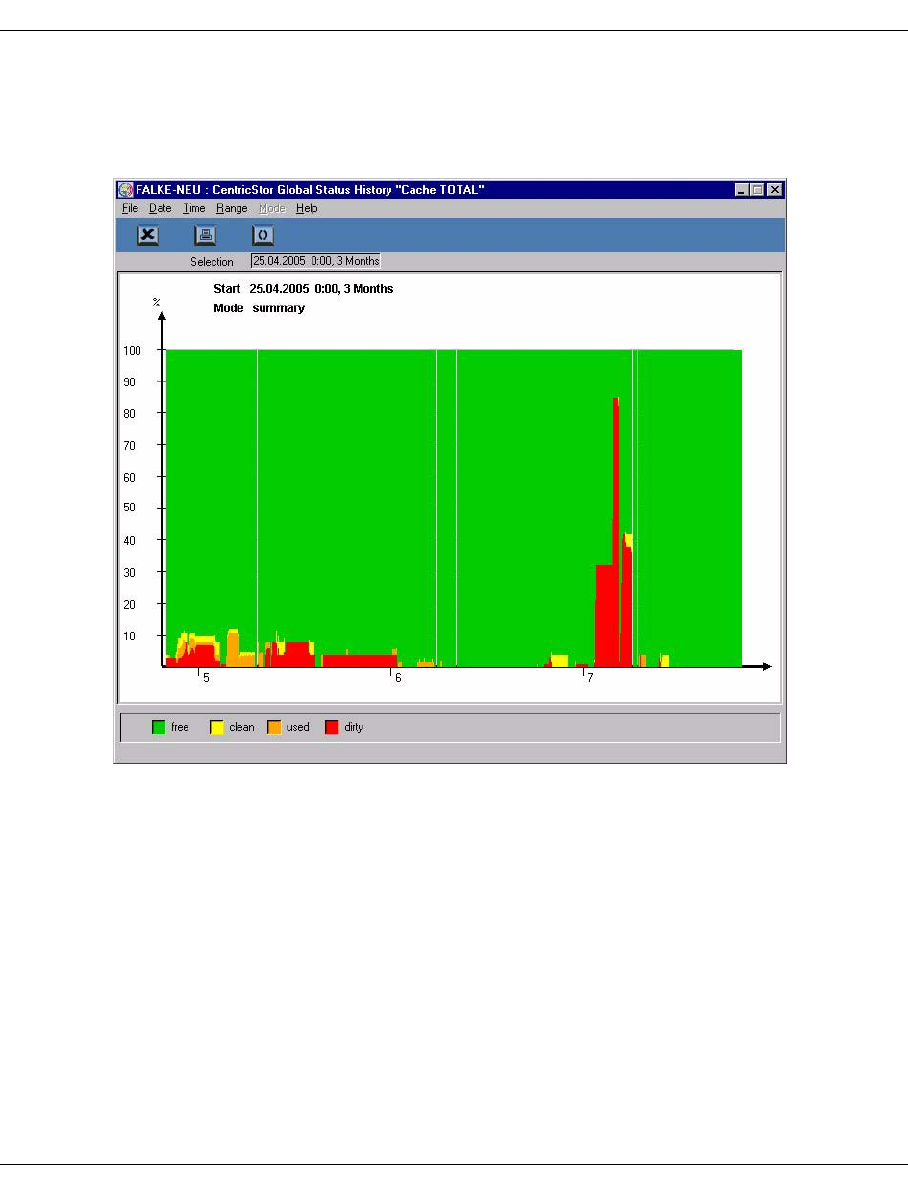
U41117-J-Z125-7-76 265
Global Status History data
7.6.2.2 Statistics » History of » Cache Usage
The history of cache usage is output in accordance with the cache total values of the virtual
components subwindow.

266 U41117-J-Z125-7-76
History data Global Status
7.6.2.3 Statistics » History of » Channel/Device Performance
Statistics on the overall throughput as they are presented continuously in the left-hand bar
of the Performance subwindow are output.
You can use the four checkboxes at the lower edge of the screen to determine what data is
presented.
The following options are offered:
Channel Read/Write (also for FC host adapters): Front-end throughput.
Device Read/Write: Back-end throughput.
In the example the back-end data is masked out.

U41117-J-Z125-7-76 267
Global Status History data
7.6.2.4 Statistics » Logical Components
The following submenus are available:
– Logical Drives (page 268)
– Logical Volumes (physical view) (page 271)
– Logical Volumes (logical view) (page 272)
– Logical Volume Groups (page 273)
– Jobs of Logical Vol. Groups (page 275)
Notes on the refresh function:
All statistics functions support the refresh function:
After the function has been executed, i.e. after the result has been displayed in the
text window, the dialog window with the selection criteria (function window) is reta-
ined for further searches. The “OK” button at the lower edge of the function window
is replaced by the “Refresh” button, which enables the search to be repeated. The
search criteria can be modified before another search takes place.
The previous text window is then used to display the result, in which case the pre-
vious contents are deleted. The function window is closed only when the user clicks
on the “Cancel” button. In this case the text window with the result is also closed
implicitly.
i
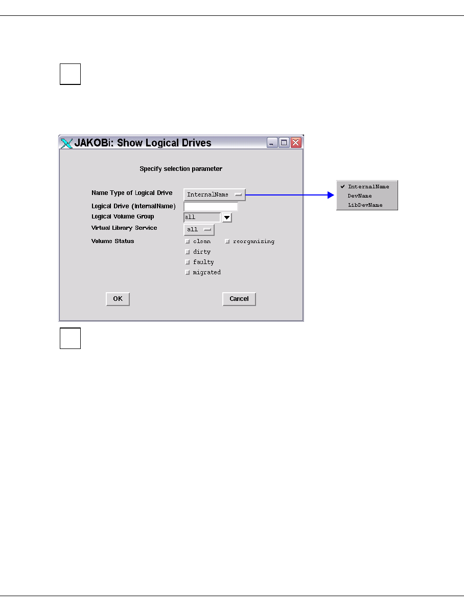
268 U41117-J-Z125-7-76
History data Global Status
7.6.2.5 Statistics » Logical Components » Logical Drives
You obtain statistics on the utilization of the logical drives by selecting an ICP in the
central section of the Global Status display and calling the object-related statistics
function.
Displays the occupied status of the logical drives. You can select drives in particular
statuses using a selection window:
This statistics function supports the refresh function. Information on this function
and the “OK” and “Cancel” buttons is provided on page 267.
You can select whether the internal name, the device name or the archive address of the
device is to be displayed.
Specification of the name is optional. You can also use wildcards.
For LVGs you can specify “all” or one particular LVG.
Volume Status See the section “Logical Volume Operations » Show Logical Volumes”
on page 203
i
i
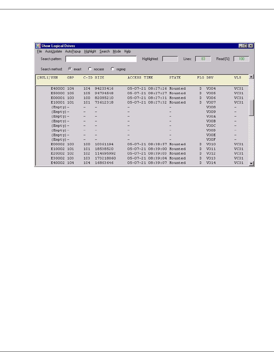
U41117-J-Z125-7-76 269
Global Status History data
The list of logical drives is output in a text window after you click on the “OK” or “Refresh”
button:
The following information is output:
VSN
VSN of the volume mounted in a drive or “Empty”
GRP
LVG of a mounted volume or -
C-ID
Number of the cache (=Cache-ID) to which the mounted volume is assigned or -
SIZE
Size of the data contained in the volume or -
ACCESS TIME
Timestamp of the last access or -
STATE
Faulty The logical volume is faulty. It can no longer be used.
Home The logical volume is currently not being used.
Mounted The logical volume has been inserted in a logical drive.
Mount Pending The logical volume has just been inserted in a virtual tape drive.
There is still no confirmation for this.
Mnt. Queued A mount request for the logical volume was queued by the VLM due
to a lack of resources.
Restoring The logical volume is just being read in by the physical volume.

270 U41117-J-Z125-7-76
History data Global Status
Rest. Canc. The reading in of the logical volume by the physical volume was
canceled (occurs with a scratch mount).
Unld. Pend. The logical volume has just been ejected from a logical drive
(emergency unload). There is still no confirmation for this.
FLG
Flags:
D “dirty”: The volume is located in the cache but has not been saved since the
last change.
M “migrated”: The volume is no longer located in the cache and must therefore be
read in from the physical tape before it is next accessed.
When the r flag is specified (i.e. -fr: displays volumes which are currently being
reorganized) an additional column with the following flags is output:
P “pending”: Reorganization running
Q “queued”: Job was queued
R “restore”: Volume is being restored
C “cancelled”: Restore is canceled
S “save”: Volume is just being saved
When the s flag is specified (i.e. -fs: displays volumes which are being restored
because a mount was canceled) an additional column with the following flags is output:
R “restore”: Volume is being restored
C “cancelled”: Restore is canceled
DRIVE
Designation of the logical drive
VLS
Library to which the mounted logical volume is assigned.
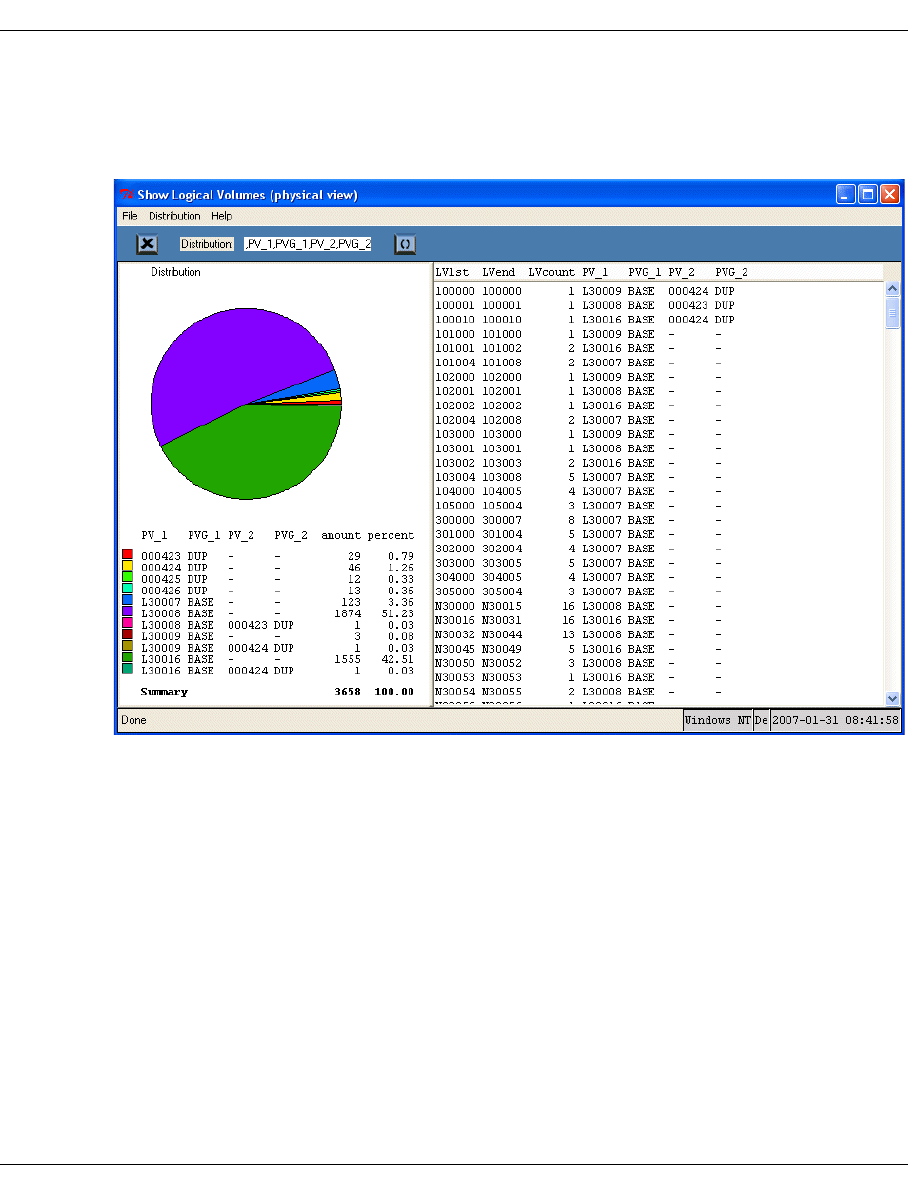
U41117-J-Z125-7-76 271
Global Status History data
7.6.2.6 Statistics » Logical Components »Logical Volumes (physical view)
You use this call to display the logical volumes which are known to the PLM together with
their statuses.
The right-hand part of the window displays all the output data in tabular form.
LV1st VSN of the first logical volume of a name group (see below)
LVend VSN of the last logical volume of a name group (see below)
LVcount Number of LVs in the name group extending from LV1st to LVend
A name group consists of a sequence of logical volumes whose VSNs differ
only in a serial number which is incremented by 1, e.g.
XXX001,XXX002,...XXX099)
The left-hand part of the window shows the distribution data, both in the form of a pie chart
and in a distribution table.
The number of LVs in the total quantity with the same distribution paramaters is used as the
ditribution function. The menu item Distribution can be used to define not only the parame-
ters but also their order; the current setting and order is displayed in the toolbar.
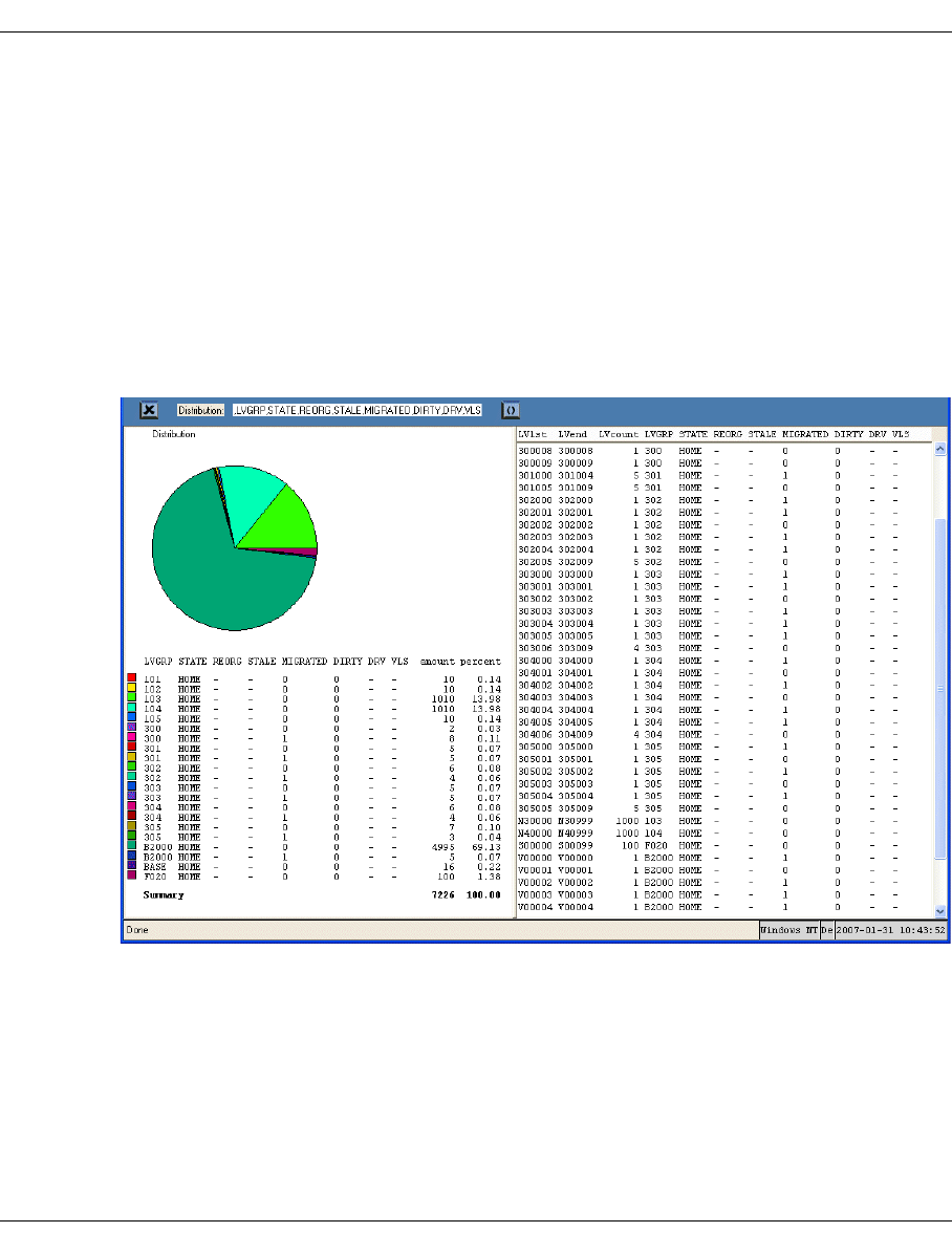
272 U41117-J-Z125-7-76
History data Global Status
The columns of the distribution table contain the associated values of the distribution para-
meters. The columns containing the number of LVs to which the various distribution para-
meter values relate and their percentage share in the total quantity are also visible.
The pie chart is a graphical presentation of the distribution table.
Clicking on a pie segment or a line in the distribution table highlights the related entries in
the overall data table.
7.6.2.7 Statistics » Logical Components » Logical Volumes (logical view)
After the function has been called, the statistics and the distribution data gathered from the-
se are displayed in a new window:
The right-hand part of the window displays all the output data in tabular form. The left-hand
part of the window shows the distribution data, both in the form of a pie chart and as a dis-
tribution table.
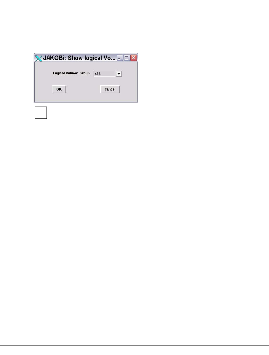
U41117-J-Z125-7-76 273
Global Status History data
7.6.2.8 Statistics » Logical Components » Logical Volume Groups
If multiple logical volume groups exist an intermediate menu is then displayed for selecting
the volume group:
This statistics function supports the refresh function. Information on this function
and the “OK” and “Cancel” buttons is provided on page 267.
You can select either all groups or a specific group.
i
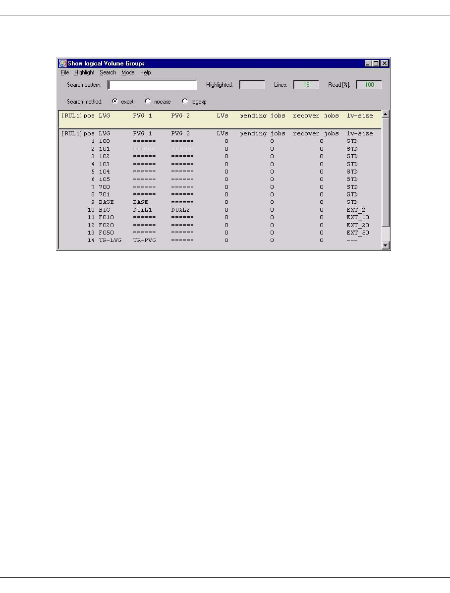
274 U41117-J-Z125-7-76
History data Global Status
After you click on “OK” or “Refresh” the following window appears:
The following data is displayed:
pos Line number
LVG Name of the logical volume group
PVG1 Name of the first or only assigned physical volume group, or -===== if empty
PVG2 Name of the second assigned PVG (if assigned - Dual Save), or -===== if
empty
LVs Number of logical volumes in this group
pending jobs Number of jobs which the PLM has accepted for this LVG.
recover jobs Number of logical volumes in a dual-save group detected when starting the
PLM for which only a single save has been performed. Another save is
performed automatically so that 2 copies are avilable again. The list of these
LVs can be viewed when a special LV group is output.
lv-size Size of the logical volumes:
STD Standard = 900 MB
EXT_x Extended: x specifies the volume size in GB (2, 5, 10, 20, 50,
100 or 200)
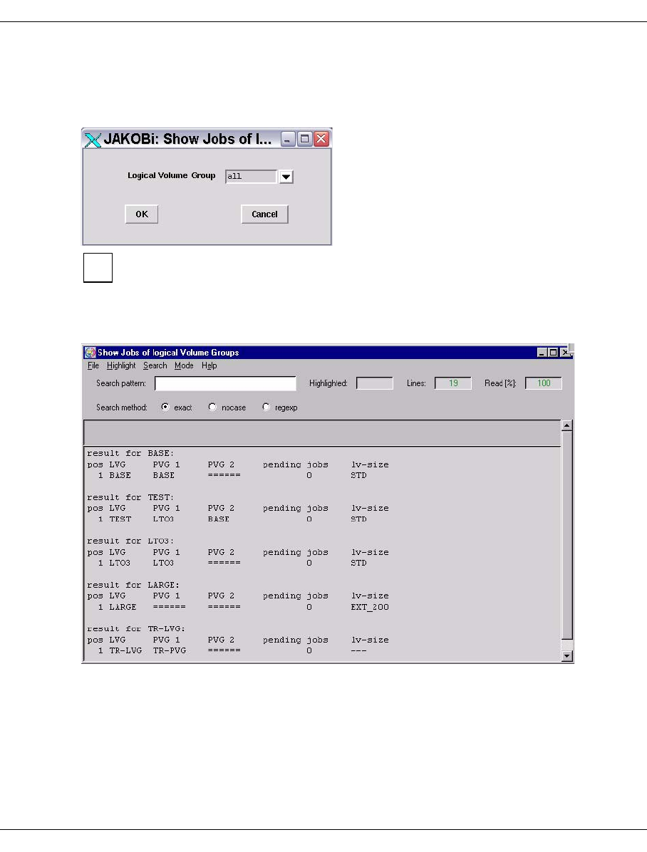
U41117-J-Z125-7-76 275
Global Status History data
7.6.2.9 Statistics » Logical Components » Jobs of Logical Volume Groups
If CentricStor contains more than one logical volume group (LVG) the required group is
entered using an intermediate menu:
This statistics function supports the refresh function. Information on this function
and the “OK” and “Cancel” buttons is provided on page 267.
If only one group is defined this intermediate step is skipped.
The job data for the selected group(s) is displayed:
i

276 U41117-J-Z125-7-76
History data Global Status
Meaning of the columns:
The job data (result for ... :) is output separately for each LVG.
pos Serial number
LVG Name of the logical volume group
PVG 1 Name of the first assigned physical volume group
If '======' is specified as the name, no PVG is assigned to the LVG.
PVG 2 Name of the second assigned physical volume group
If '======' is specified as the name, only a single save is performed for the
LVG (no Dual Copy).
pending jobs Number of jobs which have been accepted for this LVG
lv-size Size of the logical volumes:
STD Standard = 900 MB
EXT_x Extended: x specifies the volume size in GB (2, 5, 10, 20, 50,
100 or 200)
7.6.2.10 Statistics » Physical Components
The following submenus are available:
– Physical Drives (see below)
– Physical Volumes (page 279)
– Physical Volume Groups (page 283)
– Jobs of Physical Vol. Groups (page 289)
– Reorganization Status (page 291)
Notes on the refresh function:
All statistics functions support the refresh function:
After the function has been executed, i.e. after the result has been displayed in the
text window, the dialog window with the selection criteria (function window) is reta-
ined for further searches. The “OK” button at the lower edge of the function window
is replaced by the “Refresh” button, which enables the search to be repeated. The
search criteria can be modified before another search takes place.
The previous text window is then used to display the result, in which case the pre-
vious contents are deleted. The function window is closed only when the user clicks
on the “Cancel” button. In this case the text window with the result is also closed
implicitly.
i
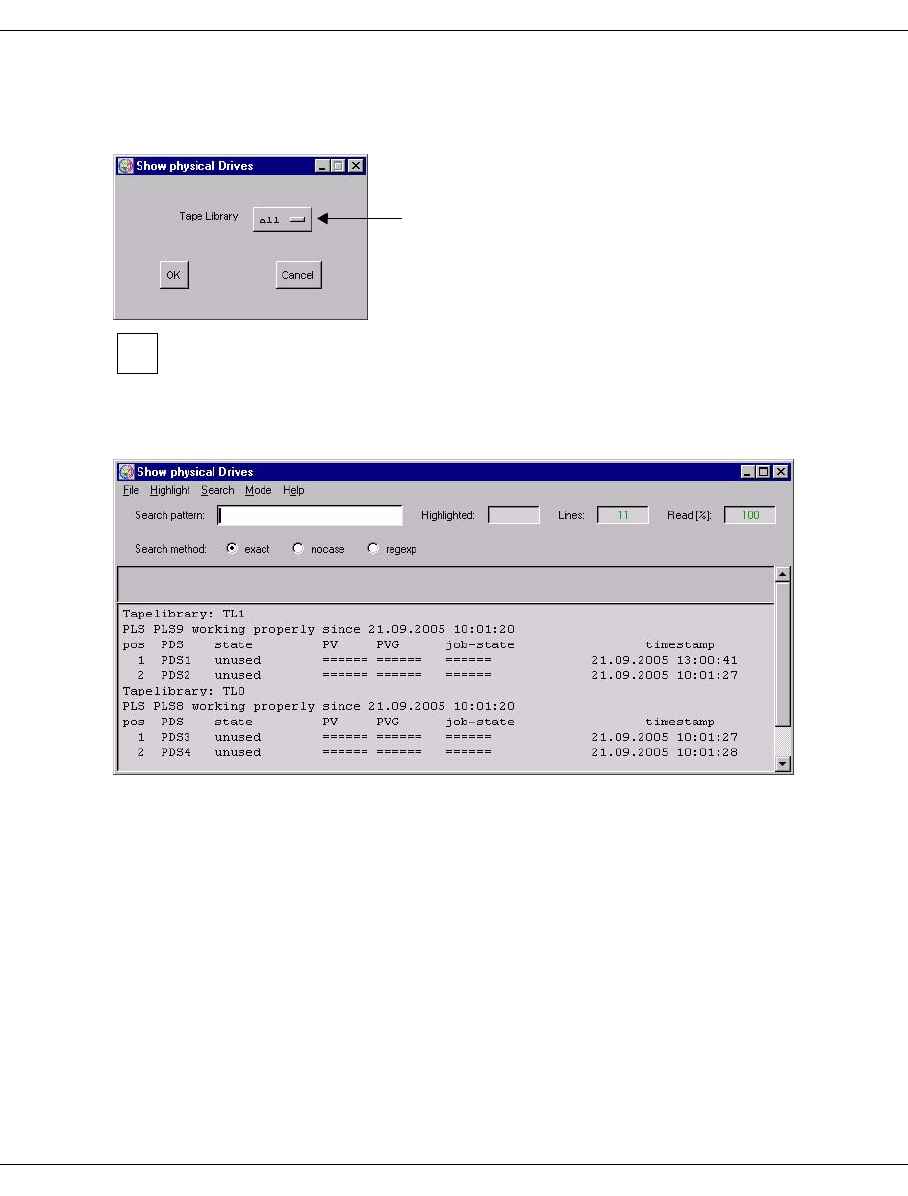
U41117-J-Z125-7-76 277
Global Status History data
7.6.2.11 Statistics » Physical Components » Physical Drives
First of all the library involved is queried:
This statistics function supports the refresh function. Information on this function
and the “OK” and “Cancel” buttons is provided on page 276.
The library required is selected via the drop-down menu.
A list of the device statuses is displayed:
The output field contains a line with the name of the archive system. The next line specifies
the time of the last status change of the PLS (Physical Library Server) responsible for the
library.
This is followed by a table of the drives:
pos Line number
PDS PDS name. Further information on the drive can be called in the XTCC menu under
this name.
If only one tape library exists, the name
of this tape library appears here.
i

278 U41117-J-Z125-7-76
History data Global Status
state Current status of the drive. Possible values:
unused Free, no PVG assigned
occupied Occupied; where relevant, the next columns show the name of the
mounted volume, the PVG, and the job status.
disabled Not used, possibly faulty
unreachable The PDS cannot be reached.
dis./unreach. The PDS is disabled and cannot be reached.
PV VSN of the physical volume
PVG Physical volume group
job state
Status of the ongoing operation. Possible values:
===== Nothing being processed
DONE Job completed
PLS_INSPECT_SENT Inspect command to a PLS
PDS_INSPECT_SENT Inspect command to a PDS (Transfer-In)
MOUNT_SENT Mount command
UMOUNT_SENT Unmount command
INIT_SENT Init command
INIT_NEW_SENT Reinitialization of a PV
ERASE_SENT Invalidating of a PV
READ_SENT Restore command
WRITE_SENT Save
WDIR_SENT Writing the directory
RDIR_SENT Reading the directory
CUR_SENT Check unit ready
UNLOAD_SENT Unload
CLEAN_SENT Drive being cleaned
If the command specified in the message was not executed in the time provided,
one of the following messages appears:
PLS_INSPECT_DELAY
MOUNT_DELAY
INIT_DELAY
INIT_NEW_DELAY
ERASE_DELAY
UNLOAD_DELAY
UMOUNT_DELAY
CLEAN_DELAY
...
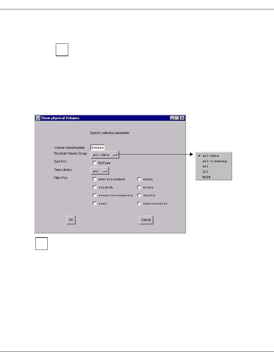
U41117-J-Z125-7-76 279
Global Status History data
timestamp
Time at which the current status was entered.
If you right-click on a library in the right-hand part of the Global Status
screen and select “Show Statistics” you are shown an overview of the drive
utilization in graphical and table form.
7.6.2.12 Statistics » Physical Components » Physical Volumes
Depending on the setting of the volume selection an overview of one or more physical
volumes and a statistical analysis are displayed.
The physical volume(s) can be identified in an intermediate menu:
This statistics function supports the refresh function. Information on this function
and the “OK” and “Cancel” buttons is provided on page 276.
See “Physical Volume Operations » Show Physical Volumes” on page 215 for a description
of how to use the filter functions and the meaning of the statuses.
i
i

280 U41117-J-Z125-7-76
History data Global Status
An overview in table form is then shown
Meaning of the columns:
pos Line number
PV Number of the physical volume
TL Tape Library: Name of the archive
PVG Name of the physical volume group
state Status; possible values:
e___ Volume ready for invalidation.
E___ The PV is reorganized and then invalidated.
f___ An error occurred while working with this tape. It is not reused and
automatically reorganized.
f_d_ A tape fault has occurred (PV is faulty) but an attempt is still made to write
the directory onto the tape
i___ The PV is currently not accessible
n___ New volume: the PV must still be initialized before it can be used.
N___ New volume: the PV must still be initialized before it can be used.
Initialization was started with the OmitHeaderCheck parameter.
o___ Initialized and empty.
_r__ Read volume on which no space is available for further data.
_rd_ The cartridge is full but an attempt is still made to write the directory onto
the tape
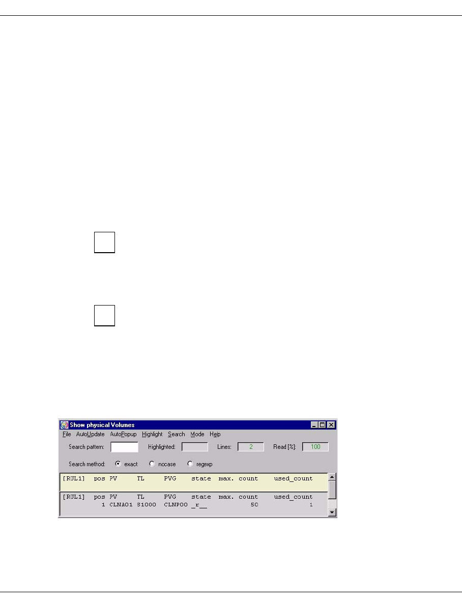
U41117-J-Z125-7-76 281
Global Status History data
s___ The PV must be scanned (used for transfer).
_v__ The PV is in “vault” state.
_w__ Write volume that can still be used for save operations.
_wd_ The cartridge is not yet full; currently there is no directory on the tape.
____ The state is unknown (used for Transfer-In).
next-bl
Block number of the free range. This indicates the physical utilization level.
LVs Number of saved logical volumes
val Number of valid saved logical volumes; copies of volumes not included here are no
longer relevant.
cap/GB
Gross capacity without data compression. This is not specified for volumes prior to
initialization (State = new).
This value is only indicated if supplied by the drive. Otherwise the value 0 is
supplied.
valid/GB
Used capacity; volume of data actually stored. Due to data compresion this value
may exceed the total capacity (previous column).
This only takes into consideration the data compression of the physical
drive. The data compression of the device emulations is displayed in “Global
Status” along with the cache data. In many cases the compression
indicated by PLM is lower if the cache data has already been compressed.
valid %
The percentage of valid data.
If you have selected several cleaning PVGs, you will see the following overview:
i
i

282 U41117-J-Z125-7-76
History data Global Status
Meaning of the columns:
pos Line number
PV Number of the physical volume
TL Tape Library: Name of the archive
PVG Name of the physical volume group, usually starts at “CLNP”.
state status
The following values are possible for cleaning cartridges:
o___ (“scratch”) when the volume has just been added.
_r__ Read volume, has no more space for additional data. This is the normal
state of a cleaning cartridge.
f___ (“faulty”) when all the cleaning cycles have been used up.
max. count
Initial number of cleaning cycles
used_count
Number of cleaning cycles used
The PLM uses the cleaning cartridges as far as possible in such a way that one
cartridge is used up fully before the next one is started. However, if a number of
cleaning requests are to be carried out at the same time, the cartridges that are
available will also be used simultaneously.
When a specific physical volume is queried (volume number specified in the query box) a
detailed overview is output:
The data for the selected PV is output in the title bar (see page 279).
This is followed by a list of the (valid) logical volumes stored on the PV.
i
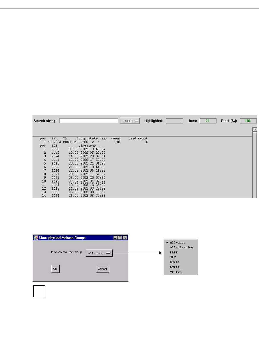
U41117-J-Z125-7-76 283
Global Status History data
Meaning of the columns:
pos Line number
LV Name of the logical volume
file-Id Hexadecimal: a type of version number in the TVC
LVG Name of the group to which the logical volume belongs
bl_nr Number of the first block of the logical volume on the PV
size/MB Size
save request at Time at which the PLM received the save job. This timestamp allows the
Disaster Recovery mechanism to identify which of the various different
copies of a logical volume is the most recent.
The information for a cleaning cartridge contains a list showing all the cleaning runs carried
out using this cartridge with the time and PDS of each run:
7.6.2.13 Statistics » Physical Components » Physical Volume Groups
If more than one physical volume group exists an intermediate menu is then displayed for
selecting the PVG:
This statistics function supports the refresh function. Information on this function
and the “OK” and “Cancel” buttons is provided on page 276.
You can select each individual PVG, all data PVGs, or all cleaning PVGs.
i
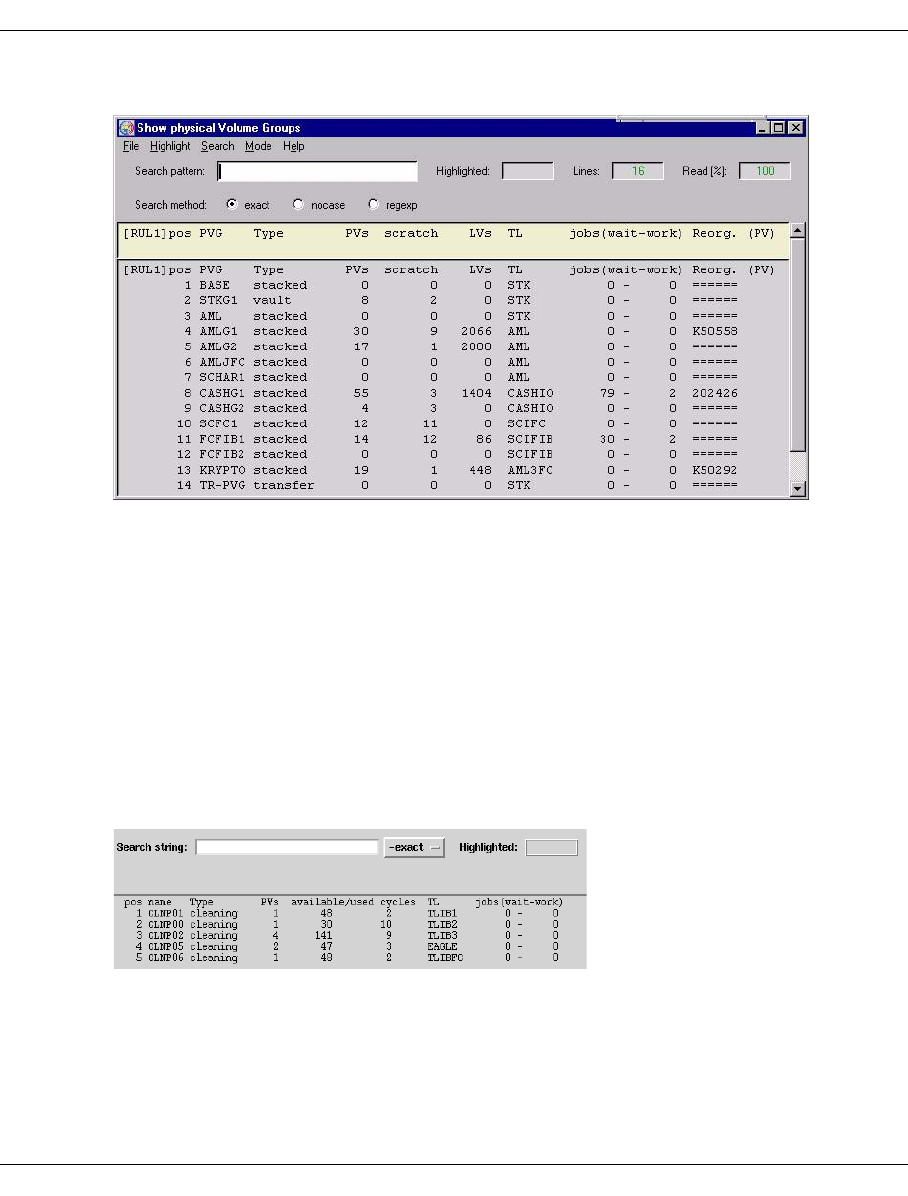
284 U41117-J-Z125-7-76
History data Global Status
When you select all data PVGs the following overview is displayed:
Meaning of the columns:
pos Line number
PVG Name of the physical volume group
Type Type of PV group (stacked, transfer, vault or cleaning)
PVs Total number of physical volumes in the group
scratch Number of empty PVs
LVs Number of logical volumes stored in this group
TL Name of the archive to which this group is assigned
jobs (wait-work) Number of jobs in the queue - number of active jobs
Reorg. (PV) Number of PV(s) which are being reorganized
When you select all cleaning PVGs the following overview is displayed:
Meaning of the columns:
pos Line number
PVG The name of the PVG.
Type Always clean.
PVs The number of PVs.

U41117-J-Z125-7-76 285
Global Status History data
available/used cycles
Number of available cleaning cycles for the physical volumes / number
of cleaning cycles which are executed.
TL The tape library.
jobs (wait-work) Number of waiting jobs / number of working jobs.
When you select only one data PVG the settings for the PVG and a list of the PVs stored
on it are displayed:

286 U41117-J-Z125-7-76
History data Global Status
PVG statistics are displayed in the first line.
The next block contains the parameters for controlling reorganization.
soft minimum number of empty PVs:
If the number of free volumes specified here is not reached, reorganization will take
place in the reorganization time shown further below.
amount of valid data for REORG
In the event of reorganization between the soft and hard limits, volumes are
recorded whose occupancy level (data volume of the valid cartridge images / data
volume of all cartridge images, specified in %) fall below the value set here.
timeframe for REORG
Time in which the reorganization runs should usually take place. Times with a low
productive load should be chosen here.
Currently only a timeframe common to all weekdays can be selected on the
graphical user interface.
hard minimum of empty PVs
If the number of free volumes specified here is not reached a reorganization run is
started immediately regardless of the occupancy level.
absolute minimum number of empty PVs
If this number of empty volumes is reached or fallen below, all resources are used
for a reorganization run. Save and restore requests from the VLM which are not
related to the reorganization are not accepted. This considerably restricts the
productive operation of CentricStor.
The following hierarchy applies:
Soft Minimum > Hard Minimum > Absolute Minimum.
Name Meaning Example
PVG Name AMLG1
Type Type of the PVG stacked
PVs Number of physical volumes 30
scratch Number empty 19
LVs Number of logical volumes 2066
TL Tape Library: Name of the archive AML
jobs (wait-work) Number of jobs in queue or being
processed
0 jobs in queues, 0job being
processed
Reorg. (PV) Indicates whether a reorganization
is running for the PV group
No reorganization being
processed

U41117-J-Z125-7-76 287
Global Status History data
number of parallel requests to VLM (REORG)
Number of “Move Requests” to be processed simultaneously which the PLM sends
to the VLM for the purpose of reorganizing PVs. The higher this value, the more
resources are reserved by the reorganization.
cancel time for REORG
If a move request issued by the PLM to the VLM remains in an unchanged status
beyond this time it is canceled by the PLM. This does not apply for a PV reorgani-
zation started by an operator command.
estimated MB/s
estimated overhead for 1 write job
With the “estimated MB/s” and “estimated overhead for 1 write job” parameters the
PLM selects the physical volume which it can release in the shortest time in the
event of a reorganization. MB/s specifies the estimated write performance of the
write drive, “Write Overhead” the estimated overhead per volume to be written.
refresh interval
Threshold value in days. If the first write job for a PV was executed before more than
the specified value, the PV will be reorganized in the time range specified in
“timeframe”.
write size per PDS
number of write jobs per PDS
These two parameters control the number of drives to be used for write jobs.
– write size:
Maximum write data volume per drive.
– number of write jobs
Maximum number of write jobs per drive.
The drive assignment is determined from the maximum value ascertained from the
two values. The number of drives used for save requests is defined by the PLM
according to the following formula:
n = int (max ((Write_data_volume/WriteWatermark_1), (Number_of_write_jobs/
WriteWatermark_2)) +1)
n = 0 if no write jobs are present.
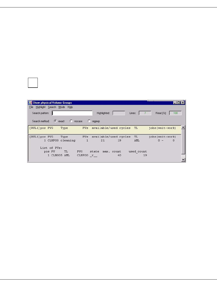
288 U41117-J-Z125-7-76
History data Global Status
time slice for PDS-scheduler
Time in seconds for which a PDS remains assigned to a PV group. After this time
has elapsed an active job is terminated and the drive may be unloaded. Depending
on the load situation it is then assigned to another PVG.
The value must be greater than or equal to 600 seconds.
Assignment of the physical drives to the PVGs can be controlled by different sized
time slices. The larger the time slice of a PVG, the greater its share in the use of the
drives.
The layout of the subsequent list of PVs is the same as that described on page 219.
When you select only one cleaning PVG you are shown the following data:
Statistical data of the cleaning PVG:
PVG Name of the PVG
Type Type of the PVG
PVs Number of PVs
available/used cycles
Total avaialble/used cleaning cycles
TL Library in which the PVG is located
jobs (wait-work)
Pending/active cleaning runs
Then follows a list containing the data of the individual volumes.
i
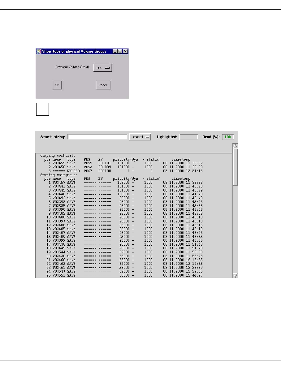
U41117-J-Z125-7-76 289
Global Status History data
7.6.2.14 Statistics » Physical Components » Jobs of Physical Vol. Groups
A window for selecting one or all PVGs is opened:
This statistics function supports the refresh function. Information on this function
and the “OK” and “Cancel” buttons is provided on page 276.
The job data for the selected group(s) is displayed:
The top part of the text field shows the jobs that are being processed, the lower part the
queue.
Meaning of the columns:
pos Serial number
LV Name of the logical volume for which the job is or is to be performed. Empty for jobs
with no reference to the LV.
i

290 U41117-J-Z125-7-76
History data Global Status
type Type of job
ERASE Invalidate PV header
INIT Load and initialize PV
INITNEW Add new PV, write header
RDIR Reads the directory.
REST Restore an LV from the physical tape to the “Tape Volume Cache”
SAVE Save an LV from the “Tape Volume Cache” to a physical type
UNLOAD Unload PV from PDS
WDIR Writes the directory.
PDS The name of the PDS which processes the job.
As long as a job is in the queue and no PDs is yet assigned to it, this column
contains ’======’.
PV The name of the physical volume.
As long as no PV was assigned with saving jobs, this contains ’======’.
priority (dyn. - static)
Dynamic priority of the job (see below) / static priority
timestamp
Time at which the status shown was entered.
Explanation of the priority
Each job is assigned a static priority when it is created. This is dependent on the following:
– the type of job,
– the current situation (scratch tapes over/under hard limit),
– the procedure for which the job is executed (depending on the number of empty tapes
a SAVE job for a reorganization can have a different priority from the SAVE job started
by the VLM for clearing the cache),
– for some jobs, the volume of data to be moved.
The dynamic priority is obtained by multiplying the wait time (in minutes) by the static
priority. This calculation is updated every 60 seconds or whenever a new job in entered in
the queue.
The example shows the following situation:
– The PVG is using three drives: PDS9, PDSA and PDS7.
– PV 001100 is being unloaded in PDS7.
– LV V03455 in PDS9 is being written to PV 001101, and LV V03456 in PDSA to
PV 001099.
– Below this is a list (not shown in full here) of the LVs which are waiting to be rewritten.
– The queue for “SAVE” is relatively long and (probably) also contains large volumes of
data. Consequently two drives are already being used for writing.
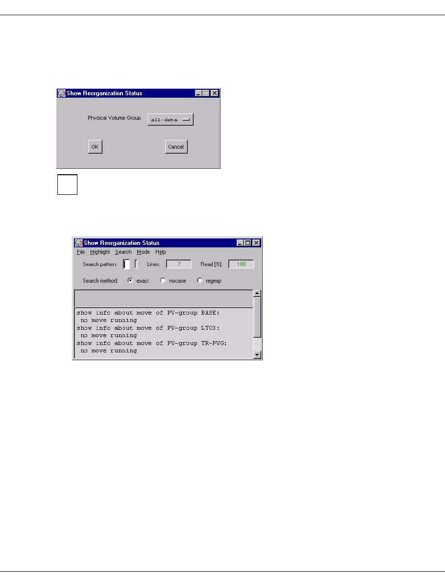
U41117-J-Z125-7-76 291
Global Status History data
7.6.2.15 Statistics » Physical Components » Reorganization Status
A window for selecting one or all PVGs is opened (naturally the clean PVGs are not
offered):
This statistics function supports the refresh function. Information on this function
and the “OK” and “Cancel” buttons is provided on page 276.
If only one group is defined this intermediate step is skipped.
If no reorganization is running the following window is displayed:
i
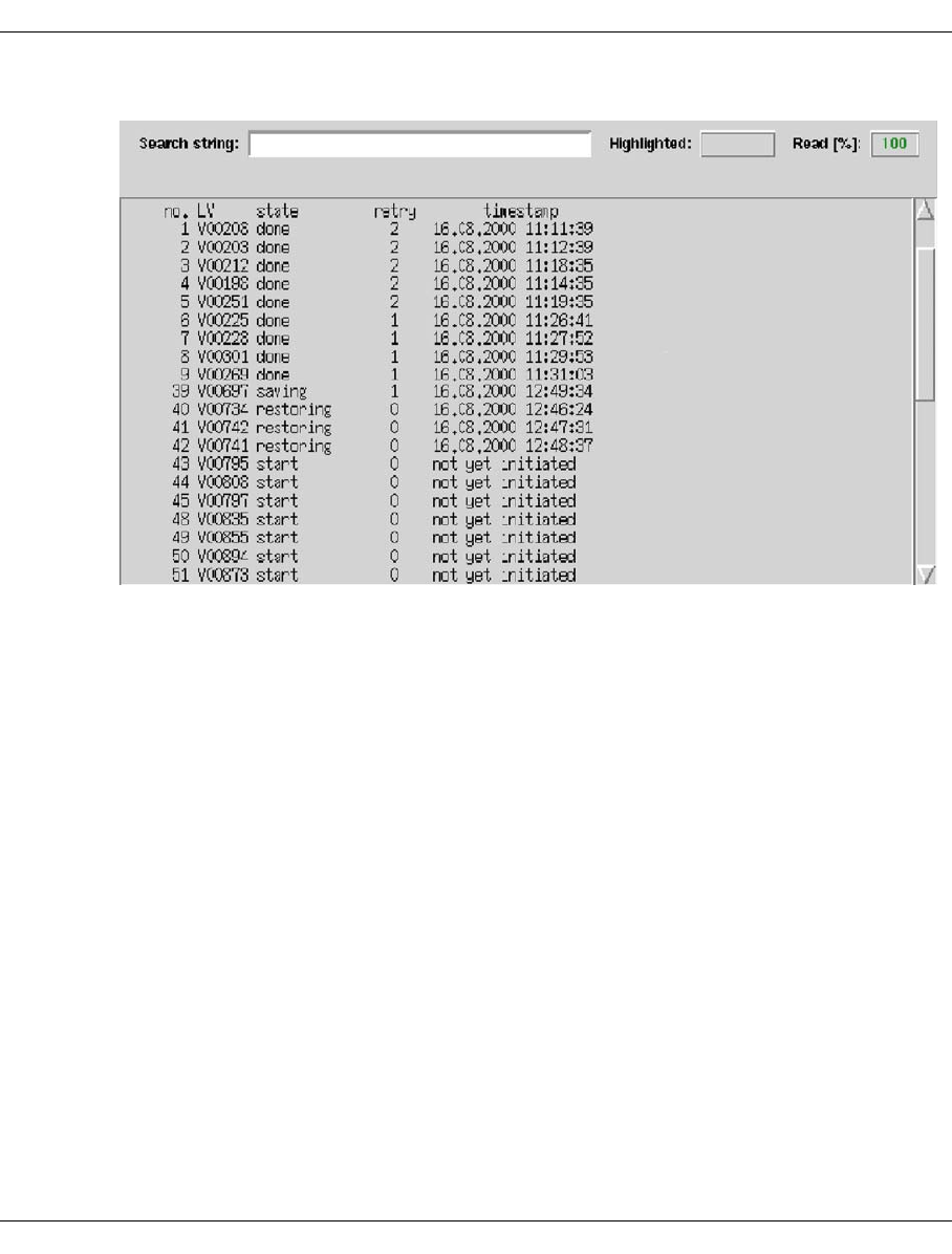
292 U41117-J-Z125-7-76
History data Global Status
Otherwise the status of the reorganization of the physical volume group(s) is displayed:
Meaning of the entries:
no. Line number
LV Name of the logical volume
state Status of the reorganization:
done Completed
failed Aborted; can only occur with runs started manually
initiated Job sent to VLM
restoring Being moved back to the cache
restore done Moved back to the cache; rewriting has not yet started
saving Being written to tape
start Not yet started
retry Number of command retries; after more than 2 the job is aborted.
timestamp Time at which the current status was entered.
The number specified in the retry column also relates to command retries at the PLM-VLM
interface. If the high load on the VLM means that a PLM request could not be satisfied within
this time limit, the job is issued again.
Retries are alarming only if a particular PV is repeatedly connected with a large number of
retries. In this case the logical volumes on the PV must be moved and the PV must be
removed (see the section “Physical Volume Operations » Erase Physical Volumes” on
page 226).
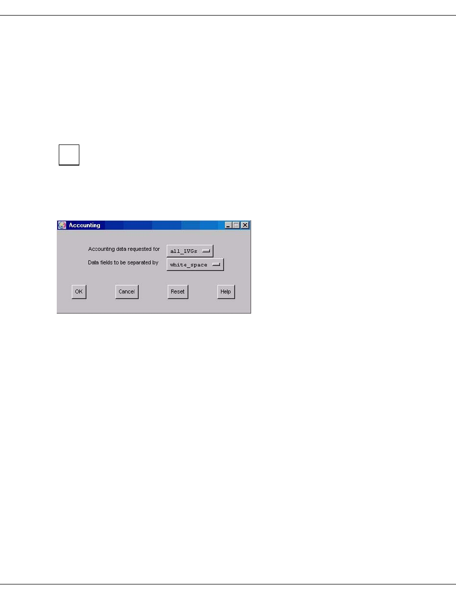
U41117-J-Z125-7-76 293
Global Status History data
The frequent occurrence of retries can also indicate that the reorganization times coincide
with peak loads. In this case the reorganization times should be moved (“Scratch Time
Frame” field, see the section “Physical Volume Groups” on page 181).
More detailed information on the retry causes is provided in the system messages (see the
section “Show System Messages” on page 158).
7.6.2.16 Statistics » Usage (Accounting)
This function is displayed only if an accounting license is installed.
This function is also available in Observe.
It enables the accounting data for logical volume groups (LVGs) to be displayed. When the
entry is activated, the “Accounting” window is displayed:
i
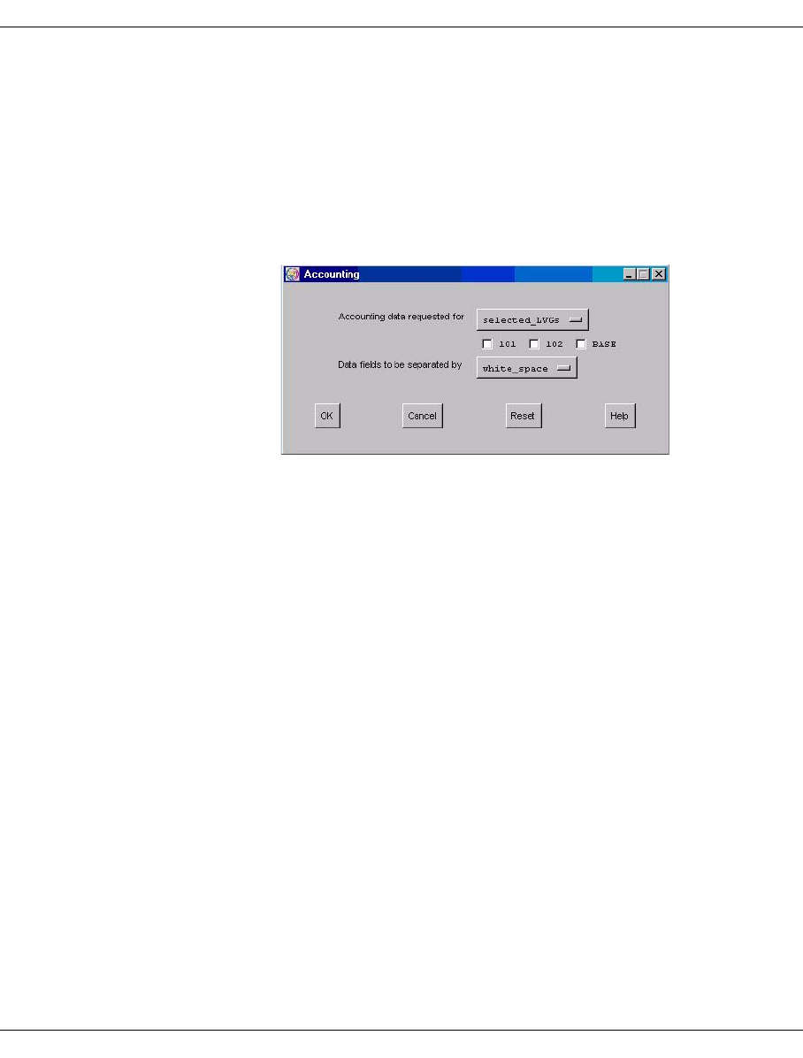
294 U41117-J-Z125-7-76
History data Global Status
Selection fields
Accounting data requested for
Here you can choose between the following options:
all_LVGs The accounting data for all LVGs in the system is output.
selected_LVGs Initially all the LVGs known in the system are displayed as check
buttons.
Example
You can then select those LVGs whose accounting data you are
interested in.
Data fields to be separated by
Here you are given the opportunity of outputting the accounting table(s) in a format in
which the individual fields are separated either by white space or by a comma.
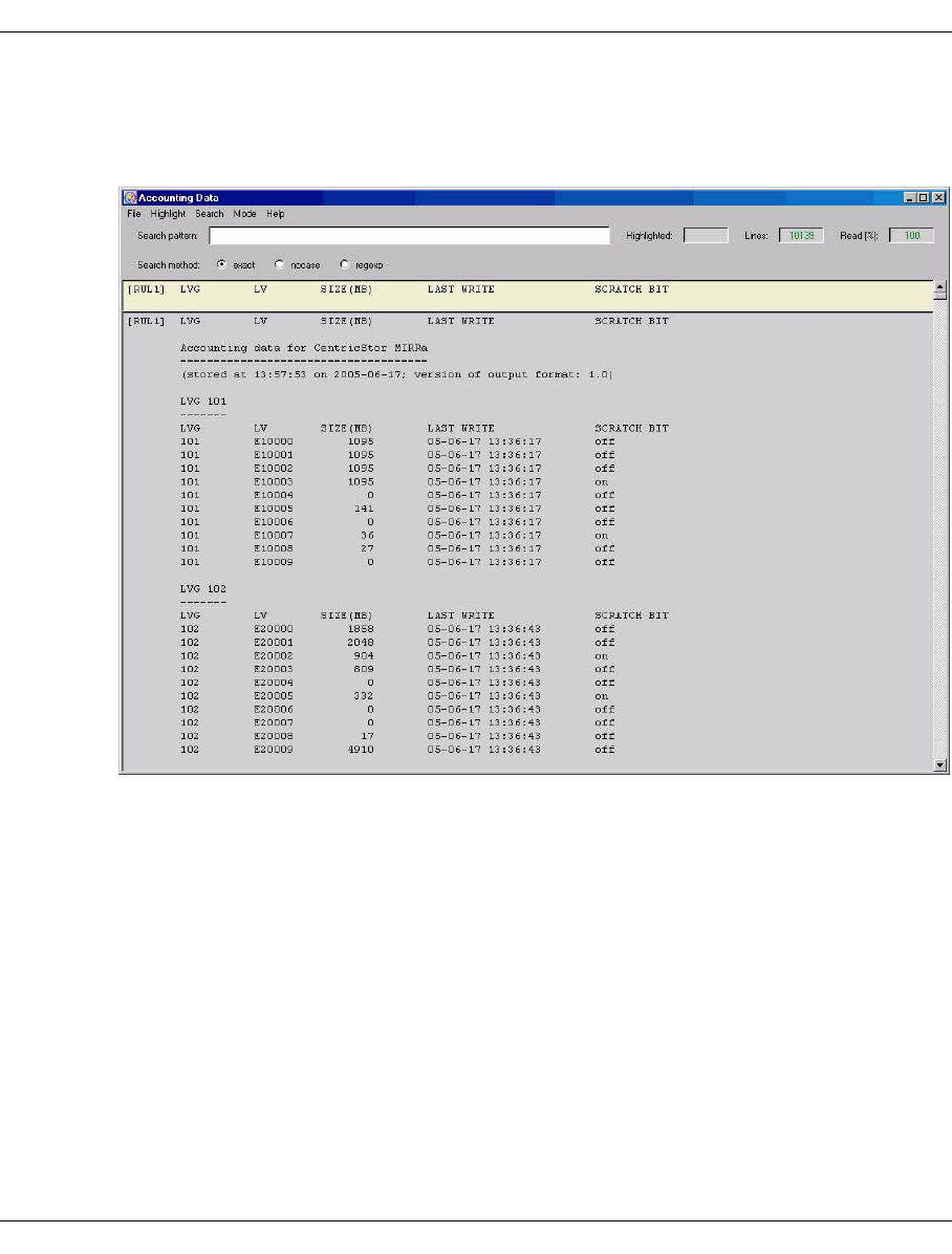
U41117-J-Z125-7-76 295
Global Status History data
Accounting Data
When you click on the “OK” button the account information is displayed in a text field (here
with the option “Data fields to be separated by white space”):
The data is output in the following form for each CentricStor computer:
●Title
“Accounting Data for CentricStor <Name des CentricStor-Systems>”
●Subtitle
Date and time and format of the output

296 U41117-J-Z125-7-76
History data Global Status
●Tab l e
One or more tables with the accounting data depending on whether the data for all, for
one or for multiple logical volume groups (LVGs) was requested.
Each table consists of the following:
–Title
all LVGS Display of all LVGs
LVG <LVG-name> Display of the selected LVG
– Columns
The individual columns are separated by white space or commas (no white space) .
LVG Name of the LVG to which the volume belongs
LV Name of the volume
SIZE (MB) Amount of data stored on this volume (in MB)
LAST WRITE Date and time of the last write access
SCRATCH BIT Value of the scratch bit1:
on Volume may be overwritten.
off Volume may not be overwritten.
●Termination
The end of the entire output is indicated by the character string “end of accounting
data”. This indicator permits a check to ensure that the accounting data is complete.
1Dieses Scratch-Bit ist ein CS-internes Merkmal und hat nichts tun mit einem Scratch-Volume aus der Sicht einer Host-Anwendung,
welches durch ein (zufällig) gleichgenanntes Scratch-Bit gekennzeichnet ist.
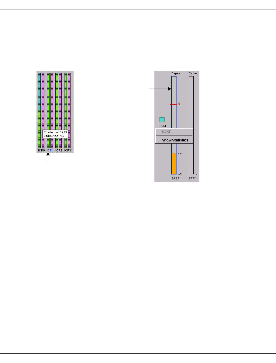
U41117-J-Z125-7-76 297
Global Status History data
7.6.3 Data which can be called via objects of the Global Status
The chronological progress and statistical data can be displayed via some Global Status
objects. To do this position the mouse cursor over the object. If data is present for the object,
this is indicated by a blue border or the device designation is colored blue. If you press the
right mouse button a context menu with the menu item “Show Statistics” is opened.
If you select the “Show Statistics” function an empty statistics window opens in which you
can enter the required time specifications, as described in the section “Selecting the time
period” on page 262. After you have clicked on the “Redraw” button the statistics graph is
displayed.
Detailed information on this subject is provided in the section “History diagrams” on
page 298.
Right mouse button: A
menu appears which
contains the function“Show
Statistics”.
Left mouse button:
Device information is
displayed.
Blue device designation
Blue border
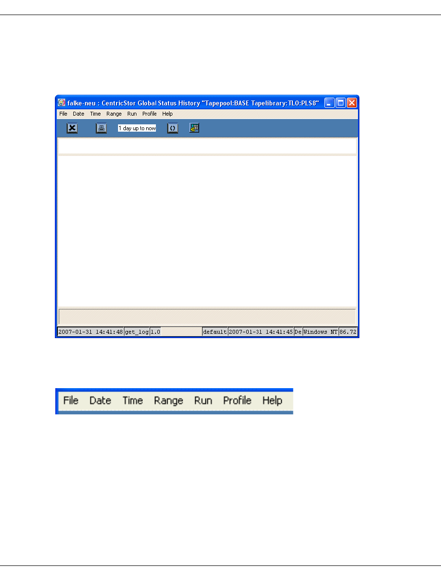
298 U41117-J-Z125-7-76
History diagrams Global Status
7.7 History diagrams
After a statistic has been selected, first of all a window with an empty page appears. The
window is structured as follows:
7.7.1 Function/menu bar
7.7.1.1 File
The following functions are available:
–Export
–Print
–Exit
Menu bar
To o lb a r
Title bar
Page
Legend bar
Status line
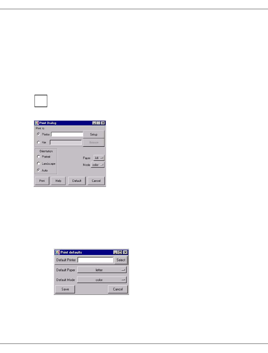
U41117-J-Z125-7-76 299
Global Status History diagrams
Export
This function causes the history data to be read in as specified by the current settings. The
data is then written to a file.
Details on this are provided in the section “Exporting history data” on page 314.
Print
Prints the chart or saves the print image to a file.
If Global Status is running under Windows it is advisable to use the print function
button (page 246). This opens the usual Windows print menu.
A printer setup menu is displayed:
Setting options
Print to
–Printer
Output is to a PostScript printer.
After you click on the “Setup” button a window is displayed for entering the printer
setup:
In this form you can make the printer default settings. After you click on the “Save”
button the settings are transferred to the previous window.
–File
Output is to a file in PostScript format.
i
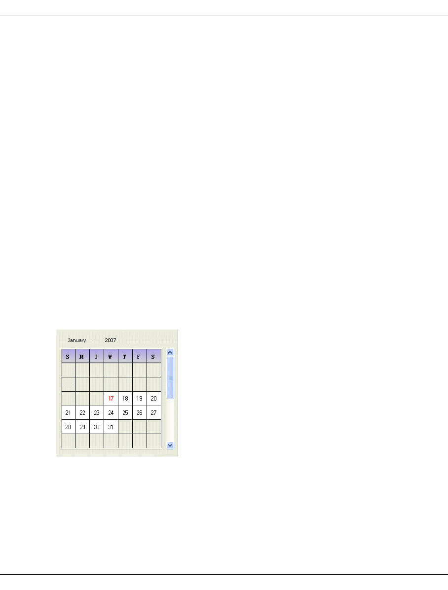
300 U41117-J-Z125-7-76
History diagrams Global Status
Orientation
You use “Orientation” to select “Portrait” format, “Landscape” format or “Auto”
(automatic adjustment).
Paper
Here you can select “A4” or “letter”.
Mode
Setting options: “color” or “grayscale”
Buttons along the lower border
Print Printout takes place with the values set.
Help A help text is output.
Default Saves all current settings.
Cancel The window is closed without the changes being accepted.
Exit
This closes the window.
7.7.1.2 Date
This function opens a window which enables the start date for a display area to be defined:
You can select the month using the scroll bar.
After you have clicked on a valid date field, the window is closed and the date is taken over.
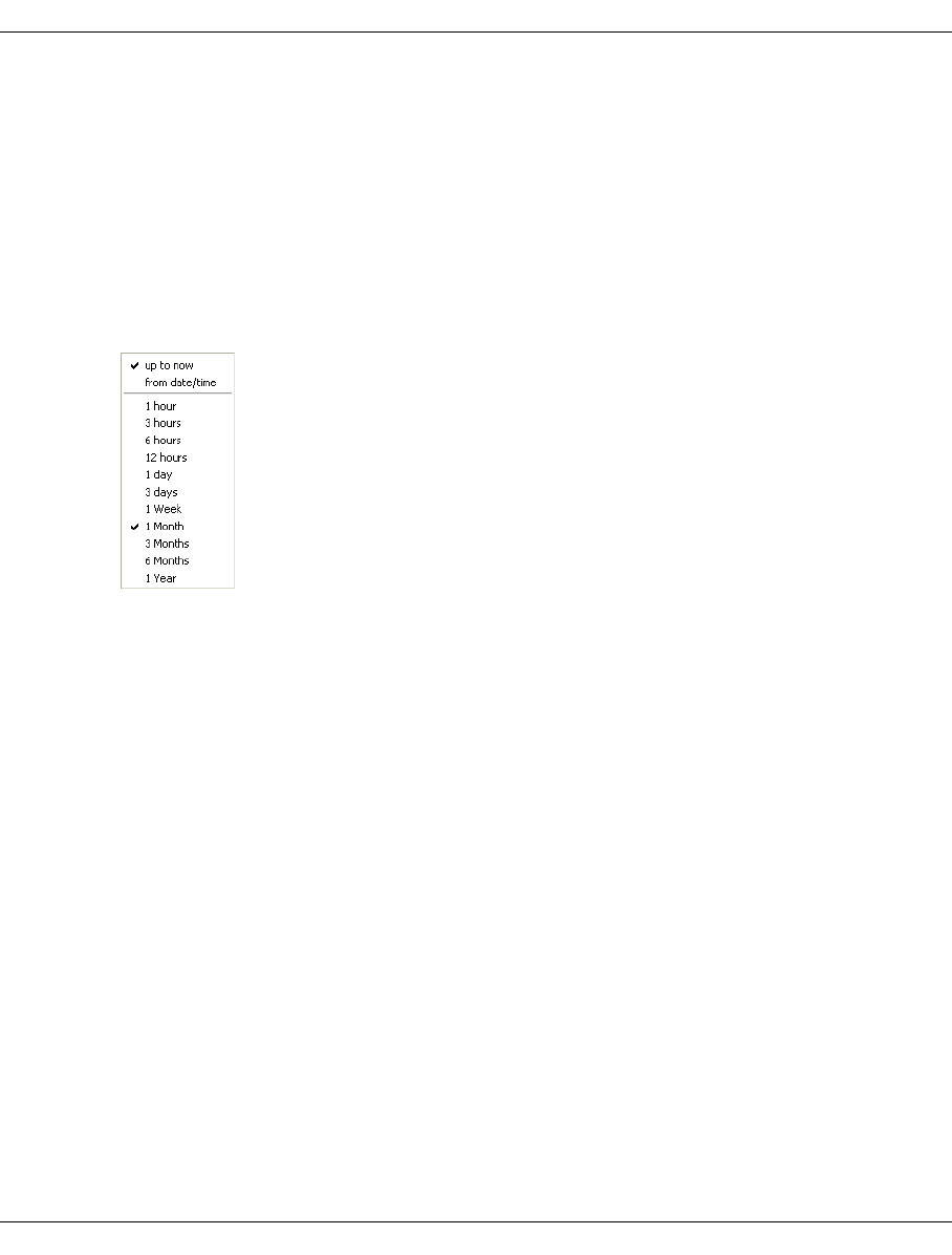
U41117-J-Z125-7-76 301
Global Status History diagrams
7.7.1.3 Time
A pull-down menu with the values 0 - 23 is opened in which you can define the start time
for a display area.
After you have clicked on the required time, the window is closed and the value selected is
taken over.
7.7.1.4 Range
A pull-down menu is opened in which you can define the the display period:
The duration of the display period is defined with the values at the bottom.
The values at the top are used to select whether the display period should start on the date
set and at the time selected (from date/time) or end with the current time (up to now).
After you have clicked on the required field, the window is closed and the value selected is
taken over.
7.7.1.5 Run
Draw
The statistics are presented again in the window using the data from Date, Time and Range.
Export
A browser is opened which enables you to save the current graphics as a text file.
7.7.1.6 Mode
After the diagram has been built up, some diagrams enable you to specify whether the ma-
ximum value (max), the spread (min/max) or the average value (average) should be presen-
ted for each display period. If you select min/max, the maximum and minimum values are
separated by a slash.
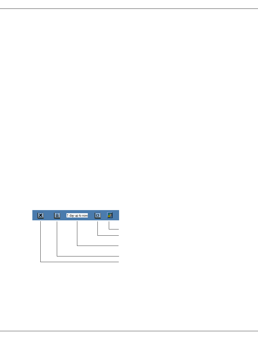
302 U41117-J-Z125-7-76
History diagrams Global Status
7.7.1.7 Profile
Profile enables the current settings, e.g. for the analysis period, to be stored and reused the
next time the program is called.
Specifically this means:
– Managing profiles (submenu: Add/Select Profile)
– Importing options from a profile file (submenu: Add/Select Profile)
– Storing options in a profile (submenu: Save)
Automatic storing/import:
When the Viewer has been terminated, the current settings are saved in the current profile.
The next time the Viewer is called, the settings from this profile are used again.
7.7.1.8 Help
Readme
Displays a text window with helps.
About
Displays a copyright notice and the revision level of the program.
7.7.2 Toolbar
The toolbar is used to start frequently used functions without having to take the detour via
the menu. The settings which are currently applicable for the analysis period are also dis-
played.
Export
Refresh
Display for Date, Time and Range
Print
Exit

U41117-J-Z125-7-76 303
Global Status History diagrams
7.7.3 Status bar
The status bar at the bottom of the screen displays (from left to right) the following informa-
tion:
remote_time Time stamp of the last history call on the connected CentricStor
protocol Type of protocol used: get_log or read_log
Protocol version Version number of the protocol
Profile Name of the profile currently used
last history call Time stamp of the last history call on the GUI computer
Language Language set for the helps
Platform Operating system
Version Version of the program
7.7.4 Diagrams for the throughput (left-hand part of the screen)
Overall throughput
This function can also be reached via the function bar (see the section “Statistics » History
of » Channel/Device Performance” on page 266). The chronological progress for the host
adapter and device throughput is displayed. The buttons along the lower border can be
used to mask out individual data types.
Mode selection (max, min/max or average, see section “Selecting the presentation mode”
on page 263) is supported.
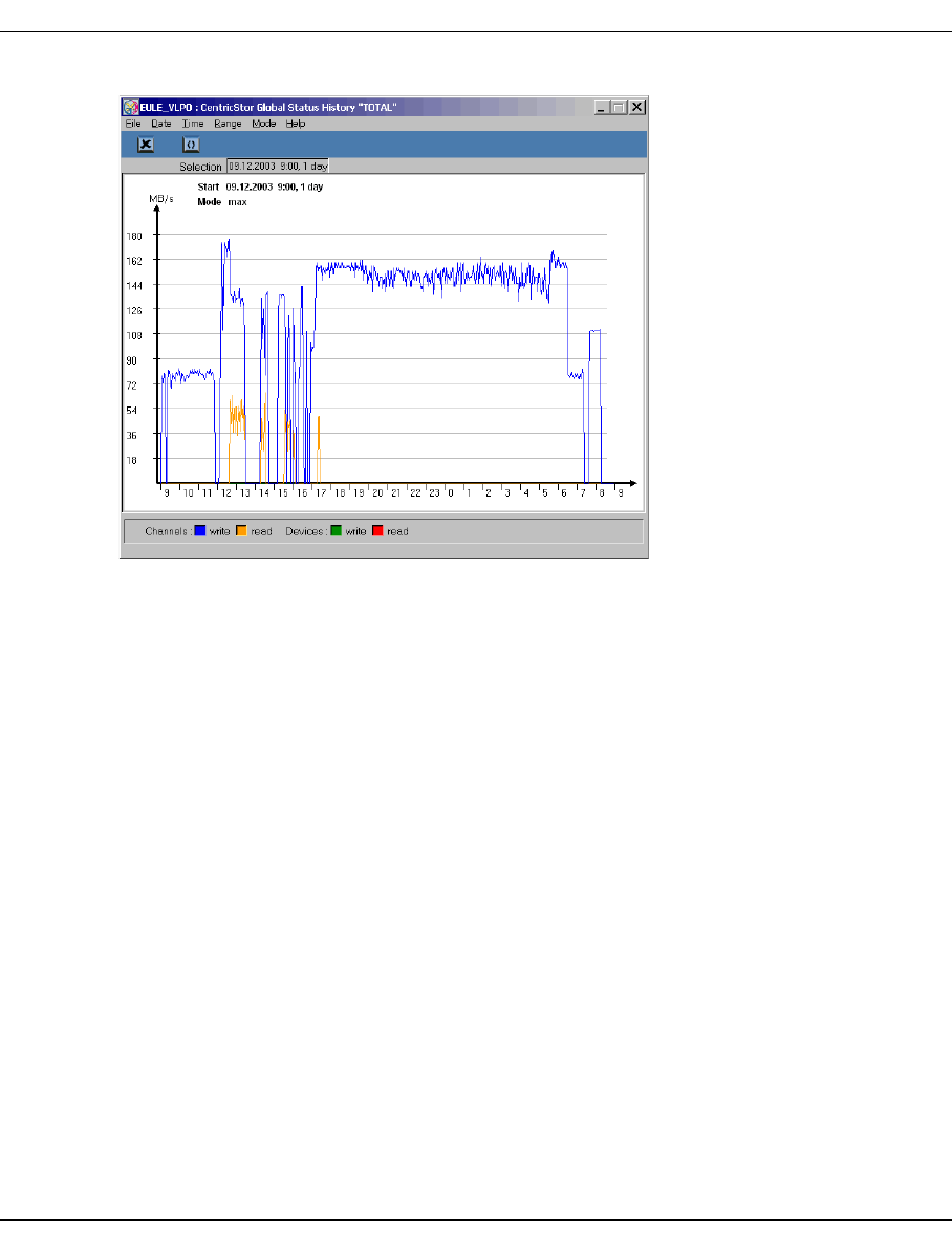
304 U41117-J-Z125-7-76
History diagrams Global Status
Host adapters
For each host adapter a column showing the current throughput for read and write opera-
tions of the host - arranged according to ICP - is displayed in the upper half of the left-hand
subwindow. As described above, you can have the chronological progress of these values
displayed for each host adapter.
Mode selection (max, min/max or average, see section “Selecting the presentation mode”
on page 263) is supported.
Device ports
For each tape drive controller a column showing the current throughput for read and write
operations of the CentricStor backend - arranged according to IDP - is displayed in the lower
half of the left-hand subwindow. As described above, you can have the chronological
progress of these values displayed for each tape drive controller.
Mode selection (max, min/max or average, see section “Selecting the presentation mode”
on page 263) is supported.

U41117-J-Z125-7-76 305
Global Status History diagrams
7.7.5 Diagrams for virtual components (central part of the screen)
7.7.5.1 ICP emulations
A distinction must be made here between whether the readlog or getlog protocol is being
used on the connected CentricStor. This depends on the CentricStor version currently in-
stalled:
= V3.1D: get_log protocol
< V3.1D: read_log protocol
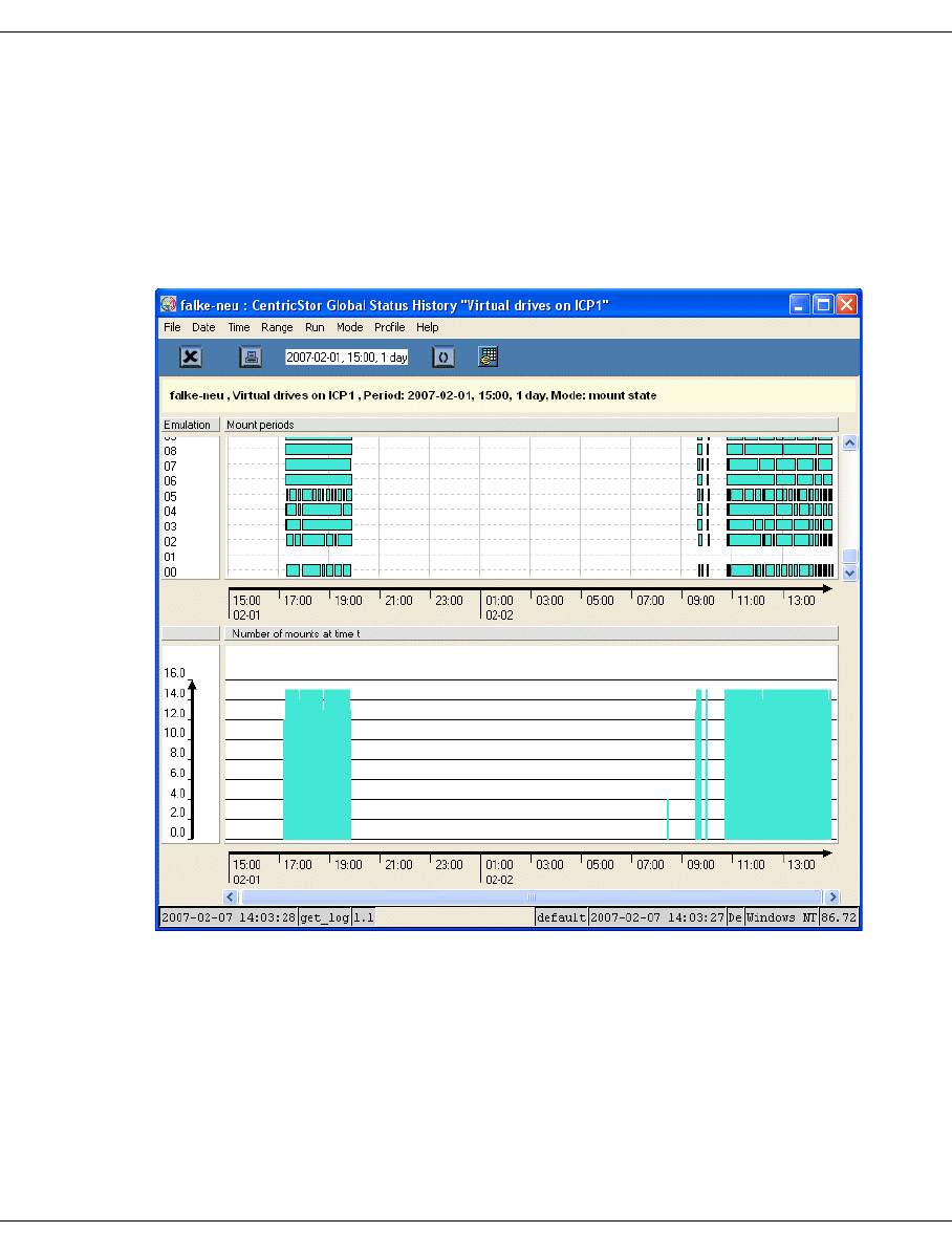
306 U41117-J-Z125-7-76
History diagrams Global Status
Outputs for CentricStor V3.1D or higher (get_log protocol)
The following diagrams are offered depending on the mode selected (see the section “Mo-
de” on page 301):
●Mount state diagram
The mounted state is displayed for each emulation/PDSs in the selected period. This
shows the time when a cartridge was mounted:
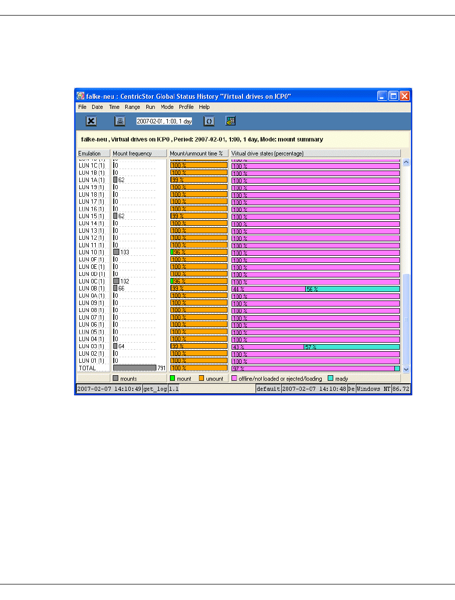
U41117-J-Z125-7-76 307
Global Status History diagrams
●Mount summary diagram
The number of emulations/PDSs in the mounted state at any given time is shown here.
This shows how many tapes were unmounted at a particular time:
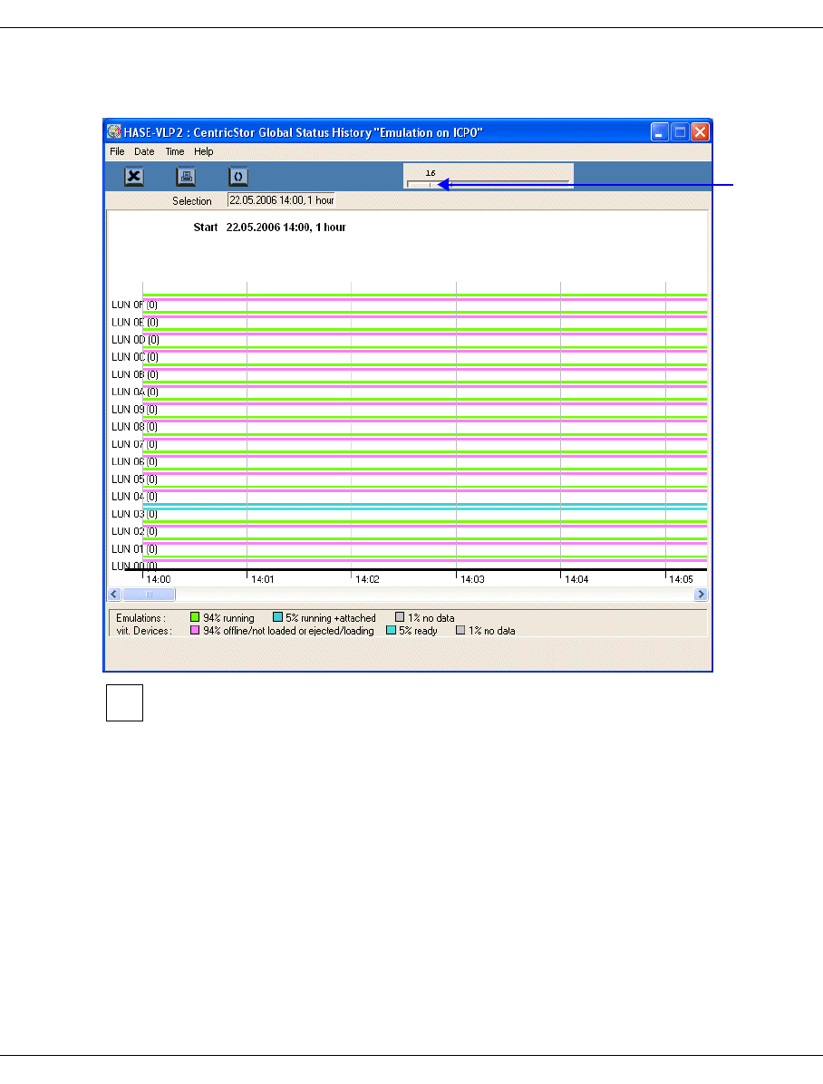
308 U41117-J-Z125-7-76
History diagrams Global Status
Outputs for CentricStor < V3.1D (read_log protocol)
If more than 16 emulations are defined, a slider is displayed in the button bar. You
can use this to select which group of 16 emulations is to be displayed.
The presentation period is set permanently to one hour.
The key at the bottom of the window describes the meaning of the colors of the lines in the
picture, i.e. statuses. The percentage share of each status in the period shown is also dis-
played.
Each line pair shows the status of the emulation (upper line) and that of the relevant virtual
drive (lower line).
Slider
i
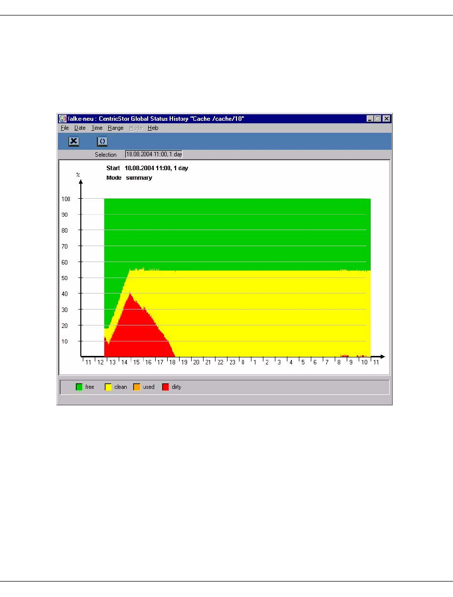
U41117-J-Z125-7-76 309
Global Status History diagrams
7.7.5.2 Cache Usage
The progress of the cache usage can be displayed for each individual cache file system or
for all caches together. To do this, right-click on the relevant cache column in the central
section and select “Show Statistics” in the context menu. After you have specified the
required time period you are shown a presentation of the cache usage:
The color presentation of the cache statuses in your system may differ from this example.
You should therefore refer to the key along the lower border.

310 U41117-J-Z125-7-76
History diagrams Global Status
Meaning of the statuses
free Not used. This area can be used immediately for saving volume images.
clean Contains valid volume images. The volumes are unchanged compared to their
images saved on tape (either not yet written or already saved). If another mount
takes place for a volume from this area, this can be performed without a delay.
If the storage space is required for other volumes, it can be used without delay.
used In use. The images of volumes which are being loaded are saved in this area.
dirty The volumes imaged here have changed compared to their contents saved on
tape. When the data is saved to tape, the status changes to “Clean”.
7.7.6 Diagrams of the physical components (right-hand part of the screen)
7.7.6.1 IDP statistics
When you click on an IDP (left-hand half of the screen) with the right mouse button and
select “Show Statistics” a window containing the IDP’s statistical data appears.
A distinction must be made here between whether the readlog or getlog protocol is being
used on the connected CentricStor. This depends on the CentricStor version currently in-
stalled:
= V3.1D: get_log protocol
< V3.1D: read_log protocol
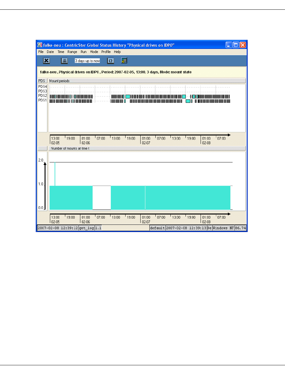
U41117-J-Z125-7-76 311
Global Status History diagrams
Example for V3.1D
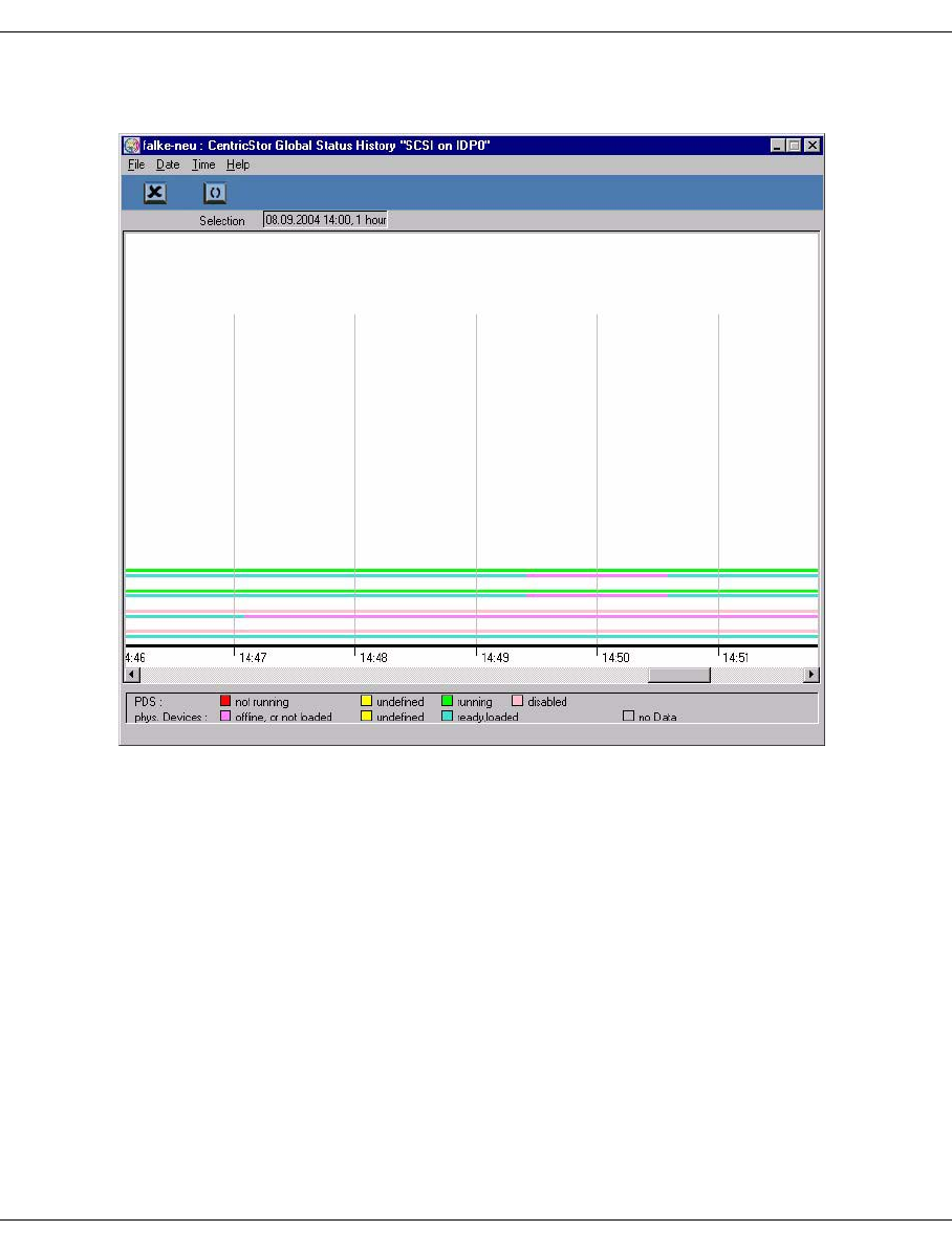
312 U41117-J-Z125-7-76
History diagrams Global Status
Example for < V3.1D
The presentation period is set permanently to one hour.
Each line pair shows the status of the PDS (upper line) and that of the relevant physical
drive (lower line).
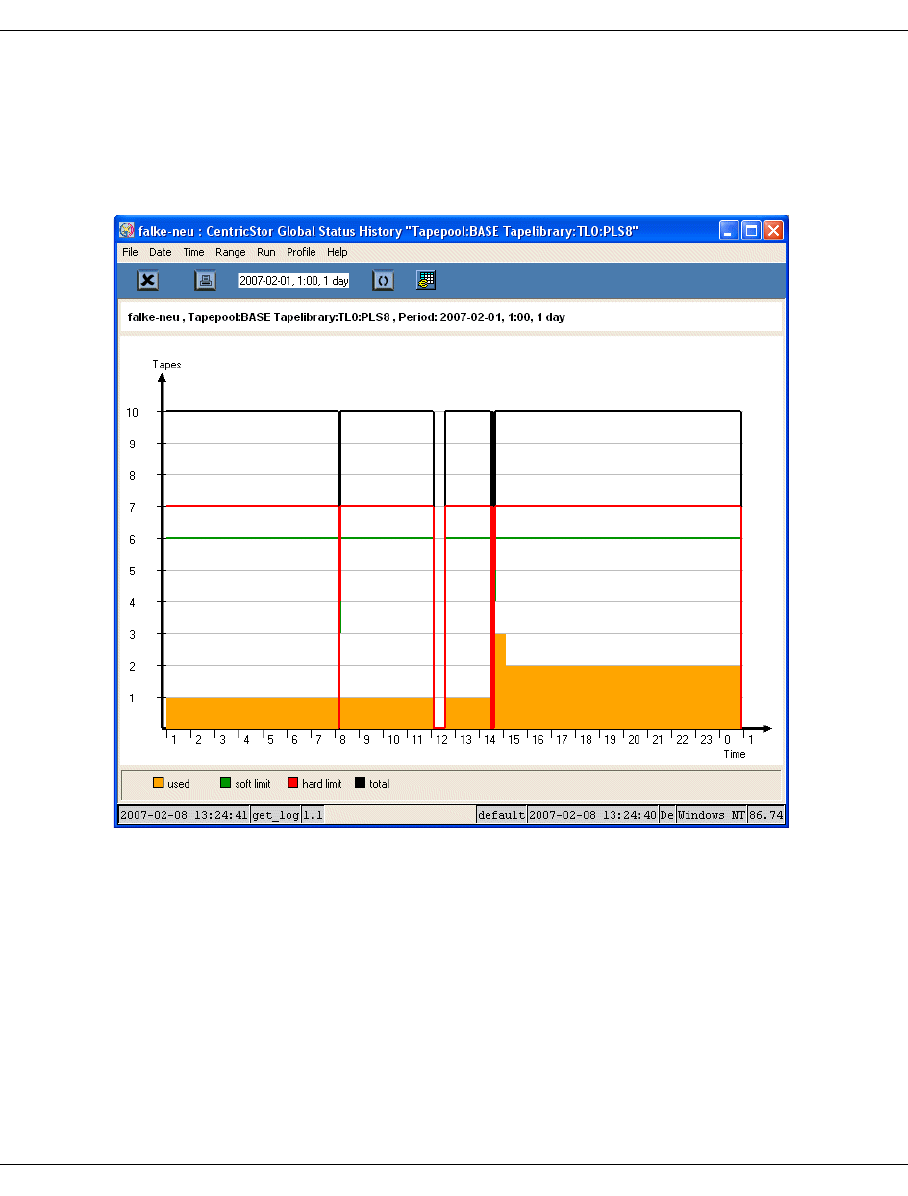
U41117-J-Z125-7-76 313
Global Status History diagrams
7.7.6.2 Tape pool values
When you click on a column in the right-hand part of the screen with the right mouse button
and select “Show Statistics” a window containing the tape pool values appears.
Example
The presentation shows the progress for the physical volumes used.
Start date, start time and range can be selected for this display.
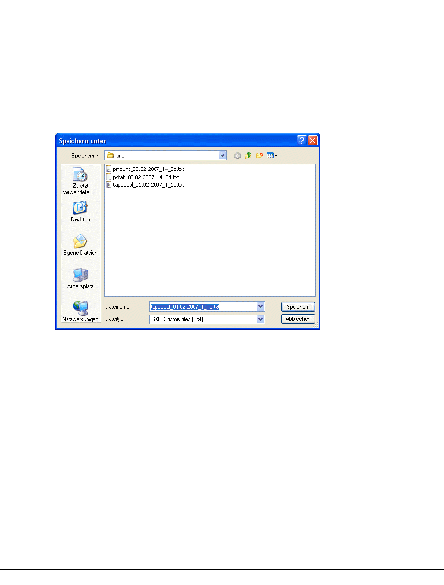
314 U41117-J-Z125-7-76
History diagrams Global Status
7.7.7 Exporting history data
This function causes the history data to be read in as specified by the current settings. The
data is then written to a file. This can involve considerably more data than would be needed
to draw the diagram currently selected (see the example below).
To save the data a selection dialog is offered which enables you to switch the directory and
assign a name to the file which is to be stored:
Preset directory: The temporary GXCC directory
Preset file name: <historytype>_date_time_range.txt
After the file has been saved, the content of the written file is displayed in the main window.
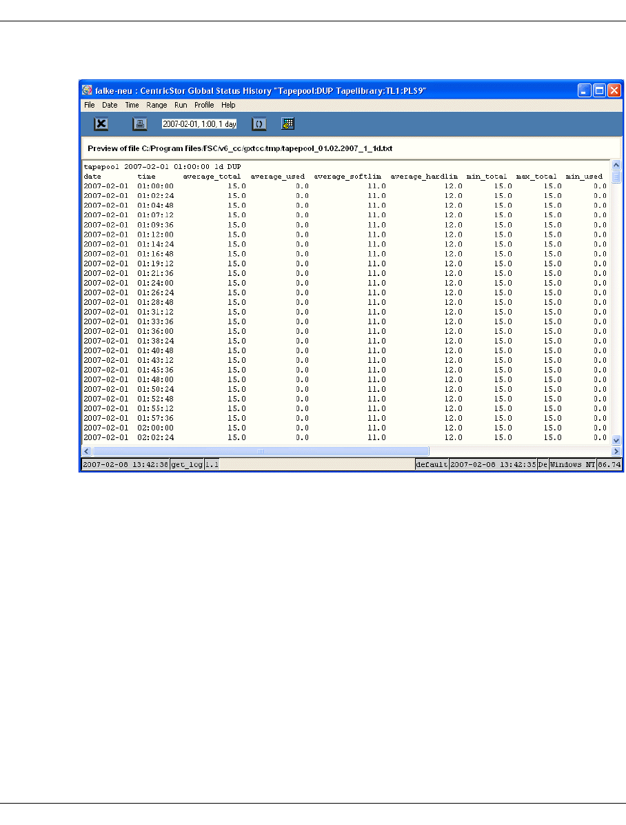
U41117-J-Z125-7-76 315
Global Status History diagrams
Example
Scope of output:
It is possible that more data fields are written to the file than would be shown on the screen,
namely all data fields which were read in for the presentation selected (i.e. the raw data sup-
plied at the interface).
Example: If the presentation mode average is selected, the min/max data fields are never-
theless imported and exported in addition to the average data fields.

316 U41117-J-Z125-7-76
History diagrams Global Status
7.7.8 Command line tool for generating the history data
The shell script get_hist.sh was created to permit the history data of a CentricStor system to
be made available in a text format (e.g. for the spreadsheet program Excel).
This script is contained in the /usr/apc/bin directory. It can be used to analyze the cur-
rent history data of the system on which it is called (Case a), or the imported data of a fo-
reign system (Case b).
In Case a) the script can be called on any ISP of the CentricStor system concerned. The
same applies for Case b) if the imported history files were saved on the RAID. Otherwise
get_hist.sh must be called on the computer whose local hard disk contains the files.
The script’s output is directed to stdout and can consequently be written to the histo-
ry.csv file (the file name is arbitrary) by adding the suffix >history.csv to the script call.
The script call has the following format:
get_hist.sh <history-type> <additional-parameter>
Explanation:
The history type must be specified as the 1st parameter. This specification corresponds to
clicking on an object in the Globstat window in the case of graphical output.
The following history types are supported:
History type Corresponds to clicking on the following in the Globstat window
cache A cache in the Virtual Components subwindow
escon A channel in an ESCON graphic in the Performance subwindow
Fc A channel in an FC graphic in the Performance subwindow
ficon A channel in a FICON graphic in the Performance subwindow
pmount A PDS box in the Physical Components subwindow
tape A device in the DEVICES graphic in the Performance subwindow
tapepool A tape pool in the Physical Components subwindow
total The bar in the TOTAL graphic in the Performance subwindow
vmount An emulation box in the Virtual Components subwindow

U41117-J-Z125-7-76 317
Global Status History diagrams
All values which can be selected in the graphical call of the history function can also be spe-
cified as additional parameters. The -hd parameter, which is described further below, is
also accepted. Which parameters can or must be specified differs according to the history
type. The correlation is shown by a matrix which the script outputs when the help function
(-h or -? parameter) is called:
get_hist.sh -?
call: get_hist.sh <history type> <parameters for specified history type>
The following history data will be delivered for the specified period of
time:
-----------------------------------------------------------------------------
History type | data delivered
-----------------------------------------------------------------------------
cache | partitioning of cache states free, clean, used, and
| dirty for specified cache
escon | average, minimal, and maximal read and write performance for
| ISP and ESCON channel specified
fc | average, minimal, and maximal read and write performance for
| ISP and fiber channel specified
ficon | average, minimal, and maximal read and write performance for
| ISP and FICON channel specified
pmount | number of mounts, mount time and time spent in different
states
| for each pds process on ISP specified
tape | average, minimal, and maximal read and write performance for
| ISP and tape device specified
total | average, minimal, and maximal read and write performance for
| the entirety of channels and devices
vmount | number of mounts, mount time and time spent in different
states
| for each virtual drive (emu or vtd) on ISP specified
History type and related parameters can be extracted from matrix below
("opt." means "parameter is optional"):
-----------------------------------------------------------------------------
history type: | cache | escon | vmount | tape | tapepool | total
| | or | | | |
| | fc | or | | |
| | or | | | |
param.: | | ficon | pmount | | |
---------------------------------------------------------------------------
-ca <cache name as | x | | | | |
found in globstat or | | | | | |
wild card term> | | | | | |
-ch <channel name as | | x | | | |
found in globstat(*1) | | | | | |

318 U41117-J-Z125-7-76
History diagrams Global Status
or wild card term> | | | | | |
-da <start date | opt. | opt. | opt. | opt. | opt. | opt.
(YYYY-MM-DD)> | | | | | |
-dv <device name as found| | | | x | |
in globstat(*2) or | | | | | |
wild card term> | | | | | |
-hd <history directory, | opt. | opt. | opt. | opt. | opt. | opt.
e.g. /usr/tmp/\ | | | | | |
hist_log> (*3) | | | | | |
-ho <start hour | opt. | opt. | opt. | opt. | opt. | opt.
(>=0 and <24)> | | | | | |
-in <ISP name, e.g. ICP0 | | x | x | x | |
or wild card term> | | | | | |
-pt <period of time | opt. | opt. | opt. | opt. | opt. | opt.
(1h, 2h, 3h, 6h, 12h, | | | | | |
1d, 3d, 1w, 1m, 3m, | | | | | |
6m, or 1y)> | | | | | |
-tn <tapepool name as | | | | | x |
found in globstat> | | | | | |
---------------------------------------------------------------------------
(*1) click left mouse button in globstat window on channel, which you are
interested in, and take string, which appears behind ':' in the balloon
help
(*2) click left mouse button in globstat window on device, which you are
interested in, and take string, which appears behind ',' in the balloon
help
(*3) This parameter is needed, if history files were imported from a foreign
CentricStor system. It specifies the directory in the local system, in
which the foreign history files were stored.
Sample calls:
get_hist.sh escon -ch ca0 -in ICP1 -da 2006-02-22 -ho 13 -pt 3h
get_hist.sh tape -dv c15t12l0 -in IDP0 -da 2006-03-31 -ho 20 -pt 1d
To process the generated history data using Excel or a program which can interpret Excel
data (referred to as the evaluation program below), the data must be transferred (e.g. using
ftp) to the computer on which the evaluation program is called. The files generated are ge-
nerally 50 KB in size.

U41117-J-Z125-7-76 319
Global Status History diagrams
Presentation of the data in Excel
In order to permit the history data to be presented on a graphical interface of a type similar
to CentricStor, an Excel macro has been created which is supplied with the GXCC product.
This macro is only intended as an example and in no way provides a 1:1 map of the GXCC
graphical interface.
The macro is contained in the following directory:
<GXCC-installation-directory>/osd/Windows/Excel_Performance_Makro.xls
Example
c:/Programs/FSC/v6_cc/gxtcc/osd/Windows/Excel_Performance_Makro.xls
Procedure:
1. Starting the macro
The macro can be started either by means of a double-click (if a link exists between xls
files and the evaluation program) or by starting the evaluation program and then ope-
ning the macro. If necessary, click on the Activate macros button to confirm.
2. Generally a dialog for opening a file is then offered to select the history file. Select a file
and then click on OK.
3. A number of dialog pages will be created and offered for display.
4. If you want to evaluate another history files, you can do so using the menu item
GlobalHistory/Historyfile (on the far right of the menu bar in Excel) or by rebooting.
5. ...
6. Terminate the macro
When you terminate the macro you will be asked whether you want to save the changes. If
you want to keep the evaluation, you should store it in the form of another xls file (i.e. as an
Excel file) in the dialog offered. Your original file will remain unaffected by this.
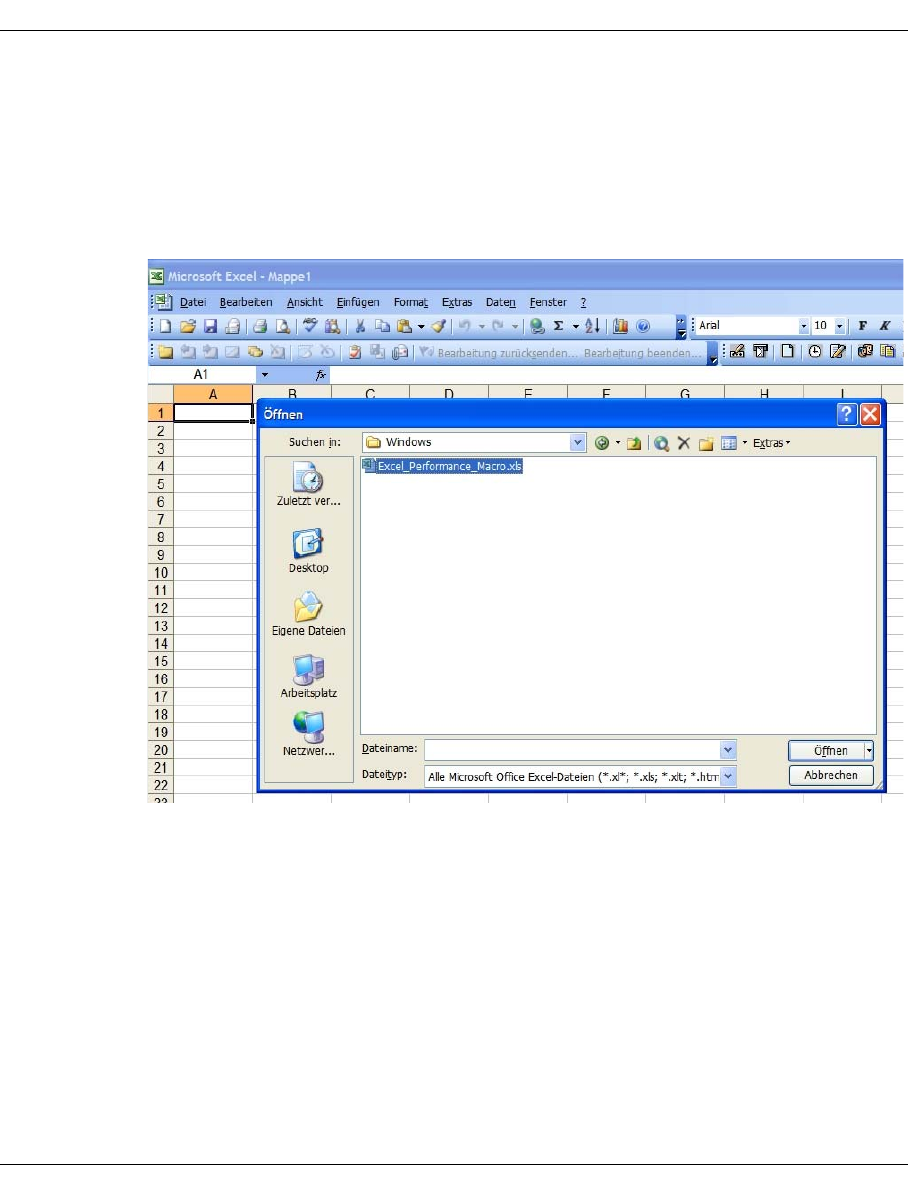
320 U41117-J-Z125-7-76
History diagrams Global Status
Example
1. Create a file
get_hist.sh total -da 2006-03-29 -ho 0 -pt 6h >YIN.total2.txt
2. Transfer file
3. Open Excel macro:
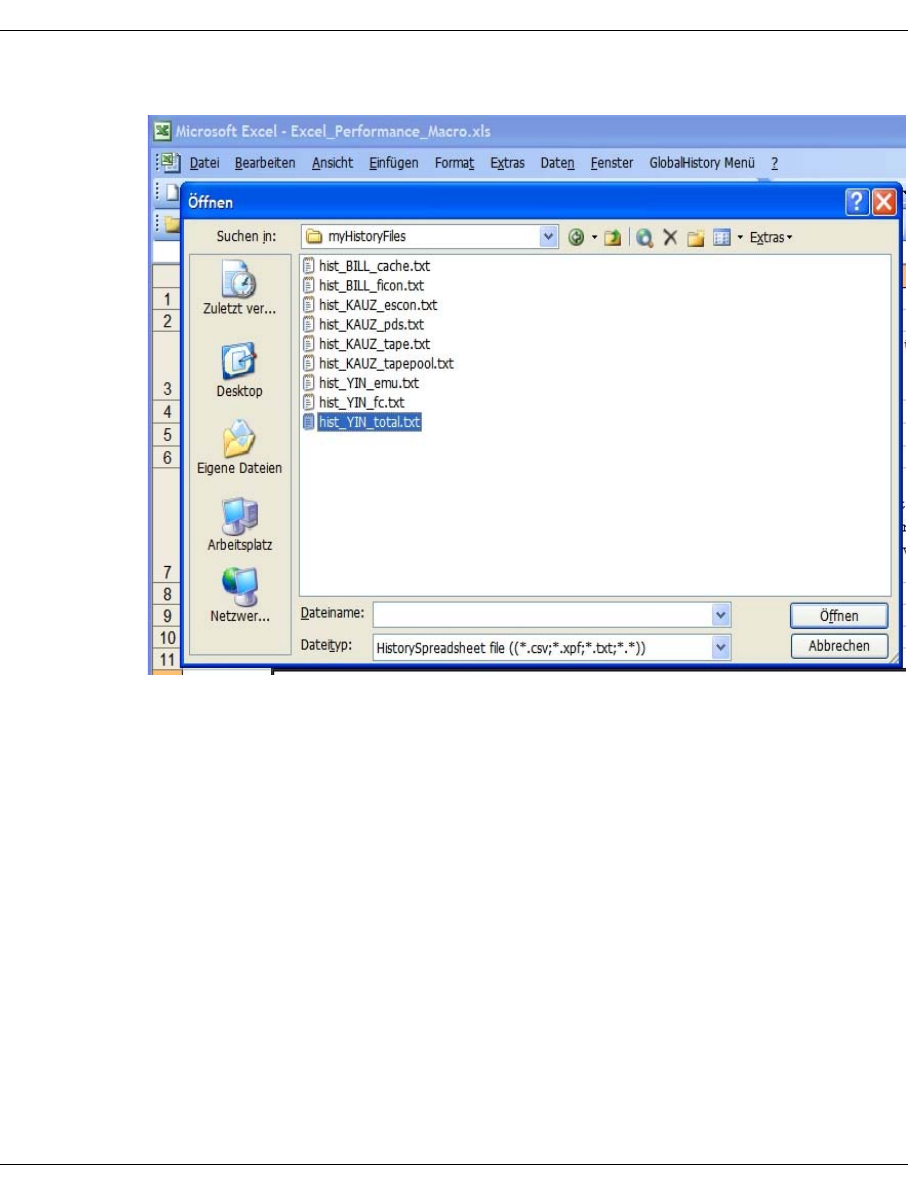
U41117-J-Z125-7-76 321
Global Status History diagrams
4. Open history file:
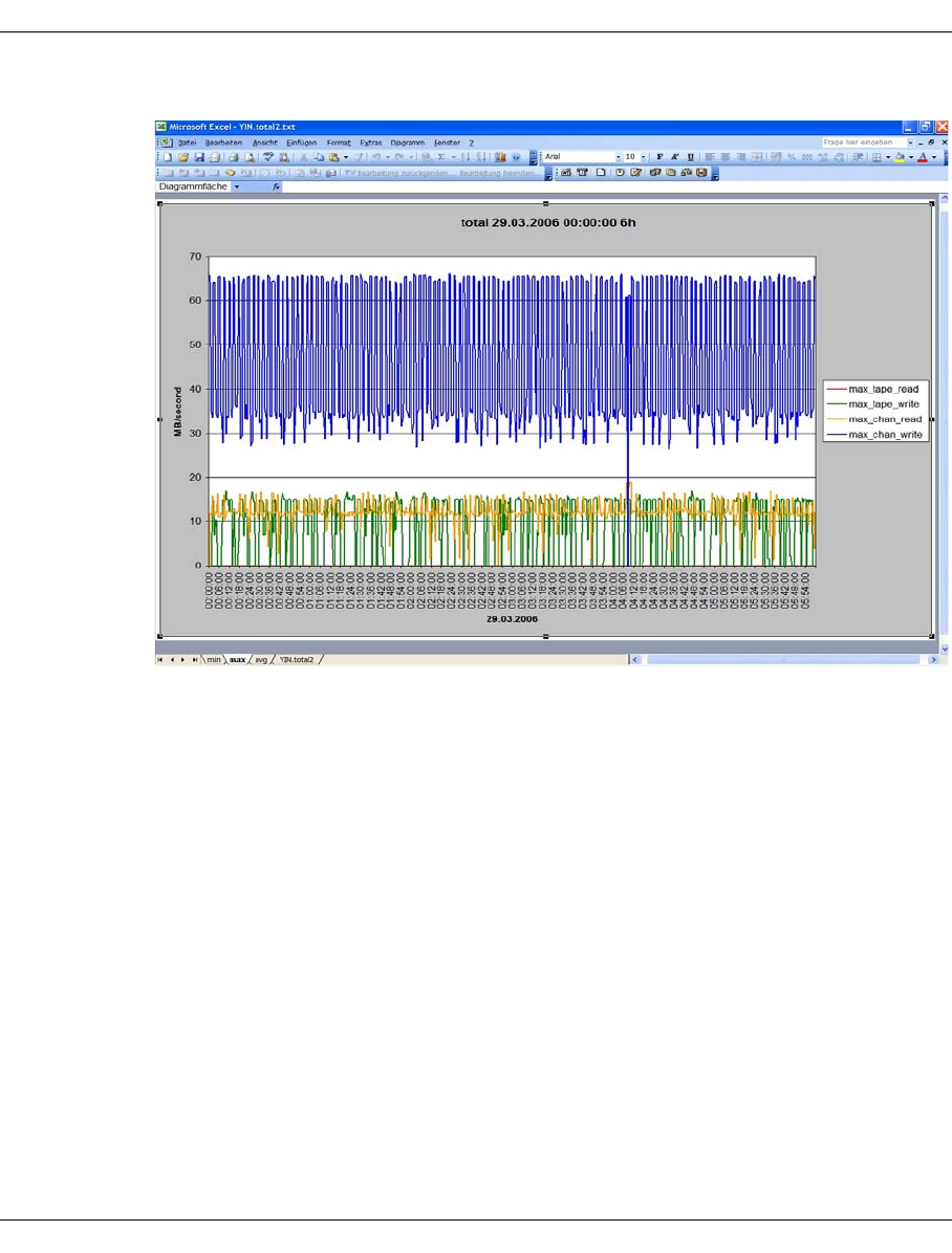
322 U41117-J-Z125-7-76
History diagrams Global Status
5. Confirm you wish to open it:
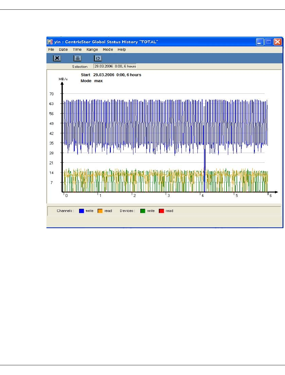
U41117-J-Z125-7-76 323
Global Status History diagrams
Here, by way of comparison, is the GXCC presentation:
Note the output mode (min,max,average) selected in GXCC and the spreadsheet of the
same name selected in EXCEL.

Eine Dokuschablone von Frank Flachenecker
by f.f. 1992

U41117-J-Z125-7-76 325
8XTCC
8.1 General
While GXCC regards a CentricStor system as a whole, XTCC is limited to one ISP together
with the connected peripherals.
You start XTCC for an ISP by positioning the mouse pointer in GXCC over the symbol of
the ISP and right-clicking to select the “Show Details (XTCC)” option from the function
menu. For each ISP, XTCC can be started as often as you wish. When GXCC is terminated,
all XTCC instances that were started from GXCC are also terminated.
XTCC assumes the operating mode (Service, User or Observe) of the initiating GXCC
application. All other display parameters are taken from the profile files.
When operating in non-CentricStor systems, under virtual Window Managers or under
installation conditions which deviate from the standard, some settings must be made to
define the data path (
Path
) and to connect to a virtual window. The current status is
described in the online help for XTCC under “Environment variables”.
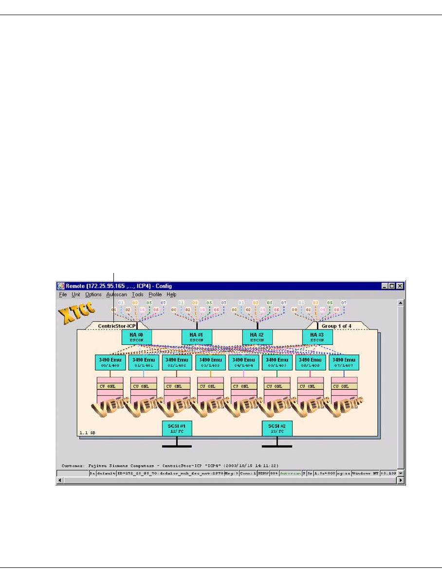
326 U41117-J-Z125-7-76
General XTCC
CentricStor recognizes various ISP types.
ICP Integrated Channel Processor
An ICP has a permanent connection to one or more BS2000/OSD, z/OS or
OS/390 hosts via ESCON/FICON adapters or to an open systems host via an
FC controller operating as a host connection. Host adapters and virtual devices
are available only on ICPs.
IDP Integrated Device Processor
An IDP always has at least one tape drive connected via SCSI or FC and an
associated PDS. Physical devices are available only on IDPs.
VLP Virtual Library Processor
Any ISP which is neither an ICP nor an IDP is regarded by the configuration
routine as a VLP.
ICP_IDP In small CentricStor configurations, the ICP and IDP are on a shared processor.
Several processors of the same type are, if necessary, configured next to each
other. The VLP functionality resides with one of these ICP_IDP.
The diagram below shows the XTCC representation of an ICP:
ISP type
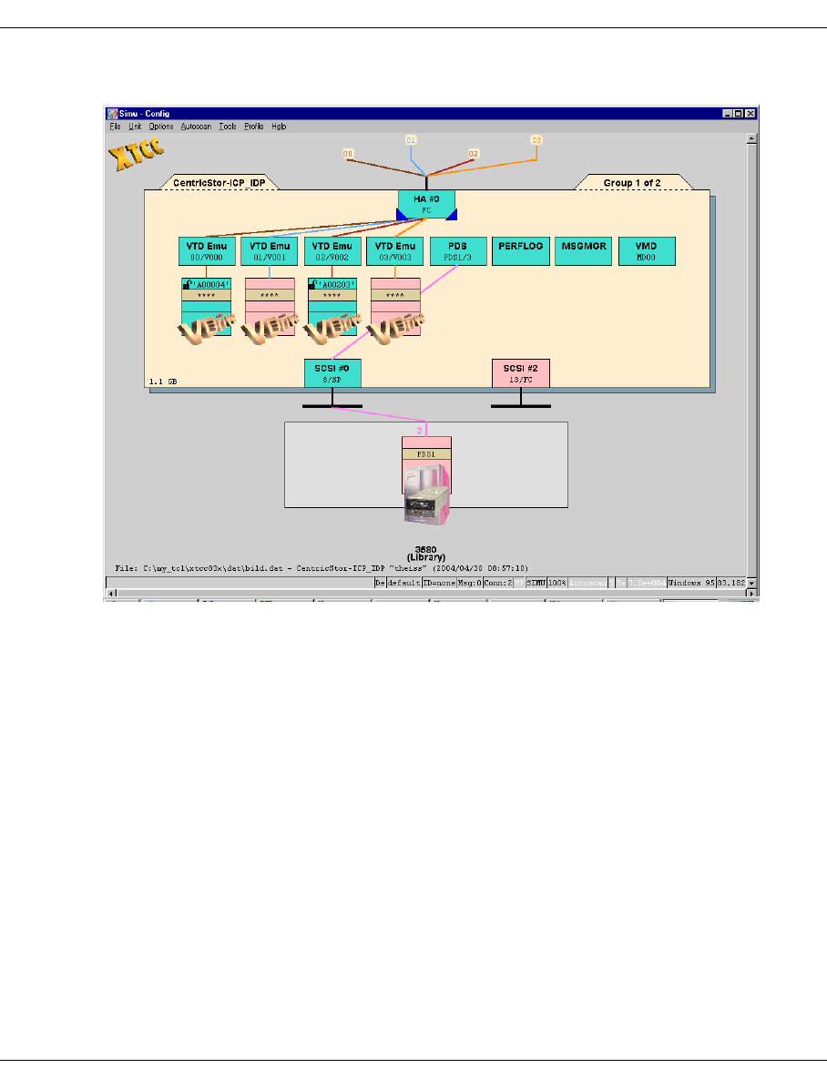
U41117-J-Z125-7-76 327
XTCC General
In the case of an ICP_IDP combination, the display is somewhat different:
PDSs and emulations/virtual devices are located on the same level in the diagram. The
PDSs are connected to the associated device controller, and the emulations are connected
to the associated host adapter(s).
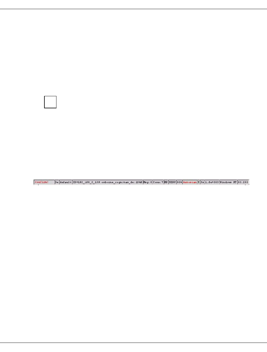
328 U41117-J-Z125-7-76
Margins of the main XTCC window XTCC
8.2 Margins of the main XTCC window
8.2.1 Title bar
Local()-Config
if XTCC is running on the ISP under consideration.
Remote(<IP addr. of ISP><host name of ISP>)-config “<comment from unit list>”
if XTCC is running on another ISP in the CentricStor system.
GXCC always starts XTCC on the system on which GXCC is also running.
Remote(<IP address 1,....,ISP name>) - Config “<comment from unit list>”
if there is an indirect connection between the VLP and the ISP under consideration.
In some cases, such an indirect connection will be established automatically instead of
a normal direct connection.
8.2.2 Status bar
The status bar is located at the bottom of the XTCC window:
The individual fields are explained below (from left to right) with the help of examples:
confirm ! If “confirm !” is flashing in red in the left-hand field you must answer a message
window (generally with “OK” to confirm you have taken note). Until you confirm
the higher-ranking window is blocked.
De/En Language of the Help system, in this case, En: English, De: German
default Current profile name specified in the command line or selected in the “Profile
Select” menu. In the example, no profile is selected.
ID=<IP address/”local”>:<ISP name>:<port number>
For identification purposes, each XTCC instance has its own ID consisting of
the IP address and name of the system on which XTCC is running, as well as
the port number. Thus the ID of the computer with which you are monitoring
CentricStor is displayed here.
Msg:0 Number of messages entered in the “XTCC Communications” window.
Conn:7 Number of existing XTCC connections to the monitored system.
MP Connection mode (MP: Multi-Port, SP: Single-Port)
i

U41117-J-Z125-7-76 329
XTCC Margins of the main XTCC window
SERV XTCC mode (OBSV=Observe, SERV=Service, USER=User,
SIMU=Simulation).
80% Current window size setting (in the example, 80%).
Autoscan Green = started
Yellow = active
Red flashing = stopped / temporarily disabled
White =blocked (SIMU mode)
S 5s Autoscan operating mode and interval (S = self-adjusting, M = manually
adjusted).
n.me+op Read rate for InfoBroker data [n.m*10op bytes/second]. The rate is calculated
using the transfer time of an InfoBroker record. When using a modem
connection, this value will also allow you to calculate the performance of the
connection.
Windows NT
Platform on which XTCC is running.
m.n XTCC version number.
The visual appearance of the main XTCC window is determined by the profile file. If you
close XTCC by selecting “File“ ➟ “Exit”, the current settings will be saved to the ISP profile
file currently active (processor- and user-specific) so that they are available again the next
time the application is started. If this is not desired, XTCC must be terminated using the
System function (icon at top left) or using the Windows Manager function (“X” box at top
right) (for details on this see the section “Exit” on page 334).
The procedures for creating and managing profile files is described on page 344.

330 U41117-J-Z125-7-76
Function bar XTCC
8.3 Function bar
Subfunctions:
●File
–Select (page 331)
–Save (page 331)
–Show (page 331)
–Print (page 332)
–Exit (page 334)
●Unit
–Select (page 335)
●Options
–Settings (page 336)
–Toggle Size (page 337)
–Toggle Aspect (page 337)
–Show Current Aspect (page 337)
–Apply Current Aspect (page 337)
●Autoscan
–Start / Stop (page 338)
–Settings (page 339)
–Scan Now (page 340)
●To o ls
–XTCC Communications (page 341)
–Get Remote/Expand Local File (page 342)
–Show Remote File (page 342)
–Compare Local Files (page 343)
–XTCC Update/Revert (page 343)
●Profile
–Select (page 346)
●Help
–README / LIESMICH (page 348)
–Direct Help / Direkthilfe (page 348)
–Mouse Functions / Maus-Funktionen (page 348)
–About XTCC... (page 349)
–CentricStor User Guide (page 350)
–CentricStor Service Manual (page 351)
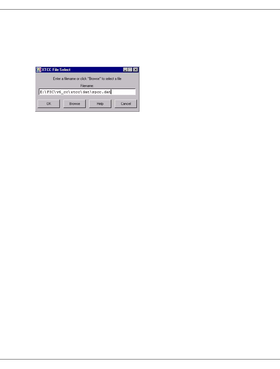
U41117-J-Z125-7-76 331
XTCC Function bar
8.3.1 File
8.3.1.1 Select
Selects a configuration file saved previously with “Save” (see below):
The window contains the field for entering the file name plus the following function keys:
OK Checks whether the specified file is a valid XTCC configuration file and, if so, its
contents are output in graphical format and in Simulation mode. If not, an error
message is output.
Browse Opens a standard dialog box for searching for and selecting a file. The file type
is preset to *.dat, and the file name is transferred to the entry field.
By default, configurations are saved as .dat files. Instead of accepting the
proposed file, you can click on any other .dat file and open it. If a .dat file has
been saved in a different directory then you can click the button next to the
directory bar to change to any higher-level and, therefore, to any required
directory.
Help Opens the XTCC help file.
Cancel Closes the window.
8.3.1.2 Save
Saves the configuration currently displayed (please refer to the information in the section
“Save” on page 145). When you select this function, the current data is initially backed up.
A standard dialog box is then opened for changing the directory and specifying a name for
the file to be saved. The file name is automatically preset to <system_name>.dat. Both
name components can be modified.
8.3.1.3 Show
This function is only available in User and Service mode.
Opens an independent file viewer. This functionality is described on page 360.
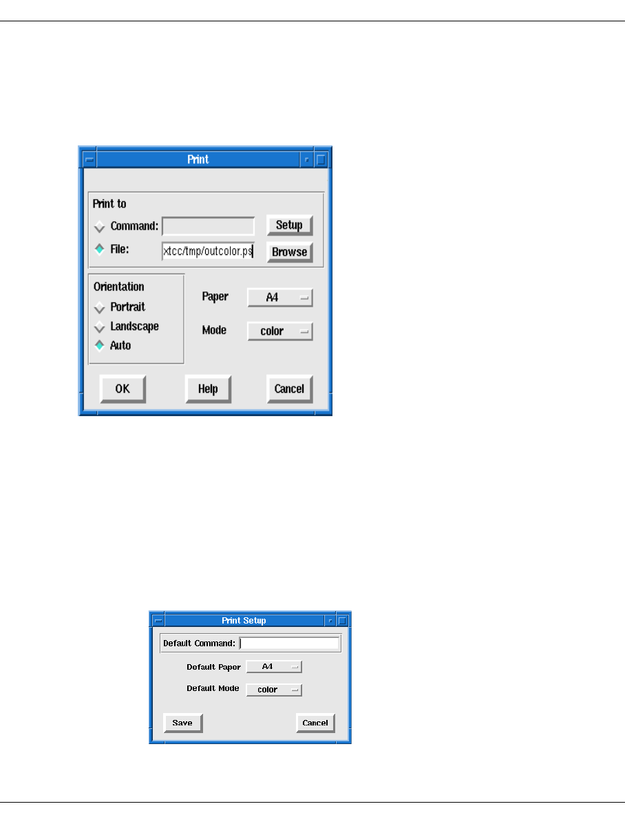
332 U41117-J-Z125-7-76
Function bar XTCC
8.3.1.4 Print
Unix Platform
Saves or prints the configuration currently displayed in PostScript format:
This opens a window containing the following fields and buttons:
Print to Specifies the target for the printout.
Command List box used to specify the printer. In the case of UNIX systems, this field must
be set to the name of the print program or script.
File Target for the PostScript file to be created. The presetting is determined by the
color mode set.
Setup Opens a submenu for defining the basic “Command”, “Paper” and “Mode”
settings. These settings can be saved by clicking the “Save” button and can be
used again the next time you open the print menu.

U41117-J-Z125-7-76 333
XTCC Function bar
File Selection with input field.
List box used to specify the name under which the PostScript file is to be saved.
Depending on the color selection made under “Mode”, this field is preset with
the file name <path>/outcolor.ps or <path>/outgray.ps, where
<path> is set to the XTCC tmp directory. To print out the configuration, these
files can then be sent to the PostScript printer that supports the corresponding
mode.
Browse Button provided under “Print to File” for opening a dialog box used to change
the directory and specify a name for the file to be saved.
Orientation
Allows you to select the display format within the PostScript file:
Portrait Portrait format
Landscape Landscape format
Auto Automatic selection depending on the page dimensions
Paper Allows you to select the paper format to be used:
A4 210 x 297 mm
Letter 216 x 279 mm
Mode Allows you to select the color mode:
color The PostScript file/printout is created in color mode.
grayscale The PostScript file/printout is created in grayscale mode.
OK Starts the creation of the PostScript file/printout.
Help Opens a text window containing the XTCC help file.
Cancel Closes the print menu without accepting the changes.
Windows Platforms
The platform-specific “Print” menu is used which enables you to control all the required
functions. In the case of “Print to file” the format corresponding to the selected printer is
used.
The display is always adjusted to the paper format selected, taking into account the
page ratio. Any scaling predefined in the printer menu is ignored.
i
334 U41117-J-Z125-7-76
Function bar XTCC
8.3.1.5 Exit
Shuts down XTCC, saving the current settings to the profile file in the process.
The settings are not saved if XTCC is exited using the following functions:
– System function
– Window Manager function
Click on the CentricStor icon at the top left and in the pull-down
menu select the “Close” function or the function at the bottom
(the menu language depends on the system language
selected).
A
t t
h
e top r
i
g
h
t c
li
c
k
on t
h
e
b
ox conta
i
n
i
ng t
h
e
X
.
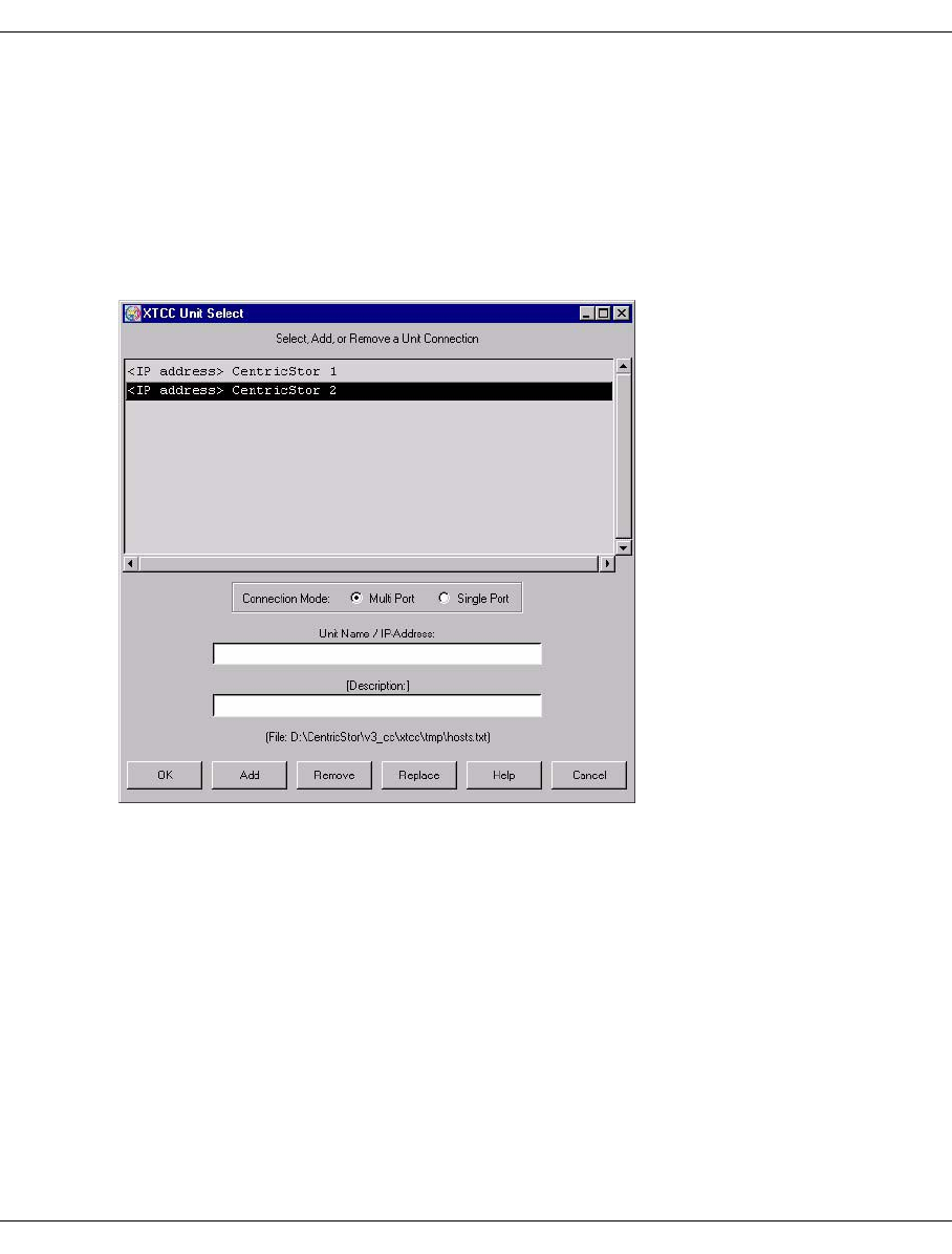
U41117-J-Z125-7-76 335
XTCC Function bar
8.3.2 Unit
8.3.2.1 Select
This function is disabled if XTCC is started from GXCC.
Otherwise, if XTCC was started directly, the “XTCC Unit Select” window is opened.
Example
The operation and functions of Unit Select are described in the section “Select” on
page 147. Errors during connection setup with “OK” are handled differently, however,
because in this case no connection exists as yet to a CentricStor.
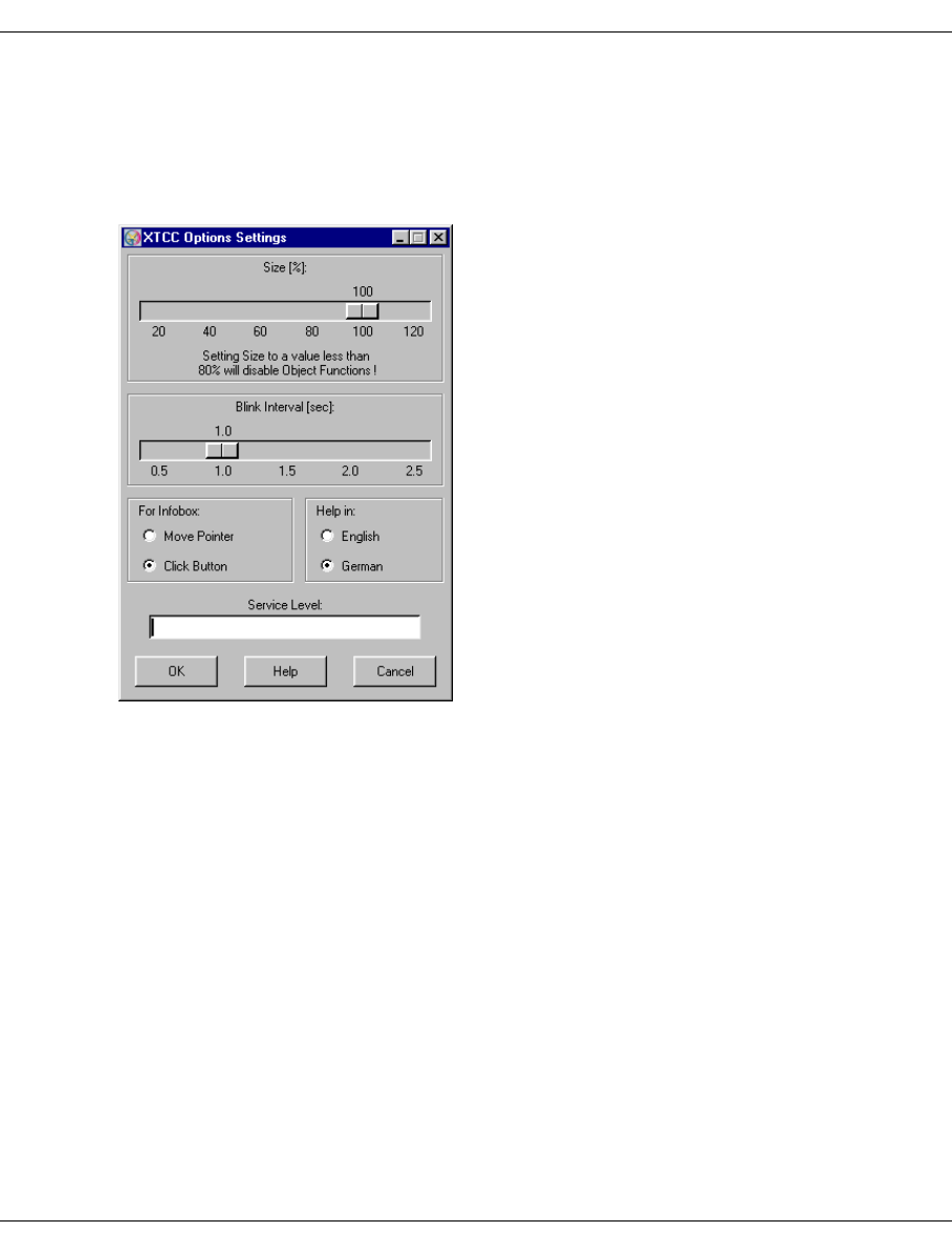
336 U41117-J-Z125-7-76
Function bar XTCC
8.3.3 Options
8.3.3.1 Settings
Opens a submenu containing the following functions:
Allows you to set the following options:
Size [%]
You can vary the scale of the graphic display from 20% to 120% in 5% steps. If you set
a value less than 80%, all the object functions will be deactivated and the images for the
drive types will no longer be displayed.
By left- or right-clicking anywhere in the XTCC window, you can reset the configuration
display to 100% with the optimum aspect. Smaller scales are particularly useful when
monitoring several ISPs, especially when these can be displayed in separate tab pages.
The group display described on page 356 is even more compact, and is more suitable
for monitoring ISPs that can only be displayed using several tab sheets.
Blink Interval [sec]
The interval for flashing objects can be set to between 0.5 and 2.5 seconds in steps of
0.1 second.

U41117-J-Z125-7-76 337
XTCC Function bar
For Infobox:
Move Pointer The infos are displayed by positioning the mouse cursor.
Click Button The infos are displayed by clicking on the left mouse button. The
descriptions in the manual generally relate to this mode.
Help in:
English Help texts in English.
German Help texts in German.
The language of the help texts also controls which version of the online manual
is offered in the Help menu. If there is no manual available in that language, no
manual is offered in the Help menu.
Service Level
Reserved field for special functions not described here.
8.3.3.2 Toggle Size
Switches between the scale 100% and the last scale < 100% selected by the user.
8.3.3.3 Toggle Aspect
Switches between the optimum aspect determined by the program for the associated scale
and the last aspect selected by the user. The aspect parameters are based on the size and
position of the window on-screen. If the optimum aspect is changed by reducing the window
size, you can scroll through the window contents by left-clicking the scroll bars underneath
and to the right. If you are using a three-button mouse, you can also scroll through the
window contents by holding down the middle button while moving the mouse pointer.
8.3.3.4 Show Current Aspect
Opens a window containing the current aspect values. This function is useful if, after setting
the desired window size and position, you wish to determine the associated aspect values
by means of an entry in a command line call.
8.3.3.5 Apply Current Aspect
Applies the current window position and size instead of the original command line argument
specified by the user. The “Toggle Aspect” function then takes these new values into
account.
i

338 U41117-J-Z125-7-76
Function bar XTCC
8.3.4 Autoscan
Each Autoscan cycle consists of a data transfer phase, a display phase, and the Autoscan
delay. The Autoscan delay is the interval between the end of the display phase and the
beginning of the subsequent data transfer phase.
The color of the “Autoscan” text in the status bar in the bottom right-hand corner of the
XTCC window shows the current status of this periodic transfer of information. The colors
have the following meaning:
green released
yellow active
red stopped temporarily or by the user
white blocked (simu mode)
Each time a main menu is opened, an information window is output, or a function menu is
called for an object, the Autoscan cycle is temporarily interrupted, indicated by the red
flashing “Autoscan” text. It is continued automatically after the menu or window is closed.
The Autoscan cycle is not interrupted on opening an information window if “Move Pointer
for Info” mode was selected in the “Options” menu. Text in yellow indicates that a new data
record is currently being received and edited by InfoBroker.
Autoscan delay is normally defined automatically but can also be set manually.
The “Autoscan” menu contains the following functions:
8.3.4.1 Start
Starts the Autoscan process manually. This function is available only if Autoscan is currently
stopped.
8.3.4.2 Stop
Stops the Autoscan process manually so that the status of the displayed objects is no longer
updated. This function is available only if Autoscan has been started.
Before the window size or position of the configuration display on the screen is
changed it is recommended that the Autoscan process first be stopped manually.
Otherwise, the ongoing process of updating of the window contents will cause the
window to jump back to its original position. The reason for this is that the appli-
cation (XTCC) does not know about these modifications (made by the Window
Manager), and always uses the most recently stored parameters to generate the
display.
i
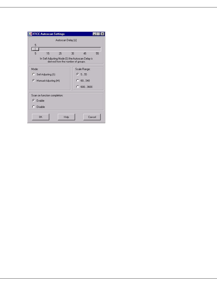
U41117-J-Z125-7-76 339
XTCC Function bar
8.3.4.3 Settings
Opens a submenu containing the following setting options and buttons:
Autoscan Delay [s]
This scale allows you to determine the interval currently set. If “Manual Adjusting” is
selected, this value can be changed.
Mode
Self Adjusting (S) The Autoscan delay is determined automatically and displayed in
the status bar in the format S<value>s.
Manual Adjusting (M)
The Autoscan delay is set manually and displayed in the status bar
in the format M<value>s
Scale Range
If “Manual Adjusting” is selected, the scale range for the slider control can be modified.
The settings 5...55, 60...540 and 600...3600 seconds are possible. Within these ranges
the resolution is 5, 30 or 300 seconds.
Scan on function completion
Enable Permits an additional scan cycle immediately after functions which
result in a change to the object status (e.g. Start/Stop) have been
terminated. This scan cycle is also executed in the event of an
Autoscan process being stopped manually.
Disable Prevents the additional scan cycle.
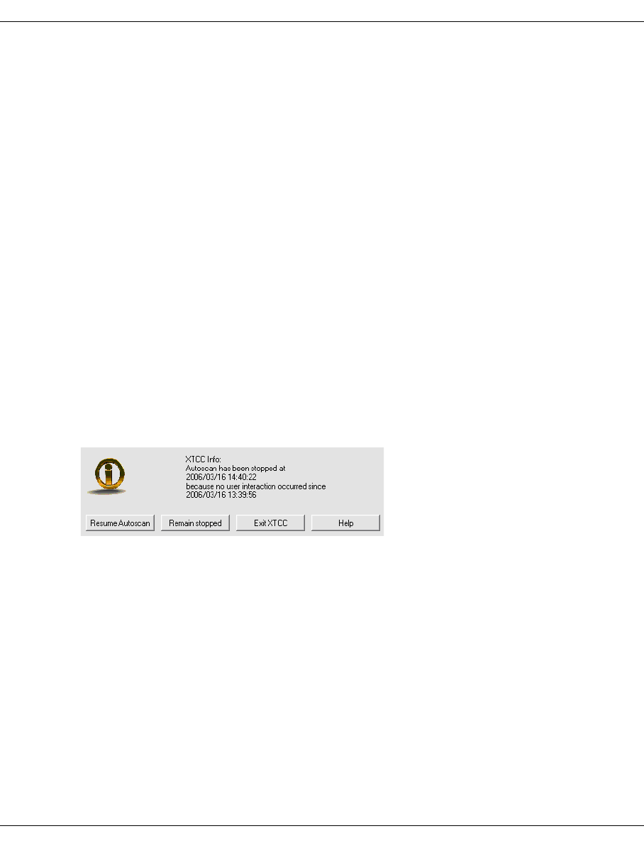
340 U41117-J-Z125-7-76
Function bar XTCC
OK
Confirms the settings and closes the menu.
Help
Opens a window containing the XTCC help file.
Cancel
Cancels the settings and closes the menu.
8.3.4.4 Scan Now
Triggers an additional, immediate scan cycle in the event of an Autoscan process being
stopped manually or a lengthy Autoscan delay. This function can also be initiated by
pressing CTRL + spacebar simultaneously.
8.3.4.5 Interaction Timeout
XTCC stops the periodic Autoscan process if no user interactions are registered for an hour.
The following are counted as user interactions:
– Moving the mouse cursor over the configuration display or the Groups window
– Iconizing, maximizing, shifting or altering the size of one of these windows
After the timeout has occurred the following dialog box is displayed:
Meaning of the buttons
Resume Autoscan
The periodic Autoscan process is started again and the time window for one hour is re-
started.
Remain stopped
The Autoscan stop status is retained.
Exit XTCC
XTCC is terminated.
Help
Opens a window with a help text.
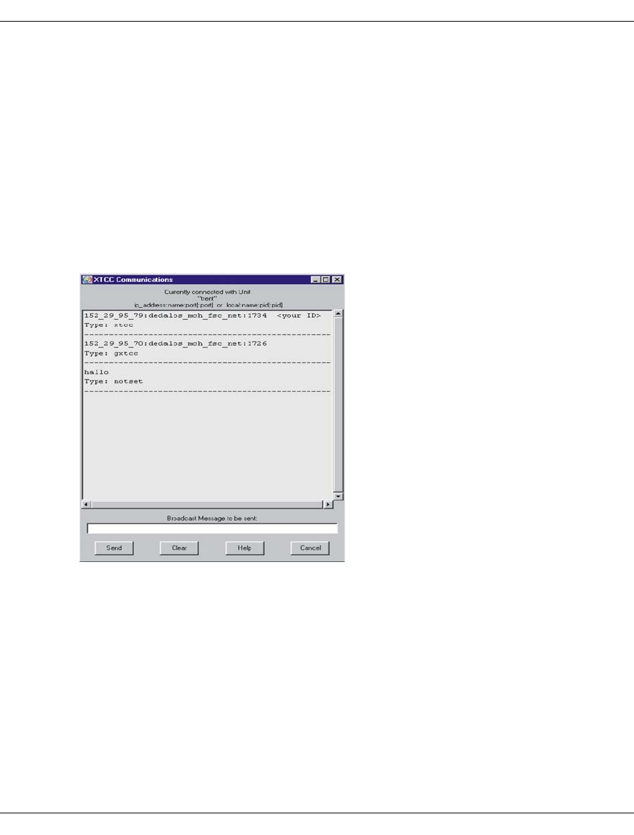
U41117-J-Z125-7-76 341
XTCC Function bar
8.3.5 Tools
The following functions are available:
–XTCC Communications
–Get Remote/Expand Local File
–Show Remote File
–Compare Local Files
–XTCC Update/Revert
8.3.5.1 XTCC Communications
Opens a window containing a list box and an input field:
The list box contains the IDs of the XTCC connections to the selected ISPs together with
short messages (Message) which are used for communication between the XTCC users.
In Remote mode, the IDs have the format <ip_address>:<name>:<port> and in Local
mode local:<name>:pid. The dots in the IP address are replaced by underscores. Your
local connection ID is indicated by <your ID>.
A message consists of two lines with the formats
Message date: YYYY/MM/DDHH:MM:SS (date and time of the sending system)
Message text: <text>.
In the messages the special characters “ \ $ [ ]” are replaced by underscores “_”.

342 U41117-J-Z125-7-76
Function bar XTCC
If messages are present, then the number of messages is displayed by means of the yellow
indicator Msg:<n> in the XTCC status bar. Yellow letter symbols are also visible in the
configuration display.
Meaning of the buttons
Send
Sends a message entered in the “Broadcast Message” window to the InfoBroker. You
can also use the Return key instead of this button.
Clear
Deletes the input field and message in the InfoBroker.
Help
Displays the XTCC help file.
Cancel
Discards any entered message text and closes the window.
A sent message cannot be registered until the next Autoscan cycle.
8.3.5.2 Get Remote/Expand Local File
This function is identical to the GXCC function of the same name. This is described on
page 154ff.
8.3.5.3 Show Remote File
This function is identical to the GXCC function of the same name. This is described on
page 156ff.
i

U41117-J-Z125-7-76 343
XTCC Function bar
8.3.5.4 Compare Local Files
Starts a graphical tool which enables two local text files to be compared. The two files are
displayed in synchronized text windows. Differences are marked in color, and the number
of differences is entered in the status line at the bottom right. By selecting “View / Show Line
Comparison Window” in the diff tool menu, differences within individual lines can be made
visible.
Notes
– The menu item “Compare Local Files” is available in Service and User mode only.
– In User mode, “View Only” mode is preset. As a result the Edit, Write, Merge and Save
functions are disabled.
– The diff tool has its own help function.
8.3.5.5 XTCC Update/Revert
The use of this tool is described in the section “GXCC Update/Revert Tool” on page 159.
Please note the following points:
– The update of GXCC is started from within GXCC independently of the XTCC update.
– When XTCC is updated, all XTCC and GXCC applications of the computer on which
GXCC/XTCC is running must be closed.
– There are no restrictions regarding the compatibility of different GXCC and XTCC
versions within a product line (CentricStor V2.x or CentricStor V3.x). Even if a
workstation is to interwork with older CentricStor versions the GXCC/XTCC software
can be updated to the latest level. GXTCC (CentricStor V2.x) cannot be upgraded to
GXCC (CentricStor V3.x) using the update tool.

344 U41117-J-Z125-7-76
Function bar XTCC
8.3.6 Profile
The term “profile” encompasses all user-specific settings chosen under “Options” and
“Autoscan”. These settings are stored in a user-specific subdirectory.
When the main menu functions
–Unit ➟ Select
–File ➟ Select
–File ➟ Exit
– Options ➟ Settings ➟ OK
– Options ➟ Apply Current Aspect
– Autoscan ➟ Settings ➟ OK
– Profile ➟ Select ➟ OK
are called, the following settings which are used are backed up implicitly on a unit-specific
basis:
– Options Settings Size, For Infobox: Move Pointer for Info / Click Button for Info,
Help in: English/German
– Autoscan Settings Autoscan Delay, Mode: Manual/Self Adjusting, Scan on function
completion: Enable/Disable
– and the current size and position of the window on-screen (aspect)
A backup operation does not take place if XTCC is terminated by some means other than
selecting File ➟ Exit.
Note that if you change the position or size of the window on the screen using the
Options ➟ Apply Current Aspect function you must confirm this.
The next time a unit is selected, the values that have already been stored are used
again. If the command line arguments -aspect, -autoscan, -lang, -size were
specified at the start, these will have priority over values which have already been
saved and, as described above, will also be saved implicitly.
i
i

U41117-J-Z125-7-76 345
XTCC Function bar
If you require individual profile settings, you should define separate profile settings. The
profile data is saved in a matrix format: A directory is set up for each profile name, including
“default”.
Profile data is stored in this directory for each unit under the name <system_name>.opt.
When changing unit, the current settings are saved under the old unit name. The directory
is then searched to determine whether there is already data for the new unit. If this is the
case, this data is used for control purposes, with the exception of any predefined command
line arguments mentioned above. Otherwise the existing settings are adopted, and these
will be saved when the system is terminated or when the unit is changed again.
Directory: default.prf Name1.prf Name2.prf Name3.prf
CentricStor A CentricStor_A.opt CentricStor_A.opt CentricStor_A.opt CentricStor_A.opt
CentricStor B CentricStor_B.opt CentricStor_B.opt CentricStor_B.opt CentricStor_B.opt
CentricStor C CentricStor_C.opt CentricStor_C.opt CentricStor_C.opt CentricStor_C.opt
CentricStor D CentricStor_D.opt CentricStor_D.opt CentricStor_D.opt CentricStor_D.opt
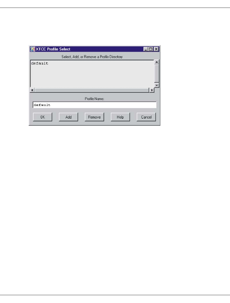
346 U41117-J-Z125-7-76
Function bar XTCC
8.3.6.1 Select
Allows you to create and select user-specific subdirectories in the temporary XTCC
directory. All option settings are then stored in unit-specific files in these subdirectories.
The name of the subdirectory is formed from the profile name and the extension .prf. The
“Profile Select” function opens a window consisting of a list box, an input field, and various
buttons.
The list box contains the profile names already defined. To select an entry and transfer it to
the input line, you simply left-click on the appropriate list item.
If special characters (/ \ [ ] “ ' $ * : ? < > |) are used when entering a profile name, these are
replaced by underscores.
Meaning of the buttons
OK Creates a new directory with the name specified in the input field (provided
this directory does not already exist) and closes the window.
Add Creates a new directory.
Remove Deletes the selected directory and all its contents.
Help Displays the XTCC help file.
Cancel Closes the window without saving your selection.

U41117-J-Z125-7-76 347
XTCC Function bar
Notes on operating
– You use the two scroll bars for positioning in the list box.
– Double-clicking on an entry with the left mouse button transfers this to the entry field.
– Simultaneously pressing the Ctrl+o keys enables the content of the list box to be sorted
in ascending or descending order.
– Search function:
After you have entered a search string in the entry field, pressing the return key displays
the next hit.
The following characters have a special meaning here:
? Detection of an individual arbitrary character
* Detection of no or multiple arbitrary characters
[abc] Detection of a character from the group “abc”
[a-z] Detection of a character from the range “a-z”
\c Detection of the special character “c”
If the entry field is empty you can press the return key to go to the next entry.
If you close XTCC by selecting “File“ ➟ “Exit”, the current profile file will be saved with the
current settings. If this is not desired, you should use the button in the top left-hand corner
of your screen instead.
If XTCC cannot find any profile file for the user and ISP on startup, the settings of the initi-
ating GXCC application will be adopted.

348 U41117-J-Z125-7-76
Function bar XTCC
8.3.7 Help
The appearance of the submenu depends on the language selected in “Settings” (see
page 336):
8.3.7.1 README / LIESMICH
This function is used to open the file viewer with the help file in accordance with the
language setting, thus here to “Help”:
Information on using the file viewer can be found starting on page 360.
8.3.7.2 Direct Help / Direkthilfe
This describes how to call up the object-related Help functions.
8.3.7.3 Mouse Functions / Maus-Funktionen
This describes the object-related mouse functions. See also the section “Object-related
functions” on page 355.
German: English:
Help Help
LIESMICH
Direkthilfe
Maus-Funktionen
About XTCC...
Benutzerhandbuch
Readme
Direct Help
Mouse Functions
About XTCC...
User Guide
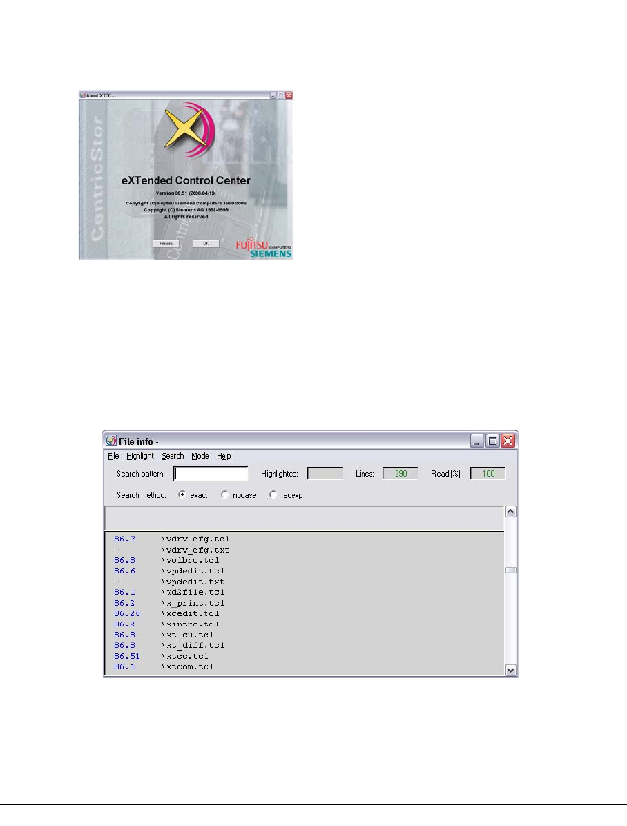
U41117-J-Z125-7-76 349
XTCC Function bar
8.3.7.4 About XTCC...
The version of XTCC can also be seen at the bottom right of the configuration overview
window.
Meaning of the buttons
OK
The window is closed.
File info
Opens a text window in which information on the XTCC files that exist is output:
The version numbers are displayed in the left-hand column provided these are
contained in the file concerned.

350 U41117-J-Z125-7-76
Function bar XTCC
8.3.7.5 CentricStor User Guide
One of the menu functions
– CentricStor User Guide (complete)
– CentricStor User Guide (GUI Part)
is offered if
– XTCC is operated in User or Observe mode,
– the monitored system is of the type “CentricStor” and
– a PDF documentation file suitable for the CentricStor Version m.n and the current
language setting is available.
In User mode XTCC updates the local documentation if more recent documentation is
found on the remote CentricStor system in the event of connection setup (“Unit/Select”) or
when changing the language setting (“Options Settings”).
Here a more recent “User Guide (GUI Part)” has priority over an older “User Guide
(complete)”. The user is notified of this via a message window.
Notes
– The “User Guide” is also offered if no “Service Manual” is available (see the section
“CentricStor Service Manual” below).
– To enable the PDF documentation files to be displayed a suitable viewer program must
be installed on the local system (xpdf in SINIX, xpdf or Acrobat Reader in LINUX, Acrobat
Reader in WINDOWS).
– To save space XTCC automatically removes obsolete local files.
A PDF viewer is started and the most up-to-date manual is displayed in the help language
selected.

U41117-J-Z125-7-76 351
XTCC Function bar
8.3.7.6 CentricStor Service Manual
One of the menu functions
– CentricStor Service Manual (complete)
– CentricStor Service Manual (GUI Part)
is offered if
– XTCC is operated in Service or Simu mode,
– the monitored system is of the type “CentricStor” and
– a PDF documentation file suitable for the CentricStor Version m.n and the current
language setting is available.
In Service mode XTCC updates the local documentation if more recent documentation is
found on the remote CentricStor system in the event of connection setup (“Unit/Select”) or
when changing the language setting (“Options Settings”). Here a more recent “Service
Manual (GUI Part)” has priority over an older “Service Manual (complete)”. The user is
notified of this via a message window.
In Simu mode this function is not available; only the documentation available locally can be
taken into consideration.
Notes
– If no suitable “Service Manual” is available, the “User Guide” may be offered (see the
section “CentricStor User Guide” on page 350).
– To enable the PDF documentation files to be displayed a suitable viewer program must
be installed on the local system (xpdf in SINIX, xpdf or Acrobat Reader in LINUX, Acrobat
Reader in WINDOWS).
– To save space XTCC automatically removes obsolete local files.
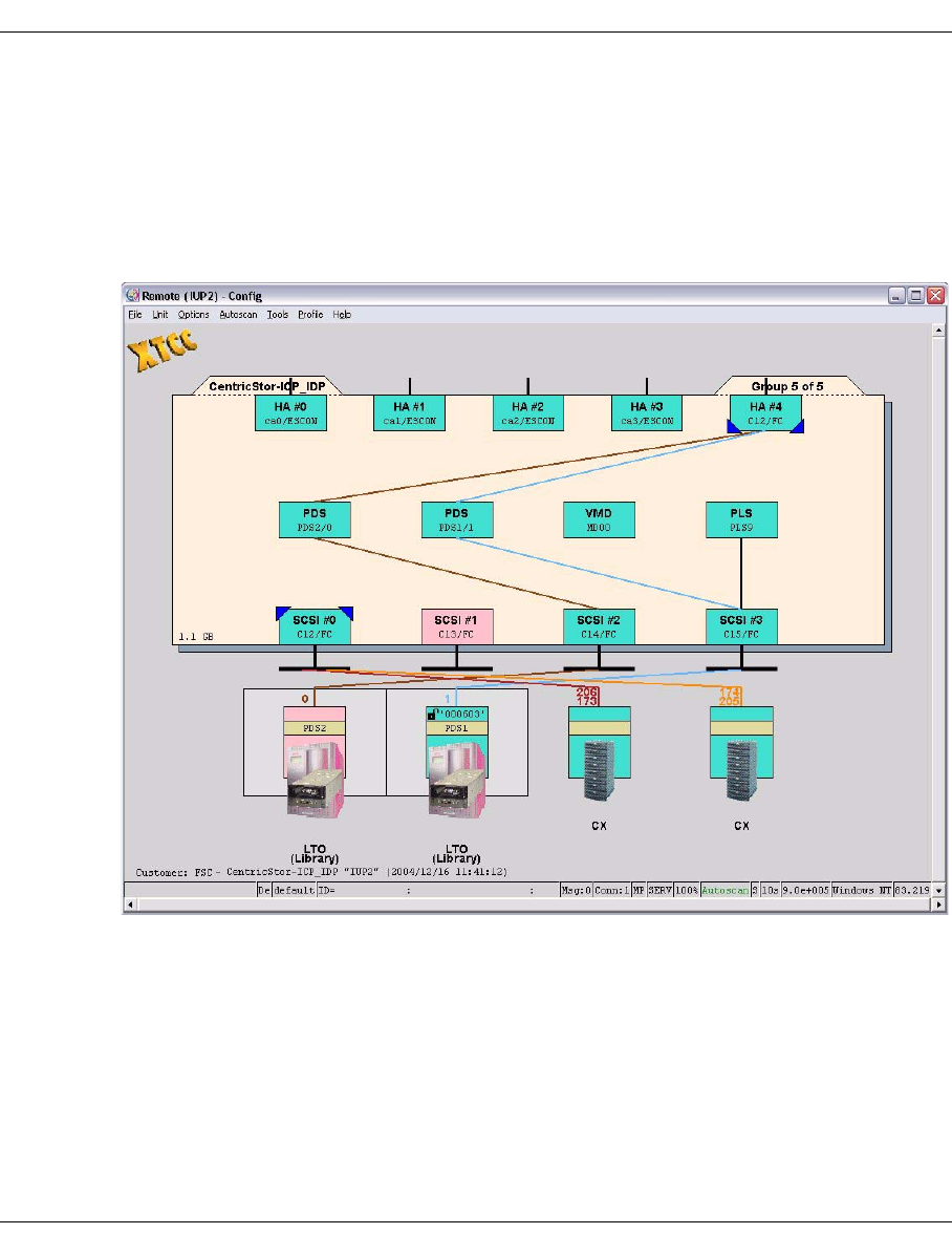
352 U41117-J-Z125-7-76
Elements of the XTCC window XTCC
8.4 Elements of the XTCC window
8.4.1 Display
Each XTCC window displays an ISP of the CentricStor system, together with the connected
peripherals. The ISP is represented by a beige field at the center of the window:
The small colored boxes around the edge represent the peripheral controllers (ESCON,
FICON, FC, SCSI, FC-SCSI). The small boxes in the middle represent software processes.
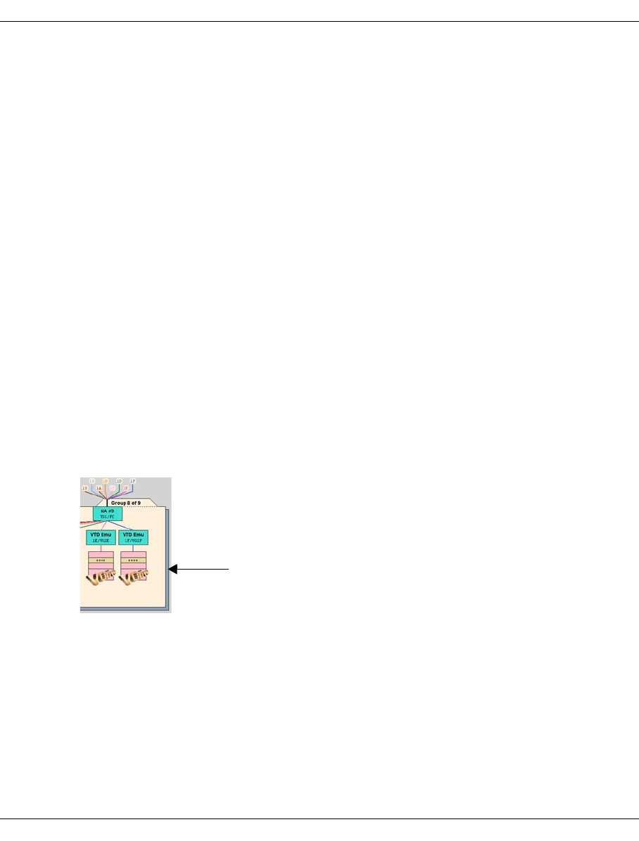
U41117-J-Z125-7-76 353
XTCC Elements of the XTCC window
The operating status of an element is indicated by the color of the associated box, where
the following color key applies:
Green: Normal
Pink: Malfunctioning, offline or not ready
Yellow: Status unclear, some subcomponents are malfunctioning
Red: Configuration error; the component is contained in the configuration
description, but the InfoBroker has not yet established contact with it
If the ISP contains numerous XTCC objects, its contents are displayed over several tab
sheets. The title of the tab sheet currently displayed is shown in the top right-hand corner.
Tab sheets are selected in the group display (see the section “Group display” on page 356).
The ISP peripherals are displayed outside the central field.
Connections between elements are represented by colored lines, purely for the purposes
of clarity.
If a connection is faulty in any way, this will be indicated by a broken line.
On the left side of the inner yellow field the particularly critical statuses of the ISP are shown
using icons. A yellow circle indicates an SNMP message, a circle with a wrench indicates
that the /usr file system is almost full (>95%) or is full (100%, symbol will flash with a red
background). The function menu of the ISP offers actions that can be used to handle the
situation.
The internal SCSI peripherals of the ISP can be addressed via the border of the symbol for
the ISP.
When you left-click on this margin, you select the
internal SCSI peripherals of the ISP. One important
example of these are internal RAID systems (see
page 411).
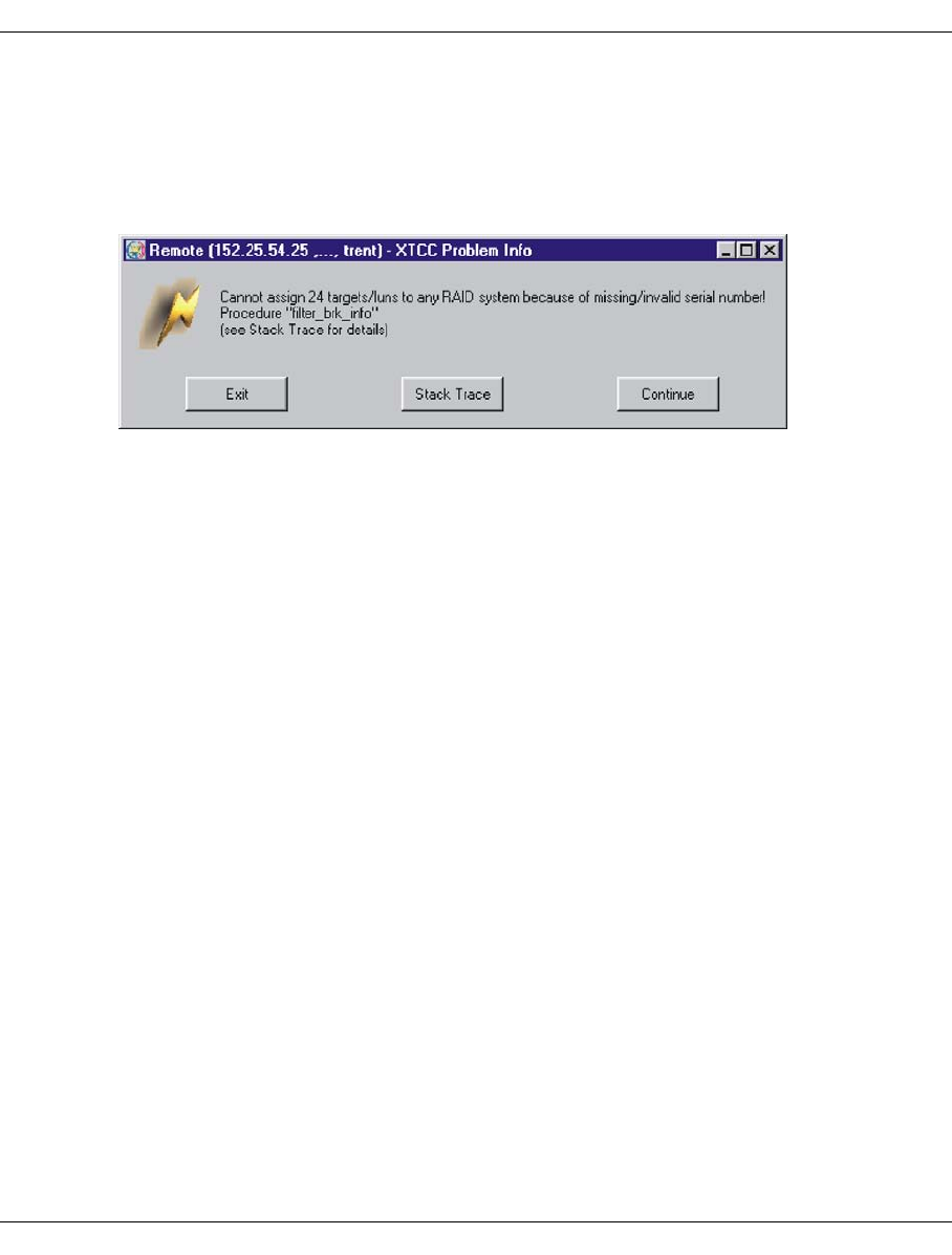
354 U41117-J-Z125-7-76
Elements of the XTCC window XTCC
8.4.2 Unexpected errors
In the event of internal errors such as those that occur owing to missing (mandatory)
variables of the InfoBroker, XTCC opens (if possible) a window with the title:
“
XTCC Problem Info
”.
This window contains the error message and buttons for further activities:
Exit
Ter m in a t e s X T C C.
Stack Trace
Opens a window with further information on the error. If you click on the “Cancel” button
in this window, the window is closed and “Continue” is attempted.
Continue
Continues the procedure in which the error occurred. This can lead to further errors, in
other words background errors. In this case XTCC must be closed.
Tr y t o s kip
This button is optional. XTCC attempts to skip the errored procedure, which can
naturally result in further errors. In this case XTCC must be terminated.
8.4.3 Message window
All XTCC messages should be noted and also acknowledged by the user. The reason for
this lies in the need to serialize device functions: You must ensure that it is not possible to
start the same function several times or to start contradictor7y functions on a device.
Message windows containing an “OK” button are closed when you click on this button.
Message windows without this button which contain texts such as “... Timeout is nn sec.
Please wait ...” are displayed if InfoBroker data is waited for synchronously to the execution
of device functions.

U41117-J-Z125-7-76 355
XTCC Elements of the XTCC window
The Autoscan process is stopped for the duration of this wait time. Such a window can - if
absolutely necessary - be closed by clicking on the relevant Window-Manager-specific
button at the top right or left of the window title bar. The wait time for restarting the Autoscan
is not reduced by this, however: The Autoscan process remains stopped until it is possible
to terminate the associated function or the maximum wait time has elapsed (timeout nn
sec.).
8.4.4 Object-related functions
When the mouse pointer is positioned above an object, you can call the following functions:
Left mouse button:
Object information is displayed
Shift + left mouse button
Object-related help.
CTRL + left mouse button
Direct Help for the object properties is displayed.
Right mouse button
Function menu is displayed.
The function menus only offer functions that can be used with the current object type
(e.g. drive). If a function can theoretically be used but is not meaningful at present
(e.g. “Stop Trace” when the trace is not running,) then this function is displayed, but
cannot be used and as such is grayed out.
Shift + right mouse button (for drives and emulations)
Function menu relating to all objects of this class in the ISP currently addressed
The function menus only offer functions that can be used with the current object type
(e.g. drive). If a function can theoretically be used but is not meaningful at present
(e.g. “Stop Trace” when the trace is not running), then this function is displayed, but
cannot be used and as such is grayed out.
Center mouse button (if available and configured appropriately)
Scrolls the configuration display in a reduced window. Depending on the type of system
being used, the center mouse button can be emulated by clicking the right and left
buttons of the mouse simultaneously.
The ISP itself is also an object. It is addressed by positioning the mouse pointer on the text
CentricStor-<Name> in the top left-hand corner of the central field.
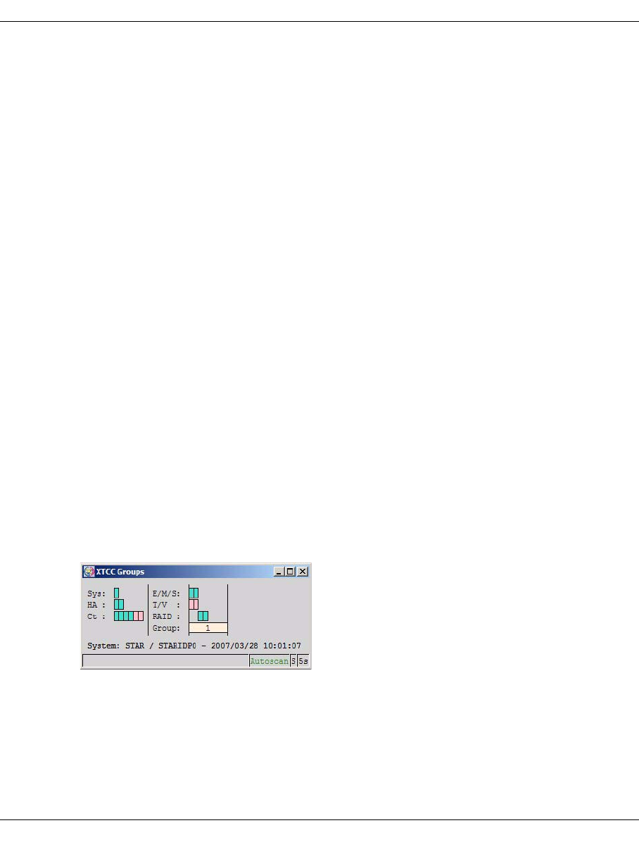
356 U41117-J-Z125-7-76
Elements of the XTCC window XTCC
8.4.5 Group display
When CentricStor components are displayed, there may be more configuration elements
(e.g. virtual drives) than can be displayed in a single window. At the same time, you may
often want to monitor operations at multiple CentricStor ISPs simultaneously. Without the
appropriate tools, this can make your screen difficult to interpret.
In XTCC, both problems are solved by the use of an overview window display.
If required, the display of the CentricStor components (e.g. ICP) can be subdivided into
groups and presented on a number of different tab sheets. Therefore only one out of a
number of different groups - represented by a tab sheet - is displayed. The tab sheet
indicates which group is currently being displayed and the number of groups into which the
display of the CentricStor components is divided.
Once XTCC is started and you have selected a unit or file, the group display is generated
automatically. It shows all components and their status in the form of color boxes. In the
case of large systems, it allows you to choose a group of logically related objects, and view
detailed information on them on a tab sheets in the configuration display without having to
scroll up and down.
Object names are shown in abbreviated form.
Sys System Entire ISP
HA Host adapter ESCON or FC-SCSI
Ct Controller SCSI controller
E/M/S Emulation/manager/server
T/V Target (tape)/virtual drive
RAID RAID system
Group Group number as specified
on the tab sheet
System System name/unit name (if available) or unit name
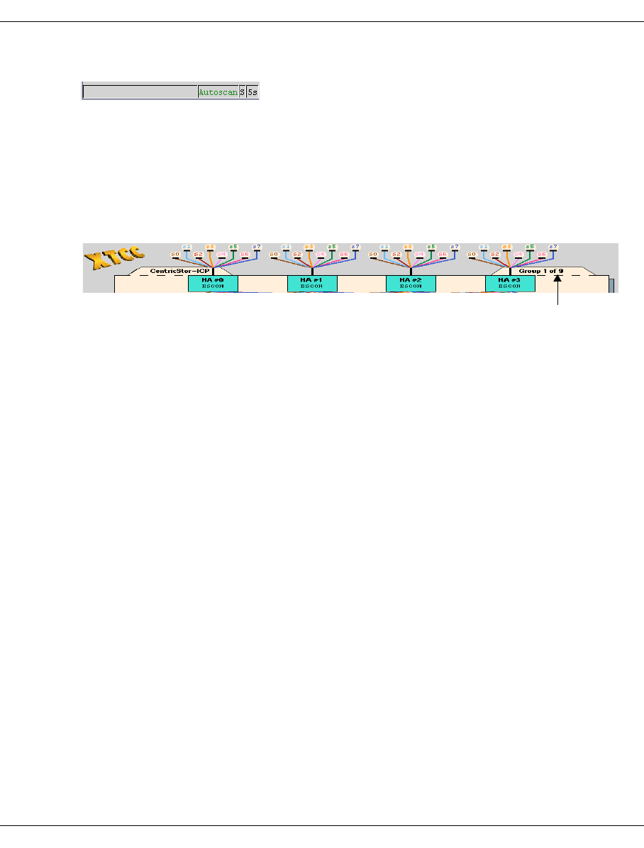
U41117-J-Z125-7-76 357
XTCC Elements of the XTCC window
The status line is contained at the bottom edge of the Groups window:
Autoscan green = released
yellow = active
flashing red= stopped / temporarily discontinued
white = locked (Simu mode)
S Autoscan operating mode(S = Automatic setting, M = Manual setting)
5s Autoscan interval
If the group display is minimized, you can reopen it simply by clicking the appropriate tab.
When you select a group, its color changes to blue. If you then click your left mouse button,
the group is transferred to the configuration display and its number appears in the
“Group m of n” field in the tab in the top right-hand corner.
The group currently displayed is colored beige.
The host adapters and SCSI controllers are always displayed together with each group.
If you rest the mouse pointer on one of the small color boxes, a small window appears
containing the name of that object. In the case of /390 emulations, the emulation name is
displayed together with its mnemonic name.
Click the tab to open the group display
for the entire ISP.

358 U41117-J-Z125-7-76
Elements of the XTCC window XTCC
Color codes in the group display
The object colors used in the group display are very similar to those in the configuration
display:
SYS HA Ct Emu/
Manager/
Server
Target/
V-Drive
RAID
Turquoise OK ACTIVE OK Running
and
attached
Read/write,
read only,
busy
OK
Green Running
and not
attached
Pink ACTIVATING
CHAN_DISAB
CONFIGURED
FAILED
INACTIVE
INITIAL
STOPPED
Hanging
11) Stopped Online,
offline
Error
Ye l l o w 12) Unknown Unknown Unknown Unknown Warning
White Removed
10) T: Removed
13)
Red File
system1) VLM halt
PLM error
VJUK: Offline
Emu
ERR_CFG8)
MIM/SIM9)
Black File
system2)
SNMP 3)
CLEAN4)
BUSY5)
INFO6)
MIM/SIM7)
Brown Trace on

U41117-J-Z125-7-76 359
XTCC Elements of the XTCC window
Explanation
1 File system full: red flashing tool symbol in the configuration overview. Flashing symbol
for system messages in the GXCC window.
2 File system 95% full: black flashing tool symbol in the configuration overview.
3 SNMP: SNMP manager has received an SNMP trap. Flashing SNMP symbol in the
configuration overview.
4 Drive needs cleaning. Yellow flashing symbol in the configuration overview.
5 Busy for some time. Clock symbol in the configuration overview.
6 Information present. “!” in the configuration overview.
7 MIM/SIM of the two lowest priorities. Flashing symbol in the overview.
8 Serious inconsistency in the configuration data. Emulation not operable.
9 MIM/SIM of the two highest priorities. Flashing symbol in the configuration overview.
10 A controller defined in the configuration could not be addressed. Its symbol is colored
white in the configuration overview
11 Controller or SCSI bus is in a jammed state.
12 If a function is implemented through several processes (e.g. virtual drives), “yellow”
means that the individual processes are in different statuses.
13 A target contained in the configuration description could not be found.

360 U41117-J-Z125-7-76
File viewer XTCC
8.5 File viewer
XTCC provides a file viewer, complete with scroll bars and search functions, for displaying
help texts and the data returned by various “Show” functions. This file viewer supports both
text and binary files. Text files or hexadecimal dumps up to 100 Mbytes in size can be read.
8.5.1 Opening the file viewer
●The file viewer can be opened manually by selecting “File” ➟ “Show” in GXCC or XTCC.
An intermediate form will be output allowing you to select a file for display. The direct
call is only possible in User and Service mode.
●If a function like “Show System Messages” or “Show Logical Volumes” is called, the
results will be displayed in the file viewer opened automatically. In this case, certain
application-specific functions (e.g. “Re-read”) may be disabled. With some applications,
special text may be displayed above the scroll area (see the section “Re-read” on
page 361 and the section “1st Line -> Ruler/Selection -> Ruler” on page 365).
8.5.2 Function bar
If you have called the GXCC/XTCC file viewer (e.g. for “Show” functions), some functions
are not offered depending on the context.
The individual functions can be selected either by clicking on them with your mouse, or by
pressing the ALT key together with the accelerator key (underlined letter).
In addition, keyboard shortcuts have also been defined for the search functions.
By left-clicking while dragging your mouse, you can select text in the text window. Pressing
CTRL+c (Copy) copies the selected text into the clipboard, from where it can then be
inserted elsewhere by pressing CTRL+v (Paste).
File AutoUpdate AutoPopup Highlight Search Mode Help

U41117-J-Z125-7-76 361
XTCC File viewer
8.5.3 File
8.5.3.1 Open (Text)/Open (Hex)
This function is only available in User and Service mode.
Opens a file selection box. Once you have made your selection, the file viewer is then
opened in pure text mode (Open (Text)) or in combined hexadecimal/text mode (Open
(Hex)). The display mode can be changed later on if desired.
When loading large files, the display window is opened as soon as the first few lines have
been read in. The percentage of file contents that have been loaded is displayed in the
“Read” field.
8.5.3.2 Save As
This function is only available in User and Service mode.
Saves the file views in a directory under a name of your choice.
8.5.3.3 Re-read
This is an optional function which reloads the file containing the text to be displayed.
Its availability is determined by the XTCC application from which a particular file is opened.
This is the case for files that are automatically updated by the system.
8.5.3.4 Print
This function is only available if XTCC is running on a Windows system.
The text file is opened with WORDPAD. The print menu can be used for printing.
8.5.3.5 Exit
Left-clicking this button closes the window.

362 U41117-J-Z125-7-76
File viewer XTCC
8.5.4 AutoUpdate
This function is offered only when called by specific GXCC/XTCC functions. The file
displayed is reread cyclically. If entries have been added, these are shown at the end of the
text window and highlighted by a lighter background.
8.5.4.1 Start
Only when AutoUpdate is stopped: AutoUpdate is activated.
8.5.4.2 Stop
Only when AutoUpdate is active: AutoUpdate is stopped.
8.5.5 AutoPopup
This menu item is only offered if the AutoUpdate is active.
With AutoPopup the text window is either maximized or placed in focus if AutoUpdate has
detected a change to the text file.
8.5.5.1 Enable
Only when AutoPopup is disabled; AutoPopup is activated.
8.5.5.2 Disable
Only when AutoPopup is enabled; AutoPopup is inactive.
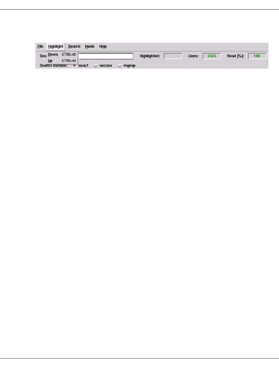
U41117-J-Z125-7-76 363
XTCC File viewer
8.5.6 Highlight
Selecting “Down” or “Up” with the left mouse button or pressing the associated keyboard
shortcut enables you to highlight all occurrences of the string specified in “Search String” in
color. The number of occurrences is output in “Highlighted”, and the cursor is positioned on
the first occurrence starting from the beginning or end of the text. If the string cannot be
found in the text, the message “No match found” is output.
Under the entry field for the search pattern there are three buttons for specifying the search
method:
Under this entry field the “Search method:” option field shows the current setting for the
search method:
exact The search is case-sensitive. This is the default setting.
nocase The search is not case-sensitive.
regexp The search is carried out in accordance with the conventions for regular expres-
sions.
Regular expressions:
r* Finds string r if there are zero or more occurrences of r
r+ Finds string r if there are one or more occurrences of r
r? Finds string r if there are zero or one occurrences of r
^r Finds string r if r occurs at the start of a line
r$ Finds string r if r occurs at the end of a line
r{m} Finds string r if there are exactly m occurrences of r
r{m,} Finds string r if there are at least m occurrences of r
r{m,n} Finds string r if there are at least m but no more than n occurrences of r
Conditions: m less than/equal to n; m=1...255; n=1...255
r1|r2 Finds sting r1 or r2
Finds any character (apart from newline)
\ Precedes control characters (e.g. [,],...) in “Search String” when searching directly
for them
[abc] Finds an individual character in the set abc
[^abc] Finds an individual character outside the set abc
[a-z] Finds an individual character in the range a...z
[^a-z] Finds an individual character outside the range a...z
() Groups strings. “(” and “)” are thus control characters. When searching for “(” and
“)”, therefore, you must insert a preceding “\”.
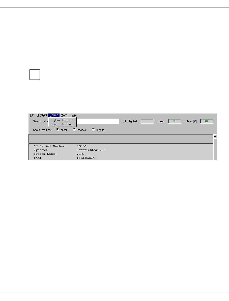
364 U41117-J-Z125-7-76
File viewer XTCC
Highlighted
Depending on the search procedure, this field outputs the number of color-highlighted
hits for the string being searched for. This counter also takes multiple hits into account
(depending on the search method and string). The search is ended when the color of
the text for this field changes from red to green.
Read [%]
Shows the percentage of the file already read in.
The functions “Highlight Down / Up” and “Search down / up” should only be called
once the text file has been read in completely. Otherwise the number of hits for a
text string to be searched for may be incorrect.
8.5.7 Search down/up
Selecting “Down” or “Up” with the left mouse button or pressing the associated keyboard
shortcut enables you to search for the string specified in “Search String” starting from the
beginning or end of the text.
Further information on the search criteria can be found in the section “Highlight” on
page 363.
If the string is found, the cursor is positioned on the occurrence highlighted in color. Each
time this function is activated, the cursor moves to the next occurrence. If the string cannot
be found in the text, the message “No match found” is output. With “Search down”, the
Return key can be used instead of the left mouse button or the shortcut.
i
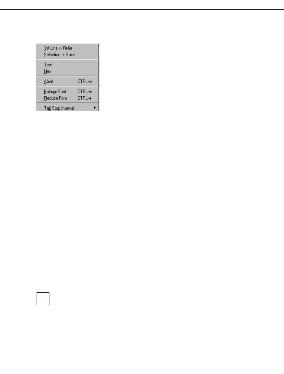
U41117-J-Z125-7-76 365
XTCC File viewer
8.5.8 Mode
8.5.8.1 1st Line -> Ruler/Selection -> Ruler
Displays the first line or the selected line in the non-scrolling area of the window.
This function can be used when viewing long tables in order to keep the title bar visible at
all times.
Some applications predefine the title bars.
8.5.8.2 Text/Hex
These functions are not offered by all applications.
The selected file is displayed either in text mode or as a hexadecimal ASCII dump. In the
hexadecimal dump all characters with the coding 0x00…0x1F and 0x7F…0xFF are
replaced in the text section by dots (standard ASCII).
8.5.8.3 Abort
Selecting “Abort” terminates preparation of the current file.
8.5.8.4 Enlarge Font / Reduce Font
The font size can be changed over five levels.
This function enables you to considerably enhance the text display if the font used
by the text viewer is not recognized as a true-type font in the GXCC system and is
not available in the size originally requested.
i

366 U41117-J-Z125-7-76
File viewer XTCC
8.5.8.5 Tab Stop Interval
In text files with tabulators the tab stop interval can change. The “default” generates an
interval of 8 characters with behavior typical for a text editor. For the other values intervals
from 1 .... 20 can be selected with behavior typical for a text editor.
8.5.9 Help
Opens a text window containing operating instructions.
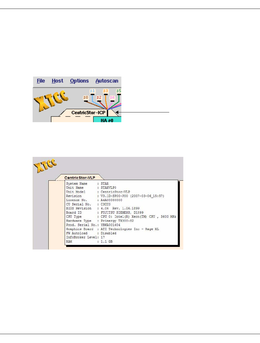
U41117-J-Z125-7-76 367
XTCC ISP
8.6 ISP
8.6.1 Object information on the ISP
The object representing the entire ISP is hidden behind the text “CentricStor” in the center
of the XTCC window.
If required two additional symbols are displayed:
– A yellow flashing SNMP symbol indicates that SNMP data is present.
– A yellow or red flashing tool symbol indicates that the file system is overfull
(yellow >95%, red = 100%).
The object information contains the following data:
System Name Name of the CS system (if available)
Unit Name Name of the ISP
Unit Model Typ of ISP
Revision Release version of the CentricStor software.
Licence Number Number of the license
CU Serial Number Serial number of the ISP.
BIOS Revision Revision level of the BIOS
Board ID ID of the motherboard.
CPU Type Type of processor
Object representing the entire ISP

368 U41117-J-Z125-7-76
ISP XTCC
Hardware Type Primergy PC model.
Prod. Serial No. Serial number of the Primergy
Graphics Board Type of graphics board
Firmware Autoload Indication of whether or not the firmware autoload function is
activated.
InfoBroker Level Revision level of the InfoBroker.
RAM Memory configuration. The usual prefixes apply; 1 MB = 220,
1 GB = 230, 1 TB = 240 bytes.
File system occupancy level (if more than 95%)
Over time, the ongoing logging process can cause the file system to
fill up. If this occurs, it is reported.
8.6.2 ISP functions
Function Note
Show Revision History
Version Consistency Check Offered only if the consistency check mechanism
is available on the system and inconsistencies
have been detected in the currently installed soft-
ware version
Show Diff. Curr./Prev. Version Offered only if the consistency check mechanism
is available on the system
Show Node Element Descriptors Offered only in the case of ICPs with ESCON
channel adapter
Show Configuration Data
Show System Log
Clean File System Offered only in the case of flashing yellow or red
tool icon
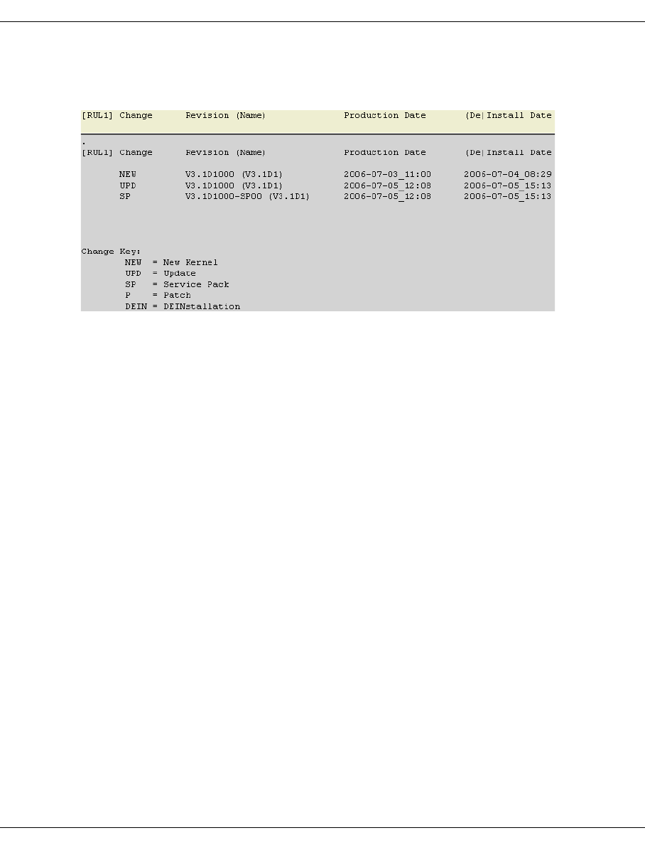
U41117-J-Z125-7-76 369
XTCC ISP
8.6.2.1 Show Revision History
This function is used to display a log showing all the software updates of the ISP:
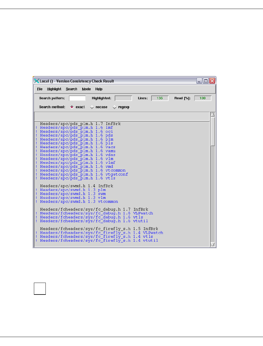
370 U41117-J-Z125-7-76
ISP XTCC
8.6.2.2 Version Consistency Check
This function is offered only if the consistency check mechanism is available on the moni-
tored system and inconsistencies have been detected in the currently installed software
version. This case can, for example, occur in the event of subsequent integration of devel-
oper corrections.
A window opens in which the result of the check is displayed:
This example shows that Version 1.7 of header file headers/apc/pds_plm.h was used
when the “InfBrk” package was created. The blue script below this which is preceded by an
exclamation point lists all the packages in which another version of this header file was
used.
For diagnostic purposes it is advisable to save the content of the file viewer window
using the file viewer’s “File - Save As” function.
i
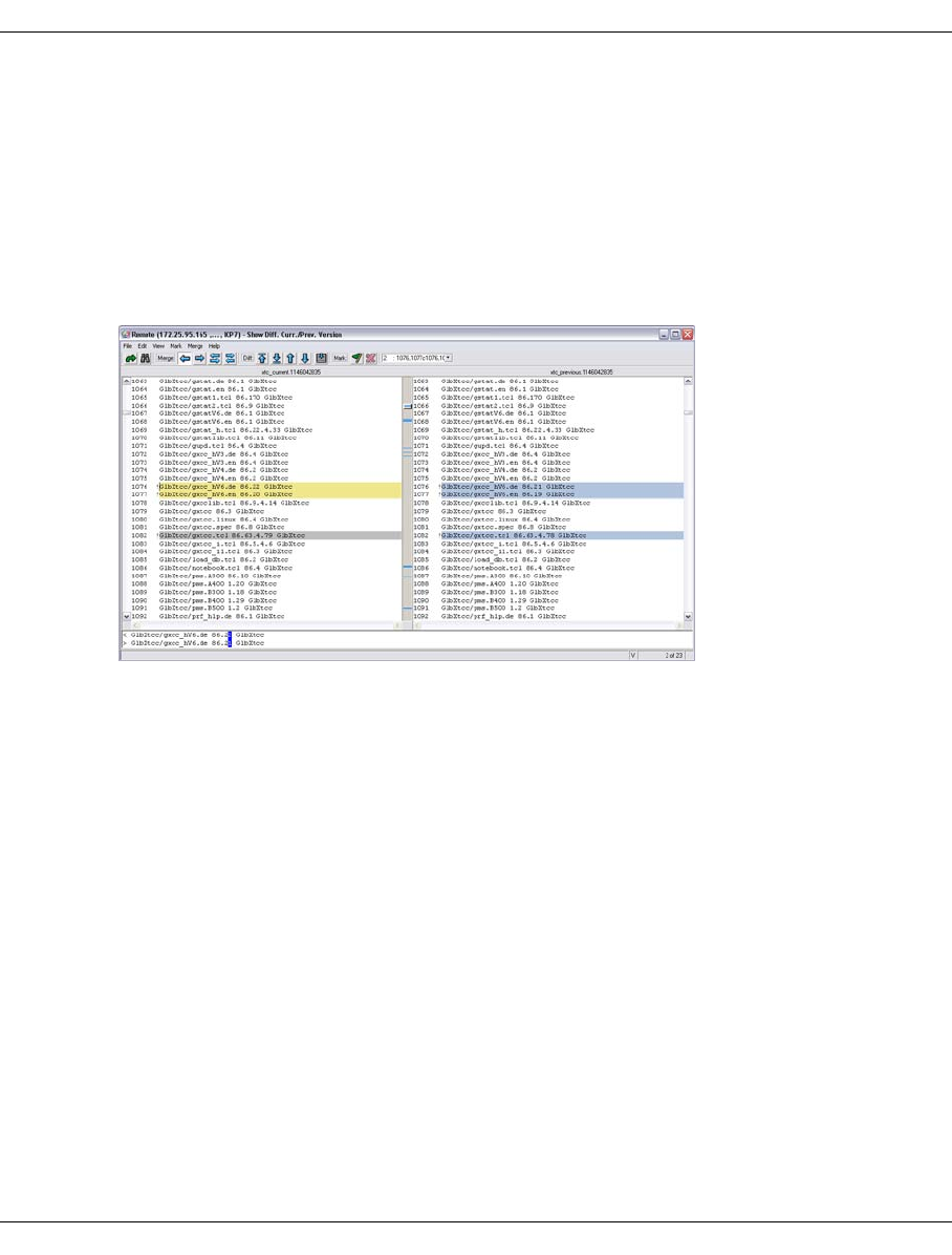
U41117-J-Z125-7-76 371
XTCC ISP
8.6.2.3 Show Diff. Curr./Prev. Version
This function is offered only if the consistency check mechanism is available on the system
being observed.
It is used to show the difference between the current and the previous versions using the
graphical Diff tool. The two versions are displayed in synchronized text windows. The differ-
ences are marked with colors and the number is shown at the bottom right in the status line.
Selecting “View / Show Line Comparison Window” in the View menu also enables differenc-
es within individual lines to be shown. The Diff tool has its own help system in English.
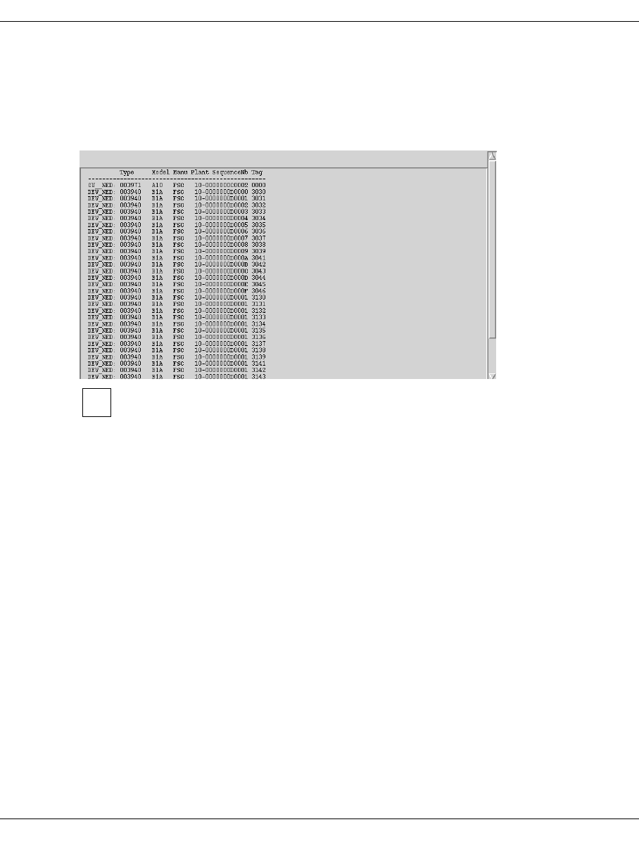
372 U41117-J-Z125-7-76
ISP XTCC
8.6.2.4 Show Node Element Descriptors
This function is available only for ICPs with an ESCON channel adapter.
It displays the node element descriptors of the ESCON channel adapters and the under-
lying virtual devices:
Show/View functions open windows that are equipped with scroll bars and search
functions. For information on the tools that can be used to navigate through these
windows when large data volumes are involved, see the section “File viewer” on
page 360.
i
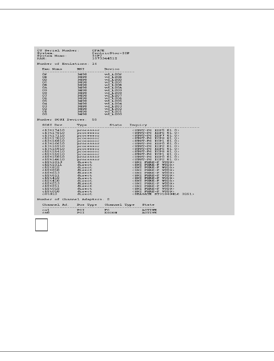
U41117-J-Z125-7-76 373
XTCC ISP
8.6.2.5 Show Configuration Data
Outputs a configuration display in table form:
For space reasons the example has been shortened.
The configuration data shows:
– information about the ISP
– a list of emulations with emulation name, HSI and device name (for ICPs) or a list of
PDSs for an IDP.
– a description of the CentricStor-internal Fibre Channel topology from the point of view
of the ISP
– information about the host adapters
The description of the Fibre Channel topology is contained in the section “Number SCSI
Devices”, but in coded form. The networking information can be found in the “SCSI Dev”
column if processor or RAID controller is specified under “Inquiry”.
i
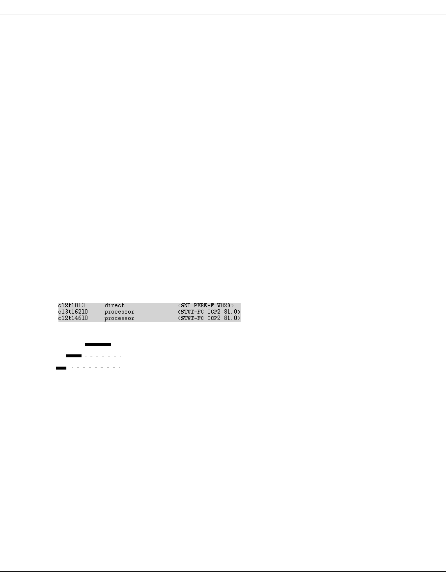
374 U41117-J-Z125-7-76
ISP XTCC
The SCSI devices are represented in the normal way as
c (=controller) <cc>t(=target)<tt>l(=Lun)<ll>, where cc, tt, ll are shown as decimal
numbers.
cc specifies the controller number in the ISP.
tt target number in the form of a decimal number. With components connected via
Fibre Channel, the path is coded in this number. This is described in more detail
in the next section.
ll Logical Unit Number of the component.
Coding the Fibre Channel path
If a binary representation is being used and the highest-order bit is set, the connection is
via the fabric protocol. If this bit is not set, an arbitrated loop connection is being used.
The following bits, as shown below, display the number of the switch and the number of the
connection.
Example
second line of the list: t162 ICP2
In binary representation, the target number is:
b’1010 0010’
In the example, the redundant connection runs over ICP2 (tt = X’92’) to switch number 1
using the same port number.
1 010 0010
Port number on the FC switch
Region (number of the switch)
1 = Fabric, 0 = Arbitrated Loop
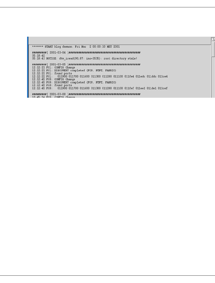
U41117-J-Z125-7-76 375
XTCC ISP
8.6.2.6 Show System Log
Displays system messages from the file klog.msg:
8.6.2.7 Show SNMP Data
This function is only available if a flashing yellow “SNMP” symbol indicates that one or more
SNMP data blocks are available. It opens a submenu in which you can select a block for
display. This is then removed from the submenu.
8.6.2.8 Clean File System
This function is not available in Observe mode.
This function is only available if a yellow or flashing red tool symbol indicates that the file
system occupancy level is greater than 95% or is at 100% (“File System full”).
The function starts a program which cleans the file systems of superfluous files. The
program deletes files that are contained in a list which can be modified by the service staff.
It also searches for temporary files that are less than 24 hours old and that occupy more
than 5 Mbytes of storage space. A message box will then appear telling you which files have
been located and how much space this now makes available. You must acknowledge this
message.
If this call does not solve the problem, you must notify your service staff. The majority of
software problems result in large volumes of diagnosis data being saved which, in turn, fills
the file system.

376 U41117-J-Z125-7-76
Internal objects of the ISP XTCC
8.7 Internal objects of the ISP
8.7.1 Representation of internal objects
Internal objects are those that do not communicate directly with the external data path and
are arranged physically within the system.
If the block for the internal objects is not in the foreground, the visible border of the dark gray
block changes its color to blue when the mouse pointer is positioned on it, indicating that it
is selected. If you press the left mouse button, it is brought into the foreground. An alter-
native display mode is described in section “Settings” on page 336.
Host connections and external drives always remain visible.
8.7.1.1 Hard disk drives
The status of a hard disk is indicated by the following colors:
Green: Read/write, read, busy
Pink: Online, offline
Yellow: Status unknown
If the mouse pointer is positioned over such an object, its color changes to blue, indicating
that it is selected.
If you press the left mouse button, a window containing the following information appears:
– vendor ID
– product ID
– product revision
–drive status
– controller number
– target number
If the drive is a logical drive of an internal RAID system, the following are also displayed:
– disk number
–RAID level
– status
– capacity
– mode
In the upper part, the write/read status is indicated by a lock symbol. If the lock is closed,
the status is read only.

U41117-J-Z125-7-76 377
XTCC Internal objects of the ISP
8.7.1.2 CD-ROM
The status of a CD-ROM drive is indicated by the following colors:
Turquoise: Read/write, read, busy
Pink: Online, offline
Yellow: Status unknown
If the mouse pointer is positioned over such an object, its color changes to blue, indicating
that it is selected.
If you press the left mouse button, a window containing the following information appears:
– vendor ID
– product ID
– product revision
–drive status
– controller number
– target number
In the upper part, the write/read status is indicated by a lock symbol. If the lock is closed,
the status is read only.
8.7.1.3 Streamer
The status of a streamer drive is indicated by the following colors:
Green: Read/write, read, busy
Pink: Online, offline
Yellow: Status unknown
If the mouse pointer is positioned over such an object, its color changes to blue, indicating
that it is selected. If you press the left mouse button, a window containing the following infor-
mation appears:
– vendor ID
– product ID
– product revision
–drive status
– controller number
– target number
In the upper part, the write/read status is indicated by a lock symbol. If the lock is closed,
the status is read only.
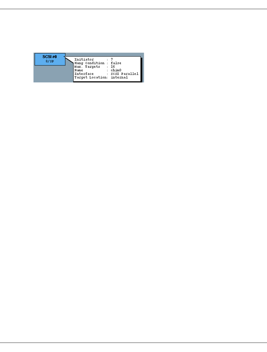
378 U41117-J-Z125-7-76
Internal objects of the ISP XTCC
8.7.1.4 SCSI controller
This is represented exactly as described in the section “Object information on SCSI
controllers” on page 421.
8.7.1.5 RAID controller
A RAID controller is represented by a block in which the device number (RAID #0, RAID #1
etc.), controller number and interface type SP (SCSI parallel) are displayed. The status of
the controller is indicated by the following colors:
Pink: Hang condition “true”
Green: Ready for operation
Yellow: Unknown
White: Not available
You will find more information in the section “Object information on RAID systems” on
page 411.
8.7.2 Functions of the ISP-internal objects
8.7.2.1 Hard disk, CD-ROM, streamer, all internal objects
There are no functions available.
8.7.2.2 SCSI controller
The functions are identical to those described for external SCSI controllers as of the section
“SCSI controller functions” on page 422.
8.7.2.3 RAID controller
Show complete internal RAID status
The status of all the components of the internal RAID system is displayed. You will find
detailed information in the section “Functions of RAID systems” on page 414.
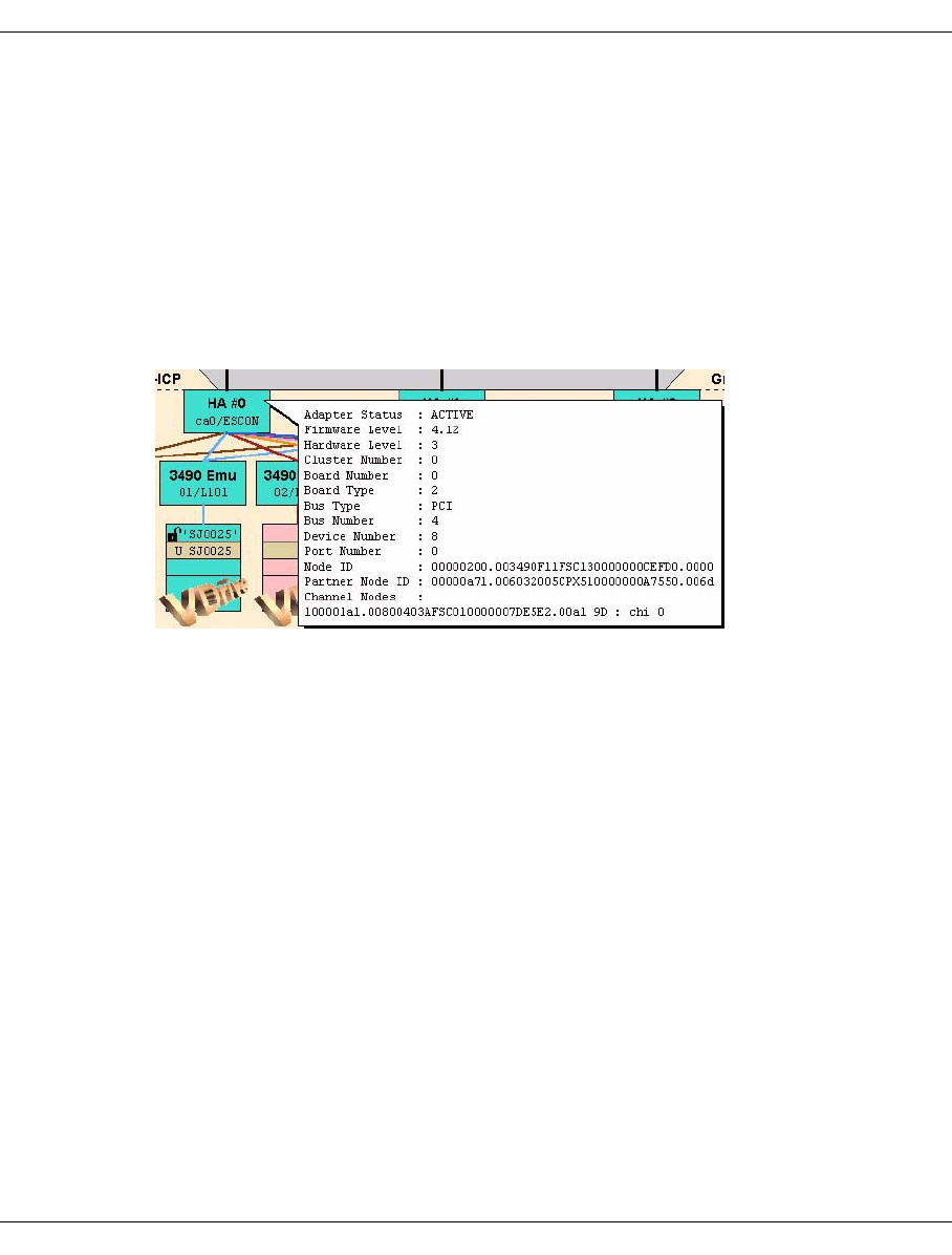
U41117-J-Z125-7-76 379
XTCC ESCON/FICON host adapter
8.8 ESCON/FICON host adapter
8.8.1 Object information for the ESCON/FICON host adapter
Each host adapter is represented by a block at the top of the ICP. Within the block, the host
adapter number (HA #0, HA #1, etc.) and type (ESCON, FICON, FC) are displayed. The
status of the host adapter is indicated by the colors pink (not active), green (active) and
yellow (unknown).
●Example for an ESCON host adapter
In the host adapter symbol, the serial number of the host adapter in the ICP appears in
the top line (here: HA #0) and the interface type appears in the second line (here:
ESCON).
The following information is also displayed in the information box:
Adapter Status Active or stopped.
Firmware Level Firmware version.
Hardware Level Hardware version.
Cluster Number Always 0 in CentricStor.
Board Number Number of the adapter board.
Board Type Board type.
Bus Type Bus type.
Bus Number Bus number.
Device Number Position of the ESCON host adapter in the ICP bus system.
Port Number Port number.
Node ID Node ID of the ESCON host adapter.
Partner Node ID Node ID at the other end of the ESCON connection (usually the
ESCON Director).
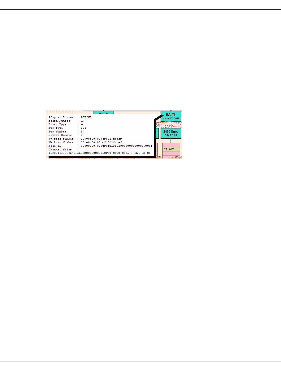
380 U41117-J-Z125-7-76
ESCON/FICON host adapter XTCC
Channel Nodes List of host channels used to establish a logical path. Each line
corresponds to one ESCON channel. The list shows the node
ID of the ESCON port in the host. The hexadecimal number
separated by a blank represents the port number of the host
channel on the ESCON Director (= link address).
The colon is followed by “chi” (= Channel Image) with a list of the
virtual channels of the host connected via this physical path.
To display formatted output of ESCON parameters, use the
“Show Node ID Details” command (see page 381).
●Example for a FICON host adapter
The following information is also displayed in the information box:
Adapter Status Active or stopped.
Board Number Number of the adapter board.
Board Type Board type.
Bus Type Bus type.
Bus Number Bus number.
Device Number Position of the FICON host adapter in the ICP bus system.
WW Node Number World Wide Node ID (WWNN)
WW Port Number World Wide Port ID (WWPN)
Node ID Node ID of the host adapters
Channel Nodes List of host channels used to establish a logical path. For further
information see the example for an ESCON host adapter.
Connecting lines to the hosts
The connecting lines from the host adapter that go over the top of the screen show the host
devices connected.
The circle at the top of the line contains the device mnemonic. If the name is underscored
and the line continuous, the connection is active; the device is reserved and a logical path
has been established.
A dashed line indicates that a path has been established but no reservation exists.
If no line is displayed, no path has been established.
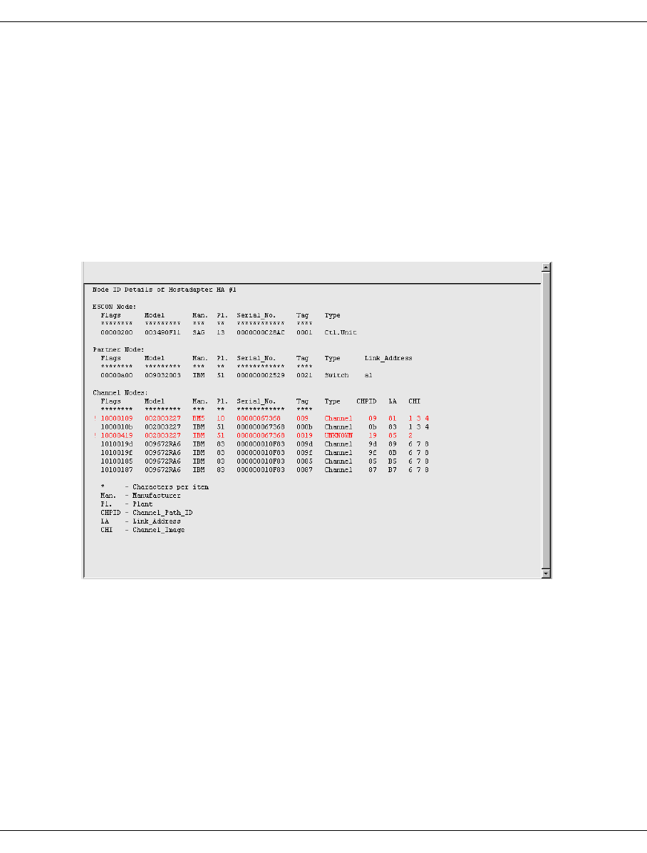
U41117-J-Z125-7-76 381
XTCC ESCON/FICON host adapter
8.8.2 ESCON/FICON host adapter functions
The following functions are available:
–Show Node ID Details
–Show Node Element Descriptors
–Show Dump (prkdump)
8.8.2.1 Show Node ID Details
Display of the node element descriptors of an ESCON/FICON host adapter, of the ESCON/
FICON Director, and of the host channels connected to the host adapter:
The node ID is formatted. An explanation of the abbreviations can be found under the list.
If the node ID cannot be decoded, the relevant line is highlighted by an exclamation mark
in the left margin and is colored red.
In the example shown, two errors were detected in the channel node IDs:
Both lines are marked by “!” at the start of the line and are colored red.
The first error involves a shift due to a missing character, while the second errored line
shows “UNKNOWN” as the type.
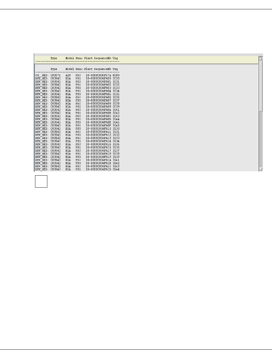
382 U41117-J-Z125-7-76
ESCON/FICON host adapter XTCC
8.8.2.2 Show Node Element Descriptors
Display of the node element descriptors of an ESCON/FICON host adapter and the under-
lying virtual devices.
Show/View functions open windows that are equipped with scroll bars and search
functions. For information on the tools that can be used to navigate through these
windows when large data volumes are involved, see the section “File viewer” on
page 360.
i

U41117-J-Z125-7-76 383
XTCC ESCON/FICON host adapter
8.8.2.3 Show Dump (prkdump)
Display of the host adapter driver dump:
To analyze this dump, you will need detailed knowledge of the system.
i
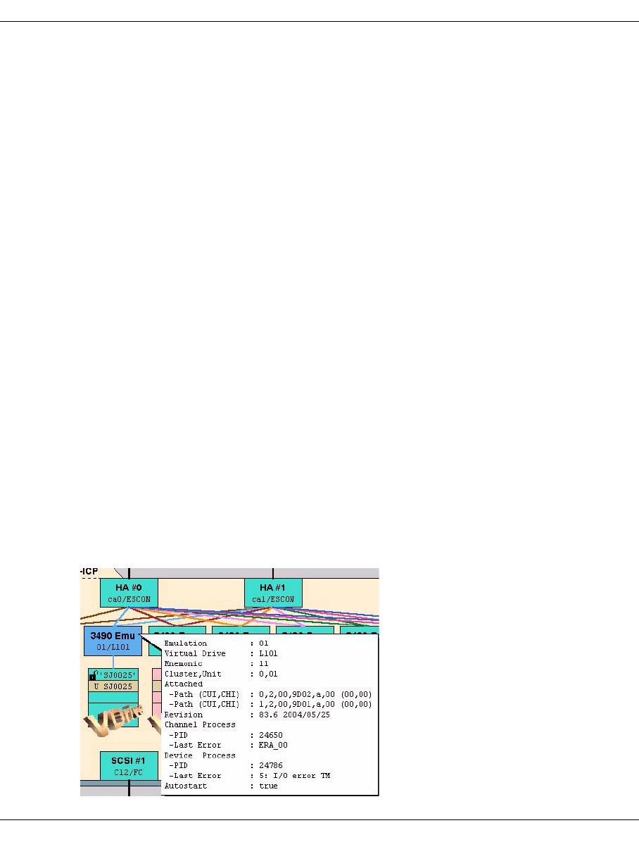
384 U41117-J-Z125-7-76
Emulations of drives connected to OS/390 host adapters XTCC
8.9 Emulations of drives connected to OS/390 host adapters
8.9.1 Information on emulations
The ESCON channel adapter only has emulations of drives of the types IBM-3490E and
Fujitsu F6473K. In the Fujitsu-Siemens Computers product lists, 3490-E devices are listed
under the number 3590 and must not be confused with 3590 tape drives from IBM.
Each emulation is assigned to a virtual tape drive. It is represented by a block connected to
one or two channel adapters. Within the block, the emulation type (IBM-3490), emulation
name (O3, etc.) and, in the case of virtual drives, the number of the logical device (L000,
L001, etc.) are displayed.
This type of emulation consists of two processes, one for communicating with the host
adapter and the other for communicating with the logical device or RAID system. These
processes are referred to as the channel process and the device process.
Normally, both processes have the same status. However, there are situations in which this
will not be the case. If this occurs, the top half of the block shows the status of the channel
process, while the bottom half shows the status of the device process. The process status
is indicated by the colors pink (stopped), green (running), green/brown (running with the
trace switched on), and red (configuration error).
XTCC represents the integration of the virtual drive in the CentricStor system:
– the connection to one or both ESCON host adapters
– the device names in the ESA/390 or BS2000 host
The connection lines are colored purely for the purposes of clarity.
In the event of an error (e.g. because of the failure of an ESCON channel) the connections
concerned are indicated by dashed lines.

U41117-J-Z125-7-76 385
XTCC Emulations of drives connected to OS/390 host adapters
The information box contains the following information:
Emulation Name of the emulation.
Virtual Drive Internal CentricStor name for the logical drive.
Mnemonic Name of the logical drive in the host (if defined).
CIuster, Unit ESCON address of the logical drive (chennel and unit number).
Revision Software revision level.
Attached Path (CUI, CHI): n,t,cc,llll,a,uu (uu, cc)
Describes the paths to the hosts:
n: Host adapter number
t: Host adapter type
cc: Channel image if defined
llll: Link address (connection number of the host on the ESCON director)
a: Connection status (a=attached)
uu: Control Unit Image (CUI)
Channel Process/Device Process/Last Error
Process ID and last error message from the channel and device processes in the SINIX
system.
Autostart
Specifies whether autostart is active for this emulation.
8.9.2 Functions for individual 3490 emulations
If the yellow “Busy” symbol is displayed for the selected drive, this means that the function
menu is currently not available.
The following functions are available:
–Show Error/Transfer Statistics
–Show Short Trace
–Show Path Trace
–Show Error Log
–Show Memory Log
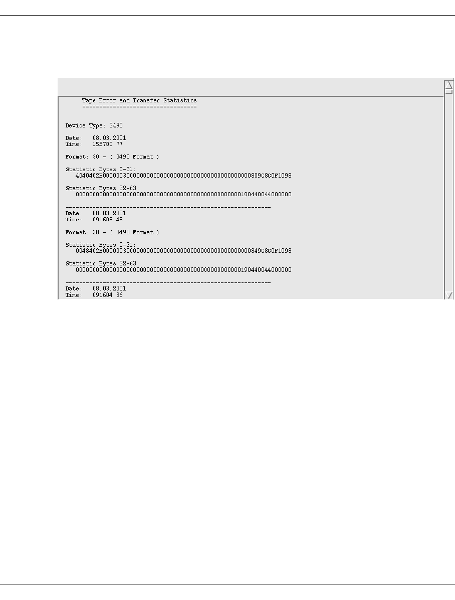
386 U41117-J-Z125-7-76
Emulations of drives connected to OS/390 host adapters XTCC
8.9.2.1 Show Error/Transfer Statistics
Display of the error and statistical data transferred to the host:
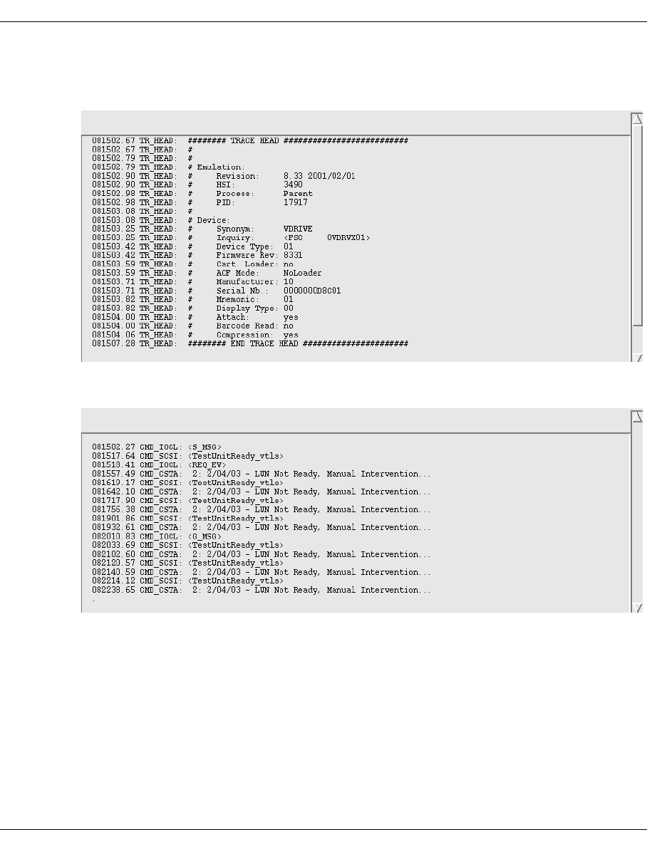
U41117-J-Z125-7-76 387
XTCC Emulations of drives connected to OS/390 host adapters
8.9.2.2 Show Short Trace
Displays general information at the beginning of the start trace file:
This is followed by the trace on all commands sent by the host together with their termi-
nation.
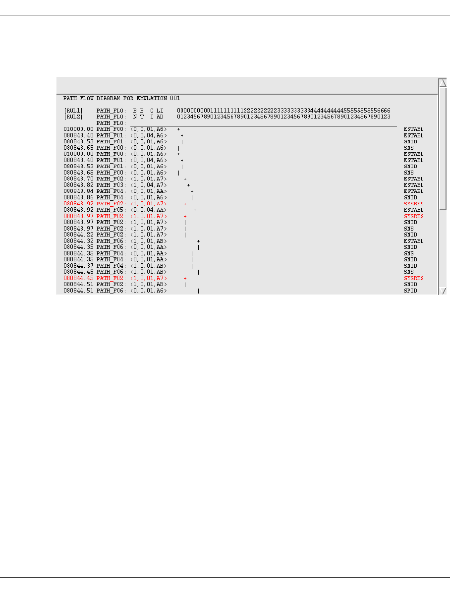
388 U41117-J-Z125-7-76
Emulations of drives connected to OS/390 host adapters XTCC
8.9.2.3 Show Path Trace
Displays the path sequence of I/Os:
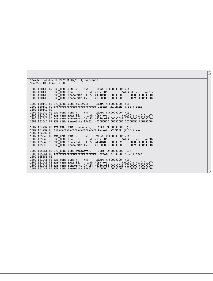
U41117-J-Z125-7-76 389
XTCC Emulations of drives connected to OS/390 host adapters
8.9.2.4 Show Error Log
Displays a text window containing the error log of the virtual device or emulation. Logical
device error messages may be issued as a result of:
– operating errors (read command for empty drive, write command for write-protected
volume)
– the mapping of internal CentricStor errors to device errors
Display of the emulations’s error logging:
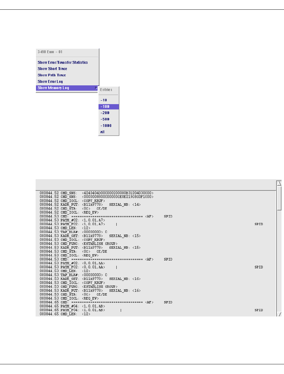
390 U41117-J-Z125-7-76
Emulations of drives connected to OS/390 host adapters XTCC
8.9.2.5 Show Memory Log
Displays the process log for the emulation which is present in memory:
This function makes it possible to display a continuous memory trace for the emulation
(logging). This logging is independent of the trace set manually.
Example
Memory log, range 100
8.9.3 Functions for all 3490 emulations
In Observe and User mode no functions are available which affect all emulations.
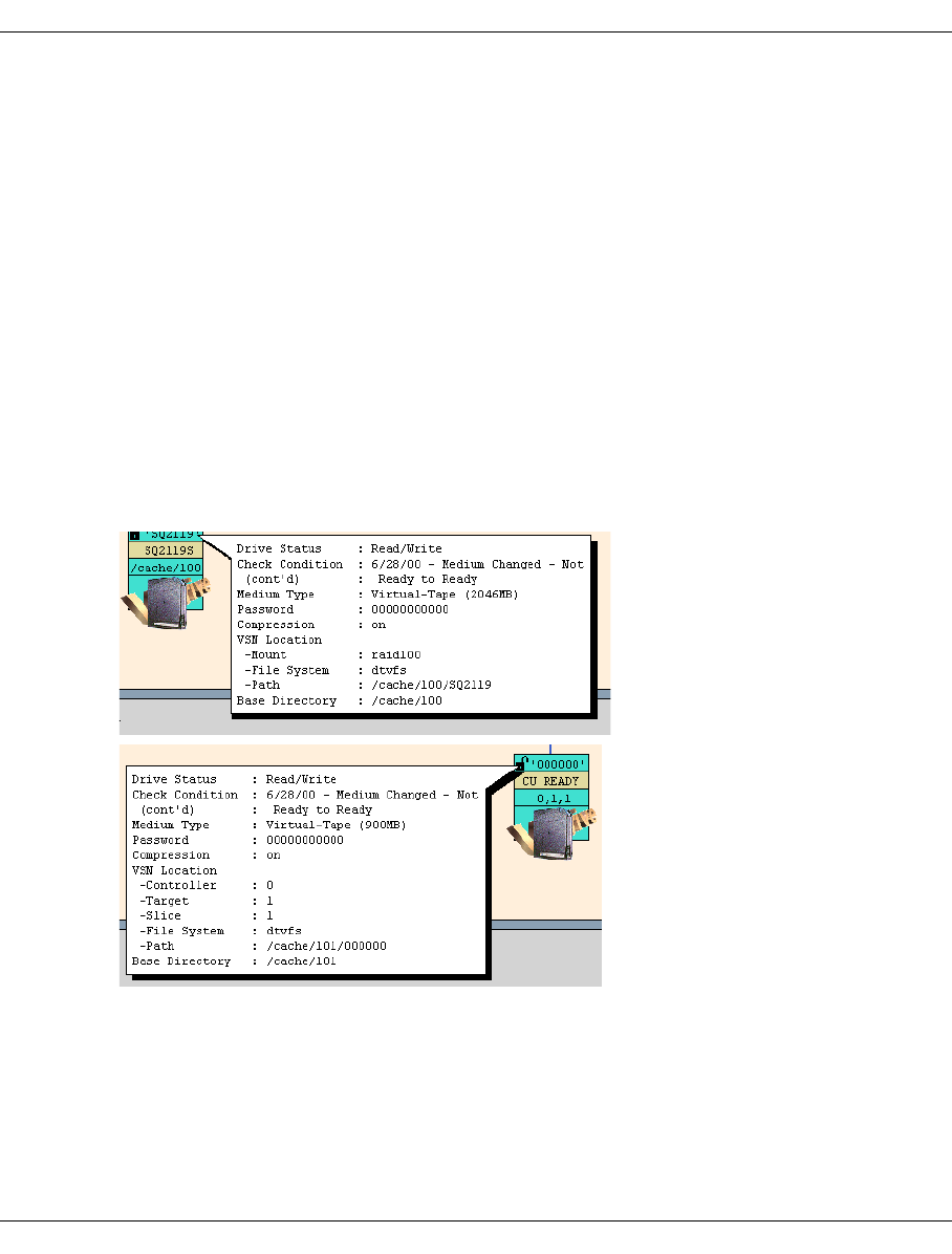
U41117-J-Z125-7-76 391
XTCC Virtual 3490 drives
8.10 Virtual 3490 drives
8.10.1 Object information and error messages for virtual 3490 drives
Each emulation is assigned its own virtual drive. In this object, the error messages and
behavior of a real drive are simulated as required. Even the display units on real 3490 drives
are reproduced faithfully and have the same displays as the real object of the emulation.
In contrast to real drives, an associated SCSI controller exists only when the logical volume
is located on the local disk. This is the case with a VTC, for example. In the case of Cen-
tricStor systems with an external RAID, a logical volume is addressed via a mount point
(e.g. 'raid100'). Access takes p lace via the mount point by means of a fully-automatic path
switchover depending on which FC controller is used to access the external RAID (in the
event of FC redundancy).
The overall integration of a virtual drive in CentricStor is displayed in the ICP main window.
The screens below display the information for the virtual drives:
The virtual drive is symbolized by a rectangle subdivided into lines. If a logical volume is
mounted, write protection (in the form of a padlock) and the name of the volume are
displayed in the top line. With an internal RAID the bottom line contains the information <c>,
<t>, <s> (Controller, Target, Slice) or <c>, <t>, <s>, <l> (Controller, Target, Slice, LUN)
depending on the filesystem. With an external RAID the Base Directory is displayed.
The middle line, displayed against a yellow background, indicates the display unit for the
drive. Here you can see the text that the host loads into the drive display.
VSN location in case of external
RAID
VSN location in case of internal
RAID

392 U41117-J-Z125-7-76
Virtual 3490 drives XTCC
The display can contain one of the following messages:
When a logical volume is loaded, the third line specifies which cache contains the
associated data.
8.10.1.1 Error conditions indicated on the display
Display 0 Display 1 Description
CU READY -- CU ready but path not yet connected.
CU ONL -- CU ready, path connected.
EMU STOP NORMAL Emulation stopped: normal end.
Display 1 Display 2 Meaning
EMU STOP ERR #001 BAD_IAT (address conflict between the emulation and the EXA
driver)
EMU STOP ERR #002 pcib open failed (no connection to the channel)
EMU STOP ERR #003 Index already exists (overlap in the kernel buffer address)
EMU STOP ERR #004 SIGSET for pcib
EMU STOP ERR #005 Device type not supported
EMU STOP ERR #006 Endless loop child (hard software error)
EMU STOP ERR #011 SIGBUS,-FPE,-SEGV (code overwritten)
EMU STOP ERR #013 Library init wrong
EMU STOP ERR #022 REG_EV (channel driver closed the connection to the
emulation)
EMU STOP ERR #030 VT_LS open error (initialization error)
EMU STOP ERR #031 VT_LS mount error
EMU STOP ERR #032 VT_LS Library Manager error
EMU STOP ERR #045 KBUF inconsistency (buffer inconsistency between the channel
and the emulation)
EMU STOP ERR #09 Test stop (trap)
EMU STOP ERR #100 PROCLOCK == ERR

U41117-J-Z125-7-76 393
XTCC Virtual 3490 drives
8.10.1.2 Object information
The extended information contains the following data:
Drive Status (Empty, write-protected); Specifies whether a cartridge is inserted and
whether data can be written to this cartridge.
Check Condition Date and description of the last Check Condition that occurred.
Medium Type (Only for mounted volume); Currently always “Virtual-Tape”.
Password Password assigned to the drive by the host software.
Compression Specifies whether data compression is activated.
VSN-Location (Only for mounted volume); Mount point, file system and path for
mapping the mounted volume in the cache (external RAID) or
Controller, Target, Slice, LUN, Filesystem and Path for mapping the
volume in the cache (internal RAID).
Cache-Directory (Only for mounted volume); Details of the cache area occupied by the
volume.
The graphical display also indicates error messages that have not yet been acknowledged.
A flashing icon indicates whether Service Information Messages (SIM) or Media Infor-
mation Messages (MIM) exist.
8.10.1.3 SIM/MIM error messages on virtual devices
The number after the SIM/MIM display specifies the severity code:
If there are several error messages, the associated codes are displayed alternately. Details
of the error message are shown if you click the error symbol. The flashing stops when you
open the error message.
As far as the host is concerned, CentricStor simulates 3490 cartridge drives. CentricStor
problems are mapped to error messages for these virtual drives. To do this, MIMs and SIMs
(Media Information Messages, Service Information Messages) that do not occur in physical
devices are used.
Code Designation Urgency
0Service Informative
1Moderate Medium
2Serious High
3Acute Urgent

394 U41117-J-Z125-7-76
Virtual 3490 drives XTCC
The following table lists the SIMs/MIMs used by the emulation and gives the probable
cause.
8.10.2 Virtual drive functions
The following functions are available:
–Show SCSI Sense
–Show Medium Info (MIM)
–Show Service Info (SIM)
–Unload and Unmount
When interpreting the information, it should be remembered that this is emulated
data.
MIM fault symptom
code FSC(0-3)
X’hhhh’
MIM text Possible cause
0C01 Unsupported format
0C02 Hard write error TFS hard write error. Hard
errors which recur repeatedly
cause CentricStor to crash.
0C03 Hard read error TFS hard read error. Hard
errors which recur repeatedly
cause CentricStor to crash.
0C04 Read, write or positioning
error
0C05 Write to write protected tape
0C06 Load failure, unload media and
retry
B111 No device Response
0815 No device Response
0816 File System Full
0817 Unknown Filesystem Sense
Code
The TFS sent an unknown error
code to the device emulation.
i
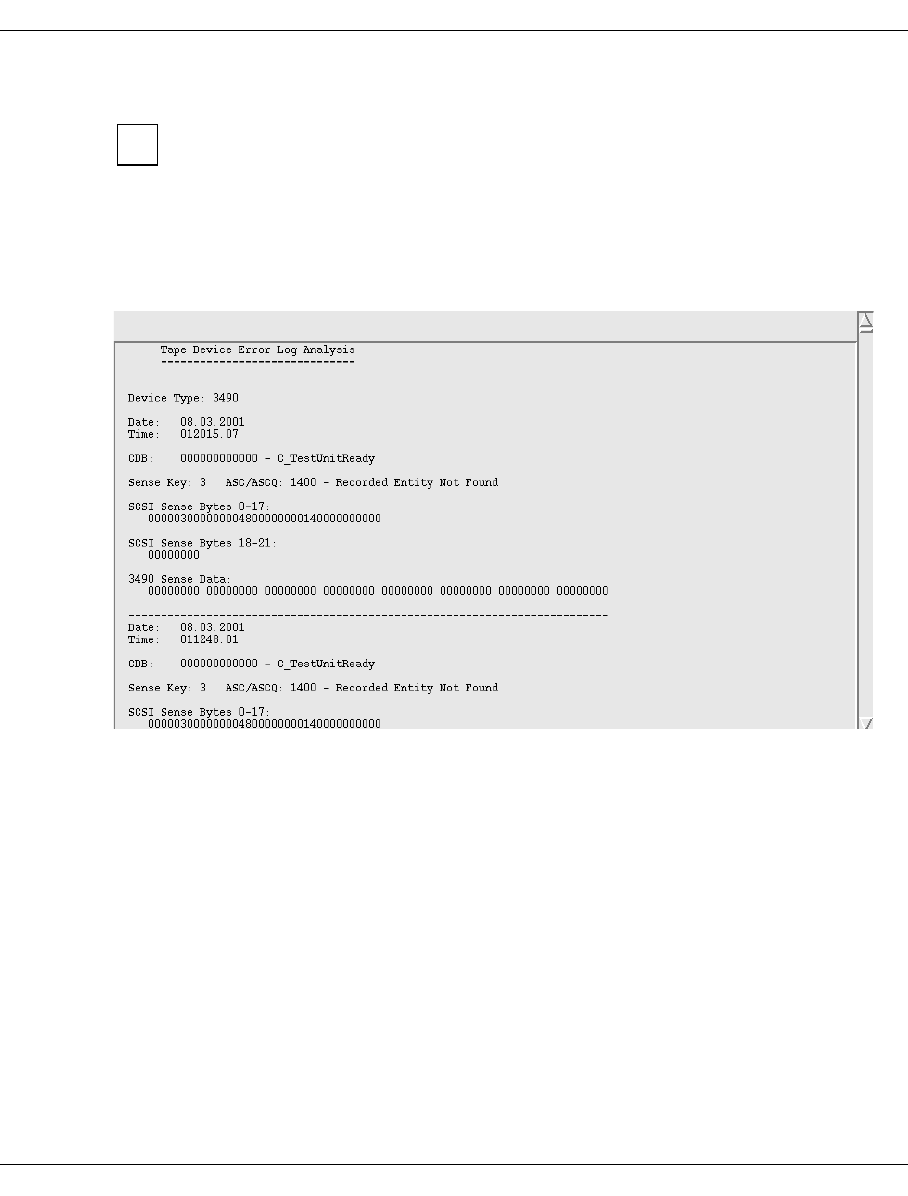
U41117-J-Z125-7-76 395
XTCC Virtual 3490 drives
8.10.2.1 Show SCSI Sense
The device emulation of CentricStor works internally as a protocol converter from
the channel to the SCSI protocol and vice versa. In a CentricStor ICP the SCSI
interface is only emulated. In the real system the device emulation works with the
interfaces of the file system to the RAID cache. However, because internal
processing takes place as SCSI, the error display is accordingly in SCSI notation
because this is standardized.
The menu item produces a text page containing the most recent SCSI sense information:
i
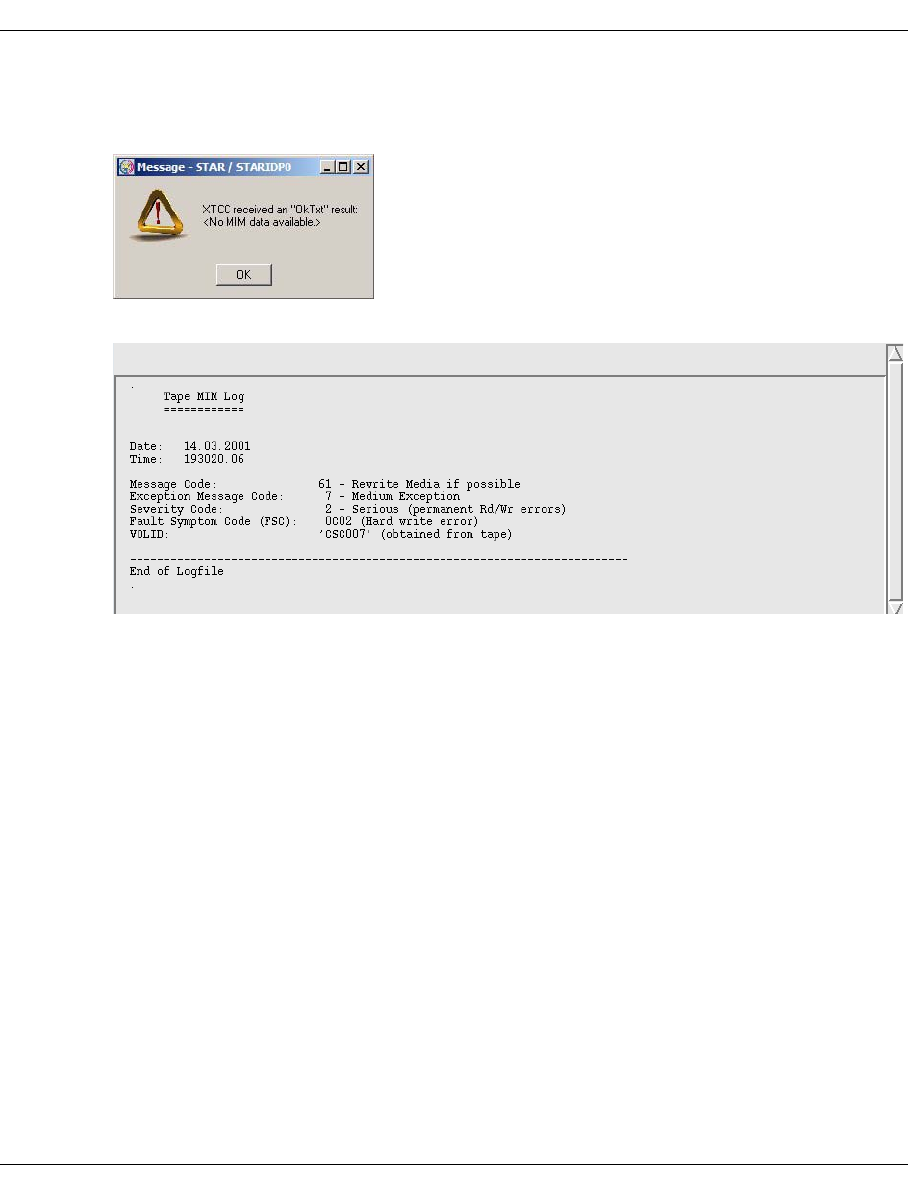
396 U41117-J-Z125-7-76
Virtual 3490 drives XTCC
8.10.2.2 Show Medium Info (MIM)
An info box appears if no MIM log exists:
Displays the latest Media Information Messages in a text window.
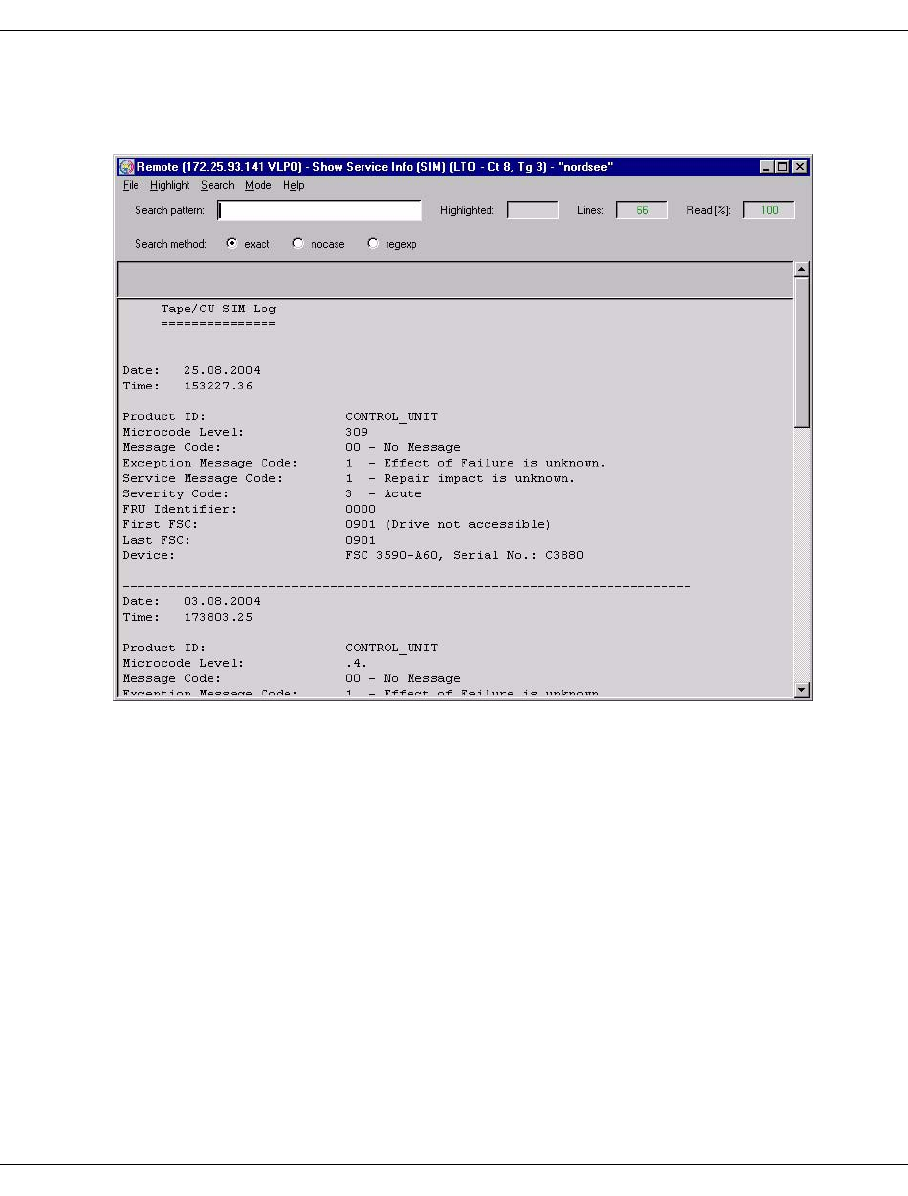
U41117-J-Z125-7-76 397
XTCC Virtual 3490 drives
8.10.2.3 Show Service Info (SIM)
Displays the latest Service Information Messages in a text window.
The MIM and SIM codes of the virtual devices are described in the section “Object infor-
mation” on page 393.
8.10.2.4 Unload and Unmount
This function is used to unload and unmount the virtual volume.
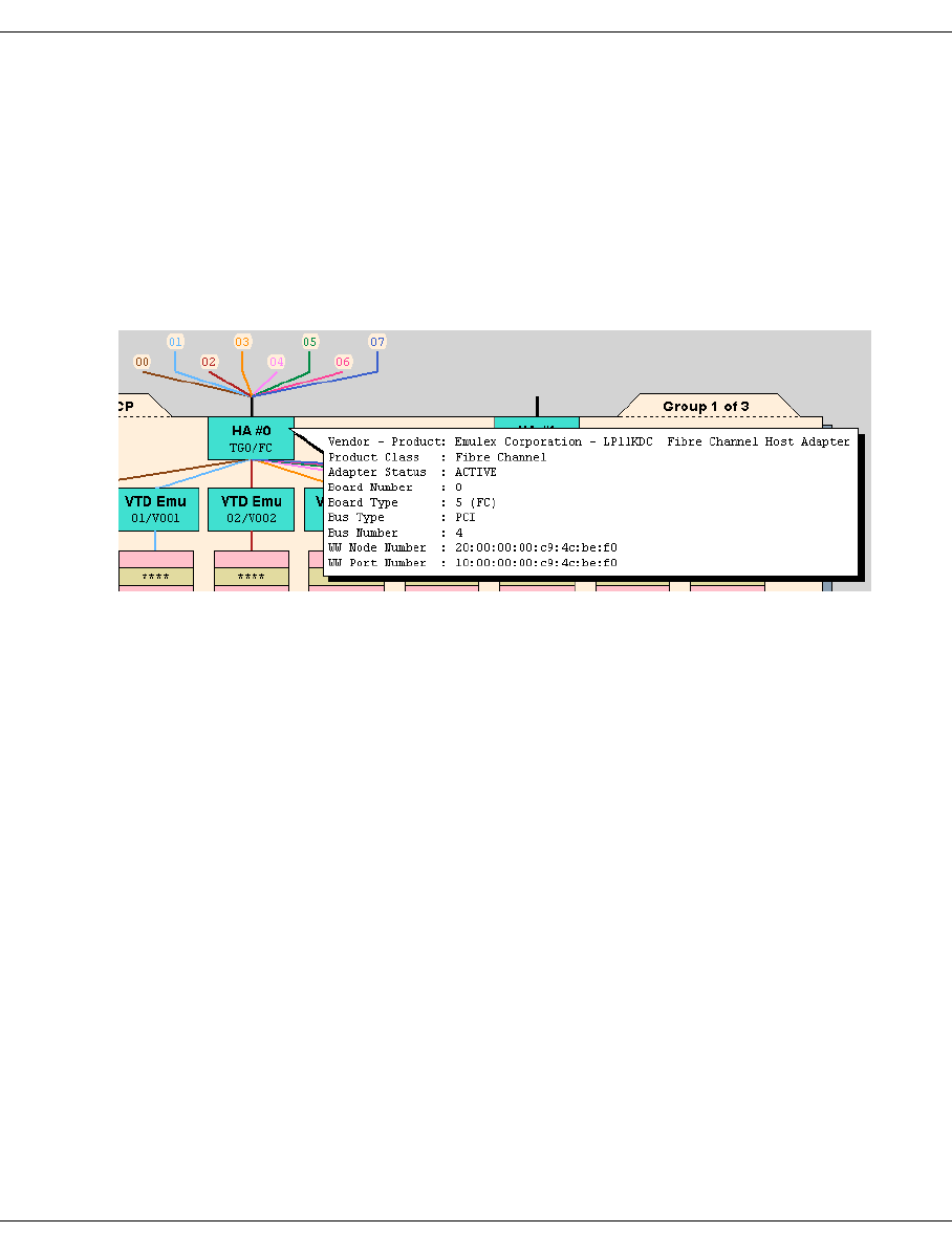
398 U41117-J-Z125-7-76
FC-SCSI host adapter XTCC
8.11 FC-SCSI host adapter
8.11.1 Object information on FC-SCSI host adapters
Each host adapter is represented by a block at the top of the ICP. Within the block, the host
adapter number (HA #0, HA #1, etc.) and type (ESCON, FICON, FC) are displayed. The
status of the host adapter is indicated by the colors pink (not active), green (active) and
yellow (unknown).
In the host adapter symbol, the serial number of the host adapter in the ICP appears in the
top line (here: HA #0) and the name and the interface type appear in the second line (here:
TG0/FC).
The following information is also displayed in the information box:
Vendor - Product Vendor and product name
Product Class Product class
Adapter Status Operational status.
Board No., Type Number and type of the host adapter.
Bus Type, Number Type and number of the internal bus to which the FC host adapter
is connected.
Device Number Internal ICP device number.
WW Node Number World Wide Node ID (WWNN).
WW Port Number World Wide Port ID (WWPN)
You need WWNN and WWPN to reconcile the configuration in the
host system.
Connecting lines to the hosts:
The connecting lines from the host adapter that go over the top of the screen show the host
devices connected.
The circle at the top of the line contains the LUN (Logical Unit) of the device. If the line is
continuous, the connection is active; host adapter and emulation are ready.
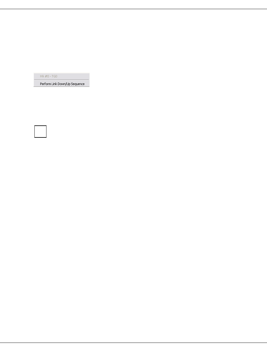
U41117-J-Z125-7-76 399
XTCC Emulations of SCSI drives (VTD)
A dashed line indicates that the host adapter and/or emulation are not ready.
If no line is displayed, no LUN was found.
8.11.2 FC-SCSI host adapter functions
8.11.2.1 Perform Link Down/Up Sequence
For approx. 30 seconds the status “Link Down” is generated, thus activating a flashing dis-
play on the module. This enables the module to be located in the hardware.
The function can be called only if the host adapter is in “ACTIVE” mode.
8.12 Emulations of SCSI drives (VTD)
8.12.1 Object information on emulations of SCSI devices
The emulation type VTD (Virtual Tape Device) is provided for open systems (OS).
Each emulation is assigned to a virtual tape drive. It is represented by a block connected to
the host adapter. Within the block, the emulation type (VTD), logical unit number (0x00,
0x01, etc.), and the number of the virtual drive (V000, V001, etc.) are displayed.
This type of emulation consists of a single process, the status of which is indicated by the
colors pink (stopped), green (running), and green/brown (running with the trace switched
on).
i
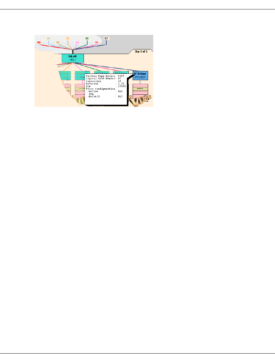
400 U41117-J-Z125-7-76
Emulations of SCSI drives (VTD) XTCC
The figure below shows the characteristics of an emulation as displayed in XTCC.
The information box displays:
Virtual Tape Device Internal SINIX name for the device.
Logical Unit Number LUN on the FC-SCSI interface.
Controller Serial number on the FC-SCSI controller.
Revision Revision level of the emulation.
Process ID Process ID of the emulation.
Active, Own and Default Trace Configuration
Trace settings (dependent on the VTD version).
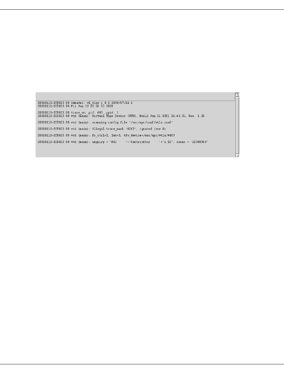
U41117-J-Z125-7-76 401
XTCC Emulations of SCSI drives (VTD)
8.12.2 Functions for individual VTD emulations
The following function is available:
–Show Trace
8.12.2.1 Show Trace
Displays the emulation trace in a text window.
The example above shows the trace entries created when the VTD is started. During
operation, the trace primarily records the SCSI commands processed.
8.12.3 Functions for all VTD emulations
“All” means all emulations on this ISP.
In Observe and User mode no functions are available.
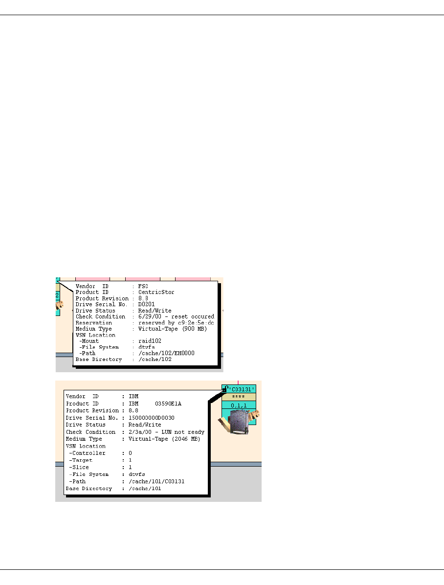
402 U41117-J-Z125-7-76
Virtual SCSI drives XTCC
8.13 Virtual SCSI drives
8.13.1 Object information on virtual tape drives
Drives of this type are designated as VDrives.
In contrast to real drives, an associated SCSI controller exists only when the logical volume
is located on the local disk. This is the case with a VTC, for example. In the case of Cen-
tricStor systems with an external RAID, a logical volume is addressed via a mount point
(e.g. 'raid102'). Access takes p lace via the mount point by means of a fully-automatic path
switchover depending on which FC controller is used to access the external RAID (in the
event of FC redundancy).
A virtual drive is symbolized by a rectangle subdivided into lines. If a logical volume is moun-
ted, the write protection (in the form of a padlock) and the name of the volume are displayed
in the top line. With an internal RAID the bottom line contains the information <c>, <t>, <s>
(Controller, Target, Slice) or <c>, <t>, <s>, <l> (Controller, Target, Slice, LUN) depending
on the filesystem. With an external RAID the Base Directory is displayed.
The drive’s display unit is emulated in the middle line, which is highlighted in yellow.
VSN location in case of external RAID
VSN location in case of internal RAID

U41117-J-Z125-7-76 403
XTCC Virtual SCSI drives
The following is displayed:
Inquiry data Vendor ID, product ID, product revision level, drive serial number.
Vendor ID and product ID can be selected during configuration.
Drive Status Online, Offline, Read/Write
Check Condition: Date and designation of the error condition that occurred last.
Reservation The last 4 bytes of the WWPN of the host which reserves the drive
are displayed.
Medium Type: (Only with a mounted volume); always corresponds to the emulated
volume type .
VSN Location Mount point, file system and path to the map of the mounted volume
in the cache (external RAID) or Controller, Target, Slice, LUN,
Filesystem and Path for mapping the volume in the cache (internal
RAID).
Base Directory (Only with a mounted volume); details on the cache area which the
volume occupies.
Depending on the operating status, some of the information listed above may not be
displayed.

404 U41117-J-Z125-7-76
Virtual SCSI drives XTCC
8.13.2 Virtual generic drive functions
Depending on the emulation, the following functions are available:
8.13.2.1 Show SCSI Sense
Shows the accumulated SCSI sense bytes of the virtual drive.
8.13.2.2 Show Medium Info (MIM)
Shows the “Media Information Messages”.
8.13.2.3 Show Service Info (SIM)
Shows the “Service Information Messages”.
8.13.2.4 Unload and Unmount
Unloads and unmounts the virtual volume.
/390 VDRV OS VDRV
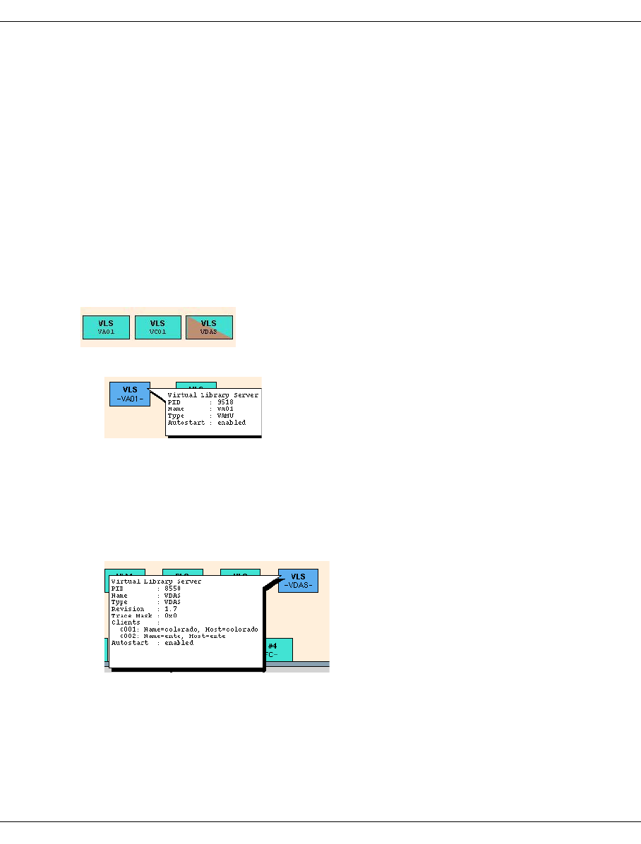
U41117-J-Z125-7-76 405
XTCC VLS (Virtual Library Service)
8.14 VLS (Virtual Library Service)
8.14.1 Object information on VLSs
A VLS (Virtual Library Server) is the emulation of an archive system for magnetic tapes.
CentricStor can emulate various types of archive systems.
VLSs of the type VACS, VLMF or VDAS serve a number of clients. These VLSs can only
run once in CentricStor. A VLS of the type VAMU or VJUK is only able to serve a single
client. However, CentricStor is able to run up to 10 instances of a library of type VAMU or
20 instances of a library of type VJUK.
The status of a VLS is indicated by the colors pink (stopped), green (running) and green/
brown (running with the trace switched on):
●The following information is displayed for all VLS types:
PID Process ID.
Name Name as it appears on the VLS symbol, which is defined during configu-
ration.
Type Type of VLS: vamu, vacs, vlmf, vdas or vjuk.
Autostart Enabled / disabled.
●The following information is also displayed for VLSs of type VDAS:
Revision Software revision level.
Trace Mask Active trace mask.
Clients Client names and hosts.
Example: VAMU
Example: VDAS
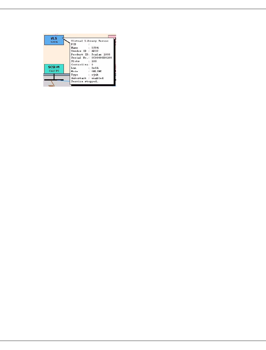
406 U41117-J-Z125-7-76
VLS (Virtual Library Service) XTCC
●The following information is also output for VLSs of the type VJUK:
Vendor ID Vendor identifier
Product ID Product identifier
Serial No Serial number
Slots Number of slots
Controller Number of the controller used
Lun SCSI Lun of the jukebox
Mode Operating status
8.14.2 Functions for individual VLSs
The functions available for a VLS depend on its type.
VDAS has the “Show Trace” function which opens a text window containing trace infor-
mation.
8.14.2.1 Show Trace
Displays the trace data. This function is available only for VLSs of type VDAS.
8.14.3 Global functions for all VLSs of an ISP
When operating in Observe or User mode, there are no such functions available.
Example: VJUK
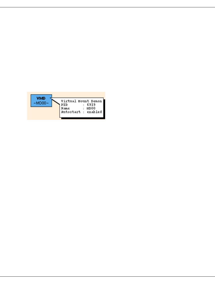
U41117-J-Z125-7-76 407
XTCC VMD (Virtual Mount Daemon)
8.15 VMD (Virtual Mount Daemon)
8.15.1 Object information on the Virtual Mount Daemon (VMD)
The VMD, also known as the mount server, controls the mounting and unmounting of virtual
volumes in the virtual drive(s) on behalf of the VLM.
Each ICP has its own VMD. The VMD and the drives it serves must be located on the same
ISP.
The status of the VMD is indicated by the colors pink (stopped), green (running), and green/
brown (running with the trace switched on).
PID Process ID.
Name Name of the VMD.
Autostart Enabled / disabled
8.15.2 VMD functions
The VMD has no functions which can be addressed via XTCC.
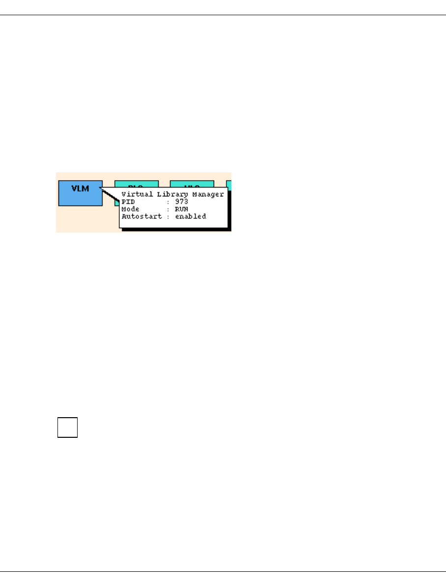
408 U41117-J-Z125-7-76
VLM (Virtual Library Manager) XTCC
8.16 VLM (Virtual Library Manager)
8.16.1 Object information for the VLM
Virtual libraries are emulated and mapped to physical libraries in a process pair consisting
of a VLM (Virtual Library Manager) and a PLM (Physical Library Manager).
In XTCC, the VLM and PLM are represented by small boxes in the VLP. The status of the
VLM is indicated by the colors pink (stopped), green (running), green/brown (running with
the trace switched on), and green/red (in HALT mode).
The following information is displayed:
PID: Process ID
Mode: Operational status (RUN, HALT)
Autostart: Autostart enabled/disabled
The trace masks are not specified for customer operation. If the mask contains only binary
zeros or is not present then the corresponding trace is inactive.
8.16.2 VLM functions
The following functions are available:
–Show Cache Status
–Set HALT Mode/Set RUN Mode
Functions for monitoring and managing virtual components (logical volumes, drives,
libraries) can be called under Global Status » Statistics (for display functions see
page 245) and GXCC » Administration (for management functions see page 202).
8.16.2.1 Show Cache Status
A cache window containing information on cache occupancy is output. The numerical
values correspond to the information that is displayed in graphical form in the Global Status
Monitor (see the chapter “Global Status” on page 237, the corresponding description also
explains the terms such as “used”, “dirty”, etc.).
In addition, the following is displayed for each cache file system:
i
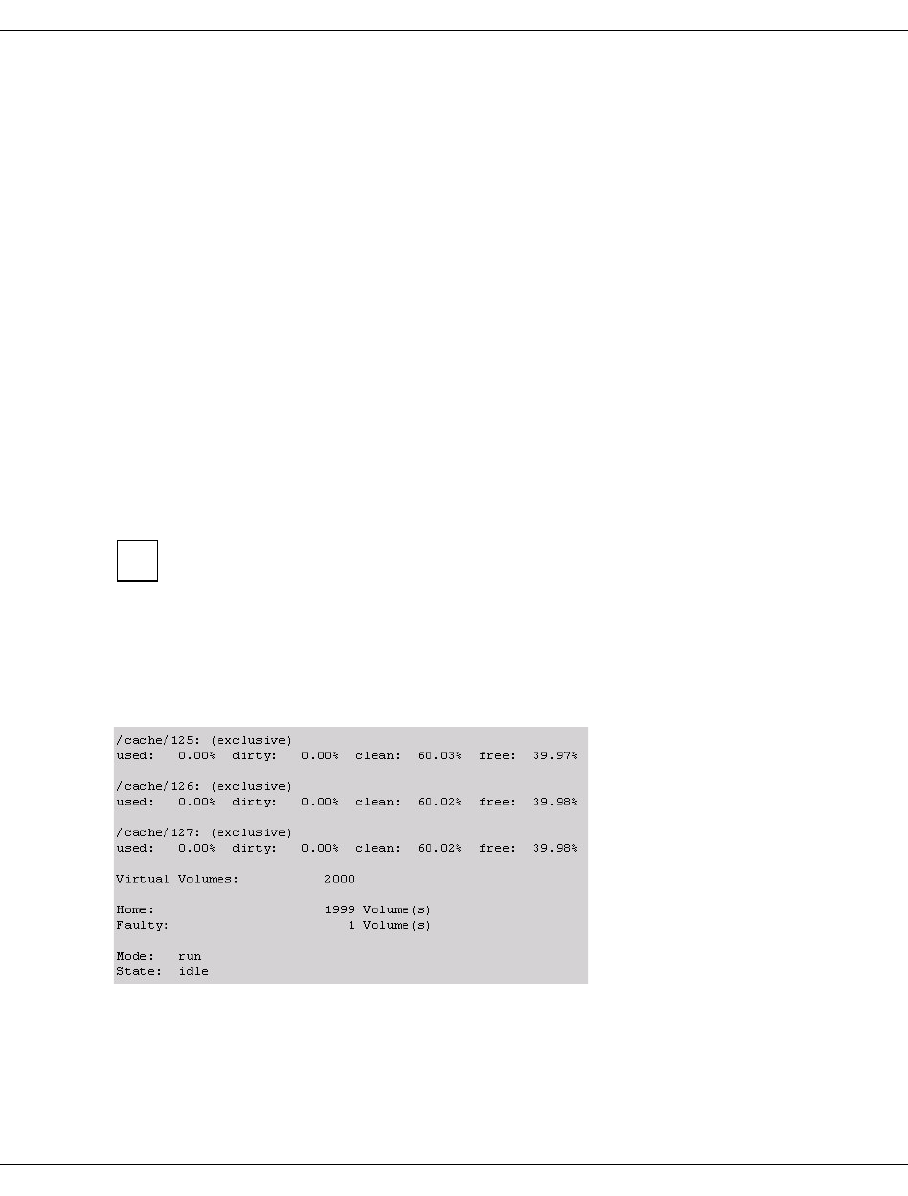
U41117-J-Z125-7-76 409
XTCC VLM (Virtual Library Manager)
●Whether the cache file system is used for “floating” volumes or whether volume groups
are permanently assigned to it (“exclusive”).
●The number of “misplaced” volumes which may be present. These are logical volumes
which are currently not located in the cache file system for which they were configured.
The cache status provides an overview of the CentricStor load status. In the case of logical
volumes, the following numerical values are displayed:
– Total number of logical volumes
– Logical volumes in home status
– Mounted (loaded) logical volumes
– Logical volumes that are currently being loaded from tape to cache (restoring)
– Logical volumes that are being read in as part of a reorganization (move restore)
– Logical volumes that are being rewritten as part of a reorganization (move save)
– Logical volumes for which a prefetch operation is running
– Logical volumes that are no longer present in the cache (migrated)
– Logical volumes whose physical tape map is obsolete (dirty)
– last mount completed: indicates when a logical volume was last mounted (if cc=0) or the
VLM error code with which the last mount job was aborted.
Only statuses which are assigned are also listed.
“Mode” indicates whether logical tape processing (i.e. the acceptance of mount
requests) was halted by the host (mode: Halt) or not (mode: Run).
“State” indicates whether the VLM is currently still executing jobs (state: busy) or not
(state: idle).
Example
i

410 U41117-J-Z125-7-76
VLM (Virtual Library Manager) XTCC
8.16.2.2 Set HALT Mode/Set RUN Mode
This function is not available in Observe mode.
In HALT mode, the VLM accepts no mount jobs for logical volumes. All other CentricStor
activities continue to run. The hosts can continue to access logical volumes that are already
mounted. Mount jobs are rejected with the error message “N005 - Robot not ready”.
WARNING!
In some host systems, even a brief HALT period can result in considerable distur-
bance to magnetic tape processing.
If you choose the “Set HALT Mode” menu item, a dialog box asks you if you really want to
execute this function. If you confirm with “Yes” then a corresponding message box is
displayed that you must confirm by clicking “OK”.
The symbol for the VLM in the corresponding XTCC window changes to red/green:
CentricStor has not yet reached its idle state. Before this can happen, all the logical volumes
must be unloaded and all the “dirty” cache data must be written back.
The idle state is most clearly identified on the basis of the cache status. In Global Status no
“dirty” data may now be displayed in the cache statistics. In this case, the status IDLE must
be displayed in the last line of the text field.
“Set RUN Mode” exits the HALT status. This command is available in the VLM function
menu if the VLM is in HALT mode. This command is also effective even if the VLM has not
yet entered idle status.
!

U41117-J-Z125-7-76 411
XTCC RAID systems
8.17 RAID systems
8.17.1 Object information on RAID systems
CentricStor can be supplied with the RAID systems S80, CX500, CX3-20 and Eternus
3000/4000. In XTCC, the RAID systems are represented as peripherals connected to the
ISP via a Fibre Channel controller.
In some CentricStor configurations, internal RAID controllers are used. These have a direct
connection to the host and do not require a Fibre Channel connection. They are thus not
visible in the overview of the ISP. They become visible when you position the mouse pointer
on the right-hand (gray) border of the ISP symbol and press the right mouse button.
The status of a RAID system is indicated by the colors green (OK), pink (fail), and yellow
(attention) (does not apply for CX500/CX3-20 and Eternus 3000/4000).
The Fibre Channel addresses of the RAID system (controller, target) can be obtained from
the overview: the controller number (number in front of “/FC”) from the controller block, and
the target number from the number that appears after the slash.
Compared to GXCC, XTCC displays additional information on the RAID systems.
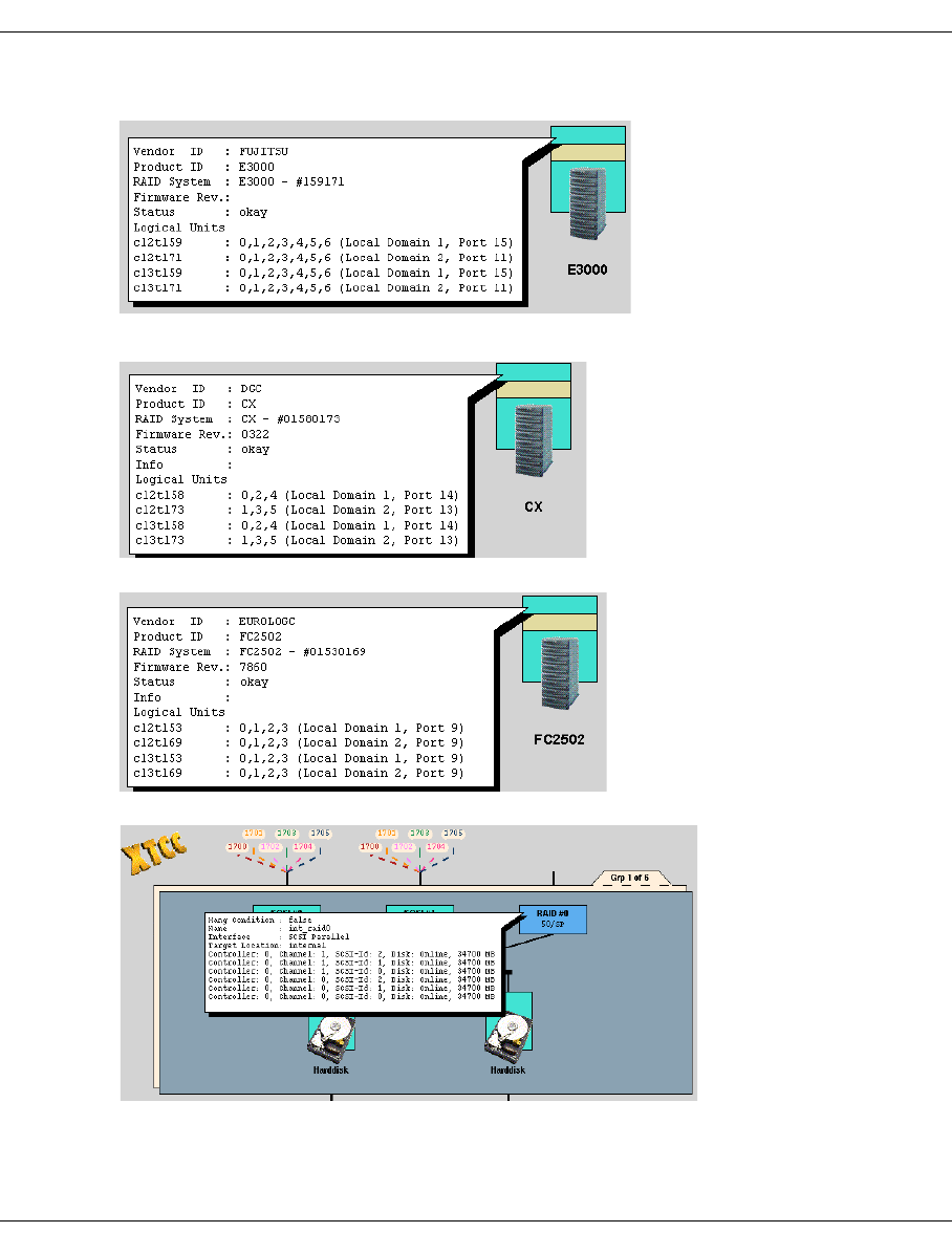
412 U41117-J-Z125-7-76
RAID systems XTCC
The controller types differ slightly in their presentation of the functions available:
S80 (=FC2502)
Internal RAID system
CX500/CX3-20
Eternus 3000/4000

U41117-J-Z125-7-76 413
XTCC RAID systems
In the case of external RAID systems, the information window contains the following infor-
mation:
– vendor ID, product ID
– type and serial number of the RAID system
– firmware release (insofar as this can be queried)
– operating status and any error messages (info)
– internal SINIX name, SCSI topology (CTL) and the connection to the FC fabric
In Fabric Mode, the information “Local Domain x, Port y“ is displayed for the target numbers
128…2047. The local domain is in the value range 1...8. In the case of FC switches with
more than 16 ports, it can differ from the “Domain” displayed in GXCC as follows:
GXCC Domain = 1 2 3 4 5 6 7 8 9 10 11 ... etc.
XTCC Local Domain = 1 2 3 4 5 6 7 8 1 2 3 ... etc.
If multiple RAID systems are contained in CentricStor and it was possible to determine the
firmware version for at least one RAID, the versions of all RAIDs of the same type are
compared. If the versions are different the message “Different Firmware!” is displayed on
the symbols for all RAIDs of this type. This is also done if the version information for a RAID
is missing.
The number contained in the internal SINIX name (e.g. c12t158) is also displayed at the
end point of the connection lines.
In the case of internal RAID systems, the following information is displayed:
– hang condition
–name
– interface type
– target location
In addition, there may be information relating to the physical disks of the RAID system:
– controller
– channel
–SCSI ID
– status
– capacity
The representation of the RAID system is a symbol rather than a photograph of the
product. Its actual appearance may well differ from this.
i
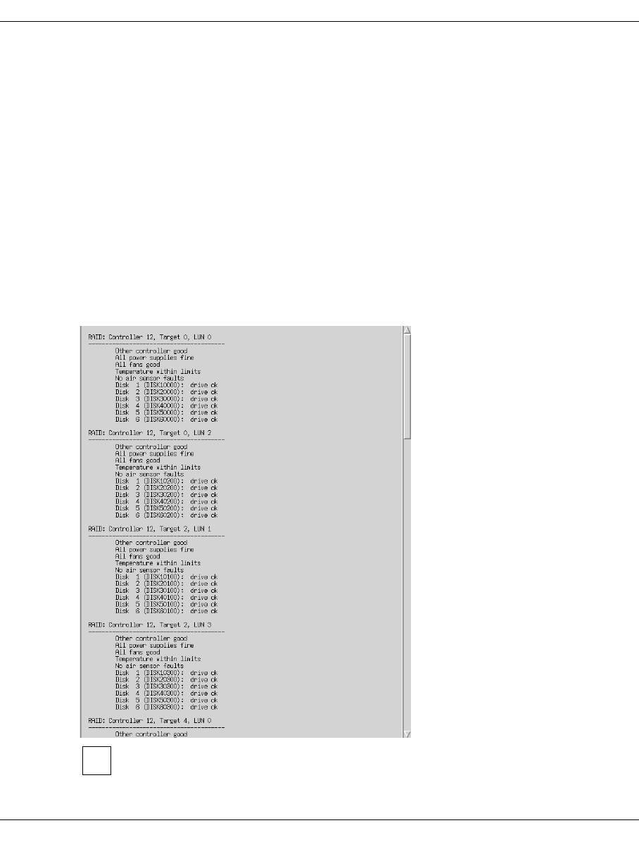
414 U41117-J-Z125-7-76
RAID systems XTCC
8.17.2 Functions of RAID systems
The following functions are available:
–Show Complete RAID Status (all types)
–Show Mode Pages (CX500/CX3-20 and FCS80)
–Show Mode Page Details
–Show Log Pages
–Show Log Page Details
The availability of the functions de-pends on the particular RAID system.
The menus are available in all operating modes.
8.17.2.1 Show Complete RAID Status (all types)
Opens a text window containing the detailed RAID status:
As it is not possible to read the status via an FC port in the FibreCAT
CX500/CX3-20 or Eternus 3000/4000, “no information available” is always output
for these RAID systems.
i

U41117-J-Z125-7-76 415
XTCC RAID systems
This very extensive information indicates the status of the controllers and the disks. The
displays are self-explanatory. For a more precise interpretation, in particular in the case of
partial failures, please refer to the RAID system manual. The content and presentation
depend on the type of RAID controller.
8.17.2.2 Show Mode Pages (CX500/CX3-20 and FCS80)
Displays the SCSI mode pages in a text window. To interpret the page data, you will need
to refer to the SCSI reference manual and the manual for the RAID system.
8.17.2.3 Show Mode Page Details
The mode pages described in the SCSI standard are displayed in detail in text windows. For
further information refer to the section “Show Mode Page Details” on page 428.
8.17.2.4 Show Log Pages
The SCSI log pages are displayed. This function is not available on all systems.
8.17.2.5 Show Log Page Details
You obtain an itemized display of the log page you selected in the submenu. This function
is not available on all systems.
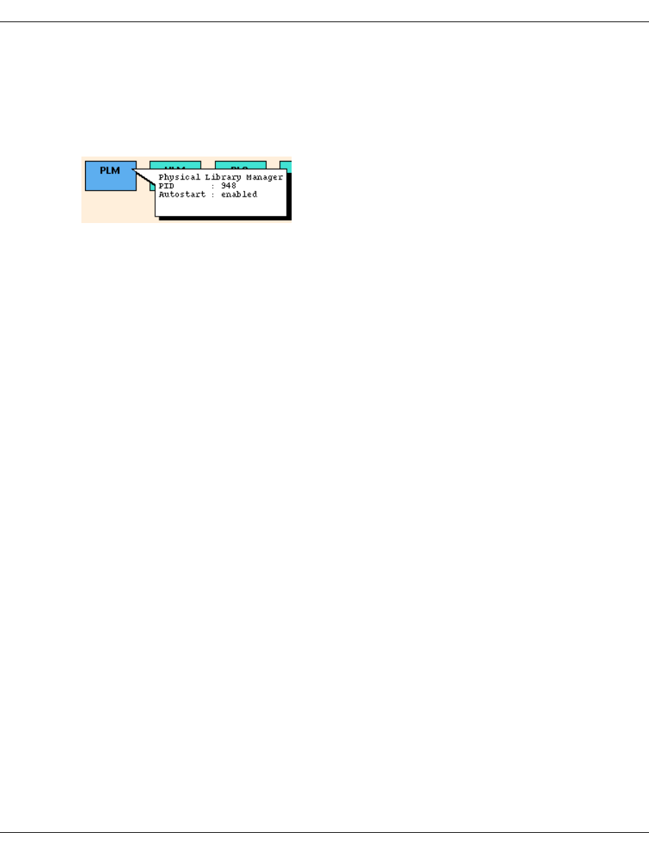
416 U41117-J-Z125-7-76
PLM (Physical Library Manager) XTCC
8.18 PLM (Physical Library Manager)
8.18.1 Object information on the PLM
The status of the Physical Library Manager (PLM) is represented by the colors pink
(stopped), green (running), green / brown (running with trace switched on) and green / red
(in recovery mode).
In the extended status the PID and the autostart setting are also displayed.
8.18.2 PLM functions
In User and Observe modes no PLM functions are available.
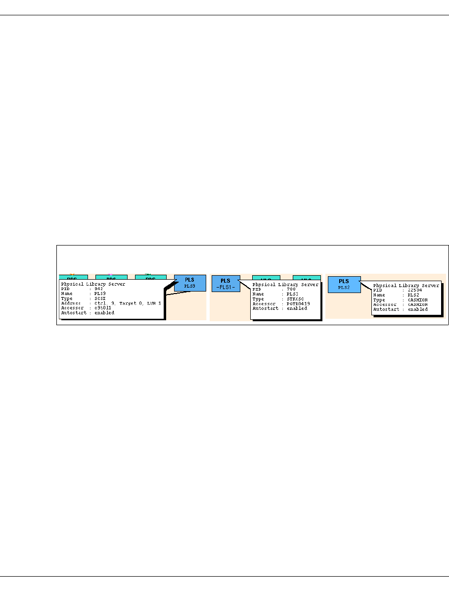
U41117-J-Z125-7-76 417
XTCC PLS (Physical Library Service)
8.19 PLS (Physical Library Service)
8.19.1 Object information on the PLS
Each physical library is assigned at least one PLS (Physical Library Server).
The PLS of a SCSI-controlled archive must run on the ISP that contains the associated
SCSI controller. The easiest way of identifying the location of a PLS is to use the Global
Status Monitor. By resting the mouse pointer on a PLS symbol, you can open an information
box which among other things specifies the associated ISP.
As in XTCC, the status of the PLS is indicated by the colors pink (stopped), green (running),
and green/brown (running with the trace switched on). In the event of an error, this is
indicated by means of a red triangle.
The example below shows the object information of an archive controlled via SCSI (left), via
LAN (center), and a CASHION archive controlled via serial interface (right):
The following information is displayed:
Name Name assigned during configuration and displayed in the PLS symbol.
Type Type of access system (SCSI, STKCSC, STLACI, CASHION or LMF).
Address SCSI address (controller, target, LUN) or SINIX name of the access system.
Accessor Internal device name of the library (device node with SCSI, otherwise IP
address or server name).
Error Only in the event of an error. Message indicating the cause of the error.
Autostart Enabled / disabled.
8.19.2 Functions for individual PLSs
There are no PLS functions available in Observe and User mode.
8.19.3 Functions for all PLSs
No functions for all PLSs are available.
SCSI archive: STK archive: CASHION archive:
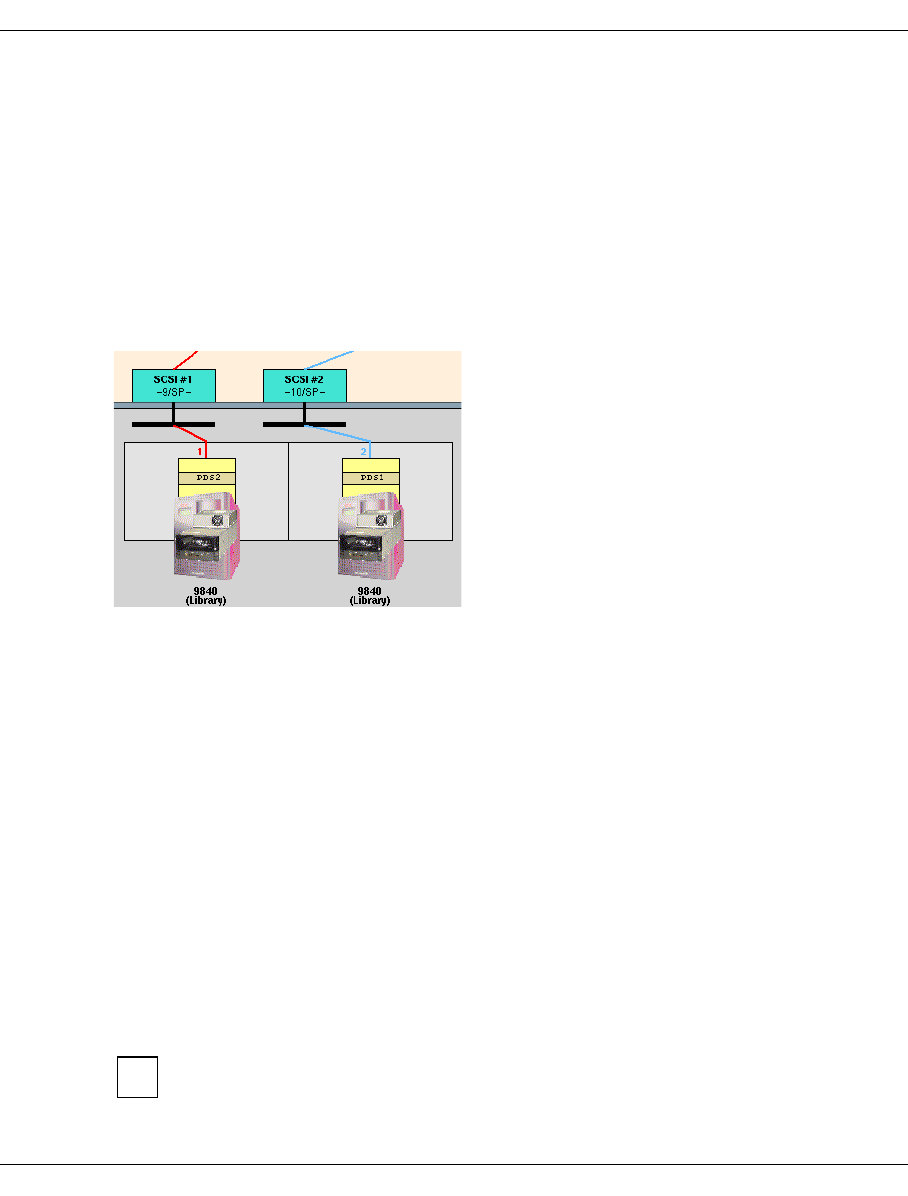
418 U41117-J-Z125-7-76
SCSI archive systems XTCC
8.20 SCSI archive systems
8.20.1 Object information on archive systems
Archives with a SCSI-controlled access system can be operated in the ISP via the XTCC
instance containing the associated PLS.
A lighter-colored image of the archive system is shown behind the drive(s) belonging to the
archive. All associated drives are also enclosed in a light gray shadow frame, which is
intended to represent the archive system.
The following detailed information is displayed:
Vendor ID Vendor identifier
Product ID Product identifier
Product Rev. Product revision level
Accessor Type Type of access system
Accessor Model Model
Accessor Status Status
Controller SCSI controller
Target SCSI target
Logical Unit SCSI LUN
Switch: Local Domain x, Port y This information is displayed for archives with the target
numbers 128…2047. The local domain is in the value
range 1...8. In the case of FC switches with more than
16 ports, it can differ from the “Domain” displayed in
GXCC as follows:
GXCC Domain = 1 2 ... 7 8 9 10 11 etc.
XTCC Local Domain = 1 2 ... 7 8 1 2 3 etc.
The statuses of all libraries, including the LAN-controlled ones, are shown on the
right-hand side of the window (Physical Components) of the “Global Status”.
i

U41117-J-Z125-7-76 419
XTCC SCSI archive systems
8.20.2 SCSI Archive system functions
This function is offered after you right-click on the archive system icon (behind the drive
icon).
The Show Mode Pages, Show Mode Page Details, Show Log Pages and Show Log Page
Details functions are not offered for all libraries.
8.20.2.1 Show Mode Pages
The SCSI mode pages are displayed.
This function is not offered for all systems and all libraries.
8.20.2.2 Show Mode Page Details
Via a submenu you must specify the mode page for which you want an itemized display.
This function is not offered for all systems and all libraries.
8.20.2.3 Show Log Pages
The SCSI log pages are displayed.
This function is not offered for all systems and all libraries.
8.20.2.4 Show Log Page Details
Via a submenu you must specify the log page for which you want an itemized display.
This function is not offered for all systems and all libraries.
i

420 U41117-J-Z125-7-76
PDS (Physical Device Service) XTCC
8.21 PDS (Physical Device Service)
8.21.1 Object information on PDS
A PDS (Physical Device Server) controls precisely one physical device. The object infor-
mation displays the controller and target of the associated SCSI device. This information is
also indicated by the color of the connecting lines to the SCSI controllers and drives.
A PDS consists of two processes, one for communicating with the RAID system and the
other for communicating with the device. These processes are referred to as the channel
process and the device process. Normally, both processes have the same status. However,
there are situations in which this will not be the case. If this occurs, the top half of the block
shows the status of the channel process, while the bottom half shows the status of the
device process. The process status is indicated by the colors pink (stopped), green
(running), and green/brown (running with the trace switched on).
Phys. Dev. Server Number of the PDS.
Controller Controller number of the drive controlled by the PDS
Target Target number of the drive controlled by the PDS
Logical Unit LUN number of the drive controlled by the PDS
Revision Revision level.
Channel Process PID Process ID of the channel process.
Device Process PID Process ID of the device process.
Attached Path FC paths through which connections are established.
Insert./Rem. State Configuration status (inserted/removed).
8.21.2 PDS functions
No PDS functions are available.
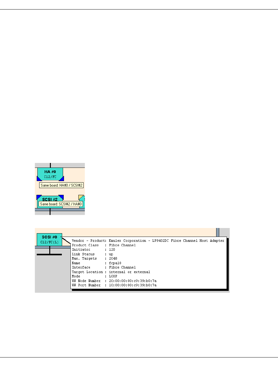
U41117-J-Z125-7-76 421
XTCC SCSI controllers
8.22 SCSI controllers
8.22.1 Object information on SCSI controllers
Each SCSI controller is represented by a block at the bottom of the inner window. Within
the block, the device number (SCSI #1, SCSI#2, etc.), controller number, and interface type
(SP = SCSI parallel / FC = Fibre Channel) are displayed. The status of the controller is
indicated by the colors pink (hanging status “true” in the case of SP, link status “down” in
the case of FC), green (ready for operation), yellow (unknown), or white (not available).
FC controllers (RAID system connection) are handled in the same way as SCSI controllers.
The label “FC” allows you to differentiate them from the drive controllers, which are labelled
“SP” (standing for SCSI parallel).
For technical reasons FC controllers are displayed at both the top border (as HA) and the
lower border of the screen. You can recognize the assignment from the small colored
triangles at the top/bottom of the symbol. Furthermore, when you touch these triangles with
the mouse cursor this assignment is displayed in a small text window (“Balloon”).
The following information is displayed:
Vendor - Product vendor and product name
Product Class product class
Initiator the SCSI address of the controller
Link Status an indication of the presence/absence of a hang condition (parallel
SCSI) or whether the link is up/down (FC)
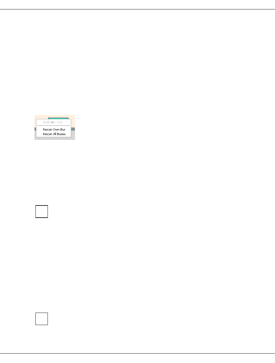
422 U41117-J-Z125-7-76
SCSI controllers XTCC
Max. Targets the maximum number of targets supported by the controller
Name the system name of the controller
Interface the interface variant (e.g. SCSI Parallel or Fibre Channel)
Target Location an indication of whether or not the targets are inside or outside the
cabinet.
Mode mode, if available (FC): LOOP (L) or POINT TO POINT (P)
WW Node Number World Wide Node Number (FC)
WW Port Number World Wide Port Number (FC)
8.22.2 SCSI controller functions
No menu is provided in Observe mode.
The title bar displays the serial number of the SCSI interface and the controller number.
The functions are used to diagnose problems and eliminate hang conditions.
8.22.2.1 Rescan own Bus
Searches for the targets connected to the SCSI bus of this controller.
This function should be used if components have been added to or removed from
the corresponding SCSI bus. It is not suitable for incorporating newly installed
devices or controllers in CentricStor.
This command enables you to rectify problems which arise from establishing FC
connections after the system startup.
These problems are indicated by messages such as “
cannot assign ... targets-
luns to any RAID system
” and indicate that the RAID LUNs’ serial numbers are
not uniquely assigned. The cause may be, for example, that the FC cables were
only connected after the system started.
8.22.2.2 Rescan all Busses
Searches for the targets connected to the SCSI buses of all controllers.
This function can also be used to search for SCSI controllers or devices that are not
displayed. It is not suitable for incorporating newly installed devices or controllers in
CentricStor.
i
i

U41117-J-Z125-7-76 423
XTCC Cartridge drives (real)
8.23 Cartridge drives (real)
8.23.1 Object information on tape drives
The XTCC user interface is designed for a wide range of tape drives. Please refer to the
data sheet for your product variant to determine which drives are or can be connected.
Depending on the drive type, some of the functions described here may not be available
and some of the information given here may not apply.
The graphical display in XTCC shows the data path in the IDP from the FC controllers that
establish the connection to the RAID system, through the PDS and the SCSI controller, and
on to the drive. The SCSI and FC-SCSI addresses (CTL) are displayed in the small boxes
that represent the components and on the connection line to the drive.
The FC controllers between RAID and IDP are shown twice in the IDP symbol: once
as host adapter at the top edge and once as controller with the acctached RAID
system.
Each tape drive is represented by a block with three sections. The top section indicates the
read/write status of the drive by means of a lock symbol. If the lock is closed, the drive will
only permit read access. To the right of the lock symbol is the serial number of the volume
currently loaded (VSN). The middle section represents the device’s display, and is used to
indicate statuses such as CU READY, LOADED, etc. The bottom section contains a
graphical representation of the device type, and the archive system icon is behind this. The
top and bottom sections are colored pink to indicate “Unloaded” or “Offline”, or green to
indicate “Ready”. The device type is specified immediately under the block. A colored line
connects the device to its associated SCSI controller, the assigned emulation, and possibly
to one or more hosts.
At the top of the device block, the SCSI target number “tgt” appears next to the connection
line. If the Logical Unit Number “lun” of the device is not 0 or if a device for which this is the
case exists for the same controller target address, “tgt,lun” is displayed instead.
If the drive requires cleaning, this is represented by a flashing “Clean” symbol. If the device
is busy (e.g. due to data security erasures (DSEs) or the loading of microcode), this is
indicated by a yellow BUSY symbol. The device function menu will not be available during
this time.
If the yellow “!” symbol is flashing, this indicates that some form of manual intervention is
required on the device.
i
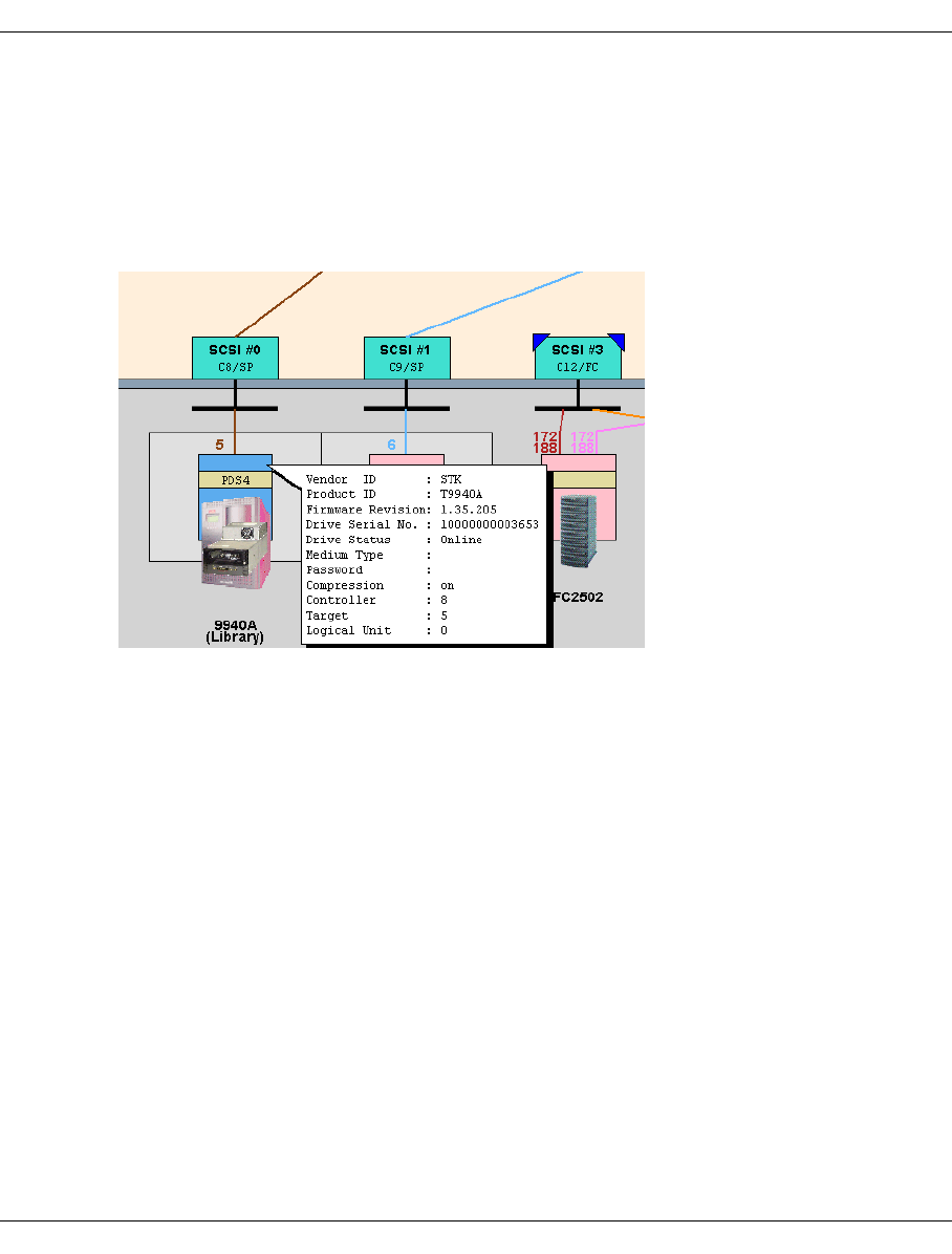
424 U41117-J-Z125-7-76
Cartridge drives (real) XTCC
If Service Information Messages (SIM) or Medium Information Messages (MIM) are present
in the drive, these are indicated by means of a yellow or red flashing SIM/MIM symbol,
depending on their severity (severity 0/1/2/3 = Service/Moderate/Serious/Acute). If the
device hangs, the entire block is marked with a large red “X”. Devices which are recognized
by XTCC as SCSI targets on the SCSI bus but which cannot be identified further are
assigned the type designation “xxxx”. In this case, the device type is depicted by means of
a question mark.
The following information is displayed:
Vendor ID, Product ID
Firmware Revision
Drive Serial Number
Drive Status
SIM/MIM Severity Appears only if SIMs or MIMs are present, and indicates
the severity of the message.
Check Condition Appears only in the event of errors.
Medium Type Appears only if the device is loaded.
Password Password of device, not used in CentricStor.
Compression Mode Data compression activated/deactivated.
Controller, Target, Logical Unit SCSI topology
Switch: Local Domain x, Port y This information is displayed for archives with the target
numbers 128…2047. The local domain is in the value
range 1...8. In the case of FC switches with more than
16 ports, it can differ from the “Domain” displayed in
GXCC as follows:
GXCC Domain = 1 2 ... 7 8 9 10 11 etc.
XTCC Local Domain = 1 2 ... 7 8 1 2 3 etc.

U41117-J-Z125-7-76 425
XTCC Cartridge drives (real)
8.23.2 Tape drive functions
Which functions are actually offered depends on the drive type. The menus are only
examples.
The following functions are available:
–Show SCSI Sense
–Show Log Pages
–Show Log Page Details
–Show Mode Pages
–Show Mode Page Details
–Show Vital Product Data
–Show Medium Info (MIM)
–Show Service Info (SIM)
The device type and the SCSI address (controller, target) are displayed in the title bar.
Depending on the drive type a subset of the functions is offered.
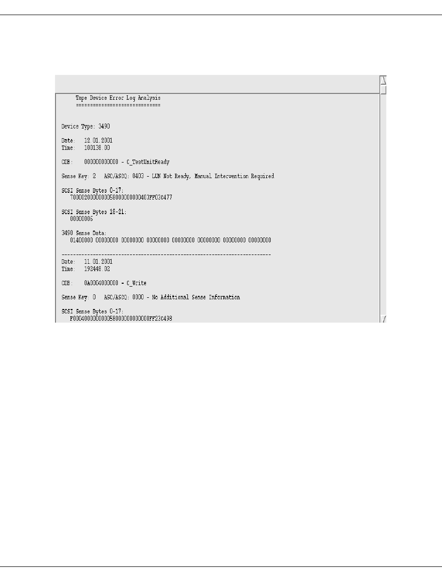
426 U41117-J-Z125-7-76
Cartridge drives (real) XTCC
8.23.2.1 Show SCSI Sense
Displays the SCSI sense data:
SCSI logging starts with the earliest entries, (see timestamp). It consists of four reference
sections which are described in the hardware reference manual of the corresponding
device.
For MBK6 (3490-HSI):
– CDB, i.e. the SCSI command with associated parameters.
– Sense Key with the corresponding analyzed message
– SCSI Sense Bytes 0-17
– SCSI Sense Bytes 18-21
– Sense data, if the device itself reports sense data, and information on how it is routed
to BS2000/OSD.
8.23.2.2 Show Log Pages
The SCSI log pages are displayed.
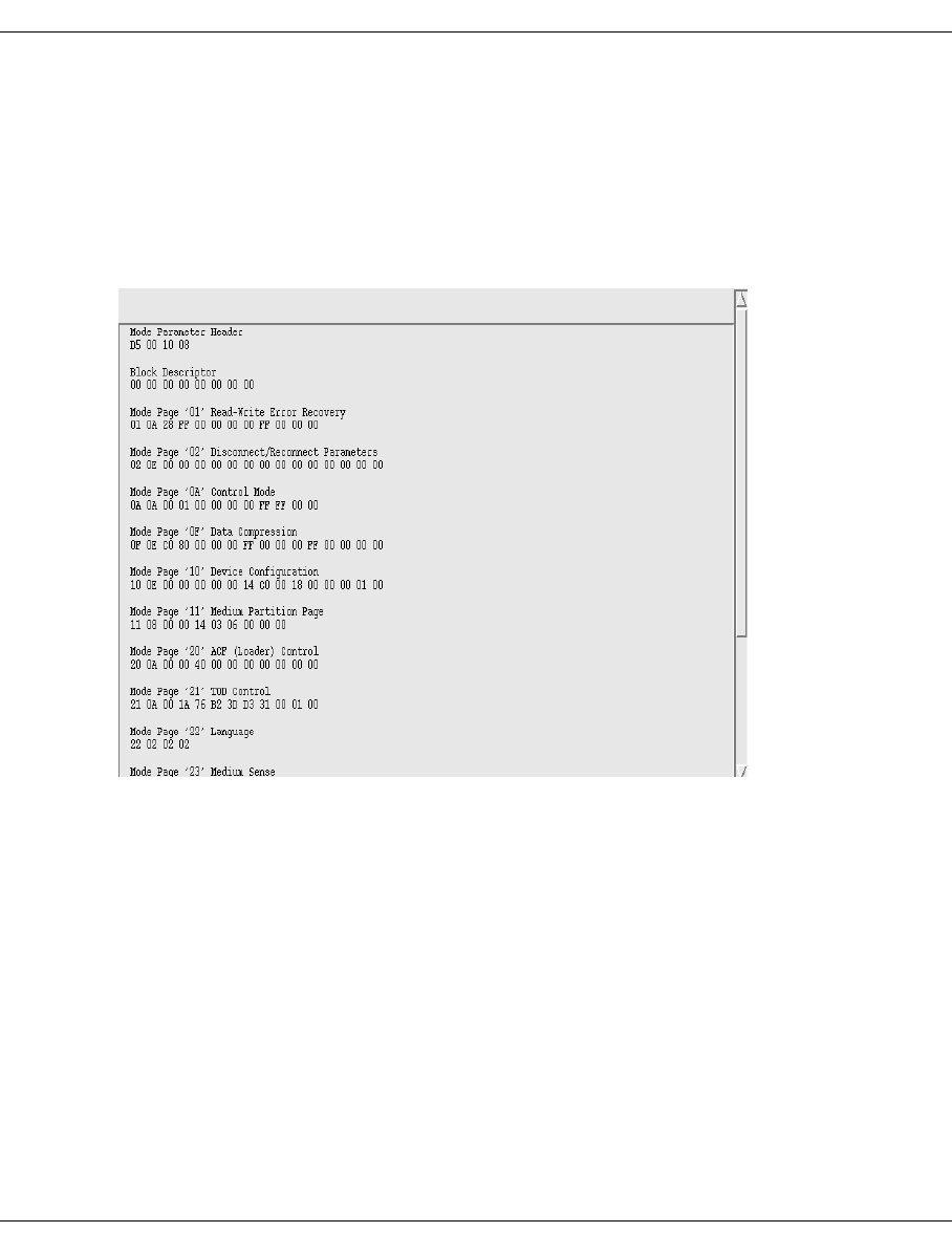
U41117-J-Z125-7-76 427
XTCC Cartridge drives (real)
8.23.2.3 Show Log Page Details
A submenu is opened in which you specify which log pages are to be itemized and
displayed.
8.23.2.4 Show Mode Pages
Displays the SCSI mode pages:
This displays the current device setting (to perform a detailed analysis it is essential to refer
to the device-specific SCSI reference manual, Mode Pages chapter).
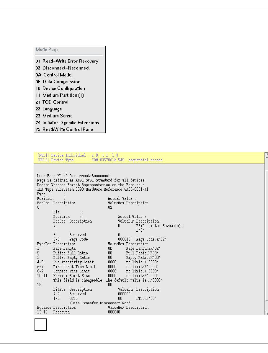
428 U41117-J-Z125-7-76
Cartridge drives (real) XTCC
8.23.2.5 Show Mode Page Details
A submenu shows which mode pages the device supplies.
If you select a page here that is also described in the SCSI standard, this will be displayed
and interpreted in detail as in the example below.
The SCSI topology (CTL) as well as the Inquiry String of the drive are shown in the
“control lines” of the text window.
i
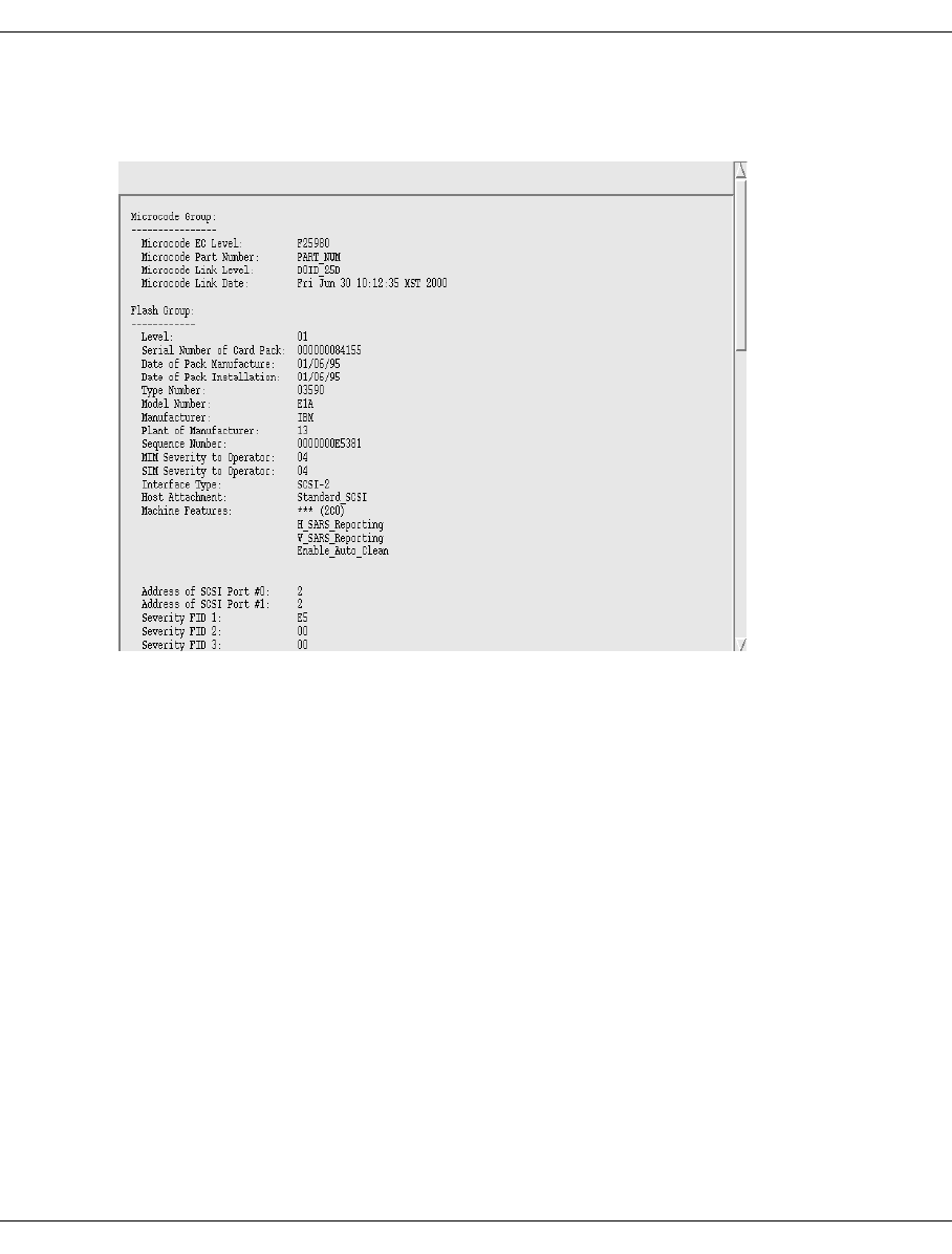
U41117-J-Z125-7-76 429
XTCC Cartridge drives (real)
8.23.2.6 Show Vital Product Data
Displays certain elements of the vital product data:
You can use this function to display a subsection of the configuration data stored in the tape
device.
The device settings made in the Service and Operator menus can be found again here.
These include, for example, the display language. Here you will also find the device’s
FID log which provides important assistance to service engineers (FID: FRU identifier,
FRU: field replaceable unit). Up to 30 entries can be logged.
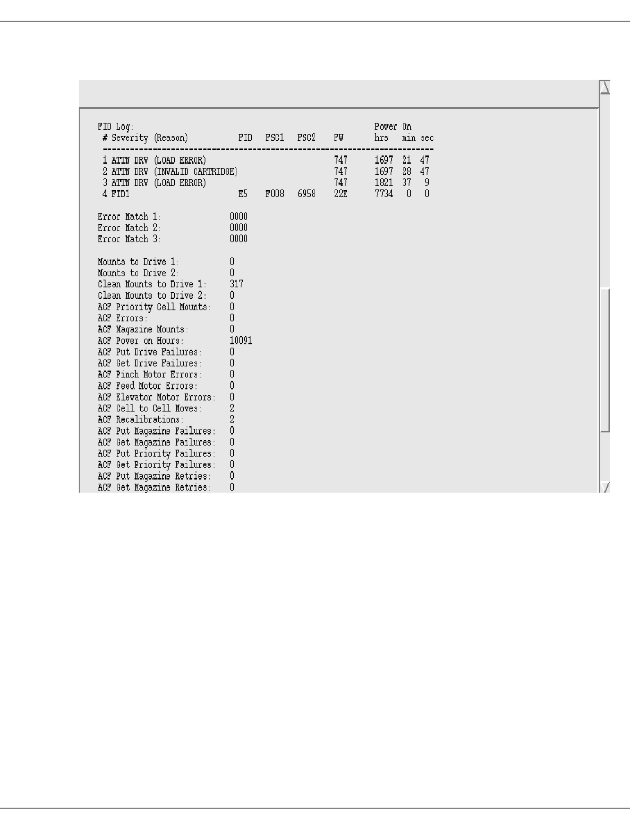
430 U41117-J-Z125-7-76
Cartridge drives (real) XTCC
Extract from the FID log:
In this way you can extract an event or error history. FID code and FSC1 and FSC2 (Fault
Symptom Code) must be reported to the manufacturer if errors which cannot be resolved
occur on the device.
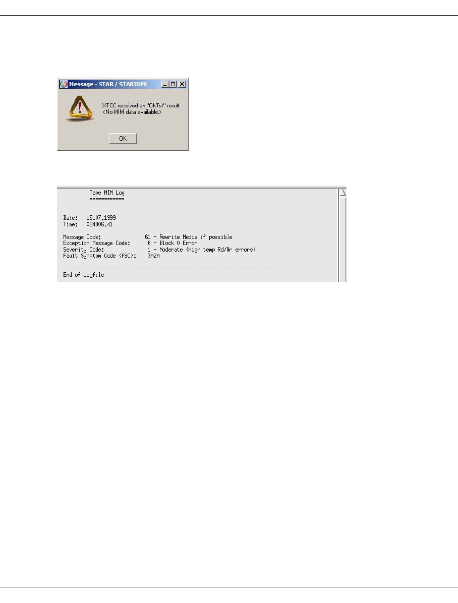
U41117-J-Z125-7-76 431
XTCC Cartridge drives (real)
8.23.2.7 Show Medium Info (MIM)
If there is no MIM entry, you will be notified in an info box:
If Medium Information Messages have been recorded, a text window appears with the
messages:
The MIMs of the drives are recorded. The MIMs and the various responses are described
in the maintenance documentation of the devices.
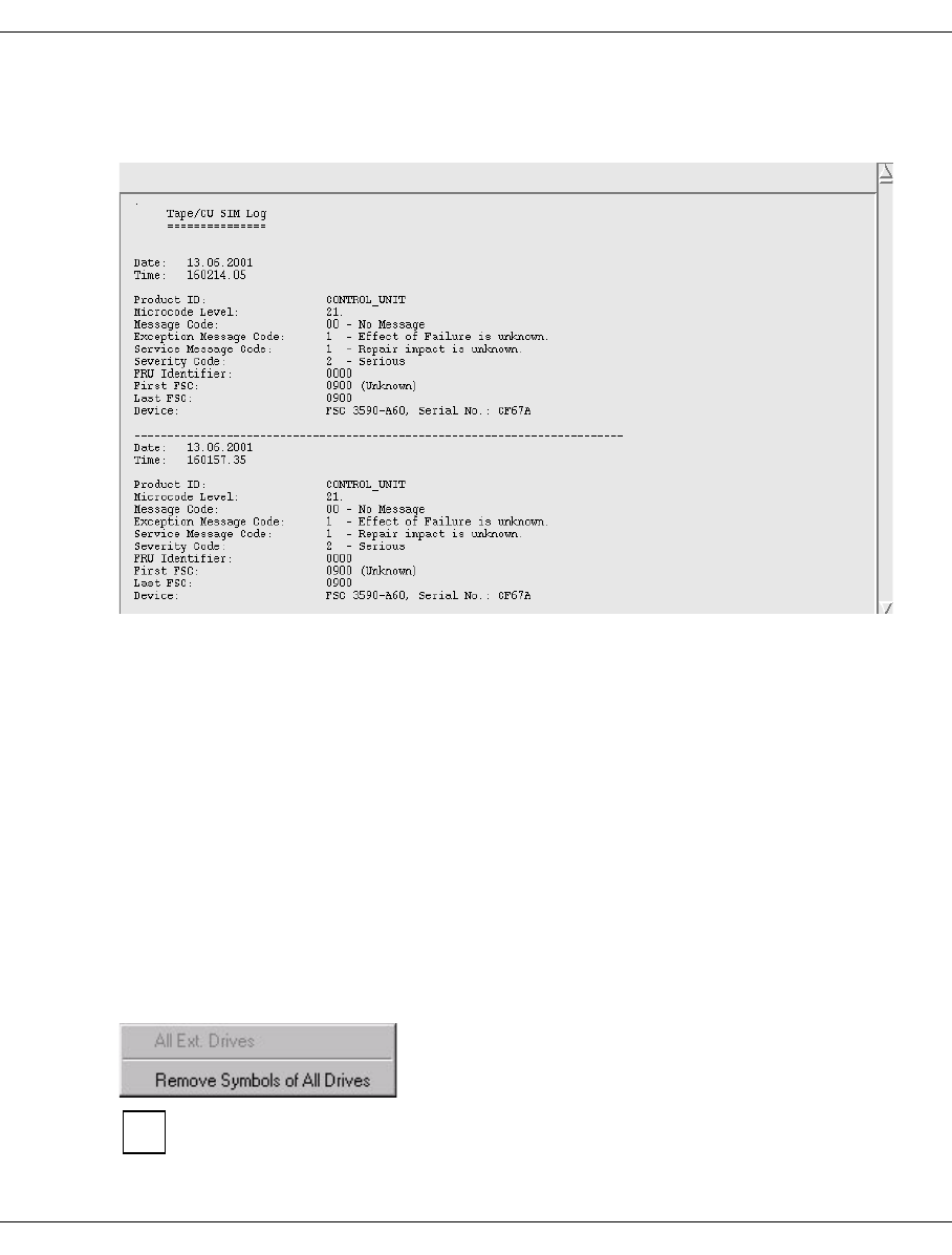
432 U41117-J-Z125-7-76
Cartridge drives (real) XTCC
8.23.2.8 Show Service Info (SIM)
Displays the Service Information Messages:
If problems relating to the channel adapter (CONTROL UNIT) or tape devices (TAPE) occur,
this information permits a better assessment of the severity of the recorded error.
The problem is described in more detail in this window. In some cases, there is already
a suggested solution for the service engineer.
If required, the PDS creates two separate SIMs.
0900 Drive did not eject a volume
0901 Drive not accessible
The other SIM codes come directly from the drive. They are explained in the drive documen-
tation.
8.23.3 Global functions for tape drives
“All” means all drives that are connected to this ISP.
No menu is provided in Observe mode.
i
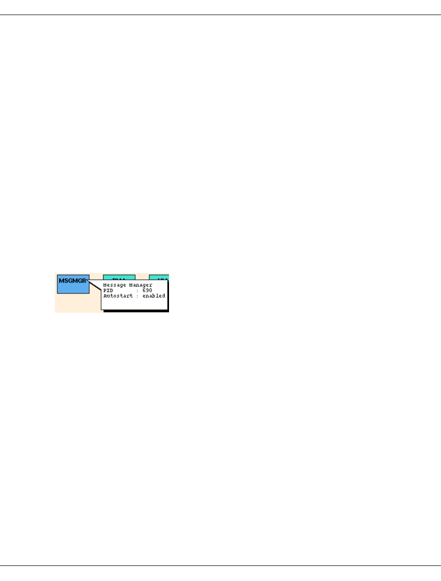
U41117-J-Z125-7-76 433
XTCC MSGMGR (Message Manager)
8.23.3.1 Remove Symbols of all Drives
Removes all warning signals on drives (MIM and SIM symbols) without having to retrieve
the underlying error message. Warning signals can also be removed in Observe mode, but
only by retrieving the underlying error message.
8.24 MSGMGR (Message Manager)
8.24.1 Object information on the Message Manager (MSGMGR)
The Message Manager monitors and saves the system outputs of the various processors
of the CentricStor system. It can respond to certain error events by instigating the appro-
priate measures, such as sending traps to the CentricStor SNMP manager.
The message list output is described on page 158.
The status of the Message Manager is indicated by the colors pink (stopped), green
(running), and green/brown (running with the trace switched on):
Name
PID Process ID.
Autostart Enabled / disabled.
8.24.2 MSGMGR functions
The following functions are available:
–Show Trace
–S how Tra p Tra c e
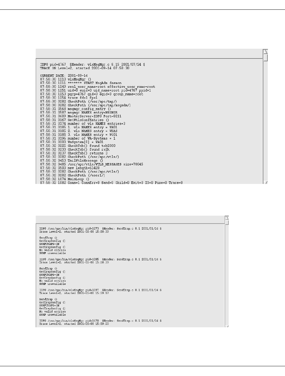
434 U41117-J-Z125-7-76
MSGMGR (Message Manager) XTCC
8.24.2.1 Show Trace
Displays the trace data:
8.24.2.2 Show Trap Trace
Displays the trap trace data:
The trap trace records all SNMP traps sent by the Message Manager to the SNMP
management station(s).

U41117-J-Z125-7-76 435
XTCC PERFLOG
8.25 PERFLOG
8.25.1 Object information of PERFLOG
PERFLOG regularly collects performance-related system data and stores it in log files. The
logging period and the directory in which log files are stored can be defined by service
personnel during configuration.
The log files can be displayed in graphical format using the tools described starting in
section “History data” on page 257.
The status of the Performance Logger is indicated by the colors pink (stopped), green
(running), and green/brown (running with the trace switched on). A black triangle on the left
edge indicates that extended logging has been enabled.
Name Name as shown in the symbol
Parent und Child PID Process ID of the parent and child processes
Extended Logging Enabled / Disabled
Autostart Enabled / Disabled
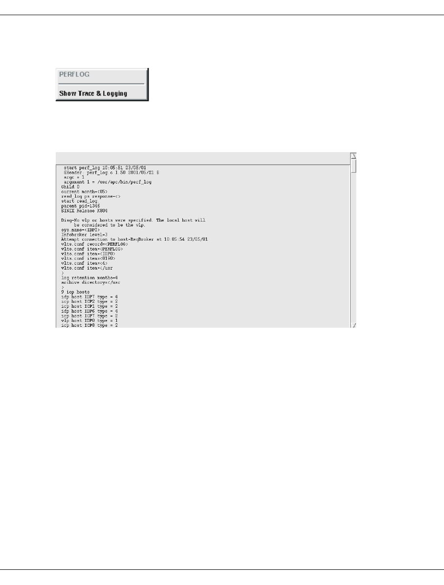
436 U41117-J-Z125-7-76
PERFLOG XTCC
8.25.2 PERFLOG functions
8.25.2.1 Show Trace & Logging
Displays the trace and log data:
This example shows an extract from a trace depicting the events recorded during startup.
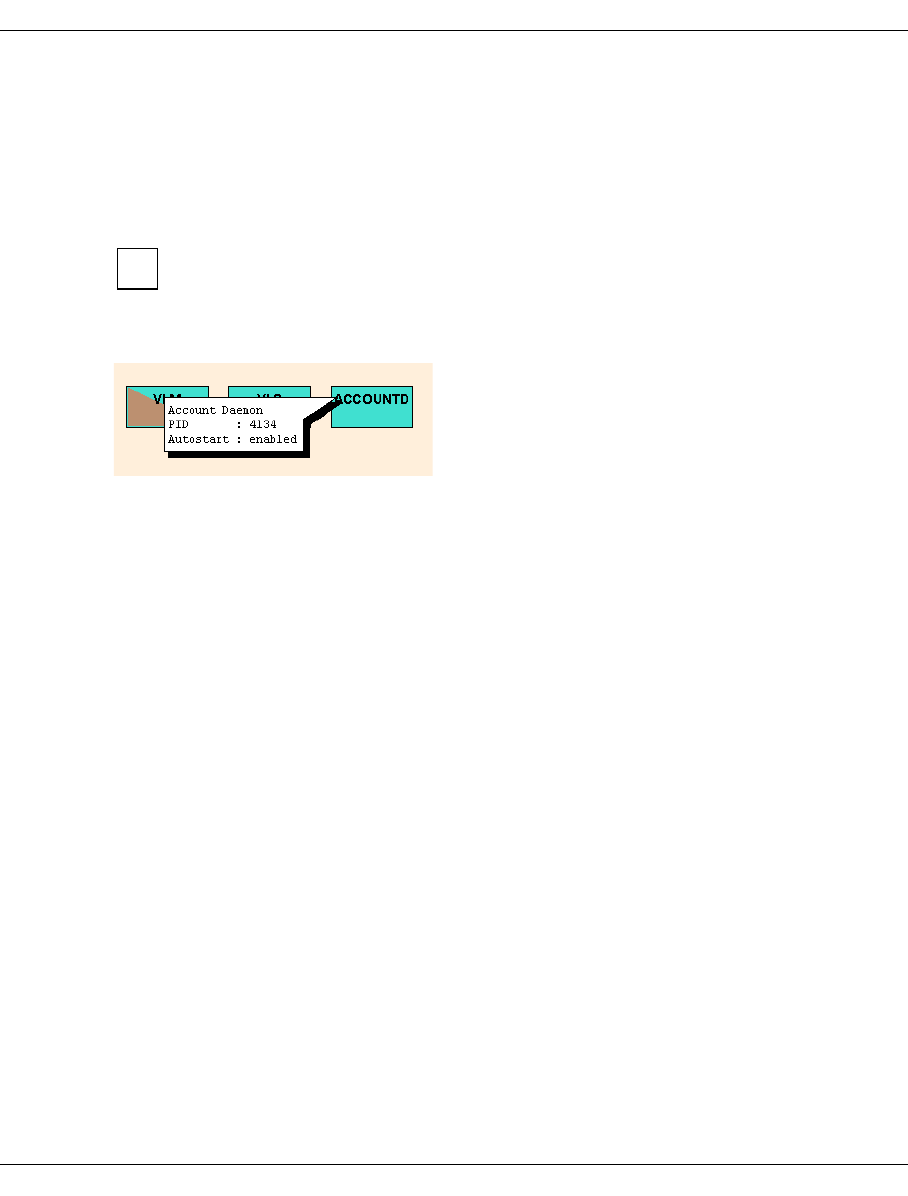
U41117-J-Z125-7-76 437
XTCC ACCOUNTD (Account Daemon)
8.26 ACCOUNTD (Account Daemon)
8.26.1 Object information of ACCOUNTD
The Account Daemon records the accounting data in a database.
This object is displayed as of CentricStor V3.1C2000 provided the Accounting
License is installed.
The status of the Account Daemon (ACCOUNTD) is shown by the colors pink (stopped) and
green (running).
Name Name as displayed in the symbol
PID Process ID
Autostart enabled / disabled
8.26.2 Functions of the ACCOUNTD
In User and Observe modes ACCOUNTD has no functions that can be called via XTCC.
i
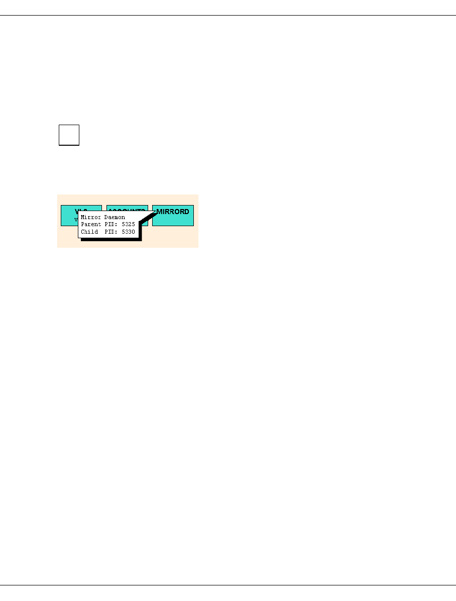
438 U41117-J-Z125-7-76
MIRRORD (mirror daemon) XTCC
8.27 MIRRORD (mirror daemon)
8.27.1 Object information of MIRRORD
The mirror daemon monitors the status of the cache mirror.
The presentation of this object requires CentricStorV3.1C and the Cache Mirroring
Feature License (CMF).
MIRRORD consists of two processes: the parent and child processes. The upper half of the
block is used to present the parent process, the lower half the child process. The status of
the processes is indicated by the colors pink (stopped) and green (running).
Name Name as shown in the symbol
Parent PID Process ID of the parent process
Child PID Process ID of the child process
8.27.2 Functions of MIRRORD
MIRRORD has no functions that can be addressed via XTCC.
i

U41117-J-Z125-7-76 439
XTCC S80D (S80 daemon)
8.28 S80D (S80 daemon)
8.28.1 Object information of S80D
Daemon S80D is a monitoring process for RAID systems of the type FC2502.
Name Name as shown in the symbol
PID Process ID
Autostart enabled / disabled
The status of the daemon is indicated by the following colors:
pink Stopped
green Running
yellow Status unknown
8.28.2 Functions of S80D
S80D has no functions which can be addressed via XTCC in User or Observe mode.
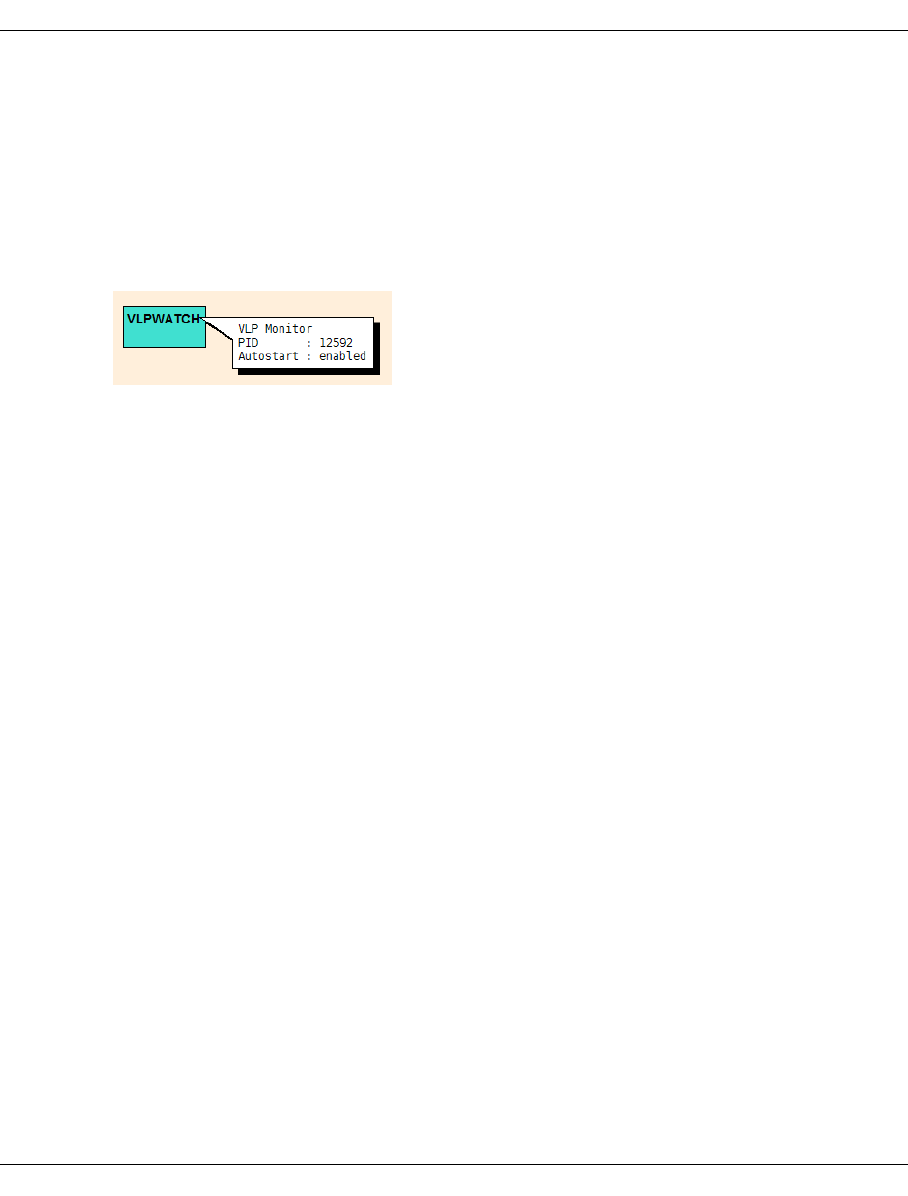
440 U41117-J-Z125-7-76
VLPWATCH (VLPwatch daemon) XTCC
8.29 VLPWATCH (VLPwatch daemon)
8.29.1 Object information of VLPWATCH
When the AutoVLP failover function is enabled, one VLPwatch daemon runs on the VLP
and one on the SVLP. These daemons monitor the operational integrity of the VLP and, in
the event of a failure, trigger automatic VLP switchover.
PID Process ID
Autostart enabled / disabled
The status of the daemon is indicated by the following colors:
pink Stopped
green Running
8.29.2 Functions of VLPWATCH
VLPWATCH has no functions which can be addressed via XTCC in User or Observe mode.

U41117-J-Z125-7-76 441
9 Explanation of console messages
9.1 General
When unusual events occur, the various CentricStor software components output
messages at the console. The message texts are stored in the file /var/adm/klog.msg on
the host in question and can be viewed centrally via the GXCC menu item “Show System
Messages” (see section “Show System Messages” on page 158).
Example screen output

442 U41117-J-Z125-7-76
General Explanation of console messages
The color and text of the message provide you with important information concerning an
event:
●Message color
The color informs you of the “urgency” of a message:
The weight is normally a component part of the message text. When this is not the case,
the weight is specified below the message line in the following messages.
●The separator - normally this is a colon - provides important information regarding a
VLP switchover from the time the event was reported.
Urgency Description Color
None --- Black
INFO General information Black
DEBUG Debug information Black
NOTICE Information about a normal state change Black
WARNING Warning message Blue
ERROR Error message Red
CRITICAL Information about a critical state Red
ALERT Alarm message: the error that has occurred must be
eliminated immediately
Flashing
red
EMERGENCY Alarm message: the system is in an unstable state Flashing
red
Separator Meaning
:Default
!Message during a VLP switchover
#: Backup message: The message relates to an event before the last VLP
switchover.
#! Backup message: After a VLP switchover has taken place twice, the
message relates to an event during the first VLP switchover.
U41117-J-Z125-7-76 443
Explanation of console messages General
●Alongside the message number, the weight and the message text itself, the message
provides the following additional information.
Example
In the sections below, only the message line components printed in bold here,
i.e. the message number and message text, are presented.
When interpreting console messages, you must take into consideration that error
messages are issued at different levels for one and the same error event.
If problems occur with physical MTC drives or cartridges, the error messages are collected
in the PLM. This is also where a relation (unknown in lower levels) to physical and logical
volume identifiers is established.
Corrective measures are suggested where possible. If there are no corrective
measures specified, this may be due to the following reasons:
– Corrective measures are not required (e.g. in the case of an “all clear”
message).
– The error is extremely complex and its source cannot be determined. In this
case, error analysis and correction are carried out by service personnel.
The DAS and VDAS error messages are described in the “DAS Administration
Guide” in chapter 6:
Version 3.1E: http://www.adic.com/us/collateral/omDas310Administration.pdf
Version 3.12: http://www.adic.com/us/collateral/omDas312Administration.pdf
SXSM018 2005-08-06 10:51:45 ICP0 : Aug 6 10:51:45 sma003: Fan 2: Fan is not manageable
Message text
Separator
Name of the ISP
Time
Date
Message number
i
i
i

444 U41117-J-Z125-7-76
General Explanation of console messages
The message numbers in the following section are arranged alphabetically
Message Page
SXCF... (CMF: Cache Mirroring Feature) 445
SXCH... (Channel: pcib/pcea) 447
SXCM... (CHIM) 449
SXDN... (DNA: Distribute and Activate) 450
SXDT... (DTV File System) 450
SXFC... (FibreChannel Driver) 452
SXFP... (FibreChannel Driver) 454
SXFW... (Firmware) 455
SXIB... (Info Broker) 456
SXLA... (LANWATCH) 458
SXLV... (Log Volume) 458
SXMM... (Message Manager) 459
SXPL... (PLM: Physical Library Manager) 465
SXPS... (PLS: Physical Library Server) 482
SXRD... (FibreCAT: RAID) 485
SXRP... (RPLM: Recovery Physical Library Manager) 491
SXSB... (Sadm Driver: SCSI bus error) 494
SXSC... (Savecore: organize coredump) 495
SXSD... (SCSI Disks: driver shd) 495
SXSE... (EXABYTE Tapes) 496
SXSM... (Server Management) 497
SXSW... (Software Mirror) 510
SXTF... (Tape File System) 510
SXVD... (Distributed Tape Volume Driver) 516
SXVL... (VLM: Virtual Library Manager) 517
SXVLS... (VT_LS: Virtual Tape and Library System) 521
SXVS... (VLS: Virtual Library Server) 522
SXVW... (VLPWATCH) 523
SXVX... (Veritas File System) 537

U41117-J-Z125-7-76 445
Explanation of console messages Message lines
9.2 Message lines
9.2.1 SXCF... (CMF: Cache Mirroring Feature)
SXCF012 CMF(#12): ALERT: failed to become PRIMARY, time exhausted: <sec> seconds
Meaning
During the switchover to multi-user mode (RunLevel 2) in the VLP’s boot phase the rc2
script /etc/rc2.d/S70mirrorstart determined that the data of the cache mirror when
obsolete when it checked it. The switchover to multi-user mode is stopped until the data
resources have been validated manually.
The cache mirror data (/etc/mirrord/ms.db) is replicated on the mirror backup server
(SVLP) by the mirror server (VLP) at regular intervals. It is regarded as obsolete after 500
seconds.
The time period is specified in the message. Depending on this period, different measures
must be taken.
Response
When a value greater than 500 seconds is specified as a period, a check must be made to
see whether CMF failures have been reported by the ICPs or IDPs since the time Time stamp
of the message minus period. For this purpose messages which contain the mirror chan-
ging string and have a corresponding time stamp must be searched for in the Klogger files
/var/adm/klog.msg* of these ISPs.
Case 1:
If no such message exists, the data resources are declared valid by the measure below.
Access to the VLP via LAN is possible despite incomplete multi-user mode as the LAN
services (inetd) have already been started.
The existing data resources can be validated using the following statement:
echo "reset -f" > /etc/mirrord/mirror_server_ctl
As an rsh call:
rsh <VLP-Name> "echo \"reset -f\" > /etc/mirrord/mirror_server_ctl"
The switchover to multi-user mode is then continued.
Case 2:
If messages of the type described above exist for the specified period,
/etc/mirrord/ms.db must be reconstructed manually. Notify 3rd-Level Support!

446 U41117-J-Z125-7-76
Message lines Explanation of console messages
Case 3:
If the value 0 seconds is specified as the period, no usable data is contained in
/etc/mirrord/ms.db. Notify 3rd-Level Support!
SXCF014 CMF(#14): ALERT: failed to become PRIMARY, stale data
Meaning
When switching from SVLP to VLP a mirror backup server switches to become the mirror
server (from the viewpoint of the CMF). During the change to multi-user mode in the VLP’s
boot phase, the /etc/rc2.d/S70mirrorstart script determines that the data resources
are not up-to-date when it checks the cache mirror data (/etc/mirrord/ms.db).
This can occur when the failed VLP was not able to replicate the data (see message
SXCF012).
The switchover to multi-user mode is stopped and the data resources are updated manually.
Response
Access to the VLP via LAN is possible because the LAN services (inetd) are already
activated.
The most recent valid data resources of the “ex-VLP” must be restored manually on the new
VLP. When activated the ex-VLP automatically becomes the SVLP. When you switch to
multi-user mode this will probably be halted in the /etc/rc2.d/S70mirrorstart script
because the database (/etc/mirrord/ms.db) which the VLP has not yet been able to
replicate is obsolete. However, access via LAN is possible.
The following steps are required to update the data resources:
1. Terminate the mirror server on the VLP:
myps -K mirror.s
2. Copy the last version of the data resources but one from the ex-VLP to the VLP using
rcp:
rcp <Name-des-Ex-VLPs>:/etc/mirrord/ms.dbak /etc/mirrord/ms.db
3. Start the mirror server on the VLP:
/etc/mirrord/mirror.spray

U41117-J-Z125-7-76 447
Explanation of console messages Message lines
4. Check whether the mirror server’s processes are running:
myps mirror.s
Sample output
? 922 1 ? ? ? ? /etc/mirrord/mirror.client
? 5179 5177 ? ? ? ? /etc/mirrord/mirror.server
? 5177 1 ? ? ? ? /etc/mirrord/mirror.server
In the mirror server’s event log (/etc/mirrord/ms.event file) there is an entry with
the message “ASSUMING role PRIMARY”.
Example: s.event:
1110 152018.18 MS: ASSUMING role PRIMARY (1, 1) 1110 152018.22 MS:
5. Start the Message Manager for the display on the GUI:
/usr/apc/broker/mycu -w "class mir public /usr/apc/broker/mir_mgr"
The switchover to multi-user mode is then continued.
9.2.2 SXCH... (Channel: pcib/pcea)
SXCH001 channel (linkad <link>) has invalid node_id: mfr='<mfr>'
ALERT
Meaning
A host with the unknown ID <mfr> is connected to the channel at address <link>. The host
is not supported.
SXCH002 ESCON-ad pcea<port> (bus <pci-bus> dev <pci-device>) failed
ERROR
Meaning
Owing to a fault the ESCON port <port> is no longer available. This fault can be in the
PCEAS controller or a cable fault (e.g. connector pulled out).
Response
Notify maintenance staff.
SXCH003 ESCON-ad pcea<port> (bus <pci-bus> dev <pci-device>) stopped
NOTICE
Meaning
The ESCON port <port> has been deactivated. This deactivatation can be the result of a
board or port being reset.

448 U41117-J-Z125-7-76
Message lines Explanation of console messages
SXCH004 ESCON-ad pcea<port> (bus <pci-bus> dev <pci-device>) started
NOTICE
Meaning
The ESCON port <port> has been activated. This happens regularly at system startup. A
port can also be reactivated after being reset or deactivated.
SXCH005 ESCON-ad pcea<port> (bus <pci-bus> dev <pci-device>) Memory error
ALERT
Meaning
A memory error has occurred on the ESCON board. The driver was requested to perform
a board reset and to recalibrate the memory.
Response
The board is operational again following a successful reset. However, if this error occurs
again, you are recommended to replace the board.
SXCH006 ESCON-ad<board> (bus <pci-bus> dev <pci-device> ser_nr <serial-nr>) defective
ALERT
Meaning
Error when starting the ESCON board (PCEAS/PCEAT). This error is reported when a me-
mory BIST (Built-in Self Test) has not been executed correctly and in the event of the board
firmware not being loaded completely.
Response
Replace the ESCON board.
SXCH007 ESCON-ad<board> (bus <pci-bus> dev <pci-device>) defective
ALERT
Meaning
Error when starting the ESCON board (PCEAF). This error is reported when a memory
BIST (Built-in Self Test) has not been executed correctly.
Response
Replace the ESCON board.
SXCH008 ESCON-adaptor <board> (ser_no <serial-nr>) Board Reset Failed
ALERT
Meaning
A board reset triggered by a memory error (SXCH005) could not be performed successfully.
Response
Replace the ESCON board.

U41117-J-Z125-7-76 449
Explanation of console messages Message lines
SXCH009 ESCON-adaptor <board> (ser_no <serial-nr) Compare Error in Channel <chn>
ALERT
Meaning
A test of the internal data paths on the ESCON board (PCEAS/PCEAT) which runs during
the startup phase and idle times returned an error.
Response
Replace the ESCON board.
SXCH010 ESCON-adaptor <board> CRC READ Error in Channel <chn>
ALERT
Meaning
During a read access the data was corrupted when it was transferred from the SINIX me-
mory to the ESCON channel.
Response
Replace the ESCON board.
SXCH011 ESCON-adaptor <board> CRC WRITE Error in Channel <chn>
ALERT
Meaning
During a write access the data was corrupted when it was transferred from the ESCON
channel to the SINIX memory.
Response
Replace the ESCON board.
9.2.3 SXCM... (CHIM)
SXCM001 chim1 (sadm9): SCSI-Bus reset
None
This message is part of a message complex (see the section “Bus Reset for SCSI
Controller” on page 542).

450 U41117-J-Z125-7-76
Message lines Explanation of console messages
9.2.4 SXDN... (DNA: Distribute and Activate)
SXDN100 (DNA#100): ALERT: switch SVLP_to_VLP successfully completed! (needed time:
<mm>:<ss> (mm:ss))
Meaning
The VLP switchover was successful. The time required for it is specified in parentheses.
SXDN101 (DNA#101): ALERT: switch SVLP_to_VLP completed with errors! (needed time:
<mm>:<ss> (mm:ss))
Meaning
The VLP switchover has been completed. The previous SVLP is now the current VLP. Ho-
wever, errors occurred when the system was started. The details can be found in the Bro-
ker’s logging files (/usr/apc/broker/broker.log). The time which was required for re-
configuration is specified in parentheses.
Response
The cause of the error must be removed. After this, the configuration function Distribute and
Activate must be initiated in Reactivate_failed_config mode.
SXDN102 (DNA#102): ALERT: switch VLP_to_SVLP successfully completed!
The VLP has been successfully reconfigured as the SVLP. This message is output only if
the reconfiguration was triggered by the VLP function Swap Master.
9.2.5 SXDT... (DTV File System)
SXDT001 DTV(# 1): ALERT: resource allocation failed, interface not activated!
Meaning
It was not possible to allocate the necessary resources for the DTV file systems. As a result,
the TFS/DTV file systems cannot be mounted.
Response
Notify maintenance staff.
SXDT002 DTV(# 2): ERROR: unmount(<maj,min>): filesystem state not clean!
Meaning
The specified file system has been unmounted, even though it was not possible to perform
all I/O operations on the metadata successfully. As a result, the file system on the corre-
sponding hard disk is inconsistent.
Response
Notify maintenance staff.

U41117-J-Z125-7-76 451
Explanation of console messages Message lines
SXDT003 DTV(# 3): ALERT: dev=<maj,min>: disk filesystem state is corrupted!
Meaning
Due to I/O errors when writing metadata, the DTV file system on the corresponding hard
disk has become inconsistent. If this I/O problem is temporary, the metadata operation is
rolled back and the file system is automatically restored to a consistent state (see message
SXDT004 ...).
Response
Notify maintenance staff.
SXDT004 DTV(# 4): NOTICE: dev=<maj,min>: disk filesystem state is clean!
Meaning
The DTV file system on the corresponding hard disk has been restored to a consistent
state.
SXDT005 DTV(# 5): ALERT: data compression disabled!
Meaning
It was not possible to allocate the necessary resources for DTV data compression. As a
result, support is not provided for TFS/DTV data compression and compressed volumes
cannot be read.
Response
Notify maintenance staff.
SXDT009 ALERT: DTV: *** filesystem may be corrupted! ***"
Meaning
This class of error messages indicates that write operations on the metadata could not be
performed. If the problem is temporary, the write operation will be performed later. If the
problem remains until the system is shut down, or the system crashes before the problem
is rectified, the CentricStor data maintenance system will be inconsistent.
Response
Check whether the RAID controller and the Fibre Channel connection are okay. If the
problem cannot be rectified, notify maintenance staff.
SXDT010 DTV(#10):ALERT: <func>(<maj,min>: ino=<ino>): cannot sync meta data to disk!
Meaning
Due to an I/O error, it is not possible to conclude the metadata transaction for the corre-
sponding file. As a result, the transaction is rolled back.

452 U41117-J-Z125-7-76
Message lines Explanation of console messages
9.2.6 SXFC... (FibreChannel Driver)
SXFC026 PVA1ICP0 : FC2: IOCB_E_LOCAL_REJECT
ALERT
SXFC005 PVA1ICP0 : FC2: loop_id 0, IOCB error sequence timeout
None
Meaning
These two messages only occur together. The 'sequence timeout' indicates a problem
which was detected/caused by the Emulex firmware. A typical example is a data transfer
while writing or reading which is not terminated within the permissible maximum time. The
source of the error cannot be determined from this. The error describes a situation which
occurs on FC-PH-2 protocol level. Use of an FC analyzer is generally required for a precise
analysis.
SXFC026 FC3: IOCB_E_LOCAL_REJECT
ALERT
SXFC005 FC3: loop_id 0, IOCB error invalid RPI
None
Meaning
These two messages only occur together and can be output when individual ISPs or the
entire CentricStor system is/are rebooted. They are issued only when certain switch
firmware revisions are used and can be ignored.
SXFC026 ICP1 : FC2: IOCB_E_LOCAL_REJECT
ALERT
SXFC005 ICP1 : FC2: loop_id 0, IOCB error abort requested
None
The CentricStor ISP concerned has aborted an I/O operation.
Response
Notify the maintenance staff.
SXFC028 FC self initiated abort
ALERT
Meaning
This message is issued when the CentricStor FC driver aborts an IO after a timeout of 2
minutes. The timeout generally concerns a data transfer which has not been completed. In
exceptional cases the abortion can also apply for commands which the CentricStor FC
driver has issued for the Emulex board and which have not been answered after 2 minutes.
The timeout can be triggered by faulty behavior of the firmware on the host or CentricStor
side. The precise cause of the problem can only be determined by also using an FC
analyzer.
Response
If the problem occurs frequently you must notify the maintenance staff.

U41117-J-Z125-7-76 453
Explanation of console messages Message lines
SXFC030 FC5: RSCN for port 00637713 received
NOTICE
RSCN means “Registered State Change Notification”. This is a “service” of the FC
switch which every FC port can request from the switch. As the “central unit” the
switch at all times has a general overview of all active FC ports in the fabric. The FC
port which utilizes the RSCN service is now notified of each change in the fabric
(e.g. addition or removal of an FC port) in the form of an “RSCN”.
Meaning
The FC port in the fabric with the address00637713, which also includes FC5 of the ISP
A02-ICPB, has either been added or removed.
SXFC031 FC<num>: invalid FW version for TARGET MODE, current: <4-digit hexnum> \
required: <4-digit hexnum>
ALERT
Meaning
This message can only appear after a new installation or an update: The current FW on the
SAN controller does not permit operation.
Response
Notify maintenance staff.
SXFC044 stgt2.06: received NACK
ERROR
Meaning
The Emulex firmware returns a negative acknowledgment to the FC driver. This not-
acknowledge (NACK) can have various causes. A more precise diagnosis of the cause may
be possible if the error messages SXFC005/SXFC026 are also taken into account (see
above).
SXFC045 stgt<number>.XX: received ABORT, HOST <host>
ERROR
Meaning
An I/O has been aborted in SCSI target mode on the FC controller with the controller
number <number>.
There are two types of FC controller (configured in vtls.conf):
– internal controllers
– external controllers
The internal controllers permit communication between the ISPs themselves and between
the ISPs and the RAID systems. The external controllers, on the other hand, are used for
connecting to SAN hosts (open system hosts).
i

454 U41117-J-Z125-7-76
Message lines Explanation of console messages
The message is only significant for external FC controllers. The abortion may have been
initiated either by the SAN host or CentricStor. <host> contains the 4 most significant bytes
of the host WWN. A data transfer (read/write) is generally aborted, and the user receives
an error message.
Response
The message can be ignored for the internal FC controllers because the SCSI target
interface is not used here for data transfers. If the message occurs for an external FC
controller, the service must be notified.
SXFC050 stgt<num>.XX: protocol <num> registered twice
ALERT
Meaning
A configuration error has been located (e.g. an inconsistent 'vtls.conf').
Response
Notify maintenance staff.
9.2.7 SXFP... (FibreChannel Driver)
SXFP033 A02-ICPB : FC5: RESET controller initiated
None
Meaning
After a hardware or firmware defect, an attempt is made to reset the module. Once this has
been completed, you can, in most cases, continue to work normally. IOs during the period
of the reset may be aborted with an error, however.
SXFP040 fcpal<n> (sadm<m>): cannot abort job on target <t> lun <l>
NONE
SXFP040 fcpal<n> (sadm<m>): will not abort job on target <t> lun <l> anymore! Use manual
BusReset!
NONE
Meaning
After a timeout (see previous message SXSB007 on page 495) an attempt is made to stop
the command that was sent. The attempt fails (cannot abort). The second variant of the
message (will not abort) only occurs with tape devices and indicates that only a bus
reset will rectify the error.
Response
Check the device specified in the message (when <m> = 12 or 13 it is generally a RAID
system, when <m> = 14 or 15 a tape device). The bus reset is executed on the GUI (XTCC)
using the SCSI controller function Reset Controller.

U41117-J-Z125-7-76 455
Explanation of console messages Message lines
Temporary unavailability of the FC
The following message complex, with LOOP-DOWN, rescheduling and LINK-UP
messages, is output:
SXFP041 fcpal<n> (sadm<k>): rescheduling after temporarily unavailable resource
None
SXFP041 fcpal<n> (sadm<k>): rescheduling on intr : unavailable resource
None
SXFP041 fcpal<n> (sadm<k>): skipping timer processing
None
Meaning
The FC configuration is being changed. Devices like PCs or RAID disk arrays are currently
being removed or added, or cables are being plugged in/removed.
Response
None if this state is temporary. However, after approximately 1 minute things should return
to normal. If this is not the case, notify maintenance staff.
9.2.8 SXFW... (Firmware)
SXFW001 Firmware update for device mbk<xxx> timed out, device not responding.
ALERT
Meaning
Loading of the firmware could not be completed within a particular time.
Response
Notify maintenance staff.
SXFW002 Firmware update for device mbk<xxx> failed.
ALERT
Meaning
Loading of the firmware could not be completed successfully.
Response
Notify maintenance staff.

456 U41117-J-Z125-7-76
Message lines Explanation of console messages
9.2.9 SXIB... (Info Broker)
System messages from the InfoBroker
SXIB001 IB 001 EMERGENCY "*** %s File System full. ***"
Meaning
%s = name of the affected file system.
The file system is 100% full.
SXIB002 IB 002 ALERT "*** %s File System %d Percent filled . ***"
Meaning
%s = name of the affected file system.
The file system is %d percent full (output once the occupancy level reaches 93%).
SXIB100 IB 100 NOTICE "%s automatically restarted."
Meaning
%s stands for: VMD name (e.g. MD03), 'perf_log', 'vlsMsgMgr'.
The process was automatically restarted.
SXIB101 IB 101 NOTICE "%s automatically restarted %s after %d tries."
Meaning
%s stands for: VMD name (e.g. MD03), 'perf_log', 'vlsMsgMgr'.
The process was automatically restarted after %d attempts.
SXIB102 IB 102 NOTICE "Stop %s for Maintenance."
Meaning
%s stands for: VMD name (e.g. MD03), 'perf_log', 'vlsMsgMgr'.
The process was stopped via a menu in the graphical user interface.
SXIB104 IB 104 ALERT "Auto restart of %s %d times %s failed. Intervention required."
Meaning
%s stands for: VMD name (e.g. MD03), 'perf_log', 'vlsMsgMgr'.
The process could not be restarted even after %d attempts. Manual intervention is required.
SXIB110 IB 110 ALERT "*** Conversion of vtls.conf: %s %s . ***"
Meaning
Contains the ERROR text:
KEY-VIOLATION: Missing Key for multiple Host Interface.
or
KEY-VIOLATION: Missing Key for multiple Physical Library Services.
or
KEY-VIOLATION: Missing Key for 64 virtual Drives.

U41117-J-Z125-7-76 457
Explanation of console messages Message lines
SXIB200 IB 200 NOTICE "Please archive the performance history log files."
Response
If performance analyses are required for periods which precede the recording period, the
history log files from the [fsys]/apc/diag/emtape/hist_log directory must be archi-
ved. Obsolete performance history log files are automatically deleted after the recording pe-
riod has elapsed .
SXIB201 IB 201 WARNING "Performance history recording discontinued."
Meaning
It is not possible to continue writing the history data (permanent or temporary problem).
Cause: may be a write error, hard disk is full, too many processes in the system, among
other things.
SXIB202 IB 202 NOTICE "Performance history recording resumed."
Meaning
If the situation indicated by IB201 was temporary, recording of history data is continued.
In the history data there will be a time gap between message IB201 and IB202.
SXIB300 IB(#300): ERROR: connection to <isp> lost
Meaning
The hosts of the CentricStor network are monitored using a “keep-alive” mechanism. Here
the hosts must report regularly to the network by means of “sign-of-life” messages. If the
above message appears this means that the host specified with <isp> has not sent any
“sign-of-life” message for more than 10 seconds. It can be assumed that the host is no
longer available. This message also occurs in poor or overloaded networks or if the
monitoring software on the host has been stopped. However, if neither is the case, this
means that the host has been shut down or has crashed.
Response
Notify maintenance staff.
SXIB400 IB(#400) ALERT: Distr. & Act.: vtls_spray: cmd "<command>" failed
Meaning
During a “Distribute and Activate” the vtls_spray.sh script encountered an error in the
command <command> and has terminated.
Response
Check why the command <command> could not be executed.
SXIB500 VLP0 : IB(#500) ERROR <fcswitch> not reachable
Meaning
The FC switch does not respond to SNMP requests.

458 U41117-J-Z125-7-76
Message lines Explanation of console messages
Response
Wait to see whether the error message appears repeatedly (multiple messages) because
with “bge” and the “cisco catalyth switches” there is the problem that the LAN is only
available with a delay. If the error recurs repeatedly, . Notify the maintenance staff.
9.2.10 SXLA... (LANWATCH)
SXLA001 LANWATCH(#1): CRITICAL: <interface><no>: <ip-addr> LINK DOWN
Meaning
The LAN interface <interface><no> (e.g. iee0, bge1) has been deactivated or no longer
has a connection to the next hub or switch. The reason for this can be:
– cable fault (connector pulled out)
– fault in the hub or switch (e.g. deactivated)
– damage to the LAN interface
Response
Notify maintenance staff.
SXLA002 LANWATCH(#2): NOTICE: <interface><no>: <ip-addr> LINK UP
Meaning
The LAN interface <interface><no> (e.g. iee0, bge1) has set up a connection to the next
hub or switch. This happens, for example, at system startup. After an interruption has been
cleared (e.g. connector pulled out) the connection is reestablished automatically.
9.2.11 SXLV... (Log Volume)
SXLV001 ERROR: TFS: LV CB3557: checksum error loading record table #1
Meaning
Checksum error
Response
In the event of a checksum error the tape emulation maps the TFS sense code for the
archiving software to medium error (~ “tape torn”). This should “automatically” lead to this
medium no longer being used. The content of the medium (in the RAID cache) need not
necessarily be “wrong” (“data corrupter” when reading), but it is undefined! It may thus well
make sense to access the medium again - via another ISP.

U41117-J-Z125-7-76 459
Explanation of console messages Message lines
9.2.12 SXMM... (Message Manager)
SXMM007 KLOG[<pid>]: INFO: Message Manager unavailable!
Meaning
Information that the Message Manager is not available.
Response
Notify maintenance staff.
SXMM005 KLOG[<pid>]: WARNING: vlsTrace(<trace signal>) error
Meaning
Error while creating a new trace file or error while activating/deactivating the trace.
Response
Notify maintenance staff.
SXMM005 KLOG[<pid>]: WARNING: getc() error errno=<error number>
<error description>
Meaning
Error while reading in the messages from /dev/osm.
Response
Notify maintenance staff.
SXMM005 KLOG[<pid>]: WARNING: fork() error errno=<error number>
<error description>
Meaning
Internal process error
Response
Notify maintenance staff.
SXMM005 KLOG[<pid>]: WARNING: vlsTrace(<trace filename>) error
Meaning
Error while creating a new trace file.
Response
Notify maintenance staff.
SXMM005 KLOG[<pid>]: WARNING: Check Path /usr/apc/tmp/msgadm error
Meaning
The directory /usr/apc/tmp/msgadm cannot be created.
Response
Notify maintenance staff.

460 U41117-J-Z125-7-76
Message lines Explanation of console messages
SXMM005 KLOG[<pid>]: WARNING: fopen(/dev/osm) error errno=<error number>
<error description>
Meaning
Error while opening /dev/osm.
Response
Notify maintenance staff.
SXMM005 KLOG[<pid>]: WARNING: fstat(/dev/osm) error errno=<error number>
<error description>
Meaning
Error while accessing /dev/osm.
Response
Notify maintenance staff.
SXMM005 KLOG[<pid>]: WARNING: stdout error errno=<error number>
<error description>
Meaning
Error while accessing stdout.
Response
Notify maintenance staff.
SXMM005 KLOG[<pid>]: WARNING: input/output files '<filename>' identical
Meaning
Error while comparing input and output.
Response
Notify maintenance staff.
SXMM005 KLOG[<pid>]: WARNING: Check Path /usr/apc/vtls error
Meaning
The directory /usr/apc/vtls cannot be created.
Response
Notify maintenance staff.
SXMM005 KLOG[<pid>]: WARNING: BuildSearchTable() error
Meaning
Error while reading in the klog parameter file.
Response
Notify maintenance staff.

U41117-J-Z125-7-76 461
Explanation of console messages Message lines
SXMM007 KLOG[<pid>]: INFO: setsid() errno=<error number> <error description>
Meaning
Internal process error
SXMM012 VLSM[<pid>]: WARNING: too many client entries pid=<process id>
sd=<socket descriptor>
Meaning
Owing to lack of space the Message Manager could not accept any new connection
request.
SXMM012 VLSM[<pid>]: WARNING: Send SNMP Trap() error
Meaning
Error while calling the SendTrap process for sending a message to the SNMP master
station.
Response
Notify maintenance staff.
SXMM012 VLSM[<pid>]: WARNING: vlsTrace(<trace signal>) error
Meaning
Error while creating a new trace file or error while activating/deactivating the trace.
Response
Notify maintenance staff.
SXMM012 VLSM[<pid>]: WARNING: CheckListeningPorts() error
Meaning
Error while waiting for inputs from Klogger or Message Manager clients.
Response
Notify maintenance staff.
SXMM012 VLSM[<pid>]: WARNING: fork() error errno=<error number>
<error description>
Meaning
Internal process error
Response
Notify maintenance staff.
SXMM012 VLSM[<pid>]: WARNING: vlsTrace(<trace filename>) error
Meaning
Error while creating a new trace file.
Response
Notify maintenance staff.

462 U41117-J-Z125-7-76
Message lines Explanation of console messages
SXMM012 VLSM[<pid>]: WARNING: Check Path /usr/apc/tmp/msgadm error
Meaning
The directory /usr/apc/tmp/msgadm cannot be created.
Response
Notify maintenance staff.
SXMM012 VLSM[<pid>]: WARNING: chdir(/usr/apc/tmp/msgadm) error
errno=<error number> <error description>
Meaning
Error while changing the working directory to /usr/apc/tmp/msgadm.
Response
Notify maintenance staff.
SXMM012 VLSM[<pid>]: WARNING: VTLS configuration file read error
Meaning
Error while reading in the configuration file vtls.conf.
Response
Notify maintenance staff.
SXMM012 VLSM[<pid>]: WARNING: Message Manager configuration entry read error
Meaning
Error while reading in the Message Manager configuration entry from the file vtls.conf.
Response
Notify maintenance staff.
SXMM012 VLSM[<pid>]: WARNING: Open VTLS message file
(/usr/apc/vtls/VTLS_MESSAGES) error
Meaning
Error while opening the file VTLS_MESSAGES (file for displaying the messages via GXCC).
Response
Notify maintenance staff.
SXMM012 VLSM[<pid>]: WARNING: TailVtlsMessage() error
Meaning
Error while reducing the file VTLS_MESSAGES.
Response
Notify maintenance staff.
SXMM012 VLSM[<pid>]: WARNING: Check Path /msg error
Meaning
Error while creating the directory /msg.

U41117-J-Z125-7-76 463
Explanation of console messages Message lines
Response
Notify maintenance staff.
SXMM013 VLSM[<pid>]: NOTICE: File <filename> removed
Meaning
Information indicating that the oldest history file has been removed.
SXMM014 VLSM[<pid>]: INFO: No space left in /msg (kbytes=<n> used=<n>
avail=<n> capacity=<n>)
Meaning
Directory /msg (history files) could no longer be written to owing to lack of space. The odest
history file has been removed.
SXMM014 VLSM[<pid>]: INFO: kbyte available /msg kbytes=<n> used=<n>
avail=<n> capacity=<n>
Meaning
Information on free memory space in /msg (after the oldest history file has been
removed).
SXMM014 VLSM[<pid>]: INFO: ******* START MsgAdm daemon
Meaning
Information on the start of the process vlsMsgMgr.
SXMM014 VLSM[<pid>]: INFO: reopen(stdin)->/dev/null error
Meaning
Error while redirecting stdin to /dev/null.
SXMM014 VLSM[<pid>]: INFO: reopen(stderr)->TraceFile error
Meaning
Error while redirecting stderr to the Message Manager trace file.
SXMM014 VLSM[<pid>]: INFO: error setsid() errno=<error number>
<error description>
Meaning
Internal process error
SXMM014 VLSM[<pid>]: INFO: ******* STOP MsgAdm daemon
Meaning
Information on termination of the process vlsMsgMgr.
SXMM019 EMSG[<pid>]: WARNING: vlsTrace(<trace signal>) error
Meaning
Error while creating a new trace file or error while activating/deactivating the trace.

464 U41117-J-Z125-7-76
Message lines Explanation of console messages
Response
Notify maintenance staff.
SXMM019 EMSG[<pid>]: WARNING: ReadNextEvtMsgLine() error
Meaning
Error while reading the event message file.
Response
Notify maintenance staff.
SXMM019 EMSG[<pid>]: WARNING: fork() error errno=<error number>
<error description>
Meaning
Internal process error
Response
Notify maintenance staff.
SXMM019 EMSG[<pid>]: WARNING: vlsTrace(<trace filename>) error
Meaning
Error while creating a new trace file.
Response
Notify maintenance staff.
SXMM019 EMSG[<pid>]: WARNING: Check Path /usr/apc/vtls error
Meaning
The directory /usr/apc/vtls cannot be created.
Response
Notify maintenance staff.
SXMM019 EMSG[<pid>]: WARNING: BuildEvtSearchTable() error
Meaning
Error while reading in the event parameter file.
Response
Notify maintenance staff.
SXMM019 EMSG[<pid>]: WARNING: Check Path /usr/apc/tmp/msgadm error
Meaning
The directory /usr/apc/tmp/msgadm cannot be created.
Response
Notify maintenance staff.

U41117-J-Z125-7-76 465
Explanation of console messages Message lines
SXMM019 EMSG[<pid>]: INFO: Message Manager unavailable!
Meaning
Information that the Message Manager is not available.
Response
Notify maintenance staff.
SXMM021 EMSG[<pid>]: INFO: ******* START EmsgTrap (EventMessageTrap) daemon
Meaning
Information on the start of the process EmsgTrap.
SXMM021 EMSG[<pid>]: INFO: reopen(stdin)->/dev/null error
Meaning
Error while redirecting stdin to /dev/null.
SXMM021 EMSG[<pid>]: INFO: reopen(stderr)->TraceFile error
Meaning
Error while redirecting stderr to the EmsgTrap trace file.
SXMM021 EMSG[<pid>]: INFO: error setsid() errno=<error number>
<error description>
Meaning
Internal process error
SXMM021 EMSG[<pid>]: INFO: ******* STOP EmsgTrap daemon
Meaning
Information on termination of the process EmsgTrap.
9.2.13 SXPL... (PLM: Physical Library Manager)
SXPL001 PLM(#1): CRITICAL: Physical Library <name> temporarily not functional:
Meaning
The PLS has reported a general error (4006).
Response
Notify maintenance staff.
SXPL002 PLM(#2): NOTICE: Physical Library <name> functional again
Meaning
A problem with the robot has been rectified.

466 U41117-J-Z125-7-76
Message lines Explanation of console messages
SXPL003 PLM(#3): ALERT: <PDS-name> on <hostname> not reachable
Meaning
It was not possible to send a message to the PDS <PDS-name> on the host <hostname>.
Response
Check whether the PDS and/or host are running and whether the TCP/IP connection is
okay. If the corresponding IDP is running but the connection is not working, check the cables
and the hubs. Notify maintenance staff if necessary.
SXPL004 PLM(#4): NOTICE: <PDS-name> on <hostname> reachable again
Meaning
The PDS <PDS-name> can again be reached.
SXPL005 PLM(#5): CRITICAL: Physical Library Server <name> not reachable
Meaning
It was not possible to send a message to the PLS.
Response
Check whether the PLS is functioning.
SXPL006 PLM(#6): NOTICE: Physical Library Server <name> reachable again
Meaning
It was again possible to send a message to the PLS.
SXPL007 PLM(#7): ALERT: VLM not reachable
Meaning
It was not possible to send a message to the VLM.
Response
Check whether the VLM is functioning (normally the VLM and PLM are running on the same
host).
SXPL008 PLM(#8): WARNING: hard minimum of free PVs (<num>) of PVG <name>, TL <name>
reached
Meaning
There are almost no more free tapes. The reserve of free cartridges created during the last
“soft configuration” was not large enough. Only <num> tapes are available. Reorganization
is performed and is given high priority.
Response
If the reduced throughput is currently causing problems, mount new cartridges.
In the long term: check the settings that control reorganization by means of the GXCC
function “Physical Volume Groups” (see page 181).

U41117-J-Z125-7-76 467
Explanation of console messages Message lines
Check the following values:
– soft minimum number of empty PV
– hard minimum number of empty PV
– absolute minimum number of empty PV
– amount of valid data for REORG
– timeframe for REORG
The margin between “soft” and “hard” should be large enough, and the REORG interval
should be suitably big. Normally, the value specified for the degree to which the cartridge
for reorganization is filled should be large.
If everything is as it should be and if the average degree to which all physical volumes are
filled is more than 50%, mount cartridges.
SXPL009 PLM(#9): NOTICE: number of free PVs of PVG <name>, TL <name> over hard minimum
(<num>) again
Meaning
The number of available tapes is again greater than <num>.
SXPL010 PLM(#10):ALERT: absolute minimum of free PVs (<num>) of PV-group <PVG> reached
Meaning
Only <num> tapes are still free. Aside from reorganization, no more save operations will be
executed. The effective throughput of CentricStor is significantly reduced.
Response
This state must be avoided at all costs.
Temporary relief for throughput problems: mount new tapes.
In the long term: check the settings that control reorganization by means of the GXCC
function “Physical Volume Groups” (see page 181).
Check the following values:
– soft minimum number of empty PV
– hard minimum number of empty PV
– absolute minimum number of empty PV
– amount of valid data for REORG
– timeframe for REORG
The margins between “soft”, “hard” and “absolute” should be large enough and the REORG
interval should be suitably big. If CentricStor often ends up with an insufficient number of
free tapes, you should try and select a higher threshold for “soft” and increase the degree
to which a physical volume can be filled. This allows larger reserves to be created on
available physical volumes during reorganization.

468 U41117-J-Z125-7-76
Message lines Explanation of console messages
SXPL011 PLM(#11):NOTICE: number of free PVs of PV-group <PVG> over absolute minimum
(<num>) again
Meaning
The number of free tapes is again greater than the absolute minimum.
SXPL012 PLM(#12): ERROR: <PDS-name> doesn't eject a volume, probably hardware error
Meaning
The PDS <PDS-name> has not ejected a physical volume in such a way that the robot can
grab it.
Response
Check whether the physical volume involved is jammed in the device identified by the PDS
number.
SXPL013 PLM(#13): ERROR: <PDS-name> reports media error on PV <PV-name>
Meaning
A media error has been reported on the physical volume <PV-name>.
Response
The physical volume has been marked by the PLM as read-only. Any logical volumes still
located on this physical volume should be moved by means of a reorganization. Once this
has been done, replace the physical volume. If a read error occurs during reorganization,
this fact will be reported by the PLM error message SXPL020 (see page 474).
SXPL014 PLM(#14): ERROR: <PDS-name> reports hardware error
Meaning
The PDS <PDS-name> has reported a hardware error.
Response
Notify maintenance staff.
SXPL015 PLM(#15): ERROR: <PDS-name> reports sense = <Sense-Byte-Value> on PV <PV-name>
Meaning
The PDS <PDS-name> has reported an error code for the physical volume <PV-name>.
Response
Notify maintenance staff.
SXPL016 PLM(#16): ERROR: <PDS-name> reports error = <PDS-error-string> on PV <PV-name>
Meaning
The PDS <PDS-name> has reported a class-3 error (ERR_PDS_03...).
Response
The meaning of the error texts transferred in <PDS-error-string> and any actions to be
taken are listed below.

U41117-J-Z125-7-76 469
Explanation of console messages Message lines
List of the error strings reported with PLM/RPLM(#16)
ERR_PDS_03_INIT:
Meaning
Error while initializing/opening the device node.
Illegal device node (path).
Illegal directory in the cartridge’s memory chip1 (tape directory corrupted).
Response
Evaluate physical error code.
This error can occur if the SCSI devices/controllers cannot be accessed when CentricStor
is started up. Therefore check whether all the drives have been switched on and are online
and whether the cables are okay. In the event of an illegal directory in the memory chip, PLM
attempts to read the directory at the end of the cartridge and to store it in the memory
memory chip. If the error occurs regularly despite this the cartridge must be replaced. Notify
maintenance staff if necessary.
ERR_PDS_03_POSITION
Meaning
Positioning error: the position is beyond the end of the tape or < 0 or
the position is at exactly the same position as the tape mark.
Response
Notify maintenance staff.
ERR_PDS_03_READ
Meaning
Read error on tape cartridge
Cartridge is not ready
Cartridge is defective
Response
The tape cartridge may well be defective. Notify maintenance staff if necessary.
ERR_PDS_03_WRITE
Meaning
Write error to tape
Response
This may be normal (if the sense ASC reports a tape length error), but it could also indicate
that the MTC drive or the tape cartridge is defective. Notify maintenance staff if necessary.
1Memory chip: An embedded non-contact electronics and interface module that can store and retrieve information relevant to the
cartridge.

470 U41117-J-Z125-7-76
Message lines Explanation of console messages
ERR_PDS_03_DRV_NOTREADY
Meaning
MTC drive/tape cartridge is not ready. Timeout expired. Error on TestUnitReady.
Response
Evaluate physical error code and sense bytes!
Normal behavior on unload if error information ASC/ASCQ 3A/00 or 04/03 present. In this
case, the message was caused by a preventive unload to an empty or already unloaded
drive.
Malfunction, if, for example, Test Unit Ready is terminated with errors other than “Medium
not present” or “Logical Unit Not Ready, Manual Intervention Required” or with a timeout.
Notify maintenance staff.
ERR_PDS_03_WRITE_FMARK
Meaning
Error when writing a tape mark (file mark). Possible cause: full tape.
Response
Notify maintenance staff.
ERR_PDS_03_UNLOAD_TAPE
Meaning
Error while executing Unload and Test Unit Ready.
MTC drive is not ready.
No tape cartridge has been inserted.
Response
This is normal if the error information includes ASC/ASCQ 53/01 or 53/00. If this is the case,
the message is triggered by a preventative Unload on an empty drive.
It indicates a functional fault if, for example Test Unit Ready is terminated with errors other
than “Medium not present” or timeout. Notify maintenance staff.
ERR_PDS_03_REWIND_TAPE
Meaning
Error while executing REWIND. Possible cause: defective tape.
Response
Notify maintenance staff.
ERR_PDS_03_READ_CDB_HISTORY
Meaning
Error while reading the CDB history. Internal error of the SCSI magnetic tape driver.
Response
Notify maintenance staff.

U41117-J-Z125-7-76 471
Explanation of console messages Message lines
ERR_PDS_03_POS_NOT_AFTER_TAPEMARK
Meaning
Positioning error: There is no tape marke immediately in front of the read/write position that
is to be adopted. The block position transferred is presumably not correct.
Response
Evaluate the physical error code and sense bytes. It may be that the PLM has transferred
an incorrect block number. If you think this is the case, save the diagnostic documentation.
SXPL017 PLM(#17) ERROR: <PDS-name> reports error = <PDS-error-string> on PV <PV-name>
Meaning
The PDS <PDS-name> has reported a class-2 error (TFS errors). Class-2 errors are all
errors which occur when accessing the TFS (access, open, read, write).
Response
The meaning of the error texts transferred in <PDS-error-string> and any actions to be
taken are listed below.
List of the error strings reported with PLM(#17)
ERR_PDS_02_GENERIC
Meaning
Generic error
Response
Notify maintenance staff.
ERR_PDS_02_OPEN
Meaning
Possible causes:
– Error while opening the TFS cache file
– File ID is not correct (-F)
Through asynchronous backup of the logical volume to tape with a time delay caused
by other backup jobs or long positioning times on the tape, the host can have modified
the logical volume in the meantime and thus have changed the file ID. The backup is
started again by this modification.
– Illegal path name
– No write/read access to file
Response
Notify maintenance staff.
ERR_PDS_02_READ
Meaning
Error while reading from the cache file

472 U41117-J-Z125-7-76
Message lines Explanation of console messages
Response
Notify maintenance staff.
ERR_PDS_02_WRITE
Meaning
Error while writing to the cache file
Response
Notify maintenance staff.
ERR_PDS_02_SEEK
Meaning
Error while positioning in the cache file
Response
Notify maintenance staff.
SXPL018 PLM(#18): ERROR: <PDS-name> reports error = <PDS-error-string> on PV <PV-name>
Meaning
The PDS <PDS-name> has reported a class-1 (general) error (ERR_PDS_01...). All generic
errors that occur during program start, evaluation of <vtls.conf>, communication, etc. are
classified as class-1 errors.
Response
The meaning of the error texts transferred in <PDS-error-string> and any actions to be
taken are listed below.
List of the error strings reported with PLM/RPLM(#18)
ERR_PDS_01_INVALID_DEF
Meaning
Invalid definition in vtls.conf
Problems while copying the PV directory from the VLP to the IDP or vice versa.
Response
Notify maintenance staff.
ERR_PDS_01_INVALID_DEVICE
Meaning
Invalid definition of the device node in <vtls.conf>.
Device nodes do not match VTLS nodes in <vtls.conf>.
Device nodes do not match the CentricStor definition of a MTC drive.
Response
Notify maintenance staff.

U41117-J-Z125-7-76 473
Explanation of console messages Message lines
ERR_PDS_01_INVALID_HEADER_SIGN
Meaning
Tape header has no valid identifier (POS1) at position 0.
Response
Notify maintenance staff.
ERR_PDS_01_TAPE_NON_VTLS
Meaning
Tape header does not have a valid CentricStor identifier.
Response
The volume was probably not imported correctly. Repeat the import procedure.
If necessary, delete header (“Erase physical Volume”) and write a new CentricStor-
compatible header to the tape (“Add physical Volume”).
ERR_PDS_01_STATE_NOT_INVALID
Meaning
Tape header does not have the status INVALID and cannot therefore be overwritten with
a new header.
Response
Check whether this is the correct physical volume. If so, remove it with the GXCC function
“Erase Physical Volumes” (see section “Physical Volume Operations » Erase Physical
Volumes” on page 226).
ERR_PDS_01_STATE_NOT_VALID
Meaning
Tape header has the status INVALID and can therefore no longer be used for write/read
operations. A new header must be written to the tape.
Response
The problem was probably caused by manual intervention in the tape archive. If this is
definitely not the case, notify maintenance staff.
ERR_PDS_01_NOT_ERASED
Meaning
Tape header is not marked with the status INVALID and can therefore not be assigned
a new header.
Response
This is probably due to an operating error while inserting a cartridge, or the cartridge was
not removed properly from CentricStor earlier. Export the cartridge in the proper manner or,
if necessary, write a header marking the tape as INVALID to the tape using the utility
routine.

474 U41117-J-Z125-7-76
Message lines Explanation of console messages
ERR_PDS_01_VSN_NOT_VALID
Meaning
VSN in the tape header and the transferred VSN are not identical. The operation can
therefore not be performed.
Response
This is probably due to manual intervention. If you are sure that there is no user data on the
cartridge, write the correct header.
ERR_PDS_01_GROUP_NOT_VALID
Meaning
PV group in the tape header and the transferred PV group are not identical. The operation
can therefore not be performed.
Response
This is probably due to manual intervention. If you are sure that there is no user data on the
cartridge, write the correct header.
ERR_PDS_01_TAPE_NOT_INIT
Meaning
No tape has yet been initialized and activated. Therefore, the operation cannot be
performed. It is possible that no physical volumes have so far been declared in CentricStor
or that they have not yet been fully initialized.
Response
Notify maintenance staff.
SXPL019 PLM(#19): NOTICE: job cancelled on PDS <PDS-name>, PV <PV-name>, LV<LV-name>
Meaning
A job for the logical volume <LV-name> was aborted due to a timeout.
Response
Notify maintenance staff.
SXPL020 PLM(#20): NOTICE: Reorganisation failed for LV <LV-name> on PV <PV-name>, trying
another PV
Meaning
Reorganization was aborted for this physical volume, the process will be continued with
a different physical volume.
Response
Check whether the physical volume is accessible and can be read.

U41117-J-Z125-7-76 475
Explanation of console messages Message lines
SXPL021 LM(#21): NOTICE: Reorganisation failed for LV <LV-name> on PV <PV-name>,
continue
Meaning
A reorganization operation initiated by the user encountered an error. The logical volume
<LV-name> could not be read from the physical volume <PV-name>. An attempt will be
made to move any other logical volumes from this physical volume.
Response
If this message occurs repeatedly, check whether the physical volume is accessible. There
may be a media error. The logical volume mentioned in the error message is not currently
available.
SXPL022 PLM(#22): ERROR: PLS reports VSN_NOEXIST on PDS <PDS-name>, PV <PV-name>
Meaning
The robot does not recognize the physical volume <PV-name>.
Response
This may be temporary. You should nevertheless check whether the relevant tape cartridge
is known to the robot. Notify maintenance staff if necessary.
SXPL023 PLM(#23): ERROR: <PDS-name> has been disabled
Meaning
An error, categorized by the PLM as a drive error, has occurred. The corresponding drive
is logically deactivated. This may also happen if the DTV filesystem is not mounted on the
PDS computer or the robot is unable to operate the drive.
Response
- Check whether the filesystems are correctly mounted
- Sense byte analysis of the corresponding PDS
- Reactivate the PDS using the XTCC function “Insert Drive”
Notify maintenance staff if necessary.
SXPL024 PLM(#24): NOTICE: Invalidation of PV-Header failed for PV <name>, PV-Group
<group>
Meaning
The header on the physical volume could not be invalidated.
Response
- Check the cause of error (PLS, PDS).
- Repeat the delete job with the -f option.
Notify maintenance staff.

476 U41117-J-Z125-7-76
Message lines Explanation of console messages
SXPL025 PLM(#25): WARNING : <num> single saved LVs in dual save LV-group <name> found
Meaning
Following a disaster recovery it is possible that logical volumes were first saved in a group
or, if a dual save group has been created from a single save group, old logical volumes
which have only been saved only once were found.
The PLM automatically attempts to save these logical volumes a second time.
Response
You can use the GXCC function “Show logical Volumes” (see section “Logical Volume
Operations » Show Logical Volumes” on page 203) to find out the logical volumes in
question. If they are no longer required, you can delete them.
SXPL026 PLM(#26): ALERT: LV-group file BASE in backup-dir, but not in LV-dir, start
aborted
Meaning
The PLM has detected an inconsistency between primary and secondary data mainte-
nance. Possible reasons for this inconsistency:
–The /DB directory is not mounted.
– Primary data maintenance was not restored after the RAID system was replaced.
Response
Notify maintenance staff.
SXPL027 PLM(#27): NOTICE: PV <name> of tapelibrary <name> is faulty !
Meaning
The PLS or a PDS have reported an error indicating that this physical volume can no longer
be used.
Response
If the (possibly manually started) physical volume is reorganized (if this is possible), then it
can be removed. In the case of the PLS, the error may be due to a temporary robot problem.
For this reason, when PLS errors occur, you should check whether the error message is
justified or whether the cause can be eliminated by intervening in the robot. Notify mainte-
nance staff if necessary.
SXPL028 PLM(#28): NOTICE: No PVs existing for PV-group <name>
Meaning
When the PLM was started, a physical volume group without physical volumes was found.
Response
If this state of affairs is intentional, you do not need to do anything. Otherwise add physical
volumes to this group.
SXPL029 PLM(#29):CRITICAL: missing licence for dual save !
Meaning
An LV group is configured for dual save, but the required license key is missing.

U41117-J-Z125-7-76 477
Explanation of console messages Message lines
Response
Install the appropriate license key.
SXPL030 PLM(#30):CRITICAL: missing licence for optional function "Multiple Library
Support", exiting !
Meaning
Several physical library servers are configured, but the required license key is missing.
Response
Install the appropriate license key.
SXPL031 PLM(#31):WARNING: Initialization failed for PV <name>, PV-group <name>; PV-file
will be removed !
Meaning
During initialization of the tape header an error occurred or the robot was unable to access
the physical volume.
Response
Notify maintenance staff.
SXPL037 PLM(#37): NOTICE: Reorganisation: PV <PV-Name> of PV-group <pv-group> selected,
reason: <reason>
Meaning
<reason> may be one of the following:
–PV is faulty
– refresh interval reached
– soft minimum reached
– hard minimum reached
– user request
– forced erase
SXPL038 PLM(#38): NOTICE: PDS <name> has to be cleaned
Meaning
A drive has reported that it needs to be cleaned.
SXPL039 PLM(#39): NOTICE: PDS <name>: cleaning finished
Meaning
A clean operation has been successfully terminated.
SXPL040 PLM(#40): NOTICE: Tape-library <name> has no cleaning-group, tape-library is
responsible for cleaning !
Meaning
No cleaning group has been configured.

478 U41117-J-Z125-7-76
Message lines Explanation of console messages
SXPL041 PLM(#41): NOTICE: Cleaning-group of Tape-library <name> has no cartridge,
tape-library is responsible for cleaning !
Meaning
No cleaning cartridge is present.
Response
It is only necessary to enter cleaning cartridges if CentricStor is to clean the physical drives.
SXPL042 PLM(#42): NOTICE: Cleaning-cartridge <name> of Tape-library <name> is unusable !
Meaning
A cleaning cartridge is unusable.
Response
Remove cleaning cartridge and insert a new one.
SXPL043 PLM(#43): WARNING: soft minimum of free cleancycles (<num> of tape-library
<name> reached
Meaning
The soft minimum for cleaning cycles has been reached.
Response
Mount new cleaning cartridges.
SXPL044 PLM(#44): ERROR: hard minimum of free cleancycles (<num>) of tape-library <name>
reached
Meaning
The hard minimum for cleaning cycles has been reached.
Response
Mount new cleaning cartridges.
SXPL045 PLM(#45): CRITICAL: no free cleancycles for tape-library <name> available
Response
Mount new cleaning cartridges.
SXPL046 PLM(#46): NOTICE: more than soft minimum cleancycles (<num>) for tape-library
<name> available again
Meaning
PLM(#43) has been correctly responded to.
SXPL047 PLM(#47): NOTICE: more than hard minimum cleancycles (<num>) for tape-library
<name> available again
Meaning
PLM(#44) has been correctly responded to.

U41117-J-Z125-7-76 479
Explanation of console messages Message lines
SXPL048 PLM(#48): NOTICE: <num> cleancycles for tape-library <name> available again
Meaning
PLM(#45) has been correctly responded to?
SXPL049 PLM(#49): WARNING: ejected PV <name> of tapelibrary <name> is needed for
restore !
Meaning
The PV of a vault group has been removed from the robot, but is now required for a restore
job.
Response
The PV must be imported.
SXPL050 PLM(#50): NOTICE: PV <name> of tapelibrary <name> is ready for eject !
Meaning
Information that this PV of a vault group can be removed from the robot.
SXPL051 PLM(#51): ERROR: <pds> reports errno = <num> ( <string> ) on PV <name>
Meaning
The PDS has detected an error.
Response
Check PDS.
SXPL053 PLM(#53): NOTICE: writing of directory failed for PV <name> on PDS <name> !
Meaning
Error when writing the tape directory. Possible causes: No space available on the tape or
tape damaged. This is normally not a problem; only in the event of a disaster recovery does
the time for reading in the physical volume increase.
Response
Check whether the PV is defective.
SXPL054 PLM(#54): WARNING: PV <name> of tapelibrary <name> is inaccessible !
Meaning
The PLM does not have access to the physical volume. Further VLM restore requests for
logical volumes on this physical volume are rejected with PLM_RELV_PVAC_ERR.
Response
Check the robot for why the access failed.
SXPL055 PLM(#55): WARNING: Capacity of PV <PV-name> is too small for PVG <PVG-name>;
PV-file will be removed!
Meaning
The capacity of the cartridge which was reported during initialization is not sufficient. It must
be at least twice as large as the largest LV that is to be saved in this group.

480 U41117-J-Z125-7-76
Message lines Explanation of console messages
Response
Only use cartridges with enough capacity.
SXPL056 PLM(#56): NOTICE: all PVGs of TL <name> deactivated
Meaning
This message is output after the plmcmd conf -e -T <TL> command has been issued:
All physical volume groups of the specified robot have been deactivated.
SXPL057 PLM(#57): NOTICE: all PVGs of TL <name> reactivated
Meaning
This message is output after the plmcmd conf -a -T <TL> command has been issued:
All physical volume groups of the specified robot have been reactivated.
SXPL058 PLM(#58): NOTICE: LVG <name>: Duplicating single saved LVs
Meaning
The duplication of LVs that were only saved 1x is started for the specified LVG.
SXPL059 PLM(#59): NOTICE: LVG <name>: Duplicating single saved LVs failed
Meaning
The duplication of LVs that were only saved 1x is aborted again for the specified LVG.
Bottlenecks have occurred again on the back end, e.g. library failure, failure of all physical
drives or lack of physical volumes.
Response
The bottlenecks mentioned must be cleared.
SXPL060 PLM(#60): NOTICE: LVG <name>: Duplicating single saved LVs finished
Meaning
The duplication of LVs that were only saved 1x has been completed for the specified LVG.
SXPL061 PLM(#61): NOTICE: retries exceeded on PDS <PDS-name> at unload/umount
Meaning
Despite several attempts the PLM was not able to unload the drive <PDS-name> or the
robot was not able to reset the cartridge. To avoid unnecessary robot movements the drive
is placed in the 'out of service' state (see message SXPL023 on page 475).
Response
The drive must be checked to see whether the cartridge is jammed. It may be necessary to
unload the cartridge manually. A robot fault may also be involved. In this case notify the
maintenance staff. After the fault has been cleared the drive can reset to 'in service'.

U41117-J-Z125-7-76 481
Explanation of console messages Message lines
SXPL062 PLM(#62): ERROR: LV <name> can not be reorganized, reason: <reason>. It was set
to inaccessible at the PLM.
Meaning
The PLM attempts to reorganize an LV. This LV is unknown to the VLM or in the “faulty” sta-
tus and can therefore not be read in. To prevent reorganization from being obstructed, the
PLM sets this LV to “inaccessible”.
Response
The following two cases must be distinguished:
– LV is not known to the VLM:
When the LV is no longer required, add it again and then delete it. If it has been deleted
by mistake, add it again as “migrated” and reset the LV to “accessible” on the PLM (in
the case of dual save this must be done in both groups).
– LV is in the “faulty” status for the VLM:
This can occur in the case of RAID access errors. Reset the status of the LV on the VLM
and set the LV to “accessible” again on the PLM (in the case of dual save this must be
done in both groups).
SXPL063 PLM(#63): ERROR: Invalid PV-file '<name>' of TL <name> was moved to the
error-directory
Meaning
An error was detected when the PV file was analyzed. In order not to disturb operations, the
PV has been moved to the error directory. It cannot be accessed, neither can any logical
volumes stored on it.
Response
The PV file must be analyzed. Notify maintenance staff.
SXPL996 PLM 996 NOTICE "Stop for Maintenance."
Meaning
The PLM was stopped via a menu of the graphical user interface.
SXPL997 PLM 997 NOTICE "Automatically restarted after %d tries."
Meaning
The PLM was automatically restarted after %d attempts.
SXPL998 PLM 998 NOTICE "Automatically restarted."
Meaning
The PLM was automatically restarted.
SXPL999 PLM 999 ALERT "Auto restart %d times failed. Intervention required."
Meaning
The PLM could not be restarted even after %d attempts. Manual intervention is required.

482 U41117-J-Z125-7-76
Message lines Explanation of console messages
9.2.14 SXPS... (PLS: Physical Library Server)
For the messages SXPS000 to SXPS008 of the robot software, only error numbers
#4000 - #4008 are described because these error messages are dependent on the robot.
The various error messages for robot types supported by at the current time are no longer
individually listed.
SXPS000 PLS(#4000) ERROR: 'vsn': <robot error message>
This message may also be issued if 'vsn' is jammed in a drive.
Meaning
The volume 'vsn' could not be found.
Response
Notify maintenance staff.
SXPS001 PLS(#4001) ERROR: `PDS-name`: <robot error message>
Meaning
The robot software does not know the LibDevName of the `PDS-name`.
Response
If the LibDevName of the `PDS-name` has been entered incorrectly, correct this in the
configuration (in SCSI robots the LibDevName is a number between 0 and the number of
drives minus 1). Or if the drive has not been released for the CentricStor system in the robot
software, release the drive on the robot control processor for the CentricStor system.
SXPS005 PLS(#4005) ERROR: 'PDS-name': <robot error message>
Meaning
The PDS <PDS-name> has not ejected a physical volume in a way that permits the robot
to take hold of it.
Response
Notify maintenance staff.
i

U41117-J-Z125-7-76 483
Explanation of console messages Message lines
SXPS006 PLS(#4006) ERROR: <robot error message>
Meaning
A general robot error which is not necessarily traceable to a device or a cassette.
The meaning of the error message can be found in the relevant robot documentation.
Response
The robot error messages are mostly self-explanatory.
Typical reasons for errors include:
●Communication errors:
– LAN connection to the AMU PC or ACSLS server is defective
– Incorrect IP address for the AMU PC or ACSLS server in the VLP
– Incorrect IP address for the VLP in the AMU PC (Check of file \mptn\etc\hosts
in AMU-PC)
– There is no address for the AMU PC or ACSLS server in the VLP’s /etc/hosts
– There is no system name (SYSNAME in vtls.conf) in the VLP’s /etc/hosts
– Client not defined in robot software (AMU-PC, LMF Lite Server)
●Robot problems
– Error in the configuration file of the AMU PC (in the case of ADIC-AML robots)
– Cartridge is jammed
– Cartridge has fallen out of the grab attachment, etc.
Notify maintenance staff.
SXPS007 PLS(#4007):ERROR: <PDS-name>: <robot error message>
Meaning
The robot is experiencing difficulties loading or unloading the device designated by the PDS
number.
Response
Notify maintenance staff.
SXPS008 PLS(#4008) ERROR: 'vsn' <robot error message>
Meaning
The robot has difficulty loading or unloading the cassette described by ’vsn’.
Response
Check the cassette described by 'vsn'. There may be a problem in reading the barcode.
SXPS096 PLS(#996) NOTICE: Stop `PLS-name` for Maintenance
Meaning
The PLS `PLS-name` was stopped via the GUI.

484 U41117-J-Z125-7-76
Message lines Explanation of console messages
SXPS996 PLS 996 NOTICE "Stop %s for Maintenance."
Meaning
%s stands for: PLS name (e.g. PLS1, ...).
The PLS process %s was stopped via a menu in the graphical user interface.
PLS 997 NOTICE "%s automatically restarted %s after %d tries."
Meaning
%s stands for: PLS name (e.g. PLS1, ...).
The PLS process %s was automatically restarted after %d attempts.
PLS 998 NOTICE "%s automatically restarted."
Meaning
%s stands for: PLS name (e.g. PLS1, ...).
The PLS process %s was automatically restarted.
PLS 999 ALERT "Auto restart %d times %s failed. Intervention required."
Meaning
%s stands for: PLS name (e.g. PLS1, ...).
The PLS process %s could not be restarted even after %d attempts. Manual intervention is
required.

U41117-J-Z125-7-76 485
Explanation of console messages Message lines
9.2.15 SXRD... (FibreCAT: RAID)
The table below shows the message numbers with the RAID systems which issue the
messages:
9.2.15.1 Messages of the monitoring daemon for the internal RAID
Messages during ongoing operation
SXRD001 NOTICE: raidd: 0:BBU - charging [xx] completed
SXRD001 NOTICE: raidd: 0:BBU - charging [xx] in progress
Meaning
These messages are normal when the BBU on controller 0 is in operation.
SXRD001 ALERT: raidd: 0:BBU - charging [xx] failed
SXRD001 ALERT: raidd: 0:BBU - pack not present
SXRD001 ALERT: raidd: 0:BBU - module not present
SXRD001 ALERT: raidd: 0:BBU - high temp
SXRD001 ALERT: raidd: 0:BBU - low voltage
SXRD001 ALERT: raidd: 0:BBU - cycles exceeded
Meaning
These messages indicate a hardware problem with the BBU on controller 0.
Response
Notify maintenance staff.
SXRD001 ALERT: raidd: 0:0:1 - disk state changed (Online -> Dead)
Meaning
The physical disk of controller 0, channel 0, target ID 1 has failed. All the associated logical
disks are without redundancy.
Response
Notify maintenance staff.
Message number RAID system Page
SXRD001
SXRD100 - SXRD104
internal RAID 485
SXRD002 - SXRD009 S80 488
SXRD010 CX500, CX3-20 489
SXRD501, SXRD901 CX500, CX3-20 490

486 U41117-J-Z125-7-76
Message lines Explanation of console messages
SXRD001 NOTICE: raidd: 0:0:1 - disk state changed (Dead -> Write-Only)
Meaning
A rebuild is active for the physical disk of controller 0, channel 0, target ID 1.
SXRD001 NOTICE: raidd: 0:0:1 - disk state changed (Dead -> Online)
Meaning
A rebuild was successful for the physical disk of controller 0, channel 0, target ID 1. All the
associated logical disks are fully operational (redundant) again.
SXRD001 ALERT: raidd: c50d0 - state changed (Online -> Critical)
Meaning
The logical disk 0 on controller 0 no longer provides any redundancy. This indicates a
hardware problem with a physical disk belonging to the addressed logical disk.
Response
Notify maintenance staff.
SXRD001 ALERT: raidd: c50d0 - state changed (Critical -> Offline)
Meaning
A further physical disk belonging to the logical disk 0 on controller 0 has failed. The
addressed logical disk is no longer accessible.
Response
Notify maintenance staff.
SXRD001 NOTICE: raidd: c50d0 - state changed (Critical -> Online)
Meaning
The logical disk 0 on controller 0 has completed a rebuild and once again provides redun-
dancy.
Messages during the start phase
SXRD001 ALERT: raidd: 0:0:3 - disk state is Dead
Meaning
This message is only generated when the raidd is started at system boot. The physical disk
on controller 0, bus 0, target 3 was failed as the system booted. This indicates a hardware
problem with the addressed physical disk.
Response
Notify maintenance staff.
SXRD001 ALERT: raidd: 0:0:3 - disk state is Write-Only
Meaning
This message is only generated when the raidd is started at system boot. As the system
was started a rebuild was active for the physical disk on controller 0, bus 0, target 3.

U41117-J-Z125-7-76 487
Explanation of console messages Message lines
SXRD001 ALERT: raidd: c50d0 - state is Critical
Meaning
This message is only generated when the raidd is started at system boot. The logical disk
0 on controller 0 no longer provides any redundancy. This indicates a hardware problem
with a physical disk belonging to the addressed logical disk.
Response
Notify maintenance staff.
SXRD001 ALERT: raidd: c50d0 - state is Offline
Meaning
This message is only generated when the raidd is started at system boot. A further physical
disk belonging to the logical disk 0 on controller 0 has failed. The addressed logical disk is
no longer accessible.
Response
Notify maintenance staff.
SXRD100 ALERT: c50d0 RAID-1, Critical, 17300 MB, Write Back
Meaning
Logical disk 0 of controller 0 has no error redundancy.
Response
Notify maintenance staff.
SXRD101 ALERT: c50d0 RAID-1, Offline, 17300 MB, Write Back
Meaning
Logical disk 0 of controller 0 is not operable.
Response
Notify maintenance staff.
SXRD102 ALERT: raid 0:1:0 - Disk: Dead, 17300 MB
Meaning
The physical disk of controller 0, channel 1, target ID 0 has failed. All the associated logical
disks are without redundancy.
Response
Notify maintenance staff.
SXRD103 NOTICE: raid 0:1:0 - Disk: Standby, 17300 MB
Meaning
The physical disk of controller 0, channel 1, target ID 0 is not active.

488 U41117-J-Z125-7-76
Message lines Explanation of console messages
SXRD104 WARNING: raid 0:1:0 - Disk: Write-Only, 17300 MB
Meaning
A rebuild is active for the physical disk of controller 0, channel 1, target ID 0.
9.2.15.2 FibreCAT S80 messages
SXRD00<n> s80d: RAID: <weight>: <raid-id> Raid<raid#> enclosure <shelf#> <component>
<status>
Meaning
If there is a status change in a S80 component, a message will be output on the console.
The terms used here have the following meanings:
n 1 - 8
weight Error severity: NOTICE information n=8,9
WARNING soft error n=6,7
ERROR error n=4,5
ALERT critical error n=2,3
raid-id FibreCAT identification (target# of the 2 RAID controllers)
raid# Number of the RAID system (1 – 8)
shelf# Number of the shelf (1 – 7)
component Internal component of the shelf
Disk drive (1 – 14)
Power supply (1 – 2)
Cooling fan (1 – 4)
Enclosure services module (1 – 2)
Loop monitor
Voltage sensor (1 – 6)
Current sensor (1 – 6)
Temperature sensor (1 – 4)
status Status of the component
OK Error corrected
Warning Non-critical error (sensor only)
Critical Critical error
Not Installed Component removed or faulty
Not Available Component not in operation
Unknown Status not available (sensor only)

U41117-J-Z125-7-76 489
Explanation of console messages Message lines
Response
In the event of a message with the error weight ALERT: Notify maintenance staff.
Example
SXRD003 s80d: RAID: ALERT: #212215 Enclosure 3, Power Supply 2 Critical
Connection between status and error weighting:
OK NOTICE
Warning WARNING
Not Available ERROR
Unknown ERROR
Critical ALERT
Not Installed ALERT
Messages with the error weighting ALERT trigger a teleservice call. For the S80 this
applies to all faulty components with the status “Critical” or “Not Installed” (faulty hard
disks have the status “Not Installed”).
A hardware fault can result in several different messages.
SXRD009 s80d: RAID: NOTICE: Raid<raid#>: <ccnt> Controller OK
Meaning
When the monitoring daemon starts (for example on reboot), information is read from the
connected FibreCAT S80 and the number of RAID controllers found per S80 is displayed
on the console.
The terms used here have the following meanings:
raid# Number of the RAID system (1 – 8)
ccnt# Number of the Controller (1 or 2)
9.2.15.3 FibreCAT CX500 and CX3-20 messages
SXRD010 RAID: ALERT <raid-id> Raid<raid#>: not all HBAs of <isp-name> registered
Where:
<raid-id> ID of the FibreCAT (target# of the two RAID controllers)
<raid#> Sequence RAID# (1 - 8)
<isp-name> Name of the ISP concerned
Meaning
One or both HBAs of the specified ISP are not registered in the FibreCAT named.
Response
Notify maintenance staff.

490 U41117-J-Z125-7-76
Message lines Explanation of console messages
9.2.15.4 FibreCAT CX500 and CX3-20 messages
SXRD501 RAID: NOTICE <raid-id> Hard SCSI Error recovered (<#501>) c<ctrl>t<tgt>l<lun>
Where:
<raid-id> ID of the FibreCAT (target # of the two RAID controllers)
c<ctrl>t<tgt>l<lun> Path via which the message was transferred
(ctrl = controller#, tgt = target#, lun = logical device)
Meaning
Access via the specified path is possible again (positive message, cf. SXRD901).
SXRD901 RAID: ALERT <raid-id> Hard SCSI Error (<#901>) c<ctrl>t<tgt>l<lun>
Where:
<raid-id> ID of the FibreCAT (target # of the two RAID controllers)
c<ctrl>t<tgt>l<lun> Path via which the message was transferred
(ctrl = controller#, tgt = target#, lun = logical device)
Meaning
An error occurred while accessing the specified path. This can be the result of a defective
controller in theFibreCAT, an error in the FC switch or a defective cable.
Response
Notify maintenance staff.

U41117-J-Z125-7-76 491
Explanation of console messages Message lines
9.2.16 SXRP... (RPLM: Recovery Physical Library Manager)
SXRP003 RPLM(#3): ALERT: <PDS-name> on <hostname> not reachable
Meaning
It was not possible to send a message to the PDS <PDS-name> on the host <hostname>.
Response
Check whether the PDS and/or host are running and whether the TCP/IP connection is
okay. If the corresponding IDP is running but the connection is not working, check the cables
and the hubs. Notify maintenance staff if necessary.
SXRP004 RPLM(#4): NOTICE: <PDS-name> on <hostname> reachable again
Meaning
The PDS <PDS-name> can be reached again.
SXRP005 RPLM(#5): CRITICAL: Physical Library Server <name> not reachable
Meaning
It was not possible to send a message to the PLS.
Response
Check whether the PLS is functioning.
SXRP006 RPLM(#6): NOTICE: Physical Library Server <name> reachable again
Meaning
It was again possible to send a message to the PLS.
SXRP013 RPLM(#13): ERROR: <PDS-name> reports media error on PV <PV-name>
Meaning
A media error has been reported on the physical volume <PV-name>.
Response
The physical volume has been marked by the PLM as read-only. Any logical volumes still
located on this physical volume should be moved by means of a reorganization. Once this
has been done, replace the physical volume.
SXRP014 RPLM(#14): ERROR: <PDS-name> reports hardware error
Meaning
The PDS <PDS-name> has reported a hardware error.
Response
Notify maintenance staff.

492 U41117-J-Z125-7-76
Message lines Explanation of console messages
SXRP015 RPLM(#15): ERROR: <PDS-name> reports sense = <Sense-Byte-Value> on PV <PV-name>
Meaning
The PDS <PDS-name> has reported an error code for the physical volume <PV-name>.
Response
Notify maintenance staff.
SXRP016 RLM(#16): ERROR: <PDS-name> reports error = <PDS-error-string> on PV <PV-name>
Meaning
The PDS <PDS-name> has reported a class-3 error (ERR_PDS_03...).
Response
The meaning of the error texts transferred in <PDS-error-string> and any actions to be
taken are described in the section “List of the error strings reported with PLM/RPLM(#16)”
on page 469.
SXRP018 RPLM(#18): ERROR: <PDS-name> reports error = <PDS-error-string> on PV <PV-name>
Meaning
The PDS <PDS-name> has reported a class-1 (general) error (ERR_PDS_01...). All generic
errors that occur during program start, evaluation of <vtls.conf>, communication, etc. are
classified as class-1 errors.
Response
The meaning of the error texts transferred in <PDS-error-string> and any actions to be
taken are described in the section “List of the error strings reported with PLM/RPLM(#18)”
on page 472.

U41117-J-Z125-7-76 493
Explanation of console messages Message lines
SXRP019 RPLM(#19): NOTICE: job canceled on PDS <pds>, PV <pv>, state <state>
Meaning
The PLS or the PDS could not execute a job because of a timeout.
<state> Describes the command in which the timeout occurred.
For the PLS:
PLS_INSPECT
MOUNT
UMOUNT
For the PDS:
PDS_INSPECT
RDIR
INIT
UNLOA
The command is extended by the suffix _SENT_TIMECHECK.
After the RPLM has started, the commands PLS_INSPECT, UMOUNT and UNLOAD
can be preceded by 'INITIAL_' in the initialization phase. This occurs if a PV
was mounted in a PDS.
Response
The RPLM repeats the command automatically. If the message appears frequently, check
the device and/or the communication path. Notify maintenance staff if necessary.
SXRP022 RPLM(#22): ERROR: PLS reports VSN_NOEXIST on PDS <PDS-name>, PV <PV-name>
Meaning
The robot does not recognize the physical volume <PV-name>.
Response
This may be temporary. You should nevertheless check whether the relevant tape cartridge
is known to the robot. Notify maintenance staff if necessary.
SXRP027 RPLM(#27): ALERT: Number of LVs over maximum
Meaning
The number of logical volumes is above the permitted maximum.
Response
Correct the configuration or remove some logical volumes with the command
plmcmd dele -v <VSN>.
SXRP028 RPLM(#28): NOTICE: Number of LVs under maximum again
Meaning
The number of logical volumes is again below the permitted maximum.

494 U41117-J-Z125-7-76
Message lines Explanation of console messages
SXRP051 RPLM(#51): ERROR: <pds> reports errno = <num> ( <string> ) on PV <name>
Meaning
The PDS has detected an error.
Response
Notify maintenance staff if necessary.
SXRP052 RPLM(#52): NOTICE: PLS reports VOLUME ERROR for PV <pv>, PV-file will be removed
Meaning
The physical library does not know this PV.
Response
Check the VSN of the PV, correct it, and notify the robot of the new VSN.
9.2.17 SXSB... (Sadm Driver: SCSI bus error)
SXSB001 chim1 (sadm9): SCSI-Bus reset
None
Meaning
This message is part of a message complex (see the section “Bus Reset for SCSI
Controller” on page 542).
SXSB003 chim1 (sadm9): reinit of target <t> lun <l> failed
None
Meaning
One of the targets could not be initialized again after a bus reset. As this initialization is
repeated automatically, this message can be ignored.
SXSB005 chim1 (sadm9): RESETTING CONTROLLER
None
Meaning
This message is part of a message complex (see the section “Bus Reset for SCSI
Controller” on page 542).

U41117-J-Z125-7-76 495
Explanation of console messages Message lines
SXSB007 <PC> : fcpal<n> (sadm<m>): timeout on target <t> lun <l> CDB <some bytes>
ALERT
For more information, see the section “Timeout on the RAID disk array” on
page 538 and section “Timeout on the MTC drives” on page 539.
Meaning
An I/O operation has taken too long (minutes!), and as a result has been stopped and
started again.
Response
Notify maintenance staff.
9.2.18 SXSC... (Savecore: organize coredump)
SXSC001 <timestamp> syslog: savecore: dump has been saved in /var/crash
ALERT
Meaning
The previous SINIX session was terminated with a crash. A crash dump was taken which
was automatically saved in the /var/crash directory when the system was rebooted.
Response
Notify maintenance staff.
9.2.19 SXSD... (SCSI Disks: driver shd)
SXSD010 shd<k>t<ctl>: Hostadapter error
ALERT
Meaning
This message indicates a serious error in the communication with the RAID system.
Response
If this message is preceded by the message
xxx: response: error = 0x03, vendor = 0x1d, .... (the 0x1d is important)
it does not have to be analyzed further. In all other cases, notify maintenance staff.
SXSD013 shd<k>t<ctl>: TIMEOUT @ nnnnnnn
ALERT
See the section “Failover at the RAID system” on page 541
SXSD015 shd<k>t<ctl>: cmd "Write or Read" @ blk <number> key "Not Ready" (0x02) asc
"Drive Not Ready" (0x04) ascq 0x02
WARNING
See the section “Failover at the RAID system” on page 541
i

496 U41117-J-Z125-7-76
Message lines Explanation of console messages
SXSD017 shd<k>t<ctl>: cmd "Read" @ blk <n> key "Medium Error" (0x03) asc ....
ALERT
Meaning
Irrecoverable read errors occur sporadically on the FibreCAT RAID disk array despite
mirroring.
Response
Notify maintenance staff.
SXSD018 shd<k>t<ctl>: Target vanished
See the section “Failover at the RAID system” on page 541
9.2.20 SXSE... (EXABYTE Tapes)
SXSE005 WARNING: exa: out of spt, deconfiguring exa
Meaning
The driver could not allocate any virtual adresses for IO mapping. No tape devices will be
usable for this ISP. Reason: the kernel has been modified. This error does not occur if the
standard kernel is used without any further tuning or modification.
Response
Notify maintenance staff.
SXSE006 mbk<n>t<t>: cmd 1B failed; status <...>
ALERT
This message is part of a message complex (see the section “Timeout on the MTC drives”
on page 539).

U41117-J-Z125-7-76 497
Explanation of console messages Message lines
9.2.21 SXSM... (Server Management)
The term “sma#” used in this description is a collective term for the process names “sma”,
“sma02”, “sma03”, “sma04”, “sma05” and “sma06” which are specified in the error
messages in accordance with the hardware type of the SINIX server.
With the fan messages, the fan IDs <Id> have the following meaning:
SysFanx System fan number x (e.g. SysFan3)
Cpux Fan CPU fan number x (e.g. Cpu0 Fan)
PSx Fan Power supply fan number x (e.g. PS1 Fan)
All error messages are also recorded in the default log file via V3 logging.
SXSM001 sma#: Power supply <Id> is not present
ALERT
Meaning
Redundant power supply module <Id> has not been installed.
Response
Notify maintenance staff.
SXSM002 sma#: Power supply <Id> is present and failed
ALERT
Meaning
Redundant power supply module <Id> has failed.
Response
Notify maintenance staff.
SXSM004 sma#: Fan <Id> is not working
ALERT
Meaning
Fan <Id> has failed and must be replaced. If the fan is inoperable for more than 3 minutes,
the SINIX system is shut down and the server deactivated to prevent the server from
overheating.
Response
Notify maintenance staff.
SXSM006 sma#: *** SHUTDOWN *** (Shutdown because of defective Fan [<Id>])
ALERT
Meaning
The SINIX system is shut down because a fan is defective and the server deactivated to
prevent the server from overheating.

498 U41117-J-Z125-7-76
Message lines Explanation of console messages
Depending on the Primergy type the server will be reactivated after the wait time specified
in the BIOS setup and the system started up. This mechanism is governed by the “ASR&R
Boot Delay” and “Boot Retry Counter” entries in the BIOS setup.
Response
Notify maintenance staff.
SXSM006 sma#: *** SHUTDOWN *** (Shutdown temperature = <value> degrees Celsius at sensor
<Id>)
ALERT
SXSM006 sma#: *** SHUTDOWN *** (Shutdown because of critical temperature)
ALERT
Meaning
The critical temperature of a sensor has reached the shutdown threshold value. The SINIX
system is shut down and the server deactivated.
Depending on the Primergy type the server will be reactivated after the wait time specified
in the BIOS setup and the system started up. This mechanism is governed by the “ASR&R
Boot Delay” and “Boot Retry Counter” entries in the BIOS setup.
A defective temperature sensor1 can also trigger this message.
Response
Notify maintenance staff.
SXSM009 sma#: Critical temperature = <value> degrees Celsius at sensor <Id>
ALERT
Meaning
The temperature of sensor <Id> is in the critical range. If a further temperature increase
exceeds a predefined limit value, a controlled shutdown will be initiated by the monitoring
software and the server deactivated.
A defective temperature sensor1 can also trigger this message.
Response
Notify maintenance staff.
1On the Primergy F250 the temperature sensors have the following meanings:
Sensor 0: CPU 0 temperature
Sensor 1: Inside temperature
Sensor 2: CPU 1 temperature
Sensor 3: Auxiliary = ambient temperature

U41117-J-Z125-7-76 499
Explanation of console messages Message lines
SXSM010 sma#: Memory Module <Id> disabled
ALERT
SXSM010 sma#: Memory Module disabled; Module# = <Id>
ALERT
Meaning
Memory module <Id> is in the “disabled” state. This can be caused by the following:
a) The memory module was disabled in the BIOS setup.
b) The memory module was enabled in the BIOS setup, but has been disabled because
of too many memory errors.
Response
Notify maintenance staff.
SXSM011 sma#: Correctable Memory Error occurred; Module# = <Id>
ALERT
Meaning
A correctable memory error has occurred in memory module <Id>.
Response
Notify maintenance staff.
SXSM012 sma#: Uncorrectable Memory Error occurred; Module# = <Id>
ALERT
Meaning
An uncorrectable memory error has occurred in memory module <Id>.
Response
Notify maintenance staff.
SXSM016 sma#: Fan <Id>: Fan failed
ALERT
Meaning
Non-redundant fan <Id> has failed and must be replaced.
If the fan is inoperable for more than 3 minutes, the SINIX system is shut down and the
server deactivated to prevent the server from overheating.
Response
Notify maintenance staff.
SXSM017 sma#: Fan <Id>: Redundant fan failed
ALERT
Meaning
Redundant fan <Id> has failed. As this fan is redundant, the SINIX system is not shut down.
Response
Notify maintenance staff.

500 U41117-J-Z125-7-76
Message lines Explanation of console messages
SXSM018 sma#: Fan <Id>: Fan is not manageable
ALERT
Meaning
Fan <Id> has failed and must be replaced.
If the fan is inoperable for more than 3 minutes, the SINIX system is shut down and the
server deactivated to prevent the server from overheating.
Response
Notify maintenance staff.
SXSM019 sma#: Fan <Id>: Removable fan is not installed
ALERT
Meaning
Fan <Id> is not installed or has failed.
If the fan is inoperable for more than 3 minutes, the SINIX system is shut down and the
server deactivated to prevent the server from overheating.
Response
Notify maintenance staff.
SXSM021 sma#: Power Supply <Id> AC fail occurred
ALERT
Meaning
Power supply module <Id> is either not installed or not connected or defective.
Response
Notify maintenance staff.
SXSM022 sma#: Power Supply <Id> DC fail occurred
ALERT
Meaning
Power supply module <Id> has failed.
Response
Notify maintenance staff.
SXSM024 sma#: Power Supply <Id> is not manageable.
ALERT
Meaning
Power supply module <Id> has failed.
Response
Notify maintenance staff.

U41117-J-Z125-7-76 501
Explanation of console messages Message lines
SXSM026 sma#: <Id> Voltage is too low
ALERT
Meaning
The voltage with ID <Id> is too low.
This message can also be triggered by faulty regulators, sensors, batteries or power
supplies.
Response
Notify maintenance staff.
SXSM027 sma#: <Id> Voltage is too high
ALERT
Meaning
The voltage with ID <Id> is too high.
This message can also be triggered by faulty regulators, sensors, batteries or power
supplies.
Response
Notify maintenance staff.
SXSM030 sma#: Warning temperature = <value> degrees Celsius at sensor <Id>
ALERT
Meaning
The temperature of sensor <Id> is in the warning range.
If a further temperature increase exceeds a predefined limit value, a controlled shutdown
will be initiated by the monitoring software and the server deactivated.
A defective temperature sensor (see footnote on page 498) can also trigger this message.
Response
Notify maintenance staff.
SXSM031 sma#: Temperature Sensor <Id> is not working
ALERT
Meaning
Temperature sensor <Id> is defective (see footnote on page 498).
Response
Notify maintenance staff.
SXSM032 sma#: Fan <Id>: Fan not available
ALERT
Meaning
Fan <Id> has failed.

502 U41117-J-Z125-7-76
Message lines Explanation of console messages
If the fan is inoperable for more than 3 minutes, the SINIX system is shut down and the
server deactivated to prevent the server from overheating.
Response
Notify maintenance staff.
SXSM033 sma#: Fan <Id>: Fan was removed
ALERT
Meaning
Fan <Id> has been removed or has failed.
If the fan is inoperable for more than 3 minutes, the SINIX system is shut down and the
server deactivated to prevent the server from overheating.
Response
Notify maintenance staff.
SXSM034 sma#: Fan <Id>: Unknown indicator for fan status <value>
ALERT
Meaning
Fan <Id> has an undefined status <value>.
Response
Notify maintenance staff.
SXSM034 sma#: <Component-Id>: Unknown indicator for sensor status <value>
ALERT
Meaning
Component <Component-Id> (fan, power supply etc.) has an undefined status <value>.
Response
Notify maintenance staff.
SXSM035 sma#: CPU <Id> not enabled
ALERT
Meaning
CPU <Id> is not in the “enabled” status. This can be due to one of the following reasons:
a) The CPU was not enabled in the BIOS setup.
b) The CPU was enabled in the BIOS setup, but an error resulted in it being disabled again
when the BIOS was rebooted.
Response
Notify maintenance staff.

U41117-J-Z125-7-76 503
Explanation of console messages Message lines
SXSM036 sma#: CPU <ID> internal error occurred
ALERT
Meaning
An internal error was detected in CPU <Id>.
Response
Notify maintenance staff.
SXSM037 sma#: Fan <Id> connection to fanboard defective
ALERT
Meaning
The cable connection from the motherboard to the fan board does not exist or is defective.
Response
Notify maintenance staff.
SXSM038 sma#: Fan <Id>: Fan prefailure
ALERT
Meaning
Fan <Id> is no longer operating at full capacity and may soon break down.
Response
Notify maintenance staff.
SXSM039 sma#: Memory Parity Error occurred; Module# = <Id>
ALERT
Meaning
A parity error has occurred in memory module <Id>.
Response
Notify maintenance staff.
SXSM040 sma#: Memory scrub failed
ALERT
Meaning
During the boot phase errors were detected in the memory test.
Response
Notify maintenance staff.
SXSM041 sma#: Power supply <Id> failed
ALERT
Meaning
Power supply module <Id> has failed.
Response
Notify maintenance staff.

504 U41117-J-Z125-7-76
Message lines Explanation of console messages
SXSM042 sma#: Memory Error Logging limit reached
ALERT
Meaning
The limit for the Memory Error Log was reached because of too many correctable memory
errors. No further correctable memory errors are recorded.
Response
Notify maintenance staff.
SXSM043 sma#: Memory Module configuration error; [Module# = <Id>]
ALERT
Meaning
The memory configuration is errored.
Response
Notify maintenance staff.
SXSM044 sma#: Prefailure of Memory Module indicated; Module# = <Id>
ALERT
Meaning
A large number of correctable errors have occurred in memory module <Id>.
Response
Notify maintenance staff.
SXSM045 sma#: PCI parity error at slot <id>
ALERT
Meaning
A parity error has occurred at the slot with the number <id>.
Response
Notify maintenance staff.
SXSM045 sma#: PCI parity error; bus# <a>; device# <b>; function# <c>
ALERT
Meaning
A PCI parity error is indicated by an onboard device. The onboard device is indicated by the
bus/device/function <a, b, c> parameters.
Response
Notify maintenance staff.
SXSM046 sma#: PCI system error at slot <id>
ALERT
Meaning
A system error has occurred at slot number <id>.

U41117-J-Z125-7-76 505
Explanation of console messages Message lines
Response
Notify maintenance staff.
SXSM046 sma#: PCI system error; bus# <a>; device# <b>; function# <c>
ALERT
Meaning
A PCI system error is indicated by an onboard device. The onboard device is indicated by
the bus/device/function <a, b, c> parameters.
Response
Notify maintenance staff.
SXSM047 sma#: PCI Bus correctable error at slot <id>
ALERT
Meaning
A correctable PCI bus error has occurred at slot number <id>.
Response
Notify maintenance staff.
SXSM047 sma#: PCI Bus correctable error; bus# <a>; device# <b>; function# <c>
ALERT
Meaning
A correctable PCI bus error is indicated by an onboard device. The onboard device is
indicated by the bus/device/function <a, b, c> parameters.
Response
Notify maintenance staff.
SXSM048 sma#: Bus uncorrectable error
ALERT
Meaning
An uncorrectable bus error has occurred.
Response
Notify maintenance staff.

506 U41117-J-Z125-7-76
Message lines Explanation of console messages
SXSM049 sma#: Primergy Product Serial Number not available
ALERT
Meaning
The product serial number of the Primergy is not available. This can be caused by the
following:
a) The product serial number is not entered in the Primergy IdProm (e.g. after the ID chip
has been replaced).
b) The ID chip is defective.
c) The connection (cable/connector) to the IdProm is defective.
Response
Notify maintenance staff.
SXSM050 smasv: Server Management terminated (unrecoverable error or unsupported HW)
ALERT
Meaning
The Server Management has shut down. This can be caused by the following:
a) An unrecoverable error while the Server Management was running
b) An unrecoverable error while accessing the Primergy hardware/firmware
c) Primergy type not supported
Response
Notify maintenance staff.
SXSM051 sma#: Fan <Id>: Fan is working [again]
WARNING
Meaning
Fan <Id>, which was previously reported to be defective, is operating again.
Response
If error messages frequently occur for the fan in question: Notify maintenance staff.
SXSM052 sma#: CPU <Id> is not present
ALERT
Meaning
CPU <Id> has been removed or has failed.
Response
Notify maintenance staff.
SXSM053 sma#: CPU <Id> prefailure detection event
ALERT
Meaning
A large number of internal recoverable errors have occurred in CPU <Id>. This could result
in a CPU failure.

U41117-J-Z125-7-76 507
Explanation of console messages Message lines
Response
Notify maintenance staff.
SXSM054 sma#: CPU <Id> automatically throttled
ALERT
Meaning
The CPU performance has been reduced because the CPU temperature was high. This is
designed to prevent the CPU from becoming any hotter and entering the critical tempera-
ture range.
The increase in the CPU temperature can, for example, be caused by a fan which is no lon-
ger fully operational (e.g. if a fan prefailure has occurred).
Response
Notify maintenance staff.
SXSM055 sma#: Fan <Id> is not installed
ALERT
Meaning
Fan <Id> is not installed or has failed. If the fan concerned is inoperable for more than 3
minutes, the SINIX system is shut down and the server is switched off to prevent the server
from becoming too hot.
Response
Notify maintenance staff.
SXSM056 sma#: Memory automatically throttled; Module# = <Id>
ALERT
Meaning
The memory performance performance has been reduced because the temperature in me-
mory module <Id> was high. This is designed to prevent the memory module from beco-
ming any hotter and entering the critical temperature range.
The increase in the memory temperature can, for example, be caused by a fan which is no
longer fully operational (e.g. if a fan prefailure has occurred).
Response
Check the ambient temperature and the fan situation Notify maintenance staff if required.
SXSM057 sma#: Memory device critical overtemperature; Module# = <Id>
ALERT
Meaning
Excessive temperatures were detected in memory module <Id>.
The increase in the memory temperature can, for example, be caused by a fan which is no
longer fully operational (e.g. if a fan prefailure has occurred).

508 U41117-J-Z125-7-76
Message lines Explanation of console messages
Response
Check the ambient temperature and the fan situation. Notify maintenance staff iff no con-
nection to increased ambient temperatures or fan faults could be determined and this mes-
sage continues to appear.
SXSM058 sma#: Fatal general memory error; Module# = <Id>
ALERT
SXSM059 sma#: Recoverable general memory error; Module# = <Id>
ALERT
SXSM060 sma#: Recoverable ECC memory error; Module# = <Id>
ALERT
SXSM061 sma#: Recoverable CRC memory error; Module# = <Id>
ALERT
SXSM062 sma#: Fatal CRC memory error; Module# = <Id>
ALERT
Meaning
An internal error has occurred in memory module <Id>.
Response
Notify maintenance staff iff the message continues to appear.
SXSM063 sma#: Recoverable thermal memory event occurred; Module# = <Id>
ALERT
SXSM064 sma#: Fatal thermal memory error; Module# = <Id>
ALERT
Meaning
High temperatures were detected in memory module <Id>. The increase in the memory
temperature can, for example, be caused by a fan which is no longer fully operational (e.g.
if a fan prefailure has occurred).
Response
Check the ambient temperature and the fan situation. Notify maintenance staff iff no con-
nection to increased ambient temperatures or fan faults could be determined and this mes-
sage continues to appear.
SXSM065 sma#: Predictive memory error without spare memory; Module# = <Id>
ALERT
Meaning
A large number of internal recoverable errors have occurred in memory module <Id>. This
could result in a failure of the memory module.
Response
Notify maintenance staff.

U41117-J-Z125-7-76 509
Explanation of console messages Message lines
SXSM501 sma#: BIOS Boot Retry Counter countdown occurred - maybe watchdog timeout
ALERT
Meaning
The Boot Retry Counter1 (BIOS setup, menu item Server) has timed out.
Response
Notify maintenance staff.
SXSM502 sma#: Internal error at communication with autoss
ALERT
Meaning
Internal communication to the autoss process (for shutting down the system) is down. One
reason for this could be that autoss has been terminated.
Response
Notify maintenance staff.
SXSM503 sma#: Internal error at communication with <name> driver
ALERT
Meaning
Internal process communication to Server Management driver <name> is down.
Response
Notify maintenance staff.
SXSM509 sma#: Internal error at HW-access
ALERT
Meaning
An error occurred during internal accesses to hardware components containing information
for monitoring the server.
Response
Notify maintenance staff.
1The Boot Retry Counter defines the maximum number of attempts that may be made to start the SINIX system after an error
has occurrred. This relates to errors such as software watchdog timeout or server shutdown owing to the temperature being too
high. The automatic SINIX reboot after a system failure with crash dump is not dependent on this mechanism. With each SINIX
reboot following such an error the Retry Counter is decremented. If the Retry Counter has reached the value 0, no automatic
SINIX reboot takes place when the next fault occurs.

510 U41117-J-Z125-7-76
Message lines Explanation of console messages
9.2.22 SXSW... (Software Mirror)
SXSW010 SWM(#10): ALERT: <dev> mirror degrade: <part> failed
Meaning
Part of the mirror (<part>, primary or secondary) has failed. As the device <dev> is
designed with redundancy, operations can continue. However, the remaining part is no
longer failsafe. To restore failsafe performance, the failed part should be repaired.
Response
Notify maintenance staff.
SXSW011 SWM(#11): NOTICE: <dev> mirror synchronized
Meaning
The device <dev> is is mirrored again. Failsafe performance has thus been restored.
9.2.23 SXTF... (Tape File System)
SXTF001 ALERT: dtv_iflush(ino=<num>): i/o error
Meaning
This class of error messages indicates that write operations on the metadata could not be
performed. If the problem is temporary, the write operation will be performed later. If the
problem remains until the system is shut down, or the system crashes before the problem
is rectified, the CentricStor data maintenance system will be inconsistent.
Response
Check that the RAID controller and the Fibre Channel connection are okay. If the problem
cannot be rectified, notify maintenance staff.
SXTF003 ERROR: dtv_AddToReplay(): Out of buffer space!
Meaning
The log replay buffer is too small. The consistency of the data maintenance system after a
system crash can therefore no longer be guaranteed if the system crashes during a
sequence of consistency-critical I/Os.
Response
Operation can be continued. Notify maintenance staff.
SXTF003 ERROR: dtv_RemoveFromReplay(ino=<num>): Entry not found!
Meaning
Internal DTV error. This does not impair operation but does increase the risk (see above).
Response
Notify maintenance staff.

U41117-J-Z125-7-76 511
Explanation of console messages Message lines
SXTF003 ERROR: dtv_ipalloc: dtv_ipsize too big, set to <val>
Meaning
The value of the Inode pool size that can be configured using space.c is invalid and is
replaced by the maximum permitted value. The result is that the maximum permitted value
is used.
Response
Notify maintenance staff.
SXTF004 WARNING: dtv_balloc(hd): not enough memory!
SXTF004 WARNING: dtv_binit: buffer pool allocation failed!
SXTF004 WARNING: dtv_binit: resource map allocation failed!
SXTF004 WARNING: dtv_irwopen: not enough memory!
SXTF004 WARNING: dtv_rdget() failed: not enough memory!
SXTF004 WARNING: dtv_readdir() failed: not enough memory!
SXTF004 WARNING: dtvinit() failed: not enough memory!
SXTF004 WARNING: dtvopen() failed: not enough memory!"
Meaning
Insufficient memory, serious operational problems with standstill/crash of the DTV system
in this processor.
Response
Notify maintenance staff.
SXTF004 WARNING: dtv_binit: illegal value <val> for variable <var>, use default <def>
SXTF004 WARNING: dtv_iocache_alloc: PG_ISVALID: ppte=<ppte>(<*ppte>)
SXTF004 WARNING: dtv_ipalloc: dtv_ipsize too big, set to <max>
Meaning
One or more of the following messages is output if illegal parameters are supplied to DTV
on start-up. Although this does not usually impair operation, the system will probably run
with settings different from the intended ones.
Response
Notify maintenance staff.
SXTF004 WARNING: dtv_binit: resource map allocation failed!
Meaning
The mapping information for the virtual volume could not be allocated. The host operation
will be rejected with “Medium Error”. The error may be of a temporary nature.
It may be that memory size is too small or part of the working memory is defective and is
not recognized by BIOS.
Response
Notify maintenance staff.

512 U41117-J-Z125-7-76
Message lines Explanation of console messages
SXTF004 WARNING: dtv_mount: setopt(CLUSTER_READS) failed!
Meaning
The disk controller intended as the volume cache cannot perform cluster read operations.
This error should only occur during test operation if no RAID controller is available. Perfor-
mance may be reduced.
Response
Notify maintenance staff if message occurs during normal operation.
SXTF004 WARNING: dtv_balloc(buf): i/o cache full!
Meaning
Warning; performance may be impaired. This may be due to an unsuitable system
configuration.
Response
Notify maintenance staff.
SXTF004 WARNING: dtv_balloc(buf): not enough memory!
Meaning
An I/O of the DTV could not be executed due to insufficient memory. This is reported to the
host as a media error. The error may be of a temporary nature.
Response
Notify maintenance staff.
SXTF004 WARNING: dtv_balloc(buf): i/o cache full!
Meaning
The system identified that the I/O cache was full when attempting to allocate a buffer. The
result is that if the limit for dynamically allocatable memory has not yet been reached then
the buffer is dynamically allocated. Otherwise the system waits until memory becomes
available again.
Response
Notify maintenance staff.
SXTF004 WARNING: dtv_mount(%d,%d): setopt(CLUSTER_READS) failed!
Meaning
The hard disk driver (shd, vdrv, raid, ...) currently in use does not support the specified
option (optimization).

U41117-J-Z125-7-76 513
Explanation of console messages Message lines
SXTF005 NOTICE: dtv_iread: root directory stale!
SXTF005 NOTICE: dtv_rdlookup: root directory stale: <name>, ino=<num>
Meaning
These error messages indicate that, due to manual intervention, the image of the root
directory stored in the working memory is no longer up to date. This does not impair
operation but, if it occurs frequently, there will be a loss of performance because the root
directory has to be read in again.
SXTF005 NOTICE: dtv_iocache_alloc: memory resource limits exceeded
SXTF005 NOTICE: dtv_iocache_alloc: not enough virtual address space
SXTF005 NOTICE: dtv_iocache_alloc: not enough physical memory
Meaning
It was not possible to allocate the necessary resources for the DTV I/O cache. As a result,
operator message DTV(# 7) is output.
Response
Notify maintenance staff.
SXTF005 NOTICE: dtv_binit: not enough physical memory
SXTF005 NOTICE: dtv_binit: syssegsz <size>, too small
SXTF005 NOTICE: dtv_binit: <resource> allocation failed
Meaning
The DTV file system interface could not be initialized. As a result, operator message
DTV(# 7) is output.
Response
Notify maintenance staff.
SXTF005 NOTICE: dtv_binit: address map allocation for data compression failed
Meaning
It was not possible to allocate the necessary resources for DTV data compression.
As a result, operator message DTV(# 5) is output.
Response
The system is configured incorrectly. Notify maintenance staff.
SXTF005 NOTICE: dtv_ta_cleanup(<maj,min>): pending meta data update, aborted!
Meaning
The specified file system has been unmounted, even though it was not possible to write all
metadata successfully. As a result, operator message DTV(# 2) is output.
Response
Notify maintenance staff.

514 U41117-J-Z125-7-76
Message lines Explanation of console messages
SXTF005 NOTICE: dtv_iread(<maj,min>: ino=<ino>): root directory stale!
SXTF005 NOTICE: dtv_rdlookup(<maj,min>: ino=<ino>): root directory stale!
Meaning
When reading in a file or searching the root directory on a DTV client system (e.g. ICP),
it was determined that the specified file has been deleted or renamed at some point.
As a result, the root directory is reloaded.
SXTF005 NOTICE: dtv_irwclose(<maj,min>: ino=<ino>): cannot sync data to disk
SXTF005 NOTICE: dtv_irwclose(<maj,min>: ino=<ino>): cannot sync inode to disk
Meaning
The (meta)data of a volume file could not be written to the hard disk when closing the file.
As a result, operator message DTV(# 6) is output.
Response
Rewrite the volume.
SXTF005 NOTICE: dtv_iflush(<maj,min>: ino=<ino>): i/o error
SXTF005 NOTICE: dtv_rdflush(<maj,min>): i/o error
SXTF005 NOTICE: dtv_sbflush(<maj,min>): i/o error
SXTF005 NOTICE: dtv_bp0flush(<maj,min>): i/o error
SXTF005 NOTICE: dtv_auhflush(<maj,min>): i/o error
Meaning
I/O error when writing the following metadata:
iflush :: Inode of a file
rdflush :: Root directory of the file system
sbflush :: Superblock of the file system
bp0flush :: Superblock, RootInode, CoreBlockMap of the file system
auhflush :: Allocation unit headers (AU BlockMaps) - " -
As a result, operator message DTV(# 3) is output.
Response
If these error messages recur, determine the source of the error and correct it. Notify
maintenance staff if necessary.
Bulletins are issued during startup of the DTV if the “verbose” mode has been activated.
SXTF006 dtv_binit: allocated <n> contiguous memory chunks of size <size>
SXTF006 dtv_binit: *** <n> chunks non contiguous
SXTF006 dtv_binit: iocache=<addr>(<size>MB)
SXTF006 dtv_binit: bhpool=<addr>(<size>KB,<n> free)
Meaning
For information purposes only and only if “verbose” = on.
Response
None. If, however, memory problems occur later, notify maintenance staff.

U41117-J-Z125-7-76 515
Explanation of console messages Message lines
SXTF006 PANIC: dtv_iactive(<maj,min>: <cnt> inode(s) in use
Meaning
The file system has been unmounted even though it was currently in use. This results in
a system crash.
Response
Notify maintenance staff if necessary.
SXTF007 ERROR: <func>:\ illegal value <val> for variable <var>, use default <val>
Meaning
The value of a variable configurable using space.c is invalid. As a result, the variable is
set to the default value.
Response
Notify maintenance staff.
SXTF008 DTV_FSCK(dev=<maj,min>): assertion failed: <which> ...programming error!
Meaning
The implicit file system check carried out when mounting a DTV file system has identified
an unexpected status.
Response
Notify maintenance staff if necessary.
SXTF009 ALERT: <fun>: cannot flush meta data to disk!
Meaning
This class of error messages indicates that write operations on the metadata could not be
performed. If the problem is temporary, the write operation will be performed later. If the
problem remains until the system is shut down, or the system crashes before the problem
is rectified, the CentricStor data maintenance system will be inconsistent.
Response
Check that the RAID controller and the Fibre Channel connection are okay. If the problem
cannot be rectified, notify maintenance staff.
SXTF010 DTV_FSCK(dev=<maj,min>):
unexpected inconsistency: <which> ...run fsck (-o'full') manually!
ALERT
Meaning
The implicit file system check carried out when mounting a DTV file system has identified
an inconsistency. As a result, the file system cannot be mounted.
Response
Notify maintenance staff if necessary.

516 U41117-J-Z125-7-76
Message lines Explanation of console messages
SXTF011 DTV_FSCK(dev=<maj,min>): <message> ...<message>
Meaning
Normal output of the implicit file system check carried out when mounting a DTV file
system.
9.2.24 SXVD... (Distributed Tape Volume Driver)
SXVD001 vdrv<n> (FAILOVER): switch ...
ERROR
See the section “Failure of RAID systems” on page 540 and the section “Failover at the
RAID system” on page 541.
SXVD002 vdrv<n> (FAILOVER): Error exit 0130002A E54EC000
See the section “Failure of RAID systems” on page 540.
SXVD003 vdrv<n> (MULTIPATH): switch 0:<n-2>->1:<n-1>
SXVD003 vdrv<n> (MULTIPATH): switch 1:<n-1>->0:<n-2>
Meaning
The path between the PC and the FC switch was switched over to a redundant (fallback)
path. This was due to disruption of the connection between the PC and the FC switch
caused, for example, by a controller failure (in the PC), GBIC failure, cabling problems, or
incorrectly identified topology.
Response
Notify maintenance staff.
SXVD004 vdrv<n> (FAILOVER): int switching
See the section “Failover at the RAID system” on page 541

U41117-J-Z125-7-76 517
Explanation of console messages Message lines
9.2.25 SXVL... (VLM: Virtual Library Manager)
SXVL001 VLM(# 1): ALERT: ???: cannot register as supervisor - not mounted ?
Meaning
The VLM cannot log on as supervisor for a specific cache filesystem. The reason for this is
usually that the filesystem specified in the error message is not mounted.
You can use the mount command to determine whether the filesystem is mounted. The
named filesystem must be present in the output list.
Response
Notify maintenance staff.
SXVL002 VLM(# 2): NOTICE: move ???: volume not found
Meaning
The PLM wants to reorganize the specified logical volume. However, the VLM is not aware
of this volume. The cause lies in an inconsistency between the VLM and PLM data mainte-
nance systems.
Response
This error is not usually critical. However, you should check whether the volume exists and
delete it in the PLM if necessary.
SXVL003 VLM(# 3): WARNING: no space in cache ???, mount of volume ??? queued
Meaning
The mount job for a logical volume has been queued because there is no further free space
available in the cache filesystem.
This error occurs if the data is not saved to tape quickly enough, e.g. in the case of PLM/
PLS/PDS errors or an incorrect configuration (not enough physical drives).
SXVL004 VLM(# 4): ERROR: volume group for volume ??? not configured: ???
Meaning
Configuration error: a volume group has been deleted even though a logical volume exists
for it.
Response
You must recreate the volume group.
SXVL005 VLM(# 5): ERROR: volume ???: more than one cache entry, cannot remove ???,
aborting
Meaning
This error occurs after system crashes: there are then two files for one logical volume
(following a move to another filesystem) but the VLM is unable to delete the superfluous file.
Response
Notify maintenance staff.

518 U41117-J-Z125-7-76
Message lines Explanation of console messages
SXVL006 VLM(# 6): ERROR: volume ??? set to 'Faulty' (???)
Meaning
This error can have a number of different causes. It is usually caused by problems
accessing the DTV filesystem. Further details can be found in the logging information.
Response
The logical volume can be reset using the XTCC function “Reset Logical Volume”. However,
you should first check the cause as it may then be necessary to check the data on the
volume.
SXVL007 VLM(# 7): ERROR: Mount: <ldxx> on <icpyy> not reachable: <errormsg> (<errno>)
SXVL007 VLM(# 8): ERROR: Unload: <ldxx> on <icpyy> not reachable: <errormsg> (<errno>)
Meaning
The VLM cannot access the logical drive <ldxx>.
Response
Notify maintenance staff.
SXVL009 VLM(# 9): ALERT: no database file found, aborted, see log for details
Meaning
The VLM has not found a data maintenance file but, instead, a backup data maintenance
system. It is possible that the file system containing the data maintenance system is not
mounted.
Response
Notify maintenance staff.
SXVL010 VLM(#10): WARNING: too many open files in cache ???, mount of volume ??? queued
Meaning
The mount job for a logical volume has been queued because no more files can be opened
in the cache filesystem. This error may occur, for example, if the configuration is incorrect:
maximum number of files that can be opened in the TVC is too small.
Response
In unfavorable instances, this behavior may be normal, for example:
– The mount jobs are distributed unequally to the individual caches.
– The reorganization of physical tapes requires too many restore jobs.
SXVL011 VLM(#11): ERROR: Mount: mount server on <icpyy> not reachable: <errmsg> (errno)
SXVL012 VLM(#12): ERROR: Unload: mount server on <icpyy> not reachable: <errmsg> (errno)
Meaning
The VLM cannot access the mount server on the ICP <icpyy>.
Response
Notify maintenance staff.

U41117-J-Z125-7-76 519
Explanation of console messages Message lines
SXVL013 VLM(#13):ALERT: FATAL: database inconsistencies !
Meaning
Inconsistencies have occurred in the VLM data maintenance system.
Response
Notify maintenance staff!
SXVL014 VLM(#14): FATAL: more files in cache X than allowed: NNN (max. MMM)
Meaning
This message occurs only if the VLM is configured for cache only mode, for example if the
system was previously not configured for cache only mode and now the number of logical
volumes exceeds the limit which depends on the cache size.
Response
It is not possible to use a system in cache only mode if it was previously configured
differently. Notify maintenance staff.
SXVL015 VLM(#15): WARNING: no space in cache ???, reorganisation of volume
??? queued
Meaning
Reorganization for a logical volume has been queued because there is no more free space
available in the cache file system.
The error occurs when the data is not saved to tape quickly enough, e.g. in the event of
PLM/PLS/PDS errors or incorrect configuration (too few physical drives).
Response
If the error only occurs periodically it can be ignored. In any other case: notify maintenance
staff.
SXVL018 VLM(#18): ALERT: wrong DTV version: X.Y.Z (must be at least N.M.O)
Meaning
After an update installation the version of the DTV file system no longer matches the
existing software status.
Response
Notify maintenance staff.
SXVL019 VLM(#19): NOTICE: LVG <name>: Accepting single save
Meaning
In the specified LVG, LVs are only saved 1x because the conditions configured for this (e.g.
cache utilization level) are satisfied. This can occur when bottlenecks occur on the back
end, e.g. library failure, failure of all physical drives or lack of physical volumes.
Response
The bottlenecks mentioned must be cleared.

520 U41117-J-Z125-7-76
Message lines Explanation of console messages
SXVL020 VLM(#20): ALERT: vtls.conf: SCRATCH_LABEL_<???>: wrong format
Meaning
When the VLM was started errors were found in configuration file vtls.conf. The VLM is
terminated.
Response
Notify maintenance staff.
SXVL021 VLM(#21): ALERT: vtls.conf: SCRATCH_BLOCK<???>: wrong format
Meaning
When the VLM was started errors were found in configuration file vtls.conf. The VLM is
terminated.
Response
Notify maintenance staff.
SXVL022 VLM(#22): ALERT: wrong DTV version for cache X: maximal LV size should be at
least NNN, is only MMM
Meaning
After an update installation the version of the DTV file system no longer corresponds to the
existing software status.
Response
Notify maintenance staff.
SXVL023 VLM(#23): ALERT: X: not accessible (<errmsg>), giving up
Meaning
Cache file system X cannot be accessed; the VLM has been terminated.
Response
Hardware faults are possibly the cause. If this is not the case or they cannot be rectified:
notify the maintenance staff.
SXVL024 VLM(#24): ALERT: more than NN logical volumes faulty in less than XXs, giving up
Meaning
In a relatively short period more than a particular number of logical volumes has been
placed in the “Faulty” status, i.e. is no longer accessible. The VLM has been terminated to
prevent further problems.
Response
Hardware faults are possibly the cause. If this is not the case or they cannot be rectified:
notify the maintenance staff.
SXVL996 VLM 996 NOTICE "Stop for Maintenance."
Meaning
The VLM was stopped via a menu in the graphical user interface.

U41117-J-Z125-7-76 521
Explanation of console messages Message lines
SXVL997 VLM 997 NOTICE "Automatically restarted after %d tries."
Meaning
The VLM was automatically restarted after %d attempts.
SXVL998 VLM 998 NOTICE "Automatically restarted."
Meaning
The VLM was automatically restarted.
SXVL999 VLM 999 ALERT "Auto restart %d times failed. Intervention required."
Meaning
The VLM could not be restarted even after %d attempts. Manual intervention is required.
9.2.26 SXVLS... (VT_LS: Virtual Tape and Library System)
SXVLS75 s75vtls: file system <name> is not mounted
ALERT
Meaning
The DTV file system <name> is not mounted.
Response
Notify maintenance staff.

522 U41117-J-Z125-7-76
Message lines Explanation of console messages
9.2.27 SXVS... (VLS: Virtual Library Server)
SXVS995 VLS(#995): NOTICE "%s started."
Meaning
%s stands for: VLS name (e.g. VA02, VC03, etc.).
The VLS process %s was started via a menu in the graphical interface.
SXVS996 VLS(#996): NOTICE "Stop %s for Maintenance."
Meaning
%s stands for: VLS name (e.g. VA02, VC03, ...).
The VLS process %s was stopped via a menu in the graphical user interface.
SXVS997 VLS(#997): NOTICE "%s automatically restarted %s after %d tries."
Meaning
%s stands for: VLS name (e.g. VA02, VC03, ...).
The VLS process %s was restarted automatically after %d attempts.
SXVS998 VLS(#998): NOTICE "%s automatically restarted."
Meaning
%s stands for: VLS name (e.g. VA02, VC03, ...).
The VLS process %s was automatically restarted.
SXVS999 VLS(#999): ALERT "Auto restart %d times %s failed. Intervention required."
Meaning
%s stands for: VLS name (e.g. VA02, VC03, ...).
The VLS process %s could not be restarted even after %d attempts. Manual intervention is
required.

U41117-J-Z125-7-76 523
Explanation of console messages Message lines
9.2.28 SXVW... (VLPWATCH)
VLP failover messages
SXVW001 VLPWATCH: ALERT: AutoVLP-Failover: switch SVLP_to_VLP successfully completed!
Meaning
The switchover from the SVLP to the VLP has been successfully completed.
SXVW002 VLPWATCH: ALERT: AutoVLP-Failover: SVLP is not alive!
Meaning
The AutoVLP function is active on the VLP. The VLP has detected that there is no sign of
life from the required SVLP. The function is activated on the VLP, but without an active SVLP
no switchover is possible in the event of a failover. As long as the SVLP is missing, the
AutoVLP failover function is ineffective.
Response
You must investigate why the SVLP is not available. The SVLP and the AutoVLP failover
function must be activated.
SXVW003 VLPWATCH: NOTICE: VW(#003) AutoVLP-Failover: terminated, VLPwatch is already
started!
Meaning
The VLPwatch daemon for the AutoVLP failover function is already activated. The daemon
may only be activated once.
SXVW004 VLPWATCH: ERROR: VW(#004) AutoVLP-Failover: missing Licence of AutoVLP
(<lizenz>)!
Meaning
The license is not available for the AutoVLP failover function. This is required as of
CentricStor V3.0.
Response
Read in the license.
SXVW005 VLPWATCH: NOTICE: VW(#005) AutoVLP-Failover: VLPwatch is already active,
process terminated!
Meaning
The AutoVLP failover function has already been started on this ISP.
SXVW006 VLPWATCH: NOTICE: VW(#006) AutoVLP-Failover: VLPwatch started!
Meaning
The AutoVLP failover function has been started. This message is only for logging purposes.

524 U41117-J-Z125-7-76
Message lines Explanation of console messages
SXVW007 VLPWATCH: ALERT: VW(#007) AutoVLP-Failover: Raid1 (cache 100 | 101) not mounted!
SXVW007 VLPWATCH: ALERT: VW(#007) AutoVLP-Failover: connection to LAN and start of vtls
prevented!
SXVW007 VLPWATCH: ALERT: VW(#007) AutoVLP-Failover: please correct the Raid1-connection
and reboot the system!
Meaning
No connection to RAID1 could be set up. Mounting of the tape file system is forbidden. The
LAN interface has been disabled so that no “duplicate address” can be created. This ISP
can only be operated via the console.
Response
The RAID problem must be examined and rectified. If it was only necessary to correct
connection problems, only a reboot is then required. If maintenance work needs to be
performed on the RAID system, the function must be deconfigured explicitly on the VLP and
SVLP.
SXVW008 VLPWATCH: ALERT: VW(#008) AutoVLP-Failover: internal or external LAN connection
is down; terminated!
SXVW008 VLPWATCH: ALERT: VW(#008) AutoVLP-Failover: please correct the LAN-connection
and reboot the system!
Meaning
The internal or external LAN connection is defective. The function cannot start its task
correctly and is terminated immediately. If the problem is detected on the VLP a “shutdown
halt” takes place.
Response
Examine and rectify the LAN problem. A reboot must then be performed.
SXVW009 VLPWATCH: NOTICE: VW(#009) AutoVLP-Failover: terminated!
Meaning
The AutoVLP failover function has been terminated on this ISP.
SXVW010 VLPWATCH: ALERT: VW(#010) AutoVLP-Failover: LAN_0 connection is DOWN; shutdown!
Meaning
link_status=down was detected for the LAN interface iee0/bge0. A shutdown with Power
OFF was performed for the ISP.
Response
Rectify the LAN connection problems and reboot the ISP.
SXVW011 VLPWATCH: ALERT: VW(#011) AutoVLP-Failover: LAN_1 connection is DOWN; shutdown!
Meaning
link_status=down was detected for the LAN interface iee1/bge1. A shutdown with Power
OFF was performed for the ISP.

U41117-J-Z125-7-76 525
Explanation of console messages Message lines
Response
Rectify the LAN connection problems and reboot the ISP.
SXVW012 VLPWATCH: ALERT: VW(#012) AutoVLP-Failover: FC connection to RAID is DOWN;
shutdown!
Meaning
There is no connection to the 1st RAID system. A shutdown with Power OFF was performed
for the ISP.
Response
Rectify the RAID problems and reboot the ISP.
SXVW013 VLPWATCH: ALERT: VW(#013) AutoVLP-Failover: SVLP (<isp_name>) is alive;
VLPwatch on <isp_name> not running!
Meaning
The VLP has detected that the SVLP can be reached via the LAN, but the VLPwatch
daemon for the AutoVLP failover function is not running on the SVLP.
Response
The function must be stopped manually via the interface (as of V3.0) and then restarted.
SXVW014 VLPWATCH: ALERT: VW(#014) AutoVLP-Failover: VLP (<isp_name>) is alive; VLPwatch
on <isp_name> not running!
Meaning
The SVLP has detected that the VLP can be reached via the LAN, but the VLPwatch
daemon for the AutoVLP failover function is not running on the VLP.
Response
The function must be stopped manually via the interface (as of V3.0) and then restarted.
SXVW015 VLPWATCH: NOTICE: VW(#015) AutoVLP-Failover: Raid currently not available!")
Meaning
The RAID is not available in the boot phase. Access to RAID is not yet possible. This occurs,
for example, when the entire CS system starts up again after a power failure. Access is
constantly repeated (timeout=30 minutes!).
Response
Check whether RAID is activated. If the message keeps appearing on the console (>10
MAL), abort the boot and examine why RAID access is not possible.
SXVW016 VLPWATCH: ALERT: VW(#016) AutoVLP-Failover: switch SVLP to VLP failed!
Meaning
The switchover of the SVLP to a VLP was aborted. The requirements were not met!

526 U41117-J-Z125-7-76
Message lines Explanation of console messages
Response
The function should already have been stopped on the VLP; if it has not been, it must be
stopped on the VLP. The additional messages must be taken into account; detailed infor-
mation is stored in the log_VLPwatch and log_vlpwatch files in the logging directory
/etc/vtls/log. The function can then be restarted via the interface.
SXVW016 VLPWATCH: ALERT: VW(#016) AutoVLP-Failover: switch VVLP to SVLP failed!
Meaning
The switchover of the VLP to a SVLP was aborted. The requirements were not met!
Response
The function should already have been stopped on the SVLP; if it has not been, it must be
stopped on the SVLP. The additional messages must be taken into account; detailed infor-
mation is stored in the log_VLPwatch and log_vlpwatch files in the logging directory
/etc/vtls/log. The function can then be restarted via the interface.
SXVW017 VLPWATCH: ALERT: VW(#017) AutoVLP-Failover: Failover defect: configurate new -
terminated!
Meaning
The AutoVLP failover function is in an undefined status.
Response
Deconfigure the function, distribute it and then reconfigure it.
SXVW018 VLPWATCH: ALERT: VW(#018) AutoVLP-Failover: communication sector could not be
determined! (fc-card may have changed)!
SXVW018 VLPWATCH: ALERT: VW(#018) AutoVLP-Failover: connection to LAN and start of vtls
prevented!
SXVW018 VLPWATCH: ALERT: VW(#018) AutoVLP-Failover: please reconfigure this function!
Meaning
The hardware has changed; the assignment of VLP/SVLP is no longer definitely possible.
Response
The function must be deconfigured. This can only take place by performing several manual
activities.
SXVW019 VLPWATCH: ALERT: VW(#019) AutoVLP-Failover: communication sector corrupted!
Meaning
The communication sector on RAID1 is unusable or has been destroyed. The function can
no longer be guaranteed and has been terminated.
Response
The function must be deconfigured. The preceding messages must be taken into account;
detailed information is stored in the function log. The communication sector is created again
by subsequently reconfiguring the SVLP.

U41117-J-Z125-7-76 527
Explanation of console messages Message lines
SXVW020 VLPWATCH: ALERT: VW(#020) AutoVLP-Failover: VLPwatch is started first on SVLP
Meaning
The VLPwatch monitoring wizard was started on the SVLP first. This is not permissible.
(Can only be done in the case of manual activation.)
Response
Restart the AutoVLP failover function via the interface.
SXVW021 VLPWATCH: ALERT: VW(#021) AutoVLP-Failover: check of /etc/vfstab failed
Meaning
Incorrect configuration of the caches and DB.
Response
Check the configuration of the caches and the DB and correct it for the VLP and SVLP.
SXVW022 VLPWATCH: ALERT: VW(#022) AutoVLP-Failover: Type of /etc/vfstab is SVLP but my
type in communication sector is VLP.
Meaning
The ISP is configured as an SVLP but is entered as a VLP in the AutoVLP communication
sector.
Response
An additional message is always output with this message. The response specified there
must be implemented.
SXVW023 VLPWATCH: ALERT: VW(#023) AutoVLP-Failover: connection to LAN and start of
CentricStor prevented!.
SXVW023 VLPWATCH: ALERT: VW(#023) AutoVLP-Failover: please reconfigure this function!.
Meaning
The ISP is placed in Disconnect mode. No connection to: LAN, cache and DB.
Response
The function must be deconfigured manually and disconnect mode must be canceled.
Check and correct the configuration of the VLP and SVLP. Depending on the analysis, the
ISP must then be rebooted or the vtls started.
SXVW024 VLPWATCH: NOTICE: VW(#024) correct CS Site
Meaning
The master VLP is on the correct CentricStor site.
SXVW025 VLPWATCH: ERROR: VW(#025) no correct CS Site
Meaning
The master VLP is not on the correct CentricStor site

528 U41117-J-Z125-7-76
Message lines Explanation of console messages
Response
If the VLP and SVLP are running correctly automatic switchover should be initiated
manually.
SXVW026 VLPWATCH: ALERT: VW(#026) switch VLP/SVLP to SVLP/VLP timed out - reboot!
Meaning
The switchover from the VLP to the SVLP or from the SVLP to the VLP cannot be
completed. The ISP is rebooted.
Response
A reboot is the automatic response.
SXVW027 VLPWATCH: NOTICE: VW(#027) AutoVLP-Failover: other ISP is currently switching
- wait maximum %d minutes
Meaning
The automatic switchover is currently running on the other ISP of the type “VLP”.
SXVW028 VLPWATCH: ALERT: VW(#028) AutoVLP-Failover: both communication sectors are
empty in bootphase!
SXVW028 VLPWATCH: ALERT: VW(#028) AutoVLP-Failover: connection to LAN and start of
CentricStor prevented!
SXVW028 VLPWATCH: ALERT: VW(#028) AutoVLP-Failover: please reconfigure this function!
Meaning
In the boot phase it is ascertained that the AutoVLP failover function is to be activated, but
the communication sectors are empty; the function is configured incorrectly. The ISP is
placed Disconnect mode. No connection to: LAN, caches and DB.
Response
The function must be deconfigured manually and disconnect mode must be canceled (see
Service Manual), and the ISP must then be rebooted.
SXVW029 VLPWATCH: NOTICE: VW(#029) AutoVLP-Failover: wait until other ISP is switching
- wait maximum %d minutes
Meaning
Max. %d minutes are waited until the other ISP (SVLP) has taken over the VLP functionality.
SXVW030 VLPWATCH: ALERT: VW(#030) AutoVLP-failover: other ISP does not start switch -
continue
Meaning
The VLP is rebooted by “swap master” and waits until the SVLP switches to become the
VLP. If this does not happen within 10 minutes the boot procedure is continued and,
depending on the current situation, the old VLP switches to become the SVLP or retains its
VLP status.
Response
None or repeat “swap master”.

U41117-J-Z125-7-76 529
Explanation of console messages Message lines
SXVW031 VLPWATCH: ALERT: VW(#031) AutoVLP-failover: internal or external LAN connection
is not configured; terminated!
SXVW031 VLPWATCH: ALERT: VW(#031) AutoVLP-failover: please correct the LAN-connection
and reboot the system!
Meaning
Less than 2 LAN interfaces are configured, and this means that the internal or external LAN
is not configured.
Response
Check the LAN configuration and configure the missing interface.
SXVW032 VLPWATCH: NOTICE: VW(#032) AutoVLP-failover: switch_SVLP_to_VLP!
Meaning
The switchover of “SVLP to VLP” has been started. This message can only occur on the
current SVLP.
SXVW033 VLPWATCH: NOTICE: VW(#033) AutoVLP-failover: switch SVLP_to_VLP is running!
Meaning
The switchover of “SVLP to VLP” is running. This is logged every 30 seconds with this
message.
SXVW034 VLPWATCH: NOTICE: VW(#034) AutoVLP-failover: switch SVLP_to_VLP end with
nothing todo!
Meaning
The switchover of “SVLP to VLP” has been completed and nothing needed to be done; the
current ISP is already the VLP. This message can only occur after the AutoVLP failover
function has been started for the first time.
SXVW035 VLPWATCH: NOTICE: VW(#035) AutoVLP-failover: %s not configured for mirror!
Meaning
The mirror key exists but the RAID node is not configured for CMF.
SXVW036 VLPWATCH: NOTICE: VW(#036) AutoVLP-Failover: wait max. 420 seconds before a
failover after boot, if VLP is not alive
Meaning
The SVLP waits for 7 minutes in its boot phase for a sign of life from the VLP. If there is no
sign of life after this period has elapsed the switchover of “SVLP to VLP” is started.
SXVW037 VLPWATCH: NOTICE: VW(#037) AutoVLP-Failover: wait max. 300 seconds before a
failover after start, if VLP is not alive
Meaning
The AutoVLP failover function has been started on the SVLP and the latter is not in the boot
phase. A sign of life from the VLP is waited for for 5 minutes. If there is no sign of life after
this waiting time the switchover of “SVLP to VLP” is started.
This message can only occur on the current SVLP.

530 U41117-J-Z125-7-76
Message lines Explanation of console messages
SXVW038 VLPWATCH: NOTICE: VW(#038) AutoVLP-Failover: VLP is alive: wait max. 180 seconds
before a failover, if VLP is not alive
Meaning
The VLP has already provided a sign of life in the extended monitoring time of 7 or 5 minutes
in the boot or start phase; the monitoring time is now reduced to 3 minutes (default).
This message can only occur on the current SVLP.
SXVW039 VLPWATCH: NOTICE: VW(#039) AutoVLP-Failover: reboot to switch!
Meaning
A manual VLP switchover was initiated via “swap master”. The VLP is therefore rebooted.
This message can only occur on the current VLP.
SXVW040 VLPWATCH: NOTICE: VW(#040) AutoVLP-Failover: open error of /etc/vtls/
vlpwatch_started (errno=%d); terminated
Meaning
The AutoVLP failover function was started a second time on this ISP. That is not permissible
and is prevented!
SXVW041 VLPWATCH: NOTICE: VW(#041) AutoVLP-Failover: lock error of /etc/vtls/
vlpwatch_started (errno=%d), terminated
Meaning
The AutoVLP failover function was started a second time on this ISP. That is not permissible
and is prevented!
SXVW042 VLPWATCH: NOTICE: VW(#042) AutoVLP-Failover: open error of /etc/vtls/
vlpwatch_daemon_started (errno=%d); terminated!
Meaning
The AutoVLP failover function was started a second time on this ISP. That is not permissible
and is prevented!
SXVW043 VLPWATCH: NOTICE: VW(#043) AutoVLP-Failover: lock error of /etc/vtls/
vlpwatch_daemon_started (errno=%d), terminated!
Meaning
The AutoVLP failover function was started a second time on this ISP. That is not permissible
and is prevented!
SXVW044 VLPWATCH: NOTICE: VW(#044) AutoVLP-Failover: VLP is alive!
Meaning
The SVLP logs that the VLP is available.
SXVW045 VLPWATCH: NOTICE: VW(#045) AutoVLP-failover: VLP is not alive (%d Seconds)!
Meaning
The SVLP has not been able to reach the VLP for %d seconds!

U41117-J-Z125-7-76 531
Explanation of console messages Message lines
SXVW046 VLPWATCH: NOTICE: VW(#046) AutoVLP-failover: SVLP is alive!
Meaning
The VLP logs that the SVLP is available.
SXVW047 VLPWATCH: ALERT: VW(#047) AutoVLP-failover: SVLP is not alive!
Meaning
The VLP logs that the SVLP is not available.
Response
The SVLP and its connections to the VLP must be checked.
SXVW048 VLPWATCH: ALERT: VW(#048) AutoVLP-failover: switch SVLP_to_VLP successfully
completed!
Meaning
The switchover of the SVLP to the VLP has been successfully completed. Files have been
created for restore purposes. The conditions are check again and normally the function is
terminated with message SXVW034.
Response
You must investigate the status of or fault on the failed VLP.
SXVW049 VLPWATCH: ALERT: VW(#049) AutoVLP-failover: switch VLP_to_SVLP successfully
completed!
Meaning
The switchover of the VLP to the SVLP has been successfully completed.
SXVW050 VLPWATCH: NOTICE: VW(#050) AutoVLP-failover: reboot after %d minutes if switch
VLP_to_SVLP doesn't terminate!
Meaning
If a switchover of “VLP to SVLP” runs for a very long time the system logs when a reboot
was executed every 5 minutes.
SXVW051 VLPWATCH: NOTICE: VW(#052) AutoVLP-failover: reboot after %d minutes if switch
SVLP_to_VLP doesn't terminate!
Meaning
If a switchover of “SVLP to VLP” runs for a very long time the system logs when a reboot
was executed every 5 minutes.
SXVW052 VLPWATCH: NOTICE: VW(#052) AutoVLP-Failover: read error of Licence!
Meaning
An error occurred while checking the license.
Response
Check the license.

532 U41117-J-Z125-7-76
Message lines Explanation of console messages
SXVW053 VLPWATCH: NOTICE: VW(#053) AutoVLP-Failover: system error of getx2kvp()!
Meaning
An error occurred while checking the license.
Response
Check the license.
SXVW054 VLPWATCH: NOTICE: VW(#054) AutoVLP-Failover: error of %d=getx2kvp()!
Meaning
An error occurred while checking the license.
Response
Check the license.
SXVW055 VLPWATCH: ERROR: VW(#055) AutoVLP-Failover: no reboot to switch!: %s
Meaning
The statement for the explicit switchover was issued on the VLP. The SVLP is not available
or the VLPwatch daemon is not running:
%s = SVLP is not alive!
%s = SVLP is not alive (%d Seconds)!
%s = SVLP (%s) is alive; VLPwatch on %s not running!
Response
The SVLP must be checked and the AutoVLP function must be activated!
SXVW056 VLPWATCH: ERROR: VW(#056) AutoVLP-Failover: no reboot to switch: not a VLP!
Meaning
The statement for the explicit switchover was issued on an SVLP. However, it may only be
issued on the VLP.
Response
Issue the statement for explicit switchover (“swap master”) on the VLP.
SXVW057 VLPWATCH: ALERT: VW(#057) AutoVLP-Failover: LAN_0 connection is DOWN on SVLP;
Failover not functional!
Meaning
The SVLP has no connection to the internal LAN. The AutoVLP failover function is not wor-
king.
Response
Investigate and correct the LAN connection problem.

U41117-J-Z125-7-76 533
Explanation of console messages Message lines
SXVW058 VLPWATCH: ALERT: VW(#058) AutoVLP-Failover: LAN_1 connection is DOWN on SVLP;
Failover not functional!
Meaning
The SVLP has no connection to the external LAN. The AutoVLP failover function is not wor-
king.
Response
Investigate and correct the LAN connection problem.
SXVW059 VLPWATCH: ALERT: VW(#059) AutoVLP-Failover: FC connection to RA ID is DOWN on
SVLP; Failover not functional
Meaning
The SVLP has no connection to the RAID and a switchover is not possible! The AutoVLP
failover function is not working.
Response
Investigate and correct the FC connection problem to the RAID.
SXVW060 VLPWATCH: NOTICE: VW(#060) AutoVLP-Failover: LAN_0 connection is UP on SVLP
Meaning
The SVLP has a connection to the internal LAN again. The AutoVLP failover function is
once more fully operational.
SXVW061 VLPWATCH: NOTICE: VW(#061) AutoVLP-Failover: LAN_1 connection is UP on SVLP
Meaning
The SVLP has a connection to the external LAN again. The AutoVLP failover function is
once more fully operational.
SXVW062 VLPWATCH: NOTICE: VW(#062) AutoVLP-Failover: FC connection to RAID is UP on SVLP
Meaning
The FC connection SVLP/RAID is OK again. The AutoVLP failover function is once more
fully operational.
SXVW063 VLPWATCH: ALERT: VW(#063) AutoVLP-Failover: one mirror-side is not accessible
and SVLP is not alive; shutdown!
Meaning
A mirror side failed 2 minutes ago and the SVLP has given no sign of life. It is not possible
to determine without doubt that the SVLP is running. It is therefore assumed that a split-
brain situation exists. The VLP master shuts itself down. This ensures that at most one VLP
master is active in the CentricStor system.
Response
Check the status of the ISPs of the type VLP (VLP and SVLP), check the LAN connections,
and also the RAID status and the connections. Clear any connection problems step by step
and reboot the failed VLP master.

534 U41117-J-Z125-7-76
Message lines Explanation of console messages
SXVW064 VLPWATCH: NOTICE: VW(#064) AutoVLP-Failover: only one mirror-side is accessible
wait maximum %d minutes to see an update of the timestamp of SVLP
Meaning
In the boot phase it is detected that only one mirror side is available. The situation and the
time stamp of the SVLP are monitored. If the timeout of up to 5 minutes has elapsed, a re-
quired action is initiated and logged accordingly.
Response
Take note of the next error message after the timeout!
SXVW065 VLPWATCH: ALERT: VW(#065) AutoVLP-Failover: only one mirror-side is available
and timestamp of SVLP is not updated
SXVW065 VLPWATCH: ALERT: VW(#065) AutoVLP-Failover: connection to LAN and start of
CentricStor prevented!
Meaning
In the boot phase the VLP master detects that it can only access one mirror side. The time
stamp of the SVLP has not been updated for 5 minutes. It is therefore assumed that a split-
brain situation exists: The CentricStor side with the SVLP has failed or is no longer acces-
sible. The VLP master is placed in Disconnect mode.
Response
Check the other CentricStor side to see whether a VLP or SVLP is active. Check the LAN
and FC connections of the ISPs of the type VLP, rectify any connection problems and reboot
the ISP.
SXVW066 VLPWATCH: ALERT: VW(#066) AutoVLP-Failover: Failover defect: check /etc/vtls/
log/.sw-<date>.err! - terminated!
Meaning
The check on the prerequisites for the function produced a negative result. The VLPwatch
daemon has been terminated.
Response
The cause must be determined by analyzing the switch-logdatei file and corrected.
SXVW067 VLPWATCH: ALERT: VW(#067) AutoVLP-Failover: check of /usr/apc/conf/vtls.conf
failed
Meaning
The entry for the SVLP or the entry for the VLM host assignment in the vtls.conf file is
not correct.
Response
The SVLP definition and the VLM host assignment must be checked and corrected if re-
quired.

U41117-J-Z125-7-76 535
Explanation of console messages Message lines
SXVW068 VLPWATCH: ALERT: VW(#068) AutoVLP-Failover: internal or external LAN connection
is not configured!
Meaning
The internal or external LAN connection is broken. The function cannot work properly.
Response
Check the LAN connection and make sure it works correctly.
SXVW069 VLPWATCH: ALERT: VW(#069) -Failover: shutdown, because an error occurred!
Meaning
As a consequence of previous messages the is system shut down (power off).
Response
Reboot the ISP. If the problems that caused the shutdown are still present they must be
analyzed and fixed.
SXVW070 VLPWATCH: ALERT: VW(#070) AutoVLP-Failover: communication sector could not be
determined!
Meaning
The function’s communication sectors have been destroyed.
Response
The function must be deconfigured and, once this has been done, configured again. If
problems should occur when the configuration is changed, the function must be stopped
and the maintenance staff must delete the communication sectors manually.
SXVW071 VLPWATCH: ALERT: VW(#071) AutoVLP-Failover: LAN0 is down - switch not useful
Meaning
The SVLP_to_VLP switch is necessary, but it is not executed on account of a defective in-
ternal LAN connection on the SVLP.
Response
Repair the internal LAN connection on the SVLP, check and activate the failed VLP.
SXVW072 VLPWATCH: ALERT: VW(#072) AutoVLP-Failover: LAN1 is down - switch not useful
Meaning
The SVLP_to_VLP switch is necessary, but it is not executed on account of a defective ex-
ternal LAN connection on the SVLP.
Response
Repair the external LAN connection on the SVLP, check and activate the failed VLP.

536 U41117-J-Z125-7-76
Message lines Explanation of console messages
SXVW073 VLPWATCH: ALERT: VW(#073) AutoVLP-Failover: VLPwatch on <isp_name> is running,
communication to <isp_name> is defective (internal LAN or Broker on <isp_name>
down)!
Meaning
VLPwatch on the SVLP is running, but communication to the SVLP via the Broker has been
interrupted. The Broker on the SVLP is not running or the internal LAN on the SVLP is in-
terrupted.
Response
Determine the Broker status and the internal LAN status on the SVLP. Rectify the LAN or
Broker problems.
SXVW074 VLPWATCH: ALERT: VW(#074) AutoVLP-Failover: Communication to <isp_name> is
functional again!
SXVW098 VLPWATCH: WARNING: VW(#098) AutoVLP-Failover: VLPwatch is configured, but not
activated!
Meaning
The function is configured and has not yet been activated or has been deactivated manually
via the interface or has been deactivated implicitly by vtcon stop.
Response
The function must be activated via the GXCC interface (switch ON AutoVLP failover).
SXVW099 VLPWATCH: WARNING: VW(#099) AutoVLP-Failover: VLPwatch is configured, but not
activated!
SXVW099 VLPWATCH: WARNING: VW(#099) AutoVLP-Failover: VLPwatch must be deconfigured and
configured again!
Meaning
The function is still configured, but the initialization no longer exists. This is a possible con-
sequence of manual interventions or of implicit deactivation via vtcon stop.
Response
The function must be deconfigured via the interface (GXCC) with distribution to the entire
CentricStor system. If you require the function to be activated again, it must be configured
and distributed again.

U41117-J-Z125-7-76 537
Explanation of console messages Message lines
9.2.29 SXVX... (Veritas File System)
SXVX001 WARNING: vxfs: vx_idelxwri_done - inode 487921 on /usr had a write error at
offset 147456
Meaning
When trying to write FS meta information (i.e. inodes) to disk, an IO error happened. The
file denoted by the inode number will not be updated properly and information is lost.
Response
You may use find /usr -inum 487921 -print to find out which file was damaged. The
ls -i command will report inode numbers also.
SXVX002 WARNING: vxfs: vx_flushsuper - / file system had an I/O error, setting
VX_FULLFSCK
Meaning
When trying to write FS meta information (i.e. superblock) to disk, an IO error happened.
The meta information is inconsistend and must be checked in depth by the fsck.
Response
The meta information must be checked in depth by the fsck.

538 U41117-J-Z125-7-76
Message complexes Explanation of console messages
9.3 Message complexes
9.3.1 Timeout on the RAID disk array
SXSB007 fcpal0 (sadm12): timeout on target <t> lun <l> CDB ....F C0 00 01 80 00
ALERT
0007b790: fc_send_fcp: FCP_ABORT...
0007b790: response: error = 0x03, vendor = 0x16, expl = 0x00, reason = 0x00,
action 0x00
0007b790: freeing FC_E_ABORT_REQUESTED
SXSD013 shd<k>t<ctl>: TIMEOUT @ nnnnnnn
shd<k>t<ctl>: REZEROING
shd<k>t<ctl>: rezero status = 2
Meaning
The message complex indicates a “normal” timeout on the RAID disk array, recovery
normally repeats the command with success.
Response
If the error messages occur sporadically, save the error messages. Otherwise they do not
indicate any significant operating problems. Notify maintenance staff.

U41117-J-Z125-7-76 539
Explanation of console messages Message complexes
9.3.2 Timeout on the MTC drives
SXSB007 adsl1 (sadm<n>): timeout on target <t> lun <l> CDB ....
ALERT
or
SXSB007 adsl2 (sadm<n+1>): timeout on target <t> lun <l> CDB ....
ALERT
followed by
WARNING: (adsl,3rd) Adaptec AIC-7870 PCI SCSI HBA: CH0 TARGET<t> LUN<l> is being
reset
Ph_NonInit: calling Ph_AbortDev
Ph_AbortDev: scanning for target <t>
Ph_AbortDev: calling Ph_ScbAbort
adsl2: Ph_ScbAbort scb_ptr->SP_MgrStat 00000040
OptimaAbort
found
abort active
ready to send
done
AbortOptima -> 00000001
complete: 00000000 00000004
SXSE006 mbk<n>t<t>: cmd 1B failed; status -2
ALERT
or other messages with a negative MTC status such as
SXSE006 mbk<n>t<t>: cmd 1B failed; status -<x>
ALERT
Meaning
This message sequence indicates a timeout at the MTC drives.
Response
Notify maintenance staff.

540 U41117-J-Z125-7-76
Message complexes Explanation of console messages
9.3.3 Failure of RAID systems
SXVD001 vdrv<n> (FAILOVER): switch 0:40->1:41
SXVD001 vdrv<n> (FAILOVER): switch 1:41->0:40
SXVD002 vdrv<n> (FAILOVER): Error exit 0130002A E54EC000
Meaning
Both RAID controllers have failed. A failover (1st line) and switchback (2nd line) have been
performed but both without success; the RAID disk array with the next highest minor
number can no longer be accessed.
Example for vdrv3
The error message is:
vdrv3 (FAILOVER): Error exit 0130002A E54EC000
The directory of the vdrives has the following contents:
$ ls -l /dev/vdrv
total 0
brw------- 1 root other 76, 13 May 15 15:44 raid1.st1.fo.b
crw------- 1 root other 76, 13 May 15 15:44 raid1.st1.fo.c
brw------- 1 root other 76, 26 May 15 15:44 raid1.st2.fo.b
crw------- 1 root other 76, 26 May 15 15:44 raid1.st2.fo.c
brw------- 1 root other 76, 39 May 15 15:47 raid2.st1.fo.b
crw------- 1 root other 76, 39 May 15 15:47 raid2.st1.fo.c
The minor numbers here are 13, 26 and 39. The error was reported by vdrv3.
The next highest device is always decisive. Therefore the RAID disk array involved is
raid1.st1.fo.c (minor number 13), i.e. the first RAID disk array.
Only an error which occurs exactly on a minor number (i.e. here on vdrv13) is forwarded. If
required, errors on other subordinate devices will be corrected elsewhere by means of con-
figuring or restarting the IO.
Response
Notify maintenance staff.

U41117-J-Z125-7-76 541
Explanation of console messages Message complexes
9.3.4 Failover at the RAID system
SXSD018 shd<k>t<ctl>: Target vanished
or
SXSD015 shd<k>t<ctl>: cmd "Write or Read" @ blk <number> key "Not Ready" (0x02) asc
"Drive Not Ready" (0x04) ascq 0x02
WARNING
followed by
SXVD004 vdrv<n> (FAILOVER): int switching
SXVD001 vdrv<n> (FAILOVER): switch 0:4->1:5
but not followed directly by another “switch” message.
Meaning
Normal failover. If one of the two RAID controllers (each CX500/CX3-20 has 2 of them) or
the corresponding cable fails then this message sequence is displayed.The RAID disk array
involved is the disk array with the next highest minor number:
Example (vdrv6)
$ ls -l /dev/vdrv
total 0
brw------- 1 root other 76, 13 May 15 15:44 raid100.b
crw------- 1 root other 76, 13 May 15 15:44 raid100.c
brw------- 1 root other 76, 26 May 15 15:44 raid101.b
crw------- 1 root other 76, 26 May 15 15:44 raid101.c
brw------- 1 root other 76, 39 May 15 15:47 raid102.b
crw------- 1 root other 76, 39 May 15 15:47 raid102.c
The minor numbers here are 13, 26 and 39. The error was reported by vdrv6. Therefore the
RAID disk array involved is raid100.c (minor number 13), i.e. the first RAID disk array.
(Compare 6 of the vdrv with the minor numbers)
Response
Notify maintenance staff.

542 U41117-J-Z125-7-76
Message complexes Explanation of console messages
9.3.5 Bus Reset for SCSI Controller
SXCM001 chim1 (sadm9): SCSI-Bus reset
None
SXSB001 chim1 (sadm9): SCSI-Bus reset
None
SXSB005 chim1 (sadm9): RESETTING CONTROLLER
None
Meaning
A bus reset was triggered for SCSI controller 9 (in this example, chim/Adaptec controller 1).

U41117-J-Z125-7-76 543
10 Waste disposal and recycling
CentricStor is a product with a long life. The decisive factors here are not just the expansion
options but also the quality.
However development is ongoing. Amounts of data which can hardly be foreseen today will
have to be processed in the future. The demands on storage space, speed and design of
computers are increasing. The time will arrive at which the hardware components of the
CentricStor will be replaced by successor modules and the old devices will have to be
disposed of. Here too our company provides support.
At Fujitsu Siemens Computers GmbH recycling of old computer equipment has already
become a tradition: For more than ten years worn-out computers have been taken back and
recycled.
Even during construction great importance is attached to reuse of components and recycla-
bility of materials. For example, all larger parts made of plastic are clearly identified as to
their material components to make subsequent recycling easier.
The hardware components of the CentricStor too have been largely made from materials
which can be disposed of in an environmentally-friendly manner and sent for appropriate
recycling.
Fujitsu Siemens Computers GmbH will take back worn-out computers at your request.
If you have questions about waste disposal, please contact your local branch, our Service
facility or get in touch directly:
Siemens AG
SPLS LCA
Werner-von-Siemens-Straße 6
D-86159 Augsburg
Tel.: (0821) 599-2424
Fax: (0821) 599-3298
Eine Dokuschablone von Frank Flachenecker
by f.f. 1992

Eine Dokuschablone von Frank Flachenecker
by f.f. 1992

U41117-J-Z125-7-76 547
12 Appendix
12.1 Integration of CentricStor V3.1 in SNMP
This document describes how CentricStor can be monitored using SNMP. What does the
system administrator need to configure on the CentricStor side for this purpose, and what
can be monitored?
An installation package is available from FSC specifically for the SNMP Management
Station CA Unicenter. The customer is provided with comprehensive support for installation
on CA Unicenter (NMS Version 3.0) under Microsoft Windows through installation scripts.
This is described in the sections “Installation on the Management Station CA Unicenter” on
page 552 and “Working with CA Unicenter and CentricStor” on page 554.
12.1.1 Structure
The section “Activating SNMP on CentricStor” on page 548 first of all describes the config-
uration steps on CentricStor. The section “Monitoring CentricStor” on page 549 shows the
options for monitoring CentricStor and describes the key data for SNMP. The sections
“Installation on the Management Station CA Unicenter” on page 552 and “Working with CA
Unicenter and CentricStor” on page 554 deal with the SNMP Management Station CA
Unicenter, describing installation on CA Unicenter NMS and how to work with this.

548 U41117-J-Z125-7-76
Integration of CentricStor V3.1 in SNMP Appendix
12.1.2 Activating SNMP on CentricStor
12.1.2.1 Configuring SNMP under CentricStor
The CentricStor system’s VLP establishes the connection to the outside world. Conse-
quently SNMP only needs to be configured on this processor. If a standby VLP exists
(VLP1), SNMP configuration must also be performed on this processor.
To configure SNMP the system administrator logs on to the VLP under “root” and calls
sysadm. The SNMP configuration menu is opened under sinix_2000 -> snmp. After SINIX-
2000 has been installed the SNMP agent does run, but no replies from any Management
Stations are responded to (owing to the preset value public 0.0.0.0 NONE). For
configuration you must select the menu item config. Under location you enter the
contact address for any problems, with the name and telephone number and the location of
the system.
The community name of the SNMP network and the IP address of the SNMP Management
Station are stored under communities and add. The only privilege required is READ. The
default Management Station with the public 0.0.0.0 NONE data should be deleted using
the delete function. If the entry is not deleted, a relic without any meaning remains. Failing
to delete the entry has no effect on the performance or functionality.
The next function you must call is traps, and under this add. Once again you must enter
the Management Station’s community name and IP address. The number of SNMP
Management Stations is not restricted.
12.1.2.2 Activating the configuration
If you do nothing more, the changes made will only become fully effective when the VLP is
rebooted again. However, you can activate these immediately by calling the update item.
The changes then take effect immediately.
12.1.2.3 Changes in central files
This item is no longer relevant. As of CentricStor V3.0 no central system files such as
/etc/hosts, /etc/default/inet or /.rhosts are modified for SNMP operation. The
changes made in the /etc/hosts file are undone automatically when the system is started
up.
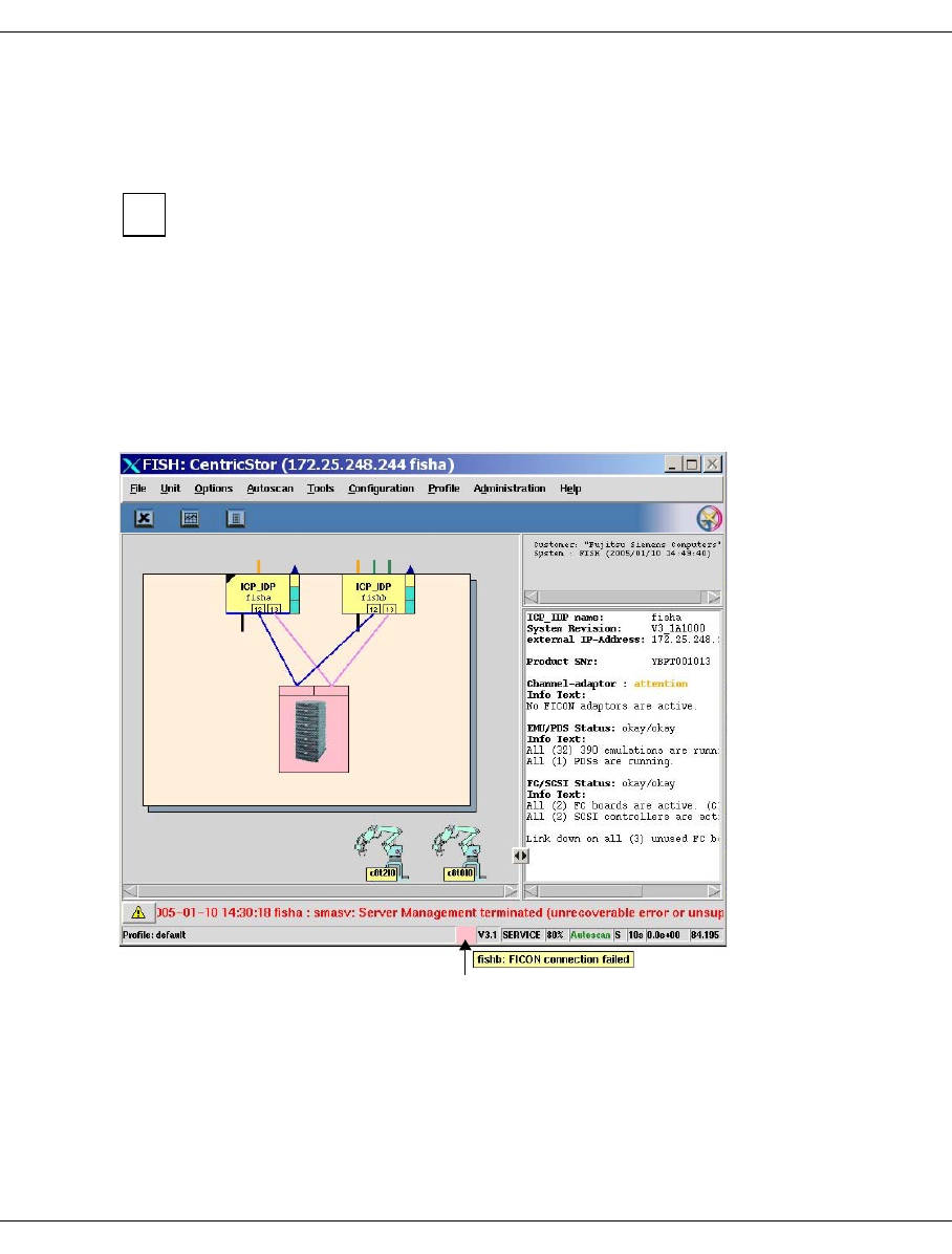
U41117-J-Z125-7-76 549
Appendix Integration of CentricStor V3.1 in SNMP
12.1.3 Monitoring CentricStor
12.1.3.1 GXCC as a monitoring tool without SNMP
This item is totally independent of SNMP and indicates that GXCC is fundamentally
an effective monitoring tool.
GXCC and XTCC together with Tcl/Tk must be installed from the GUI CD supplied with
CentricStor. If Tcl/Tk is already installed and is not to be overwritten, Tcl/Tk is installed in
an arbitrary directory. On Windows systems, Tcl/Tk is a part of GXCC. It is not necessary
to reboot after installation. A README file is provided on the CS-GUI CD for this purpose.
GXCC enables CentricStor to be monitored and controlled fully without SNMP.
All that is required for this is a Windows, LINUX, Solaris or SINIX-Z system. For details, refer
to the README file on the CentricStor GUI CD.
GXCC shows the “Global System State”. This is a concentrator for the CentricStor state,
which is obtained from many individual states of different things.
i
Global System State

550 U41117-J-Z125-7-76
Integration of CentricStor V3.1 in SNMP Appendix
With it a simple statement can be provided on the operating condition of CentricStor:
turquoise: CentricStor is working (OK)
yellow: CentricStor is working with restrictions (degraded, attention)
pink: CentricStor is in fail state
The “Global System State” is shown by a colored square in the bottom line of the GXCC.
If the mouse is positioned on this square, more details of the current state are shown in the
form of a Balloon Help.
12.1.3.2 Monitoring using any SNMP Management Station
The functional integrity of the carrier system on CentricStor and its LAN card can be
monitored by means of ping and/or MIB-II. Configuration options are provided in the SNMP
management software for checking the functional integrity cyclically. However, this only
enables you to see that the carrier system is still running. It does not allow you to check
whether the CentricStor firmware is still operating properly.
Consequently CentricStor sends traps to the Management Stations. In addition to the
standard traps (linkUp, linkDown, coldStart, etc.), CentricStor sends important error events
concerning the software or the hardware to the Management Station as a trap.
●Important key data of a CentricStor’s MIB-II:
Sysobjectid: enterprises.231.1.19.1
●Important key data of the standard traps:
Sysobjectid: enterprises.231.1.19.1
●Important key data ofImportant key data of CentricStor-specific traps:
ObjectID: enterprises.231.2.48.2.2
Specific Trap #: 0
Var. Binding 1: enterprises.231.2.48.2.1.2: CS-MsgManager
(instance on CentricStor which sends the trap)
Var. Binding 2: enterprises.231.2.48.2.1.3: Device on which the error occurred
Var. Binding 3: enterprises.231.2.48.2.1.4: Weight of the message
Var. Binding 4: enterprises.231.2.48.2.1.5: Actual message text
The weights 5=ERROR, 6=CRITICAL, 7=ALERT and 8=EMERGENCY are reported as
traps. Currently no traps are generated for the other weights 1=INFO, 2=DEBUG,
3=NOTICE and 4=WARNING.
●Storing the MIB for the CentricStor trap:
The MIB of the CentricStor trap is stored in the ASN-1 code in the directory
/usr/apc/lib/mib with the file name centricstor.mib and the MIB for the
SysObjID in the file sni.mib in each CentricStor system and can be obtained with ftp
when necessary

U41117-J-Z125-7-76 551
Appendix Integration of CentricStor V3.1 in SNMP
12.1.3.3 CentricStor Global System State
Every 300 seconds the Global System State (see the section “GXCC as a monitoring tool
without SNMP” on page 549) of CentricStor is sent via a trap. It is not meaningful to write
this trap onto the SNMP Management Station. This trap is designed to control the color of
the ICON. The format of this trap is identical to the CentricStor Trap.
The various bindings are set as follows:
ObjectID: enterprises.231.2.48.2.0
Specific Trap #: 0
Var. Binding 1: enterprises.231.2.48.2.1.2: CS-SNMP_Mgr
(the CentricStor tool which sends the trap)
Var. Binding 2: enterprises.231.2.48.2.1.3: device on which the state of CentricStor
was built.
Var. Binding 3: enterprises.231.2.48.2.1.4: weight of the Global State Trap
Var. Binding 4: enterprises.231.2.48.2.1.5: Text: “Global System State”
The following weights are sent:
1: green CentricStor is ready
4: yellow A part of CentricStor is defective, but CentricStor can go on working with
restrictions.
7: red CentricStor cannot work correctly.
A MIB call for returning the CentricStor Global System State is not possible.
12.1.3.4 GXCC on the SNMP Management Station
If permitted by the SNMP Management Station, the GXCC can be activated by means of
application launching either with a mouse click or using a start button in order to obtain
further information.
12.1.3.5 Sending a trap to the Management Station
To test the connection, a test trap can be sent after the SNMP trap has been activated on
CentricStor (see the section “Activating the configuration” on page 548) and the MIB has
been made known on the SNMP Management Station. A menu item is provided for this
under sysadm -> sinix_2000 -> snmp -> config -> traps -> send. The following data should
be output on the Management Station:
Var. Binding 1: enterprises.231.2.48.2.1.2: CS-MsgManager
Var. Binding 2: enterprises.231.2.48.2.1.3: VLP0
Var. Binding 3: enterprises.231.2.48.2.1.4: 6 (=weight)
Var. Binding 4: enterprises.231.2.48.2.1.5: Test message

552 U41117-J-Z125-7-76
Integration of CentricStor V3.1 in SNMP Appendix
12.1.3.6 Monitoring of CentricStor V2/V3.0 and V3.1
If an SNMP Management Station is required to monitor a CentricStor V3.1 and a
CentricStor V2/V3.0 simultaneously, the following applies:
On the Management Station the GUI CD of CentricStor V3.1 is read in as described here.
The V3.1 systems can be monitored as described. As the V2/V3.0 systems have different
object IDs (this includes the sysobjectID, too) and the format of the traps is changed, the
appearance differs between CentricStor V3.1 and older systems, but monitoring of both
systems is possible. You are referred here to the documentation for V2/V3.0. However, the
global state concentrator is not available in V2/V3.0. GXCC is always called with the popup
menu which serves and monitors CentricStor V2/V3.0, too. Only new V3.1 options of GXCC
lead to an error message.
CentricStor V2/V3.0 and V3.1 can thus be monitored by the same Management Station with
minor restrictions for GXCC handling of CentricStor V2/V3.0. If you do not want this,
GXTCC (for CentricStor V2/V3.0) can be installed parallel to GXCC (for CentricStor V3.1)
and can be called manually.
12.1.4 Installation on the Management Station CA Unicenter
A system on which the CA Unicenter and GXCC run is required as the base system. A
Windows-2000 system has been tested and is recommended.
12.1.4.1 Reading in the GUI CD
First GXCC and XTCC together withTcl/Tk must be installed from the GUI CD (as described
in the section “GXCC as a monitoring tool without SNMP” on page 549).
After this you should attempt to call GXCC and to set up a connection to a CentricStor. If
this works, then the GXCC has been correctly installed and the LAN connection to the
CentricStor is working.

U41117-J-Z125-7-76 553
Appendix Integration of CentricStor V3.1 in SNMP
12.1.4.2 Installation of the CA Unicenter extensions for CentricStor
Tools for adding and deleting CA Unicenter extensions were stored under Start -> Programs
-> Fujitsu Siemens Computers -> Tape Control Center -> Setup through the installation of
the GUI CD 2. The tool Add CentricStor to CA Unicenter must be called to install the exten-
sions. This tool stores all associated files which are needed for CA Unicenter operation in
the associated directories. Because of repository access for database administration, CA
Unicenter requires a user ID with a password which is inquired in a dialog box.
At the end of the installation script the following question is asked:
Do you want to “ResetDSM” ? yes, no or cancel
If no or cancel is specified (the two responses are equivalent), no ResetDSM is performed,
and therefore no reconfiguration of the CA Unicenter agent technology. The ResetDSM
command must then be issued later.
If yes is specified, ResetDSM is called immediately and the DSM is thus reconfigured. The
agent technology services are stopped for this purpose and started automatically again.
The new object class fscCentricStor now exists in the “WorldView - Repository”. It is now
known in the CA Unicenter and can be used.
All the add-ons can be deinstalled with the function “Delete CentricStor from CA Unicenter”.
12.1.4.3 Identification and editing of the CentricStor traps
After CA Unicenter add-ons have been installed for CentricStor, on receipt of CentricStor
traps messages are written which are formatted on the Event Console. The Global System
State trap leads to the icon being colored (green, yellow or red). Installation of a part of the
BS2000 integration package SMBS2-WIN (as with CentricStor V2/V3.0) is no longer
necessary.
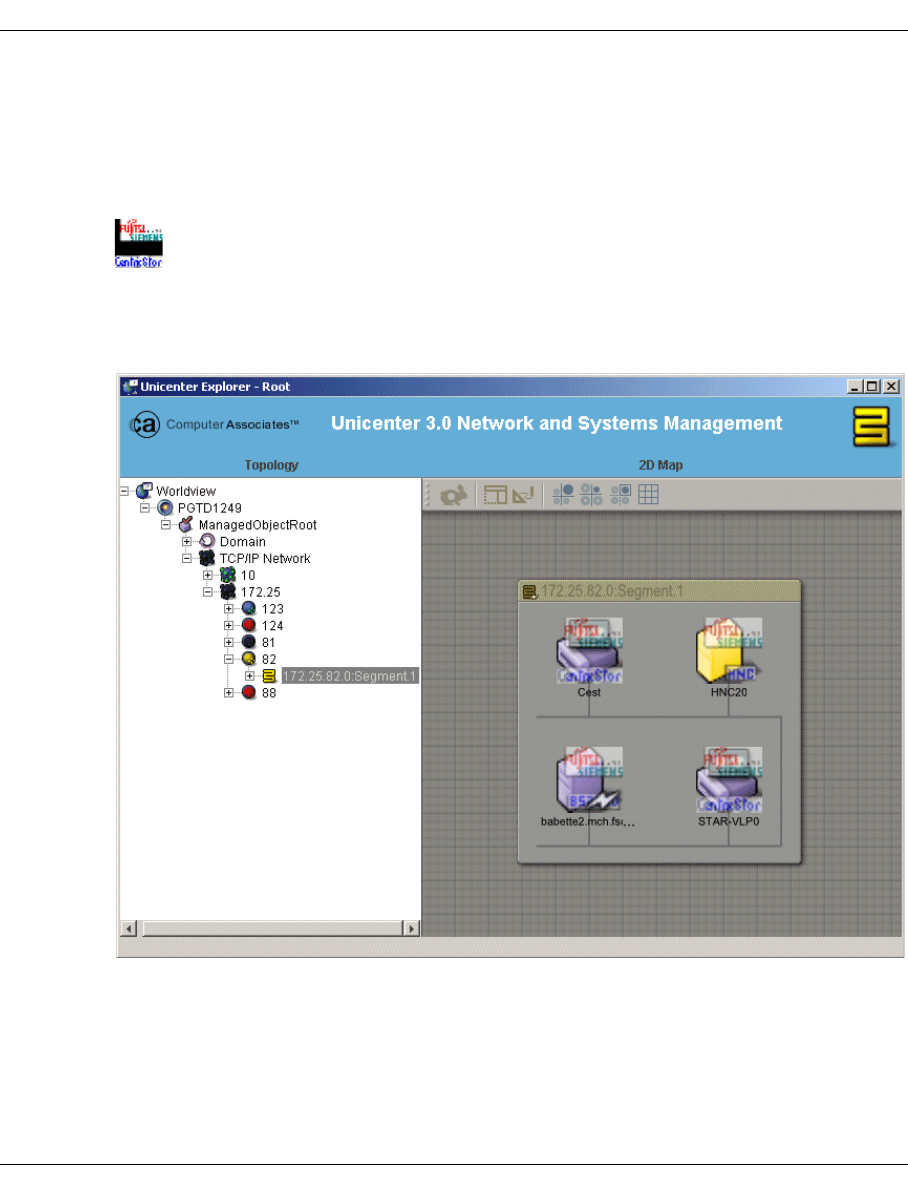
554 U41117-J-Z125-7-76
Integration of CentricStor V3.1 in SNMP Appendix
12.1.5 Working with CA Unicenter and CentricStor
12.1.5.1 CentricStor icon under CA Unicenter
The following icon was selected for CentricStor in 3-D format:
It contains the texts Fujitsu Siemens and CentricStor.
In the WorldView tree you see the CentricStor systems Cest and STAR-VLP0 in the figure
below:
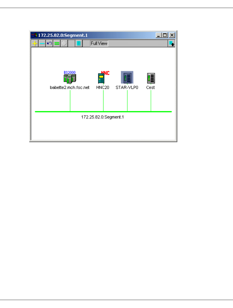
U41117-J-Z125-7-76 555
Appendix Integration of CentricStor V3.1 in SNMP
In 2D format CentricStor is represented as follows:
The Global System State trap is automatically set to green, yellow or red.
12.1.5.2 Identifying a CentricStor and assigning the icon
After the add-ons have been activated with Add CentricStor to CA Unicenter, a CentricStor
System is automatically recognized in the Unicenter-Discovery and is assigned to the
fscCentricStor class with the appropriate icon. To do this, Unicenter must work with the
appropriate community and thus be able to read the system’s SysObjID. The network
manager can now invoke GXCC directly from the popup menu of the newly added
CentricStor object.
Tip for the community string
For safety reasons CentricStor cannot work with the public community, which is the default
for CA Unicenter.
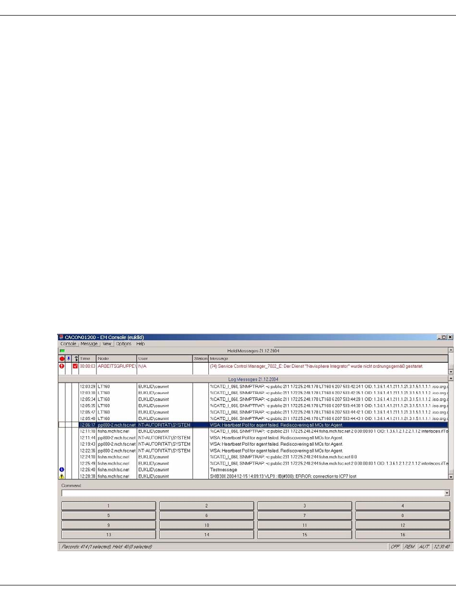
556 U41117-J-Z125-7-76
Integration of CentricStor V3.1 in SNMP Appendix
12.1.5.3 Receipt and preparation of a CentricStor trap
On receipt of CentricStor traps, messages are output on the Event Console. The standard
traps (e.g. coldStart) are issued without special preparation and appear on the Event
Console with the lead text %CATD_I_060, SNMPTRAP:.
Example
%CATD_I_060, SNMPTRAP:-c public 231 <ip-addr> <name of CentricStor>
<standard trap typ> <specific trap type>
0 0 shows a coldStart
2 0 shows linkDown with the additional binding interface etc.
A text message is shown for the enterprise-specific trap of a CentricStor.
Example of an error message text of a CentricStor component
SXIB300 2004-12-15 14:09:13 VLP0: IB(#300): ERROR: connection to ICP7 lost
After a CentricStor system has been entered in a CA Unicenter, you can send a test trap to
test the connection. The menu item sysadm -> sinix_2000 -> snmp -> config -> traps
-> send is available on the VLP for this purpose. The output on the Management Station is:
<name of CentricStor> Testmessage
The following figure shows the standard trap coldStart (0 0), then the standard trap
linkDown (2 0), then the CentricStor test trap, and finally the CentricStor trap with the key
SXB300 ... (14:09:13):

U41117-J-Z125-7-76 557
Appendix Integration of CentricStor V3.1 in SNMP
12.1.5.4 Monitoring CentricStor using ping and MIB-II
All objects entered in CA Unicenter are automatically moitored by means of ping and
MIB-II. This requires that the agent “Mib2” works with the right community. The
administrator must make any necessary adjustments in the Pollset Browser of CA
Unicenter.
12.1.5.5 Calling the GXCC from the pop-up menu of CA Unicenter
Clicking on the CentricStor icon with the right mouse button causes a pop-up menu to open.
The item at the bottom contains GXCC, which can then be opened directly.
12.1.6 Monitoring of CentricStor V2/V3.0 and V3.1 with CA Unicenter
If an SNMP Management Station is required to monitor a CentricStor V3.1 and a
CentricStor V2/V3.0 simultaneously, the following applies:
On the Management Station the GUI CD of CentricStor V3.1 is read in and the CA
Unicenter add-ons are installed as described. The V3.1 systems can be monitored as
described. The V2/V3.0 systems are initially recognized as SiemensUX systems and can
then be assigned to the class fscCentricStor as described in the documentation for
CentricStor V2/V3.0.
The traps of CentricStor V2/V3.0 are still recognized and prepared by the installed BS2000
part as described in the documentation for CentricStor V2/V3.0. However, GXCC is now
always called with the popup menu which serves and monitors CentricStor V2/V3.0, too.
Only new V3.1 options of GXCC lead to an error message.
CentricStor V2/V3.0 and V3.1 can thus be monitored by the same Management Station with
minor restrictions for GXCC handling of CentricStor V2/V3.0. If you do not want this,
GXTCC (for CentricStor V2/V3.0) can be installed parallel to GXCC (for CentricStor V3.1)
and can be called manually.
12.1.7 Summary
After the activities described above have been performed, a CentricStor system can be
integrated in any SNMP environment, CA Unicenter being supported in particular by instal-
lation scripts and the editing of traps.

558 U41117-J-Z125-7-76
E-mail support in CentricStor Appendix
12.2 E-mail support in CentricStor
12.2.1 Sendmail configuration
sendmail is started only if the configuration file /etc/mail/sendmail.cf exists. This file is
not generated, but under certain conditions it is modified to correct errors.
During installation a sample file is created under /etc/mail/sendmail.cf.sample which
can be used as /etc/mail/sendmail.cf. This file may need to be adapted.
In CentricStor systems sendmail cannot automatically determine the external name and the
customer domain. As a result, the file /etc/mail/sendmail.cf must be adjusted
manually as follows:
1. After the section
# my official domain name
# ... define this only if sendmail ...
#Dj$w.Foo.COM
you must enter the following lines:
Dw<node-name>
Dm<name-of-the-customer-domain>
Dj$w.$m
2. If the mail host (smarterhost) is not mail.<name-of-the-customer-domain>, the
entry DSmail.$m must be altered accordingly.
12.2.2 Setting up the DNS domain service
If the host is not or not fully configured as a DNS client, the following message is issued at
startup during installation:
WARNING: local host name (....) is not qualified; ...
To ensure complete sendmail functionality, the host must be configrued as a DNS client as
follows:
– The file/etc/resolv.conf must contain the following entries (the separator is the
tabulator!):
domain <name-of-the-customer-domain>
nameserver <ip-address-nameserver1>
nameserver <ip-address-nameserver2>
The nameserver must be entered with the IP address.

U41117-J-Z125-7-76 559
Appendix E-mail support in CentricStor
– In the file /etc/netconfig, the entries which have “inet” in the 4th column must be
complemented by the entry “,/usr/lib/resolv.so” in the last (7th) column.
Example
Thus (the separator is the tabulator!)
tcp tpi_cots_ord v inet tcp /dev/tcp /usr/lib/tcpip.so
udp tpi_clts vb inet udp /dev/udp /usr/lib/tcpip.so
rawip tpi_raw - inet - /dev/rawip /usr/lib/tcpip.so
icmp tpi_raw - inet icmp /dev/icmp /usr/lib/tcpip.so
becomes:
tcp tpi_cots_ord v inet tcp /dev/tcp
/usr/lib/tcpip.so,/usr/lib/resolv.so
udp tpi_clts vb inet udp /dev/udp
/usr/lib/tcpip.so,/usr/lib/resolv.so
rawip tpi_raw - inet - /dev/rawip
/usr/lib/tcpip.so,/usr/lib/resolv.so
icmp tpi_raw - inet icmp /dev/icmp
/usr/lib/tcpip.so,/usr/lib/resolv.so
– A DNS entry must exist in the customer domain with the host name which returns
“uname -n”. In CentricStor “uname -n” does not return the name which the host has in
the customer domain but the internal name (e.g. VLP0).
In the following tests the name of the host in the customer domain must be used:
–nslookup for the fully qualified host/domain name must return the correct IP address.
–nslookup for the simple host name (from “uname -n”) must return the correct IP address.
In CentricStor the name of the host in the customer domain must be used.
–nslookup for the IP address must return the fully qualified host/domain name.
–ping for the fully qualified host/domain name must supply “... is alive”.
If the customer is still using NIS, the general technical conditions must be clarified
with the network management before a congiruation change is made in the file
/etc/mail/service.switch.
i

560 U41117-J-Z125-7-76
E-mail support in CentricStor Appendix
12.2.3 Configuring the e-mail template
The configurable data of the e-mail can be set in e-mail-format-specific configuration files.
The configuration file must be created by copying a sample file and then be adapted to the
conditions.
If a customer-specific configuration file exists for an e-mail format, an e-mail is created and
sent in accordance with the configuration file.
The following entries can be configured in each e-mail-format-specific configuration file:
– Recipient
– Selection criterion
Recipients
Up to 8 recipients can be entered.
Example
# list with the recipients of the error information mail
#
RECEIVER1=""
RECEIVER2=""
RECEIVER3=""
RECEIVER4=""
RECEIVER5=""
RECEIVER6=""
RECEIVER7=""
RECEIVER8=""
Selection criterion
The Message Management defines which error messages can be sent by e-mail. In the
configuration file it is only possible to reduce this set. The criterion used for this purporse is
the error weight of a message (see section “General” on page 441).
Example
# define error levels to be reported by email
# values: yes/no
#
MAIL_NOTICE="no"
MAIL_WARNING="no"
MAIL_ERROR="no"
MAIL_CRITICAL="yes"
MAIL_ALERT="yes"
MAIL_EMERGENCY="yes"

U41117-J-Z125-7-76 561
Appendix E-mail support in CentricStor
The normal procedure is for an e-mail to be sent starting with the error weight ERROR. In
the case of the error weights NOTICE and WARNING, only very few, specially selected
messages are offered for e-mail dispatch, for example SXPL027 (page 476), SXPL049
(page 479) and SXPL050 (page 479).
12.2.4 Description of the e-mail formats
The sample file has the name:
/usr/apc/bin/msg_mail.config.sample
The e-mail-format-specific configuration file must be stored under the following name:
/usr/apc/conf/msg_mail.conf
The content of the e-mail can be defined using the configuration variables shown below:
●System details
Device_name=""
Serial_Number=""
●Customer details:
Customer_number=""
Customer_name=""
Customer_phone=""
Customer_email=""
Freely usable text area:
Remark1=""
Remark2=""
Remark3=""
Remark4=""
Remark5=""
Remark6=""
Undefined entries (="") are masked out in the e-mail.
The subject of the mail is made up of error-related entries:
Message from $Device_name $Serial_Number $ErrorWeight $MSG_NUMBER
In addition to the information shown above, the e-mail contains the error message and
details of the kernel version installed.

562 U41117-J-Z125-7-76
Transferring volumes Appendix
12.3 Transferring volumes
12.3.1 Introduction
A transfer enables LVs to be exported from a CentricStor system and imported into another
CentricStor.
For the export these LVs are temporarily copied into the special LV group TR-LVG using
“plmcmd trans …” commands and saved on PVs of the special PV group TR-PVG.
These PVs can then be removed and transported to another CentricStor.
For importing these PVs can be included in the TR-PVG and the LVs contained there can
be read into CentricStor using “plmcmd trans …” commands.
For this purpose one LVG group and one PVG group, named TR-LVG and TR-PVG respec-
tively, are available in CentricStor which are statically linked. The connection cannot be
canceled. The TR-PVG cannot be assigned to any other LVG.
Both groups are additive, i.e. 100 PV and 512 LV groups are still freely available (not
counting BASE). They are used for the temporary addition of the logical and physical
volumes during the export and import.
These two groups cannot be reached or administered via the GUI; PVs must therefore be
added or removed via the CLI.
To add: plmif conf -a -V <PV> -t <type> -G TR-PVG [-l <loop>]
To remove: plmif conf -e -V <PV> [-l <loop>]
The following must be entered for <type>:
3580 for LTO drives
3590 for Magstar and Eagle drives
Volume export and import is a solution which runs only within CentricStor.
It is not controlled by the tape management tools on the hosts via the commands which a
DAS server provides with dasadmin eject / insert ... or an ACSLS server with
eject / enter ... . These commands are not currently supported by the VDAS and
VACS in CentricStor.
This solution is specially designed for the transfer of logical volumes from one CentricStor
system to another CentricStor system, i.e. export in system 1 and import in system 2.
To handle large quantities of data, the copying operation of the LVs can take place in parallel
on multiple physical disk servers (PDSs).
The transfer operation and the next backup to the same LVs may not overlap.
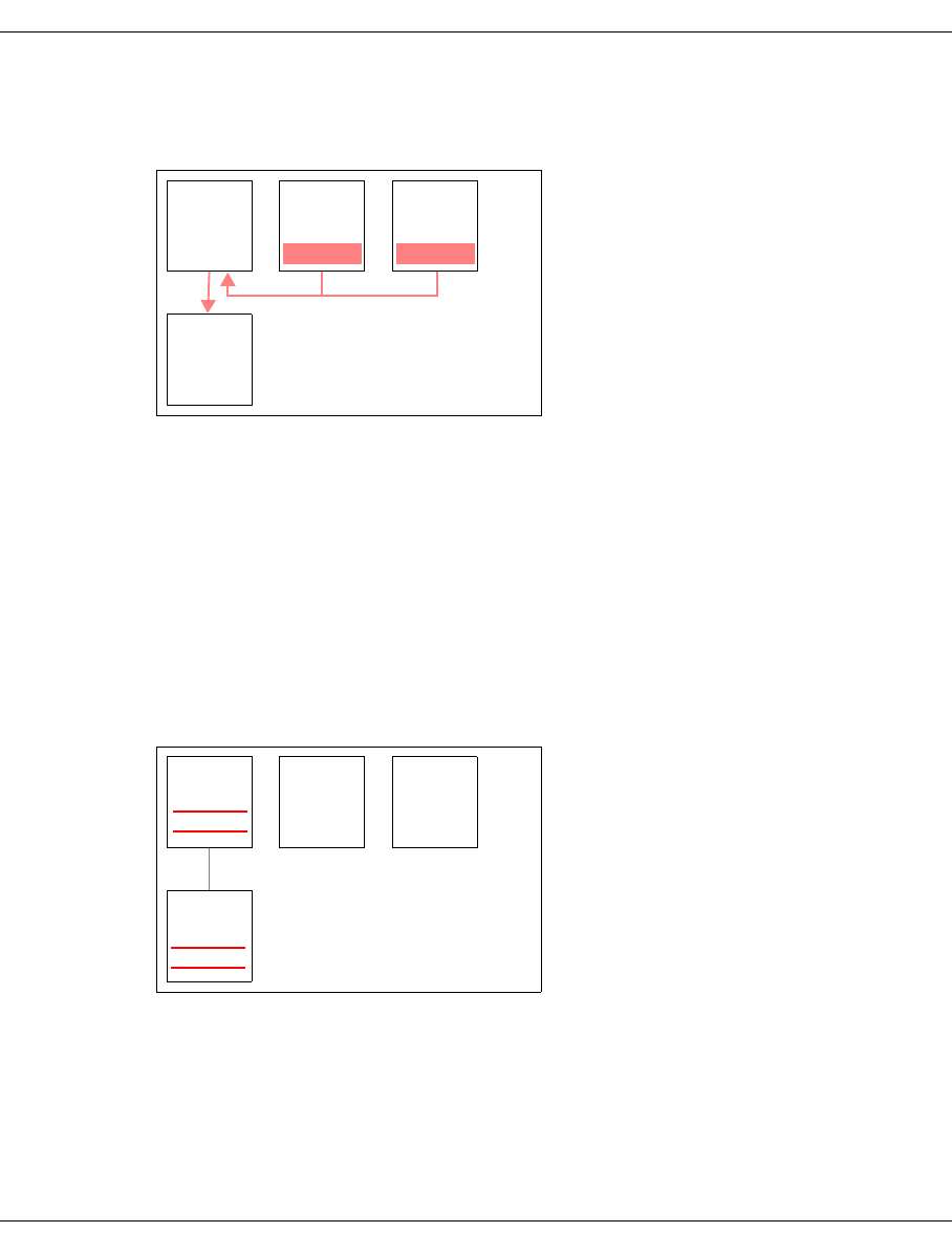
U41117-J-Z125-7-76 563
Appendix Transferring volumes
12.3.2 Export procedure
1. Copying LVs
Figure 36: Copying an LV to TR-PVG
With the aid of the transfer-out command (see the section “Transfer-out” on page 566),
the PLM creates an additional copy of the LVs selected for export in a special transfer
LVG, theTR-LVG. This is always permanently linked to a special transfer PVG, the
TR-PVG, on who’s PVs the additional copy is then stored.
Before the transfer, sufficient PVs must be added to the TR-PVG:
plmif conf -a -V <PV> [-l <loop>] -G TR-PVG -t <type>
Before the next step, plmif query -g should be used to check whether the transfer
has terminated. In this case 0 recover jobs may be outstanding in the TR-LVG.
2. Removing PVs from the CentricStor data maintenance system
Figure 37: Removing PVs
The plmif query -G TR-PVG -V command can be used to recognize PVs which
have been fully written using the transfer-out command from the status 'r' = read
for PVs which can only be read. These must be removed from the PLM’s data mainte-
nance system (see the section “Removing PVs and LVs” on page 568). CentricStor no
longer has information on the export and location of these exported LVs and PVs.
TR-LVG LVG1 LVG2
plmif trans -o -v A00001,Z10000
TR-PVG
A00001 Z10000
A00001
Z10000
A00001
Z10000
TR-LVG LVG1 LVG2
TR-PVG
A00001
Z10000
plmif trans -o -G
A00001
Z10000
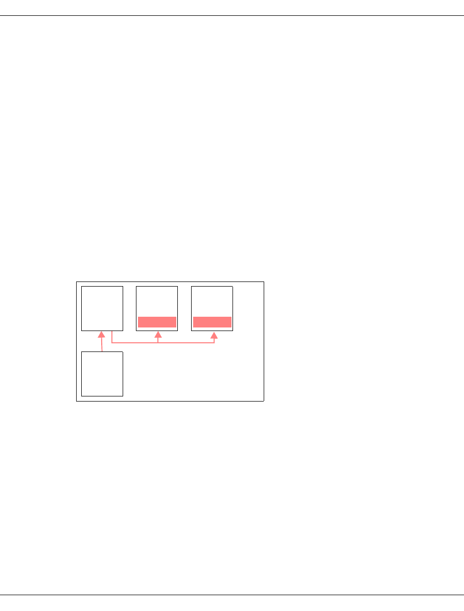
564 U41117-J-Z125-7-76
Transferring volumes Appendix
The transfer volume groups TR-LVG and TR-PVG are now ready for another transfer.
3. Removing PVs from a library
The PVs determined above can now be physically removed from the library using a DAS
or ACSLS command (see the section “Library commands” on page 571).
The existing copies of these LVs on other PVs when Mono Save or Dual Save is used remain
unaffected by the transfer: These copies are retained in the physical library unchanged.
After the export the exported LVs thus remain in CentricStor and also in the host’s tape
management tool.
12.3.3 Import procedure
1. Adding PVs to a library
The PVs to be imported are physically added to the library with the aid of a DAS or
ACSLS command (see the section “Library commands” on page 571).
2. Adding PVs in CentricStor and copying LVs
Figure 38: Importing LVs
The transfer-in command (see the section “Adding a PV to the transfer-in” on page 568)
is used to add the LVs again to the same or another CentricStor system. More precisely,
a set of PVs is specified, the LVs contained on these being added. All LVs that are to be
added must, however, already exist in the VLM! Only in this way can the LVs be added
to a normal LVG, any LVs which are already present and contain data being overwritten
in the process.
The LVs are not visible in the TR-LVG after the transfer-in. However, the PVs in the
TR-PVG with the status [old]-scratch ('o'), which can then be used for another transfer-
out, are visible.
LVG1 LVG2
plmif trans -i -V PHY001
TR-PVG
A00001 Z10000
A00001
Z10000
TR-LVG

U41117-J-Z125-7-76 565
Appendix Transferring volumes
12.3.4 Special features of the PVG TR-PVG
●PVs in the unknown status cannot be deleted using plmif conf -e ... .
●No reorganization takes place, neither can it be initiated using a command.
●Limits:
PV_SCRATCH_SOFT_MIN: not observed
PV_SCRATCH_HARD_MIN: 2
PV_SCRATCH_MIN: -1
●Similarly to cleaning groups, no configuration parameters are output in response to
plmif query -c.
●No values for this group are forwarded to the InfoBroker.
●While save jobs are present, the PLM does not return a drive for this group so as to
prevent unload/umounts.
●The transferred LVs are not part of the 'normal' PLM data maintenance. In the event of
a query, 2 lines are shown for the same LV, one for the location, one for the PV of the
PVG TR-PVG.

566 U41117-J-Z125-7-76
Transferring volumes Appendix
12.3.5 Additional command line interface (CLI)
12.3.5.1 Transfer-out
A transfer-out is initiated using this command.
– The PLM causes LVs which are located in normal LVGs to be copied to the special LVG
TR-LVG. The LVs are not moved, which means that the originals are still present after
the transfer-out.
– The LVs are copied from the TVC to the PVs. If the LVs there are no longer present in
the TVC, a restore is initiated.
– As usual, 2 normal PVGs can also be assigned to the normal source LVG in accordance
with Dual Save 2.
If another transfer-out or transfer-in has not yet been terminated, the command is rejected.
LVs which are not known to the PLM are ignored (message:
LV <name> is unknown, not transferred).
Options
-t This option selects all LVs of an LVG which were stored during a time period:
HH:MM defines the start of the time period, the range of values being within
[00:00,23:59].
– If the time is in the past, before the current time, the time period is determined
by [HH:MM, current time].
– If the time is in the future, after the current time, the time period is determined
by [HH:MM-24:00, current time].
-g Specifies the LVG
If the -g parameter is not entered, the command applies to all LVGs.
-v This option enables a list of LVs to be specified. Blanks are not permitted in the list.
-f The -f option enables a file to be entered with LV names (one LV per line). This
file is copied into a temporary local file using remote copy.
plmif trans -o ( -t HH:MM [-g <LVG>] | -v <LV>[,<LV>]* | -f <HOST>:<file> )

U41117-J-Z125-7-76 567
Appendix Transferring volumes
Example of an output when no transfer-out is active
AZUR-VLP0# plmif query -g
pos LV-Group PVGroup1 PVGroup2 LVs pending jobs recover jobs
1 A P16 ====== 10010 0 0
2 BASE BASE ====== 0 0 0
3 C P19 ====== 10000 0 0
4 D ====== ====== 0 0 0
5 TR-LVG TR-PVG ====== 0 0 0
6 ksp ====== ====== 0 0 0
Example of the start of a transfer-out
AZUR-VLP0# plmif trans -o -v EXIM00,EXIM01,EXIM02
LV EXIM00 scheduled for transfer.
LV EXIM01 scheduled for transfer.
LV EXIM02 scheduled for transfer.
Example of the output during a transfer-out
AZUR-VLP0# plmif query -G
pos name Type PVs scratch LVs tapelib jobs(wait-work) Reorg.(PV)
1 BASE stacked 0 0 0 P_HORN 0 - 0 ======
2 PHORN stacked 0 0 0 P_HORN 0 - 0 ======
3 P16 stacked 49 45 10010 TLIDP1 0 - 0 ======
4 P19 stacked 66 64 10000 S1000 0 - 0 ======
5 TR-PVG transfer 2 1 3 S1000 0 - 0 ======
AZUR-VLP0# plmif query -g
pos LV-Group PVGroup1 PVGroup2 LVs pending jobs recover jobs
1 A P16 ====== 10007 0 0
2 BASE BASE ====== 0 0 0
3 C P19 ====== 10003 0 0
4 D ====== ====== 0 0 0
5 TR-LVG TR-PVG ====== 349 5 651
6 ksp ====== ====== 0 0 0
AZUR-VLP0# plmif query -j -g TR-LVG
pos name PVGroup1 PVGroup2 pending jobs
1 TR-LVG TR-PVG ====== 3
pos name cmd TR-PVG ====== timestamp
1 EXIM00 SAVE pending ------- 21.11.2002 15:17:37
2 EXIM01 SAVE pending ------- 21.11.2002 15:17:50
3 EXIM02 SAVE pending ------- 21.11.2002 15:18:00
dumping recover-list:
pos name timestamp
1 EXIM00 21.11.2002 15:19:42
2 EXIM01 21.11.2002 15:19:42
3 EXIM02 21.11.2002 15:19:42

568 U41117-J-Z125-7-76
Transferring volumes Appendix
Example of an output after termination of the transfer-out
AZUR-VLP0# plmif query -g
pos LV-Group PVGroup1 PVGroup2 LVs pending jobs recover jobs
1 A P16 ====== 10010 0 0
2 BASE BASE ====== 0 0 0
3 C P19 ====== 10000 0 0
4 D ====== ====== 0 0 0
5 TR-LVG TR-PVG ====== 3 0 0
6 ksp ====== ====== 0 0 0
12.3.5.2 Removing PVs and LVs
This command is used to remove all PVs of the group TR-PVG which have the status 'read'
from the PLM-DB, and also all LVs which have been transferred to these PVs. This does not
affect normal PLM data maintenance.
If a PV of the TR-PVG is mounted when this command is issued, the command is rejected
After the command has been issued, the LVs just transferred no longer exist in the TR-LVG
for the PLM, nor do the associated PVs in the PVG TR-PVG, thus allowing the PVs to be
removed from the physical library. The special transfer volume groups are now empty and
ready for the next transfer.
Example
AZUR-VLP0# plmif trans -o -G
PV 000348 exported.
12.3.5.3 Adding a PV to the transfer-in
This command is used to add a PV to the transfer-in. Until it has been fully read, it has the
status 'unknown' ('----');
With this command only the physical volumes are specified, but implicitly all the logical
volumes contained there are added by means of a scan of the PV. All LVs that are to be
added must, however, already exist in the VLM! This is normally the case because these
were earlier exported from this CentricStor system. However, if these originate from a
different CentricStor system, these logical volumes must be added beforehand to a normal
LVG in the VLM (vlmcmd conf -a -v <LV> -g <LVG>).
plmif trans -o -G
plmif trans -i ( -V <PV>[,PV]* | -f <HOST>:<file>] -t <type> )

U41117-J-Z125-7-76 569
Appendix Transferring volumes
If the VLM does not know the LV, no restore command is issued to the PLM for the purpose
of actually reading in the LV. The PLM therefore waits for an unlimited time, and no progress
can be recognized when you query the jobs (plmif query -j -G TR-PVG).
You can then either create this LV in the LVG, or skip this LV using the transfer-in cancel
command (see the section “Skipping an LV / removing a PV” on page 570).
Options
-V The -V option enables a list of PVs to be entered directly; blanks are not permitted
here.
-f The -f option specifies the file which contains the PV names, one name in each
line. Thes are copied to the VLP using rcp.
Example of the start of a transfer-in
AZUR-VLP0# plmif trans -i -V 000348 -t 3580
PV 000348 prepared for transfer-in.
Example of the output when starting a transfer-in
AZUR-VLP0# plmif query -j -G TR-PVG
dumping worklist:
pos name type PDS PV priority(dyn. - static) timestamp
1 ====== RINIT PDSI 000348 0 - 0 21.11.2002
15:16:24
no entry in waitqueue
Example of the output during a transfer-in
AZUR-VLP0# plmif query -j -G TR-PVG
dumping worklist:
pos name type PDS PV priority(dyn. - static) timestamp
1 EXIM00 REST PDSI 000348 1000 - 1000 21.11.2002
15:17:13
no entry in waitqueue
As with reorganization, the PLM uses a Move command to have the LVs read into the TVC
from the transfer PVs and then have them stored again on the relevant PVs of the normal
PVG in accordance with the normal affiliation of the LVs to the LVG.
A special option (-r) in the internal Move command (from the PLM to the VLM) is used to
guarantee that a restore always takes place from the TR-PVG to the TVC, also if a (newer)
LV still exists in the TVC. This ensures that the data of an LV which may have been modified
during the export is overwritten by the (older or newer) LV in the system.

570 U41117-J-Z125-7-76
Transferring volumes Appendix
12.3.5.4 Removing an LV from a transfer list
This command enables an LV to be removed from the list of LVs to be transferred. If it has
already been transferred, the command is rejected.
If no LV is specified, the entire transfer-out is aborted. Existing save requests are still
processed.
Example
AZUR-VLP0# plmif trans -o -c
transfer-out cancelled.
12.3.5.5 Skipping an LV / removing a PV
The -v option is used to skip an LV. This is only possible if the PLM is waiting for a VLM
restore request, otherwise the command is rejected. This is useful if the VLM does not know
the LV concerned and the LV is not to be created.
The -V option enables you to remove a complete physical volume which was added
inadvertently. This can only be done if the PV is not mounted in a PDS.
12.3.6 Special situations
If you do not wish PVs with the 'read' status to really be deleted but to be reused, you must
remove them using plmif trans -o -G and then add them again using the command
plmif conf -a -f (-f=force: omit header check).
plmif trans -o -c [ -v <LV> ]
plmif trans -i -c ( -v <LV> | -V <PV> )

U41117-J-Z125-7-76 571
Appendix Transferring volumes
12.3.7 Library commands
12.3.7.1 ADIC library with DAS server
Further information is provided in the DAS manual.
12.3.7.2 StorageTek Library with ACSLS server
Further information is provided in the ACSLS manuals.
12.3.7.3 Fujitsu Library with LMF server (PLP)
Further information is available in the following PLP manuals:
– FUJITSU LMF SERVER/CLIENT USER'S GUIDE
– ETERNUS LT270 TAPE LIBRARY UNIT INSTALLATION INSTRUCTIONS
– ETERNUS LT270 Tape Library User's Guide
– ETERNUS LT270 Setup Guide
– ETERNUS LT270 Tape Library Maintenance Guide
ejects cartridges from the AML
[via the eject area]
dasadmin eject2 [-c] [-t media-type]
volserrange area
inserts [normal data] cartridges
[via the insert area] in the AML
dasadmin insert2 -n area
Eject volumes [of a cartridge pool]
from the library
eject cap_id vol_id | volrange ...
Make manual mode CAP ready to
enter labelled carts [into a
cartridge pool]
enter cap_id
Eject volume to MailSlot /opt/FJSVlmf/bin/lmeject <volume_name>
(on LMF server)
Enter volume from MailSlot /opt/FJSVlmf/bin/lmenter
(on LMF server)

572 U41117-J-Z125-7-76
Licenses Appendix
12.4 Licenses
All licenses dealed with the Open Source Software in CentricStor are listed below.
12.4.1 Xpdf, gzip
GNU GENERAL PUBLIC LICENSE
Version 2, June 1991
Copyright (C) 1989, 1991 Free Software Foundation, Inc.
59 Temple Place - Suite 330, Boston, MA
02111-1307, USA.
Everyone is permitted to copy and distribute verbatim copies of this license document, but
changing it is not allowed.
12.4.1.1 Preamble
The licenses for most software are designed to take away your freedom to share and
change it. By contrast, the GNU General Public License is intended to guarantee your free-
dom to share and change free software--to make sure the software is free for all its users.
This General Public License applies to most of the Free Software Foundation's software
and to any other program whose authors commit to using it. (Some other Free Software
Foundation software is covered by the GNU Library General Public License instead.) You
can apply it to your programs, too.
When we speak of free software, we are referring to freedom, not price. Our General Public
Licenses are designed to make sure that you have the freedom to distribute copies of free
software (and charge for this service if you wish), that you receive source code or can get
it if you want it, that you can change the software or use pieces of it in new free programs;
and that you know you can do these things.
To protect your rights, we need to make restrictions that forbid anyone to deny you these
rights or to ask you to surrender the rights. These restrictions translate to certain responsi-
bilities for you if you distribute copies of the software, or if you modify it.
For example, if you distribute copies of such a program, whether gratis or for a fee, you must
give the recipients all the rights that you have. You must make sure that they, too, receive
or can get the source code. And you must show them these terms so they know their rights.
We protect your rights with two steps: (1) copyright the software, and (2) offer you this licen-
se which gives you legal permission to copy, distribute and/or modify the software.

U41117-J-Z125-7-76 573
Appendix Licenses
Also, for each author's protection and ours, we want to make certain that everyone under-
stands that there is no warranty for this free software. If the software is modified by someone
else and passed on, we want its recipients to know that what they have is not the original,
so that any problems introduced by others will not reflect on the original authors' reputati-
ons.
Finally, any free program is threatened constantly by software patents. We wish to avoid the
danger that redistributors of a free program will individually obtain patent licenses, in effect
making the program proprietary. To prevent this, we have made it clear that any patent must
be licensed for everyone's free use or not licensed at all.
The precise terms and conditions for copying, distribution and modification follow.
12.4.1.2 GNU GENERAL PUBLIC LICENSE
TERMS AND CONDITIONS FOR COPYING, DISTRIBUTION AND MODIFICATION
0. This License applies to any program or other work which contains a notice placed by
the copyright holder saying it may be distributed under the terms of this General Public
License. The “Program”, below, refers to any such program or work, and a “work based
on the Program” means either the Program or any derivative work under copyright law:
that is to say, a work containing the Program or a portion of it, either verbatim or with
modifications and/or translated into another language. (Hereinafter, translation is inclu-
ded without limitation in the term “modification”.) Each licensee is addressed as “you”.
Activities other than copying, distribution and modification are not covered by this Licen-
se; they are outside its scope. The act of running the Program is not restricted, and the
output from the Program is covered only if its contents constitute a work based on the
Program (independent of having been made by running the Program). Whether that is
true depends on what the Program does.
1. You may copy and distribute verbatim copies of the Program's source code as you re-
ceive it, in any medium, provided that you conspicuously and appropriately publish on
each copy an appropriate copyright notice and disclaimer of warranty; keep intact all the
notices that refer to this License and to the absence of any warranty; and give any other
recipients of the Program a copy of this License along with the Program.
You may charge a fee for the physical act of transferring a copy, and you may at your
option offer warranty protection in exchange for a fee.
2. You may modify your copy or copies of the Program or any portion of it, thus forming a
work based on the Program, and copy and distribute such modifications or work under
the terms of Section 1 above, provided that you also meet all of these conditions:
a) You must cause the modified files to carry prominent notices stating that you chan-
ged the files and the date of any change.

574 U41117-J-Z125-7-76
Licenses Appendix
b) You must cause any work that you distribute or publish, that in whole or in part con-
tains or is derived from the Program or any part thereof, to be licensed as a whole
at no charge to all third parties under the terms of this License.
c) If the modified program normally reads commands interactively when run, you must
cause it, when started running for such interactive use in the most ordinary way, to
print or display an announcement including an appropriate copyright notice and a
notice that there is no warranty (or else, saying that you provide a warranty) and that
users may redistribute the program under these conditions, and telling the user how
to view a copy of this License. (Exception: if the Program itself is interactive but does
not normally print such an announcement, your work based on the Program is not
required to print an announcement.)
These requirements apply to the modified work as a whole. If identifiable sections of
that work are not derived from the Program, and can be reasonably considered inde-
pendent and separate works in themselves, then this License, and its terms, do not ap-
ply to those sections when you distribute them as separate works. But when you distri-
bute the same sections as part of a whole which is a work based on the Program, the
distribution of the whole must be on the terms of this License, whose permissions for
other licensees extend to the entire whole, and thus to each and every part regardless
of who wrote it.
Thus, it is not the intent of this section to claim rights or contest your rights to work writ-
ten entirely by you; rather, the intent is to exercise the right to control the distribution of
derivative or collective works based on the Program.
In addition, mere aggregation of another work not based on the Program with the Pro-
gram (or with a work based on the Program) on a volume of a storage or distribution
medium does not bring the other work under the scope of this License.
3. You may copy and distribute the Program (or a work based on it, under Section 2) in
object code or executable form under the terms of Sections 1 and 2 above provided that
you also do one of the following:
a) Accompany it with the complete corresponding machine-readable source code,
which must be distributed under the terms of Sections 1 and 2 above on a medium
customarily used for software interchange; or,
b) Accompany it with a written offer, valid for at least three years, to give any third party,
for a charge no more than your cost of physically performing source distribution, a
complete machine-readable copy of the corresponding source code, to be distribut-
ed under the terms of Sections 1 and 2 above on a medium customarily used for
software interchange; or,
c) Accompany it with the information you received as to the offer to distribute corres-
ponding source code. (This alternative is allowed only for noncommercial distributi-
on and only if you received the program in object code or executable form with such
an offer, in accord with Subsection b above.)

U41117-J-Z125-7-76 575
Appendix Licenses
The source code for a work means the preferred form of the work for making modifica-
tions to it. For an executable work, complete source code means all the source code for
all modules it contains, plus any associated interface definition files, plus the scripts
used to control compilation and installation of the executable. However, as a special ex-
ception, the source code distributed need not include anything that is normally distribut-
ed (in either source or binary form) with the major components (compiler, kernel, and
so on) of the operating system on which the executable runs, unless that component
itself accompanies the executable.
If distribution of executable or object code is made by offering access to copy from a
designated place, then offering equivalent access to copy the source code from the
same place counts as distribution of the source code, even though third parties are not
compelled to copy the source along with the object code.
4. You may not copy, modify, sublicense, or distribute the Program except as expressly
provided under this License. Any attempt otherwise to copy, modify, sublicense or dis-
tribute the Program is void, and will automatically terminate your rights under this Licen-
se. However, parties who have received copies, or rights, from you under this License
will not have their licenses terminated so long as such parties remain in full compliance.
5. You are not required to accept this License, since you have not signed it. However,
nothing else grants you permission to modify or distribute the Program or its derivative
works. These actions are prohibited by law if you do not accept this License. Therefore,
by modifying or distributing the Program (or any work based on the Program), you indi-
cate your acceptance of this License to do so, and all its terms and conditions for copy-
ing, distributing or modifying the Program or works based on it.
6. Each time you redistribute the Program (or any work based on the Program), the reci-
pient automatically receives a license from the original licensor to copy, distribute or mo-
dify the Program subject to these terms and conditions. You may not impose any further
restrictions on the recipients' exercise of the rights granted herein. You are not respon-
sible for enforcing compliance by third parties to this License.
7. If, as a consequence of a court judgment or allegation of patent infringement or for any
other reason (not limited to patent issues), conditions are imposed on you (whether by
court order, agreement or otherwise) that contradict the conditions of this License, they
do not excuse you from the conditions of this License. If you cannot distribute so as to
satisfy simultaneously your obligations under this License and any other pertinent obli-
gations, then as a consequence you may not distribute the Program at all. For example,
if a patent license would not permit royalty-free redistribution of the Program by all those
who receive copies directly or indirectly through you, then the only way you could satisfy
both it and this License would be to refrain entirely from distribution of the Program.
If any portion of this section is held invalid or unenforceable under any particular circum-
stance, the balance of the section is intended to apply and the section as a whole is
intended to apply in other circumstances.

576 U41117-J-Z125-7-76
Licenses Appendix
It is not the purpose of this section to induce you to infringe any patents or other pro-
perty right claims or to contest validity of any such claims; this section has the sole pur-
pose of protecting the integrity of the free software distribution system, which is imple-
mented by public license practices. Many people have made generous contributions to
the wide range of software distributed through that system in reliance on consistent ap-
plication of that system; it is up to the author/donor to decide if he or she is willing to
distribute software through any other system and a licensee cannot impose that choice.
This section is intended to make thoroughly clear what is believed to be a consequence
of the rest of this License.
8. If the distribution and/or use of the Program is restricted in certain countries either by
patents or by copyrighted interfaces, the original copyright holder who places the Pro-
gram under this License may add an explicit geographical distribution limitation exclu-
ding those countries, so that distribution is permitted only in or among countries not thus
excluded. In such case, this License incorporates the limitation as if written in the body
of this License.
9. The Free Software Foundation may publish revised and/or new versions of the General
Public License from time to time. Such new versions will be similar in spirit to the present
version, but may differ in detail to address new problems or concerns.
Each version is given a distinguishing version number. If the Program specifies a versi-
on number of this License which applies to it and “any later version”, you have the option
of following the terms and conditions either of that version or of any later version pub-
lished by the Free Software Foundation. If the Program does not specify a version num-
ber of this License, you may choose any version ever published by the Free Software
Foundation.
10. If you wish to incorporate parts of the Program into other free programs whose distribu-
tion conditions are different, write to the author to ask for permission. For software which
is copyrighted by the Free Software Foundation, write to the Free Software Foundation;
we sometimes make exceptions for this. Our decision will be guided by the two goals of
preserving the free status of all derivatives of our free software and of promoting the
sharing and reuse of software generally.
NO WARRANTY
11. BECAUSE THE PROGRAM IS LICENSED FREE OF CHARGE, THERE IS NO WAR-
RANTY FOR THE PROGRAM, TO THE EXTENT PERMITTED BY APPLICABLE LAW.
EXCEPT WHEN OTHERWISE STATED IN WRITING THE COPYRIGHT HOLDERS
AND/OR OTHER PARTIES PROVIDE THE PROGRAM “AS IS” WITHOUT WARRAN-
TY OF ANY KIND, EITHER EXPRESSED OR IMPLIED, INCLUDING, BUT NOT LI-
MITED TO, THE IMPLIED WARRANTIES OF MERCHANTABILITY AND FITNESS
FOR A PARTICULAR PURPOSE. THE ENTIRE RISK AS TO THE QUALITY AND

U41117-J-Z125-7-76 577
Appendix Licenses
PERFORMANCE OF THE PROGRAM IS WITH YOU. SHOULD THE PROGRAM
PROVE DEFECTIVE, YOU ASSUME THE COST OF ALL NECESSARY SERVICING,
REPAIR OR CORRECTION.
12. IN NO EVENT UNLESS REQUIRED BY APPLICABLE LAW OR AGREED TO IN WRI-
TING WILL ANY COPYRIGHT HOLDER, OR ANY OTHER PARTY WHO MAY MO-
DIFY AND/OR REDISTRIBUTE THE PROGRAM AS PERMITTED ABOVE, BE LIAB-
LE TO YOU FOR DAMAGES, INCLUDING ANY GENERAL, SPECIAL, INCIDENTAL
OR CONSEQUENTIAL DAMAGES ARISING OUT OF THE USE OR INABILITY TO
USE THE PROGRAM (INCLUDING BUT NOT LIMITED TO LOSS OF DATA OR DATA
BEING RENDERED INACCURATE OR LOSSES SUSTAINED BY YOU OR THIRD
PARTIES OR A FAILURE OF THE PROGRAM TO OPERATE WITH ANY OTHER
PROGRAMS), EVEN IF SUCH HOLDER OR OTHER PARTY HAS BEEN ADVISED OF
THE POSSIBILITY OF SUCH DAMAGES.
END OF TERMS AND CONDITIONS
12.4.1.3 Appendix: How to Apply These Terms to Your New Programs
If you develop a new program, and you want it to be of the greatest possible use to the pu-
blic, the best way to achieve this is to make it free software which everyone can redistribute
and change under these terms.
To do so, attach the following notices to the program. It is safest to attach them to the start
of each source file to most effectively convey the exclusion of warranty; and each file should
have at least the “copyright” line and a pointer to where the full notice is found.
<one line to give the program's name and a brief idea of what it does.> Copyright (C)
19yy <name of author>
This program is free software; you can redistribute it and/or modify it under the terms of
the GNU General Public License as published by the Free Software Foundation; either
version 2 of the License, or (at your option) any later version.
This program is distributed in the hope that it will be useful, but WITHOUT ANY WAR-
RANTY; without even the implied warranty of MERCHANTABILITY or FITNESS FOR A
PARTICULAR PURPOSE. See the GNU General Public License for more details.
You should have received a copy of the GNU General Public License along with this pro-
gram; if not, write to the Free Software Foundation, Inc., 59 Temple Place - Suite 330,
Boston, MA 02111-1307, USA.
Also add information on how to contact you by electronic and paper mail.

578 U41117-J-Z125-7-76
Licenses Appendix
If the program is interactive, make it output a short notice like this when it starts in an inter-
active mode:
Gnomovision version 69, Copyright (C) 19yy name of author Gnomovision comes with
ABSOLUTELY NO WARRANTY; for details type `show w'. This is free software, and you
are welcome to redistribute it under certain conditions; type `show c' for details.
The hypothetical commands `show w' and `show c' should show the appropriate parts of
the General Public License. Of course, the commands you use may be called something
other than `show w' and `show c'; they could even be mouse-clicks or menu items--whatever
suits your program.
You should also get your employer (if you work as a programmer) or your school, if any, to
sign a “copyright disclaimer” for the program, if necessary. Here is a sample; alter the na-
mes:
Yoyodyne, Inc., hereby disclaims all copyright interest in the program `Gnomovision'
(which makes passes at compilers) written by James Hacker.
<signature of Ty Coon>, 1 April 1989
Ty Coon, President of Vice
This General Public License does not permit incorporating your program into proprietary
programs. If your program is a subroutine library, you may consider it more useful to permit
linking proprietary applications with the library. If this is what you want to do, use the GNU
Library General Public License instead of this License.
# The contents of this file are subject to the Interbase Public
# License Version 1.0 (the “License”); you may not use this file
# except in compliance with the License. You may obtain a copy
# of the License at http://www.Inprise.com/IPL.html
#
# Software distributed under the License is distributed on an
# “AS IS” basis, WITHOUT WARRANTY OF ANY KIND, either express
# or implied. See the License for the specific language governing
# rights and limitations under the License.
#
# The Original Code was created by Inprise Corporation
# and its predecessors. Portions created by Inprise Corporation are
# Copyright (C) Inprise Corporation.
#
# All Rights Reserved.
# Contributor(s): ______________________________________.
Copyright (c) 1998,1999, InterBase Software Corporation
All Rights Reserved

U41117-J-Z125-7-76 579
Appendix Licenses
12.4.2 Firebird
INTERBASE PUBLIC LICENSE
Version 1.0
1. Definitions.
1.0.1. “Commercial Use” means distribution or otherwise making the Covered Code avai-
lable to a third party.
1.1. “Contributor” means each entity that creates or contributes to the creation of Mo-
difications.
1.2. “Contributor Version” means the combination of the Original Code, prior Modifica-
tions used by a Contributor, and the Modifications made by that particular Contribu-
tor.
1.3. “Covered Code” means the Original Code or Modifications or the combination of
the Original Code and Modifications, in each case including portions thereof.
1.4. “Electronic Distribution Mechanism” means a mechanism generally accepted in
the software development community for the electronic transfer of data.
1.5. “Executable” means Covered Code in any form other than Source Code.
1.6. “Initial Developer” means the individual or entity identified as the Initial Developer
in the Source Code notice required by Exhibit A.
1.7. “Larger Work” means a work which combines Covered Code or portions thereof
with code not governed by the terms of this License.
1.8. “License” means this document.
1.8.1. “Licensable” means having the right to grant, to the maximum extent possible, whe-
ther at the time of the initial grant or subsequently acquired, any and all of the rights
conveyed herein.
1.9. “Modifications” means any addition to or deletion from the substance or structure
of either the Original Code or any previous Modifications. When Covered Code is
released as a series of files, a Modification is:
A. Any addition to or deletion from the contents of a file containing Original Code or
previous Modifications.
B. Any new file that contains any part of the Original Code or previous Modifications.
1.10. “Original Code” means Source Code of computer software code which is descri-
bed in the Source Code notice required by Exhibit A as Original Code, and which,
at the time of its release under this License is not already Covered Code governed
by this License.

580 U41117-J-Z125-7-76
Licenses Appendix
1.10.1. “Patent Claims” means any patent claim(s), now owned or hereafter acquired, in-
cluding without limitation, method, process, and apparatus claims, in any patent Li-
censable by grantor.
1.11. “Source Code” means the preferred form of the Covered Code for making modifi-
cations to it, including all modules it contains, plus any associated interface defini-
tion files, scripts used to control compilation and installation of an Executable, or
source code differential comparisons against either the Original Code or another
well known, available Covered Code of the Contributor's choice. The Source Code
can be in a compressed or archival form, provided the appropriate decompression
or de-archiving software is widely available for no charge.
1.12. “You” (or “Your”) means an individual or a legal entity exercising rights under, and
complying with all of the terms of, this License or a future version of this License
issued under Section 6.1. For legal entities, “You” includes any entity which controls,
is controlled by, or is under common control with You. For purposes of this definition,
“control” means (a) the power, direct or indirect, to cause the direction or manage-
ment of such entity, whether by contract or otherwise, or (b) ownership of more than
fifty percent (50%) of the outstanding shares or beneficial ownership of such entity.
2. Source Code License.
2.1. The Initial Developer Grant.
The Initial Developer hereby grants You a world-wide, royalty-free, non-exclusive li-
cense, subject to third party intellectual property claims:
(a) under intellectual property rights (other than patent or trademark) Licensable by In-
itial Developer to use, reproduce, modify, display, perform, sublicense and distribute
the Original Code (or portions thereof) with or without Modifications, and/or as part
of a Larger Work; and
(b) under Patents Claims infringed by the making, using or selling of Original Code, to
make, have made, use, practice, sell, and offer for sale, and/or otherwise dispose
of the Original Code (or portions thereof).
(c) the licenses granted in this Section 2.1(a) and (b) are effective on the date Initial
Developer first distributes Original Code under the terms of this License.
(d) Notwithstanding Section 2.1(b) above, no patent license is granted: 1) for code that
You delete from the Original Code; 2) separate from the Original Code; or 3) for in-
fringements caused by: i) the modification of the Original Code or ii) the combination
of the Original Code with other software or devices.

U41117-J-Z125-7-76 581
Appendix Licenses
2.2. Contributor Grant.
Subject to third party intellectual property claims, each Contributor hereby grants
You a world-wide, royalty-free, nonexclusive license
(a) under intellectual property rights (other than patent or trademark) Licensable by
Contributor, to use, reproduce, modify, display, perform, sublicense and distribute
the Modifications created by such Contributor (or portions thereof) either on an un-
modified basis, with other Modifications, as Covered Code and/or as part of a Lar-
ger Work; and
(b) under Patent Claims infringed by the making, using, or selling of Modifications made
by that Contributor either alone and/or in combination with its Contributor Version
(or portions of such combination), to make, use, sell, offer for sale, have made,
and/or otherwise dispose of: 1) Modifications made by that Contributor (or portions
thereof); and 2) the combination of Modifications made by that Contributor with its
Contributor Version (or portions of such combination).
(c) the licenses granted in Sections 2.2(a) and 2.2(b) are effective on the date Contri-
butor first makes Commercial Use of the Covered Code.
(d) Notwithstanding Section 2.2(b) above, no patent license is granted: 1) for any code
that Contributor has deleted from the Contributor Version; 2) separate from the Con-
tributor Version; 3) for infringements caused by: i) third party modifications of Con-
tributor Version or ii) the combination of Modifications made by that Contributor with
other software (except as part of the Contributor Version) or other devices; or 4) un-
der Patent Claims infringed by Covered Code in the absence of Modifications made
by that Contributor.
3. Distribution Obligations.
3.1. Application of License.
The Modifications which You create or to which You contribute are governed by the
terms of this License, including without limitation Section 2.2. The Source Code ver-
sion of Covered Code may be distributed only under the terms of this License or a
future version of this License released under Section 6.1, and You must include a
copy of this License with every copy of the Source Code You distribute. You may not
offer or impose any terms on any Source Code version that alters or restricts the
applicable version of this License or the recipients' rights hereunder. However, You
may include an additional document offering the additional rights described in Sec-
tion 3.5.
3.2. Availability of Source Code.
Any Modification which You create or to which You contribute must be made avai-
lable in Source Code form under the terms of this License either on the same media
as an Executable version or via an accepted Electronic Distribution Mechanism to
anyone to whom you made an Executable version available; and if made available

582 U41117-J-Z125-7-76
Licenses Appendix
via Electronic Distribution Mechanism, must remain available for at least twelve (12)
months after the date it initially became available, or at least six (6) months after a
subsequent version of that particular Modification has been made available to such
recipients. You are responsible for ensuring that the Source Code version remains
available even if the Electronic Distribution Mechanism is maintained by a third par-
ty.
3.3. Description of Modifications.
You must cause all Covered Code to which You contribute to contain a file documen-
ting the changes You made to create that Covered Code and the date of any
change. You must include a prominent statement that the Modification is derived,
directly or indirectly, from Original Code provided by the Initial Developer and inclu-
ding the name of the Initial Developer in (a) the Source Code, and (b) in any notice
in an Executable version or related documentation in which You describe the origin
or ownership of the Covered Code.
3.4. Intellectual Property Matters
(a) Third Party Claims.
If Contributor has knowledge that a license under a third party's intellectual property
rights is required to exercise the rights granted by such Contributor under Sections
2.1 or 2.2, Contributor must include a text file with the Source Code distribution titled
“LEGAL” which describes the claim and the party making the claim in sufficient de-
tail that a recipient will know whom to contact. If Contributor obtains such knowledge
after the Modification is made available as described in Section 3.2, Contributor
shall promptly modify the LEGAL file in all copies Contributor makes available the-
reafter and shall take other steps (such as notifying appropriate mailing lists or new-
sgroups) reasonably calculated to inform those who received the Covered Code
that new knowledge has been obtained.
(b) Contributor APIs.
If Contributor's Modifications include an application programming interface and
Contributor has knowledge of patent licenses which are reasonably necessary to
implement that API, Contributor must also include this information in the LEGAL file.
(c) Representations.
Contributor represents that, except as disclosed pursuant to Section 3.4(a) above,
Contributor believes that Contributor's Modifications are Contributor's original crea-
tion(s) and/or Contributor has sufficient rights to grant the rights conveyed by this
License.

U41117-J-Z125-7-76 583
Appendix Licenses
3.5. Required Notices.
You must duplicate the notice in Exhibit A in each file of the Source Code. If it is not
possible to put such notice in a particular Source Code file due to its structure, then
You must include such notice in a location (such as a relevant directory) where a
user would be likely to look for such a notice. If You created one or more Modifica-
tion(s) You may add your name as a Contributor to the notice described in Exhibit
A. You must also duplicate this License in any documentation for the Source Code
where You describe recipients' rights or ownership rights relating to Covered Code.
You may choose to offer, and to charge a fee for, warranty, support, indemnity or li-
ability obligations to one or more recipients of Covered Code. However, You may do
so only on Your own behalf, and not on behalf of the Initial Developer or any Cont-
ributor. You must make it absolutely clear than any such warranty, support, indem-
nity or liability obligation is offered by You alone, and You hereby agree to indemnify
the Initial Developer and every Contributor for any liability incurred by the Initial De-
veloper or such Contributor as a result of warranty, support, indemnity or liability
terms You offer.
3.6. Distribution of Executable Versions.
You may distribute Covered Code in Executable form only if the requirements of
Section 3.1-3.5 have been met for that Covered Code, and if You include a notice
stating that the Source Code version of the Covered Code is available under the
terms of this License, including a description of how and where You have fulfilled
the obligations of Section 3.2. The notice must be conspicuously included in any
notice in an Executable version, related documentation or collateral in which You
describe recipients' rights relating to the Covered Code. You may distribute the Exe-
cutable version of Covered Code or ownership rights under a license of Your choice,
which may contain terms different from this License, provided that You are in com-
pliance with the terms of this License and that the license for the Executable version
does not attempt to limit or alter the recipient's rights in the Source Code version
from the rights set forth in this License. If You distribute the Executable version un-
der a different license You must make it absolutely clear that any terms which differ
from this License are offered by You alone, not by the Initial Developer or any Con-
tributor. You hereby agree to indemnify the Initial Developer and every Contributor
for any liability incurred by the Initial Developer or such Contributor as a result of any
such terms You offer.
3.7. Larger Works.
You may create a Larger Work by combining Covered Code with other code not go-
verned by the terms of this License and distribute the Larger Work as a single pro-
duct. In such a case, You must make sure the requirements of this License are ful-
filled for the Covered Code.

584 U41117-J-Z125-7-76
Licenses Appendix
4. Inability to Comply Due to Statute or Regulation.
If it is impossible for You to comply with any of the terms of this License with respect
to some or all of the Covered Code due to statute, judicial order, or regulation then
You must: (a) comply with the terms of this License to the maximum extent possible;
and (b) describe the limitations and the code they affect. Such description must be
included in the LEGAL file described in Section 3.4 and must be included with all
distributions of the Source Code. Except to the extent prohibited by statute or regu-
lation, such description must be sufficiently detailed for a recipient of ordinary skill
to be able to understand it.
5. Application of this License.
This License applies to code to which the Initial Developer has attached the notice
in Exhibit A and to related Covered Code.
6. Versions of the License.
6.1. New Versions.
Borland Software Corporation (“Interbase”) may publish revised and/or new versi-
ons of the License from time to time. Each version will be given a distinguishing ver-
sion number.
6.2. Effect of New Versions.
Once Covered Code has been published under a particular version of the License,
You may always continue to use it under the terms of that version. You may also
choose to use such Covered Code under the terms of any subsequent version of
the License published by Interbase. No one other than Interbase has the right to
modify the terms applicable to Covered Code created under this License.
6.3. Derivative Works.
If You create or use a modified version of this License (which you may only do in
order to apply it to code which is not already Covered Code governed by this Licen-
se), You must (a) rename Your license so that the phrases “Mozilla”, “MOZILLAPL”,
“MOZPL”, “Netscape”, “MPL”, “NPL”, “Interbase”, “ISC”, “IB” or any confusingly simi-
lar phrase do not appear in your license (except to note that your license differs from
this License) and (b) otherwise make it clear that Your version of the license con-
tains terms which differ from the Mozilla Public License and Netscape Public Licen-
se. (Filling in the name of the Initial Developer, Original Code or Contributor in the
notice described in Exhibit A shall not of themselves be deemed to be modifications
of this License.)

U41117-J-Z125-7-76 585
Appendix Licenses
6.4 Origin of the Interbase Public License.
The Interbase public license is based on the Mozilla Public License V 1.1 with the
following changes:
1. The license is published by Borland Software Corporation. Only Borland Soft-
ware Corporation can modify the terms applicable to Covered Code.
2. The license can be modified used for code which is not already governed by this
license. Modified versions of the license must be renamed to avoid confusion
with Netscape?s or Interbase Software?s license and must include a descripti-
on of changes from the Interbase Public License.
3. The name of the license in Exhibit A is the “Interbase Public License”.
4. The reference to an alternative license in Exhibit A has been removed.
5. Amendments I, II, III, V, and VI have been deleted.
6. Exhibit A, Netscape Public License has been deleted
7. A new amendment (II) has been added, describing the required and restricted
rights to use the trademarks of Borland Software Corporation
7. DISCLAIMER OF WARRANTY.
COVERED CODE IS PROVIDED UNDER THIS LICENSE ON AN “AS IS” BASIS,
WITHOUT WARRANTY OF ANY KIND, EITHER EXPRESSED OR IMPLIED, IN-
CLUDING, WITHOUT LIMITATION, WARRANTIES THAT THE COVERED CODE
IS FREE OF DEFECTS, MERCHANTABLE, FIT FOR A PARTICULAR PURPOSE
OR NONINFRINGING. THE ENTIRE RISK AS TO THE QUALITY AND PERFOR-
MANCE OF THE COVERED CODE IS WITH YOU. SHOULD ANY COVERED
CODE PROVE DEFECTIVE IN ANY RESPECT, YOU (NOT THE INITIAL DEVEL-
OPER OR ANY OTHER CONTRIBUTOR) ASSUME THE COST OF ANY NECES-
SARY SERVICING, REPAIR OR CORRECTION. THIS DISCLAIMER OF WAR-
RANTY CONSTITUTES AN ESSENTIAL PART OF THIS LICENSE. NO USE OF
ANY COVERED CODE IS AUTHORIZED HEREUNDER EXCEPT UNDER THIS
DISCLAIMER.
8. TERMINATION.
8.1. This License and the rights granted hereunder will terminate automatically if You fail
to comply with terms herein and fail to cure such breach within 30 days of becoming
aware of the breach. All sublicenses to the Covered Code which are properly gran-
ted shall survive any termination of this License. Provisions which, by their nature,
must remain in effect beyond the termination of this License shall survive.

586 U41117-J-Z125-7-76
Licenses Appendix
8.2. If You initiate litigation by asserting a patent infringement claim (excluding declatory
judgment actions) against Initial Developer or a Contributor (the Initial Developer or
Contributor against whom You file such action is referred to as “Participant”) alleging
that:
(a) such Participant's Contributor Version directly or indirectly infringes any patent, then
any and all rights granted by such Participant to You under Sections 2.1 and/or 2.2
of this License shall, upon 60 days notice from Participant terminate prospectively,
unless if within 60 days after receipt of notice You either: (i) agree in writing to pay
Participant a mutually agreeable reasonable royalty for Your past and future use of
Modifications made by such Participant, or (ii) withdraw Your litigation claim with re-
spect to the Contributor Version against such Participant. If within 60 days of notice,
a reasonable royalty and payment arrangement are not mutually agreed upon in wri-
ting by the parties or the litigation claim is not withdrawn, the rights granted by Par-
ticipant to You under Sections 2.1 and/or 2.2 automatically terminate at the expira-
tion of the 60 day notice period specified above.
(b) any software, hardware, or device, other than such Participant's Contributor Versi-
on, directly or indirectly infringes any patent, then any rights granted to You by such
Participant under Sections 2.1(b) and 2.2(b) are revoked effective as of the date You
first made, used, sold, distributed, or had made, Modifications made by that Partici-
pant.
8.3. If You assert a patent infringement claim against Participant alleging that such Par-
ticipant's Contributor Version directly or indirectly infringes any patent where such
claim is resolved (such as by license or settlement) prior to the initiation of patent
infringement litigation, then the reasonable value of the licenses granted by such
Participant under Sections 2.1 or 2.2 shall be taken into account in determining the
amount or value of any payment or license.
8.4. In the event of termination under Sections 8.1 or 8.2 above, all end user license
agreements (excluding distributors and resellers) which have been validly granted
by You or any distributor hereunder prior to termination shall survive termination.
9. LIMITATION OF LIABILITY.
UNDER NO CIRCUMSTANCES AND UNDER NO LEGAL THEORY, WHETHER
TORT (INCLUDING NEGLIGENCE), CONTRACT, OR OTHERWISE, SHALL YOU,
THE INITIAL DEVELOPER, ANY OTHER CONTRIBUTOR, OR ANY DISTRIBU-
TOR OF COVERED CODE, OR ANY SUPPLIER OF ANY OF SUCH PARTIES, BE
LIABLE TO ANY PERSON FOR ANY INDIRECT, SPECIAL, INCIDENTAL, OR
CONSEQUENTIAL DAMAGES OF ANY CHARACTER INCLUDING, WITHOUT LI-
MITATION, DAMAGES FOR LOSS OF GOODWILL, WORK STOPPAGE, COMPU-
TER FAILURE OR MALFUNCTION, OR ANY AND ALL OTHER COMMERCIAL
DAMAGES OR LOSSES, EVEN IF SUCH PARTY SHALL HAVE BEEN INFORMED
OF THE POSSIBILITY OF SUCH DAMAGES. THIS LIMITATION OF LIABILITY
SHALL NOT APPLY TO LIABILITY FOR DEATH OR PERSONAL INJURY RESUL-

U41117-J-Z125-7-76 587
Appendix Licenses
TING FROM SUCH PARTY'S NEGLIGENCE TO THE EXTENT APPLICABLE LAW
PROHIBITS SUCH LIMITATION. SOME JURISDICTIONS DO NOT ALLOW THE
EXCLUSION OR LIMITATION OF INCIDENTAL OR CONSEQUENTIAL DAMA-
GES, SO THIS EXCLUSION AND LIMITATION MAY NOT APPLY TO YOU.
10. U.S. GOVERNMENT END USERS.
The Covered Code is a “commercial item,” as that term is defined in 48 C.F.R. 2.101
(Oct. 1995), consisting of “commercial computer software” and “commercial com-
puter software documentation,” as such terms are used in 48 C.F.R. 12.212 (Sept.
1995). Consistent with 48 C.F.R. 12.212 and 48 C.F.R. 227.7202-1 through
227.7202-4 (June 1995), all U.S. Government End Users acquire Covered Code
with only those rights set forth herein.
11. MISCELLANEOUS.
This License represents the complete agreement concerning subject matter hereof.
If any provision of this License is held to be unenforceable, such provision shall be
reformed only to the extent necessary to make it enforceable. This License shall be
governed by California law provisions (except to the extent applicable law, if any,
provides otherwise), excluding its conflict-of-law provisions. With respect to dispu-
tes in which at least one party is a citizen of, or an entity chartered or registered to
do business in the United States of America, any litigation relating to this License
shall be subject to the jurisdiction of the Federal Courts of the Northern District of
California, with venue lying in Santa Clara County, California, with the losing party
responsible for costs, including without limitation, court costs and reasonable attor-
neys' fees and expenses. The application of the United Nations Convention on Con-
tracts for the International Sale of Goods is expressly excluded. Any law or regula-
tion which provides that the language of a contract shall be construed against the
drafter shall not apply to this License.
12. RESPONSIBILITY FOR CLAIMS.
As between Initial Developer and the Contributors, each party is responsible for
claims and damages arising, directly or indirectly, out of its utilization of rights under
this License and You agree to work with Initial Developer and Contributors to distri-
bute such responsibility on an equitable basis. Nothing herein is intended or shall
be deemed to constitute any admission of liability.
13. MULTIPLE-LICENSED CODE.
Initial Developer may designate portions of the Covered Code as “Multiple-Li-
censed”. “Multiple-Licensed” means that the Initial Developer permits you to utilize
portions of the Covered Code under Your choice of the NPL or the alternative licen-
ses, if any, specified by the Initial Developer in the file described in Exhibit A.

588 U41117-J-Z125-7-76
Licenses Appendix
EXHIBIT A - InterBase Public License.
``The contents of this file are subject to the Interbase Public License Version 1.0 (the “Li-
cense”); you may not use this file except in compliance with the License. You may obtain a
copy of the License at http://www.Interbase.com/IPL.html
Software distributed under the License is distributed on an “AS IS” basis, WITHOUT WAR-
RANTY OF ANY KIND, either express or implied. See the License for the specific language
governing rights and limitations under the License.
The Original Code was created by InterBase Software Corp and its successors.
Portions created by Borland/Inprise are Copyright (C) Borland/Inprise. All Rights Reserved.
Contributor(s): ______________________________________.
AMENDMENTS
I. InterBase and logo. This License does not grant any rights to use the trademarks
“Interbase”, “Java” or “JavaScript” even if such marks are included in the Original
Code or Modifications.
II. Trademark Usage.
II.1. Advertising Materials. All advertising materials mentioning features or use of the co-
vered Code must display the following acknowledgement: “This product includes
software developed by Borland Software Corp. ”
II.2. Endorsements. The names “InterBase,” “ISC,” and “IB” must not be used to endorse
or promote Contributor Versions or Larger Works without the prior written permissi-
on of Interbase.
II.3. Product Names. Contributor Versions and Larger Works may not be called “Inter-
Base” or “Interbase” nor may the word “InterBase” appear in their names without
the prior written permission of Interbase.

U41117-J-Z125-7-76 589
Appendix Licenses
12.4.3 Sendmail
SENDMAIL LICENSE
The following license terms and conditions apply, unless a different license is obtained from
Sendmail, Inc., 6425 Christie Ave, Fourth Floor, Emeryville, CA 94608, USA, or by electro-
nic mail at license@sendmail.com.
License Terms:
Use, Modification and Redistribution (including distribution of any modified or derived work)
in source and binary forms is permitted only if each of the following conditions is met:
1. Redistributions qualify as “freeware” or “Open Source Software” under one of the follo-
wing terms:
(a) Redistributions are made at no charge beyond the reasonable cost of materials and
delivery.
(b) Redistributions are accompanied by a copy of the Source Code or by an irrevocable
offer to provide a copy of the Source Code for up to three years at the cost of ma-
terials and delivery. Such redistributions must allow further use, modification, and
redistribution of the Source Code under substantially the same terms as this licen-
se. For the purposes of redistribution “Source Code” means the complete compilab-
le and linkable source code of sendmail including all modifications.
2. Redistributions of source code must retain the copyright notices as they appear in each
source code file, these license terms, and the disclaimer/limitation of liability set forth
as paragraph 6 below.
3. Redistributions in binary form must reproduce the Copyright Notice, these license
terms, and the disclaimer/limitation of liability set forth as paragraph 6 below, in the do-
cumentation and/or other materials provided with the distribution. For the purposes of
binary distribution the “Copyright Notice” refers to the following language: “Copyright (c)
1998-2003 Sendmail, Inc. All rights reserved.”
4. Neither the name of Sendmail, Inc. nor the University of California nor the names of their
contributors may be used to endorse or promote products derived from this software wi-
thout specific prior written permission. The name “sendmail” is a trademark of Send-
mail, Inc.
5. All redistributions must comply with the conditions imposed by the University of Califor-
nia on certain embedded code, whose copyright notice and conditions for redistribution
are as follows:
(a) Copyright (c) 1988, 1993 The Regents of the University of California. All rights re-
served.

590 U41117-J-Z125-7-76
Licenses Appendix
(b) Redistribution and use in source and binary forms, with or without modification, are
permitted provided that the following conditions are met:
(i) Redistributions of source code must retain the above copyright notice, this list
of conditions and the following disclaimer.
(ii) Redistributions in binary form must reproduce the above copyright notice, this
list of conditions and the following disclaimer in the documentation and/or other
materials provided with the distribution.
(iii) Neither the name of the University nor the names of its contributors may be
used to endorse or promote products derived from this software without specific
prior written permission.
6. Disclaimer/Limitation of Liability: THIS SOFTWARE IS PROVIDED BY SENDMAIL,
INC. AND CONTRIBUTORS “AS IS” AND ANY EXPRESS OR IMPLIED WARRAN-
TIES, INCLUDING, BUT NOT LIMITED TO, THE IMPLIED WARRANTIES OF MER-
CHANTABILITY AND FITNESS FOR A PARTICULAR PURPOSE ARE DISCLAIMED.
IN NO EVENT SHALL SENDMAIL, INC., THE REGENTS OF THE UNIVERSITY OF
CALIFORNIA OR CONTRIBUTORS BE LIABLE FOR ANY DIRECT, INDIRECT, INCI-
DENTAL, SPECIAL, EXEMPLARY, OR CONSEQUENTIAL DAMAGES (INCLUDING,
BUT NOT LIMITED TO, PROCUREMENT OF SUBSTITUTE GOODS OR SERVICES;
LOSS OF USE, DATA, OR PROFITS; OR BUSINESS INTERRUPTION) HOWEVER
CAUSED AND ON ANY THEORY OF LIABILITY, WHETHER IN CONTRACT, STRICT
LIABILITY, OR TORT (INCLUDING NEGLIGENCE OR OTHERWISE) ARISING IN
ANY WAY OUT OF THE USE OF THIS SOFTWARE, EVEN IF ADVISED OF THE POS-
SIBILITY OF SUCH DAMAGES.
12.4.4 XML
12.4.4.1 Licence for libxslt except libexslt
Copyright (C) 2001-2002 Daniel Veillard. All Rights Reserved.
Permission is hereby granted, free of charge, to any person obtaining a copy of this software
and associated documentation files (the “Software”), to deal in the Software without restric-
tion, including without limitation the rights to use, copy, modify, merge, publish, distribute,
sublicense, and/or sell copies of the Software, and to permit persons to whom the Software
is furnished to do so, subject to the following conditions:
The above copyright notice and this permission notice shall be included in all copies or sub-
stantial portions of the Software.
THE SOFTWARE IS PROVIDED “AS IS”, WITHOUT WARRANTY OF ANY KIND, EX-
PRESS OR IMPLIED, INCLUDING BUT NOT LIMITED TO THE WARRANTIES OF MER-
CHANTABILITY, FITNESS FOR A PARTICULAR PURPOSE AND NONINFRINGEMENT.

U41117-J-Z125-7-76 591
Appendix Licenses
IN NO EVENT SHALL THE DANIEL VEILLARD BE LIABLE FOR ANY CLAIM, DAMAGES
OR OTHER LIABILITY, WHETHER IN AN ACTION OF CONTRACT, TORT OR OTHERWI-
SE, ARISING FROM, OUT OF OR IN CONNECTION WITH THE SOFTWARE OR THE
USE OR OTHER DEALINGS IN THE SOFTWARE.
Except as contained in this notice, the name of Daniel Veillard shall not be used in adverti-
sing or otherwise to promote the sale, use or other dealings in this Software without prior
written authorization from him.
12.4.4.2 Licence for libexslt
Copyright (C) 2001-2002 Thomas Broyer, Charlie Bozeman and Daniel Veillard.
All Rights Reserved.
Permission is hereby granted, free of charge, to any person obtaining a copy of this software
and associated documentation files (the “Software”), to deal in the Software without restric-
tion, including without limitation the rights to use, copy, modify, merge, publish, distribute,
sublicense, and/or sell copies of the Software, and to permit persons to whom the Software
is furnished to do so, subject to the following conditions:
The above copyright notice and this permission notice shall be included in all copies or sub-
stantial portions of the Software.
THE SOFTWARE IS PROVIDED “AS IS”, WITHOUT WARRANTY OF ANY KIND, EX-
PRESS OR IMPLIED, INCLUDING BUT NOT LIMITED TO THE WARRANTIES OF MER-
CHANTABILITY, FITNESS FOR A PARTICULAR PURPOSE AND NONINFRINGEMENT.
IN NO EVENT SHALL THE AUTHORS BE LIABLE FOR ANY CLAIM, DAMAGES OR
OTHER LIABILITY, WHETHER IN AN ACTION OF CONTRACT, TORT OR OTHERWISE,
ARISING FROM, OUT OF OR IN CONNECTION WITH THE SOFTWARE OR THE USE
OR OTHER DEALINGS IN THE SOFTWARE.
Except as contained in this notice, the name of the authors shall not be used in advertising
or otherwise to promote the sale, use or other dealings in this Software without prior written
authorization from him.
Except where otherwise noted in the source code (trio files, hash.c and list.c) covered by a
similar licence but with different Copyright notices:
Copyright (C) 1998-2002 Daniel Veillard. All Rights Reserved.
Permission is hereby granted, free of charge, to any person obtaining a copy of this software
and associated documentation files (the “Software”), to deal in the Software without restric-
tion, including without limitation the rights to use, copy, modify, merge, publish, distribute,
sublicense, and/or sell copies of the Software, and to permit persons to whom the Software
is furnished to do so, subject to the following conditions:
The above copyright notice and this permission notice shall be included in all copies or sub-
stantial portions of the Software.

592 U41117-J-Z125-7-76
Licenses Appendix
THE SOFTWARE IS PROVIDED “AS IS”, WITHOUT WARRANTY OF ANY KIND, EX-
PRESS OR IMPLIED, INCLUDING BUT NOT LIMITED TO THE WARRANTIES OF MER-
CHANTABILITY, FIT-NESS FOR A PARTICULAR PURPOSE AND NONINFRINGEMENT.
IN NO EVENT SHALL THE DANIEL VEILLARD BE LIABLE FOR ANY CLAIM, DAMAGES
OR OTHER LIABILITY, WHETHER IN AN ACTION OF CONTRACT, TORT OR OTHERWI-
SE, ARISING FROM, OUT OF OR IN CONNECTION WITH THE SOFTWARE OR THE
USE OR OTHER DEALINGS IN THE SOFTWARE.
Except as contained in this notice, the name of Daniel Veillard shall not be used in adverti-
sing or otherwise to promote the sale, use or other dealings in this Software without prior
written authorization from him.
12.4.5 NTP
Copyright Notice
jpg "Clone me," says Dolly sheepishly
Last update: 02:45 UTC Tuesday, June 27, 2006
_________________________________________________________________
The following copyright notice applies to all files collectively called the Network Time Proto-
col Version 4 Distribution. Unless specifically declared otherwise in an individual file, this
notice applies as if the text was explicitly included in the file.
***********************************************************************
* *
* Copyright (c) David L. Mills 1992-2006 *
* *
* Permission to use, copy, modify, and distribute this software and *
* its documentation for any purpose with or without fee is hereby *
* granted, provided that the above copyright notice appears in all *
* copies and that both the copyright notice and this permission *
* notice appear in supporting documentation, and that the name *
* University of Delaware not be used in advertising or publicity *
* pertaining to distribution of the software without specific, *
* written prior permission. The University of Delaware makes no *
* representations about the suitability this software for any *
* purpose. It is provided "as is" without express or implied *
* warranty. *
* *
***********************************************************************

U41117-J-Z125-7-76 593
Appendix Licenses
The following individuals contributed in part to the Network Time Protocol Distribution Ver-
sion 4 and are acknowledged as authors of this work.
1. [1]Mark Andrews <mark_andrews@isc.org> Leitch atomic clock controller
2. [2]Bernd Altmeier <altmeier@atlsoft.de> hopf Elektronik serial line and PCI-bus de-
vices
3. [3]Viraj Bais <vbais@mailman1.intel.com> and [4]Clayton Kirkwood <kirkwood@stri-
derfm.intel.com> port to WindowsNT 3.5
4. [5]Michael Barone <michael,barone@lmco.com> GPSVME fixes
5. [6]Jean-Francois Boudreault <Jean-Francois.Boudreault@viagenie.qc.ca>IPv6 sup-
port
6. [7]Karl Berry <karl@owl.HQ.ileaf.com> syslog to file option
7. [8]Greg Brackley <greg.brackley@bigfoot.com> Major rework of WINNT port. Clean up
recvbuf and iosignal code into separate modules.
8. [9]Marc Brett <Marc.Brett@westgeo.com> Magnavox GPS clock driver
9. [10]Piete Brooks <Piete.Brooks@cl.cam.ac.uk> MSF clock driver, Trimble PARSE sup-
port
10. [11]Reg Clemens <reg@dwf.com> Oncore driver (Current maintainer)
11. [12]Steve Clift <clift@ml.csiro.au> OMEGA clock driver
12. [13]Casey Crellin <casey@csc.co.za> vxWorks (Tornado) port and help with target
configuration
13. [14]Sven Dietrich <sven_dietrich@trimble.com> Palisade reference clock driver, NT
adj. residuals, integrated Greg's Winnt port.
14. [15]John A. Dundas III <dundas@salt.jpl.nasa.gov> Apple A/UX port
15. [16]Torsten Duwe <duwe@immd4.informatik.uni-erlangen.de> Linux port
16. [17]Dennis Ferguson <dennis@mrbill.canet.ca> foundation code for NTP Version 2 as
specified in RFC-1119
17. [18]John Hay <jhay@@icomtek.csir.co.za> IPv6 support and testing
18. [19]Glenn Hollinger <glenn@herald.usask.ca> GOES clock driver
19. [20]Mike Iglesias <iglesias@uci.edu> DEC Alpha port
20. [21]Jim Jagielski <jim@jagubox.gsfc.nasa.gov> A/UX port
21. [22]Jeff Johnson <jbj@chatham.usdesign.com> massive prototyping overhaul
22. [23]Hans Lambermont <Hans.Lambermont@nl.origin-it.com> or [24]<H.Lamber-
mont@chello.nl> ntpsweep
23. [25]Poul-Henning Kamp <phk@FreeBSD.ORG> Oncore driver (Original author)
24. [26]Frank Kardel [27]<kardel (at) ntp (dot) org> PARSE <GENERIC> driver (>14 refe-
rence clocks), STREAMS modules for PARSE, support scripts, syslog cleanup, dyna-
mic interface handling
25. [28]William L. Jones <jones@hermes.chpc.utexas.edu> RS/6000 AIX modifications,
HPUX modifications
26. [29]Dave Katz <dkatz@cisco.com> RS/6000 AIX port
27. [30]Craig Leres <leres@ee.lbl.gov> 4.4BSD port, ppsclock, Magnavox GPS clock dri-
ver
28. [31]George Lindholm <lindholm@ucs.ubc.ca> SunOS 5.1 port

594 U41117-J-Z125-7-76
Licenses Appendix
29. [32]Louis A. Mamakos <louie@ni.umd.edu> MD5-based authentication
30. [33]Lars H. Mathiesen <thorinn@diku.dk> adaptation of foundation code for Version 3
as specified in RFC-1305
31. [34]Danny Mayer <mayer@ntp.org>Network I/O, Windows Port, Code Maintenance
32. [35]David L. Mills <mills@udel.edu> Version 4 foundation: clock discipline, authentica-
tion, precision kernel; clock drivers: Spectracom, Austron, Arbiter, Heath, ATOM, ACTS,
KSI/Odetics; audio clock drivers: CHU, WWV/H, IRIG
33. [36]Wolfgang Moeller <moeller@gwdgv1.dnet.gwdg.de> VMS port
34. [37]Jeffrey Mogul <mogul@pa.dec.com> ntptrace utility
35. [38]Tom Moore <tmoore@fievel.daytonoh.ncr.com> i386 svr4 port
36. [39]Kamal A Mostafa <kamal@whence.com> SCO OpenServer port
37. [40]Derek Mulcahy <derek@toybox.demon.co.uk> and [41]Damon Hart-Davis
<d@hd.org> ARCRON MSF clock driver
38. [42]Rainer Pruy <Rainer.Pruy@informatik.uni-erlangen.de> monitoring/trap scripts,
statistics file handling
39. [43]Dirce Richards <dirce@zk3.dec.com> Digital UNIX V4.0 port
40. [44]Wilfredo Sánchez <wsanchez@apple.com> added support for NetInfo
41. [45]Nick Sayer <mrapple@quack.kfu.com> SunOS streams modules
42. [46]Jack Sasportas <jack@innovativeinternet.com> Saved a Lot of space on the stuff
in the html/pic/ subdirectory
43. [47]Ray Schnitzler <schnitz@unipress.com> Unixware1 port
44. [48]Michael Shields <shields@tembel.org> USNO clock driver
45. [49]Jeff Steinman <jss@pebbles.jpl.nasa.gov> Datum PTS clock driver
46. [50]Harlan Stenn <harlan@pfcs.com> GNU automake/autoconfigure makeover, va-
rious other bits (see the ChangeLog)
47. [51]Kenneth Stone <ken@sdd.hp.com> HP-UX port
48. [52]Ajit Thyagarajan <ajit@ee.udel.edu>IP multicast/anycast support
49. [53]Tomoaki TSURUOKA <tsuruoka@nc.fukuoka-u.ac.jp>TRAK clock driver
50. [54]Paul A Vixie <vixie@vix.com> TrueTime GPS driver, generic TrueTime clock driver
51. [55]Ulrich Windl <Ulrich.Windl@rz.uni-regensburg.de> corrected and validated HTML
documents according to the HTML DTD
_________________________________________________________________
References
1. mailto:%20mark_andrews@isc.org
2. mailto:%20altmeier@atlsoft.de
3. mailto:%20vbais@mailman1.intel.co
4. mailto:%20kirkwood@striderfm.intel.com
5. mailto:%20michael.barone@lmco.com
6. mailto:%20Jean-Francois.Boudreault@viagenie.qc.ca
7. mailto:%20karl@owl.HQ.ileaf.com
8. mailto:%20greg.brackley@bigfoot.com

U41117-J-Z125-7-76 595
Appendix Licenses
9. mailto:%20Marc.Brett@westgeo.com
10. mailto:%20Piete.Brooks@cl.cam.ac.uk
11. mailto:%20reg@dwf.com
12. mailto:%20clift@ml.csiro.au
13. mailto:casey@csc.co.za
14. mailto:%20Sven_Dietrich@trimble.COM
15. mailto:%20dundas@salt.jpl.nasa.gov
16. mailto:%20duwe@immd4.informatik.uni-erlangen.de
17. mailto:%20dennis@mrbill.canet.ca
18. mailto:%20jhay@icomtek.csir.co.za
19. mailto:%20glenn@herald.usask.ca
20. mailto:%20iglesias@uci.edu
21. mailto:%20jagubox.gsfc.nasa.gov
22. mailto:%20jbj@chatham.usdesign.com
23. mailto:Hans.Lambermont@nl.origin-it.com
24. mailto:H.Lambermont@chello.nl
25. mailto:%20phk@FreeBSD.ORG
26. http://www4.informatik.uni-erlangen.de/%7ekardel
27. mailto:%20kardel(at)ntp(dot)org
28. mailto:%20jones@hermes.chpc.utexas.edu
29. mailto:%20dkatz@cisco.com
30. mailto:%20leres@ee.lbl.gov
31. mailto:%20lindholm@ucs.ubc.ca
32. mailto:%20louie@ni.umd.edu
33. mailto:%20thorinn@diku.dk
34. mailto:%20mayer@ntp.org
35. mailto:%20mills@udel.edu
36. mailto:%20moeller@gwdgv1.dnet.gwdg.de
37. mailto:%20mogul@pa.dec.com
38. mailto:%20tmoore@fievel.daytonoh.ncr.com
39. mailto:%20kamal@whence.com
40. mailto:%20derek@toybox.demon.co.uk
41. mailto:%20d@hd.org
42. mailto:%20Rainer.Pruy@informatik.uni-erlangen.de
43. mailto:%20dirce@zk3.dec.com
44. mailto:%20wsanchez@apple.com
45. mailto:%20mrapple@quack.kfu.com
46. mailto:%20jack@innovativeinternet.com
47. mailto:%20schnitz@unipress.com
48. mailto:%20shields@tembel.org
49. mailto:%20pebbles.jpl.nasa.gov
50. mailto:%20harlan@pfcs.com
51. mailto:%20ken@sdd.hp.com
52. mailto:%20ajit@ee.udel.edu

596 U41117-J-Z125-7-76
Licenses Appendix
53. mailto:%20tsuruoka@nc.fukuoka-u.ac.jp
54. mailto:%20vixie@vix.com
55. mailto:%20Ulrich.Windl@rz.uni-regensburg.de
12.4.6 tcpd
/************************************************************************
* Copyright 1995 by Wietse Venema. All rights reserved. Some individual
* files may be covered by other copyrights.
*
* This material was originally written and compiled by Wietse Venema at
* Eindhoven University of Technology, The Netherlands, in 1990, 1991,
* 1992, 1993, 1994 and 1995.
*
* Redistribution and use in source and binary forms are permitted
* provided that this entire copyright notice is duplicated in all such
* copies.
*
* This software is provided "as is" and without any expressed or implied
* warranties, including, without limitation, the implied warranties of
* merchantibility and fitness for any particular purpose.
************************************************************************/
12.4.7 PRNGD
License:
This software is free. You can do with it whatever you want. I would however kindly ask
you to acknowledge the use of this package, if you are going use it in your software,
which you might be going to distribute. I would also like to receive a note if you are a
satisfied user :-)
Disclaimer:
This software is provided “as is”. You are using it at your own risk. I will take no liability
in any case.
Author:
Lutz Jaenicke <Lutz.Jaenicke@aet.TU-Cottbus.DE>
Download:
The latest version of PRNGD can be accessed via
http://ftp.aet.TU-Cottbus.DE/personen/jaenicke/postfix_tls/prngd.html

U41117-J-Z125-7-76 597
Appendix Licenses
12.4.8 openssh
This file is part of the OpenSSH software.
The licences which components of this software fall under are as follows. First, we will sum-
marize and say that all components are under a BSD licence, or a licence more free than
that.
OpenSSH contains no GPL code.
1. * Copyright (c) 1995 Tatu Ylonen <ylo@cs.hut.fi>, Espoo, Finland
* All rights reserved
*
* As far as I am concerned, the code I have written for this software
* can be used freely for any purpose. Any derived versions of this
* software must be clearly marked as such, and if the derived work is
* incompatible with the protocol description in the RFC file, it must be
* called by a name other than "ssh" or "Secure Shell".
[Tatu continues]
* However, I am not implying to give any licenses to any patents or
* copyrights held by third parties, and the software includes parts that
* are not under my direct control. As far as I know, all included
* source code is used in accordance with the relevant license agreements
* and can be used freely for any purpose (the GNU license being the most
* restrictive); see below for details.
[However, none of that term is relevant at this point in time. All of these restrictively li-
cenced software components which he talks about have been removed from OpenSSH,
i.e.,
– RSA is no longer included, found in the OpenSSL library
– IDEA is no longer included, its use is deprecated
– DES is now external, in the OpenSSL library
– GMP is no longer used, and instead we call BN code from OpenSSL
– Zlib is now external, in a library
– The make-ssh-known-hosts script is no longer included
– TSS has been removed
– MD5 is now external, in the OpenSSL library
– RC4 support has been replaced with ARC4 support from OpenSSL
– Blowfish is now external, in the OpenSSL library
[The licence continues]
Note that any information and cryptographic algorithms used in this software are public-
ly available on the Internet and at any major bookstore, scientific library, and patent of-
fice worldwide. More information can be found e.g. at “http://www.cs.hut.fi/crypto”.

598 U41117-J-Z125-7-76
Licenses Appendix
The legal status of this program is some combination of all these permissions and rest-
rictions. Use only at your own responsibility. You will be responsible for any legal con-
sequences yourself; I am not making any claims whether possessing or using this is le-
gal or not in your country, and I am not taking any responsibility on your behalf.
NO WARRANTY
BECAUSE THE PROGRAM IS LICENSED FREE OF CHARGE, THERE IS NO WAR-
RANTY FOR THE PROGRAM, TO THE EXTENT PERMITTED BY APPLICABLE LAW.
EXCEPT WHEN OTHERWISE STATED IN WRITING THE COPYRIGHT HOLDERS
AND/OR OTHER PARTIES PROVIDE THE PROGRAM “AS IS” WITHOUT WARRAN-
TY OF ANY KIND, EITHER EXPRESSED OR IMPLIED, INCLUDING, BUT NOT LI-
MITED TO, THE IMPLIED WARRANTIES OF MERCHANTABILITY AND FITNESS
FOR A PARTICULAR PURPOSE. THE ENTIRE RISK AS TO THE QUALITY AND
PERFORMANCE OF THE PROGRAM IS WITH YOU. SHOULD THE PROGRAM
PROVE DEFECTIVE, YOU ASSUME THE COST OF ALL NECESSARY SERVICING,
REPAIR OR CORRECTION.
IN NO EVENT UNLESS REQUIRED BY APPLICABLE LAW OR AGREED TO IN WRI-
TING WILL ANY COPYRIGHT HOLDER, OR ANY OTHER PARTY WHO MAY MO-
DIFY AND/OR REDISTRIBUTE THE PROGRAM AS PERMITTED ABOVE, BE LIAB-
LE TO YOU FOR DAMAGES, INCLUDING ANY GENERAL, SPECIAL, INCIDENTAL
OR CONSEQUENTIAL DAMAGES ARISING OUT OF THE USE OR INABILITY TO
USE THE PROGRAM (INCLUDING BUT NOT LIMITED TO LOSS OF DATA OR DATA
BEING RENDERED INACCURATE OR LOSSES SUSTAINED BY YOU OR THIRD
PARTIES OR A FAILURE OF THE PROGRAM TO OPERATE WITH ANY OTHER
PROGRAMS), EVEN IF SUCH HOLDER OR OTHER PARTY HAS BEEN ADVISED OF
THE POSSIBILITY OF SUCH DAMAGES.
2. The 32-bit CRC compensation attack detector in deattack.c was contributed by CORE
SDI S.A. under a BSD-style license.
* Cryptographic attack detector for ssh - source code
*
* Copyright (c) 1998 CORE SDI S.A., Buenos Aires, Argentina.
*
* All rights reserved. Redistribution and use in source and binary
* forms, with or without modification, are permitted provided that
* this copyright notice is retained.
*
* THIS SOFTWARE IS PROVIDED ``AS IS'' AND ANY EXPRESS OR IMPLIED
* WARRANTIES ARE DISCLAIMED. IN NO EVENT SHALL CORE SDI S.A. BE
* LIABLE FOR ANY DIRECT, INDIRECT, INCIDENTAL, SPECIAL, EXEMPLARY OR
* CONSEQUENTIAL DAMAGES RESULTING FROM THE USE OR MISUSE OF THIS
* SOFTWARE.
*

U41117-J-Z125-7-76 599
Appendix Licenses
* Ariel Futoransky <futo@core-sdi.com>
* <http://www.core-sdi.com>
3. ssh-keyscan was contributed by David Mazieres under a BSD-style license.
* Copyright 1995, 1996 by David Mazieres <dm@lcs.mit.edu>.
*
* Modification and redistribution in source and binary forms is
* permitted provided that due credit is given to the author and the
* OpenBSD project by leaving this copyright notice intact.
4. The Rijndael implementation by Vincent Rijmen, Antoon Bosselaers and Paulo Barreto
is in the public domain and distributed with the following license:
* @version 3.0 (December 2000)
*
* Optimised ANSI C code for the Rijndael cipher (now AES)
*
* @author Vincent Rijmen <vincent.rijmen@esat.kuleuven.ac.be>
* @author Antoon Bosselaers <antoon.bosselaers@esat.kuleuven.ac.be>
* @author Paulo Barreto <paulo.barreto@terra.com.br>
*
* This code is hereby placed in the public domain.
*
* THIS SOFTWARE IS PROVIDED BY THE AUTHORS ''AS IS'' AND ANY EXPRESS
* OR IMPLIED WARRANTIES, INCLUDING, BUT NOT LIMITED TO, THE IMPLIED
* WARRANTIES OF MERCHANTABILITY AND FITNESS FOR A PARTICULAR PURPOSE
* ARE DISCLAIMED. IN NO EVENT SHALL THE AUTHORS OR CONTRIBUTORS BE
* LIABLE FOR ANY DIRECT, INDIRECT, INCIDENTAL, SPECIAL, EXEMPLARY, OR
* CONSEQUENTIAL DAMAGES (INCLUDING, BUT NOT LIMITED TO, PROCUREMENT OF
* SUBSTITUTE GOODS OR SERVICES; LOSS OF USE, DATA, OR PROFITS; OR
* BUSINESS INTERRUPTION) HOWEVER CAUSED AND ON ANY THEORY OF LIABILITY,
* WHETHER IN CONTRACT, STRICT LIABILITY, OR TORT (INCLUDING NEGLIGENCE
* OR OTHERWISE) ARISING IN ANY WAY OUT OF THE USE OF THIS SOFTWARE,
* EVEN IF ADVISED OF THE POSSIBILITY OF SUCH DAMAGE.
5. One component of the ssh source code is under a 3-clause BSD license, held by the
University of California, since we pulled these parts from original Berkeley code.
* Copyright (c) 1983, 1990, 1992, 1993, 1995
* The Regents of the University of California. All rights reserved.
*
* Redistribution and use in source and binary forms, with or without
* modification, are permitted provided that the following conditions
* are met:
* 1. Redistributions of source code must retain the above copyright
* notice, this list of conditions and the following disclaimer.
* 2. Redistributions in binary form must reproduce the above copyright
* notice, this list of conditions and the following disclaimer in the
* documentation and/or other materials provided with the distribution.

600 U41117-J-Z125-7-76
Licenses Appendix
* 3. Neither the name of the University nor the names of its contributors
* may be used to endorse or promote products derived from this software
* without specific prior written permission.
*
* THIS SOFTWARE IS PROVIDED BY THE REGENTS AND CONTRIBUTORS ``AS IS'' AND
* ANY EXPRESS OR IMPLIED WARRANTIES, INCLUDING, BUT NOT LIMITED TO, THE
* IMPLIED WARRANTIES OF MERCHANTABILITY AND FITNESS FOR A PARTICULAR
* PURPOSEARE DISCLAIMED. IN NO EVENT SHALL THE REGENTS OR CONTRIBUTORS BE
* LIABLE FOR ANY DIRECT, INDIRECT, INCIDENTAL, SPECIAL, EXEMPLARY, OR
* CONSEQUENTIALDAMAGES (INCLUDING, BUT NOT LIMITED TO, PROCUREMENT OF
* SUBSTITUTE GOODS OR SERVICES; LOSS OF USE, DATA, OR PROFITS; OR
* BUSINESS INTERRUPTION) HOWEVER CAUSED AND ON ANY THEORY OF LIABILITY,
* WHETHER IN CONTRACT, STRICT LIABILITY, OR TORT (INCLUDING NEGLIGENCE OR
* OTHERWISE) ARISING IN ANY WAYOUT OF THE USE OF THIS SOFTWARE, EVEN IF
* ADVISED OF THE POSSIBILITY OFSUCH DAMAGE.
6. Remaining components of the software are provided under a standard 2-term BSD li-
cence with the following names as copyright holders:
Markus Friedl
Theo de Raadt
Niels Provos
Dug Song
Aaron Campbell
Damien Miller
Kevin Steves
Daniel Kouril
Wesley Griffin
Per Allansson
Nils Nordman
Simon Wilkinson
Portable OpenSSH additionally includes code from the following copyright holders, also
under the 2-term BSD license:
Ben Lindstrom
Tim Rice
Andre Lucas
Chris Adams
Corinna Vinschen
Cray Inc.
Denis Parker
Gert Doering
Jakob Schlyter
Jason Downs
Juha Yrjölä
Michael Stone

U41117-J-Z125-7-76 601
Appendix Licenses
Networks Associates Technology, Inc.
Solar Designer
Todd C. Miller
Wayne Schroeder
William Jones
Darren Tucker
Sun Microsystems
The SCO Group
* Redistribution and use in source and binary forms, with or without
* modification, are permitted provided that the following conditions
* are met:
* 1. Redistributions of source code must retain the above copyright
* notice, this list of conditions and the following disclaimer.
* 2. Redistributions in binary form must reproduce the above copyright
* notice, this list of conditions and the following disclaimer in the
* documentation and/or other materials provided with the distribution.
*
* THIS SOFTWARE IS PROVIDED BY THE AUTHOR ``AS IS'' AND ANY EXPRESS OR
* IMPLIED WARRANTIES, INCLUDING, BUT NOT LIMITED TO, THE IMPLIED
* WARRANTIESOF MERCHANTABILITY AND FITNESS FOR A PARTICULAR PURPOSE ARE
* DISCLAIMED.
* IN NO EVENT SHALL THE AUTHOR BE LIABLE FOR ANY DIRECT, INDIRECT,
* INCIDENTAL, SPECIAL, EXEMPLARY, OR CONSEQUENTIAL DAMAGES (INCLUDING, BUT
* NOT LIMITED TO, PROCUREMENT OF SUBSTITUTE GOODS OR SERVICES; LOSS OF
* USE, DATA, OR PROFITS; OR BUSINESS INTERRUPTION) HOWEVER CAUSED AND ON
* ANY THEORY OF LIABILITY, WHETHER IN CONTRACT, STRICT LIABILITY, OR TORT
* (INCLUDING NEGLIGENCE OR OTHERWISE) ARISING IN ANY WAY OUT OF THE USE OF
* THIS SOFTWARE, EVEN IF ADVISED OF THE POSSIBILITY OF SUCH DAMAGE.
7. Portable OpenSSH contains the following additional licenses:
a) md5crypt.c, md5crypt.h
* "THE BEER-WARE LICENSE" (Revision 42):
* <phk@login.dknet.dk> wrote this file. As long as you retain this
* notice you can do whatever you want with this stuff. If we meet
* some day, and you think this stuff is worth it, you can buy me a
* beer in return. Poul-Henning Kamp
b) snprintf replacement
* Copyright Patrick Powell 1995
* This code is based on code written by Patrick Powell
* (papowell@astart.com) It may be used for any purpose as long as this
* notice remains intact on all source code distributions

602 U41117-J-Z125-7-76
Licenses Appendix
c) Compatibility code (openbsd-compat)
Apart from the previously mentioned licenses, various pieces of code in the open-
bsd-compat/ subdirectory are licensed as follows:
Some code is licensed under a 3-term BSD license, to the following copyright hol-
ders:
Todd C. Miller
Theo de Raadt
Damien Miller
Eric P. Allman
The Regents of the University of California
Constantin S. Svintsoff
* Redistribution and use in source and binary forms, with or without
* modification, are permitted provided that the following conditions
* are met:
* 1. Redistributions of source code must retain the above copyright
* notice, this list of conditions and the following disclaimer.
* 2. Redistributions in binary form must reproduce the above copyright
* notice, this list of conditions and the following disclaimer in the
* documentation and/or other materials provided with the distribution.
* 3. Neither the name of the University nor the names of its
* contributors may be used to endorse or promote products derived from
* this software without specific prior written permission.
*
* THIS SOFTWARE IS PROVIDED BY THE REGENTS AND CONTRIBUTORS ``AS IS''
* AND ANY EXPRESS OR IMPLIED WARRANTIES, INCLUDING, BUT NOT LIMITED TO,
* THE IMPLIED WARRANTIES OF MERCHANTABILITY AND FITNESS FOR A
* PARTICULAR PURPOSE ARE DISCLAIMED. IN NO EVENT SHALL THE REGENTS OR
* CONTRIBUTORS BE LIABLE FOR ANY DIRECT, INDIRECT, INCIDENTAL, SPECIAL,
* EXEMPLARY, OR CONSEQUENTIAL DAMAGES (INCLUDING, BUT NOT LIMITED TO,
* PROCUREMENT OF SUBSTITUTE GOODS OR SERVICES; LOSS OF USE, DATA, OR
* PROFITS; OR BUSINESS INTERRUPTION) HOWEVER CAUSED AND ON ANY THEORY
* OF LIABILITY, WHETHER IN CONTRACT, STRICT LIABILITY, OR TORT
* (INCLUDING NEGLIGENCE OR OTHERWISE) ARISING IN ANY WAY
* OUT OF THE USE OF THIS SOFTWARE, EVEN IF ADVISED OF THE POSSIBILITY
* OF SUCH DAMAGE.
Some code is licensed under an ISC-style license, to the following copyright hol-
ders:
Internet Software Consortium.
Todd C. Miller

U41117-J-Z125-7-76 603
Appendix Licenses
* Permission to use, copy, modify, and distribute this software for any
* purpose with or without fee is hereby granted, provided that the
* above copyright notice and this permission notice appear in all
* copies.
*
* THE SOFTWARE IS PROVIDED "AS IS" AND TODD C. MILLER DISCLAIMS ALL
* WARRANTIES WITH REGARD TO THIS SOFTWARE INCLUDING ALL IMPLIED
* WARRANTIES OF MERCHANTABILITY AND FITNESS. IN NO EVENT SHALL TODD C.
* MILLER BE LIABLE FOR ANY SPECIAL, DIRECT, INDIRECT, OR CONSEQUENTIAL
* DAMAGES OR ANY DAMAGES WHATSOEVER RESULTING FROM LOSS OF USE, DATA OR
* PROFITS, WHETHER IN AN ACTION OF CONTRACT, NEGLIGENCE OR OTHER
* TORTIOUS ACTION, ARISING OUT OF OR IN CONNECTION WITH THE USE OR
* PERFORMANCE OF THIS SOFTWARE.
Some code is licensed under a MIT-style license to the following copyright holders:
Free Software Foundation, Inc.
* Permission is hereby granted, free of charge, to any person *
* obtaining a copy of this software and associated documentation *
* files (the "Software"), to deal in the Software without *
* restriction, including without limitation the rights to use, *
* copy, modify, merge, publish, distribute, distribute with *
* modifications, sublicense, and/or sell copies of the Software, *
* and to permit persons to whom the Software is furnished to do so, *
* subject to the following conditions: *
* *
* The above copyright notice and this permission notice shall be *
* included in all copies or substantial portions of the Software. *
* *
* THE SOFTWARE IS PROVIDED "AS IS", WITHOUT WARRANTY OF ANY KIND, *
* EXPRESS OR IMPLIED, INCLUDING BUT NOT LIMITED TO THE WARRANTIES OF *
* MERCHANTABILITY, FITNESS FOR A PARTICULAR PURPOSE AND *
* NONINFRINGEMENT. IN NO EVENT SHALL THE ABOVE COPYRIGHT HOLDERS *
* BE LIABLE FOR ANY CLAIM, DAMAGES OR OTHER LIABILITY, WHETHER IN *
* AN ACTION OF CONTRACT, TORT OR OTHERWISE, ARISING FROM, OUT OF OR *
* IN CONNECTION WITH THE SOFTWARE OR THE USE OR OTHER DEALINGS IN *
* THE SOFTWARE. *
* *
* Except as contained in this notice, the name(s) of the above *
* copyright holders shall not be used in advertising or otherwise *
* to promote the sale, use or other dealings in this Software *
* without prior written authorization. *
**********************************************************************/

604 U41117-J-Z125-7-76
Licenses Appendix
12.4.9 openssl
LICENSE ISSUES
The OpenSSL toolkit stays under a dual license, i.e. both the conditions of the OpenSSL
License and the original SSLeay license apply to the toolkit. See below for the actual license
texts. Actually both licenses are BSD-style Open Source licenses. In case of any license
issues related to OpenSSL please contact openssl-core@openssl.org.
OpenSSL License
/* ====================================================================
* Copyright (c) 1998-2004 The OpenSSL Project. All rights reserved.
*
* Redistribution and use in source and binary forms, with or without
* modification, are permitted provided that the following conditions
* are met:
*
* 1. Redistributions of source code must retain the above copyright
* notice, this list of conditions and the following disclaimer.
*
* 2. Redistributions in binary form must reproduce the above copyright
* notice, this list of conditions and the following disclaimer in
* the documentation and/or other materials provided with the
* distribution.
*
* 3. All advertising materials mentioning features or use of this
* software must display the following acknowledgment:
* "This product includes software developed by the OpenSSL Project
* for use in the OpenSSL Toolkit. (http://www.openssl.org/)"
*
* 4. The names "OpenSSL Toolkit" and "OpenSSL Project" must not be used to
* endorse or promote products derived from this software without
* prior written permission. For written permission, please contact
* openssl-core@openssl.org.
*
* 5. Products derived from this software may not be called "OpenSSL"
* nor may "OpenSSL" appear in their names without prior written
* permission of the OpenSSL Project.
*
* 6. Redistributions of any form whatsoever must retain the following
* acknowledgment:
* "This product includes software developed by the OpenSSL Project
* for use in the OpenSSL Toolkit (http://www.openssl.org/)"
*
* THIS SOFTWARE IS PROVIDED BY THE OpenSSL PROJECT ``AS IS'' AND ANY
* EXPRESSED OR IMPLIED WARRANTIES, INCLUDING, BUT NOT LIMITED TO, THE

U41117-J-Z125-7-76 605
Appendix Licenses
* IMPLIED WARRANTIES OF MERCHANTABILITY AND FITNESS FOR A PARTICULAR
* PURPOSE ARE DISCLAIMED. IN NO EVENT SHALL THE OpenSSL PROJECT OR
* ITS CONTRIBUTORS BE LIABLE FOR ANY DIRECT, INDIRECT, INCIDENTAL,
* SPECIAL, EXEMPLARY, OR CONSEQUENTIAL DAMAGES (INCLUDING, BUT
* NOT LIMITED TO, PROCUREMENT OF SUBSTITUTE GOODS OR SERVICES;
* LOSS OF USE, DATA, OR PROFITS; OR BUSINESS INTERRUPTION)
* HOWEVER CAUSED AND ON ANY THEORY OF LIABILITY, WHETHER IN CONTRACT,
* STRICT LIABILITY, OR TORT (INCLUDING NEGLIGENCE OR OTHERWISE)
* ARISING IN ANY WAY OUT OF THE USE OF THIS SOFTWARE, EVEN IF ADVISED
* OF THE POSSIBILITY OF SUCH DAMAGE.
* ====================================================================
*
* This product includes cryptographic software written by Eric Young
* (eay@cryptsoft.com). This product includes software written by Tim
* Hudson (tjh@cryptsoft.com).
*
*/
Original SSLeay License
/* Copyright (C) 1995-1998 Eric Young (eay@cryptsoft.com)
* All rights reserved.
*
* This package is an SSL implementation written
* by Eric Young (eay@cryptsoft.com).
* The implementation was written so as to conform with Netscapes SSL.
*
* This library is free for commercial and non-commercial use as long as
* the following conditions are aheared to. The following conditions
* apply to all code found in this distribution, be it the RC4, RSA,
* lhash, DES, etc., code; not just the SSL code. The SSL documentation
* included with this distribution is covered by the same copyright terms
* except that the holder is Tim Hudson (tjh@cryptsoft.com).
*
* Copyright remains Eric Young's, and as such any Copyright notices in
* the code are not to be removed.
* If this package is used in a product, Eric Young should be given
attribution
* as the author of the parts of the library used.
* This can be in the form of a textual message at program startup or
* in documentation (online or textual) provided with the package.
*
* Redistribution and use in source and binary forms, with or without
* modification, are permitted provided that the following conditions
* are met:
* 1. Redistributions of source code must retain the copyright
* notice, this list of conditions and the following disclaimer.

606 U41117-J-Z125-7-76
Licenses Appendix
* 2. Redistributions in binary form must reproduce the above copyright
* notice, this list of conditions and the following disclaimer in the
* documentation and/or other materials provided with the distribution.
* 3. All advertising materials mentioning features or use of this software
* must display the following acknowledgement:
* "This product includes cryptographic software written by
* Eric Young (eay@cryptsoft.com)"
* The word 'cryptographic' can be left out if the rouines from the library
* being used are not cryptographic related :-).
* 4. If you include any Windows specific code (or a derivative thereof)
* from the apps directory (application code) you must include an
* acknowledgement:
* "This product includes software written by Tim Hudson
* (tjh@cryptsoft.com)"
*
* THIS SOFTWARE IS PROVIDED BY ERIC YOUNG ``AS IS'' AND
* ANY EXPRESS OR IMPLIED WARRANTIES, INCLUDING, BUT NOT LIMITED TO, THE
* IMPLIED WARRANTIES OF MERCHANTABILITY AND FITNESS FOR A PARTICULAR
* PURPOSE ARE DISCLAIMED. IN NO EVENT SHALL THE AUTHOR OR CONTRIBUTORS BE
* LIABLE FOR ANY DIRECT, INDIRECT, INCIDENTAL, SPECIAL, EXEMPLARY, OR
* CONSEQUENTIAL DAMAGES (INCLUDING, BUT NOT LIMITED TO, PROCUREMENT OF
* SUBSTITUTE GOODS OR SERVICES; LOSS OF USE, DATA, OR PROFITS; OR BUSINESS
* INTERRUPTION) HOWEVER CAUSED AND ON ANY THEORY OF LIABILITY, WHETHER IN
* CONTRACT, STRICT LIABILITY, OR TORT (INCLUDING NEGLIGENCE OR OTHERWISE)
* ARISING IN ANY WAY OUT OF THE USE OF THIS SOFTWARE, EVEN IF ADVISED OF
* THE POSSIBILITY OF SUCH DAMAGE.
*
* The licence and distribution terms for any publically available version
* or derivative of this code cannot be changed. i.e. this code cannot
* simply be copied and put under another distribution licence
* [including the GNU Public Licence.]
*/

U41117-J-Z125-7-76 607
Appendix Licenses
12.4.10 tcl
Copyright:
This software is copyrighted by the Regents of the University of California, Sun Microsys-
tems, Inc., Scriptics Corporation, and other parties. The following terms apply to all files as-
sociated with the software unless explicitly disclaimed in individual files.
The authors hereby grant permission to use, copy, modify, distribute, and license this soft-
ware and its documentation for any purpose, provided that existing copyright notices are re-
tained in all copies and that this notice is included verbatim in any distributions. No written
agreement, license, or royalty fee is required for any of the authorized uses. Modifications
to this software may be copyrighted by their authors and need not follow the licensing terms
described here, provided that the new terms are clearly indicated on the first page of each
file where they apply.
IN NO EVENT SHALL THE AUTHORS OR DISTRIBUTORS BE LIABLE TO ANY PARTY
FOR DIRECT, INDIRECT, SPECIAL, INCIDENTAL, OR CONSEQUENTIAL DAMAGES
ARISING OUT OF THE USE OF THIS SOFTWARE, ITS DOCUMENTATION, OR ANY DE-
RIVATIVES THEREOF, EVEN IF THE AUTHORS HAVE BEEN ADVISED OF THE POSSI-
BILITY OF SUCH DAMAGE.
THE AUTHORS AND DISTRIBUTORS SPECIFICALLY DISCLAIM ANY WARRANTIES,
INCLUDING, BUT NOT LIMITED TO, THE IMPLIED WARRANTIES OF MERCHANTABI-
LITY, FITNESS FOR A PARTICULAR PURPOSE, AND NON-INFRINGEMENT. THIS
SOFTWARE IS PROVIDED ON AN “AS IS” BASIS, AND THE AUTHORS AND DISTRIBU-
TORS HAVE NO OBLIGATION TO PROVIDE MAINTENANCE, SUPPORT, UPDATES, EN-
HANCEMENTS, OR MODIFICATIONS.
GOVERNMENT USE: If you are acquiring this software on behalf of the U.S. government,
the Government shall have only “Restricted Rights” in the software and related documen-
tation as defined in the Federal Acquisition Regulations (FARs) in Clause 52.227.19 (c) (2).
If you are acquiring the software on behalf of the Department of Defense, the software shall
be classified as “Commercial Computer Software” and the Government shall have only “Re-
stricted Rights” as defined in Clause 252.227-7013 (c) (1) of DFARs. Notwithstanding the
foregoing, the authors grant the U.S. Government and others acting in its behalf permission
to use and distribute the software in accordance with the terms specified in this license.

608 U41117-J-Z125-7-76
Licenses Appendix
12.4.11 tk
Copyright:
This software is copyrighted by the Regents of the University of California, Sun Microsys-
tems, Inc., and other parties. The following terms apply to all files associated with the soft-
ware unless explicitly disclaimed in individual files.
The authors hereby grant permission to use, copy, modify, distribute, and license this soft-
ware and its documentation for any purpose, provided that existing copyright notices are re-
tained in all copies and that this notice is included verbatim in any distributions. No written
agreement, license, or royalty fee is required for any of the authorized uses. Modifications
to this software may be copyrighted by their authors and need not follow the licensing terms
described here, provided that the new terms are clearly indicated on the first page of each
file where they apply.
IN NO EVENT SHALL THE AUTHORS OR DISTRIBUTORS BE LIABLE TO ANY PARTY
FOR DIRECT, INDIRECT, SPECIAL, INCIDENTAL, OR CONSEQUENTIAL DAMAGES
ARISING OUT OF THE USE OF THIS SOFTWARE, ITS DOCUMENTATION, OR ANY DE-
RIVATIVES THEREOF, EVEN IF THE AUTHORS HAVE BEEN ADVISED OF THE POSSI-
BILITY OF SUCH DAMAGE.
THE AUTHORS AND DISTRIBUTORS SPECIFICALLY DISCLAIM ANY WARRANTIES,
INCLUDING, BUT NOT LIMITED TO, THE IMPLIED WARRANTIES OF MERCHANTABI-
LITY, FITNESS FOR A PARTICULAR PURPOSE, AND NON-INFRINGEMENT. THIS
SOFTWARE IS PROVIDED ON AN “AS IS” BASIS, AND THE AUTHORS AND DISTRIBU-
TORS HAVE NO OBLIGATION TO PROVIDE MAINTENANCE, SUPPORT, UPDATES, EN-
HANCEMENTS, OR MODIFICATIONS.
GOVERNMENT USE: If you are acquiring this software on behalf of the U.S. government,
the Government shall have only “Restricted Rights” in the software and related documen-
tation as defined in the Federal Acquisition Regulations (FARs) in Clause 52.227.19 (c) (2).
If you are acquiring the software on behalf of the Department of Defense, the software shall
be classified as “Commercial Computer Software” and the Government shall have only “Re-
stricted Rights” as defined in Clause 252.227-7013 (c) (1) of DFARs. Notwithstanding the
foregoing, the authors grant the U.S. Government and others acting in its behalf permission
to use and distribute the software in accordance with the terms specified in this license.

U41117-J-Z125-7-76 609
Glossary
AutoVLP failover function
As the VLP Master plays a central role in the CentricStor system, failure of the VLP
Master also causes the entire system to fail. To prevent this, a standby Standby VLP
(SVLP) can be integrated into the system as a backup computer. This SVLP is inactive
except for the monitoring function.
The AutoVLP failover function checks the functional integrity of the VLP Master at regular
intervals and, when it detects a malfunction, automatically takes the requisite steps: the
current VLP Master is split from the system and the SVLP is integrated into the system
as the current VLP Master. The system is then once more fully operational.
➟ section “Automatic VLP failover” on page 52
Battery Backup Unit ➟ BBU
BBU
Emergency power supply which, in the event of a power outage, retains the data which
has not been saved in the memory for an unspecified time.
Cache
In the manual the term cache is sometimes used not only in its general sense but as a
synonym for Tape Volume Cache (TVC) or Tape Filesystem (TFS).
Cache File System ➟ TFS
Cache Mirroring Feature ➟ CMF
CMF
The Cache Mirroring Feature (CMF) is used to ensure data security and to provide
greater protection against data loss as the result of disasters. The data stored on the
internal hard disk system is mirrored synchronously to a second cluster location. This
is done over Fibre Channel connections, also when large distances are involved. Even
if a location is completely destroyed, all the data which was saved on such a CentricStor
configuration will consequently be available.

610 U41117-J-Z125-7-76
Glossary
Distribute and Activate ➟ DNA
Distributed Tape Volume File System ➟ DTVFS
DNA
The Distribute and Activate (DNA) function must be invoked in GXCC every time a
change is made to the configuration of the CentricStor system. This ensures that the
new configuration is distributed to and activated on all the ISPs.
➟ section “Distribute and Activate” on page 188
DTVFS
DTVFS (Distributed Tape Volume File System) is a file system implementation which
was developed specially for CentricStor which has been adapted to the requirements of
high concurrence and of high-speed data traffic both between the TVC (Tape Volume
Cache) and hosts and between the TVC and tape drives. In CentricStor V3.1D, all Tape
File Systems (TFSs) of the TVC are of the type dtvfs.
Emulation
An emulation is a functional simulation of one system by another. The emulated system
receives the same data, executes the same programs and achieves the same results
as the original system.
Example: A logical drive (LD) emulates a physical drive (PD).
Extented Tape Control Center➟ XTCC
Failover ➟ AutoVLP failover function
FC
Fibre Channel (FC) is a standard which was designed for serial and continuous high-
speed transfer of large volumes of data. It is also used in the Storage Area Network (SAN)
within CentricStor and in some cases for the connections between the ICPs and the
hosts and between the IDPs and the back-end devices. The FC controllers used in
CentricStor support bandwidths of between 1 Gb/s (Gigabit per second) and 4 Gb/s.
In the case of a Fibre Channel, each device has a WWNN (World Wide Node Name)
and each port of a device a WWPN (World Wide Port Name) as a unique worldwide
identifier. Each of these is a 64-bit address which is generally presented in hexadecimal
format as 8 bytes separated by colons.
A distinction is made between three types of Fibre Channel topologies :
– Switched Fabric (FC-SW)
In the case of the Fibre Channel Switched Fabric, point-to-point connections are
switched between the channel via one or more FC switches.
– Arbitrated Loop ( FC-AL)
In the case of the Fibre Channel Arbitrated Loop a logical bus is involved on which all
terminals share the same bandwidth. In CentricStor, FC-AL can only be used to
connect back-end devices.
– Point-to-Point (FC-P2P)
This refers to a direct connection between two terminals.

U41117-J-Z125-7-76 611
Glossary
The FC Layer Model has 5 layers which have the following names:
– FC-0 (Physical Layer)
– FC-1 (Data Link Layer, coding/decoding the signals to be transferred)
– FC-2 (Network Layer, flow control, service classes)
– FC-3 (Common Services Layer, e.g. multicast, striping)
– FC-4 (Protocol Mapping Layer, e.g. FCP, FICON)
FC Layer Model ➟ FC
FCP
FCP, like FICON, is a protocol of the uppermost layer FC-4 (Protocol Mapping Layer) in
the FC Layer Model. It defines how the SCSI protocol of the Application Layer above,
which is exchanged between the application and the terminal, is mapped onto the
services of the lower FC layers.
FC Switch
An FC switch is the central component of an FC-based Storage Area Network (SAN). It is
capable of connecting each of the terminals which are connected in a star-shaped
configuration with any of the others and of guaranteeing a defined bandwidth for each
connection. The FC switches used for the internal SAN in the CentricStor VTA models
have 16, 24 or 32 ports.
Fibre Connectivity ➟ FICON
Fibre Channel ➟ FC
Fibre Channel Protocol ➟ FCP
Fibre Channel Switch ➟ FC Switch
FICON
FICON, like FCP, is a protocol of the uppermost layer FC-4 (Protocol Mapping Layer)
in the FC Layer Model. It defines how the ESCON protocol of the Application Layer
above is mapped onto the services of the FC layers below.
Global Extended Control Center➟ GXCC
Graphic User Interface➟ GUI
GUI
The graphical user interface (GUI) contains the following two components:
GXCC: User interface for operation, maintenance and monitoring of the CentricStor
system
XTCC: Displays and operations within a CentricStor ISP
GXCC
GXCC is the user interface for operation, maintenance and monitoring of CentricStor .
It is a program with X user interface which supplies a complete graphical image of a
CentricStor systems which includes all the connected devices and ISPs, such as ICP,
IDP and VLP. GXCC handles all ISPs and other components of a CentricStor network
as a unit.

612 U41117-J-Z125-7-76
Glossary
Header
At the start of each physical tape written by CentricStor there is an 80-byte header
followed by a Ta p e m a r k .
ICP
In the CentricStor system the ICP is the interface to the host systems connected. These
are connected using ESCON, FICON or FCP.
The ICP’s principal task is to emulate the physical drives for the host systems
connected.
The predefined host names for this ISP type are ICP0, ICP1, etc.
➟ section “ICP (Integrated Channel Processor)” on page 28
ICP_IDP
An ICP_IDP combines the attributes of an ICP and those of an IDP: this computer has
interfaces to the hosts and to the tape drives.
The ICP_IDP is the only ISP type used in the CentricStor models VTA 500 and VTA
1000 and consequently has the attributes of a VLP.
IUP (Integrated Universal Processor) is a synonym for ICP_IDP.
The predefined host names for this ISP type are IUP0 and IUP1.
➟ section “ICP_IDP or IUP (Integrated Universal Processor)” on page 29
IDP
The IDP is the interface to the tape drives connected. Either a SCSI or FC connection
is used.
The IDP is responsible for communication with the real tape drives.
The predefined host names for this ISP type are IDP0, IDP1, etc.
➟ section “IDP (Integrated Device Processor)” on page 29
Integrated Channel Processor ➟ ICP
Integrated Device Processor ➟ IDP
Integrated Standard Processor ➟ ISP
Integrated Universal Processor ➟ ICP_IDP
ISP
Depending on the peripherals and the software configuration, CentricStor has different
types of ISP:
ICP ISP with host connection using ESCON, FICON and/or FCP.
IDP ISP without host adapter but with tape drives.
ICP_IDP This ISP type combines the attributes of ICP, IDP and VLP in one ISP. An
ICP_IDP has both a host adapter and a SCSI or FC controller to operate
real tape drives and robots.
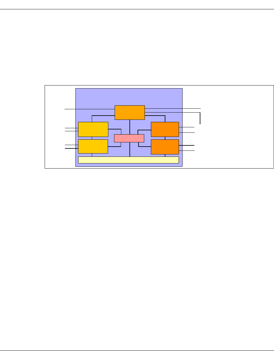
U41117-J-Z125-7-76 613
Glossary
VLP ISP which has neither a host nor a device port. Some central management
processes, in particular VLM und PLM, run on this ISP. A CentricStor
system can contain two VLP-ISPs. The central management processes
then only run on one of these, the VLP Master. The other, the Standby VLP
(SVLP), is inactive except for monitoring the VLP Master.
VTC In the small CentricStor models VTC and SBU this is the only ISP and
combines the attributes of the ICP, IDP and VLP. For the TVC the local
disks are configured to form a RAID10 instead of an external RAID system.
Figure 39: CentricStor configuration with 5 ISPs (2 ICPs, 2 IDPs and one VLP
IUP ➟ ICP_IDP
LD
A logical drive is a virtual, non-physical drive. In CentricStor up to 64 logical drives can
be operated per ICP.
Logical Drive ➟ LD
Logical Volume ➟ LV
Logical Volume Group ➟ LVG
LV
A logical volume (LV) is a file which is stored temporarily in a Tape File System of the
Tape Volume Cache (TVC) and stored permanently in a physical volume (PV). The
standard size in an LVG is 900 MB, but this can be selected in discrete steps: 2, 5, 10,
20, 50, 100 oder 200 GB.
No more than 500,000 LVs can be defined in a CentricStor system, the name of each
(VSN) being unique in the system.
LVG
Group of logical volumes for which the same rules apply.
CentricStor
Console port
IDP
ICP
ICP
VLP
IDP
Robot
Host
ports
ports
TVC
FC switch

614 U41117-J-Z125-7-76
Glossary
Message Manager ➟ MSGMGR
MSGMGR
Exists once in CentricStor. Filters and saves the ISPs’ system messages and imple-
ments predefined measures (e.g. service call, sends SMS, etc.). The MSGMGR is also
responsible for forwarding the system messages to the user interface.
PERFLOG
Exists once in each CentricStor. Obtains and stores the performance data. Global
Status supplies the performance data.
Performance Logger ➟ PERFLOG
PD
A Physical Drive is a phsysical tape cartridge drive which is connected to the IDP.
PDS
Software for controlling tape cartridge drives.
Physical Device Server ➟ PDS
Physical Drive ➟ PD
Physical Library Manager ➟ PLM
Physical Library Server ➟ PLS
Physical Volume ➟ PV
Physical Volume Group ➟ PVG
PLM
The PLM coordinates all requests for the peripherals connected (robot systems, tape
drives). The data management of the PLM contains information about where and on
which physical volume (PV) each logical volume (LV) is stored.
PLS
The PLS is the link between CentricStor and the robot archive. Requests to the robots,
e.g. to move a tape cartridge in the robot archive, are issued on behalf of the PLM.
PV
This refers to a real tape cartridge.
PVG
Group of physical volumes for which the same rules apply.
RAID system
A RAID (Redundant Array of Independent Disks) system consists of one or two RAID
controllers and multiple physical hard disks. These are organized as a logical disk drive
which permits a greater storage capacity, greater data security and/or greater
throughput than a single physical disk drive.
The TVC of a CentricStor system uses one to up to eight RAID systems.

U41117-J-Z125-7-76 615
Glossary
Redundant Array of Independent Disks ➟ RAID system
Reorganisation
Depending on the configuration paramters, the logical volumes (LVs) saved on the
physical volumes (PVs) are automatically copied onto other physical volumes (PVs) of
the same physical volume group (PVG). This is done for the following reasons:
– Effective use of the physical volumes (PVs) available
– Prevention of physical and chemical aging processes
– Faulty or inaacessible physical volumes (PVs)
This procedure is called Reorganisation. Reorganisation of an individual physical disk
(PVs) can also be initiated by the administration.
➟ section “Reorganization of the tape cartridges” on page 37
➟ section “Reorganization” on page 73
SAE
The SAE enables CentricStor to be operated from a remote PC (SAE computer) via the
graphical user interface (GUI).
SAN
The entire data flow between all CentricStor components (ISPs and external RAID
systems) is handled via an internal Starage Area Network (SAN) which can be configured
redundantly. It is implemented by one high-performance FC switch or, if redundancy is
provided, by two high-performance FC switches.
2 FC technologies are available: Multi Mode and Single Mode. In Multi Mode the devices
which are connected via Fibre Channel can be located up to 300 m from each other; in
Single Mode the distance can be as much as 10 km.
SBU
The SBU (Small Backup Unit) is a small CentricStor model and consists of a robot
system and a VTC with the software components MAREN and ROBAR.
Small Backup Unit ➟ SBU
Standby VLP ➟ SVLP
Storage Area Network ➟ SAN
SVLP
The SVLP (Standby VLP) is an ISP of the type VLP in which the central management
processes envisaged for a VLP are inactive until it takes over the tasks of the VLP
Master when the latter crashes (AutoVLP failover function).
➟ section “VLP (Virtual Library Processor)” on page 27

616 U41117-J-Z125-7-76
Glossary
System Administrator Edition ➟ SAE
Tape File System ➟ TFS
Tapemark
A tapemark identifies the end of a header or logical volume (LV ) on a physical tape.
Tape Volume Cache ➟ TVC
TFS
In CentricStor V3.1D a Tape File System (TFS) is a file system of the type dtvfs (DTVFS)
in which the logical volumes (LV s) are stored temporarily. The Tape File Systems as a
whole constitute the Tap e Volume Cache (TVC). In CentricStor the Tape File Systems are
tied to a permanent naming schema: /cache/1nn, where nn stands for 00, 01, 02 etc.
When the Cache Mirroring Feature (CMF) is used, each Tape File System is mirrored.
The mirrored Tape File Systems are then called /cache/2nn.
TVC
The TVC (Tape Volume Cache) is the core of the entire virtual archiving system. It
represents the Tape File Systems as a whole in which the logical volumes are stored
temporarily. One or more RAID systems (up to 8) are used for this purpose.
➟ section “RAID systems for the Tape Volume Cache” on page 30
Virtual Library Manager ➟ VLM
Virtual Library Processor ➟ VLP
Virtual Library Service ➟ VLS
Virtual Tape Appliance ➟ VTA
Virtual Tape Controller ➟ VTC
Virtuelles Archivsystem ➟ TVC
VLM
Each robot request of the requesting host system is registered in the VLM. The requisite
emulations (VLMF, VAMU, VACS, VDAS, VJUK) are used in CentricStor to support the
libraries.
The TVC is always accessed via the VLM.
VLP
The VLP is the central ISP in the larger CentricStor models from VTA 1500. The central
management processes run on this, in particular the VLM and the PLM.
A failure of the VLP causes the entire CentricStor system to crash. To prevent this, a
standby computer can optionally be integrated into the CentricStor as a Standby VLP
(SVLP), and this takes over the tasks of the VLP Master if this should crash.
The predefined host names for this ISP type are VLP0 and VLP1.
➟ section “VLP (Virtual Library Processor)” on page 27

U41117-J-Z125-7-76 617
Glossary
VLP Master
The VLP Master is an ISP of the type VLP in which the central management processes,
such as VLM and PLM, are active. VLP is sometimes used as a synonym for VLP
Master.
VLS
The tape archives emulated in CentricStor are referred to as Virtual Library Services
(VLS).
Depending on the type and number of host systems connected, the VLS occurs in
various instances:
Volume Header
Each logical volume (LV) which is written to a physical tape is preceded by a 32,768-
byte Volume Header.
Volume Serial Number ➟ VSN
VSN
Name of the logical volume (LV). Any combination of up to 6 characters. The following
are permitted:
– Alphabetic characters in upper case
– The special characters #, $, @, _, %, +, - (plus and minus characters may not
occupy the first position)
–Digits
The Volume Serial Number must be unnique in the entire CentricStor network.
VTA
Name of the larger CentricStor models
Host port Instance Library
BS2000/OSD, z/OS and OS/390 VAMU ADIC
Open Systems Server (UNIX, Windows) VDAS
CSC Clients of BS2000/OSD VACS StorageTek
Open Systems Server (UNIX, Windows) with ACSLS
LIB/SP Clients from Fujitsu VLMF Fujitsu
Open Systems Clients, UNIX and Windows VJUK SCSI

618 U41117-J-Z125-7-76
Glossary
VTC
VTC is both an ISP type and the name of the smallest CentricStor model, which
consists of precisely one ISP of this type.
Like an ICP_IDP it combines the attributes of an ICP, IDP and VLP. In contrast to the
ICP_IDP it is equipped with additional boards. These boards and an internal RAID
controller are used to configure an internal RAID system which is used for the TVC.
The predefined host name for this ISP type is VTC.
XTCC
The graphical user interface XTCC permits displays and operations within an ISP.

U41117-J-Z125-7-76 619
Figures
Figure 1: Conventional host robot system . . . . . . . . . . . . . . . . . . . . . . . . . . . . . . . . . . . 23
Figure 2: Host robot system with CentricStor . . . . . . . . . . . . . . . . . . . . . . . . . . . . . . . . 24
Figure 3: Example of a CentricStor configuration . . . . . . . . . . . . . . . . . . . . . . . . . . . . . 26
Figure 4: Internal VLP connections . . . . . . . . . . . . . . . . . . . . . . . . . . . . . . . . . . . . . . . . 27
Figure 5: External and internal ICP connections . . . . . . . . . . . . . . . . . . . . . . . . . . . . . . 28
Figure 6: Internal and external IDP connections . . . . . . . . . . . . . . . . . . . . . . . . . . . . . . 29
Figure 7: 2 RAID systems form the TVC . . . . . . . . . . . . . . . . . . . . . . . . . . . . . . . . . . . . 30
Figure 8: Central role of the VLP in a CentricStor configuration . . . . . . . . . . . . . . . . . . 33
Figure 9: Position of the logical volumes on the magnetic tape . . . . . . . . . . . . . . . . . . . 35
Figure 10: Repeated writing of a logical volume onto tape . . . . . . . . . . . . . . . . . . . . . . 36
Figure 11: Creating a directory on tape . . . . . . . . . . . . . . . . . . . . . . . . . . . . . . . . . . . . . 36
Figure 12: Example of a reorganization . . . . . . . . . . . . . . . . . . . . . . . . . . . . . . . . . . . . . 37
Figure 13: CentricStor after the VLM and PLM data maintenance have been created . 38
Figure 14: Procedure for a mount job . . . . . . . . . . . . . . . . . . . . . . . . . . . . . . . . . . . . . . 39
Figure 15: Principle of compressing logical volumes . . . . . . . . . . . . . . . . . . . . . . . . . . . 48
Figure 16: Example of multiple library support . . . . . . . . . . . . . . . . . . . . . . . . . . . . . . . 49
Figure 17: Example of Dual Save functionality . . . . . . . . . . . . . . . . . . . . . . . . . . . . . . . 51
Figure 18: Failure of the VLP . . . . . . . . . . . . . . . . . . . . . . . . . . . . . . . . . . . . . . . . . . . . . 53
Figure 19: Activation of the SVLP using the AutoVLP failover function . . . . . . . . . . . . . 53
Figure 20: Activation of the defective processor for the SVLP . . . . . . . . . . . . . . . . . . . . 54
Figure 21: Display of the AutoVLP failover status on the GUI . . . . . . . . . . . . . . . . . . . . 54
Figure 22: “Genuine” and “potential” RAID mirror pairs in a CentricStor system . . . . . . 56

620 U41117-J-Z125-7-76
Figures
Figure 23: Example of a CentricStor mirror system with 3 RAID mirror pairs . . . . . . . . 57
Figure 24: Primary and secondary caches in a RAID mirror pair . . . . . . . . . . . . . . . . . 57
Figure 25: Presentation of the mirror function in GXCC . . . . . . . . . . . . . . . . . . . . . . . . 58
Figure 26: POWER ON/OFF button on the ISP (example TX300) . . . . . . . . . . . . . . . . 61
Figure 27: Example of partitioning on the basis of volume groups . . . . . . . . . . . . . . . . 64
Figure 28: Example of the exclusive use of the cache file system by LV groups . . . . . . 70
Figure 29: GXCC/XTCC on the CentricStor ISPs (example VTA 2000-5000) . . . . . . . . 83
Figure 30: GXCC components with X11 server as remote computer . . . . . . . . . . . . . . 85
Figure 31: Components of GXCC with a remote computer (not an X11 server) . . . . . . 85
Figure 32: Monitoring structure in CentricStor (example VTA 2000-5000) . . . . . . . . . . 89
Figure 33: CentricStor basic configuration . . . . . . . . . . . . . . . . . . . . . . . . . . . . . . . . . . . 91
Figure 34: Configuration options at an SNMP management station . . . . . . . . . . . . . . . 94
Figure 35: X11 architecture for CentricStor operation . . . . . . . . . . . . . . . . . . . . . . . . . 103
Figure 36: Copying an LV to TR-PVG . . . . . . . . . . . . . . . . . . . . . . . . . . . . . . . . . . . . . 563
Figure 37: Removing PVs . . . . . . . . . . . . . . . . . . . . . . . . . . . . . . . . . . . . . . . . . . . . . . 563
Figure 38: Importing LVs . . . . . . . . . . . . . . . . . . . . . . . . . . . . . . . . . . . . . . . . . . . . . . . 564
Figure 39: CentricStor configuration with 5 ISPs (2 ICPs, 2 IDPs and one VLP . . . . . 613

U41117-J-Z125-7-76 621
Abbreviations
Abbreviation Long form Explanation
3490E 36-Track Drive from IBM
3490F 36-Track Drive from IBM = Berino, successor of 3490E
3590 128-Track Drive from IBM = Magstar, = SNI 3591
3590E 256-Track Drive from IBM = successor of Magstar
3592 512-Track Drive (=Jagu-
ar) from IBM
Successor to the 3590 drive family
9490 36-Track Drive from STK = Timberline
9840 Tape Drive from STK = Eagle
9940 Tape Drive from STK
ABBA/x --- Tape Robot Family from adic/GRAU
ACF Automatic Cartridge
Facility
ACI AML Client Interface Interface to ABBA Robots via DAS
ACS Automatic Cartridge Sys-
tem
ACSLS ACS Library Software
AML/x Automatic Media Library New name for ABBA-x
AMU AML Management Unit PC to control the AML Robot including LM
ASR&R Automatic Server
Reconfiguration and
Restart
BBU Battery Backup Unit
CDB Command Descriptor
Block
CMF Cache Mirroring Feature
CSI Client System Interface

622 U41117-J-Z125-7-76
Abbreviations
CSV Comma Separated
Values
CSW Console Switch
CTL Control, Target, LUN Relates to SCSI device
CU Control Unit
DAS Distributed AML Server Interface to control AML Robots
(Open Systems)
DASD Direct Access Storage
Device
In CS system usually the TVC
DLDSW0 Dual-Labeled, Dual-
Sided, Write Once
DNA Distribute and Activate GXCC function
DTVFS Distributed Tape Volume
File System
Filesystem on RAID Systems which contains
the LVs in form of files. The ISPs access dif-
ferent LVs at the same time.
EMU Virtual EMUlation of
3490E
ESCD ESCON Director
ESCON Enterprise System
Connection
FC Fibre Channel
FCAL Fibre Channel
Arbitrated Loop
FC connection via hub
FCH Fibre Channel Hub
FCS Fibre Channel Switch
FGM Release Notice Release Note
FICON Fibre Connection
FID FRU-Identifier
FRU Field Replaceable Unit
FSC Fault Symptom Code
FTP File Transfer Protocol
GUI Grafic User Interface
FUD Faulty, Used or Dirty
Tapes
Abbreviation Long form Explanation

U41117-J-Z125-7-76 623
Abbreviations
FW Firmware
GXCC Global Extended
Control Center
User interface for CentricStor including admi-
nistration, service and monitoring in
CentricStor V3.x
GXTCC Global Extended Tape
Control Center
User interface for CentricStor including admi-
nistration, service and monitoring in Cen-
tricStor V2.x
HACC Host Access from ABBA/x in and OS/390
HDD Hard Disk Drive
HSI Hardware Software
Interface
ICP Integrated Channel
Processor
ISP for satisfying host connection (/390 or
SAN)
IDP Integrated Device
Processor
ISP for connection of physical tape drives
ISP Integrated Standard Pro-
cessor
Common name for CS Server PCs (ICP, IDP,
VLP)
ITC Intelligent Tape
Controller
Smallest CentricStor Model
KVM Keyboard Video Mouse In the VTA models, a KVM cable connects an
ISP to the Console Switch.
LAN Local Area Network
LD Logical Drive Tape drive emulated in an ICP
LED Light-Emitting Diode
LM Library Manager
LMF Library Management Fa-
cility
Interface to Fujitsu robots
LRU Least Recently Used
LSM Logical Storage Module
LUN Logical Unit Number
LV Logical Volume Also called virtual volume.
LVG Logical volume group Container for LVs, rules are valid for whole
groups
LZ Distribution Center
Abbreviation Long form Explanation

624 U41117-J-Z125-7-76
Abbreviations
MCP Master Control Process
MD Mount Daemon
MIB Management
Information Base
MIM Media Information
Message
Message for a defective cartridge, only 3590-
x/3592
MBK Magnetbandkassette
(German)
Magnetic tape cartridge
MM Multi Mode
MSGMGR Message Manager One instance in CentricStor. Filters and
stores the system messages of the ISPs and
beforehand takes defined measures (e.g.
Service Call, sending SMSs, etc.). The MS-
GMGR is also responsible for forwarding the
system messages to the user interface.
OCI Operator Command
Interface
PCI Peripheral Component In-
terconnect
Bus standard for connecting peripherals with
the chip set of a processor
PD Physical Drive Physical drive hooked up to IDP
PDS Physikalischer Device
Server
Software to control a PD
PERFLOG Performance Logger One instance in each CentricStor. Obtains
and stores the performance data. Supplies
the performance data to Global Status.
PID Process ID
PL Physical Library e.g. AML/x, STK9310, STK L180
PLM Physical Library
Manager
Manages all physical library resources (PLs,
PDs PVs)
PLS Physical Library Server Software to control a PL
PS Power Supply
PV Physical Volume The real cartridge
PVG Physical Volume Group Container for PVs, rules are valid for whole
groups
Abbreviation Long form Explanation

U41117-J-Z125-7-76 625
Abbreviations
RAID Redundant Array of
Independent
(Inexpensive) Disks
RMT Remote Monitoring and
Administration
CentricStor expansion for which a license is
required
ROBAR Robot Archive ROBAR-SW allows BS2000 to talk to an
AML/x tape roboter
RPLM Recovery PLM
SAE System Administrator
Edition
SAE enables CentricStor to be operated from
a remote PC (SAE computer) via the graphi-
cal user interface.
SAN Storage Area Network
SAS Serial Attached SCSI
Service Access System
SBU Smart Backup Unit
SCP Slave Control Process
SCSI Small Computer System
Interface
SIM Service Information Mes-
sage
Only used by 3590-x/3592
SM Single Mode
SNMP Simple Network
Management Protocol
SP SCSI Parallel
Service Pack
SPCC Standard Peripheral
Channel Connector
Primergy PC which emulates various devices
(tapes, disks, printers, archives,
terminals …) for a /390-system.
SPS Standby Power Supply
SSI Storage Server Interface
ssh Secure Shell
SVLP Standby-VLP
TFS Tape File System Converts tape commands to a DASD
Abbreviation Long form Explanation

626 U41117-J-Z125-7-76
Abbreviations
TVC Tape Volume Cache File system on RAID system(s) which con-
tain(s) the LVs in the form of files. The ISPs
access different LVs at the same time.
UFS Unix File System
UPS Uninterruptable Power
Supply
VACS Virtual ACSLS Emulates an ACSLS to the host.
VAMU Virtual AML
Management Unit
Emulates an AMU to the host.
VD Virtual Drive
VDAS Virtual DAS Emulates an AMU to the host.
VDRV Virtual Disk Driver The driver controls data transfer from and to
the virtual disks of the RAID system with stri-
ping, loadsharing and failover.
VJUK Virtual Jukebox Emulated jukebox
VLM Virtual Library Manager Manages the logical components in the
library
VLP Virtual Library
Processor
PC on which the VT_LS services (VLM, VLS,
PLM, PLS) are running
VLS Virtual Library Server Emulates different library interfaces, e.g. VA-
MU, VDAS, VACS
VMD Virtual Mount Daemon In each ICP. Forwards the VLM’s mount com-
mands to the virtual devices.
VOLSER Volume Serial Number Name of a volume
VSN Volume Serial Number Name of a volume or a medium
VT_LS Virtual Tape und Library
System
Alias for CentricStor
VTA Virtual Tape Appliance Designation for the large CentricStor models
VTC Virtual Tape Controller Designation for the smallest CentricStor mo-
dels
VTD Virtual Tape Device Type of tape drive emulation for Open System
Hosts
XTCC Extented Tape Control
Center
Graphical interface for an ISP.
Abbreviation Long form Explanation

U41117-J-Z125-7-76 627
Related publications
The manuals are available as online manuals, see http://manuals.fujitsu-siemens.com, or
in printed form which must be paid and ordered separately at http://FSC-manualshop.com.
[1] SINIX-2000 V8.0/V8.1/V8.5
Installation, Operation and Administration
User Guide
Targe t group
The manual is intended for privileged users (operators, system administrators) of the
service/console processor 3970-2x, the channel adapters 3970 and 3971, the business
server SR2000-C, and the enterprise data server DS2000.
Contents
The manual contains all the information required to ensure that the systems service/
console processor 3970-2x, channel adapters 3970 and 3971, business server SR2000-C,
and enterprise data server DS2000 are ready for use. This includes helpful information on
configuring the systems and a description of important functions for system operation and
administration.
Order number
U24789-J-Z385-5-76
[2] MAREN (BS2000/OSD)
Volume 1: Basics of MTC Management
User Guide
Targe t group
This manual is addressed to all BS2000 users, computer center managers, operators and
systems support staff.
Contents
Volume 1 contains an introduction to working with MAREN. This covers the MAREN catalog
and its migration, the management of magnetic tape cartridges and locations, and the
support provided by MAREN for programs for data backup and archiving systems.
The user interfaces are described in Volume 2.

628 U41117-J-Z125-7-76
Related publications
[3] ROBAR 3.0B (BS2000/OSD, SINIX)
Tape Cartridge Archiving System
User Guide
Target group
Computer centers working with the ABBA robot system (CC staff, in particular system
administrators and archivers), ROBAR users
Contents
The manual describes the ROBAR software product that, in conjunction with the ABBA
system, controls automatic operation within a tape cartridge archiving system. It describes:
– the concept and mode of operation
– the user interfaces in BS2000 and SINIX
– installation and messages
[4] StorageTek User Guide BS2000 CSC version 6.1
User Guide (in preparation)
Targe t group
Computer centers working with the StorageTek robot
Contents
The manual describes the Client Software Component CSC for connecting a BS2000
system to a StorageTek robot.

U41117-J-Z125-7-76 629
Index
3490 emulation
function menu 385
global functions 390
object information 384
Show Error Log 389
Show Error/Transfer Statistics 386
Show Path Trace 388
Show Short Trace 387
3595-RMT 91
A
Absolute Min.
PVG 286
Account Daemon 437
ACCOUNTD
functions 437
object information 437
accounting 59
Accounting Data 295
accounting license 229, 293
accounting mails
setup 229
ACSLS 50
ACSLS server 571
Add 191
Logical Volumes 211
Physical Volume(s) 223
XTCC profile 346
additional license 3595-RMT 91
ADIC AML systems 50
ADIC library 571
ADIC scalar systems 50
administration
GXCC 193
AIX 32
analog operating data
record 258
application launching 45
Apply Current Aspect
XTCC 337
architecture
hardware 26
software 32
archive systems
diagram 132
object information 418
archive systems (SCSI)
function menu 419
asynchronous errors 125
authentication 99, 117
automatic VLP failover 52
AutoPopup
file viewer 362
Autoscan
GXCC 152
Settings GXCC 153
settings XTCC 339
start GXCC 152
start XTCC 338
stop GXCC 152
Stop XTCC 338
XTCC 338
AutoUpdate
file viewer 362
AutoVLP failover 127

630 U41117-J-Z125-7-76
Index
B
Balloon Help 242
Balloon Help Summary
Emulations 243
Physical Devices 244
Physical Library Processes 244
Virtual Library Processes 243
BASE
logical volume group 174
physical volume group 181
basic hardware 234
block diagram
GXCC 126
XTCC 352
block size 28
button bar 123
C
CA Unicenter 552
cache file system 70, 179
cache management 70
Cache Mirroring Feature 31, 55
cache residence 179
Call Home 44
Cancel Time
PVG 287
cartridge drives
Global Status 254
Show Mode Page Details 428
CD-ROM
status information 377
CentricStor
control components 88
global system state 121
monitoring structure 87
CentricStor icon 554
Change
Logical Volume Group 209
circuit diagram
GXCC 119
Clean File System 375
cleaning
drives 81
cleaning cartridges
add 225
outputting the data 282
cleaning PVG
show all 284
Click Button for Info 337
CMF 31
color key
group display 358
XTCC operating statuses 353
command line 104
communications
XTCC 341
compression 48
Configuration
(see also configuration)
menu 167
configuration
Physical Volume Group(s) 181
RAID Filesystems 171
sendmail 558
configuration changes
collective display 142
rescue 168
configuration file 197
connection setup
authentication 117
errors 116
consistency check mechanism 370
console messages 441
display 124
control components 88
copyright 232
Create
snapshot(s) 198
CX3-20
object information 412
CX500
object information 412

U41117-J-Z125-7-76 631
Index
D
DAS 50
DAS server 571
data PVG
show 285
show all 284
Delete
snapshots 200
diagnostic data 197
directory 36
Dirty Limit 178
disaster 476
recovery 283
Down/Up Sequence 399
drives
block sizes 28
cleaning 81
Dual Save 50, 71
Dual Save Dirty Limit 178
E
e-mail support 558
EMTAPE 48
emulations
Global Status 251
English Help
GXCC 150
XTCC 337
Erase
Logical Volumes 213
Physical Volume(s) 226
error messages
starting GXCC 104
virtual drives 391
ESCON boards 234
ESCON channel adapter
function menu 381
object information 379
Show Dump (prkdump) 383
Show Node Element Descriptors 382
Eternus 3000/4000
object information 412
evaluation model
Global Status 254
Exceed
setting 105
exporting
tape cartridges 45
exporting volumes 562
extend virtual drives 52
F
fabric
Fibre Channel 129
Failover 127
FC boards 234
FC switch 31, 234
FC2502 412, 439
FC-SCSI host adapter
function menu 399
information 398
fibre channel connection for load balancing and
redundancy 52
Fibre Channel elements
depiction 129
Fibre Channel switch
information 138
SNMP data 375
FICON host adapter
function menu 381
object information 379
File
GXCC 145
XTCC 331
File info 349
file viewer 360
AutoPopup 362
AutoUpdate 362
function bar 360
Highlight 363
Highlight Down / Up 364
Mode 365
Open (Text)/Open (Hex) 361
regular expressions 363
Re-read 361
Save As 361
Search down / up 364
Firebird 579

632 U41117-J-Z125-7-76
Index
flashing display
activation on the module 399
free pool 63
fscCentricStor 555
Fujitsu Library 571
Fujitsu robot 50
function bar
file viewer 360
Global Status 239
GXCC 143
XTCC 330
functions
ACCOUNTD 437
archive systems (SCSI) 419
ISP 135
G
German 150
German Help
Options XTCC 337
Get Remote / Expand Local File
GXCC 154
XTCC 342
get_log protocol 305, 310
Global History Viewer 257
Global Status 237
Balloon Help Summary 242
button bar 246
cartridge drives 254
Config 241
Display 247
emulations 251
File 239
function bar 239
Performance 249
Physical Components 254
physical volume group(s) 255
tape volume cache 252
Virtual Components 251
virtual drives 251
VLM 252
VLS 252
Global Status Monitor 257
Global System State 549
global system state 121
GLOBHIST 257
GLOBSTAT 257
graphic adapters 234
group display 356
abbreviations 356
color key 358
XTCC 356
GXCC
administration 193
Autoscan 152
button bar 123
console messages 124
extended information 133
File 145
footer 121
function bar, overview 143
Get Remote / Expand Local File 154
hardware requirements 92
Help 232
main window 119
operating modes 90
Option Settings 150
Options 150
overview 84
overview screen 83
passwords 98
principles of operation 84
Print 146
profile 191
Show Current Aspect 151
Show Remote File 156
start 95
start parameters 96
starting from X server 102
starting the console 102
status information 133
system information 123
title bar 121
Tools 154
GXCC elements
information 133
gzip 572

U41117-J-Z125-7-76 633
Index
H
hard disk
status information 376
Hard Min.
PVG 286
hardware architecture 26
hardware components 26, 234
Hardware Summary 234
Help
file viewer 366
GXCC 232
XTCC 348
Help Desk 545
Highlight
file viewer 363
Highlight Down / Up
file viewer 364
history
Print 299
history data 257
host connections
depiction 129
Host-Select menu 116
HP-UX 32
I
IBM-Cashion 50
icon 554
ICP 28
definition 126
information 134
ICP_IDP 29
definition 126
IDP 29
definition 126
information 135
importing
tape cartridges 45
importing volumes 562
inconsistencies 370
InfoBroker
loss of connection 120
information
GXCC elements 133
Integrated Universal Processor 29
Interaction Timeout 340
internal objects
CD-ROM 377
hard disk 376
ISP 376
SCSI controller 378
streamer 377
internal RAID
object information 412
ISP 27
Clean File System 375
definition 126
function menu 368
functions 135
information 367
internal objects 376
Show Configuration Data 373
Show Node Element Descriptors 372
Show SNMP Data 375
Show System Log (klog.msg) 375
ISP icon
elements 126
ISPs 234
IUP 29
K
key 196
keys
subsequent installation 196
Kill
update/revert 162
L
library commands 571
licenses 196, 572
Firebird 579
gzip 572
NTP 592
openssh 597
openssl 604
PRNGD 596
Sendmail 589
tcl 607

634 U41117-J-Z125-7-76
Index
tcpd 596
tk 608
XML 590
Xpdf 572
Link Down/Up Sequence 399
Link/Unlink
Volume Groups 221
LMF 50
LMF server (PLP) 571
Logical Drives
control component 88
see also Virtual Drives
Show 268
Logical Volume Group(s)
configuration 173
Show 273
Logical Volume(s)
Add 211
Erase 213
Show (PLM View) 271
Show (VLM View) 272
loss of connection
recovery 120
LRU procedure 39
LVG 63
M
Management Station 45
Manual
Online 235
manual
update 160
Meaning 219
message color 442
message lines 445
Message Manager
see MSGMGR
message texts 441
messages
console 441
metadata 31
migration concept 48
MIM 431
list 394
virtual devices 393, 397
mirror daemon 438
Mirror status 127
MIRRORD 438
Mode
file viewer 365
monitoring daemon 485
monitoring process
for RAID systems 439
monitoring tool 549
move 37
MSGMGR 433
control component 88
function menu 433
object information 433
Show Trace 434
Show Trap Trace 434
Multi Mode 31
Multi Port 148
N
NTP 82, 592
O
object information
3490 emulation 384
ACCOUNTD 437
archive systems 418
FC-SCSI host adapter 398
Fibre Channel switch 138
ICP 134
IDP 135
ISP 367
MSGMGR 433
PDS 420
PERFLOG 435
PLM 416
PLS 417
RAID systems 411
robot systems 140
SCSI controller 421
tape drive 423
virtual drives 391, 393
VLM 408

U41117-J-Z125-7-76 635
Index
VLP 126
VLS 405
VMD 407
VTD
VTD emulation 399
object-specific functions
XTCC 355
Observe mode 90
Open (Text)/Open (Hex)
file viewer 361
openssh 597
openssl 604
operating data 257
optional functions 196
Options 336
GXCC 150
XTCC 336
Options Settings
GXCC 150
XTCC 336
P
partitioning 44
partitioning on the basis of volume groups 63
password query
additional 101
passwords
GXCC 98
PDS 420
control component 88
function menu 420
information 420
PERFLOG
control component 88
function menu 436
information 435
Show Trace and Logging 436
Perform
Link Down/Up Sequence 399
Performance 249
Physical Components
Global Status 254
physical drive(s)
see also cartridge drives
Physical Drives
Show 277
Physical Volume Group(s)
configuration 181
control parameters 286
statistics in Global Status 255
Physical Volume(s)
Add 223
Add (cleaning cartridges) 225
Erase 226
output of the parameters 280
output parameters 217
outputting the cleaning cartridges 282
Reorganize 228
PLM 34
control component 88
function menu 416
information 416
Show Logical Volumes 271
PLP 571
PLS 34, 417
control component 88
function menu 417
object information 417
Pollset Browser 557
Print
GXCC 146
history 299
printer setup menu 299
XTCC 332
PRNGD 596
processors
depiction 126
Profile 191
profile
add/select XTCC 346
GXCC 191
XTCC 344
PVG 63
Absolute Min. 286
Cancel Time 287
Hard Min. 256, 286
Soft Min. 256, 286

636 U41117-J-Z125-7-76
Index
R
RAID controller
functions 137
GXCC information 136
RAID controller (internal)
status information 378
RAID controllers
internal 234
RAID Filesystems
configuration 171
RAID system
monitoring process 439
RAID systems 234
depiction 130
function menu 414
information 411
Show Mode Page Details 415
read tape 37
read_log protocol 305, 310
Readme
GXCC 232
XTCC 348
record
analog operating data 258
recovery 476
recycling 543
remote monitoring 45
Remote Program Starter 111
Remove Symbols
tape drive 433
Reorganize
Physical Volume 228
Re-read 361
Rescan all Busses
SCSI controller 422
Rescan own Bus
SCSI controller 422
rescue
configurations after crash 168
residence 179
RMT key 91
robot systems
depiction 132
object information 140
robots 234
S
S80
object information 412
S80 daemon 439
S80D 439
SAE 52
SAN 32
Save As
file viewer 361
SBU 32
SCALAR 100 81
SCALAR 1000 81
scratch LVs
erase 178
scratch mount 42
scratch tape 37
SCSI boards 234
SCSI controller
function menu 422
information 421
Rescan all Busses 422
Rescan own Bus 422
SCSI controller (internal) 378
SCSI managed components 86
Search down / up
file viewer 364
Select
XTCC profile 346
Sendmail 589
sendmail 558
Separator 159
separator 442
server architecture 102
Service Level
XTCC 337
Service/Modify mode 90
Set HALT Mode / Set RUN Mode
VLM 410
setup
accounting mails 229
shelf 30
shortcuts 143

U41117-J-Z125-7-76 637
Index
Show
Balloon Help Summary 242
Cache Status 408
Complete RAID Status 414
Configuration Data 373
CS Configuration 197
Current Aspect GXCC 151
Details (ISP) 135
Dump (prkdump) 383
Error Log 3490 emulation 389
Error/Transfer Statistics 3490 emulation 386
Jobs of Logical Volume Groups 275
Logical Drives 268
Logical Volume Group(s) 273
Logical Volumes 203, 271
Logical Volumes (physical view) 207
Logical Volumes (PLM View) 271
Logical Volumes (VLM View) 272
Medium Info (MIM) 431
Memory Log 390
Memory Log 3490 emulation 390
Mode Page Details 428
Mode Page Details (RAID) 415
Mode Pages 427
Mode Pages for RAID 415
Node Element Descriptors for ICP 372
Node Element Descriptors of ESCON channel
adapter 382
Path Trace 3490 emulation 388
Physical Drives 277
Remote File GXCC 156
Remote File XTCC 342
Reorganization Status 291
SCSI Sense for tape drive 426
Service Info (SIM) 432
Short Trace 3490 emulation 387
SNMP Data 375
survey / Delete snapshots 200
System Log (klog.msg) 375
System Messages 158
Trace and Logging 436
Trace MSGMGR 434
Trace VTD emulation 401
Trap Trace MSGMGR 434
Vital Product Data 429
show
all cleaning PVGs 284
all data PVGs 284
data PVG 285
Hardware Summary 234
Show Diff. Curr./Prev. Version 371
Show Trace
VLS 406
SiemensUX-Systems 557
Simulation mode 96, 146, 331
simulation mode 145
Single Mode 31
Single Port 148
SMBS2-WIN 553
SMS 44
SNMP 129, 547
activating 548
CA Unicenter 92
configuration under CentricStor 548
connection to management station 92
FC switch 138
information file 93
managed components 86
Management Station 547
messages 141
show data 375
traps 93, 551
SNMP Management Station 45
SNMP support 45
Soft Min.
PVG 286
software architecture 32
software components 26
Software versions
Update/Revert Tool 160
stacked volume 35
Standby VLP 27
start
Autoscan GXCC 152
Autoscan XTCC 338
GXCC 95
GXCC via Exceed 105
GXCC via SINIX 104

638 U41117-J-Z125-7-76
Index
GXCC via XVision 108
Observe mode 97
problems 115
User mode 97
XTCC 135
start parameters 96
starting
GXCC console 102
starting from X server
GXCC 102
status information
GXCC 133
Stop
Autoscan GXCC 152
Autoscan XTCC 338
StorageTek Library 571
StorageTek systems 50
streamer
status information 377
subsequent installation
individual keys 196
SVLP 27, 126
switch on CentricStor 61
synchronization 82
SysObjID 550, 555
system administrator’s edition 52
system data 257
system messages
collective display in GXCC 141
color key 158
show 158
system time 82
T
tape cartridges
exporting and importing 45
tape drive
function menu 425
global functions 432
information 423
Remove Symbols 433
Show Medium Info (MIM) 431
Show Mode Pages 427
Show SCSI Sense 426
Show Service Info (SIM) 432
Show Vital Product Data 429
Tap e Vol um e Cac h e 30
tape volume cache
Global Status 252
tcl 607
tcpd 596
teleservice call 141
temperature sensor 498
threshold values 201
tk 608
To g g le
Aspect XTCC 337
Size XTCC 337
To o ls
GXCC 154
XTCC 341
tools
Global Status 242
transfer PVG 46
transferring volumes 562
TR-LVG 64, 65, 563
TR-PVG 563
TVC 30
U
Unit
XTCC 335
Update/Revert Tool 159, 343
software versions 160
XUS Message 159
User mode 90
V
VACS 88
VAMU 88
vault attribute 46
vault status 46
VDAS 88
Version Consistency Check 370
version list
update/revert 161
vesion number 349
Virtual Components 251

U41117-J-Z125-7-76 639
Index
virtual drive
error conditions indicated on display 392
function menu 394
information 393
information and error messages 391
representation in Global Status Monitor 251
SCSI sense 395
Show Medium Info (MIM) 396
Show Service Info (SIM) 397
SIM/MIM error messages 393
virtual drives
display 392
object information/error messages 391
virtual SCSI drive
see VTD
VJUK 88
VLM 34
control component 88
Global Status 252
information 408
Set HALT Mode / Set RUN Mode 410
VLMF 88
VLP 27, 33
definition 126
VLP failover 127
automatic 52
VLP Master 27
VLS 34
control component 88
function menu 406
global functions 406
Global Status 252
information 405
Show Trace 406
VMD 251
control component 88
function menu 407
information 407
VOLSER 211
Volume
logical 34
physical 34
volume 44
volume group concept 44
Volume Group(s)
Change 209
Volume Groups 63
Link/Unlink 221
Volume Serial Number 211
VSN 211
VTA 1500-5000 32
VTA 500/1000 32
VTC 32
VTD 48
definition 399
function menu 404
information 402
VTD emulation
function menu 401
information 399
Show Trace 401
vtlsmirr 56
vtrc 197
W
waste disposal 543
workstation 91
write tape 37
WWNN 398
WWPN 398
X
X11 server 102
XDMCP 104
XML 590
Xpdf 572
XTCC 325
Apply Current Aspect 337
Autoscan 338
Autoscan settings 339
communications 341
File 331
function bar 330
Get Remote / Expand Local File 342
group display 356
Help 348
main window 328
object-specific functions 355

