Alpine Pxa H700 Users Manual
PXA-H700 to the manual d098e362-c400-4eaa-bc83-43b30e7f942c
2015-02-05
: Alpine Alpine-Pxa-H700-Users-Manual-355810 alpine-pxa-h700-users-manual-355810 alpine pdf
Open the PDF directly: View PDF ![]() .
.
Page Count: 46

EN
FR
ES
R
ALPINE ELECTRONICS, INC.
Tokyo office: 1-1-8 Nishi Gotanda,
Shinagawa-ku, Tokyo 141-8501, Japan
Tel.: (03) 3494-1101
ALPINE ELECTRONICS OF AMERICA, INC.
19145 Gramercy Place, Torrance,
California 90501, U.S.A.
Tel.: 1-800-ALPINE-1 (1-800-257-4631)
ALPINE ELECTRONICS OF CANADA, INC.
7300 Warden Ave., Suite 203, Markham,
Ontario L3R 9Z6, Canada
Tel.: 1-800-ALPINE-1 (1-800-257-4631)
ALPINE ELECTRONICS FRANCE S.A.R.L.
(RCS PONTOISE B 338 101 280)
98, Rue de la Belle Etoile, Z.I. Paris
Nord II, B.P. 50016, 95945, Roissy
Charles de Gaulle Cedex, France
Tel.: 01-48 63 89 89
ALPINE ELECTRONICS OF U.K., LTD.
13 Tanners Drive, Blakelands,
Milton Keynes MK14 5BU, U.K.
Tel.: 01908-61 15 56
ALPINE ELECTRONICS DE ESPAÑA, S.A.
Portal de Gamarra 36, Pabellón, 32
01013 Vitoria (Alava) - APDO 133,
Spain
Tel.: 945-283588
ALPINE ELECTRONICS OF AUSTRALIA PTY. LTD.
6-8 Fiveways Boulevarde Keysborough,
Victoria 3173, Australia
Tel.: (03) 9769-0000
ALPINE ELECTRONICS GmbH
Kreuzerkamp 7, 40878 Ratingen,
Germany
Tel.: 02102-45 50
ALPINE ITALIA S.p.A.
Viale C. Colombo 8,
20090 Trezzano Sul Naviglio (MI), Italy
Tel.: 02-48 47 81
PXA-H700
Designed by ALPINE Japan
Printed in Korea (S)
68P02294K30-A
• OWNER'S MANUAL
Please read before using this equipment.
• MODE D'EMPLOI
Veuillez lire avant d’utiliser cet appareil.
• MANUAL DE OPERACIÓN
Léalo antes de utilizar este equipo.
MULTIMEDIA MANAGER™
Kukje Printing Co., Ltd
127-2 Gamjeon-dong
Sasang-gu
Busan Korea
®

1-EN
FR
ES
DE
SE
IT
Contents
Operating Instructions
WARNING
WARNING ..................................................2
CAUTION ...................................................2
PRECAUTIONS .........................................3
Basic Operation
Turning the power on and off .......................................... 4
About indicators .............................................................. 4
Operating the Rotary encoder.......................................... 4
Setting the speakers ......................................................... 4
Using with Ai-NET connections ..................................... 5
Using with RCA-type or optical cable connections
(non Ai-NET connections) ........................................ 5
Automatic Adjustments
Performing time correction automatically
(Automated Time Correction) ................................... 6
Settings/Adjustments
Performing time correction manually (TCR)/Switching
the phase .................................................................... 8
Bass Focus ..................................................................... 10
Graphic equalizer adjustments ...................................... 12
Parametric equalizer adjustments ................................. 13
X-OVER ........................................................................ 15
X-OVER adjustment ..................................................... 16
MX settings ................................................................... 18
BASS COMP. setting .................................................... 19
ENGLISH
Using Dolby Surround
Using the Pro Logic II mode ......................................... 20
Adjustment procedure for Dolby Surround ................... 21
Speaker setup ................................................................. 22
Adjusting the speaker levels .......................................... 22
Mixing bass sound to the rear channel .......................... 23
Adjusting the acoustic image......................................... 24
Achieving powerful high volume sound ....................... 25
Adjusting the DVD level ............................................... 25
Convenient Functions
Navigation system voice guidance interruption ............ 26
Linear PCM setting ....................................................... 26
Display settings ............................................................. 27
MX mode setting (Ai-NET connection) ........................ 27
Storing settings in the memory ...................................... 28
Calling out stored values ............................................... 28
Defeat mode................................................................... 28
Switching the display mode .......................................... 29
Switching the color of the illumination ......................... 29
Installation and Connections
Warning ......................................................................... 30
Caution .......................................................................... 30
Precautions .................................................................... 31
Accessories .................................................................... 32
Installation ..................................................................... 33
Basic Connections Diagram .......................................... 36
Examples of system expansion...................................... 37
Information
Terminology .................................................................. 41
Others
In case of difficulty........................................................ 42
Specifications ................................................................ 43
LIMITED WARRANTY

2-EN
WARNING
WARNING
This symbol means important instructions.
Failure to heed them can result in serious injury
or death.
DO NOT OPERATE ANY FUNCTION THAT TAKES
YOUR ATTENTION AWAY FROM SAFELY DRIVING
YOUR VEHICLE.
Any function that requires your prolonged attention
should only be performed after coming to a complete stop.
Always stop the vehicle in a safe location before
performing these functions. Failure to do so may result in
an accident.
KEEP THE VOLUME AT A LEVEL WHERE YOU CAN
STILL HEAR OUTSIDE NOISE WHILE DRIVING.
Failure to do so may result in an accident.
MINIMIZE DISPLAY VIEWING WHILE DRIVING.
Viewing the display may distract the driver from looking
ahead of the vehicle and cause an accident.
DO NOT DISASSEMBLE OR ALTER.
Doing so may result in an accident, fire or electric shock.
USE THIS PRODUCT FOR MOBILE 12V
APPLICATIONS.
Use for other than its designed application may result in
fire, electric shock or other injury.
KEEP SMALL OBJECTS SUCH AS BATTERIES OUT
OF THE REACH OF CHILDREN.
Swallowing them may result in serious injury. If
swallowed, consult a physician immediately.
USE THE CORRECT AMPERE RATING WHEN
REPLACING FUSES.
Failure to do so may result in fire or electric shock.
USE ONLY IN CARS WITH A 12 VOLT NEGATIVE
GROUND.
(Check with your dealer if you are not sure.) Failure to do
so may result in fire, etc.
DO NOT BLOCK VENTS OR RADIATOR PANELS.
Doing so may cause heat to build up inside and may result
in fire.
CAUTION
This symbol means important instructions.
Failure to heed them can result in injury or
material property damage.
HALT USE IMMEDIATELY IF A PROBLEM APPEARS.
Failure to do so may cause personal injury or damage to
the product. Return it to your authorized Alpine dealer or
the nearest Alpine Service Center for repairing.

3-EN
FR
ES
DE
SE
IT
PRECAUTIONS
Temperature
Be sure the temperature inside the vehicle is between
+60°C (+140°F) and –10°C (+14°F) before turning your
unit on.
Installation Location
Make sure the PXA-H700 will not be installed in a
location subjected to:
• Direct sun and heat
• High humidity and water
• Excessive dust
• Excessive vibrations
Maintenance
If you have problems, do not attempt to repair the unit
yourself. Return it to your Alpine dealer or the nearest
Alpine Service Station for servicing.
4-EN
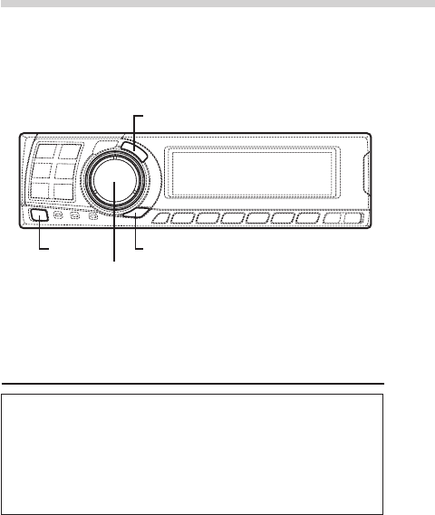
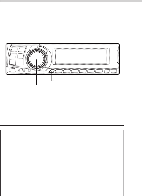
About indicators
• PRO LOGIC II indicator
Lights green in the Dolby Surround decode
mode
• Dolby Digital indicator
Lights green in the Dolby Digital decode mode
• DTS indicator
Lights green in the DTS decode mode
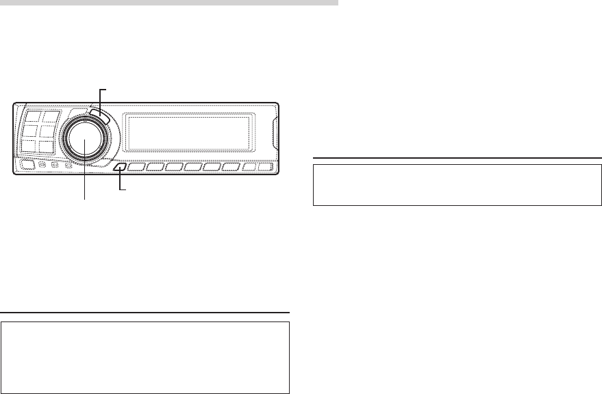
Operating the Rotary encoder
This unit uses the Rotary encoder when
establishing settings or adjustments. When
operating with the Rotary encoder, press the
Rotary encoder and startup the Rotary encoder
before the operation.
Setting the speakers
First make the speaker settings.
Turn off speaker channels that are not
connected.
1Press the SETUP button.
The setup mode is set.
2Turn the Rotary encoder to select the
“SPEAKER SELECT” mode, then press the
ENTER button.
3Press the CHANNEL button to select the
speaker, then press the ENTER button.
4Turn the Rotary encoder to set the speaker
type ON or OFF, then press the ENTER button.
Repeat steps 3 and 4 to set all unconnected
speaker channels to “OFF”.
F1 (Front 1): Tw (Tweeter)/Full (Full Range)/OFF
F2 (Front 2): Full (Full Range)/OFF
R (Rear) : ON/OFF
Ct (Center) : Center/Sub.W (Subwoofer)/OFF
NOTE
Set to “Subwoofer” when a subwoofer is connected to
the center speaker output.
Sub.W (Subwoofer) : ON/OFF
* When Full (Full Range) is selected in F1
(Front 1), the confirmation message of
Tweeter presence will be displayed next.
Turn the Rotary encoder and select YES/
NO, then press the ENTER button. Please
set to protect the speakers.
5Press the SETUP button repeatedly to quit the
setup mode.
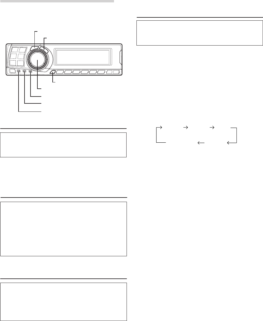
Basic Operation
CHANNEL
ENTER
SETUP
Rotary encoder
Turning the power on and off
This unit does not have a power switch. The head
unit to which the unit is connected, controls its
power.
NOTE
When the power is turned ON for the first time, the
SETUP mode is automatically activated.
PRO LOGIC II indicator
Dolby Digital indicator
DTS indicator
Ct
(Center)
Sub. W
(Subwoofer)
F1
(Front 1) F2
(Front 2) R
(Rear)
5-EN
EN
FR
ES
DE
SE
IT
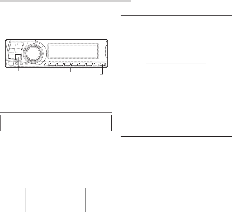
Adjusting the input level
Using the analog, RCA-type connections, the
PXA-H700’s input level must be preset from the
head unit.
Adjust the input level using a sound source with
a high recording level (such as pop or rock
music).
1Turn on the head unit’s power.
2Turn the Rotary encoder on the main unit
counterclockwise and set the volume level to “0”.
3Gradually increase the volume of the head unit
until “INPUT LEVEL OVER” appears in the
display.
Reduce the volume slightly from this position,
until “INPUT LEVEL OVER” display just turns off.
This completes the setting.
Do not change the head unit volume level from
this optimum setting. Use the PXA-H700, only,
for changing the volume level.
NOTE
Switch to the spectrum analyzer display mode or the
input channel display mode before adjusting the input
level. (See page 29)
Adjusting the volume, balance, fader and subwoofer
After determining the input level, adjust the
volume, balance, fader and subwoofer from the
PXA-H700. Be careful not to make these
adjustments on the head unit.
1Press the ENTER button and select the mode to
be adjusted.
2Turn the Rotary encoder within 5 seconds and
adjust to the desired level.
VOLUME : 0 ~ 35
BALANCE : L15 ~ R15
FADER : F15 ~ R15
Sub.W LEVEL : 0 ~ +15
NOTE
When the subwoofer is set to “OFF”, the Sub.W
LEVEL adjustment is ineffective.
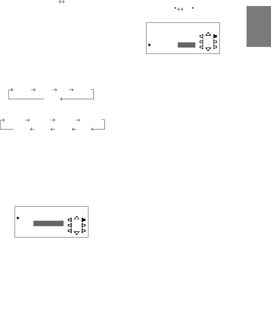
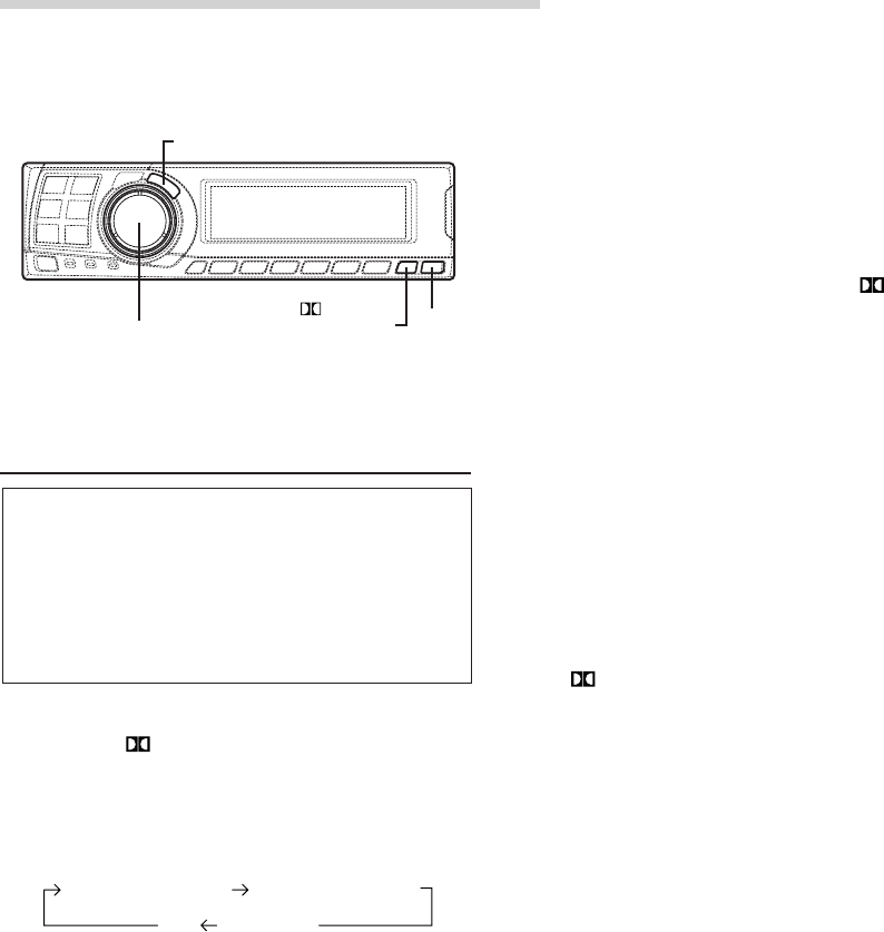
Using with RCA-type or optical cable
connections (non Ai-NET connections)
Switching the input
The PXA-H700 is equipped with three sets of
analog signal inputs and three sets of digital
signal inputs. For further information about
connections, see Page 36.
1Press the SETUP button.
The setup mode is set.
2Turn the Rotary encoder to select the “INPUT
SELECT” mode, then press the ENTER button.
3Turn the Rotary encoder to select the input
mode, then press the ENTER button.
4Press the SETUP button repeatedly to quit the
setup mode.
NOTE
Non Ai-NET connections
Alpine products are equipped for a bus connection
system called “Ai-NET” which can only be used for
connections between Ai-NET products.
The PXA-H700 is an Ai-NET product, but is designed to
allow connections to other (non Ai-NET) products as
well. Thus RCA-type and optical cable connections are
also possible.
Connections to non Ai-NET products are referred to as
“non Ai-NET connections”.
Analog 1 Analog 2 Analog 3
Digital 3 Digital 2 Digital 1
VOLUME FADERBALANCE
Sub.W LEVEL
Using with Ai-NET connections
When Ai-NET connections are used, the volume,
subwoofer, balance and fader are adjusted from
the head unit (they cannot be adjusted from the
PXA-H700). However, BASS and TREB can not
be adjusted from the head unit, so adjust them
from PXA-H700.
6-EN
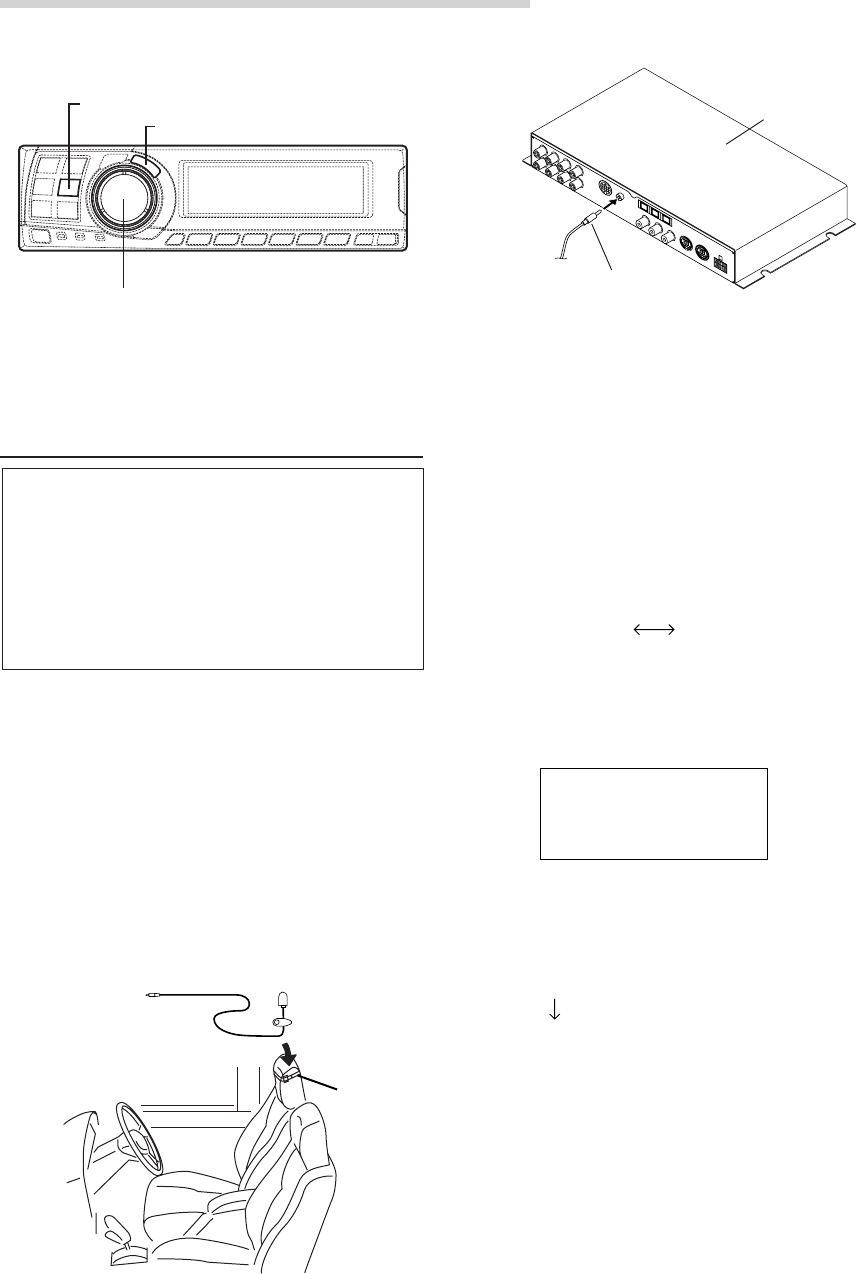
2) Connect the microphone to the PXA-H700.
4Set the vehicle’s engine key to the ACC position.
• Vibrations could make it difficult to achieve
the appropriate adjustment values, so turn
the engine off.
• Noise could make it impossible for automatic
measurements to be made, so make sure
the air conditioner, heater and all other
devices are turned off.
5Press the AUTO TCR button.
6Turn the Rotary encoder, select the tweeter
setting, then press the ENTER button.
YES NO
The count down starts.
7Once the count down starts, get out of the
vehicle and shut the doors within 10 seconds.
With the automatic adjustment function, the
operation described below is performed.
Adjustments are completed in about 10 seconds.
Time correction.
“END” is displayed for about 15 seconds and the
automatic adjustment is completed.
To microphone
input jack Microphone
Belt, etc.
To microphone
input jack
Microphone
AUT TCR
O
10 sec .
to start
Performing time correction automatically
(Automated Time Correction)
Due to the particular conditions inside the
vehicle, there is a major difference between the
distances of the various speakers and the
listening position. This function uses the
included measurement microphone to
automatically measure and analyze the distances
between the speakers and the listening position
and perform the optimum time correction.
1Check that the defeat mode is off.
(See page 28.)
2Prepare the vehicle.
1) Park the vehicle in a quiet place.
2) Close the vehicle’s doors and windows.
3Connect the microphone.
1) Fasten the included microphone at the
center of the driver’s seat’s headrest facing
upwards.
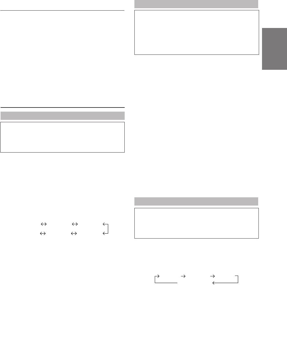
Automatic Adjustments
AUTO TCR
ENTER
Rotary encoder
Base unit

7-EN
EN
FR
ES
DE
SE
IT
• If the microphone does not pick up the
sound or the speakers are not working or are
connected or wired improperly, the automatic
adjustments are not performed and a error
message is displayed.
Check the various speakers then perform
the automatic adjustments again.
8Check that the automatic adjustment has been
completed (that “END” has been displayed for
about 15 seconds), then get back into the
vehicle and disconnect the microphone.
9To store, follow the procedure described at
“Storing settings in the memory” (page 28).
NOTES
• Automatic measurements cannot be made unless the
microphone is connected (error display). To perform
time correction automatically, be sure to connect the
included microphone first.
• Before making automatic measurements, press the
AUTO TCR button to cancel it.
• No other operations can be performed while
measurements are being made.
• Measurements will differ according to the position in
which the microphone is mounted.
• Note that using for extended periods of time without
turning on the engine may wear down the battery.
• Automatic measurements cannot be made for the
subwoofer. Make the subwoofer setting manually.
Refer to “Performing time correction manually
(TCR)/Switching the phase” (page 8).
• When the speaker is set to the “OFF” mode, the TCR
for that speaker cannot be adjusted. Refer to “Setting
the speakers” (page 4).
• After making the settings, we recommend storing
them in the memory. For instructions, see page 28.
AUT TCR
O
ERROR
8-EN
Performing time correction manually
(TCR)/Switching the phase
Because of the particular conditions inside the
vehicle, there are major differences in the
distances between the different speakers and the
listening position. The proper time correction can
be obtained using the automatic time correction
function (“AUTO TCR”), but it is also possible to
calculate the optimum correction values and
eliminate the time error at the listening position
yourself using this function. You can also use this
function to switch the phase.
1Check that the defeat mode is off.
(See page 28.)
2Sit in the listening position (the driver’s seat, for
example) and measure the distance (in meters)
between your head and the various speakers.
3Calculate the difference in distance between the
farthest speaker and the other speakers.
L = (distance of farthest speaker)
– (distance of other speakers)
4Divide the distances calculated for the different
speakers by the speed of sound (343 m/s
temperature 20°C).
This value is the time correction value for the
different speakers.
2.25m
0.5m
5.1ms
• Concrete examples
1.Calculating the time correction value for the
front left speaker on the diagram below.
Conditions:
Distance between farthest speaker and
listening position: 2.25 m (88-3/4")
Distance between front left speaker and
listening position: 0.5 m (20")
Calculation: L = 2.25 m (88-3/4") – 0.5 m (20")
= 1.75 m (68-3/4")
Compensation time = 1.75 ÷ 343 x 1000
= 5.1 (ms)
In other words, setting the time correction value
for the front left speaker to 5.1 (ms) sets a
virtual distance matching the distance to the
farthest speaker.
The sound is uneven
because the distance
between the listening
position and the different
speakers is different.
The difference in the
distance between the
front left and rear right
speakers is 1.75 meters
(68-3/4").
Time correction eliminates
the difference between
the time required for the
sound from the different
speakers to reach the
listening position.
Setting the time correction
of the front left speaker to
5.1 ms makes it possible
to coordinate the distance
from the listening position
to the speaker.
5Press the TCR/PHASE button to set the time
correction mode.
Settings/Adjustments
CHANNEL
ENTER
TCR/PHASE
Rotary encoder
9-EN
EN
FR
ES
DE
SE
IT
9Turn the Rotary encoder to switch the phase,
then press the CHANNEL button.
Press the ENTER button to return to step 8.
0 180
10
Repeat steps 7 to 9 to adjust other channels.
11
Once the adjustments are completed, press the
TCR/PHASE button.
NOTES
• When the speaker is set to the “OFF” mode, the TCR
for that speaker is ineffective. Refer to “Setting the
speakers” (page 4).
• After making the settings, we recommend storing
them in the memory. For instructions, see page 28.
(factory default)
6Press and hold the CHANNEL button for at least
2 seconds and select “L and R (LR)” or “L or R”.
L and R (LR): Sets the same adjustment values
for the left and right channels.
L or R: Different adjustment values can
be set for the left and right
channels.
7Press the CHANNEL button and select the
desired channel, then press the ENTER button.
When “L and R (LR)” is selected:
When “L or R” is selected:
*1 When center is set to subwoofer, it is not
displayed.
*2 When center is set to subwoofer, it becomes
Sub.W(L).
*3 When center is set to subwoofer, it becomes
Sub.W(R).
8Turn the Rotary encoder to adjust the time
correction value (0.00 ~ 20.00ms), then press
the ENTER button.
*The difference in the sound when the defeat
mode is turned off (adjusted time
correction) and on (default value) can be
checked as follows:
1) While in the adjustment mode, press and
hold the TCR/PHASE button for at least 2
seconds.
2) Press the TCR/PHASE button to switch the
defeat mode on and off and listen to the
difference in the sound.
3) To quit, select the desired setting, then press
the ENTER button.
Note that if you press the ENTER button with
the defeat mode turned on, the adjustments
are reset to the defeat on status (the default
values).
L and R (LR) L or R
Center
Sub. W
Front 1 Front 2 Rear
*1
Front 2 R
Center
Sub. W
Front 1 L Front 1 R Front 2 L
Rear R Rear L
*2*3
TCR HPASEFL1RR/
DE YCLA
10. ms2R
C
5
PHA : 18 0 °SE
:
TCR HPASEFL1RR/
DE YCLA
10. ms2R
C
5
PHA : 180°SE
:
10-EN
Settings/Adjustments
Bass Focus
The time difference between the front-rear/left-
right speakers, can be adjusted a pair at a time.
Audible time correction can be made from 0.05
ms to 20.00 ms in 401 steps (0 to 400).
1Check that the defeat mode is off.
(See page 28.)
2Press the TCR/PHASE button to select the time
correction mode.
3Press the B.C. button to select the “BASS
FOCUS” setting mode.
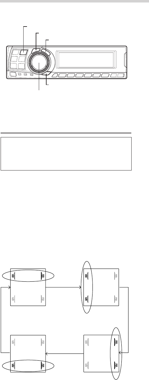
4Press the CHANNEL button to select the front-
rear/left-right speaker.
5Turn the Rotary encoder to set the step of front-
rear/left-right.
6Moreover, for setting another channel (speaker),
repeat steps 4 and 5.
7After completing the setting, press the ENTER
button to return to the time correction mode.
Here, you can compare the sound of Defeat OFF
(adjustment value) and Defeat ON (initial).
For the operation method, refer to step 8 of
“Performing time correction manually (TCR)/
Switching the phase” on page 9.
8Press the TCR/PHASE button to complete the
setting.
NOTE
The setting made in Bass Focus is reflected in the time
correction.
FL FR
RL RR
FL FR
RL RR
FL FR
RL RR
FL FR
RL RR
Front (left-right)
speakers Left (front-rear)
speakers
Rear (left-right)
speakers Right (front-rear)
speakers
CHANNEL
ENTER
TCR/PHASE
B.C.
Rotary encoder
11-EN
EN
FR
ES
DE
SE
IT
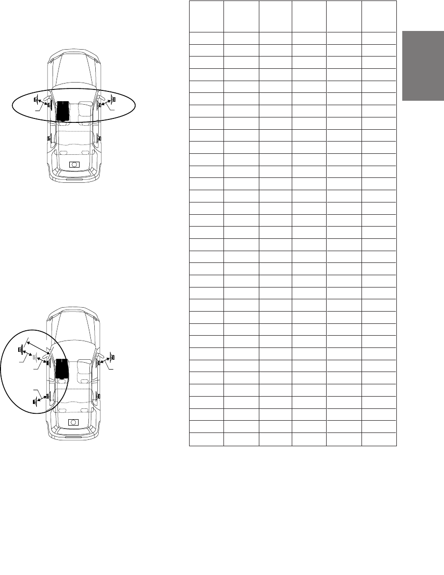
Example of Steps 4 and 5 Setting
1.After entering corrections for the front (left and
right) speakers in STEP 30, the time difference
is 1.5 ms for both front-left and front-right
speakers.
2. After entering corrections for the left (front and
rear) speakers in STEP 30, the time difference
becomes 3.0 ms* for the front left speaker, and
1.5 ms for the left rear speaker.
* Because the time difference was already set
to 1.5 ms for the front left speakers in STEP 1,
the additional correction in STEP 30 makes
the time difference of the front left speaker 3.0
ms.
1.5ms
1.5ms
1.5ms
1.5ms
3.0ms
1.5ms
1.5ms
Time difference Table
Number
of
steps
0
1
2
3
4
5
6
7
8
9
10
11
12
13
14
15
16
17
18
19
20
21
22
23
24
25
26
27
28
29
30
31
32
33
Time
Difference
(ms)
0.00
0.05
0.10
0.15
0.20
0.25
0.30
0.35
0.40
0.45
0.50
0.55
0.60
0.65
0.70
0.75
0.80
0.85
0.90
0.95
1.00
1.05
1.10
1.15
1.20
1.25
1.30
1.35
1.40
1.45
1.50
1.55
1.60
1.65
Number
of
steps
34
35
36
37
38
39
40
41
42
43
44
45
46
47
48
49
50
51
52
53
54
55
56
57
58
59
60
61
62
63
64
65
66
67
Time
Difference
(ms)
1.70
1.75
1.80
1.85
1.90
1.95
2.00
2.05
2.10
2.15
2.20
2.25
2.30
2.35
2.40
2.45
2.50
2.55
2.60
2.65
2.70
2.75
2.80
2.85
2.90
2.95
3.00
3.05
3.10
3.15
3.20
3.25
3.30
3.35
Number
of
steps
68
69
70
71
72
73
74
75
76
77
78
79
80
81
82
83
84
85
86
87
88
89
90
91
92
93
94
95
96
97
98
99
100–399
400
Time
Difference
(ms)
3.40
3.45
3.50
3.55
3.60
3.65
3.70
3.75
3.80
3.85
3.90
3.95
4.00
4.05
4.10
4.15
4.20
4.25
4.30
4.35
4.40
4.45
4.50
4.55
4.60
4.65
4.70
4.75
4.80
4.85
4.90
4.95
5.00–19.95
20.00
12-EN
Settings/Adjustments
(factory default)
*3 When center is set to subwoofer, it becomes
Sub.W(R).
5Turn the Rotary encoder to select the
frequency, then press the ENTER button.
Adjustable frequencies
Front/Rear/Center: 20Hz~20kHz (1/3 octave
step)
Sub.W: 20Hz~160Hz (1/3 octave step)
6Turn the Rotary encoder to adjust the level (± 9
dB in steps of 1 dB), then press the ENTER
button.
7Repeat steps 5 and 6 to adjust other
frequencies.
8To adjust other channels, press the CHANNEL
button to return to step 4.
*The difference in the sound when the defeat
mode is turned off (adjusted graphic
equalizer settings) and on (default values)
can be checked as follows:
1) While in the adjustment mode, press and
hold the G.EQ button for at least 2 seconds.
2) Press the G.EQ button to switch the defeat
mode on and off and listen to the difference
in the sound.
3) To quit, select the desired setting, then press
the ENTER button.
Note that if you press the ENTER button with
the defeat mode turned on, the adjustments
are reset to the defeat on status (the default
values).
9Once the adjustments are completed, press the
G.EQ button.
NOTES
• When the speaker is set to the “OFF” mode, the
graphic equalizer for that speaker is ineffective.
Refer to “Setting the speakers” (page 4).
• Check the playable frequency ranges of the connected
speakers before making the equalizer adjustments. If
the speaker’s playable frequency range is 55 Hz to 30
kHz, for example, adjusting the 40 Hz or 20 Hz band
has no effect. Additionally, you may overload and
damage the speakers.
• After making the settings, we recommend storing
them in the memory. For instructions, see page 28.
• When graphic EQ is adjusted, the adjustment for
parametric EQ becomes ineffective.
CHANNEL
ENTER
G.EQ
P.EQ
Rotary encoder
Graphic equalizer adjustments
The graphic equalizer allows you to modify the
sound using 31 bands each for the front (left and
right), rear (left and right) and center speakers.
An additional 10 bands are available for the
subwoofer. This allows you to customize the
sound to suit your taste.
1Check that the defeat mode is off.
(See page 28.)
2Press the G.EQ button to set the graphic
equalizer mode.
3Press and hold the CHANNEL button for at least
2 seconds and select “L and R (LR)” or “L or R”.
L and R (LR): Sets the same adjustment values
for the left and right channels.
L or R: Different adjustment values can
be set for the left and right
channels.
4Press the CHANNEL button to select the desired
channel, then press the ENTER button.
When “L and R (LR)” is selected:
When “L or R” is selected:
*1 When center is set to subwoofer, it is not
displayed.
*2 When center is set to subwoofer, it becomes
Sub.W(L).
Front Rear Center Sub. W
*1
Rear R
Center
Sub. W
Front L Front R Rear L
*2*3
31– .E
Q
Front LG
–9dB
12.5kHz
L and R (LR) L or R
13-EN
EN
FR
ES
DE
SE
IT
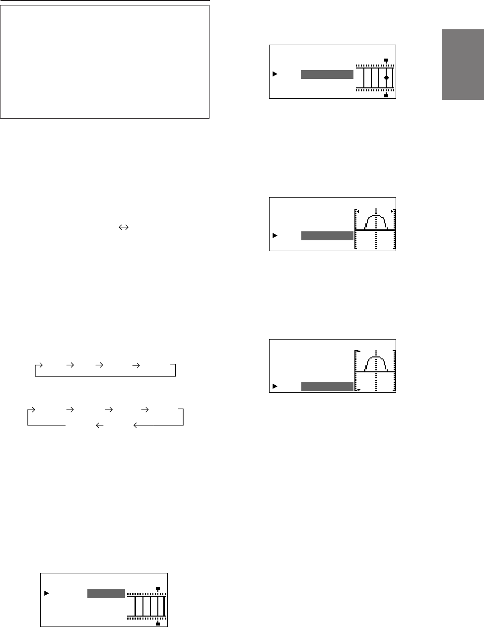
6Turn the Rotary encoder to select the
frequency, then press the ENTER button.
For the adjustable frequencies, see page 43.
7Turn the Rotary encoder to adjust the band
width (Q), then press the ENTER button.
The band width can be adjusted in 6 steps of
0.5/1/2/3/4/5.
8Turn the Rotary encoder to adjust the level (±9
dB in steps of 1 dB), then press the ENTER
button.
(factory default)
L and R (LR) L or R
Front Rear Center Sub. W
*1
Rear R
Center
Sub. W
Front L Front R Rear L
*2*3
P.E FPront L
Q
BA : 4ND
3.1Fc: Hz5k
Q
Lv :+7dB
:2
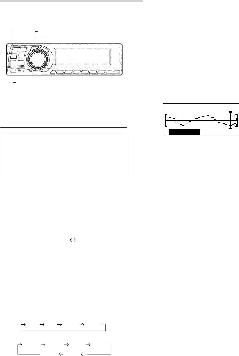
Parametric equalizer adjustments
The frequency bands of the graphic equalizer are
fixed. This makes it very difficult to correct for
undesired peaks and dips at specific frequencies.
The parametric equalizer’s center frequency can
be tuned these specific frequencies. Then, the
bandwidth (Q) and level are fine-tuned,
independently, to make the necessary
corrections. The parametric equalizer function is
an advanced tool for serious audiophiles.
1Check that the defeat mode is off.
(See page 28.)
2Press the P.EQ button to set the parametric
equalizer mode.
3Press and hold the CHANNEL button for at least
2 seconds and select “L and R (LR)” or “L or R”.
L and R (LR): Sets the same adjustment values
for the left and right channels.
L or R:
Different adjustment values can be
set for the left and right channels.
4Press the CHANNEL button to select the desired
channel, then press the ENTER button.
When “L and R (LR)” is selected:
When “L or R” is selected:
*1 When center is set to subwoofer, it is not
displayed.
*2 When center is set to subwoofer, it becomes
Sub.W(L).
*3 When center is set to subwoofer, it becomes
Sub.W(R).
5Turn the Rotary encoder to select the band,
then press the ENTER button.
Adjustable bands
Front/Rear/Center : 5 bands
Sub.W : 2 bands
P.E FPront L
Q
BA : 4ND
3.1Fc: Hz5k
Q
:
Lv :+7dB
2
P.E FPront L
Q
BA : 4ND
3.1Fc: Hz5k
Q
Lv :+7dB
:2
P.E Front L
Q
BA : 4ND
3.1Fc: Hz5k
Q
Lv :+7dB
:2
14-EN
NOTES
• When the speaker is set to the “OFF” mode, the
parametric equalizer for that speaker is ineffective.
Refer to “Setting the speakers” (page 4).
• It is not possible to adjust the frequencies of adjacent
bands within 7 steps.
• Check the playable frequency ranges of the connected
speakers before making the equalizer adjustments. If
the speaker's playable frequency range is 55 Hz to 30
kHz, for example, adjusting the 40 Hz or 20 Hz band
has no effect. Additionally, you may overload and
damage the speakers.
• After making the settings, we recommend storing
them in the memory. For instructions, see page 28.
• When parametric EQ is adjusted, the adjustment for
graphic EQ becomes ineffective.
Settings/Adjustments
9Repeat steps 5 to 8 to adjust other bands.
10
To adjust other channels, press the CHANNEL
button to return to step 4.
*To compare the factory default settings
(DEFEAT ON) with your newly adjusted
parametric equalizer settings (DEFEAT
OFF), do the following:
1) While in the adjustment mode, press and
hold the P.EQ button for at least 2 seconds.
2) Press the P.EQ button to switch the defeat
mode on and off and listen to the difference
in the sound.
3) To quit, select the desired setting, then press
the ENTER button.
Note that if you press the ENTER button with
the defeat mode turned on, the adjustments
are reset to the defeat on status (the default
values).
11
Once the adjustments are completed, press the
P.EQ button.
CHANNEL
ENTER
P.EQ
15-EN
EN
FR
ES
DE
SE
IT
X-OVER
The PXA-H700 is equipped with an active
crossover allowing the frequency bands to be
split before amplification. Because of this, there
is no need for a passive network between the
speakers and amplifiers. This makes the
amplifiers fully independent, eliminating the
problem of interference. This also makes it
possible to achieve the optimum acoustic space
by dividing the playback frequencies in a way
suited to the speaker’s response.
This adjustment requires sufficient knowledge
and experience. If you have problems, we
suggest you have the adjustment made by your
store authorized of Alpine dealer.
Adjust the high pass filter (H.P.F.) and low pass
filter (L.P.F.) and set the slope (filter response
attenuation slope) for the different bands.
Make the adjustments according to the playable
frequency ranges and frequency responses of
the connected speakers.
Cutoff frequency
adjustment range
(1/6 octave steps) Slope adjustment
H.P.F. L.P.F. H.P.F. L.P.F.
Front 1
(Front speaker 1)
Select TWEETER
6/12/18/
24/30dB
6/12/18/
24/30dB/
Filter OFF
1kHz –
18kHz 1.1kHz –
20kHz
Front 1
(Front speaker 1)
Select FULL RANGE
6/12/18/
24/30dB/
Filter OFF
6/12/18/
24/30dB/
Filter OFF
20Hz –
18kHz 22Hz –
20kHz
Front 2
(Front speaker 2)
6/12/18/
24/30dB/
Filter OFF
6/12/18/
24/30dB/
Filter OFF
20Hz –
18kHz 22Hz –
20kHz
Rear
(Rear speaker)
6/12/18/
24/30dB/
Filter OFF
6/12/18/
24/30dB/
Filter OFF
20Hz –
18kHz 22Hz –
20kHz
Center*
(Center speaker)
6/12/18/
24/30dB/
Filter OFF
6/12/18/
24/30dB/
Filter OFF
20Hz –
18kHz 22Hz –
20kHz
Sub. W
(Subwoofer)
6/12/18/
24/30dB/
Filter OFF
6/12/18/
24/30dB
20Hz –
180Hz 22Hz –
200Hz
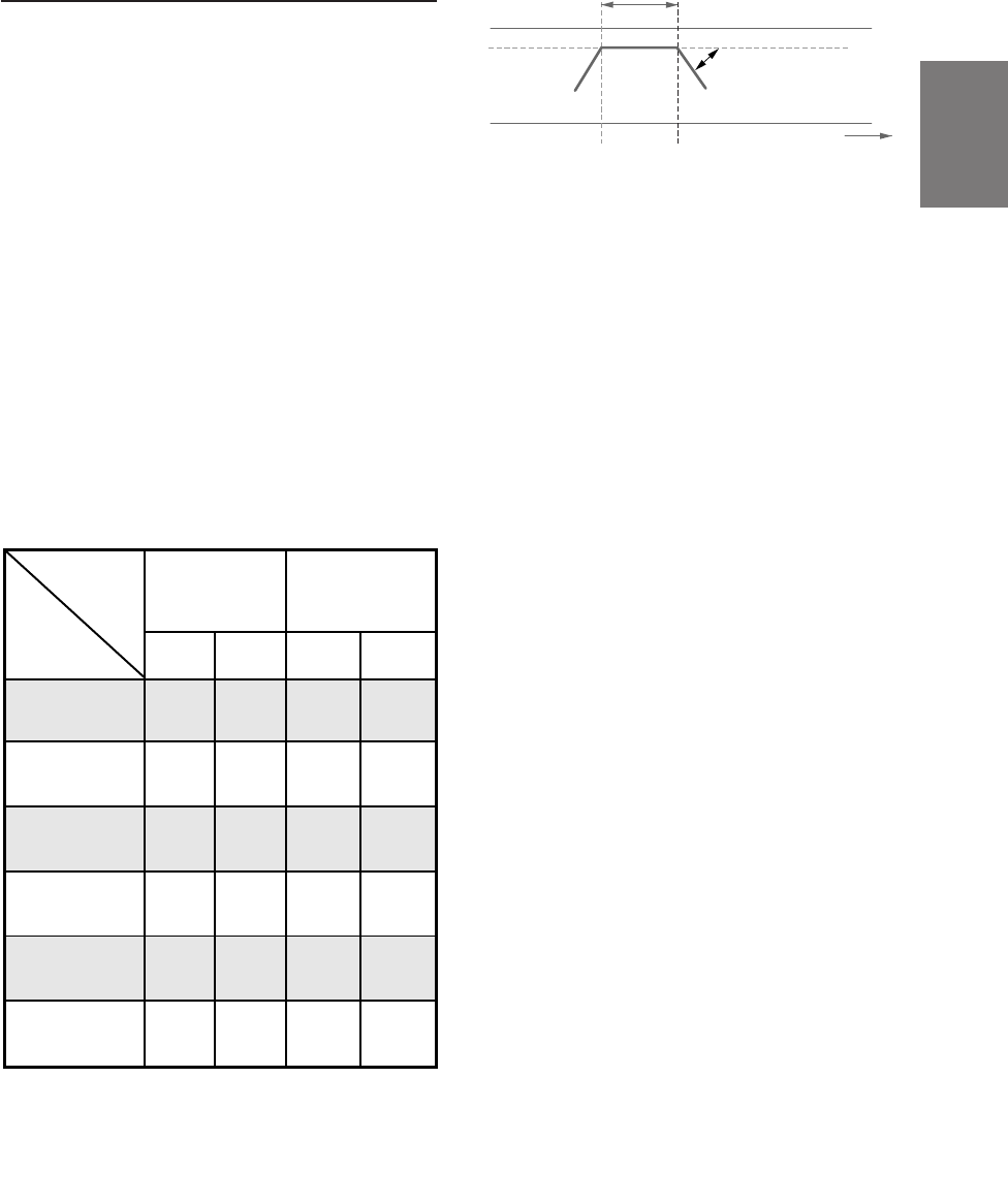
20Hz 10kHz
The H.P.F. setting cannot be the same as or
exceed the L.P.F. setting for that channel.
• The crossover network is a filter that divides
specific frequency bands.
• The high pass filter is a filter that cuts
frequencies below a certain frequency (bass
frequencies) and lets through treble
frequencies.
• The low pass filter is a filter that cuts
frequencies above a certain frequency
(treble frequencies) and lets through bass
frequencies.
• The slope is a value expressing the
attenuation of the signal in decibels when the
frequency is increased or decreased by one
octave.
• The higher the slope value, the steeper the
slope.
• If the slope is set to “OFF”, the signal does
not pass through the filter, so there is no
effect.
• In order to protect the speakers, if Tweeter is
selected in Front 1, there is no filter OFF
(slope OFF) setting for H.P.F.
For the same reason, the subwoofer low
pass filter cannot be turned off (the slope
cannot be set to “OFF”.)
• Tweeters may be damaged if low frequency
signals are input to them.
Signals with these frequencies output
Slope adjustment
Slope OFF
H.P.F. cutoff frequency L.P.F. cutoff frequency
*If center is set as subwoofer, the adjustment
range changes to the range of subwoofer.
16-EN
X-OVER adjustment
This section describes the procedure for making
the X-OVER adjustment. Before performing this
procedure, see “X-OVER” on page 15.
1Check that the defeat mode is off.
(See page 28.)
2Press the X-OVER button to set the X-OVER
adjustment mode.
3Press and hold the CHANNEL button for at least
2 seconds and select “L and R (LR)” or “L or R”.
L and R (LR): Sets the same adjustment values
for the left and right channels.
L or R: Different adjustment values can be
set for the left and right channels.
4Press the CHANNEL button to select the desired
channel, then press the ENTER button.
When “L and R (LR)” is selected:
When “L or R” is selected:
*1 When center is set to subwoofer, it is not
displayed.
*2 When center is set to subwoofer, it becomes
Sub.W(L).
*3 When center is set to subwoofer, it becomes
Sub.W(R).
Settings/Adjustments
(factory default)
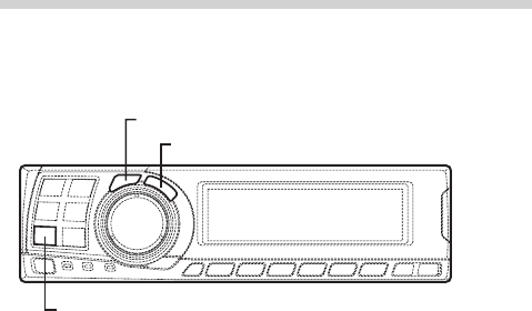
5Turn the Rotary encoder to adjust the H.P.F.
cutoff frequency, then press the ENTER button.
The adjustable bands differ according to the
channel (speaker).
6Turn the Rotary encoder to adjust the H.P.F.
slope, then press the ENTER button.
To set filter off (slope off), press and hold the X-
OVER button for at least 2 seconds.
7Next, make the adjust for the L.P.F. in the same
way as in steps 5 and 6.
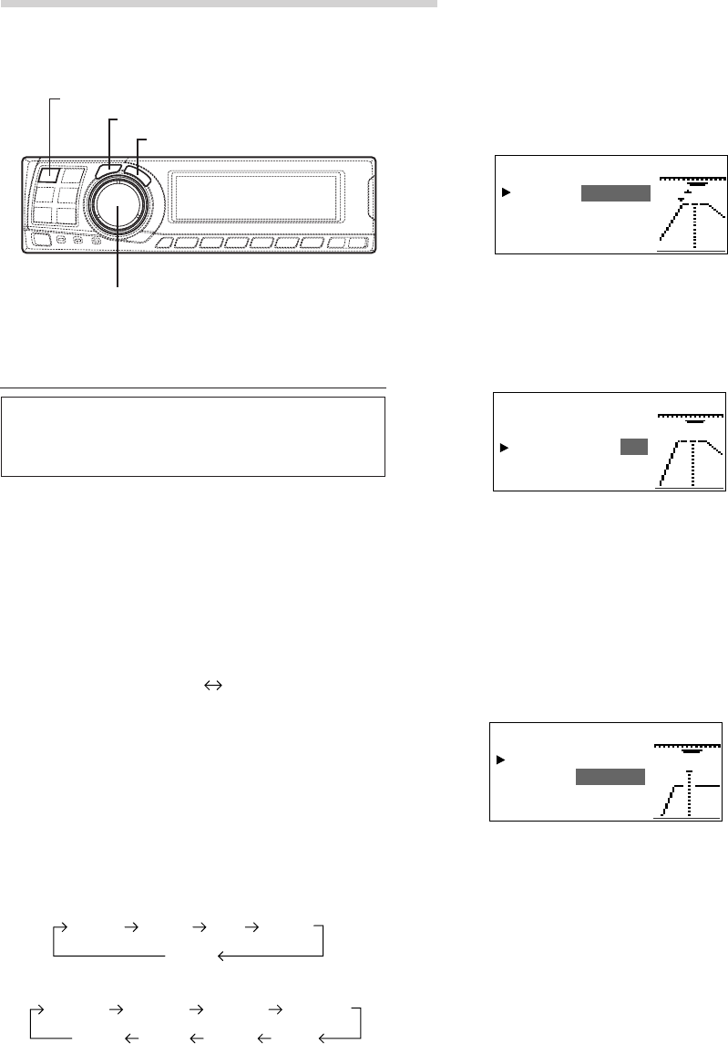
8Turn the Rotary encoder to adjust the level,
then press the CHANNEL button.
Press the ENTER button to return to step 5.
The level can be adjusted between –12 and 0.
9Repeat steps 4 to 8 to adjust other channels.
10
Once the adjustments are completed, press the
X-OVER button.
CHANNEL
ENTER
X-OVER
Rotary encoder
L and R (LR) L or R
Center
Sub. W
Front 1 Front 2 Rear
*1
Front 2 R
Center
Sub. W
Front 1 L Front 1 R Front 2 L
Rear R Rear L
*2*3
X–
O
RPFront 2 1/2VE
HP : 350fc
lopHPs 12e:
LPf 1c:
LPspe:6
I
o
.8k
X–
O
RPFront 2VE
HP : 35 0fc
lopHPs 18e:
LPf 1 .8kc:
LPs pe : 6
I
o
1/2
X–
O
RPFront 2VE
Le l :ve –dB4
2/2

17-EN
EN
FR
ES
DE
SE
IT
Hint for adjusting the subwoofer
• If the subwoofer is installed on the rear deck,
setting a gentle L.P.F. slope (for example 6 dB/
oct.) makes the sound localization more to the
rear. This can also affect the acoustic
localization of the front.
Hints for adjusting the high range
• Depending on the speaker, inputting low
frequency component signals (about 2 kHz or
less) with the H.P.F. adjustment could result in
distortion. If so, set a steep slope (for example
30 dB/oct.).
When doing so, adjust so that the mid and high
range sounds do not separate.
• Normally use with the L.P.F. off. If the high
range is too strong, we recommend adjusting for
a gentle slope.
Hint for adjusting the low range
• When a subwoofer is connected and you are
using a speaker with a low range of under 10 or
12 cm (3-15/16" or 4-3/4"), setting the low range
H.P.F. to “OFF” can result in distortion when low
frequency components are input.
If so, set the H.P.F. slope to a value suited for
the speaker’s frequency response.
NOTES
• In order to protect the speakers, if Tweeter is selected
in Front 1, there is no filter OFF (slope OFF) setting
for H.P.F.
For the same reason, the subwoofer low pass filter
cannot be turned off (the slope cannot be set to
“OFF”.)
• When the speaker is set to the “OFF” mode, the X-
OVER for that speaker is ineffective. Refer to
“Setting the speakers” (page 4).
• Check the playback frequencies of the connected
speakers before adjusting.
• After making the settings, we recommend storing
them in the memory. For instructions, see page 28.
18-EN
MX settings
MX (Media Xpander) makes vocals or
instruments sound distinct regardless of the
music source. The radio, CD, and MP3, will be
able to reproduce the music clearly even in cars
with a lot of road noise.
1When “Auto” has been set as the MX mode
setting (see page 27) while using the PXA-
H700 in combination with an Ai-NET head
unit equipped with an automatic MX mode
selection function (DVA-7996, etc.)
In this case, the MX mode is selected
automatically according to the music source on
the head unit. The MX mode can be set from
the PXA-H700 using the operation described
below.
1Press the MX button to set the MX setting mode.
2In case of “MX OFF”, press and hold the MX
button for at least 2 seconds to turn the MX
mode on.
3Turn the Rotary encoder to select the desired
mode, then press the ENTER button.
• When “OFF” is selected, the MX effect is
turned off.
• The level for the currently selected music
source (radio, CD, etc.) can be adjusted.
FM: MX1 to 3 and OFF
The medium to high frequencies become
more clear, and produces well balanced
sound in all the bands.
CD: MX1 to 3 and OFF
CD mode processes a large quantity of data.
This data is used to reproduce the sound
cleanly by making use of the data quantity.
MP3/XM: MX1 to 3 and OFF
This corrects information that was omitted at
the time of compression. This reproduces a
well-balanced sound close to the original.
DVD/Video CD: MOVIE MX 1~2, MUSIC, OFF
MOVIE MX 1~2: The dialogues of movies
are played with greater clarity.
MUSIC: Discs containing music clips are
played with a more dynamic sound.
AUX: MP3, MUSIC, MOVIE, OFF
Choose the MX mode (MP3, MUSIC, or
MOVIE) that corresponds to the media
connected.
4Once the settings are completed, press the MX
button.
NOTES
• Operations cannot be performed when the defeat
mode (page 28) is on.
• Each music source, such as radio, CD, and MP3 can
have its own MX setting.
• If "MX OFF" is set in step 2, the MX mode is set to
off for all music sources.
2When combining non Ai-Net head unit
products
When combining Ai-Net head unit products
without MX interlocking function
When combining Ai-Net head unit products
(DVA-7996, etc.) with MX interlocking
function considering that “MX mode setting”
(page 27) is set to “Manual”.
In these cases, the PXA-H700 is not interlocked
with the head unit, therefore it is necessary to set
the MX from the PXA-H700 with the operations
below.
1Press the MX button to set the MX setting mode.
2In case of “MX OFF”, press and hold the MX
button for at least 2 seconds to turn the MX
mode on.
Settings/Adjustments
ENTER
MX B.C.
Rotary encoder

19-EN
EN
FR
ES
DE
SE
IT
3Turn the Rotary encoder to select the source
(media) you want to set, then press the ENTER
button.
4Turn the Rotary encoder to select the desired
mode, then press the ENTER button.
For further information about setting mode, see
step 3 of 1 (page 18).
5To set other sources (media), press the MX
button and return to step 3.
6Once the settings are completed, press the MX
button repeatedly.
NOTES
• Operations cannot be performed when the defeat
mode (page 28) is on.
• The source (media), such as radio, CD, and MP3 can
be set.
• “MX OFF” can be set in step 2.
BASS COMP. setting
The sound of the low frequencies can be
adjusted to suit your tastes.
1Check that the defeat mode is off.
(See page 28.)
2Press the B.C. button to set the “BASS COMP.”
setting mode.
3In case of “BASS COMP. OFF”, press and hold
the B.C. button for at least 2 seconds to turn the
BASS COMP. mode on.
4Turn the Rotary encoder to select the desired
mode, then press the ENTER button.
As the bass level increases in order of BASS
COMP. 1, BASS COMP. 2, BASS COMP. 3, you
can enjoy listening to the powerful sound.
5Once the settings are completed, press the B.C.
button.
NOTE
“BASS COMP. OFF” can be set in step 3.
20-EN
*If DOLBY PL II MUSIC is selected, the
center width can be adjusted with following
operations.
This function offers the optimum vocal position
by adjusting the center channel position
between the center speaker and the L/R
speaker. (The adjustments established in
“Adjusting the acoustic image” (page 24) are
ineffective while this function is activated.)
1) After selecting DOLBY PL II MUSIC, within
15 seconds, press and hold the PLII/
REAR FILL button for at least 2 seconds.
2) Turn the Rotary encoder to select “Center
Width ON” or “Center Width OFF”, then
press the ENTER button.
When the setting is turned ON, the optimum
vocal position is offered by adjusting the
center channel position between the center
speaker and the L/R speaker.
3) Turn the Rotary encoder to adjust the level,
then press the ENTER button.
The level can be adjusted between 0 to 7.
When the level increases, the center channel
position moves from the center speaker
position to both side.
4) After the setting, press and hold the
PLII/REAR FILL button for at least 2
seconds.
NOTES
• Avoid stopping, pausing, switching the disc, cueing,
fast-forwarding or switching the audio channel of the
player while making this adjustment. The setting is
canceled if the decode mode is switched.
• This adjustment is ineffective if the center speaker is
set to “OFF” or “Sub.W” in the speaker setup
settings.
2Once the settings are completed, press the DISP
button.
NOTES
• This function only works with two-channel signals.
This operation is ineffective when 5.1-channel DTS
or Dolby Digital signals are input.
• “REAR FILL” function
Depending on the input signals, the sound may only
be output from the front speakers. In this case, the
“REAR FILL” function can be used to output signals
from the rear speakers as well.
• If the setting of REAR FILL is made when REAR MIX
is ON, sound is unchanged in the rear fill setting
because REAR MIX is given priority during 2
channel decoder other than linear PCM.
• For linear PCM signals, the voice is output from the
rear speaker regardless of the REAR FILL and REAR
MIX setting.
• Once the settings are made, we recommend storing
them in the memory. See page 28 for instructions.
Using Dolby Surround
PLII/
REAR FILL
ENTER
DISP
Using the Pro Logic II mode
With the PXA-H700, Pro Logic processing can be
conducted on the music signals recorded on two
channels to achieve Dolby Pro Logic II surround
sound. For two-channel Dolby Digital and DTS
signals, there is also a “REAR FILL” function for
outputting the signals of the front channel to the
rear channel.
1Press the PLII/REAR FILL button and select
the desired mode.
The setting mode is canceled if no operation is
performed within 15 seconds after the mode is
selected.
DOLBY PL II MOVIE: Suits the stereo TV
shows and all programs
encoded in Dolby
Surround. It improves
the sound field
directivity to near that of
discrete 5.1-channel
sound.
DOLBY PL II MUSIC: Can be used for all
stereo music
recordings, and
provides a wide, deep
sound field.
REAR FILL
OFF
DOLBY PL II MOVIE DOLBY PL II MUSIC
Rotary encoder
21-EN
FR
ES
DE
SE
IT
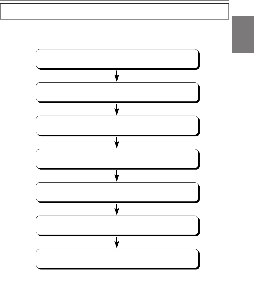
Adjustment procedure for Dolby Surround
Make the adjustments described below in order to reproduce Dolby Digital and DTS sound with greater
accuracy.
Adjustment procedure
1
2
3
4
5
6
7
Speaker setup (page 22)
(Turning the speakers to be used on and off and setting their response)
Adjusting the speaker levels (page 22)
(Adjusting the signal output level to the various speakers)
Adjusting the DVD level (page 25)
(Adjust the volume (signal level) in the Dolby Digital, Pro Logic II, DTS
and PCM modes.)
Adjusting the acoustic image (page 24)
(Adjusting the acoustic image to achieve a sound as if the center
speaker were directly in front of the listener)
Mixing bass sound to the rear channel (page 23)
(Achieving smooth sound in the rear seat by mixing the front audio
signals with the rear speaker signals)
Storing settings in the memory (page 28)
(Storing all the settings and adjustments made on the PXA-H700 (not
only the above settings/adjusts) in the memory)
Achieving powerful high volume sound (page 25)
(Achieving energetic sound with even greater power, like the sound in a
movie theater)
NOTE
In case of combining the Automatic adjustments etc.
We recommend to make the Automatic adjustments before the Dolby Surround adjustments.
22-EN
Using Dolby Surround
OFF:
When no speaker is connected
SMALL:
When a speaker that cannot play low
frequencies (80 Hz or less) is connected
LARGE:
When a speaker that can play low frequencies
(80 Hz or less) is connected
*1: It is not possible to set the front speakers to
“OFF”.
*2: If the front speakers are set to “SMALL”, the
rear and center speakers cannot be set to
“LARGE”.
6Press the SETUP button repeatedly to quit the
setup mode.
NOTES
• If the center speaker is turned "OFF", the center
channel's audio signals are added to the audio
signals output from the front speakers.
• If you set the speaker response to “OFF”, also set
the speaker setting to “OFF”. (See page 4.)
• Perform the setup for all the speakers (“Front”,
“Center”,“Rear” and “Sub. W”). If not, the sound
may not be balanced.
• When center is set to subwoofer, the setting is
ineffective even if center is set with this function.
• Once the settings are made, we recommend storing
them in the memory. See page 28 for instructions.
Adjusting the speaker levels
Use the PXA-H700’s test tones to make the
volume adjustments of the different speakers.
When levels are equal, a strong sense of
presence can be heard from the different
speakers at the listening position.
NOTE
Avoid stopping, pausing, switching the disc, cueing,
fast-forwarding or switching the audio channel of the
player while making this adjustment. The setting is
canceled if the decode mode is switched.
1Press the SETUP button.
The setup mode is set.
2Turn the Rotary encoder to select the “5.1CH
SETUP” mode, then press the ENTER button.
3Turn the Rotary encoder to select “OUTPUT
LEVEL”, then press the ENTER button.
CHANNEL
ENTER
SETUP
Rotary encoder
Speaker setup
The PXA-H700 can be set according to the
playable frequency range of your speakers.
Check the playable frequency range of the
speakers (not including the subwoofer) before
performing this operation to verify whether the
speakers can play low frequencies (of about 80
Hz or less).
NOTE
Avoid stopping, pausing, switching the disc, cueing,
fast-forwarding or switching the audio channel of the
player while making this adjustment. The setting is
canceled if the decode mode is switched.
1Press the SETUP button.
The setup mode is set.
2Turn the Rotary encoder to select the “5.1CH
SETUP” mode, then press the ENTER button.
3Turn the Rotary encoder to select the
“SPEAKER SETUP”, then press the ENTER
button.
4Press the CHANNEL button to select the
speaker, then press the ENTER button.
5Turn the Rotary encoder to select the speaker
property, then press the ENTER button.
Repeat steps 4 and 5 to set the various items.
(Subwoofer is only ON/OFF.)
Front Center Rear Sub. W
OFF SMALL LARGE
*
1
*
2

23-EN
FR
ES
DE
SE
IT
4Turn the Rotary encoder to select “Auto”, then
press the ENTER button. Test tone output is
repeated for each of the different speaker
channels. They will be repeated in the order
shown below.
If no operation is performed for 2 seconds, the
channel switches to the next channel.
5While the test tones are being produced from the
speakers, turn the Rotary encoder to adjust so
that the volume of the different speakers is
equal.
• The adjustment range for the different
speakers is ± 10 dB.
• Adjust based on the front speakers.
6Press the SETUP button repeatedly to quit the
setup mode.
Adjusting the level for individual speakers
(manual)
1) At step 4 above, select “Manual”, then press the
ENTER button.
2) Press the CHANNEL button or ENTER button to
select the speaker you wish to adjust.
3) Turn the Rotary encoder to adjust the output
level.
4) Repeat steps 2) and 3) above to adjust the levels
of the different speakers.
5) Press the SETUP button again to quit the setup
mode.
NOTES
• If a speaker is set to the off mode, that speaker’s level
adjustment cannot be made.
Refer to “Speaker setup” (page 22).
• Once the settings are made, we recommend storing
them in the memory. See page 28 for instructions.
RS (Right surround)
LS (Left surround)
L (Left front) C (Center) R (Right front)
1Press the SETUP button.
The setup mode is set.
2Turn the Rotary encoder to select the “5.1CH
SETUP” mode, then press the ENTER buton.
3Turn the Rotary encoder to select “REAR MIX”,
then press the ENTER button.
4Turn the Rotary encoder to select “REAR MIX
ON” or “REAR MIX OFF”, then press the ENTER
button.
When set to “ON”, the front audio signals are
mixed into the audio signals output from the rear
speakers.
5Turn the Rotary encoder to adjust the level,
then press the ENTER button.
The level can adjusted in five steps: –6, –3, 0, +3
and +6. The higher the level, the more bass is
output from the rear speakers. (The effect differs
according to the software (DVD, etc.).)
6Once the settings are completed, press the
SETUP button repeatedly to quit the setup
mode.
NOTES
• This adjustment is ineffective when the rear speaker
setup setting is set to “OFF”.
• For linear PCM signals, the voice is output from the
rear speaker regardless of the REAR FILL and REAR
MIX setting.
• Once the settings are made, we recommend storing
them in the memory. See page 28 for instructions.
Mixing bass sound to the rear channel
This function mixes the front channel audio
signals to the audio signals output from the rear
speakers, improving the sound in the vehicle’s
rear seat.
NOTE
Avoid stopping, pausing, switching the disc, cueing,
fast-forwarding or switching the audio channel of the
player while making this adjustment. The setting is
canceled if the decode mode is switched.
24-EN
Using Dolby Surround
Adjusting the acoustic image
In most installations, the center speaker must be
placed directly between the front passenger and
driver. Using this function, the center channel
information is distributed to the left and right
speakers. This creates an acoustic image
simulating a center speaker directly in front of
each listener. Adjusting the center width in
DOLBY PL II MUSIC (see “Using the Pro Logic II
mode”, page 20), makes this function ineffective.
NOTE
Avoid stopping, pausing, switching the disc, cueing,
fast-forwarding or switching the audio channel of the
player while making this adjustment. The setting is
canceled if the decode mode is switched.
1Press the SETUP button.
The setup mode is set.
2Turn the Rotary encoder to select the “5.1CH
SETUP” mode, then press the ENTER button.
3Turn the Rotary encoder to select “BI-
PHANTOM”, then press the ENTER button.
4Turn the Rotary encoder to select “BI-
PHANTOM ON” or “BI-PHANTOM OFF”, then
press the ENTER button.
When set to “ON”, the center channel
information is distributed to the left and right
speakers. This creates an acoustic image
simulating a center speaker directly in front of
each listener.
5Turn the Rotary encoder to adjust the level,
then press the ENTER button.
The level can be adjusted within the range of –5
to +5. The higher the level, the more the position
of the center speaker is shifted to the sides.
6Once the settings are completed, press the
SETUP button repeatedly to quit the setup
mode.
NOTES
• This adjustment is ineffective if the center speaker is
set to “OFF” or “Sub.W” in the speaker setup
settings.
• Once the settings are made, we recommend storing
them in the memory. See page 28 for instructions.
ENTER
SETUP
Rotary encoder

25-EN
FR
ES
DE
SE
IT
Achieving powerful high volume sound
With Dolby Digital, the dynamic range is
compressed so that powerful sound can be
achieved at regular volume levels. This
compression can be canceled to achieve an
energetic sound with even greater power, like the
sound in a movie theater.
NOTE
This function works only in the Dolby Digital mode.
1Press the SETUP button.
The setup mode is set.
2Turn the Rotary encoder to select the “5.1CH
SETUP” mode, then press the ENTER button.
3Turn the Rotary encoder to select “LISTENING
MODE”, then press the ENTER button.
4Turn the Rotary encoder to select “STANDARD”
or “MAXIMUM”, then press the ENTER button.
STANDARD:
For powerful sound at regular volume levels
MAXIMUM:
For powerful sound at high volumes
5Press the SETUP button repeatedly to quit the
setup mode.
NOTES
• Keep the volume to a level at which sounds outside
the vehicle can still be heard.
• This function may have no effect, depending on the
type of software (DVD, etc.).
• Once the settings are made, we recommend storing
them in the memory. See page 28 for instructions.
STANDARD MAXIMUM
Adjusting the DVD level
The volume (signal level) for the Dolby Digital,
Pro Logic II, DTS and PCM modes can be set.
NOTE
Avoid stopping, pausing, switching the disc, cueing,
fast-forwarding or switching the audio channel of the
player while making this adjustment. The setting is
canceled if the decode mode is switched.
1Press the SETUP button.
The setup mode is set.
2Turn the Rotary encoder to select the “5.1CH
SETUP” mode, then press the ENTER button.
3Turn the Rotary encoder to select the “DVD
LEVEL”, then press the ENTER button.
4Press the ENTER button to select the mode to
be adjusted.
5Turn the Rotary encoder to adjust the level.
The level can be adjusted in the range of –5 to
+5.
6Repeat steps 4 and 5 to set the levels for the
various modes.
Once the settings are completed, press the
SETUP button repeatedly to quit the setup
mode.
NOTE
After making the settings, we recommend storing them
in the memory. For instructions, see page 28.
DOLBY D DOLBY PL II DTS PCM
(DOLBY DIGITAL)
26-EN
Convenient Functions
Linear PCM setting
The output when playing discs recorded in linear
PCM can be set to 2 or 3 channels.
1Press the SETUP button.
The setup mode is set.
2Turn the Rotary encoder to select the “PCM
MODE”, then press the ENTER button.
3Turn the Rotary encoder to select “2ch Output”
or “3ch Output”, then press the ENTER button.
2ch Output: 2ch output (L/R)
3ch Output: 3ch output (L/R/CENTER)
4Press the SETUP button repeatedly to quit the
setup mode.
NOTE
This PCM mode is ineffective if the center speaker is set
to “OFF” or “Sub.W” in the speaker setup settings.
ENTER
SETUP
Rotary encoder
Navigation system voice guidance
interruption
When the navigation system is connected, make
the navigation system’s voice guidance
messages to interrupt the PXA-H700, then
output from the front speaker.
1Press the SETUP button.
The setup mode is set.
2Turn the Rotary encoder to select the “NAVI
MIX” mode, then press the ENTER button.
3Turn the Rotary encoder to select “NAVI MIX
ON” or “NAVI MIX OFF”, then press the ENTER
button.
When ON is set, the navigation system's voice
guidance messages interrupts the PXA-H700.
4Turn the Rotary encoder to adjust the “MIX
LEVEL” (volume level of navigation voice), then
press the ENTER button.
The level can be adjusted from 1 to 15.
5Turn the Rotary encoder and set “GUIDE
CONT.” to “2”, then press the ENTER button.
Do not use “1”.
6Press the SETUP button repeatedly to quit the
setup mode.
NOTE
For connection with navigation, refer to the
"Installation and Connections" (page 40).

27-EN
EN
FR
ES
DE
SE
IT
Display settings
The display’s contrast and LCD (negative/
positive) can be adjusted.
1Press the SETUP button.
The setup mode is set.
2Turn the Rotary encoder to select the “DISPLAY
SETUP” mode, then press the ENTER button.
3Turn the Rotary encoder to adjust
“CONTRAST”, then press the ENTER button.
Adjust the contrast (color depth) between –8~+8
so that the display is easy to see.
4Turn the Rotary encoder to perform the “LCD
MODE” setting, then press the ENTER button.
Set the display to “POSITIVE (Pos.)” or
“NEGATIVE (Neg.)” according to your tastes.
5Once the settings are completed, press the
SETUP button repeatedly to quit the setup
mode.
MX mode setting (Ai-NET connection)
Use this setting when using the PXA-H700 in
combination with an Ai-NET head unit equipped
with the automatic MX mode selection function
(for example, DVA-7996).
When the MX mode is set to “Auto”, the MX
settings of the head unit (the MX modes for the
different music sources) are sent to the PXA-
H700.
1Press the SETUP button.
The setup mode is set.
2Turn the Rotary encoder to select the “MX
MODE”, then press the ENTER button.
3Turn the Rotary encoder to select “Auto” or
“Manual”, then press the ENTER button.
Auto:
When the PXA-H700 is used in combination
with an Ai-NET head unit equipped with the
automatic MX mode selection function (for
example, DVA-7996), the MX settings of the
head unit are sent to the PXA-H700.
In addition, the MX mode switches
automatically according to the music source
selected by the head unit.
Manual:
Perform the MX operations on the PXA-
H700.
4Press the SETUP button repeatedly to quit the
setup mode.
28-EN
Convenient Functions
Storing settings in the memory
Up to six adjustments and settings can be stored
in the PXA-H700’s memory.
1Make the adjustment or setting you want to store
in the memory.
2Press and hold any button from 1 to 6 for at least
2 seconds to store the setting into preset
memory (“MEMORY1” to “MEMORY6”).
NOTES
• This operation can only be performed when the
defeat mode is turned off.
• The stored contents will not be deleted even when the
battery power cord is detached.
Calling out stored values
1Press any button from 1 to 6 to select the preset
memory you want to call out (“MEMORY1” to
“MEMORY6”).
In the preset memory, numerous settings/
adjustments are stored. Therefore, it may take
some time to access the stored preset memory.
NOTE
This operation can only be performed when the defeat
mode is turned off.
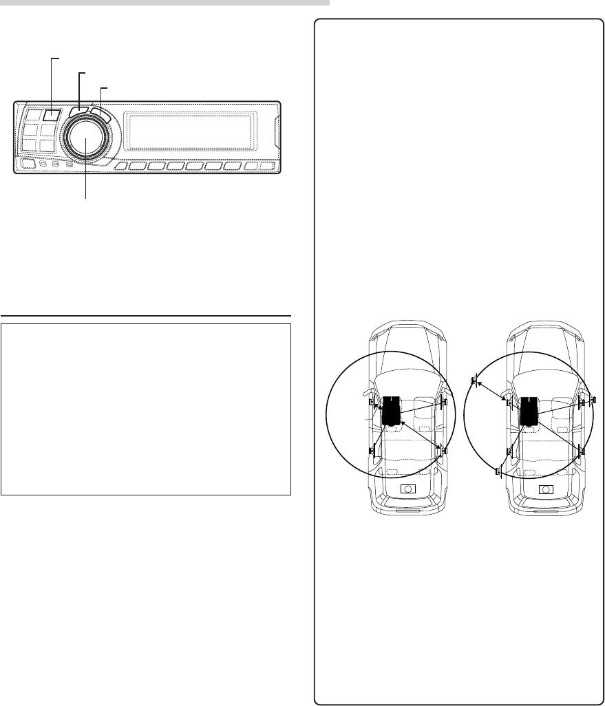
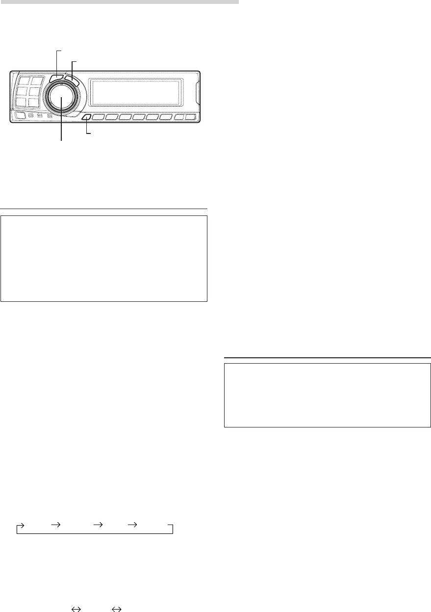
Defeat mode
1Press the DEFEAT button.
All properties are made flat.
2Press the DEFEAT button again to cancel.
NOTES
• The “Parametric EQ”, “Graphic EQ”, “AUTO
TCR”, “TCR/phase switching”, “MX”, “X-OVER”
and “BASS COMP. setting” operations cannot be
performed when the defeat mode is turned on.
• To protect the speakers, the “X-OVER” setting does
not change.
DEFEAT
1~6
DISP
SAV
E
T
O
RY 2
M
E
M
PRESE
L
O
AING
D
T
O
RY 1
M
E
M
PRESE
DEFEAT
O
N
29-EN
EN
FR
ES
DE
SE
IT
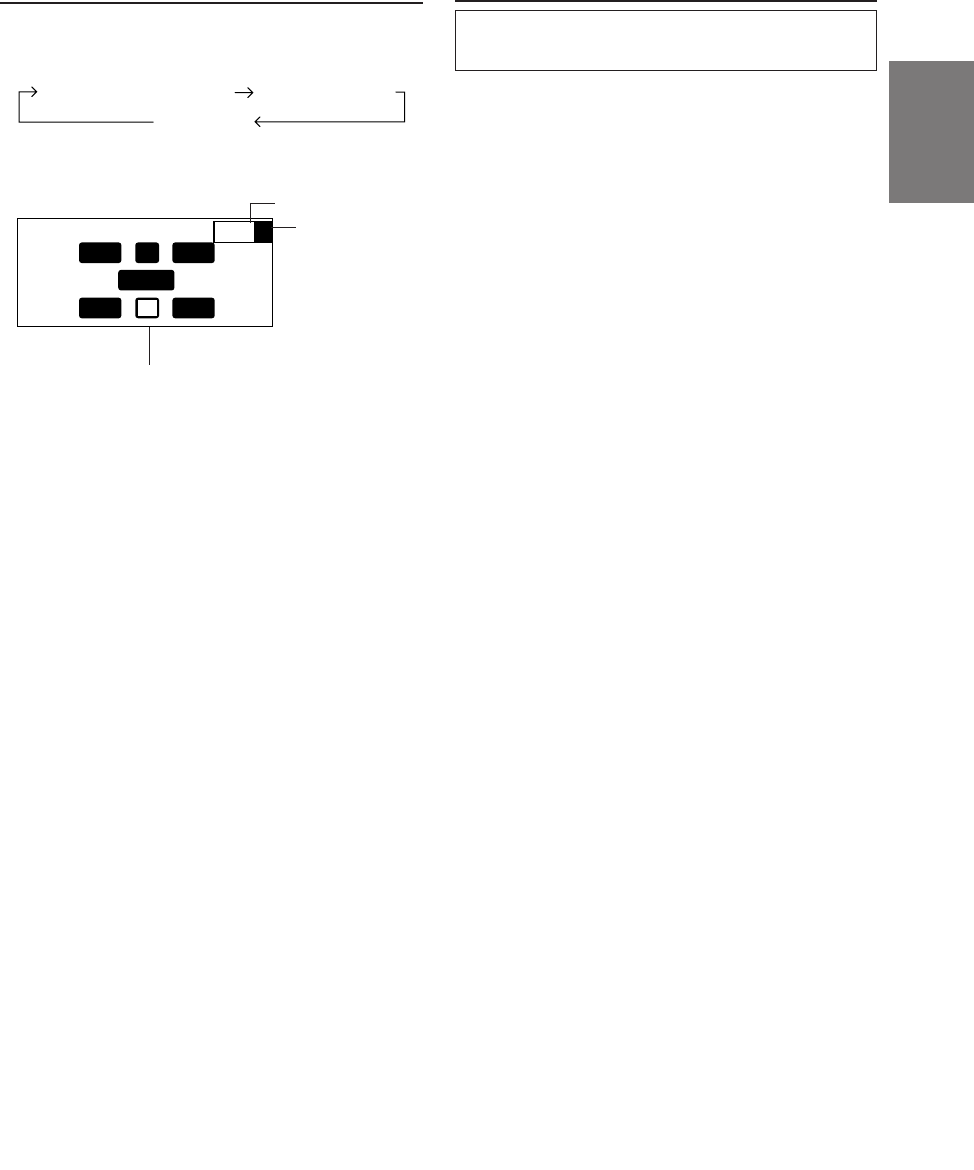
Switching the display mode
1Press the DISP button to select the desired
display mode.
INP HTC
P–2
U
L R
Ls Rs
FLE
C
P
S
Example of input channel (When
monaural surround signal (s) is
not inputted)
The display changes according to the
input signals. The indicated items are
highlighted when there is no input.
L: Left front channel
R: Right front channel
C: Center channel
Ls: Left surround channel
Rs: Right surround channel
S: Monaural surround signal
LFE: Low frequency deep bass signal
Switching the color of the illumination
The color of the PXA-H700’s switch illumination
can be changed.
1Press and hold the DISP button for at least 2
seconds and select the desired color.
Select green or amber.
Input channel display
Spectrum analyzer display(1~3)
Display OFF
Preset No.
Equalizer setting
display
Displays whether
the current EQ
setting is graphic
EQ or parametric
EQ.
G: Graphic EQ
P: Parametric EQ
30-EN
Installation and Connections
Before installing or connecting the unit, please
read the following and pages 2 and 3 of this
manual thoroughly for proper use.
Warning
DO NOT DISASSEMBLE OR ALTER.
Doing so may result in an accident, fire or electric shock.
USE THE CORRECT AMPERE RATING WHEN
REPLACING FUSES.
Failure to do so may result in fire or electric shock.
MAKE THE CORRECT CONNECTIONS.
Failure to make the proper connections may result in fire
or product damage.
USE ONLY IN CARS WITH A 12 VOLT NEGATIVE
GROUND.
(Check with your dealer if you are not sure.) Failure to do
so may result in fire, etc.
BEFORE WIRING, DISCONNECT THE CABLE FROM
THE NEGATIVE BATTERY TERMINAL.
Failure to do so may result in electric shock or injury due
to electrical shorts.
DO NOT ALLOW CABLES TO BECOME ENTANGLED
IN SURROUNDING OBJECTS.
Arrange wiring and cables in compliance with the manual
to prevent obstructions when driving. Cables or wiring
that obstruct or hang up on places such as the steering
wheel, gear lever, brake pedals, etc. can be extremely
hazardous.
DO NOT SPLICE INTO ELECTRICAL CABLES.
Never cut away cable insulation to supply power to other
equipment. Doing so will exceed the current carrying
capacity of the wire and result in fire or electric shock.
DO NOT DAMAGE PIPE OR WIRING WHEN
DRILLING HOLES.
When drilling holes in the chassis for installation, take
precautions so as not to contact, damage or obstruct pipes,
fuel lines, tanks or electrical wiring. Failure to take such
precautions may result in fire.
DO NOT USE BOLTS OR NUTS IN THE BRAKE OR
STEERING SYSTEMS TO MAKE GROUND
CONNECTIONS.
Bolts or nuts used for the brake or steering systems (or
any other safety-related system), or tanks should NEVER
be used for installations or ground connections. Using
such parts could disable control of the vehicle and cause
fire etc.
DO NOT INSTALL THE MONITOR NEAR THE
PASSENGER SEAT AIR BAG.
If the unit is not installed correctly the air bag may not
function correctly and when triggered the air bag may
cause the monitor to spring upwards causing an accident
and injuries.
DO NOT BLOCK VENTS OR RADIATOR PANELS.
Doing so may cause heat to build up inside and may result
in fire.
KEEP SMALL OBJECTS SUCH AS BATTERIES OUT
OF THE REACH OF CHILDREN.
Swallowing them may result in serious injury. If
swallowed, consult a physician immediately.
DO NOT INSTALL IN LOCATIONS WHICH MIGHT
HINDER VEHICLE OPERATION, SUCH AS THE
STEERING WHEEL OR GEARSHIFT.
Doing so may obstruct forward vision or hamper
movement etc. and results in serious accident.
Caution
HAVE THE WIRING AND INSTALLATION DONE BY
EXPERTS.
The wiring and installation of this unit requires special
technical skill and experience. To ensure safety, always
contact the dealer where you purchased this product to
have the work done.
USE SPECIFIED ACCESSORY PARTS AND INSTALL
THEM SECURELY.
Be sure to use only the specified accessory parts. Use of
other than designated parts may damage this unit
internally or may not securely install the unit in place.
This may cause parts to become loose resulting in hazards
or product failure.

31-EN
FR
ES
DE
SE
IT
ARRANGE THE WIRING SO IT IS NOT CRIMPED OR
PINCHED BY A SHARP METAL EDGE.
Route the cables and wiring away from moving parts (like
the seat rails) or sharp or pointed edges. This will prevent
crimping and damage to the wiring. If wiring passes
through a hole in metal, use a rubber grommet to prevent
the wire’s insulation from being cut by the metal edge of
the hole.
DO NOT INSTALL IN LOCATIONS WITH HIGH
MOISTURE OR DUST.
Avoid installing the unit in locations with high incidence
of moisture or dust. Moisture or dust that penetrates into
this unit may result in product failure.
Precautions
• Be sure to disconnect the cable from the (–) battery
post before installing your PXA-H700. This will
reduce any chance of damage to the unit in case of a
short-circuit.
• Be sure to connect the color coded leads according to
the diagram. Incorrect connections may cause the unit
to malfunction or damage to the vehicle’s electrical
system.
• When making connections to the vehicle’s electrical
system, be aware of the factory installed components
(e.g. on-board computer). Do not tap into these leads to
provide power for this unit. When connecting the
PXA-H700 to the fuse box, make sure the fuse for the
intended circuit of the PXA-H700 has the appropriate
amperage. Failure to do so may result in damage to the
unit and/or the vehicle. When in doubt, consult your
ALPINE dealer.
• The PXA-H700 uses female RCA-type jacks for
connection to other units (e.g. amplifier) having RCA
connectors. You may need an adaptor to connect other
units. If so, please contact your authorized ALPINE
dealer for assistance.
Wiring Connections
Improper wiring connections could cause serious damage
to your audio system. Be sure you:
1. DO NOT connect (–) wires from left and right speakers
together.
2. DO NOT ground any speaker wires.
3. DO NOT run wires where they may be pinched or cut.
4. DO NOT leave bare speaker terminals exposed. They
may contact the vehicle chassis and cause a short.
Fuse
When replacing the fuse(s), the replacement fuse must be
of the same amperage as shown on the fuse holder. If the
fuse(s) blows more than once, carefully check all
electrical connections for shorted circuitry. Also have your
vehicle’s voltage regulator checked. Do not attempt to
repair the unit yourself; return it to your Alpine dealer or
nearest Alpine Service Station for servicing.
Temperature
In order to ensure proper performance, be sure the
temperature in your vehicle is above 14°F (–10°C) and
below 140°F (60°C) before turning your unit on. Good air
circulation is essential to prevent internal heat build-up in
the unit.
32-EN
Installation and Connections
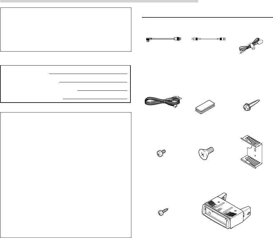
IMPORTANT
Please record the serial number of your unit in
the space provided below and keep it as a
permanent record. The serial number plate is
located on the bottom of the unit.
SERIAL NUMBER:
INSTALLATION DATE:
INSTALLATION TECHNICIAN:
PLACE OF PURCHASE:
To prevent external noise from entering the
audio system.
• Locate the unit and route the leads at least 10 cm away
from the car harness.
• Keep the battery power leads as far away from other
leads as possible.
• Connect the ground lead securely to a bare metal spot
(remove any paint, dirt or grease if necessary) of the
car chassis.
• If you add an optional noise suppressor, connect it as
far away from the unit as possible.
Your Alpine dealer carries various noise suppressors.
Contact them for further information.
• Your Alpine dealer knows best about noise prevention
measures so consult your dealer for further
information.
Accessories
Ai-NET cable Display cable
Connection Cable Velcro fastener for
mounting control
unit or base unit
Pan head screw
(M3 x 5)
x 2
Microphone
Flat head screw
(M5 x 8)
x 4
Flush mount
x 2
Self-tapping screw
(M2.6 x 8)
x 4
Flanged self-
tapping screw
(M4 x 14)
x 4
x 3
Mounting unit
1 set
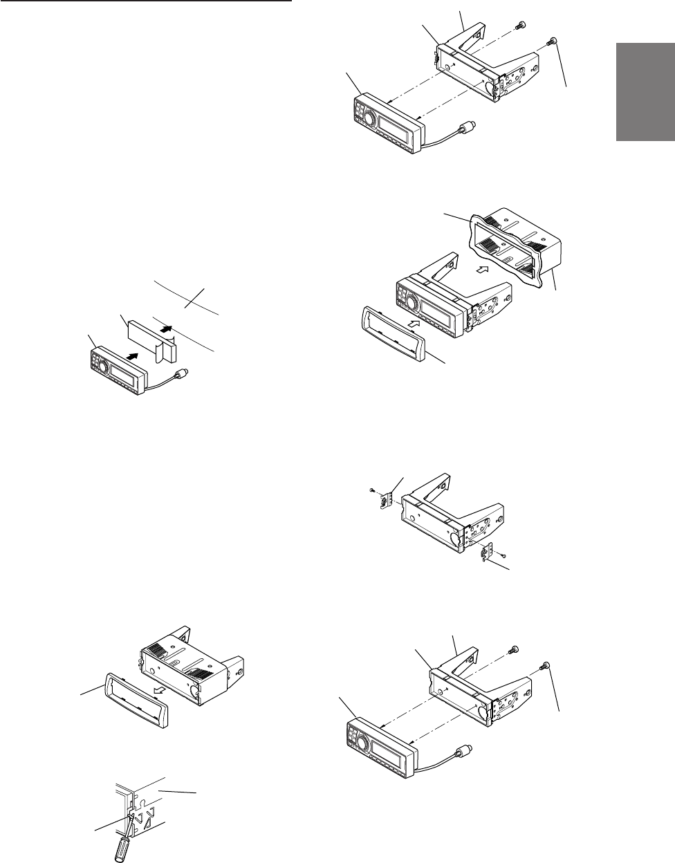
33-EN
FR
ES
DE
SE
IT
Installation
The PXA-H700 is made up of two components: the
Control Unit and Base Unit.
Mounting the control unit
CAUTION:
Do not install the control unit near the air-bag of the
front passenger’s seat.
• Confirm the installation location will be safe.
• Determine the mounting position on the
dashboard. The area should be large enough to
center the unit and reasonably flat.
Installation using Velcro fastener
1. Without separating the two pieces of Velcro
fastener, peel off the paper backing on one side
and place on the back of the control unit.
2. Make sure the location selected is free from
moisture or dirt. Peel off the backing paper from
the other side of the Velcro fastener on the
control.
3. Place the control unit on the mounting location
and press the unit firmly to mount securely.
Mounting other units
1Remove the face plate.
2Use a screwdriver, etc., to slide the locking pin,
then take out the inner case.
3Mount the control unit using the included screws.
4Mount the previously removed inner case into
the dashboard. Slide the control unit into the
case.
<JAPANESE CAR>
1After step 2 on “Mounting other units” of
“Mounting the control unit”, remove the side
bracket.
2Mount the control unit using the included screws.
Face plate
Inner case
Locking pin
Side bracket
Side bracket
Bracket
Spacer
Control unit
Pan head screw
(M3 x 5) x 2
Pan head screw
(M3 x 5) x 2
Control unit
Spacer
Bracket
Inner case
Face plate
Dashboard
Dashboard
Velcro fastener
Control unit
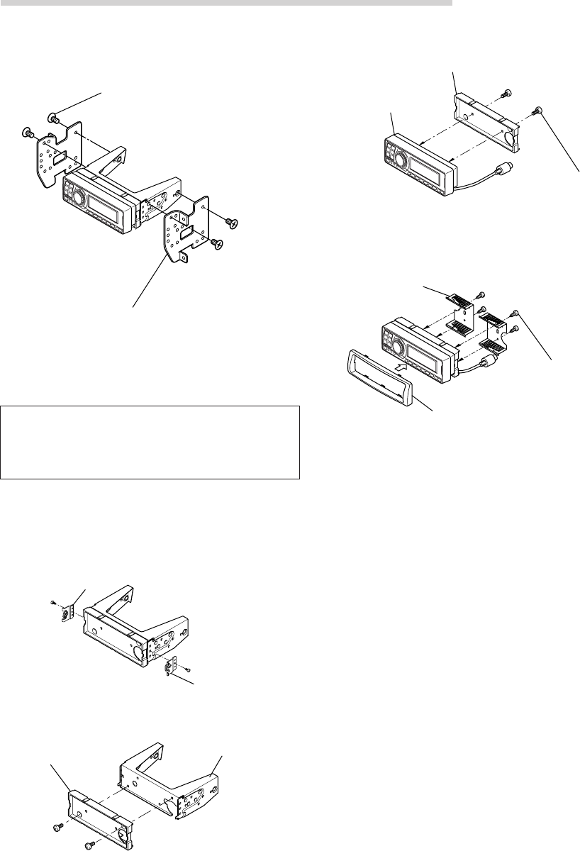
34-EN
Installation and Connections
3Mount the spacer and bracket to the control unit.
Next, securely mount the factory brackets
removed from the factory radio, to the control
unit assembly.
Flush Mounting the control unit
1Make a cut-out approximately 178 (width) by 50
(height) mm (7 inches by 2 inches) in size at
your desired mounting location.
WARNING
When making cut-outs, be careful not to
damage pipes, tanks, electric wires, etc. Doing
so could lead to accidents or fire.
2After step 2 on “Mounting other units” of
“Mounting the control unit” page 33, remove the
side bracket.
3Remove the spacer from the bracket.
Side bracket
Side bracket
Spacer Bracket
4Mount the spacer on the control unit using the
included screws.
5Attach the flush mount brackets to the control
unit using the included screws. Mount this
assembly into the prepared cut-out.
Flush mount
Face plate
Self-tapping screw
(M2.6 x 8) x 4
Flat head screws (M5 x 8)
Bracket
Control unit
Spacer
Pan head screw
(M3 x 5) x 2
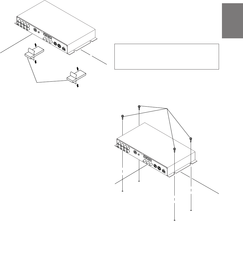
35-EN
FR
ES
DE
SE
IT
Mounting the base unit
● Velcro Fastener Mounting
Attach to the vehicle (such as under the
dashboard).
Flanged self-tapping
screw (M4 x 14)
Velcro fastener
●Using the Mounting Screws (Supplied)
The Base Unit can be mounted under the seat
using the mounting screws.
1Decide on the installation location.
• The trunk, etc., is the best place.
2Mark the positions of the mounting screws at the
chosen location.
3Drill 3 mm (1/8”) holes or smaller.
WARNING
When making holes, be careful not to damage
pipes, tanks, electric wires, etc. Doing so could
lead to accidents or fire.
4Securely mount the unit using the four included
flanged self-tapping screws (M4 x 14).
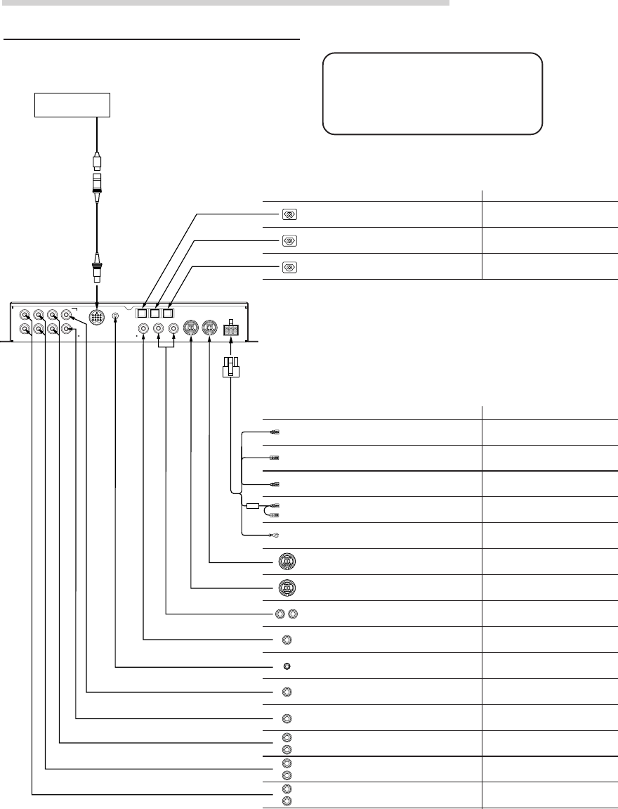
36-EN
Installation and Connections
Basic Connections Diagram
Display
Cord colors and cord/terminal specifications Connect to:
• Front 1 speaker output jacks (RCA outputs)
Outputs signals for driving the front 1 speakers.
• Front 2 speaker output jacks (RCA outputs)
Outputs signals for driving the front 2 speakers.
• Rear speaker output jacks (RCA outputs)
Outputs signals for driving the rear speakers.
• Subwoofer output jack (RCA outputs)
Outputs signals for driving the subwoofer.
• Center speaker or subwoofer output jack (RCA output)
Outputs signals for driving the center speaker or subwoofer.
• Navigation audio input jack (RCA input)
Used to input the audio output signals of a navigation
system.
Connect to the amplifier for the front 1
speaker.
Connect to the amplifier for the front 2
speaker.
Connect to the amplifier for the rear speaker.
Connect to the amplifier for the subwoofer.
Connect to the amplifier for the center
speaker or subwoofer.
Used for automatic adjustment.
• Microphone jack
Use this to connect a microphone.
Connect to the navigation system.
Connect to an Ai-NET product using an Ai-NET cord.
For connection to the PXA-H700, use the straight
side.
• Changer input terminal (Ai-NET input)
Used for system expansion (Ai-NET changer, etc.).
Connect to an Ai-NET product using an Ai-NET cord.
For connection to the PXA-H700, use the straight
side.
Used for RCA connections.
Connect to the head unit.
• Ai-NET input terminal (Ai-NET input)
Used for system expansion (DVD player, etc.).
• Audio input jacks (RCA inputs)
Used to input the audio output signals of a head unit
connected with RCA connections to the PXA-H700.
• Remote ON cable
Connect to the head unit for RCA connections.
(Non Ai-NET connection)
• Remote OUT cable
Connect to the amplifier or other peripheral device.
• Guide control cable
Used to interrupt the navigation system’s sound.
• Ground cable
Connect securely to a metal part of the vehicle’s body.
• Battery power cable
Power is supplied constantly to the PXA-H700 regardless
of whether the engine key is on or off.
Used for RCA connections.
(Non Ai-NET connection)
Used to add an amplifier.
Connect to the navigation system.
Connect to the vehicle’s body.
Connect this lead to the positive(+) post of
the vehicle's battery.
Blue/
White
Blue/
White
White/
Green
Yellow
Fuse
(3A)
Black
Terminal specifications Connect to:
Connect to an Ai-NET product
using an optical fiber cable.
• Head unit input terminal (optical digital input)
Used for system expansion (Ai-NET head unit, etc.).
Connect to an Ai-NET product
using an optical fiber cable.
• Changer input terminal (optical digital input)
Used for system expansion (Ai-NET changer, etc.).
Connect to an Ai-NET product
using an optical fiber cable.
• DVD player input terminal (optical digital input)
Used for system expansion (DVD player, etc.).
(L)
(R)
FRONT 1
(FULL RANGE
/TWEETER)
FRONT 2 REAR
SUBWOOFER
CONTROL UNIT
MIC CHG
DIGITAL 2
CD
DIGITAL 1
DVD
DIGITAL 3
GUIDEINPUTOUTPUT
CENTER
SELECTABLE
SUBWOOFER
(L) (R) Ai–NET IN
ANALOG 2
ANALOG 1 CHANGER IN
ANALOG 3 POWER SUPPLY
CAUTION
Do not connect or disconnect the
display cable when the power of the
unit is on.
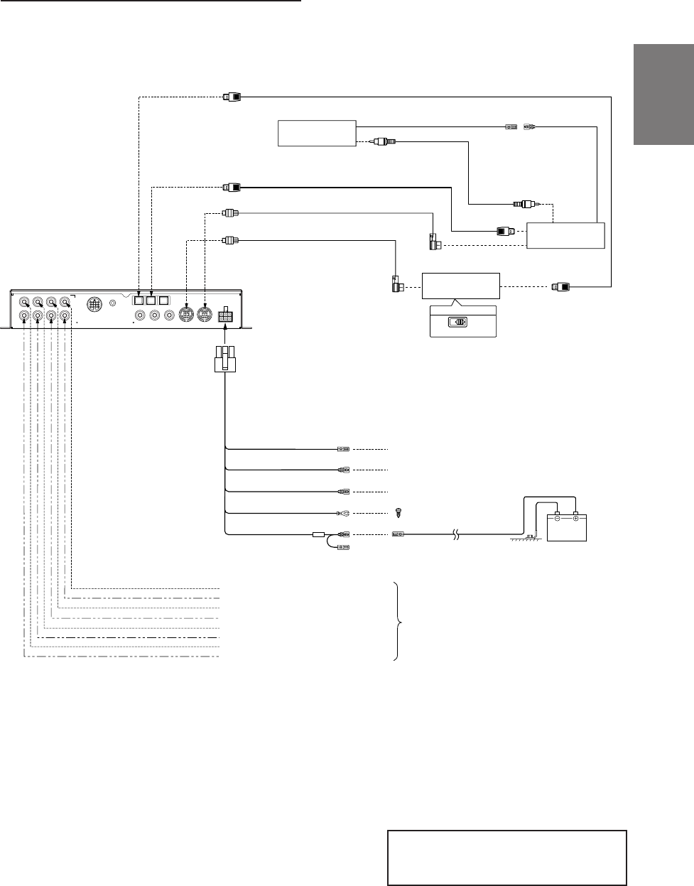
37-EN
FR
ES
DE
SE
IT
Examples of system expansion
Battery
Blue/White
Blue/White
White/green
Not used in this system
Not used in this system
To External Amplifier Remote ON Cable
Connect to a metal part of
chassis body with a screw.
Remote OUT Cable
Remote ON Cable
Guide Control Cable
Grounding Cable
Battery Power Cable
Rear Output (L)
Rear Output (R)
Center Output or Subwoofer Output (L)*
Subwoofer Output or Subwoofer Output (R)*
Front 1 Output (L)
Front 1 Output (R)
Front 2 Output (L)
Front 2 Output (R)
Ai-NET Cable (Included with DVD Changer)
Ai-NET Cable (Included)
DVD Changer
Monitor
(TME-M790 etc.)
Ai-NET Compatible
Head Unit
EQ
/DIV
System Switch
Fiber Optic Cable (Included with DVD Changer) RCA Connection Cable
To Video Input Jack
To Video Output Jack
Remote Control Output Cable Remote Control
Input Cable
Fiber Optic Cable (Sold Separately)
(White/Brown)
(White/Brown)
★
To External Amplifier
(L)
(R)
FRONT 1
(FULL RANGE
/TWEETER)
FRONT 2 REAR
SUBWOOFER
CONTROL UNIT
MIC
GUIDEINPUTOUTPUT (L) (R) Ai–NET IN
ANALOG 2
ANALOG 1 CHANGER IN
ANALOG 3 POWER SUPPLY
CHG
DIGITAL 2
CD
DIGITAL 1
DVD
DIGITAL 3
CENTER
SELECTABLE
SUBWOOFER
NOTE
Please observe the following when using Fiber Optic Cable.
• Do not coil the Fiber Optic Cable smaller than a 30mm radius.
• Do not place anything on top of the Fiber Optic Cable.
NOTE
★Used for connection to an optical digital
compatible head unit.
• PXA-H700 + Ai-NET Compatible Head Unit + DVD Changer +
Monitor + External Amplifier
* When the subwoofer is connected to the
center speaker output jack, it becomes
subwoofer output (L or R).
In this case, change the setting of the center
speaker to subwoofer in “Setting the speakers”
(page 4).
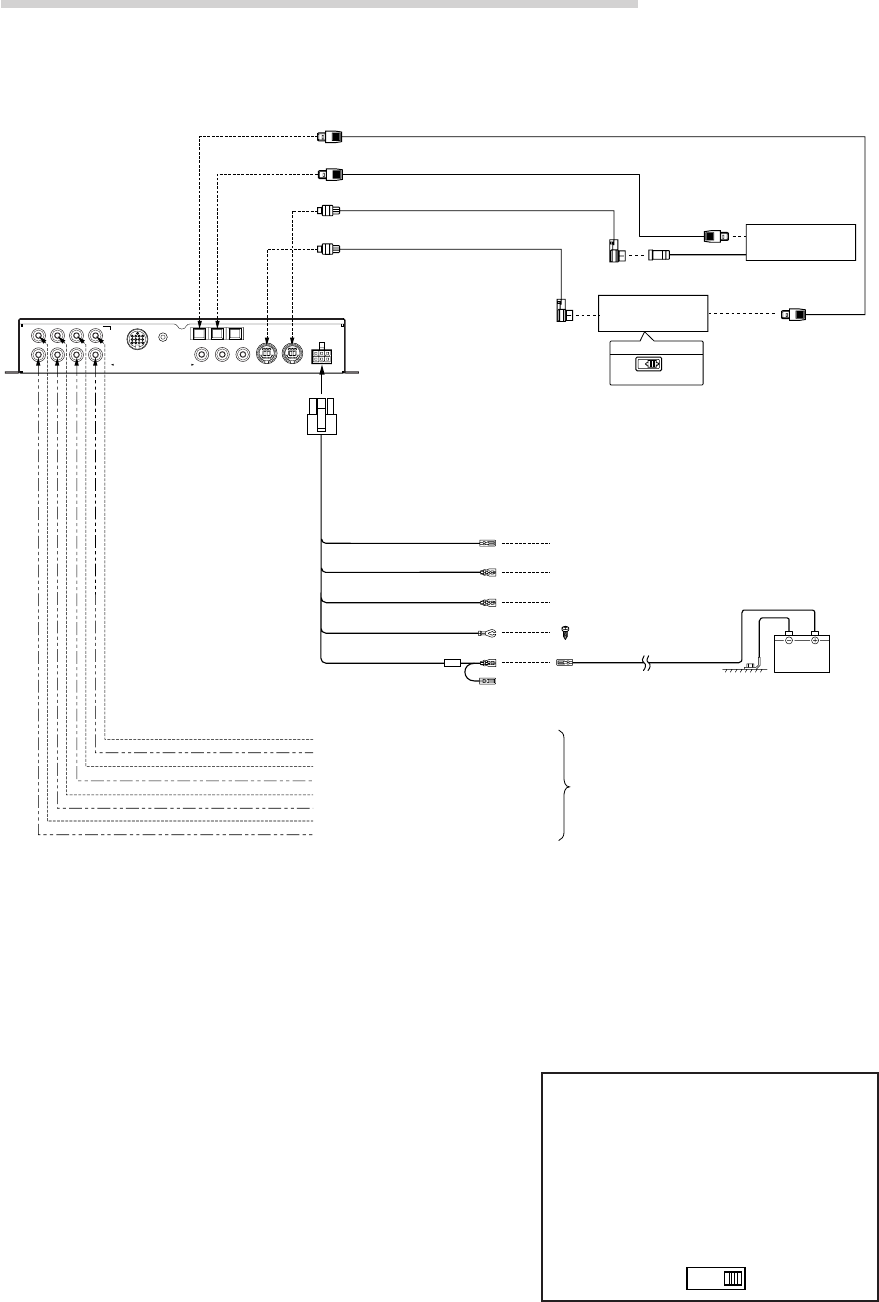
38-EN
Installation and Connections
NOTE
Please observe the following when using Fiber Optic Cable.
• Do not coil the Fiber Optic Cable smaller than a 30mm radius.
• Do not place anything on top of the Fiber Optic Cable.
• PXA-H700 + Ai-NET Compatible Head Unit + CD Changer +
External Amplifier
Battery
Blue/White
Blue/White
White/green
Not used in this system
Not used in this system
To External Amplifier Remote ON Cable
Connect to a metal part of
chassis body with a screw.
Remote OUT Cable
Remote ON Cable
Guide Control Cable
Grounding Cable
Battery Power Cable
Rear Output (L)
Rear Output (R)
Ai-NET Cable (Included with CD Changer)
Ai-NET Cable (Included)
Ai-NET Compatible
Head Unit
EQ
/DIV
System Switch
Fiber Optic Cable (Sold Separately)
Ai-NET Compatible
CD Changer
★★★
Fiber Optic Cable (Sold Separately) ★★
★
Front 1 Output (L)
Front 1 Output (R)
Front 2 Output (L)
Front 2 Output (R)
Center Output or Subwoofer Output (L)*
Subwoofer Output or Subwoofer Output (R)*
To External Amplifier
(L)
(R)
FRONT 1
(FULL RANGE
/TWEETER)
FRONT 2 REAR
SUBWOOFER
CONTROL UNIT
MIC
GUIDEINPUTOUTPUT (L) (R) Ai–NET IN
ANALOG 2
ANALOG 1 CHANGER IN
ANALOG 3 POWER SUPPLY
CHG
DIGITAL 2
CD
DIGITAL 1
DVD
DIGITAL 3
CENTER
SELECTABLE
SUBWOOFER
NOTES
★When connecting a Optical Digital CD
Changer
★★ Used for connection to an optical
digital compatible head unit.
★★★ When connecting a Optical Digital CD
Changer, change the Digital/Analog
switch of the CD Changer to "2"
(Digital Output)
12
* When the subwoofer is connected to the
center speaker output jack, it becomes
subwoofer output (L or R).
In this case, change the setting of the center
speaker to subwoofer in “Setting the speakers”
(page 4).
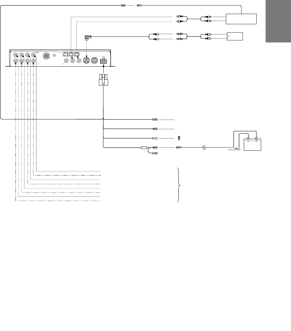
39-EN
FR
ES
DE
SE
IT
• PXA-H700 + Head Unit + Video Deck etc. + External Amplifier
• For connecting a head unit with which Ai-NET connections are not possible.
NOTE
When using the PXA-H700 with a non-Ai-NET head unit, +12V is required on this line * to turn on the equalizer. If your
head unit does not have a remote-on or power-antenna turn-on wire, an SPST switch must be connected between an
ignition source and this terminal. The PXA-H700 can then be turned on using this switch.
The PXA-H700 can be used with any head unit. However, only an Alpine Ai-NET compatible head unit will be able to
take full advantage of all the features and functions of this processor.
Battery
Blue/White
White/green
Not used in this system
To External Amplifier Remote ON Cable
Connect to a metal part of
chassis body with a screw.
Remote OUT Cable
Guide Control Cable
Grounding Cable
Battery Power Cable
Rear Output (L)
Rear Output (R)
RCA connection cable
Remote OUT cable
RCA connection cable
*
Remote ON Cable
Head Unit
Ai-RCA Conversion Cable
(Sold Separately)
TV Tuner,
Video etc.
Audio
Output
Blue/White
Blue/White
Front 1 Output (L)
Front 1 Output (R)
Front 2 Output (L)
Front 2 Output (R)
Center Output or Subwoofer Output (L)*
Subwoofer Output or Subwoofer Output (R)*
To External Amplifier
(L)
(R)
FRONT 1
(FULL RANGE
/TWEETER)
FRONT 2 REAR
SUBWOOFER
CONTROL UNIT
MIC
GUIDEINPUTOUTPUT (L) (R) Ai–NET IN
ANALOG 2
ANALOG 1 CHANGER IN
ANALOG 3 POWER SUPPLY
CHG
DIGITAL 2
CD
DIGITAL 1
DVD
DIGITAL 3
CENTER
SELECTABLE
SUBWOOFER
* When the subwoofer is connected to the
center speaker output jack, it becomes
subwoofer output (L or R).
In this case, change the setting of the center
speaker to subwoofer in “Setting the speakers”
(page 4).
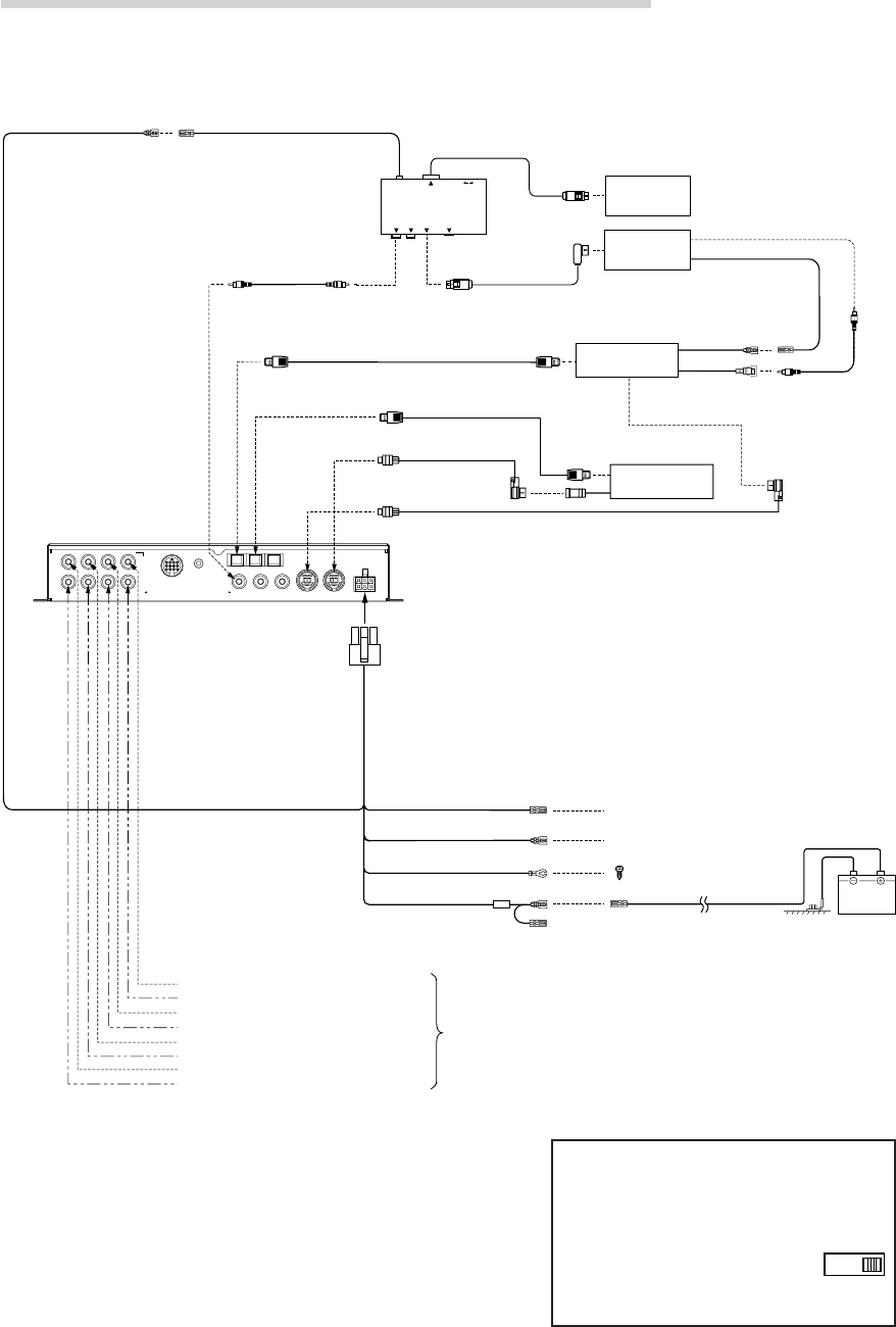
40-EN
Installation and Connections
• PXA-H700 + DVA-7996 Head Unit + CD Changer + Navigation
System + Monitor + External Amplifier
NOTE
Depending on the type of monitor used in the system, a separate
RGB conversion cable (KWE-503N) may be required. In addition,
connections are different from the ones shown above when
connecting to an all-purpose monitor. Also refer to the operating
instructions of the KCE-900E. For details, contact your store of
purchase or an Alpine Information Center.
Please observe the following when using Fiber Optic
Cable.
• Do not coil the Fiber Optic Cable smaller than a 30mm radius.
• Do not place anything on top of the Fiber Optic Cable.
Battery
NAVIGATION
INPUT
REMOTE INPUT
VIDEO OUTPUT
RGB
RGB OUTPUT
GUIDE OUTPUT NTSC VIDEO
OUTPUT
NTSC
Blue/White
Blue/White Not used in this system
To External Amplifier Remote ON Cable
Connect to a metal part of
chassis body with a screw.
Remote OUT Cable
Remote ON Cable
Grounding Cable
Battery Power Cable
Rear Output (L)
Rear Output (R)
RCA
connection
cable
To
Video
Input
Jack
RGB Cable
(Sold Separately)
Remote Control
Output Cable
Remote Control
Input Cable
Video Output
Cable
Guide Control Cable
Yellow
Navigation
KCE-900E
(Sold Separately)
DVA-7996
Head Unit
Fiber Optic Cable (
Sold Separately
)
Monitor
(TME-M790 etc.)
White/Green
White/Brown White/Brown
Front 1 Output (L)
Front 1 Output (R)
Front 2 Output (L)
Front 2 Output (R)
RCA connection cable
Guide Control Cable
White/Green
Ai-NET Compatible
CD Changer
★★
Ai-NET Cable
(Included with CD Changer)
Fiber Optic Cable
(Sold Separately)
Ai-NET Cable (Included)
★
Center Output or Subwoofer Output (L)*
Subwoofer Output or Subwoofer Output (R)*
To External
Amplifier
(L)
(R)
FRONT 1
(FULL RANGE
/TWEETER)
FRONT 2 REAR
SUBWOOFER
CONTROL UNIT
MIC
GUIDEINPUTOUTPUT (L) (R) Ai–NET IN
ANALOG 2
ANALOG 1 CHANGER IN
ANALOG 3 POWER SUPPLY
CHG
DIGITAL 2
CD
DIGITAL 1
DVD
DIGITAL 3
CENTER
SELECTABLE
SUBWOOFER
NOTES
★When connecting a Optical Digital CD
Changer
★★ When connecting a Optical
Digital CD Changer, change
the Digital/Analog switch of
the CD Changer to “2”
(Digital Output)
12
* When the subwoofer is connected to the
center speaker output jack, it becomes
subwoofer output (L or R).
In this case, change the setting of the
center speaker to subwoofer in “Setting
the speakers” (page 4).
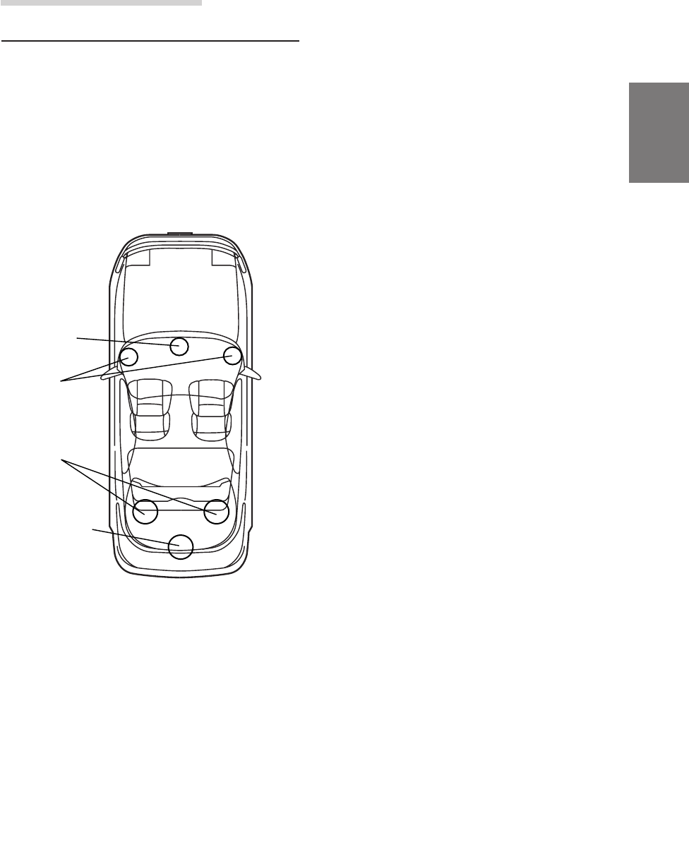
41-EN
EN
FR
ES
DE
SE
IT
Information
Terminology
Dolby Digital
Dolby Digital is a digital audio compression
technology developed by Dolby Laboratories that
allows large quantities of audio data to be efficiently
recorded on discs. It is compatible with audio signals
from mono (1 channel) all the way up to 5.1-channel
surround sound. The signals for the different
channels are completely independent, and since the
sound is high quality digital there is no loss of sound
quality.
Center
speaker
Front
speakers
Rear
speakers
Subwoofer
Speaker layout for enjoying
Dolby Digital sound/DTS sound
DTS
This is a home-use digital sound format of the DTS
Sound System. This is a high quality sound system,
developed by Digital Theater Systems Corp for use
in movie theaters.
DTS has six independent sound tracks. The theater
presentation is fully realized in the home and other
settings. DTS is the abbreviation for Digital Theater
Systems.
Dolby Pro Logic II
Dolby Pro Logic II provides multichannel surround
sound from any 2 channel source. It reproduces
extended bandwidth playback with 5.1 channels.
This is made possible by an advanced matrix
surround decoder. This new decoder is able to draw
out spatial characteristics of the recording without
adding tonal coloration or artificial delays that did not
exist in the original.
Linear PCM audio (LPCM)
LPCM is a signal recording format used for music
CDs. Whereas music CDs are recorded at 44.1 kHz/
16 bits, DVDs are recorded at 48 kHz/16 bits to 96
kHz/24 bits, thereby achieving higher sound quality
than music CDs.

42-EN
In case of difficulty
If you encounter a problem, please review the items
in the following checklist. This guide will help you
isolate the problem if the unit is at fault. Otherwise,
make sure the rest of your system is properly
connected or consult your authorized Alpine dealer.
Set does not operate.
Nothing appears on the display.
• Vehicle’s ignition key is turned off.
- Turn the vehicle’s ignition key on.
• Set’s power is not turned on.
- Turn the vehicle’s ignition key on then turn on
the power of the head unit.
• Power cord is not securely connected.
- Connect the power cord securely.
• Fuse is blown.
- Replace with a fuse of the specified capacity.
• Display mode is set to off.
- Switch the display to another mode.
(Page 29)
Power is on but no sound is produced.
• Volume level is set to the minimum.
- Increase the volume level. (Page 5)
• Input mode is set to a mode to which nothing is
connected.
- Set to a connected mode. (Page 5)
No sound is produced from the speakers.
• Cords are not securely connected.
- Connect the cords securely.
• Speaker is set to the off mode.
- Set the speaker to the on mode. (Pages 4
and 22)
Speaker setup settings cannot be made.
• Front speakers are set to “SMALL”.
- Set the front speakers to “LARGE”. (Page 22)
Sound cannot be adjusted.
• Defeat is set to the on mode.
- Set defeat to the off mode. (Page 28)
Others
Caution when connecting the DVA-5205/
DVA-5200/DHA-S680
Although the adjustment screen such as EQ and
TCR on the audio processor are available in DVA-
5205/DVA-5200/DHA-S680, these adjustments
cannot be made when they are connected to the
PXA-H700.

43-EN
EN
FR
ES
DE
SE
IT
Specifications
Graphic EQ number of bands:
Front (left and right) 31 bands
Rear (left and right) 31 bands
Center 31 bands
Subwoofer 10 bands
Graphic EQ boost cut
range: ±9 dB
Parametric EQ number of bands:
Front/rear/center 5 bands
Subwoofer 2 bands
Parametric EQ frequency:
Front, Rear and Center
Band 1: 20/22/25/28/31.5/36/40/45/50/56/
63/71/80/90/100/110/125/140/160/
180/200/220/250/280/315/360/400/
450/500 (Hz)
Band 2: 50/56/63/71/80/90/100/110/125/
140/160/180/200/220/250/280/315/
360/400/450/500/560/630/710/800/
900/1k/1.1k/1.2k (Hz)
Band 3: 125/140/160/180/200/220/250/280/
315/360/400/450/500/560/630/710/
800/900/1k/1.1k/1.2k/1.4k/1.6k/
1.8k/2k/2.2k/2.5k/2.8k/3.2k (Hz)
Band 4: 315/360/400/450/500/560/630/710/
800/900/1k/1.1k/1.2k/1.4k/1.6k/
1.8k/2k/2.2k/2.5k/2.8k/3.2k/3.6k/4k/
4.5k/5k/5.6k/6.3k/7.1k/8k (Hz)
Band 5: 800/900/1k/1.1k/1.2k/1.4k/1.6k/
1.8k/2k/2.2k/2.5k/2.8k/3.2k/3.6k/4k/
4.5k/5k/5.6k/6.3k/7.1k/8k/9k/10k/
11k/12.5k/14k/16k/18k/20k (Hz)
Subwoofer
Band 1: 20/22/25/28/31.5/36/40/45/50/56/
63/71/80 (Hz)
Band 2: 50/56/63/71/80/90/100/110/125/
140/160/180/200 (Hz)
Parametric EQ boost cut
range: ±9 dB
Time correction control
range: 0 to 20 ms (0.05 ms steps)
Frequency response: 20 Hz to 20 kHz
S/N ratio: 95 dB
Channel separation: 70 dB
Input sensitivity: 850 mA (2V for analog 1 only)
Subwoofer crossover: 20 to 200 Hz (1/6 oct. steps)
Rated output: 4V (with 10 k ohms load)
Input impedance: 10 k ohms or greater
Output impedance: 1 k ohm or less
Weight: Control unit 159 g (5 oz)
Base unit 1.1 kg (2 lbs. 6 oz)
Dimensions
Control unit
Width 170 mm (6-3/4")
Height 46 mm (1-13/16")
Depth 24 mm (15/16")
Base unit
Width 260 mm (10-3/16")
Height 40 mm (1-9/16")
Depth 160 mm (6-1/4")
<Components>
Parts name Quantity
Parts for mounting ................................ 1set
Owner’s manual.................................... 1set
Microphone........................................... 1set
Due to continuous product improvement,
specifications and design are subject to change
without notice.
The illustrations included in these instructions may
appear different from the actual product due to
printing conditions.
Manufactured under license from Dolby Laboratories.
“Dolby”, “Pro Logic” and the double-D symbol are
trademarks of Dolby Laboratories. Confidential
unpublished works. ©1992-1997 Dolby Laboratories.
All rights reserved.
Manufactured under license from Digital Theater
Systems, Inc. US Pat. No. 5,451,942 and other
worldwide patents issues and pending. “DTS” and
“DTS Digital Surround” are trademarks of Digital
Theater Systems, Inc. © 1996 Digital Theater
Systems, Inc. All rights reserved.

ALPINE ELECTRONICS OF AMERICA, INC. AND ALPINE OF CANADA INC. ("Alpine"), are dedicated to quality
craftsmanship and are pleased to offer this Warranty. We suggest that you read it thoroughly. Should you have any
questions, please contact your Dealer or Alpine at one of the telephone numbers listed below.
● PRODUCTS COVERED:
This Warranty covers Car Audio/Visual Products and
Related Accessories ("the product"). Products purchased in
the Canada are covered only in the Canada. Products
purchased in the U.S.A. are covered only in the U.S.A.
● LENGTH OF WARRANTY:
This Warranty is in effect for one year from the date of the
first consumer purchase.
● LIFETIME TAPE HEAD WARRANTY:
All Alpine Car Audio analog tape heads excluding Video
tape heads are warranted for life against manufacturing
defects causing failure.
● WHO IS COVERED:
This Warranty only covers the original purchaser of the
product, who must reside in the United States, Puerto Rico
or Canada.
● WHAT IS COVERED:
This Warranty covers defects in materials or workmanship
(parts and labor) in the product.
● WHAT IS NOT COVERED:
This Warranty does not cover the following:
1
Damage occurring during shipment of the product to
Alpine for repair (claims must be presented to the
carrier).
2
Damage caused by accident, abuse, negligence,
misuse, improper connections, improper operation or
failure to follow instructions contained in the Owner's
manual.
3
Damage caused by act of God, including without
limitation, earthquake, fire, flood, storms or other acts of
nature.
4
Any cost or expense related to the removal or
reinstallation of the product.
5
Service performed by an unauthorized person, company
or association.
6
Any product which has the serial number defaced,
altered or removed.
7
Any product which has been adjusted, altered or
modified without Alpine's consent.
8
Any product not distributed by Alpine within the United
States, Puerto Rico or Canada.
9
Any product not purchased from an Authorized Alpine
Dealer.
p
Any product that has been determined to contain an
excessive amount of dust or dirt and any product that
contains other contaminants including liquid or foreign
objects.
● HOW TO OBTAIN WARRANTY SERVICE:
1
You are responsible for delivery of the product to an
Authorized Alpine Service Center or Alpine for repair
and for payment of any initial shipping charges. Alpine
will, at its option, repair or replace the product with a
new or reconditioned product without charge. If the
repairs are covered by the warranty, and if the product
was shipped to an Authorized Alpine Service Center or
Alpine, Alpine will pay the return shipping charges.
2
You should provide a detailed description of the
problem(s) for which service is required.
3
You must supply proof of your purchase of the product.
4
You must package the product securely to avoid
damage during shipment.
● HOW WE LIMIT IMPLIED WARRANTIES:
ANY IMPLIED WARRANTIES INCLUDING FITNESS FOR
USE AND MERCHANTABILITY ARE LIMITED IN
DURATION TO THE PERIOD OF THE EXPRESS
WARRANTY SET FORTH ABOVE AND NO PERSON IS
AUTHORIZED TO ASSUME FOR ALPINE ANY OTHER
LIABILITY IN CONNECTION WITH THE SALE OF THE
PRODUCT.
● HOW WE EXCLUDE CERTAIN DAMAGES:
ALPINE EXPRESSLY DISCLAIMS LIABILITY FOR
INCIDENTAL AND CONSEQUENTIAL DAMAGES
CAUSED BY THE PRODUCT. THE TERM "INCIDENTAL
DAMAGES" REFERS TO EXPENSES OF
TRANSPORTING THE PRODUCT TO THE ALPINE
SERVICE CENTER, LOSS OF THE ORIGINAL
PURCHASER'S TIME, LOSS OF THE USE OF THE
PRODUCT, BUS FARES, CAR RENTALS OR OTHERS
COSTS RELATING TO THE CARE AND CUSTODY OF
THE PRODUCT. THE TERM "CONSEQUENTIAL
DAMAGES" REFERS TO THE COST OF REPAIRING OR
REPLACING OTHER PROPERTY WHICH IS DAMAGED
WHEN THIS PRODUCT DOES NOT WORK PROPERLY.
THE REMEDIES PROVIDED UNDER THIS WARRANTY
ARE EXCLUSIVE AND IN LIEU OF ALL OTHERS.
● HOW STATE/PROVINCIAL LAW RELATES TO THE
WARRANTY:
This Warranty gives you specific legal rights, and you may
also have other rights which vary form state to state and
province to province. In addition, some states/provinces do
not allow limitations on how long an implied warranty lasts,
and some do not allow the exclusion or limitation of
incidental or consequential damages. Accordingly,
limitations as to these matters contained herein may not
apply to you.
● IN CANADA ONLY:
This Warranty is not valid unless your Alpine car audio
product has been installed in your vehicle by an Authorized
Installation Center, and this warranty stamped upon
installation by the installation center.
● HOW TO CONTACT CUSTOMER SERVICE:
Should the product require service, please call the following
number for your nearest Authorized Alpine Service Center.
U.S.A. 1-800-ALPINE-1 (1-800-257-4631)
CANADA 1-800-ALPINE-1 (1-800-257-4631)
Alpine Electronics of America, Inc., 19145 Gramercy Place, Torrance, California 90501, U.S.A.
Alpine Electronics of Canada, Inc., Suite 203, 7300 Warden Ave. Markham, Ontario, L3R 9Z6, Canada
LIMITED WARRANTY
