Altai Technologies AP5822A A2 WiFi Access Point/Bridge User Manual rev2
Altai Technologies Limited A2 WiFi Access Point/Bridge rev2
User Manual_rev2

TPS10-013_rev1.2_A2N_Configuration_Manual_-_fm_1.0.1._FCC.doc
Commercially Confidential
1
Altai A2 WiFi
Configuration Manual
(By Professional Installation)
For
Firmware Version 1.0.0.
Version 1.2
Date: 27-May-2010

TPS10-013_rev1.2_A2N_Configuration_Manual_-_fm_1.0.1._FCC.doc
Commercially Confidential
2
Copyright © 2010 Altai Technologies Limited
ALL RIGHTS RESERVED.
Altai Technologies Limited
Unit 209, 2
nd
Floor, East Wing,
Building 17, Phase 2,
Hong Kong Science Park,
Shatin, New Territories,
Hong Kong
Telephone: +852 2116 8087
Fax: +852 2607 4021
Web: www.altaitechnologies.com
Customer Support Centre:
Email: support@altaitechnologies.com

TPS10-013_rev1.2_A2N_Configuration_Manual_-_fm_1.0.1._FCC.doc
Commercially Confidential
3
Radio Frequency Interference Requirements
This device complies with Part 15 of FCC Rules.
Operation is subject to the following conditions:
1. This device may not cause harmful interference.
2. This device must accept any interference received, including interference that may cause
undesired operation.
3. This device should not be co-located or operating in conjunction with any other antenna
or transmitter.
Interference Statement
This equipment has been tested and found to comply with the limits for a Class B digital device,
pursuant to Part 15 of the FCC Rules. These limits are designed to provide reasonable protection
against harmful interference in a residential installation. This equipment generates, uses and can
radiate radio frequency energy and, if not installed and used in accordance with the instructions,
may cause harmful interference to radio communications.
However, there is no guarantee that interference will not occur in a particular installation. If this
equipment does cause harmful interference to radio or television reception, which can be
determined by turning the equipment off and on, the user is encouraged to try to correct the
interference by one of the following measures:
- Reorient or relocate the receiving antenna.
- Increase the separation between the equipment and receiver.
- Connect the equipment into an outlet on a circuit different from that to which the
receiver is connected.
- Consult the dealer or an experienced radio/TV technician for help.
FCC Caution: To assure continued compliance, (example – use only shielded interface cables
when connecting to computer or peripheral devices). Any changes or modifications not
expressly approved by the party responsible for compliance could void the user’s authority to
operate this equipment.
Warning
The user is advised to keep apart from the base-station and antenna with at least 45cm when the
base-station is in operation.
Disclaimer
All specifications are subject to change without prior notice. Altai Technologies assumes no
responsibilities for any inaccuracies in this document or for any obligation to update information
in this document. This document is provided for information purposes only. Altai Technologies
reserves the right to change, modify, transfer, or otherwise revise this publication without notice.

TPS10-013_rev1.2_A2N_Configuration_Manual_-_fm_1.0.1._FCC.doc
Commercially Confidential
4
Table of Contents
1
I
NTRODUCTION
........................................................................................................................................7
1.1
Total Performance.......................................................................................................................7
1.2
Compatible With 802.11n...........................................................................................................7
1.3
Large Capacity............................................................................................................................7
1.4
Different Operation Modes.........................................................................................................7
2
A2
M
ODEL AND
F
IRMWARE
V
ERSION
.....................................................................................................7
3
G
ETTING
S
TART
.......................................................................................................................................8
3.1
Setup Local Area Connection on Your PC .................................................................................8
3.2
Check Access............................................................................................................................11
4
CONFIGURATION WITH
W
EB
-A
DMIN
......................................................................................................12
4.1
Web Browser Connection.........................................................................................................12
4.2
Checking the A2 Versions ........................................................................................................14
4.3
Setup – User Name, Password and System Name....................................................................14
4.4
NTP Configuration ...................................................................................................................15
4.5
SNMP Configuration ................................................................................................................15
4.6
Telnet ........................................................................................................................................16
4.7
Network Operation Mode .........................................................................................................16
4.8
Switch Mode.............................................................................................................................17
4.9
Gateway Mode..........................................................................................................................19
4.10
Access Link Safe Mode/ Backhaul Link Self-healing..............................................................22
4.11
Setup – Wireless Radio Parameter............................................................................................23
4.12
AP Mode...................................................................................................................................23
4.13
Repeater Mode..........................................................................................................................30
4.14
Bridge Mode .............................................................................................................................31
4.15
Disable Mode............................................................................................................................35
4.16
Reboot.......................................................................................................................................35
4.17
Restore Configuration to Default Setting .................................................................................37
5
P
ERFORMANCE
M
ANAGEMENT
M
ONITORING IN
W
EB
-A
DMIN
.............................................................38
5.1
System.......................................................................................................................................38
5.2
Clients Statistics........................................................................................................................39
5.3
Radio Association-AP Mode ....................................................................................................40
5.4
Radio Association-Repeater Mode ...........................................................................................41
5.5
Radio Association-Bridge Mode ..............................................................................................42
6
S
OFTWARE
U
PGRADE THROUGH
W
EB
-A
DMIN
......................................................................................44
6.1
Firmware Update Through HTTP or HTTPS ...........................................................................44
7
G
LOSSARY
..............................................................................................................................................46

TPS10-013_rev1.2_A2N_Configuration_Manual_-_fm_1.0.1._FCC.doc
Commercially Confidential
5
Table of Figures
F
IGURE
1
C
ONTROL
P
ANEL IN
W
INDOWS
XP ............................................................................................................ 8
F
IGURE
2
N
ETWORK
C
ONNECTIONS IN
W
INDOWS
XP ............................................................................................... 9
F
IGURE
3
L
OCAL
A
REA
C
ONNECTION
P
ROPERTIES IN
W
INDOWS
XP ........................................................................ 9
F
IGURE
4
I
NTERNET
P
ROTOCOL
(TCP/IP)
P
ROPERTIES IN
W
INDOWS
XP ................................................................ 10
F
IGURE
5
E
NTER
U
SER
N
AME AND
P
ASSWORD
....................................................................................................... 12
F
IGURE
6
W
EB
-
ADMIN
L
OGIN
P
AGE
........................................................................................................................ 13
F
IGURE
7
V
ERSION OF
A2
W
I
F
I
............................................................................................................................ 14
F
IGURE
8
S
YSTEM
C
ONFIGURATION
........................................................................................................................ 14
F
IGURE
9
NTP
C
ONFIGURATION
............................................................................................................................. 15
F
IGURE
10
T
HE
IP
ADDRESS HERE IS THE
E
THERNET INTERFACE OF THE
A2 ........................................................... 17
F
IGURE
11
N
ETWORK
C
ONFIGURATIONS UNDER
S
WITCH MODE
............................................................................. 17
F
IGURE
12
N
ETWORK
C
ONFIGURATIONS UNDER
G
ATEWAY MODE
......................................................................... 19
F
IGURE
13
PPP
O
E
C
ONFIGURATION
........................................................................................................................ 20
F
IGURE
14
C
ONFIGURE
DHCP
S
ERVER
................................................................................................................... 21
F
IGURE
15
C
ONFIGURE
DHCP
R
ELAY
S
ERVER
....................................................................................................... 22
F
IGURE
16
W
IRELESS
R
ADIO
P
ARAMETER
C
ONFIGURATION
................................................................................... 23
F
IGURE
17
A
DVANCED
W
IRELESS
R
ADIO
S
ETTING
................................................................................................. 25
F
IGURE
18
VAP
S
ETTING
........................................................................................................................................ 26
F
IGURE
19
ACL ...................................................................................................................................................... 27
F
IGURE
20
W
IRELESS
R
ADIO
S
ECURITY
C
ONFIGURATION
....................................................................................... 27
F
IGURE
21
WEP
K
EY
S
ETTINGS
.............................................................................................................................. 28
F
IGURE
22
WPA
S
ETTINGS
..................................................................................................................................... 28
F
IGURE
23
WPA-PSK
S
ETTINGS
............................................................................................................................. 29
F
IGURE
24
R
EPEATER
M
ODE
C
ONFIGURATION
........................................................................................................ 30
F
IGURE
25
5GH
Z
R
ADIO
P
ARAMETER
C
ONFIGURATION
......................................................................................... 31
F
IGURE
26
A
DVANCED
B
RIDGE
R
ADIO
S
ETTING
..................................................................................................... 32
F
IGURE
27
B
RIDGE ENCRYPTION SETTING
_WEP..................................................................................................... 33
F
IGURE
28
B
RIDGE ENCRYPTION SETTING
_AES...................................................................................................... 34
F
IGURE
29
W
IRELESS
R
ADIO
D
ISABLE
M
ODE
......................................................................................................... 35
F
IGURE
30
R
EBOOT
W
INDOW
.................................................................................................................................. 36
F
IGURE
31
A2
W
I
F
I
A
CCESS
P
OINT IS
R
EBOOTING
............................................................................................... 36
F
IGURE
32
R
ESET TO
F
ACTORY
D
EFAULT
S
ETTING IN
W
EB
-
ADMIN
........................................................................ 37
F
IGURE
33
D
ETAILS OF THE SYSTEM
....................................................................................................................... 38
F
IGURE
34
S
TATUSES OF THE
V
APS
......................................................................................................................... 38
F
IGURE
35
S
TATUSES OF THE
R
EMOTE
B
RIDGES
..................................................................................................... 39
F
IGURE
36
2.4GH
Z
R
ADIO
S
TATISTICS
M
ENU
......................................................................................................... 39
F
IGURE
37
R
ADIO
A
SSOCIATION
T
ABLE
.................................................................................................................. 40
F
IGURE
38
R
ADIO
S
TATISTICS PER
MAC
A
DDRESS
(
DATA IS CUMULATIVE
) ........................................................... 41
F
IGURE
39
R
ADIO
A
SSOCIATION
AP
L
IST
............................................................................................................... 41
F
IGURE
40
A
SSOCIATION
AP
S
TATISTICS PER
MAC
A
DDRESS
(
DATA IS CUMULATIVE
) .......................................... 42
F
IGURE
41
R
ADIO
A
SSOCIATION
B
RIDGE
L
IST
........................................................................................................ 42
F
IGURE
42
B
RIDGE
A
SSOCIATION
S
TATISTICS PER
MAC
ADDRESS
......................................................................... 43
F
IGURE
43
U
PLOAD THE
F
IRMWARE THROUGH
HTTP
OR
HTTPS .......................................................................... 45
F
IGURE
44
S
UCCESSFUL
F
IRMWARE
U
PDATE
–
W
EB
-
ADMIN
.................................................................................. 45
TPS10-013_rev1.2_A2N_Configuration_Manual_-_fm_1.0.1._FCC.doc
Commercially Confidential
6
Manual Conventions
Bold Bold type within paragraph text indicates commands, files
names,
directory names, paths, output, or returned values.
Italic Within commands, italics indicate a variable that the user must specify.
Titles of manuals or other published documents are also set in italics.
_____ Underline means that the words you have to pay attention.
Courier
The courier font indicates output or display.
[ ]
Within commands, items enclosed in square brackets are optional
parameters or values that the user can choose to specify or omit.
{ }
Within commands, item enclosed in braces are options from which the
user must choose.
| Within commands, the vertical bar separates options.
… An ellipsis indicates a repetition of preceding parameter.
> The right angle bracket separates successive menu selection.
NOTE: This message denotes neutral or positive information that calls out important points
to the text. A note provides information that applies only in special cases.
Caution: Cautions call special attention to hazards that can cause system damage or
data corruption, to a lesser degree than warnings.
Warnings: Warnings call special attention to hazards that can cause system damage,
data corruption, personal injury, or death.

TPS10-013_rev1.2_A2N_Configuration_Manual_-_fm_1.0.1._FCC.doc
Commercially Confidential
7
1 I
NTRODUCTION
1.1 T
OTAL
P
ERFORMANCE
Altai A2 WiFi provides coverage for outdoor WiFi coverage and enhance the Altai indoor
coverage solution. It combines IEEE 802.11a/b/g and Draft 802.11n to offer best WiFi access in
different scenarios.
1.2 C
OMPATIBLE
W
ITH
802.11
N
By adopting MIMO technology, Altai A2 WiFi provides up to 300Mbps data rate to 802.11n
clients. Maximum throughput is 150Mbps per radio.
1.3 L
ARGE
C
APACITY
Altai A2 WiFi has two working radios. One radio can work as access radio to enhance the total
capacity of A2 unit, while the other radio working as backhaul link.
1.4 D
IFFERENT
O
PERATION
M
ODES
There are multiple operation modes for each radio. AP mode means the radio is working for
clients association; Sta mode is used to repeat remote 2.4GHz radio end as backhaul link; 5GHz
radio can be selected as backhaul link when enabled Bridge mode; users can also disable the
radio.
This manual is to summarize how to perform configuration for the ALTAI A2 WiFi through
web-admin interface.
2 A2
M
ODEL AND
F
IRMWARE
V
ERSION
This manual is applicable for the following models and firmware version:
Product name : A2 WiFi
Model number : A2
Firmware version: v1.0.0.5
TPS10-013_rev1.2_A2N_Configuration_Manual_-_fm_1.0.1._FCC.doc
Commercially Confidential
8
3 G
ETTING
S
TART
3.1 S
ETUP
L
OCAL
A
REA
C
ONNECTION ON
Y
OUR
PC
A2 WiFi can be connected with your PC in wireless mode. In the followings, wireless mode will
be introduced.
Please kindly refer to the Altai A2 WiFi Installation Guide.
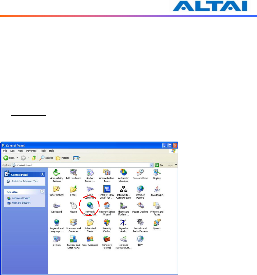
Start Network Configuration on your PC.
For Windows XP user,
1. Click the “start” menu and choose “Control Panel”.
2. Click “Network Connections”.
Figure 1 Control Panel in Windows XP
TPS10-013_rev1.2_A2N_Configuration_Manual_-_fm_1.0.1._FCC.doc
Commercially Confidential
9
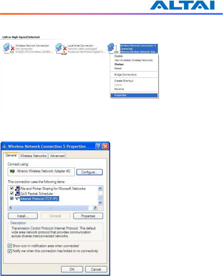
3. Right-click on the “Wireless Network Connection” and select “Properties”.
Figure 2 Network Connections in Windows XP
4. After clicking on “Properties”, you will see the diagram as below.
Figure 3 Wireless Network Connection Properties in Windows XP
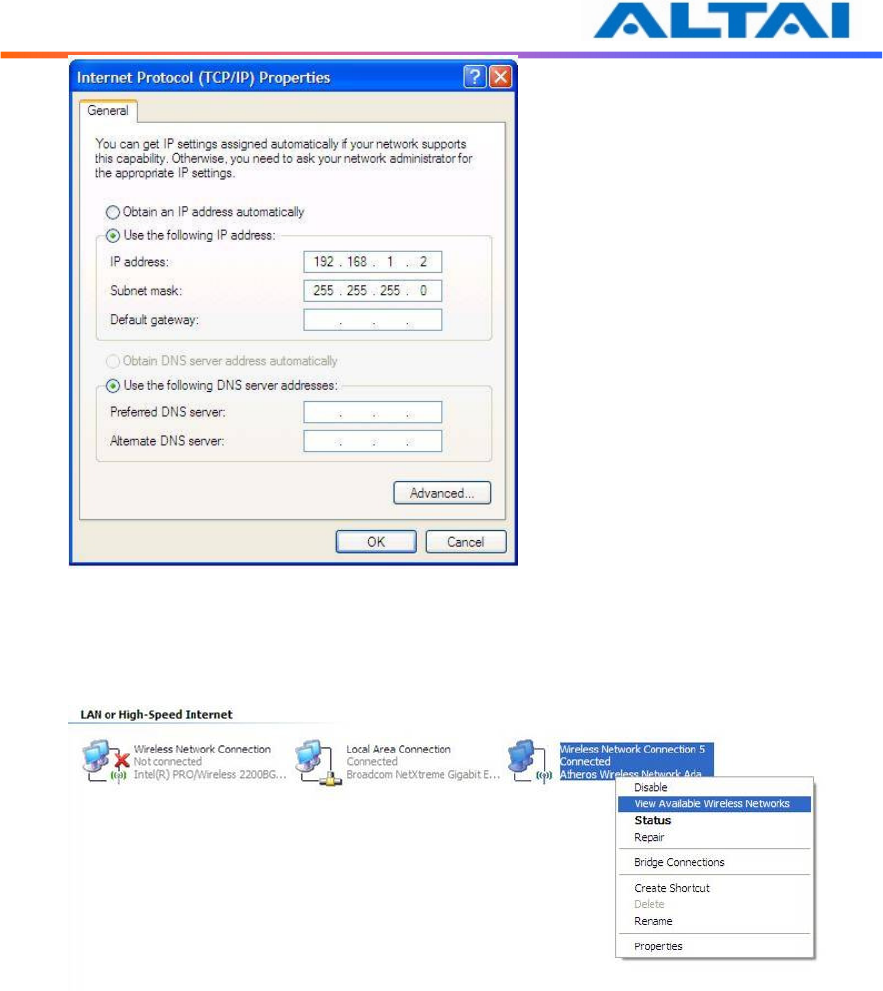
5. Marking the “Internet Protocol (TCP/IP)” and click the “Properties”.
6. Type in an “IP address”, for example, 192.168.1.2, which is under the same subnet as
the Default IP address of A2 WiFi (192.168.1.20).
7. Using the default “Subnet mask” (default: 255.255.255.0) setting at the first time.
8. Keep the “Default gateway” as “Blank”.
9. Keep the “Preferred DNS server” and “Alternate DNS server” as “Blank” also.
10. Click “OK” when you finish setting and close the Window.
TPS10-013_rev1.2_A2N_Configuration_Manual_-_fm_1.0.1._FCC.doc
Commercially Confidential
10
Figure 4 Internet Protocol (TCP/IP) Properties in Windows XP
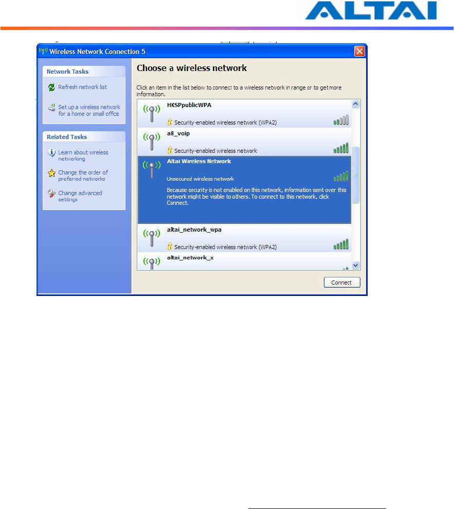
11. Right-click on the “Wireless Network Connection” and select “View Available
Wireless Networks”.
Figure 5 Network Connections in Windows XP
TPS10-013_rev1.2_A2N_Configuration_Manual_-_fm_1.0.1._FCC.doc
Commercially Confidential
11
12. Click on the “Altai Wireless Network”
Figure 6 Showing Available Wireless Network Connections in Windows XP
3.2 C
HECK
A
CCESS
“ping” utility of DOS mode is a handy tool to check the access to the A2 WiFi.
1. Go to DOS mode by typing “cmd” in “Run”.
2. Type command:
ping 192.168.1.20
The A2 WiFi shall respond to your ping request if it has a correct connection with your
PC.
NOTE: Using the same PC to ping different A2 WiFi may cause ping failure. This is because
the A2 WiFi APs have the same default IP address but different MAC addresses. You need to
type a command “arp –d” in DOS mode to clear ARP table on PC before each ping.
TPS10-013_rev1.2_A2N_Configuration_Manual_-_fm_1.0.1._FCC.doc
Commercially Confidential
12
4
CONFIGURATION WITH
W
EB
-A
DMIN
4.1 W
EB
B
ROWSER
C
ONNECTION
The A2 can be accessed through a Web Browser, for example, Internet Explorer (IE).
1. Open an IE session and type the IP address of the A2 Pico AP. Example:
https://192.168.1.20, where 192.168.1.20 is the A2’s IP address. The A2 default IP
Address is 192.168.1.20. Note: the release version 1.0.0. only supports https format
URL link.
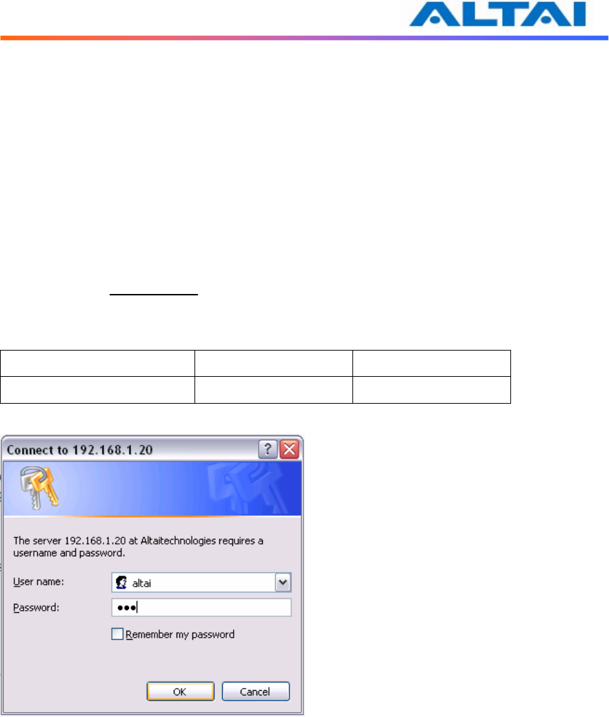
2. A window will pop up, as shown in Figure 5. Enter the user name and password in the
corresponding fields. The default User Name and Password are shown in Table 1.
They are case sensitive.
Default User Name Default Password
From version 1.0. onwards altai wag
Table 1 Default User Name and Password for logging in A2 WiFi
Figure 5 Enter User Name and Password
TPS10-013_rev1.2_A2N_Configuration_Manual_-_fm_1.0.1._FCC.doc
Commercially Confidential
13
3. Figure 6. A Menu Bar is located on the left hand side of the IE window. Different
configurations can be chosen through the menu bar.
Figure 6 Web-admin Login Page
TPS10-013_rev1.2_A2N_Configuration_Manual_-_fm_1.0.1._FCC.doc
Commercially Confidential
14
4.2 C
HECKING THE
A2
V
ERSIONS
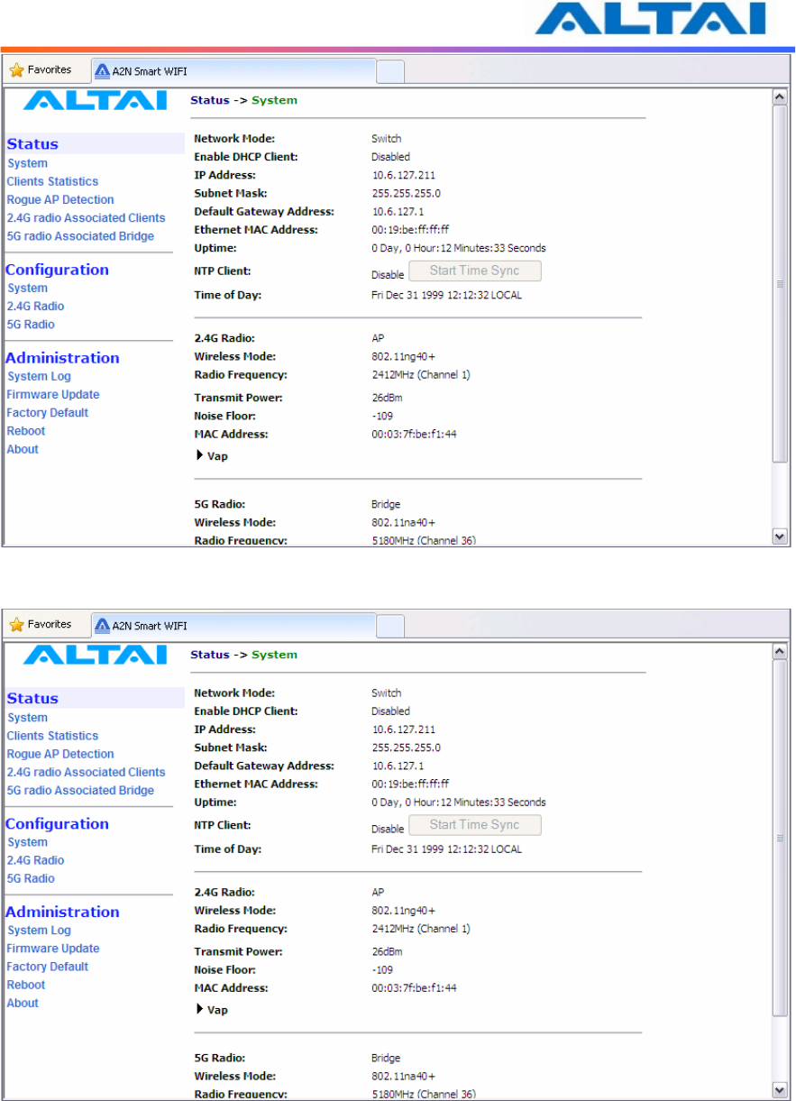
The running version can be checked by selecting About under Administration in the menu bar.
In Figure 7, it shows:
Firmware Version: v1.0.0 or above versions
Figure 7 Version of A2 WiFi
4.3 S
ETUP
–
U
SER
N
AME
,
P
ASSWORD AND
S
YSTEM
N
AME
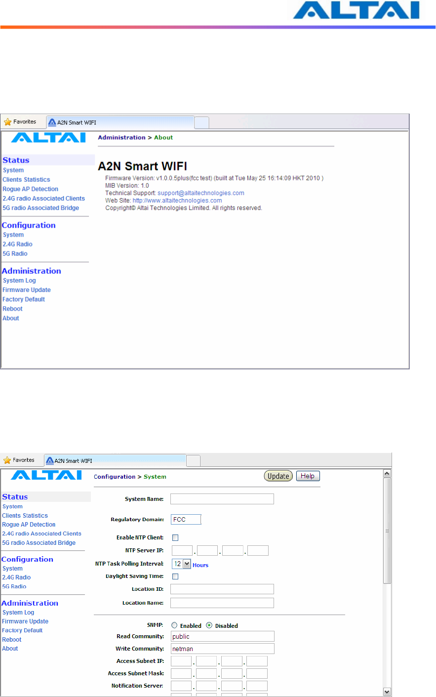
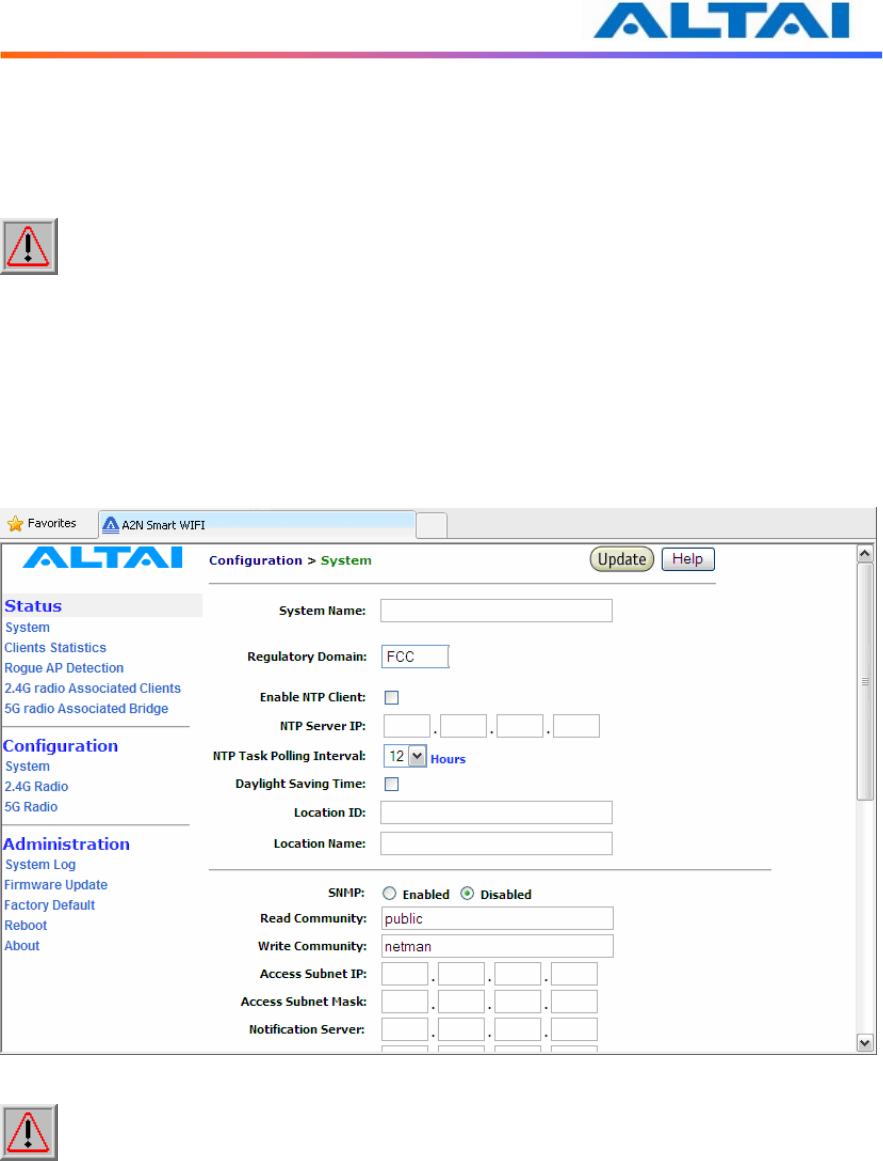
The Password and System Name can be configured by selecting System under Configuration
in the menu bar, as shown in Figure 8
Figure 8 System Configuration
TPS10-013_rev1.2_A2N_Configuration_Manual_-_fm_1.0.1._FCC.doc
Commercially Confidential
15
The User Name and Password for login are mentioned in Section 4.1, but only password can be
changed by entering a new string in the field of Password. Note: it is need to re-enter to
confirm the password. Please press Change Password button to store the new password.
The System Name is the name of the A2 WiFi.
NOTE: Click the Update icon to store the changed settings.
4.4 NTP
C
ONFIGURATION
NTP is a network time protocol for the AP to synchronize the system time. There is no NTP
server IP address by default. If NTP is needed, IP address of the NTP server must be added and
A2 will synchronize with the NTP server. This measure is useful to maintain the network and
make sure all APs using the same system time by setting the same NTP server.
Figure 9 NTP Configuration
NOTE: Click the Update icon to store the changed settings.
4.5 SNMP
C
ONFIGURATION
In the SNMP Manager, the administrator can change the Read Community and Write
Community. Access Subnet IP and Access Subnet Mask can be configured to specify the
A2’s SNMP Manger. Notification Server IP addresses can be added for SNMP control. They
are parameters used for SNMP control between Altai A2 and AWMS system.
By enabling SNMP Manager ACL mode, the A2 will only be managed by the AWMS which IP
is located in the ACL list with correct Read Community, Write Community and SNMP IP

TPS10-013_rev1.2_A2N_Configuration_Manual_-_fm_1.0.1._FCC.doc
Commercially Confidential
16
address.
It also supports SNMP Manager Access Control List which allows user to configure a list of
allowed SNMP manager IPs for managing the A2. When the SNMP manger ACL mode is
enabled, only SNMP request generated from the any of configured SNMP manger on the ACL
will be handled.
NOTE: Click the Update icon to store the changed settings.
4.6 T
ELNET
Administrator can login to the A2 WiFi by telnet command in Command Prompt via Ethernet or
WiFi. For example, to telnet A2 with IP address of 192.168.1.20; telnet command is “telnet
192.168.1.20 2223”.
NOTE: The telnet port number is limited at 2223.
4.7 N
ETWORK
O
PERATION
M
ODE
The default setting for the Network Operation Mode is Switch Mode. If the A2 WiFi is set to
Switch Mode, it acts as a switch and routes traffic between the DS and wireless clients
accordingly. When it is in Gateway mode, it acts as a gateway and the Local IP Address and
Local IP Address Mask information must be entered to specify the A2 local interface for
serving the wireless client.
In Switch mode, VLAN mode is by default disabled and clients in different SSID under the
same A2 can communicate with each other. However, if VLAN is enabled, each SSID can be
edited with a specific VLAN tag value. Only clients with same VLAN tag in same or different
SSID can communicate. Moreover, in this mode, DHCPS, NAT and PPPoE configuration have
no effort.
However, in Gateway mode, the DHCPS, NAT and PPPoE configurations can be configured but
the VLAN has no effort.
In Switch mode,
• VLAN can be configured
• DHCPS, NAT and PPPoE are disabled
In Gateway mode
• VLAN is disabled
• DHCPS, NAT and PPPoE can be configured
TPS10-013_rev1.2_A2N_Configuration_Manual_-_fm_1.0.1._FCC.doc
Commercially Confidential
17
4.8 S
WITCH
M
ODE
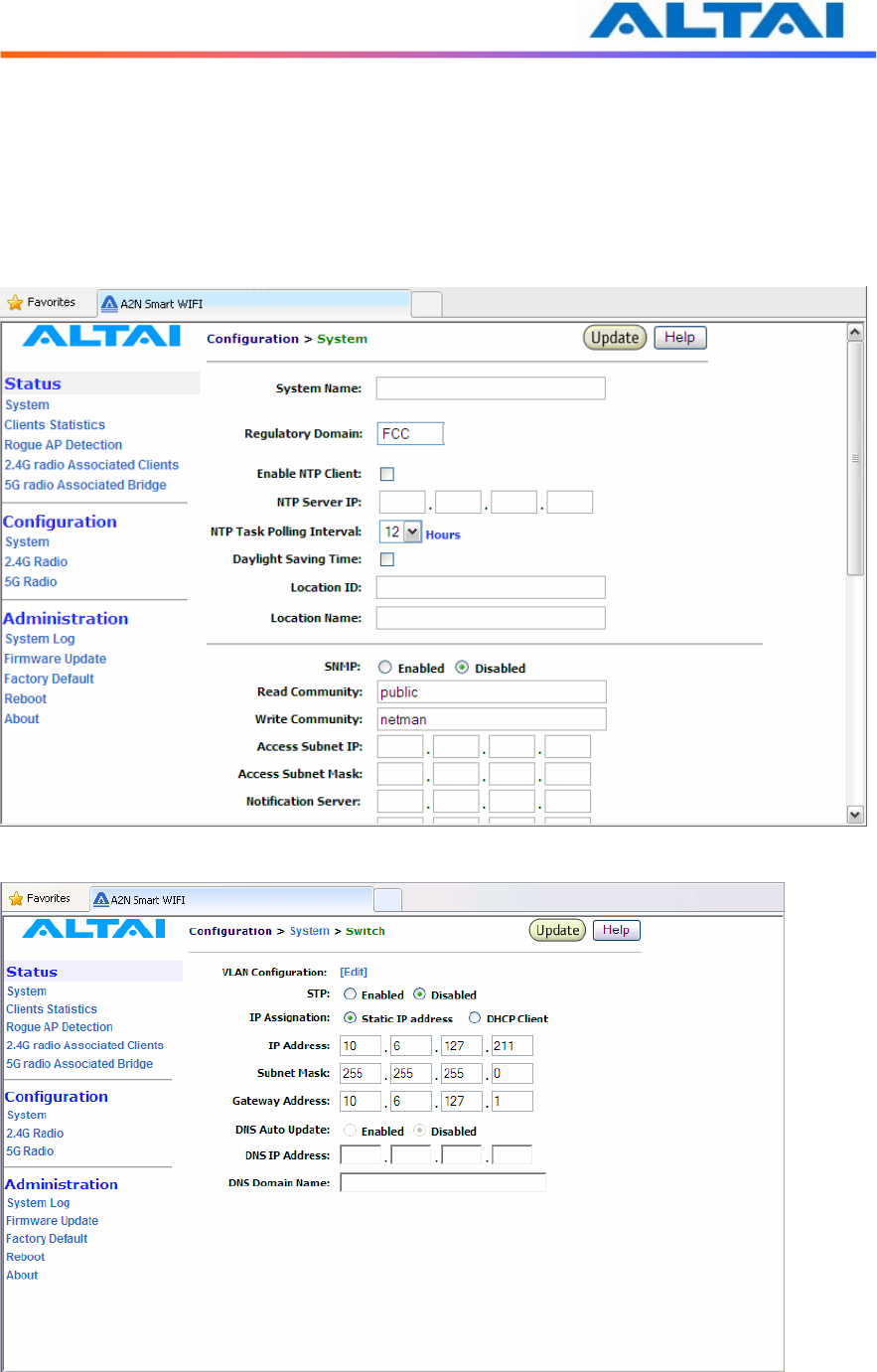
4.8.1 Static IP address
In IP Assignation, there are two kinds of working mode for A2 base station: Static IP
address and DHCP Client. In Switch mode, by clicking Network Configuration in the System
page, users can configure the IP Address, Subnet Mask and Gateway Address, as shown in
Figure 10 and Figure 11.
Figure 10 The IP address here is the Ethernet interface of the A2
Figure 11 Network Configurations under Switch mode

TPS10-013_rev1.2_A2N_Configuration_Manual_-_fm_1.0.1._FCC.doc
Commercially Confidential
18
4.8.2 VLAN Configuration
Default setting of VLAN is “Disabled”. By clicking “Enabled”, VLAN can be enabled. A2
supports VLAN to VAP mappings to provide network security.
Management VLAN is used to configure the management VLAN of A2. A2 can only be
accessed through the specified management VLAN when VLAN is enabled. It will be ignored
when VLAN is disabled.
Native VLAN Tagging control is used to control the untagged packet when VLAN is enabled.
All the packets without VLAN tags should be sent to the VLAN with Native VLAN Tag ID.
The default setting of Native VLAN Tagging is “Disabled”. Native VLAN Tagging can be
enabled when VLAN is enabled.
4.8.3 STP Configuration
STP ensures a loop free topology for any bridged LAN. Under switch mode, STP can be
configured with choice of “Enabled” and “Disabled”, where the default setting is “Disabled”.
The system supports the following fixed default STP parameters:
• Bridge priority: 32768
• Bridge maximum age: 20 seconds
• Bridge hello time: 2 seconds
• Bridge forwarding delay: 15 seconds
• Ethernet port path cost: 80
• Ethernet port priority: 128
• 802.11a bridge port path cost for each bridge link: 100
• 802.11a bridge port path priority for each bridge link: 128
4.8.4 DHCP Client
By enabling DHCP Client and clicking the icon Update, the A2 WiFi will acquire a dynamic IP
address from a DHCP server after rebooting.
Without enabling DHCP Client, the IP Address, Subnet Mask and the Default Gateway
Address should be configured by the user, unless the user prefers using the default setting.
NOTE: It is not recommend enabling DHCP client to allocate the IP address of A2 WiFi
which is hard to predict after rebooting the A2. If the IP address of A2 WiFi is unknown, there is
no way to maintain the A2 WiFi via web-admin page.
4.8.5 DNS Auto Update
By setting DNS Auto Update to Enabled and clicking the icon Update, the A2 WiFi will acquire
a DNS Server IP address via the DHCP Server after rebooting. User need not to set a DNS
Server IP Address manually.
Without enabling the A2 as a DHCP Client, the DNS IP Address and DNS Domain Name
should be configured by the user.

TPS10-013_rev1.2_A2N_Configuration_Manual_-_fm_1.0.1._FCC.doc
Commercially Confidential
19
NOTE: DNS Auto Update can only be enabled when DHCP client is enabled. If the
DNS Auto Update is enabled, it must be used in conjugation with either the DHCP Client or the
PPPoE Mode being enabled. If both the DHCP Client and the PPPoE Mode are disabled then the
DNS Auto Update must also be set to Disabled.
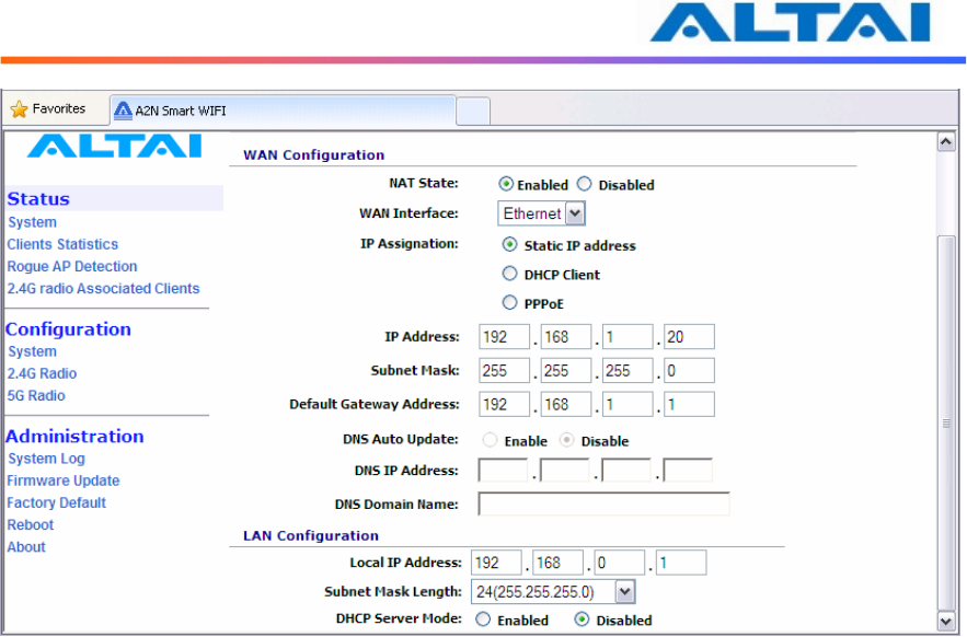
4.9 G
ATEWAY
M
ODE
In Gateway mode, by clicking Network Configuration in the System page, users can configure
the WAN and LAN settings.
Figure 12 Network Configurations under Gateway mode
4.9.1 WAN Configuration
NAT is set to “Enabled” as default.
The settings for Static IP address and DHCP Client are similar to those in switch mode. Please
refer to the previous section for details.
4.9.1.1 WAN Interface
Default setting is "Ethernet". This control is used to specify the WAN interface. The Ethernet
interface or 5G bridge interfaces can be used as the WAN interface when VAP0 works on the
AP mode. Use the pull down menu to select either one. The 2.4G Radio Client interface is
used as the WAN interface when VAP0 works on the Station mode.
TPS10-013_rev1.2_A2N_Configuration_Manual_-_fm_1.0.1._FCC.doc
Commercially Confidential
20
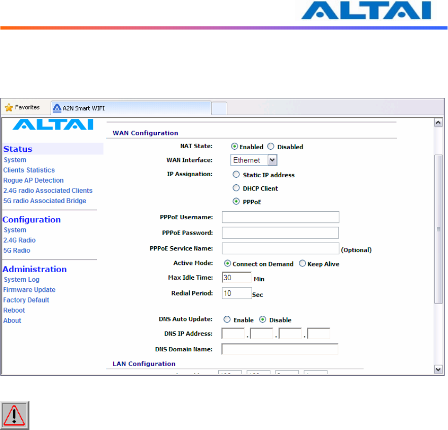
4.9.1.2 PPPoE Configuration
If PPPoE is chosen, a PPPoE login will be attempted for the PPPoE Username, PPPoE
Password and PPPoE Service Name, see Figure 13.
Figure 13 PPPoE Configuration
NOTE: The DNS Auto Update should be set to Disable when using PPPoE. User need
to configure the DNS server IP address manually.
PPPoE Active Mode, Max Idle Time and Redial Period can be configured.
When “Connect on Demand” is selected, PPPoE will establish the connection with the remote
access concentrator only when hosts in the local subnet need to access the internet. If the
parameter is set “Keep Alive”, PPPoE will establish the connection with the remote access
concentrator upon boot-up.
Default setting of Max Idle Time is 30 minutes. Only when PPPoE works under Connect on
Demand mode, it will be disconnected if PPPoE connection has been idle for the Max Idle
Time.
When last attempt failed, A2 WiFi will attempt to establish the PPPoE connection at Redial
Period.
TPS10-013_rev1.2_A2N_Configuration_Manual_-_fm_1.0.1._FCC.doc
Commercially Confidential
21
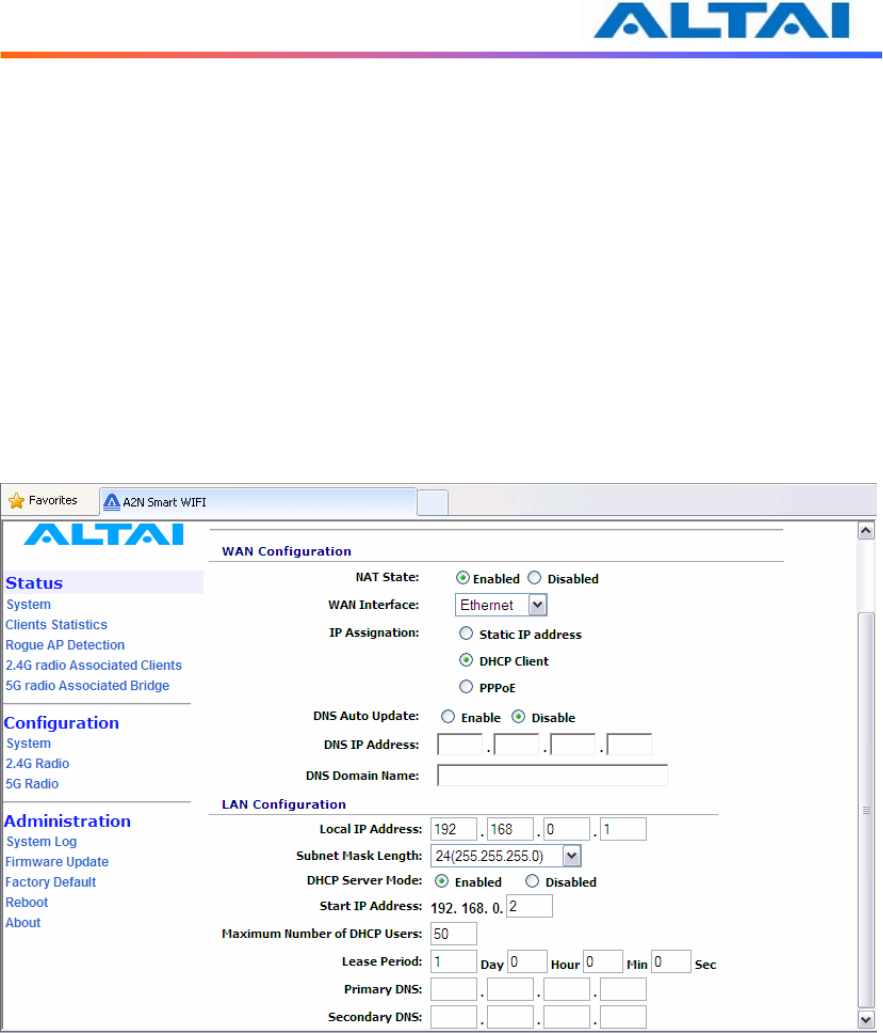
4.9.2 LAN Configuration
In Gateway Mode, the A2 can be a DHCP server, a DHCP relay or none of them.
When the DHCP Server Mode sets to Server, the A2 will act as a DHCP server and use the
settings specified in the field Start IP Address, Maximum Number of DHCP Users and DNS to
serve the wireless clients.
1. Configure the Local IP Address and Subnet Mask Length. Local IP Address is the
gateway IP address for the client who associates A2 WiFi. Only the clients under the
same subnet of local IP address can get IP address from A2 WiFi.
2. Configure the Start IP Address, Maximum Number of DHCP Users, and DNS, see
Figure 14.
3. Reboot the A2
Figure 14 Configure DHCP Server
When the DHCP Server Mode sets to Disabled, the A2 will neither be a DHCP server nor a
DHCP Relay and hence the wireless clients CANNOT get IP addresses from the A2 WiFi to
access the Internet. Instead, each wireless client should set a fixed static IP address which is in
the same network domain as the A2.
1. Configure the Relay Server IP Address, see Figure 15.
2. Reboot the A2
TPS10-013_rev1.2_A2N_Configuration_Manual_-_fm_1.0.1._FCC.doc
Commercially Confidential
22
Figure 15 Configure DHCP Server Disable
4.10 A
CCESS
L
INK
S
AFE
M
ODE
/
B
ACKHAUL
L
INK
S
ELF
-
HEALING
Access Link Safe Mode is for detecting the backhaul link integrity. If the AP loses its backhaul
connectivity, it forces the clients to re-associate with another AP by changing its SSID to a
default “A2 Safe Mode XXX”, where “XXX” is the MAC address of the 2.4GHz radio in
hexadecimal. This action can protect the client from connecting to a AP which has no backhaul
to the Internet end. Default Access Link Safe Mode is Disabled. Press the icon Enabled, A2
WiFi will work under Access Link Safe Mode.
In the case where multiple physical backhauls are available, the Backhaul Link Self-Healing
feature will switch to other backhaul if the current one goes down. For example, when default
backhaul is set to 5GHz Radio, once the 5GHz Bridge link is broken down, A2 WiFi will try
Ethernet end as its new backhaul. Default setting is Disabled. After enabled the Backhaul Link
Self-Healing, Default Backhaul Link can be configured.
Three different Ping Host can be added to the list for monitoring the connectivity. If either
Access Link Safe Mode or Backhaul Link Self-Healing is enabled, the AP will ping those
specified hosts periodically at the Ping Interval configured.
TPS10-013_rev1.2_A2N_Configuration_Manual_-_fm_1.0.1._FCC.doc
Commercially Confidential
23
4.11 S
ETUP
–
W
IRELESS
R
ADIO
P
ARAMETER
Wireless radio parameters can be modified under Configuration in the menu bar. By selecting
the icons, 2.4G Radio can operate on different modes separately: AP mode, Repeater mode,
Bridge mode and Disable. The default setting of 2.4G Radio is AP mode.
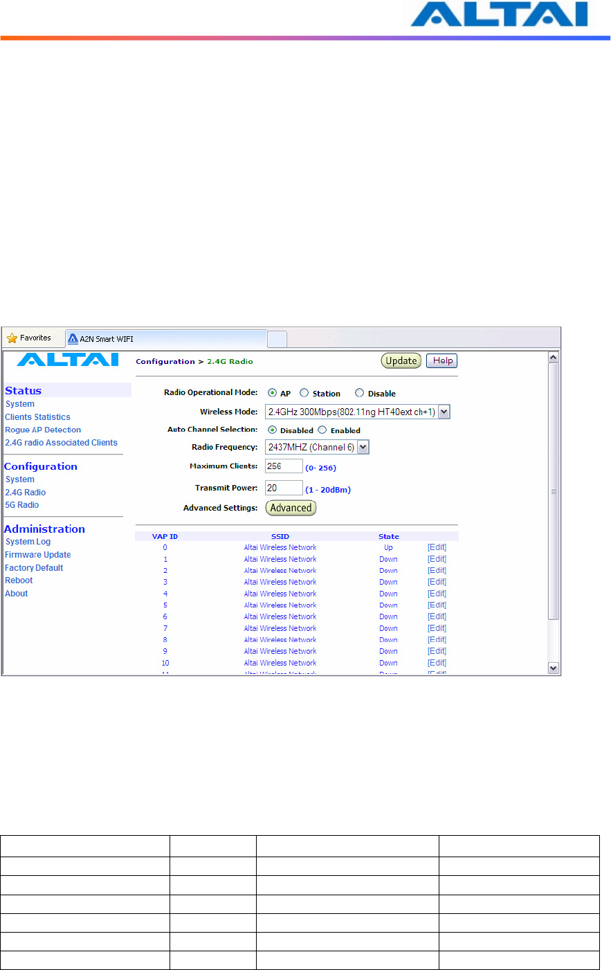
4.12 AP
M
ODE
Wireless Radio working on AP mode is used for clients association. Altai A2 WiFi combine
802.11b/g and draft 802.11n together to offer access for clients.
The Radio Enable Mode, Wireless Mode, Auto Channel Selection, Radio Frequency
(Channel), Maximum Clients, Transmit Power, Advanced Settings and VAP can be configured
by selecting AP icon under 2.4G Radio, as shown in Figure 16.
Figure 16 Wireless Radio Parameter Configuration
4.12.1 Wireless Mode and Radio Frequency
Altai A2 WiFi can offer 2.4GHz radio access, the following tables list the operation mode and
available frequency under the particularly wireless mode. Default setting of AP mode radio is
working on 2.4GHz 300Mbps (802.11n HT 40ext ch+1) and default channel is channel 6
(2437MHz).
2.4GHz Radio Mode Data Rate Channels Radio Frequency
802.11b 11 Mbps 1,2,3,4,5,6,7,8,9,10,11 2.412GHz-2.462GHz
802.11b/g 54 Mbps 1,2,3,4,5,6,7,8,9,10,11 2.412GHz-2.462GHz
802.11g 54 Mbps 1,2,3,4,5,6,7,8,9,10,11 2.412GHz-2.462GHz
802.11n HT20 130 Mbps 1,2,3,4,5,6,7,8,9,10,11 2.412GHz-2.462GHz
802.11n HT40ext ch+1 300 Mbps 3,4,5 2.422GHz-2.432GHz
802.11n HT40ext ch-1 300 Mbps 7,8,9 2.442GHz-2.452GHz
Table 2 Radio operation wireless mode, channel and Radio Frequency

TPS10-013_rev1.2_A2N_Configuration_Manual_-_fm_1.0.1._FCC.doc
Commercially Confidential
24
4.12.2 Auto Channel Selection
By default, the Auto Channel Selection is disabled; the A2 is fixed on Channel 6. When
Enabled of Auto Channel Selection is chosen, A2 WiFi can scan all available radio channels
which are assigned to the regulatory domain. The “cleanest” channel is then selected as the
operating channel.
NOTE: After changing frequency channel, it takes around 3 minutes for A2 to optimize
its radio performance.
4.12.3 Maximum Clients
A value between the ranges from 0 to 256 can be filled in Maximum Clients blank. This feature
can limit the total associated clients under the particular radio.
4.12.4 Transmit Power
The value of the Transmit Power depends on both the gain of the antenna and the maximum
value of the Effective Isotropic Radiated Power (Max EIRP) allowed based on FCC standard.
The Transmit Power should be configured within the given range as shown in Figure 16. The
Tx Power could be set from 10 to 26 dBm for 2.4GHz radio, and Tx Power range for 5GHz
radio is from 10 to 20 dBm.
NOTE: Click the Update icon to store the changed settings.
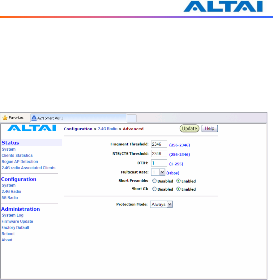
4.12.5 Advanced Radio Setting
More radio parameters can be verified and altered by selecting the Advanced icon in the field of
Advanced Setting. The parameters are shown in Figure 17. The following table showed is the
best suggested interval worked with the current operated APs. Note that it is not suggested to
change the parameters in Advanced Radio Settings unless you are experienced administrators.
Number of active
VAPs
Auto Beacon Interval
(ms)
1 100
2 150
3 150
4 200
5 200
6 240
7 280
8 320
9 360
10 400
11 440
12 480
13 520
14 560
15 600
16 640
TPS10-013_rev1.2_A2N_Configuration_Manual_-_fm_1.0.1._FCC.doc
Commercially Confidential
25
Table 3 Beacon Interval
Fragment Threshold: It means the size of each frame. If it is set to 256 bytes and the size of data
block is 1024 bytes, the data block will be divided to four frames to send.
RTS/CTS Threshold: RTS is a flow control mechanism to prevent collision between 802.11b
and 802.11g mobile stations to send data to the access point in the same time. CTS is another
flow control mechanism to prevent collision when two mobile stations, who do not know the
existence of each other, send data to the access point in the same time. RTS and CTS are used
for point-to-multipoint bridge application and they are enabled when the threshold set to 2346.
Figure 17 Advanced Wireless Radio Setting
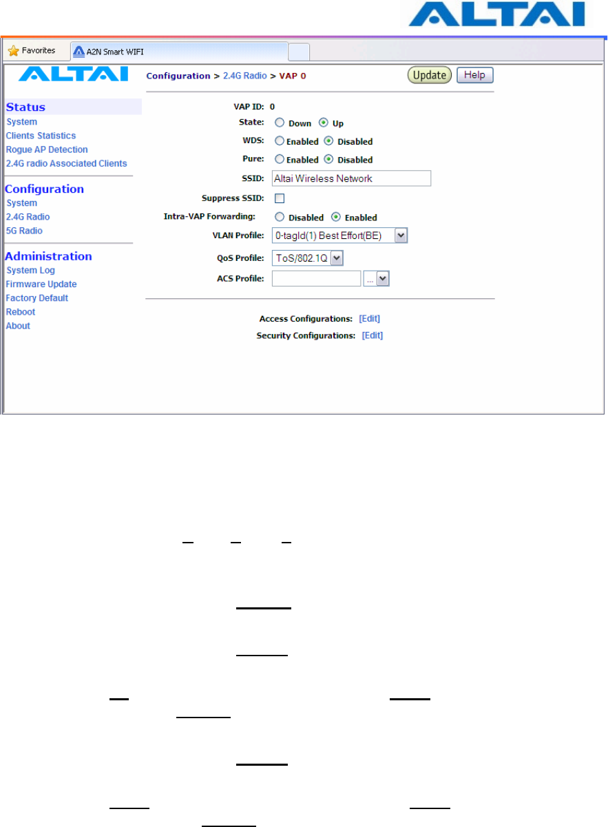
4.12.6 Service Set IDentifier (SSID) and Virtual Access Point (VAP)
In order for the A2 WiFi and mobile clients to communicate, they must all be configured to use
the same SSID for communication both at the VAP and clients ends. SSID broadcast can be
enabled or disabled by selecting Suppress SSID. Suppress SSID is used to prevent unauthorized
users scanning for SSID while still allowing users who know the correct SSID to connect.
VLAN can be enabled by adding different VLAN Tag ID. The traffic will pass through the
specific VLAN switch port when VLAN is enabled.
Each VAP setting (including SSID) can be altered by selecting Edit. The setting of each VAP is
shown in Figure 18. The default SSID for each VAP ID is Altai Wireless Network. VLAN Tag
can also be set here.
TPS10-013_rev1.2_A2N_Configuration_Manual_-_fm_1.0.1._FCC.doc
Commercially Confidential
26
Figure 18 VAP Setting
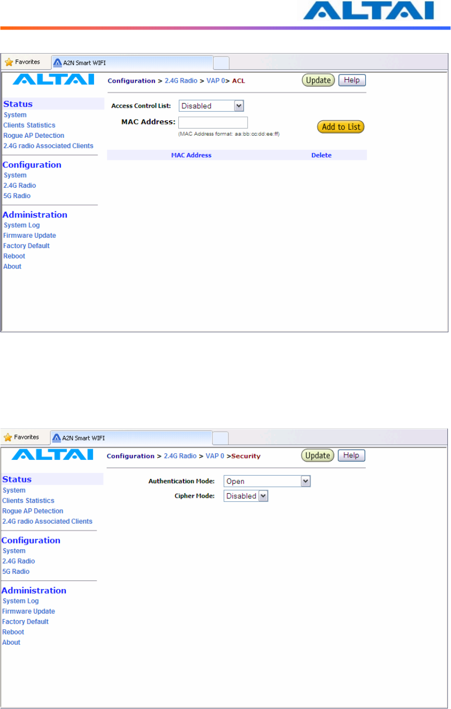
4.12.7 Access Control List (ACL)
By selecting Access Configurations, a window, as shown in Figure 19, is brought up for
choosing the ACL mode, adding MAC Address with ACL Type (Allow or Deny).
There are three modes in the Access Control List (ACL). They are Disabled, Enabled-Allow and
Strict-Deny:
1. Disabled
- The function of ACL is disabled.
2. Enabled–Allow
- The function of ACL is enabled.
- The MAC addresses which are specified in the ACL will consider as Allow.
- i.e. No computer can access to the base station, unless the computer which has an
MAC address matches one of the entries of the ACL with its ACL Type is Allow.
3. Enabled–Deny
- The function of ACL is enabled.
- The MAC addresses which are specified in the ACL will consider as Deny.
-
i.e. Every computer can access to the base station, unless the computer which has
an MAC address matches one of the entries of the ACL with its ACL Type is
Deny.
TPS10-013_rev1.2_A2N_Configuration_Manual_-_fm_1.0.1._FCC.doc
Commercially Confidential
27
Figure 19 ACL
4.12.8 Encryption and Authentication
By selecting Security Configurations, a window, as shown in Figure 20, is brought up for
choosing the Authentication Mode and Cipher Mode.
Figure 20 Wireless Radio Security Configuration
TPS10-013_rev1.2_A2N_Configuration_Manual_-_fm_1.0.1._FCC.doc
Commercially Confidential
28
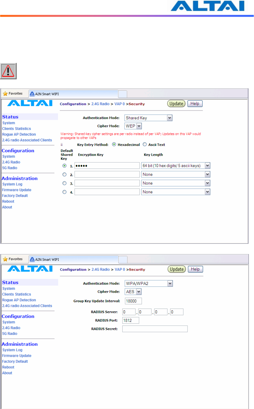
After selecting Open or Shared-Key for Authentication Mode, WEP for Cipher Mode, the WEP
key settings can be defined as shown in Figure 21.
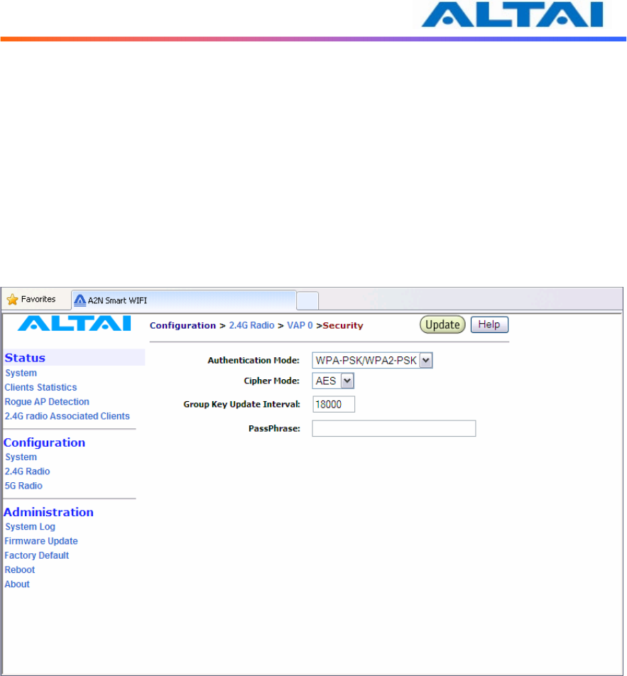
WPA/WPA2 or WPA-PSK/WPA2-PSK can be enabled by selecting WPA/WPA2 or
WPA-PSK/WPA2-PSK for Authentication Mode. The AES and TKIP are the two available
options for Cipher Mode. The related settings are shown in Figure 20 and Figure 23.
NOTE: Click the Update icon to store the WEP or WPA settings.
Figure 21 WEP Key Settings
Figure 22 WPA Settings
TPS10-013_rev1.2_A2N_Configuration_Manual_-_fm_1.0.1._FCC.doc
Commercially Confidential
29
RADIUS server is used for authentication. A2 WiFi can store separate RADIUS server address
for each VAP. It is only visible when the Authentication Mode is set to “WPA”. The default
setting of RADIUS server port is 1812. RADIUS secret shared password between the RADIUS
server and A2 WiFi. A password up to 128 characters long can be added. The VLAN IP address
and VLAN Subnet Mask configured on the VAP security web page will be used only when A2
runs in the following conditions.
1. A2 WiFi runs in switch mode and VLAN is enabled.
2. The VAP does not belong to native VLAN.
3. The authentication mode is WPA.
Figure 23 WPA-PSK Settings
TPS10-013_rev1.2_A2N_Configuration_Manual_-_fm_1.0.1._FCC.doc
Commercially Confidential
30
4.13 R
EPEATER
M
ODE
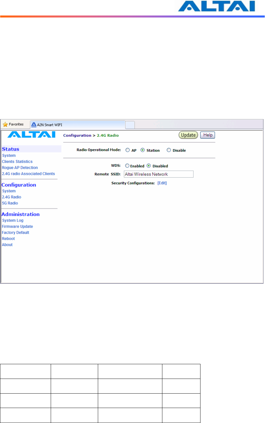
Under Wireless Radio web-site interface, Station mode can be chosen. By clicking Station icon,
backhaul link can be established through associating the Station VAP with the remote APs. That
means the Wireless Radio works as backhaul link, clients can associate with other VAPs who
works under AP mode. The local wireless clients associating with the other AP mode Radios can
communicate with remote AP through the backhaul link which is established by repeater mode
radio.
Fill the remote SSID index in the Blank, and make sure the security setting is same with the
repeater mode input SSID security method.
Figure 24 Repeater Mode Configuration
There are three different repeater modes: NAT mode, WDS mode and MAC address
translation mode (MAT mode).
When repeater works in NAT mode, A2 works in Gateway mode and the Station mode VAP is
enabled. Repeater works in WDS mode when WDS is enabled and A2 works in Station mode.
WDS mode requires the remote AP enabled WDS function. The MAT mode can be enabled
when A2 runs in Switch mode and WDS is enabled.
Repeater Mode
System Mode VAP0 working mode
WDS status
NAT mode Gateway mode
Station mode Disabled
WDS mode Switch mode Station mode Enabled
MAC mode Switch mode Station mode Enabled
Table 4 Repeater Mode Setting Method
TPS10-013_rev1.2_A2N_Configuration_Manual_-_fm_1.0.1._FCC.doc
Commercially Confidential
31
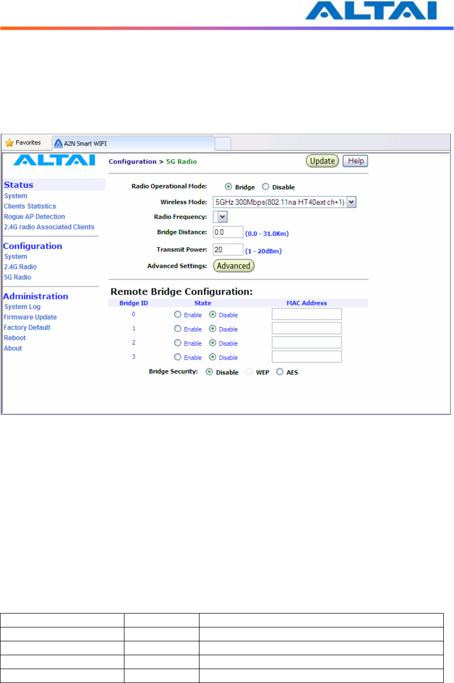
4.14 B
RIDGE
M
ODE
The 5GHz Radio, Regulatory Domain, Wireless Mode, Radio Frequency (Channel), Transmit
Power, Encryption Configuration, Advanced Settings and Remote Bridge Configuration can
be configured by selecting 5GHz Radio under Configuration in the menu bar, as shown in
Figure 25.
Figure 25 5GHz Radio Parameter Configuration
4.14.1 Bridge Radio Wireless Mode
A2 WiFi can work under either 802.11a mode or 802.11na mode by selecting on pulling down
list. If A2 is set to 802.11a mode, A2 allows only 802.11a bridges to connect as peers, if A2
work in 802.11a turbo static mode, A2 will allows only same 802.11na bridges to connect as
peers.
4.14.2 Data Rate & Radio Frequency
The choice of this item depends on the environment where A2 is used and which wireless mode
A2 is working in.
5GHz Radio Mode Data Rate Channels
802.11a 54 Mbps 149, 153, 157, 161,165
802.11na HT20 130 Mbps 149, 153, 157, 161,165
802.11na HT40ext ch+1
300 Mbps 151
802.11na HT40ext ch-1 300 Mbps 159
Table 5 5GHz Radio channel and Data Rate
TPS10-013_rev1.2_A2N_Configuration_Manual_-_fm_1.0.1._FCC.doc
Commercially Confidential
32
In 802.11a mode:
User can select a 5GHz channel in the pool from channel 149 to 165 (5.745GHz to 5.825GHz).
In 802.11na HT20:
Users can select a 5GHz channel in the pool from channel 149 to 165 (5.745GHz to 5.825GHz).
In 802.11na HT40ext ch+1:
Users can select a 5GHz channel in the pool from channel 151 (5.755GHz).
In 802.11na HT40ext ch-1:
Users can select a 5GHz channel in the pool from channel 159 (5.795GHz).
4.14.3 Bridge Radio Transmit Power
The power for 5GHz Radio (802.11a) is set in this area. The value of the Transmit Power
depends on both the gain of the 5GHz antenna and the Max EIRP allowed by the country in
which A2 is used. The Transmit Power can be configured within the given range (10-20dBm).
NOTE: Click the Update icon to store the Transmit Power settings.
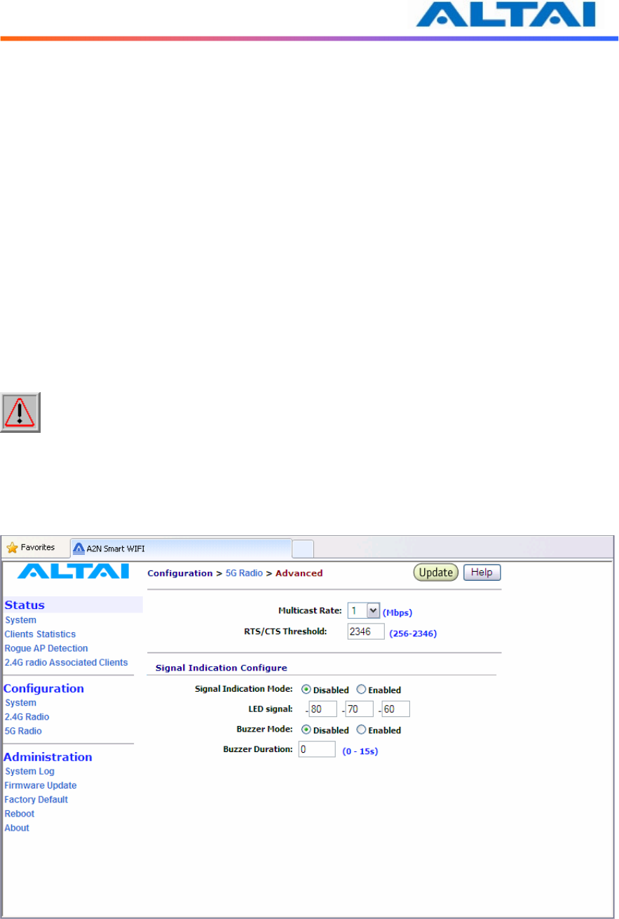
4.14.4 Advanced Radio Setting
More radio parameters can be verified and altered by selecting the Advanced icon in the field of
Advanced Setting. The parameters are shown in Figure 26.
Figure 26 Advanced Bridge Radio Setting
TPS10-013_rev1.2_A2N_Configuration_Manual_-_fm_1.0.1._FCC.doc
Commercially Confidential
33
RTS/CTS Threshold: RTS is a flow control mechanism to prevent collision between 802.11b
and 802.11g mobile stations to send data to the access point in the same time. CTS is another
flow control mechanism to prevent collision when two mobile stations, who do not know the
existence of each other, send data to the access point in the same time. RTS and CTS are used
for point-to-multipoint bridge application and they are enabled when the threshold set to 2347.
4.14.5 Remote Bridge Configuration
The MAC address of the remote AP should be added into the field MAC Address, and the
remote AP should add the MAC address of local AP to form a bridge. Moreover, all bridging
equipments including both local AP and remote APs should be set at the Same Radio
Frequency.
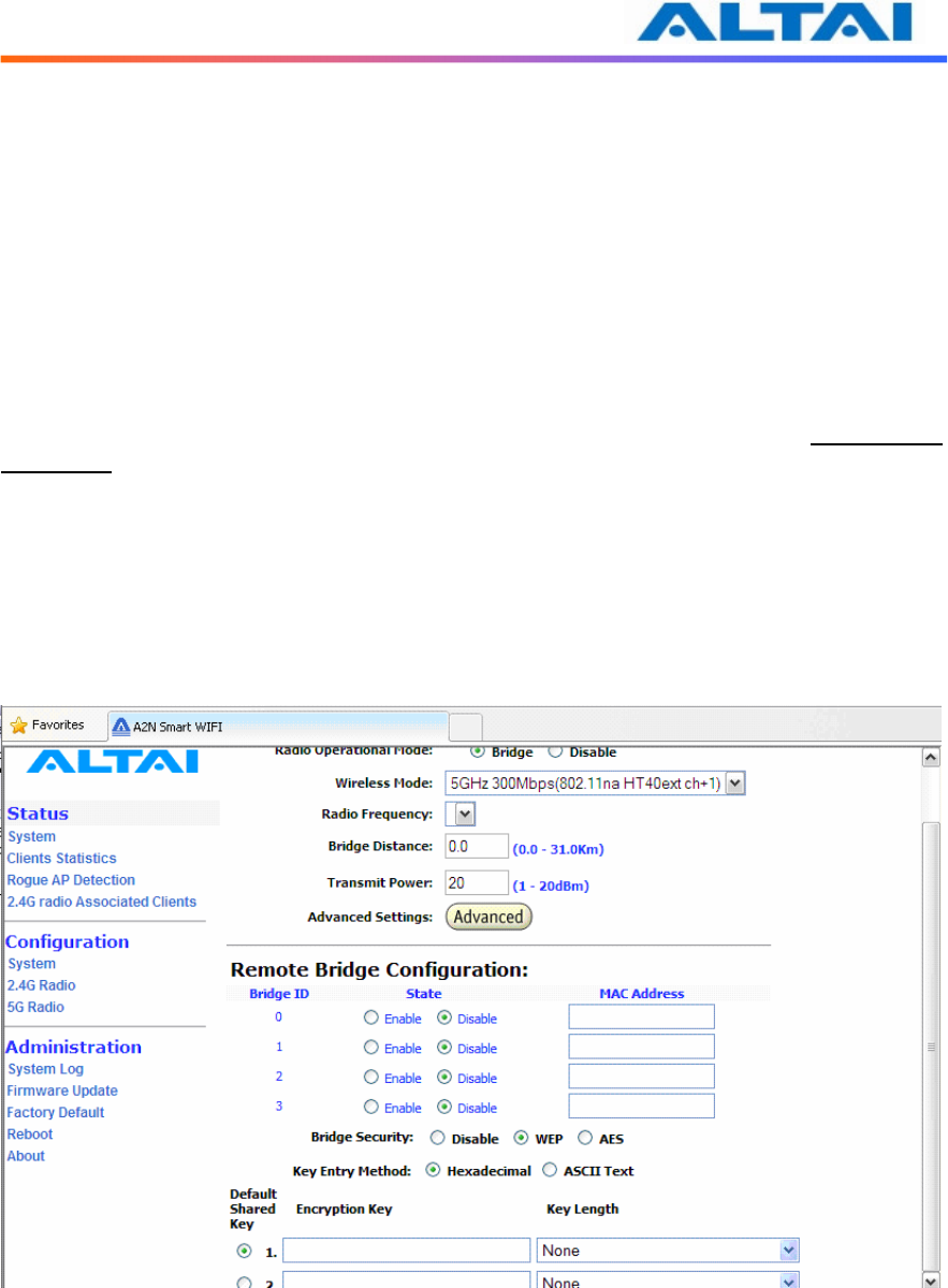
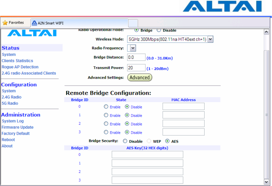
4.14.6 Bridge Security
By enabling Bridge Security in the 5GHz Configuration, as shown in Figure 27, users can input
an encryption key for the bridge. Note: if the Local AP and Remote AP mismatch the encryption
type or encryption key, there will be no link established by 5GHz radio. Please make sure the
security parameter setting at the both ends of the bridge.
Figure 27 Bridge encryption setting_WEP
TPS10-013_rev1.2_A2N_Configuration_Manual_-_fm_1.0.1._FCC.doc
Commercially Confidential
34
Figure 28 Bridge encryption setting_AES
TPS10-013_rev1.2_A2N_Configuration_Manual_-_fm_1.0.1._FCC.doc
Commercially Confidential
35
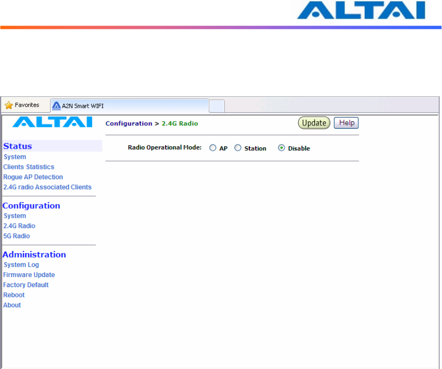
4.15 D
ISABLE
M
ODE
The particular radio of A2 WiFi can be disabled by click the Disable icon. There is no need to
configure the Transmit Power and Advanced Settings.
Figure 29 Wireless Radio Disable Mode
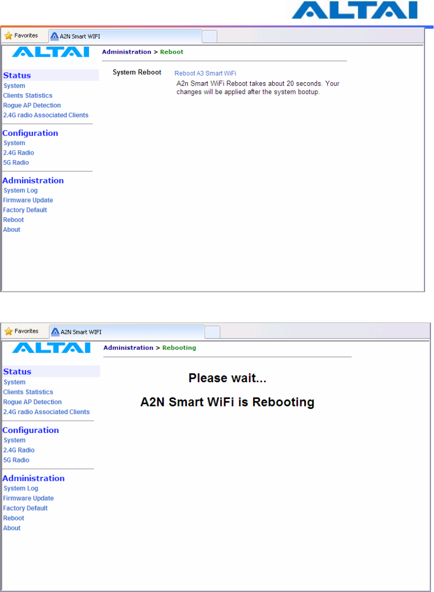
4.16 R
EBOOT
System reboot of A2 WiFi can be chosen by selecting Reboot under Administration in the
menu bar. It is required to select Reboot Base Station to confirm this action, as shown in Figure
30.
When the A2 WiFi is rebooting, a message “Please wait… Base Station is Rebooting” is
shown on the window, as shown in Figure 31. It will take about 20 seconds for the access point
to boot up.
TPS10-013_rev1.2_A2N_Configuration_Manual_-_fm_1.0.1._FCC.doc
Commercially Confidential
36
Figure 30 Reboot Window
Figure 31 A2 WiFi Access Point is Rebooting
TPS10-013_rev1.2_A2N_Configuration_Manual_-_fm_1.0.1._FCC.doc
Commercially Confidential
37
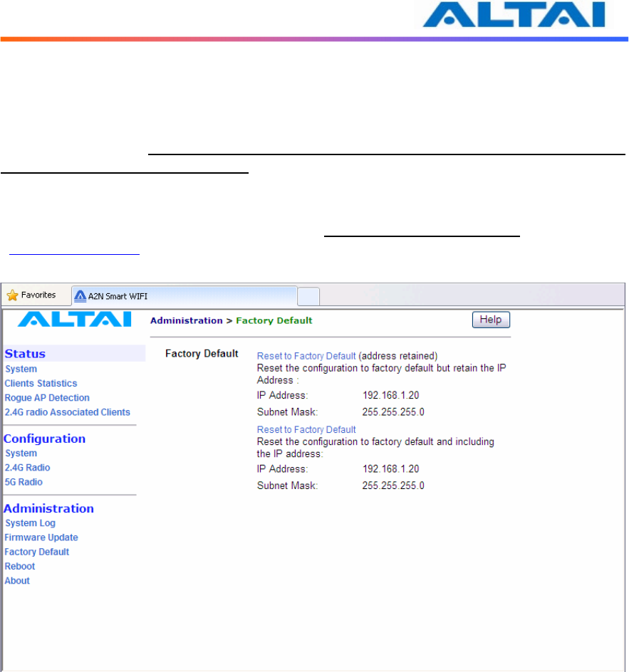
4.17 R
ESTORE
C
ONFIGURATION TO
D
EFAULT
S
ETTING
The choices of factory default can be chosen by selecting Factory Default under
Administrations in the menu bar.
The default settings (IP Address, Subnet Mask, Default Gateway Address and Remote
Bridge Configurations are retained) can be restored by selecting the icon Reset to Factory
Default (address retained) or Reset to Factory Default, as shown in Figure . Please reboot the
A2 WiFi afterwards.
Note: after resetting to factory default without address retained, please type
<https://192.168.1.20> to open A2 WiFi web-admin.
Figure 32 Reset to Factory Default Setting in Web-admin
TPS10-013_rev1.2_A2N_Configuration_Manual_-_fm_1.0.1._FCC.doc
Commercially Confidential
38
5 P
ERFORMANCE
M
ANAGEMENT
M
ONITORING IN
W
EB
-A
DMIN
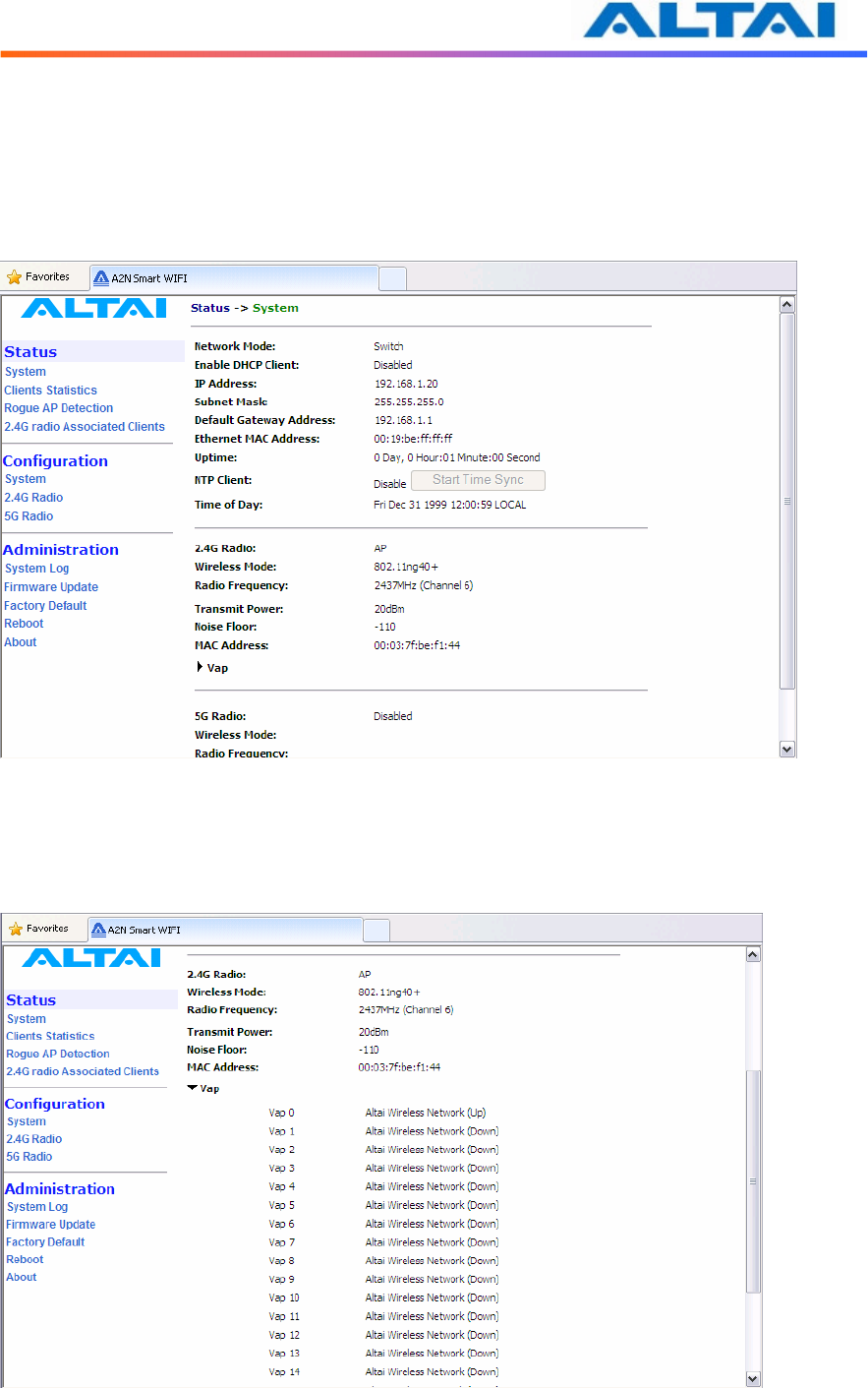
5.1 S
YSTEM
The statistics can be monitored by selecting System under Status in the menu bar. All details
are shown on the window, as shown in Figure .
Figure 33 Details of the system
The status of each VAP can be shown by clicking Vap under the field of Wireless Radio, as
shown in Figure .
Figure 34 Statuses of the Vaps
TPS10-013_rev1.2_A2N_Configuration_Manual_-_fm_1.0.1._FCC.doc
Commercially Confidential
39
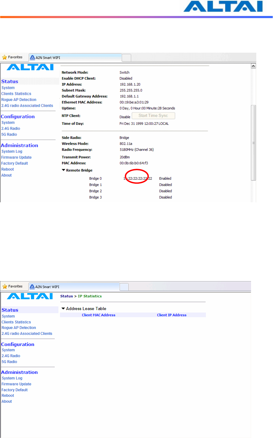
The status and MAC address of each remote bridge can be shown by selecting Remote Bridge
under the field of 5GHz Radio, as shown in Figure .
Figure 35 Statuses of the Remote Bridges
5.2 C
LIENTS
S
TATISTICS
The clients association statistics can be monitored by selecting Clients Statistics under the field
of Status in the menu bar, as shown in Figure .
The Address Lease Table shows the Client MAC Address, Client IP Address of each end user.
Figure 36 2.4GHz Radio Statistics Menu
TPS10-013_rev1.2_A2N_Configuration_Manual_-_fm_1.0.1._FCC.doc
Commercially Confidential
40
5.3 R
ADIO
A
SSOCIATION
-AP
M
ODE
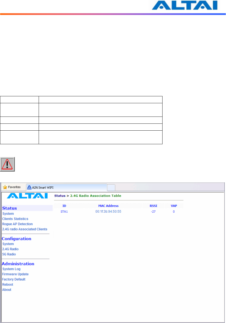
The each radio association statistics can be monitored by selecting Radio Association under the
field of Status in the menu bar, as shown in Figure . The corresponding statistics can be
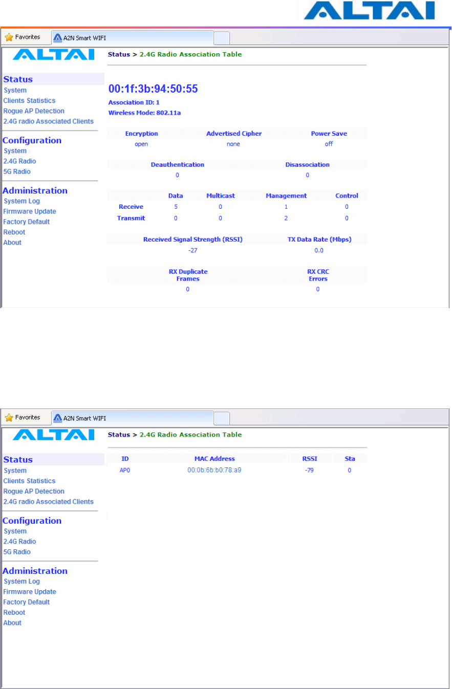
shown by selecting the related MAC Address, as shown in Figure 38.
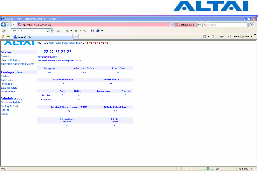
The Association Table shows the ID, Mac Address, RSSI, and VAP of each station as shown in
Figure . A more detailed 2.4GHz Association Statistic of each station can be brought up by
selecting the related Mac Address as shown in Figure 40.
Status Description
ID Station ID, a number randomly generated by A2 to
represent a mobile client
Mac Address Station Mac Address
RSSI Receiver Signal Strength
VAP Virtual Access Point ID Number that the mobile
client associates to
Table 6 2.4GHz Client Association Status
NOTE: The association page would be refreshed for every 15 seconds
Figure 37 Radio Association Table
TPS10-013_rev1.2_A2N_Configuration_Manual_-_fm_1.0.1._FCC.doc
Commercially Confidential
41
Figure 38 Radio Statistics per MAC Address (data is cumulative)
5.4 R
ADIO
A
SSOCIATION
-R
EPEATER
M
ODE
The association status of radio working on repeater mode can be monitored by selecting Radio
Association under the field of Status in the menu bar, as shown in Figure 39 and Figure 40.
Figure 39 Radio Association AP List
TPS10-013_rev1.2_A2N_Configuration_Manual_-_fm_1.0.1._FCC.doc
Commercially Confidential
42
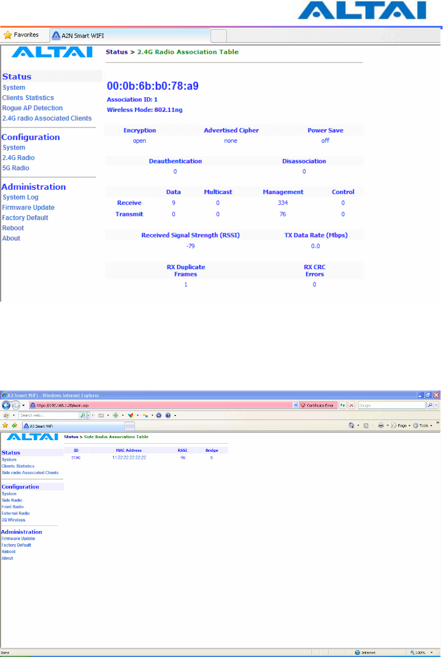
Figure 40 Association AP Statistics per MAC Address (data is cumulative)
5.5 R
ADIO
A
SSOCIATION
-B
RIDGE
M
ODE
The bridge radio association can be monitored by selecting Radio Association under the field of
Status in the menu bar, as shown in Figure 41 and Figure 42.
Figure 41 Radio Association Bridge List
TPS10-013_rev1.2_A2N_Configuration_Manual_-_fm_1.0.1._FCC.doc
Commercially Confidential
43
Figure 42 Bridge Association Statistics per MAC address

TPS10-013_rev1.2_A2N_Configuration_Manual_-_fm_1.0.1._FCC.doc
Commercially Confidential
44
6 S
OFTWARE
U
PGRADE THROUGH
W
EB
-A
DMIN
The firmware can be upgraded by selecting Firmware Update under the field of
Administrations in the menu bar respectively. Please note that the connection link should be
maintained during file transfer to prevent interruption to the system.
6.1 F
IRMWARE
U
PDATE
T
HROUGH
HTTP
OR
HTTPS
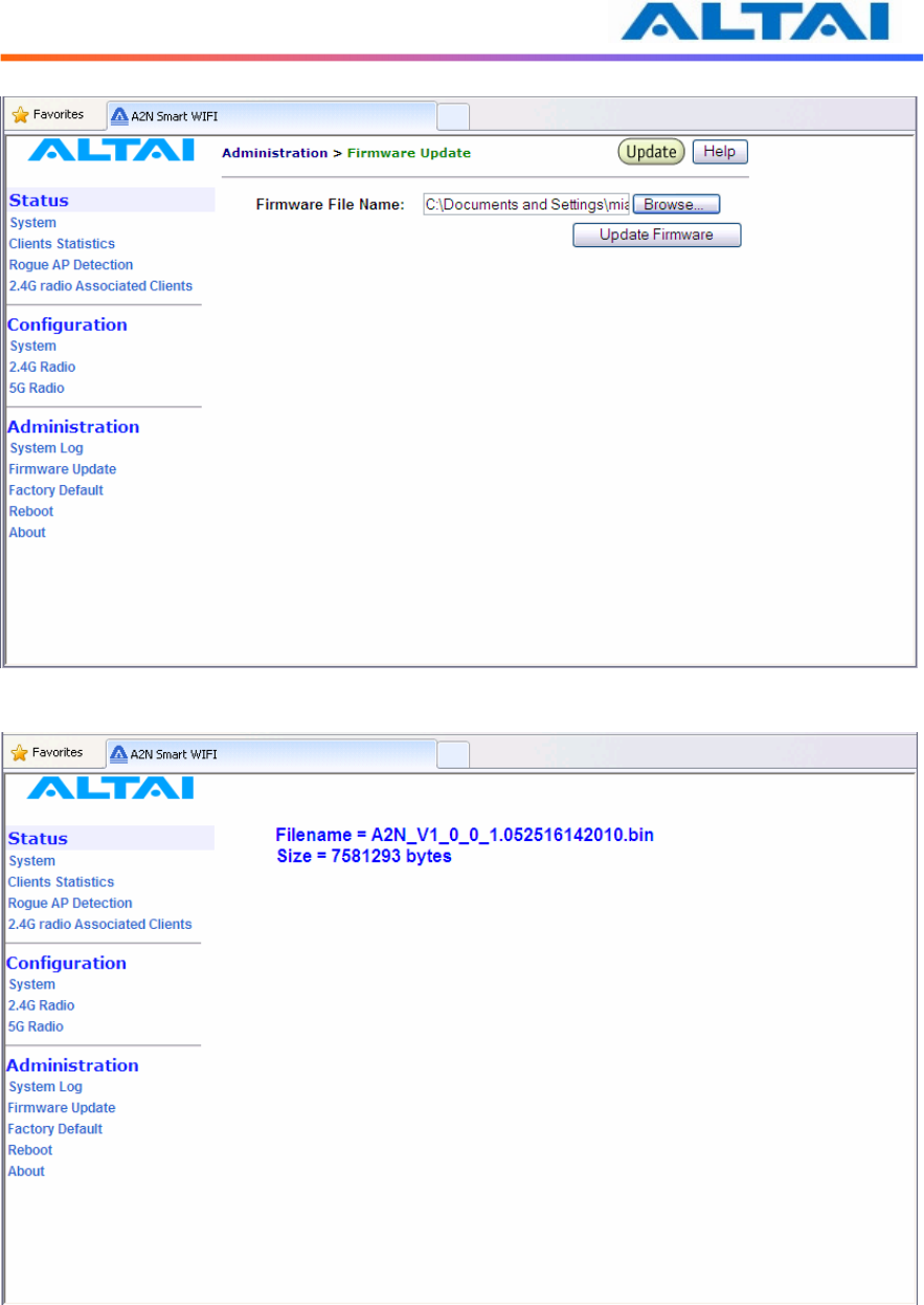
Follow the steps below to perform the Firmware Update with a firmware image file (.bin) in
local directory through HTTP or HTTPS.
1. Click the Browse… bottom to bring up a file chooser dialog which you can specify the
name and location of the firmware image you want to import.
2. Click the Update Firmware bottom to start uploading the new firmware from the local
directory, see Figure .
3. If the firmware upgrade is successful, a window will appear as Figure . A2 WiFi will
reboot automatically.
4. Type in URL with https://<ip address of A2>, note ‘http’ can not link to the web admin
of A2 under the new firmware version.
5. After the A2 reboots, check the firmware version by selecting About under the field of
Administrations in the menu bar, as discussed in Section 4.2, to ensure the expected
firmware is uploaded.
6. Select Factory Default under the field Administrations in the menu bar and click Reset
to Factory Default (address retained) or Reset to Factory Default to make the default
settings effective. Note: If press Reset to Factory Default with address retained, the IP
address of A2 web-admin will not be changed after rebooting the AP. While Reset to
Factory Default is chosen, IP address of A2 WiFi will be changed into 192.168.1.20 .
7. Click the icon REBOOT AP to reboot the A2 WiFi.
Warning: The A2 WiFi will not be working properly if there is some mistaken in the upgrade
process. You are NOT advised to perform firmware upgrade if you have not received any
training from ALTAI or its partners.
TPS10-013_rev1.2_A2N_Configuration_Manual_-_fm_1.0.1._FCC.doc
Commercially Confidential
45
Figure 43 Upload the Firmware through HTTP or HTTPS
Figure 44 Successful Firmware Update – Web-admin

TPS10-013_rev1.2_A2N_Configuration_Manual_-_fm_1.0.1._FCC.doc
Commercially Confidential
46
7 G
LOSSARY
802.1q IEEE 802.1Q was a project in the IEEE 802 standards process to develop a mechanism
to allow multiple bridged networks to transparently share the same physical network link
without leakage of information between networks (i.e. trunking). IEEE 802.1Q is also the
name of the standard issued by this process, and in common usage the name of the encapsulation
protocol used to implement this mechanism over Ethernet networks. This protocol allows for
individual VLANs to communicate with one another with the use of a layer-3 (network) router.
802.11 802.11 refers to a family of specifications developed by the IEEE for wireless LAN
technology. 802.11 specifies an over-the-air interface between a wireless client and a base
station or between two wireless clients. The IEEE accepted the specification in 1997.
802.11a An extension to 802.11 that applies to wireless LANs and provides up to 54 Mbps in
the 5GHz band. 802.11a uses an Orthogonal Frequency Division Multiplexing (OFDM)
encoding scheme rather than Frequency Hopping Spread Spectrum (FHSS) or Direct Sequence
Spread Spectrum.
802.11b Also referred to as 802.11 High Rate or Wi-Fi. It is an extension to 802.11 that
applies to wireless LANS and provides 11 Mbps transmission (with a fallback to 5.5, 2 and 1
Mbps) in the 2.4 GHz band. 802.11b uses only DSSS. 802.11b was a 1999 ratification to the
original 802.11 standard, allowing wireless functionality comparable to Ethernet.
802.11e A supplement to the IEEE 802.11 wireless LAN (WLAN) specification for
enhancements to the 802.11 Medium Access Control (MAC) to improve and manage Quality of
Service (QoS), provide Classes of Service (CoS), and enhanced security and authentication
mechanisms.
802.11g The 802.11g specification is a standard for Wireless Local Area Networks (WLANs)
that offers transmission over relatively short distances at up to 54 megabits per second (Mbps),
compared with the 11 Mbps theoretical maximum with the earlier 802.11b standard. Networks
employing 802.11g operate at radio frequencies between 2.400 GHz and 2.4835 GHz, the same
band as 802.11b. But the 802.11g specification employs Orthogonal Frequency Division
Multiplexing (OFDM), the modulation scheme used in 802.11a, to obtain higher data speed.
Computers or terminals set up for 802.11g can fall back to speeds of 11 Mbps. This feature
makes 802.11b and 802.11g devices compatible within a single network. Modification of an
802.11b access point to 802.11g compliance usually involves only a firmware upgrade.
802.11i A supplement to the IEEE 802.11 wireless LAN (WLAN) specification for enhanced
security through the use of stronger encryption protocols such as the Temporal Key Integrity
Protocol (TKIP) and AES Counter-Mode Cipher Block Chaining Message Authentication Code
Protocol (AES-CCMP). These protocols provide replay protection, cryptographically keyed
integrity checks, and key derivation based on the IEEE 802.1X port authentication standard.
802.11n A supplement to the previous 802.11 standards. 802.11n combines the MIMO
(Multiple-input Multiple-output) and channel-bonding (40MHz) operation to physical layer and
frame aggregation to the MAC layer. The current state of 802.11n supports a data rate of
300Mbit/s and the throughput can achieve at 150Mbit/s.
ACL Access Control List: It is a table that tells a computer operating system which access
rights each user has to a particular system object, such as a file directory or individual file.

TPS10-013_rev1.2_A2N_Configuration_Manual_-_fm_1.0.1._FCC.doc
Commercially Confidential
47
ad-hoc mode An 802.11 networking framework in which devices or stations communicate
directly with each other, without the use of an Access Point (AP). Ad-hoc mode is also
referred to as peer-to-peer mode or an Independent Basic Service Set (IBSS). Ad-hoc mode is
useful for establishing a network where wireless infrastructure does not exist or where services
are not required.
antenna gain The measure of an antenna assembly performance relative to a theoretical
antenna, called an isotropic radiator (radiator is another term for antenna). Certain antenna
designs feature higher performance relative to vectors or frequencies.
AP Access Point: A hardware unit that acts as a communication hub by linking wireless
mobile 802.11 stations such as PCs to a wired backbone network. A Trapeze Networks
Mobility System has Mobility Point APs.
ASCII American Standard Code for Information Interchange: An 8-bit code for representing
characters, consisting of 7 data bits plus 1 parity bit.
association The relationship established between mobile (wireless) stations and a wireless AP
(AP) in which the stations receive services from the AP.
bandwidth The gap between the highest and lowest frequencies employed by network signals.
More commonly, it refers to the rated throughput capacity of a network protocol or medium.
The frequency range necessary to convey a signal measured in units of hertz (Hz).
broadcast A data frame or packet that is transmitted to every node on the local network
segment (as defined by the broadcast domain). Broadcasts are known by their broadcast
address, which is a destination network and host address with all the bits turned on.
channel Communication path wide enough to permit a single RF transmission. Multiple
channels can be multiplexed over a single cable in certain environments.
dB decibels: Unit for measuring relative power ratios in terms of gain or loss. Units are
expressed in terms of the logarithm to base 10 of a ratio and typically are expressed in watts.
dB is not an absolute value, rather it is the measure of power lost or gained between two devices.
Because antennas and other RF devices/systems commonly have power gains or losses on the
orders of magnitude or even orders of four orders of magnitude, dB is a more easily used
expression.
dBd decibels over Dipole: A relative gain measurement with respect to a half wave dipole (0
dBd = 2.14 dBi) using a standard dipole antenna as a reference.
dBi dBi referenced to an isotropic antenna, which theoretically is perfect in terms of
symmetric patterns of radiation. Real world antennas do not perform with even nominal
amounts of symmetry, but this effect generally is used to the advantage of the system designer.
dBm decibels per Milliwatt: 0 dBm is defined as 1 mw at 1 kHz of frequency at 600 ohms of
impedance.
DHCP Dynamic Host Configuration Protocol: Provides a mechanism for allocating IP
addresses dynamically so that addresses can be reused when hosts no longer need them.
DNS Domain Name Server: System used on the Internet for translating names of network
nodes into addresses.

TPS10-013_rev1.2_A2N_Configuration_Manual_-_fm_1.0.1._FCC.doc
Commercially Confidential
48
DSSS Direct Sequence Spread Spectrum: One of two types of spread spectrum radio
technology used in wireless LAN (WLAN) transmissions. To increase a data signal's
resistance to interference, the signal at the sending station is combined with a higher-rate bit
sequence that spreads the user data in frequency by a factor equal to the spreading ratio.
EIRP Effective Isotropic Radiated Power: Term for the expression of the performance of an
antenna in a given direction relative to the performance of a theoretical (isotropic) antenna and is
expressed in watts or dBW. EIRP is the sum of the power sent to the antenna plus antenna
gain.
encryption The conversion of information into a scrambled form that effectively disguises it
to prevent unauthorized access. Every encryption scheme uses some well-defined algorithm,
which is reversed at the receiving end by an opposite algorithm in a process known as
decryption.
Ethernet Baseband LAN specification invented by Xerox Corporation and developed jointly
by Xerox, Intel, and Digital Equipment Corporation. Ethernet networks use CSMA/CD and
run over a variety of cable types at 10 Mbps. Ethernet is similar to the IEEE 802.3 series of
standards.
FastRoaming
TM
The Trapeze Mobility System feature that quickly hands off a roaming user's
credentials. Mobility Exchanges in a Trapeze Mobility Domain pass each other this vital user
information to permit seamless roaming. This allows 802.1X and non-802.1X,
MAC-authenticated devices, such as 802.11 phones, to roam quickly between Mobility
Exchanges.
FCC Federal Communications Commission: U.S. government agency that supervises, licenses,
and controls electronic and electromagnetic transmission standards. The FCC Rules in Title 47
of the Code of Federal Regulations govern telecommunications in the United States. Wireless
LANs must comply with Part 15 of the FCC rules, which are written specifically for RF devices.
firmware Software instructions set permanently or semipermanently in ROM.
FHSS Frequency Hopping Spread Spectrum: One of two types of spread spectrum radio
technology used in wireless LAN (WLAN) transmissions. The FHSS technique modulates the
data signal with a narrowband carrier signal that “hops” in a predictable sequence from
frequency to frequency as a function of time over a wide band of frequencies. Interference is
reduced, because a narrowband interferer affects the spread spectrum signal only if both are
transmitting at the same frequency at the same time. The transmission frequencies are
determined by a spreading (hopping) code. The receiver must be set to the same hopping code
and must listen to the incoming signal at the proper time and frequency to receive the signal.
FPGA Field Programmable Gate Array: An FPGA is a specially made digital semiconductor
often used for prototyping. With an FPGA, a design engineer is able to program electrical
connections on site for a specific application, without paying thousands of dollars to have the
chip manufactured in mass quantities.
FTP File Transfer Protocol: Defined in RFC 959, it is a Application protocol that is part of the
TCP/IP protocol stack, used for transferring files between network nodes.
gateway In the IP community, an older term referring to a routing device. Today, the term
router is used to describe nodes that perform this function, and gateway refers to a

TPS10-013_rev1.2_A2N_Configuration_Manual_-_fm_1.0.1._FCC.doc
Commercially Confidential
49
special-purpose device that performs an application-layer conversion of information from one
protocol stack to another.
handoff The process of transferring the handling of that cellular call to the new base station.
host address Logical address configured by an administrator or server on a device.
Logically identifies this device on an internetwork.
https Hypertext Transfer Protocol over Secure Sockets Layer: An Internet protocol developed
by Netscape to encrypt and decrypt network connections to web servers. Built into all secure
browsers, HTTPS uses the Secure Sockets Layer (SSL) protocol as a sublayer under the regular
HTTP application layer, and uses port 443 instead of HTTP Port 80 in its interactions with the
lower layer, TCP/IP.
ICMP Internet Control Message Protocol: Defined in RFC 792, it is a Network layer Internet
protocol that reports errors and provides other information relevant to IP packet processing.
IEEE Institute of Electrical and Electronic Engineers: An American professional society
whose standards for the computer and electronics industry often become national or international
standards. In particular, the IEEE 802 standards for LANs are widely followed.
infrastructure network In an infrastructure network, all communications are relayed through
an AP (AP). Wireless devices can communicate with each other or with a wired network.
The network is defined by the distance of mobile stations from the AP, but no restriction is
placed on the distance between stations. Stations must request association with the AP to
obtain network services, which the AP can grant or deny based on the contents of the association
request. Like most corporate wireless LANs (WLANs), which must access a wired LAN for
file servers and printers, Trapeze Networks Mobility System is an infrastructure network.
IP Internet Protocol: Defined in RFC 791, it is a Network Layer protocol that is part of the
TCP/IP stack and allows connectionless service. IP furnishes an array of features for
addressing, type-of-service specification, fragmentation and reassembly, and security.
IP address Often called an “Internet address”, this is an address uniquely identifying any
device (host) on the Internet (or any TCP/IP network). Each address consists of four octets (32
bits), represented as decimal numbers separated by periods (a format known as
“dotted-decimal”). Every address is made up of a network number, an optional subnetwork
number, and a host number. The network and subnetwork numbers together are used for
routing, while the host number addresses an individual host within the network or subnetwork.
The network and subnetwork information is extracted from the IP address by using the subnet
mask. There are five classes of IP addresses (A-E), which allocate different numbers of bits to
the network, subnetwork, and host portions of the address.
LOS Line Of Sight: Refers to the fact that there must be a clear, unobstructed path between
the transmitters and receivers. This is essential for our LMDS products and enhances general
performance in every RF deployment as opposed to partial or completely obstructed data paths.
The opposite to LOS is NLOS, or Non Line Of Sight.
MAC address Media Access Control address: A Data Link Layer hardware address that every
port or device needs to connect to a LAN segment. These addresses are used by various
devices in the network for accurate location of logical addresses. MAC addresses are defined
by the IEEE standard, and their length is six characters, typically using the burned-in address

TPS10-013_rev1.2_A2N_Configuration_Manual_-_fm_1.0.1._FCC.doc
Commercially Confidential
50
(BIA) of the local LAN interface. Variously called “hardware address”, “physical address”,
“burned-in address” or “MAC-layer address”.
MTU Maximum Transmission Unit: The largest packet size, measured in bytes, that an
interface can handle.
NAT Network Address Translation: An algorithm instrumental in minimizing the requirement
for globally unique IP addresses, permitting an organization whose addresses are not all globally
unique to connect to the Internet, regardless, by translating those addresses into globally routable
address space.
NLOS Non Line Of Sight. Also known as obstructed path or pathway.
noise Undesirable communications channel signals.
NTP Network Time Protocol: Protocol built on top of TCP that ensures accurate local
time-keeping with reference to radio and atomic clocks located on the Internet. This protocol is
capable of synchronizing distributed clocks within milliseconds over long time periods.
OFDM Orthogonal Frequency Division Multiplexing: A technique that splits a wide
frequency band into a number of narrow frequency bands and sends data across the subchannels.
The wireless networking standards 802.11a and 802.11g are based on OFDM.
open system authentication The sender and the recipient do not share a secret key. Each
party generates its own key-pair and asks the receiver to accept the (usually randomly) generated
key. Once accepted, this key is used for a short time only, then a new key is generated and
agreed upon. So, it is a two-step authentication method, in which sender first sends its identity
and in response of that it gets the authentication results.
ping Packet Internet Groper: ICMP echo message and its reply. Often used in IP networks to
test the reach ability of a network device.
PoE Power over Ethernet: A technology, defined in the developing IEEE 802.3af standard, to
deliver dc power over twisted-pair Ethernet data cables rather than power cords. The electrical
current, which enters the data cable at the power-supply end and comes out at the device end, is
kept separate from the data signal so neither interferes with the other.
Remote Bridge A bridge located on a network system separate from the host system.
RF Radio Frequency: Any frequency within the electromagnetic spectrum associated with
radio wave propagation. When an RF current is supplied to an antenna, an electromagnetic
field is created that then is able to propagate through space. Many wireless technologies are
based on RF field propagation.
RFC Request For Comments: Document series used as the primary means for communicating
information about the Internet. Some RFCs are designated by the IAB as Internet standards.
Most RFCs document protocol specifications, such as Telnet and FTP, but some are humorous
or historical. RFCs are available online from numerous sources.
shared key authentication Shared key authentication supports authentication of STAs as
either a member of those who know a shared secret key or a member of those who do not.
Shared key authentication accomplishes this with the use of the WEP privacy mechanism.
Therefore, this authentication scheme is only available if the WEP option is implemented. The

TPS10-013_rev1.2_A2N_Configuration_Manual_-_fm_1.0.1._FCC.doc
Commercially Confidential
51
required secret, shared key is presumed to have been delivered to participating STAs via a
secure channel that is independent of IEEE 802.11. During the shared key authentication
exchange, both the challenge and the encrypted challenge are transmitted. This facilitates
unauthorized discovery of the pseudorandom number (PRN) sequence for the key/IV pair used
for the exchange. Implementations should therefore avoid using the same key/IV pair for
subsequent frames.
SNMP Simple Network Management Protocol: SNMP forms part of the Internet Protocol
suite, as defined by the Internet Engineering Task Force (IETF). It is a Network management
protocol used almost exclusively in TCP/IP networks. SNMP provides a means to monitor and
control network devices, and to manage configurations, statistics collection, performance, and
security.
SNMP2 Simple Network Management Protocol Version 2: Version 2 of the popular network
management protocol. SNMP2 supports centralized as well as distributed network
management strategies, and includes improvements in the SMI, protocol operations,
management architecture, and security.
SSID Service Set Identifier: A 32-character (maximum) unique identifier attached to the
header of packets sent over a WLAN that acts as a password when a mobile device tries to
connect to the Basic Service Set.
STP Spanning-Tree Protocol: Bridge protocol that uses the spanning-tree algorithm, enabling
a learning bridge to dynamically work around loops in a network topology by creating a
spanning tree. Bridges exchange BPDU messages with other bridges to detect loops, and then
remove the loops by shutting down selected bridge interfaces. Refers to both the IEEE 802.1
Spanning-Tree Protocol standard and the earlier Digital Equipment Corporation Spanning-Tree
Protocol upon which it is based. The IEEE version supports bridge domains and allows the
bridge to construct a loop-free topology across an extended LAN. The IEEE version generally
is preferred over the Digital version.
subnet mask A 32-bit address mask used in IP to identify the bits of an IP address that are
used for the subnet address. Using a mask, the router does not need to examine all 32 bits, only
those selected by the mask.
telnet The standard terminal emulation protocol within the TCP/IP protocol stack. Defined
in RFC 854, it is a method of remote terminal connection, enabling users to log in to remote
networks and use those resources as if they were locally connected.
throughput Rate of information arriving at, and possibly passing through, a particular point in
a network system.
VAP Virtual Access Point: It is a logical entity that exists within a physical Access Point (AP).
When a single physical AP supports multiple “Virtual APs”, each Virtual AP appears to stations
(STAs) to be an independent physical AP, even though only a single physical AP is present.
VLAN Virtual LAN: Group of devices on one or more LANs that are configured (using
management software) so that they can communicate as if they were attached to the same wire,
when in fact they are located on a number of different LAN segments. Because VLANs are
based on logical instead of physical connections, they are extremely flexible.
VLAN tag It works by tagging each frame, i.e. an Ethernet header extension that enlarges the
header from 14 to 18 bytes. The VLAN tag contains the VLAN ID and priority.

TPS10-013_rev1.2_A2N_Configuration_Manual_-_fm_1.0.1._FCC.doc
Commercially Confidential
52
WEP Wired Equivalent Privacy: A security protocol for wireless local area networks
(WLANs) defined in the 802.11b standard. WEP is designed to provide the same level of
security as that of a wired LAN. LANs are inherently more secure than WLANs because
LANs are somewhat protected by the physicalities of their structure, having some or all part of
the network inside a building that can be protected from unauthorized access. WLANs, which
are over radio waves, do not have the same physical structure and therefore are more vulnerable
to tampering. WEP aims to provide security by encrypting data over radio waves so that it is
protected as it is transmitted from one end point to another. However, it has been found that
WEP is not as secure as once believed. WEP is used at the two lowest layers of the OSI model
- the data link and physical layers; it therefore does not offer end-to-end security.
Wi-Fi Wireless Fidelity: Wi-Fi is a label for devices conforming to the IEEE 802.11b standard
for WLAN. The IEEE 802.11b standard has been published by the IEEE, which does not
perform conformance testing. In order to establish such a conformance testing process, the
Wi-Fi Alliance (formerly known as WECA) has been formed, which tests devices for
conformance with the IEEE 802.11b standard and issues the Wi-Fi label for conforming devices.
WME Wireless Multimedia Extensions: Also known as Wi-Fi Multimedia (WMM), it is a
Wi-Fi Alliance interpretability certification, based on the IEEE 802.11e draft standard. It
provides basic Quality of service (QoS) features to IEEE 802.11 networks. WMM prioritizes
traffic according to 4 AC (Access Categories) - voice, video, best effort and background.
However, it does not provide guaranteed throughput. It is suitable for simple applications that
require QoS, such as Wi-Fi Voice over IP (VoIP) phone.
WPA Wi-Fi Protected Access: WPA was created by the Wi-Fi Alliance in 2002, in part out of
impatience with the slow-moving IEEE 802.11i standard. The industry consortium’s
consensus was that an alternative to WEP was needed quickly, and WPA was the result. To
avoid multiple standards and conflicts later on, WPA was designed from the get-go to be
compatible with IEEE 802.11i and was based on its early draft specifications.