Altai Technologies WA8011N A8-Ein Super WiFi Base Station User Manual
Altai Technologies Limited A8-Ein Super WiFi Base Station
User Manual

TPS12-016_rev1 1_A8Ein_web-admin_Configuration_Manual_-_fm_1 2 0 604 (for FCC & IC) 20130322.doc
Commercially Confidential
1
Altai A8Ein Super WiFi Base Station
Configuration Manual
For
Firmware Version 1.2.0.604
Version 1.0
Date: 16-Aug-2012

TPS12-016_rev1 1_A8Ein_web-admin_Configuration_Manual_-_fm_1 2 0 604 (for FCC & IC) 20130322.doc
Commercially Confidential
2
Copyright © 2012Altai Technologies Limited
ALL RIGHTS RESERVED.
Altai Technologies Limited
Unit 209, 2/Floor,
East Wing, Building 17
Hong Kong Science Park,
Sha Tin, New Territories,
Hong Kong
Telephone: +852 3758 6000
Fax: +852 2607 4021
Web: www.altaitechnologies.com
Customer Support Centre:
Email: support@altaitechnologies.com

TPS12-016_rev1 1_A8Ein_web-admin_Configuration_Manual_-_fm_1 2 0 604 (for FCC & IC) 20130322.doc
Commercially Confidential
3
Radio Frequency Interference Requirements
This device complies with Part 15 of FCC Rules.
Operation is subject to the following conditions:
1. This device may not cause harmful interference.
2. This device must accept any interference received, including interference that may cause
undesired operation.
3. This device should not be co-located or operating in conjunction with any other antenna or
transmitter.
Interference Statement
This equipment has been tested and found to comply with the limits for a Class B digital device,
pursuant to Part 15 of the FCC Rules. These limits are designed to provide reasonable protection
against harmful interference in a residential installation. This equipment generates uses and can
radiate radio frequency energy. If it is not installed and used in accordance with the instructions,
harmful interference to radio communications may be caused.
However, there is no guarantee that interference will not occur in a particular installation. If this
equipment does cause harmful interference to radio or television reception, which can be
determined by turning the equipment off and on, the user is encouraged to try to correct the
interference by one of the following measures:
- Reorient or relocate the receiving antenna.
- Increase the separation between the equipment and receiver.
- Connect the equipment into an outlet on a circuit different from that to which the
receiver is connected.
- Consult the dealer or an experienced radio/TV technician for help.
FCC Caution: To assure continued compliance, (example – use only shielded interface cables when
connecting to computer or peripheral devices) any changes or modifications not expressly approved
by the party responsible for compliance could void the user’s authority to operate this equipment.
This device complies with Industry Canada license-exempt RSS standard(s). Operation is subject to
the following two conditions: (1) this device may not cause interference, and (2) this device must
accept any interference, including interference that may cause undesired operation of the device
Cet appareil est conforme aux normes d'Industrie Canada exempts de licence RSS (s). Son fonctionnement est
soumis aux deux conditions suivantes: (1) cet appareil ne doit pas provoquer d'interférences, et (2) cet appareil
doit accepter toute interférence, y compris les interférences pouvant provoquer un fonctionnement indésirable de
l'appareil
Warning
The user is advised to keep away from the base-station and antenna with at least 20cm when the
base-station is in operation.
Please install a lightning arrestor to protect the base station from lightning dissipation during
rainstorms. Lightning arrestors are mounted outside the structure and must be grounded by means
of a ground wire to the nearest ground rod or item that is grounded.

TPS12-016_rev1 1_A8Ein_web-admin_Configuration_Manual_-_fm_1 2 0 604 (for FCC & IC) 20130322.doc
Commercially Confidential
4
Disclaimer
All specifications are subject to changes without prior notice. Altai Technologies assumes no
responsibilities for any inaccuracies in this document or for any obligation to update information in
this document. This document is provided for information purposes only. Altai Technologies
reserves the right to change, modify, transfer, or otherwise revise this publication without notice.

TPS12-016_rev1 1_A8Ein_web-admin_Configuration_Manual_-_fm_1 2 0 604 (for FCC & IC) 20130322.doc
Commercially Confidential
5
TABLE OF CONTENTS
1 INTRODUCTION ........................................................................................................................................ 7
2 A8EIN MODEL AND FIRMWARE VERSION ............................................................................................... 7
3 NEW FUNCTIONS INTRODUCTION ............................................................................................................. 7
4 GETTING STARTED ................................................................................................................................... 8
4.1 Setup Local Area Connection on Your PC ................................................................................. 8
4.2 Check Access ............................................................................................................................ 10
4.3 Configuration with Web-Admin ............................................................................................... 10
4.4 Interface introduction ................................................................................................................ 11
4.5 Logout from A8Ein interface .................................................................................................... 12
5 SYSTEM STATUS ..................................................................................................................................... 12
5.1 System ...................................................................................................................................... 12
5.2 Interface .................................................................................................................................... 14
5.3 Log ............................................................................................................................................ 23
6 SYSTEM CONFIGURATION ...................................................................................................................... 25
6.1 A8Ein configuration procedures ............................................................................................... 25
6.2 Basic configuration ................................................................................................................... 26
6.3 Network Configuration ............................................................................................................. 27
6.4 Wireless .................................................................................................................................... 32
6.5 Thin AP Configuration ............................................................................................................. 57
7 ADMINISTRATION CONFIGURATION ...................................................................................................... 58
7.1 Administration general setting .................................................................................................. 58
7.2 Web Admin ............................................................................................................................... 58
7.3 SNMP setting ............................................................................................................................ 59
7.4 Certificate management ............................................................................................................ 60
7.5 Syslog ....................................................................................................................................... 60
7.6 Firmware Update ...................................................................................................................... 61
7.7 Restore Factory Default ............................................................................................................ 64
7.8 Backup/Restore ......................................................................................................................... 67
7.9 Customization ........................................................................................................................... 68
8 SYSTEM TOOLS ...................................................................................................................................... 77
8.1 Channel Scan ............................................................................................................................ 77
8.2 iPerf .......................................................................................................................................... 84
9 A8EIN CPU USAGE ................................................................................................................................ 85
10 A8EIN INFORMATION ............................................................................................................................. 86

TPS12-016_rev1 1_A8Ein_web-admin_Configuration_Manual_-_fm_1 2 0 604 (for FCC & IC) 20130322.doc
Commercially Confidential
6
Manual Conventions
Bold
Bold type within paragraph text indicates commands, files names,
directory names, paths, output, or returned values.
Italic
Within commands, italics indicate a variable that the user must specify.
Titles of manuals or other published documents are also set in italics.
_____
Underline means that you have to pay attention to the words.
Courier
The courier font indicates output or display.
[ ]
Within commands, items enclosed in square brackets are optional
parameters or values that the user can choose to specify or omit.
{ }
Within commands, item enclosed in braces are options which the user
must choose from.
|
Within commands, the vertical bar separates options.
…
An ellipsis indicates a repetition of preceding parameter.
>
The right angle bracket separates successive menu selection.
NOTE: This message denotes neutral or positive information that calls out important points to
the text. A note provides information that applies only in special cases.
Caution: Cautions call special attention to hazards that can cause system damage or data
corruption, to a lesser degree than warnings.
Warnings: Warnings call special attention to hazards that can cause system damage,
data corruption, personal injury, or death.

TPS12-016_rev1 1_A8Ein_web-admin_Configuration_Manual_-_fm_1 2 0 604 (for FCC & IC) 20130322.doc
Commercially Confidential
7
1 INTRODUCTION
This manual is to summarize how to perform basic configuration for the Altai A8Ein BTS through
web-admin interface.
2 A8EIN MODEL AND FIRMWARE VERSION
This manual is applicable for the following models, hardware and firmware versions:
Product name : A8Ein Super WiFi Base Station
Hardware Platform
Firmware Version
Recommended
FPGA Version
V1.2
1.2.0.604
0xa6
Table 2-1 A8Ein model
3 NEW FUNCTIONS INTRODUCTION
This table is the new functions description:
No.
New functions
description
Property
Module
Chapter
1
2
3
4
5
6
7
Table Error! No text of specified style in document.-1 New functions introduction
TPS12-016_rev1 1_A8Ein_web-admin_Configuration_Manual_-_fm_1 2 0 604 (for FCC & IC) 20130322.doc
Commercially Confidential
8
4 GETTING STARTED
4.1 SETUP LOCAL AREA CONNECTION ON YOUR PC
A8Ein BTS can be connected to your PC in wired mode or in wireless mode. In the following,
wired mode will be introduced. This is because the configurations are similar in wireless mode,
except SSID has to be configured in both A8Ein BTS and PC.
A8Ein BTS can be connected to your PC directly or by a switch or a hub.
Please kindly refer to the Altai A8Ein WiFi Base Station Cable Configuration Guide.
Start Network Configuration on your PC.
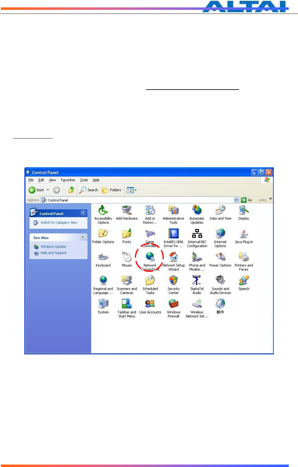
For Windows XP user,
1. Click the “start” menu and choose “Control Panel”.
2. Click “Network Connections”.
Figure 1 Control Panel in Windows XP
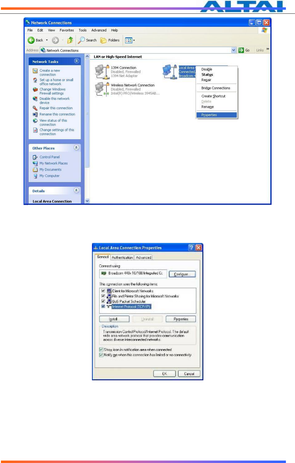
3. Right-click the “Local Area Connection” and select “Properties”.
TPS12-016_rev1 1_A8Ein_web-admin_Configuration_Manual_-_fm_1 2 0 604 (for FCC & IC) 20130322.doc
Commercially Confidential
9
Figure 2 Network Connections in Windows XP
4. After clicking “Properties”, you will see the diagram as below.
Figure 3 Local Area Connection Properties in Windows XP
5. Mark the “Internet Protocol (TCP/IP)” and click “Properties”.
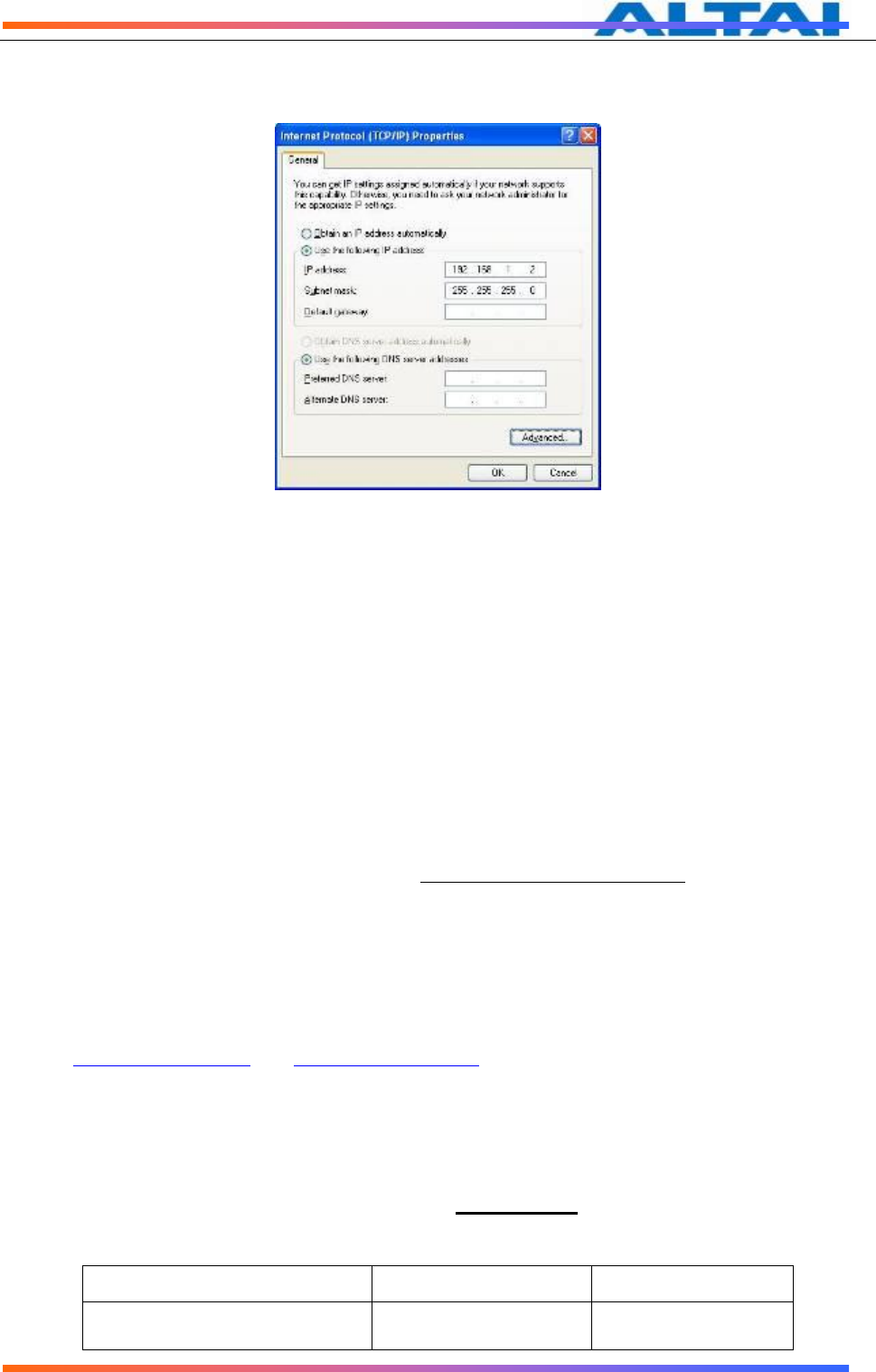
6. Type in an “IP address”, for example, 192.168.1.2, which is under the same subnet as the
Default IP Address of A8Ein BTS (192.168.1.222).
7. Using the default “Subnet mask” (default: 255.255.255.0) setting in the first time.
8. Keep the “Default gateway” as “Blank”.
TPS12-016_rev1 1_A8Ein_web-admin_Configuration_Manual_-_fm_1 2 0 604 (for FCC & IC) 20130322.doc
Commercially Confidential
10
9. Keep the “Preferred DNS server” and “Alternate DNS server” as “Blank” also.
10. Click “OK” when you finish setting and close the Window.
Figure 4 Internet Protocol (TCP/IP) Properties in Windows XP
4.2 CHECK ACCESS
“ping” utility of Command Prompt is a handy tool to check the access to the A8Ein BTS.
1. Go to the Command Prompt by typing “cmd” in “Run”.
2. Type command:
ping 192.168.1.222
The A8Ein BTS shall respond to your ping request if A8Ein BTS and your PC have a
correct connection.
NOTE: Using the same PC to ping different A8Ein BTS may cause ping failure. This is because
A8Ein BTS has the same default IP address but different MAC addresses. You need to type
command “arp –d” in Command Prompt to clear ARP table on PC before each ping.
4.3 CONFIGURATION WITH WEB-ADMIN
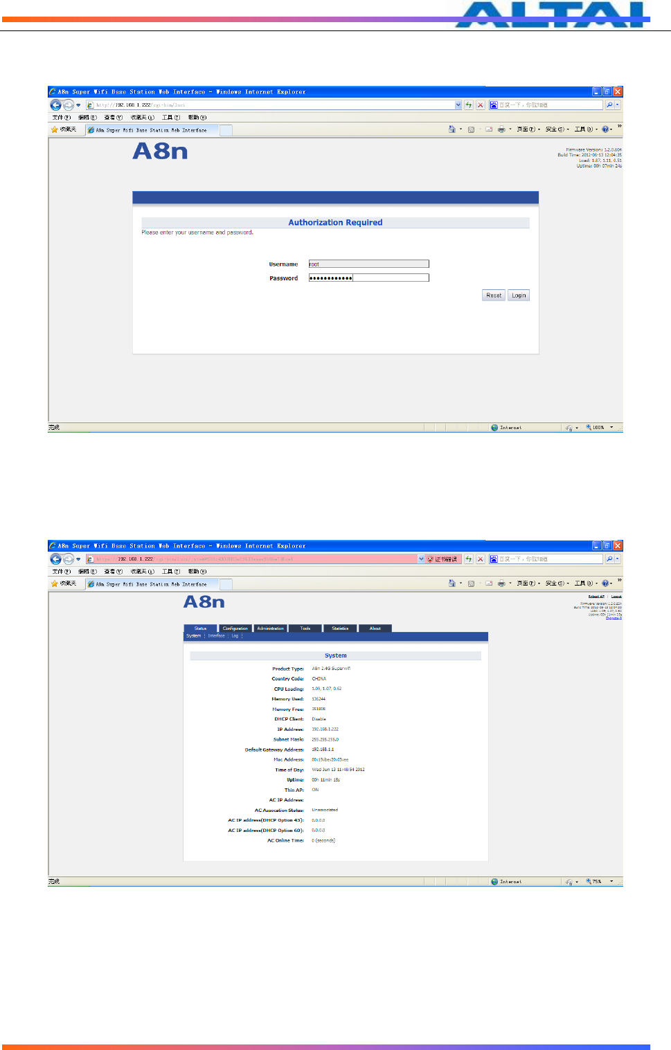
The A8Ein can be accessed through a Web Browser, for example, Internet Explorer (IE).
1. Open an IE session and type the IP address of the A8Ein BTS. Example:
http://192.168.1.222 or https://192.168.1.222, where 192.168.1.222 is the A8Ein’s IP
address. The default IP Address is 192.168.1.222.
2. A window will pop up, as shown in Figure 5. Enter the user name and password in the
corresponding fields, which are the same as for the CLI. The default User Name and
Password are shown in Table 2. They are case sensitive.
Firmware version
Default User Name
Default Password
1.2.0.604
root
superwifi123
TPS12-016_rev1 1_A8Ein_web-admin_Configuration_Manual_-_fm_1 2 0 604 (for FCC & IC) 20130322.doc
Commercially Confidential
11
Table 2 A8Ein default User Name and Password
Figure 5 Enter User Name and Password
3. A login page in IE appears, as shown in Figure 6. A Menu Bar is located on the top of
the IE window. Different functions can be accessed through the menu bar.
Figure 6 Web-admin Login Page
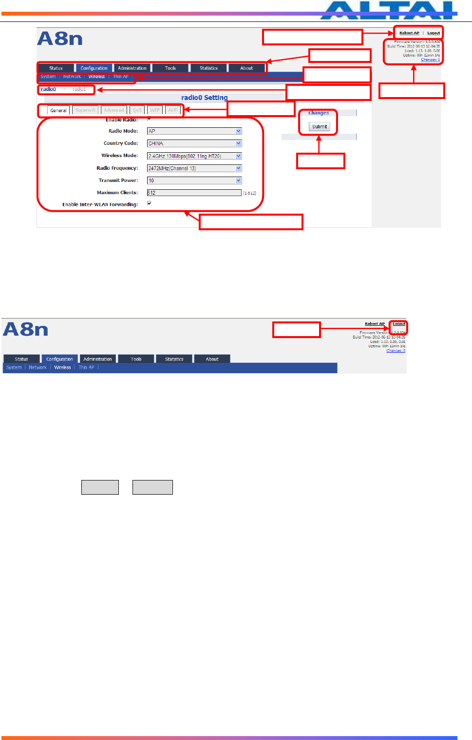
4.4 INTERFACE INTRODUCTION
A8Ein interface is separated to 5 levels: Level 1 menu, Level 2 menu, Interface selection, Level 3
menu and Configuration options
TPS12-016_rev1 1_A8Ein_web-admin_Configuration_Manual_-_fm_1 2 0 604 (for FCC & IC) 20130322.doc
Commercially Confidential
12
Figure 7 A8Ein webpage
4.5 LOGOUT FROM A8EIN INTERFACE
On the right top corner of A8Ein Web interface, click “Logout” button to logout from A8Ein.
On the other side, you can directly close A8Ein webpage to logout from A8Ein.
Figure 8 Logout
5 SYSTEM STATUS
A8Ein Status function gives System information, interface information, Log and Statistics
information.
5.1 SYSTEM
You can select Status -> System to check A8Ein basic information and real-time status.
Level 1
menu
Level 3 menu
Configuration
options
Interface
selection
Level 2 menu
System Info
Reboot AP &
Logout
Submit
Logout
TPS12-016_rev1 1_A8Ein_web-admin_Configuration_Manual_-_fm_1 2 0 604 (for FCC & IC) 20130322.doc
Commercially Confidential
13
Figure 9 System information
Following information can be found from “System” function:
Product Type:A8Ein base station model.
Country Code:A8Ein country code
CPU Loading:A8Ein CPU loading
Memory Used:A8Ein used memory (Byte)
Memory Free:The rest memory (Byte)
DHCP Client:Enable/disable DHCP Client
IP Address:A8Ein current IP address
Subnet Mask:A8Ein subnet mask
Default Gateway Address:A8Ein gateway address
Mac Address:A8Ein Ethernet interface MAC address
Time of Day:System time
Uptime:Operation time from last time reboot
Thin AP:ON/OFF Thin AP function
AC IP Address:On Thin AP mode, you will find AC IP Address
TPS12-016_rev1 1_A8Ein_web-admin_Configuration_Manual_-_fm_1 2 0 604 (for FCC & IC) 20130322.doc
Commercially Confidential
14
AC Association Status:On Thin AP mode, you will find the connection status between
A8Ein and AC
AC IP Address(DHCP Option 43):On Thin AP mode, you will find AC IP Address by DHCP
Option 43
AC IP Address(DHCP Option 60):On Thin AP mode, you will find AC IP Address by DHCP
Option 60
AC Online time:Display AC online time
5.2 INTERFACE
You can select Status -> Interface to check interface information which includes 2.4GHz
(radio0), 5GHz(radio1) and Ethernet information.
Figure 10 Interface status
5.2.1.1 2.4G INTERFACE STATUS
By selecting Status -> Interface-> radio0, you can find 2.4G interface (radio0) information which
includes following 5 parts: Status, Statistic, Channel Usage, WLAN and Association List.
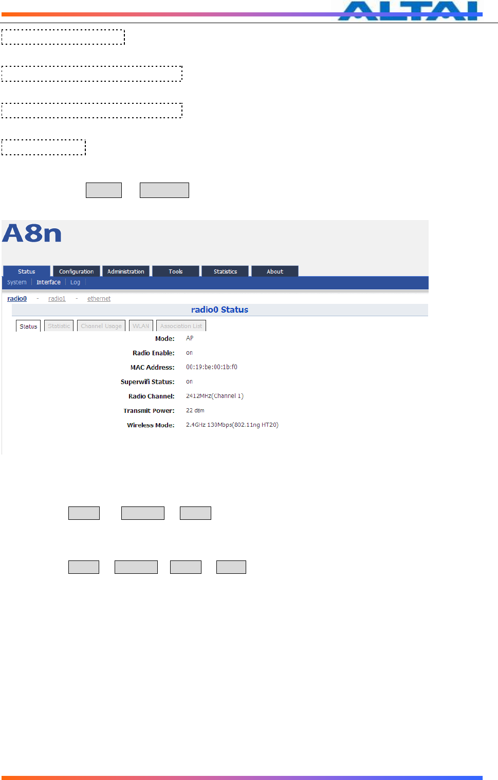
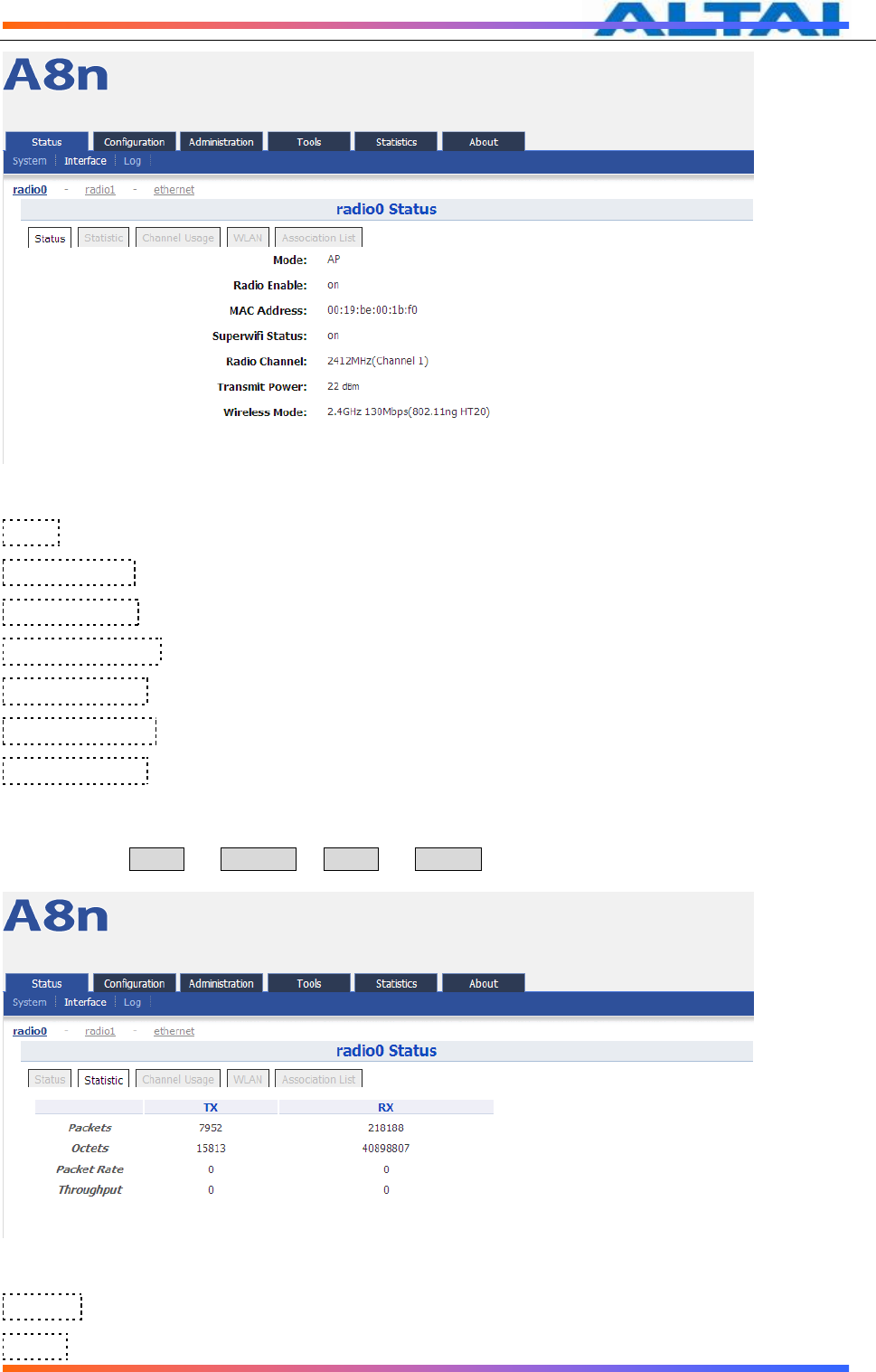
Status
Please select Status -> Interface-> radio0 -> status to check radio0 status, the webpage provides radio0
Mode, Radio Enable/Disable, MAC Address, Superwifi Status, Radio Channel, Transmit Power and
Wireless Mode.
TPS12-016_rev1 1_A8Ein_web-admin_Configuration_Manual_-_fm_1 2 0 604 (for FCC & IC) 20130322.doc
Commercially Confidential
15
Figure 11 Interface status
Mode:Operation mode
Radio Enable:radio0 status (ON/OFF)
MAC Address:radio0 MAC address。
Superwifi Status:Superwifi Status (ON/OFF)
Radio Channel:radio0 current channel
Transmit Power:radio0 transmit power
Wireless Mode:radio0 wireless mode
Statistic
Please select Status -> Interface-> radio0 -> Statistic to check radio0 statistics information which
includes radio0 Tx and Rx Packets, Tx and Rx Octets, Packet Rate, Throughput.
Figure 12 Interface statistic
Packets: radio0 received and sent packets
Octets: radio0 received and sent octets
TPS12-016_rev1 1_A8Ein_web-admin_Configuration_Manual_-_fm_1 2 0 604 (for FCC & IC) 20130322.doc
Commercially Confidential
16
Packet Rate: radio0 packet rate
Throughput: radio0 throughput
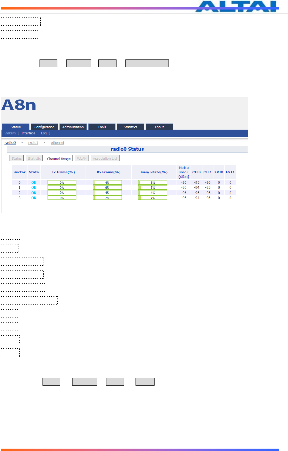
Channel usage
Please select Status -> Interface-> radio0 -> Channel Usage to check radio0 channel usage information
including: Sector, state, Tx Frame(%), Rx Frame(%), Busy State(%), Noise Floor(dBm), CTL0,
CTL1, EXT0, EXT1
When the state of a sector is ON, it means this sector is enabled. When it is OFF, it means the sector is
disabled or it is abnormal, please contact network administrator to check equipment.
Figure 13 Channel usage
Sector:A8Ein has 4 sectors from 0~3
State: A8Ein sector state
Tx Frame(%): Sector based transmit frames percentage
Rx Frame(%): Sector based receive frames percentage
Busy State(%): Sector based busy state percentage
Noise Floor(dBm) :Sector based noise floor
CTL0:。
CTL1:。
EXT0:。
EXT1:。
WLAN
Please select Status -> Interface-> radio0 -> WLAN to check radio0 wireless network information
including: Device Id, WLAN, SSID, MAC Address, Auth Mode, Unicast Cipher, Multicast Cipher, Num of
Station, Unicast Packets(TX/RX), State.
When you enable a WLAN, you can find its relevant information in “State”.

TPS12-016_rev1 1_A8Ein_web-admin_Configuration_Manual_-_fm_1 2 0 604 (for FCC & IC) 20130322.doc
Commercially Confidential
17
Figure 14 WLAN information
Device Id:2.4G interface ID
WLAN:Wireless network number
SSID: A8Ein default SSID is Superwifi Network x (x is from 0 to 15)
MAC Address: 2.4G wireless network MAC address (BSSID)
Auth Mode: Authentication mode for each wireless network
Unicast Cipher :Unicast cipher mode for each wireless network
Multicast Cipher : Multicast cipher mode for each wireless network
Num of Station: Associated client number
Unicast Packets(TX/RX):Unicast sent and received packets for each wireless network
State:Wireless network state
Association list
Please select Status -> Interface-> radio0 -> Association List to get associated client information
including: Total Client Association, Client Association Histogram, STA ID, Mac Address, Wlan ID, Sector,
SNR, Download/Bytes, Upload/Bytes, Download Rate/kbps, Upload Rate/kbps.
Figure 15 Association list
Total Client Association:Total associated clients
TPS12-016_rev1 1_A8Ein_web-admin_Configuration_Manual_-_fm_1 2 0 604 (for FCC & IC) 20130322.doc
Commercially Confidential
18
Client Association Histogram:Association client history records
STA ID: Wireless client ID
Mac Address:Wireless client MAC address
Wlan ID:Client associated WLAN ID
Sector:Client associated sector
SNR:Wireless client SNR
Download :Wireless client download traffic (Bytes)
Upload :Wireless client upload traffic (Bytes)
Download Rate :Wireless client download rate(kbps)。
Upload Rate :Wireless client upload rate(kbps)。
Warnings
:
the interface will self-refresh with 10s interval.
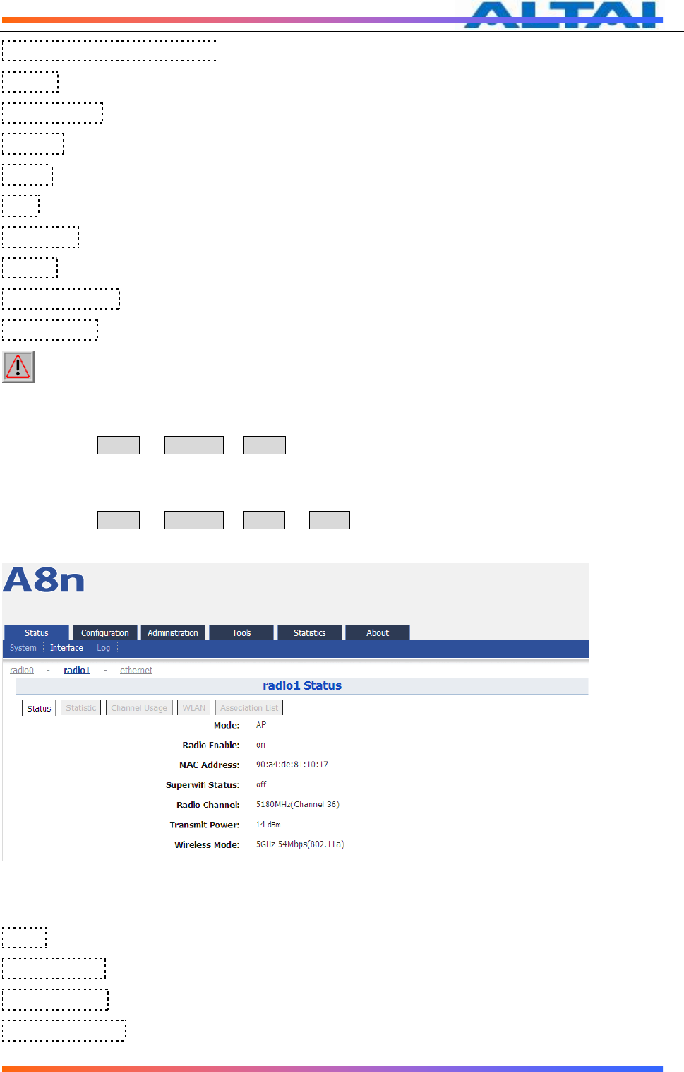
5.2.1.2 5G INTERFACE
Please select Status -> Interface-> radio1 to check 5G radio (radio1) state including Status, Statistic,
Channel Usage, WLAN, Association List.
Status
Please select Status -> Interface-> radio1 -> status to check radio1 status. In this page, you will find
radio1 mode, Radio Enable, MAC Address, Superwifi Status, Radio Channel, Transmit Power, Wireless
Mode.
Figure 16 5G interface state
Mode: radio1 operation mode
Radio Enable: radio1 enabled or disabled
MAC Address: radio1 MAC address
Superwifi Status: Superwifi ON/OFF Status

TPS12-016_rev1 1_A8Ein_web-admin_Configuration_Manual_-_fm_1 2 0 604 (for FCC & IC) 20130322.doc
Commercially Confidential
19
Radio Channel: radio1 current channel
Transmit Power: radio1 transmit power
Wireless Mode: radio1 wireless mode
Statistic
Please select Status -> Interface-> radio1 -> Statistic to check radio1 statistic information which
includes radio1 Tx & Rx Packets, Tx & Rx Octets, Packet Rate and Throughput.
Figure 17 5G interface statistic
Packets: radio1 sent and received packets
Octets: radio1 sent and received octets
Packet Rate: radio1 packet rate
Throughput: radio1 throughput
Channel usage
Please select Status -> Interface-> radio1 -> Channel Usage to check radio1 channel usage information
including Noise Floor(dBm), CTL0, CTL1, EXT0, EXT1.
Figure 18 5G interface channel usage
Noise Floor(dBm) :5GHz noise floor in A8Ein surrounding environment
CTL0:。
TPS12-016_rev1 1_A8Ein_web-admin_Configuration_Manual_-_fm_1 2 0 604 (for FCC & IC) 20130322.doc
Commercially Confidential
20
CTL1:。
EXT0:。
EXT1:。
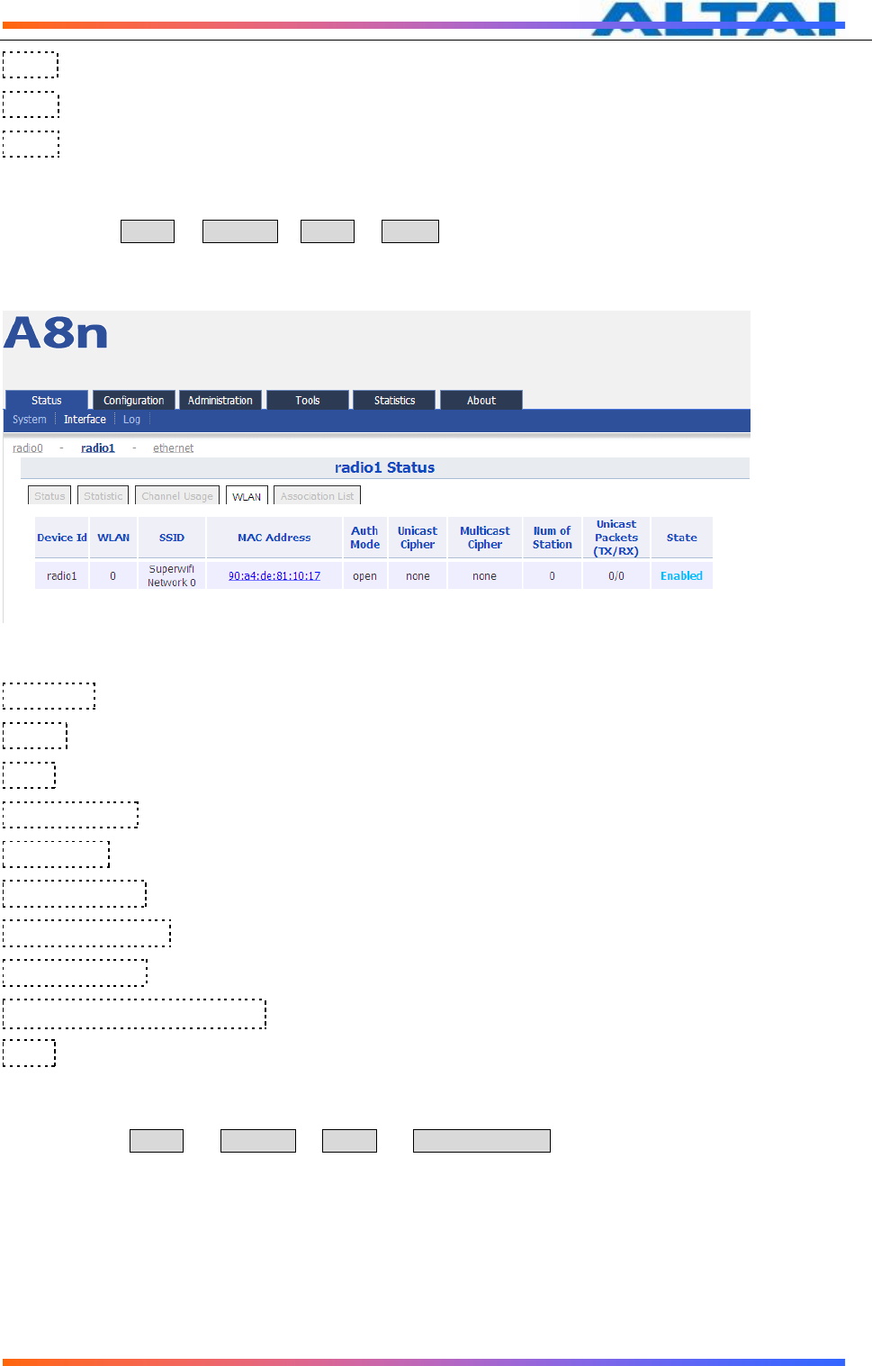
WLAN
Please select Status -> Interface-> radio1 -> WLAN to check radio1 wireless network information which
includes Device Id, WLAN, SSID, MAC Address, Auth Mode, Unicast Cipher, Multicast Cipher, Num of
Station, Unicast Packets(TX/RX)and State.
When you enable a WLAN, you can find its relevant information in “State”.
Figure 19 5G interface WLAN information
Device Id:5G interface ID
WLAN: Wireless LAN number
SSID: A8Ein default SSID is “Superwifi Network x” (x is from 0 to 15)
MAC Address: 5G wireless network MAC address (BSSID)
Auth Mode: Authentication mode for each wireless network
Unicast Cipher :Unicast cipher mode for each wireless network
Multicast Cipher : Multicast cipher mode for each wireless network
Num of Station: Associated client number
Unicast Packets(TX/RX):Unicast sent and received packets for each wireless network
State:Wireless network state
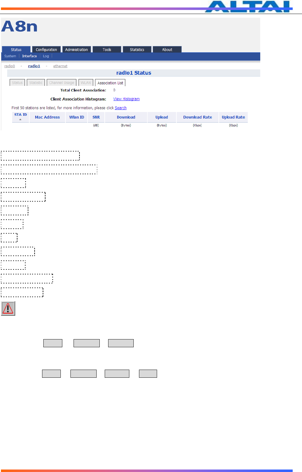
Association List
Please select Status -> Interface-> radio1 -> Association List to get associated client information
including: Total Client Association, Client Association Histogram, STA ID, Mac Address, Wlan ID, Sector,
SNR, Download/Bytes, Upload/Bytes, Download Rate/kbps, Upload Rate/kbps.
TPS12-016_rev1 1_A8Ein_web-admin_Configuration_Manual_-_fm_1 2 0 604 (for FCC & IC) 20130322.doc
Commercially Confidential
21
Figure 20 5G interface association list
Total Client Association:Total associated clients
Client Association Histogram:Association client history records
STA ID: Wireless client ID
Mac Address:Wireless client MAC address
Wlan ID:Client associated WLAN ID
Sector:Client associated sector
SNR:Wireless client SNR
Download :Wireless client download traffic (Bytes)
Upload :Wireless client upload traffic (Bytes)
Download Rate :Wireless client download rate(kbps)。
Upload Rate :Wireless client upload rate(kbps)。
Warnings
:
the interface will self-refresh with 10s interval.
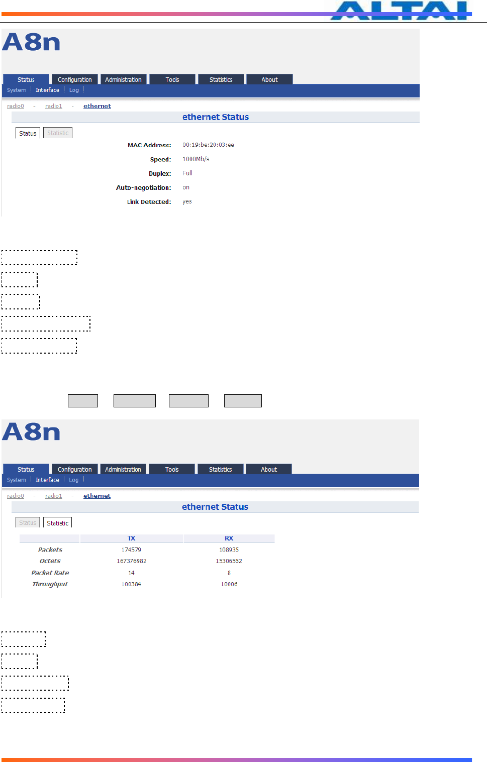
5.2.1.3 ETHERNET INTERFACE
Please select Status -> Interface-> Ethernet to check Ethernet interface information including Status
and Statistic.
Status
Please select Status -> Interface-> ethernet -> status to check Ethernet interface status which includes
Ethernet MAC Address, Speed, Duplex, Auto-negotiation and Link Detected.
TPS12-016_rev1 1_A8Ein_web-admin_Configuration_Manual_-_fm_1 2 0 604 (for FCC & IC) 20130322.doc
Commercially Confidential
22
Figure 21 Ethernet interface state
MAC Address: A8Ein Ethernet MAC address
Speed: A8Ein Ethernet speed
Duplex:A8Ein Ethernet duplex mode (Full/Half)
Auto-negotiation:A8Ein Ethernet auto-negotiation mode ON or OFF, by default it is “ON”.
Link Detected:Whether A8Ein Ethernet do link detection, by default it is “yes”.
Statistic
Please select Status -> Interface-> ethernet -> Statistic to check Ethernet statistic information including
Ethernet Tx & Rx Packets, Tx & Rx Octets, Packet Rate and Throughput.
Figure 22 Ethernet interface statistic
Packets:Ethernet sent and received packets
Octets:Ethernet sent and received octets
Packet Rate:Ethernet interface packet rate
Throughput:Ethernet interface throughput
TPS12-016_rev1 1_A8Ein_web-admin_Configuration_Manual_-_fm_1 2 0 604 (for FCC & IC) 20130322.doc
Commercially Confidential
23
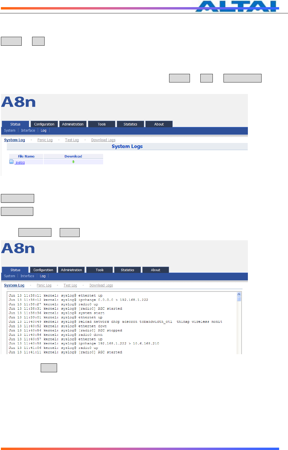
5.3 LOG
In order to realize easy monitoring and diagnosis, A8Ein provides log function. Selecting
Status -> Log, you will find 4 sub-items below: System Log, Panic Log, Test Log and
Download Logs.
System Log
The system log gives A8Ein system information like: software, hardware, system
configuration, and self-checking result. Please select Status -> Log -> System Log to
check system log:
Figure 23 System log
File Name:The name of log files, you can click it to open the log file.
Download:Dowload log file. Please click the green downward arrow to download the log
file.
Click File Name-> Syslog, and you will find the log page below:
图 Error! No text of specified style in document.-1 打开系统日志文件
Please click Back at the end of log to come back the previous page:
TPS12-016_rev1 1_A8Ein_web-admin_Configuration_Manual_-_fm_1 2 0 604 (for FCC & IC) 20130322.doc
Commercially Confidential
24
Figure 24 System log “Back” button
Panic Log
Panic Log is a self-generated log when the system finds some internal errors and need to reboot itself.
Please select Status -> Log -> Panic Log to go to Panic log page:
Figure 25 Panic Logs
File Name:The name of Panic log files, you can click it to open the log file.
Download:Dowload Panic log file. Please click the green downward arrow to download the
log file.
Delete:Delete Panic log file.
Test Log
Please select Status -> Log -> Test Log to go to Test Log page:
Figure 26 Test Logs
File Name:The name of Test log files, you can click it to open the log file.
Download:Dowload Test log file. Please click the green downward arrow to download the
log file.
TPS12-016_rev1 1_A8Ein_web-admin_Configuration_Manual_-_fm_1 2 0 604 (for FCC & IC) 20130322.doc
Commercially Confidential
25
Delete:Delete Test log file.
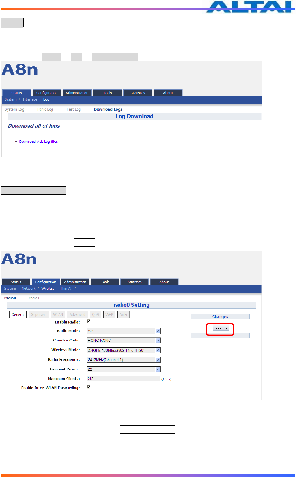
Download Logs
Please select Status -> Log -> Download Logs to go to download logs page.
Figure 27 Download Logs
Download All Log files:Dowload all log files, clicking this button you can download all types of log files.
6 SYSTEM CONFIGURATION
6.1 A8EIN CONFIGURATION PROCEDURES
1 Users need to click Submit button to store the changed settings.
Figure 28 Submit changes
2 On the right top corner, there is an Unsaved Changes button, you can click it to check
submitted items.
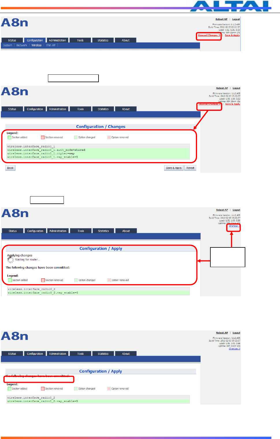
TPS12-016_rev1 1_A8Ein_web-admin_Configuration_Manual_-_fm_1 2 0 604 (for FCC & IC) 20130322.doc
Commercially Confidential
26
Figure 29 Unsaved changes
3 Please click Unsaved Changes button to check changed setting detail information.
Figure 30 Unsaved changes detail
4 Click Save&Apply button to perform all submitted changes:
Figure 31 Save and Apply changes
5 You will find “The following changes have been committed”
Figure 32 Changes have been committed
6 The whole committing changes progress, it is no need to reboot A8Ein.
Click
Save&Appl
y
TPS12-016_rev1 1_A8Ein_web-admin_Configuration_Manual_-_fm_1 2 0 604 (for FCC & IC) 20130322.doc
Commercially Confidential
27
6.2 BASIC CONFIGURATION
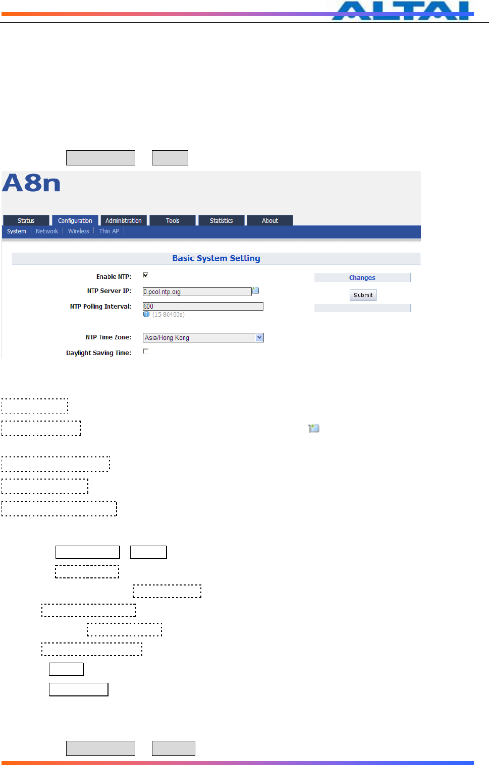
6.2.1 NTP CONFIGURATION
NTP is a network time protocol for the A8Ein BTS to synchronize the system time. NTP is disabled
by default. If NTP is needed, IP address of the NTP server must be added and A8Ein will
synchronize with the NTP server. It is useful to maintain the network and make sure all APs are
using the same system time by setting the same NTP server.
Please select Configuration -> System to configure NTP setting.
Figure 33 NTP Setting
Enable NTP: Enable or disable NTP function, by default it is selected.
NTP Server IP: NTP server IP address, please click “ ” to add new NTP server IP
address.
NTP Polling Interval: By default, it is 600s
NTP Time Zone: Time Zone setting, by default it is Asia/Hong Kong.
Daylight Saving Time: By default, it is not selected.
Procedures:
1 Select Configuration->System, to go to system setting page.
2 Select Enabled NTP to enable NTP.
3 Add NTP IP address in NTP Server IP.
4 Set NTP Polling Interval
5 Choose local NTP Time Zone
6 Set Daylight Saving Time(optinal)
7 Click Submit
8 Click Save&Apply to commit changes.
6.3 NETWORK CONFIGURATION
Please select Configuration -> Network to go to Network configuration page.

TPS12-016_rev1 1_A8Ein_web-admin_Configuration_Manual_-_fm_1 2 0 604 (for FCC & IC) 20130322.doc
Commercially Confidential
28
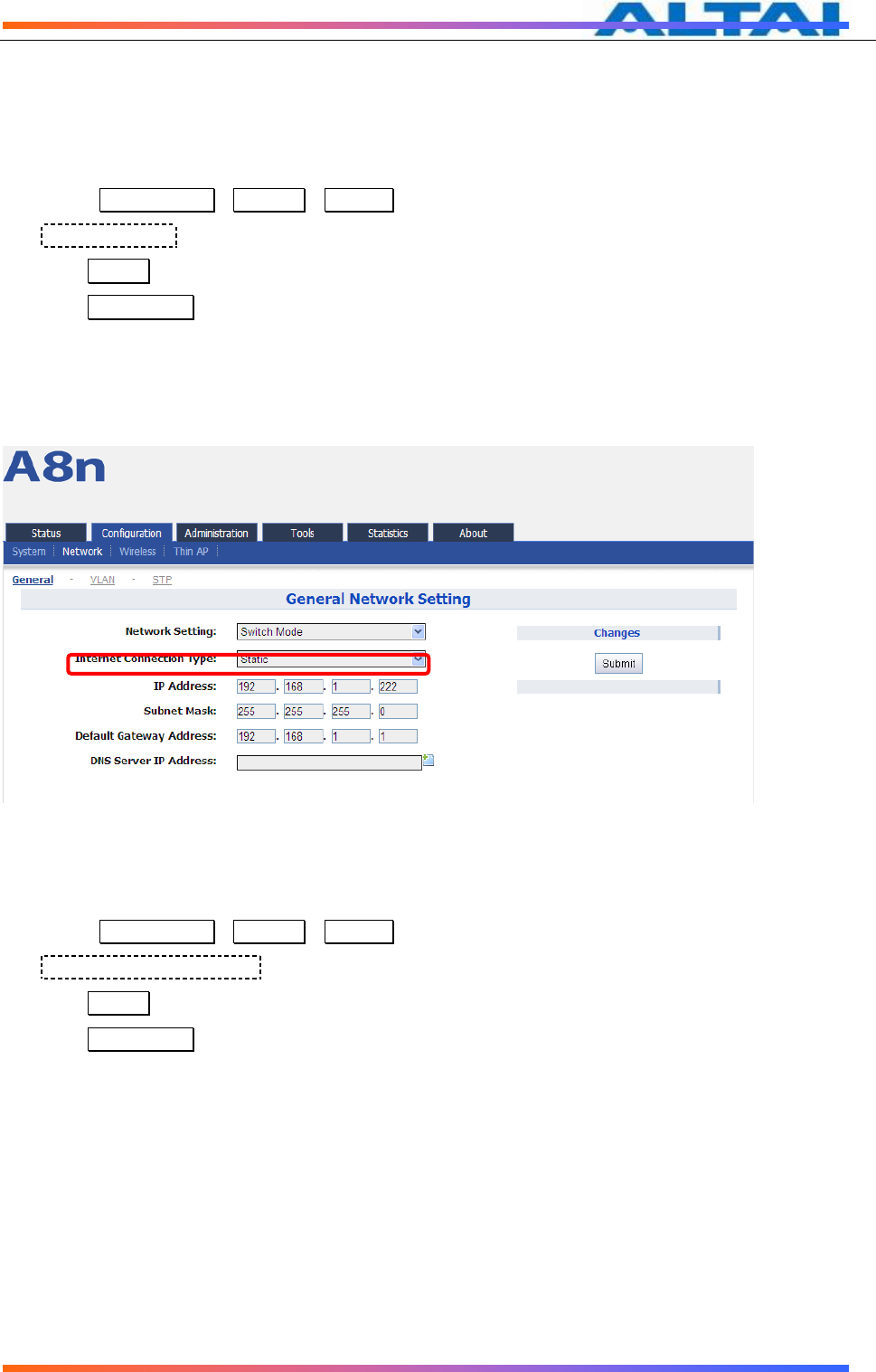
6.3.1 GENERAL NETWORK CONFIGURATION
Please select Configuration -> Network -> General and start to configure general settings.
Figure 34 Network Setting
Network Setting: Currently, it only has Switch Mode
Internet Connection Type: Static IP or DHCP client
IP Address: If A8Ein uses static IP, please give it a fixed IP
Subnet Mask:If A8Ein uses static IP, please give it a subnet mask
Default Gateway Address:If A8Ein uses static IP, please give it a Gateway address
DNS Server IP Address:If A8Ein uses static IP, please set DNS IP address
DHCP Option 60 Enterprise Code: DHCP Option 60 enterprise code is used to
communicate with AC in Thin AP mode.
1.1.1.1 Network setting
Switch Mode
Figure 35 Network Mode
TPS12-016_rev1 1_A8Ein_web-admin_Configuration_Manual_-_fm_1 2 0 604 (for FCC & IC) 20130322.doc
Commercially Confidential
29
In switch mode, A8Ein works as a switch to deliver data between Ethernet interface and
wireless interfaces.
Configuration procedures:
1 Select Configuration->Network->General to go to configuration page.
2 Network Setting: Switch Mode.
3 Click Submit.
4 Click Save&Apply to apply changes.
1.1.1.2 Internet Connection Type
In switch mode, there are 2 types: Static IP or DHCP client
Figure 36 Internet Connection Type
Procedures:
1 Select Configuration->Network->General
2 Internet Connection Type : choose Static or DHCP
3 Click Submit
4 Click Save&Apply to apply.
1)Static IP
Users need manually configure A8Ein IP address, subnet mask, gateway address and
DNS server IP address:

TPS12-016_rev1 1_A8Ein_web-admin_Configuration_Manual_-_fm_1 2 0 604 (for FCC & IC) 20130322.doc
Commercially Confidential
30
Figure 37 Static IP
Procedures:
1 Select Configuration->Network->General
2 Internet Connection Type : choose “Static”
3 IP Address : input IP address
4 Subnet Mask : input subnet mask
5 Default Gateway Address : input gateway address
6 DNS Server IP Address: input DNS address
7 Click Submit
8 Click Save&Apply to apply
2)DHCP
A8Ein will get IP from DHCP server
Figure 38 DHCP Client
Procedures:
1 Select Configuration->Network->General
TPS12-016_rev1 1_A8Ein_web-admin_Configuration_Manual_-_fm_1 2 0 604 (for FCC & IC) 20130322.doc
Commercially Confidential
31
2 Internet ConnectionType : choose DHCP;
3 Click Submit
4 Click Save&Apply to apply
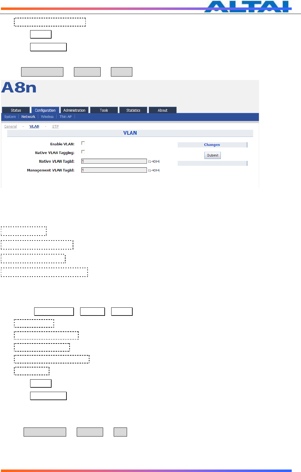
6.3.2 VLAN FUNCTION
Select Configuration -> Network -> VLAN to access to VLAN configuration page.
Figure 39 VLAN Setting
By default, A8Ein VLAN setting is disabled.
Enable VLAN:Enable or Disable VLAN function
Native VLAN Tagging:By default, it is not selected.
Native VLAN TagId:Native VLAN ID
Management VLAN TagId:Management VLAN ID。
Procedures:
1 Select Configuration->Network->VLAN
2 Enable VLAN Enable or disable VLAN
3 Native VLAN Tagging : Enable or disable native VLAN tagging
4 Native VLAN TagId: input Native VLAN ID
5 Management VLAN TagId: input management VLAN ID
6 VLAN TagId : input VLAN ID
7 Click Submit
8 Click Save&Apply to apply
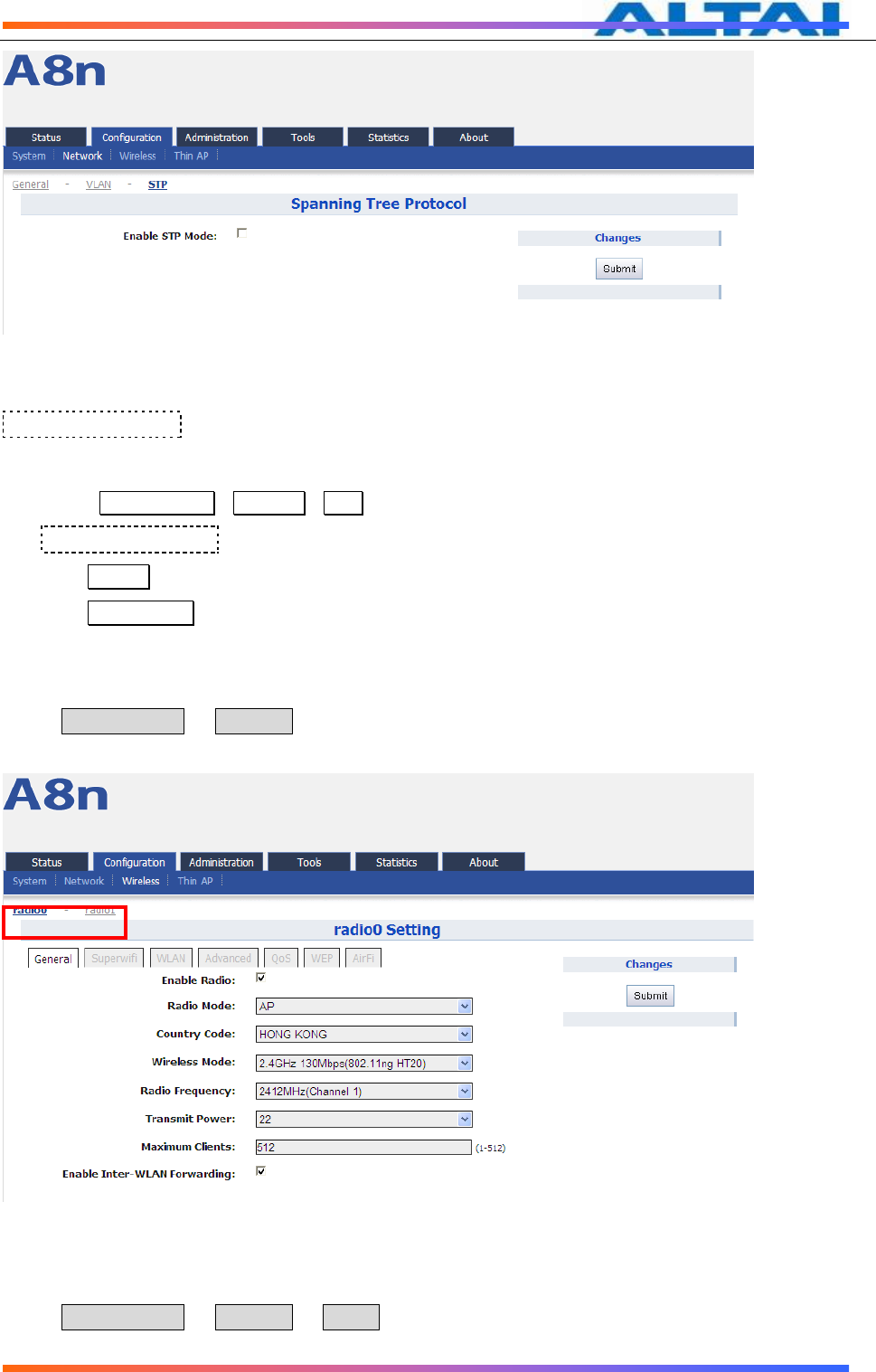
6.3.3 STP
Select Configuration -> Network -> STP to access STP configuration page.
TPS12-016_rev1 1_A8Ein_web-admin_Configuration_Manual_-_fm_1 2 0 604 (for FCC & IC) 20130322.doc
Commercially Confidential
32
Figure 40 STP Setting
Enable STP Mode:By default, it is disabled
Procedures:
1 Select Configuration->Network->STP
2 Enable STP Mode : Select it to enable STP function. By default, it is disabled.
3 Click Submit
4 Click Save&Apply to apply
6.4 WIRELESS
Select Configuration -> Wireless to access wireless network configuration page. There are 2
interfaces, 2.4G(radio0)and 5G(radio1):
Figure 41 2.4G radio setting
6.4.1.1 2.4G RADIO
Select Configuration -> Wireless -> radio0 to change 2.4G radio setting. You can configure
the items below: General, Superwifi, WLAN, Advanced, QoS, WEP, AirFi.
TPS12-016_rev1 1_A8Ein_web-admin_Configuration_Manual_-_fm_1 2 0 604 (for FCC & IC) 20130322.doc
Commercially Confidential
33
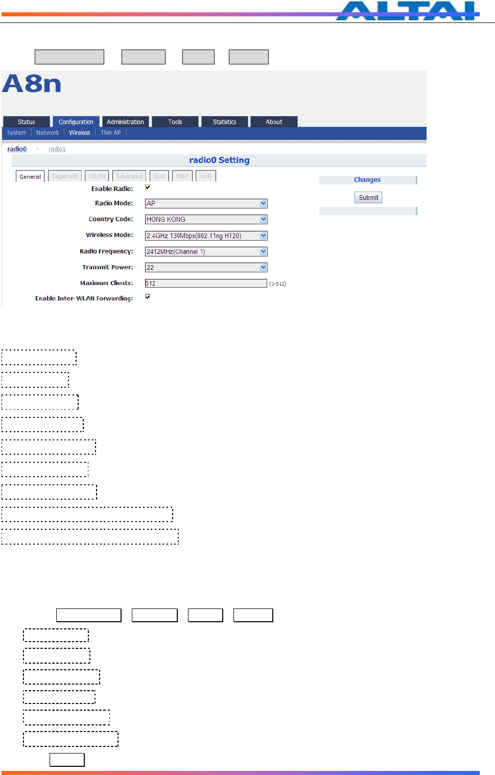
6.4.1.2 2.4G GENERAL CONFIGURATION
Select Configuration -> Wireless -> radio0-> General to access 2.4G general configuration page:
Figure 42 2.4G radio parameters
Enable Radio:Enable or disable 2.4G radio, by default it is enabled.
Radio Mode: 2.4G Radio mode
Country Code:By default, it is HONG KONG
Wireless Mode:By default, it is 2.4GHz 130Mbps(802.11ng HT20)
Radio Frequency:By default, it is 2412MHz(Channel 1)
Transmit Power:By default, it is 22
Maximum Clients:By default, it is 512
Enable Inter-WLAN Forwarding:By default, it is allowed.
Disable HT20/HT40 Auto Switch:In HT40 mode, enable or disable auto switch between
HT40 and HT20.
Procedures:
1 Select Configuration->Wireless ->Radio0->General
2 Enable Radio : Select to enable 2.4G Radio
3 Radio Mode: Select to AP mode
4 Country Code: Select your country code
5 Wireless Mode Select wireless mode
6 Transmit Power Set transmit power
7 Maximum Clients Set 2.4G maximum clients
8 Click Submit
TPS12-016_rev1 1_A8Ein_web-admin_Configuration_Manual_-_fm_1 2 0 604 (for FCC & IC) 20130322.doc
Commercially Confidential
34
9 Click Save&Apply to apply
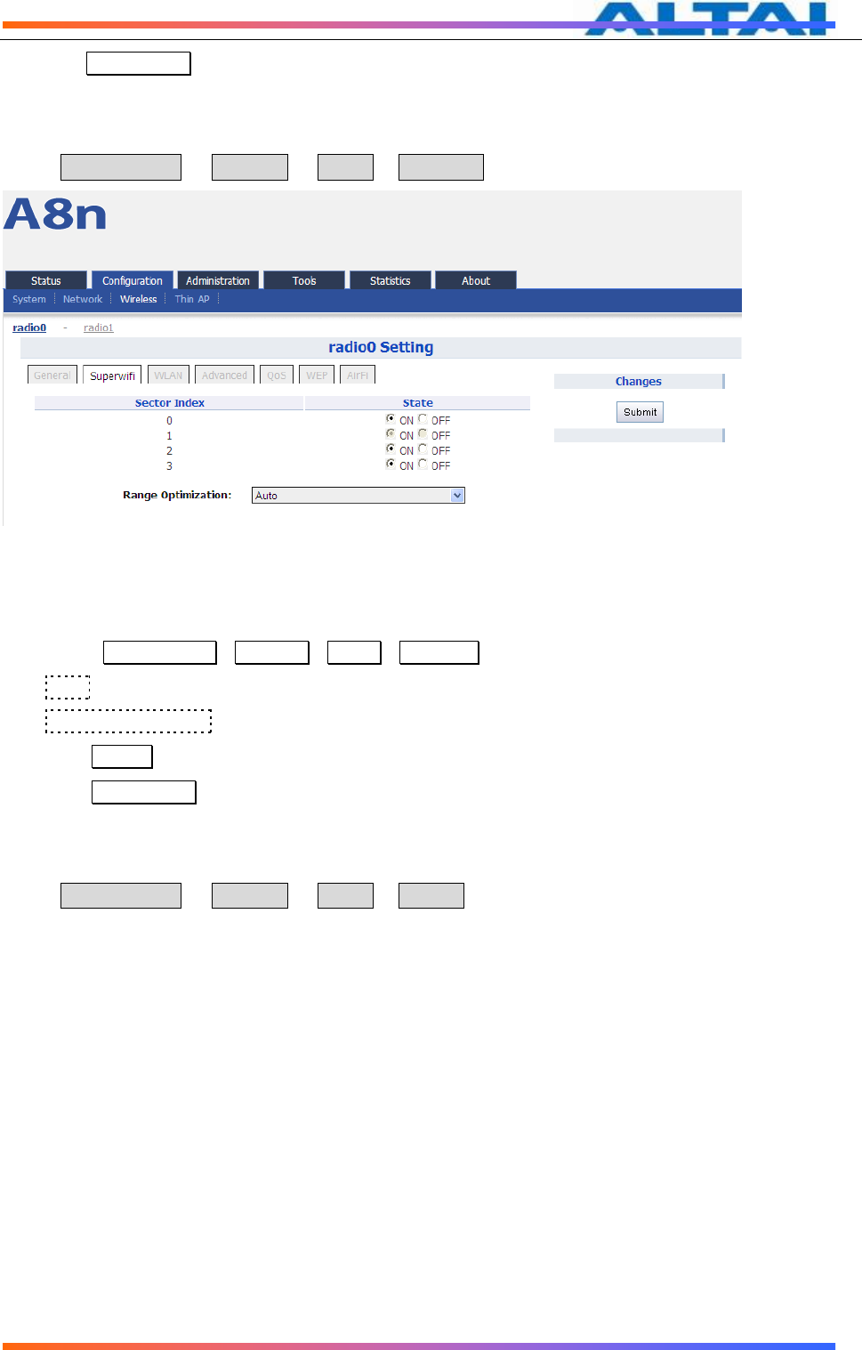
6.4.1.3 SUPERWIFI
Select Configuration -> Wireless -> radio0-> Superwifi to access to superwifi configuration page
Figure 43 Superwifi setting
Procedures:
1. Select Configuration->Wireless->radio0->Superwifi
2. State enable or disable the sector
3. Range Optimization optimized for the coverage range
4. Click Submit
5. Click Save&Apply to apply
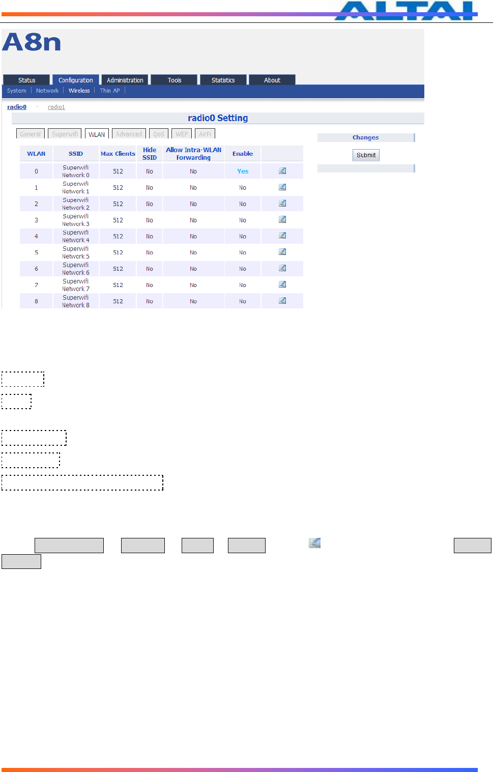
6.4.1.4 2.4G WLAN
Select Configuration -> Wireless -> radio0-> WLAN to access to 2.4G radio WLAN setting page:
TPS12-016_rev1 1_A8Ein_web-admin_Configuration_Manual_-_fm_1 2 0 604 (for FCC & IC) 20130322.doc
Commercially Confidential
35
Figure 44 WLAN setting
A8Ein2.4G radio supports maximum 16 WLAN, and they can be configured separately.
WLAN :WLAN number, from 0-15
SSID:Support maximum 32 characters, default SSID is:Superwifi Network X, X is WLAN
number.
Max Clients:Max. associated clients
Hide SSID:By default, it is disabled.
Allow Intra-WLAN Forwarding: Allow or block inter-WLAN communication
6.4.1.5 WLAN X(0-15) GENERAL CONFIGURATION
Select Configuration -> Wireless -> radio0-> WLAN to edit“ ” WLAN, and then select WLAN
General.
TPS12-016_rev1 1_A8Ein_web-admin_Configuration_Manual_-_fm_1 2 0 604 (for FCC & IC) 20130322.doc
Commercially Confidential
36
Figure 45 WLAN general setting
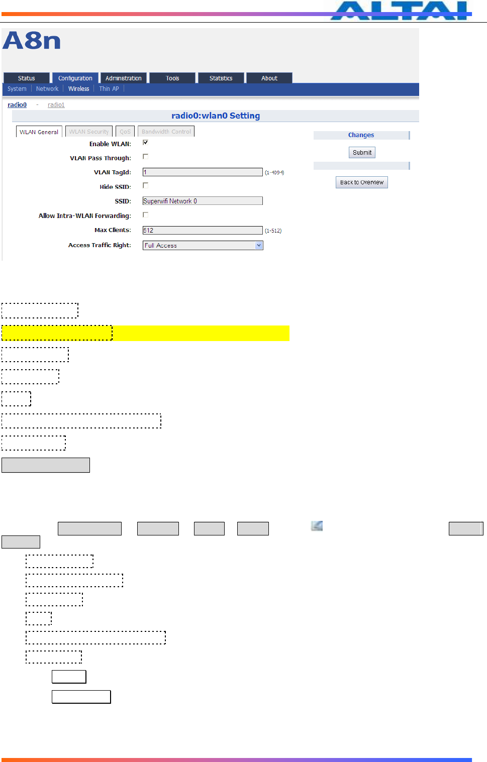
Enable WLAN:Enable or disable this WLAN
VLAN Pass Through:VLAN pass through this WLAN
VLAN TagId:set VLAN ID
Hide SSID:Hide this SSID or not
SSID:set SSID
Allow Intra-WLAN Forwarding:Allow or block inter-WLAN communication
Max Clients:Maximum value is 512
Back to Overview:Go back to previous page
Procedures:
1. Select Configuration -> Wireless -> radio0-> WLAN to edit“ ” WLAN, and then select WLAN
General.
2. Enable WLAN select to enable this WLAN
3. VLAN Pass Through allow or don’t allow VLAN pass through
4. VLAN TagId Set VLAN ID
5. SSID set SSID
6. Allow Intra-WLAN Forwarding: Allow or block
7. Max Clients Maximum is 512
8. Click Submit
9. Click Save&Apply to apply
TPS12-016_rev1 1_A8Ein_web-admin_Configuration_Manual_-_fm_1 2 0 604 (for FCC & IC) 20130322.doc
Commercially Confidential
37
6.4.1.6 WLAN X(0-15) SECURITY
A8Ein 2.4GHz supports Open, Shared Key, WPA, WPA-PSK, WPA2, WPA2-PSK, WAPI,
WAPI-PSK authentication mode, and Disabled, WEP, AES, TKIP, SMS4 cipher mode.
Select Configuration -> Wireless -> radio0-> WLAN to edit “ ” WLAN, and then select
WLAN Security to access to security configuration page.
Figure 46 WLAN security setting
6.4.1.7 OPEN
After selecting Open, you can select Disabled or WEP:
Figure 47 Open & No security
Open & No security procedures:
1. Select Configuration -> Wireless -> radio0-> WLAN to edit “ ” WLAN, and then select WLAN
Security to access to security configuration page
2. Authentication Mode choose Open
3. Cipher Mode choose Disabled
4. Click Submit
5. Click Save&Apply to apply

TPS12-016_rev1 1_A8Ein_web-admin_Configuration_Manual_-_fm_1 2 0 604 (for FCC & IC) 20130322.doc
Commercially Confidential
38
Open – WEP Procedures:
1. Select Configuration -> Wireless -> radio0-> WLAN to edit “ ” WLAN, and then select WLAN
Security to access to security configuration page
2. Authentication Mode choose Open
3. Cipher Mode choose WEP
4. Default WEP Key set the password
5. Click Submit
6. Click Save&Apply to apply
Figure 48 Open & WEP
6.4.1.8 SHARED KEY
Figure 49 Shared Key
Shared key Procedures:
TPS12-016_rev1 1_A8Ein_web-admin_Configuration_Manual_-_fm_1 2 0 604 (for FCC & IC) 20130322.doc
Commercially Confidential
39
1. Select Configuration -> Wireless -> radio0-> WLAN to edit “ ” WLAN, and then select WLAN
Security to access to security configuration page
2. Authentication Mode choose Shared
3. Cipher Mode choose WEP
4. Default WEP Key set the password
5. Click Submit
6. Click Save&Apply to apply
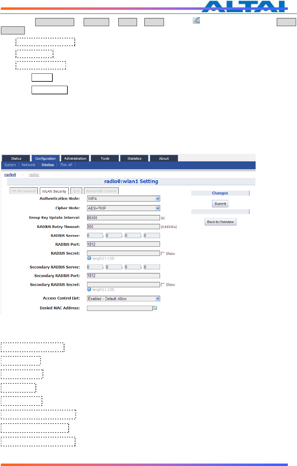
6.4.1.9 WPA/WPA2
WPA/WPA2 can be enabled by selecting WPA, WPA2 for Authentication Mode. The AES
and TKIP are the two available options for Ciper mode.
Figure 50 WPA/WPA2
Authentication Mode:WPA or WPA2
Cipher Mode: AES and TKIP can be choosed.
Radius Server:set Radius server IP address
Radius Port:set Radius server port
Radius Secret:set Radius password
Secondary Radius Server:set Secondary Radius server IP address
Secondary Radius Port:set Secondary Radius server port
Secondary Radius Secret:set Secondary Radius server password

TPS12-016_rev1 1_A8Ein_web-admin_Configuration_Manual_-_fm_1 2 0 604 (for FCC & IC) 20130322.doc
Commercially Confidential
40
WPA/WPA2 Procedures:
1. Select Configuration -> Wireless -> radio0-> WLAN to edit “ ” WLAN, and then select WLAN
Security to access to security configuration page
2. Authentication Mode choose WPA or WPA2
3. Cipher Mode choose AES+TKIP
4. Radius Server set Radius server IP address
5. Radius Port set Radius server port
6. Radius Secret set Radius password
7. Secondary Radius Server set Secondary Radius server IP address (optinal)
8. Secondary Radius Port set Secondary Radius server port (optinal)
9. Secondary Radius Secret set Secondary Radius server password (optinal)
10. Click Submit
11. Click Save&Apply to apply
6.4.1.10 WPA-PSK/WPA2-PSK
WPA-PSK can be enabled by selecting WPA-PSK, WPA2-PSK for Authentication Mode. The AES
and TKIP are the two available options for Cipher Mode.
Figure 51 WPA-PSK/WPA2-PSK
Authentication Mode:WPA or WPA2
Cipher Mode: AES and TKIP can be choosed.
Group Key Update Interval:By default, it is 3600
Pass Phrase:from 8-64 bits
WPA-PSK/WPA2-PSK Procedures:

TPS12-016_rev1 1_A8Ein_web-admin_Configuration_Manual_-_fm_1 2 0 604 (for FCC & IC) 20130322.doc
Commercially Confidential
41
1. Select Configuration -> Wireless -> radio0-> WLAN to edit “ ” WLAN, and then select WLAN
Security to access to security configuration page
2. Authentication Mode choose WPA-PSK or WPA2-PSK
3. Cipher Mode choose AES+TKIP
4. Group Key Update Interval: set interval
5. Pass Phrase set the password
6. Click Submit
7. Click Save&Apply to apply
6.4.1.11 ACL 配置
A8Ein supports ACL(Access Control List), it bases on MAC address filter.
Figure 52 ACL - Disable
Figure 53 ACL – Deny MAC address
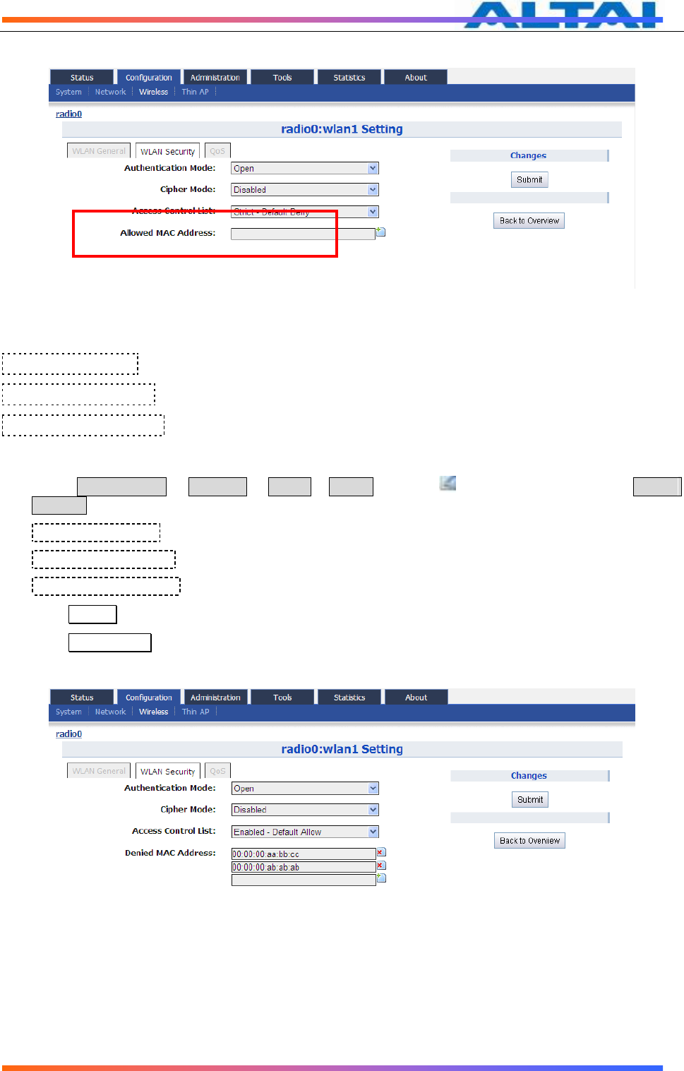
TPS12-016_rev1 1_A8Ein_web-admin_Configuration_Manual_-_fm_1 2 0 604 (for FCC & IC) 20130322.doc
Commercially Confidential
42
Figure 54 ACL – Allow MAC address
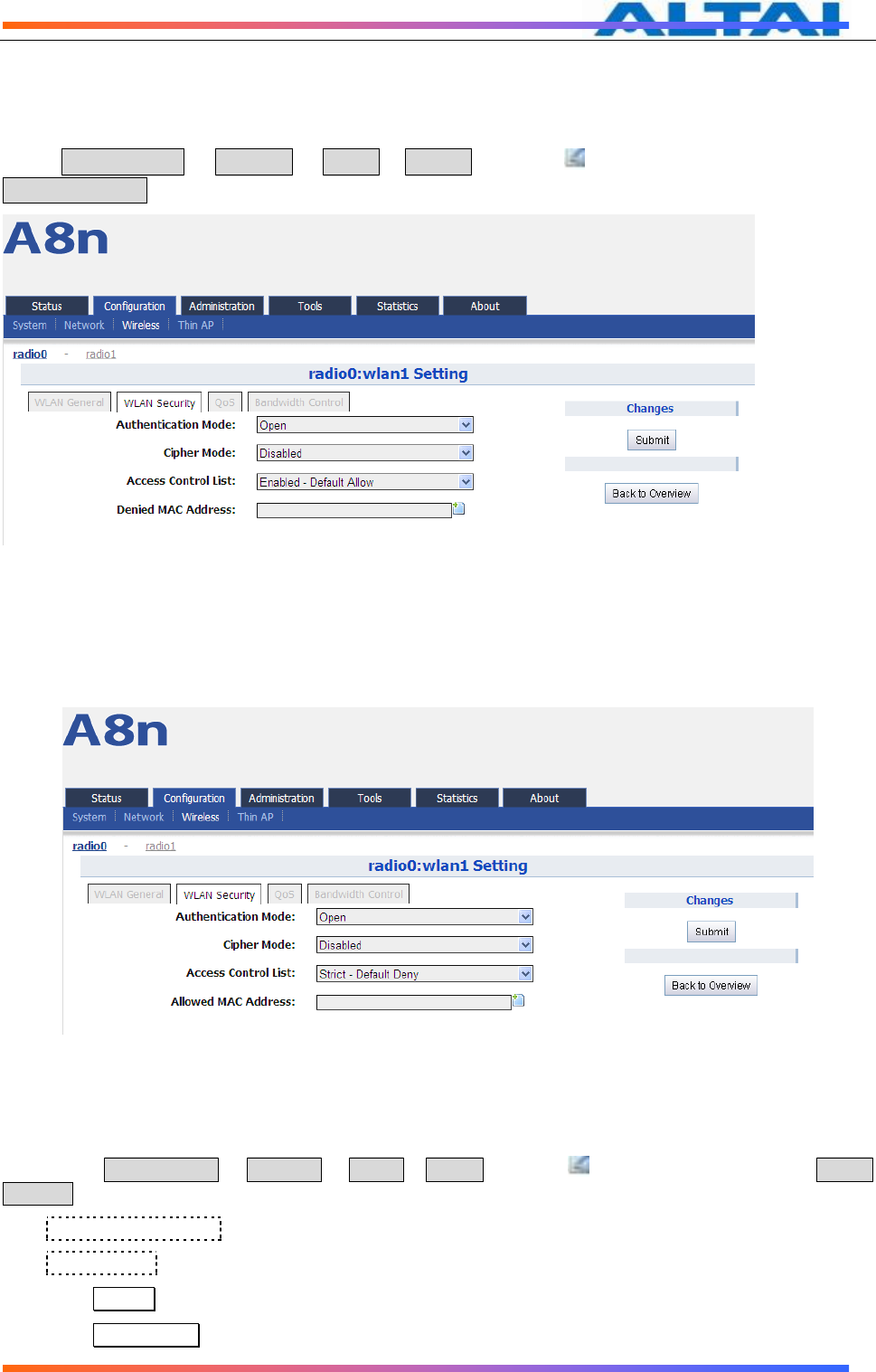
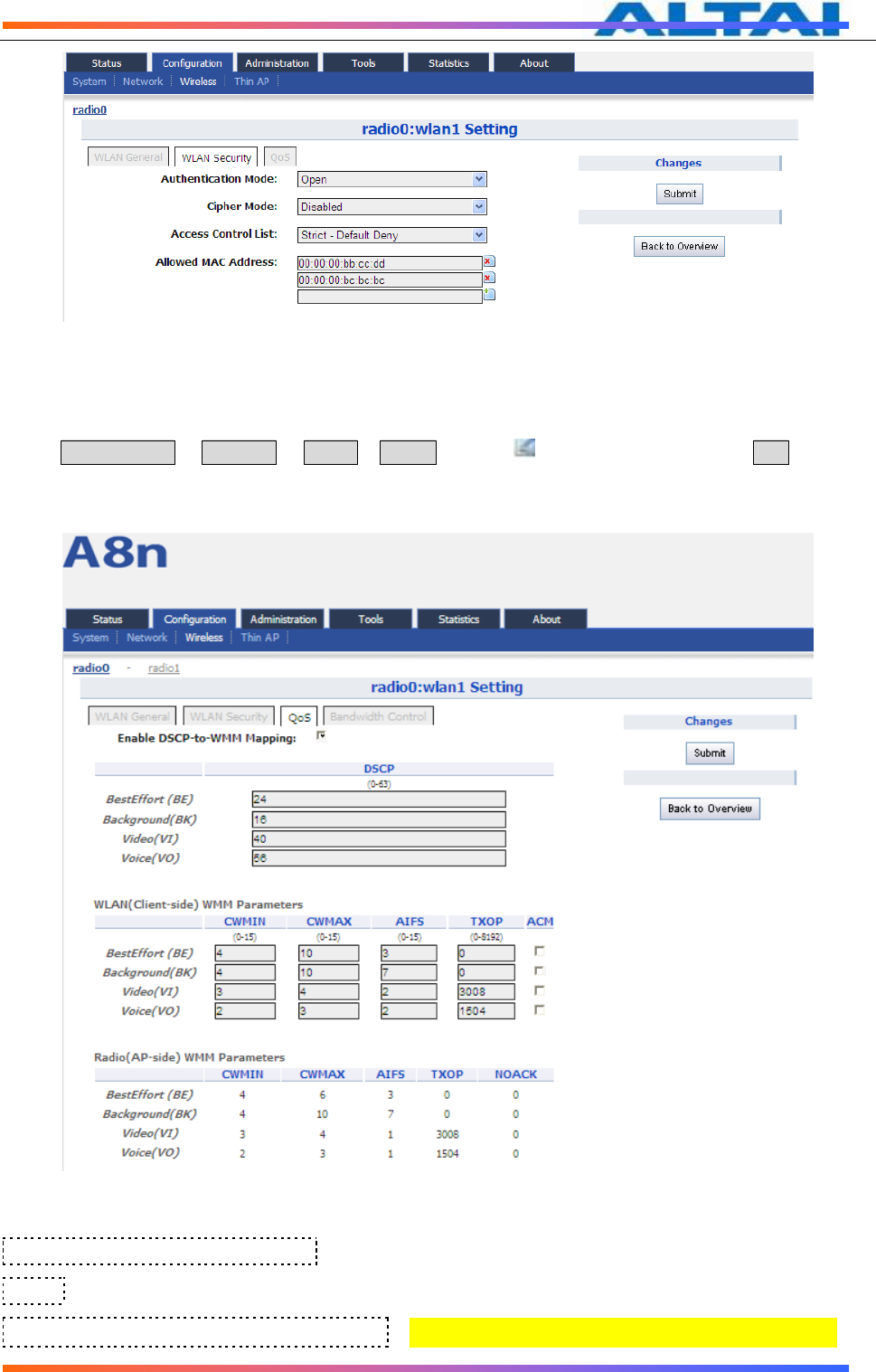
Access Control List:There area 3 modes: Disabled, Enabled-Default Allow, Strict-Default Deny
Denied MAC Address:All MAC address in the list will be blocked.
Allowed MAC Address:Only MAC address in the list can access.
ACL Procedures:
1. Select Configuration -> Wireless -> radio0-> WLAN to edit “ ” WLAN, and then select WLAN
Security to access to security configuration page
2. Access Control List choose the control mode.
3. Denied MAC Address input MAC address
4. Allowed MAC Address input MAC address
5. Click Submit
6. Click Save&Apply to apply
Figure 55 ACL – Add Denied MAC address
TPS12-016_rev1 1_A8Ein_web-admin_Configuration_Manual_-_fm_1 2 0 604 (for FCC & IC) 20130322.doc
Commercially Confidential
43
Figure 56 ACL – Add Allowed MAC address
6.4.1.12 WLAN X(0-15) QOS
Select Configuration -> Wireless -> radio0-> WLAN to edit “ ” WLAN, and then select QoS to access
to QoS configuration page
Figure 57 WLAN QoS
Enable DSCP-to-WMM Mapping:Enable mapping from DSCP to WMM.
DSCP:4 priorities: BestEffort、Background、Video、Voice
WLAN(Client-side)WMM Parameters:Set CWMIN、CWMAX、AIFS、TXOP value
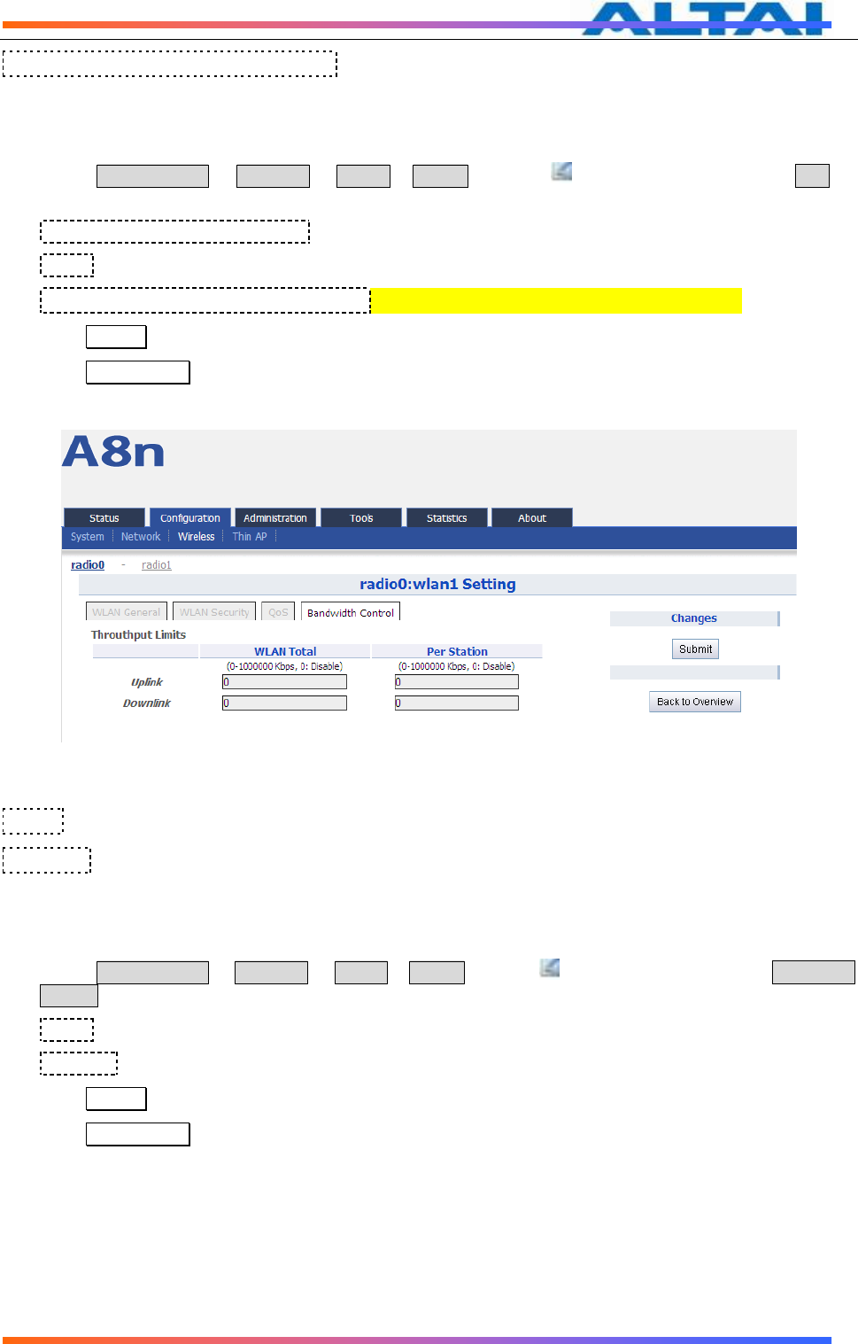
TPS12-016_rev1 1_A8Ein_web-admin_Configuration_Manual_-_fm_1 2 0 604 (for FCC & IC) 20130322.doc
Commercially Confidential
44
Radio(AP-side) WMM Parameters :list WMM parameters
WLAN X QoS configuration procedures:
1. Select Configuration -> Wireless -> radio0-> WLAN to edit “ ” WLAN, and then select QoS to
access to QoS configuration page
2. Enable DSCP-to-WMM Mapping (optinal)
3. DSCP choose one of priorities
4. WLAN(Client-side)WMM Parameters Set CWMIN、CWMAX、AIFS、TXOP value
5. Click Submit
6. Click Save&Apply to apply
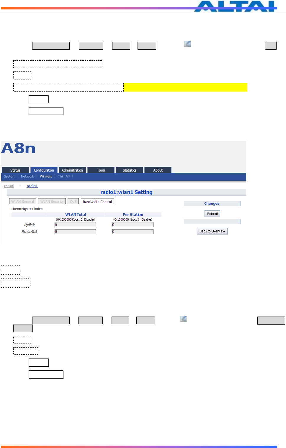
6.4.1.13 WLAN X(0-15) BANDWIDTH CONTROL
Figure 58 WLAN Bandwidth Control
Uplink:uplink bandwidth control, from 0-1000000Kbps
Downlink:downlink bandwidth control, from 0-1000000Kbps
WLAN X bandwidth control procedures:
1. Select Configuration -> Wireless -> radio0-> WLAN to edit “ ” WLAN, and then select Bandwidth
Control to access to QoS configuration page
2. Uplink set uplink bandwidth limitation
3. Downlink set downlink bandwidth limitation
4. Click Submit
5. Click Save&Apply to apply
6.4.1.14 2.4G ADVANCED CONFIGURATION
TPS12-016_rev1 1_A8Ein_web-admin_Configuration_Manual_-_fm_1 2 0 604 (for FCC & IC) 20130322.doc
Commercially Confidential
45
Figure 59 2.4G Radio Advanced setting
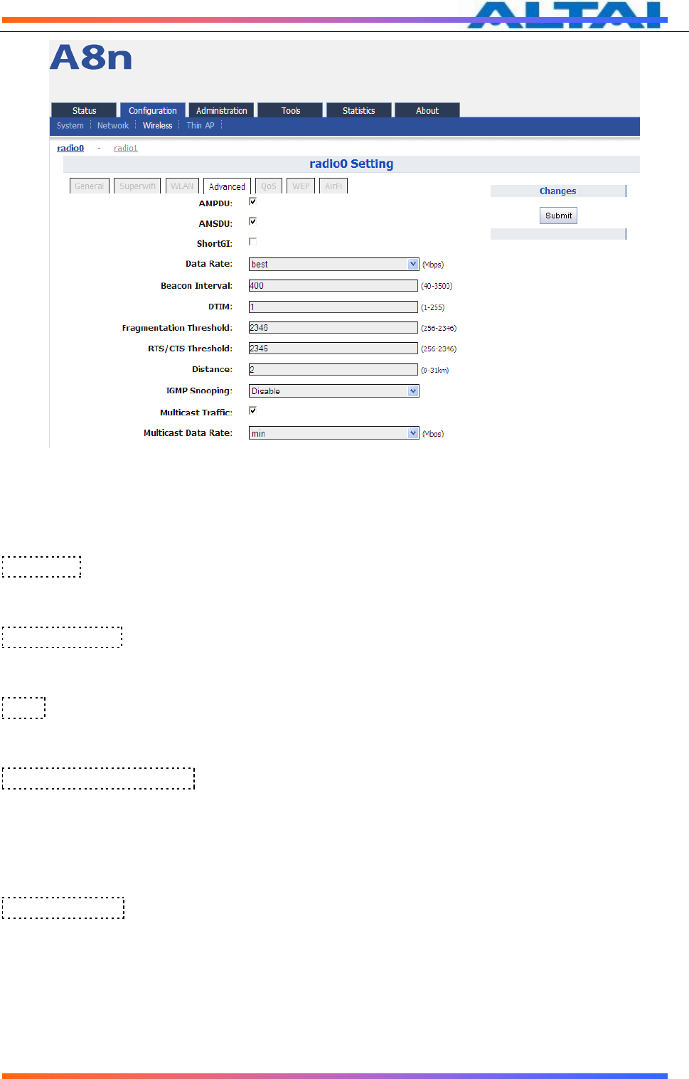
A8Ein provides advanced parameter setting, it would change A8Ein performance. Default
setting is recommended.
Data Rate:Default setting is “best”. The transmission data rate that appears on the drop-down
menu is dependent on the Wireless Mode specified. The numbered data rates denote fixed rates for
transmission.
Beacon Interval:Default setting is 100 ms (equivalent to 10 beacons per second). The amount of
time between A8Ein BTS beacon transmissions for each supported BSS, with each BSS using the
same beacon interval. The beacon interval can be configured between 20 and 1000 ms.
DTIM:Default setting is 1. DTIM Interval, always a multiple of the beacon period, determines how
often the beacon contains a traffic indicator map (TIM). The TIM alerts clients in sleep state to stay
awake long enough to receive their data frames. The value range is from 1 to 255.
Fragmentation Threshold:Default setting is 2346 bytes. The fragmentation threshold, specified
in bytes, determines whether data packets will be fragmented and at what size. Frames that are
smaller than the specified fragmentation threshold value will not be fragmented. Frames that are
larger than the fragmentation threshold will be fragmented into smaller packets and transmitted a
piece at a time instead of all at once. The setting must be within the range of 256 to 2346 bytes. It
is recommended to use the default value or only minor reductions of this default value.
IGMP Snooping:AP is a Layer 2 device when it is configured as Switch mode. However,
IGMP Snooping implementation on AP is a little bit different than that of standard Layer 2
Switch.
Each Virtual AP (VAP) port is similar to a Layer 2 switch port. With IGMP Snooping enabled
in the AP, clients associated to a VAP will only receive multicast packets if there is at least
one client joined the multicast group in that VAP. Unlike ordinary IGMP Snooping
implementation, where Layer 2 switch converts multicast to unicast and delivers them to
devices registered with the multicast group, AP should simply send out the multicast

TPS12-016_rev1 1_A8Ein_web-admin_Configuration_Manual_-_fm_1 2 0 604 (for FCC & IC) 20130322.doc
Commercially Confidential
46
packets from the VAP which has at least one client joined the multicast group. This is done
because the wireless media is a broadcast media. It does not need to be sent multiple
times when there are more than one registered clients.
When IGMP Snooping is turned on, multicast packets should be dropped at the VAP exit if
there is no client from the VAP who has joined the corresponding multicast group.
The IGMP snooping forwarding table (port and multicast MAC address mapping table)
should support aging mechanism to age out the entry which has no multicast traffic for a
period of time (120 seconds in A8Ein).
The default setting of the IGMP Snooping is “Disabled”.。
Multicast Traffic:Default setting is "Enabled ". If set to "Enabled", the system allows multicast
traffic in all VAPs. If set to "Disabled", all multicast traffic in all VAPs will be dropped.
A8Ein supports “Multicast Traffic Data Rate Setting” to transmit all multicast traffic of the 2.4G
interface at the configured multicast data rate. The multicast data rate must be set to any of the basic
data rates. Default setting is 1 Mbps。
Advanced configuration procedures:
1. Select Configuration->Wireless->radio0->Advanced
2. AMPDU selected by default
3. AMSDU selected by default
4. ShortGI un-selected by default
5. Data Rate by default it is “best”
6. Beacon Interval set beacon interval
7. Distance set target area distance
8. IGMP Snooping choose IGMP snooping mode
9. Multicast Traffic allow or block multicast traffic
10. Multicast Data Rate set multicast data rate
11. Click Submit
12. Click Save&Apply to apply
TPS12-016_rev1 1_A8Ein_web-admin_Configuration_Manual_-_fm_1 2 0 604 (for FCC & IC) 20130322.doc
Commercially Confidential
47
6.4.1.15 2.4G WIRELESS QOS CONFIGURATION
Figure 60 2.4G Radio QoS Parameters
QoS parameters configuration procedures:
1. Select Configuration->Wireless->radio0->QoS
2. Set values for this Priority-WMM table
3. Click Submit
4. Click Save&Apply to apply
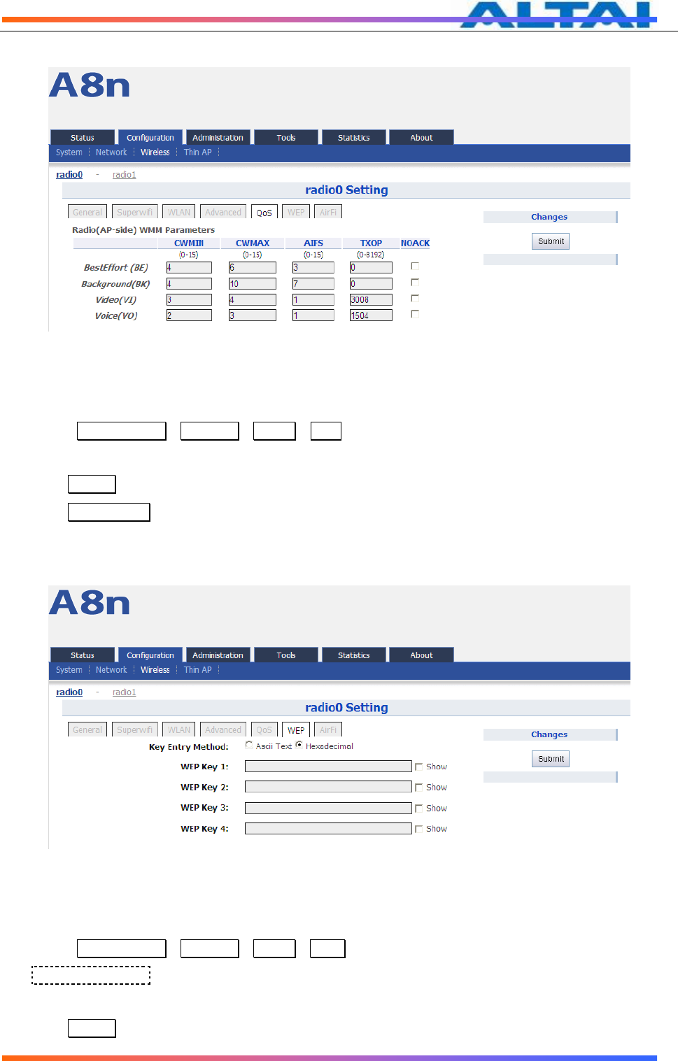
6.4.1.16 2.4G WEP KEY
Figure 61 2.4G Radio WEP Key
Procedures:
1. Select Configuration->Wireless->radio0->WEP
2. Key Entry Method select the key format
3. Input key phrase in related WEP Key
4. Click Submit
TPS12-016_rev1 1_A8Ein_web-admin_Configuration_Manual_-_fm_1 2 0 604 (for FCC & IC) 20130322.doc
Commercially Confidential
48
5. Click Save&Apply to apply
6.4.1.17 2.4G RADIO AIRFI SETTING
Figure 62 2.4G AirFi
Procedures:
1. Select Configuration->Wireless->radio0->AirFi
2. AirFi Mode enable AirFi to get enhanced throughput experience
3. AirFi Offset Level I is recommended
4. Click Submit
5. Click Save&Apply to apply
6.4.2 5G WIRELESS SETTING
6.4.2.1 5G GENERAL SETTING
Figure 63 5G General setting
TPS12-016_rev1 1_A8Ein_web-admin_Configuration_Manual_-_fm_1 2 0 604 (for FCC & IC) 20130322.doc
Commercially Confidential
49
Enable Radio:Enable or disable 5G radio, by default it is enabled.
Radio Mode: You can choose AP or station mode
Country Code:By default, it is HONG KONG
Wireless Mode:By default, it is 5GHz 54Mbps(802.11a)
Radio Frequency:By default, it is Auto
Transmit Power:By default, it is 17
Maximum Clients:By default, it is 512
Enable Inter-WLAN Forwarding:By default, it is allowed.
Disable HT20/HT40 Auto Switch:In HT40 mode, enable or disable auto switch between
HT40 and HT20.
Procedures:
10 Select Configuration->Wireless ->Radio1->General
11 Enable Radio : Select to enable 5G Radio
12 Radio Mode: Select to AP mode
13 Country Code: Select your country code
14 Wireless Mode Select wireless mode
15 Transmit Power Set transmit power
16 Maximum Clients Set 5G maximum clients
17 Click Submit
18 Click Save&Apply to apply
6.4.2.2 5G WLAN
Figure 64 5G WLAN setting
TPS12-016_rev1 1_A8Ein_web-admin_Configuration_Manual_-_fm_1 2 0 604 (for FCC & IC) 20130322.doc
Commercially Confidential
50
Figure 65 5G WLAN information
A8Ein2.4G radio supports maximum 16 WLAN, and they can be configured separately.
WLAN :WLAN number, from 0-15
SSID:Support maximum 32 characters, default SSID is:Superwifi Network X, X is WLAN
number.
Max Clients:Max. associated clients
Hide SSID:By default, it is disabled.
Allow Intra-WLAN Forwarding: Allow or block inter-WLAN communication
6.4.2.3 WLAN X(0-15) BASIC SETTING
Figure 66 5G WLAN General setting

TPS12-016_rev1 1_A8Ein_web-admin_Configuration_Manual_-_fm_1 2 0 604 (for FCC & IC) 20130322.doc
Commercially Confidential
51
Figure 67 5G Station Mode WLAN General setting
Enable WLAN:Enable or disable this WLAN
VLAN Pass Through:VLAN pass through this WLAN
VLAN TagId:set VLAN ID
Hide SSID:Hide this SSID or not
SSID:set SSID
Allow Intra-WLAN Forwarding:Allow or block inter-WLAN communication
Max Clients:Maximum value is 512
Back to Overview:Go back to previous page
Procedures:
10. Select Configuration -> Wireless -> radio1-> WLAN to edit“ ” WLAN, and then select WLAN
General.
11. Enable WLAN select to enable this WLAN
12. VLAN Pass Through allow or don’t allow VLAN pass through
13. VLAN TagId Set VLAN ID
14. SSID set SSID
15. Allow Intra-WLAN Forwarding: Allow or block
16. Max Clients Maximum is 512
17. Click Submit
18. Click Save&Apply to apply
6.4.2.4 WLAN X(0-15) SECURITY
A8Ein 5GHz supports Open, Shared Key, WPA, WPA-PSK, WPA2, WPA2-PSK, WAPI,
WAPI-PSK authentication mode, and Disabled, WEP, AES, TKIP, SMS4 cipher mode.
Select Configuration -> Wireless -> radio1-> WLAN to edit “ ” WLAN, and then select
WLAN Security to access to security configuration page.
TPS12-016_rev1 1_A8Ein_web-admin_Configuration_Manual_-_fm_1 2 0 604 (for FCC & IC) 20130322.doc
Commercially Confidential
52
Note: Please refer to 6.4.1.5 WLAN security setting
Figure 68 5G AP Mode WLAN Security setting
Figure 69 5G Station Mode WLAN Security setting

TPS12-016_rev1 1_A8Ein_web-admin_Configuration_Manual_-_fm_1 2 0 604 (for FCC & IC) 20130322.doc
Commercially Confidential
53
6.4.2.5 WLAN X(0-15) QOS SETTING
Figure 70 5G AP Mode QoS setting
Figure 71 5G Station Mode QoS setting
Enable DSCP-to-WMM Mapping:Enable mapping from DSCP to WMM.
DSCP:4 priorities: BestEffort、Background、Video、Voice
WLAN(Client-side)WMM Parameters:Set CWMIN、CWMAX、AIFS、TXOP value
Radio(AP-side) WMM Parameters :list WMM parameters
TPS12-016_rev1 1_A8Ein_web-admin_Configuration_Manual_-_fm_1 2 0 604 (for FCC & IC) 20130322.doc
Commercially Confidential
54
WLAN X QoS configuration procedures:
1. Select Configuration -> Wireless -> radio1-> WLAN to edit “ ” WLAN, and then select QoS to
access to QoS configuration page
2. Enable DSCP-to-WMM Mapping (optinal)
3. DSCP choose one of priorities
4. WLAN(Client-side)WMM Parameters Set CWMIN、CWMAX、AIFS、TXOP value
5. Click Submit
6. Click Save&Apply to apply
6.4.2.6 WLAN X(0-15) BANDWIDTH CONTROL
Figure 72 5G Bandwidth Control
Uplink:uplink bandwidth control, from 0-1000000Kbps
Downlink:downlink bandwidth control, from 0-1000000Kbps
WLAN X bandwidth control procedures:
6. Select Configuration -> Wireless -> radio1-> WLAN to edit “ ” WLAN, and then select Bandwidth
Control to access to QoS configuration page
7. Uplink set uplink bandwidth limitation
8. Downlink set downlink bandwidth limitation
9. Click Submit
10. Click Save&Apply to apply
TPS12-016_rev1 1_A8Ein_web-admin_Configuration_Manual_-_fm_1 2 0 604 (for FCC & IC) 20130322.doc
Commercially Confidential
55
6.4.2.7 5G ADVANCED CONFIGURATION
Figure 73 5G AP Mode Advanced Setting
Figure 74 5G Station Mode Advanced Setting
Note: Please refer to 6.4.1.13 2.4G Advanced configuration
。

TPS12-016_rev1 1_A8Ein_web-admin_Configuration_Manual_-_fm_1 2 0 604 (for FCC & IC) 20130322.doc
Commercially Confidential
56
6.4.2.8 5G WIRELESS QOS CONFIGURATION
Figure 75 5G QoS parameters
QoS parameters configuration procedures:
5. Select Configuration->Wireless->radio1->QoS
6. Set values for this Priority-WMM table
7. Click Submit
8. Click Save&Apply to apply
6.4.2.9 5G WEP KEY
Figure 76 5G WEP Key
Procedures:
6. Select Configuration->Wireless->radio1->WEP
7. Key Entry Method select the key format
8. Input key phrase in related WEP Key
9. Click Submit
10. Click Save&Apply to apply

TPS12-016_rev1 1_A8Ein_web-admin_Configuration_Manual_-_fm_1 2 0 604 (for FCC & IC) 20130322.doc
Commercially Confidential
57
6.4.2.10 5G WIRELESS AIRFI SETTING
Figure 77 5G AirFi
Procedures:
6. Select Configuration->Wireless->radio1->AirFi
7. AirFi Mode enable AirFi to get enhanced throughput experience
8. AirFi Offset Level I is recommended
9. Click Submit
10. Click Save&Apply to apply
6.5 THIN AP CONFIGURATION
Figure 78 Thin AP configuration
Thin AP :Enable or disable Thin AP mode
AC IP Address: Set static IP address or automatically get AC IP address
AP Name: Thin AP name
AP Location:Thin AP location information
AC debug level:AC debug level, from 0-10
TPS12-016_rev1 1_A8Ein_web-admin_Configuration_Manual_-_fm_1 2 0 604 (for FCC & IC) 20130322.doc
Commercially Confidential
58
7 ADMINISTRATION CONFIGURATION
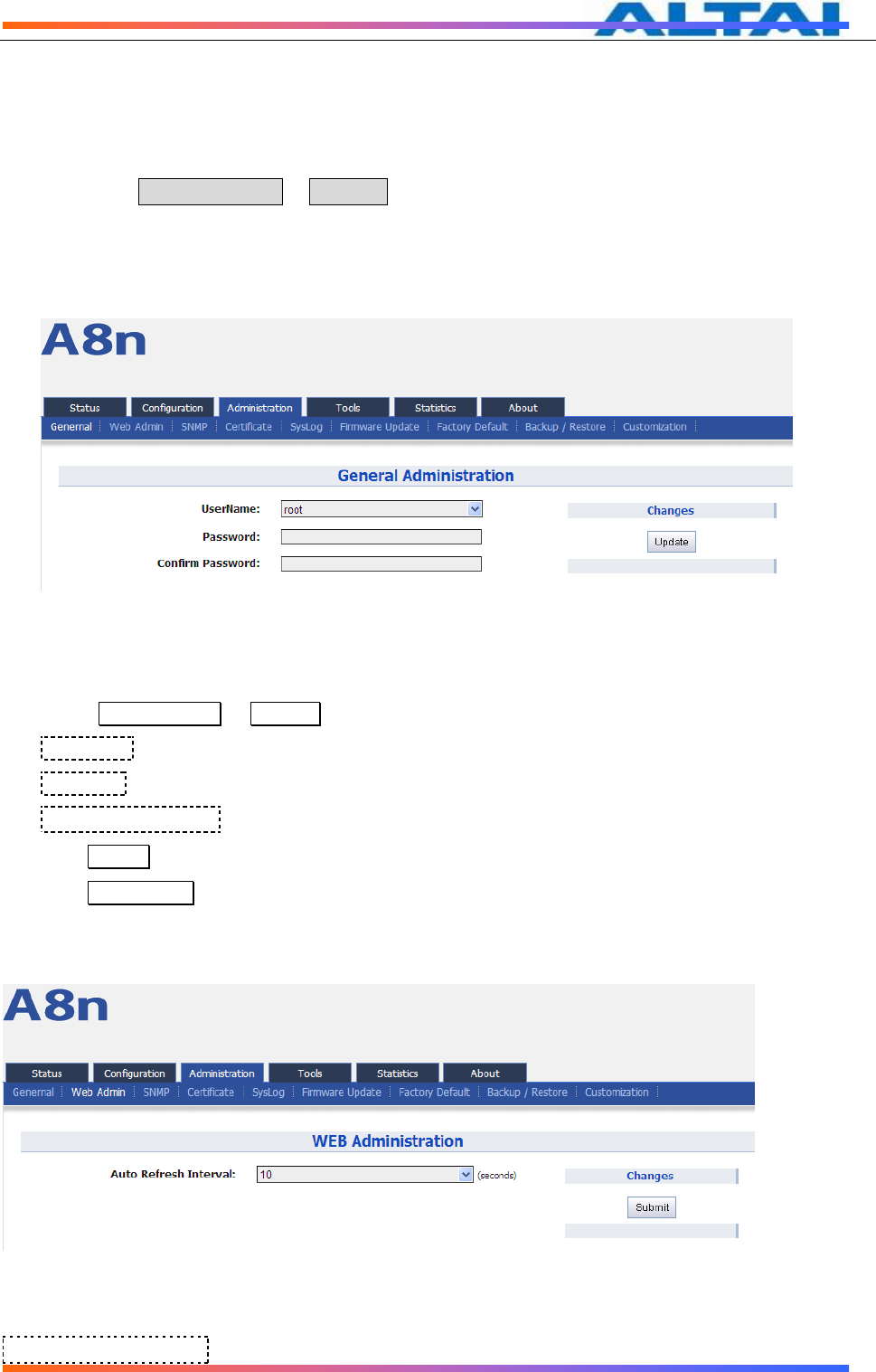
7.1 ADMINISTRATION GENERAL SETTING
Please select Administration -> General to change login username and password.
There are 2 types of user account:root and admin. Default username is :root, default
password is :superwifi123。
Figure 79 General Administration
Procedures:
1. Select Administration -> General,
2. UserName choose “root” or “admin” user
3. Password set password
4. Confirm Password input password again to confirm
5. Click Submit
6. Click Save&Apply to apply
7.2 WEB ADMIN
Figure 80 WEB Administration
Auto Refresh Interval:set auto refresh interval
TPS12-016_rev1 1_A8Ein_web-admin_Configuration_Manual_-_fm_1 2 0 604 (for FCC & IC) 20130322.doc
Commercially Confidential
59
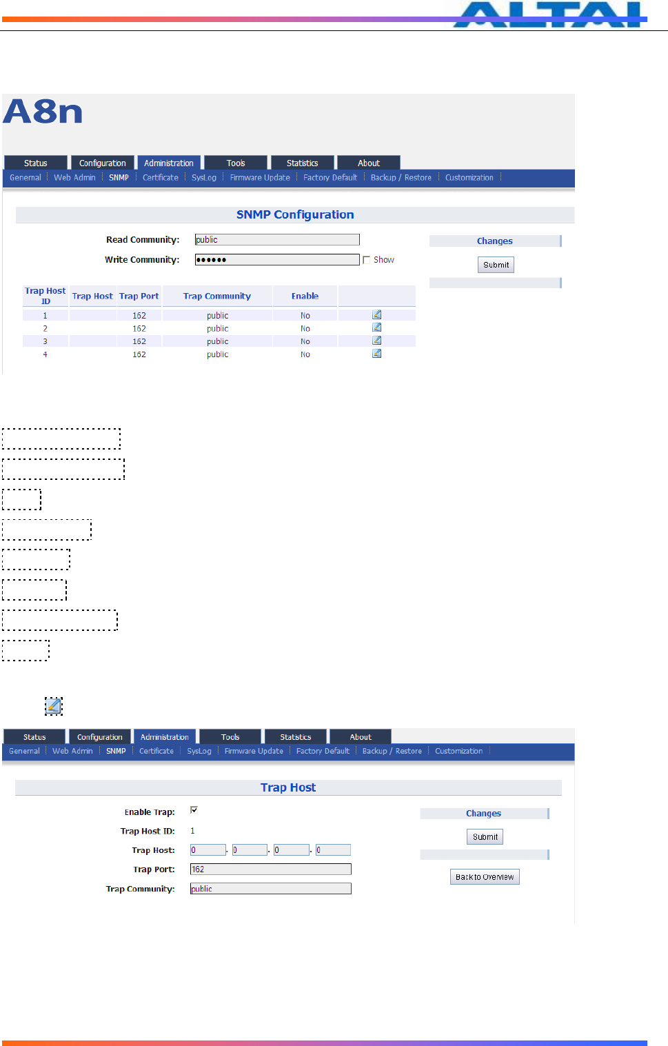
7.3 SNMP SETTING
Figure 81 SNMP Configuration
Read Community:SNMP protocol read community, by default it is “public”
Write Community:SNMP protocol write community, by default it is “write”
Show:show write community phrase
Trap Host ID: SNMP Trap host ID, it supports Max. 4 Trap Host
Trap Host: Trap Host IP address
Trap Port: Trap port, by default it is 162
Trap Community:Trap community information
Enable:Trap Host state (enabled or disabled)
Press :to edit Trap Host
Figure 82 SNMP Trap Host

TPS12-016_rev1 1_A8Ein_web-admin_Configuration_Manual_-_fm_1 2 0 604 (for FCC & IC) 20130322.doc
Commercially Confidential
60
7.4 CERTIFICATE MANAGEMENT
Figure 83 Certificate Management
Procedures:
1. Press Administration -> Certificate
2. Http Cert File click “browse” to choose Http Certificate file, and then click Upload.
3. Http Key File click “browse” to choose Http Key file, and then click Upload.
7.5 SYSLOG
Figure 84 System Log Configuration
TPS12-016_rev1 1_A8Ein_web-admin_Configuration_Manual_-_fm_1 2 0 604 (for FCC & IC) 20130322.doc
Commercially Confidential
61
Syslog severity
Emergency
Alert
Critical
Error
Warning
Notice
Information
Debug
Table 7-1 Syslog severity
Procedures:
1. Select Administration -> SysLog
2. Enable Syslog enable syslog function
3. Server IP Address The events which meet the severity condition will be sent to Syslog server
4. Severity
5. Click Submit
6. Click Save&Apply to apply
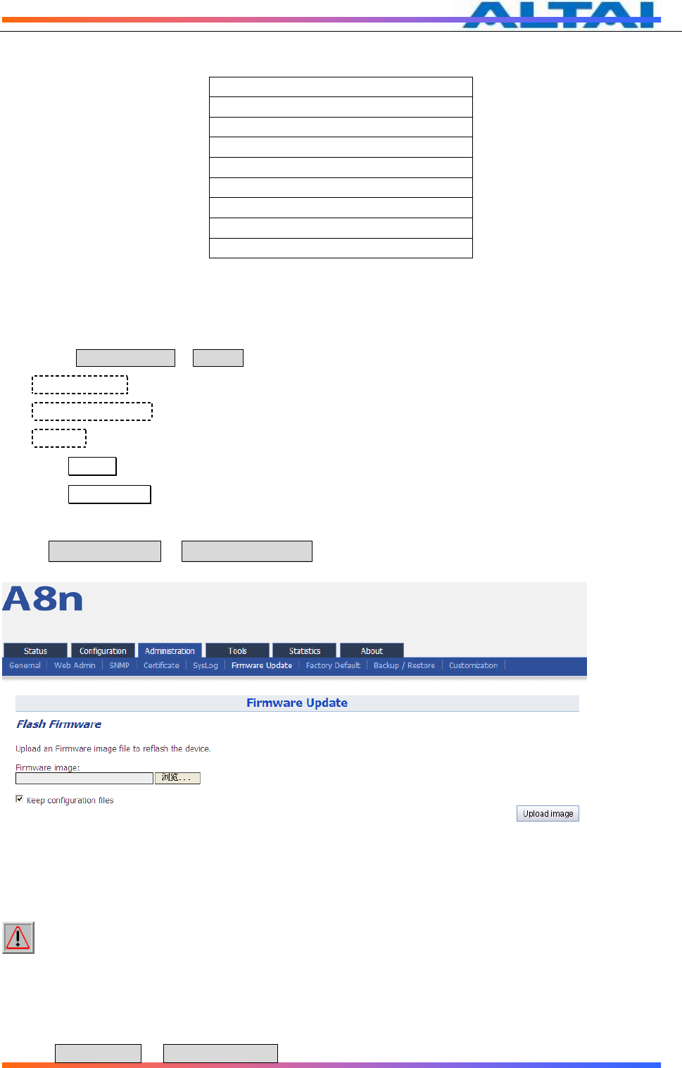
7.6 FIRMWARE UPDATE
Go to Administration -> Firmware Update to update the firmware of A8Ein:
Figure 85 Firmware Upgrade
Caution: Do not interrupt the process of firmware update. Please maintain
network connection and power supply. A8Ein will not function properly if
interruption happened during firmware update.
Procedures:
1. Go toAministration -> Firmware Update,
TPS12-016_rev1 1_A8Ein_web-admin_Configuration_Manual_-_fm_1 2 0 604 (for FCC & IC) 20130322.doc
Commercially Confidential
62
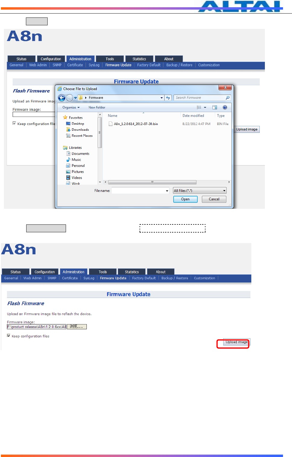
2. Press Browse,select the firmware,
Figure 86 Select firmware file
3. Press Upload image to begin the update,the keep configuration files allow user to keep the current
configuration after update,
Figure 87 Press Upload Image to start firmware update
4. A8Ein will run the checksum on the firmware, once it validate the firmware, press proceed to continue,
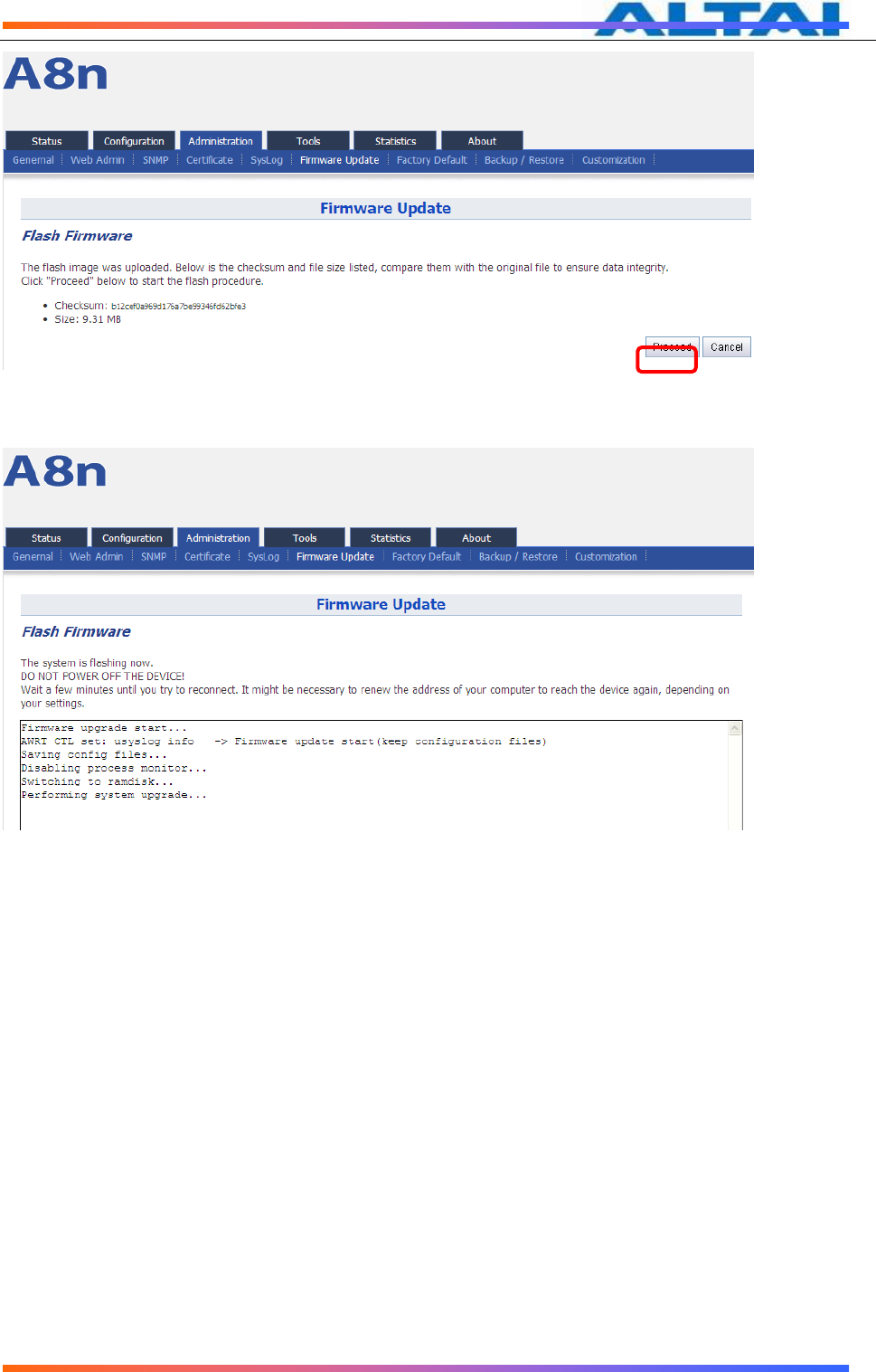
TPS12-016_rev1 1_A8Ein_web-admin_Configuration_Manual_-_fm_1 2 0 604 (for FCC & IC) 20130322.doc
Commercially Confidential
63
Figure 88 Press“Proceed”
5. You will find following notification:
Figure 89 Progress of firmware update
6. A8Ein will reboot and load the Main page after firmware update.
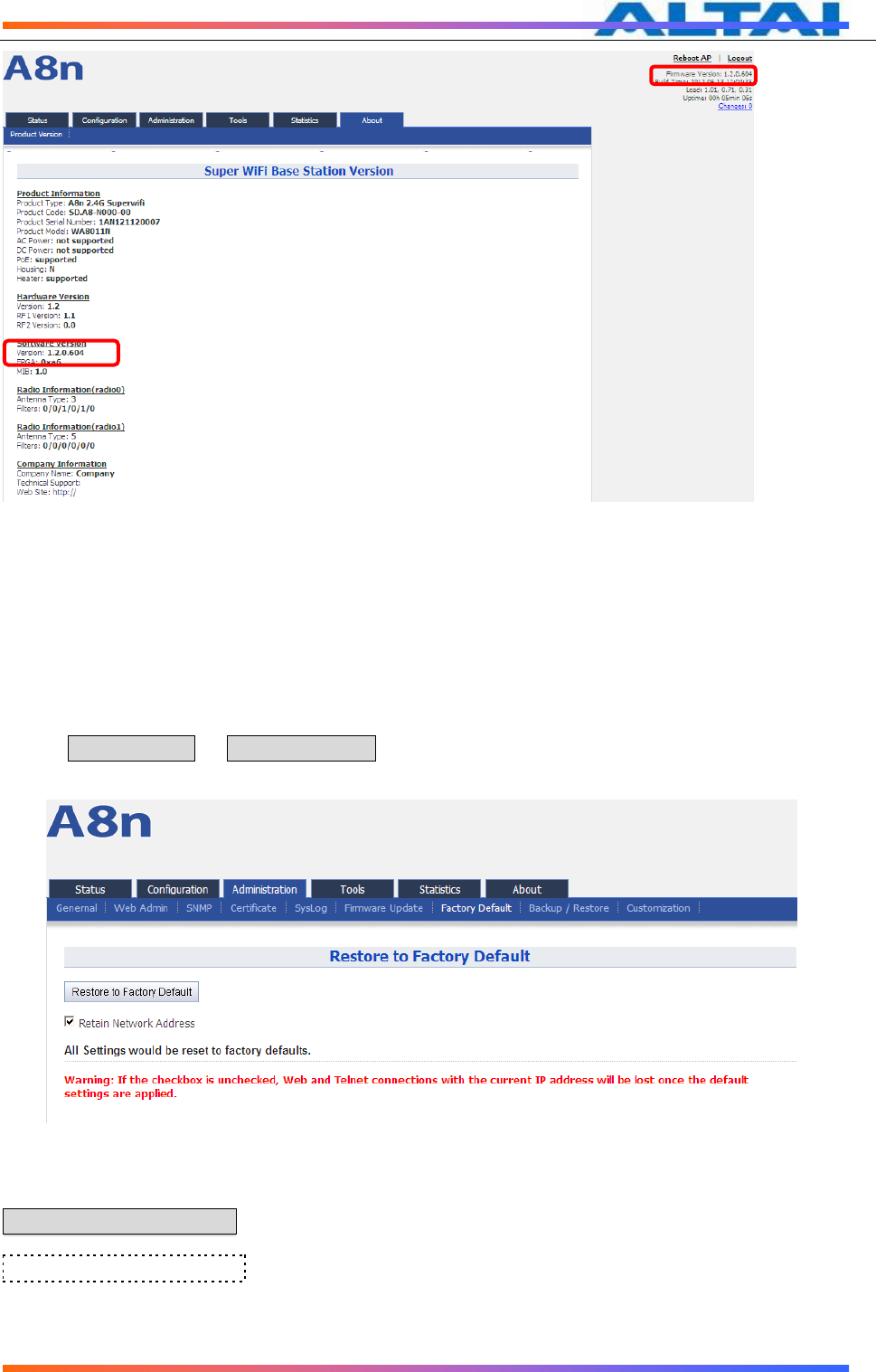
7. Login with username and password,check the firmware version on the top right corner or go to the
“About” page.
TPS12-016_rev1 1_A8Ein_web-admin_Configuration_Manual_-_fm_1 2 0 604 (for FCC & IC) 20130322.doc
Commercially Confidential
64
Figure 90 Information after firmware update
7.7 RESTORE FACTORY DEFAULT
There are 2 ways to reset the system back to factory default settings.
via user interfaces (eg. SSH/Console/Web)
via hardware reset button
7.7.1 RESET BACK TO FACTORY DEFAULT VIA USER INTERFACES
Under Aministration -> Factory Default, user can reset the A8Ein back to Factory Default
Configuration.
Figure 91 Restore to Factory Default
Procedures:
Reset to Factory Default:Press this button to reset A8Ein to Factory Default Configuration.
Retain Network Address): Select this if user doesn’t wish to reset the IP address
configuration to factory default.

TPS12-016_rev1 1_A8Ein_web-admin_Configuration_Manual_-_fm_1 2 0 604 (for FCC & IC) 20130322.doc
Commercially Confidential
65
Once restore to factory default configuration, user can login to the A8Ein with the following
information:
A8Ein default IP address:192.168.1.222
Username:root
Password:superwifi123
7.7.2 RESET BACK TO FACTORY DEFAULT VIA RESET BUTTON
Hardware reset button have 2 functions:
Soft-reboot [equivalent to UI: Reboot).
o Press & Hold the reset button until you see Power LED blink once
o Then release it immediately
Reset to factory default [equivalent to UI: Reset factory (NOT retain network
address)]
o Press & Hold the reset button until you see Power LED blink once
o Continue pressing the button until you see Power LED blink twice
consecutively
o Then release it immediately
Time (s)
Press&Hold
Blink twice
Release here
trigger
Soft-reboot
Release here trigger
Reset Factory
Blink once
0s 1s 5s 10s
TPS12-016_rev1 1_A8Ein_web-admin_Configuration_Manual_-_fm_1 2 0 604 (for FCC & IC) 20130322.doc
Commercially Confidential
66
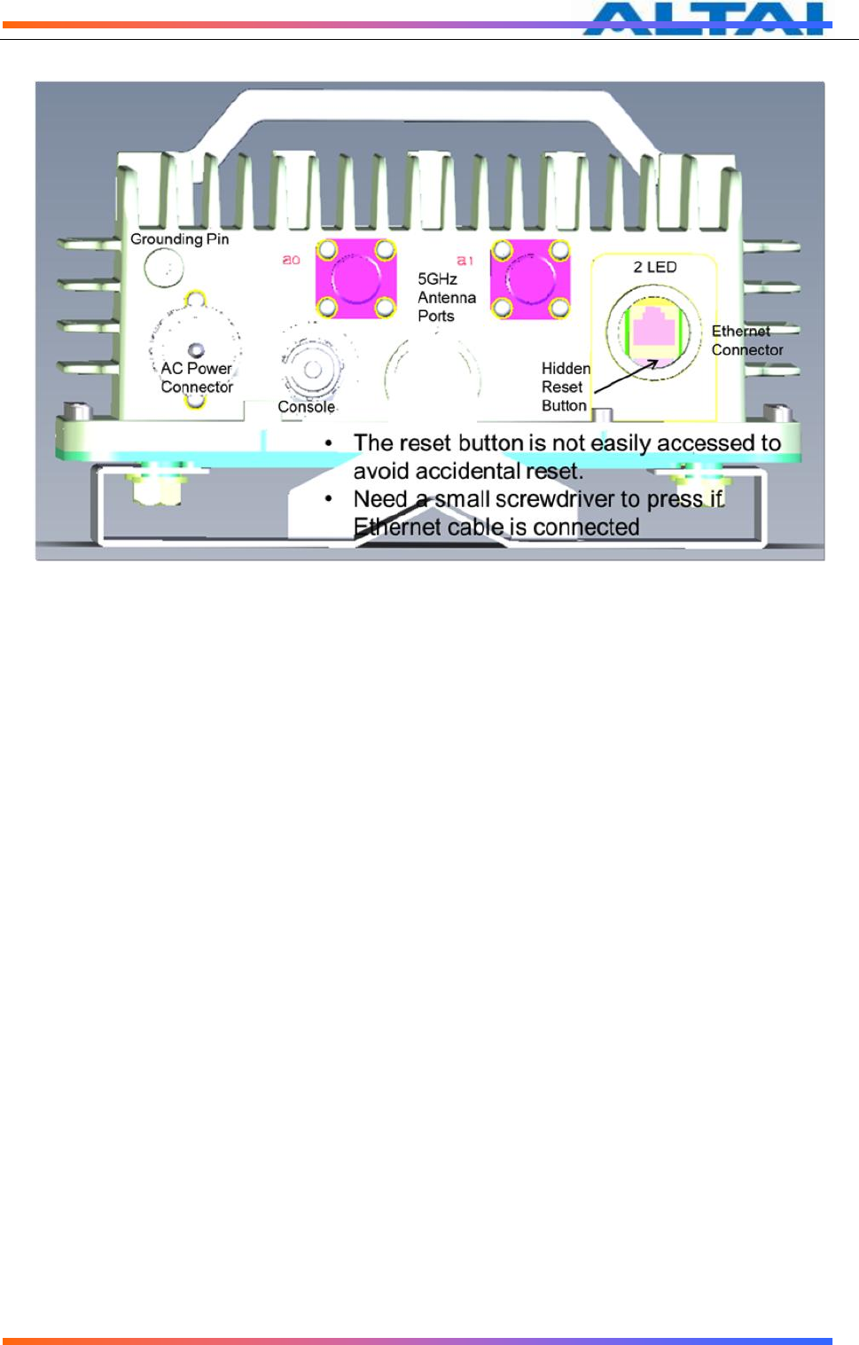
The reset button’s location is shown in following.
7.7.3 FACTORY DEFAULT SETTING
Current A8Ein factory default settings are:
Admin Username: admin
Admin Password: admin
Superuser Username: root
Superuser Password: superwifi123
Radio0 setting:
Radio Enable: Enabled
Operation Mode: AP
SSID: Superwifi Network <0..15>
Channel: 1
Wireless mode: auto, default to 11NG
ShortGI: Disabled
AMPDU: Enabled
Sector: All enabled
Power: 23dBm
Radio1 setting:
Radio Enable: Disabled
Network:
Switch mode with all interface bridged on a virtual interface called br-lan:
o Ethernet interface: eth0
o VAP interfaces: athXXX
o Bridge interface: br-lan
o Permanent 2nd IP Interface: br-lan:1

TPS12-016_rev1 1_A8Ein_web-admin_Configuration_Manual_-_fm_1 2 0 604 (for FCC & IC) 20130322.doc
Commercially Confidential
67
Network interface setting:
o br-lan: Static IP = 192.168.1.222
o br-lan:1:Static IP = 192.168.99.xxx (Error! Reference
source not found. Permanent IP)
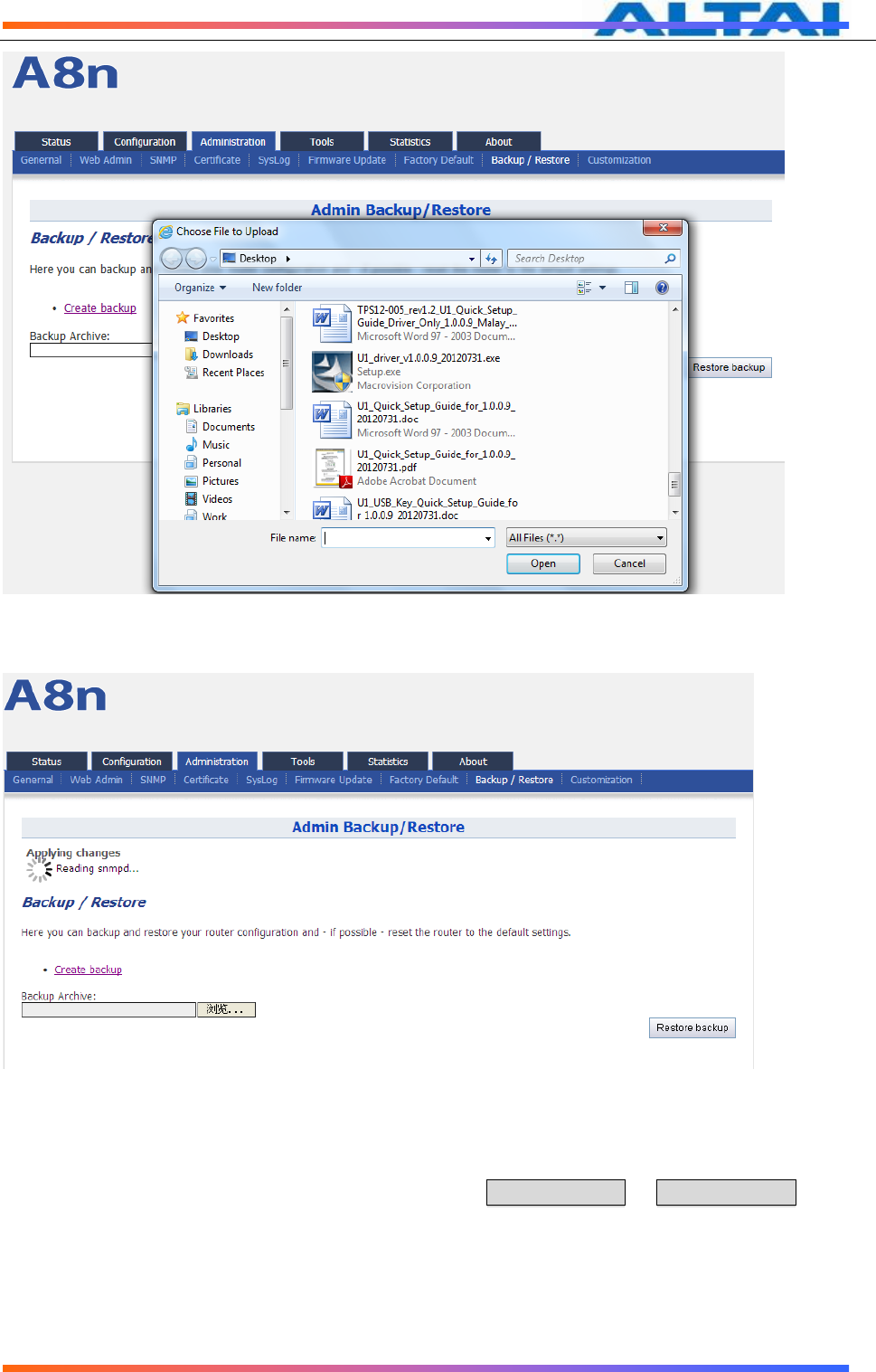
7.8 BACKUP/RESTORE
A8Ein supports Backup/Restore,Press Administration -> Backup/Restore to open the
configuration interface
Figure 92 A8Ein Backup/Restore
Procedures:
1. Select Administration->Backup/Restore
2. Press Creat backup and save it.
Figure 93 A8Ein Backup
3. To restore configuration,Under Backup Archive, press Browse…,and select the backup file,press
Restore backup to start restore.
TPS12-016_rev1 1_A8Ein_web-admin_Configuration_Manual_-_fm_1 2 0 604 (for FCC & IC) 20130322.doc
Commercially Confidential
68
Figure 94 Select the backup file
Figure 95 Press
“
Restore backup
”
to start restore
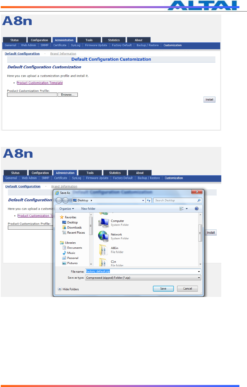
7.9 CUSTOMIZATION
A8Ein supports customization,user can press on Administration -> Customization to open
the configuration interface shown as below:

TPS12-016_rev1 1_A8Ein_web-admin_Configuration_Manual_-_fm_1 2 0 604 (for FCC & IC) 20130322.doc
Commercially Confidential
69
Figure 96 Customization Interface
There are 2 items in Customization: Default Configuration and Brand Information。
Default Configuration is use for customize the default configuration during except factory default;
Brand Information is use for customize the brand of the A8Ein.
Details in Customization:
Product Customization Template :Click on the link to download product customized template
from A8Ein.
Unistall Customizations:To uninstall product customization, remove the product customized
template from A8Ein.
Product Customization Profile :Click "Browse" button to select edited product customized
template.
Brand Information Customization Template :Click on the link to download brand information
customized template from A8Ein.
Brand Information Customization Profile :Click "Browse" button to select edited brand
customized template.
Install :Click this button to execute uploaded product and brand customization template.
Procedures:
First, download the Product Customization Template and Brand Customization
Template from A8Ein
1、Press the“Porduct Customization Template”link to donwload the template.
TPS12-016_rev1 1_A8Ein_web-admin_Configuration_Manual_-_fm_1 2 0 604 (for FCC & IC) 20130322.doc
Commercially Confidential
70
Figure 97 Download Template
2、Press “Save” and save it to a folder.
Figure 98 Save the products custom templates to the specified directory
TPS12-016_rev1 1_A8Ein_web-admin_Configuration_Manual_-_fm_1 2 0 604 (for FCC & IC) 20130322.doc
Commercially Confidential
71
Figure 99 Custom template file downloaded
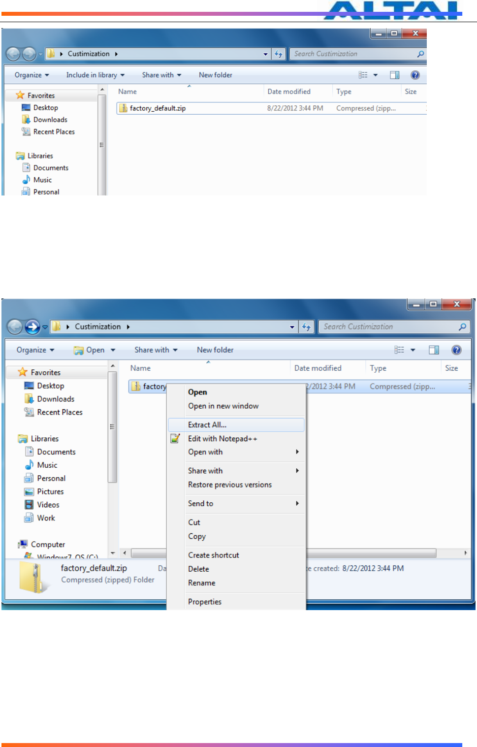
Next, edit the template,don’t unzip the file during edit, use 7-zip software to open the
template file,and edit the files inside(WinRAR compression software does not support
direct editing in a compressed file
1、Use 7-Zip to extract the archive:
Figure 100 Use 7-zip to open the archive
TPS12-016_rev1 1_A8Ein_web-admin_Configuration_Manual_-_fm_1 2 0 604 (for FCC & IC) 20130322.doc
Commercially Confidential
72
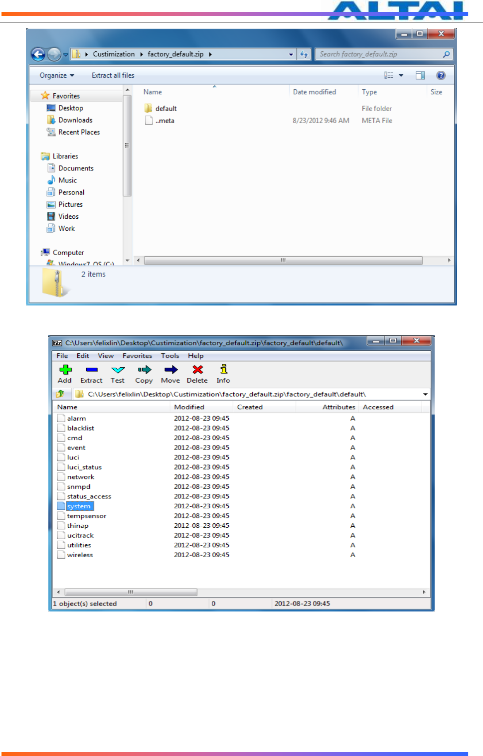
Figure 101 factory_default menu
Figure 102 files under “default”
The important customize file are system、network、wireless. They are used for customize
the system, network, wireless default configuration information.
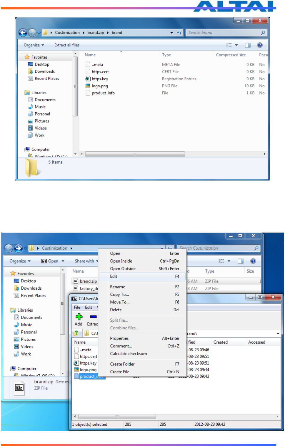
Use 7-zip software to open the Brand customize template compressed file download from
A8Ein,
TPS12-016_rev1 1_A8Ein_web-admin_Configuration_Manual_-_fm_1 2 0 604 (for FCC & IC) 20130322.doc
Commercially Confidential
73
Figure 103
“
Product_info
”
and logo.png
2、To edit the file, right click on the file and select "Edit the file to customize (open with
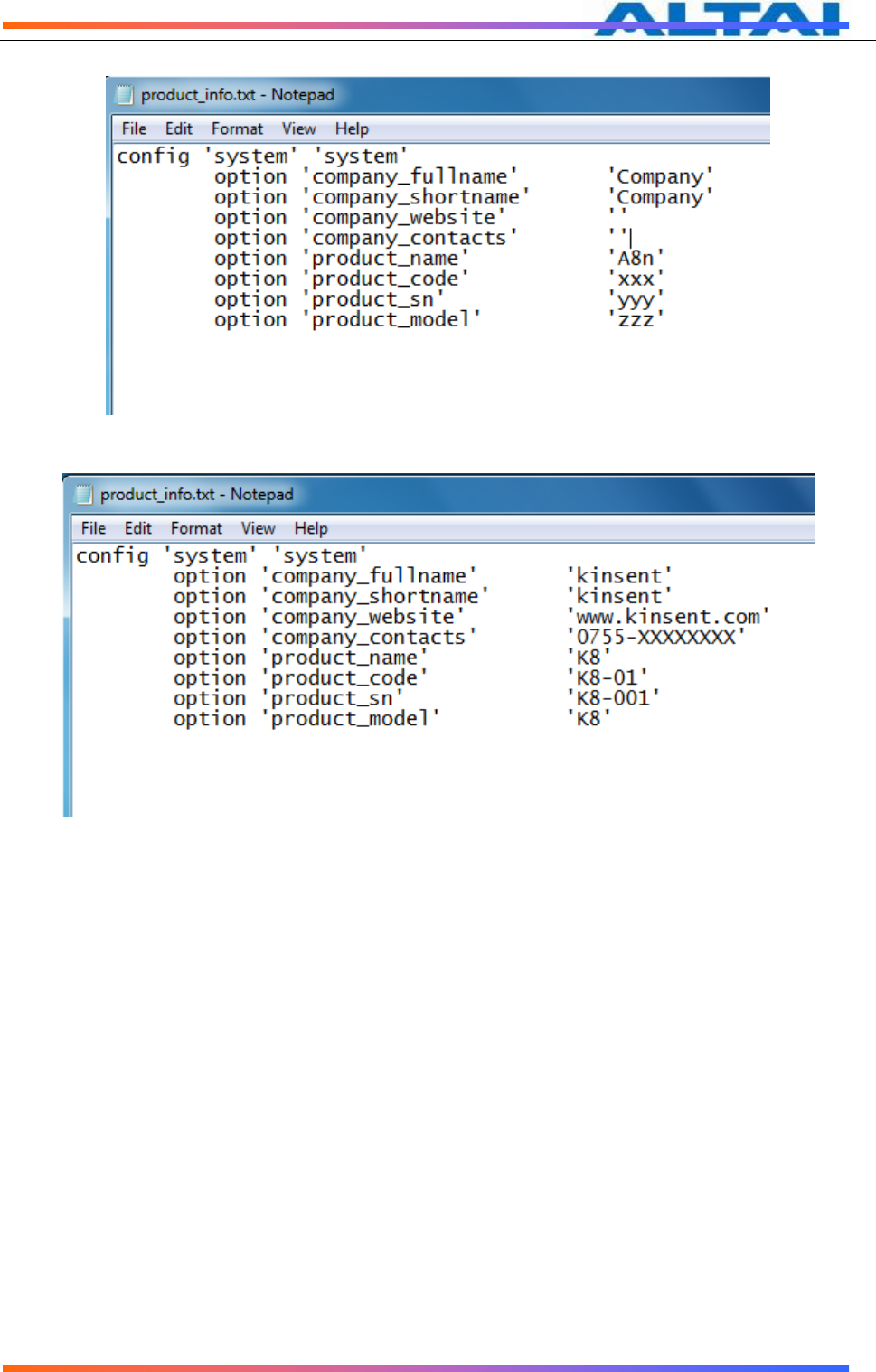
notepad), click the "Save" and exit after edit. The following shows "Product_info" brand
customized template customization process. Use the same method to edit the Product
customization template.
Figure 104 Select "Product_info", Right-click and select "Edit"
TPS12-016_rev1 1_A8Ein_web-admin_Configuration_Manual_-_fm_1 2 0 604 (for FCC & IC) 20130322.doc
Commercially Confidential
74
Figure 105 Initial information of
“
product_info
”
before the customization
Figure 106 Customized
“
product_info
”
TPS12-016_rev1 1_A8Ein_web-admin_Configuration_Manual_-_fm_1 2 0 604 (for FCC & IC) 20130322.doc
Commercially Confidential
75
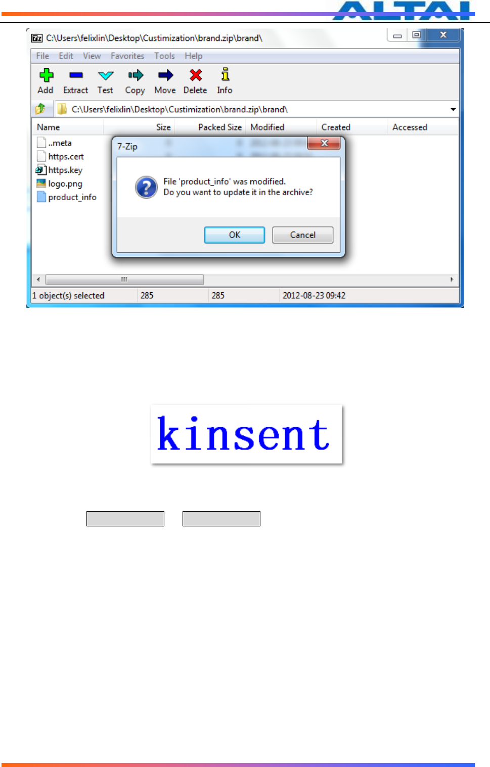
Figure 107 Save the customized file and exit, click "OK" to update
3、Create a logo and save it in png format. Rename it to logo.png. Replace the logo.png
under the brand.zip with the customized logo
Example:
Figure 108 customized logo
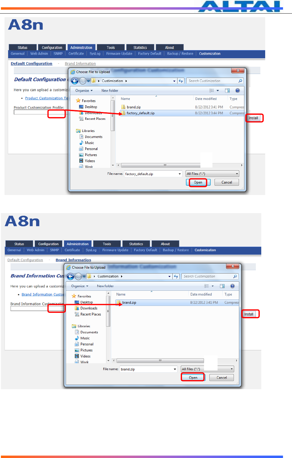
Finally,under Administration -> Customization select “Default Configuration”, press
“Browse”,select the customized product template and press“Install”to upload;under Brand
Information, press “Browse”, select the customized brand template and press “install” to
upload.
TPS12-016_rev1 1_A8Ein_web-admin_Configuration_Manual_-_fm_1 2 0 604 (for FCC & IC) 20130322.doc
Commercially Confidential
76
Figure 109 Upload Product Customization Template
Figure 110 Upload Brand Customization Template
After upload,press the “Reboot AP”button on the top righ corner of the page,reboot
A8Ein.
3
2
1
2
3
1
TPS12-016_rev1 1_A8Ein_web-admin_Configuration_Manual_-_fm_1 2 0 604 (for FCC & IC) 20130322.doc
Commercially Confidential
77
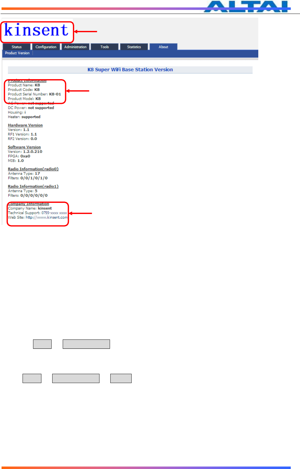
Figure 111 Changes in Product and Company Information
* The customized configuration will only take effect when reset to factory default.
8 SYSTEM TOOLS
A8Ein provides useful tools,this enable the user to have better radio planning.
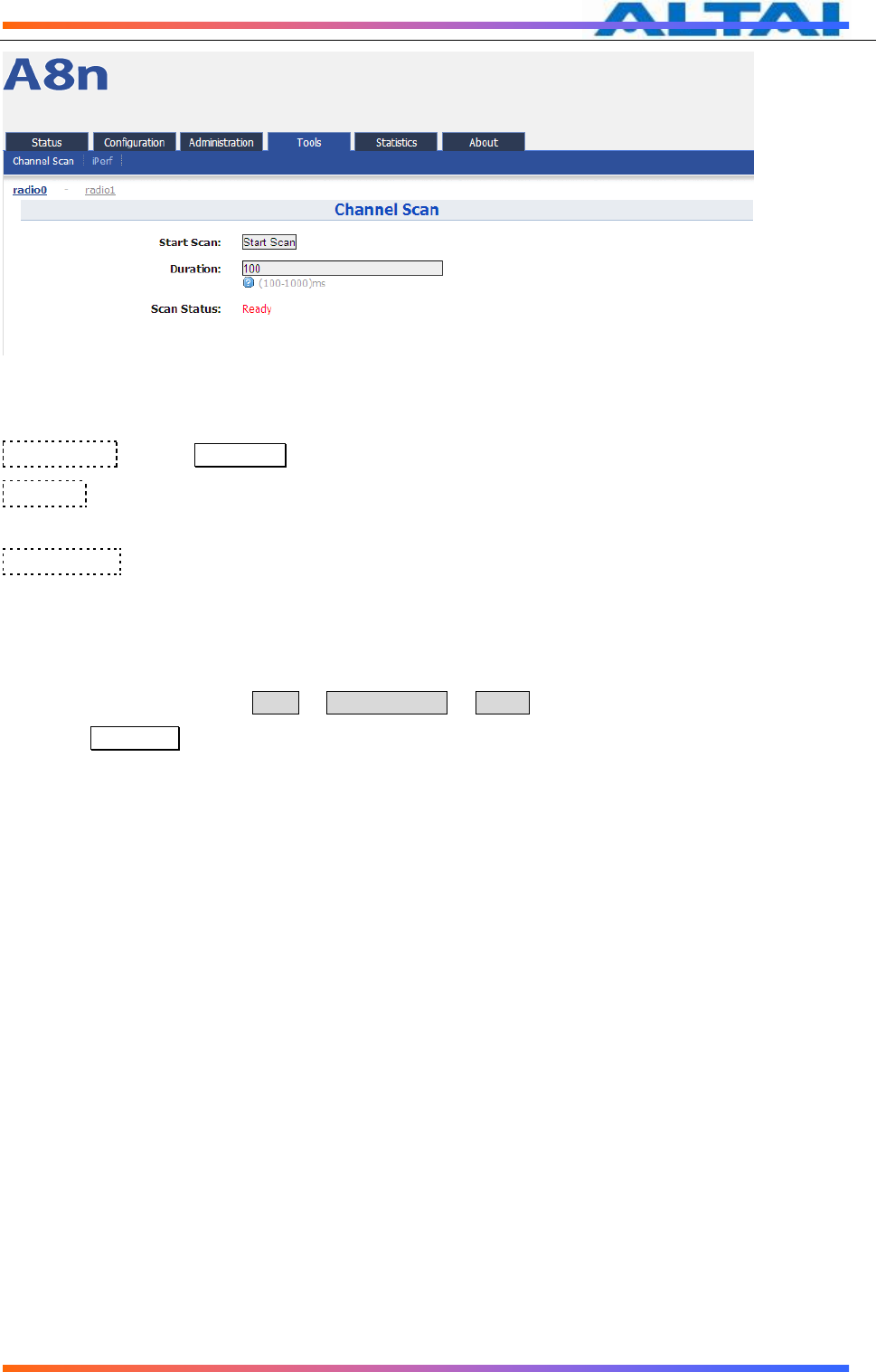
8.1 CHANNEL SCAN
Through the channel scan tool of A8Ein,user is able to know the status of 2.4GHz/5GHz
channels around the A8Ein, this provides useful information to the user on how to configure
A8Ein and radio planning.
Press on Tools -> Channel Scan to open the channel scan,for 2.4G select “radio0” or for
5G, select “radio1”.
8.1.1 2.4G CHANNEL SCAN
Press Tools -> Channel Scan -> radio0 for 2.4G channel scan.
Logo Changed
Product Information
Changed
Company Information
Changed
TPS12-016_rev1 1_A8Ein_web-admin_Configuration_Manual_-_fm_1 2 0 604 (for FCC & IC) 20130322.doc
Commercially Confidential
78
Figure 112 2.4G Channel Scan
Details of 2.4G Channel Scan:
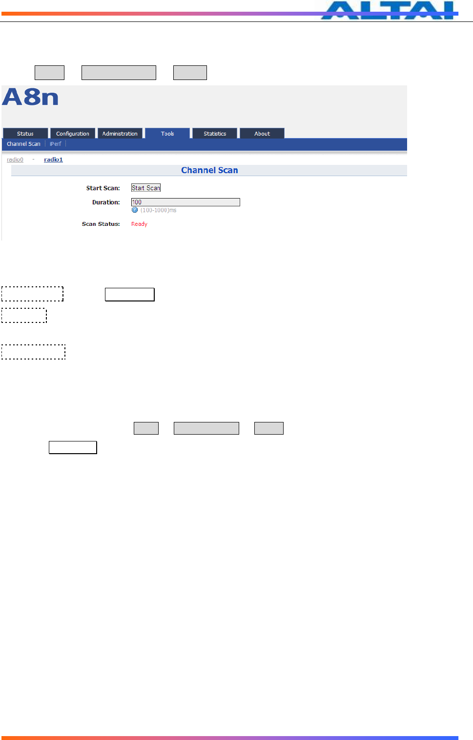
Start Scan :PressStart Scan to start 2.4G channel scan。
Duration:The switching time of the channel scanning interval,setting range is
100-1000ms,default is 100ms.
Scan Status:A8Ein Base station channel scan status,“Ready”means it can start scan.
“Success” means scan finished.
Procedures:
1. In the main menu, select Tools -> Channel Scan -> radio1
2. PressStart Scan
3. Wait until the scan status change to “Success”. The scanning will take approximately 20 seconds
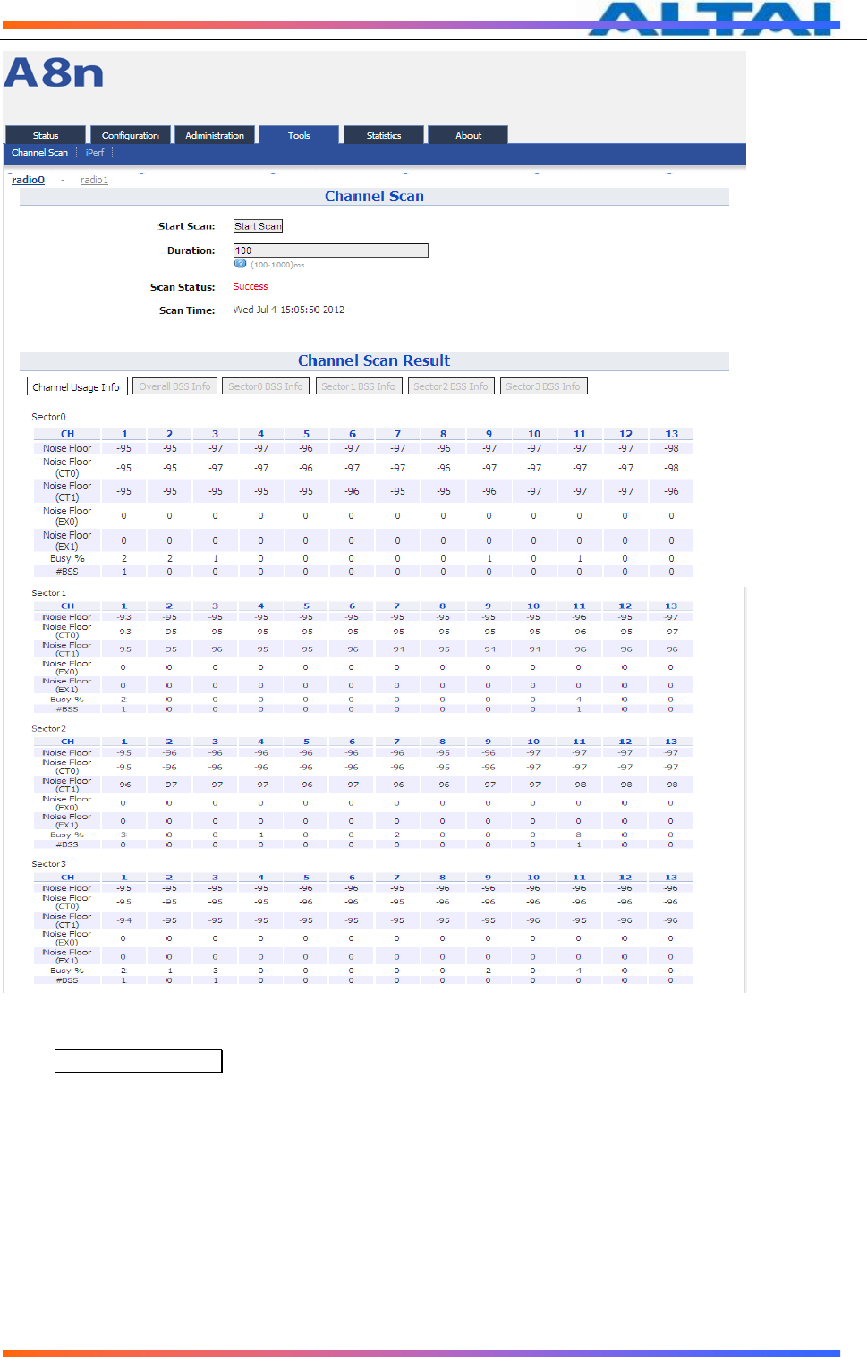
Result will be divided into 6 parts: Channel Usage Info, Overall BSS Info, Sector 0 BSS Info,
Sector 1 BSS Info, Sector 2 BSS Info and Sector 3 BSS Info.
Channel Usage Info:
TPS12-016_rev1 1_A8Ein_web-admin_Configuration_Manual_-_fm_1 2 0 604 (for FCC & IC) 20130322.doc
Commercially Confidential
79
Figure 113 2.4G Channel Scan
Press Channel Usage Info for the result of Noise Floor and Business from every sector antenna.
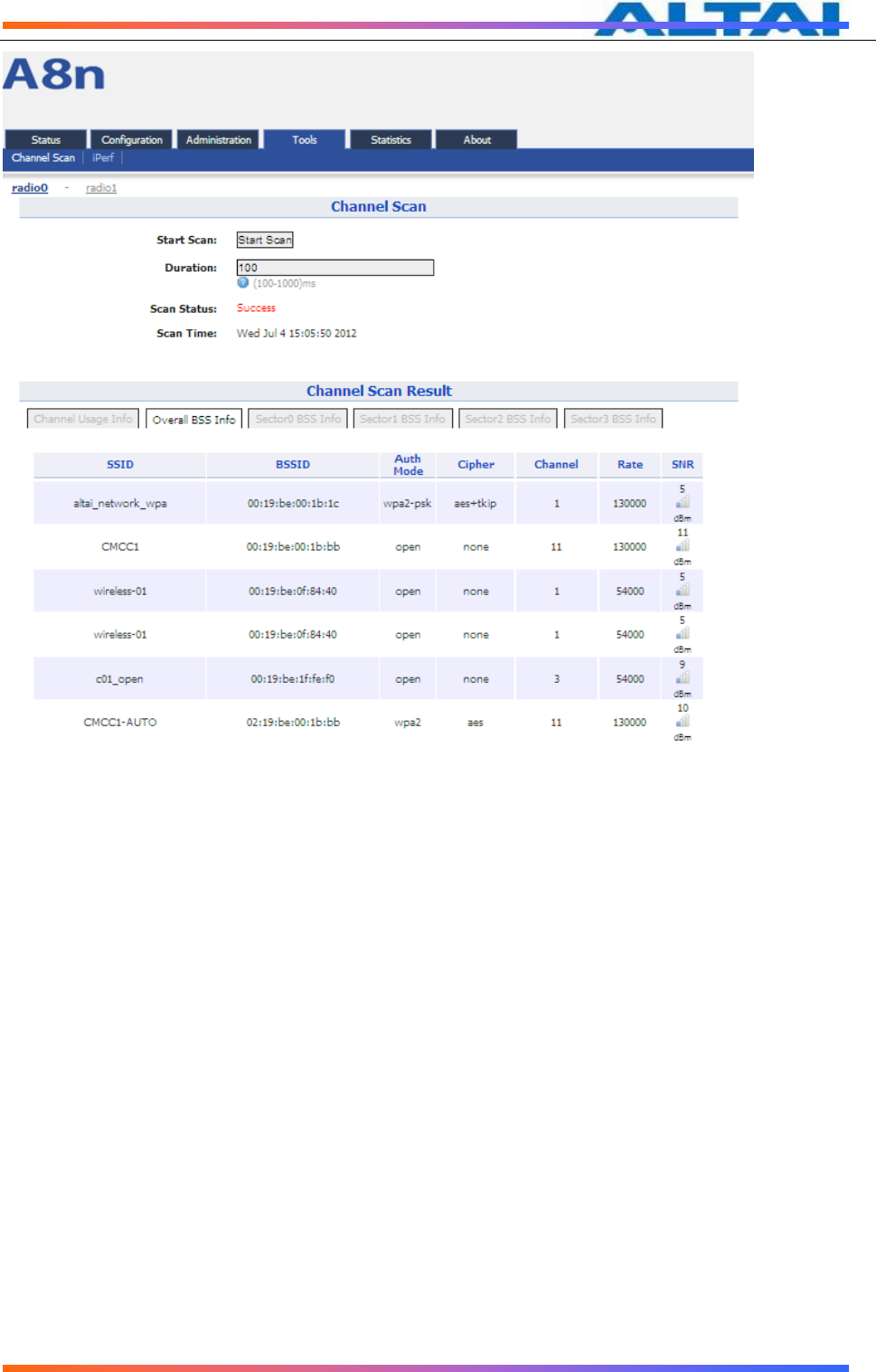
Overall BSS Info:
TPS12-016_rev1 1_A8Ein_web-admin_Configuration_Manual_-_fm_1 2 0 604 (for FCC & IC) 20130322.doc
Commercially Confidential
80
Figure 114 2.4G Overall BSS Info
TPS12-016_rev1 1_A8Ein_web-admin_Configuration_Manual_-_fm_1 2 0 604 (for FCC & IC) 20130322.doc
Commercially Confidential
81
Press Overall BSS Info to view 2.4G BSS Info around A8Ein. It includes SSID, BSSID,
Authentication Mode, Cipher, Channel, Date Rate and SNR.
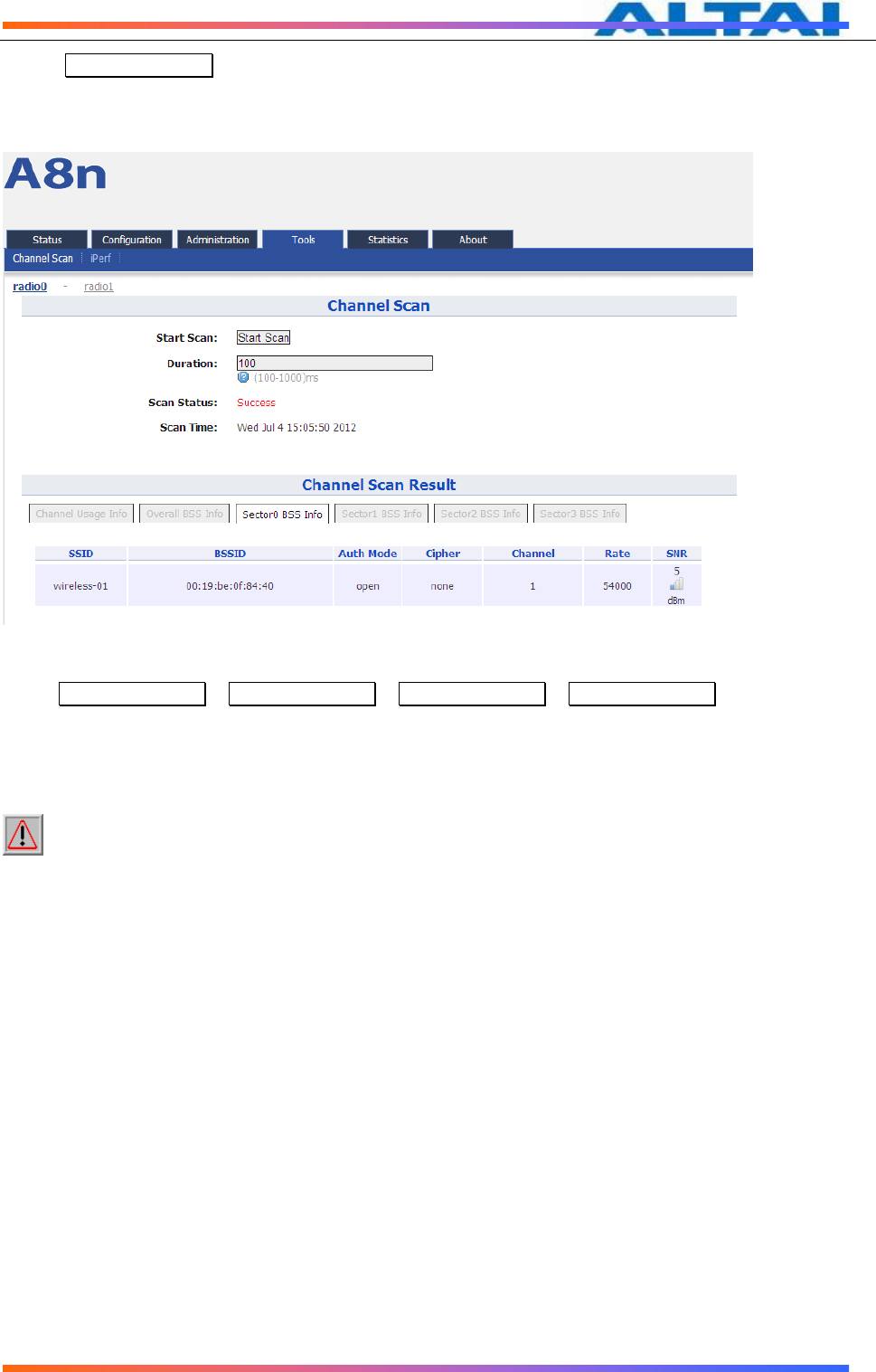
Sector 0, 1, 2, 3 BSS Info:
Figure 115 Sector 0 BSS Info
PressSector0 BSS Info、Sector1 BSS Info、Sector2 BSS Info、Sector3 BSS Info to view the BSS
Info of Sector 0、1、2、3.
Base onA8Ein 5G Channel Scan Result,user can select 5G channel with lower noise floor,
less busy and less SSID as the channel for A8Ein’s SSID.
Caution
:
During the process of channel scan, all WiFi clients associated to A8
via 2.4G channel will be drop for approximately 15-20 seconds.
TPS12-016_rev1 1_A8Ein_web-admin_Configuration_Manual_-_fm_1 2 0 604 (for FCC & IC) 20130322.doc
Commercially Confidential
82
8.1.2 5G CHANNEL SCAN
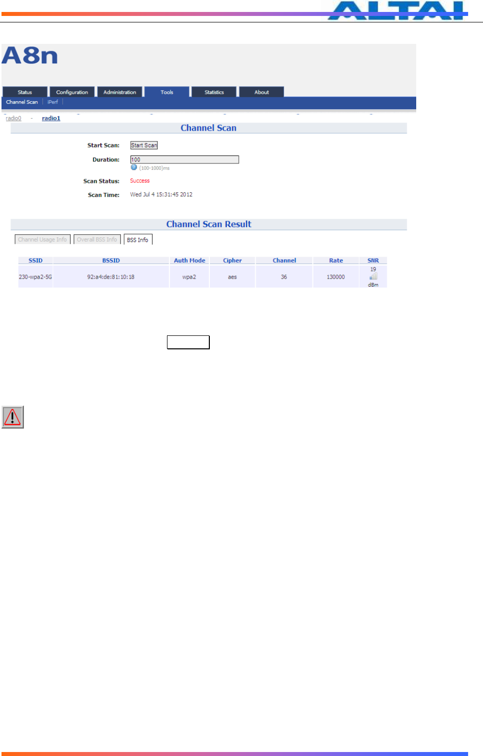
Press Tools -> Channel Scan -> radio1 to start the 5G channel scan.
Figure 116 5G Channel Scan
Details of 5G channel scan:
Start Scan :PressStart Scan to start 5G channel scan.
Duration:The switching time of the channel scanning interval,setting range is
100-1000ms,default is 100ms.
Scan Status:A8Ein Base station channel scan status,“Ready”means it can start scan.
“Success” means scan finished.
Procedures:
4. In the main menu, selectTools -> Channel Scan -> radio1
5. PressStart Scan
6. Wait until the scan status change to “Success”. The scanning will take approximately 20 seconds
TPS12-016_rev1 1_A8Ein_web-admin_Configuration_Manual_-_fm_1 2 0 604 (for FCC & IC) 20130322.doc
Commercially Confidential
83
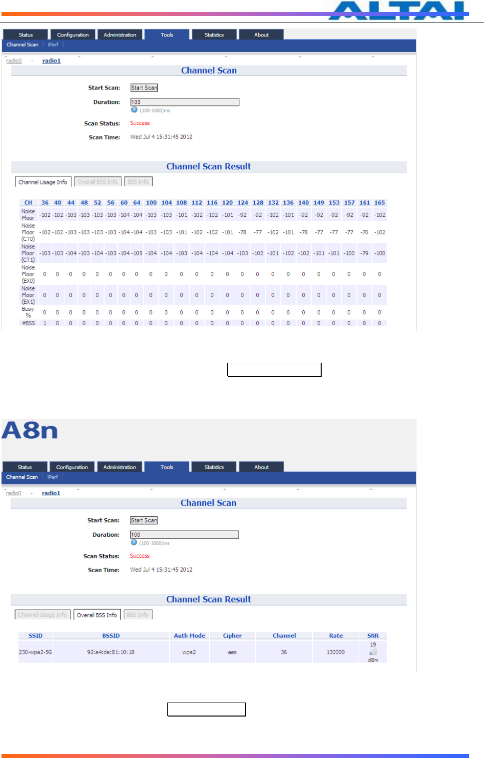
Figure 117 5G Channel Usage
From the Channel Scan Result,press on Channel Usage Info user will see the condition of
5G channel around A8Ein.
Overall BBS Info:
Figure 118 5G BSS Info
In Channel Scan Result, press Overall BSS Info for 5G BSS Info, it shows information of
BSSID around A8Ein.
TPS12-016_rev1 1_A8Ein_web-admin_Configuration_Manual_-_fm_1 2 0 604 (for FCC & IC) 20130322.doc
Commercially Confidential
84
BSS Info:
Figure 119 BSS information
In Channel Scan Result, press BSS Info and it shows information of BSSID from A8Ein.
Base onA8Ein 5G Channel Scan Result,user can select 5G channel with lower noise floor,
less busy and less SSID as the channel for A8Ein’s SSID.
Caution
:
During the process of channel scan, all WiFi clients associated to A8 via
5G channel will be drop for approximately 15-20 seconds.

TPS12-016_rev1 1_A8Ein_web-admin_Configuration_Manual_-_fm_1 2 0 604 (for FCC & IC) 20130322.doc
Commercially Confidential
85
8.2 IPERF
With build-in iPerf in A8Ein,user can use one terminal with WiFi adapter to test the
throughput performance of A8Ein.
Click on Tools -> iPerf to open up the iPerf interface shown in the picture below:
Figure 120 iPerf interface
Details of iPerf configuration interface:
Server ID :iPerf Server ID.
Server Type :iPerf Server Type.
Server Port :iPerf Server Port number.
Server Status :iPerf Server Status.
click on this icon to configure iPerf Server.
The button will appear the following interface:
Figure 121 iPerf Server Configuration Interface
Details of iPerf Server configuration interface:
Enable Server:Enable or disable iPerf Server.
Server ID:iPerf Server ID.
Server Type:Select TCP or UDP server.
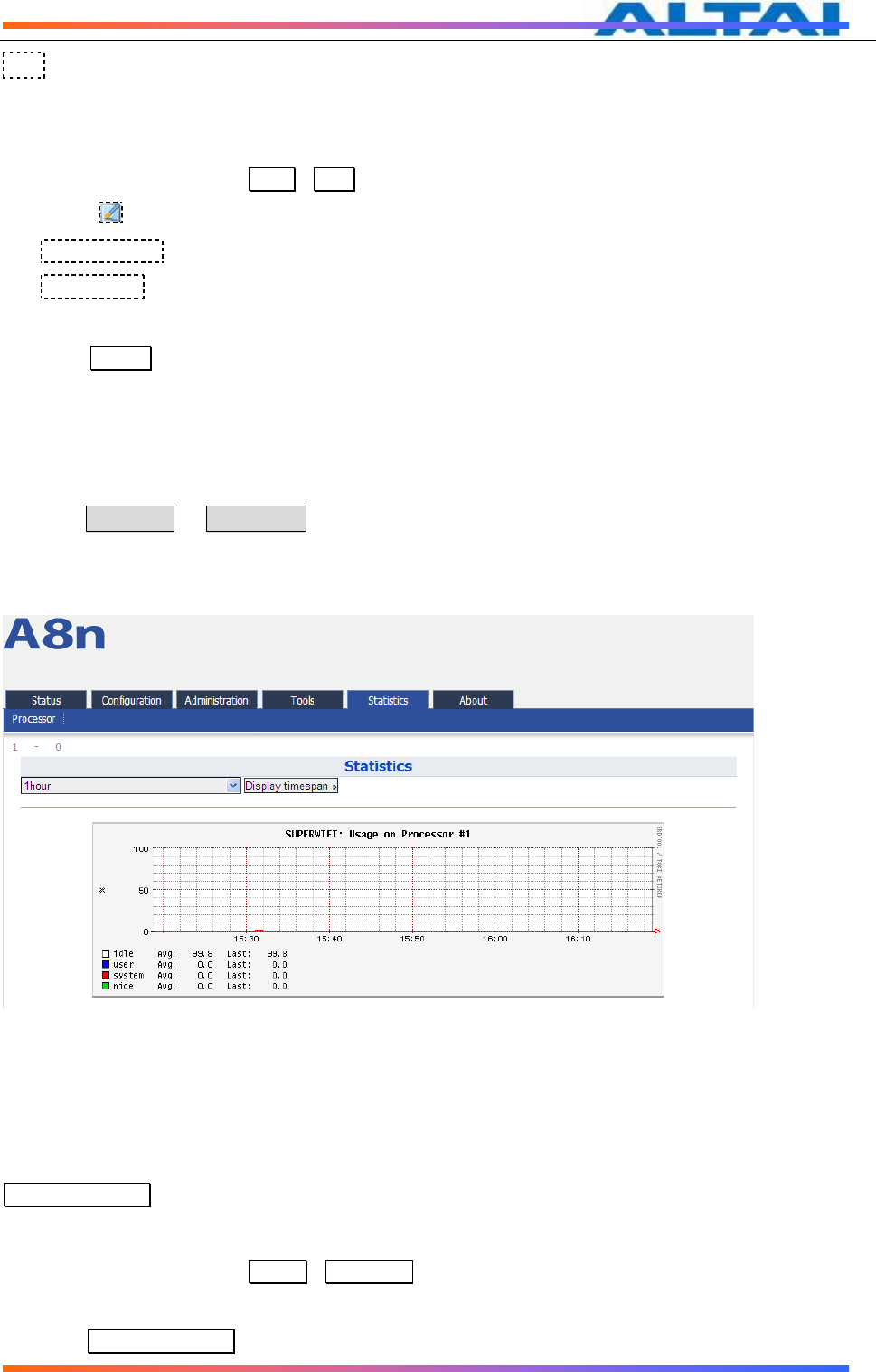
TPS12-016_rev1 1_A8Ein_web-admin_Configuration_Manual_-_fm_1 2 0 604 (for FCC & IC) 20130322.doc
Commercially Confidential
86
Port:Select port number of TCP or UDP.
Procedures:
1. In the main menu, selectTools->iPerf enter the iPerf configuration page;
2. Press to configure the iPert server parameters;
3. Enable Server Select Enable;
4. Server Type select A8Ein as TCP Server or UDP server;
5. Select the port number of TCP server or UDP server;
6. PressSubmit and start the test。
9 A8EIN CPU USAGE
A8Ein provides information of CPU Usage of the device.
Click on Statistics -> Processor and it shows A8Ein CPU processing and usage,A8Ein
utilize dual core CPU,you may select“1” or“0”to check the status of each CPU.
Picture below shows the statistic of Processer 1,Processer 0 will have the same layout as
Processor 1.
Figure 122 Processer 1 Usage
Details of Processer 1 usage are listed below:
On the top left corner, you can select the display timespan of usage,options available are
10 minutes、1 hour、1 day、1 week、1 month or 1 year。
Display timespan: this allow user to select the duration CPU usage.
Steps:
1. In the main menu, selectStatics->ProcessorInto the CPU processor usage statistics interface;
2. Select the CPU that will display at the statistic chart.
3. Click Display timespan to select the timespan.

TPS12-016_rev1 1_A8Ein_web-admin_Configuration_Manual_-_fm_1 2 0 604 (for FCC & IC) 20130322.doc
Commercially Confidential
87
10 A8EIN INFORMATION
The “About” in the web layout shows the hardware and software version, information of
radio, product and company
Figure 123 A8Ein
“
About
”
Details of A8Ein Information:
Production Information:This shows the name, code, serial number, product mode, supported power
supply and etc.
Hardware Version:Display the version of hardware, and RF
Software Version:Display the version of firmware, FPGA, and MIB
Radio Information:Display the antenna type and filer
Company Information: Display information of Altai