Altai Technologies WA8011NAC Altai A8-Ein (ac) Super WiFi Base Station User Manual A3 Series Configuration Manual
Altai Technologies Limited Altai A8-Ein (ac) Super WiFi Base Station A3 Series Configuration Manual
Contents
- 1. Users Manual - Installation
- 2. Users Manual - Configuration
Users Manual - Installation

Altai Technologies Ltd. All rights reserved
Installation Guide
Version 1.2
Altai A8n (ac) Series Super WiFi
Base Station

ii
Altai Technologies Ltd. All rights reserved
Altai A8n (ac) Series Super WiFi Base Station
Installation Guide
Copyright © 2015 Altai Technologies Limited
ALL RIGHTS RESERVED.
Altai Technologies Limited
Unit 209, 2/F, Lakeside 2,
10 Science Park West Avenue,
Hong Kong Science Park,
Shatin, New Territories,
Hong Kong
Telephone: +852 3758 6000
Fax: +852 2607 4021
Web: www.altaitechnologies.com
Customer Support Centre:
Email: support@altaitechnologies.com

iii
Altai Technologies Ltd. All rights reserved
Altai A8n (ac) Series Super WiFi Base Station
Installation Guide
Radio Frequency Interference Requirements
This device complies with Part 15 of FCC Rules.
Operation is subject to the following conditions:
1. This device may not cause harmful interference.
2. This device must accept any interference received, including
interference that may cause undesired operation.
3. This device should not be co-located or operating in conjunction
with any other antenna or transmitter.
Interference Statement
This equipment has been tested and found to comply with the limits for
a Class B digital device, pursuant to Part 15 of the FCC Rules; these
limits are designed to provide reasonable protection against harmful
interference in a residential installation. This equipment generates uses
and can radiate radio frequency energy and, if not installed and used
in accordance with the instructions, may cause harmful interference to
radio communications.
However, there is no guarantee that interference will not occur in a
particular installation. If this equipment does cause harmful interference
to radio or television reception, which can be determined by turning
the equipment off and on, the user is encouraged to try to correct the
interference by one of the following measures:
Reorient or relocate the receiving antenna.
Increase the separation between the equipment and receiver.
Connect the equipment into an outlet on a circuit different from
that to which the receiver is connected.
Consult the dealer or an experienced radio/TV technician for
help.
FCC Caution: To assure continued compliance, (example – use only
shielded interface cables when connecting to computer or peripheral
devices). Any changes or modifications not expressly approved by the
party responsible for compliance could void the user’s authority to
operate this equipment.

iv
Altai Technologies Ltd. All rights reserved
Altai A8n (ac) Series Super WiFi Base Station
Installation Guide
Warning
The user is advised to keep apart from the base-station and antenna
with at least 45cm when the base-station is in operation.
Please install a lightning arrestor to protect the base station for lightning
dissipation during rainstorms. Lightning arrestors are mounted outside
the structure and must be grounded by means of a ground wire to the
nearest ground rod or item that is grounded.
A8n (ac) product series require professional installation. The installer
shall be responsible for ensuring that the proper 5GHz antenna is
employed so that the limits in FCC Part 15.247 are not exceeded. The
installer is responsible for ensuring that the 5GHz radio is used exclusively
for fixed, point-to-point operations.
Disclaimer
All specifications are subject to change without prior notice. Altai
Technologies assumes no responsibilities for any inaccuracies in this
document or for any obligation to update information in this
document. This document is provided for information purposes only.
Altai Technologies reserves the right to change, modify, transfer, or
otherwise revise this publication without notice.

v
Altai Technologies Ltd. All rights reserved
Altai A8n (ac) Series Super WiFi Base Station
Installation Guide
Table of contents
INTRODUCTION .................................................................................................................................. 1
A8-EIN (AC) BASE STATION MOUNTING AND OUTLOOK .................................................................... 2
RESET BACK TO FACTORY DEFAULT VIA RESET BUTTON ...................................................................................... 3
A8-EIN (AC) BASE STATION MOUNTING KIT .................................................................................................. 5
MOUNTING A8-EIN (AC) ON POLE ............................................................................................................... 6
A8N (AC) AND A8IN (AC) BASE STATION MOUNTING ......................................................................... 8
A8N (AC) AND A8IN (AC) BASE STATION MOUNTING KIT ................................................................................. 9
MOUNTING A8N (AC) AND A8IN (AC) ON POLE ............................................................................................ 10
MOUNTING A8N (AC) 2.4GHZ ANTENNA AND CABLE CONNECTION ................................................. 11
MOUNTING OF A8N (AC) 2.4GHZ PANEL ANTENNA ...................................................................................... 12
CABLE CONNECTION FROM A8N (AC) TO 2.4GHZ PANEL ANTENNA .................................................................. 13
RF CABLES CONNECTION AND MOUNTING OF 5GHZ RADIO ANTENNA ............................................ 15
WEATHERPROOFING A8N (AC) SERIES RADIO ANTENNA ................................................................. 16
RECOMMENDATION ON INSTALLATION POLE .................................................................................. 22
GROUNDING PROTECTION ............................................................................................................... 23
ETHERNET CONNECTOR PACKET INSTALLATION ............................................................................... 24
LIGHTNING PROTECTION.................................................................................................................. 28

1
Altai A8n (ac) Series Super WiFi Base Station
Installation Guide
Altai Technologies Ltd. All rights reserved
Introduction
This guide is designed to provide the information needed to mount A8n
(ac) Series Super WiFi Base Station (BTS) at the site location. A8n (ac)
series contains 3 variants:
i) A8n (ac): contains A8n (ac) base station plus 4 external 2.4GHz
14dBi sector antennas. Each sector antenna can be adjusted
with different directions and tilt angles.
ii) A8-Ein (ac): integrated base station, multi-beam 2.4GHz 19dBi
antenna array for 80 degree sector coverage.
iii) A8in (ac): integrated base station, 14dBi antennas and RF
cabling optimized for long range 360-degree access coverage.
It is assumed in this document that a site survey has been performed
before the site installation. The appropriate antenna pole and BTS
locations have been selected. It is a good practice to have a
document consists of a map and drawing illustrating the base station
and poles locations, antenna bearing/down-tilt, antenna height, etc…
A planning on IP network is also an important issue for network
planning.
2
Altai A8n (ac) Series Super WiFi Base Station
Installation Guide
Altai Technologies Ltd. All rights reserved
A8-Ein (ac) Base Station Mounting and
Outlook
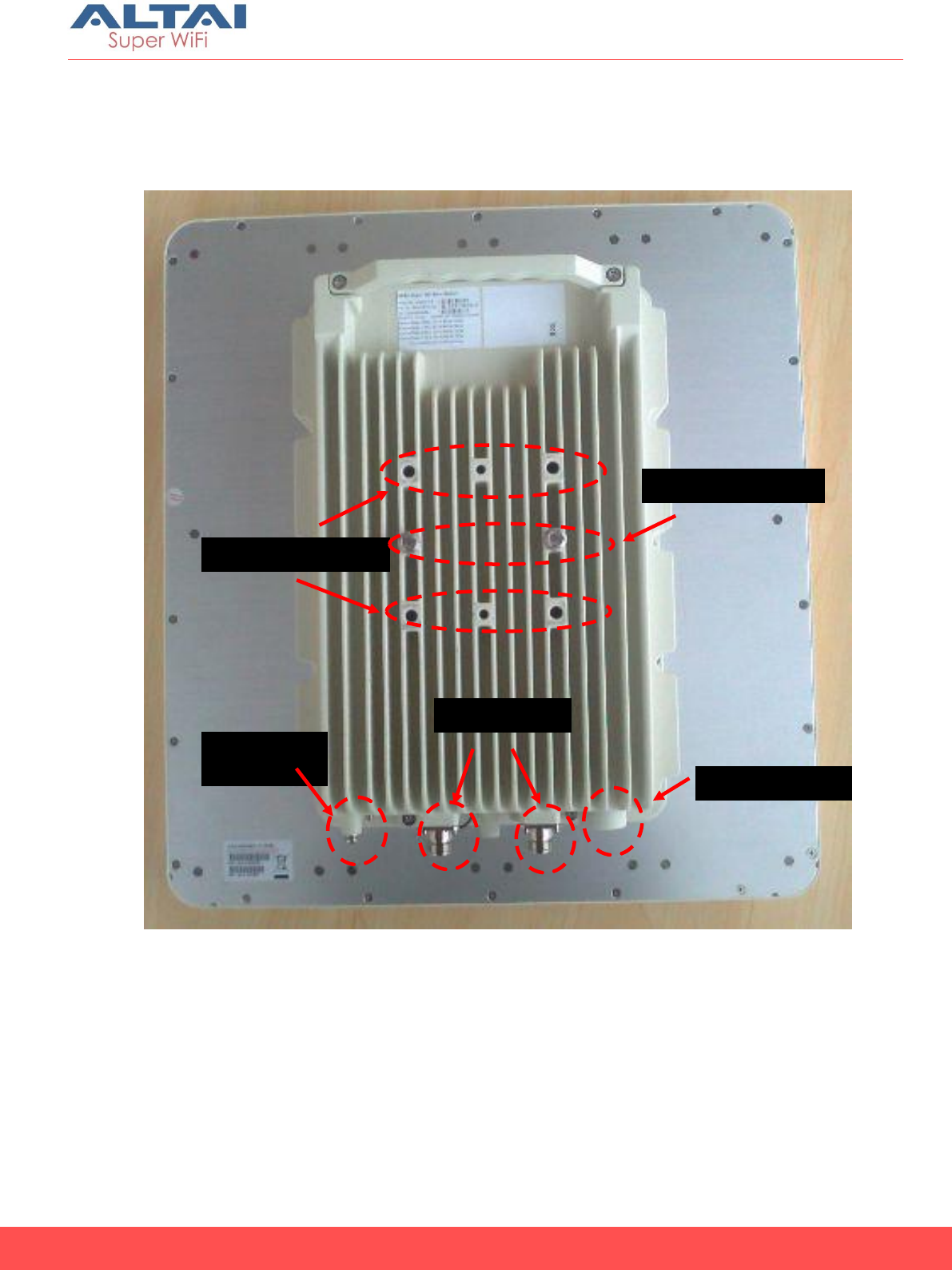
Figure 1. back-view of A8-Ein (ac)
Grounding
Screw
Locking screw
hole
Mounting screw
Ethernet Port
5GHz Port
3
Altai A8n (ac) Series Super WiFi Base Station
Installation Guide
Altai Technologies Ltd. All rights reserved
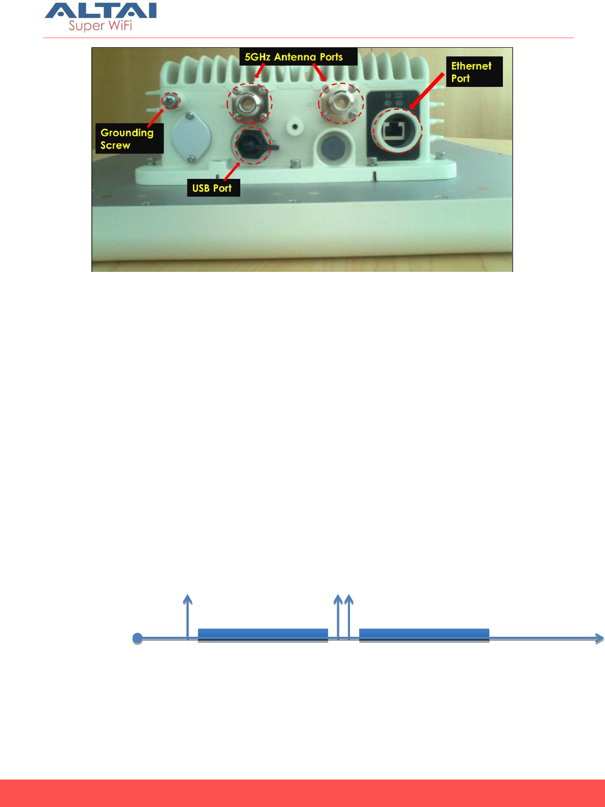
Figure 2. bottom-view of A8-Ein (ac)
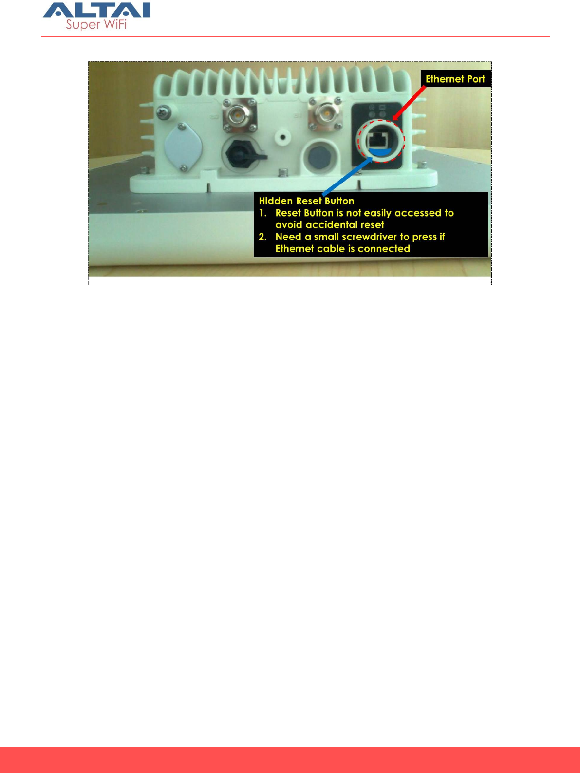
Reset back to factory default via reset button
Hardware reset button have 2 functions:
Soft-reboot [equivalent to UI: Reboot).
o Press & Hold the reset button until you see Power LED blink
once
o Then release it immediately
Reset to factory default [equivalent to UI: Reset factory (NOT
retain network address)]
o Press & Hold the reset button until you see Power LED blink
once
o Continue pressing the button until you see Power LED blink
twice consecutively
o Then release it immediately
Blink twice
Blink once
Press&Hold
Release here
trigger
Soft-reboot
Release here
trigger
Reset Factory
Time (s)
0s 1s 5s 10s
4
Altai A8n (ac) Series Super WiFi Base Station
Installation Guide
Altai Technologies Ltd. All rights reserved
The reset button’s location is shown in following.
5
Altai A8n (ac) Series Super WiFi Base Station
Installation Guide
Altai Technologies Ltd. All rights reserved
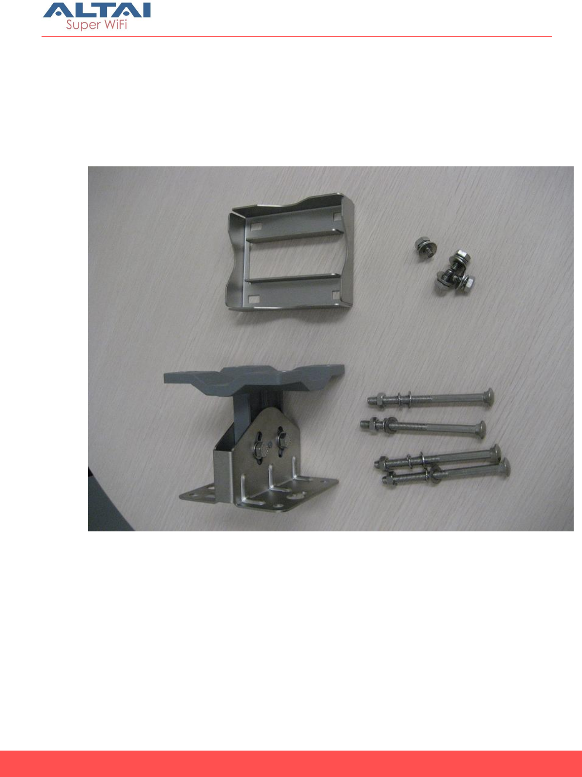
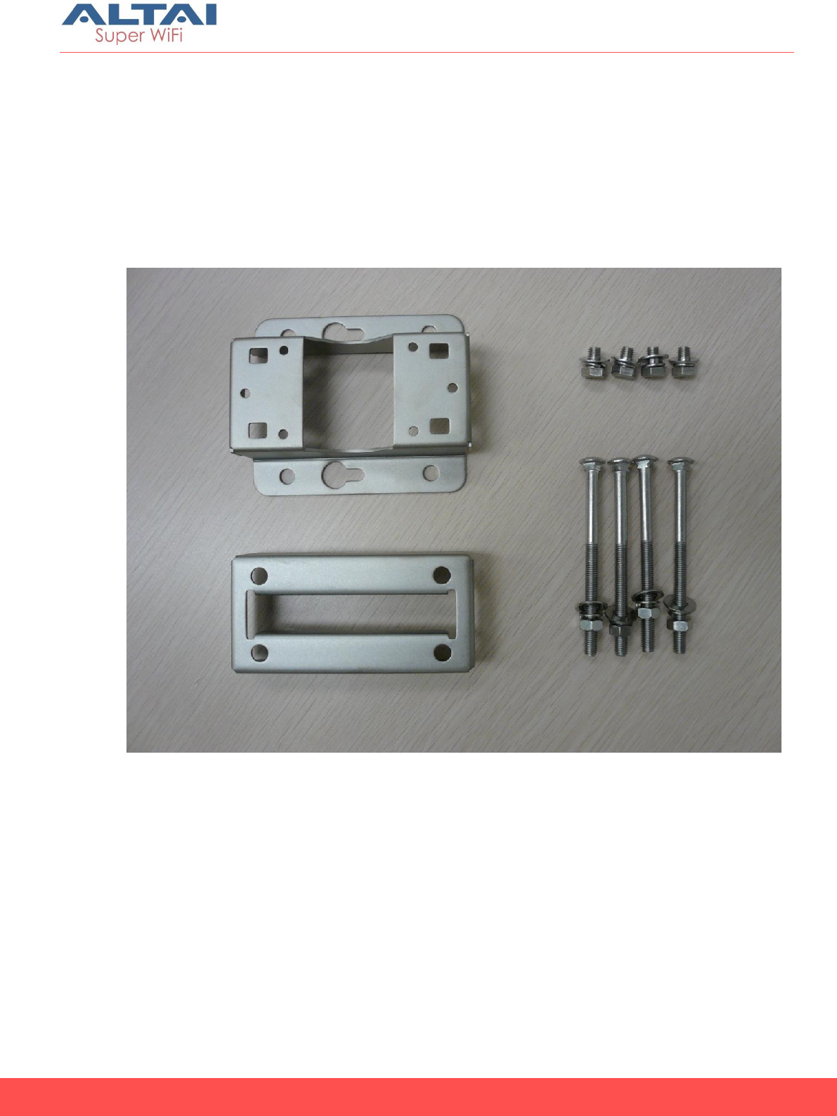
A8-Ein (ac) Base Station Mounting Kit
A Main mounting module
B Mounting back plate
C 4x mounting screw and nut
D 4x locking screw
Figure 3. A8-Ein (ac) Base Station Package
A
B
A
C
D
6
Altai A8n (ac) Series Super WiFi Base Station
Installation Guide
Altai Technologies Ltd. All rights reserved
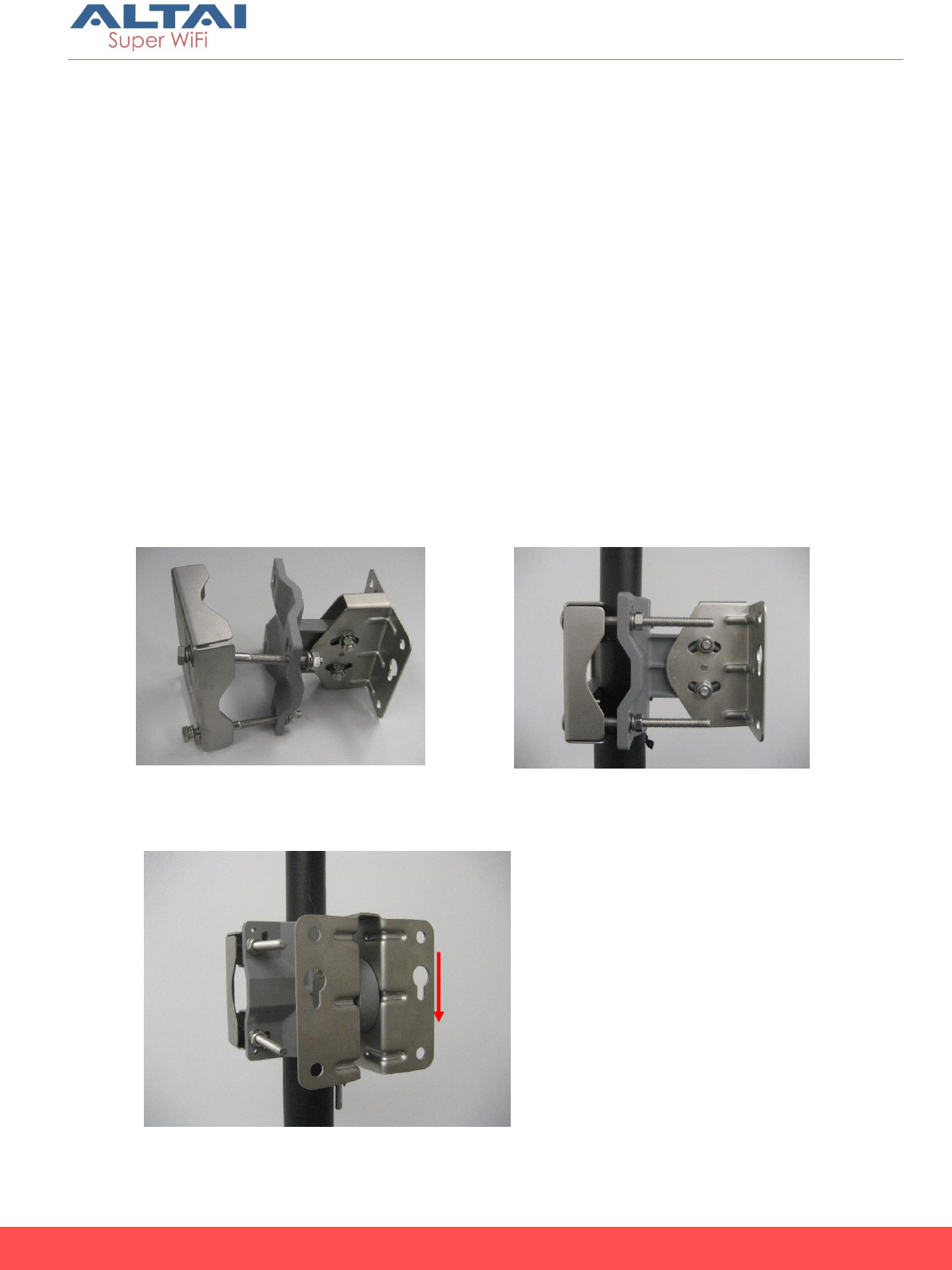
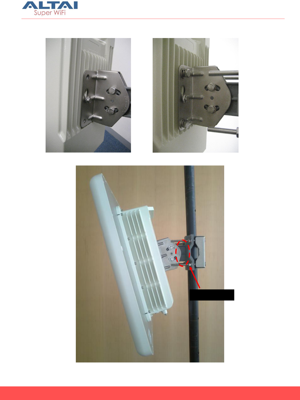
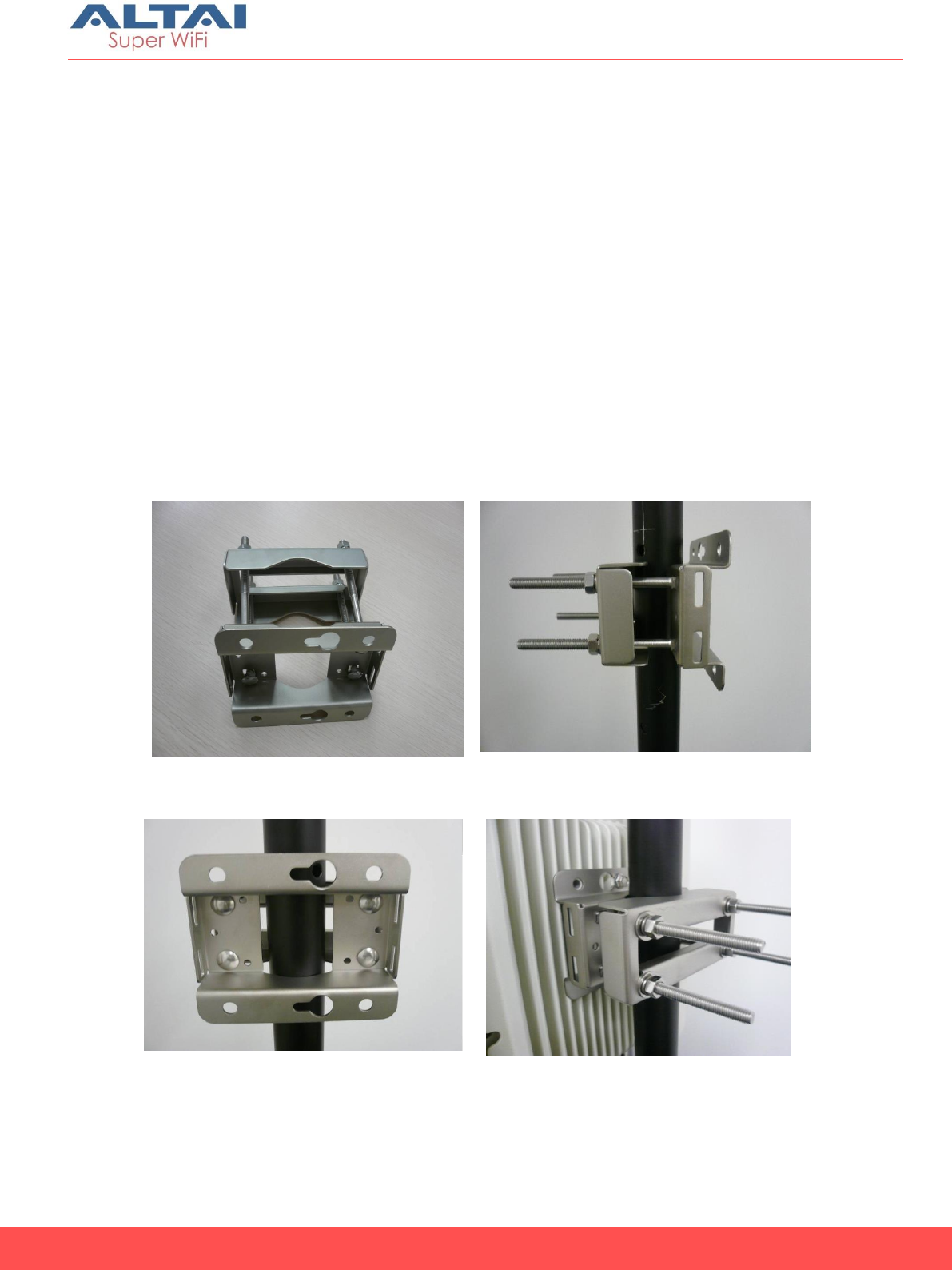
Mounting A8-Ein (ac) on Pole
1. Assemble the mounting kit according to Figure 4 with one side of
the screw installed.
2. Mount the kit to the pole at the desired height and tighten all 4
screws to fix its position (Figure 5).
3. The mounting kit must be installed with the key hole pointing
down (Figure 6).
4. Clamp the A8-Ein (ac) unit to the mounting kit, as shown in Figure
7 and make sure the mounting screw is locked in the key hole.
5. Screw in 4 locking screw to secure A8-Ein (ac) with the mounting
kit (Figure 8).
6. Adjust A8-Ein (ac) tilting by relaxing the pair of tilting screws and
tighten them back when the angle is fixed (Figure 9).
7. The mounting kit will fit with pole diameter from 1 inch to 3
inches.
Figure 4. Mounting kit assembly Figure 5. Mounting kit assembly
Figure 6. Key hole direction
7
Altai A8n (ac) Series Super WiFi Base Station
Installation Guide
Altai Technologies Ltd. All rights reserved
Figure 7. Clamping A8-Ein (ac) unit
Figure 8. Secure the unit
Figure 9. Antenna Mounted on Pole
Tilting
Screws
8
Altai A8n (ac) Series Super WiFi Base Station
Installation Guide
Altai Technologies Ltd. All rights reserved
A8n (ac) and A8in (ac) Base Station
Mounting
Mounting for A8n (ac) and A8in (ac) are the same. Figure 10 shows the
back view of A8in (ac). A8n (ac) has the same mounting screw.
Figure 10. back-view of A8in (ac)
Grounding
Screw
5GHz Port
Ethernet Port
Mounting screw
9
Altai A8n (ac) Series Super WiFi Base Station
Installation Guide
Altai Technologies Ltd. All rights reserved
A8n (ac) and A8in (ac) Base Station Mounting
Kit
A Mounting back plate
B Main mounting module
C 4x mounting screws and nuts
D 4x locking screws and nuts
Figure 11 A8n (ac) and A8in (ac) Base Station Package
B
C
D
A
10
Altai A8n (ac) Series Super WiFi Base Station
Installation Guide
Altai Technologies Ltd. All rights reserved
Mounting A8n (ac) and A8in (ac) on Pole
1. Assemble the mounting kit according to Figure 12 with one side
of the screw installed.
2. Mount the kit to the pole at the desired height and tighten all 4
screws to fix its position (Figure 13).
3. The mounting kit must be installed with the key hole pointing
direction (Figure 14).
4. Clamp the unit to the mounting kit, as shown in Figure 15 and
make sure the mounting screw is locked in the key hole.
5. Screw in 4 locking screw to secure A8in (ac) with the mounting
kit (Figure 15).
6. The mounting kit will fit with pole diameter from 1 inch to 3
inches.
Figure 12 Mounting kit assembly
Figure 13 Completion of Mounting
Figure 14 mounting screw locking direction
Figure 15 Clamping and secure the unit on
pole
11
Altai A8n (ac) Series Super WiFi Base Station
Installation Guide
Altai Technologies Ltd. All rights reserved
Mounting A8n (ac) 2.4GHz antenna and
cable connection
Introduction
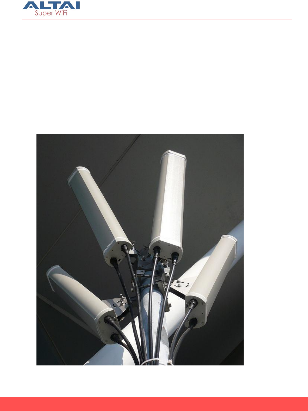
1. The A8n (ac) AP has 4 external 2.4GHz panel antennas. The A8-
Ein (ac) and A8in (ac) has internal 2.4GHz antenna. External
2.4GHz panel antenna gives you more freedom to adjust the
direction and tilting of each antenna. Internal 2.4GHz antenna is
easier for installation.
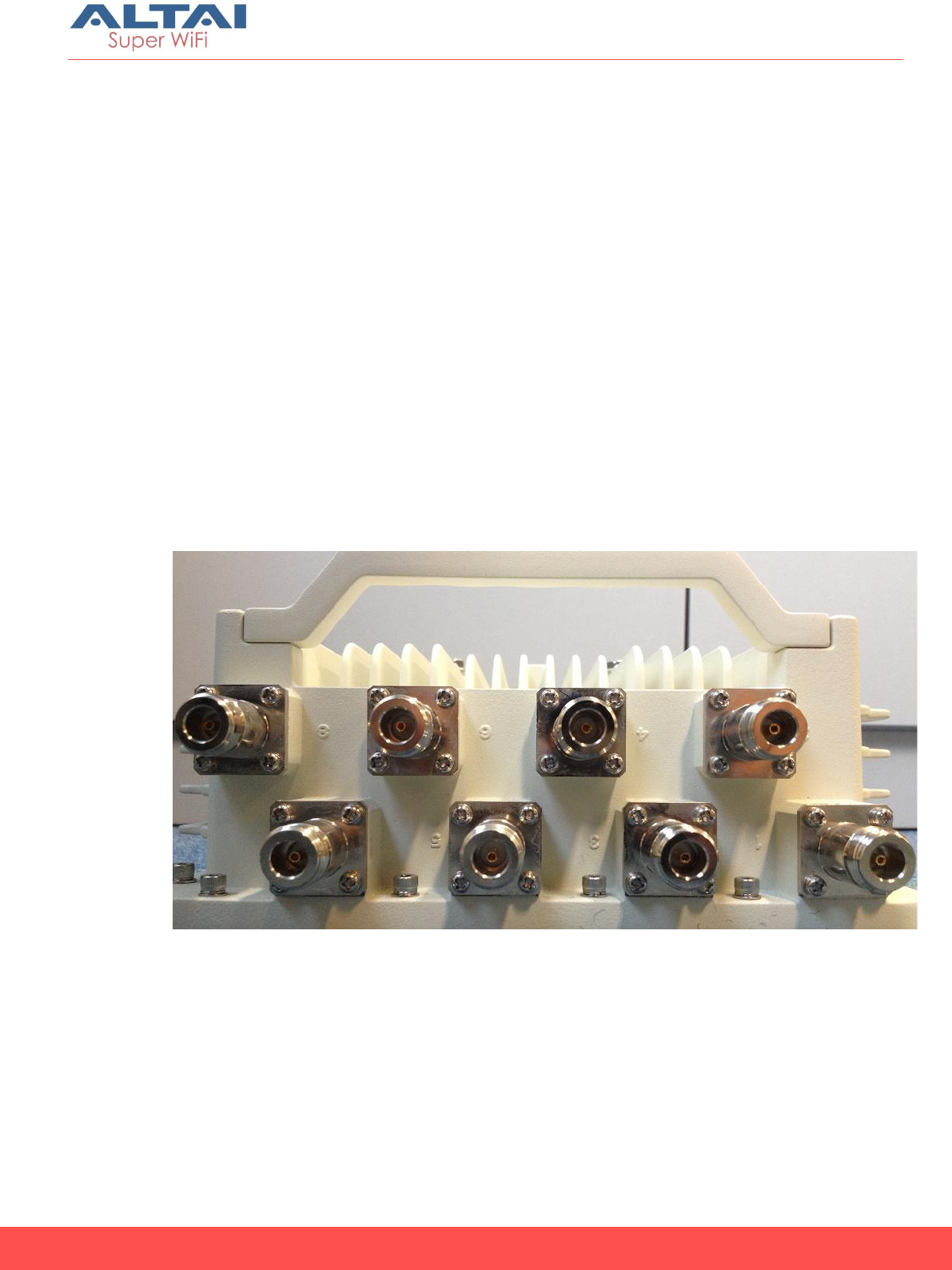
2. At the top of A8n (ac), there are 8 N-female RF connector
marked with 1-8. They are grouped to 4 groups to connect to 4
external 2.4GHz panel antenna.
3. It is recommended to seal the A8n (ac) series RF ports with
weatherproof materials to prevent water leakage.
Figure16. Top of A8n (ac) – 8 N-female RF port for external 2.4GHz panel antenna
connection
12
Altai A8n (ac) Series Super WiFi Base Station
Installation Guide
Altai Technologies Ltd. All rights reserved
Mounting of A8n (ac) 2.4GHz Panel antenna
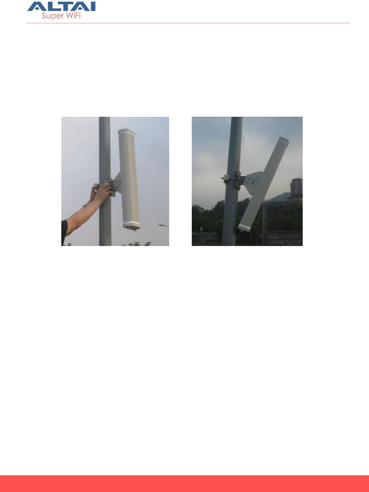
1. Mount the 2.4GHz radio antenna to the pole. It is recommended
that to install the standard A8n (ac) 2.4GHz antenna with the RF
ports facing downward, as shown in Figure 17.
2. Adjust the direction and down-tilt angle of the A8n (ac) 2.4GHz
antenna to align, as shown in Figure 18.
Figure 17. Standard A8n (ac) 2.4GHz Antenna
Figure 18. Adjust A8n (ac) 2.4GHz Antenna
tilting
13
Altai A8n (ac) Series Super WiFi Base Station
Installation Guide
Altai Technologies Ltd. All rights reserved
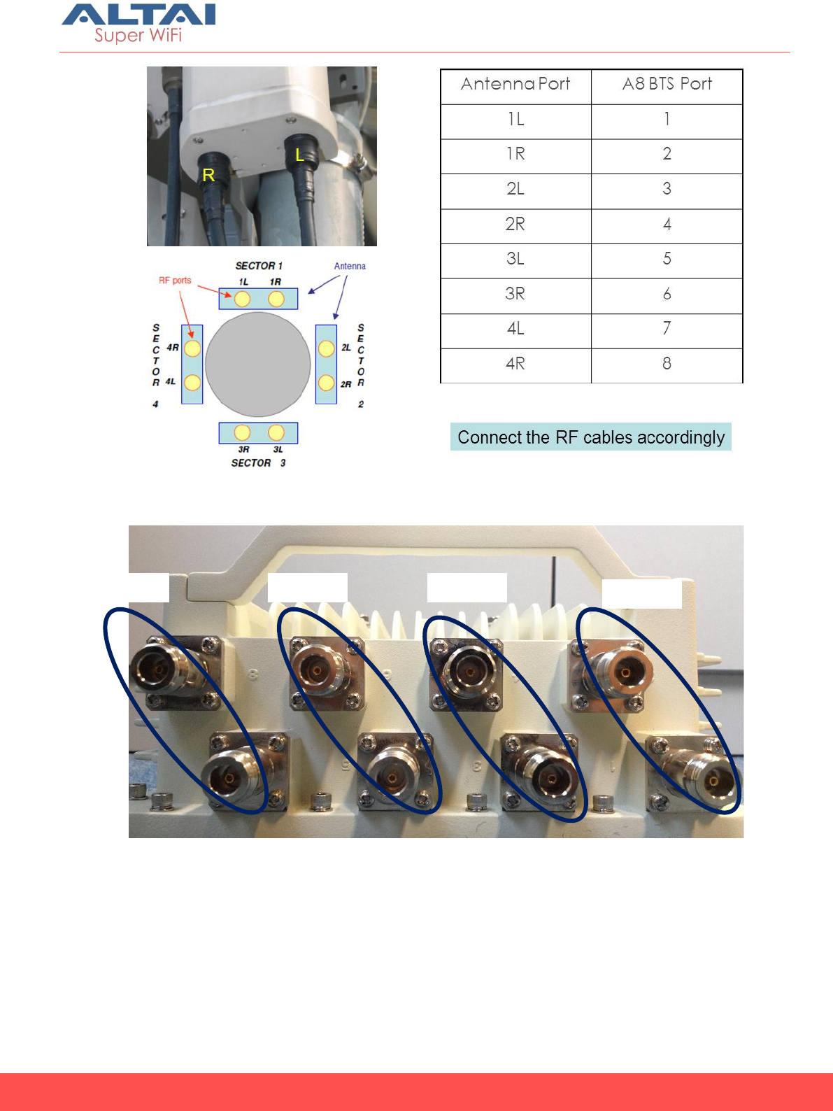
Cable connection from A8n (ac) to 2.4GHz panel
antenna
1. Connect RF cable from panel antenna port to A8n (ac) 2.4GHz RF port at
the top of A8n (ac).
2. RF port 1 and 2 of A8n (ac) must connect to the same panel antenna.
The same for ports (3.4), (5,6) and (7.8) which each pairs must connect to
the same panel antenna. It is recommended to connect the A8n (ac)
port to antenna port according Figure 20 mapping.
3. It is recommended to seal the A8n (ac) series 2.4GHz antenna RF ports
with weatherproof materials to get the best performance according to
the procedure in chapter 6 of this document.
Figure19. RF cable connection from panel antenna
14
Altai A8n (ac) Series Super WiFi Base Station
Installation Guide
Altai Technologies Ltd. All rights reserved
Figure 20. Antenna port to A8n (ac) port mapping
Figure21. A8n (ac) 2.4GHz RF port groups
Sector
4
Sector
2
Sector
3
Sector
1
15
Altai A8n (ac) Series Super WiFi Base Station
Installation Guide
Altai Technologies Ltd. All rights reserved
RF Cables Connection and Mounting of
5GHz Radio Antenna
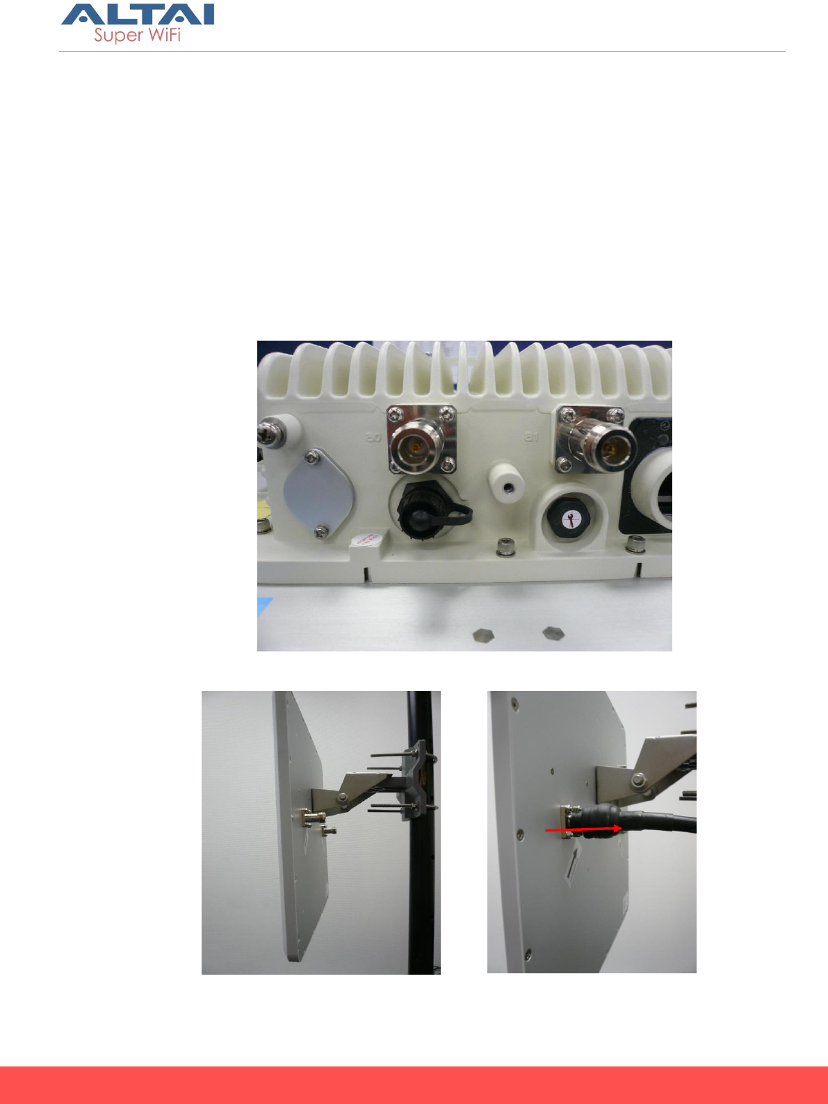
1. The standard A8n (ac) series 5GHz antenna has two RF ports.
2. Connect RF cables from the A8n (ac) series 5GHz antenna RF
ports which marked “a0” and “a1”next to the RF ports.
3. It is recommended to seal the A8n (ac) series 5GHz antenna RF
ports with weatherproof materials to get the best performance
according to the procedure in chapter 6 of this document
Figure 22. 5GHz “a0 & a1” antenna RF ports
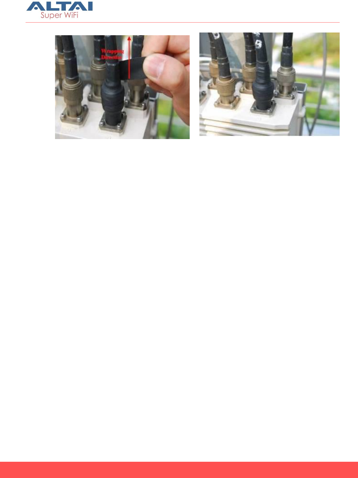
Figure 23. 20dBi 5GHz Antenna mounting
Figure 24. Waterproof wrapping
direction
5GHz Port

16
Altai A8n (ac) Series Super WiFi Base Station
Installation Guide
Altai Technologies Ltd. All rights reserved
Weatherproofing A8n (ac) Series Radio
Antenna
Introduction
Sealing materials are applied to outdoor antenna connectors to
accomplish several goals. First and foremost is to prevent water from
entering the connector. The second reason is to protect the connector
from gradual degradation due to UV radiation and pollution. Sunlight
and weather will oxidize metal surfaces and cause DC resistance to
increase on exposed mating surfaces. It is true that the RF cable
connectors are supposed to be weatherproof, but if left exposed to
weather conditions, they will tarnish and start to look rather ugly in a
short time. A good taping job will also prevent the RF cable connectors
from loosening up, which is a common occurrence for RF cables
exposed to vibration and strong winds.
We recommend the following sealing materials for weatherproofing
the antenna connectors:
1. High-quality, all-weather, black plastic electrical tape, preferably
3/4” (19mm) wide to make it easier to manipulate the tape around
the A8n (ac) Series BTS radio antenna ports. An RF port is often first
wrapped with a layer of electrical tape to make it easier to remove
the butyl rubber layer. In addition, one or more layers of electrical
tape are used as a final outer wrap to provide UV protection. We
recommend the 3M Scotch Super 88 Vinyl Electrical Tape for this
purpose.
2. High-quality, all-weather, black butyl rubber tape, preferably 3/4”
(19mm) wide to make it easier to manipulate the tape around the
A8n (ac) series BTS radio antenna ports. Butyl rubber tape is self-
amalgamating - it chemically bonds to itself, forming a strong,
waterproof joint. A layer of butyl rubber tape is applied around a
connector joint to provide a weatherproof seal, often on top of a
layer of electrical tape. We recommend the Andrew Corporation
butyl rubber tape for this purpose.
17
Altai A8n (ac) Series Super WiFi Base Station
Installation Guide
Altai Technologies Ltd. All rights reserved
Installation Tips
A few general rules about weatherproofing RF ports:
1. Always apply tape at temperature above 32 degrees F to ensure
adhesion. When working in cold weather, always protect your tape
rolls by storing it under your coat and next to your body to keep
tape flexible. If the tape cannot stretch elastically, it will not seal
properly.
2. Do not stretch the tape to the point where it distorts. Only apply
enough pressure to get a smooth wrap.
3. Smooth each wrapped layer of tape with your hands to ensure
proper adhesion.
4. Do not pull the tape to tear it - always cut the tape. A pulled tape
will most likely unravel, decreasing protection.
5. In warm climates where there will be long exposure to sunlight, it is a
good idea to wrap an extra layer or two of electrical plastic tape
over the butyl rubber layer to enhance UV protection.
6. For vertical runs of cable, the final layer of electrical tape should be
wrapped from the bottom to the top, and overlap about 50% of the
width of the tape. This will provide the same effect as shingles on a
house. The water will run down across the joints without going into
the joints.
In order to properly weatherproof of the BTS radio antenna ports, they
must be prepared before the installation.
Figure 25. 3M Scotch Super 88 Vinyl Electrical
Tape
Figure26. Andrew Corporation Butyl Rubber Tape
18
Altai A8n (ac) Series Super WiFi Base Station
Installation Guide
Altai Technologies Ltd. All rights reserved
1. Cut the butyl rubber tape into 1/5” (5mm) by 4” (100mm) strips.
2. Wrap a strip of butyl rubber tape around the base of each antenna
port in the clockwise direction. Take extra care to make sure that
the resulting butyl rubber ring would not hinder the tightening of the
RF cable connector around the antenna port.
Figure 27. Wrap the Butyl Rubber Strip
Figure 28. Butyl Rubber Ring Finished
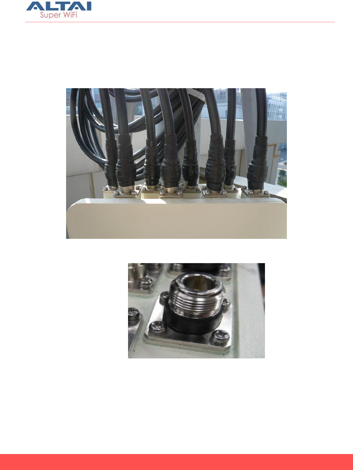
Connecting RF Cables
1. Make sure each RF cable and its connectors are absolutely dry.

19
Altai A8n (ac) Series Super WiFi Base Station
Installation Guide
Altai Technologies Ltd. All rights reserved
2. Loosely connect all the RF cables from each RF port. Do not tighten
up any of the connections.
3. Secure the RF cable bundles to the pole.
4. Tighten the RF cable connectors around the A8n (ac) series 5GHz
antenna ports with a torque wrench to the proper torque limit to
ensure that correct internal seals and surface contacts are made. If
a torque wrench is not available, first tighten the connector to finger
tight, then tighten it with a wrench for an additional ⅛ to ¼ turn from
the finger tight position.
5. Weatherproof the A8n (ac) series antenna ports.
Weatherproofing on A8n (ac) 2.4GHz Radio Antenna
Ports
1. Start wrapping a layer of electrical tape from 1/4” (6mm) above the
edge of the RF cable connector. Overlap the tape to half –width.
The tape should cover the RF cable connector body, and extend 1”
(25mm) above the cable connector clamping nut.
The tape can be applied in one or more strips if necessary. A strip
can be coiled onto an applicator such as a pencil. Apply only
enough tension to get good adhesion and keep the tape smooth.
20
Altai A8n (ac) Series Super WiFi Base Station
Installation Guide
Altai Technologies Ltd. All rights reserved
Figure 29. Wrapping direction and extends the wrap 1” above the connector clamping
2. Start wrapping a layer of butyl rubber tape from the base of the A8n
(ac) series 5GHz antenna port. Overlap the tape to half –width.
Finish the wrap at 1” (25mm) above the electrical tape and cut the
tape. Take extra care to make sure that the RF cable connector to
A8n (ac) series 5GHz antenna port junction is tightly sealed. Press the
tape edges together so that there are no gaps. Press the tape
against the RF cable connector body and the A8n (ac) series 5GHz
antenna port.
3. If enhanced UV protection is required, start wrapping a layer of
electrical tape from the base of the A8n (ac) 2.4GHz antenna port.
Overlap the tape to half –width. Finish the wrap at 1” (25mm) above
the butyl rubber tape and cut the tape.
Weatherproofing A8n (ac) series 5GHz Antenna RF
Ports
1. Start wrapping a layer of electrical tape from 1/4” (6mm) above the
edge of the RF cable connector. Overlap the tape to half –width.
The tape should cover the RF cable connector body, and extend 1”
(25mm) above the cable connector clamping nut.
The tape can be applied in one or more strips if necessary. A strip
can be coiled onto an applicator such as a pencil. Apply only
enough tension to get good adhesion and keep the tape smooth.
2. Start wrapping a layer of butyl rubber tape 1” (25mm) below the
electrical tape. Overlap the tape to half –width. Finish the wrap at
the base of the antenna port and cut the tape. Take extra care to
make sure that the RF cable connector to A8n (ac) series 5GHz
Extend 1”
(25mm)

21
Altai A8n (ac) Series Super WiFi Base Station
Installation Guide
Altai Technologies Ltd. All rights reserved
antenna RF port junction is tightly sealed. Press the tape edges
together so that there are no gaps. Press the tape against the RF
cable connector body and the A8n (ac) series 5GHz antenna RF
port.
3. Start wrapping a layer of electrical tape 1” (25mm) below the butyl
rubber tape, overlapping at half-width. Finish the wrap at the base
of the A8n (ac) series 5GHz antenna RF port and cut the tape.
Repeat this process for a second layer, and if enhanced UV
protection is required, a third layer.
22
Altai A8n (ac) Series Super WiFi Base Station
Installation Guide
Altai Technologies Ltd. All rights reserved
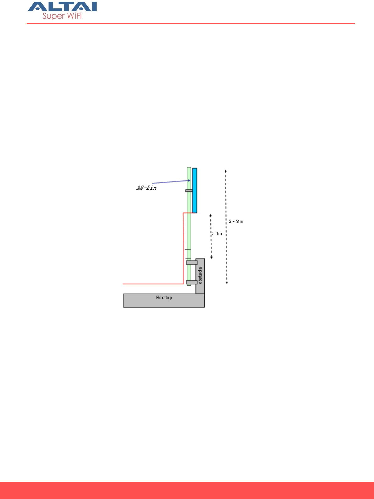
Recommendation on Installation Pole
Antenna Pole Height and Size
The antenna should be mounted at least 1 meter above any obstacle
in front. Hence, the height of the pole depends on the situation. In the
situation shown below, the pole should be at least 2 to 3 meters to
avoid any obstacle. The mounting kit can mount the pole with
diameter from 1.5 inches to 3 inches.
Remark: 2 inches pole is recommended as A8n (ac) series base station
and external antenna can be installed on the same pole.
Figure 30. At Least 1m above Any Obstacle in Front
23
Altai A8n (ac) Series Super WiFi Base Station
Installation Guide
Altai Technologies Ltd. All rights reserved
Grounding Protection
The A8n (ac) series must be properly connected to earth ground.
Failure to do so may result in equipment damage, injury or death.
Product warranty does not cover damage resulting in part or in whole
from improper grounding. An external grounding wire must be installed,
especially when A8-Ein (ac) is deployed on a non-metal pole or the
metal pole is not properly grounded. Please consult your location’s
building and electrical codes and follow them, or consult standards
such as National Electric Code. The grounding screw is located at the
bottom of A8n (ac) series as showed in figure 30. Use 10 AWG wire with
corrosion-resistant connectors for connecting to one or more approved
grounding rods or building’s earthing network. Earth-to-ground
resistance should not be more than 10ohms.
1. Loose the grounding screw of A8n (ac) series.
2. Attach a length 10 AWG bare copper with a terminal connector
to the grounding screw.
3. Tighten the screw nut.
4. Connect the other end of grounding wire to grounding rods or
earth ground.
Figure 31 Grounding Screw
Grounding
Screw
24
Altai A8n (ac) Series Super WiFi Base Station
Installation Guide
Altai Technologies Ltd. All rights reserved
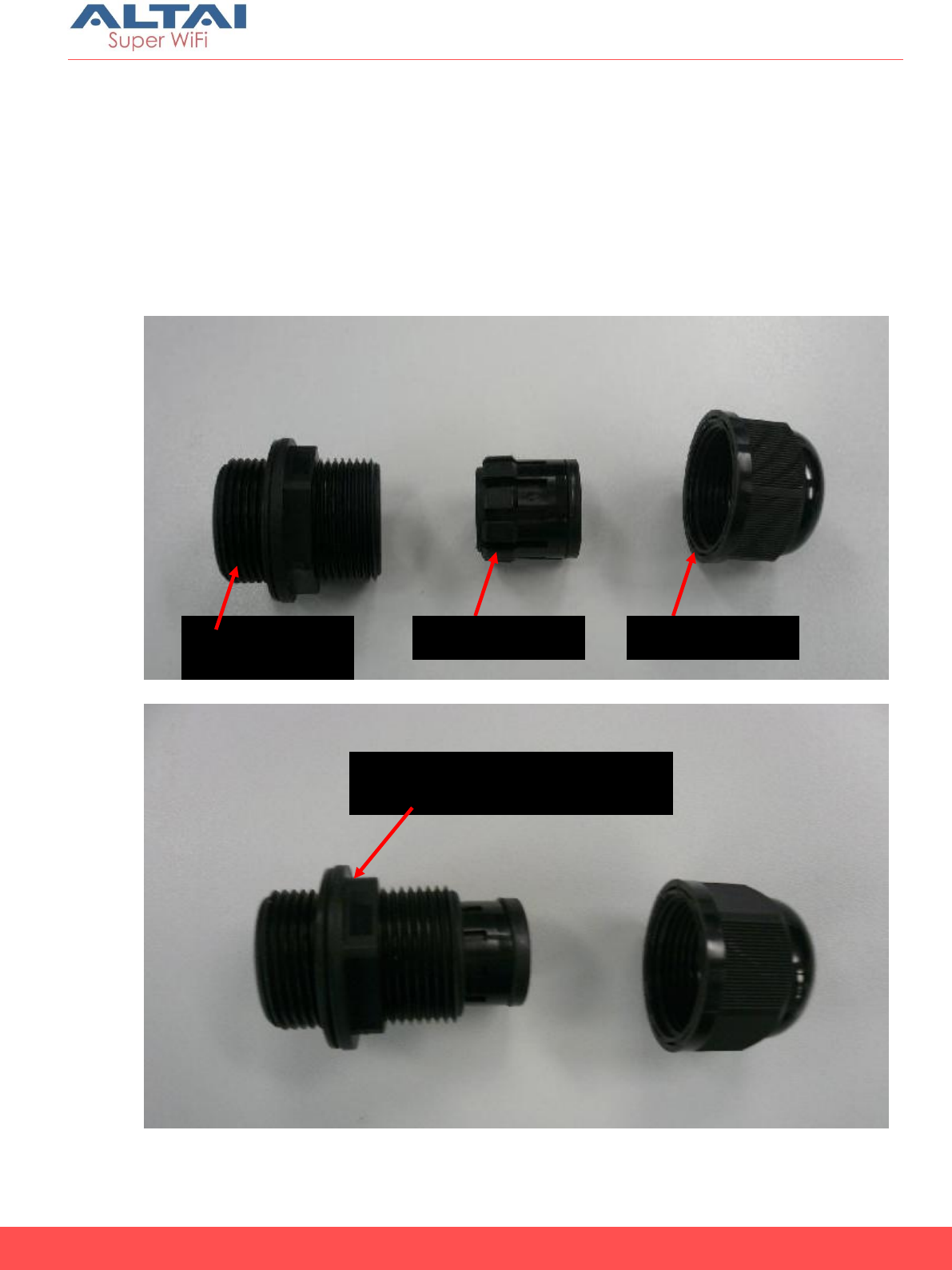
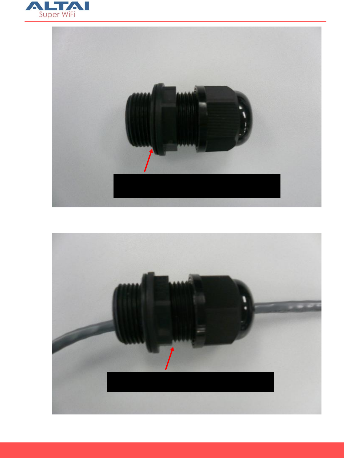
Ethernet Connector Packet Installation
The Ethernet connector packet includes the following components:
1. Gasket
2. Housing
3. Screw Nut
4. Clamping Ring
Gasket &
Housing
Clamping Ring
Screw Nut
Mount the housing and screw
nut
25
Altai A8n (ac) Series Super WiFi Base Station
Installation Guide
Altai Technologies Ltd. All rights reserved
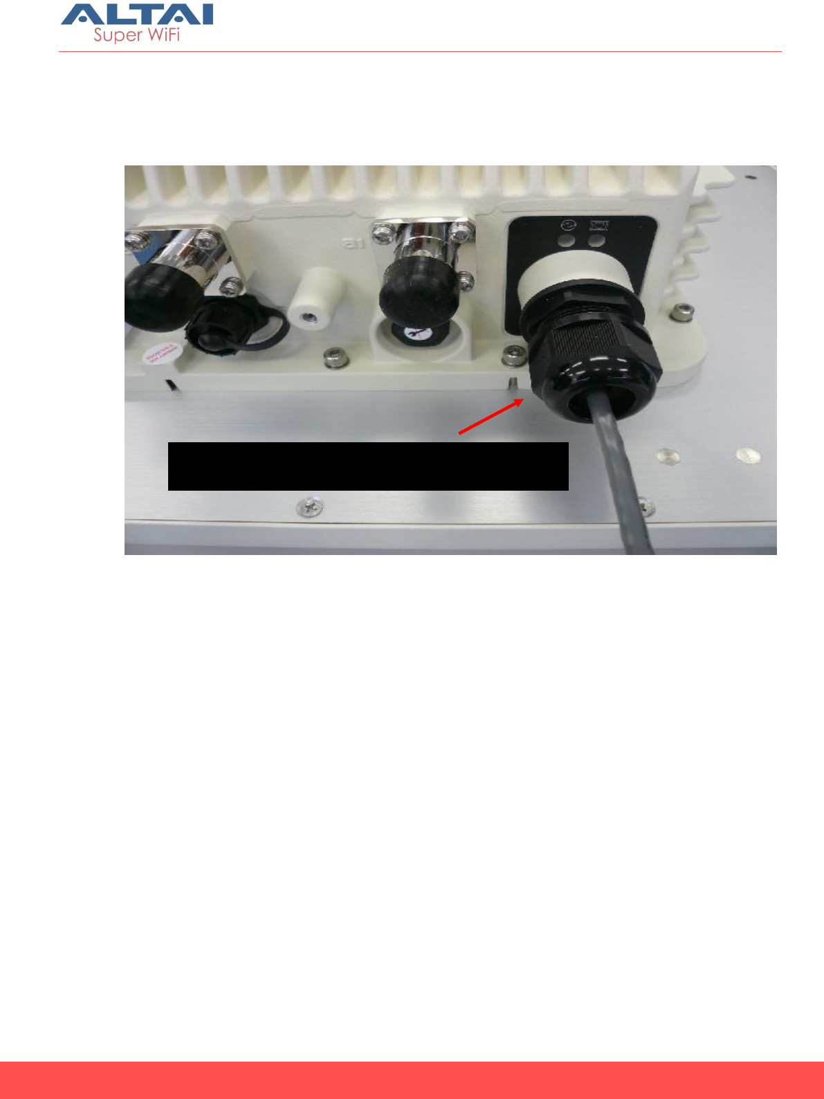
Mount the housing, screw nut and clamping
ring
Pass the housing and clamping ring through
the cable and tight up the clamping ring
26
Altai A8n (ac) Series Super WiFi Base Station
Installation Guide
Altai Technologies Ltd. All rights reserved
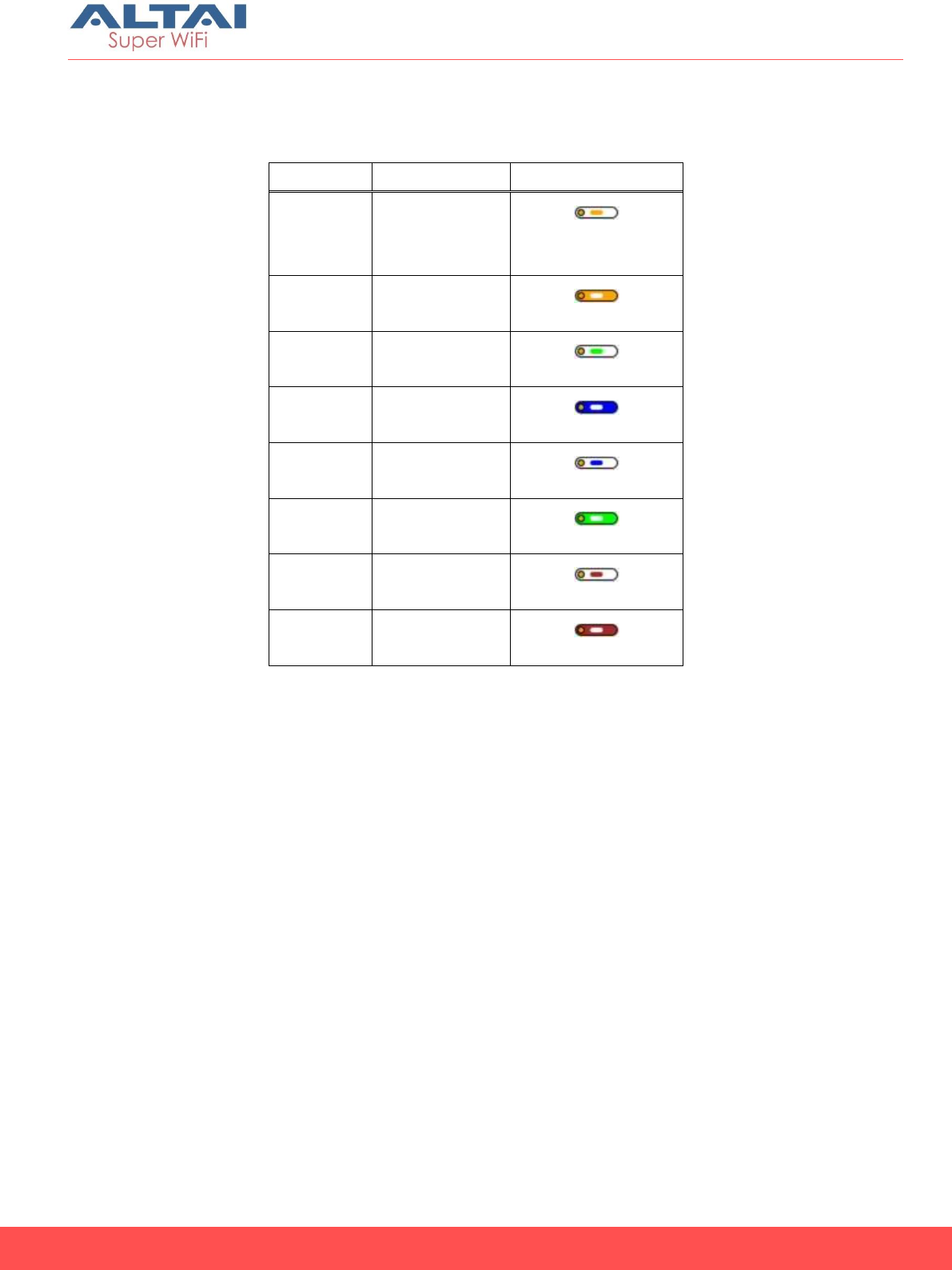
Cat 5e or cat 6 Ethernet cable are recommended. Maximum cable
length between PoE adapter and A8n (ac) is 100m.
The end of cable, RJ-45 modular jack pins are numbered 1 through 8 as
shown:
_______________________________
| | | | | | | | | |
| 8 7 6 5 4 3 2 1 |
|_____ Face of Plug ______|
|____ ____|
|________|
Tight up the screw nut into the Ethernet
connector of AP
27
Altai A8n (ac) Series Super WiFi Base Station
Installation Guide
Altai Technologies Ltd. All rights reserved
The assignments of wire pairs to plug and jack pins are as follows :
Pin
Pair
wire Color
1
2
white /
orange
2
2
orange
3
3
white / green
4
1
blue
5
1
white / blue
6
3
green
7
4
white / brown
8
4
brown
28
Altai A8n (ac) Series Super WiFi Base Station
Installation Guide
Altai Technologies Ltd. All rights reserved
Lightning Protection
Figure 24 Lightning Protection System for Pole Mounting A8n (ac) Series Base Station
A lightning protection system provides a means by which a lightning
discharge may enter or leave earth without passing through and
damaging personnel, equipment or the buildings. It does not prevent
lightning from striking but provides a means for controlling it and
prevents damage by providing a low resistance path for discharge of
the lightning energy.
60 ° Protection Cone
d
H
A8n (ac) Panel Antenna
RF Cable
Mounting Pole
Grounding Bar
Ground Conductor
Base Station
Grounding Plate
Lightning Rod
Shielded Ethernet Cable (AC Model)
Or Shielded POE Cable (DC Model)
External Lightning
Protection Box
Ground Cable
Building Rooftop
Building Cable
Entrance
Cable Terminal
Base Station Grounding Terminal
Clamp
External Lightning Protector (Optional)
Ground Cable

29
Altai A8n (ac) Series Super WiFi Base Station
Installation Guide
Altai Technologies Ltd. All rights reserved
A typical lightning protection system for A8n (ac) series base station is
shown in Figure 24. It consists of 5 parts:
Lightning Rod
Ground Conductor
Grounding Plate
Earth Termination
External Lightning Protectors
Lightning Rod
A lightning rod (air terminal) neutralizes the downward lightning strike
by launching an upward ionized path. The lightning current will follow
this path and is thus diverted away from personnel and electronic
equipment. The lightning rod must be constructed of steel with a
pointed tip and welded to a ground conductor.
The lightning rod must be installed at top of the mounting post or tower
higher than the highest portion of equipment it protects. For A8n (ac)
base station installation, the 4-sector antennas are usually the highest
points and usually protrude away from the post. Suppose the horizontal
distance from the post to the top outer most point of antenna is d, the
minimum height of the tip of lightning rod above the highest point of
antenna (H) is recommended to be at least 2d such that a cone of
protection of 60 degree is ensured around the pole or tower. In areas
of high lightning activities, the height H should be increased to 5d.
Ground Conductor
A ground conductor is a metal strip or rod usually made of copper or
similar conductive metal linking the lightning rod to the earth. The
prime purpose of the ground conductor is to conduct lightning current
from the lightning rod to the earth termination. It also provides
connection to a metal grounding plate so that the equipment under
protection can be connected to at the shortest distance possible.
A ground conductor must be installed straight and vertical without
bends such that it connects to the earth termination at the shortest
and direct path. As a rule of thumb, a minimum 50 mm2 in cross
sectional area or AWG 0 copper conductor is recommended for the
ground conductor. Aluminum or iron conductor can also be used but
with poorer conductivity. Minimum cross sectional area of copper,
aluminum and iron ground conductor are 16, 25 and 30 mm2
respectively.

30
Altai A8n (ac) Series Super WiFi Base Station
Installation Guide
Altai Technologies Ltd. All rights reserved
The connection between the ground conductor and the earth must be
no higher than 5 ohms. This is achieved by grounding to special
grounding bars in the case of post mounting or to the steel
reinforcement bars at the concrete base of the tower in case of tower
mounting.
Grounding Plate
A grounding plate is a metal plate welded to the post or tower which
provides a common grounding connection placed at a short distance
from the equipment and ground conductor. The grounding plate is
connected to the ground conductor using a ground cable and clamp.
The A8n (ac) series base station grounding terminal is located at the
bottom of chassis compartment. This grounding terminal should be
connected to the grounding plate using a ground cable and lug. AWG
10 (around 5 mm2 cross-sectional area) copper wire is recommended
for the ground cable. Only one grounding connection to the pole or
tower is allowed.
All antenna ports of A8n (ac) base station are grounded internally. For
shielded Ethernet cable (AC model) or shielded POE cable (DC model)
grounding, the ground wire of the Ethernet/ POE cable should be
connected to the screw port located at the inside bottom of lower
chassis compartment of A8n (ac) series base station. The other side of
the Ethernet/ POE cable will be connected to indoor units via a
grounded external lightning protector box. The external lightning
protector box should be located outside the building as near as
practicable to the entrance of the cables to the building and it is
connected to an earth termination via a ground cable.
Earth Termination
An earth termination is a metal grounding bar which is planted into the
earth for conducting and dispersing lightning current from the ground
conductor to earth. The ground conductor is connected to this
grounding bar at one end. The mounting post or tower should have its
own grounding bar. The size of metal grounding bar should be
designed such that the total resistance from the lightning rod to the
earth termination is less than 5 ohms.
External Lightning Protectors
Lightning protector (or surge arrestor) is a component which provides a
lower resistance path to conduct sufficient charge from the surge in
order to lower the surge voltage to a safe level.

31
Altai A8n (ac) Series Super WiFi Base Station
Installation Guide
Altai Technologies Ltd. All rights reserved
External lightning protectors can be used to provide additional
protection to the Altai A8n (ac) series base station embedded
protectors. They can be put at strategic points such as the Ethernet
port, AC power or antenna ports close to the A8n (ac) series base
station. External lightning protectors are available in the market in the
form of a protector box, which can be inserted simply in front of the
ports to be protected.
As the magnitude and speed of lightning varies in different places, the
specifications of external lightning protectors should be chosen
appropriately according to local protection requirements.
While this section gives a general guideline on lightning protection, the
detail specifications of a lightning protection system must be provided
by local electricians and must be maintained and checked
periodically in accordance with local regulations. Altai does not
provide any warranties as to the effectiveness of the suggested
measures. The implementation of the suggested measures is at the
customer’s own discretion. Under no circumstances will Altai be liable
for any consequences resulting from the implementation or lack of
implementation of the suggested measures.