Altice Labs FGW-GR240BG Fiber Gateway 4x4 User Manual Users manual
Altice Labs, S.A. Fiber Gateway 4x4 Users manual
UserManual.wiki
>
Altice Labs
>
FGW-GR240BG User Manual
>
Users manual
Contents
1.
Users manual
2.
User manual
Users manual
Navigation menu
Upload a User Manual
Namespaces
Wiki Guide
HTML
PDF
Info
Views
User Manual
Discussion / Help
Navigation

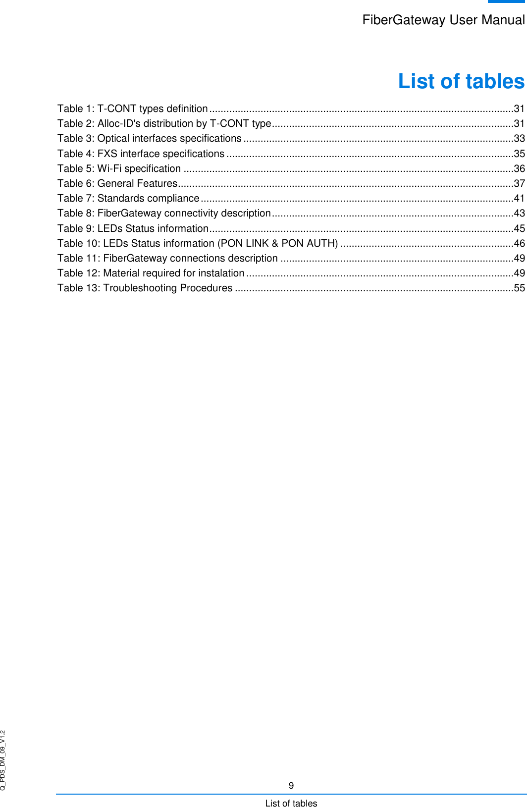
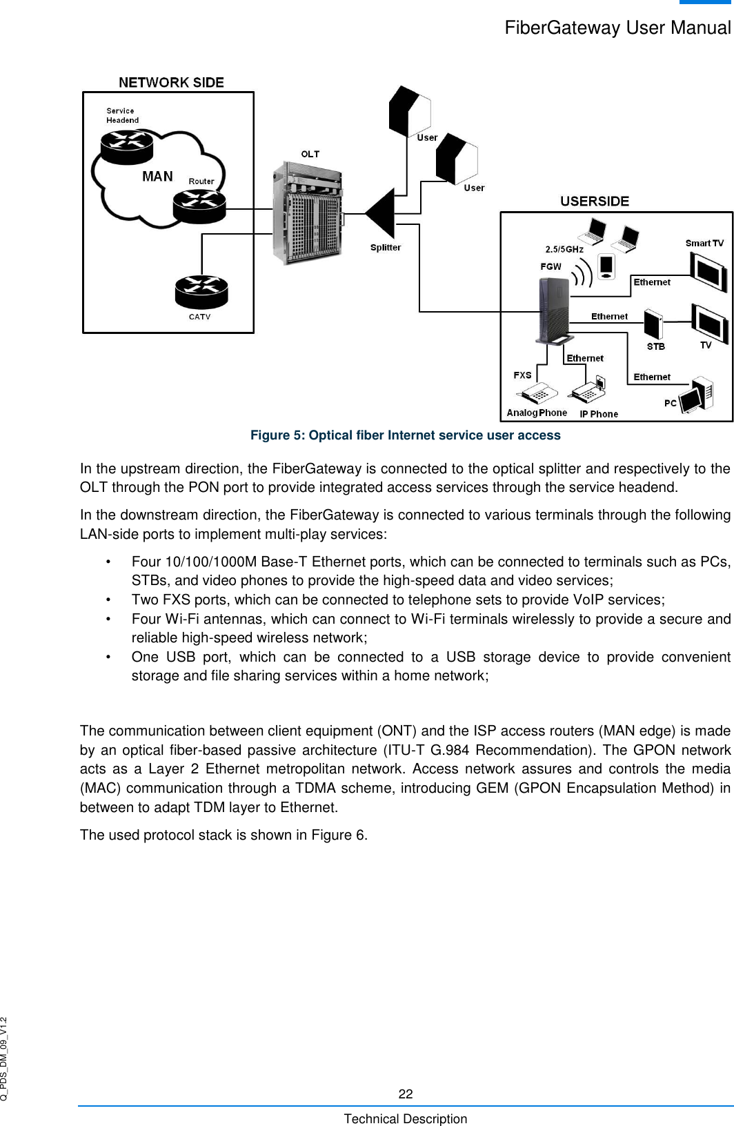
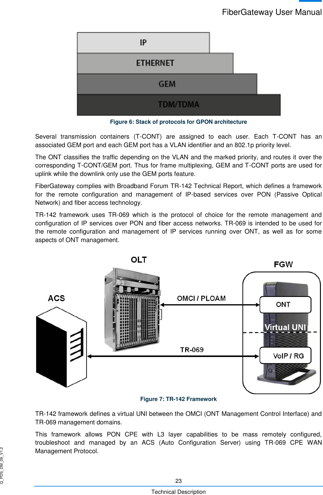
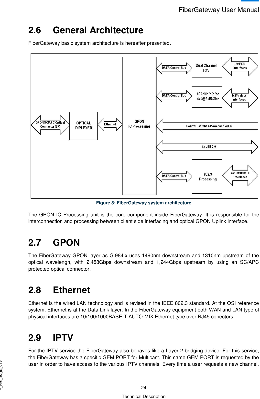
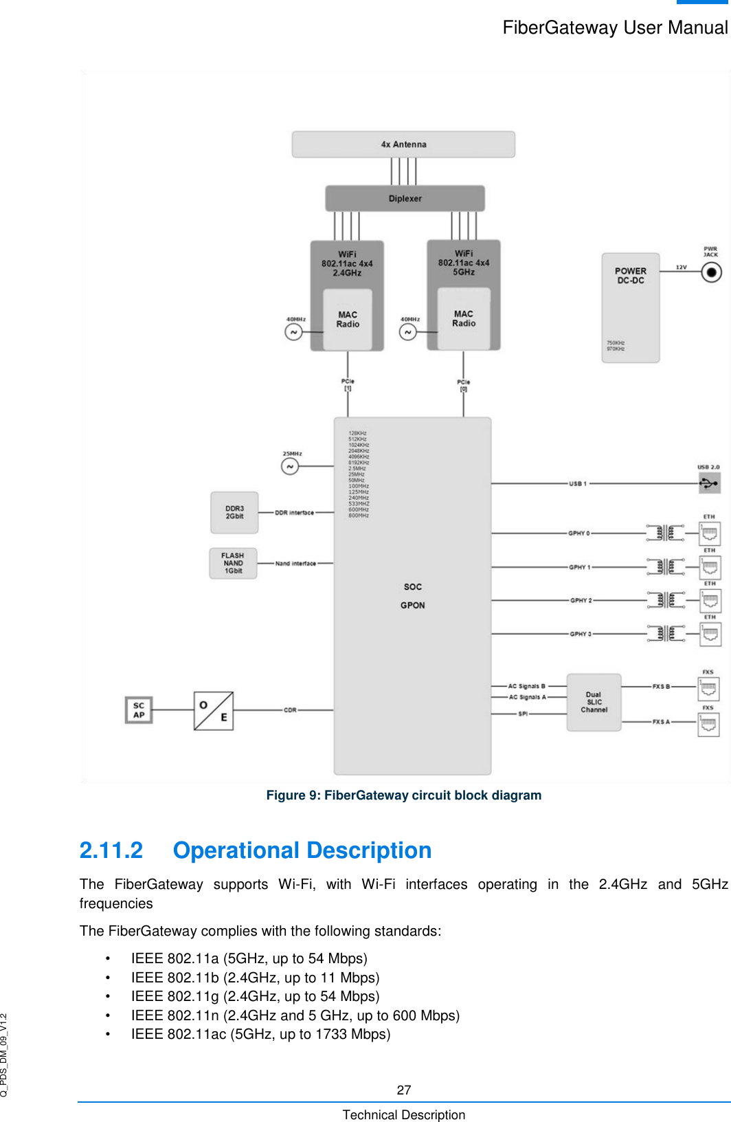
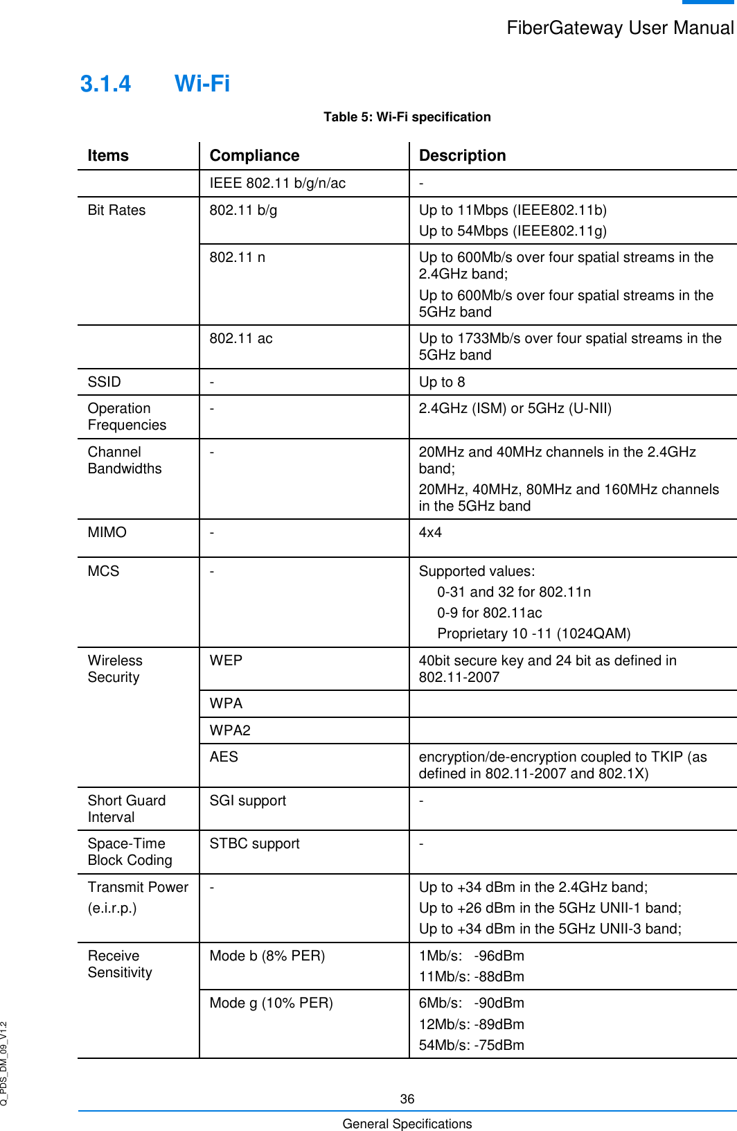
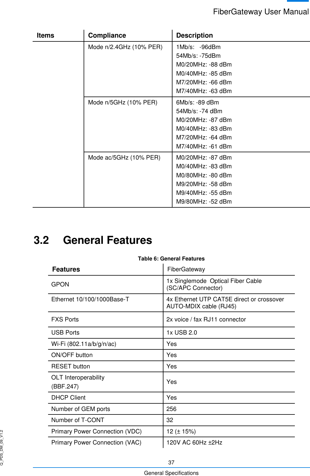
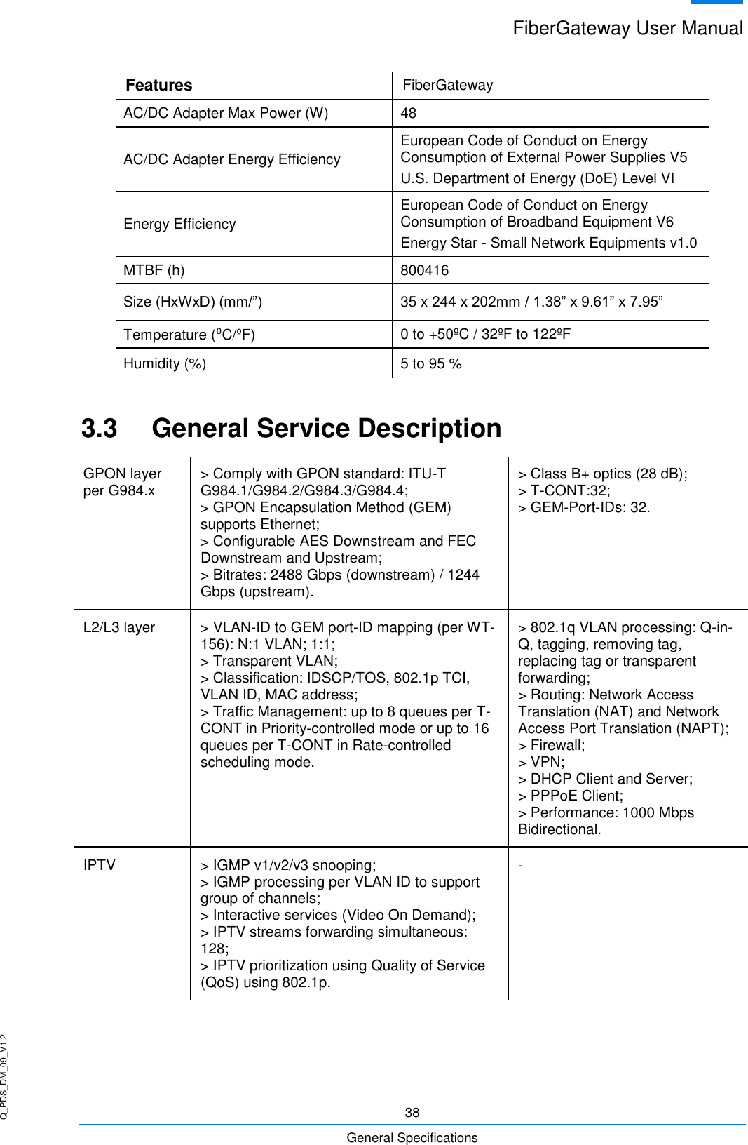
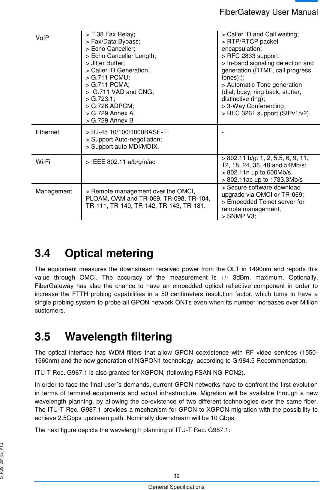
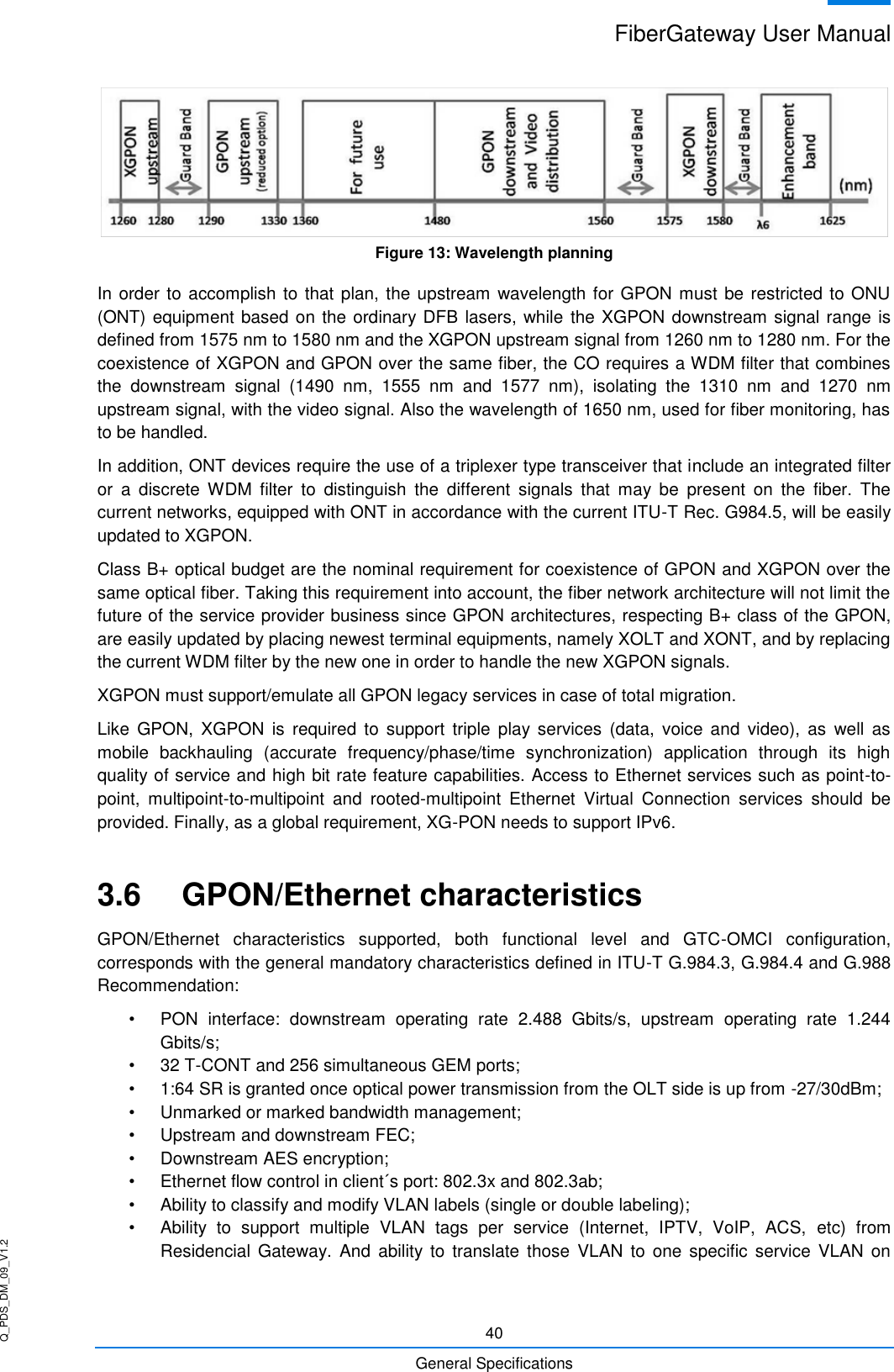
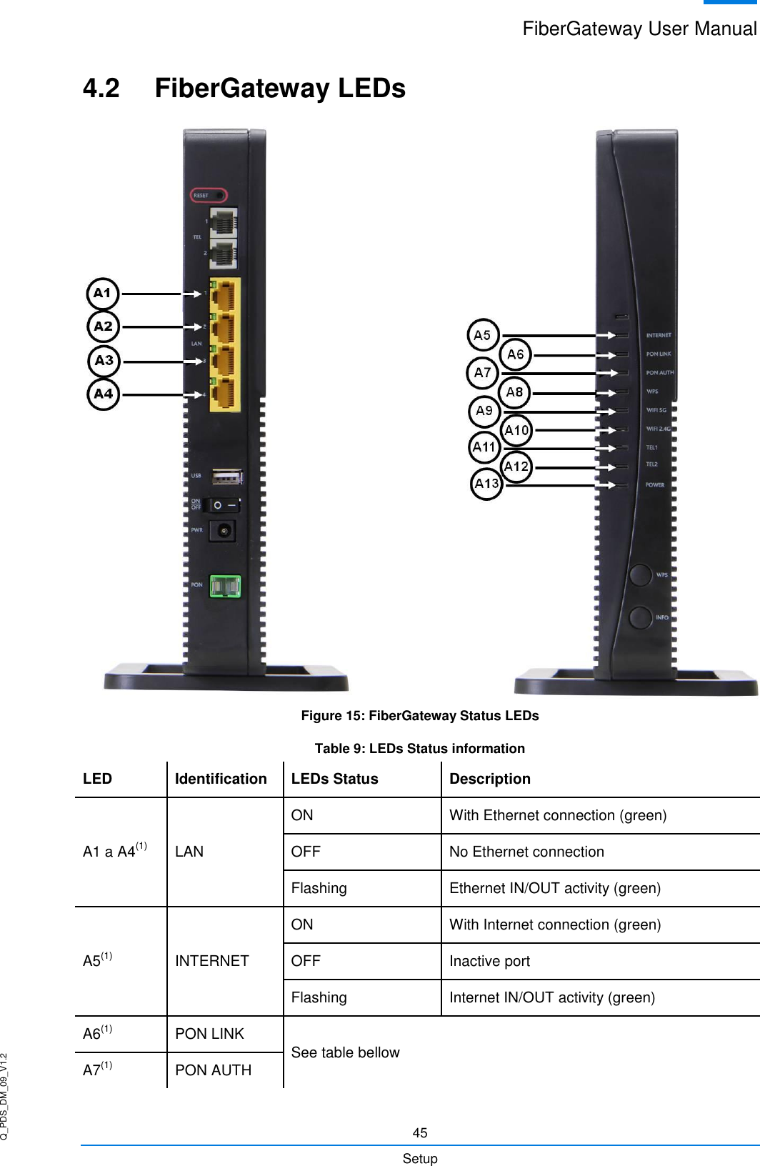
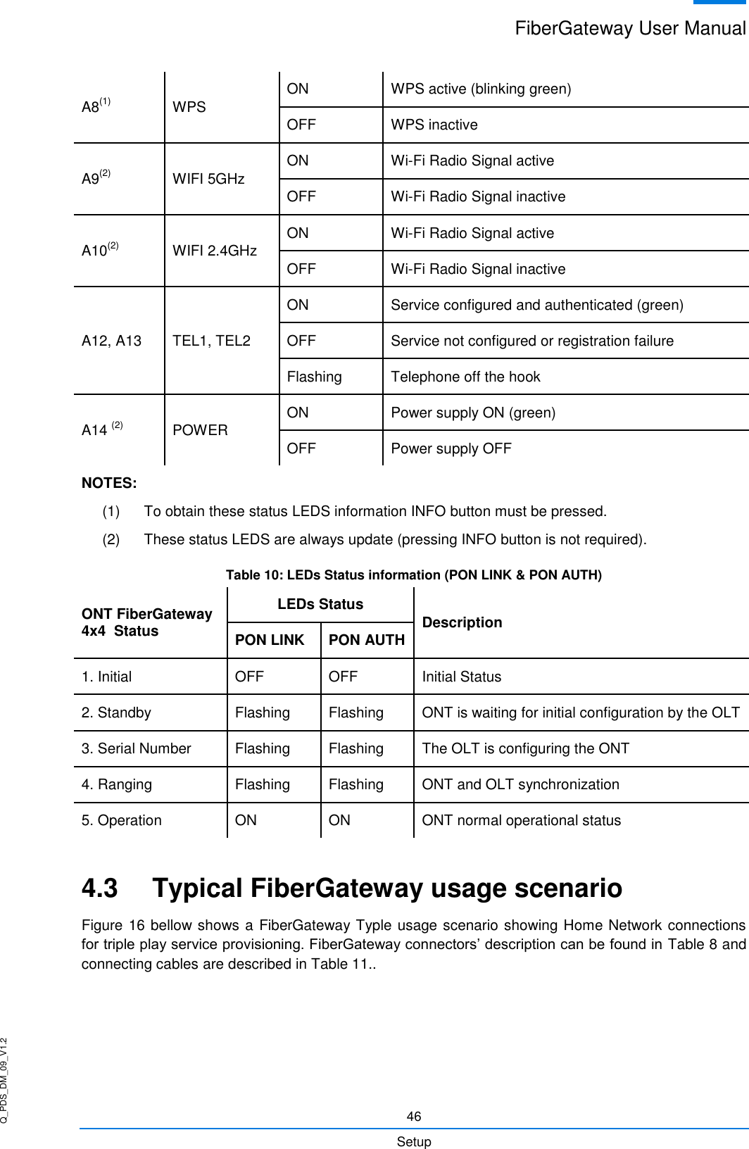
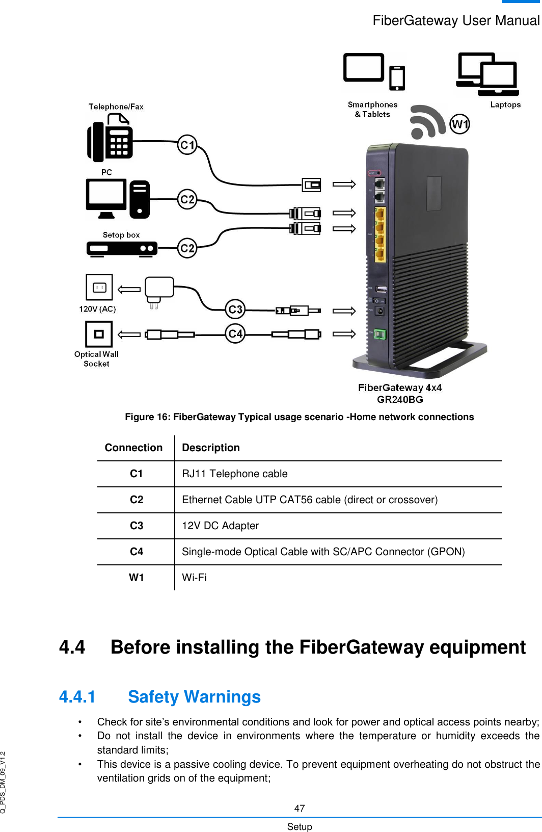
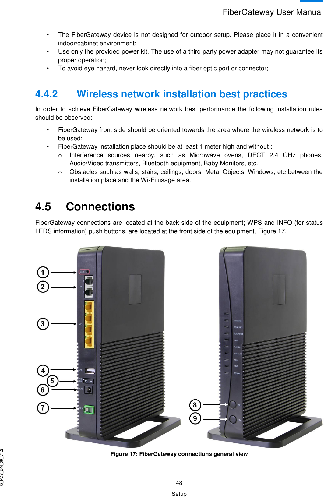
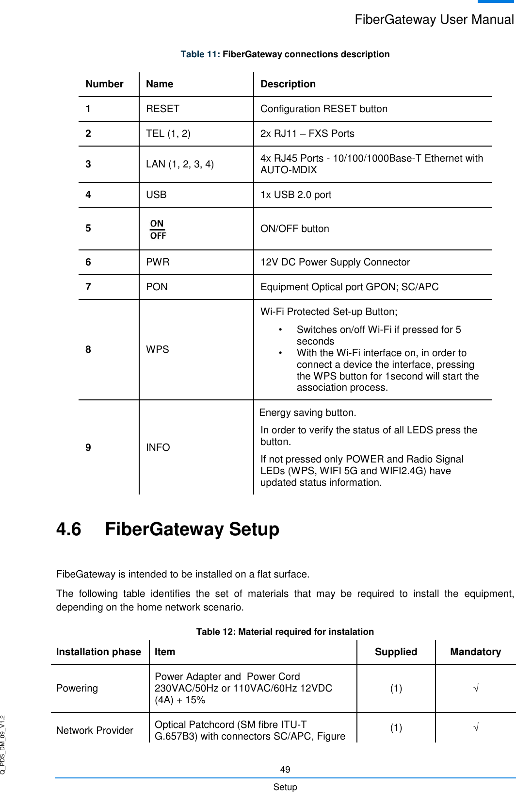
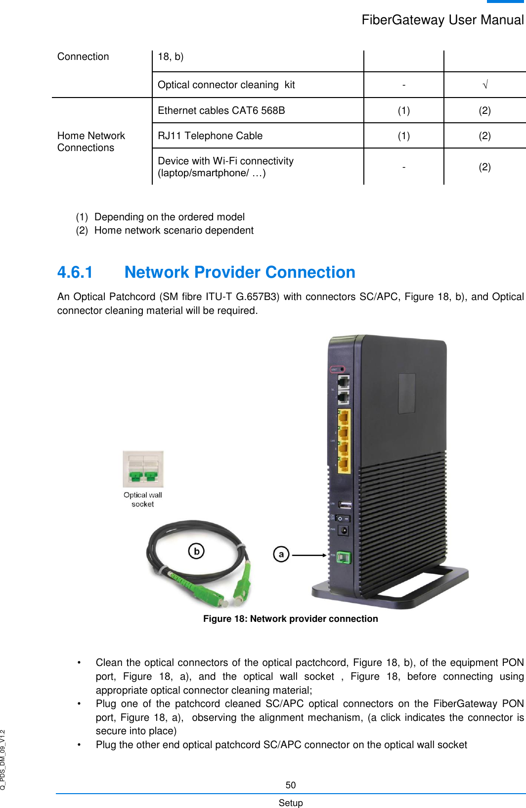
![Q_PDS_DM_09_V1.2 FiberGateway User Manual 31 Technical Description Table 1: T-CONT types definition T-CONT Type 1 Type 2 Type 3 Type 4 Type 5 Units Fixed BW- RF RF1 0 0 0 RF5 [b/s] Assured BW- RA 0 RA2 RA3 0 RA5 [b/s] Max Bw - RM RM1 = RF1 RM2 = RA2 RM3 > RA3 RM4 RM5 > RF5 + RA5 [b/s] Bandwidth Eligibility 0 0 Non-Assured BW - RNA Best-Effort - RBE RNA / RBE In each GPON interface there are 1024 Alloc-ID (T-CONT identifiers) available, provided to manage ONT services. They are distributed in the following way: Table 2: Alloc-ID's distribution by T-CONT type Alloc-ID Allocation Type 0-127 Default Alloc-ID (Dynamic or Static) 128-255 Reserved 256-639 Dynamic or Static 640-1023 Static Figure 12: Traffic distribution by service/client](https://usermanual.wiki/Altice-Labs/FGW-GR240BG.Users-manual/User-Guide-3621269-Page-31.png)