Altiostar Networks 44380400 LTE Intelligent Remote Radio Head User Manual usermanual
Altiostar Networks, Inc. LTE Intelligent Remote Radio Head usermanual
User Manual

PN 240-00-0005
Revision 2
February 11, 2015
AltiostarNetworks
iRU4438intelligentRemoteRadioHead
Product Description and Installation Guide
Copyright© 2015 Altiostar
All rights reserved.

iRU4438 intelligent Remote Radio Head Product Description and Installation Guide
Copyright
© Altiostar Networks 2015. All rights reserved. No part of this document may be reproduced
in any form without the written permission of the copyright owner. Altiostar Networks, Inc.,
iR6, and Altiostar Networks, Inc. logo are trademarks of Radio Mobile Access, Inc. All other
trademarks are the property of their respective owners.
Disclaimer
All rights reserved. Information and product specification are subject to change without
notice as part of the company continuous process and methodology improvement. Altiostar
Networks assumes no responsibility for inaccuracies contained herein.

l
Preface
iRU4438 iRRH Product Description and Installation Guide iii
Preface
About this document
This document covers the basic installation of the Altiostar Networks, Inc. iRU4438 intelligent
Remote Radio Head (iRRH) on towers, walls, roof or other structures utilizing a universal
mounting assembly.
Connections to external interfaces, including signaling, grounding, and power are described.
Descriptions of the iRU4438 iRRH indicators are also provided.
Refer also to the Altiostar Networks iRB1200 intelligent Baseband Unit (iBBU) Product
Description and Installation Guide, document number 240-00-0007, for related information.
The iRB1200 iBBU is a companion product.
Intended users
The target audience for this document is installation and engineering personnel. It assumes
personnel have a basic understanding of wireless telecommunications terminology, and
experience in installing wireless telecommunications equipment.
Conventions used
Illustrations and photos in this document are intended to show a basic installation. They
show site and equipment configurations encountered during a typical installation. They do
not show all details and exceptions, but highlight the main points of the installation.
Altiostar Networks, Inc. will often be referred to as Altiostar Networks, or simply Altiostar.
The Altiostar Networks, Inc. iRU4438 intelligent Remote Radio Head will often be referred to
as the iRU4438 iRRH, or simply the iRRH. The iRB1200 Baseband Unit, a companion unit to
the iRU4438 iRRH in the Altiostar Networks LTE micro eNodeB solution, will often be referred
to as the iRB1200 iBBU, or simply the iBBU.
The Operator or Owner of the facility and equipment where the iRU4438 iRRH is to be
installed is referred to as the Operator in this document.
NOTE
This is an example of a note used in this document that denotes important
information about the text or procedure that follows it.

l
Preface
iv iRU4438 iRRH Product Description and Installation Guide
Overview
The iRU4438 intelligent Remote Radio Head is based on a distributed architecture with the
following two essential elements:
• iRU4438 iRRH
• iRB1200 iBBU or vBBU
The iRU4438 iRRH is a compact, outdoor microcell radio head with integrated baseband for
use in the AWS band. The iRU4438 iRRH is connected to the iRB1200 iBBU through a gigabit
Ethernet (GigE) connection compliant with the Common Public Radio Interface (CPRI)
standard. Connection to other compliant fronthaul devices can also be facilitated using the
Ethernet fronthaul port.
The iRU4438 iRRH interconnects with compliant radio antennas and the iRB1200 iBBU which
operates within the RAN portion of the LTE wireless network.

Contents
iRU4438 iRRH Product Description and Installation Guide v
Contents
1 Introduction .......................................................................1-1
1.1 Conventions used .................................................................... 1-1
1.2 Overview................................................................................ 1-1
2 Safety requirements...........................................................2-1
2.1 Overview................................................................................ 2-1
2.2 Purpose ................................................................................. 2-1
2.3 Warning symbols ..................................................................... 2-1
2.4 General safety precautions ....................................................... 2-1
3 Installation prerequisites ...................................................3-1
3.1 Required tools......................................................................... 3-1
3.2 Required site equipment........................................................... 3-2
3.3 Site preparation ...................................................................... 3-3
3.4 Site pre-installation visit checklist.............................................. 3-3
3.5 Site installation checklist .......................................................... 3-4
4 iRU4438 iRRH installation overview ...................................4-1
4.1 Installation procedures............................................................. 4-1
4.2 Unpacking the shipping container .............................................. 4-1
4.3 Verifying all parts received........................................................ 4-2
5 Installing the iRU4438 iRRH ...............................................5-1
5.1 Assembling cables ................................................................... 5-1
5.2 Routing pre-assembled power/fronthaul Ethernet/grounding cables 5-2
5.3 Installing RF antennas on upper/lower omni-antenna brackets....... 5-3
5.4 Installing RF antenna cables ..................................................... 5-5
5.5 Installing the iRU4438 iRRH mounting bracket............................. 5-7
5.6 Hoisting the iRU4438 iRRH on elevated structures........................ 5-9
5.7 Installing the iRU4438 iRRH on the mounting bracket ................. 5-11
5.8 Connecting the grounding cable............................................... 5-12
5.9 Connecting the fronthaul Ethernet cables.................................. 5-13
5.10 Connecting the 110/220 V ac power cable............................... 5-15
5.11 Checking power................................................................... 5-15
5.12 Installing the solar shield ...................................................... 5-16
6.13 Terms, Acronyms and Abbreviations..............................6-1

Contents
vi iRU4438 iRRH Product Description and Installation Guide

Introduction
iRU4438 iRRH Product Description and Installation Guide 1-1
1 Introduction
1.1 Conventions used
Illustrations and photos in this document are intended to show a basic installation.
They show site and equipment configurations encountered during a typical
installation. They do not show all details and exceptions, but highlight the main points
of the installation.
Altiostar Networks, Inc. will often be referred to as Altiostar Networks, or simply
Altiostar. The Altiostar Networks, Inc. iRU4438 intelligent Remote Radio Head will
often be referred to as the iRU4438 iRRH, or simply the iRRH. The iRB1200 Baseband
Unit, a companion unit to the iRU4438 iRRH in the Altiostar Networks LTE micro
eNodeB solution, will often be referred to as the iRB1200 iBBU, or simply the iBBU.
The Operator or Owner of the facility and equipment where the iRU4438 iRRH is to be installed is
referred to as the Operator in this document.
NOTE
This is an example of a note used in this document that denotes important
information about the text or procedure that follows it.
1.2 Overview
The iRU4438 intelligent Remote Radio Head is based on a distributed architecture with
the following two essential elements:
• iRU4438 iRRH
• iRB1200 iBBU
The iRU4438 iRRH is a compact, outdoor microcell radio head with integrated
baseband for use in the AWS band. The iRU4438 iRRH is connected to the iRB1200
iBBU through a gigabit Ethernet (GigE) connection compliant with the Common Public
Radio Interface (CPRI) standard. Connection to other compliant fronthaul devices can
also be facilitated using the Ethernet fronthaul port.
The iRU4438 iRRH interconnects with compliant radio antennas and the iRB1200 iBBU
which operates within the RAN portion of the LTE wireless network.
A block diagram of the iRU4438 iRRH is shown in Figure 1-1.
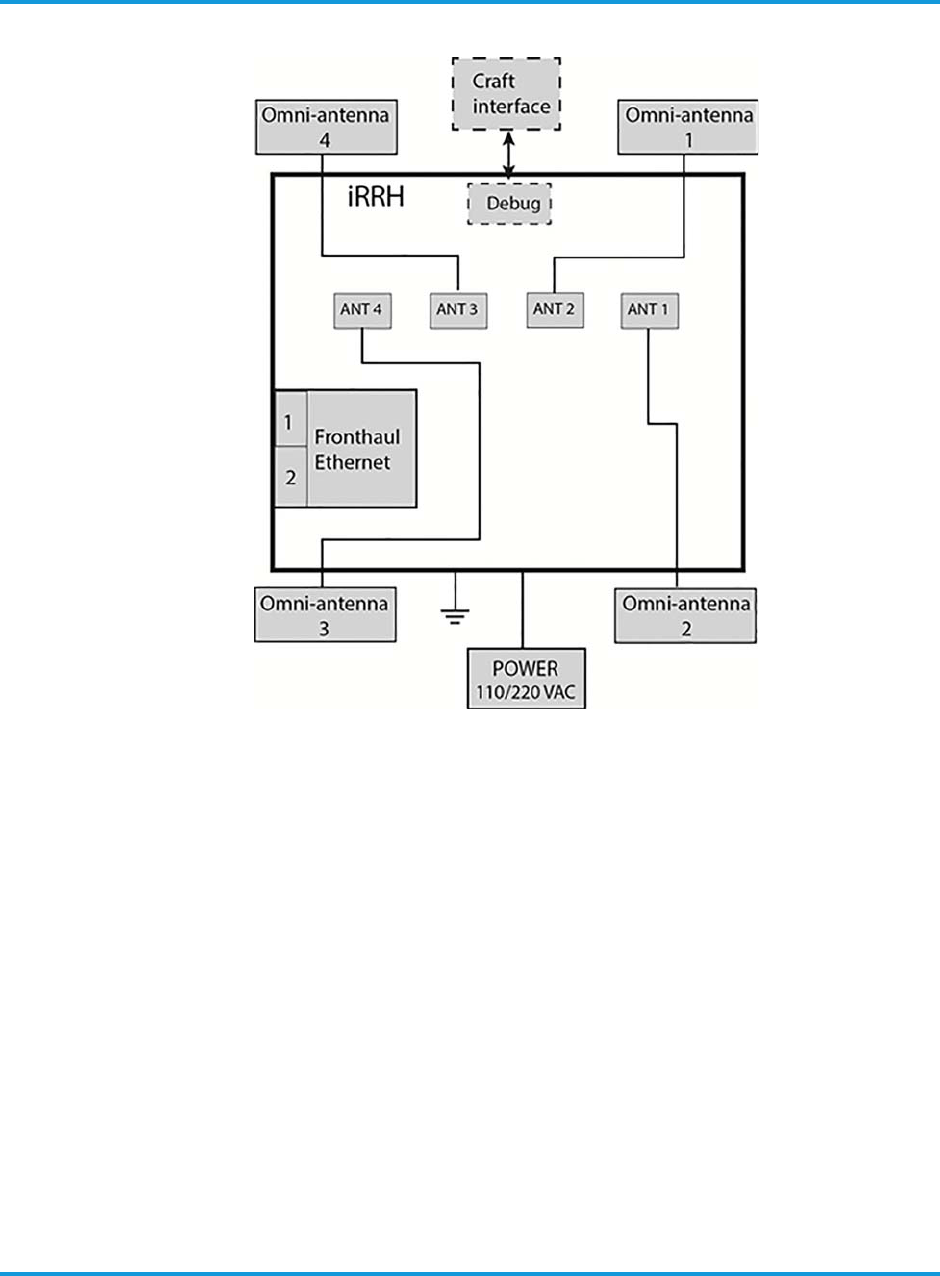
Introduction
1-2 iRU4438 iRRH Product Description and Installation Guide
Figure 1-1 iRU4438 iRRH block diagram
Safety requirements
iRU4438 iRRH Product Descripton and Installation Guide 2-1
2 Safety requirements
2.1 Overview
This section provides safety precautions that apply to the iRU4438 iRRH. The
precautions statements are required by national or regional standards institutes in the
country or region where they apply. This document complies with these requirements.
2.2 Purpose
To protect installation personnel, equipment and operations, this document contains
safety statements. Safety statements are provided at points in procedures where
risks may exist to personnel, equipment and network operations. Failure to follow the
directions in the safety statements may result in serious consequences.
2.3 Warning symbols
DANGER
Danger is used to indicate the presence of a hazard that will cause
severe personal injury, death, or substantial property damage if the
hazard is not avoided.
WARNING
WARNING
Warning is used to indicate the presence of a hazard that can
cause severe personal injury, death, or substantial property
damage if the hazard is not avoided.
CAUTION
Caution is used to indicate the presence of a hazard that will or
can cause minor personal injury or property damage if the
hazard is not avoided.
2.4 General safety precautions
Safety precautions should be observed when performing these installation
procedures. The following safety precautions are only intended to supplement the
safety precautions usually practiced by the Operator.
The power system and connected cables will have hazardous energy and voltages
present. Follow all safety warnings and practices when servicing this equipment.
This equipment must be installed, serviced, and operated only by authorized,
qualified and trained personnel who have the necessary knowledge and practical
experience with electrical equipment and who understand the hazards that can arise
Safety requirements
2-2 iRU4438 iRRH Product Descripton and Installation Guide
when working on this type of equipment. Observe all local and national electrical,
environmental and workplace codes.
DANGER
HAZARDOUS VOLTAGES!
Hazardous voltages can be present when the system is operating. Use
caution when removing or installing equipment.
DANGER
FALL HAZARD!
A fall hazard is present when installation of this equipment requires
working on towers, poles or at elevated work sites. All telecommunications
personnel who perform tower work or work at elevation must be qualified
to perform this type work.
WARNING
WARNING
Read and understand all instructions before starting this
procedure.
• Follow all warnings and safety instructions in this procedure.
• Only trained personnel should install or operate this equipment.
• Observe all local and national electrical, environmental and workplace
codes.
• Before working on equipment that is connected to power, remove
jewelry (including rings, necklaces, and watches). Metal objects will
heat up when connected to power and ground and can cause serious
burns or weld the metal object to the terminals.
• The equipment must have a direct disconnect device in line with the
power source.
• This unit has double pole/neutral fusing.
• Grounding and circuit integrity is vital to a safe operating environment.
Grounding conductors must be in place before installing the equipment.
Never operate equipment when grounding or bonding conductor has
been removed.
• Never install equipment not identified in this procedure. Fire or injury
could result from improperly installed equipment.
• Caution should be exercised when installing or modifying
telecommunications lines.
• Disconnect all power sources before servicing the equipment.

Safety requirements
iRU4438 iRRH Product Descripton and Installation Guide 2-3
• Never touch uninsulated wiring or terminals unless power to the lines
have been disconnected at the source. Always verify power has been
removed using an approved voltage tester.
• To prevent electrical shock, never remove the cover or disassemble the
equipment. There are no user serviceable components in the
equipment.
• Never insert probes or objects of any kind into slots or openings to the
equipment. Dangerous voltages may be present or the object may
cause a short circuit and start a fire or damage the equipment.
WARNING
WARNING
LIGHTNING STRIKE HAZARD!
• Lightning strikes are possible during stormy weather. Do not install
equipment if stormy conditions exist.
• Never work on telecommunications power supply lines or antenna
feeders at the cell site during stormy conditions.
WARNING
WARNING
SHOCK HAZARD!
• Some parts of all electrical systems are energized at all times. Exercise
extreme caution at all times when working around telecommunications
electrical systems. Short circuits can cause burns to the face or hands.
Failure to observe this and other safety warnings may lead to bodily
injury and property damage.
• Only trained and qualified personnel may install or service equipment
as defined in IEC 215 and EN 60215.
• Turn off or disconnect equipment from its energy source(s) by
switching off the power switch or breaker, by removing the fuse(s), or
switching off the load disconnect switch at the distribution panel
(whichever apply) before performing service or maintenance.
CAUTION
SHORT CIRCUIT HAZARD!
Condensation on the equipment has a potential to cause short circuits!
Weather conditions may exist at the site where condensation may form on
the equipment. Installing or operating the equipment when condensation is
present may cause a short circuit and damage the equipment.

Safety requirements
2-4 iRU4438 iRRH Product Descripton and Installation Guide
Equipment showing signs of condensation should be allowed to dry before
installation.
CAUTION
ELECTROSTATICALLY SENSITIVE EQUIPMENT!
Semiconductor components are sensitive to electrostatic electricity and
may be damaged by static discharge.
When handling the equipment, the following rules must be followed:
• Wear conductive or anti-static clothing.
• Wear grounded ESD wrist strap.
• Wear shoes with conductive straps or soles.
• Verify anti-static safety devices are operating properly by testing
yourself at an approved test station.
• Leave equipment in their original anti-static wrapping until ready for
installation.
• When handling equipment or modules, use handles provided to carry
the device and do not touch electrical contacts, pins or components.
• Only place equipment or modules on conductive surfaces.
• Use tools on equipment or modules only when equipment is grounded.
• Handle defective equipment or modules similarly to new equipment to
prevent additional damage.
CAUTION
GROUNDING CAUTION!
• This equipment's grounding connection is between the DC power circuit
and the grounding conductor.
• This equipment must have a direct connection to the DC supply
grounding point or to a bonding jumper from the grounding terminal
bus bar to the DC supply ground electrode for the site.
• The DC supply source should be located in the same premises as the
transmission equipment.
• The grounding circuit must not have a disconnect device located in-line
with the DC circuit grounding conductor.

Installation prerequisites
iRU4438 iRRH Product Descripton and Installation Guide 3-1
3 Installation prerequisites
This section contains information on the documentation, tools, equipment, and
conditions required for performing the installation procedure. The document assumes
that the target audience has reasonable industry experience, is qualified, and has
installed wireless base stations in the past.
3.1 Required tools
A typical telecommunications technician's toolkit is required to complete the iRRH
installation. Additional required specialty tools and consumables are listed in
Table 3-1.
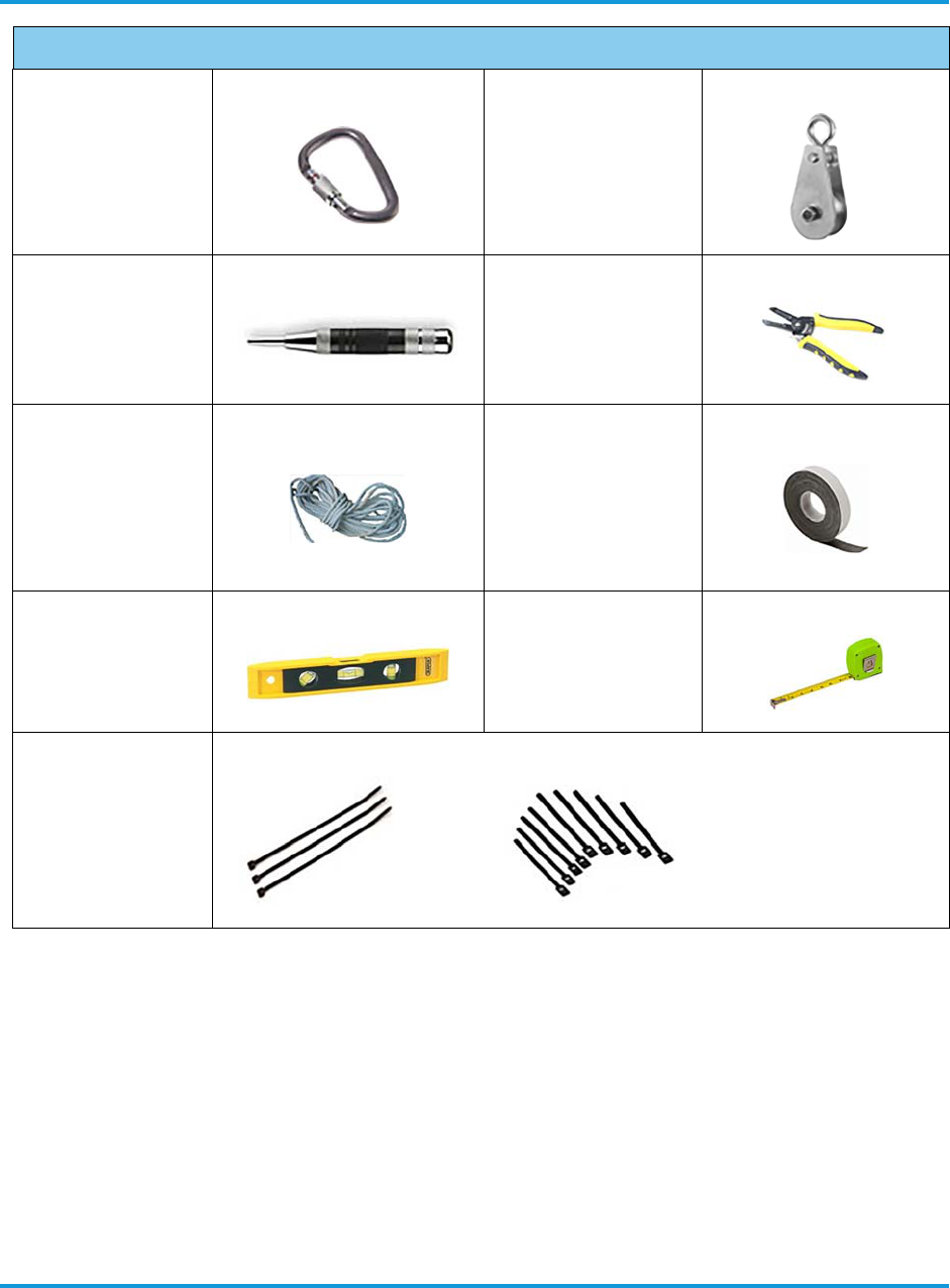
Table 3-1 Required tools
Required Tools
ESD wrist grounding
strap
Torque screwdriver and
assorted bits
Box cutter Digital voltmeter
Torque wrench, open-
end, 8 mm Crimp tool (2 to 8 AWG)
Cordless electric
screwdriver Cable tie tool
Installation prerequisites
3-2 iRU4438 iRRH Product Descripton and Installation Guide
3.2 Required site equipment
This section describes the additional interconnecting equipment required for the
installation of the Altiostar Networks iRU4438 iRRH. These are essentially cables,
connectors and fixing arrangements. The specification of these items (specifically the
length of cables) may need to be customized on site.
• Grounding cable connecting the iRU4438 iRRH to the grounding point is supplied
by the Operator and assembled on site unless otherwise specified. Altiostar
Networks provides the two-hole lug for crimping onto the cable.
• Power cable with plug connecting the iRU4438 iRRH to local 110/220 V ac power is
supplied by the Operator and assembled on site unless otherwise specified.
Caribiner (2)
(optional)
Pulley-minimum load-
bearing capacity 440 lb
(200 kg)
(optional)
Punch Wire stripper
Rope - minimum
220 lb (100 kg)
breaking strength
(optional)
Self-amalgamating
waterproofing tape (e.g.,
Commscope Miracle
Tape, Huber+Suhner
Fast-Wrap, RFS CELL-
Tape, EasyWrap® tape,
etc.)
Spirit level Tape measure
Assorted cable ties
and hook & loop
fasteners
Required Tools

Installation prerequisites
iRU4438 iRRH Product Descripton and Installation Guide 3-3
Operator must provide a lightning and surge suppression device on the power line
to the unit.
• RF transmission cables are supplied by the Operator. They are pre-assembled
according to Operator requirements. Operator must supply and install inline surge
arrestors on the RF transmission cables.
3.3 Site preparation
The conditions in this section must be fulfilled before starting work at the site.
3.4 Site pre-installation visit checklist
To verify site conditions required for the installation of the iRU4438 iRRH are known, a
pre-installation visit, attended by the Operator's representative, Altiostar Networks,
and other required parties, must be performed. Tasks required to be accomplished
should include, at a minimum, those listed in Table 3-2.
Table 3-2 Site pre-installation visit checklist
Item Site pre-installation visit checklist Check
1Verify Site Installation Plan and installation documentation is available.
2Verify health and safety documentation specified by the Operator and Altiostar
Networks are understood and installation personnel are trained accordingly.
3Know locations of fire equipment, eyewash stations, and evacuation procedures
posted for fire/halon discharge.
4Know locations of first aid and emergency equipment and installation personnel are
familiar with their operation and use.
5Verify site authorizations, clearances, and releases from Operator and local
authorities are complete.
6Verify emergency telephone numbers are posted for fire, police, and ambulance/
medical aid.
7Verify Operator and local authorities contact and phone numbers are posted.
8Verify installation schedule is approved.
9Wear approved protective equipment such as hard hats, safety glasses, gloves, etc.
when needed.
10 Verify the installation location of the iRRH meets the mounting requirements indicated
in this document.
11
Verify main power supply is properly installed and tested and capable of supplying the
required 110/220 V ac voltage and current for proper operation of the iRRH system to
within ±20% of rated output.
12 Verify 110/220 V ac power cable to the iRU4438 iRRH is labeled and tested as
specified in the Site Installation Plan.

Installation prerequisites
3-4 iRU4438 iRRH Product Descripton and Installation Guide
3.5 Site installation checklist
Verify site conditions required for the installation of iRRH are known. In addition, the
site must be prepared by the Operator in accordance with the Site Installation Guide
provided by the Operator which must include, at a minimum, the required tasks in
Table .
13 Verify recommended size breakers/fuses for the external power source is properly
installed and capable of protecting the 110/220 V ac power to the unit.
14
Verify earth ground bonding point, for connection of the grounding cable to the
iRU4438 iRRH, is correctly installed, labeled and tested as specified in the Site
Installation Plan.
15 Determine safe method to hoist and secure iiRU4438 RRH into position on selected
structure and enter into Site Installation Plan.
16 Verify proper in-line surge protectors are installed, where required, on power/RF/
fronthaul/backhaul cables to iRU4438 iRRH as specified in the Site Installation Plan.
17
Verify that the Operator, Altiostar Networks and all other affected parties are in
agreement with the equipment installation location, power source, and grounding
location, to meet the installation checklist requirements.
Item Site pre-installation visit checklist Check
Table 3-3 Site installation checklist
Item Site installation checklist Check
1Verify Site Installation Plan and installation documentation is available.
2Verify health and safety documentation specified by the Operator and Altiostar
Networks are understood and installation personnel are trained accordingly.
3Know locations of fire equipment, eyewash stations, and evacuation procedures posted
for fire/halon discharge.
4Know locations of first aid and emergency equipment and installation personnel are
familiar with their operation and use.
5Verify site authorizations, clearances, and releases from Operator and local authorities
are complete.
6Verify emergency telephone numbers are posted for fire, police, and ambulance/
medical aid.
7Verify Operator and local authorities contact and phone numbers are posted.
8Verify installation schedule is approved.
9Wear approved protective equipment such as hard hats, safety glasses, gloves, etc.
when needed.
10 Verify pre-installation work specified in the Site Installation Plan is complete.
11 Verify the installation location of the iRRH meets the mounting requirements indicated
in this document.

Installation prerequisites
iRU4438 iRRH Product Descripton and Installation Guide 3-5
12 Verify all required tools are available.
13 Verify all ordered hardware, including that not provided as part of the Altiostar Networks
intelligent eNodeB solution, is available and on site.
14
Verify that the Operator, Altiostar Networks and all other affected parties are in
agreement with the equipment installation location, power source, and grounding
location, to meet the installation checklist requirements.
15
Verify proper in-line surge protectors are installed, where required, on 110/220 V ac
power and on RF/fronthaul/backhaul cables to iRU4438 iRRH as specified in the Site
Installation Plan.
16 Verify recommended size wire is installed in the external power source supplying 110/
220 V ac power to the unit.
17
Verify custom pre-assembled cables, wires and other material are properly labeled,
installed and tested according to system and site requirements as specified in the Site
Installation Plan.
18 Verify earth grounding of the chassis/rack hosting the iRRH is correctly installed, using
the correct size/type wire, and is tested.
19
Verify main power supply is properly installed and tested and capable of supplying the
required 110/220 V ac voltage and current for proper operation of the iRu4438 iRRH 3-
sector system to within ±20% of rated output.
20 Verify all cables are neatly routed through cable ladders, cable trays and ducts, are
secured with cable ties, and dressed according to Company local practice.
Table 3-3 Site installation checklist
Item Site installation checklist Check

Installation prerequisites
3-6 iRU4438 iRRH Product Descripton and Installation Guide

iRU4438 iRRH installation overview
iRU4438 iRRH Product Descripton and Installation Guide 4-1
4 iRU4438 iRRH installation overview
This section provides an overview of the installation procedures and instructions for
installing the Altiostar Networks iRU4438 iRRH.
All required cabling for grounding, power, fronthaul, with the exception of RF and
optional GPS cables, are supplied by the Operator, as provided in the Site Installation
Plan, and should already be pre-installed with drops to the iRU4438 iRRH installation
location, or according Operator local practice.
4.1 Installation procedures
The following list describes the top-level iRU4438 iRRH installation procedures. You can
instantly navigate to any procedure by clicking on the procedure with the mouse.
•Unpacking the shipping container on page 4-1
•Verifying all parts received on page 4-2
•Assembling cables on page 5-1
•Routing pre-assembled power/fronthaul Ethernet/grounding cables on page 5-2
•Installing RF antennas on upper/lower omni-antenna brackets on page 5-3
•Installing RF antenna cables on page 5-5
•Installing the iRU4438 iRRH mounting bracket on page 5-7
•Hoisting the iRU4438 iRRH on elevated structures on page 5-9
•Installing the iRU4438 iRRH on the mounting bracket on page 5-11
•Connecting the grounding cable on page 5-12
•Connecting the fronthaul Ethernet cables on page 5-13
•Connecting the 110/220 V ac power cable on page 5-15
•Checking power on page 5-15
•Installing the solar shield on page 5-16
4.2 Unpacking the shipping container
The following procedure describes removing the iRU4438 iRRH from the shipping
container, inspecting the contents for damage, and what to do if damage is found.
To unpack the shipping container:
1. Verify no shipping damage to box.
NOTE
It is important to report damage or material shortages to the shipping
carrier while a representative is on site. If concealed damage or material
shortages are found at a later time, contact the shipper to make
arrangements for inspection and claim filing.
iRU4438 iRRH installation overview
4-2 iRU4438 iRRH Product Descripton and Installation Guide
2. Remove packing materials.
The shipping materials can be recycled. In some regions or countries it
is mandatory that packing materials be recycled or re-purposed. Please
dispose of shipping material accordingly.
3. Remove equipment from packing material and inspect equipment for shipping
damage or missing items.
NOTE
If concealed damage or material shortages are found at a later time,
contact the shipper to make arrangements for inspection and claim
filing.
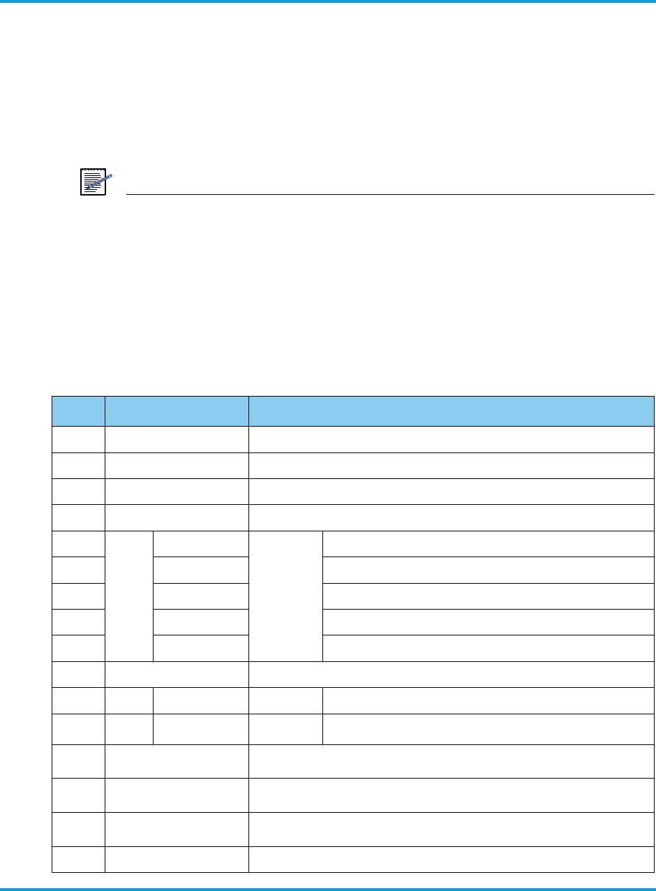
4.3 Verifying all parts received
There are two iRB1200 iRRH models 340-00-0009 and 340-00-0008, depending on
installed SSD. Verify all parts listed in the accessory list in Table 4-4 were received.
Table 4-4 iRU4438 iRRH parts list
Qty Pard number Part description
1 340-00-0010 iRU4438 iRRH main unit
1 420-00-0030 Mounting clamp (metal, powder-coated)
1 420-00-0053 Mounting bracket (metal, powder-coated)
1 350-00-0007 Kit, mounting bracket hardware
2 460-00-0014 Screw, M4-0.7 × 12 mm, cross-head pan, SEMS, SS
2 460-00-0020 Screw stud, M12-1.75 × 168 mm, SS
4 495-00-0001 Washer, flat, M12, max. 24 mm OD, SS
4 495-00-0002 Washer, split, M12, max. 24 mm OD, SS
4 445-00-0003 Nut, M12-1.75, SS
1 350-00-0009 Kit, accessory, grounding cable lug
1 440-00-0033 Dual-hole grounding lug, CAT10-5POI
3 460-00-0017 Screw, crosshead pan, M5-0.8 × 10 mm, split/plain
washer, SEMS, SS
4 195-00-0018 Omni-directional antenna, 1710-2700 MHz (with included
mounting hardware)
2 360-00-0064 RF cable, QMA right angle plug to N-male, LMR 195 series
coax, 0.195 in (4.95 mm) diameter, 26.5 in (67.3 cm) length
2TBD RF cable. QMA right angle plug to N-male, LMR 195 series
coax, 0.195 in (4.95 mm) diameter, 9.5 in (24 cm) length
1 430-00-0002 Solar shield

iRU4438 iRRH installation overview
iRU4438 iRRH Product Descripton and Installation Guide 4-3
4 460-00-0017 Screw, sun shield mounting, M5-0.8 × 10 mm, crosshead pan,
split/plain washer, SEMS, SS
Standard equipment shipped pre-installed
1 420-00-0054 Mounting plate
1 420-00-0064 Mounting bracket, upper antenna
1 420-00-0065 Mounting bracket, lower antenna
8 460-00-0012 Screw, antenna mounting bracket, M3 × 0.5, 10 mm,
crosshead pan, split/plain washer, SEMS, SS
6 460-00-0016 Screw, mounting plate, M4-0.7 × 20 mm, crosshead pan,
SEMS, SS
2 460-00-0018 Screw, unit mounting, M4-1 × 20 mm, 10 mm unthreaded,
captive, crosshead pan, SEMS, SS
4 460-00-0017 Screw, sun shield mounting, M5-0.8 × 10 mm, crosshead pan,
split/plain washer, SEMS, SS
GPS option shipped pre-installed
1 195-00-0017 GPS antenna, 3-16 V dc
1 360-00-0066 GPS cable, LMR 240 series, 0.24 in (6.1 mm) diameter, SMA to
N, 24 in (61 cm) length
1 420-00-0066 GPS bracket (includes mounting hardware)
4 460-00-0014 Screw, GPS bracket mounting, M4 × 0.7, 12 mm, pan head,
split/plain washer, SEMS, SS
4 445-00-0004 Nut, GPS bracket mounting, M4 × 0.7, 7 mm WAF, SS
Operator-acquired parts for pre-installation requirements
1Amphenol BD 03BFFA
LL7001
3-pin Amphenol power connector (Operator ordered and installed on
power cable)
1As specified per site
requirement
Power cable, 110/220 V ac, (Operator ordered to length
according to site requirements)
1As specified per site
requirement
Fronthaul cable assy, RJ45 Gigabit Ethernet, with cable gland
Table 4-4 iRU4438 iRRH parts list
Qty Pard number Part description

iRU4438 iRRH installation overview
4-4 iRU4438 iRRH Product Descripton and Installation Guide
Installing the iRU4438 iRRH
iRU4438 iRRH Product Descripton and Installation Guide 5-1
5 Installing the iRU4438 iRRH
This section provides the procedure for installing the iRU4438 iRRH in remote
locations such as on towers, poles, masts, walls, roofs, or other structures utilizing a
universal mounting assembly.
Instructions for making connections to external interfaces, cabling, grounding and
power are also provided.
5.1 Assembling cables
5.1.1 Verify Operator supplied 110/220 V ac power cable
The Operator supplies and pre-assembles the 110/220 V ac power connection cable.
We recommend using a 14 AWG, round, 2-wire with ground, shielded cable rated at
300 V minimum. The female plug (manufacturer's part no. BD-03BFFA-LL7001) for
connection at the iRU4438 iRRH end is also provided by the Operator. The connection
configuration for the supply side of the power cable is determined by site specific
requirements.
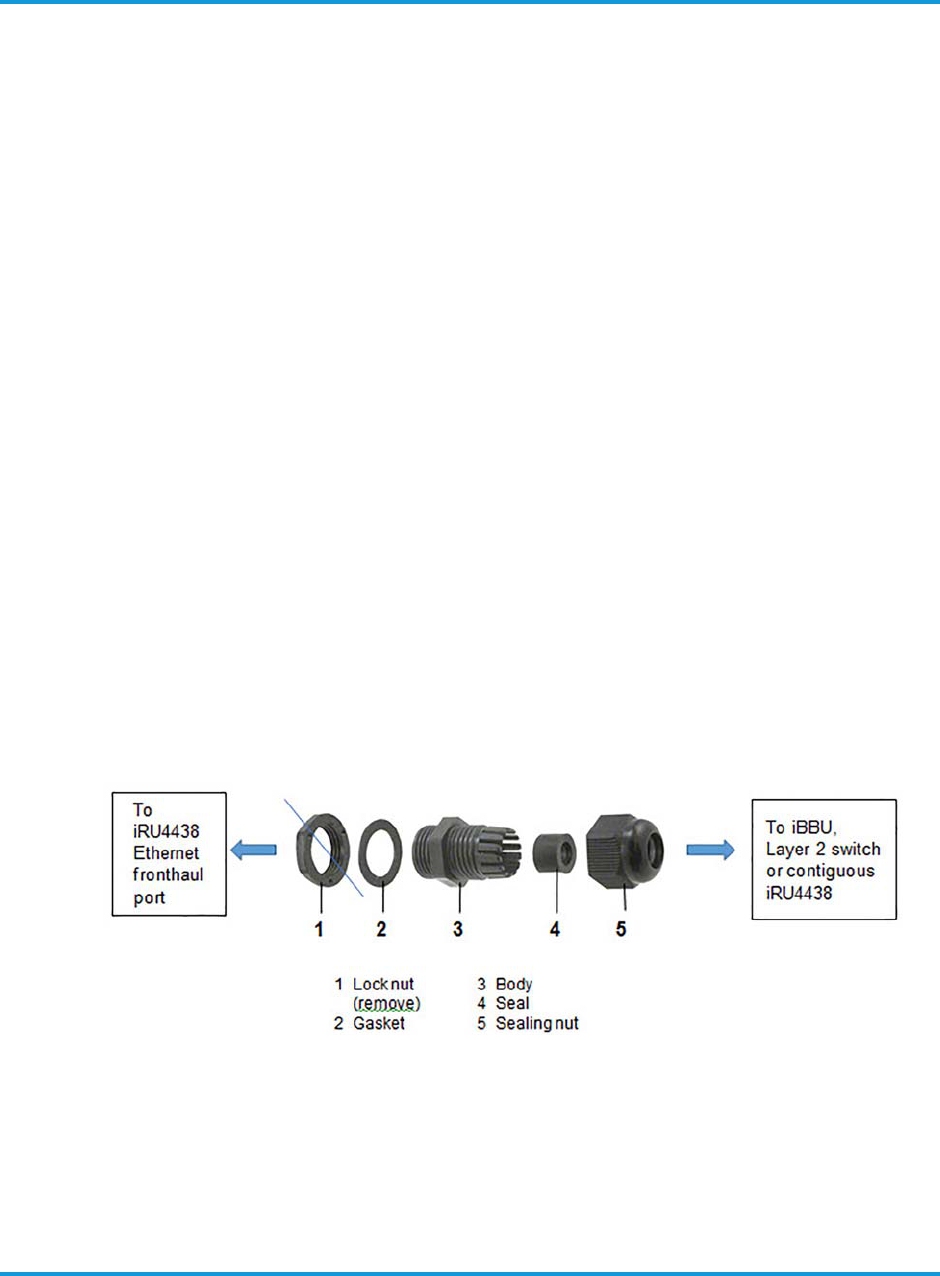
5.1.2 Verify Operator supplied fronthaul Ethernet cable
The CAT-5 Ethernet cable is supplied and pre-assembled by the Operator. A cable
gland may be pre-installed on the Ethernet cable, or may be installed on a CAT-5
cable, in the order shown in Figure 5-2. If the cable gland has a lock nut installed on
it, it must be removed before installing the cable gland to the fronthaul entry port.
The cable gland screws directly into the fronthaul port on the bottom of the iRU4438.
A gasket seals the cable gland at the fronthaul port. The sealing nut is then hand-
tightened to complete the weatherproof seal.
Figure 5-2 CAT-5 Ethernet cable gland assembly
5.1.3 Verify Operator supplied grounding cable
The operator pre-assembles the grounding cable prior to routing to the iRU4438 iRRH.
The grounding cable and ground bonding hardware is supplied by the Operator.
However, the grounding terminal lug is supplied with the iRU4438 iRRH.
Installing the iRU4438 iRRH
5-2 iRU4438 iRRH Product Descripton and Installation Guide
NOTE
The grounding cable to the iRRH should be 3.9 in (10 cm) longer than
other cables to the unit. This will maintain ground connection should the
cables be pulled off when the unit is extended beyond the length of the
cables.
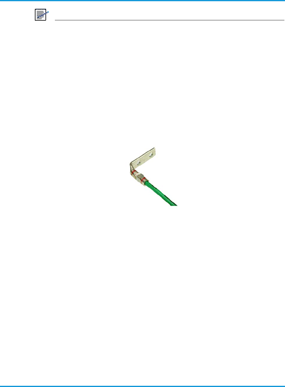
To install ground terminal lug:
1. Cut a 6 AWG (4.11 mm) stranded grounding cable the appropriate length for the
iRU4438 iRRH installation.
2. trip away insulation from one end to expose 3/4 in (19 mm) of bare wire.
3. Crimp the dual-lug grounding terminal (supplied) to the cable using the special
purpose crimp tool specified in (or equivalent) as directed by tool manufacturer
instruction manual. Figure 5-3 shows assembled cable/lug assembly.
Figure 5-3 Grounding terminal lug assembled on grounding cable
5.2 Routing pre-assembled power/fronthaul Ethernet/grounding
cables
This procedures provides instructions for routing the pre-assembled 110/220 V ac
power cable, the CAT 5 Ethernet cable, and the grounding cable to the iRU4438 iRRH
mounting location before assembling the iRRH components.
To route cables:
1. Route the cables from the iRU4438 installation location to cable sources as shown
in Figure 5-4.
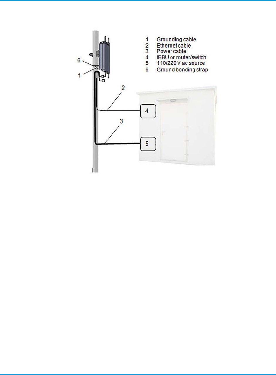
Installing the iRU4438 iRRH
iRU4438 iRRH Product Descripton and Installation Guide 5-3
Figure 5-4 Cable routing
2. Secure and dress all cables according to Operator local practice.
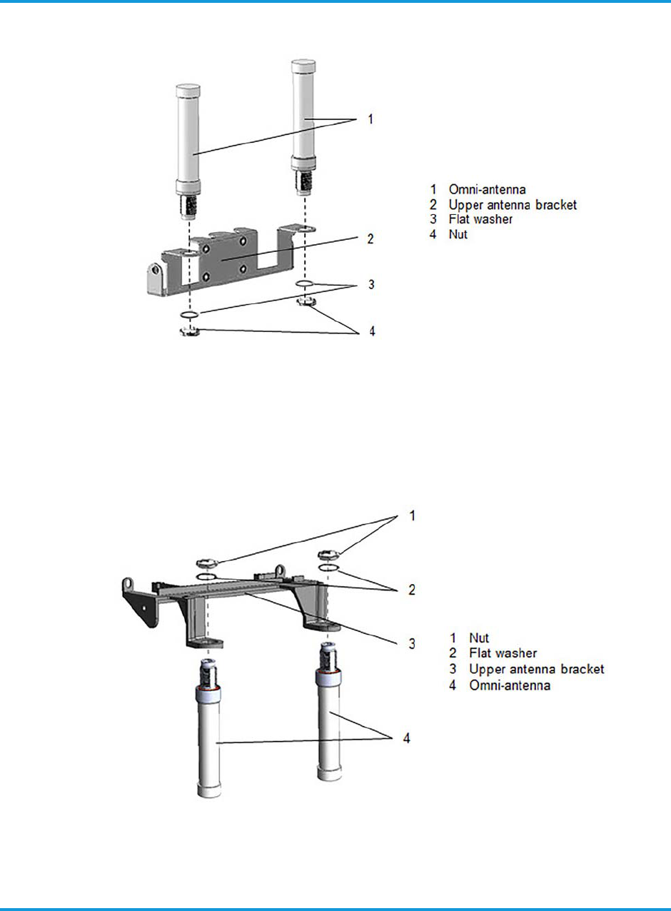
5.3 Installing RF antennas on upper/lower omni-antenna brackets
This procedure describes installing up to four (4) omni-directional RF antennas on the
upper and lower antenna brackets.
To install antennas on brackets:
1. Remove the nut and flat washer from each of the antennas leaving the rubber O-
rings in place.
2. Install up to two (2) omni-antennas on the upper antenna bracket as shown in
Figure 5-5 using hardware removed from the antennas in step 1.
3. Tighten the antenna nuts 6-7.4 ft-lb (8-10 Nm) using a torque wrench.
Installing the iRU4438 iRRH
5-4 iRU4438 iRRH Product Descripton and Installation Guide
Figure 5-5 Installing omni-antennas on upper antenna bracket
4. Install up to two (2) omni-antennas on the lower antenna bracket as shown in
Figure 5-6 using the supplied antenna hardware.
5. Tighten the antenna nuts 6-7.4 ft-lb (8-10 Nm) using a torque wrench.
Figure 5-6 Installing omni-antenna on lower antenna bracket

Installing the iRU4438 iRRH
iRU4438 iRRH Product Descripton and Installation Guide 5-5
5.4 Installing RF antenna cables
The RF antenna cables are shipped installed on the iRU4438 iRRH. If for any reason
the RF cables are removed, the following procedure provides instructions for routing
and connecting the cables. The RF antenna cables connect to the omni-directional
antennas. The upper RF antenna cables are 10.5 in (26.7 cm) in length. The lower RF
antenna cables are 26.5 in (67.3 cm) in length.
DANGER
RF antenna coaxial cables may be damaged if bent or curved to a radius
that is less than the recommended minimum bend radius of 0.6 in (1.52
cm). Always observe the recommended bend radius limit when routing
coaxial cables.
The RF coaxial cables are routed from the N-type connector at the base of each omni-
directional antenna to the corresponding QMA RF jack located on the front of the
iRRH. Antenna and connector designations are shown in Figure 3-5 and Figure 3-6,
respectively.
The four QMA RF jacks on the front of the iRU4438 iRRH are labeled ANT 1–4 (as
viewed from right to left) and as shown in Figure 3-5. The four omni-directional
antennas are designated OMNI 1–4 and are configured as shown in Figure 3-6. The
RF cable routing is shown in Figure 5-4.
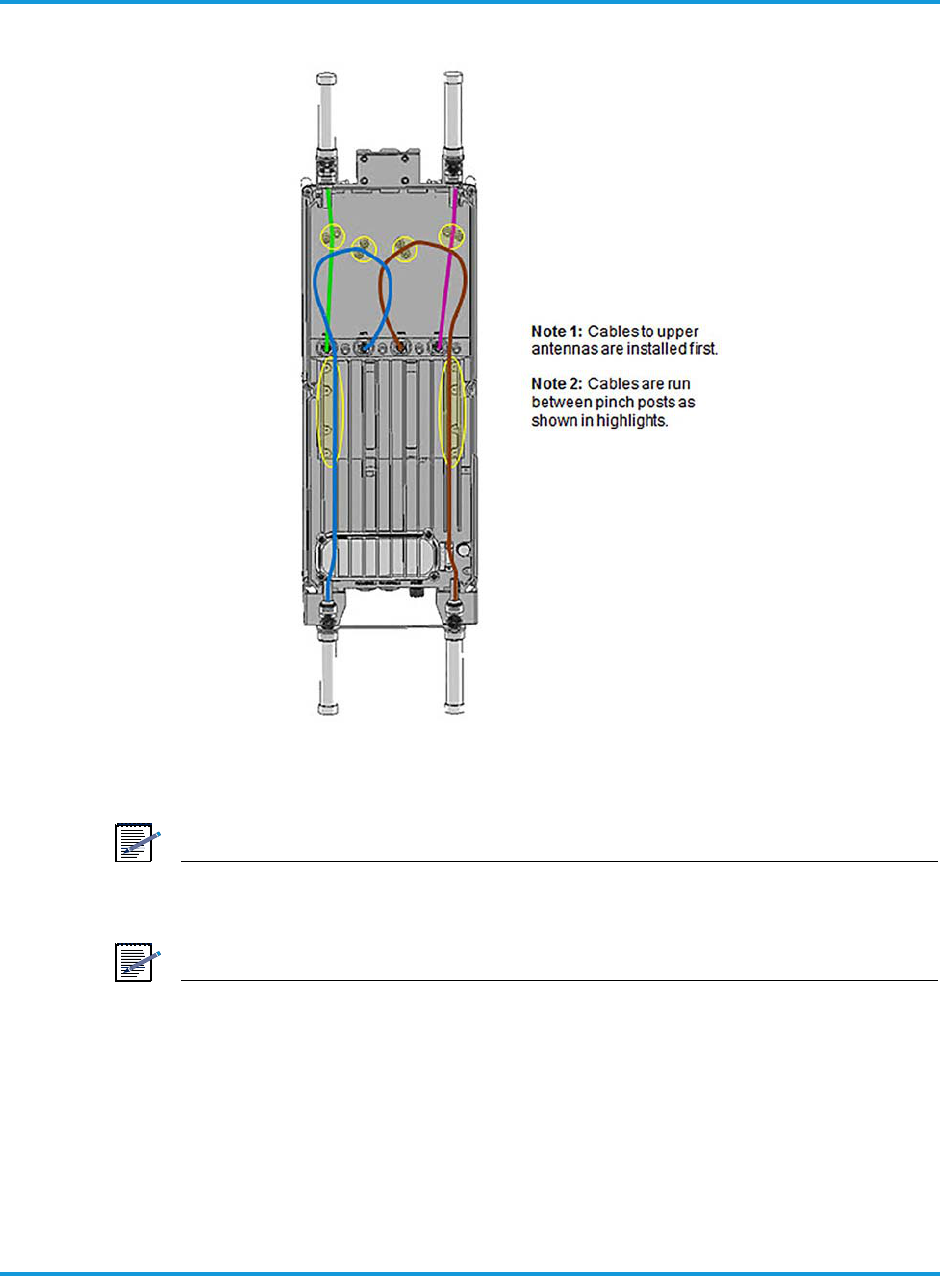
Installing the iRU4438 iRRH
5-6 iRU4438 iRRH Product Descripton and Installation Guide
Figure 5-7 RF antenna coaxial cable routing
NOTE
Leave the dust cover on any unused antenna port.
NOTE
The RF connections must be waterproofed using a self-fusing tape made
for that purpose. The application of the tape will vary by Operator, so
local practice will determine how the tape is applied.
To install RF cables:
1. Route one RF cable from ANT 1 to OMNI 1. Orient the cable with the N-type
connector end at the antenna and the QMA-type connector end at the RF jack on
the iRRH.
Installing the iRU4438 iRRH
iRU4438 iRRH Product Descripton and Installation Guide 5-7
2. Connect the RF cable N-type connector to the OMNI 1 antenna and secure 15 in-lb
(1.7 Nm).
3. Connect the RF cable QMA-type connector to the ANT 1 RF connector on the front
of the iRRH by pushing on it until it snaps into place.
4. Repeat step 1 through step 3 for the remaining RF cables according to the RF
cable connection scheme provided in Table 3-3.
5. If required, waterproof the connections by wrapping each connector with self-
fusing tape according to Operator local practice.
5.5 Installing the iRU4438 iRRH mounting bracket
This section provides the procedure for installing the iRU4438 iRRH on a mast/pole
pipe, V-angle or H-angle, or mounting on a wall.
The iRU4438 iRRH can be installed on a pole/mast structure having the following
dimensions using the supplied mounting bracket assembly:
Pole/mast:2.36-4.49 in (60-114 mm)
U-frame:1.97-3.94 in (50-100 mm)
V-frame:1.97-3.94 in (50-100 mm)
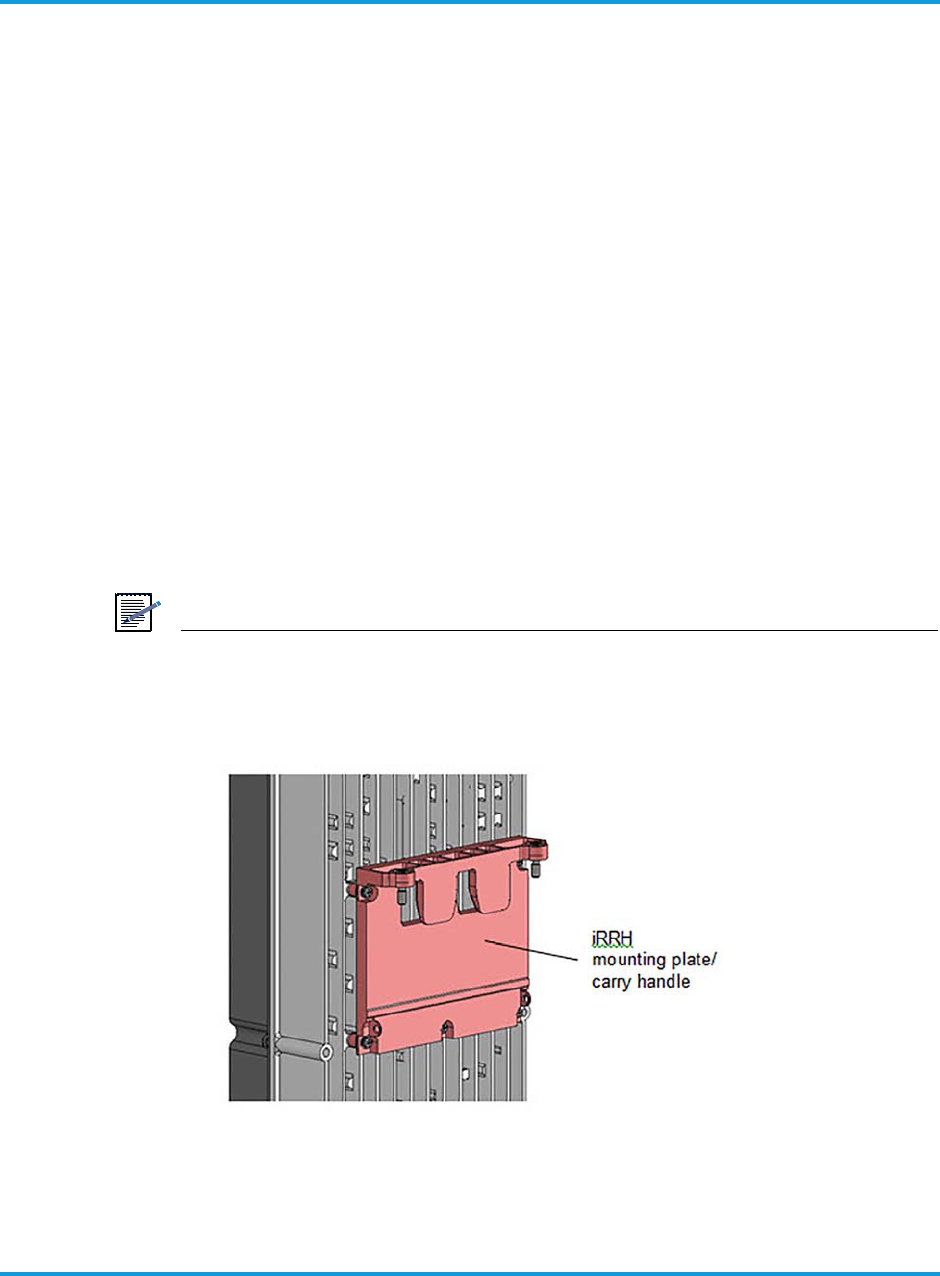
NOTE
The iRU4438 iRRH is shipped from the factory with the aluminum
mounting plate/carry handle pre-installed on the chassis as shown in
Figure 5-8.
Figure 5-8 iRU4438 iRRH mounting plate/carry handle
Installing the iRU4438 iRRH
5-8 iRU4438 iRRH Product Descripton and Installation Guide
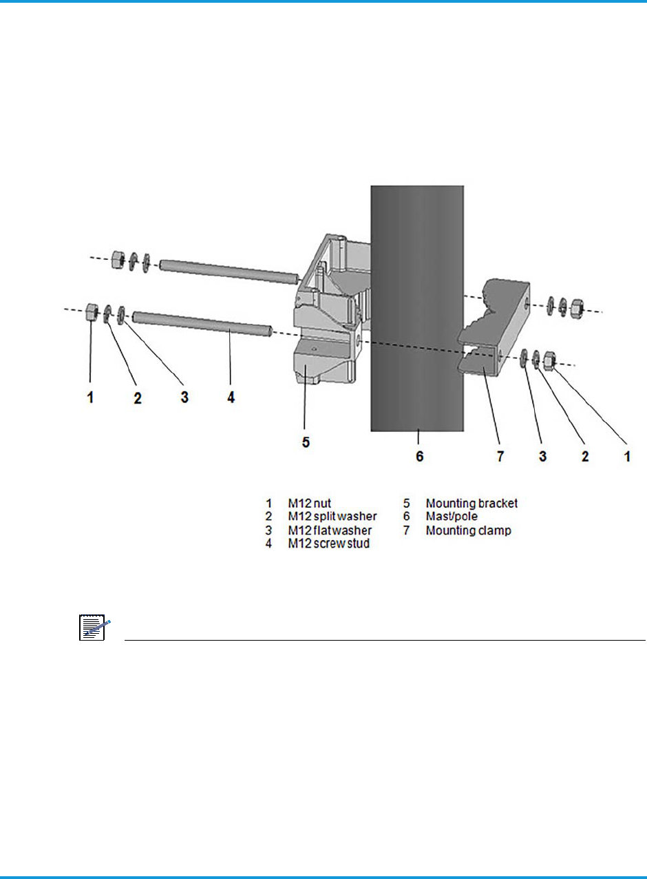
5.5.1 Mounting on a pole/mast
The following procedure provided instructions for mounting the iRU4438 iRRH on a
pole/mast using the supplied mounting bracket assembly.
To install mounting plate on a pole or mast:
1. Install the mounting bracket and mounting clamp onto the pole/mast with
mounting hardware as shown in Figure 5-9.
Figure 5-9 Installing mounting bracket on a pole
NOTE
IMPORTANT! Maintain the parallel orientation of the clamp and bracket
while tightening the nuts. This will require alternating tightening the
nuts on each screw stud until the final torque is achieved.
5.5.2 Mounting on a wall
The following procedure provides instructions for mounting the iRU4438 iRRH to a
wall or other flat, vertical surface.

Installing the iRU4438 iRRH
iRU4438 iRRH Product Descripton and Installation Guide 5-9
NOTE
The wall where the iRU4438 iRRH is to be mounted must be able to
support four times the weight of the unit. The unit can be mounted at a
deviation from vertical of ≤ 10°.
NOTE
The mounting clamp is not used when mounting the iRU4438 iRRH to a
wall or other flat surface. In addition, the M12 bolts supplied in the
hardware kit are not used for wall-mount applications.
NOTE
The Operator must provide two (2) M12 anchors, designed for outdoor
use, that are compatible with the type structure on which the iRRH is to
be installed.
To install mounting plate on a wall:
1. Determine the location where the mounting bracket is to be installed.
NOTE
The center-to-center distance for drilling holes to install the selected
anchor is 5.5 in (140 mm).
2. Using a tape measure and spirit level, mark where the anchor will be installed
using a center punch.
3. Drill the holes where the fastener will be installed on the wall using a drill bit sized
for the fastener.
4. Install the iRRH mounting bracket to the wall using the two (2) M12 anchor bolts
selected and supplied by the Operator, two (2) washers and two (2) lock washers
supplied with the mounting hardware.
5. Tighten the bolts as specified by the M12 anchor's manufacturer using a torque
wrench.
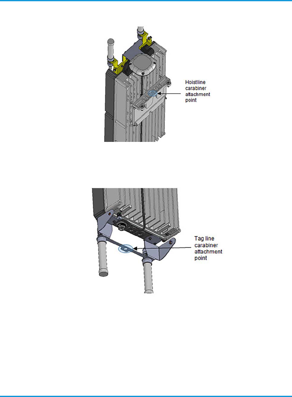
5.6 Hoisting the iRU4438 iRRH on elevated structures
Hoist line and tag line lift points are provided on the iRU4438 iRRH. These are the
ONLY recommended locations of attachment when hoisting and guiding the iRRH into
position on elevated structures. Carabiners should be used at both the hoist and tag

Installing the iRU4438 iRRH
5-10 iRU4438 iRRH Product Descripton and Installation Guide
lines lift and guy points. The carabiners must be ≤ 3/8 in (≤ 9 mm) and sized to
safely lift the load of the iRRH.
The hoist line lift point for the iRRH is shown in Figure 5-10. The tag line guy point for
guiding and limiting any rotation of the iRRH while lifting is shown in Figure 5-11.
DANGER
The Operator is responsible for determining the method of hoisting the
iRU4438 iRRH into position on elevated structures. Be sure to follow all
established Operator procedures safety precautions when hoisting the
equipment on elevated structures.
Installing the iRU4438 iRRH
iRU4438 iRRH Product Descripton and Installation Guide 5-11
Figure 5-10 Hoist line carabiner attachment point
Figure 5-11 Tag line carabiner attachment point
5.7 Installing the iRU4438 iRRH on the mounting bracket
This section provides the procedure for installing the iRU4438 iRRH main unit on the
installed mounting bracket.
Installing the iRU4438 iRRH
5-12 iRU4438 iRRH Product Descripton and Installation Guide
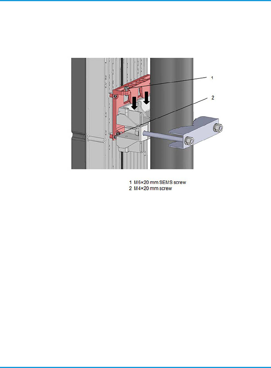
To install iRRH on the mounting bracket:
1. Hang the iRU4438 iRRH chassis on the mounting bracket by aligning the mounting
plate tabs on the rear of the chassis to the mounting bracket slots (see Figure 5-
12).
Figure 5-12 Aligning mounting plate tabs to mounting bracket
2. Lower iRU4438 iRRH onto the mounting bracket and align the tapped screw hole
on top of the mounting plate with the tapped screw hole on the mounting bracket.
3. Insert two (2) M6 × 20 mm SEMS screws into the screw hole on the top of the
mounting plate. See Figure 5-12.
4. Start threading the M6 screws into the mounting bracket screws. Do NOT fully
tighten.
5. Insert two (2) M4 × 20 mm SEMS screws into the screw holes on either side of the
mounting plate.
6. Tighten the M4 screws on the side 13.3 in-lb (1.5 Nm) using a torque wrench.
7. Tighten the M6 screws to 9 in-lb (1 Nm) using a torque wrench.
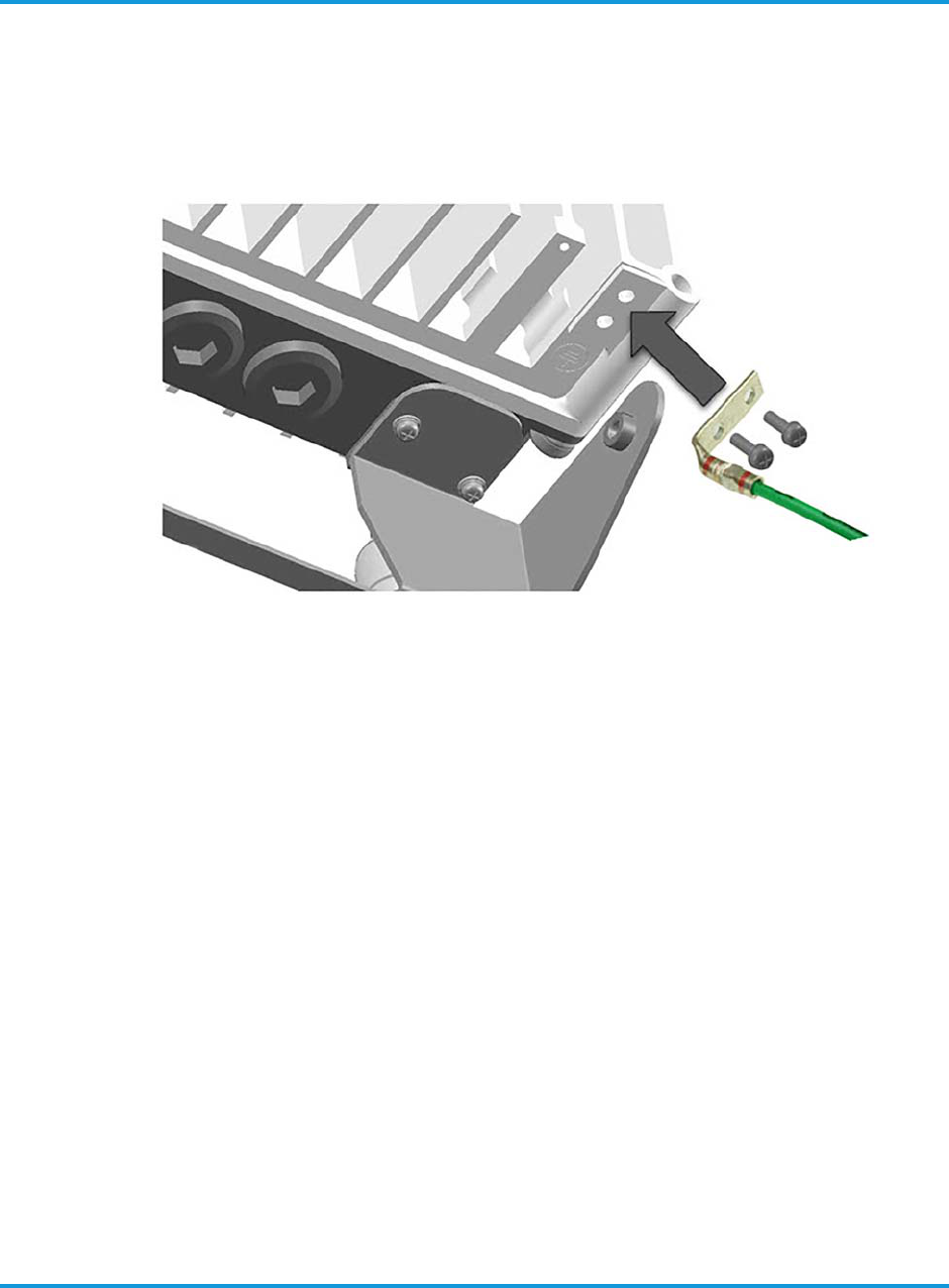
5.8 Connecting the grounding cable
This section provides the procedure for properly grounding the iRU4438 iRRH to an
earth grounding point. Verify that grounding cable/lug assembly is terminated at the
other end to a tested earth grounding point according to Operator local practice.
Installing the iRU4438 iRRH
iRU4438 iRRH Product Descripton and Installation Guide 5-13
To connect grounding cable:
1. Fasten the dual-hole grounding lug and cable assembly to the iRU4438 iRRH
chassis grounding posts using the two (2) M5-0.8 bolts and washers supplied. See
Figure 5-13.
Figure 5-13 Connecting the grounding cable
2. Tighten the bolts to 2.4 ft-lb (3.2 Nm) using a torque screwdriver.
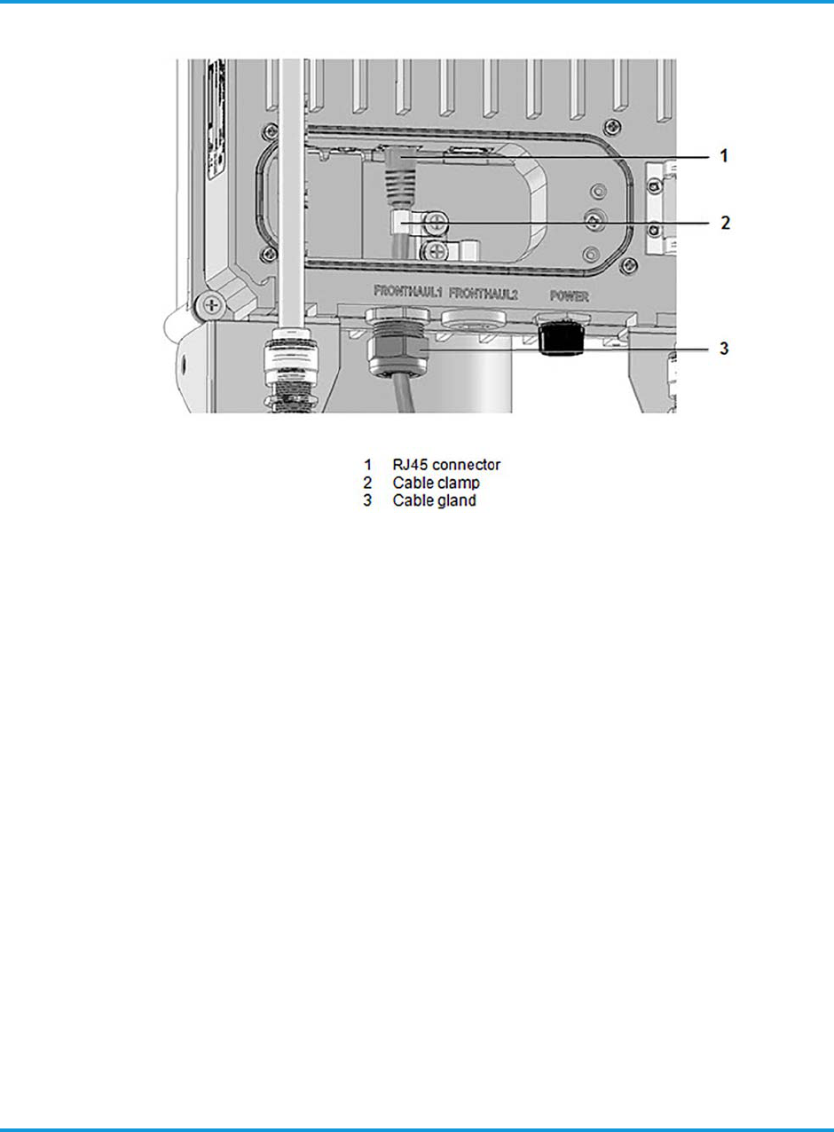
5.9 Connecting the fronthaul Ethernet cables
This section provides the procedure for connecting the fronthaul CAT-5 Ethernet cable
to the FRONTHAUL 1 or FRONTHAUL 2 Ethernet RJ45 connector sockets located
inside the front access panel. See Figure 5-14.
Installing the iRU4438 iRRH
5-14 iRU4438 iRRH Product Descripton and Installation Guide
Figure 5-14 Connecting fronthaul Ethernet cable to iRU4438 iRRH
To connect fronthaul Ethernet cables:
1. Disconnect the ANT 3 RF cable N-type connector from the OMNI 3 omni-
directional antenna to allow access to the front access panel.
2. Open the front access panel by unscrewing the four (4) M3 × 0.5 captive panel
screws.
3. Remove the dust plug in the FRONTHAUL 1 Ethernet cable entry port and place
in spare parts inventory.
4. Access the cable clamp by removing cable clamp screw.
5. Route the Ethernet cable through the FRONTHAUL 1 Ethernet cable entry port.
6. Install the cable clamp onto the Ethernet cable directly behind the RJ45 connector
plug.
7. Plug the RJ45 connector into the FRONTHAUL 1 port.
8. Secure the cable clamp and Ethernet cable assembly inside the iRU4438 iRRH
using the screw with washers removed in step 7
9. Tighten the cable clamp screw 28.3 in-lb (3.2 Nm) using a torque screwdriver.
10. If required, repeat step 3 through step 9 to install a FRONTHAUL 2 Ethernet
cable.

Installing the iRU4438 iRRH
iRU4438 iRRH Product Descripton and Installation Guide 5-15
11. Close the access panel and tighten the four panel screws hand tight or 2.1 in-lb
(0.24 Nm).
NOTE
The fronthaul Ethernet connection must be waterproofed using a self-
fusing tape made for that purpose. The application of the tape will vary
by Operator, so local practice will determine how the tape is applied.
12. Waterproof the connection by wrapping the connector with self-fusing tape
according to Operator local practice. Refer to Required tools on page 3-1.
5.10 Connecting the 110/220 V ac power cable
This section provide the procedure for connecting the 110/220 V ac power cable with
the 3-conductor circular power plug to the iRU4438 iRRH power input connector.
Recommended use type SJOW 14/3 stranded portable indoor/outdoor round cable
wire rated 300 V, or equivalent.
NOTE
Power to the 110/220 V ac power supply cable should be switched off at
the breaker before connecting to the iRU4438 iRRH power input
connector.
To connect the ac power cable:
1. Plug the power cable plug into the power input receptacle labeled POWER located
on the bottom of the iRRH.
2. Secure the connection by hand tightening the coupling nut until you feel it "click"
into the locked position.
NOTE
The 110/220 V ac power connection must be waterproofed using a self-
fusing tape made for that purpose. The application of the tape will vary
by Operator, so local practice will determine how the tape is applied.
3. Waterproof the connection by wrapping the connector with self-fusing tape (refer
to Required tools on page 3-1) according to Operator local practice.
5.11 Checking power
This section provides the procedure for verifying power to the iRU4438 iRRH is
connected correctly and operating normally.
Installing the iRU4438 iRRH
5-16 iRU4438 iRRH Product Descripton and Installation Guide
NOTE
After applying 110/220 V ac power and verifying that the iRU4438 iRRH
is functioning properly, leave power to the unit ON.
To check power to the iRRU:
1. Switch ON the breaker (or insert the appropriate size and type of fuse) to provide
power to the iRU4438 iRRH.
2. Verify that the iRU4438 iRRH powers up as indicated by the LEDs on the side of
the iRU4438 iRRH lighting in the boot sequence provided in Table 3-6.
3. Leave power to the iRU4438 iRRH ON.
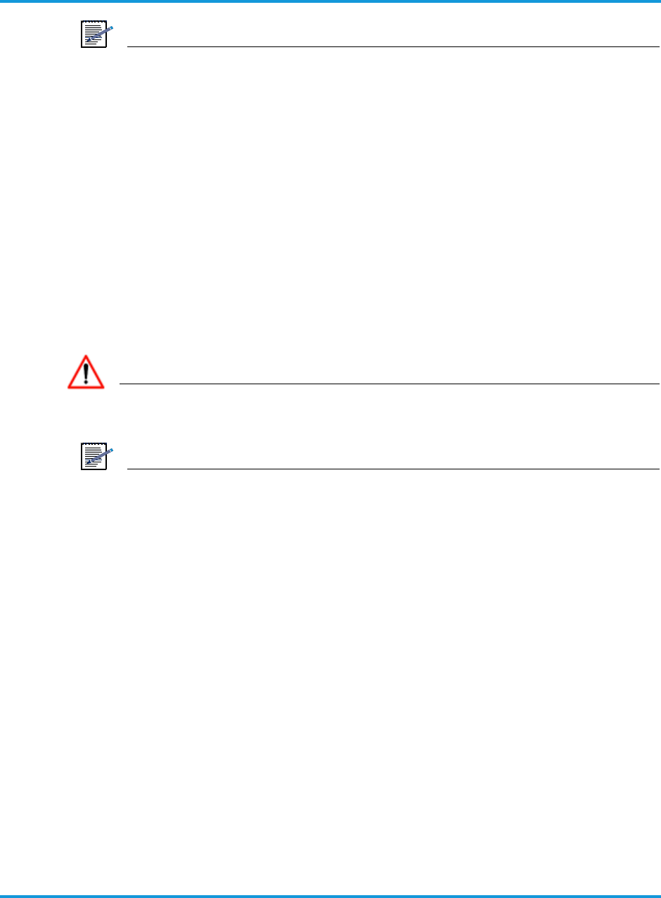
5.12 Installing the solar shield
This section provides the procedure for installing the solar shield on the iRU4438
iRRH.
DANGER
When installing the solar shield on the iRU4438 iRRH, be sure that you
do not crimp or crush the coaxial RF coaxial cables.
NOTE
When installing the solar shield on the iRU4438 iRRH, routing the coaxial
cable between the cooling fins of the iRU4438 iRRH is permitted.
Installing the iRU4438 iRRH
iRU4438 iRRH Product Descripton and Installation Guide 5-17
To install the solar shield:
1. Install the solar shield on the assembled iRU4438 iRRH as shown in Figure 5-15.
Figure 5-15 Installing solar shield
Installing the iRU4438 iRRH
5-18 iRU4438 iRRH Product Descripton and Installation Guide
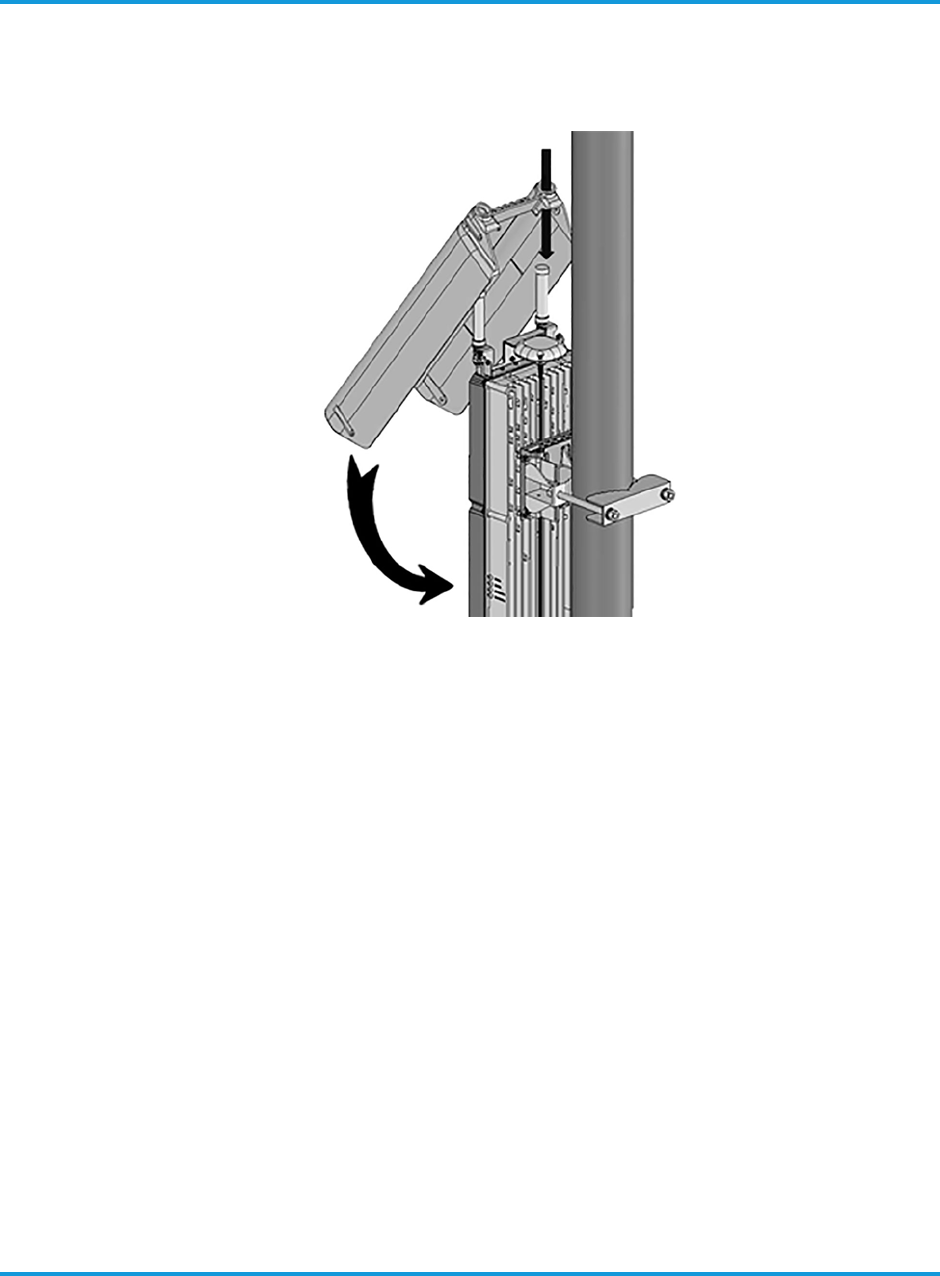
2. Secure the solar shield with four (4) screws as shown in Figure 5-16.
Figure 5-16 Securing solar shield on iRU4438 iRRH
3. Tighten the screws 62 in-lb (7 Nm) using a torque screwdriver.

Terms, Acronyms and Abbreviations
iRU4438 iRRH Product Descripton and Installation Guide 6-1
6.13 Terms, Acronyms and Abbreviations
Term Description
AISG Antenna Interface Standards Group
AWG American Wire Gauge
CFR Code of Federal Regulations
EMC Electromagnetic Compatibility
GPS Global Positioning System
GigE Gigabit Ethernet
iBBU intelligent Baseband Unit
IEC International Special Committee on Radio
Interference
iRRH intelligent Remote Radio Head
LED Light Emitting Diode
ODC Outdoor Connector
PWR Power
RAN Radio Access Network
RX Receive
SEMS Screw and Washer Assemblies
SS Stainless Steel
TX Transmit
VAC or V ac Voltage alternating current

Terms, Acronyms and Abbreviations
6-2 iRU4438 iRRH Product Descripton and Installation Guide
vBBU virtual Baseband Unit
Term Description