Altiostar Networks 4438E400 AWS-3 band LTE Remote Radio Head User Manual usermanual
Altiostar Networks, Inc. AWS-3 band LTE Remote Radio Head usermanual
UserManual.wiki
>
Altiostar Networks
>
4438E400 User Manual
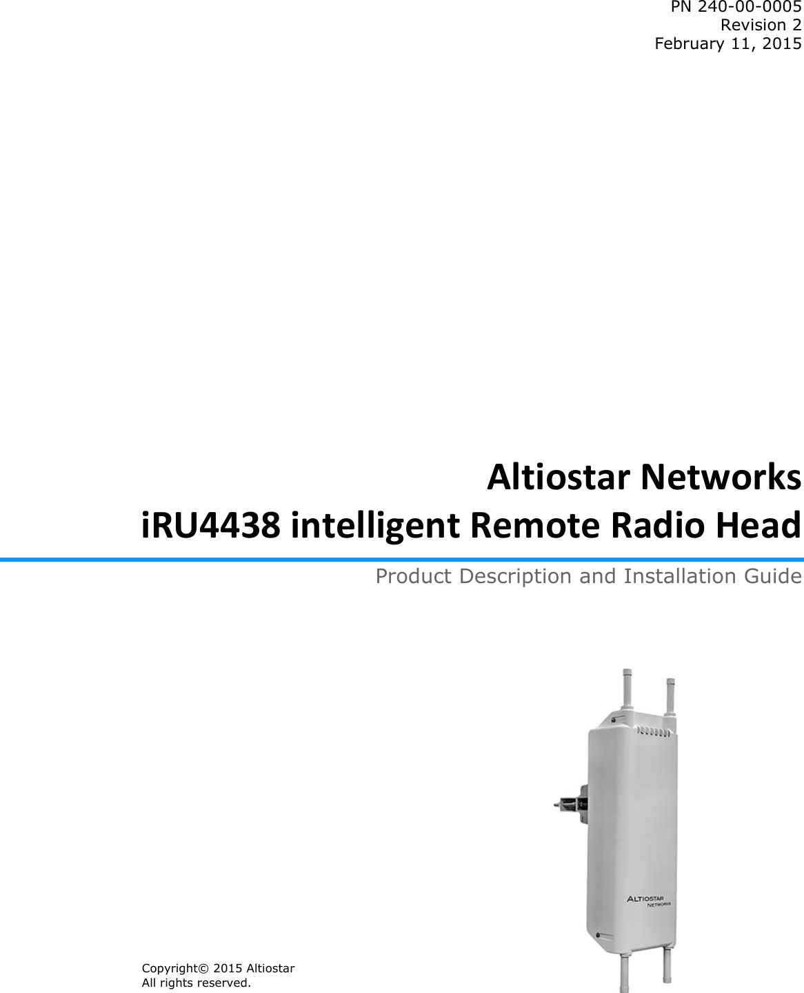
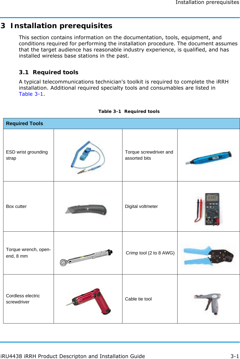
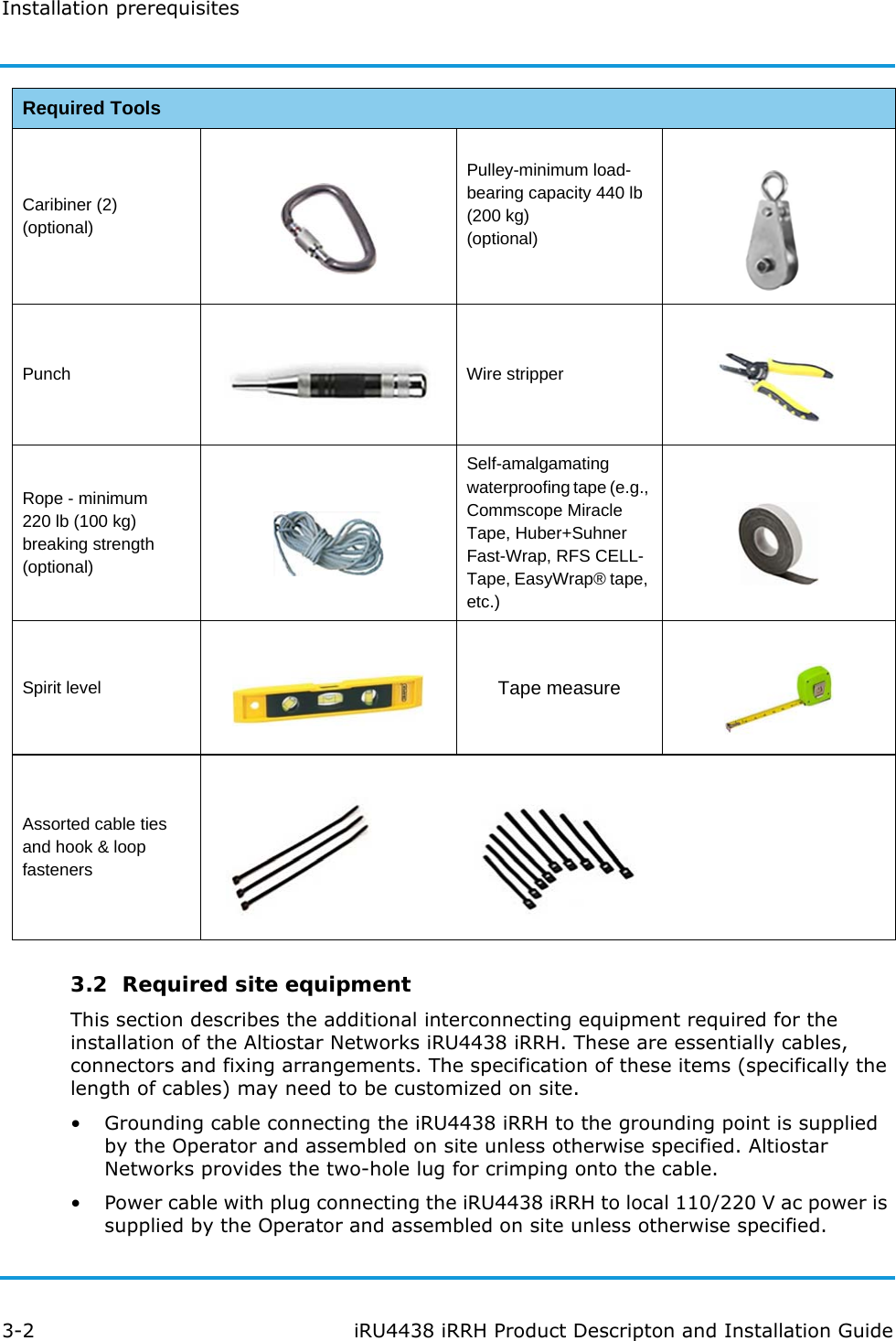
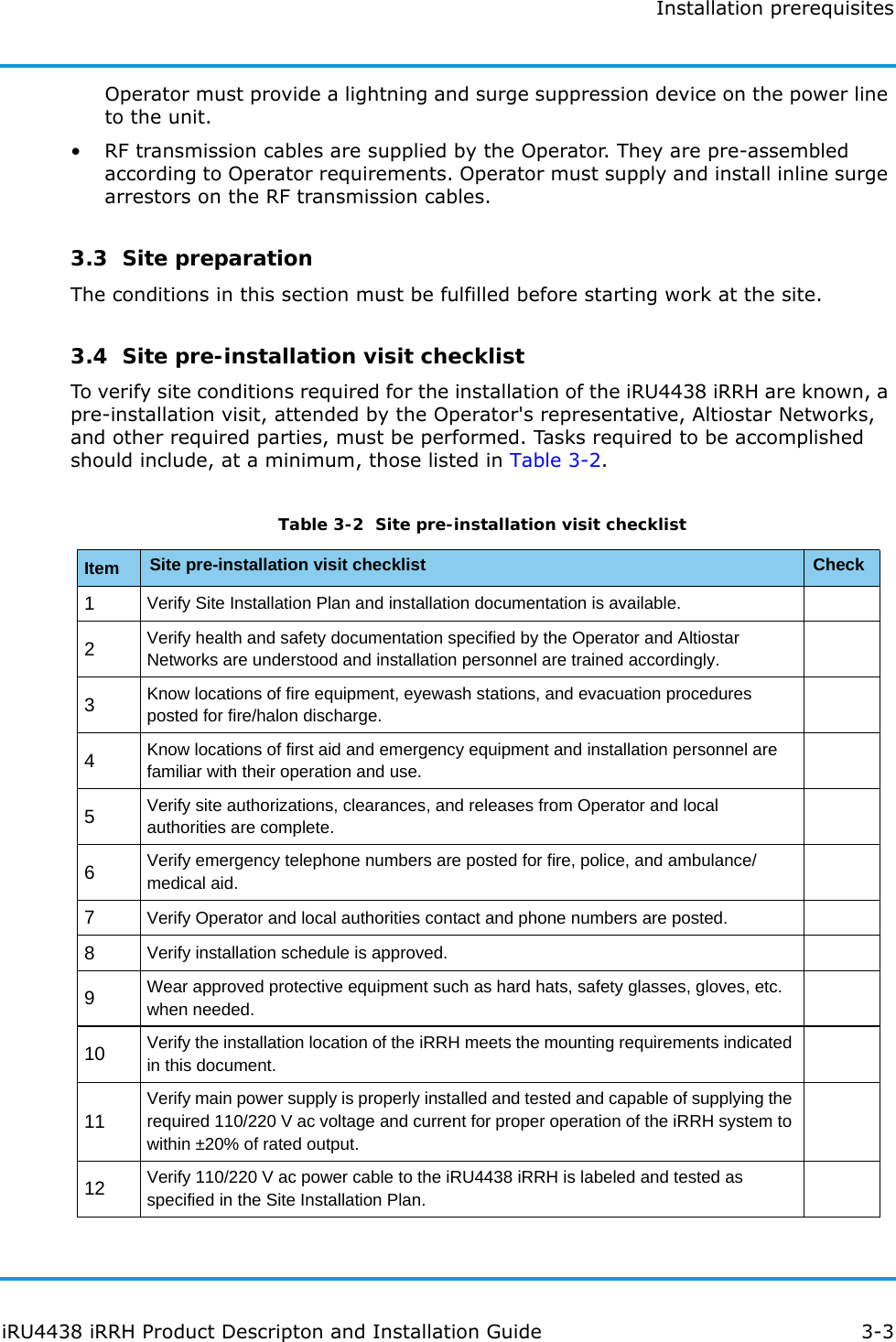
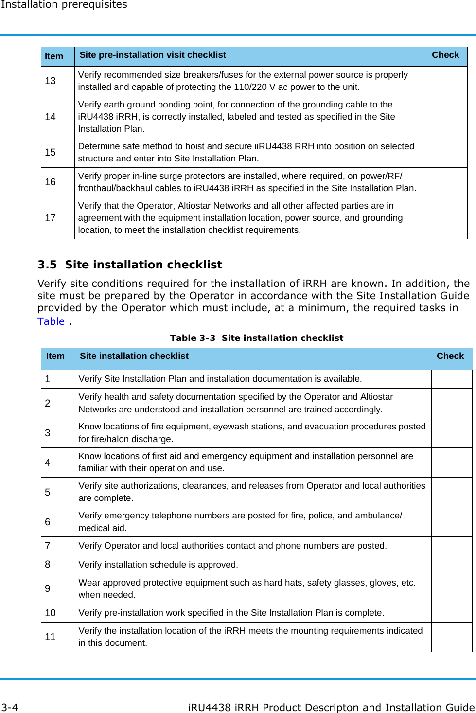
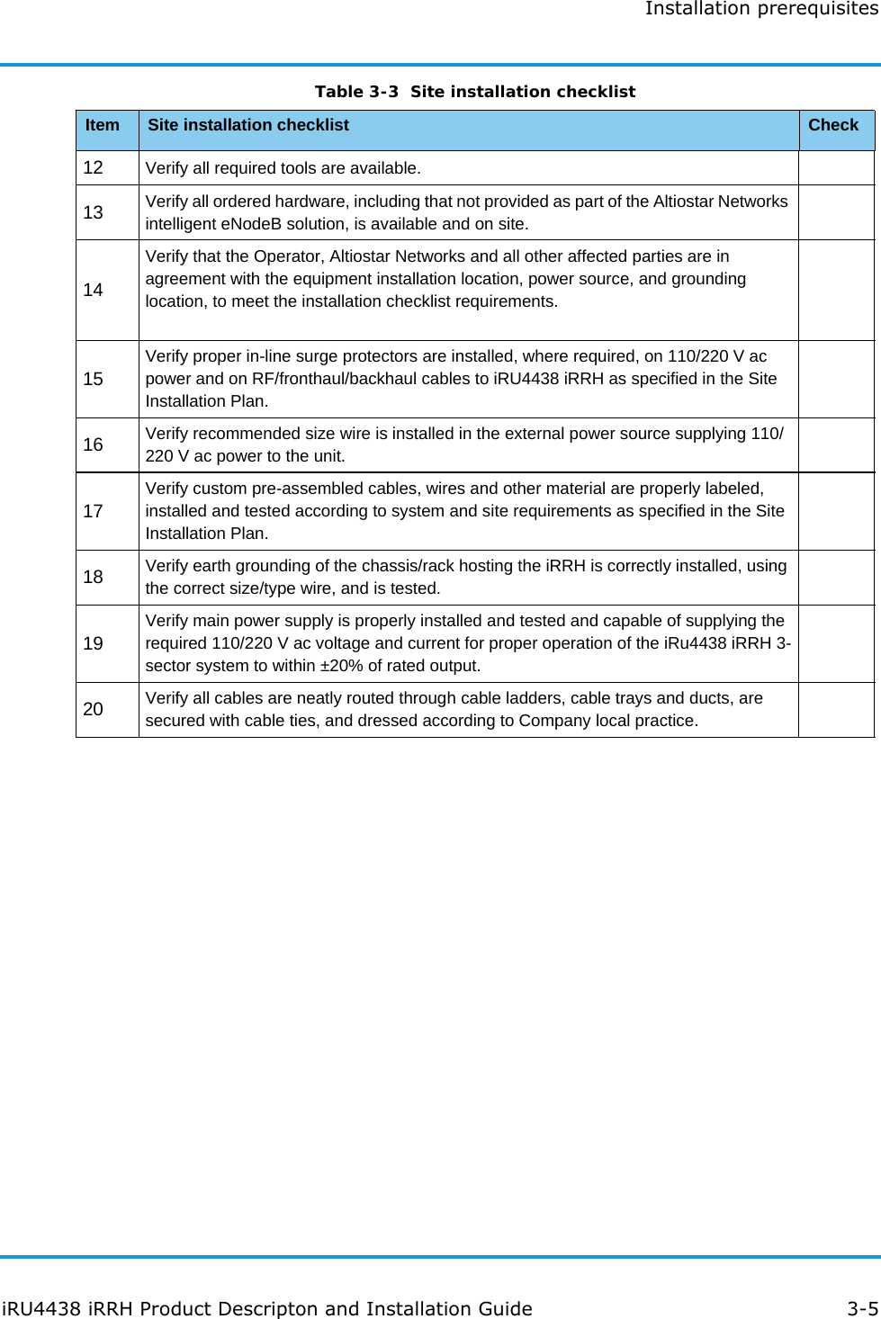
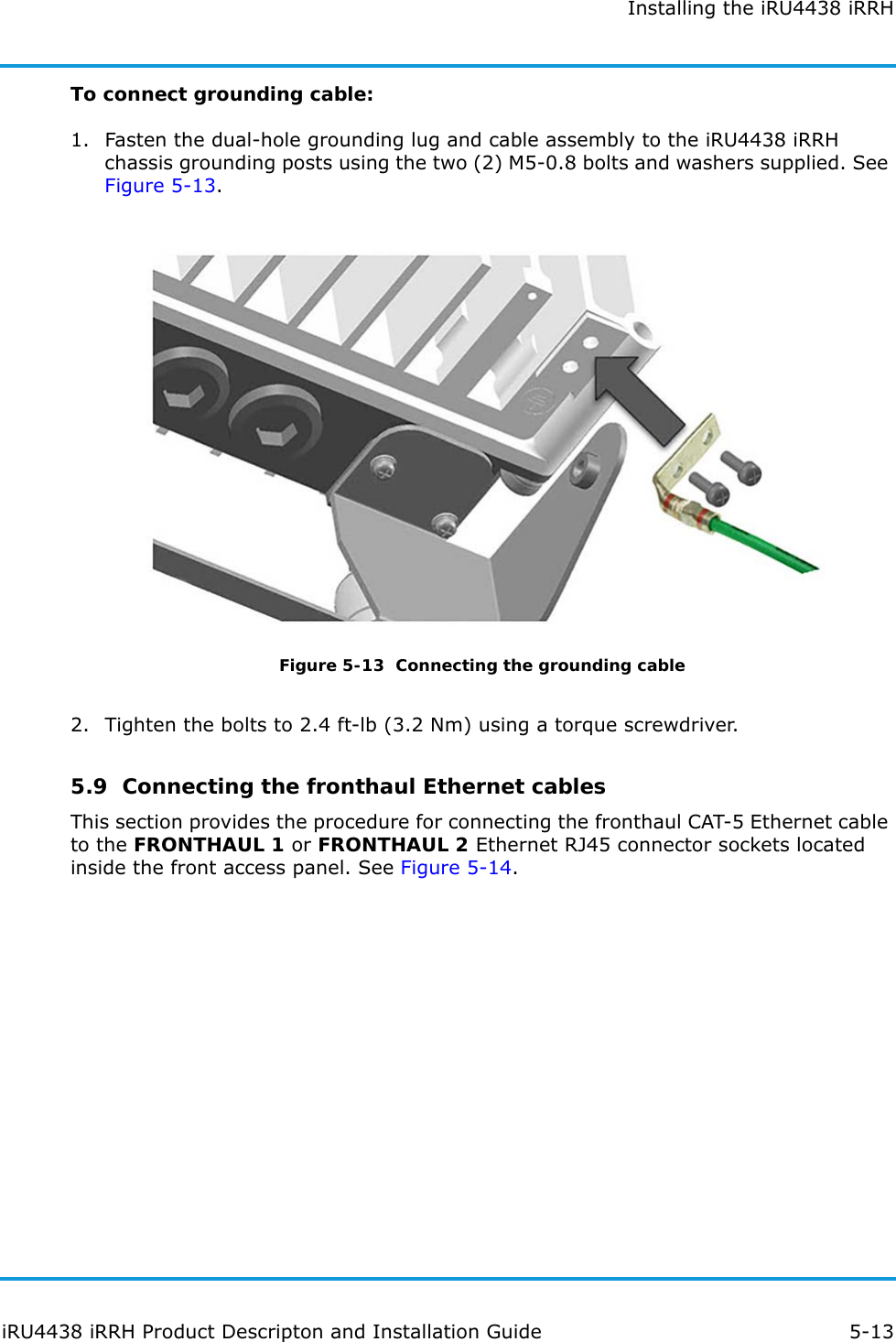
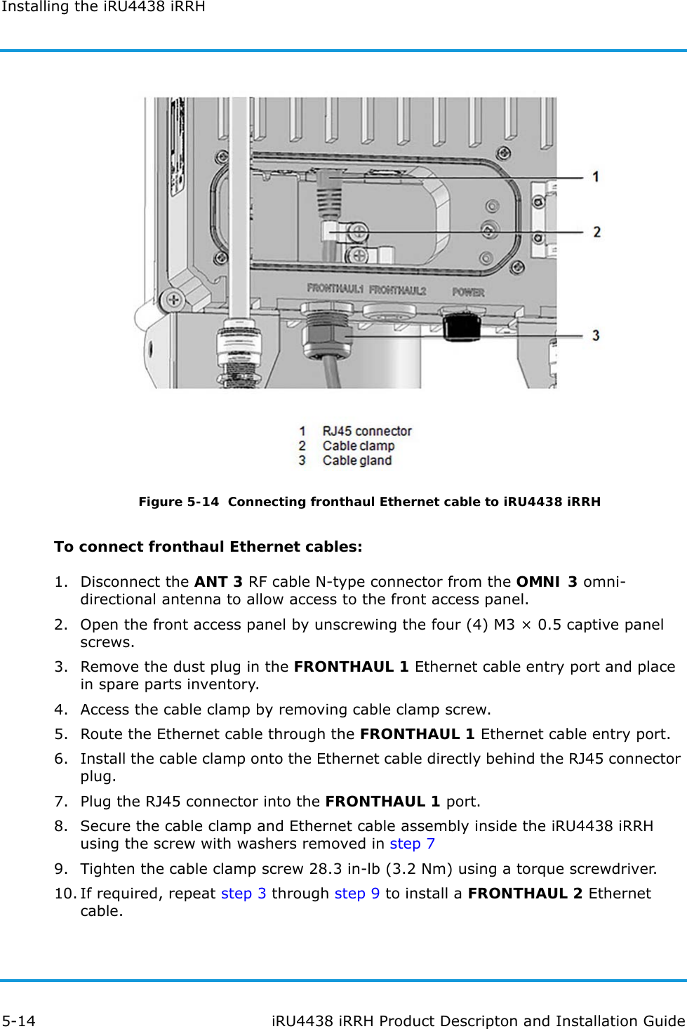
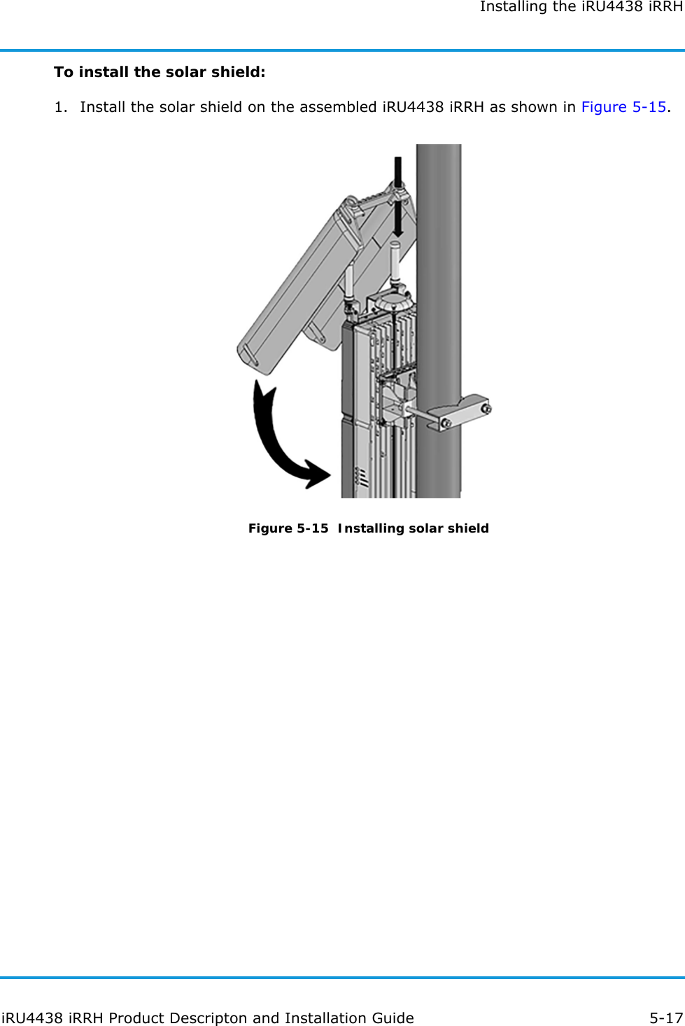
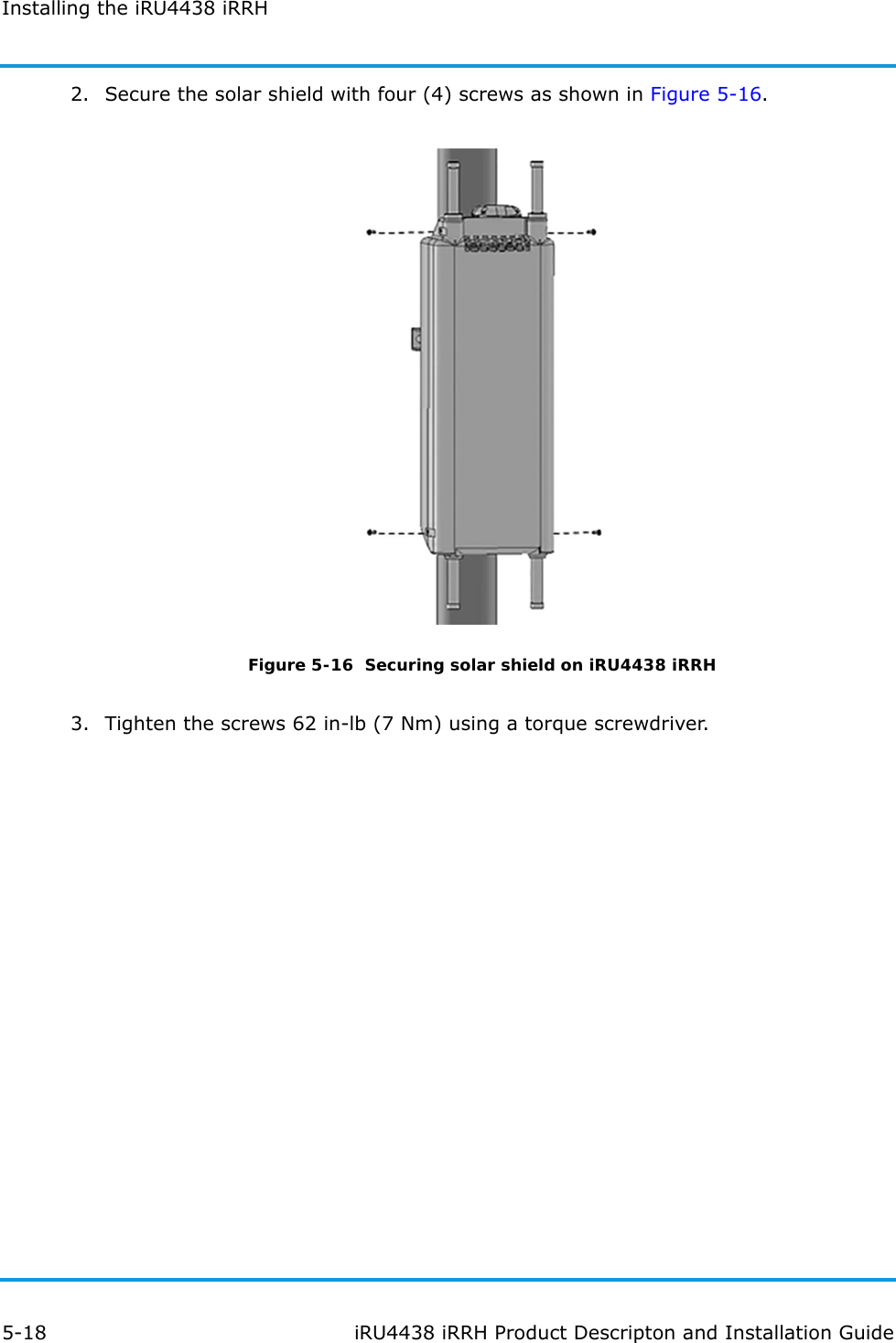
Product Description and Installation Guide
Navigation menu
Upload a User Manual
Namespaces
Wiki Guide
HTML
PDF
Info
Views
User Manual
Discussion / Help
Navigation