Altiostar Networks 44510200 PCS band LTE Remote Radio Head User Manual
Altiostar Networks, Inc. PCS band LTE Remote Radio Head
UserManual.wiki
>
Altiostar Networks
>
44510200 User Manual
>
User Manual
Contents
1.
User Manual
2.
Specsheet
User Manual
Navigation menu
Upload a User Manual
Namespaces
Wiki Guide
HTML
PDF
Info
Views
User Manual
Discussion / Help
Navigation


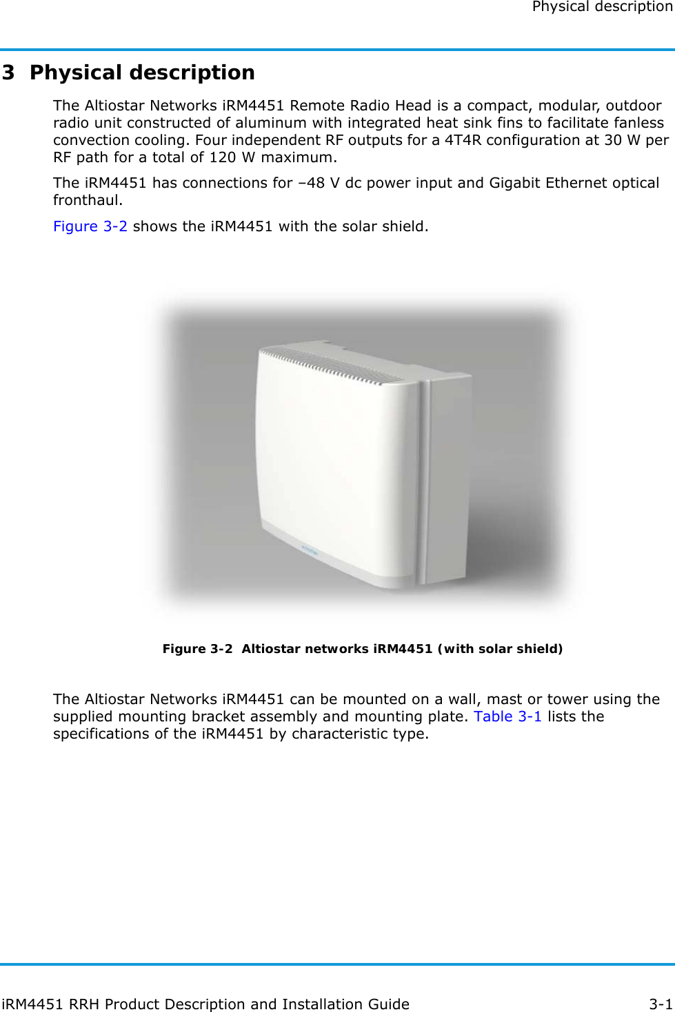
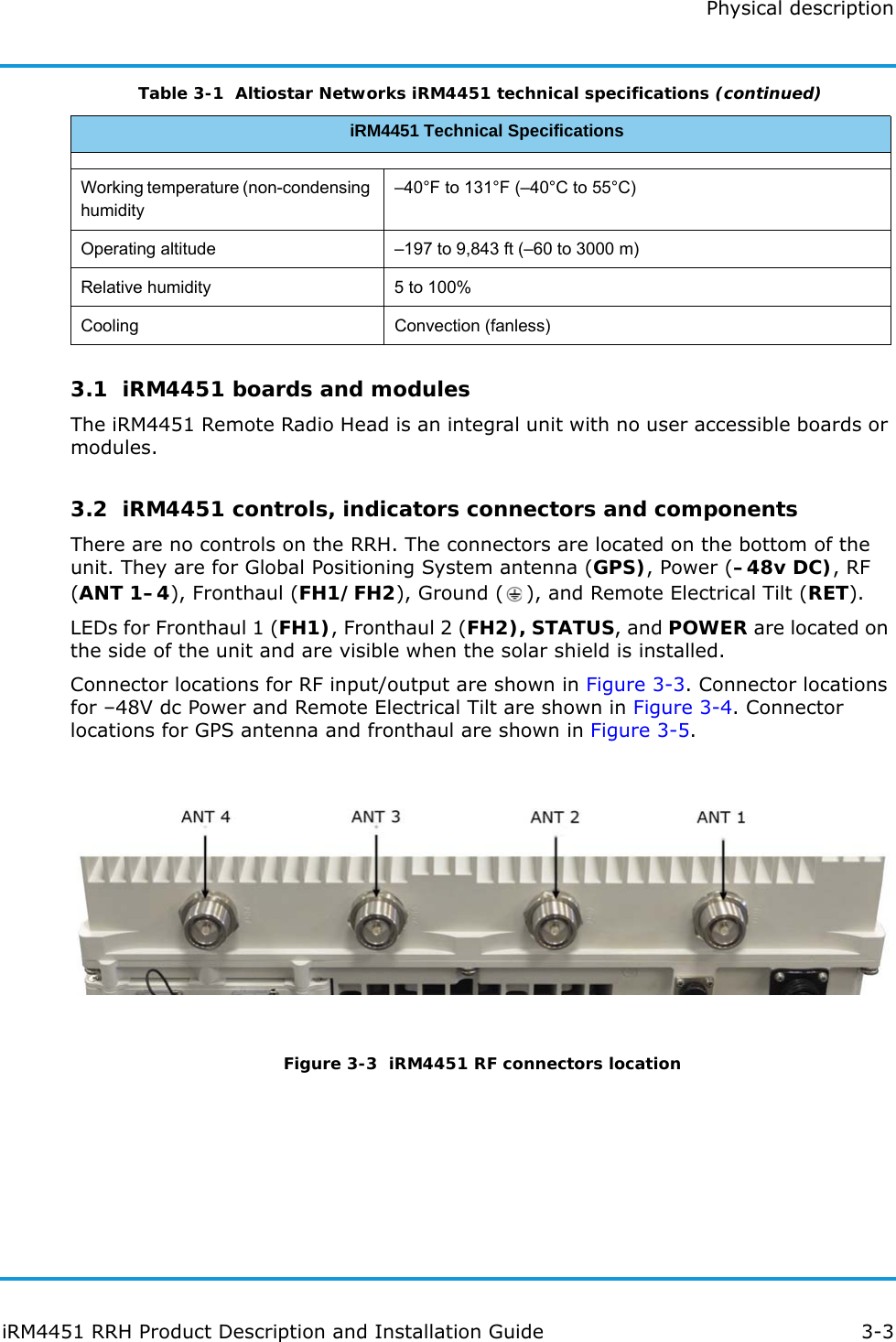
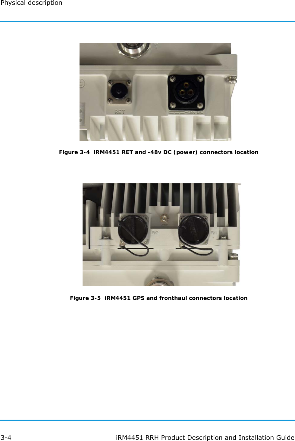
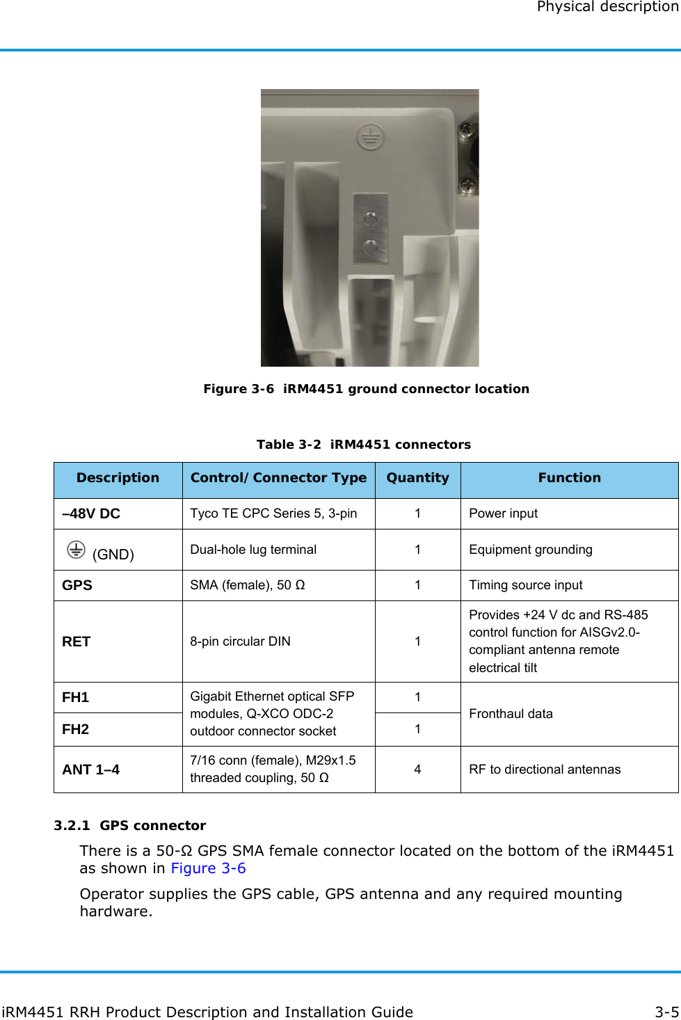
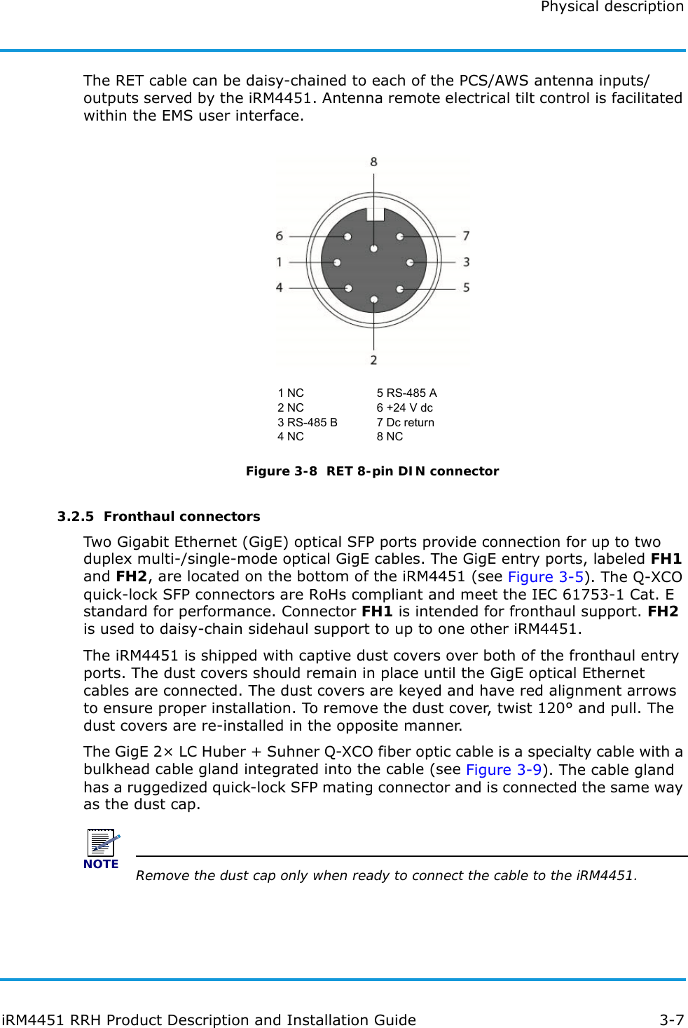
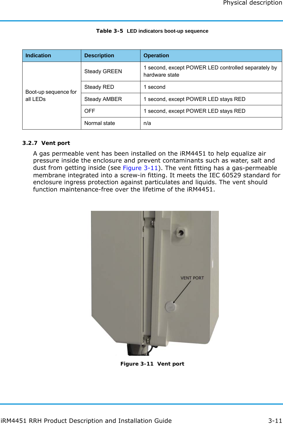
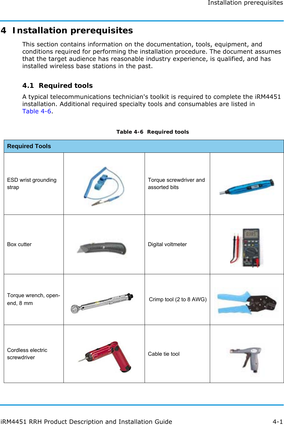
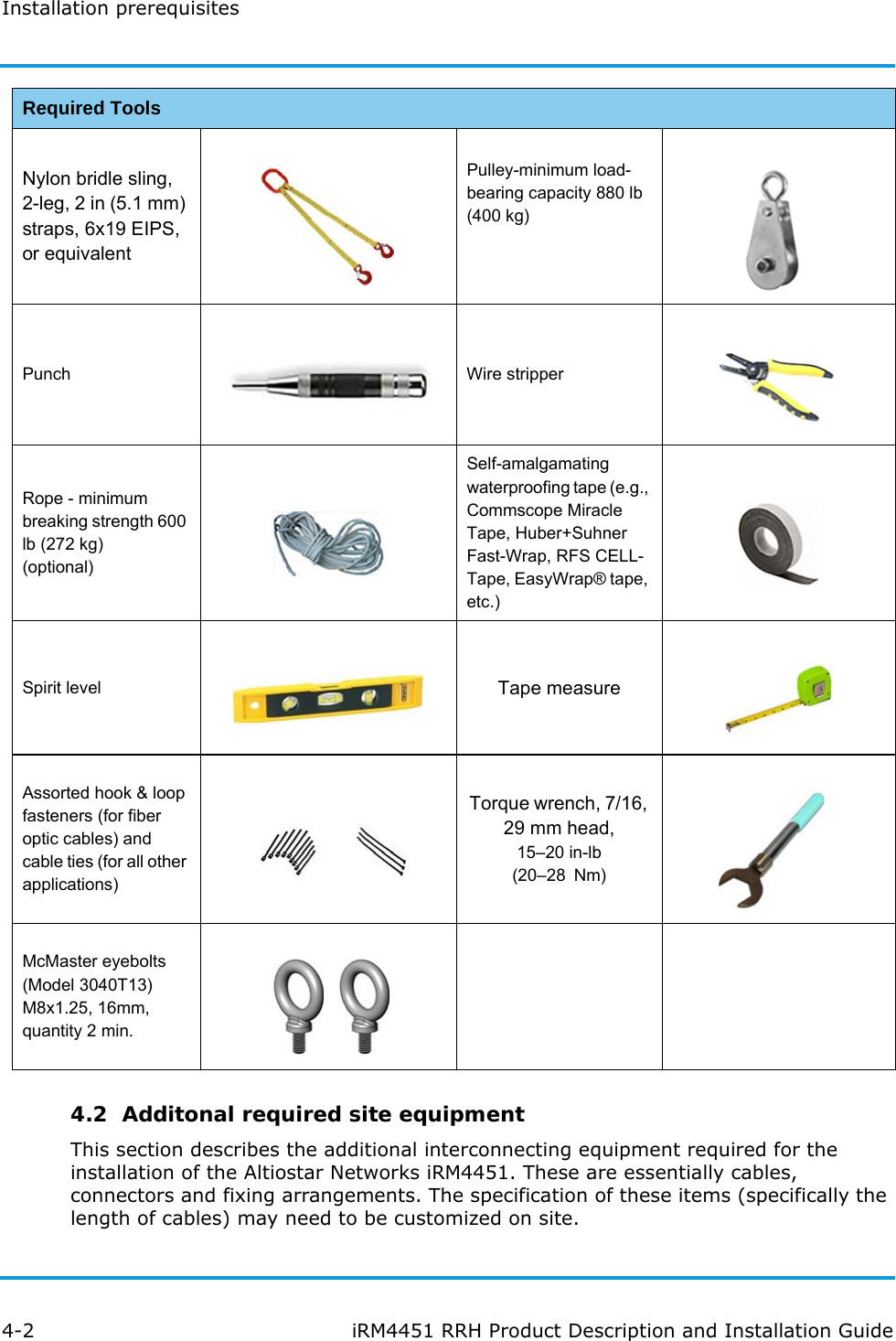
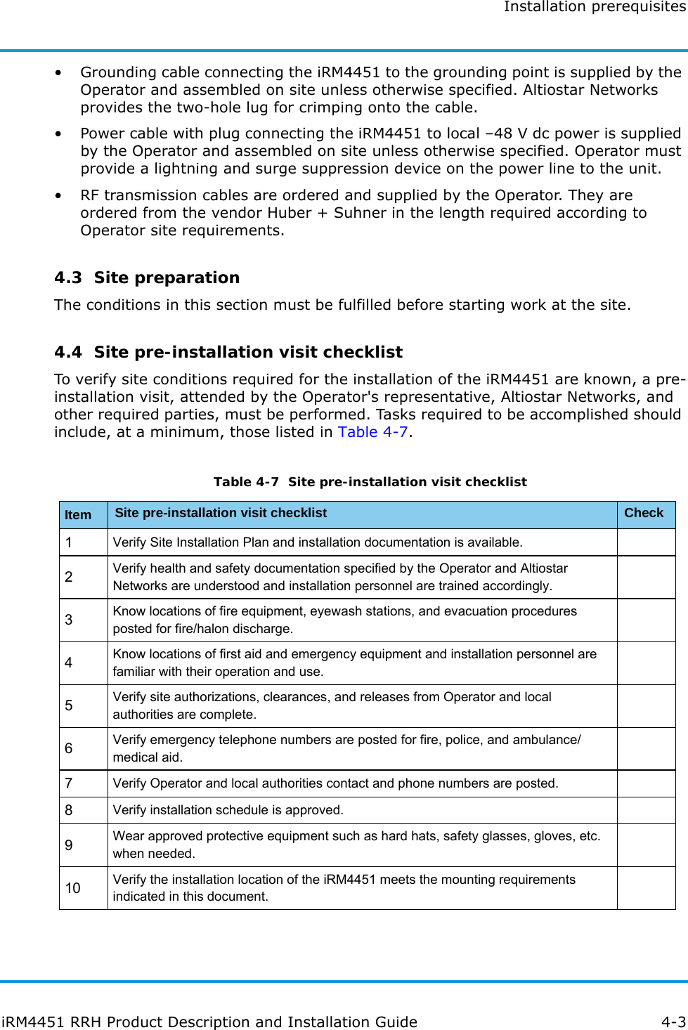
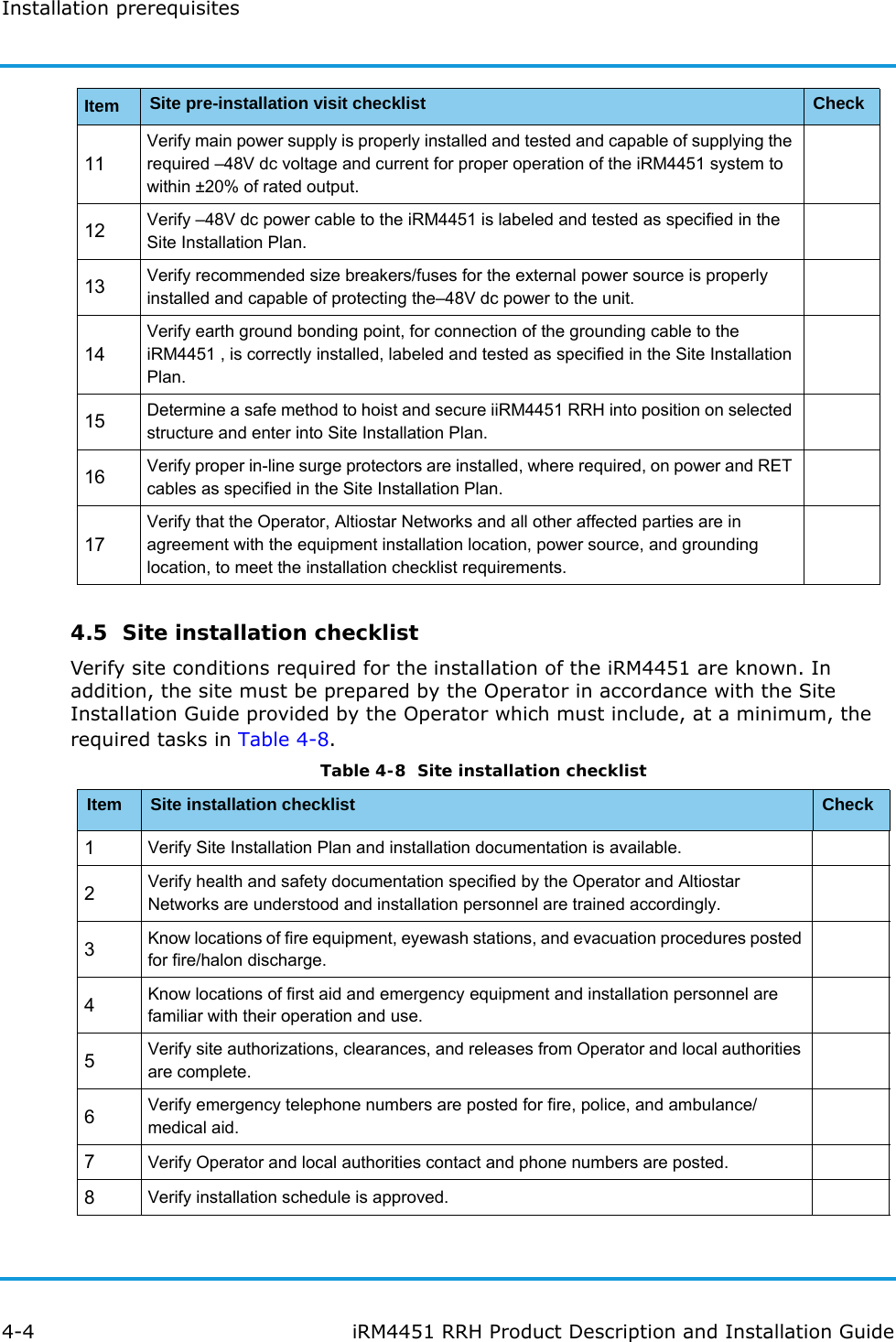
![Physical description3-6 iRM4451 RRH Product Description and Installation GuideGPS cables are provided and pre-installed by the Operator. The GPS cable bend radius is ≤0.75 in (19 mm).3.2.2 RF connectorsThere are four 50-Ω, 7/16 RF jacks (M29x1.5 threaded couplings) that terminate on the bottom of the iRM4451. They are marked ANT 1 through ANT 4.The RF cables are supplied and pre-installed by the Operator.The RF 7/16 connectors are secured by torquing the M29 screw ferrule 15–20 in-lb (20–28 Nm) using a torque wrench. NOTEThe Operator is responsible for determining the antenna type, and supplying and pre-installing the antennas at the site.3.2.3 Power connector–48V dc power to the iRM4451 is through a 3-pin circular twist-lock power connector, Tyco TE CPC Series 5 (788189-1). The connector is keyed to prevent mis-mating. The mating plug (TE CPC Series 5 [7963075-1]) is fastened by turning the coupling nut clockwise until it 'clicks' into the locked position. The power connector pin assignments, as viewed from the bottom of the iRM4451, are shown in Figure 3-7.1 –48V dc2 RTN3 NCFigure 3-7 –48 V dc 3-pin circular power connectorWe recommend cable type SOOW, 8 AWG (min.), 2-conductor, stranded copper wires, indoor/outdoor, round cable, rated at 600 V, or equivalent.3.2.4 RET connectorThe RET (Remote Electrical Tilt) connector provides the capability of electrical antenna control to all antennas connected to the iRM4451. Pin assignments for the RET 8-pin DIN connector is shown in Figure 3-8. The connector is keyed to prevent mis-mating. The connector is fastened by turning the coupling nut clockwise until hand tight.](https://usermanual.wiki/Altiostar-Networks/44510200.User-Manual/User-Guide-3066252-Page-20.png)