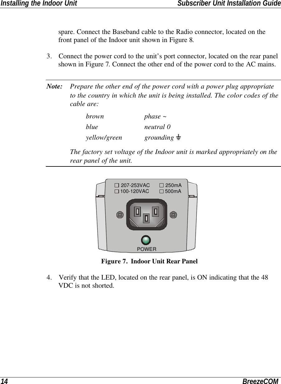
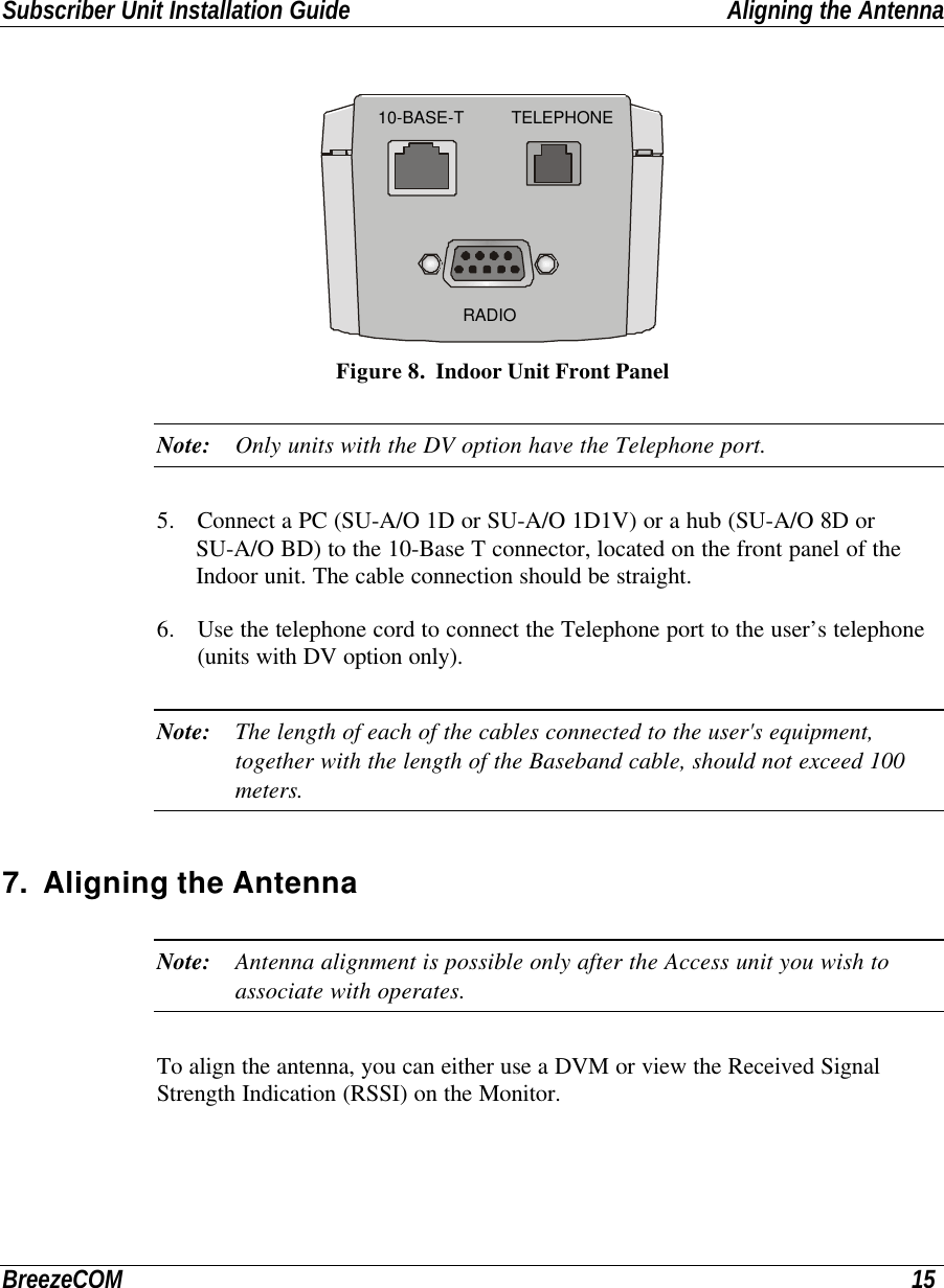
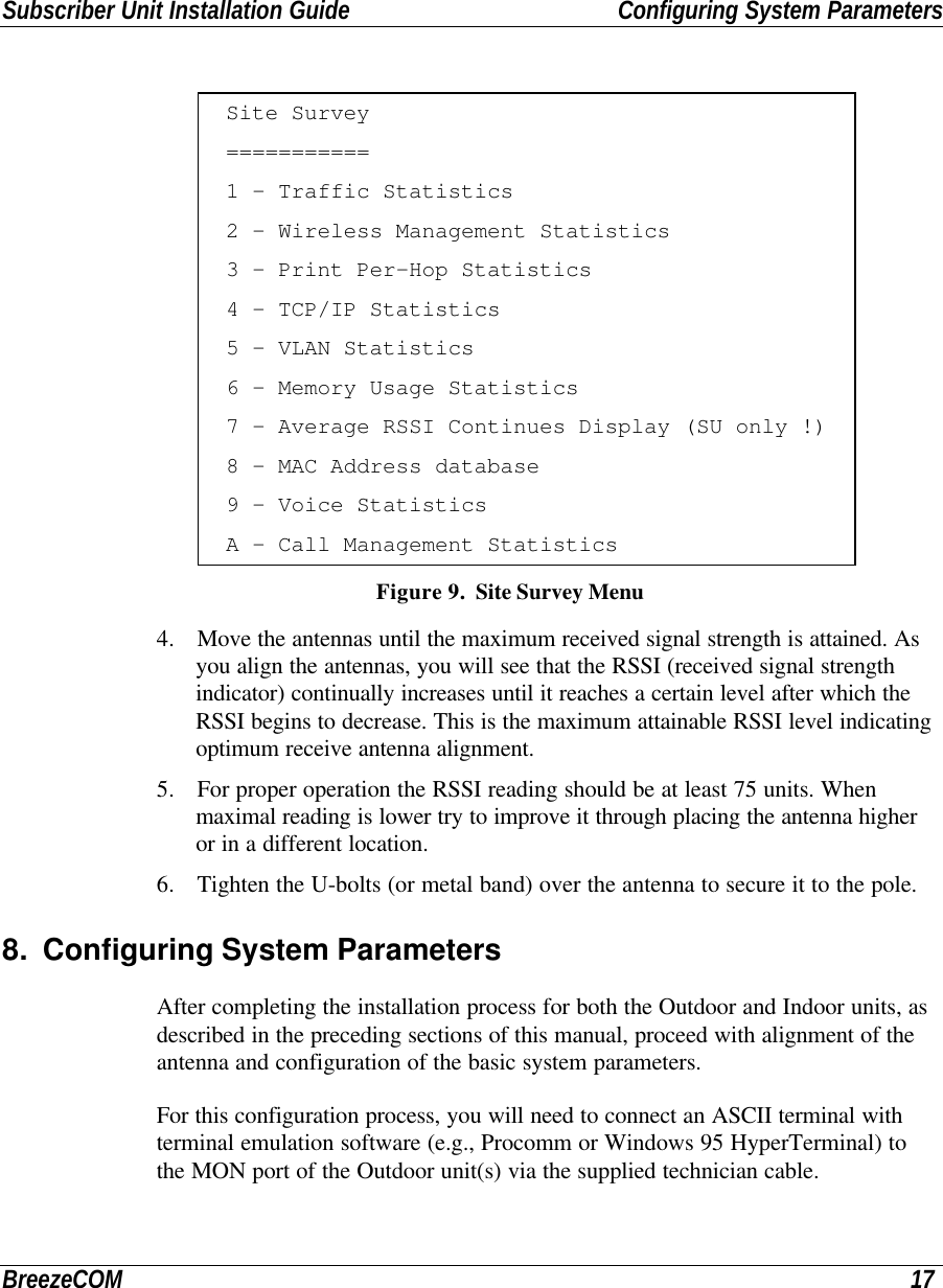
Alvarion Technologies AAU-10 WLL System User Manual su2

Alvarion Ltd. WLL System su2

Contents

36 pages

Breeze ACCESSSubscriber UnitSU-A-D/DV - 2.4-110/220 SeriesSU-O-D/DV - 2.4-110/220 SeriesInstallationManualRevision B.1August, 1999Cat. No. 213059
Front Matter Subscriber Unit Installation GuideII BreezeCOM© 1999 by BreezeCOM Ltd. All rights reserved.No part of this publication may be reproduced in any material form without the written permission ofthe copyright owner.Trade NamesBreezeACCESS, BreezeNET, BreezeLINK, BreezeVIEW and WIX are trade names of  BreezeCOM Ltd. Otherbrand and product names are registered trademarks or trademarks of their respective companies.Statement of ConditionsThe information contained in this manual is subject to change without notice. BreezeCOM shall not be liable forerrors contained herein or for incidental or consequential damages in connection with the furnishing, performance, oruse of this manual or equipment supplied with it.WarrantyIn the following warranty text, “the Company” shall mean:• BreezeCOM Inc., for products located in the USA.• BreezeCOM Ltd., for products located outside the USA.This Breeze ACCESS product is warranted against defects in material and workmanship for a period of one yearfrom date of purchase. During this warranty period the Company will, at its option, either repair or replace productsthat prove to be defective.For warranty service or repair, the product must be returned to a service facility designated by the Company.Authorization to return products must be obtained prior to shipment. The buyer shall pay all shipping charges to theCompany and the Company shall pay shipping charges to return the product to the buyer within the USA.The Company warrants that the firmware designed by it for use with the unit will execute its programminginstructions when properly installed on the unit. The Company does not warrant that the operation of the unit orfirmware will be uninterrupted or error-free.Limitation of WarrantyThe foregoing warranty shall not apply to defects resulting from improper or inadequate maintenance by the buyer,buyer supplied interfacing, unauthorized modification or misuse, operation outside of the environmental specificationsfor the product, or improper site preparation or maintenance. No other warranty is expressed or implied. TheCompany specifically disclaims any implied merchantable and fitness warranties for any particular purpose.Information to UserAny changes or modifications of equipment not expressly approved by the manufacturer could void the user’sauthority to operate the equipment.
Subscriber Unit Installation Guide Front MatterBreezeCOM IIISafety ConsiderationsFor the following safety considerations, “Instrument” means the Breeze-Access Subscriber Unitcomponents and its cables.CautionTo avoid shock, do not perform any servicing unless you are qualified to do so.GroundingBefore connecting the instrument to the power line, verify that a suitable power cord is being used(the protective earth terminal of this instrument must be connected to the protective conductor of thepower cord). The mains plug shall only be inserted in a socket outlet provided with a protective earthcontact. If an extension cord (power cable) is used make sure it has a protective conductor(grounding).Line VoltageBefore connecting this instrument to the power line, make sure that the voltage of the power sourcematches the requirements of the instrument:• 207-253 VAC for SU-A/O 2.4-220• 100-120 VAC for SU-A/O 2.4-110RadioThe instrument transmits radio energy during normal operation. To avoid possible harmful exposureto this energy, do not stand or work for extended periods of time in front of its antenna. The long-term characteristics or the possible physiological effects of Radio Frequency Electromagnetic fieldshave not been yet fully investigated.Antenna Installation and GroundingBe sure that the Outdoor unit, the antenna and the supporting structure are properly installed toeliminate any physical hazard to either people or property. Verify that the antenna mast is groundedso as to provide protection against voltage surges and static charges. Make sure that the installationof the antenna and cable is performed in accordance with all relevant national and local building andsafety codes.FCC NoticeThis equipment has been tested and found to comply with the limits for a Class B digital device,pursuant to part 15 of the FCC Rules. These limits are designed to provide reasonable protectionagainst harmful interference in a residential installation. This equipment generates, uses and can
Front Matter Subscriber Unit Installation GuideIV BreezeCOMradiate radio frequency energy and, if not installed and used in accordance with the instructions, maycause harmful interference to radio communications. However, there is no guarantee thatinterference will not occur in a particular installation. If this equipment does cause harmfulinterference to radio or television reception, which can be determined by turning the equipment offand on, the user is encouraged to try to correct the interference by one or more of the followingmeasures:-Reorient or relocate the receiving antenna.-Increase the separation between the equipment and receiver.-Connect the equipment into an outlet on a circuit different from that to which the receiver isconnected.-Consult the dealer or an experienced radio/TV technician for help.Changes or modifications to this equipment not expressly approved by the party responsible forcompliance could void the user’s authority to operate the equipment.
Subscriber Unit Installation Guide  Table of ContentsBreezeCOM iTABLE OF CONTENTS1. System Description......................................................................................................... 22. Packing List................................................................................................................... 42.1 Other Optional Items Available from BreezeCOM ....................................................... 42.2 Other Required Items................................................................................................ 53. Installation Guidelines ..................................................................................................... 63.1 Installation Overview ................................................................................................ 84. Installing the Outdoor Unit - SU-O Series ........................................................................104.1 Pole Mounting.........................................................................................................104.2 Wall Mounting the Outdoor Unit ...............................................................................114.3 Mounting the Antenna..............................................................................................115. Installing the Outdoor Unit - SU-A Series ........................................................................125.1 Connecting the Baseband, Antenna (SU-O) and Ground Cables...................................126. Installing the Indoor Unit................................................................................................137. Aligning the Antenna......................................................................................................157.1 Aligning the Antenna Using a DVM ...........................................................................167.2 Aligning the Antenna Using the Site Survey Menu ......................................................16
Table of Contents Subscriber Unit Installation Guideii BreezeCOM8. Configuring System Parameters ......................................................................................178.1 Setup for PC Terminal Emulation Program................................................................188.2 Parameters..............................................................................................................188.3 IP, Subnet Mask and Default Gateway Address Configuration.....................................198.4 ESSID Configuration ...............................................................................................208.5 Max. Data Rate Configuration...................................................................................218.6 Change Access Rights and Reset Unit........................................................................228.7 Voice Port Setup .....................................................................................................229. Initial Operation.............................................................................................................2310. Specifications ..............................................................................................................24Appendix A. Preparing the Indoor Unit to Outdoor Unit Baseband Cable ...............................27
Subscriber Unit Installation Guide Table of FiguresBreezeCOM iiiTable of FiguresFigure 1.  System Diagram.................................................................................................. 3Figure 2.  General Installation Scheme - SU-A Pole Mounting................................................ 9Figure 3.  Pole Mounting Installation...................................................................................11Figure 4.  Outdoor Unit Bottom Connection Panel ...............................................................12Figure 5.  Outdoor Unit (SU-O) Top Connection Panel ........................................................12Figure 6.  Wall Mounting the Indoor Unit ............................................................................13Figure 7.  Indoor Unit Rear Panel.......................................................................................14Figure 8.  Indoor Unit Front Panel......................................................................................15Figure 9.  Site Survey Menu...............................................................................................17Figure 10.  Breeze Access Monitor Main Menu....................................................................19Figure 11.  System Configuration Menu ..............................................................................19Figure 12.  IP and SNMP Parameters .................................................................................20Figure 13.  Wireless LAN Parameters Menu........................................................................21Figure 14.  Outdoor Unit LEDs ..........................................................................................23Figure 15.  Assembling the Indoor-Unit-to-Outdoor Unit Baseband Cable...............................27Figure 16.  Bulgin to 9-Pin D-Type Pin Assignments............................................................28
BreezeCOM 1About this ManualThis manual contains the following information:⇒ System Description⇒ Packing List⇒ Installation Guidelines⇒ Installing the Outdoor Unit⇒ Installing the Indoor Unit⇒ Setting Basic System Configuration Parameters⇒ Specifications⇒ Preparing the Indoor-to-Outdoor Baseband Cable
System Description Subscriber Unit Installation Guide2BreezeCOM1. System DescriptionThe BreezeACCESS IP Broadband Wireless Local Loop (WLL) system is a high-performance wireless access system. It allows ISPs and service providers to offertheir subscribers high-speed wireless IP connectivity services. BreezACCESSemploys wireless packet data switching technology, significantly more appropriatefor IP-based services than older switching technology, and supports Voice over IP(VoIP) based on the H.323 protocol.The BreezeACCESS 2.4 line of products use Frequency Hopping SpreadSpectrum radios and operate in the 2.4 GHz ISM band allowing for license-freeinstallation in most countries.The difference between the SU-A-D/DV series and the SU-O-D/DV series is in thestructure of the Outdoor unit: the Outdoor unit of the SU-A-D/DV line of productsincludes an integrated antenna, while the Outdoor unit of the SU-O-D/DV line ofproducts does not include an antenna.The Indoor units of both the SU-A-D/DV and the SU-O-D/DV series provideinterfaces to user's equipment. In addition, the Indoor unit provides 48 VDC to theOutdoor unit.The SU-A-D/DV and the SU-O-D/DV lines of products, through the Ethernet port,provide all the functionality required to connect workstation computers and otherEthernet equipment at the subscriber premises to the network. SU-A-DV andSU-O-DV lines of products provide the same data functionality, plus a telephoneinterfaces supporting regular telephones.The SU-A/O-D/DV-2.4 110 lines of products operate with main voltage of 110VAC, while the SU-A/O-D/DV-2.4 220 lines of products operate with main voltageof 220 VAC.The SU-A/O-D 2.4-110/220 series includes the following products:• SU-A/O-1D-2.4-110/220: supports a single Ethernet workstation/PC• SU-A/O-8D-2.4-110/220: supports up to 8 Ethernet workstations/PCs• SU-A/O-BD-2.4-110/220: supports a LAN (a bridge functionality)
Subscriber Unit Installation Guide System DescriptionBreezeCOM 3The SU-A/O-DV 2.4-110/220 series includes the following product:• SU-A/O-1D1V-2.4-110/220: supports a single Ethernet workstation and aregular telephone interfaceSU-1DSU-BDAURouter/GatewaySU-1D1VFigure 1.  System Diagram
Packing List Subscriber Unit Installation Guide4BreezeCOM2. Packing List• Indoor unit• Outdoor unit (includes integrated antenna on SU-A models)• 110/220 VAC Power Cord (open ended)• Sun-guard (installed on the rear side of the Outdoor unit)• Telephone cable (for the SU-A/O DV series only)2.1 Other Optional Items Available from BreezeCOM• Technician cable• U-bolts size A kit for pole mounting (up to 2" pole)• U-bolts size B kit for pole mounting (up to 3" pole)• Wall mounting kit• Sun-guard (optional for front side, SU-O only)• Baseband cable (available in different lengths)• A set of connectors for the Baseband cable (when not using the cablesavailable from BreezeCOM. Refer to Appendix A for instructions on how tobuild the cable.)
Subscriber Unit Installation Guide Packing ListBreezeCOM 52.2 Other Required ItemsIn addition to the items supplied by BreezeCOM, the following items must beavailable for the installation.• Antenna for SU-O series line of products; refer to the Specifications onpage 24 for information regarding the radio unit• An RF cable connecting the antenna to the Outdoor unit (SU-O series only)• Power mains cable termination plug per country of installation• U-bolts or metal bands for pole mounting (if not using the optional U-boltskit available from BreezeCOM)• Ground cables with an appropriate terminal• Ethernet cable (straight)
Installation Guidelines Subscriber Unit Installation Guide6BreezeCOM3. Installation GuidelinesThis manual covers basic installation procedures. All the parameters not mentionedhere can be configured remotely from the Access unit (refer to the AdministrationManual for further information).Follow the instructions in the appropriate column according to the products thatyou have purchased.SU-O Series SU-A Series• Select an appropriate location for theOutdoor unit and the antenna (not suppliedby BreezeCOM). The antenna should bemounted on a pole and should be installedwhere a direct line of sight with the AccessUnit/Base Station antenna can beestablished. The antenna should be directedtowards the Access Unit/Base Station andplaced where it shall be convenient to alignit to optimally aim towards the AccessUnit/Base Station.• The Outdoor unit can be pole- or wall-mounted. Its location should be selected toallow easy access to the unit for installationand testing. The antenna and Outdoor unitshould be installed near each other.• The Outdoor unit is designed for operationunder outdoors environmental conditions.However, it is recommended to try to installit in a place where its exposure to directsunlight will be minimal. • The unit is designed to withstand rain andhumidity. However, it is not designed to• Select an appropriate location for theOutdoor unit. The Outdoor unit should bemounted on a pole and should be installedwhere a direct line of sight with theAccess Unit/Base Station antenna can beestablished. The front side of the unitshould be directed towards the AccessUnit/Base Station and placed where itshall be convenient to align it to optimallyaim towards the Access Unit/BaseStation.• The Outdoor unit can be pole- or wall-mounted. Its location should be selectedto allow easy access to the unit forinstallation and testing.• The Outdoor unit is designed foroperation under outdoors environmentalconditions. However, it is recommendedto try to install it in a place where itsexposure to direct sunlight will beminimal.
Subscriber Unit Installation Guide Installation GuidelinesBreezeCOM 7SU-O Series SU-A Serieswithstand immersion in water and it shouldnot be installed in a place where largequantities of water can accumulate.• The maximum length of the Basebandcable, between the Indoor and the Outdoorunit, should not exceed 30 meters.• Select an appropriate location for the Indoorunit. The Indoor unit should be installed in aplace that is as close as possible to the exitpoint of the cable connecting it to theOutdoor unit. The selection of location ofthe Indoor unit should also take into accountthe need to connect it to a power outlet andto the user’s PC (or LAN).• The unit is designed to withstand rain andhumidity. However, it is not designed towithstand immersion in water and itshould not be installed in a place wherelarge quantities of water can accumulate.• The maximum length of the Basebandcable, between the Indoor and theOutdoor unit, should not exceed 30meters.• Select an appropriate location for theIndoor unit. The Indoor unit should beinstalled in a place that is as close aspossible to the exit point of the cableconnecting it to the Outdoor unit. Theselection of location of the Indoor unitshould also take into account the need toconnect it to a power outlet and to theuser’s PC (or LAN).Note: The SU-O Outdoor unit comes with a sun-guard mounted on its rearside. This accessory can be removed by unscrewing the attaching screws,and can be installed on the front side if necessary. A second, optionalsun-guard can be ordered for assembly on the front cover. The secondsun-guard is recommended for installations where both the front and theback of the Outdoor unit may be exposed to direct sunlight. Contact yourBreezeCOM representative for a parts catalog with the accessories thatyou can order.
Installation Guidelines Subscriber Unit Installation Guide8BreezeCOM3.1 Installation OverviewNote: It is highly recommended to complete configuration of the systemparameters in a lab prior to the installation. Refer to page 17 forinstructions on these settings.The typical installation scheme is depicted in Figure 2. The installation processshould follow these general steps:1. Mount the Outdoor unit. If you are installing an SU-O series, mount anexternal antenna (not supplied by BreezeCOM). Connect the Outdoor unit tothe antenna (SU-O series only). Connect the Baseband and ground cables tothe Outdoor unit.2. Mount the Indoor unit. Connect the Baseband cable (from the Outdoor unit).Connect the Indoor unit to the AC mains via the power cable.3. Verify optimal antenna positioning.4. Verify connectivity to the Base Station.5. Connect the Indoor unit Ethernet connector to the user’s network/PC using anEthernet Cable (a straight cable for connecting SU-A/O 1D or SU-A/O 1D1Vto a PC, or for connecting SU-A/O BD or SU-A/O 8D to a hub).6. Connect the telephone cord to the voice port and the POTS (DV products).7. Connect an ASCII terminal to the MON port of the Outdoor unit(s) via thetechnician cable and configure basic system parameters.Note: The Indoor unit should be connected to the power source only after theOutdoor unit have been connected to it.
Subscriber Unit Installation Guide Installation GuidelinesBreezeCOM 9OUTDOORINDOORIndoor UnitTo Monitor/DVMTo MainsTo Telephone (DV Series)To PC/LANTo Outdoor UnitOutdoor UnitTechnician cableFigure 2.  General Installation Scheme - SU-A Pole MountingBaseband cable
Installing the Outdoor Unit - SU-O Series Subscriber Unit Installation Guide10 BreezeCOM4. Installing the Outdoor Unit - SU-O SeriesNote: When mounting the Outdoor unit, be sure to mount it with the Antennaconnectors facing upwards.The Outdoor unit can be mounted in either of the following configurations:• Pole mounted• Wall mounted4.1 Pole MountingChoose a location where the unit's exposure to direct sunlight is minimal. Avoidplacing it in locations where water might accumulate. If necessary, install the sun-guard plates on the panels where exposure to sunlight is expected.The installation holes on the rear side of the Outdoor unit (see Figure 3) can beused to pole mount the unit using one of the following options:• U-bolt - size A (inside installation holes, up to 2" pole)• U-bolt - size B (outside installation holes, up to 3" pole)• Metal bands
Subscriber Unit Installation Guide Installing the Outdoor Unit - SU-O SeriesBreezeCOM 11Figure 3.  Pole Mounting Installation4.2 Wall Mounting the Outdoor UnitSee the instructions included with the wall mounting kit.4.3 Mounting the AntennaSecure brackets to the antenna using screws, lock washers and nuts as appropriate.Mount the antenna on a pole and secure it using metal bands or U-bolts. Do nottighten the metal bands or U-bolts, in order to enable rotation of the antenna overthe horizontal plane. The front of the antenna should be directed towards the BaseStation/Access Unit. Use Vertical Polarization.
Installing the Outdoor Unit - SU-A Series Subscriber Unit Installation Guide12 BreezeCOM5. Installing the Outdoor Unit - SU-A SeriesNote: All SU-A Outdoor units are supplied with a sun-guard assembled on therear panel of the unit.The SU-A Outdoor unit should be installed on a pole to allow optimal alignment.Use the installation holes (see Figure 3) to pole mount the unit using one of thefollowing options:• U-bolt - size A (inside installation holes, up to 2" pole)• U-bolt - size B (outside installation holes, up to 3" pole)• Metal bands5.1 Connecting the Baseband, Antenna (SU-O) and Ground CablesThe Baseband and Ground cable connectors are located on the bottom panel of theOutdoor unit, shown in Figure 4. The Antenna connector is located on the toppanel of the SU-O series Outdoor unit, shown in Figure 5.LMHETHWLNKPWRINDOOR MONFigure 4.  Outdoor Unit Bottom Connection PanelANT. 2Figure 5.  Outdoor Unit (SU-O) Top Connection Panel
Subscriber Unit Installation Guide Installing the Indoor UnitBreezeCOM 131. If you are installing an SU-O series, connect the antenna cable between theOutdoor unit and the antenna.2. Connect one end of the ground cable to the Outdoor unit bottom panel andconnect the other end to a good ground connection.3. Connect the Indoor unit to Outdoor unit Baseband cable, supplied with theaccess unit, to the appropriate connector. Appendix A provides instructions onhow to prepare this cable.6. Installing the Indoor Unit1. Remove the wall mounting bracket clipped to the rear of the Indoor unit andmount the Indoor unit on a wall as shown in Figure 6.  Figure 6.  Wall Mounting the Indoor Unit2. According to specific conditions, route the Outdoor unit to Indoor unitBaseband cable into the house/office so that it shall conveniently reach theIndoor unit in such a way as to ensure minimal interference, leaving some
Installing the Indoor Unit Subscriber Unit Installation Guide14 BreezeCOMspare. Connect the Baseband cable to the Radio connector, located on thefront panel of the Indoor unit shown in Figure 8.3. Connect the power cord to the unit’s port connector, located on the rear panelshown in Figure 7. Connect the other end of the power cord to the AC mains.Note: Prepare the other end of the power cord with a power plug appropriateto the country in which the unit is being installed. The color codes of thecable are:brown phase ~blue neutral 0yellow/green grounding The factory set voltage of the Indoor unit is marked appropriately on therear panel of the unit. POWER100-120VAC207-253VAC 250mA500mA Figure 7.  Indoor Unit Rear Panel4. Verify that the LED, located on the rear panel, is ON indicating that the 48VDC is not shorted.
Subscriber Unit Installation Guide Aligning the AntennaBreezeCOM 15 RADIO10-BASE-T TELEPHONE Figure 8.  Indoor Unit Front PanelNote: Only units with the DV option have the Telephone port.5. Connect a PC (SU-A/O 1D or SU-A/O 1D1V) or a hub (SU-A/O 8D orSU-A/O BD) to the 10-Base T connector, located on the front panel of theIndoor unit. The cable connection should be straight.6. Use the telephone cord to connect the Telephone port to the user’s telephone(units with DV option only).Note: The length of each of the cables connected to the user's equipment,together with the length of the Baseband cable, should not exceed 100meters.7. Aligning the AntennaNote: Antenna alignment is possible only after the Access unit you wish toassociate with operates.To align the antenna, you can either use a DVM or view the Received SignalStrength Indication (RSSI) on the Monitor.
Aligning the Antenna Subscriber Unit Installation Guide16 BreezeCOM7.1 Aligning the Antenna Using a DVM1. Connect the technician cable to the Monitor port on the bottom panel of theOutdoor unit.2. Connect a DVM (Digital Voltmeter) to the two wires in the technician cable.3. Move the antenna left and/or right until you reach the point of maximum RSSIreading. RSSI readout range is 1.50 to 3.30 volts (the higher the better). Makesure that all the time, the front of the antenna faces the general direction of theBase Station so as not to use the back lobe rather than the front lobe of theantenna for tuning.4. For proper operation the RSSI reading should be at least 2 volts. If maximalreading is lower try to improve it through placing the antenna higher or in adifferent location.Note: The DVM reading might be inaccurate due to possible reception ofenergy from other devices transmitting energy in the 2.4GHz ISM band.When in doubt, verify performance using the Print-Per-Hop Statisticsthat is based on measurement of the desired signal only.7.2 Aligning the Antenna Using the Site Survey Menu1. To use the Site Survey menu configure the ESSID parameter (refer toSection 8.4).2. Connect the terminal to the Outdoor unit using the technician cable.3. From the main menu type 3 to access the Site Survey menu. Type 3 to accessthe Print Per-Hop Statistics selection screen. Type 1 to display RSSI readoutsper frequency. In order to update the screen press Enter twice.
Subscriber Unit Installation Guide Configuring System ParametersBreezeCOM 17Site Survey===========1 - Traffic Statistics2 - Wireless Management Statistics3 - Print Per-Hop Statistics4 - TCP/IP Statistics5 - VLAN Statistics6 - Memory Usage Statistics7 - Average RSSI Continues Display (SU only !)8 - MAC Address database9 - Voice StatisticsA - Call Management StatisticsFigure 9.  Site Survey Menu4. Move the antennas until the maximum received signal strength is attained. Asyou align the antennas, you will see that the RSSI (received signal strengthindicator) continually increases until it reaches a certain level after which theRSSI begins to decrease. This is the maximum attainable RSSI level indicatingoptimum receive antenna alignment.5. For proper operation the RSSI reading should be at least 75 units. Whenmaximal reading is lower try to improve it through placing the antenna higheror in a different location.6. Tighten the U-bolts (or metal band) over the antenna to secure it to the pole.8. Configuring System ParametersAfter completing the installation process for both the Outdoor and Indoor units, asdescribed in the preceding sections of this manual, proceed with alignment of theantenna and configuration of the basic system parameters.For this configuration process, you will need to connect an ASCII terminal withterminal emulation software (e.g., Procomm or Windows 95 HyperTerminal) tothe MON port of the Outdoor unit(s) via the supplied technician cable.
Configuring System Parameters Subscriber Unit Installation Guide18 BreezeCOM8.1 Setup for PC Terminal Emulation ProgramUse the following setup for the ASCII terminal connection:Baud rate 9600Data bits 8Stop bits 1Parity NoneFlow Control NoneConnector Available Com PortNote: Optionally, the product can be configured using Telnet over the Ethernetport, after setting IP address. For further information refer to theAdministration Manual.8.2 ParametersThe following system parameters must be configured for each specific installation:• IP Address• Subnet Mask• Default Gateway Address• ESS ID• Max. Data RateAt the end of the configuration process access rights setting should be changed to“Installer”. It is recommended to configure system parameters at the laboratoryprior to the actual installation.Note: You should select Reset Unit in the Station Control Sub-menu for thechanges to take effect.
Subscriber Unit Installation Guide Configuring System ParametersBreezeCOM 198.3 IP, Subnet Mask and Default Gateway Address Configuration1. After connecting the ASCII terminal to the Outdoor unit, press Enter to accessthe BreezeACCESS Monitor main screen.BreezeACCESS (SU-A/O)Official Release Version - 1.3.5Release Date:  Wed Apr 28 16:23:57 1999BreezeACCESS Monitor=====================1 - System Configuration2 - Advanced Settings3 - Site Survey4 - Access ControlBreezeACCESS >>>Figure 10.  Breeze Access Monitor Main Menu2. Type 1 to access the System Configuration sub-menu.System Configuration====================1 - Station Status2 - TCP\IP and SNMP Parameters3 - Wireless LAN Parameters4 - Bridging5 - Station ControlBreezeACCESS >>>Figure 11.  System Configuration Menu3. Type 2 to access the TCP/IP and SNMP Parameters sub-menu.
Configuring System Parameters Subscriber Unit Installation Guide20 BreezeCOMIP and SNMP Parameters======================1 - IP Address2 - Subnet Mask3 - Default GatewayAddress4 - SNMP Traps5 - TCP ParametersS - Display Current ValuesFigure 12.  IP and SNMP Parameters4. Type 1 to access the IP Address selection screen. Type in the required IPAddress determined by the system manager. Press Enter to return to the IPand SNMP Parameters menu.5. Type 2 to access the Subnet Mask selection screen. Type in the requiredSubnet mask.6. Press Enter to return to IP and SNMP Parameters menu.7. Type 3 to access the Default Gateway Address selection screen. Type in therequired gateway address. Press Enter to return to IP and SNMP Parametersmenu.8.4 ESSID Configuration1. Press Esc to return to the System Configuration menu.2. Type 3 to access the Wireless LAN Parameters menu.
Subscriber Unit Installation Guide Configuring System ParametersBreezeCOM 21Wireless LAN Parameters=======================1 - Hopping Sequence (Shift) (AU only)2 - Hopping Sequence Offset3 - Hopping Sequence Set4 - ESS ID5 - Max. Data Rate6 - Transmit Diversity7 - Mobility8 - Load Sharing9 - Long RangeA - Prioritized ChannelsB - MIR And CIR ParametersS - Display Current ValuesBreezeACCESS >>>Figure 13.  Wireless LAN Parameters Menu3. Type 4 to access the ESS ID selection screen.4. Type in the required ESS ID.8.5 Max. Data Rate Configuration1. Press any key to return to the Wireless LAN Parameters menu.2. Type 5 to access the Max. Data Rate selection screen.a) Select 3 (3Mbps) if the RSSI reading, when using the Site Survey menu, ishigher than 2.5 Volts (93 units).b) Select 2 (2Mbps) if the RSSI reading, when using the Site Survey menu, isbetween 2.2 Volts and 2.5 Volts (83 to 93 units).
Configuring System Parameters Subscriber Unit Installation Guide22 BreezeCOMc) Select 1 (1Mbps) if the RSSI reading, when using the Site Survey menu, islower than 2.2 Volts (83 units).8.6 Change Access Rights and Reset Unit1. After properly configuring all system parameters, the access right should bechanged to USER to prevent users from unauthorized tampering with systemparameters. Press Esc three times to return to the main menu. Type 4 toaccess the Access Control menu. Type 1 to access the Change Access Rightsmenu. Type 0 to select Installer access rights allowing users only reading theconfigured parameters.2. Press Esc twice to return to main menu. Type 1 to access the SystemConfiguration menu. Type in 5 to access the Station Control sub-menu. Type1 to access the Reset Unit sub-menu. Type in 1 to reset the unit so that newconfiguration settings are applied.Note: Should you make any mistake during configuration, or should youencounter any problem associated with system configuration parameters,you may configure the unit back to the factory defaults.Select 2 in the Station Control menu to access the Set Factory Defaultsmenu and than Type in 1 to load the default values. Select 1 in the stationcontrol menu to access the Reset Unit, then type 1 so that the unit will bereset in order for the factory defaults to take effect.8.7 Voice Port SetupNote: This setting only applies to DV series units that have a telephoneinterface.The specific configuration sequence varies according to the equipment (gatewayand gatekeeper) that is used by the Service Provider. For further information onthe Voice Port setup refer to the Telephony Application Manual.
Subscriber Unit Installation Guide Initial OperationBreezeCOM 239. Initial OperationAfter completing the installation as described above, the system starts operation.To verify correct operation, view the LED panel located on the bottom panel ofthe Outdoor unit, as shown in Figure 14.LMHETHWLNKPWRFigure 14.  Outdoor Unit LEDsThe following table lists the various LED states.Name Description FunctionalityPWR Power supply On – After successful power upOff – Power offWLNK Synchronization Off – No SynchronizationOn – Synchronization with Access unitETH Ethernet activity Blinking – Reception of data from Ethernet LANOff – No reception of data from Ethernet LANQLT Quality ofreceived RFsignalvery low quality reception or notsynchronized with Access Point less than-81 dBmlow quality reception (usually enabling1Mbps traffic) from -81 to -77 dBmmedium quality reception (usually enabling2 Mbps traffic) from -77 to -65 dBmhigh quality reception (usually enabling 3Mbps traffic) greater than -65 dBm
Specifications Subscriber Unit Installation Guide24 BreezeCOM10. SpecificationsRadioFrequency 2.4 GHz ISM BandOperation and Standards FHSS, ETSI, ETS 300 328; FCC Part 15Operation mode Time Division DuplexOutput Power (SU-O) USA (FCC): 17 dBm, Europe (ETSI): 0dBmAntenna Gain (SU-A) 16dBiTransmitted Power (SU-A) FCC: 33dBm EIRPETSI: 20dBm EIRP, max.Sensitivity(dBm, BER 1E10-6)1Mbps2Mbps3Mbps-81-75-67Data Rate 3Mbps maxModulation Multilevel GFSK: 2 (@ 1Mbps), 4 (@ 2Mbps) or 8 (@3Mbps) FSKManagementCIR Committed Information rate; Symmetrical/Asymmetrical CIR supportMIR Maximum Information Rate (burst rate) limitationsClass of Service CIR/MIR by customer; Prioritize transport by customerSystemManagement SNMP agent, TelnetSecurity Authentication based on RC-4Software Upgradeable (download)
Subscriber Unit Installation Guide SpecificationsBreezeCOM 25Voice Communication (DV series only)Protocol H.323 Voice over IP compliantCompression G.723 6.3 Kbps compression, G.729 8Kbps compression, G.71164Kbps transparentEcho Cancellation G.165InterfacesOutdoor Unit Indoor UnitRF N Type, male (SU-O)Ethernet 10Base-T (RJ-45)Telephone(DV products) RJ-11 (POTS)Monitor Mini Sealed connector, 5 pin,femalePower AC power ouletOutdoor to Indoorunit Mini Sealed connector, 8 pin,male 9-pin D-type, femaleIndicatorsOutdoor Unit Indoor UnitPower, Ethernet, Sync, quality Power
Specifications Subscriber Unit Installation Guide26 BreezeCOMElectricalOutdoor Unit Indoor Unit48 VDC from Indoor Unit 110/220 VACMechanicalOutdoor Unit Indoor Unit31cm x 31cm x 4.7cm (SU-O)31cm x 31cm x 9.6cm (SU-A)15.4cm x 8.4cm x 5.6cmEnvironmentalOutdoor Unit Indoor UnitOperatingTemperature -400C to 500C00C to 400COperating Humidity Weather protected 5%-95% non condensing
Subscriber Unit Installation Guide Apeendix ABreezeCOM 27Appendix A. Preparing the Indoor Unit to Outdoor UnitBaseband CableTo assist in assembling the Indoor-Unit-to-Outdoor Unit Baseboard cable, use thefollowing tools.1. For Bulgin Mini Sealed connector:• Bulgin Contact Insertion Tool (P/N SA3150)• Bulgin Crimping Tool (SA 2800) For further information, refer to Bulgin's Internet site at www.bulgin.co.uk.2. For D-Type 9-pin connector:• Amphenol hand crimp tool 17 D 440 SP• Amphenol contact insertion and removal tool 17 D 438 SPFlex Mounting BodyBULGINPX0800Contact CarrierM/F BULGINCat. No. 12735Desc. ContactsM/F BULGINCat. No. SA3149MaleD-Type9-pin4x2x24# Cat.5Patch CableFor Outdoor UseFigure 15.  Assembling the Indoor-Unit-to-Outdoor Unit Baseband Cable
Appendix A Subscriber Unit Installation Guide28 BreezeCOM123456789BULGINETH_TX-ETH_TX-ETH_TX+ETH_TX+N.C.DC_0VDC_0VDC_-48VDC_-48VETH_RX-ETH_RX-ETH_RX+ETH_RX+TEL_TIPTEL_TIPTEL_RINGTEL_RINGFigure 16.  Bulgin to 9-Pin D-Type Pin AssignmentsTable 1.  Bulgin to 9-Pin D-Type Pin AssignmentsD-9 BULGIN Description1 6 ETH_TX-2 5 ETH_TX+3N.C.4 1 DC_0V5 2 DC_-48V6 8 ETH_RX-7 7 ETH_RX+8 3 TEL_TIP9 4 TEL_RING

Navigation menu