Alvarion Technologies BA-4900 High Speed Broadband Wireless Access System User Manual BreezeACCESS 4900 System Manual
Alvarion Ltd. High Speed Broadband Wireless Access System BreezeACCESS 4900 System Manual
Contents
- 1. User Manual
- 2. System User Manual
System User Manual

BreezeACCESS® 4900
S/W Version 3.2
July 2005
P/N 214151
System Manual

Legal Rights
Legal Rights
© Copyright 2005 Alvarion Ltd. All rights reserved.
The material contained herein is proprietary, privileged, and confidential and
owned by Alvarion or its third party licensors. No disclosure thereof shall be
made to third parties without the express written permission of Alvarion Ltd.
Alvarion Ltd. reserves the right to alter the equipment specifications and
descriptions in this publication without prior notice. No part of this publication
shall be deemed to be part of any contract or warranty unless specifically
incorporated by reference into such contract or warranty.
Trade Names
Alvarion®, BreezeCOM®, WALKair®, WALKnet®, BreezeNET®, BreezeACCESS®,
BreezeMANAGE™, BreezeLINK®, BreezeCONFIG™, BreezeMAX™, AlvariSTAR™,
MGW™, eMGW™, WAVEXpress™, MicroXpress™, WAVEXchange™, WAVEView™,
GSM Network in a Box and TurboWAVE™ and/or other products and/or services
referenced here in are either registered trademarks, trademarks or service marks
of Alvarion Ltd.
All other names are or may be the trademarks of their respective owners.
Statement of Conditions
The information contained in this manual is subject to change without notice.
Alvarion Ltd. shall not be liable for errors contained herein or for incidental or
consequential damages in connection with the furnishing, performance, or use of
this manual or equipment supplied with it.
Warranties and Disclaimers
All Alvarion Ltd. (“Alvarion”) products purchased from Alvarion or through any of
Alvarion’s authorized resellers are subject to the following warranty and product
liability terms and conditions.
Exclusive Warranty
(a) Alvarion warrants that the Product hardware it supplies and the tangible
media on which any software is installed, under normal use and conditions, will
be free from significant defects in materials and workmanship for a period of
fourteen (14) months from the date of shipment of a given Product to Purchaser
(the “Warranty Period”). Alvarion will, at its sole option and as Purchaser’s sole
remedy, repair or replace any defective Product in accordance with Alvarion’
standard R&R procedure.
(b) With respect to the Firmware, Alvarion warrants the correct functionality
according to the attached documentation, for a period of fourteen (14) month
from invoice date (the "Warranty Period")". During the Warranty Period, Alvarion
may release to its Customers firmware updates, which include additional
BreezeACCESS 4900 System Manual
iii

Legal Rights
performance improvements and/or bug fixes, upon availability (the “Warranty”).
Bug fixes, temporary patches and/or workarounds may be supplied as Firmware
updates.
Additional hardware, if required, to install or use Firmware updates must be
purchased by the Customer. Alvarion will be obligated to support solely the two
(2) most recent Software major releases.
ALVARION SHALL NOT BE LIABLE UNDER THIS WARRANTY IF ITS TESTING
AND EXAMINATION DISCLOSE THAT THE ALLEGED DEFECT IN THE PRODUCT
DOES NOT EXIST OR WAS CAUSED BY PURCHASER’S OR ANY THIRD
PERSON'S MISUSE, NEGLIGENCE, IMPROPER INSTALLATION OR IMPROPER
TESTING, UNAUTHORIZED ATTEMPTS TO REPAIR, OR ANY OTHER CAUSE
BEYOND THE RANGE OF THE INTENDED USE, OR BY ACCIDENT, FIRE,
LIGHTNING OR OTHER HAZARD.
Disclaimer
BreezeACCESS 4900 (the “Product”) is intended as a non-critical public safety
communication channels and is provided subject to and on condition of this
Disclaimer. If the communication channel is CRITICAL, customer shall provide
for backup. Alvarion is neither an insurer nor guarantor and does not guarantee
that the Product will reduce the time it takes for emergency personnel to respond
to or locate the source of any emergency call. Nor does Alvarion guarantee that
the Product will be error-free or work all of the time or, in all cases, provide
access to emergency services. The Product may be subject to compromise, error
or failure due to a variety of reasons, including, but not limited to:
Signals sent by wireless transmitters may be blocked or reflected before
reaching their destination.
The equipment, like any other electrical device, is subject to component
failure.
Although the Product works on radio frequencies and telephone lines, there
may be interference on the radio frequency.
ACCORDINGLY, THE PRODUCT IS PROVIDED “AS IS” WITHOUT WARRANTIES
OF ANY KIND, AND ALVARION EXPRESSLY DISCLAIMS ALL WARRANTIES WITH
RESPECT TO THE PRODUCT, AND TO ALL COMPONENTS THEREOF,
WHETHER EXPRESS, IMPLIED OR STATUTORY, INCLUDING WITHOUT
LIMITATION, ANY WARRANTY OF MERCHANTABILITY OR FITNESS FOR A
PARTICULAR USE, NON-INFRINGEMENT OF THIRD PARTY RIGHTS, OR BASED
ON COURSE OF CONDUCT OR TRADE CUSTOM OR USAGE. Alvarion shall not
be liable for any damages arising from or related to the use of the Product,
including, but not limited to, any emergency calls placed via the Product, or any
BreezeACCESS 4900 System Manual
i
v

Legal Rights
other cause related to the use or inability to use the Product. Alvarion shall not
have any liability for any personal injury, property damage or other loss based on
any claim arising from or related to the Product, the use of or inability to use
such Product or any other cause related to the Product. Alvarion shall have no
liability whatsoever for any direct, indirect, punitive, special, incidental or other
consequential damages arising directly or indirectly from the use of or inability to
use the Product, including, but not limited to, any damages or injury caused by
any error, omission, deletion, defect, interruption, failure of performance, delay in
operation or transmission, computer virus, communication line failure, theft or
destruction or unauthorized access to, alteration of whether for breach of
contract, negligence, tortious behavior, or under any other cause of action.
YOUR SOLE REMEDY AND ALVARION’S SOLE LIABILITY IS, IN ALVARION’S
DISCRETION, EITHER (i) THE REPLACEMENT OR REPAIR OF THE PRODUCT;
OR (ii) THE REFUND OF THE PURCHASE PRICE FOR THE PRODUCT.
All use the Product is at your sole risk. You assume all risks of use of this
Product and hereby waive and release, to the full extent permitted by law,
Alvarion and its subsidiaries and affiliated companies, and their respective
employees, officers, directors and agents, from any and all claims, damages,
demands, and any other liability relating to or arising from the use of the Product
and agree to defend, indemnify and hold harmless Alvarion and its subsidiaries
and affiliated companies, and their respective employees, officers, directors and
agents against any and all claims resulting from or arising out of any use of or
inability to use the Product.
Limitation of Liability
(a) ALVARION SHALL NOT BE LIABLE TO THE PURCHASER OR TO ANY THIRD
PARTY, FOR ANY LOSS OF PROFITS, LOSS OF USE, INTERRUPTION OF
BUSINESS OR FOR ANY INDIRECT, SPECIAL, INCIDENTAL, PUNITIVE OR
CONSEQUENTIAL DAMAGES OF ANY KIND, WHETHER ARISING UNDER
BREACH OF CONTRACT, TORT (INCLUDING NEGLIGENCE), STRICT LIABILITY
OR OTHERWISE AND WHETHER BASED ON THIS AGREEMENT OR
OTHERWISE, EVEN IF ADVISED OF THE POSSIBILITY OF SUCH DAMAGES.
(b) TO THE EXTENT PERMITTED BY APPLICABLE LAW, IN NO EVENT SHALL
THE LIABILITY FOR DAMAGES HEREUNDER OF ALVARION OR ITS
EMPLOYEES OR AGENTS EXCEED THE PURCHASE PRICE PAID FOR THE
PRODUCT BY PURCHASER, NOR SHALL THE AGGREGATE LIABILITY FOR
DAMAGES TO ALL PARTIES REGARDING ANY PRODUCT EXCEED THE
PURCHASE PRICE PAID FOR THAT PRODUCT BY THAT PARTY (EXCEPT IN THE
CASE OF A BREACH OF A PARTY’S CONFIDENTIALITY OBLIGATIONS).
BreezeACCESS 4900 System Manual
v

Legal Rights
Electronic Emission Notices
This device complies with Part 15 of the FCC rules.
Operation is subject to the following two conditions:
1 This device may not cause harmful interference.
2 This device must accept any interference received, including interference that
may cause undesired operation.
FCC Radio Frequency Interference Statement
The Subscriber Unit equipment has been tested and found to comply with the
limits for a class B digital device, pursuant to part 15 of the FCC rules and to
ETSI EN 301 489-1 rules. These limits are designed to provide reasonable
protection against harmful interference when the equipment is operated in a
residential environment notwithstanding use in commercial, business and
industrial environments. This equipment generates, uses, and can radiate radio
frequency energy and, if not installed and used in accordance with the
instruction manual, may cause harmful interference to radio communications.
The Base Station equipment has been tested and found to comply with the limits
for a class A digital device, pursuant to part 15 of the FCC rules and to EN 301
489-1 rules. These limits are designed to provide reasonable protection against
harmful interference when the equipment is operated in commercial, business
and industrial environments. This equipment generates, uses, and can radiate
radio frequency energy and, if not installed and used in accordance with the
instruction manual, may cause harmful interference to radio communications.
Operation of this equipment in a residential area is likely to cause harmful
interference in which case the user will be required to correct the interference at
the user’s own expense.
FCC Radiation Hazard Warning
To comply with FCC RF exposure requirement, the antenna used for this
transmitter must be fixed-mounted on outdoor permanent structures with a
separation distance of at least 2 meter from al persons for antennas with a gain
up to 28 dBi, and must not be co-located or operating in conjunction with any
other antenna or transmitter.
R&TTE Compliance Statement
This equipment complies with the appropriate essential requirements of Article 3
of the R&TTE Directive 1999/5/EC.
Safety Considerations
For the following safety considerations, “Instrument” means the BreezeACCESS
4900 units’ components and their cables.
BreezeACCESS 4900 System Manual
vi

Legal Rights
Caution
To avoid electrical shock, do not perform any servicing unless you are qualified to
do so.
Line Voltage
Before connecting this instrument to the power line, make sure that the voltage of
the power source matches the requirements of the instrument.
Radio
The instrument transmits radio energy during normal operation. To avoid
possible harmful exposure to this energy, do not stand or work for extended
periods of time in front of its antenna. The long-term characteristics or the
possible physiological effects of Radio Frequency Electromagnetic fields have not
been yet fully investigated.
Outdoor Unit and Antenna Installation and Grounding
Ensure that outdoor units, antennas and supporting structures are properly
installed to eliminate any physical hazard to either people or property. Make sure
that the installation of the outdoor unit, antenna and cables is performed in
accordance with all relevant national and local building and safety codes. Even
where grounding is not mandatory according to applicable regulation and
national codes, it is highly recommended to ensure that the outdoor unit and the
antenna mast (when using external antenna) are grounded and suitable lightning
protection devices are used so as to provide protection against voltage surges and
static charges. In any event, Alvarion is not liable for any injury, damage or
regulation violations associated with or caused by installation, grounding or
lightning protection.
BreezeACCESS 4900 System Manual
vii

Important Notice
Important Notice
This user manual is delivered subject to the following conditions and restrictions:
This manual contains proprietary information belonging to Alvarion Ltd. Such
information is supplied solely for the purpose of assisting properly authorized
users of the respective Alvarion products.
No part of its contents may be used for any other purpose, disclosed to any
person or firm or reproduced by any means, electronic and mechanical,
without the express prior written permission of Alvarion Ltd.
The text and graphics are for the purpose of illustration and reference only.
The specifications on which they are based are subject to change without
notice.
The software described in this document is furnished under a license. The
software may be used or copied only in accordance with the terms of that
license.
Information in this document is subject to change without notice.
Corporate and individual names and data used in examples herein are
fictitious unless otherwise noted.
Alvarion Ltd. reserves the right to alter the equipment specifications and
descriptions in this publication without prior notice. No part of this
publication shall be deemed to be part of any contract or warranty unless
specifically incorporated by reference into such contract or warranty.
The information contained herein is merely descriptive in nature, and does
not constitute an offer for the sale of the product described herein.
Any changes or modifications of equipment, including opening of the
equipment not expressly approved by Alvarion Ltd. will void equipment
warranty and any repair thereafter shall be charged for. It could also void the
user’s authority to operate the equipment.
Some of the equipment provided by Alvarion and specified in this manual, is
manufactured and warranted by third parties. All such equipment must be
installed and handled in full compliance with the instructions provided by such
manufacturers as attached to this manual or provided thereafter by Alvarion or
the manufacturers. Non compliance with such instructions may result in serious
damage and/or bodily harm and/or void the user’s authority to operate the
equipment and/or revoke the warranty provided by such manufacturer.
BreezeACCESS 4900 System Manual
viii

About This Manual
This manual describes the BreezeACCESS 4900 Broadband Wireless Access
System Release 3.2 and how to install, operate and manage the system
components.
This manual is intended for technicians responsible for installing, setting up and
operating the BreezeACCESS 4900 system, and for system administrators
responsible for managing the system.
This manual contains the following chapters and appendices:
Chapter 1 – System description: Describes the BreezeAccess 4900 system and
its components.
Chapter 2 – Installation: Describes how to install the system components.
Chapter 3 – Commissioning: Describes how to configure basic parameters,
align the Subscriber Unit antenna and validate unit operation.
Chapter 4 – Operation and Administration: Describes how to use the
BreezeACCESS 4900 Monitor application for configuring parameters, checking
system status and monitoring performance.
Appendix A – Software Version Loading Using TFTP: Describes how to load a
new software version using TFTP.
Appendix B – File Download and Upload Using TFTP: Describes how to
download and upload configuration files using TFTP. This procedure is also
applicable for uploading country code and feature license files.
Appendix C – Using the Restore Link Parameters Utility: Describes how to use
the special Restore Link Parameters utility to enable management access to
units where wrong or unknown configuration disables regular access to the
unit for management purposes.
Appendix D – Preparing the indoor to outdoor cable: Provides details on
preparation of the indoor to outdoor Ethernet cable.

About This Manual
Appendix E – Supported MIBs and Traps: Provides a brief description of the
parameters contained in the private MIB agent incorporated into the
BreezeACCESS 4900 devices. In addition, a description of all traps relevant to
the BreezeACCESS 4900 devices is provided.
Appendix F – Parameters Summary: Provides an at a glance summary of the
configuration parameters, value ranges and default values.
Appendix G – Using the Feature License Web application: Describes how to
use the Feature License web application for getting License Keys.
Appendix H – Troubleshooting.
BreezeACCESS 4900 System Manual
x

Contents
Chapter 1 - System Description ...............................................................1
1.1 Introducing BreezeACCESS 4900 ............................................................................... 2
1.2 Base Station Equipment............................................................................................... 3
1.2.1 Modular Base Station Equipment ........................................................................ 3
1.2.2 Standalone “Micro-cell” Access Unit.................................................................... 4
1.3 Subscriber Unit............................................................................................................. 6
1.4 Networking Equipment................................................................................................. 7
1.5 Management Systems.................................................................................................. 8
1.5.1 BreezeCONFIG™................................................................................................ 8
1.5.2 AlvariSTAR™....................................................................................................... 8
1.6 Specifications ............................................................................................................. 10
1.6.1 Radio ................................................................................................................. 10
1.6.2 Data Communication ......................................................................................... 11
1.6.3 Configuration and Management ........................................................................ 12
1.6.4 Standards Compliance, General........................................................................ 13
1.6.5 Physical and Electrical....................................................................................... 14
Chapter 2 - Installation ..........................................................................21
2.1 Installation Requirements.......................................................................................... 22
2.1.1 Packing List ....................................................................................................... 22
2.1.2 Indoor-to-Outdoor Cables.................................................................................. 24
2.2 Equipment Positioning Guidelines ........................................................................... 26

Contents
2.3 Installing the Outdoor Unit.........................................................................................27
2.3.1 Pole Mounting the Outdoor Unit.........................................................................27
2.3.2 Connecting the Grounding and Antenna Cables ...............................................29
2.3.3 Connecting the Indoor-to-Outdoor Cable...........................................................30
2.4 Installing the Universal IDU Indoor Unit ...................................................................32
2.4.1 RESET Button Functionality ..............................................................................33
2.5 Installing the Modular Base Station Equipment.......................................................34
2.5.1 BS-SH Slot Assignment .....................................................................................34
2.5.2 BS-PS-AC Power Supply Module ......................................................................35
2.5.3 BS-PS-DC Power Supply Module......................................................................36
2.5.4 BS-AU Network Interface Module ......................................................................37
2.5.5 Installing the BS-SH Chassis and Modules........................................................38
Chapter 3 - Commissioning....................................................................41
3.1 Configuring Basic Parameters...................................................................................42
3.2 Aligning the Subscriber Unit Antenna ......................................................................45
3.3 Configuring the Subscriber Unit’s Maximum Modulation Level.............................46
3.4 Operation Verification.................................................................................................48
3.4.1 Outdoor Unit Verification....................................................................................48
3.4.2 Indoor Unit Verification.......................................................................................51
3.4.3 Verifying the Ethernet Connection (Modular Base station)................................52
3.4.4 Verifying the Indoor-to-Outdoor Connection (Modular Base Station).................52
3.4.5 Verifying Data Connectivity................................................................................52
Chapter 4 - Operation and Administration.............................................53
4.1 Working with the Monitor Program ...........................................................................54
4.1.1 Accessing the Monitor Program Using Telnet....................................................54
4.1.2 Common Operations..........................................................................................55
BreezeACCESS 4900 System Manual
xii

Contents
4.2 Menus and Parameters .............................................................................................. 57
4.2.1 Main Menu......................................................................................................... 57
4.2.2 Info Screens Menu............................................................................................. 57
4.2.3 Unit Control Menu.............................................................................................. 62
4.2.4 Basic Configuration Menu.................................................................................. 74
4.2.5 Site Survey Menu .............................................................................................. 77
4.2.6 Advanced Configuration Menu .......................................................................... 90
Appendix A - Software Version Loading Using TFTP...........................145
Appendix B - File Download and Upload Using TFTP ..........................149
Appendix C - Using the Set Factory Defaults Utility ...........................153
Appendix D - Preparing the Indoor to Outdoor SU Cable.....................155
Appendix E - Supported MIBS and Traps.............................................159
E.1 System Object Identifiers......................................................................................... 160
E.2 breezeAccessVLMib ................................................................................................. 162
E.2.1 System Information Parameters ...................................................................... 162
E.2.2 Unit Control Parameters .................................................................................. 165
E.2.3 Network Management Parameters.................................................................. 168
E.2.4 IP Parameters.................................................................................................. 170
E.2.5 Bridge Parameters........................................................................................... 171
E.2.6 Air Interface Parameters.................................................................................. 174
E.2.7 Service Parameters ......................................................................................... 188
E.2.8 User Filtering Parameters................................................................................ 193
E.2.9 Security Parameters ........................................................................................ 195
E.2.10 Performance Parameters................................................................................. 196
E.2.11 Site Survey Parameters................................................................................... 198
BreezeACCESS 4900 System Manual
xiii

Contents
E.3 Supported Traps .......................................................................................................209
E.3.1 Trap Variables..................................................................................................209
E.3.2 Private Traps....................................................................................................210
Appendix F - Parameters Summary .....................................................213
F.1 Unit Control Parameters...........................................................................................214
F.2 IP Parameters ............................................................................................................216
F.3 Air Interface Parameters...........................................................................................217
F.4 Network Management Parameters ..........................................................................219
F.5 Bridge Parameters ....................................................................................................220
F.6 Performance Parameters..........................................................................................222
F.7 Service Parameters...................................................................................................223
F.8 Security Parameters .................................................................................................225
Appendix G - Using the Feature License Web Application .................227
G.1 The Feature License Web Application ....................................................................228
G.1.1 Loading License Strings to Devices.................................................................230
Appendix H - Troubleshooting .............................................................233
H.1 Ethernet Port Connection Problems .......................................................................234
H.2 SU Association Problems ........................................................................................235
H.3 Low Throughput Problems ......................................................................................236
BreezeACCESS 4900 System Manual
xi
v

Figures
Figure 2-1: 3" Pole Installation Using Special Brackets.............................................................................. 28
Figure 2-2: Bottom Panel of the Outdoor Unit (without the seal assembly)................................................ 29
Figure 2-3: The Waterproof Seal ................................................................................................................ 30
Figure 2-4: IDU PS 1073 Front Panel......................................................................................................... 32
Figure 2-5: BS-SH Chassis Slot Assignment..............................................................................................34
Figure 2-6: BS-PS-AC Front Panel............................................................................................................. 35
Figure 2-7: BS-PS-DC Front Panel............................................................................................................. 36
Figure 2-8: BS-AU Front Panel................................................................................................................... 37
Figure 4-1: Main Menu (Administrator Level) ............................................................................................. 55
Figure D-1: Ethernet Connector Pin Assignments.................................................................................... 156

Tables
Table 1-1: AU Detached Antennas ............................................................................................................... 4
Table 1-2: Subscriber Unit ODU Types ........................................................................................................ 6
Table 1-3: Radio Specifications .................................................................................................................. 10
Table 1-4: Data Communication ................................................................................................................. 11
Table 1-5: Configuration and Management ................................................................................................ 12
Table 1-6: Standards Compliance, General................................................................................................ 13
Table 1-7: Mechanical Specifications, Subscriber Unit............................................................................... 14
Table 1-8: Connectors, Subscriber Unit...................................................................................................... 14
Table 1-9: Electrical Specifications, Subscriber Unit .................................................................................. 15
Table 1-10: Mechanical Specifications, Modular Base Station Equipment ................................................ 16
Table 1-11: Connectors, Modular Base Station Equipment........................................................................ 17
Table 1-12: Electrical Specifications, Modular Base Station Equipment.................................................... 17
Table 1-13: Mechanical Specifications, Stand Alone Access Unit ............................................................. 18
Table 1-14: Connectors, Stand Alone Access Unit..................................................................................... 18
Table 1-15: Electrical Specifications, Stand Alone Access Unit ................................................................. 19
Table 1-16: Environmental Specifications................................................................................................... 19
Table 2-1: Approved Category 5E Ethernet Cables ................................................................................... 25
Table 2-2: BS-PS LED Functionality........................................................................................................... 36
Table 3-1: Basic Parameters ...................................................................................................................... 42
Table 3-2: Recommended Maximum Modulation Level ............................................................................. 47
Table 3-3: AU-ODU LEDs........................................................................................................................... 48
Table 3-4: SU-ODU LEDs........................................................................................................................... 49
Table 3-5: SU-ODU SNR Bar LED Functionality ........................................................................................ 50
Table 3-6: BS-AU LEDs .............................................................................................................................. 51

Tables
Table 3-7: PS1073 SU IDU / AU-SA IDU LEDs ..........................................................................................52
Table 4-1: Default Passwords .....................................................................................................................54
Table 4-2: Sub-Band Dependent Parameters.............................................................................................61
Table 4-3: Parameters not reset after Set Complete Factory/Operator Defaults........................................64
Table 4-4: Parameters that are not reset after Set Partial Factory/Operator Defaults................................65
Table 4-5: Authentication and Association Process....................................................................................85
Table 4-6: VLAN Management Port Functionality.....................................................................................114
Table 4-7: VLAN Data Port Functionality - Access Link............................................................................115
Table 4-8: VLAN Data Port Functionality - Trunk Link ..............................................................................116
Table 4-9: VLAN Data Port Functionality - Hybrid Link .............................................................................116
Table 4-10: Recommended Maximum Modulation Level..........................................................................128
BreezeACCESS 4900 System Manual
xviii


Chapter 1 - System Description
1.1 Introducing BreezeACCESS 4900
BreezeACCESS 4900 is a high capacity, IP services oriented Broadband Wireless
Access system operating in the 4.9 GHz licensed spectrum band allocated for
public safety. The system employs wireless packet switched data technology to
support high-speed IP services with a network connection that is always on. The
system is designed for both Point-to-Point and Point-to Multipoint configurations,
supporting data, VoIP and video applications.
The system supports Virtual LANs based on IEEE 802.1Q, enabling secure
operation and Virtual Private Network (VPN) services. The system supports layer-
2 traffic prioritization based on IEEE 802.1p and layer-3 traffic prioritization
based on either IP ToS Precedence (RFC791) or DSCP (RFC2474). It also supports
traffic prioritization based on UDP and/or TCP port ranges. BreezeACCESS 4900
uses advanced security mechanisms, including WEP128, AES128 and FIPS
compliance.
Using OFDM modem technology and high power radios, BreezeACCESS 4900
offers an unmatched combination of wide coverage, high capacity and value-
added features to provide wireless connectivity that works also in near and
non-line-of-site (NLOS) conditions.
Alvarion’s Complete Spectrum solution enables the BreezeACCESS 4900 to
integrate seamlessly into other BreezeACCESS networks. Supporting both fixed
and mobile platforms at multiple frequency bands, the Complete Spectrum
enables simultaneous deployment of systems at 900 MHz, 2.4 GHz, 3.5 GHz,
4.9 GHz, and the entire 5 GHz band.
A BreezeACCESS 4900 system comprises the following:
Customer Premise Equipment (CPE): BreezeACCESS 4900 Subscriber Units
(SUs).
Base Station Equipment (BS): BreezeACCESS 4900 Access Units and
supporting equipment.
Networking Equipment: Standard Switches/Routers supporting connections
to the backbone and/or Internet.
Management Systems: SNMP-based Management, Billing and Customer
Care, and other Operation Support Systems.
BreezeACCESS 4900 System Manual
2
Base Station Equipment
1.2 Base Station Equipment
The Access Units, installed at the Base Station site, provide all the functionality
necessary to communicate with the Subscriber Units and to connect to the
backbone of the network.
There are 2 lines of Access Units with different architectures:
Modular Base Station Equipment
Standalone “Micro-Cell” Access Unit
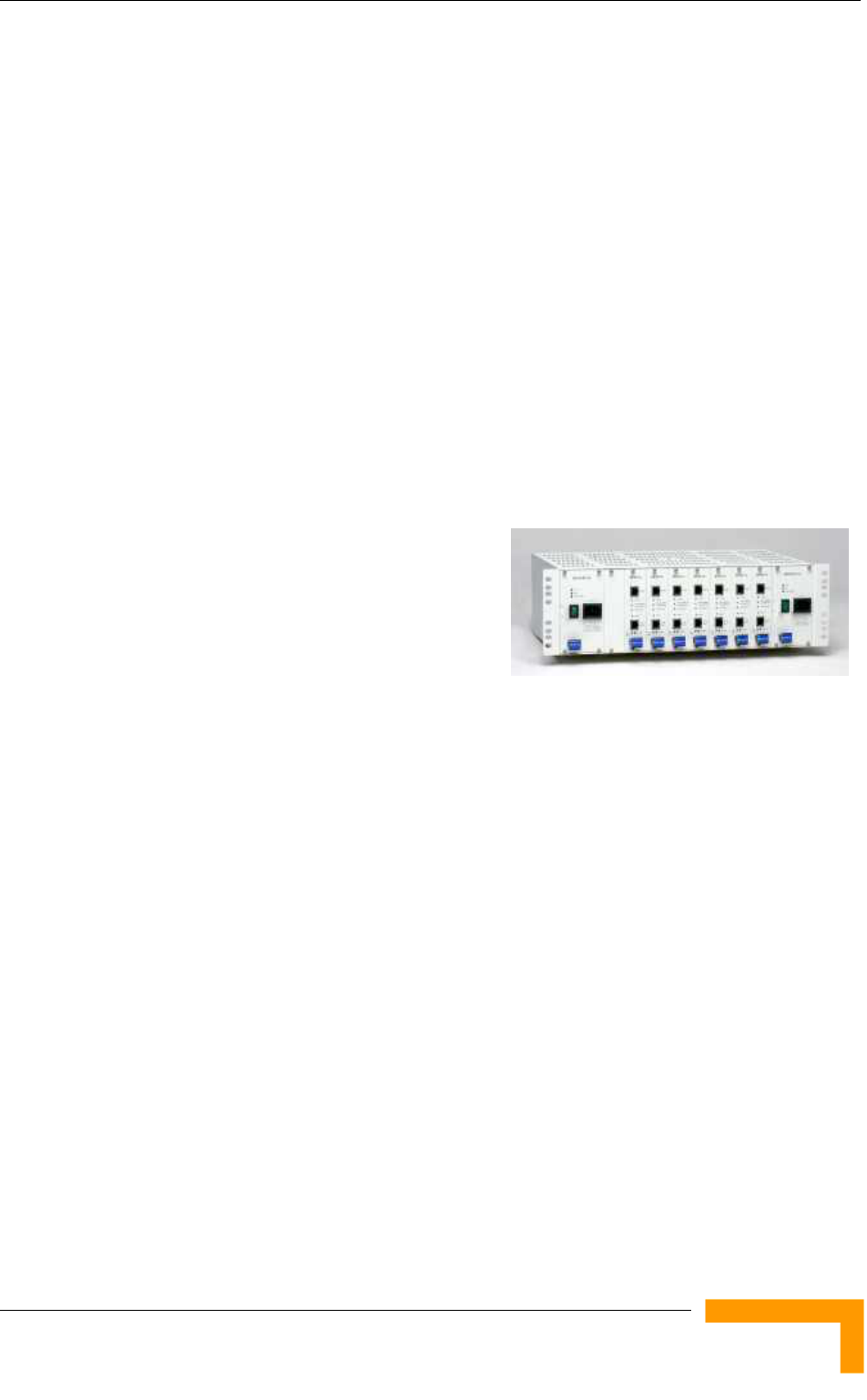
1.2.1 Modular Base Station Equipment
The Base Station Equipment is based on the BS-SH 3U chassis, which is suitable
for installation in 19-inch racks. The chassis contains one or two Power Supply
modules and has 8 slots that can accommodate BS-AU Network Interface
modules. These slots can also
accommodate various combinations of
other modules, including Network
Interface (BS-AU) modules for Access
Units operating in any of the bands
supported by BreezeACCESS VL
equipment or BreezeACCESS equipment using GFSK modulation, including
BreezeACCESS 900, BreezeACCESS II, BreezeACCESS XL and BreezeACCESS V.
It can also accommodate a BS-GU GPS and Alarms module to support GPS-based
synchronization of BreezeACCESS systems using Frequency Hopping radios.
Two different types of power supply modules are available for the BreezeACCESS
4900 chassis: The BS-PS-DC that is powered from a -48 VDC power source, and
the BS-PS-AC, powered from the 110/220 VAC mains. The optional use of two
power supply modules ensures fail-safe operation through power supply
redundancy. When the same chassis is used also for Access Unit modules
belonging to other BreezeACCESS families using GFSK modulation, then one
BS-PS power supply (AC or DC) should be used to provide power to the
BreezeACCESS 4900 Access Units, and a different power supply module, suitable
for GFSK equipment, is required for powering the BreezeACCESS GFSK Access
Units.
Each BS-AU module, together with its outdoor AU-D/E-BS-ODU radio unit and
an antenna comprise an AU-D/E-BS Access Unit that serves a single sector/cell.
One AU-BS Access Unit can serve up to 512 Subscriber Units (124 when Data
Encryption is used).
System Description
3
Chapter 1 - System Description
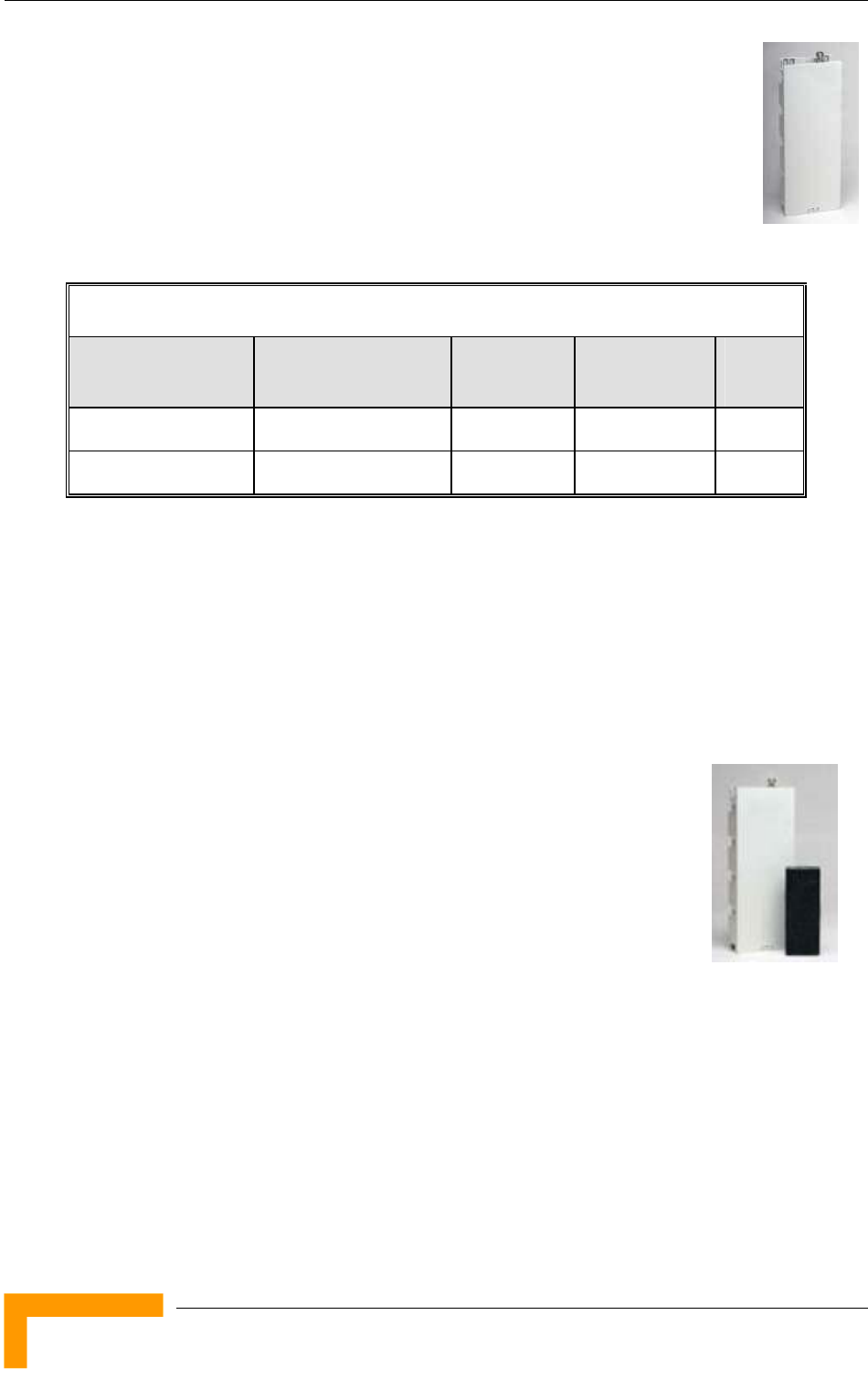
The AU-D/E-BS-ODU outdoor unit contains the processing and
radio modules and connects to an external antenna using a short
RF cable.
E model units, such as the AU-E-BS-4900, are supplied without an
antenna and are primarily intended for Point-to-Point applications.
D model units, namely AU-D-BS-4900-360 and AU-D-BS-4900-120,
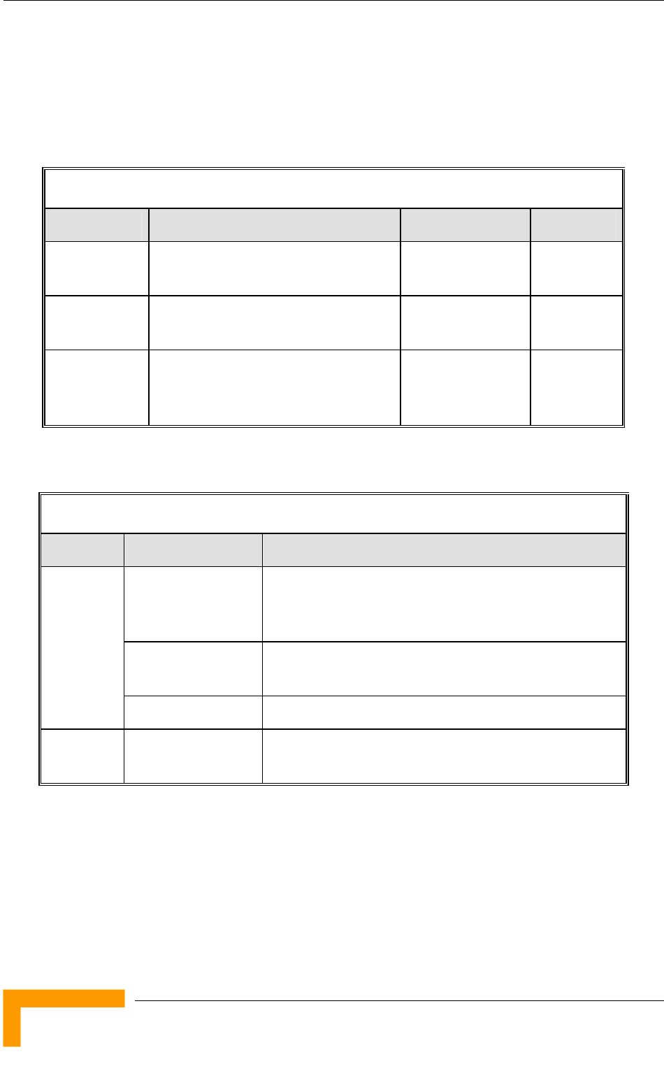
are supplied with a detached antenna, as listed in Table 1-1:
Table 1-1: AU Detached Antennas
Unit Antenna Band (GHz) Horizontal
Beam Width
Gain
(dBi)
AU-D-BS-4900-120 AU-Ant-4.9G-15-120 4.900-5.100 120° 15
AU-D-BS-4900-360 AU-Ant-4.9G-9-Omni 4.900-5.100 360° 9
The BS-AU indoor module connects to the network through a standard IEEE
802.3 Ethernet 10/100BaseT (RJ 45) interface. The indoor module is connected
to the outdoor unit via a Category 5E Ethernet cable. This cable carries Ethernet
traffic between the indoor module and the outdoor unit, and also transfers power
(54 VDC) and control from the indoor module to the outdoor unit.
1.2.2 Standalone “Micro-cell” Access Unit
The standalone AU-D/E-SA Access Unit is very similar to the AU-D/E-BS unit.
The AU-D/E-SA-ODU outdoor unit is very similar to the
AU-D/E-BS-ODU outdoor unit (identical functionality, but the
units are not interchangeable). Units are differentiated based
on the availability of an antenna: E model units are supplied
without an antenna, while D model units are supplied with a
detached antenna.
Available units are:
AU-D-SA-4900-360 (Standalone AU with a 9 dBi omni antenna)
AU-D-SA-4900-120 (Standalone AU with a 15 dBi, 120° sector antenna)
AU-E-SA-4900 (Standalone AU)
The available antennas for D model units are the same as those of the AU-D-BS
Access Unit. The main difference is in the structure of the indoor part; in the AU-
D/E-SA Access Unit the indoor unit is a standalone desktop or wall-mountable
BreezeACCESS 4900 System Manual
4

Base Station Equipment
unit (the same Universal IDU that is also used in the SU) rather than a 19”
module.
The AU-SA Access Unit can serve up to 512 Subscriber Units (124 when Data
Encryption is used).
The IDU connects to the network through a standard IEEE 802.3 Ethernet
10/100BaseT (RJ 45) interfaces and is powered from the 110/220 VAC mains.
The indoor unit is connected to the outdoor unit via a Category 5E Ethernet
cable. This cable carries Ethernet traffic between the indoor and the outdoor
units, and also transfers power (54 VDC) and control from the indoor unit to the
outdoor unit.
NOTE
The AU-D/E-SA-ODU and the AU-D/E-BS-ODU are not interchangeable:
The AU-D/E-SA-ODU cannot be used with the BS-AU; the AU-D/E-BS-ODU cannot be used with
the standalone IDU.
System Description
5
Chapter 1 - System Description
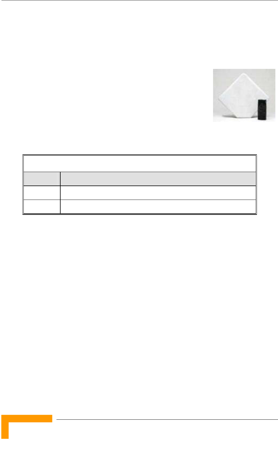
1.3 Subscriber Unit
The Subscriber Unit (SU) installed at locations that require service, enables the
customer data connection to the Access Unit. The Subscriber Unit provides an
efficient platform for high speed Internet and Intranet
services, supporting single or multiple end users. The
use of packet switching technology provides the user
with a connection to the network that is always on,
enabling immediate access to services.
The Subscriber Unit comprise a desktop or wall-
mountable Indoor Unit (IDU) and an outdoor unit that
contains the processing and radio modules. Several ODU types are available to
support different requirements, as detailed in Table 1-2:
Table 1-2: Subscriber Unit ODU Types
SU Type Antenna Description
SU-A-ODU Vertically polarized high-gain flat antenna integrated on the front panel
SU-E-ODU A connection to an external antenna
The Subscriber Unit supports a gross rate of up to 27 Mbps and can bridge a full
LAN.
The IDU provides the interface to the user’s equipment and is powered from the
110/220 VAC mains. The customer's data equipment is connected via a standard
IEEE 802.3 Ethernet 10/100BaseT (RJ 45) interface. The indoor unit is
connected to the outdoor unit via a Category 5E Ethernet cable. This cable
carries Ethernet traffic between the indoor and the outdoor units, and also
transfers power (54 VDC) and control from the indoor unit to the outdoor unit.
BreezeACCESS 4900 System Manual
6

Networking Equipment
1.4 Networking Equipment
The Base Station equipment is connected to the backbone through standard data
communication and telecommunication equipment. The 10/100BaseT ports of
the AU modules can be connected directly to a multi-port router or to an Ethernet
switch connected to a router.
The point-to-point link from the Base Station to the backbone can be either wired
or wireless. Data to the Internet is routed to the backbone through standard
routers.
System Description
7

Chapter 1 - System Description
1.5 Management Systems
The end-to-end IP-based architecture of the system enables full management of
all components, from any point in the system. BreezeACCESS 4900 components
can be managed using standard management tools through SNMP agents that
implement standard and proprietary MIBs for remote setting of operational modes
and parameters. The same SNMP management tools can also be used to manage
other system components including switches, routers and transmission
equipment. Security features incorporated in BreezeACCESS 4900 units restrict
access for management purposes to specific IP addresses and/or directions, that
is, from the Ethernet and/or wireless link.
In addition, the Ethernet WAN can be used to connect to other Operation Support
Systems including servers, Customer Care systems and AAA (Authentication,
Authorization and Admission) tools.
1.5.1 BreezeCONFIG™
The BreezeCONFIG for BreezeACCESS 4900 utility is an SNMP-based application
designed to manage BreezeACCESS 4900 system components and upgrade unit
software versions. The system administrator can use the BreezeCONFIG utility to
control a large number of units from a single location. In addition, BreezeCONFIG
enables you to load an updated configuration file to multiple units
simultaneously, thus radically reducing the time spent on unit configuration
maintenance.
1.5.2 AlvariSTAR™
AlvariSTAR is a comprehensive Carrier-Class network management system for
Alvarion’s Broadband Wireless Access products-based Networks. AlvariSTAR is
designed for today’s most advanced Network Operation Centers (NOCs), providing
the network Operation, Administration and Maintenance (OA&M) staff and
managers with all the network surveillance, monitoring and configuration
capabilities that they require in order to effectively manage the BWA network
while keeping the resources and expenses at a minimum.
AlvariSTAR is designed to offer the network’s OA&M staff with a unified, scalable
and distributable network management system. The AlvariSTAR system uses a
distributed client-server architecture, which provides a robust, scalable and fully
redundant network management system in which all single points of failure can
be avoided.
BreezeACCESS 4900 System Manual
8

Management Systems
AlvariSTAR provides the following BWA network management functionality:
Device Discovery
Device Inventory
Topology
Fault Management
Configuration Management
Performance Monitoring
Device embedded software upgrade
Security Management
Northbound interface to other Network Management Systems or OSS.
System Description
9

Chapter 1 - System Description
1.6 Specifications
1.6.1 Radio
Table 1-3: Radio Specifications
Item Description
Frequency 4.940 – 4.990 GHz
Operation Mode Time Division Duplex (TDD)
Channel Bandwidth 10 MHz / 5 MHz
Central Frequency Resolution 5 MHz
Antenna Port
(AU-D-BS/SA-ODU)
N-Type, 50 ohm
Max. Input Power
(at antenna port)
-40 dBm typical
Maximum Output Power TBD
SU-A-ODU Integral Antenna 20 dBi, 10.5o horizontal x 10.5o vertical,
vertical or horizontal polarization, compliant with EN 302 085
V1.1.1 Range 1, Class TS 1, 2, 3, 4, 5
AU-D Detached Antennas AU-Ant-4.9G-15-120: 15 dBi, 4.900-5.100 GHz,
124o horizontal x 6.5o vertical sector antenna, vertical
polarization, compliant with EN 302 085 V1.1.2 CS3.
AU-Ant-4.9G-9-Omni: 9 dBi, 4.900-5.100 GHz,
360o horizontal x 8o vertical, vertical polarization.
BreezeACCESS 4900 System Manual
10
Specifications
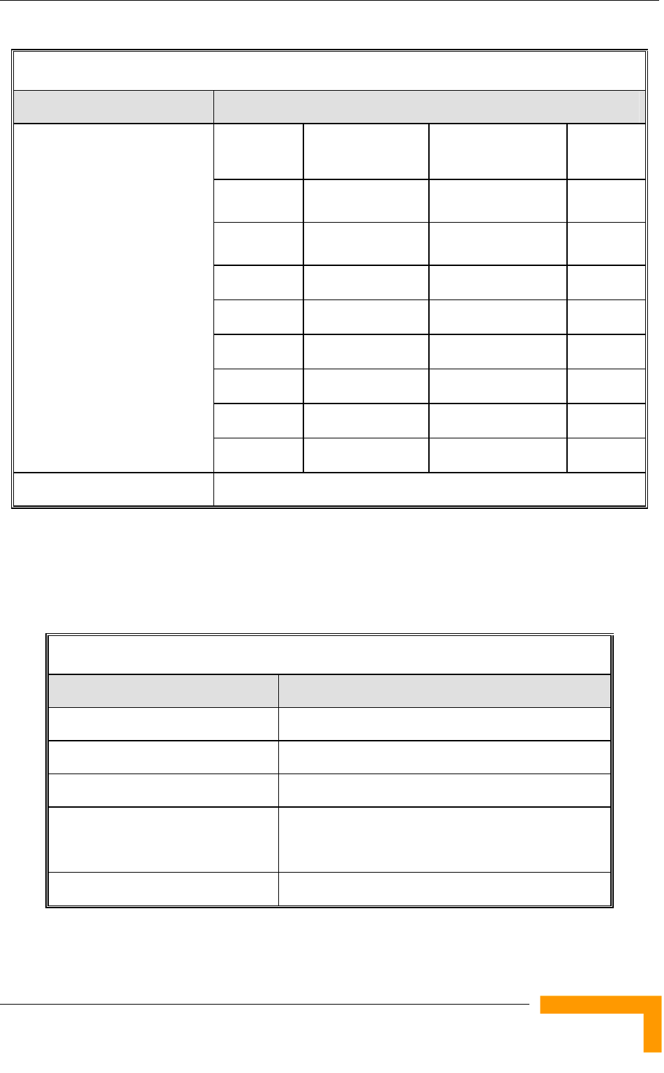
Table 1-3: Radio Specifications
Item Description
Modulation
Level1
Sensitivity
5 MHz bandwidth
Sensitivity
10 MHz bandwidth
Min. SNR
1 -93 dBm -92 dBm 6 dB
2 -92 dBm -91 dBm 7 dB
3 -91 dBm -89 dBm 9 dB
4 -89 dBm -87 dBm 11 dB
5 -86 dBm -84 dBm 14 dB
6 -82 dBm -80 dBm 18 dB
7 -77 dBm -76 dBm 22 dB
Sensitivity, typical (dBm at
antenna port, PER<10%)
8 -75 dBm -74 dBm 23 dB
Modulation OFDM modulation, 64 FFT points; BPSK, QPSK, QAM16, QAM64
1 Modulation Level indicates the radio transmission rate and the modulation scheme. Modulation Level 1 is for the
lowest radio rate and modulation scheme.
1.6.2 Data Communication
Table 1-4: Data Communication
Item Description
Standard compliance IEEE 802.3 CSMA/CD
VLAN Support Based on IEEE 802.1Q
Layer-2 Traffic Prioritization Based on IEEE 802.1p
Layer-3 Traffic Prioritization IP Precedence ToS (RFC791)
DSCP (RFC2474)
Layer 4 Traffic Prioritization UDP/TCP destination ports
System Description
11

Chapter 1 - System Description
1.6.3 Configuration and Management
Table 1-5: Configuration and Management
Type Standard
Management Monitor program via Telnet
SNMP
Configuration upload/download
Management Access From Wired LAN, Wireless Link
Management access protection Multilevel password
Configuration of remote access direction (from
Ethernet only, from wireless link only or from both)
Configuration of IP addresses of authorized stations
Security Authentication messages encryption option
Data encryption option
Selection between WEP, AES/OCB and AES/CCM
128-bit encryption standards
ESSID
SNMP Agents SNMP ver 1 client
MIB II, Bridge MIB, Private BreezeACCESS MIB
Allocation of IP parameters Configurable or automatic (DHCP client)
Software upgrade FTP
TFTP
Configuration upload/download FTP
TFTP
BreezeACCESS 4900 System Manual
12

Specifications
1.6.4 Standards Compliance, General
Table 1-6: Standards Compliance, General
Type Standard
EMC FCC Part 15 class B
Safety UL 60950-1
Radio FCC Part 90
FCC Part 15
System Description
13
Chapter 1 - System Description
1.6.5 Physical and Electrical
1.6.5.1 Subscriber Unit
1.6.5.1.1 Mechanical
Table 1-7: Mechanical Specifications, Subscriber Unit
Unit Structure Dimensions (cm) Weight (kg)
General An IDU indoor unit and an SU-A-ODU
outdoor unit with an integral antenna
IDU PS1073 Plastic box (black), desktop or wall
mountable
14 x 6.6 x 3.5 0.3
SU-A-ODU Metal box plus an integral antenna in
a cut diamond shape in a plastic
enclosure, poll or wall mountable
43.2 x 30.2 x 5.9 1.85
1.6.5.1.2 Connectors
Table 1-8: Connectors, Subscriber Unit
Unit Connector Description
ETHERNET 10/100BaseT Ethernet (RJ-45)
Cable connection to a PC: crossed
Cable connection to a hub: straight
RADIO 10/100BaseT Ethernet (RJ-45)
2 embedded LEDs in PS1036
IDU
AC IN 3 pin AC power plug
SU-A-ODU INDOOR 10/100BaseT Ethernet (RJ-45), protected by a
waterproof sealing assembly
BreezeACCESS 4900 System Manual
14

Specifications
1.6.5.1.3 Electrical
Table 1-9: Electrical Specifications, Subscriber Unit
Unit Details
General Power consumption: 25W
IDU AC power input: 85-265 VAC, 50-60 Hz
SU-A-ODU 54 VDC from the IDU over the indoor-outdoor Ethernet cable
System Description
15

Chapter 1 - System Description
1.6.5.2 Modular Base Station Equipment
1.6.5.2.1 Mechanical
Table 1-10: Mechanical Specifications, Modular Base Station Equipment
Unit Structure Dimensions (cm) Weight (kg)
BS-SH 19" rack (3U) or
desktop
13 x 48.2 x 25.6 4.76
BS-PS-DC DC power supply
module
12.9 x 7.0 x 25.3 1.2
BS-PS-AC AC power supply
module
12.9 x 7.0 x 25.3 1.2
BS-AU Indoor module of the
AU-D-BS access unit
12.9 x 3.5 x 25.5 0.15
AU-D-BS-ODU pole or wall mountable 30.6 x 12.0 x 4.7 1.85
AU-Ant-4.9G-15-120 2"-4" pole mountable 55 x 25 x 1.7 1.5
BreezeACCESS 4900 System Manual
16

Specifications
1.6.5.2.2 Connectors
Table 1-11: Connectors, Modular Base Station Equipment
Unit Connector Description
10/100 BaseT 10/100BaseT Ethernet (RJ-45) with 2 embedded
LEDs.
Cable connection to a PC: crossed
Cable connection to a hub: straight
BS-AU
RADIO 10/100BaseT Ethernet (RJ-45) with 2 embedded
LEDs
INDOOR 10/100BaseT Ethernet (RJ-45), protected by a
waterproof sealing assembly
AU-D-BS-ODU
ANT N-Type jack, 50 ohm, lightning protected
BS-PS-AC AC-IN 3-PIN AC power plug
BS-PS-DC -48 VDC 3 pin DC D-Type 3 power pins plug
Amphenol 717TWA3W3PHP2V4RRM6
Antenna RF N-Type jack (on a 1.5m cable in the Omni-8-5.8)
1.6.5.2.3 Electrical
Table 1-12: Electrical Specifications, Modular Base Station Equipment
Unit Details
General 240W max. for a fully equipped chassis (1 PS, 6 AU)
BS-PS-AC AC power input: 85-265 VAC, 47-65 Hz
DC power output: 54 V; 3.3 V
BS-PS-DC DC power input: -48 VDC nominal (-34 to -72), 10 A max
DC power output: 54 V; 3.3 V
BS-AU 3.3 VDC, 54 VDC from the power supply module(s) via the back plane
AU-D-BS-ODU 54 VDC from the BS-AU over the indoor-outdoor Ethernet cable
AU-D-BS
(IDU+ODU)
Power consumption: 30W
System Description
17

Chapter 1 - System Description
1.6.5.3 Standalone Access Unit
1.6.5.3.1 Mechanical
Table 1-13: Mechanical Specifications, Stand Alone Access Unit
Unit Structure Dimensions (cm) Weight (kg)
General An IDU indoor unit and an
AU-D-BS-ODU outdoor unit
connected to a detached
antenna
IDU PS1073 Plastic box (black), desktop
or wall mountable
14 x 6.6 x 3.5 0.3
AU-D-SA-ODU Poll or wall mountable 30.6 x 12 x 4.7 1.85
AU-Ant-4.9G-15-120 2"-4" pole mountable 55 x 25 x 1.7 1.5
AU-Ant-4.9G-9-Omni 1.5”-3” pole mountable 46 cm high, 5.5 cm
base diameter
0.6
1.6.5.3.2 Connectors
Table 1-14: Connectors, Stand Alone Access Unit
Unit Connector Description
ETHERNET 10/100BaseT Ethernet (RJ-45)
Cable connection to a PC: crossed
Cable connection to a hub: straight
RADIO 10/100BaseT Ethernet (RJ-45).
2 embedded LEDs in the PS1036
IDU
AC IN 3-PIN AC power plug
INDOOR 10/100BaseT Ethernet (RJ-45), protected by a
waterproof sealing assembly
AU-D-SA-ODU
ANT N-Type jack, 50 ohm, lightning protected
Antenna RF N-Type jack
BreezeACCESS 4900 System Manual
18

Specifications
1.6.5.3.3 Electrical
Table 1-15: Electrical Specifications, Stand Alone Access Unit
Unit Details
General Power consumption: 25W
IDU AC power input: 85-265 VAC, 50-60 Hz
AU-D-SA-ODU 54 VDC from the IDU over the indoor-outdoor Ethernet cable
1.6.5.4 Environmental
Table 1-16: Environmental Specifications
Type Unit Details
Outdoor units -40 o C to 55 o C Operating
temperature Indoor equipment 0 o C to 40 o C
Outdoor units 5%-95% non condensing, weather protected Operating
humidity Indoor equipment 5%-95% non condensing
System Description
19


Chapter 2 - Installation
2.1 Installation Requirements
This section describes all the supplies required to install the BreezeACCESS 4900
system components and the items included in each installation package.
2.1.1 Packing List
2.1.1.1 Subscriber Unit
The SU installation kit includes the following components:
IDU indoor unit with a wall mounting kit
Mains power cord
Outdoor Unit:
SU-A-ODU outdoor unit with an integrated vertically polarized antenna
OR
SU-E-ODU outdoor unit with a connection to an external antenna
Pole mounting kit for the ODU
20m Category 5E indoor-to-outdoor Ethernet cable with shielded RJ-45
connectors
2.1.1.2 Modular Base Station Equipment
This section describes the items included in the installation packages for each
Modular Base Station system component.
2.1.1.2.1 BS-SH Base Station Chassis
The BS-SH installation kit includes the following components:
BS-SH chassis with blank panels
Rubber legs for optional desktop installation
2.1.1.2.2 AU-D/E-BS Access Unit
The AU-D/E-BS and installation kit includes the following components:
BS-AU Network Interface module
BreezeACCESS 4900 System Manual
22

Installation Requirements
AU-D/E-BS-ODU outdoor unit
Pole mounting kit for the AU-D/E-BS-ODU
In AU-D-BS kits: Antenna, including pole mounting hardware
RF cable
2.1.1.2.3 BS-PS-AC Power Supply
Up to two BS-PS-AC power supply modules can be included in each Base Station
chassis. The BS-PS-AC installation kit includes the following components:
BS-PS-AC power supply module
Mains power cord
2.1.1.2.4 BS-PS-DC Power Supply
Up to two BS-PS-DC power supply modules can be included in each Base Station
chassis. The BS-PS-DC installation kit includes the following components:
BS-PS-DC power supply module
DC power cable
2.1.1.3 AU-D/E-SA Standalone Access Unit
The AU-D/E-SA installation kit includes the following components:
IDU indoor unit with a wall mounting kit
Mains power cord
AU-D/E-SA-ODU outdoor unit with an integrated antenna
Pole mounting kit for the AU-D/E-SA-ODU
In AU-D-SA kits: Antenna, including pole mounting hardware
RF cable
2.1.1.4 Additional Installation Requirements
The following items are also required to install the BreezeACCESS 4900 system
components:
Installation
23

Chapter 2 - Installation
Indoor-to-outdoor Category 5E Ethernet cable with shielded RJ-45 connectors
* (available in different lengths. For more details refer to section 2.1.2
)
Ethernet cable (straight for connecting to a hub/switch etc., crossed for
connecting directly to a PC’s NIC)
Crimping tool for RJ-45 connectors
Antenna, for E model units supplied without an antenna
Ground cables with an appropriate termination
Mains plug adapter or termination plug (if the power plug on the supplied AC
power cord does not fit local power outlets)
Portable PC with Ethernet card and Telnet software or BreezeCONFIG for
BreezeACCESS 4900* application and a crossed Ethernet cable
Installation tools and materials, including appropriate means (e.g. a pole) for
installing the outdoor unit.
NOTE
Items marked with an asterisk (*) are available from Alvarion.
2.1.2 Indoor-to-Outdoor Cables
NOTE
The length of the Ethernet cable connecting the indoor unit to the user's equipment, together with
the length of the Indoor-to-Outdoor cable, should not exceed 100 meters.
Use only Category 5E Ethernet cables from approved manufacturers, listed in
Table 2-1. Consult with Alvarion specialists on the suitability of other cables.
BreezeACCESS 4900 System Manual
24

Installation Requirements
Table 2-1: Approved Category 5E Ethernet Cables
Manufacturer Part Number
Superior Cables Ltd.
www.cvalim.co.il
612098
HES Cabling Systems
www.hescs.com
H5E-00481
Teldor
www.teldor.com
8393204101
Southbay Holdings Limited
11th Fl., 15, Lane 347, Jong Jeng Rd.
Shin Juang City, Taipei County
Taiwan, R.O.C
Attn: Eva Lin
Tel. 886-2-2832 3339
Fax. 886-2-2206 0081
E-mail: eva@south-bay.com.tw
TSM2404A0D
Installation
25

Chapter 2 - Installation
2.2 Equipment Positioning Guidelines
This section provides key guidelines for selecting the optimal installation
locations for the various BreezeACCESS 4900 system components.
CAUTION
ONLY experienced installation professionals who are familiar with local building and safety codes
and, wherever applicable, are licensed by the appropriate government regulatory authorities should
install outdoor units and antennas.
Failure to do so may void the BreezeACCESS 4900 product warranty and may expose the end
user or Service Provider to legal and financial liabilities. Alvarion and its resellers or distributors are
not liable for injury, damage or regulation violations associated with the installation of Outdoor Units
or antennas.
Select the optimal locations for the equipment using the following guidelines:
The outdoor unit can be either pole or wall mounted. Its location should
enable easy access to the unit for installation and testing.
The higher the placement of the antenna, the better the achievable link
quality.
AU-ODU units should be installed as close as possible to the antenna.
The antenna connected to the AU-ODU unit, should be installed so as to
provide coverage to all Subscriber Units (SUs) within its service area.
NOTE
The recommended minimum distance between any two antennas serving adjacent sectors is 2
meters. The recommended minimum distance between two antennas serving opposite cells
(installed back-to-back) is 5 meters.
The antenna of the SU (integrated on the front side of SU-A-ODU and SU-A-H-
ODU unit) should be installed to provide a direct, or near line of sight with the
Base Station antenna. The antenna should be aligned to face the Base
Station.
The indoor equipment should be installed as close as possible to the location
where the indoor-to-outdoor cable enters the building. The location of the
indoor equipment should take into account its connection to a power outlet
and the CPE.
BreezeACCESS 4900 System Manual
26

Installing the Outdoor Unit
2.3 Installing the Outdoor Unit
The following sections describe how to install the outdoor units, including pole
mounting the ODU, and connecting the indoor-to-outdoor, grounding and RF
cables.
NOTE
Ensure that outdoor units, antennas and supporting structures are properly installed to eliminate
any physical hazard to either people or property. Make sure that the installation of the outdoor unit,
antenna and cables is performed in accordance with all relevant national and local building and
safety codes. Even where grounding is not mandatory according to applicable regulation and
national codes, it is highly recommended to ensure that the outdoor unit and the antenna pole
(when using external antenna) are grounded and suitable lightning protection devices are used so
as to provide protection against voltage surges and static charges. In any event, Alvarion is not
liable for any injury, damage or regulation violations associated with or caused by installation,
grounding or lightning protection.
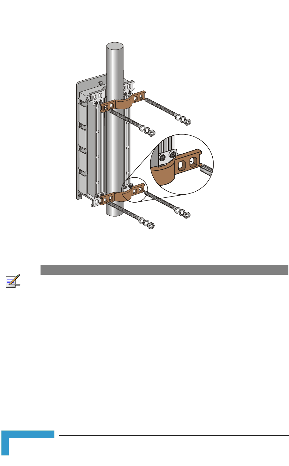
2.3.1 Pole Mounting the Outdoor Unit
The Outdoor Unit can be mounted on a pole using one of the following options:
Special brackets and open-ended bolts are supplied with each unit. There are
two pairs of threaded holes on the back of the unit, enabling the special
brackets to be mounted on diverse pole diameters.
Special grooves on the sides of the unit enable the use of metal bands to
secure the unit to a pole. The bands must be 9/16 inches wide and at least 12
inches long. The metal bands are not included with the installation package.
NOTE
Be sure to mount the unit with the bottom panel, which includes the LED indicators, facing
downward.
Installation
27
Chapter 2 - Installation
Figure 2-1 illustrates the method of mounting an outdoor unit on a pole, using
the brackets and open-ended bolts.
Figure 2-1: 3" Pole Installation Using Special Brackets
NOTE
Be sure to insert the open ended bolts with the grooves pointing outward, as these grooves enable
you to use a screwdriver to fasten the bolts to the unit.
BreezeACCESS 4900 System Manual
28
Installing the Outdoor Unit
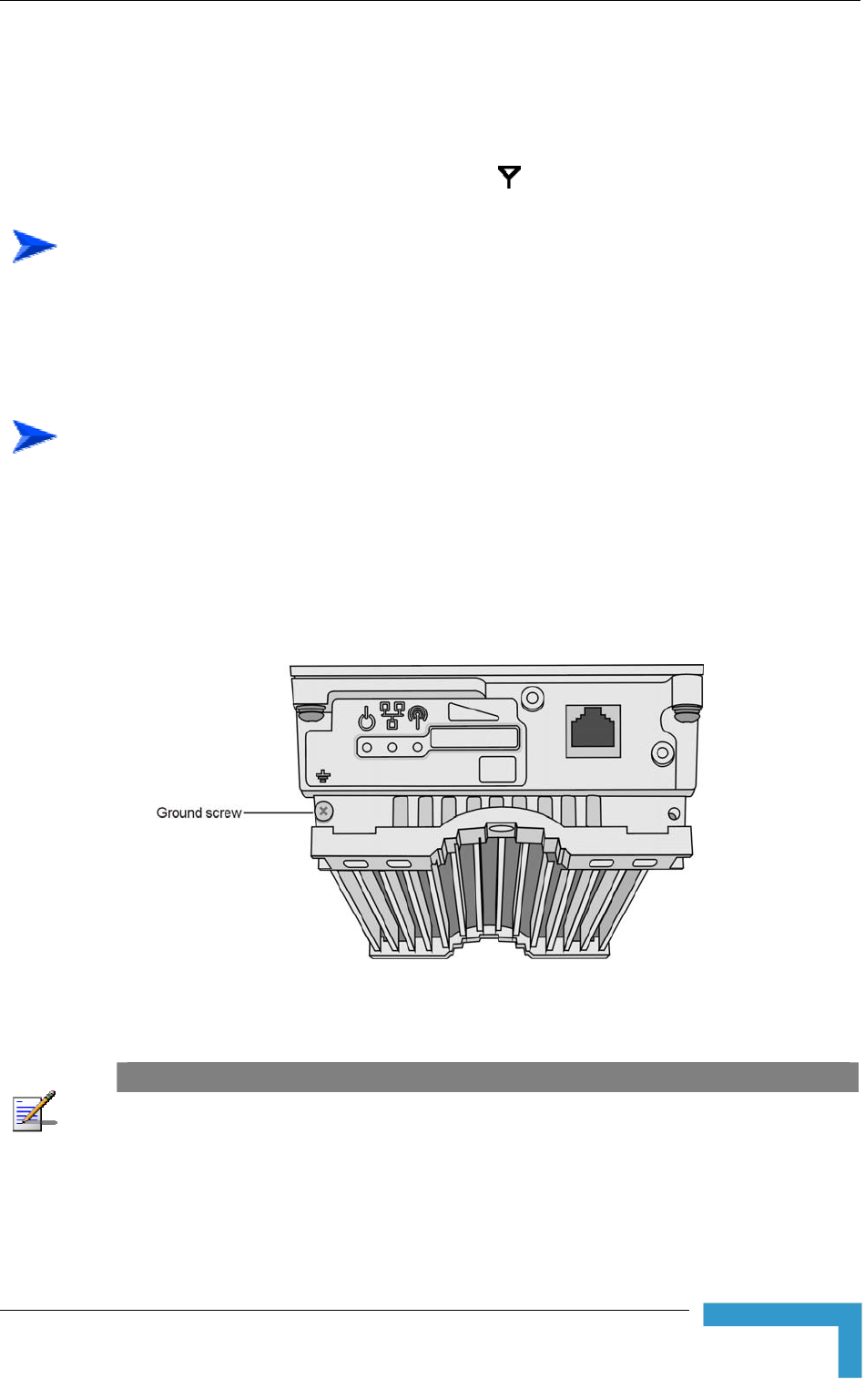
2.3.2 Connecting the Grounding and Antenna
Cables
The Grounding screw (marked ╤) is located on the bottom panel of the outdoor
unit. The Antenna RF connector (marked ) is located on the top panel of the
AU-ODU.
To connect the grounding cable:
1 Connect one end of a grounding cable to the grounding terminal and tighten
the grounding screw firmly.
2 Connect the other end of the grounding cable to a good ground (earth)
connection.
To connect the RF cable (units with external antenna):
1 Connect one end of the coaxial RF cable to the RF connector on the top panel
of the unit
2 Connect the other end of the RF cable to the antenna.
3 The RF connectors should be properly sealed to protect against rain and
moisture.
Figure 2-2: Bottom Panel of the Outdoor Unit (without the seal assembly)
NOTE
The MAC Address of the unit is marked on both the ODU and the indoor unit (on the print side of
the BS-AU module or on the bottom side of the Universal IDU). If for any reason the ODU is not
used with the IDU with which it was shipped, the MAC Address of the system is in accordance with
the marking on the ODU.
Installation
29
Chapter 2 - Installation
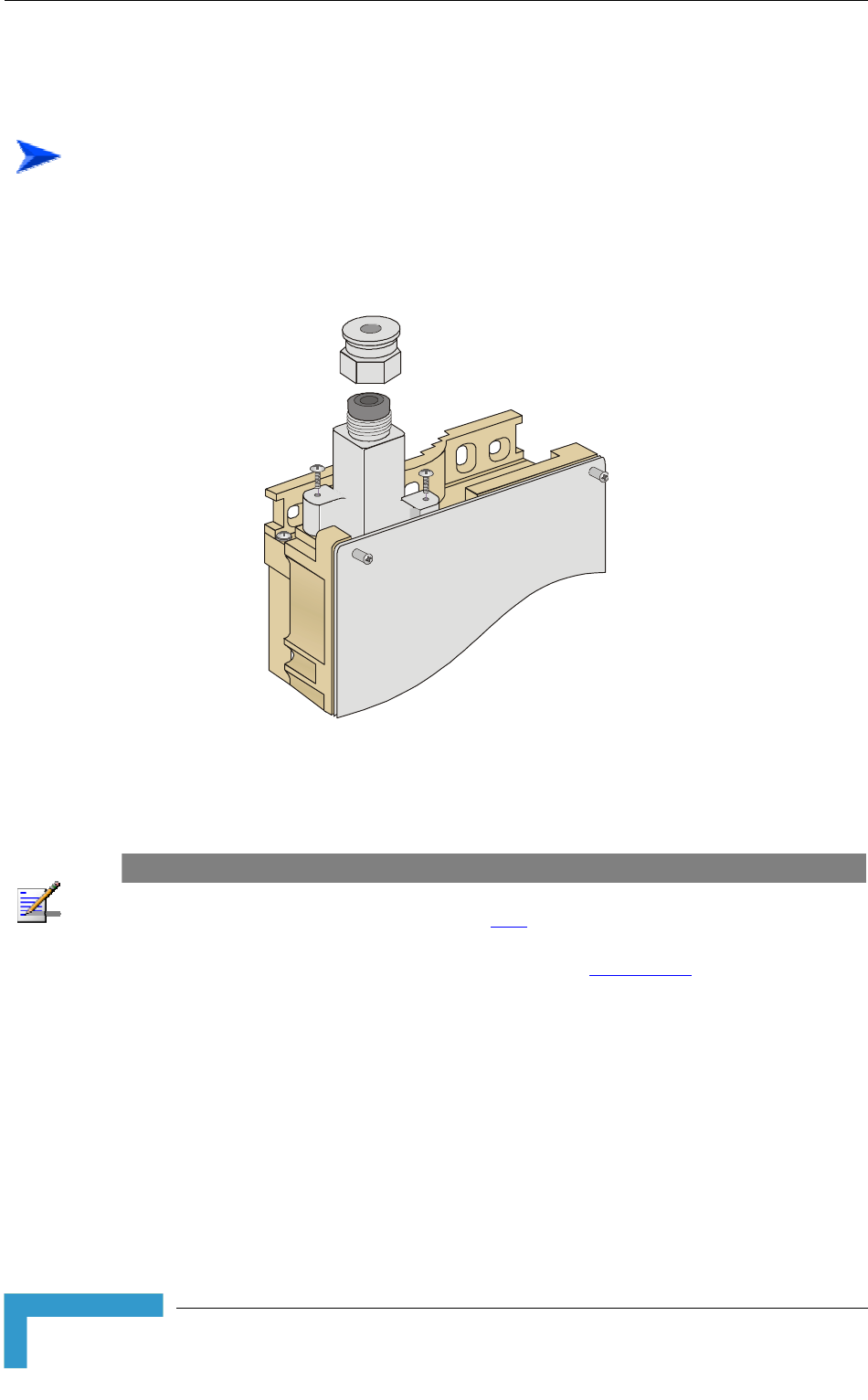
2.3.3 Connecting the Indoor-to-Outdoor Cable
2.3.3.1 Units with an Installed Waterproof Seal
To connect the indoor-to-outdoor cable:
1 Remove the two screws holding the waterproof seal to the outdoor unit and
remove the waterproof seal.
2 Unscrew the top nut from the waterproof seal.
Figure 2-3: The Waterproof Seal
3 Route a straight Category 5E Ethernet cable (8-wire, 24 AWG) through both
the top nut and the waterproof seal.
NOTE
Use only Category 5E 4x2x24# FTP outdoor cables from an approved manufacturer. See list of
approved cables and length limitations in section 2.1.2.
4 Insert and crimp the RJ-45 connector. Refer to Appendix C for instructions on
preparing the cable.
5 Connect the Ethernet cable to the outdoor unit RJ-45 connector.
6 Replace the waterproof seal and then the top nut. Make sure that the external
tee a good seal. jack of the cable is well inside the waterproof seal to guaran
7 Route the cable to the location selected for the indoor equipment.
8 Assemble an RJ-45 connector with a protective cover on the indoor end of the
indoor-to-outdoor cable.
BreezeACCESS 4900 System Manual
30

Installing the Outdoor Unit
2.3.3.2 Units with a Waterproof Seal Supplied with the Ethernet
Cable
To connect the indoor-to-outdoor cable:
1 Verify that the o-ring supplied with the cable kit is in place.
2 Connect the RJ-45 connector of the Ethernet cable to the outdoor unit.
3 Attach the waterproof seal to the unit. Tighten the top nut.
4 Route the cable to the location selected for the indoor equipment.
5 Assemble an RJ-45 connector with a protective cover on the indoor end of the
indoor-to-outdoor cable.
See Appendix C for instructions on preparing the cable.
Installation
31
Chapter 2 - Installation
2.4 Installing the Universal IDU Indoor Unit
used to facilitate
n in the following figure:
The unit can be placed on a desktop or a shelf. Alternatively, it may be wall-
mounted. The drilling template included with the unit can be
the wall installation process.
The equipment is shipped with a PS1073 IDU, show
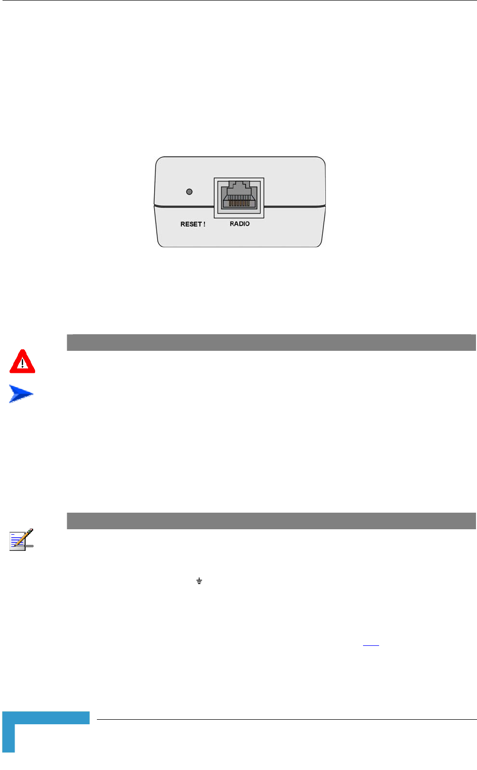
Figure 2-4: IDU PS 1073 Front Panel
The RADIO connector and RESET button are located on the front panel, the
ETHERNET connector is located on the side panel and LEDs are located on the
top panel.
CAUTION
Do not connect the data equipment to the RADIO port. The RADIO port supplies DC power to the
ODU, and this may harm other equipment connected to it.
To install the IDU:
1 Connect the Indoor-to-Outdoor cable to the RADIO connector, located on the
front panel of the indoor unit.
2 Connect the power cord to the unit's AC socket, located on the rear panel.
Connect the other end of the power cord to the AC mains. The unit can
operate with AC mains of 100-240 VAC, 50-60 Hz.
NOTE
The color codes of the power cable are as follows:
Brown Phase ~
Blue Neutral 0
Yellow/Green Ground
3 Verify that the POWER LED is lit, indicating that power is supplied to the
unit.
4 Configure the basic parameters as described in section 3.1.
5 Connect the 10/100 BaseT ETHERNET connector to the network. The cable
connection should be a straight Ethernet if connecting the indoor unit to a
BreezeACCESS 4900 System Manual
32

Installing the Universal IDU Indoor Unit
hub/switch and a crossed cable if connecting it directly to a PC Netw
Interface Card (NIC).
ork
NOTE
The length of the Ethernet cable connecting the indoor unit to the user's equipment, together with
the length of the Indoor-to-Outdoor cable, should not exceed 100 meters.
2.4.1
p object, press the recessed RESET button for a short time to reset
The RESET button can also be used for setting the unit to its factory defaults.
ops
blinking): the unit will reboot with the factory default configuration.
RESET Button Functionality
Using a shar
the unit and reboot from the Main version.
Press the button for at least 5 seconds (until the ETH LED of the IDU st
NOTE
Reset the ODU using the RESET button on the IDU after connecting or reconnecting the indoor
and outdoor units with the indoor-to-outdoor cable.
Installation
33
Chapter 2 - Installation
2.5 Installing the Modular Base Station
Equipment
The following sections describe the slot assignment for the Base Station chassis,
provide illustrated descriptions of the power supply modules and Access Unit
network interface modules, and describe how to install the Base Station
equipment.
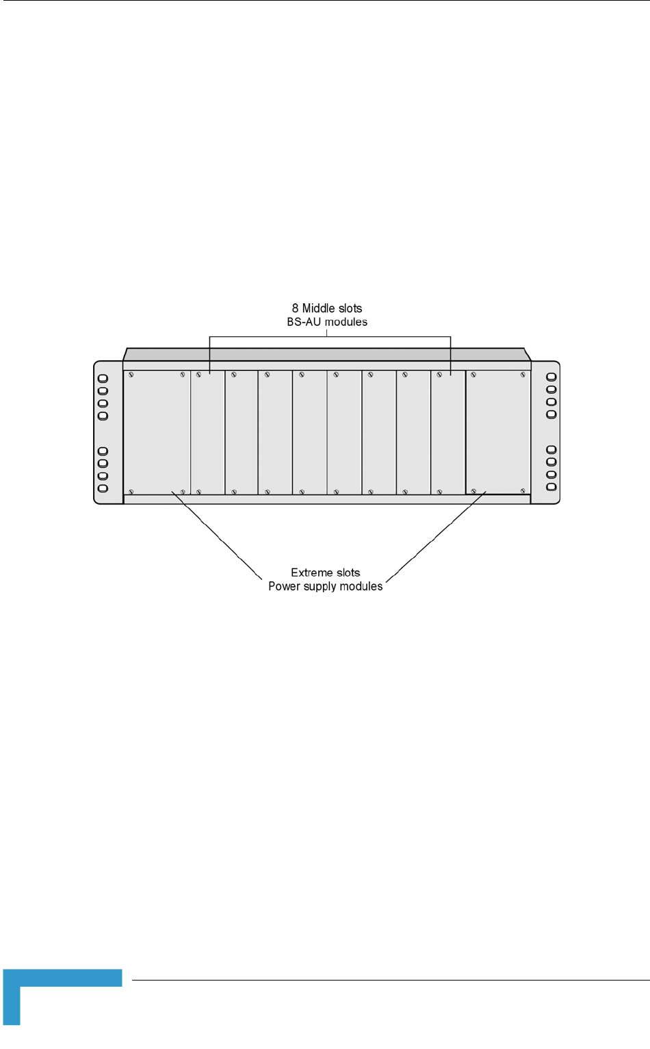
2.5.1 BS-SH Slot Assignment
The Base Station chassis comprises ten slots, as shown in Figure 2-5.
Figure 2-5: BS-SH Chassis Slot Assignment
To enable power supply redundancy, two BS-PS power supply modules can be
ed i ide slots. If a single power supply module is used, it can be
inserted into either one of the two available slots.
The remaining eight slots can hold up to six BS-AU modules. Unused slots
should rem
sign s
Units with longing to BreezeACCESS VL family or other
rts any mixture of
CESS GFSK BS-AU
00
s and one BS-PS GFSK (AC or DC) for the BreezeACCESS GFSK
install n the wider s
ain covered until required.
The de of the BS-SH supports collocation of BreezeACCESS 4900 Acces
Access Units be
BreezeACCESS families using GFSK modulation. It suppo
BS-AU 4900 modules with BreezeACCESS VL or BreezeAC
modules, including an optional BS-GU-GPS module. If Access Units belonging to
BreezeACCESS GFSK families are used, then it is necessary to use two power
supply modules: one BS-PS (AC or DC) power supply for the BreezeACCESS 49
Access Unit
BreezeACCESS 4900 System Manual
34
Installing the Modular Base Station Equipment
Access Units. The es can be used to power also
2.5.2 Module
ides power to all the BS-AU
modul assis. Figure 2-6 shows the BS-PS-AC front
same BS-PS power supply modul
BreezeACCESS VL BS-AU modules.
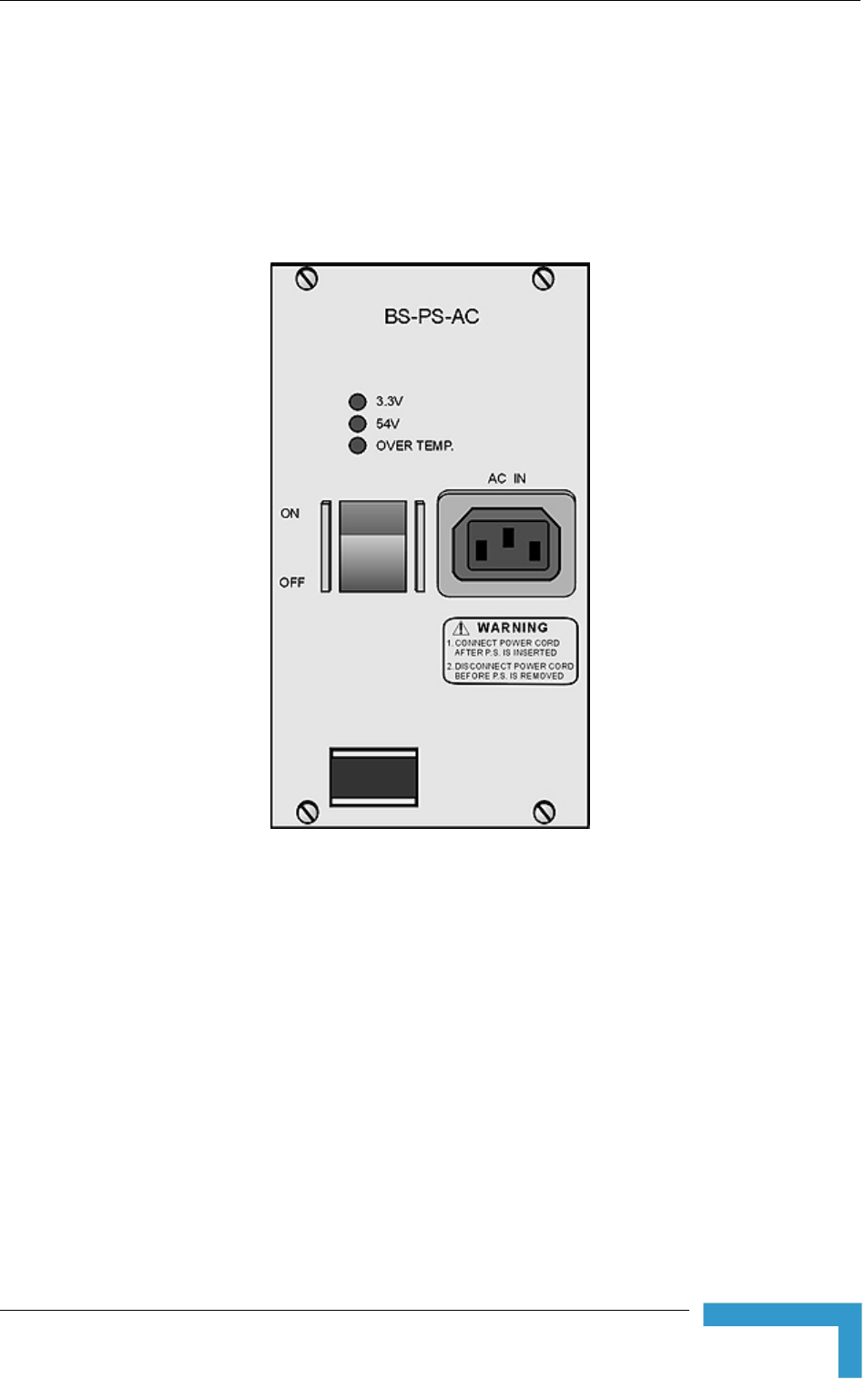
BS-PS-AC Power Supply
The BS-PS-AC is an AC to DC converter that prov
es installed in the BS-SH ch
panel.
Figure 2-6: BS-PS-AC Front Panel
The BS-PS-AC includes a power input connector, marked AC IN, for connecting
the AC power cord to the mains.
The ON/OFF Power Switch controls the flow of mains power to the power supply
module.
Installation
35
Chapter 2 - Installation
Table 2-2: BS-PS LED Functionality
Name Description
54V es that the 54V power supply module is OK Green LED. Indicat
3.3V Green LED. Indicates that the 3.3V power supply module is OK
OVER Red LED. Indicates an over temperature condition in the power supply TEMP
module
2.5.3
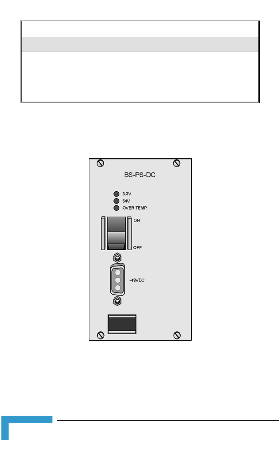
BS-PS-DC Power Supply Module
The BS-PS-DC is a DC-to-DC converter that provides power to all the BS-AU
modules installed in the BS-SH chassis. Figure 2-7 shows the BS-PS-DC front
panel.
Figure 2-7: BS-PS-DC Front Panel
Th BS-PS-DC provides a power input connector, marked -48VDC, for connect
-48 VDC power sou
e ing
the rce to the module.
e
Black (pin 2): 48 VDC
Th color codes of the cable wires are as follows:
BreezeACCESS 4900 System Manual
36
Installing the Modular Base Station Equipment
The N ower to the power supply
module
e
2.5.4 B
Fig ss Unit Network Interface
module.
Red (pin 1): + (Return)
Shield (pin 3)
O /OFF Power Switch controls the flow of mains p
.
Th functionality of the LEDs is described in Table 2-2.
S-AU Network Interface Module
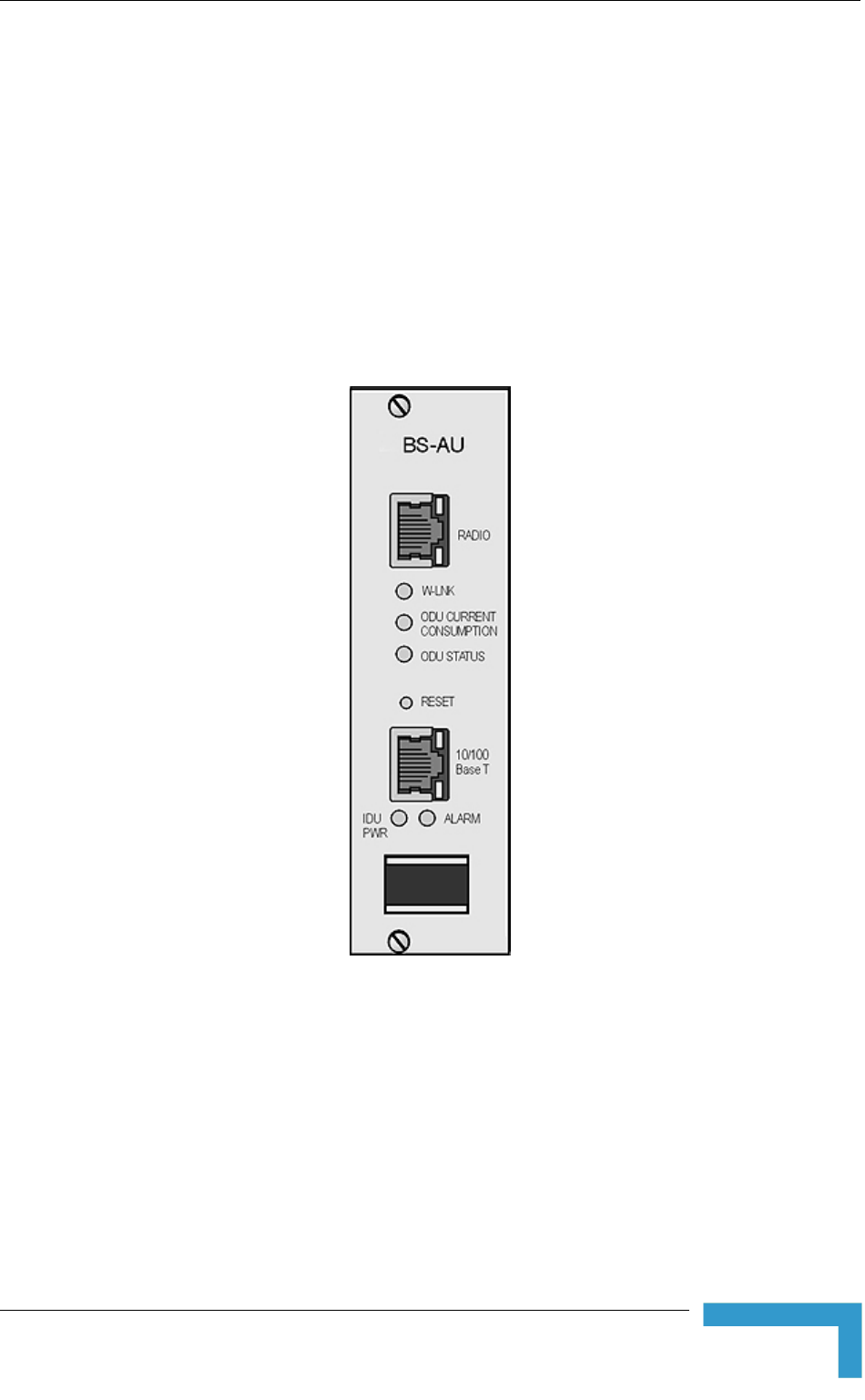
ure 2-8 shows the front panel of the BS-AU Acce
Figure 2-8: BS-AU Front Panel
The BS-AU provides the following interfaces:
10/100 BaseT: A 10/100BaseT Ethernet connector for connecting the BS-AU
to the network. A straight Ethernet cable should be used to connect the
module to a hub, router or switch.
RADIO: A 10/100BaseT Ethernet connector for connecting the BS-AU to an
AU-ODU outdoor unit.
Installation
37

Chapter 2 - Installation
CAUTION
Do not connect the data equipment to the RADIO port. The RADIO port supplies DC power to the
ODU, and this may harm other equipment connected to it.
The recessed RESET switch on the front panel is for resetting the outdoor unit.
2.5.5 Installing the BS-SH Chassis and Modules
This section describes how to install the power supply and Access Unit network
interface modules in the Base Station chassis.
To install the BS SH chassis and modules:
1 Install the BS-SH chassis in a 19” cabinet. To prevent over-heating, leave a
free space of at least 1U between the upper/lower covers of the BS-SH chassis
and other units in the cabinet.
OR
Place the BS-SH chassis on an appropriate shelf or table. When mounting the
BS-SH on a shelf or table, attach the rubber legs supplied with the unit.
2 Connect one end of a grounding cable to the ground terminal located on the
rear panel of the BS-SH chassis and firmly tighten the grounding screw.
3 Connect the opposite end of the grounding cable to a ground connection or to
the cabinet, if applicable.
4 Carefully insert the BS-PS power supply and the BS-AU modules into the
relevant slots and push firmly until they are securely locked. Before insertion,
verify that the switches of all BS-PS modules are in the OFF position. Refer to
section 2.5.1 for a description of the slot assignment.
5 Close the captive screws attached to each module.
6 Place blank covers over all of the unused slots.
7 Connect the indoor-to outdoor cable(s) to the RADIO connector(s) of the
BS-AU module(s).
8 If a BS-PS-DC power supply is used, connect the DC power cord to the -48
VDC IN jack of the BS-PS-DC power supply. If a redundant power supply
module is installed, connect a DC power cord also to the second DC power
module. Connect the power cord(s) to the -48 VDC power source, as follows:
a Connect the black wire to the 48 VDC contact of the power source.
b Connect the red wire to the + (Return) contact.
c Connect the shield to the ground.
BreezeACCESS 4900 System Manual
38

Installing the Modular Base Station Equipment
9 If a BS-PS-AC power supply is used, connect the AC power cord to the AC IN
jack of the BS-PS-AC power supply. If a redundant power supply mo
installed, connect an AC power cord also to the second AC power mo
Connect the power cord(s) to the mains outlet.
10 Switch the BS-PS-AC/DC power supplies to ON. Verify that all powe
indicator LEDs on the BS-PS-AC/DC front panel are ON and that th
OVERTEMP alarm indicator is off. Refer to Table 2-2 for a descriptio
LEDs.
11 Configure the basic parameters in all BS-AU modules as described in section
3.1
dule is
dule.
r
e
n of these
.
r(s) to the network. The cable
connecting the indoor unit to a
hub/switch and a crossed cable if connecting it directly to a PC Network
Interface Card (NIC).
12 Connect the 10/100 BaseT LAN connecto
connection should be straight Ethernet if
NOTE
The length of each of the Ethernet cables (the cable connecting the indoor unit to the user's
equipment and the Indoor-to-Outdoor cable) should not exceed 100 meters.
Reset the unit using the RESET button after connecting or reconnecting the indoor and outdoor
units with the indoor-to-outdoor cable.
Installation
39


Chapter 3 - Commissioning
3.1 Configuring Basic Parameters
After completing the installation process, as described in the preceding chapter,
the basic parameters must be configured to ensure that the unit operates
basic p rs have been configured, additional parameters
remotely configured via the Ethernet port or the wireless link using Telnet
P management, or a configuration file.
1
correctly. After the aramete
can be
or SNM by loading
Refer to section 4. for info n on how to access the Monitor program using
.
c Configuration m cludes all the parameters necessary for the
initial installation and operation of Subscriber and Access Units. In many
tions, most of thes ld not b changed from their default
values. The basic paramet ault values are listed in Table 3-1.
efer to Chapter 4
rmatio
Telnet and how to use it
The Basi enu in
installa e parameters shou
ers and their def
e
R for detailed information on the applicable parameters.
Table 3-1: Basic Parameters
Parameter Default Value Comment
Ethernet Port Negotiation Mode (in
Unit Control Parameters)
Auto Negotiation
IP Address 10.0.0.1
Subnet Mask 255.0.0.0
Default Gateway Address 0.0.0.0
DHCP Options Disable
Access to DHCP AU: From Ethernet Only
SU: From Wireless Only
ESSID ESSID1
Sub-Band Select 1
Frequency Subset Definition (SU) A (All) The list of frequencies is
in accordance with the
Sub-Band.
BreezeACCESS 4900 System Manual
42

Configuring Basic Parameters
Table 3-1: Basic Parameters
Parameter Default Value Comment
Tx Powe
to 5,
Tx Power for Modulation Level 6,
Tx Power for n Level 7,
Tx Powe
parameter.
r for Modulation Levels 1 Dependent on Sub-Band Tx Power cannot be
higher than the applicable
Maximum Tx Power
Modulatio
r for Modulation Level 8
Maximum Tx Power for Modulation
evels 1
Maximu
Level 6 (SU),
Maximum Tx Power for Modulation
Level 7
Maximum T
Level 8 (SU
n Sub-Band
Max Tx Power cannot be
higher than the upper
L to 5 (SU),
Dependent o
m Tx Power for Modulation limit according to the
Sub-Band in use.
(SU)
x Power for Modulation
)
Tx Power (AU) On
Antenna Gai
antenna
ing to the antenna If set to “Not Set Yet”,
n (units with external Accord
) supplied with the unit and
the Sub-Band.
must be configured
according to actual value,
taking into account
cable’s attenuation.
ATPC Option Enable
Best AU Support (SU) Disable
Preferred A
Best AU Support is
enabled.
U MAC Address (SU) 00-00-00-00-00-00 (none) Applicable only when
Cell Distance Mode (AU) Automatic
Maximum Cell Distance (AU) 0 (No Compensation)
Maximum Modulation Level (SU) 8 Refer to section 3.3.
VLAN ID-Management 65535
Authentication Algorithm Open System
Commissioning
43

Chapter 3 - Commissioning
Table 3-1: Basic Parameters
Parameter Default Value Comment
Data Encryption Option Disable
Security WEP Mode
Default Multicast Key (AU) Key 1
Promiscuous Authentication (AU) Disable
Default Key (SU) Key 1
Key 1 to Key 4 00……0 (32 zeros,
meaning no key)
NO
TE
So e parameters are changed to their new values only after reset (refer to Appendix Em for more
details). After the basic parameters are configured, the unit should be reset in order to activate the
new configuration.
BreezeACCESS 4900 System Manual
44

Aligning the Subscriber Unit Antenna
3.2 ligning the Subscriber Unit Antenna
The SNR bar display is located on the bottom panel of the outdoor unit. The ten
LEDs indicate the quality of the re e number of green
LEDs indicating On, the higher the quality of the received signal. This section
es how to align the Subscriber Unit antenna using the SNR bar display.
A
ceived signal. The higher th
describ
NOTE
Antenna alignment using the SNR bar dis y is possible only after the Subscriber Unit is pla
associated with an Access Unit. The associ ccess Unit must be operational and the basic ated A
Subscriber Unit parameters must be corre y configured. Otherwise, the unit will not be able to ctl
synchronize with the Access Unit. As the R measurement is performed on received frames, its SN
results are meaningless unless the Subscri it is associated with an Access Unit. ber Un
To align the Subscriber Unit antenna:
antenna by pointing it in the general direction of the Base Station.
at the power indicatio f the unit is On.
3 Verify that the W-LINK LED of the ODU is On, indicating that the unit is
associated with an Access Unit. If the W-LINK LED is Off, check that the
ESSID and Frequency parameters are correctly configured. If the SU is still
not associated with the AU, increase the transmit power level to its maximum
value. If the unit is still not associated with the AU, improve the quality of the
link by changing the direction of the antenna or by placing the antenna at a
higher or alternate location.
4 Rotate the antenna until the maximum SNR reading is achieved, where at
least 1 green LED is on. If you encounter prolonged difficulty in illuminating
the minimum required number of green LEDs, try to improve the reception
quality by placing the antenna at a higher point or in an alternate location.
5 Ensure that the front of the antenna is always facing the Base Station.
However, in certain conditions, such as when the line of site to the Base
Station is hampered, better reception may be achieved using a reflected
signal. In this case, the antenna is not always directed toward the Base
Station.
6 Secure the unit firmly to the pole.
1 Align the
2 Verify th n o
NOTE
In some cases, the antenna may need to be tilted to ensure that the level at which the SU receives
transmissions from the AU (and vice versa) is not too high. As a rule of thumb, if the SU is located
at a distance of less than 300 meters from the AU, it is recommended to up-tilt the antenna by
approximately 10° to 15°. To guarantee a safety margin from the saturation level (received signal
of –40 dBm at the antenna port), the SNR should not be higher than 50 dB. The orange LED of the
SNR bar indicates that the SNR is higher than 50 dB.
Commissioning
45

Chapter 3 - Commissioning
3.3 Configuring the Subscriber Unit’s
Maximum Modulation Level
or This section describes how to configure the maximum modulation level f
Subscriber Units.
NOTE
If the unit is associated with the AU, then the final configuration of the Maximum Modulation Level
parameter may be performed remotely, for example, from the site of the AU or from another site.
To configure the Maximum Modulation Level:
value that is lower
than the maximum supported by the unit. This can decrease the number of
r transmissions due to attempts to transmit at modulation levels that are too
high for the actua
2 Check the SNR of the SU at the AU. You can use Telnet to view the SNR
values in dress D h can be accessed from the Site
Survey m TPC al he
test sho ne with the In Level at the SU configured to its
maximum value. If the SNR d for the
maximum modulation level ac ommended that
you decrease the value of the
1 If the SNR of the SU at the AU is too low, it is recommended that you
configure the Maximum Modulation Level parameter to a
e
l quality of the link.
the MAC Ad atabase, whic
enu. If the A
uld be do
gorithm is not enabled in both AU and SU, t
itial Power
is lower than the values require
cording to Table 3-2, it is rec
Maximum Modulation Level.
NOTE
The SNR measurement at the AU is ac e curate only when receiving transmissions from th
applicable SU. If necessary, use the Ping T he Site Survey menu to verify data est utility in t
transmission.
3 Configure the Maximum Modulat 3-2, using the
typical S eco added to
compens ible mea ality of
the link.
ion Level according to Table
mmended that a 2 dB margin beNR values. It is r
ate for poss
surement inaccuracy or variance in the qu
BreezeACCESS 4900 System Manual
46

Configuring the Subscriber Unit’s Maximum Modulation Level
Table 3-2: Recommended Maximum Modulation Level
SNR Maximum Modulation Level
SNR > 23 dB 8
21 dB < SNR < 23 dB 7
16 dB < SNR < 21 dB 6
13 dB < SNR < 16 dB 5
10 dB < SNR < 13 dB 4
8 dB < SNR < 10 dB 3
7 dB < SNR < 8 dB 2
6 dB < SNR < 7 dB 1
Commissioning
47
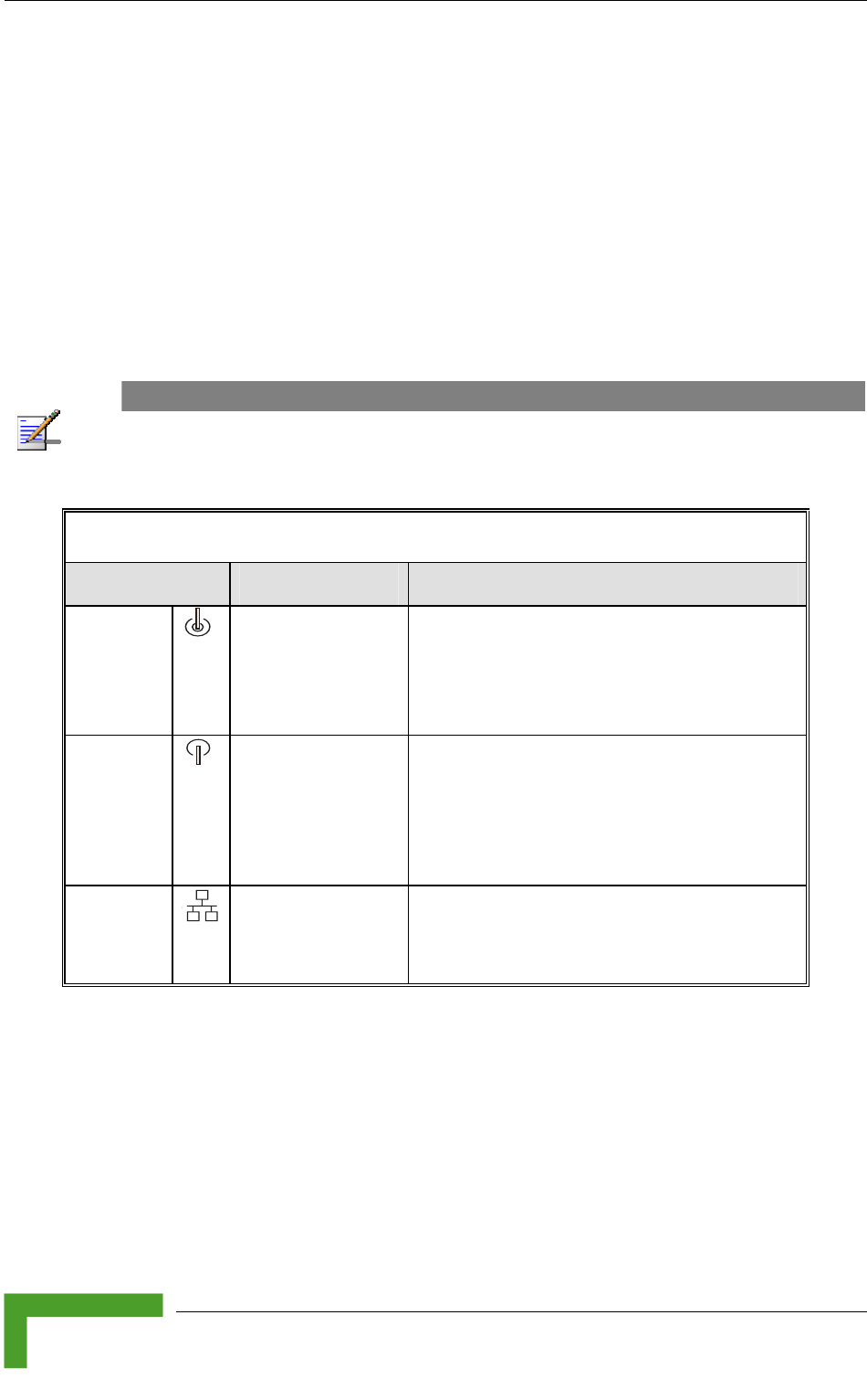
Chapter 3 - Commissioning
3.4 Operation Verification
ing sections describe how t rect functioning of the
nit, Indoor Unit, Ethernet c vity.
3.4.1 r Unit Verifica
operation of the Outdoor Unit, examine the LED indicators
l of the ou
The following tables list the provided LEDs and their associated indications.
The follow o verify the cor
Outdoor U onnection and data connecti
Outdoo tion
To verify the correct
located on the bottom pane tdoor unit.
NOTE
Verifying the correct operation of the Outdoor Unit using the LEDs, as described below, is only
possible after the configuration and alignment ompleted. processes are c
Table 3-3: AU-O
DU LEDs
Name Description Functionality
W-LINK Wireless Link
Indictor
Green – Unit is associated with one or
more SUs
Blinking red – No associations
Off – Wireless link is disabled
Status Self-test and power
indication
Green – Power is available and
self-test passed.
Blinking Amber – Testing (not ready for
operation)
Red – Self-test failed – fatal error
ETH Ethernet activity/
connectivity
indication
Green –Ethernet link detected.
Amber – No Ethernet connectivity between
the indoor and outdoor units.
BreezeACCESS 4900 System Manual
48
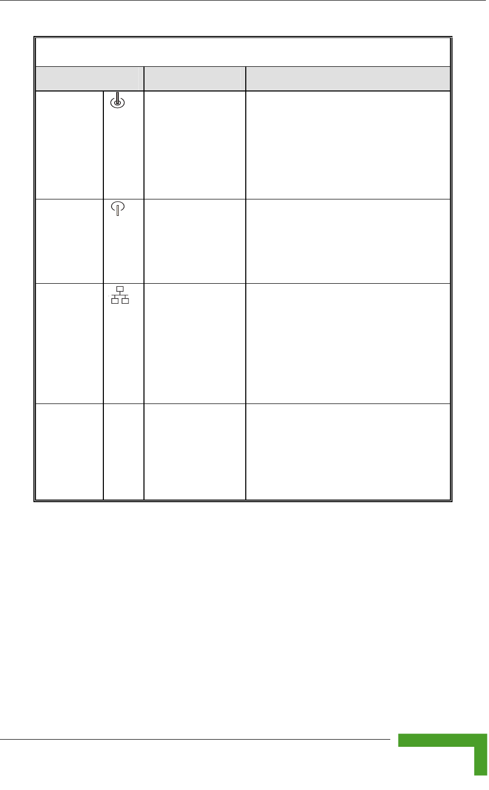
Operation Verification
Table 3-4: SU-ODU LEDs
Name Description Functionality
W-LINK Wireless Link Green – Unit is associated with an AU,
Data received or
transmitted on the wireless link.
Blinking rate is proportional to wireless
te
Off – Wireless link is disabled
Indictor no wireless link activity
Blinking Green –
traffic ra
Status Self-test power er is available and
for
and
indication
Green – Pow
self-test passed.
Blinking Amber – Testing (not ready
operation)
Red – Self-test failed – fatal error
ETH Ethernet activity/
connectivity
indication
etween the
connectivity
ng
Green – Ethernet link b
indoor and outdoor units is detected,
no activity
Blinking Green – Ethernet
is OK, with traffic on the port. Blinki
rate proportional to traffic rate.
Red – No Ethernet connectivity
between the indoor and outdoor units.
SNR BAR
(SU-RA)
Received signal
strength Indication
w
e received
Red LED: Signal is too lo
(SNR<4 dB)
8 green LEDs: Quality of th
signal
Orange LED: Signal is too high
(SNR > 50 dB)
Commissioning
49

Chapter 3 - Commissioning
T able 3-5: SU-ODU SNR Bar LED Functionality
SNR Bar LEDs SNR (typical)
LED 1 (red) is On B) Signal is too low (SNR < 4 d
LED 2 (green) is On SNR > 4 dB
LEDs 2 to 3 (green) S are On NR > 8 dB
LEDs 2 to 4 (green) S are On NR > 13 dB
LEDs 2 to 5 (green) are On SNR > 19 dB
LEDs 2 to 6 (green) are On SNR > 26 dB
LEDs 2 to 7 (green) are On SNR > 31 dB
LEDs SNR > 38 dB 2 to 8 (green) are On
LEDs 2 to 9 (green) are On SNR > 44 dB
LEDs 2 to 9 (green) and 10 (orange) are On Signal is too high (SNR > 50 dB)
BreezeACCESS 4900 System Manual
50

Operation Verification
3.4.2 Indoor Unit Verification
To verify the correct operation of the indoor equipment, examine the LE
indicators located on the top panel of the SU IDU and AU IDU units, or
front panel of the BS-AU module.
Table 3-6
D
on the
provides information for the BS-AU IDU LEDs. Table 3-7 lists
of the PS1073 IDU and their associated indications.
Table 3-6: BS-AU LEDs
the LEDs
Name Description Functionality
W-LINK Wireless link activity
Blinking Red - No SU is associated.
Off - Wireless link is disabled.
Green - At least one SU is associated.
ODU CURRENT
CONS
Current Consumption of Red - over current.
d - open circuit or below
anticipated current consumption.
Green - within tolerance.
UMPTION the Outdoor Unit Blinking Re
ODU STATUS Outdoor Unit Self-test Green - Self test passed and ODU
ready for operation.
Blinking Amber - Testing (not ready
for operation)
Red - fatal failure.
IDU PWR Power indication for the
Indoor Unit
Green - IDU power is OK.
Off - no power is supplied to the IDU.
ALARM Indoor Unit Alarm
Indication
Red - a fatal failure indication.
Off - IDU is functioning properly.
Commissioning
51

Chapter 3 - Commissioning
Table 3-7: PS1073 SU IDU / AU-SA IDU LEDs
Na me Description Functionality
POWER Powe Green - IDU power is OK
r Indication
Off - No power or power failure
ETH been detected between the outdoor
unit and the device connected to the
Self test and end-to-
end Ethernet
Off - No Ethernet connectivity has
connectivity indoor unit.
Green - Self-test passed and Ethernet
connection confirmed by the outdoor
unit (Ethernet integrity check passed).
3.4.3 Verifying the Ethernet Connection (Modular
Base station)
necting the unit to an Ethe , verify that the Ethernet Integrity
ator, which is the yellow LED e ed in the 10/100 BaseT connector, is
on. This indicates that the unit is connected to an Ethernet segment. The
hernet Activity Indicator, which is green embedded LED, should blink
whenever the unit receives or transmits traffic on the 10/100 BaseT port.
.4.4 Verifying the Indoor-to-Outdoor Connection
Modular Base Station)
y
his
indicates that the unit has detected an Ethernet link connection. The Ethernet
t
un
3.4.5 Verifying Data Connectivity
To verify data connectivity, from the end-user’s PC or from a portable PC
connected to the unit, ping the Access Unit, or try to connect to the Internet.
After con rnet outlet
Indic mbedd
Et the
3(
After connecting the unit to an Ethernet outlet, verify that the Ethernet Integrit
Indicator, which is the yellow LED embedded in the RADIO connector, is on. T
Ac ivity Indicator, which is the green embedded LED, should blink whenever the
it receives or transmits traffic on the RADIO port.
BreezeACCESS 4900 System Manual
52
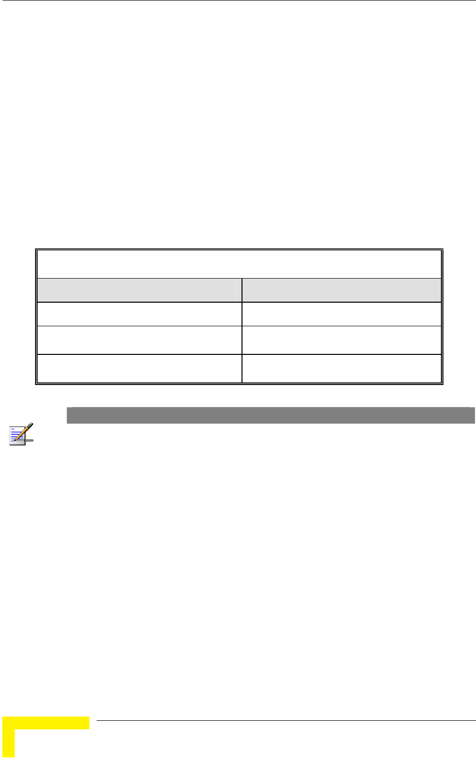
Chapter 4 - Operation and Administration
4.1 orking with the Monitor Program
4.1.1 ing Telnet
it. The
ed.
4 Select the required access level, depending on your specific access rights. A
password entry request is displayed. Table 4-1 lists the default passwords for
each of the access levels.
Table 4-1: Default Passwords
W
Accessing the Monitor Program Us
1 Connect a PC to the Ethernet port, using a crossed cable.
2 Configure the PC's IP parameters to enable connectivity with the un
default IP address is 10.0.0.1.
3 Run the Telnet program. The Select Access Level menu is display
Access Rights Password
Read-Only public
Installer user
Administrator private
NOTE
Following three unsuccessful login attempts (using incorrect passwords), the monitor program is
blocked for several minutes. To enable access to the monitor program during that time, the unit
must be reset via SNMP or by disconnecting/reconnecting power.
5 Enter your password and press Enter. The Main Menu is displayed as shown
in Figure 4-1. The unit type, SW version number and SW release date
displayed in the Main Menu vary according to the selected unit and SW
version.
BreezeACCESS 4900 System Manual
54

Working with the Monitor Program
BreezeACCESS 4900/AU-SA-4900
Official Release Version – 3.2.3
Release Date: June 14 2005, 17:10:21
Main Menu
==========
1 – Info Screens
2 – Unit Control
3 - Basic Configuration
4 – Site Survey
5 - Advanced Configuration
x - Exit
>>>
Figure 4-1: Main Menu (Administrator Level)
NOTE
If th ow, the e Telnet session is not terminated properly; for example, if you simply close the wind
mon inutes. To enable access to the monitor program during itor program is blocked for several m
that P or by disconnecting/reconnecting power. time, the unit must be reset via SNM
The display of the Main Menu varies depending on the user's access level, a
ows.
For users with read only acce
s
foll
ss rights, only the Info Screens option is
displayed. Users with this access level are not able to access the Unit Control,
For users with Installer access rights, the first four menu items, Info Screens,
For users with Administrator access rights, the full Main Menu is displayed.
items.
4.1.2
ases you
may need to click Enter.
Click Esc to exit a menu or option.
Basic Configuration, Site Survey and Advanced Configuration menus.
Unit Control, Basic Configuration and Site Survey, are displayed. Users with
this access level are not able to access the Advanced Configuration menu.
These users can access all menu
Common Operations
The following describes the standard operations used when working with the
Monitor program.
Type an option number to open or activate the option. In certain c
Operation and Administration
55

Chapter 4 - Operation and Administration
NOTE
The program is automatically terminated following a determined period of inactivity. The default
time out is 5 minutes and is configured with the Log Out Timer parameter.
In some cases, to activate
Certain settings are auto
any configuration changes, you must reset the unit.
matically activated without having to reset the unit.
Refer to Appendix E for information on which parameters are run time
configurable, which means that the unit need not be reset for the parameter to
take effect, and which parameters do require that the unit be reset.
BreezeACCESS 4900 System Manual
56

Menus and Parameters
4.2 M
Monitor program.
4.2.1
cess the following menus, depending on your access
level, as described in section 4.1
enus and Parameters
The following sections describe the menus and parameters provided by the
Main Menu
The Main Menu enables to ac
.
Info Screens: Provides a read only display of current parameter values.
Unit Control: Enables to access general operations, such as resetting the
swi
Administrator access levels.
Bas uration: Enables to access the set of parameters that are
configured during the installation process. These parameters are also
Adm
cou aller and Administrator access levels.
ess all system parameters, including
the Basic Configuration parameters. Available only at the Administrator access
4.2.2 Info Screens Menu
The view the current values of various
parameter sets. The parameter sets are identical to the main parameter groups in
or choose to view
all parameters at once. While this menu is available at all access levels, some
security related parameters including the encryption Keys, ESSID and Operator
ESSID are only displayed to users with Administrator access rights.
The Info Screens menu includes the following options:
Show Unit Status
Show Basic Configuration
Available at all access levels.
unit, reverting to factory default parameters, changing passwords and
tching between software versions. Available at the Installer and
ic Config
available in the Advanced Configuration menu. Available at the Installer and
inistrator access levels.
Site Survey: Enables to activate certain tests and view various system
nters. Available at the Inst
Advanced Configuration: Enables to acc
level.
Info Screens menu enables you to
the configuration menus. You can view a specific parameter set
Operation and Administration
57

Chapter 4 - Operation and Administration
Show Advanced Configuration
Show Country Dependent Parameters
Show All Parameters
4.2.2.1 Show Unit Status
The Show Unit Status menu is a read only menu that displays the current values
of t
ed in the Unit Control menu.
es the unit's function: AU-BS (a modular access unit), AU-
SA (a stand-alone access unit), or SU-BD (a subscriber unit that supports a
Unit MAC Address: The unit's unique IEEE MAC address.
Current Number of Associations (AU only): The total number of SUs
mber may include units that are not
currently active as there is no aging algorithm for associated SUs.
he following parameters:
Unit Name: As defin
Unit Type: Identifi
gross CPE rate of 27 Mbps and a full LAN).
associated with this AU. This nu
NOTE
An SU is only removed from the list of associated SUs under the following conditions:
her AU indicating that the SU is now associated with the A SNAP frame is received from anot
other AU.
nsecutive frames transmitted by the AU and The SU failed to respond to a certain number of co
is considered to have "aged out".
Number of Associations Since Last Reset: For SUs - displays the total
s the number of SUs that
have associated with the AU since the last reset, including duplicate
me SU.
tus of the SU. There are two status
options:
SCANNING: The SU is searching for an AU with which to associate.
ed with an AU.
number of associations with any AU since the last reset, including duplicate
associations with the same AU. For AUs - display
associations with the sa
Unit Status (SU only): The current sta
ASSOCIATED: The SU is associat
BreezeACCESS 4900 System Manual
58

Menus and Parameters
AU MAC Address (SU only): The MAC address of the AU with which the unit
is currently associated. If the unit is not associated with any AU, the address
ardware.
.
is running from the Main or from
the Shadow Version.
Main Version File Name: The name of the compressed file (with a “.bz”
ed as the main version.
version currently defined as the main
version.
Shadow Version File Name: The name of the compressed file (with a “.bz”
y defined as the shadow (backup) version.
Shadow Version Number: The software version currently defined as the
shado
adio Band: The radio ba it.
Out Timer: The value of the Log Out Timer a efined in the Unit Control
nu.
Ethernet Port Negotiatio Ethernet p on mode as
n the Unit Contro
ate: The tate of the Ethe t.
defaults to the IEEE broadcast address, which is FF-FF-FF-FF-FF-FF.
Unit Hardware Version: The version of the outdoor unit h
Unit BOOT Version: The version of the BOOT SW
Time Since Last Reset
Flash Versions:
Running from: Shows whether the unit
extension) of the version currently defin
Main Version Number: The software
extension) of the version currentl
w (backup) version.
Rnd of the un
Log s d
me
n Mode: The ort negotiati
defined i l menu.
Ethernet Port St actual s rnet por
Operation and Administration
59

Chapter 4 - Operation and Administration
FTP Parameters: General FTP parameters (common to SW Version Download,
Configuration File Upload/Download and Event File Upload using FTP):
FTP Client IP Address
IP Mask
FTP Server IP Address
FTP Gateway IP Address
FTP Software Download Parameters: The parameters for SW download
ng FTP, as defined in Unit Control menu.
as defined in the Unit Control
File Name
ource Directory
Name
rameters: The parameters for Event Log file upload
Unit Control menu.
y
4.2.2.2
menu is a read only menu that displays the
current values of the parameters included in the Basic Configuration menu.
FTP Client
FTP User Name
FTP Password
usi
FTP Source Directory
FTP SW Version File Name
Configuration File Download/Upload Parameters: The parameters for
Configuration file upload/download using FTP,
menu.
Configuration
Configuration File S
Operator Defaults File
FTP Log File Upload Pa
using FTP, as defined in the
FTP Log File Name
FTP Log File Destination Directory
Event Log Polic
Show Basic Configuration
The Show Basic Configuration
BreezeACCESS 4900 System Manual
60

Menus and Parameters
4.2.2.3 Configuration
onfiguration menu enables to access the read only sub
menus that display the current values of the parameters included in the
s of the Advanced Configuration menu.
4.2.2.4
the parameters that are afftected by
zeACCESS 4900 supports two sets of frequencies
ese Sub-Bands, there is a set of parameters that
eral
rs include the following:
: Supported.
ion Support: Supported.
ndent Parameters:
Table 4-2: Sub-Band Dependent Parameters
Show Advanced
The Show Advanced C
applicable sub menu
Show Country Dependent Parameters
The Country Dependent Parameters displays
applicable regulations. Bree
(Sub-Bands). For each of th
reflects the applicable radio regulations. In addition, there are several gen
parameters that reflect availability of various security options. The Country
Dependent Paramete
Country Code: 1022 – FCC 4.9 GHz.
Data Encryption Support
AES Encrypt
Authentication Encryption Support: Supported.
Sub-Band Depe
Parameter Sub-Band 1 Sub-Band 2
Sub-Band ID 1 2
Frequenci
eps 5 MHz steps
es 4947.5 - 4982.5 MHz,
5 MHz st
4947.5 - 4982.5 MHz,
Allowed Bandwidth 10 MHz 5 MHz
Regula
Antenn
tion Max Tx Power at
a Port
20 dBm 17 dBm
Regula
SU: No Limit
: 43 dBm
SU: No Limit
tion Max EIRP AU: 46 dBm AU
Min Modulation Level 1 1
Max M 8 odulation Level 8
Burst M Enabled ode Enabled
Operation and Administration
61

Chapter 4 - Operation and Administration
Table 4-2: Sub-Band Dependent Parameters
Parameter Sub-Band 1 Sub-Band 2
Maximum Burst Duration 10 milliseconds 10 milliseconds
DFS O upported ption Not Supported Not S
Minimum HW Revision Support D D
New Country Code files can be uploaded remotely using TFTP (see Appendix B).
4.2.2.5
ters menu is a enu that displays the current
values of all status and configur
Show All Parameters
The Show All Parame read only m
ation parameters.
NOTE
The values of some security related par and ameters, including the encryption Keys, ESSID
Operator ESSID, are available only with Administrator access rights.
4.2.3 Unit Control Menu
The Unit Control menu enables configurin r the unit. The
Unit Control menu includes the
Reset Unit
Default Settings
Change Unit Name
Change Password
Flash Memory Control
g control parameters fo
following options:
SW Version Download
Configuration File Upload/Download
Log Out Timer
Ethernet Port Negotiation Mode
Change System Location
BreezeACCESS 4900 System Manual
62

Menus and Parameters
Event Log Menu
4.2.3.1 Reset t
ption enables reset it. After reset, any modifications
made to the system parameters are
4.2.3.2 Default Settings
The Set defaults submenu enables meters to a
predefined set of defaults or saving t tion as the set of
Operator Defaults.
The Default Setting options are avai with Administrator access
rights.
The available options are:
efaults
Save Current Configuration As Op ults
4.2.3.2.1 Set Defaults
The Set Defaults submenu enables r em parameters to a
predefined set of defaults. There are t ult configurations:
efaults: This is the sta tion.
B Operator Defaults: Operator Def on can be defined by the
Administrator using the Save Cu s Operator Defaults
option in this menu. It may also be defined at the factory according to specific
operator's definition. The defaul uration is the
Factory Defaults configuration.
The current configuration file and t lts configuration file can be
uploaded/downloaded by the unit u re information, see section
Feature Upgrade
Uni
The Reset Unit o ting the un
applied.
resetting the system para
he current configura
lable only to users
Set D
erator Defa
everting the syst
wo sets of defa
A Factory D ndard default configura
aults configurati
rrent Configuration A
t Operator Defaults config
he Operator Defau
sing FTP. For mo
4.2.3.7 option. These files can also b ed/downloaded remotely using TFTP
(see Appendix B
e upload
).
The available options in the Set Defaults submenu are:
Set Complete Factory Defaults
Set Partial Factory Defaults
Set Complete Operator Defaults
Operation and Administration
63

Chapter 4 - Operation and Administration
S t Partial Operator Defaults
4.2.3.2 te Factory Defaults
Select this option to reset the unit t actory Defaults configuration,
excluding several parameters that are
Table 4-3: Parameters not reset after Se /Operator Defaults
e
Cancel Current Pending Request
.1.1 Set Comple
o the standard F
listed in Table 4-3.
t Complete Factory
Parameters Group Parameter
All Passwords
FTP e note below) Server IP address* (se
FTP low) Gateway IP address* (see note be
FTP Client IP address* (see note below)
FTP below) Client IP Mask* (see note
FTP User Name* (see note below)
FTP Password* (see note below)
Unit Control Parameters
Ethernet Port Negotiation Mode
Selected Sub-Band
Frequency (AU)
Frequency Subset (AU)
Air Interface Parameters
Antenna Gain (AU)
NOTE
The FTP parameters are not set to their default values after Set Complete Operator Defaults.
However, they are set to their default value after Set Complete Factory Defaults. Note that in this
case they are set to the default values immediately upon selecting the Set Complete Factory
Default option (even before the next reset).
4.2.3.2.1.2 Set Partial Factory Defaults
Select this option to reset the unit to the standard Factory Default configur
excluding the parameters that are required to maintain connectivity and
ation,
management access. The parameters that do not change after Set Partial Factory
Defaults are listed in Table 4-4.
BreezeACCESS 4900 System Manual
64

Menus and Parameters
Table 4-4: Parameters that are not reset after Set Partial Factory/Operator Defaults
Parameters Group Parameter
Passwords
Ethernet Port Negotiation Mode
FTP Server IP address
FTP Gateway IP Address
FTP Client IP address
FTP Client IP Mask
FTP User Name
Unit C
FTP Password
ontrol parameters
IP Address
Subnet Mask
Default Gateway Address
DHCP Option
IP Parameters
Access to DHCP
Authentication Algorithm
Default Key (SU)
Data Encryption Mode
Default Multicast Key (AU)
Security Mode
Securi
Key # 1 to Key # 4
ty Parameters
ESSID
Operator ESSID Option (AU)
Operator ESSID (AU)
Cell Distance Mode (AU)
Maximum Cell Distance (AU)
Air Interfac
Selected Sub-Band
e Parameters
Operation and Administration
65

Chapter 4 - Operation and Administration
Table 4-4: Parameters that are not reset after Set Partial Factory/Operator Defaults
Parameters Group Parameter
Frequency (AU)
Frequency Subset (SU)
ATPC Option (AU)
Transmit Power
Tx Control (AU)
Best AU Support (SU)
Preferred AU MAC Address (SU)
Performance Parameters Adaptive Modulation Decision Thresholds
VLAN ID – Management Bridge Parameters
MAC Address Deny List (AU)
4.2.3.2.1.3 Se ults
Select this option to reset the unit to the Operator Defaults configuration,
4.2.3.2.1.4 Se
Select this option to reset the unit to the Operator Defaults configuration,
exc at are required to maintain connectivity and
management access. The parameters that do not change after Set Partial
4.2.3.2.1.5 Cancel Current Pending Request
Aft lts options, it will be executed after the next
reset. This option enables you to cancel the pending request before execution
4.2.3.2.2 Save Cur
The tion As Operator Defaults enables defining the
current configuration of the unit as the Operator Defaults configuration.
t Complete Operators Defa
excluding several parameters that are listed in Table 4-3.
t Partial Operator Defaults
luding the parameters th
Operator Defaults are listed in Table 4-4.
er selecting one of the Set defau
(provided the unit has not been reset yet).
rent Configuration As Operator Defaults
Save Current Configura
BreezeACCESS 4900 System Manual
66

Menus and Parameters
4.2.3.3
The Change Unit Name option enables changing the name of the unit, which is
als used as the
prompt at the bottom of each Monitor window.
Valid values: A string of up to 32 printable ASCII characters.
4.2.3.4 Change Password
The sword(s). The
Ch enu is available only to users with Administrator access
rights.
Ref
Change Unit Name
o the system's name in the MIB2. The name of the unit is also
The default unit name is an empty string.
Change Password submenu enables changing the access pas
ange Password subm
Valid values: A string of up to 8 printable ASCII characters.
er to section 4.1
for a list of the default passwords for each of the access levels.
4.2.3.5 Flash Memory Control
ash Memory Control submenu enables selecting the active software version
and
select the shadow version as the new active version by selecting
after the next reset, the main
version is re-activated. To continue using the currently active version after the
w
red in the unit are not changed as a result of loading new
software versions unless the new version includes additional parameters or
the
Sel
Reset and Boot from Shadow Version: Activates the shadow (backup)
ally. Following the next reset the
unit will switch to the main version.
Use Running Version After Reset: Defines the current running version as
ed following the next reset.
The Fl
for the unit.
The flash memory can store two software versions. One version is called Main
the other is called Shadow. New software versions are loaded as the shadow
version. You can
Reset and Boot from Shadow Version. However,
next reset, select Use Running Version After Reset: The previous shado
version will be the new main version, and vice versa.
The parameters configu
additional changes in the list of parameters. New parameters are loaded with
ir default values.
ect from the following options:
software version. The unit is reset automatic
the new main version. This version will also be us
Operation and Administration
67

Chapter 4 - Operation and Administration
4.2.3.6
The ownload submenu enables the optional downloading of a SW
Version file from a remote FTP server. The SW Version Download submenu
inc
Execute FTP GET SW Version: The Execute FTP GET SW Version option
wnload according to the parameters defined
below.
version file.
tring.
Valid values: A string of up to 20 printable ASCII characters. An empty string
The default is VxWorks.bz.
FTP Client IP Address: The FTP Client IP Address option enables defining the
The default is: 1.1.1.3
FTP Client IP Mask: The FTP Client IP Mask option enables defining the IP
The default is: 255.255.255.0
FTP Server IP Address: The FTP Server IP Address option enables defining
The default is: 1.1.1.4.
FTP Gateway IP Address: The FTP Gateway IP Address option enables
The default is: 0.0.0.0.
SW Version Download
SW Version D
ludes the following options:
executes the SW Version FTP do
FTP SW Source Dir: The FTP SW Source Dir option enables defining the
source directory of the SW
Valid values: A string of up to 80 printable ASCII characters. To clear the field
press "."
The default is an empty s
FTP SW Version File Name: The FTP SW Version File Name option enables
defining the name of the SW version file in the FTP server.
is not allowed.
IP address of the FTP client in the unit. This secondary IP address is required
only to support the optional FTP process.
Mask for the FTP client mask in the unit.
the IP address of the FTP server that is hosting the SW Version file.
defining the FTP default gateway address.
BreezeACCESS 4900 System Manual
68

Menus and Parameters
P User Name option enables defining the user name
to be used for accessing the FTP server that is hosting the SW Version file.
P Password option enables defining the password to be
used for accessing the FTP server that is hosting the SW Version file.
s.
ownload Parameters and Status: Displays the current
values of the SW Version Download parameters, the current SW version and
FTP User Name: The FT
Valid values: A string of up to 18 printable ASCII characters.
The default is: vx
FTP Password: The FT
Valid values: A string of up to 18 printable ASCII character
The default is: vx
Show SW Version D
the SW versions stored in the Flash memory.
NOTE
There is one set of general FTP parameters (FTP Server IP Address, FTP Gateway IP Address,
FTP Client IP Address, FTP Client IP Mask, FTP User Name and FTP Password). This set (or
relevant parts of the set) serves the SW Download Procedure, the Configuration File
Upload/Download procedure and the Event Log File Upload procedure. Changing any of these
parameters in the menu for any procedure will automatically change its value in the menu for the
other procedures.
4.2.3.7
load/Download submenu enables the optional
d submenu includes
figuration File: The Execute FTP GET/PUT
ownload of a Configuration file or an
rameters defined below. The
t Configuration File (cfg)
n File (cfg)
aults File (cmr)
ults File (cmr)
Configuration File Upload/Download
The Configuration File Up
uploading or downloading of a configuration or an Operator Defaults file from a
remote FTP server. The Configuration File Upload/Downloa
the following options:
Execute FTP GET/PUT Con
Configuration File executes the upload/d
Operator Defaults file according to the pa
following options are available:
Execute FTP Ge
Execute FTP Put Configuratio
Execute FTP Get Operator Def
Execute FTP Put Operator Defa
Operation and Administration
69

Chapter 4 - Operation and Administration
FTP Configuration File Source Dir: The FTP Configuration File Source Dir
option enables defining the source directory of the configuration/Operator
rintable ASCII characters. To clear the field
e FTP File Name
option enables defining the name of the configuration file to be
up to 20 printable ASCII characters. An empty string
Operator Defaults FTP File Name: The Operator Defaults File Name option
FTP Client IP Address: The FTP Client IP Address option enables defining the
ndary IP address is required
only to support the optional FTP process.
The default is: 1.1.1.3
FTP Client IP Mask: The FTP Client IP Mask option enables defining the IP
nt mask in the unit.
55.255.0
ess: The FTP Host IP Address option enables defining the
: The FTP Gateway IP Address option enables
defining the FTP default gateway address.
Defaults file.
Valid values: A string of up to 80 p
press "."
The default is an empty string.
Configuration File FTP File Name: The Configuration Fil
uploaded/downloaded.
Valid values: A string of
is not allowed.
The default is config.cfg.
enables defining the name of the Operator Defaults file to be
uploaded/downloaded.
Valid values: A string of up to 20 printable ASCII characters. An empty string
is not allowed.
The default is operator.cmr.
IP address of the FTP client in the unit. This seco
Mask for the FTP clie
The default is: 255.2
FTP Server IP Addr
IP address of the FTP server that is hosting the file.
The default is: 1.1.1.4
FTP Gateway IP Address
BreezeACCESS 4900 System Manual
70

Menus and Parameters
The default is: 0.0.0.0.
ng the password to be
e FTP server that is hosting the file.
Show Configuration File Upload/Download Parameters: Displays the
FTP User Name: The FTP User Name option enables defining the user name
to be used for accessing the FTP server that is hosting the file.
Valid values: A string of up to 18 printable ASCII characters.
The default is: vx
FTP Password: The FTP Password option enables defini
used for accessing th
Valid values: A string of up to 18 printable ASCII characters.
The default is: vx
current values of the Configuration File Upload/Download parameters.
NOTE
The Address, re is one set of general FTP parameters (FTP Server IP Address, FTP Gateway IP
FTP Client IP Address, FTP Client IP Mask, FTP User Name and FTP Password). This set (or
relevant parts of the set) serves the SW Download procedure, the Configuration File
Upload/Download procedure and the Event Log File Upload procedure. Changing any of these
para menu for any procedure will automatically change its value in the menu for the meters in the
other procedures.
4.2.3.8 Log
wh
The
The s.
4.2.3.9 Ethernet Port Negotiation Mode
The e current Ethernet port
state and enables defining the negotiation mode of the Ethernet port. The
ava
Force 10 Mbps and Full-Duplex
Force 100 Mbps and Half-Duplex
Out Timer
The Log Out Timer parameter determines the amount of inactive time following
ich the unit automatically exits the Monitor program.
time out duration can range from 1 to 999 minutes.
default value is 5 minute
Ethernet Port Negotiation Mode submenu displays th
ilable options are:
Force 10 Mbps and Half-Duplex
Force 100 Mbps and Full-Duplex
Operation and Administration
71

Chapter 4 - Operation and Administration
The d gotiation (10/100 Mbps and Half/Full Duplex)
4.2.3.10
The Change System Location option enables changing the system location of the
un is also
displayed as a part of the Monitor menu’s header.
Valid values: A string of up to 35 printable ASCII characters.
4.2.3.11 Event Log Menu
ent Log Menu enables controlling the event log feature. The event log is an
from the configured severity and higher are saved and may be displayed upon
displayed up to the full number of current active
g Policy
4.2.3.11.1
minimal severity level. All events whose
everity is equal to or higher than the defined severity are logged.
.
Auto Negotiation (10/100 Mbps and Half/Full Duplex)
efault is Auto Ne
Change System Location
it, which is also the sys location in MIB2. The System Location
The default system location is an empty string.
The Ev
important debugging tool and a flash memory sector is dedicated for storing it.
Events are classified according to their severity level: Message (lowest severity),
Warning, Error or Fatal (highest severity).
The severity at which events are saved in the Event Log is configurable. Events
request. Log history can be
events. In the log, an event is defined as active as long as it has not been erased
(a maximum of 1000 events may be stored). The Event Log may be read using
TFTP, with remote file name <SNMP Read Community>.log (the default SNMP
Read Community is “public”). The Event Log may also be uploaded to a remote
FTP server.
The Event Log Menu includes the following options:
Event Lo
Display Event Log
Erase Event Log
Event Load Upload
Event Log Policy
The Event Log Policy determines the
s
Valid values are: Message (MSG) Level, Warning (WRN) Level, Error (ERR) Level,
Fatal (FTL) Level, Log None
The default selection is Warning Level severity.
BreezeACCESS 4900 System Manual
72

Menus and Parameters
4.2.3.11.2 Display Event Log
nt Log option enables viewing how many events are logged and
sele er of events to be displayed (up to 1000). The display of each
event time (elapsed time since last reset), the severity level and
a m The events are displayed in descending order, with the most
4.2.3.11.3 Erase Event Log
The Erase Event Log option enables clearing the event log.
4.2.3.11.4 Event Log Upload
The bmenu enables the optional uploading of the event log
file to a remote FTP server. The Event Log Upload submenu includes the following
: The FTP event Log Upload Execute executes
the upload of the Event Log file according to the parameters defined below.
Event Log Destination Directory: The Event Log Destination Directory
irectory for the Event Log File.
o 80 printable ASCII characters. To clear the field
press "."
The default is an empty string.
Event Log File Name: The Event Log File Name option enables defining the
g of up to 20 printable ASCII characters.
The default is logfile.log.
FTP Server IP Address: The FTP Host IP Address option enables defining the
er that is hosting the file.
FTP Gateway IP Address option enables
defining the FTP default gateway address.
The default is: 0.0.0.0.
FTP User Name: The FTP User Name option enables defining the user name
erver that is hosting the file.
The Display Eve
cting the numb
event includes the
essage string.
recent event displayed first.
Event Log Upload su
options:
FTP Event Log Upload Execute
enables defining the destination d
Valid values: A string of up t
name of the event log file to be uploaded.
Valid values: A strin
IP address of the FTP serv
The default is: 1.1.1.4
FTP Gateway IP Address: The
to be used for accessing the FTP s
Operation and Administration
73

Chapter 4 - Operation and Administration
Valid values: A string of up to 18 printable ASCII characters.
word option enables defining the password to be
rver that is hosting the file.
CII characters.
g File Upload Parameters: Displays the current values
of the Event Log Upload parameters.
The default is: vx
FTP Password: The FTP Pass
used for accessing the FTP se
Valid values: A string of up to 18 printable AS
The default is: vx
Show FTP Event Lo
NOTE
There is one set of gener P Server IP Address, FTP Gateway IP Address, al FTP parameters (FT
FTP Client IP Address, FTP Client IP Mask, FTP User Name and FTP Password). This set (or
relevant parts of the set) serves the SW Download procedure, the Configuration File
Upload/Download procedure and the Event Log File Upload procedure. Changing any of these
parameters in the menu for any procedure will automatically change its value in the menu for the
other procedures.
4.2.3.12 Feature Upgrade
ables to enter a license string for upgrading the
unit to support new features and/or options. Upon selecting the Manual Feature
be requested to enter the license string. Each license
string is associated with a unique MAC Address and one feature/option. If the
he unit’s MAC
ed. If there is a match, a message notifying of the
new feature/option will be displayed. The unit must be reset for the change to
The license string should comprise 32 to 64 hexadecimal digits.
New Feature License files can be uploaded remotely using TFTP (see Appendix B
The Feature Upgrade option en
Upgrade option the user will
encrypted MAC Address in the license string does not match t
Address, the string will be reject
take effect.
).
4.2.4 guration Menu
udes all parameters required for the initial
installation and operation of the unit. After the unit is properly installed and
l parameters can be configured either locally or remotely
using Telnet or SNMP management.
Basic Confi
The Basic Configuration menu incl
operational, additiona
NOTE
All parameters in the Basic Configuration menu are also available in the relevant sub menus of the
Advanced Configuration menu.
The Basic Configuration menu enables to access the following parameter sets:
BreezeACCESS 4900 System Manual
74

Menus and Parameters
4.2.4.1.1
s
IP Parameters
IP Addres
Subnet Mask
Default Gateway Address
DHCP Client
DHCP Option
Access to DHCP
Refer to section 4.2.6.1 for a description of these parameters.
4.2.4.1.2 ce Parameters
ers (AU)
ID
Sub-Band Definition
dress
Maximum Cell Distance (AU)
Air Interfa
ESSID
Operator ESSID Paramet
Operator ESSID Option
Operator ESS
Frequency Definition
Select Sub-Band (if more than one is available)
Frequency (AU)
Best AU Parameters (SU)
Best AU Support
Preferred AU MAC Ad
Cell Distance Parameters
Cell Distance Mode (AU)
Operation and Administration
75

Chapter 4 - Operation and Administration
ATPC
ATPC Option
Transmit Power parameters
Maximum Transmit Power parameters (SU)
Tx Control (AU)
Antenna Gain (AU)
Refer to section 4.2.6.2
for a description of these parameters.
rformance Parameters 4.2.4.1.3 Pe
n Level (SU) Maximum Modulatio
Refer to section 4.2.6.5
for a description of these parameters.
Bridge Parameters
VLAN ID – Management
MAC Address Deny List
Refer to section 4.2.6.4
4.2.4.1.4
for a description of these parameters.
Security Parameters 4.2.4.1.5
U)
us Authentication (AU)
Authentication Algorithm
Data Encryption Option
Security Mode
Default Multicast Key (AU)
Default Key (S
Key 1 to Key 4
Promiscuo
BreezeACCESS 4900 System Manual
76

Menus and Parameters
Some or all of the security parameters may not be available in units that do not
support the applicable features. Refer to section 4.2.6.7
for a description of these
4.2.5 Site Survey Menu
The
ver
det
and
ide ential problems. In the AU, there is also an extensive database for
all SUs served by it.
The S ludes the following options:
Ping T
4.2.5.1 Traffic
The traffic statistics are used to monitor, interpret and analyze the performance
link
opt
Display Counters: Select this option to display the current value of the
Reset Counters: Select this option to reset the counters.
4.2.5.1.1 Et
The mes
to i frame should be
transmitted to the wireless medium. Frames discarded by the unit's hardware
parameters.
Site Survey menu displays the results of various tests and counters for
ifying the quality of the wireless link. These tests can be used to help
ermine where to position the units for optimal coverage, antenna alignment
troubleshooting. The counters can serve for evaluating performance and
ntifying pot
ite Survey menu inc
Traffic Statistics
est
Continuous Link Quality display (SU only)
MAC Address Database
Per Modulation Level Counters
Link Capability
Statistics
of the wired and wireless links. The counters display statistics relating to wireless
and Ethernet frames. The Traffic Statistics menu includes the following
ions:
Ethernet and wireless link (WLAN) counters.
hernet Counters
unit receives Ethernet frames from its Ethernet port and forwards the fra
ts internal bridge, which determines whether each
filter are not counted by the Ethernet counters. The maximum length of a regular
Operation and Administration
77

Chapter 4 - Operation and Administration
IEE
byt e is 1522 bytes.
The he
Ethern
manag
The Ethernet Counters include the following statistics:
Tot ed
from cludes both invalid frames (with errors)
and valid frames (without errors).
Tra y the
un ernet port. These are generally frames received from the
wireless side, but also include frames generated by the unit itself.
4.2.5.1.2 WL
The l
bri management frames. After a
unicast data frame is transmitted, the unit waits for an acknowledgement (ACK)
as
ack CK is not received after a predefined time, which is
determined by the Maximum Cell distance parameter, the unit retransmits the
ret
det y the Number of HW Retries parameter, the frame is dropped.
Each packet to be transmitted to the wireless link is transferred to one of three
que igh queue have the highest
priority for transmission, and those in the Low queue have the lowest priority.
The
emptie s in the Medium queue will be sent. Finally, when both the
High and Medium queues are empty, the packets in the Low queue will be sent.
Data p e
selecte hem before the MIR/CIR mechanism (for more information see
section 4.2.6.6.3
E 802.1 Ethernet frame that can be accepted from the Ethernet port is 1518
es. For tagged IEEE 802.1Q frames the maximum siz
unit transmits valid data frames received from the wireless medium to t
et port, as well as internally generated frames, such as responses to
ement queries and pings received via the Ethernet port.
al received frames via Ethernet: The total number of frames receiv
the Ethernet port. This counter in
nsmitted wireless to Ethernet: The number of frames transmitted b
it to the Eth
AN Counters
unit submits data frames received from the Ethernet port to the interna
dge, as well as self generated control and wireless
message from the receiving unit. Some control and wireless management frames,
well as broadcast and multicast frames sent to more than one unit, are not
nowledged. If an A
frame until an ACK is received. If an ACK is not received before the number of
ransmissions has reached a maximum predefined number, which is
ermined b
ues: Low, Medium and High. Packets in the H
packets in the High queue will be transmitted first. When this queue is
d, the packet
ackets are routed to either the High or Low queue, according to the queu
d for t
).
Bro
Control and wireless management frames generated in the unit are routed to the
An
Bre ded
adcasts/multicasts are routed to the Medium queue (applicable only for AU).
High queue.
y frame coming from the Ethernet port, which is meant to reach another
ezeACCESS 4900 unit via the wireless port (as opposed to messages inten
BreezeACCESS 4900 System Manual
78

Menus and Parameters
for
reg iguration.
reless: The number of frames transmitted to
es (excluding
ions, excluding Beacons in AU)
nsmitted to the wireless medium, excluding retransmissions.
This count is useful for calculating the rates of retransmissions or dropped
Total submitted frames (bridge): The total number of data frames submitted
re are also separate counts for each priority queue
through which the frames were routed (High, Mid and Low).
umber of dropped frames, which
are unsuccessfully retransmitted without being acknowledged until the
d
Total retransmitted frames: The total number of retransmissions, including
catenated
5.10
stations behind other BreezeACCESS 4900 units), is sent to the High queue,
ardless of the priority conf
The Wireless Link Counters include the following statistics:
Total transmitted frames to wi
the wireless medium. The total includes one count for each successfully
transmitted unicast frame (excluding retransmissions), and the number of
transmitted multicast and broadcast frames, including control and wireless
management frames. In the AU, there are also separate counters for the
following:
Beacons (AU only)
Management and Other Data frames, including successfully transmitted
unicast frames and multicast/broadcast data fram
retransmiss
Total Transmitted Unicasts (AU only): The number of unicast frames
successfully tra
frames, as only unicast frames are retransmitted if not acknowledged.
to the internal bridge for transmission to the wireless medium. The count
does not include control and wireless management frames, or
retransmissions. The
Frames dropped (too many retries): The n
maximum permitted number of retransmissions. This count includes droppe
data frames as well as dropped control and wireless management frames.
all unsuccessful transmissions and retransmissions.
Total transmitted concatenated frames: The total number of con
frames transmitted successfully to the wireless medium, excluding
retransmissions. There are also separate counts for concatenated frames that
include one frame (Single), two frames (Double) or more than two frames
(More). For more details refer to section 4.2.6. .
smission Total Tx events: The total number of transmit events. Typically, tran
events include cases where transmission of a frame was delayed or was
Operation and Administration
79

Chapter 4 - Operation and Administration
aborted before completion. The following additional counters are displayed to
indicate the reason for and the nature of the event:
f dropped frames, which are unsuccessfully
retransmitted without being acknowledged until the maximum permitted
derrun: The number of times that transmission of a frame was aborted
for transmission exceeds the
available transmission capability.
er than those represented by the other
of frames received
from
rames
r of frames that were not received properly.
or the
CRC: The number of frames received from the wireless medium containing
CRC errors.
ve
rate exceeded the processing capability or the capacity of the Ethernet
that were not received properly due to a
ames: The total number of concatenated
frames received from the wireless medium, including duplicate frames. There
catenated frames that include one frame
Dropped: The number o
number of retransmissions.
Un
because the rate of submitting frames
Others: The number of frames whose transmission was not completed or
delayed due to a problem oth
counters.
Total received frames from wireless: The total number
from the wireless medium. The count includes data frames as well as control
and wireless management frames. The count does not include bad frames and
duplicate frames. For a description of these frames, refer to Bad frames
received and Duplicate frames discarded below.
Total received data frames: The total number of data frames received
the wireless medium, including duplicate frames. Refer to Duplicate f
discarded below.
Total Rx events: The total numbe
The following additional counters are displayed to indicate the reason f
failure:
Phy: The number of unidentified signals.
Overrun: The number of frames that were discarded because the recei
port.
Decrypt: The number of frames
problem in the data decryption mechanism.
Total received concatenated fr
are also separate counts for con
BreezeACCESS 4900 System Manual
80

Menus and Parameters
(Single), two frames (Double) or more than two frames (More). For more details
refer to section 4.2.6.5.10
.
Bad fragments received: The number of fragments received from the wire
medium containing CRC errors.
less
because
in all counters that include data
frames, only the first copy is forwarded to the Ethernet port.
discarded MIR\CIR: The number of data frames received from the
Ethe re discarded by the MIR/CIR mechanism to avoid
4.2.5.2 Pin
The Pin he unit and includes the
following options:
De
pin ess is 192.0.0.1.
mpts per session. The
available range is from 0 to 9999. The default value is 1. Select 0 for
Pin
1472
Ping Fr
(in ms) be ts. The available range is from 100 to 60,000 ms.
The
Start Sendi
nding
option can be used to end the test before completing the specified number of
Sh ues of the ping test
parameters, the transmission status, which means whether it is currently
Duplicate frames discarded: The number of data frames discarded
multiple copies were received. If an acknowledgement message is not received
by the originating unit, the same data frame can be received more than once.
Although duplicate frames are included
Internally
rnet port that we
exceeding the maximum permitted information rate.
g Test
g Test submenu is used to control pinging from t
stination IP Address: The destination IP address of the device being
ged. The default IP addr
Number of Pings to Send: The number of ping atte
continuous pinging.
g Frame Length: The ping packet size. The available range is from 60 to
bytes. The default value is 64 bytes.
ame Timeout: The ping frame timeout, which is the amount of time
tween ping attemp
default value is 200 ms.
ng: Starts the transmission of ping frames.
Stop Sending: Stops the transmission of ping frames. The test is
automatically ended when the number of pings has reached the value
specified in the No. of Pings parameter, described above. The Stop Se
pings, or if continuous pinging is selected.
ow Ping Test Values: Displays the current val
Operation and Administration
81

Chapter 4 - Operation and Administration
sending or not sending pings, the number of pings sent, and the number of
gs received, which means the number of acknowledged frames.
4.2.5.3
Th ality submenu enables viewing continuously updated information on
opt
4.2.5.3.1 Continuous Average SNR Display
The Co
inform
Noise Ratio (SNR) measurements.
Click t
4.2.5.3.2 Cont
The Co isplays continuously
updated information regarding the average quality of the wireless link to the AU,
using the dynamically updated average modulation level measurements. The Link
Quality Indicator (LQI) calculation is performed using the formula:
LQI = (0.9 x ”Previous LQI”) + (0.1 x ”Last Successful Modulation Level”).
Each successful transmit will be included in this average, by using the
modulation level in which the frame was successfully transmitted as the “Last
Successful Modulation Level”.
In order to receive quick and reliable LQI measurements, there should be
sufficient traffic between the SU and the AU. It is recommended to have traffic of
at least 100 packets per second. The traffic can be generated either by an
external utility (FTP session, ping generator, etc.) or by the Ping Test option in the
Site Survey menu with the appropriate settings (see section 4.2.5.2
pin
Link Quality (SU only)
e Link Qu
the quality of the wireless link. The Link quality submenu includes the following
ions:
ntinuous Average SNR Display option displays continuously updated
ation regarding the average quality of the received signal, using Signal to
he Esc key to abort the test.
inuous UpLink Quality Indicator Display
ntinuous UpLink Quality Indicator Display option d
).
NOTE
If Limited Test is indicated next to the LQI results, it means that the results may not indicate the true
quality, as not all modulation levels from 1 to 8 are available. The limitation may be due to the
configurable Maximum Modulation Level parameter.
Click the Esc key to abort the test.
4.2.5.4 MAC Address Database
The MAC Address Database submenu includes the following options:
MAC Address Database in AU
MAC Address Database in SU
BreezeACCESS 4900 System Manual
82

Menus and Parameters
4.2.5.4.1 AC Address Database in AU
AC Address Database option in the AU displays information regarding the
stations
rwarding Database. For stations behind an SU, the SU's MAC
address is also displayed (SU Address).
Each MAC address entry is followed by a description, which may include the
Et (Ethernet): An address learned from the Ethernet port.
: An address of a node behind an associated SU. For
these addresses, learned from the wireless port, the address of the
associated SU. For these entries, the following details are
also displayed: SU Unit Name, SU SW version, SU Unit Type and SU’s
s U.
X: An SU that is included in the Deny List.
The MAC address of the AU, which appears twice as it is learned from
both the Ethernet and wireless ports.
stack, which also
appears twice.
Alvarion's Multicast 1-20-D hich also appears
. The system treats this address as a Broadcast address.
t Broadc s (FF- F-FF-FF-FF).
summary table displays information about the Forwarding
dging Info) and the Associated Subscriber Units Database
nfo). Each da udes
number of r Brid includes the Et
and the Vp (Virtual ports) entries. For Association Info this is
the number of the currently associated SUs.
M
The M
Subscriber Units associated with the AU, as well as bridging (forwarding)
information. The following options are available:
Display Bridging and Association Info: The Display Bridging and
Association Info option displays a list of all the Subscriber Units and
in the AU's Fo
following:
Vp (Virtual port)
applicable SU is also displayed (in parenthesis).
St (Static): An
Di tance from the A
Sp (Special): 7 addresses that are always present, including:
The MAC address of the internal Operating System
address (0 6-00-00-01, w
twice
The Etherne ast addres FF-F
In addition, a
Database (Bri
(Association I tabase incl the following information:
The current entries. Fo ging Info this
(Ethernet)
Operation and Administration
83

Chapter 4 - Operation and Administration
NOTE
There is no aging algorithm for associated SUs. An SU is only removed from the list of associated
SUs under the following conditions:
A SNAP frame is received from another AU indicating that the SU is now associated with the
other AU.
The SU failed to respond to 50 consecutive frames transmitted by the AU and is considered to
have "aged out".
The aging time specified for e s in th The aging time for
Bridging Info is as spec Bridge Aging Time parameter. The
default is 300 seconds. There is no aging time for Association Info entries.
The maximum number of entries permitted for these tables, which are
ber of special Sp addresses as defined above)
for Bridging Info and as specified by the Maximum Number of
ion Info. The default value of the
Maximum Number of Associations parameter is 512.
ntrie ese tables.
ified by the
1017 (1024 minus the num
Associations parameter for Associat
BreezeACCESS 4900 System Manual
84
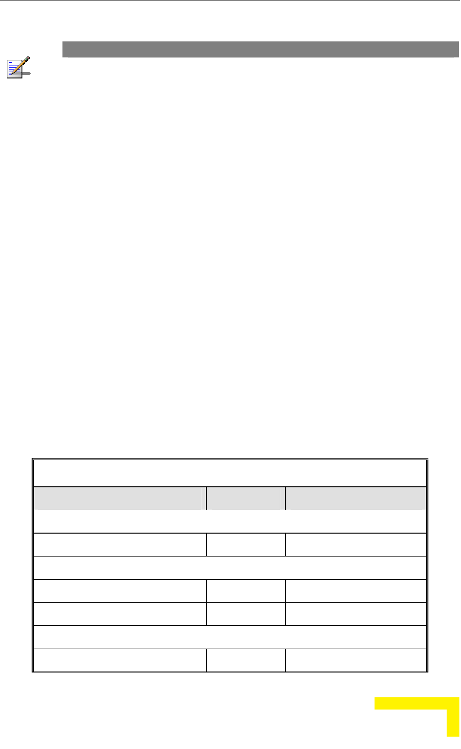
Menus and Parameters
NOTE
Whe r of associations is limited to 124. n Data Encryption is enabled, the actual maximum numbe
The Number of Associations parameter, displayed number is the value configured for the Maximum
which might be higher than the actual limit.
Display Association Info: Displays information regarding the Subscriber
info
Age in seconds, indicating the elapsed time since receiving the last packet
e
re three options:
The various status states are described below (this is a simplified
Table 4-5: Authentication and Association Process
Units associated with the AU. Each list entry includes the following
rmation:
The MAC Address of the associated Subscriber Unit
from the Subscriber Unit.
The value configured for the Maximum Modulation Level parameter of th
Subscriber Unit
The Status of the Subscriber Unit. There a
1 Associated
2 Authenticated
3 Not Authenticated (a temporary status)
description of the association process without the effects of the Best AU
algorithm).
Message Direction Status in AU
SU Status: Scanning
A Beacon with correct ESSID AU → SU -
SU Status: Synchronized
Authentication Request SU → AU Not authenticated
Authentication Successful AU → SU Authenticated
SU Status: Authenticated
Association Request SU → AU Authenticated
Operation and Administration
85
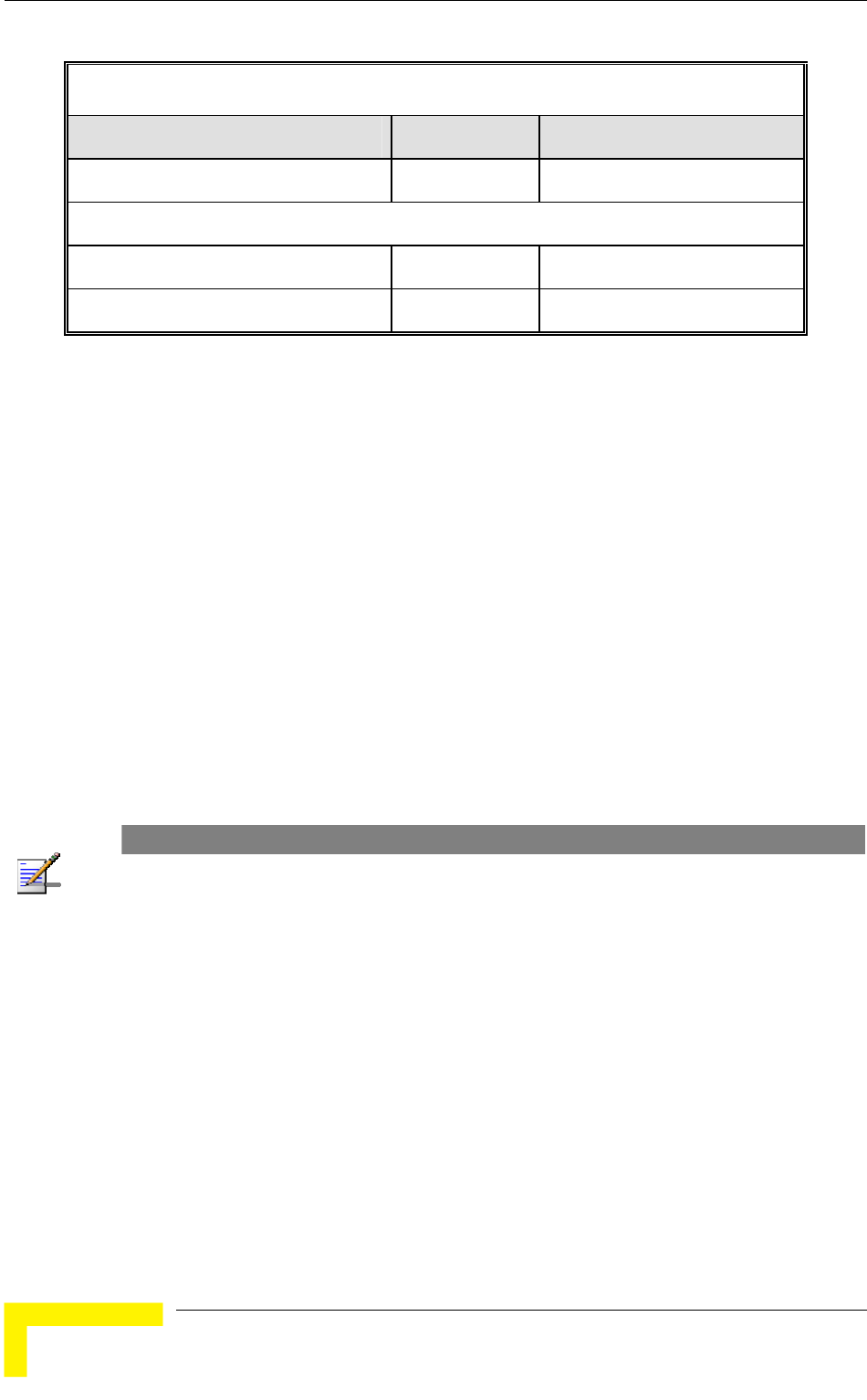
Chapter 4 - Operation and Administration
Table 4-5: Authentication and Association Process
Message Direction Status in AU
Association Successful AU → SU Associated
SU Status: Associated
ACK SU → AU Associated
Data Traffic SU ↔ AU Associated
The SNR measured at the SU
The SW version of the SU.
In addition, a summary table displays information about the Forwarding
The Unit Name of the SU.
The Unit Type of the SU.
Distance.
Database (Bridging Info). The database includes the following information:
The current number of entries. This is the number of currently associated
SUs.
NOTE
There is no aging algorithm for associated SUs. An SU is only removed from the list of associated
SUs under the following conditions:
A SNAP frame is received from another AU indicating that the SU is now associated with the
other AU.
The SU failed to respond to 50 consecutive frames transmitted by the AU and is considered to
have "aged out".
The aging time specified for entries in these table. There is no aging time
for Association Info entries.
ble, which is
ximum Number of Associations parameter. The
Maximum Number of Associations parameter is 512.
The maximum number of entries permitted for this ta
specified by the Ma
default value of the
BreezeACCESS 4900 System Manual
86

Menus and Parameters
Show MIR/CIR Database: Displays information on the MIR/CIR su
associated Subscriber Units.
pport for
ameters configured in the applicable SU
r the uplink (SU to AU).
meter.
ber Unit
he
ed by it, the identity (MAC Address) of the
wireless device to which they are connected.
4.2.5.4.2 MA Database in SU
The
availa
include the
An address learned from the Ethernet port.
ode behind the associated AU, learned via
the wireless port.
Sp (Special): 8 addresses that are always present, including:
The MAC address of the SU, which appears twice as it is learned from
ternal Operating System stack, which also
Each entry includes the following information:
The MAC address of the associated Subscriber Unit
The values of the MIR and CIR par
for the downlink (AU to SU) and fo
The value configured in the applicable SU for the Maximum Delay
para
The maximum data rate of the Subscri
Display MAC Pinpoint Table: The MAC Pinpoint table provides for each of
the Ethernet stations (identified by the MAC Address) connected to either t
AU or to any of the SUs serv
C Address
MAC Address Database option in the SU displays information regarding the
Subscriber Units bridging (forwarding) information. The following option is
ble:
Display Bridging Info: The Display Bridging Info option displays a list of all
the stations in the SU's Forwarding Database.
Each MAC address entry is followed by a description, which may
following:
Et (Ethernet):
Wl (Wireless): An address of a n
both the Ethernet and wireless ports.
The MAC address if the in
appears twice.
Operation and Administration
87

Chapter 4 - Operation and Administration
Alvarion's Multicast address (01-20-D6-00-00-01), which also appears
twice. The system treats this address as a Broadcast address.
-FF-FF-FF).
In addition, a summary table displays information about the Forwarding
rent number of
entries, the aging time specified by the Bridge Aging Time parameter and the
le, which is 1016.
Display Counters: Select this option to display the current values of the Per
ulation Level
t categories
since the last reset.
For SUs, the Per Modulation Level Counters display the following information for
vel supported by the unit:
ber of successfully transmitted unicasts at the
applicable modulation level.
FAILED: The total number of failures to successfully transmit unicast frame
ycle at the applicable modulation level.
ulation Level (AML) is also displayed. This is the
average modulation level (rounded to the nearest integer) since the last time the
nters were reset. The average is calculated using the
SUCCESS count at each modulation level as weights.
nd FAILED counts are provided for each of the
associated SUs, which are identified by their MAC address.
4.2.5.6 Link Capability
The Link Capability option provides information on HW and SW capabilities of
relevant units. In an AU, the information provided in the Link Capability reports
Alvarion's special Multicast address (01-20-D6-00-00-05), reserved for
future use.
The Ethernet Broadcast address (FF-FF-FF
Database (Bridging Info). The summary table includes the cur
maximum number of entries permitted for this tab
4.2.5.5 Per Modulation Level Counters
The Per Modulation Level Counters display statistics relating to wireless link
performance at different radio modulation levels. The Per Modulation Level
Counters menu includes the following options:
Modulation Level Counters.
Reset Counters: Select this option to reset the Per Mod
Counters.
The statistics show the number of frames accumulated in differen
each modulation le
SUCCESS: The total num
during a HW Retry c
In addition, the Average Mod
Per Modulation Level cou
For AUs, the SUCCESS a
BreezeACCESS 4900 System Manual
88

Menus and Parameters
is for all associated SUs. In an SU, the Link Capability reports include
information on all AUs in the neighboring AUs table (all AUs with whom the SU
The Link Capability feature enables to adapt the configuration of the unit
sure optimal operation.
ility submenu includes the following options:
4.2.5.6.1 Show Link Capability-General
Select this option to view information on general parameters of relevant units. For
y its MAC address, the following details are
displayed:
HwVer: the hardware version of the unit.
CpldVer: The version of the Complex Programmable Logic Device (CPLD) used
ying the CPLD
r 4 digits country code supported by the unit. Currently this
SwVer: The SW version used by the unit. This parameter is available only in
n in the relevant AU.
unit. This parameter is available only in
4.2.5.6.2
view information on current wireless link parameters of
ach relevant unit, identified by its MAC address, the following
ation Option: Enable or Disable.
: Enable or Disable.
n Option: Enable or Disable.
nt AU.
can communicate).
according to the capabilities of other relevant unit(s) to en
The Link Capab
each relevant unit, identified b
in the unit. This parameter is available only in AUs, displa
version in the relevant SU.
Country: The 3 o
value is 1022.
SUs, displaying the SW versio
BootVer: The Boot Version of the
AUs, displaying the Boot version in the relevant SU.
Show Link Capability-Wireless Link Configuration
Select this option to
relevant units. For e
details are displayed:
ATPC Option: Enable or Disable.
Adaptive Modul
Burst Mode Option
Concatenatio
Country Code Learning by SU: Enable or Disable. This parameter is
available only in SUs, displaying the current option in the releva
Operation and Administration
89

Chapter 4 - Operation and Administration
4.2.5.6.3
Select this option to view information on current security related parameters of
det
Data Encryption Option: Enable or Disable.
4.2.5.6.4 Sh
Sel
Con s).
4.2.5.6.5 Sh
Sel iew all capabilities information (General, Wireless Link
Config uration) of a selected SU (by its MAC address).
Menu
g
nced Configuration menu enables accessing the following menus:
ers
Show Link Capability-Security Configuration
relevant units. For each relevant unit, identified by its MAC address, the following
ails are displayed:
Security Mode: WEP, AES/OCB or AES/CCM.
Authentication Algorithm: Shared Key or Open System.
ow Link Capability by AU (SU only)
ect this option to view all capabilities information (General, wireless Link
figuration, Security Configuration) of a selected AU (by its MAC addres
ow Link Capability by SU (AU only)
ect this option to v
uration, Security Config
4.2.6 Advanced Configuration
The Advanced Configuration menu provides access to all parameters, includin
the parameters available through the Basic Configuration menu.
The Adva
IP Parameters
Air Interface Paramet
Network Management Parameters
Bridge Parameters
Performance Parameters
Service Parameters
Security Parameters
BreezeACCESS 4900 System Manual
90

Menus and Parameters
4.2.6.1 IP Parameters
The IP Parameters menu enables defining IP parameters for the selected un
determining its method of IP parameter acquisition.
The IP Parameters menu includes the following options:
IP Address
Subnet Mask
Default Gateway Address
DHCP Client
IP Address
it and
4.2.6.1.1
ress parameter defines the IP address of the unit.
4.2.6.1.2
efines the subnet mask for the IP address of the
nit.
4.2.6.1.3 Default Gateway Address
fines the IP address of the unit's
fault gateway address is 0.0.0.0.
4.2.6.1.4
parameters that define the method of IP
.
ubmenu includes the following options:
Access to DHCP
4.2.6.1.4.1 DHCP Option
t status of the DHCP support, and allows
selecting a new operation mode. Select from the following options:
The IP Add
The default IP address is 10.0.0.1.
Subnet Mask
The Subnet Mask parameter d
u
The default mask is 255.0.0.0.
The Default Gateway Address parameter de
default gateway.
The default value for the de
DHCP Client
The DHCP Client submenu includes
parameters acquisition
The DHCP Client s
DHCP Option
The DHCP Option displays the curren
Operation and Administration
91

Chapter 4 - Operation and Administration
Select Disable to configure the IP parameters manually. If this option is
eters as described above.
t(s) through which the unit searches for and
selected, configure the static IP param
Select DHCP Only to cause the unit to search for and acquire its IP
parameters, including the IP address, subnet mask and default gateway, from
a DHCP (Dynamic Host Configuration Protocol) server only. If this option is
selected, you must select the por
communicates with the DHCP server, as described in section 4.2.6.1.4.2
. You do
not have to configure static IP parameters for the unit. DHCP messages are
handled by the units as management frames.
Select Automatic to cause the unit to search for a DHCP server and acquire
its IP parameters from the server. If a DCHP server is not located within
approximately 40 seconds,
the currently configured parameters are used. If
.6.1.4.2
this option is selected, you must configure the static IP parameters as
described above. In addition, you must select the port(s) through which the
unit searches for and communicates with the DHCP server, as described in
section 4.2 .
The default is Disable.
municates with a DHCP server. Select from the following
options:
From Ethernet Only
Ethernet and Wireless Link
Subscriber
4.2.6.1.5
lues of the IP parameters,
ss, Run Time Subnet Mask and Run Time
Default Gateway Address.
4.2.6.2
4.2.6.1.4.2 Access to DHCP
The Access to DHCP option enables defining the port through which the unit
searches for and com
From Wireless Link Only
From Both
The default for Access Units is From Ethernet Only. The default for
Units is From Wireless Link Only.
Show IP Parameters
The Show IP Parameters option displays the current va
including the Run Time IP Addre
Air Interface Parameters
The Air Interface Parameters menu enables viewing the current Air Interface
parameters defined for the unit and configuring new values for each of the
relevant parameters.
BreezeACCESS 4900 System Manual
92

Menus and Parameters
4.2.6.2.1
sed to identify a wireless
network and to prevent the unintentional merging of two wireless networks or two
To of SUs to an existing network without a prior
knowledge of which specific AU will serve it, and to support the Best AU feature,
AU r ESSID Option is enabled at the AU, the Beacon frames
transmitted by it will include both the ESSID and Operator ESSID. The SU shall
ES the AU with which the SU is eventually associated is
defined as the Run-Time ESSID of the SU. Typically, the initial ESSID of the SU
ass ESSID can be reconfigured to the value of the
ESSID of the AU.
4.2.6.2.1.1
The
ESSID Parameters
The ESSID (Extended Service Set ID) is a string u
sectors in the same network. Typically, a different ESSID is defined for each AU.
facilitate easy addition
a secondary "global" ESSID, namely "Operator ESSID", can be configured in the
. If the Operato
regard such frames if either the ESSID or the Operator ESSID matches it own
SID. The ESSID of
is configured to the value of the Operator ESSID. When the SU has become
ociated with a specific AU, its
ESSID
ESSID parameter defines the ESSID of the unit.
Valid values: A string of up to 31 printable ASCII characters.
The default value is ESSID1.
NOTE
The ESSID string is case sensitive.
4.2.6.2.1.2 Operator ESSID Parameters (AU only)
4.2.6.2.1.2.1 Operator ESSID Option
bles or disables the use of Operator ESSID for
The default is Enable.
parameter defines the Operator ESSID.
The Operator ESSID Parameters submenu includes the following parameters:
The Operator ESSID Option ena
establishing association with SUs.
4.2.6.2.1.2.2 Operator ESSID
The Operator ESSID
Valid values: A string of up to 31 printable ASCII characters.
The default value is ESSID1.
NOTE
The Operator ESSID string is case sensitive.
Operation and Administration
93

Chapter 4 - Operation and Administration
4.2.6.2.2 Frequency Definition Parameters
4.2.6.2.2.1
et
ature is enabled, the SU will scan the defined
l
cle.
configured Sub-Bands, according to the
ters include also the frequencies that can be
4.2.6.2.3 in AU
4.2.6.2.3.1
Sub-Bands and Frequency Selection
The parameters that determine the frequency to be used are set in the AU. The
SU should be configured with a minimal set of parameters to ensure that it will
be able to automatically detect and use the frequency used by the AU, including
possible changes in this frequency.
To simplify the installation process the SU scans a definable frequencies subs
after power-up. If the Best AU fe
subset and the operating frequency will be determined by the Best AU
mechanism (including the optional use of the Preferred AU feature). Otherwise
the SU will try to associate with the first AU it finds. If no AU is found, the SU wil
start another scanning cy
Each unit is delivered with two pre-
country code. These sets of parame
used and the bandwidth. The sub-band to be used can be selected in both the AU
and the SU.
Frequency Definition Submenu
The Frequency Definition submenu in AU includes the following parameters:
Sub-Band Select
For information on how to view the Sub-Bands supported by the unit and the
supported parameters’ values and options, refer to section 4.2.2.4
.
The available options are 1 and 2.
The default selection is Sub-Band 1.
Frequency
The Frequency parameter defines the transmit/receive frequency.
The range depends on the selected Sub-Band.
4.2.6.2.3.2
The default is the lowest frequency in the Sub-Band. In the current version, the
4.2.6.2.3.3 arning by SU
ature support simplified installation and updates processes by enabling
are the same. If they are not the same and the
default frequency for both Sub-Bands is 4947.5 MHz.
ountry Code LeC
This fe
the SU to adapt the Country Code used by the AU.
The AU advertises its country code in every beacon and association response
message. Upon synchronization the SU will check if its country code and the
country code received from the AU
BreezeACCESS 4900 System Manual
94

Menus and Parameters
Country Code Learning by SU is enabled, the SU will use the AU’s country code:
rived limitations will be forced and the following parameters
w country definitions:
(per modulation level) will be set to the maximum defined
t to the maximum modulation level defined by
l be set to enable if the country code supports burst mode,
and the burst duration will be set to default.
learning (adaptation) the unit is automatically reset. Before
this automatic reset, if the unit is running from the shadow version, the versions
ing version must be set as main. This is done to
the country code de
will be set according to ne
Maximum TX Power
by the country code.
TX Power (per modulation level) will be set to the maximum defined by the
country code.
The Modulation Level will be se
the country code.
The Multicast Modulation Level will be set to the minimum modulation level
defined by the country code.
The Burst Mode wil
After country code
must be swapped and the runn
avoid returning to the previous version, which occurs automatically after the
reset.
The default is Enable.
NOTE
The Country Code Learning by SU feature does not function with the default ESSID (ESSID1).
4.2.6.2.3.4
ing Show Frequency Definitions, the selected Sub-Band and
4.2.6.2.4 Frequency
4.2.6.2.4.1
ntry code supports two or more Sub-
and
Show Frequency definitions
Upon select
Frequency are displayed.
Definition Submenu in SU
Sub-Band Select
This parameter is available only if the cou
Bands. For information on how to view the Sub-Bands supported by the unit
the supported parameters’ values and options, refer to section 4.2.2.4
.
The range depends on the number of Sub-Bands supported by the country code
The default selection is Sub-Band 1.
.
Operation and Administration
95

Chapter 4 - Operation and Administration
4.2.6.2.4.2
The e frequencies that will be
able frequencies according to
the Su
the
The
4.2.6.2.4.3 Sh
Definitions, the selected Sub-Band
parameters and the current operating frequency will be displayed. The current
e next
lso displayed.
4.2.6.2.5 Best AU Parameters (SU)
An SU that can communicate with more than one AU using the same ESSID may
AU it "finds", not necessarily the best choice in
terms of quality of communication. The same limitation also exists if only one AU
entical to the one used by the SU, as it is
not always necessarily the best choice.
The e
density can accumulate to create substantial
est for load sharing together with the desire to
best AU in its neighborhood.
U
decision according to the information gathered. The AU with the highest quality
by defining a specific AU as
the preferred AU.
Frequency Subset Definition
Frequency Subset Definition parameter defines th
used by the SU when scanning for an AU. The avail
b-Band are displayed, and each of the frequencies in the list is associated
with an index. The frequencies subset can be defined by entering the indexes of
required frequencies, or “A” to select all available frequencies.
default is the complete list of frequencies available in the Sub-Band.
ow Frequency Definitions
Upon selecting the Show Frequency
defined frequency subset as well as the defined subset (to be used after th
reset) are a
become associated with the first
in the neighborhood has an ESSID id
topology of a fixed access network is constantly changing. Changes in bas
station deployment and subscriber
changes in SU performance. The qu
create best throughput conditions for the SU created the need for the Best AU
feature, to enable an SU to connect to the
When the Best AU feature is used, each of the AUs is given a quality mark based
on the level at which it is received by the SU. The SU scans for a configured
number of cycles, gathering information from all the AUs with which it can
communicate. At the end of the scanning period, the SU reaches a Best A
mark is selected as the Best AU, and the SU will immediately try to associate with
it. The quality mark given to each AU depends on the level at which it is received
by the SU.
The Best AU selection mechanism can be overridden
NOTE
Although the SU selects the Best AU based on long-term conditions prior to the decision time, it
may not always be connected to the instantaneous Best AU at any given time. Note also that the
decision is made only once during the scanning interval. The decision may not remain the optimal
one for ever. If there are significant changes in deployment of neighboring AUs and the SUs served
by them, overall performance may be improved if the applicable SUs are reset intentionally so as to
re-initiate the Best AU decision process.
BreezeACCESS 4900 System Manual
96

Menus and Parameters
The Best AU Parameters menu includes the following options:
Best AU Support 4.2.6.2.5.1
The Best AU Support option enables or disables the Best AU selection feature.
The default is Disable.
NOTE
If the Best AU feature is not used, the SU associates with the first AU it finds whose ESSID or
Operator ESSID is identical to its own ESSID.
4.2.6.2.5.2
that the
process will be repeated for all relevant frequencies. A higher number may result
4.2.6.2.5.3
ing control of the SUs association is a powerful tool in
network management. The Preferred AU MAC Address parameter is intended for
U
ble AU it
nd
f the preferred AU is not found, the SU will
he decision reached using the best AU
The default value for the Preferred AU MAC Address is 00-00-00-00-00-00 (12
4.2.6.2.5.4 Show Best AU Parameters and Data
the unit can communicate:
MAC Address
Number Of Scanning Attempts
When the Best AU option is enabled, the SU gathers information on neighboring
AUs for approximately 2 seconds on each of the scanned frequencies. The
Number of Scanning Attempts parameter defines the number of times
in a better decision at the cost of an increased scanning time during which the
SU is not operational.
Valid values: 1 - 255.
Default value: 4.
Preferred AU MAC Address
The Preferred AU MAC Address parameter defines a specific AU with which the
SU should associate. Gain
applications where there is a need to dictate the preferred AU with which the S
should associate. To prevent the SU from associating with the first via
finds, the Best AU Support mechanism should be enabled. Once the SU has
identified the preferred AU based on its MAC address, it will associate with it a
terminate the scanning process. I
associate with an AU according to t
algorithm.
Valid values: A MAC address string.
zeros), meaning that there is no preferred AU.
The Show Best AU Parameters and Data option displays the applicable
information:
The Neighboring AU Data table displays the following details for each AU with
which
Operation and Administration
97

Chapter 4 - Operation and Administration
SNR of the received signal
Mark - The computed quality mark for the AU.
Full - The association load status of the AU. It is defined as full if the number
the AU has reached the maximum allowed according to
the value of the Maximum Number of Associations parameter. An AU whose
s
computed mark is the highest.
In a
displayed:
Best AU Support
ddress of the selected AU)
the SU “listens” to the wireless medium for approximately
until the SU decides that it
should start searching for another AU, is approximately seven seconds.
here is a high probability that SUs might need to roam
among different AUs, the use of active scanning enables to significantly reduce
transmitting a Probe Request at each frequency. This reduces the time spent at
The default selection is Passive.
4.2.6.2.7
lgorithm simplifies the
inimizing
interference to other units. This is achieved by automatically adjusting the power
level transmitted by each SU according to the actual level at which it is received
of SUs associated with
associations load status is full cannot be selected as the Best AU, even if it
ESSID - The ESSID of the AU.
ddition to the neighboring AU data table, the following information is
Preferred AU MAC Address
Number of Scanning Attempts
Associated AU MAC Address (the MAC a
4.2.6.2.6 Scanning Mode (SU only)
The Scanning Mode parameter defines whether the SU will use Passive or Active
scanning when searching for an AU.
In passive scanning,
two seconds at each frequency, searching for beacons. The disassociation period,
which is the time from the moment the link was lost
In some situations when t
the link establishment time. This is achieved by using shorter dwell periods,
each frequency as well as the disassociation period.
Power Control Parameters
The Automatic Transmit Power Control (ATPC) a
installation process and ensures optimal performance while m
BreezeACCESS 4900 System Manual
98

Menus and Parameters
by the AU. To support proper operation of the system with optimal performance
terference between neighboring sectors, the ATPC algorithm
ed in all units.
ntrolled by the AU that calculates for each received frame the
average SNR at which it receives transmissions from the specific SU. The average
count the previous calculated average, thus reducing the
es in link conditions. The weight of history (the
sed for calculating the average SNR is determined
ed
ot in the configured target range, the AU
er-down message. The target is that each
optimal level, or as high (or low) as possible if the
onditions.
with
transmit power level.
provide
here may be a need to decrease the transmitted
pport relatively small cells and to minimize the
eration of neighboring cells, or for compliance with local
4.2.6.2.7.1
ters are defined separately for different modulation
d
algorithm after either power up or losing synchronization with the
and minimum in
should be enabl
The algorithm is co
calculation takes into ac
effect of short temporary chang
previous value) in the formula u
by a configurable parameter. In addition, the higher the time that has passed
since the last calculation, the lower the impact of history on the calculat
average. If the average SNR is n
transmits to the SU a power-up or a pow
SU will be received at an
optimal range cannot be reached because of specific link c
Each time that the SU tries to associate with the AU (following either a reset or
loss of synchronization), it will initiate transmissions using its Transmit Power
parameters. If after a certain time the SU does not succeed to synchronize
the AU, it will start increasing the
In an AU the maximum supported transmit power is typically used to
maximum coverage. However, t
power level in order to su
interference with the op
regulatory requirements.
In some cases the maximum transmit power of the SU should be limited to
ensure compliance with applicable regulations or for other reasons.
Different power levels may be used for different modulation levels to optimize
performance taking into account the different modulation schemes as well as
possible regulatory restrictions.
Transmit Power
The Transmit Power parame
levels.
In the AU, the Transmit Power parameter defines the fixed transmit power level
and is not part of the ATPC algorithm.
In the SU, The Initial Transmit Power parameter defines the fixed transmit power
level when the ATPC algorithm is disabled. If the ATPC Option is enabled the
value configured for this parameter serves for setting the initial value to be use
by the ATPC
AU.
Operation and Administration
99

Chapter 4 - Operation and Administration
The minimum value for the Transmit Power Parameters is -10 dBm. (The ATPC
actual transmit power of the SU to lower values). The maximum
ower Parameter depends on several unit properties and
as defined for the applicable Sub-Band, together with the
a Gain. The Maximum EIRP of AUs (defined as Point-to-
lti-Point equipment) cannot exceed a certain value. In these cases the
to view the Sub-Bands supported by the unit and the
alues and options, refer to section 4.2.2.4
may reduce the
value of the Transmit P
parameters:
The modulation level
The Maximum Allowed Tx Power as defined for the applicable Sub-Band.
The Maximum EIRP
value of the Antenn
Mu
Transmit Power cannot exceed the value of (Maximum EIRP – Antenna Gain).
Maximum Tx Power parameter (in SU only)
For information on how
supported parameters’ v .
ter is selected.
4 2.6.2.7.2 er (SU only)
aximum Tx Power parameter limits the maximum transmit power that can
or the Maximum Tx Power is -10 dBm. The maximum value
ted parameters’ values and options, refer to section 4.2.2.4
The unit calculates the maximum allowed Transmit Power according to the unit
properties and parameters listed above, and displays the allowed range when a
Transmit Power parame
The default Transmit Power is the highest allowed value.
. Maximum Tx Pow
The M
be reached by the ATPC algorithm. It also sets the upper limits for the Transmit
Power parameters.
The minimum value f
depends on several unit properties and parameters:
The modulation level
The Maximum Allowed Tx Power as defined for the applicable Sub-Band.
For information on how to view the Sub-Bands supported by the unit and the
suppor .
ter is selected.
The unit calculates the maximum allowed Maximum Tx Power according to the
unit properties and parameters listed above, and displays the allowed range when
the Maximum Tx Power parame
The default Maximum Tx Power is the highest allowed value.
BreezeACCESS 4900 System Manual
100

Menus and Parameters
4.2.6.2.7.3
4.2.6.2.7.3.1
be
4.2.6.2.7.3.3 ATPC Delta from Minimum SNR Level
The
you
rec
Ma
Available values: 4 to 20 (dB).
4.2.6.2.7.3.4 Min
The e
bet p/power-down messages to a specific SU. Setting a
4.2.6.2.7.3.5
SUs
t
-
Default value: 5 (dB)
ATPC Parameters in AU
ATPC Option
The ATPC Option enables or disables the Automatic Transmit Power Control
(ATPC) algorithm.
The default is Enable.
4.2.6.2.7.3.2 ATPC Minimum SNR Level
The Minimum SNR Level defines the lowest SNR at which you want each SU to
received at the AU (the lower limit of the optimal reception level range).
Available values: 4 to 60 (dB).
Default value: 28 (dB).
Delta from Minimum SNR Level is used to define the highest SNR at which
want each SU to be received at the AU (the higher limit of the optimal
eption level range):
x. Level=Minimum SNR Level + Delta from Minimum SNR Level.
Default value: 11 (dB).
imum Interval Between ATPC Messages
Minimum Interval Between ATPC Messages parameter sets the minimal tim
ween consecutive power-u
low value for this parameter may lead to higher overhead and to an excessive rate
of power level changes at the SUs. High values for this parameter increase the
time it will take the SUs to reach optimal transmit power level.
Available values: 1 to 3600 seconds.
Default value: 30 seconds.
ATPC Power Level Step
The ATPC Power Level Step parameter defines the step size to be used by the
for incrementing/decrementing the Current Transmit Power after receiving a
power-up/power-down message. If the distance between the value of the Curren
Transmit Power and the desired range is smaller than the step size, the power
up/power-down message will include the specific step value required for this
condition.
Valid range: 1-20 (dB)
Operation and Administration
101

Chapter 4 - Operation and Administration
4.2.6.2.7.4 ATPC Parameters in SU
4.2.6.2.7.4.1
t immediately. However, when
nsmit power level will remain at the last
Current Transmit Power determined by the ATPC algorithm before it was
the value configured for the Initial Transmit Power
t reset or following loss of synchronization.
ATPC Option
The ATPC Option enables or disables the Automatic Transmit Power Control
(ATPC) algorithm. The parameter takes effec
changed from Enable to Disable, the tra
disabled. It will change to
parameter only after the nex
The default is Enable.
NOTE
The accuracy of the Transmit Power level is typically +/- 1 dB. However, at levels that are 15 dB or
more below the maximum supported by the hardware, the accuracy is +/- 3 dB. At these levels the
use of ATPC may cause significant fluctuations in the power level of the transmitted signal. When
operating at such low levels, it is recommended to disable the ATPC Option and to set the Transmit
Power parameter to the average Tx Power level before the ATPC was disabled.
4.2.6.2.7.5
n enables turning Off/On the AU’s transmitter. This feature
Tx Control (AU only)
The Tx Control optio
can be used during maintenance or testing to avoid transmissions using
undesired parameters.
The parameter is available only when managing the unit from its Ethernet port.
The default is On.
NOTE
The unit is reset immediately upon configuring the Tx Control parameter to either On or Off (even if
it is set to its current option).
4.2.6.2.8 Antenna Gain
The Antenna Gain parameter enables to define the net gain of a detached
antenna. The configured gain should take into account the attenuation of t
cable connecting the antenna to the unit. The Anten
he
na Gain is important
especially in cases when there is a limit on the EIRP allowed for the unit; the
meters cannot exceed the
read-only parameter in the
applicable “Show” menus.
The
imp
actual value (in the 0 to 50) is configured. The unit can be configured to
maximum allowed value for the Transmit Power para
value of (EIRP - Antenna Gain), where the EIRP is defined in the selected Sub-
Band.
In certain units with an integral antenna the Antenna Gain is not available as a
configurable parameter. However, it is available as a
range is 0–50 (dB). A value of “Don’t Care” means that the actual value is not
ortant. A value of “Not Set Yet” means that the unit will not transmit until the
range
BreezeACCESS 4900 System Manual
102

Menus and Parameters
“Don’t Care” or “Not Set Yet” only in factory. Once a value is configured, it is not
sible to reconfigure the unit to either “Don’t Care” or “Not Set Yet”.
default value depends on unit type. In SUs with integral antenna it is set to
(read only). The default value for AUs that are supplied with a detached
nna is in accordance with the antenna’s gain. In units supplied without an
pos
The
19
ante
4.2.6.2.9
be adapted
to the distances of SUs from the serving AU:
ts for a response message before retransmission
(acknowledge time delay) should take into account the round trip propagation
of the farthest SU. (The one-way propagation delay at 5 GHz is 3.3
etween SUs located
should also take
e
r
ual mode, this distance is configured
ce from each of the SUs it serves, determine which SU is located the
rthest and use the estimated distance of the farthest SU as the maximum
ce.
to
t
of the cell. In certain situations, the operator may decide to improve the overall
throughput by reducing the slot size below the value required for full fairness.
This means that when there is competition for bandwidth, the back-off algorithm
will give an advantage to SUs that are located closer to the AU.
The Cell Distance Parameters menu includes the following parameters:
antenna the default is typically “Not Set Yet”.
Cell Distance Parameters (AU only)
The higher the distance of an SU from the AU that is serving it, the higher the
time it takes for messages sent by one of them to reach the other. To ensure
appropriate services to all SUs regardless of their distance from the AU while
maintaining a high overall performance level, two parameters should
The time that a unit wai
delay
microsecond/km.) The higher the distance from the AU of the farthest SU
served by it, the higher the acknowledge time delay for all units in the cell
should be.
To ensure fairness in the contention back-off algorithm b
at different distances from the AU, the size of the time slot
into account the one-way propagation delay. The size of the time slot of all
units in the cell should be proportional to the distance from the AU of th
farthest SU served by it.
The distance from the AU of the farthest SU served by it can be determined eithe
manually or automatically. In man
manually. In automatic mode, the AU uses a special algorithm to estimate its
distan
fa
distan
It should be noted that if the size of the time slot used by all units is adapted
the distance of the farthest unit, then no unit will have an advantage when
competing for services. However, this reduces the overall achievable throughpu
Operation and Administration
103

Chapter 4 - Operation and Administration
4.2.6.2.9.1
ll Distance Mode option defines whether the maximum distance of the AU
meter) or automatically.
4.2.6.2.9.2
l meaning for No
representing the
f 9
4.2.6.2.9.3
The Fairness Factor enables to define the level of fairness in providing services to
t to 100%, all SUs have the same probability of getting
r bandwidth. If set to X%, then SUs located up to X%
of the maximum distance from the AU will have an advantage in getting services
4.2.6.2.9.4 Show Cell Distance Parameters
it
4.2.6.2.10
called Inter-
Frame Spacing (IFS). This is the time during which the unit determines whether
pends on the
llows:
oseconds.
Cell Distance Mode
The Ce
from any of the SUs it serves will be determined manually (using the Maximum
Cell Distance para
The Options are Automatic or Manual.
The default is Automatic.
Maximum Cell Distance
The Maximum Cell Distance parameter allows configuring the maximum distance
when the Cell Distance Mode option is Manual.
The range is 0 to 54 (Km). The value of 0 has a specia
Compensation: Acknowledge Time Out is set to a value
maximum distance of 54 km. The time slot size is set to its minimal value o
microseconds.
The default is 0 (No Compensation).
Fairness Factor
different SUs. When se
services when competing fo
over SUs located farther than this distance.
The range is 0 to 100 (%)
The default is 100 (%).
Select Show Cell Distance Parameters to view the Cell Distance parameters. In
addition, the Measured Maximum Cell Distance and the MAC address of the un
that the mechanism found to be the farthest from the AU are displayed. A
distance of 1 km means any distance below 2 km.
Arbitration Inter-Frame Spacing (AIFS)
The time interval between two consecutive transmissions of frames is
the medium is idle using the carrier sense mechanism. The IFS de
type of the next frame to be transmitted, as fo
SIFS (Short Inter-Frame Spacing) is used for certain frames that should be
transmitted immediately, such as ACK and CTS frames. The value of SIFS is
16 micr
BreezeACCESS 4900 System Manual
104
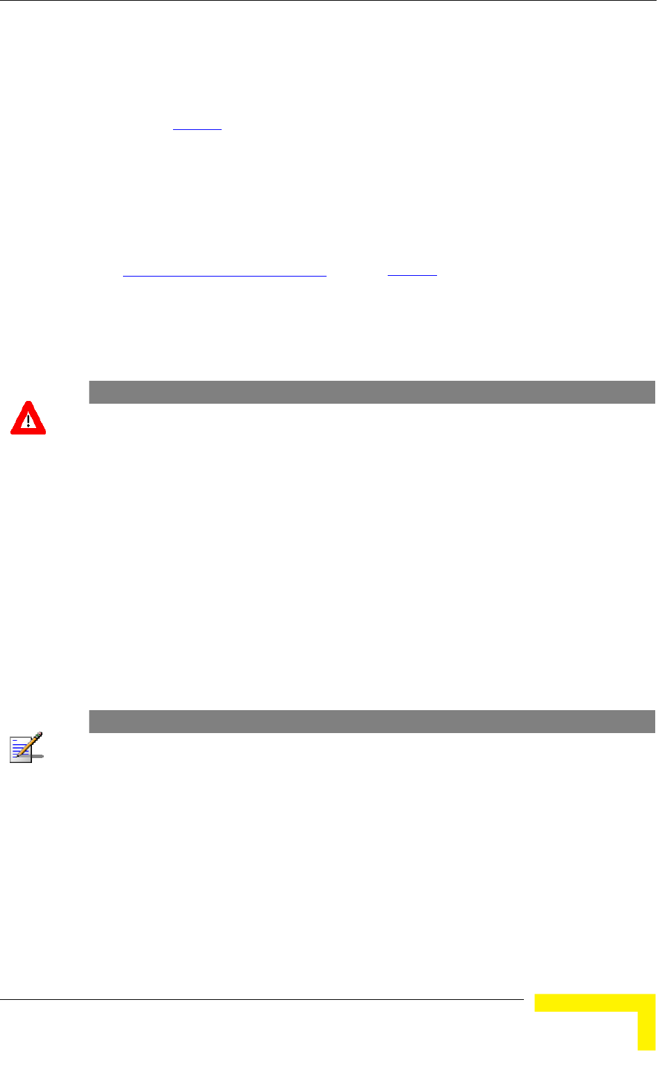
Menus and Parameters
DIFS (Distributed coordination function Inter-Frame Spacing) is typically used
edium is free. If the unit decides that the
on by DIFS plus a number of time
for other frame types when the m
medium is not free, it will defer transmissi
slots as determined by the Contention Window back-off algorithm (see
section 4.2.6.5.2
) after reaching a decision that the medium has become free.
FS, where AIFS can be configured to one or two time
d be configured to two time slots. A value of 1 should
nt-to-point link, where in the other
slots. This ensures that the unit
DIFS equal SIFS plus AI
slots. Typically, AIFS shoul
only be used in one of the two units in a poi
unit the AIFS remains configured to two time
with AIFS configured to one has an advantage over the other unit, provided that
the Minimum Contention Window (section 4.2.6.5.2 ) parameter in both units is
configured to 0 to disable the contention window back-off algorithm.
The available options are 1 or 2 (time slots).
The default is 2 time slots.
CAUTION
An AIFS value of 1 should only be used in point-to-point applications. Otherwise the default value of
2 must always be used. In a point-to-point link, only one unit should be configured to an AIFS value
of 1. When both units need to transmit, the unit with an AIFS value of 1 will have an advantage over
the unit with AIFS of 2. In this case, the Minimum Contention Window parameter in both units must
be configured to 0 to disable the contention window back-off algorithm.
4.2.6.2.11
r of Associations parameter defines the maximum number
selected AU, while still
to 5.
and AU-SA is 512. For AUS-BS and AUS-SA the default
is 5.
Maximum Number of Associations (AU only)
The Maximum Numbe
of Subscriber Units that can be associated with the
guaranteeing the required quality of service to customers.
Available values for AU-BS and AU-SA range from 0 to 512. For AUS-BS and
AUS-SA the range is from 0
Default value for AU-BS
NOTE
When the Data Encryption Option is enabled, the actual maximum number of SUs that can
associate with the AU-BS or AU-SA is limited to 124. The number displayed for the Maximum
Number of Associations is the value configured for this parameter, which might be higher than the
actu imit (512 when Data Encryption is disabled, al limit. The Maximum Number of Associations L
124 the Show Air Interface Parameters display. when Data Encryption is enabled) is indicated in
Operation and Administration
105

Chapter 4 - Operation and Administration
NOTE
There is no aging time for SUs. An SU is only removed from the list of associated SUs under the
following conditions:
A SNAP frame is received from another AU indicating that the SU is now associated with the
other AU.
The SU failed to respond to a certain number of consecutive frames transmitted by the AU and
is considered to have "aged out".
Therefore, the database of associated SUs may include units no longer associated with the AU. If
the number of associated SUs has reached the value of the Maximum Number of Associations
parameter, the selected AU cannot serve additional SUs. To view the current number of associated
SUs, use the Display Association Info option in the MAC Address Database menu. To delete
inactive SUs from the database you must reset the AU.
4.2.6.2.12 Wireless Link Trap Threshold (AU only)
lity trap, indicating that the quality of the wireless link has dropped
bove (off trap) the specified threshold.
The Wireless Link Trap Threshold is in percentage of retransmissions, and the
4.2.6.2.13
Gaining knowledge of the noise characteristics per channel enables construction
rder to gain information
regar location of the unit, the unit will enter
a definite period, during which information will be
gathe the channels comprising the selected sub
ill automatically reset. During
the information-gathering period the unit will not receive nor transmit data. It
4.2.6.2.13.1
channel during each cycle for information gathering when performing spectrum
The Wireless Link Trap Threshold parameter defines the threshold for the
wireless qua
below (on trap) or has increased a
allowed range is from 1 to 100 (%).
The default is 30 (%).
Spectrum Analysis
of a relatively noise free working environment. In o
ding noise characteristics in the
passive scanning mode for
red. The scanned channels will be
set.
Upon activating the spectrum analysis the unit w
also will not be able to synchronize/associate, meaning that it cannot be
managed via the wireless link. During the spectrum analysis period the unit
security mode is changed to promiscuous to enable gathering information
regarding all legal frames received by the unit. At the end of the period the unit
will reset automatically regaining normal operability upon start up.
The Spectrum Analysis submenu includes the following options:
Spectrum Analysis Channel Scan Period
The Spectrum Analysis Channel Scan Period is the period of staying on each
analysis.
Range: 2-30 seconds.
BreezeACCESS 4900 System Manual
106

Menus and Parameters
Default value: 5 seconds.
4.2.6.2.13.2 Spectrum Analysis Scan Cycles
The Spectrum Analysis Scan Cycle is the number of scanning cycles when
Rang
Default value: 2 cycles.
4.2.6.2.13.3 nel Selection (AU only)
s weather the AU will choose the
best noise free channel upon startup after completion of the spectrum analysis
4.2.6.2.13.4 Spectrum Analysis Activation
The Spectrum analysis Activation option enables activation of the spectrum
will reset automatically and start-up
in spectrum analysis mode.
4.2.6.2.13.5
ctrum Analysis Information option enables resetting the spectrum
4.2.6. .13.6
nformation Display option enables viewing the results of
ormation includes the following details
OFDM frames with
performing Spectrum Analysis.
e: 1-100 cycles.
Automatic Chan
The Automatic Channel selection option define
process. The selection is per analysis: when the analysis is completed it will be
disabled automatically.
The default is Disable.
analysis process. Upon activation, the unit
Reset Spectrum Analysis Information
The Reset Spe
analysis counters.
Spectrum Analysis Information Display
The Spectrum Analysis I
2
the last analysis process. The displayed inf
for each channel:
Frequency in MHz
Signal Count: The number of signals (excluding OFDM frames with the
correct bandwidth) in the channel.
Signal SNR: The approximate SNR of signals (excluding
the correct bandwidth) in the channel.
Signal Width: The average width in microseconds of signals (excluding OFDM
frames with the correct bandwidth) in the channel.
OFDM Frames: The number of OFDM frames with the correct bandwidth
detected in the channel.
Operation and Administration
107

Chapter 4 - Operation and Administration
4.2.6.2.13.7
The y
wh
res
sam
opt
4.2.6.2.14 Lost Beacons Transmission Watchdog Threshold
as
Tra
bea
The e being 218. When the
parameter is set to 0, this feature is disabled, i.e. internal refresh will never be
or
to
e association process, including the search for the
a full
4.2.6.3
m
unauthorized access by defining a set of discrete IP addresses as well as IP
red.
cess may be permitted from the
rnet only, or from both.
lowing options:
Spectrum Analysis Information Display - Continuous
Spectrum Analysis Information Display - Continuous option is available onl
en the analysis process is active. It enables viewing the continuously updated
ults of the current analysis process. The displayed information includes the
e details available for a regular Spectrum Analysis Information Display
ion.
When it is unable to send beacon frames for a predetermined period of time, such
in the case of interferences, the AU resets itself. The Lost Beacons
nsmission Threshold parameter represents the number of consecutive lost
cons after which the unit will reset itself.
range for this parameter is 100 – 1000, its default valu
performed.
4.2.6.2.15 Disassociate (AU only)
The Disassociate feature enables disassociating all SUs associated with the AU
a selected SU. This feature is useful during configuration changes, enabling
force the SU(s) to re-initiate th
best AU (or a preferred AU) using the Best AU process, without performing
reset.
The Disassociate submenu includes two options:
Disassociate All SUs
Disassociate SU By MAC Address: to disassociate a selected SU
Network Management Parameters
The Network Management Parameters menu enables protecting the Unit fro
address ranges from which the unit can be managed using protocols such as
Telnet, FTP, TFTP, SNMP, DHCP and ICMP. This excludes management messages
generated in the unit, such as Traps or Ping Test frames, which are not filte
The direction from which management access is permitted can also be
configured, which means that management ac
wireless medium only, from the wired Ethe
The Network Management Parameters menu includes the fol
Access to Network Management
Network Management Filtering
BreezeACCESS 4900 System Manual
108

Menus and Parameters
Set Network Management IP address
Delete a Network Management IP Address
Delete All Network Management IP Addresses
Set/Change Network Management IP Address Ranges
SNMP Traps
Access to Network Management 4.2.6.3.1
The Access to Network Management option defines the port through which the
ink Only
thernet and Wireless Link
The default selection is From Both Ethernet and Wireless Link.
unit can be managed. The following options are available:
From Wireless L
From Ethernet Only
From Both E
CAUTION
Be careful not to block your access to the unit. For example, if you manage an SU via the wireless
link, setting the Access to Network Management parameter to From Ethernet Only completely
blocks your management access to the unit. In this case, a technician may be required to change
the settings at the user's site.
4.2.6.3.2
s the IP address
If management filtering is enabled, the unit can only
be managed by stations with IP addresses matching one of the entries in either
the unit via the
available:
Activate IP Filter on Ethernet Port: Applicable only if the Access to Network
ink. The unit can be managed from the Ethernet
IP addresses matching one of the entries in the Set
dress based filtering is configured for the wireless port.
Network Management Filtering
The Network Management Filtering option enables or disable
based management filtering.
the Network Management IP Addresses list or in the Network Management IP
Address Ranges list, described below, and that are connected to
defined port(s). The following options are
Disable: No IP address based filtering is configured.
Management parameter is configured to either From Ethernet Only or From
Both Ethernet and Wireless L
port only by stations with
Network Management IP Addresses parameter. If the Access to Network
Management parameter is configured to From Both Ethernet and Wireless
Link then no IP ad
Operation and Administration
109

Chapter 4 - Operation and Administration
Activate IP Filter on Wireless Link Port: Applicable only if the Access to
Network Management parameter is configured to either From Wireless Link
f the
er. If the Access
Both Ethernet and
Wireless Link then no IP address based filtering is configured for the Ethernet
d Wireless Link Ports: Applicable to
all options of the Access to Network Management parameter. The unit can be
e Access to Network Management
parameter only by stations with IP addresses matching one of the entries in
nagement IP Addresses parameter.
.
4.2.6.3.3 Set Network Management IP Address
The Set Network Management IP Address option enables defining up to 10 IP
anage the unit if the Network Management
Filtering option is enabled.
dress is 0.0.0.0 (all 10 addresses).
k Management IP Address
4.2.6.3.5
4.2.6.3.6 Set/Change
enables defining,
n be managed if the
Network Management Filtering option is enabled. This is in addition to the
he Network Management menu that enable defining,
updating and deleting discrete IP addresses.
ng options:
4.2.6.3.6.1 gement IP Address Ranges
The Set/Change Network Management IP Address Ranges option enables
to 10 IP address ranges from which the unit can be
managed if the Network Management Filtering option is enabled.
Only or From Both Ethernet and Wireless Link. The unit can be managed
from the wireless port only by stations with IP addresses matching one o
entries in the Set Network Management IP Addresses paramet
to Network Management parameter is configured to From
port.
Activate IP filter on Both Ethernet an
managed from the port(s) defined by th
the Set Network Ma
The default selection is Disable
addresses of devices that can m
The default Network Management IP Ad
4.2.6.3.4 Delete a Networ
The Delete Network Management IP Address option enables deleting IP address
entries from the Network Management IP Addresses list.
Delete All Network Management IP Addresses
The Delete All Network Management IP Addresses option enables deleting all
entries from the Network Management IP Addresses list.
Network Management IP Address Ranges
The Set/Change Network Management IP address Ranges menu
updating or deleting IP address ranges from which the unit ca
previous options in t
The menu includes the followi
Set/Change Network Mana
defining/updating up
BreezeACCESS 4900 System Manual
110

Menus and Parameters
The default Network Management IP Address Range is 0.0.0.0 TO 0.0.0.0 (all 10
ranges).
A rang either a start and end
t address> to <end address>” (example: 192.168.1.1
address and a mask, in the format “<base address>
4.2.6.3.6.2
ess Range option enables deleting IP
ork Management IP Address Ranges list.
4.2.6.3.6.3 rk Management IP Address Ranges
all entries from the Network Management IP Address Ranges list.
4.2.6.3.7 SN
The
can
4.2.6.3.7.1
The Send SNMP Traps option enables or disables the sending of SNMP traps.
The
4.2.6.3.7.2 SN
add
The IP destinations is 0.0.0.0.
4.2.6.3.7.4
eleting Trap address entries from
st.
4.2.6.3.7.5
The Delete All Trap Addresses option enables deleting all entries from the SNMP
Traps Addresses list.
e can be defined using a string that includes
address, in the format “<star
to 192.168.1.255), or a base
mask <mask>” (example: 192.168.1.1 mask 255.255.255.0).
Delete Network Management IP Address Range
The Delete Network Management IP Addr
address range entries from the Netw
Delete All Netwo
The Delete All Network Management IP Address Ranges option enables deleting
MP Traps
SNMP submenu enables or disables the transmission of SNMP Traps. If this
option is enabled, up to 10 IP addresses of stations to which SNMP traps are sent
be defined.
Send SNMP Traps
default selection is Disable.
MP Traps Destination IP Addresses
The SNMP Traps Destination IP Addresses submenu enables defining up to 10 IP
resses of devices to which the SNMP Traps are to be sent.
default of all 10 SNMP Traps
4.2.6.3.7.3 SNMP Traps Community
The SNMP Traps Community option enables defining the Community name for
each IP address to which SNMP Trap messages are to be sent.
Valid strings: Up to 8 ASCII characters.
The default for all 10 addresses is “public”, which is the default Read community.
Delete One Trap Address
The Delete One Trap Address option enables d
the SNMP Traps Addresses li
Delete All Trap Addresses
Operation and Administration
111

Chapter 4 - Operation and Administration
4.2.6.4
The Bridge Parameters menu provides a series of parameter sets that enables
tra
The
VLAN Support
Ethernet Broadcast Filtering (SU only)
Unicast Relaying (AU only)
MAC Address Deny List (AU only)
4.2.6.4.1 VLAN Support
The VLAN Support menu enables d EEE
802.1Q compliant VLAN aware (Virtual LAN aware) feature of the units. Each
stations that can co t cannot
communicate with stations belongin ure also
vides the ability to set traffic pri ion of certain frames. The
related to the VLAN is incl ag Header, which is
frame between the MAC header and the data. VLAN
implementation in BreezeACCESS 4900 units supports frame routing by port
onnected to only one VLAN.
The llowing parameters:
Bridge Parameters
configuring parameters such as control and filtering options for broadcast
nsmissions, VLAN support, and Type of Service prioritization.
Bridge Parameters menu includes the following options:
Ethernet Broadcast/Multicast Limiter
Bridge Aging Time
Roaming Option (SU only)
Broadcast Relaying (AU only)
efining the parameters related to the I
VLAN includes mmunicate with each other, bu
g to different VLANs. The VLAN feat
pro
information
orities for transmiss
uded in the VLAN T
inserted in each
information, whereby each port is c
VLAN Support menu includes the fo
VLAN Link Type
VLAN ID – Data (SU only)
VLAN ID – Management
VLAN Forwarding
BreezeACCESS 4900 System Manual
112

Menus and Parameters
VLAN Relaying (AU only)
4.2.6.4.1.1 VLAN -Data (SU only)
set
to Access Link. It enables defining the VLAN ID for data frames, which identifies
the VLA
Valid values range from 1 to 4094.
Default value: 1.
The VLAN ID-Data affects frames received from the wireless link port, as follows:
nly tagged frames with a VLAN AN ID-Data defined
in the unit are forwarded to the Ethernet port.
ers are removed from the data frames received from the wireless
ey are transmitted on the Ethernet port.
frames received from the Ethernet port, as follows:
in all untagged frames received from the
port before transmission on the wireless link. The tag includes the
the VLAN ID-Data and the VLAN Priority-Data parameters.
ort, are discarded. This includes frames with tagging for
prioritization purposes only.
4.2.6.4.1.2
e
anagement frames, which identifies remote stations for
ervers/stations using these protocols must tag the management frames sent to
it with the value of the VLAN ID-Management parameter.
VLAN Traffic Priority
ID
The VLAN ID-Data is applicable only when the VLAN Link Type parameter is
N to which the unit belongs.
O ID (VID) equal to the VL
The tag head
link before th
The VLAN ID-Data affects
A VLAN Data Tag is inserted
Ethernet
values of
Tagged frames received on Ethernet port, which are meant to be forwarded to
the wireless link p
VLAN ID-Management
The VLAN ID-Management is applicable for all link types. It enables defining th
VLAN ID for m
management purposes. This applies to all management applications using
protocols such as SNMP, TFTP, ICMP (ping), DHCP and Telnet. All
s
the un
Valid values: 1 to 4094 or 65535 (No VLAN).
The default value is 65535.
If the VLAN ID-Management is other than 65535:
Operation and Administration
113

Chapter 4 - Operation and Administration
Only tagged management frames with a matching VLAN ID received on either
Ethernet or wireless link ports are forwarded to the unit.
d the VLAN Priority-
If the VLAN ID-Management is 65535 (No VLAN):
Only untagged management frames received on either the Ethernet or wireless
link ports are forwarded to the u
Management frames generated by the unit are not tagged.
The following table summarizes the nt port
in accordance with the value of the gement parameter. The table is
k types. Refer to the - Access Link and Trunk Link
options for some restrictions when configuring this parameter.
Table 4-6: VLAN Managem ionality
the
A VLAN Management Tag is inserted in all management frames generated by
the unit before transmission on either the Ethernet or wireless link port. The
tag includes the values of the VLAN ID-Management an
Management parameters.
nit.
functionality of the internal manageme
VLAN ID-Mana
valid for all lin VLAN Link Type
ent Port Funct
Action Management Port - Internal
Receive from Ethernet ed frames, matching VID-M
Untagged frames when VID-M=65535
Tagg
Receive from Wireless Tagged frames, matching VID-M
Untagged frames when VID-M=65535
Transmit Insert VID-M, PID-M
Table Legend:
VID-
PID-M: VLAN Priority-Managem
4.2.6.4 pe
Type parameter ena defining the functionality of the VLAN
e capability of the unit.
The available options are Hybrid Link, Trunk Link and Access Link (Access Link
is available only in SUs).
The default selection is Hybrid Link.
M: VLAN ID-Management
ent
.1.3 VLAN Link Ty
The VLAN Link bles
awar
option
BreezeACCESS 4900 System Manual
114
Menus and Parameters
4.2.6.4.1.3.1 Access Link (SU only)
Access Link transfers frames while tagging/untagging them since all devices
connected to the unit are VLAN unaware. Thus, the unit cannot transfer tagged
frames.
Table 4-7 summarizes the func
tionality of the data port for an Access link.
Table 4-7: VLAN Data Port Functionality - Access Link
Action Data Port - SU
Receiv ernet Untagged frames e from Eth
Accep es, matching VID-D t from Wireless Tagged fram
Tag In VID-D, PID-D (to wireless) sert
Tag Remove Yes (to Ethernet)
Table Legend:
VID-D: VLAN ID-Data
PID-D: VLAN Priority-Data
4.2.6.4.1.3.2
es, as all devices connected to the unit are
ink
ed.
Trunk Link
Trunk Link transfers only tagged fram
VLAN aware. Only tagged data frames received on the Ethernet or wireless l
ports are forward
CAUTION
It is not recommended that you configure a unit as a Trunk Link with the VLAN ID-Management
parameter set at 65535, as it does not forward any 'NO VLAN' management frames to its other
port, making it impossible to manage devices connected behind the unit that are also configured
with 'NO VLAN'.
If the VLAN Forwarding option is enabled, a data frame received with a VLAN ID
that is not a member of the unit's VLAN Forwarding List is discarded.
NOTE
If the VLAN Forwarding option is enabled, be sure to include the VLAN ID-Management value of
all units that should be managed via the wireless port of the unit, in the Forwarding List.
If the VLAN Relaying option is enabled in an AU, a data frame relayed with a
VLAN ID that is not a member of the unit's VLAN Relaying List is discarded.
Operation and Administration
115
Chapter 4 - Operation and Administration
NOTE
If the VLAN Relaying option is enabled and you manage your devices from behind an SU unit, be
sure to include the VLAN ID-Management value of all units to be managed when relaying via the
wireless port of the AU unit, in the Relaying List. If the VLAN Forwarding option is also enabled in
the AU, these VLAN IDs should also be included in the Forwarding List.
Table 4-8 summarizes the functionality of the data port for a Trunk link.
Table 4-8: VLAN Data Port Functionality - Trunk Link
Action Data Port – AU and SU
Accept from Ethernet Tagged frames.
ng list
If Forwarding is enabled, only frames with
VLAN ID values which are included in the
Forwardi
Accep Tagged frames
If Forwarding is enabled, only frames with
t from Wireless
VLAN ID values which are included in the
Forwarding list
Tag In No sert
Tag Remove No
4.2.6.4.1.3.3 Hybrid
ybrid Link transfers both tagged and untagged frames, as the devices connected
unit can be either VLAN aware or VLAN unaware. This is equivalent to
Data Port Functionality - Hybrid Link
Link
H
to the
defining no VLAN support, as the unit is transparent to VLAN.
Table 4-9 summarizes the functionality of the data port for a Hybrid link.
Table 4-9: VLAN
Action Data Port – AU and SU
Accept from Ethernet All
Accept from Wireless All
Tag Insert No
Tag R No emove
BreezeACCESS 4900 System Manual
116

Menus and Parameters
4.2.6.4.1.4 VLAN Forwarding (AU and SU)
The VLAN Forwarding feature is applicable for Trunk Links only. It enab
defining the VLAN ID values to be included in the VLAN Forwarding List. If the
Link Type is defined as a Trunk Link and the VLAN Forwarding option is enabled,
a data frame received with a VLAN ID that is not a member of th
les
e unit's VLAN
Forwarding List is discarded.
The VLAN Forwarding submenu provides the following options:
The VLAN Forwarding Support option enables or disables the VLAN Forwarding
4.2.6.4.1.4.2
dding a VLAN ID to the VLAN
ID can be entered at a time. The maximum number of
94.
4.2.6.4.1.4.4
4.2.6.4.1.4.1 VLAN Forwarding Support
feature.
Available selections are Disable and Enable.
The default selection is Disable.
Add Forwarding VLAN ID
The Add Forwarding VLAN ID option enables a
Forwarding List. One VLAN
VLAN IDs in the VLAN Forwarding List is 20.
Valid values are 1 to 40
4.2.6.4.1.4.3 Remove Forwarding VLAN ID
The Remove Forwarding VLAN ID option enables removing a VLAN ID from the
VLAN ID Forwarding List.
Valid values are VID values (from 1 to 4094) that are included in the VLAN
Forwarding List.
Show VLAN ID Forwarding List
The Show VLAN Forwarding List option displays the values of the VLAN IDs
included in the VLAN Forwarding List.
NOTE
If the VLAN ID Forwarding List is empty and the VLAN Forwarding Support is set to Enable, then all
data frames are discarded.
If VLAN Relaying Support and VLAN Forwarding Support are both enabled, then all VLAN IDs
configured in the Relaying List must also be configured in the Forwarding List.
4.2.6.4.1.5
ble for Trunk Links only. It enables defining
the VLAN ID values to be included in the VLAN Relaying List. If the Link Type is
N Relaying Support option is enabled, a frame
relayed from the wireless link, which is a frame received from the wireless link
that should be transmitted back through the wireless link, with a VLAN ID that is
VLAN Relaying (AU only)
The VLAN Relaying feature is applica
defined as Trunk Link and the VLA
Operation and Administration
117

Chapter 4 - Operation and Administration
not a member of the unit's VLAN Relaying List, is discarded. If VLAN Forwarding
The VLAN Relaying menu provides the following options:
4.2.6.4.1.5.1
feat
The lection is Disable.
4.2.6.4.1.5.2
The VLAN ID to the VLAN
Relaying List. One VLAN ID can be entered at a time. The maximum number of
ist is 20.
4.2.6.4.1.5.3
e VLAN
in the VLAN Relaying List.
4.2.6.4.1.5.4
The Show VLAN Relaying option displays the values of the VLAN IDs included in
Support is also enabled, it is necessary to configure all the VLAN IDs in the
Relaying List also in the Forwarding List to enable the relaying operation.
VLAN Relaying Support
The VLAN Relaying Support option enables or disables the VLAN Relaying
ure.
Available selections are Disable and Enable.
default se
Add Relaying VLAN ID
Add Relaying VLAN ID option enables adding a
VLAN IDs in the VLAN Relaying L
Valid values are 1 to 4094.
Remove Relaying VLAN ID
The Remove Relaying VLAN ID option enables removing a VLAN ID from th
ID Relaying List. Valid values are VID values (from 1 to 4094)) that are included
Show VLAN ID Relaying List
the VLAN Relaying List.
NOTE
If the VLAN ID Relaying List is empty and the VLAN Relaying Support is Enabled, then all data
frames relayed from the wireless link are discarded.
If VLAN Relaying Support and VLAN Forwarding Support are both enabled, then all VLAN IDs
configured in the Relaying List must also be configured in the Forwarding List.
4.2.6.4.1.6
andle the packet. In version 3.2 all parameters
that affect prioritization within the BreezeACCES 4900 system, including VLAN-
The :
VLAN Priority – Management
VLAN Traffic Priority
The VLAN Traffic Priority menu enables configuring the VLAN Priority field in
applicable frames. These parameters only impact the way in which other VLAN
aware devices in the network will h
based prioritization, are located in the Services > Traffic Prioritization menu.
VLAN Traffic Priority menu includes the following parameters
VLAN Priority – Data (SU only)
BreezeACCESS 4900 System Manual
118

Menus and Parameters
4.2.6.4.1.6.1
ble for Access Links only. It enables
ly
4.2.6.4.1.6.2 VL
fiel n units with VLAN ID-Management that is other
than 65535. All management frames are routed to the High queue. This
other VLAN aware devices handle the packet.
4.2.6.4.1.7
4.2.6.4.2
lticast filtering capabilities for the selected SU. Filtering the
the following parameters:
erride Filter
er
VLAN Priority - Data (SU only)
The VLAN Priority - Data is applica
configuring the value of the VLAN Priority field for data frames transmitted to the
wireless link. All data frames are routed to the Low queue. This parameter on
impacts the way other VLAN aware devices handle the packet.
Valid values range from 0 to 7.
The default value is 0.
AN Priority - Management
The VLAN Priority - Management enables defining the value of the VLAN Priority
d for management frames i
parameter only impacts the way
Valid values range from 0 to 7.
The default value is 4 for SUs and 0 for AUs.
Show VLAN Parameters
The Show VLAN Parameters option displays the current values of the VLAN
support parameters.
Ethernet Broadcast Filtering (SU only)
The Ethernet Broadcast Filtering menu enables defining the layer 2 (Ethernet)
broadcast and mu
Ethernet broadcasts enhances the security of the system and saves bandwidth on
the wireless medium by blocking protocols that are typically used in the
customer's LAN but are not relevant for other customers, such as NetBios, which
is used by the Microsoft Network Neighborhood. Enabling this feature blocks
Ethernet broadcasts and multicasts by setting the I/G bit at the destination
address to 1. This feature should not be enabled when there is a router behind
the SU.
The Ethernet Broadcast Filtering menu includes
Filter Options
DHCP Broadcast Ov
PPPoE Broadcast Override Filt
ARP Broadcast Override Filter
Operation and Administration
119

Chapter 4 - Operation and Administration
4.2.6.4.2.1
adcast filtering functionality
- filters broadcast messages received from the
reless
ed
sable.
The DHCP Broadcast Override Filter option enables or disables the broadcasting
ns
is set to Enable. Select from the following options:
Disable - DHCP Broadcast messages are filtered or transmitted according to
e Filter Options parameter.
Enable - DHCP Broadcast messages are transmitted regardless of the selected
4.2.6.4.2.3
if according to
Options parameter, broadcast messages should
transmitted if this parameter is set to Enable.
Filter Options
The Filter Options enables defining the Ethernet Bro
of the unit. Select from the following options:
Disable - no Ethernet Broadcast Filtering.
On Ethernet Port Only
Ethernet port.
On Wireless Port Only - filters broadcast messages received from the wi
link port.
On Both Ethernet and Wireless Ports - filters broadcast messages receiv
from both the Ethernet and wireless link ports.
The default selection is Di
4.2.6.4.2.2 DHCP Broadcast Override Filter
of DHCP messages. Even if according to the selected option in the Filter Optio
parameter, broadcast messages should be filtered, DHCP broadcasts are
transmitted if this parameter
the general filtering criteria in th
value of the Filter Options parameter.
The default selection is Disable.
PPPoE Broadcast Override Filter
The PPPoE Broadcast Override Filter option enables or disables the broadcasting
of PPPoE (Point to Point Protocol over Ethernet) messages. Even
the selected option in the Filter
be filtered, PPPoE broadcasts are
Select from the following options:
Disable - PPPoE Broadcast messages are filtered or transmitted according to
the general filtering criteria in the Filter Options parameter.
Enable - PPPoE Broadcast messages are transmitted regardless of the
selected value of the Filter Options parameter.
BreezeACCESS 4900 System Manual
120

Menus and Parameters
The default selection is Disable.
4.2.6.4.2.4 ARP Broadcast Override Filter
The ARP Broadcast Override Filter option enables or disables the broadcasting of
ARP messages. Even if according to the selected option in the Filter Options
parameter, broadcast messages should be filtered, ARP broadcasts are
transmitted if this parameter is set to Enable. Select from the following op
Disable - ARP messages are filtered or transmitted
tions:
according to the general
filtering criteria in the Filter Options parameter.
regardless of the selected value of the
Filter Options parameter.
4.2.6.4.3 Ethernet
/Multicast Limiter parameters, available in both AU and
roadcast and/or multicast packets that can be
transmitted per second, in order to prevent the potential flooding of the wireless
In SUs, the limiter is placed after the Ethernet Broadcast Filters. For this reason,
ets that pass through these filters. If the
it
p
last period.
4.2.6.4.3.1
g broadcast)
Enable - ARP messages are transmitted
The default selection is Enable.
Broadcast/Multicast Limiter
The Ethernet Broadcast
SU, enable to limit the number of b
medium by certain ARP attacks.
the limiter will receive only the pack
Ethernet filters of the SU are disabled, the limiter will be applied to all relevant
packets received.
When the Ethernet Broadcast/Multicast Limiter is enabled and the specified lim
is reached, the unit will send a trap. The trap will be sent periodically till the
number of broadcast/multicast packets will be less than the maximum. The tra
will inform the user how many packets were discarded in the
The Ethernet Broadcast/Multicast Limiter menu allows viewing and setting the
following parameters:
Ethernet Broadcast/Multicast Limiter Option
The Ethernet Broadcast/Multicast Limiter Option defines the limiter’s
functionality. The available options are:
Disable: No limiter
Limit only Broadcast Packets
Limit Multicast Packets that are not Broadcasts
Limit All Multicast Packets (includin
Operation and Administration
121

Chapter 4 - Operation and Administration
The default selection is Disable.
Limiter Threshold
m
d that will pass the limiter when it is enabled.
The range is from 0 to 204800 (packets/second).
4.2.6.4.3.3
The Ethernet Broadcast/Multicast Limiter Send Trap Interval defines the
secutive transmissions of the trap
hat were dropped by the limiter since the
previous trap (or since the time that the limit has been exceeded).
rom 1 to 60 minutes.
4.2.6.4.4 Bri
dresses of devices on both the wired and wireless sides, not including
The available range is 20 to 2000 seconds.
The default value is 300 seconds.
4.2.6.4.5 ly)
les selecting whether the unit performs
broadcast relaying. When the Broadcast Relaying parameter is enabled,
s on the wireless link are transmitted by
the AU back to the wireless link devices, as well as to the wired LAN. If disabled,
e local wired LAN and are not sent back to the
wireless link. Disable the broadcast relaying only if all broadcast messages from
directed to the wired LAN.
The default selection is Enable.
4.2.6.4.6 Unicast Relaying (AU only)
option enables selecting whether the unit performs unicast
g parameter is enabled, unicast packets
less link can be transmitted back to the
wireless link devices. If disabled, these packets are not sent to the wireless link
even if they are intended for devices on the wireless link. Disable the Unicast
Relaying parameter only if all unicast messages from the wireless link are certain
to be directed to the local wired LAN.
4.2.6.4.3.2 Ethernet Broadcast/Multicast
The Ethernet Broadcast/Multicast Limiter Threshold defines the maximu
number of packets per secon
The default is 50 packets.
Ethernet Broadcast/Multicast Limiter Send Trap Interval
minimum time in minutes between two con
indicating the number of packets t
The range is f
The default is 5 minutes.
dge Aging Time
The Bridge Aging Time parameter enables selecting the bridge aging time for
learned ad
BreezeACCESS 4900 units.
Broadcast Relaying (AU on
The Broadcast Relaying option enab
broadcast packets originating from device
these packets are sent only to th
the wireless link are certain to be
The Unicast Relaying
relaying. When the Unicast Relayin
originating from devices on the wire
BreezeACCESS 4900 System Manual
122

Menus and Parameters
The default selection is Enable.
4.2.6.4.7
unit to values different than his subscription plan.
.
4.2.6.4.8
dd a MAC Address to the Deny List.
4.2.6.4.9 Remove MAC Address from Deny List
4.2.6.4.9.1
4.2.6.4.10 ion (SU only)
or
d
fast
se,
U will
tworking
et port, to facilitate uninterrupted connectivity and
correct routing of transmissions to these clients. The new AU as well as the
previous AU with which the SU was associated, will forward the SNAP messages
to all other SUs associated with them.
MAC Address Deny List (AU only)
The MAC Address Deny List submenu enables to define units that are not
authorized to receive services. The AU will not provide services to a unit whose
MAC Address is included in the deny list. This feature enables to disconnect
units from the services in cases such as when the user had fraudulently
succeeded to configure the
The deny list can include up to 100 MAC Addresses
The MAC Address Deny List submenu includes the following:
Add MAC Address to Deny List
Select Add MAC Address to Deny List to a
Select Remove MAC Address from Deny List to remove a MAC Address from the
Deny List.
Show MAC Address Deny List
Select Show MAC Address Deny List to display the current list of MAC Addresses
included in the Deny List.
Roaming Opt
The Roaming Option defines the roaming support of the unit. When roaming is
not expected, it is preferable to set this parameter to Disable. This will cause the
unit to start scanning for another AU after losing connectivity with the current
AU only after 7 seconds during which no beacons were received from the current
AU. This will prevent scanning for another AU in cases where no beacons were
received due to a short temporary problem.
When set to Enable, the SU will wait only one second before it starts scanning f
another AU. In addition, when the Roaming Option is enabled, the SU will sen
Roaming SNAP messages upon associating with a new AU. This enables
distribution of the new location for all clients that are behind the SU. In this ca
the SU will send multicast SNAP messages via the wireless link each time it
associates with a new AU, except for the first association after reset. The S
send one SNAP message for each client learned on its Ethernet port, based on its
bridging table. In the SNAP message the clients’ MAC address is used as the
source address. The AU that receives this SNAP message learns from it the new
location of the clients. It forwards the SNAP to other AUs and Layer-2 ne
equipment via its Ethern
Operation and Administration
123

Chapter 4 - Operation and Administration
The default is Disable.
4.2.6.4.11 Ports Control (SU only)
4.2.6.4.11.1
bling or disabling non-management
traffic.
4.2.6.4.12 Show Bridge Parameters
rrent values of the Bridge
4.2.6.5
ormance Parameters menu includes the following parameters:
y)
The Ports Control sub-menu includes the Ethernet Port Control option:
Ethernet Port Control
The Ethernet Port Control option allows ena
traffic to/from the Ethernet port. When changed to Disable, all current data
sessions will be terminated. The unit is still manageable via the Ethernet port
even if it is disabled for data
The default selection is Enable.
The Show Bridge Parameters option displays the cu
parameters.
Performance Parameters
The Performance Parameters menu enables defining a series of parameters that
control the method by which traffic is transmitted through the wireless access
network.
The Perf
RTS Threshold
Minimum Contention Window
Maximum Contention Window
Multicast Modulation Level (AU onl
Maximum Modulation Level
Average SNR Memory Factor
Number of HW Retries
Burst Mode
Adaptive Modulation Algorithm
BreezeACCESS 4900 System Manual
124

Menus and Parameters
4.2.6.5.1
res an
eless link
lue larger
ndshake for frames
ansmitted by this unit.
ailable values range from 20 to 4032 bytes.
ed that these values be used to ensure that RTS/CTS is never used in
4.2.6.5.2
ter determines the time that a unit
re no detectable transmissions
y other units until it attempts to transmit. The BreezeACCESS 4900 system
es a special mechanism based on detecting the presence of a carrier signal and
analyzing the information contained in the transmissions of the AU to estimate
the activity of other SUs served by the AU. The target is to minimize collisions in
the wireless medium resulting from attempts of more than one unit to transmit at
the same time.
The system uses an exponential Back-off algorithm to resolve contention between
several units that want to access the wireless medium. The method requires each
station to choose a random number N between 0 and a given number C each time
it wants to access the medium. The unit will attempt to access the medium only
after a time equal to DIFS (for more details refer to section 4.2.6.2.10
RTS Threshold
The RTS Threshold parameter defines the minimum frame size that requi
RTS/CTS (Request To Send/Clear To Send) handshake. Frames whose size is
smaller than the RTS Threshold value are transmitted directly to the wir
without being preceded with RTS frames. Setting this parameter to a va
than the maximum frame size eliminates the RTS/CTS ha
tr
The av
The default value is 60 bytes for SUs. For AUs the default is 4032. It is
recommend
the AU.
Minimum Contention Window
The Minimum Contention Window parame
waits from the time it has concluded that there a
b
us
) plus N time
slots, always checking if a different unit has accessed the medium before. Each
time the unit tries to transmit and a collision occurs; the maximum number C
used for the random number selection will be increased to the next available
value. The available values are 7, 15, 31, 63, 127, 255, 511 and 1023.
The Minimum Contention Window parameter is the first maximum number C
used in the back-off algorithm. The higher the number of SUs served by the same
AU, the higher the Minimum Contention Window for each SU should be.
The available values are 0, 7, 15, 31, 63, 127, 255, 511 and 1023. A value of 0
means that the contention window algorithm is not used and that the unit will
attempt to access the medium immediately after a time equal to DIFS.
The default value is 15.
Operation and Administration
125

Chapter 4 - Operation and Administration
CAUTION
A value o y be used in point-to-f 0 disables the contention window back-off algorithm. It should onl
point app lications. For more details on configuring units in a point-to-point link refer to section
4.2.6.2.10.
4.2.6.5.3 Maximum Contention Win
ximum Contention Window parameter defines the upper limit for the
ber C used in the b ff algorithm as described in Minimum
Contention Window above.
The available values are 7, 15, 31, 63, 127, 255, 511 and 1023.
The default value is 1023.
4.2.6.5.4 Multicast Modulation Level (AU only)
The Multicast Modulation Level parameter defines the modulation level used for
multicast and broadcast data frames. Multicast and broadcast
s are not acknowledg ; therefore if a multicast or broadcast
rly received there is no possibility of retransmitting. It is
recommended that you set a lower modulation level for broadcast and multicast
bability that they are received without
errors.
4.2.6.5.5
e Modulation Algorithm (see section 4.2.6.5.9
dow
The Ma
maximum num ack-o
transmitting
transmission
transmission is not prope
ed
frame transmissions to increase the pro
The Multicast Modulation Level parameter is applicable only to data frames.
Beacons and other wireless management and control frames are always
transmitted at the lowest modulation level, modulation level 1.
The range is from 1 to 8.
The default is 1 (the lowest modulation level).
Maximum Modulation Level
When the Adaptiv ) is enabled, it
ynamically according to link conditions. The
ability of using the maximum possible modulation
der
conditions, a higher Maximum Modulation Level increases the number or
is being reduced by the Adaptive
high number of retransmissions reduces the overall
throughput of the applicable SU as well as all other SUs associated with the same
AU.
changes the modulation level d
purpose is to increase the prob
level at any given moment. Although the algorithm will avoid using modulation
levels that are too high for the prevailing link conditions, it might be better un
certain conditions to limit the use of higher modulation levels. If the link quality
is not sufficient, it is recommended that the maximum modulation level be
decreased, as higher modulation levels increase the error rate. In such
retransmissions before the modulation level
Modulation Algorithm. A
BreezeACCESS 4900 System Manual
126

Menus and Parameters
The link quality can be estimated based on the SNR measurement of the SU at
the AU, which can be viewed in the MAC Address Database option in the Site
sible
or variance in the link quality.
Survey menu. If the measured SNR is less than a certain threshold, it is
recommended that the maximum modulation level of the SU be decreased in
accordance with Table 4-10, using the values of typical sensitivity. It is
recommended to add a 2 dB safety margin to compensate for pos
measurement inaccuracy
NOTE
The SNR measurement at the AU is accurate only when receiving transmissions from the
applicable SU. If necessary, use the Ping Test utility in the Site Survey menu to verify data
transmission.
When the Adaptive Modulation Algorithm is disabled, this parameter will serve to
determine Fixed Modulation Level used for transmissions.
The range is from 1 to 8.
The default is 8 (the highest modulation level).
Operation and Administration
127

Chapter 4 - Operation and Administration
Table 4-10: Recommended Maximum Modulation Level
SNR Maximum Modulation Level
SNR > 23 dB 8
21 dB 7 < SNR < 23 dB
16 dB < SNR < 21 dB 6
13 dB < SNR < 16 dB 5
10 dB < SNR < 13 dB 4
8 dB < SNR < 10 dB 3
7 dB < SNR < 8 dB 2
6 dB < SNR < 7 dB 1
4.2.6.5.6
m in
on
. The higher the value of this
s the weight of history in the formula.
weight for history, meaning that average
4.2.6.5.7
Average SNR Memory Factor
The Average SNR Memory Factor defines the weight of history (value of last
calculated average SNR) in the formula used for calculating the current average
SNR for received data frames. This average SNR is used by the ATPC algorith
the AU and is also included in the Adaptive Modulation Algorithm informati
messages transmitted by the AU and the SU
parameter, the higher i
Available values: -1 to 32. -1 is for no
SNR equals the last measured SNR.
Default value: 5
Number of HW Retries
The Number of HW Retries parameter defines the maximum number of times that
an unacknowledged packet is retransmitted. When the Adaptive Modulation
Algorithm is disabled, a frame will be dropped when the number of unsuccessful
retransmissions reaches this value. For details on the effect of this parameter
when the Adaptive Modulation Algorithm is enabled, refer to section 4.2.6.5.9
.
The available values range is from 1 to 15.
The default value is 10.
BreezeACCESS 4900 System Manual
128

Menus and Parameters
4.2.6.5.8
erhead
associated with transmissions in the wireless medium. In a burst transmission
n
broadcasts/multicasts).
4.2.6.5.8.1
The Bur Option enables or disables the Burst Mode operation.
The
4.2.6.5.8.2 Burst Mode Time Interval
The Bu defines the burst size, which is the time in which
data frames are sent immediately without contending for the wireless medium.
The
4.2.6.5.9 Adaptive Modulation Algorithm (Multi Rate)
The Ad
transmitted data to the prevailing conditions of the applicable radio link. The
algorithm provides Access Units with simultaneous, adaptive support for multiple
Su
level d
Link q
switch
using t
any giv
he decisions made by the Adaptive Modulation Algorithm for the modulation
be used are based on multiple parameters, including information on
cision algorithm is performed
mission mechanism operates as follows:
modulation level selected by the Adaptive Modulation algorithm.
the frame will be retransmitted at the
e maximum number of retransmission
arameters:
Burst Mode
Burst mode provides an increased throughput by reducing the ov
the inter-frame spacing is reduced and unicast data frames are transmitted
without any contention period (burst mode is not activated oo
Burst Mode Option
st Mode
default is Enable.
rst Mode Time Interval
range is from 1 to 10 milliseconds. The default is 5 milliseconds.
aptive Modulation Algorithm enables adapting the modulation level of
bscriber Units at different modulation levels, as transmission’s modulation
ecisions are made separately for each associated SU.
uality fluctuates due to various environmental conditions. Dynamically
ing between the possible modulation levels increases the probability of
he maximum modulation level suitable for the current radio link quality at
en moment.
T
level to
received signal quality (SNR) that is received periodically from the destination
unit, the time that has passed since last transmission to the relevant unit, and
the recent history of successful and unsuccessful
transmissions/retransmissions. In the AU the de
separately for each SU.
The transmission/retrans
1 Each new frame (first transmission attempt) will be transmitted at a
2 If first transmission trial has failed,
same modulation level up to th
attempts defined by the Number of HW Retries parameter.
The Adaptive Modulation Parameters menu includes the following p
Operation and Administration
129

Chapter 4 - Operation and Administration
4.2.6.5.9.1
Option enables or disables the Adaptive Modulation
ed, the algorithm supports decrease/increase of
between the lowest possible level (Modulation
meter. If
possible level, the Adaptive
Modulation algorithm has no effect.
The default selection is Enable.
4.2.6.5.9.2 Modulation Messages
n Adaptive Modulation Messages sets the minimum
interval between two consecutive adaptive modulation messages, carrying
f received signals. The messages in the AU include SNR
information on all the SUs associated with it.
4.2.6.5.9.3
th a low SNR (below 13), the Adaptive
vel when
ay try to use
s too high, resulting in a relatively large number of
The default is Normal.
4.2.6.5.10 Concate s
data frames into a single
frame for transmission to the wireless link. This feature improves throughput and
con applicable, and a single waiting period
according to the contention window mechanism before transmission. When
acc before the concatenated frame is transmitted to the wireless
medium. Up to 8 data frames can be accumulated, to a maximum total size of
enation process is performed separately for each
Adaptive Modulation Option
The Adaptive Modulation
decision algorithm. When enabl
transmission’s modulation levels
Level 1) to the value configured for the Maximum Modulation Level para
the Maximum Modulation Level is set at the lowest
Minimum Interval Between Adaptive
The Minimum Interval Betwee
information on the SNR o
The available range is from 1 to 3600 seconds.
The default is 4 seconds.
Adaptive Modulation Decision Thresholds
Enables selection between Normal and High decision thresholds for the Adaptive
Modulation algorithm. In links wi
Modulation algorithm may not stabilize on the correct modulation le
using the standard decision thresholds. In this case the algorithm m
a modulation level that i
dropped frames. The “High” option solves this limitation and ensures good
performance also in links with a low SNR.
nation Parameter
The Concatenation mechanism enables bundling several
reduces the overhead in the wireless medium, by requiring only one CRC for each
catenated frame, one RTS/CTS cycle if
concatenation is enabled, data packets in the queue of the internal bridge can be
umulated
4032 bytes. In the AU, the concat
destination SU.
A frame is a candidate for bundling into a concatenated frame if all the following
conditions are met:
BreezeACCESS 4900 System Manual
130

Menus and Parameters
The frame is a data frame
The destination is an entity behind the destination AU/SU.
When a frame is identified as an eligible candidate for concatenation, it is marked
accordingly and will be processed according to the following:
in
y – the frame is transmitted immediately.
not empty) – the frame is inserted to the queue as
a concatenated frame.
in the
allowed
concatenated frame size – both frames are transmitted as two separate
Otherwise (the combined frames size is below the maximum size) – the
ncatenated frame will be transmitted to the wireless medium. Otherwise
mains in the queue (until the hardware queue
becomes free).
If there is no concatenated frame designated to the same destination unit
the queue:
If the hardware queue is empt
Otherwise (the queue is
If a concatenated frame designated to the same destination unit exists
queue:
If the combined size of both frames is above the maximum
frames.
new frame is added to the concatenated frame. If the number of data
frames in the concatenated frame has reached the maximum allowed – the
co
– the concatenated frame re
NOTE
When a frame is marked as a candidate for concatenation, it will be transmitted as a concatenated
frame. If it is not bundled with another data frame before transmission, it will be a concatenated
frame with a single data frame (Concatenated Frame Single). If it is bundled with two or more data
frames, it will be a concatenated frame with either double data frames (Concatenated Frame
Double) or more data frames (Concatenated Frame More).
The Concatenation Parameters submenu includes:
4.2.6.5.10.1
4.2.6.5.10.2
Concatenation Option
The Concatenation Option enables or disables the concatenation mechanism.
The default is Enable.
Maximum Number of Frames
The Maximum Number of Frames parameter defines the maximum number of
data frames that can be bundled into a single concatenated frame.
Operation and Administration
131

Chapter 4 - Operation and Administration
The range is from 2 to 8 frames.
The default is 8 frames.
4.2.6.6
enu enables defining user filtering, MIR/CIR
4.2.6.6.1
ining the IP addresses of user
security and/or control
be used to enable the transmission and reception of
specific protocol frames. These filtering options do not affect management frames
eters menu provides the following options:
4.2.6.6.1.1 User Filtering Option
feature. The
following options are available:
y - only IP frames from/to IP addresses included
in the User Filter Addresses list pass.
type 0x8863 and
Disable.
4.2.6.6.1.2
The Set/Change Filter IP Address Ranges option enables defining/updating up to
8 IP address ranges to/from which IP frames are to pass if the User Defined
Addresses Only option is selected in the User Filtering Option parameter.
Service Parameters
The Service Parameters m
parameters, and traffic prioritization parameters.
The Service Parameters menu includes the following parameters:
User Filtering Parameters (SU only)
MIR and CIR Parameters
Traffic Prioritization
User Filtering Parameters (SU only)
The User Filtering Parameters submenu enables def
devices authorized to access the wireless medium for
purposes. In addition, it can
sent to or generated by the unit.
The User Filtering Param
The User Filtering Option disables or enables the User Filtering
Disable - no filtering.
IP Protocol Only - only IP Protocol packets pass.
User Defined Addresses Onl
PPPoE Protocol Only - only PPPoE messages pass (Ethernet
0x8864).
The default selection is
Set/Change Filter IP Address Range
BreezeACCESS 4900 System Manual
132

Menus and Parameters
The default Filter IP Address Range is 0.0.0.0 TO 0.0.0.0 (all 8 ranges).
ple: 192.168.1.1
in the format “<base address>
255.255.0).
4.2.6.6.1.3 ss Range
m the Filter IP Address Ranges list.
4.2.6.6.1.5
er. The DHCP Unicast
to overcome this problem. When enabled, unicast
DHCP messages pass, overriding the user filtering mechanism.
4.2.6.6.1.6
f the
4.2.6.6.2
ecifies the minimum data rate
e MIR (Maximum Information Rate)
ailable for burst transmissions,
mand in over-subscribed cells. When this
an the CIR.
ging the information rate in such cases can result in
an unfair allocation of resources, as subscribers with a higher CIR actually
A range can be defined using a string that includes either a start and end
address, in the format “<start address> to <end address>” (exam
to 192.168.1.255), or a base address and a mask,
mask <mask>” (example: 192.168.1.1 mask 255.
Delete Filter IP Addre
The Delete Filter IP Address Range option enables deleting IP address range
entries fro
4.2.6.6.1.4 Delete All User Filtering Entries
The Delete All User Filtering Entries option enables deleting all entries from the
Filter IP Address Ranges list.
DHCP Unicast Override Filter
When user filtering is activated, unicast DHCP messages are filtered out;
therefore the unit cannot communicate with the DHCP serv
Override Filter option enables
The default is Disable DHCP Unicast.
Show User Filtering Parameters
The Show All User Filtering Parameters option displays the current value o
User Filtering Option and the list of User Filtering addresses, subnet masks and
ranges.
MIR and CIR Parameters
The CIR (Committed Information Rate) sp
guaranteed to the relevant subscriber. Th
value specifies the maximum data rate av
provided such bandwidth is available.
Under normal conditions, the actual Information Rate (IR) is between the
applicable CIR and MIR values, based on the following formula:
IR=CIR+K(MIR - CIR).
In this formula K is between 0 and 1 and is determined dynamically by the AU
according to overall demand in the cell and the prevailing conditions that
influence the performance of the wireless link. In some situations the minimum
rate (CIR) cannot be provided. This may result from high demand and poor
wireless link conditions and/or high de
occurs, the actual information rate is lower th
The simple solution for mana
Operation and Administration
133

Chapter 4 - Operation and Administration
receive an IR lower than the CIR designated for subscribers in a lower CIR
y. If no data is received from
the Ethernet port during the last N seconds, the unit is allowed to transmit N
out any delay. For example, after a period of inactivity of
128 Kbps can transmit up to 128 Kbits x 0.5 =
64 Kbits without any delay.
4.2.6.6.2.1 MIR:
n Rate of the downlink from the AU to the SU. The
4.2.6.6.2.2
Information Rate of the up-link from the SU to the AU. The
MIR value cannot be lower than the corresponding CIR value.
8 Kbps.
4.2.6.6.2.3
The
o 45056 Kbps.
8
bracket.
A special algorithm for graceful degradation is incorporated into the AU, ensuring
that the degradation of performance for each individual Subscriber Unit is
proportional to its CIR.
The MIR/CIR algorithm uses buffers to control the flow of data. To balance the
performance over time, a special Burst Duration algorithm is employed to enable
higher transmission rates after a period of inactivit
times its CIR value with
0.5 seconds, a unit with CIR =
Downlink (SU only)
Sets the Maximum Informatio
MIR value cannot be lower than the corresponding CIR value.
Available values range is from 128 to 53888 Kbps.
The default is 53888 Kbps.
The actual value will be the entered value rounded to the nearest multiple of 128
(N*128).
MIR: Uplink (SU only)
Sets the Maximum
Available values range is from 128 to 5388
The default is 53888 Kbps.
The actual value will be the entered value rounded to the nearest multiple of 128
(N*128).
CIR: Downlink (SU only)
Sets the Committed Information Rate of the downlink from the AU to the SU.
CIR value cannot be higher than the corresponding MIR value.
Available values range is from 0 t
The default is 0 Kbps.
The actual value will be the entered value rounded to the nearest multiple of 12
(N*128).
BreezeACCESS 4900 System Manual
134

Menus and Parameters
4.2.6.6.2.4
esponding MIR value.
from 0 to 45056 Kbps.
(SU and AU)
Available values range from 0 to 2000 (milliseconds).
The value is 5 (milliseconds), enabling a maximum burst of (0.005 X CIR)
or more.
4.2.6.6.2.6 Maximum Delay (SU only)
ers system. As certain applications
latively high delays are permitted, these
from poor performance due to data accumulation in the
as FTP. The Maximum Delay parameter
4.2.6.6.2.7 Graceful Degradation Limit (AU only)
used as long as
e Graceful Degradation Limit. Beyond this point the simple
CIR: Uplink (SU only)
Sets the Committed Information Rate of the uplink from the SU to the AU. The
CIR value cannot be higher than the corr
Available values range is
The default is 0 Kbps.
The actual value will be the entered value rounded to the nearest multiple of 128
(N*128).
4.2.6.6.2.5 Maximum Burst Duration
Sets the maximum time for accumulating burst transmission rights according to
the Burst Duration algorithm.
default
Kbps after a period of inactivity of 5 milliseconds
Sets the maximum permitted delay in the buff
are very sensitive to delay, if re
applications may suffer
buffers from other applications, such
limits the number of available buffers. Data that is delayed more than the
permitted maximum delay is discarded. If the SU supports applications that are
very sensitive to delay, the value of the Maximum Delay should be decreased.
Valid values range from 300 to 10000 (milliseconds).
The default value is 5000 (milliseconds).
Sets the limit on using the graceful degradation algorithm. In cases of over
demand, the performance of all SUs is degraded proportionally to their CIR
(IR=(100%-k%) x CIR). The graceful degradation algorithm is
k ≤ K, where K is th
“brute force” algorithm is used. The Graceful Degradation Limit should be raised
in proportion to the demand in the cell. The higher the expected demand in a cell,
the higher the value of the Graceful Degradation Limit. Higher demand can be
expected in cases of significant over subscription and/or in deployments whe
high number of subscribers are in locations without proper communication wi
the AU at the highest data rate.
re a
th
The default value is 70 (%).
The available values range from 0 to 70 (%).
Operation and Administration
135

Chapter 4 - Operation and Administration
4.2.6.6.2.8
algorithm to use
ines the actual information rate
on
r
value. When enabled, the graceful degradation algorithm, which is
.
4.2.6.6.2.9
current values of the MIR and CIR parameters.
4.2.6.6.3 Traffic
Each packet that is received from the Ethernet port is placed in either the High or
the Traffic Prioritization parameters. When the MIR/CIR
mechanism decides that a packet must be sent, the High priority queue will be
ueue is not empty, the first element in the
queue is forwarded to the MIR/CIR mechanism. Packets from the Low priority
only if the High queue is empty.
he packets is done using different classifiers:
more than one
classifier is activated, the priority of each packet will be determined by the
The
cla
4.2.6.6.3.1 VL
The
ena
fiel
par field
is low e Low
queue (unless it is assigned a High priority by another classifier).
MIR Only Option (AU only)
When the MIR Only Option is enabled, it forces the MIR/CIR
MIR values only. The MIR/CIR algorithm determ
for each of the supported SUs under changing conditions of demand, based
the configured CIR and MIR values. When the MIR Only Option is enabled, the
MIR/CIR algorithm is overridden and forced to operate with MIR values only. Fo
example, the AU attempts to enable all SUs to transmit/receive information at the
specified MIR
a part of the CIR/MIR algorithm, is also disabled
The default is Enable.
Show MIR/CIR Parameters
Displays the
Prioritization
Low queue, according to
checked first. If the High priority q
queue will be forwarded
The prioritization of t
VLAN Priority
ToS Priority: IP Precedence or DSCP
UDP and/or TCP ports
Each one of these classifiers can be activated/deactivated. If
highest priority given to it by the active classifiers.
Traffic Prioritization menu enables activating/deactivating each of these
ssifiers, and configuring the applicable parameters for each classifier.
AN Priority Threshold
VLAN Priority Threshold is applicable for Trunk and Hybrid Links only. It
bles defining the value of the VLAN Priority Threshold. If the VLAN Priority
d in a tagged frame is higher than the value of the VLAN Priority Threshold
ameter, the packet will be routed to the High queue. If the VLAN Priority
er than or equal to this value, the packet will be transferred to th
BreezeACCESS 4900 System Manual
136

Menus and Parameters
Val
The
to disa sifier).
4.2.6.6.3.2 To
The parameters enable defining prioritization in accordance
with either the 3 IP Precedence bits in the IP header in accordance with RFC 791,
or t ferentiated Services Code Point) bits in accordance with RFC
2474. The ToS Prioritization menu includes the following parameters:
4.2.6.6.3.2.1 T
or d
The
4.2.6.6.3.2.2 IP
The when the ToS Prioritization
Option is set to Enable IP Precedence (RFC791) Prioritization. If the value of the 3
is
rou n or equal to this threshold, the
packet will be transferred to the Low queue (unless it is assigned a High priority
Val
hich means that all packets get a low priority (equivalent
4.2.6.6.3.2.3
tion
n or equal to this threshold, the packet will be
y by another
classifier).
id values range from 0 to 7.
default value is 7, which means that all packets get a low priority (equivalent
bling the VLAN-based clas
S Prioritization
ToS Prioritization
he 6 DSCP (Dif
oS Prioritization Option
The ToS Prioritization Option defines whether ToS-based prioritization is enabled
isabled. The following options are available:
Disable
Enable IP Precedence (RFC791) Prioritization
Enable DSCP (RFC2474) Prioritization
default is Disable.
Precedence Threshold
IP Precedence Threshold parameter is applicable
IP Precedence bits in the IP header is higher than this threshold, the packet
ted to the High queue. If the value is lower tha
by another classifier).
id values range from 0 to 7.
The default value is 7, w
to disabling the IP Precedence-based classifier).
DSCP Threshold
The DSCP Threshold parameter is applicable when the ToS Prioritization Op
is set to Enable DSCP (RFC2474) Prioritization. If the value of the 6 DSCP bits in
the IP header is higher than this threshold, the packet is routed to the High
queue. If the value is lower tha
routed to the Low queue (unless it is assigned a High priorit
Valid values range from 0 to 63.
Operation and Administration
137

Chapter 4 - Operation and Administration
The
(eq
4.2.6.6.3.3 UDP/TCP Port Ranges Traffic Prioritization
The
pri es.
The following
parameters:
4.2.6.6.3.3.1 UD
The s Prioritization Option defines whether port ranges
bas or disabled. The following options are available:
r UDP
The
4.2.6.6.3.3.2 UD
The UDP Port Ranges menu enables defining port ranges to be used as priority
cla ion Option is set to either
Enable Only for UDP or Enable for both UDP and TCP. All packets whose
pac
pri
The
ransported using Real Time
rol Protocol (RTCP) is used to control the
ys an even number, and the port with
g it will be assigned to RTCP.
ackets, then all the
bered destination port will always have Low priority.
number for destination port will receive High
default value is 63, which means that all packets get a low priority
uivalent to disabling the IP Precedence-based classifier).
UDP/TCP Port Ranges Traffic Prioritization parameters enable defining
oritization in accordance with the UDP and/or TCP destination port rang
UDP/TCP Port Ranges Traffic Prioritization menu includes the
P/TCP Port Ranges Prioritization Option
UDP/TCP Port Range
ed prioritization is enabled
Disable
Enable Only fo
Enable Only for TCP
Enable for both UDP and TCP
default is Disable.
P Port Ranges
ssifiers when the UDP/TCP Port Ranges Prioritizat
destination is included in the list will be routed to the High queue. All other
kets will be routed to the Low queue (unless they were assigned a High
ority by another classifier).
UDP Port Ranges menu includes the following options:
UDP RTP/RTCP Prioritization: Voice over IP is t
Protocol (RTP). The Real Time Cont
RTP. When an application uses RTP/RTCP, it chooses for destination ports
consecutive numbers: RTP port is alwa
the odd number followin
If the administrator selects to prioritize only the RTP p
packets with an odd num
The packets with an even
priority, if the port number is included in the specified ranges.
BreezeACCESS 4900 System Manual
138

Menus and Parameters
If the administrator selects to prioritize both RTP and RTCP packets, then all
packets whose destination port number is included is in the specified ranges
RTP Only
Th
Add UDP Port Ranges: This option enables adding UDP port ranges to the list
to
For example: 8900,9000-9005,9010,9016-9017.
s
nges. In ranges, a hyphen is used to separate start and end port
numbers. A comma is used to separate entries.
Delete All UDP Port Ranges: This option enables deleting all UDP port
Show UDP Port Ranges: Select this option to view the current UDP
tion and the list of UDP Port Ranges.
4.2.6.6.3.3.3
es menu enables defining port ranges to be used as priority
classifiers when the UDP/TCP Port Ranges Prioritization Option is set to either
able for both UDP and TCP. All packets whose
destination is included in the list will be routed to the High queue. All other
eue (unless they were assigned a High
priority by another classifier).
enu includes the following options:
ver IP is transported using Real Time
Protocol (RTP). The Real Time Control Protocol (RTCP) is used to control the
RTP. When an application uses RTP/RTCP, it chooses for destination ports
will receive High priority.
The available options are:
RTP & RTCP
e default is RTP & RTCP
of priority port numbers. The list can include up to 64 ranges. It is possible
add discrete port numbers and/or ranges. In ranges, a hyphen is used to
separate start and end port numbers. A comma is used to separate entries.
Delete UDP Port Ranges: This option enables deleting UDP port ranges from
the list of priority port numbers. It is possible to delete discrete port number
and/or ra
For example: 8900,9000-9005,9010,9016-9017.
ranges from the list of priority port numbers.
RTP/RTCP Prioritization op
TCP Port Ranges
The TCP Port Rang
Enable Only for TCP or En
packets will be routed to the Low qu
The TCP Port Ranges m
TCP RTP/RTCP Prioritization: Voice o
Operation and Administration
139

Chapter 4 - Operation and Administration
consecutive numbers: RTP port is always an even number, and the port with
the odd number following it will be assigned to RTCP.
P packets, then all the
red destination port will always have Low priority.
If the administrator selects to prioritize both RTP and RTCP packets, then all
RTCP
The list can include up to 64 ranges. It is possible to
d/or ranges. In ranges, a hyphen is used to
separate between start and end port numbers. A comma is used to separate
Delete TCP Port Ranges: This option enables deleting TCP port ranges from
of priority port numbers. It is possible to delete discrete port numbers
and/or ranges. In ranges, a hyphen is used to separate between start and end
s
from the list of priority port numbers.
P/RTCP
4.2.6.6.3.4
alues of the Traffic Prioritization parameters, including the
lists of UDP and TCP priority port ranges.
If the administrator selects to prioritize only the RT
packets with an odd numbe
The packets with an even number for destination port will receive High
priority, if the port number is included in the specified ranges.
packets whose destination port number is included in the specified ranges will
receive High priority.
The available options are:
RTP &
RTP Only
The default is RTP & RTCP
Add TCP Port Ranges: This option enables adding TCP port ranges to the list
of priority port numbers.
add discrete port numbers an
between entries.
For example: 8900,9000-9005,9010,9016-9017.
the list
port numbers. A comma is used to separate between entries.
For example: 8900,9000-9005,9010,9016-9017.
Delete All TCP Port Ranges: This option enables deleting all TCP port range
Show TCP Port Ranges: Select this option to view the current TCP RT
Prioritization option and the list of TCP Port Ranges.
Show Traffic Prioritization
Displays the current v
BreezeACCESS 4900 System Manual
140

Menus and Parameters
4.2.6.6.4 Show Service Parameters
iltering
4.2.6.7
hentication messages
ee encryption standards:
lent Privacy algorithm. WEP is defined in the IEEE
sed on the RSA’s RC4 encryption
y the National
ogy (NIST) and is based on Rijndael block
ok) is a mode that operates by augmenting
n process by incorporating an offset value.
ncryption Standard. AES is defined by the National
integrity in one
Displays the current values of the Service Parameters, including the user f
parameters and MIR and CIR parameters.
Security Parameters
BreezeACCESS 4900 systems can support encryption of aut
and/or data frames using one of thr
WEP Wireless Equiva
802.11 Wireless LAN standard and is ba
algorithm.
AES/OCB Advanced Encryption Standard. AES is defined b
Institute of Standards and Technol
cipher. AES/OCB (Offset Code Bo
the normal encryptio
AES/CCM Advanced E
Institute of Standards and Technology (NIST) and is based on Rijndael block
cipher. AES/CCM mode provides encryption and message
solution.
NOTE
The AES/CCM encryption functionality in BreezeACCESS 4900 is FIPS (Federal Information
Processing Standards) 197 certified.
The following parameters are available through the Security Parameters menu (in
certain units some or all of the security options may not be available):
miscuous Authentication (AU only)
Authentication Algorithm
Data Encryption Option
Security Mode
Default Key (SU only)
Default Multicast Key (AU only)
Key # 1 to Key # 4
Pro
Operation and Administration
141

Chapter 4 - Operation and Administration
4.2.6.7.1 Authentication Algorithm
The Authentication Algorithm option determines the operation mode of the
selected unit. The following two options are available:
Open System: An SU configured to Open System can only associate with an
AU also configured to Open System. In this case, the authentication
encryption algorithm is not used.
Shared Key: The authentication messages are encrypted. An SU configured to
use a Shared Key can only be authenticated by an AU configured to use a
Shared Key, provided the applicable Key (which means both the key number
and its content) in the AU is identical to the key selected as the Default Key in
the SU.
The default is Open System.
NOTE
The Shared Key option cannot be selected before at least one Key is defined. In the SU, a Default
Key that refers to a valid Key must be selected.
The AU and all the SUs it serves should be configured to the same Authentication Algorithm option.
Mixed operation is not supported.
4.2.6.7.2 Data Encryption Option
The Data Encryption Option allows enabling or disabling data encryption. When
enabled, all data frames, including frames using management protocols such as
Telnet, FTP, TFTP, SNMP, DHCP and ICMP, are encrypted.
The default is Disable.
NOTE
The AU and all the SUs it serves should be configured to the same Data Encryption Option.
Mixed operation is not supported.
An SU with Data Encryption Option enabled can accept non-encrypted data frames.
When the Data Encryption Option is enabled, the maximum number of SUs that can associate
with the AU is limited to 124. The Maximum Number of Associations Limit is indicated in the
Show Air Interface Parameters display.
4.2.6.7.3 Security Mode
The Security Mode option enables selecting the algorithm to be used for
encrypting the authentication messages and/or data frames.
Available options are WEP, AES/OCB and AES/CCM.
The default is WEP.
BreezeACCESS 4900 System Manual
142

Menus and Parameters
4.2.6.7.4 Default Key (SU only)
The Default Key defines the Key to be used for encrypting/decrypting t
authentication messages (Shared Key mode) and/or data frames (Data
Encryption enabled). The AU learns the Default Key from the SU provi
one of the Keys defined in the AU. The AU may use different keys when
authenticating and/or communicating with different SUs.
Available values range from 1 to 4.
The default is KEY # 1.
4.2.6.7.5 Default Multicast Key (AU only)
rypting
es range from 1 to 4.
The default is KEY # 1.
4.2.6.7.6 Key # 1 to Key # 4
The Key # options enables defining the encryption key to be used for initializing
the pseudo-random number generator that forms part of the
encryption/decryption process. The Keys must be set before the Shared Key
authentication algorithm or Data Encryption can be used. To support proper
operation, both the Key # and the content must be identical at both sides of a
wireless link.
Each Key is a string of 32 hexadecimal numbers. For security reasons, it is a
“write only” parameter, displayed as a string of asterisks (“*”).
The default for all 4 Keys is 000…0 (a string of 32 zeros), which means no key.
4.2.6.7.7 Promiscuous Authentication (AU only)
The Promiscuous Authentication mode enables new SUs to join an active cell
where Shared Key operation and/or Data Encryption are used, even if this SU
does not have the correct security parameters. In promiscuous mode, all
downlink transmissions (from AU to SUs) are not encrypted, allowing remote
configuration of security parameters, regardless of the current settings in the SUs
of the parameters related to data encryption. After a new SU joins the cell it
should be remotely configured with the proper parameters (or upgraded). When
the SU is configured properly, the Promiscuous Mode should be disabled.
The default is Disable.
he
ded it is
The Multicast Default Key defines the Key to be used for encrypting/dec
multicasts and broadcasts when Data Encryption is enabled.
Available valu
NOTE
Do not leave the AU in the enabled Promiscuous Authentication mode for prolonged periods. Use it
only when absolutely necessary, perform the required actions as quickly as possible and disable it.
The unit will return automatically to Promiscuous Authentication disabled mode after reset.
Operation and Administration
143

A
A
Appendix A - Software Version Loading
Using TFTP

Appendix A - Software Version Loading Using TFTP
Firmware upgrades to the unit's FLASH memory can be performed by a simple
loading procedure using a TFTP application. Before performing an upgrade
procedure, be sure you have the correct files and most recent instructions.
Upgrade packages can be obtained from the Technical Support section of
Alvarion's web site, http://www.alvarion.com/.
CAUTION
Shutting down power to the unit before completion of the loading procedure may cause the unit to
be inoperable.
To load software versions:
1 Verify that IP connectivity to the required unit is established.
2 Ensure that the IP address of the PC from which the upgrade is to be
performed belongs to the same subnet as the unit to be upgraded, unless the
unit is behind a router. If the unit is behind a router, verify that the unit is
configured with the correct Default Gateway Address.
3 To view the current IP parameters of the unit, use the Monitor program by
connecting the PC to the unit either directly or via Telnet. To access the IP
parameters via the Monitor program:
a From the Main Menu select 1 - Info Screens.
b From the Info Screen menu select 2 - Show Basic Configuration. The
current basic configuration is displayed, including the run time values for
the IP Address, Subnet Mask and Default Gateway Address parameters.
4 To modify any of the IP parameters:
a From the Main Menu, select 3 - Basic Configuration.
b To configure the IP address, select: 1 - IP Address.
c To configure the subnet mask, select 2 - Subnet Mask.
d To configure the default gateway address, select 3 - Default Gateway
Address.
5 To verify the connection, PING the unit's IP address and verify that PING
replies are being received.
6 Use the TFTP utility, with the following syntax, to perform the upgrade:
tftp -i hostaddress put sourcefile [destinationfile]
where -i is for binary mode and hostaddress is the IP address of the unit to be
upgraded. put causes the PC client to send a file to the hostaddress.
BreezeACCESS 4900 System Manual
146

Software Version Loading Using TFTP
7 The original sourcefile name of SW files is in the structure uX_Y_Z.bz, where u
is the unit type (a for AU, s for SU) and X.Y.Z is the version numbe
8 destinationfile is the name of the file to be loaded. Use the SNMP w
community <SnmpWriteCommunity>.bz to define the destination f
The default SNMP write community is private. For example, to load
upgrade file a1_0_6.bz to an AU whose IP address is 206.25.63.65:
206.25.63.65 put a1_0_6.bz private.bz
9 When the loading is complete, the following message is displayed, indicating
completion of the TFTP process:
Download operation has been completed successfully
new
e new version replaces the previous shadow version only after
. If verification tests fail, the loaded version will be rejected. Among
other things that are tested, the unit will reject a file if either the file name or
the version number matches the current Main versions. The unit will also
reject a file designated for a different unit type, e.g. an AU upgrade file with
the prefix a in the original file name will not be accepted by SUs.
11 The FLASH memory can store two software versions. One version is called
Current and the second version is called Shadow. The new version is loaded
into the Shadow (backup) FLASH memory. To check that the new firmware
was properly downloaded and verified, view the firmware versions stored in
the FLASH, as follows:
a From the Main Menu, select 2 - Unit Control.
b From the Unit Control menu, select 5 - Flash Memory Control.
c From the Flash Memory Control menu, select S - Show Flash Versions.
The following information is displayed:
Flash Versions
============
Running from :Main Version
Main Version File Name :1_0_5.bz
Main Version Number :1.0.5
Shadow Version File Name :1_0_6.bz
File Name Number :1.0.6
r.
rite
ilename.
the
tftp -i
10 The unit decompresses the loaded file and checks the integrity of the
version. Th
verification
BreezeACCESS 4900 System Manual
147
B
B
Appendix B - File Download and Upload
Using TFTP

Appendix B - File Download and Upload Using TFTP
The File Download/Upload feature simplifies the task of remotely configuring a
large number of units using TFTP protocol. By downloading the configuration file
to a PC it is possible to view all the parameters configured for the unit, as a plain
ASCII text file. It is necessary to edit the file using a simple editor and remove
certain parameters or change their values prior to uploading the configuration to
another unit. The file loading procedure can also be used for uploading a feature
license file or an updated country code file to multiple units.
When multiple configurations are being done simultaneously, that is, the file is
being uploaded to several units, it is recommended that the file will include only
the required parameters.
In the configuration file, the following three fields represent each parameter:
1 A symbolic string similar to the name of the parameter in the Monitor
program, followed by "=".
2 The value of the parameters, which uses the same values as the Monitor
program.
3 An optional comment. If used, the comment should start with a ";" character.
An unknown parameter will be ignored. A known parameter with a value that is
invalid or out of range will be set by the unit to its default value.
Use the SNMP write community string (the default is “private”) to define both the
uploaded file (put) and the downloaded file (get). The file should be transferred in
ASCII mode.
Use the extension cfg for a configuration file.
Use the extension cmr for the Operator Defaults file.
Use the extension fln for a Feature License file.
Use the extension ccf for a Country Code file.
Feature license and country code files include multiple strings, where each string
is applicable only for a certain unit identified by its MAC address. When
uploading a feature license or a country code file to multiple units, each unit will
accept only the parts that are applicable for itself.
BreezeACCESS 4900 System Manual
150

File Download and Upload Using TFTP
Examples:
1 To upload the configuration file using a DOS based TFTP Client to
whose IP address is 206.25.63.65, enter:
tftp 206.25.63.65 put Suconf private.cfg
2 To download the Operator Defaults file from the same unit, enter:
tftp 206.25.63.65 get private.cmr Suconf
3 To upload the Feature Upgrade file to the same unit, enter:
tftp 206.25.63.65 put private.fln Suconf
4 To upload the Country Code file from to same unit, enter:
an SU
tftp 206.25.63.65 put private.ccf Suconf
NOTE
The Configuration File mechanism is common to BreezeACCESS 4900, BreezeACCESS VL and
BreezeNET B product lines. The Configuration File includes also parameters that are not applicable
to BreezeACCESS 4900, such as DFS parameters. Do not attempt to change the default values of
these parameters.
BreezeACCESS 4900 System Manual
151

C
C
Appendix C - Using the Set Factory
Defaults Utility
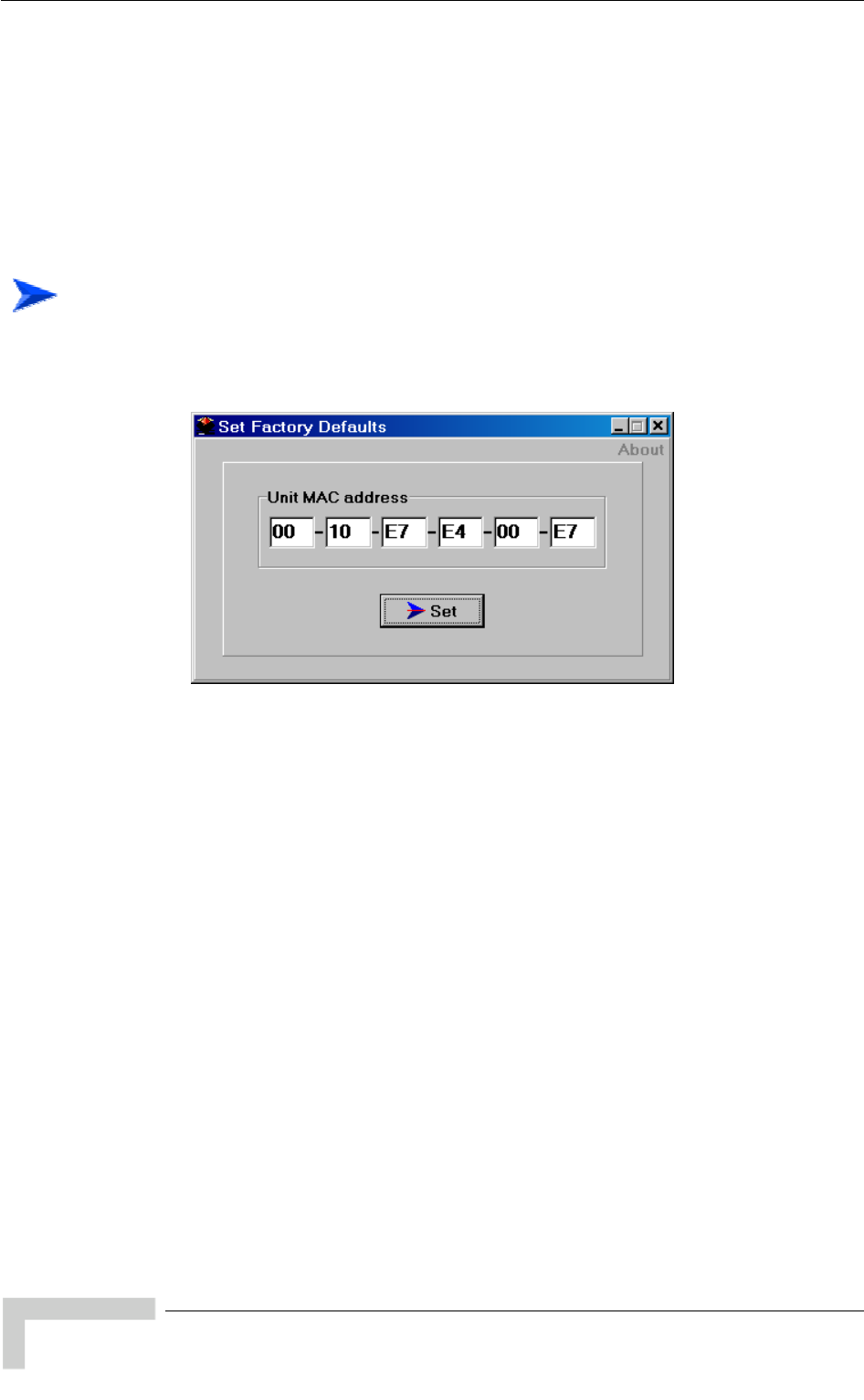
Appendix C - Using the Set Factory Defaults Utility
The Set Factory Defaults utility is intended to enable management access to a
ement VLAN ID and wrong management access filtering.
The utility accesses the unit by sending a special packet. Access to the unit is
based on its MAC address, which must be entered in the Unit MAC address field.
The set unit defaults feature is only available via the Ethernet port.
unit in cases where such access is not possible due to wrong or unknown
configuration of certain parameters. This includes cases such as unknown
Manag
To set factory defaults:
1 Connect the PC with the Set Factory Defaults utility to the Ethernet port of
the unit.
2 Enter the unit’s MAC
lick on the Set button.
This utility performs the same oper n as Set Complete Factory Defaults,
default factory configuration of all parameters, except to Passwords,
general FTP parameters and AU’s Frequency.
address.
3 C
atio
restoring the
BreezeACCESS 4900 System Manual
154

D
D
Appendix D - Preparing the Indoor to
Outdoor SU Cable
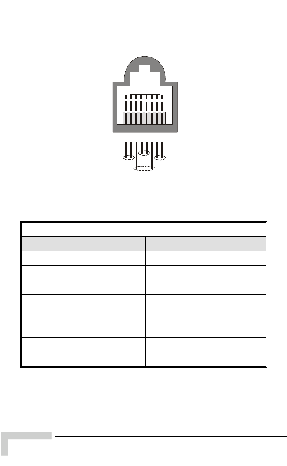
Appendix D - Preparing the Indoor to Outdoor SU Cable
The Indoor-to-Outdoor cable provides pin-to-pin connection on both ends.
Figure D-1 shows the wire pair connections required for the Indoor-to-Outdoor
cable.
12345678
1 + 2 4 + 5 7 + 8
3 + 6
Figure D-1: Ethernet Connector Pin Assignments
The color codes used in cables that are supplied with crimped connectors are as
listed in the following table:
Cable Color Codes
Wire color Pin
Blue 1
Blue/white 2
Orange 3
Orange/white 6
Brown 4
Brown/white 5
Green 7
Green/white 8
BreezeACCESS 4900 System Manual
156

Preparing the Indoor to Outdoor SU Cable
Use a crimp tool for RJ-45 connectors to prepare the wires, insert them into the
appropriate pins and use the crimp tool to crimp the connector. Make s
the following:
1 Remove as small a length as possible of the external jacket. Verify t
external jacket is well inside the service box to ensure good sealing.
2 Take back the shield drain wire before inserting the cable into the R
connector, to ensure a good connection with the connector's shield after
crimping.
ure to do
hat the
J-45
BreezeACCESS 4900 System Manual
157

E
E
Appendix E - Supported MIBS and Traps
In This Appendix:
BreezeACCESS 4900 agents support the following MIBs:
MIB II (RFC1213)
BRIDGE MIB (RFC1286)
BreezeACCESS VL Private MIB (breezeAccessVLMib)
The following are described in this Appendix:
System Object Identifiers, page 160
breezeAccessVLMib, page 162
Supported Traps, page 209
NOTE
The BreezeAccessVLMib is used for BreezeACCESS 4900 (AU, SU), BreezeACCESS VL (AU,
SU) and BreezeNET B (BU, RB) product lines. Some of the parameters are only applicable to one
or two of the product lines.
Generally, all parameters that are applicable to BreezeACCESS VL are also applicable to
BreezeACCESS 4900 (note that in BreezeACCESS 4900 DFS is always Not Supported).

Appendix E - Supported MIBS and Traps
E.1 System Object Identifiers
Object Path
alvarion 94 {(iso(1) org(3) dod(6) internet(1)
private(4) enterprises(1) alvarion(12394)}
OID =1.3.6.1.4.1.123
prod s OID = 1.3.6.1.4.1.12394.1 {alvarion 1} uct
breezeAcce sVLMib OID = 1.3.6.1.4.1.12394.1.1 {products 1} s
alvarionOID OID = 1.3.6. {alvarion 4} 1.4.1.12394.4
brzAccessVLOID OID = 1.3.6 .4.1 {alvarionOID 1} .1.4.1.12394
brzAccessVLAU OID = 1.3.6 rzAccessVLOID 1} .1.4.1.12394.4.1.1 {b
brzAccessVLSU OID = 1.3.6 zAcce.1.4.1.12394.4.1.2 {br ssVLOID 2}
brzAccessVLAU-BS OID = 1.3.6 zAcce D 4} .1.4.1.12394.4.1.4 {br ssVLOI
brzAccessVLAU-SA OID = 1.3.6 Acce.1.4.1.12394.4.1.5 {brz ssVLOID 5}
brzAccessVLAUS-BS OID = 1.3.6.1.4.1.12394.4.1.6 {brzAccessVLOID 6}
brzAccessVLAUS-SA OID = 1.3.6 cessVLOID 7} .1.4.1.12394.4.1.7 {brzAc
brzAccessVLSU-6-1D OID = 1.3.6 ccessVLOI.1.4.1.12394.4.1.11 {brzA D 11}
brzAccessVLSU-6-BD OID = 1.3.6 rzAcc.1.4.1.12394.4.1.12 {b essVLOID 12}
brzAccessVLSU-24-BD OID = 1.3.6. ccessVLOI1.4.1.12394.4.1.13 {brzA D 13}
brzAccessVLSU-BD OID = 1.3.6. cessVLOID 14} 1.4.1.12394.4.1.14 {brzAc
brzAccessVLSU-54-BD OID = 1.3.6. ccessVLOI } 1.4.1.12394.4.1.15 {brzA D 15
brzAccessVLSU-3-1D OID = 1.3.6.1.4.1.12394.4.1.16 {brzAccessVLOID 16}
brzAccessVLSU-3-4D OID = 1.3.6.1.4.1.12394.4.1.17 {brzAccessVLOID 17}
brzNetB-BU-B14 OID = 1.3.6.1.4.1.12394.4.1.21 {brzAccessVLOID 21}
brzNetB-BU-B28 OID = 1.3.6.1.4.1.12394.4.1.22 {brzAccessVLOID 22}
BrzNetB-RB-B14 OID = 1.3.6.1.4.1.12394.4.1.31 {brzAccessVLOID 31}
brzNetB-RB-B28 OID = 1.3.6.1.4.1.12394.4.1.32 {brzAccessVLOID 32}
brzAccess 4900-AU-BS OID = 1.3.6.1.4.1.12394.4.1.41 {brzAccessVLOID 41}
brzAccess 4900-AU-SA OID = 1.3.6.1.4.1.12394.4.1.42 {brzAccessVLOID 42}
BreezeACCESS 4900 System Manual
160

System Object Identifiers
Object Path
brzAccess 4900-SU-BD OID = 1.3.6 brzAcc D 51} .1.4.1.12394.4.1.51 { essVLOI
brzAccessVLProducts OID = 1.3.6.1.4.1.12394.4.1.3 {brzAccessVLOID 3}
BreezeACCESS 4900 System Manual
161

Appendix E - Supported MIBS and Traps
E.2 breezeAccessVLMib
= 1.3.
OBJECT IDENTIFIER
6.1.4.1.12394.1.1
NOTE
An * is used instead of the brzaccVL prefix.
E.2 a ete
.1 System Inform tion Param rs
MIB Parameter Description Value/Range
*SysInfo Information
(breezeAccessVLMib 1) System
Parameters
*Un
(*SysInfo 1)
itHwVersion units. DisplayString (SIZE(0..32)) Applicable to all
Read-only: Hardware
platform version.
*RunningSoftwareVe
(*SysInfo 2) rsion Applicable to all units.
Read-only: Running
software version.
DisplayString (SIZE(0..32))
*RunningFrom l units. y
Integer
shadowVersion (2)
(*SysInfo 3) Applicable to al
Read-only: The memor
(main or shadow) from
which the current version
is running from.
mainVersion (1)
*MainVersionNumber re DisplayString (SIZE(0..32))
(*SysInfo 4) Applicable to all units.
Read only: Main softwa
version number.
*MainVersionFileName
(*SysInfo 5) ..32)) Applicable to all units.
Read-only: Main software
version file name.
DisplayString (SIZE(0
*ShadowVersionNumber
(*SysInfo 6) re version number.
ng (SIZE(0..32)) Applicable to all units.
Read-only: Shadow
softwa
DisplayStri
*ShadowVersionFileName
(*SysInfo 7) Applicable to all units.
Read-only: Shadow
software version file name.
ng (SIZE(0..32)) DisplayStri
*UnitMacAddress Applicable to all units. are (*SysInfo 8) Read-only: Unit hardw
MAC address.
MAC address
BreezeACCESS 4900 System Manual
162

breezeAccessVLMib
MIB Parameter Description Value/Range
*UnitType
(*SysInfo 9) Applicable to all units.
Read-only: Unit type.
Integer
auBS (1)
auSA (2)
su-6-BD
su-24-BD (4)
(3)
)
8)
su-54-BD (11)
(12)
5)
su-6-1D (5)
bu-B14 (6)
bu-B28 (7
rb-B14 (
rb-B28 (9)
su-BD (10)
su-3-1D
su-3-4D) (13)
ausBS(14)
ausSA(1
auBS4900(16)
auSA4900(17)
0(18) suBD490
*AssociatedAU
(*SysInfo 10) Applicable to SU/RB.
Read-only: Associated
AU/BU MAC address.
MAC address
*NumOfAssociationsSinceLastReset
Info Applicable to all units.
ber of
st
reset, including duplicate
associations (re-
associations).
Integer
(*Sys 11) Read-only: The num
associations since la
*CurrentNumO
(*SysInfo 13) fAssociations le to AU only. Not
reezeNET B
products. Read-only. The
number of subscriber units
Integer
n
Applicab
applicable to B
currently associated with
the AU.
a (65535)
*UnitBootVersion
4) plicable to all units. D 32))
(*SysInfo 1 Ap
Read-only: The Boot
software version.
isplayString (SIZE(0..
*RadioBand
(*SysInfo 15) ll units. Integer
b
b
b
b
b
b -5-3GHz (6)
Applicable to a
Read-only: The radio band
of the unit. and-5-8GHz (1)
and-5-4GHz (2)
and-4-9GHz (3)
and-5-2GHz (4)
and-2-4GHz (5)
and
*CurrentEthernetPortState
(*SysInfo 16) ble to all units. Integer
HalfDuplexAnd10Mbps (1)
FullDuplexAnd10Mbps (2)
HalfDuplexAnd100Mbps 3)
FullDuplexAnd100Mbps (4)
linkDown (5)
Applica
Read-only. The current
state of the Ethernet port.
*TimeSinceLastReset DisplayString (SIZE(0..32))
(*SysInfo 17) Applicable to all units.
Read-only. The elapsed
time since last reset.
*CountryDependentParameters
(*SysInfo 18) ountry Dependent
Parameters C
*CountryCode
(*CountryDependentParameters 1) Applicable to all units.
Read only. The country
code and country or
country group name that is
supported by the unit
DisplayString (SIZE(0..32))
BreezeACCESS 4900 System Manual
163

Appendix E - Supported MIBS and Traps
MIB Parameter Description Value/Range
*CountryDependentParamsTable
endentParameters 2) nits. Not
ameters.
(*CountryDep Applicable to all u
accessible. A table of
country dependent
par
*CountryDependentParameterEntry
(*CountryDependentParamsTable 1)
Applicable to all units. Not
accessible. An entry in the
country dependent
parameters table.
*CountryDependentParameterTableId
endentParameterEntry -band
y.
I
x
1) Applicable to all units.
Read only. The sub
ID of the entry in the
Country Dependent
(*CountryDep
Parameters table. Serves
also as index for the table
entr
nteger
*CountryDependentParameterFreque
(*CountryDependentParameterEntry 2) frequencies included in the
ntry.
D ing nci Applicable to all units.
Read only. The es
applicable sub-band e
isplayStr
*AllowedBandwidth
ntParameterEntry able to all units.
pplicable
the sub-band.
Integer
(*CountryDepende 3) Read only. The bandwidth
when using the a
Applic
*RegulationMaxTxPowerAtAntennaP
entParameterEntry . um
allowed Tx power at the
ing
Iort
4) Applicable to all units
Read only. The maxim(*CountryDepend
antenna port when us
the applicable sub-band.
nteger
*RegulationMaxEIRP
(*CountryDependentParameterEntry ead only. The maximum
-band.
I
A Regulation Max EIRP of
1 s no limit.
5) Applicable to all units.
R
allowed EIRP when using
the applicable sub
nteger
00 mean
*MinModulationLevel
(*CountryDependentParameterEntry 6) Applicable to all units.
Read only. The minimum
supported modulation
level.
I
l
l
l
l
l
l
l
level8 (8)
nteger
evel1 (1)
evel2 (2)
evel3 (3)
evel4 (4)
evel5 (5)
evel6 (6)
evel7 (7)
*MaxModulationLevel
entParameterEntry able to all units.
on
Integer
level1 (1)
level2 (2)
l
l
l
l
l
l
(*CountryDepend 7) Read only. The maximum
supported modulati
Applic
level. evel3 (3)
evel4 (4)
evel5 (5)
evel6 (6)
evel7 (7)
evel8 (8)
*BurstModeSupport
ntParameterEntry I
supp
notSupported (2)
(*CountryDepende 8) Applicable to all units.
Read only. The supported
Burst Mode Option.
nteger
orted (1)
*MaximumBurstDuration
ParameterEntry y I
(*CountryDependent 9) Applicable to all units.
Read only. Applicable onl
if Burst Mode Option is
supported. The maximum
supported burst duration.
nteger
BreezeACCESS 4900 System Manual
164

breezeAccessVLMib
MIB Parameter Description Value/Range
*DfsSupport
(*CountryDependentParameterEntry only.
upported Integer
supported (1)
n
10) Applicable to AU/BU
Read only. The s
DFS Option. otSupported (2)
*MinimumHwRevision
(*CountryDependentParameterEntry 11) Read only. The Minimum
HW Revision needed to
I
H
H (2),
H
n
Applicable to all units.
support the Sub-Band.
nteger
wRevisionA (1),
wRevisionB
wRevisionC (3),
a (255)
*AuthenticationEncryptionSupport
(CountryDependentParameters 3) able to all units.
Read only. The supported I
s ted (1)
n rted (2)
Applic
Authentication Encryption
Option.
nteger
uppor
otSuppo
*DataEncryptionSupport
meters 4) Applicable to all units.
upported I
supported (1)
notSupported (2)
(CountryDependentPara Read only. The s
Data Encryption Option.
nteger
*AESEncryptionSupport
(CountryDependentParameters 5) nly. The supported Integer
supported (1)
n
Applicable to all units.
Read o
AES Encryption Option. otSupported (2)
*AntennaGainChange
(*SysInfo 19)
the
Antenna Gain parameter is
I
s
n (2)
Applicable to all units.
Indicates whether
changeable or fixed.
nteger
upported (1)
otSupported
E.2.2 Unit Control Parameters
MIB Parameter Description Value/Range
*UnitControl
(breezeAccessVLMib 2)
*ResetUnit
(*UnitControl 1) o all units. Resets the
nit and applies new parameter
values.
A
upplicable t Integer
cancel (1)
resetSystemNow (2)
*SetDefaults
(*UnitControl 2) Applicable to all units. Sets unit
configuration to Defaults values
after the next reset.
completeFactory: All parameters
ters
ults
d
tory (1)
y (2)
ompleteOperator (3)
uest
revert to Factory Defaults values
partialFactory: All parameters
revert to Factory Defaults values,
except the parameters required
for maintaining wireless
connectivity.
completeOperator: All parameters
revert to Operator Defaults values
partialOperator: All parame
revert to Operator Defa
values, except the parameters
required for maintaining wireless
connectivity.
Integer
NoDefaultSettingRequeste
(0), ccompleteFa
artialFactorp
c
partialOperator (4) qcancelCurrentPendingRe
(5)
*UnitName
(*UnitControl 3) Applicable to all units. The unit
name. DisplayString (
A string of up tSIZE(32))
o 32 printable
rs. ASCII characte
BreezeACCESS 4900 System Manual
165

Appendix E - Supported MIBS and Traps
MIB Parameter Description Value/Range
*FlashMemoryControl
Version: Activates the shadow
version.
Use Running Version After Reset:
The currently active version will
ted after next reset.
From
ion (1)
gVersion
et (2)
(*UnitControl 4) Applicable to all units.
Reset And Boot From Shadow
become the main version and will
be activa
Integer
resetAndBoot
ShadowVers
useRunnin
AfterRes
cancel (3)
*TelnetLogoutTimer
) Applicable to all units. Time-out of
exit if the program is
(*UnitControl 5 management via Telnet.
Automatic
inactive for the defined time.
Integer
1-999 (minutes)
*SaveCurrentConfigurationAs Applicable to all units. Saves the
or Integer
OperatorDefaults
(*UnitControl 6) current configuration as Operat
Defaults. saveAsDefaults (1)
cancel (2)
*ExitTelnet
(*UnitControl 7) le to all units. Exit the
Telnet Monitor session. cancelOperation (1)
Applicab Integer
exit (2)
*UnitPas rds Applicable to all units. Unit swo
(*UnitControl 8) passwords.
*ReadOnlyPassw d
(*UnitPasswords 1) Applicable to all units. The User
(read only) password. DisplayString (SIZE(8)).
Up to 8 printable ASCII
ters.
or
charac
*Ins
(*Un ll units. The
ord. yString (SIZE(8)).
Up to 8 printable ASCII
characters.
tallerPassword
itPasswords 2) Applicable to a
Installer passw Displa
*Ad
(*Un he
password. T
e SNMP Write Com
String.
g (SIZE(8)).
able ASCII
minPassword
itPasswords 3) Applicable to all units. T
Administrator
also th his is
munity Up to 8 print
characters.
DisplayStrin
*Eth nMode
(*Un the
Integer
ce10MbpsAnd
HalfDuplex (3)
force100MbpsAnd
FullDuplex (4)
autoNegotiationMode (5)
ernetNegotiatio
itControl 9) Applicable to all units. E
port mode of operation. rnet for
HalfDuplex (1)
force10MbpsAnd
FullDuplex (2)
force100MbpsAnd
*FTPParameters
(*UnitControl 10) P Applicable to all units. FT
parameters
*FTPServerParams
(*FT l
ters.
PParameters 1) Applicable to all units. Genera
FTP server parame
*FT
(*FT s. The user
access DisplayString (SIZE(20)).
ntable ASCII
aracters.
PServerUserName
PServerParams 1) Applicable to all unit
name to be used for to the Up to 18 pri
chFTP server
*FT
(*FT he
used for ac DisplayString (SIZE(20)).
Up to 18 printable ASCII
characters.
PServerPassword
PServerParams 2) Applicable to all units. T
e password to b
the FTP server cess to
*FT
(*FTPParameters 3) he
tack in the IP address PClientIpAddress Applicable to all units. T
address of the FTP s
unit.
IP
*FT
(*FT e
rver PServertIpaddress
PServerParams 4) Applicable to all units. Th
address of the FTP se IP IP address
*FTPClientMask
(*FTPParameters 5) ts. The
MASK of the FTP stack in
unit.
Applicable to all uni IP
the IP address
*FTPGatewayIPAddress
(*FTPParameters 6) Applicable to all units. The FTP
Default Gateway IP address. IP address
BreezeACCESS 4900 System Manual
166

breezeAccessVLMib
MIB Parameter Description Value/Range
*FT
(*FT PSwDownload
PParameters 2) Applicable to all units. SW
download parameters.
*FTPSwFileName
(*FTPSwDownload 1) to all units. The
of the SW file to be downlo ng (SIZE(80)).
Up to 20 printable ASCII
characters. An empty string is
t allowed.
Applicable name DisplayStri
aded.
no
*FtpSwDownloadSourceDir
(*FT ) Applicable to all units. The
file n the isplayString (SIZE(80)).
Up to 80 printable ASCII
characters. Use “.” To clear
field.
PSwDownload 2 source D
directory of the required
FTP server i
*DownloadSwFile
(*FT ) ble to all units. Execution
ad opera n. Integer
downloadFile (1)
cancel (2)
PSwDownload 3 Applica
of the SW downlo tio
*ConfigurationFileLoading
(*FT ble to all units. pe
plo
PParameters 3) Applica
Configuration file and O
Defaults file download/u
parameters.
rator
ad
*ConfigurationFileName
(*Co 1) nits. The name
ile to b DisplayString (SIZE(80)).
to 20 printable ASCII
characters. An empty string is
not allowed.
nfigurationFileLoading Applicable to all u
of the configuration f
downloaded/uploaded. e Up
*Op
(*Co ing 2) efaults fil
ded.
DisplayString (SIZE(80)).
Up to 20 printable ASCII
characters. An empty string is
not allowed.
eratorDefaultsFileName
nfigurationFileLoad Applicable to all units. The
of the Operator D
downloaded/uploa
name
e to be
*FT Di
(*ConfigurationFileLoading 3) The
quired file
FTP server
ng (SIZE(80)).
intable ASCII
characters. Use “.” To clear
field.
PConfigurationFileSource r Applicable to all units.
directory of the re source
in the DisplayStri
Up to 80 pr
*Ex eL
(*ConfigurationFileLoading 4) Exe
e file download/upload
operation.
ger GetConfiguration
File (1)
executeFTPPutConfiguration
File (2)
executeFTPGetOperator
Defaults (3)
executeFTPPutOperator
Defaults (4)
cancel (5)
ecuteFTPConfigurationFil oading Applicable to all units.
of th cution Inte
executeFTP
*Ev
(*FTPParameters 4) its. Eve
ad parameters. entLogFileUploading Applicable to all un
file uplo nt Log
*Ev
(*Ev The DisplayString (SIZE(80)).
entLogFileName
entLogFileUploading 1) Applicable to all units.
of the event log file to be
uploaded.
name Up to 20 printable ASCII
characters.
*EventLogDestinationDir
(*EventLogFileUploading 2) e event
r
DisplayString (SIZE(80)).
Up to 80 printable ASCII
characters. Use “.” To clear
ld.
Applicable to all units. The
destination directory for th
logd file in the FTP serve fie
*Upl
(*Ev ll units.
ent log Integer
loadFile (1)
cancel (2)
oadEventLogFile
entLogFileUploading 3) Applicable to a
Execution of the ev
operation upload up
*LoadingStatus
(*UnitControl 11) he status
ding Integer
inProcess (1)
ccessful (2)
failed (3)
Applicable to all units. T
of an FTP or TFTP loa
process. su
*EventLogFileParams
(*UnitControl 12) Event Log parameters
BreezeACCESS 4900 System Manual
167

Appendix E - Supported MIBS and Traps
MIB Parameter Description Value/Range
*Ev
(*Ev e
e log Integer )
error (3)
fatal(4)
one(5)
entLogPolicy
entLogFileParams 1) Applicable to all units. Th
severity of events to b lowest
ged. message (1
warning (2)
logN
*EraseEventLog
(*EventLogFileParams 2) ble to all units. Eras
log file. eraseEventLog (1)
cancel(2)
Applica e the Integer
*SysLocation
(*UnitControl 13) Applicable to al
location. l units. The unit DisplayString (SIZE(0..34))
*FeatureUpgrade
(*UnitControl 14 Feature Upgrade parameters
)
*FeatureUpgradeManually
(* Applicable to all units.
e unit to support new
DisplayString (SIZE(32..64))
string: 32 to 64
imal digits.
FeatureUpgrade 1) Upgrad
feature. License
hexadec
E.2 twork r rs .3 Ne Management Pa amete
MIB Parameter Description Value/Range
*NwMngParameters
sVLMib 3) N
p
(breezeAcces etwork management
arameters.
*AccessToNwMng
(*NwMngParameters 1) A
t
m
In
fr (1)
fromEthernetOnly (2)
fromBothWirelessnAndEthernet (3)
na (255)
pplicable to all units. The port
o be used for remote
anagement.
teger
omwirelessOnly
*NwMngFilter
(*NwMngParameters 2) A
o
f
m
Integer
disable (1)
activateOnEthernetPort (2)
activateOnWirelessPort (3)
activateOnBothWirelessAndEthernet
(4)
na
pplicable to all units. Disables
r enable IP address based
iltering of management
essages on one or both ports.
(255)
mngIpFilterTable
(*NwMngParameters 3) A
u sses of stations
that are authorized to access the
u
N
pplicable to all units. A table of
p to 10 IP addre
nit for management purposes.
ot accessible.
mngIpFilterEntry
(mngIpFilterTable 1) A
M
T
pplicable to all units. A
anagement IP Addresses
able entry. Not accessible.
*NwMngIpAddress Applicable to all units. An IP
a
A
IP address
(mngIpFilterEntry 1) ddress in the Management IP
ddresses Table entry.
*NwMngIpTableIdx
(mngIpFilterEntry 2) A
R
e t IP
A
Integer
1-10
pplicable to all units.
ead-only. A table index for an
ntry in the Managemen
ddresses Table.
*DeleteOneNwIpAddr
(*NwMngParameters 4) A Deletes a
single selected entry from the
Management IP Addresses
Table.
Integer
cancelOperation (0)
deleteEntry (1…10)
na (255)
pplicable to all units.
BreezeACCESS 4900 System Manual
168

breezeAccessVLMib
MIB Parameter Description Value/Range
*DeleteAllNwIpAddrs
(*NwMngParameters 5) A
e
A
In eteAll (1)
cancelOperation (2)
na (255)
pplicable to all units. Deletes all
ntries from the Management IP
ddresses Table. del
teger
*AccessToNwTrap
(*NwMngParameters 6) A
d
t
Integer
disable (1)
enable (2)
pplicable to all units. Enables or
isables the sending of SNMP
raps.
mngTrapTable Applicable to all units. A table of
tions
.
Not accessible.
(*NwMngParameters 7) up to 10 IP addresses of sta
to which to send SNMP traps
mngTrapEntr
(mngTrapTable 1) Applicable to all units. A
Management Trap Table entry.
No
y
t accessible.
*NwMngTrapCommunity Ap he trap
co ith the
ap
Ma
DisplayStrin
Up to 14 pri ble ASCII characters. (mngTrapEntry 1) plicable to all units. T
mmunity associated w
plicable entry in the
nagement Trap Table.
g
nta
(SIZE(14))
*NwMngTrapAddress
(mngTrapEntry 2) Ap
ad
Ta
ress plicable to all units. An IP IP add
dress in the Management Trap
ble.
*NwMngTrapTableIdx Applicable to all units. Read only.
Ind
Ma
Integer
(mngTrapEntry 3) ex for an entry in the
nagement Trap Table. 1-10
*DeleteOneTrapAddr
(*NwMngParameters 8) Ap
sin
Ma er
eteEntry
(255)
plicable to all units. Deletes a
gle selected entry from the Integer
cancelOp
nagement Trap Table. del
na
ation (0)
(1…10)
*DeleteAllTrapAddrs
(*NwMngParameters 9) Ap
entries from the Management
Tra
Integer
deleteAll (1)
lOper
5)
plicable to all units. Deletes all
p Table. cance
na (25
ion (2) at
*MngIpRangesTable 10) (*NwMngParameters Ap
Ma
Ra
plicable to all units. A table of
nagement IP Address
nges. Not accessible.
*MngIpRangesEntry Ap An entry
in
Ad
(*MngIpRangesTable 1) plicable to all units.
the table of Management IP
dress Ranges. Not accessible.
*MngIpRangeIdx
(*MngIpRangesEntry 1) Ap
an
Ra
plicable to all units. Index of
entry in the IP Address
nges Table.
Integer
1-10
*MngIPRangeFlag
(*MngIpRangesEntry 2) Ap
the
Us
(ra
or
(ra
e ByStartEndAddr(1),
edByStartAddrMask(2)
plicable to all units. Defines
method of defining the range:
ing Start & End Addresses
Integer
rangeDefin
rangeDefin
ngeDefinedByStartEndAddr),
using Start Address and Mask
ngeDefinedByStartAddrMask
d
*MngIpRangeStart
(*MngIpRangesEntry 3) Ap
Ad ess plicable to all units. Start
dress of the range. IP addr
*MngIpRangeEnd
(*MngIpRangesEntry 4) Ap
Ad
if b
ran
s plicable to all units. End
dress of the range. Used only
rzaccVLMngIPRangeFlag is
IP addres
geDefinedByStartEndAddr
*MngIpRangeMask ) Ap
su
onl
brz
ran
ss
(*MngIpRangesEntry 5 plicable to all units. The IP addre
bnet mask of the range. Used
y if
accVLMngIPRangeFlag is
geDefinedByStartAddrMask.
BreezeACCESS 4900 System Manual
169

Appendix E - Supported MIBS and Traps
MIB Parameter Description Value/Range
*DeleteOneNwIpRange
s 11) Ap
sin
Ma
peration (0)
Entry (1…10)
255)
(*NwMngParameter plicable to all units. Deletes a
gle selected entry from the
nagement IP Ranges Table.
Integer
cancelO
delete
na (
*DeleteAllNwIpRanges
(*NwMngParameters 12) Ap
en
Ra eteAll (1)
per on (2)
plicable to all units. Deletes all
tries from the Management IP Integer
del
nges Table. cancelO
na (255) ati
E.2. me
4 IP Para ters
MIB Parameter Description Value/Range
*
(breezeAccessVLMib 4) IpParams
*UnitIpAddress
(*IpParams 1) A
odres pplicable to all units. IP address
f the unit. IP ad s
*
(A
mask of the uni
SubNetMask
*IpParams 2) pplicable to all units. Subnet
t. IP address
*
(Applicable to all units. Default
gIP addresDefaultGWAddress
*IpParams 3) ateway IP address of the unit. s
*UseDhcp
(A
cl
di
m
p
D
c
a
c
D
m
*U
*D
Integer
(1
nl
utomatic
*IpParams 4) pplicable to all units. DHCP
ient mode of operation.
sable: Use regular (manual)
ethods to configure IP
disable
dHCPO
a
arameters.
HCP Only: Use DHCP server to
onfigure IP parameters.
utomatic: Use DHCP server to
onfigure IP parameters. If a
HCP server is not available, use
anually configured values for
nitIpAdress, *SubnetMask and
efaultGWAdress.
)
y (2)
(3)
*
(A
b
D
r
irel
omEthe
fromBothWirelessAndEthernet (3)
AccessToDHCP
*IpParams 5) pplicable to all units. The port to
e used for communicating with a
HCP server.
Intege
fromW
fr essOnly (1)
rnetOnly (2)
*
(A
T
is
th
th
IP
resRunTimeIPaddr
*IpParams 6) pplicable to all units. Read-only:
he run-time IP address. If DHCP
used, the run-time IP address is
e address given to the unit by
IP add
e server. Alternatively the static
address is used.
s
*
(*IpParams 7) A
T sk. If
D
s
th
A
m
res
RunTimeSubNetMask pplicable to all units. Read-only: IP add
he run-time subnet ma
HCP is used, the run-time
ubnet mask is the mask given to
e unit by the server.
lternatively the static subnet
ask value is used.
s
BreezeACCESS 4900 System Manual
170

breezeAccessVLMib
MIB Parameter Description Value/Range
*
(*IpParams 8) A
T
If
G
a he unit by the
s
d
ddres
RunTimeDefaultIPGateway pplicable to all units. Read-only:
he run-time Gateway IP address.
DHCP is used, the Run Time
ateway IP Address is the
ddress given to t
IP a
erver. Alternatively, the static
efault gateway is used.
s
E.2. Bridge Par
5 ameters
MIB Parameter Description Value/Range
*BridgeParameters
(breezeAccessVLMib 5) Bridge parameters.
*VLANSupport
(*BridgeParameters 1) Applicable to all units. VLAN suppo
paramete rt
rs. Applicable to Access Link
only.
*VlanID Applicable to SU/RB only. VLAN ID for
AN ID)
(*VLANSupport 1) data frame tagging. Integer 1-4094.
0 –na (no VL
*EthernetLinkType
(*VLANSupport 2) Applicable to all units. VLAN support
e for accessLink (1)
trunkLink (2)
mode (Link Type).
The accessLink option is not availabl
AU.
Integer
hybridLink (3)
*ManagementVID
(*VLANSupport 3) Applicable to all units. VLAN ID for
management frame tagging. Intege
1-4094
r
65535 - no VLAN
tagging.
*VLANForwarding
(*VLANSupport 4) VLAN forwarding feature parameters.
*VlanForwardingSupport
(*VLANForwarding 1) Applicable to all units. Enables or disables ) the VLAN forwarding feature. Applicable
to Trunk links only.
Integer
disable (1
enable (2)
na (255)
*VlanForwardingTable
2)
(*VLANForwarding Applicable to all units. A table of up to 20
VLAN IDs of devices to which data frames
are forwarded when the VLAN Forwarding
feature is Enabled. Applicable to Trunk
links only. Not accessible.
*VlanForwardingEntry
(*VlanForwardingTable 1) only.
Applicable to all units. A VLAN Forwarding
Table entry. Applicable to Trunk links
Not accessible.
*VlanForwardingTableIdx
(*VlanForwardingEntry 1) e Integer
1-20
Applicable to all units. A read only tabl
index for a VLAN entry in the VLAN
Forwarding Table.
*VlanIdForwarding
(*VlanForwardingEntry 2) . To
w
Integer
1-4094
-remove entry.
Applicable to all units. The list of VLAN
ID's in the VLAN ID Forwarding Table
remove a VLAN ID - SET the
corresponding entry to 0. To add a ne
VLAN ID SET an entry which is now 0.
0
*VLANRelaying
(*VLANSupport 5) t
VLAN Relaying feature parameters. No
applicable to BreezeNET B products.
*VlanRelayingSupport
(*VLANRelaying 1)
products. Enables or Integer
disable (1)
nable (2)
na (255)
Applicable to AU only. Not applicable to
BreezeNET B
disables the VLAN Relaying feature.
Applicable to Trunk links only. e
BreezeACCESS 4900 System Manual
171

Appendix E - Supported MIBS and Traps
MIB Parameter Description Value/Range
*VlanRelayingTable
(*VLANRelaying 2)
e VLAN o
Applicable to AU only. Not applicable to
BreezeNET B products. A table of up to
20 VLAN IDs of devices to which data
frames are relayed when th
Relaying feature is Enabled. Applicable t
Trunk links only. Not accessible.
*VlanRelayingEntry
(*VlanRelayingTable 1) ly.
Applicable to AU only. Not applicable to
BreezeNET B products. A VLAN Relaying
Table entry. Applicable to Trunk links on
Not accessible.
*VlanRelayingTableIdx U only. Not applicable to Integer Applicable to A
(*VlanRelayingEntry) 1 BreezeNET B products. A read only table
index for a VLAN entry in the VLAN
Relaying Table.
1-20
*VlanIdRelaying
(*VlanRelayingEntry 2) AN
a VLAN ID - SET the
1-4094
0-remove entry.
Applicable to AU only. Not applicable to
BreezeNET B products. The list of VL
ID's in the VLAN ID Relaying Table. To
remove
Integer
corresponding entry to 0. To add a new
VLAN ID SET an entry which is now 0.
*VLANTrafficPriority VLAN traffic priority parameters.
(*VLANSupport 6)
*VlanDataPriority g for data frames. teger
0 – 7
Applicable to SU/RB only.
Priority taggin In
(*VLANTrafficPriority 1) Applicable to Access Link only. 255-na
*VlanManagementPriority
(*VLANTrafficPriority 3) Applicable to all units. Priority tagging for
management frames. Applicable to
Access Link and Trunk Link only.
Integer
0 – 7
255-na
*VlanPriorityThreshold Applicable to all units. Not applicable to
Priority threshold for tagged frames
received from Ethernet port. Applicable to
Hybrid Link and Trunk Link only.
Integer
0 – 7
255-na
(*VLANTrafficPriority 4) units with SW version 3.1 and higher
where this parameter is replaced by
*
( 2) Applica ridge aging tim
for devi ther
and wir (seconds)
BridgeAgingTime
eters ble to all units. B e
et Integer
20 – 2000
*BridgeParam ces learned from both the E
eless link ports. n
*
( ) Applica icable to
Breeze s or
disable
messag
Integer
disable (1)
BroadcastRelaying
*BridgeParameters 4 ble to AU only. Not appl
NET B products. Enable
s the relaying of broad
cast
es to the wireless link. enable (2)
na (255)
*
(*BridgeParameters 5) Applica to
Breeze
disable essages
to the w enable (2)
na (255)
UnicastRelaying ble to AU only. Not applicable
NET B products. Enables or
s the relaying of unicast m
ireless link.
Integer
disable (1)
*EthBroadcastFiltering
(*BridgeParameters 6) Applica
disable
broadc
disable
onEthrn
receive ly.
onWirelessOnly: Filters broadcasts
received on the wireless port only.
onBothWirelessAndEthernet: Filters
broadcasts received on both ports.
Integer
disable (1)
EthernetOnly (2)
wirelessOnly (3)
thWirelessAndEthe
rne )
na (
ble to SU/RB only. Enables or
s the filtering of Ethernet (layer2)
asts.
: No filtering.
etOnly: Filters broadcasts
d on the Ethernet port on
on
on
onBo
t (4
255)
*EthBroadcastingParameter
s
(*BridgeParameters 7)
BreezeACCESS 4900 System Manual
172

breezeAccessVLMib
MIB Parameter Description Value/Range
* verrideFil
t
(*EthBroadcastingParameter
s 1)
Applica or
disable f DHCP
messag neral
*EthBro dcast
filtering na (255)
DHCPBroadcastO
er ble to SU/RB only. Enables
s the broadcasting o
es, overriding the ge
adcastFiltering Ethernet broa
option.
Integer
disable (1)
enable (2)
*PPPoEBroadcastOverrideFi
l
( Parameter
s 2)
Applica
disable
messag l
*EthBro broadc
filtering
Integer
able (1) ter
*EthBroadcasting
ble to SU/RB only. Enables or
s the broadcasting of PPPoE
es, overriding the genera
adcastFiltering Ethernet
option. ast enable (2)
na (255)
dis
*ARPBroadcastOverrideFilte
r
(*EthBroadcastingParameter
s 3)
Applica s or
disable ARP
messag
*EthBro dc
filtering
ger ble to SU/RB only. Enable
s the broadcasting of
es, overriding the general
adcastFiltering Ethernet broa
option. ast
disable (1)
enable (2)
na (255)
Inte
*EthBroadcastMulticastLimit
erOption
(*EthBroadcastingParameter
s 4)
Applica t
limiter f t
packets
limitOnlyBroadcasts(2)
limitMulticastsExceptBro
adcasts(3)
limitAllMulticasts(4)
ble to all units. Enable/disable he Integer
disable (1)or multicast and broadcas
.
*EthBroadcastMulticastLimit
erThreshold
(*EthBroadcastingParameter
s
Applica for the
allowed
broadc
Etherne ast Limiter
Option
Integer
0 - 204800
ble to all units. The limit
number of multicast and
ast packets when the
t Broadcast/Multic
is enabled
5)
*EthBroadcastMulticastLimit
erSendTrapInterval
(*EthBroadcastingParameter
s 5)
Applica tim
in minu traps
that are r of
packets
Etherne ince
the last
ger
1-60
ble to all units. The minimum
tes between two successive
sent, indicating the numbe
that were dropped by the
t Broadcast/Multicast Limiter s
trap was sent.
e Inte
*ToSPriorityParameters
(*BridgeParameters 8)
*ToSPrecedenceThreshold
(*T Applica le to
units wi
Priority fo
frames
Integer ble to all units. Not applicab
th SWoSPriorityParameters 1) version 3.1 and higher.
threshold (based on the ToS)
received from Ethernet port. r 0-7
*RoamingOption
(*BridgeParameters 9) Applica ble
the roa he
SU will start scanning for an AU/RB after
one sec from
current w
AU/BU
wireles n
behalf o her
devices
location or
seven s ing,
and it w SNAPs.
Integer
disable (1)
enable (2)
na (255)
ble to SU/RB only.Disable/ena
ming feature. When enabled, t
ond of not receiving beacons
AU/BU. Once it found a ne
, it will also send through the
s network a roaming SNAP o
f its clients informing ot
in the network of their new
. When disabled, it will wait f
econds before starting scann
ill not send roaming
*MacAd
(MAC A dressDenyList
*BridgeParameters 10) ddress Deny List parameters
*
(*MacAddressDenyList 1) Applica to
Breeze
MAC A
allowed to transfer data to the AU. Not
accessi
MacAddressDenyListTable ble to AU only. Not applicable
NET B units. A list of up to 100
ddresses of SUs that are not
ble.
*MacAddressDenyListEntry
(*MacAddressDenyListTable
1)
Applica plicable to
Breeze ry in the Mac
Address Deny List Table. Not accessible.
ble to AU only. Not ap
NET B units. An ent
BreezeACCESS 4900 System Manual
173

Appendix E - Supported MIBS and Traps
MIB Parameter Description Value/Range
*
d
(*MacAddressDenyListEntry
1)
Applica to
Breeze nly table
index fo M
Addres
e: 1 to 100
MacAddressDenyListTableI
x ble to AU only. Not applicable
NET B units. A read o
r a MAC Address entry in the
s Deny List Table.
Integer
Rang
ac
*MacAddressDenyListId
(*MacAddressDenyListEntry
2)
Applica to
Breeze
Addres ddress Deny List
Table. S
the cor a
new MA hic
is curre
MAC Address
ble to AU only. Not applicable
NET B units. The list of MAC
ses in the MAC A
To Remove a MAC Address -
responding entry to 0. To Add
C Address - SET an entry w
ntly 0.
ET
h
*MacAddressDenyListAdd
(*MacAddressDenyList 2) Applica U only. Not applicable to
Breeze addres
to the M
MAC Address ble to A
NET B units. Add a MAC s
AC Address Deny List Table
*MacAddressDenyListRemo
ve
(*MacAddressDenyList 3)
Applica ble to
Breeze ve a MAC
addres L
Table
ble to AU only. Not applica
NET B units. Remo
ist
MAC Address
s from the MAC Address Deny
*NumberOfMacAddressesIn
DenyList
(*MacAddressDenyList 4)
Applica to
Breeze
numbe MAC
Addres
ble to AU only. Not applicable
NET B units. Read only. The
r of MAC addresses in the
s Deny List Table.
Integer
Range: 0 to 100
Na (255)
*PortsControl
(*BridgeParameters 11) Ports C Applicable to
SU/RB only.
ontrol parameters.
*Ethern
(Applicable to SU/RB only
Enable en
disable d
Manag
),
etPortControl
*PortsControl 1) .
/disable the Ethernet po Integer
disable (1
. enable (2),
na (255)
rt. Wh
d, only data frames are blocke
ement frames are accepted.
E.2.6 Air Interface Parameters
MIB Parameter Description Value/Range
*AirInterface
(breezeAccessVLMib 6) Applicable to all units. Air
Interface parameters.
*ESSIDParameters
(*AirInterface 1) Applicable to all units.
ESSID Parameters.
*ESSID
(*ESSIDParameters 1) Applicable to all units. The
Extended Service Set ID
(ESSID) used to prevent the
merging of collocated
systems. The ESSID is
accessible only with the
write community string
(administrator password).
printable case
e ASCII characters.
DisplayString (SIZE(31))
31Up to
sensitiv
*OperatorESSIDOption
(*ESSIDParameters 2) disable (1)
enable (2)
Applicable to AU/BU only.
Enabling/disabling the use
of the Operator ESSID
Integer
na (255)
*OperatorESSID
(*ESSIDParameters 3) Applicable to AU/BU only. A
secondary ESSID to suppor
easy installation of SUs as
well as the use of the Best
AU/BU feature. Accessibl
t
e
only with SNMP Write
Community string
(administrator password).
.
DisplayString (SIZE(31))
Up to 31 printable case
sensitive ASCII characters
BreezeACCESS 4900 System Manual
174

breezeAccessVLMib
MIB Parameter Description Value/Range
*RunTimeESSID ly.
P
d).
SIZE(31))
characters.
(*ESSIDParameters 1) Applicable to SU/RB on
The ESSID of the
associated AU/BU.
Accessible only with SNM
Write Community string
(administrator passwor
DisplayString (
Up to 31 printable case
sensitive ASCII
*MaximumCellDistance to all units. For
hen the to
U of
teger or units with SW
n
he range is 0 to
4 Kilometers.
0 means no compensation
slot size, maximal
t).
Applicable In
(*AirInterface 2) AU/BU: read-write. For
SU/RB: read-only. The
distance is learned from the
AU/BU. In units with SW
version 2.0 and up -
applicable only w
Range: F
version bellow version 2.0
the range is 0 - 50000
Meters.
For units with SW versio
2.0 and up t
Cell Distance Mode is set
Manual. The highest 5
distance from the AU/B
any SU/RB served by it.
Affects the maximum time
the units wait for a response
(minimum
delay timeou
message and the slot size
by taking into account the
round trip propagation
delay.
*AIFS
ts.
e
in
Integer
Applicable to AU and SU.
(*AirInterface 3) Not applicable to
BreezeNET B produc
Arbitration Inter-Frame
Spacing (AIFS). This is the
number of time slots that
oneSlot (1)
twoSlots (2)
na (255)
define the DIFS.
(DIFS=SIFS+AIFS). A valu
of 1 should be used only
point-to-point applications to
allow one unit to have
advantage over the other
unit.
*WirelessTrapThreshol
(*AirInterface 4) d
Applicable to AU/BU only. A
wireless link quality
threshold, expressed in % of
Integer
1-100 (%)
retransmissions, for sending
the
brzaccVLAUWirelessQuality
TRAP.
This trap indicate whether
the quality has gone below
or above the specified
threshold
*TransmitPowerTable
(*AirInterface 5) r Applicable to all units. Not
accessible. Transmit Powe
parameters table.
*TransmitPowerEntry
Applicable to all units. Not
(*TransmitPowerTable 1) accessible. An entry in the
Transmit Power parameters
table.
*TransmitPowerIdx
(*TransmitPowerEntry 1) -
le.
Integer
1-4
Applicable to all units. Read
only. An index of an entry in
the Transmit Power
parameters tab
BreezeACCESS 4900 System Manual
175

Appendix E - Supported MIBS and Traps
MIB Parameter Description Value/Range
*ApplicableModulationLevel
(*TransmitPowerEntry 2) Applicable to all units. Read-
only. The applicable
modulation level for an entry
in the Transmit Power
parameters table. Level 8 i
not applicable to units
HW revision A.
s
with
5 (1)
2)
Level1to
Level6 (
Level7 (3)
Level8 (4)
*MaximumTxPowerRange
(*TransmitPowerEntry 3) ead- DisplayString
Range: -10 to the maximum
allowed for the applicable
modulation level.
Applicable to all units. R
only. The allowed range for
the *TxPower parameter at
the applicable modulation
level.
*TxPower try 4)
led,
on level. If ATPC is
DisplayString
SU/RB: The range is -10
dBm to the power value
defined by
*MaximumTxPower for the
applicable modulation level.
In AU/BU: The range is -10
he power value
ange
odulation
(*TransmitPowerEn Applicable to all units.
AU/BU: The transmit power
defined for the applicable
modulation level.
SU/RB: If ATPC is disab
this is The transmit power
defined for the applicable
modulati
enabled, it serves as the
initial transmit power for the
ATPC algorithm.
Range:
In
dBm to t
defined by
*MaximumTxPowerR
for the applicable m
level
*CurrentTxPower
(*TransmitPowerEntry 5) Applicable to SU/RB.
The actual transmit power in
dBm at the applicable
modulation level.
ng
ange: -17 to the maximum
value defined by
*MaximumTxPowerRange
for the applicable modulation
DisplayStri
R
level.
*MaximumTransmitPowerTable
(*AirInterface 6) rs
Applicable to SU /RB. Not
accessible. Maximum
Transmit Power paramete
table.
*MaximumTransmitPowerEntry
(*TransmitPowerTable 1) t
the
Applicable to SU/RB. No
accessible. An entry in
Maximum Transmit Power
parameters table.
*MaximumTransmitPowerIdx y 1) ble to SU/RB. Read- Integer
(*MaximumTransmitPowerEntr Applica
only. An index of an entry in
the Maximum Transmit
Power parameters table.
1-4
*MaxTxApplicableModulationLevel
(*MaximumTransmitPowerEntry 2) l for an entry
.
(1)
Level6 (2)
Level7 (3)
)
Applicable to SU/RB. Read-
only. The applicable
modulation leve
in the Maximum Transmit
Power parameters table
Level 8 is not applicable to
units with HW revision A.
Level1to5
Level8 (4
*DefinedMaximumTxPowerRange
(*MaximumTransmitPowerEntry 3) ad-
wed range for
ble
DisplayString
Range: -10 to the maximum
for the applicable
evel.
Applicable to SU/RB. Re
only. The allo
the *MaxTxPower
parameter at the applica
modulation level.
allowed
modulation l
BreezeACCESS 4900 System Manual
176

breezeAccessVLMib
MIB Parameter Description Value/Range
*MaxTxPower
(*MaximumTransmitPowerEntry 4) smit
ATPC
ng
o the maximum
e
aximumTxPowerR
ange for the applicable
modulation level.
Applicable to SU/RB.
The maximum tran
power level that can be
either configured for the
*TxPower parameter or
reached by the
algorithm.
DisplayStri
Range: -10 t
defined by th
*DefinedM
*MaxNumOfAssociations B
ted
A: 0-512 (0-124
cryption Option is
enabled).
AUS-BS, AUS-SA: 0-5.
na (65535)
(*AirInterface 10) Applicable to AU. Not
applicable to BreezeNET
products. The upper limit for
the number of Subscriber
Units that can be associa
with the AU.
Integer
AU-BS, AU-S
if Data En
*BestAu
(*AirInterface 11) Best AU/BU parameters.
Applicable to SU/RB.
*BestAuSupport
(*BestAu 1) sm )
enable (2)
na (255)
Applicable to SU/RB.
Disable/enable the Best
AU/BU selection mechani
Integer
disable (1
*BestAuNoOfScanningAttempts
(*BestAu 2) Applicable to SU/RB. The
number of scanning
attempts to collect
information for the Best
AU/BU decision
Integer
1-255
*PreferredAuMacAddress
(*BestAu 3) dress of the
Mac Address
000000000000 means no
Applicable to SU only. The
MAC ad
preferred AU/BU (overriding
the Best AU/BU selection
process).
preferred AU
*NeighborAuTable
(*BestAu 4) Not Applicable to SU/RB.
accessible. Neighboring
AUs/BUs table.
*NeighborAuEntry ble to SU only. Not
the
AUs table.
(*NeighborAuTable 1) Applica
accessible. An entry in
Neighboring
*NeighborAuIdx
(*NeighborAuEntry 1) Applicable to SU/RB. Read-
only. An Index of an entry in
the Neighboring AU/BU
Table
Range: 1…20
Integer
*NeighborAuMacAdd
(*NeighborAuEntry 2) ead-
MAC Address Applicable to SU/RB. R
only. The MAC Address of
the AU/BU associated with
the entry in the Neighboring
AU/BU Table
*NeighborAuESSID
(*NeighborAuEntry 3)
community string
(Administrator Password).
DisplayString
Applicable to SU/RB. Read-
only. The ESSID of the
AU/BU associated with the
entry in the Neighboring
AU/BU Table. Accessible
only with the SNMP Write
*NeighborAuSNR
(*NeighborAuEntry 4) Applicable to SU/RB. Read-
only. The average SNR at
which the SU/RB receives
the AU/BU associated with
the entry in the Neighboring
AU/BU Table.
Integer
Na (255)
BreezeACCESS 4900 System Manual
177

Appendix E - Supported MIBS and Traps
MIB Parameter Description Value/Range
*NeighborAuAssocLoadStatus -
ns
eached its
f
full (1)
notFull (2)
na (255)
(*NeighborAuEntry 5) Applicable to SU/RB. Read
only. The load status of the
AU/BU associated with the
entry in the Neighboring
AU/BU Table. Full mea
that it has r
maximum permitted load,
meaning in AU that the
number of associated SUs
is the Maximum Number O
Associations (for AU) or in
BU that it is already
associated with an RB.
Integer
*NeighborAuMark
(*NeighborAuEntry 6) Read-
en Integer
Applicable to SU/RB.
only. The overall mark giv
by the Best AU/BU
algorithm to the AU/BU
associated with the entry in
the Neighboring AU/BU
Table.
*NeighborAuHwRevision
(*NeighborAuEntry 7) d-
the
with the
Integer
HwRevisionA (1),
HwRevisionB (2),
wRevisionC (3),
na (255)
Applicable to SU/RB. Rea
only. The HW revision of
AU/BU associated
entry in the Neighboring
AU/BU Table. H
*NeighborAuCountryCode
(*NeighborAuEntry 8) -
ring
Integer
Applicable to SU/RB. Read
only. The Country Code of
the AU/BU associated with
the entry in the Neighbo
AU/BU Table.
*NeighborAuSwVer
(*NeighborAuEntry 9) d-
he SW Version of the DisplayString
Applicable to SU/RB. Rea
only. T
AU/BU associated with the
entry in the Neighboring
AU/BU Table.
*NeighborAuAtpcOption
(*NeighborAuEntry 10) Applicable to SU/RB. Read-
only. The current ATPC
Option of the AU/BU
associated with the entry in
disable (1),
enable (2),
na (255)
the Neighboring AU/BU
Table.
Integer
*NeighborAuAdapModOption
(*NeighborAuEntry 11) ve Integer
disable (1),
enable (2),
na (255)
Applicable to SU/RB. Read-
only. The current Adapti
Modulation Option of the
AU/BU associated with the
entry in the Neighboring
AU/BU Table.
*NeighborAuBurstModeOption
(*NeighborAuEntry 12) ad-
nt Burst Integer
disable (1),
2),
Applicable to SU/RB. Re
only. The curre
Mode Option of the AU/BU
associated with the entry in
the Neighboring AU/BU
Table.
enable (
na (255)
*NeighborAuDfsOption
(*NeighborAuEntry 14) Read-
with the entry in
the Neighboring AU/BU
Table.
Integer
disable (1),
enable (2),
na (255)
Applicable to SU/RB.
only. The current DFS
Option of the AU/BU
associated
BreezeACCESS 4900 System Manual
178

breezeAccessVLMib
MIB Parameter Description Value/Range
*NeighborAuConcatenationOption
(*NeighborAuEntry 15) Applicable to SU/RB. Read-
only. The current
Concatenation Option of the
AU/BU associated with th
entry in the Neighboring
AU/BU Table.
e
disable (1),
enable (2),
na (255)
Integer
*NeighborAuLearnCountryCodeBy
SU
e
the
le.
Integer
disable (1),
2),
(*NeighborAuEntry 17)
For future use. Applicable to
SU/RB. Read-only. The
current Country Code
Learning by SU option of th
AU/BU associated with
entry in the Neighboring
AU/BU Tab
enable (
na (255)
*NeighborAuSecurityMode
(*NeighborAuEntry 18) For future use. Applicable t
SU/RB. Read-only. The
current Security Mode of the
AU/BU associated with the
entry in the Neighborin
AU/BU Tab
o
g
le.
teger
wep (1),
aes (2),
na (255)
In
*NeighborAuAuthOption
(*NeighborAuEntry 19) For future use. Applicable t
SU/RB. Read-only. The
current Authentication
algorith
o
m of the AU/BU
teger
openSysteme (1),
sharedKey (2),
na (255)
associated with the entry in
the Neighboring AU/BU
Table.
In
*NeighborAuDataEncyptOption Applicable to
in
Integer 1),
enable (2),
na (255)
(*NeighborAuEntry 20) For future use.
SU/RB. Read-only. The
current Data Encryption
option of the AU/BU
associated with the entry
the Neighboring AU/BU
Table.
disable (
*FrequencyDefinition
(*AirInterface 12) Frequency Definition
parameters
*SubBandLowerFrequency
(*FrequencyDefinition 1) ot
her. The
40 to 5830 MHz
he z
.
ion C and
Integer
Applicable to SU/RB. N
applicable to units with SW
version 2.0 or hig
lowest frequency in the
subset to be used for
scanning.
For 5.8 GHz products the
range is 57
using a 10 MHz resolution.
For 4.9GHz products t
range is 4920 to 5080 MH
using a 10 MHz resolution
For HW Revis
above this leaf is not
relevant - shall return 0.
BreezeACCESS 4900 System Manual
179

Appendix E - Supported MIBS and Traps
MIB Parameter Description Value/Range
*SubBandUpperFrequency
e z
the z
(*FrequencyDefinition 2) Applicable to SU/RB. Not
applicable to units with SW
version 2.0 or higher. The
lowest frequency in the
subset to be used for
scanning.
For 5.8 GHz products th
range is 5740 to 5830 MH
using a 10 MHz resolution.
For 4.9G Hz products
range is 4920 to 5080 MH
using a 10 MHz resolution.
For HW Revision C and
above this leaf is not
relevant - shall return 0.
Integer
*ScanningStep
(*FrequencyDefinition 3) r
b-Bands only.
The scanning step to be
used for generating the
frequency subset.
Integer
mhz-5 (1),
Applicable to all units - Fo
flexible Su
For units with version 2.0
and above this is a read-
only parameter.
mhz-10 (2),
mhz-20 (3)
na (255)
*FrequencySubsetTable
(*FrequencyDefinition 4) Applicable to all units. Not
accessible. The Frequency
Subset table that includes
he
wer Frequency
y the Scanning
all frequencies from t
Sub-band Lo
to the Sub-band Upper
Frequency, using steps as
defined b
Step
*FrequencySubsetEntry
(FrequencySubsetTable 1) o all units. Not
the Applicable t
accessible. An entry in
Frequency Subset table.
*FrequencySubsetTableIdx
(*FrequencySubsetEntry 1) Applicable to all units. Read-
only. The index of an entry
in the Frequency Subset
table.
Integer
*FrequencySubsetFrequency
(*FrequencySubsetEntry 2)
r C
nc
ion
Frequency
Applicable to all units with
HW revision B and lowe
(for units with HW revision
and higher replaced by
*FrequencySubsetFreque
yNew to support a resolut
of 0.5 MHz). Read-only.
The frequency in MHz of an
entry in the
Subset table.
Integer
*FrequencySubsetActive
(*FrequencySubsetEntry 3) Read-
of
al list of
frequencies to be used for
scanning.
active (1)
notActive (2)
Applicable to all units.
only. The status of an entry
in the Frequency subset
Table. Only frequencies
active entries will be
included in the fin
Integer
BreezeACCESS 4900 System Manual
180

breezeAccessVLMib
MIB Parameter Description Value/Range
*FrequencySubsetFrequ
(*FrequencySubsetEn encyNew
try 4) ead-
MHz
nd higher).
ng Applicable to all units. R
only. The frequency in
of an entry in the Frequency
Subset table. (Replaces
*FrequencySubsetFrequenc
y to support a resolution of
0.5 MHz for units with HW
revision C a
DisplayStri
*SetSelectedFreqsSubset
(*FrequencyDefinition 5) pply
ed for
dFreqsSubset (1)
Applicable to all units. A
the selected subset. After
the next reset the new
subset will be us
scanning.
Integer
SetSelecte
cancel (2)
*CurrentFrequencySubsetTable . Not
t t
(*FrequencyDefinition 6) Applicable to all units
accessible. The Curren
Frequency Subset table tha
includes all frequencies that
are currently used for
scanning.
*CurrentFrequencySubsetEntry nits. Not
(CurrentFrequencySubsetTable 1) Applicable to all u
accessible. An entry in the
Current Frequency Subset
table.
*CurrentFrequencySubsetTableIdx
ySubsetEntry 1) Applicable to all units. Read- Integer
(*CurrentFrequenc only. The index of an entry
in the Current Frequency
Subset table.
*CurrentFrequencySubset nits with
C
tFr
Integer
Frequency
(*FrequencySubsetEntry 2)
Applicable to all u
HW revision B and lower
(for units with HW revision
and higher replaced by
*CurrentFrequencySubse
equencyNew to support a
resolution of 0.5 MHz).
Read-only. The frequency in
MHz of an entry in the
Current Frequency Subset
table.
*CurrentFrequencySubset
FrequencyNew
(*FrequencySubsetEntry 3)
ead-
es
.
ng
Applicable to all units. R
only. The frequency in MHz
of an entry in the Current
Frequency Subset table.
(Replac
*CurrentFrequencySubsetFr
equency to support a
resolution of 0.5 MHz for
units with HW revision C
and higher)
DisplayStri
*CurrentAUOperatingFrequency
(*FrequencyDefinition 7) on C
quen
operating
Integer
For 5.8 GHz products with
SW version below 2.0 the
range is 5740 to 5830 MHz
0 MHz resolution.
with SW version
2.0 and up the range is as
defined in the selected Sub-
and.
Applicable to AU/BU with
HW revision B and lower
(for units with HW revisi
and higher replaced by
*CurrentUOperatingFre
cyNew to support a
resolution of 0.5 MHz).
Read-only. The
frequency in MHz.
using a 1
For units
B
BreezeACCESS 4900 System Manual
181

Appendix E - Supported MIBS and Traps
MIB Parameter Description Value/Range
*AUDefinedFrequency
(*FrequencyDefinition 8) Applicable to AU/BU with
and higher replaced by
requ
ion
et.
products with
below 2.0 the
740 to 5830 MHz
0M Hz resolution.
version
2.0 and up the range is as
defined in the selected Sub-
Band.
HW revision B and lower
(for units with HW revision C
*DefinedAUOperatingF
encyNew to support a
resolution of 0.5 MHz).
Read-only. For 5.8 GHz
products with SW vers
below 2.0 this is the
frequency in MHz of the
AU/BU after the next res
For units with SW version
2.0 and up this is the
frequency in MHz to use
when the DFS Option is
disabled.
Integer
For 5.8 GHz
SW version
range is 5
using a 1
For units with SW
*CurrentSUOperatingFrequen
(*FrequencyDefinition 9) cy ead ng
products with
below 2.0 the
740 to 5830 MHz
z resolution.
Applicable to SU/RB. R
only. The current operating
frequency in MHz.
DisplayStri
For 5.8 GHz
SW version
range is 5
using a 10 MH
For units with SW version
2.0 and up the range is as
defined in the selected Sub-
Band.
*SubBandSelect
(*FrequencyDefinition 10) Sub-Band Selection
parameters
*SelectSubBandIndex
(*SubBandSelect 1) he
ID of the sub-band used by
Applicable to all units. T
the unit.
Integer
*DFSParameters
(*FrequencyDefinition 11) DFS Parameters. Applicable
to AU/BU.
*DFSOption
(*DFSParameters 1) licable if d
nd.
Applicable to AU/BU.
Enabling/disabling the DFS
Algorithm. Not app
DFS Option is not supporte
by the current Sub-Ba
Integer
disable (1)
enable (2)
na (255)
*DFSChannelCheckTime
(*DFSParameters 3) r
cting
radar in the previously used
Range: 1 to 3600 (seconds).
Applicable to AU/BU.
Defines the time the unit
checks the channel fo
presence of radar signals
and does not transmit after
power up or association
or after moving to a new
channel due to dete
channel.
Integer
*DFSChannelAvoidancePeriod
(*DFSParameters 4) fter
detecting radar signals in a
channel of avoiding using
the channel or adjacent
channels in accordance with
the bandwidth.
60 (minutes).
Applicable to AU/BU.
Defines the time a Integer
Range: 1 to
BreezeACCESS 4900 System Manual
182

breezeAccessVLMib
MIB Parameter Description Value/Range
*DFSSuWaitingOption
(*DFSParameters 5)
ey
enable (2)
na (255)
Applicable to AU/BU.
Defines whether the
associated SUs may should
wait for this AU/BU after it
stopped transmitting due to
radar detection, before th
starts scanning for other
AUs/BUs.
Integer
disable (1)
*DFSClearRadarChannels
(*DFSParameters 6)
rate
Integer
cancel (1)
clearRadarChannels (2)
na (255)
Applicable to AU/BU.
Clear Radar Detected and
Adjacent to Radar channels
after unit reset.
Returns the unit to ope
in default frequency
*DFSRadarDetectionChannelsTabl
e
(*DFSParameters 7) n r
Applicable to AU/BU.
Applicable only when DFS
option is on. Displays the
current channels defined i
the sub-band and their rada
detection status.
*DFSRadarDetectionChannelsEntr
rDetectionChannelsTa
.
ble.
y
(*DFSRada
ble 1)
Applicable to AU/BU
An entry in the DFS Radar
Detection Channels Ta
*DFSChannelIdx nChannelsEnt
Integer
(*DFSRadarDetectio
ry 1)
Applicable to AU/BU. Read-
only. The index of the entry
in the DFS Radar Detection
Channels Table.
*DFSChannelFrequency
(*DFSRadarDetectionChannelsEnt
d lower C
and higher replaced by *
-only. The
frequency in MHz of a ar
Integer
ry 2)
Applicable to AU/BU with
HW revision B an
(for units with HW revision
DFSChannelFrequency
New to support a resolution
of 0.5 MHz). Read
channel in the DFS Rad
Detection Channels Table.
*DFSChannelRadarStatus
(*DFSRadarDetectionChannelsEnt
ry 3) nels r (2)
cted (3)
Applicable to AU/BU.
The radar detection status
of a channel in the DFS
Radar Detection Chan
Table.
Integer
radarFree (1)
adjacentToRada
radarDete
*DFSChannelFrequencyNew
(*DFSRadarDetectionChannelsEnt r
0.5
ry 4)
Applicable to AU/BU. Read-
only. The frequency of a
channel in the DFS Rada
Detection Channels Table.
(Replaces
*DFSChannelFrequency to
support a resolution of
MHz for units with HW
revision C and higher).
DisplayString
*DFSMinimumPulsesToDetect
(*DFSParameters 8) detect
radar.
1 - 100
Applicable to AU/BU.
Defines the minimum
number of pulses to
Integer
*DFSChannelReuseParameters
(*DFSParameters 9) Channel Reuse Parameters
BreezeACCESS 4900 System Manual
183

Appendix E - Supported MIBS and Traps
MIB Parameter Description Value/Range
*DFSChannelRe
(*DFSChannelReu
useOption
seParameters
1) e DFS
Applicable to AU/BU.
Enabling/disabling th
Channel Reuse Algorithm.
Integer
disable (1)
enable (2)
na (255)
*DFSRadarActivityAssessmentPeri
od
(*DFSChannelReuseParameters
2)
AU/BU.
ity
Applicable to
The period in hours for
assessment of radar activ
when the Channel reuse
algorithm is enabled.
Integer
1 – 12 hours.
*DFSMaximumNumberOfDetection
seParameters
U/BU. The
f radar
e original
ching
Integer
– 10 detections.
sInAssessmentPeriod
(*DFSChannelReu
3)
Applicable to A
maximum number o
detection in th
channel during the Radar
Activity Assessment Period
that is required for rea
a decision to try again the
original channel.
1
*CountryCodeLearningBySU
(*FrequencyDefinition 12) eather the SU Integer
disable (1)
2)
Applicable to AU only.
Defines w
should learn the country
code of the AU. enable (
na (255)
*CurrentAUOperatingFrequencyNe
w
W
DisplayString
For 5.8 GHz products with
ion below 2.0 the
to 5830 MHz
Hz resolution.
with SW version
2.0 and up the range is as
n the selected Sub-
(*FrequencyDefinition 13)
Applicable to AU/BU. Read-
only. The operating
frequency in MHz.
(Replaces
*CurrentAUOperatingFreque
ncy to support a resolution
of 0.5 MHz for units with H
revision C and higher).
SW vers
range is 5740
using a 10 M
For units
defined i
Band.
*AUDefinedFrequencyNew
(*FrequencyDefinition 14) Read-
sion below 2.0
se
n is
For 5.8 GHz products with
SW version below 2.0 the
5740 to 5830 MHz
Hz resolution.
ersion
2.0 and up the range is as
n the selected Sub-
Applicable to AU/BU.
only. For 5.8 GHz products
with SW ver
this is the frequency in MHz
of the AU/BU after the next
reset.
For units with SW version
2.0 and up this is the
frequency in MHz to u
when the DFS Optio
disabled. (Replaces
*AUDefinedFrequency to
support a resolution of 0.5
MHz for units with HW
revision C and higher).
DisplayString
range is
using a 10 M
For units with SW v
defined i
Band.
*ATPC
(*AirInterface 13) ATPC parameters
*AtpcOption
(*ATPC 1) Applicable to all units.
Enabling/disabling the
ATPC Algorithm
In
disa
teger
ble (1)
enable (2)
na (255)
BreezeACCESS 4900 System Manual
184

breezeAccessVLMib
MIB Parameter Description Value/Range
*DeltaFromMinSNRLevel
(*ATPC 2)
red
level,
4-20 (dB)
Applicable to AU/BU. The
Minimum SNR Level plus
the value of this parameter
define the maximum desi
level of the average SNR at
the AU/BU. If the ATPC
Option is enabled, than if
the received SNR is above
the maximum desired
the AU/BU will transmit
Power-Down messages to
the applicable SU/RB.
Integer
*MinimumSNRLevel
(*ATPC 3) vel in dB of the
PC
Integer
4-60 (dB)
Applicable to AU/BU.
Defines the minimum
desired le
average SNR at the AU/BU.
Below this level, if ATPC
Option is enabled, the
AU/BU will transmit AT
Power-Up messages to the
applicable SU/RB.
*MinimumIntervalBetweenATPC
Messages
(*ATPC 4) up/power-down messages.
Applicable to AU/BU. The
minimal time between
consecutive power-
Integer
Range: 1 to 3600 (seconds)
*PowerLevelSteps
(*ATPC 6) Applicable to AU/BU. The
step in dB that the SU/RB
will use when receiving an
ATPC Power-Up/Power-
Down message
Integer
1-20 (dB)
*CellDistanceParameters
(*AirInterface 15) s Cell distance Parameter
*CellDistanceMode
(*CellDistanceParameters 1) The automatic (1)
2)
)
Applicable AU/BU.
selected mode of deciding
on Cell Distance.
Integer
manual (
5na (25
*FairnessFactor
(*CellDistanceParameters 2)
tage of
that
Range: 0 to 100 (Percent). A
value of 0 means the
lot size (9
Applicable AU/BU. Not
applicable to BreezeNET B
products. The percen
the maximum distance
is taken into account in the
time slot calculation.
Integer
minimal s
microseconds).
Na (255)
*MeasuredMaxCellDistance
(*CellDistanceParameters 3) e as
calculated by the AU/BU.
2 km”.
Applicable AU/BU. The
Maximum Cell Distanc Integer
Range: 0 to 54 (Kilometers).
1 means “below
*UnitWithMaxDistance
(*CellDistanceParameters 4) Applicable AU only. Not
applicable to BreezeNET B
units. The MAC address of
the unit with the maximum
distance from the AU.
MAC Address
*ScanningMode
(*AirInterface 16) Applicable to SU/RB. The
scanning mode. In cells
where the DFS Option is
enabled Scanning Mode is
forced to Passive.
Integer
passive (1)
active (2)
BreezeACCESS 4900 System Manual
185

Appendix E - Supported MIBS and Traps
MIB Parameter Description Value/Range
*Antenna Gai Applicable to all units. Read-
Integer
ble) means
ot Set Yet”.
urable) means
n
(*AirInterface 17) write in units where
*AntennaGainChange is
supported. Read-only in
units where
*AntennaGainChange is not
supported. The net gain
(including cable attenuation
for detached antennas) of
the antenna.
0-50 (dB)
-1 (not configura
“N
-2 (not config
“Don’t Care”.
*SpectrumAnalysisParameters
(*AirInterface 18) Spectrum Analysis
Parameters.
*SpectrumAnalysisChannelScanP
eriod
(*SpectrumAnalysisParameters 1)
Applicable to all units. The
period in seconds of staying
on each channel for g
information gathering durin
each cycle when performing
Spectrum analysis.
Integer
Range: 2-30 seconds.
*SpectrumAnalysisChannelScanC
ycles
(*SpectrumAnalysisParameters 2)
when performing Spectrum
Analysis.
Applicable to all units. The
number of scanning cycles Integer
Range: 1-100 seconds.
*AutomaticChannelSelection
(*SpectrumAnalysisParameters 3) Applicable to AU/BU.
Defines weather the AU/BU
shall choose the most noise
free channel upon startup
after spectrum analysis.
Integer
disable (1),
enable (2),
na (255)
*SpectrumAnalysisActivation
(*SpectrumAnalysisParameters 4)
pon
Applicable to all units.
Activates the spectrum
analysis. The unit is
automatically reset u
activation.
Integer
cancelOperation (1),
activateNow (2)
*SpectrumAnalysisStatus
(*SpectrumAnalysisParameters 5) only. Indicates whether the
unit is currently performing a
spectrum analysis process.
Applicable to all units. Read- Integer
inactive (1),
currentlyActive (2)
*ResetSpectrumCounters
meters 6) peration (1),
)
(*SpectrumAnalysisPara Applicable to all units.
Resets the spectrum
analysis counters.
Integer
cancelO
resetCounters (2
*SpectrumAnalysisInformationTabl
e
(*SpectrumAnalysisParameters 7) analysis information table.
Applicable to all units. Not
accessible. The spectrum
*SpectrumAnalysisInformationEntr
y
(*SpectrumAnalysisInformationTab
le 1)
Applicable to all units. Not
accessible. An entry in the
spectrum analysis
information table.
*SpectrumAnalysisInformationTabl
eIdx nalysisInformationEntr
Applicable to all units. Read-
only. A table index for a
(*SpectrumA
y 1) Spectrum Analysis
Information Entry in the
Spectrum Analysis
Information Table.
*SpectrumAnalysisInformationCha
nnel
(*SpectrumAnalysisInformationEntr
y 2) able.
Applicable to all units. Read-
only. The channel’s
frequency of the relevant
entry in the Spectrum
Analysis Information T
DisplayString
BreezeACCESS 4900 System Manual
186

breezeAccessVLMib
MIB Parameter Description Value/Range
*SpectrumAnalysisInformationSign
(*SpectrumAnalysisInformationEntr
y 3)
-
of signals alCount Applicable to all units. Read
only. The number
(excluding OFDM frames)
detected in the channel.
Integer
*SpectrumAnalysisInformationSign
alSNR
(*SpectrumAnalysisInformationEntr
y 4)
-
NR
frames) detected in
Applicable to all units. Read
only. The approximate S
of the signals (excluding
OFDM
the relevant channel.
Integer
*SpectrumAnalysisInformationSign
alWidth
(*SpectrumAnalysisInformationEntr
y 5)
gnals
es)
levant
Applicable to all units. Read-
only. The average width in
microseconds of the si
(excluding OFDM fram
detected in the re
channel.
Integer
*SpectrumAnalysisInformationOFD
MFrames
(*SpectrumAnalysisInformationEntr
y 6)
Applicable to all units. Read-
only. The number of OFDM
frames received in the
relevant channel.
Integer
* MaxNumOfAssociationsLimit
(*AirInterface 19) T B
e limit for
Integer
AU-BS, AU-SA: If Data
Encryption is enabled, the
upper limit is 124. Otherwise
it is 512.
AUS-BS, AUS-SA: 5
BreezeNET B products
turn 65535.
Applicable to AU only. Not
applicable to BreezeNE
products. Shows th
the number of SUs that can
be associated with the AU.
re
*Disassociate
(*AirInterface 20) Disassociation parameters.
*DisassociateAllSUs teger
cancelOperation (1),
disassociateAllSUs (2)
(*Disassociate 1) Applicable to AU.
Disassociate ass SUs. In
*DisassociateSuByMacAddress ress
(*Disassociate 2) Applicable to AU.
Disassociate specified SU. MacAdd
*TxControl
(*AirInterface 21)
Integer
on(1)
off (2)
Applicable to AU/BU.
Enables to turn the
transmitter Off and On. The
unit is reset automatically
upon configuration.
*LostBeaconsWa
(*AirInterface 22)
tchdogThreshold
ons before internal
refresh is performed.
ange: 100..1000 or ‘0’
A value of ‘0’ means that the
lost beacons watchdog is not
used and internal refresh is
not performed
Applicable to AU/BU.
The number of unsuccessful
consecutive transmissions
of beac
Integer
R
BreezeACCESS 4900 System Manual
187

Appendix E - Supported MIBS and Traps
E.2.7 Service Parameters
MIB Parameter Description Value/Range
*ServiceParameters
(breezeAccessVLMib 7) Applicable to all units.
Service parameters.
*MirDownlink
(*ServiceParameters 2) te
e
.
Integer
Range for Set:
SU-3: 128 – 2,048 (Kbps)
SU-6: 128 – 3,968 (Kbps)
SU-54: 128 – 53,888 (Kbps)
RB-14: 128 – 6,912 (Kbps)
RB-28:128 – 22,016 (Kbps)
The actual value (Get) will be
the entered value rounded to
the nearest multiple of 128
(N*128)
Applicable to SU/RB. The
Maximum Information Ra
(MIR) from AU/BU to
SU/RB. MIR must be abov
brzaccVLCirDownlink value
*MirUplink
(*ServiceParameters 3) e Integer
Range for Set:
SU-3: 128 – 2,048 (Kbps)
SU-6: 128 – 3,968 (Kbps)
28 – 53,888 (Kbps)
128 – 6,912 (Kbps)
8 – 22,016 (Kbps)
The actual value (Get) will be
the entered value rounded to
the nearest multiple of 128
(N*128)
Applicable to SU/RB. The
Maximum Information Rat
(MIR) from SU/RB to
AU/BU. MIR must be above
brzaccVLCirUplink value. SU-54: 1
4: RB-1
RB-28: 12
*CirDownlink
(*ServiceParameters 4)
from
t be below .
Integer
Range for Set:
SU-3: 0 – 2,048 (Kbps)
SU-6: 0 – 3,968 (Kbps)
SU-54: 0 – 45,056 (Kbps)
The actual value (Get) will be
red value rounded to
est multiple of 128
BreezeNET B products will
return 65535 for na.
Applicable to SU only. Not
applicable to BreezeNET B
products. The Committed
Information Rate (CIR)
AU to SU.
CIR mus
brzaccVLMirDownlink value the ente
arthe ne
(N*128).
*CirUplink
(*ServiceParameters 5)
MirUplink value.
Integer
Integer
Range for Set:
SU-3: 0 – 2,048 (Kbps)
SU-6: 0 – 3,968 (Kbps)
SU-54: 0 – 45,056 (Kbps)
The actual value (Get) will be
e entered value rounded to
est multiple of 128
(N*128). ET B products will
Applicable to SU only. Not
applicable to BreezeNET B
products. The Committed
Information Rate (CIR) from
SU to AU.
CIR must be below
brzaccVL th
the near
BreezeN
return 65535 for na.
*MaxDelay
(*ServiceParameters 6) Applicable to SU only. Not
applicable to BreezeNET B
products. The maximal time
packets may be delaye
the CIR\MIR mechanism.
d by
10000
BreezeNET B products will
return 65535 for na.
Above the configured
maximal period the packets
are discarded.
Integer -Range: 300
(milliseconds)
BreezeACCESS 4900 System Manual
188

breezeAccessVLMib
MIB Parameter Description Value/Range
*MaxBurstDuration
(*ServiceParameters 7) Applicable to AU a
Not applicable to
Breeze
nd SU.
NET B products.
ng
nus time
rst transmissions.
teger
Range: 0 – 2000
(milliseconds)
ET B products will
na.
The maximum time duri
which inactivity bo
can be accumulated for
future bu
In
BreezeN
return 65535 for
*GracefulDegradationLimit
(*ServiceParameters 8) T B
ting the
Integer
Range: 0 – 70 (%)
na (255)
Applicable to AU only. Not
applicable to BreezeNE
products. The maximum
limit for activa
graceful degradation
algorithm.
*MirOnlyOption
(*ServiceParameters 9) B
CIR/MIR
with MIR
is
Integer
disable (1)
enable (2)
na (255)
Applicable only to AU. Not
applicable to BreezeNET
products. When enabled, it
overrides the
algorithm for determining
actual information rate and
forces the algorithm to
operate
parameters’ settings only.
When enabled, the Graceful
Degradation algorithm
disabled.
*TrafficPrioritization
(*ServiceParameters 10) o all Traffic Prioritization
parameters. Applicable t
units.
*VLTrafficPriVLAN
(*TrafficPrioritization 1) VLAN Prioritization
parameters. Applicable to
units. all
*LANPriorityThreshold
than or equal
frame will get
High priority. Untagged
frames will get Low priority.
(*VLTrafficPriVLAN 1) Applicable to all units. If the
VLAN Priority's value of the
frame is less
to this threshold, the frame
will get Low priority,
otherwise the
Integer
0-7
*TrafficPriIPToS
(*TrafficPrioritization 2) ToS Prioritization l
parameters. Applicable to al
units.
BreezeACCESS 4900 System Manual
189

Appendix E - Supported MIBS and Traps
MIB Parameter Description Value/Range
*ToSPrioritizationOption
(*TrafficPriIPToS 1) Applicable to all units.
Disable/Enable IP ToS
prioritization and chooses
the interpretation of the IP
ToS field from IP header:
ipPrecedence(2): The IP
ToS field is defined by
RFC791. In this case the
prioritization will be done
using the Precedence sub-
field of IP ToS. This sub-
field has 3 bits, so it can be
between 0 and 7.
dSCP(3): The IP ToS field is
this
-
b-
e range is
defined by RFC2474. In
case the prioritization will be
done using the DSCP sub
field. The size of the su
field is 6 bits, so th
0 to 63.
Integer
disable(1),
ipPrecedence(2),
dSCP(3)
*IPPrecedenceThreshold ble to all units. The
e
field from
a
ld the frame
Integer
(*TrafficPriIPToS 2) Applica
threshold of Precedenc
sub-field of IP ToS
IP Header (RFC791) to be
used when the ToS
Prioritization Option is set to
IP Precedence. If the
Precedence sub-field of
frame is less than or equal
to this thresho
will have Low priority,
otherwise it will get High
priority.
0-7
*IPDSCPThreshold
(*TrafficPriIPToS 3) he
from IP
et to
-field
,
Integer
0-63
Applicable to all units. T
threshold of DSCP sub-field
of IP ToS field
Header (RFC2474) to be
used when ToS
Prioritization Option is s
DSCP. If the DSCP sub
of a frame is less than or
equal to this threshold the
frame will have Low priority
otherwise it will get High
priority.
*TrafficPriUdpTcpPortRange
(*TrafficPrioritization 3) ers. UDP/TCP Port Ranges
Prioritization paramet
Applicable to all units.
*UdpTcpPortRangePrioriti
tion zationOp
rtRange 1) tion
ill
ill
UDP and
TCP packets
Integer
disable(1),
(2),
),
(*TrafficPriUdpTcpPo
Applicable to all units.
Disable/Enable Prioritiza
using UDP and/or TCP Port
Ranges.
udpOnly(2): prioritization w
be done only for UDP
packets
tcpOnly(3): prioritization w
be done only for TCP
packets
udpANDtcp(4): prioritization
will be done for
udpOnly
tcpOnly(3
udpANDtcp(4)
BreezeACCESS 4900 System Manual
190

breezeAccessVLMib
MIB Parameter Description Value/Range
*UdpPortRangeConfig
(*TrafficPriUdpTcpPortRange 2) ll
UDP Port Range
parameters. Applicable to a
units.
*UdpPortPriRTPRTCP
(*UdpPortRangeConfig 1) ts
prioritization option for UDP
packet.
rtpANDrtcp(1): the possible
RTP and RTCP packet with
destination port in the
defined port ranges will get
High priority.
rtpOnly(2): only possible
RTP packet (packet with
ith
Applicable to all units.
RTP/RTCP por
even destination port) w
destination port in the
defined port ranges will get
High priority.
Integer
rtpANDrtcp(1),
rtpOnly(2)
*UdpPortRangeNum
(*UdpPortRangeConfig 2) l units. Read-
only. The number of entries
in the UDP Port Range
Table.
Applicable to al Integer
*UdpPortRangeTable
(*UdpPortRangeConfig 3) Applicable to all units. Not
accessible. A table of UDP
port ranges used for
prioritization. The user can
define up to 64 ranges. An
entry is empty if start is
65535 and end is 0.
*UdpPortRangeEntry
(*UdpPortRangeTable 1) Applicable to all units. Not
accessible. A UDP Port
Ranges Table entry.
*Ud ngeStart
(*Ud ortRangeEntry 1) Applicable to all units. Read
only. Start port of an UDP
Port Range
pPortRa
pP -Integer
0-65535
*UdpPortRangeEnd
(*UdpPortRa eEntry 2) Applicable to all units. Read-
only. End port of an UDP
Port Range
Integer
0-65535 ng
*UdpPortRangeIdx 3) l units. Read-
(*UdpPortRangeEntry Applicable to al
only. Index of an UDP Port
Range entry
Integer
-64 1
*UdpPortRangeAdd
(*UdpPortRangeConfig 4) Add
ort
rn an
tring
efined by
d> or <start>,
>
f only ge
is <start>-<start>. The value
of <start> and <end> are
between 0 and 65535.
The user can add several
nges using a comma to
eparate between ranges.
Example: 10-26,99,987-900.
Applicable to all units.
port range(s) to UDP P
Ranges Table.
Get operation will retu
empty string.
DisplayS
A range is d
n<start>-<e
where <start> is the Start
and <endPort of the range
Port. Iis the End
<start> is specified the ran
ra
s
BreezeACCESS 4900 System Manual
191

Appendix E - Supported MIBS and Traps
MIB Parameter Description Value/Range
*UdpPortRangeDelete
onfig 5) om
nges Table.
isplayString
A range is defined by
<start>-<end> or <start>,
> is the Start
Port of the range and <end>
is the End Port. If only
ecified the range
is <start>-<start>. The value
of <start> and <end> are
between 0 and 65535.
The user can delete several
ranges using a comma to
separate between ranges.
Example: 10-26,99,987-900.
(*UdpPortRangeC Applicable to all units.
Delete port range(s) fr
UDP Port Ra
Get operation will return an
empty string.
D
where <start
<start> is sp
*UdpPortRangeDeleteAll
(*UdpPortRangeConfig 6) ll entries form UDP Integer
deleteAll(1),
eration (2)
Applicable to all units.
Delete a
Port Ranges Table. Get
operation will return 1 cancelOp
*TcpPortRangeConfig
(*TrafficPriUdpTcpPortRange 3) l UDP Port Range
parameters. Applicable to al
units.
*TcpPortPriRTPRTCP
(*TcpPortRangeConfig 1)
th
ority. le
rt) with
t
Integer
rtpANDrtcp(1),
rtpOnly(2)
Applicable to all units.
RTP/RTCP ports
prioritization option for TCP
packets.
rtpANDrtcp(1): the possible
RTP and RTCP packet wi
destination port in the
defined port ranges will get
High pri
rtpOnly(2): only possib
RTP packet (packet with
even destination po
destination port in the
defined port ranges will ge
High priority.
*TcpPortRangeNum
(*TcpPortRangeConfig 2) Applicable to all units. Read-
only. The number of entries
in the TCP Port Range
Table.
Integer
*TcpPortRangeTable
(*TcpPortRangeConfig 3) Applicable to all units. Not
accessible. A table of TCP
port ranges used for
prioritization. The user can
. An define up to 64 ranges
entry is empty if start is
65535 and end is 0.
*TcpPortRangeEntry pplicable to all units. Not
t (*TcpPortRangeTable 1) A
accessible. A TCP Por
Ranges Table entry.
*TcpPortRangeStart
(*TcpPortRangeEntry 1) -
ge
Applicable to all units. Read
only. Start port of an TCP
Port Ran
Integer
0-65535
*TcpPortRangeEnd
(*TcpPortRangeEntry 2) Applicable to all units. Read-
only. End port of an TCP
Port Range
Integer
0-65535
*TcpPortRangeIdx
(*TcpPortRangeEntry 3) Applicable to all units. Read-
only. Index of an TCP Port
Range entry
Integer
1-64
BreezeACCESS 4900 System Manual
192

breezeAccessVLMib
MIB Parameter Description Value/Range
*TcpPortRangeAdd
(*TcpPortRangeConfig 4) Applicable to all units. Add
port range(s) to TCP Port
Rang
Get o rn an
empty g.
DisplayString
A range is defined by
<start> ,
where rt
Port of the range and <end>
is the End Port y
<start> ange
is <sta lue
sta re
ween 0 and 65535.
er can add several
using a comma to
parate between ranges.
pl ,99,987-900.
es Table.
eration will retup
strin
-<end> or <start>
start> is the Sta<
. If onl
is specified the r
rt>-<start>. The va
rt> and <end> aof <
bet
The us
ranges
se
Exam e: 10-26
*TcpPortRangeDelete
(*TcpPortRangeConfig 5) Applic
Delet
TCP
Get o
empty
lay
rang
tart>-<end> or <start>,
here < the Start
d <end>
the E ly
the range
ta >. The value
of <sta re
between 0 and 65535.
The user can delete several
nges omma to
para n ranges.
Exampl 87-900.
able to all units.
e port range(s) from
Port Ranges Table.
peration will return an
Disp
A
<s
w
string. Port of the range an
is
String
e is defined by
start> is
nd Port. If on
<start>
is <s is specified
rt>-<start
rt> and <end> a
ra
se using a c
te betwee
e: 10-26,99,9
*TcpPortRangeDeleteAll
(*TcpPortRangeConfig 6) Applic
Delet orm TCP
Port R
opera
Integer
deleteAll(1),
cancelO (2)
able to all units.
e all entries f
anges Table. Get
tion will return 1 peration
E.2.8 User Filtering Parameters
MIB Parameter Description Value/Range
*UserFilterParams
eezeAccessVLMib 8) Applicable to SU/RB. User
filterin
(br g parameters.
*UserFilterOption
(*UserFilterParams 1) Applic
Defin
option
disab
iPOnl
packe
userD
IP fra
define
pPPo
frame
teger
(2)
userDefinedAddrOnly (3)
PoE
(255
able to SU/RB.
es user-filtering
s.
le: No filtering.
In
disable (1)
ipOnly
y: Only IP protocol
ts pass.
efinedAddrOnly: Only
mes from/to user
d IP addresses pass.
pP
na
E Only: Only PPPoE
s pass.
Only (4)
)
*IpFilterTable
(*UserFilterParams 2) Applic
table
addre
groups, to be u
User Filtering Option
(*UserFilterOption) is
userDefinedAddrOnly. Not
accessible.
able to SU/RB. A
of up to 8 user defined
sses, or address
sed if the
BreezeACCESS 4900 System Manual
193

Appendix E - Supported MIBS and Traps
MIB Parameter Description Value/Range
*IpFilterEntry
(*IpFilterTable 1) Applic
Filter
acces
able to SU/RB. An IP
table entry. Not
sible.
*IpID
(*IpFilterEntry 1) Applicable to SU/RB. An IP
address in the IP Filter
table.
IP Address
*MaskID
(*IpFilterEntry 2) Applicable to SU/RB. An IP
mask for the IP Filter entry.
Either a mask or a range,
but not both can be used to
define an address group. If
and only the range value is
used to define the address
group.
IP Address
the range is other than 0,
than the mask is ignored
*IpFilterRange
(*IpFilterEntry 3) Applicable to SU/RB. An
address range for the IP
Filter entr he first
address in the range is the
IP address (*iPID). O means
that the range is not used.
Either a mask or a range,
but not both can be used to
define an address group. If
the range is other than 0,
than the mask is ignored
and only the range value is
used to de
group.
Integer
0 - 255
y. T
fine the address
*IpFilterIdx
(*IpFilterEntry 4) Applicabl
Read-onl
the IP Fil
e to SU/RB.
y. A table index for
ter entry.
Integer
1-8
*DeleteOneUserFilter
(*UserFilterParams 3) Applicabl
Deletes a
entry from tEntry (1)
ondEntry (2)
deletethirdEntry (3)
rthE
En
en
hth
era
e to SU/RB.
single selected
the IP Filter table.
Integer
deletefirs
deletesec
deletefou
deletefifth
deletesixthE
deletesev
deleteeig
cancelOp
ntry (4)
try (5)
ntry (6)
thEntry (7)
Entry (8)
tion (9)
na (255)
*DeleteAllUserFilters
(*UserFilterParams 4) Applicabl
Deletes a
IP Filter t
)
era
e to SU/RB.
ll entries from the
able.
Integer
deleteAll (1
cancelOp
na (255) tion (2)
*DHCPUnicastOverrideFilter
(*UserFilterParams 5) Applicabl
Enables o
unicast D essages,
overriding the IP Filtering
option.
(1)
enable(2)
na (255)
e to SU/RB.
r disables the
HCP m
Integer
disable
BreezeACCESS 4900 System Manual
194

breezeAccessVLMib
E.2.9 Security Parameters
MIB Parameter De ription sc Value/Range
*SecurityParams
(breezeAccessVLMib 9)
*AuthenticationAlgorithm
(*SecurityParameters 1) Applicable to all units.
Enables/disables the
authentication encryption
option.
openSystem: Authentication
messages are not encrypted.
sharedKey : Authentication
messages are encrypted.
Integ
open
share
er
System (1)
dKey (2)
*DefaultKey
(*SecurityParameters 2) Applicable to SU/RB. The ID
of the key to be used for
encrypting/decrypting the
aut
Integer
Range: 1 to 4.
hentication messages.
*Da
(*Securit App
Ena
enc
nteg
ble (1)
enable (2)
taEncryptionOption
yParameters 3) licable to all units.
bles/disables the data
ryption option.
I
disa er
*DefaultMulticastKey
(*S App
of t
enc
mu
Integer
Range: 1 to 4. ecurityParameters 4) licable to AU/RB. The ID
he key to be used for
rypting/decrypting
lticasts.
*Se
(*Securit App
enc
use
me
enc
g
p
aesO
C
curityMode
yParameters 5) licable to all units. The
ryption algorithm to be Inte
we
d for authentication
ssages and/or data
ryption
aes
er
(1)
CB (2)
CM (3)
*PromiscuousAuthenticationMode
(*SecurityParameters 6) App
Ena
pro
any
by
AU
g
b
enable (2)
licable to AU/RB.
bling/disabling the
miscuous mode, where
Inte
disa
SU can be authenticated
and communicate with the
.
er
le (1)
*Key1
(*SecurityParameters 7) App
num
with ty
Stri
pas
isplayString
32 hexadecimal digits
licable to all units. Key
ber 1. Accessible only D
SNMP Write Communi
ng (administrator
sword).
*Key2
(*SecurityParameters 8) App
num
with
Stri
s
layString
hexadecimal digits
licable to all units. Key
ber 2. Accessible only
SNMP Write Community
ng (administrator
Disp
32
pa sword).
*Ke
(*S pp
num
with
Stri
pas
spl digits
y3 A
ecurityParameters 9) licable to all units. Key
ber 3. Accessible only
SNMP Write Community
ng (administrator
sword).
Di
32 he
ayString
xadecimal
*Ke
(*S App
num
with
Stri
pas
spl
he igits
y4
ecurityParameters 10) licable to all units. Key
ber 4. Accessible only
SNMP Write Community
ng (administrator
sword).
Di
32 ayString
xadecimal d
BreezeACCESS 4900 System Manual
195

Appendix E - Supported MIBS and Traps
MIB Parameter Description Value/Range
*Se
(Se 12) App rns
typ
sup
Integer (0..7)
o encryption (0)
P
S/OCB (2)
WEP B (3)
/CCM (4)
WEP + AES/CCM (5)
ES/OCB + AES/CCM (6)
/OCB
AES/CCM (7)
curityModeSupport
curityParameters licable to all units. Retu
es of encryption that are
ported N
WE
AE
AES
A
WEP + AES
+
(1)
+ AES/OC
E.2.10 Performance Para
meters
MIB Parameter Description Value/Range
*PerformanceParams
(breezeAccessVLMib 10)
*RTSThreshold
(*PerformanceParams 1) Applicable to SU and A
applicable to BreezeNE
products. The minimum fram
size that requires an RTS/C
U. Not
T B e
TS
es)
g SW
low
400 for
ith SW
ersion 3.0)
na (65535)
handshake.
Integer
20-4032 (byt
r(20-1600 fo
inunits runn
beversion
0-33.0, 2
nits wu
v
*MinContentionWindow
(*PerformanceParams 3) Applicable to SU and AU. Not
applicable to BreezeNET B
products. The initial value to be
used by the contention window
calculation algorithm. A value of
0 disables the back-off
ould be used
y in point-to-point
applications.
Integer
0, 7, 15, 31, 63,
127, 255, 511,
1023.
na (65535)
algorithm and sh
onl
*MaxContentionWindow t 7, 15, 31, 63,
127, 255, 511,
1023
na (65535)
(*PerformanceParams 4) Applicable to SU and AU. No
applicable to BreezeNET B
products. The maximum value
to be used by the contention
window calculation algorithm.
Integer
*MaximumModulationLe
s 5vel
) is enabled, it sets the maximum
set the
to 8*
ends
version
Levels as
defined by Sub-
(*PerformanceParam Applicable to all units. If the
Adaptive Modulation algorithm
modulation level to be used. If
The Adaptive Modulation
algorithm is disabled, it
fixed modulation level to be
used.
Integer
Range: 1
ange dep*R
on HW
and Min/Max
Modulation
Band.
BreezeACCESS 4900 System Manual
196

breezeAccessVLMib
MIB Parameter Description Value/Range
*MulticastModulationLevel Applicable to AU/BU. The
modulation level for multicast
and broadcast data frames.
Range: 1 to 8*
*Range depends
n
and Min/Max
Modulation
Levels as
defined by Sub-
Band.
(*PerformanceParams 6) Integer
on HW versio
*AvgSNRMemoryFactor
(*PerformanceParams 7) TPC
DisplayString
-1 (Disregard
History) to 32
Applicable to all units. The
weight of history in average
RSSI calculation for the A
(AU only) and Adaptive
Modulation algorithm. The
higher is the value, the higher is
the weight of history
*HardwareRetries
(*PerformanceParams 8) ed
Integer
1-15
Applicable to all units. The
maximum number of trials to
transmit an unacknowledg
frame in each Hardware
Retrials phase.
*AdaptiveModulationParams
(*PerformanceParams 9) Adaptive Modulation
Parameters
*AdaptiveModulationAlgorithmOption
(*AdaptiveModulationParams 1) l units. daptive Integer
enable (2)
Applicable to al
Enabling/disabling the A
Modulation algorithm. disable (1)
*SoftwareRetrySupport
(*AdaptiveModulationParams 2) sion
he
are Retry
d
on is
Integer
disable (1)
enable (2)
na (255)
Applicable to all units.
Read-only for units with ver
2.0. Not applicable for units with
SW version 3.0 and higher. T
status of the Softw
mechanism.
Enabled when the Adaptive
Modulation algorithm is enable
and the Burst Mode Opti
disabled. Otherwise it is
disabled.
*NumberOfSoftwareRetries its.
Read-only for units with version
2.0. Not applicable for units with
SW version 3.0 and higher. The
maximum number of times to
use the Software Retry
mechanism when it is enabled.
Integer
(*AdaptiveModulationParams 3) Applicable to all un 0-14
*MinimumIntervalBetweenAdaptiveModulation
(*AdaptiveModulationParams 4) two 1-3600
(seconds)
AlgorithmMessages Applicable to all units. The
minimum interval between
consecutive adaptive
modulation algorithm messages
carrying information on the
SNR of received signals.
Integer
*AdaptiveModulationDecisionThresholds
(*AdaptiveModulationParams 5) its. Defines
the setting of thresholds for the
rate decision algorithm. high (2)
should typically be used when
the SNR is lower than 13 dB.
Integer
normal (1)
high (2)
na (255)
Applicable to all un
*BurstMode
(*PerformanceParams 10) Burst Mode Parameters.
Applicable to all units.
BreezeACCESS 4900 System Manual
197

Appendix E - Supported MIBS and Traps
MIB Parameter Description Value/Range
*BurstModeOption
(*BurstMode 1) Applicable to all units.
Applicable only if Burst Mode
Option is supported by the
Band. Enabling/disabling burs
mode operation. blocked (3)
value is returned when trying to
enable Burst Mode when it
should not be used due to the
configuration of certain other
parameters. These limitation
depend on HW revi
Sub-
t
s
sion and
unit type.
disable (1)
enable (2)
blocked (3)
na (255)
Integer
*BurstInterval
(*BurstMode 2) Applicable to all units. The burst
interval in milliseconds. Integer
1-the maximum
value as defined
in the Sub-Band.
)
na (255)
(milliseconds
*ConcatenationParameters
(*PerformanceParams 11) Concatenation Parameters.
Applicable to all units.
*ConcatenationOption
(*ConcatenationParameters 1) .
chanism.
Integer
disable (1)
enable (2)
a (255)
Applicable to all units
Enabling/disabling the
concatenation me n
*ConcatenationMaximumNumberOfFrames Applicable to all units. umber Integer
(*ConcatenationParameters 2) Defines the maximum n
of data frames that can be
concatenated.
2 – 8
E.2.11 Site Survey Parameters
MIB Parameter Description Value/Range
*SiteSurvey
(breezeAccessVLMib 11)
*AverageReceiveSNR
(*SiteSurvey 1) mes.
Applicable to SU/RB. Read-
only. The average Signal to
Noise Ratio of received fra
Integer
*TrafficStatistics
(*SiteSurvey 2) Applicable to all units. Traffic
statistics parameters.
*ResetTrafficCounters
(*TrafficStatistics 1) Applicable to all units. Resets
the traffic counters. cancel (2)
Integer
reset (1)
*EthCounters
(*TrafficStatistics 2) Applicable to all units. Ethernet
counters.
*TotalRxFramesViaEthernet
(*EthCounters 1) Applicable to all units.
Read-only. Total number of
frames received via the
Ethernet port.
Counter 32
*TxWirelessToEthernet its. er of Counter 32
(*EthCounters 2) Applicable to all un
Read-only. Total numb
frames transmitted to the
Ethernet port.
*WirelessLinkCounters
(*TrafficStatistics 3) s Applicable to all units. Wireles
link counters.
*TxFramesToWireless
(*WirelessLinkCounters 1) Transmitted frames counters
BreezeACCESS 4900 System Manual
198

breezeAccessVLMib
MIB Parameter Description Value/Range
*AUBeaconsToWireless
(*TxFramesToWireless 1) Applicable to AU/BU. Read-
only. The number of Beacon
frames transmitted to the
wireless medium.
Counter 32
*DataAndOtherMngFramesToWireless
mes
nd one
icast frame
).
Counter 32
(*TxFramesToWireless 3) Applicable to AU/BU.
Read-only. The number of data
and other management fra
(excluding beacons)
transmitted to the wireless
medium. The count includes
multicasts/broadcasts a
count for each un
transmitted successfully
(excluding retransmissions
*TotalTxFramesToWireless
(*TxFramesToWireless 4)
he count
ess management
Counter 32
Applicable to all units.
Read-only. The number of
frames transmitted to the
wireless medium. T
includes one count for each
data frame transmitted
successfully (excluding
retransmissions), and the
number of transmitted control
and wirel
frames.
*TotalTransmitted Unicasts
(*TxFramesToWireless 5)
medium, excluding
Counter 32
Applicable to AU. Not
applicable to BreezeNET B
products. Read-only. The total
number of unicast frames
successfully transmitted to the
wireless
retransmissions.
*TotalTransmittedConcatenatedFramesDouble
ToWireless 6) Read-
of Counter 32
(*TxFrames Applicable to all units
only. The total number
double concatenated frames
that were successfully
transmitted to the wireless
medium, excluding
retransmissions.
*TotalTransmittedConcatenatedFramesSingle
(*TxFramesToWireless 7) s Read-
the
Counter 32
Applicable to all unit
only. The total number of single
concatenated frames that were
successfully transmitted to
wireless medium, excluding
retransmissions.
*TotalTransmittedConcatenatedFramesMore
(*TxFramesToWireless 8) re
ted to the
Counter 32
Applicable to all units Read-
only. The total number of
concatenated frames with mo
than two data frames that were
successfully transmit
wireless medium, excluding
retransmissions.
BreezeACCESS 4900 System Manual
199

Appendix E - Supported MIBS and Traps
MIB Parameter Description Value/Range
*TotalRxFramesFr
(*WirelessLinkCounters 2)
omWireless of
ontrol and
ived
Counter 32
Applicable to all units.
Read-only. The total number
frames received from the
wireless medium. The count
includes data and c
wireless management frames,
including beacons rece
from the AU. The count does
not include frames discarded
internally, bad frames and
duplicate frames.
*TotalRetransmittedFrames
(*WirelessLinkCounters 3) number of
s
).
Counter 32 Applicable to all units.
Read-only. The total
retransmissions of data frame
(counts all unsuccessful
transmissions/retransmissions
*FramesDropped nters 4)
Counter 32
(*WirelessLinkCou Applicable to all units.
Read-only. The number of
dropped frames. The frames
retransmitted to the maximum
allowed number of
retransmissions without being
acknowledged.
*DataFramesSubmitt
(*WirelessLinkCounters 5)
edToBridge Submitted frames counters
*DataFramesSubmittedViaHighQueue
(*DataFramesSubmittedToBridge 1)
Counter 32
Applicable to all units.
Read-only. The number of data
frames submitted to the
internal bridge via the high
priority queue for transmission
to the wireless medium.
*DataFramesSubmittedViaMidQ
tedToBridgueue
e 2) r of data
on
ess medium.
ounter 32
(*DataFramesSubmit Applicable to all units.
Read-only. The numbe
frames submitted to the
internal bridge via the mid
priority queue for transmissi
to the wirel
C
*DataFramesSubmittedViaLowQueue
) (*DataFramesSubmittedToBridge 3 Applicable to all units.
Read-only. The number of data
frames submitted to the
internal bridge via the low
priority queue for transmission
to the wireless medium.
Counter 32
*TotalNoOfDataFramesSubmitted of
n
Counter 32
(*DataFramesSubmittedToBridge 4) Applicable to all units.
Read-only. The total number
data frames submitted to the
internal bridge for transmissio
to the wireless medium.
*TotalRecievedDataFrames
(*WirelessLinkCounters 6) Applicable to all units.
Read-only. The total number
data frames received from the
wireless medium, including
duplicate frames.
of 2 Counter 3
*RecievedBadFrames
(*WirelessLinkCounters 7) le to all units.
Read-only. The number of
Applicab
frames received from the
wireless medium with errors
(CRC errors).
Counter 32
BreezeACCESS 4900 System Manual
200

breezeAccessVLMib
MIB Parameter Description Value/Range
*NoOfDuplicateFramesDiscarded
(*WirelessLinkCounters 8) Applicable to all units.
Read-only. The number of
frames discarded due to
receiving multiple copies.
Counter 32
*InternallyDiscardedMirCir
(*WirelessLinkCounters 9) ta
/CIR ng
Counter 32
Applicable to all units.
Read-only. The number of da
frames received from the
Ethernet port that were
discarded by the MIR
mechanism to avoid exceedi
the maximum allowed
information rate
*TotalRxConcatenatedFramesDouble
0) to all units Read-
double concatenated frames
wireless medium, including
Counter 32
(*WirelessLinkCounters 1 Applicable
only. The total number of
that were received from the
duplicate frames.
*TotalRxConcatenatedFramesSingle
(*WirelessLinkCounters 11) ere
te
2
Applicable to all units Read-
only. The total number of single
concatenated frames that w
received from the wireless
medium, including duplica
frames.
Counter 3
*TotalRxConcatenatedFramesMore
(*WirelessLinkCounters 12)
plicate
Counter 32
Applicable to all units Read-
only. The total number of ore concatenated frames with m
than two data frames that were
received from the wireless
medium, including du
frames.
*WirelessLinkEven
(*TrafficStatistics 4)
ts Applicable to all units. Wireless
link event counters.
*TxEvents nkEvents 1) s.
(*WirelessLi Applicable to all units.
Read-only. Tx event counter
*DroppedFrameEvents
(*TxEvents 1) s that were
use they were
retransmitted to the maximum
Applicable to all units. The
number frame
dropped beca
allowed number of
retransmissions without being
acknowledged.
Counter 32
*FramesDelayedDueToSwRetry Applicable to all units. Not
applicable for units running SW
version 3.0 and higher. The
number of frames that were
delayed because the SW retry
32
(*TxEvents 2)
algorithm was activated on a
previous frame designated for
the same recipient.
Counter
*Underrun Events
(*TxEvents 3) was aborted
because the rate of submitting
Applicable to all units. The
number of frames whose
transmission
frames for transmission
exceeds the available
transmission capability.
Counter 32
BreezeACCESS 4900 System Manual
201

Appendix E - Supported MIBS and Traps
MIB Parameter Description Value/Range
*OtherTxEvents
(*TxEvents 4) Applicable to all units. The
number of Tx events due to
problems other than those
represented by the other Tx
Events counters.
Counter 32
*TotalTxEvents
(*TxEvents 5) Applicable to all units. The total
number of Tx events. Counter 32
*RxEvents
(*WirelessLinkEvents 2) Applicable to all units.
Read-only. Rx errors counters.
*PhyErrors
(*RxErrors 1) Applicable to all units. Read-
only. Applicable only when
DFS is enabled. The number
unidentified signals. of
Counter 32
*CRCEvents
(*RxEvents 2)
rs.
Counter 32
Applicable to all units. Read-
only. The number of frames
received from the wireless
medium containing CRC erro
*OverrunEvents
(*RxEvents 3)
rnet port.
Counter 32 Applicable to all units. Read-
only. The number of frames
that were discarded because
the receive rate exceeded the
processing capability or the
capacity of the Ethe
*RxDecryptEvents
(*RxEvents 4) Applicable to all units. Read-
only. The number of frames
that were not received proper
due to a problem in the data
decryption mechanism.
ly
Counter 32
*TotalRxEvents
(*RxEvents 5) Counter 32 Applicable to all units. Read-
only. The total number of Rx
events.
*PerModulationLevelCounters
(*TrafficStatistics 5) Per Modulation Level
Counters.
*ResetPerModulationLevelCounters
(*PerModulationLevelCounters 1) Integer
resetCounters
(1)
Applicable to all units. Resets
the Per Modulation Level
Counters cancel (2)
*SUPerModulation
(*PerModulationLev
LevelCountersTable
elCounters 2)
Applicable to SU/RB. Not
accessible. The Per Modulation
Level Counters Table.
*SUPerModulationLevelCountersEntry
(*PerModulationLevelCountersTable 1) Applicable to SU/RB. Not
accessible. An entry in the Per
Modulation Level Counters
Table.
*SUPerModulation
(*PerModulationLev
LevelCountersTableIdx
elCountersEntry 1) Applicable to SU/RB. Read-
only. The index of an entry in
the Per Modulation Level
Counters Table.
*SUPerModulationLevelCountersApplicable
ModulationLeve rsEntry 2)
Integer
Range: 1 to 8*
ot
applicable to
devices with HW
revision A
(*PerModulationLevelCounte
Applicable to SU/RB. Read-
only. The modulation level
applicable for the entry in the
Per Modulation Level Counters
Table.
*Level 8 is n
*SUPerModulationLevelCountersTxSuccess
(*PerModulationLevelCountersEntry 3) tted
unicasts at the applicable
modulation level.
Counter 32 Applicable to SU/RB. Read-
only. The total number of
successfully transmi
BreezeACCESS 4900 System Manual
202

breezeAccessVLMib
MIB Parameter Description Value/Range
*SUPerModulationLevelCountersTxFailed
elCountersEntry 4) -
ng
t the
(*PerModulationLev Applicable to SU/RB. Read
only. The total number of
failures to successfully
transmit a unicast frame duri
a HW Retry cycle a
applicable modulation level.
Counter 32
*AverageModulationLevel
(*PerModulationLevelCounters 3)
t
Integer
1-8.
Applicable to SU/RB. Read-
only. The average modulation
level for successful
transmission (rounded to
nearest integer) since last rese
of the Per Modulation Level
counters.
*MacAddressDatabase
(*SiteSurvey 5) MAC Address Database
*AUMacAddressDatabase
atabase
(*MacAddressDatabase 1) AU MAC Address D
*AdbResetAllCounters
(*AUMacAddressDatabase 1)
Integer
reset (1)
noReset (2)
Applicable to AU/BU. Resets
all the counters for all SUs in
the MAC Address Database.
*AUAdbTable
(*AUMacAddressDatabase 2) C
able.
Applicable to AU/BU. Not
accessible. The AU MA
Address Database T
*AUAdbEntry
(*AUAdbTable 1) Applicable to AU/BU. Not
accessible. An entry in the AU
MAC Address Database Table.
*AdbIndex
(*AUAdbEntry 1) Integer
Applicable to AU/BU. Read-
only. The Index of an entry in
the AU MAC Address
Database Table.
*AdbMacAddress
(*AUAdbEntry 2) Applicable to AU/BU. Read-
only. The MAC Address of an
SU entry in the AU MAC
Address Database Table.
MAC Address
*AdbStatus
(*AUAdbEntry 3) s of the Integer
associated (1)
d (2)
ated
(3)
Applicable to AU/BU. Read-
only. The wireless statu
relevant SU. authenticate
notAuthentic
*AdbSwVersion
(*AUAdbEntry 4) Display String Applicable to AU/BU. Read-
only. The SW Version of the
relevant SU.
*AdbSNR ead- Integer
(*AUAdbEntry 5) Applicable to AU/BU. R
only. The average Signal to
Noise Ratio in dB of frames
received by the AU from the
relevant SU.
0-60
*AdbMaxModulationLevel
(*AUAdbEntry 6)
Integer
Range: 1 to 8*
*Level 8 is not
applicable to
devices with HW
revision A.
Applicable to AU/BU. Read-
only. The value configured in
the relevant SU for the
Maximum Modulation Level
parameter.
*AdbTxFramesTotal
(*AUAdbEntry 7) r
t were
transmitted by the AU to the
relevant SU.
Counter 32 Applicable to AU/BU. Read-
only. Counts the total numbe
of frames (excluding
retransmissions) tha
BreezeACCESS 4900 System Manual
203

Appendix E - Supported MIBS and Traps
MIB Parameter Description Value/Range
*AdbDroppedFramesTotal -r
out being
Counter 32
(*AUAdbEntry 8) Applicable to AU/BU. Read
only. Counts the total numbe
of intended to the relevant SU
that were dropped because
they were retransmitted by the
AU to the extent of the
maximum allowed number of
retransmissions with
acknowledged.
*AdbTxSuccessModLevel1
(*AUAdbEntry 9)
e
Counter 32
Applicable to AU/BU. Read-
only. Counts the total number
of unicast frames (excluding
retransmissions) that were
successfully transmitted to th
SU over the wireless link using
modulation level 1.
*AdbTxSuccess ModLevel2
try 10) U. Read-
umber
nk using
evel 2.
Counter 32
(*AUAdbEn Applicable to AU/B
only. Counts the total n
of unicast frames (excluding
retransmissions) that were
successfully transmitted to the
SU over the wireless li
modulation l
*AdbTxSuccess ModLevel3
ere
d to the
g
32
(*AUAdbEntry 11) Applicable to AU/BU. Read-
only. Counts the total number
of unicast frames (excluding
retransmissions) that w
successfully transmitte
SU over the wireless link usin
modulation level 3.
Counter
*AdbTxSuccess ModLevel4
(*AUAdbEntry 12) mber
mes (excluding
Counter 32
Applicable to AU/BU. Read-
only. Counts the total nu
of unicast fra
retransmissions) that were
successfully transmitted to the
SU over the wireless link using
modulation level 4.
*AdbTxSuccess ModLevel5
(excluding
retransmissions) that were
successfully transmitted to the
SU over the wireless link using
modulation level 5.
32
(*AUAdbEntry 13) Applicable to AU/BU. Read-
only. Counts the total number
of unicast frames
Counter
*AdbTxSuccess ModLevel6
14) Applicable to AU/BU. Read- r
hat were e
Counter 32
(*AUAdbEntry only. Counts the total numbe
of unicast frames (excluding
retransmissions) t
successfully transmitted to th
SU over the wireless link using
modulation level 6.
*AdbTxSuccess ModLevel7
(*AUAdbEntry 15) Applicable to AU/BU. Read-
only. Counts the total number
of unicast frames (excluding
retransmissions) that were
successfully transmitted to the
SU over the wireless link using
modulation level 7.
Counter 32
BreezeACCESS 4900 System Manual
204

breezeAccessVLMib
MIB Parameter Description Value/Range
*AdbTxSuccess ModLevel8
unts
f unicast
SU over the wireless link using
modulation level 8.
32
(*AUAdbEntry 16) Applicable to AU/BU. Not
applicable to units with HW
revision A. Read-only. Co
the total number o
frames (excluding
retransmissions) that were
successfully transmitted to the
Counter
*AdbTxFailed ModLevel1
(*AUAdbEntry 17) Applicable to AU/BU. Read-
only. Counts the total number
of failures to successfully
modulation level 1.
transmit a unicast frame
intended to the SU during a
HW Retry cycle using
Counter 32
*AdbTxFailed ModLevel2 tal number
32
(*AUAdbEntry 18) Applicable to AU/BU. Read-
only. Counts the to
of failures to successfully
transmit a unicast frame
intended to the SU during a
HW Retry cycle using
modulation level 2.
Counter
*AdbTxFailed ModLevel3
ntry 19) r 2
(*AUAdbE Applicable to AU/BU. Read-
only. Counts the total numbe
of failures to successfully
transmit a unicast frame
intended to the SU during a
HW Retry cycle using
modulation level 3.
Counter 3
*AdbTxFailed ModL
(*AUAdbEntry 20) evel4 er
Applicable to AU/BU. Read-
only. Counts the total numb
of failures to successfully
transmit a unicast frame
intended to the SU during a
HW Retry cycle using
modulation level 4.
Counter 32
*AdbTxFailed ModLevel5
(*AUAdbEntry 21)
Applicable to AU/BU. Read-
only. Counts the total number
of failures to successfully
transmit a unicast frame
intended to the SU during a
HW Retry cycle using
modulation level 5.
Counter 32
*AdbTxFailed ModLevel6
(*AUAdbEntry 22) Applicable to AU/BU. Read-
only. Counts the total number
of failures to successfully
transmit a unicast frame
intended to the SU during a
HW Retry cycle using
modulation level 6.
Counter 32
*AdbTxFailed ModLevel7
(*AUAdbEntry 23) Counter 32
Applicable to AU/BU. Read-
only. Counts the total number
of failures to successfully
transmit a unicast frame
intended to the SU during a
HW Retry cycle using
modulation level 7.
BreezeACCESS 4900 System Manual
205

Appendix E - Supported MIBS and Traps
MIB Parameter Description Value/Range
*AdbTxFailed ModLevel8
Applicable to AU/BU. Not
applicable to units with HW
nicast
g
ounter 32
(*AUAdbEntry 24) revision A. Read-only. Counts
the total number of failures to
successfully transmit a u
frame intended to the SU
during a HW Retry cycle usin
modulation level 8.
C
*AdbCirTx
(*AUAdbEntry 25) t
zeNET B
alue
r.
Integer Applicable to AU Only. No
applicable to Bree
products. Read-only. The v
configured in the relevant SU
for the CIR: Uplink paramete
*AdbMirTx
(*AUAdbEntry 26) ed in
:
Integer
Applicable to AU/BU. Read-
only. The value configur
the relevant SU for the MIR
Uplink parameter.
*AdbCirRx
(*AUAdbEntry 27)
for the CIR: Downlink
parameter.
Integer Applicable to AU. Not
applicable to BreezeNET B
products. Read-only. The value
configured in the relevant SU
*AdbMirRx
(*AUAdbEntry 28) Applicable to AU/BU. Read-
only. The value configured in
the relevant SU for the MIR:
Downlink parameter.
Integer
*AdbCirMaxDelay
(*AUAdbEntry 29) Applicable to AU. Not
applicable to BreezeNET B
products. Read-only. The value
configured in the relevant SU
for the Maximum Delay
parameter.
Integer
*AdbDistance
(*AUAdbEntry 30) Applicable to AU/BU. Read-
only. The measured distance
between the relevant SU/RB
and the AU/BU (In Kilometers).
Integer
1 means any
distance below
2 km
*AdbHwRevision
(*AUAdbEntry 31) Applicable to AU/BU. Read-
only. The HW Revision of the
relevant SU/RB.
Integer
HwRevisionA
(1),
HwRevisionB
(2),
HwRevisionC
(3),
na(255)
*AdbCpldVer
(*AUAdbEntry 32) Applicable to AU/BU. Read-
only. The CPLD Version of the
relevant SU/RB.
DisplayString
*AdbCountryCode
(*AUAdbEntry 33) Applicable to AU/BU. Read-
only. The Country Code of the
relevant SU/RB.
Integer
*AdbBootVer
(*AUAdbEntry 34) Applicable to AU/BU. Read-
only. The Boot Version of the
relevant SU/RB.
DisplayString
*AdbAtpcOption
(*AUAdbEntry 35) Applicable to AU/BU. Read-
only. The current ATPC Option
of the relevant SU/RB.
Integer
disable (1),
enable (2),
na(255)
BreezeACCESS 4900 System Manual
206

breezeAccessVLMib
MIB Parameter Description Value/Range
*AdbAd Option
(*AUAdb 6) Applicable to AU/BU. Read-
only. The current Adaptive
Modulation Option of the
relevant SU/RB.
Integer
disable (1),
enable (2),
na(255)
apMod
Entry 3
*AdbBurstModeOption
(*AUAdbEntry 37) Applicable to AU/BU. Read-
only. The current Burst Mode
Option of the relevant SU/RB.
Integer
disable (1),
enable (2),
na(255)
*AdbConcatenationOption
(*AUAdbEntr Applicable to AU/BU. Read-
only. The current
Concatenation Option of the
ant SU/RB.
Integer
disable (1),
enable (2),
55)
y 39)
relev na(2
*AdbSecurityMode le to AU/BU.
only. The current Security
evant SU/RB.
er
wep (1),
255)
(*AUAdbEntry 41) Applicab Read- Integ
Mode of the rel aes (2),
na(
*AdbAuthOption
y 42) AU/BU. Read-
only. The current
Authentication Algorith
ant SU/RB
Integer
nSystem(1),
redKey (2),
na(255)
(*AUAdbEntr Applicable to
m ope
sha
Option of the relev .
*AdbDataEncryptOption
(*AUAdbEntry 43) /BU.
rrent Data
tion of th
.
Integer
disable (1),
enable (2),
55)
Applicable to AU
only. The cu Read-
Encryption Op
relevant SU/RB e na(2
*AdbAge
(*AUAdbEntry 44) /BU.
co
ivin
eva
Applicable to AU
only. The time in se
elapsed since rece
Read- Integer
nds
g the last
packet from the rel
SU/RB. nt
*AdbUnitName
(*AUAdbEntry 45) Applicable to AU/BU.
only. The Unit Name o
relevant SU/RB.
splayString Read-
f the
Di
*UpLinkQualityIndicator
6) ato
abl
(*SiteSurvey UpLink quality Indic
parameters. Applic
SU/RB.
r (LQI)
e only to
*MeasureUpLinkQualityIndic
ualityIndicator 1) ator .
he
e for a period
s.
er
start (1),
cancel (2)
(*UpLinkQ Applicable to SU/RB
calculation of LQI. T
calculation will b
Starts Integ
of 10 second
*ReadUpLinkQualityIn
(*UpLinkQualityIndicato
dicator
r 2) SU/RB. Read-
ults of the .
Applicable to
only. The res last LQI Integer
1-8
calculation.
*UpLinkQualityIndicatorStatus
alityIndicator 3) O
d
ere are
n the range of
n levels,
evels
used.
s that the
cate the
since the available
range is limited - by HW (HW
Revision A), or by the
applicable parameters in the
country code, or by the
configurable Maximum
Modulation Level parameter.
Integer
fullTest (1),
limitedTest (2)
(*UpLinkQu Applicable to SU/RB
Indicates the test con
fullTest means that th
no limitations o
available modulatio
and that all modulation l
from 1 to 8 can be
limitedTest indicate
results may not indi
true quality
nly.
itions.
*MacPinpoint
(*SiteSurvey 7) Applicable to AU/BU. MAC
Pinpoint parameters.
BreezeACCESS 4900 System Manual
207

Appendix E - Supported MIBS and Traps
MIB Parameter Description Value/Range
*MacPinpointTable
nt 1) /BU.
accessible. (*MacPinpoi Applicable to AU
Pinpoint table. Not MAC
*MacPinpointEntry
(MacPinpointTable 1) . An entry
Pinpoint table. Not
ch entry
rnet station
and the MAC
wireless device
t to th
Applicable to AU/BU
in the MAC
accessible. Ea
contains an Ethe
MAC address
address of the
used to connect i
wireless network e
MptEthernetStationMACAddress
(*MacPinpointEntry 1) U/BU only.
AC address
of the Ethernet station
used as an index in th
Pinpoint Table.
MAC address Applicable to A
Read only. The M . It is
e MAC
MptUnitMACAddress
(*MacPinpointEntry 2) Applicable to AU/BU o
Read only. The MAC a
of the wireless device
the station with the MA
Address from the inde
to access the wireless network
MAC address nly.
ddress
used by
C
x in order
BreezeACCESS 4900 System Manual
208

Supported Traps
E.3 Supported Traps
NOTE
An * is used instead of the brzaccVL prefix.
E.3.1 Trap Variables
MIB Parameter Description Value/Range
*Traps
(breezeAccessVLMib 14)
*TrapSUMacAddr
(*Traps 1) A
SU/RB MAC address.
MAC address pplicable to AU/BU. An
*TrapText A ll units. Textual
string for future use. DisplayString
(*Traps 3) pplicable to a
*TrapToggle
(*Traps 4) A s. An
O
on (1)
off (2)
pplicable to all unit
n/Off toggle status. Integer
*TrapParameterChanged
(*Traps 5) A
m
p
Filtering, MIR/CIR or VLAN.
Integer
cirOrMir (1)
ipFilter (2)
vlan (3)
pplicable to all units. A
odification to one of the
arameters related to IP
*TrapAccessRights
(*Traps 6) A nits. The
anotLoggedIn (1)
readOnly (2)
r (3)
pplicable to all u
ccess rights used for login. Integer
installe
administrator (4)
factory (5)
*TrapLog
(*Traps 7) A Login
or logout to the Monitor
p
Integer
telnetLogin (1)
telnetLogout (2)
pplicable to all units.
rogram Telnet.
*TrapTelnetUserIpAddress
(*Traps 8) A IP
a ser. IP address pplicable to all units. The
ddress of a Telnet u
*TrapRTx
(*Traps 9) A
Rpplicable to AU/BU.
etransmissions rate.
*TrapFtpOrTftpStatus
(*Traps 10) A
T t
F .
successful (1)
failed (2)
pplicable to all units.
he status of the las
TP/TFTP loading process
*TrapDFSMoveFreq
(*Traps 11) A with HW
r r units
w and
h
* req New to
s
M y in
M on
a
pplicable to AU/BU
evision B and lower (fo
ith HW revision C
igher replaced by
TrapDFSMoveF
Integer
upport a resolution of 0.5
Hz). The new frequenc
Hz after detecting radar
previous channel.
BreezeACCESS 4900 System Manual
209

Appendix E - Supported MIBS and Traps
MIB Parameter Description Value/Range
*TrapDFSMoveFreqNew
(*Traps 12) A The
n r
d
c ces
*
s .5
M
r
pplicable to AU/BU.
ew frequency in MHz afte
etecting radar on a previous
hannel. (Repla
TrapDFSMoveFreq to
upport a resolution of 0
Hz for units with HW
evision C and higher).
DisplayString
*EthBroadcastThresholdExceeded
(*Traps 13) A . The
n ere
d
b ulticast limiter.
Integer
pplicable to all units
umber of packets that w
ropped by the Ethernet
roadcast/m
*TrapSubscriberType
(*trap 14) A he
t as
r S
c
S
s
Integer rType(0),
su-3(3)
su-6(6),
rb-14(14),
su-24(24),
rb-28(28),
su-54(54)
pplicable to AUS only. T
ype of subscriber that w
ejected by the AUS (AU
an serve up to SUs. Only
U-3 and SU-6 are
upported).
unknownSubscribe
E.3.2 Private Traps
Trap (Number) Description Variables
*SUassociatedAUTRAP (2) An AU/BU trap
indicating a new
association with an
SU/RB.
*TrapSUMacAddr
*AUdisassociatedTRAP (3) An AU/BU trap
indicating that an SU/RB
has been disassociated
from the AU/BU. The
AU/BU decides that an
SU/RB has been
disassociated from it
and remove it from the
ADB after receiving from
another AU/BU a SNAP
frame with the SU/RB
MAC address. The
SNAP frame indicating a
network topology
change where the
SU/RB has associated
with another AU/BU will
be received if both
AUs/BUs are connected
to the same Ethernet
backbone.
*TrapSUMacAddr
BreezeACCESS 4900 System Manual
210

Supported Traps
Trap (Number) Description Variables
*AUagingTRAP (4) An AU/BU trap
indicating that an SU/RB
aged out and was
removed from the
Associations database
following its failure to
acknowledge a specified
number of consecutive
frames.
*TrapSUMacAddr
*SUassociatedTRAP (6) An SU/RB trap
indicating association
with an AU/BU. In
the average SNR of
frames received from
the AU/BU.
*AssociatedAU
addition to the MAC
address information of
the AU/BU, the trap also
includes information on
*AU An AU/BU trap,
indicating that the
quality of the wireless
*TrapToggle
*TrapRTx
wirelessQualityTRAP (20)
link has changed and
dropped below (Off) or
increased above (On) a
threshold defined by the
*WirelessTrapThreshold.
*PowerUpFromReset (101) indicating power up after
reset.
An AU/BU trap *UnitMacAddress
*MonitorStatusTRAP (102) Applicable to all units. A
trap indicating that a
log-in or log-out has
been performed via
Telnet. Includes the
login access right and
the IP address of the PC
performing Telnet.
*TrapLog
*TrapAccessRights
*TrapTelnetUserIpAddress
*ParameterChangedTRAP(103) Applicable to all units. A
trap indicating a change
in CIR/MIR, IP Filter or
VLAN parameter.
*TrapParameterChanged
*LoadingStatusTRAP(104) Applicable to all units. A
trap indicating the
results (successful or
failed) of the last
FTP/TFTP loading
process.
*TrapFtpOrTftpStatus
*UnitMacAddress
*PromiscuousModeTRAP (105) An AU/BU trap
indicating that
promiscuous mode was
enabled (on) or disabled
(off)
*TrapToggle
*UnitMacAddress
*DFSRadarDetectedTRAP (106) An AU/BU trap
indicating that radar was
detected
*UnitMacAddress
*DFSFrequencyTRAP (107) An AU/BU trap
indicating the new
frequency after radar
was detected.
*UnitMacAddress
*TrapDFSMoveFreq
BreezeACCESS 4900 System Manual
211

Appendix E - Supported MIBS and Traps
Trap (Number) Description Variables
*DFSNoFreeChannelsExistTRAP
(An AU/BU trap
cating that radar was
o
*UnitMacAddress
108) indi
detected and there is n
free channel.
*EthBroa imiterTRAP
(nits.
the
ed
contains the
that
ropped since the
last trap.
*UnitMacAddress
*EthBroadcastThresholdExceeded
dcastMulticatL
109) Applicable for all u
The trap is send if
Ethernet broadcast filter
threshold is exceed
and it
number of packets
were d
*USUnsupportedSubscr R
(110) nly.
bscriber unit
t
he AUS .
cAddr
*TrapSubscriberType
iberTypeT AP Applicable to AUS o
This trap is generated
when a su
that is not supported
tries to associate with
the AUS. T
supports only up to 5
SU-3 and/or SU-6 units
*TrapSUMa
BreezeACCESS 4900 System Manual
212

F
F
App F Summary endix - Parameters
In This Appendix:
The tables provide an at a glance summary of the configurable parameters,
value ranges, and default values. In addition, each parameter entry also
includes an indication as to whether the parameter is updated in run-time or
whether the unit must be reset before the modification takes effect.

Appendix F - Parameters Summary
F.1 Unit Control Parameters
Parameter Unit Range Default Run-Time
Change Unit Name printable ASCII AU, SU Up to 32
characters None Yes
Change Read Only table ASCII
Password AU, SU Up to 8 prin
characters public No
Change Installer AU, SU Up to 8 printable ASCII user No
Password characters
Change
Administrator
Password
AU, SU le ASCII private No Up to 8 printab
characters
FTP SW Version AU, SU le ASCII
characters. An empty string VxWorks.bz Yes Up to 20 printab
File Name is not allowed.
Configuration File
Name AU, SU g onfig.cfg Yes Up to 20 printable ASCII
characters. An empty strin c
is not allowed.
Operator Defaults
File Name AU, SU characters. An empty string
is not allowed.
operator.cmr Yes Up to 20 printable ASCII
FTP Source Dir AU, SU Up to 80 printable ASCII
characters. Use “.” to clear. None (empty) Yes
FTP Client IP
Address AU, SU IP address 1.1.1.3 No
FTP Client IP Mask AU, SU IP address 255.255.255.0 No
FTP Server IP
Address AU, SU IP address 1.1.1.4 No
FTP Gateway IP
Address AU, SU IP address 0.0.0.0 No
FTP User Name AU, SU Up to 18 printable ASCII
characters vx No
FTP Password AU, SU Up to 18 printable ASCII
characters Vx No
FTP Log File Name AU, SU Up to 20 printable ASCII
characters logfile.log Yes
FTP Log File
Destination
Directory
AU, SU Up to 80 printable ASCII
characters. Use “.” to clear. None (empty) Yes
Event Log Policy AU, SU Message
Warning
Error
Fatal
Log None
Warning Yes
Log Out Timer AU, SU 1-999 minutes 5 Yes
BreezeACCESS 4900 System Manual
214

Unit Control Parameters
Parameter Unit Range Default Run-Time
Ethernet Por
Negotiation Mode AU, SU Force 10 Mbps and
Half-Duplex
nd
l-Duplex
e 100 Mbps and
Half-Duplex
l-Duplex
Negotiation
Auto Negotiation No
t
Force 10 Mbps a
Ful
Forc
Force 100 Mbps and
Ful
Auto
Change System
Location AU, SU rs None Yes Up to 34 printable ASCII
characte
Manual Fea
Upgrade ture U, SU nse string: 32 to 64
hexadecimal digits None No A Lice
BreezeACCESS 4900 System Manual
215

Appendix F - Parameters Summary
F.2 IP Parameters
Parameter Unit Range Default Run-Time
IP Address AU, SU IP address 10.0.0.1 No
Subnet Mask AU, SU 5.0.0.0 No IP address 25
Default Gatewa
Address y AU, SU IP address 0.0.0.0 No
DHCP Option AU, SU le No
Disable
DHCP Only
Automatic
Disab
Access to DHCP AU, SU
Ethernet Only
Both Wireless and
U: From Ethernet
Only
SU: From Wireless
Only
No From Wireless Only
From
From
Ethernet
A
BreezeACCESS 4900 System Manual
216

Air Interface Parameters
F.3 Air Interface Parameters
Parameter Unit Range Default Run-Time
ESSID AU, SU Up to 31 printable ASCII ESSID1 No
characters
Operator ESSID
Option AU Enable No
Disable
Enable
Operator ESSID AU Up to 31 printable ASCII ESSID1 No
characters
Best AU Support SU
Disable No
Disable
Enable
Number of
Scanning
Attempts
SU 4 No 1 – 255
Preferred AU
MAC Address SU 00-00-00-00-00-00
(no preferred AU) Yes MAC Address
Scanning Mode SU Pas Passive No sive, Active
Cell Distance
Mode Manual Automatic AU Automatic, No
Maximum Cell AU 0-54 (Km) n 0 (no compensation)
Yes
Distance 0 means no compensatio
Fairness Factor AU 100 (%) 100 (%) No 0 –
Arbitration In
Frame S ter-
pacing AU, SU 1 time slot
ots
Yes
2 time sl
2 time slots
Wireless Trap
Threshold AU 1-100 (%) 30 (%) Yes
Maximum
Number of AU 1-512 (1-124 if Data
Encryption Option is 51
enabled).
2 Yes
Associations
Sub-Band
Select* AU, SU 1, 2 1 No
Frequency AU
4947.5 - 4982.5 MHz,
5MHz steps
4947.5 MHz No
Frequency
Subset Definition
(in SU)
SU According to the Sub-Band.
A list of frequency indexes
or A for all frequencies
supported by the Sub-Band
A (All)
No
Country Code
Learning by SU AU Disable
Enable
Enable Yes
Tx Power For
Modulation
Levels 1 to 5
AU, SU -10 dBm to a value
determined by Sub-Band The highest allowed
value Yes
Tx Power For
Modulation Level
6
AU, SU -10 dBm to a value
determined by the Sub-
Band.
The highest allowed
value Yes
Tx Power For
Modulation Level
7
AU, SU -10 dBm to a value
determined by the Sub-
Band
The highest allowed
value Yes
BreezeACCESS 4900 System Manual
217

Appendix F - Parameters Summary
Parameter Unit Range Default Run-Time
Tx Power For
Modulation Level AU, SU -10 dBm to a value
determined by the Sub-
B
The highest allowed
value Yes
8 and
Max Tx Power
For Modulation S -10 dBm to a value
determined by the Sub-
B
The highest allowed
value Ye
Levels 1 to 5
U
and
s
Max Tx Po
For Modulatio
wer
n S -
determined by the Sub-
Band
Th
value Ye
Level 6
U 10 dBm to a value e highest allowed s
Max Tx Power
For Modulation
Level 7
SU -
d Sub-
B
The highest allowed
value Yes 10 dBm to a value
etermined by the
and
Max Tx Power SU -
d
Band
he highest allowed
al Yes
For Modulation
Level 8
10 dBm to a value
Sub- T
vetermined by the ue
ATPC Option A
En YeU, SU Disable
Enable
able s
Delta from
Minimum SNR
Level
AU 4-20
11 dB Yes (dB)
Minimum SNR
Level A 4-60 (dB) 28 (dB) YeU s
Minimum
Interval Between A 1 seconds) 30 (seconds) YeU -3600 ( s
ATPC Messages
ATPC Power
Level Steps AU 1 4 Yes -20 (dB)
Tx Control AU
On Yes (unit is
reset
automatically)
Off
On
Antenna Gain AU,
SU*** 0 – 50
AU: According to the
an ied with
the unit.
SU-E: NA
No (dB) tenna suppl
Spectrum
Analysis
Channel Scan
Period
AU, SU 2 5 secon No – 30 seconds ds
Spectrum
Analysis Scan
Cycles
AU, SU 1 – 100 c 2 c No ycles ycles
Automatic AU Disable
Enable
Disable No
(Co red
per analysis)
Channel
Selection nfigu
Lost Beacons
Watchdog
Threshold
AU 1
Used 218 Yes 00 – 1000, 0 means Not
*** Configurable on gral antenna. ly in units without an inte
BreezeACCESS 4900 System Manual
218

Network Management Parameters
F.4 Network Management Parameters
Parameter Unit Range Default Run-Time
Access to
Network AU, SU From Wireless Link Only
ly
Ethernet and
nk
From Both Ethernet
and Wireless Link No
Management From Ethernet On
From Both
Wireless Li
Network AU, SU
Activate Management IP
ireless Port
nagement IP
ss Ports
Disable No
Management
Filtering
Disable
Filter On Ethernet Port
Activate Management IP
Filter On W
Activate Ma
Filter On Both Ethernet
and Wirele
Set Network
Management
IP Address
AU, SU IP address 0.0.0.0
(all 10 entries) No
Set/Change
Network
Management
IP Address
Ranges
AU, SU <start address> to <end
address>
or,
<base address> mask <mask>
0.0.0.0 TO 0.0.0.0
(all 10 entries) No
Send SNMP
Traps AU, SU Disable
Enable
Disable Yes
SNPM Traps
IP Destination AU, SU IP address 0.0.0.0
(all 10 entries) No
SNMP Traps
Community AU, SU Up to 14 printable ASCII
characters public
(all 10 entries) No
BreezeACCESS 4900 System Manual
219

Appendix F - Parameters Summary
F.5 Bridge Parameters
Parameter Unit Range Default Run-
Time
VLAN ID-Data SU 1 – 4094 No 1
V
Mo VLAN) LAN ID –
anagement AU, SU 1 – 4094, 65535 65535 (n No
V pe AU, SU
unk Link
ccess Link (only in SU)
Hybrid Link No
LAN Link Ty Hybrid Link
Tr
A
V
SDisable, Enable le LAN Forwarding
upport AU, SU Disab No
V
ID 1 – 4094
0 entries) y list LAN Forwarding
AU, SU (up to 2 Empt No
VLAN Relay
SEnable le ing
upport AU Disable, Disab No
V 1 – 409
(up to 20 entries) y list LAN Relaying ID AU 4 Empt No
VLAN Prior –
Data ity SU 0 – 7 0 No
VLAN Prior
Mity –
anagement AU, SU 0 – 7 0 No
Ethernet Broadcast
F s Disab
On Ethernet Port Only
ort Only
On Both Wireless and
Ethernet Ports
iltering Option SU le,
On Wireless P
Disable Yes
D ast
O r SU Disable Disable Yes HCP Broadc
teverride Fil
Enable
PPPoE Broadcast
OSU Disable Yes
Disable
verride Filter
Enable
ARP Broadcast
Override F SU
Enable Yes
Disable
ilter
Enable
E
Broadcast/Multicast
Limiter Option
AU, SU Disable
Limit only Broadcast
Packets
Limit Multicast Packets
that are not Broadcasts
Limit All Multicast
Packets (including
broadcast)
Disable Yes
thernet
Ethernet
Broadcast/Multicast
Limiter Threshold
AU, SU 0 – 204800 (packets/second) 50 Yes
BreezeACCESS 4900 System Manual
220

Bridge Parameters
Parameter Unit Range Default Run-
Time
Ethernet ticas
ap
AU, SU 1 – 60 (minutes) 5 (minutes) Yes
Broadcast/Mul t
Limiter Send Tr
Interval
Bridge Aging Time AU, SU 300 No 20 – 2000 seconds
Broadcast Relaying AU Enable No Disable, Enable
Unicast Relaying AU able No
Disable En
Enable
MAC Address
Deny List AU on s Up to 100 MAC addresses N e (empty) Ye
Roaming Option SU Disable Disab No le
Enable
Ethernet Port SU Enable Yes
Disable
Control
Enable
BreezeACCESS 4900 System Manual
221

Appendix F - Parameters Summary
F.6 Performance Parameters
Parameter Unit Range Default Run-Time
RTS Threshold 20 – 4032 (bytes) AU:
SU: 60
AU, SU 4032 Yes
Minimum
Contention
Window
AU, SU 3, 127, 255,
511, 1023 15 Yes 0, 7, 15, 31, 6
Maximum
Contention
Window
AU, SU 7, 15, 31, 63, 127, 255, 511,
1023 1023 Yes
Maximum
Modulation Level AU, SU 1 - 8 8 Yes
Multicast
Modulation Level AU 1 - 8 1 Yes
Number of HW
Retries AU, SU 1 - 15 10 Yes
Average SNR
Memory Factor AU, SU -1 to 32 5 Yes
Burst Mode
Option AU, SU Disable
Enable
Enable No
Burst Mode Time
Interval AU, SU 1 to 10 (milliseconds) 5 milliseconds Yes
Adaptive
Modulation
Option
AU, SU Disable
Enable
Enable No
Minimum Interval
Between
Adaptive
Modulation
Messages
AU, SU 1-3600 (seconds) 4 (seconds) Yes
Adaptive
Modulation
Decisión
Threshold
AU, SU Normal
High
Normal No
Concatenation
Option AU, SU Disable
Enable
Enable No
Maximum
Number of
Frames
AU, SU 2 – 8 frames 8 No
BreezeACCESS 4900 System Manual
222

Service Parameters
F.7 Service Parameters
Parameter Unit Range Default Run-Time
User Filtering
Option SU Disable
IP Protocol Only
ined Addresses Only
Protocol Only
User Def
PPPoE
Disable Yes
Set/Change
Filter IP
Address
Ranges
<start address> to <end address>
mask <mask>
0 TO
0.0.0.0
(all 8 entries)
SU 0.0.0. No
or,
<base address>
DHCP Unicast
r SU CP Unicast
Enable DHCP Unicast
Disable DHCP
nicast Yes
Disable DH
Override Filte
U
MIR: Downlink SU No
128-53888 (Kbps) 53888 (Kbps)
MIR: Uplink SU ps) bps) No
128-53888 (Kb
53888 (K
CIR: Downlink SU s) 0 (Kbps) No
0-45056 (Kbp
CIR: Uplink SU 0-45056 (Kbps) 0 (Kbps) No
Maximum
Delay SU 300 – 10,000 (ms) 5,000 (ms) No
Maximum Burst
Duration AU, SU 0 – 2,000 (ms) 5 (ms) No
Graceful
Degradation
Limit
AU 0 – 70 (%) 70 (%) No
MIR Only
Option AU Disable
Enable
Enable No
VLAN Priority
Threshold AU, SU 0 – 7 7 No
ToS
Prioritization
Option
AU, SU Disable
Enable IP Precedence
(RFC791) Prioritization
Enable DSCP (RFC2474)
Prioritization
Disable No
IP Precedence
Threshold AU, SU 0 – 7 7 No
DSCP
Threshold AU, SU 0 – 63 63 No
UDP/TCP Port
Ranges
Prioritization
Option
AU, SU Disable
Enable Only for UDP
Enable Only for TCP
Enable for both UDP and TCP
Disable No
BreezeACCESS 4900 System Manual
223

Appendix F - Parameters Summary
Parameter Unit Range Default Run-Time
UDP
RTP/RTCP
Prioritization
AU, SU RTP & RTCP
RTP Only
RTP & RTCP No
TCP
RTP/RTCP
Prioritization
AU, SU RTP & RTCP
RTP Only
RTP & RTCP No
BreezeACCESS 4900 System Manual
224

Security Parameters
F.8 Security Parameters
Parameter Unit Range Default Run-Time
Authentication
Algorithm* AU, SU Open system
Shared Key
Open system No
Data Encryption
Option* AU, SU Disable
Enable
Disable No
Security Mode* AU, SU WEP WEP No
AES/OCB
AES/CCM
Default Key SU 1-4 1 No
Default AU 1-4
Multicast Key 1 No
Key # 1 to Key
# 4 AU, SU 32 hexadecimal digits 0…0 (all 0=no
key) No
Promiscuous
Authentication AU Disable
Enable
Disable Yes
(Disable
after reset)
BreezeACCESS 4900 System Manual
225

G
G
Appendix G - Using the Feature License
Web Application
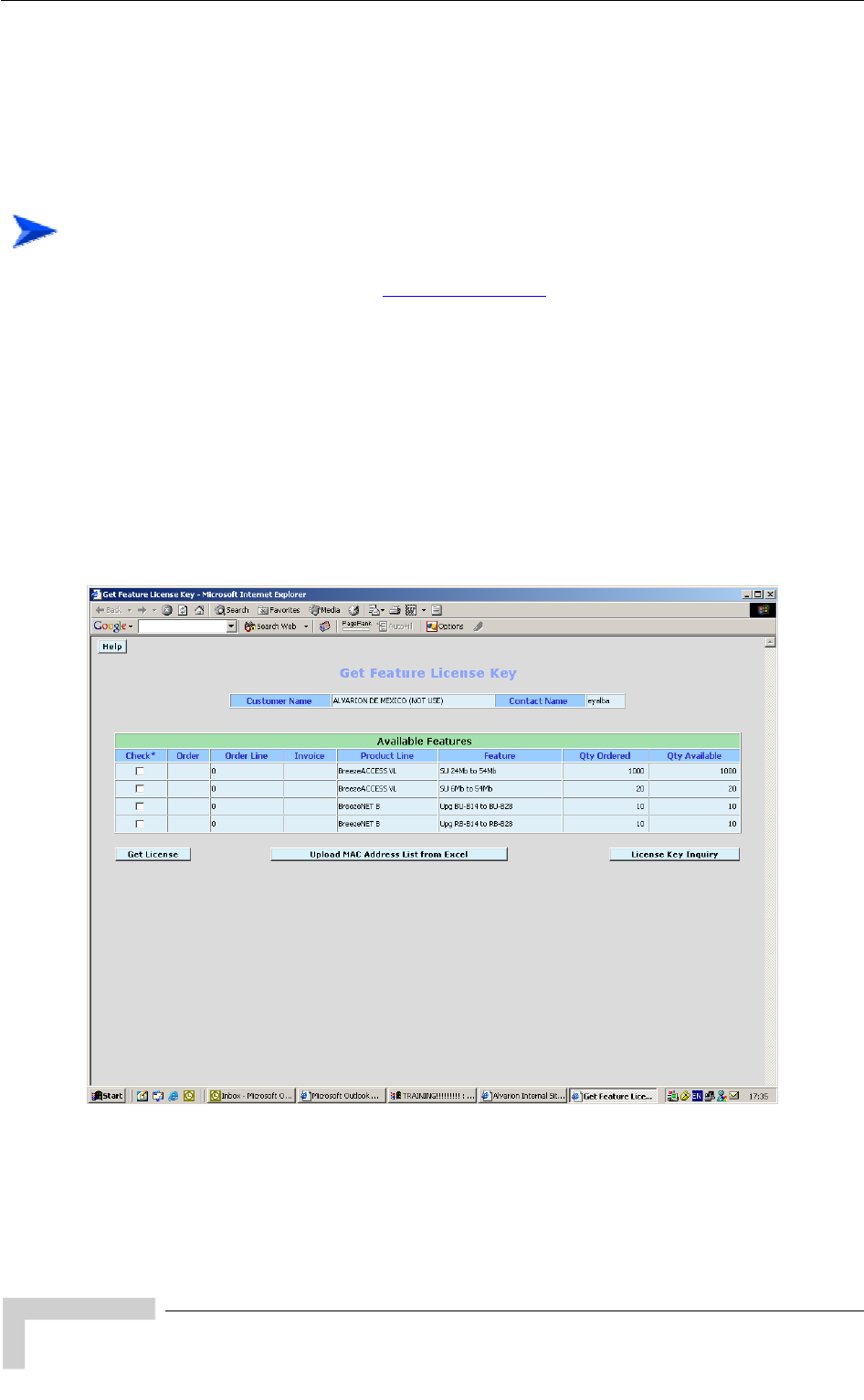
Appendix G - Using the Feature License Web Application
G.1 The Feature License Web Application
Certain features of BreezeACCESS 4900 products may be upgraded through
loading special feature license strings. When you receive the invoice for new
license(s) purchased, use the Alvarion web site for getting license strings for
specific products.
To access the Feature License Application:
1 In the Alvarion web site (www.alvarion.com), select the Customer Service
option.
2 In the Customer Service page, select the Service Call Entry option.
3 In the User Login form, enter your User ID and Password and click Login.
4 Select SSM - Customer Service Area.
5 Select the Feature License option.
The Get Feature License Key form with the current status of your licen
isplayed.
se(s) is
d
BreezeACCESS 4900 System Manual
228
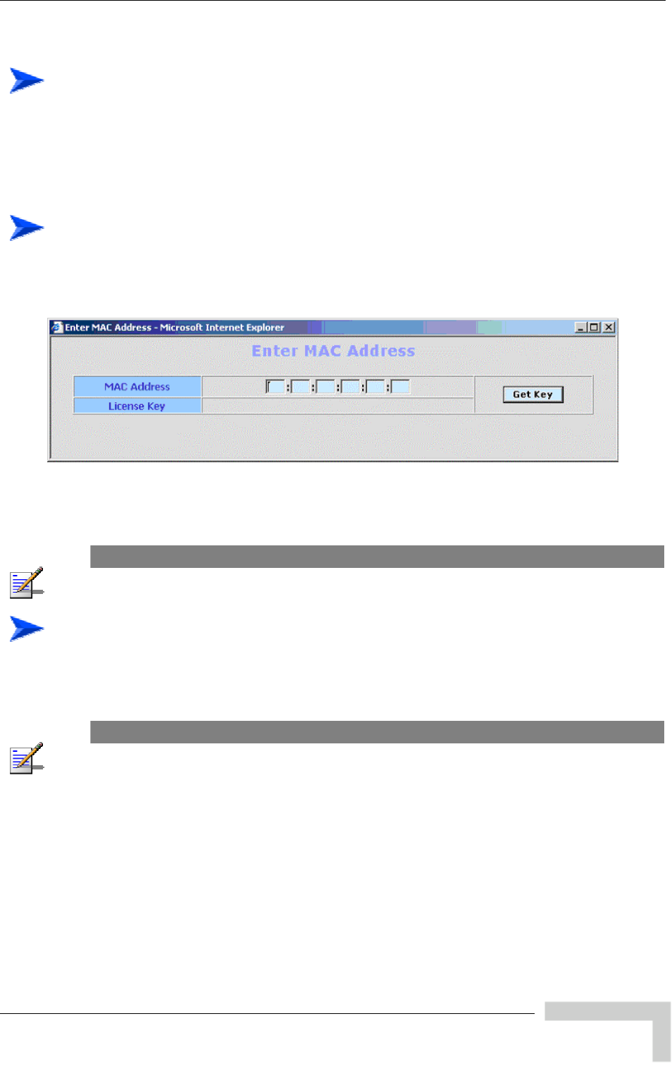
The Feature License Web Application
To s on the updated status of your licenses:
ted status of the
The
str
get detail
Check on the License Key Enquiry button to get the upda
licenses.
displayed information includes account history with details on all license
ings that were provided.
To
1
get a License Key for a single device:
Check the required feature license entry and click on the Get Key button. The
Enter MAC Address form will be displayed:
2 Enter the MAC Address of the device you want to upgrade.
3 Click on the Get Key button. The License Key for the device will be displayed.
NOTE
An error message will be displayed upon requesting a key for a non-valid MAC address.
To get License Keys for multiple devices:
This feature enables you to load a list of MAC Addresses from a pre-prepared
Excel file.
NOTE
The Excel file should contain a single column of MAC addresses (no empty cells). This must be
column A, starting at row 1, which is the title row.
1 Check the required feature license and click on Upload MAC Address List
from Excel button. The Get MAC Addresses from Excel File form will be
displayed:
BreezeACCESS 4900 System Manual
229
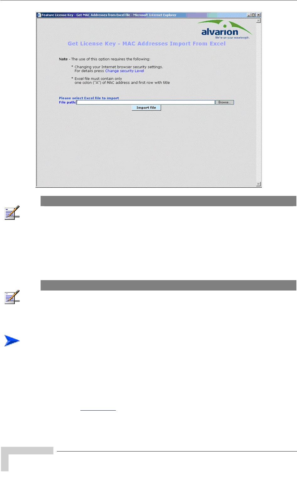
Appendix G - Using the Feature License Web Application
NOTE
You may need to change your Browser security settings. For details press the Change Security
Level link in the form.
2 Use the browser or enter the path to the MAC addresses file. Enter the MAC
address of the device you want to upgrade.
3 Click on the Import File button to get a list of License Keys for the devices
included in the Excel file.
NOTE
An error message will be displayed upon requesting a key for a non-valid MAC address.
G.1.1 Loading License Strings to Devices
To upgrade a single device:
There are several methods of loading a feature license string to a single device:
Using Telnet: Use the Feature Upgrade option in the Unit Control menu.
Using TFTP: Use the file with the extension “.fln” for feature license strings.
Refer to Appendix B (File Upload and Download Using TFTP) for more details.
BreezeACCESS 4900 System Manual
230
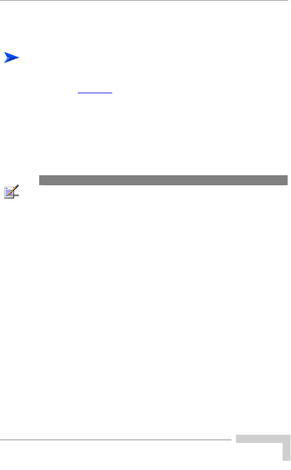
The Feature License Web Application
Using BreezeCONFIG: Enter the license string in the Feature Upgrade field of
the Unit Control window. Refer to the BreezeCONFIG User Manual
details.
for more
To upgrade multiple devices using a feature licenses file:
Using TFTP: Use the file with the extension “.fln” for feature licen
Refer to Appendix B
se strings.
(File Upload and Download Using TFTP) for more details.
Note that Feature license files include multiple strings, where each string is
applicable only for a certain unit identified by its MAC address. When
uploading a e to multiple units, each unit
it.
Using BreezeCONFIG: Use the File Loading Utility. Refer to the
BreezeCONFIG User Manual for more details.
feature license or a country code fil
will accept only the parts that are applicable for
NOTE
After completing loading process, reset the unit(s) to apply the change. Use the Info Screens menu
(Show Unit Status) to verify that the unit has been upgraded.
BreezeACCESS 4900 System Manual
231

H
H
Appendix H - Troubleshooting

Appendix H - Troubleshooting
H.1 Ethernet Port Connection Problems
Problem and Indication Possible Cause Corrective Action
Wrong type of Ethernet
cable If connected directly to PC-use a
crossed cable. Otherwise-use a
straight cable
The Ethernet Integrity Indica
(the yellow LED embedded tor
y d
re Faulty Ethernet cable R
in
the Ethernet connector) is off,
and/or the Ethernet Activit
Indicator (the green embedde
LED) does not blink when the
should be traffic on the
Ethernet port.
eplace cable
Wrong IP configuration Make sure that the PC is on the same
subnet as the unit*.
The unit does not respond to
ping.
et port Wrong Ethern
operation mode Make sure that the speed and
settings in the PC match the
configuration in the unit (the default is
Auto Negotiation)
duplex
* If the IP parameters of the known, s utility to
restore the default factory c p eneral
FTP parameters and AU’s F P ad s of the unit after setting to factory
defaults is 10.0.0.1.
unit are un
onfiguration of all
requency). The I
use the Set Factory Default
arameters (except to Passwords, g
dres
BreezeACCESS 4900 System Manual
234

SU Association Problems
H.2 SU Association Problems
Problem and Indication
Possible Cause Corrective Action
Wrong configur Check proper configuration of basic
parameters:
ESSID
Sub-band and frequencies subset
Best AU parameters
ATPC Option
Transmit Power
Maximum Transmit Power
Antenna Gain
Security parameters: Authentication
Algorithm, and Default Key. If
necessary-use Promiscuous Mode
in AU.
ation
Access is denied by
AU Verify that the SU is not included in MAC
Address Deny List of the AU.
S AU
Link quality is too low Verify that unit is in coverage area of
AU according to radio planning.
Verify that antenna is directed
toward the AU
Try to improve location/height of
antenna.
U does not associate with
BreezeACCESS 4900 System Manual
235
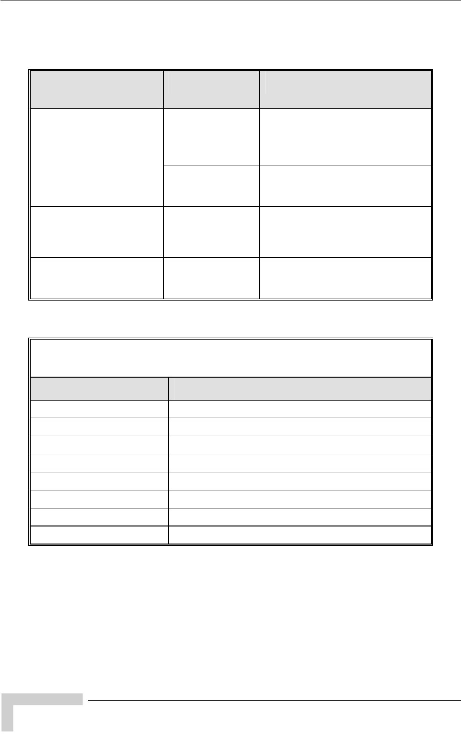
Appendix H - Troubleshooting
BreezeACCESS 4900 System Manual
236
H.3 Low Throughput Problems
Problem and Indication
Possible Cause Corrective Action
Ethernet link
problems Verify proper settings of Ethernet
operation mode (actual Ethernet
speed of 100 Mbps).
Check Ethernet counters
Low throughput is suspected
(Check the dominant
Modulation Level in Per rate
Counters and see expected
throughput in the “Expected
Throughput” table below) Wrong configuration
of Maximum
Modulation level
Verify that Maximum Modulation level is
not set to a value that is not too low
according to the “Recommended
Maximum Modulation Level” table below.
Low throughput of
multicast/broadcast traffic Non-optimal
configuration of
Multicast Modulation
level
A value that is too low (see the
“Recommended Maximum Modulation
Level” table below) may degrade
throughput of broadcast and multicast
traffic.
High retransmissions rate Interference
problems
(retransmissions rate
in excess of 15%)
Check for interference using the
Spectrum Analysis Mode. If necessary,
change the operating frequency of the
AU.
Expected Throughput in Mbps, TCP session,
Burst Mode Disabled
Modulation Level Expected Throughput (Mbps) @ 10 MHz Bandwidth
1 2.40
2 3.57
3 4.69
4 6.76
5 8.76
6 12.02
7 14.13
8 14.25

Low Throughput Problems
BreezeACCESS 4900 System Manual
237
Recommended Maximum Modulation Level*
SNR Maximum Modulation Level
SNR > 23 dB 8
21 dB < SNR < 23 dB 7
16 dB< SNR < 21 dB 6
13 dB < SNR < 16 dB 5
10 dB < SNR < 13 dB 4
8 dB < SNR < 10 dB 3
7 dB < SNR < 8 dB 2
6 dB < SNR < 7 dB 1