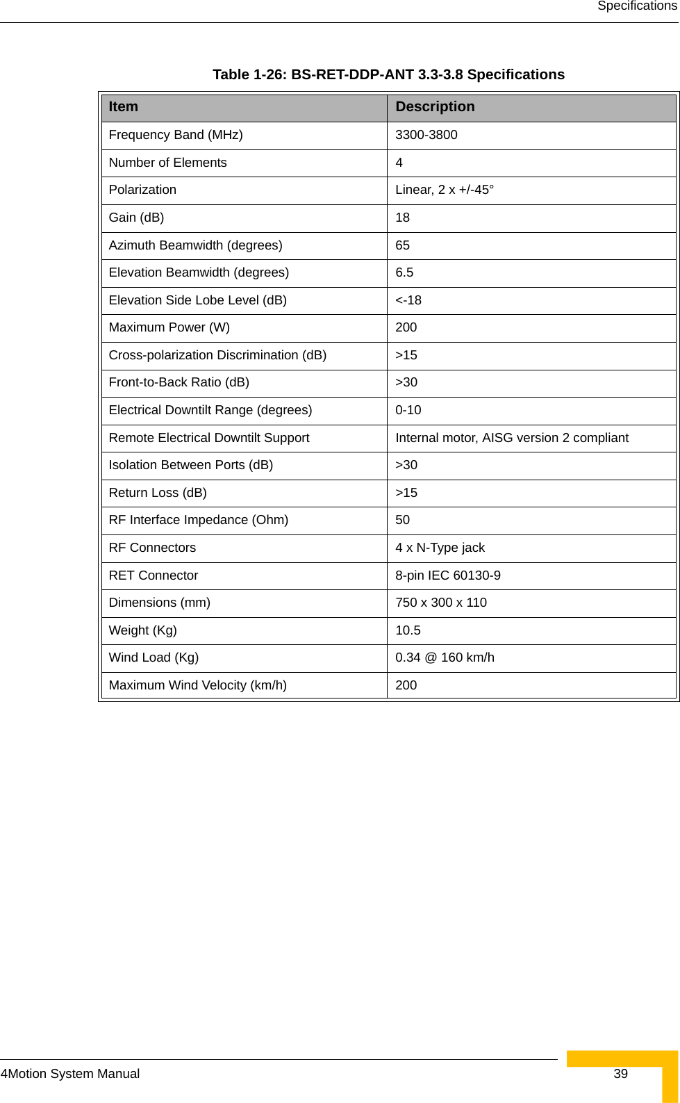
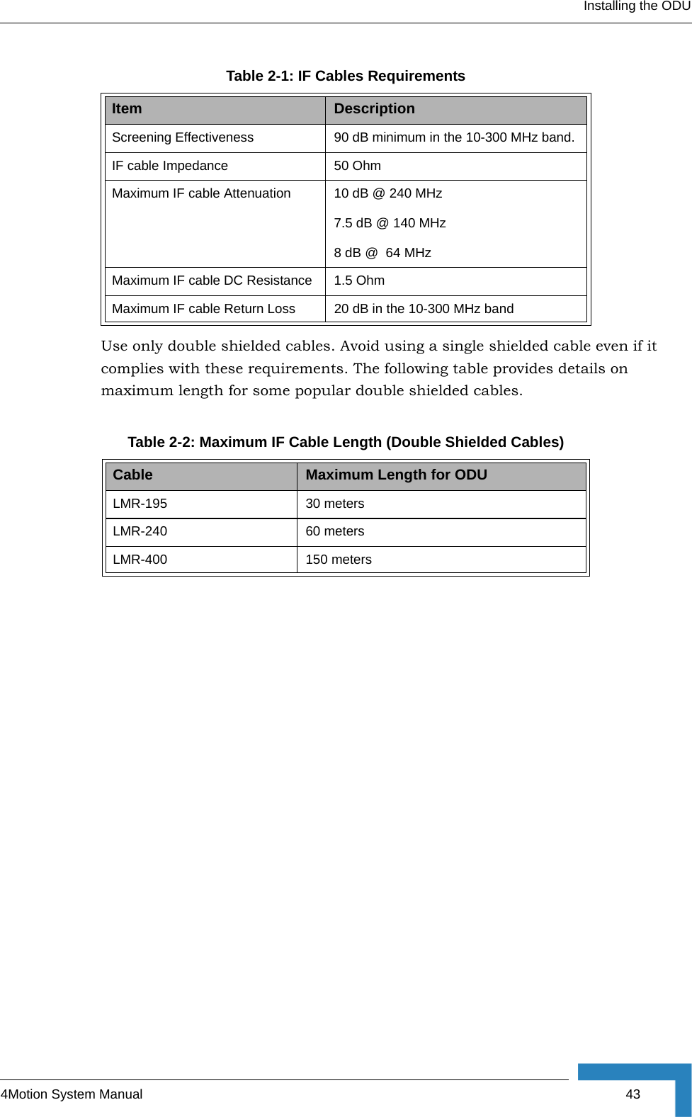
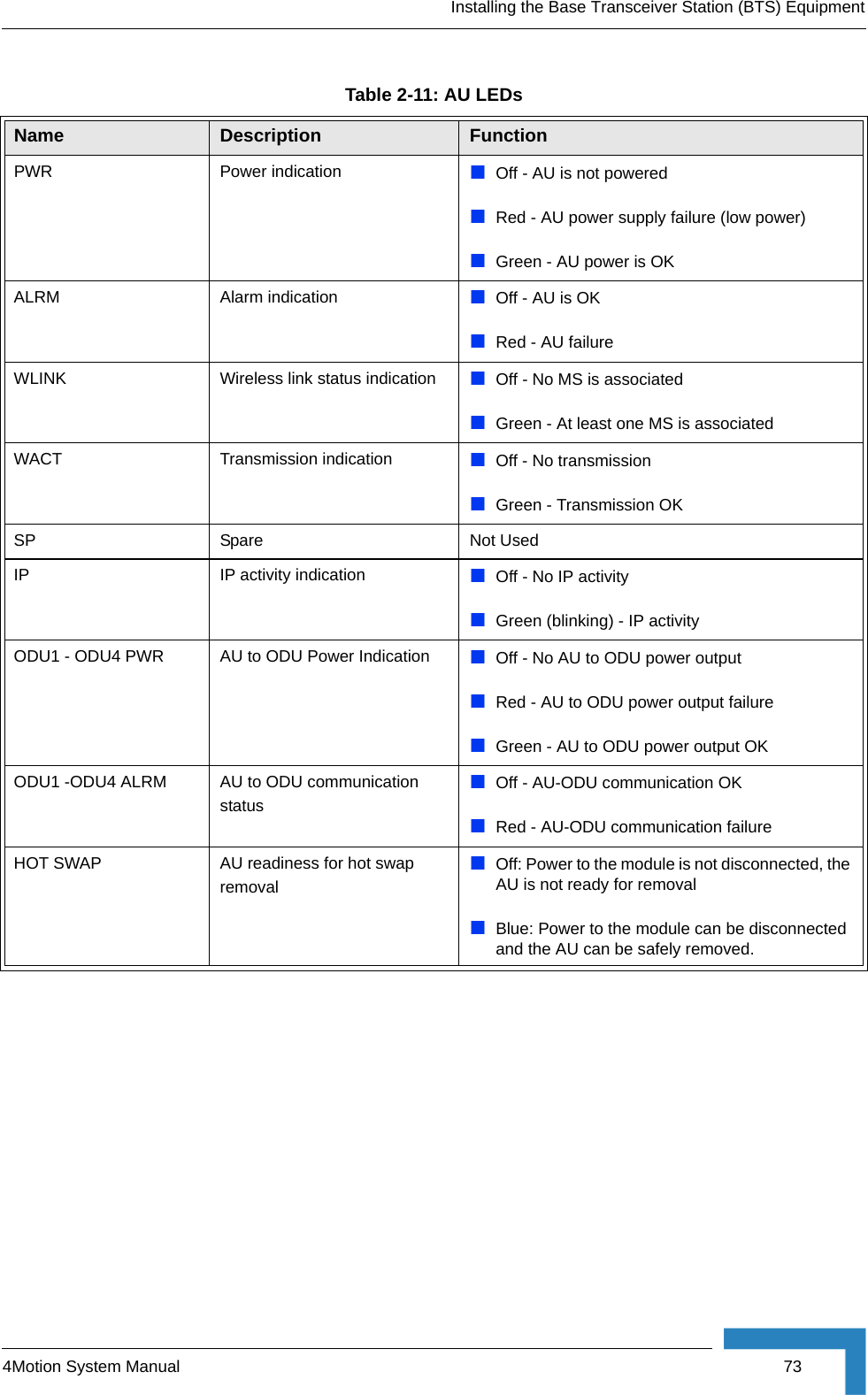
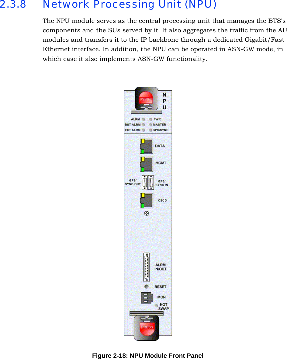
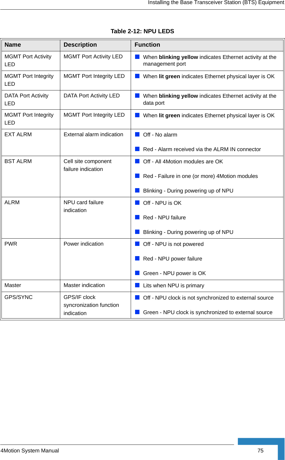
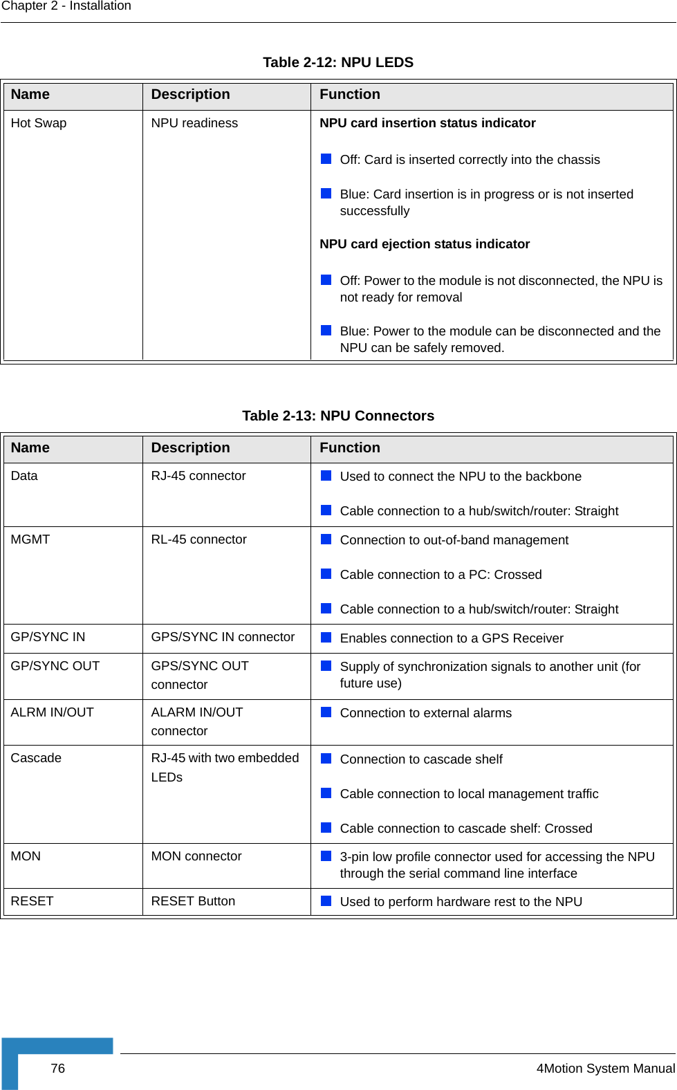
Alvarion Technologies BMAX-BA4M-B25 WiMAX Base Station User Manual 4Motion System Manual

Alvarion Technologies Ltd. WiMAX Base Station 4Motion System Manual

Users Manual

4Motion™System ManualRelease 2.0 July 2008P/N 215038
ii 4Motion System ManualDocument HistoryDocument HistoryTopic Description Date IssuedPreliminary Release for Early Field TrialsNew System Manual January 2008Preliminary Release for Beta May 2008Release for GA July 2008
4Motion System Manual iiiLegal RightsLegal Rights© Copyright 2008 Alvarion Ltd. All rights reserved.The material contained herein is proprietary, privileged, and confidential and owned by Alvarion or its third party licensors. No disclosure thereof shall be made to third parties without the express written permission of Alvarion Ltd.Alvarion Ltd. reserves the right to alter the equipment specifications and descriptions in this publication without prior notice. No part of this publication shall be deemed to be part of any contract or warranty unless specifically incorporated by reference into such contract or warranty.Trade NamesAlvarion®, BreezeCOM®, WALKair®, WALKnet®, BreezeNET®, BreezeACCESS®, BreezeMANAGE™, BreezeLINK®, BreezeCONFIG™, BreezeMAX™, AlvariSTAR™, AlvariCRAFT™, BreezeLITE™, MGW™, eMGW™, 4Motion™ and/or other products and/or services referenced here in are either registered trademarks, trademarks or service marks of Alvarion Ltd.All other names are or may be the trademarks of their respective owners.Statement of ConditionsThe information contained in this manual is subject to change without notice. Alvarion Ltd. shall not be liable for errors contained herein or for incidental or consequential damages in connection with the furnishing, performance, or use of this manual or equipment supplied with it.Warranties and DisclaimersAll Alvarion Ltd. ("Alvarion") products purchased from Alvarion or through any of Alvarion's authorized resellers are subject to the following warranty and product liability terms and conditions.Exclusive Warranty(a) Alvarion warrants that the Product hardware it supplies and the tangible media on which any software is installed, under normal use and conditions, will be free from significant defects in materials and workmanship for a period of fourteen (14) months from the date of shipment of a given Product to Purchaser (the "Warranty Period"). Alvarion will, at its sole option and as Purchaser's sole remedy, repair or replace any defective Product in accordance with Alvarion' standard R&R procedure.(b) With respect to the Firmware, Alvarion warrants the correct functionality according to the attached documentation, for a period of fourteen (14) month from
iv 4Motion System ManualLegal Rightsinvoice date (the "Warranty Period")". During the Warranty Period, Alvarion may release to its Customers firmware updates, which include additional performance improvements and/or bug fixes, upon availability (the "Warranty"). Bug fixes, temporary patches and/or workarounds may be supplied as Firmware updates. Additional hardware, if required, to install or use Firmware updates must be purchased by the Customer. Alvarion will be obligated to support solely the two (2) most recent Software major releases. ALVARION SHALL NOT BE LIABLE UNDER THIS WARRANTY IF ITS TESTING AND EXAMINATION DISCLOSE THAT THE ALLEGED DEFECT IN THE PRODUCT DOES NOT EXIST OR WAS CAUSED BY PURCHASER'S OR ANY THIRD PERSON'S MISUSE, NEGLIGENCE, IMPROPER INSTALLATION OR IMPROPER TESTING, UNAUTHORIZED ATTEMPTS TO REPAIR, OR ANY OTHER CAUSE BEYOND THE RANGE OF THE INTENDED USE, OR BY ACCIDENT, FIRE, LIGHTNING OR OTHER HAZARD.Disclaimer(a) The Software is sold on an "AS IS" basis. Alvarion, its affiliates or its licensors MAKE NO WARRANTIES, WHATSOEVER, WHETHER EXPRESS OR IMPLIED, WITH RESPECT TO THE SOFTWARE AND THE ACCOMPANYING DOCUMENTATION. ALVARION SPECIFICALLY DISCLAIMS ALL IMPLIED WARRANTIES OF MERCHANTABILITY AND FITNESS FOR A PARTICULAR PURPOSE AND NON-INFRINGEMENT WITH RESPECT TO THE SOFTWARE. UNITS OF PRODUCT (INCLUDING ALL THE SOFTWARE) DELIVERED TO PURCHASER HEREUNDER ARE NOT FAULT-TOLERANT AND ARE NOT DESIGNED, MANUFACTURED OR INTENDED FOR USE OR RESALE IN APPLICATIONS WHERE THE FAILURE, MALFUNCTION OR INACCURACY OF PRODUCTS CARRIES A RISK OF DEATH OR BODILY INJURY OR SEVERE PHYSICAL OR ENVIRONMENTAL DAMAGE ("HIGH RISK ACTIVITIES"). HIGH RISK ACTIVITIES MAY INCLUDE, BUT ARE NOT LIMITED TO, USE AS PART OF ON-LINE CONTROL SYSTEMS IN HAZARDOUS ENVIRONMENTS REQUIRING FAIL-SAFE PERFORMANCE, SUCH AS IN THE OPERATION OF NUCLEAR FACILITIES, AIRCRAFT NAVIGATION OR COMMUNICATION SYSTEMS, AIR TRAFFIC CONTROL, LIFE SUPPORT MACHINES, WEAPONS SYSTEMS OR OTHER APPLICATIONS REPRESENTING A SIMILAR DEGREE OF POTENTIAL HAZARD. ALVARION SPECIFICALLY DISCLAIMS ANY EXPRESS OR IMPLIED WARRANTY OF FITNESS FOR HIGH RISK ACTIVITIES.(b) PURCHASER'S SOLE REMEDY FOR BREACH OF THE EXPRESS WARRANTIES ABOVE SHALL BE REPLACEMENT OR REFUND OF THE PURCHASE PRICE AS SPECIFIED ABOVE, AT ALVARION'S OPTION. TO THE FULLEST EXTENT ALLOWED BY LAW, THE WARRANTIES AND REMEDIES SET FORTH IN THIS AGREEMENT ARE EXCLUSIVE AND IN LIEU OF ALL OTHER
4Motion System Manual vLegal RightsWARRANTIES OR CONDITIONS, EXPRESS OR IMPLIED, EITHER IN FACT OR BY OPERATION OF LAW, STATUTORY OR OTHERWISE, INCLUDING BUT NOT LIMITED TO WARRANTIES, TERMS OR CONDITIONS OF MERCHANTABILITY, FITNESS FOR A PARTICULAR PURPOSE, SATISFACTORY QUALITY, CORRESPONDENCE WITH DESCRIPTION, NON-INFRINGEMENT, AND ACCURACY OF INFORMATION GENERATED. ALL OF WHICH ARE EXPRESSLY DISCLAIMED. ALVARION' WARRANTIES HEREIN RUN ONLY TO PURCHASER, AND ARE NOT EXTENDED TO ANY THIRD PARTIES. ALVARION NEITHER ASSUMES NOR AUTHORIZES ANY OTHER PERSON TO ASSUME FOR IT ANY OTHER LIABILITY IN CONNECTION WITH THE SALE, INSTALLATION, MAINTENANCE OR USE OF ITS PRODUCTS.Limitation of Liability(a) ALVARION SHALL NOT BE LIABLE TO THE PURCHASER OR TO ANY THIRD PARTY, FOR ANY LOSS OF PROFITS, LOSS OF USE, INTERRUPTION OF BUSINESS OR FOR ANY INDIRECT, SPECIAL, INCIDENTAL, PUNITIVE OR CONSEQUENTIAL DAMAGES OF ANY KIND, WHETHER ARISING UNDER BREACH OF CONTRACT, TORT (INCLUDING NEGLIGENCE), STRICT LIABILITY OR OTHERWISE AND WHETHER BASED ON THIS AGREEMENT OR OTHERWISE, EVEN IF ADVISED OF THE POSSIBILITY OF SUCH DAMAGES.(b) TO THE EXTENT PERMITTED BY APPLICABLE LAW, IN NO EVENT SHALL THE LIABILITY FOR DAMAGES HEREUNDER OF ALVARION OR ITS EMPLOYEES OR AGENTS EXCEED THE PURCHASE PRICE PAID FOR THE PRODUCT BY PURCHASER, NOR SHALL THE AGGREGATE LIABILITY FOR DAMAGES TO ALL PARTIES REGARDING ANY PRODUCT EXCEED THE PURCHASE PRICE PAID FOR THAT PRODUCT BY THAT PARTY (EXCEPT IN THE CASE OF A BREACH OF A PARTY'S CONFIDENTIALITY OBLIGATIONS).Radio Frequency Interference StatementThe Base Transceiver Station (BTS) equipment has been tested and found to comply with the limits for a class A digital device, pursuant to ETSI EN 301 489-1 rules and Part 15 of the FCC Rules. These limits are designed to provide reasonable protection against harmful interference when the equipment is operated in commercial, business and industrial environments. This equipment generates, uses, and can radiate radio frequency energy and, if not installed and used in accordance with the instruction manual, may cause harmful interference to radio communications. Operation of this equipment in a residential area is likely to cause harmful interference in which case the user will be required to correct the interference at the user's own expense.
vi 4Motion System ManualLegal RightsFCC Radiation Hazard Warning To comply with FCC RF exposure requirements in Section 1.1307 and 2.1091 of FCC Rules, the antenna used for this transmitter must be fixed-mounted on outdoor permanent structures with a separation distance of at least 2 meter from all persons.R&TTE Compliance StatementThis equipment complies with the appropriate essential requirements of Article 3 of the R&TTE Directive 1999/5/EC.Safety Considerations - GeneralFor the following safety considerations, "Instrument" means the BreezeMAX units' components and their cables.GroundingBTS chassis, Power Feeders and Outdoor Units are required to be bonded to protective grounding using the bonding stud or screw provided with each unit. Safety Considerations - DC Powered Equipment (BTS & Power Feeder)Restricted Access Area: The DC powered equipment should only be installed in a Restricted Access Area.Installation Codes: The equipment must be installed according to the latest edition of the country national electrical codes. For North America, equipment must be installed in accordance with the US National Electrical Code and the Canadian Electrical Code.Overcurrent Protection: A readily accessible Listed branch circuit overcurrent protective device, rated 60A for the BTS or 20A for the Power Feeder, must be incorporated in the building wiring.CAUTION: This equipment is designed to permit connection between the earthed conductor of the DC supply circuit and the grounding conductor at the equipment. See installation instructions.CAUTION ATTENTIONRisk of electric shock and energy hazard.Disconnecting one Power Interface Unit (PIU) disconnects only one PIU module. To isolate the BTS completely, disconnect both PIUsRisque de décharge électrique et d'electrocution. La déconnection d'un seul module d'alimentation (PIU) n'isole pas complètement la Station de Base. Pour cela, il faut impérativement débrancher les deux modules d'alimentation (PIU).
4Motion System Manual viiLegal RightsThe equipment must be connected directly to the DC Supply System grounding electrode conductor.All equipment in the immediate vicinity must be grounded in the same way, and not be grounded elsewhere.The DC supply system is to be local, i.e. within the same premises as the equipment.There shall be no disconnect device between the grounded circuit conductor of the DC source (return) and the point of connection of the grounding electrode conductor.Lithium BatteryThe battery on the NPU card is not intended for replacement.CautionTo avoid electrical shock, do not perform any servicing unless you are qualified to do so.Line VoltageBefore connecting this instrument to the power line, make sure that the voltage of the power source matches the requirements of the instrument.RadioThe instrument transmits radio energy during normal operation. To avoid possible harmful exposure to this energy, do not stand or work for extended periods of time in front of its antenna. The long-term characteristics or the possible physiological effects of radio frequency electromagnetic fields have not been yet fully investigated.Outdoor Units and Antennas Installation and GroundingEnsure that outdoor units, antennas and supporting structures are properly installed to eliminate any physical hazard to either people or property. Make sure that the installation of the outdoor unit, antenna and cables is performed in accordance with all relevant national and local building and safety codes. Even where grounding is not mandatory according to applicable regulation and national codes, it is highly recommended to ensure that the outdoor unit and the antenna mast (when using external antenna) are grounded and suitable lightning protection devices are used so as to provide protection against voltage surges and static charges. In any event, Alvarion is not liable for any injury, damage or
viii 4Motion System ManualLegal Rightsregulation violations associated with or caused by installation, grounding or lightning protection.Disposal of Electronic and Electrical WasteDisposal of Electronic and Electrical WastePursuant to the WEEE EU Directive electronic and electrical waste must not be disposed of with unsorted waste. Please contact your local recycling authority for disposal of this product.
4Motion System Manual ixLegal RightsImportant NoticeThis user manual is delivered subject to the following conditions and restrictions:This manual contains proprietary information belonging to Alvarion Ltd. Such information is supplied solely for the purpose of assisting properly authorized users of the respective Alvarion products.No part of its contents may be used for any other purpose, disclosed to any person or firm or reproduced by any means, electronic and mechanical, without the express prior written permission of Alvarion Ltd.The text and graphics are for the purpose of illustration and reference only. The specifications on which they are based are subject to change without notice.The software described in this document is furnished under a license. The software may be used or copied only in accordance with the terms of that license.Information in this document is subject to change without notice. Corporate and individual names and data used in examples herein are fictitious unless otherwise noted.Alvarion Ltd. reserves the right to alter the equipment specifications and descriptions in this publication without prior notice. No part of this publication shall be deemed to be part of any contract or warranty unless specifically incorporated by reference into such contract or warranty. The information contained herein is merely descriptive in nature, and does not constitute an offer for the sale of the product described herein.Any changes or modifications of equipment, including opening of the equipment not expressly approved by Alvarion Ltd. will void equipment warranty and any repair thereafter shall be charged for. It could also void the user's authority to operate the equipment.Some of the equipment provided by Alvarion and specified in this manual, is manufactured and warranted by third parties. All such equipment must be installed and handled in full compliance with the instructions provided by such manufacturers as attached to this manual or provided thereafter by Alvarion or the manufacturers. Non-compliance with such instructions may result in serious
x4Motion System ManualLegal Rightsdamage and/or bodily harm and/or void the user's authority to operate the equipment and/or revoke the warranty provided by such manufacturer.
About This ManualThis manual describes the 4Motion solution, and details how to install, operate and manage the BTS system components.This manual is intended for technicians responsible for installing, setting and operating the 4Motion BTS equipment, and for system administrators responsible for managing the system.This manual contains the following chapters and appendices:Chapter 1 - System description: Describes the 4Motion BTS and its components.Chapter 2 - Installation: Describes how to install the BTS components.Chapter 3 - Commissioning: Describes how to configure basic parameters and validate units' operation.Chapter 4 - Operation and Administration Using the CLI: Describes how to use the Command Line Interface (CLI) for configuring parameters, checking system status and monitoring performance. Appendix A - Antenna Configurations: Describes the proposed antenna configurations that support the different available diversity scenarios.Appendix B - Software Upgrade: Describes how to load new software files using TFTP, and how to switch to a new software version in 4Motion units.Glossary: A listing of commonly used terms.
ContentsChapter 1 - System Description1.1 About WiMAX.................................................................................................................21.2 4Motion Solution ...........................................................................................................31.2.1 4Motion Solution Highlights..................................................................................31.2.2 WiMAX Network Reference Model.......................................................................51.3 The Base Transceiver Station....................................................................................121.3.1 The BreezeMAX Shelf........................................................................................121.3.2 NPU....................................................................................................................141.3.3 AU ......................................................................................................................161.3.4 PIU .....................................................................................................................181.3.5 PSU....................................................................................................................181.3.6 AVU....................................................................................................................181.3.7 ODU ...................................................................................................................191.3.8 Power Feeder.....................................................................................................201.3.9 Antenna..............................................................................................................201.3.10 GPS....................................................................................................................211.4 Element Management Systems..................................................................................221.4.1 AlvariSTAR™.....................................................................................................221.5 Specifications..............................................................................................................241.5.1 Modem & Radio .................................................................................................241.5.2 Sensitivity...........................................................................................................241.5.3 ODUs .................................................................................................................251.5.4 AU - ODU Communication.................................................................................30
xiv 4Motion System ManualContents1.5.5 Data Communication (Ethernet Interfaces)........................................................301.5.6 Configuration and Management.........................................................................311.5.7 Standards Compliance, General........................................................................321.5.8 Environmental ....................................................................................................321.5.9 Mechanical and Electrical ..................................................................................331.5.10 Antennas............................................................................................................36Chapter 2 - Installation 2.1 Installing the ODU .......................................................................................................422.1.1 Guidelines for Positioning the ODU ...................................................................422.1.2 IF Cables............................................................................................................422.1.3 Installing the 1x1 ODU .......................................................................................442.1.4 Installing the 4x2 ODU .......................................................................................492.1.5 Connecting the Cables.......................................................................................592.2 Installing the Antennas...............................................................................................612.2.1 Guidelines for Positioning the Antennas ............................................................612.2.2 Antenna Installation Requirements ....................................................................612.2.3 Recommended Installation Procedure...............................................................622.3 Installing the Base Transceiver Station (BTS) Equipment......................................642.3.1 BTS Installation Requirements...........................................................................642.3.2 BTS Chassis Slot Assignments..........................................................................652.3.3 Power Requirements..........................................................................................662.3.4 HOT SWAP Support ..........................................................................................672.3.5 Power Interface Unit (PIU) .................................................................................672.3.6 Power Supply Unit (PSU)...................................................................................702.3.7 Access Unit Module (AU)...................................................................................722.3.8 Network Processing Unit (NPU).........................................................................74
4Motion System Manual xvContents2.3.9 Connecting the BTS Chassis and Modules........................................................772.3.10 Replacing BTS Components..............................................................................792.4 Installing the ODU Power Feeder...............................................................................822.4.1 Installation Requirements...................................................................................822.4.2 The ODU Power Feeder ....................................................................................832.4.3 Installing the ODU Power Feeder ......................................................................842.5 Installing the Outdoor GPS Receiver ........................................................................862.6 Connecting the GPS Cables.......................................................................................87Chapter 3 - Commissioning3.1 Initial NPU Configuration............................................................................................903.1.1 Introduction ........................................................................................................903.1.2 NPU Local Connectivity .....................................................................................903.1.3 Site Connectivity ................................................................................................903.1.4 ACL Definition ....................................................................................................923.1.5 Static Route Definition........................................................................................923.1.6 SNMP Manager Definition..................................................................................933.1.7 Site ID Definition ................................................................................................933.2 Completing the Site Configuration Using AlvariSTAR ............................................943.2.1 Introduction ........................................................................................................943.2.2 Site Configuration...............................................................................................953.2.3 Connectivity Configuration (optional) .................................................................953.2.4 Equipment Configuration....................................................................................953.2.5 ASNGW Configuration .......................................................................................973.2.6 BS Configuration................................................................................................993.2.7 Site Sector Configuration .................................................................................104
xvi 4Motion System ManualContentsChapter 4 - Operation and Administration Using the CLI4.1 Using the Command Line Interface for 4Motion System Management................1084.1.1 Accessing the CLI ............................................................................................1094.1.2 Command Modes.............................................................................................1114.1.3 Interpreting the Command Syntax ...................................................................1124.1.4 Using the CLI ...................................................................................................1144.1.5 Managing Users and Privileges .......................................................................1164.2 Shutting Down/Resetting the System .....................................................................1264.2.1 Shutting Down the System...............................................................................1264.2.2 Managing System Reset..................................................................................1274.3 NPU Configuration ....................................................................................................1294.3.1 Managing the IP Connectivity Mode ................................................................1304.3.2 Configuring Physical and IP Interfaces ............................................................1334.3.3 Managing the NPU Boot Mode ........................................................................1634.3.4 Managing the 4Motion Configuration File ........................................................1664.3.5 Batch-processing of CLI Commands ...............................................................1744.3.6 Configuring the CPU ........................................................................................1764.3.7 Configuring QoS Marking Rules.......................................................................1904.3.8 Configuring Static Routes ................................................................................2054.3.9 Configuring ACLs.............................................................................................2094.3.10 Configuring the ASN-GW Functionality............................................................2404.3.11 Configuring Logging.........................................................................................3684.3.12 Configuring Performance Data Collection........................................................3854.3.13 Configuring the SNMP/Trap Manager..............................................................4054.3.14 Configuring the 4Motion Shelf..........................................................................4134.4 Managing AUs ...........................................................................................................444
4Motion System Manual xviiContents4.4.1 Enabling the AU Configuration Mode\Creating an AU Object..........................4444.4.2 Configuring AU Parameters .............................................................................4454.4.3 Restoring Default Values for AU Configuration Parameters ............................4504.4.4 Terminating the AU Configuration Mode..........................................................4534.4.5 Deleting an AU Object......................................................................................4544.4.6 Displaying Configuration and Status Information for AU Parameters ..............4554.5 Managing ODUs.........................................................................................................4624.5.1 Configuring ODUs............................................................................................4624.5.2 Configuring ODU Ports ....................................................................................4764.6 Managing Antennas ..................................................................................................4844.6.1 Enabling the Antenna Configuration Mode\Creating an Antenna ....................4844.6.2 Configuring Antenna Parameters.....................................................................4864.6.3 Restoring Default Values for Antenna Parameters ..........................................4884.6.4 Terminating the Antenna Configuration Mode .................................................4894.6.5 Deleting an Antenna.........................................................................................4904.6.6 Displaying Configuration Information for Antennas..........................................4904.7 Managing BSs............................................................................................................4934.7.1 Enabling the BS Configuration Mode\Creating a BS Object ............................4974.7.2 Deleting a BS ...................................................................................................4984.7.3 Managing BS General Parameters ..................................................................4994.7.4 Managing BS Services.....................................................................................5024.7.5 Managing Service Mapping Rules ...................................................................5084.7.6 Managing Power Control Levels and Policies..................................................5284.7.7 Managing BS Feedback Allocation Parameters...............................................5594.7.8 Managing Neighbor Advertisement Parameters ..............................................5634.7.9 Managing Triggers Parameters........................................................................566
xviii 4Motion System ManualContents4.7.10 Managing Trigger Setup Parameters ...............................................................5704.7.11 Managing Scan Negotiation Parameters .........................................................5744.7.12 Managing Handover Negotiation at SBS Parameters......................................5784.7.13 Managing Handover Negotiation at TBS Parameters......................................5814.7.14 Managing Neighbor BSs ..................................................................................5854.7.15 Managing UCD Parameters.............................................................................6084.7.16 Managing DCD Parameters.............................................................................6124.7.17 Managing the RF Frequency Parameter..........................................................6164.7.18 Managing the Baseband Bandwidth Parameter...............................................6194.7.19 Managing Airframe Structure Parameters........................................................6214.7.20 Managing Rate Adaptation Parameters...........................................................6624.7.21 Managing BS Bearer Interface Parameters .....................................................6714.7.22 Managing Authentication Relay Parameters....................................................6744.7.23 Managing Handover Control Parameters.........................................................6794.7.24 Managing Bearer Traffic QoS Marking Rules ..................................................6834.7.25 Managing Control Traffic QoS Marking Rules..................................................6914.7.26 Managing BS Management Alarm Thresholds Parameters.............................7004.7.27 Managing ID-IP Mapping Parameters..............................................................7044.7.28 Managing Ranging Parameters .......................................................................7074.7.29 Managing Alarm Threshold Parameters ..........................................................7294.7.30 Displaying Status Information for HARQ Maximum Retransmissions  Parameter....................................................................................................................7344.7.31 Managing BS Reserved Parameters................................................................7354.8 Managing Sectors .....................................................................................................7414.8.1 Configuring Sector Parameters........................................................................741
4Motion System Manual xixContents4.8.2 Configuring Sector Association Entries............................................................7504.9 Monitoring Performance of Hardware and Software Components ......................7554.9.1 Monitoring Hardware Components ..................................................................7554.9.2 Monitoring Software Components....................................................................7634.9.3 Displaying System Files ...................................................................................7984.10Troubleshooting .......................................................................................................8004.10.1 Configuring Tracing..........................................................................................8004.10.2 Configuring Port Monitoring .............................................................................808Appendix A - Antenna ConfigurationsA.1 Introduction ...............................................................................................................816A.2 Antenna Configurations ...........................................................................................817A.2.1 Second Order Diversity Configurations............................................................817A.2.2 Fourth Order Diversity Configurations..............................................................817A.2.3 Beam-Forming/MIMO Configurations ..............................................................817A.3 Antenna Down-Tilt Guidelines .................................................................................820Appendix B - Software UpgradeB.1 Before You Start........................................................................................................822B.2 Upgrading the NPU ...................................................................................................823B.2.1 Executing the Upgrade Procedure...................................................................823B.2.2 Displaying the Operational, Shadow, and Running Versions...........................827B.2.3 Displaying the TFTP Configuration Information ...............................................828B.2.4 Displaying the Download Status Information ...................................................828B.3 Upgrading the AU......................................................................................................830B.3.1 Procedure for Upgrading the AU......................................................................830B.3.2 Displaying the Shadow, Running, and Operational Versions...........................837B.3.3 Displaying the Download Status Information ...................................................838
xx 4Motion System ManualContentsB.3.4 Displaying the AU-to-Image Mapping ..............................................................839B.3.5 Deleting the AU-to-Image Mapping..................................................................840B.3.6 Deleting AU Images from the NPU Flash.........................................................841B.3.7 Displaying Images Residing in the AU Flash ...................................................842
1Chapter 1 - System DescriptionIn This Chapter:“About WiMAX” on page 2“4MotionTM Solution” on page 3“The Base Transceiver Station” on page 12“Element Management Systems” on page 22“Specifications” on page 24
24Motion System ManualChapter 1 - System Description1.1 About WiMAXEmanating from the broadband world and using all-IP architecture, mobile WiMAX is the leading technology for implementing personal broadband services. With huge market potential and affordable deployment costs, mobile WiMAX is on the verge of a major breakthrough. No other technology offers a full set of chargeable and differentiated voice, data, and premium video services in a variety of wireless fashions - fixed, portable and mobile - that increase revenue and reduce subscriber churn.WiMAX technology is the solution for many types of high-bandwidth applications at the same time across long distances and will enable service carriers to converge the all-IP-based network for triple-play services data, voice, and video.WiMAX with its QoS support, longer reach, and high data capacity is positioned for fixed broadband access applications in rural areas, particularly when distance is too large for DSL and cable, as well as in urban/suburban areas of developing countries. Among applications for residential are high speed Internet, Voice Over IP telephony and streaming video/online gaming with additional applications for enterprise such as Video conferencing, Video surveillance and secured Virtual Private Network (with need for high security). WiMAX technology allows covering applications with media content requesting more bandwidth.WiMAX allows portable and mobile access applications, with incorporation in notebook computers and PDAs, allowing for urban areas and cities to become “metro zones” for portable and mobile outdoor broadband wireless access. As such WiMAX is the natural complement to 3G networks by offering higher bandwidth and to Wi-Fi networks by offering broadband connectivity in larger areas.The WiMAX Forum is an organization of leading operators and communications component and equipment companies. The WiMAX Forum’s charter is to promote and certify the compatibility and interoperability of broadband wireless access equipment that conforms to the Institute for Electrical and Electronics Engineers (IEEE) 802.16 and ETSI HiperMAN standards. The ultimate goal of the WiMAX Forum is to accelerate the introduction of cost-effective broadband wireless access services into the marketplace. Standards-based, interoperable solutions enable economies of scale that, in turn, drive price and performance levels unachievable by proprietary approaches, making WiMAX Forum Certified products.
4Motion Solution4Motion System Manual  31.2 4Motion Solution1.2.1 4Motion Solution HighlightsLeveraging its extensive experience in Broadband Wireless Access (BWA) systems, leading technology and current favorable economics for broadband and mobile services, Alvarion's 4Motion mobile WiMAX solution represents the next evolution in communications.With 4Motion, Alvarion offers a diversified range of products and services for all operators. Integrating the most advanced and adaptive radio management and control technologies, 4Motion optimizes usage of the operator's spectrum and network resources. At the same time, the solution supports the most stringent quality of service (QoS) requirements for next-generation applications such as video and gaming.As a mobile solution, 4Motion network can be efficiently integrated with existing networks, including 3G, DSL, satellite, and cable, to provide multiple service applications.4Motion enables operators and their customers to address the following consumer and enterprise market segments: “Best effort" fixed broadband access (DSL equivalent)Portable broadband access"Personal broadband" (handheld) accessMobile broadband (including full handover and roaming support)4Motion supports the following services:IP-based services (e.g. VoIP, video streaming, gaming)QoS and application-based prioritization and de-prioritization4Motion is designed as an end-to-end solution based on the following elements:BTS (Base Transceiver Station) equipment with an optional localized access service network gateway (ASN-GW)
44Motion System ManualChapter 1 - System DescriptionOptional centralized, fully integrated ASN-GW, which may be offered as a part of an end-to-end solution that includes third-party partners' equipmentAAA servers provided by either Alvarion or its leading WiMAX partnersAlvariSTARTM Element management system supporting NMS and OSS systemsCustomer premises equipment and handsetsFigure 1-1 illustrates the entire service provider environment and 4Motion solution elements within the radio access network, core network and subscriber environment.Alvarion believes that compliance with standard-driven open architecture protects the infrastructure investment, and opens the system to a variety of fully interoperable end-user devices. As such, 4Motion is designed with open architecture and interfaces according to the WiMAX Forum networking working group (NWG) profile C, which supports openness and enables flat as well as hierarchical topologies. In addition, by keeping the radio resource management functionality in the Base Transceiver Station only, Profile C delivers a faster, optimized handover mechanism.Figure 1-1: 4Motion Solution Elements
4Motion Solution4Motion System Manual  51.2.2 WiMAX Network Reference ModelFigure 1-2 and Figure 1-3 show the basic mobile WiMAX network architecture, with a single ASN-GW and with multiple ASN-GWs, as defined by the WiMAX Forum NWG.Figure 1-2: Mobile WiMAX Network Reference Model
64Motion System ManualChapter 1 - System Description The various components and entities involved in the networking architecture are:1.2.2.1 Access Service Network (ASN)An ASN is defined as a complete set of network functions needed to provide radio access to a WiMAX subscriber. The ASN provides the following mandatory functions:WiMAX Layer-2 (L2) connectivity with WiMAX mobile station (MS) Transfer of AAA messages to the WiMAX subscriber's home network service provider (H-NSP) for authentication, authorization and session accounting for subscriber sessionsNetwork discovery and selection of the WiMAX subscriber's preferred NSPRelay functionality for establishing Layer-3 (L3) connectivity with a WiMAX MS (i.e. IP address allocation)Radio resource managementASN-CSN tunnelingASN anchored mobilityFigure 1-3: ASN Reference Model containing Multiple ASN-GWs
4Motion Solution4Motion System Manual  7An ASN is comprised of network elements such as one or more base transceiver stations and one or more ASN gateways. An ASN may be shared by more than one connectivity service network (CSN).1.2.2.2 Connectivity Service Network (CSN)A CSN is defined as a set of network functions that provide IP connectivity services to WiMAX subscribers. A CSN may offer the following functions:MS IP address and endpoint parameter allocation for user sessionsInternet accessAAA proxy or serverPolicy and admission control based on user subscription profilesASN-CSN tunneling supportWiMAX subscriber billing and inter-operator settlementWiMAX services such as location-based services, connectivity for peer-to-peer services, provisioning, authorization and/or connectivity to IP multimedia services, and facilities to support lawful intercept services such as those compliant with Communications Assistance Law Enforcement Act (CALEA) proceduresA CSN is comprised of network elements such as routers, proxy/servers, user databases, and inter-working gateway devices.1.2.2.3 Network Access Provider (NAP)An NAP is a business entity that provides WiMAX radio access infrastructure to one or more WiMAX network service providers (NSPs). A NAP implements this infrastructure using one or more ASNs.1.2.2.4 Network Service Provider (NSP)An NSP is a business entity that provides IP connectivity and WiMAX services to WiMAX subscribers compliant with the established service level agreement. The NSP concept is an extension of the Internet service provider (ISP) concept, providing network services beyond Internet access. To provide these services, an NSP establishes contractual agreements with one or more NAPs. An NSP may also establish roaming agreements with other NSPs and contractual agreements with
84Motion System ManualChapter 1 - System Descriptionthird-party application providers (e.g. ASP, ISP) for the delivery of WiMAX services to subscribers. From a WiMAX subscriber standpoint, an NSP may be classified as a home or visited NSP.1.2.2.5 Base Station (BS)The WiMAX BS is an entity that implements the WiMAX MAC and PHY in compliance with the IEEE 802.16e standard. A BS operates on one frequency assignment, and incorporates scheduler functions for uplink and downlink resources.The basic functionality of the BS includes:IEEE 802.16e OFDMA PHY/MAC entityR6 and R8 functionality according to NWG definitions Extensible Authentication Protocol (EAP) relayControl message authenticationUser traffic authentication and encryptionHandover managementQoS service flow management entity1.2.2.6 ASN Gateway (ASN-GW)The ASN-GW is a network entity that acts as a gateway between the ASN and CSN. The ASN functions hosted in an ASN-GW may be viewed as consisting of two groups - the decision point (DP) and enforcement point (EP). The EP includes bearer plane functions, and the DP includes non-bearer plane functions.The basic DP functionality of the ASN-GW includes:Implementation of EAP Authenticator and AAA clientTermination of RADIUS protocol against the selected CSN AAA server (home or visited AAA server) for MS authentication and per-MS policy profile retrieval Storage of the MS policy profileGeneration of authentication key material
4Motion Solution4Motion System Manual  9QoS service flow authorization entityAAA accounting clientThe basic EP functionality of the ASN-GW includes:Classification of downlink data into generic routing encapsulation (GRE) tunnelsPacket header suppression functionalityDHCP functionalityHandover functionalityThe WIMAX Forum NWG has adopted two different approaches for ASN architecture - centralized and distributed: In the centralized approach there is at least one central ASN-GW, and the BTS NPU operates in transparent mode, as shown in Figure 1-4. Figure 1-4: Centralized Network Reference Model
10 4Motion System ManualChapter 1 - System DescriptionIn the distributed approach, the BTS NPU operates in ASN-GW mode, as shown in Figure 1-5. Alvarion believes in providing operators with the flexibility to select the mobile WiMAX network topology that best suits their needs and existing network architecture. Therefore, 4Motion is designed to support both distributed and centralized topology approaches according to WiMAX Forum NWG profile C.1.2.2.7 Reference PointsReference point R1 consists of the protocols and procedures between the MS and ASN as per the air-interface (PHY and MAC) specifications (IEEE 802.16e).Reference point R2 consists of protocols and procedures between the MS and CSN associated with authentication, services authorization and IP host configuration management. This reference point is logical in that it does not reflect a direct protocol interface between the MS and CSN. The authentication part of reference point R2 runs between the MS and CSN operated by the home NSP, however, the ASN and CSN operated by the visited NSP may partially process the aforementioned procedures and mechanisms. Reference point R2 might support IP host configuration management running between the MS and CSN (operated by either the home NSP or visited NSP).Figure 1-5: Distributed Network Reference Model
4Motion Solution4Motion System Manual  11Reference point R3 consists of the set of control plane protocols between the ASN and CSN to support AAA, policy enforcement and mobility management capabilities. It also encompasses the bearer plane methods (e.g. tunneling) to transfer user data between the ASN and CSN.Reference point R4 consists of the set of control and bearer plane protocols originating/terminating in various functional entities of an ASN that coordinate MS mobility between ASNs and ASN-GWs. R4 is the only interoperable reference point between similar or heterogeneous ASNs.Reference point R5 consists of the set of control plane and bearer plane protocols for internetworking between the CSN operated by the home NSP and that operated by a visited NSP.Reference point R6 consists of the set of control and bearer plane protocols for communication between the BS and ASN-GW. The bearer plane consists of an intra-ASN data path between the BS and ASN gateway. The control plane includes protocols for data path establishment, modification and release control in accordance with the MS mobility events.Reference point R8 consists of the set of control plane message flows and optional bearer plane data flows between the base stations to ensure a fast and seamless handover. The bearer plane consists of protocols that allow data transfer between base stations involved in the handover of a certain MS. It is important to note that all reference points are logical and do not necessarily imply a physical or even direct connection. For instance, the R4 reference point between ASN-GWs might be implemented across the NAP internal transport IP network, in which case R4 traffic might traverse several routers from the source to the destination ASN-GW.
12 4Motion System ManualChapter 1 - System Description1.3 The Base Transceiver StationThe 4Motion solution features a multi-carrier, high-power Base Transceiver Station (BTS). Designed for high availability and redundancy, it utilizes a central networking and management architecture, and a range of diversity schemes. The BTS main features include:R1 support - 802.16e interface handling (e.g. PHY, MAC, CS, Scheduler, ARQ) and processes such as handover, power control and network entry R6 support - communication with ASN-GWEAP proxy in ASN-GW modeHandover triggering for mobility tunnel establishment - R6 (GRE tunnel)Local QoS PEP for traffic via air interface (or SFM) and admission controlHand-Over (HO) control functionRadio resource management agentKey generation (TEK, KEK) and traffic encryptionThe 4Motion Base Transceiver Station includes the modular BreezeMAX shelf, Outdoor Radio Units, GPS Receiver and other components.1.3.1 The BreezeMAX ShelfThe BreezeMAX shelf is an indoor -48 VDC powered 8U cPCI PICMG 2.x standard shelf prepared for installation in a 19" or 21" (ETSI) rack. This chassis has a total of nine double-Euro (6U high) slots and six single-Euro (3U high) slots. All the
The Base Transceiver Station4Motion System Manual  13modules are hot swappable, and high availability can be provided through multiple redundancy schemes.The shelf modules are:The six single-Euro slots are intended for one or two redundant Power Interface Units (PIUs) and up to four redundant Power Supply Units (PSUs). One of the double Euro slots is dedicated to the NPU module, with interfaces for network backhaul, in-band and out-of-band (OOB) management connections. Another Figure 1-6: BreezeMAX Shelf (with all modules installed)Table 1-1: BreezeMAX Shelf ModulesModule DescriptionPIU 3U high power interface unit, 1+1 redundancy, -48VDC, protection, filtersPSU 3U high power supply unit, up to 3+1 redundancyNPU 6Uhigh network processing unit with optional ASN-GW functionality, hardware ready for 1+1 redundancy, 1000/100 Base-T main network interface, 1000/100 Base-T cascade interface and 100/10 Base-T out-of-band management interfaceAU 6U high access unit, 4-channel, 802.16e MAC-modem-baseband IF cardAVU 2U high air ventilation unit, 9+1 redundancy fans with alarm control
14 4Motion System ManualChapter 1 - System Descriptiondouble-Euro slot is reserved for an optional redundant NPU (the shelf is HW-ready for NPU redundancy). The remaining seven double-Euro slots are dedicated for Access Unit (AU) modules, thereby enabling various network topologies and future redundancy configurations. In addition, the shelf contains an Air Ventilation Unit (AVU).1.3.2 NPUThe Network Processing Unit is the controller of the Base Transceiver Station. Serving as the central processing unit that manages the BTS components, the NPU aggregates traffic to/from the AU modules, and transfers it to/from the IP backbone through a dedicated Gigabit/Fast Ethernet interface. In addition, the NPU can be operated in ASN-GW mode, in which case it also implements ASN-GW functionality.When operating in ASN-GW mode, the NPU implements the R3 reference point toward the CSN, R4 reference point toward other ASN-GWs, and R6 reference point toward AU/BSs. The R8 reference point traffic is transparently relayed between AU/BSs (intra- or inter-BTS). When operating in transparent mode, the NPU transparently relays R6 and R8 reference-point traffic between AU/BSs (intra- or inter-BTS). The BreezeMAX shelf is hardware-ready for 1+1 NPU card redundancy. The NPU main functions, when operating in transparent mode, are: Aggregate backbone Ethernet connectivity for user and control traffic Aggregate backbone Ethernet connectivity for management traffic (in-band or out-of-band)Connection to a cascaded shelf (future feature)L2 switch forwarding capabilitiesInternal and external traffic VLAN encapsulationQoS markingOverall operation, control and shelf management, including AU diagnostics and control, PSU monitoring, AVU management and redundancy support
The Base Transceiver Station4Motion System Manual  15Local and remote extensive management support via CLI (Telnet, SSH) and SNMP, including software download, fault and performance managementAlarm management, including external alarm inputs and activation of external devicesSynchronization, including GPS receiver interface, clock and IF reference generation and distribution to the shelf modules, and holdover handling Security functionalities such as rate limiting and access control listsWhen operating in ASN-GW mode, the following additional ASN-GW functions are supported: EAP authenticatorRADIUS AAA clientAAA accounting clientMS policy profile storageQoS service flow authorizationClassification of downlink data into service flowsPacket header suppression functionalityDHCP functionalityHandover functionalityGRE encapsulation/decapsulationIP-in-IP encapsulation/decapsulationFragmentation/reassemblyR4/R6/R3 interfaces implementationWhen several shelves are collocated, the NPU cascade interface can be used for shelf interconnection. In this architecture, the NPU that is directly connected to
16 4Motion System ManualChapter 1 - System Descriptionthe backhaul implements a layer-2 connection toward the NPUs in the cascaded shelves. Bearer, control and management traffic is sent over the cascade connection. Synchronization and GPS backup power are sent toward the NPUs in the cascaded shelves through the GPS/SYNC ports.GPS synchronization cascading will be implemented in a future release.1.3.3 AUThe Access Unit module performs the WiMAX/IEEE 802.16e BS function according to the NWG Profile C definitions via digital signal processors (DSPs) and field-programmable gate array (FPGA) technology. The AU module is designed to support high-traffic throughput and enable diversity, MIMO and AAS, thereby extending capacity and range. The AU implements the following functionality:802.16e multi-channel OFDMA PHYUp to four-channel support (Tx/Rx)Diversity and future AAS Flexible channel bandwidth - up to 20 MHzFlexible FFT size - up to 2048 pointsWide variety of reuse patternsAdvanced channel coding (CTC)HARQRate adaptationHigh-performance CDMA detectorIF interface to RF ODUMAC-PHY interfaceLink management (network entry, basic capabilities negotiation, authentication and registration, connection management)
The Base Transceiver Station4Motion System Manual  17Fragmentation/ reassemblyQoS PEP for air interface trafficQoS DSCP markingScheduling - connections quota computation for all data delivery types Frame/burst buildingPower saveHandover managementPower controlR1/R6/R8 functionalityData path mapping between R6 (GRE) and 802.16e interfacesTraffic authentication and encryptionAuthentication relay Security key receiverContext client/server ID to IP address resolution for ASN entitiesThe AU is built according to the Software-Defined Radio SDR approach, making it a highly flexible platform. Utilization of this approach also enables enhancing the BS capabilities and capacity via software upgrades only, to add more features, and to comply with future WiMAX Forum profiles. In addition, the SDR approach prepares the AU for adaptive beam-forming. The AU design is based on Alvarion's programmable, off-the-shelf, cutting-edge components, in order to provide a future-proof solution with excellent cost and performance.The AU card interfaces with the NPU card for R6/R8 functionality, as well as control, synchronization and management between the NPU and AU.The AU implements four receive and transmit channels, each of them is HW-ready for up to 20 MHz bandwidth.
18 4Motion System ManualChapter 1 - System Description1.3.4 PIUThe single-Euro Power Interface Unit module serves as the interface between the DC power source and both the PSU modules and external ODU radio transceivers.The PIU filters and stabilizes the input power, and protects the system from power problems such as over-voltage, surge pulses, reverse polarity connection, and short circuits. It filters high-frequency interference (radiated emissions) and low-frequency interference (conducted emissions) at the external power source. Each shelf contains two slots for optional 1+1 PIU redundancy. One PIU is sufficient to support a fully populated shelf, and two modules provide redundant power feeding (i.e. from two input sources), while avoiding current flow between the two input sources.1.3.5 PSUThe single-Euro Power Supply Unit module is a -48 VDC power supply unit that generates low-voltage DC output to comply with PICMG 2.x standard requirements. Each shelf can contain up to four PSU modules supporting N+1 redundancy configuration scheme.Table 1-2 displays the number of PSU modules (excluding redundant units) required for various Base Station configurations without NPU redundancy (one NPU):1.3.6 AVUThe 2U-high AVU includes a 1U-high integral chamber for inlet airflow and a 1U-high fan tray with an internal alarm module. To support high availability, the fan tray includes 10 brushless fans (9 fans are sufficient for cooling a fully-loaded shelf). Fan failure is indicated by both the front panel LEDs and a trap sent to the management system. To further support high availability, the chassis may operate without the hot-swappable fan tray for up to 10 minutes until the AVU is replaced.Table 1-2: PSU Requirements, Configurations with one NPU (excluding PSU redundancy)Number of AUs Minimum Required Number of PSUs1 - 4 25 - 6 3
The Base Transceiver Station4Motion System Manual  191.3.7 ODUThe outdoor unit (ODU) is a high-power, multi-carrier radio unit that connects to one or more external antennas. It is designed to provide high system gain and interference robustness utilizing high transmit power and low noise figure. It is HW-ready for supporting a bandwidth of up to 20 MHz, enabling future options such as increased capacity through the use of a multiplexer or wider frequency channels.The following ODU port configurations will be available:1x1(1Rx by 1 Tx): One receive port, one transmit port2x1 (2Rx by 1Tx): Two receive ports, one transmit port4x2 (4Rx by 1Tx): Four receive ports, two transmit portsIn the current release only 1x1 and 4x2 ODUs are available.The wide range of ODU types will enable efficient utilization of various second and fourth order transmit and receive diversity schemes.The following table provides details on the currently available ODUs following the WiMAX Forum’s definitions:
20 4Motion System ManualChapter 1 - System Description1.3.8 Power FeederThe PIU can support a maximum current of 58 A (@-40.5 VDC). In certain installations with a relatively high number of ODUs this current may not be sufficient to power the shelf and all the ODUs. In such installations the ODU Power Feeder is used as an additional power source providing power (-48 VDC) to ODUs. It transfers transparently all signals between the AU and the ODU, while injecting DC power received from an external source. Each ODU Power Feeder unit can serve up to four ODUs. Up to three ODU Power Feeder units can be installed in a 1U high Power Feeder panel.The Power Feeder is not applicable for the configurations supported in the current release. It will be necessary in the future to support configurations with 6 AUs where each AU is connected to either six 1x1 ODUs or one 4x2 ODU.1.3.9 AntennaIn the 4Motion architecture, the antenna is approached as an independent element. This provides the operator with the flexibility to select the antennas source according to its supplier policy. To ensure the availability of antennas that complement the 4Motion solution, Alvarion works closely with several antenna suppliers to ensure availability of antennas that comply with its requirements.In cases where the operator prefers other antenna vendors, Alvarion can provide a recommended antenna specification based on the required antennas types.Table 1-3: ODU TypesBand (GHz) ODU Frequency Range (MHz) ODU Port Configuration ODU Bandwidth (MHz) ODU Max Tx Power (dBm)2.3 2300-2360 1Rx by 1Tx Up to 10 362.5 2496-2602 (band A) 1Rx by 1Tx Up to 10 362590-2690 (band B) 1Rx by 1Tx Up to 10 362496-2602 (band A) 4Rx by 2Tx Up to 20 382590-2690 (band B) 4Rx by 2Tx Up to 20 383.x 3400-3455 1Rx by 1Tx Up to 14 343445-3500 1Rx by 1Tx Up to 14 343500-3555 1Rx by 1Tx Up to 14 343545-3600 1Rx by 1Tx Up to 14 343400-3600 4Rx by 2Tx Up to 20 373600-3800 4Rx by 2Tx Up to 20 37
The Base Transceiver Station4Motion System Manual  21For more information on recommended antenna configurations and required antennas refer to Appendix A.1.3.10 GPSGPS is used to synchronize the air link frames of Intra-site and Inter-site located Base Transceiver Stations to ensure that in all Base Stations the air frame will start at the same time, and that all Base Stations will switch from transmit (downlink) to receive (uplink) at the same time. This synchronization is necessary to prevent Intra-site and Inter-site interference and Base stations saturation (assuming that all Base Stations are operating with the same frame size and with the same DL/UL ratio).In order for the system to be synchronized, the GPS have to first acquire at least 4 satellites. After that the GPS reception can be reduced to 1 satellite.If no satellite is received the BTS will go to holdover state where internal clock is provided to synchronize the BTS.1.3.10.1 Outdoor GPS ReceiverThe all-outdoor GPS Receiver is a pole mountable GPS receiver and antenna in a single environmentally protected enclosure. The GPS Receiver is powered by a 12 VDC power source, supplied to it by the NPU. The RS-422 interface allows installation at distances up to 100m.
22 4Motion System ManualChapter 1 - System Description1.4 Element Management SystemsThe end-to-end IP-based architecture of the system enables full management of all components, using standard management tools. An SNMP agent in the NPU implements proprietary MIBs for remote setting of operational modes and parameters of the Base Transceiver Station equipment. Security features incorporated in the equipment restrict the access for management purposes.Alvarion offers the following management tool:1.4.1 AlvariSTAR™AlvariSTAR is a comprehensive carrier-class Element Management System (EMS) for Alvarion’s Broadband Wireless Access systems. AlvariSTAR is designed for today's most advanced Network Operation Centers (NOCs), providing the network Operation, Administration and Maintenance (OA&M) staff and managers with all the network surveillance, monitoring and configuration and service provisioning capabilities required to effectively manage the network while keeping the resources and expenses at a minimum.AlvariSTAR offers the network's OA&M staff with a unified, scalable and distributable management system. Utilizing distributed client-server architecture, the user is provided with a robust, scalable and fully redundant management system in which all single points of failure can be avoided.AlvariSTAR provides the following management functionality:Device DiscoveryDevice InventoryTopologyFault ManagementConfiguration ManagementService ManagementData CollectionPerformance Monitoring
Element Management Systems4Motion System Manual  23Device embedded software upgradeSecurity ManagementNorthbound interface to other Network Management Systems.
24 4Motion System ManualChapter 1 - System Description1.5 Specifications1.5.1 Modem & Radio1.5.2 SensitivityTable 1-4: General Modem & Radio SpecificationsItem DescriptionOperation Mode TDDChannel Bandwidth 5 MHz10 MHzCentral Frequency Resolution 0.125 MHz (actual configurable frequencies depend on the local radio regulations and allocated spectrum)Modulation OFDM modulation, 1024/512 FFT points;  QPSK, QAM16, QAM64Access Method OFDMAFEC Convolutional Turbo Coding: 1/2, 2/3, 3/4, 5/6Table 1-5: Sensitivity, AWGN @ PER=1%Modulation & Coding Sensitivity (dBm),  5 MHz Bandwidth Sensitivity (dBm),  10 MHz BandwidthQPSK 1/2 -97.3 -94.2QPSK 3/4 -94.9 -91.816QAM 1/2 -92.2 -89.116QAM 3/4 -88.3 -85.264QAM1/2 -86.8 -83.764QAM2/3 -83.0 -79.964QAM3/4 -82.2 -79.164QAM5/6 -81.0 -77.9
Specifications4Motion System Manual  251.5.3 ODUs1.5.3.1 2.3 GHz BandTable 1-6: 1x1 ODU-HP-2.3 SpecificationsItem DescriptionFrequency Band 2300-2360 MHzPorts Configuration 1x1 (1Rx, 1Tx)Bandwidth Support  Up to 10 MHz, 5 & 10 MHz SAW filtersMaximum Tx Power ) 36 dBmTx Power Control Range 6 dB, in 1 dB stepsTx Power Accuracy +/- 1 dBMaximum Input Power @ antenna port  -60 dBm before saturation, -8 dBm before damageNoise Figure 4.6 dB typical, 6.0 dB maximumDimension 329 x 157 x 169 mmWeight 6.1 KgConnectors ANT: N-Type jack, 50 Ohm, lightning protectedIF: TNC jack, 50 Ohm, lightning protectedPower Source -40.5 to -60 VDC over the IF cable Power Consunption Transmit - 89W maximum, 75W typicalReceive - 15W maximum, 9W typical
26 4Motion System ManualChapter 1 - System Description1.5.3.2 2.5 GHz BandTable 1-7: 2.5 GHz Band 1x1 ODUs SpecificationsItem DescriptionFrequency Band ODU-HP-2.5A: 2496-2602 MHz (Band A)ODU-HP-2.5B: 2590-2690 MHz (Band B)Ports Configuration 1x1 (1Rx, 1Tx)Bandwidth Support  Up to 10 MHzMaximum Tx Power ) 36 dBmTx Power Control Range 6 dB, in 1 dB stepsTx Power Accuracy +/- 1 dBMaximum Input Power @ antenna port -60 dBm before saturation, -8 dBm before damageNoise Figure 4.6 dB typical, 6.0 dB maximumDimension 329 x 157 x 209 mmWeight 6.1 KgConnectors ANT: N-Type jack, 50 Ohm, lightning protectedIF: TNC jack, 50 Ohm, lightning protectedPower Source -40.5 to -60 VDC over the IF cable Power Consunption Transmit - 89W maximum, 75W typicalReceive - 15W maximum, 9W typical
Specifications4Motion System Manual  27Table 1-8: 2.5 GHz Band 4x2 ODUs SpecificationsItem DescriptionFrequency Band ODU-2496-2602-000N-38-4x2-N-0: 2496-2602 MHz (Band A)ODU-2590-2690-000N-38-4x2-N-0: 2590-2690 MHz (Band B)Ports Configuration 4x2 (4Rx, 2Tx)Bandwidth Support  Up to 20 MHzMaximum Tx Power ) 38 dBmTx Power Control Range 10 dB, in 1 dB stepsTx Power Accuracy +/- 1 dBMaximum Input Power @ antenna port -60 dBm before saturation, -8 dBm before damageNoise Figure 4.5 dB typical, 5.5 dB maximumDimension 420 x 340 x 270 mmWeight 15 KgConnectors ANT: 4 x N-Type jack, 50 Ohm, lightning protectedIF: 4 x TNC jack, 50 Ohm, lightning protectedPower Source -40.5 to -60 VDC over the IF cable Power Consunption Transmit - 284W maximumlReceive - 70W maximum
28 4Motion System ManualChapter 1 - System Description1.5.3.3 3.x GHz BandTable 1-9: 3.x GHz Band 1x1 ODUs SpecificationsItem DescriptionFrequency Band ODU-HP-TDD-3.4a: 3400-3455 MHzODU-HP-TDD-3.4b: 3445-3500 MHzODU-HP-TDD-3.5a: 3500-3555 MHzODU-HP-TDD-3.5b: 3545-3600 MHzPorts Configuration 1x1 (1Rx, 1Tx)Bandwidth Support  Up to 14 MHzMaximum Tx Power 34 dBmTx Power Control Range 10 dB, in 1 dB stepsTx Power Accuracy +/- 1 dBMaximum Input Power @ antenna port -60 dBm before saturation, -8 dBm before damageNoise Figure 4.5 dB typical, 5.5 dB maximumDimension 329 x 157 x 169 mmWeight 6.1 KgConnectors ANT: N-Type jack, 50 Ohm, lightning protectedIF: TNC jack, 50 Ohm, lightning protectedPower Source -40.5 to -60 VDC over the IF cable Power Consunption Transmit - 90W maximum, 62W typicalReceive - 20W maximum, 14W typical
Specifications4Motion System Manual  29Table 1-10: 3.x GHz Band 4x2 ODUs SpecificationsItem DescriptionFrequency Band ODU-3400-3600-000N-37-4x2-N-0: 3400-3600 MHzODU-3600-3800-000N-37-4x2-N-0: 3600-3800 MHzPorts Configuration 4x2 (4Rx, 2Tx)Bandwidth Support  Up to 20 MHzMaximum Tx Power ) 387 dBmTx Power Control Range 10 dB, in 1 dB stepsTx Power Accuracy +/- 1 dBMaximum Input Power @ antenna port -60 dBm before saturation, -8 dBm before damageNoise Figure 4.5 dB typical, 5.5 dB maximumDimension 420 x 340 x 270 mmWeight 15 KgConnectors ANT: 4 x N-Type jack, 50 Ohm, lightning protectedIF: 4 x TNC jack, 50 Ohm, lightning protectedPower Source -40.5 to -60 VDC over the IF cable Power Consunption Transmit - 216W maximumlReceive - 24W maximum
30 4Motion System ManualChapter 1 - System Description1.5.4 AU - ODU Communication1.5.5 Data Communication (Ethernet Interfaces)Table 1-11: AU - ODU CommunicationItem Description IF Frequency Tx: 240 MHzRx: 140 MHzRef Synchronization Frequency 64 MHzBi-Directional Control Frequency 14 MHzIF cable Impedance 50 OhmMaximum IF cable Attenuation   10 dB @ 240 MHz7.5 dB @ 140 MHz8 dB @  64 MHzMinimum IF cable Shielding Effectiveness 90 dB in the 10-300 MHz bandMaximum IF cable Return Loss 20 dB in the 10-300 MHz bandMaximum IF cable DC Resistance 1.5 OhmTable 1-12: Data Communication (Ethernet Interfaces)Item DescriptionStandard Compliance IEEE 802.3 CSMA/CDSpeed NPU Data Port  100/1000 Mbps, Full Duplex with Auto NegotiationNPU Management Port  10/100 Mbps, Half/Full Duplex with Auto NegotiationNPU Cascade Port 100/1000 Mbps, Full Duplex with Auto NegotiationAU Calibration Port 10/100 Mbps, Half/Full Duplex with Auto Negotiation
Specifications4Motion System Manual  311.5.6 Configuration and ManagementTable 1-13: Configuration and ManagementItem DescriptionOut Of Band (OOB) Management Telnet via Management portSSH via Management portSNMP via Management portTelnet via Cascade portSSH via Cascade portSNMP via Cascade portMonitor port (serial interface)In Band (IB) Management via Data Port SNMP TelnetSSHSNMP Agents SNMP ver 2 clientMIB II (RFC 1213), Private MIBsSoftware Upgrade Using TFTP Configuration Upload/Download Using TFTP
32 4Motion System ManualChapter 1 - System Description1.5.7 Standards Compliance, General1.5.8 EnvironmentalTable 1-14: Standards Compliance, GeneralType StandardEMC ETSI EN 301 489-1/4Safety  EN60950-1 (CE)UL 60950-1 US/C (TUV)Environmental  ETS 300 019:Part 2-1 T 1.2 & part 2-2 T 2.3 for indoor & outdoorPart 2-3 T 3.2 for indoorPart 2-4 T 4.1E for outdoorRadio   ETSI EN 302 326FCC part 15, part 27Table 1-15: Environmental SpecificationsType Unit DetailsOperating TemperatureOutdoor units ODUs: -40°C to 55°COutdoor GPS Receiver: -40°C to 85°CIndoor equipment 0°C to 40°COperating HumidityOutdoor units 8%-100%, weather protectedIndoor equipment 5%-95% non condensing
Specifications4Motion System Manual  331.5.9 Mechanical and Electrical1U = 44.45 mm (1.75”).1HP = 5.08 mm (0.2”)1.5.9.1 BreezeMAX Shelf1.5.9.2 PIU1.5.9.3 PSUTable 1-16: BreezeMAX Shelf, Mechanical & Electrical SpecificationsItem DescriptionDimensions 8U ETSI type shelf, 8U x 43.2 x 24 cmWeight 6.9 Kg (excluding AVU)Table 1-17: PIU, Mechanical & Electrical SpecificationsItem DescriptionDimensions 3U x 5HP x 16 cmWeight 0.45 KgPower Source -40.5 to -60 VDCPower Dissipation 35W maximum (active PIU)Maximum Supplied Current 58A-48V Connector 5 pin/40A D-Type plugTable 1-18: PSU, Mechanical & Electrical SpecificationsItem DescriptionDimensions 3U x 5HP x 16 cmWeight 0.7 KgPower Output 300W maximum output powerEfficiency: 80% minimum
34 4Motion System ManualChapter 1 - System Description1.5.9.4 NPU1.5.9.5 AU1.5.9.6 GPS ReceiverTable 1-19: NPU, Mechanical & Electrical SpecificationsItem DescriptionDimensions 6U x 7HP x 16 cmWeight 0.7 KgPower Consumption 68W maximum, 61W typicalConnectors DATA 100/1000Base-T (RJ-45) with 2 embedded LEDsMGMT 10/100Base-T (RJ-45) with 2 embedded LEDsGPS/SYNC IN 15-pin micro D-Type jackGPS/SYNC OUT 15-pin micro D-Type jackCSCD 100/1000Base-T (RJ-45) with 2 embedded LEDsALRM IN/OUT 25-pin micro D-Type jackMON 3-pin low profile jackTable 1-20: AU, Mechanical & Electrical SpecificationsItem DescriptionDimensions 6U x 7HP x 16 cmWeight 0.6 KgPower Consumption 74W maximum, 66W typicalConnectors ODU1 - ODU4 4 x TNC jack, lightning protectedCAL UNIT 10/100Base-T (RJ-45) with 2 embedded LEDsTable 1-21: GPS Receiver, Mechanical & Electrical SpecificationsItem DescriptionDimensions Tubular enclosure, 15.5 D x 12.7 H cmWeight 0.363 KgPower Source 12 VDC from the NPUPower Consumption 6W maximumConnector 12-pin round plug
Specifications4Motion System Manual  351.5.9.7 ODU Power FeederTable 1-22: ODU Power Feeder, Mechanical & Electrical SpecificationsItem DescriptionDimensions 15.7 x 14.6 x 3.17 cmWeight 0.6 KgPower Source -40.5 to -60 VDCPower Dissipation 2W per channelConnectors ODU 1 - ODU 4 4 x TNC jack, lightning protectedIDU 1 - IDU 4 4 x TNC jack, lightning protectedPower 3 pin/20A D-Type plug
36 4Motion System ManualChapter 1 - System Description1.5.10 Antennas1.5.10.1 2.x GHz AntennasTable 1-23: BS-RET-DP-ANT 2.3-2.7 SpecificationsItem DescriptionFrequency Band (MHz) 2300-2700Number of Elements 2Polarization Linear, +/-45°Gain (dB) 17.3 @ 2.4 GHz 18 @ 2.6 GHzAzimuth Beamwidth (degrees) 65Elevation Beamwidth (degrees) 6.5Elevation Side Lobe Level (dB) <-18Maximum Power (W) 250Cross-polarization Discrimination (dB) >15Front-to-Back Ratio (dB) >30Electrical Downtilt Range (degrees) 0-10Remote Electrical Downtilt Support Internal motor, AISG version 2 compliantIsolation Between Ports (dB) >30Return Loss (dB) >15RF Interface Impedance (Ohm) 50RF Connectors 2 x N-Type jackRET Connector 8-pin IEC 60130-9Dimensions (mm) 1060 x 126 x 69Weight (Kg) 6Wind Load (Kg) 0.24 @ 160 km/hMaximum Wind Velocity (km/h) 200
Specifications4Motion System Manual  37Table 1-24: BS-RET-DDP-ANT 2.3-2.7 SpecificationsItem DescriptionFrequency Band (MHz) 2300-2700Number of Elements 4Polarization Linear, 2 x +/-45°Gain (dB) 17.3 @ 2.4 GHz 18 @ 2.6 GHzAzimuth Beamwidth (degrees) 65Elevation Beamwidth (degrees) 6.5Elevation Side Lobe Level (dB) <-18Maximum Power (W) 250Cross-polarization Discrimination (dB) >15Front-to-Back Ratio (dB) >30Electrical Downtilt Range (degrees) 0-10Remote Electrical Downtilt Support Internal motor, AISG version 2 compliantIsolation Between Ports (dB) >30Return Loss (dB) >15RF Interface Impedance (Ohm) 50RF Connectors 4 x N-Type jackRET Connector 8-pin IEC 60130-9Dimensions (mm) 1070 x 300 x 110Weight (Kg) 13Wind Load (Kg) 0.48 @ 160 km/hMaximum Wind Velocity (km/h) 200
38 4Motion System ManualChapter 1 - System Description1.5.10.2 3.5 GHz AntennasTable 1-25: BS-RET-DP-ANT 3.3-3.8 SpecificationsItem DescriptionFrequency Band (MHz) 3300-3800Number of Elements 2Polarization Linear, +/-45°Gain (dB) 18Azimuth Beamwidth (degrees) 65Elevation Beamwidth (degrees) 6.5Elevation Side Lobe Level (dB) <-18Maximum Power (W) 200Cross-polarization Discrimination (dB) >15Front-to-Back Ratio (dB) >30Electrical Downtilt Range (degrees) 0-10Remote Electrical Downtilt Support Internal motor, AISG version 2 compliantIsolation Between Ports (dB) >30Return Loss (dB) >15RF Interface Impedance (Ohm) 50RF Connectors 2 x N-Type jackRET Connector 8-pin IEC 60130-9Dimensions (mm) 760 x 126 x 69Weight (Kg) 4.5Wind Load (Kg) 0.17@ 160 km/hMaximum Wind Velocity (km/h) 200
Specifications4Motion System Manual  39Table 1-26: BS-RET-DDP-ANT 3.3-3.8 SpecificationsItem DescriptionFrequency Band (MHz) 3300-3800Number of Elements 4Polarization Linear, 2 x +/-45°Gain (dB) 18Azimuth Beamwidth (degrees) 65Elevation Beamwidth (degrees) 6.5Elevation Side Lobe Level (dB) <-18Maximum Power (W) 200Cross-polarization Discrimination (dB) >15Front-to-Back Ratio (dB) >30Electrical Downtilt Range (degrees) 0-10Remote Electrical Downtilt Support Internal motor, AISG version 2 compliantIsolation Between Ports (dB) >30Return Loss (dB) >15RF Interface Impedance (Ohm) 50RF Connectors 4 x N-Type jackRET Connector 8-pin IEC 60130-9Dimensions (mm) 750 x 300 x 110Weight (Kg) 10.5Wind Load (Kg) 0.34 @ 160 km/hMaximum Wind Velocity (km/h) 200
2Chapter 2 - Installation In This Chapter:“Installing the ODU” on page 42.“Installing the Antennas” on page 61“Installing the Base Transceiver Station (BTS) Equipment” on page 64“Installing the ODU Power Feeder” on page 82“Installing the Outdoor GPS Receiver” on page 86“Connecting the GPS Cables” on page 87
42 4Motion System ManualChapter 2 - Installation2.1 Installing the ODUThe following sections describe how to install the ODU, including pole mounting the ODU and connecting the cables.2.1.1 Guidelines for Positioning the ODUThis section provides key guidelines for selecting the optimal installation locations for the ODU See also Section 2.2.1 for guidelines on installing the antennas.Select the optimal locations for the equipment using the following guidelines:The ODU is pole mounted. Its location should enable easy access to the unit for installation and testing.When mounting several ODUs on a pole, make sure that at least one side of the pole is clear, to enable easy access to all the ODUs.The ODU should be installed as close as possible to the antenna.2.1.2 IF CablesODUs are connected to the AU (or to the ODU Power Feeder) via IF cables carrying both signals and power. The maximum permitted attenuation of the IF cable at applicable frequencies, its screening effectiveness and its maximum permitted DC resistance (the sum of the DC resistance of the inner and outer conductors) are provided in the following table.CAUTIONONLY experienced installation professionals who are familiar with local building and safety codes and, wherever applicable, are licensed by the appropriate government regulatory authorities should install outdoor units and antennas.Failure to do so may void the BreezeMAX product warranty and may expose the end user or Service Provider to legal and financial liabilities. Alvarion and its resellers or distributors are not liable for injury, damage or regulation violations associated with the installation of Outdoor Units or antennas.
Installing the ODU4Motion System Manual  43Use only double shielded cables. Avoid using a single shielded cable even if it complies with these requirements. The following table provides details on maximum length for some popular double shielded cables.Table 2-1: IF Cables RequirementsItem DescriptionScreening Effectiveness 90 dB minimum in the 10-300 MHz band.IF cable Impedance 50 OhmMaximum IF cable Attenuation  10 dB @ 240 MHz7.5 dB @ 140 MHz8 dB @  64 MHzMaximum IF cable DC Resistance 1.5 OhmMaximum IF cable Return Loss 20 dB in the 10-300 MHz bandTable 2-2: Maximum IF Cable Length (Double Shielded Cables)Cable Maximum Length for ODULMR-195 30 metersLMR-240 60 metersLMR-400 150 meters
44 4Motion System ManualChapter 2 - Installation2.1.3 Installing the 1x1 ODU2.1.3.1 1x1 ODU (ODU-HP) Installation Requirements2.1.3.1.1 ODU Packing ListODUPole mounting kit2.1.3.1.2 Additional Installation RequirementsThe following items are also required to install the ODU:IF cable with two TNC connectors* (see Section 2.1.3 for details on IF cable types and length).Antenna* and RF cable* for connecting the antenna to the ODU.Grounding cable with an appropriate termination.Installation tools and materials, including appropriate means (e.g. a 1" to 4" pole) for installing the ODU and antenna. 2.1.3.2 Pole Mounting the ODUThe ODU can be mounted on a 1" to 4" pole using one of the following options:Special clamps and threaded rods are supplied with each unit. There are two pairs of threaded holes on the back of the unit, enabling to use the clamps for mounting the unit on diverse pole diameters.The protrusions with grooves on the top backsides of the unit, and the protrusion on the bottom backside, enable the use of 9/16" wide metal bands (not included with the package) to secure the unit to a pole. NOTEItems marked with an asterisk (*) are available from Alvarion.NOTEInstall the unit with the bottom panel, which includes the LEDs, facing downward.
Installing the ODU4Motion System Manual  452.1.3.2.1 Pole Mounting the ODU Using ClampsFigure 2-1 illustrates the method of mounting a ODU on a pole, using the clamps and threaded rods.Figure 2-1: ODU Pole Installation Using Special ClampsNOTEThere is a groove on one end of the threaded rod. Insert the threaded rods with the grooves pointing outward, as these grooves enable you to use a screwdriver to fasten the rods to the unit.
46 4Motion System ManualChapter 2 - Installation2.1.3.2.2 Pole Mounting the ODU Using Metal BandsFigure 2-2 illustrates the method of mounting a ODU on a pole, using metal bands.Figure 2-2: ODU Pole Installation Using Metal BandI
Installing the ODU4Motion System Manual  472.1.3.3 1x1 ODU Connectors and LEDsFigure 2-3: Bottom Panel of the 1x1 ODU CAUTIONDo not open the impermeability test screw - you may impair the sealing of the unit against moisture and humidity.Table 2-3: 1x1 ODU LEDsName Description FunctionalityPWR Power indication Off - Power failureGreen - Power to ODU is OK, internal 3.3 VDC power supply is OK.ALARM AU-ODU communication and synthesizer status indicationOff - AU-ODU communication is OK, synthesizer is locked.Red - AU-ODU communication failure or synthesizer is not lockedETH Not Used
48 4Motion System ManualChapter 2 - InstallationTable 2-4: 1x1 ODU ConnectorsName Connector   FunctionalityIF TNC jack Connection to the AU/ODU Power FeederANT N-Type jack, 50 Ohm Connection to an external antenna (GND) Grounding screw Connection to ground (earth)
Installing the ODU4Motion System Manual  492.1.4 Installing the 4x2 ODU2.1.4.1 AU-ODU Package ContentsODU (weight 15.5 kg +/- 1.5 kg)Four M10X30 screwsPole Mounting Kit: (weight ~6 kg)»One Carriage for 4x2 ODU»Four M10x265 Threaded Rods»Eight M10 Nuts»One M6X12 Grounding Screw»Eight M10 Spring Washers»Eight M10 Flat Washers»Two M10 Clamps2.1.4.2 Sun Guard Package Content 4x2 ODU Sun GuardFour M6X16 screws2.1.4.3 Pole Mounting Kit for Two ODUs Package Content (Optional)Two Carriage for 4x2 ODUFour M10x265 Threaded RodsEight M10 NutsIMPORTANTThe weight of each ODU is 15.5 kg (+/- 1 kg) and the weight of the Pole Mounting Kit is approximately 6 kg. Be sure to plan the installation accordingly. It is recommended to use a harness to lift the units.Install the AU-ODUs using the supplied kit only.
50 4Motion System ManualChapter 2 - InstallationOne M6X12 Grounding ScrewEight M10 Spring WashersEight M10 Flat Washers2.1.4.4 Additional Installation RequirementsThe following items are also required to install the AU-ODU:4 IF cables with two TNC connectors* (see Section 2.1.3 for details on IF cable types and length).Antenna(s)* and 4 RF cables* for connecting the antenna(s) to the ODUGrounding cable with an appropriate terminationInstallation tools and materials, including appropriate means (e.g. a 1.5" to 6" pole, a harness) for installing the ODU and antenna2.1.4.5 4x2 ODU Installation GuidelinesThe ODU can be mounted on a 1.5" to 6" pole depending on the pole construction. To install toe ODUs it is recommended to use the optional Mounting Kit for two ODUs available from Alvarion. The installation of more than two ODUs can be carried out in one of the following ways:1Position the third ODU directly beneath one of the two ODUs, with a distance of 30 cm between the top and bottom carriage to allow easy routing of the cables.2Position the third ODU at an angle below the two ODUs. No minimum distance is required. 2.1.4.6 Pole Mounting One ODU1Open the packaging and remove the ODU and screws.NOTEItems marked with an asterisk (*) are available from Alvarion.
Installing the ODU4Motion System Manual  512Insert the four M10X30 screws into the designated holes (Figure 2-4).3Position the carriage on the pole at the desired location.4Thread the four M10x265 threaded rods through the carriage and the rear clamps (Figure 2-5).5 Tighten on both sides using the supplied washers, spring washers and nuts.Figure 2-4: Preparing the 4x2 ODU for InstallationODUM10x30 screws
52 4Motion System ManualChapter 2 - Installation6Hang the ODU on the carriage and tighten the four M10x30 screws (Figure 2-6 and Figure 2-7). Figure 2-5: Mounting the Single 4x2 ODU Carriage on a PoleM10x265 Threaded RodsM10 ClampsM10 nuts, washers, spring washersCarriage for 4x2 ODU
Installing the ODU4Motion System Manual  53Figure 2-6: Mounting the 4x2 ODUFigure 2-7: 4x2 ODU Mounted on Pole
54 4Motion System ManualChapter 2 - Installation2.1.4.7 Pole Mounting Two ODUs1Prepare the two ODUs for installation as shown in Figure 2-4.2Position both carriages at the desired location on the pole.3Thread the 4 M10x265 threaded rods through one carriage and tighten using the supplied washers, spring washers and nuts. Lean the carriage vertically on the pole and thread the rods through the second carriage (Figure 2-8).4Tighten using the washers, spring washers and nuts.5Hang the ODUs on the carriages and tighten the M10x30 screws (Figure 2-9 and Figure 2-10). Figure 2-8: Mounting Two Carriages on the PoleCarriage for 4x2 ODUM10 nuts, washers, spring washersCarriage for ODU-HPM10x265 Threaded Rods
Installing the ODU4Motion System Manual  55Figure 2-9: Mounting the two ODUsFigure 2-10: Two ODUs Mounted on the Pole
56 4Motion System ManualChapter 2 - Installation2.1.4.8 Mounting the Sun Guard1Attach the Sun Guard to the front of the ODU using the four M6x16 screws supplied with the Sun Guard.CAUTIONTo avoid damage to the Sun Guard, assemble it after the ODUs are mounted on the pole.Figure 2-11: Attaching the Sun Guard to the 4x2 ODUSun GuardM6x16 screws
Installing the ODU4Motion System Manual  57Figure 2-12: 4x2 ODU with Sun Guard
58 4Motion System ManualChapter 2 - Installation2.1.4.9 4x2 ODU Connectors and LEDsFigure 2-13: Bottom Panel of 4x2 ODUCAUTIONDo not open the impermeability test screw - you may impair the sealing of the unit against moisture and humidity.Grounding ScrewImpermeability Test Screw
Installing the ODU4Motion System Manual  592.1.5 Connecting the Cables2.1.5.1 Connecting the Grounding CableThe Grounding screw (marked ) is located on the bottom panel of the outdoor unit.1Connect one end of a grounding cable to the grounding screw and tighten the grounding screw firmly. 2Connect the other end of the grounding cable to a good ground (earth) connection.Table 2-5: 4x1 ODU LEDsName Description FunctionalityPWR Power indication Off - Power failureGreen - Power to ODU is OK, internal 3.3 VDC power supply is OK.ALARM AU-ODU communication and synthesizer status indicationOff - AU-ODU communication is OK, synthesizer is locked.Red - AU-ODU communication failure or synthesizer is not lockedETH Wireless Link Traffic Green when there is traffic on the wireless link Table 2-6: 4x1 ODU ConnectorsName Connector   FunctionalityIF-1 to IF-4 4 x TNC jack Connection to the AU/ODU Power FeederANT-1 to ANT-4 4 x N-Type jack, 50 Ohm Connection to an external antenna (GND) Grounding screw Connection to ground (earth)CAL-1, CAL-1 Not used in current release To connect the grounding cable:
60 4Motion System ManualChapter 2 - Installation2.1.5.2 Connecting the Antenna Cable1Connect one end of the coaxial RF cable to the RF (ANT) connector located on the bottom panel of the unit. 2Connect the other end of the RF cable to the antenna.3The RF connectors should be properly sealed to protect against rain and moisture.2.1.5.3 Connecting the IF Cable1Connect one end of the coaxial IF cable to the IF connector located on the bottom panel of the unit.2Verify that the length of the IF cable is sufficient to reach the AU/Power Feeder. See IF cable length limitation in Section 2.1.2.3The IF cable connector should be properly sealed to protect against rain and moisture.4Route the cable to the location selected for the indoor equipment. To connect the RF cable: To connect the IF cable:
Installing the Antennas4Motion System Manual  612.2 Installing the AntennasThis section provides general guidelines on installation of antennas and necessary accessories provided by Alvarion.2.2.1 Guidelines for Positioning the AntennasThis section provides key guidelines for selecting the optimal installation locations for the antennas.Select the optimal locations for the equipment using the following guidelines:The antennas are pole or wall mounted. Their location should enable easy access to the unit for installation and testing.The higher the placement of the antenna, the better the achievable link quality. The antenna should be installed so as to provide coverage to the intended service area.The antenna should be installed as close as possible to the ODU.2.2.2 Antenna Installation RequirementsThe following equipment is required to complete installation of the antennas, including all equipment required for controlling the electronic downtilt of the antennas (RET):CAUTIONONLY experienced installation professionals who are familiar with local building and safety codes and, wherever applicable, are licensed by the appropriate government regulatory authorities should install outdoor units and antennas.Failure to do so may void the BreezeMAX product warranty and may expose the end user or Service Provider to legal and financial liabilities. Alvarion and its resellers or distributors are not liable for injury, damage or regulation violations associated with the installation of Outdoor Units or antennas.NOTEThe recommended minimum distance between any two antennas in neighboring sectors is 0.5 meters.
62 4Motion System ManualChapter 2 - InstallationAntennas, including mounting kit (fixed and adjustable downtilt).Remote Cable Outdoor Termination Unit (3 Way AISG Breakout Box): One for up to 3 antennas, 2 for 4 to 6 antennas.Long AISG Remote Cable (available in length of 60 or 80 meter).Remote Cable Termination Panel.Short AISG Remote Cables (available in length of 2, 3 or 5 meter according to the distance of the Remote Cable Outdoor Termination Unit from the antennas): One for each antenna. An additional cable is required if two Remote Cable Outdoor Termination Units are used.Remote Downtilt Control Kit.RF cables for connecting the antenna to the ODU(s).2.2.3 Recommended Installation Procedure2.2.3.1 Pre-Installation1Connect the AISG Antenna Controller to each antenna to verify that it functions properly. Check the address of each antenna and note it together with its planned location (azymuth) for future reference. Note that an XX antenna (4 ports antenna) has two bands, each with its own RET adjustment. For details on using the AISG Antenna Controller refer to the documentation supplied with it. Return the electronic downtilt to 0 degrees to ensure that the indicator will not be damaged during installation.2Prepare the short AISG Remote Cables and connect them to the Remote Cable Outdoor Termination Unit(s). If two Remote Cable Outdoor Termination Units should be installed, prepare and connect also the cable interconnecting the two units. Refer to the instruction supplied with the unit. Connect the antennas and use the AISG Antenna Controller to verify proper operation. Disconnect the antennas and Controller (and interconnecting cable if used). 2.2.3.2 Installation1Install the Remote Cable Termination Panel in a 19” rack. Its placement should enable easy connection of the AISG Antenna Controller.
Installing the Antennas4Motion System Manual  632Install the antennas according to the planned azymuth. It is recommended to use the Adjustable Downtilt Kit and set it at 0 degrees downtilt. Refer to the installation instructions supplied with the antennas.3Install the Remote Cable Outdoor Termination Unit(s) according to the instructions supplied with the unit. The placement of the unit(s) should enable connection of all the AISG Remote Cables to the antennas. Connect all the cables to the antennas. If needed, connect the two units using the pre-prepared cable.4Connect the long AISG Remote Cable to the Remote Cable Outdoor Termination Unit and route it to the location of the Remote Cable Termination Panel. Connect it to the Panel according to the instructions supplied with the Panel. 5Connect the AISG Antenna Controller to the Remote Cable Termination Panel and set to downtilt of each antenna to the desired angle. For recommendation on typical downtilt required in various scenarios refer to “Antenna Down-Tilt Guidelines” on page 820.
64 4Motion System ManualChapter 2 - Installation2.3 Installing the Base Transceiver Station (BTS) Equipment2.3.1 BTS Installation Requirements2.3.1.1 Packing ListBTS Chassis:»Base Transceiver Station Chassis»AVU Air Ventilation Unit (installed)»Cables Tray kitPIU (1 or 2 per chassis) High-Power Interface Unit(s). A suitable DC power cable is supplied with each PIU.PSU (up to 4 per chassis) Power Supply Unit(s)NPU Network Processing Unit and Monitor cableAU-4CH Access Unit Indoor Unit(s) as required for specific configuration2.3.1.2 Additional Installation RequirementsThe following items are also required to install the BTS:Ethernet cable (straight) for connecting the NPU to a Hub/Switch. A grounding cable with appropriate terminations for connecting the chassis to the rack or another ground (earth) connection.For installation in a 21" ETSI rack: Two 21" ETSI rack adaptersA portable PC for configuring parameters using the Monitor cable (supplied with the NPU)NOTEThe maximum length of the Ethernet cable is 100m when operating at 100 Mbps and 70m when operating at 1 Gbps.
Installing the Base Transceiver Station (BTS) Equipment4Motion System Manual  65Other installation tools and materials2.3.2 BTS Chassis Slot AssignmentsThe BTS chassis comprises 6 3U high slots and 9 6U high slots, as shown in Figure 2-14. The Cable Tray (the installation kit is supplied with the chassis) should be installed on the top of the chassis front to enable convenient routing of cables connecting to power source(s), outdoor unit(s) and other equipment.To enable power source and/or Power Interface Unit 1+1 redundancy, two PIU modules can be installed in the designated slots. If a single PIU module is used, it can be inserted into either one of the two designated slots.The number of installed PSU modules depends on the specific configuration (number of AUs) and NPU redundancy scheme (refer to Table 2-9). If less than 4 PSU modules are used, they can be installed in any of the designated slots.The NPU should be installed in slot number 5 (slot numbers are marked on the Cable Guide). Slot 6 is reserved for a future redundant NPU.Slots 1-4 and 7-9 can hold up to seven AU modules (only six AUs can be active). Unused slots should remain covered until required.Figure 2-14: BTS Chassis Slot AssignmentsAir Ventillation Unit
66 4Motion System ManualChapter 2 - Installation2.3.3 Power RequirementsUse the following table to calculate worst-case power source requirements for the BTS equipment:Power Calculation Example:Configuration: A 2.x GHz BTS with 3 AU cards and 4 1x1 ODUs connected to each AU. Uplink-Downlink split (allocation ratio) of 12-34.Maximum power consumption that should be supplied by PSUs: NPU: 68W3 AUs: 3*46=138WAVU: 40WGPS Receiver: 6wTotal maximum power supplied by PSUs: 252WTable 2-7: Power Requirements, BTS EquipmentUnit Details Power Source -40.5 to -60 VDCPIU Power Consumption: 35W maximum (active PIU)Maximum Supplied Current: 58 APSU 300W max output power Efficiency: 80% minimumNPU 68W maximum, excluding GPS Receiver (6W maximum)AU-4CH 46W maximumODU-2.x GHz Tx (DL): 89W maximumRx (UL): 15W maximumODU-3.x GHz Tx (DL): 90W maximumRx (UL): 20W maximumAVU 40W maximum, 23W typicalOutdoor GPS Receiver  6W maximumNOTEThe PSU(s) do not supply power to the ODUs that are powered directly from the PIU via the backplane and the AU cards. The PIU can support up to a maximum of 20 1x1 ODUs. Additional ODUs should be powered from ODU Power Feeders (not applicable for current release).
Installing the Base Transceiver Station (BTS) Equipment4Motion System Manual  67Total maximum power required excluding ODUs: 252/0.8 (PSUs Efficiency) + 35 (PIU) = 350WWhen calculating the power requirements associated with the ODUs, we should distinguish between the peak power consumption (maximum current during Tx) and the average power consumption (taking into account Tx/Rx split ratio) that affect the requirements from a backup power source.For a 2.x GHz system, the peak power consumption of 12 ODUs under worst conditions is 12*89 = 1068W. Thus, the maximum peak power of the system is 350 + 1068 = 1418W (35A @ -40.5 VDC).The maximum average power consumption of each ODU, assuming UL-DL (Rx/Tx) ratio of 12-34 is (15*12+89*34)/46 = 70W. Thus, the maximum average power required for the whole system is 350 + 70*12 = 1190W (29.4A @ -40.5 VDC).2.3.4 HOT SWAP SupportThe NPU, AU, and PIU modules includes a blue HOT SWAP LED and a micro-switch in the injector/ejector handle to support hot-swap control. After releasing the ejector's button, the HOT SWAP LED should turn on, indicating that power to/from the back-panel is disconnected and the module can be removed safely. 2.3.5 Power Interface Unit (PIU)The single Euro PIU module serves as the interface between the BTS site's DC power source and the BTS Chassis Power Supply Units and external ODUs, which receive power via the IDUs. The PIU filters and stabilizes the BTS input power and protects the system from power problems such as over voltage, surge pulses, reverse polarity connection and short circuits. It also filters high frequency interference (radiated emissions) and low frequency interference (conducted emissions) to the external power source. Each BTS chassis contains two slots for an optional 1+1 PIU redundancy. One PIU is sufficient to support a fully populated chassis. Two PIU modules provide redundant power feeding (two input sources) while avoiding current flow between the two input sources.
68 4Motion System ManualChapter 2 - InstallationFigure 2-15: PIU Module Front PanelCAUTIONWhen replacing a PIU, disconnect power from the PIU module before inserting/ejecting it to/from the chassis.  After disconnecting from power, disconnect the power cable to avoid irreversible damage due to potential excessively high transient current. Connect power to the PIU only after it is fully inserted into the chassis.Table 2-8: PIU LEDsPWR and MASTER/ACT LEDs  PIU StatusPWR MASTER/ACTOff Off Chassis is not connected to powerRed Off  Power input is out of range or PIU card is damaged. Chassis is powered by the redundant PIU
Installing the Base Transceiver Station (BTS) Equipment4Motion System Manual  692.3.5.1 Preparing a Power Cable for the PIUA 2.5m DC power cable is supplied with each chassis. Additional DC cables can be ordered from Alvarion. If necessary, use the following instruction to prepare a DC cable.1For a cable length up to 2.5m use a cable with 4 x 10AWG (or thicker) wires for the power plus and an additional 10AWG (or thicker) ground wire. For a longer cable (up to 10m), use a cable with 4 x 8AWG (or thicker) wires for the power plus and an additional 10AWG (or thicker) ground wire.2The matching power connector to be used is D-SUB 5W5S Female with power pins 40A.3Connect the cable to the power connector as follows:»Pin 1 (RTN): Red (10/8 AWG min wire)»Pin 2 (-48V): Black (10/8 AWG min wire)»Pin 3 ( ): Ground (shield), Green/Yellow (10AWG min wire)»Pin 4 (-48V): Black (10/8 AWG min wire)»Pin 5 (RTN): Red (10/8 AWG min wire)4Attach suitable terminal rings to the side that connects to the power source.Red Green Power input is out of range or PIU card is damaged. Chassis is powered by the PIUGreen  Off Power to PIU is OK.  PIU is in redundant mode and the chassis is powered from the other PIUGreen Green Power to PIU is OK.  The chassis is powered from the PIU.HOT SWAP LED Off: Power from the module to the chassis is not disconnected, the PIU is not ready for removalBlue: Power from the module to the chassis can be disconnected and the PIU can be safely removedTo prepare the power cable:Table 2-8: PIU LEDsPWR and MASTER/ACT LEDs  PIU Status
70 4Motion System ManualChapter 2 - Installation2.3.6 Power Supply Unit (PSU)The single Euro PSU module is a 48 VDC power supply unit. Each BTS chassis can contain up to four PSU modules providing N+1 redundancy configurations. The following table displays the number of PSU modules (excluding redundant units) required for various BTS configurations:CAUTIONIt is strongly recommended to always use the power cables available from Alvarion. Due to the high current that should be supported by the cable, good workmanship is esstential in preparing it.Table 2-9: PSU Requirements, Configurations with one NPU (excluding PSU redundancy)Number of AUs Minimum Required Number of PSUs1 - 4 25 - 6 3NOTEThe PSU(s) do not supply power to the ODUs. ODUsare powered directly from the power source via the PIU and the back plane.
Installing the Base Transceiver Station (BTS) Equipment4Motion System Manual  71Figure 2-16: PSU Module Front PanelTable 2-10: PSU LEDsLED Status DescriptionPWR ALRMOff Off No power or fatal damageOff Red Power input is out of range or PSU is damaged or PSU is inhibited by NPUGreen Off Power is OK and PSU operates properly
72 4Motion System ManualChapter 2 - Installation2.3.7 Access Unit Module (AU)The double Euro Access Unit IDU module contains the wireless MAC and modem that enable the establishment of wireless network connection and bandwidth management. Each AU includes four PHY channels that can be connected to ODUs.Figure 2-17: AU Module Front Panel
Installing the Base Transceiver Station (BTS) Equipment4Motion System Manual  73Table 2-11: AU LEDsName  Description FunctionPWR Power indication Off - AU is not poweredRed - AU power supply failure (low power)Green - AU power is OK ALRM Alarm indication Off - AU is OKRed - AU failure WLINK Wireless link status indication Off - No MS is associatedGreen - At least one MS is associatedWACT Transmission indication Off - No transmissionGreen - Transmission OKSP Spare Not UsedIP IP activity indication Off - No IP activityGreen (blinking) - IP activityODU1 - ODU4 PWR AU to ODU Power Indication Off - No AU to ODU power outputRed - AU to ODU power output failureGreen - AU to ODU power output OKODU1 -ODU4 ALRM AU to ODU communication statusOff - AU-ODU communication OKRed - AU-ODU communication failureHOT SWAP AU readiness for hot swap removalOff: Power to the module is not disconnected, the AU is not ready for removalBlue: Power to the module can be disconnected and the AU can be safely removed.
2.3.8 Network Processing Unit (NPU)The NPU module serves as the central processing unit that manages the BTS's components and the SUs served by it. It also aggregates the traffic from the AU modules and transfers it to the IP backbone through a dedicated Gigabit/Fast Ethernet interface. In addition, the NPU can be operated in ASN-GW mode, in which case it also implements ASN-GW functionality.Figure 2-18: NPU Module Front Panel
Installing the Base Transceiver Station (BTS) Equipment4Motion System Manual  75Table 2-12: NPU LEDSName Description FunctionMGMT Port Activity LEDMGMT Port Activity LED When blinking yellow indicates Ethernet activity at the management portMGMT Port Integrity LED MGMT Port Integrity LED  When lit green indicates Ethernet physical layer is OK DATA Port Activity LEDDATA Port Activity LED When blinking yellow indicates Ethernet activity at the data portMGMT Port Integrity LED MGMT Port Integrity LED  When lit green indicates Ethernet physical layer is OK EXT ALRM External alarm indication Off - No alarmRed - Alarm received via the ALRM IN connectorBST ALRM Cell site component failure indicationOff - All 4Motion modules are OKRed - Failure in one (or more) 4Motion modulesBlinking - During powering up of NPUALRM NPU card failure indicationOff - NPU is OKRed - NPU failureBlinking - During powering up of NPUPWR Power indication Off - NPU is not powered Red - NPU power failureGreen - NPU power is OKMaster Master indication Lits when NPU is primaryGPS/SYNC GPS/IF clock syncronization function indicationOff - NPU clock is not synchronized to external sourceGreen - NPU clock is synchronized to external source
76 4Motion System ManualChapter 2 - InstallationHot Swap  NPU readiness NPU card insertion status indicatorOff: Card is inserted correctly into the chassisBlue: Card insertion is in progress or is not inserted successfullyNPU card ejection status indicatorOff: Power to the module is not disconnected, the NPU is not ready for removalBlue: Power to the module can be disconnected and the NPU can be safely removed.Table 2-13: NPU ConnectorsName Description FunctionData RJ-45 connector Used to connect the NPU to the backboneCable connection to a hub/switch/router: StraightMGMT RL-45 connector Connection to out-of-band managementCable connection to a PC: CrossedCable connection to a hub/switch/router: StraightGP/SYNC IN  GPS/SYNC IN connector Enables connection to a GPS ReceiverGP/SYNC OUT GPS/SYNC OUT connectorSupply of synchronization signals to another unit (for future use)ALRM IN/OUT ALARM IN/OUT connectorConnection to external alarmsCascade RJ-45 with two embedded LEDsConnection to cascade shelfCable connection to local management trafficCable connection to cascade shelf: CrossedMON MON connector 3-pin low profile connector used for accessing the NPU through the serial command line interfaceRESET RESET Button  Used to perform hardware rest to the NPUTable 2-12: NPU LEDSName Description Function
Installing the Base Transceiver Station (BTS) Equipment4Motion System Manual  772.3.9 Connecting the BTS Chassis and ModulesThe indoor equipment should be installed as close as possible to the location where the IF cable(s) enters the building. The location of the indoor equipment should take into account its connection to the power source(s) and to the BTS networking equipment.2.3.9.1 IntroductionThe BTS modules include special handles for high-force insertion/extraction of modules. Each of the 6U high modules (NPU, AU) includes two such handles, whereas each of the 3U high-modules (PIU, PSU) includes a single handle at the bottom of the front panel. The bottom injector/ejector handle of the NPU and AU modules includes a micro-switch to support hot-swap control. Second generation PIU modules also support hot-swap, as indicated by the HOT SWAP blue LED.1 Attach the Cable Guide to the top panel of the chassis using the screws and washers supplied with the Cable Guide.2Install the chassis in a 19" cabinet. For installation in a 21" cabinet, attach suitable ETSI rack adapters to the chassis. To provide a sufficient space for the Cable Guide and to allow air flow for preventing over-heating, leave a free space of at least 1U between the upper covers of the chassis and other units in the cabinet.3Connect one end of a grounding cable to the ground terminal located on the rear panel of the chassis and firmly tighten the grounding screw. Connect the opposite end of the grounding cable to a ground connection or to the cabinet, if applicable.4Carefully insert the modules into the relevant slots. Secure the modules in their alloted locations. 5Place blank covers over all unused slots.6Connect the DATA port of the NPU to the backbone data equipment (use a straight Ethernet cable to connect to a hub/switch/router). The maximum length of the Ethernet cable is 100m when operating at 100 Mbps and 70m when operating at 1 Gbps.To connect the BTS chassis and modules:
78 4Motion System ManualChapter 2 - Installation7If the MGMT port is used for remote management, connect it to the appropriate data equipment (use a straight Ethernet cable to connect to a hub/switch/router). The maximum length of the Ethernet cable is 100m.8Connect the DC power cable to the power jack of the PIU module. If a redundant PIU is installed, connect a DC power cable also to the second PIU module. Connect the power cord(s) to the -48 VDC power source(s), as follows. »Black wire to the 48 VDC contact of the power source. »Red wire to the + (Return) contact. »Ground wire to the ground.2.3.9.2 Air Ventilation Unit (AVU)The 2U high, 84 HP wide AVU includes a 1U high integral chamber for inlet airflow and a 1U high fan tray with an internal alarm module. To support a high availability BTS, the fan tray includes 10 brush-less fans, where 9 fans are sufficient for cooling a fully loaded chassis. To further support high availability, the chassis can operate with the hot-swappable fan tray extracted from it for a period of time sufficient for replacing it (up to 10 minutes).Figure 2-19: AVU Drawer Front PanelTable 2-14: AVU LEDsLED Status DescriptionPWR ALRMOff Off No 5V power inputRed Red 12V power failedGreen Red One or more fans have failedGreen Off AVU operates properly
Installing the Base Transceiver Station (BTS) Equipment4Motion System Manual  79If the red ALRM LED is on while the PWR LED is green, it indicates a failure of at least one fan. Although the BTS chassis may continue operating with one failed fan, it is recommended to replace the AVU as soon as possible.2.3.10 Replacing BTS Components2.3.10.1 Replacing an AVURelease the four screws securing the AVU to the chassis.Using the handle take out the faulty chassis.Insert a new AVU drawer and tighten the screws. 2.3.10.2 Replacing an NPUTo minimize downtime and facilitate fast and easy NPU replacement, it is recommended to maintain an updated copy of the NPU configuration. Refer to Section 4.3.4 for details on preparing and uploading a backup file of the NPU configuration.1Release the screws located on the top and bottom of the NPU's front panel.2Press the red button of both handles until they are unlocked.3Wait until the blue HOT SWAP LED turns on, indicating that the module has been disconnected and can be removed. 4Press the upper handle up and the lower handle down until the module is unlocked. Firmly hold both handles and take the module out of the chassis.5Disconnect all IF cables connecting the AUs to the ODUs. This is necessary as the initial configuration of the new NPU is most probably inappropriate.6Firmly push the new NPU module into its intended slot (slot 5).7Press the upper handle up and the lower handle down simultaneously until you hear the locking click and the red buttons are released. The blue HOT SWAP LED will briefly turn on, indicating that the module is being powered up.8Secure the module in place by tightening the screws located on the top and bottom of the front panel.To replace an AVU drawer:
80 4Motion System ManualChapter 2 - Installation9Download the backup file using a DOS based TFTP. Use the command: tftp  i <NPU port IP address> put <file name>. The default IP address of the MGMT port is 10.0.0.1.10 Use the monitor program to configure the IP parameters (IP address, Subnet Mask, Default Gateway Address) of the MGMT port. These parameters are not affected by the loaded file.11 Reset the system.12 Reconnect the IF cables.2.3.10.3 Replacing an AU1Disconnect all IF cables connecting the AUs to ODUs. 2Release the screws at the top and the bottom of the AU's front panel.3Press the red button of both handles until they are unlocked.4Wait until the blue HOT SWAP LED turns on, indicating that the module has been disconnected and can be removed. 5Press the upper handle up and the lower handle down until the module is unlocked. Firmly hold both handles and take the module out of the chassis.6Firmly push the new AU module into its intended slot.7Press the upper handle up and the lower handle down simultaneously until you hear the locking click and the red buttons are released. The blue HOT SWAP LED will briefly turn on, indicating that the module is being powered up.8Secure the module in place by tightening the screws located on the top and bottom of the front panel.9Reconnect the IF cables. Make sure that each ODU is connected to the appropriate port on the AU.10 Wait until the AU reboot process is completed. This might take few minutes.11 Reset the AU.  (To perform the reset go to the main menu of the AU, select 2 - Unit Control, than select 1 - Reset and confirm the reset. Alternatively, you can press the reset button on the front panel of the AU). 12 Go to the AU main menu and check that the SW version and all parameters are as required.

Navigation menu