Alvarion Technologies BMAX-SI36 BreezeMax 3.65 Broadband Wireless Access System User Manual BreezeMAX CPEs Product Manual
Alvarion Technologies Ltd. BreezeMax 3.65 Broadband Wireless Access System BreezeMAX CPEs Product Manual
Revised User manual 29Dec09

BreezeMAX™ CPEs
Product Manual
SW Version 4.5
May 2008
P/N 214974

ii BreezeMAX CPEs Product Manual
Document History
Document History
Topic Description Date Issued
First Release New Product Manual SW Version 4.0.1,
August 2006
Si CPE U model (USB port)
Sections 2.3, 2.3.5, 4.4.1
Added info on USB driver and MAC
address of USB Controller.
SW Version 4.0.2,
December 2006
Smart Card
Sections 1.1, 2.3.1, 3.2.2
New option SW Version 4.0.2,
December 2006
WiMAX Modem Application
Sections 1.1, 2.3.1, 3.2.2
New Installation/Configuration tool SW Version 4.0.2,
December 2006
SAU
Section 3.3.2
New SU alignment Unit SW Version 4.0.2,
December 2006
BST/AU Parameters
Section 4.6
Updated parameters, defaults and
functionality
SW Version 4.0.2,
December 2006
Radio Parameters
Section 4.7
Updated parameters, defaults and
functionality.
SW Version 4.0.2,
December 2006
FDD Parameters
Section 4.10
New menu (3.x GHz units only) SW Version 4.0.2,
December 2006
Basic Parameters
Section 3.2.1
Updated to reflect changes in
parameters/defaults
SW Version 4.0.2,
December 2006
SU Parameters Summary
Section 4.11
Updated to reflect changes in
parameters/defaults
SW Version 4.0.2,
December 2006
IDU-1D1V/1D2V
Sections 1.2, 1.4
Updated description SW Version 4.1.1,
April 2007
3.3 GHz band
Sections 1.1, 1.2, 1.5.1
New band (PRO-S CPE) SW Version 4.1.1,
April 2007
Detached 2.x GHz Antenna
Section 1.6.8
Updated specifications SW Version 4.1.1,
April 2007
SAU LEDs
Tables 3-2, 3-3
Updated functionality SW Version 4.1.1,
April 2007
Si CPE antennas numbering
Section 4.7.3
Updated numbering for External and
Automatic options
SW Version 4.1.1,
April 2007
Continuos Transmission
Menu
Section 4.8.4
New feature SW Version 4.1.1,
April 2007

BreezeMAX CPEs Product Manual iii
Document History
Counters
Section 4.9.2.1
Updated (counters related to
retransmissions were removed)
SW Version 4.1.1,
April 2007
APD
Sections 1.1, 4.10
Updated description of the feature SW Version 4.1.1,
April 2007
Fast Scanning
Section 4.7.3
New feature SW Version 4.1.1,
April 2007
Antennas Specifications
1.5.1, 1.6.7
Updated SW Version 4.1.1
June 2007
Best BST/AU
Section 4.6
Improved description of the feature SW Version 4.1.1
June 2007
Wall Mounting the 2.x GHz
Detached Antenna with
Rotation capability
Section 2.5.3
New SW Version 4.1.1
June 2007
SRU
Section 1.4
New optional voice gateway for the Si
CPE
SW Version 4.1
June 2007
Changes in units with RF
Version 11
Sections 1.6.1, 2.3.3
Maximum Tx Power for 3.5 GHz Si
CPEs is 23 dBm.
No RESET button.
SW Version 4.5
October 2007
APD support of IEEE 802.16e
(mobile WiMAX)
Section 1.1
New feature SW Version 4.5
March 2008
3.x GHz Si CPE
Section 1.1
Si CPE covering the 3300-3800 MHz
band
SW Version 4.5
March 2008
3.6 GHz PRO-S CPE
Sections 1.1, 1.5.1,
Table 1-2
PRO-S CPE for the 3.650-3.700 MHz
band
SW Version 4.5
March 2008
DRAP and detailed
descriptions of gateways
Section 1.4
Removed SW Version 4.5
March 2008
FDD Parameters
Sections 4.3.8, 4.10
Updated (applicable to all 3 GHz
units except the 3.x GHz Si CPE
SW Version 4.5
March 2008
Best BST/AU Support
Sections 3.2.1, 4.6, 4.11
Removed (always enabled) SW Version 4.5
March 2008
Topic Description Date Issued

iv BreezeMAX CPEs Product Manual
Document History
Set Mobility Mode
Sections 3.2.1, 4.6, 4.11
New parameter SW Version 4.5
March 2008
User Name
SDection 4.5.2
Update description (for IP CS
Switching Mode)
SW Version 4.5
March 2008
Spectrum Analyzer
Section 4.9.3
New feature SW Version 4.5
March 2008
IDU-ODU Cable
Section 2.1.6.3
Added detaoils on data and power
pairs.
SW Version 4.5
April 2008
Topic Description Date Issued

BreezeMAX CPEs Product Manual v
Legal Rights
Legal Rights
© Copyright 2008 Alvarion Ltd. All rights reserved.
The material contained herein is proprietary, privileged, and confidential and
owned by Alvarion or its third party licensors. No disclosure thereof shall be made
to third parties without the express written permission of Alvarion Ltd.
Alvarion Ltd. reserves the right to alter the equipment specifications and
descriptions in this publication without prior notice. No part of this publication
shall be deemed to be part of any contract or warranty unless specifically
incorporated by reference into such contract or warranty.
Trade Names
Alvarion®, BreezeCOM®, WALKair®, WALKnet®, BreezeNET®, BreezeACCESS®,
BreezeMANAGE™, BreezeLINK®, BreezeCONFIG™, BreezeMAX™, AlvariSTAR™,
AlvariCRAFT™, BreezeLITE™, MGW™, eMGW™, and/or other products and/or
services referenced here in are either registered trademarks, trademarks or
service marks of Alvarion Ltd.
All other names are or may be the trademarks of their respective owners.
Statement of Conditions
The information contained in this manual is subject to change without notice.
Alvarion Ltd. shall not be liable for errors contained herein or for incidental or
consequential damages in connection with the furnishing, performance, or use of
this manual or equipment supplied with it.
Warranties and Disclaimers
All Alvarion Ltd. ("Alvarion") products purchased from Alvarion or through any of
Alvarion's authorized resellers are subject to the following warranty and product
liability terms and conditions.
Exclusive Warranty
(a) Alvarion warrants that the Product hardware it supplies and the tangible
media on which any software is installed, under normal use and conditions, will
be free from significant defects in materials and workmanship for a period of
fourteen (14) months from the date of shipment of a given Product to Purchaser
(the "Warranty Period"). Alvarion will, at its sole option and as Purchaser's sole
remedy, repair or replace any defective Product in accordance with Alvarion'
standard R&R procedure.
(b) With respect to the Firmware, Alvarion warrants the correct functionality
according to the attached documentation, for a period of fourteen (14) month from

vi BreezeMAX CPEs Product Manual
Legal Rights
invoice date (the "Warranty Period")". During the Warranty Period, Alvarion may
release to its Customers firmware updates, which include additional performance
improvements and/or bug fixes, upon availability (the "Warranty"). Bug fixes,
temporary patches and/or workarounds may be supplied as Firmware updates.
Additional hardware, if required, to install or use Firmware updates must be
purchased by the Customer. Alvarion will be obligated to support solely the two (2)
most recent Software major releases.
ALVARION SHALL NOT BE LIABLE UNDER THIS WARRANTY IF ITS TESTING
AND EXAMINATION DISCLOSE THAT THE ALLEGED DEFECT IN THE PRODUCT
DOES NOT EXIST OR WAS CAUSED BY PURCHASER'S OR ANY THIRD
PERSON'S MISUSE, NEGLIGENCE, IMPROPER INSTALLATION OR IMPROPER
TESTING, UNAUTHORIZED ATTEMPTS TO REPAIR, OR ANY OTHER CAUSE
BEYOND THE RANGE OF THE INTENDED USE, OR BY ACCIDENT, FIRE,
LIGHTNING OR OTHER HAZARD.
Disclaimer
(a) The Software is sold on an "AS IS" basis. Alvarion, its affiliates or its licensors
MAKE NO WARRANTIES, WHATSOEVER, WHETHER EXPRESS OR IMPLIED,
WITH RESPECT TO THE SOFTWARE AND THE ACCOMPANYING
DOCUMENTATION. ALVARION SPECIFICALLY DISCLAIMS ALL IMPLIED
WARRANTIES OF MERCHANTABILITY AND FITNESS FOR A PARTICULAR
PURPOSE AND NON-INFRINGEMENT WITH RESPECT TO THE SOFTWARE.
UNITS OF PRODUCT (INCLUDING ALL THE SOFTWARE) DELIVERED TO
PURCHASER HEREUNDER ARE NOT FAULT-TOLERANT AND ARE NOT
DESIGNED, MANUFACTURED OR INTENDED FOR USE OR RESALE IN
APPLICATIONS WHERE THE FAILURE, MALFUNCTION OR INACCURACY OF
PRODUCTS CARRIES A RISK OF DEATH OR BODILY INJURY OR SEVERE
PHYSICAL OR ENVIRONMENTAL DAMAGE ("HIGH RISK ACTIVITIES"). HIGH
RISK ACTIVITIES MAY INCLUDE, BUT ARE NOT LIMITED TO, USE AS PART OF
ON-LINE CONTROL SYSTEMS IN HAZARDOUS ENVIRONMENTS REQUIRING
FAIL-SAFE PERFORMANCE, SUCH AS IN THE OPERATION OF NUCLEAR
FACILITIES, AIRCRAFT NAVIGATION OR COMMUNICATION SYSTEMS, AIR
TRAFFIC CONTROL, LIFE SUPPORT MACHINES, WEAPONS SYSTEMS OR
OTHER APPLICATIONS REPRESENTING A SIMILAR DEGREE OF POTENTIAL
HAZARD. ALVARION SPECIFICALLY DISCLAIMS ANY EXPRESS OR IMPLIED
WARRANTY OF FITNESS FOR HIGH RISK ACTIVITIES.
(b) PURCHASER'S SOLE REMEDY FOR BREACH OF THE EXPRESS
WARRANTIES ABOVE SHALL BE REPLACEMENT OR REFUND OF THE
PURCHASE PRICE AS SPECIFIED ABOVE, AT ALVARION'S OPTION. TO THE
FULLEST EXTENT ALLOWED BY LAW, THE WARRANTIES AND REMEDIES SET
FORTH IN THIS AGREEMENT ARE EXCLUSIVE AND IN LIEU OF ALL OTHER

BreezeMAX CPEs Product Manual vii
Legal Rights
WARRANTIES OR CONDITIONS, EXPRESS OR IMPLIED, EITHER IN FACT OR BY
OPERATION OF LAW, STATUTORY OR OTHERWISE, INCLUDING BUT NOT
LIMITED TO WARRANTIES, TERMS OR CONDITIONS OF MERCHANTABILITY,
FITNESS FOR A PARTICULAR PURPOSE, SATISFACTORY QUALITY,
CORRESPONDENCE WITH DESCRIPTION, NON-INFRINGEMENT, AND
ACCURACY OF INFORMATION GENERATED. ALL OF WHICH ARE EXPRESSLY
DISCLAIMED. ALVARION' WARRANTIES HEREIN RUN ONLY TO PURCHASER,
AND ARE NOT EXTENDED TO ANY THIRD PARTIES. ALVARION NEITHER
ASSUMES NOR AUTHORIZES ANY OTHER PERSON TO ASSUME FOR IT ANY
OTHER LIABILITY IN CONNECTION WITH THE SALE, INSTALLATION,
MAINTENANCE OR USE OF ITS PRODUCTS.
Limitation of Liability
(a) ALVARION SHALL NOT BE LIABLE TO THE PURCHASER OR TO ANY THIRD
PARTY, FOR ANY LOSS OF PROFITS, LOSS OF USE, INTERRUPTION OF
BUSINESS OR FOR ANY INDIRECT, SPECIAL, INCIDENTAL, PUNITIVE OR
CONSEQUENTIAL DAMAGES OF ANY KIND, WHETHER ARISING UNDER
BREACH OF CONTRACT, TORT (INCLUDING NEGLIGENCE), STRICT LIABILITY
OR OTHERWISE AND WHETHER BASED ON THIS AGREEMENT OR
OTHERWISE, EVEN IF ADVISED OF THE POSSIBILITY OF SUCH DAMAGES.
(b) TO THE EXTENT PERMITTED BY APPLICABLE LAW, IN NO EVENT SHALL
THE LIABILITY FOR DAMAGES HEREUNDER OF ALVARION OR ITS EMPLOYEES
OR AGENTS EXCEED THE PURCHASE PRICE PAID FOR THE PRODUCT BY
PURCHASER, NOR SHALL THE AGGREGATE LIABILITY FOR DAMAGES TO ALL
PARTIES REGARDING ANY PRODUCT EXCEED THE PURCHASE PRICE PAID
FOR THAT PRODUCT BY THAT PARTY (EXCEPT IN THE CASE OF A BREACH OF
A PARTY'S CONFIDENTIALITY OBLIGATIONS).
Radio Frequency Interference Statement
The Subscriber Unit equipment has been tested and found to comply with the
limits for a class B digital device, pursuant to ETSI EN 301 489-1 rules and Part
15 of the FCC Rules. These limits are designed to provide reasonable protection
against harmful interference when the equipment is operated in a residential
environment notwithstanding use in commercial, business and industrial
environments. This equipment generates, uses, and can radiate radio frequency
energy and, if not installed and used in accordance with the instruction manual,
may cause harmful interference to radio communications.
The Base Station equipment has been tested and found to comply with the limits
for a class A digital device, pursuant to ETSI EN 301 489-1 rules and Part 15 of
the FCC Rules. These limits are designed to provide reasonable protection against
harmful interference when the equipment is operated in commercial, business

viii BreezeMAX CPEs Product Manual
Legal Rights
and industrial environments. This equipment generates, uses, and can radiate
radio frequency energy and, if not installed and used in accordance with the
instruction manual, may cause harmful interference to radio communications.
Operation of this equipment in a residential area is likely to cause harmful
interference in which case the user will be required to correct the interference at
the user's own expense.
FCC Radiation Hazard Warning
Base Station - To comply with FCC RF exposure requirements in Section 1.1307
and 2.1091 of FCC Rules, the antenna used for this transmitter must be
fixed-mounted on outdoor permanent structures with a separation distance of at
least 2 meter from all persons and must not be co-located or operating in
conjunction with any other antenna or transmitter.
Indoor CPE - To comply with FCC RF exposure requirements in Section
1.1307and 2.1091 of FCC Rules, the antenna used for this transmitter must be
kept at a separation distance of at least 20 cm from all persons and must not be
co-located or operating in conjunction with any other antenna or transmitter.
Outdoor CPE - To comply with FCC RF exposure requirements in Section 1.1307
and 2.1091 of FCC Rules, the antenna be used for this transmitter must be
fixed-mounted on outdoor permanent structures with a separation distance of at
least 120 cm from all persons and must not be co-located or operating in
conjunction with any other antenna or transmitter.
R&TTE Compliance Statement
This equipment complies with the appropriate essential requirements of Article 3
of the R&TTE Directive 1999/5/EC.
Safety Considerations - General
For the following safety considerations, "Instrument" means the BreezeMAX units'
components and their cables.
Caution
To avoid electrical shock, do not perform any servicing unless you are qualified to
do so.
Line Voltage
Before connecting this instrument to the power line, make sure that the voltage of
the power source matches the requirements of the instrument.
Radio
The instrument transmits radio energy during normal operation. To avoid possible
harmful exposure to this energy, do not stand or work for extended periods of time

BreezeMAX CPEs Product Manual ix
Legal Rights
in front of its antenna. The long-term characteristics or the possible physiological
effects of radio frequency electromagnetic fields have not been yet fully
investigated.
Outdoor Units and Antennas Installation and Grounding
Ensure that outdoor units, antennas and supporting structures are properly
installed to eliminate any physical hazard to either people or property. Make sure
that the installation of the outdoor unit, antenna and cables is performed in
accordance with all relevant national and local building and safety codes. Even
where grounding is not mandatory according to applicable regulation and national
codes, it is highly recommended to ensure that the outdoor unit and the antenna
mast (when using external antenna) are grounded and suitable lightning
protection devices are used so as to provide protection against voltage surges and
static charges. In any event, Alvarion is not liable for any injury, damage or
regulation violations associated with or caused by installation, grounding or
lightning protection.
Disposal of Electronic and Electrical Waste
Disposal of Electronic and Electrical Waste
Pursuant to the WEEE EU Directive electronic and electrical waste must not be disposed of with
unsorted waste. Please contact your local recycling authority for disposal of this product.

xBreezeMAX CPEs Product Manual
Legal Rights
Important Notice
This user manual is delivered subject to the following conditions and restrictions:
This manual contains proprietary information belonging to Alvarion Ltd. Such
information is supplied solely for the purpose of assisting properly authorized
users of the respective Alvarion products.
No part of its contents may be used for any other purpose, disclosed to any
person or firm or reproduced by any means, electronic and mechanical,
without the express prior written permission of Alvarion Ltd.
The text and graphics are for the purpose of illustration and reference only.
The specifications on which they are based are subject to change without
notice.
The software described in this document is furnished under a license. The
software may be used or copied only in accordance with the terms of that
license.
Information in this document is subject to change without notice. Corporate
and individual names and data used in examples herein are fictitious unless
otherwise noted.
Alvarion Ltd. reserves the right to alter the equipment specifications and
descriptions in this publication without prior notice. No part of this
publication shall be deemed to be part of any contract or warranty unless
specifically incorporated by reference into such contract or warranty.
The information contained herein is merely descriptive in nature, and does not
constitute an offer for the sale of the product described herein.
Any changes or modifications of equipment, including opening of the
equipment not expressly approved by Alvarion Ltd. will void equipment
warranty and any repair thereafter shall be charged for. It could also void the
user's authority to operate the equipment.

About This Manual
This document describes and explains how to install and manage the BreezeMAX
PRO-S CPE and Si CPE, Subscriber Units using SW Version 4.5.
This document contains the following chapters:
Chapter 1 - Product description: Describes the PRO-S CPE and the Si CPE,
and their specifications.
Chapter 2 - Installation: Describes how to install the PRO-S CPE and the Si
CPE.
Chapter 3 - Commissioning: Describes how to configure basic parameters,
align the antenna (where applicable) and validate unit operation.
Chapter 4 - Operation and Administration: Describes how to use the Monitor
application for configuring parameters, checking system status and
monitoring performance.
Appendix A - The Web Configuration Server: Describes how to use the SU's
web configuration application for configuring parameters, checking system
status and monitoring performance.
Appendix B - Si CPE Troubleshooting: Provides troubleshooting guidelines for
the Si CPE.
Glossary - A listing of commonly used terms.

Contents
Chapter 1 - Products Description
1.1 BreezeMAX CPEs ..........................................................................................................2
1.2 Introducing BreezeMAX PRO-S CPE...........................................................................4
1.3 Introducing BreezeMAX Si CPE...................................................................................6
1.4 Voice and Networking Gateways.................................................................................7
1.5 PRO-S CPE Specifications ...........................................................................................8
1.5.1 Radio.................................................................................................................... 8
1.5.2 Sensitivity ............................................................................................................. 9
1.5.3 IDU/ODU Communication ..................................................................................10
1.5.4 Data Communication (Ethernet Port) .................................................................10
1.5.5 Configuration and Management.........................................................................10
1.5.6 Environmental .................................................................................................... 11
1.5.7 Standards Compliance, General ........................................................................11
1.5.8 Physical and Electrical ....................................................................................... 12
1.6 Si CPE Specifications .................................................................................................13
1.6.1 Radio.................................................................................................................. 13
1.6.2 Data Communication (Ethernet Port) .................................................................14
1.6.3 Configuration and Management.........................................................................15
1.6.4 Standards Compliance, General ........................................................................15
1.6.5 Environmental .................................................................................................... 16
1.6.6 Physical and Electrical ....................................................................................... 16
1.6.7 Detached 3.5 GHz Antenna ...............................................................................17
1.6.8 Detached 2.3/2.5 GHz Antenna .........................................................................17

xiv BreezeMAX CPEs Product Manual
Contents
Chapter 2 - Installation
2.1 Installing the ODU of the PRO-S CPE........................................................................20
2.1.1 ODU Installation Requirements.......................................................................... 20
2.1.2 Guidelines for Positioning the ODU ................................................................... 21
2.1.3 IDU-ODU Cables................................................................................................22
2.1.4 Pole Mounting the ODU .....................................................................................22
2.1.5 Connectors......................................................................................................... 27
2.1.6 Connecting the Cables.......................................................................................27
2.2 Installing the IDU-1D Indoor Unit of the PRO-S CPE ...............................................31
2.2.1 Installation Requirements................................................................................... 31
2.2.2 Location.............................................................................................................. 32
2.2.3 CPE IDU-1D Connectors and LEDs................................................................... 32
2.2.4 RESET Button.................................................................................................... 33
2.2.5 IDU Installation...................................................................................................33
2.3 Installing the Si CPE ...................................................................................................35
2.3.1 Installation Requirements................................................................................... 35
2.3.2 Si CPE Connectors and LEDs ...........................................................................36
2.3.3 RESET Button.................................................................................................... 39
2.3.4 Installation Guidelines ........................................................................................40
2.3.5 Installing the Si CPE ..........................................................................................40
2.4 Installing the 3.5 GHz Detached Antenna .................................................................43
2.4.1 Wall Mounting the 3.5 GHz Detached Antenna .................................................44
2.4.2 Window Mounting the 3.5 GHz Detached Antenna............................................ 45
2.4.3 Window Mounting the 3.5 GHz Detached Antenna, with Rotation Capability .... 47
2.4.4 Wall Mounting the 3.5 GHz Detached Antenna, with Tilt & Pan Capabilities.....49
2.5 Installing the 2.3/2.5 GHz Detached Antenna ...........................................................51

BreezeMAX CPEs Product Manual xv
Contents
2.5.1 Wall Mounting the 2.3/2.5 GHz Detached Antenna ...........................................51
2.5.2 Window Mounting the 2.3/2.5 GHz Detached Antenna, with Rotation Capability ..
53
2.5.3 Wall Mounting the 2.3/2.5 GHz Detached Antenna, with Rotation Capability.... 54
Chapter 3 - Commissioning
3.1 Commissioning Steps.................................................................................................58
3.2 Configuring Basic Parameters...................................................................................59
3.2.1 The Basic Parameters........................................................................................ 59
3.2.2 Configuration Tools ............................................................................................60
3.2.3 Using the Configuration Tools............................................................................ 60
3.3 Aligning the PRO-S CPE’s Antenna ..........................................................................62
3.3.1 Fast Configuration and Antenna Alignment (PRO-S CPE) ................................ 62
3.3.2 SU Alignment Unit (SAU) ...................................................................................63
3.3.3 Using SAU for Aligning the PRO-S CPE's Antenna...........................................66
3.4 Aligning the Si CPE's Antenna...................................................................................68
3.5 Operation Verification.................................................................................................70
Chapter 4 - Operation
4.1 The SU Installer Monitor Program .............................................................................72
4.2 Using the Monitor Program........................................................................................73
4.2.1 Accessing the Monitor Program .........................................................................73
4.2.2 Using the Program .............................................................................................73
4.3 The Main Menu ............................................................................................................75
4.3.1 Show all Parameters and Status........................................................................ 75
4.3.2 Unit Control ........................................................................................................ 75
4.3.3 Registration Parameters ....................................................................................75
4.3.4 BST/AU Parameters...........................................................................................76

xvi BreezeMAX CPEs Product Manual
Contents
4.3.5 Radio Parameters .............................................................................................. 76
4.3.6 Multirate and ATPC Parameters ........................................................................76
4.3.7 Performance Monitoring.....................................................................................76
4.3.8 FDD Parameters ................................................................................................ 76
4.3.9 Exit ..................................................................................................................... 76
4.4 Unit Control Menu .......................................................................................................77
4.4.1 Show .................................................................................................................. 77
4.4.2 Reset Unit ..........................................................................................................79
4.4.3 Change Password..............................................................................................79
4.4.4 SW Versions Control..........................................................................................80
4.4.5 Configuration Control ......................................................................................... 83
4.4.6 Ethernet Port Operation Mode ........................................................................... 86
4.5 Registration Parameters Menu ..................................................................................88
4.5.1 Show .................................................................................................................. 88
4.5.2 User Name ......................................................................................................... 88
4.5.3 User Password................................................................................................... 89
4.5.4 Organization Name ............................................................................................ 89
4.5.5 Address .............................................................................................................. 89
4.5.6 Country............................................................................................................... 89
4.6 BST/AU ID Parameters Menu .....................................................................................90
4.6.1 Show .................................................................................................................. 91
4.6.2 BST/AU ID.......................................................................................................... 91
4.6.3 BST/AU ID Mask ................................................................................................92
4.6.4 Preferred BST/AU ID..........................................................................................92
4.6.5 Preferred BST/AU ID Mask ................................................................................92
4.6.6 Selected BST/AU Parameters............................................................................ 93

BreezeMAX CPEs Product Manual xvii
Contents
4.6.7 Set Mobility Mode............................................................................................... 93
4.6.8 Show Mobility Mode ...........................................................................................93
4.6.9 Best BST/AU Table ............................................................................................93
4.7 Radio Parameters Menu .............................................................................................94
4.7.1 Show .................................................................................................................. 94
4.7.2 Frequency Scanning Parameters.......................................................................94
4.7.3 Antenna Selection (Si CPE) ............................................................................... 98
4.7.4 Rx Attenuator .....................................................................................................98
4.7.5 Bandwidth .......................................................................................................... 99
4.8 Multirate and ATPC Parameters Menu ....................................................................100
4.8.1 Show ................................................................................................................ 100
4.8.2 Enable ATPC ...................................................................................................100
4.8.3 Disable ATPC and Set Tx Power .....................................................................101
4.8.4 Continuous Transmission Menu....................................................................... 101
4.9 Performance Monitoring Menu ................................................................................103
4.9.1 Start Link Quality Display .................................................................................103
4.9.2 Counters........................................................................................................... 103
4.9.3 Spectrum Analyzer...........................................................................................105
4.10FDD Parameters (3.3/3.5/3.6 GHz units only) .........................................................108
4.10.1 BST/AU ID........................................................................................................ 108
4.10.2 BST/AU ID Mask ..............................................................................................108
4.10.3 Bandwidth ........................................................................................................ 108
4.10.4 Uplink (Tx) Frequency...................................................................................... 109
4.11SU Parameters Summary.........................................................................................110

xviii BreezeMAX CPEs Product Manual
Contents
Appendix A - The Web Configuration Server
A.1 The Web Configuration Server.................................................................................114
A.2 Pocket PC/PDA Requirements.................................................................................115
A.3 Accessing the Web Configuration Server...............................................................117
A.4 Using the Web Configuration Server.......................................................................118
A.5 Control Buttons.........................................................................................................120
A.6 Changing the Password ...........................................................................................121
A.7 Unit Reset...................................................................................................................122
Appendix B - Troubleshooting
B.1 Si CPE Troubleshooting ...........................................................................................124
B.2 PRO-S CPE Troubleshooting ...................................................................................128

Figures
Figure 2-1: Back View of CPE-ODU-PRO-SA (integral antenna)...........................................23
Figure 2-2: ODU Pole Installation Using the Special Clamp, Vertical Polarization................. 24
Figure 2-3: ODU Pole Installation Using the Special Clamp, Horizontal Polarization ............ 25
Figure 2-4: ODU Pole Installation Using the Tilt Accessory, Vertical Polarization .................26
Figure 2-5: Bottom Panel of the ODU (SE model, without sealing covers) ............................ 27
Figure 2-6: Ethernet Connector Pin Assignments .................................................................. 29
Figure 2-7: Inserting the IDU COM Cable into the Sealing Cap............................................. 30
Figure 2-8: Connecting the IDU COM connector and inserting the Sealing Cap ................... 30
Figure 2-9: CPE-IDU-1D Front Panel.....................................................................................32
Figure 2-10: CPE-IDU-1D 3D View ..........................................................................................32
Figure 2-11: Si CPE Connectors ..............................................................................................36
Figure 2-12: Si CPE Top View (Without RF Connector's Cover) ............................................. 37
Figure 2-13: Si CPE Bottom View ............................................................................................39
Figure 2-14: Si CPE Wall Mount ..............................................................................................42
Figure 2-15: Wall Mounting the 3.5 GHz Detached Antenna ...................................................44
Figure 2-16: Window Mounting the 3.5 GHz Detached Antenna..............................................46
Figure 2-17: Window Mounting the 3.5 GHz Detached Antenna, with Rotation Capability ...... 48
Figure 2-18: Wall Mounting the 3.5 GHz Detached Antenna, with Pan & Tilt Capabilities.......50
Figure 2-19: Wall/Window Mounting the 2.3/2.5 GHz Detached Antenna................................52
Figure 2-20: Wall Mounting the 2.3/2.5 GHz Detached Antenna with Rotation Capability....... 55
Figure 2-21: Wall Mounting the new 2.3/2.5 GHz Detached Antenna with Rotation Capability55
Figure 3-1: Connecting the Y-Cable....................................................................................... 62
Figure 3-2: Inserting the SAU Sealing Cap ............................................................................64
Figure 3-3: SAU...................................................................................................................... 64
Figure 4-1: Si CPE Antennas Numbering Scheme.................................................................98
Figure A-1: Typical Web Configuration Page (Notebook/PC)...............................................118


Tables
Table 1-1: CPEs Frequencies .......................................................................................................2
Table 1-2: PRO-S CPE ODU Types.............................................................................................. 4
Table 1-3: PRO-S CPE Radio Specifications................................................................................ 8
Table 1-4: Sensitivity, 2.x GHz Units............................................................................................. 9
Table 1-5: Sensitivity, 3.x GHz Units............................................................................................. 9
Table 1-6: PRO-S CPE IDU/ODU Communication .....................................................................10
Table 1-7: PRO-S CPE Data Communication (Ethernet Port) ....................................................10
Table 1-8: PRO-S CPE Configuration and Management............................................................ 10
Table 1-9: PRO-S CPE Environmental Specifications ................................................................11
Table 1-10: PRO-S CPE Standards Compliance, General ......................................................... 11
Table 1-11: PRO-S CPE Mechanical Specifications ...................................................................12
Table 1-12: PRO-S CPE Electrical Specifications.......................................................................12
Table 1-13: PRO-S CPE Connectors..........................................................................................12
Table 1-14: Si CPE Radio Specifications....................................................................................13
Table 1-15: Si CPE Data Communication (Ethernet Port) ..........................................................14
Table 1-16: Si CPE Configuration and Management ..................................................................15
Table 1-17: Si CPE Standards Compliance, General .................................................................15
Table 1-18: Si CPE Environmental Specifications ......................................................................16
Table 1-19: Si CPE Mechanical and Electrical Specifications.....................................................16
Table 1-20: Si CPE Connectors ..................................................................................................16
Table 1-21: Si CPE Detached 3.5 GHz Antenna Specifications .................................................17
Table 1-22: Si CPE Detached 2.3/2.5 GHz Antenna Specifications ........................................... 17
Table 2-1: Approved Category 5E Ethernet Cables....................................................................22

2BreezeMAX CPEs Product Manual
Tables
Table 2-2: CPE-ODU-PRO Connectors ...................................................................................... 27
Table 2-3: Cable Color Codes..................................................................................................... 29
Table 2-4: CPE-IDU-1D Connectors ...........................................................................................33
Table 2-5: CPE-IDU-1D LEDs.....................................................................................................33
Table 2-6: Si CPE Front Panel Connectors.................................................................................36
Table 2-7: Si CPE Top Panel Components................................................................................. 37
Table 3-1: SU's Basic Parameters ..............................................................................................59
Table 3-2: SAU LEDs.................................................................................................................. 65
Table 3-3: SAU LINK QUALITY LEDs Functionality ...................................................................66
Table 4-1: Intermediate Steps..................................................................................................... 95
Table 4-2: SU Parameters Summary ........................................................................................110
Table A-1: Pocket PC/PDA Minimum/Recommended Requirements....................................... 115


2BreezeMAX CPEs Product Manual
Chapter 1 - Products Description
1.1 BreezeMAX CPEs
The WiMAX-compatible PRO-S CPE and Si CPE Subscriber Units (SUs) are
powered by Intel's WiMAX Connection 2250 chip. BreezeMAX CPEs serve as an
efficient platform for a wide range of services, providing bridge functionality and
supporting up to 512 MAC addresses.
BreezeMAX CPEs are currently available in the 2.3 GHz (WCS), 2.5 GHz (MMDS
and MCS), 3.3 GHz, 3.5 GHzand 3.6 GHz frequency bands.
BreezeMAX CPEs support dual operation modes, enabling detection of the
protocol used in the wireless link (APD) and automatic switching between FDD
and TDD operation modes provided they hold the appropriate SW versions
(applicable only to CPEs in the 3.3 GHz, 3.5 GHz and 3.6 GHz bands where both
operation modes are supported. Not applicable for the new 3.x GHz Si CPE). In
addition, the Intel's WiMAX Connection 2250 chip is ready for future support of
IEEE 802.16e (mobile WiMAX) through simple over the air software upgrade. The
APD will support automatic switching to the appropriate air protocol, allowing
simple upgrade to mobile WiMAX.
Configuration and performance monitoring of the unit can be performed using
any of the following options:
Remotely by the serving device, where the serving device is managed using
either the Monitor program or SNMP.
Table 1-1: CPEs Frequencies
Band TDD Frequencies FDD Frequencies
2.3 GHz 2300 - 2360 MHz Not Applicable
2.5 GHz 2496 - 2690 MHz Not Applicable
3.3 GHz (PRO-S) 3300 - 3400 MHz Uplink: 3366 - 3400 MHz
Downlink: 3316 - 3350 MHz
(Duplex Separation: 50 MHz)
3.5 GHz (PRO-S, Si
with RF Version 12)
3399.5 - 3600 MHz Uplink: 3399.5 - 3500 MHz
Downlink: 3499.5 - 3600 MHz
(Duplex Separation: -100 MHz)
3.6 GHz (PRO-S) 3650 - 3700 MHz Uplink: 3600 - 3700 MHz
Downlink: 3700 - 3800 MHz
(Duplex Separation: -100 MHz)
3.x GHz (Si with RF
Version 11)
3300 - 3800 MHz Not Applicable

BreezeMAX CPEs
BreezeMAX CPEs Product Manual 3
Locally via the Ethernet port, using Telnet to access the Installer Monitor
program.
Using a PC/Notebook or a PDA/Pocket PC with an http browser to access the
built-in web configuration server.
For the Self-Install Si CPE, several tools that support easy installation by
non-professional users are available to support various business models.
These include:
»A user-friendly WiMAX Modem Application designed for the
non-professional end user provides easy to follow installation instructions.
The application includes pre-configuration of most of the relevant
parameters, which are automatically loaded into the unit. It guides the
user to enter the required credentials (User Name and Password) and
optionally select the proper location. The application also includes simple
but efficient performance monitoring tools to support easy identification of
possible problems.
»An optional Smart Card, that may be supplied either together with the unit
or separately, can include all relevant configuration details, including
location and end user specific parameters.
»The unit may also be pre-configured prior to shipment to the end user,
including all location and end user specific parameters.
4BreezeMAX CPEs Product Manual
Chapter 1 - Products Description
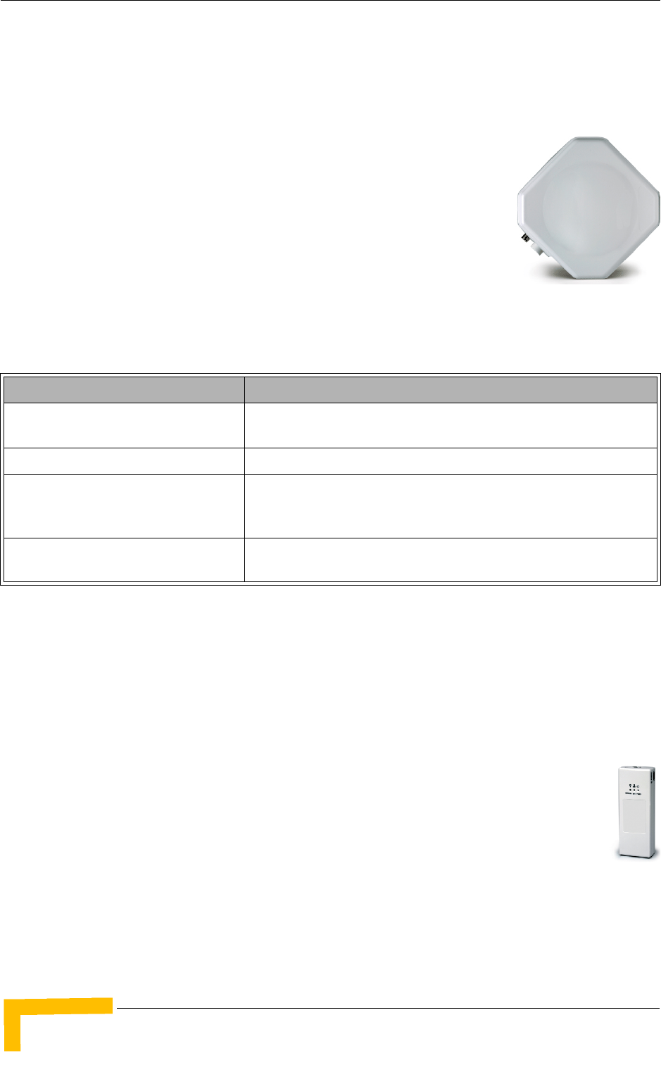
1.2 Introducing BreezeMAX PRO-S CPE
The PRO-S CPE comprises an Outdoor Unit (ODU) and an Indoor Unit (IDU).
The ODU includes the modem, radio, data processing and
management components of the SU. It also includes an
integral high-gain flat antenna (SA models) or a connection
to an external antenna (SE models), as described in
Table 1-2. “L” (Limited Performance) models of the CPEs
support a limited overall throughput of 2 Mbps maximum.
These L-models can be upgraded to support maximum
throughput through a suitable license. The ODU connects
to the IDU and to the user's equipment through a 10/100BaseT Ethernet port.
* x.x indicates the radio band: 2.3, 2.5, 3.3, 3.5 or 3.6
The indoor unit is powered from the mains and connects to the ODU via a
Category 5E Ethernet cable carrying the Ethernet data between the two units, as
well as power (-54 VDC) and control signals to the ODU and status indications
from the ODU.
There are several types of indoor units:
The BMAX-CPE-IDU-1D is the basic IDU, functioning as a simple
power supply and interface unit with a 10/100BaseT Ethernet port
that connects to the user's equipment.
The IDU-NG-4D1W Wireless Networking Gateway IDU provides
advanced routing capabilities and can also serve as a Wireless LAN Access
Point.
Table 1-2: PRO-S CPE ODU Types
ODU Type Description
BMAX-CPE-ODU-PRO-SA-x.x Subscriber Outdoor Unit with an integrated vertical/horizontal
polarization antenna.
BMAX-CPE-ODU-PRO-SE-x.x Subscriber Outdoor Unit with a connection to an external antenna.
BMAX-CPE-ODU-PRO-L-SA-x.x Subscriber Outdoor Unit with an integrated vertical/horizontal
polarization antenna. The unit's total throughput is limited to 2 Mbps
maximum.
BMAX-CPE-ODU-PRO-L-SE-x.x Subscriber Outdoor Unit with a connection to an external antenna. The
unit's total throughput is limited to 2 Mbps maximum.

Introducing BreezeMAX PRO-S CPE
BreezeMAX CPEs Product Manual 5
The IDU-1D1V and IDU-1D2V SIP Voice Gateway IDUs provide one or two
telephony ports and include a backup battery to ensure uninterrupted service
during power outages.
To facilitate the configuration process, antenna alignment and performance
monitoring during installation/testing, a special Y-cable is available. This enables
connecting a Notebook or a PDA directly to the ODU for fast and easy completion
of all the necessary operations.
A miniature SU Alignment Unit (SAU), that includes signal strength and status
indicators, is also available to support easy and convenient antenna alignment
and status verification.

6BreezeMAX CPEs Product Manual
Chapter 1 - Products Description
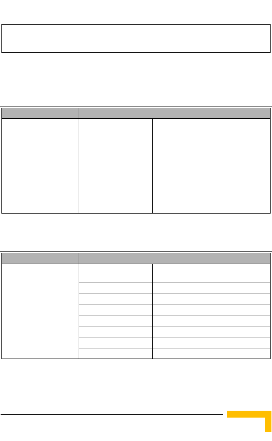
1.3 Introducing BreezeMAX Si CPE
The Self Install Si CPE is a compact Subscriber Unit (SU) that is intended for
indoor installations.
The Si CPE includes embedded capabilities and supplementary tools
that support easy installation by a non-professional user, supporting
fully automated network-entry, authentication and services
provisioning. The Base Station equipment and the Si CPE also
include advanced capabilities that significantly increase the link
budget in both directions to ensure optimal performance in indoors
installations, providing a highly effective solution for self-installation
by end-users.
The Si CPE includes 6 internal antennas providing full 360° coverage, and a
connection to an optional wall/window detached antenna. The Si CPE connects to
the end-user equipment through a 10/100 BaseT Ethernet interface.

Voice and Networking Gateways
BreezeMAX CPEs Product Manual 7
1.4 Voice and Networking Gateways
The following Gateways are currently available from Alvarion:
IDU-NG-4D1W: A Networking Gateway with advanced routing capabilities that
serves also as an IDU for the PRO-S CPE, supporting 4 data ports and 1
Wireless LAN port.
VG-1D1V: A stand-alone (external) SIP Voice Gateway, connecting to the
Ethernet port of the CPE and supporting 1 data port and 1 POTS port.
VG-1D2V: A stand-alone (external) SIP Voice Gateway, connecting to the
Ethernet port of the CPE and supporting 1 data port and 2 POTS ports.
IDU-1D1V: A SIP Voice Gateway with battery backup that serves also as an
IDU for the PRO-S CPE, supporting 1 data port and 1 POTS port.
IDU-1D2V: A SIP Voice Gateway with battery backup that serves also as an
IDU for the PRO-S CPE, supporting 1 data port and 2 POTS ports.
The Self Install Voice (Si-V)I unit acts as a bridge between the Si CPE and the
subscriber’s LAN, with either one or two POTS ports providing SIP based VoIP
services and a battery backup for both the SRU and the Si CPE.
Details on installing, managing and using the Voice Gateways, the Wireless
Networking Gateway and the Si-V are provided separately in the relevant
manuals.

8BreezeMAX CPEs Product Manual
Chapter 1 - Products Description
1.5 PRO-S CPE Specifications
1.5.1 Radio
Table 1-3: PRO-S CPE Radio Specifications
Item Description
Frequency Band TDD Frequencies (MHz) FDD Frequencies (MHz)
2.3 GHz 2300-2360 Not Applicable
2.5 GHz g 2496-2690 Not Applicable
3.3 GHz 3300 - 3400 Uplink: 3366-3400
Downlink: 3316-3350
3.5 GHz 3399.5-3600 Uplink: 3399.5-3500
Downlink: 3499.5-3600
3.6 GHz 3650-3700 Uplink: 3600-3700
Downlink: 3700-3800
Operation Mode TDD, Half Duplex
FDD, Half duplex (3.x GHz band only)
Channel Bandwidth 1.75 MHz (only in FDD mode in the 3.3/3.5 GHz bands)
3.5 MHz
5 MHz (only in TDD mode)
Central Frequency
Resolution
0.125 MHz
Antenna Port
(PRO-SE CPEs)
N-Type, 50 Ohm
2.3 GHz Integral
Antenna (PRO-SA CPE)
14 dBi typical, 33°AZ x 27°EL, vertical/horizontal polarization, compliant with RoHS and
EN 301 525, V1.1.1 (2000-06).
2.5 GHz Integral
Antenna (PRO-SA CPE)
14 dBi typical, 33°AZ x 27°EL, vertical/horizontal polarization, compliant with RoHS and
EN 301 525, V1.1.1 (2000-06).
3.x GHz Integral
Antenna (PRO-SA CPE)
16.5 dBi typical (16 dBi in the 3.3-3.4 GHz band), 20°AZ x 20°EL, vertical/horizontal
polarization, compliant with RoHS and EN 302 085, V1.2.2 (2003-08) Range 1
Max. Input Power
(at antenna port)
-20 dBm before saturation
0 dBm before damage
Output Power
(at antenna port)
2.x, 3.3, 3.5 GHz units: 19 dBm +/-1 dB maximum
3.6 GHz units: 20 dBm +/-1 dB maximum
ATPC Dynamic range: 45 dB
PRO-S CPE Specifications
BreezeMAX CPEs Product Manual 9
1.5.2 Sensitivity
1.5.2.1 Sensitivity, 2.x GHz Units
1.5.2.2 Sensitivity, 3.x GHz Units
Modulation Downlink: OFDM; Uplink: OFDMA-16
BPSK, QPSK, QAM16, QAM64
FEC Convolutional Coding: 1/2, 2/3, 3/4
Table 1-4: Sensitivity, 2.x GHz Units
Item Description
Typical Sensitivity
(BER=1E-6), 2.x GHz units
Modulation &
Coding
Minimum
SNR (dB)
Sensitivity (dBm)
@ 3.5 MHz BW
Sensitivity (dBm)
@ 5 MHz BW
BPSK 1/2 2.5 -98 -96
QPSK 1/2 5.9 -95 -93
QPSK 3/4 8.6 -92 -90
QAM16 1/2 11.4 -89 -87
QAM16 3/4 14.8 -86 -84
QAM64 2/3 20 -81 -79
QAM64 3/4 20.9 -80 -78
Table 1-5: Sensitivity, 3.x GHz Units
Item Description
Typical Sensitivity
(BER=1E-6), 3.x GHz units
Modulation &
Coding
Minimum
SNR (dB)
Sensitivity (dBm)
@ 3.5 MHz BW
Sensitivity (dBm)
@ 5 MHz BW
BPSK 1/2 2.5 -99 -97
QPSK 1/2 5.9 -96 -94
QPSK 3/4 8.6 -93 -91
QAM16 1/2 11.4 -89 -87
QAM16 3/4 14.8 -86 -84
QAM64 2/3 20 -81 -79
QAM64 3/4 20.9 -80 -78
Table 1-3: PRO-S CPE Radio Specifications

10 BreezeMAX CPEs Product Manual
Chapter 1 - Products Description
1.5.3 IDU/ODU Communication
1.5.4 Data Communication (Ethernet Port)
1.5.5 Configuration and Management
Table 1-6: PRO-S CPE IDU/ODU Communication
Item Description
Cable Type Category 5E, Outdoor Data Cable, Double Jacket, 4x2x24# FTP
Maximum Length 90 meter
Table 1-7: PRO-S CPE Data Communication (Ethernet Port)
Item Description
Standard Compliance IEEE 802.3 CSMA/CD
Maximum Packet Size (including 4 CRC bytes) 1550 Bytes
Speed 10/100 Mbps, Half/Full Duplex with Auto Negotiation
Table 1-8: PRO-S CPE Configuration and Management
Item Description
Local Management/via Ethernet Port Tel n et
Built-in web configuration server (using PC or PDA with http
browser)
Remote Management Via the Base Station
Software upgrade Using TFTP via the Base Station
Using TFTP via Ethernet port
Configuration upload/download Using TFTP via the Base Station
Using TFTP via Ethernet port

PRO-S CPE Specifications
BreezeMAX CPEs Product Manual 11
1.5.6 Environmental
1.5.7 Standards Compliance, General
Table 1-9: PRO-S CPE Environmental Specifications
Type Unit Details
Operating temperature PRO-S CPE ODU -40°C to 55°C
PRO-S CPE IDU 0°C to 40°C
Operating humidity Outdoor units 5%-95% non condensing, Weather protected
Indoor equipment 5%-95% non condensing
Table 1-10: PRO-S CPE Standards Compliance, General
Type Standard
EMC ETSI EN 301 489-1/4
FCC part 15 Subpart B
Safety EN 60950-1 (CE)
UL 60950 (US)
AS/NZS 3260 (Australia / New Zealand)
Environmental ETS 300 019:
Part 2-1 T 1.2 & part 2-2 T 2.3 for indoor & outdoor
Part 2-3 T 3.2 for indoor
Part 2-4 T 4.1E for outdoor
Radio ETSI EN 301 021 V.1.6.1
ETSI EN 301 753 V.1.2.1

12 BreezeMAX CPEs Product Manual
Chapter 1 - Products Description
1.5.8 Physical and Electrical
1.5.8.1 Mechanical
1.5.8.2 Electrical
1.5.8.3 Connectors
Table 1-11: PRO-S CPE Mechanical Specifications
Unit Dimensions (cm) Weight (kg)
CPE-IDU-1D 14 x 6.6 x 3.5 0.3
CPE-ODU-PRO-SA 21 x 21 x 5.4 1.25
CPE-ODU-PRO-SE 21 x 21 x 5.4 1.13
Table 1-12: PRO-S CPE Electrical Specifications
Item
Power Consumption (IDU+ODU) 2.x GHz units: 25W
3.x GHz units: 22W
ODU Power Consumption 16.5W
CPE-IDU Power Input 100-240 VAC, 47-63 Hz
CPE-ODU-PRO Power Input 54 VDC from the IDU over the indoor-outdoor Ethernet cable
Table 1-13: PRO-S CPE Connectors
Unit Connector Description
CPE-IDU-1D ETHERNET 10/100Base-T (RJ-45).Cable connection to a PC:
StraightCable connection to a hub: Crossed
RADIO 10/100Base-T (RJ-45)
AC IN 3 pin AC power plug
CPE-ODU-PRO-SA/SE IDU COM 10/100Base-T (RJ-45)
SAU Special mini USB
ANT (SE model) N-Type jack, 50 Ohm, lightning protected

Si CPE Specifications
BreezeMAX CPEs Product Manual 13
1.6 Si CPE Specifications
1.6.1 Radio
Table 1-14: Si CPE Radio Specifications
Item Description
Frequency Band TDD Frequencies (MHz) FDD Frequencies (MHz)
2.3 GHz 2300-2360 Not Applicable
2.5 GHz 2496-2690 Not Applicable
3.5 GHz 3399.5-3600 Uplink: 3399.5-3500
Downlink: 3499.5-3600
3.x GHz 3300-3800 Not Applicable
Operation Mode TDD, Half Duplex
FDD, Half duplex (3.5 GHz band only)
Channel Bandwidth 1.75 MHz (only in FDD mode in the 3.5 GHz band)
3.5 MHz
5 MHz (only in TDD mode)
Central Frequency
Resolution
0.125 MHz
Internal Antennas (Si) A beam switching antennas array providing 360° coverage.
Antenna gain (typical): 7 dBi for 2.3/2.5 GHz units, 9 dBi for 3.5 and 3.x GHz units
External Antenna Port SMA, 50 Ohm
Max. Input Power
(at antenna port)
-20 dBm before saturation
0 dBm before damage
Output Power
(at antenna port)
2.3 GHz: 23 dBm +/- 1 dB maximum
2.5 GHz: 24 dBm +/- 1 dB maximum
3.5 GHz: 22 dBm +/- 1 dB maximum
3.x GHz: 23 dBm +/- 1 dB maximum
ATPC Dynamic range: 45 dB minimum
Modulation Downlink: OFDM; Uplink: OFDMA-16
BPSK, QPSK, QAM16, QAM64
FEC Convolutional Coding: 1/2, 2/3, 3/4

14 BreezeMAX CPEs Product Manual
Chapter 1 - Products Description
1.6.2 Data Communication (Ethernet Port)
Typical Sensitivity
(BER=1E-6), 2.x GHz
Modulation
& Coding
Minimum
SNR (dB)
Sensitivity (dBm)
@ 3.5 MHz BW
Sensitivity (dBm)
@ 5 MHz BW
BPSK 1/2 2.5 -96 -94
QPSK 1/2 5.9 -93 -91
QPSK 3/4 8.6 -90 -88
QAM16 1/2 11.4 -87 -85
QAM16 3/4 14.8 -84 -82
QAM64 2/3 20 -78 -77
QAM64 3/4 20.9 -78 -76
Typical Sensitivity
(BER=1E-6), 3.5/3.x GHz
Modulation
& Coding
Minimum
SNR (dB)
Sensitivity (dBm)
@ 3.5 MHz BW
Sensitivity (dBm)
@ 5 MHz BW
BPSK 1/2 2.5 -98 -96
QPSK 1/2 5.9 -95 -93
QPSK 3/4 8.6 -92 -90
QAM16 1/2 11.4 -88 -86
QAM16 3/4 14.8 -85 -83
QAM64 2/3 20 -80 -78
QAM64 3/4 20.9 -79 -77
Table 1-15: Si CPE Data Communication (Ethernet Port)
Item Description
Standard Compliance IEEE 802.3 CSMA/CD
Maximum Packet Size (including 4 CRC bytes) 1550 Bytes
Speed 10/100 Mbps, Half/Full Duplex with Auto Negotiation
Table 1-14: Si CPE Radio Specifications

Si CPE Specifications
BreezeMAX CPEs Product Manual 15
1.6.3 Configuration and Management
1.6.4 Standards Compliance, General
Table 1-16: Si CPE Configuration and Management
Item Description
Local Management and Configuration Telnet via Ethernet Port
Built-in web configuration server (using PC or PDA with http
browser) via Ethernet Port
Si CPE Installation Utility
Smart Card
Remote Management Via the Base Station
Software upgrade Using TFTP via the Base Station
Using TFTP via Ethernet port
Configuration upload/download Using TFTP via the Base Station
Using TFTP via Ethernet port
Table 1-17: Si CPE Standards Compliance, General
Type Standard
EMC ETSI EN 301 489-1/4
FCC part 15 Subpart B
Safety EN 60950-1 (CE)
UL 60950 (US)
AS/NZS 3260 (Australia / New Zealand)
Environmental ETS 300 019:
Part 2-1 T 1.2 & part 2-2 T 2.3 for indoor & outdoor
Part 2-3 T 3.2 for indoor
Part 2-4 T 4.1E for outdoor
Radio ETSI EN 301 021 V.1.6.1
ETSI EN 301 753 V.1.2.1

16 BreezeMAX CPEs Product Manual
Chapter 1 - Products Description
1.6.5 Environmental
1.6.6 Physical and Electrical
1.6.6.1 Mechanical and Electrical
1.6.6.2 Connectors
Table 1-18: Si CPE Environmental Specifications
Type Details
Operating temperature -5°C to 45°C
Operating humidity 5%-95% non condensing
Table 1-19: Si CPE Mechanical and Electrical Specifications
Item
Dimensions (mm) 167 (H) x 170 (L) x 79 (W)
Weight (g) 650
Power Consumption 10W typical, 12W maximum
DC Power Input (from Power Supply) 7.3 VDC
Mains Power Input (to Power Supply) 90-256 VAC, 47-63 Hz
Table 1-20: Si CPE Connectors
Connector Description
ETHERNET 10/100Base-T (RJ-45) with two embedded LEDs. Cable connection to a
PC: Straight Cable connection to a hub: Crossed
DC IN Standard DC power jack
Antenna SMA jack, 50 Ohm

Si CPE Specifications
BreezeMAX CPEs Product Manual 17
1.6.7 Detached 3.5 GHz Antenna
1.6.8 Detached 2.3/2.5 GHz Antenna
Table 1-21: Si CPE Detached 3.5 GHz Antenna Specifications
Item
Frequency Range 3400 - 3700 MHz
Gain (excluding cable) 14 dBi max. (RF cable loss is 3 dB)
Polarization Linear-Vertical
Beam Width 77° Horizontal, 17° vertical
Connector SMA jack
Dimensions (cm) 33 x 9.3 x 2.1
Weight (g) 190
Table 1-22: Si CPE Detached 2.3/2.5 GHz Antenna Specifications
Item
Frequency Range 2300-2700 MHz
Gain (excluding cable) 9.5~10.5 dBi
Polarization Linear-Vertical
Beam Width 70° Horizontal, 20° vertical
Connector SMA jack
Dimensions (cm) 32.7 x 8 x 2.2
Weight (g) 600


20 BreezeMAX CPEs Product Manual
Chapter 2 - Installation
2.1 Installing the ODU of the PRO-S CPE
The following sections describe how to install the outdoor unit (ODU) of the PRO-S
CPE.
2.1.1 ODU Installation Requirements
2.1.1.1 Packing List
ODU
Pole mounting kit
2.1.1.2 Additional Installation Requirements
The following items are also required to install the ODU:
Indoor-to-outdoor Category 5E Ethernet cable with two shielded RJ-45
connectors* (see Section 2.1.3 for details on approved cables and maximum
length), and an RJ-45 connectors crimping tool.
For units that connect to an external antenna (SE model): Antenna* and RF
cable* for connecting the antenna to the ODU.
SAU* (SU Alignment Unit) for antenna alignment and status verification.
Grounding cable with an appropriate termination.
Installation tools and materials, including appropriate means (e.g. a 1" to 4"
pole) for installing the ODU (and antenna where applicable).
2.1.1.3 Optional Items
Tilt Pole Mounting kit*.
To connect directly to the ODU for configuration/performance monitoring: A
special Y-cable*, a Notebook or Pocket PC/PDA with web browser, and a
straight Ethernet cable to connect the Notebook/PDA to the PDA connector
(RJ-45 plug) of the Y-cable.

Installing the ODU of the PRO-S CPE
BreezeMAX CPEs Product Manual 21
2.1.2 Guidelines for Positioning the ODU
This section provides key guidelines for selecting the optimal installation locations
for the ODU.
Select the optimal locations for the equipment using the following guidelines:
The ODU should be mounted on a 1"-4" pole. Its location should enable easy
access to the unit and its connectors for installation and testing.
The higher the placement of the antenna, the better the achievable link
quality.
The antenna should be installed to provide a direct, or near line of sight with
the Base Station antenna. The antenna should be aligned to face the general
direction of the Base Station.
In some cases it might be necessary to up/down-tilt the antenna. An optional
Tilt accessory for the ODU providing a tilt range of +/-15° is available from
Alvarion. The tilt option might be necessary to either improve the link
conditions or, if the SU is too close to the Base Station, to reduce the receive
signals strength. As a rule of thumb, if the SU is located at a distance of less
than 300 meters from the Base Station, it is recommended to up-tilt the
antenna by approximately 10° to 15° (especially in line-of-sight conditions) to
avoid saturation of the receivers by too strong signals.
Outdoor units with a connection to an external antenna should be installed as
close as possible to the antenna.
NOTE
Items marked with an asterisk (*) are available from Alvarion.
CAUTION
ONLY experienced installation professionals who are familiar with local building and safety codes
and, wherever applicable, are licensed by the appropriate government regulatory authorities should
install outdoor units and antennas.
Failure to do so may void the BreezeMAX product warranty and may expose the end user or
Service Provider to legal and financial liabilities. Alvarion and its resellers or distributors are not
liable for injury, damage or regulation violations associated with the installation of Outdoor Units or
antennas.
22 BreezeMAX CPEs Product Manual
Chapter 2 - Installation
2.1.3 IDU-ODU Cables
Use only Category 5E Ethernet cables from either Alvarion or any of the approved
manufacturers, listed in Table 2-1. Consult with Alvarion's specialists on the
suitability of other cables.
In case of missing information in the manufacturer's WEB site (product
specifications, ordering issues, etc.), it is highly recommended to contact the
manufacturer's sales representative directly.
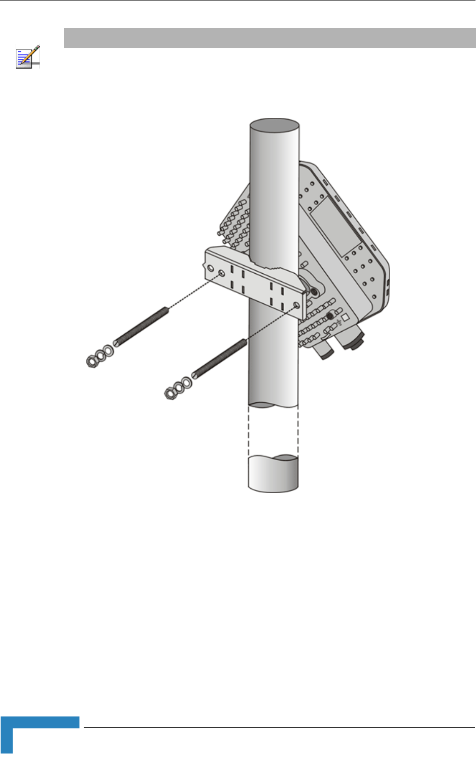
2.1.4 Pole Mounting the ODU
The ODU can be mounted on a 1" to 4" pole using one of the following options:
A pole mounting kit is supplied with each unit. The kit includes a special
clamp and a pair of threaded rods, flat washers, spring washers and nuts.
There are two pairs of threaded holes on the back of the unit, enabling to use
NOTE
The length of the Indoor-to-Outdoor cable should not exceed 90 meters. The length of the
Indoor-to-Outdoor cable, together with the length of the Ethernet cable connecting the CPE-IDU-1D
to the data equipment, should not exceed 100 meters.
Table 2-1: Approved Category 5E Ethernet Cables
Manufacturer Part Number
Superior Cables Ltd.
www.superior-cables.com
612098
HES Cabling Systems
www.hescs.com
H5E-00481
Tel d or
www.teldor.com
8393204101
Southbay Holdings Limited
11th Fl., 15, Lane 347, Jong Jeng Rd.
Shin Juang City, Taipei County
Taiwan, R.O.C.
Attn: Eva Lin
Tel. 886-2-2832 3339
Fax. 886-2-2206 0081
E-mail: eva@south-bay.com.tw
TSM2404A0D
GU-Tech., LLC . - A Member of OVIS GroupTel/Fax :
732 918 8221 Mobile: 718 909 4093
www.OVIS.COM.TW www.GU-TECH.COM
Installing the ODU of the PRO-S CPE
BreezeMAX CPEs Product Manual 23
the mounting kit for installing the unit using either vertical or horizontal
polarization. The clamp enables installing the unit on diverse pole diameters
from 1" to 4".
A Tilt Pole Mounting kit, providing a tilt range of +/-15° is available from
Alvarion. The Tilt kit can be attached to the ODU and be mounted on a 1" to 4"
pole using two 9/16" wide metal bands.
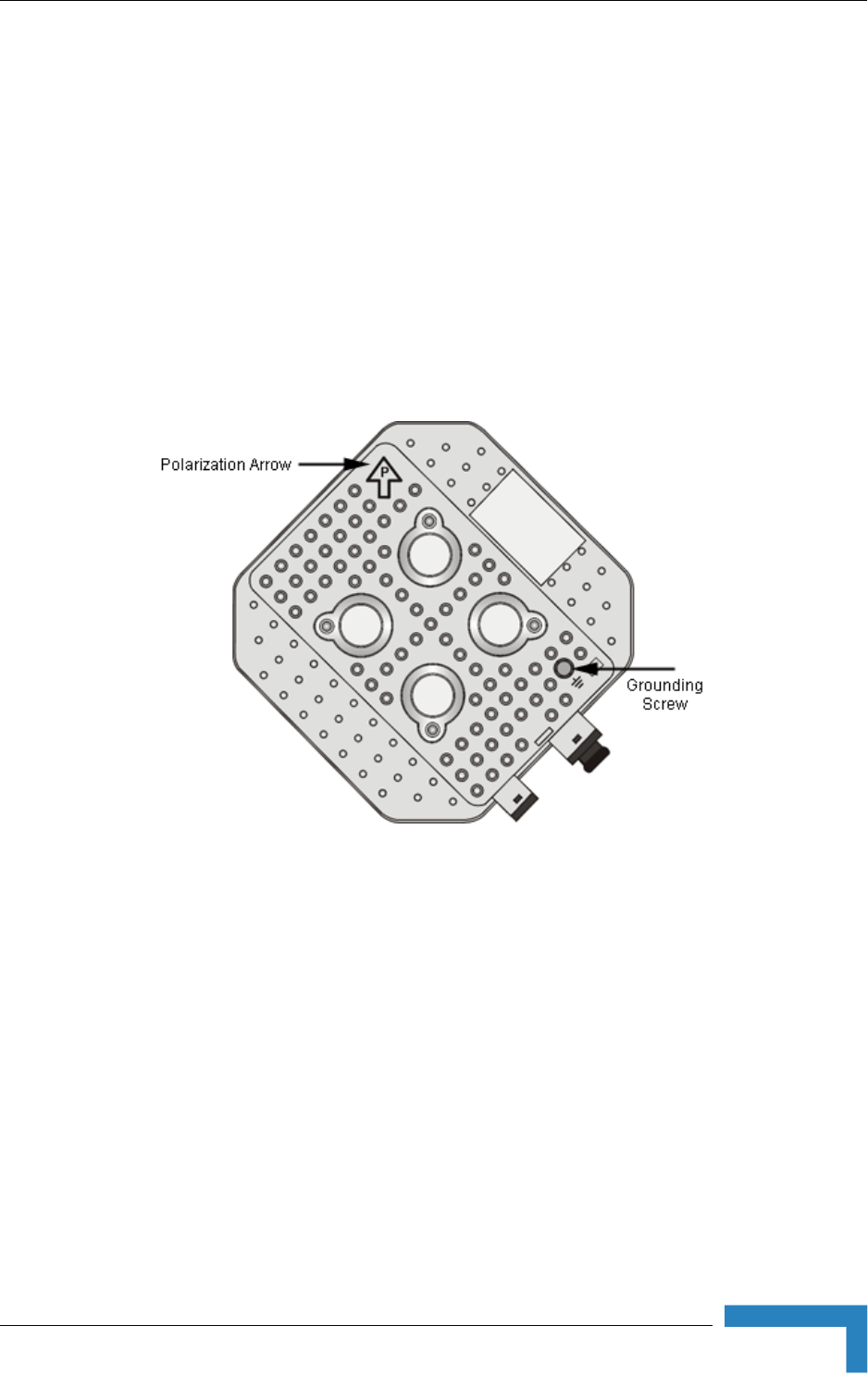
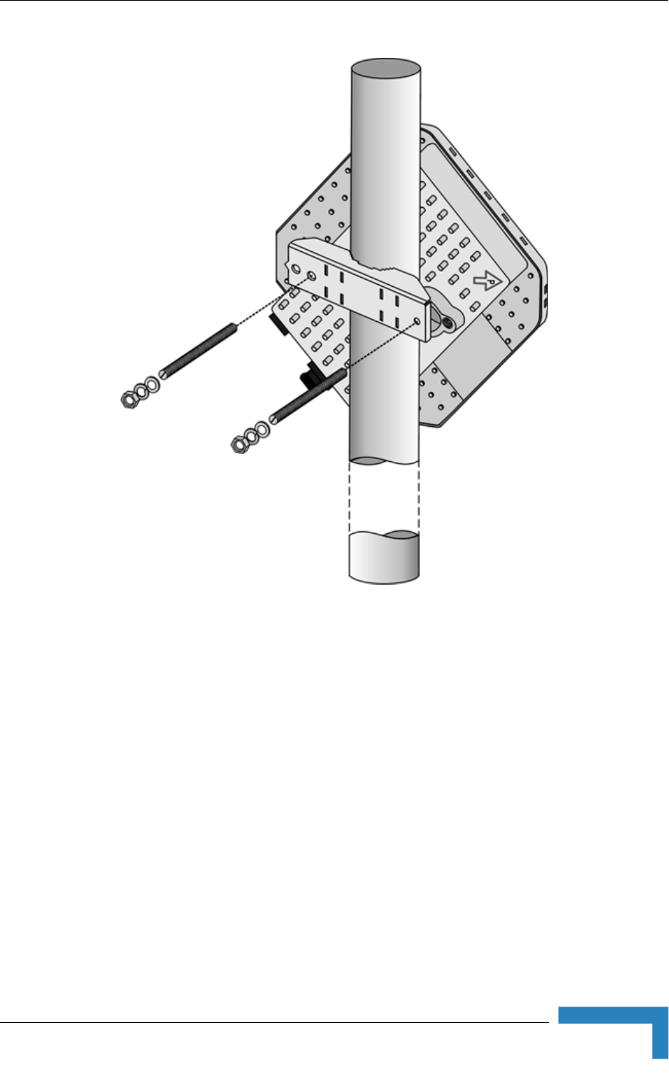
2.1.4.1 Polarization
The ODU with integral antenna can be pole mounted to provide either vertical or
horizontal polarization.
The Polarization Arrow on the back of the unit indicates the type of polarization.
For vertical polarization install the unit with the Polarization Arrow pointing
upward (as in the figure above).
For horizontal polarization install the unit with the Polarization Arrow pointing
sideward and the connectors facing downward.
2.1.4.2 Pole Mounting the ODU Using the Clamp
Figure 2-2 and Figure 2-3 illustrate how to mount an ODU on a pole, using the
clamp and threaded rods.
Figure 2-1: Back View of CPE-ODU-PRO-SA (integral antenna)
24 BreezeMAX CPEs Product Manual
Chapter 2 - Installation
NOTE
There is a groove on one end of the threaded rod. Insert the rods with the grooves pointing outward,
and fasten them to the unit using a screwdriver.Install the unit with the bottom panel, which includes
the connectors, facing downward.
Figure 2-2: ODU Pole Installation Using the Special Clamp, Vertical Polarization
Installing the ODU of the PRO-S CPE
BreezeMAX CPEs Product Manual 25
Figure 2-3: ODU Pole Installation Using the Special Clamp, Horizontal Polarization
26 BreezeMAX CPEs Product Manual
Chapter 2 - Installation
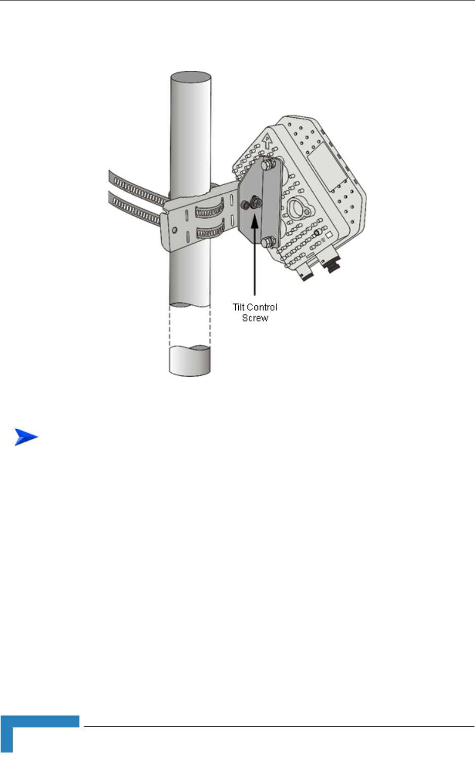
2.1.4.3 Pole Mounting the ODU with the Tilt Accessory
1Attach the Tilt accessory to the ODU using the two pairs of flat washers, spring
washers and nuts supplied in the Tilt kit.
2Mount the Tilt accessory on a 1" to 4" pole using two 9/16" metal bands.
3Release slightly the Tilt Control Screw, tilt the ODU downward/upward as
required, and re-tighten the screw.
Figure 2-4: ODU Pole Installation Using the Tilt Accessory, Vertical Polarization
To mount the ODU on a pole using the Tilt accessory:
Installing the ODU of the PRO-S CPE
BreezeMAX CPEs Product Manual 27
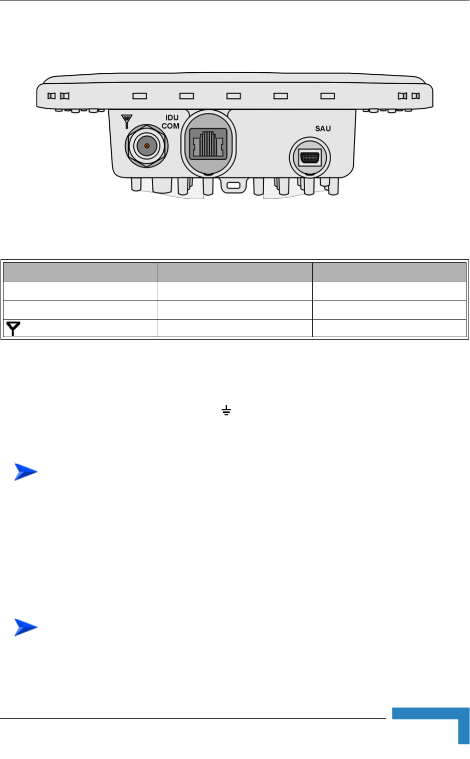
2.1.5 Connectors
2.1.6 Connecting the Cables
2.1.6.1 Connecting the Grounding Cable
The Grounding screw (marked ) is located on the back panel of the ODU (see
Figure 2-1).
1Connect one end of a grounding cable to the grounding screw and tighten the
grounding screw firmly.
2Connect the other end of the grounding cable to a good ground (earth)
connection.
2.1.6.2 Connecting the Antenna Cable
Figure 2-5: Bottom Panel of the ODU (SE model, without sealing covers)
Table 2-2: CPE-ODU-PRO Connectors
Name Connector Functionality
IDU COM 10/100Base-T (RJ-45) Connection to the IDU
SAU Special mini USB Connection to SAU
(ANT, only in SE model) N-Type jack, 50 Ohm Connection to an external antenna
To connect the grounding cable:
To connect the RF cable (units with external antenna):
28 BreezeMAX CPEs Product Manual
Chapter 2 - Installation
1Connect one end of the coaxial RF cable to the RF connector (marked )
located on the bottom panel of the unit.
2Connect the other end of the RF cable to the antenna.
3The RF connectors should be properly sealed to protect against rain and
moisture.
2.1.6.3 Connecting the IDU-ODU Cable
Use a crimp tool for RJ-45 connectors to prepare the wires. Insert them into the
appropriate pins and use the tool to crimp the connector. Make sure to do the
following:
Remove as small a length as possible of the external jacket. Verify that the
external jacket is well inside the sealing cover when connected to the unit, to
ensure good sealing.
Pull back the shield drain wire before inserting the cable into the RJ-45
connector, to ensure a good connection with the connector's shield after
crimping.
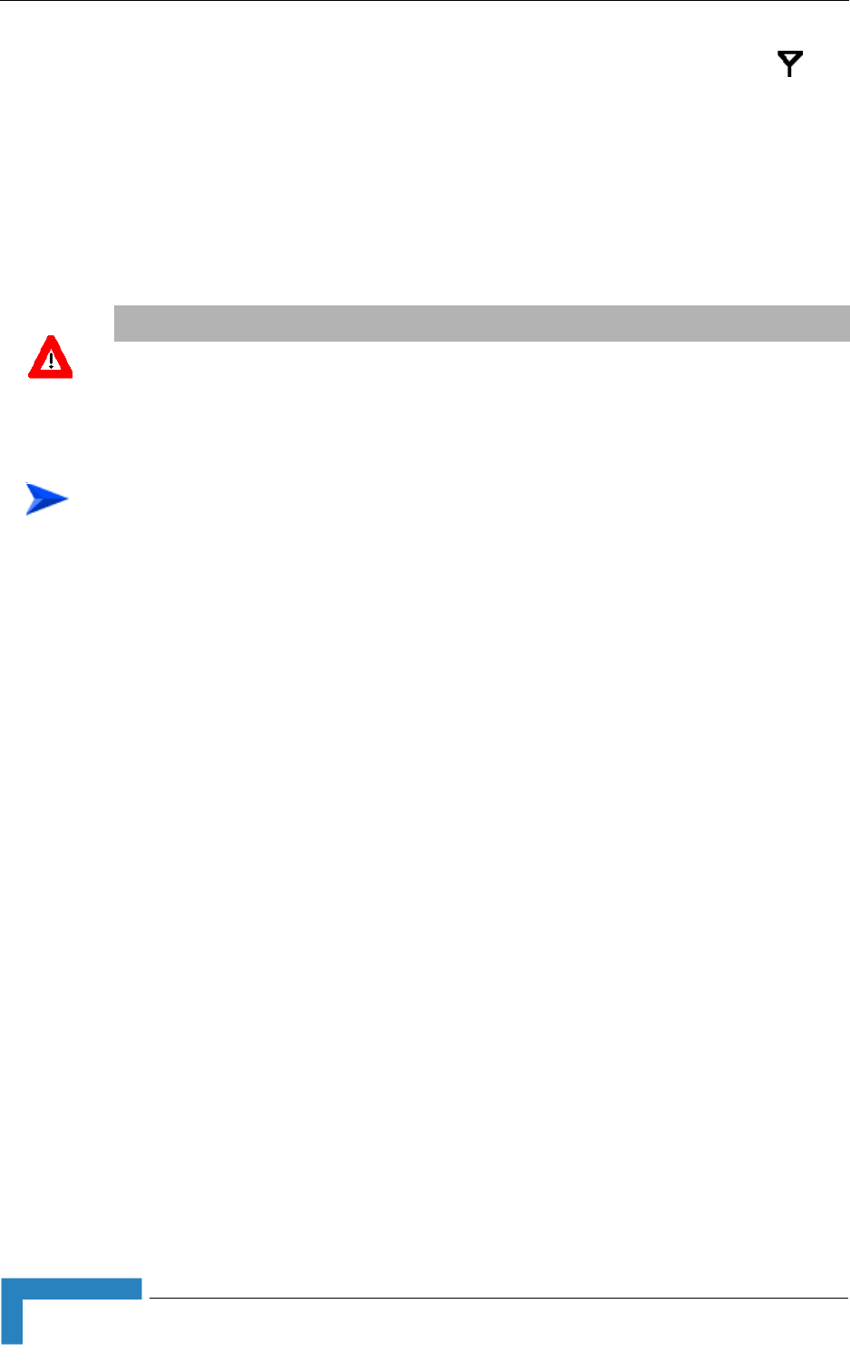
The IDU-ODU cable provides pin-to-pin connection on both ends.
The following figure shows the required wire pair connections.
CAUTION
Use only Category 5E 4x2x24# FTP outdoor cables from an approved manufacturer. See list of
approved cables in Table 2-1.The length of the Indoor-to-Outdoor cable should not exceed 90
meters. The length of the Indoor-to-Outdoor cable, together with the length of the Ethernet cable
connecting the CPE-IDU-1D to the data equipment, should not exceed 100 meters.
To prepare the IDU-ODU cable:
Installing the ODU of the PRO-S CPE
BreezeMAX CPEs Product Manual 29
Data pairs are 1&2, 3&6.
Power pair (proprietary solution) is 4&5.
The color codes used in standard cables supplied by Alvarion are as listed in the
following table:
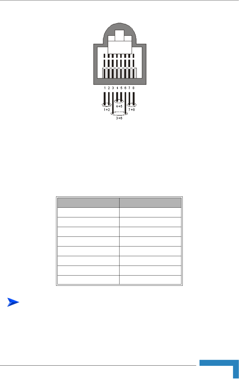
1The sealing cap has a special groove allowing to insert an ethernet cable with
an already assembled RJ-45 connector through the cap. To expose the groove,
Figure 2-6: Ethernet Connector Pin Assignments
Table 2-3: Cable Color Codes
Wire color Pin
Blue 1
Blue/white 2
Orange 3
Orange/white 6
Brown 4
Brown/white 5
Green 7
Green/white 8
To connect the IDU-ODU cable:
30 BreezeMAX CPEs Product Manual
Chapter 2 - Installation
lightly squeeze the cap. Carefully insert the cable with the assembled
connector through the groove.
2Connect the Ethernet cable to the IDU COM RJ-45 connector.
3Put the sealing cap back in its place. Make sure that the small protrusion on
the side of the cap fits inside the hole on the connector's protective body.
4Use appropriate sealing material to protect the connection against moisture
and humidity. Use removable sealing material, such as a tar seal, to enable
future access to the connector.
5Route the cable to the location selected for the indoor equipment.
6Assemble an RJ-45 connector with a protective cover on the indoor end of the
IDU-ODU cable. Refer to the pin assignment and color codes in standard
cables described above.
Figure 2-7: Inserting the IDU COM Cable into the Sealing Cap
Figure 2-8: Connecting the IDU COM connector and inserting the Sealing Cap

Installing the IDU-1D Indoor Unit of the PRO-S CPE
BreezeMAX CPEs Product Manual 31
2.2 Installing the IDU-1D Indoor Unit of the
PRO-S CPE
2.2.1 Installation Requirements
2.2.1.1 Packing List
BMAX-CPE-IDU-1D
Wall mounting kit
Mains power cord
2.2.1.2 Additional Installation Requirements
Ethernet cable(s): a crossed cable if connecting to a hub/switch and a straight
cable if connecting directly to a PC Network Interface Card (NIC).
Mains plug adapter or termination plug (if the power plug on the supplied AC
power cord does not fit local power outlets).
Means for configuring parameters:
»A Portable PC/Notebook and a straight Ethernet cable for configuring
parameters using Telnet. TFTP server SW is required for downloading SW
versions.
Or:
»A Portable PC/Notebook or Pocket PC/PDA and a straight Ethernet cable
for configuring parameters using a web browser.
NOTE
The IDU must be ordered separately. It is not supplied with the ODU.
NOTE
The length of the Ethernet cable connecting CPE-IDU-1D to the user's equipment, together with the
length of the IDU-ODU cable, should not exceed 100 meters.
32 BreezeMAX CPEs Product Manual
Chapter 2 - Installation
Other installation tools and materials (a drill for wall-mounting the unit,
means for securing cables to walls, etc.)
2.2.2 Location
The unit can be placed on a desktop or a shelf. Alternatively, it may be
wall-mounted using the mounting kit and guidelines supplied with the unit.
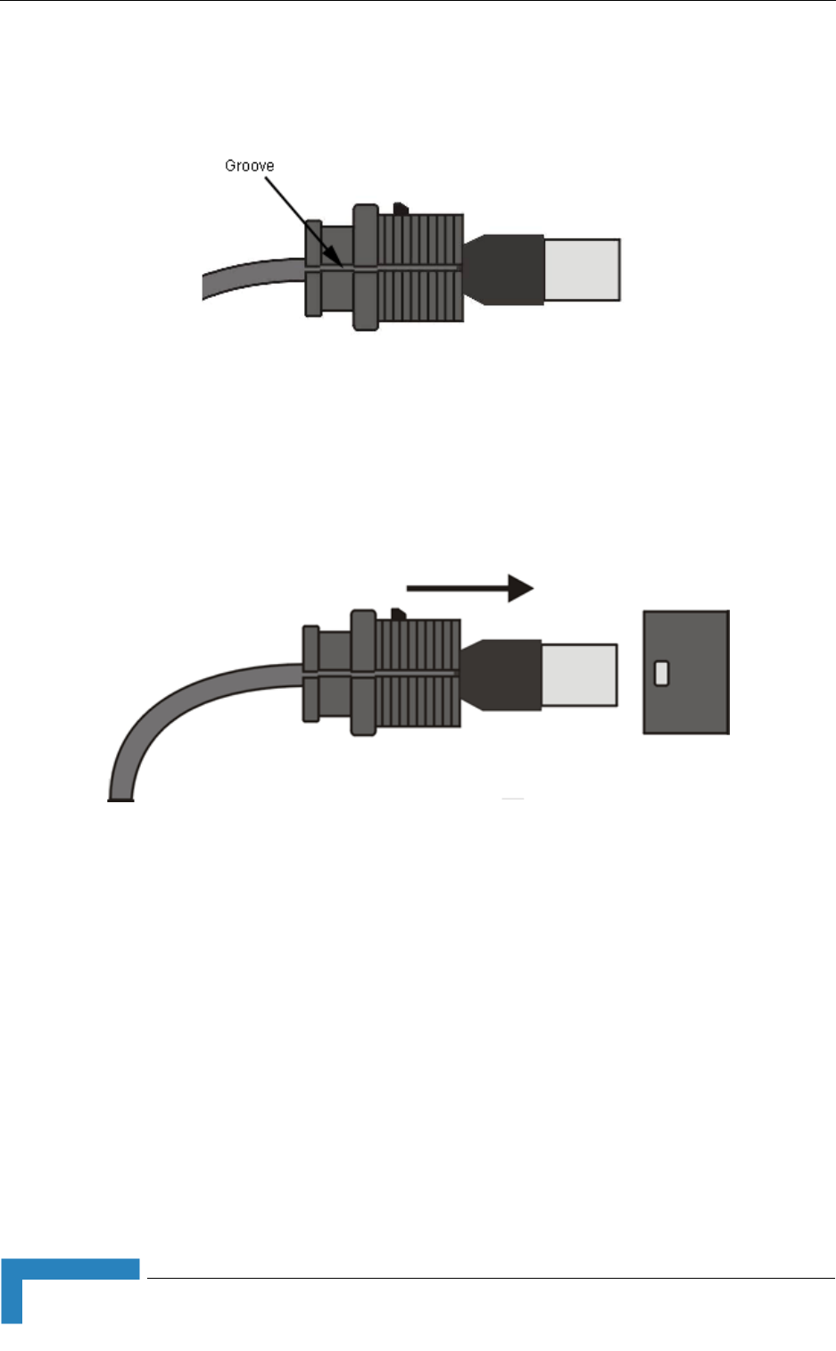
2.2.3 CPE IDU-1D Connectors and LEDs
Figure 2-9: CPE-IDU-1D Front Panel
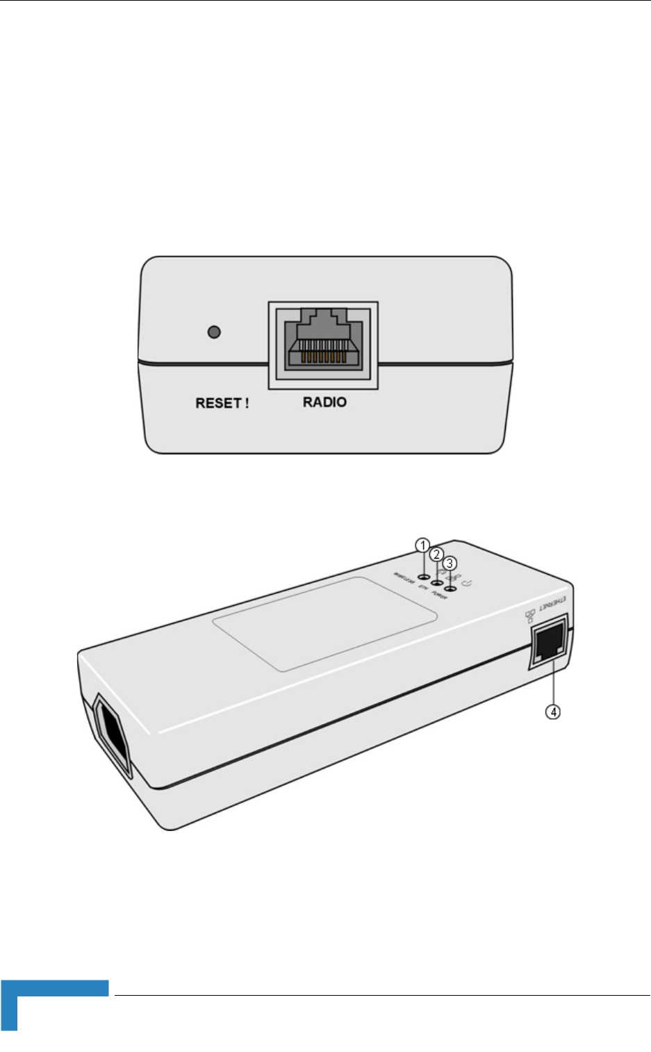
Figure 2-10: CPE-IDU-1D 3D View

Installing the IDU-1D Indoor Unit of the PRO-S CPE
BreezeMAX CPEs Product Manual 33
* After power-up, the WIRELESS LED illuminates until self-test is finished.
2.2.4 RESET Button
The recessed RESET button is located on the front panel of the unit. When
pressed, power to the ODU is disconnected (hard reset).
2.2.5 IDU Installation
Table 2-4: CPE-IDU-1D Connectors
Name Connector Functionality
ETHERNET (4)
(on the side panel)
10/100Base-T (RJ-45) with 2
embedded LEDs
Connection to the user's LAN/PC
Cable connection to a hub/switch/router: Crossed
Cable connection to a PC: Straight
RADIO
(on the front panel)
10/100Base-T (RJ-45) Connection to the ODU
POWER
(on the bottom panel)
3-pin AC Mains power connection
Table 2-5: CPE-IDU-1D LEDs
Name Description Functionality
POWER (3) Power Indication Off - IDU is not powered or power failed
Green - IDU power is OK
ETH (2) Ethernet link status
(Ethernet integrity)
Off - No Ethernet connectivity has been detected between
the outdoor unit and the device connected to the indoor
unit’s data port
Green - Ethernet connectivity has been detected between
the outdoor unit and the device connected to the indoor
unit’s data port
WIRELESS (1) Wireless link status Off - SU is not associated with a Base Station
Green - SU is connected with a Base Station (network
entry completed)
Blinking Green - Authentication failed
To install the IDU:
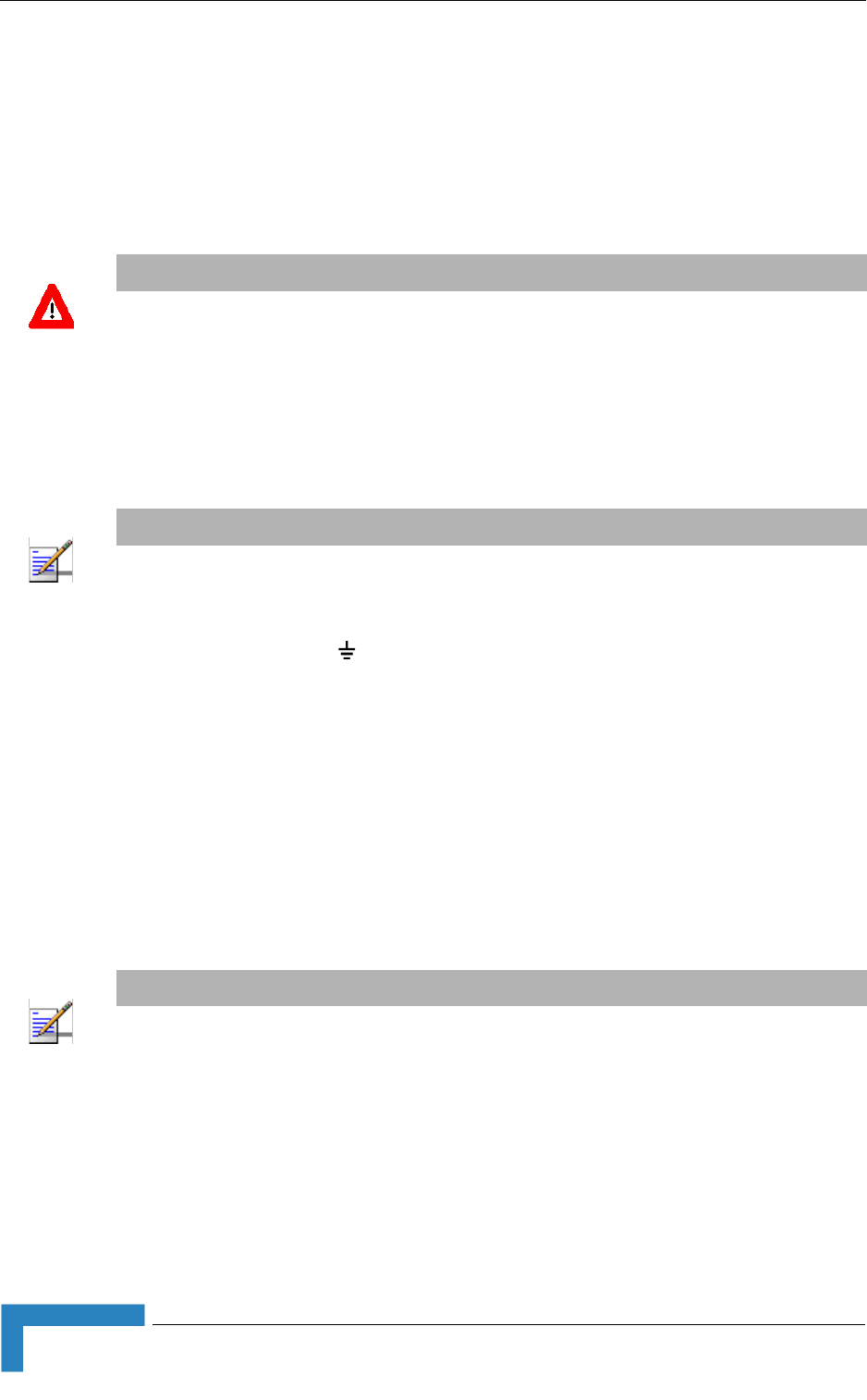
34 BreezeMAX CPEs Product Manual
Chapter 2 - Installation
1It is assumed that the IDU-ODU cable is already connected to the ODU.
Assemble an RJ-45 connector with a protective cover on the indoor end of the
IDU-ODU cable. Refer to Section 2.1.6.3 for instructions on preparing the
cable.
2Connect the IDU-ODU cable to the RADIO connector. The RADIO connector in
the CPE-IDU-1D is located on the front panel as shown in Figure 2-9.
3Connect the power cord to the unit's AC socket, located on the rear panel.
Connect the other end of the power cord to the AC mains after verifying that
the unit is rated for the voltage in the country of use; the AC range is indicated
on the back side of the CPE-IDU-1D.
4Verify that the POWER LED located on the front panel is lit, indicating that the
unit is supplying power to the radio port.
5Configure the basic parameters and align the antenna as described in the
applicable sections of Chapter 3.
6Connect the 10/100 Base-T ETHERNET connector(s) to the data equipment.
The cable connection should be a crossed Ethernet if connecting to a
hub/switch and a straight cable if connecting directly to a PC Network
Interface Card (NIC).
7Verify proper operation as described in the applicable section of Chapter 3.
CAUTION
Do not connect the data equipment to the RADIO port. The RADIO port supplies DC power to the
ODU, and this may harm other equipment connected to it.
NOTE
The color codes of the power cable are as follows:
Brown Phase ~
Blue Neutral 0
Yellow/Green Ground
NOTE
The length of the Ethernet cable connecting CPE-IDU-1D to the user's equipment, together with the
length of the IDU-ODU cable, should not exceed 100 meters.

Installing the Si CPE
BreezeMAX CPEs Product Manual 35
2.3 Installing the Si CPE
The following sections describe how to install the Si CPE.
2.3.1 Installation Requirements
2.3.1.1 Packing List
Si CPE
Power Adapter and Mains Power Cord
2 meters Ethernet Cable
Wall Mounting Bracket kit for the Si CPE.
Smart Card (optional)
A CD with WiMAX Modem Application (optional)
2.3.1.2 Additional/Optional Items
Wall/window mountable detached antenna kit, including wall/window
mounting accessories and a 2 meters SMA-SMA (M/F) RF cable*.
Wall mounting kit with pan/tilt capabilities for the detached antenna*.
Mains plug adapter or termination plug (if the power plug on the supplied AC
power cord does not fit local power outlets).
Portable PC with an Ethernet card and a straight Ethernet cable for
configuring parameters using either Telnet or web browser. TFTP server SW is
required for downloading SW versions.
Other installation tools and materials (means for securing cables to walls,
etc.).
NOTE
Items marked with an asterisk (*) are available from Alvarion.
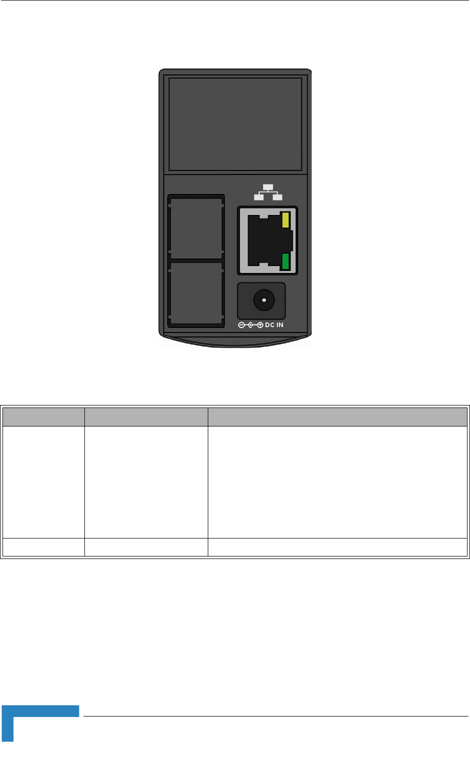
36 BreezeMAX CPEs Product Manual
Chapter 2 - Installation
2.3.2 Si CPE Connectors and LEDs
* After power-up, the Ethernet LEDs illuminate for a few seconds until self-test is
finished.
Figure 2-11: Si CPE Connectors
Table 2-6: Si CPE Front Panel Connectors
Name Connector Functionality
ETHERNET 10/100Base-T (RJ-45) with
2 embedded LEDs
Connection to the user's LAN/PC
Cable connection to a hub/switch/router: Crossed
Cable connection to a PC: Straight
Green LED: Ethernet Integrity. Ethernet connection detected.
Yellow LED: Ethernet Activity indication. Blinks during
transmission/reception of Ethernet packets.
POWER DC Power Jack Connection to Power Adapter
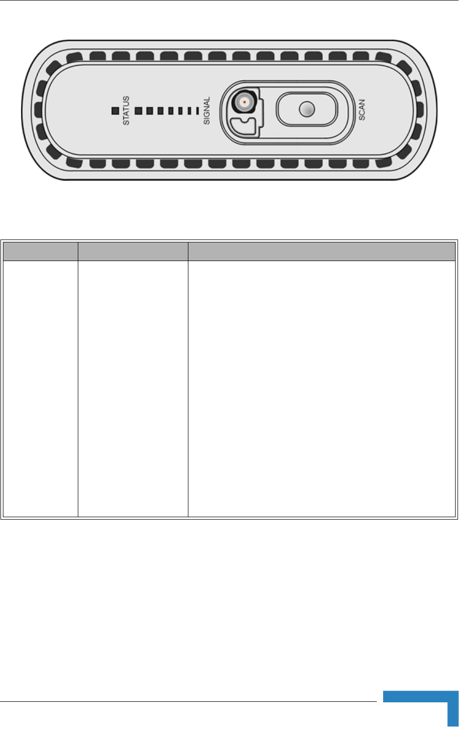
Installing the Si CPE
BreezeMAX CPEs Product Manual 37
Figure 2-12: Si CPE Top View (Without RF Connector's Cover)
Table 2-7: Si CPE Top Panel Components
Name Description Functionality
STATUS S tatus Indication Off - CPE is not powered or power failure
Green - CPE is connected with a base station
Red - CPE failure
Orange - After power-up (if power supply is ok) until start of
self test, after passing self-test until network entry is
completed, or upon restarting the network entry process.
Blinking Orange - CPE is being set to Factory Defaults (during
6 seconds after pressing the RESET button for more than 5
seconds. The RESET button is not available in new units with
RF Version 11 ).
Blinking Green - If SIGNAL LEDs 5, 6 and 7 are on:
Authentication reject by RADIUS server.
If SIGNAL LEDS 6 and 7 are on: Rejected by Base Station
(Duplicate SU Name in database).
If LED 7 is on: Authentication Timeout, re-authentication failure
(connection to RADIUS server lost or Shared Secret
mismatch).

38 BreezeMAX CPEs Product Manual
Chapter 2 - Installation
* After power-up, the SIGNAL LEDs illuminates for a few seconds until self-test is
finished.
SIGNAL Link Quality Indication LEDS 1 - 7 Off, STATUS is green: 3 dB ≤ SNR < 5 dB
LED 1 On: 5 dB ≤ SNR < 8 dB
LEDs 1 - 2 On: 8 dB ≤ SNR < 12 dB
LEDs 1 - 3 On: 12 dB ≤ SNR < 15 dB
LEDs 1 - 4 On: 15 dB ≤ SNR < 18 dB
LEDs 1 - 5 On: 18 dB ≤ SNR < 20 dB
LEDs 1 - 6 On: 20 dB ≤ SNR < 25 dB
LEDs 1 - 7 On: SNR ≥ 25 dB
LEDs 1 - 7 Blinking simultaneously ((300ms on, 300ms off):
RSSI ≥ -20 dBm (saturation)
LEDs 1 - 7 Blinking one after the other (LED-1: 200ms on then
off, LED-2: 200ms on then off, up to LED-7 and then LED-1
again): During full frequency scan.
LEDs 1 - 7 Blinking as follows: LED 4 lights, after 200ms LEDs
3 & 5 light, after 200ms LEDs 2&6 light, after 200ms LEDs 1&7
light, after 200ms all the LEDs are extinguished and then the
sequence is repeated. During Best AU selection process.
SCAN button Initiating Scanning Mode Press for less than 3 seconds to initiate Best AU selection
process without full scanning. It means that the CPE scans
only the AUs detected in the last full scan. For each AU, all
relevant antennas are scanned. The LEDs will be blinking as
mentioned above for Best AU operation.
Press for 3 seconds or more to initiate full scan, prepare an
updated best AU list and select the best AU. The LEDs will be
blinking as mentioned above for full scan operation.
RF (behind cap) SMA Jack Connection to detached antenna
Table 2-7: Si CPE Top Panel Components
Name Description Functionality
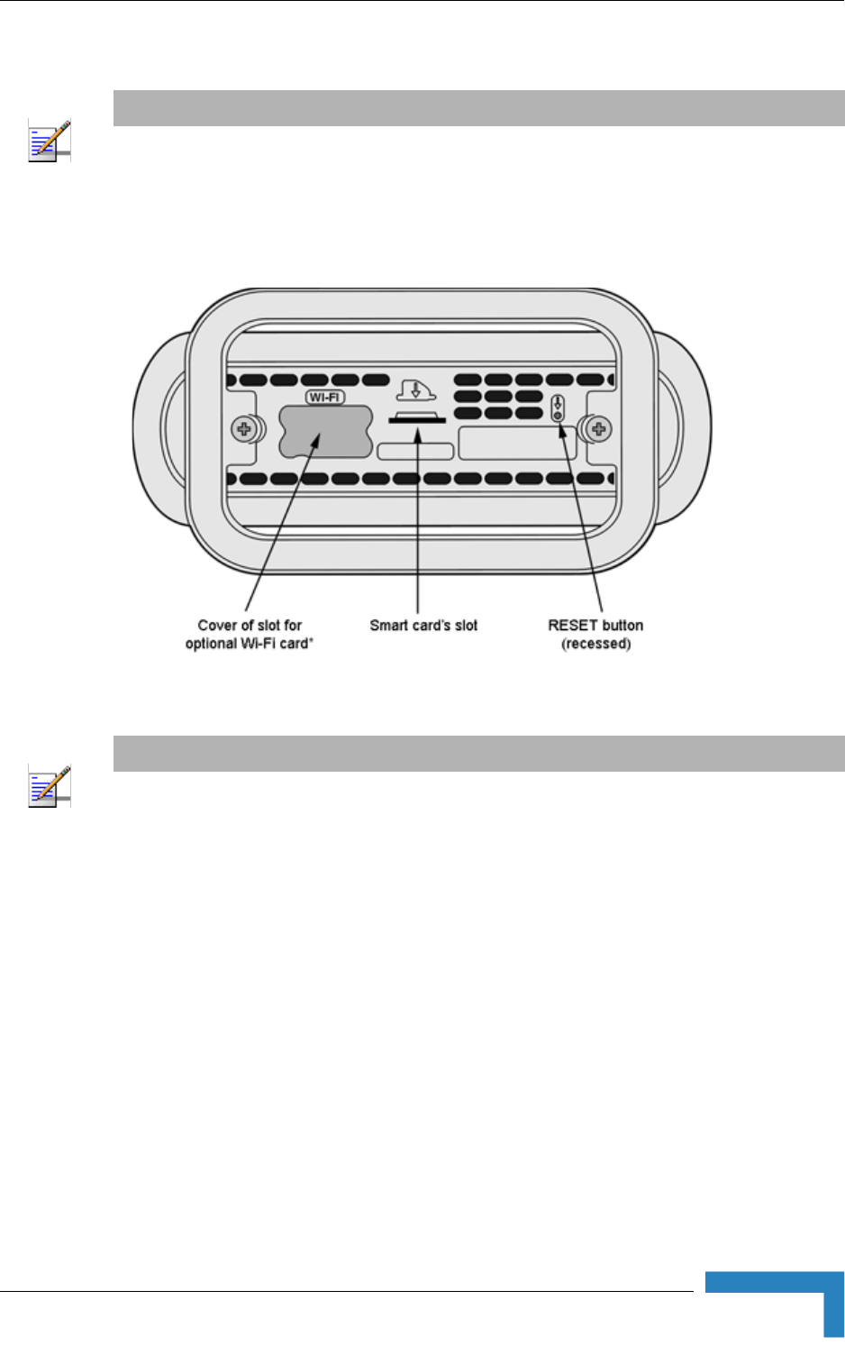
Installing the Si CPE
BreezeMAX CPEs Product Manual 39
2.3.3 RESET Button
The RESET button is located on the bottom side of the unit:
Press the recessed RESET button briefly (for less than 5 seconds) to reset the unit
and restart the network entry process. The unit will try for 60 seconds to connect
to the last used AU. If not found, it will try the next AU in the best AU list. The
same behavior shall be implemented for power-up.
Press the RESET button for 5 seconds and more to load the factory defaults and
reset the unit after 6 seconds, to perform full scan with factory defaults. If the
Installation Utility application is connected the user will be requested to confirm
the operation.
NOTE
RESET button is not available in units with RF Version 11.
Figure 2-13: Si CPE Bottom View
NOTE
* WI-FI option is not supported in the current version. The slot is used for connecting to Si-V.

40 BreezeMAX CPEs Product Manual
Chapter 2 - Installation
2.3.4 Installation Guidelines
The unit can be placed on a desktop or a shelf. It can also be wall mounted using
the optional bracket available from Alvarion. It can be configured to use either one
of its six internal antennas or a detached antenna (optional). Instructions for the
available installation options of the detached antenna are provided in the antenna
package and in Section 2.4.
It is recommended to position the unit near a window facing the direction of
the Base Station, with the selected antenna aimed at the direction of the Base
Station. Do not cover the unit. Leave a free space of at least 50 cm around the
unit. Do not place any object between the selected antenna and the window
towards which the antenna is directed.
When a detached antenna is used, install it on a window or on a wall
according to specific conditions of the location. The antenna should be facing
the required direction. Use only the RF cable supplied with the antenna (if
needed, use a longer Ethernet cable).
Avoid metal obstacles such as metal window frames or metal film anti-glare
windows in the transmission path.
Position the unit (or the detached antenna) away from electrical equipment,
including the data equipment, monitor etc., metal furniture, and moving metal
objects such as metal fans or doors.
2.3.5 Installing the Si CPE
2.3.5.1 Connecting the Si CPE
1If a Smart Card for the unit is available, insert it in the intended slot at the
bottom side of the unit.
2If a CD with WiMAX Modem Application is supplied with the unit, refer to the
documentation of the WiMAX Modem Application.
1Connect the Power Adapter DC cable to the POWER jack. Connect the AC
power cord to the Power Adapter. Connect the other end of the power cord to
the AC mains.
To install the Si CPE:

Installing the Si CPE
BreezeMAX CPEs Product Manual 41
2Verify that the orange Status LED located on the unit's top panel illuminates,
indicating that the power supply to the unit is OK and the unit is not yet
connected to a Base Station (the LED will change to green when the unit is
connected to a Base Station).
3If a detached antenna is used, remove the cap on the unit's top panel to expose
the RF connector and connect to it the RF cable supplied with the antenna.
Install the antenna using the instructions provided in Section 2.4 on page 42,
and connect to it the other end of the RF cable. To tighten the SMA connectors,
use only the torque key supplied with the antenna.
4Configure the basic parameters as described in Section 3.3.1.
5Align the antenna as described in Section 3.5.
6Connect the 10/100 Base-T ETHERNET connector to the data equipment. The
cable connection should be a crossed Ethernet if connecting to a hub/switch
and a straight cable if connecting directly to a PC Network Interface Card
(NIC).
Verify proper operation of the Ethernet link. The Ethernet Integrity green LED
should be on and the Ethernet Activity yellow LED should blink when there is
Ethernet traffic. To verify data connectivity from the end-user's PC or from a
portable PC connected to the unit, ping a known device in the network, or try
connecting to the Internet.
2.3.5.2 Wall Mounting the Si CPE
The wall mounting kit for the Si CPE includes a bracket, 2 screws, and 2 plastic
anchors. Refer to Figure 2-14.
1If anchors are needed (wall-board, plaster board, etc.), drill two holes for the
anchors using a 6 mm drill bit and insert anchors. The distance between the
two holes should be 86 mm. Use the drilling template supplied with the Si
CPE.
2Fasten the two screws provided with the kit directly to the anchors.
NOTE
The color codes of the power cable are as follows:
Brown Phase ~
Blue Neutral 0
Yellow/Green Ground
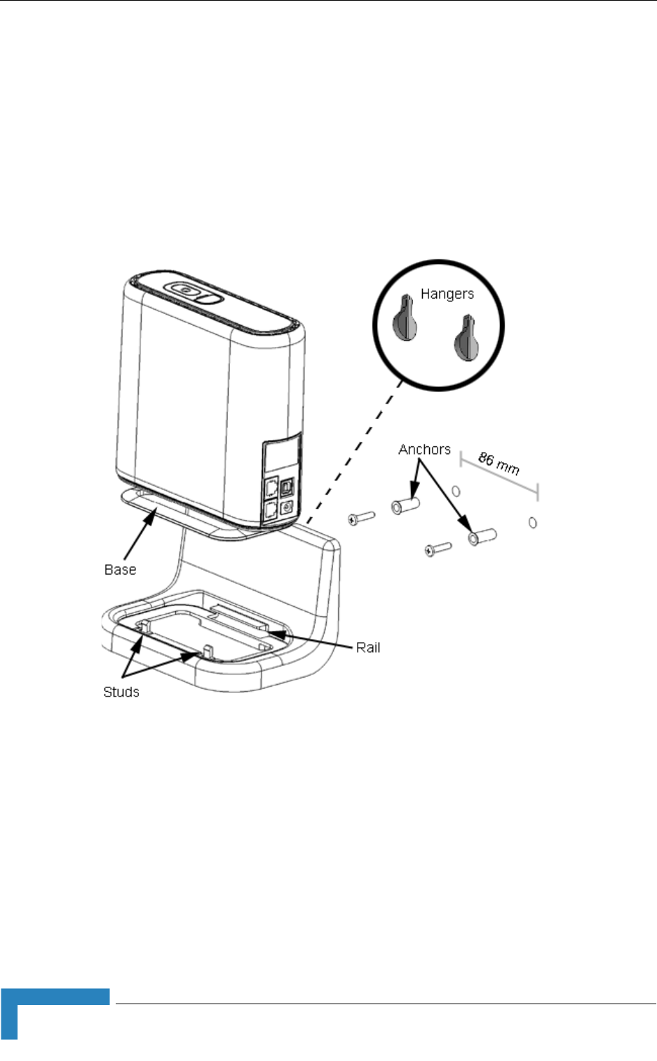
42 BreezeMAX CPEs Product Manual
Chapter 2 - Installation
3Use the two hangers on the rear to hang the mounting bracket on the two
screws. Make sure the bracket is stable.
4Insert one side of the Si CPE's base diagonally under the designated rail.
5Gently apply pressure on the opposite side of the Si CPE, until a clicking
sound is heard and the two bracket studs are locked onto the Si CPE's base.
To dismount the Si CPE, gently push the two bracket studs in the direction of the
wall and lift the CPE diagonally. Pull the CPE until free from the rail.
2.3.5.3 Wall Mounting the Power Adapter
Use the wall mounting kit included with the unit for wall mounting the Power
Adapter.
Figure 2-14: Si CPE Wall Mount
Installing the 3.5 GHz Detached Antenna
BreezeMAX CPEs Product Manual 43
2.4 Installing the 3.5 GHz Detached Antenna
The detached antenna kit includes the following components:
ALA-12002 antenna
Torque Key (see picture to the right) →
2 meter SMA-SMA (M/M) RF cable
Simple wall mounting kit, enabling installation on a wall (without any
capability for adjusting the direction). For installation instructions see
Section 2.4.1.
Simple window mounting accessories, enabling installation on a glass window
(without any capability for adjusting the direction). For installation
instructions see Section 2.4.2.
Window mounting kit with tilt capability, enabling installation on a glass
window (with rotation capability for adjusting the direction). For installation
instructions see Section 2.4.3.
A wall-mounting accessory that provides full adjustment capabilities (Pan/Tilt) is
also available from Alvarion. For installation instructions see Section 2.4.4.
NOTE
Ensure that the antenna is mounted vertical to the floor, with the connector facing downward, and
the front of the antenna facing to the exterior of the building, preferably directed towards the Base
Station.
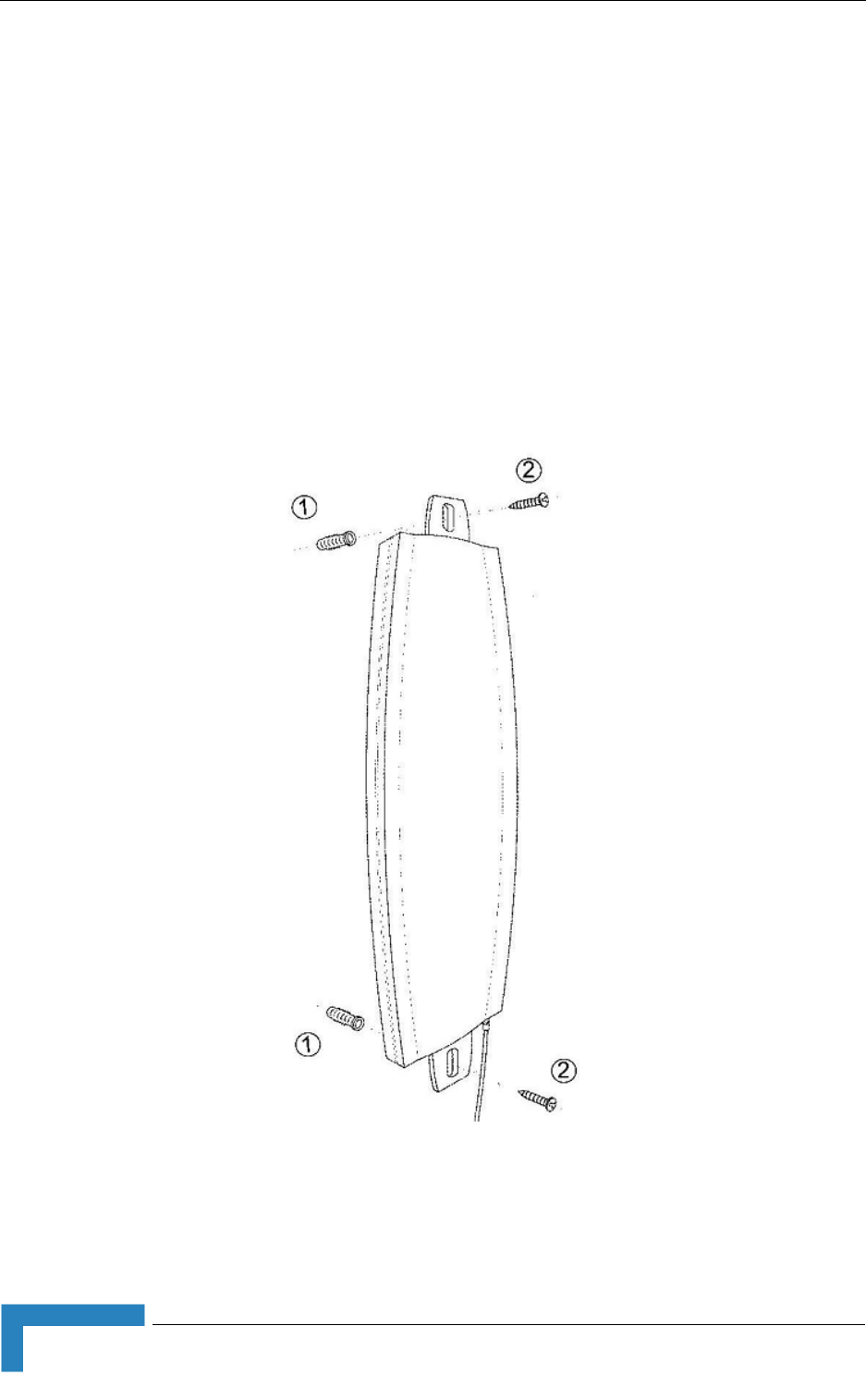
44 BreezeMAX CPEs Product Manual
Chapter 2 - Installation
2.4.1 Wall Mounting the 3.5 GHz Detached Antenna
The installation kit includes 2 plastic anchors and 2 #8 screws.
1If anchors are needed (wall-board, plaster board, etc.), drill two holes for the
anchors using a 5 mm drill bit and insert anchors. Use a 9/64" drill bit for
screwing directly into a solid surface (stud).
2Fasten the antenna to the wall. Refer to Figure 2-15 for directions. Use the
two #8 screws provided with the kit. Do not over tighten.
3Connect the antenna cable to the connector located on the bottom side of the
antenna. Use only the torque key supplied with the antenna. Do not over
tighten. Do not use a wrench or a similar tightening tool.
Figure 2-15: Wall Mounting the 3.5 GHz Detached Antenna

Installing the 3.5 GHz Detached Antenna
BreezeMAX CPEs Product Manual 45
2.4.2 Window Mounting the 3.5 GHz Detached
Antenna
The installation kit includes 2 suction cups.
1Attach the suction cups to the antenna. Refer to Figure 2-16 for directions.
2Determine the location of the antenna on the glass. Attach it to the window by
pressing the suction cups onto the glass.
3Connect the antenna cable to the connector located on the bottom side of the
antenna. Use only the torque key supplied with the antenna. Do not over
tighten. Do not use a wrench or a similar tightening tool.
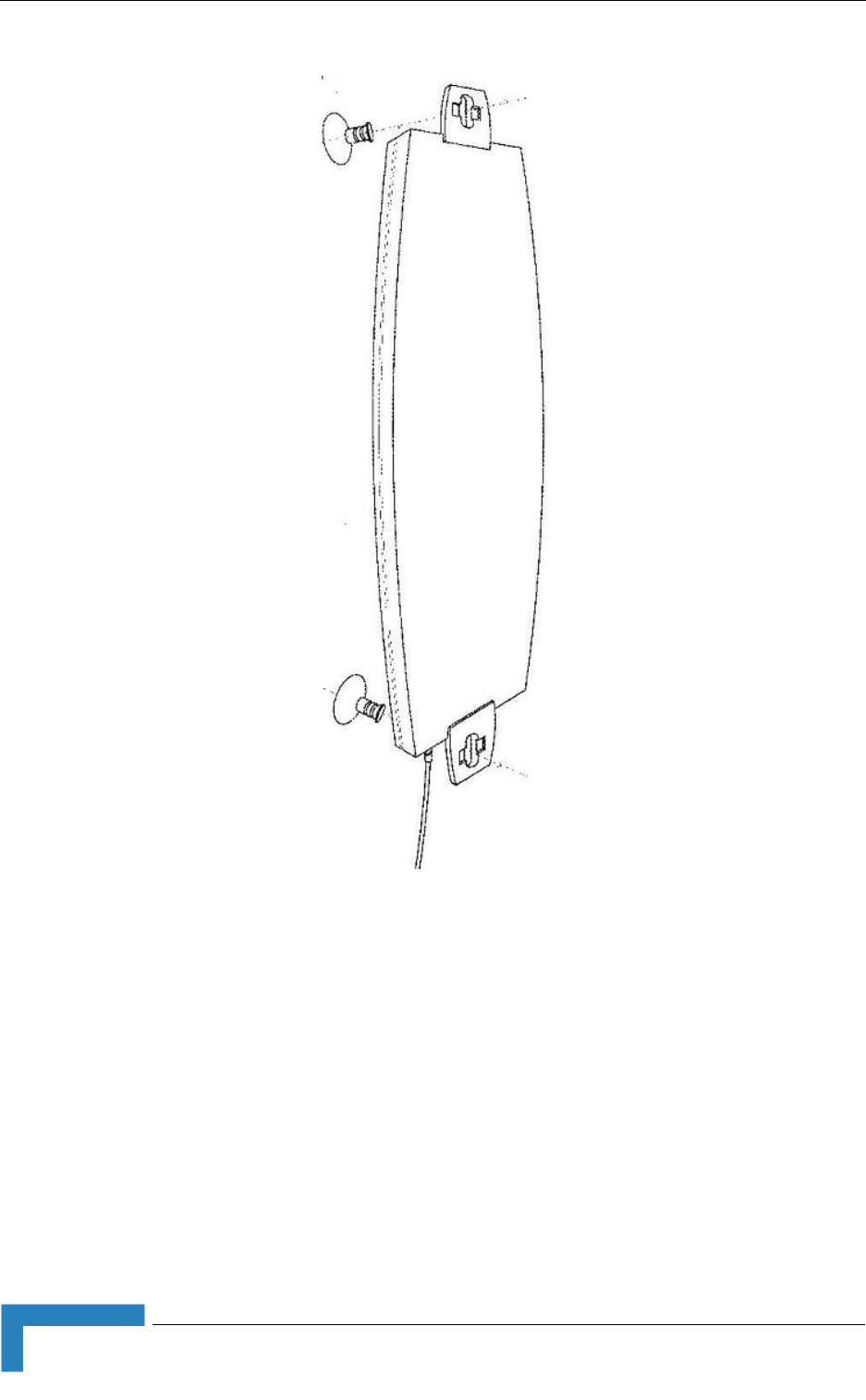
46 BreezeMAX CPEs Product Manual
Chapter 2 - Installation
Figure 2-16: Window Mounting the 3.5 GHz Detached Antenna

Installing the 3.5 GHz Detached Antenna
BreezeMAX CPEs Product Manual 47
2.4.3 Window Mounting the 3.5 GHz Detached
Antenna, with Rotation Capability
The installation kit includes the following: 4 PHK40*16PT screws (1), 2 M4
washers (2), 2 rotation bars (3) and 2 suction cups (4).
1Attach the rotation bars to the antenna and the suction cups to the rotation
bars. Refer to Figure 2-17 for directions.
2Determine the location of the antenna on the glass. Attach it to the window by
pressing the suction cups onto the glass.
3Connect the antenna cable to the connector located on the bottom side of the
antenna. Use only the torque key supplied with the antenna. Do not over
tighten. Do not use a wrench or a similar tightening tool.
4Rotate the antenna left or right so the domed surface of the antenna is facing
the direction of the Base Station. Check the received Signal LEDs to ensure
the antenna is aimed correctly.
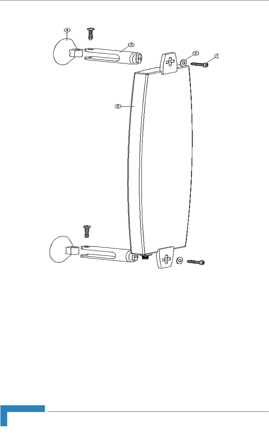
48 BreezeMAX CPEs Product Manual
Chapter 2 - Installation
Figure 2-17: Window Mounting the 3.5 GHz Detached Antenna, with Rotation Capability

Installing the 3.5 GHz Detached Antenna
BreezeMAX CPEs Product Manual 49
2.4.4 Wall Mounting the 3.5 GHz Detached Antenna,
with Tilt & Pan Capabilities
The installation kit includes the following:
2 M3*8 Screws (1)
2 M3 washers (2)
Antenna back plate (4)
U-Joint Set (adjustable arm) (5)
4 5/32-16*1TP Wall Screws (6)
4 ¼" Wall anchors (7)
Grounding Wire (8) - Not Used
1Attach the adjustable arm to the wall following the directions in Figure 2-18.
2Assemble the antenna to back plate with supplied screws and washers.
3Screw the back plate to the adjustable arm following the directions in
Figure 2-18.
4Remove the cap from the antenna connector located on the bottom side of the
antenna and connect the cable. Use only the torque key supplied with the
antenna. Do not over tighten. Do not use a wrench or a similar tightening tool.
5Align the antenna by releasing the spike knob located next to the base bracket.
The bracket's arm can be adjusted sideways or tilted up and down. Position
the antenna such that it faces the base station cell site. Tighten the spike knob
to lock the antenna into position.
6Check your receive signal strength (RSSI) LEDs in the Si CPE to ensure the
antenna is optimally aligned. If necessary, re-align antenna following the steps
described above.
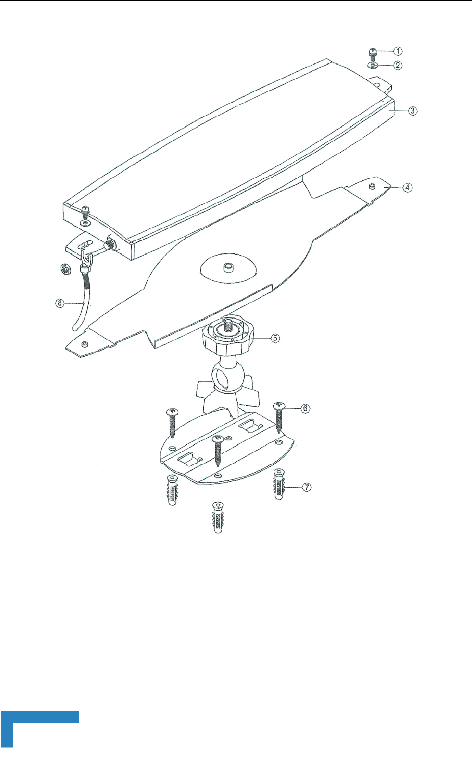
50 BreezeMAX CPEs Product Manual
Chapter 2 - Installation
Figure 2-18: Wall Mounting the 3.5 GHz Detached Antenna, with Pan & Tilt Capabilities
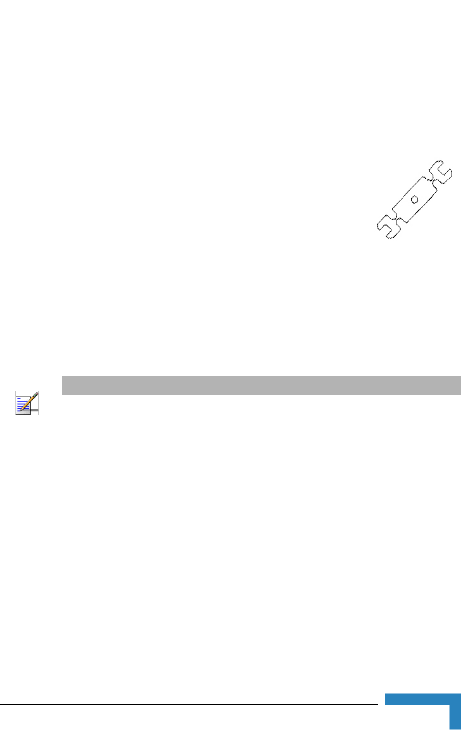
Installing the 2.3/2.5 GHz Detached Antenna
BreezeMAX CPEs Product Manual 51
2.5 Installing the 2.3/2.5 GHz Detached
Antenna
The detached antenna kit includes the following components:
ALA05-050320 antenna
Torque Key (see picture to the right) →
2 meter SMA-SMA (M/F) RF cable
Simple wall mounting kit, enabling installation on a wall
(without any capability for adjusting the direction). For
installation instructions see Section 2.5.1.
Window mounting kit with tilt capability, enabling installation on a glass
window (with rotation capability for adjusting the direction). For installation
instructions see Section 2.5.2.
Wall mounting kit with rotation capability. For installation instructions see
Section 2.5.3.
2.5.1 Wall Mounting the 2.3/2.5 GHz Detached
Antenna
The installation kit includes 2 plastic anchors and 2 #8 screws.
1If anchors are needed (wall-board, plaster board, etc.), drill two holes for the
anchors using a 5 mm drill bit and insert anchors. Use a 9/64" drill bit for
screwing directly into a solid surface (stud).
2Fasten the antenna to the wall. Refer to Figure 2-19 for directions. Use the
two #8 screws provided with the kit. Do not over tighten.
3Connect the antenna cable to the connector located on the bottom side of the
antenna. Use only the torque key supplied with the antenna. Do not over
tighten. Do not use a wrench or a similar tightening tool.
NOTE
Ensure that the antenna is mounted vertical to the floor, with the connector facing downward, and
the front of the antenna facing to the exterior of the building, preferably directed towards the Base
Station.
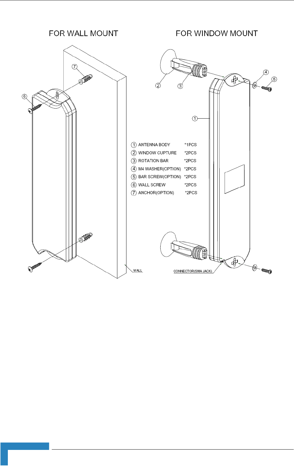
52 BreezeMAX CPEs Product Manual
Chapter 2 - Installation
Figure 2-19: Wall/Window Mounting the 2.3/2.5 GHz Detached Antenna

Installing the 2.3/2.5 GHz Detached Antenna
BreezeMAX CPEs Product Manual 53
2.5.2 Window Mounting the 2.3/2.5 GHz Detached
Antenna, with Rotation Capability
The installation kit includes the following: 2 screws, 2 M4 washers, 2 rotation
bars and 2 suction cups (4).
1Attach the rotation bars to the antenna and the suction cups to the rotation
bars. Refer to Figure 2-19 for directions.
2Determine the location of the antenna on the glass. Attach it to the window by
pressing the suction cups onto the glass.
3Connect the antenna cable to the connector located on the bottom side of the
antenna. Use only the torque key supplied with the antenna. Do not over
tighten. Do not use a wrench or a similar tightening tool.
4Rotate the antenna left or right so the domed surface of the antenna is facing
the direction of the Base Station. Check the received Signal LEDs to ensure
the antenna is aimed correctly.

54 BreezeMAX CPEs Product Manual
Chapter 2 - Installation
2.5.3 Wall Mounting the 2.3/2.5 GHz Detached
Antenna, with Rotation Capability
The installation kit includes 4 L-type mounting plates (one top, one bottom, one
Wall-V and one Wall-H), 6 M5 screws (with washers and spring washers), 2 plastic
anchors and 2 #8 screws.
1If anchors are needed (wall-board, plaster board, etc.), drill two holes (361 mm
apart) for the anchors using a 5 mm drill bit and insert anchors. Use a 9/64"
drill bit for screwing directly into a solid surface (stud).
2Assemble the top L-type plate with the Wall-V L-type plate. Note, the Wall-V
plate is the one with the vertical ellipse on the short side. Make sure the
inscriptions are facing upwards. Use two M5 screws to fasten the plates
together. Do not over tighten. See Figure ý0?1.
3Assemble the bottom L-type plate with the Wall-H L-type plate. Note, the
Wall-H plate is the one with the horizontal ellipse on the short side. Make sure
the inscriptions are facing upwards. Use two M5 screws to fasten the plates
together. Do not over tighten.
4Attach the assembled plates to the flat rear-side of the antenna. Use the two
remaining M5 screws to fasten them.
5Fasten the antenna to the wall. Use the two #8 screws provided with the kit.
Do not over tighten.
6Connect the antenna cable to the connector located on the bottom side of the
antenna. Use only the torque key supplied with the antenna. Do not over
tighten. Do not use a wrench or a similar tightening tool.
7Rotate the antenna left or right so the domed surface of the antenna is facing
the direction of the Base Station. Check the received Signal LEDs to ensure
the antenna is aimed correctly.
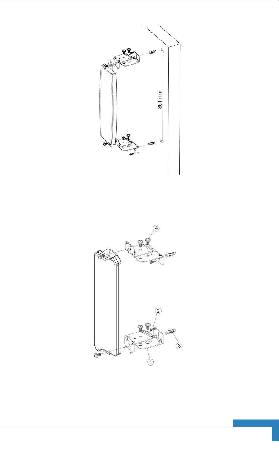
Installing the 2.3/2.5 GHz Detached Antenna
BreezeMAX CPEs Product Manual 55
For the new antenna, the bracket pairs switch places such that the bottom pair is
attached at the top and the top pair at the bottom:
Figure 2-20: Wall Mounting the 2.3/2.5 GHz Detached Antenna with Rotation Capability
Figure 2-21: Wall Mounting the new 2.3/2.5 GHz Detached Antenna with Rotation Capability

3
Chapter 3 - Commissioning
In This Chapter:
“Commissioning Steps” on page 58
“Configuring Basic Parameters” on page 59
“Fast Configuration and Antenna Alignment (PRO-S CPE)” on page 62
“SU Alignment Unit (SAU)” on page 63
“Using SAU for Aligning the PRO-S CPE's Antenna” on page 66
“Aligning the Si CPE's Antenna” on page 68
“Operation Verification” on page 70

58 BreezeMAX CPEs Product Manual
Chapter 3 - Commissioning
3.1 Commissioning Steps
After completing the installation process, as described in the preceding chapter,
several actions should be performed to ensure connectivity with the Base Station
and provisioning of services. After the SU is connected with the Base Station, it
can be fully managed via the wireless link from the Base Station or a central
management system:
1The basic parameters must be configured to ensure that the unit operates
correctly and can communicate with the Base Station.
2The antenna must be aligned to ensure optimal performance of the wireless
link.
3Proper operation should be verified, including data connectivity.

Configuring Basic Parameters
BreezeMAX CPEs Product Manual 59
3.2 Configuring Basic Parameters
3.2.1 The Basic Parameters
Table 3-1: SU's Basic Parameters
Parameter Default Value Comment
Ethernet Port auto Negotiation
Enable/Disable
Enabled Applicable only to E-model units (with Ethernet
interface).
Ethernet Port Speed and Duplex Applicable only to E-model units (with Ethernet
interface). Applicable only if Ethernet Port Auto
Negotiation Enable/Disable is set to Disable
User Name Null, changed
automatically to MAC
address if not configured
to any other value
Should be supplied by system administrator
User Password quickynikynyoky Should be supplied by system administrator
Organization Name Optional - according to administrator policy
Address Optional- according to administrator policy
Country Optional- according to administrator policy
BST/AU ID 186.190.0.0.250.206
BST/AU ID ID Mask 0.0.0.0.0.0
Preferred BST/AU ID 186.190.0.0.250.206
Preferred BST/AU ID Mask 0.0.0.0.0.0
Set Mobility Mode nomadic
Bandwidth 3.5 MHz
Antenna (Si CPE only) Automatic
Scanning Start Frequency Depend on Radio Band
and Bandwidth
Scanning End Frequency Depend on Radio Band
and Bandwidth
Scanning Main Step 875 KHz
Scanning Intermediate Steps Enable for all eight Steps
Discrete Frequencies None
Rx Attenuator (2.3 GHz units
only)
0

60 BreezeMAX CPEs Product Manual
Chapter 3 - Commissioning
3.2.2 Configuration Tools
Two options for local configuration and monitoring are incorporated into all SUs:
The Installer Monitor program, based on a user-friendly CLI (Command Line
Interface). The Installer Monitor program can be accessed using Telnet.
The web Configuration Server, providing a web-based GUI. The Web
Configuration Server can be accessed using a PC/Notebook or a Pocket
PC/PDA with a web browser.
The SU may be delivered with the operator’s default settings already configured in
the FLASH memory. If there is need to change these settings then the only
parameters that should be configured are the end user’s credentials (User Name
and User Password). In certain scenarios (where the MAC address of the unit is
known to the system administrator and services are provisioned based on this
MAC address), there is no need to configure the credentials. the SU will
automatically use the credentials User Name = MAC address, User Password =
quickynikynyoky.
If a Smart Card is used in an Si CPE, the unit will always use the configuration
incorporated into the Smart Card. Once the Smart Card is removed, the SU will
load the configuration from the FLASH.
If a WiMAX Modem Application utility is used, the SU will load to the FLASH and
use the operator’s configuration from the WiMAX Modem Application CD. This
configuration may be changed via the utility’s configuration screens. For more
details refer to the WiMAX Modem Application documentation.
3.2.3 Using the Configuration Tools
1To configure parameters using Telnet, connect a PC/Notebook to the Ethernet
port of the IDU, using a straight Ethernet cable.
NOTE
Some parameters are changed to their new values only after reset (refer to Section 4.11 for more
details). Once the basic parameters are configured, the unit should be reset in order to activate the
new configuration.
To configure the SU's basic parameters:

Configuring Basic Parameters
BreezeMAX CPEs Product Manual 61
To configure parameters using the Web Configuration Server, connect a
PC/Notebook or a Pocket PC/PDA with a web browser to the Ethernet port of
the SU, using a straight Ethernet cable.
In a PRO-S CPE, you can also connect directly to the ODU's IDU COM
connector, using the special Y-cable.
2Configure the PC's IP parameters to enable connectivity with the unit. The IP
address of the SU for local management access is 192.168.254.251. The
Subnet Mask is 255.255.255.0. The recommended IP address for the PC is
192.168.254.250, as this is also the default TFTP Sever IP Address (required
for downloading SW versions and for downloading/uploading configuration
files).
3Run the Telnet program or open a web browser, and connect to
192.168.254.251. The “Enter the Password” prompt is displayed. Enter the
password and press the Enter key.
4The Main menu of the SU Installer Monitor program/Web Configuration
Server is displayed, enabling access to the required parameters configuration
and performance monitoring options. Refer to Chapter 4 for instructions on
using the SU Installer Monitor program and detailed information on the
various parameters and other features supported by the program. Refer to
Appendix A for instructions on using the Web Configuration Server.
5Configure the basic parameters listed in Table 3-1.
6Reset the unit to apply the new settings and enable synchronization with the
Base Station.
NOTE
The default password is "installer".
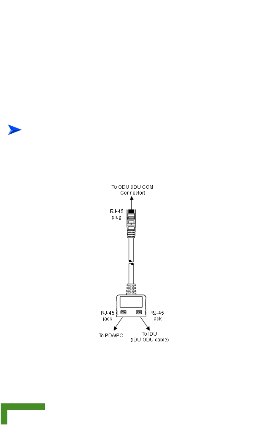
62 BreezeMAX CPEs Product Manual
Chapter 3 - Commissioning
3.3 Aligning the PRO-S CPE’s Antenna
3.3.1 Fast Configuration and Antenna Alignment
(PRO-S CPE)
A special Y-cable, available from Alvarion, enables to connect a Pocket PC (or a
portable PC) directly to the IDU COM port of the ODU. This enables the installer to
perform the entire process of configuring basic parameters, aligning the antenna
and verifying proper operation of the unit right after completing the installation,
minimizing the number of times the installer must climb to the roof.
1Disconnect the IDU-ODU cable from the ODU.
2Connect the Y-cable according to the following drawing:
To use a Pocket PC/Notebook for completing the entire installation process on the
roof:
Figure 3-1: Connecting the Y-Cable
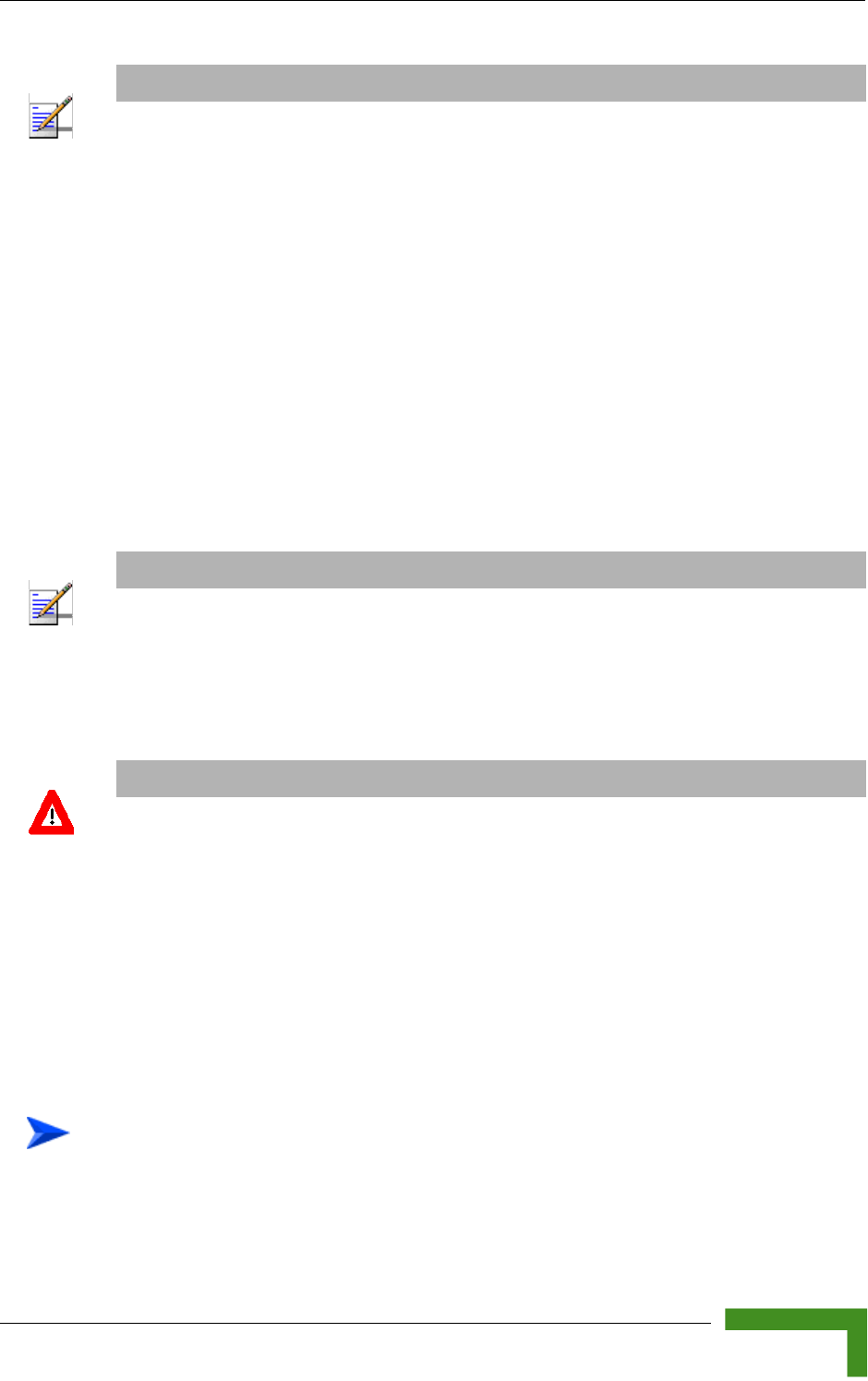
Aligning the PRO-S CPE’s Antenna
BreezeMAX CPEs Product Manual 63
3From the Pocket PC/Notebook, connect to the SU and complete the process of
configuring basic parameters.
4Verify that the the unit is synchronized with a Base Station. If the SU is not
synchronized with a Base Station, ensure that all parameters are configured
properly. If the unit is still not synchronized with a Base Station, improve the
quality of the link by changing the direction of the antenna or by placing the
antenna at a higher or in an alternate location.
5Rotate (and/or tilt if applicable) the ODU/antenna until the maximum link
quality (SNR and RSSI) reading is achieved. If you encounter prolonged
difficulty in achieving the expected link quality, try to improve the reception
quality by placing the antenna at a higher point or in an alternate location.
6Secure the ODU/antenna firmly to the pole.
3.3.2 SU Alignment Unit (SAU)
The miniature SU Alignment Unit can be used during installation and testing to
support an easy process of antenna alignment and provide the ODU's status
indications.
1Remove the sealing cap of the ODU's SAU connector.
NOTE
When the Y-Cable is connected, there is no Ethernet connectivity between the ODU and the data
device connected to the IDU.
NOTE
Ensure that the front of the antenna is always facing the Base Station. However, in certain
conditions, such as when the line of sight to the Base Station is hampered, better reception may be
achieved using a reflected signal. In this case, the antenna is not necessarily directed toward the
Base Station.
CAUTION
In some cases, the antenna may need to be tilted to ensure that the level at which the SU receives
transmissions from the AU (and vice versa) is not too high. When the RSSI reading is higher than
-20 dBm, the received signal level is too high (saturation). This must be avoided, preferably by
up-tilting the antenna. As a rule of thumb, if the SU is located at a distance of less than 300 meters
from the AU, it is recommended to up-tilt the antenna by approximately 10° to 15°.
To connect the SAU to the ODU:
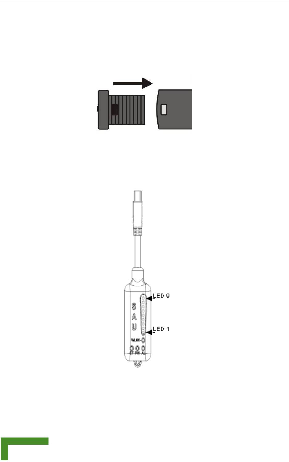
64 BreezeMAX CPEs Product Manual
Chapter 3 - Commissioning
2Connect the cable attached to the SAU to the SAU connector.
3After completing the installation, disconnect the cable and replace the cap as
shown in the following figure. Make sure that the small protrusion on the side
of the cap fits inside the hole on the connector's protective body:
Use appropriate sealing material to protect the connection against moisture and
humidity. Use removable sealing material, such as a tar seal, to enable future
access to the connector.
Figure 3-2: Inserting the SAU Sealing Cap
Figure 3-3: SAU

Aligning the PRO-S CPE’s Antenna
BreezeMAX CPEs Product Manual 65
* After power-up of the ODU, the all LEDs illuminate until self-test has completed.
Table 3-2: SAU LEDs
Name Description Functionality
AL Alarm indication Off - ODU is OK, diagnostic test passed
Red - ODU failure
PW Pow er indication Off - ODU is not powered or 3.3 VDC failure
Green - ODU power to SAU is OK
ET Ethernet link status
indication
(Ethernet integrity)
Off - No Ethernet connectivity has been
detected between the outdoor unit and the
device connected to the indoor unit’s
Ethernet port
Green- Ethernet connectivity has been
detected between the outdoor unit and the
device connected to the indoor unit’s
Ethernet port
WLNK Wireless link status
indication
Off - The SU is not connected with a Base
Station
Orange on - The SU is connected with and
receives services from the Base Station
(Network Entry completed). Link Quality is
indicated by LEDs 1-9 as described in
Table 3-3. below.
Blinking orange - Authentication failed. The
reason is provided by Link Quality Bar
LEDs:
If LEDs 6, 7 and 8 are on: Authentication
reject by RADIUS server.
If LEDS 7 and 8 are on: Rejected by Base
Station (Duplicate SU Name in database).
If LED 8 is on: Authentication Timeout,
re-authentication failure (connection to
RADIUS server lost or Shared Secret
mismatch)

66 BreezeMAX CPEs Product Manual
Chapter 3 - Commissioning
3.3.3 Using SAU for Aligning the PRO-S CPE's
Antenna
The LINK QUALITY bar display on the SAU comprises 9 LEDs:
The WLNK LED indicates that the wireless link is active, and is lit when the SU
has completed the Network Entry process.
LEDs 1 to 8 (green) and 9 (red) indicate the quality of the received signal. The
higher the number of LEDs illuminating, the better the quality of the received
signal.
If all LEDs, including LED 9 (red) are on, the received signal strength is too
high. This must be avoided, preferably by up-tilting the antenna. As a rule of
thumb, if the SU is located at a distance of less than 300 meters from the Base
Station, it is recommended to up-tilt the antenna by approximately 10° to 15°.
Table 3-3: SAU LINK QUALITY LEDs Functionality
Bar LEDs SNR
LED 1 (green) is On 5dB ≤ SNR < 10dB
LEDs 1-2 (green) are On 10dB ≤ SNR < 15dB
LEDs1-3 (green) are On 15dB ≤ SNR < 20dB
LEDs 1-4 (green) are On 20dB ≤ SNR < 24dB
LEDs 1-5 (green) are On SNR ≥ 24dB and RSSI < -75dBm
LEDs 1-6 (green) are On SNR ≥ 24dB and RSSI ≥ -75dBm
LEDs 1-7 (green) are On SNR ≥ 24dB and RSSI ≥ -70dBm
LEDs 1-8 (green) are On SNR ≥ 24dB and RSSI ≥ -60dBm
LEDs 1-8 (green) and 9 (red) are On RSSI ≥ -20dBm (saturation)
LEDs 1 - 8 Blinking one after the other During full frequency scan
LEDs 1 - 9 Blinking as follows: LED 5 lights,
after 200ms LEDs 4 & 6 light, after 200ms
LEDs 3&7 light, after 200ms LEDs 2&8
light, after 200ms LEDs 1 lights, after
200ms all the LEDs are extinguished and
then the sequence is repeated.
During Best AU selection process or short scan
To align the antenna:

Aligning the PRO-S CPE’s Antenna
BreezeMAX CPEs Product Manual 67
1Point the antenna toward the general direction of the Base Station.
2Connect the SAU to the ODU.
3Verify that the PWR (power) indication on the SAU is on.
4Verify that the WLNK LED indicator is on, indicating that the unit is
synchronized with the Base Station. If the SU is not synchronized with the
Base Station, ensure that all parameters are configured properly. If the unit is
still not synchronized with the Base Station, improve the quality of the link by
changing the direction of the antenna or by placing the antenna at a higher
point or in an alternate location.
5Rotate (and/or tilt if applicable) the ODU/antenna until the maximum link
quality reading is achieved. If you encounter prolonged difficulty in achieving
the expected link quality, try to improve the reception quality by placing the
antenna at a higher point or in an alternate location.
6Secure the ODU/antenna firmly to the pole.
NOTE
Ensure that the front of the antenna is always facing the Base Station. However, in certain
conditions, such as when the line of sight to the Base Station is hampered, better reception may be
achieved using a reflected signal. In this case, the antenna is not necessarily directed toward the
Base Station.

68 BreezeMAX CPEs Product Manual
Chapter 3 - Commissioning
3.4 Aligning the Si CPE's Antenna
The Signal link quality 7-LEDs display is located on the top panel of the unit. The
higher the number of LEDs that are on, the better the quality of the received
signal. Refer to “Si CPE Top Panel Components” on page 37 for more details on the
functionality of the LEDs.
The link quality can be estimated more accurately using the Link Quality Display
option in the SU Installer Monitor program. Refer to Section 4.9.1 for more details
on this option.
This section describes how to align the Subscriber Unit antenna using either the
Signal 7-LEDs display or the Start Link Quality Display option of the Monitor
program.
In the following instructions, the term "antenna" means either the selected
integral antenna or a detached antenna. The default active antenna is the internal
antenna number 3 (opposite to the connectors' side). Refer to Section 4.7.3 for
instructions on changing the active antenna selection.
1Point the antenna towards the general direction of the Base Station.
2Verify that the power indication of the unit is on.
3Verify that the green Status LED illuminates and at least one LED of the
Signal LEDs is on, indicating that the unit is synchronized with the Base
Station. If the SU is not synchronized with the Base Station, ensure that all
parameters are configured properly. If the unit is still not synchronized with
the Base Station, try improving the quality of the link by changing the
direction of the antenna or by placing the antenna at a higher or alternate
location.
4Try changing the location/direction of the antenna until the maximum link
quality reading is achieved. If you encounter prolonged difficulty in achieving
the expected link quality, try improving the reception quality by placing the
antenna at an alternate location.
To align the antenna:

Aligning the Si CPE's Antenna
BreezeMAX CPEs Product Manual 69
NOTE
Ensure that the front of the antenna is always facing the Base Station. However, in certain
conditions, such as when the line of sight to the Base Station is hampered, better reception may be
achieved using a reflected signal. In this case, the antenna is not necessarily directed toward the
Base Station.

70 BreezeMAX CPEs Product Manual
Chapter 3 - Commissioning
3.5 Operation Verification
To verify proper operation of the PRO-S CPE, examine the LED indicators on the
IDU (see Table 2-5) and the SAU (see Table 3-2).
To verify proper operation of the Si CPE, examine the LED indicators on the top
panel (see Table 2-7).
To verify proper connection to the end-user's data equipment, examine the
Ethernet Integrity and Ethernet Activity LEDs of the Ethernet connectors.
To verify data connectivity, from the end-user's PC or from a portable PC
connected to the unit, ping a known device in the network, or connect to the
Internet.
NOTE
Verifying the correct operation of the ODU using the SAU LEDs is meaningful only after the
configuration and alignment processes are completed, and the unit is synchronized with the Base
Station.

4
Chapter 4 - Operation
In This Chapter:
“The SU Installer Monitor Program” on page 72
“Using the Monitor Program” on page 73
“The Main Menu” on page 75
“Unit Control Menu” on page 77
“Registration Parameters Menu” on page 88
“BST/AU ID Parameters Menu” on page 90
“Radio Parameters Menu” on page 94
“Performance Monitoring Menu” on page 103
“Multirate and ATPC Parameters Menu” on page 100
“SU Parameters Summary” on page 110

72 BreezeMAX CPEs Product Manual
Chapter 4 - Operation
4.1 The SU Installer Monitor Program
The SU Installer Monitor program enables configuration of basic parameters
during installation to facilitate communication with the AU/Micro Base Station,
including all parameters required for completion of the Network Entry process. It
also enables downloading of SW files, control of the running SW version, and
downloading/uploading of the configuration file, simplifying and accelerating the
configuration process.
The SU Installer Monitor program also provides a selection of performance
monitoring capabilities, allowing installers and technicians to view information on
link quality and traffic counters. These monitoring capabilities enable
performance verification and problem identification.
To further support local testing, the program also enables temporary control of the
ATPC and Multirate mechanisms.
Using the Monitor Program
BreezeMAX CPEs Product Manual 73
4.2 Using the Monitor Program
4.2.1 Accessing the Monitor Program
1The Monitor program uses the fixed IP address 192.168.254.251 with the
subnet mask 255.255.255.0. The PC used for accessing the Monitor program
should be configured accordingly. It is recommended to set the PC's IP address
to 192.168.254.250, which is the default TFTP Server IP address (required for
downloading SW versions and for downloading/uploading configuration files).
2Connect the PC to the Ethernet port, using a straight cable.
3Run the Telnet program connecting to 192.168.254.251. The Enter the
password prompt is displayed. Enter the password and press the Enter key.
4The Main menu of the SU Installer Monitor program is displayed, enabling
access to the required parameters configuration and performance monitoring
options.
4.2.2 Using the Program
This section describes the Monitor program structure and navigation rules.
To access the Monitor program:
NOTE
The IP address 192.168.254.251 is used only for the Monitor program. This is not the IP address used
by the unit for other purposes. The IP parameters for management purposes are allocated by the NPU
during the Network Entry process.
NOTE
Following three consecutive failures to enter the correct password, access to the Monitor program will
be blocked for 5 minutes.The factory default password is "installer".If you forgot the password, type
"help" to get a challenge string consisting of 24 characters. Contact Customer Service and give them
the challenge string (after user identification) to receive a one-time password. You can use this
password only for a single entrance to the program. The password must be changed during the
session to a different "permanent" password. The administrator should be notified of this new
password. Five consecutive errors in entering the one-time password will invalidate it, and a new
challenge string should be used to receive a new one-time password.

74 BreezeMAX CPEs Product Manual
Chapter 4 - Operation
Each menu or submenu displays a list of numbered options. To access an
option, enter the number of the required option at the > prompt and press the
Enter key.
The header of each displayed item includes the unit identification (MAC
Address), the running SW version and the name of the current item.
The first selectable item in each menu is the Show option, enabling to view the
current configuration of the applicable parameters. For some menus some
additional status information is displayed.
At any point in the program, you can use the Esc key to return to the previous
menu (one level up) without applying any change.
Configurable parameter's menus display the current value/status of the
parameter and provide instructions for changing the configuration. These
instructions may include the permitted value range for the parameter, the
permitted format, or the selectable options.
Each change in a parameter 's configuration must be confirmed using the
Enter key. If the new value/option is a valid one, the program will return to the
previous menu. Entry of a wrong value will be indicated by an appropriate
error message, and the configuration change text will be displayed again.
Changes to certain parameters are applied only after reset. For these
parameters, if the configured value differs from the current value, the
applicable Show menus display both current and configured values.
If the Monitor program is not used for 10 minutes, the session will be
terminated automatically.
Select the Exit option in the Main menu to exit the program and terminate the
session.

The Main Menu
BreezeMAX CPEs Product Manual 75
4.3 The Main Menu
The Main menu of the SU Installer Program includes the following options:
Show All Parameters and Status
Unit Control
Registration Parameters
Base Station ID Parameters
Radio Parameters
Multirate and ATPC Parameters
Performance Monitoring
FDD Parameters (3.x GHz units only)
Exit
4.3.1 Show all Parameters and Status
Select this option to view the current values/selected options of all parameters as
well as additional status information. The display includes all the items listed in
the descriptions of the Show option in the sections explaining the Unit Control,
Registration Parameters, Base Station ID Parameters, Radio Parameters, and
Multirate and ATPC Parameters menus.
4.3.2 Unit Control
The Unit Control menu enables resetting the unit, reverting to the default
configuration, changing the password, configuring the operation mode of the
Ethernet port, and selecting the running SW version. It also enables to download
a new SW version.
4.3.3 Registration Parameters
The Registration Parameters menu enables viewing and configuring
authentication parameters that are required for services provisioning to the unit,

76 BreezeMAX CPEs Product Manual
Chapter 4 - Operation
and some optional parameters that provide information on the ownership and
location of the unit.
4.3.4 BST/AU Parameters
The BST/AU Parameters menu enables viewing and configuring the parameters
that define the Base Station(s)/AU(s) with which the unit can synchronize,
including parameters related to the Best BST/AU selection feature.
4.3.5 Radio Parameters
The Radio Parameters menu enables viewing and configuring the radio
parameters necessary for communication with the Base Station, including
parameters of the frequency scanning mechanism.
4.3.6 Multirate and ATPC Parameters
The Multirate and ATPC Parameters menu enables temporary control of the
transmitted signal for testing purposes.
4.3.7 Performance Monitoring
The Performance Monitoring menu enables viewing continuously updated link
quality parameters and traffic counters.
4.3.8 FDD Parameters
The FDD Parameters menu enables viewing/updating the Radio parameters for
Standard operation mode. These parameters do not affect the operation of the unit
when using Advanced Si operation mode. These parameters are provided to
support the Automatic Platform Detection mechanism of the dual-mode CPEs,
allowing pre-configuration of the relevant parameters before switching the sector
to operate in FDD mode using Standard operation mode. These parameters are
applicable only to SUs that may support FDD operation (all SUs in the 3 GHz
bands except the new 3.x GHz Si CPE supporting the entire band from 3.3 to 3.8
GHz).
4.3.9 Exit
Select the Exit option to exit the Monitor program and terminate the Telnet
session.

Unit Control Menu
BreezeMAX CPEs Product Manual 77
4.4 Unit Control Menu
The Unit Control menu includes the following options:
Show
Reset Unit
Change Password
SW Versions Control
Configuration Control
Ethernet Port Operation Mode (not applicable for U-model)
4.4.1 Show
Select this option to view the current values/selected option of applicable
parameters as well as general status information, as follows:
HW Details
»SU Type:
◊CPE (first generation CPE. Not applicable in TDD systems)
◊CPE PRO
◊CPR PRO-L
◊CPE PRO2
◊CPE PRO2-L
◊CPE Si
◊CPE Si-L (not applicable in current release)
◊CPE Si2
◊CPE-Si2-L (not applicable in current release)

78 BreezeMAX CPEs Product Manual
Chapter 4 - Operation
CPE PRO, CPE PRO-L, CPE Si and CPE Si-L use first generation Intel
WiMAX Connection 2250 chip. CPE PRO2, CPE PRO2-L, CPE Si2 and CPE
Si2-L use second generation (IEEE 802.16e-ready) WiMAX chip. The “L”
suffix indicates that the SU was supplied with limited capabilities (limited
bandwidth).
»Serial Number
»MAC Address
»MAC Address Control Number (a number computed from the MAC Address
that can be used for verification purposes)
»Radio Band
»HW Version: The version of the digital module
»HW Configuration
»RF Version: The version of the radio module
»SU Interface Type (Si CPE): In the current release only Ethernet is available
»Smart Card Status (Si CPE): Installed/Not Installed/Fault
Ethernet Port Operation Mode parameters and status (applicable only for
E-model units)
»Ethernet Port Auto Negotiation Enable/Disable
»Ethernet Port Speed and Duplex
Operation Mode: Advanced Si or Standard (not applicable in current version
supporting only Advanced Si mode). Standard is the air protocol of the first
generation BreezeMAX systems. Advanced Si is the air protocol used in the
WiMAX-ready systems, providing full support for Self Install SUs. In the
current release only Advanced-Si mode is applicable.
Unit Status: the connectivity status of the unit. Possible statuses are:
»Searching for Base Station
»Base station found

Unit Control Menu
BreezeMAX CPEs Product Manual 79
»Not Authorized
»Not Registered
»Registered
SW Versions:
»Boot Version
»Main SW File Name
»Main SW Version
»Shadow SW File Name
»Shadow SW Version
»Running from: Main or Shadow, and the SW version.
Upload/Download Parameters:
»TFTP Server IP address: the IP address of the TFTP server used for SW
version download.
»SW File Name: the name in the TFTP server of the SW version to be
downloaded to the unit.
»Configuration File Upload Name
»Configuration File Download Name
4.4.2 Reset Unit
Select this option to reset the unit. To avoid unintentional reset, you will be
prompted to confirm the reset request. Changes to most of the configurable
parameters are applied only after reset. Refer to Section 4.11 for information on
which parameters are changeable in run time and which changes are applied only
after reset.
4.4.3 Change Password
Select this option to change the password. You will be prompted to enter the new
password. After pressing enter, you will be prompted to re-enter the new
password.

80 BreezeMAX CPEs Product Manual
Chapter 4 - Operation
Valid passwords: Up to 20 printable characters.
Default password: installer
4.4.4 SW Versions Control
The SU can contain two SW versions:
Main: Each time the SU resets it will reboot using the version defined as Main.
Shadow: Normally the Shadow version is the backup version. Each time a new
SW File is downloaded to the SU, it will be stored as a Shadow version,
replacing the previous Shadow Version.
The typical process of upgrading to a new SW version includes the following steps:
1Download the new SW File to the SU. It will be stored as the Shadow version.
2Reset and run the unit from its Shadow version. Note that at this stage, after
reset the unit will reboot from its previous Main version.
3If you want to continue using the new version, swap the Shadow and Main
versions. The new version is now defined as Main, and will be used each time
the unit reboots. The previous version is defined now as Shadow.
The SU functions as a TFTP client, enabling the loading of SW files from a TFTP
server.
The SW Versions Control submenu includes the following options:
Show
Reset and Run from Shadow
Set Running Version as Main
SW Download Parameters
Perform SW Download
NOTE
Notify the administrator of the new password!

Unit Control Menu
BreezeMAX CPEs Product Manual 81
4.4.4.1 Show
Select this option to view the current available versions and the running version
as well as the TFTP parameters:
SW Versions:
»Main SW File Name
»Main SW Version
»Shadow SW File Name
»Shadow SW Version
»Running from: indicates whether the unit is currently running the Main or
the Shadow version.
Download Parameters:
»TFTP Server IP address: the IP address of the TFTP server used for SW
version download.
»SW File Name: the name in the TFTP server of the SW version to be
downloaded to the unit.
4.4.4.2 Reset and Run from Shadow
Select this option to reset the unit and run the Shadow version after power up. To
avoid unintentional actions you will be prompted to confirm the request.
4.4.4.3 Set Running Version as Main
When the unit is running the Shadow version (after selecting Reset and Run from
Shadow), it will boot from the Main version after the next reset. Select this option
if you want to swap versions so that the running version will become the Main
version and will be the version to be used after reset. To avoid unintentional
actions you will be prompted to confirm the request.
4.4.4.4 SW Download Parameters
This submenu enables viewing or defining the parameters to be used for
downloading a new SW version from a TFTP server. It includes the following
options:
Show

82 BreezeMAX CPEs Product Manual
Chapter 4 - Operation
TFTP Server IP Address
SW File Name
4.4.4.4.1 Show
Select this option to view the current SW Download parameters:
TFTP Server IP address: the IP address of the TFTP server used for SW version
download.
SW File Name: the name in the TFTP server of the SW version to be
downloaded to the unit.
4.4.4.4.2 TFTP Server IP Address
Select this option to change the IP Address of the TFTP server.
The default TFTP Server IP address is 192.168.254.250.
4.4.4.4.3 SW File Name
Select this option to enter the name in the TFTP server of the required SW file.
4.4.4.5 Perform SW Download
Select this option to execute the SW download operation. To avoid unintentional
actions you will be prompted to confirm the request.

Unit Control Menu
BreezeMAX CPEs Product Manual 83
1The required SW file should be available in the TFTP Server directory in a PC
connected to the unit.
2Typically it is recommended to configure the IP address of the PC to
192.168.154.250, which is the default TFTP Server IP address of the unit. If a
different IP address is configured in the PC with the TFTP, configure the TFTP
Server IP Address to the same address.
3Enter the name of the SW file (as called in the TFTP server) as the SW File
Name.
4Select Perform SW Download and confirm the download request. Wait to
receive a success/failure message.
5Following a successful download, the loaded SW version becomes the Shadow
version in the unit.
4.4.5 Configuration Control
The Configuration Control Submenu includes the following options:
Set Factory Defaults
Configuration File Download Control
Configuration File Upload Control
4.4.5.1 Set Factory Defaults
Select this option to reset the unit and revert to the default configuration. To avoid
unintentional actions you will be prompted to confirm the request. All parameters
except the Password will revert to the factory default values.
4.4.5.2 Configuration File Download Control
The Configuration File Download Control submenu enables to define parameters
related to downloading a configuration file from a TFTP server to the SU, and to
initiate the download operation. It includes the following options:
Show
TFTP Server IP Address
To perform SW download:
84 BreezeMAX CPEs Product Manual
Chapter 4 - Operation
Configuration File Download Name
Perform Configuration Download
4.4.5.2.1 Show
Select this option to view the current Configuration File Download parameters:
TFTP Server IP address: the IP address of the TFTP server used for
configuration file download.
Configuration File Download Name: the name in the TFTP server of the
configuration file to be downloaded to the unit.
4.4.5.2.2 TFTP Server IP Address
Select this option to change the IP address of the TFTP server.
The default TFTP Server IP address is 192.168.254.250.
4.4.5.2.3 Configuration File Download Name
Select this option to enter the name in the TFTP server of the required
configuration file. A Configuration File Download Name consists of up to 50
characters.
The default Configuration File Download Name is SU_DOWNLOAD_CFG.
4.4.5.2.4 Perform Configuration Download
Select this option to execute the configuration file download operation. To avoid
unintentional actions you will be prompted to confirm the request.
1The required configuration file should be available in the TFTP Server directory
in a PC connected to the unit.
NOTE
When the SU is synchronized with a base station, it receives the TFTP Server IP Address from the
base station during the network entry process. This address is 1.7.1.1 for a Base Station (NPU)
and 1.1.1.1 for a Micro Base Station. This will be the TFTP Server IP Address after each reset, as
long as the SU is associated with a base station.
The same TFTP Server IP Address parameter is used in the SW Download, Configuration File
Download and Configuration File Upload processes.
To perform configuration file download:

Unit Control Menu
BreezeMAX CPEs Product Manual 85
2Typically it is recommended to configure the IP address of the PC to
192.168.154.250, which is the default TFTP Server IP address of the unit. If a
different IP address is configured in the PC with the TFTP server, configure the
TFTP Server IP address to the same address.
3Enter the name of the configuration file (as called in the TFTP server) as the
Configuration File Download Name.
4Select Perform Configuration Download and confirm the download request.
Wait to receive a success/failure message.
5Following a successful download, reset the unit to apply the new
configuration.
4.4.5.3 Configuration File Upload Control
The Configuration File Upload Control submenu enables to define parameters
related to uploading the configuration of the SU to a file in the TFTP server
directory, and to initiate the upload operation. It includes the following options:
Show
TFTP Server IP Address
Configuration File Upload Name
Perform Configuration Upload
4.4.5.3.1 Show
Select this option to view the current Configuration File Upload parameters:
TFTP Server IP address: the IP address of the TFTP server used for
configuration file upload.
Configuration File Upload Name: the name in the TFTP server directory of the
configuration file to be uploaded.
4.4.5.3.2 TFTP Server IP Address
Select this option to change the IP address of the TFTP server.
The default TFTP Server IP address is 192.168.254.250.
86 BreezeMAX CPEs Product Manual
Chapter 4 - Operation
4.4.5.3.3 Configuration File Upload Name
Select this option to enter the name in the TFTP server directory of the
configuration file to be uploaded. A Configuration File Upload Name consists of up
to 50 characters.
The default Configuration File Upload Name is SU_UPLOAD_CFG.
4.4.5.3.4 Perform Configuration Upload
Select this option to execute the configuration file upload operation. To avoid
unintentional actions you will be prompted to confirm the request.
1Typically it is recommended to configure the IP address of the PC to
192.168.254.250, which is the default TFTP Server IP address of the unit. If a
different IP address is configured in the PC with the TFTP server, configure the
TFTP Server IP address to the same address.
2Enter the name of the configuration file (as will appear in the TFTP server) as
the Configuration File Upload Name.
3Select Perform Configuration Upload and confirm the dupload request. Wait to
receive a success/failure message.
4.4.6 Ethernet Port Operation Mode
The Ethernet Port Control parameter enables viewing and defining the operation
mode of the Ethernet port
The available options are:
Show Ethernet Mode
Set Ethernet Mode
NOTE
When the SU is synchronized with a base station, it receives the TFTP Server IP Address from the
base station during the network entry process. This address is 1.7.1.1 for a Base Station (NPU)
and 1.1.1.1 for a Micro Base Station. This will be the TFTP Server IP Address after each reset, as
long as the SU is associated with a base station.
The same TFTP Server IP Address parameter is used in the SW Download, Configuration File
Download and Configuration File Upload processes.
To perform configuration file upload:

Unit Control Menu
BreezeMAX CPEs Product Manual 87
4.4.6.1 Show Ethernet Mode
Upon selecting the Show Ethernet Mode option, the following parameters will be
displayed:
Ethernet Port Auto Negotiation Enable/Disable.
Ethernet Port Speed and Duplex: If Ethernet Port Auto Negotiation is enabled,
the detected speed and duplex will be displayed. If Ethernet Port Auto
Negotiation is disabled, the current and configured values will be displayed
(one value will be displayed if configured and current values are the same).
4.4.6.2 Set Ethernet Mode
The Set Ethernet Mode option enables configuring the following parameters:
Ethernet Port Auto Negotiation Enable/Disable: To enable/disable Auto
Negotiation.
The default is Enable.
If Ethernet Port Auto Negotiation Enable/Disable is set to Enable, you will
return to the previous menu. If set to Disable, the speed and duplex operation
setting options will be displayed:
Ethernet Port Speed and Duplex: If Ethernet Port Auto Negotiation
Enable/Disable is set to Disable, this parameters allows selecting one of the
following options:
»10 Mbps, Half-Duplex
»10 Mbps, Full-Duplex
»100 Mbps, Half-Duplex
»100 Mbps, Full-Duplex

88 BreezeMAX CPEs Product Manual
Chapter 4 - Operation
4.5 Registration Parameters Menu
The Registration Parameters menu includes the following options:
Show
User Name
User Password
Organization
Address
Country
4.5.1 Show
Select this option to view the registration parameters (excluding the User
Password that is not shown for security reasons):
User Name: the name of the unit, to be used for service provisioning. Changes
to the User Name parameter are applied only after reset. Therefore, the actual
value may differ from the configured value. In this case, both the actual and
configured values are displayed.
Organization: the name of the organization (customer) using the unit.
Address: the location of the unit.
Country: the country name.
4.5.2 User Name
The User Name consists of up to 32 printable characters, case sensitive.
The default User Name is “Not Set Yet”. This is a mandatory parameter - the User
Name must be defined during the installation process for proper authentication
and service provisioning. If not defined, the MAC address will be used as the User
Name, enabling provisioning of default services based on the MAC address (if
supported by the Base Station/RADIUS configuration).

Registration Parameters Menu
BreezeMAX CPEs Product Manual 89
If the serving device operates in IP CS Switching Mode, the User Name must be
defined for provisioning of services. The User Name must include the identifier of
the SU and the ISP Domain Name as defined for the applicable Service Group,
separated by the @ sign (<name>@<ISP Domain Name>).
4.5.3 User Password
The User Password consists of up to 32 characters, case sensitive.
The default User Password is quickynikynyoky. This password, together with the
MAC Address as the default User Name, may be used for provisioning of default
services. Otherwise, the User Password must be defined during the installation
process for proper authentication and service provisioning.
4.5.4 Organization Name
Select this option to enter the name of the organization (customer) using the unit.
This parameter is optional, and is intended for optional use by the Network
management System.
The Organization Name can include up to 32 printable characters.
The default Organization Name is an empty string (no Organization name).
4.5.5 Address
Select this option to enter the location of the unit. This parameter is optional, and
is intended for optional use by the Network management System.
The Address can include up to 32 printable characters.
The default Address is an empty string (no address).
4.5.6 Country
Select this option to enter the name of the country where the unit is located. This
parameter is optional, and is intended for optional use by the Network
management System.
The Country name can include up to 12 printable characters.
The default Country name is an empty string (no Country name).

90 BreezeMAX CPEs Product Manual
Chapter 4 - Operation
4.6 BST/AU ID Parameters Menu
Each AU/Micro Base Station (logical sector) in the network is configured with a
unique ID comprising an Operator ID, Cell ID and Sector ID. The BST/AU ID
parameters in the SU define the Micro Base Station(s)/AU(s) that can synchronize
with the SU. These parameters include the base BST/AU ID and the BST/AU ID
Mask. The SU can synchronize only with AUs/Micro Base Stations whose Base
Station ID is included in the IDs range defined by the applicable parameters in the
SU.
The quest for load sharing together with the desire to create best throughput
conditions for the SU created the need for the Best BST/AU feature, to enable an
SU to connect to the best Micro Base Station/AU in its neighborhood.
The SU scans all Micro Base Stations/AUs in a predefined range, using all defined
scanning frequencies (see “Frequency Scanning Parameters” on page 94). Each of
the devices with which the SU can communicate (perform initial phase of network
entry) is given a quality mark based on the quality of the signal at which it is
received by the SU. At the end of the scanning period, the SU reaches a Best
BST/AU decision according to the information gathered. The Micro Base
Station/AU with the highest quality mark is selected as the Best BST/AU, and the
SU will immediately try to associate with it at the relevant frequency.
The range used for scanning is defined by the BST/AU ID and BST/AU ID Mask
parameters. The initial range can be limited by defining a preferred range of
BST/AUs, and selecting the best BST/AU in the preferred range. If no device is
found in the preferred range, the SU will scan the entire range.
A Mobility Mode parameter enables supporting optimal performance after loosing
connectivity to the AU according to the expected mobility of the SU: A Mobile SU is
expected to move among different AU, while a Nomadic SU is typically stationary
although it may also be moved to the coverage area of a different AU.
If a Nomadic SU loses communication with the best BST/AU, it will continue
searhing for it for 5 minutes. If not found within 5 minutes, the SU initiate a short
scan and try to associate with the second BST/AU in the of Best BST/AU Table
and so on, checking all the BSTs/AUs in the table, and trying to associate with
the best one. If no BST/AU from the table is found, the Best BSTs/AUs table will
be deleted and the SU will initiate a Full Scan (all defined scanning frequencies
and all BSTs/AUs in the defined range).
The same process will be executed also for a Mobile SU, with one exception: The
SU will search for the BST/AU to which it was previously connected only for 100
milliseconds to allow daster association with a new AU.

BST/AU ID Parameters Menu
BreezeMAX CPEs Product Manual 91
The same process will be executed following a reset of the SU, with the exception
that the SU will search for the BST/AU to which it was previously connected for
one minute only.
The BST/AU ID Parameters menu includes the following options:
Show
BST/AU ID
BST/AU ID Mask
Preferred BST/AU ID
Preferred BST/AU ID Mask
Selected BST/AU Parameters
Set Mobility Mode
Show Mobility Mode
Best BST/AU Table
4.6.1 Show
Select this option to view the Best BST/AU parameters. These parameters are
applied only after reset. Therefore, actual values may differ from configured
values. For each parameter both the current and configured values are displayed.
In addition, the details of the selected AU (if applicable) are shown, These details
include the BS ID, RSSI (dBm) and SNR (dB) of the received signal.
4.6.2 BST/AU ID
Select this option to define the BST/AU ID. This is the base BST/AU ID used
together with the BST/AU ID Mask to define the range of AUs that can
synchronize with the unit.
The BST/AU ID comprises 6 groups of up to 3 digits each, where the range of each
group is 0 to 255. The first 3 groups form the Operator ID. The next 2 groups form
the Cell ID, and the last group forms the Sector ID.
The default BST/AU ID is 186.190.0.0.250.206

92 BreezeMAX CPEs Product Manual
Chapter 4 - Operation
4.6.3 BST/AU ID Mask
Select this option to define the BST/AU ID Mask. The BST/AU ID Mask, together
with the BST/AU ID, define the range of BSTs/AUs that can synchronize with the
SU.
The BST/AU ID Mask comprises 6 groups of up to 3 digits each, where the range
of each group is 0 to 255. The first 3 groups form the mask for the Operator ID.
The next 2 groups form the mask for the Cell ID, and the last group forms the
mask for the Sector ID.
The default BST/AU ID Mask is 0.0.0.0.0.0.
4.6.4 Preferred BST/AU ID
The Preferred BST/AU ID parameter defines the base BST/AU ID, that together
with the Preferred BST/AU ID Mask define the initial range for scanning in order
to find the best BST/AU. The SU will select the best BST/AU within this range. If
no BST/AU is found within this range, the SU will continue searching in the
entire range defined by the BST/AU ID and BST/AU ID Mask parameters.
The Preferred BST/AU ID consists of 6 groups of up to 3 digits each, where the
range of each group is 0 to 255. The first 3 groups form the base ID for the
Operator ID. The next 2 groups form the base ID for the Cell ID, and the last
group forms the base ID for the Sector ID.
The Preferred BST/AU ID must be in the range defined by the BST/AU ID and the
BST/AU ID Mask.
The default Preferred BST/AU ID is 186.190.0.0.250.206.
4.6.5 Preferred BST/AU ID Mask
The Preferred BST/AU ID Mask defines the mask, that together with Preferred
BST/AU ID define the initial range for scanning in order to find the best BST/AU.
The SU will select the best BST/AU within this range. If no BST/AU is found
within this range, the SU will continue searching in the entire range defined by
the BST/AU ID and BST/AU ID Mask parameters.
The Preferred BST/AU ID Mask consists of 6 groups of up to 3 digits each, where
the range of each group is 0 to 255. The first 3 groups form the mask for the
Operator ID. The next 2 groups form the mask for the Cell ID, and the last group
forms the mask for the Sector ID.
The range defined by the Preferred BST/AU ID and Preferred BST/AU ID Mask
must be within the range defined by the BST/AU ID and the BST/AU ID Mask.

BST/AU ID Parameters Menu
BreezeMAX CPEs Product Manual 93
The default Preferred BST/AU ID Mask is 0.0.0.0.0.0.
4.6.6 Selected BST/AU Parameters
Select this option to view the following details on the selected BST/AU:
Selected BST/AU ID
Selected Rx Frequency
RSSI of the received signal, in dBm
SNR of the received signal, in dB
Selected Rx Antenna
4.6.7 Set Mobility Mode
The Set Mobility Mode enables defining the expected mobility of the SU: nomadic
or mobile.
4.6.8 Show Mobility Mode
Select this option to view the current Mobility Mode.
4.6.9 Best BST/AU Table
Select this option to view the following details for each of the BST(s)/AU(s) found
during the scanning process:
BST/AU ID
Rx Frequency
SNR (dB)
Antenna

94 BreezeMAX CPEs Product Manual
Chapter 4 - Operation
4.7 Radio Parameters Menu
The Radio Parameters menu includes the following options:
Show
Frequency Scanning Parameters
Antenna Parameters (applicable only for Si CPE)
Rx Attenuator (applicable only in the 2.3 GHz band)
Bandwidth (not applicable if the SU supports only a single bandwidth)
4.7.1 Show
Select this option to view the Bandwidth, Antenna Selection and Rx Attenuator
parameters (if applicable). These parameters are applied only after reset.
Therefore, actual values may differ from configured values. For each parameter
both the current and configured values are displayed.
4.7.2 Frequency Scanning Parameters
The Frequency Scanning menu enables viewing and updating the set of
frequencies to be used during the scanning process. The list of frequencies that
participate in the scanning process includes a set of frequencies belonging to the
scanning range and/or a set of up to 10 discrete frequencies.
The scanning range is defined by Start Rx Frequency, End Rx Frequency,
Scanning Main Step and Intermediate Steps. The set of frequencies to be scanned
is defined as follows:
The “Main Frequencies” are defined by the Start Frequency and Main Step, using
the formula F(N) =Start Frequency + N*Main Step;
F(1) = Start Frequency + Main Step, F(2) = Start Frequency +2*Main Step,...
End Frequency is the upper limit.
The Intermediate Steps can be used to define additional frequencies using a finer
resolution. The intermediate steps are defined as follows:

Radio Parameters Menu
BreezeMAX CPEs Product Manual 95
For example, If Steps 1,2 and 5 are enabled and all other steps are disabled, the
scanned frequencies are: Start Frequency, Start Frequency + 125 KHz, Start
Frequency + 500 KHz, Start Frequency +N*Main Step, Start Frequency +N*Main
Step + 125 KHz, Start Frequency +N*Main Step + 500 KHz (N=1, 2,...). End
Frequency is the upper limit for the scanned frequencies.
In addition, the Discrete Frequencies option enables defining up to 10 discrete
frequencies to be used in the scanning process in addition to the frequencies
defined by the Frequency Scanning parameters.
The Frequency Scanning menu includes the following options:
Show scanning parameters
Show scanning Tables
Start Rx frequency
End Rx frequency
Set main & intermediate steps
Discrete scanning frequencies
Update scanning Tables
Table 4-1: Intermediate Steps
Step Effect on scanned frequencies set when Step is Enabled
1 Start Frequency is added to the set of “Main Frequencies”
2 All intermediate frequencies defined by “Main Frequency” + 125 KHz are added to the scanning set
3 All intermediate frequencies defined by “Main Frequency” + 250 KHz are added to the scanning set
4 All intermediate frequencies defined by “Main Frequency” + 375 KHz are added to the scanning set
5 All intermediate frequencies defined by “Main Frequency” + 500 KHz are added to the scanning set
6 All intermediate frequencies defined by “Main Frequency” + 625 KHz are added to the scanning set
7 All intermediate frequencies defined by “Main Frequency” + 750 KHz are added to the scanning set
8 For a bandwidth of 3.5 MHz: All intermediate frequencies defined by “Main Frequency” + 875 KHz are
added to the scanning set
For a bandwidth of 5 MHz: All intermediate frequencies defined by “Main Frequency” + 1250 KHz are
added to the scanning set

96 BreezeMAX CPEs Product Manual
Chapter 4 - Operation
Clear Best AU Table
Force full scanning
4.7.2.1 Show Scanning Parameters
The Show Scanning Parameters option enables viewing the following:
Start Rx Frequency
End Rx Frequency
Scanning Main Step
Scanning Intermediate Steps
Discrete Frequencies
4.7.2.2 Show Scanning Tables
Select this option to view the Full Scanning Table, displaying a list of all current
frequencies that participate in the full scanning process. At the end of the
displayed list, the Best AU Scanning Table displays all the frequencies associated
with AUs that are included in the current Best AU Table.
4.7.2.3 Start Rx Frequency (MHz)
The lowest frequency in the range of frequencies to be scanned.
The available values depend on the radio band of the unit and selected
Bandwidth.
4.7.2.4 End Rx Frequency (MHz)
The highest frequency in the range of frequencies to be scanned.
The available values depend on the radio band of the unit and selected
Bandwidth.
4.7.2.5 Scanning Main and Intermediate Steps
The Main Scanning Step, that together with the Intermediate Scanning Steps
define the frequencies to be scanned between the Start and End Rx Frequencies.
For a bandwidth of 3.5 MHz, the range is from 125 KHz to 1750 KHz, in steps of
125 KHz. The default is 875 KHz.

Radio Parameters Menu
BreezeMAX CPEs Product Manual 97
For a bandwidth of 5 MHz, the range is from 125 KHz to 5000 KHz, in steps of 125
KHz. The default is 875 KHz.
The Intermediate Scanning Steps include 8 Steps that define the intermediate
scanning steps as described above. The default is Enable for all eight steps.
The highest step defined by the Intermediate Scanning Steps cannot be higher
than the Scanning Main Step.
4.7.2.6 Discrete Scanning Frequencies
The Discrete Scanning Frequencies menu enables viewing and editing the list of
discrete frequencies that will be included in the Frequency Scanning Table. The
Discrete Scanning Frequencies menu includes the following options:
Show List of Discrete Frequencies: Select this option to view the current list
of discrete frequencies (if any)
Update List of Discrete Frequencies: Enter a list of up to 10 discrete
frequencies, separated by commas (no space). This list will replace the current
list of discrete frequencies.
Add One Discrete Frequency: Enter one frequency to be added to the current
list of discrete frequencies.
Delete One Discrete Frequency: Enter one frequency to be removed from the
current list of discrete frequencies.
Delete All Discrete Frequencies
4.7.2.7 Update Scanning Table
Select this option to update the frequency scanning table in run time (without
resetting the unit).
4.7.2.8 Clear Best AU Table
Select this option to clear the current Best AU Table. Typically this should be done
prior to initiating a full scanning process (see below).
4.7.2.9 Force Full Scanning
Select this option to initiate a full scanning process.
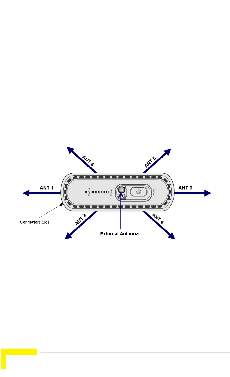
98 BreezeMAX CPEs Product Manual
Chapter 4 - Operation
4.7.3 Antenna Selection (Si CPE)
This option enables selection of either an internal antenna, an external (detached)
antenna or automatic antenna selection.
The available options are 0 (External), 1 to 6 (Internal), or 7 (Automatic).
The default is Automatic.
In Automatic antenna selection mode, all antennas are scanned during the
scanning process to find the best antenna. In addition, all antennas are scanned
continuously during normal operation (using the selected BST/AU and Rx
Frequency), and the selected antenna is always the best one. This fast scanning
process guarantees uniterrupted connectivity and optimal performance upon
possible occurrence of unintentional changes (such as a change in the placement
of the unit or insertion of an obstacle in the communication path).
The numbering plan of the internal antennas is described in the following figure:
4.7.4 Rx Attenuator
The Rx Attenuator option is applicable only for units operating in the 2.3 GHz
band. This option defines the attenuation that can be inserted in the receive path
to improve performance under certain strong interference conditions. This
optional attenuation is aimed primarily to reduce the impact of SDARS (Satellite
Digital Audio Radio Service) in the 2320-2345 MHz frequencies band. It is
Figure 4-1: Si CPE Antennas Numbering Scheme

Radio Parameters Menu
BreezeMAX CPEs Product Manual 99
recommended to set this parameter to 10 db if an interfering signal in the SDARS
band is received at the SU's site at a level exceeding -40 dBm.
The available options are 0 or 10 dBm.
The default is 0 dBm (no attenuation).
4.7.5 Bandwidth
The Bandwidth parameter may not be available in units that support a single
bandwidth. In units where more than one Bandwidth option is available, select
this option to define the bandwidth of the signal.
The options are 1.75 MHz, 3.5 MHz and 5 MHz. Only the options supported by the
specific unit will be available.
The default is 3.5 MHz.
NOTE
RSSI readings do not take into account the Rx attenuation. This means that when the Rx Attenuator is
set to 10 dB, the actual RSSI is higher by 10 dBm from the RSSI value in the Link Quality Display (see
next section).

100 BreezeMAX CPEs Product Manual
Chapter 4 - Operation
4.8 Multirate and ATPC Parameters Menu
In regular operation, the transmitted signal is controlled by the ATPC mechanism.
The ATPC mechanism in the SU is controlled by the Base Station.
The Multirate and ATPC Parameters menu enable temporary control of the signal
transmitted by the SU. It is intended for test purposes only.
These settings will not be saved and will automatically return to original values as
received from the Base Station when the unit resets or upon exiting the program
(or upon termination).
The Multirate and ATPC Parameters menu includes the following options:
Show
Enable ATPC
Disable ATPC and Set Tx Power
Continuous Transmission Menu
4.8.1 Show
Select this option to view the current Multirate and ATPC parameters:
Last Tx Rate
Optimal Rx Rate: The current optimal rate for received signals.
ATPC: The current status current status (Enabled/Disabled) of the ATPC
mechanism
Tx Power: The current Tx power.
4.8.2 Enable ATPC
Select this option to enable the ATPC mechanism after disabling it temporarily for
testing purposes.

Multirate and ATPC Parameters Menu
BreezeMAX CPEs Product Manual 101
4.8.3 Disable ATPC and Set Tx Power
Select this option to temporarily disable ATPC for testing purposes. You will be
prompted to enter the requested Tx Power. The minimum Tx Power is -26 dBm.
The maximum depends on the unit’s type and band.
The default Tx Power is the last power level used before the ATPC algorithm was
disabled.
Upon completing the test, enable ATPC to resume normal operation. If not enabled
manually, ATPC will be enabled automatically after the next reset or following
termination of the Telnet session.
4.8.4 Continuous Transmission Menu
The Continuous Transmission Menu enables activating continuous transmission
of specific signals for special testing purposes. The continuous transmission mode
cannot be activated when the SU has either started a network entry process or is
already synchronized with a Base Station.
The Continuous Transmission Menu includes the following options:
4.8.4.1 Transmission Type
The available Transmission Types are CW (Continuous Wave, or carrier only) and
OFDM.
4.8.4.2 Transmission Duration
The Transmission Duration from 0 to 536 seconds. 0 means the unit will transmit
continuously until it will be reset. After 15 minutes the unit will be reset
automatically.
4.8.4.3 Transmission Tx Power
The Transmission Tx Power in dBm according to the range supported by the
tested unit.
4.8.4.4 Transmission Frequency [MHz]
The Transmission Frequency in MHz according to the range supported
4.8.4.5 Start Transmission
Selected this option to start the continuous transmission test using the
configured test parameters.

102 BreezeMAX CPEs Product Manual
Chapter 4 - Operation
4.8.4.6 Show Current Parameters
Select this option to view the current test parameters and status (on/off).

Performance Monitoring Menu
BreezeMAX CPEs Product Manual 103
4.9 Performance Monitoring Menu
The Performance Monitoring menu includes the following options:
Start Link quality Display
Counters
Spectrum Analyzer
4.9.1 Start Link Quality Display
Select this option to get a continuously updated display of link quality indicators.
Each displayed line includes:
DL SNR (dB): The average Signal to Noise Ratio of the signal received by the
SU
DL RSSI (dBm): The average level of the signal received by the SU
Optimal Rx Rate: The optimal Rx rate calculated by the SU and requested
from the AU/Micro Base Station.
Last Rx Rate
Last Tx Power (dBm)
UL SNR (dB): The average Signal to Noise Ratio of the signal received by the
AU/Micro Base Station
UL RSSI (dBm): The average level of the signal received by the AU/Micro Base
Station
4.9.2 Counters
The Counters menu includes the following options:
Display Counters
Reset Counters

104 BreezeMAX CPEs Product Manual
Chapter 4 - Operation
4.9.2.1 Display Counters
Select this option to display the current status of the traffic counters. The counts
are the accumulated number of relevant Bytes since the last unit reset or the last
Counters Reset.
The counters indicate the traffic at the Ethernet and Wireless ports. The displayed
counters include:
Ethernet Port Counters
»Data Bytes Received: The total number of data bytes received from the
Ethernet link. Management frames and frames with errors are not
included.
»Data Bytes Discarded on Rx: The number of bytes discarded when a
packet received from the Ethernet port is not forwarded to the Wireless
port due to bridging or classification considerations.
»Data Bytes Transmitted: The total number of data bytes transmitted to
the Ethernet link. Management frames and frames with errors are not
included.
»Data Bytes Discarded on Tx: The number of bytes discarded when a
packet received from the Wireless port is not forwarded to the Ethernet
port due to bridging or VLAN considerations.
Wireless Port Counters
»Data Bytes Received: The total number of data bytes received from the
Wireless link. Management frames and frames with errors are not
included.
»Data Bytes Discarded on Rx: The number of bytes in packets received
from the Wireless link and discarded due to MAC protocol receive errors,
such as duplicate sequence number, wrong sequence number, etc. (not
CRC errors).
»Data Bytes Transmitted: The total number of data bytes transmitted to
the Wireless link. MAC Management frames and frames with errors are not
included.
»Data Bytes Discarded on Tx: The number of bytes in packets discarded
due to congestion in the wireless medium.
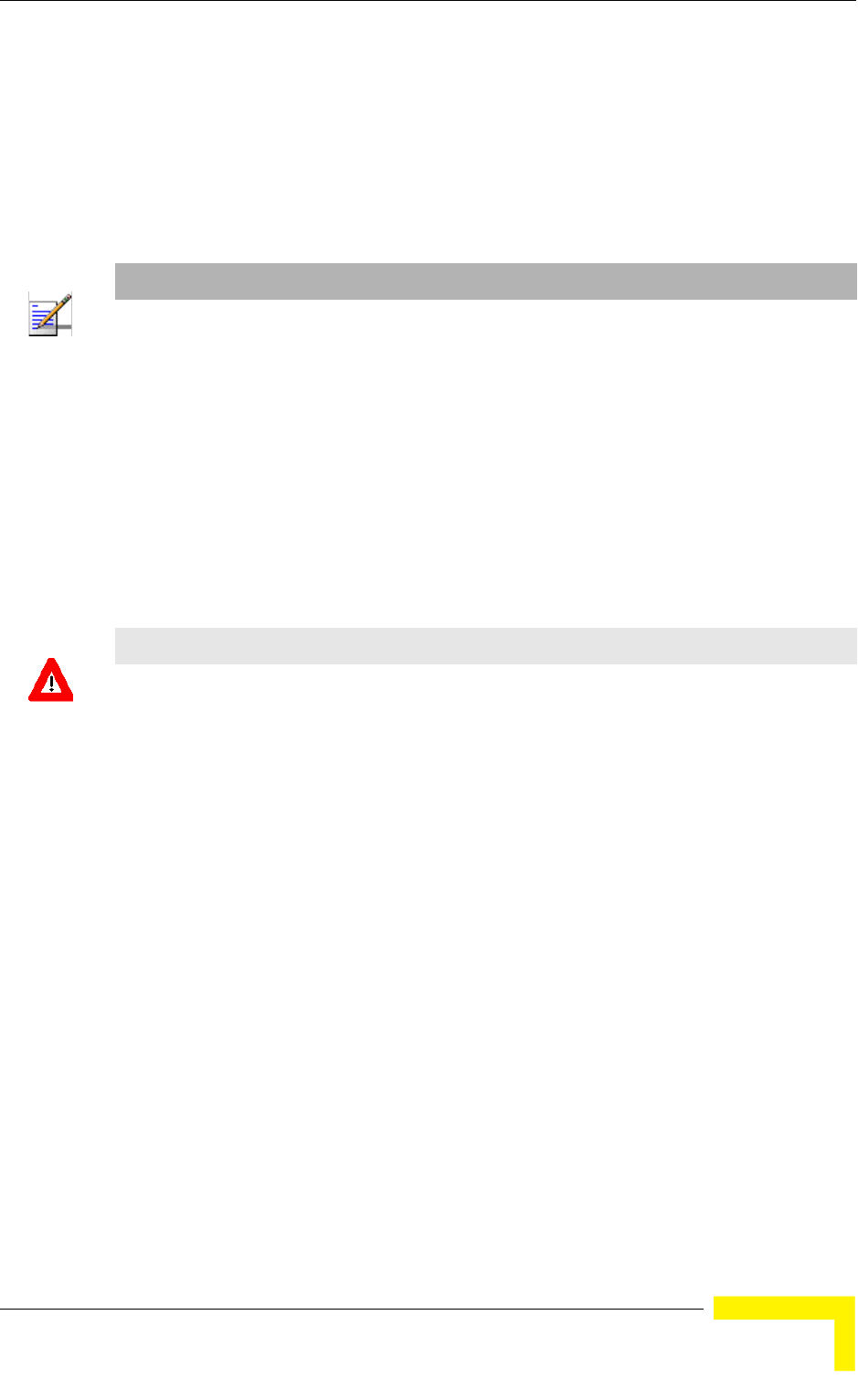
Performance Monitoring Menu
BreezeMAX CPEs Product Manual 105
4.9.2.2 Reset Counters
Select this options to reset all the counters.
4.9.3 Spectrum Analyzer
The Spectrum Analyzer option enables initiating a spectrum analysis test on
selected frequencies/antennas, terminating an active test and viewing the results
of the last test.
Using the parameters defined for the test, the SU scans the selected central
frequencies. At each frequency it measures the RSSI for each of the applicable
sub-carrier frequencies, and calculates the median RSSI (for all sub-carriers).
After completion of the test the results are displayed automatically.
The displayed results include for each of the tested central frequency and
antennas the median RSSI and the MAX (highest) RSSI measurement at the
relevant sub-carries.
The Spectrum Analyzer menu includes the following options:
Start Frequency
Stop Frequency
Scanning Step
Single Freq Scanning Duration
Antenna to be tested
Show Parameters
Start Scanning
NOTE
During the test, the SU switches to receive mode and is disconnected from the AU.
CAUTION
After completion of the test (and viewing the results) exit the menu by selecting the Exit Spectrum
Mode option. This will automatically reset the SU. The SU must be reset to resume normal
operation.

106 BreezeMAX CPEs Product Manual
Chapter 4 - Operation
Stop Scanning
Exit Spectrum mode
4.9.3.1 Start Frequency
The first frequency (in MHZ) participating in the test. Must be in the range
supported by the unit.
4.9.3.2 Stop Frequency
The highest frequency (in MHz) that may participate in the test (the actuall
highest frequency depends on the defined Start Frequency and Scanning Step).
Must be in the range supported by the unit.
4.9.3.3 Scanning Step
The scanning step size. The available options are:
1 - 1.75 MHz
2 - 3.5 MHz
3 - 2.5 MHz
4 - 5 MHz
The scanned frequencies are defined by Start Frequency + N*Scanning Step where
N is 0, 1, 2...and the scanned frequency is lower than or or equal to the Stop
Frequency.
4.9.3.4 Single Freq Scanning Duration
The test duration in seconds at each of the scanned frequencies. The available
range is from 1 to 65535 seconds.
4.9.3.5 Antenna to be tested
The antenna(s) to be tested during the test: external (0), internal (1 - 6) or all (7).
4.9.3.6 Show parameters
Select this option to view the current values of the test parameters.

Performance Monitoring Menu
BreezeMAX CPEs Product Manual 107
4.9.3.7 Start Scanning
Select this option to start the test. Upon completion of the test the results will be
displayed automatically.
4.9.3.8 Stop Scanning
Select this option to abort a currently active test.
4.9.3.9 Exit Spectrum mode
Select this option to properly exit the Spectrum Analysis menu. The SU will reset
automatically and resume normal operation.

108 BreezeMAX CPEs Product Manual
Chapter 4 - Operation
4.10 FDD Parameters (3.3/3.5/3.6 GHz units
only)
The FDD Parameters menu enables viewing/updating the Radio parameters for
Standard operation mode. These parameters do not affect the operation of the unit
when using Advanced Si operation mode. These parameters are provided to
support the Automatic Platform Detection mechanism of the dual-mode CPEs,
allowing pre-configuration of the relevant parameters before switching the sector
to operate in FDD mode using Standard operation mode. These parameters are
applicable only to SUs that may support FDD operation (all SUs in the 3 GHz
bands except the new 3.x GHz Si CPE supporting the entire band from 3.3 to 3.8
GHz).
4.10.1 BST/AU ID
Select this option to define the BST/AU ID. This is the base BST/AU ID used
together with the BST/AU ID Mask to define the range of BSTs/AUs that can
synchronize with the unit.
The BST/AU ID comprises 6 groups of up to 3 digits each, where the range of each
group is 0 to 255. The first 3 groups form the Operator ID. The next 2 groups form
the Cell ID, and the last group forms the Sector ID.
The default BST/AU ID is 186.190.0.0.250.206
4.10.2 BST/AU ID Mask
Select this option to define the BST/AU ID Mask. The BST/AU ID Mask, together
with the BST/AU ID, define the range of BSTs/AUs that can synchronize with the
SU.
The BST/AU ID Mask comprises 6 groups of up to 3 digits each, where the range
of each group is 0 to 255. The first 3 groups form the mask for the Operator ID.
The next 2 groups form the mask for the Cell ID, and the last group forms the
mask for the Sector ID.
The default BST/AU ID Mask is 255.255.255.0.0.0.
4.10.3 Bandwidth
The Bandwidth parameter may not be available in units that support a single
bandwidth. In units where more than one Bandwidth option is available, select
this option to define the bandwidth of the signal.

FDD Parameters (3.3/3.5/3.6 GHz units only)
BreezeMAX CPEs Product Manual 109
The options are 1.75 MHz, 3.5 MHz and 5 MHz. Only the options supported by the
specific unit will be available.
The default is 3.5 MHz.
4.10.4 Uplink (Tx) Frequency
Select this option to define the transmit frequency of the SU when operating in
FDD (Standard) mode.
The available range and default value depend on the Radio Band of the unit and
on the Bandwidth. The resolution is 0.125 MHz.
NOTE
Some frequencies are available only with a certain Bandwidth. For example, in 3.5 GHz units that
support bandwidth options of either 1.75 MHz or 3.5 MHz, the frequencies 3400.375-3401.125,
3498.375-3499.125 are available only with bandwidth of 1.75 MHz. Prior to selecting any of these
frequencies the Bandwidth must be configured to 1.75 MHz.

110 BreezeMAX CPEs Product Manual
Chapter 4 - Operation
4.11 SU Parameters Summary
Table 4-2: SU Parameters Summary
Parameter Range Default Run-Time
Updated
Unit Control Parameters
Password Up to 20 printable characters,
case sensitive
installer No
TFTP Server IP Address IP address 192.168.254.250 Yes
SW File Name Yes
Ethernet Port Auto Negotiation
Enable/Disable
Disable
Enable
Enable No
Ethernet Port Speed and Duplex 10Mbps,
Half-Duplex10Mbps,
Full-Duplex100Mbps,
Half-Duplex100Mbps,
Full-Duplex
No
Registration Parameters
User Name Up to 32 printable characters,
case sensitive
User Password Up to 32 printable characters,
case sensitive
Organization Name Up to 32 printable characters Empty Yes
Address Up to 32 printable characters Empty Yes
Country Up to 12 printable characters Empty Yes
BST/AU ID Parameters
BST/AU ID 6 groups of up to 3 digits each.
Each group range is 0-255.
186.190.0.0.250.206 No
BST/AU ID Mask 6 groups of up to 3 digits each.
Each group range is 0-255.
0.0.0.0.0.0 No
Preferred BST/AU ID 6 groups of up to 3 digits each.
Each group range is 0-255.
186.190.0.0.250.206 No

SU Parameters Summary
BreezeMAX CPEs Product Manual 111
Preferred BST/AU ID Mask 6 groups of up to 3 digits each.
Each group range is 0-255.
0.0.0.0.0.0 No
Set Mobility Mode nomadic
mobile
nomadic Yes
Radio Parameters
Bandwidth 1.75 MHz
3.5 MHz
5 MHz
Actually available options
depend on HW
3.5 MHz No
Antenna Selection(Si CPE) 0 (External)
1 - 6 (Internal)
7 (Automatic
Automatic Yes
Scanning Start Frequency Depend on Radio Band and
Bandwidth
Yes
(after Update
Scanning Table
Scanning End Frequency Depend on Radio Band and
Bandwidth
Yes
(after Update
Scanning Table
Scanning Main Step Depend on Radio Band and
Bandwidth
875 KHz Yes
(after Update
Scanning Table
Scanning Intermediate Steps 1
-8
Disable/Enable for each of the
8 Intermediate Steps
Enable for all Steps Yes
(after Update
Scanning Table
Discrete Frequencies Up to 10. Available frequencies
depend on Radio Band and
Bandwidth.
Null (empty list) Yes
(after Update
Scanning Table
Rx Attenuator
(2.3 GHz units)
0, 10 (dB) 0
Multirate and ATPC Parameters
Table 4-2: SU Parameters Summary
Parameter Range Default Run-Time
Updated

112 BreezeMAX CPEs Product Manual
Chapter 4 - Operation
Set Tx Power -26 dBm to the highest value
supported by the unit.
Last power used by
ATPC
Yes
FDD Parameters (3.x GHz units only)
BST/AU ID 6 groups of up to 3 digits each.
Each group range is 0-255.
186.190.0.0.250.206 No
BST/AU ID Mask 6 groups of up to 3 digits each.
Each group range is 0-255.
255.255.255.0.0.0 No
Bandwidth 1.75 MHz
3.5 MHz
5 MHz
Actually available options
depend on HW
Depend on HW No
Uplink (Tx) Frequency Depends on the Radio Band
and Bandwidth
Depends on Radio Band No
Table 4-2: SU Parameters Summary
Parameter Range Default Run-Time
Updated

A
Appendix A - The Web Configuration Server
In This Appendix:
“The Web Configuration Server” on page 114
“Pocket PC/PDA Requirements” on page 115
“Accessing the Web Configuration Server” on page 117
“Using the Web Configuration Server” on page 118
“Control Buttons” on page 120
“Changing the Password” on page 121
“Unit Reset” on page 122

114 BreezeMAX CPEs Product Manual
Appendix A - The Web Configuration Server
A.1 The Web Configuration Server
The Web Configuration Server enables the configuration of all SU parameters
using a Pocket PC/PDA or a Notebook/PC with a web browser. The computing
device can be connected either to the Ethernet port of the IDU, or to the IDU COM
connector of the ODU (using a special Y-Cable available from Alvarion). It also
enables downloading of SW files, control of the running SW version, and
downloading/uploading of the configuration file, enabling simplified and faster
configuration process.
The Web Configuration Server also provides a selection of performance monitoring
capabilities, allowing installers and technicians to view information on link quality
and traffic counters. These monitoring capabilities enable performance
verification and problems identification.
To further support local testing, the program also enables temporary control of the
ATPC mechanism.

Pocket PC/PDA Requirements
BreezeMAX CPEs Product Manual 115
A.2 Pocket PC/PDA Requirements
The following table displays the minimum/recommended requirement for a Pocket
PC/PDA:
Table A-1: Pocket PC/PDA Minimum/Recommended Requirements
Item Minimum/Recommended
CPU Strong ARM, 200MHz
Memory RAM: 64MB
Flash: 32MB
Display & Backlight 3.5" diagonal, TFT 240x320, 64K colors + Backlight
Keys Soft Keyboard on screen or compatible
Touch Panel With Stylus
Expansion Slot Compact Flash (CF)
Expansion Card Recommended: CF Ethernet Card EA2902-139 from Socket
Connection to CPE Ethernet
W/L 802.11b/g (optional-for use with IDU-NG-4D1W and other future
CPEs)
Carrying Concept Neck Strap or Handle Strap
Operating System Windows Mobile 2003
Software & Protocols TCP/IP
DHCP client
FTP
Te l n e t
WEB
TFTP Server
PPPoE Client
Ethernet/WL drivers

116 BreezeMAX CPEs Product Manual
Appendix A - The Web Configuration Server
The following PDAs from Hewlett-Packard were tested and approved for use with
the Web Configuration Server:
1IPAQ FA296A Hx2110
2IPAQ FA282A Hx4700
Standards Compliance EN-300 019-2-2 (Storage & Transportation Temperature, Random
Vibration, Shock)
EN-300 019-2-4 (Operating Temperature, Sun Light Visibility, Rain,
Humidity, Drop)
EN-300386 (EMC)
EN-60950-1 (Safety)
Table A-1: Pocket PC/PDA Minimum/Recommended Requirements
Item Minimum/Recommended

Accessing the Web Configuration Server
BreezeMAX CPEs Product Manual 117
A.3 Accessing the Web Configuration Server
To configure parameters using the Web Configuration Server, connect a
PC/Notebook or a Pocket PC/PDA with a web browser to the Ethernet port of the
IDU, using a straight Ethernet cable.
You can also connect directly to the ODU's IDU COM, using the special Y-cable.
1Configure the PC's IP parameters to enable connectivity with the unit. The IP
address of the SU for local management access is 192.168.254.251. The
Subnet Mask is 255.255.255.0. The recommended IP address for the PC is
192.168.254.250, as this is also the default TFTP Sever IP Address (required
for downloading SW versions and for downloading/uploading configuration
files).
2Open a web browser, and connect to http://192.168.254.251. The Enter
Network Password window is displayed. Enter the Username and password
and click OK.
3The Main menu of the Web Configuration Server is displayed, enabling access
to the required parameters configuration and performance monitoring options.
NOTE
The User Name is "installer".
The default Password is "installer".
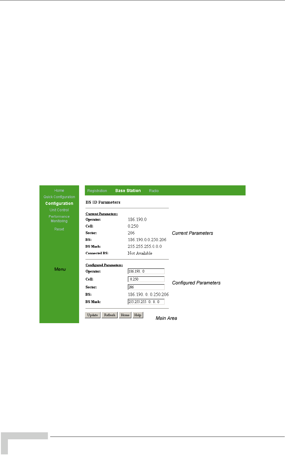
118 BreezeMAX CPEs Product Manual
Appendix A - The Web Configuration Server
A.4 Using the Web Configuration Server
The Web Configuration Server view when using a Notebook/PC consists of a
number of menu links (to the left). Clicking on each of them will display the
configuration/status page for the selected menu item, with the applicable content
(configurable parameters/options or status information) in the main area.
Several pages include a page selection bar at the top of the page, enabling
selection between several pages related to the same menu item.
When using a Pocket PC/PDA, the Home page includes the Main Menu with all
menu links to the available pages.
Several pages include a Current Parameters area and a Configured Parameters
area. The Current Parameters area displays the current unit's settings. To change
the settings of the parameters, enter the new settings in the Configured
Parameters area and click the Update button.
For information on each parameter, click on the Help button on the appropriate
page.
Figure A-1: Typical Web Configuration Page (Notebook/PC)
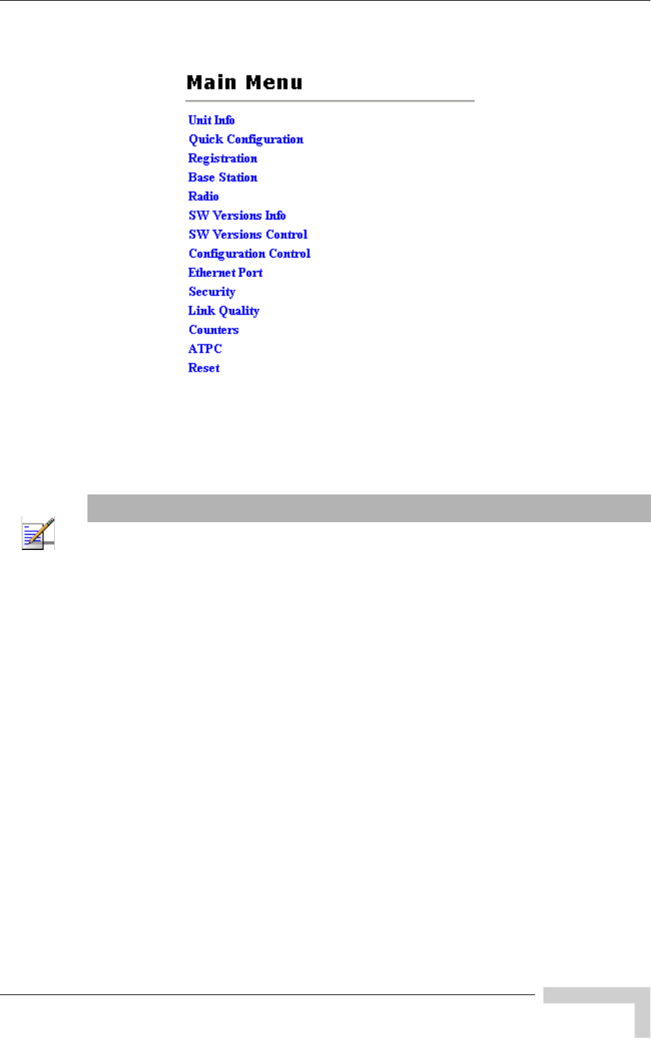

120 BreezeMAX CPEs Product Manual
Appendix A - The Web Configuration Server
A.5 Control Buttons
Many of the pages include the following buttons:
Update - accepts the changes to the parameters setting. Click on the Update
button before selecting another page/menu item, or before quitting the
application. The Update functionality in many cases is per page - if you leave
the page without clicking the Update button, all the changes in the page will
be lost.
Refresh - refreshes the values displayed. Changes made without clicking the
Update button, are discarded upon clicking the Refresh button.
Home - In the Notebook/PC, opens the Unit Info page while still highlighting
the menu and submenu from which the Home button was clicked. In the
Pocket PC/PDA, opens the Main Menu page.
Help - opens the help page with information on the parameters/options in the
currently displayed page.

Changing the Password
BreezeMAX CPEs Product Manual 121
A.6 Changing the Password
1Select the Security page in the Unit Control menu.
2Enter the new password in the New Password field.
3Re-enter the new password in the Confirm New Password field.
4Click on the Save New Password button.
Valid passwords: Up to 20 printable characters.
Default password: installer
To change the unit's password:
NOTE
Notify the administrator of the new password!

122 BreezeMAX CPEs Product Manual
Appendix A - The Web Configuration Server
A.7 Unit Reset
To reset the unit, select the Reset menu and click on the Reset Unit button. To
avoid unintentional reset, you will be prompted to confirm the reset request.
Changes to most of the configurable parameters are applied only after reset. Refer
to Section 4.11 for information on which parameters are changeable in run time
and which changes are applied only after reset.


124 BreezeMAX CPEs Product Manual
Appendix B - Troubleshooting
B.1 Si CPE Troubleshooting
Refer to the BreezeMAX Troubleshooting Guide for additional information on
troubleshooting,
Problem and Indication Possible Cause Corrective Action
Power Failure: None of the
LEDs illuminate after
connecting to power
Mains power problem Verify mains power availability on the power outlet to
which the power supply is connected. Try using a
different outlet.
Mains power connection
problem
Verify that the AC jack of the power cord is
connected properly to the power supply.
Verify that the AC plug of the power cable is
connected properly to the mains power outlet.
DC power connection
problem
Verify that the DC plug is connected properly to the
power jack of the Si CPE.
Unit failure Contact the supplier.
When connected to the
data equipment, the
Ethernet Integrity Indicator
(green LED) is off, and/or
the Ethernet Activity
Indicator (yellow LED) does
not blink when there should
be traffic on the Ethernet
port.
Wrong type of Ethernet
cable or faulty cable.
If connected directly to PC-use a straight cable.
Otherwise-use a crossed cable. If the problem
persists, try replacing the cable.
If a hub or switch is installed between the PC and
the CPE, verify first the Ethernet connection integrity
between the hub/switch and the PC by checking the
Ethernet LEDs at the hub/switch and at the PC's
NIC card. If not ok, try replacing the cable.
Unit failur Contact the supplier

Si CPE Troubleshooting
BreezeMAX CPEs Product Manual 125
The Ethernet Activity and/or
Integrity LEDs are on, but
no management access
using Telnet or web
browser, and the unit does
not respond to ping.
Wrong IP configuration Make sure that the PC is on the same subnet as the
unit. The unit's IP address for management
purposes is 192.168.254.251, and the subnet mask
is 255.255.255.0.
Wrong Ethernet port
operation mode
Make sure that the speed and duplex settings in the
PC match the configuration in the unit. The default
operation mode is Auto Negotiation, and supported
speeds are 10/100 Mbps, Full or Half Duplex.
ARP table in the PC
contains a wrong MAC
address for the
192.168.254.251 IP
address (due to a recent
connection to another SU).
Perform arpV-d at the DOS command prompt to
clear the ARP table, and retry the Telnet command
to the unit.
Bridging table in SU is full
(expected when Number of
Supported Devices,
configurable from the Base
station's side, is set to a
small number.
Reset the SU to clear the table and retry the Telnet
command to the unit.
After power-up, STATUS
LED does not illuminate, at
least one of the SIGNAL
LEDs illuminate
STATUS LED failure Try completing the installation process.
Unit failure If the installation process fails, contact the supplier.
Problem and Indication Possible Cause Corrective Action

126 BreezeMAX CPEs Product Manual
Appendix B - Troubleshooting
Scanning failed: STATUS
LED is orange, none of the
SIGNAL LEDs illuminate or
all SIGNAL LEDs illuminate
one after the other.
Configuration problem Verify proper configuration of Frequency Scanning
parameters.
If proper configuration parameters are not known,
press the RESET button for more than 5 seconds to
activate the factory default configuration
Poor link quality Verify that the correct antenna is selected.
If an internal antenna is used, verify that the
selected antenna is directed towards the Base
Station.
For either a selected internal antenna or automatic
antenna selection, verify that all installation
guidelines are followed (no interfering objects,
proper distance from electrical equipment and metal
objects, location as near as possible to the window,
etc).Try changing the location of the unit to improve
link quality using the SIGNAL LEDs.
Try using a detached antenna. Verify that the
antenna selected is external antenna. Verify proper
antenna installation and cable connection. Improve
antenna’s location using the SIGNAL LEDs.
Base Station not found:
STATUS LED is orange,
SIGNAL LEDs illuminate
from the middle outwords
(LED 4 lights, after 200ms
LEDs 3 & 5 lights, after
200ms LEDs 2&6
lights,after 200ms LEDs
1&7 lights, after 200ms all
the LEDs are extinguished
and then the sequence is
repeated)
Configuration problem Verify proper configuration of Base Station and Best
AU parameters.
If proper configuration parameters are not known,
press the RESET button for more than 5 seconds to
activate the factory default configuration
Signal is too strong:
STATUS LED is orange, All
SIGNAL LEDs blink
simultaneously
Signal is too strong-may
cause saturation.
Change the location/direction of the unit/antenna to
reduce signal strength using the SIGNAL LEDs
Problem and Indication Possible Cause Corrective Action

Si CPE Troubleshooting
BreezeMAX CPEs Product Manual 127
Authentication Failure:
STATUS LED is blinking
green, SIGNAL LED 7 is
on, all other SIGNAL LEDs
are off.
Authentication problem:
a. Wrong User Name
and/or User Password.
b.Maximum number of
Multiple Sessions (number
of SUs that can receive the
Service simultaneously)
has been reached.
Enter User Name and User Password and reset the
unit. If the problem persists, contact the operator.
Duplicate Name: STATUS
LED is blinking green,
SIGNAL LEDs 6 and 7 are
on, all other SIGNAL LEDs
are off.
User Name already exists
in the Base Station’s
database, associated with
another SU (MAC address)
Enter a correct User Name or contact the operator
for a new User Name/Password. Reset the unit after
configuring new authentication parameters.
Authentication Timeout:
STATUS LED is blinking
green, SIGNAL LEDs 5, 6
and 7 are on, all other
SIGNAL LEDs are off.
The unit was not
reauthenticated after
authentication timeout.
Contact the operator.
Problem and Indication Possible Cause Corrective Action

128 BreezeMAX CPEs Product Manual
Appendix B - Troubleshooting
B.2 PRO-S CPE Troubleshooting
Refer to the BreezeMAX Troubleshooting Guide for additional information on
troubleshooting,
Problem and Indication Possible Cause Corrective Action
Power Failure: None of the
IDU LEDs illuminate after
connecting to power
Mains power problem Verify mains power availability on the power outlet to
which the power supply is connected. Try using a
different outlet.
Mains power connection
problem
Verify that the AC jack of the power cord is
connected properly to the unit.
Verify that the AC plug of the power cable is
connected properly to the mains power outlet.
Unit failure Replace the IDU.
IDU-ODU connection
problem: None of the SAU’s
indicators illuminate
IDU-ODU connection
problem
Verify that the IDU-ODU cable is connected
properly.
Unit failur Try replacing the IDU. If the problem persists, try
replacing the IDU-ODU cable. If the problem
persists, try replacing the ODU.
When connected to the
data equipment, the
Ethernet Integrity Indicator
(green LED) is off, and/or
the Ethernet Activity
Indicator (yellow LED) does
not blink when there should
be traffic on the Ethernet
port.
Wrong type of Ethernet
cable or faulty cable.
If connected directly to PC-use a straight cable.
Otherwise-use a crossed cable. If the problem
persists, try replacing the cable.
If a hub or switch is installed between the PC and
the CPE, verify first the Ethernet connection integrity
between the hub/switch and the PC by checking the
Ethernet LEDs at the hub/switch and at the PC's
NIC card. If not ok, try replacing the cable.
IDU-ODU cable problem. Verify that the IDU-ODU cable is in order and
connected properly. Using SAU, verify that PWR
LED is on and ALRM LED is off.
Unit failur Try replacing the IDU. If the problem persists, try
replacing the IDU-ODU cable. If the problem
persists, try replacing the ODU.

PRO-S CPE Troubleshooting
BreezeMAX CPEs Product Manual 129
The Ethernet Activity and/or
Integrity LEDs are on, but
no management access
using Telnet or web
browser, and the unit does
not respond to ping.
Wrong IP configuration Make sure that the PC is on the same subnet as the
unit. The unit's IP address for management
purposes is 192.168.254.251, and the subnet mask
is 255.255.255.0.
Wrong Ethernet port
operation mode
Make sure that the speed and duplex settings in the
PC match the configuration in the unit. The default
operation mode is Auto Negotiation, and supported
speeds are 10/100 Mbps, Full or Half Duplex.
ARP table in the PC
contains a wrong MAC
address for the
192.168.254.251 IP
address (due to a recent
connection to another SU).
Perform arpV-d at the DOS command prompt to
clear the ARP table, and retry the Telnet command
to the unit.
Bridging table in SU is full
(expected when Number of
Supported Devices,
configurable from the Base
station's side, is set to a
small number.
Reset the SU to clear the table and retry the Telnet
command to the unit.
Scanning failed and/or
Base Station not found:
None of the LINK QUALITY
LEDs illuminate.
Configuration problem Verify proper configuration of Frequency Scanning
parameters.
Verify proper configuration of Base Station and Best
AU parameters.
If proper configuration parameters are not known,
press the RESET button for more than 5 seconds to
activate the factory default configuration
Poor link quality Try changing the location of the unit/antenna to
improve link quality using the LINK QUALITY LEDs.
Signal is too strong:All LINK
QUALITY LEDs, including
the red LED are on
Signal is too strong-may
cause saturation.
Change the location/direction of the unit/antenna to
reduce signal strength using the LINK QUALITY
LEDs.
Problem and Indication Possible Cause Corrective Action

130 BreezeMAX CPEs Product Manual
Appendix B - Troubleshooting
Authentication Failure: LED
1 (ELNK-orange) of the
LINK QUALITY bar blinks.
Authentication problem:
a. Wrong User Name
and/or User Password.
b.Maximum number of
Multiple Sessions (number
of SUs that can receive the
Service simultaneously)
has been reached.
c. Duplicate Name: User
Name already exists in the
Base Station’s database,
associated with another SU
(MAC address).
d. Authentication
Timeout:The unit was not
reauthenticated after
authentication timeout.
Enter User Name and User Password and reset the
unit. If the problem persists, contact the operator.
Problem and Indication Possible Cause Corrective Action

Glossary
APD Automatic Platform Detection. A mechanism that dtects the wreless
link protocol used by the Base Station, enabling automatic selection of
the Duplex Mode (FDD or TDD) to be used by the Subscriber Unit.
ATPC Automatic Transmit Power Control
AU Access Unit
BE Best effort. A service where neither throughput nor delay guarantees
are provided. The subscriber unit sends requests for bandwidth in
either random access slots or dedicated transmission opportunities.
The occurrence of dedicated opportunities is subject to network load,
and the subscriber unit cannot rely on their presence. Service
parameters include Committed Time (CT) and Maximum Information
Rate (MIR).
BPSK Binary Phase-Shift Keying. A data transfer technique. BPSK transmits
data using two phase modulation signals, one phase representing a
binary one, and the other representing a binary zero. The signal is
divided into bits; their status is determined by the preceding wave. If
the wave changes, for example, the signal is reversed.
BST Base Station
BWA Broadband Wireless Access
CF Compact Flash. A popular memory card that uses flash memory to
store data on a very small card.
CG Continuous Grant. Also known as Unsolicited Grant Services (UGS), is
tailored for carrying constant bit- rate (CBR) real-time services
characterized by fixed size data packets on a periodic basis such as
VoIP or E1/T1. Service parameters include unsolicited grant size
(packet size) and normal grant interval (sample interval).
CIR Committed Information Rate. The rate (in bits per second) at which a
network guarantees to transfer information under normal conditions,
averaged over a minimum increment of time.

132 BreezeMAX CPEs Product Manual
Glossary
CLI Command Line Interface. A user interface where the user sees the
command line on the monitor and a prompt that is waiting to accept
instructions from the user. The user types in the command, the
computer acts on that command and then issues a new prompt for the
next instruction from the user.
CPE Customer Premise Equipment. Communications equipment that
resides on the customer's premises.
CPU Central Processing Unit
CRC Cyclical Redundancy Check. A common technique for detecting data
transmission errors, in which the frame recipient calculates a
remainder by dividing frame contents by a prime binary divisor and
compares the calculated remainder to a value stored in the frame by
the sending equipment.
CSMA/CD Carrier Sense Multiple Access with Collision Detection. Media-access
mechanisms wherein devices ready to transmit data first check the
channel for a carrier. If no carrier is sensed for a specific period of
time, a device can transmit. If two devices transmit at once, a collision
occurs and is detected by all colliding devices. This collision
subsequently delays retransmissions from those devices for some
random length of time. Ethernet and IEEE 802.3 use CSMA/CD
access.
CT Committed Time. The time interval used for measuring average
information transfer rates.
DHCP Dynamic Host Configuration Protocol. A protocol for dynamically
assigning IP addresses from a pre-defined list to nodes on a network.
Using DHCP to manage IP addresses simplifies client configuration
and efficiently utilizes IP addresses.
DL Down Link
DRAP Dynamic Resources Allocation Protocol
EMC Electro-Magnetic Compatibility. The capability of equipment or
systems to be used in their intended environment within designed
efficiency levels without causing or receiving degradation due to
unintentional EMI (Electro Magnetic Interference). EMC generally
encompasses all of the electromagnetic disciplines.
ETSI European Telecommunications Standards Institute. A non-profit
organization producing voluntary telecommunications standards used
throughout Europe, some of which have been adopted by the EC as
the technical base for Directives or Regulations.

Glossary
BreezeMAX CPEs Product Manual 133
FCC Federal Communications Commission. A U.S. government agency that
supervises, licenses, and controls electronic and electromagnetic
transmission standards.
FDD Frequency Division Duplex. Full duplex operation by using a pair of
frequencies, one for transmission and one for reception.
FEC Forward Error Correction. A method of communicating data that can
corrects errors in transmission on the receiving end. Prior to
transmission, the data is put through a predetermined algorithm that
adds extra bits specifically for error correction to any character or code
block. If the transmission is received in error, the correction bits are
used to check and repair the data.
FFT Fast Fourier Transform. An algorithm for converting data from the
time domain to the frequency domain; often used in signal processing.
FTP File Transfer Protocol. A protocol for exchanging files over the Internet.
FTP uses the Internet's TCP/IP protocols to enable data transfer.
GUI Graphical User Interface. In a GUI operating system, the user
responds to graphic images on the screen instead of typing in
commands in response to a prompt.
H.323 A protocol suite defined by ITU-T for voice transmission over internet
(Voice over IP or VoIP). In addition to voice applications, H.323
provides mechanisms for video communication and data collaboration,
in combination with the ITU-T T.120 series standards.
HTTP HyperText Transfer Protocol. The protocol used to transmit and receive
all data over the World Wide Web.
IDU Indoor Unit
IEEE Institute of Electrical and Electronics Engineers. IEEE (pronounced
I-triple-E) is an organization composed of engineers, scientists, and
students. The IEEE is best known for developing standards for the
computer and electronics industry. In particular, the IEEE 802
standards for local-area networks are widely followed.
IEEE 802.3 A Local Area Network protocol suite commonly known as Ethernet.
Ethernet uses Carrier Sense Multiple Access bus with Collision
Detection CSMA/CD. This method allows users to share the network
cable. However, only one station can use the cable at a time. A variety
of physical medium dependent protocols are supported.

134 BreezeMAX CPEs Product Manual
Glossary
IEEE 802.11b The IEEE 802.11b (also referred to as 802.11 High Rate or Wi-Fi). An
extension to 802.11 standard for wireless Ethernet networks, that
applies to wireless LANS and provides 11 Mbps transmission (with a
fallback to 5.5, 2 and 1 Mbps) in the 2.4 GHz band.
IEEE 802.11g An extension to 802.11 standard for wireless Ethernet networks, that
applies to wireless LANs and provides 20+ Mbps in the 2.4 GHz band.
IP Internet Protocol. The standard that defines how data is transmitted
over the Internet. IP bundles data, including e-mail, faxes, voice calls
and messages, and other types, into "packets", in order to transmit it
over public and private networks.
LAN Local area Network. A computer network limited to a small
geographical area, such as a single building. The network typically
links PCs as well as shared resources such as printers.
LED Light Emitting Diode.
MAC Address Standardized data link layer address that is required for every port or
device that connects to a LAN. Other devices in the network use these
addresses to locate specific ports in the network and to create and
update routing tables and data structures. MAC addresses are 6bytes
long and are controlled by the IEEE.
MCS Multipoint Communications Systems. Applications licensed at 2500 MHz in Canada. A
wide variety of applications are possible including one-way and two-way transmission
and a diversity of distribution capacities.
MIR Maximum Information Rate. Specifies the maximum rate of
information that can be available to a user. The MIR is used by the
traffic policing mechanism to prevent users from sending excess traffic
to the network.
MMDS Multichannel Multipoint Distribution Service. MMDS is a licensed wireless service that
has the capability to provide broadband access. MMDS operates in several parts of the
2 GHz spectrum.
NA Not Available or Not Applicable
NAT Network Address Translation. Basic Network Address Translation
(Basic NAT) is a method by which IP addresses are mapped from one
group to another, transparent to end users. Network Address Port
Translation, or NAPT is a method by which many network addresses
and their TCP/UDP ports are translated into a single network address
and its TCP/UDP ports. Together, these two operations, referred to as
traditional NAT, provide a mechanism to connect a realm with private
addresses to an external realm with globally unique registered
addresses.

Glossary
BreezeMAX CPEs Product Manual 135
NIC Network Interface Card. An expansion board you insert into a
computer (or a built-in component) that enables the computer to
connect to a network. Most NICs are designed for a particular type of
network, protocol, and media, although some can serve multiple
networks.
NPU Network Processing Unit
NRT Non Real Time. is very similar to the Real-Time polling service except
that connections may utilize random access transmit opportunities for
sending bandwidth requests. These Non Real Time Variable Bit Rate
(NRT-VBR) services, such as file transfer and Internet access with a
minimum guaranteed rate, are characterized by requirement for a
guaranteed rate, but can tolerate longer delays and are rather
insensitive to jitter. Service parameters include CIR, Committed Time
(CT), and MIR that limit the rate as otherwise bandwidth-intensive
services may expand to occupy full bandwidth.
ODU Outdoor Unit
OFDM Orthogonal Frequency Division Multiplexing: A method for
multiplexing signals, which divides the available bandwidth into a
series of frequencies known as tones. Orthogonal tones do not interfere
with each other when the peak of one tone corresponds with the null.
The rapid switching, frequency-hopping technique is intended to allow
more robust data service.
OFDMA Orthogonal Frequency Division Multiple Access. It’s a logical extension of OFDM and a
modulation/multiple access technique. OFDMA divides a signal into sub-channels (i.e.
groups of carriers), with each sub-channel (or several sub-channels) being allocated to
a different subscriber.
PDA Personal Digital Assistant. A handheld computing device.
PER Packet Error Rate. In a digital transmission, PER is the percentage of
packets with errors divided by the total number of packets that have
been transmitted, received or processed over a given time period.
PHY PHYsical Layer. The physical, or lowest, layer of the OSI Network
Model. In a wireless network, the PHY defines parameters such as data
rates, modulation method, signaling parameters, transmitter/receiver
synchronization, etc. Within an actual radio implementation, the PHY
corresponds to the radio front end and baseband signal processing
sections.
POTS Plain Old Telephone System. A basic analog telephone equipment.

136 BreezeMAX CPEs Product Manual
Glossary
PPPoE Point-to-Point Protocol over Ethernet. PPPoE relies on two widely
accepted standards: PPP and Ethernet. PPPoE is a specification for
connecting the users on an Ethernet to the Internet through a
common broadband medium, such as a single DSL line, wireless
device or cable modem. All the users over the Ethernet share a
common connection, so the Ethernet principles supporting multiple
users in a LAN combines with the principles of PPP, which apply to
serial connections.
QAM Quadrature Amplitude Modulation. A technique used in wireless
applications to double the available bandwidth by combining two
amplitude-modulated signals. The two combined signals differ in
phase by 90 degrees; this technique doubles the bandwidth by
combining the two signals at the source before transmission,
transmitting digital data at a rate of 4 bits per signal change.
QoS Quality of Service. Measure of performance for a transmission system
that reflects its transmission quality and service availability.
QPSK Quadrature Phase Shift Keying. A data transfer technique used in
coaxial cable networks that sends data using modulating signals. Four
different phases represent data, with each signal's information
determined by the signal before it. For example, if a phase stays the
same from one signal to the other, the information has not changed.
RADIUS Remote Authentication Dial-In User Service, an authentication and accounting system
used by many Internet Service Providers (ISPs). When you connect to the system you
must enter your username and password. This information is passed to a RADIUS
server, which checks that the information is correct, and then authorizes access to the
system.
RF Radio frequency. An AC signal of high enough frequency to be used for
wireless communications.
RSSI Received Signal Strength Indicator. A signal or circuit that indicates
the strength of the incoming (received) signal in a receiver.
R&TTE Radio & Telecommunications Terminal Equipment. The R&TTE
Directive 1999/5/EC governs the marketing and use of R&TTE
equipment. With the exception of a few categories of equipment, the
Directive covers all equipment, which uses the radio frequency
spectrum. It also covers all terminal equipment attached to public
telecommunication networks.

Glossary
BreezeMAX CPEs Product Manual 137
RT Real Time. Real Time service is designed to meet the needs of Real
Time Variable Bit Rate (RT-VBR) like services characterized by
requirements for guaranteed rate and delay such as streaming video or
audio. These services are dynamic in nature, but offer periodic
dedicated requests opportunities to meet real-time requirements.
Because the subscriber equipment issues explicit requests, the
protocol overhead and latency is increased, but capacity is granted
only according to the real needs of the connection. Service parameters
include CIR and CT.
Rx Receive
SAU SU Alignment Unit
SDARS Satellite Digital Audio Radio Service. A satellite-based direct-broadcast
radio service in which digitally encoded audio entertainment material
is broadcast to earth-based receivers from an orbiting satellite, either
directly or via a repeater station.
SIP Session Initiation Protocol. An application-layer control IETF protocol
that can establish, modify, and terminate multimedia sessions such as
Internet telephony calls (VoIP). SIP can also invite participants to
already existing sessions, such as multicast conferences. Media can be
added to (and removed from) an existing session. SIP transparently
supports name mapping and redirection services, which supports
personal mobility - users can maintain a single externally visible
identifier regardless of their network location.
SNMP Simple Network Management Protocol. A network management
protocol that provides a means to monitor and control network
devices, and to manage configurations, statistics collection,
performance, and security. SNMP works by sending messages, called
protocol data units (PDUs), to different parts of a network.
SNMP-compliant devices, called agents, store data about themselves in
Management Information Bases (MIBs) and return this data to the
SNMP requesters.
SNR Signal to Noise Ratio. The ratio of the amplitude of a desired analog or
digital data signal to the amplitude of noise in a transmission channel
at a specific point in time. SNR is typically expressed logarithmically in
decibels (dB). SNR measures the quality of a transmission channel or a
signal over a network channel. The greater the ratio, the easier it is to
identify and subsequently isolate and eliminate the effects of noise.
SNR also is abbreviated as S/N.
SU Subscriber Unit

138 BreezeMAX CPEs Product Manual
Glossary
TCP Transmission Control Protocol. Connection-oriented transport layer
protocol that provides reliable full-duplex data transmission. TCP is
the part of the TCP/IP suite of protocols that is responsible for forming
data connections between nodes that are reliable, as opposed to IP,
which is connectionless and unreliable.
TCP/IP Transmission Control Protocol/Internet Protocol. A set of protocols
developed by the U.S. Department of Defense to allow communication
between dissimilar networks and systems over long distances. TCP/IP
is the de facto standard for data transmission over networks, including
the Internet.
TDD Time Division Duplex is a duplexing technique dividing a radio channel in time to allow
downlink operation during part of the frame period and uplink operation in the
remainder of the frame period.
TFTP Trivial File Transfer Protocol. Simplified version of FTP that allows files
to be transferred from one computer to another over a network,
usually without the use of client authentication.
Tx Transmit
μBST Micro Base Station
UDP User Datagram Protocol. Connectionless transport layer protocol in
the TCP/IP protocol stack. UDP is a simple protocol that exchanges
datagrams without acknowledgments or guaranteed delivery, requiring
that error processing and retransmission be handled by other
protocols. UDP is defined in RFC 768.
UL Up Link
VLAN Virtual Local Area Network. A group of devices on one or more LANs
that are configured with the same VLAN ID so that they can
communicate as if they were attached to the same wire, when in fact
they are located on a number of different LAN segments. Used also to
create separation between different user groups.
VoIP Voice over Internet Protocol. Provides an advanced digital
communications network that bypasses the traditional public
switched telephone system and uses the Internet to transmit voice
communication. VoIP enables people to use the Internet as the
transmission medium for telephone calls by sending voice data in
packets using IP rather than by traditional circuit switched
transmissions of the PSTN.
WCS Wireless Communications Services. The variety of services available using frequencies
in the 2.3 GHz band for general fixed wireless use.

Glossary
BreezeMAX CPEs Product Manual 139
WEEE Waste Electronic and Electrical Equipment. The purpose of Directive
2002/96/EC on waste electrical and electronic equipment (WEEE) is,
as a first priority, the prevention of waste electrical and electronic
equipment (WEEE), and in addition, the reuse, recycling and other
forms of recovery of such wastes so as to reduce the disposal of waste.
It also seeks to improve the environmental performance of all operators
involved in the life cycle of electrical and electronic equipment, e.g.
producers, distributors and consumers and in particular those
operators directly involved in the treatment of waste electrical and
electronic equipment.
WL (or W/L) Wireless LAN
WIMAX The name commonly given to the IEEE 802.16 standard.
Specifications for fixed broadband wireless metropolitan access
networks (MANs) that use a point-to-multipoint architecture. WIMAX
supports very high bit rates in both uploading to and downloading
from a base station up to a distance of 30 miles.