Alvarion Technologies BMAX-SU23 BreezeMAX 2300 Wireless Access Outdoor CPE User Manual BreezeMAX TDD CPE Product Manual
Alvarion Technologies Ltd. BreezeMAX 2300 Wireless Access Outdoor CPE BreezeMAX TDD CPE Product Manual
Contents
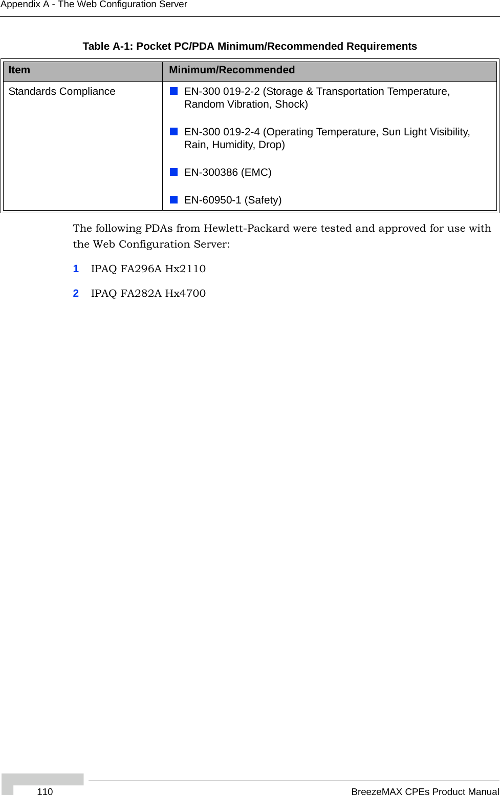
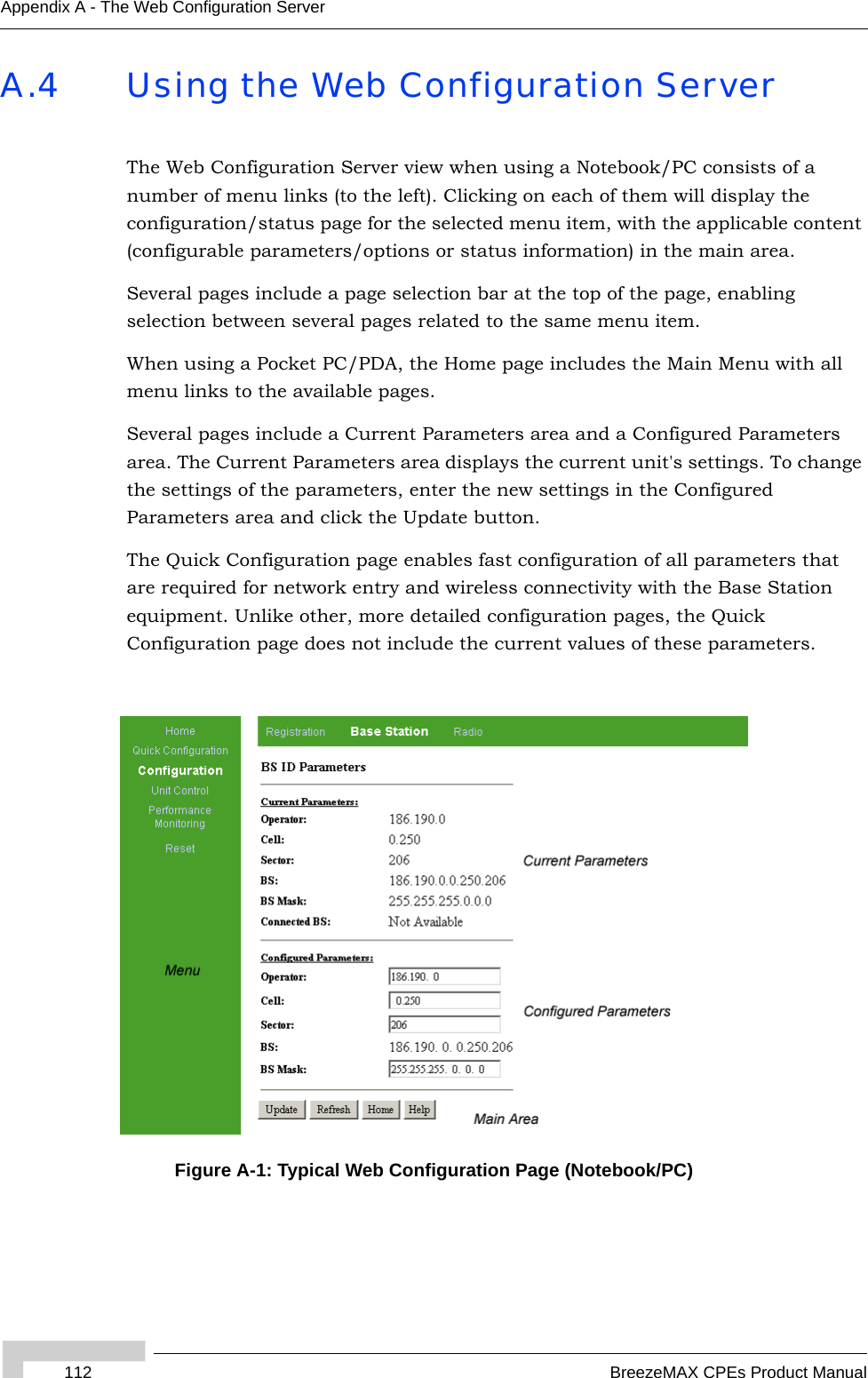
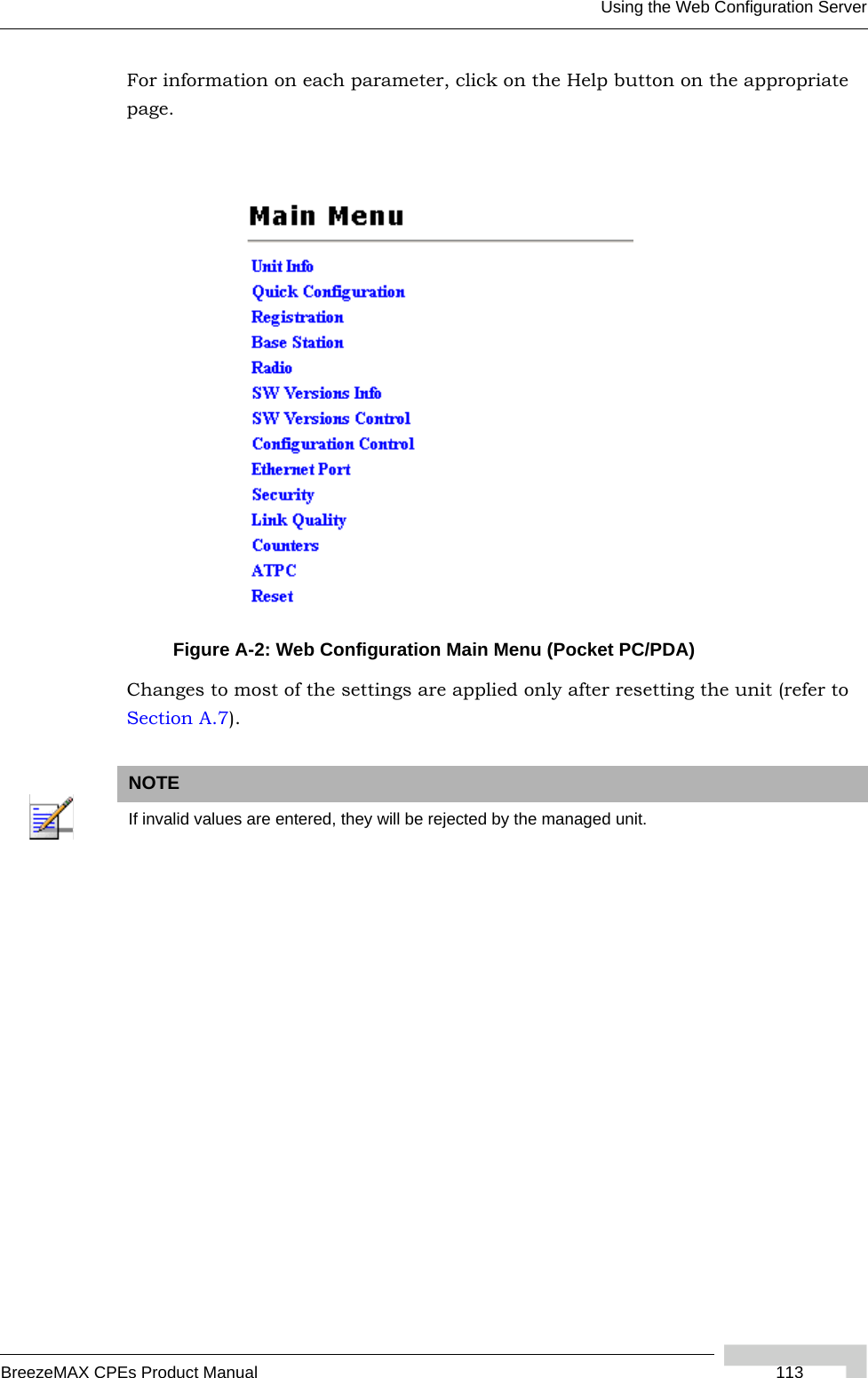
- 1. User Manual
- 2. Manual Filter page
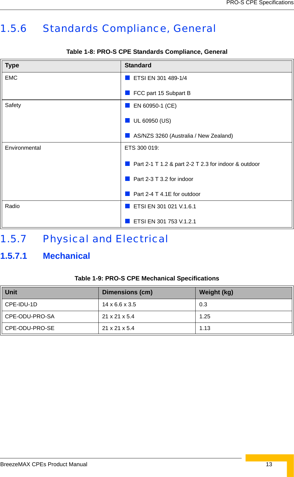
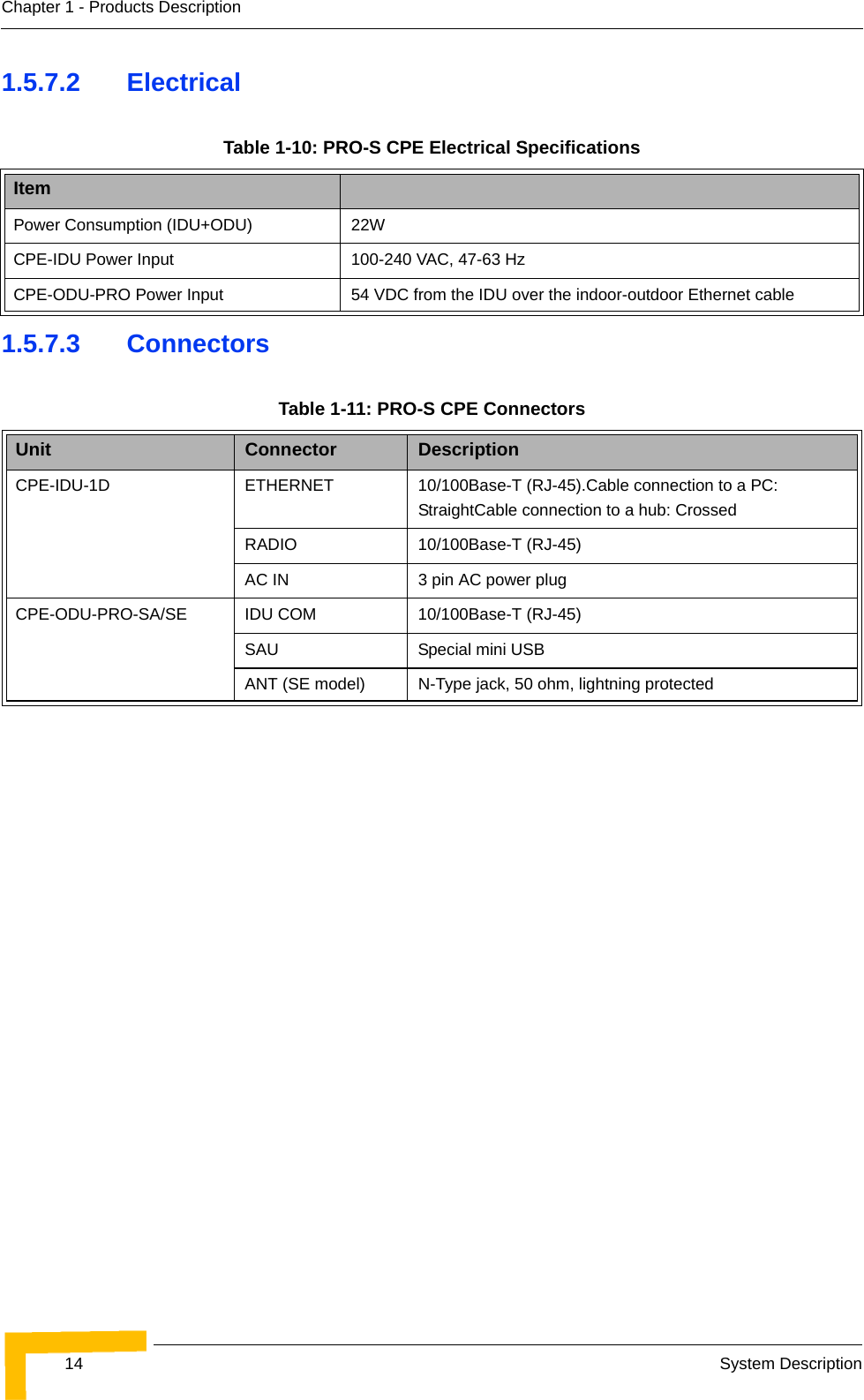
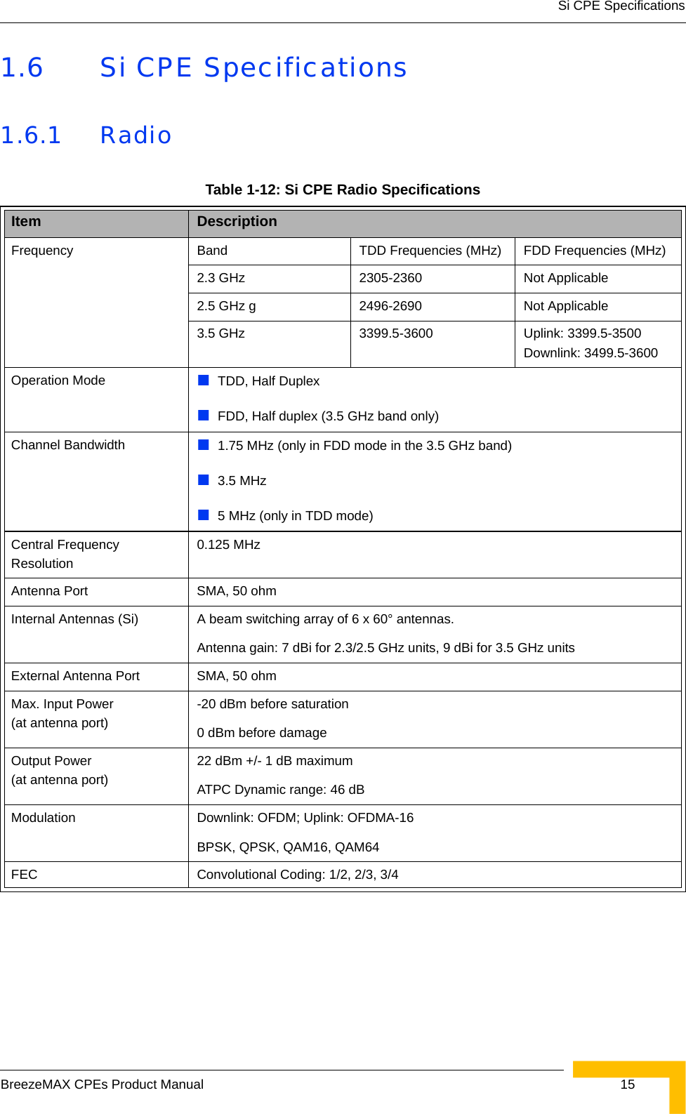
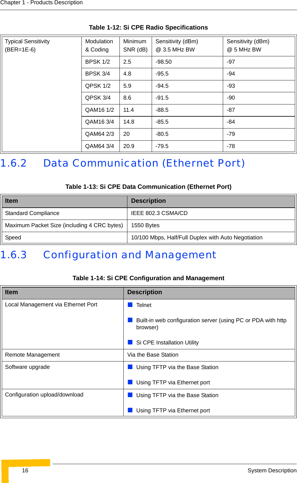
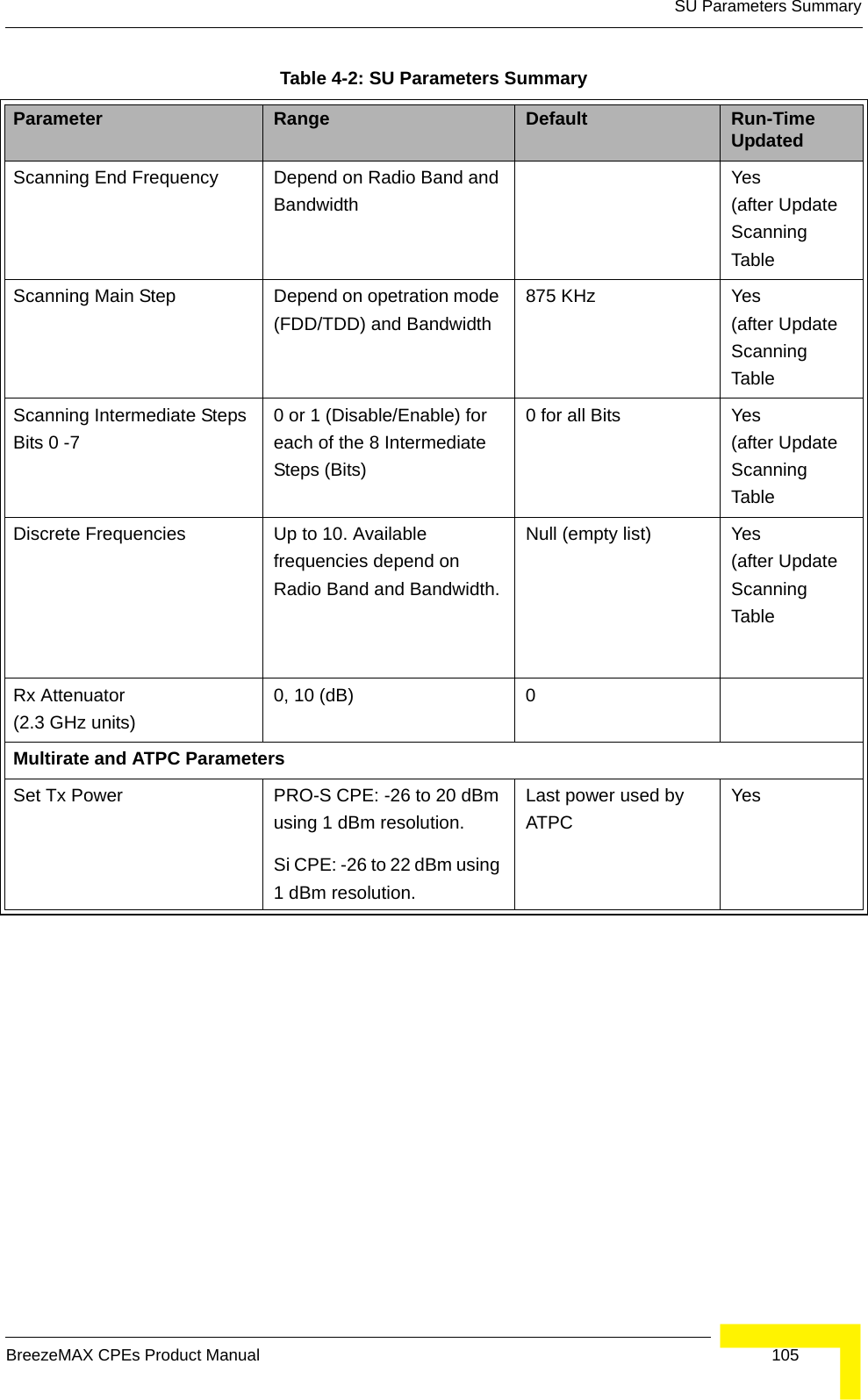
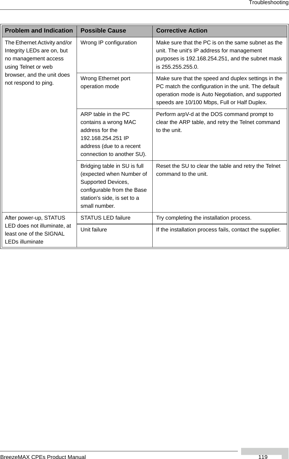
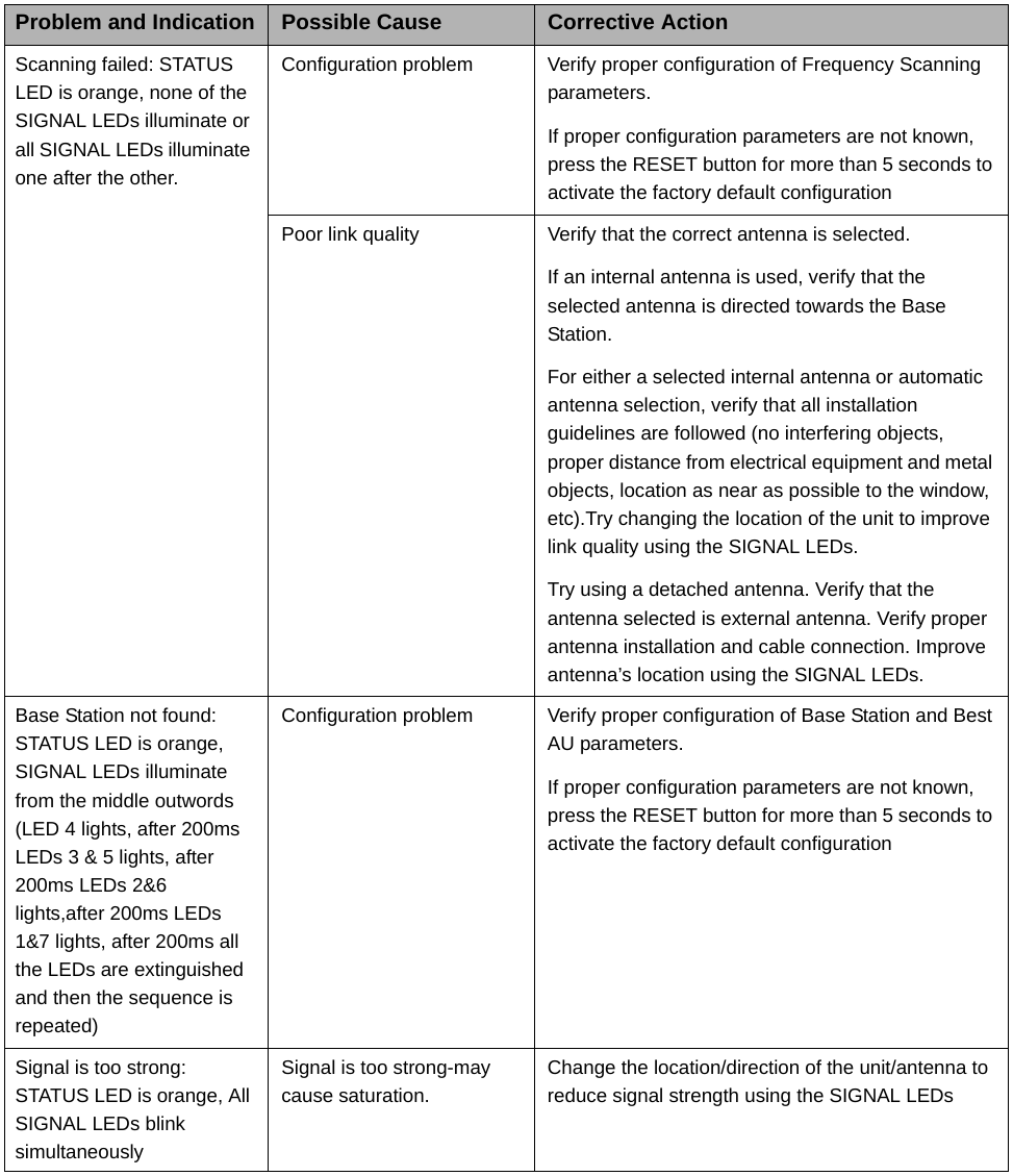
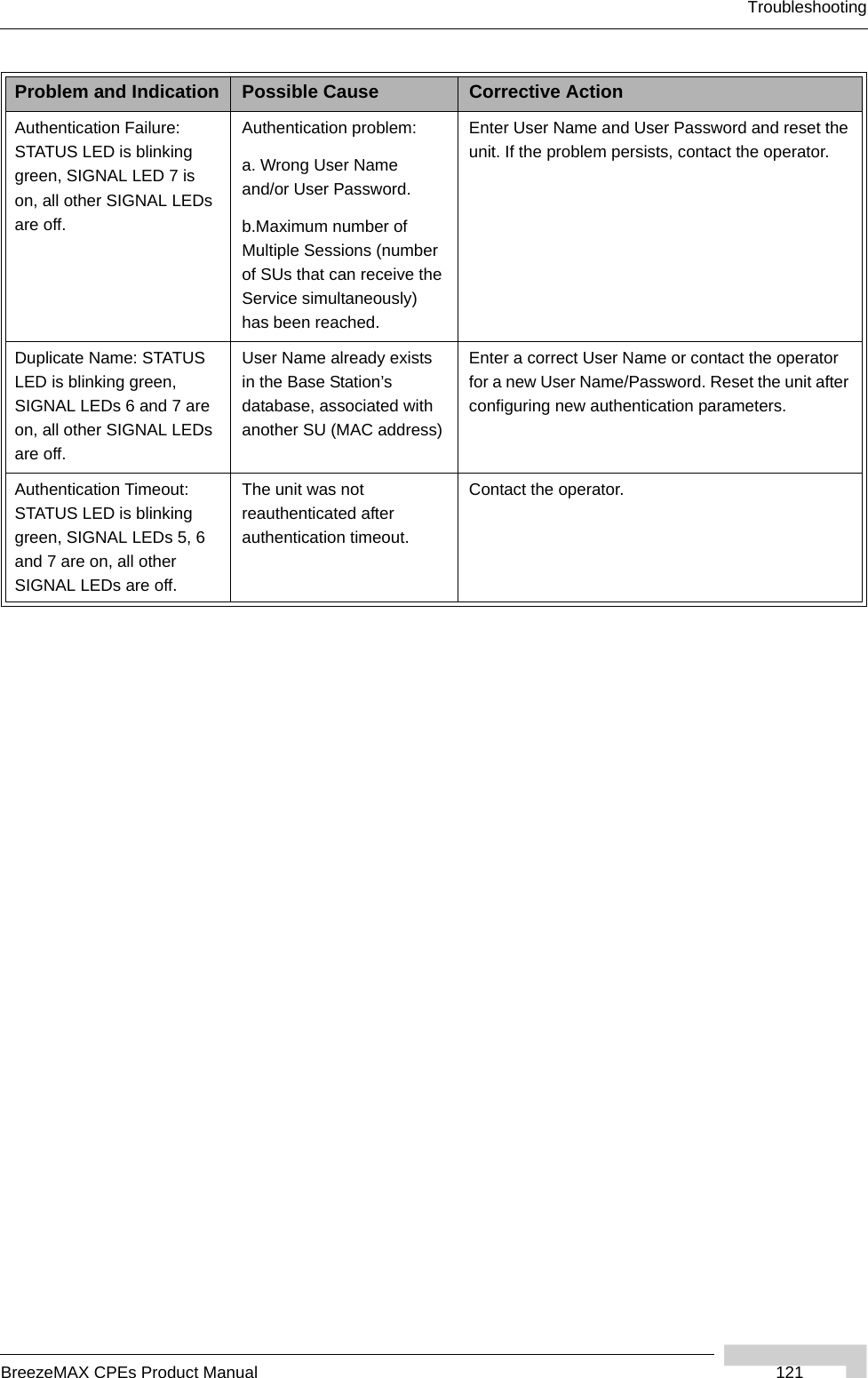
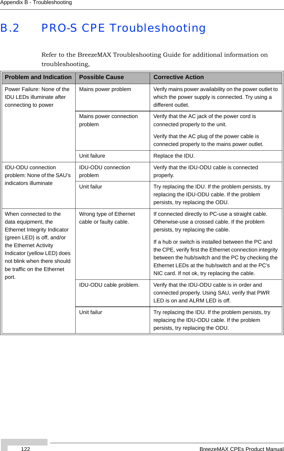
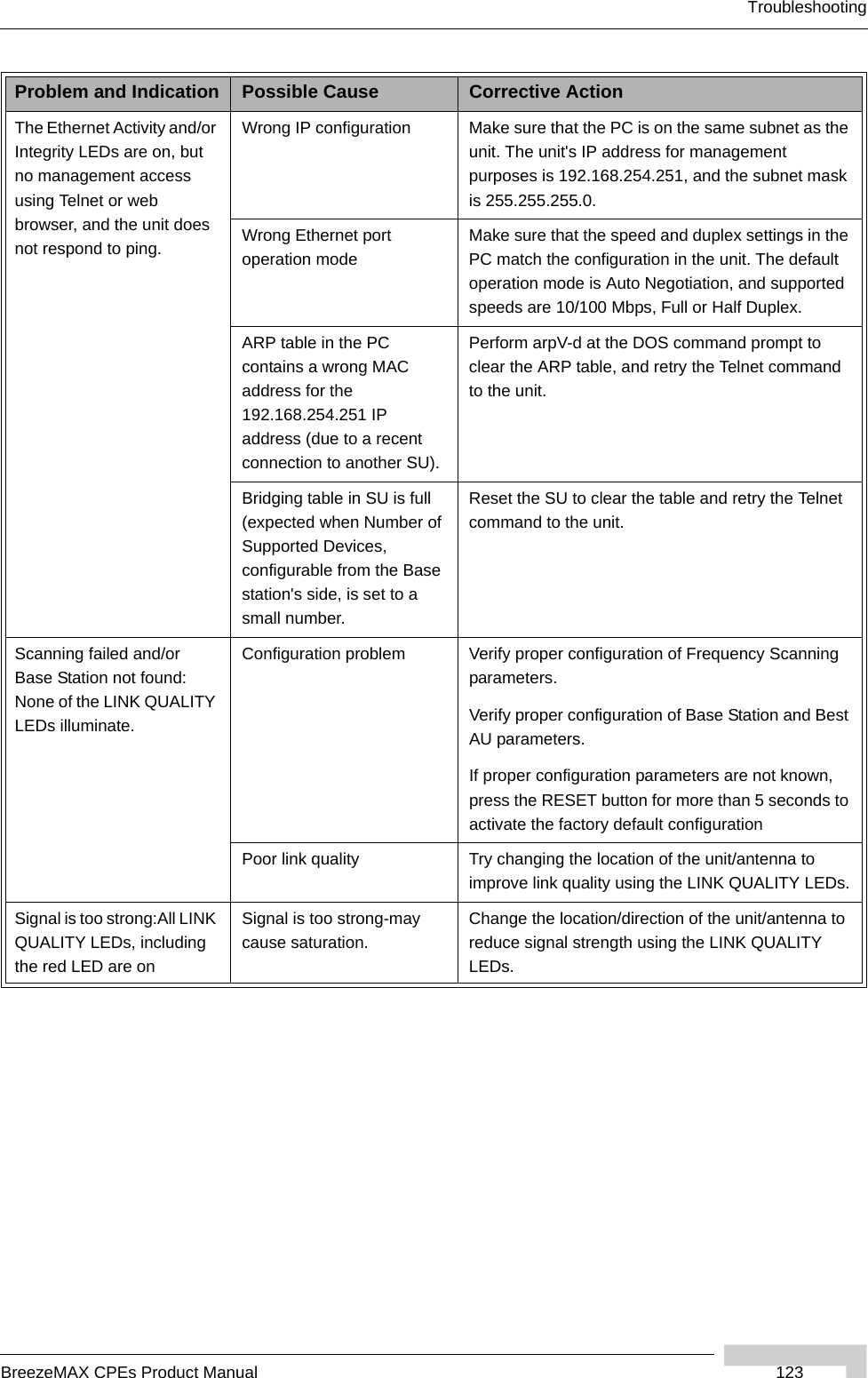
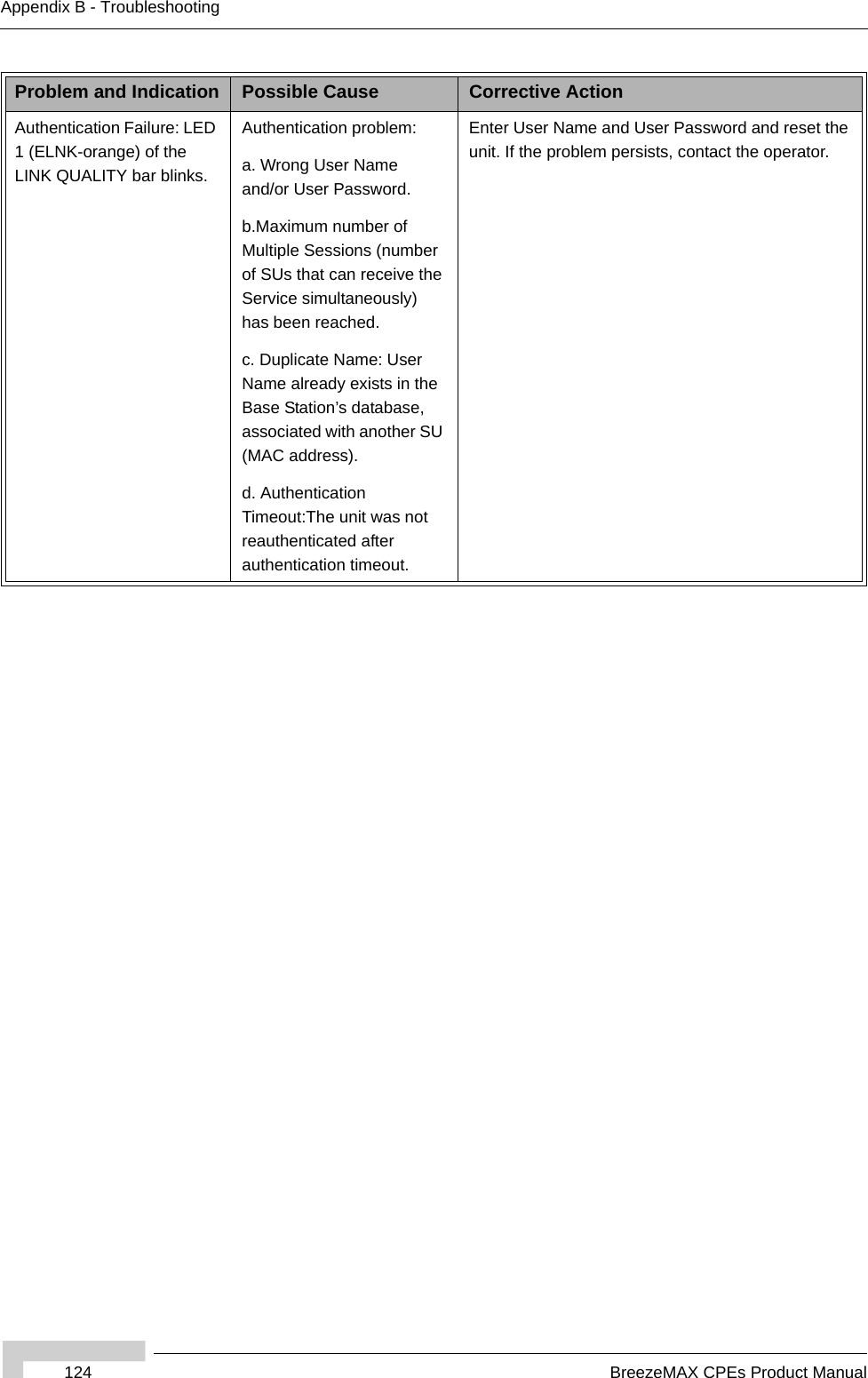
User Manual