Alvarion Technologies BNETB-49 BreezeNET B300 System User Manual BNB300 Technical
Alvarion Technologies Ltd. BreezeNET B300 System BNB300 Technical
Contents
- 1. Technical Manual 2 of 2
- 2. Technical Manual 1 of 2
- 3. User Manual 2 of 2
- 4. User Manual 1 of 2
Technical Manual 2 of 2

3
Chapter
Basic Configuration Instructions

Chapter 3 - Basic Configuration Instructions
Alvarion BreezeNET B300 37 Technical User Manual
In This Chapter:
“Initial Settings Configuration Procedure” on page 38
“Device Interfaces” on page 40
“Command Line Interface (CLI)” on page 41
“Lost Password Recovery” on page 42
“Configuration Manipulations” on page 45
“Ethernet Interface Configuration” on page 47
“Radio Interface Configuration” on page 48

Chapter 3 - Basic Configuration Instructions Initial Settings Configuration Procedure
Alvarion BreezeNET B300 38 Technical User Manual
3.1 Initial Settings Configuration Procedure
Before starting new device, one should perform initial configuration. The
configuration can be performed either using serial console port or using Telnet
protocol. In order to configure the device using Console port, follow the
instructions below:
Device should be connected with host .g. Hyper Terminal)
Set serial interface properties to 38400 baud rate, 8 bit, 1 stop bit, parity off,
flow control disabled
Enable emulation mode ANSI or VT100, keyboard VT100
To connect using Telnet protocol from the wired LAN run Telnet with 10.10.10.1
IP-address that is configured for the Ethernet interface of the device by default.
If all above procedures are completed correctly, you will see the WanFlex OS
prompt:
Every new device has got default login and password settings as written below:
After default authorization there will be standard console prompt:
Now the device is ready for the initial configuration procedure. The most relevant
thing to be done at this phase is to define device name/user/password.
Login:
Login: admin
Password: private
console>
system name Test
system user root
system password qwerty

Chapter 3 - Basic Configuration Instructions Initial Settings Configuration Procedure
Alvarion BreezeNET B300 39 Technical User Manual
NOTE
Part of commands in bold must be typed in CLI (Command Line Interface). The rest of the
command name is optional and can be skipped while typing.

Chapter 3 - Basic Configuration Instructions Device Interfaces
Alvarion BreezeNET B300 40 Technical User Manual
3.2 Device Interfaces
The Device has several physical and logical interfaces:
lo0 - loopback interface, used for system interaction needs
null0 - logical interface, can be used for auxiliary addresses assignation (for
NAT module, for example); for routes aggregation for RIP protocol. Addresses
(subnet) are announced to the network but every packet transmitted through
this interface is destroyed
eth0 - First Ethernet 10/100 Mbit interface
eth1 - Second Ethernet 10/100 Mbit interface
rf5.0 - radio interface. See device's labeling it learn your radio interface
name
vlanX - interfaces supporting VLAN 802.1q tagging
All configured interfaces of the device can be reviewed using the following
command:
ifconfig -a

Chapter 3 - Basic Configuration Instructions Command Line Interface (CLI)
Alvarion BreezeNET B300 41 Technical User Manual
3.3 Command Line Interface (CLI)
For device's management and configuration a Unix-like command line language is
used. Every command starts having the power right after Enter key is pressed.
However, each command lifetime duration is limited within one configuration
session. In order to save a current configuration "config save" command is used.
Several commands can be grouped in one line using ";" character. If a
wrong-syntax line is met in the group, the rest of the string is checked anyway
and the wrong command is ignored. Command name can be shortened unless the
ambiguity occurs.
If your terminal supports VT100 or ANSI standard you can move around the list of
recently executed commands using cursor keys. Numbered list of these
commands can be reviewed by "!h" command. Any command from this list can be
available using "!<NUMBER>" command. TAB key performs substring search of
recently executed commands.
Ctrl/R combination refreshes the command string if its content was disturbed by
system messages.
The command executed with no arguments prints a short hint about its keys,
parameters and syntax.
Context help can be obtained by printing "?" in any position of the line.
Chapter 3 - Basic Configuration Instructions Lost Password Recovery
Alvarion BreezeNET B300 42 Technical User Manual
3.4 Lost Password Recovery
The password for the device can be recovered remotely.
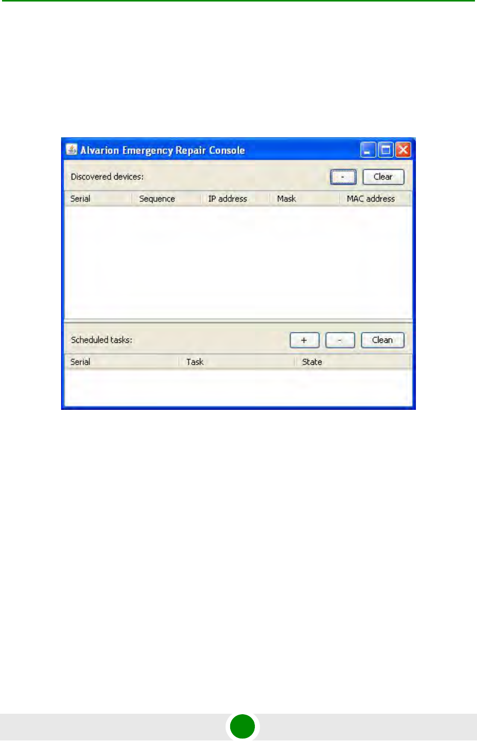
Recovery procedure can be done with the help of graphical "ERConsole" utility.
Below is a description of ERConsole’s utility recovery procedure:
1Connect a computer and a device that should be repaired to one physical
Ethernet segment.
2Start the ERConsole utility on the computer by running the ERConsole.jar file.
Utility will be running in a waiting mode.
3Restart the device. During its restart, the ERConsole utility will determine the
device and will show necessary information about it in the "Discovered
devices" section of the main window.
Figure 3-1: ERConsole (Step 1)
Chapter 3 - Basic Configuration Instructions Lost Password Recovery
Alvarion BreezeNET B300 43 Technical User Manual
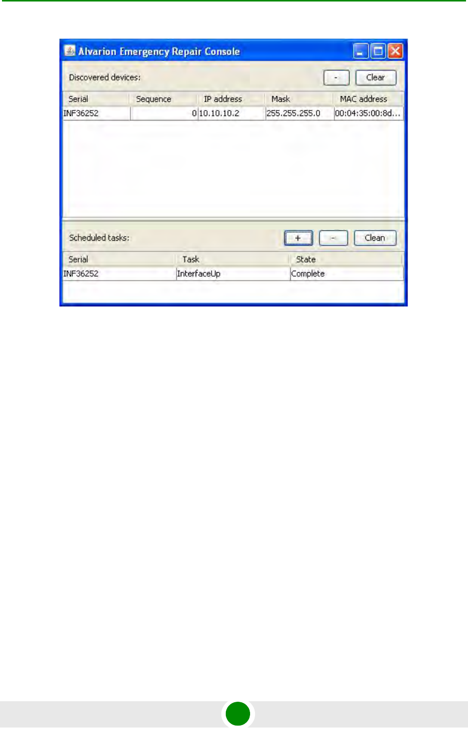
4Send "Serial" and "Sequence" fields values to the Technical Support.
5You will be given a factory password for the device.
6Click the "+" button in the "Scheduled tasks" section of the main window.
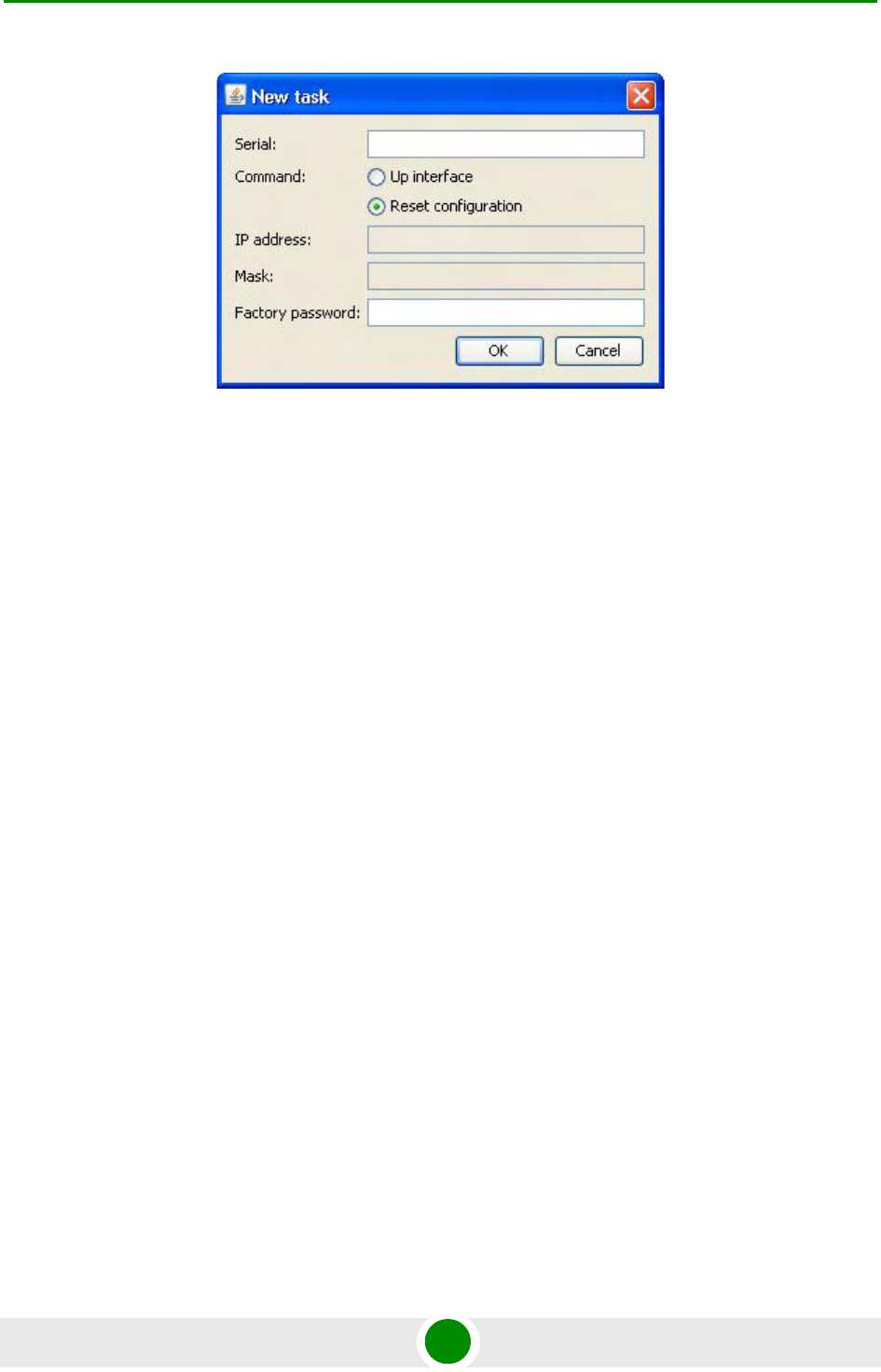
7In the opened "New task" window choose "Reset configuration" in the
"Command" field. Then enter Serial number and factory password in the
corresponding fields. Click "Ok".
Figure 3-2: ERConsole (Step 2)
Chapter 3 - Basic Configuration Instructions Lost Password Recovery
Alvarion BreezeNET B300 44 Technical User Manual
8Restart the device.
After device restart the ERConsole utility will reset device configuration.
9Login the device with Serial number as a login name and new password that
was received from tech support.
10 Reconfigure device username and password.
ERConsole utility's "New task" window also allows changing device's IP-address on
its Ethernet interface (eth0) without login to device.
Figure 3-3: ERConsole (Step 3)

Chapter 3 - Basic Configuration Instructions Configuration Manipulations
Alvarion BreezeNET B300 45 Technical User Manual
3.5 Configuration Manipulations
3.5.1 Printing and Saving Your Configuration
You can easily review your current device's configuration by executing "config
show" command. The output of the command is sorted by the configuration
sections (e.g. "System parameters", "Interfaces configuration" etc).
You can review some particular parts of the configuration specifying the part of
the configuration you want to see.
Example:
This command will print the interfaces configuration.
In order to save your configuration "config save" command is used. It saves the
current system configuration in the device's flash memory for subsequent
permanent use. All modifications to the system parameters, if not saved by this
command, are valid only during the current session (until the system reset
occurs).
3.5.2 Import/Export
Export/import of the device's configuration is performed using "config export" and
"config import" commands correspondingly. "Config export" saves the device
configuration on a remote server and "config import" reloads it from a remote
server. The information is transferred using FTP.
Example:
"Config import" command writes the uploaded file directly into the Flash memory
without changing the active configuration in RAM. In order to make a new
configuration active, right after "config import" command implementation
finishes the device should be rebooted. If "config save" command is run before
rebooting, Flash memory is overwritten by the copy of the active configuration.
This action will erase the uploaded configuration file.
3.5.3 IP Address Formats
Many commands of the operating system require specification of IP addresses.
config show ifc
config export user:secret@192.168.1.1/var/conf/test.cfg

Chapter 3 - Basic Configuration Instructions Configuration Manipulations
Alvarion BreezeNET B300 46 Technical User Manual
In OS WANFleX, the IP-addressees may be specified in traditional numeric format.
Optionally, the mask may be specified either by its bit length (the specified
number of leading bits in the mask are set to 1, the remaining bits are reset to 0)
or numeric value. The IP address 0/0 denotes all possible IP addresses.
Therefore, the possible formats to specify IP-addresses are:
nn.nn.nn.nn (no mask is used)
nn.nn.nn.nn/N (N is the bit length of the mask)
nn.nn.nn.nn:xxx.xxx.xxx.xxx (xxx.xxx.xxx.xxx is the numerical value of the mask)
Example:
The 192.168.9.0/24 address describes the network address 192.168.9.0 and the
mask with leading 24 bits on.
The same set of addresses may be denoted as 192.168.9.0:255.255.255.0.

Chapter 3 - Basic Configuration Instructions Ethernet Interface Configuration
Alvarion BreezeNET B300 47 Technical User Manual
3.6 Ethernet Interface Configuration
In the most basic form Ethernet interface can be configured as follows:
UP flag means than the interface is turned to UP state.
Also you can specify the following parameters for the Ethernet interface:
Media type. By default media type is selected automatically (media auto
parameter).
Assign aliases to the Ethernet interface (alias key word)
Full information about interfaces configuration can be reviewed in OS WanFlex
User Guide - ifconfig command.
ifconfig eth0 1.1.1.1/24 up

Chapter 3 - Basic Configuration Instructions Radio Interface Configuration
Alvarion BreezeNET B300 48 Technical User Manual
3.7 Radio Interface Configuration
Radio interface configuration is performed using "rfconfig" command. In its most
basic form one need to configure the following parameters of the radio interface:
Frequency (freq parameter) in MHz. For example, 5260.
Bit-rate (bitr parameter). Bit transfer rate in kBits/sec.
System identifier (SID parameter). A hexadecimal number in the range of 1H to
FFFFFFH. All devices that are supposed to see each other on the same radio
link must have the same identifier.
To learn your device's radio module capabilities type the command:
<IF-NAME> - radio interface name. Can be read on the device's labeling located on
the case.
Radio interface configuration is performed using "rfconfig" command.
Example:
Additional important parameters and settings for the radio interface:
rf5.0 - radio interface name in this case. In order to obtain radiointerface
name either see the ODU/Device labeling or execute "ifc -a" command.
pwr - transmitting power selection. Available power levels can be obtained
using "capabilities" parameter as shown above
distance: this parameter is used to set the exact distance value between two
devices (in kilometers). This parameter changes time values for some delays
NOTE
Radio interface state is not saved in the configuration. That means that if you put radio interface to
the down state after rebooting it will be in the up state.
rfconfig <IF-NAME> capabilities
rfconfig rf5.0 freq 5260 bitr 130000 sid 01010101

Chapter 3 - Basic Configuration Instructions Radio Interface Configuration
Alvarion BreezeNET B300 49 Technical User Manual
and time-outs thus making possible to work on longer distances with smooth
adjustment.
There are several ways to manage this parameter:
»If you set an exact value, this value is used no matter what the connection
method is used
»If the device has auto value instead of a number (by default), the device will
configure its parameters automatically. While configuration showing, there
might be the current distance value after auto parameter: auto (XX). Auto
mode is recommended to be used
»If distance parameter is set to 0 radio module will work on the distances
from 0-3 km.
Example:
rfconfig rf5.0 freq 5260 bitr 300000 sid 10203040
rfconfig rf5.0 pwr 63 distance auto

4
Chapter
Link Configuration

Chapter 4 - Link Configuration
Alvarion BreezeNET B300 51 Technical User Manual
In This Chapter:
“Link Diagnostic Tools” on page 52
Chapter 4 - Link Configuration Link Diagnostic Tools
Alvarion BreezeNET B300 52 Technical User Manual
4.1 Link Diagnostic Tools
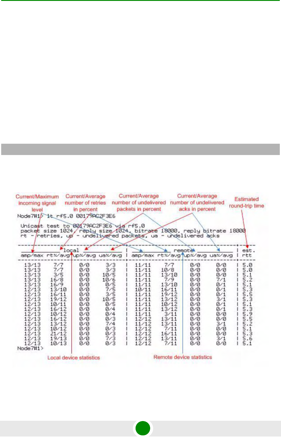
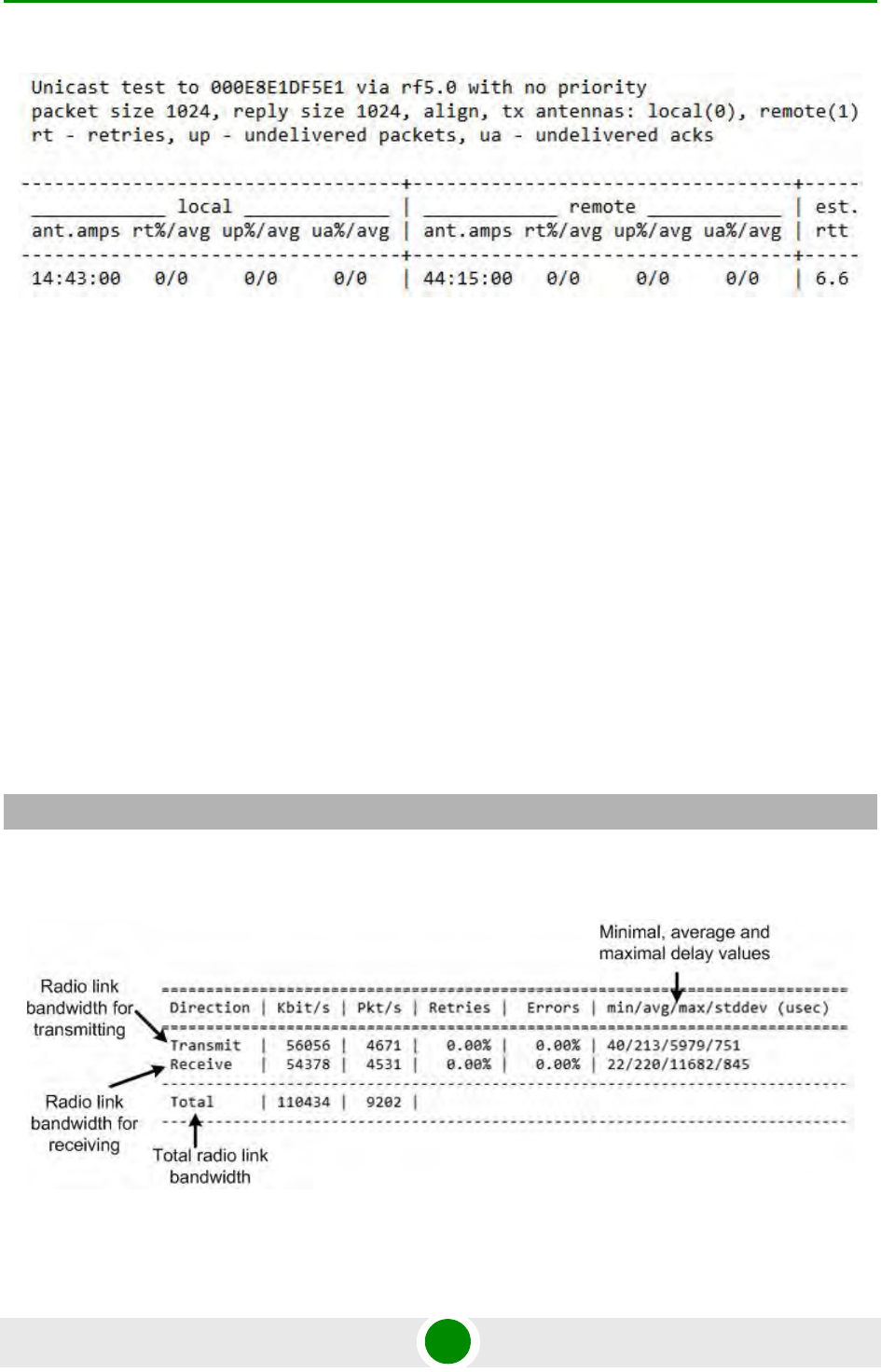
4.1.1 Ltest
Ltest utility allows precise test of a radio link. It is recommended for antenna
alignment when installing a new device or for testing of existing radio link.
Ltest can work in standard, alignment and bandwidth modes.
Standard mode:
In standard mode Ltest measures signal levels, retries, lost packets and acks.
To start Ltest in this mode:
When "ltest" command starts it will show you output information that contains
testing results. You can see Ltest output below:
For successful radio link establishing the following factors have to be considered:
ltest rf5.0 <Mac-address of a device on the other side of the radio link>
Figure 4-1: Ltest

Chapter 4 - Link Configuration Link Diagnostic Tools
Alvarion BreezeNET B300 53 Technical User Manual
1It is recommended to start antenna alignment with searching maximum signal
level on a minimal possible bitrate. Afterwards automatic MINT mechanisms
will set the most appropriate bitrate if autobitrate mode will be enabled.
2Current incoming signal level in "amp/max" columns (see "ltest" command
output) must be between 12 and 40.
When it is more than 40 it is recommended to lower amplifier power.
If maximal signal level is less than 12 it is recommended to lower bitrate or
channel width (for example, from 20MHz to 10MHz on the both sides of the
radio link).
In some cases signal level that is less then 12 may be enough for radio link
operation. In this case one has to be guided by such parameters as number of
retries, number of undelivered packets and number of undelivered acks. If the
number of undelivered packets and the number of undelivered acks is null,
the number of retries is small and all these parameters are constant in time
then the radio link, most often, will be operating properly.
3Number of retries value in "rt%" columns must be as close to zero as possible.
4Number of undelivered packets value in "up%" columns must be zero; if this
value is not zero then the radio link couldn't be exploit.
5Number of undelivered acks value in "ua%" columns must be zero; if this value
is not zero then the radio link couldn't be exploit.
ALL described parameters must be observed in the both (Local and Remote)
sections of the "ltest" command output.
Alignment mode:
The difference of this mode from the standard one is that "ant.amps" column is
used instead of "amp/max". "Ant.amps" column indicates signal levels for each of
two antennas of a devce divided by ":" correspondingly.
To start Ltest in this mode:
Ltest output in alignment mode:
ltest rf5.0 <Mac-adress> -align [N,R]
Chapter 4 - Link Configuration Link Diagnostic Tools
Alvarion BreezeNET B300 54 Technical User Manual
Bandwidth mode (Bandwidth meter):
Bandwidth meter is used to test the following radio link characteristics: speed in
kilobits per second, speed in packets per second, number of retries and errors.
Use the following "ltest" command options for testing:
-tu [seconds] - Unidirectional test: packets are transmitted only from the
current side to the specified address ("target" option)
-tb [seconds] - Bidirectional test: packets are transmitted in both directions
"Seconds" parameter allows setting test period (5 seconds by default). Maximum
value is 60 seconds.
To start Ltest in this mode:
"Ltest" command output in Bandwidth meter mode:
Figure 4-2: Ltest Align
ltest rf5.0 <Mac-adress> -tb
Figure 4-3: Ltest Bandwidth Meter
Chapter 4 - Link Configuration Link Diagnostic Tools
Alvarion BreezeNET B300 55 Technical User Manual
4.1.2 Muffer
The muffer module makes it possible to rapidly test the electromagnetic
environment, visually estimate the efficiency of the utilization of the air links,
reveal sources of interference, and estimate their power.
Several operating regimes of the muffer module provide for different levels of
details in test results
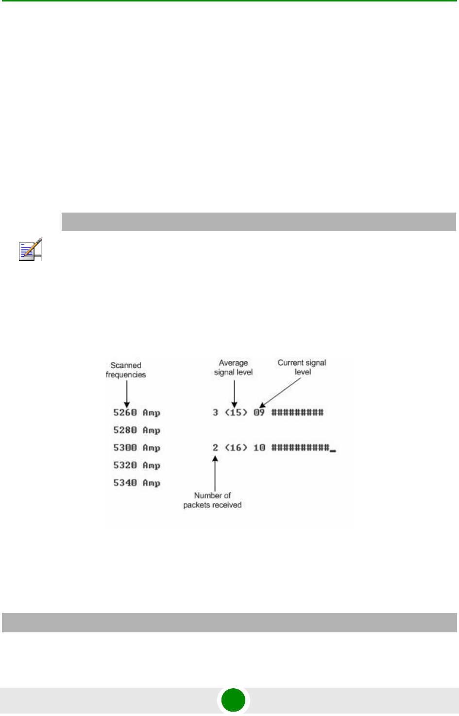
4.1.2.1 Review Mode
This regime is enabled by the review option. It makes possible to have a general
estimation of emissions and interference within specified frequency range.
This regime can be useful on the first steps of link configuration. One can observe
the activity on the selected list of frequencies and make decisions of what
frequencies can be used for the link so that the link did not interfere with other
sources of signals.
The picture above shows the output of review mode.
To run the review mode please type the following command:
NOTE
Normal operation of the radio is not possible in this mode.
Figure 4-4: Muffer Review Mode
muffer <IF-NAME> review
Chapter 4 - Link Configuration Link Diagnostic Tools
Alvarion BreezeNET B300 56 Technical User Manual
Once the link is established you can use this mode to review the activity on the
configured for frequency for the link. If no activity is observed that means that the
signal from the remote side is being broken by the interference sources or by the
obstacles on the signal propagation path.
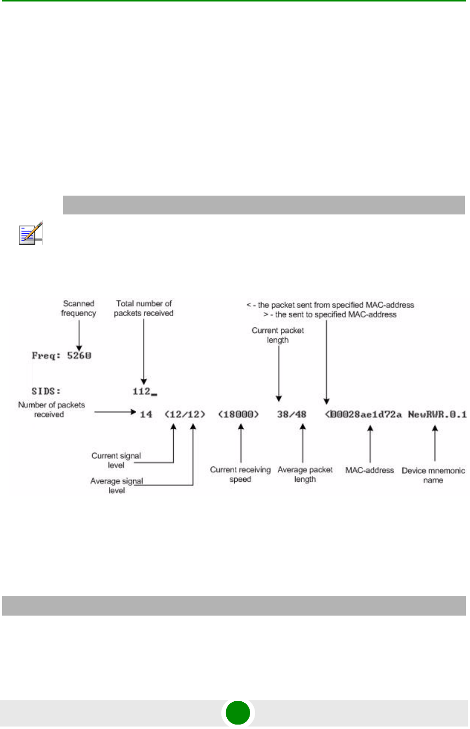
4.1.2.2 MAC2 Mode
This regime performs MAC-address analysis to estimate the efficiency of
utilization of the air link. The analysis is carried out at the frequency previously
specified by rfconfig command. The mac2 regime checks both data packets and
the link-level ACK messages sent by protocol supported devices.
The picture below shows the output mac2 regime.
Like in review mode this regime provides with the information about a current
activity but on the configured frequency.
To run the review mode please type the following command:
NOTE
Normal operation of the radio is not possible in this mode.
Figure 4-5: Muffer MAC2 Mode
muffer <IF-NAME> mac2
Chapter 4 - Link Configuration Link Diagnostic Tools
Alvarion BreezeNET B300 57 Technical User Manual
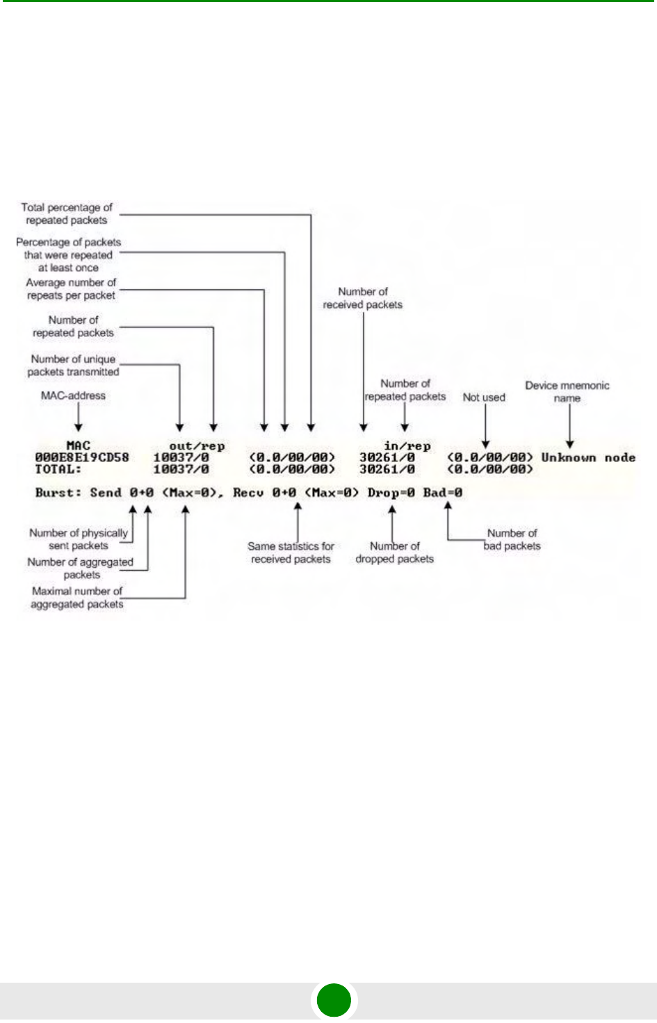
4.1.2.3 Statistics
The statistics gathering is used for estimating link load intensity. The amount of
packets sent and received, and the number of retransmissions is shown for each
MAC address participating in the data exchange.
The statistics output is presented in the picture below.
The following decisions can be made by analyzing the outputted parameters:
If the number of repeated packets is comparable with total number of packets
that means that you might have an interference source on the selected
frequency. For normally operating link the percentage of repeated packets
should not exceed 10%. It is extremely important to obtain a permanent zero
value for the average number of repeats per packet. If the value is not zero that
means that the link is NOT working properly and requires further
improvement
If total percentage of repeated packets and the percentage of packets that were
repeated at least once are close to each other that might mean that you have
Figure 4-6: Muffer Statistics Mode

Chapter 4 - Link Configuration Link Diagnostic Tools
Alvarion BreezeNET B300 58 Technical User Manual
got a permanent source of interference. Otherwise, it means that a strong
interference source appears from time to time breaking your signal
Concerning the fact that statistics module outputs the information for each
MAC-address separately, you can reveal the problem for some specific unit on
the wireless network
The "muffer stat" command shows the statistics only from registered devices.
To view statistics type the following command:
To reset all counters please type
4.1.2.4 Other Modes of Muffer
The muffer also has the following modes:
mac mode. Compared to the mac2 mode this mode does not take link-level
ACK messages sent by protocol support devices into account
mac2 mode. This mode is used to detect impulse interference and doesn't
disturb radio model normal operation.
mac3 mode. Compared to mac2 mode this mode also performs calculation of
impulse interference.
mynet mode. This mode performs the radio testing without disturbing radio
module's normal operation, but taking into account only packets from within
the given network
sid mode. The sid regime allows estimating the number of currently operating
subscriber groups having different identifiers (SID), and the efficiency of air
links utilization. The analysis is carried out for all network identifiers at the
frequency previously specified for the radio module by rfconfig command.
Sensor mode. In this mode shows the radio environment testing results on the
screen in a visual-digital format.
muffer stat
muffer stat clear
Chapter 4 - Link Configuration Link Diagnostic Tools
Alvarion BreezeNET B300 59 Technical User Manual
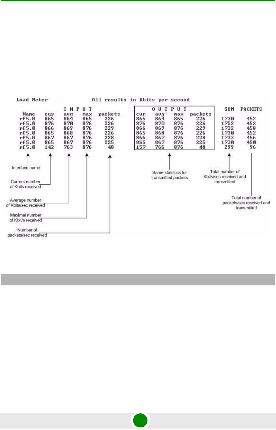
4.1.3 Load Meter
Load meter is a powerful tool that allows estimating the load of a system interface
specified by interface parameter. By default, the information is displayed on one
line and updated every second; the load is measured in kilobytes.
Below picture shows the load meter output for the radio interface outputted in
line-by-line mode with one second interval.
To run load meter like it is shown above, please type:
4.1.4 Acquiring Interfaces Statistics
Interface statistics can be acquired using netstat module which includes two
modes:
Routing tables output (using "-r" parameter with the command)
Interfaces statistics output (using "-i" parameter with the command)
Below picture shows the example of interfaces statistics output.
Figure 4-7: Load Meter
loadm -l <IF-NAME>
Chapter 4 - Link Configuration Link Diagnostic Tools
Alvarion BreezeNET B300 60 Technical User Manual
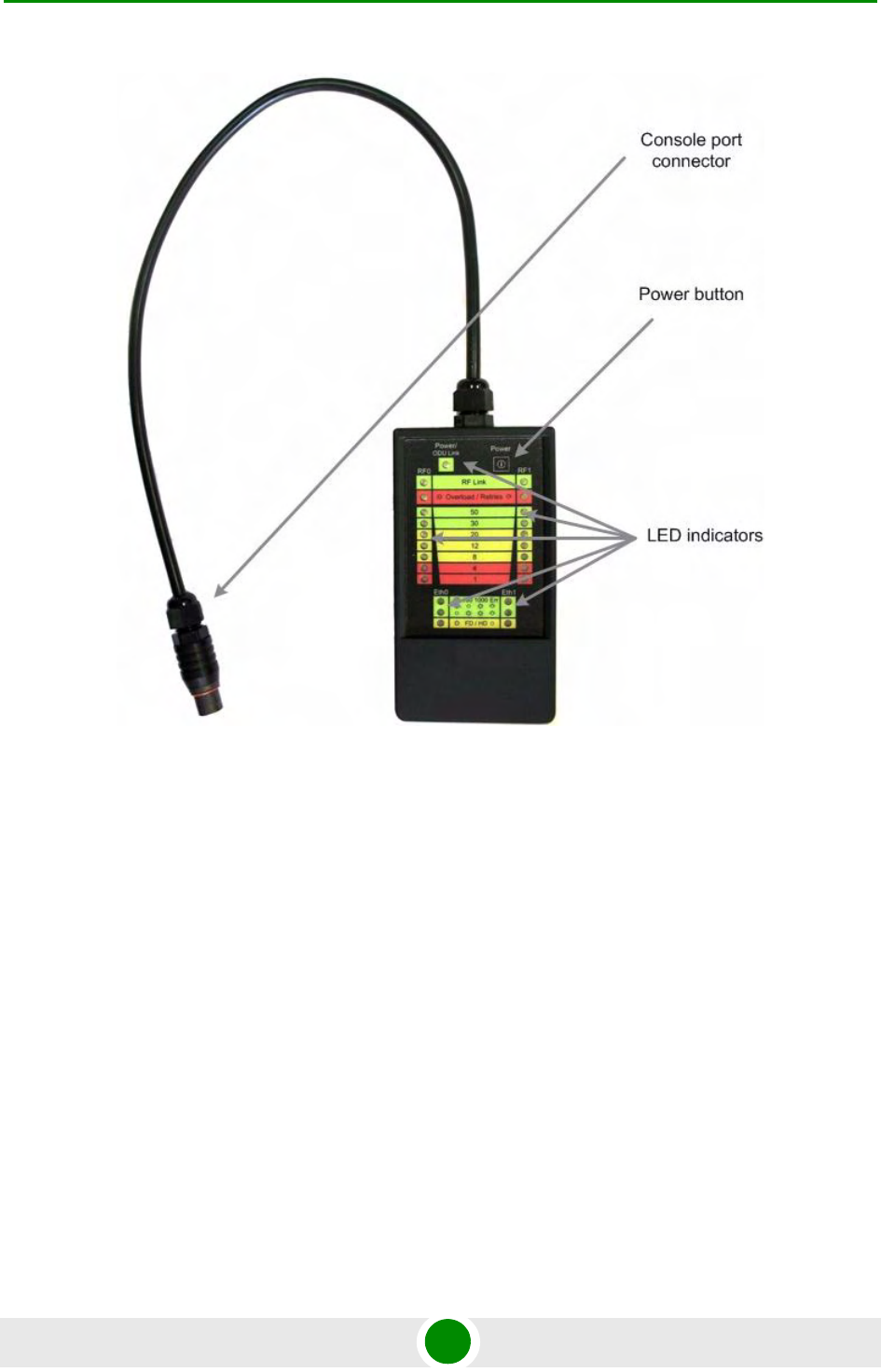
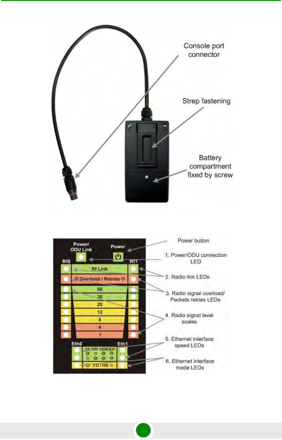
4.1.5 RapidView
RapidView - is a special diagnostic device that is used for equipment comfort
installation, antenna alignment and configuration.
Device allows getting the following information:
Radio link establishment indication
Visual monitoring of radio signal levels
Receiving retries information
Diagnostic of RF and Ethernet interfaces
Figure 4-8: Netstat
NOTE
If the interface has several aliases the statistics is still measured for physical interface in a whole.
For example, see rf5.0 or eth0 interfaces above. The numbers shown in 4 right columns correspond
in physical interface.
Chapter 4 - Link Configuration Link Diagnostic Tools
Alvarion BreezeNET B300 61 Technical User Manual
Figure 4-9: RapidView Top
Chapter 4 - Link Configuration Link Diagnostic Tools
Alvarion BreezeNET B300 62 Technical User Manual
Figure 4-10: RapidView Back
Figure 4-11: RapidView Indicator Panel

Chapter 4 - Link Configuration Link Diagnostic Tools
Alvarion BreezeNET B300 63 Technical User Manual
4.1.5.1 How to Use
Turning on:
1For turning RapidView on simply push the "Power button".
2Device LEDs will light up for 2 seconds.
3Device will perform constant tries to connect to ODU. If device's power is
normal Power/ODU connection LED (1) will blink 1 time per second. If device's
power is low LED 1 will blink 4 times per second in turn with not lighting
intervals.
4Once ODU link is established, LED 1 stops blinking (if power is normal) and
device's interfaces status are shown by LEDs 2-6.
51 time per second device updates its status output.
6If ODU link will be broken, LEDs 2-6 will go out after 2 seconds and LED 1 will
start blinking 1 time per second.
Diagnostic device connection to ODU should be done via console port of the ODU.
Once link is up between ODU and diagnostic device the following record is put in
ODU system log:
Exact radio interface names depend on wireless equipment configuration.
When diagnostic device is unplugged from the following record is put in ODU
system log:
LEDs modes description:
ODU status monitoring via diagnostic device is performed by its LEDs indication.
LEDs modes and ODU status correspondence is shown in the following table:
Connected test unit. Begin service communication over console.
Test unit detected: rf0 - rf5.0
Test unit disconnected. Return to normal console mode.

Chapter 4 - Link Configuration Link Diagnostic Tools
Alvarion BreezeNET B300 64 Technical User Manual
Table 4-1: Indicator LEDs
LEDs Function
1. Power/ODU
connection LED
Shows diagnostic device power status and diagnostic device-ODU connection
status.
Constant lighting - diagnostic device-ODU connection established,
diagnostic device power is normal.
Blinking 1 time per second - diagnostic device power is normal, diagnostic
device-ODU connection is not established.
Blinking 4 times per second - diagnostic device-ODU connection
established, diagnostic device power is low (change batteries).
Frequent blinking with intervals - diagnostic device power is low,
diagnostic device-ODU connection is not established.
2. Radio link LEDs Show whether radio link is established on certain ODU's radio interface.
Constant lighting - radio link is established.
What ODU's radio interface to show by what column RF0 or RF1 is chosen by the
following way:
for RF0 column is taken radio interface with the least number, for RF1 the other
interface.
For example, there are the following radio interfaces on ODU:
rf5.0. Then for RF0 column rf5.0 will be taken, for RF1 - rf5.1.
When no radio link then LEDs 2-4 are not lighting.
3. Radio signal
overload/Packets
retries LEDs
Show receiving radio signal level overload and number of packet retries
information.
Constant lighting -receiving radio signal level on the interface is too high.
Blinking 4 times per second - number of retries >= 50%
Blinking 2 times per second - number of retries >= 28 %
Blinking 1 time per second - number of retries >= 7 %
If certain radio interface (radio module) is not present on the device then all
corresponding LEDs of this radio interface is off.
If ODU has certain radio interface but it is not activated (for example, not entered
"mint rf5.0 start" command) then LED 3 is blinking 1 time per second whereas
LEDs 2 and 4 are not lighting.
If ODU has certain radio interface but it is not activated (for example, not entered
"mint rf5.0 start" command) then LED 3 is blinking 1 time per second whereas
LEDs 2 and 4 are not lighting.
If ODU has certain radio interface activated ("mint rf5.0 start" command entered)
then LED 3 is blinking 4 times per second whereas LEDs 2 and 4 are not lighting.

Chapter 4 - Link Configuration Link Diagnostic Tools
Alvarion BreezeNET B300 65 Technical User Manual
4. Radio signal level
scales
Show receiving signal level of the established radio link.
Each LED can be in 4 modes:
Not lighting - radio signal level is lower than scale value.
Blinking - the more frequently is blinking the nearer signal level is to given scale
value.
Constant lighting - signal level is higher or equal to scale value.
5. Ethernet interface
speed LEDs
Show speed of corresponding Ethernet interface.
There are 2 LEDs for each Ethernet interface (Eth0 and Eth1).
6. Ethernet interface
mode LEDs
Constant lighting - Full Duplex.
Not lighting - Half Duplex.
IF Ethernet connection is established but corresponding ODU's interface is not
enabled then LEDs 5, 6 indicate connection configuration by blinking 1 time per
second.
Table 4-1: Indicator LEDs
LEDs Function
10 Mbps 100 Mbps 1000 Mbps Error
Upper LED Lighting Not lighting Lighting Blinking
Lower LED Not lighting Lighting Lighting Blinking

5
Chapter
Configuration Via Web Interface

Chapter 5 - Configuration Via Web Interface
Alvarion BreezeNET B300 67 Technical User Manual
In This Chapter:
“Overall Functionality Overview” on page 68
“Run Requirements” on page 69
“Basic Settings” on page 70
“Device Status” on page 73
“Maintenance” on page 75
“Spectrum Analyzer” on page 76

Chapter 5 - Configuration Via Web Interface Overall Functionality Overview
Alvarion BreezeNET B300 68 Technical User Manual
5.1 Overall Functionality Overview
Web-interface is used for the following purposes:
View and change system parameters of the device
View and change system interface parameters of the device
View and change radio link parameters
View and change network parameters of the device
Monitoring statistics for all interfaces
Monitoring radio link statistics

Chapter 5 - Configuration Via Web Interface Run Requirements
Alvarion BreezeNET B300 69 Technical User Manual
5.2 Run Requirements
In order to run and properly use the application, the following requirements must
be met:
Web-browser
OS WANFleX for MINT
Web-interface support activated on the device ("webcfg start" command)
To connect to the device via Web-browser type: http://<device IP adress> (by
default http://10.10.10.1).
Chapter 5 - Configuration Via Web Interface Basic Settings
Alvarion BreezeNET B300 70 Technical User Manual
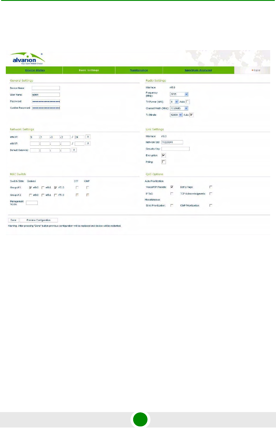
5.3 Basic Settings
The following system parameters can be changed/viewed in this sheet:
General Settings:
Device name - general device name
User Name - User Name used as Login
Password - Secret Password used to login to the unit
Confirm Password - please confirm the password to the unit
Network Settings:
ethX IP - Primary IP-address for ethX interface
Figure 5-1: Basic Settings

Chapter 5 - Configuration Via Web Interface Basic Settings
Alvarion BreezeNET B300 71 Technical User Manual
Default Gateway - Default Gateway for the unit
Radio Settings:
Frequency - Central Operating Frequency. Must be equal at both sides of the
link
TX Power - Output (TX) Power of the radio in milliwatts
Channel Width - Operating Channel Width of the radio in - must be equal at
both sides of the link
Tx Bitrate - Fixed Operating Bitrate (if numerical value chosen) or Auto Bitrate
(Automatic Modulation Control) if "Auto" is chosen. Auto Bitrate is
recommended
Link Settings:
Network SID - Network System Identifier (8-digit HEX figure). Must be equal at
both sides
Security Key - Key word to encode protocol messages. Must be equal at both
sides
Encryption - Enables AES encryption
Enable Polling - Turns marker access mode on. Polling is recommended for
long links (7+ km) and must be enabled just at one side (do not enable polling
at both sides, otherwise wireless connection will fail!)
MAC switch:
Group#1 - allows to create switch group and start switching on the device
Group#2 - allows to create a second switch group
STP -enables Spanning Tree Protocol (STP)
IGMP - enables IGMP snooping functionality
Management VLAN - defines VLAN for device management

Chapter 5 - Configuration Via Web Interface Basic Settings
Alvarion BreezeNET B300 72 Technical User Manual
To apply specified system parameters to the unit use the "Done" button.
After pressing "Done" button unit's current configuration will be overwritten with
new configuration generated by Web-Interface application, unit will be restarted
and turned into a switch mode.
Chapter 5 - Configuration Via Web Interface Device Status
Alvarion BreezeNET B300 73 Technical User Manual
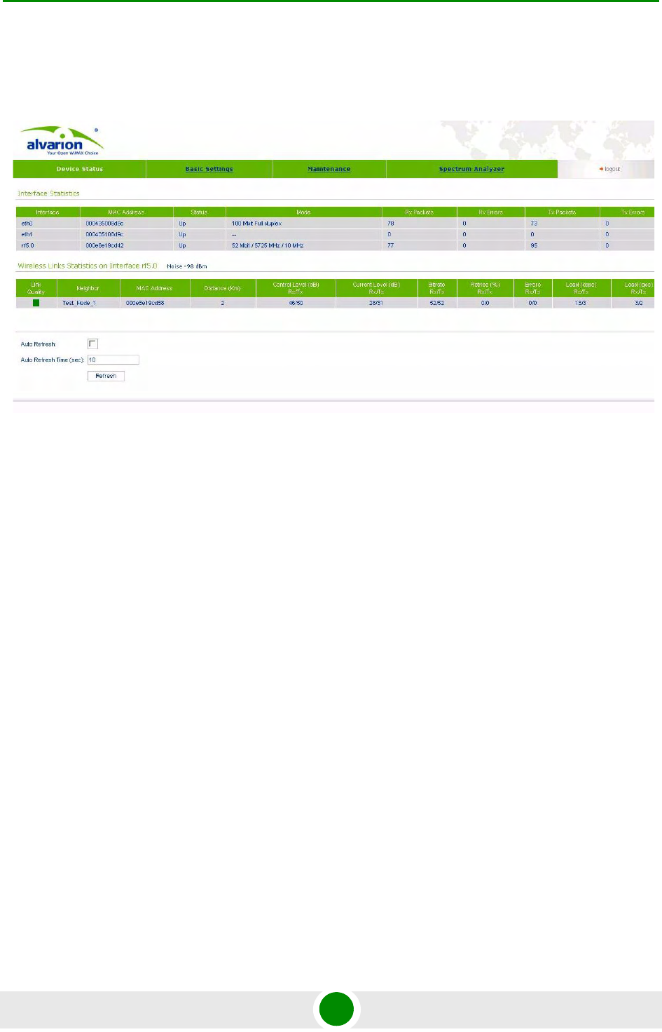
5.4 Device Status
"Device status" sheet allows viewing interface and radio link statistic. One can set
"Auto Refresh" option to refresh the statistics automatically. Refreshment
frequency can be set by "Auto Refresh Time" parameter. Device statistics can be
also refreshed manually by "Refresh" button.
"Interface Statistics" section displays the following parameters of all device's
interfaces:
Interface name
Interface MAC Address
Status
Mode
Packets (Rx/Tx)
Errors (Rx/Tx)
"Wireless Links Statistics" section displays all neighbor devices that it may
physically "hear" and that satisfy the given criteria. The following radio link
parameters are displayed:
Figure 5-2: Device Status

Chapter 5 - Configuration Via Web Interface Device Status
Alvarion BreezeNET B300 74 Technical User Manual
Link Quality (color indication of a connection quality: red - bad connection,
yellow - "not very good" connection, green - good connection)
Unit's interface, to which neighbor is connected
Neighbor's name
Neighbor's MAC address
Distance
Control Level (dB) Rx/Tx - signals levels for minimal available bitrate
Current Level (dB) Rx/Tx - signals levels for current bitrate
Bitrate Rx/Tx
Retries (%)
Errors
Load (Rx/Tx) in kbps
Load (Rx/Tx) in pps
Chapter 5 - Configuration Via Web Interface Maintenance
Alvarion BreezeNET B300 75 Technical User Manual
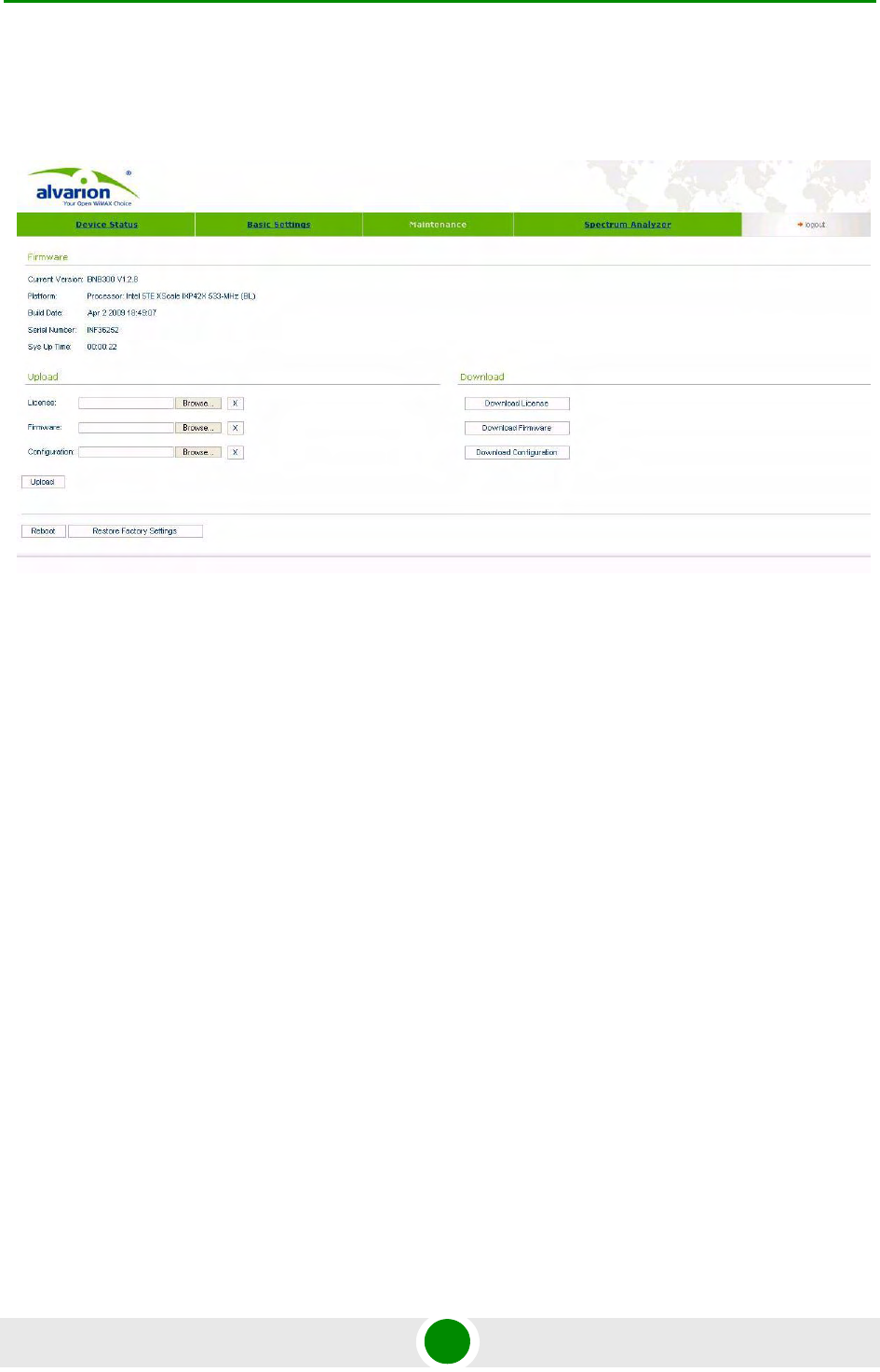
5.5 Maintenance
"Firmware" section shows current firmware version, firmware build date, serial
number and system up time.
"Upload"/"Download" sections allows uploading and downloading license files,
firmware and configuration on/off the device.
Pressing "Reboot" button reboots the device.
Pressing "Restore Factory Settings" button restores factory defaults configuration.
Figure 5-3: Maintenance
Chapter 5 - Configuration Via Web Interface Spectrum Analyzer
Alvarion BreezeNET B300 76 Technical User Manual
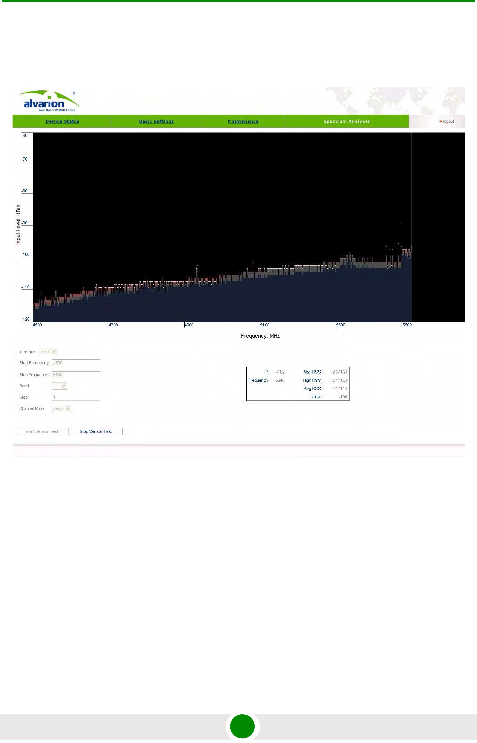
5.6 Spectrum Analyzer
"Spectrum Analyzer" provides deep analysis of radio emission sources. In this
mode device scans the radio spectrum on all available frequencies. To obtain
information as complete as possible, the scanning process may take some time.
The following parameters can be set to manage "Spectrum Analyzer" operation:
Unit's radio interface
Start frequency, determining the initial frequency for scanning in MHz.
Stop frequency, determining the ending frequency for scanning in MHz.
Figure 5-4: Spectrum Analyzer

Chapter 5 - Configuration Via Web Interface Spectrum Analyzer
Alvarion BreezeNET B300 77 Technical User Manual
Band - bandwidth in MHz.
Step - frequency changing step in MHz.
Channel mask - specify what antenna will scan the radio environment. "Auto"
value set scanning by both antennas.
To start/stop "Spectrum Analyzer" use "Start Sensor Test"/"Stop Sensor Test"
buttons.
You can get detailed information about scanned radio signals on a specific
frequency. Just point a cursor on the needed frequency and you will see a hint
with exact Signal level (dBm), Frequency (MHz), Noise Floor (dBm), Avg RSSI
(dBm), High RSSI (dBm), Max RSSI (dBm) values.

6
Chapter
Supplementary Information

Chapter 6 - Supplementary Information
Alvarion BreezeNET B300 79 Technical User Manual
In This Chapter:
“"RJ-45" Service Cable Connector Soldering Scheme” on page 80
“Console Cable Connector Soldering Scheme” on page 81
Chapter 6 - Supplementary Information "RJ-45" Service Cable Connector Soldering Scheme
Alvarion BreezeNET B300 80 Technical User Manual
6.1 "RJ-45" Service Cable Connector
Soldering Scheme
Figure 6-1: Service Cable Connector Soldering Scheme
Chapter 6 - Supplementary Information Console Cable Connector Soldering Scheme
Alvarion BreezeNET B300 81 Technical User Manual
6.2 Console Cable Connector Soldering
Scheme
Figure 6-2: Console Cable Connector Soldering Scheme